

Page 1

Disposal Instruction (US)
For better protection of our earth, please don’t throw this electronic device into
municipal trash bin when discarding. To minimize pollution and ensure utmost
protection of the global environment, please recycle the product. For more
information about the collection and recycling of Waste Electrical and Electronic
Equipment (WEEE), you are invited to visit our homepage at www.aopen.com
under “Green Products”
廃棄上の指示
より良い地球保護のために、電子機器を廃棄処分にする時は、ゴミ箱に捨てな
いで下さい。汚染を最小限に抑え、地球環境の最大限の保護のために、製品を
リサイクルして下さい。廃電気電子機器 (WEEE) の回収とリサイクルについて
の情報は、弊社ホームページwww.aopen.com の“Green Products”(環境に優
しい製品)をご覧下さい。
廢棄及回收處理
為了保護環境,請勿將本產品當作一般廢棄物處理。為減少環境污染,維護地球
資源,本產品報廢時,請回收本產品。
Instruktion til bortskaffelse (Danish)
Af hensyn til vores miljø bedes De ikke bortskaffe denne elektroniske enhed i
en almindelig affaldsspand. For at mindske forurening og sikre beskyttelse af
miljøet bedes De genbruge produktet. For yderligere information vedrørende
indsamling og genbrug af elektronik-affald (Waste Electrical and Electronic
Equipment (WEEE)) er De velkommen til at besøge vores website www.aopen.
com og læse nærmere under “Green Products”.
i
Page 2

Verwijderingsinstructie (Dutch)
Om mogelijke schade aan het milieu of de menselijke gezondheid door ongecontroleerde afvalverwijdering te voorkomen, moet u dit elektronisch product
scheiden van andere soorten afval en op een verantwoorde manier recyclen.
Verwijder dit product dan ook alstublieft niet samen met ander huishoudelijk
afval. Voor meer informatie over de verzameling en recycling van elektrisch
afval en elektronische apparatuur (WEEE), nodigen we u uit om onze homepage te bezoeken www.aopen.com onder “Green Products”.
Instruction de Disposition (French)
Pour une meilleure protection de la terre, ne jetez pas ce dispositif électronique
dans la poubelle municipale lors de la disposition. Pour éliminer la pollution et assurer la plus grande protection de l’environnement global, réutilisez
s’il vous plaît le produit. Pour plus d’informations sur la gestion des déchets
d’Equipements Electriques et Electroniques (DEEE ou WEEE), vous êtes invité
à visiter notre site à www.aopen.com sous “ Green Products”.
Entsorgungsanleitung (German)
Zum besseren Schutze unseres Planeten, schmeissen Sie elektrische Geräte
bitte nicht in öffentliche Mülleimer. Zur Verringerung der Verschmutzung und
zur Sicherstellung grösstmöglichen Schutzes der Umwelt recyceln Sie bitte das
Produkt. Für mehr Informationen zum Sammeln und Recyceln von elektrischen
und elektronischen Müll (WEEE) besuchen Sie bitte unsere Homepage unter
www.aopen.com unter dem Punkt “Green Products”.
Istruzioni per lo smaltimento (Italian)
Per una migliore salvaguardia del nostro pianeta, si prega di non gettare
questo dispositivo elettronico nei normali rifi uti al momento dell’eliminazione.
Per ridurre al minimo l’inquinamento ed assicurare la massima protezione
dell’ambiente, si prega di riciclare il prodotto. Per maggiori informazioni riguardanti la raccolta ed il riciclaggio delle apparecchiature elettriche ed elettroniche
residue (WEEE), siete invitati a visitare la nostra homepage www.aopen.com
alla voce “Green Products”.
ii
Page 3

Instruksjoner for Resirkulering og Oppsamling (Norweigian)
For ĺ beskytte vĺr planet, kast ikke dette elektroniske utstyret sammen med
vanlig avfall. For ĺ beskytte vĺr natur og miljř, vennligst resirkuler dette produktet. For mer informasjon om oppsamling og resirkulering i henhold til Waste
Electrical and Electronic Equipment (WEEE), se vĺr hjemmeside pĺ www.aopen.
com under “Green Products”.
Programa de Tratamento de Resíduos de Equipamentos
Eléctricos e Electrónicos (Portugese)
Para melhor protecção ambiental do nosso planeta terra, não coloque o dispositivo electrónico no receptáculo de lixo municipal. Para minimizar a poluição
e garantir protecção máxima do ambiente global, recicle o produto. Para mais
informações sobre acerca da recolha e reciclagem de Equipamento Eléctrico
e Electrónico (WEEE), convidamos-lhe a visitar nossa página na Internet em
www.aopen.com sobre “Green Products”.
Instrucciones para depositar los productos electrónicos
(Spanish)
Para proteger mejor el medio ambiente, por favor, no deposite los productos
electrónicos en los contenedores de basura tradicionales. Para reducir la
contaminación y proteger el medio ambiente se recomienda que los recicle.
Para más información acerca de dónde depositar y cómo reciclar Equipos
Electrónicos y Desperdicios Electrónicos (WEEE), por favor, visite la página
web www.aopen.com y entre en la sección Productos Ecológicos (“Green
Products”).
Kassering (Swedish)
För att bättre värna om vår jord bör denna elektroniska utrustning ej kasseras
tillsammans med vanligt avfall. För att minimera mängden föroreningar och så
långt som möjligt skydda den globala miljön bör produkten återvinnas.
För vidare information om insamling och återvinning av uttjänta elektriska och
elektroniska produkter (Waste Electrical and Electronic Equipment, WEEE),
besök avsnittet “Green Products” på vår hemsida, www.aopen.com.
iii
Page 4

iv
Page 5

Contents
Disposal Instructions
Welcome
Copyright © 2007 AOpen Inc. All Right Reserved
Notes and Warning labels used in the manual .......................
Safety Information ...............................................
Chapter 1 Introduction .........................................
1.1 Board and I/O Layout ...................................
1.2 Rear I/O Ports .........................................
1.3 System Block Diagram ..................................
Chapter 2 Hardware Installation .................................
2.1 Installation Overview ....................................
2.2 Installing the CPU ......................................
2.3 Installing CPU Cooler ...................................
2.4 Installing CPU and System Fans .........................
2.5 Installing System Memory Modules .......................
2.6 Installing IDE Cable ....................................
2.7 Installing SATA Cable ...................................
2.8 Connecting Front Panel Cable ...........................
2.9 PCI x 1 Installation .....................................
2.10 Gigabit LAN ...........................................
2.11 Connecting USB 2.0 ....................................
2.12 Channel Audio .........................................
2.13 Connecting Front Audio .................................
2.14 JP14 Clear CMOS Jumper ..............................
Chapter 3 Setting the BIOS .....................................
3.1 Introduction .............................................
3.2 How to use the Phoenix-Award BIOS Setup Program ........
3.3 How to Enter the BIOS Setup .............................
3.4 Standard CMOS Features ................................
3.5 Advanced BIOS Features .................................
3.6 Advanced Chipset Features ...............................
3.7 Integrated Peripherals ....................................
3.8 Power Management Setup ................................
3.9 PC health status .........................................
3.10 Load Optimized Defaults .................................
i
1
1
2
2
3
3
4
6
7
7
8
9
10
11
12
13
14
15
16
17
18
19
20
21
21
21
22
23
25
27
28
30
31
32
v
Page 6

3.11 Set Supervisor Password ................................
3.12 Save & Exit Setup ......................................
3.13 Exit Without Saving .....................................
3.14 BIOS Upgrade under Windows Environment ...............
Chapter 4 Special Features and Utilities.............................
Driver Install Utility ..........................................
Chapter 5 Installing Drivers .......................................
5.1 Driver Install Utility .......................................
5.2 Other useful Features ....................................
5.3 Useful Utilities ..........................................
Chapter 6 Troubleshooting .......................................
Troubleshooting Steps .......................................
Chapter 7 Technical Support and Contact ..........................
AOpen Technical Support Team Global Locations ...............
AOpen Technical Support ....................................
33
34
35
36
38
38
42
42
43
44
45
45
46
46
48
vi
Page 7

Welcome
First of all, we would like to express our gratitude for purchasing AOpen
products. This motherboard is designed to meet all your personal needs with
industry-leading features, the newest components and a strong focus on quality manufacturing and the testing and service that brings a positive computing
experience that lasts for years.
This manual will introduce how this motherboard is installed. Please keep it
well for your future reference. If you lose your printed manual, you may also
go to our website at http://www.aopen.com to download an updated fi le in PDF
format. Now, we would like to invite you to experience this user-friendly manual
and all of the powerful functions this AOpen product offers.
Copyright © 2007 AOpen Inc. All Right Reserved
This document is based on the copyright laws in order to protect our company
and reserve all rights. Under no circumstances are any types of duplicating
and loading this brochure in any databases and media permitted without the
express written permission of AOpen Inc.
Products and corporate names appearing in this manual may or may not be
registered trademarks or copyrights of their respective companies, and are
used only for identifi cation or explanation and to the owners’ benefi t, without
intent to infringe.
The logos of Adobe and Acrobat are the registered trademarks of Adobe Systems Incorporated.
The logos of AMD, Athlon, and Duron are the registered trademarks of Advanced Micro Devices, Inc.
The logos of Intel, Intel Celeron, Pentium II, III, Pentium 4, Pentium M and Core
2 Duo are the registered trademarks of Intel Corporation.
The logos of nVIDIA are the registered trademarks of nVIDIA Corporation.
The logos of Microsoft, Windows are the registered trademarks of Microsoft
Corporation in America and other countries.
All the titles of the products and the trademarks mentioned in this manual are
for the purpose of illustrative conveniences and are possessed by their respective fi rms.
We regret not informing about any changes in usage standards and other
related information. AOpen reserves the right to alter or modify the content of
this manual. In case of any mistakes or incorrect descriptions, which include
those on the products, AOpen makes no guarantee or commitments.
1
Page 8

Notes and Warning labels used in the manual
Please pay attention when you see the following symbols. They point out useful
information for this motherboard and make users aware of certain conditions.
Warning: Please be careful when you see this mark. Can possibly
injure yourself or the motherboard if you do not follow
instructions.
Note: This contains knowledge you should know when assem-
bling or using this AOpen product, or some helpful tip.
Tip: This Tip tells you some useful information that will make
your installation go smoothly.
Caution: Highlights where mistakes often occur during assembly or
use.
Safety Information
Warning: 1. Please wear a wrist strap and attach it to a metal part
of the system unit before handling a component.
You can also touch a metal object that has a ground
connection or another metal surface.
2. Always unplug the power before you make any jumper
settings.
3. Before you install or remove any components on the
motherboard, please make sure to disconnect the power
fi rst to prevent damage to the motherboard or other
components.
2
Page 9

Chapter 1 Introduction
1.1 Board and I/O Layout
1
2
17
3
4
5
6
7
8
9
1110
12
Table 1.1 Board Components
Item Item
01. Front Audio Connector 10. SATA II Connector
02. PCI slot 11. IDE Connector
03. nVIDIA MCP68S 12. CPU Fan
04. System Fan 13. NB Fan
05. JP14 CMOS clear jumper 14. SO DIMM Slot x 2
06. Battery 15. LGA 775 CPU Socket P
07. USB 2.0 Connector x 2 16. Retention modules
08. 4-pin DC Power Output Connector 17. Standby LED
09. Front Panel Connector
16
15
14
13
3
Page 10

1.2 Rear I/O Ports
Figure 1.1 Board I/O Layout
10
11
134
2
14
1
5
6 8
73
Table 1.2: Real I/O
Item Item
01. 19V DC Adapter Conector 08. Rear Surround (S/PIDF Out)
02. PS/2 Mouse Connector 09. Center/Subwoofer
03. PS/2 Keyboard Connector 10. Side Surround
04. USB 2.0 Port x 4 11. Line-In (S/PIDF In)
05. RJ45 LAN Jack Port 12. Speaker Out
06. COM 1 Port 13. Mic-In
07. VGA Port
14. HDMI
9
12
4
Page 11
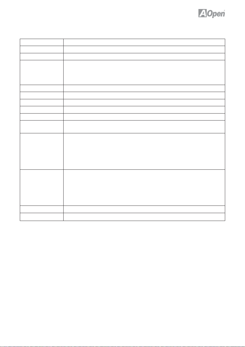
Table 1.3: NMCP68ST / NMCP68PVNT Specifi cations Model
Model NMCP68ST / NMCP68PVNT
CPU AMD AM2 Athlon 64 x 2/64, Sempron under 65W
Chipset nVIDIA® MCP68St / MCP68PVNT
Main Memory DDRII 533/667
Graphics nVIDIA® Geforce 7 class
Storage nVIDIA® MCP68St / MCP68PVNT
LAN (Giga) Marvell 88E1116
Sound Realtek® ALC888
USB nVIDIA® MCP68St / MCP68PVNT
Slots PCI Slot x 1
Back Panel I/O PS/2 Keyboard x 1, PS/2 Mouse x 1
On-Board
Connector
BIOS Award PnP 16Mb Flash ROM BIOS
Board Size 170 mm x 170 mm
DDR DIMM x 2
DIMM Type : 256/512MB/1GB/2GB
Max Memory : 4GB
IDE x 1
VGA Port x 1, COM Port x 1,
USB Port x 4, LAN Port x 1,
Speaker Out x 1, Line-In x 1, Mic-In x 1
Side Surround x 1, Rear Surround x 1, Center/Subwoofer x 1
HDMI x 1 (MCP68PVNT only)
4-pin DC Power Output Connector
Serial ATA II Channel x 2
Front Panel x 1
Front Audio x 1
CPU FAN x 1, System FAN x 1, NB FAN x 1
USB 2.0 pin header 10 pins x 2
* Specifi cations are subject to change without notice.
5
Page 12

1.3 System Block Diagram
SO DDRII
400/533/667MHz
HDMI
(MCP68PVNT only)
AMD AM2
under 65W
Series
CPU
MCP68S /
MCP68PVNT
Chipset
Serial ATA Port x 2
IDE x 1
RealTek
ALC888
VGA
LAN
Marevall
88E1116
LAN Connect
Componant
PS/2 Keyboard
PS/2 Mouse
Serial Port x 1
USB 2.0 x 8
Winbond
Super
I/O
6
Page 13

Chapter 2 Hardware Installation
2.1 Installation Overview
Generally, when installing a new motherboard and peripherals into a chassis,
people typically follow a certain order of steps for the installation.
The list below are the general steps:
Start
1. Installing CPU
2. Installing CPU Fan and System Fan
3. Installing Memory Module
4. Installing HD, CD-ROM and
SATA Disk , etc
5. Connecting front Panel Cable
6. Installing PCI Cards
7. Installing Other Devices
(USB, Front Audio, etc)
8. Connecting DC Adaptor
9. Connecting Back Panel Ports
(Keyboard, Mouse, etc)
10. Turn on the power Button
11. Loading Default BIOS
12. Installing Operating Systm
(such as , Windows Vista)
13. Installing Drivers & Utilities
END
7
Page 14

2.2 Installing the CPU
1. Erect CPU socket lever up.
2. Locate Pin 1 in the socket and look for a golden arrow on the CPU upper
interface. Match Pin 1 and golden arrow. then gently put CPU onto socket.
3. Press lever back to CPU socket, and then it’s done.
Lever
Golden arrow
Socket Pin 1
Warning:
Note:
1. If you do not match the CPU socket Pin 1 and CPU golden arrow well,
you may damage the CPU.
2. AMD CPU power consumption can not over 65W !
CPU Frequency Table
Spec. Model ID / L2 / FSB / Ratio / Freq. Vender
(DO)45W Athlon 64 X2 BE-2400 FB2 / 2*512M / 1000MHz / 11.5 / 2.30GHz AMD
(DO)45W Athlon 64 X2 BE-2350 FB2 / 2*512M / 1000MHz / 10.5 / 2.10GHz AMD
(DO)45W Athlon 64 X2 BE-2300 FB2 / 2*512M / 1000MHz / 9.5 / 1.90GHz AMD
(DE)45w Sempron LE-1200 FF1 / 512M / 800Hz / 10.5 / 2.10GHz AMD
(DD)65w Athlon 64 X2 4800+ FB1 / 512K*2 / 1000MHz / 12.5 / 2.50GHz AMD
(DD)65w Athlon 64 X2 4400+ FB1 / 512K*2 / 1000MHz / 11.5 / 2.30GHz AMD
(DD)65w Athlon 64 X2 4000+ FB1 / 512K*2 / 1000MHz / 10.5 / 2.10GHz AMD
(DD)65w Athlon 64 X2 3600+ FB1 / 512K*2 / 1000MHz / 9.5 / 1.90GHz AMD
(DE)45w Athlon 64 3200+ FF1 / 512K / 1000MHz / 10 / 2.00GHz AMD
(CZ)65w Athlon 64 X2 5200+ F33 / 1M*2 / 1000MHz 13.0 / 2.60GHz AMD
(CZ)65w Athlon 64 X2 4600+ F33 / 512K*2 / 1000MHz / 12 / 2.40GHz AMD
(CS)65w Athlon 64 X2 4600+ F32 / 512K*2 / 1000MHz / 12 / 2.40GHz AMD
(CZ)65w Athlon 64 X2 3800+ F33 / 512K*2 / 1000MHz / 10 / 2.00GHz AMD
Above table is AMD® AM2 Athlon 64 x 2 / 64, Sempron CPU numbers and
simple specifi cation for your reference only.
8
Page 15
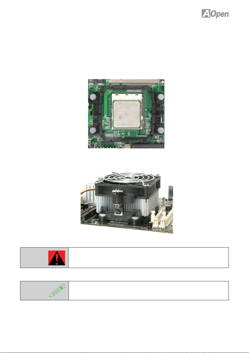
2.3 Installing CPU Cooler
Gently put down the CPU fan on CPU socket with four studs aimed directly
over the four mounting holes.
Warning:
Note:
Always use the correct amount of thermal grease when mounting
the CPU cooler. Follow the instructions closely.
This cooler and picture shown might be different from your purchased
product.
9
Page 16

2.4 Installing CPU and System Fans
Plug the CPU fan cable to the 3-pin CPU FAN connector.
If you have a chassis fan, you can also plug it into the SYSFAN connector.
Sensor
+12V
GND
SYSFAN Connector
Note:
GND
+12V
Sensor
CPUFAN Connector
Some fans do not have a sensor pin, so fan monitoring is not supported.
10
Page 17
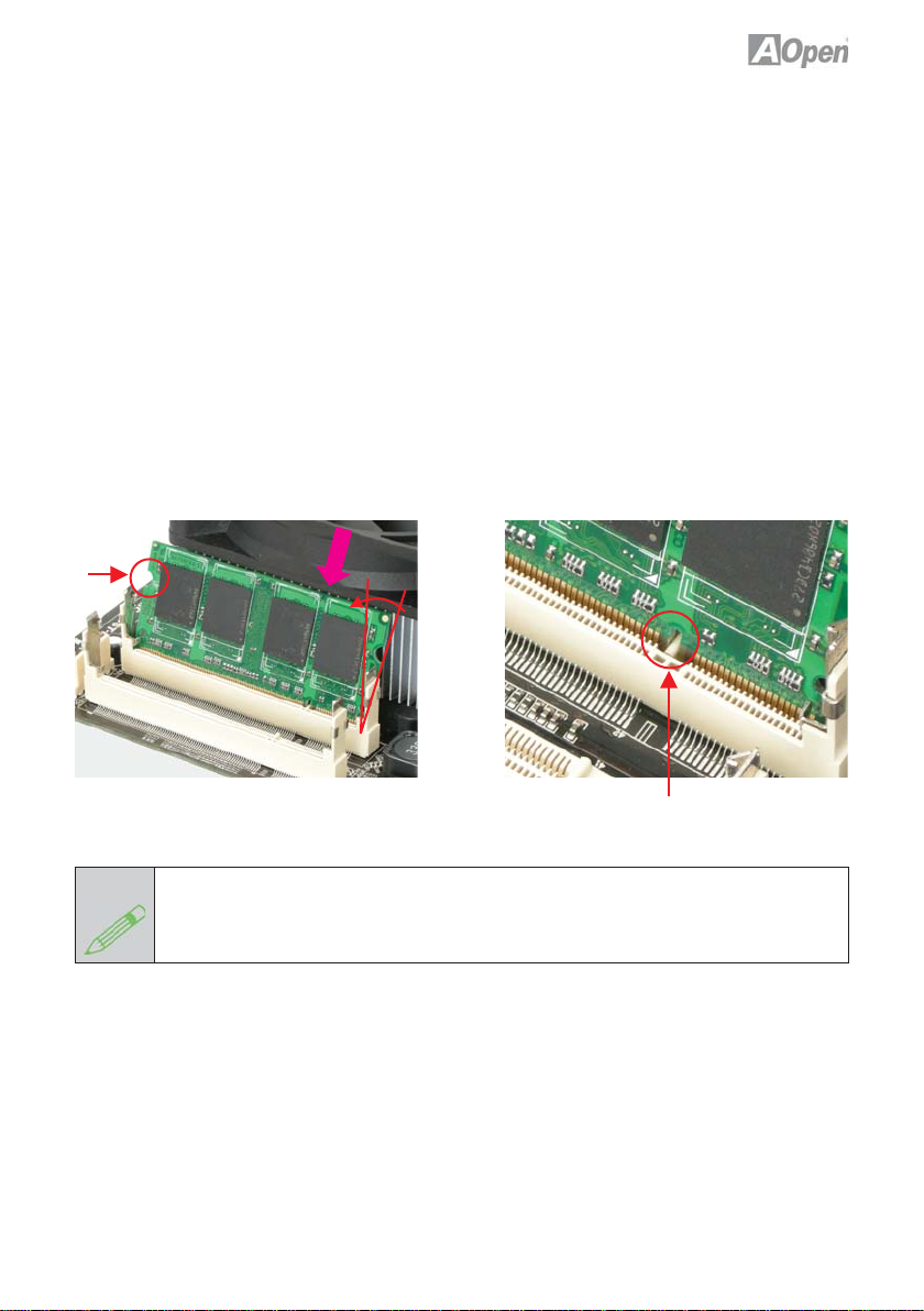
2.5 Installing Memory Module
The motherboard provide SODIMM type memory support. There’re two
SODIMM memory slots which motherboard provided. The installation of
memory module as below.
1. Put the memory module with correct direction. Notice there’s one stick to
make sure direction is correct.
2. Plug in memory module into SODIMM slot with angle 20~30º. Make sure
memory moule plug into slot completely.
3. There’re tabs which located in the side of SODIMM holder. Use fi nger to
push memory module vertically until the tabs lock memory module tightly.
4. Now, the memory modules have been plugged properly with horizontal fl at.
Ta b
Note:
30º
Stick
Pay careful attention to align the slot in the middle of the memory module.The tabs of
the DIMM slot will clip to hold the DIMM in place when the DIMM touches the slot’s
bottom. You can hear it click into place.
11
Page 18
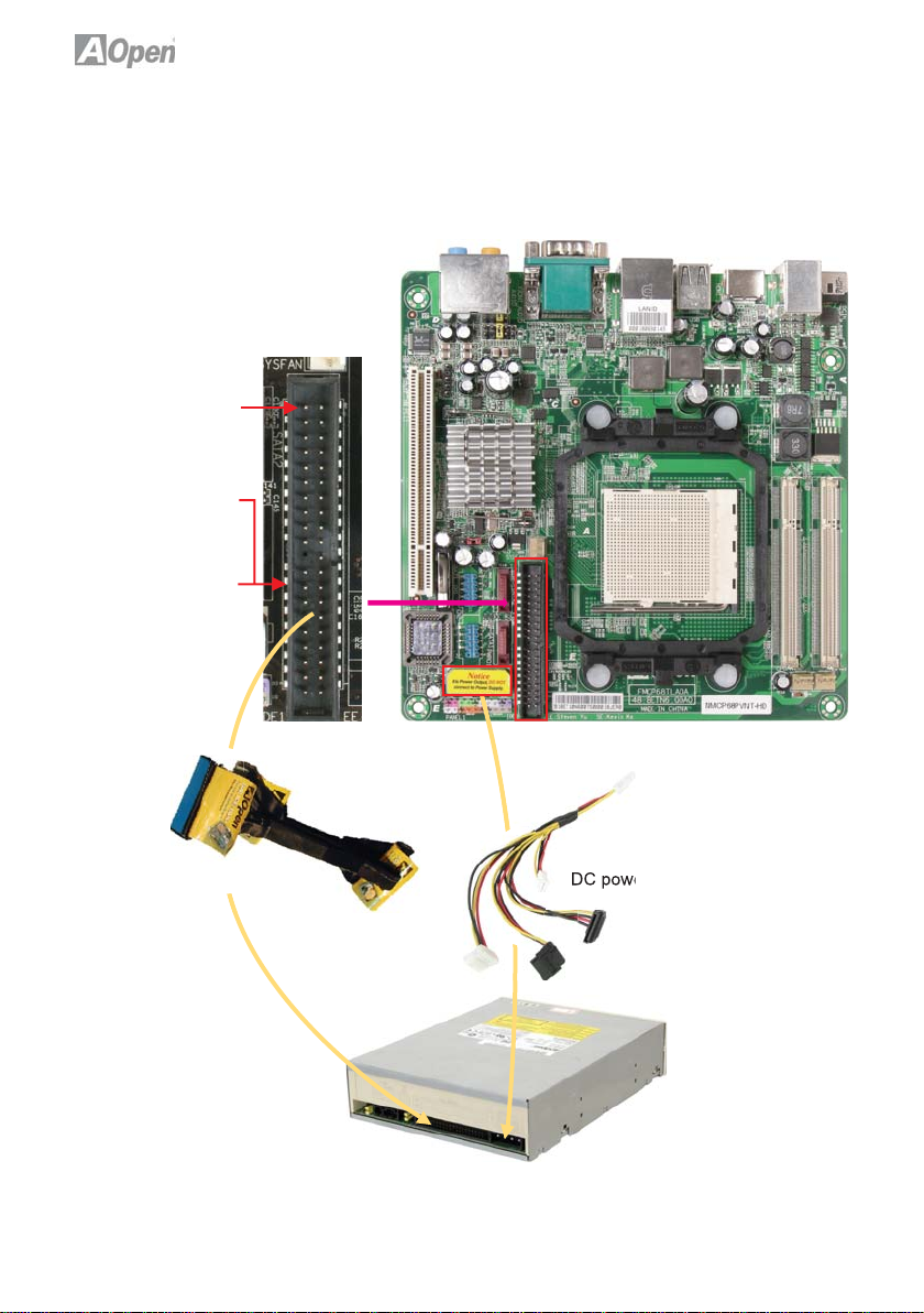
2.6 Installing IDE Cable
The motherboard provides one IDE connector which allow you to connect two
ATA 33/66/100 IDE devices like HDD.
Pin1
Primary Master
(1st)
Primary Slave
(2nd)
ATA 33/66/100 IDE Connector
Power Connector
IDE cable to connect IDE devices
DC power to connect IDE devices
12
Page 19

2.7 Installing SATA Cable
The mother board provides two SATA connectors.
And the nvidia MCP68PVNT supports RAID0 & RAID1 , refer to Chapter
“Confi guring SATA Hard device(s) for instructions on confi ruring a RAID Array.
RAID0 or RAID1 confi guration requires at least two hard drives.
Connect SATA cable to the on board SATA connector.
You can fi nd SATA cable in our package. (this is SATA signal cable)
And please also connect 5V power connector with SATA power cable.
RSATA_RXN1
GND
RSATA_RXN1
GND
RSATA_TXN1
RSATA_TXP1
GND
SATA 2
SATA 1
Power Connector
SATA Power Cord
SATA Signal Cable
SATA Hard Disk
13
Page 20
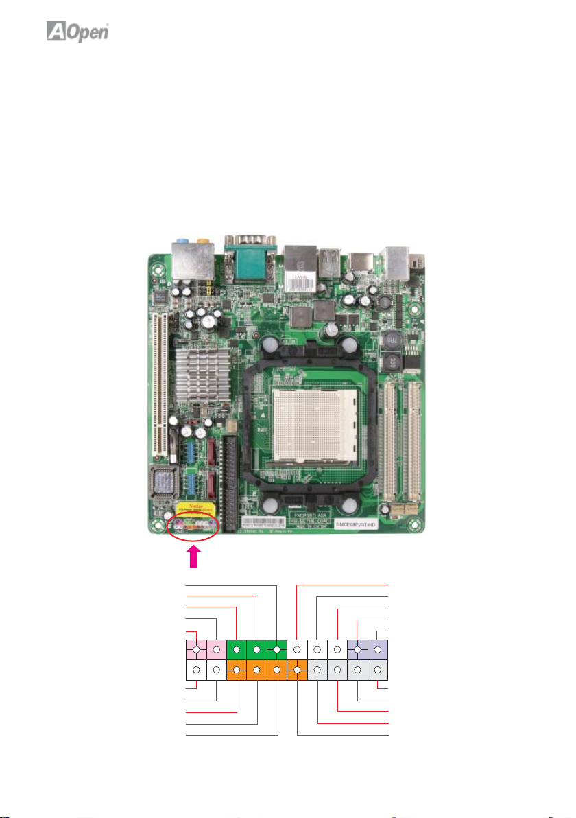
2.8 Connecting Front Panel Cable
Attach the power LED, speaker and reset switch connectors to the
corresponding pins. If you enable “Suspend Mode” item in BIOS Setup, the
ACPI & Power LED will keep fl ashing while the system is in suspend
mode.
Locate the power switch cable from your housing, which is a 2-pin female
connector from the housing front panel. Plug this connector to the soft-power
switch connector marked SPWR.
POWER LED+
GND
POWER LED -
NC
SPEAKER
Pin 1
NC
NC
+5V
HDD LED
HDD LED
NC
GND
GND
RESET
GND
SPEAKER
NC
GND
+5V
+5V
Front Panel Connector
14
Page 21
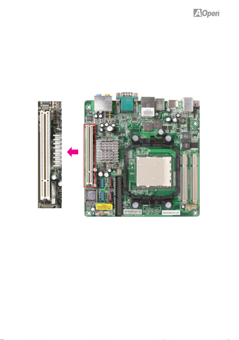
2.9 PCI x 1 Installation
The 1x PCI cards have SATA II and Firewire and USB cards … etc.
PCI Slot
15
Page 22

2.10 Gigabit LAN
One of the strengths is the Gigabit LAN controller on board, this mother board
provides 10/100/1000Mbps Ethernet for offi ce and home use. The Ethernet
RJ45 connector is located above the USB connectors. The right hand sid LED
indicates link mode; it lights in yellow when linking to a network. The left hand
side LED indicates the transfer mode and will light in green when data is
transferring at 100Mbps (never lights while at 10Mbps), and will light in orange
when transferring in Gigabit mode. To enable or disable this function, you
simply adjust it through the BIOS. To enable the LAN wakeup function, you
have to set the “Wake on PCI Card” to enable in the BIOS“Power Management
Setup” section.
Speed
Green 100Mbps
Orange Gigabit
ACT
LED Yellow
16
Page 23

2.11 Connecting USB 2.0
This motherboard provides eight USB 2.0 ports to connect USB devices such
as mouse, keyboard, modem, printer, etc. There are four ports on the back
panel. You can use proper cables to connect Front USB connector to USB
modules or chassis front panel.
1
+ 5V
SBD6 -
SBD6+
GND
KEY
+5V
SBD7 -
SBD7+
GND
NC
USB 2.0 Connector
17
Page 24

2.12 Channel Audio
This motherboard comes with an Azalia (Realtek ALC888) codec, which
supports the latest 7.1 Channel sound with high quality audio effects,
bringing you an excellent audio experience. This motherboard provides 7.1
Channel ports as shown below. The diagram represents the standard
location of all speakers for 7.1 Channel sound use. Please connect the plug
of your front speakers to the green “Speaker out” port, rear surround speakers
to orange port, side surround speakers to gray port and both of the center and
subwoofer speakers to the black port on the back panel.
Line-in
Mic-in
Front Left
(Green)
Center
(Black)
Front Right
(Green)
Rear Left
(Orange)
Side Surround
(Gray)
Subwoofer
(Black)
Side Surround
(Gary)
18
Rear Right
(Orange)
Page 25

2.13 Connecting Front Audio
If the chassis is designed with an audio port on the front panel, you’ll be able
to connect onboard audio to the front panel through this connector. Please
remove the jumper cap from the Front Audio Connector before you connect the
cable. Do not remove this yellow jumper cap if your housing doesn’t have an
audio port on the front panel.
AUD_FPOUT_L
Front_IO_Sense
AUD_FPOUT_R
AUD_MIC_R
AUD_MIC_L
Pin 1
AUD_GND
Front_IO_Plug
AUD_RET_R
KEY
AUD_RET_L
Front Audio Connector
19
Page 26
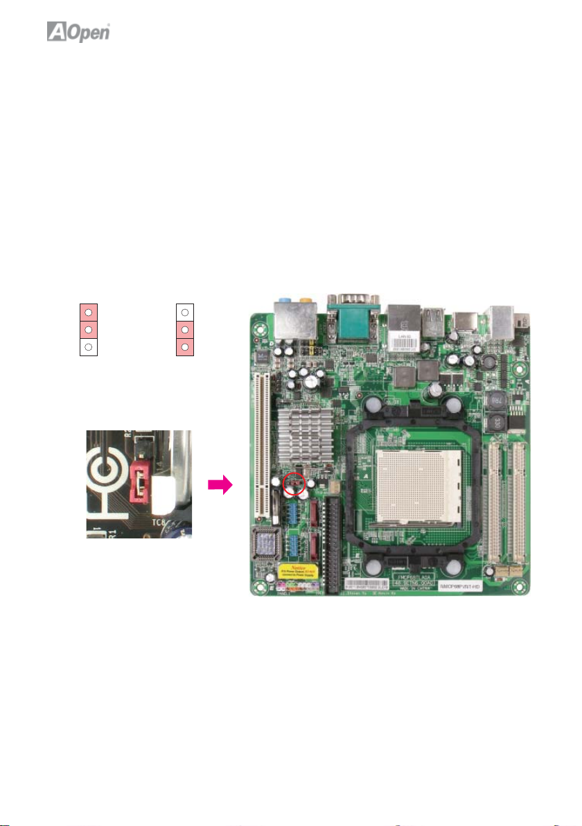
2.14 JP14 Clear CMOS Jumper
You can clear CMOS to restore system default settings. To clear the CMOS,
follow the procedure below.
1. Turn off the system and unplug the AC power.
2. Locate JP14 and short pins 2-3 for a few seconds.
3. Return JP14 to its normal setting by connecting it to Pin 1-2 again.
4. Connect ATX power cable back to connector PWR3.
11
Normal (Default) Clear CMOS
JP14 Clear CMOS Jumper
20
Page 27

Chapter 3 Setting the BIOS
3.1 Introduction
System parameters can be modifi ed by going into BIOS Setup menu; this
menu allows you to confi gure the system parameters and save the confi
guration into the 128 byte CMOS area (normally in the RTC chip or in the main
chipset).
The Phoenix-Award BIOS™ that is installed in the Flash ROM of the
motherboard is a custom version of an industry standard BIOS. The BIOS
provides critical low-level support for standard devices such as hard disk
drives, serial and parallel ports.
AOpen’s R&D engineering team has optimized most BIOS settings of this
motherboard. However, some default settings of the BIOS cannot fi ne-tune
items that are controlled by chipset. Therefore, this chapter is intended to guide
you and help you to confi gure some other settings. To enter the BIOS setup
menu, press <Del> when POST (Power-On Self Test) screen is shown on your
monitor.
Note:
Because BIOS code is the most often changed part on motherboard, the BIOS
information contained in this manual may be different from the BIOS version
that comes with your motherboard.
3.2 How to use the Phoenix-Award BIOS Setup Program
Generally, you can use arrow keys to highlight items that you want to choose,
press <Enter> key to select, and use <Page Up> and <Page Down> keys to
change setting values. You can press <Esc> key to quit Phoenix-Award™
BIOS setup program. The following table provides details about how to use the
keyboard in the Phoenix-Award™ BIOS setup program.
21
Page 28

Key Description
Page Up or + Change setting to next value or increase the value.
Page Down or - Change setting to previous value or decrease value.
Enter Select the item.
Esc In main menu Quit without saving any changes.
In sub menu Exit current menu to main menu.
Up Arrow Highlight previous item.
Down Arrow Highlight next item.
Left Arrow Move the light bar to left side of menu.
Right Arrow Move the light bar to right side of menu.
F6 Load Setup Default setting value from CMOS.
F7 Load turbo setting value from CMOS.
F10 Save changed settings and exit setup program.
3.3 How to Enter the BIOS Setup
After fi nishing the jumper settings and connecting cables, you can power on
and enter the BIOS Setup. Press <Del> during POST (Power-On Self Test) and
choose “Load Fail-Safe Defaults” for recommended optimal performance.
Caution:
Please avoid of using “Load Optimized Defaults”, unless you are certain
your system components (CPU, SDRAM, HDD, etc.) have been proven
acceptable for use.
22
Page 29
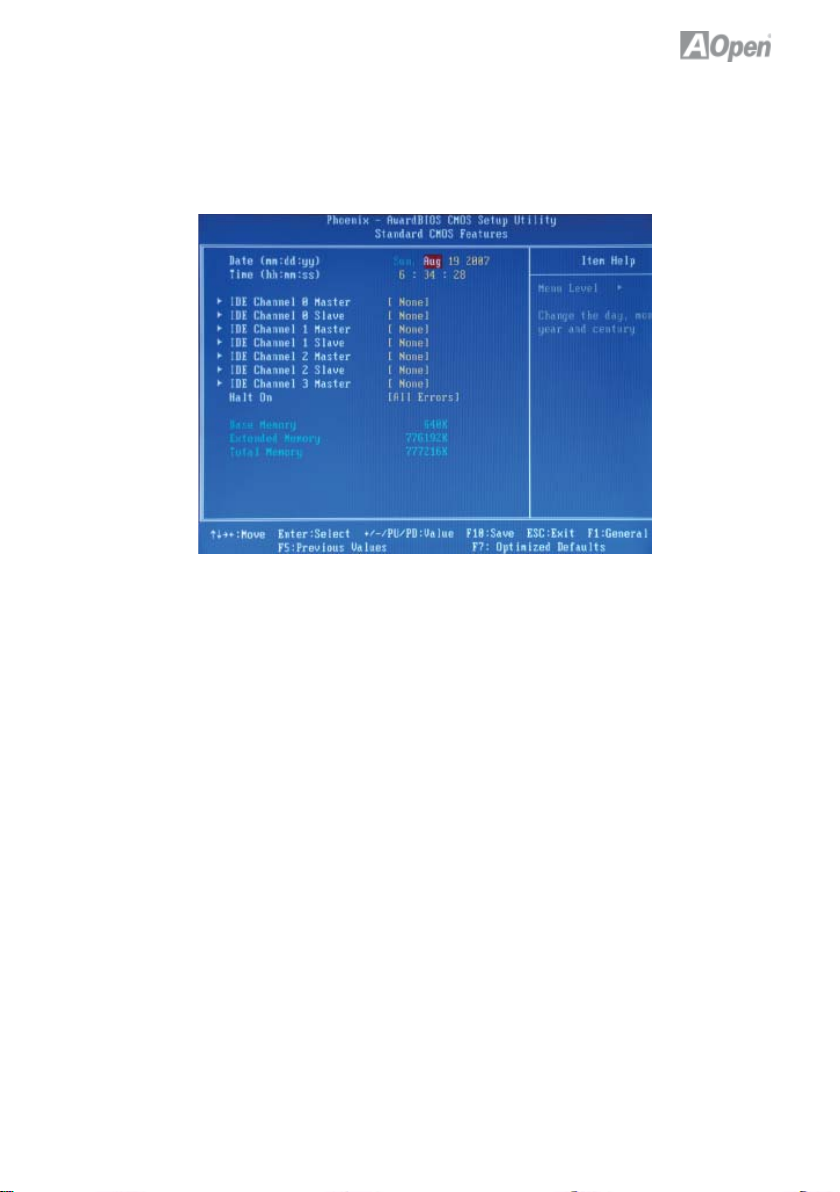
3.4 Standard CMOS Features
The “Standard CMOS Setup” sets the basic system parameters such as the
date, time, and the hard disk type. Use the arrow keys to highlight an item and
<PgUp> or <PgDn> to select the value for each item.
Standard CMOS Features > Date
To set the date, highlight the Date parameter. Press <PgUp> or <PgDn> to set
the current date. The date format is month, date, and year.
Standard CMOS Features > Time
To set the time, highlight the Time parameter. Press <PgUp> or <PgDn> to set
the current time in hour, minute, and second format. The time is based on the
24 hour military clock.
Standard CMOS features > IDE Channel 0 Master
Standard CMOS features > IDE Channel 0 Slave
Standard CMOS features > IDE Channel 1 Master
Standard CMOS features > IDE Channel 1 Slave
Standard CMOS features > IDE Channel 2 Master
Standard CMOS features > IDE Channel 2 Slave
Standard CMOS features > IDE Channel 3 Master
This item lets you select the IDE hard disk parameters that your system
supports. These parameters are Size, Number of Cylinder, Number of Head,
Start Cylinder for Pre-compensation, Cylinder number of Head Landing Zone
and Number of Sector per Track. The default setting is Auto, which enables
BIOS to automatically detect the parameters of installed HDD (Hard Disk Drive)
at POST (Power-On Self Test). If you prefer to enter HDD parameters
manually, select Manual.
23
Page 30

Standard CMOS Features > IDE Channel 0 Master > IDE HDD AutoDetection
Press “Enter” to auto-detect parameters of HDD.
Standard CMOS Features > IDE Channel 0 Master > IDE Channel 0 Master
Defi ne the parameters of IDE devices in Channel 0 (Master or Slave).
Available options:
None: If there is no device, please select “None” for speeding boot up.
Auto: This will enable BIOS to auto-detect parameters of IDE device. (Default)
Manual: Allow users to defi ne parameter of IDE device.
Standard CMOS Features > IDE Channel 0 Master > Access Mode
Set the using mode of HDD. Available options: CHS / LBA / Large / Auto
(default). User can select the mode according to the label on HDD.
Cylinder: Enter cylinder number
Head: Enter head number
Precomp: Write precompensation
Landing Zone: Location of head
Sector: Sector number
Standard CMOS Features > HaltOn
This parameter enables you to stop the system in case of Power-On Self Test
(POST) error. Available items: All errors / No errors / All, But Keyboard
24
Page 31
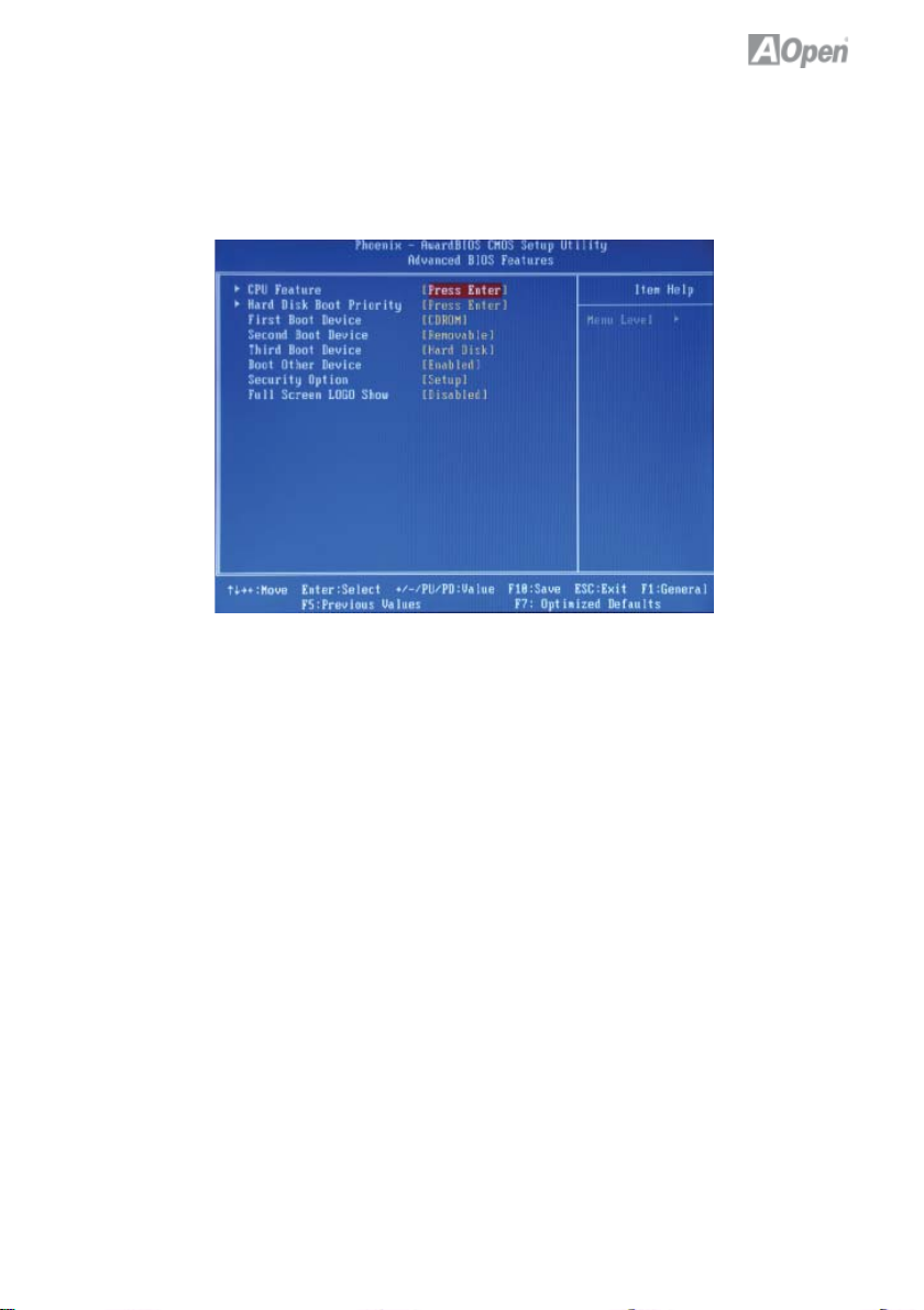
3.5 Advanced BIOS Features
This screen appears when you select the option “Advanced BIOS Features”
from the main menu.
Advanced BIOS Features > Removable Device Priority
Advanced BIOS Features > Hard Disk Boot Priority
Advanced BIOS Features > CD-ROM Boot Priority
This parameter allows you to specify the system boot up search sequence.
Advanced BIOS Features > Hyper-Threading Technology
Provides thread-level parallelism on each processor, resulting in more effi cient
use of processor resources, higher processing throughput, and improved performance for multithreaded software.
Available options: Disabled, Enabled
25
Page 32

Advanced BIOS Features > First Boot Device
Advanced BIOS Features > Second Boot Device
Advanced BIOS Features > Third Boot Device
Advanced BIOS Features > Boot Other Device
Allows you to specify the system boot sequence.
Available options:
Removable: Floppy, USB, ZIP…etc
Hard Disk: Hard Disk Drives
CD-ROM: CD-ROM, DVD-ROM…etc
LAN: LAN Card with boot ROM
Advanced BIOS Features > Security Option
The “System” option limits access to both the System boot and BIOS setup. A
prompt asking you to enter your password appears on the screen every time
you boot the system. The “Setup” option limits access only to BIOS setup. To
disable the security option, select Password Setting from the main menu, don’t
type anything and just press <Enter>.
Advanced BIOS Feature > Frame Buffer Size
Advanced BIOS Features > Full Screen Logo Show
This item allows user to select to show or hide “Full Screen logos” or “Vivid
BIOS logos”. Available options: Disabled, Enabled
26
Page 33

3.6 Integrated Peripherals
This submenu appears if you select the option “Integrated Peripherals” from the
main menu. This option allows you to confi gure the I/O features.
Integrated Peripherals > IDE Function Setup
SATA Operation Mode > This item is used to select IDE/RAID mode
IDE : Confi gures the SATA controller to PATA mode(Default)
RAID :Enables RAID for SATA controller
Integrated Peripherals> Onboard Serial Port 1 >Disable 3F8/IRQ4 3E8/IRQ4
2E8/IRQ3 Auto
Integrated Peripherals> USB Device Setting >USB1.0 Controller
This item lets you enable or disable the USB 1.0 controller
Integrated Peripherals> USB Device Setting >USB2.0 Controller
This item lets you enable or disable the USB 2.0 controller
Integrated Peripherals> USB Device Setting >USB Keyboard Function
This item lets you enable or disable the USB Keyboard Function
Integrated Peripherals> USB Device Setting >USB Keyboard Function
This item lets you enable or disable the USB Mouse
27
Page 34

3.7 Power Management Setup
The Power Management Setup screen enables you to control the motherboard
green features.
Power Management > ACPI Suspend Type
The function allows you to select suspend types. S1 is power On Suspend and
S3 is Suspend to RAM,Available Options : S1,S3 & S1 & S3
Power Management > Soft-Off by PBTN
This is a specifi cation of ACPI and supported by hardware. When Delay 4 sec.
is selected, the soft power switch on the front panel can be used to control
power On, Suspend and Off. If the switch is pressed for less than 4 seconds
during power On, the system will go into Suspend mode. If the switch is
pressed for longer than 4 seconds, the system will be turned Off. The default
setting is Instant-Off. If Instant-Off is selected the soft power switch is only used
to control On and Off, so there is no need to press it for 4 seconds, and there is
no Suspend.
Available Options: Delay 4 sec., Instant-Off
Power Management > WOL(PME#) From Soft-Off>
This is a function of PCI specifi cation 2.2. PCI bus supports standby current to
PCI card and PCI card can wakeup system if it detects certain activity.
Available options: Disabled, Enabled
28
Page 35

Power Management > WOR(RI#) From Soft-Off>
This option lets you specify enable or disable Wake On Modem Ring function.
Available options: Disabled, Enabled
Power Management > Power-On by Alarm>
This function can provide alarm to resume system immediately.
Available options: Disabled, Enabled
Power Management > Power-On by Alarm> Date (of Month) Alarm>
This item is displayed when you enable the Wake On RTC Timer option. Here
you can specify what date you want to wake up the system. For Example, setting to 15 will wake up the system on the 15th day of every month.
Power Management > Power-On by Alarm> Time (hh:mm:ss) Alarm>
This item is displayed when you enable the Wake On RTC Timer option. Here
you can specify what time you want to wake up the system.
Power Management > HPET Support>
High Precision Event Timer is a hardware timer , The HPET can produce periodic interrupts at a much higher resolution than the RTC and is often used to
synchronize multimedia streams, providing smooth playback and reducing the
need to use other timestamp calculations
Power Management > Power On Fuction>
This item is used to select Wake on Keyboard/Mouse mode.
Power Management > Power On Fuction> Password:
Disable the function of power button and let the system can only be powered
on through the preset keys(like a password).
KB Power ON Password: You can specify 1-5 keys as a password.
Power Management > Power On Fuction> Hot Key:
If selecting this option, you also need to specify the hot key from “Hot Key
Power On” item.
Hot Key Power On:
If you select “Hot Key” option in “Power On Function” Item, you need to specify
a hot key here.
Power Management > Power On Fuction> Any Key:
This function allows you wake up the system by clicking any key.
29
Page 36

Power Management > Power On Fuction> Button Only:
Disable Wake on KB/MS function. You can boot up your system by power button only.
Power Management > AC PWR Auto Recovery>
A traditional ATX system should remain at power off stage when AC power
resumes from power failure. This design is inconvenient for a network server or
workstation, without an UPS, that needs to keep power-on. This item is used
to solve this problem. Selecting On enabling system to automatically power-on
after AC power resumes; in the other hand, the system will remain power-off if
you select Off.
If Former-Sts (former status) option is selected, the system will power-on or
power-off based on the original state. Available options: Former-Sts, On, Off
30
Page 37

3.8 PC health status
The Power Management Setup screen enables you to control the motherboard
green features.
PC Health Status
The PC Health Status can bring PC important safety parameters for detect
Health of your system.
PC Health Status > CPU Smart Fan
The CPU smart fan can detect CPU temperature and adjust fan speed automatically. That can ensure you to have silent & best working environment for
system. Suggestion: Enabled it.
Available options: Disabled, Enabled
PC Health Status > System Temperature
PC Health Status > CPU Temperature
PC Health Status > System Fan
PC Health Status > CPU Fan
PC Health Status > VCC (V)
PC Health Status > VBAT (V)
PC Health Status > SVSB (V)
PC health status bring you on the system temperature, CPU temperature, CP
Fan speed, Vcore, VCC, VBAT, SVSB – these important system parameters for
you to check the health status of your system.
31
Page 38

3.9 Load Optimized Defaults
The “Load Optimized Defaults” is used to load the factory defaults for BIOS and
Chipset features that are detected by the system.
32
Page 39
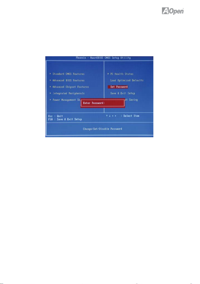
3.10 Set Password
A Password prevents unauthorized use of your computer. If you set a password, the system prompts for the correct password before boot or access to
Setup.
To set a password:
1. At the prompt, type your password. Your password can be up to 8
alphanumeric characters. When you type the characters, they appear as
asterisks on the password screen box.
2. After typing the password, press the “Enter” key.
3. At the next prompt, re-type your password and press the “Enter” key again
to confi rm the new password. After the password was typed-in, the screen
automatically reverts to the main screen. To disable the password, press
“Enter” when being prompted to input the password.
33
Page 40

3.11 Save & Exit Setup
A Password prevents unauthorized use of your computer. If you set a password, the system prompts for the correct password before boot or access to
Setup.
34
Page 41
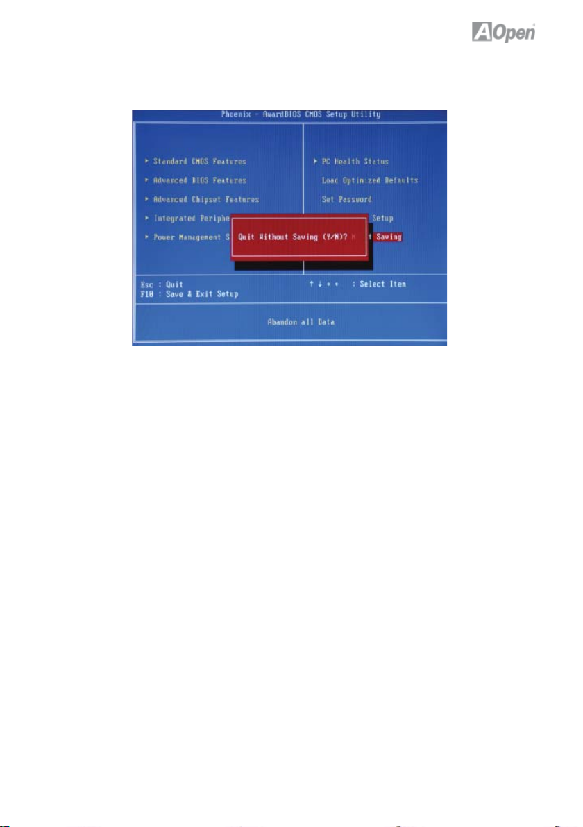
3.12 Exit Without Saving
35
Page 42

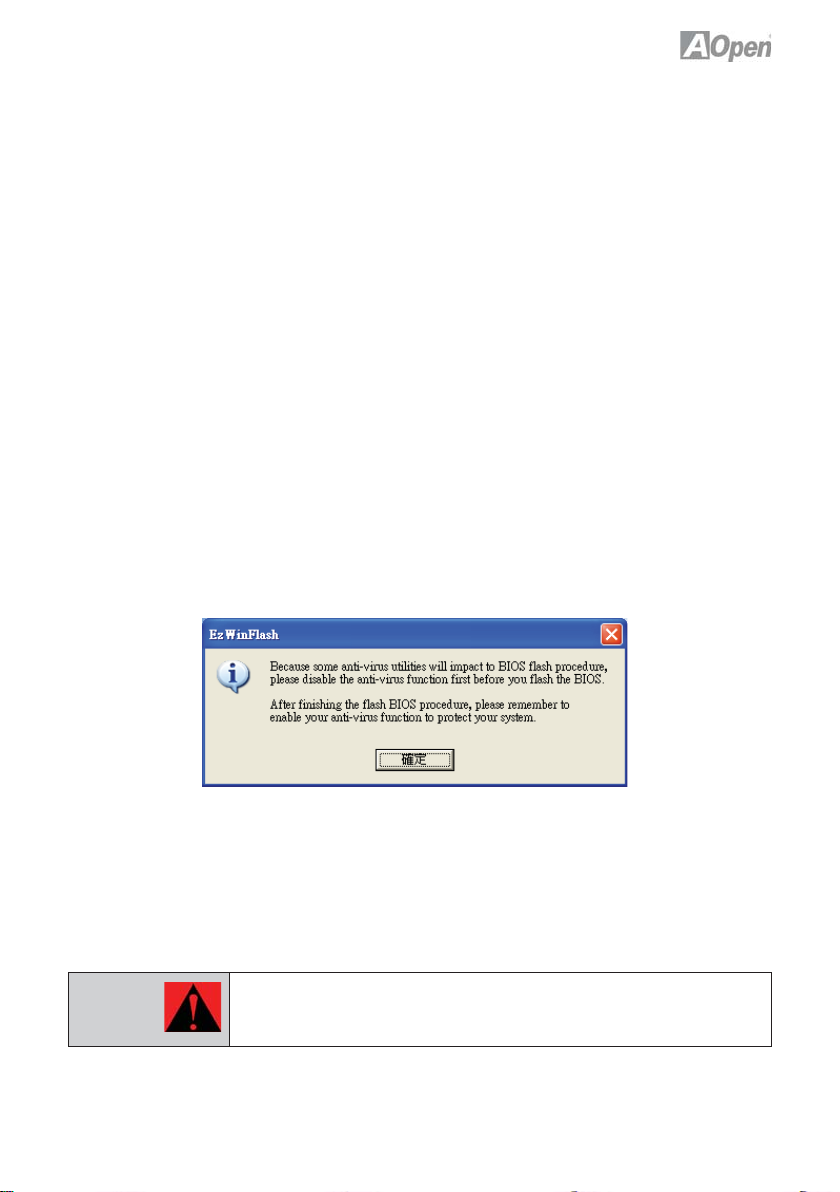
3.13 BIOS Upgrade under Windows Environment
With outstanding R&D ability of AOpen, we now bring you the EzWinFlash
BIOS wizard. With an eye on convenience for users, EzWinFlash combines the
BIOS binary code and fl ash module together, so the only thing you have to do
is just click on the utility and downloaded from web and let it help you
complete the fl ash process automatically. EzWinFlash detects your
motherboard and checks the BIOS version to prevent your system from any
possible failure. Moreover, EzWinFlash takes into consideration any Windows
platform you might be using, no matter if you’re using Windows 95/98, 98SE/
ME, NT4.0/2000, or Windows XP.
n order to provide a much more user-friendly operating environment, AOpen
EzWinFlash is natively designed to have multi-language function to make it
easier way for users to change the BIOS setting.
Caution:
Note:
You are taking a risk of BIOS fl ash failure when you update your system. If your
motherboard is working stable, and there are no major bugs to be fi xed by a latter
BIOS revision, we recommend that you DO NOT upgrade your BIOS. If you intent
on upgrade PLEASE MAKE SURE you get the right BIOS revision for your motherboard model so as to avoid any possible failure.
The model name on this BIOS picture is for reference only. It may not be the same
model with your motherboard.
36
Page 43
You may accomplish BIOS upgrade procedure with EzWinFlash according to
following steps, and it’s STRONGLY RECOMMENDED to close all applications
before you start the upgrades.
Download the latest version of BIOS package zip fi le from AOpen offi cial web
site. (Ex: http://english.aopen.com.tw/)
Unzip the downloaded BIOS package (ex: WSGMAXII102.ZIP) with WinZip
(http://www.winzip.com) in Windows environment.
Save the unzipped fi les into a folder, for example, WSGMAXII102.EXE & WSG-
MAXII102.BIN.
Double click WSGMAXII102.EXE; EzWinFlash will detect the model name and
BIOS version of your motherboard. If you got the wrong BIOS, you will not be
allowed to proceed with the fl ash steps.
You may select a preferred language in main menu, then click [Start Flash] to
begin the BIOS upgrade procedure.
EzWinFlash will complete all the process automatically, and a dialogue box will
pop up to ask you to restart Windows. Click [YES] to reboot Windows.
Press <Del> at POST to enter BIOS setup screen; choose “ Load Setup
Defaults ”, then “ Save & Exit Setup ”. Done!
It is strongly recommended NOT to turn off the power or run any applications
during FLASH PROCESS.
Warning:
The new BIOS upgrade will permanently replace your original BIOS setting
when fl ashing. You may need to reconfi gure the BIOS setting before your
system works normally again.
37
Page 44

Chapter 4 Special Features and Utilites
4.1 Driver Install Utility
RAID (Redundant Array of Independent Disks)
With nVIDIA MCP68PVNT implemented, nMCP68PVNt-HD provides RAID 0
and RAID 1 function for the Serial ATA hard disks.
Installation Raid driver under window installation
In order to make sure your system can recognize and operate Serial ATA RAID
device smoothly, one have to install Raid Driver under window installation
When start installing windows, then press “F6” when prompted at the beginning
of window setup
38
Page 45

Press the “S” key to select “Specify Additional Device
Please insert Raid Driver fl oppy Disk into Drive A:
After Raid driver fl oppy disk insert properly in drive A, please “ENTER” to con-
tinue.
39
Page 46

Please select “nVIDIA nForce Storage Controller (required)”
Press “enter” after selection.
Please press “ENTER” to continue installation
40
Page 47

When the screen as show below appers, Press”Enter” to continue the driver
insatllation from the fl oppy disk .
41
Page 48
Chapter 5 Installing Drivers
5.1 Driver Install Utility
You may think that installing drivers and utilities would be a repeated task of
going through these installation wizards and step-by-step. You will be surprised
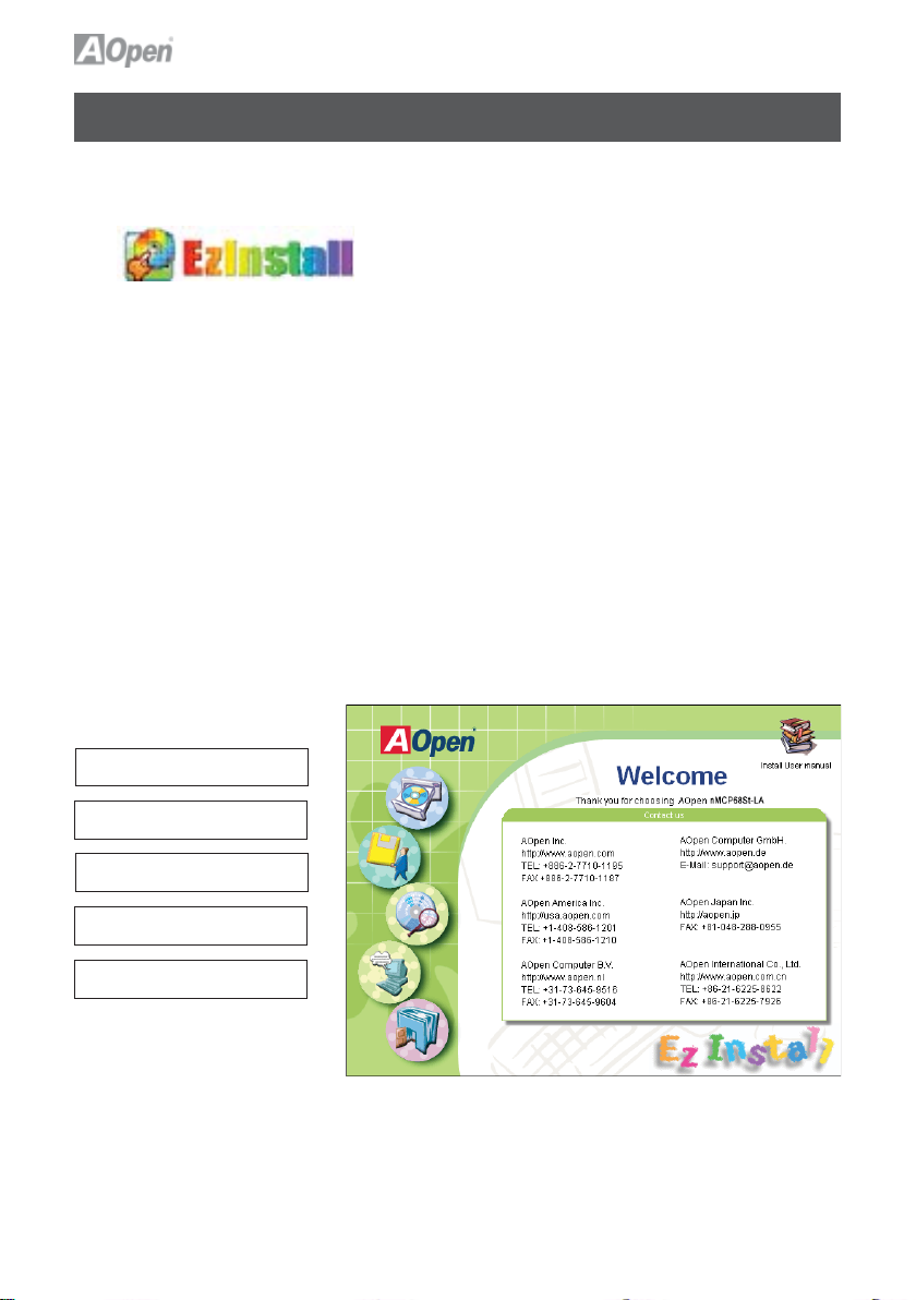
how using EzInstall makes it so easy. Without wizards or steps, all you have
to do is to do is click and then it’s done. Click and it is done. EzInstall makes
installation easy and even foolproof!
After putting in the CD, you will be prompted with the AOpen welcome page
and our branch information.
First, click on the install driver ICON on the left side for necessary drivers.
Second, click on the install utility ICON on the left side for preferred utilities.
You may also browse CD contents, and Readme to get more information, or
just exit the CD installation.
Install Driver
Install Utility
Browse CD Contents
Read me
Exit CD
42
Page 49

5.2 Other useful Features
Press the Icon to go to the “Install Driver” page. You may press “Back” to return
to the main page.
Once clicking “GO”, EzInstall will run the installing procedure automatically, and
prompt a reboot dialog (Some drivers or utilities may skip the reboot part).
Note: Due to the limitation of Intel chipsets driver, Windows 2000 is
needed to be updated to service pack 4 for installing the audio
driver correctly.
43
Page 50
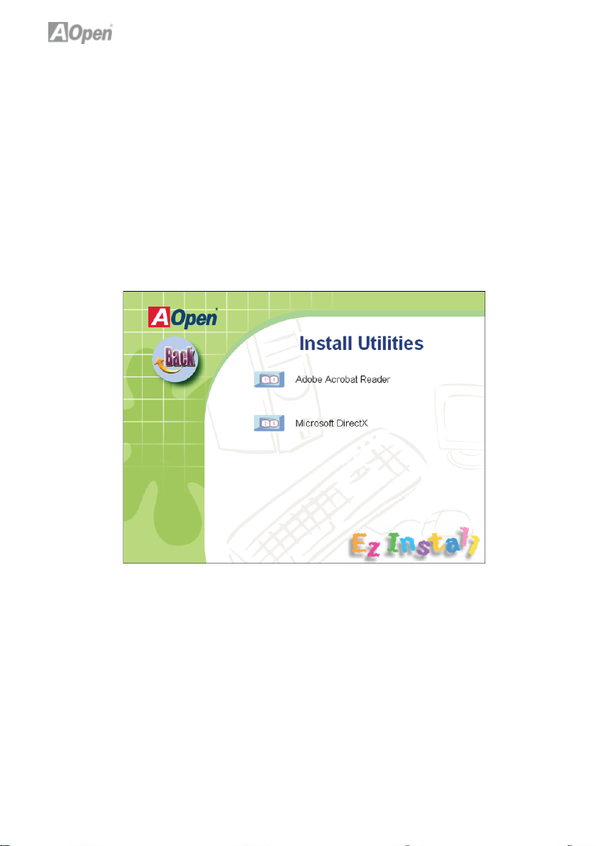
5.3 Useful Utilities
Installing Utilities is virtually the same as installing drivers. AOpen provides you
with many friendly and powerful utilities to manage your system. You will fi nd
a lot of fabulous utilities listed here, and all you have to do is to click on “GO”,
then it will install the utilities to your system right away without complicated
steps.
Press the icon to go to the “Install Utilities” page for your selection. You may
also press “Back” to get back to the Main page.
44
Page 51

Chapter 6 Troubleshooting
6.1 Troubleshooting Steps
You are welcome to visit our technical website to learn more about these features.
Start
Turn off the power and unplug the AC
power cable, then remove all of the addon cards and cables including VGA, IDE,
DFF, COM1, COM2, printer and other
external devices.
Clear CMOS and then plug the
DC power adapter.
Yes
Turn on power button
Yes
Check if there is display
Press Del to enter BIOS setup, and choose "Load
Setup Default". (For AMD user, please make sure
you set the right CPU frequency in BIOS) Save the
changes you make in BIOS and reboot the system
Yes
Turn on the system again and re-connect
the IDE cable. Check if the system can
reboot successfully
Reinstall operating system such as Windows 2000
or Windows XP
End
No
No
No
45
Perhaps your memory is not
compatible with the system,
or either your VGA card*2
or monitor is out of order
The problem maybe caused
by power supply/motherboard
failure. Please contact your
reseller or your distributor for
repairing.
The problem maybe caused by
the IDE cables or HDD itself.
Page 52

Chapter 7 Technical Support and Contact
Dear Customer,
Thanks for choosing AOpen products. We invite you to register at
http://www.aopen.com to become a Gold Member of Club AOpen so as to
ensure quality service in the future. In order to maintain the best service to
every customer, we recommend you to follow the procedures below and seek
help from our branches according to the region you purchased the product.
With your help, we can then continue to provide effi cient and high quality
service to every customer.
Thank very much for your understanding!
AOpen Technical Support Team Global Locations
Europe
AOpen Computer b.v.
Email: Support@AOpen.NL
China
艾爾鵬國際貿易(上海)有限公司
Tel: 86-21-6225-8622
Fax: 86-21-6225-7926
America
AOpen America Inc.
Tel: 1-408-586-1201
Fax: 1-408-586-1210
Europe Email: Support@AOpen.NL
Pacifi c Rim: http://www.aopen.com.tw
China: http://www.aopen.com.cn
Germany: http://www.aopencom.de
America: http://usa.aopen.com
Japan: http://aopen.jp
Germany
AOpen Computer GmbH.
E-mail :support@aopen.de
Pacifi c Rim
AOpen Inc.
Tel: 886-2-7710-1195
Fax: 886-2-7710-1187
Japan
AOpen Japan Inc.
Fax: +81-048-288-0955
46
Page 53

Model Name and BIOS Version
Model name and BIOS version can be found on upper left corner of fi rst boot
screen (POST screen). For example: nMCP68St-LA is model name of motherboard; R1.00 is BIOS version.
Register Your Motherboard
Phoenix - AwardBIOS v6.00PG, An Energy Star Ally
Copyright (C) 2007, Phoenix Technologies, LTD.
nMCP68St R1.00 Nov. 01. 2007 AOpen Inc.
Main Processor : AM2 Athlon 64 x 2/64,
1.60GHz(133x12.0)
Memory Testing : 516096K OK + 8M shared memory
Thanks for choosing this AOpen product, please register this motherboard at
http://club.aopen.com.tw/productreg/ to become a Gold member of Club
AOpen, and to ensure high service quality and priority from AOpen. You will
also have a chance to play a slot machine game to win a prize from AOpen.
Please prepare the following information before you start: Model Name,
Part Number (P/N), Serial Number (S/N) and Purchase Date. The Part Number
and Serial number are printed on the bar code label. You can fi nd this bar code
label on the outside packing or on the component side of the PCB.
For example:
P/N: 91881102010 is part number, S/N: 91949378KN73 is the serial number.
Phoenix-Award BIOS ERROR Message
Beep Sound Message
1 short(Beep) System booting is normally.
1 long - 1 short(Beep) DRAM ERROR
1 long - 2 short(Beep) Display card or monitor connected error
1 long - 3 short(Beep) Keyboard Error
Long(Beep) continuous DRAM hasn’t inset correctly.
47
Page 54

AOpen Technical Support
Online Manuals: To download a manual, please log on and then select your
preferred language. Under “Type¨ directly, choose “Manuals¨ to go to our
manual database. You can also fi nd the manual and EIG in AOpen Bonus
Pack.
http://www.aopen.com > Chose Territory > Download
RCL: We recommend you to choose board/ card/device from the
compatibility test reports for assembling your PC. It may prevent incompatibility
problems.
http://www.aopen.com > Chose Territory > RCL
FAQ: Here we list problems that users often encounter and FAQ (Frequently
Asked Questions). You may select your preferred language after log on, and
may be able to fi nd a solution to your problem.
http://www.aopen.com > Chose Territory > Tech.FAQ
Download Software: After log on and selecting language, you may get the
latest updated BIOS/ utility and drivers that you need under “Type¨ directly.
In most cases, newer versions of drivers and BIOS have solved earlier bugs,
or compatibility problems.
http://www.aopen.com > Chose Territory > Download
48
 Loading...