

Page 1

Table of Contents
Table of Contents
Table of Contents ................................................................................... 1
1.1 A Thank-you Note Before You Get Start ..........................................................3
1.2 Features of This Manual ...............................................................................4
1.3 Safety Information ......................................................................................4
Chapter 2 Introduction to This Motherboard ............................................... 5
2.1 How does your motherboard look like?...........................................................5
2.2 Specification ............................................................................................... 6
2.3 Block Diagram ............................................................................................7
3.1 Quick Installation Procedure .........................................................................8
3.2 Installation You Have to Know.......................................................................9
Installing CPU ............................................................................................ 9
Installing Retention Module ........................................................................10
Installing CPU and System Fans ..................................................................10
Installing CPU and System Fans ..................................................................11
Installing Memory Modules .........................................................................12
Connecting IDE and Floppy Cables ..............................................................13
Connecting ATX Power Cables .....................................................................14
Connecting Front Panel Cable .....................................................................15
3.3 Other Installation for Your Reference ........................................................... 16
Setting CPU Voltage and Frequency .............................................................16
Connecting Serial ATA................................................................................17
Adjusting your Hard Disk Setting.................................................................18
Connecting PCI Express x16 Graphics Slot ....................................................19
Connecting PCI Express x 1 Slot..................................................................20
Connecting IrDA........................................................................................ 21
10/100/1000Mbps LAN Supported ...............................................................22
1
Page 2

Connecting USB2.0....................................................................................23
Connecting 1394 .......................................................................................24
Connecting S/PDIF ....................................................................................25
Super 7.1 Channel Audio Effects .................................................................26
Connecting Front Audio ..............................................................................27
Connecting Game Port ...............................................................................28
Connecting CD_IN .....................................................................................29
Connecting Case Open ...............................................................................30
Colored Coded Back Panel ..........................................................................31
3.4 Jumper Settings ........................................................................................ 32
Chapter 4 Special Features and Utilities ................................................... 34
RAID (Redundant Array of Independent Disks) ...................................................34
RAID Configuration Utility...........................................................................34
Other Useful Features...................................................................................... 35
Chapter 5 Setting BIOS......................................................................... 36
Introduction .............................................................................................36
How To Use Phoenix-Award™ BIOS Setup Program .......................................37
How To Enter BIOS Setup ..........................................................................37
Chapter 6 Installing Drivers ................................................................... 38
6.1 Installing Drivers ....................................................................................... 39
6.2 Installing Utilities ...................................................................................... 40
Chapter 7 Troubleshooting..................................................................... 41
Chapter 8 Technical Support .................................................................. 42
Model Name and BIOS Version....................................................................43
Register Your Motherboard .........................................................................43
2
Page 3

1.1 A Thank-you Note Before You Get Start
First of all, we would like to express our gratitude for purchasing AOpen products.
Once again, this motherboard is designed uniquely to meet all your personal
needs with our great industry-designing ability and our everlasting perseverance
to the quality of all our products.
This manual will introduce you how this motherboard is installed. Please keep it
well fo r your fut ure ref ere nce. If you los t yo ur p rin ted man ual , yo u ma y al so g o to
our website at http://www.aopen.com to download the updated file.
Now, we would like to invite you to personally experience this user-friendly
manual and all of the powerful functions this AOpen product offers.
The logos of Adobe and Acrobat are the registered trademarks of Adobe Systems
Incorporated.
The logos of AMD, Athlon, and Duron are the registered trademarks of Advanced Micro
Devices, Inc.
The logos of Intel, Intel Celeron, Pentium II, III and Pentium 4 are the registered
trademarks of Intel Corporation.
The logos of nVidia are the registered trademarks of nVidia Corporation.
The logos of Microsoft, Windows are the registered trademarks of Microsoft Corporation in
America and other countries.
All the titles of the products and the trademarks mentioned in this manual are for the
purpose of illustrative conveniences and are possessed by their respective firms.
We regret not informing about any changes in usage standards and other related
information. AOpen reserves the right of altering or modifying the content of this manual. In
case of any mistakes or incorrect descriptions, which include those on the products, AOpen
makes no guarantee or commitments.
This document is based on the copyright laws in order to protect our company and reserve
all rights.
Under no circumstances are any types of duplicating and loading this brochure in any
databases and media permitted except the permission signed on formal document by
AOpen Company.
1996-2005 Copyrights, AOpen Ltd. All rights reserved.
3
Page 4
1.2 Features of This Manual
To help you grab the useful information of this motherboard and aware of certain
conditions that you might need to know, you will see the icons below frequently:
Note
Warning / Caution
Warning
Tip
Warning
This contains knowledge you should know in process
of assembling, or some helpful tips.
Please be careful when you see this mark. It
highlights mistakes that occur often during
assembling, or something you need to pay attention
to.
This tip tells you some useful information that will
make your installation smoothly.
1.3 Safety Information
Please wear a wrist strap and attach it to a metal part of the system unit
before handling a component. Alternatively, you can also touch an object
that is of ground connection or with metal surface.
Always unplug the power before you make any jumper setting.
Before you install or remove any components on the motherboard, please
make sure to disconnect the power first in case of damaging motherboard
or other components.
4
Page 5
12 13 3 2 5 8 9 10 11 14 15 16 18 19 17 20 18 22 21 23 24 25 26 27 28 29 3 4 6 7
Chapter 2 Introduction to This Motherboard
Chapter 2 Introduction to This Motherboard
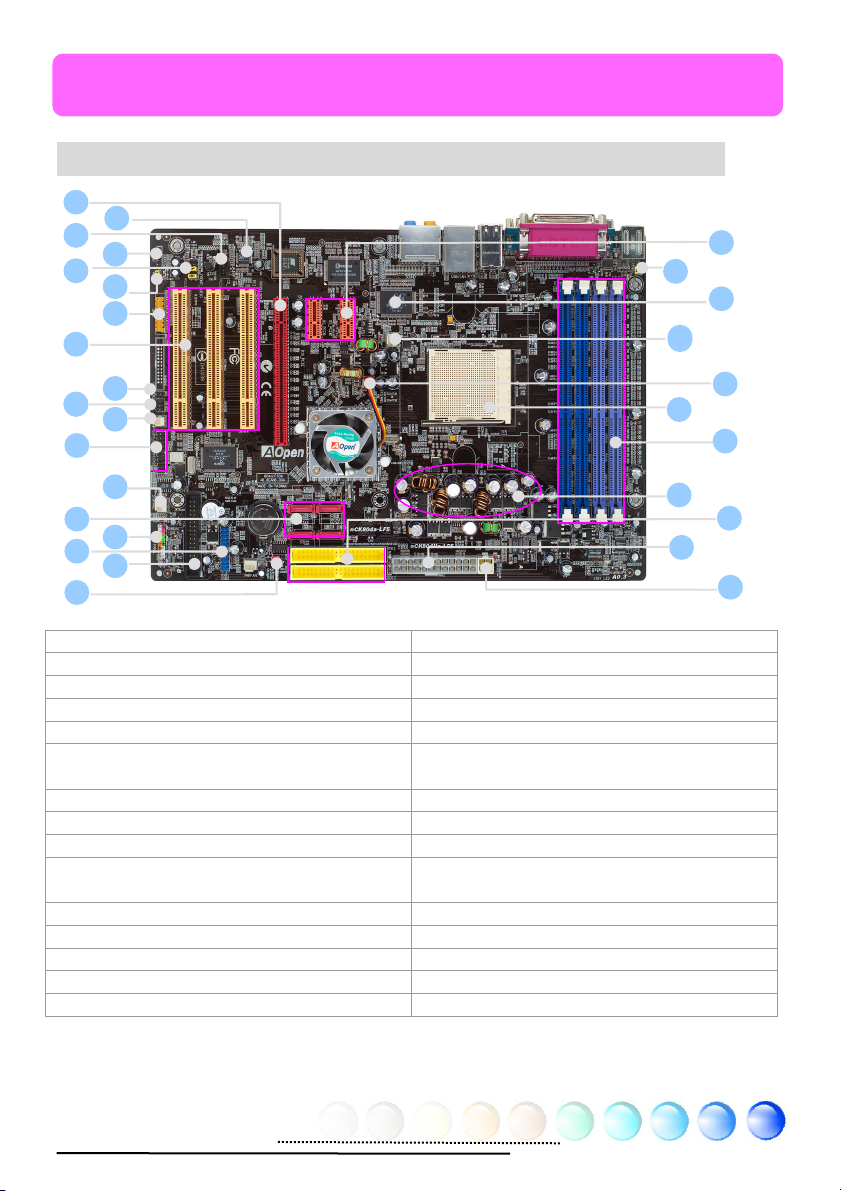
2.1 How does your motherboard look like?
1.PCI Express x 1 16.Front Audio Connector
2.JP28 PS2 KB/Mouse Wakeup Jumper 17.JP40 S/PDIF Source Jumper
3.LAN PHY 88E1111 18.Game Port Connector
4.CPUFAN Connector 19.32-bit PCI Expansion Slots x 3
5.SYSFAN1 Connector 20.Case Open Connector
6.939-pin CPU Socket Supports AMD Athlon 64
CPU
7.184-pin DIMMsx4 22.Sensor of System Temperature Connector
8. 3300μ F Low ESR Capacitor 23.IEEE1394 Connectors X 2
9. ATA133 Connectors x 2 24. SYSFAN2 Connector
10.ATX Power Connector
11.4-pin 12V ATX Power Connector 26. Front Panel Connector
12.PCI Express x 16 27. USB 2.0 Connector
13.Onboard AC’97 CODEC 28. FDD Connector
14.CD-IN Connector 29. JP24 BIOS Rescue Jumper
15.S/PDIF Connector
21.IrDA Connector
25. Serial ATA II Ports x 2 (for nCK804Ua-LFS)
Serial ATA Ports x 2 (for nCK804a-LFS)
1
5
Page 6
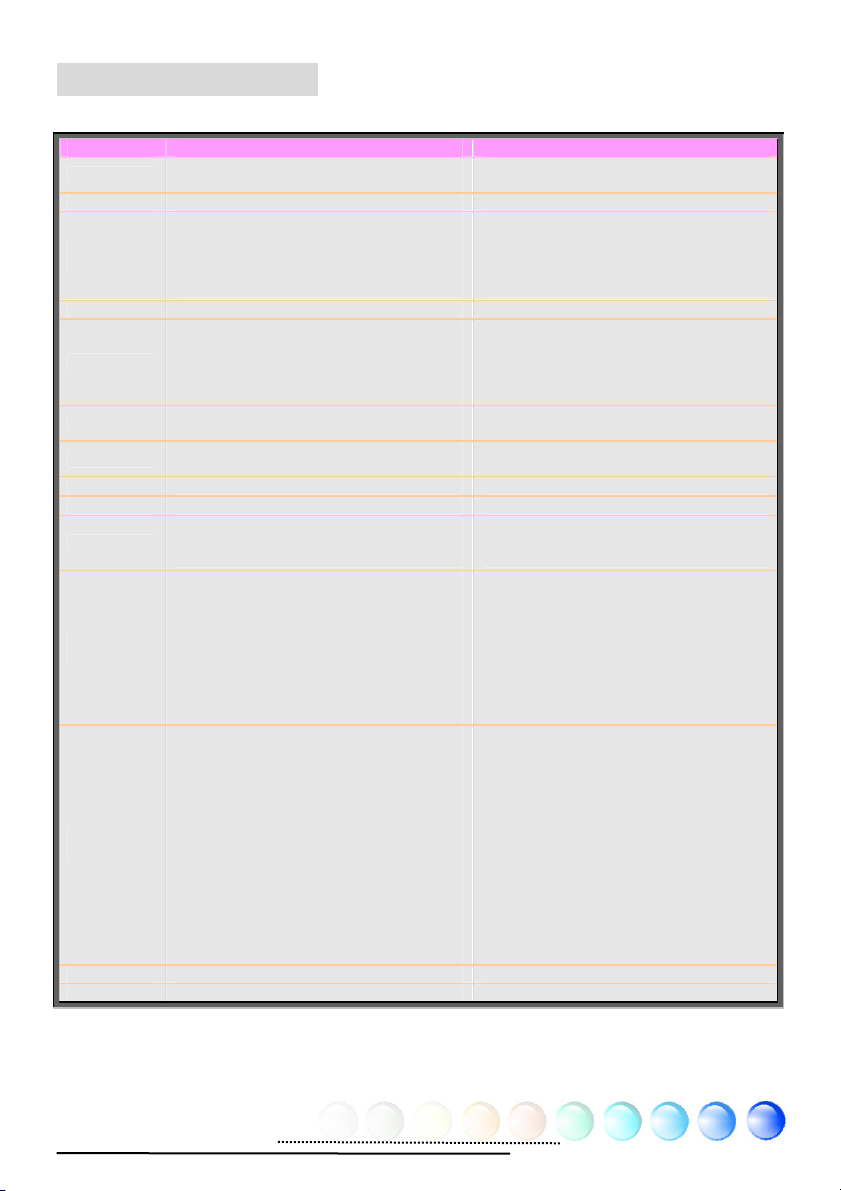
2.2 Specification
Here is the main function of your motherboard.
Models nCK804a-LFS nCK804Ua-LFS
CPU
Chipset nVIDIA nFORCE4 CK8-04 nVIDIA nFORCE4 Ultra CK8-04
Main
Memory
Graphics PCI Express x16 (PCIe x16) slot PCI Express x16 (PCIe x16) slot
IDE
LAN
Sound
USB
IEEE1394 Agere 1394 Control Chip Agere 1394 Control Chip
Slots
Back Panel
I/O
On Board
Connector
BIOS Award PnP 4Mb Flash ROM BIOS Award PnP 4Mb Flash ROM BIOS
Board Size Board Size : 305 mm x 215 mm Board Size : 305 mm x 215 mm
AMD Athlon 64 CPU
Socket 939
Dual Channel Mode
Support:DDR400 [PC3200]
DDR DIMM x 4
DIMM Type :256/512MB & 1GB
Max Memory :4GB
Integrated ATA133 and Serial ATA
Controller (Support Serial ATA RAID 0, 1
and 0+1)
Max Disk:144,000,000GB [by 48 bits
LBA Spec.]
Integrated nVidia Gigabit LAN Controller
Marvell PHY
Realtek AC'97 CODEC on-board
7.1 Channel
Integrated in chipset ,USB 2.0 x 10 Integrated in chipset ,USB 2.0 x 10
PCI Express (PCIe x1) x 2
PCI Express x16 Graphics(PCIe x16)x 1
PCI x 3
PS/2 Keyboard x 1, PS/2 Mouse x 1
USB Port x 6, LAN Port x 1
COM Port x 2, Printer Port x 1
Speaker_Out x 1
Line_In x 1
MIC_In x 1
Rear Surround x 1
Center/Subwoofer x 1
Side Surround x 1
Front Panel x 1
Front Audio x 1
CPU FAN x 1
System FAN x 1
Chassis FAN x 1
Power FAN x 1
Power Temperature Connector x 1
CD_IN x 1
AUX_IN x 1
IrDA x 1
Game Connector x 1
S/PDIF x 1
IEEE 1394 x 2
USB Port x 2
AMD Athlon 64 CPU
Socket 939
Dual Channel Mode
Support:DDR400 [PC3200]
DDR DIMM x 4
DIMM Type :256/512MB & 1GB
Max Memory :4GB
Integrated ATA133 and Serial ATA II
Controller (Support Serial ATA II RAID 0,
1 and 0+1)
Max Disk:144,000,000GB [by 48 bits
LBA Spec.]
Integrated nVidia Gigabit LAN Controller
Marvell PHY
Realtek AC'97 CODEC on-board
7.1 Channel
PCI Express (PCIe x1) x 2
PCI Express x16 Graphics (PCIe x16) x 1
PCI x 3
PS/2 Keyboard x 1, PS/2 Mouse x 1
USB Port x 6, LAN Port x 1
COM Port x 2, Printer Port x 1
Speaker_Out x 1
Line_In x 1
MIC_In x 1
Rear Surround x 1
Center/Subwoofer x 1
Side Surround x 1
Front Panel x 1
Front Audio x 1
CPU FAN x 1
System FAN x 1
Chassis FAN x 1
Power FAN x 1
Power Temperature Connector x 1
CD_IN x 1
AUX_IN x 1
IrDA x 1
Game Connector x 1
S/PDIF x 1
IEEE 1394 x 2
USB Port x 2
6
Page 7
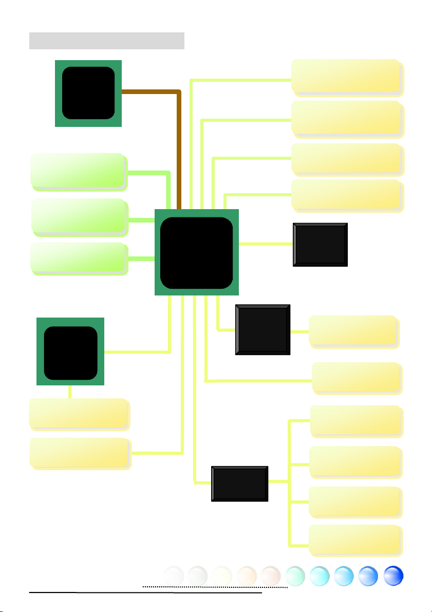
2.3 Block Diagram
(
)
(
)
p
AMD Athlon
64 CPU
Socket 939
PCI Express x 16
Graphics Slot
PCI Express x 1
Slots x 2
DIMM Sockets x4
Dual Channel
DDR400/333/266
Up to 4GB
Realtek
LAN Chip
LAN connect
Com
onent
USB Ports x 10
150MB/s
Serial ATA Ports x 4
nCK804a-LFS
300MB/s
Serial ATA II Ports x 4
nCK804Ua-LFS
ATA 66/100/133
IDE Drives x 2
PCI Bus
32-bit PCI Slot x 3
NVIDIA
nForce4
(nCK804a-LFS)
nForce4 Ultra
(nCK804Ua-LFS)
RealTek
AC97
CODEC
Agere
IEEE 1394
FW323
4Mbit Flash EEPROM x2
IEEE 1394 Ports
4Mbit Flash
EEPROM
Floppy Disk Drive
Parallel Port
Winbond
Super IO
Serial Ports x2
Keyboard / Mo use
7
Page 8
Chapter 3 Hardware Installation
Chapter 3 Hardware
q
Installation
3.1 Quick Installation Procedure
2. Installing CPU
Fan & System Fan
3. Installing
Memory Module
4. Installing HD,
CD-ROM and
SATA Disk, etc
5. Connecting Front
Panel Cable
1. Installing CPU
6. Connecting ATX
Power Cable
12. Installing Drivers &
Utilities
11. Installing
Operating System
(such as, Windows
XP)
8. Installing Other
Devices (USB, Front
Audio, etc)
7. Installing PCI
Express x 16 Graphics
Cards & PCI Express x
10. Loading
Default BIOS,
Setting CPU
uency
Fre
9. Connecting
Back Panel Ports
(Keyboard,
Mouse, etc)
8
Page 9
3.2 Installation You Have to Know
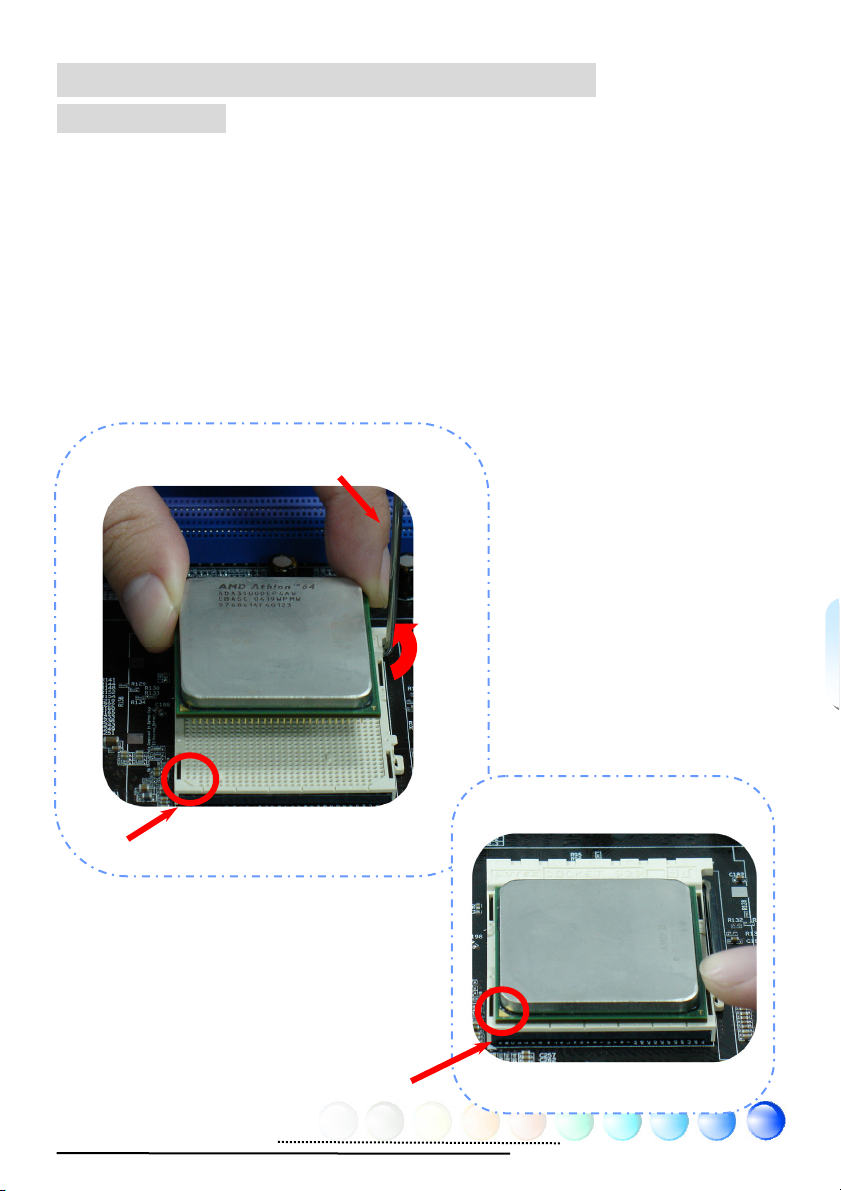
Installing CPU
This motherboard supports AMD® Athlon 64 Socket 939 CPU. Be careful of CPU
orientation when you plug it into CPU socket (with CPU Overheat Protection
function implemented, the system will be automatically power off when the
temperature of CPU reached 97 degree).
1. Pull up the CPU socket lever and up to 90-degree angle.
2. Locate Pin 1 in the socket and look for a golden arrow on the CPU upper
interface. Match Pin 1 and golden arrow. Then insert the CPU into the
socket.
3. Press down the CPU socket lever to finish CPU installation.
Socket Pin 1
CPU socket lever
Golden Arrow
9
Page 10
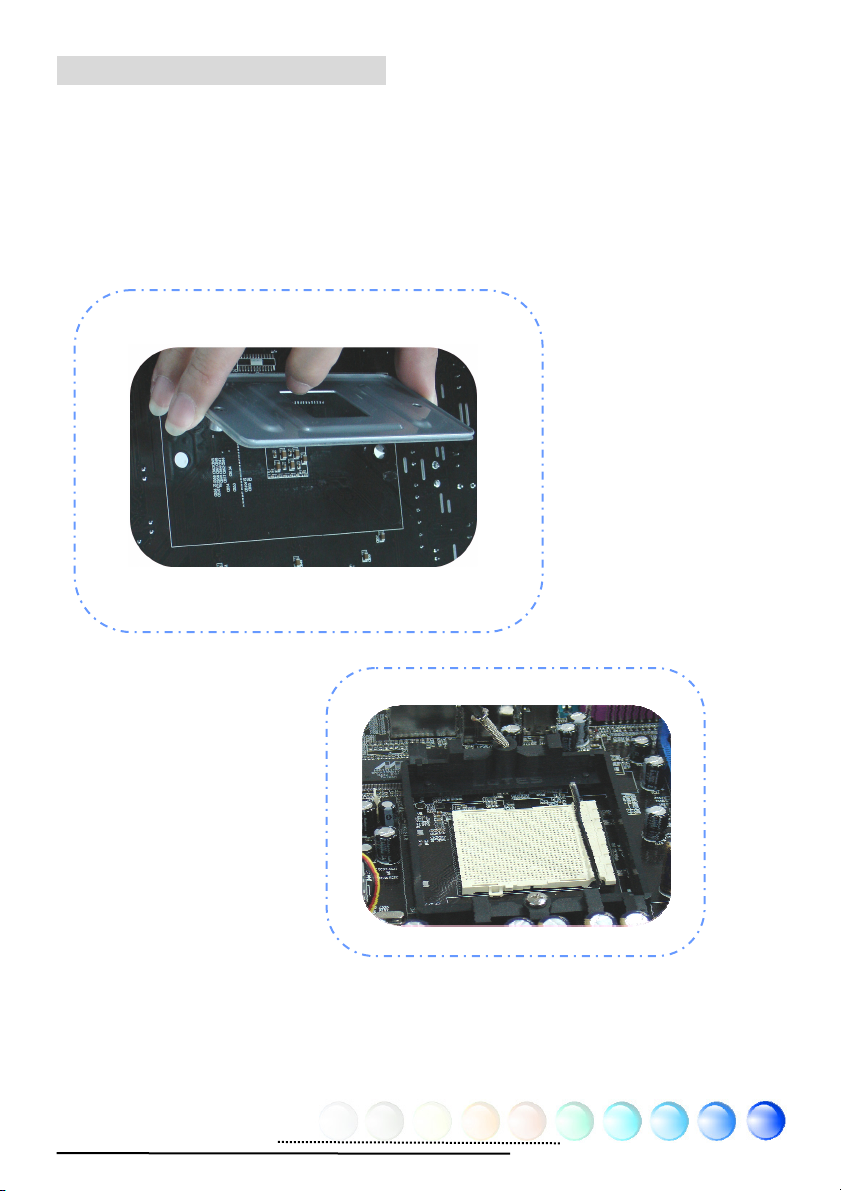
Installing Retention Module
1. To paste the adhesive side on the motherboard, and the two-screw holder
should be relative to the hole of the screw holder.
2. To alien the two-side hole of the RM and screw holder of the motherboard, then
lock the two screws holder.
10
Page 11
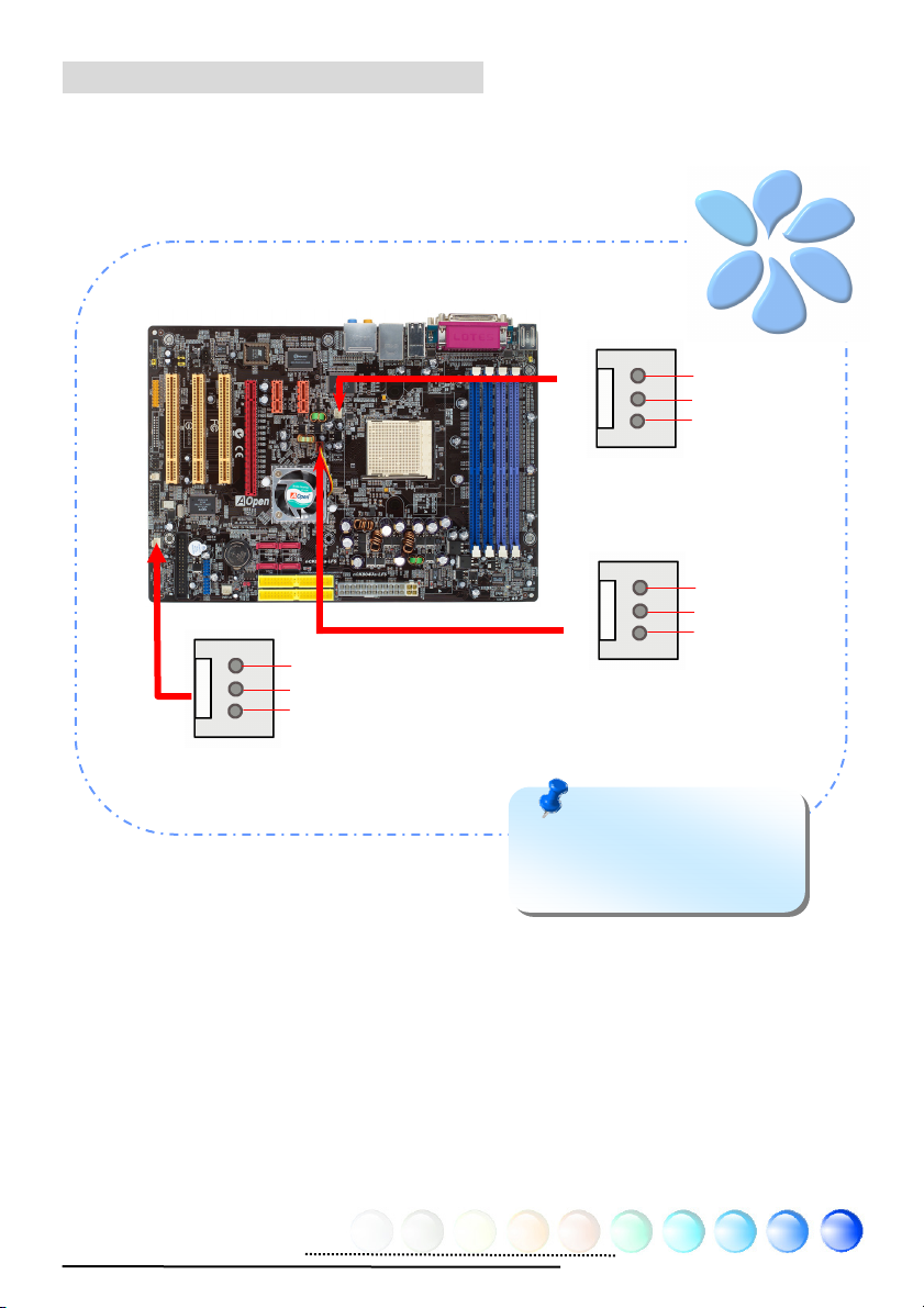
Installing CPU and System Fans
Plug the CPU fan cable to the 3-pin CPUFAN connector. If you have chassis fan,
you can also plug it in SYSFAN1 or SYSFAN2 connector.
GND
+12V
SENSOR
SYSFAN2 Connector
GND
+12V
SENSOR
Note: Some CPU fans
do not have sensor pin so
that they cannot support fan
monitoring.
CPUFAN Connector
GND
+12V
SENSOR
System Connector
11
Page 12
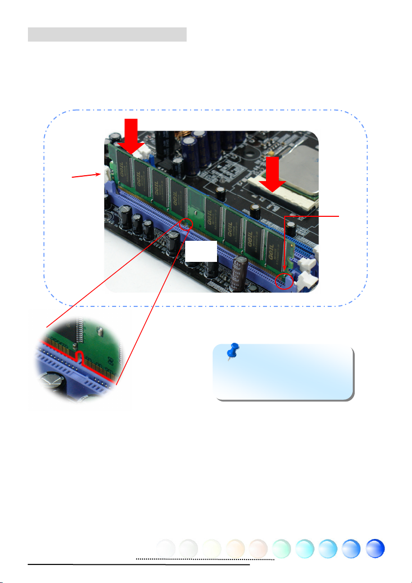
Installing Memory Modules
DIMM slots are designed in Navy Blue or Electronic Blue which are very easy to
recognize. Insert the module straight down to the DIMM slot with both hands and
press down firmly until the DIMM module is securely in place.
Tab
Key
Pin 1
Note: The tabs of the
DIMM slot will clip to hold the
DIMM in place when the DIMM
touches the slot’s bottom.
12
Page 13
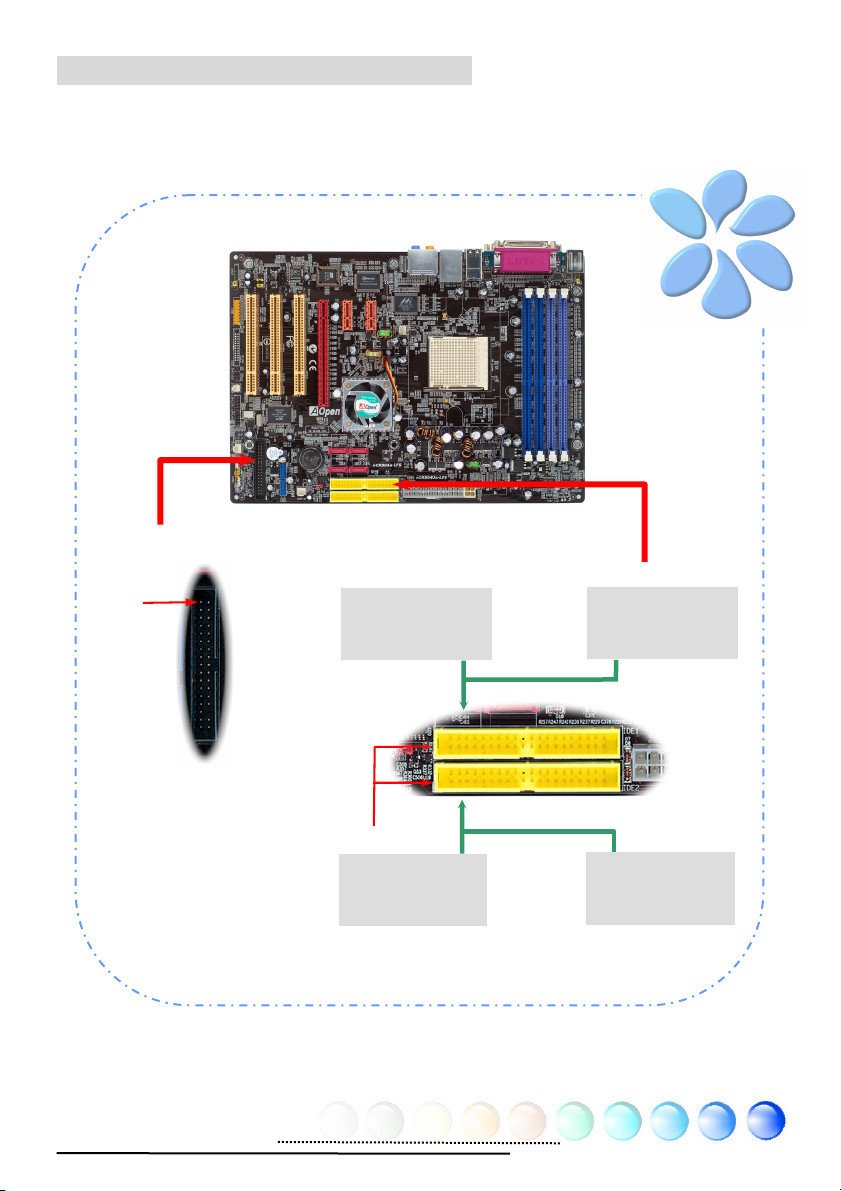
Connecting IDE and Floppy Cables
Connect the 34-pin floppy cable and 40-pin, 80-wire IDE cable to floppy
connector and IDE connector. Be careful of the pin1 orientation. Wrong
orientation may cause system damage.
FDD Connector
Pin 1
Primary
Slave (2nd)
Primary
Master (1st)
Pin 1
Secondary
Slave (4th)
ATA 66/100/133
IDE Connector
13
IDE
1 (Primary)
Secondary
Master (3rd)
Page 14
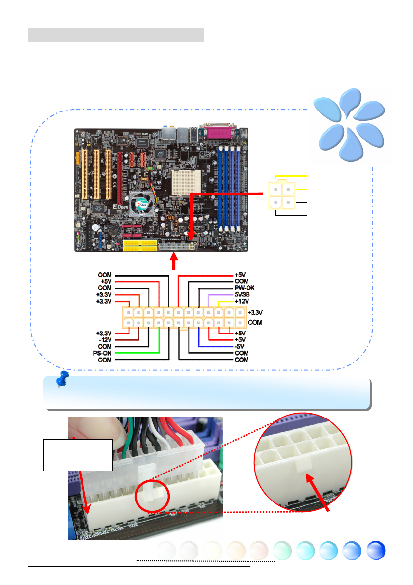
Connecting ATX Power Cables
This motherboard comes with a 24-pin and 4-pin ATX power connector as shown
below. Make sure you plug them in the right direction. We strongly recommend
you to insert the 4-pin connector before connecting the 24-pin connector.
Note: Please aim the power plug at the left side of the 24-pin ATX power
connector when the foolproof design faces you as shown.
Aiming at the
left side
+12V
+12V
Ground
Ground
Foolproof
14
Page 15
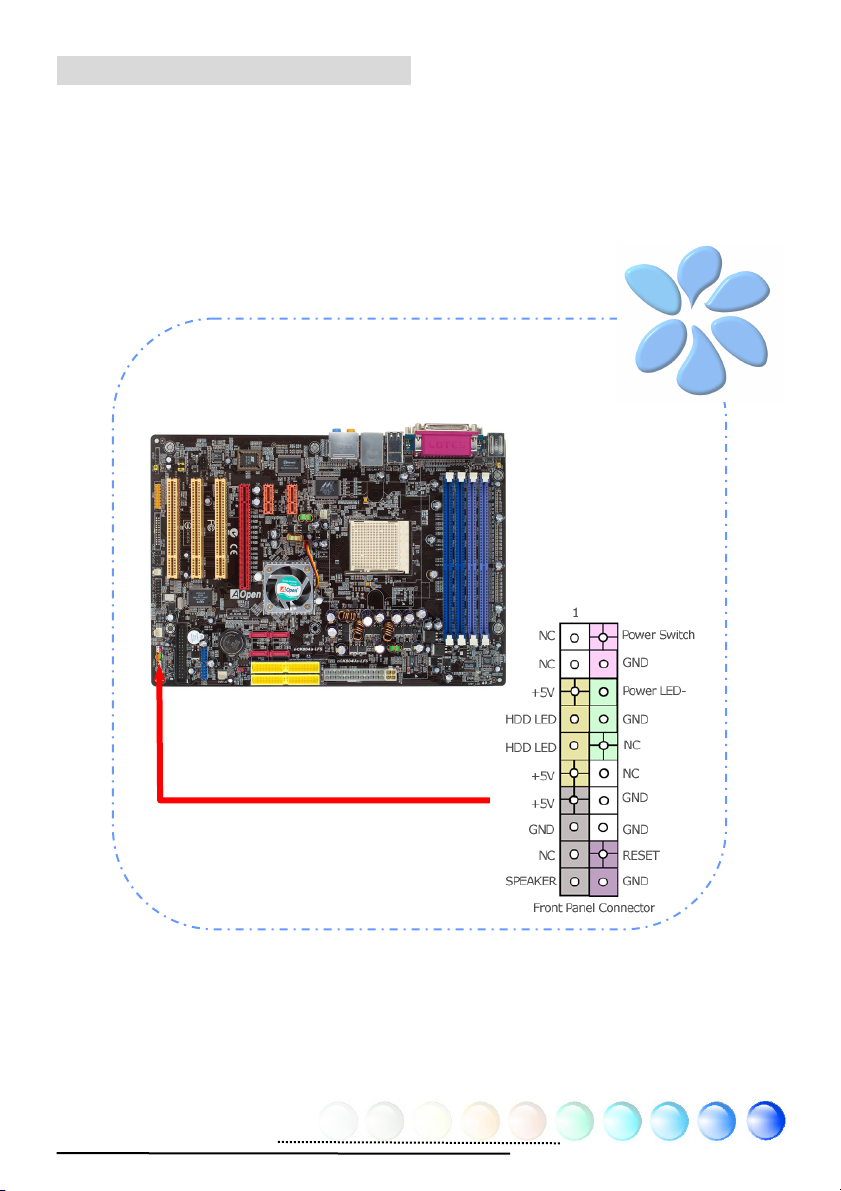
Connecting Front Panel Cable
Attach the power LED, speaker and reset switch connectors to the corresponding
pins. If you enable “Suspend Mode” item in BIOS Setup, the ACPI & Power LED
will keep flashing while the system is in suspend mode.
Locate the power switch cable from your ATX housing, which is a 2-pin female
connector from the housing front panel. Plug this connector to the soft-power
switch connector marked SPWR.
15
Page 16

3.3 Other Installation for Your Reference
Setting CPU Voltage and Frequency
Setting CPU Core Voltage
This motherboard supports Voltage ID (VID) function to detect CPU voltage
automatically during power-on. However, if users are willing to do overclocking,
we also provide a range from 0.80V to 1.55V in the BIOS. Sometimes increasing
the original core voltage a little bit will make CPU overclock more properly.
Setting CPU Frequency
This motherboard is of CPU jumper-less design; you can set CPU frequency by
1MHz stepping CPU Overclocking in the BIOS. CPU Core Frequency = CPU FSB
clock x CPU Ratio. However, all CPU now sold in market belong to "Fixed
Multiplier". That means users can not adjust the CPU Ratio but change CPU FSB
clock to achieve overclocking only.
BIOS Setup > Frequency / Voltage Control > CPU Speed Setup
(Users will do the overclocking at their own risks!!)
CPU Ratio From 4x to 25x step 1x
CPU FSB (Adjustment
manually)
AMD CPU
Athlon 64 3000+ 1800MHz 200MHz 512KB 9x
Athlon 64 3000+ 2000MHz 200MHz 512KB 10x
Athlon 64 3200+ 2000MHz 200MHz 512KB 11x
Athlon 64 3200+ 2200MHz 200MHz 1024KB 11x
Athlon 64 3400+ 2200MHz 200MHz 512KB 12x
Athlon 64 3400+ 2400MHz 200MHz 1024KB 12x
Athlon 64 3700+ 2000MHz 200MHz 256KB 10x
Note: With CPU speed changing rapidly, there might be faster CPU on the market by the time you
received this installation guide. This table is kindly for your references only, please contact with
your distributor for more information
FSB = 200 MHz-250 MHz by 1 MHz Stepping CPU Overclocking
CPU Core
Freq.
CPU Clock L2 Cache Ratio
Note: If your system hangs or fails to boot because of overclocking, simply
use <Home> key to restore the default setting or you can wait the AOpen “Watch
Dog ABS” reset the system in five seconds and system will auto-detect hardware
Warning: Supposed you have had adjusted CPU ratio on your current CPU,
and you plan to replace a new CPU. Please use <Home> key or Clear CMOS to
restore the default setting when changing a new CPU, because the system will still
implement the previous CPU setting on the new one.
16
Page 17

Connecting Serial ATA
To connect a serial ATA disk, you have to have a 7-pin serial ATA cable. Connect
two ends of the serial ATA cable to the serial ATA header on the motherboard and
the disk. Like every other traditional disk, you also have to connect a power cable.
Please be noted that it is a jumper free implement; you don’t need to set jumpers
to define a master or slave disk. When serial ATA hard disks are installed on serial
ATA ports, the one connected on Port1(SATA1) will be set as the first boot device
automatically. Please note that it doesn’t support Hot-Plug in function.
SATA2.0
Port2
SATA2.0
Port4
For nCK804Ua-LFS
SATA1.0
Port2
SATA1.0
Port4
SATA2.0
Port1
SATA2.0
Port3
SATA1.0
Port1
SATA1.0
Port3
For nCK804a-LFS
17
Page 18

Adjusting your Hard Disk Setting
Except its original 2 sets of parallel IDE, this motherboard supports the latest
serial ATA hard disk. If you are unable to find your newly installed serial ATA hard
disks on your operating system after having them installed, the problem may lie
in the BIOS setting. You can simply adjust BIOS settings to have them work
properly.
After installing your hard disks properly, you can directly go to BIOS setting
screen for adjustment. You may simply press “Integrated Peripherals
Function Setup to enable or disable SATA interface.
Æ
IDE
18
Page 19

Connecting PCI Express x16 Graphics Slot
nCK804a-LFS/nCK804Ua-LFS provides a PCI Express x 16 Graphics slot, a black
slot having the latest PCI Express x 16 specification on motherboard. The PCI
Express x 16 is a bus interface targeted for high-performance 3D graphic.
Traditionally AGP used both rising and falling edge of the 66MHz clock for 8X AGP,
and the data transfer rate could achieve 2.1GB/s. Now PCI Express x 16 is moving
to higher data transfer rate, which is upgraded to 8.0GB/s (250MB/s x 16 x 2, it’s
4.0GB/s per direction).
19
Page 20

Connecting PCI Express x 1 Slot
This motherboard provides two PCI Express x 1 slots, which are located between
the PCI Express x 16 and traditional PCI slot. In order to go with the step of
today’s and tomorrow’s processors, PCI Express x 1 provides higher I/O
bandwidth. The transfer data rate could achieve 250MB/s, which is close to twice
the traditional PCI 2.2 data transfer rate. You could install any PCI Express x 1
device in the slot for your preference.
20
Page 21

Connecting IrDA
The IrDA connector can be configured to support wireless infrared module, with
this module and application software such as Laplink or Windows Direct Cable
Connection, user can transfer files to or from laptops, notebooks, PDA devices
and printers. This connector supports both HPSIR (115.2Kbps, 2 meters) and
ASK-IR (56Kbps).
Install an infrared module onto the IrDA connector and enable the infrared
function from BIOS Setup, UART Mode, you can use this function. Please make
sure you connect correct orientation when plugging IrDA module.
Pin 1
21
Page 22

10/100/1000Mbps LAN Supported
On the strength of Gigabit LAN controller on board, this motherboard provides
10/100/1000Mbps Ethernet for office and home use. The Ethernet RJ45
connector is located on the top of USB connectors. The right hand side LED
indicates link mode; it lights in orange when linking to network. The left hand side
LED indicates the transfer mode and will light in green when data is transferring
at 100Mbps (never lights while at 10Mbps), but will light in orange when
transferring in Gigabit’s mode. To enable or disable this function, you may simply
adjust it through BIOS. To enable LAN wakeup function, you have to set the
“Wake on PCI Card” enable in the BIOS “Power Management Setup” section.
Speed LED (Left)
Green 100Mbps
Orange Gigabit mode
ACT LED (Right)
Orange
22
Page 23

Connecting USB2.0
This motherboard provides ten USB 2.0 ports to connect USB devices such as
mouse, keyboard, modem, printer, etc. There are six ports on the back panel. You
can use proper cables to connect Front USB connector to USB modules or chassis
front panel.
Pin 1
Pin 1
23
Page 24
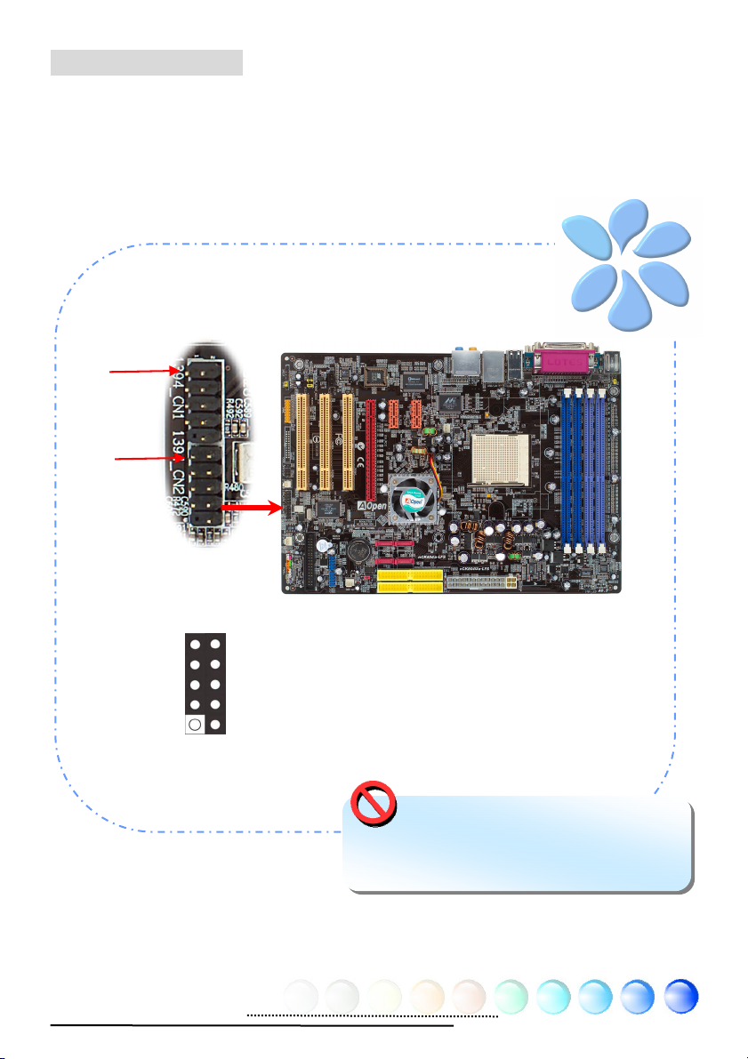
Connecting 1394
A
(
)
This motherboard comes with AGERE 1394 Control Chip onboard, the IEEE 1394
provides data transfer rate up to 400Mb/s, this interface can connect to devices
that require high data transferring performance such as digital camera, scanner
or others IEEE 1394 devices. Please use appropriate cables to connect IEEE1394
devices.
Pin 1
Pin 1
1
+12V (Fused)
TPA+
GND
TPB+
IEEE 1394 Connector
2
TP
GND
TPB+12V
SHIED GND
-
Fused
Warning: Please note that Hot-Plug is
not allowed on IEEE 1394 headers; doing so
will burn the controller IC and damage the
motherboard.
24
Page 25
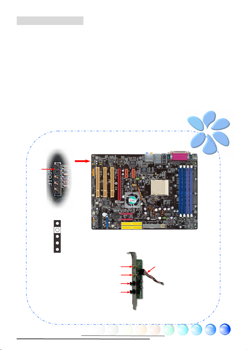
Connecting S/PDIF
S/PDIF (Sony/Philips Digital Interface) is a newest audio transfer file format,
which provides impressive audio quality through optical fiber and allows you to
enjoy digital audio instead of analog audio. Through a specific audio cable, you
can connect the S/PDIF connector to other end of the S/PDIF audio module, which
bears S/PDIF digital output. Normally there are two S/PDIF outputs as shown,
one for RCA connector, the most common one used for consumer audio products,
and the other for optical connector with better audio quality. Same as outputs,
you can also connect RCA or optical audio products to input connectors on the
module and have the voice or music come out from your computer. However, you
must have a S/PDIF supported speaker/amplifier/decoder with S/PDIF digital
input/output to connect to the S/PDIF digital input/output to make the most out
of this function.
Pin 1
S/PDIF Connector
1
+5V
KEY
SPDIF OUT
GND
SPDIF IN
5
(RCA)
S/PDIF OUT
S/PDIF IN
S/PDIF OUT
S/PDIF IN
(Optical)
S/PDIF
Cable
S/PDIF Module
25
Page 26
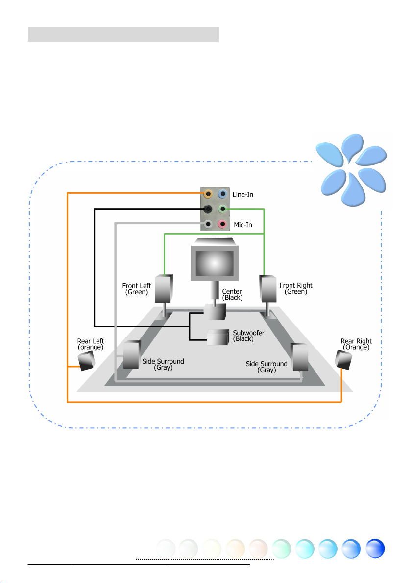
Super 7.1 Channel Audio Effects
This motherboard comes with an AC’97 (Realtek ALC850) CODEC, which supports
the latest 7.1 Channel with high quality of audio effects, bringing you a brand new
audio experience. This motherboard provides 7.1 Channel ports shown as below.
Picture represents the standard location of all speakers in 7.1 Channel sound
tracks. Please connect the plug of your front speakers to the green “Speaker out”
port , rear surround speakers to orange port, side surround speakers to gray port
and both of the center and subwoofer speakers to black port on the back panel.
26
Page 27
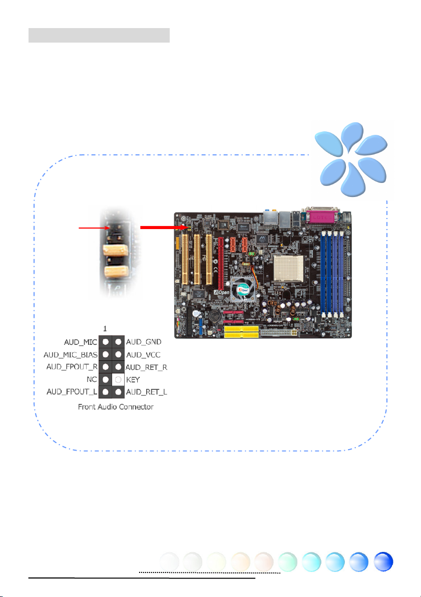
Connecting Front Audio
If the housing is designed with an audio port on the front panel, you’ll be able to
connect onboard audio to front panel through this connector. By the way, please
remove the jumper cap from the Front Audio Connector before you connect the
cable. Do not remove this yellow jumper cap if your housing doesn’t have an
audio port on the front panel.
Pin1
27
Page 28

Connecting Game Port
Y
Y
Y
X
V
This motherboard comes with a game port (Joystick-Midi) for you to connect any
midi devices or joysticks. To use this function you have to have a joystick module
and connect it with a game port cable to this port on the motherboard.
Pin1
KE
MIDI_RXD
JBB2
JBC
MIDI_TXD
JBC
JBB1
+5
Game Port Connector
(User Upgrade Optional)
+5V
JAB2
JAC
GND
GND
JACX
JAB1
+5V
2 1
28
Page 29
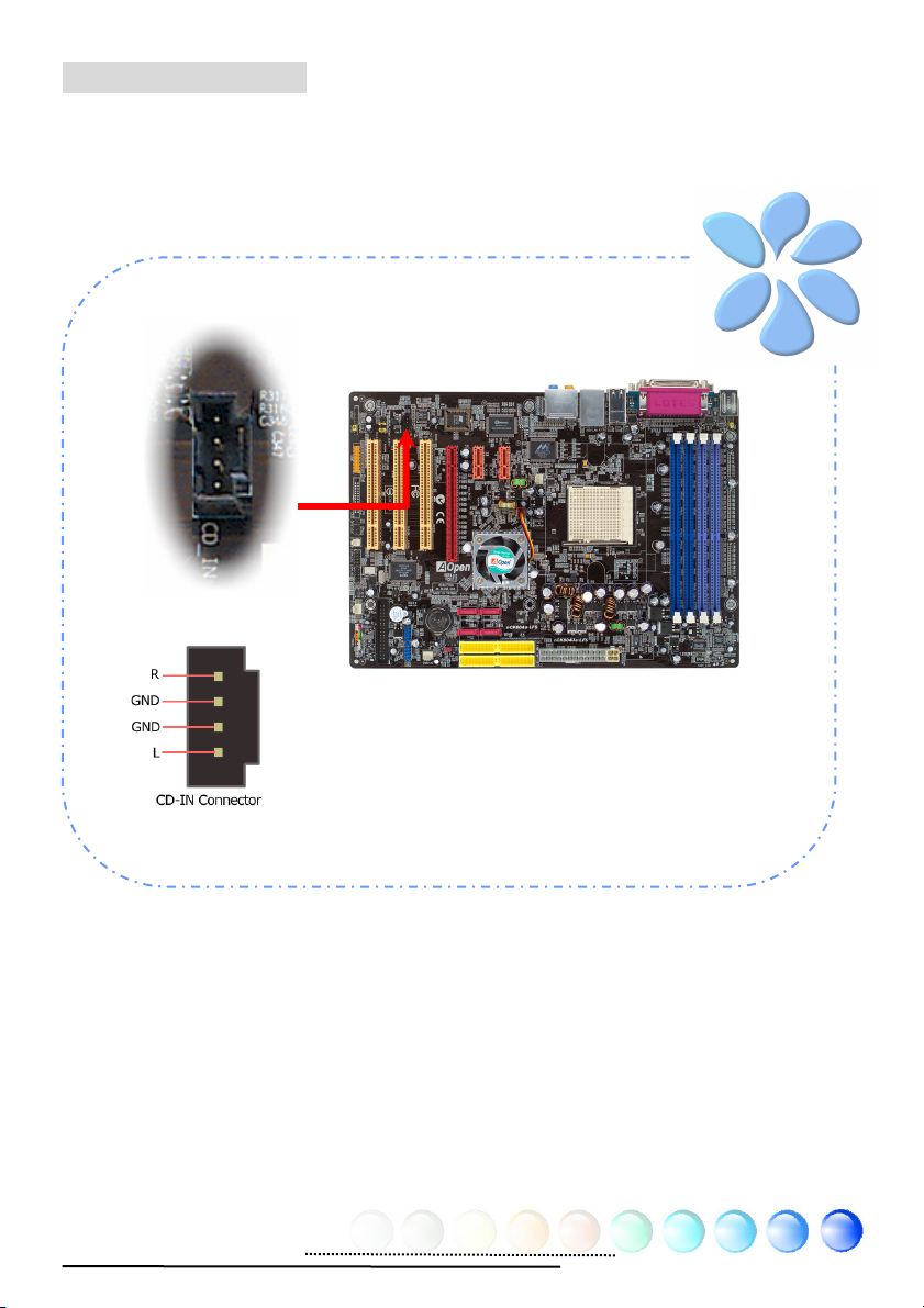
Connecting CD_IN
This connector is designed to connect CD Audio cable from CDROM or DVD drive
to onboard sound.
29
Page 30
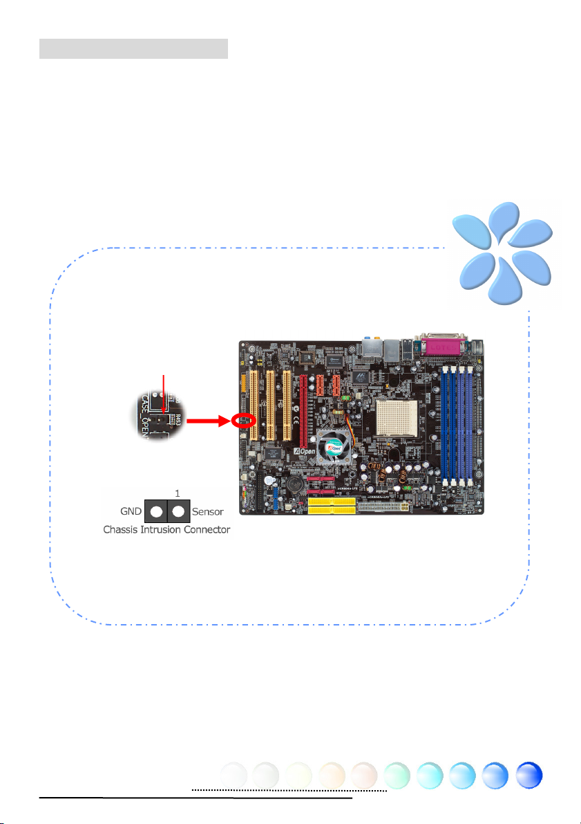
Connecting Case Open
The “CASE OPEN” header provides chassis intrusion-monitoring function. To
make this function work, you have to enable it in the system BIOS, connect this
header to a sensor somewhere on the chassis. So, whenever the sensor is
triggered by lights or by the opening of the chassis, the system will beep to inform
you. Please be informed that this useful function only applies to advanced chassis;
you may purchase an extra sensor, attach it on your chassis and make a good use
of this function.
Pin 1
30
Page 31
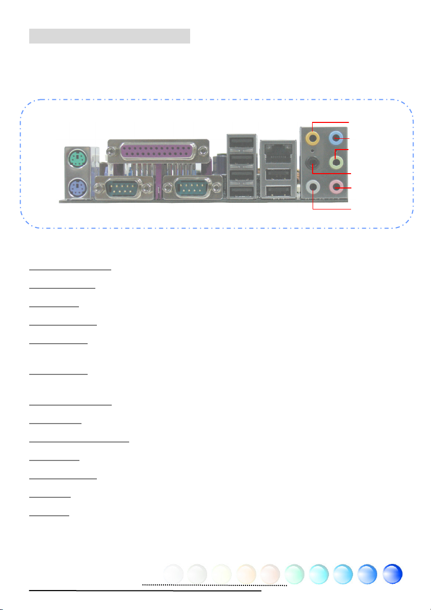
Colored Coded Back Panel
The onboard I/O devices have PS/2 Keyboard, PS/2 Mouse, RJ-45 LAN Connector,
COM1, COM2 port, Printer, USB, AC’97 sound. The view angle of drawing shown
here is from the back panel of the housing.
PS/2 Mouse
Connector
PS/2 Keyboard
Connector
SPP/EPP/ECP Parallel Port
COM 1 Port
COM 2 Port
USB 2.0
Ports
PS/2 Keyboard: For standard keyboard, which use a PS/2 plug.
PS/2 Mouse: For PC-Mouse, which use a PS/2 plug.
USB Port: Available for connecting USB devices.
Parallel Port: To connect with SPP/ECP/EPP printer.
RJ45
LAN Jack
USB 2.0
Ports
Rear SUR
Line-I
Speaker Out
Center/
Subwoofer
MIC-In
Side SUR
COM1 Port: To connect with pointing devices, modem or others serial
devices.
COM2 Port:
To connect with pointing devices, modem or others serial
devices.
RJ-45 LAN Port:
To connect Ethernet for home or office use.
Rear SUR: For rear speaker.
Center/Subwoofer: For center & subwoofer speaker.
Side SUR: For side surround speaker.
Speaker Out: To External Speaker, Earphone or Amplifier.
Line-In: Comes from the signal sources, such as CD/Tape player.
MIC-In: For Microphone
31
Page 32

(
3.4 Jumper Settings
JP14 Clear CMOS
You can clear CMOS to restore system default setting. To clear
the CMOS, follow the procedure below.
1. Turn off the system and unplug the AC power.
2. Remove ATX power cable from connector PWR2.
3. Locate JP14 and short pins 2-3 for a few seconds.
4. Return JP14 to its normal setting by shorting pin 1 & pin 2.
5. Connect ATX power cable back to connector PWR2.
Pin 1
1 1
Normal
default)
Clear CMOS
Tip: When should I Clear CMOS?
1. Boot fails because of overclocking…
2. Forget password…
3. Troubleshooting…
32
Page 33

1 1
JP28 Keyboard/
Mouse Wakeup Jumper
This motherboard provides keyboard / mouse wake-up
function. You can use JP28 to enable or disable this
function, which could resume your system from suspend
mode with keyboard or mouse. The factory default
setting is “Disable” (1-2), and you may enable this
function by setting the jumper to 2-3.
Pin 1
Disable
(Default)
Enable
33
Page 34

Chapter 4 Special Features and Utilities
Chapter 4 Special Features and Utilities
RAID (Redundant Array of Independent Disks)
This motherboard supports RAID 0, RAID 1 and RAID 0+1 functions. For more
RAID introduction, please visit our website:
http://english.aopen.com.tw/tech/techinside/RAID.htm
RAID Configuration Utility
Nvidia nForce4 chipset support RAID 0, 1 and 1+0 functions. In order to make
sure your system can recognize and operate Serial ATA RAID device smoothly, we
have to enter RAID Configuration Utility to do some settings. After finishing the
BIOS setup and reboot, you will see [Press F10 to enter RAID setup utility] about
half way through the boot up. Pressing F10 immediately, you will later be
presented with a screen as shown below, You can use this utility to create or
delete your disk arrays.
NVIDIA RAID IDE ROM BIOS 4.34
Copyright (c) 2003 NVIDIA Corp.
Detecting array…
Press F10 to enter RAID setup utility
Note: For operating RAID 0 or RAID 1 smoothly, user has to install both
NVIDIA RAID CLASS DRIVER and NVIDIA NForce Storage Controller.
34
Page 35

Other Useful Features
With excellent design ability of R&D team, AOpen boasts for its various powerful
and handy features that come with our product like follows. You are welcomed
to visit our technical website to learn more about those features.
http://english.aopen.com.tw/tech/techinside
35
Page 36
Chapter 5 Setting BIOS
Chapter 5 Setting BIOS
Introduction
System parameters can be modified by going into BIOS Setup menu; this menu
allows you to configure the system parameters and save the configuration into
the 128 bytes CMOS area (normally in the RTC chip or in the main chipset).
The Phoenix-Award BIOS™ that installed in the Flash ROM of the motherboard is
a custom version of an industry standard BIOS. The BIOS provides critical
low-level support for standard devices such as hard disk drives, serial and parallel
ports.
AOpen’s R&D engineering team had optimized most BIOS settings of this
motherboard. However, some default settings of BIOS cannot fine-tune those
sections that controlled by chipset. Therefore, this chapter is intended to guide
you and help you to configure some other settings.
To enter BIOS setup menu, press <Del> when POST (Power-On Self Test) screen
is shown on your monitor.
Note: 9cause BIOS code is the mos6
often4changed part on motherboard, the BIOS
information contained in this manual may be
different from the BIOS version that comes with
your motherboard.
36
Page 37
How To Use Phoenix-Award™ BIOS Setup Program
Generally, you can use arrow keys to highlight items that you want to choose,
press <Enter> key to select, and use <Page Up> and <Page Down> keys to
change setting values. You can press <Esc> key to quit Phoenix-Award™ BIOS
setup program. The following table provides details about how to use keyboard in
the Phoenix-AwardBIOS setup program. Alternatively, it's strongly
recommended to install AOpen’s newest WinBIOS Utility to get more detailed
description, further powerful functions and advanced setting of BIOS.
Key Description
Page Up or + Change setting to next value or increase the value.
Page Down or - Change setting to previous value or decrease value.
Enter Select the item.
Esc In main menu: Quit without saving any changes.
In sub menu: Exit current menu to main menu.
Up Arrow Highlight previous item.
Down Arrow Highlight next item.
Left Arrow Move the light bar to left side of menu.
Right Arrow Move the light bar to right side of menu.
F6 Load Setup Default setting value from CMOS.
F7 Load turbo setting value from CMOS.
F10 Save changed settings and exit setup program.
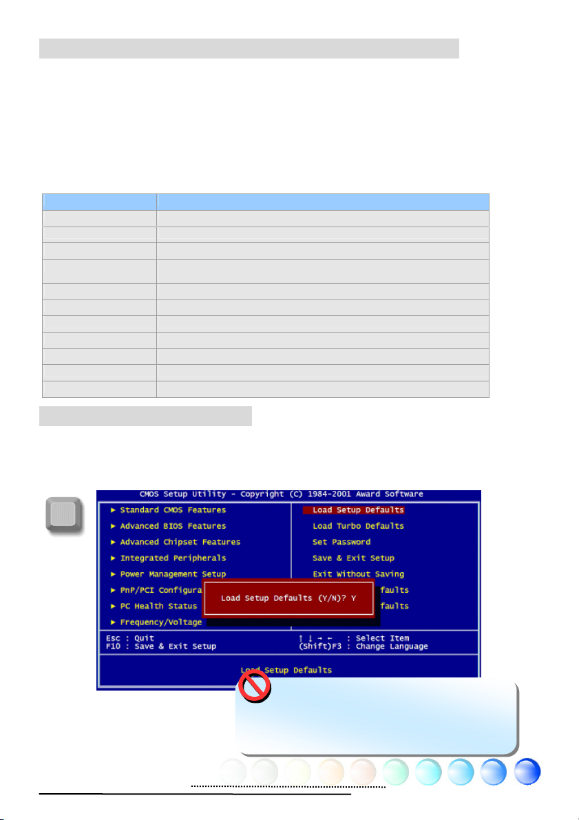
How To Enter BIOS Setup
After finishing the jumper settings and connecting cables, you can power on and
enter the BIOS Setup. Press <Del> during POST (Power-On Self Test) and choose
"Load Setup Defaults" for recommended optimal performance.
Del
Warning: Please avoid of using “Load
Turbo Defaults”, unless you are certain your
system components (CPU, SDRAM, HDD, etc.)
are good enough for turbo setting.
37
Page 38

Chapter 6 Installing Drivers
Chapter 6 Installing Drivers
You may think that installing drivers and utilities would be a repeated task of
going through those installation wizards and steps-by-steps. Now, you will be
surprised with how “Ez” EzInstall could do. Without wizards or steps, all you have
to do is to do one click and then it’s done. Click and done. Yes. EzInstall makes
installation easy and even foolproof!
After putting in the CD, you will be prompted with AOpen welcome page and our
branches information.
First, click on the install driver ICON at left side for necessary drivers.
Second, click on the install utility ICON at left side for preferred utilities.
Practically, it’s done. But you may also browse CD contents, Readme to get more
information or just exit the CD installation.
Install
driver
Install
utility
Browse CD
Contents
Readme
Click to install
online manual
AOpen
branches
information
Exit CD
38
Page 39

6.1 Installing Drivers
As you may see from the Installing driver page, EzInstall had picked up necessary
for your motherboard. All you have to do is just click on the “GO”, and no m o re
steps afterward, of all listed drivers, grey checks indicate necessary drivers; you
cannot click them off. Red checks can be disabled if you don’t want to install them
now.
Press the icon will prompt the
“Install Driver” page. You
may also press “Back” to
return to the Main page.
Once clicking “GO”, EzInstall will run the installing procedure
automatically, and prompt a reboot dialog (Some drivers or
utilities may skip the reboot part).
39
Page 40

6.2 Installing Utilities
Installing Utilities is virtually the same as installing drivers. AOpen provides you
many friendly and powerful utilities to manage your system. You may find lots of
fabulous utilities listed there, and all you have to do is to click on the “GO”, t h en
it will install the utilities to your system right away without complicated steps.
Press the icon will
prompt the “Install
Utilities” page for your
selection. You may also
press “Back” to get back
to the Main page.
40
Page 41

Chapter 7 Troubleshooting
g
Chapter 7 Troubleshootin
41
Page 42

Chapter 8 Technical Support
pp
L
Chapter 8 Technical Support
Dear Customer,
Thanks for choosing AOpen products. We invite you to register at
http://www.aopen.com
to become a Gold Member of Club AOpen so as to
ensure quality service in the future. In order to maintain the best service to every
customer of us, we recommend you to follow the procedures below and seek help
from our branches according to the region you buy the product. With your help,
we can then continue to provide efficient and the best quality service to every
customer.
Thanks very much for your understanding!
AOpen Technical Supporting Team
Europe
AOpen Computer b.v.
Tel: 31-73-645-9516
Email: Su
ort@AOpen.N
China
艾爾鵬國際貿易(上海)有限公司
Tel: 86-21-6225-8622
Fax: 86-21-6225-7926
Germany
AOpen Computer GmbH.
Tel: 49-2131-1243-710
Fax: 49-2131-1243-999
Pacific Rim
AOpen Inc.
Tel: 886-2-3789-5888
Fax: 886-2-3789-5899
Japan
AOpen Japan Inc.
Tel: 81-048-290-1800
Fax: 81-048-290-1820
Europe Email: Support@AOpen.NL
Pacific Rim: http://www.aopen.com.tw/tech/default.htm
China: http://www.aopen.com.cn/tech/default.htm
Germany: http://www.aopencom.de/tech/default.htm
America: http://usa.aopen.com/tech/default.htm
Japan: http://www.aopen.co.jp/tech/default.htm
America
AOpen America Inc.
Tel: 1-510-489-8928
Fax: 1-510-489-1998
42
Page 43
Model Name and BIOS Version
Model name and BIOS version can be found on upper left corner of first boot
screen (POST screen).
Phoenix AwardBIOS v6.00PG, An Energy Star Ally
Copyright (C) 2003, Phoenix Technologies, LTD.
nCK804a-LFS R1.02 Mar. 01. 2004 AOpen Inc.
For example: nCK804a-LFS is model name of motherboard; R1.02 is BIOS
version
Register Your Motherboard
Thanks for choosing AOpen product, please register this motherboard at
http://club.aopen.com.tw/productreg/
and to ensure high service quality and priority from AOpen. You will also have a
chance to play slot machine game to win prize from AOpen. Please prepare the
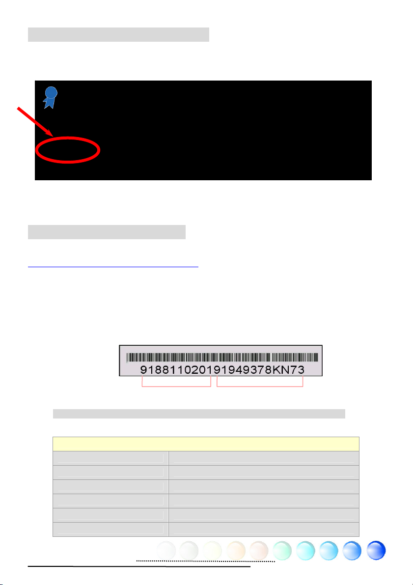
following information before you start: Model Name, Part Number (P/N), Serial
Number (S/N) and Purchase Date. The Part Number and Serial number are
printed on bar code label. You can find this bar code label on the outside packing
or on component side of PCB. For example:
to become a Gold member of Club AOpen,
P/N: 91.88110.201 is part number, S/N: 91949378KN73 is serial number.
Phoenix-Award BIOS ERROR Message
Beep Sound Message
1 short(Beep) System booting is normally.
1 long - 1 short(Beep) DRAM ERROR
1 long - 2 short(Beep) Display card or monitor connected error
1 long - 3 short(Beep) Keyboard Error
Long(Beep) continuous DRAM hasn't inset correctly.
Part No.
43
Serial No.
Page 44

44
 Loading...