

Page 1

Chapter 1
Overview
MX64 is a slot 1 based motherboard that utilizes VIA 694X AGPset on Micro
ATX form factor. It implements an onboard audio CODEC and supports new
architectures such as AGP 4x, SDRAM, Ultra DMA 33/66, Bus master IDE
and USB ports. It supports three Dual in-line memory module (DIMM) slots
that allow the installation of SDRAM memory and expansion up to a maximum
of 768MB.
In addition to the above features, MX64 also implements plenty of fabulous
features.
Jumper-less Design Pentium II / Pentium III / Celeron VID signal and SMbus
clock generator provide CPU voltage auto-detection and allows the user to set
the CPU frequency through the CMOS setup, therefore no jumpers or switches
are used. The correct CPU information is saved into the EEPROM. With these
technologies, the disadvantages of the Pentium based jumper-less designs
are eliminated. There will be no worry of wrong CPU voltage detection and no
need to re-open the housing in case of CMOS battery loss. The only jumper
left is to clear the CMOS, which is a safety hook if you forget the password.
Full-range CPU core voltage This motherboard supports the CPU core
voltage from 1.3V to 3.5V, that can be applied to various CPU type in future.
Zero Voltage Wake on Modem In conjunction with ATX soft power On/Off, it
is possible to have system totally power off and wakeup to automatically
answer a phone call such as answering machine or to send/receive fax. The
most important break through is not only external box modem but also internal
modem card can be used to support 0V Wake On Modem. The MX64 and
FM56-P internal modem card implement special circuit (patent applied) to
make sure the modem card work properly without any power.
Wake on LAN This feature is very similar as 0V Wake On Modem, but it is
through local area network. To use Wake on LAN function, you must have a
network card that supports this feature and also need to install a network
management software.
1-1
Page 2

Overview
Wake on RTC Timer The Wake Up Timer is more like an alarm, which wakes
up and power on your system at a pre-defined time for specific application. It
can be set to wake up everyday or on specific date within a month. The
date/time accuracy is second.
CPU Thermal Protection MX64 has a special thermal detection circuit to have
warning through application software when the temperature is higher than a
predefined value.
CPU and Housing Fan Monitoring MX64 has one more "fan monitoring"
function to prevent system overheat. The system will report and alarm fan
malfunction though utility software such as Hardware Monitoring Utility (named
AOhw140, where 140 means version number).
System Voltage Monitoring Furthermore, MX64 implements a voltage
monitoring system, As you turn on your system, this smart design will continue
to monitor your system working voltage. If any of the system voltage is over
the component's standard. There will be alarm though software such as
Hardware Monitoring Utility for a warning to user.
ACPI Suspend to DRAM You can resume your original work directly from
DRAM without going through the Win98 booting process and run your
application again. Suspend to DRAM saves your current work into the system
memory.
Resetable Fuse MX64 implements resetable fuses to prevent any accidental
short circuit caused by keyboard or USB devices hot plug.
FCC DoC Certificate MX64 has passed FCC DoC test. The radiation is very
low, you can use any kind of housing.
PC99 Ready For user’s convenience in installing the PC system, AOpen
adopts the recommended PC99 color scheme in all connectors that mount on
this motherboard.
Powerful Utility Software AOpen Bonus Pack CD disc contains many useful
utilities, such as Norton Antivirus, AOchip, Hardware Monitoring Utility, and
Suspend to Hard Drive utility.
1-2
Page 3

1.1 Specifications
Overview
Form Factor
Board Size
CPU
System Memory
Second-level Cache
Chipset
Expansion Slots
Audio CODEC
Serial Port
Parallel Port
Floppy Interface
IDE Interface
USB Interface
PS/2 Mouse
Keyboard
RTC and Battery
BIOS
Micro ATX
220 mm x 245 mm
Intel Pentium II / Pentium III / Celeron
DIMM 168-pin x3, maximum 768MB.
Built-in CPU depends on processor
VIA 694X AGPset
PCI x 3 and AGP x 1
AD1881
Two serial ports UART 16C550 compatible
One parallel port supports standard parallel port (SPP),
enhanced parallel port (EPP) or extended capabilities
port (ECP).
Floppy interface supports 3.5 inches drives with
720KB, 1.44MB or 2.88MB format or 5.25 inches
drives with 360KB, 1.2MB format
Dual-channel IDE interface support maximum 4 IDE
hard disks or CDROM, mode 4, bus master hard disk
drives and Ultra DMA 33/66 mode hard drives are also
supported.
Two USB ports supported by USB bracket, the BIOS
also supports USB driver to simulate legacy keyboard.
Mini-Din PS/2 mouse connector onboard.
Mini-Din PS/2 keyboard connector onboard.
RTC build in chipset, Lithium (CR-2032) battery.
AWARD Plug-and-Play, 2M bit Flash ROM BIOS.
1-3
Page 4
Overview
)
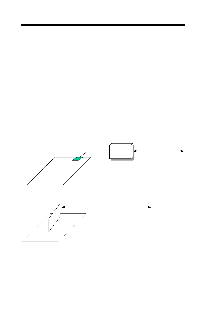
1.2 Zero Voltage Wake on Modem
The Wake on Modem discussed here is to wakeup from true power off
(identified by fan of power supply is off), This motherboard still supports
traditional green PC suspend mode but it is not discussed here.
With the help ATX soft power On/Off, it is possible to have system totally
power off (The traditional suspend mode of power management function does
not really turn off the system power supply), and wakeup to automatically
answer a phone call such as answering machine or to send/receive fax. You
may identify the true power off by checking fan of your power supply. Both
external box modem and internal modem card can be used to support 0V
Wake On Modem, but if you use external modem, you have to keep the box
modem always power-on. AOpen MX64 and internal modem card implement
special circuit (patent applied) and make sure the modem card works properly
without any power. We recommend you choose AOpen modem card (For
example, FM56-P, FM56-H, etc.) for 0V Wake On Modem applications.
ne
TELLi
port
COM
Ext e
rnalBox
Mo d e m
ExternalModemWake
TEL L
Internal Modem Card Wake U
1-4
Up
ine
p(such
as FM56
-P
Page 5

Overview
For Internal Modem Card (AOpen FM56-P):
1. Go into BIOS setup, Power Management Æ 0V Wake On Modem, select
Enabled.
2. Setup your application, put into Windows 95.
3. Turn system power off by soft power switch.
4. Connect 4-pin Modem Ring-On cable from FM56-P RING connector to
MX64 connector WKUP.
5. Connect telephone line to FM56-P. You are now ready to use Wake On
Modem.
For External Box Modem:
1. Go into BIOS setup, Power Management Æ 0V Wake On Modem, select
Enabled.
2. Setup your application, put into Windows 95 Start Up.
3. Turn system power off by soft power switch.
4. Connect RS232 cable of external box Modem to COM1 or COM2.
5. Connect telephone line to external box Modem. Turn on Modem power
(you must keep Modem power always on). You are now ready to use Wake
On Modem.
Tip: External 0V Wake On Modem signal is detected
through COM1 or COM2. Internal modem card wake up
signal is detected through cable from connector RING
(on modem card) to WKUP (on mainboard).
Note: If you use external modem, the power of external
modem must be kept on to receive signal from telephone
line. Internal modem card has no such limitation.
1-5
Page 6
Overview
1.3 System Voltage Monitoring
This motherboard implements a voltage monitoring system. As you turn on
your system, this smart design will continue to monitor your system working
voltage. If any of the system voltage is over the component's standard. There
will be alarm through application software such as Hardware Monitor utility for
a warning to user. System voltage monitoring function monitors CPU core
voltage. It is automatically implemented by BIOS and Hardware Monitor utility
(the file name is like aohw100.exe, where 100 means the version number, no
hardware installation is needed.
1.4 Fan Monitoring
There are three fan connectors, two is for CPU, the other can be a housing fan.
The fan monitoring function is implemented by connecting fan to 3-pin fan
connector CPUFAN1 and FAN, and installing Hardware Monitoring Utility.
Note: You need 3-pin fan that supports SENSE
signal for fan monitoring function to work
properly.
1-6
Page 7

Overview
1.5 CPU Thermal Protection
This motherboard implements special thermal protection circuit below the CPU.
When temperature is higher than a predefined value, the CPU speed will
automatically slow down and there will be warning from BIOS and also
Hardware Monitoring Utility software.
CPU Thermal Protection is automatically implemented by BIOS and utility
software, no extra hardware installation is needed.
1-7
Page 8

Chapter 2
Hardware Installation
This chapter gives you a step-by-step procedure on how to install your system.
Follow each section accordingly.
Caution: Electrostatic discharge (ESD) can
damage your processor, disk drives, expansion
boards, and other components. Always
observe the following precautions before you
install a system component.
1. Do not remove a component from its
protective packaging until you are ready
to install it.
2. Wear a wrist ground strap and attach it to
a metal part of the system unit before
handling a component. If a wrist strap is
not available, maintain contact with the
system unit throughout any procedure
requiring ESD protection.
2-1
Page 9
Hardware Installation
COM1
PRINTER
JP14
COM2
JP12
JP27
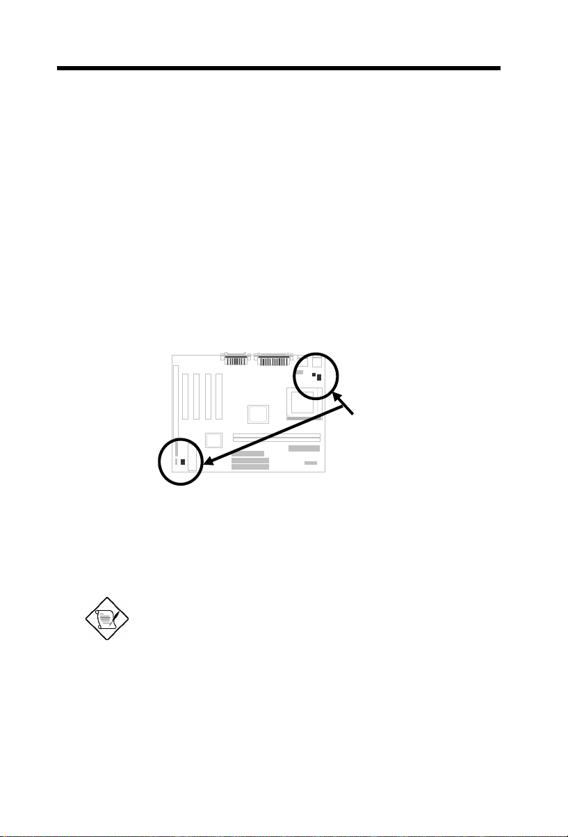
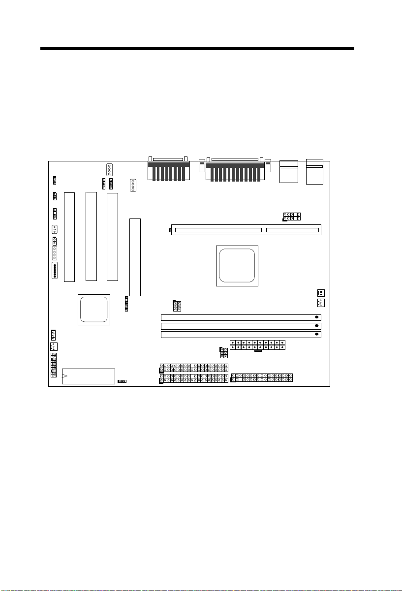
2.1 Jumper and Connector Locations
The following figure shows the locations of the jumpers and connectors on the
system board:
CD-IN2
CD-IN
MODEM-CN
KB2
USB
PS/2 MS
USB2
WOM
WOL
IA
SMB
AOL2
P
P
C
C
I
I
2
3
INSPK
P
C
I
1
A
G
P
2-2
PWLED1
FAN1
PANEL
BIOS
IrDA
IDE2
IDE1
JP29
CPUFAN2
CPU FAN1
DIMM1
DIMM2
DIMM3
JP23
FDC
Page 10

Hardware Installation
Jumpers:
JP12: Sound
JP14: Clear CMOS
JP27: PC Beep
JP23, JP29: Host CLK
Connectors:
PS2: PS/2 mouse connector
KB: PS/2 keyboard connector
COM1: COM1 connector
COM2: COM2 connector
PRINTER: Printer connector
PWR2: ATX power connector
USB: USB connector (port 1, 2)
USB2: USB second connector (port 3, 4)
FDC: Floppy drive connector
IDE1: IDE1 primary channel
IDE2: IDE2 secondary channel
CPUFAN1: 3-pin CPU fan connector
CDUFAN2: 2-pin CPU fan connector
FAN1: Fan connector
IrDA: IrDA (Infrared) connector
PANEL: Front panel (Multifunction) connector
CD-IN: CD-audio connector
MODEM-CN: Mono in (Pin 1-2) and Mic out (Pin 3-4)
WOM: 0V Wake On Modem connector
WOL: Wake On LAN connector
2-3
Page 11

Hardware Installation
2.2 Jumpers
With the help of the Pentium II Pentium III / Celeron VID signal and SMbus, this
motherboard is a jumper-less design.
2.2.1 Selecting the CPU Frequency
The Pentium II \ Pentium III \ Celeron VID signal and the SMbus clock
generator provide CPU voltage auto-detection and allow the user to set CPU
frequency through the CMOS setup, no jumpers or switches are needed. The
correct CPU information is saved into the EEPROM. With these technologies,
the disadvantages of the Pentium based jumper-less design are eliminated.
There will be no worry of wrong CPU voltage detection and no need to re-open
the housing if the CMOS battery is lost.
The CPU frequency selection is set by going into:
BOIS Setup à Chipset Features Setup à CPU Clock Frequency
(The possible setting is 66.8, 75, 83.3, 100, 105, 110, 112, 115, 120, 124, 133,
140, 150, MHz)
BOIS Setup à Chipset Features Setup à CPU Clock Ratio
(The possible setting is 1.5x, 2x, 2.5x, 3x, 3.5x, 4x, 4.5x, 5x, 5.5x, 6x, 6.5x, 7x,
7.5x, and 8x)
Core frequency = Ratio * External bus clock
Intel Pentium II /
Pentium III
Pentium II 233 233MHz= 3.5x 66MHz
Pentium II 266 266MHz= 4x 66MHz
Pentium II 300 300MHz= 4.5x 66MHz
Pentium II 333 333MHz= 5x 66MHz
Pentium II 350 350MHz= 3.5x 100MHz
Pentium II 400 400MHz= 4x 100MHz
Pentium II 450 450MHz= 4.5x 100MHz
Pentium III 450 450MHz= 4.5x 100MHz
Pentium III 500 500MHz= 5x 100MHz
Pentium III 550 550MHz= 5.5x 100MHz
Pentium III 533 533MHz= 4x 133MHz
Pentium III 600 600MHz= 4.5x 133MHz
CPU Core Frequency Ratio FSB Clock
2-4
Page 12

Hardware Installation
Home
1 2 3
Intel Celeron CPU Core Frequency Ratio FSB Clock
Celeron 266 266MHz= 4x 66MHz
Celeron 300 300MHz= 4.5x 66MHz
Celeron 300A 300MHz= 4.5x 66MHz
Celeron 333 333MHz= 5x 66MHz
Celeron 366 366MHz= 5.5x 66MHz
Celeron 400 400MHz= 6x 66MHz
Celeron 433 433MHz= 6.5x 66MHz
Celeron 466 466MHz= 7x 66MHz
Tip: If your system hangs or fails to boot because of overclocking, simply use <Home> key to restore to the default
setting. Press <Home> key and the power button at the same
time. Note that do not release <Home> key until POST screen
appears.
Warning: the VIA 694X chipset supports a maximum of 133MHz
FSB. The higher clock settings are for internal testing only. These
settings exceed the specification of the chipset, which may
cause serious system damage.
2.2.2 Setting the CPU Voltage
This motherboard supports the Pentium II / Pentium III / Celeron VID function,
the CPU core voltage is automatically detected and ranged from 1.3V to 3.5V.
2.2.3 Clearing the CMOS
JP14
1-2
2-3
Clear CMOS
Normal operation
(default)
Clear CMOS
You need to clear the CMOS if you forget your
system password. To clear the CMOS, follow
the procedure below:
JP14
1 2 3
Normal Operation
(default)
JP14
Clear CMOS
2-5
Page 13

Hardware Installation
1 3 5
2 4 6
1 3 5
2 4 6
2 4 6
2 4 6
2 4 6
The procedure to clear CMOS:
1. Turn off the system and unplug the AC power.
2. Remove ATX power cable from connector PWR2.
3. Locate JP14 and short pins 2-3 for a few seconds.
4. Return JP14 to its normal setting by shorting pins 1-2.
5. Connect ATX power cable back to connector PWR2.
6. Turn on the system power.
7. Press during bootup to enter the BIOS Setup Utility and specify a new
password, if needed.
Tip: If your system hangs or fails to boot because of overclocking, simply use the <Home> key to restore the default
setting (233MHz). By this smart design, it would be more
convenient to clear CPU frequency setting. For using this
function, you just need to press the <Home> key first and
then press the Power button at the same time. Note: do not
release the <Home> key until the POST screen appears.
2.2.4 Host/PCI Clock
JP23
1-2
3-4
3-4
5-6
2-6
JP29
1-2
3-4
5-6
5-6
Host Clock
Auto (default)
133~ 150MHz (4X)
100 ~ 124MHz (3X)
66 ~ 83MHz (2X)
This jumper is used to specify the
relation of PCI and host clock.
Generally speaking, we suggest you not
to change the default setting Auto. But
for overclocking, changing these jumper
settings becomes a prerequisite. For
example, you must set JP23 to “3-4”
and JP29 to “5-6” if you want to
overclock a 66MHz FSB clock CPU to
100MHz or higher.
JP29 JP23
Auto (Default)
JP29 JP23
2 4 6
1 3 5
1 3 5
JP29 JP23
1 3 5
1 3 5
133-150 MHz (4X)
JP29 JP23
2 4 6
2 4 6
1 3 5
1 3 5
Page 14

Hardware Installation
100-124 MHz
(3X)
66-83 MHz (2X)
2-7
Page 15

Hardware Installation
3
3
Mode CPU (Host) AGP Memory PCI
2X 66 66 66 33
3X 100 66 133/100/66 33
3X, overclocking 112 66 149/112/74.6 33
4X 133 66.5 133/100 33
4X, overclocking 150 77.5 150 37.5
2.2.5 On Board Audio
JP12
1-2
2-3
On Board Audio
Enabled (default)
Disabled
If you want to install another sound card, it
is necessary to disable the onboard audio
by setting this jumper to Disabled.
JP12
1
2
Enabled (default)
JP12
1
2
Disabled
2-8
Page 16

Hardware Installation
5V SB
3.3V
+12V
SENSE
GND
+12V
2.3 Connectors
2.3.1 Power Cable
The ATX power supply uses a 20-pin connector as shown below. Make sure
you plug in the cable in the right direction.
Caution: Make sure that the power supply is
off before connecting or disconnecting the
power cable.
+5V
3.3V
+5V
PWR2
2.3.2 Fan
The CPU fan connectors are marked as CPUFAN1 and CPUFAN2 on the
system board. You can plug the CPU fan cable to both the 2-pin fan
connector CPUFAN2 and the 3-pin fan connector CPUFAN1. And FAN
connector can be used to connect housing fan. Note that only CPUFAN1 and
FAN support the fan monitoring function, because 3-pin fan has an extra pin
called SENSE, which periodically sends fan signal out.
CPUFAN1 & FAN
GND
CPUFAN2
2-9
Page 17

Hardware Installation
PS/2 Mouse
PS/2 KB
COM1
COM2
2.3.3 PS/2 Mouse
The onboard PS/2 mouse connector is a 6-pin Mini-Din connector marked
PS2. The view angle of drawing shown here is from the back panel of the
housing.
PCB
2.3.4 Keyboard
The onboard PS/2 keyboard connector is a 6-pin Mini-Din connector marked
KB2. The view angle of drawing shown here is from the back panel of the
housing.
PCB
2.3.5 Serial Devices (COM1/COM2)
The onboard serial connectors are 9-pin D-type connectors on the back panel
of motherboard. The serial port 1 connector is marked as COM1 and the serial
port 2 connector is marked as COM2.
PCB
2-10
Page 18

Hardware Installation
PRINTER
USB
34
33
2.3.6 Printer
The onboard printer connector is a 25-pin D-type connector marked PRINTER.
The view angle of the drawing shown here is from the back panel of the
housing.
PCB
2.3.7 USB Device
You can attach USB devices to the USB connector. The motherboard
contains two USB connectors, which are marked as USB.
PCB
2.3.8 Floppy Drive
Connect the 34-pin floppy drive cable to the floppy drive connector marked as
FDC on the system board.
2
1
FDC
2-11
Page 19

Hardware Installation
1
40
2
39
1
40
2
39
(3rd)
(4th)
2.3.9 IDE Hard Disk and CD ROM
This motherboard supports two 40-pin IDE connectors marked as IDE1 and
IDE2. IDE1 is also known as the primary channel and IDE2 as the secondary
channel. Each channel supports two IDE devices that make a total of four
devices.
In order to work together, the two devices on each channel must be set
differently to master and slave mode. Either one can be the hard disk or the
CDROM. The setting as master or slave mode depends on the jumper on your
IDE device, so please refer to your hard disk and CDROM manual accordingly.
Connect your first IDE hard disk to master mode of the primary channel. If you
have second IDE device to install in your system, connect it as slave mode on
the same channel, and the third and fourth device can be connected on
secondary channel as master and slave mode respectively.
IDE2
IDE1
2-12
Caution: The specification of the IDE cable is
a maximum of 46cm (18 inches), make sure
your cable does not exceed this length.
Caution: For better signal quality, it is
recommended to set the far end side device to
master mode and follow the suggested
sequence to install your new device. Please
refer to the following figure.
IDE2 (Secondary Channel)
Slave
IDE1 (Primary Channel)
Slave
(2nd)
Master
Master
(1st)
Page 20

2.3.10 Panel Connector
1
11
10
20
+++
+
+
+
Hardware Installation
The Panel (multifunction) connector is
a 20-pin connector marked as PANEL
on the board. Attach the power LED,
keylock, speaker, SPWR, IDE LED and
reset switch to the corresponding pins
as shown in the figure.
If your ATX housing supports ACPI
specification, the ACPI & Power LED
will keep flashing if you have enabled
“suspend mode” item in the BIOS
Setup.
KEYLOCK
IDE LED
IDE LED
SPEAKER
Keylock
IDE LED
Speaker
GND
+5V
+5V
+5V
GND
NC
1
11
10 20
PANEL
PANEL
SPWR
GND
ACPI & POWER LED
GND
+5V
GND
GND
GND
RESET
GND
SPWR
ACPI &
Power LED
Reset
Caution: Locate the power switch cable from
your ATX housing. It is 2-pin female connector
from the housing front panel. Plug this
connector onto the soft-power switch connector
on the panel, which is marked as SPWR.
2.3.11 IrDA Connector
The IrDA connector can be configured to support wireless infrared module,
with this module and application software such as Laplink or Win95 Direct
Cable Connection, the user can transfer files to or from laptops, notebooks,
PDA devices and printers. This connector supports HPSIR (115.2Kbps, 2
meters) and ASK-IR (56Kbps).
2-13
Page 21

Hardware Installation
Install the infrared module onto the IrDA
connector and enable the infrared
function from the BIOS setup, make sure
to have the correct orientation when you
plug in the IrDA connector.
Pin
1
2
3
4
5
6
1
2
3
4
5
6
IrDA
Description
+5V
NC
IRRX
GND
IRTX
NC
2-14
Page 22

Hardware Installation
2.3.12 Wake on Modem Connector
This motherboard implements special circuit to support
Modem Ring-On, both Internal Modem Card (AOpen
MP56) and external box Modem are supported. Since
Internal Modem card consumes no power when system
power is off, it is recommended to use an internal
modem. To use AOpen MP56, connect 4-pin cable
from RING connector of MP56 to the WOM connector
on the motherboard.
1
2
3
4
WOM
2.3.13 Wake on LAN Connector
This motherboard implements a WOL connector. To
use LAN Wake-up function, you need a network card
that supports this feature. In addition, you also need to
install network management software, such as ADM.
Pin
1
2
3
4
Pin
1
2
3
Description
+5V SB
NC
RING
GND
Description
+5V SB
GND
LID
1
2
3
WOL
2-15
Page 23

Hardware Installation
PIN1
168
2.4 Configuring the System Memory
The DIMM type supported is SDRAM
(Synchronous DRAM), Registered
SDRAM and Virtual Channel Memory.
This motherboard has three 168-pin
DIMM sockets (Dual-in-line Memory
Module) that allow you to install system
memory up to 768MB.
Warning: This motherboard does not support EDO
DRAM.
DIMM modules can be identified by the following factors:
I. Size: single side, 1Mx64 (8MB), 2Mx64 (16MB), 4Mx64 (32MB), 8Mx64
(64MB), 16Mx64 (128MB), and double side, 1Mx64x2 (16MB), 2Mx64x2
(32MB), 4Mx64x2 (64MB), 8Mx64x2 (128MB).
Tip: Here is a trick to check if your DIMM is
single-side or double-side -- if there are traces
connected to golden finger pin 114 and pin 129 of
the DIMM, the DIMM is probably double-side;
otherwise, it is single-side. Following figure is for
your reference.
Pin 129
Pin 114
II. Speed: Normally marked as -12, which means the clock cycle time is 12ns
and the maximum clock of this SDRAM is 83MHz. Sometimes you can also
find the SDRAM marked as -67, which means maximum clock is 67MHz.
2-16
Page 24

Hardware Installation
Caution: Some SDRAMs marked as -10 may work
fine with 100 MHz CPU clock, but not all of this kind
of modules can work properly under 100MHz
external clock. We suggest you choose and install
SDRAMs that match PC 100 specification if 100MHz
or above CPU clock is selected.
III. Buffered and non-buffered: This motherboard supports non-buffered
DIMMs. You can identify non-buffered DIMMs and buffered DIMMs
according to the position of the notch. The following figure is for your
reference:
Reserved
non-buffered
buffered
Because the positions are different, only non-buffered DIMMs can be
inserted into the DIMM sockets on this motherboard. Although most DIMMs
available in the current market are non-buffered, we still recommend you
ask your dealer for the correct type.
IV. 2-clock and 4-clock signals: Although both 2-clock and 4-clock signals
are supported by this motherboard, we strongly recommend you choose 4clock SDRAM for its reliability.
Tip: To identify 2-clock and 4-clock SDRAM, you may
check if there are traces connected to the golden finger
pins 79 and 163 of the SDRAM. If there are traces, the
SDRAM is probably 4-clock; Otherwise, it is 2-clock.
V. Parity: This motherboard supports standard 64 bit wide (without parity) and
72-bit wide (with parity) DIMM modules.
VI. SPD support: The BIOS will automatically detect DIMMs with SPD, and set
to the appropriate timing. DIMMs without SPD are still able to work fine on
this board, but the BIOS POST screen will give you a warning message that
you use a DIMM without SPD.
There is no jumper setting required for the memory size or type. It is
automatically detected by the system BIOS, and the total memory size is all of
them added together.
2-17
Page 25

Hardware Installation
Total Memory Size = Size of DIMM1 + Size of DIMM2 + Size of DIMM3
The following table list the recommended SDRAM combinations of DIMM:
DIMM
Data chip
1M by 16 1Mx64 x1 4 8MB Yes
1M by 16 1Mx64 x2 8 16MB Yes
2M by 8 2Mx64 x1 8 16MB Yes
2M by 8 2Mx64 x2 16 32MB Yes
4M by 16 4Mx64 x1 4 32MB Yes
4M by 16 4Mx64 x2 8 64MB Yes
8M by 8 8Mx64 x1 8 64MB Yes.
8M by 8 8Mx64 x2 16 128MB Yes.
DIMM
Data chip
2M by 32 2Mx64 x1 2 16MB Yes, but not tested.
2M by 32 2Mx64 x2 4 32MB Yes, but not tested.
Bit size
per side
Bit size
per side
Single/
Double side
Single/
Double side
Chip
count
Chip
count
DIMM size Recommended
DIMM size Recommended
The following table are possible SDRAM combinations that is NOT
recommended:
DIMM
Data chip
4M by 4 4Mx64 x1 16 32MB No
4M by 4 4Mx64 x2 32 64MB No
16M by 4 16Mx64 x1 16 128MB No
Bit size
per side
Single/
Double side
Chip
count
DIMM size Recommended
To use parity checking, it is necessary to choose 72 bit DIMMs (64+8 bit parity),
which are automatically detected by the BIOS.
2-18
Page 26

Chapter 4
Software Installation
This chapter gives you a step-by-step procedure on how to install the driver and
utility of this motherboard. Because chipset and technology improvement is
faster than operating system, sometimes we need certain procedures to
successfully install necessary software. Please follow each section accordingly.
You can use the autorun menu of Bonus CD Disc. Choose Motherboard
Drivers and select model name. There are INF utility, ATA/66 IDE and audio
driver need to be installed.
3-1
Page 27

Software Installation
4.1 Software Installation in Windows 95
For installing Windows 95, please make sure you have followed below
procedures.
1. First, don’t install any add-on card.
2. Install Window 95 into your system.
3. Install Windows 95 OSR2 v2.1, 1212 or 1214 version and later with USB
support. Otherwise, you need to install USBSUPP.EXE.
4. Install the VIA 4 in 1 driver, which includes VIA Bus Master IDE Driver,
AGP Vxd driver, IRQ routing driver, and VIA chipset function registry
program.
5. Install the onchip audio driver.
6. Finally, Install other add-on cards.
Note: Make sure you have set the display mode to the
default setting (640 x 480, 16 colors) prior to uninstalling
the VIA 4 in 1 driver.
3-2
Note: Both VIA AGP driver and audio driver don’t support
Windows NT.
Page 28

Software Installation
4.2 Software Installation in Windows 98
For installing Windows 98, please make sure you have followed below
procedures.
1. First, don’t install any add-on card.
2. Enable USB Controller in BIOS Setup menu to make BIOS fully capable
of controlling IRQ assignment.
3. Install Window 98 into your system.
4. Install the VIA 4 in 1 driver, which includes VIA Bus Master IDE Driver,
AGP Vxd driver, IRQ routing driver, and VIA chipset function registry
program.
5. Install the onchip audio driver.
6. Finally, Install other add-on cards.
Note: Make sure you have set the display mode to the
default setting (640 x 480, 16 colors) prior to uninstalling
the VIA 4 in 1 driver.
Note: Both VIA AGP driver and audio driver don’t support
Windows NT.
3-3
Page 29

Software Installation
4.3 VIA 4 in 1 Driver
You can install the VIA 4 in 1 ( IDE Busmaster, VIA AGP, IRQ Routing Driver,
VIA Registry ) from the Bonus Pack CD disc autorun menu.
3-4
Page 30

Software Installation
4.4 Onboard Audio CODEC
When VIA 4 in 1 driver was installed, choose to reboot your system. When the
system restarts, the Audio device will be automatically detected. Give the
correct path from the AOpen Bonus Pack Disc ( driver path can refer to
readme.txt under the motherboard directory ).
3-5
Page 31

Software Installation
4.5 Install Hardware Monitoring Utility
The hardware monitoring function is automatically implemented by the BIOS and
Hardware Monitoring Utility, no hardware installation is needed.
Hardware Monitoring Utility (the program’s file name is like aohwxxx.exe, where
xxx means the version number) is developed by AOpen which monitors the
status of system voltage, thermal, & fan. This utility is especially designed for
personal user. You may install it on your AOpen motherboard based system
which comes with Hardware Monitoring features. To install Hardware
Monitoring Utility, please follow the procedure below.
Choose “Hardware Monitoring Utility” from the autorun menu of AOpen Bonus
Pack CD disc.
3-6
Page 32

Software Installation
4.6 Install Norton AntiVirus
You can install this antivirus software from AOpen Bonus Pack CD disc, please
follow the procedure below.
To install Norton Antivirus, please follow the procedure below.
To run AOchip, please follow the procedure below.
1. Choose “Norton Antivirus” from the autorun menu of AOpen Bonus Pack CD
disc.
2. Choose one language version accordingly and click “OK” button.
~ 0r ~
Brazilian version: Run \Nav\Brazilian\Setup.exe
Simple Chinese version: Run \Nav\China\Setup.exe
Traditional Chinese version: Run \Nav\Chinese\Setup.exe
Dutch version: Run \Nav\Dutch\Setup.exe
English version: Run \Nav\English\Setup.exe
French version: Run \Nav\French\Setup.exe
German version: Run \Nav\German\Setup.exe
Italian version: Run \Nav\Italian\Setup.exe
Japanese version: Run \Nav\Japanese\Setup.exe
Korean version: Run \Nav\Korean\Disk1\Setup.exe
Spanish version: Run \Nav\Spanish\Setup.exe
3-7
Page 33

Software Installation
3-8
Page 34

Software Installation
4.7 Install Docucom Reader
The AOpen Bonus Pack CD disc includes an online manual of this
motherboard, which is PDF file format. You must use Docucom Reader to read
these PDF files.
To install Docucom Reader, please follow the procedure below.
Choose “Docucom Reader” from the autorun menu of AOpen Bonus Pack CD
disc.
~ 0r ~
Run \Utility\Docucom\Setup\Setup.exe
3-9
Page 35

Chapter 3
Award BIOS
This chapter tells how to configure the system parameters. You may update
your BIOS via AWARD Flash Utility.
Important: Because the BIOS code is the most
often changed part of the motherboard design, the
BIOS information contained in this chapter
(especially the Chipset Setup parameters) may be
a little different compared to the actual BIOS that
came with your motherboard.
3-1
Page 36

AWARD BIOS
3.1 Entering the Award BIOS Setup Menu
The BIOS setup utility is a segment of codes/routines residing in the BIOS
Flash ROM. This routine allows you to configure the system parameters and
save the configuration into the 128 byte CMOS area, (normally in the RTC chip
or directly in the main chipset). To enter the BIOS Setup, press during
POST (Power-On Self Test). The BIOS Setup Main Menu appears as follows.
Tip: Choose "Load Setup Defaults" for
recommended optimal performance. Choose
"Load Turbo Defaults" for best performance
with light system loading. Refer to section 3.7.
The section at the bottom of the screen tells how to control the screen. Use the
arrow keys to move between items, F9 to change language, ESC to exit, and
F10 to save the changes before exit. Another section at the bottom of the
screen displays a brief description of the highlighted item.
After selecting an item, press Enter to select or enter a submenu.
3-2
 Loading...