

Page 1

LP5
User’s Guide
Page 2

Copyright
Copyright Ó 1995 by this company. All rights reserved. No part of
this publication may be reproduced, transmitted, transcribed, stored in
a retrieval system, or translated into any language or computer
language, in any form or by any means, electronic, mechanical,
magnetic, optical, manual or otherwise, without the prior written
permission of this company.
ii
Page 3

Disclaimer
This company makes no representations or warranties, either
expressed or implied, with respect to the contents hereof and
specifically disclaims any warranties, merchantability or fitness for any
particular purpose. Any software described in this manual is sold or
licensed "as is". Should the programs prove defective following their
purchase, the buyer (and not this company, its distributor, or its
dealer) assumes the entire cost of all necessary servicing, repair, and
any incidental or consequential damages resulting from any defect in
the software. Further, this company reserves the right to revise this
publication and to make changes from time to time in the contents
hereof without obligation to notify any person of such revision or
changes.
AMI is a registered trademark of American Megatrends Inc.
Pentium is a registered trademark of Intel Corporation.
PC XT/AT is a registered trademark of International Business Machines Corporation.
iii
Page 4

Copyright
Other brand and product names are trademarks and/or registered trademarks of their
respective holders.
iv
Page 5

FCC Statement
FCC Class B Radio Frequency
Interference Statement
Note:
This equipment has been tested and found to comply with the limits
for a Class B digital device, pursuant to Part 15 of FCC Rules. These
limits are designed to provide reasonable protection against harmful
interference in a residential installation. This equipment generates,
uses, and can radiate radio frequency energy and, if not installed and
used in accordance with the instructions, may cause harmful
interference to radio communications. However, there is no
guarantee that interference will not occur in a particular installation. If
this equipment does cause harmful interference to radio or television
reception, which can be determined by turning the equipment off and
on, the user is encouraged to try to correct the interference by one or
more of the following measures:
1. Reorient or relocate the receiving antenna.
2. Increase the separation between the equipment and receiver.
3. Connect the equipment into an outlet on a circuit different from that
to which the receiver is connected.
4. Consult the dealer or an experienced radio/television technician for
help.
Notice 1:
The changes or modifications not expressly approved by the party
responsible for compliance could void the user's authority to operate
the equipment.
Notice 2:
Shielded interface cables, if any, must be used in order to comply with
emission limits.
iv
Page 6

About this Manual
Purpose and Scope
This manual tells how to install and configure the system board.
Organization
This manual consists of five chapters and one appendix.
Chapter 1, Features, covers the specifications, layout and components of
the system board.
Chapter 2, Hardware Setup, tells how to set the jumpers, upgrade the CPU
and the system memory, install the system board and add expansion cards.
Chapter 3, AMI BIOS, explains the system BIOS and tells how to configure
the system by setting the BIOS parameters.
Chapter 4, VGA, describes the video graphics accelerator on board, and lists
the supported applications and display modes.
Chapter 5, Audio Chip, discusses the onboard 16-bit sound processor and
tells how to install the audio drivers and utilities.
Appendix A, Jumper Summary, gives you a tabular summary of the jumper
settings discussed in Chapter 2. It also gives a list of the onboard
connectors.
v
Page 7

About this Manual
Conventions
The following conventions are used in this manual:
Text entered by user,
default settings
Represent text input by the user,
default settings and recommended
selections
message displayed
Denotes actual messages that appear
on screen
a, e, s, etc
Represent the actual keys that you
have to press on the keyboard.
NOTE
Gives bits and pieces of additional
information related to the current topic.
WARNING
Alerts you to any damage that might
result from doing or not doing specific
actions.
CAUTION
Suggests precautionary measures to
avoid potential hardware or software
problems.
IMPORTANT
Reminds you to take specific action
relevant to the accomplishment of the
procedure at hand.
TIP
Tells how to accomplish a procedure
with minimum steps through little
shortcuts.
vi
Page 8

Table of Contents
1 Features
Specifications....................................................1-2
Board Layout.....................................................1-3
System Board Parts..........................................1-4
Microprocessor.........................................1-4
ASICs 1-4
AMI BIOS..................................................1-5
Local-bus VGA Accelerator......................1-5
16-bit Sound Chip.....................................1-5
Two-channel PCI Mode 4 Enhanced-IDE 1-5
Fax/Modem (Optional)..............................1-6
Super I/O Controller..................................1-6
Expansion Slot..........................................1-6
DRAM Sockets.........................................1-7
Keyboard and Mouse Connectors............1-7
SRAM1-7
Power Management.................................1-7
2 Hardware Setup
ESD Precautions...............................................2-1
Installing a Microprocessor...............................2-2
Upgrading the Microprocessor..........................2-4
Jumper Settings................................................2-5
vii
Page 9

Table of Contents
Selecting the CPU Type...........................2-7
Selecting the Memory Mode.....................2-8
Setting the Cache Size.............................2-9
Selecting the Flash ROM Type..............2-10
Enabling the Onboard
Super I/O Controller...............................2-11
Selecting the ECP DMA Channel...........2-11
Enabling the VGA...................................2-12
Selecting the Audio Output.....................2-12
Selecting the Audio I/O Address............2-13
Clearing the CMOS................................2-13
Memory Configuration.....................................2-14
Installing a SIMM....................................2-16
Removing a SIMM..................................2-17
Connectors......................................................2-18
Multifunction Connector..........................2-18
Break Switch...........................................2-20
Keyboard and Mouse Connectors..........2-20
Power Connector....................................2-21
Fan Connector........................................2-21
Installation.......................................................2-22
Installing the System Board....................2-22
Installing Riser Card...............................2-23
Installing Expansion Boards...................2-24
viii
Page 10

Table of Contents
Applying the Port Indicator Sticker.........2-25
3 AMI BIOS
AMI BIOS Setup Main Menu.............................3-1
Standard CMOS Setup......................................3-2
Date/Time.................................................3-2
Floppy Drives A and B..............................3-3
Hard Disk Drives.......................................3-4
Advanced CMOS Setup....................................3-5
Typematic Rate (Chars./Sec.)..................3-6
System Keyboard.....................................3-7
Primary Display.........................................3-7
PS/2 Mouse Support................................3-7
Above 1 MB Memory Test........................3-7
Memory Test Tick Sound..........................3-8
Hit “Del” Message Display........................3-8
Extended BIOS RAM Area.......................3-8
Wait for F1 If Any Error.............................3-8
System Boot-up Num Lock.......................3-8
Floppy Drive Seek at Boot........................3-9
Floppy Drive Swapping.............................3-9
System Boot-up Sequence.......................3-9
Password Checking..................................3-9
Cache Memory.......................................3-10
System BIOS Shadow Cacheable..........3-10
ix
Page 11

Table of Contents
Adapter ROM Control.............................3-10
IDE Control.............................................3-11
Secondary Drives Present......................3-13
Chipset Setup Mode...............................3-13
Chipset Features Setup..................................3-14
DRAM Control.........................................3-16
ISA Control.............................................3-17
PCI Control.............................................3-17
IRQ Allocated..........................................3-18
Power Management Setup..............................3-19
Advanced Power Management..............3-20
Full-on to Standby Timeout....................3-20
Standby to Suspend Timeout.................3-20
IDE Drive Power Down in.......................3-21
Video Power Down in.............................3-21
VGA Power Down Mode.........................3-21
Slow Clock Ratio.....................................3-21
Break Event (IRQ 3~7, 9~15).................3-21
Peripheral Setup..............................................3-22
Programming Mode................................3-22
Onboard FDC.........................................3-23
Serial Port 1............................................3-23
Serial Port 2............................................3-23
x
Page 12

Table of Contents
Parallel Port............................................3-23
IRQ Active...............................................3-23
Parallel Port Mode..................................3-23
Utility Setup.....................................................3-24
IDE Setup...............................................3-24
Color Set.................................................3-25
Default Setup...................................................3-25
Original....................................................3-25
Optimal....................................................3-26
Fail-safe..................................................3-26
Security Setup.................................................3-27
Password................................................3-27
Anti-virus.................................................3-29
Exit Setup........................................................3-30
Chapter 4 VGA
Upgrading Video Memory.................................4-2
Drivers and Utilities...........................................4-3
Getting Started..........................................4-3
Supported Applications.............................4-3
Display Modes...................................................4-5
Standard Display Modes..........................4-5
Extended Video Modes............................4-6
xi
Page 13

Table of Contents
Chapter 5 Audio Chip
Driver Installation...............................................5-1
Windows Applications.......................................5-1
WaveEditor...............................................5-1
QuickCD..................................................5-26
Wave’OLE...............................................5-33
Mixer Control..........................................5-42
QuickPlayer............................................5-47
DOS Utilities....................................................5-50
Play Utility...............................................5-50
Knowing the Play Command..................5-50
Record Utility..........................................5-57
Mixerset Utility........................................5-60
Appendix A Jumper Summary
xii
Page 14

Chapter
Features 1
The LP5 is an all-in-one Pentium
Ô
-based motherboard that features
an onboard video graphics accelerator (VGA) and a 16-bit sound
processor. It integrates the Intel Triton 82437FX, 82438FX and
82371FB application-specific integrated circuit (ASIC) chipsets that
enable the System Management Mode (SMM) function of the Pentium
chip. The board also features the Dark Green power management
that extends energy conservation from system components to display
monitors.
The system board utilizes the PCI/ISA architecture. The system
memory is expandable to 128 MB by adding single in-line memory
modules (SIMMs) that support either the Extended Data Out (EDO) or
the Fast-page Mode DRAMs. The board may come with a
256-KB/512-KB asynchronous second-level cache or a 256-KB
pipeline-burst memory.
A super I/O controller and a PCI mode 4 enhanced-IDE controller with
bus master support are incorporated in the design to further enhance
system performance. An optional fax/modem module is also
available. The board measures 220 mm x 330 mm (LPX size).
Since the board does not have a conventional arrangement of
connectors, the board package includes a sticker that serves as port
indicator.
User’s Guide 1-1
Page 15

Features
Specifications
Microprocessor Pentium™ (3.3V) Processor
75/90/100/120/133/150/166 MHz
Max. Memory 128 MB
SIMM Sockets Four 72-pin, 32-bit
Supports EDO or Fast Page Mode DRAMs
ASICs Intel Triton 82437FX
Intel Triton 82438FX
Intel Triton 82371FB
I/O Chip SMC FDC37C665GT
VGA S3 Trio64
Audio Chip Creative CT2504
Bus
Architecture
PCI, ISA
Expansion Slot One riser card slot
Riser Card Single-sided riser card: Two PCI slots
Two ISA slots
One PCI-/ISA-shared slot
Double-sided riser card: Two PCI slots
Two ISA slots
Ports One parallel port (SPP/ECP/EPP)
Two serial ports (UART 16C550)
Two-channel PCI mode 4 enhanced IDE
One floppy disk port
(1.2/1.44/2.88 MB, 3-mode floppy support)
Secondary
Cache
256-KB/512-KB asynchronous or
256-KB pipeline-burst cache
BIOS AMI Plug-and-Play Flash EPROM BIOS
RTC and Battery Dallas DS12887A
Board Size 220 mm x 330 mm (LPX)
1-2 User’s Guide
Page 16

Features
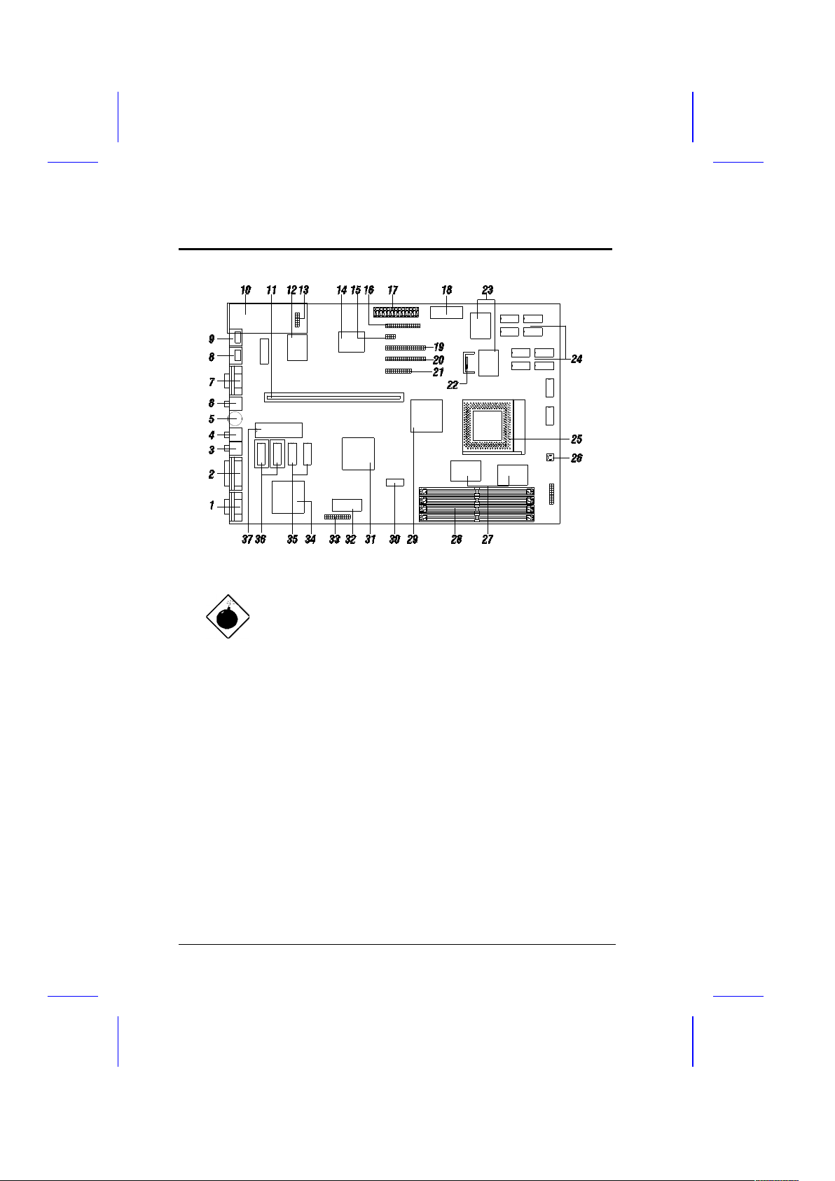
Board Layout
1. VGA connector 20. IDE1 connector
2. Game/MIDI port 21. Parallel port connector
3. Speaker out 22. Voltage regulator with heatsink
4. Line in 23. Pipeline-burst cache
5. Volume control 24. Asynchronous cache
6. Mic in 25. CPU socket
7. COM1 port 26. CPU fan connector
8. PS/2 mouse connector 27. Intel 82438FX ASIC (TDP)
9. PS/2 keyboard connector 28. SIMM sockets
10. Fax/modem module (optional) 29. Intel 82437FX ASIC (TSC)
11. Riser card slot 30. Clock generator
12. Creative CT2504 audio chip 31. Intel 82371FB ASIC (PIIX)
13. Fax/modem connector 32. BIOS
14. Super I/O chip 33. VGA feature connector
15. COM2 port connector 34. S3 Trio64 audio chip
16. FDC connector 35. First 1-MB video DRAM
17. Power connector 36. Second 1-MB video DRAM sockets
18. RTC and battery 37. Keyboard controller
19. IDE2 connector
User’s Guide 1-3
Page 17
Features
The heatsink becomes very hot when the
system is on. NEVER touch the heatsink
with any metal or with your hands.
System Board Parts
Microprocessor
The LP5 system board uses an Intel Pentium (3.3V) processor
running at speeds of 75, 90, 100, 120, 133, 150 or 166 MHz. Chapter
2 tells details on how to upgrade the Pentium processor.
1-4 User’s Guide
Page 18

Features
ASICs
The ASICs onboard are the 82437FX, 82438FX and 82371FB. The
82437 serves as the system memory controller and PCI bus interface.
The two 82438FX ASICs function as PCI local-bus data paths that
offer 64-bit DRAM and 32-bit PCI bus interfaces to support the 64-bit
Pentium processor data bus.
The 82371FB acts as the PCI-/ISA-bus bridge that translates the PCI
bus cycles into ISA bus cycles or vice-versa. It also functions as the
PCI fast-IDE interface and the SMM controller.
AMI BIOS
The AMI BIOS (basic input-output system) resides in the flash ROM
chip. This contains the program that performs the power-on self-tests
(POST) upon booting. During POST, this program activates the
peripheral devices, tests onboard memory, and prepares the system
for operation. Chapter 3 gives more information on the AMI BIOS.
Local-bus VGA Accelerator
The system board has an onboard S3 Trio64 graphics accelerator
and a 1-MB video memory expandable to 2 MB. These enable the
LP5 to support VESA Display Power Management Signalling (DPMS)
monitors. For more details on the onboard VGA, see Chapter 4.
User’s Guide 1-5
Page 19

Features
16-bit Sound Chip
The onboard sound chip is a 16-bit Creative CT2504. It offers true
16-bit audio and is compatible with Sound Blaster Pro and AdLib,
enabling the LP5 to serve multimedia purposes. Chapter 5 discusses
the features of this audio chip in detail.
Two-channel PCI Mode 4 Enhanced IDE
The board integrates two-channel PCI mode 4 enhanced-integrated
drive electronic (E-IDE) interfaces with bus master support. This
improves the data transfer rate. The E-IDE interfaces allow the
system to support four E-IDE devices, including hard disks with more
than 528-MB capacity. This feature offers users increased data
storage capacity.
Fax/Modem (Optional)
The LP5 may come with an optional fax/modem module. The module
uses the Cirrus Logic chipset and has a fax/data rate of 14.4 kbit/sec.
It conforms to the CCITT V.32bis protocol.
For more details on the fax/modem function, refer to the manuals that
come with the module.
1-6 User’s Guide
Page 20

Features
Super I/O Controller
The onboard super I/O controller chip SMC 37C665GT supports two
UART 16450/16550-compatible serial ports and a parallel port (SPP,
EPP, ECP)1. It also accommodates 1.2-/1.44-/2.88-MB disk drives
allowing full-range access to 5.25-inch drives with 360-KB or 1.2-MB
format and 3.5-inch drives with 720-KB, 1.44-MB or 2.88-MB format.
The I/O chip also supports the three-mode Japanese floppy drives.
Expansion Slot
The system board has one riser card slot for add-on card
connections. Chapter 2 tells how to install a riser card.
DRAM Sockets
The system board has four 72-pin DRAM sockets that expand system
memory to a maximum of 128 MB. These sockets accept single- and
double-density SIMMs with the EDO or the Fast-page Mode feature.
Chapter 2 tells how to install memory modules and lists the possible
memory configurations.
Keyboard and Mouse Connectors
The system board accepts PS/2 keyboard and mouse connectors.
See Chapter 2 for information on how to install a keyboard and a
mouse.
1
SPP: Standard Parallel Port
EPP: Enhanced Parallel Port (IEEE 1284 compliant)
ECP: Extended Capabilities Port (IEEE 1284 compliant)
User’s Guide 1-7
Page 21

Features
SRAM
The system board may come with either a 256-KB pipeline-burst
cache or a 256-KB/512-KB asynchronous cache.
Power Management
The LP5 features a system power-management mode (Dark Green)
that conforms to the power-saving standards of the U.S.
Environmental Protection Agency (EPA) Energy Star program. See
Chapter 3 for more information on the power-management mode.
1-8 User’s Guide
Page 22

Chapter
Hardware Setup 2
This chapter tells how to set jumpers, upgrade system memory, add
expansion boards, and install the system board.
Install the CPU, memory, and set the jumpers before you install the
board inside a housing. You may add the other components after
installing the board. Read this chapter to learn about the components
before you install them.
ESD Precautions
Electrostatic discharge (ESD) can damage your CPU, disk drives,
expansion boards, and other components. Always observe the
following precautions before you install a system component.
1. Do not remove a component from its protective packaging until
you are ready to install it.
2. Wear a wrist grounding strap and attach it to a metal part of the
system unit before handling components. If a wrist strap is not
available, maintain contact with the system unit throughout any
procedure requiring ESD protection.
User’s Guide 2-1
Page 23

Hardware Setup
Installing a Microprocessor
The motherboard has a zero-insertion force microprocessor socket
that allows you to install a Pentium CPU without using any tools.
Follow these steps to install a Pentium CPU in a ZIF-type upgrade
socket:
Make sure that the system power is OFF
before installing a component.
1. Attach the heatsink and the fan to the CPU.
CPU in socket
Heatsink
2-2 User’s Guide
Page 24

Hardware Setup
CPU in socket
(with heatsink)
Fan
2. Pull up the socket lever.
3. Insert the CPU with the attached heatsink and fan. Make sure
that pin 1 of the CPU aligns with the hole 1 of the socket. The
notched corner on the CPU indicates pin 1.
4. Pull down the socket lever to lock the CPU into the socket.
User’s Guide 2-3
Step 2
Step 3
Step 4
Page 25

Hardware Setup
5. Plug the fan cable into the fan connector. See the section
Connectors for details on the fan connector.
6. Set the jumpers accordingly. See the following sections for the
correct jumper settings.
2-4 User’s Guide
Page 26

Hardware Setup
Upgrading the Microprocessor
Follow these steps to upgrade the Pentium CPU from 75 MHz to
90,100, 120, 133, 150 or 166 MHz:
1. Turn off the system power.
2. Remove the housing cover and locate the CPU socket on the
system board.
3. Pull up the socket lever.
4. Remove the installed CPU.
5. Install the upgrade CPU. Refer to the section Installing a
Microprocessor for instructions on how to install a Pentium CPU.
6. Set the jumpers accordingly. See the following sections for the
correct jumper settings.
User’s Guide 2-5
Page 27

Hardware Setup
Jumper Settings
You have to change the jumper settings when you reconfigure the
system. This section tells how to set the jumpers. The figure below
shows the jumper locations.
2-6 User’s Guide
Page 28

Hardware Setup
Set a jumper switch as follows:
· To close a jumper, insert the plastic jumper cap over two pins of a
jumper.
· To open a jumper, remove the jumper cap.
The following conventions are used to represent the proper jumper
settings:
User’s Guide 2-7
Open
Closed (1-2 position)
Page 29

Hardware Setup
Selecting the CPU Type
The jumpers JP9, JP10, JP11 and JP13 let you select the CPU type.
The available settings are as follows:
2-8 User’s Guide
CPU TYPE JP9 JP10 JP11 JP13
P54C-75
P54C-90
P54C-100
P54C/CS/CQS-120
P54C/CS/CQS-133
P54CS/CQS-150
P54CS/CQS-166
Page 30

Hardware Setup
Selecting the Memory Mode
The system board supports both the EDO and the Fast-page Mode
memory features. If you want to install memory with EDO features,
you must set jumper JP6 to 2-3. Otherwise, set the jumper to 1-2 for
the Fast-page Mode feature.
User’s Guide 2-9
Mode Select JP6
Fast Page
EDO
Page 31

Hardware Setup
Setting the Cache Size
The motherboard comes either with a 256-KB pipeline-burst cache or
a 256-KB/512-KB asynchronous cache. The pipeline-burst cache
improves system performance by reducing the standard processing
time.
See the following figure for the location of the second-level cache.
See the table below for the various cache configurations.
Cache
Size
Tag SRAM (U36)
(SOJ-type, 15 ns)
Data SRAM
(U53, U54, U55, U56,
U58, U59, U60, U61)
256 KB 32 Kb x 8 x 1 pc. or
16 Kb x 8 x 1 pc.
32 Kb x 8 x 8 pcs (SOJ type, 15 ns)
512 KB 32 Kb x 8 x 1 pc. or
16 Kb x 8 x 1 pc.
64 Kb x 8 x 8 pcs (SOJ type, 15 ns)
256 KB (p.b.) 32 Kb x 8 x 1 pc or
16 Kb x 8 x 1 pc.
32 Kb x 32 x 2 pcs (QFP type, 8 ns)
2-10 User’s Guide
256-KB pipelined-burst cache
256-KB/512-KB asynchronous cache
Page 32

Hardware Setup
Also, you must reset jumper JP14 if you upgrade the cache. See the
figure below for the correct jumper settings.
Selecting the Flash ROM Type
Set the jumper JP7 according to the Flash ROM type. If you use a 5V
Flash ROM, then you must close pins 2-3 of JP7. For a 12V Flash
ROM, the required setting is 1-2. The default setting is 2-3.
User’s Guide 2-11
CACHE SIZE JP14
256 KB
512 KB
Flash ROM Type JP7
12 V
5 V
Page 33

Hardware Setup
Enabling the Onboard Super I/O Controller
The onboard super I/O controller is SMC37C665GT. If you want to
enable or disable the onboard I/O controller you must reset the jumper
marked JP8 on the system board.
Selecting the ECP DMA Channel
The jumpers JP3 and JP4 let you select the DMA channel for ECP
function. The channel selections are DMA 1 and DMA 3.
2-12 User’s Guide
JP8
Enabled
Disabled
JP3 JP4
DMA 1
DMA 3
Page 34

Hardware Setup
Enabling the VGA
The VGA chip onboard is S3 Trio64. To enable the VGA chip, set
jumper JP5 to 1-2. Otherwise, set it to 2-3.
Selecting the Audio Output
You may direct your audio output to line out or speaker out. If you
select speaker out, the audio signal passes through the onboard
amplifier module before output. Selecting line out lets you bypass the
amplifier module and allows you to use an external amplifier.
You must set jumpers JP1 and JP2 according to the selected audio
output. See the figure for the proper jumper settings.
User’s Guide 2-13
Audio Output JP1 JP2
Line out
Speaker out
VGA JP5
Enabled
Disabled
Page 35

Hardware Setup
Selecting the Audio I/O Address
The jumpers J1 and J2 let you select the I/O address for audio
function. The available selections are 22XH, 24XH, 26XH, and 28XH.
See the following figure for the corresponding settings for each
address.
Clearing the CMOS
The jumper JP12 clears the values in the CMOS. You need to clear
the CMOS if you forget your system password. To do this, shut off
the system power and short pins 2-3 of JP12 for a few seconds.
Reset the jumper to the normal setting by shorting pins 1-2 with a
jumper cap. Enter Setup to specify a new password.
2-14 User’s Guide
JP12
Default (Normal)
Clearing CMOS
Audio I/O Address J1 J2
22XH
24XH
26XH
28XH
Page 36

Hardware Setup
Memory Configuration
The system board supports a maximum memory of 128 MB. The
four 72-pin SIMM sockets accommodate 4- and 16-MB single-density
SIMMs, and 8- and 32-MB double-density SIMMs - with or without the
Extended Data Out (EDO) function. The EDO feature expands data
output efficiency (speed), thus improving memory performance. All
SIMMs support a DRAM speed of 70/60 ns (or less). Refer to the
section Board Layout and see the figure for the location of the SIMMs.
The table below lists the SIMM types and their corresponding
capacities.
SIMM Type Capacity
1 Mb x 32/36 4 MB
2 Mb x 32/36 8 MB
4 Mb x 32/36 16 MB
8 Mb x 32/36 32 MB
User’s Guide 2-15
Page 37

Hardware Setup
The following are the possible SIMM configurations.
Total Memory SIMM 0/1 SIMM 2/3
8 MB 4 MB x 2
16 MB 4 MB x 2 4 MB x 2
16 MB 8 MB x 2
32 MB 8 MB x 2 8 MB x 2
32 MB 16 MB x 2
40 MB 16 MB x 2 4 MB x 2
48 MB 16 MB x 2 8 MB x 2
64 MB 16 MB x 2 16 MB x 2
64 MB 32 MB x 2
72 MB 32 MB x 2 4 MB x 2
80 MB 32 MB x 2 8 MB x 2
96 MB 32 MB x 2 16 MB x 2
128 MB 32 MB x 2 32 MB x 2
2-16 User’s Guide
Page 38

Hardware Setup
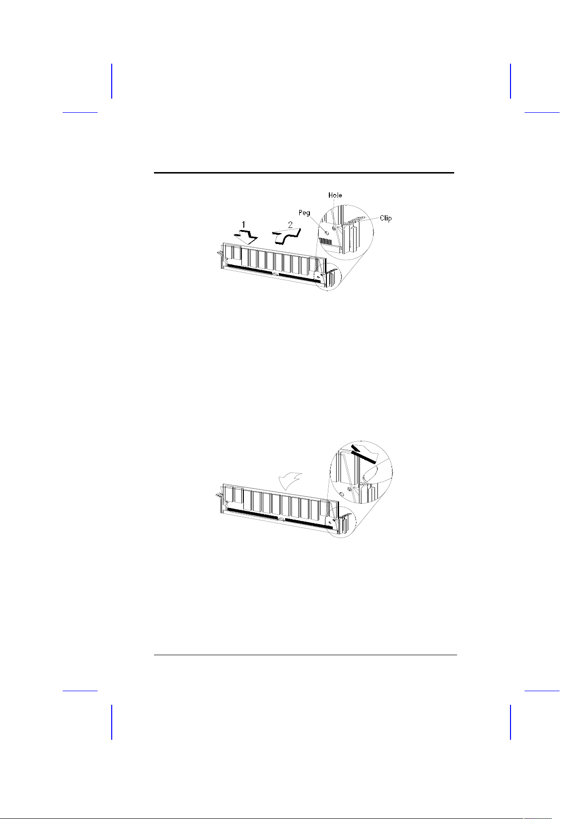
Installing a SIMM
Observe the ESD precautions when
installing components.
Follow these steps to install a SIMM:
1. Slip a SIMM at a 45o angle into a socket with the component side
facing down. Always install SIMMs beginning with SIMM 0.
Be careful when inserting or removing
SIMMs. Forcing a SIMM in or out of a
socket can damage the socket or the
SIMM (or both).
2. Gently push the SIMM up until the pegs of the socket slip into the
holes on the SIMM and the holding clips lock the SIMM into a
vertical position.
The SIMM should be at a 90o angle when
installed.
User’s Guide 2-17
Page 39
Hardware Setup
Removing a SIMM
1. Press the holding clips on both sides of the SIMM outward to
release it.
2. Press the SIMM downward to about a 45o angle.
3. Gently pull the SIMM out of the socket.
2-18 User’s Guide
Page 40

Hardware Setup
Connectors
Multifunction Connector
This 20-pin connector is marked CN21 on the system board. It
supports a number of system functions: green mode LED, power
LED, break switch, keylock, and speaker. Attach the front panel
connectors to the corresponding pins as in the illustration below.
( Turbo Switch ) ( Turbo LED )
Break Switch Green Mode LEDReset
Speaker Power LED Keylock
Some housings have a five-pin connector for the keylock and power
LED. See the following illustration.
User’s Guide 2-19
Speaker Power LED Keylock
Page 41

Hardware Setup
Speaker Keylock & Power LED
Break Switch Green Mode LED
( Turbo Switch ) ( Turbo LED )
Reset
Other housings may have a 12-pin connector. If your housing has
this type of connector, plug it into CN21 as shown in the following
figure. Make sure that the red wire of the connector connects to pin
11.
( Turbo Switch )
Break Switch
Ground
VCC
Ground
Ground
Keylock
Reset
Res-VCC
Speaker
2-20 User’s Guide
Speaker Keylock and Power LED
Page 42

Hardware Setup
Break Switch
The break switch gives the user the option to directly enter the system
suspend mode by setting the switch to the on position. To set, simply
press the switch. Make sure that the break switch is in the off position
before you set it to the on position. To set it to the off position, simply
press the switch to release it from the on position.
Keyboard and Mouse Connectors
The board accepts PS/2 keyboard and mouse connectors. The
following figure shows how to connect a keyboard (or mouse).
User’s Guide 2-21
Page 43

Hardware Setup
Power Connector
A standard power supply has two cables with six wires each. Attach
these cables to the power connector on the board in such a way that
all the black wires are in the center. The power connector is marked
CN13 on the system board.
Fan Connector
The 2-pin fan connector is marked CN20 on the system board. The
figure below shows the pin configuration of the connector.
2-pin fan power connector (J2)
GND
2-22 User’s Guide
2-pin fan connector (CN20)
GND
Page 44

Hardware Setup
Installation
The LP5 board conforms to the LPX standard form factor. It has
mounting holes that fit LPX housings. However, before installing the
system board, make sure that the housing accommodates a LPX
board with long opening in the rear panel for the onboard connectors.
Some housings may differ slightly in design, requiring additional steps
to install the board. Read the documentation that comes with the
housing.
Make sure that you have already installed
the system board components like the
CPU and memory, and have set the
appropriate jumpers before you proceed.
Installing the System Board
1. Open the system housing.
2. The system board comes with a bracket and hex screws. Attach
the bracket to the board with the hex screws. See the figure
below.
User’s Guide 2-23
Page 45

Hardware Setup
3. Use the screws that come with the housing to secure the board.
4. Attach the power supply cables to the power connector and the
front panel connectors to the multifunction connector. See the
section Connectors.
5. Install any additional components that you have not yet installed.
Installing a Riser Card
Follow these steps to install a riser card:
1. Observe the ESD precautions before removing the riser card
from its protective packaging.
2. Locate the riser card slot on the system board. See the section
Board Layout.
3. Gently insert the golden edge of the riser card into the slot until it
fits.
2-24 User’s Guide
Page 46

Hardware Setup
4. Make sure that the riser card is properly seated.
User’s Guide 2-25
riser card
motherboard
riser card slot
Page 47

Hardware Setup
Installing Expansion Boards
Install any expansion boards after you have secured the system
board and the riser card in the housing.
Follow these steps to install an expansion board.
1. Observe the ESD precautions before removing the expansion
card from its protective packaging.
2. Remove the bracket opposite the slot that you want to use. Save
the cover for future use. Save the screw to secure the expansion
board.
3. Remove the board from its protective packaging.
4. Gently insert the golden edge of the board into the slot on the
riser card until it fits into place.
5. Secure the board bracket with the screw.
2-26 User’s Guide
PCI card ISA card
Page 48

Hardware Setup
Applying the Port Indicator Sticker
The board comes with a silver sticker that serves as port indicator. It
has the following indicators on it.
MODEM K/B MOUSE COM1 MIC VOL LINE SPK MIDI/GAME
VGA
To apply the sticker:
1. Remove the protective paper backing from the sticker.
2. Position the sticker over the rear panel, just above the
connectors. Align each indicator with the connectors on the
board. Press the sticker evenly to adhere.
User’s Guide 2-27
REAR PANEL
STICKER
CONNECTORS
Page 49

Chapter
AMI BIOS 3
AMI BIOS Setup Main Menu
The AMI BIOS Setup Main Menu appears below. Press c during
POST to enter the BIOS Setup.
The AMI BIOS is in Windows form. You can use either the keyboard
or a mouse to move between the items. To select among the Setup
groups, use v to highlight the selected group or simply click on the
icon of the selected Setup menu.
To select among the options, you can either use the arrow keys to
move the highlight bar or simply click on the icon of the desired
option.
After selecting, press e or double-click on the icon to open the menu.
User’s Guide 3-1
Page 50

AMI BIOS
Standard CMOS Setup
Highlight Setup using v or simply click on the Setup icon. Select
Standard to input configuration values such as the date, time, and
disk types. The Standard CMOS Setup pop-up window appears
below:
Date/Time
To set the date and time, highlight Date/Time and press e or
double-click on the Date/Time icon. The following screen appears:
3-2 User’s Guide
Page 51

AMI BIOS
Use the arrow keys to move among the items. Press the + and keys or click the + and - icons to set the current date and time. Close
the window by pressing ^ or double-clicking the Control menu box in
the upper-left corner of the window.
Floppy Drives A and B
To configure the floppy drive, select Floppy A. The following
values appear on the screen:
After selecting the proper setting, press ^ or double-click the Control
menu box to close the window.
Select Floppy B and follow the same procedure to configure the
second floppy drive, if present.
User’s Guide 3-3
Page 52

AMI BIOS
Hard Disk Drives
Select Master Hard Disk to configure the first hard disk. The
following values appear on the screen:
If you cannot find your hard disk drive type on the list, select User
and enter the disk parameters. You can also select Utility Setup.
This automatically configures your hard disk. Refer to the section
Utility Setup for more information.
Select ESDI or SCSI depending the device installed.
If you have two hard disks installed, select Slave Disk and follow
the same procedure to configure the second hard disk.
3-4 User’s Guide
Page 53

AMI BIOS
Advanced CMOS Setup
The window below appears if you select the Advanced option.
The screen above does not show all the parameters of the Advanced
Configuration menu. Use w or y to highlight the desired parameter.
Press } to view the rest of the parameters. The following screens
appear:
User’s Guide 3-5
Page 54

AMI BIOS
Typematic Rate (Chars./Sec.)
This parameter determines the typematic rate. The typematic rate
settings are 15, 20, 30 and Disabled. The default setting is 30.
Select Disabled to disregard the rate setting.
3-6 User’s Guide
Page 55

AMI BIOS
System Keyboard
Set this parameter to Present if there is a keyboard connected to
the system. However, some servers may not have keyboards.
Select Absent if there is no keyboard present.
Primary Display
This function detects the type of VGA in use. The settings are
VGA/EGA, CGA 40 x 25, CGA 80 x 25, Mono, and Absent. The
default setting is VGA/EGA.
PS/2 Mouse Support
Setting this parameter to Enabled lets you support a PS/2 mouse.
Disable the parameter if you are under the UNIX X-window
environment.
Above 1 MB Memory Test
This parameter allows your system to check all available memory.
Therefore, setting this parameter to Enabled slows down the poweron self-test. The default setting is Disabled.
User’s Guide 3-7
Page 56

AMI BIOS
Memory Test Tick Sound
Enabling this parameter lets you hear the tick sound during the
memory test. Disable the parameter to bypass the function.
Hit “Del” Message Display
This option lets you enable or disable the Hit <Del> if you want Setup
message from appearing when the system boots. The default setting
is Enabled.
Extended BIOS RAM Area
This function allows you to relocate the BIOS from ROM to RAM.
Relocating to RAM enhances system performance as information
access is faster than ROM. The parameter settings are 0:300 and
DOS 1K. The default address is 0:300.
Wait for F1 If Any Error
When enabled, the BIOS waits for the end user to press l before
continuing. If disabled, the BIOS continues the boot process without
waiting for l to be pressed. The default setting is Enabled.
System Boot-up Num Lock
Setting this parameter to On enables the numeric function of the
numeric keypad. Set this parameter to Off to disregard the function.
Disabling the numeric function allows you to use the numeric keypad
for cursor control. The default setting is On.
3-8 User’s Guide
Page 57

AMI BIOS
Floppy Drive Seek at Boot
When enabled, the BIOS detects whether there is a floppy disk drive
installed. Disable the parameter to bypass the function. The default
setting is Disabled.
Floppy Drive Swapping
This parameter allows you to swap floppy drives. For example, if you
have two floppy drives (A and B), you can assign the first drive as
drive B and the second drive as drive A or vice-versa. Disable the
parameter to bypass the function. The default is Disabled.
System Boot-up Sequence
The settings are C:, A: and A:, C: to specify the system search
sequence. The default setting is A:,C:.
Password Checking
The settings are Setup and Always. The Setup setting allows the
system to boot and use the password to protect the Setup Utility
Configuration settings from being tampered with. The Always setting
requires you to enter the password everytime you boot the system.
The default setting is Setup.
User’s Guide 3-9
Page 58

AMI BIOS
Cache Memory
The available selections for this parameter are Internal, Both and
Disabled. Select Internal if you want to enable the internal cache
memory. Select Both if you want to use both the internal and
external cache memories. Select Disabled to disregard the
internal and external cache features.
System BIOS Shadow Cacheable
The default setting for this parameter is Enabled. This enhances
the system performance. Disabling the parameter prevents the
system BIOS from being cached.
Adapter ROM Control
C000, 32 K
This address is for shadowing video ROMs. Select Shadow to
assign the address for shadowing expansion video card with ROM.
Select Cache to assign them for cache. The default setting is
Cache.
C800 ~ DC00, 16 K
These addresses are for shadowing other expansion card ROMs.
The default setting for these areas is Disabled. Set the
addresses to Shadow if you want to use them for shadowing
expansion cards with ROM. Set the addresses to Cache to assign
them for cache.
3-10 User’s Guide
Page 59

AMI BIOS
The F000 and E000 addresses are
exclusively shadowed for BIOS.
IDE Control
IDE Auto-detect
There are cases wherein the HDD parameters that you entered and
those detected by the auto-detection function are mismatched. This
causes the system not to boot. If this happens, we recommend that
you set this parameter to Disabled to bypass the auto-detection
function. The default setting is Enabled.
Block Mode
This function enhances disk performance depending on the hard disk
in use. This parameter is normally set to Auto. This setting allows
data transfer in block (multiple sectors) by increasing the data transfer
rate. The other selections for this parameter are 2 S/B, 4 S/B, 8 S/B,
16 S/B, 32 S/B, 64 S/B and Disabled. Disable the parameter if your
hard disk does not support this feature.
Onboard IDE Present
The settings for this function are Auto, Enabled and Disabled. Select
Enabled if you have an onboard PCI IDE. Select Auto to
automatically detect the presence of PCI IDE. Select Disabled to
disregard the PCI-IDE function.
User’s Guide 3-11
Page 60

AMI BIOS
PIO Mode
This parameter lets you set the PIO mode that your onboard PCI IDE
supports. The selections are from Mode 0 to Mode 4, Auto and
Disabled. Set this parameter either by entering the PIO mode
manually or selecting Auto to automatically detect the supported PIO
mode. Disable the parameter to bypass the feature.
32-bit Mode
Enabling this function improves the hard disk performance by
increasing the data transfer rate from 16-bit to 32-bit. The data
transfer rate is auto-detected by BIOS.
Primary 1st LBA Mode
This enhanced IDE feature allows you to use a hard disk with a
capacity higher than 528 MB. This is made possible through the
Logical Block Address (LBA) mode translation. This parameter
affects the primary IDE hard disk drive connected to the IDE 1
connector. The default setting is Disabled.
Primary 2nd LBA Mode
This enhanced IDE feature allows you to use a hard disk with a
capacity higher than 528 MB. This is made possible through the
Logical Block Address (LBA) mode translation. This parameter
affects the secondary IDE hard disk drive connected to the IDE 1
connector. The default setting is Disabled.
3-12 User’s Guide
Page 61

AMI BIOS
Secondary 1st LBA Mode
This enhanced IDE feature allows you to use a hard disk with a
capacity higher than 528 MB. This is made possible through the
Logical Block Address (LBA) mode translation. This parameter
affects the primary IDE hard disk drive connected to the IDE 2
connector. The default setting is Disabled.
Secondary 2nd LBA Mode
This enhanced IDE feature allows you to use a hard disk with a
capacity higher than 528 MB. This is made possible through the
Logical Block Address (LBA) mode translation. This parameter
affects the secondary IDE hard disk drive connected to the IDE 2
connector. The default setting is Disabled.
Secondary Drives Present
This parameter lets you install up to two IDE hard disks in the
secondary channel. Select None if you do not have any.
Chipset Setup Mode
This function allows you to change the Chipset Setup DRAM control
parameters according to the end-user type. The available settings
are End-user and Engineer. We recommend that you select End-
user. See the following section for more details on Chipset Features
Setup.
User’s Guide 3-13
Page 62

AMI BIOS
Chipset Features Setup
The Chipset Features Setup controls the board's chipset settings.
The controls for this menu are the same as for the previous screen.
The Chipset Setup DRAM control parameters differ depending on the
Chipset Setup Mode setting in the Advanced CMOS Setup. This
screen appears if you select the Chipset option from the Setup menu
and if the Chipset Setup Mode parameter setting is End-user.
The following screen appears if your Chipset Setup Mode parameter
setting is Engineer. Take note of the DRAM control parameters.
3-14 User’s Guide
Page 63

AMI BIOS
Both screens do not show all the parameters of the Chipset Setup
menu. Use w or y to highlight the desired parameter. Press } to
view the rest of the parameters. The following screens appear
regardless of the end-user type or the Chipset Setup Mode parameter
setting:
User’s Guide 3-15
Page 64

AMI BIOS
This manual describes only the End-user
setting parameters.
DRAM Control
Speed
This DRAM control parameter lets you set the DRAM speed. The
speed settings are 60 ns and 70 ns. The default setting is 70 ns.
Memory Hole
This option lets you assign the system memory area to avoid memory
conflicts. The settings are 512 ~ 640 K, 15 ~ 16 M and Disabled.
3-16 User’s Guide
Page 65

AMI BIOS
ISA Control
8-bit I/O Recovery Time
This parameter allows you to set the response time of the 8-bit I/O
connected to your system. The range is from 1~7 SYSCLK. The
default setting is 4 SYSCLK.
16-bit I/O Recovery Time
This parameter allows you to set the response time of the 16-bit I/O
connected to your system. The range is from 1~4 SYSCLK. The
default setting is 1 SYSCLK.
PCI Control
VGA Palette Snooping
PCI devices support the “palette snooping” technique that enables the
device to control access to their palette registers.
Set this parameter to Enabled to activate the palette snooping
function in the PCI VGA devices installed in your system.
PCI-IDE Card Selection
This parameter allows you to select the PCI-IDE card that you want to
enable. The board supports a maximum of four PCI-IDE cards. The
available selections are Slot 1, Slot 2, Slot 3, Slot 4, and Absent.
Select Absent if you do not have a PCI card installed.
User’s Guide 3-17
Page 66

AMI BIOS
PCI Primary IDE INT# Line
This parameter lets you assign an INT for the IDE device connected
to your primary IDE connector. The settings are INT A, INT B, INT C,
INT D, Absent and Not Used. If you do not have a PCI-IDE card
installed in your system and your PCI-IDE Card Selection parameter
setting is Absent, this parameter becomes non-configurable.
PCI Secondary IDE INT# Line
This parameter lets you assign an INT for the IDE device connected
to your secondary IDE connector. The settings are INT A, INT B, INT
C, INT D, Absent and Not Used. If you do not have a PCI-IDE card
installed in your system and your PCI-IDE Card Selection parameter
setting is Absent, this parameter becomes non-configurable.
IRQ Allocated
IRQ 3, 4, 5, 7, 9, 10, 11, 14, 15 is for...
These lines allow you to assign the available IRQs to either ISA or
PCI/PnP devices.
3-18 User’s Guide
Page 67

AMI BIOS
Power Management Setup
To take advantage of the power management features, select Power
Management from the Setup menu. To select, highlight Power
Mgmt and press e or double-click on the Power Management icon.
The following screen appears:
The screen above does not show all the parameters of the Power
Management Setup menu. Use w or y to highlight the desired
parameter. Press } to view the remaining parameters. The following
screens appear:
User’s Guide 3-19
Page 68

AMI BIOS
Advanced Power Management
Set this parameter to Enabled to take advantage of the powersaving feature. Disable the parameter to bypass the feature.
Full-on to Standby Timeout
This function lets you determine when to put the system into standby
mode. In standby mode, the CPU clock slows down and the VGA
suspends the video signal. Any events detected returns the system to
full power. The settings range from 1~255 Min. and Disabled.
Standby to Suspend Timeout
This function lets you specify when to put the system into suspend
mode. In suspend mode. the CPU clock stops, the IDE hard disk
spins down and the VGA suspends video signal. This mode
conserves the most power. Any events detected returns the system
to full power. The settings range from 1~255 Min. and Disabled.
3-20 User’s Guide
Page 69

AMI BIOS
IDE Drive Power Down in
This option allows you to specify the mode when to "spin down" your
IDE hard disk. The disk returns to full speed once the system
resumes to normal mode. The settings are Standby, Suspend and
Disabled.
Video Power Down in
This option allows you to set the mode when to power down your
video monitor. The video monitor returns to full power once the
system returns to normal mode. The settings are Standby, Suspend
and Disabled.
VGA Power Down Mode
This option lets you choose the VGA power down mode. The settings
are Standby, Suspend and Off.
Slow Clock Ratio
When the system enters the standby mode, the CPU clock starts to
slow down. This parameter lets you set the “slow-down” clock ratio.
The settings are 1:2, 1:4, 1:8, 1:16, 1:32, 1:64, and 1:128.
Break Event (IRQ 3~7, 9~15)
Enabling these parameters allows your system to monitor the IRQ
activities. Any activity detected resets the power-management timers
and returns the system to normal mode.
User’s Guide 3-21
Page 70

AMI BIOS
You must enable at least one IRQ activity.
Otherwise, the system stays in suspend
mode.
Under Windows 95, do not disable the
parameter IRQ 12. Otherwise, the system
disregards any mouse or keyboard activity
and stays in power-saving mode.
Peripheral Setup
This screen appears if you select Peripherals or double-click on
the Peripheral Setup icon from the Setup menu. The Peripheral Setup
screen allows you to set up your system peripherals.
Programming Mode
The settings for this option are Auto and Manual. The Manual setting
allows you to set up the screen items manually. The Auto setting sets
up all the items automatically except for the Parallel Port Mode
parameter.
3-22 User’s Guide
Page 71

AMI BIOS
Onboard FDC
Enabling this function allows you to use the onboard floppy disk
controller (FDC). The default setting is Enabled.
Serial Port 1
This parameter allows you to set the base address of serial port 1.
The available settings are 3F8H, 2F8H, 3E8H, 2E8H and Disabled.
Serial Port 2
This parameter allows you to set the base address of serial port 2.
The available settings are 3F8H, 2F8H, 3E8H, 2E8H and Disabled.
Parallel Port
This parameter allows you to set the base address of the parallel port.
The available settings are 3BCH, 378H, 278H and Disabled.
IRQ Active
This option specifies if the parallel and serial port IRQs are active high
or active low. The settings are High and Low.
Parallel Port Mode
This option lets you set the parallel port mode. The settings are
Normal or Extended.
User’s Guide 3-23
Page 72

AMI BIOS
Utility Setup
IDE Setup
This function allows your system to automatically configure your IDE
hard disk(s). This screen appears if you select IDE Setup.
After a few seconds, the screen below appears showing your disk(s)
parameters. Select Yes to accept the values.
3-24 User’s Guide
Page 73

AMI BIOS
Color Set
This pop-up window appears if you select Color Set from the
Utility Setup menu.
Color Set lets you specify the color of your windows background. The
selections are LCD, Army, Pastel, and Sky.
Default Setup
Select this option to automatically set your system configuration
parameters. To select, highlight Default and press e.
Original
This option loads the values that you saved before shutting off the
system. The following prompt appears if you choose Original
from the Default Setup menu. Select Yes to load the original values.
User’s Guide 3-25
Page 74

AMI BIOS
Optimal
Choose this option and the BIOS configures the system using the
best-case values to optimize system performance. However, these
values may not be applicable to your system. If your system does not
boot after choosing this setting, reconfigure it using the Fail-safe
settings. Refer to the following section.
The screen below appears if you choose Optimal from the Default
Setup menu. Select Yes to load the optimum values.
Fail-safe
Choose this option and the BIOS automatically configures the system
using the most stable settings. These settings are not necessarily the
best settings for system performance, but they are safe and stable
enough to guarantee that your system will boot. This is useful if you
are having problems with your current system configuration and need
to determine the cause.
A prompt appears if you choose Fail-safe from the Default Setup
menu. Select Yes to load the fail-safe values.
3-26 User’s Guide
Page 75

AMI BIOS
Security Setup
Password
The system password prevents unauthorized use of your computer. If
you enabled the password feature, it is impossible to boot the
computer without entering the password.
To set a password, highlight Password or simply double-click the
Password icon. The following screen appears:
Your password can consist of up to six characters. The password
does not appear on the screen. WinBIOS prompts you to retype the
password. The following screen appears.
User’s Guide 3-27
Page 76

AMI BIOS
If you forget your password, you must clear the CMOS RAM and
reconfigure the system.
To disable the password, press e when prompted for your password.
Press e again when prompted to retype the password.
3-28 User’s Guide
Page 77

AMI BIOS
Anti-virus
Set this parameter to Enabled to protect the boot sector and
partition table of your hard disk from virus intrusion. Set it to
Disabled to bypass the feature.
A prompt appears when you select Anti-virus from the Security
Setup menu:
Select Enabled and the screen below appears:
User’s Guide 3-29
Page 78

AMI BIOS
Exit Setup
To exit Setup, you can either double-click on the Control menu box or
simply press ^. A dialog box appears on the screen.
If you select Save Changes and Exit, BIOS automatically
saves all CMOS values before leaving Setup. Select Do Not
Save Changes and Exit to exit Setup without saving the
CMOS values. Select Continue to return to Setup if you want to
reconfigure your system.
3-30 User’s Guide
Page 79

Chapter
VGA 4
The LP5 comes with an onboard S3 Trio64 high-performance
graphics accelerator that greatly enhances display capabilities. It has
the following features:
· Support for PCI bus
· Supports GUI (Graphical User Interface) accelerations such as
bit-block transfer, line-drawing, rectangle fill, and windows
clipping to improve performance in a graphics environment
· Screen refresh rate up to 75 Hz
· 1280 x 1024, 256 colors (non-interlaced) maximum resolution
· Resolutions/colors in graphics mode
· 1-MB DRAM
640 x 480 non-interlaced, 64 K colors
800 x 600 non-interlaced, 64 K colors
1024 x 768 non-interlaced, 256 colors
1280 x 1024 non-interlaced, 16 colors
· 2-MB DRAM
640 x 480 non-interlaced, 16.7 million colors (true color)
800 x 600 non-interlaced, 16.7 million colors (true color)
1024 x 768 non-interlaced, 64 K colors
1280 x 1024 non-interlaced, 256 colors
1600 x 1200 interlaced, 256 colors
· Features 132-column text modes
· Register-level compatibility with IBM VGA and backward
· Hardware cursor support
User’s Guide 4-1
Page 80

VGA
· Display memory upgradable to 2 MB
Upgrading Video Memory
You can upgrade the video memory by installing additional memory
chips. The added memory allows you to use more colors and display
graphics at higher resolutions.
The board comes with 1-MB video display memory. You can upgrade
this to 2 MB by installing two 256 Kb x 16 DRAMs with an access
speed of 70 nanoseconds or faster. See the section Board Layout for
the location of the second 1-MB DRAMs.
To upgrade the video memory, follow these steps:
1. Before you upgrade the video memory, check your DRAM type.
Make sure that your upgrade DRAMs and the onboard DRAMs
are exactly of the same type.
2. Align the dot on the DRAM with the notch on the empty socket.
3. Insert the DRAM into the socket. Make sure the chip orientation
is correct. Be careful not to bend any pins.
4-2 User’s Guide
SOJ
Type
dot
Page 81

VGA
The board automatically detects the memory size and tests the
memory when you power-on. Check the memory chip installation if
you receive an error message.
Drivers and Utilities
Getting Started
See to it that you have the following before you install the drivers:
· DOS 5.0, 6.0, 6.2 (or higher version) or OS/2 2.0, 2.1 (or higher
version)
· VGA analog monitor
We recommend that you create backup copies of the original driver
diskettes. Store the originals and work from the backups. If the copy
gets damaged, use the original to create a new copy. Label the
working diskettes properly.
Use the DISKCOPY command to create
backup diskettes. Refer to your MS-DOS
manual for instructions.
Supported Applications
The board comes with a set of display drivers for various applications.
The software drivers for the following applications are contained in the
driver diskettes.
· Windows v3.x
· Autodesk ADI 4.2 Protected mode
User’s Guide 4-3
Page 82

VGA
· AutoCAD 11/12
· 3D Studio 1.0/2.0
· AutoShade 2.1
· MicroStation PC
· Protected Mode v4.0
· Protected Mode v5.0
· OS/2 2.x, 3.0
· Windows NT 3.5
· WESU (Power-Saving Utility)
Refer to the README.TXT file contained in each driver diskette for
detailed installation instructions.
After installing the Windows drivers, a Galileo
utility icon appears in the Windows control
panel. Click-on this icon if you want to use
the utility. The Galileo utility allows you to
change the resolution and the refresh rates.
4-4 User’s Guide
Page 83

VGA
Display Modes
Standard Display Modes
The table below lists the standard display modes supported by the S3
video BIOS.
Mode
(Hex)
Display
Mode
Screen
Resolution
(Chars)
Colors Buffer
Start
Sweep
/Refresh
Rate
(KHz/Hz)
Dot
Clock
(MHz)
00 Text 40 x 25 b/w B8000 31.5/70 25.175
00+ Text 40 x 25 b/w B8000 31.5/70 28.322
01 Text 40 x 25 16 B8000 31.5/70 25.175
01+ Text 40 x 25 16 B8000 31.5/70 28.322
02 Text 80 x 25 b/w B8000 31.5/70 25.175
02 Text 80 x 25 b/w B8000 31.5/70 25.175
02+ Text 80 x 25 b/w B8000 31.5/70 28.322
03 Text 80 x 25 16 B8000 31.5/70 25.175
03+ Text 80 x 25 16 B8000 31.5/70 28.322
04 Graph 320 x 200 4 B8000 31.5/70 25.175
05 Graph 320 x 200 4 B8000 31.5/70 25.175
06 Graph 640 x 200 2 B8000 31.5/70 25.175
07 Text 80 x 25 Mono B0000 31.5/70 28.322
0D Graph 320 x 200 16 A0000 31.5/70 25.175
0E Graph 640 x 400 16 A0000 31.5/70 25.175
0F Graph 640 x 350 Mono A0000 31.5/70 25.175
10 Graph 640 x 350 16 A0000 31.5/70 25.175
11 Graph 640 x 480 2 A0000 31.5/60 25.175
12 Graph 640 x 480 16 A0000 31.5/60 25.175
13 Graph 320 x 200 256 A0000 31.5/70 25.175
“+” Requires more than 1-MB memory
User’s Guide 4-5
Page 84

VGA
Extended Video Modes
The following table lists the extended display modes and the
corresponding resolutions available for each mode.
Mode
No.
Screen Resolution
(Chars)
Colors Refresh Rate (Hz)
10A 132 x 43 16 70
109 132 x 25 16 70
101 640 x 480 256 60
101 640 x 480 256 72
101 640 x 480 256 75
103 800 x 600 256 56
103 800 x 600 256 60
103 800 x 600 256 72
103 800 x 600 256 75
105 1024 x 768 256 43 (I)
105 1024 x 768 256 60
105 1024 x 768 256 70
105 1024 x 768 256 75
106 1280 x 1024 16 45 (I)
+107 1280 x 1024 256 45 (I)
+107 1280 x 1024 256 60
+107 1280 x 1024 256 72
+107 1280 x 1024 256 75
110 640 x 480 32768 60
110 640 x 480 32768 72
110 640 x 480 32768 75
111 640 x 480 16 60
111 640 x 480 16 72
111 640 x 480 16 75
+112 640 x 480 16.7 M 60
+112 640 x 480 16.7 M 72
+112 640 x 480 16.7 M 75
113 800 x 600 32768 60
113 800 x 600 32768 72
113 800 x 600 32768 75
114 800 x 600 65536 60
114 800 x 600 65536 72
114 800 x 600 65536 75
4-6 User’s Guide
Page 85

VGA
Extended Video Modes (continued)
Mode
No.
Screen Resolution
(Chars)
Colors Refresh Rate (Hz)
+115 800 x 600 16.7 M 60
+115 800 x 600 16.7 M 72
+115 800 x 600 16.7 M 75
+116 1024 x 768 32768 43 (I)
+116 1024 x 768 32768 60
+116 1024 x 768 32768 70
+116 1024 x 768 32768 75
+117 1024 x 768 65536 43 (I)
+117 1024 x 768 65536 60
+117 1024 x 768 65536 70
+117 1024 x 768 65536 75
+120 1600 x 1200 256 48.5 (I)
201 640 x 480 256 60
201 640 x 480 256 72
201 640 x 480 256 75
203 800 x 600 256 56
203 800 x 600 256 60
203 800 x 600 256 72
203 800 x 600 256 75
205 1024 x 768 256 43 (I)
205 1024 x 768 256 60
205 1024 x 768 256 70
205 1024 x 768 256 75
207 1152 x 864 256 60
208 1280 x 1024 16 43 (I)
208 1280 x 1024 16 60
208 1280 x 1024 16 72
208 1280 x 1024 16 75
“+” Requires more than 1-MB memory
Extended VGA text modes up to 132 columns
by 43 rows are possible as well.
User’s Guide 4-7
Page 86

VGA
4-8 User’s Guide
Page 87

Chapter
Audio Chip 5
The LP5 system board comes with the Windows and DOS application
package for the onboard Creative CT2504 chip. This chapter tells
how to use these applications.
Driver Installation
To install the drivers, simply insert the Audio Installation Disk into
drive A and type:
A:\INSTALL
Follow the screen instructions to complete the installation.
Windows Applications
WaveEditor
WaveEditor allows you to record, play, edit and enhance 8-bit (tape
quality) and 16-bit (CD quality) wave data in the Windows
environment.
Starting WaveEditor
To start WaveEditor, simply double-click on the WaveEditor icon. The
WaveEditor window appears as follows.
User’s Guide 5-1
Page 88

Audio Chip
Toolbar Contains the buttons and control boxes for file and
wave operations.
Creates a new window without any data.
Loads an existing wave file.
Saves changes made to a wave file.
Cuts the selected data of a wave file.
5-2 User’s Guide
New Cut Play Record CD Start Size Zoom
Ope
n
Play
Cop
y
Save Paste Pause Mixer
Format
Page 89

Audio Chip
Copies the selected data of a wave file.
Pastes cut or copied data onto a wave file.
Plays the wave file that is currently active in the
WaveEditor.
Stops the playback of a wave file.
Pauses/Resumes the playback of a wave file.
Records a wave file.
Sets the default recording format.
Activates the mixer.
Activates the CD player. (This button appears only if
you have a CD-ROM drive installed.)
Displays the starting position of the wave data
selection. To specify the position, enter the
numerical value in the text box or use the scrolls to
select the starting position.
Displays the size of the wave data selection. To
adjust the size, enter the desired size in the text box
or use the scroll arrows.
Displays the zoom ratio of the wave file on display.
To adjust the ratio, simply enter the desired ratio in
the text box or use the scroll arrows. The smaller
the value, the larger the magnification.
User’s Guide 5-3
Page 90

Audio Chip
Edit Window Refers to the area where the content of a wave file
is displayed. You can open several edit windows
at the same time. This allows you to perform
editing functions quickly and easily.
Status Bar Displays information related to the wave file in the
active edit window and each menu command.
5-4 User’s Guide
Page 91

Audio Chip
WAVEEDITOR MENUS
WaveEditor has seven menus. It also has a context-sensitive menu
that you can activate easily with your mouse.
File
The File menu contains the following commands:
New Creates a new window without any data.
Open Loads an existing wave file.
Close Closes an open wave file.
Close All Closes all open wave files.
Save Save changes made to the wave file.
Save As Saves the wave file with a new name.
Save All Saves all open wave files.
Exit Quits WaveEditor.
WaveEditor keeps a record of the last four wave files that you have
opened by displaying them on the File menu after the Exit command.
To open any of the files, select the file with the left mouse button.
Edit
The Edit menu contains the following commands:
Undo Restores the wave file to the state last saved.
Cut Copies and then removes the selected portion of
the wave data.
Copy Copies the selected portion of the data.
User’s Guide 5-5
Page 92

Audio Chip
Paste Pastes cut or copied wave data into the Edit
window.
Paste Mix Mixes cut or copied wave data with the one in the
Edit window.
Delete Deletes a selected portion of the data. Unlike the
Cut command, the data is not copied first.
Crop to Selection Deletes the entire data except the portion
selected.
Select All Selects the entire wave file in the Edit window.
You can also do this by double-clicking the mouse
anywhere within the Edit window.
View
The View menu allows you to customize the WaveEditor workspace:
Toolbar Toggles the Toolbar on or off.
Status Bar Toggles the Status bar on or off.
Fit Wave In WindowScales (adjusts the zoom ratio) the wave display to
fit the size of the Edit window.
Actual Size Resets the zoom ratio of the wave display in the
Edit window to its actual size.
Cursor Position Displays the wave file at the starting point of the
wave selection.
Cursor End Displays the wave file at the ending position of the
wave selection.
Zoom Zooms into the portion of the wave file.
Special Menu
5-6 User’s Guide
Page 93

Audio Chip
The Special menu allows you to add special effects to the wave files.
Reverse Reverses the playback of the entire or selected
portion of the wave file.
Add Echo Adds echo effect to the entire or selected portion
of the wave file.
Rap! Repeats the selected portion of the wave file.
Insert Silence Inserts silence into the selected wave file portion.
Force to Silence Silences the selected wave file portion.
Fade In Fades into the entire or selected wave file portion.
Fade Out Fades out the entire or selected wave file portion.
Amplify Volume Changes the volume level of the entire or selected
wave file portion.
For stereo files, options for editing each
channel are available.
Options Menu
The Options menu lets you change the WaveEditor’s default settings.
Record Settings Sets the default record settings.
Mixer Settings Activates the mixer.
Display in Bytes Displays the wave selection information in bytes.
Display in Samples Displays the wave selection information in
milliseconds.
Always on Top Toggles WaveEditor as the topmost window.
User’s Guide 5-7
Page 94

Audio Chip
Window Menu
The Window menu allows you to organize the Edit windows when
several wave files are open. Refer to your Microsoft Windows manual
for more information on Windows menu commands.
Help Menu
The commands on the Help menu are:
Contents Displays the WaveEditor’s menu contents.
Search Searches the Help menu based on your selected
topic.
System Information Displays the information about Windows and your
system such as CPU and available memory.
About WaveEditor Opens a window displaying copyright information.
Context-sensitive Menu
The Context-sensitive menu appears when you click the right mouse
button in the Edit window. It contains the following commands:
Play Plays the entire or selected portion of the wave file
in the Edit window.
Record Records a wave file. If the current active window
in the Edit window is an open file, the recorded file
replaces the contents in the open file.
Stop Stops the playback of a wave file.
Mixer Settings Activates the mixer.
Fit Wave in Window Scales the wave display to fit the size of the Edit
window.
5-8 User’s Guide
Page 95

Audio Chip
Cursor Position Displays the wave file at the starting position of the
wave selection.
Zoom Zoom into the portion of the selected wave file.
New Creates a new window without any data.
Open Loads an existing wave file.
Save Saves changes made to the wave file.
Working with WaveEditor
SPECIFYING WAVE FORMATS
Before recording a wave file, make sure that the format of the file is
specified correctly. Wave format refers to the sound channel and
sampling rate and file size.
To specify the wave format:
1. Select Record Setting from the Options menu. See the
following figure.
User’s Guide 5-9
Page 96

Audio Chip
2. Select the format of the wave file.
· Select Mono for single-channel sound and Stereo for dual-
channel sound.
· Select 11025 Hz for voice-, 22050 Hz for cassette- and
44100 Hz for CD-quality recording.
· Select 8 bits for cassette and 16 bits for CD-quality
sound.
3. Select OK.
A wave file with better sound quality
requires greater space because of its high
sampling rate. Therefore, the amount of
storage space required for a file depends
on the quality of a wave file
5-10 User’s Guide
Page 97

Audio Chip
Opening Wave Files
You can open a wave file using the Open command from the File
menu or the drag-and-drop method.
To use the Open command:
1. Select Open from the File menu. The Open Sound File dialog
box appears.
2. From the File Name list box, select the file you want to open.
You may have to specify the directory that contains your .WAV
files. Choose Play to listen to the selected wave file.
3. Choose OK.
User’s Guide 5-11
Page 98

Audio Chip
If you select a file with raw data (.RAW) or
Creative’s Voice format (.VOC), a dialog
box prompting you to confirm the
conversion of the file to .WAV format
appears on screen.
To use the drag-and-drop method:
1. Start File Manager and open the directory containing the wave
file.
2. Arrange the windows in such a way that the file and the
WaveEditor windows fit the screen.
3. Hold the left mouse button as you drag the file into the
WaveEditor window.
4. Drop the file by releasing the mouse button. The file opens
automatically.
You may open multiple files using the
drag-and-drop method by holding the j key
and clicking on the files in the File
Manager.
Recording Wave Files
To record a new file:
1. Choose New on the Toolbar.
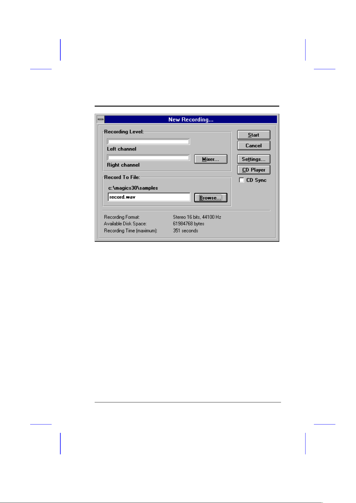
2. Choose Record on the Toolbar. The New Recording dialog box
appears.
5-12 User’s Guide
Page 99
Audio Chip
3. Make sure that the settings in the dialog box are properly
specified.
· Check the record level in the Recording Level group box.
Adjust the level using the Mixer button (if necessary).
· Check the path and the filename created in the Record to
File group box. Change the filename and the directory
using the Browse button.
· Check the recording format as shown at the bottom of the
dialog box. To change the format, select the Settings
button.
· Check your system’s storage space as shown at the bottom
of the dialog box. Make sure that you have sufficient
storage for your file.
User’s Guide 5-13
Page 100

Audio Chip
4. Choose Start.
If you have a CD-ROM drive installed,
select the CD Player button to activate the
CD player. Also, select the CD Sync
check box to synchronize the start of the
recording and playback of audio CDs.
To record over an existing file:
1. Activate the file you want to record over.
2. Choose Record on the Toolbar. The Record Over dialog box
appears.
3. Choose Start.
Saving Wave Files
To save a wave file:
5-14 User’s Guide
 Loading...