

Page 1

ISDN Router
User’s Manual
Page 2

Table of Content
1. INTRODUCTION....................................................................................................................................................... 4
1.1 FEATURES................................................................................................................................................................. 5
2. OUTLET DESCRIPTION.......................................................................................................................................... 8
2.1 FRONT PANEL............................................................................................................................................................ 8
2.2 REAR PANEL ............................................................................................................................................................. 9
2.3 BOTTOM PLATE....................................................................................................................................................... 12
2.4 ACCESSORY............................................................................................................................................................. 12
3 CONNECTION METHOD.......................................................................................................................................13
4. INSTALLING THE ROUTER.................................................................................................................................14
5. ROUTER COMMAND LINE INTERFACE.......................................................................................................... 18
5.1 QUICK CONFIGURATION TO INTERNET ....................................................................................................................21
5.2 COMPLETE COMMAND SET ..................................................................................................................................... 23
5.3 CONFIGURE ETHERNET INTERFACE......................................................................................................................... 23
5.4 CONFIGURE ISDN INTERFACE, AUTHENTICATION AND VJ COMPRESSION.............................................................. 24
5.4.1 Configure Dial-In and Call Back Function........................................................................................... 25
5.4.2 Configure DOD (Dial On Demand) ..................................................................................................... 26
5.4.3 Configure BOD (Bandwidth On Demand)........................................................................................... 27
5.4.4 Configure ISDN Switch Type and Directory Number.........................................................................28
5.5 CONFIGURE GENERAL SETUP.................................................................................................................................. 28
5.6 CONFIGURE IP ROUTING TABLE.............................................................................................................................. 30
5.6.1 CONFIGURE STATIC ROUTING................................................................................................................ 30
5.6.2 Configure Dynamic Routing.................................................................................................................31
5.7 CONFIGURE FIREWALL AND NETWORK ADDRESS TRANSLATION............................................................................ 32
5.8 CONNECTING/DISCONNECTING ISDN.....................................................................................................................35
5.9 SAVE AND DELETE CONFIGURATION....................................................................................................................... 35
5.10 SHOW CONFIGURATION......................................................................................................................................... 36
5.11 ROUTER COMMAND EXAMPLES ............................................................................................................................ 37
5.12 ROUTER TEST SETUP PROCEDURE......................................................................................................................... 39
5.13 ROUTER TEST SETUP PROCEDURE WITH NAT....................................................................................................... 42
5.14 SETUP LAN-TO-LAN CONNECTION......................................................................................................................45
6. AT COMMAND......................................................................................................................................................... 47
ISDN Router Manual V.1.1
1
Page 3

6.1 DESCRIPTION OF AT COMMAND ............................................................................................................................47
6.1.1 AT Command...................................................................................................................................... 47
6.2 AT COMMAND........................................................................................................................................................ 49
6.2.1 AT Command Overview ..................................................................................................................... 49
6.2.2 AT Command List............................................................................................................................... 51
6.3 S REGISTER............................................................................................................................................................ 56
6.4 RESULT CODE ........................................................................................................................................................ 57
7. SETTING UP INF FILE............................................................................................................................................ 58
7.1 USING DIAL-UP NETWORK .................................................................................................................................... 61
8. GRAPHIC USER INTERFACE CONFIGURATION MANAGER......................................................................64
9. EASY SETUP FROM TELEPHONE KEYPAD..................................................................................................... 65
9.1 ENTERING PROGRAMMING MODE ...........................................................................................................................67
9.2 SETUP CONFIGURATION .......................................................................................................................................... 67
9.3 STORING THE SETTING............................................................................................................................................ 67
9.4 INSPECT THE SETTING............................................................................................................................................. 68
9.5 LCD DISPLAY MESSAGE...................................................................................................................................69
10. RE-FLASH THE NEW SOFTWARE.................................................................................................................... 70
10.1 NORMAL RE-FLASH PROCEDURE .......................................................................................................................... 70
11. TROUBLE SHOOTING......................................................................................................................................... 72
11.1 POWER SWITCH ON BUT PW LED IS NOT LIT........................................................................................................72
11.2 ER LED NOT LIT, AND THE ROUTER DOES NOT CONNECT..................................................................................... 72
11.3 TYPE “AT’, BUT THE ROUTER DOES NOT RESPOND WITH “OK’ MESSAGE .............................................................73
11.4 USING ATD TO CALL, BUT “NOCARRIER” IS DISPLAYED ON THE SCREEN........................................................ 74
11.5 CAN NOT ACCEPT INCOMING DATA CALL............................................................................................................. 75
11.6 FAIL TO ACCEPT INCOMING VOICE CALL.............................................................................................................. 76
11.7 CAN NOT USE CALL WAITING .............................................................................................................................. 77
11.8 SELF DIAGNOSIS.................................................................................................................................................... 78
12. SUPPLEMENTARY SERVICE FUNCTION.......................................................................................................79
12.1 DEFINITION ...........................................................................................................................................................79
12.2 MAKING AN OUTGOING CALL.............................................................................................................................. 80
12.3 MAKING AN INCOMING CALL............................................................................................................................... 81
12.4 MAKING AN INNER COMMUNICATION.................................................................................................................. 81
12.5 MAKING A LOCAL CALL WAITING....................................................................................................................... 81
ISDN Router Manual V.1.1
2
Page 4

12.6 MAKING A LOCAL CALL TRANSFER...................................................................................................................... 81
12.7 MAKING A LOCAL 3 PARTY CONFERENCE ............................................................................................................ 82
12.8 MAKING A LOCAL CALL FORWARDING................................................................................................................. 83
APPENDIX.....................................................................................................................................................................85
APPENDIX 1 DCE 9PIN D TYPE CONNECTOR DEFINITION........................................................................................ 85
APPENDIX 2 DISCONNECT CAUSE INDICATION......................................................................................................... 86
APPENDIX 3 SPECIFICATION .....................................................................................................................................87
ISDN Router Manual V.1.1
3
Page 5

1. Introduction
The ISDN (Integrated Service Digital Network) SOHO (Small Office Home Office) router is a
network product used to connect LAN to the Internet or to the head office through the high-speed
ISDN interface.
The advanced all-in-one design can ease a your installation for connecting a your Ethernet card
directly to the built-in hub port. Apart from the flexible router capability, it also provides full ISDN
TA functions for both data and voice communication. This design supports two analog ports for the
normal telephony application, allowing you to connect the regular telephone, fax machine, and
answering machine to the analog port to make an outgoing call or receive an incoming call. One
data port allows you to configure the router and connects outside ISDN device with data protocol
like V.110, V.120. The SOHO router also features an optional soft-fax function to simulate the
G3/G4 fax operation with PC to save the fax investment.
The router provides a Windows based easy configuration software to help out with the entire
relative configuration. You can easily click the mouse to select the settings. The router also comes
with an easy-setup mechanism from telephone keypad, enabling some of the configuration being
made through the regular telephone while checking the setting on the LCD panel.
The router supports BACP (Bandwidth Allocation Control Protocol)/ BOD (Bandwidth On
Demand) function which allows you to utilize the 128k ISDN bandwidth with a demanded manner.
When using the ML-PPP (Multi-Link PPP) connection, the entire 128k ISDN bandwidth is used
for accessing the Internet. With the aid of BOD, the router automatically releases one B channel as
soon as the phone receiver is picked up to make a call. It also tells router to returns to two B
channels for 128k ML-PPP connection when the phone receiver hung up. Upon an incoming call,
the router releases one B channel automatically and return to 128k ML-PPP connection as soon as
one gets off the phone.
The RIP (Routing Information Protocol) and DHCP (Dynamic Host Configuration Protocol) save
the network administrator a lot of effort on maintaining the entire relative network configuration.
E-mail sharing capability allows a connected LAN user to have the e-mail address distinguished,
while using the same e-mail address in ISP. The router will automatically distinguish the
transmitting/receiving mail to the designated person.
The router complies with ITU-T Q.921, and Q.931 for D channel protocol as well as provides
switching type selections for different countries. The router is equipped with flash EPROM for
future software upgrade through the data port.
ISDN Router Manual V.1.1
4
Page 6

1.1 Features
• Integrated all-in-one design for ISDN TA, NT1, hub, and router
It saves the expense on purchasing NT1 and hub device. Moreover, it eases the cable
connection and separates installation for the all-in-one design.
• One page quick configuration guidance
With the one-page quick configuration guidance, the end-user can install the router following
the step-by-step procedure and operate the router easily. Even the first-time user will have no
problem following the instruction to link to ISP (Internet Service Provider) and connect the
LAN correctly.
• On line remote maintenance
The router has a built-in a remote maintenance facility to help the end-user to troubleshoot.
The maintenance center can dial in remotely to diagnose and correct the wrong settings to fasten
connection to the ISDN network.
• Two analog ports supported for normal telephony application
It allows you to use regular telephone to make outgoing/incoming calls just like using a regular
telephone at home.
• Support BACP/BOD for dynamic bandwidth demand
With the voice priority first mechanism at work, it fully utilizes the 128K ISDN bandwidth to
ensure no voice calls missing. Under ML-PPP connection, the router can automatically release
one B channel for voice communication and return to 128K bandwidth when the receiver hung
up.
• Dial On Demand to save communication cost
Dial-On-Demand activates the PPP link when needed. Whenever there is an outgoing packet,
the router makes an outgoing connection automatically and disconnects the PPP link after the
system is idle for specific amount of time (configured by the user) to save cost on
communication.
• Dial-in and call back security
The dial-in function enables you to remotely access your LAN. The call-back security can
protect your LAN from any attempts of illegal accessing.
ISDN Router Manual V.1.1
5
Page 7

• Two standard RJ45 modular jack for S/T interface
The built-in two standard RJ45 S/T ports are for constructing a multi-drop connection to share
the same ISDN line.
• LCD display panel and LED indication
They provide visual display for you to monitor every status and message during the whole
connection process. You can see the calling party number (Caller-ID) immediately on the LCD
whenever the router receiving an incoming voice or data call. You can also check all of the
settings on the LCD panel.
• Battery backup utility
It automatically switches over to battery mode when local power source is off. In the battery
backup mode, you can still make outgoing calls or receive incoming calls.
• DHCP (Dynamic Host Configuration Protocol) function supported
DHCP allows the router to assign the IP address dynamically for the connected host on the LAN
that supports DHCP client. This saves the network administrator’s effort in maintaining the IP
address on the LAN and makes the IP address reusable.
• NAT (Network Address Translation) function supported
The NAT function converts all inside IP addresses to one single outside IP address. By doing so
you can translate all of the connected workstations’ IP addresses to single one and pay only one
IP account cost to the ISP.
• E-mail sharing
The e-mail sharing capability allows you to pay and use only one e-mail address account for all
of the users connected to the router. The router automatically receives and allocates mails to
designated mail users.
• RIP (Routing Information Protocol) function supported
With RIP the router can exchange renewed routing information with other routers automatically.
This help saves expense and manual labor on maintaining the routing table.
• Firewall security built-in
The built-in firewall can stop unauthorized communication between an organization’s intranet
and the outside, preventing the system being hacked from the outside.
ISDN Router Manual V.1.1
6
Page 8

• Win 95/98/NT configure software
The Windows based configuration software enables you to setup the router easily by clicking
the around under Windows OS.
• Flexible ISDN TA function supported
The router provides ITU-T V.110, V.120, X.75, and X.25 on D protocol to let you connect with
other ISDN devices through these useful data protocols. You can use any terminal program like
HyperTerminal and make a data connection with other ISDN TA using the above protocol.
• Soft-Fax function
The router can bundle with the RVSCOM package (an end-user needs to order this RVSCOM
CD) running on PC to simulate a G3/G4 fax machine. With this function you can transmit
/receive G3/G4 fax in Word, Excel, Power Point format automatically. This not only saves the
budget on a fax machine but also eases the management of the fax files directly from PC.
• Local supplementary service
The router can simulate mini-PBX function for voice application such as inner intercom, call
waiting, call transfer, call forwarding, and three party conference all locally without doing it via
the internet.
• Easy setup from telephone keypad
The router also provides a quick setup mechanism through regular telephone. The end-user
may press some sequence code to enter the programming mode and setup some configuration
directly from the telephone keypad while checking the result displayed on the LCD panel.
ISDN Router Manual V.1.1
7
Page 9
2. Outlet Description
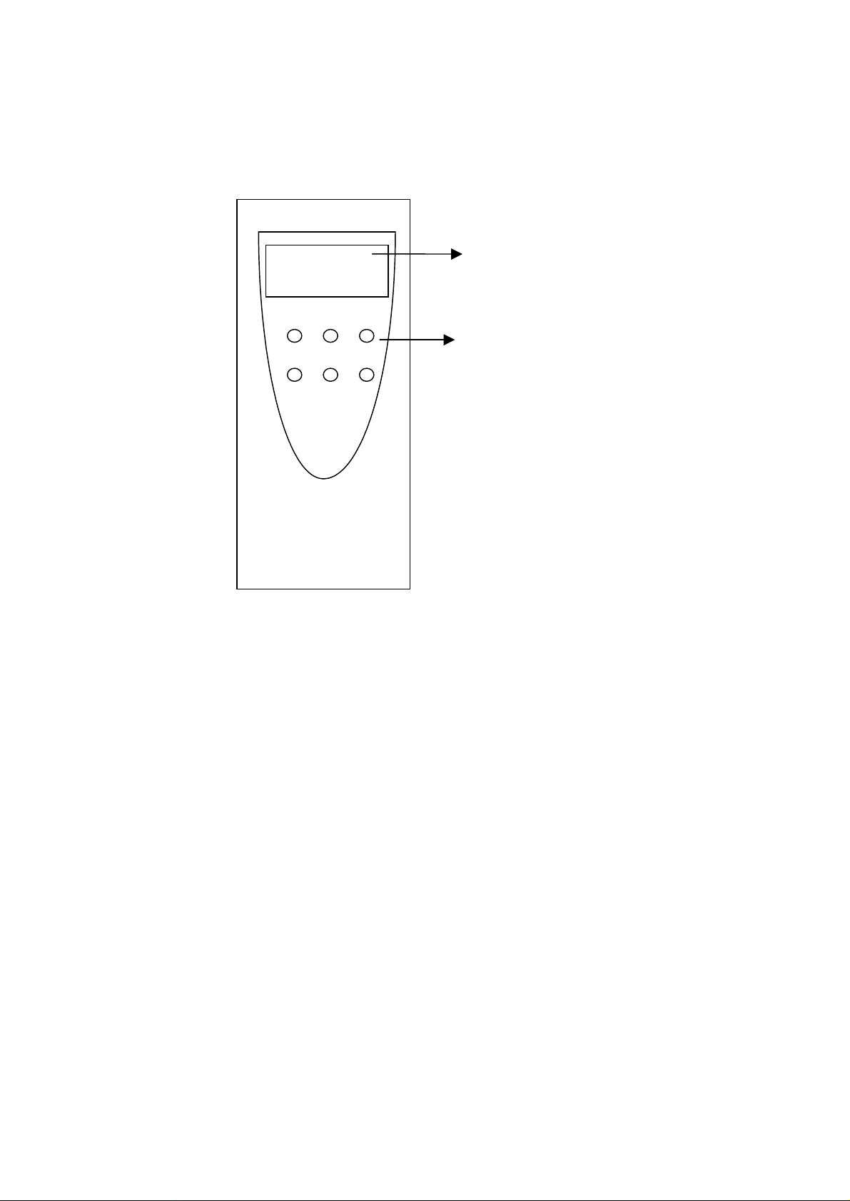
2.1 Front Panel
PW ER DA
B1 B2 LAN
LCD panel
LED indicator
1.PW – Power on/off indication
2.ER – Router had connected to the DTE (PC) device
3.DA – Flashing: Router is transmitting/receiving data from to DTE
4.B1 – ISDN B1 channel is busy in use
5.B2 – ISDN B2 channel is busy in use
6.LAN – Indicating the Ethernet device has been connected to the router
7.LCD –2 x 10 characters display all router’s statuses information
Note : The LCD panel is an optional item for purchase. Some model may not come with a LCD panel.
8.Icon –indicates TELA and B hook status and B channel usage
A – TEL A is off-hook, making an outgoing call or answering
B – TEL B is off-hook, making an outgoing call or answering
F – Call forwarding in operation
B1– B1 channel is busy
B2– B2 channel is busy
ISDN Router Manual V.1.1
8
Page 10
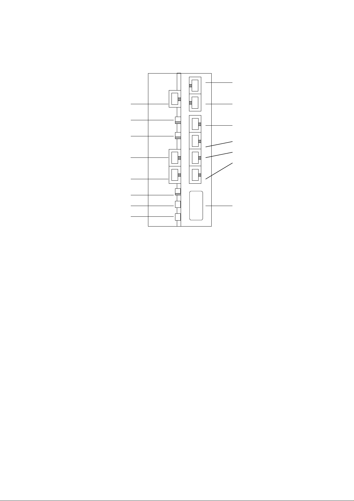
2.2 Rear Panel
ISDN
TEL-B
U-interface
U REV S.W.
U ON/OFF S.W.
ST2
ST1
T.R S.W.
FG
AC
TEL-A
Ethernet 10BaseT
4
3
2
1
DTE (RS232)
1. TEL-B, TEL-A
You can plug in the regular telephone, fax machine, or answering machine to these ports.
The ISDN technology allows you to connect two telephones and make outgoing/incoming call sat
the same time. Please make certain to use the right RJ11 cable to connect the telephone.
2. Ethernet 10BaseT 4,3,2,1
The router provides four IEEE802.3 Ethernet 10BaseT hub ports. You can connect to your PC
with LAN card directly into one of these four ports to construct a fully network installation with
router. Please make certain to use the right RJ45 cable to connect the LAN card.
If you wished to connect with a hub to expand the 10BaseT ports to allow more users to share
the router, make certain the cable connecting the hub and the router is the right one. The
cable for LAN card-router and hub-router is pin-reversed.
3. DTE
Connect your DTE device to this DTE port. Mostly you would connect your PC’s RS232 port
through the attached RS232 cable to the DTE port. Via this connection you can use any of the
terminal programs like HyperTerminal to issue valid AT command or configuration command to
the router. You can also use ATD command to connect router with other ISDN TA under V.110,
V.120 protocol.
ISDN Router Manual V.1.1
9
Page 11

4. ISDN U-interface
Connect the U-interface with the attached RJ11 cable to the ISDN outlet installed by the local
PTT. Please consult your local PTT office for help in connecting the ISDN outlet .
5. U REV S.W.
Indicating the router had synchronized with the ISDN network. The LED blinks when the router
tries to synchronize with the ISDN network. When the synchronization is reached, the LED
stays still in on or off mode. Please note that the router has to be synchronize with the ISDN
network to establish external communication.
6. U ON/OFF S.W.
The ISDN technology allows up to 8 ISDN S/T devices to connect all together in the same S/T
bus to construct a multi-drop connection and let 8 S/T device sharing the same U-line. You can
set U OFF and connect ST2/ST1 port to other S/T bus to make multi-drop connection.
In case that your local PTT has provided a NT1 box already (one side connected to the ISDN
network with U interface, the other connected to user’s device with S/T interface), you just need
to connect the router with ST2/ST1 to the NT1’s S/T port. Please make certain the U switch is
set to OFF prior connection.
7. ST2,ST1
Providing two S/T ports to be connected by other ISDN S/T phone, Terminal Adapter for
constructing a multi-drop connection for sharing the same ISDN line resource. The S/T ports
should be connected with a right RJ45 cable.
8. T.R. S.W.
ON : set 100 ohm terminating resistance in S/T port (ST2/ST1)
OFF : set none
For ISDN multi-drop connection, it is suggested that one should make impedance match between
the NT1 and the farthest S/T device. If the NT1 was set to 100 ohm in its S/T port, (most of the
NT1 will set 100 ohm) then the farthest S/T device should be set to 100 ohm too to get impedance
match while all other S/T devices should not be set. If the NT1 was not set the 100 ohm
impedance, none of the S/T devices should be set the 100 ohm impedance.
9. Frame Ground
Connecting to the house’s safety ground pin for safety.
ISDN Router Manual V.1.1
10
Page 12

10. AC power
Connecting to AC power source directly. The router has a full range of internal built-in switching
power supply to enable a direct connection with 110VAC or 230VAC.
ISDN Router Manual V.1.1
11
Page 13

2.3 Bottom Plate
Battery Backup
The battery backup solution a supporting device when there’s a sudden power loss. A total of 6 AA
batteries are required to backup the router. Please make sure that all 6 batteries are placed
correctly.
Battery Mode Operation
In case of sudden loss of power, the router switches to battery backup mode automatically. ( with all
6 batteries correctly installed) Please note that in the power backup mode, only the analog ports
can function normally.
In battery backup mode, with the brand new regular batteries, the router can last at least 3 hours in
standby or can run one analog port continuously for about 2 hours.
Changing Batteries
Please check the battery if the router does not function normally in battery backup mode. If the
battery is low, please replace them. A user is suggested to replace all 6 batteries together.
2.4 Accessory
The accessory may be different in different markets or by customer requirements. Please check
with the local dealer for accessory information.
♦ router main unit
♦ RS232 cable
♦ RJ11 cable for connecting to ISDN U-line
♦ Diskette or CD ROM (including Win NT/95/98 configure software and INF file)
♦ User‘s manual
When opening the package, make sure it contains all the above items in good order. If any of
the accessories was damaged, please contact your dealer immediately.
ISDN Router Manual V.1.1
12
Page 14
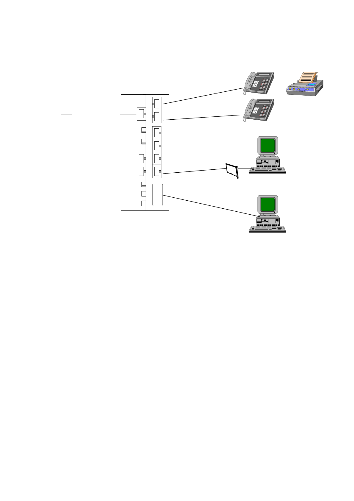
3 Connection Method
To ISDN
or
TEL-B (RJ11)
U-Line (RJ11)
Ethernet 10BaseT (RJ45)
TEL-A (RJ11)
Ethernet card
DTE (RS232)
1. Connecting telephone, fax, or answering machine
l Use the right RJ11 cable to connect the telephone, fax or answering machine into TEL-B or
TEL-A port.
2. Connecting Ethernet card
l Use the right RJ45 cable to connect the Ethernet card (the Ethernet card was installed inside
a your PC) into any of the Ethernet 4/3/2/1 ports.
3. Connecting console
l Use the right RS232 cable to connect the PC into DTE port.
4. Connecting ISDN line
l Use the right RJ11 cable to connect the ISDN U-line to U port.
5. Connecting power
l Connect the AC power directly to the power source.
6. Start operation
l After finishing the above procedure, you can now start operating the router.
ISDN Router Manual V.1.1
13
Page 15
4. Installing the Router
4.1 Entering AT command mode
To operate the router, you need to set up the necessary configuration. Follow these steps to setup
the router.
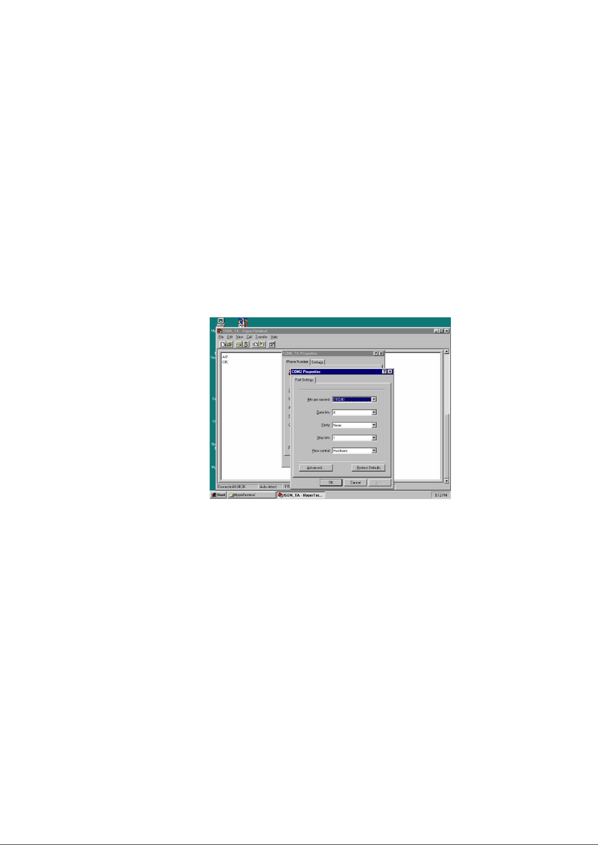
(1) Connect your PC with RS232 cable to router’s DTE port.
(2) Use any terminal programs that support ASCII file transfer function, such as HyperTerminal.
(3) Enter into the terminal mode and make sure that the terminal program had set the following
configuration.
l 115200 baud rate
l 8 data bit, no parity, 1 stop bit (8N1)
l Hardware flow control
(4) Type AT and check router responded with “OK”. If the router responded “OK”, meaning that
you have successfully entered into AT command mode. Otherwise please check the RS232
cable to see if it’s connected ok, or check if the COM port setting was correctly.
4.2 Setting ISDN telephone number
Similar with the regular PSTN (Public Switch Telephone Network) line, it has an unique
telephone number. When you apply the ISDN line from PTT or service provider, you will be
assigned an ISDN line number. But due to 2B+D technology, the ISDN allows you to have
two numbers in one ISDN line. The local PTT or service provider may assign two different
numbers to you. One is the line-number ( registered as the number of this ISDN line), the
other one is the DDI (Direct Dial In) number (allowing someone to call in directly using this
DDI number). Therefore you can apply two different numbers for both analog ports of TEL-A
and TEL-B. If you apply only one set of number (line number), the router will ring TEL-A and
ISDN Router Manual V.1.1
14
Page 16

TEL-B alternatively upon an incoming call. You may setup to ring TEL-A only or TEL-B only
by AT$CG (global call select setting) and AT$CP (receive priority setting). Telephone
numbers of TEL-A and TEL-B can also be distinguished by sub-addressing.
To setup the telephone number for TEL-A and TEL-B, you issue the following AT command.
l Setup line number to TEL-A
AT!D1 = 3930219 (where 3930219 is the applied line number from PTT)
l Setup telephone number to TEL-B
AT!D2 = 3930217 (where 3930217 is the applied DDI number from PTT)
l Setup SPID to TEL-A
AT!S1 = 50839302190101 (where 50839302190101 is the SPID number from PTT)
l Setup SPID to TEL-B
AT!S2 = 50839302170101 (where 50839302170101 is the SPID number from PTT)
l Setup data port number
AT%N = 3930217 (assign the telephone number to data port)
Note: SPID is necessary only for the Northern American users that connect with AT&T 5ESS or Nortel
DMS100 switch type or NI1 switch type.
4.3 Setting ISDN switch
To make your router work and connect to the ISDN network, you need to setup correct switch type
with your local ISDN exchange. Different countries may have different ISDN switch types.
Therefore you should consult your local PTT to setup the right switch type.
Type AT!Wn to Setup switch type:
n = 0 AT&T 5ESS
n = 1 Nortel DMS-100
n = 4 European NET3
n = 5 Australia switch
n = 6 Japan INS64 switch
n = 7 NI-1
Make an incoming or outgoing call to test the setting.
Note: if the switching type is setup wrong, the router may not place incoming or outgoing calls.
ISDN Router Manual V.1.1
15
Page 17

4.4 Quick Configuration
To minimize the configuration setting and connect into the ISDN network for voice and
Internet access. The router provides a one-page quick configuration procedure to ease all of
the necessary setting. Follow the this quick configuration to enable you to connect to the
Internet within a couple of minutes. Please see Chapter 5 for quick configuration guidance.
4.5 User Interface
One of the strong features of the SOHO router is that comes with the ISDN TA functionality. Hence
the router user interface also incorporates the AT command interface. This allows users who are
already familiar with TA command to continue using the TA functions of the router. We call this
interface the AT Command Interface.
The user interface that is used to operate the routing (not the TA) functionality of the SOHO router
is called the Command Line Interface (CLI). The CLI user interface is designed for the
sophisticated user to setup the router configuration more directly.
Basically, with just the AT Command Interface and the Router, the CLI user can drive SOHO to its
full capability. However, in order to make the router easy to configure and setup, we added a menu
driven interface so the user doesn't have to learn all the AT commands and the CLI commands to
operate the router.
This user interface contains:
* AT Command Interface
* Router Command Line Interface
When the unit first powered on, the AT Command Interface is activated. To display a list of
available commands to configure the ISDN interface, enter the following command:
ATI0
The following menu appears,
• ISDN interface can also be configured in Router CLI interface.
ISDN Router Manual V.1.1
16
Page 18

***FREQUENTLY USED AT COMMANDS:***
ATI0: Display useful AT commands
ATI1: Display modem configuration
AT!Dn = str: Set directory number n=1 or 2
AT!Sn = str: Set SPID number n=1 or 2
AT!Wn: Set switch type AT!Pn: Set connection protocol
n = 0 5ESS n = 0 Clear channel
n = 1 DMS-100 n = 1 V.110
n = 2 1TR6 n = 3 PPP
n = 3 VN3/4 n = 4 MLPPP
n = 4 NET3
n = 5 Australia switch
n = 6 Japan switch
n = 7 NI-1
AT&W: Save current configuration
ATZ: Reset modem to activate saved configuration
ATD tel-number: Dial a number
OK
ISDN Router Manual V.1.1
17
Page 19

5. Router Command Line Interface
To access the Router Command Line Interface (CLI), enter the following command:
AT:
The SOHO router then presents a log on banner where you type in your ID and password to log on.
If logged on successful, the user is presented with the Router CLI Interface prompt that looks like
this.
at:
OK
Router Command Line Interface
Console Login: admin
Please note: The default Console Login is admin and Password is also admin.
As its name implied, the Command Line Interface is an interface where every command must be
entered in a single line.
A command is a sequence of tokens or words that are separated by spaces or tabs and terminated by
a carriage return. Each token represents as a sub-menu or level, and a choice of the next token is
available at every level. To exit CLI and return to AT command interface, type exit then the router
will return to the AT command mode.
Once at the command prompt, the user can get the available commands at that level by entering ? or
help for all the command with a description of each command that looks like this:
ISDN Router Manual V.1.1
18
Page 20

CLI> ?
? config connect date exit flash help hwinfo
log menu ping reset show trace version
CLI> help
? -- Display menu options
config -- Change the configuration
connect -- Start a PPP connection
date -- Set the date
exit -- Exit the current session
flash -- Operations on the flash-based file system
help -- Display this help
hwinfo -- Display hardware information
log -- Operations on the log
Entering Command
There are two ways to enter commands to configure the router.
1. Enter multiple commands at the top level and terminate with a carriage return.
2. Enter a single command (one token) at the top level followed by a carriage return and goes
down one level of menu at a time until the desired command is completed. At each level, the
user can type help or ? to get a complete list of command for that particular level.
Example:
To configure the ethernet interface with the IP address 192.168.70.1 and with the subnet mask of
255.255.255.0
Method 1:
CLI> config interface ether ip address 192.168.70.1 255.255.255.0
CLI>
ISDN Router Manual V.1.1
19
Page 21

Method 2:
Note: The user can type the remaining of the command at anytime in Method 2 in order to
complete the entire command sequence.
Tips: Some of the commands don’t need to be type all out. The number of
character(s) required for that command depends on if there is a similar
command (spelling) to it.
CLI> config
CLI\config> interface ether
CLI\config\intf-ether> ?
? help ip peer ppp show switch quit
CLI\config\intf-ether> ip
USAGE: ip address <IP address> <netmask>
USAGE: ip mtu <mtu size in bytes>
CLI\config\intf-ether> ip address 192.168.70.1 255.255.255.0
For example:
1. help : can be entered as “he”
2. quit : can be entered as “q”
3. config interface ether : can be entered as ”conf in ether”
Use up/down arrow key to recall your previous commands and backspace/ backward /forward
arrow key to edit your commands.
ISDN Router Manual V.1.1
20
Page 22

5.1 Quick Configuration to Internet
Before you can connect your LAN to the Internet you must obtain an ISDN internet account
from your local Internet Service Provider (ISP). Your local ISP should provide you the
following information when you register with them:
1. Account user ID and password
2. Dial in telephone number, you may need to have two phone numbers if you wish to
run Multilink Point-to-Point Protocol (ie. MLPPP).
When the above information is ready, you can configure the router with it to connect your LAN
to the internet. Configuring the router is very easy with the quick config "qconfig" command.
The router will prompt you to enter the ethernet IP address for the router, the ISP user ID,
password, and the ISP phone number. When you’re done typing the information, the router will
return you to the CLI prompt. At this point we recommend you to save all your configuration
by entering the command:
> config save
Now you are ready to launch the connection to the internet. To do this please use the connect
command:
> connect <user id>
The router shall attempt to connect you with your local ISP. If succeed you should see a
message indicating that connection with the internet is successful. At this point, depending on
weather your LAN has private IP addresses or not, you may want to configure NAT (Network
Address Translation) to translate all of your private IP addresses to the public IP address. This
can be done with the this command:
> config ip nat add isdn
Simple as that! Now you can start surfing.
Quick configuration is designed to help users with limited network knowledge to setup the SOHO
router and connect to the internet with ease within the least amount of time.
To start quick configuration for the internet, enter qconfig at the command prompt. An example of
the quick configuration screen is displayed as shown below.
ISDN Router Manual V.1.1
21
Page 23

Quick Configuration Setup (ESC, ESC to exit)
-------------------------------IP address of this unit's LAN port : 123.97.35.7
IP mask of this unit's LAN port : 255.255.255.0
Switch Type (etsi, ni1, ntt) : ni1
DN1 : 3930219
DN2 : 3930237
SPID1 : 50839302190101
SPID2 : 50839302370101
Phone number of the remote unit : 8398111
User's ID to log into remote site : john
User's password to log into remote site : master
At this point the unit is configured. It is suggested to save the configuration immediately to keep it
in the EPROM. The user can connect and start surfing the internet by entering the following
command.
CLI> connect john (user entered)
CLI> B1 channel up (automatic display by router)
CLI> add net (automatic display by router)
By using qconfig you can change the telephone number and connect to any specified destination or
ISP manually. For detailed significance of the above command, please see the following command
set.
Note: The quick configuration can only be executed in CLI mode.
ISDN Router Manual V.1.1
22
Page 24

5.2 Complete Command Set
The commands can be loosely grouped into two categories: show and config. The show will display
a category of information and config will configure that category.
The following command is available at all level in the menu.
? Display all the available commands for that level.
help Display all the available commands for that level with a description for
each.
quit Go up one level toward the top, that is the root.
5.3 Configure Ethernet Interface
config interface ether ip address <IP address> <netmask>
Configure the ethernet interface with the <IP address> and the <netmask>
Every machine connected to the TCP/IP network must have an unique IP address. The IP
address is always presented by dotted decimal format (four 8-bit number between 0 to 255
separated by periods), e.g. 123.97.35.7. The IP address was defined by the IANA (Internet
Assigned Numbers Authority). The IANA had reserved the following IP address for the private
network, therefore it is recommended that you follow the defined rules.
10.0.0.0 - 10.255.255.255
172.16.0.0 - 172.31.255.255
192.168.0.0 - 192.168.255.255
An IP address consists of network ID and host ID. The netmask is used to extract the network ID from the
dotted decimal notation. The router will automatically calculate the network ID from the IP address and
netmask. This command configures the IP address and network mask for the LAN of this router.
ISDN Router Manual V.1.1
23
Page 25

config interface ether physical show
Display the current physical address of the ethernet
The physical ethernet address is a 48-bit unique address preset during manufacturing. The
physical address is the lowest hardware ID for that ethernet device and was assigned by the
manufacturer. Use this command to check the physical ethernet address.
config interface ether show
Display the current settings of the ethernet interface
5.4 Configure ISDN Interface, Authentication and VJ compression
config interface isdn ip address <IP address> <netmask>
Configure the ISDN interface with the IP address <IP address> and the netmask <netmask>
Like the IP address and netmask configured for the LAN interface, sometimes you need to setup
the IP address and netmask for the WAN/ISDN (Wide Area Network) interface for LAN-toLAN application or static IP address requested by the ISP (Internet Service Provider) site. Under
normal situation you don’t need to setup the WAN IP address as most of the ISP will
assign the IP address to the router dynamically.
config interface isdn ppp authen <pap,chap,both>
Configure the authentication protocol when the PPP or ML-PPP connection is established.
When establishing the connection with the remote site under PPP or ML-PPP protocol, it is
necessary to specify the authentication mechanism by both parties. If pap (Password
Authentication Protocol) is selected the router will use PAP only, the PAP will send username and
password in plain text for authentication. If chap (Challenge Handshake Authentication
Protocol) is selected the router will use CHAP only, the CHAP will scrambles the password
And sent for authentication. If both is selected, the router will try PAP when remote site
requested PAP or it will try CHAP when remote site requested CHAP.
config interface isdn ppp ipcp vjcompression
Turn on the VJ (Van Jacobson) compression function for IP header.
The VJ compression is a mechanism to compress the IP header of a packet during transmission
ISDN Router Manual V.1.1
24
Page 26

by reducing the size of IP header for speeding up transmission performance. The remote site
must also support the VJ compression, otherwise the router won’t compress the IP header if the
remote site did not support the VJ compression.
It is suggested to turn on VJ compression.
config interface isdn ppp ipcp none
Turn off the VJ compression function.
5.4.1 Configure Dial-In and Call Back Function
config interface isdn ip pool <initial_ip_addr>
Configure the IP address assignment of the PPP connection.
This command is used for the remote dial-in function. The router can accept the remote user to
dial in with PPP connection and assign the IP address for the remote site if the remote site did not
setup its own IP address. By the remote dial-in function the remote user can access the LAN
resource just like it is connected the router locally. The router will check both the username and
password for valid access.
config interface isdn ppp add user <username> password <password> maxchan {1,2} callback
{yes,no} phone <phone#1> <phone#2>
Configure the user account for PPP or ML-PPP connection.
The router allows you to store multiple user accounts for both dialing in and out purpose. For
example, you can store different usernames and passwords for corresponding ISP when dialing
out. Also if the router received an incoming call for remote dial in, it will check the valid
username and password based on the stored User Account Table. The router will compare if the
dial-in username and password was defined in the User Account Table. If it is a valid account,
the router will accept the call and connect, after that the remote site can access the LAN resource
through the router. If the user account is invalid, the router will disconnect immediately.
The maxchan specifies to use 1-B channel for PPP connection or 2-B channel for ML-PPP
connection. For 1-B channel (64k, PPP) connection you need to setup phone#1, the router will
make an outgoing connection based on phone#1. For 2-B channel (128K, ML-PPP) connection
ISDN Router Manual V.1.1
25
Page 27

you need to setup phone#1 and phone#2, the router will make an outgoing connection by dialing
phone#1 and phone#2. If under ML-PPP connection but just setup phone#1 then the router will
make an outgoing connection by dialing the phone#1 twice.
If callback is set to ‘yes’, then after the router checks valid dial-in username and password, it
disconnects immediately. It also calls back to the remote site based on the remote site’s
telephone number. The router supports MS-CBCP (MicroSoft Call Back Control Protocol)
therefore when the remote user enables MS-CBCP function for call back, the router will
automatically disconnect and call back the remote site.
config interface isdn ppp set user <username> password <password> maxchan {1,2}
callback {yes,no} phone <phone#1> <phone#2>
Modify the current password and relative settings for the specified username in the User
Account Table.
config interface isdn ppp delete user <username>
Delete the current user account entry.
This command will delete all of the setting in the User Account Table for the specified
username. After this command the deleted username become no longer available to the router.
5.4.2 Configure DOD (Dial On Demand)
config interface isdn ppp dod {on, off} user <username> <idle_timer>
Set dial-on-demand to remote user.
If dod is ‘on’ for the specified username, whenever there is an outgoing packet, the router
will search the first username which enabled dod ‘on’ in the User Account Table, and make an
outgoing connection automatically. If there are several usernames enabled dod ‘on’ in the User
Account Table, the router will always search sequentially the first one which labeled dod ‘on’
and make an outgoing call based on that telephone number.
The idle_timer (unit: second) defines the idle time for disconnection. If there’s no packet
transmission occurred within the defined idle time, the router will disconnect the link
automatically to save the communication cost and to prevent any mistake for disconnecting.
ISDN Router Manual V.1.1
26
Page 28

5.4.3 Configure BOD (Bandwidth On Demand)
config interface isdn ppp bod incre <increase> decre <decrease>
Set bandwidth-on-demand to router. By default BOD is enabled on the router.
Bandwidth on Demand (BOD) is a feature that allows the second telephone line connection
to the internet to be made only if there is enough traffic between the router and the internet which exceeds the capacity of the first telephone line connection. Since it is likely that there
are many periods of little activity where there may be no data to be sent between the router
and the internet, this feature helps the user to save a considerable amount on connection with
the ISDN phone line.
To enable BOD (throughput BOD) enter the following command at the CLI prompt:
> config int isdn ppp bod incre 80 decre 20
This tells the router that it should bring up the second telephone line connection when the
traffic level on the first telephone line exceeds 80% of its capacity. At the same time if the
traffic level on the first telephone line connection drops below 20% of its capacity, the
second telephone line connection should be terminated.
To disable BOD, i.e., if you don’t want the second telephone line connection to be brought
down even if there is no traffic on the line, enter the following command:
> config int isdn ppp bod decre 0
The other BOD function (resource BOD) acts as voice priority first manner. When the router
connected by 2B channels (ML-PPP), if you want to place an outgoing voice call, the router
will automatically drop 1B channel for your dialing to the destination. As soon as you hang up,
the router will automatically connect the second B channel again to return ML-PPP connection.
The same mechanism works also under ML-PPP connection: If someone made a voice call to
the router, it will drop 1B channel to accept the call and ring TEL-A or TEL-B. As soon as the user
hang up, the router will again connect the second B channel and back to ML-PPP.
ISDN Router Manual V.1.1
27
Page 29

5.4.4 Configure ISDN Switch Type and Directory Number
config interface isdn switch type {etsi,ntt,ni1}
Configure the switch type for an ISDN interface
Check with your local PTT to setup proper ISDN switch type otherwise the router may not
operate correctly.
etsi : European DSS1 switch (also called NET3)
ntt : Japan INS64 switch (also called NTT-KDD)
ni1 : Northern American National ISDN-1 switch
You should check the supported switch type by your router by typing ATI2 in AT command
mode.
Note: you can also use AT!W to setup the appropriate switch type in AT command mode.
config interface isdn switch spid1 <spid#1> spid2 <spid#2> dn1 <dn#1> dn2 <dn#2>
Configure the service provider id and directory number for an ISDN interface
Setup the telephone number and Service Profile Identifier (SPID) to TEL-A and TEL-B. The
spid#1 and dn#1 will be assigned to TEL-A. The spid#2 and dn#2 will be assigned to TEL-B.
The SPID is always obtained from your local PTT for service and identification purpose.
config interface isdn show
Display the current ISDN interface settings
5.5 Configure General Setup
config system hostname <hostname>
Change the top level of CLI prompt.
You can change the top level of the CLI prompt as you like by this command. The default
prompt is ‘CLI’.
ISDN Router Manual V.1.1
28
Page 30

config system login <login id>
Change the login name to enter into CLI.
The default login name is ‘admin’. It is suggested to change the login
ID for security reason, furthermore to prevent illegal entry.
config system password <password>
Change the login password to enter into CLI.
The default login password of this router is ‘admin’ . It is suggested to change the
login password for security reason, furthermore to prevent illegal entry.
config system show
Display the current login name, password and router’s host name.
exit
Exit to the AT command mode.
hwinfo
Display the current hardware information.
ping <IP address>
Send an ICMP (Internet Control Message Protocol) echo to the host IP address.
The ping is a useful internet program to check the if the specified IP address host device is alive
or not. If the destination host is alive then the router should receive the echo from the host and
display the message. Otherwise if the destination host did not reply after time out, the router will
display timeout message.
qconfig
Quick configuration of the router to connect the internet.
The qconfig is a very useful command to setup the minimum requirement of the router. After the
quick configuration procedure you should be able to connect into the internet and place voice
call. The qconfig will request you to enter IP address, IP mask, switch type, directory number,
and remote destination number. Please see Chapter 5 for detail operation.
ISDN Router Manual V.1.1
29
Page 31

reset
Reset the router.
All current configuration will be omitted if it wasn’t saved (config save) before hand. The reset
function will restart the router with new configuration stored by config save. The router will
start up in AT command mode.
uptime
Display the current time elapsed since the router was booted.
version (currently implementing)
Display the software and firmware version.
5.6 Configure IP Routing Table
There are two ways to construct the routing table. One is by manually setup one-by-one, so called
static route. The other is setup automatically by the router, so called dynamic route.
5.6.1 Configure Static Routing
config interface isdn ppp ip route {add, delete} {default, <destination>} <metric>
Add or delete a PPP route over ISDN interface.
The command is used to specify a route over the ISDN interface. By adding or deleting such
route, the administrator can specify the route will be automatically added when the ISDN
interface is up. For example,
> config interface isdn ppp ip route add 192.168.1.1 1
will add the route to 192.168.1.1 to the routing table ONLY when a PPP connection is up over
the ISDN interface. Otherwise, the route will NOT be added. Similarly,
> config interface isdn ppp ip route add default 1
will add the default route when the PPP connection is up. The default route represents the default
IP gateway for destination that is not defined in the router’s routing table. Hence all packets that
have IP destination address that weren’t defined in the router will be forwarded to the default
gateway connected to the router over the ISDN connection as specified by the command.
ISDN Router Manual V.1.1
30
Page 32

config ip route add default <gateway> <metric>
Add the default route to the routing table.
This command is similar to the one above except for the command will take effect immediately if
the gateway is determined to be reachable by the router. Otherwise, the command has no effect.
config ip route add <destination> <gateway> <netmask> <metric>
Add the static route of <destination> to the routing table with <metric> hop away.
This command will immediately add the route to the network <destination> via the gateway
<gateway> if <gateway> is determined to be reachable from the router. Otherwise, the command
has no effect.
config ip route delete <destination> <netmask>
Delete a static route from the routing table.
The route to destination <destination> will be immediately removed from the routing table if it
exists.
config ip route del default
Delete the default route.
The default route will be immediately removed from the routing table if it exists
5.6.2 Configure Dynamic Routing
config router rip { enable, disable }
Enable or disable Routing Information Protocol (RIP). Default is disable.
The RIP protocol let the router to maintain up-to-date routing information into the routing table
from the network automatically and dynamically. If set to enable the router will broadcast its
routing table on the LAN and updating the routing table when receiving the RIP broadcast from
other routers.
ISDN Router Manual V.1.1
31
Page 33

5.7 Configure Firewall and Network Address Translation
config firewall <command> <action> <protocol> <address>
command = { add, delete, flush, zero }
action = { allow, count, deny, divert, reject, reset }
protocol = { ip, icmp, tcp, udp }
address = from { any, <IP address/netmask:port> }
to { any, <address/netmask:port> } via { any, ether, isdn }
add Add an entry to the firewall/accounting rule list
delete Delete an entry from the firewall/accounting rule list
flush This causes all entries in the firewall chain to be removed except the fixed default
policy enforced by the kernel (index 65535). Use caution when flushing rules, the
default deny policy will leave your system cut off from the network until allow
entries are added to the chain.
zero <index>When used without an index argument, all packet counters are cleared. If an index is
supplied, the clearing operation only affects a specific chain entry.
reject Drop the packet, and send an ICMP host or port unreachable (as appropriate) packet
to the source.
allow Pass the packet on as normal. (aliases: pass and accept)
deny Drop the packet. The source is not notified via an ICMP message (thus it appears
that the packet never arrived at the destination).
count Update packet counters but do not allow/deny the packet based on this rule.The
search continues with the next chain entry.
all Matches any IP packet
icmp Matches ICMP packets
tcp Matches TCP packets
ISDN Router Manual V.1.1
32
Page 34

udp Matches UDP packets
The address specifies from <address/mask>[port] to <address/mask>[port] [via <interface>]
You can only specify port in conjunction with protocols which support ports
(UDP and TCP).
The via is optional and may specify the IP address or domain name of a local IP interface, or an
interface name (ie, isdn or ethernet ) to match only packets coming through this interface.
Example commands for firewall
This command will deny all packets from the host 129.97.34.1 to the telnet port of the host
192.168.34.1 by being forwarded by the router:
>config firewall add deny tcp from 129.97.34.1 to 192.168.34.123
The next example denies any TCP traffic from the entire 129.98.3.0 network (a class C) to the
192.168.34.1 machine (any port).
>config firewall add deny tcp from 129.98.3.0/24 to 129.99.1.2
Firewall is an internet traffic filtering process which is used to keep certain type of traffic from
entering or leaving a specific site. This control mechanism is used mainly for security purpose
where an organization can selectively reject traffic on the internet.
There are currently two distinct types of firewalls in common use on the Internet today. The first
type is more properly called a packet filtering router, where the kernel on a multi-homed machine
chooses whether to forward or block packets based on a set of rules. The second type, known as
proxy servers, rely on daemons to provide authentication and to forward packets, possibly on a
multi-homed machine which has kernel packet forwarding disabled.
The router uses the first type of the packet filtering process to implement the firewall. A fairly
sophisticated level of packet filtering process has been implemented on the router; therefore, it is
expected that a novice user may take sometime to get familiar with all of the firewall commands
and features.
The firewall can filter the following type of traffics:
ISDN Router Manual V.1.1
33
Page 35

• IP, ICMP, TCP, UDP
• It can reject the above traffic from a certain machine given its IP address
• It can reject the above traffic on a certain port. This is useful because one can configure
firewall to selectively reject Telnet, Ftp, IRC, News, Web surfing, etc.
Let us try to answer this question by picking up an example, hopefully this example can help you to
understand the steps required in configuring a firewall better.
Let‘s say you want to configure firewall to disallow someone on the internet to telnet into the
company computers on the LAN. Since we know that telnet always use TCP port #23, we will
configure the router to deny any TCP traffic on this port. The commands are as follow:
Enter the rule for denying TCP traffic on port #23
> config firewall add deny tcp from any to any:23 via isdn
By default, firewall will be off. When it is turned on, all traffic will be denied. After that you can
add in your own rules to selectively let some or all of the traffic to go through the router.
The firewall also allows you to add new rule in between existing rules. For example if there are
two existing rules with index number 100 and 200, then we can add a new rule in between those
two rules:
>config fire add 150 allow ip from any to any
then this rule will be placed between 100 and 200.
config ip nat add isdn
The NAT configuration has been separated from the firewall configuration. That is if the
firewall is not turned on, then in order to have NAT you must enter the command.
The router has the capability to perform IP routing with the addition of changing the IP
address in the packets on the fly, i.e. as the data is passed through from the LAN to the
Internet. In router this feature is called Network Address Translation (NAT). It allows
multiple machines connected to a LAN access the Internet through only 1 IP address. For
this reason routers with NAT are also called IP Share devices.
Configuring NAT on the router is easy. When the connection has been established with the
Internet, enter the following command:
ISDN Router Manual V.1.1
34
Page 36

When the firewall is turned on, in order to have NAT you must enter the command :
>config fire add divert ip from any to any via isdn
5.8 Connecting/Disconnecting ISDN
connect <username>
Start a PPP or ML-PPP connection with the username.
This is a manual method to make connection. The router will automatically extract the telephone
number associated with the username and make an outgoing call to connect with the destination
site. The PPP/ML-PPP connection will be decided by the maxchan set of the username stored in
the User Account Table. You can connect two username at the same time under PPP
connection for each user. Therefore the router can connect two different destinations
simultaneously.
disconnect <username>
Stop a PPP or ML-PPP connection of the current user.
When disconnect one destination link, you need to specify the corresponding username.
Because the router may connect two separated link with two username, each under PPP
connection. Therefore you must specify which one to be disconnected.
5.9 Save and Delete Configuration
config save
Save the configuration from memory to flash. All the changes up to this point are saved onto
EPROM and will take effect at the next reboot.
delete all
Delete all of the current configuration. Only take effect after resetting the power of the router.
flash { list, delete }
Display/erase the files on the flash which consist of the boot image and the configuration
ISDN Router Manual V.1.1
35
Page 37

log { display, clear, save }
Display/Clear/Save the log to/from the flash.
config tftp { disable, enable }
Enable or disable tftp.
TFTP (Trival File Transfer Protocol) allows the user to update the boot images and the
configuration. TFTP is disabled by default.
5.10 Show Configuration
show interface ether
Display the information about the ethernet interface.
show interface isdn
Display the information about the ISDN interface.
show ip arp
Display the ARP (Address Resolution Protocol) table.
show ip route
Display the routing table.
show ppp isdn
Display the PPP information of the ISDN interface.
show config boot
Display the configuration that is used to boot the router. This configuration is never changed.
show config modified
Display the configuration that was modified.
show config running
Display the current configuration of the box. This would include changes to the PPP
configuration or to the routing table.
show config saved
Display the configuration stored on flash. This configuration would take effect the next time the
ISDN Router Manual V.1.1
36
Page 38

router is rebooted.
Show config user <name>
Display the configuration of a PPP user
5.11 Router Command Examples
1. To configure the ethernet interface with the IP address 192.168.70.1 and with the mask of
255.255.255.0
CLI> config interface ether ip address 192.168.70.1 255.255.255.0
2. To enable routing information protocol, RIP.
CLI> config router rip enable
3. To change system hostname to foo.
CLI> config system hostname foo
4. To add a route to the network 192.168.70.0 via the gateway 192.168.l.1 and is 1 hop away.
Since the netmask for the destination network is 255.255.255.0,
CLI> config ip route add 192.168.70.0 192.168.1.1 255.255.255.0 1
5. To set default router to 192.168.1.1 and one metric/hop away
CLI> config ip route add default 192.168.1.1 1
6. To delete the route to 192.168.70.0,
CLI> config ip route del 192.168.70.0 255.255.255.0
7. To delete the default route
CLI> config ip route del default
8. To enable tftp for software update,
CLI> config tftp enable
9. To add a PPP user, test
CLI> config int isdn ppp add user test password test maxchan 2 callback yes bod 40 phone
3840001 3840101
ISDN Router Manual V.1.1
37
Page 39

10. -To delete a PPP user, test
CLI> config interface isdn PPP delete user test
11. To modify the information of PPP user, test
CLI> config interface isdn PPP set user test password test2 maxchan 1 callback no bod 20
phone 5550001 5551001
12. To show the information of PPP user, test
CLI> show config user test
13. To set a switch type to ntt, spid1 to 111 and dn1 to 123
CLI> conf in isdn switch type ntt
14. To set a switch type to ni1, spid1 to 111 spid2 to 222 dn1 to 123 and dn2 to 234
CLI> conf in isdn switch type ni1 spid1 111 spid2 222 dn1 123 dn2 234
ISDN Router Manual V.1.1
38
Page 40

5.12 Router Test Setup Procedure
There are three steps to the router test setup:
Connect the router to your ethernet network
Connect the router to the ISDN interface (ARCA box and Total Control Hub)
Configure the router
The following figure is used as an example to illustrate how to connect the router to various
network components and configure the router:
129.97.34.0
129.97.34.1
.100
Server
Hub
LAN2
129.97.35.58
PC
129.97.35.0
LAN1
.1 192.168.1.2
Router
192.168.1.1
ISDN
Total Control
The labeled addresses will be used to configure the IP addresses for all the corresponding devices.
Connect all the network components as shown in the figure.
After loading up the AT command interface on your PC, which has the IP address 129.97.35.58, the
router can be configured as follows:
Type AT: to go to router command interface mode.
Configure the ethernet ip address for the router:
CLI> config int ether ip add 129.97.35.1 255.255.255.0
ISDN Router Manual V.1.1
39
Page 41

Configure the user name and password for authentication:
CLI> config int isdn ppp add user john pass master phone 3840001
Alternatively, the router can be configured to use both data channels to increase the bandwidth:
CLI> config int isdn ppp add user john pass master maxchan 2 phone 3840001 3840101
Connect user “john” to ISDN interface:
CLI> connect john
Then wait for connection to establish.
On your PC update the routing table:
route add 129.97.34.0 mask 255.255.255.0 129.97.35.1 metric 1
route add 192.168.1.0 mask 255.255.255.0 129.97.35.1 metric 1
Update the routing table on NT server:
route add 129.97.34.0 mask 255.255.255.0 129.97.34.8 metric 1
route add 129.97.35.0 mask 255.255.255.0 129.97.34.100 metric 1
Testing the configuration
To insure the router is working properly the router can be tested as follows:
On your PC:
Test the router’s ethernet interface:
ping 129.97.35.1
The router shoud respond. If it does not respond then there should be a problem.
ISDN Router Manual V.1.1
40
Page 42

The following tests are done similarly:
Test the router’s ISDN interface:
ping 192.168.1.2
Test the connectivity with the Total Control hub:
ping 192.168.1.1
Test the connectivity with the NT server:
ping 192.97.34.1
ISDN Router Manual V.1.1
41
Page 43

5.13 Router Test Setup Procedure with NAT
The following figure is used as an example to illustrate how to connect the router to various
network components and configure the router:
129.97.34.0
129.97.34.1
.100
Server
Hub
LAN2
129.97.35.58
PC
129.97.35.0
LAN1
.1 192.168.1.2
Router
192.168.1.1
ISDN
Total Control
Connect all the network components as shown in the figure.
After loading up the AT command interface on your PC, which has the IP address 129.97.35.58, the
router can be configured as follows:
Type at: to go to config mode.
Console login: admin
Password: admin
On the router command line interface:
CLI> config int ether ip add 129.97.35.1 255.255.255.0
Add user “john”, password “master”, and phone number “3840001”:
CLI> config int isdn ppp add user john pass master phone 3840001
If the user “john” already exists then type:
CLI> config int isdn ppp set user john pass master phone 3840001
ISDN Router Manual V.1.1
42
Page 44

Alternatively, the router can be configured to use both data channels to increase the bandwidth:
CLI> config int isdn ppp add user john pass master maxchan 2 phone 3840001 3840101
If the user “john” already exists then type:
CLI> config int isdn ppp set user john pass master maxchan 2 phone 3840001 3840101
Save the configuration:
CLI> config save
The configuration can be display as follows:
CLI> show config user john
Connect to ISDN interface for user john:
CLI> connect john
Then wait for connection to establish.
Add isdn interface to NAT:
CLI> config ip nat add isdn
Configure your network PC client to have the router as the default gateway:
route add 129.97.34.0 mask 255.255.255.0 129.97.35.1 metric 1
route add 192.168.1.0 mask 255.255.255.0 129.97.35.1 metric 1
Testing the configuration
To insure the router is working properly the router can be tested as follows:
On your PC, test the router’s ethernet interface:
ISDN Router Manual V.1.1
43
Page 45

ping 129.97.35.1
The router shoud respond. If it does not respond then there should be a problem.
The following tests are done similarly:
Test the router’s ISDN interface:
ping 192.168.1.2
Test the connectivity with the Total Control hub:
ping 192.168.1.1
Test the connectivity with the NT server:
ping 192.97.34.1
ISDN Router Manual V.1.1
44
Page 46

5.14 Setup LAN-to-LAN Connection
To setup a LAN-to-LAN connection you need to have the following information before you can
do it.
• Remote router ISDN telephone numbers
• Remote router logon user ID and password
• Remote router ISDN IP pool and ISDN IP address must be configured before dialing in can
take place. You can usually decide on an arbitrary IP address and IP pool for the purpose of
doing LAN-to-LAN connection. For example using 192.168.1.1 for IP address and
192.168.1.2- for IP pool would be an acceptable choice.
With the above information can begin to configure your remote and local router for LAN-toLAN connection.
Configure Remote Router for LAN-to-LAN Connection
If the remote router is also the same model of router then follow the following steps:
1. Setting up you account for dialing in
> config int isdn ppp add user <user id> pass <password>
2. Configure IP address
> config int isdn ip address 192.168.1.1 255.255.255.0
3. Configure IP pool
> config int isdn ip pool 192.168.1.2
That's it, you are done with configuring the remote router. In the case that the remote router
is not the same model then you should consult the router's documentation in order to do
similar configuration for LAN-to-LAN connection.
Configure Local Router for LAN-to-LAN connection:
Assuming that the local router is the current router, the following steps are used to configure
the router:
ISDN Router Manual V.1.1
45
Page 47

1 Setting up dialing out user account, including telephone numbers for dialing out
> config int isdn ppp add <user id> pass <password> max 2 phone <dial out phone
#1> <dial out phone #2>
2 Issue the connection command
> connect <user id>
Your local router should make the connection to the remote router, after that you should be
able to establish any TCP/IP connection from one LAN to another.
ISDN Router Manual V.1.1
46
Page 48

6. AT COMMAND
6.1 Description of AT Command
Hayes command set is a standard for Hayes modem commands for its Smartmodem 300. Most
modem manufacturers have adopted this command set in order to have Hayes compatible. The
command set used by the Smartmodem 300, as well as most modems today (with a few additional
new advanced commands), is known as the AT command set. AT stands for attention, and is placed
in front of actual content of command so that the router knows what follows is an command
directed at the modem or router. With the exception of some “A/” and “+++” command, “AT”
command is the process to place command to the router.
Different modems or routers may have slightly different command sets, but generally speaking,
most of the routers follow the standard set by Hayes.
6.1.1 AT Command
When you connect terminal equipment (like PC) with the router, after typing AT command ending
with [ENTER] key, TA will process the command and then return the result code to the terminal
equipment. Each AT command must starts with “AT” and end with [ENTER] key (with the
exception of “A/” and “+++” commands).
Command Format
The following is the format of AT command:
AT
Command value command value CR LF
Result code has two styles (Verbose and Numeric). The following are their formats:
CR LF Result code(Verbose) CR LF
Result code(Numeric) CR
S register
The S register is used to store the settings including
auto answer mode
escape sequence character
V.110 connect speed .....etc.
ISDN Router Manual V.1.1
47
Page 49

If you want to change the value of S register, you can use the ATS command.
ISDN Router Manual V.1.1
48
Page 50

6.2 AT Command
6.2.1 AT Command Overview
Command Description Default
ATA Manual answer
ATD Dialing
ATDSn Speed dialing
ATEn Echo command ATE1
ATH Hang up
ATIn Interrogate the TA product status
ATL Dialing the latest number
ATO
ATQn Return result codes select ATQ0
ATSn=x Set S register
ATVn Verbose mode ATV1
ATWn Connection message format select ATW0
ATXn Result code set select ATX0
ATZn
AT&Cn CD signal control AT&C1
AT&Dn ER signal control AT&D2
AT&F Recall factory default setting
AT&Kn Flow control AT&K3
AT&Sn DR signal control AT%S0
AT&Vn Display system configuration
AT&Wn Write user profile
AT&Yn Load user configuration when power on AT&Y0
AT&Zn=x Register speed dial number
AT%A2=n Data port protocol selection AT%A2=5
AT%A5=n Set enbloc or overlap sending mode when dialing telephone number AT%A5=0
AT%D Data port setting display
AT%DC Show disconnect cause, source, charge
AT%SDL n Re-Flash the new software
AT%N=x Set data port directory number / sub-address
AT%Sn Data port call screen function enable AT%S1
AT%Z1 Software reset
AT$AAn Set analog port A voice information capability in answer mode AT$AA2
AT$AN=x Set analog port A directory number / sub-address
AT$AOn Set analog port A voice information capability in originate mode AT$AO0
AT$APn Dial pause set up for analog port A AT$AP1
AT$ASn Screen incoming call for analog port A AT$AS1
AT$BAn Set analog port B voice information capability in answer mode AT$BA2
AT$BN=x Set analog port B directory number / sub-address
AT$BOn Set analog port B voice information capability in originate mode AT$BO0
AT$BPn Dial pause set up for analog port B AT$BP1
AT$BSn Screen incoming call for analog port B AT$BS1
AT$CC Display advice of accumulate charge
AT$CD Display all analog port setting
AT$CGn Global call select setting AT$CG2
AT$CIn Enable inner communication AT$CI1
AT$CPn Receiver priority setting AT$CP1
AT$CSn Select supplementary service function AT$CS1
AT$CZn Initialize charge
AT$CFn Call forwarding function select AT$CF1
Return to on¡Ðline state
Reset¡þrecall user profile
ISDN Router Manual V.1.1
49
Page 51

AT*CFAn Enable call forwarding for analog port A AT*CFA0
AT*CFBn Enable call forwarding for analog port B AT*CFB0
AT*CFGn Enable call forwarding under global call AT*CFG0
AT*CFA= Set call forwarding number for analog port A
AT*CFB= Set call forwarding number for analog port B
AT*CFG= Set call forwarding number for global call
AT*Ln Set a-law or u-law coding AT*L0
AT*Zan=x Register call screen number for analog port A
AT*ZBn=x Register call screen number for analog port B
AT*ZDn=x Register call screen number for data port
AT*Z! Display all call screen number
AT*IAn Enable to send caller ID for analog port A AT*IA1
AT*IBn Enable to send caller ID for analog port B AT*IB1
AT*IDn Enable to send caller ID for data port AT*ID1
AT*W0=n
AT*W1=n
A/ Repeat last command
+++ Escape sequence from data mode
ISDN Router Manual V.1.1
50
Page 52

6.2.2 AT Command List
* means default setting
Command Description Value Remark
ATA
ATD
ATDSn
ATEn
ATH
ATIn
ATL
ATO
ATQn
ATSn=x
ATVn
ATWn
ATXn
ATZn
Manual answer
Answer an incoming data call
Dialing
Dial the destination number
Max main address : 20 digits
Max sub-address : 5 digits
Speed dialing
Echo command
Define whether characters are echoed
back from the TA to the DTE within
command mode.
Hang up
Hang up the connection
Interrogate the TA product status
Dialing the latest number
Return to on-line state
Return result codes select
Defines whether or not the TA will issue
result codes to the DTE
Set S register
Change S register value
Verbose mode
Defines the form of result codes returned
by the TA
Connection message format select
Defines the type of (extended )
negotiation result codes to return.
Result code set select
DescriptionSelect the result code set.
Reset/recall user profile
The user configuration stored in the nonvolatile memory is recalled to become the
active configuration.
ATD4125678+ 123
0-9
+
0-19 Speed dialing number
0
*1
0
1
2
3
4
*0
1
n
x
0
*1
*0
1
*0
1
0
1
• Dialing digits
• Sub-address delimiter
• No echo
• Echo
Type ATH during the RING will reject
the call
• Display useful AT commands
• Display modem configuration
• Supported switch type
• Software release date
• Software version
ATD4125678
Then ATDL will dial 4125678 again
Return from command mode to data
mode
• result code returned
• not returned
• S register number
• setting value
• Numeric form responses enabled
• Verbose responses enabled (English
responses)
• Negotiation codes reported in 1
line format : (CONNECT)
• 3 line format (Hayes format )
(CONNECT xxx)
(PROTOCOL xxx)
(CARRIER xxx)
• Data result codes 0-4 enabled
• All supported data result codes
Enabled
• Reset the TA and recall user profile
• Reset the TA and load default value
(except stored dial number, own address, sub-address and
accumulated charge)
ISDN Router Manual V.1.1
51
Page 53

AT&Cn
AT&Dn
AT&F
AT&Kn
AT&Sn
AT&Vn
AT&Wn
AT&Yn
AT&Zn=x
AT%A2=n
AT%A5=n
AT%D
AT%DC
CD signal control
Defines what the TA outputs as the DCD
(CD) signal on the DTE interface
ER signal control
Defines how the DTR (ER) signal is
interpreted by TA.
Recall factory default setting
Flow control
DR signal control
Defines how the DSR (DR) signal is
handled by the TA
Display system configuration
Cause the TA to display its current
configuration
Write user profile
The TA ‘s active configuration will be
stored into the non-volatile memory as User
profile
Load user configuration when power on
Register speed dial number
Data port protocol selection
Select the protocol on B¡þD channel
Enbloc/overlap sending mode
Select the sending method for telephone
number (refer also AY*W0, AT*W1)
Data port setting display
Show disconnect cause, source, charge
*1
*2
*3
4
*0
1
14
*0
0
• DCD (CD) signal on at all time.
(TA‘s DCD signal follow PC’s
DTR)
• DCD (CD) signal on at only
communication time.(DCD signal
high during communication time)
0
• DTR signal consider on at all time.
(TA won‘t detect DTE’s DTR, TA
consider DTR is always on)
• TA will detect DTE‘s DTR (ER)
Signal
The factory configuration contained in
the ROM is loaded to become the TA‘s
configuration.
0
• no flow control
• hardware flow control (RTS/CTS)
• software flow control (Xon/Xoff¡^
• TA‘s DSR (DR) signal follows
DTE’s
DTR
• DSR (DR) signal on at only
communication time.
(DSR signal high during
communication time)
0
2
• Displays the current configuration
• Display Directory Numbers and all
stored phone numbers
0
1
0
• write user profile 0
• write user profile 1
• Use user profile 0 as active Profile
when power up
1
• Use user profile 1 as active Profile
when power up
n
x
1
2
4
8
• n = 0-19
• x = telephone number
• V.110
• V.120
• X.25 on D
• X.75
• Channel Bundling
• Overlap sending
The dialing telephone will be sent to
network after TA detect the ending
1
digit
• Enbloc sending
The dialing telephone number will
be sent to network immediately
whenever the user dialing each digit
Display all corresponding setting
Display the disconnect reason and
connection fee
ISDN Router Manual V.1.1
52
Page 54

AT%SDL n
AT%N=x
AT%Sn
AT%Z1
AT$AAn
AT$AN=x
AT$AOn
AT$APn
AT$ASn
AT$BAn
AT$BN=x
AT$BOn
AT$BPn
AT$BSn
AT$CC
AT$CD
AT$CGn
Re-Flash the new software
Set data port directory number / subaddress
(eg. AT%N=12345678 + 12345)
Data port call screen function enable
Software reset
Set analog port A voice information
capability in answer mode
Set analog port A directory number /
sub-address
Eg:AT$AN=12345678+12345
Set analog port A voice information
capability in originate mode
Dial pause set up for analog port A
Screen incoming call for analog port A
Set analog port B voice information
capability in answer mode
Set analog port B directory number /
sub-address
(eg. AT$BN=12345678 + 12345)
Set analog port B voice information
capability in originate mode
Dial pause set up for analog port B
Screen incoming call for analog port B
Display advice of accumulate charge
Display all analog port setting
Global call select setting
If the incoming call did not contain the
called party number ¡Athen TA had to
determine ring mechanism
0
1
x
*1
*2
x
*0
*1
*1
*2
x
*0
*1
*1
*2
• Upgrade software by program area
only
• Upgrade the program area and boot
sector
• x=telephone number
main - address: max 20 digits
sub - address: max 5 digits
0
• accept incoming call if the calling
party number is in the call screen
table
• accept all incoming call
Reset all internal state of TA
0
1
• accept speech
• accept 3.1kHz audio
• accept both
• X = telephone number
Main - address: max 20 digits
Sub - address: max 5 digits
• select speech
1
• select 3.1kHz audio
• 5sec
2
3
4
0
• 9sec
• 11sec
• 13sec
• accept incoming call if the calling
party number is in the call screen
table
• accept all incoming call
0
1
• accept speech
• accept 3.1kHz audio
• accept both
• x = telephone number
main - address: max 20 digits
sub - address: max 5 digits
• select speech
1
• select 3.1kHz audio
• 5sec
2
3
4
0
• 9sec
• 11sec
• 13sec
• accept incoming call if the calling
party number is in the call screen
table.
• accept all incoming call
Display advice of accumulate charge
( data port, analog port A, analog port B)
Display all of the setting for analog port
A and B
0
1
• ring TEL-A only
• ring TEL-B only
• ring both TEL-A and TEL-B
ISDN Router Manual V.1.1
53
Page 55

AT$CIn
AT$CPn
AT$CSn
AT$CZn
AT$CFn
AT*CFAn
AT *CFBn
AT*CFGn
AT*CFA=x
AT*CFB=x
AT*CFG=x
AT*Ln
AT*W0=n
Enable inner communication
Receiver priority setting
This function only available when
set AT$CG2
Select supplementary service function
Initialize charge
AT$CZn =MM-DD-YY
Call forwarding function select
Select call forwarding by local or
Network.
Enable call forwarding for analog port A
Enable call forwarding for analog port B
Enable call forwarding under global call
Set call forwarding number for analog
port A
Set call forwarding number for analog
port B
Set call forwarding number for global
call
A-law or u-law coding select
Set the dialing interpretation of ‘#’
*1
*1
*1
*0
*0
*0
x
x
*0
*0
1
2
0
• disable inner communication
• enable
• ring TEL-A/B alternatively
2
3
1
2
3
• ring TEL-A 10 times first
• ring TEL-B 10 times first
• initialize TEL-A to zero charge
• initialize TEL-B to zero charge
• initialize data port to zero charge
• local call forwarding
2
3
4
5
• network forwarding, ID=32
• network forwarding, ID=33
• network forwarding, ID=34
• network forwarding, ID=35
• no forwarding
1
• if the incoming call is for TEL-A,it
will forward automatically to the
phone number defined by
AT*CFA=xxxxxx
• no forwarding
1
• if the incoming call is for TEL-B, it
will forward automatically to the
phone number defined by
AT*CFB=xxxxxx
• no forwarding
1
• if the incoming call is a global call it
will forward automatically to the
phone number defined by
AT*CFG=xxxxxx
x
• x=forward phone number
• x=forward phone number
• x=forward phone number
• A-law coding
For European, China, Australian and
1
etc
• U-law coding
For American, Japan and etc
• ‘#’ is interpreted as a normal digit
• ‘#’ is interpreted as a sub-address
delimiter
• ‘#’ is interpreted as an ending digit.
In enbloc sending mode TA will
send the dialing number after
received the ending digit or after
timeout
ISDN Router Manual V.1.1
54
Page 56

AT*W1=n
AT*ZAn=x
AT*ZBn=x
AT*ZDn=x
AT*Z!
AT*IAn
AT*IBn
AT*IDn
AT!Dn=x
AT!Pn
AT!Sn=x
AT!Wn
A/
AT:
+ + +
Set the dialing interpretation of ‘*’
Register call screen number for TEL-A
Register call screen number for TEL-B
Register call screen number for data port
Display all call screen number
Enable to send caller ID for TEL-A
Enable to send caller ID for TEL-B
Enable to send caller ID for data port
Set directory number
AT!D1=4125678
Set connection protocol
Set SPID number
Set switch type
Repeat last command
TA will re-execute the most recently
received command line
Enter into router command mode
Escape sequence from data mode
*0
1
2
*1
*1
*1
• ‘*’ is interpreted as a normal digit
• ‘*’ is interpreted as a sub-address
delimiter
• ‘*’ is interpreted as an ending digit.
In enbloc sending mode TA will
send the dialing number after
received the ending digit or after
timeout A-law coding
For European, China, Australian and
etc
n
x
n
x
n
x
• n = 1-5
• x = call screen number
• n = 1 - 5
• x = call screen number
• n = 1 - 5
• x = call screen number
Display all screen number for analog
Port A, B and data port
0
• not to send TEL - A telephone
number under outgoing call
• send TEL - A telephone number
0
• not to send TEL - B telephone
number under outgoing call
• send TEL - B telephone number
0
• not to send data port telephone
number under outgoing call
• send data port telephone number
n
• n = 1,2, set directory number 1
(TEL-A) or 2 (TEL-B)
x
0
1
2
n
• x = directory number
• Clear channel
• V.110
• V.120
• n = 1,2, set Service Provider
Identification 1 (TEL-A) or 2 (TEL-
B)
x
0
1
4
5
6
7
• x = SPID string
• AT&T 5ESS
• DMS-100
• NET3
• Australia switch
• Japan INS64
• NI-1
This command does not use the AT
prefix nor does it require a carriage
return to enter
• you can type “exit” to leave router
command mode and back to AT
command mode.
Escape from the data mode
ISDN Router Manual V.1.1
55
Page 57

6.3 S Register
Number Meaning Range Unit Description Default
0 Auto answer 0
1 - 255
1 RING count 0 - 255 Time
2 Escape character 0
0 - 127
3 Carriage Return 0 - 127 ASCII
4 Line Feed 0 - 127 ASCII
5 Back Space 0 - 32 ASCII
12 Escape sequence
Prompt time
25 DTR detection time 0 - 255 0.01sec
26 CS delay time 0 - 255 0.01sec
37 V.110 speed set 5
0
1 - 255
6
15
17
27
50
Time
ASCII
20ms
• manual answer
• Auto answer the incoming data
call after defined counting
• stored the RING count
• disabled
• use the ASCII value as escape
character
• use the ASCII value as CR
• use the ASCII value as LF
• use the ASCII value as BS
• do not check guard time
• check guard time
• DTR recognized time
• Delay between lost carrier and
Hang up (RTS to CTS)
• 5 = 1200bps
• 6 = 2400bps
• 15 = 4800bps
• 17 = 9600bps
• 27 = 19200bps
• 50 = 38400bps
0
0
43
13
10
8
50
20
1
50
ISDN Router Manual V.1.1
56
Page 58

6.4 Result Code
Data Result
Code
0 OK Normal response
1 CONNECT Connected
2 RING Incoming call ringing
3 NO CARRIER No carrier detected
4 ERROR Error operation
7 BUSY Busy state
5 CONNECT 1200 1200bps connection
10 CONNECT 2400 2400bps connection
11 CONNECT 4800 4800bps connection
12 CONNECT 9600 9600bps connection
14 CONNECT 19200 19200bps connection
28 CONNECT 38400 38400bps connection
18 CONNECT 57600 57600bps connection
19 CONNECT 64000 64000bps connection
20 CONNECT 115200 115200bps connection
21 CONNECT 230400 230400bps connection
46 CARRIER 1200 1200bps carrier detected
47 CARRIER 2400 2400bps carrier detected
48 CARRIER 4800 4800bps carrier detected
50 CARRIER 9600 9600bps carrier detected
54 CARRIER 19200 192000bps carrier detected
56 CARRIER 38400 384000bps carrier detected
39 CARRIER 48000 48000bps carrier detected
57 CARRIER 57600 57600bps carrier detected
59 CARRIER 64000 64000bps carrier detected
83 PROTOCOL:V.120 V.120 connection
85 PROTOCOL:V.110 V.110 connection
86 PROTOCOL:PPP PPP connection
88 PROTOCOL:MLPPP MLPPP connection
Word Format Description
ISDN Router Manual V.1.1
57
Page 59

7. Setting up INF file
The router provides an INF file to ease the dial-up configuration when you are using the dialup network to connect outside under ISDN data protocols. Follow the procedure to setup
INF file.
Window 95/98/NT:
1. Choose ‘My Computer’
icon.
2. Open the ‘Control Panel’
menu box as shown on the right
hand side.
3. Double click Modem
icon, ’Modems Properties’
box appear and show the
existing modems which has
been installed previously.
4. Click ‘Add’ button.
ISDN Router Manual V.1.1
58
Page 60

5. Tick the box (Don’t
detect my modem)
Choose “next” to
select the driver.
6. In ‘Install New Modem’,
click on ‘Have Disk’ button
and put the driver disk or
CD into drive D:
7. Press ‘OK’ if the location of
driver disk or CD is correct.
Otherwise you may press
‘Browse’ button to change.
ISDN Router Manual V.1.1
59
Page 61

8. Select the protocol to be
installed. Click ‘Next’ to
continue.
9. Choose an available COM
port which is available
(It should not conflict
other devices) and click
‘Next’ button.
10. Press ‘finish’ to complete
setup.
ISDN Router Manual V.1.1
60
Page 62

7.1 Using Dial-Up Network
After you setup the driver completely. The next step is going to have your Dial-Up network
working. Following tips will guide you how to configure your Dial-Up Network with
Windows 95/98/NT.
1. Choose Dial-Up Network
icon from ‘My Computer’
window.
2. Click the ‘Make New
Connector’ icon
twice to create a connection.
ISDN Router Manual V.1.1
3. Choose a protocol and
give a name for this
connection and press
‘Next’ button.
61
Page 63

5. Reconfirm the New
connection and press
Finish button.
4. Enter the correct
country, area code
and phone number
(The phone number
depends on the ISP
you selected) Then
press ‘Next’.
6. The new connection has
been completed and a new
icon will appear. You
may make future
modifications by checking
the contents of function.
Before you test the ISDN TA function, pay attention to the follow things:
1. Select the correct
transfer protocol
you are going to
dial, make sure that
these models have
been set already.
(See Chapter 5.6
for reference)
ISDN Router Manual V.1.1
62
Page 64

2. Make sure the right User
name, Password and DialUp number (i.e.
Telephone number
provided by ISP) are used
and click the connect
button.
3. The Dialog Box
shows dialing the
connection.
ISDN Router Manual V.1.1
63
Page 65

8. Graphic User Interface Configuration Manager
The router provides a very convenient Windows base GUI (Graphic User Interface) configuration
tool to help you to configure the router easily only by clicking the mouse. The GUI configuration
manager is stored in the diskette or CD and is a self-executed file. Find the first diskette and
execute the file named GUI_manager and follow the instruction to install it. After the installation
you can enjoy the configuration just by clicking your mouse, rather than to type a lot of AT/router
command in terminal mode.
ISDN Router Manual V.1.1
64
Page 66

9. Easy Setup From Telephone Keypad
The router provides a easy configuration way through the analog port. If you use TEL-A port then
you can setup the corresponding attributes only for TEL-A. If you are using TEL-B, you can
setup the configuration for TEL-B only. If your router installed with LCD panel then you can check
all of the relative setting on the LCD panel. Otherwise if your router doesn’t come with a LCD
panel, you can still operate but hear the confirmation tone only.
Easy Setup
Operation
* 1 2 8 Enter into programming
Mode
Flash/
On-hook
* * Store setting into active
# # Display corresponding
# * # Store setting into
0 0 * n Global Call Select
0 1 * n Inner Communication
0 2 * n Receive Priority
0 3 * n Accumulate Charge
0 4 * n Initialize Charge
0 5 * n Factory Default DEFAULT
Cancel setting Cancel the current operation Cancel
profile
setting item
Non-volatile memory
Display
Meaning Value Description LCD Display
Instruct TA to enter into
programming mode
Save the current setting into
active memory profile
Inspect the setting
Save the current setting into
NV-RAM
n=0 Ring TEL-A only GLOBAL
1 Ring TEL-B only GLOBAL
2 Ring TEL-A and TEL-B GLOBAL
n=0 Disabled inner communication INNER
1 Enabled INNER
n=1 No receive priority PRIORITY
2 Ring TEL-A first PRIORITY
3 Ring TEL-B first PRIORITY
n=1 Display TEL-A CHARGE
2 Display TEL-B CHARGE
3 Display data port CHARGE
n=1 Initialize TEL-A INITIALIZE
2 Initialize TEL-B INITIALIZE
3 Initialize data port INITIALIZE
EASY SETUP
V.1100
FINISH
TEL:A
TEL:B
TEL:A¡AB
OFF
ON
OFF
TEL:A
TEL:B
A$000000
B$000000
D$000000
TEL:A
TEL:B
DATA
VALUE
ISDN Router Manual V.1.1
65
Page 67

0 6 * n Supplementary Service
0 7 * n Call Forwarding Criteria
0 8 * n Local/Network Call
Forwarding
0 9 * n * x Forwarding Number
n=1 No supplementary service SERVICE
OFF
2 Network supplementary service SERVICE
NETWORK
3 Local supplementary service SERVICE
LOCAL
n=1 Call is forwarding when received an
incoming global call (without called
GLOBAL
ON
party number)
2 Call is not forwarding when received
an incoming global call
3 Call is forwarding when received an
incoming call for
GLOBAL
OFF
TEL:A
ON
TEL-A
4 Call is not forwarding when received
an incoming call for
TEL:A
OFF
TEL-A
5 Call is forwarding when received an
incoming call for
TEL:B
ON
TEL-B
6 Call is not forwarding when received
an incoming call for
TEL:B
OFF
TEL-B
n=1 Local call forwarding FORWARDING
LOCAL
2 Network forwarding, ID=32 FORWARDING
Network 1
3 Network forwarding, ID=33 FORWARDING
Network 2
4 Network forwarding, ID=34 FORWARDING
Network 3
5 Network forwarding, ID=35 FORWARDING
Network 4
n=1 Global call forwarding no. SETTING
1 0 * x Register Telephone
Number
1 1 * n * x Register Call Screen
Number
1 2 * n Enable Caller-ID
1 3 * n Answered Bearer
Capability
1 4 * n Originated Bearer
Capability
2 TEL-A call forwarding no. SETTING
3 TEL-B call forwarding no. SETTING
x=tel
number
n=1-5
x=tel
Register telephone number for
TEL-A/TEL-B
Register call screen number for TELA/TEL-B
xxxxxxxxxx
#xxxxx
ADDRESS:n
xxxxxxxxxx
number
n=0 Do not send out caller-ID when
made an outgoing call
1 Send out caller-ID when made
Outgoing call
n=0 Answer the incoming call with
speech bearer capability
1 Answer the incoming call with
3.1kHz (Fax) bearer capability
2 Answer the incoming call with
Both bearer capability
n=0 Set speech bearer capability for
outgoing call
1 Set 3.1kHz (Fax) bearer capability
for outgoing call
CALLER ID
OFF
CALLER ID
ON
RECEIVE
SPEECH
RECEIVE
FAX
RECEIVE
NO CHECK
ORIGINATE
SPEECH
ORIGINATE
FAX
ISDN Router Manual V.1.1
66
Page 68

1 5 * n Call Screen Function
1 6 * n Dial Pause Setting
n=0 No check for call screen number FILTER TEL
OFF
1 Check call screen number FILTER TEL
ON
n=1 Dial pause for 5-sec DIAL PAUSE
5 SEC
2 Dial pause for 9-sec DIAL PAUSE
9 SEC
3 Dial pause for 11-sec DIAL PAUSE
11 SEC
4 Dial pause for 13-sec DIAL PAUSE
13 SEC
9.1 Entering Programming Mode
To enter the programming mode from telephone sets, please follow the steps below :
A). Use a regular telephone set and plug into analog port A (TEL-A) or B (TEL-B)
B). Pick up the telephone and wait for dial-tone.
C). Press * 1 2 8 one the telephone keypad , you will hear a confirmation tone which indicate that
the TA is now under the programming mode. The LCD panel will display the programming
mode message.
9.2 Setup Configuration
To setup the corresponding settings, please check the above Easy Setup Table and do the following
steps.
A). Press 0 0 * 0 to set global call select - ring TEL - A only (for example)
B). Press * * to store the setting into active profile and the LCD panel will response the setting
message.
C). Repeat the procedure A) and B) for other settings.
D). When the settings is finished, press * # * to store all the updated settings into the non –
violate memory.
9.3 Storing The Setting
After performing the * # * sequence, even if there is a power outage, the modified settings will still
be stored in the non-violate memory. After power resumes, you can recall the setting from user
profile 0 or 1. If you hang up the phone before you execute the * # * sequence, the TA will abort
from the programming mode and return to idle mode. The LCD will again display the idle message.
ISDN Router Manual V.1.1
67
Page 69

9.4 Inspect The Setting
Operation Description
1 0 0 # # Check the setting for global call select
2 0 1 # # Check the setting for inner communication
3 0 2 # # Check the setting for receive priority
4 0 6 # # Check the setting for supplementary service
5 0 7 * n # # Check the setting for call forwarding enable/disable
6 0 8 # # Check the setting for network/local call forwarding
7 0 9 * n # # Check the setting for call forwarding number
8 1 0 # # Check self directory number
9 1 1 * n # # Check call screen telephone number
10 1 2 # # Check the setting for caller-ID enable/disable
11 1 3 # # Check the setting for answering bearer capability
12 1 4 # # Check the setting for originated bearer capability
13 1 5 # # Check the setting for call screen enable/disable
14 1 6 # # Check the setting for dial pause
To view all of the stored settings, you need to enter the programming mode first then do the
following to check the settings item by item.
A). Press 0 0 # # to check the global call select setting. (example)
B). TA will respond the setting message on LCD panel.
C). Repeat the procedure A) and to B) to check other settings.
D). Hang up the telephone set to finish checking.
ISDN Router Manual V.1.1
68
Page 70

9.5 LCD Display Message
Display Description
1 Company name
Model
2 INCOMING Indicate there is an incoming call without calling
3 INCOMING
xxxxxxxxxx
4
5 A00:00:05 (example) Connection time for TEL-A (HH:MM:SS)
6 B00:10:05 Connection time for TEL-B
7 D01:04:07 Connection time for data port
8 B00:45:35
$1020
9 WAITING Operating call waiting
10 TRANSFER Operating call transfer
11 3 PARTY Operating 3-party conference
12 FORWARDING Operating call forwarding
13 UNKNOWN Error operation
14 U REV SW U-line polarity reversed
Idle mode message
Party number (Global call)
Indicate an incoming call with the calling party number
Display the communication cost when disconnect
ISDN Router Manual V.1.1
69
Page 71

10. Re-Flash the New Software
10.1 Normal Re-Flash Procedure
To provide the upgraded software function in the future. The router had been installed with the
flash EPROM for re-flash the new software function. Usually you should get the zipped (*.ROM)
file directly from your local dealer or from your local agent’s web site. After you get the *.ROM
file please do following carefully.
(5) Use any terminal programs that support ASCII file transfer function such as HyperTerminal.
(6) Enter the terminal mode and make sure the configuration is as identical as follows.
115200 baud rate
. 8 data bit, no parity, 1 stop bit (8N1)
. CTS/RTS hardware flow control
(7) Type AT and check router responding “OK”
(8) Type AT%SDL 0 the screen will display the following message.
SOFTWARE DOWNLOAD VERSION 1.0
Download New Code To Flash (y/n)?
(9) If you typed “n” screen will displayed
“Power Reset To Continue”.
You need turn off the router and restart.
(10) If you typed “y” the screen will display :
ISDN Router Manual V.1.1
70
Page 72

*** WARNING ***
Erasing Flash Memory
Flash Eprom Upgrade Procedure
Ready for ASCII download
CTS(hardware) flow control
115200,8,N,1
(11) After you see the above message, select the new upgraded software from the correct path.
Then click the ASCII file transfer icon to start downloading. The screen will display the “/”
rotated to indicate the router is downloading.
(12) After the download is finished you’ll see this on the LCD display
“Code update successful”
“OK”
Normally it takes about 5 minutes to finish re-flash.
(13) When the above message appears, the download is complete.
(14) Type ATI3 to check the version of the new software.
ISDN Router Manual V.1.1
71
Page 73

11. Trouble Shooting
These troubleshooting flow charts assist you to resolve frequently encountered installation problems.
11.1 Power Switch On but PW LED is not lit.
Please check Power. Does the
power cord connected?
No
Connect the power cord.
11.2 ER LED not lit, and the Router does not connect.
Are all connections to the
router correctly connected?
No
Turn off the router. Reconnect
all connectors before turning on
the router.
Yes
1. Please confirm that the ISDN
line to local switch center is
connected.
2. Confirm that the ISDN line
of local switch center is
working.
ISDN Router Manual V.1.1
72
Page 74

11.3 Type “AT’, but the router does not respond with “OK’ message
Is the “PW” LED lit? Turn on power
Yes
Does the attention code contain
both upper and lower case letters?
(i.e. aT or At?)
No
Is COM Port Setting correct?
Yes
No
Yes
No
Use only one case in attention
code.
Retrieve and review COM Port
setting.
No
No
Yes
Check the connection between
TA and DTE.
1. Check the socket connections.
2. Use the connection cord
provided with the router.
3. Make sure the cord is in good
condition.
4. Make sure the router is connect
to the correct COM Port on the
PC.
Reconfirm COM Port.
“DA” LED does not flash when
entering command from terminal
(DTE)
Yes
Is the “ER” LED lit? Enter AT command of “AT&D0”
Yes
Does the “DA” LED flash when
enter “AT<CR>” ?
ISDN Router Manual V.1.1
73
Page 75

11.4 Using ATD to call, but “NO CARRIER” is displayed on the Screen.
No
Capable of dialing an outgoing
call?
Yes
Does the LCD display light up
when receiving an incoming
call?
Yes
Does the PC indicate RING?
No
No
Reconfirm settings on the
two previous sections.
1. Please confirm the telephone
is functioning properly on the
other end.
2. Confirm Data bits, stop bits,
Parity and Flow control type
settings.
3. Reset service functions to the
same settings on both calling
side and called side.
4. Terminate “Call Screen”
function.
1. Refer to previous section and
check all settings.
2. Reset after enter the
command of “ATQ0”.
3. The command “ATA” can
make router to auto answer
mode.
ISDN Router Manual V.1.1
74
Page 76

11.5 Can not Accept Incoming Data Call
Can outgoing calls be
made?
Yes
Does the “line” LED light
up when receiving an
incoming call?
Yes
No
No
Confirm settings on the 2
nd
and third section of trouble
shooting.
1. Please confirm the
telephone is functioning
properly on the other end.
2. Confirm Data bits, stop
bits, Parity and Flow
control type settings.
3. Reset service functions to
the same settings on both
calling side and called
side.
4. Terminate “Call Screen”
function.
Does the PC indicate
RING?
No
1. Refer to previous section and
check all settings.
2. Reset after enter the
command of “ATQ0”.
3. The command “ATA” can
make router to auto answer
mode.
ISDN Router Manual V.1.1
75
Page 77

11.6 Fail to Accept Incoming Voice Call
Hear a dial tone when headset
is removed from the hook?
Yes
Are incoming calls rejected?
No
Yes
No
Go through checks outlined in
section 2 and 3 of this trouble
shooting manual. Contact the
phone manufacturer if the
phone still fails to work.
1. Please confirm the telephone
on the other side is
functioning properly.
Confirm Data bits, stop bits,
Parity and Flow control type
settings.
2. Reset service functions to the
same settings on both calling
side and called side.
3. Terminate “Call Screen”
function.
Is this analog port connected to
more than one telephone and/or
Yes
Only one telephone set or one fax
machine can be connected to one
analog port. Please disconnect all
additional devices.
ISDN Router Manual V.1.1
76
Page 78

11.7 Can Not Use Call Waiting
Does incoming tone appear
during calls?
No
Confirm local switch provides
Call Waiting services.
Yes
Make sure when hang up
or use the “flash” key to
switch calls, the duration
is about one second.
ISDN Router Manual V.1.1
77
Page 79

11.8 Self Diagnosis
Power On Self Diagnosis
The router is installed with power-on self-diagnostic functions. After the power is switched
on, the router will perform the following self-test diagnostics.
Item Description
ROM inspect ROM‘s to CHECK ROM size
RAM inspect RAM‘s read/write operations
after execute the previous self-diagnostic the LED will be lit in following sequences
PW LED will be always light when power is on
ER LED on then off
ER flash two times
DA LED is lit during sending or receiving data with PC
♦ Do not turn off power during self-diagnosis.
♦ If a problem occurs during self-diagnosis, the ER LED will keep flashing
throughout the test.
ISDN Router Manual V.1.1
78
Page 80

12. Supplementary Service Function
TA1 / Router1 TA2 / Router2
12.1 Definition
AT$CI1
AT$CS1
AT$CS2
AT$CS3
LIT
BT
DT
RBT
IRBT
IR
ICR
HT
Set inner communication enable
No Network/Local supplementary service function provided
Only Network supplementary service function provided
Only Local supplementary service function provided
Local incoming
tone
Busy tone
Dial tone
Ring-back tone
Inner ring-back
tone
Inner ring
Incoming ring
Holding tone
♦ 400Hz tone
♦ 0.125sec on, 0.1sec off, 0.125sec on, 0.1sec off,
3.55sec off repeated
♦ 400Hz tone
♦ 0.5sec on, 0.5sec off continually
♦ 400Hz tone
♦ Continual
♦ Receive from Network ISDN switch
♦ 60ms on, 50ms off, 60ms on, 3250ms off,
repeated
♦ 400 HZ tone
♦ 20Hz ring signal
♦ When detects an inner communication and
sending inner ring signal to TEL-A/B
♦ Ringing period is same as IRBT
♦ 20Hz ring signal
♦ When accepts an incoming call and sends ring
signal to TEL-A/B
♦ Ringing period is 1sec on, 2sec off repeated
♦ Send by Network ISDN switch
ISDN Router Manual V.1.1
79
Page 81

Waiting first dial digit time
Flash signal recognition time
On-Hook signal recognition
time
♦ After TEL-A/B off hook, sends DT to TEL-A/B
♦ If after 25 seconds still did not receive any
dialing digit, send BT to TEL-A/B
♦ Detects Flash-Hook signal from TEL-A/B
♦ If 0.3sec <= Flash-Hook time <= 1 sec then it is
a correct Flash signal
♦ Detects a Flash-Hook signal from TEL-A/B
♦ If Flash-Hook time >=2.2 sec then it is a correct
On-Hook signal
Ideal mode
Talk mode
♦ On-hook, disconnected and no any event occurred to the
TEL-A/TEL-B
♦ Off-Hook and talking with only one other party
12.2 Making an Outgoing Call
Case No Representation
When A is in the idle mode
0
1. A off-hook
2. A hears TA’s DT
3. A dials the telephone number of C
4. TA2 rings C (if C is in idle mode, TA2 sends ICR to C)
5. A hears Network’s RBT
6. C off-hook (TA2 stops ICR)
7. A talks to C (A is in talk mode with C)
When A at Case 0, step 3
1
1. If C is busy
2. A hears TA’s BT
3. A on hook
4. A returns to idle mode
1.1
When A at Case 1, step 2
1. A flash
2. A go to Case 0, step 2
When A at Case 0, step 2/3/4/5/6
2
1. A on-hook
2. A is disconnected
3. A returns to the idle mode
When A at Case 0, step 4
3
1. A flash
2. TA2 stops to ring C
3. A go to Case 0, step 2
When A at Case 0, step 6/7
4
1. A flash
2. C is disconnect
3. C hears Other TA’s BT
4. A go to Case 0, step 2
When A at Case 0, step 7 (talk mode)
5
1. A on-hook
2. C hears Other TA’s BT
3. A is disconnected
ISDN Router Manual V.1.1
80
Page 82

4. A returns to idle mode
When A at Case 0, step 7 (talk mode)
6
1. C on-hook
2. C is disconnected
3. A go to Case 1, step 2
12.3 Making an Incoming Call
Case No Representation
When A is in idle mode
0
1. TA receives an incoming call to A
2. TA rings A (TA sends ICR to A)
3. A off-hook
4. A talks to the originated party (talk mode)
When A is in (1) Outgoing call, Case 0, step 1/2/3
1
1. TA receives an incoming call to A
2. TA reject the incoming call
3. A still at (1) Outgoing call, Case 0, step 1/2/3 (A’s state is not
changed)
12.4 Making an Inner Communication
. TEL-A calls TEL-B by dialing *0
. TEL-B calls TEL-A by dialing *0
12.5 Making a Local Call Waiting
Case No Representation
When A is in talk mode with C
0
1. A Talks to C (occupy one B-ch for example B1-ch)
2. D calls A
3. A hears TA’s ICT
4. A flash
5. C holds (C hears LHT from TA)
6. A talks to D (B2-ch, if C use B1-ch then D should use B2-ch)
7. A flash
8. D holds (D hears silent from TA)
9. A go to Case 0, step 1
12.6 Making a Local Call Transfer
Case No Representation
When A is in talk mode with C
0
1. A talk to C
2. A flash +2
3. C hold (hears silent from TA)
ISDN Router Manual V.1.1
81
Page 83

4. A dial *0
When A at Case 1, step 2
5. TA rings B
6. B off-hook
7. B talks to C
8. A hears TA’s BT
9. A returns to idle mode
When A at Case 0, step 5
1
1. if B is busy (off-hook or talking with somebody)
2. A hears TA’s BT
3. A flash
4. A talks to C (A is in talk mode with C)
2
1. A on hook
2. TA rings A
3. A off-hook
4. A talks to C (A is in talk mode with C)
12.7 Making a Local 3 Party Conference
Case No Representation
When A is in talk mode with C
0
1. A talk to C
2. A flash +1
3. C hold (hears Network’s HT)
4. A hears TA’s DT
5. A calls E
6. D off-hook
7. A talks to D
8. A flash +0
9. A talks to both C and D
When A at Case 0, step 4
1
1. A calls D (D is busy or A not yet dialing out the last ending digits)
2. A flash
3. A talks to D
4. A go to Case 0, step 1
When A at Case 0, step 4
2
1. A calls D (D is busy or A not yet dialing out the last ending digits)
2. A on hook
3. TA rings A
4. A off-hook
5. A talks to C
6. A go to Case 0, step1
When A at case 0, step 7
3
1. C on hook
2. A talks to D (A is in talk mode with D)
When A at Case 0, step 7
4
1. D on hook (D is disconnected)
2. A hear BT
3. A flash
4. A talks to C (A is in talk mode with C)
ISDN Router Manual V.1.1
82
Page 84

4.1
5
6
7
When A at Case 0, step 7
1. D on hook (D is disconnected)
2. A hear BT
3. A on hook
4. TA rings A
5. A off-hook
6. A talk to C (A is in talk mode with C)
When A at Case 0, step 7
1. A on hook
2. D is disconnected (D hears Other TA’s BT)
3. TA rings A
4. A off-hook
5. A talks to C (A is in talk mode with C)
When A at Case 0, step 7
1. A flash
2. A remains in Case 0, step 7
When A at Case 0, step 4
1. A calls D
2. TA2 rings D on hook
3. A on hook
4. TA2 stops to ring D
5. TA rings A
6. A off hook
7. A go to Case 0, step 1
12.8 Making a Local Call Forwarding
Case No Representation
1. Set AT$CF1 for local call forwarding
0
2. Set AT*CFG1 to enable global call forwarding
3. Set AT*CFA1 to enable call forwarding for A
4. Set AT*CFB1 to enable call forwarding for B
5. Set AT*CFG=xxxxxx for the global call forwarding number
(if TA received an incoming call but without called party
number then this call is named global call)
6. Set AT*CFA=xxxxxx for A call forwarding number only
7. Set AT*CFB=xxxxxx for B call forwarding number only
1
2
When TA received an incoming global call
1. TA will inform network to forward this incoming call to the
number specified by AT*CFG=xxxxxx
(for example, if set AT*CFG= to D then D will be ringed)
note:
If there is no B-ch available, then TA will reject the local
call forwarding. Calling party will hear BT.
When TA received an incoming call directly for A
1. TA will inform network to forward this incoming call to the
number specified by AT*CFA=xxxxxx
(For example, if set AT*CFA= to D then D will be ringed)
note:
If there is no B-ch available, then TA will reject the local
ISDN Router Manual V.1.1
83
Page 85

call forwarding. Calling party will hear BT.
3
When TA received an incoming call diretly for B
1. TA will inform network to forward this incoming call to the
number specified by AT*CFA=xxxxxx
(For example, if set AT*CFA= to D then D will be ringed)
note:
If there is no B-ch available, then TA will reject the local
call forwarding. Calling party will hear BT.
ISDN Router Manual V.1.1
84
Page 86

APPENDIX
123546789
APPENDIX 1 DCE 9Pin D Type Connector Definition
Pin Signal Name Direction Description
3 SD, Send Data
2 RD, Receive Data
7 RS, Request to Send
8 CS, Clear to Send
6 DR, Data Set Ready
5 SG, Signal Ground
1 CD, Carrier Detect
4 ER, Data Terminal Ready
9 CI, Ring Indication
à
ß
à
ß
ß
ß
ß
à
ß
DTE send data to TA
TA send data to DTE
DTE request to send data
TA inform DTE can to send data
TA is ready receiving command from DTE
TA signal ground (GND)
TA inform DTE that has a call incoming already
DTE is ready, it can working now
incoming ring indication
ISDN Router Manual V.1.1
85
Page 87

APPENDIX 2 Disconnect Cause Indication
Class No. Description
Normal
Event
Resource
Unavailable
Service or
option not
available
Service or
option not
implemented
Invalid
message
Protocol error
Inter-working 127 Inter-working, unspecified
001 Unassigned (unallocated) number
002 No route to specified transit network
003 No route to destination
006 Channel unacceptable
007 Call awarded and being delivered in an established channel
016 Normal call clearing
017 User busy
018 No user responding
019 User alerting no answer
021 Call rejected
026 Non-selected user clearing
027 Destination out of order
028 incomplete number
029 Facility rejected
030 Response to STATUS ENQUIRY
031 Normal, unspecified
034 No circuit/channel available
038 Network out of order
041 Temporary failure
042 Switching equipment congestion
043 Access information discarded
044 Requested circuit/channel not available
047 Resource unavailable, unspecified
049 Unable to use QOS
050
057 Bearer capability no authorized
058 Bearer capability not presently available
063 Service or option not available
065 Bearer capability not implemented
066 Channel type not implemented
069 Requested facility not implemented
070 Only restricted digital information bearer capability is available
079 Service or option not implemented, unspecified
081 Invalid call reference value
082 Identified channel does not exist
083 A suspended call exists, but this call identity does not
Exist
085 No call suspended
086 Call having the requested call identity has been cleared
088 Incompatible destination
091 Invalid transit network selection
095 Invalid message, unspecified
096 Mandatory information element is missing
097 Message type non-existent or not implemented
098 Message not compatible with call state or message type non-existent
or not implemented
099 Information element non-existent or not implemented
100 Invalid information element contents
101 Message not compatible with call state
102 Recovery on time expiry
111 Protocol error, unspecified
ISDN Router Manual V.1.1
86
Page 88

APPENDIX 3 Specification
Rate
Type
U interface
S/T interface
Connection
Analog port
Data port
Protocol
Switching
Supplementary service
• 2B +D Basic Rate (BRI)
• External
• ITU-T G.961 U-interface
• 2 – wire
• 1 x U-interface port
• 2B1Q line coding
• RJ11 modular jack
• ITU-T I.430 S/T-interface
• 4-wire
• 2 x S/T-interface port
• AMI line coding
• RJ45 modular jack
• Terminating resistance selectable for 100 Ohm or none
• point-to-point
• point-to-multipoints
• 2 x analog ports
• RJ11 modular jack
• ITU-T G.711 a-law
• 20Hz, 55Vrms ringing signal : 1-sec on, 2-sec off
• Tone Generation
• Dial tone : 400 +/- 20 Hz
• Busy tone
• Holding tone
• Incoming tone
• -48VDC
• Polarity reverse
• DTMF dialing
• 1 x data port
• DB - 9SUB male connector
• Auto - baud detection
• DTE speed
• 1200/2400/4800/9600/19200/38400/57600/115200 bps
• Communication speed
• Sync: 64000/128000 bps
• Async:1200/2400/4800/9600/19200/38400 bps
• Hardware RTS/CTS flow control
• Software Xon/Xoff flow control
• Clear Channel
• V.110
• V.120
• Channel bundling
• Soft-Fax
• BACP/BOD
• National ISDN (NI-1,NI-2)
• AT&T 5ESS CUSTOM
• NorTel DMS 100 CUSTOM
• Japan INS64
• Euro ISDN (EDSS1)
• Australian TS-013
• Inner communication
• Local supplementary services
ISDN Router Manual V.1.1
87
Page 89

LED
LCD
Power
Maintenance
EMI
Operation
Humidity
Dimension
Weight
• local call waiting
• local call transfer
• local 3-party conference
• local call forwarding
• PW : power on indication
• ER : DTE ready
• DA : Data transmitting/receiving
• B1 : B1 channel status
• B2 : B2 channel status
• LAN: LAN status
• 2 x 10 characters display panel
• 5 x icon
• 100VAC-230VAC, 50-60 Hz
• 6 x A3 DC battery
• Power on self-diagnostic
• Flash EPROM for software upgrade
• Minimum operation mode
• Factory default setting
• User profile saving in non-volatile memory
• auto battery backup
• CE EMI Class-2
• 0 to 40 degree C
• 10 to 95% RH
• 55mm(W)x170mm(D)x130mm(H)
• 0.8Kg
ISDN Router Manual V.1.1
88
 Loading...