

Page 1

Table of Contents
Chapter Table of Contents
Chapter Table of Contents ....................................................................... 1
1.1 Saftey Precautions.......................................................................................4
1.2 A Thank-you Note Before You Get Start.......................................................... 6
1.3 Features of This Manual ...............................................................................7
1.4 Safety Information ......................................................................................7
Chapter 2 Introduction to This Motherboard............................................... 8
2.1 How does your motherboard look like?...........................................................8
2.2 Specification...............................................................................................9
2.3 Block Diagram ..........................................................................................10
Chapter 3 Hardware Installation............................................................. 11
3.1 Quick Installation Procedure .......................................................................11
3.2 Installation You Have to Know.....................................................................12
Installing CPU ...........................................................................................12
Installing CPU Cooler .................................................................................13
Installing CPU and System Fans .................................................................. 15
Installing CPU and System Fans .................................................................. 16
Installing Memory Modules .........................................................................17
Maximum the Performance of the Dual Channel ............................................18
Connecting IDE and Floppy Cables ..............................................................19
Connecting Front Panel Cable .....................................................................20
Connecting ATX Power Cables.....................................................................21
3.3 Other Installation for Your Reference ...........................................................22
Setting CPU Voltage and Frequency .............................................................22
Connecting Serial ATA................................................................................22
Connecting Serial ATA................................................................................23
Adjusting your Hard Disk Setting.................................................................24
1
Page 2

Adjusting your Hot Plug Hard Disk Setting....................................................26
Connecting PCI express x16 Graphics Slot....................................................27
Connecting PCI Express x 1 Slot ..................................................................29
10/100/1000Mbps LAN Supported...............................................................30
Connecting USB2.0....................................................................................31
Connecting 1394.......................................................................................32
Connecting IR...........................................................................................33
Super 7.1 Channel Audio Effects .................................................................39
Connecting Front Audio.............................................................................. 40
Connecting CD_IN.....................................................................................41
Connecting COM1......................................................................................42
Colored Coded Back Panel ..........................................................................43
LED Indication ..........................................................................................44
3.4 Jumper Settings........................................................................................ 45
4.2 Other Useful Features ................................................................................48
Chapter 5 Setting BIOS......................................................................... 49
5.1 Introduction ............................................................................................. 49
5.2 How To Use Phoenix-Award™ BIOS Setup Program........................................50
5.3 How To Enter BIOS Setup...........................................................................50
Standard CMOS Features ...........................................................................51
Advanced BIOS Features............................................................................ 53
Advanced Chipset Features.........................................................................55
Integrated Peripherals ...............................................................................57
Power Management Setup..........................................................................62
PC Health Status.......................................................................................64
Frequency/Voltage Control .........................................................................65
Load Optimized Defaults ............................................................................68
Set Supervisor Password............................................................................69
Set User Password.....................................................................................69
2
Page 3

Save & Exit Setup .....................................................................................69
Exit without Saving ...................................................................................69
5.4 BIOS Upgrade under Windows environment..................................................70
Chapter 6 Installing Drivers................................................................... 72
6.1 Installing Drivers.......................................................................................73
6.2 Installing Utilities ...................................................................................... 74
Chapter 7 Troubleshooting..................................................................... 75
Chapter 8 Technical Support .................................................................. 76
Model Name and BIOS Version....................................................................77
Register Your Motherboard .........................................................................77
Technical Support......................................................................................78
Chapter 5 Setting BIOS......................................................................... 78
3
Page 4

1.1 Saftey Precautions
Read and follow the content of the Safety Precautions carefully so that you will not
cause damages to yourself or the system. Before you install or remove any
components on the motherboard, please make sure to disconnect the power first
in case of damaging motherboard or other components.
1. Pay attention to the warnings and notes in this manual to avoid causing
unexpected damages.
2. If you want to wipe the system with a wet cloth, make sure the power cord is
disconnected. We strongly suggest not wiping the system with chemical
detergent or sprayed detergent.
3. When moving the system, do not put the system on uneven, unsteady or
slanting surfaces.
4. Do not put water cups or beverages near the PC system to protect the system
from being damaged by liquids.
5. There are ventilati n g holes on the backboard of the computer case to
dissipate heat from the machine. You should pay attention to the position of
the PC so that the ventilating holes will not be blocked. And please not put
your PC on somewhere is not sturdy. – For examples, rug or bed mattress.
Ensure smooth air flow for heat dissipation.
6. Before plugging on power, make certain the electric voltage in your area
complies with that of the PC. If you are uncertain, consult your PC dealer or
power electricity Service Compan y firs t .
7. Do not place your PC on power cords. Do not leave the power lines in tangles
which may cause people to stumble.
8. It normally takes several power sockets to meet the need of a PC system.
Make sure the extension power line is capable of handling the total power load
for all equipment. In other words, the combined amperage of all electrical
appliances on the same extension line must not exceed the strength of
electric currents or the fuse of the extension line.
9. When your PC system runs into problems, do not try to fix it unless you
possess adequate technical know-how concerning hardware installation and
system maintenance. It would advisable to seek assistance from qualified
maintenance personnel so as to avoid improper disassembling.
10. When encountering the following more dangerous situations, unplug the
power to shut down the system and then seek help from professional
technicians to fix the problems:
4
Page 5

* When liquids find their way into the equipment.
* When the PC is soaked by rain.
* When power cords or power sockets are damaged.
* When the PC system falls to the ground and is damaged.
* When some problems cannot be solved even after you installed the system
according to the manual or the troubleshooting procedures.
Disposal Instruction
For better protection of our earth, please don't throw this electronic device into
municipal trash bin when discarding. To minimize pollution and ensure utmost
protection of the global environment, please recycle the product.
For more information about the collection and recycling of Waste Electrical and
Electronic Equipment (WEEE) , you are invited to visit our homepage at
www.aopen.com under “Green Products”.
5
Page 6

1.2 A Thank-you Note Before You Get Start
First of all, we would like to express our gratitude for purchasing AOpen products.
Once again, this motherboard is designed uniquely to meet all your personal
needs with our gre at industr y-d esigning ability and our ev erlasti ng perse ver ance
to the quality of all our products.
This manual will introduce you how this motherboard is installed. Please keep it
well for your future reference. If you lost your printed manual, you may also go to
our website at http://www.aopen.com
Now, we would like to invite you to personally experience this user-friendly
manual and all of the powerful functions this AOpen product offers.
The logos of Adobe and Acrobat are the registered trademarks of Adobe Systems
Incorporated.
The logos of AMD, Athlon, and Duron are the registered trademarks of Advanced Micro
Devices, Inc.
The logos of Intel, Intel Celeron, Pentium II, III, Pentium 4 and Pentium Mare the registered
trademarks of Intel Corporation.
The logos of nVidia are the registered trademarks of nVidia Corporation.
The logos of Microsoft, Windows are the registered trademarks of Microsoft Corporation in
America and other countries.
to download the updated file.
All the titles of the products and the trademarks mentioned in this manual are for the
purpose of illustrative conveniences and are possessed by their respective firms.
We regret not informing about any changes in usage standards and other related
information. AOpen reserves the right of altering or modifying the content of this manual. In
case of any mistakes or incorrect descriptions, which include those on the products, AOpen
makes no guarantee or commitments.
This document is based on the copyright laws in order to protect our company and reserve
all rights.
Under no circumstances are any types of duplicating and loading this brochure in any
databases and media permitted except the permission signed on formal document by
AOpen Company.
1996-2006 Copyrights, AOpen Ltd. All rights reserved.
6
Page 7
1.3 Features of This Manual
T o help you g rab the useful information of this motherboard and aware of certain
conditions that you might need to know, you will see the icons below frequently:
Note
Warning / Caution
Warning
Tip
Warning
This contains knowledge you should know in process
of assembling, or some helpful tips.
Please be careful when you see this mark. It
highlights mistakes that occur often during
assembling, or something you need to pay attention
to.
This tip tells you some useful information that will
make your installation smoothly.
1.4 Safety Information
Please wear a wrist strap and attach it to a metal part of the system unit
before handling a component. Alternatively, you can also touch an objec t
that is of ground connection or with metal surface.
Always unplug the power before you make any jumper setting.
Before you install or remove any components on the motherboard, please
make sure to disconnect the power first in case of damaging motherboard
or other components.
7
Page 8
r
14 17 16
20 22 34 33 32 35
26 27 28 29 30 24 21 23 12 15 31
Chapter 2 Introduction to This Motherboard
Chapter 2 Introduction to This Motherboard
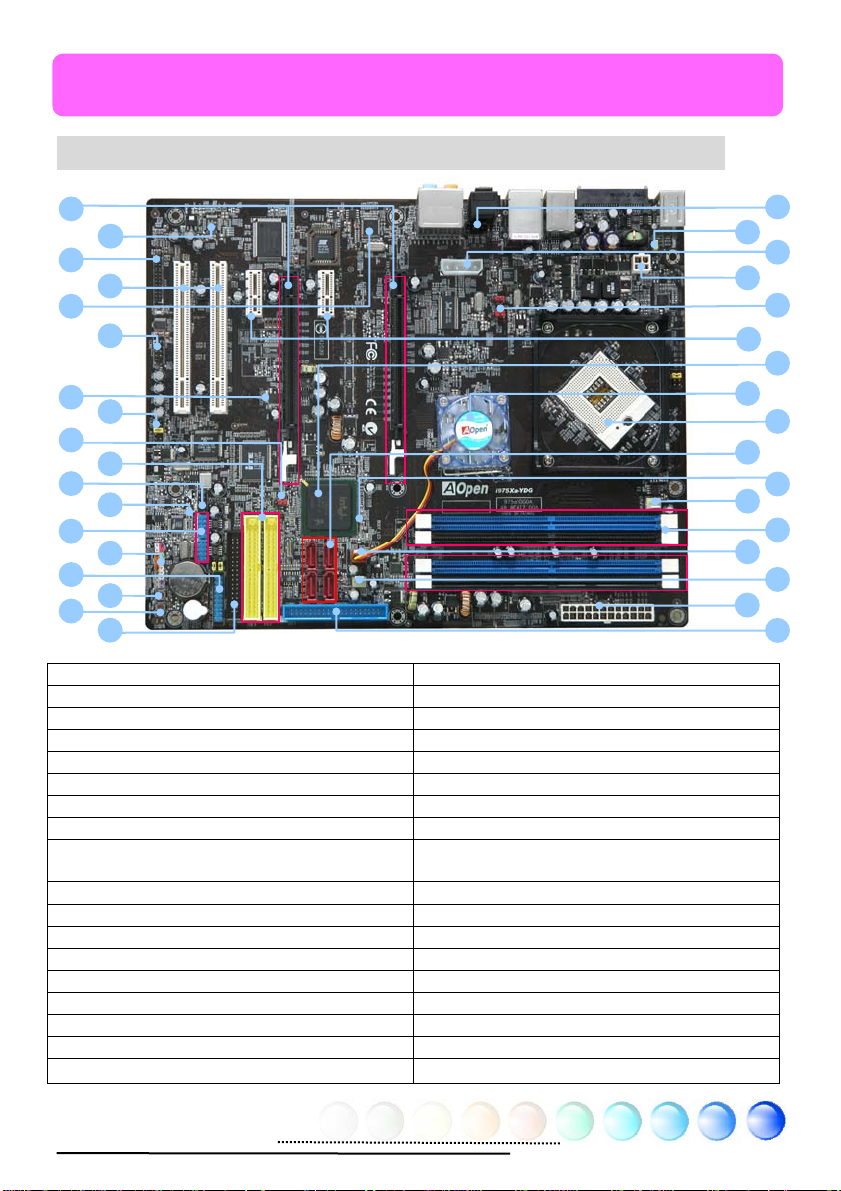
2.1 How does your motherboard look like?
18
19
25
1. CD_IN Connector 19. Realtek HDA CODEC
2. JP28 PS2 KB/Mouse Wakeup Jumper 20. Printer Connector
3. 1x4 Peripheral Connector 21. 32-bit PCI Expansion Slot x 2
4. 4-pin 12V ATX Power Connector 22. Marvell Gigabit LAN Chip
5. J4, J5 Front Side Bus Frequency Jumpe
6. PCI Expressx1 Slot x 2 24. Stand By LED
7. Intel ICH7 Chipset 25. Front Audio Connector
8. Intel 975X Chipset 26. JP14 CMOS Data Clear Jumper
9. 479-pin CPU Socket supporting Intel Yonah
Core Duo / Solo Processors
10. Serial ATA II connector x 4 28. IEEE 1394 Connector
11. Boot LED 29. Power Master II Ready LED
12. CPU FAN connector 30. USB 2.0 Connector x 2
13. 240-pin DIMM x 4 support DDR II 667MHz 31. Front Panel Connector
14. System FAN1 Connector 32. Power Master II Connector
15. Power FAN connector 33. Reset Switch Connector
16. 24-pin ATX power connector 34. Power Switch Connector
17. ATA100 IDE connector 35. FDD Connector
18. PCI Expressx16 Graphics Slot x 2
23. COM connector
27. ATA133 IDE connector x 2
1
2
3
4
5
6
7
8
9
10
11
13
8
Page 9

2.2 Specification
Here is the main function of your motherboard.
Models i975Xa-YDG
CPU
Chipset
Main Memory
Graphics
IDE
LAN Integrated Marvell Gigabit PCI Expr ess Ethernet Chip
Sound
USB Integrated in Chipset, USB 2.0 x 8 Port
IEEE 1394 Agere 1394 Control Chip
Slots
Back Panel I/O
On Board Connector
BIOS Award PnP 4Mb Flash ROM BIOS
Board Size 305 mm x 244 mm
Intel Yonah Core Duo/Solo Processor
Socket 479
533/667MHz
Intel 975X/ICH7
Dual Channel Mode
DDRII DIMM x 4, DDRII 533/667MHz
Support ECC
DIMM Type : 256/512MB & 1GB
Max Memory : 4GB
Dual PCI Expressx16 Graphics Slots
Support Dual Graphics Cards ATi Crossfire Mode
Integrated ATA100 and Serial ATA II Controller
JMicron External Serial ATA II Control Chip
ITE IDE ATA133 control chip [Support RAID 0, 1, 0+1]
Max Disk: 144,000,000GB [by 48 bits LBA Spec.]
Intel High Definition Audio on-board
Support 7.1 Channel
PCI Express x 16 Graphics Slot x 2
PCI Express x 1 Slot x 2
PCI Slot x 2
PS/2 Keyboard x 1, PS/2 Mouse x 1
Hot Plug SATA Connector x 1
USB Port x 4, LAN Port x 1,
IEEE 1394 x 1,
SP/DIF_In x 1, SP/DIF_Out x 1
Speaker_Out x 1
Line_In x 1, MIC_In x 1
Side Surround x 1, Rear Surround x 1
Center/Subwoofer x 1
Floppy Drive Connector x 1
IDE Channel: ATA100 x 1
IDE Channel: ATA133 x 2
Serial ATA II Channel x 4
Front Panel x 1
Front Audio x 1
CPU FAN x 1
System FAN x 1
Power FAN x 1
CD_IN x 1,
COM Connector x 1
Printer Connector x 1
IEEE 1394 x 1
USB2.0 Connector x 2
Power Master II Connector x 1
Reset Switch Connector x 1
Power Switch Connector x 1
9
Page 10
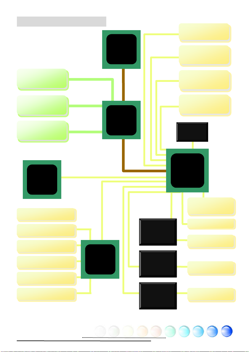
2.3 Block Diagram
Up
p
p
PCI Express x 16
hics Slot
Gra
4 GB/s
Socket 479
Intel Core
Duo/Solo
CPU
(Yonah)
533/667 MHz
System Bus
ATA 33/66/100
300MB/s
PCI Bus
IDE Drive x 2
Serial ATA Port x
4
32-bit PCI Slot x
2
PCI Express x 16
hics Slot
Gra
DDRII DIMM x 2
Marvell
Gigabit
LAN Chip
Hardware Moniter
Parallel Port x 1
PS2 Keyboard x 1
PS2 Mouse x 1
Floppy Disk Drive
Serial Port x 2
4 GB/s
Dual Channel Mode
DDRII 533/667
Support ECC
SDRAM
to 4GB
Winbond
Super I/O
Intel
975X
Chipset
500MB/s
Agere IEEE
1394
Controller
JMicron
Serial ATA
Controller
ITE
ATA133
Controller
PCI Express x 1
Slot x 1
HD Audio
CODEC
ICH7
4Mbits Flash
EEPROM
IEEE 1394 x 2
Serial ATA
IDE Drive x 4
10
Page 11
Chapter 3 Hardware Installation
Chapter 3 Hardware
q
Installation
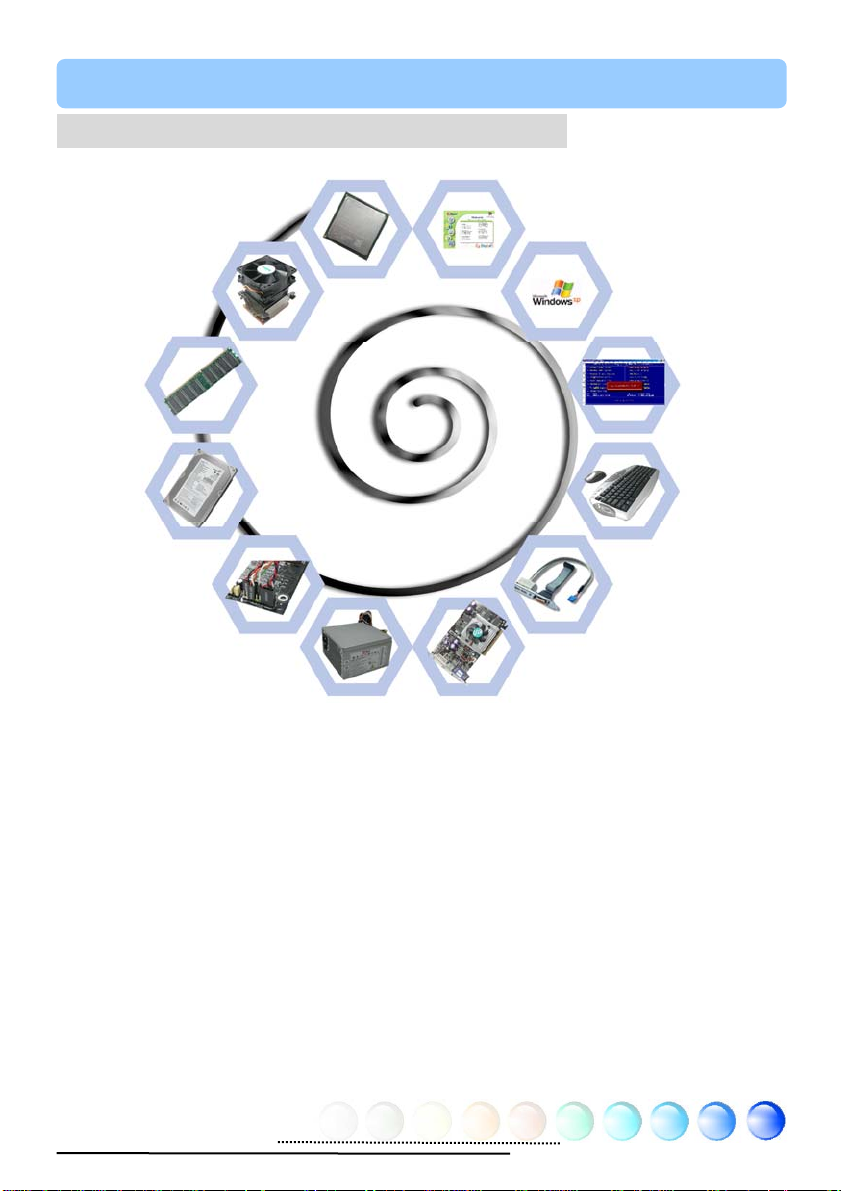
3.1 Quick Installation Procedure
2. Installing CPU
Fan & System Fan
3. Installing
Memory Module
4. Installing HD,
CD-ROM and
SATA Disk, etc
5. Connecting Front
Panel Cable
1. Installing CPU
12. Installing Drivers &
Utilities
11. Installing
Operating System
(such as, Windows
XP)
8. Installing Other
Devices (IrDA Remote
Control, Audio, etc)
10. Loading
Default BIOS,
Setting CPU
uency
Fre
9. Connecting
Back Panel Ports
(Keyboard,
Mouse, etc)
6. Connecting ATX
Power Cable
7. Installing PCI
Express x 16 Graphics
Cards & PCI Express x 1
Cards and PCI Cards
11
Page 12
3.2 Installation You Have to Know
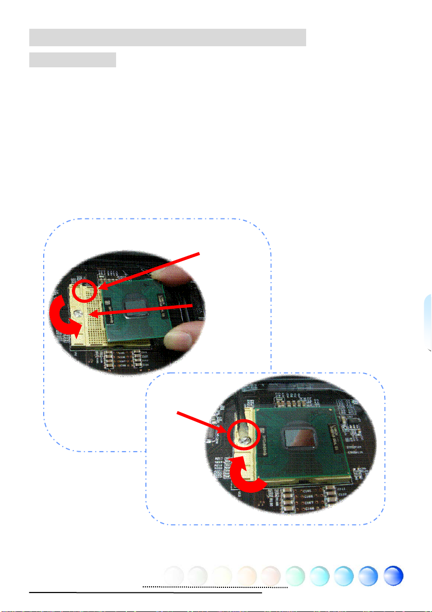
Installing CPU
This socket supports uFCPGA & uFCBGA package CPU, which is the latest CPU
package developed by Intel. It is for Yonah core CPU, other forms of CPU package
are impossible to be fitted in.
1. Unscrew the socket screw counter-clockwise.
2. Locate Pin 1 in the socket and look for a golden arrow on the CPU upper
interface. Match Pin 1 and golden arrow. Then insert the CPU into the
socket.
3. Lock the CPU socket screw clockwise to fasten CPU.
Socket Pin 1
Socket screw
Golden arrow
12
Page 13
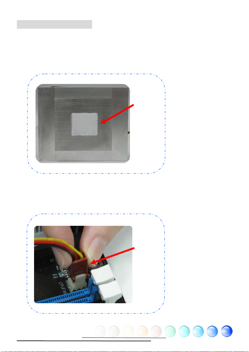
Installing CPU Cooler
This motherboard comes with a special CPU cooler desiged by AOpen, please
follow the following steps to install CPU cooler.
1. Please apply thermal paste on the bottom of CPU cooler.
2. Gently put CPU cooler onto the CPU retention module.
Thermal
paste
3. Connect cooler’s fan power cable onto CPUFAN connector.
CPUFAN
Connector
13
Page 14
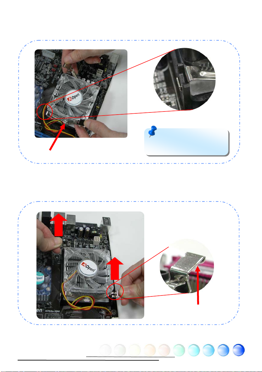
4. Install two cooler fixing sticks into CPU retention module.
Fixing stick
Note: Make sure that the
sticks have hooked CPU
retention module firmly.
5. Push the iron plate of cooler fixing stick up a bit.
14
Iron plate
Page 15
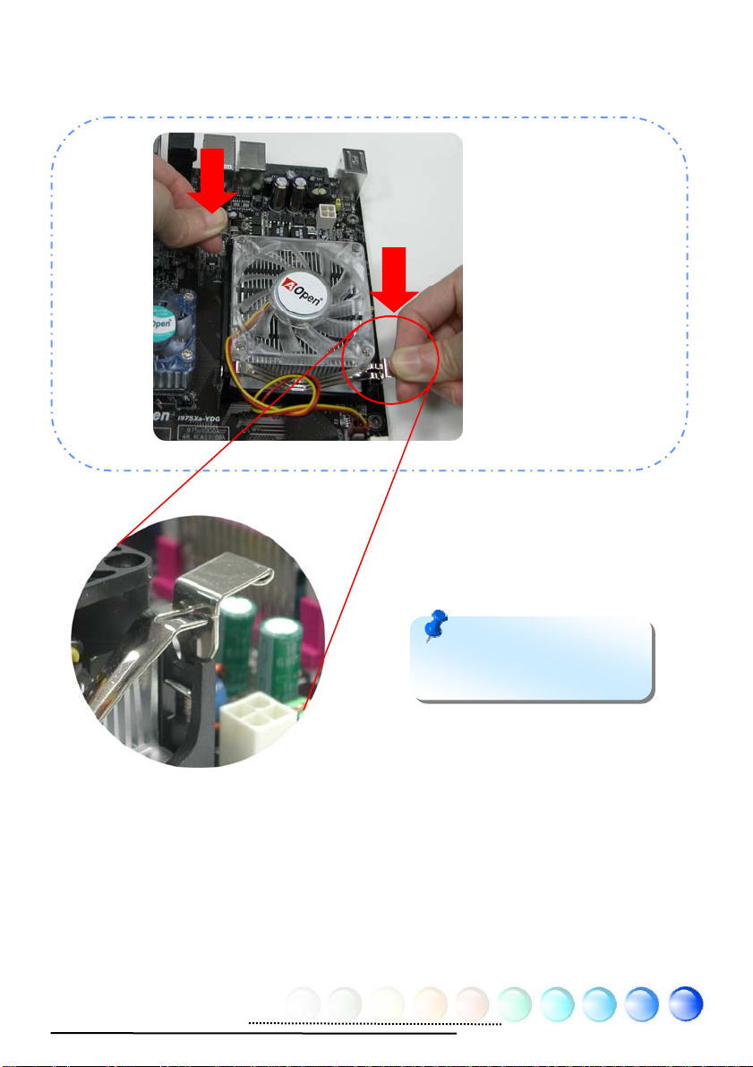
6. Then press iron plate downward till you hear a “clip” sound.
Note: Make sure that the
iron plate have hooked CPU
retention module firmly.
15
Page 16
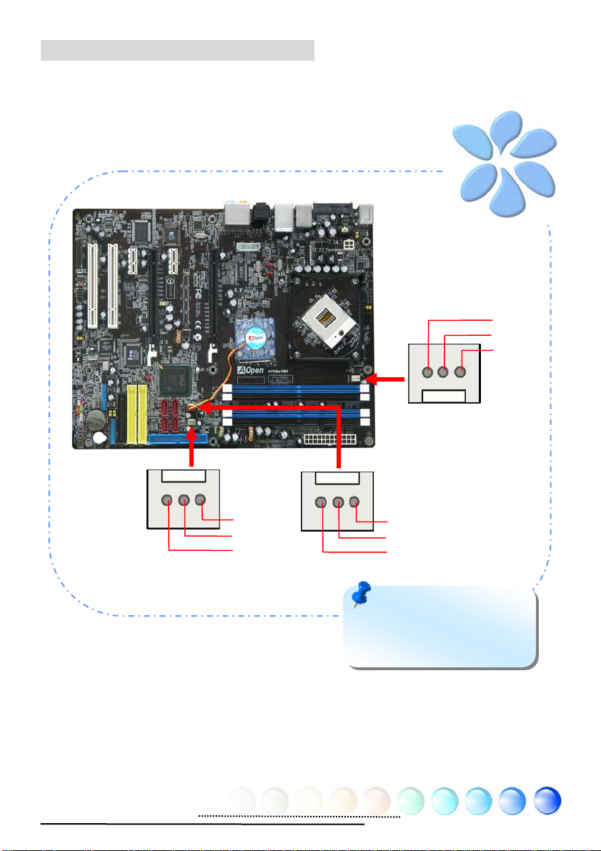
Installing CPU and System Fans
Plug the CPU fan cable to the 3-pin CPU FAN connector. If you have chassis fan,
you can also plug it in and SYSFAN and PWRFAN connector.
CPUFAN Connector
GND
+12V
Sensor
PWRFAN Connector
Sensor
+12V
GND
Sensor
+12V
GND
SYSFAN1 Connector
Note: Some CPU FANs do
not have sensor pin so that
they cannot support fan
monitoring.
16
Page 17
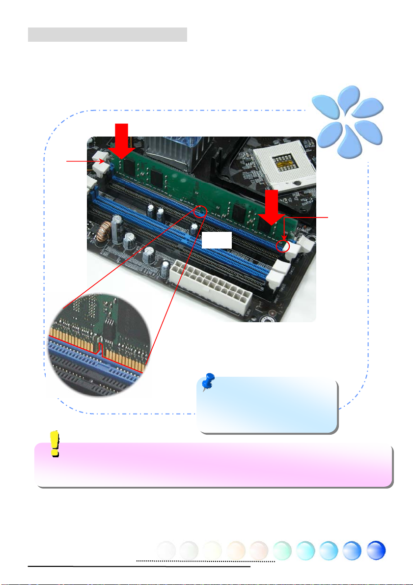
Installing Memory Modules
DIMM slots are designed in black and navy blue which are very easy to recognize.
Insert the module straight down to the DIMM slot with both hands and press down
firmly until the DIMM module is securely in place.
Tab
Pin 1
Limition: Due to the implemention of SLI function that required to reserve
buffers of memory, this board with Intel Yonah CPU can not support up to 4GB memory
address.).
Key
Note: The tabs of the DIMM
slot will clip to hold the DIMM in
place when the DIMM touches
the slot’s bottom.
17
Page 18
Maximum the Performance of the Dual Channel
To obtain the highest performance of Dual Channel, the configuration of DIMM
must meet the following conditions.
Matched DIMM configuration in each channel
● Same density (256MB~1GB)
As long as you inse rt memory modules of same densit y into Chan nel 1 (DIMM1
& DIMM3) and Channel 2 (DIMM2 & DIMM4), dual channel mode will be
enabled.
DIMM1 + DIMM3 = DIMM2 + DIMM4
Ex: if you insert 1GB memory module into DIMM1 and DIMM3, dual channel
Mode will be enabled when DIMM2 + DIMM4 = 1GB
● Same DRAM bus width (x8 or x16)
● Either single-sided or double-sided
Note: Using memory modules of different chip will
cause system unstable.
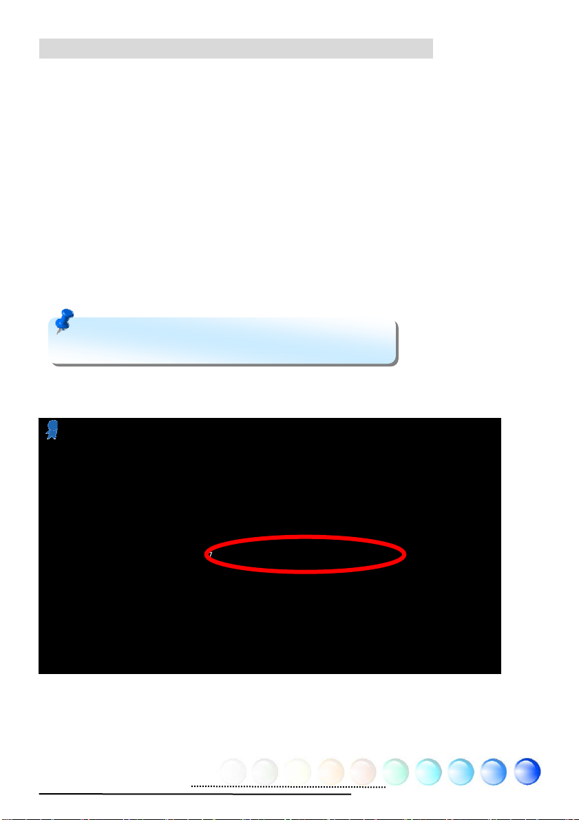
When dual channel mode is successfully enabled, the screen will show “Dual
Channel Mode Enabled” while entering POST screens.
Phoenix - AwardBIOS v6.00PG, An Energy Star Ally
Copyright (C) 1984-2003, Phoenix Technologies, LTD.
i975Xa-YDG R1.00 Feb. 24.2006 AOpen Inc.
Main Processor : Intel(R) Pentium(R) M CPU 000 @ 2.19GHz(199x11), 2 CPUs
Memory Testing : 1047552K
CPU Brand Name : Intel(R) Pentium(R) M CPU 000 @ 1.03GHz
Memory Frequency For DDR2 667 (Dual Channel Mode Enabled)
IDE Channel 0 Master : Maxtor 6E040L0 NAR61590
IDE Channel 0 Slave : None
IDE Channel 2 Master : None
IDE Channel 2 Slave : None
IDE Channel 3 Master : None
IDE Channel 3 Slave : None
18
Page 19
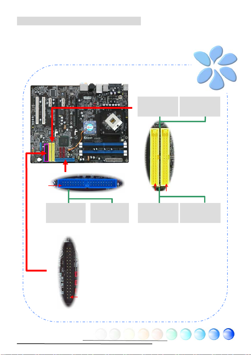
Connecting IDE and Floppy Cables
Connect the 34-pin floppy cable and 40-pin, 80-wire IDE cable to floppy
connector and IDE connector. Be careful of the pin1 orientation. Wrong
orientation may cause system damage.
Pin 1
Primary
Slave (2nd)
ATA 33/66/100 IDE Connector
Primary
Master (1st)
Primary
Slave (2nd)
Pin 1
Secondary
Slave (4th)
ATA 66/100/133 IDE Connector
Pin 1
Primary
Master (1st)
IDE2 (Primary)
Secondary
Master (3rd)
FDD Connector
Pin 1
19
Page 20
Connecting Front Panel Cable
Attach the power LED, speaker and reset switch connectors to the corresponding
pins. If you enable “Suspend Mode” item in BIOS Setup, the ACPI & Power LED
will keep flashing while the system is in suspend mode.
Locate the power switch cable from your housing, which is a 2-pin female
connector from the housing front panel. Plug this connector to the soft-power
switch connector marked SPWR.
HDD LED
HDD LED
SPEAKER
Front Panel Connector
20
NC
NC
+5V
+5V
+5V
GND
NC
1
Power Switch
GND
Power LED-
GND
Power LED+
NC
GND
GND
RESET
GND
Page 21
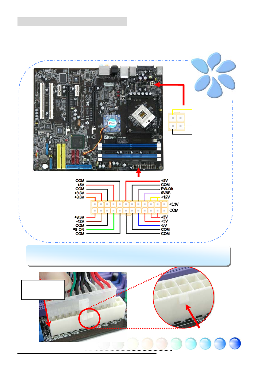
Connecting ATX Power Cables
This motherboard comes with a 24-pin and 4-pin ATX power connector as shown
below. Make sure you plug them in the right direction. We strongly recommend
you to insert the 4-pin connector before connecting the 20-pin connector.
Note: Please aim the power plug at the left side of the 24-pin AT X power
connector when the foolproof design faces you as shown.
Aiming at the
left side
+12V
+12V
Ground
Ground
Foolproof
21
Page 22
g p
”
3.3 Other Installation for Your Reference
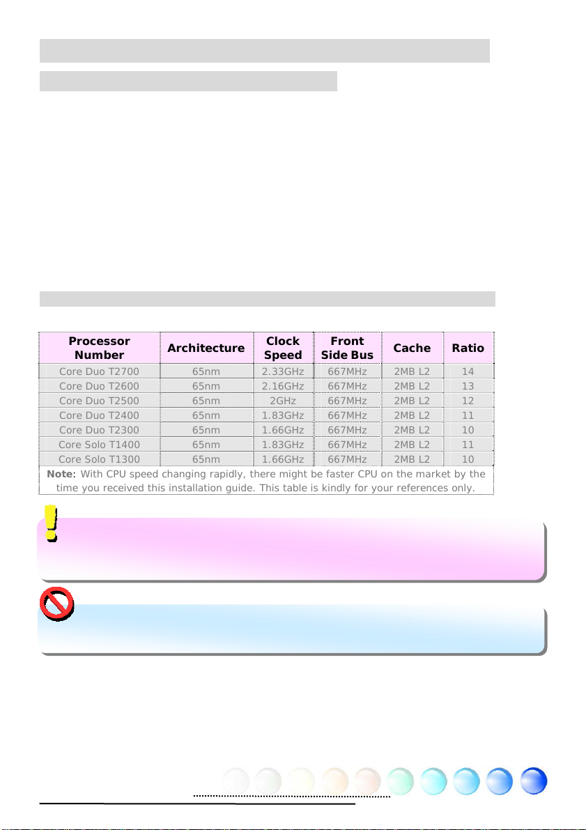
Setting CPU Voltage and Frequency
Setting CPU Core Voltage
This motherboard supports Voltage ID (VID) function to detect CPU voltage
automatically during power-on.
Setting CPU Frequency
i975Xz-YDG is CPU jumper-less design, you can set CPU frequency through 1MHz
stepping CPU Overclocking in the BIOS. CPU Core Frequency = CPU external
frequency x CPU Ratio. However, all CPU now selling in the market belong to
"Fixed Multiplier". That means users can not adjust the CPU Ratio but only change
CPU FSB clock to achieve overclocking.
(Users do the overclocking at their own risk!!)
BIOS Setup > Frequency / Voltage Control > CPU Bus Frequency
Processor
Number
Core Duo T2700 65nm 2.33GHz 667MHz 2MB L2
Core Duo T2600 65nm 2.16GHz 667MHz 2MB L2
Core Duo T2500 65nm 2GHz 667MHz 2MB L2
Core Duo T2400 65nm 1.83GHz 667MHz 2MB L2
Core Duo T2300 65nm 1.66GHz 667MHz 2MB L2
Core Solo T1400 65nm 1.83GHz 667MHz 2MB L2
Core Solo T1300 65nm 1.66GHz 667MHz 2MB L2
Note: With CPU speed changing rapidly, there might be faster CPU on the market by the
time you receiv ed this installation guide. This table is kindly for your references only.
Architecture
Clock
Speed
Front
Side Bus
Cache Ratio
14
13
12
11
10
11
10
Tip: When you fail to over-clock, you could:
1. Clear CMOS (JP14) to restore the default setting.
2. After turnin
Warning: Intel 975X chipset support maximum 667MHz (166MHz*4) system
bus; higher clock setting may cause serious system damage.
ower on, press “Home
immediately until the screen appears.
22
Page 23
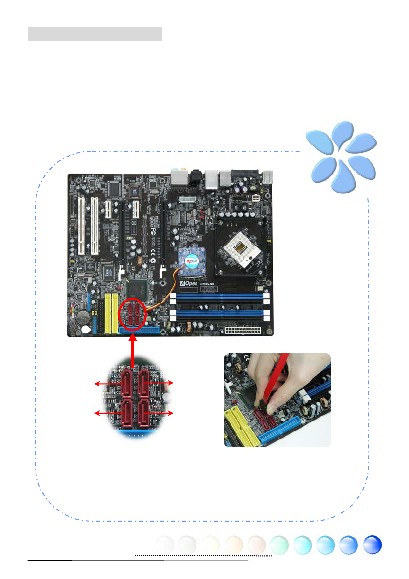
Connecting Serial ATA
To connect a serial ATA disk, you have to have a 7-pin serial ATA cable. Connect
two ends of the serial AT A cable to the serial A T A header on the motherboard and
the disk. Like every other traditional disk, you also have to connect a power cable.
Please be noted that it is a jumper free implement; you don’t need to set jumpers
to define a master or slave disk. When serial AT A hard disks are installed on serial
AT A ports, the one connected on P ort0 (SA T A1) will be set as the first boot device
automatically.
SATA2
SATA1
Serial ATA II Port
SATA3
SATA4
23
Page 24
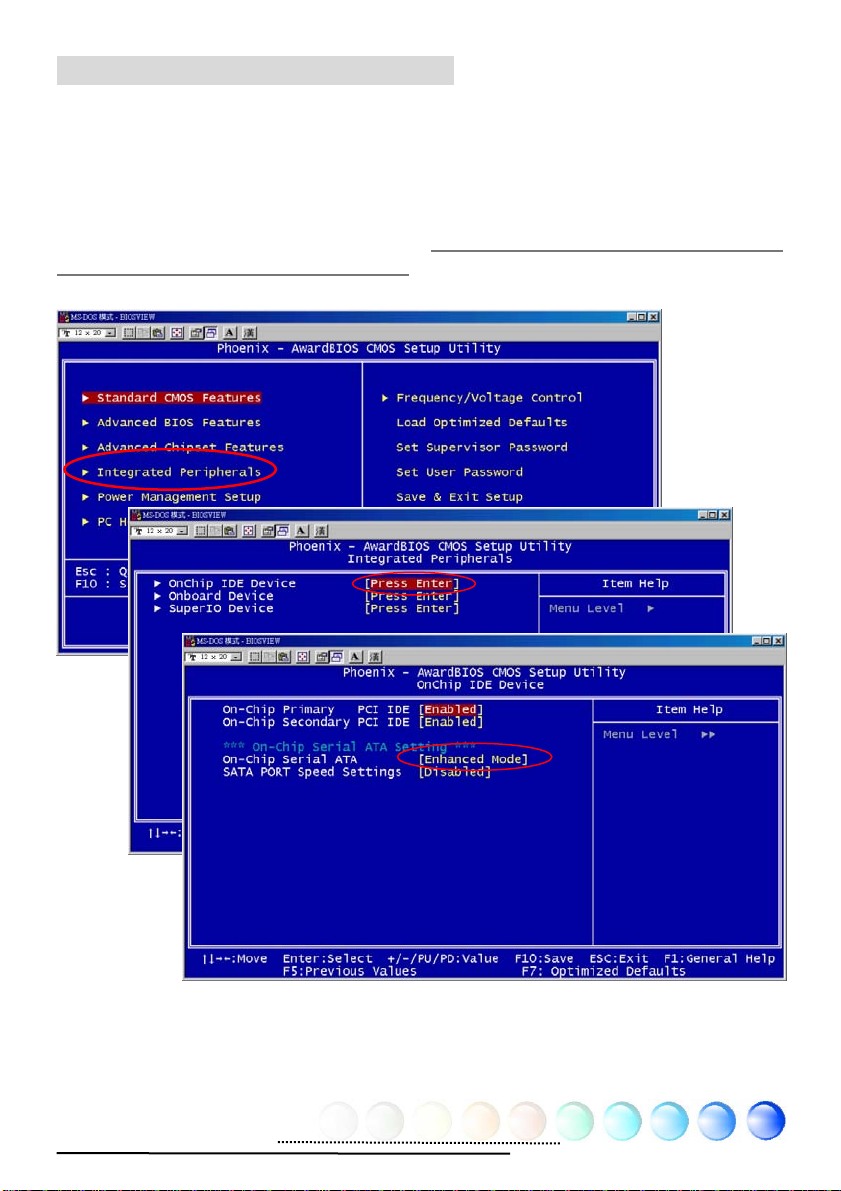
Adjusting your Hard Disk Setting
Except its original 1 set of parallel IDE, this motherboard supports the latest serial
ATA hard disk. If you are unable to find your newly installed serial AT A hard disks
on your operating system after having them instal led, the p roblem ma y lie in th e
BIOS setting. You can simply adjust BIOS settings to have them work properly.
After installing your hard disks properly, you can directly go to BIOS setting
screen for adjustment. Simply pressing “Integrated Peripherals Æ OnChip
IDE Device Æ On-Chip Serial ATA” to choose your preferable mode. If you
have no intention of changing its original setting, the default would be “Auto”.
24
Page 25

If you desire to change the default setting,
press Enter for selection list:
Disabled:
there are only traditional IDE hard disks
had been installed on your system.
Disabling this item will also cancel the
detection of serial ATA hard disks during
POST, which will theoretically speed up
your boot-up time a little bit; however,
please remember to re-adjust the setting here if you want to use serial ATA hard
disk later.
Auto:
This is factory default setting on this motherboard. Basically, if your system
functions properly, it is no necessary to change it. The system will automatically
recognize PATA (IDE) as primary..
Combined Mode:
installed at the same time, then you can choose this mode. Under this mode, you
can randomly choose either IDE hard disks or serial AT A had disk as your first boot
device. But please note, IDE will exist with serial ATA in a mapping way, which
means it will occupy one of the serial Channel and leave you one serial Channel
only. When PATA Mode is set to primary, SATA3 and SATA4 will be set to secondary,
and when PA TA Mode is set to secondary , SA T A1 and SA T A2 will be set to primary.
Enhanced Mode:
Windows.NET Server), it is highly recommended that you select Enhanced Mode.
Under this mode the system will detect all six devices (traditional IDE x 2, Serial
AT A x 4) completely and function perfectly. But please note that PA T A Mode is set
to primary under this mode.
Note: According to practical lab tests of us, there are no obvious
problems or mistakes happened when we set this mode under
Windows2000 operating system; however, it is not recommended by
Intel.
If you have traditional IDE hard disks and serial AT A hard disks
If you are using the latest operating system (say , Windows XP,
You can choose this item if
SATA Only:
You may select this mode if you install serial ATA hard disks only.
25
Page 26

Adjusting your Hot Plug Hard Disk Setting
External Hot Plug SATA HDD:
1. Plug SATA cable to onboard External
2. Plug SATA cable to SATA HDD
26
Page 27

Connecting PCI express x16 Graphics Slot
This motherboard provides a PCI Express x 16 Graphics slot, a black slot having
the latest PCI Express x 16 specification on motherboard. The PCI Express x 16 is
a bus interface targeted for high-performance 3D graphic. T raditionally AGP used
both rising and falling edge of the 66MHz clock for 8X AGP, and the data transfer
rate could achieve 2.1GB/s. Now PCI Express x 16 is moving to higher data
transfer rate, which is upgraded to 8.0GB/s (250MB/s x 16 x 2, it’s 4.0GB/s per
direction)..
PCIex16
JP3 ~ JP12
27
Page 28

1. Please plug ATX 4Pin Power to the onboard 4 Pins peripherals connector. It is
recommended and must plug while you want to use one or two PCI Express
VGA. This power can provide extra power from power supply to make sure all
peripherals run well. It is POWER IN connector.
2. Plug PCI Express VGA card properly
3. This MB allow you plug two PCI Express x 16 VGA cards
28
Page 29

Connecting PCI Express x 1 Slot
This motherboard provides one PCI Express x 1 slot, which is located between the
PCI Express x 16 and traditional PCI slot. In order to go with the step of today’s
and tomorrow’s processors, PCI Express x 1 provides higher I/O bandwidth. The
transfer data rate could achieve 500MB/s concurrently (it’s 250MB/s per
direction), which is nearly 4 time s faster than the t raditional P CI. Y ou could ins tall
any PCI Express x 1 device in these slots for your preference.
PCIex1
29
Page 30

10/100/1000Mbps LAN Supported
On the strength of Marvell Gigabit LAN controller on board, this motherboard
provides 10/100/1000Mbps Ethernet for office and home use. The Ethernet RJ45
connector is located on the top of USB connectors. The right hand side LED
indicates link mode; it lights in yellow when linking to n etwork. The left hand side
LED indicates the transfer mode and will light in green when data is transferring
at 100Mbps (never lights while at 10Mbps), but will light in orange when
transferring in Gigabit’s mode. To enable or disable this function, you may simply
adjust it through BIOS. To enable LAN wakeup function, you have to set the
“Wake on PCI Card” enable in the BIOS “Power Management Setup” section.
ACT LED (Right)
Yellow
Speed LED (Left)
Green 100Mbps
Orange Gigabit mode
30
Page 31

Connecting USB2.0
This motherboard provides eight USB 2.0 ports to connect USB devices such as
mouse, keyboard, modem, printer, etc. There are four ports on the back panel.
You can use proper cables to connect Front USB connector to USB modules or
chassis front panel.
Pin 1
Pin 1
31
Page 32

Connecting 1394
A
(
)
With IEEE1394 Chip on board (AGERE 1394), having its data transfer rate up to
400Mb/s, this interface can connect to devices that require high data transferring
performance such as digital camera, scanner or others IEEE 1394 devices. Please
use appropriate cables to connect IEEE1394 devices.
Pin1
+12V (Fused)
TPA+
GND
TPB+
1 2
-
TP
GND
TPB-
Fused
+12V
SHIED GND
IEEE 1394 Connector
32
Warning: Please note that
Hot-Plug is not allowed on
IEEE 1394 headers; doing so
will burn the controller IC and
damage the motherboard.
Page 33

Connecting IR
1. Take IR_Receiver and IR_Remote Control from package
2. Install IR_Receiver
(1) Instal l IR_Receiver Connector on the Power Master II Connector
IR_Data_In
1
+5VSB
GND
KEY
Power Master II
Connector
33
Page 34

(2) Instal l IR_Receiver on the front panel of case, the receiver should not
have any block on it. So it can receive IR signal without interfere.
IR Receiver
3. Remote Control Installation:
(1) Pul l out Remote Control’s battery socket
Push the stick on the
left side and pull out
battery socket
(2) Pl acce battery into battery socket and plug into remote control
togetherly
34
Page 35

4. Install AOpen COO Paradise Utility
(1) Put AOpen Bonus Pack CD into Optical driver, there will show screen
with ” EZInstall”, Select “Install Utilities”. In “Install Utilities”, click
“AOpen COO Paradise”
Press the icon will prompt the
“Install Utility” page. You
may also press “Back” to
return to the Main page.
(2) After installation, you can find icon on the desk with AOpen COO
Paradise Utility
35
Page 36

36
Page 37

5. Remote Control picture
Power On/Off
Windows Media Player
Previous Track
Task
Play
Pause
Next Track
Arrows
Window
Fast key
Auto Mode / Normal Mode
FSB Up
FSB Down
Vloume Up
Vloume Down
Mute
Stop
Full Screen,
(Zoom Out/In)
Enter
AOpen remote control can help you to make convience life. You can
1). Power On/Off control for PC
- One can use remote con trol to power on the machine and shut down the
machine with one click on remote control.
2). Over-clocking
- User can use this remote control to make over-clocking with 1MHz step per
click. Especial under game environment, user can click to increase performance
instantly . No need to shut down machine and power on again to enter BIOS setup.
Over-clcokin g using AOpen remo te control is ve ry convience a nd instant solut ion.
3). Window Media player control to play DVD, VCD
- With AOpen remote control on hand. User can enjoy AV program with one
thumb click. Media player is ready for it. You can enjoy MP3/ VCD, even DVD if
your system provided DVD decoder through window media player.
37
Page 38

Below picture show you the AOpen COO Paradise utility which it brings clear
information for you while you are over-clocking.
38
Page 39

Super 7.1 Channel Audio Effects
This motherboard comes with an ALC880 CODEC, which supports the latest 7.1
Channel with high quality of audio effects, bringing you a brand new audio
experience. This motherboard provides 7.1 Channel ports shown as below.
Picture represents the standard location of all speakers in 7.1 Channel sound
tracks. Please connect the plug of your front speakers to the green “Speaker out”
port , rear surround speakers to orange port, side surround speakers to gray port
and both of the center and subwoofer speakers to black port on the back panel.
39
Page 40

Connecting Front Audio
r
Y
_
_
If the housing is designed with an audio port on the front panel, you’ll be able to
connect onboard audio to front panel through this connector. By the way, please
remove the jumper cap from the Front Audio Connector before you connect the
cable. Do not remove this yellow jumper cap if your housing doesn’t have an
audio port on the front panel.
Pin1
MIC_L
1
AUD_GND
FRONT_IO_Plug
AUD_RET_R
KE
AUD_RET_L
40
AUD
AUD_MIC_R
AUD
FRONT_IO_SENSE
FPOUT_R
AUD_FPOUT_L
Front Audio Connecto
Page 41

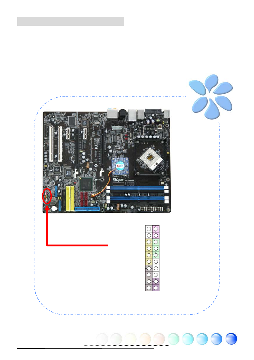
Connecting CD_IN
This connector is designed to connect CD Audio cable from CDROM or DVD drive
to onboard sound.
CD-IN Connector
L
GND
GND
R
41
Page 42

Connecting COM1
r
This motherboard provides two serial ports. All of them are on the left of PCI32
slot. With proper cable, you can connect it to the back panel of chassis.
DCD#
SOUT
GND
RTS#
R1#
1
SIN
DTR#
DSR
CTS#
COM1 Connecto
42
Page 43

Colored Coded Back Panel
The onboard I/O devices have PS2 Keyboard/Mouse, Serial ATA II, RJ-45 LAN
Jack, IEEE 1394 Ports, USB Ports, S/PDIF_Out, S/PDIF_Inand Audio Connector,
ect. The view angle of drawing shown here is from the back panel of the housing.
PS/2 Mouse
Connector
PS/2 Keyboard
Connector
Hot Plug SATA II
IEEE
1394
LAN Jack
USB 2.0 Ports
RJ45
S/PDIF_Out
S/PDIF_In
Rear SUR
Line-In
Center/
Subwoofer
Speaker Out
MIC_In
Side SUR
PS/2 Keyboard: For standard keyboard which use a PS/2 connector.
PS/2 Mouse: For PC-Mouse which use a PS/2 connector.
Serial ATA: To connect with Serial ATA Hardware Drive Disk.
IEEE 1394 Port: Available for connecting IEEE 1394 interface devices.
USB Port: Available for connecting USB devices.
RJ-45 LAN Port: To connect Ethernet for home or office use.
S/PDIF Out: An optical S/PDIF output to send signals via the digital
outputs.
S/PDIF In:
An optical S/PDIF input to record from the digital inputs.
Side Surround: For side surround speaker.
Center/Subwoofer: For center & subwoofer speaker.
Rear Surround: For rear speaker.
Line-In: Comes from the signal sources, such as CD/Tape player.
Speaker Out: To External Speaker, Earphone or Amplifier.
MIC-In: To connect with Microphone
43
Page 44

LED Indication
LED indication including Standby LED and BOOT LED are AOpen’s considerate
designs that aim at providing you friendly system information.
STBY LED will light up when power is provided to the motherboard, giving you a
convenient indication check the system power status in circumstances such as
power on/off, stand-by mode and RAM power status during Suspend to RAM
mode.
BOOT LED will keep blinking when you power the system on and when your
system is under POST (Power-On Self Test). After POST diagnoses everything all
right and finishes the booting, the LED will stay on otherwise it will remain
flashing to warn you that mistakes have occurred during POST.
Power Master II Ready LED will light up while Power Master Function is
working.
STBY LED
BOOT LED
Power Master II Ready LED
44
Page 45

3.4 Jumper Settings
JP14 Clear CMOS
Pin 1
You can clear CMOS t o restore s ystem de fault se tting. To clear
the CMOS, follow the procedure below.
1. Turn off the system and unplug the AC power.
2. Remove ATX power cable from connector PWR2.
3. Locate JP14 and short pins 2-3 for a few seconds.
4. Return JP14 to its normal setting by shorting pin 1 & pin 2.
5. Connect ATX power cable back to connector PWR2.
1
Normal
(Default)
JP14 Clear CMOS Jumper
Clear CMOS
1
Tip: When should I Clear CMOS?
1. Boot fails because of overclocking…
2. Forget password…
3. Troubleshooting…
45
Page 46

1 1
JP28 Keyboard/
Mouse Wakeup Jumper
This motherboard provides keyboard / mouse wake-up
function. You can use JP28 to enable or disable this
function, which could resume your system from suspend
mode with keyboard or mouse. The factory default
setting is “Disable” (1-2), and you may enable this
function by setting the jumper to 2-3.
Pin 1
Disable
(Default)
JP28 PS2 KB/Mouse
Enable
46
Page 47

JP4 and JP5 Front Side
Bus Clock Frequency
Jumper
Front Side Bus, FSB is also known as the
Processor Bus, Memory Bus, or System Bus and
connects the CPU with the main memory and is
used to connect to other components within the
computer.
Front Side Bus Frequency Jumper
JP4
JP5
Normal
(Default)
47
1
1
JP5
FSB 800MHz
(Take off Jumpers)
Over-Clocking
1JP4
1
Page 48

Chapter 4 Special Features and Utilities
Chapter 4 Special Features and Utilities
4.2 Other Useful Features
With excellent design ability of R&D team, AOpen boasts for its various powerful
and handy features that come with our product like follows. You are welcomed
to visit our technical website to learn more about those features.
http://english.aopen.com.tw/tech/techinside
48
Page 49

Chapter 5 Setting BIOS
Chapter 5 Setting BIOS
5.1 Introduction
System parameters can be modified by going into BIOS Setup menu; this menu
allows you to configure the system parameters and save the configuration into
the 128 bytes CMOS area (normally in the RTC chip or in the main chipset).
The Phoenix-Award BIOS™ that installed in the Flash ROM of the motherboard is
a custom version of an industry standard BIOS. The BIOS provides critical
low-level support for standard devices such as hard disk drives, serial and parallel
ports.
AOpen’s R&D engineering team had optimized most BIOS settings of this
motherboard. However, some default settings of BIOS cannot fine-tune those
sections that controlled by chipset. Therefore, this chapter is intended to guide
you and help you to configure some other settings.
T o enter BIOS setup menu, press <Del> when POST (P ower-On Self Test) screen
is shown on your monitor.
49
Page 50

5.2 How To Use Phoenix-Award™ BIOS Setup
Program
Generally, you can use arrow keys to highlight items that you want to choose,
press <Enter> key to select, and use <Page Up> and <Page Down> keys to
change setting values. You can press <Esc> key to quit Phoenix-Award™ BIOS
setup program. The following table provides details about how to use keyboard in
the Phoenix-AwardBIOS setup program.
Key Description
Page Up or + Change setting to next value or increase the value.
Page Down or - Change setting to previous value or decrease value.
Enter Select the item.
Esc In main menu: Quit without saving any changes.
In sub menu: Exit current menu to main menu.
Up Arrow Highlight previous item.
Down Arrow Highlight next item.
Left Arrow Move the light bar to left side of menu.
Right Arrow Move the light bar to right side of menu.
F10 Save changed settings and exit setup program.
5.3 How To Enter BIOS Setup
After finishing the jumper settings and connecting cables, you can power on and
enter the BIOS Setup. Press <Del> during POST (Power-On Self T est) and choose
"Load Setup Defaults" for recommended optimal performance.
Del
50
Page 51

Standard CMOS Features
The "Standard CMOS Setup" sets the basic system parameters such as the date,
time, and the hard disk type. Use the arrow keys to highlight an item and <PgUp>
or <PgDn> to select the value for each item.
Standard CMOS Features > Date
To set the date, highlight the Date parameter. Press <PgUp> or <PgDn> to set
the current date. The date format is month, date, and year.
Standard CMOS features > Time
To set the time, highlight the Time parameter. Pres s <PgUp> or <PgDn> to set
the current time in hour, minute, and second format. The time is based on the
24 hour military clock.
Standard CMOS features > IDE Channel 0 Master
Standard CMOS features > IDE Channel 0 Slave
Standard CMOS features > IDE Channel 2 Master
Standard CMOS features > IDE Channel 2 Slave
Standard CMOS features > IDE Channel 3 Master
Standard CMOS features > IDE Channel 3 Slave
This item lets you select the IDE hard d isk parameters that your system supports.
These parameters are Size, Number of Cylinder, Number of Head, Start Cylinder
for Pre-compensation, Cylinder number of Head Landing Zone and Number of
Sector per Track. The default setting is
automatically detect the parameters of installed HDD (Hard Disk Drive) at POST
(Power-On Self Test). If you prefer to enter HDD parameters manually, select
Manual.
51
Auto, which enables BIOS to
Page 52

Standard CMOS features > IDE Channel 0 Master > IDE HDD
Auto-Detection
Press “Enter” to auto-detect parameters of HDD
Standard CMOS features > IDE Channel 0 Master > IDE Channel 0 Master
(Slave)
Define the parameters of IDE devices in Channel 0 (Master or Slave). Available
options:
z None: if there is no device, please select “None” for speeding boot up.
z Auto: enable BIOS to auto-detect parameters of IDE device. (Default)
z Manual: allow users to define parameter of IDE device.
Standard CMOS features > IDE Channel 0 Master > Access Mode
Set the using mode of HDD. Available options: CHS / LBA / Large / Auto
(default). User can select the mode according to the label on HDD.
z Cylinder: Enter cylinder number
z Head: Enter head number
z Precomp: Write precompensation
z Landing Zone: Location of head
z Sector: Sector Number
Standard CMOS features > Drive A
This item allows use r select the floppy drive type. Ava ilable items: None / 360KB
5.25” / 1.2MB 5.25” / 720KB 3.5” / 1.44MB 3.5” / 2.88MB 3.5”
Standard CMOS features > HaltOn
This parameter enables you to control the system stops in case of Power-On Self
Test (POST) error. Available items: No errors / All errors / All, But Keyboard
/ All, But Diskette / All, But Disk/Key
52
Page 53

Advanced BIOS Features
This screen appears when you select the option "Advanced BIOS Features" from
the main menu.
Advanced BIOS Features > Removable Device Priority
Advanced BIOS Features > Removable Device Priority > Floppy Disks
Advanced BIOS Features > Hard Disk Boot Priority
z Ch0 M.: MAXTOR 6L080J4
z Bootable Add-in Cards
Advanced BIOS Features > CD-ROM Boot Priority
This parameter allows you to specify the system boot up search sequence.
Advanced BIOS Features > First Boot Device
Advanced BIOS Features > Second Boot Device
Advanced BIOS Features > Third Boot Device
This parameter allows you to specify the system boot up search sequence.
Available options:
z Removable: Floppy, USB, ZIP…etc
z Hard Disk: Hard Disk Drives
z CD-ROM: CD-ROM, DVD-ROM…etc
z LAN: LAN Card with boot ROM
z Disabled
Advanced BIOS Features > Boot Other Device
This parameter allows you to enable other system boot up devices that is not
described above.
53
Page 54

Advanced BIOS Features > Security Option
The “System” option limits access to both the System boot and BIOS setup. A
prompt asking you to enter your password appears on the screen every time you
boot the system.
The “Setup” option limits access only to BIOS setup.
T o disable the security option, select Password Setting from the main menu, don't
type anything and just
Advanced BIOS Features > Full Screen Logo Show
Available options: Disabled, Enabled
press <Enter>
54
Page 55

Advanced Chipset F e atures
The "Advanced Chipset Features" includes settings for the chipset dependent
features. These features are related to system performance.
Warning: Make sure you fully understand the items contained
in this menu before you try to change anything. You may change
the parameter settings to improve system performance. However,
it may cause your system to be unstable if the setting is not
Advanced Chipset features > DRAM Timing Selectable
Available options:
z By SPD: System will define timing according to default of Dram. (Default)
z Manual: Allow user to define timing himself.
Advanced Chipset features > CAS Latency Time
When synchronous DRAM is installed, the number of clock cycles of CAS latency
depends on the DRAM timing.
Available options: 5, 4, 3, 6, Auto
Advanced Chipset features > DRAM RAS# to CAS# Delay
This field lets user to insert a timing delay between the CAS and RAS strobe
signals, used when RAM is written to, read from, or refreshed. Fast gives fater
performance; and Slow give more stable performance. This field applies only
when synchronous DRAM is installed in the system.
Available options: 2, 3, 4, 5, 6 Auto
Advanced Chipset features > DRAM RAS# Precharge
If an insufficient number of cycles are allowed for the RAS to accumulate its
charge before DRAM refresh, the refresh may be incomplete and the DRAM may
fail to retain data. Fast give faster performance; and Slow gives more stable
performance. This field applies only when synchronous DRAM is installed in the
system.
Available options: 2, 3, 4, 5, 6, Auto
55
Page 56

Advanced Chipset features > Precharge dealy (tRAS)
Select the operating system that is active to precharge delay.
Available options: 4, 5, 6, 7, 8, 9, 10, 11, 12, 13, 14, 15
Advanced Chipset features > System Memory Frequency
This item is used to set DRAM timing.
Available options: DDRII533 MHz, 667 MHz, Auto
Advanced Chipset features > PCI Express Root Port Func
Advanced Chipset features > DRAM Data Integrity Mode
Advanced Chipset features > PEG Force X1
This item is use d t o s ele ct dis play first from onboard VGA or P CI E xp r es sGraphic
card.
Available options: Disabled, Enabled
56
Page 57

Integrated Peripherals
This submenu appears if you select the option "Integrated Peripherals" from the
main menu. This option allows you to configure the I/O features.
Integrated peripherals > OnChip IDE Device
Integrated peripherals > OnChip IDE Device > On-Chip Primary PCI IDE
This item allows you to select work mode on PATA .
Available options:
z Disabled: Disabled PATA Controller
z Enabled: Enabled PATA Controller
57
Page 58

Integrated peripherals > OnChip IDE Device > On-Chip Secondary PCI
IDE
This item allows you to select work mode on PATA .
Available options:
z Disabled: Disabled PATA Controller
z Enabled: Enabled PATA Controller
Integrated peripherals > OnChip IDE Device > On-Chip Serial ATA
This item allows you to select work mode between SATA.
Available options:
z Disabled: Disabled SATA Controller
z Auto: Auto arrange by BIOS
z Combined Mode: PA TA and SA T A are combine. Max. of 2 IDE drives in each
channel.
z Enhanced Mode: Enable both SATA and PATA. Max. of 6 IDE drives are
supported.
z SATA only: SATA is operating in legacy mode..
Integrated peripherals > OnChip IDE Device > PATA IDE Mode
When On-chip SATA is selected to ”Combined Mode” , this item allows you to
set PATA to primary or secondary.
Integrated peripherals > OnChip IDE Device > SATA Port Speed Settings
Available options: Disabled, Force GENI, Force GENII
Integrated peripherals > Onboard Device > USB Controller
This item lets you enable or disable the USB controller.
Available options: Disabled, Enabled
Integrated peripherals > Onboard Device > USB 2.0 Controller
This item lets you enable or disable the USB 2.0 controller.
58
Page 59

Integrated peripherals > Onboard Device > USB Keyboard Support
This item lets y o u enable or disable the USB keyboard driver within the onboard
BIOS. The keyboard driver simulates legacy keyboard command and let you use
USB keyboard during POST or after boot if you don't have USB driver in the
operating system.
Integrated peripherals > Onboard Device > Azalia/AC97 Audio Select
This item is used to enable or disable the onboard audio.
Integrated peripherals > Onboard Device > Onboard LAN Control
This item lets you enable or disable onboard LAN.
Integrated peripherals > Onboard Device > Onboard 1394 Control
This item lets you enable or disable onboard 1394.
Integrated peripherals > Onboard Device > Onboard IDE Control
This item lets you enable or disable onboard IDE.
Integrated peripherals > Onboard Device > Onboard SATA2 Control
This item lets you enable or disable onboard SATA.
Integrated peripherals > SuperIO Device
This item allows you to set SuperIO device.
Note:
Whenever you change this item, it will only take
effect after you restart the system and successfully
boot the Windows or DOS.
Wake on Mouse function appies to PS/2 mouse only.
If you set a password but forget it, please clear
CMOS.
If you want to use Wake on Mouse function in DOS, it is
necessary to install the DOS driver of the mouse.
59
Page 60

Integrated peripherals > SuperIO Device > Power ON Function
This item is used to select Wake on Keyboard/Mouse mode.
z Password: Disable the function of power button and let the system can
only be powered on through the preset keys (like a password).
z Hot Key: If selecting this option, you also need to specify the hot key from
“Hot Key Power On” item.
z Any Key: This function allows you wake up the system by clicking any key.
z Button Only: Disable Wake on KB/MS function. You can boot up your
system by power button only.
Integrated peripherals > SuperIO Device > KB Power ON Password
You can specify 1-5 keys as a password.
Integrated peripherals > SuperIO Device > Hot Key Power On
If you select “Hot Key” option in “P ower On Function” Item, you need to specify a
hot key here.
Integrated peripherals > SuperIO Device > Onboard Serial Port 1
This item allows you to assign address and interrupt for the board serial port.
The default is “3F8/IRQ4”.
Integrated peripherals > SuperIO Device > Onboard Serial Port 2
This item allows you to assign address and interrupt for the board serial port. The
default is “2F8/IRQ3”.
Integrated peripherals > SuperIO Device > Onboard Parallel Port
This item controls the onboard parallel port address and interrupt. Available
options: 378/IRQ7, 278/IRQ5, 3BC/IRQ7, Disabled
Integrated peripherals > SuperIO Device > Parallel Port Mode
This item lets you set the parallel port mode. The mode options are SPP
(Standard and Bidirection Parallel Port), EPP (Enhanced Parallel Port)
and ECP (Extended Parallel Port). Available options:
z SPP (Standard and Bidirection Paralell Port): SPP is the IBM AT and
PS/2 compatible mode.
z EPP (Enhanced Parallel Port): EPP enhances the parallel port throughput
by directly writing/reading data to/from parallel port without latch.
z ECP (Extend Parallel Port): ECP supports DMA and RLE (Run Length
Encoded) compression and decompression.
z ECP + EPP
z Normal
Integrated peripherals > SuperIO Device > EPP Mode Select
This item lets you select EPP mode protocol.
60
Page 61

Integrated peripherals > SuperIO Device > ECP Mode Use DMA
This item lets you set the DMA channel of ECP mode.
Available options: 3, 1
Integrated peripherals > SuperIO Device > PWRON After PWR-Fail
A traditional ATX system should remain at power off stage when AC power
resumes from power failure. This design is inconvenient for a network server or
workstation, without an UPS, that needs to keep power-on. This item is used to
solve this proble m. Selecting On enabli ng system to automatic ally power-on afte r
AC power resumes; in the other hand, the system will remain power-off if you
select Off. If Former-Sts (former status) option is selected, the system will
power-on or power-off based on the original state.
Available options: Former-Sts, On, Off
61
Page 62

Power Management Setup
The Power Management Setup screen enables you to control the motherboard
green features. See the following screen.
Power Management > ACPI Suspend Type
This function allows you to select suspend types. S1 is Power On Suspend and S3
is Suspend to RAM.
Available Options: S1, S3, S1 & S3
Power Management > Run VGABIOS if S3 Resume
Power Management > Wake-up by PCI Card
This is a functio n of PCI specif ication 2.2. PCI bus supports standby current to PCI
card and PCI card can wakeup system if it detects certain activity.
Available options: Disabled, Enabled
Power Management > Power On by Ring
The option lets you specify enable or disable Wake On Modem Ring function.
Available options: Disabled, Enabled
Power Management > USB KB Wake-Up From S3
The USB KB wake-up from S3 support USB Keyboard wake up under S3 mode.
Available options: Disabled, Enabled
Power Management > Resume by Alarm
The Wake Up Timer is more like an alarm, which wakes up and powers on your
system at a pre-defined time for a specific application. It can be set to wake up
everyday or on specific date within a month. The date/time is accurate to within
a second. This option lets you enable or disable the RTC Wake Up function.
Available options: By Date, By Week, Disabled
62
Page 63

Power Management > Date (of Month) Alarm
This item is display ed when yo u enable th e W ake On RT C Timer option. Here y ou
can specify what date you want to wake up the system. For Example, setting to 15
will wake up the system on the 15th day of every month.
Tip: Setting this item to 0 will wake up the system on the specified time (which can
be set in the Wake On RTC Timer) every day.
Power Management > Time (hh:mm:ss) Alarm
This item is display ed when yo u enable th e W ake On RT C Timer option. Here y ou
can specify what time you want to wake up the system.
63
Page 64

PC Health Status
The PC Health Status can bring PC important safety parameters for detect Health
of your system.
PC Health Status > System Temperature
PC Health Status > CPU Temperature
PC Health Status > PWR Fan
PC Health Status > CPU Fan
PC Health Status > System Fan
PC health status bring you on the System temperature, CPU temperature,
System Fan, CPU Fan , PWR Fan, Vcore, 5VSB, VCC, VBAT – these important
system parameters for you to check the health status of your system.
64
Page 65

Frequency/Voltage Control
This submenu allows you to configure the CPU and memory clock.
Frequency/Voltage Control > CPU Voltage Setting
This item allows user to adjust CPU Vcore voltage, BIOS will determine the
adjustable value according to the CPU installed.
65
Page 66

Frequency/Voltage Control > DRAM Voltage Seting
Frequency/Voltage Control > NB Voltage Seting
This item allows user to adjust North Bridge voltage, BIOS will determine the
adjustable value according to the North Bridge default.
Available options: Auto, 1.525V, 1.575V, 1.625V, 1.675V
Frequency/Voltage Control > Spread Spectrum
This item is used to set the value of clock Spread Spectrum. BIOS will determine
the adjustable v alue accor ding to the CPU in stalle d, n ot all items will be showe d.
Available options: Pisable, -0.5%, -1.0%,+-0.25%, +-0.5%
66
Page 67

Frequency/Voltage Control > CPU Clock
Thie item shows the CPU Clock of status. You can adjust the clock according it.
Available options: 166MHz ~ 199MHz
Tip: When you fail to overclock, you could: Clear CMOS (JP14) to restore the
default setting. After turning power on, press
Frequency/Voltage Control > Power Master
Please press the Del button after you start the computer, then you can enter the
BIOS setting page. Once you get into BIOS setting page, please select the
Frequency/voltage control to set up the Power Master.
67
Page 68

Frequency/Voltage Control > Power Master > Automatic Mode
Once you enable this mode, Power Master will detect your processor true loading
automatically . When the processor loading is heavy, Power Master will raise your
processor’s clock frequency to meet your requirement. On the contrary , when the
processor is in low loading, Power Master will drop the clock frequency to reduce
the noise from processor fan.
Frequency/Voltage Control > Power Master > Normal Mode
When you choose this mode, Power Master will be turned off. The processor clock
frequency will always keep at the original speed.
Load Optimized Defaults
The "Load Optimized Defaults" option loads optimized settings for optimum
system performance. All the product verification, compatibility/reliability test
report and manufacture quality control are based on “Load Optimized Defaults”.
We recommend using these settings for normal operation. “Load Optimized
Defaults” is not the slowest setting for this motherboard. If you need to verify an
unstable problem, you may manually set the parameter in the “Advanced BIO
Features” and “Adanced Chipset Features” to get slowest and safer setting.
68
Page 69

Set Supervisor Password
Supervisor Password prevents unauthorized use of your computer. If you set a
password, the system prompts for the correct password before boot or access to
Setup.
To set a password:
1. At the prompt, type your password. Your password can be up to 8
alphanumeric characters. When you type the characters, they appear as
asterisks on the password screen box.
2. After typing the password, press.
3. At the next prompt, re-type your password and press again to confirm the
new password. After the password entry, the screen automatically reverts to
the main screen.
To disable the password, press “Enter” when being prompted to enter the
password. The screen displays a message confirming that the password has been
disabled.
Set User Password
User Password can authorize users check only . It can not modify the BIOS setting
inside.
To set a password:
1. At the prompt, type your password. Your password can be up to 8
alphanumeric characters. When you type the characters, they appear as
asterisks on the password screen box.
2. After typing the password, press.
3. At the next prompt, re-type your password and press again to confirm the
new password. After the password entry, the screen automatically reverts to
the main screen.
To disable the password, press “Enter” when being prompted to enter the
password. The screen displays a message confirming that the password has been
disabled.
Save & Exit Setup
This function automatically saves all CMOS values before leaving Setup.
Exit without Saving
Use this function to exit Setup without saving the CMOS value changes. Do not
use this option if you want to save the new configuration.
69
Page 70

5.4 BIOS Upgrade under Windows
y p
environment
With outstanding R&D ability of AOpen, we now bring you a whole new BIOS Flash
wizard ---- EzWinFlash. With an eye to convenience for users, EzWinFlash
combines the BIOS binary code and flash module together, so the only thing you
have to do is just c lic kin g o n th e u tilit y y ou do wnloa d ed fro m web and le t it h elp
you complete the flash process automatically. EzWinFlash detects your
motherboard and checks the BIOS version cleverly to prevent your system from
any possible failure. Moreover, EzWinFlash has been taken into consideration to
go with any windows platform you might be using, no matter if you’re using
Windows 95/98, 98SE/ME, NT4.0/2000, or Windows XP.
In the meanwhile, in order to provide a much more user-friendly operating
environment, AOpen EzWinFlash is natively designed to have multi-language
function to provide easier way for user in changing BIOS setting.
Caution: You are taking a risk of BIOS flash
failure when you update your system. If your
motherboard is working stable, and there are no
major bugs to be fixed by a latter BIOS revision, we
recommend that you DO NOT upgrade your BIOS.
If you intent on upgrade PLEASE MAKE SURE you
get the right BIOS revision for your motherboard
model so as to avoid an
ossible failure.
Note: The model name on this BIOS picture is for reference only. It may
not be the same model with your motherboard.
70
Page 71

You may accomplish BIOS upgrade procedure with EzWinFlash according to
following steps, and it’s STRONGLY RECOMMENDED to close all applications
before you start the upgrades.
Download the latest ve rsion of BIOS packag e zip file from AOpen official web site.
(Ex: http://english.aopen.com.tw/
)
Unzip the downloaded BIOS package (ex: WSGMAXII102.ZIP) with WinZip
(http://www.winzip.com
) in Windows environment.
Save the unzipped files into a folder, for example, WSGMAXII102.EXE &
WSGMAXII102.BIN.
Double click WSGMAXII102.EXE; EzWinFlash will detect the model name and
BIOS version of your motherboard. If you collect wrong BIOS, you will not be
allowed to proceed with the flash steps.
You may select a preferred language in main menu, then click [Start Flash] to
begin the BIOS upgrade procedure.
EzWinFlash will complete all the process automatically, and a dialogue box will
pop up to ask you to restart Windows. Click [YES] to reboot Windows.
Press <Del> at POST to enter BIOS setup screen; choose "Load Setup Defaults",
then “Save & Exit Setup”. Done!
It is strongly recommended NOT to turn off the power or run any applications
during FLASH PROCESS.
Warning: The new BIOS upgrade will
permanently replace your original BIOS setting
when flashing. You may need to reconfigure the
BIOS setting before your system goes back to
work as normal.
71
Page 72

Chapter 6 Installing Drivers
Chapter 6 Installing Drivers
You may think that installing drivers and utilities would be a repeated task of going
through those installation wizards and steps-by-steps. Now, you will be surprised
with how “Ez” EzInstall could do. Without wizards or steps, all you have to do is to
do one click and then it’s done. Click and done. Yes. EzInstall makes installation
easy and even foolproof!
After putting in the CD, you will be prompted with AOpen welcome page and our
branches information.
First, click on the install driver ICON at left side for necessary drivers.
Second, click on the install utility ICON at left side for preferred utilities.
Practically, it’s done. But you may also browse CD contents, Readme to get more
information or just exit the CD installation.
Install
driver
Click to install
online manual
Install
utility
Browse CD
Contents
Readme
AOpen
branches
information
Exit CD
72
Page 73

6.1 Installing Drivers
As you may see from the Installing driver page, EzInstall had picked up necessary
for your motherboard. All you have to do is just click on the “GO”, and n o more
steps afterward, of all listed drivers, grey checks indicate necessary drivers; you
cannot click them off. R ed checks can be disabled if you don’t want to install them
now.
Press the icon will prompt the
“Install Driver” page. You
may also press “Back” to
return to the Main page.
Once clicking “GO”, EzInstall will run the installing procedure
automatically, and prompt a reboot dialog (Some drivers or
utilities may skip the reboot part).
73
Page 74

6.2 Installing Utilities
Installing Utilities is virtually the same as installing drivers. AOpen provides you
many friendly and powerful utilities to manage your system. Y ou may find lots of
fabulous utilities listed there, and all you have to do is to click on the “GO”, then
it will install the utilities to your system right away without complicated steps.
Press the icon will
prompt the “Install
Utilities” page for your
selection. You may also
press “Back” to get back
to the Main page.
74
Page 75

Chapter 7 Troubleshooting
g
Chapter 7 Troubleshootin
75
Page 76

Chapter 8 Technical Support
Chapter 8 Technical Support
Dear Customer,
Thanks for choosing AOpen products. We invite you to register at
http://www.aopen.com
to become a Gold Member of Club AOpen so as to
ensure quality service in the future. In order to maintain the best service to every
customer of us, we recommend you to follow the procedures below and seek help
from our branches according to the region you buy the product. With your help,
we can then continue to provide efficient and the best quality service to every
customer.
Thanks very much for your understanding!
AOpen Technical Supporting Team
Europe
AOpen Computer b.v.
Tel:31-73-645-9516
Email: Support@AOpen.NL
Germany
AOpen Computer GmbH.
Tel: 49-2131-1243-710
Fax: 49-2131-1243-999
Europe http://www.aopen.nl/tech/default.htm
Pacific Rim: http://www.aopen.com.tw/tech/default.htm
China: http://www.aopen.com.cn/tech/default.htm
Germany: http://www.aopencom.de/tech/default.htm
America: http://usa.aopen.com/tech/default.htm
Japan: http://aopen.jp/tech/index.html
China
艾爾鵬國際貿易(上海)有限公司
Tel: 86-21-6225-8622
Fax: 86-21-6225-7926
Pacific Rim
AOpen Inc.
Tel: 886-2-3789-5888
Fax: 886-2-3789-5899
Japan
AOpen Japan Inc.
Tel: 81-048-288-0988
Fax: 81-048-288-0955
America
AOpen America Inc.
Tel: 1-510-489-8928
Fax: 1-510-489-1998
76
Page 77

Model Name and BIOS Version
Model name and BIOS version can be found on upper left corner of first boot
screen (POST screen). For example:
Phoenix AwardBIOS v6.00PG, An Energy Star Ally
Copyright (C) 2005, Phoenix Technologies, LTD.
i975Xa-YDG R1.00 May. 1. 2006 AOpen Inc.
i975Xa-YDG is model name of motherboard; R1.00 is BIOS version
Register Your Motherboard
Thanks for choosing AOpen product, please register this motherboard at
http://club.aopen.com.tw/productreg/
and to ensure high service quality and priority from AOpen. You will also have a
chance to play slot machine game to win prize from AOpen. Please prepare the
following information before you start: Model Name, Part Number (P/N), Serial
Number (S/N) and Purchase Date. The Part Number and Serial number are
printed on bar code label. You can find this bar code label on the outside packing
or on component side of PCB. For example:
to become a Gold member of Club AOpen,
P/N: 91.88110.201 is part number, S/N: 91949378KN73 is serial number.
Phoenix-Award BIOS ERROR Message
Beep Sound Message
1 short(Beep) System booting is normally.
1 long - 1 short(Beep) DRAM ERROR
1 long - 2 short(Beep) Display card or monitor connected error
1 long - 3 short(Beep) Keyboard Error
Long(Beep) continuous DRAM hasn't inset correctly.
Part No.
77
Serial No.
Page 78

Chapter 5 Setting BIOS
Technical Support
78
 Loading...