

Page 1

Table of Contents
Chapter 1 Table of Contents
Chapter 1 Table of Contents..................................................................... 1
1.1 Disposal Instruction .....................................................................................4
1.2 A Thank-you Note Before You Get Start..........................................................6
1.3 Features of This Manual ...............................................................................7
1.4 Safety Information ......................................................................................7
Chapter 2 Introduction to This Motherboard ............................................... 8
2.1 How does your motherboard look like?...........................................................8
2.2 Specification ...............................................................................................9
2.3 Block Diagram .......................................................................................... 10
Chapter 3 Hardware Installation............................................................. 11
3.1 Quick Installation Procedure ....................................................................... 11
3.2 Installation You Have to Know..................................................................... 12
Installing CPU ...........................................................................................12
Installing CPU Cooler .................................................................................13
Installing CPU and System Fans ..................................................................16
Installing Memory Modules .........................................................................17
Maximum The Performance of the Dual Channel............................................18
Connecting IDE and Floppy Cables ..............................................................19
Connecting Front Panel Cable .....................................................................20
Connecting ATX Power Cables.....................................................................21
3.3 Other Installation for Your Reference ...........................................................22
Setting CPU Frequency...............................................................................22
Connecting Serial ATA................................................................................23
Adjusting your Hard Disk Setting.................................................................24
Connecting PCI express x16 Graphics Slot....................................................25
Connecting PCI Express x 1 Slot ..................................................................27
Connecting IrDA........................................................................................28
1
Page 2

10/100/1000Mbps LAN Supported...............................................................29
Connecting USB2.0....................................................................................30
Connecting 1394.......................................................................................31
Super 7.1 Channel Audio Effect...................................................................32
Connecting Front Audio..............................................................................33
Connecting CD_IN.....................................................................................34
Connecting COM1/COM2 ............................................................................35
Connecting Case Open ...............................................................................36
Connecting S/PDIF (Sony/Philips Digital Interface)........................................37
3.4 Jumper Settings ........................................................................................ 38
Chapter 4 Special Features and Utilities................................................... 39
4.1 RAID (Redundant Array of Independent Disks)..............................................39
Installation Raid driver under window installation ..........................................39
4.2 Other Useful Features ................................................................................42
Chapter 5 Setting BIOS......................................................................... 43
5.1 Introduction ............................................................................................. 43
5.2 How To Use Phoenix-Award™ BIOS Setup Program........................................ 44
5.3 How To Enter BIOS Setup ........................................................................... 44
Standard CMOS Features ...........................................................................45
Advanced BIOS Features............................................................................47
Advanced Chipset Features.........................................................................48
Integrated Peripherals ...............................................................................49
Power Management Setup..........................................................................53
PC Health Status.......................................................................................55
Frequency/Voltage Control .........................................................................56
Load Optimized Defaults ............................................................................57
Set Supervisor Password............................................................................57
Set User Password.....................................................................................58
Save & Exit Setup .....................................................................................58
2
Page 3

Exit without Saving ...................................................................................58
5.4 BIOS Upgrade under Windows environment..................................................59
Chapter 6 Installing Drivers................................................................... 61
6.1 Installing Drivers.......................................................................................62
6.2 Installing Utilities ...................................................................................... 64
6.3 Display output behavior .............................................................................65
Display output behavior .............................................................................66
Chapter 7 Troubleshooting..................................................................... 67
Chapter 8 Technical Support .................................................................. 68
Model Name and BIOS Version....................................................................69
Register Your Motherboard .........................................................................69
Technical Support......................................................................................70
3
Page 4

1.1 Disposal Instruction
Disposal Instruction (US)
For better protection of our earth, please don't throw this
electronic device into municipal trash bin when discarding. To
minimize pollution and ensure utmost protection of the global
environment, please recycle the product.
For more information about the collection and recycling of Waste
Electrical and Electronic Equipment (WEEE) , you are invited to
visit our homepage at www.aopen.com
Instruktion til bortskaffelse (Danish)
Af hensyn til vores miljø bedes De ikke bortskaffe denne elektroniske enhed i en
almindelig affaldsspand. For at mindske forurening og sikre beskyttelse af miljøet
bedes De genbruge produktet.
For yderligere information vedrørende indsamling og genbrug af elektronik-affald
(Waste Electrical and Electronic Equipment (WEEE)) er De velkommen til at
besøge vores website www.aopen.com
Products".
Verwijderingsinstructie (Dutch)
Om mogelijke schade aan het milieu of de menselijke gezondheid door
ongecontroleerde afvalverwijdering te voorkomen, moet u dit elektronisch
product scheiden van andere soorten afval en op een verantwoorde manier
recyclen. Verwijder dit product dan ook alstublieft niet samen met ander
huishoudelijk afval.
Voor meer informatie over de verzameling en recycling van elektrisch afval en
elektronische apparatuur (WEEE), nodigen we u uit om onze homepage te
bezoeken www.aopen.com
Instruction de Disposition (French)
Pour une meilleure protection de la terre, ne jetez pas ce dispositif électronique
dans la poubelle municipale lors de la disposition. Pour éliminer la pollution et
assurer la plus grande protection de l'environnement global, réutilisez s’il vous
plaît le produit.
Pour plus d'informations sur la gestion des déchets d’Equipements Electriques et
Electroniques (DEEE ou WEEE), vous êtes invité à visiter notre site à
www.aopen.com
Entsorgungsanleitung (German)
Zum besseren Schutze unseres Planeten, schmeissen Sie elektrische Geräte bitte
nicht in öffentliche Mülleimer. Zur Verringerung der Verschmutzung und zur
Sicherstellung grösstmöglichen Schutzes der Umwelt recyceln Sie bitte das
Produkt.
sous " Green Products".
onder "Green Products".
under “Green Products”.
og læse nærmere under "Green
4
Page 5

Für mehr Informationen zum Sammeln und Recyceln von elektrischen und
elektronischen Müll (WEEE) besuchen Sie bitte unsere Homepage unter
www.aopen.com
unter dem Punkt "Green Products".
Istruzioni per lo smaltimento (Italian)
Per una migliore salvaguardia del nostro pianeta, si prega di non gettare questo
dispositivo elettronico nei normali rifiuti al momento dell'eliminazione. Per ridurre
al minimo l'inquinamento ed assicurare la massima protezione dell'ambiente, si
prega di riciclare il prodotto.
Per maggiori informazioni riguardanti la raccolta ed il riciclaggio delle
apparecchiature elettriche ed elettroniche residue (WEEE), siete invitati a visitare
la nostra homepage www.aopen.com
alla voce "Green Products".
Instruksjoner for Resirkulering og Oppsamling (Norweigian)
For ĺ beskytte vĺr planet, kast ikke dette elektroniske utstyret sammen med vanlig
avfall. For ĺ beskytte vĺr natur og miljř, vennligst resirkuler dette produktet.
For mer informasjon om oppsamling og resirkulering i henhold til Waste Electrical
and Electronic Equipment (WEEE), se vĺr hjemmeside pĺ www.aopen.com under
"Green Products".
REEE - Programa de Tratamento de Resíduos de Equipamentos Eléctricos
e Electrónicos (Portugese)
Para melhor protecção ambiental do nosso planeta terra, não coloque o
dispositivo electrónico no receptáculo de lixo municipal. Para minimizar a poluição
e garantir protecção máxima do ambiente global, recicle o produto.
Para mais informações sobre acerca da recolha e reciclagem de Equipamento
Eléctrico e Electrónico (WEEE), convidamos-lhe a visitar nossa página na Internet
em www.aopen.com
sobre "Green Products".
Instrucciones para depositar los productos electrónicos (Spanish)
Para proteger mejor el medio ambiente, por favor, no deposite los productos
electrónicos en los contenedores de basura tradicionales. Para reducir la
contaminación y proteger el medio ambiente se recomienda que los recicle.
Para más información acerca de dónde depositar y cómo reciclar Equipos
Electrónicos y Desperdicios Electrónicos (WEEE), por favor, visite la página web
www.aopen.com
y entre en la sección Productos Ecológicos (“Green Products”).
Kassering (Swedish)
För att bättre värna om vår jord bör denna elektroniska utrustning ej kasseras
tillsammans med vanligt avfall. För att minimera mängden föroreningar och så
långt som möjligt skydda den globala miljön bör produkten återvinnas.
För vidare information om insamling och återvinning av uttjänta elektriska och
elektroniska produkter (Waste Electrical and Electronic Equipment, WEEE), besök
avsnittet "Green Products" på vår hemsida, www.aopen.com
5
.
Page 6

1.2 A Thank-you Note Before You Get Start
First of all, we would like to express our gratitude for purchasing AOpen products.
Once again, this motherboard is designed uniquely to meet all your personal
needs with our great industry-designing ability and our everlasting perseverance
to the quality of all our products.
This manual will introduce you how this motherboard is installed. Please keep it
well for your future reference. If you lost your printed manual, you may also go to
our website at http://www.aopen.com
Now, we would like to invite you to personally experience this user-friendly
manual and all of the powerful functions this AOpen product offers.
The logos of Adobe and Acrobat are the registered trademarks of Adobe Systems
Incorporated.
The logos of AMD, Athlon, and Duron are the registered trademarks of Advanced Micro
Devices, Inc.
The logos of Intel, Intel Celeron, Pentium II, III, Pentium 4 and Pentium Mare the registered
trademarks of Intel Corporation.
The logos of nVidia are the registered trademarks of nVidia Corporation.
The logos of Microsoft, Windows are the registered trademarks of Microsoft Corporation in
America and other countries.
to download the updated file.
All the titles of the products and the trademarks mentioned in this manual are for the
purpose of illustrative conveniences and are possessed by their respective firms.
We regret not informing about any changes in usage standards and other related
information. AOpen reserves the right of altering or modifying the content of this manual. In
case of any mistakes or incorrect descriptions, which include those on the products, AOpen
makes no guarantee or commitments.
This document is based on the copyright laws in order to protect our company and reserve
all rights.
Under no circumstances are any types of duplicating and loading this brochure in any
databases and media permitted except the permission signed on formal document by
AOpen Company.
1996-2006 Copyrights, AOpen Ltd. All rights reserved.
6
Page 7
1.3 Features of This Manual
To help you grab the useful information of this motherboard and aware of certain
conditions that you might need to know, you will see the icons below frequently:
Note
Warning / Caution
Warning
Tip
Warning
This contains knowledge you should know in process
of assembling, or some helpful tips.
Please be careful when you see this mark. It
highlights mistakes that occur often during
assembling, or something you need to pay attention
to.
This tip tells you some useful information that will
make your installation smoothly.
1.4 Safety Information
Please wear a wrist strap and attach it to a metal part of the system unit
before handling a component. Alternatively, you can also touch an object
that is of ground connection or with metal surface.
Always unplug the power before you make any jumper setting.
Before you install or remove any components on the motherboard, please
make sure to disconnect the power first in case of damaging motherboard
or other components.
7
Page 8
L
Chapter 2 Introduction to This Motherboard
Chapter 2 Introduction to This Motherboard
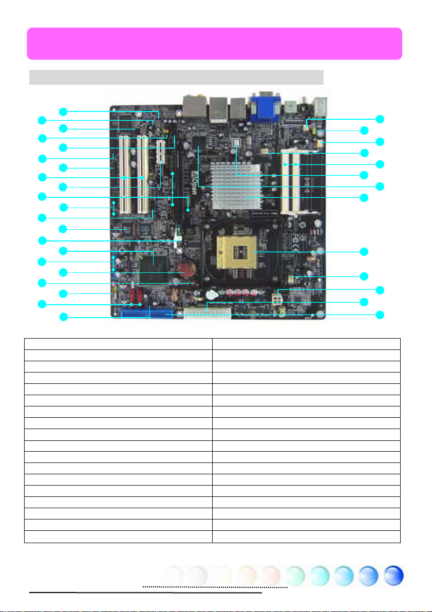
2.1 How does your motherboard look like?
L1
L2
L3
L4
L5
L6
L7
L8
L9
L10
L11
L12
L13
L14
L15
L16
L17
L18
L19
L20
L21
L1. Onboard HD audio codec R1. Power Temperature Connector
L2. S/PDIF Connector R2. JP28 PS2 KB/Mouse Wakeup Jumper
L3. IRDA Connector R3. Power FAN1 power connector
L4. Front Audio Connector R4. System FAN1 power connector
5. CD-IN Connector
L6. FDD Connector R6. Marvell PCIe gigabit Lan Chip(i945GMm-HL)
L7. Printer Connector R7. intel PCIe gigabit Lan(i945GTm-VHL)
L8. 32-bit PCI Expansion slot x 2 R8. intel 945GT/945GM north bridge
L9. PCI Express x1 Slot R9. Socket 479 for Yonah Core Duo/Solo CPU
L10. PCI Express VGA card enable jumper R10. CPU FAN power connector
L11. COM1+COM2 Connectors R11. 4 pins CPU power connector
L12. IEEE 1394 Connector R12. ATX power connector
L13. BIOS R13. IDE connector
L14. PCI Express x 16 Graphic expansion slot
L15. ICH7M/ICH7MRDH Southbridge
L16. USB 2.0 connectors L19. Front Panel connectors
L17. Battery L20. Serial ATA Port x 2
L18. JP14 CMOS clear Jumper L21. Case open connector
i945GTm-VHL Picture
R5. 200 Pins SODIMM x 2
R2
R4
R6
R8
R9
R10
R12
R1
R3
R5
R7
R11
R13
8
Page 9
2.2 Specification
Here is the main function of your motherboard.
Models i945GTm-VHL I945GMm-HL
CPU
Chipset
Main
Memory
Graphics
IDE
LAN intel Gigabit PCI Express LAN chip Marvell Gigabit PCI Express LAN Chip
Sound
USB Integrated in chipset, USB 2.0 x 8
IEEE 1394 Agere 1394 Control Chip
Slots
Back Panel
I/O
On Board
Connector
BIOS Award PnP 4Mb Flash ROM BIOS
Board Size 244 mm x 244 mm
intel Yonah Core Duo/Core Solo CPU
Socket 479
533/667MHz
intel 945GT/ICH7MDH intel 945GM/ICH7M
Dual Channel DDRII SODIMM x 2, DDRII400/533
DIMM Type : 256/512MB & 1GB SODIMM
Max Memory : 4GB
Integrated VGA Engine in Chipset
PCI Express x 16 Graphic Slot
Integrated ATA100 and Serial ATA Controller
Max Disk: 144,000,000GB [by 48 bits LBA Spec.]
intel High Definition Audio on Board
Support 7.1 Channel and above
PCI Express x16 Graphics Slot x 1
PCI Express x1 Slot x 1
PCI Slots x 3
USB Ports x 4, LAN Port x 1
VGA Port x 1, DVI Port x 1
Standard Video Port x 1
PS/2 Connector x 2
Analog S/PDIF audio connector x 1
Line_In x 1, Speaker_Out x 1, MIC_In x 1
Rear SUR x 1, Center/Subwoofer x 1, Side SUR x 1
Floppy Drive Connector x 1
IDE Channel: ATA100 x 1
Serial ATA Channel x 2
Front Panel x 1
Front Audio x 1
USB2.0 Connector x 4
CPU FAN x 1
System FAN x 1
Power FAN x 1
Power Temperature Connector x 1
Case Open Connector x 1
S/PDIF Connector x 1
CD_IN x 1
IrDA x 1
Printer Connector x 1
COM1 Connector x 1
COM2 Connector x 1
IEEE 1394 x 1
9
Page 10
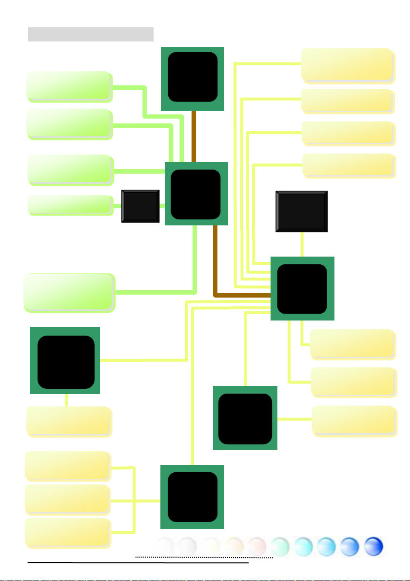
2.3 Block Diagram
p
p
r
VGA Onboard
Standard Video
PCI Express x 16
Gra
hics Slot
DVI Connector
DDRII
SODIMM x 2
Marvell/intel
PCI Express
Gigabit LAN
Chip
LAN connect
Com
onent
Socket 479
intel Yonah
Core
Duo/Solo
CPU
Intel
Chrontel
7307
945GT/945GM
Chipset
DDRII 400/533/667
RAM Up to 2GB
533/667MHz
System
Bus
Agere
IEEE
1394
Controlle
500MB/s
PCI Bus
150MB/s
ATA
33/66/100
RealTek
Azalia
CODEC
ICH7M/
ICH7MDH
PCI Express x 1
Slot x 1
32-bit PCI Slot x 2
Serial ATA Port x 2
IDE Drives x 2
4Mbits Flash
EEPROM
USB Port x 8
IEEE 1394 x 2
Parallel Port
Floppy Disk
Drive
Winbond
Super I/O
Serial Port x2
10
Page 11
Chapter 3 Hardware Installation
Chapter 3 Hardware
q
Installation
3.1 Quick Installation Procedure
2. Installing CPU
Fan & System Fan
3. Installing
Memory Module
4. Installing HD,
CD-ROM and
SATA Disk, etc
5. Connecting Front
Panel Cable
1. Installing CPU
12. Installing Drivers &
Utilities
11. Installing
Operating System
(such as, Windows
XP)
8. Installing Other
Devices (USB, Front
Audio, etc)
10. Loading
Default BIOS,
Setting CPU
uency
Fre
9. Connecting
Back Panel Ports
6. Connecting ATX
Power Cable
7. Installing PCI
Express x 16 Graphics
Cards & PCI Express x 1
Cards and PCI Cards
11
Page 12
3.2 Installation You Have to Know
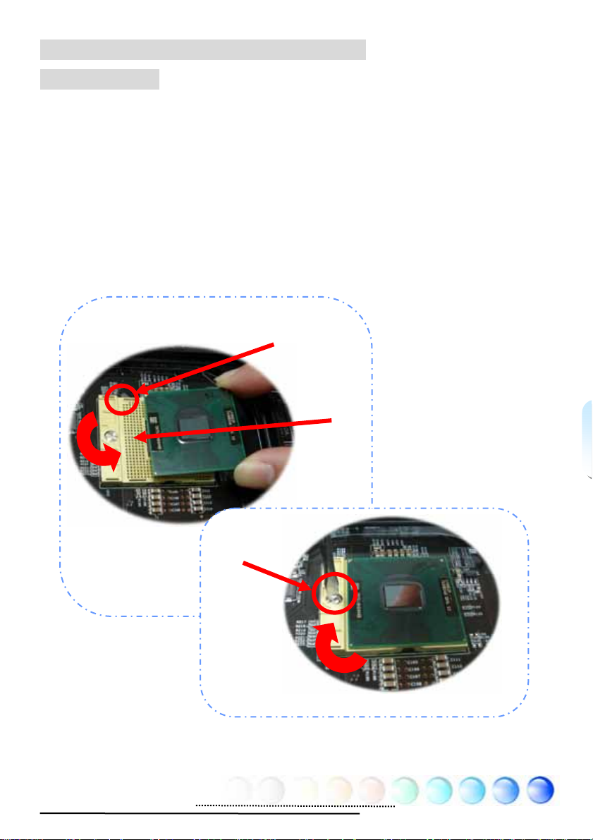
Installing CPU
This socket supports uFCPGA & uFCBGA package CPU, which is the latest Yonah
Core Duo and Core Solo CPU package developed by Intel. Other forms of CPU
package are impossible to be fitted in.
1. Unscrew the socket screw counter-clockwise.
2. Locate Pin 1 in the socket and look for a golden arrow on the CPU upper
interface. Match Pin 1 and golden arrow. Then insert the CPU into the
socket.
3. Lock the CPU socket screw clockwise to fasten CPU.
Socket Pin 1
Golden arrow
Socket screw
12
Page 13
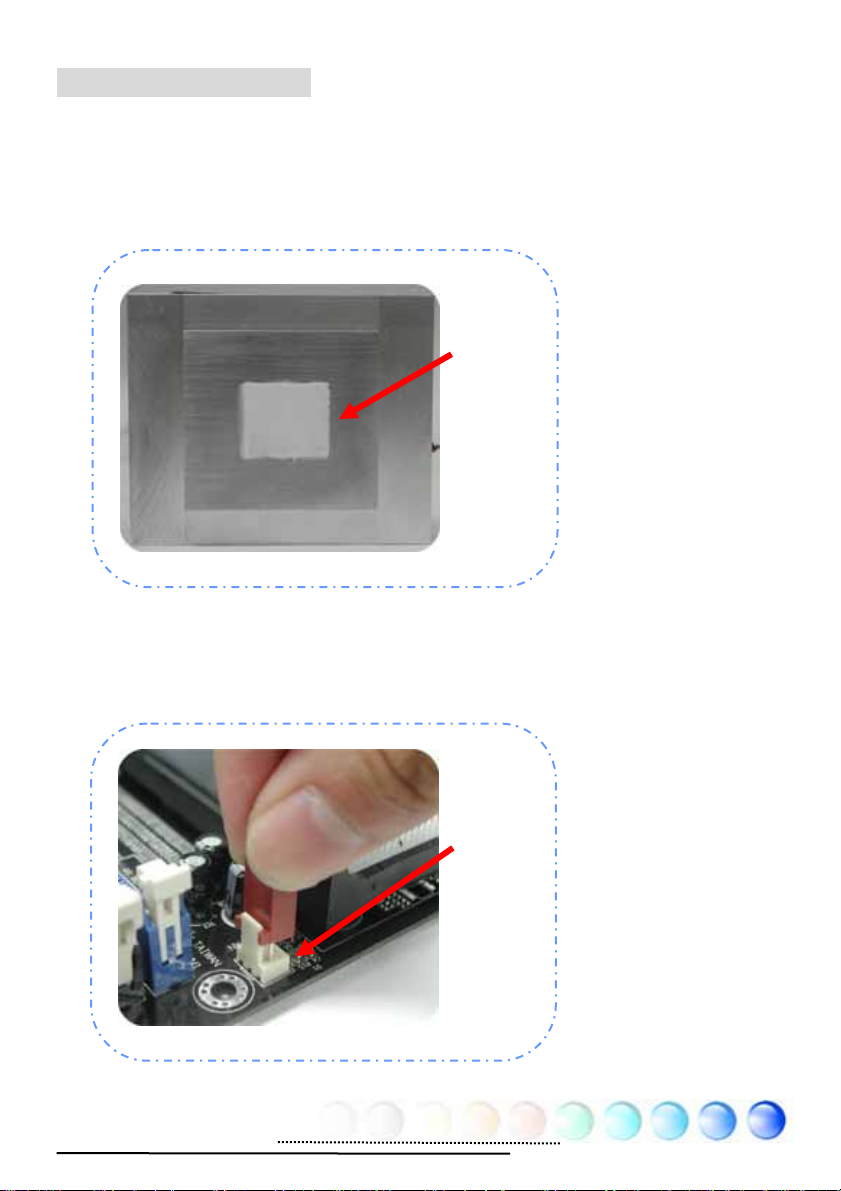
Installing CPU Cooler
This motherboard comes with a special CPU cooler desiged by AOpen, please
follow the following steps to install CPU cooler.
1. Please apply thermal paste on the bottom of CPU cooler.
2. Gently put CPU cooler onto the CPU retention module.
Thermal
paste
3. Connect cooler’s fan power cable onto CPUFAN connector.
CPUFAN
Connector
13
Page 14
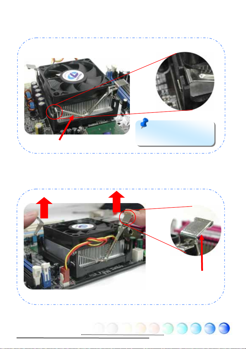
4. Install two cooler fixing sticks into CPU retention module.
Fixing stick
Note: Make sure that the
sticks have hooked CPU
retention module firmly.
5. Push the iron plate of cooler fixing stick up a bit.
Iron plate
14
Page 15
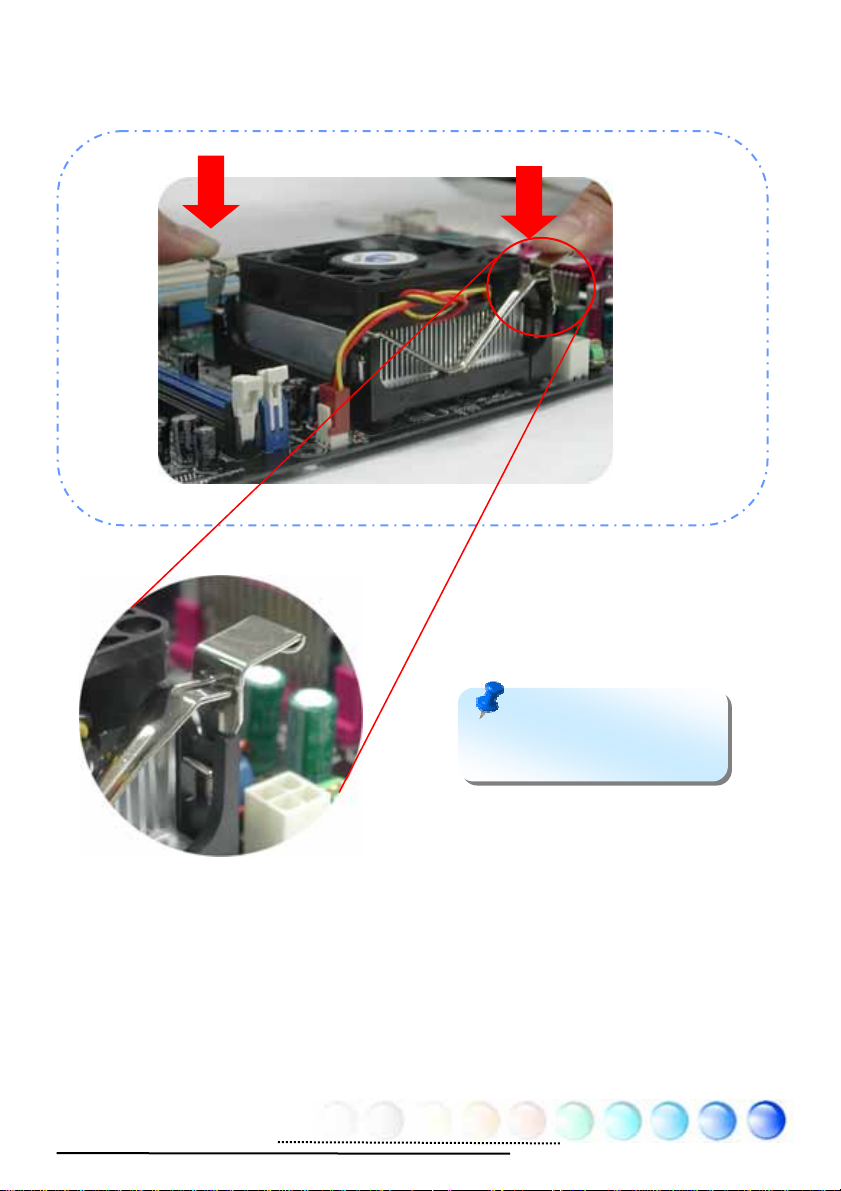
6. Then press iron plate downward till you hear a “clip” sound.
Note: Make sure that the
iron plate have hooked CPU
retention module firmly.
15
Page 16
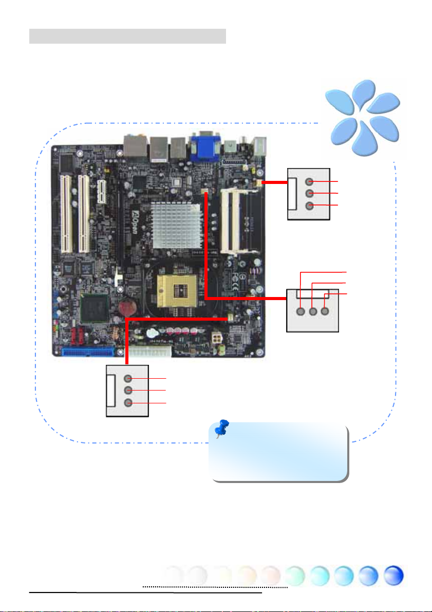
Installing CPU and System Fans
Plug the CPU fan cable to the 3-pin CPU FAN connector. If you have chassis fan,
you can also plug it in SYSFAN2 connector.
---
+
CPU FAN Connector
GND
+12V
Sensor
Note: Some CPU fans do
not have sensor pin so that
they cannot support fan
monitoring.
POWER FAN
System FAN Connector
Connector
+
16
Page 17
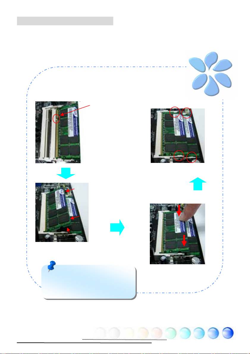
Installing Memory Modules
y
SODIMM slots are designed in high and low positions which are very easy to
recognize. Insert the module straight down to the SODIMM slot with fingers and
press down firmly until the SODIMM module is securely in place.
Ke
1.
Please aim the
key with SODIM
memory module
2.
Please have 30°
angle around to
plug and insert
into the SOMDIMM
slot
4.
Check the tabs
are properly hold
memory module
3.
Please press the
Memory vertically
to have “Clip”
sound
Note: The tabs of the SODIMM
slot will clip to hold the mod ule in
place when the SODIMM module
touches the slot’s bottom.
17
Page 18
Maximum The Performance of the Dual Channel
To obtain the highest performance of Dual Channel, the configuration of DIMM
must meet the following conditions.
Matched DIMM configuration in each channel
● Same density (128MB~1GB)
As long as you insert memory modules of same density into Channel 1
(SODIMM1) and Channel 2 (SODIMM3), dual channel mode will be enabled.
Ex: if you insert 1GB memory module into DIMM1 and DIMM3, dual channel
mode will be enabled when DIMM1 + DIMM3 = 1GB
● Same DRAM bus width (x8 or x16)
● Either single-sided or double-sided
Note: Using memory modules of different chip will
cause system unstable.
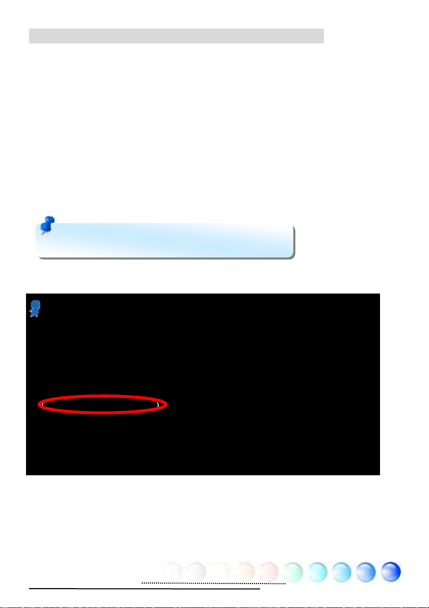
When dual channel mode is successfully enabled, the screen will show “Dual
Channel Mode Enabled” while entering POST screens.
Phoenix - AwardBIOS v6.00PG
Copyright (C) 1984-2003, Phoenix Technologies, LTD.
i945GTm-VHL R1.00 Mar. 06. 2006 AOpen Inc.
Main Processor : Intel(R) Pentium(R) M CPU T2500 @ 2.00GHz(166x12), 2 CPUs
Memory Testing : 1047552K
CPU Brand Name : Intel(R) Pentium(R) M CPU T2500 @ 2.00GHz
Memory Frequency For DDR2 667
(Dual Channel Mode Enabled)
IDE Channel 0 Master : Maxtor 6E040L0 NAR61590
IDE Channel 0 Slave : None
IDE Channel 2 Master : None
IDE Channel 2 Slave : None
18
Page 19
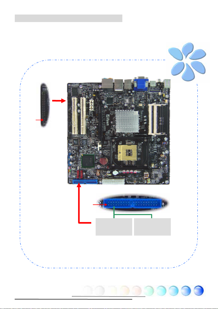
Connecting IDE and Floppy Cables
Connect the 34-pin floppy cable and 40-pin, 80-wire IDE cable to floppy
connector and IDE connector. Be careful of the pin1 orientation. Wrong
orientation may cause system damage.
Pin 1
FDD Connector
Pin 1
Primary
Slave (2nd)
ATA 33/66/100 IDE Connector
Primary
Master (1st)
19
Page 20
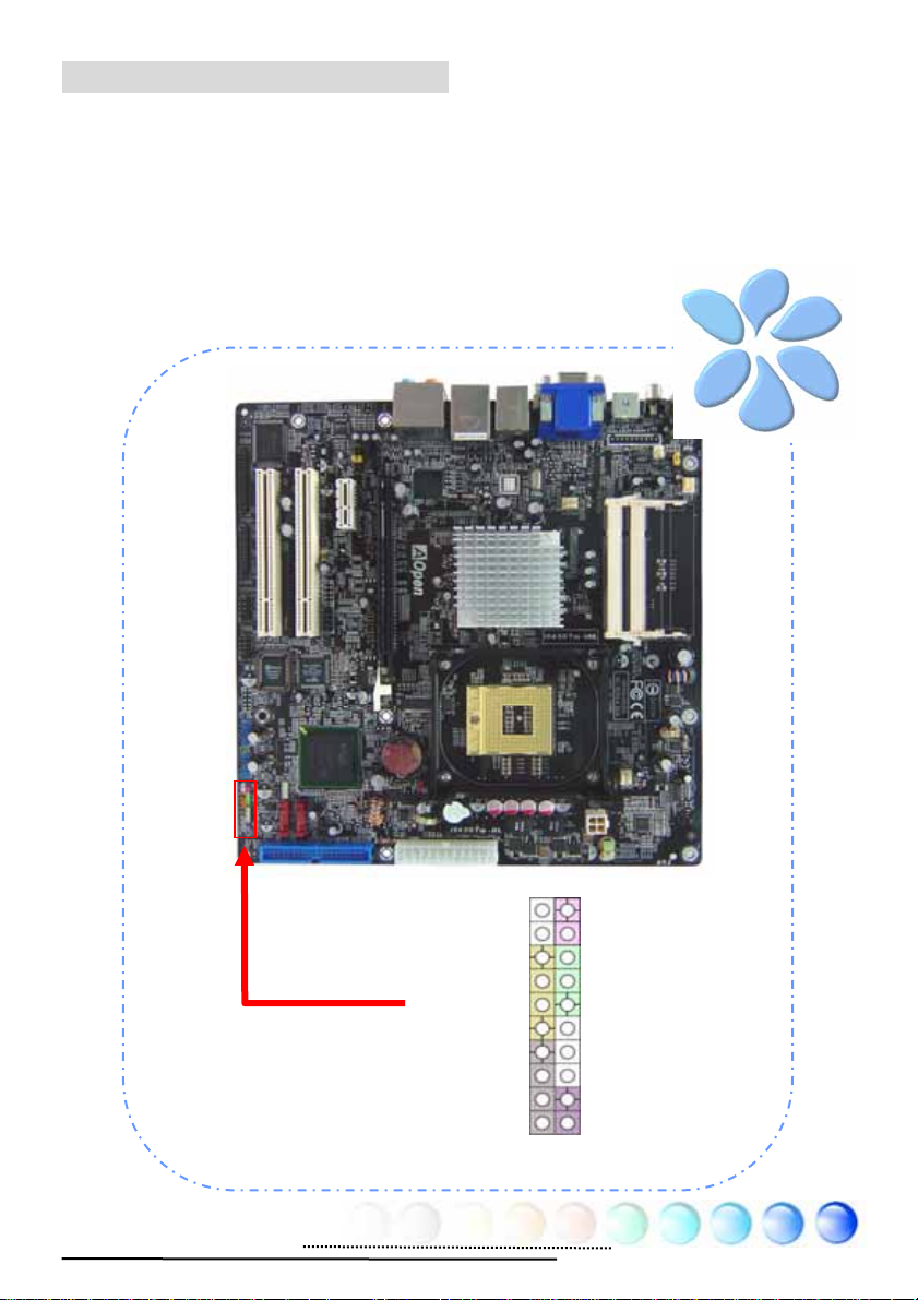
Connecting Front Panel Cable
Attach the power LED, speaker and reset switch connectors to the corresponding
pins. If you enable “Suspend Mode” item in BIOS Setup, the ACPI & Power LED
will keep flashing while the system is in suspend mode.
Locate the power switch cable from your housing, which is a 2-pin female
connector from the housing front panel. Plug this connector to the soft-power
switch connector marked SPWR.
HDD LED
HDD LED
SPEAKER
Front Panel Connector
20
NC
NC
+5V
+5V
+5V
GND
NC
1
Power Switch
GND
Power LEDGND
Power LED+
NC
GND
GND
RESET
GND
Page 21
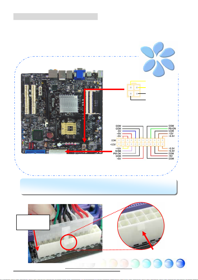
Connecting ATX Power Cables
This motherboard comes with a 24-pin and 4-pin ATX power connector as shown
below. Make sure you plug them in the right direction. We strongly recommend
you to insert the 4-pin connector before connecting the 20-pin connector.
Note: Please aim the power plug at the left side of the 24-pin AT X power
connector when the foolproof design faces you as shown.
Aiming at the
left side
+12V
+12V
Ground
Ground
Foolproof
21
Page 22

3.3 Other Installation for Your Reference
Setting CPU Frequency
Setting CPU Frequency
This motherboard is CPU jumper-less design, you can set CPU frequency through
1MHz stepping CPU Overclocking in the BIOS. CPU Core Frequency = CPU
External Frequency x CPU Ratio. However, all CPU now selling in the market
belong to "Fixed Multiplier". That means users can not adjust the CPU Ratio but
only change CPU FSB clock to achieve overclocking.
(Users do the overclocking at their own risk!!)
BIOS Setup > Frequency / Voltage Control > CPU Bus Frequency
Processor
Number
Core Duo T2700 65nm 2.33GHz 667MHz 2MB L2
Core Duo T2600 65nm 2.16GHz 667MHz 2MB L2
Core Duo T2500 65nm 2GHz 667MHz 2MB L2
Core Duo T2400 65nm 1.83GHz 667MHz 2MB L2
Core Duo T2300 65nm 1.66GHz 667MHz 2MB L2
Core Solo T1400 65nm 1.83GHz 667MHz 2MB L2
Core Solo T1300 65nm 1.66GHz 667MHz 2MB L2
Note: With CPU speed changing rapidly, there might be faster CPU on the market by the
time you received this installation guide. This table is kindly for your references only.
Architecture
Clock
Speed
Front
Side Bus
Cache Ratio
14
13
12
11
10
11
10
Warning: Intel 945GT/945GM chipset
supports maximum 667MHz (166MHz*4) system
bus; higher clock setting may cause serious
system damage.
Tip: When you fail to over-clock, you could:
1. Clear CMOS (JP14) to restore the default setting.
2. After turning power on, press “Home”
immediately until the screen appears.
22
Page 23

Connecting Serial ATA
To connect a serial ATA disk, you have to have a 7-pin serial ATA cable. Connect
two ends of the serial ATA cable to the serial ATA header on the motherboard and
the disk. Like every other traditional disk, you also have to connect a power cable.
Please be noted that it is a jumper free implement; you don’t need to set jumpers
to define a master or slave disk. When serial ATA hard disks are installed on serial
ATA ports, the one connected on Port0 (SATA1) will be set as the first boot device
automatically.
SATA1
SATA2
23
Page 24

Adjusting your Hard Disk Setting
Except its original 1 set of parallel IDE, this motherboard supports the latest serial
ATA hard disk. If you are unable to find your newly installed serial ATA hard disks
on your operating system after having them installed, the problem may lie in the
BIOS setting. You can simply adjust BIOS settings to have them work properly.
After installing your hard disks properly, you can directly go to BIOS setting
screen for adjustment. Simply pressing “Integrated Peripherals Æ OnChip
IDE Device Æ On-Chip Serial ATA” to choose your preferable mode. If you
have no intention of changing its original setting, the default would be Auto.
24
Page 25

Connecting PCI express x16 Graphics Slot
This motherboard provides a PCI Express x 16 Graphics slot, a black slot having
the latest PCI Express x 16 specification on motherboard. The PCI Express x 16 is
a bus interface targeted for high-performance 3D graphic. Traditionally AGP used
both rising and falling edge of the 66MHz clock for 8X AGP, and the data transfer
rate could achieve 2.1GB/s. Now PCI Express x 16 is moving to higher data
transfer rate, which is upgraded to 8.0GB/s (250MB/s x 16 x 2, it’s 4.0GB/s per
direction)..
PCIex16
25
Page 26

If user plugs a PCI Express x 16 Graphics, you must remove jumpers beside PCI
Express x 16 Slot.
Plug PCI Express x16 graphic card, please
remove jumpers below
Remove Jumpers
Warning: If user doesn’t remove jumper, it might make system unstable.
26
Page 27

Connecting PCI Express x 1 Slot
This motherboard provides one PCI Express x 1 slot, which is located between the
PCI Express x 16 and traditional PCI slot. In order to go with the step of today’s
and tomorrow’s processors, PCI Express x 1 provides higher I/O bandwidth. The
transfer data rate could achieve 500MB/s concurrently (it’s 250MB/s per
direction), which is nearly 4 times faster than the traditional PCI. You could install
any PCI Express x 1 device in these slots for your preference.
PCIex1
27
Page 28

Connecting IrDA
The IrDA connector can be configured to support wireless infrared module, with
this module and application software such as Laplink or Windows Direct Cable
Connection, user can transfer files to or from laptops, notebooks, PDA devices
and printers. This connector supports both HPSIR (115.2Kbps, 2 meters) and
ASK-IR (56Kbps).
Install an infrared module onto the IrDA connector and enable the infrared
function from BIOS Setup, UART Mode, you can use this function. Please make
sure you connect correct orientation when plugging IrDA module.
Pin 1
1
NC
+5V
IR_TX
IrDA Connector
KEY
GND
IR_RX
28
Page 29

10/100/1000Mbps LAN Supported
On the strength of Marvell Gigabit LAN controller on board, this motherboard
provides 10/100/1000Mbps Ethernet for office and home use. The Ethernet RJ45
connector is located on the top of USB connectors. The right hand side LED
indicates link mode; it lights in yellow when linking to network. The left hand side
LED indicates the transfer mode and will light in green when data is transferring
at 100Mbps (never lights while at 10Mbps), but will light in orange when
transferring in Gigabit’s mode. To enable or disable this function, you may simply
adjust it through BIOS. To enable LAN wakeup function, you have to set the
“Wake on PCI Card” enable in the BIOS “Power Management Setup” section.
Speed LED (Left)
Green 100Mbps
Orange Gigabit mode
29
ACT LED (Right)
Yellow
Page 30

Connecting USB2.0
This motherboard provides eight USB 2.0 ports to connect USB devices such as
mouse, keyboard, modem, printer, etc. There are four ports on the back panel.
You can use proper cables to connect Front USB connector to USB modules or
chassis front panel.
Pin 1
Pin 1
30
Page 31

Connecting 1394
With IEEE1394 Chip on board (AGERE 1394), having its data transfer rate up to
400Mb/s, this interface can connect to devices that require high data transferring
performance such as digital camera, scanner or others IEEE 1394 devices. Please
use appropriate cables to connect IEEE1394 devices.
SHIED GND
+12V (Fused)
TPBGND
TPA-
2 1
IEEE 1394 Connector
Warning: Please note that Hot-Plug is not allowed on IEEE
1394 headers; doing so will burn the controller IC and damage
the motherboard.
Pin1
+12V (Fused)
TPB+
GND
TPA+
Warning: 12V Power Support 6W only.
31
Page 32

Super 7.1 Channel Audio Effect
This motherboard comes with an ALC882D CODEC, which supports the latest 7.1
Channel with high quality of audio effects, bringing you a brand new audio
experience. This motherboard provides 7.1 Channel ports shown as below.
Picture represents the standard location of all speakers in 7.1 Channel sound
tracks. Please connect the plug of your front speakers to the green “Speaker out”
port , rear surround speakers to orange port, side surround speakers to gray port
and both of the center and subwoofer speakers to black port on the back panel.
32
Page 33

Connecting Front Audio
r
If the housing is designed with an audio port on the front panel, you’ll be able to
connect onboard audio to front panel through this connector. By the way, please
remove the jumper cap from the Front Audio Connector before you connect the
cable. Do not remove this yellow jumper cap if your housing doesn’t have an
audio port on the front panel.
Pin1
33
AUD_MIC_L
AUD_MIC_R
AUD_FPOUT_R
FRONT_IO_SENSE
AUD_FPOUT_L
Front Audio Connecto
1
AUD_GND
FRONT_IO Plug
AUD_RET_R
KEY
AUD_RET_L
Page 34

Connecting CD_IN
This connector is designed to connect CD Audio cable from CDROM or DVD drive
to onboard sound.
L
GND
GND
R
34
CD-IN Connector
Page 35

Connecting COM1/COM2
This motherboard provides two serial ports. All of them are on the left of PCI32
slot. With proper cable, you can connect it to the back panel of chassis.
Pin 1
Pin 1
DCD#
SOUT
GND
RTS#
R1#
1
SIN
DTR#
DSR
CTS#
35
Page 36

Connecting Case Open
r
The “CASE OPEN” header provides chassis intrusion-monitoring function. To
make this function work, you have to enable it in the system BIOS, connect this
header to a sensor somewhere on the chassis. So, whenever the sensor is
triggered by lights or by the opening of the chassis, the system will beep to inform
you. Please be informed that this useful function only applies to advanced chassis;
you may purchase an extra sensor, attach it on your chassis and make a good use
of this function.
Pin 1
1
Senso
Chassis Intrusion
Connector
GND
36
Page 37

Connecting S/PDIF (Sony/Philips Digital Interface)
S/PDIF (Sony/Philips Digital Interface) is a newest audio transfer file format,
which provides impressive audio quality through optical fiber and allows you to
enjoy digital audio instead of analog audio. Through a specific converter, you can
connect the S/PDIF connector to other end of the S/PDIF audio module, which
bears S/PDIF digital input/output. However, you must have an S/PDIF supported
speaker/amplifier/decoder with S/PDIF digital input/output to connect to the
S/PDIF digital input/output to make the most out of this function.
(RCA)
S/PDIF OUT
S/PDIF IN
S/PDIF OUT
S/PDIF IN
(Optical)
S/PDIF Module
(User Upgrade Optional)
S/PDIF
Cable
37
5
SPDIF IN
GND
SPDIF OUT
KEY
+5V
1
S/PDIF Connector
Pin 1
Page 38

3.4 Jumper Settings
This motherboard provides PS2 keyboard / mouse
wake-up function.
1
Disable
(Default) Enable
JP28 PS2 KB/Mouse
Wakeup Jumper
1
Normal
(Default)
JP14 Clear CMOS Jumper
1
1
Clear CMOS
You can clear CMOS to restore system default setting. To
clear the CMOS, follow the procedure below.
JP14 Clear CMOS Data
1. Turn off the system and unplug the AC power.
2. Remove ATX power cable from connector PWR2.
3. Locate JP14 and short pins 2-3 for a few seconds.
4. Return JP14 to its normal setting by shorting pin 1 & pin 2.
5. Connect ATX power cable back to connector PWR2.
38
Page 39

Chapter 4 Special Features and Utilities
Chapter 4 Special Features and Utilities
4.1 RAID (Redundant Array of Independent Disks)
With intel Southbridge ICH7MDH implemented, i945GTm-VHL provides RAID 0
and RAID 1 function for the Serial ATA hard disks.
Installation Raid driver under window installation
In order to make sure your system can recognize and operate Serial ATA RAID
device smoothly, one have to install Raid Driver under window installation
When start installing windows, then press “F6” when prompted at the beginning
of window setup
39
Page 40

Press the “S” key to select “Specify Additional Device
Please insert Raid Driver floppy Disk into Drive A:
After Raid driver floppy disk insert properly in drive A, please “ENTER” to
continue.
40
Page 41

Please select “intel® 82801 GHM SATA RAID Controller (Mobile ICH7R/DH)”
Press “enter” after selection.
Please press “ENTER” to continue installation
41
Page 42

4.2 Other Useful Features
With excellent design ability of R&D team, AOpen boasts for its various powerful
and handy features that come with our product like follows. You are welcomed
to visit our technical website to learn more about those features.
http://english.aopen.com.tw/tech/techinside
42
Page 43

Chapter 5 Setting BIOS
Chapter 5 Setting BIOS
5.1 Introduction
System parameters can be modified by going into BIOS Setup menu; this menu
allows you to configure the system parameters and save the configuration into
the 128 bytes CMOS area (normally in the RTC chip or in the main chipset).
The Phoenix-Award BIOS™ that installed in the Flash ROM of the motherboard is
a custom version of an industry standard BIOS. The BIOS provides critical
low-level support for standard devices such as hard disk drives, serial and parallel
ports.
AOpen’s R&D engineering team had optimized most BIOS settings of this
motherboard. However, some default settings of BIOS cannot fine-tune those
sections that controlled by chipset. Therefore, this chapter is intended to guide
you and help you to configure some other settings.
To enter BIOS setup menu, press <Del> when POST (Power-On Self Test) screen
is shown on your monitor.
Note: Because BIOS code is the most often
changed part on motherboard, the BIOS
information contained in this manual may be
different from the BIOS version that comes with
your motherboard.
43
Page 44

5.2 How To Use Phoenix-Award™ BIOS Setup Program
Generally, you can use arrow keys to highlight items that you want to choose,
press <Enter> key to select, and use <Page Up> and <Page Down> keys to
change setting values. You can press <Esc> key to quit Phoenix-Award™ BIOS
setup program. The following table provides details about how to use keyboard in
the Phoenix-AwardBIOS setup program.
Key Description
Page Up or + Change setting to next value or increase the value.
Page Down or - Change setting to previous value or decrease value.
Enter Select the item.
Esc In main menu: Quit without saving any changes.
In sub menu: Exit current menu to main menu.
Up Arrow Highlight previous item.
Down Arrow Highlight next item.
Left Arrow Move the light bar to left side of menu.
Right Arrow Move the light bar to right side of menu.
F7 Load optimized setting value from CMOS.
F10 Save changed settings and exit setup program.
5.3 How To Enter BIOS Setup
After finishing the jumper settings and connecting cables, you can power on and
enter the BIOS Setup. Press <Del> during POST (Power-On Self Test) and choose
"Load Setup Defaults" for recommended optimal performance.
Del
44
Page 45

Standard CMOS Features
The "Standard CMOS Setup" sets the basic system parameters such as the date,
time, and the hard disk type. Use the arrow keys to highlight an item and <PgUp>
or <PgDn> to select the value for each item.
Standard CMOS Features > Date
To set the date, highlight the Date parameter. Press <PgUp> or <PgDn> to set
the current date. The date format is month, date, and year.
Standard CMOS features > Time
To set the time, highlight the Time parameter. Press <PgUp> or <PgDn> to set
the current time in hour, minute, and second format. The time is based on the
24 hour military clock.
Standard CMOS features > IDE Channel 0 Master
Standard CMOS features > IDE Channel 0 Slave
Standard CMOS features > IDE Channel 2 Master
Standard CMOS features > IDE Channel 2 Slave
This item lets you select the IDE hard disk parameters that your system supports.
These parameters are Size, Number of Cylinder, Number of Head, Start Cylinder
for Pre-compensation, Cylinder number of Head Landing Zone and Number of
Sector per Track. The default setting is
Auto, which enables BIOS to
automatically detect the parameters of installed HDD (Hard Disk Drive) at POST
(Power-On Self Test). If you prefer to enter HDD parameters manually, select
Manual.
45
Page 46

IDE HDD Auto-Detection: Press “Enter” to auto-detect parameters of HDD
IDE Channel 0 Master (Slave): Define the parameters of IDE devices in
Channel 0 (Master or Slave). Available options:
z None: if there is no device, please select “None” for speeding boot up.
z Auto: enable BIOS to auto-detect parameters of IDE device. (Default)
z Manual: allow users to define parameter of IDE device.
Access Mode: Set the using mode of HDD. Available options: CHS / LBA /
Large / Auto (default). User can select the mode according to the label on
HDD.
Cylinder: Enter cylinder number
Head: Enter head number
Precomp: Write precompensation
Landing Zone: Location of head
Sector: Sector Number
Standard CMOS features > Drive A
This item allows user select the floppy drive type. Available items: None / 360KB
5.25” / 1.2MB 5.25” / 720KB 3.5” / 1.44MB 3.5” / 2.88MB 3.5”
Standard CMOS features > HaltOn
This parameter enables you to control the system stops in case of Power-On Self
Test (POST) error. Available items: No errors / All errors / All, But Keyboard
/ All, But Diskette / All, But Disk/Key
46
Page 47

Advanced BIOS Features
This screen appears when you select the option "Advanced BIOS Features" from
the main menu.
Advanced BIOS Features > Removable Device Priority
Advanced BIOS Features > Hard Disk Boot Priority
Advanced BIOS Features > CD-ROM Boot Priority
This parameter allows you to specify the system boot up search sequence.
Advanced BIOS Features > First Boot Device
Advanced BIOS Features > Second Boot Device
Advanced BIOS Features > Third Boot Device
This parameter allows you to specify the system boot up search sequence.
Available options:
z Removable: Floppy, USB, ZIP…etc
z Hard Disk: Hard Disk Drives
z CD-ROM: CD-ROM, DVD-ROM…etc
z LAN: LAN Card with boot ROM
z Disabled:
Advanced BIOS Features > Security Option
The “System” option limits access to both the System boot and BIOS setup. A
prompt asking you to enter your password appears on the screen every time you
boot the system.
The “Setup” option limits access only to BIOS setup.
To disable the security option, select Password Setting from the main menu, don't
type anything and just
press <Enter>
47
Page 48

Advanced Chipset Features
The "Advanced Chipset Features" includes settings for the chipset dependent
features. These features are related to system performance.
Warning: Make sure you fully
understand the items contained in this menu
before you try to change anything. You may
change the parameter settings to improve
system performance. However, it may cause
your system to be unstable if the set ting is not
correct for your system configuration.
Advanced Chipset features > On-Chip Frame Buffer Size (1M and 8M
optional)
Advanced Chipset features > DVMT mode
This item allows user to control the on-chip frame buffer size, fixed memory size,
DVMT.(Mode: Fixed,DVMT,Both)
Advanced Chipset features > DVMT/FIXED Memory Size
(64MB/128M/224MB)
48
Page 49

Integrated Peripherals
This submenu appears if you select the option "Integrated Peripherals" from the
main menu. This option allows you to configure the I/O features.
Integrated peripherals > OnChip IDE Device
Integrated peripherals > OnChip IDE Device > On-Chip Primary PCI IDE
This item allows you to select work mode on PATA .
Available options:
z Disabled: Disabled PATA Controller
z Enabled: Enable PATA Controller
Integrated peripherals > OnChip IDE Device > SATA Mode
This item allow you to select working mode on SATA
z IDE: SATA working as PATA IDE
z AHCI: SATA working as AHCI(Support hot plug function)
z Raid: SATA working as RAID also support hot play
49
Page 50

Integrated peripherals > Onboard Device
Integrated peripherals > Onboard Device > USB Controller
Integrated Peripherals > Onboard Device > USB 2.0 Controller
Integrated Peripherals > Onboard Device > USB keyboard Controller
Integrated Peripherals > Onboard Device > Azalia/AC97 Audio Select
Integrated Peripherals > Onboard Device > Onboard Lan Controller
Integrated Peripherals > Onboard Device > Onboard 1394 Controller
These items allow you to select working or non working.
Available options:
z Disabled: Disabled onboard selected device
z Enabled: Enable on board selected device
50
Page 51

Integrated peripherals > SuperIO Device
This item allows you to set SuperIO device.
Power ON Function: This item is used to select Wake on Keyboard/Mouse mode.
z Password: Disable the function of power button and let the system can
only be powered on through the preset keys (like a password).
z Hot Key: If selecting this option, you also need to specify the hot key
from “Hot Key Power On” item.
z Any Key: This function allows you wake up the system by clicking any
key.
z Button Only: Disable Wake on KB/MS function. You can boot up your
system by power button only.
Note:
Whenever you change this item, it will only take e ffect after you restart
the system and successfully boot the Windows or DOS.
Wake on Mouse function applies to PS/2 mouse only.
If you set a password but forget it, please clear CMOS.
If you want to use Wake on Mouse function in DOS, it is necessary to install
the DOS driver of the mouse.
KB Power ON Password: You can specify 1-5 keys as a password.
Hot Key Power On: If you select “Hot Key” option in “Power On Function”
Item, you need to specify a hot key here.
Onboard FDC Controller:
Setting this parameter to “Enabled“ allowing you
to connect your floppy disk drives to the onboard floppy disk connector
instead of a separate controller card. Change the setting to Disabled if you
want to use a separate controller card.
Onboard Serial Port 1:
This item allows you to assign address and interrupt
for the board serial port. The default is “Auto”.
51
Page 52

Onboard Serial Port 2: This item allows you to assign address and interrupt
for the board serial port. The default is “Auto”.
UART Mode Select: This item is configurable only if the "Onboard Serial Port
2" is enabled. This allows you to specify the mode of serial port2. Available
options:
z Normal:
setting.
z IrDA (SIR): This setting allows infrared serial communication at a
maximum baud rate of 115.2K baud.
z ASKIR: This setting allows infrared serial communication at a maximum
baud rate of 57.6K baud.
RXD, TXD Active: This item is used to select RxD (Receive Data) and TxD
(Transmit Data) mode for UART, for instance, IR device, modem, etc.
Normally, we suggest you keep the default setting. Please see the
documentation that comes with your device. Available options: Hi, Hi / Hi, Lo
IR Transmission Delay: If “Enabled” is selected, there will be a 4
character delay when SIR is changed from TX mode to RX mode.
Onboard Parallel Port: This item controls the onboard parallel port address
and interrupt. Available options: 3BC/IRQ7, 3BC/IRQ7, 3BC/IRQ7,
Disabled
Parallel Port Mode:
mode options are SPP (Standard and Bidirection Parallel Port), EPP (Enhanced
Parallel Port) and ECP (Extended Parallel Port). Available options:
z SPP (Standard and Bidirection Paralell Port): SPP is the IBM AT
and PS/2 compatible mode.
z EPP (Enhanced Parallel Port): EPP enhances the parallel port
throughput by directly writing/reading data to/from parallel port
without latch.
z ECP (Extend Parallel Port): ECP supports DMA and RLE (Run Length
Encoded) compression and decompression.
z ECP + EPP
EPP Mode Select: This item lets you select EPP mode protocol.
Available options: EPP 1.7, EPP 1.9
ECP Mode Use DMA: This item lets you set the DMA channel of ECP mode.
Available options: 3, 1
AC Power Auto Recovery: A traditional ATX system should remain at power
off stage when AC power resumes from power failure. This design is
inconvenient for a network server or workstation, without an UPS, that needs
to keep power-on. This item is used to solve this problem. Selecting On
enabling system to automatically power-on after AC power resumes; in the
other hand, the system will remain power-off if you select Off. If Former-Sts
(former status) option is selected, the system will power-on or power-off
based on the original state. Available options: Former-Sts, On, Off
Sets seria l port 2 to operate in norm al m ode. This is the default
This item lets you set the parallel port mode. The
52
Page 53

Power Management Setup
The Power Management Setup screen enables you to control the motherboard
green features. See the following screen.
Power Management > ACPI Suspend Type
This function allows you to select suspend types. S1 is Power On Suspend and S3
is Suspend to RAM. Available Options: S1, S3, S1 & S3
Power Management > Soft-off by PWR-BTTN
This is a specification of ACPI and supported by hardware. When Delay 4 sec. is
selected, the soft power switch on the front panel can be used to control power On,
Suspend and Off. If the switch is pressed for less than 4 seconds during power On,
the system will go into Suspend mode. If the switch is pressed for longer than 4
seconds, the system will be turned Off. The default setting is Instant-Off. If
Instant-Off is selected the soft power switch is only used to control On and Off, so
there is no need to press it for 4 seconds, and there is no Suspend.
Available Options: Delay 4 sec., Instant-Off
Power Management > Energy Lake Function
This is a function of Energy Lake Function supports
Available options: Disabled, Enabled
Power Management > Wake On PCI card
This is a function of PCI specification 2.2. PCI bus supports standby current to PCI
card and PCI card can wakeup system if it detects certain activity.
Available options: Disabled, Enabled
Power Management > Power On by Ring
This option lets you specify enable or disable Wake On Modem Ring function.
Available options: Disabled, Enabled
53
Page 54

Power Management > USB KB wake-up From S3
The USB KB wake-up from S3 support USB Keyboard wake up under S3 mode
Available options: Disabled, Enabled
Power Management > Resume by Alarm
This function can provide alarm to resume system immediately.
Available options: Disabled, Enabled
Power Management > Date (of Month) Alarm
This item is displayed when you enable the Wake On RTC Timer option. Here you
can specify what date you want to wake up the system. For Example, setting to 15
will wake up the system on the 15th day of every month.
Tip: Setting this item to 0 will wake up the
system on the specified time (which can be set in
the Wake On RTC Timer) every day.
Power Management > Time (hh:mm:ss) Alarm
This item is displayed when you enable the Wake On RTC Timer option. Here you
can specify what time you want to wake up the system.
54
Page 55

PC Health Status
The PC Health Status can bring PC important safety parameters for detect Health
of your system.
PC Health Status > CPU Smart Fan
The CPU smart fan can detect CPU temperature and adjust fan speed
automatically. That can ensure you to have silent & best working environment for
system. Suggestion: Enabled it.
Available options: Disabled, Enabled
PC Health Status > System Temperature
PC Health Status > CPU Temperature
PC Health Status > CPU Fan
PC Health Status > Vcore
PC Health Status > VCC (V)
PC Health Status > VBAT (V)
PC Health Status > SVSB (V)
PC health status bring you on the system temperature, CPU temperature, CP Fan
speed, Vcore, VCC, VBAT, SVSB – these important system parameters for you to
check the health status of your system.
55
Page 56

Frequency/Voltage Control
This submenu allows you to configure the CPU and memory clock.
Frequency/Voltage Control > Spread Spectrum
This item is used to set the value of clock Spread Spectrum. BIOS will determine
the adjustable value according to the CPU installed, not all items will be showed.
Available options: Disabled, Enabled
Frequency/Voltage Control > CPU Clock
This item shows the CPU Clock of status. You can adjust the clock according it.
Available options: 166MHz-190Mhz
Tip: When you fail to overclock, you could:
Clear CMOS (JP14) to restore the default setting.
After turning power on, press “Home” immediately until
the screen appears.
56
Page 57

Load Optimized Defaults
The "Load Optimized Defaults" option loads BIOS default settings.
Set Supervisor Password
Supervisor Password prevents unauthorized use of your computer. If you set a
password, the system prompts for the correct password before boot or access to
Setup. The item are supervisor level, that can be allow modification all kind of
item on BIOS inside.
To set a password:
1. At the prompt, type your password. Your password can be up to 8
alphanumeric characters. When you type the characters, they appear as
asterisks on the password screen box.
2. After typing the password, press.
3. At the next prompt, re-type your password and press again to confirm the
new password. After the password entry, the screen automatically reverts to
the main screen.
To disable the password, press “Enter” when being prompted to enter the
password. The screen displays a message confirming that the password has been
disabled.
57
Page 58

Set User Password
User Password can authorize users check only. It cannot modify the BIOS setting
inside. The item just allow take a look defult value on BIOS inside.
To set a password:
4. At the prompt, type your password. Your password can be up to 8
alphanumeric characters. When you type the characters, they appear as
asterisks on the password screen box.
5. After typing the password, press.
6. At the next prompt, re-type your password and press again to confirm the
new password. After the password entry, the screen automatically reverts to
the main screen.
To disable the password, press “Enter” when being prompted to enter the
password. The screen displays a message confirming that the password has been
disabled.
Save & Exit Setup
This function automatically saves all CMOS values before leaving Setup.
Exit without Saving
Use this function to exit Setup without saving the CMOS value changes. Do not
use this option if you want to save the new configuration.
58
Page 59

5.4 BIOS Upgrade under Windows environment
y p
With outstanding R&D ability of AOpen, we now bring you a whole new BIOS Flash
wizard ---- EzWinFlash. With an eye to convenience for users, EzWinFlash
combines the BIOS binary code and flash module together, so the only thing you
have to do is just clicking on the utility you downloaded from web and let it help
you complete the flash process automatically. EzWinFlash detects your
motherboard and checks the BIOS version cleverly to prevent your system from
any possible failure. Moreover, EzWinFlash has been taken into consideration to
go with any windows platform you might be using, no matter if you’re using
Windows 95/98, 98SE/ME, NT4.0/2000, or Windows XP.
In the meanwhile, in order to provide a much more user-friendly operating
environment, AOpen EzWinFlash is natively designed to have multi-language
function to provide easier way for user in changing BIOS setting.
Caution: You are taking a risk of BIOS flash
failure when you update your system. If your
motherboard is working stable, and there are no
major bugs to be fixed by a latter BIOS revision, we
recommend that you DO NOT upgrade your BIOS.
If you intent on upgrade PLEASE MAKE SURE you
get the right BIOS revision for your motherboard
model so as to avoid an
ossible failure.
Note: The model name on this BIOS picture is for reference only. It may
not be the same model with your motherboard.
59
Page 60

You may accomplish BIOS upgrade procedure with EzWinFlash according to
following steps, and it’s STRONGLY RECOMMENDED to close all applications
before you start the upgrades.
Download the latest version of BIOS package zip file from AOpen official web site.
(Ex: http://english.aopen.com.tw/
)
Unzip the downloaded BIOS package (ex: WSGMAXII102.ZIP) with WinZip
(http://www.winzip.com
) in Windows environment.
Save the unzipped files into a folder, for example, WSGMAXII102.EXE &
WSGMAXII102.BIN.
Double click WSGMAXII102.EXE; EzWinFlash will detect the model name and
BIOS version of your motherboard. If you collect wrong BIOS, you will not be
allowed to proceed with the flash steps.
You may select a preferred language in main menu, then click [Start Flash] to
begin the BIOS upgrade procedure.
EzWinFlash will complete all the process automatically, and a dialogue box will
pop up to ask you to restart Windows. Click [YES] to reboot Windows.
Press <Del> at POST to enter BIOS setup screen; choose "Load Setup Defaults",
then “Save & Exit Setup”. Done!
It is strongly recommended NOT to turn off the power or run any applications
during FLASH PROCESS.
Warning: The new BIOS upgrade will
permanently replace your original BIOS setting
when flashing. You may need to reconfigure the
BIOS setting before your system goes back to
work as normal.
60
Page 61

Chapter 6 Installing Drivers
Chapter 6 Installing Drivers
You may think that installing drivers and utilities would be a repeated task of going
through those installation wizards and steps-by-steps. Now, you will be surprised
with how “Ez” EzInstall could do. Without wizards or steps, all you have to do is to
do one click and then it’s done. Click and done. Yes. EzInstall makes installation
easy and even foolproof!
After putting in the CD, you will be prompted with AOpen welcome page and our
branches information.
First, click on the install driver ICON at left side for necessary drivers.
Second, click on the install utility ICON at left side for preferred utilities.
Practically, it’s done. But you may also browse CD contents, Readme to get more
information or just exit the CD installation.
Install
driver
Click to install
online manual
Install
utility
Browse CD
Contents
Readme
AOpen
branches
information
Exit CD
61
Page 62

6.1 Installing Drivers
As you may see from the Installing driver page, EzInstall had picked up necessary
for your motherboard. All you have to do is just click on the “GO”, and n o mor e
steps afterward, of all listed drivers, grey checks indicate necessary drivers; you
cannot click them off. Red checks can be disabled if you don’t want to install them
now.
Press the icon will prompt the
“Install Driver” page. You
may also press “Back” to
return to the Main page.
Once clicking “GO”, EzInstall will run the installing procedure
automatically, and prompt a reboot dialog (Some drivers or
utilities may skip the reboot part).
62
Page 63

After installed the driver successfully, the system configuration of your system can be
checked through the Window Device Manager. There should not have any warning sign on
each red frame below. That means your driver work successful now.
63
Page 64

6.2 Installing Utilities
Installing Utilities is virtually the same as installing drivers. AOpen provides you
many friendly and powerful utilities to manage your system. You may find lots of
fabulous utilities listed there, and all you have to do is to click on the “GO”, then
it will install the utilities to your system right away without complicated steps.
Press the icon will
prompt the “Install
Utilities” page for your
selection. You may also
press “Back” to get back
to the Main page.
64
Page 65

r
6.3 Display output behavior
AOpen provides newest innovation with high definition display output. Below
diagram will show the way of display output.
D-SUB
DVI
S-Video
YPbP
CRT
TV/SDTV
TV/HDTV
LCD with DVI Connector
FAQ
(1) Intel Drive just supports “Dual Monitor Mode” and “Single Monitor Mode”.
(2) When running in Dual Monitor mode and playing Media Player, there is only an output
device can work. If want to support both output devices, please change “Dual Monitor
Mode” to “Extended Mode”
(3) Because both of YPbPr and D connector are from the same signal, select either one to
output will get the better quality.
(4) If you pull out the primary device under Dual Monitor Mode and reboot, the secondary
device’s screen will be dark. You can use hotkey to set the primary device.
Hot Key List
Ctrl + Alt + F1 D-SUB
Ctrl + Alt + F2 TV (set as primary)
Ctrl + Alt + F4 DVI
(5) When plug Geforce FX5200 PCI VGA card, the system will be crashed. It results from
Intel Driver will conflict with this card.
Output Device as Primary
65
Page 66

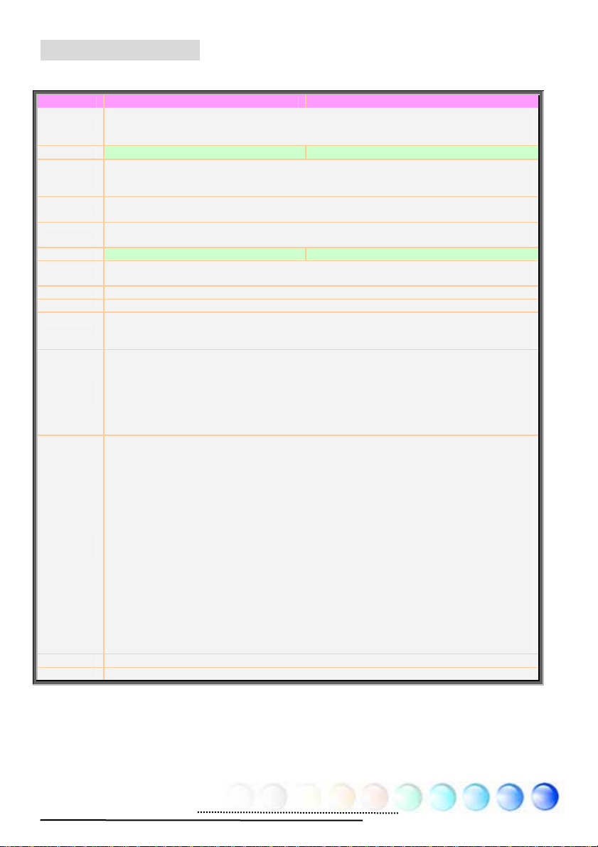
Display output behavior
Output Mode During POST VGA initial
Output Connector D-SUB DVI
Output Device
Combination
D-SUB On N/A N/A
DVI N/A On N/A
YPbPr / S-Video N/A N/A On
D-SUB+DVI On On N/A
D-SUB+YPbPr / S-Video On N/A OFF
YpbPr /
S-Video
CRT LCD TV 1
D-SUB+DVI+YPbPr / S-Video
DVI+YPbPr / S-Video N/A On OFF
Output Mode Windows Platform
Output Connector D-SUB DVI
Output Device
Combination
D-SUB On N/A N/A
DVI N/A On N/A
YPbPr / S-Video N/A N/A On
D-SUB+DVI On On N/A
D-SUB+YPbPr / S-Video On N/A On
D-SUB+DVI+YPbPr / S-Video On On On
DVI+YPbPr / S-Video N/A On On
Note:
(1) Dual Monitor only support two devices to output. The “On” mean it can work with
another one.
On On OFF
YpbPr /
S-Video
CRT LCD TV 1
66
Page 67

Chapter 7 Troubleshooting
g
Chapter 7 Troubleshootin
67
Page 68

Chapter 8 Technical Support
Chapter 8 Technical Support
Dear Customer,
Thanks for choosing AOpen products. We invite you to register at
http://www.aopen.com
to become a Gold Member of Club AOpen so as to
ensure quality service in the future. In order to maintain the best service to every
customer of us, we recommend you to follow the procedures below and seek help
from our branches according to the region you buy the product. With your help,
we can then continue to provide efficient and the best quality service to every
customer.
Thanks very much for your understanding!
AOpen Technical Supporting Team
Europe
AOpen Computer b.v.
Tel: 31-73-645-9516
Email: Support@AOpen.NL
Germany
AOpen Computer GmbH.
Tel: 49-2131-1243-710
Fax: 49-2131-1243-999
Europe Email: Support@AOpen.NL
Pacific Rim: http://www.aopen.com.tw/tech/default.htm
China: http://www.aopen.com.cn/tech/default.htm
Germany: http://www.aopencom.de/tech/default.htm
America: http://usa.aopen.com/tech/default.htm
Japan: http://aopen.jp/tech/index.html
China
艾爾鵬國際貿易(上海)有限公司
Tel: 86-21-6225-8622
Fax: 86-21-6225-7926
Pacific Rim
AOpen Inc.
Tel: 886-2-3789-5888
Fax: 886-2-3789-5899
Japan
AOpen Japan Inc.
Tel: 81-048-290-1800
Fax: 81-048-290-1820
America
AOpen America Inc.
Tel: 1-510-489-8928
Fax: 1-510-489-1998
68
Page 69

Model Name and BIOS Version
Model name and BIOS version can be found on upper left corner of first boot
screen (POST screen). For example:
Phoenix AwardBIOS v6.00PG, An Energy Star Ally
Copyright (C) 2005, Phoenix Technologies, LTD.
i945GTm-VHL R1.00 Jan. 31. 2005 AOpen Inc.
i945GTm-VHL is model name of motherboard; R1.00 is BIOS version
Register Your Motherboard
Thanks for choosing AOpen product, please register this motherboard at
http://club.aopen.com.tw/productreg/
and to ensure high service quality and priority from AOpen. You will also have a
chance to play slot machine game to win prize from AOpen. Please prepare the
following information before you start: Model Name, Part Number (P/N), Serial
Number (S/N) and Purchase Date. The Part Number and Serial number are
printed on bar code label. You can find this bar code label on the outside packing
or on component side of PCB. For example:
to become a Gold member of Club AOpen,
P/N: 91.88110.201 is part number, S/N: 91949378KN73 is serial number.
Beep Sound Message
1 short(Beep) System booting is normally.
1 long - 1 short(Beep) DRAM ERROR
1 long - 2 short(Beep) Display card or monitor connected error
1 long - 3 short(Beep) Keyboard Error
Long(Beep) continuous DRAM hasn't inset correctly.
Part No.
Phoenix-Award BIOS ERROR Message
69
Serial No.
Page 70

Technical Support
70
 Loading...