

Page 1
E
E
a
a
s
s
y
y
I
I
n
n
s
s
t
t
a
a
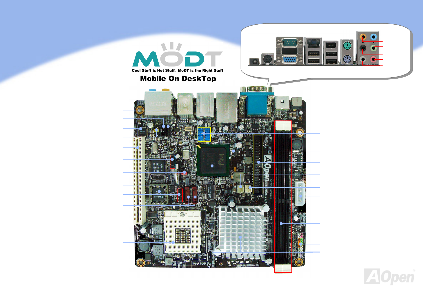
i915GMt-FSA
S/PDIF Connector
CD_IN Connector
DC Jack
S-Video
COM Port
VGA Port
RJ45
LAN Jack
USB2.0 Ports
IEEE
1394
Port
PS/2
Mouse
PS/2
Keyboard
Line-In
Rear SUR
Speaker-Out
Center/
Subwoofer
MIC-In
Side SUR
l
l
l
l
a
a
t
t
i
i
o
o
n
n
G
G
u
u
i
i
d
d
e
e
Onboard AC’97 CODEC
Front Audio Connector
32-bit PCI Expansion Slot
IEEE 1394 Connector
JP14 CMOS Data Clear Jumper
DieHard BIOS Lite
COM2 Connector
Serial ATA Ports x 2
479-pin CPU socket with Voltage and
supports Intel
Frequency Auto-detection that
®
Pentium® M (Dothan)
and Celeron
®
M CPU
USB 2.0 Connector
STBY LED
IDE Connector
(ATA 33/66/100 supported)
SYSFAN Connector
CPUFAN Connector
4-pin 12V Power Output Connector
240-pin DIMMsx2
400/533 Dual Channel
Max. To 2GB
Front Panel Connector
®
915GM/ICH6-M Chipsets that
Intel
support 533 MHz FSB,
DDRII 400/533 Dual Channel
support DDRII
AOpen reserves the right to revise all the specifications and information contained in this document, which are subject to change without notice.
Page 2
,
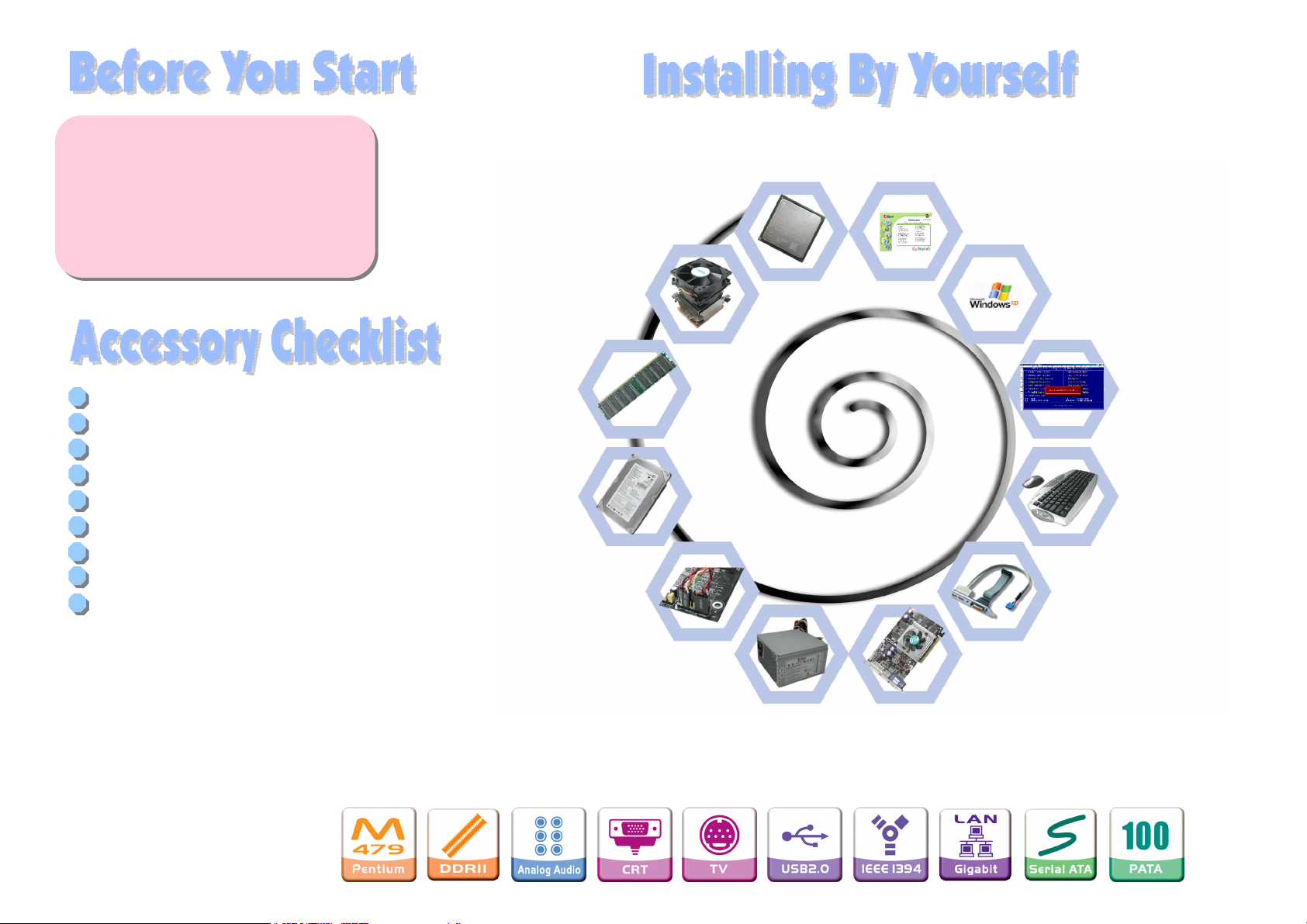
Everything you need to boot this
motherboard is included in this
Easy Installation Guide. For more
information, a complete Online
User's Manual can be found in the
Bonus Pack CD. Thanks for the
help of saving our earth.
1. Installing CPU
2. Installing CPU Fan
& System Fan
12. Installing Drivers & Utilities
11. Installing Operating
System (such as,
Windows XP)
Easy Installation Guide x 1
80-Wire IDE Cable x 1
Serial ATA Cable x 1
Serial ATA Power Cable x 1
4-pin Power cable x 1
Back Panel I/O Shield x 1
Bonus Pack CD x 1
CPU Cooler x 1
Power Adapter x 1
3. Installing
Memory Module
4. Installing HD,
CD-ROM and SATA
Disk
etc
5. Connecting Front
Panel Cable
8. Installing Other Devices
(USB, Front Audio, etc)
10. Loading Default
BIOS, Setting CPU
Frequency
9. Connecting Back
Panel Ports
(Keyboard, Mouse,
etc)
6. Connecting
Power Adapter
7. Installing PCI Card
PART NO: 49.8ET03.EE10
DOC. NO: I915GMTFSA-EG-E0604A
Page 3
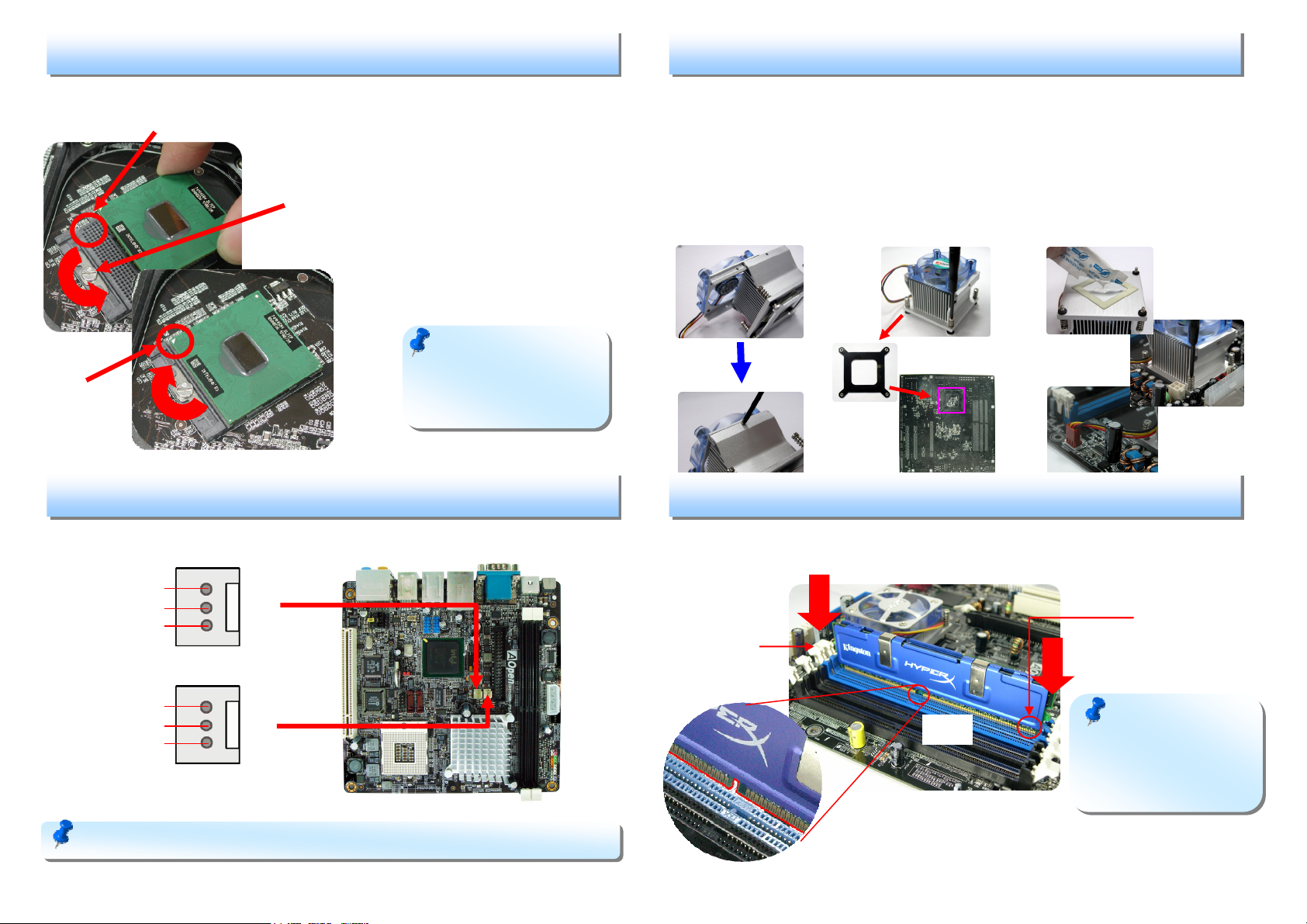
This socket supports uFCPGA package CPU, which is the latest CPU package
developed by Intel. Other forms of CPU package are impossible to be fitted in.
Socket Pin 1
1. Installing CPU
1. Unscrew socket screw counterclockwise.
2. Locate Pin 1 in the socket and look for
Socket Screw
a golden arrow on the CPU upper
interface. Match Pin 1 and golden
arrow. Then insert the CPU into the
socket.
3. Lock the socket screw clockwise to
fasten CPU.
3. Installing CPU Cooler
Step1: Plug the CPU Fan into the top of the heat sink and then lock the screws
between the CPU Fan and heat sink.
Step2: Remove the four screws of heat sink and let the bracket lock on the back
of motherboard.
Step3: Smear over the thermal compound under heat sink. Put CPU cooler on the
CPU and lock the four screws of heat sink. Please make sure screws are
well tied between motherboard and heat sink. Finally, Let CPU cooler’s
power cord connects to CPU FAN connector.
STEP 1
STEP 2
STEP 3
Golden arrow
Note: If you do not
match the CPU socket Pin 1
and CPU golden arrow well,
you may damage the CPU.
2. Installing CPU & System FANs
Plug in the CPU fan cable to the 3-pin CPUFAN connector. If you have chassis fan,
you can also plug it in SYSFAN connector.
SENSOR
+12V
GND
SYSFAN Connector
SENSOR
+12V
GND
CPUFAN Connector
Note: Some CPU fans do not have sensor pin so they cannot support fan monitoring.
4. Installing Memory Modules
DIMM slots are designed in black which are very easy to recognize. Insert the
module straight down to the DIMM slot with both hands and press down firmly until
the DIMM module is securely in place.
Pin 1
Tab
Key
Note: The tabs of the
DIMM slot will close-up to
hold the DIMM in place
when the DIMM touches
the slot’s bottom.
Page 4
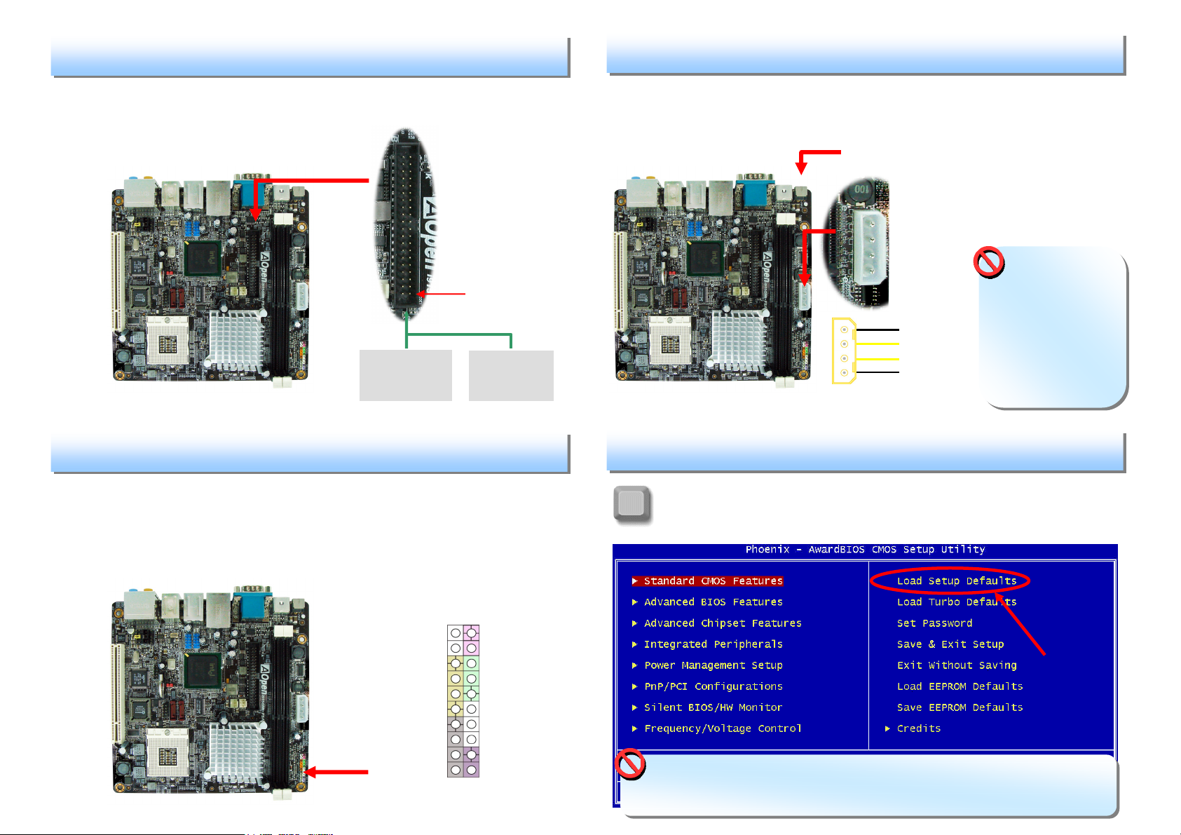
Connect 40-pin, 80-wire IDE cable to IDE connector. Be careful of the pin1
orientation. Wrong orientation may cause system damage.
5. Connecting IDE Cable
Pin 1
Primary
Slave (2nd)
ATA 33/66/100 IDE Connector
IDE 1 (Primary)
Primary
Master (1st)
6. Connecting Front Panel cable
7. Connecting Power Cable and Power Adapter
This motherboard comes with a 4-pin power connector as shown below. Make
sure you plug in the right direction. Use the bundled 4-pin power cable to
connect IDE device from on-board 4-pin connector. Last step is to plug power
into DC Jack from power Adapter.
Connect to power adapter.
+5V
Ground
Ground
+12V
Warning: This
4-pin connector is
for power output.
Do not connect any
power cable from
power supply. It
will demage the
mainboard..
8. Power-on and Loading BIOS Setup
Attach the power LED, speaker, and reset switch connectors to the corresponding
pins. If you enable “Suspend Mode” item in BIOS Setup, the ACPI & Power LED
will keep flashing while the system is in suspend mode.
Locate the power switch cable from your ATX housing. It is 2-pin female
connector from the housing front panel. Plug this connector to the soft-power
switch connector marked SPWR.
After you finish the setting of jumpers and connect correct cables. Power
on and enter the BIOS Setup, press <Del> during POST (Power On Self
Del
Tes t ).
Choose "Load Setup Defaults" for recommended optimal
performance.
HDD LED
HDD LED
SPEAKER
Front Panel Connector
NC
NC
+5V
+5V
+5V
GND
NC
1
Power Switch
GND
Power LEDGND
Power LED+
NC
GND
GND
RESET
GND
Warning: Please avoid of using "Load Turbo Defaults", unless you are sure your
system components (CPU, RAM, HDD, etc.) are good enough for turbo setting.
Page 5
S
CPU C
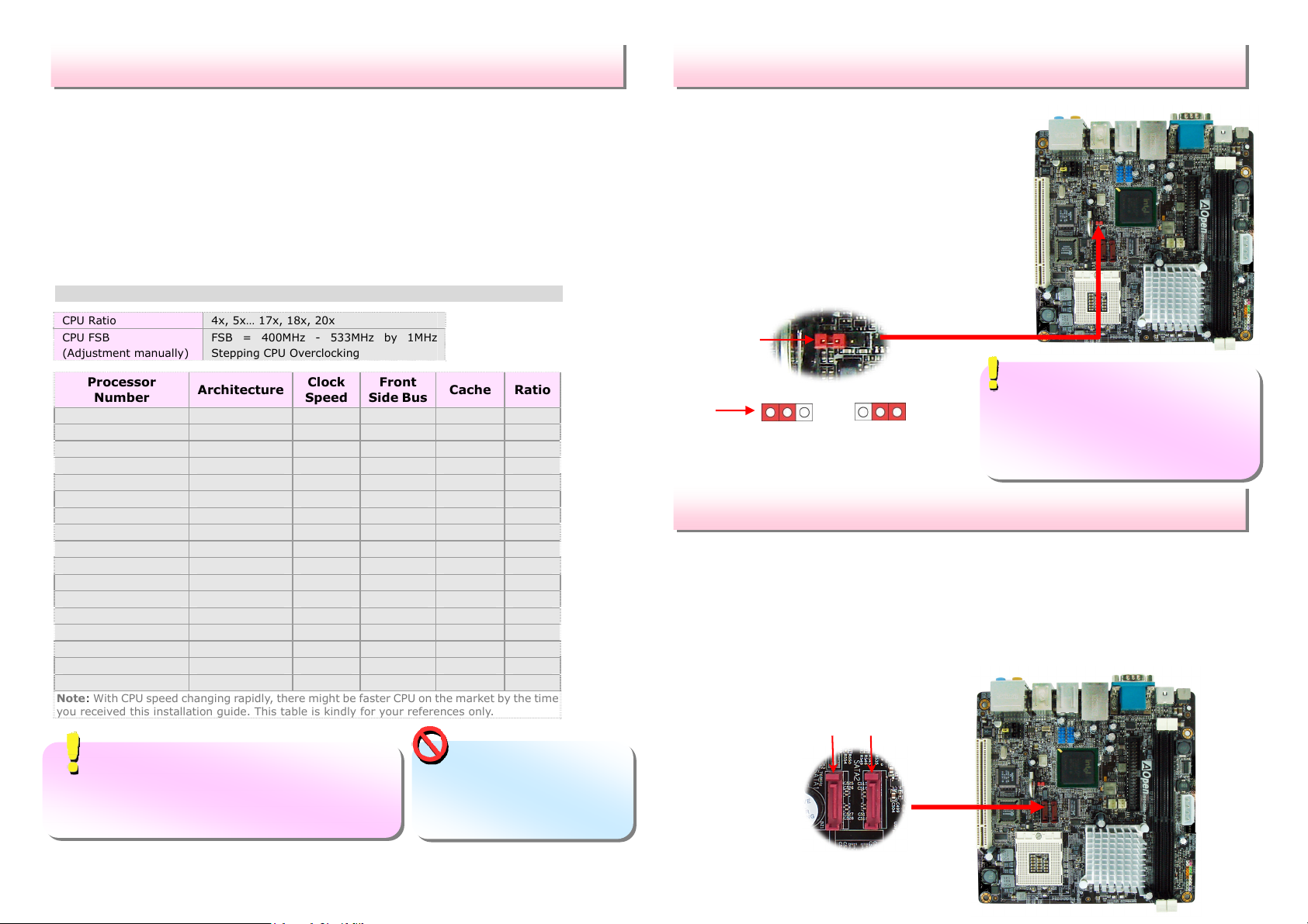
Setting CPU Voltage & Frequency
etting
This motherboard supports Voltage ID (VID) function to detect CPU voltage
automatically during power-on.
Setting CPU Frequency
This motherboard is CPU jumper-less design, you can set CPU frequency through
1MHz stepping CPU Overclocking in the BIOS. CPU Core Frequency = CPU external
frequency x CPU Ratio. However, all CPU now selling in the market belong to "Fixed
Multiplier". That means users can not adjust the CPU Ratio but only change CPU
FSB clock to achieve overclocking.
(Users do the overclocking at their own risk!!)
BIOS Setup > Frequency / Voltage Control > CPU Bus Frequency
CPU Ratio 4x, 5x… 17x, 18x, 20x
CPU FSB
(Adjustment manually)
Processor
Number
Pentium M 770 90nm 2.13GHz 533MHz 2MB L2
Pentium M 760 90nm 2.00GHz 533MHz 2MB L2
Pentium M 750 90nm 1.86GHz 533MHz 2MB L2
Pentium M 740 90nm 1.73GHz 533MHz 2MB L2
Pentium M 730 90nm 1.60GHz 533MHz 2MB L2
Pentium M 765 90nm 2.10GHz 400MHz 2MB L2
Pentium M 755 90nm 2.00GHz 400MHz 2MB L2
Pentium M 745 90nm 1.80GHz 400MHz 2MB L2
Pentium M 735 90nm 1.70GHz 400MHz 2MB L2
Pentium M 725 90nm 1.60GHz 400MHz 2MB L2
Pentium M 715 90nm 1.50GHz 400MHz 2MB L2
Pentium M 705 130nm 1.50GHz 400MHz 1MB L2
Celeron M 370 90nm 1.50GHz 400MHz 1MB L2
Celeron M 360 90nm 1.40GHz 400MHz 1MB L2
Celeron M 350 90nm 1.30GHz 400MHz 1MB L2
Celeron M 340 130nm 1.50GHz 400MHz 512KB L2 15x
Celeron M 330 130nm 1.40GHz 400MHz 512KB L2 15x
Note: With CPU speed changing rapidly, there might be faster CPU on the market by the time
you received this installation guide. This table is kindly for your references only.
Tip: When you fail to overclock, you could:
1. Clear CMOS (JP14) to restore the default setting.
2. After turning power on, press “Home”
immediately until the screen appears.
ore Voltage
FSB = 400MHz - 533MHz by 1MHz
Stepping CPU Overclocking
Architecture
Clock
Speed
Front
Side Bus
Cache Ratio
16x
15x
14x
13x
12x
21x
20x
18x
17x
16x
15x
15x
15x
14x
13x
Warning: Intel 915GM
chipset support maximum
533MHz (133MHz*4) system
bus; higher clock setting may
cause serious system damage.
JP14 Clear CMOS
You can clear CMOS to restore system default setting. To clear the CMOS, follow
the procedure below.
1. Turn off the system and unplug the AC
power.
2. Remove ATX power cable from connector
PWR2.
3. Locate JP14 and short pins 2-3 for a few
seconds.
4. Return JP14 to its normal setting by shorting
pin 1 & pin 2.
5. Connect ATX power cable back to connector
PWR2.
Pin 1
Tip: When should I Clear CMOS?
1. Boot fails because of overclocking…
2. Forget password…
3. Troubleshooting…
Pin 1
1
Normal
(Default)
JP14 Clear CMOS Jumper
1
Clear CMOS
Serial ATA Connectors
To connect a serial ATA disk, you have to have a 7-pin serial ATA cable. Connect
two ends of the serial ATA cable to the serial ATA header on the motherboard and
the disk. Like every other traditional disk, you also have to connect a power cable.
Please be noted that it is a jumper free implement; you don’t need to set jumpers
to define a master or slave disk. When serial ATA hard disks are installed on serial
ATA ports, the one connected on SATA1 will be set as the first boot device
automatically. Please note that it doesn’t support Hot-Plug in function.
SATA2
SATA1
Page 6
r
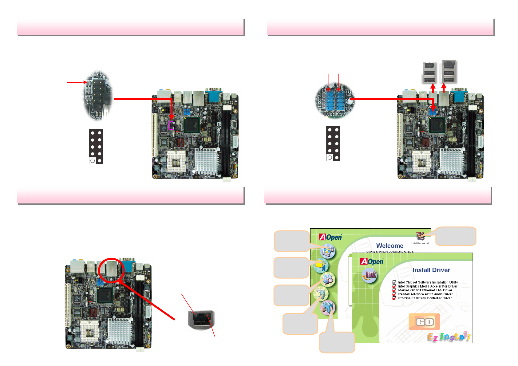
IEEE 1394 Connectors
With IEEE1394 Chip on board (AGERE 1394), having its data transfer rate up to
400Mb/s, this interface can connect to devices that require high data transferring
performance such as digital camera, scanner or others IEEE 1394 devices. Please
use appropriate cables to connect IEEE1394 devices.
Pin 1
USB 2.0 Connectors
This motherboard provides eight USB 2.0 ports to connect USB devices, such as
mouse, keyboard, modem, printer, etc. There are four ports on the back panel.
You can use proper cables to connect the Front USB connector to USB modules or
front panel of chassis.
Pin 1
Pin 1
+12V (Fused)
IEEE 1394 Connector
TPA+
GND
TPB+
1
9
2
TPA-
GND
TPB+12V (Fused)
SHIED GND
10
Pin 1
Gigabit LAN onboard
On the strength of Gigabit LAN controller on board, this motherboard provides
10/100/1000 Mbps Ethernet for office and home use. The Ethernet RJ45
connector is located on top of USB connectors. The right hand side LED indicates
link mode, it lights in orange whenever linking to network. The left hand side LED
indicates the transfer mode and it lights in green when data is transferring in
100Mbps (never lights while in 10Mbps), but lights in orange when transferring in
Gigabit’s mode. To enable or disable this function, you may simply adjust it
through BIOS.
Transferring (Left)
Green 100Mbps
Orange Gigabit mode
1 2
+5V
SBD6SBD6+
GND
KEY
USB Connector
+5V
SBD7-
SBD7+
GND
NC
9 10
AOpen EzInstall and Bonus Pack CD
You can use the autorun menu of Bonus CD disc. Choose the utility and driver
from the icons at left side, and then click on the “GO” button to complete
installation automatically.
Click to install
Install drive
Install utility
Browse
online manual
Read me
Linking (Right)
Yellow
Exit CD
Page 7
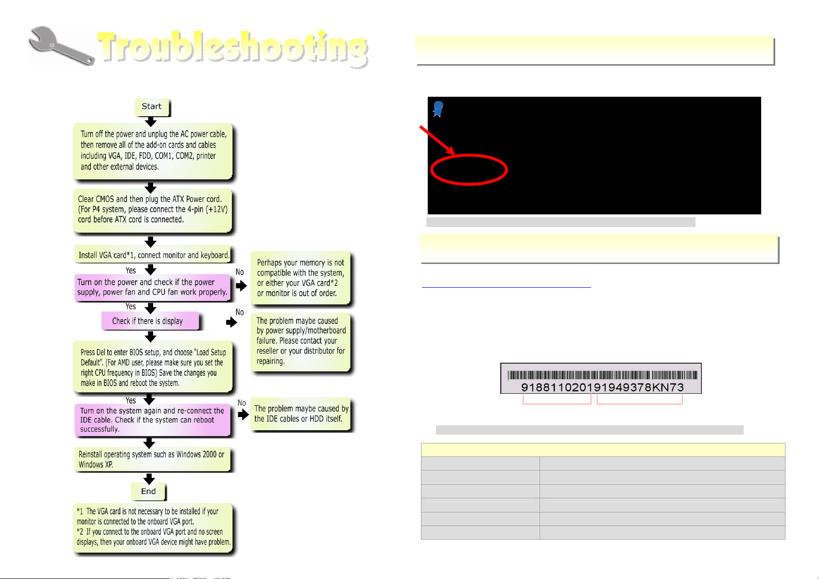
Model name and BIOS version
If you encounter any trouble to boot you system, follow the procedures
accordingly to resolve the problem.
Model name and BIOS version can be found on upper left corner of first boot
screen (POST screen). For example:
Phoenix - AwardBIOS v6.00PG, An Energy Star Ally
Copyright (C) 2005, Phoenix Technologies, LTD.
i915GMt-FSA R1.00 Jan. 31. 2006 AOpen Inc.
i915GMt-FSA is model name of motherboard; R1.00 is BIOS version
Register Your Motherboard
Thanks for choosing AOpen product, please register this motherboard at
http://club.aopen.com.tw/productreg/
and to ensure high service quality and priority from AOpen. You will also have a
chance to play slot machine game to win prize from AOpen. Please prepare the
following information before you start: Model Name, Part Number (P/N),
Serial Number (S/N) and Purchase Date. The Part Number and Serial
number are printed on bar code label. You can find this bar code label on the
outside packing or on component side of PCB. For example:
to become a Gold member of Club AOpen,
P/N: 91.88110.201 is part number, S/N: 91949378KN73 is serial number.
Part No. Serial No.
Beep Sound Message
1 short(Beep) System booting is normally.
1 long - 1 short(Beep) DRAM ERROR
1 long - 2 short(Beep) Display card or monitor connected error
1 long - 3 short(Beep) Keyboard Error
Long(Beep) continuous DRAM hasn't inset correctly.
Phoenix-Award BIOS ERROR Message
Page 8

Dear Customer,
Thanks for choosing AOpen products. We invite you to register at
http://www.aopen.com to become a Gold Member of Club AOpen so as to ensure
quality service in the future. In order to maintain the best service to every
customer of us, we recommend you to follow the procedures below and seek help
from our branches according to the region you buy the product. With your help, we
can then continue to provide efficient and the best quality service to every
customer.
Thanks very much for your understanding!
Europe
AOpen Computer b.v.
Tel: 31-73-645-9516
Email: [email protected]
Germany
AOpen Computer GmbH.
Tel: 49-2131-1243-710
Fax: 49-2131-1243-999
Europe http://www.aopen.nl/tech/default.htm
Pacific Rim: http://www.aopen.com.tw/tech/default.htm
China:
Germany:
America:
Japan:
http://www.aopen.com.cn/tech/default.htm
http://www.aopencom.de/tech/default.htm
http://usa.aopen.com/tech/default.htm
http://aopen.jp/tech/index.html
Pacific Rim
AOpen Inc.
Tel: 886-2-3789-5888
Fax: 886-2-3789-5899
China
艾爾鵬國際貿易(上海)有限公司
Tel: 86-21-6225-8622
Fax: 86-21-6225-7926
Japan
AOpen Japan Inc.
Tel: 81-048-288-0988
Fax: 81-048-288-0955
America
AOpen America Inc.
Tel: 1-510-489-8928
Fax: 1-510-489-1998
 Loading...