

Page 1

Chapter 0 Catalogue
Chapter 0 Catalogue
........................................................0-1
Chapter 1 How To Use This Manual.......................1-1
1.1 A Thank-you Note Before You Get Started ......................................................................... 1-1
1.2 The Features Of This Manual ............................................................................................. 1-2
1.3 Preliminary Tools ................................................................................................................ 1-3
Chapter 2 Start To Assemble......................................2-1
2.1 Open The Housing.............................................................................................................. 2-1
2.2 Check Accessories ............................................................................................................. 2-3
2.3 Check Your I/O Back-panel................................................................................................. 2-5
2.4 Set Up Hard Disk ................................................................................................................ 2-7
2.5 Set Up Motherboard ........................................................................................................... 2-9
2.6 Set Up CPU .......................................................................................................................2-11
2.7 Plug In Memory................................................................................................................. 2-18
2.8 Set Up Front USB / Audio Module (Optional) ................................................................... 2-20
2.9 Set Up Floppy Diskette Drive............................................................................................ 2-22
2.10 Set Up Optical Storage Devices ..................................................................................... 2-24
2.11 Connect Signal Cable ..................................................................................................... 2-27
2.12 Connect Power Cord ...................................................................................................... 2-30
2.13 Connect The Front Panel LEDs ...................................................................................... 2-33
2.14 Set Up Interface Card ..................................................................................................... 2-34
2.15 All Set.............................................................................................................................. 2-37
Catalogue
0-1
Page 2

Chapter 3 Check What You've Achieved..3-1
3.1 Connect The External Peripherals...................................................................................... 3-1
3.2 Turn On The Power To Check............................................................................................. 3-5
3.3 Postscripts .......................................................................................................................... 3-9
0-2
How To Use This Manual
Page 3

Chapter 1 How To Use This Manual
1.1 A Thank-you Note Before You Get Started
First of all, we would like to express our gratitude to your purchase of this specially-designed
bare-system by
personal needs with our great industrial designing ability and our everlasting perseverance with
the quality of all products.
This manual is for those who want to set up the computer by themselves. In other words, this is a
book for " Fresh drivers on the road." If you are already a veteran, this manual may not be that
suitable for you. It is our hope that the novices can build up their own computers step by step.
Now, we invite you to personally experience this user-friendly manual and all the powerful
functions this
AOpen
. Once again, this bare-system is designed uniquely to meet all your
AOpen
Baresystem offer.
The logos of Adobe and Acrobat are the registered trademarks of Adobe Systems Incorporated.
The logos of AMD, Athlon, and Duron are the registered trademarks of Advanced Micro Devices, Inc.
The logos of Intel, Intel Celeron and Pentium II&III are the registered trademarks of Intel Corporation.
The logos of Microsoft, Windows are the registered trademarks of Microsoft Corporation in America and other
countries.
All the titles of the products and the trademarks mentioned in this manual are for the purpose of illustrative
conveniences and are possessed by their respective firms.
We regret not informing about any changes in usage standards and other related information. AOpen Company
reserves the right of altering or modifying the content of this manual. In case of any mistakes or incorrect descriptions,
which include those on the products, AOpen makes no guarantee or commitments.
This document is based on the copyright laws in order to protect our company and reserve all rights.
Under no circumstances are any types of duplicating and loading this brochure in any databases and media
permitted except the permission signed on formal document by AOpen Company.
1996-2000 Copyrights, AOpen Ltd. All rights reserved.
http://www.aopen.com
How To Use This Manual
1-1
Page 4
1.2 The Features Of This Manual
In this manual, you will be able to know how to:
Set up a personal computer on your own.
Correctly and safely put everything together and get some ideas about hardware.
Make the setup easier with some practical techniques.
In addition, this manual DOES NOT offer you:
Any sorts of back doors, such as overclocking.
A great bunch of hardware standard that is difficult to understand.
Lengthy, fanciful but vague theories.
Instead, this manual explains theories in simple language by colorful illustrations. Therefore,
you will see the icons below quite often.
Note
Warning
Setup Order
Contains knowledge you should know in process of
assembling and some helpful tips.
When seeing this mark, please beware. It highlights
mistakes occurred often when assembling or something
you should pay attention to.
This mark indicates the assembling sequence which
should be followed by numerical order.
Force direction
This arrow shows the right direction the force should be
imposed or the correct assembling direction.
1-2
How To Use This Manual
Page 5
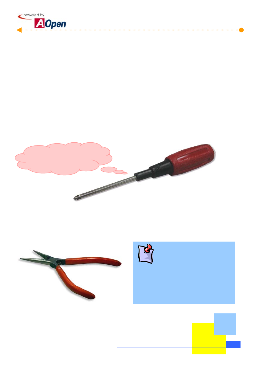
1.3 Preliminary Tools
"A workman must first sharpen his tools if he is to do his work well". Before you start the setup,
there are some tools that you can't spare.
Firstly, the most frequently used tool is cross screwdriver. You can use it to screw most interior
components. A suitable screwdriver can make the setup job much easier. But does any
screwdriver apply? No, we suggest a screwdriver with a magnetic tip. When you set up your
PC, the situation is very likely to happen: you accidentally drop screws into the space between
components. In case of this, a magnetic screwdriver helps attracting those fallen screws that
are impossible to reach by hands. Some screw holes are difficult to reach. At this case, we
need a magnetic screwdriver as well. In addition, the size of tool does matter. Generally, the
domestic 107 cross screwdriver
is the best one.
I can get it done!!
When putting things together, you can't avoid adjusting Jumpers. In most of cases, it can be
done barehanded. But the time always comes when there is a situation hands fail to reach in
and fix the problem. You will thank God if you have a pliers on hand to avoid any hassle just
because of one JUMPER.
What is Jumper?
Jumper is something generally referred to "
Jumping wire", which is used to adjust some
functions such as FSB (front side bus), ratio, and
sound switches adjustment by causing them
short circuit.
How To Use This Manual
1-3
Page 6
[Note]
1-4
How To Use This Manual
Page 7
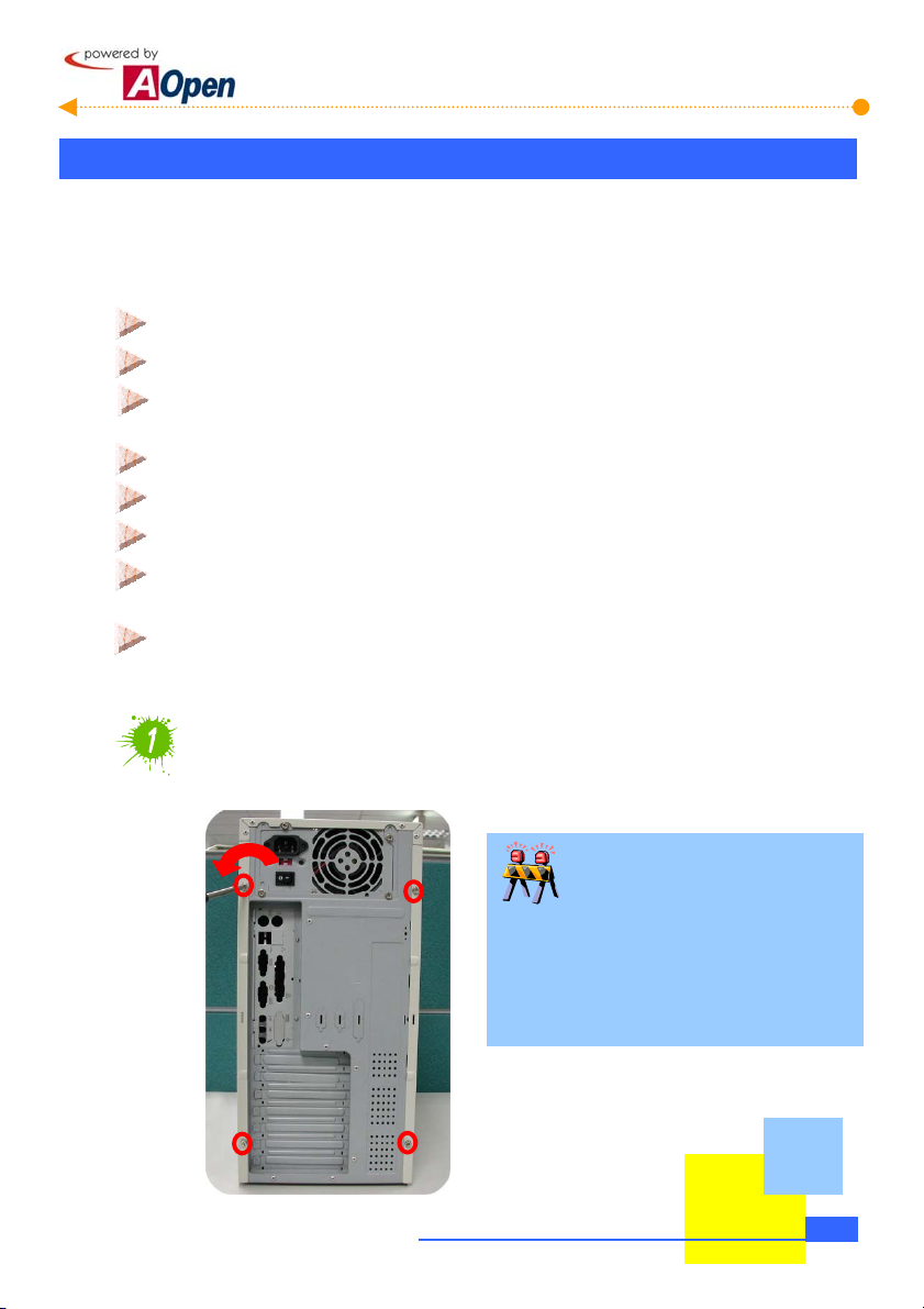
Chapter 2 Start To Assemble
2.1 Open The Housing
This product you bought from
MicroATX / ATX. And this bare-system has following distinguishing features:
The MicroATX/ATX housing provides you a big space to expand capacity.
Bend-in edges ensure your safety when assembling.
A highly efficient 300/250W power supplier ensures your computer work smoothly
in most cases.
FCC Class B / DoC and CE conformed standards guarantee your health.
A high-efficiency motherboard attached makes your job much easier.
Led cover provides 4 kinds of option colors.
A great extensible function; you can optionally purchase AGP/PCI interfaces,
VGA or other add-on cards.
P4 ready
Now, let's open the housing and take a look at the interior design and attached accessories:
Loosen screws on the housing
You can loosen them with a cross screwdriver.
AOpen Baresystem
series belongs to special standards of
Need your attention.
This manual can be applied to HQ / LX / HX
series Baresystem. They are only different
in their appearance. The pictures shown
below are just for your reference.
Start To Handle
2-1
Page 8
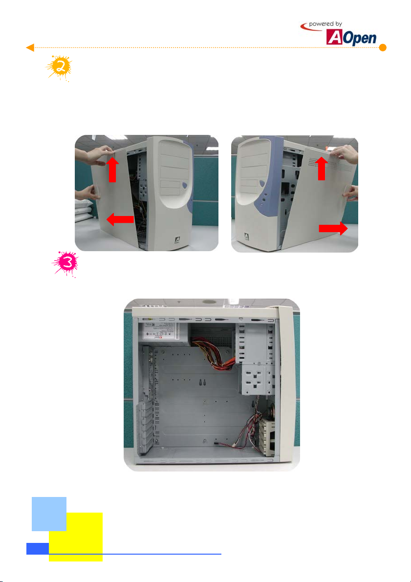
Remove both sides of housings.
To remove side housings, slide the housing a bit backward and lift it up. Procedure goes
the same with the other side..
Then you can have a clear look of AOpen Baresystem.
2-2
Start To Handle
Page 9
A
A
g
A
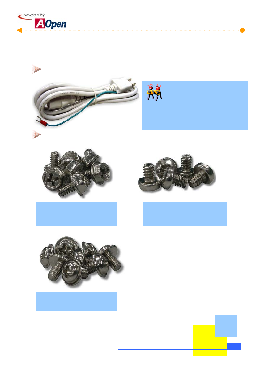
2.2 Check Accessories
Opening the housing, you are supposed to see the following accessories:
Power cord: Connects the computer power.
Power cords are various in different countries.
Please use an appropriate power cord according
to your country.
Fixed screws: After opening the accessory parcel, you'll see three different types of
screws as follows:
s shown in the picture, the threads
on NO.1 screw are wide and it is a
so-called hex screw.
s shown in the picture, the NO.2
screw’s threads are wide as well but it
has a round head. It is a so-called
bindin
Are power cords all the same?
head screw.
s shown in the picture, threads on
NO.3 screw are narrow. It is a
so-called round head washer screw.
Start To Handle
2-3
Page 10
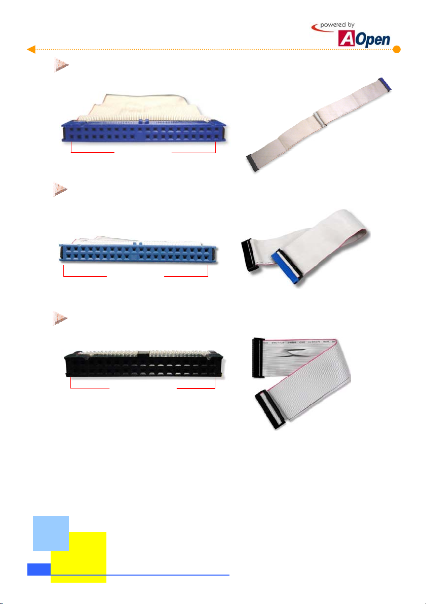
disk and CD-ROM.
CD-ROM.
IDE Cable: is a 40-pin connector used to link IDE interface devices such as hard
40-Pin Connector
IDE Cable: a 80-pin connector to connect the hard disk with IDE interface and
80-Pin Connector
Floppy diskette Drive (FDD) Cable: is a 34-pin connector to connect disk drive.
2-4
34-Pin Connector
Start To Handle
Page 11
k
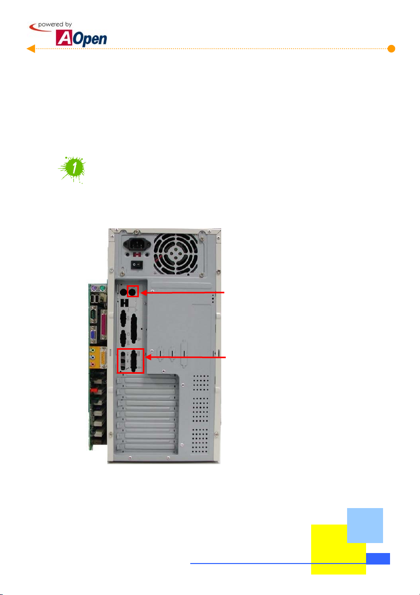
2.3 Check Your I/O Back-panel
HQ / LX /HX series Baresystem is equipped with an all-purpose I/O back-panel. You can break
through the port bracket according to your personal needs. If your motherboard has built-in
sound effects or network functions, then you need more ports to connect external speakers
and network.
Check I/O connector ports on the motherboard with your housing
and decide which port brackets you need to break through.
If there is a built-in network card on the
motherboard, then you need to brea
through this bracket.
If there is a built-in sound device, then
you need to break though these two
brackets.
Start To Handle
2-5
Page 12
r
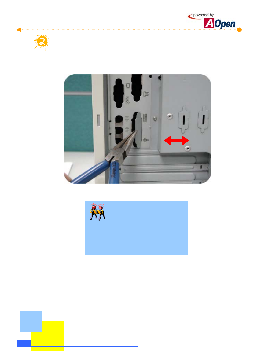
Use a tool to break the iron bracket on the I/O back-panel.
As shown in the picture, use a tool to tear down the bracket by twisting it several
times.
2-6
Start To Handle
Be careful when twisting!!
When breaking brackets, it is wise to use a pliers
to avoid cutting yourself. If you fail to have a
pliers on hand, pad a piece of cloth on you
palm to tear it down.
Page 13
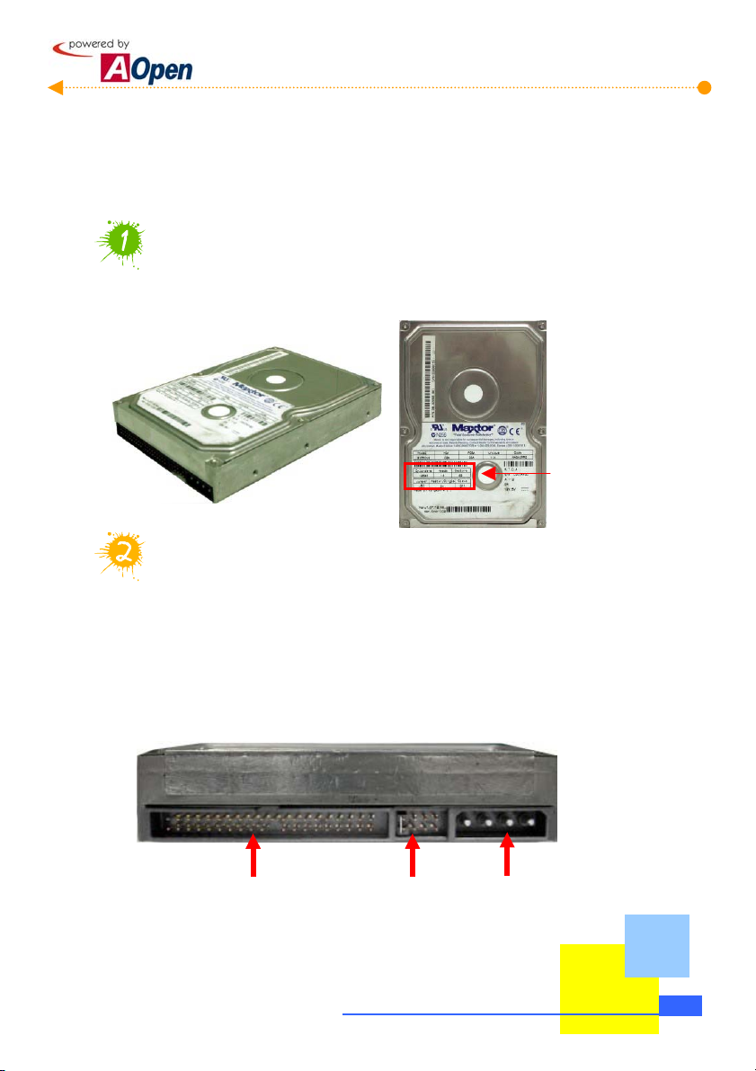
2.4 Set Up Hard Disk
A Hard disk is the place where most of the data is stored. Therefore, it is one of the most
important components in a personal computer. This section will introduce you the knowledge
of the hard disk and some important tips when you set it up.
Get to know the hard disk
Taking out the hard disk from the parcel, you will see the following equipment:
Jumper
configurations
Adjust Jumpers on your hard disk
As has been mentioned to you, we assume you know the definition of Jumpers. The
setting of Jumpers in IDE hard disk is essential for a computer to distinguish various
devices connected on the same cable. To be general, we normally set the hard disk
to "Master", indicating the first device of the cable; and we set CD-ROM to "Slave",
meaning the second device of the cable. The Jumper settings are marked on the tag
affixed to the surface of the hard disk or mentioned in its handbook. Here we only set
up one hard disk so that it has to be set as "Master."
IDE cable connector
Jumper here is set as
"Master"
Power connector
Start To Handle
2-7
Page 14
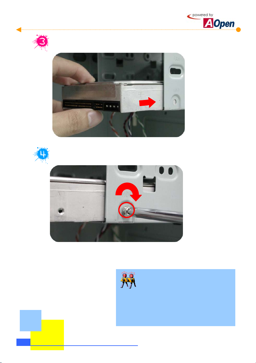
Place the hard disk into the frame.
Tighten the screws to the frame.
In fact, a hard disk is a very fragile and delicate device though it is covered with a metal
housing. When in operation, a slight vibration might do great harm. Therefore, be sure to
screw it on the frame securely.
2-8
Start To Handle
Don't mess up screws!!
Generally there are special screws for a hard disk in the
parcel when you buy a new hard disk. If no screws are
attached, use those packed in the accessory parcel.
Make sure to use the NO.2 screws. (See page 2-3)
Page 15
r
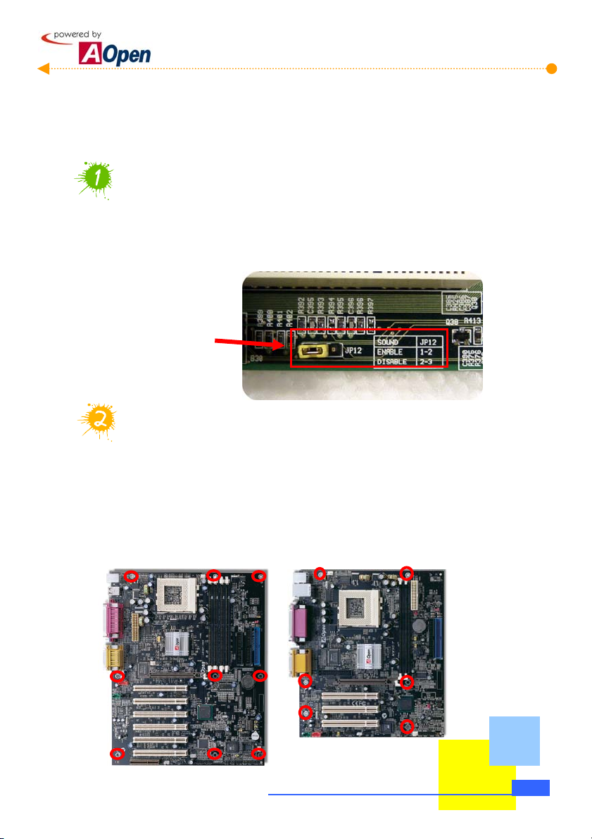
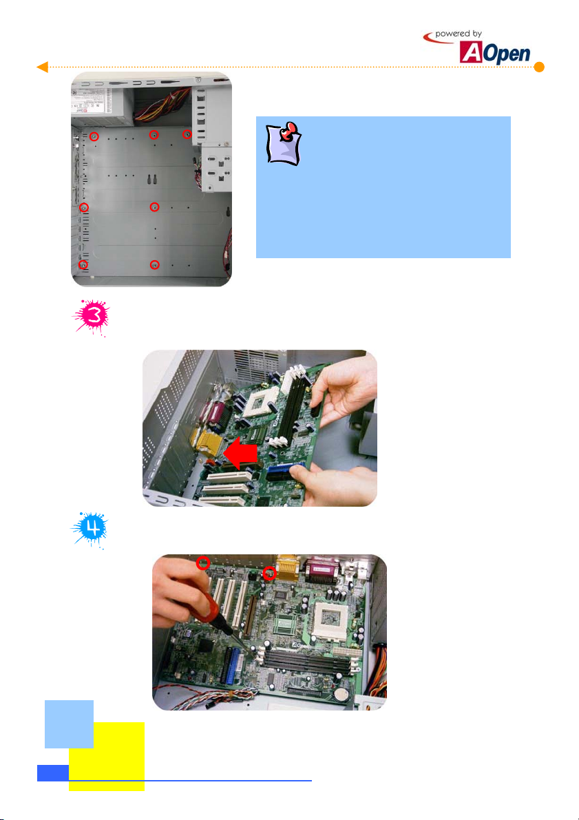
2.5 Set Up Motherboard
It is very easy to set up a motherboard in
in the correct position and tighten the screws. Please follow the steps below:
Read the handbook of the motherboard and adjust Jumper settings.
Currently almost all motherboards have a Jumper-free design (or Jumperless design).
Even so, there are still some other functions that need to be adjusted through Jumpers.
Please refer to the handbook of your motherboard and adjust the Jumper settings
according to your personal requirements.
Please refer to you
motherboard handbook to
adjust the Jumper settings
according to your needs.
How many brass studs should I screw?
Before setting up the motherboard, you have to screw brass studs at the chassis
of housing to avoid the motherboard from directly contacting with the iron base.
For your convenience, we have fastened 7 brass studs on HQ / LX / HX series
Baresystem. Please compare your motherboard with your housing. Then just
screw the brass studs you need. The Motherboard you purchase may look
different from the one shown below.
ATX Model
AOpen Baresystem
Micro ATX Model
. Just place the motherboard
Start To Handle
2-9
Page 16
I
How many brass studs should
screw?
There are holes for screws on the motherboard. Just
compare the position of the holes with the iron base of
the housing. Then you will know the position where to
screw the brass studs. The number of the brass studs
depends on the motherboard you purchased.
With an angle of 45 degrees, level the motherboard at the back panel brackets
and place it on the brass studs you just screwed.
2-10
Tighten the screws respectively with screws NO.1
Start To Handle
Page 17
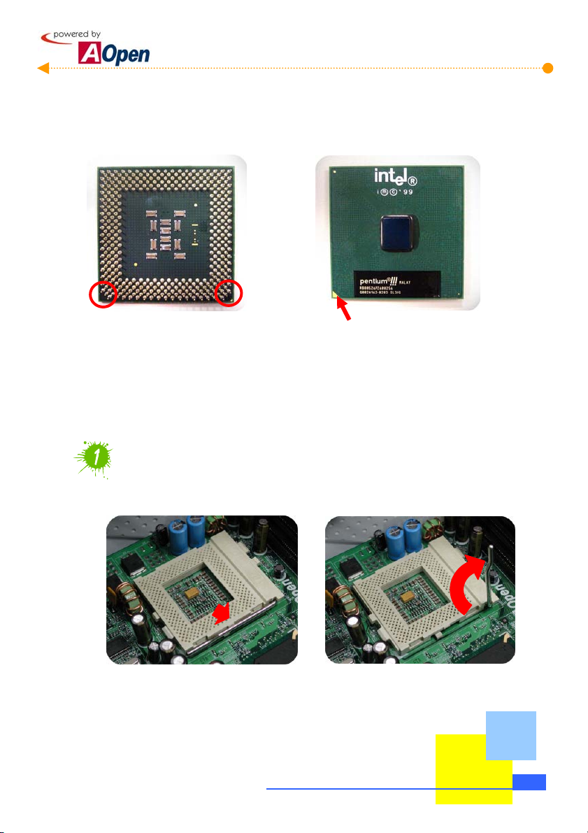
2.6 Set Up CPU
When setting up CPU, please don't go wrong with the direction of CPU. It is very easy to
distinguish its direction. First of all, let's have a look at what CPU is like:
As shown in the picture, it's FC-PGA CPU of Intel Pentium III, which is so-called Socket370
CPU. There are still many other varieties of CPU available in the marketplace. Please pay
attention to the model when you are purchasing. It should be consistent with your
motherboard. What we use here is an Intel’s Pentium III CPU. You need not worry if you
are not using the same one as all models have similar set-up procedures.
Pull open the lever next to the CPU socket to 90 degrees.
Pull outward the lever beside the CPU socket and pull it upward vertically.
Note that the arrow indicates
the first pin
Start To Handle
2-11
Page 18

a
gly
p
y
Aim the arrow marked on CPU at the first pin position on the socket.
Don’t worry!! CPU socket also has
foolproof device.
You may find out the pin arrangement at four corners of
CPU is different. Two of them have a bevel-angle,
which is a foolproof. As long as you don't insert it too
hard, the CPU is unable to be located into the socket if
After CPU is located in the socket, pull down the lever and click to the tenon.
it is wron
laced!
Beware of CPU pins!
When setting up CPU, please be careful not to
crook the pins or CPU can't be properl
located into the socket!
2-12
Start To Handle
Page 19

Set up the cooling fan above the CPU socket.
Get the clip of the cooling fan hooked by the tenon above the socket.
Be careful not to scratch the motherboard!
When setting up the cooling fan, please avoid the clip
scratching the motherboard; otherwise it may cause serious
damage!
Use a tool to place the clip at the
other side into the tenon.
Lastly, plug in the fan connector.
Be aware of its direction.
Start To Handle
2-13
Page 20

p
Set Up Pentium 4 CPU
With the increasing popularity of Pentium4 CPU in the market, we considerately introduce CPU
installation of Pentium4 in this section. As with setting up all types of CPU, please don't go wrong with
the direction, let’s take a look at Pentium4 CPU itself.
2-14
Note that the arrow indicates
the first
in
As shown in the picture, it's a Micro FC-PGA CPU of Intel Pentium4, which is the so-called
Socket478 CPU. Please pay attention to the model when you buy one. It should be
consistent with your motherboard.
Pull open the rod next to CPU socket to 90 degrees
Pull outward the rod beside the CPU socket and pull it upward vertically
Start To Handle
Page 21

y
Aim the arrow mark on CPU at the first pin in the socket
You may find the pin arrangement at four corners of CPU is
different. Two of them have a bevel-angle, which is for
foolproof purpose. As long as you don't insert it too hard,
the CPU is unable to be located into the socket if it is
wrongly placed!
Don’t worry!! CPU socket also has a
foolproof device.
After CPU is located in the socket, pull down the rod and click to the tenon.
When setting up CPU, please be careful not
to crook the pins or CPU can't be properl
located into the socket!
Beware of CPU pins!
Start To Handle
2-15
Page 22

A
Motherboard for Pentium4 CPU usually comes with a special-designed retention module
Set up the cooling fan above the CPU socket
which is as shown below.
Be careful not to scratch
the motherboard!
When setting up the cooling fan, please
avoid the iron piece scratching the
motherboard; otherwise it may cause
serious damage!
Press iron sticks to get hooked on
the retention module.
t last, plug in the fan connector. Be
aware of its direction.
2-16
Start To Handle
Page 23

Connect ATX power cord to the motherboard
Before connecting 20-pin ATX power connector to transmit the current of the power supplier
to the motherboard, please remember to plug in the 4-pin power connector at the first place.
Still pay attention to the direction when you plug it in.
Be careful the direction of
tenon when plugging
Be careful the direction of tenon
when plugging
Start To Handle
2-17
Page 24

R
2.7 Plug In Memory
The DIMM modules available on the market belong to several standard modules. The
pictures shown below are the most common use ones. As the pictures show below, the jag is
the foolproof device. Be careful not to plug in the wrong side.
Pay attention to the
direction of the jag.
Pay attention to the
direction of the jag.
Pull open two sides of tenons on the memory socket.
This one is a 168-pin SDRAM.
This one is a 184-pin DD
SDRAM.
2-18
Start To Handle
Make the golden finger as fresh as a new product!!
The lower edge of the memory has a line of metal material, which is
the so-called golden finger. It will oxidize after long term usage and
cause ill tangency. In case of this, just use a clean eraser to rub the
golden finger several times to make it work perfectly again.
Page 25

Aim the first pin and the jag on the memory module at the marked area of the
socket.
Insert the memory module vertically downward into the socket with both hands.
Please be careful when you insert the memory module. It can never survive too
much strength!
Start To Handle
2-19
Page 26

2.8 Set Up Front USB / Audio Module (Optional)
Except standard audio output and USB connectors, AOpen also considerately designs "the
front audio module (Optional equipment)" for you. It allows you to conveniently connect
speakers and earphones on the front panel and there are two sets of USB jacks to make your
system a greater extensibility.
External
speaker jack
Microphone jack
Extended USB jack
To connect front panel audio cable
To connect USB signal cable
Remove the front panel of the housing
1
Settle the front panel audio module
2
How to remove the front panel?
There are 6 tenons on the HQ / LX / HX series
housing. We recommend you to press down the
tenon NO.1 and 2 shown on the left side and pull
tenon NO.3 rightward to remove the front panel.
3
2-20
Start To Handle
Page 27

r
Screw the front-panel audio connector module to the housing
Connect the signal cable to the motherboard
Please see the manual of your motherboard for the precise position of USB
connector and front audio module. Then, connect the USB signal cable and audio signal cable
from the front audio module. All of the connectors and cables have a foolproof device. You
won’t go wrong.
Do all USB face the same
direction?
The pin direction of the USB may be different on
various motherboards. Please refer to you
motherboard manual.
The 6-pin connector is use to connect
the old type front audio connector.
Start To Handle
2-21
Page 28

a
2.9 Set Up Floppy Diskette Drive
The diskette drives available on the market are 3.5-inch with the capacity of 1.44MB. The
floppy cable applied here is different from the IDE device introduced in the previous section.
It uses a narrow 34-pin cable and no Jumper has to be adjusted before the diskette drive is
installed.
Know your diskette drive.
This is where the
Remove the diskette drive cover on the front panel of housing.
first pin is located
Connector of diskette
cable
Power connector
2-22
In order to safely and easily remove the cover, you may use
screwdriver to knock it off. Please see the pictures shown above.
Start To Handle
How to remove Diskette Drive cover?
Page 29
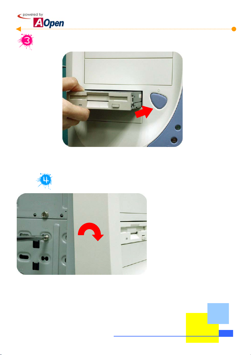
Place the diskette drive into the housing.
Tighten the screws. Here we use NO.3 screws.
Start To Handle
2-23
Page 30

A
2.10 Set Up Optical Storage Devices
Basically speaking, the set-up procedure of IDE CD-ROM drive is almost the same as that
of installing IDE hard disk. First of all, let's take a look at your CD-ROM drive:
Adjust the Jumper settings of CD-ROM drive.
Like hard disk drive, every IDE device has to adjust Jumper settings. Here we set
CD-ROM drive as Slave.
CD audio
Jumper settings
IDE cable connector
Power connector
Set CD-ROM drive to
Slave as marked.
Can I install the CD-Recorder as the same way?
s long as it belongs to IDE-interface device, no matter it is CD-ROM
drive, CD-Recorder or DVD-ROM; the set-up procedure is the same.
Just follow the steps above; it is easy for you to install any IDE-interface
device.
2-24
Start To Handle
Page 31

a
Plug in audio cable
The audio cable is a small cable composed of red, black and white lines. The red line
is used to connect the right volume channel while the white one is used to connect the left
volume channel. And the black line is used as earthing. As a result, when connecting the
audio cable to CD-ROM drive, plug the red line to the side marked "R" and the white line to the
side marked "L".
What is audio cable for?
Keep in mind that the red line is
aimed at the right volume channel
marked as "R"
When you play music with CD-ROM player, the
digital music data is transmitted to audio
device through this cable. That’s why you can
hear the music through speakers.
Remove CD-ROM drive cover on the front panel of the housing.
In order to safely and easily remove the cover, you may use
screwdriver to knock it off. Please see the pictures shown above.
How to remove CD-ROM Drive cover?
Start To Handle
2-25
Page 32

Place CD-ROM drive into the housing.
Screw the CD-ROM drive with NO.3 screws.
Next, lock the CD-ROM drive in the fixed frame. The screws used for CD-ROM drive
are the same as those used for diskette drive. They are NO.3 screws with narrow
threads.
2-26
Start To Handle
Page 33

t
p
2.11 Connect Signal Cable
After setting up disk devices, we need to connect their cables to the motherboard. As a
result of various connector locations on different motherboards, it is wise to read the words
marked on the motherboard before you connect the cable. Let's take a look at how these
connectors are marked on the motherboard.
You won't go wrong if you read the words correctly.
First pin
34-pin floppy disk drive connector
You can distinguish IDE cable from left and right. Normally, a standard cable has a
fool-proof device which is a small salient on the cable and you will find a small dent on the
socket. Just aim the salient at the dent and then plug it in.
First pin
40-pin IDE connector
Connect IDE cables to hard-disk drive and CD-ROM drive.
Hard-disk Drive
CD-ROM Drive
The red line aims at the firs
in.
Start To Handle
2-27
Page 34

A
f
r
e
p
Connect the cable of CD-ROM drive to the motherboard.
Connect the cable of hard disk drive to the motherboard.
Where is Pin1?
im the red side
of cable at the
first pin
When connecting IDE cables, bear in mind to
What if there is no foolproof devic
on the cable?
If you happen to have a no fool-proof cable, just
remember that the first pin is next to the red line and
it would be safe to locate the first pin close to the
ower cord.
2-28
Start To Handle
aim the red side of IDE cables at the first pin o
the socket where has a bold line marked at the
corner of socket on the motherboard. If you
are still not sure, please refer to you
motherboard manual.
Page 35

Connect CD audio cable to the motherboard
We have connected one side of cable to the CD-ROM drive earlier, now we are going
to connect the other end to work it. Please note that the position of CD audio
connectors is various on different motherboards. You will never go wrong if you
know how to read the words on the motherboard.
You won't go wrong if you
can recognize the word on
the motherboard.
Keep in mind that the red line
is aimed at the right volume
channel marked as "R".
Start To Handle
2-29
Page 36

f
f
2.12 Connect Power Cord
There is nothing easier than connecting power cord. Both power cord connector and
socket have a foolproof device. You cannot plug it in if you get it in the wrong direction. Just
match the connector bevel with that of the socket to plug it in.
Connect the power cord of hard disk drive.
Let's have a look how the power connector is like:
You won’t go wrong i
you match the bevel o
connector.
Both power cord connector and socket have a foolproof device. You cannot plug it in if you
get it in the wrong direction.
2-30
Start To Handle
Page 37

f
Connect the power cord of CD-ROM drive.
Then connect the power cord of CD-ROM. Both power cord connector and socket
have a foolproof device. You cannot plug it in if you get it in the wrong direction.
Connect the power cord of the floppy diskette drive.
The power cord shown below is for the floppy diskette drive. Although powered by
12V as well, you can easily recognize it with a smaller connector.
Pay attention to the
shape and direction o
the connector.
Start To Handle
2-31
Page 38

Connect ATX power cord to the motherboard.
Finally comes the one marked P1. This ATX power connector transmits the current of
the power supplier to the motherboard. Please pay attention to the direction when you
plug it in.
Be careful the direction
of clip when plugging.
Pentium 4 CPU power connector (Only For Pentium 4 CPU users)
If you choose a P4 motherboard you have to connect a special connector as shown
below. Just connect it with a rectangle female connector on the motherboard. This step
should be finished before plugging ATX power connector.
2-32
Be careful the direction
of clip when plugging.
Start To Handle
Page 39

A
e
r
2.13 Connect The Front Panel LEDs
The front panel LEDs indicate the current situation of the system such as power-indicating
light, hard disk reading indicator, ATX power switch and system Reset button. Now look at
their pin locations on the motherboard:
Due to the lack of the standard pin module on the front panel lights, please refer to your
motherboard manual and follow its instructions to connect each signal cable.
The pictures above show the standard of AOpen motherboards and just fo
your reference; please refer to the manual of the motherboard you
purchased and follow its instructions.
Do all front panel LEDs look the same?
IDE LED
SPEAKER
Pins to connect the
front panel LEDs.
1
Power Switch
CPI & Power LED
RESET
Start To Handl
2-33
Page 40

y
A
y
2.14 Set Up Interface Card
If there is no built-in VGA card in your system, you have to choose a suitable one. Read
this section carefully if you desire to install other interfaces (such as network card, modem
card, image card, or 3D-acceleration card). We take VGA card as an example to
demonstrate how to set up an interface card. The set-up of other interface cards is very
similar.
Different interface cards not only vary in outlooks but in sockets!
This AGP socket, usuall
brown, is a high-speed
interface specially designed
for VGA cards.
These are PCI sockets and
usually white. They can be
connected with various
interface cards.
AGP interface card: Generally only VG
card applies to AGP interface. However,
most 3D acceleration cards apply to AGP
interface as well after integrating the displa
function.
PCI interface card: Commonly seen are
sound-effect card, network card, modem card,
SCSI card, and image card. Also, some
outdated display card or 3D acceleration card are
PCI-interfaced.
2-34
Start To Handle
Page 41

Take apart the rear port bracket that you need to install on the housing.
You should remove the brackets before setting up the interfaces in order to lock them
in. It is very easy to remove the rear port brackets from the housing. You can use a
screwdriver to help you to remove our specially designed rear port brackets.
Aim the golden finger of the interface card at the socket you want to
connect, and insert the interface card vertically downward into the socket
with both hands.
Start To Handle
2-35
Page 42

Screw the interface card to the housing with NO.1 screws.
2-36
Start To Handle
Page 43

2.15 All Set
So far we had almost completed all the assembling. It is much easier than you imagine,
isn't it? The final thing to do is to put both sides of housings back. Then it is all done!
Relocate both sides of the housing.
Please note that you have to locate the hooks of the side housing into the holes on
the frame to cover it securely.
Tighten screws.
Start To Handle
2-37
Page 44

[Note]
2-38
Start To Handle
Page 45

r
p
r
Chapter 3 Check What You've Achieved
3.1 Connect The External Peripherals
Having spent so much effort, do you feel confident to DIY your computer? Now, let's take a
look at the connectors at the back of your system and know their names, purposes and
positions.
Power Supply connector
PS/2 mouse connector
PS/2 Keyboard connector
RJ45 jack
COM1
VGA Connector
Multimedia speaker jack
External sound input
Microphone jack
USB connector
Printer port
Joystick of MIDI-device
connecto
If the module you choose
doesn’t have VGA,
network, audio and
modem functions, please
note that the connectors
ositions are different.
Do all back panels look the same?
Different modules may have slight difference in thei
positions of back panel connectors. Compared to the
above pictures, you can easily tell their differences.
Check What You've Achieved
3-1
Page 46

onnect keyboard and mouse
C
Connect monitor and tighten screws
Connect the D Type 15-pin plug of the monitor cable to the monitor connector at the
back of bare-system and tighten the screws.
If the module you choose doesn’t have a VGA function, please note that the connector
position is different. Remember to tighten screws after connecting.
3-2
Check W hat You've Achieved
Page 47
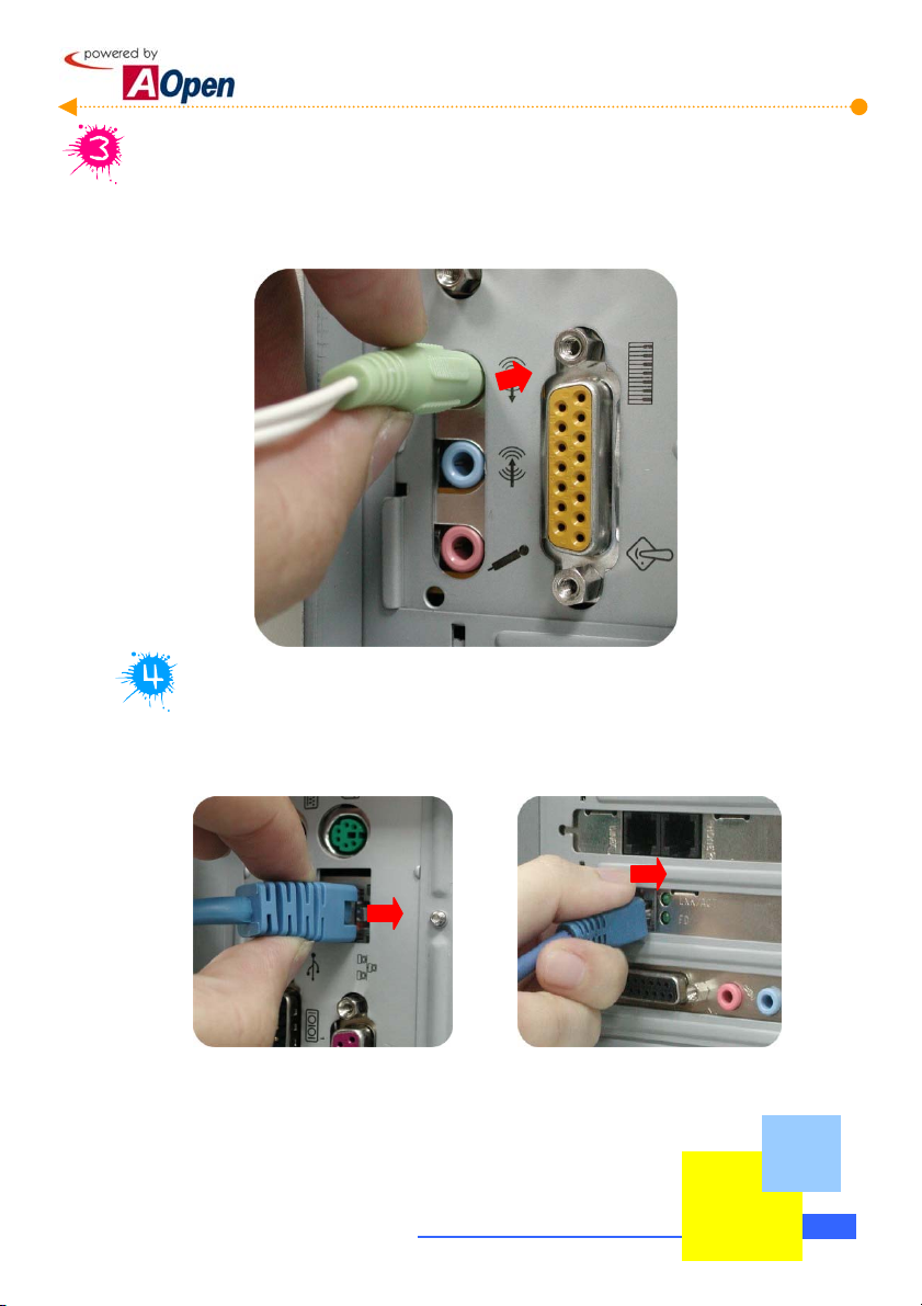
Connect the multimedia speaker
Connect the jacks of the multimedia speakers as marked. The device conformed to
PC99 standard has been marked by certain colors. You won't get wrong if you follow
those marked colors.
Connect network cable
If the model you choose has a built-in network function on the motherboard or you have
installed a Network Interface card, please remember to connect RJ-45 network cable.
Motherboard with a built-in network function Motherboard without a built-in network
function
Check What You've Achieved
3-3
Page 48

Connect telephone cable
You can install an internal modem card to allow your computer linking with the colorful
Internet cyber world via a phone line. Please beware that there are two connectors
on the modem card. One connects to phone line (To Line) while the other one
connects to telephone (To Phone).
To Line
Finally connect the power supply cable.
To Phone
Please adjust the voltage
setting according to your
local standard.
3-4
Check W hat You've Achieved
Page 49
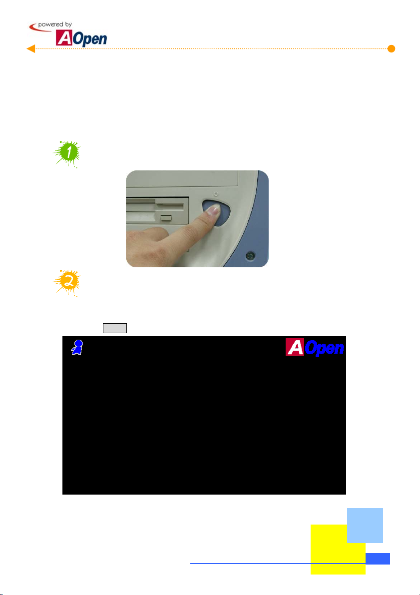
3.2 Turn On The Power To Check
Ok, all cables have been properly connected. Are you getting confident of assembling a
computer? The final step is to turn on the power to check what you have done so far. Now
you can take a short break and have a drink before turning on the computer to see how things
are going.
Turn the power on
Set BIOS (Basic Input/Output System)
Not long after activating the power, you'll expect to see the following screen and a line
of message saying " Press DEL to enter SETUP" at the bottom of the screen. Please
press Delete button:
Award Modular BIOS v6.00PG, An Energy Star Ally
Copyright (C) 1984-2000, Award Software, Inc.
MX3S R1.00 Nov.01.2000 AOpen Inc.
Main Processor : Intel Pentium III 866MHz(133x6.5)
Memory Testing : 261120K OK + 1024K Shared Memory
SPD Supported
Primary Master : QUANTUM FIREBALL_TM1280A A6B.2D00
Primary Slave : None
Secondary Master : None
Secondary Slave : None
Press DEL to enter SETUP, ESC to skip memory test
11/01/2000-i815-W83627HF-6A69MABBC-00
Check What You've Achieved
3-5
Page 50

After pressing Delete, you'll see the following BIOS setup:
Now, you can move the cursor by using direction keys on the keyboard. Move the
cursor to the option item "Load Setup defaults" and press Enter :
3-6
Check W hat You've Achieved
Page 51

Then, the following dialogue screen will pop up to confirm the default BIOS values.
Please press "Y" to confirm and then press Enter.
Finally, move the cursor to "Save & Exit Setup" and press Enter to save the parameters
and exit BIOS setup.
Check What You've Achieved
3-7
Page 52

At the same time, type "Y" in the dialogue box and press Enter to exit.
Now everything is perfectly finished!!
3-8
Check W hat You've Achieved
Page 53

3.3 Postscripts
First of all we would like to congratulate your successful computer DIY. Now you can install
an operation system and some application software according to your personal requirements.
However, these are beyond discussions of this manual whose main aim is to teach you correct
understanding of DIY skills and enable you to assemble a computer step by step. As for the
application part, you can find all varieties of books with comprehensive introduction in
bookstores.
Having a computer of your own is a beginning to the era of information. If this computer is
assembled yourself, it is uniquely meaningful to you. Through our introduction, you have
learned the key components a computer needs and what details you need to pay attention to
when assembling. We sincerely hope every customer who wants to assemble a computer on
his or her own has a wonderful beginning!
Check What You've Achieved
3-9
Page 54

[Note]
3-10
Check W hat You've Achieved
 Loading...