


Fortress 1120
User’s guide

Copyright © 2003 AOpen Incorporated
All Rights Reserved.
Fortress 1120
User’s guide
Changes may be made periodically to the information in this publication without obligation
to notify any person of such revision or changes. Such changes will be incorporated in new
editions of this manual or supplementary documents and publications. This company makes
no representations or warranties, either expressed or implied, with respect to the contents
hereof and specifically disclaims the implied warranties of merchantability or fitness for a
particular purpose.
Record the model number, serial number, purchase date, and place of purchase information in
the space provided below. The serial number and model number are recorded on the label
affixed to your computer. All correspondence concerning your unit should include the serial
number, model number, and purchase information.
No part of this publication may be reproduced, stored in a retrieval system, or transmitted, in
any form or by any means, electronic, mechanical, photocopy, recording, or otherwise,
without the prior written permission of AOpen Incorporated.
Model Number : _________________________________
Serial Number: ___________________________________
Purchase Date: ___________________________________
Place of Purchase: ________________________________
AOpen and the AOpen logo are registered trademarks of AOpen Incorporated. Other
company’s product names or trademarks are used herein for identification purposes only and
belong to their respective companies.

Notices
CE notice
The shipped version of this device complies with the requirements of
the EEC directives 89/336/EEC ”Electromagnetic compatibility“ and
73/23/EEC ”Low voltage directive“. The device therefore qualifies for
the CE certificate (CE=Communauté Européenne).
FCC notice
If there is an FCC statement on the device, then:
The following statement applies to the products covered in this
manual, unless otherwise specified herein. The statement for other
products will appear in the accompanying documentation.
This equipment has been tested and found to comply with the limits
for a ”Class A“ digital device, pursuant to Part 15 of the FCC rules and
meets all requirements of the Canadian Interference-Causing
Equipment Regulations. These limits are designed to provide
reasonable protection against harmful interference in a residential
installation. This equipment generates, uses and can radiate radio
frequency energy and, if not installed and used in strict accordance
with the instructions, may cause harmful interference to radio
communications. However, there is no warranty that interference will
not occur in a particular installation. If this equipment does cause
harmful interference to radio or television reception, which can be
determined by turning the equipment off and on, the user is
encouraged to try to correct the interference by one or more of the
following measures:
iii

iv
• Reorient or relocate the receiving antenna.
• Increase the separation between equipment and the receiver.
• Connect the equipment into an outlet on a circuit different from
that to which the receiver is connected.
• Consult the dealer or an experienced radio/TV technician for help.
AOpen Incorporated is not responsible for any radio or television
interference caused by unauthorized modifications of this equipment
or the substitution or attachment of connecting cables and equipment
other than those specified by AOpen Incorporated. The correction of
interferences caused by such unauthorized modification, substitution
or attachment will be the responsibility of the user.
Notice: Shield cables
All connections to other computing devices must be made using
shielded cables to maintain compliance with FCC regulations.
Notice: Peripheral devices
Only peripherals (input/output devices, terminals, printers, etc.)
certified to comply with the Class B limits may be attached to this
equipment. Operation with noncertified peripherals is likely to result
in interference to radio and TV reception.
Caution: Changes or modifications not expressly approved by
the manufacturer could void the user’s authority, which is granted
by the Federal Communications Commission, to operate this
server.
Use conditions
This part complies with Part 15 of the FCC Rules. Operation is subject
to the following two conditions: (1) this device may not cause harmful
interference, and (2) this device must accept any interference received,
including interference that may cause undesired operation.
Notice: Canadian users
This Class A digital apparatus meets all requirements of the Canadian
Interference-Causing Equipment Regulations.
Laser compliance statement

The CD-ROM drive contains a laser diode classified according to
IEC 825-1:1993:LASER CLASS 1.
Important safety instructions
Caution: This server is not designed for office use as a
workstation.
Read these instructions carefully. Save these instructions for future
reference.
1 Follow all warnings and instructions marked on the product.
2 Unplug this product from the wall outlet before cleaning. Do not
use liquid cleaners or aerosol cleaners. Use a damp cloth for
cleaning.
3 Do not use this product near water.
4 Do not place this product on an unstable cart, stand, or table. The
product may fall, causing serious damage to the product.
5 Slots and openings in the cabinet and the back or bottom are
provided for ventilation; to ensure reliable operation of the
product and to protect it from overheating, these openings must
not be blocked or covered. The openings should never be blocked
by placing the product on a bed, sofa, rug, or other similar surface.
This product should never be placed near or over a radiator or
heat register, or in a built-in installation unless proper ventilation
is provided.
6 This product should be operated from the type of power indicated
on the marking label. If you are not sure of the type of power
available, consult your dealer or local power company.
7 Do not allow anything to rest on the power cord. Do not locate
this product where persons will walk on the cord.
8 If an extension cord is used with this product, make sure that the
total ampere rating of the equipment plugged into the extension
cord does not exceed the extension cord ampere rating. Also,
make sure that the total rating of all products plugged into the
wall outlet does not exceed the fuse rating.
9 Never push objects of any kind into this product through cabinet
slots as they may touch dangerous voltage points or short out
v

vi
parts that could result in a fire or electric shock. Never spill liquid
of any kind on the product.
10 Do not attempt to service this product yourself, as opening or
removing covers may expose you to dangerous voltage points or
other risks. Refer all servicing to qualified service personnel.
11 Unplug this product from the wall outlet and refer servicing to
qualified service personnel under the following conditions:
a When the power cord or plug is damaged or frayed
b If liquid has been spilled into the product
c If the product has been exposed to rain or water
d If the product does not operate normally when the operating
instructions are followed. Adjust only those controls that are
covered by the operating instructions since improper
adjustment of other controls may result in damage and will
often require extensive work by a qualified technician to
restore the product to normal condition.
e If the product has been dropped or the cabinet has been
damaged
f If the product exhibits a distinct change in performance,
indicating a need for service.
12 Replace the battery with the same type as the product's battery we
recommend. Use of another battery may present a risk of fire or
explosion. Refer battery replacement to a qualified serviceman.
13 Warning! Batteries may explode if not handled properly . Do not
disassemble or dispose of them in fire. Keep them away from
children and dispose of used batteries promptly.
14 Use only the proper type of power supply cord set (provided in
your accessories box) for this unit. It should be a detachable type:
UL listed/CSA certified, type SJT, rated 7A 125V minimum, VDE
approved or its equivalent. Maximum length is 15 feet
(4.6 meters).

Safety information
This device complies with the relevant safety regulations for data
processing equipment, including electronic office machines for use in
an office environment.
If you have any questions, contact your sales outlet or an AOpen
customer service centre.
Caution: The actions described in these instructions should only
be performed by technicians, service personnel or technical
specialists. Equipment repairs should only be performed by
qualified staff. Any failure to observe the guidelines in this
manual could expose the user to risks (electric shock, fire hazards)
and could also damage the equipment. Note that any
unauthorized opening of the device will result in the invalidation
of the warranty and exclusion from all liability.
Before setting up
• During installation and before operating the device, observe the
instructions on environmental conditions for you device (refer to
page 7).
• If the device is brought in from a cold environment, condensation
may form both inside and on the outside of the machine.
Before operating the device, wait until it is absolutely dry and has
reached approximately the same temperature as the installation
site. Failure to observe these guidelines can lead to material
damage of the device.
• Transport the device only in the original packaging or in a
packaging which protects it from knocks and jolts.
vii
Installation and operation
• The server automatically adjusts to a mains voltage between 100 V
to 127 V and/or 200 V to 240 V. The server may be place in
operation only, if the mains voltage range set on the server
corresponds to the local mains voltage.
• This device has a safety tested power cable and must only be
connected to a properly grounded power socket.

viii
• Ensure that the power socket on the device or the grounded mains
outlet is freely accessible.
• The power switch does not disconnect the device from the mains
voltage. To completely disconnect it from the mains voltage,
remove the power plug from the power socket.
• Always connect the device and the attached peripherals to the
same power circuit. Otherwise you run the risk of losing data if, for
example, the central processing unit is still running but the
peripheral device (e.g. storage subsystem) has failed during a
power outage.
• Data cables for peripherals must be adequately shielded to avoid
interference.
• Route the cables in such a way that they do not form a potential
hazard (make sure no-one can trip over them) and that they
cannot be damaged.
• No data transmission cable should be connected or disconnected
during a thunderstorm (lightning hazard).
Otherwise you run the risk of losing data if, for example, the
central processing unit is still running but the peripheral device
(e.g. storage subsystem) has failed during a power outage.
• In emergencies (e.g. damaged casing, elements, or cables,
penetration of liquids or foreign matter), switch off the device
immediately, remove the power connector from the grounded
power socket, and contact your customer service centre.
• Proper operation of the device (in accordance with IEC 60950/DIN
EN 60950) is only ensured if the casing is completely assembled and
the rear covers for the installation openings have been put in place
(electric shock, cooling, fire protection, interference suppression).
• Install only system expansions that satisfy the requirements and
rules governing safety and electromagnetic compatibility and
relating to telecommunications terminal equipment. If you install
other expansions, you may damage the system or violate the
safety regulations and regulations governing RFI suppression.
Information on which system expansions are suitable can be
obtained from the customer service centre or your sales outlet.
• Components marked with a warning label (e.g. lightning symbol)
may only be opened, removed, or exchanged by authorized,
qualified personnel. The hot-swap or hot-plug components are
exceptions to this rule.
• The warranty is invalidated if the device is damaged during the

installation or replacement of system expansions.
• You may set only those resolutions and refresh rates specified in
the documentation accompanying the monitor. Otherwise, you
may damage your monitor. If you are in any doubt, contact your
sales outlet or customer service centre.
Batteries
• Incorrect replacement of batteries may lead to a risk of explosion.
The batteries may only be replaced with identical batteries or with
a type recommended by the manufacturer.
• Do not throw batteries into the trash can. They must be disposed
of in accordance with local regulations concerning special waste.
• Replace the lithium battery on the mainboard in accordance with
the instructions given by the manufacturer.
• All batteries containing pollutants are marked with a symbol (a
crossed-out garbage can). In addition, the marking is provided
with the chemical symbol of the heavy metal decisive for the
classification as a pollutant:
Cd Cadmium
Hg Mercury
Pb Lead
ix

x
Environmental protection
Environmentally friendly product design and development
This product has been designed in accordance with standards for
”environmentally friendly product design and development“. This
means that the designers have taken into account important criteria
such as durability, selection of materials and coding, emissions,
packaging, the ease with which the product can be dismantled and the
extent to which it can be recycled. This saves resources and thus
reduces the harm done to the environment.
Notes on saving energy
Devices that do not have to be on permanently should not be switched
on until they need to be used and should be switched off during long
breaks and on completion of work
Notes on packaging
Please do not throw away the packaging. We recommend that you do
not throw away the original packaging in case you need it later for
transporting your system unit. If possible, devices should be
transported in their original packaging.
Notes on dealing with consumables
Please dispose of printer consumables and batteries in accordance with
local government regulations.
Do not throw lithium batteries into the household waste. They must be
disposed of in accordance with local regulations concerning special
waste.
Notes on labeling plastic housing parts
Please avoid attaching your own labels to plastic housing parts
wherever possible, since this makes it difficult to recycle them.

Notices iii
CE notice iii
FCC notice iii
Important safety instructions v
Safety information vii
Before setting up vii
Installation and operation vii
Batteries ix
Environmental protection x
1 System tour 1
Introduction 3
System features 4
Hardware 4
Software 5
Physical specifications 6
Electrical data 6
Compliance standards 6
Mechanical values 6
Environmental conditions 7
Noise level 7
External and internal structure 8
Front panel 8
Rear panel 9
Mainboard layout 10
Contents
2 System setup 15
Pre-setup reminders 17
Transporting the server 17
Target group 17
Setup precautions 17
ESD precautions 18
System setup 19
Unpacking the server 19
Setting up the stand-alone model 20
Connecting the server cables 21
Connecting the monitor 21
Connecting the server to the mains 22
Turning on the server 23
Configuring the server 25

3 System maintenance
and protection 27
Server maintenance 29
Important reminders in cleaning the server 29
Property and data protection 30
BIOS Setup security functions 30
System troubleshooting 31
FAQs 31
Appendix A — System rack installation 35
Guidelines in rack installation 37
Rack installation precautions 37
System rack installation 38
Preparing the server 38
Mounting the assembly kit 41
Mounting/removing the server in the rack 45

1 System tour

This chapter discusses the key features and
components of your system.

Introduction
The Fortress 1120 server is an Intel-based server for small and mediumsized networks and can be used as stand-alone or in a rack-mounted
manner . A stand-alone model can be converted into a rack model using
an optional conversion kit (refer to “Appendix A — System rack
installation” on page 35).
The Fortress 1120 server offers a high level of reliability and availability
through highly developed hardware and software components. These
include the following:
• IPMI 1.5-compliant
• Prefailure Detection and Analyzing technology
• System Event Log (SEL) viewer
Security functions in the BIOS Setup menu and on the mainboard
protect the data on the server against manipulation. Additional
security is provided by the lockable rack door on the rack model
(optional feature).
3

1 System tour4
System features
Hardware
• Mainboard features
• Form factor: 6-layer, 310 mm x 215 mm
•Intel
•ServerWorks
• Onboard Ethernet chipsets
• Onboard Promise PDC20270 IDE RAID controller
• Onboard ATI Rage XL 8-MB VRAM
• Three (3) DIMM slots that accept registered ECC DDR PC1600/
• Two (2) 64-bit/33 MHz PCI slots
• Fixed 200W standard power supply unit with fan (adjusts
automatically to a power voltage in the range from 100 V-127 V
and 200 V-240 V).
• Cooling system includes three (3) system fans, one (1) system
blower, and one (1) CPU heatsink assembly
• Media drives
• The server has two hard disk drives with IDE interface.
• 1.44-MB, 3.5-inch, slim type floppy disk drive
• Slim type CD-ROM drive
• I/O ports
• Three USB ports (two in the front, one in the rear)
• One PS/2 mouse port
• One PS/2 keyboard port
®
Pentium® 4 processor (400/533 Mhz, 512 KB L2 up to
3.06 Ghz)
®
CMIC-SL (north bridge) + CSB6 (south bridge)
chipset
®
- Intel
- Intel
PC2100 memory modules for a maximum capacity of 3.0 GB
The hard disk drives can be accessed as single drives or as disk
array in a RAID configuration.
82550PM Server Ethernet controller chipset
®
82540EM Gigabit Ethernet controller chipset

• One monitor/VGA port
• Two LAN ports
• One serial (COM) port
Software
• Operating system support include Windows 2000 Server or Red Hat
Linux 8.0
• Server management support include IPMI 1.5 and OSM 2.0
• Easy configuration
You can configure the server quickly and precisely using the
Fortress 1120 Driver CD.
• High-level availability and reliability features
When memory data are accessed, 1-bit errors in the main memory
are recognized and automatically corrected with the ECC method.
The PDA (Prefailure Detection and Analyzing) technology
analyzes and monitors all components important for system
reliability.
• Service and support
The Fortress 1120 server is service-friendly and modular, thus
enabling quick and simple maintenance. The flash EEPROM
(Electrically Erasable Programmable Read-Only Memory) program
supports fast BIOS Update.
5

Physical specifications
Electrical data
Rated voltage range 100V -127V / 200V-240V
Rated frequency 50 Hz - 60 Hz
Rated current in basic configuration 100 V - 127 V / 5.5 A
Maximum rated current 200 V - 240 V / 2.75 A
Active power 203W
Apparent power 253.75 VA
Thermal dissipation 0.169 kJ/h
Main power fuse 16 A (6.3A)
Protection class I
Compliance standards
Product safety and ergonomics IEC 60950 / EN 60950 UL 1950,
CSA 22.2 No. 950
Electromagnetic Compatibility
(standard power supply)
FCC class A
VCCI class A
AS/ NZS 3548 class A
1 System tour6
Emitted interference EN 55022
Harmonic current EN 61000-3-2
Flicker EN 61000-3-3
Noise immunity EN 55024
CE label according to EU directives Low-Voltage Directive 73/23/EWG
Electromagnetic Compatibility 89/336/EEC
Mechanical values
Stand-alone model Rack model
Width 430 mm 480 mm
Depth 400 mm 400 mm
Height 43 mm or 1U 43 mm or 1U
Depth Cable -- 200 mm

Weight
Approximately 7-12 kg (depending on the configuration)
Ventilation clearance
At least 200 mm on the front and on the rear side
Environmental conditions
7
Environment class 3K2
Environment class 2K2
Temperature:
Operation (3K2)
Transport (2K2)
Relative humidity 10%...85%
Note: Condensation during operation must be avoided.
DIN IEC 721 section 3-3
DIN IEC 721section 3-2
10°C .... 35°C
-25°C ....60°C
Noise level
Sound power level L
Sound pressure level at bystander position
(ISO 9296)
L
pA
(ISO 9296) ≤ 6.5 B (standby)
WAd
≤ 6.5 B (operation)
≤ 50 dB(A) (standby)
≤ 58.3 dB(A) (operation)

External and internal structure
Front panel
No. Icon Component
1 CD-ROM drive with power on indicator
2 Floppy disk drive with power-on indicator
1 System tour8
3 IDE busy indicator
4 Service button and indicator
5 Health indicator
6Power indicator
7 Power button
8Reset switch
9 NMI switch
10 - 11 Front USB ports

Rear panel
The ports for external devices are on the front and on the rear of the
server. Which additional ports are available on your server depends on
the PCI boards installed.
The standard ports on the rear panel are marked with symbols, and
some are color-coded.
No. Icon Description
1 Service indicator
2Health indicator
9
3 Rear USB port
4 PS/2 mouse port (green)
5 PS/2 keyboard port (purple)
6 Monitor/VGA port
7 - 8 LAN ports
9 Serial port
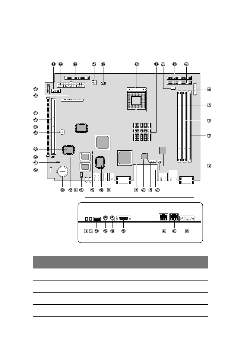
Mainboard layout
1 System tour10
No. Description
1 Front USB connector
2 20-pin ATX power connector
3 Secondary IDE RAID connector
4 4-pin ATX power connector

No. Description
5 CPU fan connector (CPU FAN2)
6 CPU socket
11
7
ServerWorks
®
CMIC-SL (north bridge)
8 CPU fan connector (CPU FAN1)
9 Primary IDE RAID connector
10 Primary IDE connector
11 CD-ROM and HHD power jumper (JP4)
12 -14 DIMM slots
15
®
82540EM Gigabit Ethernet controller chipset
Intel
16 Power connector for Server Management Card
17 IPMB (Intelligent Platform Management Bus) signal connector
18
®
Intel
82550PM Server Ethernet controller chipset
19 ATI Rage XL VGA chipset
20
ServerWorks
®
CSB6 (south bridge)
21 NS 87414 Super I/O chipset
22 Boot block jumper (JP3)
23 System fan connector (SYSFAN1)
24 IPMI BIOS
25 System BIOS
26 Battery
27 System fan connector (SYSFAN2)
28 Clear CMOS jumper (JP1)

No. Description
29 Power-on circuit jumper (JP2)
30 IPMI chipset
31 Buzzer
32 Promise PDC20270 IDE RAID controller
33 64-bit/33 MHz PCI bus slot with riser card (PCI 1)
34 64-bit/33 MHz PCI bus slot with low-profile card (PCI 2)
35 Floppy disk drive connector
36 Front LED board connector
37 Serial port (COM1)
38 1-GbE LAN port
39 10/100 Mbit LAN port
40 Monitor/VGA port
1 System tour12
41 PS/2 keyboard port
42 PS/2 mouse port
43 Rear USB port
44 Health indicator
45 Service indicator
Jumper setting
Label Setting Function
JP1
1-2
2-3
Clear CMOS
Standard CMOS settings
Clear CMOS settings

Label Setting Function
13
JP2
1-2
2-3
JP3
1-2
2-3
JP4 Power connector for CD-ROM and HDD
Power on circuit
Control system power via IPMI (standard)
Control system power via south bridge
Boot block (BIOS recovery)
Disable boot block (standard)
Enable boot block

1 System tour14

2 System setup

This chapter gives you instructions on how to set
up the system. Procedures on how to connect
the monitor is also explained.

17
Pre-setup reminders
Transporting the server
Transport the server only in its original packaging or in a packaging
which protects it from knocks and jolts. If you need to lift or transport
the server , ask other people to help you. Do not unpack the server until
you are done transporting.
Target group
The operating instructions are intended for the person responsible for
installing the hardware and correctly operating the system. This User’s
guide contains all the information required for installing and
operating the Fortress 1120 server.
For installing the hardware and correctly operating the system it is
necessary to have a knowledge of hardware and data transmission, as
well as basic knowledge of the operating system used. You should also
have a good working knowledge of the English language.
Setup precautions
• Please note the safety instructions on page vii.
• Do not expose the server to extreme environmental conditions
(refer to “Environmental conditions” on page 7). Protect it from
dust, moisture, and heat.
• The server must be acclimatized in its operating environment for
an acclimatization time.
Temperature difference (°C)
(operating environment/
outside)
5 3
10 5
15 7
20 8
Minimum acclimatization time
(hours)

2 System setup18
Temperature difference (°C)
(operating environment/
outside)
25 9
30 10
Minimum acclimatization time
(hours)
ESD precautions
Electrostatic discharge (ESD) can damage your processor, disk drives,
and other components. Electrostatic-sensitive components may be
identified by the following sticker:
Always observe the following precautions before you install a server
component labelled as an ESD:
• You must always discharge static build up by wearing a wrist
grounding strap and attach it to a metal part of the server before
handling components or by touching a grounded object before
working .
If a wrist strap is not available, maintain contact with the server
throughout any procedure requiring ESD protection.
• The equipment and tools you use must be free of static charge.
• Remove the power plug from the power socket before inserting or
removing components containing ESDs.
• Always hold components with ESDs by their edges.
• Do not touch any exposed pins or conductors on a component.
• Use a grounding cable designed for this purpose to connect
yourself to the system unit as you install components.
• Do not remove a component from its protective packaging until
you are ready to install it.
• Place all components on a static-safe base.

System setup
The following setup installation steps are described in detail in other
sections of this chapter:
Important! DO NOT attempt the procedures in the following
sections unless you are confident of your capability to perform
them. Otherwise, ask a service technician for assistance.
1 Unpack the server.
Refer to the succeeding “Unpacking the server”section.
2 Set up the server as a stand-alone unit (refer to page 20).
- or -
Mount the server into the rack (go to page 35).
3 Connect the server cables (see page 21).
4 Connect the monitor and other peripheral devices (refer to
page 21).
5 Connect the server to the power supply (go to page 22).
6 Turn on the server (refer to page 23).
7 Configure the server (see page 25).
19
Unpacking the server
Important! Please note the safety instructions on page vii and
the pre-setup reminders on page 17.
1 Transport the server to the place where you want to set it up. Do
not unpack the server until you are done transporting.
2 Unpack all the individual parts. The Fortress 1120 package
contents include the following:
• Fortress 1120 system
• CPU heatsink assembly
• System cables and screws package
• Rubber foot (for stand-alone model only)

2 System setup20
• Fortress 1120 User’s guide
• Fortress 1120 Driver CD
• Fortress 1120 Anti-virus CD
3 Check the contents of the package for visible transport damage.
4 Check whether the delivery agrees with the details in the delivery
note.
The identification rating plate is located on the front area on the
server.
If you find transport damage or inconsistencies between the
contents of the package and the delivery note, inform your
supplier immediately!
5 It is recommended not to throw away the original packaging
material as it may be required for transportation at some later
date.
Setting up the stand-alone model
Position the stand-alone model at the intended location.
Note the following:
• The device must be protected from direct sunlight.
• The required minimum distances for operation and maintenance
areas must be adhered to.
• In order to connect other devices (e. g.: storage subsystem) the
rear of the server must be accessible.
• The mains plug must be accessible easily and safely.
• There must be a clearance of at least 200 mm in front of and
behind the server to ensure adequate ventilation.
• The delivered rubber feet must be glued on the bottom of the
device. You find corresponding square reliefs at the bottom of the
device.

Connecting the server cables
Cable connection guideline
1 Be sure to read the documentation for all peripheral devices
before connecting them.
2 Do not connect or disconnect data cables during a thunderstorm.
3 When removing a cable, always hold it by the plug.
4 Connect and disconnect the cables in the order described below.
To connect cables
1 Turn off all power and equipment switches.
2 Pull all power plugs out of grounded power sockets.
3 Plug all cables into the server and peripherals. Secure the data
transmission cable connections (e. g. nut retention).
4 Plug all data communication cables into the utility sockets.
5 Plug all power cables into the grounded power sockets.
To disconnect cables
21
1 Turn off all power and equipment switches.
2 Pull all power plugs out of grounded power sockets.
3 Unplug all data communication cables from the utility sockets.
4 Loosen the nut retentions on the connector housings and pull the
corresponding cables out from the server and from the
peripherals.
Connecting the monitor
1 Plug the data cable of the monitor into the monitor port.
For the location of the monitor port, refer to page 9.

2 System setup22
2 Connect the power cable of the monitor to a grounded mains
outlet of the in-house mains and/or into the mains socket strip of
the rack.
Note: The rated current for the monitor can be found on the
technical data label on the monitor or in the operating manual for
the monitor.
Connecting options
Aside from the monitor, other peripheral devices (e.g., mouse,
keyboard) can also be connected to the server. Some of these devices
may require special driver software; if this is the case you will need to
refer to the documentation that accompanies that device.
To connect a peripheral device, plug in the device’s data cable to its
corresponding port on the server. Refer to “Rear panel” on page 9 for
a list of standard ports available for Fortress 1120.
Connecting the server to the mains
The server has a fixed power supply unit.
The server automatically adjusts to a mains voltage between 100 V to
127 V and/or 200 V to 240 V . The server may be place in operation only,
if the mains voltage range set on the server corresponds to the local
mains voltage.
To connect the server to the mains
1 Connect the insulated connector of the power cable to power
supply unit of the server.

2 Connect the server power plug to a grounded mains outlet of the
in-house mains (for the rack model, into the mains socket strip of
the rack).
23
Turning on the server
After making sure that server has been properly set up and all the
required cables are connected, the server can now turned on.
To switch on the system, press the power button on the front panel.
The server performs a system test and boots the operating system.
If after switching on the server there is nothing but flickering stripes
on the screen, turn off the server immediately (see page 32).
Note: The power button does not disconnect the server from the
mains voltage. To completely disconnect it from the mains
voltage, remove the power plug from the socket.

Server power status
Power status. Description
2 System setup24
Server is
switched off
Server is
switched on
Server in
suspend mode
The power indicator color is solid amber.
The power indicator color is solid green.
To shut down the server, press the power button and/
or send a corresponding controlling signal (refer to
the next section on ”Other ON/OFF possibilities“).
The power indicator color is flashing green.
System fans speed slows down based on IPMI setting
and all RGB displays are shut down.
To resume normal operation, press any button.
Other ON/OFF possibilities
In addition to the power button, the server can be switched on and off
in the following ways:
• Specified switch-on time/switch-off time
The server is switched on or off at a time specified in the BIOS
Setup menu.
• Ring indicator
The server is switched on via an internal or external modem.
• Wakeup On LAN (WOL)
The server is switched on by a command via the LAN.
• After power failure
The server automatically switches on following a power failure
(depending of the settings in the BIOS).
• Intelligent Platform Management Interface (IPMI)
The server is switched on by an IPMI console via COM1 or RJ-45.

25
Configuring the server
This section contains information about configuring the server and
installing the operating system.
To configure the RAID controller
If your server is fitted with a RAID controller, you must configure it as
described in the related documentation.
To configure the PCI-SCSI controller
Configure the PCI-SCSI controller as described in the manufacturer's
documentation. Further information is available on the driver diskettes
provided.
To install the operating system
Note: If your server is equipped with a RAID controller, refer how
to install the desired operating system in the related manual.
1 Insert the installation disk and the CD of the operating system you
want to install.
2 Reboot the server.
3 Follow the instructions on the screen and in the manual for the
operating system.

2 System setup26

3 System maintenance
and protection

3 System maintenance and protection28
This chapter describes the proper way of
cleaning the server and protecting it from
unauthorized access. A list of
troubleshooting tips are also given.

29
Server maintenance
Follow the steps to clean the server.
1 Switch the server off, and pull the power plug out of the
grounded-contact power socket.
2 Make sure that the ventilation areas of the server and the monitor
are free from any obstruction.
3 Wipe the server and monitor casing with a dry cloth. If particularly
dirty, use a cloth that has been moistened in a mild domestic
detergent and then carefully wrung out.
4 Use a cloth for disinfection to clean the keyboard and the mouse.
Important reminders in cleaning the server
• Do not clean any interior parts yourself; leave this job to a service
technician.
• Do not use any cleaning agents that contain abrasives or may
corrode plastic.
• Ensure that no liquid enters the system.

3 System maintenance and protection30
Property and data protection
The rack model is protected against unauthorized access by means of a
lockable rack door (optional feature).
To protect your system and data internally against unauthorized
access, use the BIOS Setup menu’s security functions.
BIOS Setup security functions
The System Security menu in BIOS Setup offers you various options for
protecting your data from unauthorized access. By combining these
options, you can achieve optimum protection for your system.
Preventing unauthorized BIOS Setup calls
Y ou can activate this protection by setting a supervisor password in the
System Security menu.
Preventing unauthorized system access
You can activate this protection by setting a user password in the
System Security menu.
Preventing unauthorized writing of diskettes and/or of hard disk
drives
To activate this protection, select the value Write Protect All Sectors or
Write Protect Boot Sector for the Floppy Drive and/or Hard Disk Drive
in the System Security menu.

System troubleshooting
If you encounter a problem with your Fortress 1120 server, try to
resolve it as described:
• in this chapter,
• in the documentation for the attached devices, or
• in the help systems of the software used.
If the problem still persists, proceed as follows:
1 Make a note of the steps and the circumstances that led to the
fault. Note also any error message which may have been displayed.
2 Switch the server OFF.
3 Go to http://english.aopen.com.tw/tech/contact/
on how to contact the AOpen technical support.
FAQs
Below are possible situations that may arise during the use of the
server with corresponding easy troubleshooting solutions.
for information
31
Caution: Always observe the safety information described on
page vii in performing any of the troubleshooting procedures
described in this section.
The power indicator remains dark after switching the server on.
Power cable not connected correctly
• Make sure that the power cable is correctly connected to the
server and to the grounded power socket.
Power supply overloaded
1 Pull the server power plug out of the power socket.
2 Wait a few seconds and plug the power plug into the power
socket again.
3 Switch the server back on.

3 System maintenance and protection32
The server switches itself off.
Server management has detected an error
• Check the error list or the ErrorLog file in the BIOS Event Log
viewer, and attempt to eliminate the error.
The monitor remains dark.
Monitor is switched off
• Switch on the monitor.
Power saving has been activated (screen is blank)
• Press any key on the keyboard.
• Deactivate the screen saver (a password maybe required).
Brightness control is set too dark
• Adjust the brightness control to increase the brightness. For
detailed information, please refer to the operating manual
supplied with your monitor.
Power cable or monitor cable not connected
1 Switch off the monitor and the server.
2 Check whether the power cable is properly connected to the
monitor and to the power socket.
3 Check whether the monitor cable is properly connected to the
server and monitor (if it is connected with a plug). If a separate
graphics card is installed in the server , then the monitor cable must
be connected to the connection on this graphics card.
4 Switch the monitor and the server back on.
There are flickering stripes across the monitor.
Caution: Switch off the server immediately . Risk of damaging the
server.
Monitor does not support the set horizontal frequency
1 Find out which horizontal frequency the monitor supports. You
will find the horizontal frequency (also known as line frequency or
horizontal deflection frequency) in the documentation
accompanying the monitor.

2 Refer to the documentation of the server’s operating system or to
the corresponding software for the monitor controller for
instructions on how to set the correct horizontal frequency for the
monitor, and follow the procedures accordingly.
There’s no monitor display or the display drifts.
The wrong horizontal frequency and/or resolution has been
selected for the monitor or for the application program.
1 Find out which horizontal frequency the monitor supports. You
will find the horizontal frequency (also known as line frequency or
horizontal deflection frequency) in the documentation
accompanying the monitor.
2 Refer to the documentation of the server’s operating system or to
the corresponding software for the monitor controller for
instructions on how to set the correct horizontal frequency for the
monitor, and follow the procedures accordingly.
There’s no mouse pointer displayed on the monitor.
Mouse driver not loaded
• Check whether the mouse driver is properly installed and is
present when the application program is started. Detailed
information can be found in the documentation for the mouse,
the operating system, or the application program.
33
Mouse controller disabled
• The mouse controller on the mainboard must be enabled if you
use the supplied mouse. Check BIOS Setup to make sure the mouse
controller is enabled.
The floppy disk cannot be read or written.
• Make sure that the floppy disk is not write-protected (the writeprotect tab is in the not-write protected position)
• Check the entry for the floppy disk drive in BIOS Setup.
• Check BIOS Setup whether the floppy disk drive controller and
write permission are enabled.

3 System maintenance and protection34
The system time and/or date are incorrect.
• Set the time and/or date in the operating system or in BIOS Setup.
• If the wrong time and date is repeatedly displayed when you
switch on your server, you must change the lithium battery. Go to
http://english.aopen.com.tw/tech/contact/
to contact the AOpen technical support.
for information on how
The system fails to boot.
The system will not boot after installing a new hard disk drive.
• Reboot the system with the operating system CD or with a boot
diskette and reconfigure the server. For details, refer to
“Configuring the server” on page 25.

Appendix A — System rack
installation

This appendix describes the procedures for
configuring the system in a rack-mount
fashion.

37
Guidelines in rack installation
The Fortress 1120 server occupies 1U in the rack. Count the U positions
and hole numbers from the bottom up.
Note: The unit of measurement used in this document is "U"
(1U = 1.75 inches or 44.45 mm). The total sum of the heights of all
components in the rack measured in "U" cannot exceed the
height of the rack. For more information, refer to the
documentation that came with the system rack.
The distance from the center of two holes with closer spacing to the
center of the next pair is equivalent to 1U.
When installing components, you must start your measurement from
the center of the two holes with closer spacing. Otherwise, the screw
holes on the component may not match those on the rack.
Rack installation precautions
Observe the following precautions when you install the server in the
rack:
• When connecting and disconnecting cables, observe the relevant
notes in the documentation of the corresponding rack.
• If necessary, the cables are routed directly on the rack support
uprights.
• Ensure that the anti-tilt bracket is correctly mounted when you set
up the rack.
• For safety reasons, only one unit should be withdrawn from the
rack at any one time. If several units are withdrawn at the same
time from the rack there is a danger that the rack will tilt forward.
• The power connection for the rack must be installed by an
authorized technician (electrician).
• Observe the ESD precautions indicated on page 18 when installing
the server in a rack model fashion.

Appendix A — System rack installation38
System rack installation
Important! Do not attempt the procedures described in the
following sections unless you are a qualified service technician.
Preparing the server
1 Screw the front mounting brackets (left and right) to the server
with the eight screws.
2 Mount the two support plates between the left and right
telescopic bars with the eight screws .
3 Align the telescopic bars with the two support plates to the front
mounting brackets attached to the server.
4 Secure the telescopic bars to the front mounting brackets with the
six screws. For more information on this steps, refer to page 39.

39
Note: If two Fortress 1120 servers are installed directly on top of
each other in the rack, the support plates in the bottom server will
be mounted into the bottom row of holes, and in the upper server
into the upper row of holes. This guarantees that enough free
space is available between the servers for the leads that are to be
routed.
To secure the telescopic bars to the server
1 Screw the telescopic bar to the front mounting bracket and make
sure the screws go through the three screw holes on the lower
part of the bracket.

Appendix A — System rack installation40
2 The left and right mounting bracket share a common part. Thus, a
mounting bracket could be used as either a left or right mounting
bracket depending on how you turn it around.

41
Pay attention to the two letters, L and R, circled in figure below.
When the frontal mounting bracket is placed with the letter L in a
upright position and R upside down, it should be used as a left
mounting bracket, and vice versa.
Mounting the assembly kit
The Fortress 1120 server can be set up in rack mount fashion using
either the DataCenter Rack or a standard rack assembly kit.
DataCenter Rack
For mounting the rack model in the DataCenter Rack, a support
bracket must first be mounted on the rear left support upright of the
rack.

Appendix A — System rack installation42
This support bracket must be mounted level with the lower edge of
the device. The support bracket is used for the rear fixing of the left
carrier rail.
1 Review the installation instructions in the DataCenter Rack
documentation.
2 Mark the position of the attachment points of the server on the
support uprights (1 HU).
3 Mount the support bracket using two screws and cage nuts at the
appropriate height on the rear left support upright.
Note: If required, you can mount one additional cable clip for
vertical cable routing.
To fasten the carrier rails, no cage nuts are necessary since the rails
are equipped with threaded holes.
To mount the carrier rails, mounting brackets must be installed in
the support uprights and/or in the support bracket. To do this:
a Place the mounting brackets in the holes of the support
uprights and/or of the support bracket at the marked
attachment points.
b Secure the two carrier rails in the rack at the left and right
support uprights or at the support bracket.

43
Standard rack
For mounting the rack model in the standard rack, two fitting brackets
must first be mounted at the carrier rails. Spring nuts must also be
inserted in the support uprights. The spring nuts are used for fixing the
carrier rails and securing the server at the front.
1 Review the installation instructions in the standard rack
documentation.
2 Mark the position of the attachment points of the server on the
support uprights (1 HU).
3 Place the spring nuts in the groove of the support uprights at the
marked attachment points.
4 If necessary, adjust the position of the nuts in the groove until they
lock into the correct position.

Appendix A — System rack installation44
5 Place on both ends of the carrier rails one fitting bracket. Please
note that the holes (1) must fit onto the guide nubs (2) of the
carrier rails.
6 Place the prepared carrier rails at the marked attachment points
on the support uprights. Refer to the figure on the next page.

45
The fitting bracket (1) is located between the carrier rail (2) and
the support upright (3). Please note that the guide nubs of the
fitting bracket must fit into a hole in the support upright next to
the spring nut.
7 Secure the two carrier rails in the rack at the left and right support
uprights (4).
Mounting/removing the server in the rack
To finish setting up the Fortress 1120 server in rack mount fashion,
mount the prepared server into the assembled rack model.
To mount the server in the rack
1 Lift the server onto the two carrier rails.
2 To mount the server into the rack:
a Slide the server into the rack (1).
b Secure the server in the rack using the two knurled screws (2)
Refer to the figure on the next page.

Appendix A — System rack installation46
.

To remove the server from the rack
1 Press in the safety springs on both telescopic bars.
2 Carefully slide out the server from the rack.
47

Appendix A — System rack installation48
 Loading...