

Page 1

Internal
Fax Modem 56K
User’s Manual
Doc. No.: 111601-01
Page 2

FCC REGULATORY STATEMENTS
FCC Part 68 Registration
This device complies with FCC Part 68 rules, and the use of this
device is subject to the following restrictions:
1. The FCC has established rules which permit this device to be
directly connected to the telephone network. Standardized jacks
are used for these connections. This equipment should not be
used on party lines or coin phones.
2. If this device is malfunctioning, it may also be causing harm to
the telephone network; this device should be disconnected until
the source of the problem can be determined and until repair has
been made. If this is not done, the telephone company may
temporarily disconnect service.
3. The telephone company may make changes in it's facilities,
equipment, operation and procedures; if such changes affect the
compatibility or use of this device, the telephone company is
required to give adequate notice of the situation with the FCC.
4. If the telephone company requests information on what
equipment is connected to their lines, inform them of:
a. The telephone number to which this unit is connected.
b. The Ringer Equivalence Number (REN).
c. The USOC jack required.
d. The FCC Registration number.
Items (b) and (d) are indicated on the label. The Ringer
Equivalence Number (REN) is used to determine how many
devices can be connected to your telephone line. In most areas, the
sum of the REN's of all the devices on any one line should not
exceed 5.0. If too many devices are attached, they may not ring
properly.
FCC Part 15 Registration
This device complies with Part 15 of FCC rules. Operation is
subject to the following two conditions:
1. This device may not cause harmful interface, and
2. This device must accept any interface received including
interface that may cause undesired operation.
This equipment has been tested and found to comply with the
limits for a Class B digital device, pursuant to Part 15 of the FCC
Rules. These limits are designed to provide reasonable protection
against harmful interference in a residential installation. This
equipment generates, uses and can radiate radio frequency energy,
and if not installed and used in accordance with the instructions,
may cause harmful interference to radio communications. However,
Page 3

there is no guarantee that interference will not occur in a
particular installation. If this equipment does cause harmful
interference to radio or television reception, which can be
determined by turning off and on, the user is encouraged to try to
correct the interference by one or more of the following measures:
Reorient or relocate the receiving antenna.
Increase the distance between the equipment and receiver
Connect the equipment into an outlet on a circuit different
from that to which the receiver is connected.
Consult an experienced radio/TV technician for help.
CTR 21 pan-European Certification
This equipment has been approved in accordance with Council
Decision 98/482/EC for pan-European single terminal connection
to the public switched telephone network (PSTN). However, due to
differences between the individual PSTNs provided in different
countries, the approval does not, of itself, give an unconditional
assurance of successful operation on every PSTN network
termination point. In the event of problems, you should contact
your equipment supplier in the first instance.
This device is designed to work with the notified networks in all
EC member states. Nevertheless, some of the network services in
invidual countries might not be supported, but they will not affect
the normal data and fax applications. For example, the metering
charge service in Germany. Besides you may encounter difficulty
of using PULSE dialing function in some of the countries, such as
Nordic countries. This kind of network compatibility is dependent
on the physical and software settings of this device. If the users
are desired to use this device on those networks, they should
contact the vendor or supplier first.
Page 4

Table of Contents
INTRODUCTION ...................................................1
PECIFICATIONS
S
YSTEM REQUIREMENTS
S
.....................................................1
........................................2
HARDWARE INSTALLATION ...........................3
SOFTWARE INSTALLATION.............................4
INDOWS
W
INDOWS
W
INDOWS
W
INDOWS
W
INDOWS
W
INDOWS
W
NSTALLAITON
95 I
NSTALLATION
98 I
NSTALLATION
ME I
NSTALLATION
NT I
NSTALLATION
2000 I
NSTALLATION
XP I
.................................4
.................................7
................................9
..............................14
...........................14
..............................18
CHECKING COUNTRY/REGION ....................21
INDOWS
W
INDOWS
W
INDOWS
W
INDOWS
W
95/98/ME............................................21
NT4.0 .................................................21
2000....................................................21
XP.......................................................22
UNINSTALL..........................................................23
APPLICATIONS...................................................24
NTERNET ACCESS
I
................................................24
TROUBLE SHOOTING.......................................26
APPENDIX A: AT COMMAND .........................31
APPENDIX B: S-REGISTERS ............................38
Page 5

INTRODUCTION
The Internal FaxModem 56K is Bell, ITU-T
(formerly CCITT) compliant and Hayes AT
command compatible, so that it can be used
worldwide with today’s popular communication
software programs. You will be able to send and
receive faxes to/from any Group 3 compatible fax
machine. Using standard phone lines, the data
communication functions of the modem will enable
you to successfully hook up to the Internet, transmit
E-mail, send and receive information and
communicate with other PCs, Bulletin Board
Services (BBS) or computer networks such as
Compuserve
Specifications
Data:
K56flex, V.90, V.92, V.34bis, V.34, V.32bis,
V.32, V.22bis, V.22, and V.21, Bell 212A and
Bell 103
Fax:
V.17, V.29, V.27ter, and V.21 channel 2
Group 3 send and receive facsimile
Error Correction:
V.42 and MNP 2-4
Data Compression:
V.42bis and MNP 5
Communication software compatible commands:
Hayes compatible enhanced "AT" command
set
Fax Service Class 1 commands
Built-in DTE interface:
DTE speed up to 115,200 bps
16C550 UART interface
- 1 -
Page 6

System Requirements
A telephone line with RJ-11 jack.
A CD-ROM drive.
Windows 95/98/ME/NT/2000/XP pre-installed.
- 2 -
Page 7

HARDWARE INSTALLATION
Precautions:
Please be sure you take adequate anti-static
precautions when handling this product. The
simplest way to achieve this is; before you begin and
every minute or so during the hardware installation
touch a non-painted surface of the computer’s
chassis.
1. Before installing the device, make sure the
computer is turned off.
2. Remove the expansion slot cover from the
computer.
3. Carefully slide the PCI modem card into an
available PCI slot, push it evenly and firmly and
ensure it is screwed securely in place using the
mounting screw (PCI slots are 85mm long and
positioned 40mm from the PC’s rear panel.
Generally there are several PCI slots side by
side).
4. Plug one end of the telephone cable into the
Modem line jack and the other end to the
telephone jack in the wall.
5. Replace the cover.
6. After hardware installation is done, move on to
the software installation.
- 3 -
Page 8
SOFTWARE INSTALLATION
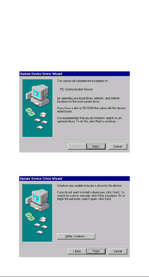
Windows 95 Installaiton
1. Reboot the computer system after the modem is
correctly plugged into your PCI slot of computer.
The Windows95 will automatically detect the
new hardware device and prompt the following
message. Click on Next button to continue.
2. Insert the device driver compact disc into your
CD-ROM drive. When the following dialog box
appears, click the Other Locations button.
- 4 - - 5 -
Page 9
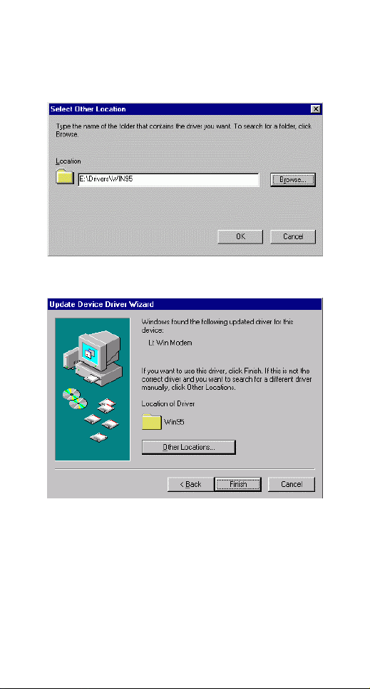
3. Type the CD-ROM drive letter followed by
driver\win95. Or you may click the Browse
button to select the driver\win95 folder in your
CD-ROM drive. Click OK.
4. When the following figure appears, click Finish.
The Installation program will continue.
5. When the following figure appears, click OK to
continue.
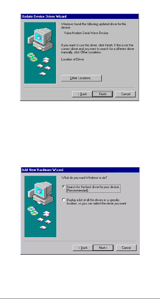
Page 10
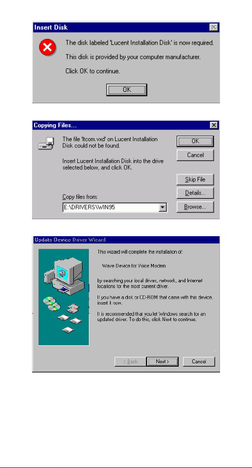
6. Repeat Step 3 as described above.
7. Follow the on-screen instruction to continue.
8. When finished, press Finish to complete the
installation. Remember to restart Windows 95 to
activate the new device.
- 6 -
Page 11
Windows 98 Installation
1. Restart the computer system after the modem is
correctly plugged into the PCI slot of your
computer. Windows will automatically detect the
device. Click Next.
2. When the following dialog box appears, insert
the device driver compact disc into your CDROM drive and click Next.
3. Select Specify a location and press Browse to
choose the folder driver/win98 in your CDROM drive. Then click Next.
- 7 -
Page 12
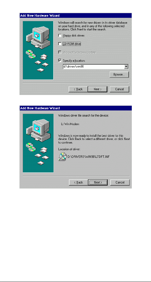
4. Click Next to continue.
5. When the following figure appears, click Finish.
The Installation program will continue.
- 8 -
Page 13
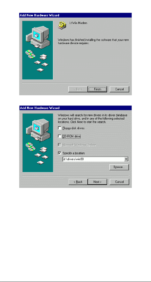
6. Follow the on-screen instructions to proceed.
7. The program will proceed automatically. Click
Finish to complete software installation.
Windows ME Installation
Restart the computer system after the modem is
properly plugged into the PCI slot of your computer.
Windows ME will automatically detect the device. If
you want to use the Microsoft built-in driver, execute
d:\Driver\WinME\PAR.exe (assume that d: is your
CD-ROM drive). Or you may update the device
driver with the utility provided by the manufacturer.
- 9 -
Page 14
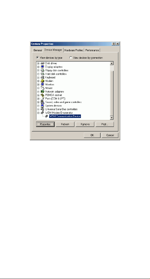
1. Right-click My Computer, then click
PropertiesDevice Manager.
2. Click WDM Modem Enumerator to expand.
3. Load the device driver into your CD-ROM drive.
Click PropertiesDriverUpdate Driver.
- 10 -
Page 15

4. Select Specify the location of the driver
(Advanced) and click Next.
5. Select Display a list of all the drivers…and
click Next.
- 11 -
Page 16

6. Click the Have Disk…button.
7. Click Browse to select the drive where the
device driver exists. (for example: D:\) Enter
the CD-ROM driver letter followed by
driver\Win_ME.
8. Click Next.
- 12 -
Page 17

9. Click Next to proceed.
10. Click Finish to complete the software
installation.
Note: Windows ME users who experience low
connection speeds to their Internet provider can apply
a driver update to improve speeds. To do this, insert
the modem driver CD, (you will need to press Exit
when the PICShell software installation utility starts).
Click on Start, Programs, Windows Explorer.
Now explore the CD-ROM by opening the Driver
folder, then Win_Me_faster. Double-click on
Driver_update.exe, this will lead you through the
upgrade process.
- 13 -
Page 18

Windows NT Installation
1. Reboot the computer system after the modem is
correctly plugged into your PCI slot of computer.
2. Load the device driver compact disk in the CD-
ROM drive.
3. Start Windows NT.
4. Go to My Computer.
5. Click the CD-ROM drive. Click the
driver\winnt folder. Or you may click the
Browse button to select the CD-ROM drive and
the driver\winnt folder.
6. Double-click setup.exe. The installation
program will proceed automatically.
Windows 2000 Installation
Restart the computer system after the modem is
properly plugged into the PCI slot of your computer.
Windows 2000 will automatically detect the device.
If you want to use the Microsoft built-in driver,
execute d:\Driver\Win2000\PAR.exe (assume that d:
is your CD-ROM drive). Or you may update the
device driver with the utility provided by the
manufacturer.
1. Go to Control Panel, double-click System.
Select Hardware. Click Device Manager.
- 14 -
Page 19

2. Right-click LT Win Modem. Select Properties.
3. Select Driver. Click the Update Driver…button.
- 15 -
Page 20

4. Follow the on-screen instructions to proceed.
(Click Next to continue.)
5. Load the Compact Disc that contains the device
driver into your CD-ROM drive. Click Browse
and select the proper file location with the disc
drive followed by Driver\Win2000.
6. Check Install one of the other drivers. Click
Next.
- 16 -
Page 21
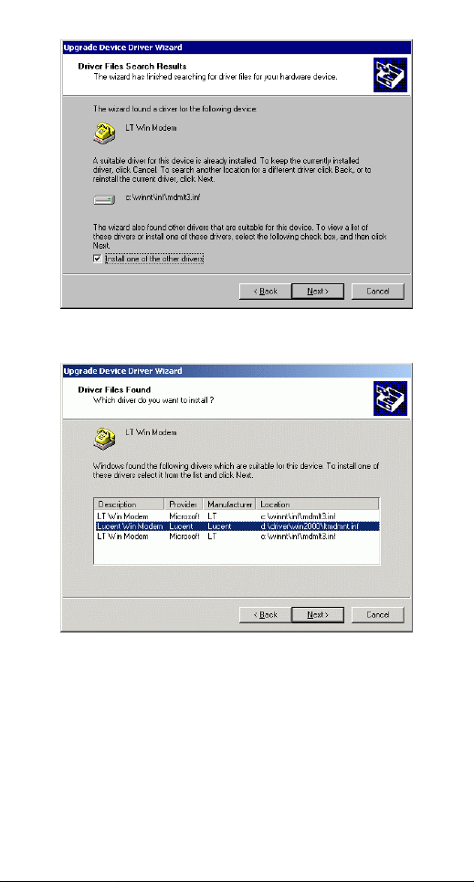
7. Select d:\Driver\Win2000\ltmdmnt.inf, click
Next.
8. When Windows prompt you to continue the
installation. Select Yes.
- 17 -
Page 22

9. Click Finish to complete the software
installation.
Windows XP Installation
Restart the computer system after the modem is well
inserted into the PCI slot of your computer.
Windows XP will automatically detect the modem.
Perform the following procedures to install the driver.
1. Load the device driver CD into your CD-ROM
drive. Close the window that automatically
pops up.
2. Go to StartRun. Click Browse to direct
your system to the location where contains the
device’s driver (e.g., E:\Driver\Win
2000&XP\Setup). Click OK.
3. Click OK to install the driver.
- 18 -
Page 23

4. When the following window appears, click
Continue Anyway to complete the software
installation.
5. Go to StartRun, enter “regedit”, and click
OK.
6. Select HKEY_LOCAL_MACHINE, and
click SOFTWARE to expand. If the Lucent
and Modem are listed as below, the modem
exists and is successfully enabled. If not,
consult your distributor for the technical
support.
- 19 -
Page 24

- 20 -
Page 25

CHECKING COUNTRY/REGION
Perform the following steps to check the
country/region settings for the modem before you use
the Internal Fax Modem 56K. For best performance,
make sure that the country/region is set to the country
that you are using the modem in, eg. United States
of America.
Windows 95/98/ME
1. Go to
Start→Settings→Control Panel→Modems.
2. When the Modems Properties dialog box
appears, click the Dialing Properties button.
3. When the Dialing Properties dialog box
appears, specify the country/region that you are
in and click OK.
Windows NT4.0
1. Go to
Start→Settings→Control Panel→Modems.
2. When the Modems Properties dialog box
appears, click the Dialing Properties button.
3. When the Dialing Properties dialog box
appears, specify the country/region that you are
in and click OK.
Windows 2000
1. Go to
Start→Settings→Control Panel→Modems.
2. When the Phone And Modem Options dialog
box appears, click the Edit button.
3. When the Edit Location dialog box appears,
specify the country/region that you are in and
click OK.
- 21 -
Page 26

Windows XP
1. Go to Start→Control Panel→Phone And
Modem Options.
2. Select the Dialing Rules tab, and click the
Edit button.
3. When the Edit Location dialog box appears,
specify the country/region that you are in and
click OK.
- 22 -
Page 27

UNINSTALL
If you have to uninstall the driver of Internal
FaxModem 56K for some reason after installation,
perform the following steps.
1. Go to My Computer.
2. Select the CD-ROM drive whichever contains
the Internal FaxModem 56K device driver.
3. Choose and double-click the win98,
win2000&XP, winME or winnt folder
depending on the system you are working on.
4. Click
Ltremove.exe
device driver will automatically removed.
. The Internal FaxModem 56K
- 23 -
Page 28
APPLICATIONS
To use the Internal FaxModem 56K for data
communication, for example, to send/receive faxes or
to get onto the Internet, you may use any application
software that you are familiar with. Or you may also
choose to use the bundled application software that
comes with the Internal FaxModem 56K . The
following are examples for sending faxes and going
to the Internet.
Internet Access
1. Go to My Computer.
2. Select Dial-Up Networking.
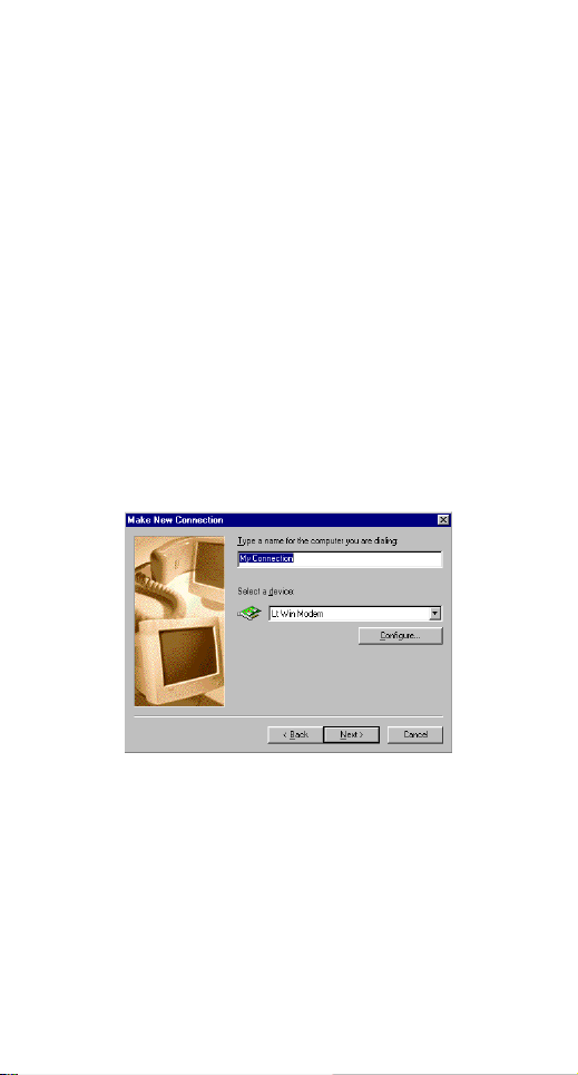
3. Double-click Make a New Connection, a
dialogue box appears for you to name the new
connection and select the device. Name the new
connection appropriately and click Next.
4. Enter the area code and phone number of your
Internet Service Provider (ISP). Follow the onscreen instruction to proceed.
5. When finished, from the Dial-Up Networking
window right-click your newly created
connection. Select Properties. On the Server
Types tab, enter the proper selections as shown
below and click OK to finish the settings.
- 24 -
Page 29

.
6. You are now ready to connect to the Internet.
- 25 -
Page 30

TROUBLE SHOOTING
This chapter provides information on the most
commom problems, the possible causes, and the
solutions.
The modem does not respond to AT commands.
Conflict of COMx: port setting with another device.
Change the COMx: port of the Internal FaxModem
56K to a free port. Be sure to update your software
COMx: port setting as well.
The modem does not execute the command line.
Make sure you are typing 'AT' at the beginning of
command line.
Make sure the modem is not in Data Mode. type +++ if
necessary.
Make sure your software is set to the same COMx:
port as the modem is.
The modem does not give a response after an AT
command was executed.
The echo and/or responses may be turned off by the
ATE0Q1 commands.
Use AT&V to check that.
Use ATE1Q0 then Enter to change them back.
Make sure the modem is in Command Mode rather
than in Data Mode when you type the AT command.
The modem gives an 'ERROR' response after an AT
command was executed.
Make sure you did not type an invalid command.
Make sure your command line is 40 characters or less
in length.
The modem goes off-hook and disables the telephone
line.
The modem may be set to auto-answer mode when it
rings.
Type ATS0=0, then Enter at the command line to
disable the auto-answer mode.
- 26 -
Page 31

The modem does not auto-answer the phone.
Make sure the software is configured to auto-answer
the phone.
Type ATS0=n then press Enter. The n stands for the
number of rings the modem will answer on.
The software does not control the modem properly or
can not detect the modem.
Make sure the software has been set up correctly.
Check the initialization and dial strings.
Some TSRs (programs that stay in memory after they
are loaded) may conflict with the communications
software.
Restart your computer without loading any TSRs.
The characters on the screen are doubled.
Both the modem and the software have the echo
feature turned on at the same time.
Turn off the software echo feature off.
The remote modem is echoing your typed characters.
Type ATE1 then Enter at the command line. Then turn
off the software echo feature.
No text appears on the screen when in data mode.
The remote modem is not echoing your typed
characters.
Type ATE0 then press Enter at the command line.
Then turn the software echo feature on.
Your software may not be set to use Full Duplex or the
remote modem may not be set to use Full Duplex
either.
C:The remote modem may be waiting for you to type a
command before it will reply with text.
No text appears on the screen when in command mode.
If you can't see the characters you are typing, then
type ATE1 then press Enter.
The modem does not dial a phone number after you
execute the AT dial command.
- 27 -
Page 32

If you are using touch tone dialing on a phone line that
requires pulses, then it may not work.
Use ATDT in place of ATDP.
When your communications software tells the modem
to dial, it does not.
Make sure the software dialing prefix is ATDT.
Make sure the software and modem are set to the
same COMx: port.
The modem may not have hung up the phone line
since the last call.
Change to command mode and type ATH then
press Enter.
When dialing another modem, you receive a
'CONNECT' response, but nothing else.
The remote modem may be waiting for you to type a
command. Or try to press Enter for logging on to the
remote site.
The modem speaker does not make any sound when
you're connecting to another modem.
The software may have the speaker disabled.
Change the setting in your software or use the ATMn
command to turn the speaker on.
The modem disconnects (looses the connection) in the
middle of use.
The remote modem may have locked up.
The telephone switch may have disconnected your
call.
Your software may have turned off the DTR signal.
The modem does not connect with another modem.
There may be a problem with the remote modem if
you do not hear the high pitched tone from the remote
modem.
Occasionally, the modem gives a burst of errors.
The telephone line may be noisy or bad.
- 28 -
Page 33

Hang up the call and try to connect again for getting a
better telephone line.
If there are other telephones on the same line that
your modem is using, someone may have picked up a
telephone on that extension.
Your telephone line may have the call waiting feature.
Try adding '*70,' to your ATDT dialing command line.
If it doesn’t help, ask your telephone company how to
disable it temporarily.
The modem gets errors in transmitted data randomly.
Try to use V.42 or MNP1-4 if possible.
Connect the modems at a slower baud rate.
After you download a file, it was not stored on your
disk drive.
If both modems are using MNP or V.42 protocol, then
the flow control may not be enabled.
Configure your software to use RTS/CTS flow control.
That will cause your computer to pause long enough
for the file to be stored to disk.
The text on the screen is not legible.
Your software settings may not match the settings on
the remote site.
Make sure your data bits, stop bits, and parity settings
match the settings that the other computer is using.
The two most common settings are: 8 data bits, None
parity, and 1 stop bit (8,N,1) or 7 data bits, Even parity,
and 1 stop bit (7,E,1).
If the telephone line is very noisy, you may see
corrupted data on your screen.
Due to poor telephone line conditions, the modem
may have fallen back to a slower communication
speed. You may need to change the baud rate setting
in your software to match this slower speed. To return
the modem to the higher speed, disconnect the link
and re-establish again.
When using V.42bis or MNP5, some features are
disabled.
- 29 -
Page 34

You may be using a non-streaming protocol, like
Xmodem or Ymodem to transfer files. Those are fine
unless you are using V.42bis or MNP5
When using V.42bis or MNP5, you should use a
streaming transfer protocol like Ymodem-G or
Zmodem.
Configure your software to use hardware flow control
(RTS/CTS ON).
When the modem is connecting to another modem, it
reports a higher connect baud rate that it is really
using.
The modem defaults to report the modem-to-computer
baud rate when it responds with CONNECT.
Go to command mode with your communication
program (like Telix) and type ATW2, then press Enter.
This tells the modem to report the modem-to-modem
baud rate instead.
- 30 -
Page 35

APPENDIX A: AT COMMAND
Basic AT Command Set
Command Options Function & Description
A/ Re-execute the last command string
<any key> Terminate the current connection attempt
All the following commands require an “AT” prefix
A Go off-hook and attempt to establish a
Bn Line modulation options
B0 Select V.22 mode for 1200 bps connection
B1 * Select Bell 212A for 1200 bps connection
B2 Select V.23 1200 bps for receiving, 75 bps
B3 Select V.23 75 bps for receiving, 1200 bps
B15 Select V.21 for 300 bps connection
B16 Select Bell 103 for 300 bps connection
Dn Dial command, beginning the dialing
L Re-dial last number. Should be the first
P Pulse dial.
R Reverse dial. Originate call in answer
S=n Dial the phone number stored in NVRAM
T DTMF tone dial.
, Pause. Cause the modem to pause for a
! Hook Flash (for call transfer). Cause the
@ Wait for 5 seconds of silence after dialing
W Wait for second dial tone. The modem
when entered in handshaking state
connection without waiting for a ring
for transmitting in originate mode; 75 bps
for receiving and 1200 bps for
transmitting in answer mode
for transmitting in originate mode; 1200
bps for receiving and 75 bps for
transmitting in answer mode
sequence. The string “n” (telephone
number and modifiers) listed as follows is
entered after the “D” command
character following ATD, ignored
otherwise
mode (go on-line in answer mode)
at location “n” (n=0, 1, 2, 3)
waits for the second dial tone before
processing the dial string
time before processing the next character
in the dial string (specified by S8 register)
modem to go on-hook for 0.5 second then
return to off-hook
- 31 -
Page 36

; Return to command state after dialing a
En AT command echo options
E0 Echo disabled
E1 * Echo enabled
Hn Switch-hook control
H0 * Modem goes on-hook
H1 Modem goes off-hook
Mn Speaker control
M0 Speaker always off
M1 * Speaker on until carrier present
M2 Speaker always on
M3 Speaker off during dialing and on until
Nn Select negotiate handshake
N0 When originating or answering,
N1 * When originating or answering, start
On Go on-line
O0 Return modem to a previously established
O1 Begin a retrain sequence, then return to
O3 Issue a rate re-negotiation, then return to
P Enable pulse dialing
Qn Result code display options
Q0 * Result code enabled
Q1 Result code disabled
T Enable tone dialing
Vn Result code form
V0 Display result code in numeric form (see
V1 * Display result code in verbose (text) form
Wn Select extended result code options
W0 CONNECT result code reports DTE
W1 CONNECT result code reports DTE
number
number without disconnecting the call
carrier present
handshake only at the communication rate
specified by S37 register and “ATBn” and
no fallback
handshaking only at the communication
standard specified by S37 register and
“ATBn” During handshake, fallback to a
lower speed may occur.
state (return to data mode).
on-line state.
on-line state.
also the result code options table)
speed. Disable protocol result codes.
(see also the “Result Code Options
Table”)
speed. Enable protocol result codes.
- 32 -
Page 37

W2 * CONNECT result code reports DCE
Xn Select result codes/call progress options
X0 Display CONNECT or “1” for all speeds.
X1 Display connect message and the
X2 Display connect message and the
X3 Display connect message and the
X4 * Display connect message and the
X5 Same as X4.
X6 Same as X4.
X7 Display CONNECT or “1” for all speeds.
Zn Recall stored profile
Z0 Reset and recall user profile 0. Either Z0
* Manufacturer default
speed. Enable protocol result codes.
Ignore dial tone and busy tone detection.
modem’s data rate, and an indication of
the modem’s error correction and data
compression.
Ignore dial tone and busy tone detection.
modem’s data rate, and an indication of
the modem’s error correction and data
compression.
Check dial tone before proceeding dialing,
ignore busy tone detection.
modem’s data rate, and an indication of
the modem’s error correction and data
compression.
Ignore dial tone before proceeding
dialing,
check busy tone after making dialing.
modem’s data rate, and an indication of
the modem’s error correction and data
compression.
Check dial tone and busy tone.
Check dial tone and busy tone.
or
Z1 restores the same single profile.
Extended “AT&” (Ampersand) Command Set
Command Options Function & Description
&Cn Data carrier detect option
&C0 State of carrier from remote modem is
&C1 * DCD turns on when the remote modem’s
&Dn Data Terminal Ready (DTR) option.
&D0 DTR ignored
ignored. DCD circuit is always on
carrier signal is detected, and off when the
carrier signal is not detected.
- 33 -
Page 38

&D1 Go to command mode on on-to-off DTR
&D2 * Hang up and go to command mode on on-
&D3 Hang up and reset from user profile 0 on
&F Recall factory default setting as active
&Gn V.22bis guard tone option
&G0 * No guard tone
&G1 550 Hz guard tone
&G2 1800 Hz guard tone
&Kn Set local flow control
&K0 Disable flow control
&K3 * Enable bi-directional hardware flow
&K4 Enable bi-directional software flow control
&Pn Pulse dialing make/break ratio selection
&P0 Make=39%, Break=61%, international
Make=33%, Break=67% for use in 20 pps,
&P1 Make=33%, Break=67%, international
Make=33%, Break=67% for use in 10 pps,
&Qn Async communications mode options
&Q0 Async mode, buffered (same as “AT\N0”)
&Q5 * Error control mode, buffered (same as
&Q8 MNP error control mode. If an MNP error
&Q9 V.42 or MNP error control mode. If neither
&Sn Data Set Ready (DSR) option
&S0 * DSR always on
&S1 DSR on during handshake and on-line, off
&Tn Self-test commands
&T0 Terminate any test in progress
&T1 Local analog loopback test
&T3 Local digital loopback (LDL) test
transition
to-off DTR transition. Auto-answer is
disabled if DTR is low
the on-to-off DTR transition
configuration
control (CTS/RTS)
(XON/XOFF)
version (Default)
Japanese version
version
Japanese version (Default)
“AT\N3”)
control protocol is not established, the
modem will fallback according to the
current setting in S36 register.
error control protocol is established, the
modem will fallback according to the
current setting in S36 register.
in test mode or idle mode
- 34 -
Page 39

&T6 Remote digital loopback test, in normal
&V View active file and stored phone numbers
&W Store active configuration into the
&Zn=x Store telephone number
* Manufacturer default
mode
modem’s NVRAM
n=0 to 3
x=<string> see also the dial modifier
in ”ATDn” command
The max. number of digits per string is 40.
Extended “AT\” (Back Slash) Command Set
Command Options Function & Description
\Jn Constant DTE speed option
\J0 * DCE and DTE rates are independent
\J1 Force the DTE interface speed to the DCE
\Nn Error control mode options
\N0 Buffered mode, no error control (flow
\N1 Direct mode, no error control (no flow
\N2 MNP reliable mode. If MNP 2-4 error
\N3 * V.42, MNP or buffer mode. The modem
\N4 V.42 or disconnect. The modem attempts
\Qn Local flow control options
\Q0 Disable flow control (same as “AT&K0”)
\Q1 XON/XOFF software flow control (same
\Q3 * RTS/CTS hardware flow control (same as
\Tn Set inactive timer (for buffer mode only)
n=0 * Disable inactive timer
n=1 - 255 Enable inactive timer. Length in minutes
\Vn Protocol result codes
\V0 Disable protocol result code appended to
\V1 * Enable protocol result code appended to
connection rate (line speed) after on-line
control is allowed).
control is allowed).
control establishment fails, the modem
disconnects.
attempts to connect in V.42 mode. If this
fails, the modem attempts to connect in
MNP mode. If this fails, the modem
connects in buffer mode.
to connect in V.42 mode. If this fails, the
call will be disconnected.
as “AT&K4”)
“AT&K3”)
DCE speed
- 35 -
Page 40

* Manufacturer default
DCE speed
Extended “AT%” (Percent) Command Set
Command Options Function & Description
%B View numbers in blacklist. If blacklisting
%Cn Data compression control
%C0 No data compression
%C1 * V.42bis/MNP 5 data compression enabled.
* Manufacturer default
is in effect, this command displays the
numbers for which the last call attempted
in the past two hours failed. The ERROR
result code appears in the countries that do
not require blacklisting.
Extended “AT-” (Dash) Command Set
Command Options Function & Description
-Cn Data calling tone options
-C0 * Disable data calling tone
-C1 Enable data calling tone (the freq. is
-V90=<n> command to enable/disable .90 and change
-V90=0 disable V.90
-V90=1 enable V.90 Auto Rate (default value)
-V90=X controls the downstream rate
-V90? Shows the current value
-V90=? Shows the range [0-21]
• Manufacturer default
1,300 Hz with a cadence of 0.5 sec. ON
and 2 sec. OFF)
downstream rate
Possible Values of V.90
“AT-V90=X” Downstream Rate
0 V.90 disabled
1 Auto Rate (default)
2 28000 kbit/s
3 29333 kbit/s
4 30666 kbit/s
5 32000 kbit/s
6 33333 kbit/s
7 34666 kbit/s
8 36000 kbit/s
9 37333 kbit/s
- 36 -
Page 41

10 38666 kbit/s
11 40000 kbit/s
12 41333 kbit/s
13 42666 kbit/s
14 44000 kbit/s
15 45333 kbit/s
16 46666 kbit/s
17 48000 kbit/s
18 49333 kbit/s
19 50666 kbit/s
20 52000 kbit/s
21 53333 kbit/s
- 37 -
Page 42

APPENDIX B: S-REGISTERS
S-Registers, “ATSn=x”
Register Dec. Function & Description Default
S0= 0 - 255 Set the number of the rings
S1= 0 - 255 Count the incoming rings and
S2= 0 - 255 S2 holds the decimal value of
S3= 0 - 127 Hold the decimal value of the
S4= 0 - 127 Hold the decimal value of the
S5= 0 - 32,
127
S6= Set the length of time, in
required before the modem
automatically answers
a call. Set “S0=0” to disable
auto-answer mode
store the value to this register.
The value of this register is
incremented with each ring. If
no rings occur over an 8 sec.
interval, this register is cleared.
User can read but should not
change this value
the ASCII character used as the
escape character.
The default value (043)
corresponds to
an ASCII character “+”. A
value of 128
to 255 disables the escape
process, i.e.,
no escape character will be
recognized
Carriage Return <CR>
character used as the command
line and result code terminator.
Pertain to asynchronous
operation only
character recognized as a line
feed.The line feed control
character is output after the
carriage return control
character if verbose result code
are used.
Hold the decimal value of the
character recognized as a
backspace. The modem will
not recognize the backspace
character if this register is set
to a value greater than 32
- 38 -
000
000
043
013
010
008
Page 43

seconds, that the modem must
wait (minimum 2 seconds even
if the value is less than 2) after
going off-hook before dialing
the first digit of the telephone
number
2 - 65 For international version 003
S7= Set the time, in seconds, that
the modem must wait before
hanging up because carrier is
not detected
1 - 255 For international version 050
35 - 59 For Japanese version 050
S8= 0 - 65 Set the time, in seconds, that
the modem must pause when
the “,” dial modifier is
encountered in the dial string
S10= 1 - 255 Set the length of time, in tenths
of a second, that the modem
waits before hanging up after a
loss of carrier
S11= 50 - 150 DTMF duration and inter digit
delay. Set the duration and
spacing, in mini-seconds, in
DTMF touch tine dialing
S12= 0 - 255 Define the maximum period, in
2-hundredths of a second,
allowed between consecutive
asynchronous escape character
“+” (plus) for the escape
sequence to be considered
valid
S28= 0 - 255 V.34 modulation en-/disabler
0: disabled
1- 255: enabled
S30= 0 - 90 Inactivity timer. Set the length
of time, in minutes, that the
modem counts when
there is no data flow in or out
the DTE serial port. A
connection is disengaged when
the counter reaches the preset
value. Set S30 =0 to disable the
inactivity timer.
For buffer mode only.
S37= Desired DCE speed (line
speed)
0 Maximum modem speed
2 Attempt 1200/75 bps
connection
- 39 -
002
020
144
050
001
000
000
Page 44

3 Attempt to a 300 bps
connection
5 Attempt to a 1200 bps
connection
6 Attempt to a 2400 bps
connection
7 Attempt to a 4800 bps
connection
8 Attempt to a 7200 bps
connection
9 Attempt to a 9600 bps
connection
10 Attempt to a 12000 bps
connection
11 Attempt to a 14400 bps
connection
12 Attempt to a 16800 bps
connection
13 Attempt to a 19200 bps
connection
14 Attempt to a 21600 bps
connection
15 Attempt to a 24000 bps
connection
16 Attempt to a 26400 bps
connection
17 Attempt to a 28800 bps
connection
18 Attempt to a 31200 bps
connection
19 Attempt to a 33600 bps
connection
S38= 56K Dial Line Rate Options.
Set the max. 56K downstream
speed that the modem attempts
to connect
0 56K disabled
1 56K enabled, auto-speed
selection, max. modem speed
2 32000 bps
3 34000 bps
4 36000 bps
5 38000 bps
6 40000 bps
7 42000 bps
8 44000 bps
9 46000 bps
10 48000 bps
- 40 -
000
Page 45

11 50000 bps
12 52000 bps
13 54000 bps
14 56000 bps
S48= 7, 128 LAPM error control and
feature negotiation.
S48=7 Negotiation enabled
S48=128 Negotiation
disabled. Force
immediate fallback
options
specified in S36
S36=0 or 2, and S48=7
LAPM or hang up
S36=0 or 2 and S48= 128
Don’t use
S36=1 or 3, and S48=7
LAPM or async
S36=1 or 3, and S48=128
Async
S36=4 or 6, and S48=7
LAPM, MNP or hang up
S36=4 or 6, and S48=128
MNP or hang up
S36=5 or 7, and S48=7
LAPM, MNP or async
S36=5 or 7, and S48=128
MNP or hang up
S91= 6 - 15 Transmitting power level
adjustment (Japanese version
only)
Range: -6 dBm to -15 dBm
Default: -15 dBm
010
- 41 -
 Loading...