

Page 1

AOpen Fax/Modem Series
Thank you for cho os in g AOpen Fax/Modem. This file will guide you for
inst allation and AT command s.
AOpen FM56-ITU/2 Manual
AOpen FM56-ITU/2 AT Commands
Page 2

FM56-ITU/2 Manual
ability or fitness for any particular purpose. Furthermore, the manufacturer
Published in 2000
All rights reserved. No part of this publication may be reproduced,
transmitted, transcribed, stored in a retrieval system, or translated into any
language or computer language, in any form or by any means, electronic,
mechanical, magnetic, optical, chemical, manual or otherwise, without the
prior written consent of the manufacturer.
Disclaimer
The manufacturer makes no representations or warranties with respect to the
contents hereof and specifically disclaims any implied warranties of merchant
reserves the right to revise this publication and to make changes from time to
time in the content hereof without obligation to notify any person of such
revisions or changes.
Tr ademar ks
The manufacturer does not claim any trademark that appears in this
publication. All names, brands, products or services are trademarks or
registered trademarks of their respective companies.
Ta b le of Cont ent s
1 Int r odu ction
2 Feature
3 Pa rt s And Fu nctions
3.1 PC Card Conn ection
3.2 PC Car d Br acket C onn ection
4 Installing Th e Fa x/Modem
4.1 Checking Your Compon ent s
4.2 What Else You Need
4.3 Installing The PC Card Fa x/Modem
4.4 Conn ecting To Th e Telephone Line
4.5 Connecting To You Telephone Set
4.6 Verifying Your Connection
4.7 Connecting Micr oph one And Speaker
4.8 Voice Fu nction Alter natives
4.9 Configuring Intern al Mod em W it h Win d ows3.1/95/98/2000/NT
Page 3

4.10 Tips On Configur ing Your Comm u n ication Software
Appendix A: F CC Compliance
4.11 Tips On Con figurin g SVD
5 Executing Comman d s
6 S-Register s
7 Respon se Sets
8 Specificat ions
A.1 FC C Notice
A.2 FCC Requir ement
Appendix B: Defau lt P rofiles
Page 4

FM56-ITU/2 AT Commands
Ta b le of Cont ent s
1 Hayes Compa t ible AT Comma n d Set
2 EC C Command Set
3 List Of Class 1 Fax Comm a n d s
4 List Of Class 2 Fax Comm a n d s
5 List Of Voice Comm ands (Voice Models On ly)
Page 5

1 Introduction
Congratulations on purchasing a state-of-the-art fax/modem! Your
Fax/Modem incorporates the latest technological advancement for you to
electronically communicate with other computers, information networks, fax
machines or other fax/modems. It embraces most of the industry and
commercially popular standards to ensure compatibility with most equipment
and application programs. The voice capability renders a wide range of
application possibilities from a simple telephone-answering device to a
sophisticated voice-mail system. The SVD feature allows you to talk and
transmit data at the same time.
This manual includes instructions on installing, connecting and setting your
Fax/Modem. A section on diagnostics using loopback test is also included to
help you isolate problems that may occur anywhere from the computer
interface to the modem at the remote site.
Page 6

2 Feature
• Line rate of 56 Kbps for download (FM56 series model only)
• ITU-T V.90 specifications for operation at speed of 56,000 bps.
• MNP10 dynamic data rate fallback and forward on the run.
• Software controlled speaker volume.
• Software selectable flow control.
• Voice option for voice mail application.
• SVD for simultaneous voice and data. (Optional)
• Uses 16550/A compatible enhanced UART for sustained DTE speed of
115,200 bps.
•
Zero-Voltage Modem wake-up function
•
Cooperate with the sound card setting in your computer. (Optional)
Page 7

3.1 PC Card Connection
FM56-ITU/2
J P 13 : Sound Inter face Pin Define (Optional)
For connecting to AOpen Audio Card.
J P 18 : Ring Wake Up Interface Pin Define (Opt ional)
For connecting to AOpen Mother Boar d.
COM Port Setting
Port HE X ADDRESS J P1 J P2
COM 1 3F8 to 3FF On On
COM 2 2F8 to 2FF On Off
COM 3 3E8 to 3EF Off On
COM4 (Default) 2E 8 to 2EF Off O ff
IRQ Setting (Default: IRQ 3)
JP 3 4 5 6 7 8 9 10 11
IRQ 3 4 5 7 9 10 11 12 15
Page 8
3.2 PC Card Bracket Connection
Page 9

4.1 Checking Your Components
Unpack your fax/modem and make sure you have the following items:
•
The fax/modem.
• A modular telephone cable to connect your fax/modem to the telephone
line.
• Communication software.
• Two cables link JP13 and JP18 to sound card and mother board
When you open your package, make sure all of the above items are included
and not damaged. If you see that any components are damaged, please notify
your dealer immediately.
Page 10

4.2 What Else You Need
To complete your data communication system, you will need the following
items:
Other communication software, if needed.
An active telephone line and telephone set (if you need to use a telephone
with your modem).
An available ISA card slot in the personal computer.
For voice function, a microphone and a speaker for voice recording and
playing (voice function can also be performed by handset of telephone set
connected to fax/modem).
Page 11

4.3 Installing The PC Card Fax/Modem
work in most cases. To set the fax/modem to other COM port and IRQ
IRQ s other th a n 3 and 4 should be used only if you have no other choice.
The following instructions explain how to install the fax/modem into a PC
computer. If you will be installing the fax/modem into a different computer,
refer to the manual that came with your computer or contact your computer
dealer for instructions.
1. Your fax/modem is factory set at COM4 and IRQ 3. This setting should
combinations, refer to Section 3.1 of this manual.
NOTE:
In PC envir onment, two ser ial devices configur ed to use the same
COM port or IR Q may conflict. Existing multi- I/O card usua lly
occupies CO M 1 and CO M2 using IRQ 4 and IRQ3 r espectively. For
maximum flexibility, your fax/modem supports sever a l IR Qs. However,
Not all PCs and DOS progra ms support higher IR Q s. Check with your
PC dealer or PC man ua l for more informa t ion.
2. Turn off the computer. No power must be applied to your computer when
you install the internal fax/modem, or the computer could be damaged.
3. Make sure you can freely a ccess the back of the personal computer.
Remove the computer cover.
4. Select any available half-card slot into which you can install the internal
fax/modem.
5. Unscrew and remove the slot cover.
6. Hold the internal fax/modem above the slot you have selected, and
carefully slide the fax/modem into the slot, applying even pressure to both
ends of the fax/modem. Stop inserting the fax/modem when its
gold-plated edge connector is aligned and fully seated into the base of the
computer.
Page 12

7. Connect the sound card cable with JP13 and the sound card.(Optional)
8. Connect the wake up ring cable with JP18 and the mother
board.(Optional)
9. Use the screw that was holding the slot cover to secure the fax/modem in
the slot.
1. Use the cover-mounting screws to secure the computer cover. This
completes the hardware installation of your fax/modem.
Page 13

4.4 Connecting To The Telephone Line
Use the following procedure to connect your fax/modem to the telephone line:
1. Locate an available RJ-11 modular jack telephone outlet.
2. Take one end of the modular cord supplied with the fax/modem and plug it into
the LINE modular jack on the back of the fax/modem.
3. Plug the other end of the modular cord into the modular jack on the wall outlet,
as you would any modular telephone.
Page 14

4.5 Connecting To You Telephone Set
Your fax/modem also conveniently provides a second modular jack that lets
you connect your telephone to the same telephone line that the fax/modem is
using. This lets you manually dial data calls or make voice calls when you
are not using your fax/modem. Also if you do not have speaker phone and
microphone, handset of telephone set can function as an input/output device
for voice to verify the connection.
Use the following procedure to connect your telephone to your fax/modem:
1. Connect the telephone's modular cord into the PHONE jack on the back
of your fax/modem.
2. Lift your telephone's handset and listen for a dial tone.
Page 15

4.6 Verifying Your Connection
dialing. The
For example, if your fax/modem is c
tone dialing is supported in your area,
Start a communication program and place the computer into terminal mode.
Refer to your computer manual to find out the appropriate command to do so.
Then use the following procedure to verify your installation:
1. Type
AT[Enter]
If your system is operating properly, your fax/modem sends an OK response
to your screen and waits for your next command.
2. Use your communication software to prepare your
computer to dial a call. Then type
ATDx
where x is equal to T for touch-tone or P for pulse
phone number
line 555-2121 and touch type
3. You should hear the busy signal and receive a BUSY
response because the fax/modem is calling itself.
ATDT 5552121[Enter].
phone number
is your telephone number.
[Enter]
onnected to the telephone
Page 16

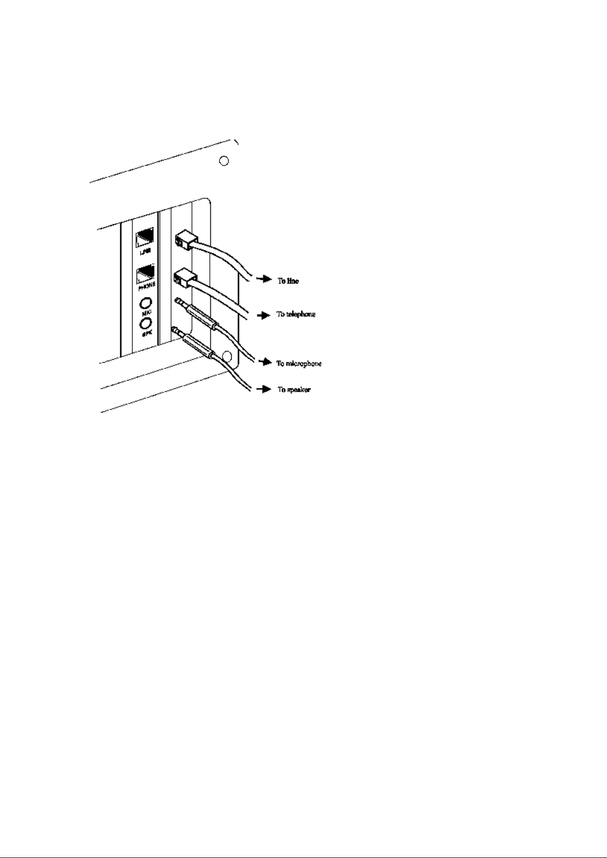
4.7 Connecting Microphone And Speaker
You could either use a handset connected to the fax/modem, or connect a
microphone and a speaker for voice recording and playback, or connect cable
of Jumper 13 with sound card in your PC (optional, refer to sound card user's
guide). Also, you may enable the ring wake up function by connecting the
cable of Jumper 18 to motherboard. (the function is optional, see the PC
user's manual for more detail)
NOTE:
Any commercially availab le micr oph one is usab le.
For the speaker , any 8 ohm speaker r a ted around 1Watt can be driven
directly by the audio output. An amp lifier isr equ ired if you need a
higher outp u t volume.
1. Connect the microphone to the mini-phone jack marked MIC.
2. Connect the speaker to the mini-phone jack marked SPK.
NOTE:
Ta ke car e of the pin setting and cable setting dir ection (JP 13 and JP18)
for you r Fax/Modem card, Sound car d and Mother boar d.
Page 17

4.8 Voice Function Alternatives
1. AOpen Sound Card (recommanded)
Simply connect the cable from modem to AOpen Sound Card. User can get all
the voice function including message playing and recording through sound
cards.
2. Telephone Handset
If there is a telephone set connected to modem. User can get all the voice
function including message playing and recording through telephone handset.
3. SpeakerPhone and MicroPhone
Connect SpeakerPhone and MicroPhone to modem. User can also get voice
performance.
NOTE:
Any commercially availab le micr oph one is usab le.
For the speaker , any 8 ohm speaker r a t ed ar oun d 1 Watt can be dr iven
directly by the audio output. An amp lifier is req u ired if you need a
higher outp u t volume.
Page 18

4.9 Configuring Internal Modem With
Device Man a ger . Check the COM ports listed under
Windows3.1/95/98/2000/NT
Windows 3.1:
1. From the Main group choose Control Pan el icon.
2. Double click on Ports.
3. Double click on the COM port that the modem is using.
4. Click on Advanced button.
5. Set the base I/O address according to the following table:
COM Port Base I/O Address
1 03F8
2 02F8
3 03E8
4 02E8
Set the interrupt line to match modem's setting.
6. Click OK to save and Windows will prompt y ou to restart the PC.
Windows 95:
1. From the My Computer window, click on Control Pa nel.
2. Go to System,
If the COM port the modem is using is listed, go to step 5. Click Cancel to
close the System Properties window.
3. Click on the Add New Har d ware to detect the card.
4. Click the Detail button when the Add New Har d ware Wizard finishes its
detection. A successful hardware installation and detection should add a
Communication Port. Click the Finish button to complete the Add New
Hardwar e.
5. Click the Modems icon to let the modem wizard search for the new
modem. Windows will query the new modem as 'Standard Modem'. Click
Chan ge button and then Have Disk button. Insert the driver diskette and
press Enter.
6. Select the proper model to finish the installation. After completing the
installation, you can check if the fax/modem was properly installed by
using the following procedure:
Ports.
1. From My Computer , double click Control Pan el.
2. Double click Modems.
3. Select Diagnost ics tab.
4. Choose the COM port where the newly installed modem device is. Click
on Mor e Info If the Comman d an d Response box displays results from
ATI1 to AT+FCL A..., it indicates that your fax/modem is set up
properly.
Page 19

Win dows 2000:
2. If the COM port
5. When you see ”Install New Modem”
Windows NT4.0:
1. Go to Control Panel. Click System. Choose Hardwar e, and Device
Manager , then Ports.
that the modem is using is not listed, and enter the
correct Base I/O Port address and Interrupt Request Line.
Set the base I/O address according to the following table:
COM Port Base I/O Address
1 03F8
2 02F8
3 03E8
4 02E8
3. Otherwise if the COM port is already listed. Click Phone and Modem
Opt ions.
4. Choose M odems tab and click Add.
box and choose “Don’t detect my
modem, I will select it form a list”. Click Next.
6. Highlight the port you want to install the modem on. C lick Next.
7. When you see “Install New Modem” box and choose Ha ve Disk.
8. Choose Browse to indicate the correct path.
9. Select D:\Drivers\Win2K\Fm56-ITU-2. (D is your CD-ROM) Then click
on Open.
10. When you see the correct path and then click on OK.
11. Select the model of your modem and then click on Next.
12. Select the ports you want to install the modem and then click on Next.
13. If you want to continue installation and then click on Yes.
14. Windows has finished the installation and then click on Finish.
1. Go to Control P a nel. Click on Ports.
2.If the COM port, click on Add. Enter the correct Base I/O Port address and
Interrupt Request Line.
Set the base I/O address according to the following table:
COM Port Base I/O Address
1 03F8
2 02F8
3 03E8
4 02E8
3. If the COM port is already listed, highlight that COM port, click on
Settings, Advanced button, and select the proper base I/O address and
Interrupt line to match the modem's setting. Click OK to save.
Refer to Step#5 in the above Win95 section to finish installing the modem.
Page 20

4.10 Tips On Configuring Your Communication
control program flow. Make sure that the software is set to recognize a
Software
Your fax/modem uses the most up-to-date industry and commercially popular
standards to ensure functional compatibility with most communication
software. During initial set-up of the communication software, it will
normally prompt you to define the type of fax/modem you are using.
Following is a general guideline to the device type you should choose.
NOTE:
The device type only defines the protocol by which your softwa re will
communicate with your fax/modem an d does not set nor limit the speed.
1. For modem device type, choose 'Hayes V.32' or 'Hayes Compatible 2400
Baud' modem.
2. For the baud rate. Choose any speed between 38,400 to 115,200.Your
fax/modem will automatically adjust to the best transmission speed after
successfully connecting with a remote fax/modem.
3. Many communication software uses the modem response (see Ch 7) to
CO NNEC T 28800 response. If this does not work, set the program to
simply recognize just the CONNECT response without any baud rate
information.
4. There are three flow control mode: none, hardware (CTS/RTS) or
software (XON/XOFF). Set your software to use either hardware or
software flow control. If set to none, the communication software will
not be able to detect a buffer overflow and result in transmission errors.
5. For fax device type, choose 'TR 29 Class 1'.
6. For fax speed, choose 'automatic' or 'fastest speed'. Your fax/modem will
automatically adjust to be best transmission speed after successfully
connecting with a remote fax machine or another fax/modem.
7. Make sure that you have correctly set all the other parameters required by
the soft ware to operate successfully.
Refer to the manual that came with your communication software for
details.
You ar e now r eady to do fax/modem communication !
Page 21

4.11 Tips on Configuring SVD
Add "-SMS=2" to the modem string in communication programs to enable the SVD
function. For complete SVD commands, please refer to the AT command file on the
driver disk.
Page 22

5 Executing Commands
AT M3 DT 9, 1(818)555
key. If you want
If you will be using a communication software program to make data calls,
you will probably not need to type commands, because your software
program will handle these tasks for you. Similarly, you will probably not see
the responses because your software program may intercept them. However,
if you perform data activities directly with your fax/modem, you will find the
format for typing fax/modem commands and fax/ modem response helpful.
Using commands, you can have your fax/modem perform a variety of
activities, such as dialing or answering a data call or sending a fax. In order to
send commands to your fax/modem, you must access the modem in a
terminal mode which is provided by most communication software. To enter
a command line, type:
ATccpp[Enter]
where
command).
cc any of the commands available, described in succeeding sections.
pp any parameters that is required by the command.
must precede every command line (except when you type the A/
AT
If you make a mistake while ty ping a command, press the Backspace key to
delete the error.
To make a command line easy to read, you can insert spaces parentheses,
hyphens, and other punctuation in your command line. For example:
-1234
Your fax/modem ignores spaces and punctuation marks when executing a
command line, but these characters apply to the 40 characters limit.
A command line can contain up to 39 characters. If you want to type more
than 39 characters on a command line, type a regular command line (up to 39
characters long) and end it with a semicolon as the last character. When you
press Enter, your fax/modem executes the commands and returns to
command mode, so you can type your next command line.
For your convenience, the last command line you execute remains stored in
the modem's memory until you type a new command line and press the Enter
to re-execute the last command, type
The A/ command need not be prefixed by the 'AT' characters or ended with
A/
Page 23

the [Enter] key.
NOTE:
Th e fax/modem comman d a n d response set are descr ib ed in th e text file,
AT_CM D.TXT, in the fax/modem Windows95 driver diskette. You can
use DOS EDI T or an y suita b le editor to view this file.
If a command requires a parameter such as 0 and 1, the parameter is
identified as n in the left column and described in the right column of the
AT_CMD.TXT file.
IMPORT ANT:
Ea ch command , except for ' +++' an d ' A/' , must be preced ed by 'AT' and
executed when you press th e [Ent er] key. To review th e form a t used to
send fax/modem com m a nds, refer t o Section of th is man u al.
Page 24

6 S-Registers
the fax/modem. Each S
Your fax/modem has S-registers that affect various operating characteristics.
The registers let you obtain information about the fax/modem, and let you test
-Register has a factory-set value, which you can
read or change to fit your particular requirements. A complete list of
S-Register is provided in the COM M AND.TXT file on the driver diskette.
6.1 Reading An S-Register Value
6.2 changing An S-Register Value
Page 25

6.1 Reading An S-Register Value
ATSr?[Enter]
ATSr ?Sr?[Enter ]
r specify the different S
rings before answering) and
ATS0?S1?[Enter]
1. To read the current value of an S-Register, type:
where r is an S-Register number.
The fax/modem responds with decimal value of the
S-Register, in three-digit format, followed by OK.
2. To read values from more than one S-Register, type:
where
For example, to read the value of Register S0 (number of
type:
-Register numbers.
S1 (incoming ring count),
Page 26

6.2 changing An S-Register Value
ATSr=n[Enter]
where r is the S
To change an S-Register value, type
-register number.
n is the value you want to assign to that S-register.
Page 27

7 Response Sets
When you send a command to your fax/modem, it sends a response to your
computer. For example, if you type AT[Ent er ], the fax/modem should
respond with OK. The fax/modem gives out different responses for the
different tasks that it performs. Communication software use these responses
to control the flow of the program. The responses that are intercepted by the
communication program are normally not displayed on your computer screen.
This section describes the fax/modem responses returned by the fax/modem
when you communicate directly with the fax/modem.
There are five X response sets: 0, 1, 2, 3 and 4. They define certain dialing
characteristics and how the fax/modem handles dial tones and busy signals,
as described in the following sections. The response classifications are
designed to meet the requirements for various types of operation and
application. You can select an X response set by using the Xn command as
described in Section .
Aside from the X response sets, extended responses are also available that
shows the carrier speed, compression method and the error-correction
protocol as described in the following table. You can enable the extended
responses by using the Wn command as described in Section .
Fax/modem responses can appear as words or numbers. Your fax/modem is
set up to return word responses. Word responses are followed by a carriage
return and line feed. If your fax/modem is operating under an application that
handles character strings inefficiently or cannot handle them at all, you can
use the V0 command to switch to numeric fax/modem responses. Numeric
responses are followed by a carriage return only.
If you do not want to receive fax/modem responses at all, you can use Q1
command to disable them.
The following table lists and describes the available response codes, where x
means that result word/code is available:
WORD CODE n Value in ATXn Comman d
0 1 2 3 4
OK 00 x x x x x
CONNECT 01 x x x x x
RING 02 x x x x x
NO CARRIER 03 x x x x x
ERROR 04 x x x x x
CONNECT 1200 05 x x x x
NO DIALTONE 06 x x x
BUSY 07 x x
NO ANSWER 08 x x x x x
Page 28

CONNECT 600 09 x x x x
DATA
CONNECT 2400 10 x x x x
CONNECT 4800 11 x x x x
CONNECT 9600 12 x x x x
CONNECT 7200 13 x x x x
CONNECT 12000 14 x x x x
CONNECT 14400 15 x x x x
CONNECT 19200 16 x x x x
CONNECT 38400 17 x x x x
CONNECT 57600 18 x x x x
CONNECT 115200 19 x x x x
CONNECT 230400 20 x x x x x
CONNECT 75TX / 1200RX 22 x x x x
CONNECT 1200TX / 75RX 23 x x x x
DELAYED 24 x
BLACKLISTED 32 x
FAX 33 x x x x x
35 x x x x x
CARRIER 300 40 x x x x x
CARRIER 1200/75 44 x x x x x
CARRIER 75/1200 45 x x x x x
CARRIER 1200 46 x x x x x
CARRIER 2400 47 x x x x x
CARRIER 4800 48 x x x x x
CARRIER 7200 49 x x x x x
CARRIER 9600 50 x x x x x
CARRIER 12000 51 x x x x x
CARRIER 14400 52 x x x x x
CARRIER 16800 53 x x x x x
CARRIER 19200 54 x x x x x
CARRIER 21600 55 x x x x x
CARRIER 24000 56 x x x x x
CARRIER 26400 57 x x x x x
CARRIER 28800 58 x x x x x
CONNECT 16800 59 x x x x
CONNECT 21600 61 x x x x
CONNECT 24000 62 x x x x
CONNECT 26400 63 x x x x
CONNECT 28800 64 x x x x
COMPRESSION: CLASS 5 66 x x x x
x
COMPRESSION: V.42bis 67 x x x x x
COMPRESSION: NONE 69 x x x x x
PROTOCOL: NONE 70 x x x x x
PROTOCOL: LAMP 77 x x x x x
CARRIER 31200 78 x x x x x
CARRIER 33600 79 x x x x x
Page 29

PROTOCOL: ALT 80 x x x x x
CONNECT 33600
CONNECT 31200
CARRIER 32000
PROTOCOL: ALT-CELLULAR 81 x x x x x
84 x x x x
CARRIER 34000 151 x x x x x
91 x x x x
150 x x x x x
CARRIER 36000 152 x x x x x
CARRIER 38000 153 x x x x x
CARRIER 40000 154 x x x x x
CARRIER 42000 155 x x x x x
CARRIER 44000 156 x x x x x
CARRIER 46000 157 x x x x x
CARRIER 48000 158 x x x x x
CARRIER 50000 159 x x x x x
CARRIER 52000 160 x x x x x
CARRIER 54000 161 x x x x x
CARRIER 56000 162 x x x x x
CONNECT 32000 165 x x x x x
CONNECT 34000 166 x x x x x
CONNECT 36000 167 x x x x x
CONNECT 38000 168 x x x x x
CONNECT 40000 169 x x x x x
CONNECT 42000 170 x x x x x
CONNECT 44000 171 x x x x x
CONNECT 46000 172 x x x x x
CONNECT 48000 173 x x x x x
CONNECT 50000 174 x x x x x
CONNECT 52000 175 x x x x x
CONNECT 54000 176 x x x x x
CONNECT 56000 177 x x x x x
FCERROR +FC
Following are descriptions of the different sets of fax/modem responses:
X0 The X0 response set consists of the first five responses as
well as the NO ANSW ER response.
X1 The X1 response set consists of the first five responses as
well as NO ANSWER and all CONNE CT xxx responses.
X2 The X2 response set consists of first seven responses as
well as the NO ANSWER and all C ONNECT xxx responses.
X3 The X3 response set consists of the first five responses as
well as the BUSY, NO ANSWER and all C ONNECT
xxx responses.
X4 The X4 response set is the factory-default response set.
It consists of all the responses.
Page 30

W0 Extended responses is disabled. With W0, all CONNECT
responses reports the DTE speed.
W1 The modem will send CARRIER and PROTOCOL
responses. The CO NNECT response shows the DTE speed.
W2 The modem will send CARRIER and PROTOCOL
responses. The
rather than the DTE speed.
CONNECT
response shows the DCE speed
Page 31

8 Specifications
Sampling Rate
MODEM OPERATION
Line Rate 0.3, 1.2, 2.4, 4.8, 7.2, 9.6, 12, 14.4, 16.8,
19.2, 21.6, 24, 26.4, 28.8, 31.2, 33.6,
56 Kbps (for 56K model only)
DTE Rate 115200 bps maximum
Opera tion Half or full-duplex over 2-wire dial-up
line, asynchronous
Linking Auto dial/answer, auto bauding, MNP10
auto fall-back/forward
Flow Control RTS/CTS, XON/XOFF (software
selectable)
Compa t ibility Bell 103; 212A, ITU-T V.21; V.22; V.23;
V.22bis; V.32; V.32bis; V.34; K56flex (56K model only)
Er r or Corr ection ITU-T V.42, MNP4 (auto-match)
Data Compression ITU-T V.42bis, MNP5 (auto-match)
Receive Sensitivity -38 dB m
Comman d Set Hayes AT and Escape sequence
Memory 2 configuration profiles, 4 sets by 34 digit
telephone number
Diagnostics
Power on self-test, V.54 loop test
FAX O PE R ATIO N
Speed 14400 bps
Compa t ibility Group 3 with T.30 protocol over ITU-T
V.17; V.21 ch2; V.27ter; V.29
Comman d Set TR-29 Class 1
VOICE OPERATION
Opera tion
PVS Telephone answering machine (TAM),
voice mail system, Simultaneuos Voice and Data (SVD)
7.2 Khz using 2, 3 or 4 bits ADPCM;
GENERAL
Configu rat ion COM1/2/3/4, IRQ3/4/5/7/9/10/11/1 2/15
Line Inter face 2 x RJ-11 for line and telephone
DTE Inter face
Voice Interface 2 x mini phone jack for microphone input
Ambient Temp. 0 to 50
Relative Humidity 10 to 95% non-condensing
Dimensions 1.6w x 10.7h x 17.0d cm
11.025 Khz linear PCM
16550/A compatible UART with 16 byte
double-buffered FIFO; PC, PC/XT bus
and audio output
Page 32

A.1 FCC Notice
This equipment has been tested and found to comply with the limits for a
Class B digital device, pursuant to Part 15 of FCC Rules. These limits are
designed to provide reasonable protection against harmful interference in a
residential installation. This equipment generates, uses and can radiate radio
frequency energy and, if not installed and used in accordance with the
instructions, may cause harmful interference to radio communications.
However, there is no guarantee that interference will not occur in a particular
installation. If this equipment does cause harmful interference to radio or
television reception, which can be determined by turning the equipment off
and on, the user is encouraged to try to correct the interference by one or
more of the following measures:
• Reorient of relocate the receiving antenna.
•
Increase the separation between the equipment and receiver.
•
Connect the equipment into an outlet on a circuit different from that to
which the receiver is connected.
•
Consult the dealer or an experienced radio / TV technician for help.
This unit was tested with shielded cables on the periph eral devices. Shielded
cables must be used with the unit to insure compliance. This statement can be
deleted if unit was not tested with shielded cables.
The manufacture is not responsible for any radio or TV interference caused
by unauthorized modifications to this equipment. Such modifications could
void the user's authority to operate the equipment.
This device complies with Part 15 of the FCC rules. Operation is subject to
the following two conditions:
1. This device may not cause harmful interference.
2.
This device must accept any interference that may cause undesired
operation.
Page 33

A.2 FCC Requirement
This equipment complies with Part 68 of the FCC Rules. On the base unit of
this equipment is a label that contains, among other information, the FCC
Registration Number and Ringer Equivalence Number (REN) for this
equipment. If requested, this information must be given to telephone
company.
The REN is useful in determining the quantity of devices you may connect to
your telephone line and still have all of those devices ring when your
telephone number is called. In most, but not all area, the sum of the REN's of
all devices connected to one line should not exceed five (5). To be certain of
the number of devices you may connect to your line, as determined by the
REN, you should contact your local telephone company to determine the
maximum REN for your calling area.
If your equipment causes harm to the telephone network, the telephone
company may discontinue your service temporarily. If possible, they will
notify you in advance. But if advance notice is not practical, you will be
notified as soon as possible. You will be informed of your right to file a
complain with the FCC. Your telephone company may make changes in its
facilities, equipments, operations or procedures that could affect the proper
functioning of your equipment. If they do, you will be notified in advance to
give you an opportunity to maintain uninterrupted telephone service.
The equipment may not be used on coin service by the telephone company.
Connection to party lines is subject to state tariffs.
Page 34

Appendix B: Default Profiles
1200 bps
SETTING DEFAULT NVRAM
Auto-answer Disabled Yes
Backspace character 08 No
Bell / CCITT compatibility at Bell 212A
Yes
Busy signal detect Enabled Yes
Carriage return character 13 No
Line feed character 10 No
Data Set Ready option Always on Yes
Data Terminal Ready option &D2 Yes
Data Terminal Ready pulse width 0.5 seconds Yes
Echo option On Yes
Escape character definition 43 (+++) Yes
Guard tones Disabled Yes
Long space disconnect Disabled Yes
Parity None Yes
Pulse make / break ratio 39/61 Yes
Responses Word Yes
Response enable All Yes
RTS-to-CTS delay 10 milliseconds Yes
Speaker status On until DCD Yes
Speaker volume Low Yes
Test timer setting 0 second Yes
Wait for carrier after dialing 50 seconds Yes
Wait for dial tone 2 seconds No
Wait for dial tone before dialing Enabled Yes
Dial delay pause time 2 seconds Yes
Wait before accepting carrier detect 0.6 seconds Yes
Wait before disconnecting 1.4 seconds
after carrier loss Yes
DTMF tone duration and spacing 95 milliseconds Yes
Flash (!) dial modifier time 0.7 second s No
PSTN attenuation level -10 dBm No
Fax attenuation level -10 dBm No
Page 35

1. Hayes Compatible AT Command Set
COMMAND DESCRIPTION
+++ Escape to command mode
ATA Answer command
The modem will go off
A/ Repeat l
n=0 CCITT Mode
n=1 BELL Mode (Default)
0
Dial Digit
* The "star" digit on tone dialing mode
# The "gate" digit on tone dialing mode
Dial modifiers:
P Pulse dial.
T Tone dial.
, Pause.
! Flash.
; Command append.
ATEn Command Echo
The modem enables or disables the echo of character to the DTE
ATHn Disconnect (Hang
ATH0 The modem will releas
ATBn Select CCITT or BEL L Mode, where n = 0 or 1
ATDstr ing Dial command, where " str in g" is the combin ation of the
following parameters and modifiers:
Upon on-lin e mode, it will remain the conn ectio n and switc h the
mod em to co m mand mo d e. The char acter of "Esc ap e
command " is defined by S-Regis ter " S2" .
-hoo k and attempt to answer incomin g call.
ast command
- 9
W Wait for dial tone.
S=n Dial a stored number.
ATE0 Do not echo commands
ATE1 Echo commands (Default)
This command initiates a hang up sequence.
accord ing to the parameter su pp lied . The par ameter v alu e, if valid , is
wr it t en to S14 bit 1.
-Up)
e the line if the modem is
Page 36

currentlyon-lin e, and wi l l term in ate any test (AT&T) th at is in
ATIn Identification
command parameter.
ATI2 Reports "OK".
ATI4 Reports OEM defined identifier string
ATI6 Reports modem data pump model and internal code revision
ATI7 Repor
ATLn Speaker Volume Controls
supplied. The parameter value, if valid, is written to S22 bits 0 and
ATL0 Low volume.
ATL1 Low volume (Default).
ATL2 Medium volume.
ATL3 High volume.
ATMn Speaker Control
ATM0 Speaker is always off.
ATM3 Speaker is off when receiving carrier and during dialing, but
ATNn Automode Enable
pro gress. Coun try specific, modulation specific, and error cor rection
pro t oco l sp ecific (S38) pro cess in g is handled ou ts id e of the H0
command .
ATH1 If on-h o o k, the modem wil l go off-hoo k and ent er
com mand mod e. For US mod els, the modem will remain off-h o ok .
For W-class models, the modem will return on-ho ok after a period
of tim e determin ed by S7.
The modem reports to the DTE the requested result accordin g to the
ATI0 Reports product code(e.g.,"33600").
ATI1 Reports a precomputed checksum (normally "255").
ATI3 Reports firmware revision (VX.XXX)
ATI5 Reports Country Code parameter
e.g.,RC288DPi Rev CE).
ts "255"
The modem sets the speaker volume control according to the
parameter
1.
This com mand selects wh en th e speaker wi ll be on or off. The
pr ameter value, if valid, is wr it t en to S22 bit s 2 and 3.
ATM1 Speaker is on during call establishment, but off when
receivin g carr ier.(Default .)
ATM2 Speaker is always on.
on during answering .
This command enables or disables Automode detection(see+MS
Page 37

comm and).
The parameter value, if valid, is written to S31 bit1.
conducted according to the contents of S37 or, if S37 is zero
ATN1 Au
ATOn Return to On
ATO0 Enters on
ATO1 Enters on
ATP Set Pulse Dial Default
This command fo rces pulse dialing until the next T dial modifier or T
As soon as a dial command is exec uted which explicit ly specifies the
This command may not be
The command enables or disables the sending of result codes to the
according to the parameter supplied. The parameter value, if valid, is
ATQ0 Enables result codes to the DTE (Default.)
ATN0 Automode detection is disabled(equivalent to setting the
+MS
<automode>subparameter to 0). A subsequent handshake
will be
, according to the most recently sensed DTE speed.
tomo d e detection is enabled (equivalent to settin g the
+MS <au t omode>
sub p arameter to 1). A su b sequent handsh ake will be condu ct ed
according
the aut om od e algo rit h m sup po r ted by the modem, e.g., accord in g
to the
co n t ent s o f S37 or , if S37 is zero, start i ng at 28800 bps V.34
(RC288). This
co m man d is als o equ i v alen t to F0 (RC144). (Default .)
-Li n e Data Mod e
This command determines how the modem will enter the on-lin g data
mod e. If the modem is in the off-lin e command mod e (no co n n ect i o n ), ERROR is
report ed.
-lin e data mod e witho u t a retrain . Handli ng is
determin ed by the Call Establish ment task . Generally, if a conn ecti o n exist s, this
com mand co n n ects the DTE b ack to the remote modem after an es cape(+++).
-lin e data mode with a retrain befor e returni n g to
on-lin e data mode.
com mand is received. It also sets S14 bit 5.
dialin g mod e for that parti cu l ar call (e.g.,ATDT...), this co mmand is ov erri d d en so
that all future dialing wil l be tone dialed.
permitted in some countr ies.
ATQn Quiet Results Codes Control
DTE
wr it t en to S14 bit 2.
ATQ1 Disables result codes to the DTE.
Page 38

ATSn Read/Write S
-Regi st er
The modem selects an S
Sn Establishes S
Sn=v Sets S
The parameter n can be omitted, in which case the
For example:
AT=40 sets the co
If the number "n" is beyond the range of the S
the modem will return the ERROR message. The val
Due to country restrictions, some commands will be ac ceptd, but the
ATT Set Tone Dial Default
This command forces DTMF dialing until the next P dial modifier or P
It also clears S14 bit 5. This command may not be permitted in some
ATVn Result Code Form
ATV0 Enables short
result code.
ATV1 Enables l
ATWn Connect Message Control
writ e functi on , or repo rt s the value of an S-Regi s t er.
-Register, perfor m s an S-Regist er read or
-Register n as the last regist er accessed.
Sn=? Repotrs the value of S-Reg is t er n.
-Register n to th e value v.
last S-Regis t er
accessed w il l be assumed. The S c an be omit ted for AT=and AT?, in wh ic h case
th e S-Regis t er accessed will be ass u med.
ATS7 establishes S7 as the last accessed register.
ntent s of the last regis ter accessed to 40.
ATS=20 sets the contents of the last register accessed to 20.
-Registers available,
"MOD"ed wit h 256. If the resu lt is ou ts id e the range permitted for a given
ue " V” is
S-Regis t er the values will sti ll be stored, but funct io nally the lower and higher
limit s wi ll be o bs erved. Inp u t and outp u t are always ind ecimal form at. Note that
some S Registers are read-only .
In some cases, writing to the S-Register w il l appear to be accepted
but the value wil l not actually be writt en.
value may be limited and repl aced by a maximu m or minim um value.
command is
received.The modem will set an S-Register bit to ind ic ate that all
subs equent dialing shou l d be cond u c ted in to n e mode. Note that th e DP
command will overrid e this command.
coun tries.
This command selects the sending of short-form or long-form result
co d es to th e DTE. The parameter, if valid , is wr i t t en to S14 bit 3.
-for m(terse)result cod es. Line feed is not
issu ed before a short-for m
ong-for m (verbos e) resu l t cod es.(Default)
This command controls the format of CONNECT messages. The
parameter valu e, if valid,
Page 39

is written to S31 bits 2 and 3. Note that the Wn command can be
ATW0 Upon connection, the modem reports only the DTE
Subsequent responses are disabled.(Default)
ATW2 Upon connection, the modem reports the DCE
ATXn Extended Result
Blind dialing is enabled or di sabl ed by country parameter s. If the user
If the modem i
ATX0 Disables monitoring of busy tones unless forced otherwise
ATX1 Disables monitoring of busy tones unless forced otherwise
ATX2 Disables monitoring of busy tones unless forced otherwise
ry requirements;send only OK,CONNECT,RING,NO CARRIER, ERROR,
overridden by register
S95 bits(see S95 description).
speed(e.g.,CONNECT 57600).
ATW1 Upon connection, the modem reports the l in e speed, the err o r
cor r ectio n pro to c ol , and the DTE speed, respecti vely . Sub sequ ent respo n ses are
disabled.
sp eed(e.g.,CONNECT 28800). Sub s eq u en t resp o nses are disab led .
Codes
This co mmand selects which subs et of the result messages will be
used by the modem to infor m the DTE of the results of com mand s .
wis hes to enforc e fail ton e detection , a "W" can be placed in th e dial str in g (see D
com mand ). Note th at the inform atio n below is based upon the default
imp lement atio n of th e X resu lt s table. Table 3-1 indicates the messages which
are enab l ed for each X value.
s in facs i m il e mo d e(+FCLASS=1 or 2), th e onl y
message sent to ind ic ate a con nect io n is CONNECT wit ho u t a sp eed indi catio n .
by co untry r equ i r ement s ; send onl y OK, CONNECT, RING, NO CARRIER,
ERROR, and NO ANSWER result codes. Bli n d d iali n g is enabled /dis ab led by
cou ntr y parameters. If bus y ton e detecti on is enforced and busy tone is not
detected , NO CARRIER will be repo r t ed. If di al ton e detect io n is enfo r c ed or
selected and dial tone is not det ect ed, NO CARRIER will be repo r t ed in s t ead of
NO DIAL TONE. The vale 000b is wr itten to S22 bits 6, 5, and 4, res pect ively.
by coun tr y requir ements; send onl y Ok, CONNECT, RING, NO CARRIER,
ERROR, NO ANSWER, and CONNECT XXXX(XXXX=rate). Blind dialing
enabled/disabled by cou nt r y parameters . If busy ton e detect io n is enforc ed and
bu s y to n e is detect ed, NO CARRIER wil l be repo r t ed ins t ead of BUSY. If dial
ton e detection is enfor c ed or select ed and dial ton e is no t detect ed, NO
CARRIER w il l b e repo rted in s t ead of NO DIAL TONE. The valu e 100b is wr i t t en
to S22 bi t s 6, 5, and 4, res p ectively.
by count
NO DIALTONE, NO ANSWER, and CONNECT XXXX. If busy to ne detection i s
enfor c ed and bu sy to n e is detected, NO CARRIER wi ll be repor ted in s tead of
BUSY. If dial to n e detecti o n is enfor ced or selected and dial tone is not detected,
NO DIAL TONE wi l l b e rep orted in stead of NO CARRIER. The value 101b is
wr i t t en to S22 bit s 6, 5, and 4, res p ect iv ely.
Page 40

ATX3 Enables monitoring of busy tones; send only
OK,CONNECT,RING, NO CARRIER,ERROR,NO ANSWER, and CONNECT
detecti o n is enfor ced and dial to ne is not detect ed. NO CARRIER will be report ed.
ATYn Long Space Disconnect
This co mmand enables/d isables the generation and response to long
The parameter value, if valid, is written to S21 bit 7.
ATY0 Disables long space disconnect.(default)
ATY1 Enables long space disconnect. In non
The modem performs a sof
ATZ0 Soft reset and restore stored profile 0.
ATZ1 Soft reset and restore stored profile 1.
AT&Cn RLSD(DCD) Option
AT&C1 RLSD follows the
AT&Dn DTR Option
This command interprets the ON to OFF transition of the DTR signal
XXXX. Blin d di alin g is enabled/disabled by co u nt r y parameters. If dial ton e
The value 110b is w r i t t en to S22 bits 6, 5, and 4, respect i v ely.
ATX4 Enables monitoring of busy tones; send all messages. The
valu e 111b is wr i t t en to S22 bit s 6,5,and 4,respecti v ely.(Default )
space disconn ect.
mod e, th e modem will send a long sp ace of four secon ds prior to going on-hock .
-error correction
In erro r corr ecti on mod e, the modem will respo nd to the receipt of a long space
(i.e., a b r eak signal gr eater than 1.6 second s )by go in g on-h ook .
ATZn Soft Reset and Restore Profile
t reset and resto r es(recalls)th e
con fig u ratio n pro fil e acco rd i ng to the parameter suppl ied. If no parameter is
specif ied, zero is assumed.
The modem controls the RLSO output in accordance with the
parameter su p p l ied . The parameter value, if valid, is wr it t en to S21 bit 5.
AT&C0 RLSD remains ON at all times.
state of the carr i er.(Default.)
fro m th e DTE in acc o r danc e wit h th e parameter supp li ed. The parameter value, if
valid , is wri t t en to S21 bits 3 and 4. Als o, s ee S25.
AT&D0 DTR drop is interpreted according to the current &Qn
setti n g as foll o w s :
&Q0,&Q5,&Q6 DTR is ignored(assumed ON).Allows
operatio n with DTEs which do not pro vi de DTR.
&Q1,&Q4 DTR dro p causes the modem to hang
up. Auto-answer is not affected.
&Q2,&Q3 DTR drop causes the modem to hang
up. Auto-answer is inhibit ed.
Page 41

AT&D1 DTR drop is interpreted according to the current & Qn
&Q2,&Q3 DTR drop causes the mode
The mode
AT&Gn Select Guard Tone
AT&Kn Flow control
This command defines the DTE/DCE (terminal/mod
AT&K5 Enables transparent XON/XOFF flow control.
setting as follow s:
&Q0,&Q1,&Q4,&Q5,&Q6 DTR drop is interpreted by the
mod em as if th e async hr o n o u s escape sequence had been entered. The modem
returns to asy nch ron ous command state without discon necting.
m to hang up.
Auto-answer is inhibit ed.
AT&D2 DTR drop is interpreted according to the current & Qn
setting as follow s:
&Q0,&Q1,&Q4,&Q5,&Q6 DTR drop causes the modem to
perfor m a so ft reset as if the Z co m mand were received. The &Y setti n g
determines which pro file is loaded.
&Q2,&Q3 DTR drop causes the modem to hang
up.Auto-answer is inhibit ed.
AT&Fn Restore Factory Configu ration (Profile)
m loads the facto r y default confi gu r ation (profi le).The
factor y defaults are ident ifi ed for each comm and and in the S-Regist er
descrip tio ns . A confi gu ration profil e co ns ist s of a subset of S-Regist ers.
AT&F0 Restore factory configuration 0.
AT&F1 Restore factory configuration 1.
The modem generates the guard tone selected by this command
according
to the parameter supplied (DPSK modulation modes only). The
parameter valu e, if valid,
is written to S23 bits 6 and 7.
AT&G0 Disables guard tone. (Default)
AT&G1 Disables guard tone.
AT&G2 Selects 1800 Hz guard tone.
mechanism.
el)flow cont ro l
The parameter value, if valid, is written to S39 bits 0,1,and 2.
AT&K0 Disables flow control.
AT&K3 Enables RTS/CTS flow control.(Default for data modem
mod es.)
AT&K4 Enables XON/XOFF flow control.
AT&K6 Enables both RTS/CTS and XON/XOFF flow control.
(Default for fax mod em mod es.)
Page 42

AT&Mn Asy nchr onou s/Synchronou s Mod e Select i on (Extern al Models Only)
AT&M0 Select s di r ect asy nchro n ous oper ati on. Note that th e
AT&M2 Selects s
AT&Pn Sele
AT&P0 Selects 39%
AT&P1 Selects 33%
AT&P2 Selects 39%
AT&P3 Selects 33%
AT&Q0 Selects direct asynchronous operation. The value 000b is
com mand sequence &M0\N0 selects no r mal buf fered mode, but the command
sequenc e \N0&M0 selects dir ect mo d e. Thi s is becaus e the \N0 command is
analogo u s to th e &Q6 comm and . The value 000b is writ t en to S27 bit s 3,1,and 0,
resp ec t ively .(See &Q).
AT&M1 Selects synchronous connect mode with async off-line
co mm and mode. The value 001b is written to S27 bit s 3,1,and 0, resp ec ti v ely.
(Serial interface operatio n onl y .)
ynch ron ous connect mode with async off-line
co mm an d mo d e. Same as &M1 except th at &M2 enables DTR dialin g of
dir ect or y slo t 0. The mod em wil l dis c o n n ect if DTR is OFF for mor e than the
period in S25 (in uni ts of hund r edths of a secon d ) the data connecti on wil l be
sy n c h r o n o u s . The value 010b is wr i tt en to S27 bits 3, 1, and 0, resp ect iv ely .
(Serial interface operation only.)
AT&M3 Selects synchronous connect mode. This mode allows
DTR to act as a talk/data swi t c h . The call is manuall y ini ti ated wh il e DTR is
inact iv e. When DTR becom es activ e, the hand s h ake pro c eeds in or iginate or
answ er mo d e according to S 14 bit 7.Th e value 010b is wr i t t en to S27 bi t s 3, 1,
and 0, respecti v ely . (Serial interface operatio n on l y .)
ct Puls e Dial Make/Break Ratio
This command determines the make/break ratio used during pulse
dialing . The default is coun tr y -dep end ent . The parameter value, if valid, is writ t en
to S28 b i t s 3 and 4.
-61% mak e/break rati o at 10 pp s.(Defau lt )
-67% make/br eak rat io at 10 pps.
-61% make/br eak rat io at 20 pps.
-67% make/br eak rat io at 20 pps.
AT&Qn Sync/Async mod e (external models only )
This command is an extension of the &M command and is used to
con tr ol the conn ectio n modes permitt ed. It is us ed in conju nct io n with S36 and
S48. (Also, see \N)
writt en t o S27 bits 3, 1, and 0, respectively. (See &M0)
AT&Q1 Selects synchronous connect mode with async off-l i n e
co mm and mode. The value 001b is written to S27 bit s 3,1,and 0, resp ec ti v ely.
(See &M1)
AT&Q2 Selects synchronous connect mode with async off-line
co mm and mod e and enables DTR dialing of dir ect o r y 0. The valu e 010b is
wr i t ten to S27 bi t s 3,1, and 0, resp ec t i v ely. (See &M2)
AT&Q3 Selects synchronous connect mode with async off-l i n e
com mand mod e and enables DTR to act as Talk/Data switch . The value 011b is
wr i t ten to S27 bi t s 3,1 ,and 0, resp ec t i v ely. (See &M3)
Page 43

AT&Q4 Selects AutoSync operation.The value 100b is written to
Stopping AutoSync.AutoSync operation is stopped upon loss
AT&Rn RTS/CTS Option
This selects how the modem controls CTS. CTS operati
AT&Sn DSR Override
AT&Tn Test and Diagnostics
S27 bits 3, 1, and 0, respecti vely Aut o Sync operatio n , when used in con ju n c ti on
with th e Hayes Syn ch r o n o u s Interface (HSI) capabilit y in the DTE, pro v ides
sync hro nou s communic ation capability from an asyn chr ono us terminal.
Starting AutoSync. Set registers S19, S20, and S26 to the
desired values befor e selectin g AutoSyn c op eratio n with &Q4.Aft er the
CONNECT mess age is iss u ed , the modem wait s th e perio d mess age of tim e
sp ecif i ed by S25 befor e examini n g DTR. If DTR is on, the modem enters th e
sy nc h ro n ou s operatin g state; if DTR is off, th e modem terminates the line
connection and retur ns to the async hro n ou s command state.
of carrier or the on-to-off trans iti o n of DTR. Loss of carri er will cause the modem
to return to the async hr on ou s command state.An on-to-of f trans it io n of DTR will
cause the modem to return to the sync h ro no us command state and either not
termin ate the lin e conn ecti o n (&D1 acti v e) or termin ate the lin e conn ect io n (any
oth er &Dn command active).
AT&Q5 The modem will try to nego ti ate an erro r-c o rr ected link.
The mod em can be config u r ed usi n g S36 to determin e whether a failu r e will
result in the modem return ing on-ho ok or will result in fallback to an
asyn ch r o n o us con n ecti o n . The value 101b is writt en to S27 bits 3,1,and
0,resp ectiv ely .(Default)
AT&Q6 Selects asynchronous operation in normal mode (speed
bu ff ering). The valu e 110b is wr i t ten to S27 bit s 3,1,and 0, respec t iv ely.
if hardware flow co n tr o l is selected (see &K co m mand ). The parameter value, if
on is modif ied
valid , is wr it t en to S21 bit 2.
AT&R0 In sync mode. CTS tracks the state of RTS. The
RTS-to-CTS delay i s defined b y S26. In async mode. CTS acts acc o rdin g
toV.25bi s hand s h ake.
AT&R1 In sync mode, CTS is always ON (RTS transition are
ign or ed).
In async mode. CTS will only drop if required by flow
con tr o l.(Default)
AT&S0 DSR will remain ON at all ti m es.(Default)
AT&S1 DSR will become active after answer tone has been
detected and inact iv e after the carr i er has been lost.
The modem will perform sele cted test and diagnostic functions
accordi ng to th e parameter supp l ied. A test can be run only when in an
asynchro nou s operation in non-error-cor r ectio n mod e (no rmal or dir ect mode).
Page 44

To terminate a test in pr o g r ess, the esc ape sequence mus t be entered first ,
AT&T0 Terminates test in progress.Clears S16.
AT&T1 Initiates local analog loopback,V.54 Loop 3,Sets S16 bit 0.
AT&T2 Returns ERROR.
AT&T3 Initiates local digital loopback,V.54 l
If no connection exists, ERROR is returned. Sets S16 bit 4
If no connection exists, ERROR is returned. When the test is
AT&T8 Initiates local analog loopback, V.54 Loop3, with self test.
AT&V Display Curren t Co nfiguration and St ored Profile
Reports the curren t (act ive) configuration, the stored(user) profiles,
Displays the last connection statistics in the following
except fo r par ameter s 7 and 8. If S18 is non-zero, a test w il l termi n ate
autom atic ally after the time specified by S18 an d di sp l ay th e Ok mess age.
If a connection exists when this command is issued, the
modem hangs up.
The CONNECT XXXX message is displayed upon the start
of th e test.
oop 2.Sets S16 bi t 2.
when the test is in prog r ess.
AT&T4 Enables digital loopback acknowledgment for remote
requ est , i.e., an RDL requ es t fr o m a remote modem is allowed. Sets S23 b it 0.
(Defau l t )
AT&T5 Disables digital loopback acknowledgment for remote
requ es t , i.e., an RDL requ est fr o m a remot e mod em is d eni ed. Clears S23 bit 0.
AT&T6 Requests a remote digital loopback(RDL), V.54 Loop2,
without self test .
If no connection exists,ERROR is returned. Sets S16 bit 4
wh en th e test is in pr o g r ess . The CONNECT XXXX messag e is dis p l ayed up o n
the start of th e tests.
AT&T7 Requests a remote digital loopback(RDL), V.54 Loop 2,
wit h self test.(In self test, a test pattern is loo p ed back and check ed by the
mod em.)
termi n ated either vi a expir atio n of S18, or via the &T0 or H command , the
num ber of detected erro r s is rep orted to the DTE. Sets S16 bit 5 when th e test is
in progr ess.
(In self test , a test patt ern is loo p ed back and ch eck ed by t h e mod em.) If a
conn ection exists, the modem hang s up befor e the test is init i ated. When the test
is termi n ated eith er via expir ation of S18, or via the &T0 or H co m man d , the
nu mb er of detected erro r s is repo r t ed to the DTE. Sets S16 bi t 6 w hen the test is
in pro gr ess.This command may not be available in some cou n t r i es du e to PTT
restrictions .
and the four stor ed telephon e numbers. The stor ed profi les and telepho n e
num b ers are no t di sp l ayed if the NVERAM is no t inst alled or is no t op eratio n al as
detected by the NVRAM test duri ng reset proc essi ng .
AT& V1 Display Last Connection Statistics
format (sh ow n
with typical results):
TERMINATION REASON.......... LINK DISCONNECT or LOCAL
Page 45

REQUEST
AT&W0 Store the
AT&W1 Store the current configuration as profile 1.
AT&Zn Store Telephone Numbers
telephone nu m b er di al str i n g can co n t ain up to 34 di gi t s .
AT&Zn=x n=0 to 3 and x=d
AT%En En able/Disable Li ne Quali ty Mo nitor And Auto
Controls whether or not the modem will aut omatically moni tor the line
AT%L Line signal Level
For example, 009=
LAST TX dat a rat e........... 33600 BPS
HIGHEST TX data rate........ 33600 BPS
LAST RX dat a rate........... 28800 BPS
HIGHEST RX data rate........ 28800 BPS
Erro r co r rect ion PROTOCOL... LAPM
Data COMPRESSION............ V42Bis
Line QUALITY................ 030
Hig hest SPX RX s tate........ 068
Hig hest SPX TX state........ 067
AT&Wn Store Current Configuration
current con fig ur ation as pr of ile 0.
At&Yn Designate a Default Reset Profile
Selects which user profile will be used after a hardware reset.
AT&Y0 The modem will use pr o f il e 0.
AT&Y1 The modem will use profile 1.
The modem can store up to four telephone numbers and each
ial str i n g . (Requ ir e 256-byte NVRAM.)
-Retrain or
Fallback/Fall Forw ard
qu alit y and requ est a retrain (%E1) or fall back when line qu ality is insuffic ient or
fall forward wh en line quality is suff ic ient (%E2). Applies to dial-up lin e only. The
parameter valu e, if valid, is wr i t t en to S41 bit s 2 and 6. If enabled,the modem
attempts to retrain for a maximu m of 30 second s .
AT%E0 Disable line quality monitor and auto-retrain. AT%E1
Enable line quality monit or and auto-retrain . AT%E2 Enabl e li n e quali ty monitor
and fallback /fall forw ard .(Default)
Returns a value which indicates th e received si g n al level.The valu e
retu rned is a direct ind i c atio n (DAA dependent ) of the receive level at th e MDP,
not at th e teleph on e line connecto r .
-9dBm, 043=-43 dBm, and so on .
AT%7 Plug and Play Serial Number
AT%7<8 hex numbers><same 8 hex numbers ><cr> - Sets Plug and Play
Page 46

Seri al Numb er
Sets an d stor es eight s erial n umbers in hex format u sed fo r seri al Plug
Sets an d stores Vendor ID and product number for serial Plug and Play
Example:
AT%8<3 ASCII characters><4 hex numbers><same 3 ASCII
AT%Q Line Signal Quality
Reports the line signal quality (DAA dependent). Returns the higher
EQM value. Based on the EQM value, retrain or fallback/fall fo rward
if enabled by %E1 or % E2.
Gn Modem
In non
AT&
Kn Break Control
K0 Enter on
K1 Clear data b uff ers an d send break t o r em ote mod em .
K2 Same as
K4 Same as
and Play and for ISA Plug and Play wh ic h us e the Rockwell 11575 Plu g and Play
devic e.
Example:
AT%7<8 hex numbers><same 8 hex numbers>
AT%8 Plug and Play Vendor ID and Pro duct Number
and for ISA Plug and
Play which use the Rockwell 11575 Plug and Play devic e.
ch aracter s><same 4 hex numb ers ><cr>
ord er byte of the
may be in it iated
AT\
generation or recognition of modem-to-modem XON/XOFF flow con t ro l accor di ng
-to-Mod em Flow Con t r ol (XON/OFF)
-error cor recti o n mod e, the modem enabl es or disables the
to th e parameter su p p l ied. The par ameter valu e, if valid, is wri tt en to S41 bit 3. In
error cor rectio n mod e, the settin g of modem-to-mod em XON/XOFF flo w co n t r o l
is ignor ed.however,the serial port flow con tr ol setting s (AT&K) remain active
dur in g a reliable link . Due to the bufferin g sy st em used in the modem,
modem-to-mod em flow contro l is normally disabled.
\G0 Disables mo d em-to-m o d em XON/XOFF flow co n t r o l .(Defaul t)
AT&\G1 Enables mod em-to -mo d em XON/XOFF flo w co n tr ol.
AT\
Controls the response of the modem to a break received from the
DTE or the remot e mod em or th e \B command accord i ng to the parameter
su pplied. The parameter value, if valid, is written to S40 bi t s 3, 4, and 5. The
respo n se is diff erent in th r ee separate states.
The first state is where the modem receives a break from the DTE
when the modem is operation in data trans fer mode:
AT\
mod em.
-line command mod e, n o br eak sent to the remote
AT\
AT\
AT\k3 Send break t o remot e modem im mediately.
AT\
\K0.
\K0.
Page 47

AT\K5
Send break to rem o t e mod em in sequ en c e wit h tr ansmitted
The second case is where the modem is in the on
K0 Clear data b uff ers an d send break t o r em ote mod em .
K1 Clear data b uff ers an d s en d b reak t o r em ote mod em .
K3 Send break to
K4 Send b reak to remote modem in seq uence wi th data.
K5 Send b reak t o remote modem in s equ ence w ith data .(Same
The third case is where a break is received fro
during a non
K1 Clears data buf fers and s ends b reak to the DTE.(Same as
K2 Send a break immediately
K4 Send a break i n sequ ence with rec ei ved dat a t o DTE.
K5 Send a break i n sequ ence with rec eived data to DTE.(Same
Nn Operating
N1 Serial interface s elected
N2 Selects reliable(err
N4 Selects LAPM error
N5 Selects MNP error
data. (Defau l t )
-line command
statewaitin g for AT co mmands dur in g a data connecti on , and the \B is receiv ed in
ord er to send a br eak to the remote mod em:
AT\
AT\
(Same as \K0)
AT\K2 Send break t o remo te mo dem imm ediately.
AT\
AT\
AT\
as \K4, Defau l t)
remot e mod em imm edi ately .(Same as \K2)
m a remo t e modem
AT\K0 Clears data b uffers and send s break to the DTE.
-error corrected conn ection:
AT\
\K0)
AT\
AT\K3 Send a break immediately to DTE.(Same as \K2)
to DTE.
AT\
AT\
as \K4, Defau l t)
AT\
This command controls the preferred error correcting mode to be
Mode
negot iated in a subs equ ent data co nn ectio n .This command is affect ed by the
OEM firmware config ur atio n.
AT\N0 Selec ts n ormal s peed b uffered m ode (dis ables
error-correctio n mod e, For c es &Q6)
AT\
equiv alent to &M0,&Q0 mode of oper atio n . (For c es &Q0)
- Selects di r ect mod e and is
Parallel interface selected - Same as \N0.
AT\
attempt a LAPM con n ect i on and th en an MNP co n n ect i on. Failu r e to make a
or-co rr ectio n)mod e. The mod em will first
reliable con n ect io n resu l ts in the mod em hangi n g up. (For c es &Q5, S36=4, and
S48=7)
AT\N3 Select s auto rel iable mode. This operates the same as \N2
except failure to make a reliable conn ecti on resul ts in the modem falling back to
th e sp eed buffered no r m al mo de. (Forces &Q5, S36=7, an d S48=7)
AT\
LAPM error-correction connecti on results in the modem hangi ng up. (Forces
-cor r ect io n mod e. Failur e to make an
&Q5 and S48=0) Not e: The-K1 command can overr id e the \N4 co m mand.
AT\
-cor r ect io n mod e. Failur e to make an
Page 48

MNP erro r -c or rection conn ection results in the modem hanging up. (For c es & Q5,
V0 Con nect messag es ar e contr olled by the co mman d setting s
V1 Conn ec t messages are displayed in t he single lin e format
CONNECT
Where:
<DTE Speed = DTE speed, e.g., 57600.
"V
Note: Modulation is omitted for
Protocol = "NONE" for no protocol.
"LAPM" for LAP
Compression = "CLASS5" for Microcom MNP5
TX/75 RX.
Symmetric rates are displayed
Voice and Data = Blank for Data mode only.
AT+MS Commands Select Modulation
S36=4, and S48=128)
AT\Vn Single Line Connect Message Enable
The single li ne connect message format can be enabled or disab led by
th e \Vn comm and as follo w s:
AT\
X, W, and S95.
AT\
descr i b ed below su bj ect to the com mand setti n g s V (Verb o s e) and Q (Quiet). In
Non-Verbos e mode (V0), sin g le lin e connect mess ages are disabl ed and a singl e
numeric resul t code is g en erat ed fo r CONNECT DTE.
When single line connect messages are enabled, there are no
CARRIER, PROTOCOL, or COMPRESSION messag es apart from th e fi el ds
describ ed below.
The single line connect message format is:
<DTE
Speed></Modul ati o n ></Prot o c ol></Com p r ess i o n ></Line Sp eed>/<Voice and
Data>
Modulation = "V.32"for V.32 or V.32bis modulations.
"V.34"* for V.34 modulations.
all ot her modu lation s.
"A "ALT" for Microc o m Netwo rk
Protocol.
"L
-M pro toc ol.
compression .
"V "V42BIS" for V.42bis compression.
Note: Compression is omitted if
pro t o c o l is NONE.
Line Speed = Asymmetric rates are displayed as
/rat e:TX/rate: RX, e.g., /1200
as a single DCE rate, e.g., 14400.
" S "SVD" for AudioSpan analog simultaneous
audio /vo ic e and data.
" D "SVD" for G.729A or DigiTalk digital
simu lt aneous voice and data.
Page 49

This extended
-format comm and selects the mod ulatio n and, opt io nally ,
The command format is:
+MS= <mod>
2. Subparameters not entered (enter a comma only or <CR> to skip the
Reporting Selected Opt
The modem can send a string of information to the DTE consisting of
The response is:
+MS:
For example,
AT+MS: 56,1,300,56000,0,0 [RC56 default values]
AT+MS: 11,1,300,33600,0,0 [RC336 default values]
AT+MS: 10,1,300,14400,0,0 [RC144 default values]
The modem can send a string o f information to the DTE consisting of
The response is:
AT+MS: (list of supported <mo d> values), (list of s upported
For exam
AT+MS:
enables or disables aut om od e, sp ecifies the lowest and high est con necti o n rates,
selects m-Law or A-Law cod es typ e, and enables or disables robb ed bit signaling
generation (server modem) or detection (client modem) usin g on e to five
subparam et er s.
[,[<autom o d e>][,[<min_rat e>][,[<max_rate>][,[<x_law >][,[<
rb_sig nalin g>]]]] ]] <CR>
Notes:
1. For 14400 bps and lower speeds, the Nn command and S37
regis ter can alternativ ely be used, in wh ic h case the +MS sub p arameters will
mod i f ied to refl ect th e Nn and S37=x settin g s . Use of th e Nn and S37=x
commands is not recommended bu t is provid ed for comp atibility with existing
com mu n ic atio n sof tw are. (S37 is not up dated by th e AT+MS command .)
last sub p arameter) remain at their curr ent values.
ions
selected option s using the follow ing command:
AT+MS?
<mod >,<aut o m o d e>,<mi n _r ate>,<max_rate>,<x_law>,<rb _si g n ali n g>
Report ing Supported Option s
support ed options
using the following command:
AT+MS=?
<aut o mo d e> values), (list of sup p o r ted <min_rate> values),(lis t of sup p o rt ed
<max_rate> values), (list of su p p o r t ed <x_law> values), (lis t of su p p o r t ed
<rb_sign aling > values)
ple,
AT+MS: (0,1,2,3,9,10,11,56,
64,69),(0,1),(300-33600),(300-56000),(0,1),(0,1) [RC56]
Page 50

(0,1,2,3,9,10,11,64,69),(0,1),(300-33600),(300-33600),(0,1),(0,1) [RC336]
AT+MS:
Subparameter Definitions
(automode enabled) or the modulation (automode disabled) to
<mod> Modulation Possible Rates (bps) 1
0 V.21 300
2 V.22 bis 2400 or 1200
1200
V.32 9600 or 4800
4800 Default for RC1
9600, 7200, 4800, or 2400 Default for
50000, 48000, [R56 only]
36000
Notes:
2. For V.23, originating modes transmit at 75 bps and receive at
The modem may also automatically switch to anothe
a. The modem may not be able to automatically switch from the current
(0,1,2,3,9,10,64,69),(0,1),(300-14400),(300-14400),(0,1),(0,1) [RC144]
1. <mod> = A decimal number which specifies the preferred
modulation
use in orig inating
or answering a connection. The options are:
Notes
1 V.22 1200
3 V.23
See Note 2
9
10 V.32 bis 14400, 12000, 9600, 7200, or
44
11 V.34 33600, 31200, 28800,
26400, 24000,
21600,19200, 16800, 14400,
12000,
RC56/RC336/RC288
[RC56/RC336/RC288 on ly ]
56 K56flex 56000, 54000, 52000,
46000,44000, 42000, 40000, 38000,
, 34000, 32000
64 Bell103 300
69 Bell 212 1200
1. See optional <automode>, <min_rate>, and <max_rate>
subparameters.
1200 bps; ans w eri n g mo d es tr ansmit at 1200 bp s and receiv e at 75 bps . The rate
is alway s speci fi ed as 1200 bp s .
r modulation
(auto mod e), subject to the follow ing const raints :
mod u latio n (specified by <mod>) to som e other modu l ation . For example, there
is no standard way to automo de from Bell 103 to V.23.
Page 51

b. The DTE may disable automode operation (see <automode>
0 Automode disabled
1 Automode enab
rate is that specified by<max_rate>. For example:
AT+MS=10,0,1200,4800 selects V.32 bis 480
b. If <max_rate> is greater than the highest speed supported by the
AT+MS=10,
For <automode> = 1 (autom
The modem connects at the highest possibl e rate in accordance with
a. If <
below ).
c. The DTE may constrain the range of modulations available by
speci fying the low est and hig h est rates (see<min_rate> and <max_rate> below ).
2. <auto mo d e> is an optio nal num eric value which enables or disables
autom atic mod u l atio n negot iati o n usi n g V.8 bis/V.8 or V.32 bi s An n ex A. The
optio ns are:
<automode> Option Selected Notes
The default value is 1, which enables automode. Note, however,
led us i ng V.8 b is/V.8 or V.32 Ann ex A Default
there are mod u latio n s for wh ic h th ere is no automatic nego ti atio n , e.g., Bell 212
(<mod> = 69).
For <automode> = 0 (automode d i sabl ed, i.e., fixed mod ul atio n ):
a. If <max_rate> is within the rates supported by the selected
modu latio n , the selected
0 bps fix ed rate.
modulation
specified by <mod>, the starting rate is the highest rate
sup po r ted by the selected mod u latio n. For exampl e:
0,2400,14400 selects V.32 bis 14400, 12000, 9600,
7200, or 4800 bps .
c. To emulate issuance of the N0S37=x command sequence to
select fixed mo d e operati on , specif y th e <max_rate> and <min_rate> bo th to be
the (same) requ es ted sp eed, and <mo d> to be th e modu latio n for th at speed. For
example:
AT+MS=11,0,16800,16800 s elect s V.34 16800 bps fixed mode (no
co mp arabl e S37 command ).
AT+MS=10,0,12000,12000 s elect s V.32 bis 12000 bps fixed mo de
(same as N0S37=10).
od e enabled, i.e., auto mati c ally selected
speed and modu latio n):
V.8 bis/V.8, or
V.32 bis Annex A if V.8 bis/V.8 is not supported by the remote
mod em.
max_rate> is greater than the high est rate supp or t ed by the
modu latio n specified by <mod>, the mod em auto mo des dow n from the highest
rate of the selected mod u l atio n. For examp le:
AT+MS=10,1,1200,24000 selects automoding down from V.32
bi s 14400 bps .
Page 52

b. To emulate issuance of the N1S37=x sequence command, specify
5. <x_law> is an optional
0 = m
1 = A
AT+H1 Enable RPI mode and set DTE speed to 19200 bps.
AT+H2 Enab
AT+H3 Enable RPI mode and set DTE speed to 57600 bps.
AT+H11 Enable RPI+ mode (applicable only to modems supp orting RPI).
AT+H16 Enable video
the modulatio n and the rate to start auto mo din g down from using <mod> and
<max_rate>, respecti vely. Set <min_rate> to 300 to allow auto moding all the way
do w n to V.21 300 bps. For example:
AT+MS=11,1,300,16800 selects automode starting at V.34
16800 bps (no co m parabl e S37 com man d ).
AT+MS=9,1,300,12000 s el ects automo de star ting at V.32 b is 12000 bps
(same as N1S37=10).
3. <min_rate> is an optional number wh i ch specif ies the low est rate at
whi c h th e modem may est ablis h a co n nect io n . The value is decim al coded, in
un i ts of bp s , e.g., 2400 sp eci f ies th e lowest rate to be 2400 bps. The d efault is
300 fo r 300 bps.
4. <max_rate> is an optional number whi ch specif ies the highest rate
at which the modem may establish a connecti o n. The value is decimal coded, in
un i t s of bp s , e.g., 14400 spec if i es th e hig hest rate to be 14400 bp s . The default
is 28800 fo r 28800 bps.
num ber whi ch specifi es the codec type. The
optio ns are:
-Law
Note that ATZ will reset the <x_law> selection to 0 (m-Law).
-Law
6. <rb_signaling> is an optional number which enables or disabl es
rob bed bit signalin g generation in a server modem or enables or dis ables robb ed
bit sig nalin g detection in a client modem. The optio ns are:
0 = Robb ed bi t signaling g eneration (server modem ) or d et ec tion
(client mod em) disabled (default)
1 = Robb ed bit sig nalin g generation (server modem ) or detecti on
(client mod em) enabl ed
Note that ATZ will reset th e <rb_sig n ali n g > selecti o n to 0 (di s abl ed ).
AT+Hn Enable/Disable RPI and DTE Speed
This command enables or disables Roc k w el l Prot o c o l Interf ace (RPI)
pro c essin g and sets the DTE speed. (Applic able only to mod ems sup p o rt in g RPI
and RPI+). +H0 Disable protoco l in t erf ace and vid eo ready mo d e.
le RPI mode and s et DTE speed to 38400 bp s.
When in RPI+ mode, a lin k is est abl i s h ed betw een th e mod em and th e WinRPI or
WinRPI95 hos t PC softw are driv er to allow the modem to sup p or t pr ot o co l
(V.42bis/LAP-M/MNP2-5) co nn ecti on s wit h a remo te modem. This command
sho u l d onl y b e used wh en the WinRPI or WinRPI95 driver so ft w are is ins t alled in
the PC.
ready mo de
Page 53

2. ECC Command Set
AT%C0
AT%C1
AT%C2
AT%C3
Bn Transmit Break to Remote
COMMAND
COMMAND DESCRIPTION
AT%Cn Enable/Disable Data Compression
Enables or disables data compression negotiation.The modem can
onl y perfor m data deco mp ressi on on an err o r cor r ected link . The parameter
valu e, if valid, is wr i t t en to S41 bit s 0 and 1.
Disables data decomp r ess i o n .Resets S46 b it 1.
S46 bit 1.
co mp r ess i o n .Sets S46 bit1.(Default )
AT\An Select Maximum MNP Block Size
The modem will operate an MNP error corrected link using a
maximum blo ck size cont ro lled by the parameter suppli ed. The param eter value,
if valid , is wr it t en to S40 bits 6 and 7.
AT\A0 64 ch aract ers .
AT\A1 128 ch arac t ers.(Defaul t.)
AT\A2 192 char act ers .
AT\A3 256 char act ers .
Enables MNP 5 data co mp r ess io n nego t iati o n .Resets
Enables V.42 bis data co m p r ess i o n.Sets S46 bit 1.
Enables bo th V.42 bi s and MNp 5 data
AT\
In non-err o r cor recti on mod e, the modem will transmit a break signal
to th e remot e mod em wit h a length in mul ti p l es of 100ms acc o r d i n g to
parameter sp eci f ied . If a numb er in exces s of 9 is entered, 9 is u sed . The
command works in conjun ctio n with the \K comm and. In error co rr ectio n mode,
the modem will signal a break thr ou gh the active err or corr ection prot oc ol ,giving
no indi cation of the length .
AT\B 1-\B9 Break leng th in 100 ms units.(Default =3,
Non-error corr ection mode only.)
2.1 MNP 10 Com m an d Set
DESCRIPTION
AT)Mn Automatic Level Ad justment Cont rols
This co mmand is include d only fo r compat ibility and performs no
function .
AT)M0 A T)M0 co m man d .
AT)M1 A T)M1 co m man d .
AT)M2 A T)M2 co m man d .
Page 54

AT*Hn
Link Negotiation Speed
Kn MNP Extend Services
Enables or disables conversion of a V.42 LAPM connec
AT
Q1 AT
SEC=n Enable/Disable MNP10
AT
This co mmand is include d only fo r compat ibility and performs no
function .
*H0 *H0 command .
*H1 *H1 command .
*H2 *H2 command .
AT-
tion to an MNP
10 con nect ion.
The parameter value, if valid, is written to S40 bits 0 and 1.
AT-K0 Disabl es V.42 LAPM to MNP 10 c o nversion. (Default .)
AT-K1 Enables V.42 LAPM to MNP 10 convers i o n.
AT-K2 Enables V.42 LAPM to MNP 10 convers i o n; inh i b it s MNP Extend ed
Serv ic es ini ti ation du r in g V.42 LAPM answ er mo de detectio n phase.
AT-Qn Enable Fallback to V.22bis/V.22
This command is inclu ded only for comp atibility and perfo rms no functi on .
AT-Q0
AT-
-Q0 co mm and .
-Q1 co mm and .
AT@Mn Initial Cell ular Power Level Setting
This command is included only for co mpatib ility and perfo rms no
function .
@M0 @M0 co m man d.
.
.@M30 @M30 command .
AT-
Enables or disab les MNP10-EC operatio n . The comm and for m at is:
-EC
-SEC=n, [<tx level>] where <tx level> is th e opt ional tr an sm i t
level sub parameter.
AT-SEC=0 Disab le MNP10-EC; the trans m it level is th at defin ed in S91.
AT-SEC=1, [<tx l evel>] Enable MNP10-EC; the transmi t level wil l be
defin ed by th e su b parameter <tx level> range 0 to 30 (0 dBm to -30 dBm), th e
defaul t <tx level> (<tx level> not sp eci f i ed) is th e S91 value.
AT:En Enable Compromise Equalizer
This command is included only for comp atibility and perfo rms no
function .
AT:E0 AT:E0 command .
AT:E1 AT:E1 command .
Page 55

3. List Of Class 1 Fax Commands
DESCRIPTION
AT+FCLASS=n Select Service Class
Report Active Configuration
AT+FAE=?
AT+FRH=n
AT+FRM=n Receive Data
AT+FFRMn
Receive silence
AT+FTH=n
AT+FTM=n Transmit data
AT+FTS=n Stop Transmission and W ait
COMMAND
AT+F<command>?
AT+F<command>=? Report Operating Capabilities
is enabled
0 if autoansweris disabled; 1 if auto answer
Receive Data with HDLC Framing
Transmit Data with HDLC Framing
Page 56

4. List Of Class 2 Fax Commands
DESCRIPTION
AT+FCLASS=n
AT+FDT Data Transmission
AT+FET=n Transmit Page Punctuation
AT+FDR
AT+FK Session
AT+FCON
AT+FDCS: Report current session
AT+FDIS: Report remote identification
AT+FCFR:
AT+FCSI: Report the called station ID
AT+FPTS: Page transfer status
AT+FET: Post page message response
AT+FHNG: Call termina
AT+FMFR?
AT+FMDL? Identify Product Model
AT+FREV? Identify Product Revision
AT+FDCC= DCE Capabilities Parameters
AT+FDIS
AT+FDCS
AT+FLID= Local ID String
AT+FCR Capability to Receive
AT+FPTS= Page Transfer Sta
AT+FCQ Copy Quality Checking
AT+FAE Adaptive answer
AT+FBUF? Buffer Size
AT+FPHCTO DTE
AT+FAXERR T.30 Session Error Report
AT+FBOR Data Bit Order
COMMAND
Select Service Class. Same as class 1.
AT+FTSI: Report the transmit station ID
Begin or Continue Phase C Receive Data
termination
Facsimile connection response
Indicate confirmation to receive
tion status
Request Manufacturer Identification
Current Sessions Capabilities Parameters
Current Session Results Parameters
tus
Phase C Respo nse Time-out
Page 57

5. List Of Voice Commands (Voice Models Only)
DESCRIPTION
This
non zero (no autobaud selected), th e modem supp o r t s a ful l dup l ex DTE in t erfac e.
Parameters:
Result Codes: OK If n=0
ERROR Otherwise
Command options:
#BDR? Returns the c
#BDR=n Where 1<n
This command selects Data,Fax,or Voice Mode from operation in any
Parameters:
Default:
ERROR Otherwise.
Command options:
COMMAND
AT#BDR Select Baud Rate(Turn of f Aut o b aud )
com mand for c es the modem to select a sp ecifi c DTE/modem
baud rate witho u t fur t her speed sensin g on the interface. When a valid #BDR=n
com mand is entered, the OK result cod e is sent at the cu rr ent assumed sp eed.
After th e OK has been sent, the modem swit c hes to the speed indic ated by th e
#BDR=n command it has ju st received.
When in "Online Voice Command Mode" and the #BDR setting is
This means th at th e DTE can enter commands at any tim e, even if th e modem is
in the proc ess of sendi ng a shielded code indic ating DTMF detectio n to the
DTE.When in Onli n e Voice Command Mode and th e #BDR setti ng is zero
(aut o b aud selected), shi elded cod e repor t in g to the DTE is dis abled. [Note th at
wh en #BDR has been set non zero , the mod em empl o ys the S30 Deadman Timer,
and this tim er starts at the p oi nt wh ere #BDR is set no n zero. If this perio d expir es
(nomin ally 60 secon d s) with no activ it y on the activity on the DTE int erface, th e
mod em reverts to #BDR=0 and #CLS=0)
0
n=0-48 (New baud rat e is n *2400bps), default :
-48
ASCII deci mal valu e in result co d e form at.
#BDR=? Returns a message indicating the speeds that are
suppo rted.
#BDR=0 Enables autobaud detection on the DTE interface.
swi tc hes to th e new speed defined by n*2400 bp s unl ess and unti l anoth er
#BDR=n command is received. Autob aud is dis abled, and the character format is
maintained at the for mat mos t recently detected.
AT#CLS Sel ec t Data , Fax , or Voi ce
mod e.
Result Codes: OK If n=0,1,2, or 8
#CLS? Returns the current setting(0,1,2, or 8)of the #CLS
com mand as an ASCII decimal value in result co d e format .
urr ent setti n g of th e #BDR command as an
<48.Send s OK message at curr en t sp eed,then
n = 0, 1, 2, or 8;
0
Page 58

#CLS=0 Data. This is similar to setting +FCLASS=0,and instructs
wn state des pite diso rder ly DTE
#CLS=8 Voice Mode. This is the main setting the DTE uses to effect
AT#MDL? Identify Model
AT#MFR? Iden tify Manu facturer
This command requests the modem manufacturer.
AT#REV? Identify Revision
The #FREV? command requests the revision level of the modem. The
AT#VBQ? Query Buffer Size
This query
AT#VBS Bits Per
Parameters:
the modem to act like a data modem on subs equ ent answer or ori g in ate
operatio ns. When a discon n ect or inactiv ity time out in the non-autobaud mod e is
detected, the modem automati call y sets th e #CLS setting to 0 and hangs up .
This ensures th at the modem is always in a kn o
behavior.
#CLS=1 Class 1 fax. This is similar to setting +FCLASS=1, and
ins t r u ct s th e modem to be a Class 1 fax mod em. Onc e this is set, eith er th e
+FAA or +FAE command can be us ed to fo rc e sub sequ ent answ ers to be Class
1 adapti v e answers .
#CLS=2 Class 2 fax. This is similar to setting +FCLASS=2, and
ins t r u c t s th e mod em to be a Class 2 fax modem. Onc e thi s is set, the +FAA
com mand can be us ed to for ce sub sequ ent answers to be Class 2 adaptiv e
answers.
direct ed or adaptive answ er or orig in ate sequences inv olv in g voic e modes. All
telepho ne calls ini ti alized by #CLS=8 resul t (after answ er or suc c essf u l call
pro gr ess) in the modem in Online Voice Com man d Mode.
#CLS=n 0 Data mode
1 Fax class 1 mode
2 Fax class 2 mode
8 Voice mode
This comm and request s the model num ber or name of the modem.
message format i s the sam e as t he ATI3 mess age.
trans mi t and voi c e receive bu ff ers in ASCII decimal, follo w ed by the OK resu lt
-onl y command return s the size of the modem's voice
cod e.
Sample (Voi c e Com p r essi o n Factor)
This command selects the degree of ADPCM voice compression to
be used.
n=2, 3, or 4 (Voi ce com pression b i t s per
Page 59

sampl e)
Default:
Result Codes: OK If n=2,3
ERROR Otherwise.
Command options:
#VBS=n n=2, Selects 2 b
n=3, Selects 3 bits per sample ADPCM
AT#VBT Beep Tone Timer
Parameters:
Result Codes: OK If
ERROR Otherwise.
Command options:
ASCII decimal value
#VBT=? Returns the me
#VBT=0 Disables the tone generation capability.
AT#VLS Voice Line
This act ion command can be us ed to select which devices are routed
4
,or 4
#VBS? Returns the current setting of the #VBS command as an
ASCII decimal value in result co d e for mat.rates are corr elated wi t h the #VCI?
query command response which prov ides the sin gle compressio n method
availabl e.
#VBS=? Returns "2,3,4", which are the ADPCM compression
bit s /sampl e rates availabl e.
These bits/sample compression method available.
its p er sample ADPCM
n=4, Selects 4 bits per sample ADPCM (Default)
This command defines the time period, in 10ths of a second up to 4
secon d s(40) whi c h is us ed by the modem as the DTMF or fixed tone dur atio n for
generatin g ton es via the D command wh il e in Online Com mand Mode.
n=0-40 (0-4 seconds), Defaul t : 10 (1 second )
n=0-40
#VBT? Returns the current setting of the #VBT command as an
in result format.
ssage, "0-40".
#VBT=1 to 40 Sets tone duration time.
AT#VCI? Identif y Comp ression Metho d
This co mmand queries the modem as to its compression met hod and
raw bits-per-sample capabi l i t y. <OP0C0>;<D>p air s, separated b y<LF0>s, Withi n
each line, th e<O>is left jus t if ied, and is separated fro m th e<D> by the semico l o n
character and operated from the bits-per- sample str in g by another semicolo n.
<F255P245C255>
Selectio n
thro ug h the modem.
Page 60

Parameters:
n=0,1,2,3,or 4 [This is th e device po s it i o n
Default:
Result Codes: OK If n=0,1,2,3,or 4
Command options:
2 transmit only device (on
3 receive only (microphone)
#VLS=1
num b er(not device numb er) as reflected in respo n se to #VLS=?]
0
con n ect to th e telephon e line. (A speaker is such a device, but a teleph o n e line
VCON If device selected does not
wi th sp eaker ON is not suc h a device, and generates OK.)
ERROR If n do es not equal 0,1,2,3,or
4,o r if already of f-ho ok.
#VLS? This query returns the current setting of the #VLS
com mand as an ASCII decimal value in result co d e format .
#VLS=? This q uery r eques ts a r eport of the dev ice types avai l able
for selectio n. The respo n s e is a series of num bers separated by com m as, and
each numb er indic ates a device po si tio n numb er. Curr ently , device po sit io n
numb ers do happen to correspo nd to devic e ty p e nu m b er s as 0,1,2,3,or 4, but
thi s co rr elatio n is no t requ ir ed (i.e.,0's coul d be placed in the first few device
posit ion number locations to correspo nd to multiple telephone line conn ection s.)
#VLS=n where n=0 telephone line with teleph o n e set
(Defau l t )
1 transmit/receive device (handset)
sp eaker)
and handset
4 telephone line with speaker on
-board
#VLS=0 The default option on the modem. This command instructs
the modem that when entering any of the three voi ce operating sub mod es
(Online Command , Transmi t, or Receive), that the telephon e line interface sh ou ld
be rout ed th r o u gh the mod em. The OK respons e is sent to th e DTE, and any
previo us conn ectio n is lost (i.e.,the modem end s up on-h oo k as a resul t of issu in g
this command to con nect to the teleph on e line).
This command instr uc ts the mod em to route only the
hand s et thr o u g h th e mod em. Thi s setti n g can be cho sen befor e recor d i n g a
greetin g message.
#VLS=2 This command instructs the modem to route only the
speaker throu g h the modem. This settin g can Comman d Mode, and the VCON
respo ns e is generated for com pl eteness. However, since this is an ou tp ut onl y
devic e, no t h in g of co n sequ en ce can happen un ti l th e DTE send s th e #VTX
command .
#VLS=3 This command instructs the modem that only the auxiliary
inp ut device (mic ro ph o ne) sho u ld be routed thro u gh the modem. This setting can
be chosen befor e recordin g a gr eeting message.
#VLS=4 This command is the same as #VLS=0,except that the
mod em enables the intern al speaker as well as the telephone line/hands et
circuit.
Page 61

AT#VRA Ringback Goes Away Timer (Originate)
This command can be used, when originating a voice call(#CLS=8)to
Parameters:
Result Code: OK If n=0
ERROR Otherwise.
Command options:
This command can be used when originating a voice call(#CLS=8)to
Parameters:
Result Code: OK If n=0
ERROR Otherwise.
Command options:
#VRN=0 Turns off the "righback never came timer". After dialing, the
#VRN=n Where n defines the period without ringback after dialing in
AT#VRX Voice Receive
This act in command is only valid if the modem is in the Online Voice
set the "Ring b ack Goes Away" timer value,i.e.,an amoun t of time (in units of
100ms) measured fr o m wh en the ringb ack cadence stop s on ce detected. If
ring b ack is not detected withi n thi s period , the mod em assumes that the remote
has pick ed up th e line and switc h es to Onlin e Voi ce Command Mode. Every tim e
a ri ng b ack cy c le is detected, th is timer is reset.
(7,000m s)
n=0-255 (0-25.5 seconds); Default: 70
-255
#VRA? Returns the current setting of the #VRA command as an
ASCII deci mal valu e in result co d e form at.
#VRA=? Returns the message,"0-255".
#VRA=0 Turns off the "ringback goes away timer."After one
rin g b ack, the dialing modem sends VCON and enters Onlin e Voice Comm and
Mode immediately .
#VRA=n Wher e n defines the p eriod without ringback(after at least
one rin g back has been detected)in 100 ms un it s .
AT#VRN Ring back Neve r Came Timer(Originate)
set the " Ringback Never Came" tim er valu e, i.e., an amo u n t of tim e (in unit s of
100 ms) measured from co mp letio n of dialing . If ring b ack is not detected with in
thi s perio d, the modem ass um es the remote has pic ked up th e line and sw it ch es
to Onli n e Vo ic e Command Mode.
(10,000ms)
n=0-255 (0-25.5 seco nds); Default: 100
-255.
#VRN? Returns the current setting of the #VRN command as an
ASCII deci mal valu e in result co d e form at.
#VRN=? Returns the message,"0-255".
modem sends
VCON and immediately enters Online Voice
Command Mode.
100 ms uni t s .
Command Mode (ind i cated previo u s ly wit h th e VCON message), and is the
swi t ch to the Voice Receive Mod e. This com mand is used wh en a voice file is to
Page 62

be received from the line, microp h o n e, or hands et. The #VLS command sh o u ld
Parameters:
Result Codes:
This command
Parameters: n=0 or 1; Defaul t: 0 o r 1
Result Code: OK If n=1
ERROR Otherwise
Command options:
#VSD? Ret
AT#VSK Buffer Skid Setting
This command queries and sets the number of bytes
have been previou sly iss ued to select the inp ut sou rc e.
None
CONNECT When voice transfer from modem to DTE can
begin.
ERROR If #VLS=0 and not connected to any input
devic e.
AT#VSD Enabl e Silence Detection (Voice Receive)
is used to enabl e or di s abl e Voice Receiv e Mode
silenc e deletio n .
ASCII deci mal valu e in result co d e form at.
urn s the cur r ent settin g of th e #VSD command as an
#VSD=? Returns the message ,"1".
#VSD=0 Turns off the silence deletion.
#VSD=1 Turns on the silence deletion if the silence sensitivity
setti n g #VSS is nonzero .
The aggressiveness of the silence deletion is
con t r ol led by #VSS.
 Loading...