

Page 1

AOpen FM56 PCI Fax/Modem
Thank you for choo si n g AOpen Fax/Modem. This file wi ll gui de you for inst allati on and AT
commands.
AOpen FM56-PL Manual
AOpen FM56-PL AT Commands
Page 2

AOpen FM56 PCI Manual
Published in 2000
All rights reserved. No part of this publi catio n may be reprod u ced, transmit ted,
transc ri bed, stor ed in a retrieval system, or translated into any language or
comp u ter langu age, in any form or by any means, electroni c, mechanical,
magnetic , opti cal, chemical, manual or otherwise, with out the prio r writ ten
cons ent of the manufactu rer.
Disclaimer
The manufactur er makes no representatio n s or warr anties with respect to the
cont ents hereof and specifically disc laims any implied warranties of merchant
ability or fitness for any par t ic u l ar purpo se. Furthermor e, the manufact urer
reserves the right to revise this pu bl ic ation and to make changes from time to
time in the content hereof with ou t oblig ation to not ify any person of such
revision s or changes.
Trademarks
The manufa
ctu r er do es no t claim any tr ademark th at appears in th i s publicati o n .
All names, brands , produ ct s or services are trademarks or regist ered trademarks
of their respective compani es.
Table of Contents
1. Introduction
2. Feat ures
3 Pa rt s And Fun ctions
3.1 PC Car d Connection
3.2 PC Car d Br acket Connection
4. In stalling T h e Fa x/Modem
4.1 Ch ecking Your Components
4.2 What Else You Need
4.3 Installing The PC Card Fax/Modem
4.4 Connecting To Th e Telephone Line
4.5 Connecting To Your Telephone Set
4.6 Verifying Your Connection
4.7 Connecting Micr ophone And Speaker
4.8 Voice Function Alter n a tives
4.9 Configuring In t er n a l Modem With Windows95/98/2000/NT
Page 3

4.10 Tips On Co
nfiguring Your Commu nication Software
4.11 Tips On Configuring SVD
5. Executing Comma n d s
6. S-Registers
7. Specification
Appendix A: FC C Compliance
A.1 FCC Notice
A.2 FCC Requirement
Append ix B: Defau lt P rofiles
Page 4

AOpen FM56 PCI AT Commands
Table of Contents
1. Introduction
1.1 OVERVIEW
1.2 Command Descriptions
1.3 REFERENCE DOCUMENTATION
2. Syntax And Procedures
2.1 Alphabet
2.2 DTE Commands Lines
2.2.1 Command Line Gen
eral Format
2.2.2 Command Line Editing
2.2.3 Command Line Echo
2.2.4 Repeating a Command Line
2.2.5 Types of DTE Commands
2.3 Basic Syntax Commands
2.3.1 Basic syntax command format
2.3.2 S
-Parameters
2.4 Extended Syntax Commands
2.4.1 Command Naming Rules
2.4.2 Values
2.4.2.1 Numeric Constants
2.4.2.2 String Constants
2.4.2.3 Compound Values
2.4.3 Action commands
2.4.3.1 Action ex
ecution command syntax
2.4.3.2 Action Test Command Syntax
2.4.4 Parameter Commands
2.4.4.1 Parameter Types
2.4.4.2 Parameter Set Command Syntax
2.4.4.3 Parameter Read Command Syntax
2.4.4.
4 Parameter test command syntax
2.4.5 Additional Syntax Rules
2.4.5.1 Concatenating Commands after Extended Syntax
Commands
2.4.5.2 Concatenating commands After Basic Format
Commands
2.5 Issuing Commands
2.6 Executin
g Commands
2.6.1 Aborting Commands
2.6.2 Handling of Invalid Numbers and S-Parameter Values
2.7 Modem Responses
2.7.1 Responses
2.7.2 Extended Syntax Result Codes
2.7.3 +<name>: <compound_value>Information Text F
ormats for
Test Commands
2.7.3.1 Range of Values
Page 5

2.7.3.2 Compound Range of Values
3. DATA COMMAND SET
3.1 COMMAND GUIDELINES
3.1.1 Escape Code Sequence
3.1.1.1 +FCLASS=0
- Select Data Modem Mode
3.2 DAT A COMMANDS
3.2.1 Generic Modem Control
3.2.1.1 Z
- Reset to Default Configuration
3.2.1.2 +FCLASS
- Select Active Service Class
3.2.1.3 &F
- Set to Factory-Defined Configuration
3.2.1.4 I
- Request Identification Information
3.2.1.5 +GMI
- Request Manufacturer Identification
3.2.1.6 +GMM
- Request Model Identification
3.2.1.7 +GMR
- Request Revision Identification
3.2.1.8 +GSN
- Request Product Serial Number Identification
3.2.1.9 +GOI
- Request Global Object Identification
3.2.1.10 +GCAP
- Request Complete Capabilities List
3.2.2 DTE-Modem Interface Commands
3.2.2.1 E
- Command Echo
3.2.2.2 Q - Quiet Results Codes Control
3.2.2.3 V
- Result Code Form
3.2.2.4 X
- Extended Result Codes
3.2.2.5 &C
- RLSD Behavior
3.2.2.6 &D
- DTR Behavior
3.2.2.7 +IFC
- DTE-Modem Local Flow Control
3.2.2.8 +ILRR
- DTE-Modem Local Rate Reporting
3.2.2.9 +H
- Enable/Disable Video Ready Mode
3.2.3 Call Control
3.2.3.1 D
- Dial
3.2.3.2 T
- Set Tone Dial Default
3.2.3.3 P
- Set Pulse Dial Default
3.2.3.4 A
- Answer
3.2.3.5 H
- Disconnect (Hang-Up)
3.2.3.6 O
- Return to On-Line Data Mode
3.2.3.7 L
- Speaker Volume
3.2.3.8 M
- Speaker Control
3.2.3.9 &G
- Select Guard Tone
3.2.3.10 &P
- Select Pulse Dial Make/Break Ratio
3.2.3.11 &V
- Display Current Configuration and Stored Profile
3.2.3.12 &W
- Store Current Configuration
3.2.4 Modulation Control Commands
3.2.4.1 +MS
- Modulation Selection
3.2.4.2 +MR
- Modulation Reporting Control
3.2.5 Error Control Commands
3.2.5.1 +ES
- Error Control and Synchronous Mode Selection
3.2.5.2 +EB
- Break Handling in Error Control Operation
3.2.5.3 +ESR
- Selective Repeat
3.2.5.4 +EFCS
- 32-bit Frame Check Sequence
Page 6

3.2.5.5 +ER
- Error Control Reporting
3.2.5.6 +ETBM
- Call Termination Buffer Management
3.2.6 Data Compression Commands
3.2.6.1 +DS
- Data Compression
3.2.6.2 +DR
- Data Compression Reporting
3.2.6.3 %E
- Enable/Disable Line Quality Monitor, Auto-Retrain,
and Auto-Rate Renegotiation
3.2.6.4 %L
- Line Signal Level
3.2.6.5 %Q
- Line Signal Quality
3.2.7 V.8/V.8bis Commands
3.2.7.1 +A8E
- V.8 and V.8bis Operation Controls
3.2.7.2 +A8M
- Send V.8 Menu Signals
3.2.7.3 +A8T
- Send V.8bis Signal and/or Message(s)
3.2.7.4 +A8I:
- CI Signal Indication
3.2.7.5 +A8C:
- Calling Tone Indication
3.2.7.6 +A8A:
- Answer Signal Indication
3.2.7.7 +A8J:
- V.8 Negotiation Complete
3.2.7.8 +A8M:
- V.8 Menu Report
3.2.7.9 +A8R:
- V.8bis Signal and Message Reporting
3.2.8 Synchronous Access Mode Commands
3.2.8.1 +ESA
- Configure Synchronous Access Mode
3.2.8.2 +ITF
- Transmit Flow Control Thresholds
3.2.9 World Class Commands
3.2.9.1 *B
- Display Blacklisted Numbers
3.2.9.2 *D
- Display Delayed Numbers
3.2.9.3 +GCI
- Country of Installation
3.3 S-PARAMETERS
3.3.1.1 AT=x
- Write to Selected S-Parameter
3.3.1.2 AT?
- Read Selected S-Parameter
3.3.1.3 Sn
- Read/Write S-Parameter
3.3.2 Factory Defaults
3.3.3 S
-Parameter Definitions
3.3.3.1 S0
- Number of Rings to Automatic Answer
3.3.3.2 S1
- Ring Counter
3.3.3.3 S2
- Escape Character
3.3.3.4 S3
- Line Termination Character
3.3.3.5 S4
- Response Formatting Character
3.3.3.6 S5
- Command Line Editing Character
3.3.3.7 S6
- Wait Time for Dial Tone Before Blind Dialing, or
After "W" Dial Modifier (W-Class Models)
3.3.3.8 S7
- Wait Time For Carrier After Dial, For Silence, or For
Dial Tone After "W" Dial Modifier (USModels)
3.3.3.9 S8
- Pause Time For Dial Delay
3.3.3.10 S10
- Lost Carrier To Hang Up Delay
3.3.3.11 S11
- DTMF Tone Duration
3.3.3.12 S12
- Escape Prompt Delay (EPD)
3.3.3.13 S29
- Flash Dial Modifier Time
3.4 CELLULAR COMMANDS
Page 7

3.5 RESULT CODES
3.5.1 General
3.5.2 Description of Result Codes
3.6 AUDIOSPAN AND DSVD
3.6.1 Commands
3.6.1.1
-SSE - Enable/Disable DSVD
4. FAX COMMANDS
4.1 FAX I/O PROCESSING
4.1.1 DTE
-to-Modem Transmit Data Stream
4.1.2 Modem
-to-DTE Receive Data Stream
4.1.3 Fax Mode Selection
4.1.4 Fax Origination
4.1.5 Fax Answering
4.1.6 Fax Control Transmission
4.1.7 Fax Control Reception
4.1.8 Fax Data Transmission
4.1.9 Fax Data Reception
4.2 COMMANDS AND PARAMETERS
4.2.1 Commands
4.2.1.1 +FCLASS=1.0 or +FCLASS=1 - Select Facsimile Class 1
Mode
4.2.1.2 +FAE
- Auto Answer Enable
4.2
.1.3 +FTS - Transmit Silence
4.2.1.4 +FRS
- Receive Silence
4.2.1.5 +FTM
- Transmit Facsimile
4.2.1.6 +FRM
- Receive Facsimile
4.2.1.7 +FTH
- Transmit Data with HDLC Framing
4.2.1.8 +FRH
- Receive Data with HDLC Framing
4.2.2 Service Class 1 Parameters
4.2.2.1 +FAR
- Adaptive Reception Control
4.2.2.2 +FCL
- Carrier Loss Timeout
4.2.2.3 +FDD
- Double Escape Character Replacement
4.2.2.4 +FIT
- DTE Inactivity Timeout
4.2.2.5 +FPR
- Fixed DTE Rate
4.2.2.6 +FMI
- Request Manufacturer Identification
4.2.2.7 +FMM
- Request Model Identification
4.2.2.8 +FMR
- Request Revision Identification
4.2.2.9 +FLO - Flow Control
4.3 EXAMPLES
5. VOICE COMMANDS
5.1 Voice Commands Overview
5.2 Voice Commands
5.2.1 Configuration Commands
5.2.1.1 +FCLASS=8
- Select Voice Mode
5.2.1.2 +FCLASS=80
- Select VoiceView Mode
5.2.1.3 +VCID
- Caller ID (CID)
5.2.1.4 +VDID
- DID
5.2.1.5 +VNH
- Automatic Hang-up Control
Page 8

5.2.2 Voice Commands
5.2.2.1 +VIP
- Voice Initialize All Parameters
5.2.2.2 +VR
X - Start Modem Receive (Record)
5.2.2.3 +VTS
- Send Voice Tone(s)
5.2.2.4 +VTX
- Start Modem Transmit (Playback)
5.2.2.5 +VGR
- Voice Gain Receive (Record Gain)
5.2.2.6 +VGT
- Voice Gain Transmit (Playback Volume)
5.2.2.7 +VIT
- Voice Inactivity Timer (DTE/Modem)
5.2.2.8 +VLS
- Analog Source/Destination Selection
5.2.2.9 +VRA
- Ringback Goes Away Timer
5.2.2.10 +VRN
- Ringback Never Appeared Timer
5
.2.2.11 +VSD - Silence Detection (Quiet and Silence)
5.2.2.12 +VSM
- Compression Method Selection
5.2.2.13 +VTD
- Beep Tone Duration Timer
5.2.2.14 +VDR
- Distinctive Ring
5.2.2.15 +VDT
- Control Tone Cadence Reporting
5.2.2.16 +VBT
- Buffer Threshold Setting
5.2.2.17 +VPR
- Select DTE/Modem Interface Rate (Turn Off
Autobaud)
5.2.3 Speakerphone Commands
5.2.3.1 +VSP
- Speakerphone ON/OFF
5.2.3.2 +VDX
- Speakerphone Duplex Mode
5.2.3.3 +VGM
- Microphone Gain
5.2.3.4 +VGS
- Speaker Gain
6. ISDN COMMANDS
7. COMMAND SET SUMMARY
8. INDEX
Page 9

1. Introduction
Congratulatio ns on purch asin g a state-of-the-art fax/modem! Your Fax/Modem inco r po r ates the
latest technol og ic al advancement for you to electronically comm u ni cate with other computers,
info rm ati on networ ks , fax machin es or other fax/modems. It embraces most of the indus tr y and
commerci ally popul ar standards to ensure compatibil ity with most equipment and application
prog rams. The voice capability renders a wide range of applicatio n pos si b il i ti es from a simple
telephone-answerin g device to a sophis tic ated voice-mail sy s tem . The SVD feature allow s yo u to
talk and transmit data at the same tim e.
This manual includes instru ct ion s on installi ng , connecting and setting your Fax/Modem. A
section on diagnos ti cs usi ng loop back test is also inclu ded to help you isol ate prob lems that may
occu r anyw here from the compu ter interface to the modem at the remote site.
Page 10

2. Features
• Lin e rate of 56 Kbps for do w n l o ad (FM56 series model on l y )
• ITU-T V.90 specifi cations for operati o n at speed of 56,000 bps.
• MNP10 dyn ami c data rate fallb ack and forward on the run.
• Software contro ll ed speaker volume.
• Software selectable flow cont ro l .
• Voice option for voice mail application .
• SVD for simu l t aneou s vo i ce and data. (Optio n al)
• Zero-Volt age Modem wake-up function
• Cooperate with the sound card setting in yo u r com pu ter. (Optional)
Page 11
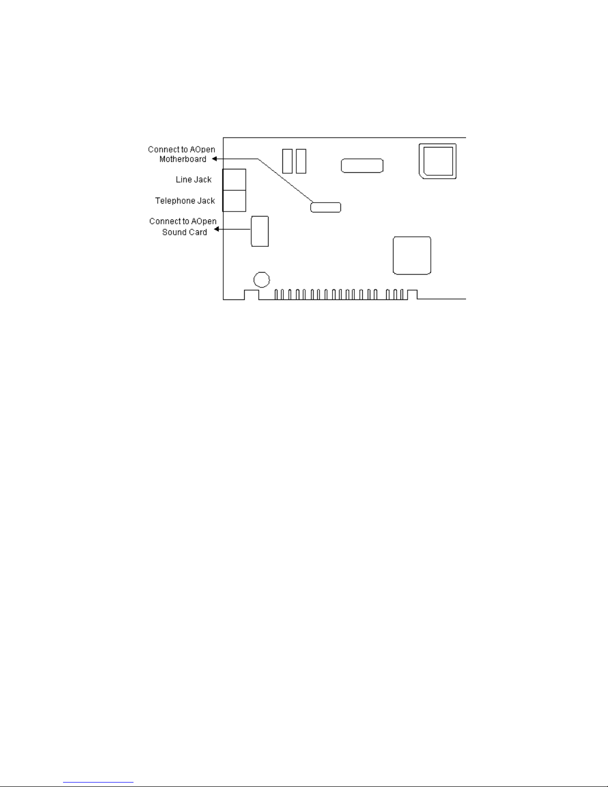
3.1 PC Card Connection
Page 12
3.2 PC Card Bracket Connection
Page 13

4.1 Checking Your Components
Unpack your fax/modem and make sure you have the follow i n g items:
• The fax/modem.
• A modu l ar telephone cable to connect your fax/modem to the telephon e line.
• Communic ation softw are.
• Two cables li n k JP1 and JP2 to sound card and mother board
When you op en yo u r package, make sure all of the above items are incl u d ed and not damaged. If
you see that any compo n ents are damaged, please notify yo u r dealer immediately .
Page 14

4.2 What Else You Need
To compl ete your data communicatio n system, you will need the follow in g items:
Other commun i catio n softw are, if needed.
An active telephon e line and telephone set (if you need to use a telephone with you r mod em).
An available PCI slo t i n the personal computer.
For voice function, a micro p h one and a speaker for voi c e reco rding and pl ay ing.
Page 15

4.3 Installing The PC Card Fax/Modem
The follo w i ng instr u cti o ns explain how to inst all the fax/modem into a PC comput er. If you wil l be
ins t alling th e fax/modem in t o a differ ent comput er, refer to the manual that came with yo u r
compu ter or contact your computer dealer for instructio ns.
1. Turn of f the computer. No power must be applied to your
computer when you install the internal fax/modem, or the
computer could b
e damaged.
2. Make sure you can freely access the back of the person al
computer. Remove the computer cover.
3. Select any available PCI slot into which you can
install the internal fax/modem.
4. Unscrew and remove the slot c
over.
5. Hold the in ternal fax /modem above the slot you h av e selected, and c ar ef ull y slide
the fax/modem int o the slo t, apply ing even pressur e to both ends of the fax/modem .
Stop inserting the fax/modem when its gold-pl ated edge connector is align ed and full y
seated int o the base of the computer.
6. Connect the sound card cable wit h JP1 and the sound card.(Optional)
7. Connect the wake up ring cabl e with JP2 and the moth er board.(Option al)
8. Use the screw that was holdin g the slot cov er to secure the
fax/mo dem in the slot.
9. Use the cov er-m o u n ti n g scr ews to secure the compu ter
cover. This comp letes the hardw are installation of your
fax/modem.
Page 16

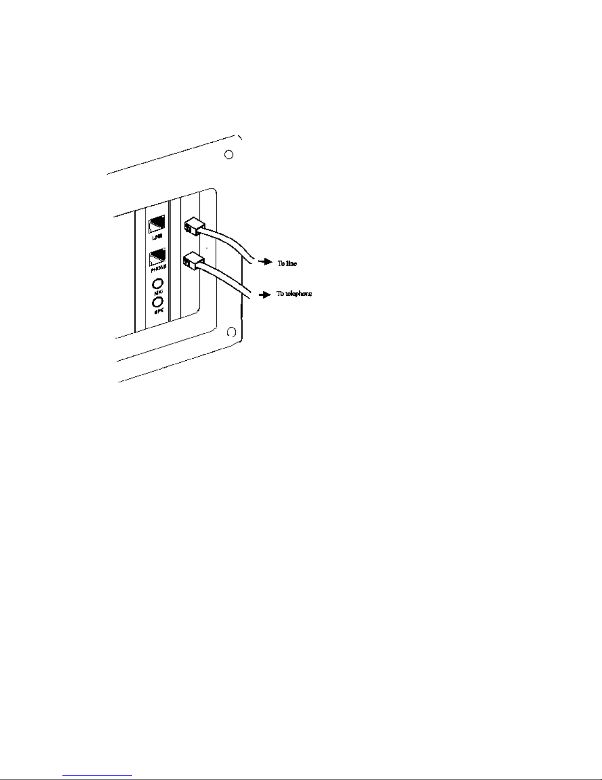
4.4 Connecting To The Telephone Line
Use the foll ow i ng proc edure to connect your fax/modem to the telephone line:
1. Loc ate an availab l e RJ-11 modu l ar jac k teleph one outl et.
2. Take one end of the modular cor d supp l i ed wi th the fax/modem and plug it in to the
LINE modular jack on the b a ck of the fax/modem.
3. Plug the other end of the mod ular cord into the modu lar jack on the wall outlet, as you
would any modular telephone.
Page 17

4.5 Connecting To Your Telephone Set
Your fax/modem also convenientl y prov id es a second modu lar jack that lets you conn ect you r
telephon e to the same telephone line that the fax/mo d em is us ing. Thi s lets y o u manuall y dial
data calls or make voice calls when you are not usi n g yo u r fax/modem. Also if you do no t have
speaker phone and microph o n e, handset of telephone set can functi o n as an inpu t /outp ut device
for voice to verify the connecti o n.
Use the foll ow i ng proc edure to connect your telephone to your fax/modem:
1. Connect the telephon e's mo d u l ar cor d int o th e PHONE jack
on the back of your fax/modem.
2. Li f t y o ur telephone's handset and lis t en fo r a dial tone.
Page 18

4.6 Verifying Your Connection
Start a commun ic atio n prog r am and place the compu ter into termin al mod e. Refer to your
comp u ter manual to find out the approp ri ate command to do so.
Then use the followi n g procedu re to verify you r ins tallation :
1. Type
AT[Enter]
If you r sy stem is operatin g pro perl y , your fax/modem sends an OK response to your screen and
waits for your next command.
2. Use your commun icati o n soft ware to prepar e your
computer to dial a call. Then type
ATDx phone number[Enter]
where x is equal to T for touch
-to ne or P for pu lse
dialing. The ph one number is your telephone number.
For example, if your fax /m odem i s connected to the telep hon e
line 555-2121 and tou c h -to ne dialing is supported in your area,
type
ATDT 5552121[Enter ].
3. You s h oul d hear the bus y signal and rec ei ve a BUSY
response becaus e the fax/mod em is call ing itself.
Page 19

4.7 Connecting Microphone And Speaker
You coul d either use a handset conn ected to the fax/mod em, or conn ect a micr op h o n e and a
speaker for voice recording and playback, or connect cable of Jumper 1 with soun d card in you r
PC (option al, refer to sound card user's gui d e). Also, you may enable the ring wake up functi o n
by connecting the cable of Jumper 5 to motherbo ard . (the funct i o n is opt i onal, see the PC user's
manual for mo re detail)
NOTE:
Any commercially available microphone is usable.
For the speaker, any 8 ohm speaker rated around 1Watt can
be driven directly by the audio output. An amplifier is
required if you need a higher output volume.
1. Connect the micro ph on e to the mini-p h one jack marked MIC.
2. Connect the speaker to the min i-p h o n e jack marked SPK.
NOTE:
Take care of the pin setting and cable setting direction (JP1 and JP2) for your Fax/Modem
card, Sound card and Motherboard.
Page 20

4.8 Voice Function Alternatives
1. AOpen Sound Card (recommanded)
Simply co n nect the cabl e from modem to AOpen Sound Card. User can get all th e voice
function incl uding message pla
yin g and recording through sound cards.
2. SpeakerPhone and MicroPho n e
Con nect SpeakerPh one and MicroPh one to modem. User can also get vo ice perf orman ce.
NOTE:
Any commercially available microphone is usable.
For the speaker, any 8 ohm speaker rated around 1 Watt can
be driven directly by the audio output. An amplifier is
required if you need a higher output volume.
Page 21

4.9 Configuring Internal Modem With
Windows95/98/2000/NT
Wind ows 95:
1. Compl ete the installati o n referred to sectio n 4.3.
2. Restart the comput er after plugg i n g in the mod em. When Window s detects th e modem, the
message "This wizard will comp l ete the installatio n of: PCI Serial Contro ll er" is displayed.
3. Click Next, then Other location, then enter the path to the driv ers , then cli ck OK.
4. Win
dows display "Wind o ws found th e following updated d river fo r th i s device: AOpen PCI
Modem Enumerator".
5. Click Finish and Window s di sp l ays " Pl ease insert the disk labeled 'WIN95 install ati on Disk' ,
and then click OK.
6. Click OK and enter the path of the drivers again. Installation sho ul d then compl ete
automatically.
After compl eting the installation, you can check if the fax/modem was properly installed by usi ng
the follow in g procedure:
1. From My Comput er, doub l e click Control Panel.
2. Double click Modems.
3. Select Diagnostics tab.
4. Choose the COM port wh ere the newly in stal l ed mod em devic e is. Clic k More Info
If the
Command and Respo ns e box dis p l ays result s fro m ATI1 to AT+FCLA..., it indic ates that your
fax/modem is set up pro perl y .
Wind o ws 2000:
1. Start compu ter after pluggi ng in the modem. Windows wil l detect the modem.
2. Then the message “Welcom e to the Found New Hardw are Wizard” is dis p l ayed.
Click Next.
3. When Windows displ ay “This wizard will compl ete the installatio n for this device:
PCI Simpl e comm un i c ations contro ll er”, choos e “ Search for a suitable driver for
my device”, then click Next.
4. When Windows disp l ay” Search for driv er files for the foll ow i ng hardware device:
PCI Simple communication s contro ller”, choose “Specify a location”, then clic k
Next.
5. In order to copy manufacturer’s files, click Browse.
6. Choose the correct path: D:\Drivers\Win2K\FM56-PL.( D is y our CD-ROM.) Then
click OK.
7. Then the message will sho w the path you cho s e. Click Next.
8. If you want to contin ue installation , click Yes.
9. Windo w s has finish ed installatio n. Click Finish.
After compl etin g the installatio n, you can check if the fax/modem was properl y
installed by using the follow i ng procedure:
1. From My Computer, doub l e click Control Panel.
2. Double click Modems.
3. Select Diagnostics tab.
4. Choo s e the COM port where the newly ins tall ed mo dem devi ce is. Click on
More Info If the Command and Response box displays results from ATI1 to
AT+FCLA..., it indi c ates that your fax/modem is set up properly .
Page 22

Win d ows NT4.0:
1. Explorer the driver files on you r CD.
D:\Drivers\WinNT\FM56-PL
2. If you are usin g th e WINACPCI driver already stop it usi n g the steps in the follo w i n g li s t.
a) Stop any programs (e.g., Hyp er Ter m) that are usi ng the modem driver
b) Click on Start, th en Settings, then Control Panel .
c) Start the Devices applet
d) Scro l l dow n to WinAcPci and highlight it
e) If the di s p lay says "running", contin u e with the next st ep . If not,
you are done.
f) Pres s the STOP but t on and say "yes", you do wan t to sto p the dr iver.
g) Wait until the driver stops (there shoul d be a "w ait" dialog to watch)
h) Where the applet said th e driver was " runn ing" sho uld no w be blank
3. Start SETUP.EXE with a doub le cli c k or by highli g h ti n g the fil e and pressin g the ENTER key.
You shou l d see a welcome screen. Clic k on the NEXT butto n .
4. You shou l d see "AOpen FM56-
PM(SM) Data Fax Speakerphone PCI Modem" in the display
win d ow . Highlig h t it by cli ck in g on the text. Click on the NEXT button to install the driver.
5. You shoul d see a few copy operation s and hear a small flurr y of disk activi ty , and you shou l d
see the next screen which says "the follo w in g dri vers were install ed successful ly ."
6. The driv er is now ins tall ed and runn i ng . Note that you do not have to re-boot your system to
use the driv er. You may exit the installatio n pro c edur e and start HyperTerm to use the driv er
on COM3 right no w .
7. To continu e the installatio n pro ced ur e to create the registry entri es for the modem, perform
the steps in the followi ng list.
a) Cli ck the check box tit led, "Setup
mod em for the install ed devices", and press the
FINISH button . You are now in the domain o f th e st an dard
Wind o ws NT modem ins t aller. If you have previously in s t alled the NT mod em , you will
see a listbo x sho wi n g the installed modems on you r sys tem.
b) If you are usin g the HCF modem already, remove it by click in g on it in the listbo x and
pressing the REMOVE butto n . When the modem is gone, press the ADD but to n to
conti n ue install in g this versio n of the HCF modem.
8. There are two ways to fin i sh the install atio n . The firs t way is to ask the install er to detect the
HCF modem. The second way is to select the HCF mod em from the lis t usi n g the "h ave disk "
feature.
9. To ask the install er to detect the modem, clear the " Don' t detect my mo dem..." check box and
press the NEXT button . Windows NT will qu ery every com por t and fin d every mod em
attached to you r sy st em. When it gets to COM3, it wi l l detect a " st and ard mod em". Clic k the
CHANGE butto n and prep are to select th e modem INF fil e.
10. To select the mod em fro m a list, check the "Don't detect my mod em..." check box and press
the NEXT button . After a moment , NT will show the li s t. Press the HAVE DISK butto n to
select th e HCF mo dem INF file.
11. At the " Install From Disk" dialog, enter the directory path where you loaded the installation
Page 23

fil es. Select the modem from the list bo x and cli ck the OK butto n . This wil l return you to the
" Install new modem" dialog. Press the NEXT button to ins tall the modem files.
12. Check the "Selected Ports" button and high light COM3. Press the Next button .
13. You are don e. Clic k the FINISH butto n and start using the mod em.
Page 24

4.10 Tips On Configuring Your Communication Software
Your fax/modem uses the most up-to-date indu str y and commercially pop ul ar standards to
ensure functi onal compatib ili ty with most commu ni cation software. During initial set-up of the
comm un i catio n softw are, it will nor m ally prom pt yo u to define the type of fax/modem you are
usin g . Follow in g is a general guideli n e to the device type you should choose.
NOTE:
The device type only defines the protocol by which your software will communicate with
your fax/modem and does not set nor limit the speed.
1. For the baud rate. choo s e any sp eed between 38,400 to 115,200.Your fax/mo d em will
automatically adjust to the best transmissio n speed after successfull y connectin g wi th a
remot e fax/modem.
2.
Many com m u n i cati o n sof tw are uses the modem respo n s e (see Ch 7) to contr o l pro g r am
fl ow. Make sure that the software is set to reco gni ze a CONNECT 115200
respo n s e. If this
does not wo rk , set the progr am to simp l y recogn i ze just the CONNECT respo ns e with ou t any
baud rate inform ation .
3. There are three flow cont r ol mode: none, hardware (CTS/RTS) or software (XON/XOFF). Set
you r sof tw are to use either hardware or softw are flow control . If set to none, the
comm un i catio n softw are will not be able to detect a buffer overflow and result in transmissi on
errors.
4. For fax devi c e type, choo s e 'TR29 Class 1'.
5. For fax speed, choos e 'autom atic ' or 'fastest sp eed'. Your fax/modem will automatically adjust
to be best transmis si o n speed after successfu l ly con n ectin g with a remote fax machin e or
another fax/modem.
6. Make sure that you have correctl y set all the other parameters requi red by the soft ware to
op erate successfully. Refer to the manual that came with yo ur comm u ni catio n softw are for
details.
You are now ready to do fax/modem communication !
Page 25

4.11 Tips On Configuring SVD (Option)
Add "-SMS=2" to the modem stri n g in com mu n i catio n prog ams to enable the SVD functi on. For
com p l ete SVD comm an d s , please refer to the AT command fil e on the dri v er di s k .
Page 26

5. Executing Commands
If you wi ll be using a comm un i cation softw are program to make data calls, you wil l prob ably not
need to typ e commands , because your softw are prog
ram w ill handle these task s for yo u .
Similarly , you wil l prob ably not see the respons es because your soft ware program may intercept
them. However, if you perfo r m data activiti es di r ectl y wi t h yo u r fax/modem, you wi l l fin d the
format for typi ng fax/modem commands and fax/ modem respons e helpful.
Using com mand s , you can have your fax/modem perform a variety of activi ties, such as dialing or
answ eri n g a data call or sendi ng a fax. In ord er to send co m mands to y o u r fax/modem, you
mus t access the mod em in a terminal mode which is provi ded by most commu ni cation software.
To enter a command lin e, type:
ATccpp[Enter]
where AT must preced e ever y com mand l ine (except w hen
you ty pe the A/ command ).
cc any of the commands available, described in
succeeding sections.
pp any parameters that is requi red by the command .
If you make a mistak e while typ i ng a com m an d , press th e Backs p ac e key to delete the error .
To make a command line easy to read, you can ins ert spaces parenth eses, hyp h ens , and other
punc tuatio n in you r com mand lin e. For example:
AT M3 DT 9, 1(818)555
-1234
Your fax/modem ignor es spaces and punc tuati on marks when executing a command line, but
these characters apply to the 40 characters lim i t.
A command li n e can contain up to 39 characters. If you want to typ e mor e than 39 characters on
a command lin e, type a regular com m an d lin e (up to 39 characters lon g ) and end it with a
semic ol o n as the last character. When you press Enter, your fax/modem executes the commands
and returns to command mod e, so you can type your next command li ne.
For your conv enienc e, the last command lin e you execute remains stored in the modem's
memo r y until you ty p e a new comm an d li n e and pres s the Enter key. If you wan t to re-execut e
the last co mmand , ty p e
A/
The A/ command need not be prefixed by the 'AT' characters or ended wi t h the [Enter] key.
NOTE:
The fax/modem com mand and respo nse set are descri b ed in th e text fil e, AT_CMD.TXT, in the
fax/mo d em Window s 95 driver di sk ette. You can use DOS EDIT or any suitable editor to vi ew thi s
fil e.
If a com mand requires a parameter su ch as 0 and 1, the parameter i s identif ied as n in the left
col u mn and descr ib ed in the righ t col um n of the AT_CMD.TXT file.
IMPORTANT:
Each command , except for '+++' and 'A/', must be preceded by 'AT' and executed when yo u
press th e [Enter] key. To review th e for m at us ed to send fax/modem com mands, refer to Section
of this manual.
Page 27

6. S-Registers
Your fax/mod em has S-registers that affect various operatin g ch aracterist i cs . The registers let
yo u ob t ain information abou t the fax/mod em , and let you test the fax/mod em. Each S
-Register
has a factory -s et value, whi ch yo u can read or change to fit your partic ul ar requi rements . A
complete list of S-Register is pr o vided in the COMMAND.TXT file on the driv er di s kette.
6.1 Reading An S-Register Value
6.2 Changing An S-Register Value
Page 28

6.1 Reading An S-Register Value
1. To read the curr en t val ue of an S-Register, type:
ATSr?[Enter]
where r is an S-Register numb er.
The fax/modem responds with decimal value of the
S-Register, in thr ee-digi t form at, follo w ed by OK.
2. To read values from more than one S-Register, type:
ATSr?Sr?[
Enter]
where
r sp ecify the d iffer ent S
-Register numbers.
For example, to read the value of Register S0 (number of
rings before answering) an d S1 (incoming ri ng count),
type:
ATS0?S1?[Enter]
Page 29

6.2 Changing An S-Register Value
To change an S-Register value, typ e
ATSr=n[Enter]
where r is the S
-register numb er.
n i s the value you want to assign to th at S-regis ter.
Page 30

7. Specification
MODEM OPERATION
Li n e Rate 0.3, 1.2, 2.4, 4.8, 7.2, 9.6, 12, 14.4, 16.8, 19.2, 21.6, 24, 26.4, 28.8,
31.2, 33.6, 56 Kb ps
DTE Rate 115200 bps maxi m u m
Operation Half or full -d up l ex over 2-wire dial-up line, asynch ron ous
Linking Auto dial/answer, auto baud i n g , MNP10 auto fall-back/forward
Flow Control RTS/CTS, XON/XOFF (software selectable)
Compatibility Bell 103; 212A, ITU-T V.21; V.22; V.23; V.22bis ; V.32; V.32bis; V.34;
V.90; K56flex (56K model on l y)
Error Correction ITU-T V.42, MNP4 (auto-match)
Data Comp ressi o n ITU-T V.42bis, MNP5 (auto-match)
Receiv e Sensitivity -36 dBm
Command Set Hayes AT and Escape sequen c e
Memory 1 configu ration profil es
Diagnostics Power on self-test, V.54 loop test
FAX OPERATION
Speed 14400 bps
Compatibility Group 3 with T.30 proto c o l ov er ITU-T V.17; V.21 ch2; V.27ter; V.29
Command Set TR-29 Class 1
VOICE OPERATION
Operation
PVS Telephon e answ ering mach i n e (TAM), voice mail sy s t em,
Simu l t aneu o s Voic e and Data (SVD), Option al
Samplin g Rate 7.2 Khz using 2, 3 or 4 bi t s A DPCM; 11.025Khz li near PCM
GENERAL
Lin e Interface 2 x RJ-11 for li n e and telephon e
Voice Interface 2 x mini phone jack for micropho ne input and audio output
Amb ient Temp. 0 to 50
Relative Humi di ty 10 to 95% non-condensing
Dimensions 1.6w x 10.7h x 13.0d cm
Page 31

A.1 FCC Notice
This equipm ent has been tested and foun d to com p l y wi th the limi ts for a Class B digit al device,
pur suant to Part 15 of FCC Rules. These limit s are designed to pro v i d e reasonable prot ecti o n
against harmfu l in terference in a residential in stall atio n . This equip m ent generates, uses and can
radiate radio frequenc y energy and, if not inst alled and used in accordance with the instru ct io n s,
may cause harmful in terference to radio com mu n i catio n s . However, there is no guarantee that
interference will not occu r in a particu lar install ation. If this equipm ent does cause harmful
interference to radio or televisio n reception, which can be determined by turni n g the equipment
off and on, the user is enco ur aged to try to cor r ect the interferenc e by one or mor e of the
follow in g measures:
• Reori ent of reloc ate the receivin g antenna.
• Increase the separatio n betw een the equip m ent and receiver.
• Connect the equi pm ent int o an outlet on a circ u it different from that to whic h the receiver is
conn ected.
• Consul t the dealer or an experienced radio / TV techni cian for help.
This uni t was tested with shi eld ed cables on the peripheral devices. Shield ed cables must be
used with the unit to in su re comp l i ance. This statement can be deleted if unit was not tested with
shield ed cables.
The manufactu r e is not respons i bl e for any radio or TV interference caused by unauthor i zed
modi fi cation s to this equipment. Such modif icatio ns cou ld void the user's authori ty to operate the
equipment.
This devic e comp l i es wit h Part 15 of the FCC rul es. Operatio n is subject to the follow in g two
conditions:
1. This device may not cause harmful in terference.
2. This device must accept any interference that may cause undesi red op eration .
Page 32

A.2 FCC Requirement
This equi p m en t compli es wi t h Part 68 of the FCC Rules. On the base unit of thi s equi pm en t is a
label that contain s, among oth er info r mati o n, the FCC Regis trati o n Number and Ringer
Equiv alence Number (REN) for this equip m ent. If requested, this info rm ati on mu st be given to
telephone company.
The REN is usefu l in determin i ng the quantity of devices you may connect to your telephone line
and still have all of those devices ring when yo u r telepho ne numb er is called. In most, but not all
area, the sum of the REN's of all devices con n ected to one lin e shou l d not exceed five (5). To be
certain of the numb er of devices yo u may conn ect to yo u r li n e, as determined by the REN, you
shou ld contact you r loc al telephone company to determine the maximum REN for you r callin g
area.
If you r equi pm ent causes harm to the telephon e network, the telephon e com pany may
disc on ti nu e your service temporarily . If possib le, they wil l noti fy yo u in advance. But if advance
noti ce is not practical, you wil l be notified as soon as possib l e. You will be informed of your righ t
to file a compl ain with the FCC. Your telephone comp any may make changes in its facil i ti es,
equip men ts, operatio ns or pro c edur es that coul d affect the proper
funct io n in g of your equipm ent. If they do, you wil l be notified in advance to give you an
opportu nity to maintain uninterrupted telephon e service.
The equipm ent may not be used on coin servic e by the telepho ne comp any . Connection to party
lin es is subj ect to state tariffs .
Page 33

Appendix B: Default Profiles
SETTING DEFAULT NVRAM
Auto-answer Disabled Yes
Backspace character 08 No
Bell / CCITT compatibility at Bell 212A
1200 bps
Yes
Busy signal detect Enabled Yes
Carriage return character 13 No
Line feed character 10 No
Data Set Ready option Always on Yes
Data Terminal Ready option &D2 Yes
Data Terminal Ready pulse width 0.5 seconds Yes
Echo option On Yes
Escape character definition 43 (+++) Yes
Guard tones Disabled Yes
Long space disconnect Disabled Yes
Parity None Yes
Pulse make / break ratio 39/61 Yes
Responses Word Yes
Response enable All Yes
RTS-to-CTS delay 10 milliseconds Yes
Speaker status On until DCD Yes
Speaker volume Low Yes
Test timer setting 0 second Yes
Wait for carrier after dialing 50 seconds Yes
Wait for dial tone 2 seconds No
Wait for dial tone before dialing Enabled Yes
Dial delay pause time 2 seconds Yes
Wait before accepting carrier detect 0.6 seconds Yes
Wait before disconnecting 1.4 seconds
after carrier loss Yes
DTMF tone duration and spacing 95 milliseconds Yes
Flash (!) dial modifier time 0.7 seconds No
PSTN attenuation level -10 dBm No
Fax attenuation level -10 dBm No
Page 34

1. INTRODUCTION
1.1 OVERVIEW
This manual describ es the host command and responses for the follow in g Rockwell
modem families:
RC144HCF for ISA Bu s Modem Device Set
RC144HCF-for PCI Bus Mod em Devic e Set
RC144HCF-fo r PC Card Modem Device Set.
Refer to Modem Design er' s Guides and Modem Softw are Release notes fo r co mm and s
specific to a produ ct model.
The command s and respon ses are implemented in host soft w are for specific mod em
models. The suppo rt for a command category is identifi ed by modem model in the
Modem Design er's Guide. Additio nal confi gu ration and implementation information is
available in release notes and/or readme files that accomp any pro d u ct sof tw are release.
The Product Configu ration File contains exact application un iq ue infor mation and default
values.
1.2 Command Descriptions
These commands are group ed into the follow in g categories:
Syntax and procedu res Section 2
Data/fax command s Section 3
Fax comm and s Section 4
Voice commands Section 5
ISDN comm and s Sectio n 6
Command Set Summary Sectio n 7
1.3 REFERENCE DOCUMENTATION
Rock w ell Doc u m ent Ord er No. 1123, RC144HCF for ISA Bus Modem Desig n er's Guide
Rock w el l Docu m en t Ord er No. 1129, RC144HCF for PCI Bus Modem Desig n er's Guid e
Rock well Docu m ent Ord er No. 1130, RC144HCF for PC Card Modem Desig ner's Gui d e
Docu m en t TD/ - E, STUDY GROUP 14, 19-27 March 1996, ITU-T, Revisi o n s to V.25ter
Docu m en t TD/ - E, STUDY GROUP 14, 19-27 March 1996, ITU-T, Clean Draft An nex
A/V.25ter
ITU-T Recommen d atio n T.31 (08/94), Termin als for Telematics Servic es, Asy n c h r o n o u s
Facsimi le DCE Cont r o l -Servic e Class 1
ITU-T Recom m en d ation T.31 Amend m ent 1(07/96), Termin als fo r Telematics Services,
Asy nc hr on o us Facsimile DCE Control - Servi c e Class 1, Annex B - Procedur e for
Servic e Class 1 Support of V.34 Modems TIA Standar d s Prop osal No. SP-3131A Draft
Revisi on 5, Propo s ed New Standard " Voic e Control Standard for Asy nc hr o no us DCE" (if
appro v ed to be publ i sh ed as TIA/EIA-695)
Page 35

2. SYNTAX AND PROCEDURES
The command and respons e syntax and proc edures generally con for m to referenced
recommendation s and standards.
Since these recommendations and standards descri be characteristic s uni versal to a
large inst alled base of modems to a maximu m degr ee, there may be sy n tax and
pro cedur al differences due to extension s and behavioral differences in implemented
comm ands , parameters, and respon s es beyon d th at describ ed in these
recommendations and standards.
The syn tax and pro c edur es descri b ed in this secti on are based on V.25ter with
addition al informatio n incl ud ed for implemented extensions and behavioral differences
beyo nd V.25ter.
2.1 Alphabet
The T.50 Internatio nal Alphab et 5 (IA5) is used in th i s doc ument. Only the low-ord er
seven bits of each character are signi fic ant to the modem; any eighth or hig h er-ord er
bit(s), if present, are ignored for the purp o se of identify i n g co mmand s and parameters.
Lower-case characters are consi dered identi c al to their upp er-case equivalents w hen
received by th e modem fro m th e DTE. Result co des from the mod em are in up p er case.
2.2 DTE Commands Lines
Word s enclo s ed in <angle brackets > are references to sy n tact i cal elements. The
brackets are not used when the word s appear in a comman d li n e, the brack ets are not
used. Words enclos ed in [squ are brackets] represent optio nal items whi ch may be
omit ted fro m the command lin e at the specified poi n t. The square brackets are not us ed
wh en the word s appear in the comm and lin e. Other characters that appear in sy n tax
descript ions must as includ ed as shown .
Any mod em respons es are mention ed in terms of their alphabetic for mat; the actual
respon s e issued wi ll depend on the setting of parameters that affect respons e formats,
e.g., Q and V com m an ds (see 2.7).
2.2.1 Command Line General Format
A command lin e is made up of thr ee elements: the prefix, the body , and the termination
character.
The command line prefix cons is ts of the characters "AT" or " at" or, to repeat the
execution of the previou s comm and line, the characters "A/" or " a/".
The body is made up of indiv id u al commands descr ib ed in this doc u ment. Space
charact ers (IA5 2/0) are ignor ed and may be used freely for for matt in g pur p o ses, unl ess
they are embedded in numeric or strin g co ns tants . The termination character may not
appear in the body. The modem can accept at least 40 charact ers in the bod y.
The termin ati o n char acter may be selected by a user opt i on (parameter S3), the default
bein g CR.
2.2.2 Command Line Editing
The character defin ed by parameter S5 (default, BS) is interp r eted as a request fro m th e
DTE to the modem to delete the previo u s ch aracter. Any co n tr o l charact ers (IA5 0/0
thr ou g h 1/15, inclus i ve) that remain in the com mand line after receipt of the termination
character are igno r ed by the modem.
The mod em checks ch aracters from th e DTE first to see if they match the termin atio n
charact er (S3), then the editin g ch aracter (S5), before checki n g for other characters.
This ensures that these characters will be properly recogni zed even if they are set to
Page 36

valu es th at the mod em us es fo r ot her purp o s es. If S3 and S5 are set to the same value,
a match i n g ch aract er wi l l be treated as matchin g S3 (S3 is checked befo r e S5).
2.2.3 Command Line Echo
The mod em may echo ch aracters received from the DTE duri n g com mand state and
onl i ne com mand st ate back to the DTE, depending on the settin g of th e E comman d . If
so enabled , character s receiv ed fr om th e DTE are echo ed in th e same format as
received. Invalid ch aracters in the command line or incompl ete or improperly -fo rm ed
comm and lin e prefixes may not be echoed.
2.2.4 Repeating a Command Line
If the prefix " A /" or "a/" is received, the modem immediately executes onc e again the
body of the preceding command lin e.
No editin g is pos si bl e, and no termination character is necessary. A command line may
be repeated multi pl e times in th is manner. Respo n ses to the repeated command li ne are
issued usi ng format of the origin al command line. If "A/" is received before any co mmand
lin e has been executed, the preceding co mm and lin e is assumed to have been empty
(that results in an OK result cod e).
2.2.5 Types of DTE Commands
There are two ty pes of comm ands : actio n com mand s and parameter comm ands .
Commands of either type may be includ ed in command lin es, in any ord er.
Actio n commands may be "execut ed" (to invoke a particul ar functio n of the equip ment,
wh ic h generally inv o lv es more than the simpl e storage of a value for later use), or
" tested" (to determine whether or not the equipment implements the action comm and,
and, if subparameters are assoc iated wi th the action , the ranges of sub parameter values
that are sup po r ted).
Parameters may be "set" (to stor e a value or values for later use), "r ead" (to determin e
the current value or values stored), or " tested" (to determine whether or not the
equipm ent imp lements the parameter, and the ranges of values supp o rted).
2.3 Basic Syntax Commands
2.3.1 Basic syntax command format
The format of Basic Synt ax com mand s, except for th e D and S command s , is as follows:
<command>[<number>]
where <command> is either a single character, or the " &" character follow ed by a single
charact er per V.25 ter. In addi ti o n , <command> can be the "%" ch aracter fol l o w ed by a
sing le character, the " *" character follow ed by a sing le character, or the "^" character
follo w ed by a single character.
<number> may be a strin g of one or more characters from "0" thro u gh " 9" representing a
decimal int eger value. Commands th at expect a <number> are noted in the descr ip t io n
of the command. If a comm and expects <numb er> and it is missi ng (<command> is
immediately follo w ed in the command line by another <command> or the termination
charact er), the value "0" is assu med. If a command does not expect a <num ber> and a
num b er is p resent , an ERROR is generated. All leading "0"s in <numb er> are ignor ed by
the modem.
Addi t io nal comm ands may follo w a command (and assoc iated parameter, if any) on the
same command line with ou t any character required for separation . The actio ns of some
command s cause the remaind er of th e com man d lin e to be ign o r ed (e.g., A).
See the D command for details on the format of the inform atio n that foll o w s it.
2.3.2 S-Parameters
Page 37

Commands that begin wit h the letter "S" are know n as "S-parameters". The number
followin g the "S" ind ic ates the "parameter number" being referenced. If the number is not
recog n i zed as a valid parameter num b er, an ERROR result co d e is iss u ed.
Immediately follow i ng this numb er, either a "?" or "=" character must appear. "? " is used
to read the current
value of the indi cated S-parameter; " =" is used to set the S
-parameter
to a new value.
S<parameter_numb er>?
S<parameter_num b er>=[<value>]
If the " =" is used, the new value to be stored in th e S-parameter is specified in decimal
follo wi ng the "=" . If no value is given (i.e., the end of th e command line occu r s or th e
next command foll ow s immediately ), the S-parameter speci fi ed may be set to 0, or an
ERROR result cod e issu ed and th e stor ed valu e left unch ang ed. The ranges of
acceptabl e values are given in the descript io n of each S-parameter.
If the " ? " is used, the modem transmi ts a sing le line of info rm atio n text to th e DTE. The
text portio n of this infor mation text consi sts of exactly three characters, giving the value
of th e S-parameter in decimal, wi th leading zeroes included.
2.4 Extended Syntax Commands
2.4.1 Command Naming Rules
Bot h actio n s and parameters have names, whi c h are used in the related comm ands .
Names alway s begin with the character "+" . Follo w in g the "+" , from one to 16 additio n al
characters appear in the comm and name. These charact ers wi ll be selected from the
followin g set:
A thr ough Z (IA5 4/1 thr o ugh 5/10)
0 thro u gh 9 (IA5 3/0 through 3/9)
! (IA5 2/1)
% (IA5 2/5)
- (IA5 2/13)
. (IA5 2/14)
/ (IA5 2/15)
: (IA5 3/10)
_ (IA5 5/15)
The first character follow in g the "+" must be an alphabetic character in the range of "A "
thro ug h " Z" . This first character generally impli es the application in whi ch a command is
us ed (e.g., F for Fax or V for vo i ce).
The modem consid ers low er-case characters to be the same as their upper-case
equivalents.
2.4.2 Values
When subp arameters are assoc iated wi th the executio n of an actio n , or when settin g a
parameter, the command may inclu de specifi catio n of values. This is ind icated by the
appearance of <value> in the descrip tio ns below.
<value> consis ts of either a numeric const ant or a strin g cons tant.
2.4.2.1 Numeric Constants
Numeric con st ants are expressed in decim al, hexadecimal, or binary .
Decimal numeric cons t ants co ns is t of a sequence of one or more of the characters " 0"
thro ug h " 9" , inclu siv e. Hexadecimal numeric const ants con si st of a sequence of one or
more of the characters "0" throu gh "9" , inclusi ve, and "A" through "F" inclu siv e. The
characters "A " through " F" represent the equivalent decimal values 10 throu g h 15.
Binary numeric cons tants cons ist of a sequence of one or more of the characters "0" and
"1".
Page 38

In all numeric constants , the most sign ific ant digit is specified first. Leading " 0"
characters are ignored by the modem. No spaces, hyp hens , periods , comm as,
parentheses, or other generally-accepted numeric for mattin g characters are permitted in
numeric cons tants ; note in particular that no "H" suff ix is appended to the end of
hexadecimal constants.
2.4.2.2 String Constants
String constants consist of a sequence of disp l ay abl e IA5 characters , each in the range
from 2/0 to 7/15, inclusiv e, except for th e charact ers '"' (IA5 2/2) and " \
" (IA5 5/12). String
con st ants are bou nded at the beginn ing and end by the double-quot e character ('" ', IA5
2/2).
Any character value may be includ ed in the string by representin g it as a backslash ("\" )
character follow ed by two hexadecimal digits. For example, "\0D" is a string cons ist ing of
th e si n gle char ac t er <CR> (IA5 0/13). If the "\" character itself is to be represent ed in a
strin g , it is encoded as "\5C" . The dou b l e-qu ot e character, used as the beginni ng and
ending str ing delimiter, is represented within a strin g con stant as "\22".
A "n ull " stri ng cons tant, or a strin g con stant of zero length, is represented by two
adjacent delimiters ("" ).
2.4.2.3 Compound Values
Acti on s may have more than one subparameter assoc iated wi th them, and parameters
may have mor e than one value.
These are known as "co mp ou n d values", and their treatment is the same in both actio n s
and parameters. A compo un d value consist s of any combin ation of numeric and string
values (as defined in the descrip ti o n of the action or parameter). The comma character
mus t be inclu d ed as a separator, before the secon d and all sub sequ ent valu es in the
compou n d value. If a value is not sp eci fi ed (i.e., defaults assu m ed), the required co m ma
separator must be specified; how ever, trailing comma characters may be omitted if all
assoc iated values are also omi tt ed.
2.4.3 Action commands
2.4.3.1 Action execu
tion command syntax
There are two general typ es of action comm ands : th os e that have assoc iated
sub parameter values that affect only that invo c ation of the command, and those that
have no subp arameters. If subp arameters are assoc iated wit h a command, the definition
of the actio n comm and ind ic ates, for each subp arameter, whether the specific atio n of a
value for that subparameter is mandatory or opt io nal. For opt io n al subparameters, the
definit io n ind ic ates the assu med (default) value for the subp arameter if no value is
speci fi ed for that su b p arameter; the assumed valu e may be either a previou s valu e (i.e.,
the value of an omitted su bp arameter remains the same as the previo us inv o cati on of
the same command, or is determin ed by a separate parameter or oth er mechani s m), or
a fixed value (e.g., the value of an omit t ed su b p arameter is assu m ed to be zero).
Generally, the default value for numeri c sub p arameters is 0, and the default value for
strin g subp arameters is "" (empty string).
The follow ing sy ntax is used for action s that have no subp arameters:
+<name>
The follow i ng sy nt ax is used for actio ns that have one subparameter:
+<name>[=<value>]
The follow in g syn tax is used for actio ns that have two or more subparameters:
+<name>[=<comp o u nd _valu e>]
For actio ns that accept sub p arameters, if all subp arameters are defined as being
opt io n al, and the default values for all sub parameters are satis facto r y , the data terminal
equip men t (DTE) may use the first sy n t ax above (i.e., omit the " =" from the action
Page 39

execution command as well as all of the subparameter value strin g ).
If all other relevant cri t eri a are met (e.g., the modem is in th e pro p er st ate), the
com mand is executed wi th any ind i cated sub p arameters. If <name> is not recogn ized,
the mod em iss u es th e ERROR result co d e and terminates process ing of the command
lin e. An ERROR is also generated if a subp arameter is spec if ied fo r an actio n that do es
not accept su b parameters, if too many sub parameters are specifi ed, if a mandato ry
sub p arameter is not speci fied, if a value is specified of the wro ng ty p e, or if a value is
specified that is not within the suppor ted range.
2.4.3.2 Action Test Command Syntax
The DTE may test if an actio n co mmand is impl emented in th e modem by usi n g the
syntax:
+<name>=?
If the modem does no t recog n i ze the indi cated name, it retur n s an ERROR resul t cod e
and terminates process ing of the comm and lin e. If the modem does recogn ize the actio n
name, it retur ns an OK result cod e. If the named actio n accept s on e or mor e
sub parameters, the modem sends an info rm atio n text respo n se to the DTE, prior to th e
OK result co de, specifyin g the values suppo rted by the modem for each such
subp arameter, and poss ibl y additio nal infor mation . The format of this infor mation text is
defined for each action command .
2.4.4 Parameter Commands
2.4.4.1 Parameter Types
Parameters may be defined as " r ead-only " or "read-writ e" . "Read-onl y " parameters are
used to prov id e status or identi fy in g infor matio n to the DTE, but cannot be set by the
DTE; attempt in g to set their value is an error . In som e cases (specifi ed in th e descrip t io n
of the indi vi d ual parameter), the modem may ignor e attempts to set the value of such
parameters rather than respon d wit h an ERROR result cod e, if the cont in u ed cor rect
operation of the interface between the modem and DTE will no t be affected by su c h
actio n . Read-on l y parameters may be read and tested.
" Read-wri t e" parameters may be set by th e DTE, to stor e a value or values for later us e.
Read-wr i t e parameters may be set, read, and tested.
Parameters may take either a single value, or multi p l e (com p o und) values. Each value
may be either numeric or str in g; the definitio n of the parameter will speci fy the type of
value for each sub p arameter. Attempti n g to stor e a strin g value in a numeric parameter,
or a numeric value in a string parameter, is an error .
2.4.4.2 Parameter Set Command Syntax
The definit io n of the parameter indicates, for each value, whether the specifi cati on of
that value is mandator y or op ti on al. For opti on al values, the definiti on indi cates the
assum ed (default) value if none is specif ied; th e assumed value may be either a
previo u s value (i.e., the value of an omitted su b parameter retains its prev io u s value), or
a fixed value (e.g., the value of an omit t ed su b p arameter is assum ed to be zero).
Generally , the default value for numeri c parameters is 0, and the default value for stri n g
parameters is " " (empty strin g).
The follo w in g sy nt ax is used for parameters that accept a single value:
+<name>=[<value>]
The followin g sy ntax is used for parameters that accept more than one value:
+<name>=[<comp o u nd _valu e>]
For each imp l emented parameter, if all mandato ry values are specif ied, and all values
are valid accor di n g to the definiti o n of the parameter, the specif ied values are sto red. If
<name> is not recog n ized, one or more mandatory values are omitt ed, or one or more
values are of the wron g typ e or outs i de the permitted range, the modem issu es the
Page 40

ERROR result co de and termi nates pr o c ess ing of the comm and lin e. An ERROR is also
generated if too many valu es are specifi ed. In case of an
error , all previou s values of the parameter are unaffected.
2.4.4.3 Parameter Read Command Syntax
T
he DTE may determine the curr ent value or values st o red in a parameter by us i n g the
following syntax:
+<name>?
The modem respon d s by send in g the cur rent values st or ed for the parameter to the DTE
in an information text respons e.
The format of this respo ns e is descr ib ed in th e definitio n of th e parameter. Generally, the
valu es are sent in the same form in wh ic h they wo u ld be issued by the DTE in a
parameter setting comm and; if multi p le values are sup p or ted, they will generally be
separated by co mm as, as in a parameter setting co mman d.
2.4.4.4 Parameter test command syntax
The DTE may test if a parameter is implement ed in th e modem, and determin e the
supp ort ed values, by using the syntax:
+<name>=?
If the mod em does no t recog n ize the indi c ated name, it retur ns an ERROR result co d e
and terminates pro cess in g of the command lin e. If the modem does recogn ize the
parameter name, it returns an info r matio n text resp on s e to the DTE, follow ed by an OK
result cod e. The informatio n text respons e indicates the values suppo rted by the modem
for each such subp arameter, and poss ib ly additio n al information . The format of this
info rm atio n text is defined for each parameter.
2.4.5 Additional Syntax Rules
2.4.5.1 Concatenating Commands after Extended Syntax Commands
Addit io nal commands may follow an extended-syntax comm and on the same command
lin e if a
semicolo n (";") is inserted after the preceding extended command as a separator.
The semicolo n is not necessary when the extended syntax com mand is the last
command on the command line.
2.4.5.2 Concatenating commands After Basic Format Commands
Extended sy n tax co mmand s may appear on the same command lin e after a basic
syn t ax command wi th ou t a separator, in the same manner as concatenation of basic
syn tax commands.
2.5 Issuing Commands
All ch aracters in a com mand line mus t be issu ed at the same data rate, and wi th the
same parity and format. ???
The modem will igno r e any command lin e that is not prop erly termin ated. The modem
may con si d er 30 second s of mark idle time between any tw o charact ers as an
impr op erly terminated command line. In this case the modem may or may no t generate
an ERROR message. The modem wi ll ig n o r e any ch aract ers receiv ed fro m th e DTE that
are not part of a pro perly-formatted comm and line.
If the maximum num b er of characters that the modem can accept in the body is
exceeded , an ERROR result cod e is generated after the comman d lin e is termin ated.
The DTE will not begin iss u in g a subsequent comm and lin e until at least one-tenth of a
secon d has elapsed after receipt of the entire result cod e issued by the modem in
respons e to the preceding command lin e.
2.6 Executing Commands
Upon receipt of the termination character, the modem comm ences executio n of the
Page 41

comm ands in the command line in the order received from the DTE. Shoul d executio n of
a command resul t in an error, or a character be not recog n i zed as a valid comm and,
executi o n is terminated, the remainder of the comm and lin e is ign o red, and the ERROR
result cod e is issued.
Otherwis e, if all command s execute correctly , only the result code associated wit h the
last command is issued; result codes for precedin g com mand s are suppress ed. If no
com mands appear in the command line, the OK resul t cod e is issu ed.
2.6.1 Aborting Commands
Some action command s that require time to execut e may be aborted whil e in prog ress ;
these are expli ci tl y noted in the descrip ti on of the command. Abortin g of commands is
accompl is hed by the transmiss ion from th e DTE to the modem of any character. A sing le
character is sufficient to abort the command in progr ess; ho w ever, characters
transmitted durin g the first 125 milliseco nd s after transmissi on of the terminatio n
character are ignor ed (to allow for th e DTE to append additio n al
con tr o l ch aracters suc h as line feed after the command lin e termination ch aracter). To
ensure that the abortin g character is recognized by th e modem, it sho u ld be sent at the
same rate as the preceding com mand lin e; the modem may igno r e characters sent at
oth er rates. When such an abortin g event is recog ni zed by the mod em, the modem
terminates the command in progr ess and returns an appropr i ate result co d e to th e DTE,
as specified for the particular command .
2.6.2 Handling of Invalid Numbers and S-Parameter Values
The modem reacts to un defin ed num b ers and S-parameter values in one of three ways:
1. Issu e th e ERROR resu l t c o de, and leave the previo us value of the parameter
unchanged;
2. Issue the OK result cod e, and leave the previou s value of the parameter unch ang ed;
or,
3. Issue the OK result co d e, and set th e parameter value to the valid valu e nearest to
that specified in the command line. The descripti on of each command specifies wh ic h of
these three techni qu es is used to handl e invalid parameter values for that comm and or
parameter.
2.7 Modem Responses
While in command state and onl in e command state, the modem will issu e respons es
usi n g th e same rate, wor d length, and parity as the most recent ly received DTE
com mand li n e. In the event that no DTE command has yet been received, rate, wor d
length , and parity used wi ll depend on the capabilit ies of th e modem. When the modem
transitions from the command st ate or onli ne com mand st ate to the onlin e data state, the
result co d e CONNECT shou l d be issu ed at the bit rate and parity used dur in g the
command state. When the modem transitio ns from the onli ne data state to the comm and
state or onlin e command state, the result co d es sho u ld be issu ed at the bit rate used
dur in g th e onlin e data state. Thereafter, any uns o li ci ted result cod es sho ul d us e the bit
rate and pari ty of the last command lin e iss ued by the DTE to the mod em. The
charact ers of a response will be contig uo u s, with no more than 100 millisecon ds of mark
idle issued between characters in addit io n to sto p elements
.
2.7.1 Responses
There are two ty pes of respon s es that may be issu ed by the modem: infor matio n text
and result codes.
Info
rmation Text. Information text respo ns es con si st of thr ee parts: a header, information
text, and a trail er:
Page 42

1. The characters trans mi t ted fo r th e header are determined by the V command.
2. The trailer consis t s of tw o characters , being the character having the ordin al value of
parameter S3 follow ed by the charact er havin g the ord i nal valu e of parameter S4.
3. Informatio n text usually consi sts of a sing le line; information text returned in respon se
to some commands may cont ain mult ip le lines, and the text may therefor e inc l u d e CR,
LF, and other formatting characters to impr ov e readabilit y .
Result Code Parts. Result co des con s i s t of thr ee parts: a header, the result text, and a
trailer.
1. The characters trans mi t ted fo r th e header and trail er are determin ed by th e V
command setting .
2. The result text may be transmi t ted as a numb er or as a str in g , also dependi n g on a
the V command setti n g.
Result Code Types. There are three types of resul t co d es: fin al, interm edi ate, and
uns ol ic ited. Result cod es are described in Section 3.3.
1. A final result code indi cates the comp letio n of a full modem action and a ability to
accept new co m mand s fro m th e DTE.
2. An intermedi ate result co d e is a repor t of th e prog r ess of an modem actio n . The
CONNECT result co de is an intermedi ate result co d e. In the case of a dialing or
answering com mand, the modem switc h es from com mand state to onli ne data state, and
iss u es a CONNECT result cod e. This is an intermedi ate result co d e for th e modem
because it cannot accept com mand s from the DTE while in onlin e data state. When the
modem sw itc h es back to the command state it then issues a final result code (such as
OK or NO CARRIER).
3. Unsolic it ed resu lt cod es (such as RING) indi c ate the occu rr enc e of an event not
directly associated with the issuance of a co mm and fr o m th e DTE.
2.7.2 Extended Syntax Result Codes
Extended synt ax result cod es may be issu ed in respon s e to either basic or extended
comm ands , or both. The appropr iate respons es are specified in the definit ion s of the
command s, the respons es, or both . The general format of extended syn tax resul t co d es
is th e same as result co d es defin ed in TIA-602 wit h regard to headers and tr ail ers . The
characters sp ecified in S-parameters S3 and S4 are used in headers and trail er s of
extended syntax result cod es as they are in basic format resul t co d es. The setting of the
V command affects the headers and trailers associated wit h extended sy nt ax result
cod es in the same manner as basic format result cod es; how ever, unlike basic form at
result co des, extended syntax resul t cod es have no numeric equivalent , and are always
issu ed in alphabetic form.
Extended synt ax result cod es are subject to supp ress io n by the Q1 command, as with
basic format result cod es. The issu ance of extended syntax result cod es are not be
affected by the setting of th e X command. Extended synt ax result cod es may be either
final, intermediate, or unsoli ci ted; the typ e being indic ated in the definition of the result
cod e.
Extended synt ax result cod es are prefixed by the " +" character to avoid dupl ication of
basic format result cod es specified in TIA-602. Follo w in g th e " +" ch aract er, the name of
the result cod e appears; result cod e names follow the same rules as command names.
Extended syntax result codes may inclu de the report ing of values. The definiti o n of th e
result cod e specifi es wh eth er or not values are appended to the result cod e, and, if so,
how many, their typ es, and their assum ed default values if omitted.
Data/voic e Modes. When no values are to be reported, the resul t co d e appears in the
simplest form:
+<name>
If a single value is to be reported , the form of the result co de is:
Page 43

+<name>: <value>
Note that a singl e space character separates the colon ch aracter fro m th e <value>; no
space appears between the result co de name and the colon . If multi p le values are to be
reported wit h the result cod e, the form is:
+<name>: <comp o u n d _valu e>
Fax Modes. If a sing l e value is to be reported, the form of th e result co d e is:
<value> or (<value>) Needs co n f i r mati o n !!!!!!!!!
2.7.3 +<name>: <com
pound_value>Information Text Formats for Test
Commands
In general, the format of informatio n text returned by extended syn tax comm ands is
describ ed in the definit ion of the command.
Note that the modem may insert int ermedi ate <CR> charact ers in very lon g information
text respo n s es, in ord er to avoi d overr u n ni n g DTE receive buff ers. If intermediate <CR>
characters are includ ed, the modem does not inc l ud e the character sequences "0
<CR>"o r " OK<CR>" , so th at DTE can avoi d false detecti o n of th e end of thes e
information text responses.
2.7.3.1 Range of Values
When the action accepts a single numeric su b p arameter, or the parameter accepts on ly
one numeric value, the set of supp o r ted values may be presented in the infor matio n text
as an ordered list of valu es. The list is pr eceded by a left parenthesis (() , and is foll o w ed
by a right parent hesi s ()). If only a sing le value is supp o r t ed, it appears between the
parenth eses. If more than one value is supp o rt ed, then the values may be listed
indiv idu ally, separated by comma characters, or, when a contin uo u s rang e of values is
sup po rt ed, by the first value in the range, follow ed by a hy ph en character (-), follow ed by
the last value in the range. The specifi c atio n of sin g l e values and ranges of values may
be intermixed with in a single infor matio n text. In all cases, the sup po rt ed values is
indi cated in ascendin g ord er.
For example, the follo w i ng are some examples of value range indi c atio ns :
(0) Only th e value 0 is suppor ted .
(1,2,3) The values 1, 2, and 3 are sup p orted .
(1-3) The values 1 throu g h 3 are supp orted.
(0,4,5,6,9,11,12) The sever al li sted val u es are su pported.
(0,4-6,9,11-12) An alternative express io n of the above list.
2.7.3.2 Comp ound Range of Values
When the action accepts mor e than one subp arameter, or the parameter accepts mo r e
than one value, the set of sup p or t ed values is pr esented as a list of the
parenthetically-enclo sed value range string s descr i bed above, separated by commas.
For example, the infor matio n text in respo ns e to testing an actio n that accepts thr ee
sub parameters, and suppo rt s variou s ranges for each of them, cou ld appear as follow s:
(0),(1-3),(0,4-6,9,11-12)
This indi cates that the first sub parameter accepts onl y the value 0, the second accepts
any value from 1 thro ug h 3 incl u si ve, and the third sub p arameter accepts any of the
values 0, 4, 5, 6, 9, 11, or 12.
Page 44

3.1 COMMAND GUIDELINES
The command s us ed to cont r ol and report mod em operation in data modem mod e are
defined in this secti on . The default values are typic al of a fully con fig u red mod em
sup po rt i ng all data rates and opti on s . The actual default value is dependent upon
modem software as defined by the Product Configu ratio n File. Commands wil l onl y be
accepted by the modem once the previo us com mand has been fully executed, whic h is
no
rmally ind ic ated by the return of an appro pr iate result code. Executio n of co mmand s D
and A, either as a result of a direct co mm and or a re-execute command, will be aborted
if another character is entered before compl etion of the handsh ake.
3.1.1 Escape Code Sequence
When the modem has establi s h ed a con n ecti o n and has entered on-line data mode, it is
poss ib le to break into the data transmissi on in order to issue further comm ands to the
modem in an on-lin e command mod e. This is achieved by th e DTE sendin g to the
mod em a sequence of thr ee ASCII charact ers sp ec if ied by regist er S2. The default
charact er is '+'. The maximu m time allowed between receipt of th e last character of the
three escape character sequence from the DTE and sendi ng of t he OK result co d e to
the
DTE is contr o l led by th e S12 regis t er.
3.1.1.1 +FCLASS=0- Select Data Modem Mode
+FCLASS=0 selects t h e Data Mod em Mod e. The Data Mod em Mod e co m m ands and
respo n s es descr i b ed in th is sect io n are appl ic abl e when co mm and +FCLASS=0. (See
Secti on 3.2.1.2 for the definitio n of the FCLASS command.)
Page 45

3.2 DATA COMMANDS
The modem wil l respo n d to the command s detailed below . Parameters applic able to
each command are listed with the command descripti on . The defaults show n corr espon d
to default values provided in th e Produc t Confi g u r atio n File (PCF).
Page 46

3.2.1 Generic Modem Control
3.2.1 Generic Modem Control
3.2.1.1 Z - Reset to Default Configuration
This command ins tr u ct s the modem to reset to default values as altered by no n-vo l atile
parameter stor age. If the modem is conn ected to the line, it will be disco nn ected from
the line, terminatin g any call in prog ress. All of the functi on s of the command are
com pl eted before the modem issues the result cod e. The DTE shou l d not incl u de
additio nal commands on the same command line after the Z com mand becaus e such
command s are igno red.
Syntax
Z
Result Code
OK
3.2.1.2 +FCLASS - Select Active Service Class
This comm and selects the active servic e class (mode).
Syntax
+FCLASS=<mode>
Defined Values
<mode> Decimal numb er whic h corr espo nd s to the selected servic e class.
Command options :
0 Select Data Mode (see Secti on 3). (Default .)
1 or 1.0 Select Facsi m i le Class 1.0 Mode (see Section 4)
8 Select Voi c e Mod e (see Secti on 5)
80 Select Voic eView Mod e (see Secti o n 5)
Result Codes
OK For <mod e> = 0, 1, 1.0, 8, and 80 as su p p o r t ed by the Produ c t Conf i g u r ati o n File.
ERROR Other wis e.
Reportin g Current or Selected Values
Command : +FCLASS?
Respon se: +FCLASS: <mod e>
Example: +FCLASS: 0 For th e default s ett i n g .
Reportin g Suppor t ed Range of Parameter Values
Command : +FCLASS=?
Respon se: +FCLASS: (<mod e> range)
Example: +FCLASS: (0, 1,1.0,8, 80)
3.2.1.3 &F - Set to Factory-Defined Configuration
This command ins tr u ct s the modem to set all parameters to factory default values
defined in the produc t Configu ratio n Table
The modem loads the factor y default con fig u rati on (profi le). The factory defaults are
identif ied for each command and in the
S-
Parameter descripti on s. A configu ration (profile) consis ts of a subset of S
-Parameters.
Syntax
&F
Result Code
OK
3.2.1.4 I - Request Identification Information
This com mand causes the modem to report one or more lines of prod uc t info rmation text
Page 47

as provi ded by th e Product Config ur atio n File, as selected by the <value> subp arameter,
follo wed by a final result code.
Syntax
I[<value>]
Defined Values
<value> Decimal number correspo n di ng to the selected informatio n.
0 <valu e> 0 report.
1 <valu e> 1 report.
2 <valu e> 2 report.
3 <valu e> 3 report.
4 <valu e> 4 report.
5 <valu e> 5 report.
6 <valu e> 6 report.
7 <value> 7 report.
Result Codes
OK <value> = 0 to 7.
ERROR Other wis e.
3.2.1.5 +GMI - Request Manufacturer Identification
This command causes the modem to report the modem produ ct manufactu rer as
prov id ed by the Produc t Configur ation File.
Syntax
+GMI
Respon s e
ROCKWELL
OK
3.2.1.6 +GMM - Request Model Identification
This command causes the modem to report the modem produc t model as provid ed by
the Produ c t Configu r ation File.
Syntax
+GMM
Typic al Respons e
RC56HCF
OK
3.2.1.7 +GMR - Request Revision Identification
This command causes the modem to report the modem version , revisio n level or date as
prov id ed by the Produc t Configur ation File.
Syntax
+GMR
Typic al Respons e
RC56HCF R6775 V2.0 5/29/97
OK
3.2.1.8 +GSN - Request Product Serial Number Identification
This command causes the modem to report the modem produ c t mod el serial number as
prov ided by the Product
Configu ratio n File.
Syntax
+GSN
Typic al Respons e
Page 48

VX.XXX-serial number
OK
3.2.1.9 +GOI - Request Global Object Identification
This command causes the modem to transmit one or more lines of information text
identif y in g the device, based on the ISO sy st em for registering uni qu e object identi fiers.
Typically , the text consist s of a singl e line containi ng numeric strin gs delimited by period
charact ers . The general format of ob j ect iden ti fiers is defin ed in Section 28 of ITU-T
Recommendati o n X.208; the encod i n g ru les are defined in ITU-T Recomm endati o n
X.209.
Syntax
+GOI
Typic al Respons e
TBD
OK
3.2.1.10 +GCAP - Request Complete Capabilities List
This extended-format command causes the modem to trans mit one or more lines of
infor matio n text listi ng additio nal capabiliti es command +<name>s , whic h is int ended to
permit th e user to identify the overall capabili ti es of the modem. In particu lar, if the
modem implements a particu lar modem cont ro l stand ard that uses Extended Synt ax
Commands, and if that modem contr ol standard inc lu d es command(s) that indicate
general capabilities, the +<names>(s) of thos e comm ands w ill be report ed to th e modem
in resp o n s e to a +GCAP command.
Syntax
+GCAP
Example Respons es
+GCAP: +FCLASS, +MS, +ES, +DS, for a data mod em that sup port s all capabi l ities
listed
Where:
+FCLASS T.class1, +F (Class 1 Facsimi le modem Cont r ol)
+MS +M com mands (Modu l ati o n Cont ro l : +MS and +MR comm and s )
+ES +E comm ands (Error Contro l: +ES, +EB, +ER, +EFCS, +ETBM)
+DS +D comm an ds (Data Comp r es s ion: +DS and +DR)
Page 49

3.2.2 DTE-Modem Interface Commands
3.2.2 DTE-Modem interface commands
The parameters defined in this sectio n con tr o l th e operation of the interface between the
DTE and modem.
3.2.2.1 E - Command Echo
The mod em enables or disabl es the echo of charact ers to the DTE accord i n g to the
parameter sup pl ied.
Syntax
E[value>]
Defined Values
<value> Decimal number correspo n di ng to the selected option .
0 Disables com mand echo.
1 Enables com man d echo . (Default.)
Result Codes
OK <value> = 0 or 1.
ERROR Other wis e.
3.2.2.2 Q - Quiet Results Codes Control
The command enables or disables the sendin g of result cod es to the DTE accordi n g to
the parameter sup p l ied . The parameter value, if valid, is writ t en to S14 bit 2.
Syntax
O[value>]
Defined Values
<value> Decimal number correspo n di ng to the selected option .
0 Enables res u l t codes to th e DTE. (Default .)
1 Disabl es resu l t co d es to th e DTE.
Result Codes
OK <value> = 0 or 1.
ERROR Other wis e.
3.2.2.3 V - Result Code Form
This command selects the sending of shor t-for m or long-for m resu lt co d es to th e DTE.
Syntax
V[value>]
Defined Values
<value> Decimal number correspo n di ng to the selected option .
0 Enables short -fo r m (terse) result cod es. Line feed is not issu ed before a shor t-fo rm
result cod e.
1 Enables long -fo r m (verbos e) result co d es. (Default.)
Result Codes
OK <value> = 0 or 1.
ERROR Other wis e.
3.2.2.4 X - Extended Result Codes
This command selects whi ch subs et of the result messages will be used by the modem
to info r m the DTE of the result s of comm and s.
Blin d dialin g is enabled or disabled by co un tr y parameters. If the user wishes to enforce
dial ton e detectio n , a " W" can be placed in the dial stri n g (see D comm and ). Note that
the information below is based upon the default implementatio n of the X results table.
Table 3-4 indic ates th e messages wh ic h are enabled for each X value.
Page 50

If the modem is in facsi m i l e mode (+FCLASS=1), the onl y message sent to indicate a
con nect io n is CONNECT wit ho u t a speed indi cati o n.
Syntax
X[<value>]
Defined Values
<value> Decimal number correspo n di ng to the selected option .
0 CONNECT result code is given up o n enterin g online data state. Dial tone and
bus y detection are disabled.
1 CONNECT <text > resu lt code is given upo n enterin g onl in e data state. Dial tone
and busy detectio n are disabl ed.
2 CONNECT <text> resul t co d e is giv en upo n enteri n g on l i ne data state. Dial tone
detection is enabled, and busy detection is disabled.
3 CONNECT <text> resul t co d e is gi v en up on enterin g on li n e data state. Dial tone
detection is disabl ed, and busy detectio n is enabled.
4 CONNECT <text> resul t co d e is giv en upo n enteri n g on l i ne data state. Dial tone
and bus y detection are both enabled. (Default.)
Result Codes
OK <value> = 0 to 4.
ERROR Other wis e.
3.2.2.5 &C - RLSD Behavior
This parameter determi n es ho w the state of the Received Lin e Signal Detector (RLSD)
outp u t relates to the detectio n of received line sign al from the distant end. Changing the
parameter will take effect immediately in both the command and onlin e command states.
In &C1 mode of operation, RLSD is not tur n ed off unt il all data previo u s ly received fro m
the remote modem is deli vered to the loc al DTE. How ever, such bu ff ered data will be
dis card ed and RLSD wil l be turned of f if the DTE tur n s off DTR (if &D1 or &D2 is set).
Syntax
&C[<val u e>] <value> = 0 or 1.
Defined Values
<value> Decimal number correspo n di ng to the selected option .
0 RLSD is always ON.
1 RLSD fol l o ws the state of th e carri er. (Default.)
Result Code
OK <value> = 0 or 1
ERROR Other wis e.
3.2.2.6 &D - DTR Behavior
This parameter determines how the modem respond s wh en th e Data Terminal Ready
(DTR) inp u t is ch ang ed from the ON to the OFF cond i ti o n du ri n g onl i ne data state.
Syntax
&D[<val ue>] <value> = 0 - 2.
Defined Values
<value> Decimal number correspo n di ng to the selected option .
0 Mod em ig nores DTR.
1 Upon an on-to-off transit io n of DTR, the modem enters on li n e command state and
issu es an OK result cod e; the call remains con n ected.
2 Upon an on-to-off transitio n of DTR, the modem instruc ts the underlyi ng modem
to perform an orderly cleardow n of the call. The dispos it io n of any data in the
modem pending transmi ss io n to the remote modem is cont ro lled by the +ETBM
parameter; otherwi s e, this data is sent before the call is cleared, unless the
remote modem clears the call first (in whi c h case pendin g data is disc arded). The
Page 51

modem disc o nn ects from the line. Auto matic answer is disabled whi le DTR
remains off.
Result Code
OK <value> = 0 or 2
ERROR Other wis e.
3.2.2.7 +IFC - DTE-Modem Local Flow Control
This extended-format compo un d parameter controls the operation of local flow contr o l
betw een the DTE and the modem dur i n g the data state when V.42 error co n t r o l is us ed,
or when fallback to non-error contro l mode is specified to include buffering and flow
con tro l. It accepts two numeric sub parameters.
Syntax
+IFC=[<modem_b y_DTE>[,<DTE_by_modem>]]
Defined Values
<modem_by _DTE> Specifies the method to be used by th e DTE to con t r ol th e flow of
received data from the modem.
0 = None.
1 = XON/XOFF on trans m i tted data (XON/XOFF on trans m i t data); do no t pas s
XON/XOFF charact ers to the remot e mod em.
2 = Circu it 133 (Ready fo r Receiving ). (Default.)
3 = XON/XOFF on trans m i t t ed data wi t h XON/XOFF characters being pas s ed th r o ugh
to the remote modem in additi on to being acted upon for local flow con tro l.
<DTE_by_modem> Specifies th e method to be used by th e modem to con tr o l th e flow of
trans m it t ed data from th e DTE.
0 = None.
1= XON/XOFF on received data.
2 = CTS/RTS. (Defaul t.)
Repor ti ng Current or Selected Values
Command : +IFC?
Response: +IFC: <modem_by_DTE>,<DTE_by_modem>
Exampl e: +IFC: 2,2 for th e defaul ts.
Reportin g Supp or t ed Range of Parameter Values
Comman d : +IFC=?
Response: +IFC: (<modem_by_DTE> rang e),(<DTE_by _mo dem> range)
Examp le: +IFC: (0-3),(0-2)
3.2.2.8 +ILRR - DTE-Modem Local Rate Reporting
This extended-format numeric parameter contr ol s wh ether or not the extended-format
+ILRR:<rate> inform atio n text is
trans mi t ted fro m the modem to the DTE.
Syntax
+ILRR=<value>
Defined Values
<value> Decimal number correspo n di ng to the selected option .
0 Disables report in g of loc al por t rate (+ILRR: is not transmi tt ed).
1 Enables report in g of loc al por t rate (+ILRR: is transmit ted).
Reportin g Current or Selected Values
Command : +ILRR?
Response: +ILRR: <curr ent value>
Example: +ILRR: 0 For the default sett in g
Reportin g Supp or t ed Range of Parameter Values
Command : +ILRR=?
Page 52

Respon se: +ILRR: (<valu e> range)
Examp le: +ILRR: (0,1)
Report ed Rate
The <rate> reported repr esent s th e curr ent (negoti ated or renegotiated) DTE-modem
rate. If enabled, the intermediate result co d e is transmi tt ed after any mod u latio n , error
con tro l or data compressi on reports are transmitt ed, and before any final result cod e
(e.g., CONNECT) is transm itted . The <rate> is applied after the final result co de is
transmitted.
The DTE-mod em port rate will change only if neither buffered mode nor error con tr o lled
means are enabled (+ES=x,0) and if th e negotiated carr i er rate (+MRR) does no t matc h
the cu rr ent DTE-modem port rate (autodetected from the previou s co mmand line).
Syntax
+ILRR: <rate>[,<rx_rate>]
Defined Values
<rate> Decimal value represent i n g the cur r ent (negoti ated or renegot i ated) DTE-modem
rate:
0, 300, 1200, 2400, 4800, 9600, 19200, 38400, 57600, or 115200
<rx_rate> Optio n al deci m al valu e repor ti n g th e RXD rate, if it is dif ferent fro m th e TXD
rate:
0, 300, 1200, 2400, 4800, 9600, 19200, 38400, 57600, or 115200
Example
+ILRR: 19200
3.2.2.9 +H - Enable/Disable Video Ready Mode
This command enables or disables Rockw ell Video Ready Mod e.
Syntax
+H[<value>]
Defined Values
<value> Decimal number correspo n di ng to the selected option .
0 Disable vid eo ready mod e.
16 Enable video ready mo d e.
Result Codes
OK <value> = 0 or 16.
ERROR Other wis e.
Page 53

3.2.3 Call Control
3.2.3.1 D - Dial
This command directs the modem to go on-li ne, dial accor di n g to the entered string and
attempt to establish a conn ectio n . If no dial strin g is sup p lied, the modem will go on-li ne
and attempt th e handsh ake in ori gi n ate mode. In W-class models , the action of going
off-ho ok is affected by the status of the Line Current Sense inpu t , if line curr ent sensi ng
is enabled, and by the blackl i s t and delay ed lis t. NOTE: If the ATD command is is s u ed
before the S1 register has cleared, the modem will respo n d w it h t h e NO CARRIER resul t
cod e.
If +FCLASS=0 is selected, the mod em wi l l behave as a data modem and w i l l attemp t to
con nect to another data modem.
The mod em wil l have up to the period of tim e specifi ed by regis t er S6 or S7 to wait for
carrier and comp l ete the handshake.
If this time expires before the modem can compl ete the handshake, the modem wil l go
on-ho o k wi th the NO CARRIER respo n se. This co mman d wi l l be aborted up o n receipt of
any DTE character before compl etio n of the hands hake.
If +FCLA SS=1 or 1.0 is s elect ed, the modem wi ll behave as a facsimi l e modem and
attempt to co n n ect to a facsimil e machin e (or modem) by enteri n g the HDLC V.21
ch ann el 2 receive state (as if +FRH=3 had been issu ed ). This co mm and w i l l be abort ed
upo n receipt of any DTE character if the modem has not fini s hed di aling . In this case,
the modem will go on-hoo k and return to comm and mod e after disp lay in g the NO
CARRIER message. If the modem fin i s h es di ali n g , it wi l l pr o ceed as if the +FRH=3
com m and is is s u ed. (Refer to the +FRH command to determin e how the modem
behaves followin g this
stag e.)
Syntax
D<mod ifi er>
Defined Values
<modifier> The valid dial strin g parameters (modi fiers ) are describ ed below . Punctuatio n
characters may be used for clarity, with parentheses, hy ph en, and spaces ignor ed.
0-9 DTMF di g its 0 to 9.
A-D DTMF digi t s A, B, C, and D. Some cou n t ri es may pr oh i b it send ing of these digi t s
during dialing.
L Re-dial last numb er: the modem will re-dial the last valid teleph o ne num b er. The L
must be
immedi ately after the D with all the followin g characters ignor ed).
P Select pulse dialing : pul se dial the numbers that follow unt il a " T" is encoun t ered.
Affects current
and subsequ ent dialing . Some countr ies prevent changin g dialin g mod es after the first
digit is
dialed.
T Select ton e dialing : ton e dial the numbers that follo w un til a "P" is encou nt ered. Affects
current
and subsequ ent dialing . Some countr ies prevent changin g dialin g mod es after the first
digit is
dialed.
W Wait for di al ton e: the modem wil l wait for dial to ne before dialing the digits follow ing
" W". If dial
ton e is no t detect ed wi th i n the time sp ecif ied b y S7 (US) or S6 (W-
class), the modem will
abort
the rest of the sequence, return on-h o o k, and generate an error mess age.
Page 54

* The 'star' dig i t (tone dialing onl y ).
# The 'gate' digit (tone dialing only ).
+
! Flash: the modem will go on-h o o k for a time defined by th e value of S29. Coun tr y
requirements
may limit th e time imposed.
@ Wait for silenc e: the modem wi ll wait for at least 5 second s of sil enc e in the call
progress
frequency band before conti n uin g wit h the next dial string parameter. If the modem does
not
detect these 5 seconds of si lenc e before the expirati o n of the call abort timer (S7), the
modem will
termi n ate the call attemp t w i th a NO ANSWER message. If bus y detectio n is enabled,
the modem
may terminate the call with the BUSY resul t co de. If answer tone arriv es du ri ng
execution of this
parameter, the modem wil l hand s h ake.
$ Wait for credit card dialing ton e before contin ui n g wi th the dial strin g. If the tone is not
detected
wi t h i n th e time sp eci fi ed by S7 (US models) or S6 (W-class models), the modem wil l
abort the
rest of the sequence, return on-h o o k, and generate an error messag e.
& Wait for credit card dialing tone before contin u in g wi th the dial string. If the tone is not
detected
wi t h i n th e time sp eci fi ed by S7 (US models) or S6 (W-class models), the modem wil l
abort the
rest of the sequence, return on-h o o k, and generate an error messag e.
, Dial pause: the modem will paus e for a time specified by S8 befor e dialing the digits
following "," .
; Return to com mand state. Added to the end of a dial stri n g. This causes the modem to
return to
the command state after it proc esses the portio n of the dial strin g precedin g the "; ". This
allows
the user to issu e addit io nal commands wh ile remainin g off-ho ok . The addit io n al
commands may
be placed in the origin al command line follow i ng the ";" and/or may be entered on
subsequent
comm and lin es. The modem will enter call progress on ly after an additio n al dial
command is
issued without the " ;" terminator. Use "H" to abort the dial in progr ess, and go back
on-hoo k.
^ Toggles calling tone enable/disable: applicable to current dial attempt only.
( ) Ignor ed: may be used to for mat the dial stri n g .
- Ignored: may be used to form at the dial string.
<space> Ignored: may be used to format the dial strin g .
3.2.3.2 T - Set Tone Dial Default
This comm and for c es DTMF dialing un ti l th e next P dial modifi er or P command is
receiv ed. The mod em wi l l set an S-Parameter bit to ind ic ate that all sub s equent dialing
sho ul d be cond u ct ed in tone mode. Note that the DP command will overri de this
co m m and. Clears S14 bit 5.
This com mand may no t be permitt ed in so me cou n t r ies. (See P.)
Page 55

Syntax
T
Result Codes
OK
3.2.3.3 P - Set Pulse Dial Default
This command forces puls e dialing un ti l the next T dial modifier or T comm and is
received. Sets S14 bit 5.
As soo n as a dial command is executed which explici tly sp ecifies the dialing mode for
that parti cu l ar call (e.g., ATDT..), this co mm and i s ov erri d den so th at all fut
ure dialing will
be tone dialed. (See T command .) This co mman d may no t be permitt ed in so me
countr ies.
3.2.3.4 A - Answer
The modem will go off-ho o k and will attempt to answer an incoming call if correct
cond it ion s are met. Upon succ essfu l comp letion of answer hands hake, the modem will
go on-lin e in answ er mod e. This com mand may be affected by the state of Line Current
Sense, if enabled. (Most cou n t r ies do no t requi re Lin e Current Sense.) Operation is also
dependent upo n +FCLASS command and coun try -sp ecific requiremen t s . If +FCLASS=0
is selected, the modem wil l enter the conn ect state after exchangi n g carri er with the
remote modem. If no carrier is detected wi th i n a period sp ecif ied in regis ter S7, the
modem will hang up . Any character entered durin g the connect sequenc e will abort the
con n ect i o n attempt . If +FCLASS=1.0 is selected , the modem wil l go off-hook in V.21
answer mod e. It will g ener ate th e V.21 2100 Hz answ er t o n e fo r 3 ± 0.5 seco nds.
Follo w i n g a delay of 70 ms, it will pr o c eed as if the +FTH=3 command were issu ed. At
any stage up to (but exclu di n g ) the +FTH=3 com mand state, any ch aract er wil l abor t the
com mu ni c atio n . (See the descri p ti o n of the +FTH command for details.)
3.2.3.5 H - Disconnect (Hang-Up)
This command ini ti ates a hang up sequenc e. This com mand may not be available for
some coun tr ies due to PTT restrictio n s.
Syntax
H[<value>]
Defined Values
<value> Decimal number correspo n di ng to the selected option .
0 The mod em wil l release the line if the modem is cur r entl y on-lin e.
1 If on -h o ok, the modem will go off-ho ok and remain in comm and mod e.
Result Codes
OK <value> = 0 or 1.
ERROR Other wis e.
3.2.3.6 O - Return to On-Line Data Mode
This command specifi es that the modem will enter the on-lin e data mode from the
on-line command mode with or with o u t a retrain. If in the off-line command mod e when
thi s com mand is entered, the modem report s ERROR.
Syntax
O[<value>]
Defined Values
<value> Decimal number correspo n di ng to the selected option .
0 Enters on -l in e data mod e from the on-lin e command mod e witho ut a retrain.
Handl in g is determined by the Call Establish ment task. Generally, if a con nect io n
exists , this comm and con n ects the DTE back to the remote modem after an
Page 56

escape (+++).
1 Performs a retrain then enters on-l in e data mode from the on-line command
mod e.
Result Codes
OK <value> = 0 or 1 and a connec ti o n exists .
ERROR Otherwis e or no con n ecti o n exists .
3.2.3.7 L - Speaker Volume
This command sets the speaker volume contr ol accord in g to the parameter suppli ed.
Syntax
L[<value>]
Defined Values
<value> Decimal number corr espo n din g to the selected optio n.
0 Off.
1 Low vo lume. (Default.)
2 Medium vo l um e.
3 High vo l u me.
Result Codes
OK <value> = 0 to 3.
ERROR Other wis e.
3.2.3.8 M - Speaker Control
This command contro ls speaker on or off accord in g to the supp l ied parameter.
Syntax
M[<value>]
Defined Values
<value> Decimal number correspo n di ng to the selected option .
0 Speaker off.
1 Speaker on dur ing call establis hm ent, but off wh en receivi ng carr ier. (Default .)
2 Speaker on.
3 Speaker is off wh en receiving carrier and during dialing, but on during answering.
Result Codes
OK <value> = 0 to 3.
ERROR Other wis e.
3.2.3.9 &G - Select Guard Tone
This command causes the modem to generate the guard tone selected by thi s co mmand
accordi ng to the parameter supp li ed (DPSK modul ation mod es onl y ). This comm and
may not be permitted in some cou nt ri es.
Syntax
&G[<val ue>] n = 0 - 2.
Defined Values
<value> Decimal number correspo n di ng to the selected option .
0 Disab l es g u ar d to ne. (Default fo r U.S.)
1 Disables guard ton e.
2 Select s 1800 Hz guard ton e. (Defaul t fo r W-Class .)
Result Code
OK <value> = 0 to 2.
ERROR Other wis e.
3.2.3.10 &P - Select Pulse Dial Make/Break Ratio
This command determines the make/break ratio used dur in g puls e dialing. It is only
Page 57

effectiv e if the appropri ate bit to enable this comm and is set throug h the Product
Config u r ati on File. If enabled, it wil l ov err id e the make/break ratios in th e OEM
parameters in the Produc t Config u ratio n File. The default is countr y-d epen d ent . The
parameter value, if valid, is wr i t t en to S28 bit s 3 and 4.
Syntax
&P[<value>]
Defined Values
<value> Decimal number correspo n di ng to the selected informatio n.
0 Selects 39%-61% make/br eak ratio at 10 pulses per sec o n d. (Default .)
1 Selects 33%-67% make/break ratio at 10 puls es per second.
2 Selects 39%-61% make/break ratio at 20 pul s es per sec o n d .
3 Selects 33%-67% make/break ratio at 20 pul s es per sec o n d .
Result Codes
OK <value> = 0 to 3.
ERROR Other wis e.
3.2.3.11 &V - Display Current Configuration and Stored Profile
This command reports the current (active) confi gu ratio n and the stored (user) profiles.
Syntax
&V
Result Code
OK
Example: (Need cor r ect example)
AT&V
ACTIVE PROFILE:
B0 E1 L1 M1 N1 QO T V1 W0 X4 Y0 &C0 &D0 &G2 & J0 &K 3 &Q5 &R1 &S0 &T4 &X0
&Y0
S00:002 S01:000 S02:043 S03:013 S04:010 S05:008 S06:002 S07:030 S08: 002
S09:006
S10:014 S11:255 S12:050 S18:000 S25:005 S26:001 S36:007 S37:000 S38:020
S46:138
S48:007 S95:000
STORED PROFILE:
B0 E1 L1 M1 N1 QO T V1 W0 X4 Y0 &C0 &D0 &G2 & J0 &K 3 &Q5 &R1 &S0 &T4 &X0
S00:002 S02:043 S06:002 S07:030 S08:002 S09:006 S10:014 S11:095 S12:050
S18:000
S36:007 S37:000 S40:105 S41:003 S46:138 S95:000
OK
3.2.3.12 &W - Store Current Configuration
This command saves the curr ent (active) config ur ation (profil e), includ in g S-Parameters,
in Product Configur ation File. The current co nfi gu ratio n is compr is ed of a list of storable
parameters illus tr ated in the &V command. These settings are restored to the active
conf ig uratio n upo n receiving an Z command or at pow er up.
Syntax
&W
Result Code
OK
Page 58

3.2.4 Modulation Control Commands
3.2.4.1 +MS - Modulation Selection
This extended-format comp ou n d parameter cont ro ls the manner of operation of the
modu latio n capabilit ies in the modem. It accepts six subp arameters:
Syntax
+MS=[<carrier>[,<auto m o d e>[,<min_tx_rate>[,<max_tx_rate>[,<min_rx _rate>[,<max_rx_
rate>]]]]]]
Defined Values
<carrier> A string wh ic h specifies the preferred modem carrier to use in orig in ating or
answering a
conn ectio n . <carrier> values are strin gs of up to eight characters, cons is tin g onl y of
numeric digits
and upp er case letters. <carrier> values for ITU stand ard mo du l atio n s take the form :
<letter ><1-4
dig i t s><oth er letters as needed>. Defined values are:
B103 For Bell 103
B212 For Bell 212
V21 For V.21
V22 For V.22
V22B For V.22bis
V23C For V.23
V32 For V.32
V32B For V.32bis
V34 For V.34
K56FLEX For K56flex
The modem may also automatically sw it ch to another modul ation (automo d e), subject to
several
constraints:
1. The modem may not sup po r t som e other modul ation s, regardless of the automo d e
mechanism supported.
2. The modem may not be able to automatically swi tc h fro m the current mod ul atio n
<carrier> to some other modulation s , restri ct ed by the selected modu latio n stand ard and
by the modem manufacturer's techn o log y . For example, there is no standard way to
auto mo de from V.32bis to V.27ter.
3. The DTE may di s abl e autom o d e oper ation, see <auto m o d e> below .
4. The DTE may constr ain the range of mo d ul ati o n s availabl e, see <min_rate> and
<max_rate> below.
5. The DTE may selecti v ely di s abl e some mod u
lations by reading, editing and writin g th e
+MA parameter (6.4.2).
If the DTE issues a +MS=<carrier> command to the mod em, and if the modem su p p o r t s
th e +MA
parameter, the modem wil l reini t i alize the +MA parameter.
<automo d e> An optio nal numeric value which enables or disables automatic modul ation
nego t iation (e.g., ITU-T V.32 bis An nex A or V.8). The default valu e is enabl ed if i t i s
defined for the asso ci ated
mod u lation (e.g., ITU-
T V.32 bis, V.8 for V.34); how ever, there are modu lati o n s fo r w h i ch
there is
no auto m ati c neg o ti ati o n defin ed (e.g., V.26 bis).
0 = Automo d e disabl ed.
1 = Autom o d e enabled, wi th V.8 or V.32bis An n ex w h ere appli c ab le. (Default.)
For <auto m od e> = 0 (auto m od e dis abl ed, i.e., fixed mod u l ati on):
Page 59

1. If <max_rate> is wi t h i n th e rates sup po rt ed by the selected modul atio n, the selected
rate
is th at speci fi ed by <max_rate>. For example:
+MS=V32B,0,1200,4800 selects V.32 bis 4800 bps fix ed rate.
2. If <max_rate> is greater than the hig hest s peed sup po rt ed by th e modul ation sp ecified
by <mod>, the startin g rate is the high est rate suppor ted by the selected modul ation . For
example:
+MS=10,0,2400,14400 selec ts V.32 bi s 14400, 12000, 9600, 7200, or 4800 bps.
For <automo d e> = 1 (automo d e enabled, i.e., autom ati c all y select ed sp eed and
modulation):
1. The modem con n ect s at the high est po s si b le rate in accord anc e wit h V.8 bis/V.8, or
V.32
bis Ann ex A if V.8 bis/V.8 is not su pp o r ted by the remote modem.
2. If <max_rate> is greater than the hig h est rate suppo r ted by th e modu latio n speci fied
by
<mod>, the modem automo d es dow n fro m the highest rate of the selected modulation .
For example:
+MS=V32B,1,1200,14400 select s autom o ding dow n from V.32 bis 14400 bps .
<min_rate> and
<min_rx_rate> Option al numeric values whic h specify the low est value at whic h the
modem may establis h a connec ti on . If uns p ecifi ed (set to 0), they are determined by th e
mod ul atio n means selected in the <carrier> and <automo d e> settin g s . Values for this
sub p arameter are decimal enco d ed, in uni ts of bi t/s. The value range is 75-56000 in t he
follo wing inc rement s: 75, 300, 600, 1200, 2400, 4800,
7200, 9600, 12000, 14400, 16800, 19200, 21600, 24000, 26400, 28800, 31200, 33600,
32000,
34000, 36000, 38000, 40000, 42000, 44000, 46000, 48000, 50000, 52000, 54000, or
56000, as
permitt ed for th e assoc iated carri er. (Default = Lowest rate suppo r ted by th e selected
carri er.)
<max_rate> and <max_rx_rate> Option al num eric values wh ic h speci fy the hig h est
value at which the mod em may establis h a conn ecti o n . If unsp eci fied , (set to 0) they are
determined by the modul atio n means selected in the <carrier> and <automo de> setting s
and by the cur ren t DTE-mod em rate. Non-zero values for th is su b p arameter are decimal
encod ed, in un i ts of bi t /s. The value range is 75-56000 in the following inc rement s : 75,
300, 600, 1200, 2400, 4800, 7200, 9600, 12000, 14400, 16800, 19200, 21600, 24000,
26400, 28800, 31200, 33600, 32000, 34000, 36000, 38000, 40000, 42000, 44000,
46000, 48000, 50000, 52000, 54000, or 56000, as per m itted for t he associated carrier.
(Default = Highest rate supp or ted by th e selected carrier.)
<min_rx_rate> and <max_rx_rate> May be used to condi ti o n di sti n c t limi ts for th e
receive directio n as distin c t fro m the transmit direct io n . For example, these can be used
to select either directio n for asymmetric modulati o n s lik e V.23 with con s t ant carri er. The
valu e range is 75-56000 in th e followi ng in cremen t s: 75, 300, 600, 1200, 2400, 4800,
7200, 9600, 12000, 14400, 16800, 19200, 21600, 24000, 26400, 28800, 31200, 33600,
32000, 34000, 36000, 38000, 40000, 42000, 44000, 46000, 48000, 50000, 52000,
54000, or 56000, as permit t ed fo r t h e associat ed c arrier. (Default = 0.)
Reportin g Current or Selected Values
Command : +MS?
Respon se: +MS:
<carrier >,<automo de>,<min_rate>,<max_rate>,<min_rx _rate>,<max_rx_rate>
Note: The curr ent activ e setting s are report ed und er co nt ro l of the +MR parameter.
Examp le: +MS: K56FLEX,1,300,56000,0,0 For def ault values.
Page 60

Example: +MS: K56FLEX,1,300,56000 For K56flex, autom o de, expli c i t li m i t s , bu t no
disti nc t receive and transmit
rate limits.
Ex
ample: +MS: V32B,1,1200,33600 For V.32bis, auto mo d e, expli c it l im i ts , bu t n o dis ti n c t
receive and transmit
rate limits.
Reportin g Supp or t ed Range of Parameter Values
Command : +MS=?
Respon se: +MS: (< carri er> rang e),(<auto m o de> rang e),(<min _rat e>
range),(<max_rate> range),(<min_r x_rate> range),
(<max_rx_rate> range)
Example: +MS: (V21,V22,V22B,V32,V32B),(0,1),(75, 300, 600, 1200, 2400, 4800, 7200,
9600, 12000, 14400, 16800, 19200, 21600, 24000, 26400, 28800, 31200, 33600, 32000,
34000, 36000, 38000, 40000, 42000, 44000, 46000, 48000, 50000, 52000, 54000, or
56000), (75, 300, 600, 1200, 2400, 4800, 7200, 9600, 12000, 14400, 1680 0, 19200,
21600, 24000, 26400, 28800, 31200, 33600, 32000, 34000, 36000, 38000, 40000,
42000, 44000, 46000, 48000, 50000, 52000, 54000, or 56000)
For V.21, V.22, V.22bis, V.32 and V.32bis, wi th Au tomode.
The modem may also automatically sw it ch to another modul ation (automo d e), subject to
the following constraints:
a. The modem may not be able to automatically sw it ch from the current mod ul ation
(specified by <mod>) to some other modu lati on . For example, there is no stand ard way
to aut o m o d e fro m Bell 103 to V.23.
b. The DTE may di s ab le auto m o d e oper ation (see <automo d e>).
c. The DTE may con s tr ain th e range of modulatio n s available by speci fyi ng the lowest
and hi g h est rates (see <min_rate> and <max_rate> below).
Result Code
OK Valid subparameter string
ERROR Other wis e.
3.2.4.2 +MR - Modulation Reporting Control
This extended-format numeric parameter contr ol s wh ether or not the extended-format
+MCR:<carrier> and +MRR:<rate> interm edi ate result co d es are transm it t ed fr om th e
modem to th e DTE. If enabled, +MCR:<carrier> and +MRR:<rate> inter m edi at e resu l t
cod es represent the current (negotiated or renegotiated) modul ation <carrier> and
<rate> that are transmi tted at the point duri ng con n ect negotiati on (handshakin g) at
wh ic h th e modem has determined whic h modu l atio n and rate will be used, i.e., before
any Error Contr ol or Data Compr essi o n report s are transmitted, and before any final
result code
(e.g., CONNECT) is transm itted .
Syntax
+MR=[<valu e>]
Defined Values
<value> A decimal number corresp on di ng to the selected opti on :
0 = Disables repor t ing of modu l atio n co n n ecti o n (+MCR: and +MRR: are not
transmit ted).
1 = Enables report in g of mod ul ation con n ect i on (+MCR: and +MRR: are trans m i t t ed).
(Default .)
Reportin g Current or Selected Values
Command : +MR?
Response: +MR: <curr ent valu e>
Example: +MR: 1 For default sett in g
Page 61

Reportin g Supp or t ed Range of Parameter Values
Command : +MR=?
Respon se: +MR: (<value>range)
Example: +MR: (0,1)
The format of this infor mation text is:
+MCR: Repor t Syn t ax
Respon se: +MCR: <carrier>
<carrier> Alphanu meric cod e correspo n di ng to the reported carrier. Defined values are:
B103 For Bell 103
B212 For Bell 212
V21 For V.21
V22 For V.22
V22B For V.22bis
V23C For V.23
V32 For V.32
V32B For V.32bis
V34 For V.34
K56FLEX For K56flex
+MRR: Repor t Syn t ax
Response: +MRR: <tx_rate>,<rx_r at e>
<tx_rate> Decimal transmi t rate in bits /s.
<rx_rate> Decimal receiv e rate in bi t s /s.
Exampl e: +MRR: 28600, 48000
Page 62

3.2.5 Error Control Commands
This secti o n descr i b es parameters used to select and op erate the modem in V.42 LAPM
or MNP error co nt r o l mod e, Normal (Buffered) Mode, or V.80 Sync h r o no u s Acc ess
Mode.
3.2.5.1 +ES - Error Control and Synchronous Mode Selection
This extended-format command specifies the initial requested mode of operation when
the modem is operating as the orig in ator, optio n ally specifi es the acceptable fallback
mode of operation wh en the modem is operating as the originator , and optionally
specifi es the acceptable fallback mode of operation w hen the modem is operatin g as the
answerer. It accepts thr ee num eric su bp arameters:
Syntax
+ES=[<orig _rqs t >[,<orig_fbk >[,<ans_fbk >]]]
Defined Values
<orig_rqst > Decimal numb er whic h specifies the initial requested mod e of operation
when th e modem is operating as the orig i nato r. The option s are:
1 Initi ate call wi th Norm al Mode (also referred to as Buff ered Mode or Direct Mode)
only.
2 Init i ate V.42 without Detecti o n Phase. If V.8 is in u s e, disab le V.42 Detection
Phase.
3 Ini tiate V.42 with Detection Phase. (Default.)
4 Initiate MNP.
6 Initiate V.80 Synch r on o u s Ac cess Mode when conn ecti on is co mp leted, and Data
State is ent ered. (See +ESA and +ITF com mands .)
<orig_fbk> Decimal number which specifi es the acceptable fallback mode of operatio n
when the modem is operating as the orig in ator .
0 LAPM, MNP, or Normal Mode error co n t r o l op t i o n al. (Default.)
2 LAPM or MNP error cont ro l requir ed; disc o nn ect if error contr ol is not establish ed.
3 LAPM error cont rol required; disc onn ect if error contr ol is not established.
4 MNP error contro l requir ed; disco n nect if error contr ol is not established.
<ans_fbk> Decimal num ber wh i ch speci fies the acceptable fallback mode of operation
when the modem is operating as the answerer or speci fies V.80 Synch ro no u s Access
Mode.
1 Error co nt r ol dis abl ed, use Normal Mode.
2 LAPM, MNP, or Normal Mode error co n t r o l op t i o n al. (Default.)
4 LAPM or MNP error cont ro l requir ed; disc o nn ect if error contr ol is not establish ed.
5 LAPM error contr ol requir ed; disco n nect if error contr ol is not established.
6 MNP error contro l requir ed; disco n nect if error contr ol is not established.
8 Initiate V.80 Synch r on o u s Ac cess Mode when conn ecti on is co mp leted, and Data
State is ent er ed (see +ESA and +ITF comman ds).
Examples
+ES=6 Enable V.80 Sync hr o n o us Access Mode orig in ato r
+ES=,,8 Enable V.80 Sync hron o u s Ac c ess Mode answerer
+ES=6,,8 Enable V.80 Sync h r o n o u s Acc ess Mode ori g in ato r and answ erer
+ES=3 Enable V.42 with Detectio n Phase ori g i n ato r . Disable V.80 Synch r o no u s Acc ess
Mode orig in ator.
+ES=,,2 Allow LAPM, MNP, or Nor m al Mod e co n nection answerer. Disable V.80
Synchronous Access
Mode answerer.
+ES=3,,2 Enable V.42 with Detecti o n Phase orig i n at o r , allo w LAPM, MNP, or Normal
Mode connection
Page 63

answer. Disable Sync hr on ou s Acc ess Mode origin ator and answerer.
Reportin g Current or Selected Values
Command : +ES?
Respons e: +ES: <ori g _rq st >,<orig_fb k>,<ans_fbk >
Example: +ES: 3,0,2 For default s ett i n g s .
+ES: 6,0,8 For V.80 Synch r o n o u s Access Mode ori gi n ator and answerer.
Reportin g Supp or t ed Range of Parameter Values
Command : +ES=?
Respon s e: +ES: (<orig_rq st> range),( <ori g _fb k > range), (<ans_fbk> rang e)
Examp le: +ES: (1-4,6),(0,2-4),(1-2, 4-6,8)
3.2.5.2 +EB - Break Handling in Error Control Operation
This extended-form at comp ou n d parameter contro ls the break handling in V.42
operation . It accepts three numeric sub p arameters:
Syntax
+EB=[<break_selection >[,<timed>[,<default_leng th >]]]
Defined Values
<break_selectio n > Decimal numb er 0 specifyi n g th at break is to be igno r ed, i.e., no t
sig n aled to remo t e DCE.
<timed> Decimal numb er 0 speci fying that any trans m it ted V.42 L-SIGNAL wil l not
indi cate break sign al
length <default_length> Decimal numb er 0 speci fy in g that break is not delivered to the
DTE.
Reporti ng Current or Selected Values
Command: +EB?
Response: +EB: <break_selection >,<timed>,<default _leng t h ><CR>
Example: +EB: 0,0,0 For default sett i n g s .
Reportin g Supp or t ed Range of Parameter Values
Command: +EB=?
Respon s e: +EB: (<break_selecti o n > range),(<timed> range), (default_leng t h > range)
Example: +EB: (0),(0),(0)
3.2.5.3 +ESR - Selective Repeat
This extended-for mat num eric parameter con tr o ls th e use of the selectiv e repeat (SREJ)
opt i o n in V.42.
Syntax
+ESR=[<value>] Decimal num b er 0 speci fying that SREJ is not used.
Example:
+ESR: (0) For defaul t s ett i ngs.
3.2.5.4 +EFCS - 32-bit Frame Check Sequence
This extended-for mat numeric parameter contr ol s the use of the 16-bit or 32-bit frame
ch eck sequ en c e (FCS) option in V.42.
Syntax
+EFCS=[<valu e>]
Defined Values
<value> Decimal numb er 0 specifying the use of the 16-bit FCS sp eci f i ed in V.42.
Reportin g Current or Selected Values
Comman d : +EFCS?
Response: +EFCS: <valu e>
Example: +EFCS: 0 For default set t i n g .
Reportin g Supp or t ed Range of Parameter Values
Page 64

Command: +EFCS=?
Respo n se: +EFCS: (<value> range)
Example: +EFCS: (0)
3.2.5.5 +ER - Error Control Reporting
This extended-format numeric parameter contr ol s wh ether or not the extended-format
" +ER: " interm ediate result cod e is transmit t ed from the modem to the DTE.
+ER=[<value>]
Syntax
+ER=[<value>]
Defined Values
<value> A decimal number corr espo ndi ng to the selected error con tro l opti on :
0 = Error con t ro l repor t in g disabl ed (no +ER intermediate result cod e transmi tt ed).
1 = Error con t r o l repo r ti n g enabled (+ER intermediate result cod e transmitt ed).
(Default .)
Reportin g Current or Selected Values
Command : +ER?
Response: +ER: <curr ent valu e>
Example: +ER: 1 for th e default sett i n g
Reportin g Supp or t ed Range of Parameter Values
Command : +ER=?
Response: +ER: (<value> range)
Example: +ER: (0,1)
+ER: <ty pe>
The +ER: <ty pe> report ed represent s the cur ren t (negoti ated or renego t i ated)
modem-mod em error con tr o l ty p e. If enabled,
the intermediate result code is transmitted at the point dur in g error con tro l negoti ation
(handshaking) at which the modem has determined whi ch error contro l pro to co l will be
us ed (if any ), before the fin al result co d e (e.g., CONNECT) is trans m i t t ed.
The format of this result cod e is:
The +ER intermedi ate resu lt co d e, if enabled, is iss u ed after the Modulation report
(+MCR and +MRR) and bef ore th e Data
Compr ess i o n Report (+DR).
Syntax
+ER: <ty pe>
Defined Values
<type> An alphanumeric code correspon d ing to the selected protoco l.
NONE Erro r co n tr o l is not in us e.
LAPM V.42 LAPM prot o c o l is in use.
AL T MNP is in u s e.
Example
+ER: LAPM
3.2.5.6 +ETBM - Call Termination Buffer Management
This extended-format comp ou nd parameter contro ls the handling of data remaining in
modem buffers upon call termination .
It accepts three numeric sub parameters:
Syntax
+ETBM=[<pendin g _TD>[,<pending_RD>[,<timer>]] ]
Defined Values <pending _TD> Decimal numb er 0 specify i n g that dis co n nect wil l occ u r
immediately and all buffered transm it data will be disc arded wh en th e local DTE
requests call discon nectio n.
Page 65

<pendin g _RD> Decimal nu mb er 0 specifyi ng that disco nn ect will occur immediately and
all buffered receive data will be disc arded w hen th e local DTE request s call
disconnection.
<timer> Decimal num ber 0 specifyi ng that the modem wil l no t attempt to deliv er the
buff ered data before abandoni ng the attempt and disc ardin g remaining data.
Reportin g Current or Selected Values
Command : +ETBM?
Respon s e: +ETBM: <pendi n g _TD>,<pendi n g _RD>,<timer>
Example: +ETBM: 0,0,0
Reportin g Supp or t ed Range of Parameter Values
Command : +ETBM=?
Respon s e: +ETBM: (<pendi n g_TD> rang e),(<pending_RD> rang e), (<timer > rang e)
Example: +ETBM: (0),(0),(0)
Page 66

3.2.6 Data Compression Commands
This section con tains parameters to conditi on mod em use of standard ITU-T V.42 bi s
Data Compress i on Procedu res.
3.2.6.1 +DS - Data Compression
This extended-format comp ou n d parameter cont ro ls the V.42bis data compress io n
func tio n if prov id ed in the modem. It accepts four nu meric subp arameters:
Syntax
+DS=[<directi on >[,<compr _neg>[,<max_dict >[,<max_stri ng >]]] ]
Defined Values
<direction > Specifies the desired directio n(s) of operation of the data compress io n
func ti on ; fro m the DTE point of view.
0 = Negot i ated; n o co m p r ession (V.42bis P0=0).
3 = both di r ect i o n s, accept any di r ect i o n (V.42bis P0=11). (Default .)
<compr_neg> Specifies wh ether or not the modem shou ld con tin u e to operate if the
desired result is not ob tained.
0 = Do not disc o n n ect if V.42bis is not nego ti ated by the remote modem as speci fied
in <direction >.
<max_dict> Specifi es the maximum num b er of dic ti on ary entri es (2048 entri es) which
shou ld be negotiated
(may be used by th e DTE to limit the codew or d size transmitt ed, based on its kno w l edge
of the
natur e of the data to be transm it t ed).
<max_strin g> Specifies the maximum st r in g lengt h (32 bytes) to be negotiated (V.42bis
P2).
Reportin g Current or Selected Values
Command : +DS?
Respons e: +DS: <direct io n >,<compr _neg>,<max_dict >,<max_str in g >
Example: +DS: 3,0,2048,32 for the default s and 2048 entry max di c t i o n ar y.
Reportin g Supp or t ed Range of Parameter Values
Command : +DS=?
Resp o nse: +DS: (<directi o n > range),(< comp r _neg > range),(<max_dict>
range),(<max_stri n g > range)
Exam ple: +DS: (0,3),(0),(2048),(32)
3.2.6.2 +DR - Data Compression Reporting
This extended-format numeric parameter contr ol s wh ether or not the extended-format
" +DR: " int ermediate result cod e is transmi tt ed fro m the modem to the DTE.
Syntax
+DR=[<valu e>]
Defined Values
<value> decimal number corresp on di ng to the selected option :
0 = Data compr ess io n report i ng dis abl ed (no +DR result co d e transmit ted).
1 = Data comp r essi on repor t in g enabled (+DR result code transm i tt ed). (Default.)
Reportin g Current or Selected Values
Command : +DR?
Response: +DR: <curr ent valu e>
Example: +DR: 1 For the default sett i n g .
Reportin g Supp or t ed Range of Parameter Values
Command : +DR=?
Respo nse: +DR: (<value> range)
Page 67

Example: +DR: (0,1)
+DR: <typ e> Intermediate Result Code
The +DR: <ty pe> report ed represent s the cur ren t (negoti ated or renego t i ated)
modem-mod em data compress i on ty p e. If enabled, the intermedi ate result co de is
transmit ted at the point after error cont rol negotiatio n (handshaking) at which the modem
has determined which data comp ressi o n techni qu e will be used (if any) and the directio n
of oper atio n . The +DR int ermedi ate result co d e, if enabled, is iss u ed after the Error
Control Report (+ER) and before the final resu l t c o de (e.g., CONNECT).
The format of this result cod e is:
Result Code Synt ax
+DR: <ty pe>
Defined Values
<type> An alphanumeric code correspon di ng to the selected option:
NONE Data compr ess i on is not in us e.
V42B V.42bis is in use in both directi on s.
ALT MNP 5 compr ess i o n .
Example
+DR: V42B
3.2.6.3 %E - Enable/Disable Line Quality Monitor, Auto-Retrain, and Auto-Rate
Renegotiation
This command contro ls wh ether or not the modem will automatically monito r the line
qualit y and requ est a retrain (%E1) or a rate renegotiatio n wh en lin e qualit y merit s a
chang e. If enabled, the modem attempts to retrain for a maximum of 30 secon ds.
Syntax
%E[<value>]
Defined Values
<value> A decimal number cor resp on di ng to the selected option:
0 = Disable line quality mon i to r , auto-r etrain , and auto-rate renegotiatio n.
1 = Enable line quality mon it or , auto-retrain , and auto-rate renegoti ati o n . (Default.)
Result Code
OK <value> = 0 and 1
ERROR Other wis e.
3.2.6.4 %L - Line Signal Level
This comm and retur n s a value whic h ind i cates the received sign al level. The value
retur ned is a direct ind i c atio n (DAA dependent) of the receive level at the modem data
pu mp (MDP), not at the teleph o n e lin e connecto r . For example, 009 = -9
dB m, 043 = -43 dBm , and so o n .
Syntax
%L
Example:
%L
015
Result Code
OK
3.2.6.5 %Q - Line Signal Quality
This command return s a value whic h ind ic ates the line signal quality (DAA dependent).
Returns the hig h er or d er byte of the EQM value. Based on th e EQM value, retrain or rate
renegot iatio n may be init iated if enabled by %E1.
Example:
Page 68

%Q
015
Result Code
OK If con nected. ERROR If not co n n ec ted , or co n n ec t ed in 300 bps , V.23, or fax mod es
Page 69

3.2.7 V.8/V.8bis Commands
3.2.7.1 +A8E - V.8 and V.8bis Operation Controls
This com mand is defined for two cond it io ns : as a parameter while the modem is on-hook ,
and as an actio n command wh ile the modem is off-ho o k. If enabled, V.8 negotiati o n
does not preclu d e simult aneous impl ementation of ot her negot iatio n means (e.g., V.8bis,
V.18, V.32bis Ann ex A).
This command is a compou n d parameter if issued wh ile the modem is on-hook, used to
precon d it i on V.8 and V.8bis orig in atin g and answ erin g operation . It is iss ued by the DTE
befor e the Dial (D) or An s w er (A) command, regardl ess of th e state of the +FCLASS
parameter.
This command is an action comm and if issued wh il e the modem is off-ho o k, to (re)start
V.8 or V.8bis negot i atio n . For example, if initi al V.8 negotiatio n failed, but su b s equen t
T.30 negotiati on ind i cated V.8 capability , this comm and may be used to in it iat e V.8
negotiation.
Syntax
+A8E=<v8o>,<v8a>,<v8cf>[,<v8b>][,<cfr ang e>][ ,<pro t r an g e>]
Defined Values
<v8o> Decimal number whi ch enables/disables issuance of +A8 x indication s dur in g
modem-controlled
V.8 origin ation negotiation
1 = Enable DCE-contro lled V.8 origination negotiation with ou t +A8x indication s.
(Default .)
6 = Enable DCE-con tro ll ed V.8 originatio n negotiation wit h +A8 x indications .
<v8a>= Decimal number whi ch enables/disables issu anc e of +A8 x indi catio n s du ri n g
modem-controlled
V.8 answ er negot iati o n.
1 = Enable DCE-co nt ro ll ed V.8 answer negotiatio n wit h ou t +A8x indicatio ns . (Default.)
5 = Enable DCE-co nt ro lled V.8 answer negotiation wit h +A8 x indic ation s.
<v8c>= Set the V.8 CI sig n al call fun c t i o n to th e hexadeci mal oct et v alu e X.
<v8b>= Decimal numb er whi c h enables/disab les V.8bis negot i atio n.
0 = Disable V.8bis neg o t i ati on. (Default.)
1 = Enable DCE-con tro ll ed V.8bis negotiatio n.
2 = Enabl e DTE-con tro lled V.8bis negotiation.
<cfrange>= " <strin g of values>". Applicable only for <v8a>=5 (not su p ported).
< pro tr ange >= "<str in g of values>". Appl ic abl e only for <v8a>=5 (not su pp o rt ed).
Default values: 1,1,,1," ",""
The ATD and ATA c ommands beh av e as specif ied in §6.3.1/V.25ter and §6.3.5/V.25ter,
respecti vely , and +A8n indicatio n s are not generated by the modem.
For subp aram eter v alues <v8o>=6 and <v8a>=5, th e +A8I, +A8C, +A8A, +A8J, and
+A8M indicati on s are issued duri ng the cou rs e of the V.8 session to no ti fy th e DTE when
the relevant V.8 sign als are received . The mod em cont ro l s th e V.8 sessio n, how ever,
and the +A8M command is no t us ed.
Reportin g Current or Selected Values
Command: +A8E?
Respon s e: +A8E: <v8o>,<v8a>,<v8cf>[,<v8b>][,<cfr ang e>][,<protrang e>]
Example: +A8E: 1,1,,1,""," " For the defaults
Repor tin g Support ed Range of Parameter Values
Command : +A8E=?
Respon se: +A8E: (<v8o> rang e),(<v8a> rang e), (maxim u m si ze of v8cf in octets),
(<v8b> range),(<cfrange> optio n bi t
range),(<protrang e> optio n bi t range)
Page 70

Exampl e: +A8E: (1,6),(1,5),(1),(0),(1,6),(1)
3.2.7.2 +A8M - Send V.8 Menu Signals
This comm and, applic able onl y in DTE-cont ro l l ed V.8, dir ect s the mod em to sen d a V.8
CM or JM signal using th e specified hexadecimal coded str in g. If the modem can decode
the menu octet stri n g, and if it cannot impl ement a specif ied feature, the modem reports
an ERROR final result co d e, but stays in V.8 operation awaitin g anoth er com mand .
Syntax
+A8M=<hexadecimal cod ed CM or JM octet st ri n g >
3.2.7.3 +A8T - Send V.8bis Signal and/or Message(s)
This command dir ects the modem to transmit a V.8bis sig n al and/or mess age. The first
sub p arameter select s the V.8bis si gn al (see Tables 1-3/V.8bis). Values of 0 corr es p o n d
to no sig n al sent. The hex cod ed messages, if prov i d ed, are used to generate V.8bis
messages.
Syntax
+A8T=<sign al>[,<1st message>][,<2nd mess age>][,< sig _en
>][,<msg_en>][,<sup p _delay>]
Defined Values
<sign al> Decimal num b er wh ic h sp ecif i es the V.8bis sig n al (see Table 3-1).
Table 3-1. V.8bis Sign al Sub p arameter Values
<signal> Value Descript i on
0 None
1 Initi at i n g MRe
2 Initiatin g MRd
3 Initiati n g CRe, low power
4 Initiati ng CRe, hig h po w er
5 Initi atin g CRd
6 Initi ati n g ESi
7 Respo n di n g MRd, low power
8 Respo n din g MRd, high pow er
9 Respond in g CRd
10 Respo n d i n g ESr
<1st message> The transmi tt ed V.8bis message frame(s) is sp eci fi ed as hexadecimal
oct et co d ed str i n g (A.4.1).
Addi t io n al messages are delimited by comm a characters. Flag generation, flag
transparency 0-bit
ins erti on and FCS generation are perfor med by the modem. If no data is provi d ed by th e
DTE, no
V.21 carrier is gen erated beyon d that used in segment 2. For two co nc atenated
messages, the
modem insert s the required preamble between the first and second messages.
<2nd message> See <1st message> descrip t i o n .
<sig_en> Decimal numb er wh ic h specif ies enables the modem to search for specified
V.8 bis sign als:
0 = Enable detection of init iatin g si gn als;
1 = Enable detection of respon d in g sig n als;
2 = Enable detecti on of bo th sig n als.
<msg_en>, Decimal numb er wh i c h dis ables or enables the modem to search for V.8 bis
messag es. Note that detection of an ES sign al automatically con d iti on s the modem to
look for an immediately
sub s eq uen t V.8 bis message regardl es s of the setti n g of <msg _en>; see §A.9.2
Page 71

0 = Disables detect i o n of the messages
1 = Direct s th e modem to search for V.8 bis messages.
<supp _delay>, Decimal numb er wh ic h dis abl es or enables the modem to ins ert a 1.5
secon d delay between the transmit t ed V.8 bis sign al and the subs equ ent V.8 bis
messag e, if any .
0 = Disabl es ins er ti o n of a 1.5 second delay.
1 = Enables ins ert ion of a 1.5 second delay .
Reportin g Current or Selected Values
Command: +A8T?
Respon s e: +A8T: <sig n al>[,<1st message>][,<2nd message>][,< sig_en
>][,<msg_en>][,<sup p _delay>]
Example: 1,XXXX,YYYY,1,1,1,
Reportin g Supp or t ed Range of Parameter Values
Command : +A8T=?
Respon s e: +A8T: (<sign al> range),(max lengt h of mess age 1),(max leng t h of mess age
2),(<sig_en > range)
Exampl e: +A8T: (0-10) (????),(????),(0-1),(0-1)
3.2.7.4 +A8I: - CI Signal Indication
This indi cati on is iss u ed by an answering mod em, if +A8E,<v8a> ¹ 0, to ind i cate
detecti o n of a V.8 CI signal, and report th e recovered Call Functi o n oct et(s).
Indication Syntax
+A8I:<v8c f><CR>
Defined Values
<v8cf> A hexadecimal co d e octet repres entati o n of tho s e Call Funct io n oc tet(s). +A8I:0
indi cates that the modem timed out waitin g for CI.
Example
+A8I:0 The modem tim ed ou t wait i n g for CI.
+A8I:X YYY
3.2.7.5 +A8C: - Calling Tone Indic atio n
This ind ic atio n is iss u ed by an answering mod em, if +A8E,<v8a> ¹ 0, to indicate
detect i o n o f 1100 Hz or 1300 Hz callin g tones, or sigC signal s , as defin ed in T.30, V.8
and in V.25.
Indication Syntax
+A8C: <ty pe><CR>
Defined Values
<type> Decimal number whic h ind ic ates the correspo n di ng detected calling tone.
0 The modem conc lud ed answer tone transmiss ion with ou t reportin g detection of
any calling tone.
1 CNG tone (1100 Hz) detec ted.
2 1300 Hz V.25 data modem cal l i ng to n e detec t ed .
3 sigC sig n al: V.32/V.32 bis A A to ne detected.
Example
+A8C: 1 For CNG to ne detected .
3.2.7.6 +A8A: - Answer Signal Indication
This indication is issued by a callin g mod em, if +A8E <v8o> ¹ 0, to indic ate detectio n of
an answ ering sign al.
Indication Syntax
+A8A:<type><CR>
Defined Values
<type><CR> Decimal number whic h indi cates the corresp on d in g detected answer
Page 72

sign al.
0 The modem timed ou t w aitin g for an answering signal.
1 V.8 ANSam sign al (2100 Hz with ampl it u de modul ati o n ) detect ed.
2 V.25 ans wer to ne (2100 Hz) detec ted.
3 V.25 answ er tone with phase reversals detect ed. (Note)
4 sigA si gnal: V.21 Ch2 with flags (e.g., T.30 contr o l p reamb le) detected.
5 sigA sig n al: V.22bis USB1 sign al detect ed.
6 sigA sig n al: V.32bis AC sign al detected.
7 sigA sig n al: V.34 ToneA sign al detect ed.
Example
+A8A:1 For V.8 ANSam sign al (2100 Hz with ampl i tude modu l ati o n ) detected.
3.2.7.7 +A8J: - V.8 Negotiation Complete
This indic ation is issu ed by either modem when the negotiation is comp lete and CJ is
sent or detected. An answering modem will issu e this on detection of CJ from the remote
termin al. A calling mo dem wi ll send a CJ sign al to the remote terminal at the same time
as a +A8J indic atio n . +A8J:1 indi c ates CJ; +A8J:0 indi c ates that the modem timed ou t
waitin g for a CJ sign al.
Indication Syntax
+A8J:<v al ue><CR>
Defined Values
<value> Decimal number correspo n di ng to the selected option .
0 The modem timed out w aiti n g for a CJ signal.
1 CJ sign al sent or detect ed.
Example
+A8J:1 For CJ sent to a remote terminal.
3.2.7.8 +A8M: - V.8 Menu Report
This indic ation is iss ued by either modem, duri n g V.8 negoti ation , to indic ate the
con t ent s of a valid received CM or JM sign al. A +A8M:0 indic ates that the mod em timed
out waiti n g for a CM or JM sign al.
Repor t Syntax
+A8M:< hex_stri ng>
Defined Values
< hex_str i ng > CM or JM hexadecimal coded st r in g . A +A8M:0 ind ic ates that th e modem
timed out waiting for a
CM or JM sig n al.
Example
A8M:XXX YYY
3.2.7.9 +A8R: - V.8bis Signal and Message Reporting
If enabled by +A8E=,,,[<v8b>=2] command , the modem mon i t o r s for V.8 bis si gnals and
messag es, and uses th e +A8R:
intermedi ate result cod e respons e to report that sig nal. Two co nc atenated V.8 bis
messages are reported wit h tw o con s ecuti ve <message> indic ation s.
Repor t Syntax
+A8R:<signal >[,[<1st mess age>]][ ,<2nd messag e>]<CR>
Defined Values
<sign al> The V.8 bis si g n al, if detected, is in d i c ated us i n g a <signal> value (see Table
3-1). Values of 4 and 8 are not repo rt ed, i.e., the modem is no t expect ed to dis c ern th e
power level of received CRe
and MRd signals . If a V.8 bis messag e is detected wi thout a precedin g V.8 bis sig n al,
Page 73

the preamble
is repo r t ed as a 0 <signal> value.
<1st message> The con t ent s of vali d V.8 bis message(s), if detected, are report ed us i n g
hexadecimal oct et cod ed str in g (s) (A.4.1). Flag detection and con s u mp t io n , flag
transparency 0-bit deletion and FCS
checki ng are perform ed by th e modem. The modem does not report inv alid messages
(e.g., bad
FCS). If two con s ecu t iv e messages are detected bu t th e firs t is inv alid , the modem
indicates this
wit h no charact ers betw een the first and secon d co mm a (e.g., +A8R:<signal>,,<2nd
mess ag e>).
<2nd message See <1st message>.
Example
+A8R: 0,XX,YY For a V.8 bis message detected wi th o u t a preceding V.8 bis sig n al.
+A8R:0,XX,YY For a V.8 bis mess ag e detect ed with a precedi ng V.8 bis si g nal.
Table 3-2. V.8/V.8bis Example Commands/Respon s es for Origin ato r and Ans w erer
Originator Answerer
Scenari o DTE Command Modem Respo n s e or Indic atio n DTE Command Modem
Answ erer Response or Indic ation
1 AT&FS0=1<cr> AT&FS0=1<cr><cr><lf>OK<cr><lf> AT&FS0=1<cr>
AT&FS0=1<cr><cr ><lf>OK<cr ><lf>
ATDT102<cr > ATDT102<cr> <cr><lf >RING<cr><lf>
<cr><l f>CONNECT 57600<cr><lf > <cr><lf>CONNECT 57600<cr><lf>
2 AT&FS0=1<cr> AT&FS0=1<cr><cr><lf >OK<c r><lf AT&FS0=1<cr >
AT&FS0=1<cr><cr ><lf>OK<cr ><lf>
AT+A8E=6,5<cr> AT+A8E=6,5<cr><cr><lf>OK<cr ><lf >
ATDT102<cr > ATDT102<cr> <cr><lf >RING<cr><lf>
<cr><l f >CONNECT 57600<cr><lf> <cr><lf>+A8I: 0<cr><lf>
<cr><lf >+A8M: C145<cr><lf >
<cr><lf>+A8J: 1<cr><lf>
<cr ><l f>CONNECT 57600<cr ><lf>
3 AT&FS0=1<cr> AT& FS0=1<cr> AT&FS0=1<cr > AT& FS0=1<cr><cr ><lf >OK<cr><lf>
AT+A8E=6,5<cr> AT+A8E=6,5<cr><cr><lf>OK<cr ><lf >
ATDT102<cr > ATDT102<cr> <cr><lf >RING<cr><lf>
<cr><lf>+A8A: 1<cr><lf>
<cr><lf >+A8M: C145<cr><lf >
<cr><lf>+A8J: 1<cr><lf>
<cr ><l f>CONNECT 57600<cr ><lf> <cr><lf>CONNECT 57600<cr ><l f>
4 AT&FS0=1<cr> AT&FS0=1<cr> AT&FS0=1<cr> AT&FS0=1<cr>
AT+A8E=6,5<cr > AT+A8E=6,5<cr ><cr><lf>OK<cr ><lf> AT+A8E=6,5<cr>
AT+A8E=6,5<cr><cr><lf>OK<cr><lf>
ATDT102<cr > ATDT102<cr> <cr><lf >RING<cr><lf>
<cr><lf>+A8A: 1<cr><lf > <cr><lf>+A8I: C1<cr><lf >
<cr><lf >+A8M: C145<cr><lf> <cr><lf>+A8M: C145<cr><lf>
<cr><lf>+A8J: 1<cr><lf> <cr><lf>+A8J: 1<cr><lf>
<cr><l f >CONNECT 57600<cr><lf> <cr><lf>CONNECT 57600<cr><lf>
5 AT&FS0=1<cr> AT&FS0=1<cr> AT&FS0=1<cr> AT&FS0=1<cr>
AT+A8E=6,5,21<cr> AT+A8E=6,5,21<cr ><cr><lf>OK<cr ><lf
>
AT+A8E=6,5<cr> AT+A8E=6,5<cr><cr><lf>OK<cr ><lf >
ATDT102<cr > ATDT102<cr> <cr><lf >RING<cr><lf>
<cr><lf>+A8A: 1<cr><lf> <cr><lf>+A8I: 21<cr><lf>
Page 74

<cr><lf >+A8M: C1000000<cr><lf > <cr ><lf >+A8M: 2145<cr><lf>
<cr><lf>+A8J: 1<cr><lf> <cr><lf>+A8J: 0<cr><lf>
<cr><l f >NO CARRIER<cr><lf > <cr><lf>NO CARRIER<cr ><lf >
6 AT&FS0=1<cr> AT&FS0=1<cr> AT&FS0=1<cr> AT&FS0=1<cr>
AT+A8E=6,5,21<cr> AT+A8E=6,5,21<cr><cr><lf>OK<cr><lf
>
AT+A8E=6,5,21<cr> AT+A8E=6,5,21<cr><cr ><l f >OK<cr><lf>
ATDT102<cr > ATDT102<cr> <cr><lf >RING<cr><lf>
<cr><lf>+A8A: 1<cr><lf > <cr><lf>+A8I: 21<cr><lf>
<cr><lf >+A8M: 2145<cr><lf> <cr><lf >+A8M: 2145<cr><lf>
<cr><lf>+A8J: 1<cr><lf> <cr><lf>+A8J: 1<cr><lf>
<cr ><l f>CONNECT 57600<cr ><lf> <cr><lf>CONNECT 57600<cr ><l f>
7 AT&FS0=1<cr> AT&FS0=1<cr> AT&FS0=1<cr> AT&FS0=1<cr>
AT+A8E=6,5,21<cr> AT+A8E=6,5,21<cr ><cr><lf>OK<cr ><lf
>
AT+A8E=6,5,,,"1"<c r
>
AT+A8E=6,5,,,"1"<c r><cr><lf>OK<cr><lf>
ATDT102<cr> ATDT102<cr> <cr ><l f >RING<cr><lf >
<cr><lf>+A8A: 1<cr><lf > <cr><lf>+A8I: 21<cr><lf>
<cr><lf >+A8M: 2145<cr><lf> <cr><lf >+A8M: 2145<cr><lf>
<cr><lf>+A8J: 1<cr><lf> <cr><lf>+A8J: 1<cr><lf>
<cr ><l f>CONNECT 57600<cr ><lf> <cr><lf>CONNECT 57600<cr ><l f>
Table 3-2. V.8/V.8bis Example Commands /Respon s es for Orig in ato r and Ans werer
(Cont' d )
Originator Answerer
Scenario DTE Comman d Mod em Response or Indi c ation DTE Command Modem
Answerer Respons e or Indicatio n 8 Origi natin g Modem that Sends a Protoc o l Octet that
indi c ates LAPM
AT&FS0=1<cr> AT&FS0=1<cr>
AT+A8E=6,5<cr> AT+A8E=6,5<cr><cr><lf>OK<cr ><lf >
<cr><lf >RING<cr ><lf >
<cr><lf>+A8I: C1<cr><lf>
<cr><lf>+A8M: C145000026<cr><lf>
<cr><lf>+A8J: 1<cr><lf>
<cr><l f >NO CARRIER<cr><lf >
9 Origi n atin g Modem th at Sends a Protoco l Octet that indicates LAPM
AT&FS0=1<cr> AT&FS0=1<cr>
AT+A8E=6,5,,,," 1"<cr
>
AT+A8E=6,5,,,," 1"<cr><cr ><lf>OK<cr ><lf>
<cr><lf >RING<cr ><lf >
<cr><lf>+A8I: C1<cr><lf>
<cr><lf>+A8M: C145000026<cr><lf>
<cr><lf>+A8J: 1<cr><lf>
<cr ><l f>CONNECT 57600<cr ><lf>
Page 75

3.2.8 Synchronous Access Mode Commands
3.2.8.1 +ESA - Configure Synchronous Access Mode
This extended-format comp ou n d parameter cont ro ls the manner of operation of the
Synch ron o us Access Mode in the modem.
Enabling Synch ro no us Access Mode enables the use of the 8-bit command characters
defi ned in Tabl e 9/V.80 of the Draft ITU-T Recom m en datio n V.80 (DATA
COMMUNICATION OVER THE TELEPHONE NETWORK; In-
Band modem Control and
Synch ro no us Data Modes for Asyn ch ro n ou s DTE).
Syntax
+ESA=[<trans_i d l e>[,<framed_idle>[,<framed_un_ov>[,<hd_auto>[,<crc_ty p e>[,<nrzi_e
n>[,<syn 1>[,<syn 2>]]]]]]]]
Defined Values
<trans_idle> Decimal number whic h sp ecifi es the bit sequence transmit ted by the
modem when a transmit data buffer underrun con di tio n occ ur s, while operating in
Transparent sub-Mode. The optio n s are:
0 In Transp arent sub -Mod e, modem transmit s 8-bit SYN sequence on id l e. Modem
receiver does not hunt for sy nc h ro ni zation sequence (default and fixed).
<framed_idle> Decimal number whi ch specif ies the bit sequence transmit t ed by the
modem when a transm it data buffer underrun con di ti on occ u rs immediately after a flag,
whi le operating in Framed sub-Mode.
The opti on s are:
0 In Framed sub -Mod e, modem trans mi t s HDLC flags on idle (default and fixed).
<framed_un_ov> Decimal numb er w
hich specifies the actions und ertaken by the modem
when a transmit data buffer underrun or overrun con dit io n occ ur s immediately after a
non-flag octet, whil e operating in Framed sub-Mode.
0 In Framed sub -Mode, modem transmit s abort on und errun in middl e of frame.
(Default .)
1 In Framed sub -Mod e, modem transmits a flag on und erru n in midd le of frame,
and notifi es DTE of underru n or overru n .
<hd_auto> Decimal numb er whi c h sp eci fies wh eth er or not , in V.34 half-duplex
operation, additi onal
proc edures besides those speci fi ed in § 12/V.34 will be perform ed by the modem when
switching
from pri mary channel to second ary chann el operation, and vice versa. This
subp arameter should
not be commanded.
<crc_type> Decimal number which specifi es the CRC polyno mial us ed whi le operating in
Framed sub -Mode.
The opti on s are:
0 CRC generation and checkin g di s abl ed. (Default.)
1 In Framed sub -Mo de, use th e 16-bit CRC spec i f i ed in V.42.
2 In Framed sub -Mo de, use th e 32-bit CRC spec i f i ed in V.42.
<nrzi_en> Decimal number wh i ch specifi es if Non Retur n t o Zero Inver t ed (NRZI)
encod in g is to be used by the modem for trans mit and receive data. The opti on s are:
0 NZRI encodi n g and decod i n g dis abl ed (default and fixed).
<syn 1>, <syn2> Decimal numb er wh ic h speci fi es the octet valu e(s) to be used whi le
performing character-orient ed frami n g . <syn1> is to be comm and ed to 255 (FFh);
<syn2> is not to be commanded.
Reportin g Current or Selected Values
Command: +ESA?
Respon s e: +ESA:
Page 76

<trans_id l e>,<framed_idle>,<framed_un_ov>,<hd_auto>,<crc_typ e>,<nrzi_en>,<syn1>,
<syn2>
Examp le: +ESA: 0,0,0,,0,0,255, For th e def au lts.
Reportin g Supp or t ed Range of Parameter Values
Command : +ESA=?
Response: +ESA: (<trans _idl e> rang e), (<framed_idl e> rang e),(<framed_un_ov > r ang e),
(<hd_auto > rang e), (<crc _type> range), (<nrzi_en> rang e),(<sy n 1> rang e), (<sy n 2>
range)
Example: +ESA: (0),(0),(0-1), ,(0-2),(0),(255)
3.2.8.2 +ITF - Transmit Flow Control Thresholds
In V.80 Synch ro n ou s Acc ess Mode, this opti on al comp o u n d parameter allow s the DTE
to determine the effective inpu t bu ffer size in the modem for data on transmit data from
the DTE, to contr ol the threshold s used for flow con tr ol of such data,
and to cont ro l ho w often the modem reports to the DTE the numb er of octets in this
buff er. Note that the DTE can adjus t its ow n thresh old s for flow cont rol of data on
received data from the mod em.
Syntax
+ITF=[<off>[,<on>[,<repor t _peri o d>]] ]
Defined Values
<off> Determines the thresho ld , in octets, above whi ch the modem wil l generate a flow
off signal.
Applicable in Synchrono us Access Mod e.
The <off> rang e is 20 -7000. Default <off> valu e is 128.
For the <on> and <off> sub p arameters, the input bu ff er is assum ed to resid e between
the
modem' s V.24 interface and the Synch r on o us Acc ess pro to c ol layer; i.e., the buffer
count
inclu des all octets, inclu d in g EM codes, received from the DTE, wit h th e exception of
XON and
XOFF if these are used to si g n al <mod em-by-DTE> flow co n t ro l .
The modem retur n s th e ERROR result co d e if th e DTE spec if ies th at th e <off>
sub parameter be
set to a value less than or equal to the <on> sub p arameter; in thi s case, the curr ent
parameter
value setting s are set to default valu es.
<on> Determin es the thresh old , in octets , below wh ic h the modem will generate a flow
on sign al.
Appli cable in Synch ro nou s Acc ess Mode.
The <on> rang e is 10 -5000. Default <on> value is 64.
<report_perio d> Not suppo r ted. A fixed value of zero is used and reported.
Reportin g Current or Selected Values
Command: +ITF?
Respon s e: +ITF: <off>,<on>,<repo r t _peri od>
Examp le: +ITF: 128,64,0 For defau l t values
Reportin g Supp or t ed Range of Parameter Values
Comman d : +ITF=?
Respon se: +ITF: (<off> rang e),(<on> rang e),(<repor t _period> rang e)
Example: +ITF: (20-7000),(10-5000),(0)
Page 77

3.2.9 World Class Commands
3.2.9.1 *B - Display Blacklisted Numbers
This command requests the mod em to return a list of blackli s ted num b ers to th e DTE.
The format of the response is sho w n by the example below. Permanently for bi d den
numb ers as defined by coun t ry requirements wi ll not appear on this list. If no numbers
are blacklist ed, only the OK result code is iss ued.
Example:
NO. - PHONE NUMBER -------
-----------------------------1; 4175537660
2; 8288924961
3; 3887278862
4; 3124839442
5; 6284664
OK
3.2.9.2 *D - Display Delayed Numbers
This command causes the modem to send a list of the delayed numbers together wit h
the delay associ ated wit h each. The modem will retur n a list of delayed telephon e
numb ers as defined in the *B command. The format of the respons e is show n by the
example below (delay times are show n as hours: min ut es:s eco nds). If no num b ers are
delayed, only th e OK result co de is iss ued.
Example:
NO. - PHONE NUMBER -DELAY
------ ------------------------------------------1; 8264734660 2:00:00
2; 7532634661 2:00:00
3; 2587334662 0:02:00
4; 7532651663 0:03:25
5; 7459931664 0:01:45
OK
3.2.9.3 +GCI - Country of Installation
This extended syn tax command indic ates and selects the country of inst allation for the
mod em. This parameter selects the setting s for any operatio n al parameters that need to
be adjus ted for nation al regulations or telephone networks.
Syntax
+GCI=<count r y _co d e>
Defined Values
<countr y _cod e> 8-bit cou n t ry code from Ann ex A of T.35. The value is the hexadecimal
equi v alent of th e T.35
cod e, with bit 8 treated as the most sig ni fic ant bi t and bit 1 treated as the least sig ni ficant
bit.
Default
If the modem is specified for use in only one count ry, that count r y cod e is the default.
Otherwis e, the default is the expected count ry of sale or first in st allatio n . The modem
may use hardware means to select the coun try of installation , in which case the modem
uses th at to determin e the default value.
Reportin g Current or Selected Values
Command : +GCI?
Respo ns e: +GCI: <cur rent coun t ry _co d e>
Page 78

Example: +GCI: 3D indic ates th at th e mod em is set fo r France.
Reportin g Supported Range of Parameter Values
Comman d : +GCI=?
Respons e: +GCI: (<coun tr y _co d e>[,<cou n tr y _co d e>[,<cou nt r y _co d e].......]]
Exampl e: +GCI: (20,73,B5) The mod em can be set fo r Canada, Mexico or th e Unit ed
States.
Page 79

3.3 S-PARA METERS
The supp o rt ed S-Parameter s are summ ari zed in Table 3-3.
Table 3-3. S-Parameter Summary
Register Functi o n Range Units Saved
S0 Number of Rings to Auto matic
Answer
0-255 rin g s *
S1 Ring Coun ter 0-255 ring s
S2 Escap e Charac t er 0-255 ASCII *
S3 Lin e Termination Character 0-127 ASCII
S4 Com m and Li n e Editing Character 0-127 ASCII
S5 Command Li n e Editin g Character 0-255 ASCII
S6 Wait Time for Dial Tone 2-255 s *
S7 Wait Time fo r Carrier 1-255 s *
S8 Pause Time for Dial Delay Modi f i er 0-255 s *
S10 Carrier Lo ss Disc o n n ec t Time 1-255 0.1 s *
S11 DTMF Ton e Dur at i on 50-255 0.001 s *
S12 Escape Prompt Delay 0-255 0.02 s *
S29 Flash Dial Modi f i er Time 0-255 10 ms
* Parameter value may be stored in the Produ c t Config u r atio n File with the &W
command.
** Default values may be modified usi n g the Product Configu r ation File.
3.3.1.1 AT=x - Write to Selected S-Parameter
This command w rit es the value x to the currentl y selected S-Parameter. An S
-Parameter
can be selected by usi n g th e ATSn command . All of the S-Parameters will retu r n th e OK
respo ns e if x is a number. Some registers may not be writt en due to countr y specifi c
PTT limi tati o ns .
Syntax
S=x
Result Codes
OK For all argum ents .
3.3.1.2 AT? - Read Selected S-Parameter
This command reads and displ ays the selected S-Parameter. An S-Parameter can be
selected by usin g the ATSn command .
Syntax
S=?
Result Codes
OK For all argum ents .
3.3.1.3 Sn - Read/Write S-Parameter
The modem selects an S-Parameter, perfo rm s an S-Parameter read or wri te func ti o n, or
repor ts the value of an S-Parameter.
n Establish es S-Parameter n as the last regis t er access ed.
n=v Sets S-Parameter n to th e valu e v.
n? Report s th e value of S-Parameter n.
The parameter n can be omit ted, in w hi c h case the last S-Parameter access ed wi l l be
assum ed. The S can be omitt ed for AT= and AT?, in which case the last S-Parameter
accessed wil l be assumed.
For example:
Page 80

ATS7 establis h es S7 as the last accessed regi s t er.
AT=40 sets the conten ts of th e last regis t er access ed to 40.
ATS=20 sets the con t ents of the last regis t er access ed to 20.
If the number " n" is beyon d the range of the S-Parameters available, the modem wil l
retur n the ERROR message. The value "v " is "MOD"ed wi th 256. If the result is out s i d e
the range permitt ed for a given S-Parameter the values will sti ll be stor ed, but
functio nally the lower and high er limits w ill be observed. Input and outpu t are always in
decim al for mat. Note that some S-Parameters are read-only.
In some cases, writ i n g to the S-Parameter wi ll appear to be accept ed but th e value will
not actually be written.
3.3.2 Factory Defaults
The factory default valu es are stored in Produc t Config u r ation File and are loaded into
the active config ur atio n at power up or by the Z command . In addition , the default pro fil e
is subs equ ently loaded, and may change some of the factory default values.
The default values in Produ ct Config u rati on File may be loaded at any time by entering
the &F command.
3.3.3 S-Parameter Definitions
3.3.3.1 S0 - Number of Rings to Automatic Answer
S0 sets the number of the rings requir ed before the modem automatically answ ers a call.
Setting thi s regist er to zero disables auto-answer mode.
Range: 0-255 rings
Default: 0
3.3.3.2 S1 - Ring Counter
S1 is incr emented each time the modem detects a ring si gnal on the telephone lin e. S1
is cleared if no rings occu r over an eight second interval.
Range: 0-255 rings
Default: 0
3.3.3.3 S2 - Escape Character
S2 hol d s th e decim al valu e of the ASCII ch aract er us ed as the escape charact er. The
default valu e corr esp o n ds to an ASCII '+'. A value over 127 dis abl es the escape pr oc ess,
i.e., no escap e character wi l l be recog n i zed.
Range: 0-255, ASCII decim al
Default: 43 (+)
3.3.3.4 S3 - Line Termination Character
S3 sets the decimal value of the command lin e and result co de terminato r ch aracter.
Pertains to async hro no us operation only .
Range: 0-127, ASCII decim al
Default: 13 (Carriage Return )
3.3.3.5 S4 - Response Formatting Character
S4sets the decimal value of the character generated by the modem as part of the header,
trailer, and terminator for result cod es and informati on text, along w it h th e S3 parameter
(see the descr i p t i o n of th e V parameter for usage). If the value of S4 is chang ed in a
comm and line, the result cod e issued in respon s e to that command line will use the new
value of S4.
The Respo ns e Formatting character is outpu t after the Line Termination ch aracter if
verbos e result co d es are used.
Range: 0-127, ASCII decim al
Page 81

Default: 10 (Line Feed)
3.3.3.6 S5 - Command Line Editing Character
S5s sets the decim al value of the character reco gn i zed by the mod em as a request to
delete from th e command line the immediately precedin g character. The modem will no t
recog ni ze the Command Lin e Editing ch aracter if it is set to a value that is greater than
32 ASCII. This charact er can be used to edit a comm and li n e. When the echo co mm and
is enabled, the modem echoes back to the loc al DTE the Command Lin e Editin g
charact er, an ASCII space character and a second Command Li n e Editing character;
thi s means a total of thr ee characters are transmi tt ed each time the modem process es
the
Command Line Editing character.
Range: 0-32, ASCII decim al
Default: 8 (Backs p ac e)
3.3.3.7 S6 - Wait Time for Dial Tone Before Blind Dialing, or After "W" Dial Modifier
(W-Class Models)
S6 sets one of two pos si bl e parameters:
1. Sets the lengt h of tim e, in second s , that the modem will wait before starting to dial
after going off-ho ok when bli nd dialin g . This operatio n , however, may be affected by
some ATX options accord in g to cou nt ry restrictio ns . The "Wait for Dial Tone" call
pro g ress feature (W dial modifier in the dial stri n g) wil l ov err id e the value in register S6.
2. For W-class mod els, S6 sets the lengt h of tim e, in seconds , that the modem will wait
for di al tone when enco u nt erin g a "W" dial modi fi er before return in g NO DIAL TONE
result cod e.
The mod em always pauses for a minimu m of 2 second s , even if the value of S6 is less
than 2 secon ds .
Range: 2-255 seconds
Default: 2
3.3.3.8 S7 - Wait Time For Carrier After Dial, For Silence, or For Dial Tone After
"W" Dial Modifier (US Models)
S7 sets on e of thr ee possib l e parameters:
1. Sets the length of tim e, in seconds, that the modem will wait for carri er before hangin g
up. The timer is started wh en the modem fini sh es dialin g (origi n ate), or 2 second s after
going off-ho o k (answ er). In origi n ate mode, the timer is reset upon detectio n of answ er
tone if allowed by country restrictions .
2. Sets the length of time, in second s, that modem wil l wait for silenc e when
encoun terin g the @ dial modif ier before continu in g with the next dial string parameter.
3. For US mod els, S7 sets the length of tim e, in seconds, that the modem will wait for
dial tone when encou n tering a " W" dial modifier before continu in g wit h the next dial
stri n g parameter.
Range: 1-255 seconds
Default: 50
3.3.3.9 S8 - Pause Time For Dial Delay
S8 sets the time, in second s, that the modem must pause when the "," dial modifi er is
encoun tered in the dial strin g .
Range: 0-255 seconds
Default: 2
3.3.3.10 S10 - Lost Carrier To Hang Up Delay
S10 sets the length of tim e, in tenths of a second, that the modem waits before hanging
Page 82

up after a loss of carrier. This allows for a temporary carrier loss wit ho ut causin g the
loc al modem to di s co nn ect . When register S10 is set to 255, the modem func ti o n s as if a
carrier is always present.
The actual int erval the modem waits befor e disco n n ectin g is the value in register S10
minu s th e value in regist er S9.
Therefore, the S10 value must be gr eater th an th e S9 valu e or else th e mod em
disc o nn ects before it recognizes the carrier.
Range: 1-255 tenths o f a second
Default: 14 (1.4 seco n ds)
3.3.3.11 S11 - DTMF Tone Duration
S11 sets the durati on of ton es in DTMF dialin g (US models on l y ). This valu e has no
effect on pulse dialing.
For W-class models , this parameter is a country parameter loaded by the Produ ct
Configuration File.
Range: 50-255 millisecond s
Default : 95 (95 millis eco n d s )
3.3.3.12 S12 - Escape Prompt Delay (EPD)
S12 defines the maximu m perio d, in fifti eth s of a second , allowed betw een receipt of the
last charact er of the thr ee escape charact er sequenc e from the DTE and sendi ng of the
OK result co d e to the DTE. If any char acters are detected duri n g th is ti me, the OK will
not be sent. Note that sending of the OK result co de does not affect entry into co mmand
mode. (See 3.1.3.)
Range: 0-255 1/50 of a seco nd
Default: 50 (1 secon d )
3.3.3.13 S29 - Flash Dial Modifier Time
S29 sets the length of tim e, in units of 10 ms, that the modem wi ll go on-hook wh en it
encou n t ers th e flash (!) dial modi fier in the dial str i ng . The time can be limited as it is a
coun try dependent parameter.
Range: 0-255 10 ms intervals
Default: 70 (700 ms )
Page 83

3.4 CELLULAR COMMANDS
To be added.
Page 84

3.5 RESULT CODES
3.5.1 General
The modem responds to command s from the DTE and to activi ty on the line by sign alin g
to th e DTE in the form of resu lt co d es. The result co d es that th e modem can send are
describ ed below.
Two forms of each result cod e are available: long -fo r m, an English-like "v erbose"
respons e, and short-form, a data-like numeric respo ns e (inclu d ed in parentheses
followi ng the long-fo rm ). The long-fo r m cod e is preceded and terminated by the
sequence < CR> < LF>. The sho r t -fo r m is termin ated by < CR>, only wi th no pr ecedin g
sequenc e.
If result messages are suppress ed, noth in g is retur n ed to th e DTE. The long-
form results
cod es can be modifi ed by the OEM throu gh the Produc t Config u ratio n File.
Table 3-4 lists each result co d e sho r t fo rm (ATV0), result co de lon g for m (ATV1), and
the correspo n di ng n value in the ATVx command.
Table 3-4. Result Codes
Short Form Lon g Form n Value in ATXn Command Notes
(ATV0) (ATV1) 0 1 2 3 4
0 OK x x x x x
1 CONNECT x x x x x
1 CONNECT XXXX 1 x x x x
2 RING x x x x x
3 NO CARRIER x x x x x
4 ERROR x x x x x
6 NO DIAL TONE 3 3 x x x
7 BUSY 3 3 3 x x
8 NO ANSWER x x x x x
24 DELAYED 4 4 4 4 x
32 BLACKL ISTED 4 4 4 4 x
33 FAX x x x x x
35 DATA x x x x x
+F4 +FCERROR x x x x x
Notes:
1. An 'x' in a colum n ind ic ates that th e message (either the long form if verbo s e, or the
value only for sh or t form ) will be generated when that particu lar value of 'n' (shown at the
top of the column) has been selected by th e use of ATXn. If the colu m n is bl ank , then no
message will be generated for that x opti on . A numeral indi cates whi ch less explici t
message (verbose or sho r t for m) wil l be outp u t for th at X opt io n . (Also, see Sectio n 3.3).
3.5.2 Description of Result Codes
OK (0)
The OK cod e is returned by the modem to ackno w ledg e execution of a command line.
CONNECT (1)
The modem will send this result cod e when a con necti o n has been establis h ed and the
modem is switch ing from command state to online data state:
CONNECT XXXX (1)
For X1, X2, X3, and X4, the modem sen d s this result co de when th e DTE speed is
XXXX bps and th e mod em has been ins t r u c t ed to report the DTE speed to the DTE
upo n con n ecti n g. (Also, see the W command .)
RING (2)
The modem sends this result cod e when inco min g rin gi ng is detected on the line. What
Page 85

qualifies as a ring signal is determined by count ry-d ependent parameters, modifiabl e
thro ug h the Produ ct Configu ration File.
When cellul ar in terface is select ed, RING indic ates th at th
e cellular phone is receivin g an
inco ming call.
NO CARRIER (3)
The modem sends thi s resul t cod e when an attempt o establish a connecti on fails or an
established con nectio n has been terminated
Under X0, if busy ton e detection is enfor c ed, this result cod e is used as a respo n s e to
the detection of busy or circui t busy .
Under X0, if dial tone detection is enfor ced or selected, this result cod e indi c ates that
dial ton e has not been detected.
ERROR (4)
The modem returns this resul t cod e if the command is not recog n ized (e.g., the
comm and line has a syntax error or the command is not su pp or t ed), the command line
maximum length is exceeded, a parameter value is invalid , or other prob l em with
pro cessi ng the command line is detected.
Und er X0, X1, X2, and X3, this resu lt is us ed in s t ead of DELAYED and BLACKL ISTED.
NO DIALTONE (6)
For X2 and X4, the modem sends this resul t co d e if it has been inst ru c ted to wait fo r di al
tone durin g dialin g but no ne is received.
When cell u l ar ph o n e in t erface is select ed, NO DIALTONE indicates that cellul ar service
is not cur rentl y available.
BUSY (7)
For X3 and X4, if busy tone detection is enfor c ed, the modem sends this resul t co d e
wh en attemptin g to or ig in ate a call if the bus y (engaged) sign al is detected on the line.
NO ANSWER (8)
The modem sends this result code when:
1. Attempting to ori gi nate a call if a con tin u ou s ri ng back sig n al is detected on the line
unt il the expiratio n of the timer S7.
2. "@" (Wait for Quiet Answ er) dial modifier was used, but remote ringi n g foll ow ed by
five secon ds of silenc e was not detected before expiratio n of the connect io n timer (S7)
DELAYED (24)
For X4, the modem returns thi s resul t cod e when a call fails to con n ect and the numb er
dialed is considered 'delayed' due to country blacklist ing requirements.
BLACKL ISTED (32)
For X4, the modem returns thi s resul t cod e when a call fails to con n ect and the numb er
dialed is considered 'blacklist ed'.
FAX (33)
The modem returns thi s result cod e when a fax modem connect io n is establis h ed in a
facsimi le mode.
DATA (35)
The modem returns thi s resul t cod e when a data modem connecti on is establish ed in a
facsimi le mode.
+FCERROR (+F4)
This mes s ag e is s en t t o t he DTE wh en h i g h speed fax d ata (V.27, V.29, V.33, or V.17) is
expect ed and a V.21 sign al is receiv ed .
Page 86

3.6 AUDIOSPAN A ND DSVD
3.6.1 Commands
Audi o Span and DSVD are two techno l og i es that allow sim u lt aneous voi ce and data
operation us ing a Rockw ell mod em conn ected to a telephon e line. Audio Span and
DSVD implementati o n s diff er in the manner that vo ic e and modem data are combin ed.
Voice and data channels are com bi ned in th e analog domain for Aud i o Span and in the
dig i t al dom ain fo r DSVD.
Establish in g a AudioSpan or DSVD conn ecti on is analogou s to establishi n g a regular
data modem conn ect io n. Initiate the call using nor mal dialin g (ATD) and answ eri n g (ATA)
pro cedur es. The modem can switch from a regular pho ne convers ation into Audio Span
or DSVD mode and back to ph o n e conv ers atio n . A hands et, headset, or
micro ph one/speaker can be used for voice communic ation durin g Audio Span or DSVD
mod e.
Audi oSpan operates in normal (non-error corr ected) or error-co rrected/compression
mod e (MNP 5 or V.42 bis dependi n g on th e error co rr ect i on sett in g s of the mod ems).
The DTE rate must be equal to or greater than the antic ip ated modem conn ect
ion speed.
In general, DTE speed of 38400 bps or hi g her shou l d be us ed.
3.6.1.1 -SSE - Enable/Disable DSVD
This comm and enables/dis ables DSVD accord in g to the sup pl ied parameter.
Syntax
-SSE=[<value>]
Defined Values
<value> Decimal numb er corresp on di ng to the selected optio n.
0 = Dis able DSVD. (Default.)
1 = Enable DSVD. A modem no t su p p orting DSVD wil l resp o nd wi t h ERROR.
Page 87

4.1 FAX I/O PROCESSING
The fax I/O interface supp o r ts asyn c h r on o u s seri al and parallel interfaces. The interface
rate is 19200 bp s . The character form at is 8 bits data, no parity, and 1 stop bi t. Start and
sto p elements are removed fro m th e transmi t data and added to the receive data. Bot h
trans m i t and receiv e data are buf f ered. Flow co ntro l us i n g XON/XOFF or RTS/CTS is
provid ed.
Uniqu e cont ro l character st ri ng s are identified, filtered, or reinserted into the I/O data
stream. These cont ro l charact ers and their resultant actio n are describ ed below .
4.1.1 DTE-to-Modem Transmit Data Stream
Characters Detected Actio n Taken
<DLE><data> Delete <DLE><data> charact ers.
<DLE><ETX> Recogni ze as a strin g terminato r and take appro p r iate actio n .
<DLE><DLE> Replace wi th sin gle <DLE> ch arac t er.
4.1.2 Modem-to-DTE Receive Data Stream
Characters Detected Actio n Taken
<DLE> Ins ert extra <DLE> ahead of <DLE>.
The modem also ident i fi es th e end of a frame by inserting <DLE><ETX> into th e data
str eam after the FCS byt es.
4.1.3 Fax Mode Selection
Fax class 1 co mm and s are identif ied in Table 4-1.
Table 4-1. Fax Class 1 Comm an ds
Command/Parameter Func ti on
+FCLASS=<class> Select, read or test serv i c e class
+FAE=<value> Aut o ans wer enable
+FTS=<time> Stop trans m is s i o n and paus e
+FRS=<tim e> Wait fo r s i l en ce
+FTM=<mod> Transmit data wit h <mod > carrier
+FRM=<mod> Receive data with <mod > carr i er
+FTH=<mo d> Trans m it HDLC data wit h <mod> carrier
+FRH=<mod > Receive HDLC data wit h <mod> carri er
+FAR=<off/on> Adaptive reception con t ro l
+FCL=<time> Carrier loss tim eout
+FDD=<value> Double escape character repl acement co n t ro l
+FIT=<time>, <acti o n > DTE inact i v i t y timeou t
+FPR=<rate> Fix ed DTE Rate
+FMI? Repor t manu f act u r er ID
+FMM? Report model ID
+FMR? Repor t revi sion ID
+FLO Flow Contr o l
+IFC Lo cal DTE-modem fl o w con t r o l (see +IFC in 3.2.2)
A An swer (see A in 3.2.3)
D <stri ng> Dial (see D in 3.2.3)
H Hangu p (see H in 3.2.3)
4.1.4 Fax Origination
Origin atio n of fax calls is made using the ATD command. Upon comp leti on of the dial
function , a callin g to ne at 1100 Hz is transmit t ed, with a cadence of 0.5 seconds on and
3 second s off. The modem automatically enter s mo d e +FRH=3 and sends the
Page 88

CONNECT messag e to th e DTE when FSK flags are detect ed fr o m th e remo te.
4.1.5 Fax Answering
Answ eri ng of fax calls is identi cal to answerin g of data calls with the exception th at the
mod em enters the fax hands h aking mod e inst ead of the data handshaking mode after
going off-ho o k. If +FAE=0, the modem, after sendi n g answer tone, auto m atic all y enters
fax mo d e (+FTH=3), send s t h e CONNECT message to t h e DTE, and st arts sending FSK
flags . If +FAE=1, the modem determi n es w h eth er th e caller is a data modem or fax
mod em and send s th e DATA or FAX result co d e, respecti v ely , to the DTE.
4.1.6 Fax Control Transmission
Fax cont ro l trans mis s io n is init iated by the +FTH=<mod> command. After this co mmand
is is s ued, the modem generates th e CONNECT message and tr ansmits carrier in the
mod ul atio n sch eme specified by th e parameter n. The mod em then transmi t s HDLC
flags for a minimu m of 1 secon d. The modem cont in u es to trans mit the HDLC flags unt il
it receiv es a character fr o m th e DTE.
When charact ers are received from th e DTE, the modem adds st art and end flags,
performs zero-bit in ser ti o n , generates FCS, and deletes <DLE><chr > charact er pair s
befor e transm it t i ng th e charact ers to th e remote fax machin e. Each <DLE><DLE>
sequ enc e is tr an s mi t t ed as a sing l e <DLE>. <DLE><ETX> is consid ered as th e end of
frame marker and is not trans m i t t ed. All data receiv ed fro m th e DTE after <DLE><ETX>
is ig n o r ed by the modem unt i l th e mod em generates either the CONNECT, OK, or
ERROR resul t code.
If no more data is in the transmit buff er and the final bi t w as a 1 (bit 4 of the second by t e
received fro m the DTE), the mod em generates the OK result co d e and return s to the
co m man d mo d e. If the final bi t w as a 0, the mod em gen erates th e CONNECT messag e
and waits for fu rt h er data from the DTE whil e transmi tt i ng HDLC flags. If no mor e data is
received before 5 second s elapse, the modem drop s carri er, goes on-hook , and
generates th e ERROR result code.
4.1.7 Fax Control Reception
Fax con tr o l recepti o n is in it iated usi n g th e AT+FRH=<mod> command. After this
command is issu ed, the modem looks for carrier in the modulatio n sch eme specified by
the parameter n. If no carrier is detected before the period of time speci fied by register
S7 expir es , the mod em gen erates the NO CARRIER message and returns to comm and
mod e. If a carrier is detect ed th at is no t the one speci fi ed by the parameter n, the
mod em gener ates th e +FCERROR mess age and retu r n s to th e com man d mo d e. If the
sp eci fi ed carr i er is detect ed, the modem gen erates th e CONNECT message and enters
the HDLC receiv e mode.
In HDLC receive mode, the mod em receives HDLC frames from the remot e fax machin e,
strip s the flags, performs zero-bit deletion, performs error checki ng , and handles
<DLE><chr> charact er pair s befo r e passi n g th e data to the DTE. The mod em prefixes
each <DLE> charact er wi t h anot h er <DLE> character befor e send ing it to th e DTE. After
the last byte in th e frame, the modem send s <DLE><ETX> to th e DTE marking the end
of th e frame. The mod em then generates either th e OK message if no errors w ere
detected or th e ERROR message if erro r s w ere detected (FCS is incorr ect ), and retu r n s
to
command mode.
While in com mand mod e, the modem conti n u es to receive data in the selected
mod u l atio n sc h eme, and send s the data after sending the CONNECT message to the
DTE when the DTE reiss u es the +FRH comman d w ith th e same parameter . If the DTE
iss u es the +FRH command wi th a different parameter, the modem clears all buffers and
Page 89

proc eeds as described previously .
If carrier is lost wh i le in co mman d mod e and the DTE reissu es the +FRH command w it h
the same parameter, and there is no data in th e buf fer , the modem send s th e ERROR
resul t cod e to th e DTE and return s to the com man d mo d e. If there is data in the buffer,
the mod em sends the next frame of buf f ered data to the DTE
, foll owed by <DLE><ETX>,
and either th e ERROR resul t co d e if errors w ere detected or th e OK result co de if no
errors were detected. The modem then return s to command mod e.
The modem conc l ud es an error is detected if carrier is lost for any period of time during
or befor e the reception of a frame. If carrier is lost fo r a time period lon g er than the time
speci fi ed by the regist er S10, the modem finis h es deliv erin g the data in the receive
bu f f er (if any) to th e DTE, sends <DLE><ETX>, generates t h e ERROR message, and
returns to com mand mod e. All sub sequ ent data received from the remote is disc arded.
If the modem detects a frame abort sequenc e (seven con s ecut iv e ones wit h no zero
ins ertio n ) while it is waitin g for a frame beginni ng flag (it was receiving HDLC flags), it
wil l w ait for the HDLC flags again until eith er carrier is lo s t, or the DTE aborts the
pro cess by sendi n g an abort character or by dro p p in g DTR with &D2 in effect. If the
frame abort sequ ence is detected whi le the modem is receivin g a frame it finishes
deli v eri n g the data in the receive buffer (if any ) to the DTE, sends <DLE><ETX>,
generates th e ERROR message, and retur n s to co m man d mo d e. The modem keeps
look in g for HDLC flags
follo w ed by more data from the remote, with the selected modu lation sch eme.
If the modem detects a receive buffer overfl ow condi tio n , it concl u des that there was an
FCS error in th at frame. The modem will receiv e more frames onl y if a startin g flag is
detected and there is room in th e receive buffer. If a starting flag is detect ed and th ere is
no ro om in the buffer, the modem disc ards all data in that frame.
If the modem receiv es any c h aract er fro m th e DTE after th e +FRH comm and (except
flow con tr ol characters if softw are flow con t ro l is in effect), or if the modem detects a
high-to-l o w transi t io n of th e DTR sig n al wh i l e &D1 is in effect, it sends <DLE><ETX> to
the DTE, generates OK result co d e, and retu r n s to com man d mod e. The receive buffer
is cleared and all data received from th e remote is dis c ard ed. If the mod em detects a
DTR drop wh i l e &D2 is in effect, it goes on-hoo k , sends <DLE><ETX> to th e DTE,
generates OK result co d e, and returns to co mm and mod e. If the modem detects a DTR
dro p wh il e &D3 is in effect, the modem perfo rm s a warm reset.
4.1.8 Fax Data Transmission
Fax data transmissi on is ini tiated by th e AT+FTM=<mod> command. After thi s co mmand
is is sued, the mod em generates th e CONNECT message and transmits carr i er in th e
modu l ation sch eme specified by the parameter n. The modem then transmi ts con s tant 1
bits for a minimum of one second and continu es to transmit cons tant 1 bits unt il it
receiv es a charact er from the DTE.
When data is received fr om th e DTE, the modem deletes start and sto p bi t s and deletes
all DLE><chr > character pairs before trans mit t in g the data to the remot e. Each
<DLE><DLE> sequence is trans m i t t ed as a single <DLE>. <DLE><ETX> is con sidered
as the end of stream marker, and is not tr ansm it t ed. All data received from th e DTE after
the <DLE><ETX> is ign o red by th e modem un ti l th e modem generates either th e
CONNECT, OK, or ERROR result c o d e. If no mor e data is in the trans m i t b u f fer, and the
last trans m i tt ed ch aracter was no t an ASCII NULL, the modem generates the OK result
cod e and returns to the com mand mode. If the last character transmit ted was an ASCII
NULL, the modem gener ates th e CONNECT message to th e DTE and w ait s fo r fu r t h er
data from the DTE while trans mi t t in g NULLs to th e remote. If more data is received
before five seconds elapse, the modem conti n ues to trans mi t the data as describ ed in
the previou s paragr aph. If five seconds elapse and no data is received fr om th e DTE, the
Page 90

modem drops carrier, goes on-ho ok,
and gener ates th e ERROR resul t co d e.
4.1.9 Fax Data Reception
Fax data reception is ini t iated usi ng th e AT+FRM=<mod> command . After thi s command
is issu ed, the modem look s for carrier in the modul ation sch eme specified by the
parameter n. If no carrier is detected befor e the period of tim e specifi ed by register S7
expi res , the modem generates th e NO CARRIER message and retu r n s to co mm and
mode. If a V.21 carri er is detect ed w h en a high sp eed carr ier is exp ect ed, the mod em
generates th e +FCERROR message and retu rn s to th e com m and mo d e. If the speci fi ed
carri er is d etect ed, the mod em gener ates th e CONNECT message and enters th e data
receive mode.
Whil e in data receive mode, the modem receives data from th e remote, adds start and
sto p bit s , and handl es <DLE><chr> character pairs before passin g the data to the DTE.
The modem prefix es each <DLE> character wit h anot h er <DLE> character befo re
sending it to the DTE. If the modem detects a receive buffer ov erflo w co n d it ion, it stops
receiving fro m the remote until there is room in th e receive buffer. The modem inform s
the DTE of the buff er ov erfl o w after it sends to the DTE the last character that was
stored in th e buffer before the overflow occ u rr ed. If the modem receives any character
from the DTE after the +FRM command (except flow co nt ro l ch aracters if soft w are flow
con tr o l is in effect), or if the modem detects a high-to-low trans it io n of the DTR signal
wh i l e &D1 is in effect , it sends <DLE><ETX> to the DTE, generates the OK resul t code,
and return s to co mm and mode. The receive buffer is cleared and all data received from
the remote is di sc ar ded . If loss of DTR is detected wh i l e &D2 is in effect, the modem
goes on-ho o k, sends <DLE><ETX> follo w ed by OK resul t code to the DTE, and retu r n s
to co mm and mode. If the modem detects a DTR drop w h i le &D3 is in effect, the modem
perfor m s a warm reset.
Page 91

4.2 COMMANDS AND PARAMETERS
4.2.1 Commands
4.2.1.1 +FCLASS=1.0 or +FCLASS=1 - Select Facsimile Class 1 Mode
+FCLASS=1.0 or +FCLASS=1 select s the Fax Class 1.0 Mode (see Section 3.2.1.2).
The Fax Class 1.0 Mode commands and respo n s es descr ib ed in th i s sect io n are
appl i c ab l e when com m an d +FCLASS=1.0 or 1. (See Sectio n 3.2.1.2 for the defin i ti o n of
the FCLASS com man d .)
4.2.1.2 +FAE - Auto Answer Enable
This command enables or disables fax adaptive answer.
Syntax
+FAE=<value>
Defined Values
<value> Decimal number correspo n di ng to the selected option .
0 Disable dat a /fax auto answer mode. (Default.)
1 Enable data /fax auto answer mode. The modem determin es the callin g type and
iss u es DATA resul t cod e (13) if the caller is a data modem or is s ues FAX result co d e (15)
if the caller is a fax modem.
4.2.1.3 +FTS - Transmit Silence
This command causes the modem to termin ate a transmiss i o n and wait for <time>
10-ms intervals before respond in g wi th the OK result code.
Syntax
+FTS=<time>
Defined Values
<time> Decimal number fro m 0 (default) to 255 which sp eci fies th e length of time in
10-ms intervals to
delay before respo nd in g with the OK result cod e after terminating the session.
Result Codes
OK Reported when transm is si on has been termin ated for the specified amount of time.
ERROR <value> is invalid or th is com mand is iss u ed whi le the modem is on-hoo k.
Reportin g Supp or t ed Range of Parameter Values
Comman d : +FTS=?
Respon se: +FTS: <time> rang e
Examp le: +FTS: 0-255
4.2.1.4 +FRS - Receive Silence
This command causes the modem to listen and report an OK result cod e when silenc e
has been detected on the line for the specifi ed period of time. This com mand wi l l
termin ate when the required perio d of silenc e is detected or wh en the DTE sends the
mod em anoth er ch aract er oth er th an XON or XOFF, whi c h is di s car d ed. In either event,
the OK result code is returned.
This com mand is abor ted if any ch aracter is received from the DTE after receipt of the
com mand but befor e the time delay elapses. In thi s case, the mod em disc ard s the
aborti ng character and issu es an OK result code.
Syntax
+FRS =<tim e>
Defined Values
<time> Decimal number fro m 0 (default) to 255 which sp eci fies th e length of ti me in
10-ms intervals to
delay before respond in g w ith the OK result co de after detecting sil ence on the line.
Page 92

Result Codes
OK Report ed wh en sil enc e has been present on the line for the specifi ed amount of time
or when the
DTE sends the modem a charact er o t h er th an XON or XOFF.
ERROR <value> is invalid or th is com mand is iss u ed wh il e the modem is on-hook.
Reportin g Supp or t ed Range of Parameter Values
Comman d : +FRS=?
Respon se: +FRS: <time> range
Examp le: +FRS: 0-255
4.2.1.5 +FTM - Transmit Facsimile
This command causes the modem to transmit data using the modulatio n defined below.
When a valid <mod> value is entered, the modem trans mi ts the pro p er traini n g
sequence in the selected mode, followed by con s tant 1 bits unt il data is received from
the DTE. The mod em also retu r n s th e CONNECT result co de at the beginning of th e
trainin g sequence.
Syntax
+FTM=<mod>
Defined Values
<mod> Decimal number cor respo n di ng to the selected mod u latio n mod e and data rates
shown in Table
4-2.
Table 4-2. Fax Class 1 Modul ati o n Modes and Rates
<mod> Modu lati on Trainin g Modu latio n Mode and Rate
3 V.21 300 bps
24 V.27 ter 2400 bps
48 V.27 ter 4800 bps
72 V.29 7200 bps
73 V.17 lon g 7200 bps lo ng
74 V.17 sh o r t 7200 bps sh o r t
96 V.29 9600 bps
97 V.17 long 9600 bps lon g
98 V.17 sh o r t 9600 bps sh o r t
121 V.17 long 12000 bps l o n g
122 V.17 sho rt 12000 bp s sh ort
145 V.17 long 14400 bps l o n g
146 V.17 sho rt 14400 bp s sh ort
Result Codes
CONNECT Reported wh en the modems begin s the trainin g sequenc e after receipt of a
valid <mod> value.
ERROR If the modem' s tr ansm i t bu ffer becom es empty and th e last transmi tt ed
charact er is NUL (00), the modem con ti n u es to tr ans mi t NULs unti l the DTE sends mo re
data or five secon ds elapses. After
five seconds elapse with a empty transmi t buf fer, the modem will tur n off the transmit
carrier,
retur n to the com mand st ate, and repor t th e ERROR resul t co d e.
OK If the modem's tr ansmi t buf fer becomes empty and the last transmitt ed character is
was no t NUL,
the modem will tur n off the transmit carri er, return to the command state, and report the
OK resul t
cod e.
Reportin g Current or Selected Values
Page 93

Command : +FTM?
Respon se: +FTM: <mod >
Example: +FTM: 98 For V.17 9600 bps.
Reporti ng Support ed Range of Parameter Values
Comman d : +FTM=?
Respon se: +FTM: (<mod> rang e)
Exampl e: +FTM: 3,24,48,72,73,74,96,97,98,121,122,145,146
4.2.1.6 +FRM - Receive Facsimile
This command causes the modem to enter the receiver mode using the modu latio n
defined below.
Syntax
+FRM=<mod>
Defined Values
<mod> Decimal number corr espo nd i ng to the selected modulatio n mode and data rates
shown in Table
4-2.
Reportin g Current or Selected Values
Command : +FRM?
Respon se: +FRM: <mod >
Example: +FRM: 98 For V.17 9600 bps.
Reporti n g Suppo r ted Range of Parameter Values
Comman d : +FRM=?
Respon se: +FRM: (<mod> range)
Exampl e: +FRM: 3,24,48,72,73,74,96,97,98,121,122,145,146
Result Codes
CONNECT Repor t ed w h en the select ed car ri er is det ect ed.
+FCERROR Report ed i f ano t h er c arr i er is d e
tected and FAR=0; the modem then retur ns
to th e command st ate. NO CARRIER Repor t ed if lo s s-of-carri er is detected.
OK Repor t ed if th e DTE sends any charact er to the mo d em other than XON or XOFF
whi le operating in con fig ur ed flow co nt ro l from the DTE; the modem then returns to the
comm and state.
4.2.1.7 +FTH - Transmit Data with HDLC Framing
This command causes the modem to transmit data using HDLC proto co l and the
modul ation defined below.
Syntax
+FTH=<mod>
Defined Values
<mod> Decimal number correspo ndi ng to the selected modu l atio n mod e and data rates
shown in Table
4-2.
Result Codes
CONNECT Repor ted for either of two con d it i on s :
1. At the beginni ng of transmiss io n of the training pattern for the selected modul ation .
2. If the Final Frame bi t i s 0.
OK Repo rt ed for either of two condi tion s:
1. If the Final Frame Bi t is 1.
2. if the DTE sends on l y <DLE><ETX> (a null fr ame) whil e tran s mi t t i n g flag s .
ERROR Reported if fiv e secon d s elapse from the time wh en the mod em repor t ed the
CONNECT resu lt
code withou t any addi ti on al data transmitt ed from the DTE; the modem then turn s off
Page 94

carrier and
returns to the command mode.
Reportin g Current or Selected Values
Command: +FTH?
Respon se: +FTH: <mod>
Example: +FTH: 98 For V.17 9600 bps .
Reportin g Supp or t ed Range of Parameter Values
Command: +FTH?
Respon se: +FTH?
Example: +FTH: 98 For V.17 9600 bps .
4.2.1.8 +FRH - Receive Data with HDLC Framing
This command causes the modem to receive frames usi ng HDLC proto c ol and the
modu l ation defined below . An ERROR response code results if this comm and is issu ed
whi le the modem is on-ho ok.
Syntax
+FRH=<mod>
Defined Values
<mod> Decimal number corr espo nd i ng to the selected modulatio n mode and data rates
shown in Table
4-2.
Reportin g Current or Selected Values
Command : +FRH?
Response: +FRH: <mod >
Example: +FRH: 98 For V.17 9600 bps.
Reportin g Supp or t ed Range of Parameter Values
Command : +FRH?
Respon se: +FRH?
Example: +FRH: 98 For V.17 9600 bps.
Result Codes
CONNECT Repor ted for either of two con d it i on s :
1. When the select ed carr i er is detected w i t h an HDLC flag.
2. If the DTE sends ano t h er +FTH=<MOD> com m and after sending the resu l t co d e
indi catin g frame reception is comp lete.
+FCERROR Reported if a diff eren t carrier is d etec t ed and FAR=0.
NO CARRIER Report ed if lo s s of carr i er is detec t ed.
OK Reported for either of two condi tio n s:
1. If a frame was receiv ed correctl y.
2. If the DTE sends any character ot h er than XON or XOFF whil e th e mod em is in th e
configu red flow control.
ERROR Repor t ed if a frame was received in erro r .
4.2.2 Service Class 1 Parameters
4.2.2.1 +FAR - Adaptive Reception Control
If Adaptive Receptio n is enabled, the modem adaptively detects the selected message
carri er or V.21 contr o l messages. If the expected carr i er is detect ed, the modem
operates as specified in th e respecti ve +FRM=<mod> or +FRH=<mod>
co mm and s . If V.21 flag preambl e is detect ed in stead, the modem iss u es a +FRH:3
int ermedi ate resul t co d e, and th en execut es an impli ed +FRH=3 command .
Writ e Syntax
+FAR=<value>
Defined Values
Page 95

<value> Decimal number correspo n di ng to the selected option .
0 Disabl e Adap ti v e Receptio n . (Default.)
1 Enable Adapti v e Recepti on.
Reportin g Current or Selected Values
Command: +FAR?
Respon se: +FAR: <value>
Example: +FAR: 0 For th e default setti n g .
Reporti n g Supp o rt ed Range of Parameter Values
Command : +FAR=?
Response: +FAR: (<value> range )
Examp le: +FAR: (0,1)
4.2.2.2 +FCL - Carrier Loss Timeout
This parameter allows the DTE to select the modem's los s-of -carr ier delay betw een
initial loss-of-carri er and qualified loss-of- carrier, when the modem will giv e up and exit
a receive mode. Intermedi ate (less than FCL timeout) loss-of-carri er shoul d be indicated
by inserti o n of the SQ-BAD sign al qualit y ind ic ator in the received data stream.
In unfr amed receiv e mod es, if the mod em detect s RTC as described in
Recommendatio n T.30 prio r to ini ti al loss of th e high speed carrier, or if the modem
detects V.21 carrier after initial los s of hig h sp eed carrier, then the modem immediately
accepts the loss-of-carri er as qualified, withou t w aitin g for the FCL timer to expire.
In HDLC receive modes, if the modem detects HDLC abor t pr i or to ini ti al los s of the hig h
speed carrier, or if the modem detects V.21 carrier after initi al los s of hig h speed carrier,
then the modem l immediately accepts th e loss-of-carrier as qualified, witho ut w aiting for
the FCL timer to expi r e.
Writ e Syntax
+FCL=<time>
Defined Values
<value> Decimal number representi n g th e loss-o f-carr i er delay tim e in un it s of 100 ms.
The range is 0 -255.
Reportin g Current or Selected Values
Command: +FCL?
Respon s e: +FCL: <tim e>
Example: +FCS: 0 For the default sett i n g .
Reportin g Supp or t ed Range of Parameter Values
Command : +FCL=?
Respon se: +FCL: (<time> range)
Exampl e: +FCL: (0-255)
4.2.2.3 +FDD - Double Escape Character Replacement
This parameter condi t io n s the use of the <DLE> <SUB> pair to enco de con s ecu t iv e
<1/0> <1/0> in data. This may be used to pr event un b o u n d exp ans io n of data that
con t ains many <1/0> patterns .
Syntax
+FDD=<value>
Defined Values
<value> Decimal number cor respo n di n g to the selected optio n. For modem decode of
<DLE><SUB>, the defined rang e are:
0 <DLE> <DLE> or di s card (default and only)
1 <DLE> <DLE> (not su pported)
For mod em encodin g of <1/0> <1/0>the defin ed v alu es are:
0 <DLE> <DLE> <DLE> <DLE> (defau l t and o nly )
Page 96

1 <DLE> <SUB> (not supp o rted)
Reportin g Current or Selected Values
Command : +FDD?
Response: +FDD: <value>
Example: +FDD: 0 For the default sett i n g .
Reportin g Supp or t ed Range of Parameter Values
Comman d : +FDD=?
Response: +FDD: (<value> range)
Example: +FDD: (0)
4.2.2.4 +FIT - DTE Inactivity Timeout
This command speci fi es a DTE inactiv it y timeou t value that allow s the modem to break
away from an unsu c cess fu l co nn ecti o n attempt at any stage of a facsim ile transfer. The
DTE inactiv it y timer operates only wh il e the modem is off-hoo k.
Syntax
+FIT=<time>,<act i on>
Defined Values
<time> The <time> parameter ind ic ates the DTE inactivi ty timeout in secon d s . The value
of 0 indi cates
that tim eou t is di sab l ed (default). The requi r ed tim eou t range is 1 to 255 seconds . The
inactivity
timer start s w h en the modem has taken some action that requi res DTE respons e. If the
DTE does
respon d , the modem resets the inacti vi ty tim er. Inactiv ity timer related events are listed
in
Table 4-3.
<action > The <actio n > parameter has two meaning s .
0 Upo n timeout , the modem will go on-hoo k, executing an implied ATH command;
th en res et to +FCLASS=0.
1 Upon timeou t , the DCE will onl y go on-h ook.
Reportin g Current or Selected Values
Command: +FIT?
Respon se: +FIT: <time>,<actio n >
Examp l e: +FIT: 0,0 For the default settings.
Reportin g Supp or t ed Range of Parameter Values
Command: +FIT?
Response: +FIT: (<time> rang e), (<actio n > rang e)
Examp le: +FIT: (0-255),(0-1)
Table 4-3. Inactivi t y Timer Start and Stop Events
On-lin e state Start timer event Stop tim er event
Waiting for a command modem sends fin al result cod e DTE sends AT or " at"
for tr an s m i t dat a mod em sen d s CONNECT after +FTM or +FTH com m and
DTE sends dat a Waiti n g for tr ansmit data mo d em s ends <XON> or sets CTS ON DTE
sends data
Waitin g to deli ver receiv ed data modem s ends <XOFF> after +FRM or +FRH
co m m and DTE send s <XON>
Waiti ng to del i ver receiv ed dat a DTE sets V.24 Ckt 133 OFF after
+FRM or +FRH command
DTE sets V.24 Ckt 133 ON
4.2.2.5 +FPR - Fixed DTE Rate
This numeric extended-form at parameter specifies the data rate at whic h the modem wi ll
Page 97

accept co m m and s , in addi t i o n to 1 200 bit/s or 9 600 bit/s (as required in 4.3). It may be
used to select operation at rates at wh ich the modem is not capable of auto matic ally
detecti n g the data rate being us ed by th e DTE. Specify i n g a value of 0 disables the
func ti on and allows operation only at rates automatically detectable by the modem. The
specifi ed rate takes effect follow in g the issu ance of any
result cod e(s) associated with the current command line.
The <rate> spec i fi ed do es no t appl y in OnLi n e Data State if Normal Mode (Direct Mode)
of operation is selected.
Syntax
+FPR=<rate>
Defined Values
<rate> The rate in bit s per seco n d at wh i c h th e DTE-modem interface sho ul d operate,
e.g., "19200" or
" 115200". If unsp eci fi ed or set to 0, auto mati c detectio n is selected and the character
format is
also for ced to auto d etec t , +ICF=0. The availabl e rates are:
0 (defa ult), 300, 1200, 2400, 4800, 9600, 19200, 38400, 57600, or 115200.
Reportin g Current or Selected Values
Command : +FPR?
Respo n se: +FPR: <rate>
Example 1: +FPR: 0 If set for auto mati c rate detect i o n .
Example 2: +FPR: 115200 If set to 115200 bps .
Reportin g Supp or t ed Range of Parameter Values
Comman d : +FPR=?
Respon s e: +FPR: (auto d etec t abl e <rate> rang e),(fix ed-on l y <rate> rang e)
Example: +FPR: (0,300,1200,2400,4800,9600),(19200,38400,57600)
if the modem can autod etect up to 9600 bit/s and can suppo r t th ree addit io n al high er
fixed rates.
4.2.2.6 +FMI - Request Manufacturer Identification
This command causes the modem to report the modem produ ct manufacturer.
Syntax
+FMI
Respon s e
ROCKWELL
OK
4.2.2.7 +FMM - Request Model Identification
This command causes the modem to report the modem produc t mod el.
Syntax
+FMM
Typic al Respons e
RC56HCF
OK
4.2.2.8 +FMR - Request Revision Identification
This command causes the modem to transmit on e or more lines of information text
identifying the modem version, revision level or date.
Syntax
+FMR
Typic al Respons e
RC56HCF
Page 98

OK
4.2.2.9 +FLO - Flow Control
This parameter allows the DTE to identi fy and select the typ e of flow con tro l used.
Syntax
+FLO=<metho d >
Defined Values
<method> Decimal numb er corresp on di ng to the selected optio n .
0 XON/XOFF and RTS/CTS flow c o ntro l turned off.
1 Use XON/XOFF flow co n t r ol in eith er dir ect i o n .
2 Use RTS for flow con tr o l of th e modem by th e DTE; use CTS for flow con tr o l of
the DTE by th e mod em.
Reportin g Current or Selected Values
Command: +FLO?
Respons e: +FLO: <method >
Example: +FLO: 0 For th e default setti n g.
Reportin g Supp or t ed Range of Parameter Values
Command: +FLO=?
Response: +FLO: (<method >rang e)
Exampl e: +FLO: (0-2)
Result Codes
OK <metho d> = 0-2.
ERROR Other wis e.
Page 99

4.3 EXAMPLES
Examples of calling (transmit tin g ) and answ erin g (receiving) one page usin g fax class 1
com mand s are show n in Table 4-4 and Table 4-5, respect iv ely. The examples sho w th e
int erch ang e between the DTE and the modem for variou s cases.
Comments are includ ed to explain how to handl e various situ ation s . Commands and
resp o n s es are in up p er cas e (e.g., AT+FRH=3) and co mm ent s are in lo w er case. All
str eams o f data deno t ed by <..frame> are termi n ated by the <DLE><ETX> charact ers .
Table 4-4. Fax Class 1 Calling Sequenc e (Transmit ting a Singl e Page)
DTE Commands Modem Respo ns es Lo c al Modem Action Remote Station Act i on Notes
AT+FCLASS=1.0 OK Set Class 1
ATDT<strin g >
CONNECT
<NSF fr ame>
<DLE><ETX>
OK
Dial and sen d CNG
Loo k for V.21
Detect flags
Answer
send CED, V.21
Send HDLC flags
Send NSF frame
AT+FRH=3
implied by dialing with
+FCLASS=1.0
AT+FRH=3
CONNECT
<CFI frame data>
<DLE><ETX>
OK
Detect flags
get CSI
get FCS
accep t FCS
send CSI frame
ch eck FCS Frame stat u s OK
AT+FRH=3
CONNECT
<DIS frame data>
<DLE><ETX>
OK
Detect flags
get DIS
get FCS
accep t FCS
send DIS frame
ch eck FCS
DTE must detect fin al
frame bit to antic ip ate
loss of carrier
AT+FRH=3 NO CARRIER detect loss-of-carrier drop carrier
Page 100

AT+FRH=3
<TSI frame d ata>
<DLE><ETX>
<DCS frame data>
<DLE><ETX>
CONNECT
CONNECT
OK
send V.21 carrier
send flags
send TSI frame
send FCS
send flags
send DCS frame
send FCS, flags
drop carrier
detect carrier
detect flags
get TSI frame
get DCS frame
Final frame bit clear tells the
modem to expect another
frame.
Final frame bit set tells th e
modem not to expect another
frame
AT+FTS=8;
+FTM=96
<TCF data pattern>
<DLE><ETX>
CONNECT
OK
wait 80 ms
send V.29 carrier
send TCF data
drop carrier
detect carrier
get TCF data
AT+FRH=3
CONNECT
<CFR frame data>
<DLE><ETX>
OK
detect carrier
detect flags
get CFR frame
ch eck FCS
accep t FCS
send V.21 carrier
send flags
get CRF frame
send FCS
 Loading...