

Page 1

AAXX44RR PPlluuss OOnnlliinnee MMaannuuaall
AX4R Plus
DOC. NO.: AX4RPLUS-OL-E0 303C
Overview
Installation
Hardware
Drivers &
Utilities
BIOS Setup
AWARD
Glossary
Troubleshooting &
Technical Support
1
Page 2

AAXX44RR PPlluuss OOnnlliinnee MMaannuuaall
WWhhaatt’’ss iinn tthhiiss mmaannuuaall
AX4R Plus ........................................................................................................................................1
What’s in this manual ...................................................................................................................................................... 2
You Must Notice .............................................................................................................................................................. 9
Before You Start............................................................................................................................................................ 10
Overview ....................................................................................................................................................................... 11
Feature Highlight........................................................................................................................................................... 12
Quick Installation Procedure ......................................................................................................................................... 16
Motherboard Map .......................................................................................................................................................... 17
Block Diagram............................................................................................................................................................... 18
Hardware Installation.................................................................................................................. 19
About “Manufacturer Upgrade Optional” and “User Upgrade Optional”…...................................................................... 20
JP14 Clear CMOS Data ................................................................................................................................................21
CPU Installation ............................................................................................................................................................22
CPU Jumper-less Design ..............................................................................................................................................25
CPU Core Voltage Auto Detectable............................................................................................................................... 27
CPU and System Fan Connector (with H/W Monitoring) ............................................................................................... 30
JP28 Keyboard/Mouse Wake-up Enable/Disable Jumper.............................................................................................. 31
2
Page 3

AAXX44RR PPlluuss OOnnlliinnee MMaannuuaall
DIMM Sockets ............................................................................................................................................................... 32
Front Panel Connector .................................................................................................................................................. 36
ATX Power Connector................................................................................................................................................... 37
STBY LED and BOOT LED ........................................................................................................................................... 38
AC Power Auto Recovery .............................................................................................................................................. 39
IDE and Floppy Connector ............................................................................................................................................ 40
Serial ATA Supported ....................................................................................................................................................42
Connecting Serial ATA Disk ........................................................................................................................................... 42
Connecting Serial ATA Disk ........................................................................................................................................... 43
IrDA Connector .............................................................................................................................................................44
S/PDIF (Sony/Philips Digital Interface) Connector......................................................................................................... 45
Super 5.1 Channel Audio Effect .................................................................................................................................... 46
AGP Slot ....................................................................................................................................................................... 47
AGP Protection Technology........................................................................................................................................... 48
WOM (Zero Voltage Wake on Modem) Connector......................................................................................................... 49
WOM by External BOX Modem .....................................................................................................................................50
WOM by Internal Modem Card ...................................................................................................................................... 51
WOL (Wake on LAN)..................................................................................................................................................... 52
CNR (Communication and Network Riser) Expansion Slot............................................................................................ 54
3
Page 4

AAXX44RR PPlluuss OOnnlliinnee MMaannuuaall
PC99 Color Coded Back Panel ..................................................................................................................................... 55
Support 10/100 Mbps LAN onboard .............................................................................................................................. 56
Support Six USB2.0 Connectors ................................................................................................................................... 57
Chassis Intrusion Connector ......................................................................................................................................... 58
CD Audio Connector ..................................................................................................................................................... 59
AUX-IN Connector ........................................................................................................................................................ 60
Front Audio Connector .................................................................................................................................................. 61
Dr. LED Connector........................................................................................................................................................ 62
JP2 Speaker Enable/Disable Jumpers .......................................................................................................................... 64
Battery-less and Long Life Design ................................................................................................................................ 65
CPU Over-current Protection......................................................................................................................................... 66
AOConfig Utility............................................................................................................................................................. 67
Die-Hard BIOS and JP30 Die-Hard BIOS Select Jumper .............................................................................................. 69
3300µF Low ESR Capacitor .......................................................................................................................................... 72
Layout (Frequency Isolation Wall) ................................................................................................................................. 73
Fansink on North Bridge ............................................................................................................................................... 74
The noise is gone!! ---- SilentTek ..................................................................................................................................75
Vivid BIOS technology................................................................................................................................................... 78
Open JukeBox Player.................................................................................................................................................... 79
4
Page 5

AAXX44RR PPlluuss OOnnlliinnee MMaannuuaall
Driver and Utility ......................................................................................................................... 83
Auto-run Menu from Bonus CD Disc ............................................................................................................................. 84
Installing Intel® Chipset Software Installation Utility...................................................................................................... 85
Installing Intel IAA Driver............................................................................................................................................... 86
Installing Onboard Sound Driver ................................................................................................................................... 87
Installing LAN Driver .....................................................................................................................................................88
Installing USB2.0 Driver ................................................................................................................................................ 90
PHOENIX-AWARD BIOS................................................................................................................ 92
About BIOS Function Description… .............................................................................................................................. 93
How To Use Phoenix-Award™ BIOS Setup Program ....................................................................................................94
How To Enter BIOS Setup ............................................................................................................................................. 96
BIOS Upgrade under Windows environment ................................................................................................................. 97
VGA Card & Hard Disk................................................................................................................................................ 100
Glossar y ..................................................................................................................................... 101
AC97........................................................................................................................................................................... 101
ACPI (Advanced Configuration & Power Interface) ..................................................................................................... 101
AGP (Accelerated Graphic Port) ................................................................................................................................. 101
AMR (Audio/Modem Riser).......................................................................................................................................... 102
5
Page 6

AAXX44RR PPlluuss OOnnlliinnee MMaannuuaall
AOpen Bonus Pack CD ............................................................................................................................................... 102
APM (Advanced Power Management)......................................................................................................................... 102
ATA (AT Attachment) ................................................................................................................................................... 102
ATA/66 ........................................................................................................................................................................102
ATA/100 ...................................................................................................................................................................... 103
ATA/133 ...................................................................................................................................................................... 103
BIOS (Basic Input/Output System) .............................................................................................................................. 103
Bus Master IDE (DMA mode) ...................................................................................................................................... 104
CNR (Communication and Networking Riser).............................................................................................................. 104
CODEC (Coding and Decoding) .................................................................................................................................. 104
DDR (Double Data Rated) SDRAM ............................................................................................................................. 104
DIMM (Dual In Line Memory Module) .......................................................................................................................... 105
DMA (Direct Memory Access)...................................................................................................................................... 105
ECC (Error Checking and Correction) ......................................................................................................................... 105
EDO (Extended Data Output) Memory ........................................................................................................................ 105
EEPROM (Electronic Erasable Programmable ROM).................................................................................................. 106
EPROM (Erasable Programmable ROM) .................................................................................................................... 106
EV6 Bus ...................................................................................................................................................................... 106
FCC DoC (Declaration of Conformity) .........................................................................................................................106
6
Page 7

AAXX44RR PPlluuss OOnnlliinnee MMaannuuaall
FC-PGA (Flip Chip-Pin Grid Array).............................................................................................................................. 107
Flash ROM .................................................................................................................................................................. 107
FSB (Front Side Bus) Clock ........................................................................................................................................107
I2C Bus........................................................................................................................................................................ 107
IEEE 1394................................................................................................................................................................... 108
Parity Bit ..................................................................................................................................................................... 108
PBSRAM (Pipelined Burst SRAM)............................................................................................................................... 108
PC-100 DIMM ............................................................................................................................................................. 109
PC-133 DIMM ............................................................................................................................................................. 109
PC-1600, PC-2100 or PC-2700 DDR DRAM ............................................................................................................... 109
PCI (Peripheral Component Interface) Bus ................................................................................................................. 109
PDF Format................................................................................................................................................................. 110
PnP (Plug and Play) .................................................................................................................................................... 110
POST (Power-On Self Test) ........................................................................................................................................ 110
RDRAM (Rambus DRAM) ........................................................................................................................................... 110
RIMM (Rambus Inline Memory Module) .......................................................................................................................111
SDRAM (Synchronous DRAM) .....................................................................................................................................111
Shadow E2PROM .........................................................................................................................................................111
SIMM (Single In Line Memory Module) ........................................................................................................................111
7
Page 8

AAXX44RR PPlluuss OOnnlliinnee MMaannuuaall
SMBus (System Management Bus) ............................................................................................................................. 112
SPD (Serial Presence Detect)..................................................................................................................................... 112
Ultra DMA ................................................................................................................................................................... 112
USB (Universal Serial Bus) ......................................................................................................................................... 113
USB2.0 (Universal Serial Bus) .................................................................................................................................... 113
VCM (Virtual Channel Memory)................................................................................................................................... 113
ZIP file......................................................................................................................................................................... 113
Troubleshooting......................................................................................................................... 114
Technical Support ..................................................................................................................... 118
Product Registration ................................................................................................................. 121
How to Contact Us .................................................................................................................... 122
8
Page 9

AAXX44RR PPlluuss OOnnlliinnee MMaannuuaall
YYoouu MMuusstt NNoottiiccee
Adobe, the Adobe logo, Acrobat is trademarks of Adobe Systems Incorporated.
AMD, the AMD logo, Athlon and Duron are trademarks of Advanced Micro Devices, Inc.
Intel, the Intel logo, Intel Celeron, Pentium II, Pentium III, Pentium 4 are trademarks of Intel Corporation.
Microsoft, Windows, and Windows logo are either registered trademarks or trademarks of Microsoft Corporation in the United
States and/or other countries.
All product and brand names used on this manual are used for identification purposes only and may be the registered
trademarks of their respective owners.
All of the specifications and information contained in this manual are subject to change without notice. AOpen reserves the right
to revise this publication and to make reasonable changes. AOpen assumes no responsibility for any errors or inaccuracies that
may appear in this manual, including the products and software described in it.
This documentation is protected by copyright law. All rights are reserved.
No part of this document may be used or reproduced in any form or by any means, or stored in a database or retrieval
system without prior written permission from AOpen Corporation.
Copyright
©
1996-2003, AOpen Inc. All Rights Reserved.
9
Page 10

AAXX44RR PPlluuss OOnnlliinnee MMaannuuaall
BBeeffoorree YYoouu SSttaarrtt
This Online Manual will introduce to the user how this product is installed. All useful information will be described in later
chapters. Please keep this manual carefully for future upgrades or system configuration changes. This Online Manual is saved
in PDF format
get free download from Adobe web site
Although this Online Manual is optimized for screen viewing, it is still capable for hardcopy printing, you can print it by A4 paper
size and set 2 pages per A4 sheet on your printer. To do so, choose File > Page Setup and follow the instruction of your printer
driver.
Thanks for the help of saving our earth.
, we recommend using Adobe Acrobat Reader 4.0 for online viewing, it is included in Bonus CD disc or you can
.
10
Page 11

AAXX44RR PPlluuss OOnnlliinnee MMaannuuaall
OOvveerrvviieeww
Thank you for choosing AOpen AX4R Plus motherboard. The AX4R Plus is Intel® Socket 478 motherboard (M/B) based on the ATX form
factor featuring the Intel® E7205 chipset
Socket 478 Pentium
chipset memory interface supports DDR200/266 RAM devices with densities of 64, 128, 256, 512Mb DDR RAM DIMM modules and the
maximum memory size can be up to 4 GB. The onboard IDE controller supports Ultra DMA
100MB/s. With a Silicon Image Serial ATA
Mbytes/second. Further flexibility can be achieved by taking advantage of the Communication and Network Riser (CNR)
allows audio, modem configuration on a single baseboard design. More than that,
on the strength of RealTek RTL8100BL controller on board, which is a
highly integrated Platform LAN Connect device, it provides 10/100M
bps Ethernet for office and home use. Besides, the AX4R Plus has
an AC97
magic surround stereo sound to let people enjoy working with it. Now,
let’s enjoy all features from AOpen AX4R Plus motherboard.
CODEC chipset onboard, providing high performance and
®
4 and 400/533 MHz Front Side Bus (FSB) clock. According to different customer’s requirements, the Intel E7205
. As high performance chipset built in the M/B, the AX4R Plus motherboard can support Intel®
33/66/100 mode and the transfer rate up to
(Sili3112ACT144) controller onboard, it aims to provide you an even faster transfer rate of 150
card option that
11
Page 12

AAXX44RR PPlluuss OOnnlliinnee MMaannuuaall
FFeeaattuurree HHiigghhlliigghhtt
CPU
Supports Intel® Socket 478 Pentium® 4 1.4GHz~3.06GHz+ with 400/533MHz Front Side Bus (FSB) designed for Socket 478
technology (Supports Intel
®
Hyper-Threading Technology).
Chipset
With the Intel® E7205 chipset, Intel delivers a discrete graphics solution with all the performance, innovative features and proven
reliability of the Intel
graphics solution for Intel
Hub (ICH4) features USB controllers supporting six USB ports. With support for 5.1 channels of AC’97 audio and the ability to
make the most of soft audio/modem technology, the E7205 chipset delivers an ideal solution for innovative new form factors.
®
E7205 chipset. With its highly scalable design, the new E7205 chipset offers an ideal, leading-edge AGP
®
Pentium® 4 processor platforms. And the smart integration in the Intel E7205 chipset's I/O Controller
Expansion Slots
Including six 32-bit/33MHz PCI, one CNR and one AGP 4X/8X slots. The PCI local bus throughput can be up to 132MB/s. The
Communication & Networking Riser (CNR)
The Accelerated Graphics Port (AGP)
supports data transfer rate up to 2112MB/s. AX4R Plus motherboard can support 4X/8X mode. Of six PCI slots provided, all of
them are master PCI slots with arbitration and decoding for all integrated functions and LPC bus.
slot provided from AX4R Plus can support CNR interface for a Modem/Audio card.
specification provides a new level of video display sophistication and speed which
12
Page 13

AAXX44RR PPlluuss OOnnlliinnee MMaannuuaall
Memory
Provides four 184-pin DDR RAM DIMM sockets that support up to 4GB of DDR200/266 compliant DDR RAM (Synchronous Dynamic
Random Access Memory). You may install 64, 128, 256, 512Mb DDR RAM DIMM modules into each socket..
LAN Port
On the strength of RealTek RTL8100BL controller on board, which is an highly-integrated Platform LAN Connect device, it provides 10/100
Mbps Ethernet for office and home use.
Ultra DMA 33/66/100 Bus Master IDE
Comes with an on-board PCI Bus Master IDE controller with two connectors that supports four IDE devices in two channels, supports Ultra
DMA 33/66/100, PIO Modes 3 and 4 and Bus Master IDE DMA Mode 5, and supports Enhanced IDE devices.
On-board AC’97 Sound
AX4R Plus uses the AC97 sound chip. This on-board audio includes a complete audio recording and playback system.
1MHz Stepping Frequency Adjustment
Provides “1MHz Stepping Frequency Adjustment” function in the BIOS. This magic function allows you adjust FSB frequency from 100~248
by 1MHz stepping adjustment, and lets your system can get maximum performance.
Overview
13
13
Page 14

AAXX44RR PPlluuss OOnnlliinnee MMaannuuaall
Watch Dog Timer
Includes AOpen “Watch Dog Timer” function that can auto-reset default settings in 4.8 seconds when you fail to system
overclocking.
S/PDIF Connectors
S/PDIF (Sony/Philips Digital Interface) is a newest audio transfer file format, which provides impressive quality through optical
fiber and allows you to enjoy digital audio instead of analog audio.
Six USB2.0 Connectors
Provides three ports, six USB connectors for USB interface devices, such as mouse, keyboard, modem, scanner, etc. Compared
to traditional USB 1.0/1.1 with the speed of 12Mbps, USB 2.0 has a fancy speed up to 480Mbps, which is 40 times faster than
the traditional one.
Dr. LED (User Upgrade Optional)
The Dr. LED has 8 LEDs on this AX4R Plus M/B to easily show what kind of problems you may encounter.
Power Management/Plug and Play
Supports the power management function that confirms to the power-saving standards of the U.S. Environmental Protection
Agency (EPA) Energy Star program. It also offers Plug-and-Play
making the system much user-friendlier.
, which helps save users from configuration problems, thus
14
Page 15

AAXX44RR PPlluuss OOnnlliinnee MMaannuuaall
Hardware Monitoring Management
Supports CPU or system fans status, temperature and voltage monitoring and alert, through the on-board hardware monitor
module.
Enhanced ACPI
Fully implement the ACPI standard for Windows® 98/ME/2000/XP series compatibility, and supports Soft-Off, STR (Suspend to
RAM, S3), STD (Suspend to Disk, S4) features.
Super Multi-I/O
Provides two high-speed UART compatible serial ports and one parallel port with EPP and ECP capabilities. UART can also be
directed from COM1 to the Infrared Module for the wireless connections.
15
Page 16

AAXX44RR PPlluuss OOnnlliinnee MMaannuuaall
QQuuiicckk IInnssttaallllaattiioonn PPrroocceedduurree
This page gives you a quick procedure on how to install your system. Follow each step accordingly.
1. Installing CPU and Fan
2. Installing System Memory (DIMM)
3. Connecting Front Panel Cable
4. Connecting IDE and Floppy Cable
5. Connecting ATX Power Cable
6. Connecting Back Panel Cable
7. Power-on and Load BIOS Setup Default
8. Setting CPU Frequency
9. Reboot
10. Installing Operating System (such as Windows 98)
11. Installing Driver and Utility
16
Page 17

r
r
r
r
A
A
A
μ
r
r
r
r
A
A
r
AAXX44RR PPlluuss OOnnlliinnee MMaannuuaall
Front Audio Connecto
Onboard AC’97 CODEC
Green: AUX-IN Connector
Black: CD-IN Connector
Joystick/MIDI Connector
32-bit PCI Expansion Slot x6
Serial ATAConnector2
Serial AT
JP14 CMOS Clear Jumper
S/PDIF Connecto
CNR Expansion Slot
IrDA Connector
3rdUSB Connecto
Serial AT
Dr. LED Connecto
SYSFAN2 Connecto
Front Panel Connector
Controlle
Connector1
WOL Connecto
WOM Connecto
Buzzer
Die-Hard BIOS
Motherboard Map
PC99 Colored Back Panel
RealTek RTL8100BL
JP28 Keyboard/Mouse Wakeup
4-pin 12V. ATX Power Connector
3300
SYSFAN3 Connector
CPUFAN1 Connector with H/W
Monitoring Function
478-pin CPU socket with Voltage
and Frequency Auto-detection
support Intel
1.4~3.06GHz+ CPU
184-pin DIMMx4 supports
DDR200/DDR266(Max.to 4GB)
Chassis Intrusion Connector
JP30 Die-Hard BIOS
Select Jumper
IDE Connector x2
FDD Connector
Enable/Disable Jumpe
F Low ESR Capacitors
GP Slot
(For 1.5V AGP card)
®
Pentium® 4
Intel®E7205 chipset
TX Power Connector
TA/33/66/100
17
Page 18

AAXX44RR PPlluuss OOnnlliinnee MMaannuuaall
BBlloocckk DDiiaaggrraamm
Soc ket 47 8
Intel
Pentiu m 4
CPU
AGP Slot
LAN connect Component
DDR-266/200 DDR
DRAM Up to 4G B
DIMM Soc ket x4
40 0/5 33MH z
System Bus
Floppy Disk Drive x2
Intel E 7205
Conn ect or x6
PCI B us
Realtek
RTL8100BL
1stUSB PortUSB
2ndUSB Port
3rdUSB Port
32-bi t PCI Sl ot x6
ATA
33/ 66 100
Pri mary
Chan nel
Sec ondar y
Chan nel
Intel ICH4
Low Pin
Count
Super
I/O
AC97
CODEC
AC Li nk
Firmware H ub
3Mbi t Fl ash EE PR OM
Parallel Por t
Seri al Por t x 2
IDE Dr ive x 4
CNR Slot
18
Page 19

AAXX44RR PPlluuss OOnnlliinnee MMaannuuaall
HHaarrddwwaarree IInnssttaallllaattiioonn
This chapter describes jumpers, connectors and hardware devices of this motherboard.
Note: Electrostatic discharge (ESD) can damage your processor, disk drives, expansion boards, and
other components. Always observe the following precautions before you install a system component.
1. Do not remove a component from its protective packaging until you are ready to install it.
2. Wear a wrist ground strap and attach it to a metal part of the system unit before handling a
component. If a wrist strap is not available, maintain contact with the system unit throughout any
procedure requiring ESD protection.
19
Page 20

AAXX44RR PPlluuss OOnnlliinnee MMaannuuaall
AAbboouutt ““MMaannuuffaaccttuurreerr UUppggrraaddee OOppttiioonnaall”” aanndd ““UUsseerr UUppggrraaddee
OOppttiioonnaall””……
When you read this online manual and start to assemble your computer system, you may find some of functions are called
“Manufacturer Upgrade Optional”, and some are called “User Upgrade Optional”. Though all AOpen motherboards include many
amazing and powerful features, in some situations, these powerful features are not used to every user. Hence, we changed
some key features as “Manufacturer Upgrade Optional” for you to choose. Some optional functions that can be upgraded by
users, we call them “User Upgrade Optional”. As for those optional functions that can’t be upgraded by ourselves, we call them
“Manufacturer Upgrade Optional”. If needed, you can contact our local distributors or resellers for purchasing “User Upgrade
Optional” components, and again you can visit AOpen official web site: www.aopen.com
for more detail information.
20
Page 21

AAXX44RR PPlluuss OOnnlliinnee MMaannuuaall
JJPP1144 CClleeaarr CCMMOOSS DDaattaa
You can clear CMOS to restore system default setting. To clear the CMOS, follow the procedure below.
1. Turn off the system and unplug the AC power.
2. Remove ATX power cable from connector PWR2.
3. Locate JP14 and short pins 2-3 for a few seconds.
4. Return JP14 to its normal setting by shorting pins 1 & pin2.
5. Connect ATX power cable back to connector PWR2.
Pin 1
1
Normal Operation
(default)
1
Clear CMOS
Tip: When should I Clear CMOS?
1. Boot fail because of overclocking…
2. Forget password…
3. Troubleshooting…
21
Page 22

AAXX44RR PPlluuss OOnnlliinnee MMaannuuaall
CCPPUU IInnssttaallllaattiioonn
This motherboard supports Intel® Pentium 4 Socket 478 series CPU. Be careful of CPU orientation when you plug it into CPU
socket.
1. Pull up the CPU socket lever and
up to 90-degree angle.
2. Locate Pin 1 in the socket and look for a cut edge on the CPU upper
interface. Match Pin 1 and cut edge, then insert the CPU into the socket.
Note: These pictures are for example only, it may not exactly be the same motherboard.
CPU socket
Lever
CPU pin 1 and
cut edge
CPU cut edge
22
Page 23

y
AAXX44RR PPlluuss OOnnlliinnee MMaannuuaall
3. Press down the CPU socket lever and finish
CPU installation.
Note: This picture is for example only, it may not exactly be the same motherboard.
CPU cut edge
Note: If you do not match the CPU
socket Pin 1 and CPU cut edge well, it
ma
damage the CPU.
Note: This socket supports
Micro-FC-PGA2 package CPU, which
is the latest CPU package developed
by Intel. Other forms of CPU package
are impossible to be fitted in.
23
Page 24

AAXX44RR PPlluuss OOnnlliinnee MMaannuuaall
CCPPUU FFaann IInnssttaallllaattiioonn
This motherboard comes with a retention module attached on the CPU socket when shipped, we strongly recommend you to
install AOpen special designed CPU Fan as shown below on the retention module for better heat dissipation. Please install the
CPU Fan correctly as the following pictures shown.
1. Gently put the CPU Fan down on the
retention module with clips aligning
correctly to the four corners.
2. Pressing down the four clips with force one by
one on the retention module.
Clip
24
Page 25

AAXX44RR PPlluuss OOnnlliinnee MMaannuuaall
CCPPUU JJuummppeerr--lleessss DDeessiiggnn
CPU VID signal and SMbus clock generator provide CPU voltage auto-detection and allows the user to set the CPU frequency
through the BIOS setup
designs are eliminated. There will be no worry of wrong CPU voltage detection.
, therefore no jumpers or switches are used. The disadvantages of the Pentium based jumper-less
Intel® Socket 478
Pentium 4 CPU
CPU VID signal
Power Regulator
(Automatically generates CPU voltage)
CPU voltage
Clock Generator
CPU Freq. Ratio
BIOS
Controlled
Circuit
25
Page 26

AAXX44RR PPlluuss OOnnlliinnee MMaannuuaall
AAOOppeenn ““WWaattcchh DDoogg TTiimmeerr””
With this motherboard, AOpen provides a very special, useful feature for overclockers. When you
power-on the system, the BIOS will check last system POST
enable “Watch Dog Timer” function immediately, and set the CPU FSB
that stored in the BIOS. If system failed in BIOS POST, the “Watch Dog Timer” will reset the
system to reboot in five seconds. Then, BIOS will detect the CPU’s default frequency and POST
again. With this special feature, you can easily overclock your system to get higher system performance, and without removing
the cover of system housing to set the jumper to clear CMOS data when your system hanged.
AOpen
Watch Dog
Timer
Enable/Disable Signal
from BIOS
Countdown about
5 seconds if fails
in POST
Reset Signal
Clock Generator
status. If it succeeded, the BIOS will
frequency by user’s setting
BIOS
CPU ID Signal
CPU
26
Page 27

AAXX44RR PPlluuss OOnnlliinnee MMaannuuaall
CCPPUU CCoorree VVoollttaaggee AAuuttoo DDeetteeccttaabbllee
The CPU core voltage will be automatically detected. It is not necessary to set CPU core voltage.
SSeettttiinngg CCPPUU FFrreeqquueennccyy
BIOS Setup > Frequency/Voltage Control > CPU Clock Setting
This motherboard is CPU jumper-less design, you can set CPU frequency through the BIOS setup, and no jumpers or switches
are needed.
CPU Ratio
CPU FSB
Home
8x ~ 30x
100~248MHz
Tip: If your system hangs or fails to boot because of
overclocking, simply use <Home> key to restore the
default setting or you can wait the AOpen “Watch Dog
Timer” reset the system after five seconds and system
will auto-detect hardware again.
27
Page 28

AAXX44RR PPlluuss OOnnlliinnee MMaannuuaall
Core Frequency = CPU FSB Clock * CPU Ratio
PCI Clock = CPU FSB Clock / Clock Ratio
Northwood CPU
Pentium 4 1.6G 1600MHz 100MHz 400MHz 16x
Pentium 4 1.6G 1600MHz 133MHz 533MHz 12x
Pentium 4 1.7G 1700MHz 133MHz 533MHz 13x
Pentium 4 1.8G 1800MHz 100MHz 400MHz 18x
Pentium 4 2.0G 2000MHz 100MHz 400MHz 20x
Pentium 4 2.2G 2200MHz 100MHz 400MHz 22x
Pentium 4 2.26G 2260MHz 133MHz 533MHz 17x
Pentium 4 2.4G 2400MHz 100MHz 400MHz 24x
Pentium 4 2.4G 2400MHz 133MHz 533MHz 18x
Pentium 4 2.53G 2530MHz 133MHz 533MHz 19x
Pentium 4 2.66G 2660MHz 133MHz 533MHz 20x
Pentium 4 2.80G 2800MHz 133MHz 533MHz 21x
Pentium 4 3.06G 3060MHz 133MHz 533MHz 23x
CPU Core
Frequency
FSB Clock System Bus Ratio
AGP Clock = PCI Clock x 2
Note: Since the latest processor,
Northwood, would detect the clock
ratio automatically, you may not be
able to adjust the clock ratio in
BIOS manually.
28
Page 29
A
y
AAXX44RR PPlluuss OOnnlliinnee MMaannuuaall
Willamette CPU CPU Core Frequency FSB Clock System Bus Ratio
Pentium 4
1.8G
Pentium 4
1.9G
Pentium 4
2.0G
1800MHz 100MHz 400MHz 18x
1900MHz 100MHz 400MHz 19x
2000MHz 100MHz 400MHz 20x
Celeron CPU CPU Core Frequency FSB Clock System Bus Ratio
1.7G 1700MHz 100MHz 400MHz 17x
1.8G 1800MHz 100MHz 400MHz 18x
Warning: Intel® E7205 chipset supports maximum
400/533MHz (100/133MHz*4) system bus and 66MHz
GP clock; higher clock setting may cause serious
s
stem damage.
29
Page 30
AAXX44RR PPlluuss OOnnlliinnee MMaannuuaall
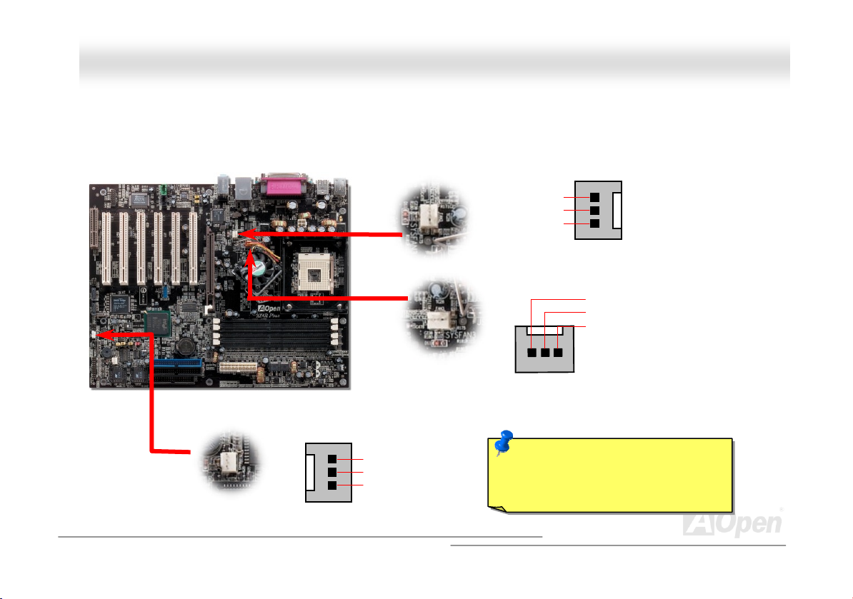
CCPPUU aanndd SSyysstteemm FFaann CCoonnnneeccttoorr ((wwiitthh HH//WW MMoonniittoorriinngg))
Plug in the CPU fan cable to the 3-pin CPUFAN1 connector. If you have chassis fan, you can also plug it on SYSFAN2 or
SYSFAN3 connector.
CPUFAN1 Connector
SENSOR
+12V
GND
SYSFAN3 Connector
SENSOR
+12V
GND
SYSFAN2 Connector
GND
+12V
SENSOR
Note: Some CPU fans do not have
sensor pin, so that cannot support
hardware monitoring function.
30
Page 31

AAXX44RR PPlluuss OOnnlliinnee MMaannuuaall
JJPP2288 KKeeyybbooaarrdd//MMoouussee WWaakkee--uupp EEnnaabbllee//DDiissaabbllee JJuummppeerr
This motherboard provides keyboard / mouse wake-up function. You can use JP28 to enable or disable this function, which
could resume your system from suspend mode with keyboard or mouse installed. The factory default setting is set to
“Disable”(1-2), and you may enable this function by setting the jumper to 2-3.
Pin 1
Disable
(Default)
JP28
KB/Mouse Wake-up
Enable
31
Page 32

AAXX44RR PPlluuss OOnnlliinnee MMaannuuaall
DDIIMMMM SSoocckkeettss
This motherboard has four 184-pin DDR DIMM sockets that al low you to install DDR266 or DDR200 m emory up to 4 GB.
Both ECC or Non-ECC DDR RAM are supported.
DIMM1
DIMM2
DIMM3
DIMM4
32
Page 33

AAXX44RR PPlluuss OOnnlliinnee MMaannuuaall
Each DIMM slot supports up to a maximum size of 1GB. Users can install either single- or double-sided modules to meet their
own needs. Please note that Channel A DIMMS (DIMM1 and DIMM3) can respectively work alone, but Channel B DIMMS
(DIMM2 and DIMM4) must work in pair with Channel A DIMMs. It is recommended that users have to install memory modules of
the same type and density on DDR DIMMs in pairs.
DIMM1 (Channel A ) DIMM2 (Channel B ) DIMM3 (Channel A ) DIMM4 (Channel B ) System Density
128MB~1GB 128MB~1GB
128MB~1GB 128MB~1GB
128MB~1GB ※ 128MB~1GB ※
128MB~1GB 128MB~1GB
128MB~1GB ※ 128MB~1GB ※
128MB~1GB
128MB~1GB ※ 128MB~1GB ※ 128MB~1GB ◎ 128MB~1GB ◎
※ ◎ Please install memory modules of the same density and same type on (DIMM1 and DIMM2) and (DIMM3 and DIMM4).
Please install on DIMM1 or DIMM3 if there is only one module.
256MB~2GB
128MB~1GB ◎ 128MB~1GB ◎
128MB~1GB
128MB~1GB ◎ 128MB~1GB ◎
256MB~2GB
256MB~2GB
256MB~2GB
256MB~2GB
512MB~4GB
33
Page 34

AAXX44RR PPlluuss OOnnlliinnee MMaannuuaall
HHooww ttoo IInnssttaallll MMeemmoorryy MMoodduulleess
Please follow the procedure as shown below to finish memory installation.
1. Make sure the DIMM module’s pin face down and match the socket’s size as depicted below.
2. Insert the module straight down to the DIMM slot with both hands and press down firmly until the DIMM module is securely
in place.
Ta b
40 pins 52 pins
Note: The tabs of the DIMM slot
will close-up to hold the DIMM in
place when the DIMM touches
the slot’s bottom.
34
Page 35

AAXX44RR PPlluuss OOnnlliinnee MMaannuuaall
3. Repeat step 2 to finish additional DIMM modules installation.
35
Page 36

e
A
A
AAXX44RR PPlluuss OOnnlliinnee MMaannuuaall
FFrroonntt PPaanneell CCoonnnneeccttoorr
Pin1
Attach the power LED, speaker, power and reset switch connectors to th
corresponding pins. If you enable “Suspend Mode” item in BIOS Setup, the ACPI
& Power LED will keep flashing while the system is in suspend mode.
Locate the power switch cable from your ATX housing. It is 2-pin female
connector from the housing front panel. Plug this connector to the soft-power
switch connector marked SPWR.
Suspend Type ACPI LED
Power on Suspend (S2) or Suspend to RAM (S3) Flashing for every second
Suspend to Disk (S4) The LED will be turned off
IDE LED
Speaker
1
SPWR
CPI & PWR
LED
CPILED_BLUE
Reset
SPEAKER
NC
NC
+5V
IDE LED
IDE LED
+5V
+5V
GND
NC
1
5VSB
SPWR
ACPI LED GND
ACPILED
NC
ACPILED _B
GND
RESET
GND
36
Page 37

AAXX44RR PPlluuss OOnnlliinnee MMaannuuaall
AATTXX PPoowweerr CCoonnnneeccttoorr
This motherboard comes with a 20-pin and 4-pin ATX power connector. Make sure you plug in the right direction. We strongly
recommend you to connect the 4-pin 12V ATX connector before connecting the 20-pin ATX power connector and use standard
power supply specially designed for Pentium 4 system.
Pin1
4-Pin 12V ATX Power Connector
20-Pin Power Connector
37
Page 38

AAXX44RR PPlluuss OOnnlliinnee MMaannuuaall
SSTTBBYY LLEEDD aanndd BBOOOOTT LLEEDD
Both STBY LED and BOOT LED are AOpen’s considerate designs that we aim at providing you friendly system information. The
STBY LED will light up when power is provided to the motherboard. This is a convenient indication for you to check the system
power status in many circumstances such as power on/off, stand-by mode and RAM power status during Suspend to RAM
mode
.
BOOT LED will keep blinking when you power the system on and when your system is under POST (Power-On Self Test)
POST diagnoses everything alright and finishes the booting, the LED will stay on otherwise it will remain flashing to warn you
that mistakes have occurred during POST.
Warning: Do not install or
remove the DIMM module or
others devices when the STBY
STBY_LED
. After
BOOT_ LED
38
Page 39

AAXX44RR PPlluuss OOnnlliinnee MMaannuuaall
AACC PPoowweerr AAuuttoo RReeccoovveerryy
A traditional ATX system should remain at power off stage when AC power resumes from power failure. This design is
inconvenient for a network server or workstation, without an UPS, that needs to keep power-on. This motherboard implements
an AC Power Auto Recovery function to solve this problem.
39
Page 40

AAXX44RR PPlluuss OOnnlliinnee MMaannuuaall
IIDDEE aanndd FFllooppppyy CCoonnnneeccttoorr
Connect 34-pin floppy cable and 40-pin IDE cable to floppy connector FDC and IDE connector. The blue connector is IDE1 for
clear identification. Be careful of the pin1 orientation. Wrong orientation may cause system damage.
Primary
Slave (2nd)
Pin 1
Secondary
Slave (4th)
ATA 33/66/100
IDE Connector
Pin 1
FDD Connector
Primary Master
(1st)
IDE 1 (Primary)
IDE 2 (Secondary)
Secondary
Master (3rd)
40
Page 41

y
33/66/100 is required
AAXX44RR PPlluuss OOnnlliinnee MMaannuuaall
IDE1 is also known as the primary channel and IDE2 as the secondary channel. Each channel supports two IDE devices that
make a total of four devices. In order to work together, the two devices on each channel must be set differently to Master and
Slave mode. Either one can be the hard disk or the CDROM. The setting as master or slave mode depends on the jumper on
your IDE device, so please refer to your hard disk and CDROM manual accordingly.
This motherboard supports ATA3 3
modes. The IDE bus is 16-bit, which means every transfer is two bytes.
Mode Clock Period Clock
PIO mode 0 30ns 20 600ns (1/600ns) x 2byte = 3.3MB/s
PIO mode 1 30ns 13 383ns (1/383ns) x 2byte = 5.2MB/s
PIO mode 2 30ns 8 240ns (1/240ns) x 2byte = 8.3MB/s
PIO mode 3 30ns 6 180ns (1/180ns) x 2byte = 11.1MB/s
PIO mode 4 30ns 4 120ns (1/120ns) x 2byte = 16.6MB/s
DMA mode 0 30ns 16 480ns (1/480ns) x 2byte = 4.16MB/s
DMA mode 1 30ns 5 150ns (1/150ns) x 2byte = 13.3MB/s
DMA mode 2 30ns 4 120ns (1/120ns) x 2byte = 16.6MB/s
ATA 33 30ns 4 120ns (1/120ns) x 2byte x2 = 33MB/s
ATA 66 30ns 2 60ns (1/60ns) x 2byte x2 = 66MB/s
ATA100 20ns 2 40ns (1/40ns) x 2byte x2 = 100MB/s
Warning: The specification of the IDE cable is a maximum of 46cm (18 inches);
make sure
our cable does not exceed this length.
, ATA 66 or ATA100 IDE devices. Following table lists the transfer rate of IDE PIO and DMA
Count
Cycle Time Data Transfer Rate
Tip:
1. For better signal quality,
it is recommended to set
the far end side device
to master mode and
follow the suggested
sequence to install your
new device. Please refer
to above diagram
2. To achieve the best
performance of Ultra
DMA 33/66/100 hard
disks, a special 80-wires
IDE cable for Ultra DMA
.
41
Page 42

AAXX44RR PPlluuss OOnnlliinnee MMaannuuaall
SSeerriiaall AATTAA SSuuppppoorrtteedd
This motherboard comes with a Silicon Image Serial ATA (Sil3112ACT144) controller, aiming to provide you an even faster
transfer rate of 150 Mbytes/second. The traditional parallel ATA specification has defined the standard storage interface for PCs
with its original speed of just 3 Mbytes/second since the protocol was introduced in the 1980s. And the latest generation of the
interface, Ultra ATA-133, has been developed further with a burst data transfer rate of 133 Mbytes/second. However, while ATA
has enjoyed an illustrious track record, the specification is now showing its age and imposes some serious design issues on
today’s developers, including a 5-volt signaling requirement, high pin count, and serious cabling headaches.
The Serial ATA specification is designed to overcome these design limitations while enabling the storage interface to scale with
the growing media rate demands of PC platforms. Serial ATA is to replace parallel ATA with the compatibility with existing
operating systems and drivers, adding performance headroom for years to come. It reduces voltage and pins count
requirements and can be implemented with thin and easy to route cables.
Serial ATA Controller
Serial ATA Connectors
42
Page 43

AAXX44RR PPlluuss OOnnlliinnee MMaannuuaall
CCoonnnneeccttiinngg SSeerriiaall AATTAA DDiisskk
To connect a Serial ATA disk, you have to have a 7-pin serial ATA cable. Connect two ends of the serial ATA cable to the serial
ATA header on the motherboard and the disk. Like every other traditional disk, you also have to connect a power cable. Please
be noted that it is a jumper free implement; you don’t need to set jumpers to define a master or slave disk. When connecting
two serial ATA disks, the system will automatically take the one connected to “Serial ATA 1” header as a master disk.
Comparison between Parallel ATA and Serial ATA
Bandwidth
Vol ts
Pins
Length Limitation
Cable
Ventila ti on
Peer-to-Peer
Parallel ATA Serial ATA
100/133 MB/Secs 150/300/600 MB/Secs
5V 250mV
40 7
18 inch (45.72cm) 1 meter (100cm)
Wide Thin
Bad Good
No Yes
43
Page 44

X
AAXX44RR PPlluuss OOnnlliinnee MMaannuuaall
IIrrDDAA CCoonnnneeccttoorr
The IrDA connector can be configured to support wireless infrared module, with this module and application software such as
Laplink or Windows 95 Direct Cable Connection, the user can transfer files to or from laptops, notebooks, PDA devices and
printers. This connector supports HPSIR (115.2Kbps, 2 meters) and ASK-IR (56Kbps).
Install the infrared module onto the IrDA connector and enable the infrared function from BIOS Setup, UART Mode, make sure
to have the correct orientation when you plug in the IrDA connector.
Pin 1
NC
+5V
IR_T
IIrrDDAA CCoonnnneeccttoorr
KEY
GND
IR_RX
44
Page 45

A
r
AAXX44RR PPlluuss OOnnlliinnee MMaannuuaall
SS//PPDDIIFF ((SSoonnyy//PPhhiilliippss DDiiggiittaall IInntteerrffaaccee)) CCoonnnneeccttoorr
S/PDIF (Sony/Philips Digital Interface) is a newest audio transfer file format, which provides impressive audio quality through
optical fiber and allows you to enjoy digital audio instead of analog audio. Normally there are two S/PDIF outputs as shown, one
for RCA connector, the most common one used for consumer audio products, and the other for optical connector with better
audio quality. Through a specific audio cable, you can connect the S/PDIF connector to other end of the S/PDIF audio module,
which bears S/PDIF digital output. However, you must have a S/PDIF supported speaker/amplifier/decoder with S/PDIF digital
input to connect to the S/PDIF digital output to make the most out of this function.
(RCA)
S/PDIF OUT
S/PDIF IN
S/PDIF OUT
S/PDIF IN
(Optical)
S/PDIF Module
(User Upgrade Optional)
S/PDIF Cable
Pin 1
udio cable
S/PDIF
Connecto
1
+5VSB
NC
S/PDIFOUT
GND
45
Page 46

AAXX44RR PPlluuss OOnnlliinnee MMaannuuaall
SSuuppeerr 55..11 CChhaannnneell AAuuddiioo EEffffeecctt
This motherboard comes with an ALC650 CODEC, which supports high quality of 5.1 Channel audio effect, bringing you a brand
new audio experience. On the strength of the innovative design of ALC650, you're able to use standard line-jacks for surround
audio output without connecting any external module. To apply this function, you have to install the audio driver in the Bonus
Pack CD as well as an audio application supporting 5.1 Channel. Picture bellow represents the standard location of all speakers
in 5.1 Channel sound track. Please connect the plug of your front speakers to the green “Speaker out” port, rear speakers’ plug
to the blue “Line in” port and both of the center and subwoofer speakers to the red “MIC in” port.
46
Page 47

AAXX44RR PPlluuss OOnnlliinnee MMaannuuaall
AAGGPP SSlloott
The AX4R Plus provides an AGP 8x slot. The AGP 8x is a bus interface targeted for high-performance 3D graphic. AGP
supports only memory read/write operation and single-master single-slave one-to-one only. AGP uses both rising and falling
edge of the 66MHz clock, for 4X AGP, the data transfer rate is 66MHz x 4bytes x 4 = 1056MB/s. AGP is now moving to AGP 8x
mode, which is 66MHz x 4bytes x 8 =2.1GB/s, This AGP expansion slot is for 1.5V-1.6V AGP card only.
47
Page 48

p
A
AAXX44RR PPlluuss OOnnlliinnee MMaannuuaall
AAGGPP PPrrootteeccttiioonn TTeecchhnnoollooggyy
With the outstanding R&D ability of AOpen and its specially developed circuit, AX4R Plus implements a brand new technology to
protect your motherboard from being damaged by over-voltaging of AGP card. When AGP Protection Technology is implemented,
this motherboard will automatically detect the voltage of AGP card and prevent your chipsets from being burnt out. Please note
that if you install an AGP card with 3.3V, which is not supported by Intel E7205 chipset, the AGP_LED will light up to warn you
the possible damage of the exceeding voltage. You may contact your AGP card vendor for further support.
GP_LED
Warning: It is strongly
recommended not to install
a 3.3V AGP card, which is
not supported by Intel
Granite chipset. When you
do so, the AGP_LED will
light up to warn you the
ossible damage.
48
Page 49

AAXX44RR PPlluuss OOnnlliinnee MMaannuuaall
WWOOMM ((ZZeerroo VVoollttaaggee WWaakkee oonn MMooddeemm)) CCoonnnneeccttoorr
This motherboard implements special circuit to support Wake On Modem, both Internal modem card and external box modem
are supported. Since Internal modem card consumes no power when system power is off, it is recommended to use an internal
modem. To use internal modem, connect 4-pin cable from RING connector of modem card to the WOM connector on the
motherboard.
WOM Connector
+5VSB
NC
RI-
GND
49
Page 50

AAXX44RR PPlluuss OOnnlliinnee MMaannuuaall
m
WWOOMM bbyy EExxtteerrnnaall BBOOXX MMooddeem
TTrraaddiittiioonnaall GGrreeeenn PPCC ssuussppeenndd mmooddee ddooeess nnoott rreeaallllyy ttuurrnn ooffff tthhee ssyysstteemm ppoowweerr ssuuppppllyy,, iitt uusseess eexxtteerrnnaall bbooxx mmooddeemm ttoo ttrriiggggeerr MMBB
CCOOMM ppoorrtt aanndd rreessuummee bbaacckk ttoo aaccttiivvee..
Note: This picture is for example only, it may not be exactly the same as this motherboard.
Pin 1
Pin 1
50
Serial Port
(Modem Side)
Serial Port
(Motherboard Side)
Page 51

AAXX44RR PPlluuss OOnnlliinnee MMaannuuaall
d
WWOOMM bbyy IInntteerrnnaall MMooddeemm CCaarrd
WWiitthh tthhee hheellpp ooff tthhee AATTXX ssoofftt ppoowweerr OOnn//OOffff,, iitt iiss ppoossssiibbllee ttoo hhaavvee aa ssyysstteemm ttoottaallllyy ppoowweerr ooffff,, aanndd wwaakkeeuupp ttoo aauuttoommaattiiccaallllyy aannsswweerr
aa pphhoonnee ccaallll aass aann aannsswweerriinngg mmaacchhiinnee oorr ttoo sseenndd//rreecceeiivvee aa ffaaxx.. YYoouu mmaayy iiddeennttiiffyy wwhheetthheerr oorr nnoott yyoouurr ssyysstteemm iiss iinn ttrruuee ppoowweerr ooffff
mmooddee bbyy cchheecckkiinngg ttoo sseeee iiff tthhee ffaann ooff yyoouurr ppoowweerr ssuuppppllyy iiss ooffff.. BBootthh aann eexxtteerrnnaall bbooxx mmooddeemm aanndd aann iinntteerrnnaall mmooddeemm ccaarrdd ccaann bbee
uusseedd ttoo ssuuppppoorrtt MMooddeemm WWaakkee UUpp,, bbuutt iiff yyoouu uussee aann eexxtteerrnnaall mmooddeemm,, yyoouu hhaavvee ttoo lleeaavvee yyoouurr bbooxx mmooddeemm oonn..
Note: This picture is for example only, it may not be exactly the same as this motherboard.
51
Page 52

AAXX44RR PPlluuss OOnnlliinnee MMaannuuaall
WWOOLL ((WWaakkee oonn LLAANN))
This feature is very similar as Wake On Modem, but it goes through local area network. To use Wake On LAN function, you must
have a network card with chipset that supports this feature, and connect a cable from LAN card to motherboard WOL connector.
The system identification information (probably IP address) is stored on network card and because there is a lot of traffic on the
Ethernet, you need to install network management software, such as ADM, for the checking of how to wake up the system. Note
that, at least 600mA ATX standby current is required to support the LAN card for this function.
WOL Connector
+5VSB
GND
LID
52
Page 53

AAXX44RR PPlluuss OOnnlliinnee MMaannuuaall
WOL Connector
(Motherboard Side)
Note: This picture is for example only, it may not exactly be the same motherboard.
(Ethernet Card Side)
WOL Connector
53
Page 54

AAXX44RR PPlluuss OOnnlliinnee MMaannuuaall
CCNNRR ((CCoommmmuunniiccaattiioonn aanndd NNeettwwoorrkk RRiisseerr)) EExxppaannssiioonn SSlloott
CNR is a riser card specification to replace the AMR (Audio/Modem Riser) that supports V.90 analog modem, multi-channel
audio, and phone-line based networking. Owing to CPU computing power getting stronger, the digital processing job can be
implemented in main chipset and share CPU power. The analogy conversion (CODEC
circuit design, which is put on CNR card. This motherboard implements sound CODEC on board, but reserves CNR slot for the
option of modem function. Note that you can still use PCI modem card. Please note that if you want to use CNR audio card on
CNR slot, you must disable the sound output of CODEC from BIOS to prevent the CODEC from making out noises at the same
time.
) circuit requires a different and separate
54
Page 55

AAXX44RR PPlluuss OOnnlliinnee MMaannuuaall
PPCC9999 CCoolloorr CCooddeedd BBaacckk PPaanneell
The onboard I/O devices are PS/2 Keyboard, PS/2 Mouse, COM1 and COM2, RJ45 LAN, PrinterUSB, and AC97 sound. The
view angle of drawing shown here is from the back panel of the housing.
PS/2 Keyboard: For standard keyboard, which is using a PS/2 plug.
PS/2 Mouse: For PC-Mouse, which is using a PS/2 plug.
USB Port: Available for connecting USB devices.
Parallel Port: To connect with SPP/ECP/EPP printer.
COM1/COM2 Port: To connect with pointing devices, modem or others serial devices.
Speaker Out: To External Speaker, Earphone or Amplifier.
Line-In: Comes from the signal sources, such as CD/Tape player.
MIC-In: From Microphone.
PS/2 Mouse
Connector
PS/2 Keyboard
Connector
USB2.0
Connector
COM 1 Port COM2 Port
SPP/EPP/ECP
Parallel Port
RJ45 10/100
LAN Jack
USB2.0
Connector
Line-In
Speaker Out
MIC-In
55
Page 56

AAXX44RR PPlluuss OOnnlliinnee MMaannuuaall
SSuuppppoorrtt 1100//110000 MMbbppss LLAANN oonnbbooaarrdd
The South Bridge ICH4 includes a fast Ethernet controller on chip. On the strength of Realtek 8100BL LAN controller on
board, which is a highly-integrated Platform LAN Connect device, it provides 10/100M bps Ethernet for office and home use,
the Ethernet RJ45 connector is located on top of USB connectors. The green LED indicates the link mode, it lights when
linking to network and blinking when transferring data. The orange LED indicates the transfer mode, and it lights when data
is transferring in 100Mbps mode. To enable or disable this function, you may simply adjust it through BIOS.
Green/ACT
Orange/Speed
56
Page 57

AAXX44RR PPlluuss OOnnlliinnee MMaannuuaall
SSuuppppoorrtt SSiixx UUSSBB22..00 CCoonnnneeccttoorrss
Compared to traditional USB 1.0/1.1 with the speed of 12Mbps, USB 2.0 has a fancy speed up to 480Mbps, which is 40 times
faster than the traditional one. Except for the speed increase, USB 2.0 supports old USB 1.0/1.1 software and peripherals,
offering impressive and even better compatibility to customers. On this motherboard, all six USB connectors support USB 2.0
function. To connect those two headers, you have to use proper USB cables and connect them to any USB models.
Pin 1
USBPWR0
USB_FP_P0-
USB_FP_P0+
GND
KEY
1 2
USBPWR0
USB_FP_P1USB_FP_P1+
GND
USB_FP_OC0
9 10
57
Page 58

1
AAXX44RR PPlluuss OOnnlliinnee MMaannuuaall
CChhaassssiiss IInnttrruussiioonn CCoonnnneeccttoorr
The “CASE OPEN” header provides chassis intrusion-monitoring function. To make this function works, you have to enable it in
the system BIOS, connect this header to a sensor somewhere on the chassis. So, whenever the sensor is triggered by lights or
the opening of the chassis, the system will send out beep sound to inform you. Please be informed that this useful function only
applies to advanced chassis, you may purchase an extra sensor, attach it on your chassis, and make a good use of this
function.
SENSOR
GND
Chassis Intrusion
Connector
58
Page 59

AAXX44RR PPlluuss OOnnlliinnee MMaannuuaall
CCDD AAuuddiioo CCoonnnneeccttoorr
This connector is used to connect CD Audio cable from CDROM or DVD drive to onboard sound.
CCDD--IINN CCoonnnneeccttoorr
L
GND
GND
R
59
Page 60

A
AAXX44RR PPlluuss OOnnlliinnee MMaannuuaall
AAUUXX--IINN CCoonnnneeccttoorr
This connector is used to connect MPEG Audio cable from MPEG card to onboard sound.
UUXX--IINN CCoonnnneeccttoorr
A
L
GND
GND
R
60
Page 61

g
A
A
A
A
AAXX44RR PPlluuss OOnnlliinnee MMaannuuaall
FFrroonntt AAuuddiioo CCoonnnneeccttoorr
If the housing has been designed with an audio port on the front panel, you’ll be able to connect onboard audio to front panel
through this connector. By the way, please remove 5-6 and 9-10 jumper caps from the Front Audio Connector before
connecting the cable. Please do not remove these 5-6 and 9-10 yellow jumper caps if there’s no audio port on the front
panel.
Pin 1
AUD_MIC
AUD_MIC_BIAS
AUD_FPOUT_R
NC
AUD_FROUT_L
1 2
UD_GND
UD_VCC
UD_RET_R
KEY
UD_RET_L
9 10
Note: Please remove the jumper cap from the Front Panel Audio Connector
before you connect the cable. Do not remove this yellow jumper cap if
housin
without an audio port on the front panel.
61
Page 62

AAXX44RR PPlluuss OOnnlliinnee MMaannuuaall
DDrr.. LLEEDD CCoonnnneeccttoorr
In conjunction with Dr. LED (Upgrade Optional), which can easily shows what kind of problems may occur on your system during
assembly. It can clearly indicate whether there is a component issue or an installed issue by the 8 LEDs on the front panel of Dr.
LED. This can helps you to have a self-diagnostic to your system status quickly.
Pin 1
3.3V
KEY
GND
1 2
S1
S2
S3
5 6
62
Page 63

AAXX44RR PPlluuss OOnnlliinnee MMaannuuaall
Dr. LED is a CD disc storage box with 8 LEDs on its front panel, the size of Dr. LED is exactly the same as 5.25 in floppy drive,
so that it can be mount into normal 5.25 in drive bay of any housing.
The total 8 LEDs light up alternatively if the system fails in one of eight stages. Once the LED7 (latest LED) is lit, this indicates
that the system has completed its boot-up procedure.
The 8 LEDs indicate the following messages when lit:
LED 0 - Indicates that the CPU may have been installed incorrectly or is damaged.
LED 1 - Indicates that the memory may have been installed incorrectly or is damaged.
LED 2 - Indicates that the AGP may have been installed incorrectly or is damaged.
LED 3 - Indicates that the PCI card may have been installed incorrectly or is damaged.
LED 4 - Indicates that the floppy disk drive may have been installed incorrectly or is damaged.
LED 5 - Indicates that the HDD may have been installed incorrectly or is damaged.
LED 6 - Indicates that the keyboard may have been installed incorrectly or is damaged.
LED 7 - Indicates that the system is OK.
7654 3210
Boot O.K. KB HDD Floppy CPUVideo MemoryPCI
Note: During POST (Power On Self Test) procedure, the
Debug LED will light on sequentially from LED0 to LED7 until
the system boot O.K
63
Page 64

AAXX44RR PPlluuss OOnnlliinnee MMaannuuaall
JJPP22 SSppeeaakkeerr EEnnaabbllee//DDiissaabbllee JJuummppeerrss
This motherboard comes with another considerate option that allows you to turn off the voice from speaker. You can choose not
to be bothered by the warning made from Dr. Voice when it detects any error in operating system. To disable this function, set
JP2 to pin 2-3 to stop both the speaker from sending out voices. The language selections of Dr.Voice can be adjusted in BIOS.
1
Enable
(Default)
1
Disable
Pin1
64
Page 65

A
f
AAXX44RR PPlluuss OOnnlliinnee MMaannuuaall
Auto Switch
RTC
CMOS
BatteryATX Stand-by Power
uto switching to ATX standby power as
long as AC power line is plugged. This
smart design increases battery life i
you still plug battery on motherboard.
Backup by EEPROM
BBaatttteerryy--lleessss aanndd LLoonngg LLiiffee DDeessiiggnn
This Motherboard implements Flash ROM and a special circuit that allows you to save your current CPU and CMOS Setup
configurations without the need of a battery. The RTC (real time clock) can also keep running as long as the power cord is
plugged. If you lose your CMOS data by accident, you can just reload the CMOS configurations from Flash ROM and the system
will recover as usual.
Flash
ROM
(Real Time Clock)
00:00:00
65
Page 66

A
AAXX44RR PPlluuss OOnnlliinnee MMaannuuaall
CCPPUU OOvveerr--ccuurrrreenntt PPrrootteeccttiioonn
Over Current Protection has been popularly implemented on ATX 3.3V/5V/12V switching power supply for a while. However,
new generation CPU is able to use regulator of different voltages to transfer 12V to CPU voltage (for example, to 2.0V). This
motherboard is with switching regulator onboard that supports CPU over-current protection, and it applies to 3.3V/5V/12V power
supply for providing full line over-current protection.
TX Switching Power Supply
Note: Although we have implemented protection circuit try to prevent any human operating
mistake, there is still certain risk that CPU, memory, HDD, add-on cards installed on this
motherboard may be damaged because of component failure, human operating error or unknown
nature reason. AOpen cannot guaranty the protection circuit will always work perfectly.
5V (Protected by power supply)
3.3V (Protected by power supply)
12V (Protected by power supply)
Onboard Power
Regulator
66
Over-Current
Protection
Circuit
CPU Core
Vol tag e
Page 67

r
AAXX44RR PPlluuss OOnnlliinnee MMaannuuaall
AAOOCCoonnffiigg UUttiilliittyy
AOpen always dedicated to provide users a much friendlier computer environment. We now bring you a comprehensive system
detective utility. AOconfig is a Windows based utility with user-friendly interface that allows users to obtain information of the
operation system and hardware such as motherboard, CPU, memory, PCI devices and IDE devices. The powerful utility also
displays the version of BIOS and firmware for your convenience of maintenance.
Moreover, AOconfig allows users to save information in *.BMP or *.TXT format which users may collect the system information
in detail and send them to AOpen directly for technical support or further diagnosis of system problem.
1. The system page shows the
detail information of the
motherboard, the operating
system, the processor, and
BIOS version.
2. The PCI device page shows
the configurations of all PCI
devices installed on you
motherboard.
67
Page 68

AAXX44RR PPlluuss OOnnlliinnee MMaannuuaall
3. This page presents the IDE
devices information, such as
the serial number, the
manufacturer, the firmware
version, and capacity.
4. From this page, users may
obtain the technical support
information of AOpen.
Moreover, detailed information
could be saved in .bmp or .txt
format.
NOTE: AOconfig can be used in Windows 98SE/ME, NT4.0/2000, or even the latest Windows XP. Please be
informed that AOconfig can only be operated in a system equipped with an AOpen motherboard. Meanwhile, all
applications must be closed before starting AOconfig.
68
Page 69

AAXX44RR PPlluuss OOnnlliinnee MMaannuuaall
DDiiee--HHaarrdd BBIIOOSS aanndd JJPP3300 DDiiee--HHaarrdd BBIIOOSS SSeelleecctt JJuummppeerr
Many viruses have been found that may destroy bios code and data area lately. This motherboard implements a very effective
hardware protection method without any software or BIOS coding involved, therefore it is 100% virus free. You may restore the
originally mounted BIOS with 2nd BIOS ROM by setting JP30 to pin 2-3 if it fails to act normally. This motherboard comes with
one BIOS ROM, you may contact our local distributors or resellers for purchasing an extra BIOS ROM. Please visit our website:
www.aopen.com for details.
1
normal
1
rescue
BIOS1
Pin1
JP30 Die-Hard BIOS
Select Jumper
BIOS2
69
Page 70

AAXX44RR PPlluuss OOnnlliinnee MMaannuuaall
EExxtteerrnnaall CCoonnttrroolllleerr ffoorr DDIIEE--HHAARRDD BBIIOOSS ((UUsseerr UUppggrraaddee OOppttiioonnaall))
External Controller provides you a better and convenience way to switch the BIOS status between “Rescue” and “Normal”
without opening the case of your computer. You have to plug the jumper cable to the connector pin (JP30) on the motherboard.
Be careful of the orientation when you connect, the red wire should correspond to Pin1.
Normal
To / From CPU
Read Only
Read/Write
Rescue ROM
Manual Switch
Flash ROM
70
Page 71

p
AAXX44RR PPlluuss OOnnlliinnee MMaannuuaall
Note: If you suspect your BIOS is infected by virus, just rescue your bios by following steps:
1. Turn off the system, set the External Controller to “Rescue” to read from rescue ROM.
2. Boot the system and set the switch back to “Normal”.
3. Follow the BIOS upgrade procedure to rehabilitate BIOS.
Reboot the system, and you should be able to go back to normal mode.
Normal
(Read from normal
Flash ROM)
Tip: If you place the switch to the middle
rd
picture shows), you will not be
(as 3
able to boot your system, thus you can
rotect your data from molesting.
Rescue
(Read from
Rescue ROM)
Lock
(Lock your computer
to protect your data)
71
Page 72

AAXX44RR PPlluuss OOnnlliinnee MMaannuuaall
0
3333000
The quality of low ESR capacitor (Low Equivalent Series Resistance) during high frequency operation is very important for the
stability of CPU power. The idea of where to put these capacitors is another know-how that requires experience and detail
calculation.
Not only that, AX4R Plus implements 3300μF capacitors, which is much larger than normal capacitor (1000 and 1500μf ) and it
provides better stability for CPU power.
μμμμ
μμμμ
FF LLooww EESSRR CCaappaacciittoorr
72
Page 73

AAXX44RR PPlluuss OOnnlliinnee MMaannuuaall
LLaayyoouutt ((FFrreeqquueennccyy IIssoollaattiioonn WWaallll))
Note: This diagram for example only, it may not be exactly the same as this motherboard.
For high frequency operation, especially overclocking,
layout is the most important factor to make sure
chipset and CPU working in stable condition. The
layout of this motherboard implements AOpen’s
unique design called “ Frequency Isolation Wall”.
Separating each critical portion of motherboard into
regions where each region operates in a same or
similar frequency range to avoid cross talk and
frequency interference between each region’s
operations and condition. The trace length and route
must be calculated carefully. For example, the clock
trace must be equal length (not necessarily as short
as possible) so that clock skew will be controlled
within few a pico second (1/10
12
Sec)
73
Page 74

AAXX44RR PPlluuss OOnnlliinnee MMaannuuaall
FFaannssiinnkk oonn NNoorrtthh BBrriiddggee
In order to provide a better effect of cooling and make the chipset work more stable, we especially design a fansink on the north
bridge. After locating the fansink on the north bridge, plug the connector to the header marked SYSFAN3 on the motherboard.
74
Page 75

AAXX44RR PPlluuss OOnnlliinnee MMaannuuaall
TThhee nnooiissee iiss ggoonnee!!!! -------- SSiilleennttTTeekk
As the clock of CPU keeps rocketing higher and higher, it inevitably brings higher heat and
system temperature in a relative way. The way we deal with this heat problem, however, is to
spare no effort to add one fan after another to protect our pampered system, expecting these
fans could cool down our machine as much as it could.
But at the same time, we believe that same amount of users are affected terribly while working with their PC by the irritating
noises of these fans. As a matter of fact, we do not have to get our fans running at such a high speed in most cases; on the
contrary, we discovered that having your fans
running at appropriate time and speed could not
only reduce the noise, but also consume the least
power the system needed, so as to prevent
over-wasting of energy resource.
Today, AOpen Motherboard is honored to bring you
a new overall solution, SilentTek, to have your
system quiet. To collocate with hardware circuit,
BIOS and the utility under Windows, SilentTek
combined “Hardware-Status Monitoring”, “Overheat
Warning” and “Fan Speed Control” with
user-friendly interfaces to provide you a perfect
balance between noises, system performance and
stability.
75
Page 76

r
r
r
AAXX44RR PPlluuss OOnnlliinnee MMaannuuaall
The first image you have here is the Voltage Status
page. You can find current status of all voltages and set
your expected margins of warning level.
You may check you
system voltage from the
indicating bar here.
In “Temp/Fan/Case” page, you may get aware of the
current temperature of CPU and the heat inside chassis,
plus checking if fans are running properly.
Of course, you may set you
defaulted lowest margin fo
your fans and the SilentTek
would also pop up a message
box and alarm you when the
fan is rotating slower than this
specified speed.
You may set the highest
margin of your CPU and
system temperature as
default, and SilentTek would
pop up a message box and
alert you with alarm when the
temperature goes beyond the
specified margin.
76
Page 77

AAXX44RR PPlluuss OOnnlliinnee MMaannuuaall
The following page is sure to be the most important part of this utility, you may control the rotation speed of specific fans you got
with options inside in this page. Respectively illustrate as follow:
1. Smart FAN Control: This is the default setting of
SilentTek and can be used for any branded computer
housing. With a special algorithm developed by
AOpen, the fan speed is automatically adjusted by
the factors of CPU and ambient temperature.
Ease-of-use and trouble free at your service.
2. Fixed FAN Control: Under this setting, a desired fan
speed is set fixed when operating.
3. Multiple Level Control: This is the most versatile
setting that allows you to set fan speed in relation to
temperature. You may find this setting fits youbest.
4. AOpen Recommend Setting: This setting is
designed specifically for AOpen housing. A series of
lab tests were conducted under the real world
scenario to determine optimum fan speed to reduce
noise level within CPU working condition and
temperature. Most of the time, the fan would remain
still when CPU is not fully utilized.
77
Page 78

AAXX44RR PPlluuss OOnnlliinnee MMaannuuaall
VViivviidd BBIIOOSS tteecchhnnoollooggyy
Have you been fed up with the conservative and immutable POST screen? Let’s rule out the
tradition idea that POST screen are stiff and frigid, and let AOpen show you the newly
developed VividBIOS to experience the lively vivid colorful POST screen!
Unlike earlier graphic POST screen which could occupy the whole screen and mask text information during POST, AOpen
VividBIOS deals with graphics and texts separately, and makes them running simultaneously during POST. With this innovative
design, VividBios now brings you a beautiful and sleek 256 colors screen without missing any important information shown on
POST screen.
In addition, the limited space of BIOS ROM is another big issue. When all of the traditional BIOS can only show
space-consuming and uncompressed Bitmap, AOpen has considerately tuned the BIOS to next generation, to recognize the
smaller-sized GIF format and even dynamic-showing GIF animation.
Vivid BIOS shares the same fundamental technology with Open JukeBox CD Player, you may use the same EzSkin utility to
change your Vivid BIOS screen or to download your favorite Open JukeBox skin. If you see this little logo
your model name on the BIOS download page, http://english.aopen.com.tw/tech/download/skin
motherboard supports this innovative feature!
shown beside
, it is assured that your
78
Page 79

AAXX44RR PPlluuss OOnnlliinnee MMaannuuaall
OOppeenn JJuukkeeBBooxx PPllaayyeerr
Here we are pleased to provide you a brand-new powerful interface—Open JukeBox. Without
any cost you can have your PC turn into a fashionable CD player! This latest Open JukeBox
motherboard aims at helping you directly operate your CD player on the PC without any hassle of entering Windows operation
system.
79
Page 80

l
A
N
y
play
AAXX44RR PPlluuss OOnnlliinnee MMaannuuaall
How Your Open JukeBox Works
The operation of Open JukeBox Player is the same as other CD players. By pressing specific keys on the keyboard you will find
playing Open JukeBox Player couldn’t be easier than the traditional CD Players. Below is the function description of respective
buttons.
Power-Off Button
Operation S
Boot to
Power: Pressing O
Boot: Pressing B
Play: Pressing A
Stop: Pressing S
Pause: Pressing P
Eject: Pressing E
Repeat: Like other CD Players, pressing R
Volume +/-: Pressing + or – to adjust the volume of playing music.
stem
, to directly power off your computer with no hassle of entering Windows Operation System.
, to intelligently boot to Windows Operation System for you.
, to start playing CD music.
, to stop the music playing.
, to pause the music playing temporarily.
, to eject CD tray for you to change CD disc.
, to shift the repeat mode.
Rewind/Forward / : Pressing arrow keys, to rewind or forward the music.
80
Note: Though some of the latest
version of Windows support “Digita
udio” through IDE bus. However, in
order to use Open Jukebox player,
which is driven under BIOS, it is a
MUST to insert audio cable to CD-I
connector on the motherboard.
Dis
Function Key
Screen
Page 81

AAXX44RR PPlluuss OOnnlliinnee MMaannuuaall
Your Open JukeBox Settings in BIOS
There are three Open JukeBox settings in BIOS as follows.
Auto
: The default setting is “Auto” with which the Open JukeBox will automatically check the CD player every time you power
on. The Open JukeBox will automatically be launched when it detects a music CD in your CD player.
Press Insert Key
you of pressing “Ins” key on your keyboard to start Open JukeBox Player; otherwise the system will launch the Windows
Operation System.
CD Player
pressing B on your keyboard the Windows Operation System will be launched.
: Choosing this setting will allow a reminder message popped up on the screen during BIOS POST. It reminds
: Choosing this setting allows the system to launch Open JukeBox Player every time you power on. However, by
81
Page 82

AAXX44RR PPlluuss OOnnlliinnee MMaannuuaall
Your Open JukeBox EzSkin
Except these powerful functions above, Open JukeBox Player is also equipped with another fancy feature for you to
change its “skin”. You can download as many skins as you want from AOpen Website, and changing them whenever
you want by using this useful utility – EzSkin – which may also be downloaded from our website.
Even more, you may design your own skins with innovative idea and sharing them to users around the world by uploading to our
website. For further technical information, we welcome you to visit our website at
http://english.aopen.com.tw/tech/download/skin
.
82
Page 83

AAXX44RR PPlluuss OOnnlliinnee MMaannuuaall
DDrriivveerr aanndd UUttiilliittyy
There are motherboard drivers and utilities included in AOpen Bonus CD disc. You don’t need to install all of them in order to
boot your system. But after you finish the hardware installation, you have to install your operation system first (such as Windows
98) before you can install any drivers or utilities. on system’s installation guide.
Note: Please follow recommended procedure
to install Windows 2000 and Windows 98
.
83
Page 84

AAXX44RR PPlluuss OOnnlliinnee MMaannuuaall
AAuuttoo--rruunn MMeennuu ffrroomm BBoonnuuss CCDD DDiisscc
You can use the auto-run menu of Bonus CD disc. Choose the utility and driver and select model name.
84
Page 85

AAXX44RR PPlluuss OOnnlliinnee MMaannuuaall
IInnssttaalllliinngg IInntteell®® CChhiippsseett SSooffttwwaarree IInnssttaallllaattiioonn UUttiilliittyy
You can install the Intel INF Update Utility from the Bonus Pack CD auto-run menu to eliminate the “?” marks.
85
Page 86

AAXX44RR PPlluuss OOnnlliinnee MMaannuuaall
IInnssttaalllliinngg IInntteell IIAAAA DDrriivveerr
You can install Intel IAA Driver to increase the performance of software applications and reduce PC boot times. You can find it in
the AOpen Bonus Pack
CD disc.
86
Page 87

AAXX44RR PPlluuss OOnnlliinnee MMaannuuaall
IInnssttaalllliinngg OOnnbbooaarrdd SSoouunndd DDrriivveerr
This motherboard comes with AC97 CODEC. You can find the audio driver from the Bonus Pack CD disc auto-run menu.
87
Page 88

I
AAXX44RR PPlluuss OOnnlliinnee MMaannuuaall
IInnssttaalllliinngg LLAANN DDrriivveerr
ntroduction:
------------This document describes the procedure to install Windows 95 (Golden version), Win95A, OSR2, Windows 98/98 SE,
Windows 2000, Windows ME, Windows NT v4.0 driver for Realtek RTL8139 PCI Fast Ethernet adapter.
[Windows 95 (Golden version), Win95A and OSR2]
Installing driver procedure on Microsoft Windows 95 :
-----------------------------------------------------
1. Ask you to select which driver you want to install, select "Driver from disk provided by hardware manufacturer".
2. Specify the setup file pathname
[CD-ROM]:Driver\LAN\RTL8100\Windows\Win95\WIN95A (for Windows 95 and Win95A) or
[CD-ROM]:Driver\LAN\RTL8100\Windows\Win95 (for Windows 95 OSR2).
3. Windows 95 will appear some messages to insert Windows 95 systemdisk to complete setup step.
4. Windows 95 will finish the other installation procedure automatically, then you restart the system.
[Windows 98, Windows 98 SE, Windows2000, Windows ME, Windows XP]
Installing driver for Win98/Win98 SE/Windows2000/Windows ME/Windows XP :
-------------------------------------------------------------------
1. Ask you to select which driver you want to install, select "Driver from disk provided by hardware manufacturer".
2. Specify the setup file pathname
[CD-ROM]:Driver\LAN\RTL8100\Windows\WIN98 (for Windows 98/98 SE) or
[CD-ROM]:Driver\LAN\RTL8100\Windows\WIN2000 (for Windows 2000) or
[CD-ROM]:Driver\LAN\RTL8100\Windows\WINME (for Windows ME) or
[CD-ROM]:Driver\LAN\RTL8100\Windows\WinXP (for Windows XP)
3. Win98/Win98 SE/Windows2000/Windows ME will appear some messages to insert Win98/Win98
SE/Windows2000/Windows ME system disk tocomplete setup step.
4. Win98/Win98 SE/Windows2000/Windows ME will finish the other installation procedure automatically, then you restart
the system.
88
Page 89

[Wind
0]
AAXX44RR PPlluuss OOnnlliinnee MMaannuuaall
ows NT 3.5, 3.51 & 4.
Installing driver procedure on Microsoft Windows NT :
----------------------------------------------------When you are in Windows NT :
1. In the Main group of NT, select the "Control Panel" icon.
2. In the Control Panel window, choose the "Network" icon.
3. In the Network Settings dialog box, choose the "Add Adapter" button.
The Add Network Adapter dialog box appears.
4. In the list of network cards, select "<other> Requires disk from manufacturer", and then press <Enter> button.
5. Enter drive and pathname
[CD-ROM]:\Driver\LAN\RTL8100\Windows\WinNT4 (for NT 4.0) which is the path where thesetup file OEMSETUP.INF is
located, and then choose the OK button.
6. The screen will appear "Select Line Speed" dialog box which is provide by RTL8139.SYS driver. The default value is
"auto" so that the RTL8139 PCI Fast Ethernet adapter and its driver RTL8139.SYS will auto-detect the line speed, 10 Mb or
100Mb, while the RTL8139.SYS is loading. The other values, "10" or "100", are only used when you want to forced RTL8139
PCI Fast Ethernet adapter to 10Mb or 100Mb.
7. The screen will appear "Input EthernetID" dialog box which is provide by RTL8139.SYS driver. This option is only required
when you have more than one Realtek RTL8139 PCI Fast Ethernet adapters on this computer. Select "SKIP" if only one
adapter is installed on this computer.
8. "Bus Location" display in next screen. Your machine contains more than one hardware bus, please select the Bus Type
and Bus number on which your network adapter card is installed.
9. NT will then perform the binding process. If any additional network software options were installed, you may be rompted
for specific information for these packages.
10. Restarting your system you will acquire network service.
NOTES:
-----* Installing Multiple LAN Adapters:
Enter Windows NT and follow above setup procedure step 2,in the "Network Settings" dialog box, choose the "Configure.."
button. The "Input Ethernet ID" dialog box appears and input adapter's Ethernet ID. Last step to select OK and close
NETWORK SETUP. Select SKIP if only one adapter is installed on this computer.
89
Page 90

A
AAXX44RR PPlluuss OOnnlliinnee MMaannuuaall
IInnssttaalllliinngg UUSSBB22..00 DDrriivveerr
* Windows 2000 Installation Guide
*************************************************
Installing Driver in Existing Windows 2000 System
*************************************************
fter enabling the USB 2.0 controller and rebooting your system, Windows 2000 setup will
show a "New Hardware Found" dialog box. Under Windows 2000, "Universal Serial Bus (USB)
Controller" will be displayed.
1. Choose "Search for a suitable driver for my device (Recommended)". from the list, and
then press "Enter".
2. Choose "Specify a location." and then press "Next"
3. Insert the Bonus CD in CD-ROM.
4. Type "[CD-ROM]:\Driver\Intel\USB2.0" in the text box that appears. Press " OK ".
5. Click on "Next." A message informing you that Windows has found "Intel (R) USB Enhanced
Host Controller (ICH4)" should appear.
6. Click on "Next," and then on "Finish."
************************************
Confirming Windows 2000 Installation
************************************
1. From Windows 2000, open the Control Panel from "My Computer" followed by the System icon.
2. Choose the "Hardware" tab, and then click the "Device Manager" tab.
3. Click the "+" in front of "Universal Serial Bus controllers". "Intel (R) USB Enhanced
Host Controller (ICH4)" should appear.
90
Page 91

A
AAXX44RR PPlluuss OOnnlliinnee MMaannuuaall
* Windows XP Installation Guide
***********************************************
Installing Driver in Existing Windows XP System
***********************************************
fter enabling the USB 2.0, Windows XP setup will show a "Found New Hardware" dialog box.
Under Windows XP, "Universal Serial Bus (USB) Controller" will be displayed.
1. Click on "Next," and from the generated list box, choose "Install from a list or special
location (Advanced)", click "Next"
2. Click on "Next," and from the generated choices, choose "Include this location in the
search:"
3. Insert the Bonus CD in CD-ROM.
4. Type "[CD-ROM]:\Driver\Intel\USB2.0" in the text box that appears.
5. Click on "Next." A message informing you that Windows XP has found "Intel (R) USB
Enhanced Host Controller (ICH4)" should appear.
6. When the New Hardware Wizard has finished installing the USB driver, click on "Finish"
**********************************
Confirming Windows XP Installation
**********************************
1. From Windows XP, open the Control Panel from "My Computer".
2. Click on "Performance and maintenance".
3. Click on the "System" icon.
4. Choose the "Hardware" tab, and then click the "Device Manager" tab.
5. Click the "+" in front of "Universal Serial Bus Controllers". "Intel (R) USB Enhanced
Host Controller (ICH4)" should appear.
91
Page 92

AAXX44RR PPlluuss OOnnlliinnee MMaannuuaall
PPHHOOEENNIIXX--AAWWAARRDD BBIIOOSS
System parameters can be modified by going into BIOS Setup menu, this menu allows you to configure the system parameters
and save the configuration into the 128 bytes CMOS area, (normally in the RTC chip or in the main chipset).
The Phoenix-AwardBIOS™ that installed in the Flash ROM
The BIOS provides critical low-level support for standard devices such as hard disk drives, serial and parallel ports.
Most BIOS setting had been optimized by AOpen’s R&D engineering team. But, the default setting of BIOS still can’t fine-tune
the chipset controlling entire system. Hence, the rest of this chapter is intended to guide you through the process of configuring
your system using setup.
Currently there are two kinds of beep sound when system fails to boot at POST. The first type of beep sound consists of a single
long beep and two short beeps, indicating a video error has failed BIOS from initializing video screen for displaying any
additional information. The 2
occurred. You may look over the indicated error according to different beep significances.
To enter to BIOS setup menu
nd
type of beep sound is a single long beep that beeping repeatedly, signaling a DRAM error has
, press <Del> when POST (Power-On Self Test) screen is shown on your monitor.
Note: Because the BIOS code is the most often
changed part of the motherboard design, the BIOS
information contained in this manual may be
different with actual BIOS that come with your
motherboard.
of the motherboard is a custom version of an industry standard BIOS.
92
Page 93

AAXX44RR PPlluuss OOnnlliinnee MMaannuuaall
AAbboouutt BBIIOOSS FFuunnccttiioonn DDeessccrriippttiioonn……
AOpen always dedicates to give users a friendlier computer system. Now, we include all function descriptions of BIOS setup
program into the BIOS Flash ROM. When you select one function of BIOS setup program, the function description will appeared
at right side of screen. Hence, you don’t need read this manual while you changing the BIOS setting.
Menu Items Select Window Item Function Description Window
93
Page 94

AAXX44RR PPlluuss OOnnlliinnee MMaannuuaall
HHooww TToo UUssee PPhhooeenniixx--AAwwaarrdd™™ BBIIOOSS SSeettuupp PPrrooggrraamm
Generally, you can use the arrow keys to highlight items that you want to choose, then press <Enter> key to select, and use the
<Page Up> and <Page Down> key to change setting value. You also can press <F1> key for help and press <Esc> key to quit
Phoenix-Award™ BIOS setup program. The following table provides details about how to use keyboard in the Phoenix-Award™
BIOS setup program. By the way, all products of AOpen also provides a special function in the BIOS setup, you can press <F3>
key selecting preferred menu language to display
Key Description
Page Up or + Changing setting to next value or increase the value.
Page Down or - Changing setting to previous value or decrease value.
Enter Select the item.
Esc 1. In main menu: Quit and don’t save any change.
2. In sub menu: Exit current menu to main menu.
Up Arrow Highlight previous item.
Down Arrow Highlight next item.
Left Arrow Move the light bar to left side of menu.
Right Arrow Move the light bar to right side of menu.
F1 Get menu or item help description.
F3 Changing menu language.
F5 Load previous setting value from CMOS.
94
Page 95

AAXX44RR PPlluuss OOnnlliinnee MMaannuuaall
Key Description
F6 Load Setup Default setting value from CMOS.
F7 Load turbo setting value from CMOS.
F10 Save changed setting and exit setup program.
95
Page 96

AAXX44RR PPlluuss OOnnlliinnee MMaannuuaall
HHooww TToo EEnntteerr BBIIOOSS SSeettuupp
After you finish the setting of jumpers and connect correct cables. Power on and enter the BIOS Setup, press <Del> during
POST (Power-On Self Test). Choose "Load Setup Defaults" for recommended optimal performance.
Del
Warning: Please avoid of using "Load Turbo Defaults", unless
you are sure your system components (CPU, DRAM, HDD, etc.)
are good enough for turbo setting.
96
Page 97

AAXX44RR PPlluuss OOnnlliinnee MMaannuuaall
BBIIOOSS UUppggrraaddee uunnddeerr WWiinnddoowwss eennvviirroonnmmeenntt
With outstanding R&D ability of AOpen, we now bring you a whole new BIOS Flash
wizard ---- EZWinFlash. With an eye to users convenience, EZWinFlash combines the
BIOS binary code and flash module together, so the only thing you have to do is just
clicking on the utility you downloaded from web and let it helps you complete the flash process automatically. EZWinFlash
detects your motherboard and checks the BIOS version cleverly to prevent your system from any possible failure. Moreover,
EZWinFlash has been taken into consideration to go with any windows platform you might be using, no matter if you’re using
Windows 95/98, 98SE/ME, NT4.0/2000, or even the latest Windows XP.
In the meanwhile, in order to provide a much more user-friendly operating environment, AOpen EZWinFlash is natively designed
to have multi-language function to provide easier way for users’ usage in changing BIOS setting.
Note: The model name on this BIOS picture is for reference only. It may not be the exact model name.
Caution: By updating your motherboard, you are
taking a risk of BIOS flash failure. If your
motherboard is working stable, and there are no
major bugs that had been fixed by a latter BIOS
revision, we recommend that you DO NOT try to
upgrade your BIOS.
If you intent on upgrading, PLEASE BE SURE to
get the right BIOS revision for the right motherboard
model to avoid any possibility failure.
97
Page 98

AAXX44RR PPlluuss OOnnlliinnee MMaannuuaall
the applications before you start the upgrading.
1. Download the new version of BIOS package zip file from AOpen official web site. (ex: http://www.aopen.com)
2. Unzip the download BIOS package (ex: WAX4RPLUS102.ZIP) with WinZip (http://www.winzip.com) in Windows environment.
3. Save the unzipped files into a folder, for example, WAX4RPLUS102.EXE & WAX4RPLUS102.BIN.
4. Double click on the WAX4RPLUS102.EXE, EZWinFlash will detect the model name and BIOS version of your motherboard. If you
had got the wrong BIOS, you will not be allowed to proceed with the flash steps.
5. You may select preferred language in the main menu, then click [Start Flash] to start the BIOS upgrade procedure.
6. EZWinFlash will complete all the process automatically, and a dialogue box will pop up to ask you to restart Windows. You may click
[YES] to reboot Windows.
7. Press <Del> at POST to enter BIOS setup, choose "Load Setup Defaults", then “Save & Exit Setup”. Done!
It is strongly recommended NOT to turn off the power or run any application during FLASH PROCESS.
Warning: The new BIOS upgrade will
permanently replace your original
BIOS’s settings when flashing. You
may need to reconfigure your BIOS
setting so that your system can go
BIOS Setup
AWARD
98
Page 99

AAXX44RR PPlluuss OOnnlliinnee MMaannuuaall
VVGGAA CCaarrdd && HHaarrdd DDiisskk
VGA and HDD is key components for overclocking, for your reference, the following list are what have been successful
overclocked in our lab. Please note that AOpen can not guaranty they can be successful overclocked again. Please check the
Available Vendor List (AVL) by link to our official website.
VGA: http://english.aopen.com.tw/tech/report/overclk/mb/vga-oc.htm
HDD: http://english.aopen.com.tw/tech/report/overclk/mb/hdd-oc.htm
100
Page 100

AAXX44RR PPlluuss OOnnlliinnee MMaannuuaall
GGlloossssaarryy
AACC9977
Basically, AC97 specification separates sound/modem circuit to two parts, digital processor and a CODEC for analogy I/O they
are linked by AC97 link bus. Since digital processor can be put into motherboard main chipset, the cost of sound/modem
onboard solution can be reduced.
AACCPPII ((AAddvvaanncceedd CCoonnffiigguurraattiioonn && PPoowweerr IInntteerrffaaccee))
ACPI is the power management specification of PC97 (1997). It intends to save more power by taking full control of power
management to operating system and bypass BIOS
to operating system (such as Windows 98). This is a bit similar as the PnP
power switch to control the power state transition.
AAGGPP ((AAcccceelleerraatteedd GGrraapphhiicc PPoorrtt))
AGP is a bus interface targeted for high-performance 3D graphic. AGP supports only memory read/write operation and
single-master single-slave one-to-one only. AGP uses both rising and falling edge of the 66MHz clock, for 2X AGP, the data
transfer rate is 66MHz x 4byte x 2 = 528MB/s. AGP is now moving to 4X mode, 66MHz x 4byte x 4 = 1056MB/s. AOpen is the
first company to support 4X AGP motherboards by both AX6C (Intel 820) and MX64/AX64 (VIA 694x), started from Oct 1999.
. The chipset or super I/O chip needs to provide standard register interface
register interface. ACPI defines ATX momentary soft
101
 Loading...