

Page 1

AAXX44CC MMaaxx IIII O
AX4C Max II
DOC. NO.: AX4CMAXII-OL-E0403C
Onnlliinnee MMaannuuaall
1
Page 2

AAXX44CC MMaaxx IIII O
Onnlliinnee MMaannuuaall
WWhhaatt’’ss iinn tthhiiss mmaannuuaall
AX4C Max II ................................................................................................................................... 1
What’s in this manual...................................................................................................................................................... 2
You Must Notice..............................................................................................................................................................9
Before You Start ........................................................................................................................................................... 10
Overview....................................................................................................................................................................... 11
Feature Highlight ..........................................................................................................................................................12
Quick Installation Procedure ......................................................................................................................................... 17
Motherboard Map ......................................................................................................................................................... 18
Block Diagram .............................................................................................................................................................. 19
Hardware Installation ...............................................................................................................20
About “Manufacturer Upgrade Optional” and “User Upgrade Optional”… ..................................................................... 21
JP14 Clear CMOS Data ................................................................................................................................................ 22
CPU Installation............................................................................................................................................................23
CPU Jumper-less Design..............................................................................................................................................25
CPU Core Voltage Auto Detectable............................................................................................................................... 27
CPU and System Fan Connector (with H/W Monitoring) ............................................................................................... 29
JP28 Keyboard/Mouse Wake-up Enable/Disable Jumper ............................................................................................. 30
2
Page 3

AAXX44CC MMaaxx IIII O
DIMM Sockets (128-Bit DDR Dual Channel) ................................................................................................................. 31
Front Panel Connector..................................................................................................................................................34
ATX Power Connector................................................................................................................................................... 35
AC Power Auto Recovery ............................................................................................................................................. 36
STBY LED and BOOT LED ........................................................................................................................................... 37
IDE and Floppy Connector............................................................................................................................................ 38
ATA/133 Supported....................................................................................................................................................... 41
Serial ATA Supported (with RAID function) ...................................................................................................................42
Connecting Serial ATA Disk ..........................................................................................................................................43
IrDA Connector ............................................................................................................................................................. 46
S/PDIF (Sony/Philips Digital Interface) Connector ........................................................................................................47
Super 5.1 Channel Audio Effect .................................................................................................................................... 48
AGP 8X Slot.................................................................................................................................................................. 49
AGP Protection Technology and AGP LED.................................................................................................................... 50
Self-Powered PCI Slot .................................................................................................................................................. 51
WOM (Zero Voltage Wake on Modem) Connector ........................................................................................................ 52
WOL (Wake on LAN) .................................................................................................................................................... 55
PC99 Color Coded Back Panel ..................................................................................................................................... 57
Support Gigabit LAN onboard ....................................................................................................................................... 58
Onnlliinnee MMaannuuaall
3
Page 4

AAXX44CC MMaaxx IIII O
Support Eight USB2.0 Connectors................................................................................................................................59
Onboard IEEE 1394 Controller ..................................................................................................................................... 60
Chassis Intrusion Connector .........................................................................................................................................61
CD Audio Connector ..................................................................................................................................................... 62
AUX-IN Connector ........................................................................................................................................................ 63
Front Audio Connector .................................................................................................................................................. 64
Die-Hard BIOS II (User Upgrade Optional) ...................................................................................................................65
External Controller for DIE-HARD BIOS (User Upgrade Optional) ................................................................................ 66
JP2 Dr. Voice Output Select Jumper.............................................................................................................................68
Dr. LED Connector........................................................................................................................................................ 69
Battery-less and Long Life Design ................................................................................................................................71
CPU Over-current Protection ........................................................................................................................................ 72
AOConfig Utility ............................................................................................................................................................ 73
Resetable Fuse............................................................................................................................................................. 75
3300µF Low ESR Capacitor.......................................................................................................................................... 76
V4 Power Engine .......................................................................................................................................................... 77
Open JukeBox Player ...................................................................................................................................................79
Vivid BIOS technology .................................................................................................................................................. 83
Hyper Threading Technology ........................................................................................................................................84
Onnlliinnee MMaannuuaall
4
Page 5

AAXX44CC MMaaxx IIII O
RAID Introduction ..................................................................................................................... 86
What’s RAID? ............................................................................................................................................................... 86
What are the RAID levels?............................................................................................................................................ 87
HDD Capacity of RAID Levels ...................................................................................................................................... 90
Serial ATA RAID for Intel ICH5R ................................................................................................................................... 91
Serial ATA RAID for Promise PDC20378....................................................................................................................... 94
Driver and Utility .....................................................................................................................111
Auto-run Menu from Bonus CD Disc ............................................................................................................................111
Installing Intel® Chipset Software Installation Utility ................................................................................................... 112
BroadCOM BCM5705 Gigabit LAN Driver ................................................................................................................... 113
Installing Onboard Sound Driver ................................................................................................................................. 124
The noise is gone!! ---- SilentTek ................................................................................................................................ 131
EzClock ......................................................................................................................................................................134
PHOENIX-AWARD BIOS ........................................................................................................... 138
About Phoenix-Award BIOS Function Description… ................................................................................................... 139
How To Use Phoenix-Award™ BIOS Setup Program .................................................................................................. 140
How To Enter BIOS Setup........................................................................................................................................... 141
WinBIOS Utility ........................................................................................................................................................... 142
BIOS Upgrade under Windows environment............................................................................................................... 144
Onnlliinnee MMaannuuaall
5
Page 6

AAXX44CC MMaaxx IIII O
Onnlliinnee MMaannuuaall
Glossary ..................................................................................................................................146
AC97 CODEC ............................................................................................................................................................. 146
ACPI (Advanced Configuration & Power Interface) ..................................................................................................... 146
ACR (Advanced Communication Riser) ......................................................................................................................146
AGP (Accelerated Graphic Port) ................................................................................................................................. 147
AMR (Audio/Modem Riser) .........................................................................................................................................147
ATA (AT Attachment)...................................................................................................................................................147
BIOS (Basic Input/Output System).............................................................................................................................. 148
Bluetooth .................................................................................................................................................................... 148
CNR (Communication and Networking Riser) ............................................................................................................. 149
DDR (Double Data Rate) RAM.................................................................................................................................... 149
ECC (Error Checking and Correction)......................................................................................................................... 150
EEPROM (Electronic Erasable Programmable ROM) ................................................................................................. 150
EPROM (Erasable Programmable ROM) .................................................................................................................... 150
EV6 Bus...................................................................................................................................................................... 150
FCC DoC (Declaration of Conformity)......................................................................................................................... 151
FC-PGA (Flip Chip-Pin Grid Array) ............................................................................................................................. 151
FC-PGA2 (Flip Chip-Pin Grid Array) ........................................................................................................................... 151
Flash ROM.................................................................................................................................................................. 151
6
Page 7

AAXX44CC MMaaxx IIII O
Hyper Threading ......................................................................................................................................................... 151
IEEE 1394 .................................................................................................................................................................. 152
Parity Bit ..................................................................................................................................................................... 152
PCI (Peripheral Component Interface) Bus ................................................................................................................. 153
PDF Format ................................................................................................................................................................ 153
PnP (Plug and Play).................................................................................................................................................... 153
POST (Power-On Self Test) ........................................................................................................................................ 153
PSB (Processor System Bus) Clock ........................................................................................................................... 154
RDRAM (Rambus Dynamic Random Access Memory) ............................................................................................... 154
RIMM (Rambus Inline Memory Module) ...................................................................................................................... 154
SDRAM (Synchronous DRAM).................................................................................................................................... 154
SATA (Serial ATA) ....................................................................................................................................................... 155
SMBus (System Management Bus) ............................................................................................................................ 155
SPD (Serial Presence Detect)..................................................................................................................................... 155
USB 2.0 (Universal Serial Bus)...................................................................................................................................155
VCM (Virtual Channel Memory) .................................................................................................................................. 156
Wireless LAN – 802.11b ............................................................................................................................................. 156
ZIP file ........................................................................................................................................................................ 157
Onnlliinnee MMaannuuaall
Troubleshooting ......................................................................................................................158
7
Page 8

AAXX44CC MMaaxx IIII O
Technical Support ...................................................................................................................162
Product Registration ............................................................................................................... 165
How to Contact Us .................................................................................................................. 166
Onnlliinnee MMaannuuaall
8
Page 9

AAXX44CC MMaaxx IIII O
Onnlliinnee MMaannuuaall
YYoouu MMuusstt NNoottiiccee
Adobe, the Adobe logo, Acrobat is trademarks of Adobe Systems Incorporated.
AMD, the AMD logo, Athlon and Duron are trademarks of Advanced Micro Devices, Inc.
Intel, the Intel logo, Intel Celeron, Pentium II, Pentium III, Pentium 4 are trademarks of Intel Corporation.
Microsoft, Windows, and Windows logo are either registered trademarks or trademarks of Microsoft Corporation in the United
States and/or other countries.
All product and brand names used on this manual are used for identification purposes only and may be the registered
trademarks of their respective owners.
All of the specifications and information contained in this manual are subject to change without notice. AOpen reserves the right
to revise this publication and to make reasonable changes. AOpen assumes no responsibility for any errors or inaccuracies that
may appear in this manual, including the products and software described in it.
This documentation is protected by copyright law. All rights are reserved.
No part of this document may be used or reproduced in any form or by any means, or stored in a database or retrieval
system without prior written permission from AOpen Corporation.
Copyright
©
1996-2003, AOpen Inc. All Rights Reserved.
9
Page 10

AAXX44CC MMaaxx IIII O
Onnlliinnee MMaannuuaall
BBeeffoorree YYoouu SSttaarrtt
This Online Manual will introduce to the user how this product is installed. All useful information will be described in later
This Online Manual will introduce to the user how this product is installed. All useful information will be described in later
chapters. Please keep this manual carefully for future upgrades or system configuration changes. This Online Manual is saved
chapters. Please keep this manual carefully for future upgrades or system configuration changes. This Online Manual is saved
PDF format
PDF format, we recommend using Adobe Acrobat Reader 4.0 for online viewing, it is included in Bonus CD disc or you can
in
in
get free download from
Although this Online Manual is optimized for screen viewing, it is still capable for hardcopy printing, you can print it by A4 paper
size and set 2 pages per A4 sheet on your printer. To do so, choose File > Page Setup and follow the instruction of your printer
driver.
Thanks for the help of saving our earth.
Beeffoorree YYoouu SSttaarrtt
Adobe web site.
10
Page 11

AAXX44CC MMaaxx IIII O
Onnlliinnee MMaannuuaall
OOvveerrvviieeww
Thank you for choosing AOpen AX4C Max II motherboard. The AX4C Max II is Intel® Socket 478 motherboard (M/B) based on
the ATX form factor featuring the
Max II motherboard supports Intel
performance, it supports 1.5V AGP 8X interface and pipelined spilt-transaction long burst transfer up to 2.1GB/sec. According
to different customer’s requirements, the Intel 875P (Canterwood) chipset memory interface supports
DRAM devices with densities of 128, 256, 512MB and 1GB DDR RAM DIMM modules and the maximum memory size can be
up to 4 GB. The onboard IDE controller supports
up to 133MB/s. With integrated Serial ATA in chipset, it aims to provide you an even faster transfer rate of 150 Mbytes/second
(supports RAID 0, 1, 0+1 with Promise Chip). On the strength of Broadcom Gigabit
PCI LAN Chip, which is an highly-integrated Platform LAN Connect device,
it provides Gigabits for office and home use. Besides, the AX4C
Max has an
performance and magic surround stereo sound to let people enjoy
working with it. More than that, this motherboard supports
function with a fancy speed of up to 480Mbps, and
controller to provides data transfer rate up to 400Mbps. Now,
let’s enjoy all features from AOpen AX4C Max II motherboard.
Intel® 875P (Canterwood) chipset. As high performance chipset built in the M/B, the AX4C
®
Socket 478 Pentium® 4 and 800/533 MHz Front Side Bus (FSB) clock. In the AGP
Ultra DMA 33/66/100 and Promise (PDC20378) 133 mode with transfer rate
AC97 CODEC chipset onboard, providing high
USB 2.0
IEEE 1394
DDR400/DDR333 DDR
11
Page 12

AAXX44CC MMaaxx IIII O
Onnlliinnee MMaannuuaall
FFeeaattuurree HHiigghhlliigghhtt
CPU
Supports Intel® Socket 478 Pentium® 4 1.6GHz~3.06GHz+ with 800/533MHz Front Side Bus (FSB) designed for Socket 478
technology.
Chipset
With the Intel® 875P (Canterwood) chipset, Intel delivers a discrete graphics solution with all the performance, innovative
features and proven reliability of the Intel
(Canterwood) chipset offers an ideal, leading-edge AGP graphics solution for Intel
the smart integration in the Intel 875P (Canterwood) chipset's I/O Controller Hub features USB controllers supporting eight USB
ports and integrated Serial ATA function that offers faster transfer rate of 150Mbps, plus RAID functions of RAID 0, 1, 0+1 (with
Promise Chip). With support for 5.1 channels of AC’97 audio and the ability to make the most of soft audio/modem technology,
the 875P (Canterwood) chipset delivers an ideal solution for innovative new form factors.
®
875P (Canterwood) chipset. With its highly scalable design, the new 875P
®
Pentium® 4 processor platforms. Additionally,
Expansion Slots
Including six 32-bit/33MHz PCI, in which PCI 6 is named as Self-Powered PCI, which is reserved especially for high
power-consuming PCI cards, and one AGP 8X slot. The
it supports 1.5V AGP interface with 8x Data Transfer capability and pipelined spilt-transaction long burst transfer up to
2.1GB/sec.
PCI local bus throughput can be up to 132MB/s. For AGP performance,
12
Page 13

AAXX44CC MMaaxx IIII O
Onnlliinnee MMaannuuaall
Memory
Providing ECC four 184-pin DDR RAM DIMM sockets that support up to 4GB of DDR400/333 compliant DDR RAM. You may
install 128, 256, 512MB or 1GB DDR RAM DIMM modules into each socket.
LAN Port
Broadcom Gigabit PCI LAN Chip, which is an highly-integrated Platform LAN Connect device, it provides Gigabits or
10/100Mbps Ethernet for office and home use.
Ultra DMA 33/66/100, Promise 133 IDE
Coming with an on-board PCI Bus Master IDE controller with two connectors that supports four IDE devices in two channels
supports
Besides, this motherboard comes with Promise controller that supportsATA133 mode.
Ultra DMA 33/66/100, PIO Modes 3 and 4 and Bus Master IDE DMA Mode 5, and supports Enhanced IDE devices.
On-board AC’97 Sound
Implementing AC97 sound chip, this on-board audio includes a complete audio recording and playback system.
13
Page 14

AAXX44CC MMaaxx IIII O
Onnlliinnee MMaannuuaall
1MHz Stepping Frequency Adjustment
Provides “1MHz Stepping Frequency Adjustment” function in the BIOS. This magic function allows you adjust FSB frequency
from 100~400 by 1MHz stepping adjustment, and lets your system can get maximum performance.
Watch Dog ABS
Includes AOpen “Watch Dog ABS” function, which could auto-reset default settings in 4.8 seconds when you fail to system
overclocking.
Die-Hard BIOS II (User Upgrade Optional)
The Die-Hard BIOS technology is a very effective hardware protection method that doesn’t involve any software or BIOS coding.
Hence, it is 100% virus free. This motherboard comes with BIOS 1 and BIOS 2 (User Upgrade Optional) that allow you to rescue
BIOS 1 with BIOS 2.
S/PDIF Connectors
S/PDIF (Sony/Philips Digital Interface) is a newest audio transfer format, which provides impressive quality through optical fiber
and allows you to enjoy digital audio instead of analog audio.
IEEE 1394 ports
This motherboard comes with IEEE 1394a controller onboard, which provides data transfer rate up to 400Mbps. to connect with
the devices that need high data transferring performance, such as digital camera, scanner or others IEEE 1394 devices.
14
Page 15

AAXX44CC MMaaxx IIII O
Onnlliinnee MMaannuuaall
Eight USB Connectors (2.0)
Provide four ports, eight USB connectors for USB interface devices, such as mouse, keyboard, modem, scanner, etc. Compared
to traditional USB 1.0/1.1 with the speed of 12Mbps, USB 2.0 has a fancy speed up to 480Mbps, which is 40 times faster than
the traditional one.
Dr. LED (User Upgrade Optional)
The Dr. LED has 8 LEDs on this AX4C Max II M/B to easily show what kind of problems you may encounter.
Power Management/Plug and Play
Support the power management function that confirms to the power-saving standards of the U.S. Environmental Protection
Agency (EPA) Energy Star program. It also offers
making the system much user-friendlier.
Plug-and-Play, which helps save users from configuration problems, thus
Hardware Monitoring Management
Support CPU, system fans status, temperature and voltage monitoring and alert, through the on-board hardware monitor
module.
15
Page 16

AAXX44CC MMaaxx IIII O
Enhanced ACPI
Fully implement the ACPI standard for Windows® 98/ME/2000/XP series compatibility, and supports Soft-Off, STR (Suspend to
RAM, S3), STD (Suspend to Disk, S4) features.
Super Multi-I/O
Provide two high-speed UART compatible serial ports and one parallel port with EPP and ECP capabilities. UART can also be
directed from COM1or COM2 to the Infrared Module for the wireless connections.
Onnlliinnee MMaannuuaall
16
Page 17

AAXX44CC MMaaxx IIII O
Onnlliinnee MMaannuuaall
QQuuiicckk IInnssttaallllaattiioonn PPrroocceedduurree
This page gives you a quick procedure on how to install your system. Follow each step accordingly.
1. Installing CPU and Fan
2. Installing System Memory (DIMM)
3. Connecting Front Panel Cable
4. Connecting IDE and Floppy Cable
5. Connecting ATX Power Cable
6. Connecting Back Panel Cable
7. Power-on and Load BIOS Setup Default
8. Setting CPU Frequency
9. Reboot
10. Installing Operating System (such as Windows 98)
11. Installing Driver and Utility
17
Page 18
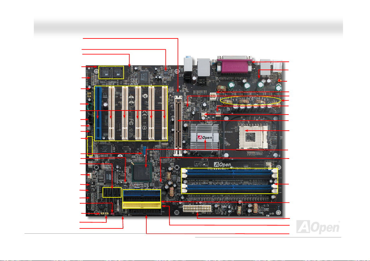
d
p
AAXX44CC MMaaxx IIII O
Broadcom Gigabit PCI LAN Chi
Onboard AC’97 CODEC
S/PDIF Connector
Die-Hard BIOS (BIOS1 & 2)
(User Upgrade Optional)
GAME Connector
Front Audio Connector
AUX-IN Connector
32-bit PCI Expansion Slot x6
(Slot 6: Self-Powered PCI card that
supports high power-consuming PCI cards)
JP24 DieHard BIOS Rescue Jumper
JP2 Dr. Voice Output Select Jumper
CD-IN Connector
WOL Connector
WOM Connector
IEEE 1394 Connectors x 2
n
2
USB (2.0) Connector
Serial ATA Ports x 4
SYSFAN3 Connector
Dr. LED Connector
(User Upgrade Optional)
Front Panel Connector
JP14 CMOS Clear Jumper
STBY LED
(RAID 0, 1, 0+1)
IrDA Connector
Chassis Intrusion Connector
Onnlliinnee MMaannuuaall
Motherboard Map
PC99 Colored Back Panel
Resetable Fuse
JP28 Keyboard/Mouse Wakeup
Enable/Disable Jumper
4-pin 12V. ATX Power Connector
AGP LED
V4 Power Engine
CPUFAN1 Connec
Monitoring Function
18 19
SYSFAN2 Connector
AGP Slot
(For 1.5V AGP card only)
478-pin CPU socket with Voltage
and Frequency Auto-detection
support Intel® Pentium® 4 CPU
Intel® 875P (Canterwood) and
ICH5R chipsets
BOOT LED
184-pin DIMMx4
support DDR400/333
(Max. to 4GB)
ATA 33/66/100
IDE Connector x2
ATX Power Connector
Promise ATA133 IDE Connector x1
FDD Connector
tor with H/W
Page 19
AAXX44CC MMaaxx IIII O
Onnlliinnee MMaannuuaall
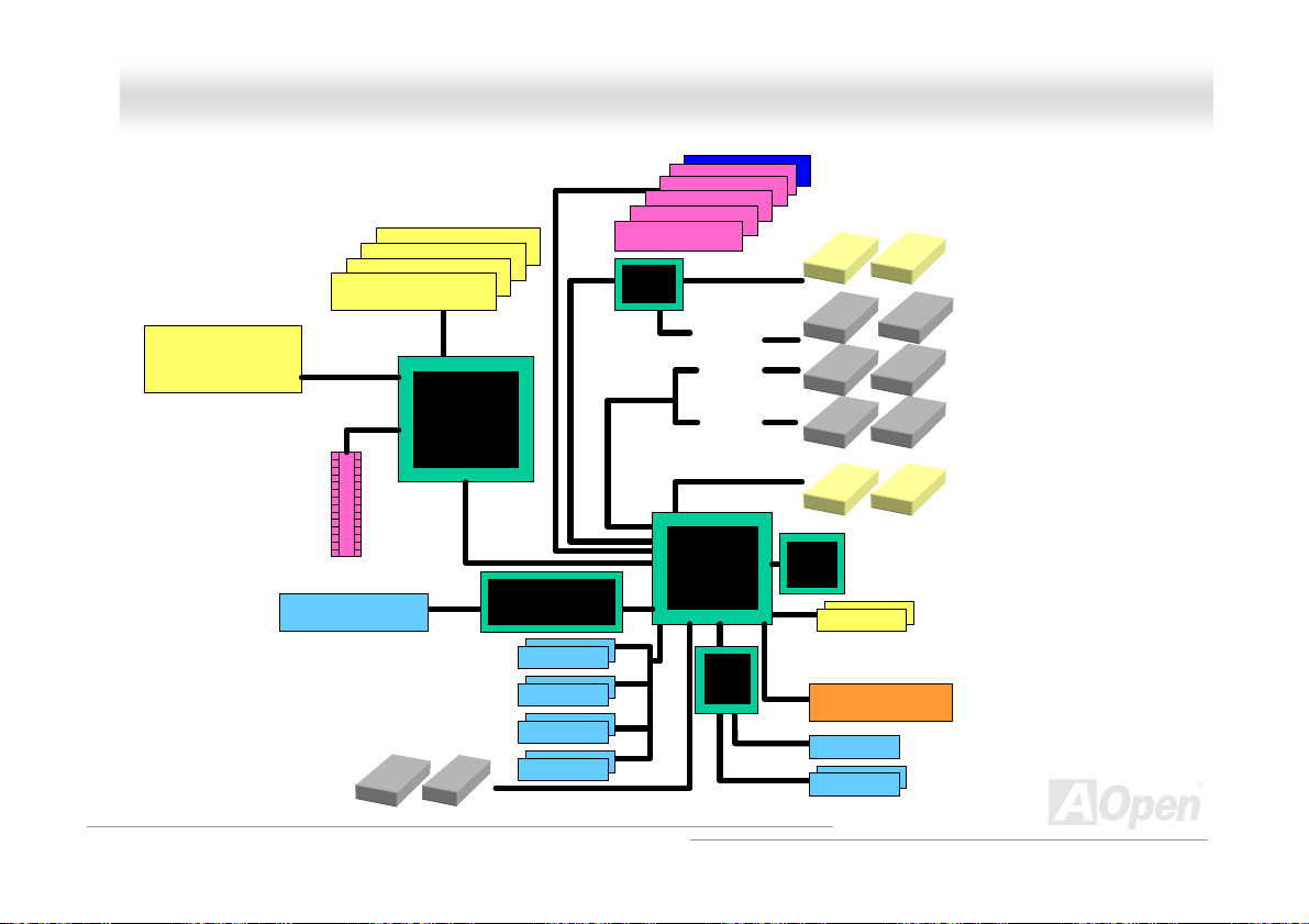
BBlloocckk DDiiaaggrraamm
Socket 478
Intel
Pentium 4
CPU
AGP 8x Sl ot
Floppy Disk Drive x2
800/533MHz
System Bus
LAN connect Component
DDR400/333 DDR RAM Up to
DIMM Socket x4
4GB
Intel 875P
USB 2.0
Connector x8
PCI Bus
Broadcom Gigabit LAN
1stUSB Port
2ndUSB Port
3rdUSB Port
4thUSB Port
32-bit PCI Slot x6
Promise
PDC20378
ATA
33/66100
Serial ATA
Third Channel
ATA 133
Primary
Channel
Secondary
Channel
Intel ICH5R
Low
Pin
Count
Super
I/O
Self-
Powered
PCI slot
AC97
CODEC
IEEE 1394
Firmware Hub
4Mbit Flash EEPROM
Parallel Port
Serial Port x2
SATA Drive x2
IDE Drive x6
SATA Drive x2
IEEE 1394 x 2
Page 20

AAXX44CC MMaaxx IIII O
Onnlliinnee MMaannuuaall
HHaarrddwwaarree IInnssttaallllaattiioonn
This chapter describes jumpers, connectors and hardware devices of this motherboard. This chapter describes jumpers, connectors and hardware devices of this motherboard.
Note: Electrostatic discharge (ESD) can damage your processor, disk drives, expansion boards, and
other components. Always observe the following precautions before you install a system component.
1. Do not remove a component from its protective packaging until you are ready to install it.
2. Wear a wrist ground strap and attach it to a metal part of the system unit before handling a
component. If a wrist strap is not available, maintain contact with the system unit throughout any
procedure requiring ESD protection.
Haarrddwwaarree IInnssttaallllaattiioonn
20
Page 21

AAXX44CC MMaaxx IIII O
A
Abboouutt ““MMaannuuffaaccttuurreerr UUppggrraaddee OOppttiioonnaall”” aanndd ““UUsseerr UUpp
A
bboouutt ““MMaannuuffaaccttuurreerr UUppggrraaddee OOppttiioonnaall”” aanndd ““UUsseerr UUppg
O
O
ppttiioonnaall””……
OOppttiioonnaall””……
When you read this online manual and start to assemble your computer system, you may find some of functions are called
When you read this online manual and start to assemble your computer system, you may find some of functions are called
“Manufacturer Upgrade Optional”, and some are called “User Upgrade Optional”. Though all AOpen motherboards include many
“Manufacturer Upgrade Optional”, and some are called “User Upgrade Optional”. Though all AOpen motherboards include many
amazing and powerful features, in some situations, these powerful features are not used to every user. Hence, we changed
amazing and powerful features, in some situations, these powerful features are not used to every user. Hence, we changed
some key features as “Manufacturer Upgrade Optional” for you to choose. Some optional functions that can be upgraded by
some key features as “Manufacturer Upgrade Optional” for you to choose. Some optional functions that can be upgraded by
users, we call them “User Upgrade Optional”. As for those optional functions that can’t be upgraded by ourselves, we call them
users, we call them “User Upgrade Optional”. As for those optional functions that can’t be upgraded by ourselves, we call them
“Manufacturer Upgrade Optional”. If needed, you can contact our local distributors or resellers for purchasing “User Upgrade
“Manufacturer Upgrade Optional”. If needed, you can contact our local distributors or resellers for purchasing “User Upgrade
Optional” components, and again you can visit AOpen official web site:
Optional” components, and again you can visit AOpen official web site:
http://english.aopen.com.tw/
http://english.aopen.com.tw/ for more detail information.
Onnlliinnee MMaannuuaall
grraaddee
grraaddee
g
21
Page 22
AAXX44CC MMaaxx IIII O
Onnlliinnee MMaannuuaall
(default)
1
Clear CMOS
Tip: When should I Clear CMOS?
1. Boot fail because of overclocking…
2. Forget password…
3. Troubleshooting…
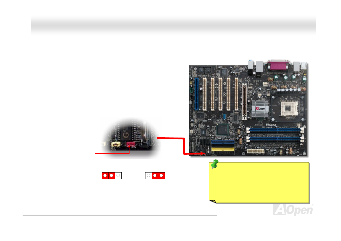
JJPP1144 CClleeaarr CCMMOOSS DDaattaa
You can clear CMOS to restore system default setting. To clear the CMOS, follow the procedure below.
1. Turn off the system and unplug the AC power.
2. Remove ATX power cable from connector PWR2.
3. Locate JP14 and short pins 2-3 for a few seconds.
4. Return JP14 to its normal setting by shorting pins 1 & pin2.
5. Connect ATX power cable back to connector PWR2.
Pin 1
1
Normal Operation
22
Page 23
AAXX44CC MMaaxx IIII O
Onnlliinnee MMaannuuaall
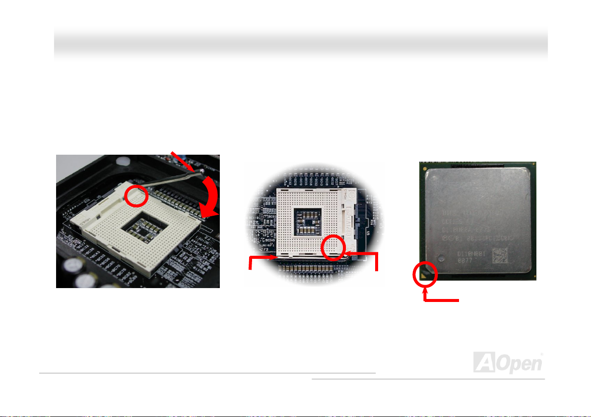
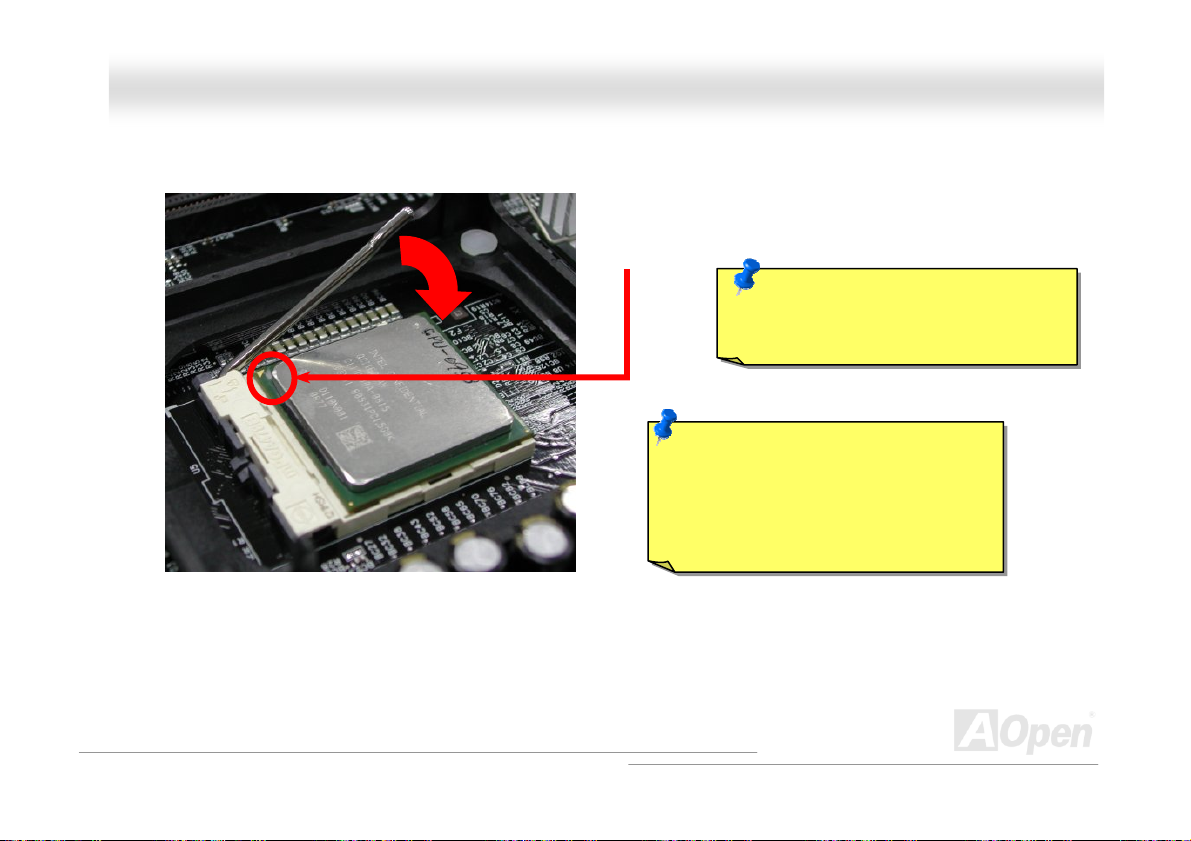
CCPPUU IInnssttaallllaattiioonn
This motherboard supports Intel® Pentium 4 Socket 478 series CPU. Be careful of CPU orientation when you plug it into CPU
This motherboard supports Intel® Pentium 4 Socket 478 series CPU. Be careful of CPU orientation when you plug it into CPU
socket.
socket.
1. Pull up the CPU socket lever and
up to 90-degree angle.
CPPUU IInnssttaallllaattiioonn
2. Locate Pin 1 in the socket and look for a cut edge on the CPU upper
interface. Match Pin 1 and cut edge, then insert the CPU into the socket.
Note: These pictures are for example only, it may not exactly be the same motherboard. Note: These pictures are for example only, it may not exactly be the same motherboard.
CPU socket
Lever
CPU pin 1 and
cut edge
CPU cut edge
23
Page 24
y
AAXX44CC MMaaxx IIII O
3. Press down the CPU socket lever and finish
CPU installation.
Note: This picture is for example only, it may not exactly be the same motherboard. Note: This picture is for example only, it may not exactly be the same motherboard.
CPU cut edge
Note: If you do not match the CPU
socket Pin 1 and CPU cut edge well, it
ma
damage the CPU.
Note: This socket supports
Micro-FC-PGA2 package CPU, which
is the latest CPU package developed
by Intel. Other forms of CPU package
are impossible to be fitted in.
Onnlliinnee MMaannuuaall
24
Page 25
AAXX44CC MMaaxx IIII O
Onnlliinnee MMaannuuaall
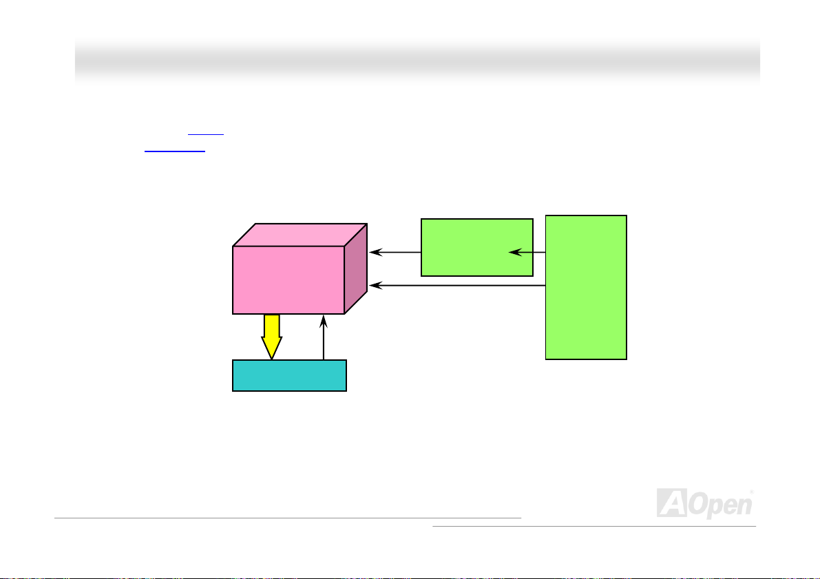
CCPPUU JJuummppeerr--lleessss DDeessiiggnn
CPU VID signal and SMbusCPU VID signal and SMbus clock generator provide CPU voltage auto-detection and allows the user to set the CPU frequency
through the
designs are eliminated. There will be no worry of wrong CPU voltage detection.
BIOS setup, therefore no jumpers or switches are used. The disadvantages of the Pentium based jumper-less
Intel® Socket 478
Pentium 4 CPU
CPU VID signal
Power Regulator
(Automatically generates CPU voltage)
CPPUU JJuummppeerr--lleessss DDeessiiggnn
CPU voltage
Clock Generator
CPU Freq. Ratio
BIOS
Controlled
Circuit
25
Page 26
AAXX44CC MMaaxx IIII O
Onnlliinnee MMaannuuaall
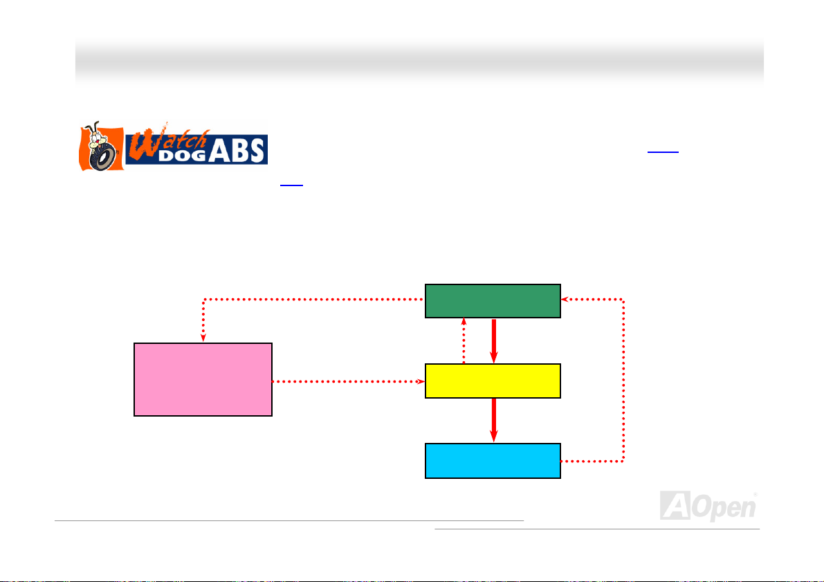
AAOOppeenn ““WWaattcchh DDoogg AABBSS””
the “Watch Dog ABS” will reset the system to reboot in five seconds. Then, BIOS will detect the CPU’s default frequency and
POST again. With this special feature, you can easily overclock your system to get higher system performance, and without
removing the cover of system housing to set the jumper to clear CMOS data when your system hanged.
AOpen
Watch Dog ABS
Enable/Disable Signal
AOOppeenn ““WWaattcchh DDoogg AABBSS””
With this motherboard, AOpen provides a very special, useful feature for overclockers.
With this motherboard, AOpen provides a very special, useful feature for overclockers.
POST
When you power-on the system, the BIOS will check last system
When you power-on the system, the BIOS will check last system
succeeded, the BIOS will enable “Watch Dog ABS” function immediately, and set the CPU
FSB frequency by user’s setting that stored in the BIOS. If system failed in BIOS POST,
from BIOS
BIOS
Reset Signal
Clock Generator
Countdown about
5 seconds if fails
in POST
CPU
POST status. If it
CPU ID Signal
26
Page 27
AAXX44CC MMaaxx IIII O
Onnlliinnee MMaannuuaall
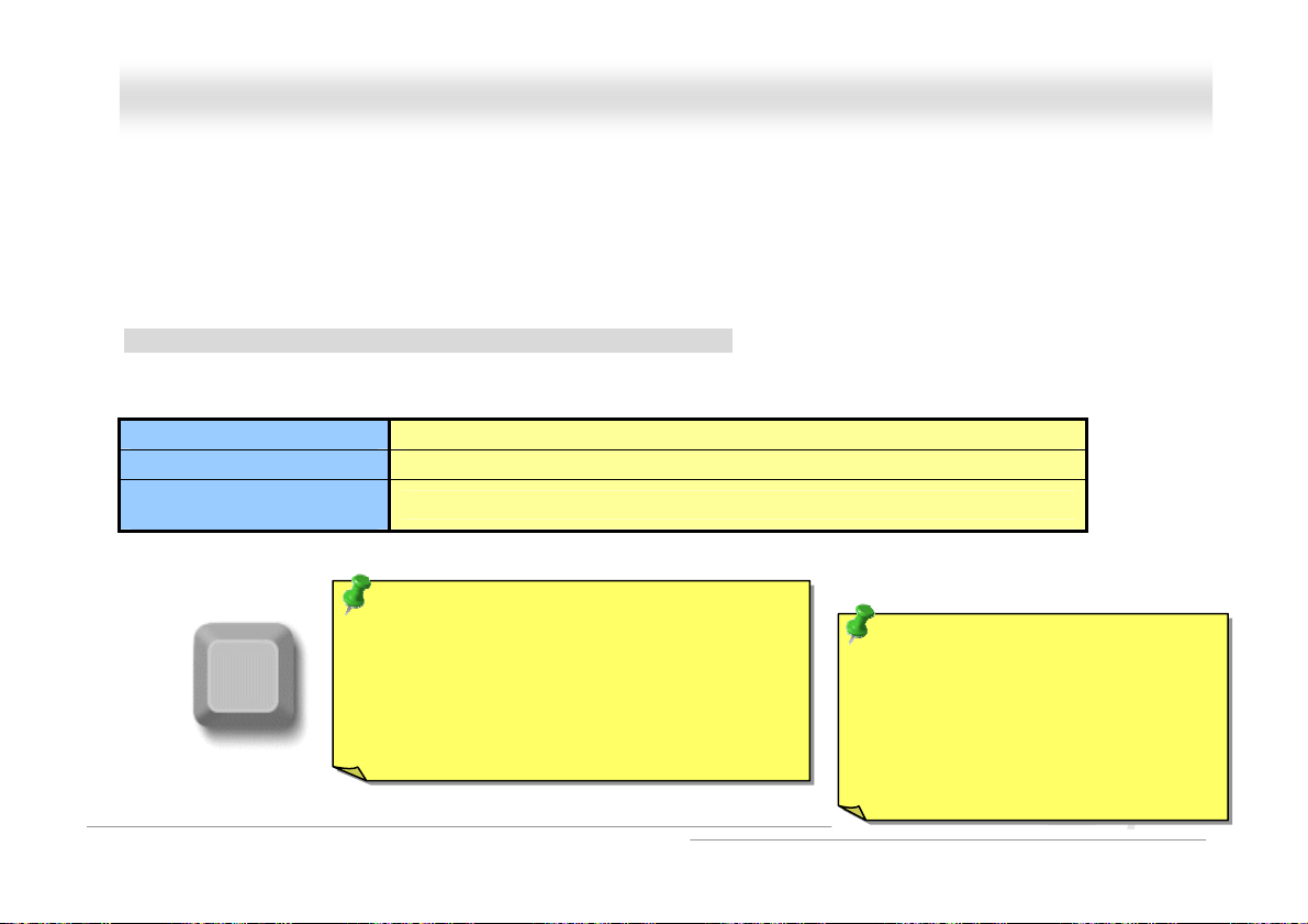
CCPPUU CCoorree VVoollttaaggee AAuuttoo DDeetteeccttaabbllee
This motherboard supports CPU VID function. The CPU core voltage will be automatically detected and the range is from 1.1V
This motherboard supports CPU VID function. The CPU core voltage will be automatically detected and the range is from 1.1V
to 1.925V. It is not necessary to set CPU Core Voltage.
to 1.925V. It is not necessary to set CPU Core Voltage.
SSeettttiinngg CCPPUU FFrreeqquueennccyy
SSeettttiinngg CCPPUU FFrreeqquueennccyy
BIOS Setup > Frequency/Voltage Control > CPU Clock Setting
This motherboard is CPU jumper-less design, you can set CPU frequency through the BIOS setup, and no jumpers or switches
are needed.
CPU Ratio 8x, 9x, 10x,…22x, 23x…39x
CPU FSB 133~200MHz
1MHz Stepping CPU
Overclocking
Home
100~400MHz
Tip: If your system hangs or fails to boot because
of overclocking, simply use <Home> key to
restore the default setting or you can wait the
AOpen “Watch Dog ABS” reset the system after
five seconds and system will auto-detect
hardware again.
CPPUU CCoorree VVoollttaaggee AAuuttoo DDeetteeccttaabbllee
Tip: The North Bridge of Canterwood
does supports “Turbo mode”, which is
used to lower latency paths from FSB
to system memory that enhances the
system performance, when it is set at
FSB800 and DDR400 mode.
27
Page 28
AAXX44CC MMaaxx IIII O
Core Frequency = CPU FSB Clock * CPU Ratio
PCI Clock = CPU FSB Clock / Clock Ratio
AGP Clock = PCI Clock x 2
Northwood CPU
Pentium 4 2.26G 2260MHz 133MHz 533MHz 17x
Pentium 4 2.4G 2400MHz 133MHz 533MHz 18x
Pentium 4 2.53G 2530MHz 133MHz 533MHz 19x
Pentium 4 2.66G 2660MHz 133MHz 533MHz 20x
Pentium 4 2.80G 2800MHz 133MHz 533MHz 21x
Pentium 4 3.0G 3000MHz 200MHz 800MHz 15x
Pentium 4 3.06G 3060MHz 133MHz 533MHz 23x
Note: With CPU speed changing rapidly, there might be fastest CPU on the market by
the time you received this installation guide. This table is kindly for your references
only.
CPU Core
Frequency
FSB Clock System Bus Ratio
Note: Since the latest processor,
Northwood, would detect the clock
ratio automatically, you may not be
able to adjust the clock ratio in
BIOS manually.
Warning: Intel® 875P
(Canterwood) chipset supports
maximum 800/533MHz
(200/133MHz*4) system bus and
66MHz AGP clock; higher clock
setting may cause serious system
damage.
Onnlliinnee MMaannuuaall
28
Page 29
AAXX44CC MMaaxx IIII O
Onnlliinnee MMaannuuaall
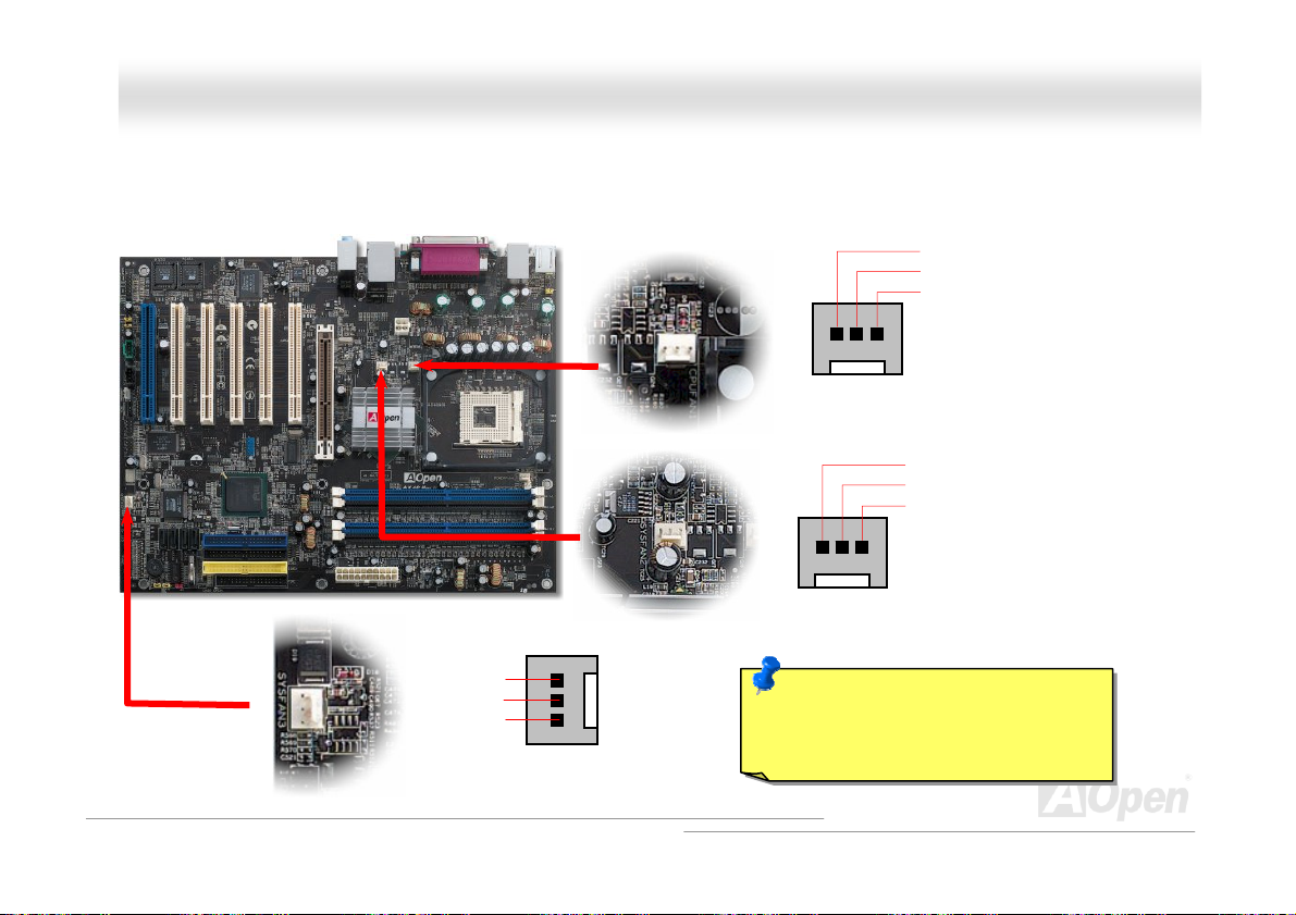
CCPPUU aanndd SSyysstteemm FFaann CCoonnnneeccttoorr ((wwiitthh HH//WW MMoonniittoorriinngg))
Plug in the CPU fan cable to the 3-pin CPUFAN1 connector. If you have chassis fan, you can also plug it on SYSFAN2 or
SYSFAN3 connector.
SENSOR
+12V
GND
CPUFAN1 Fan Connector
SYSFAN2 Connector
Note: Some CPU fans do not have
sensor pin, so that cannot support
hardware monitoring function.
GND
+12V
SENSOR
GND
+12V
SENSOR
SYSFAN3 Connector
29
Page 30
AAXX44CC MMaaxx IIII O
Onnlliinnee MMaannuuaall
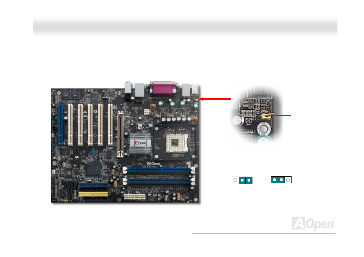
JJPP2288 KKeeyybbooaarrdd//MMoouussee WWaakkee--uupp EEnnaabbllee//DDiissaabbllee JJuummppeerr
This motherboard provides keyboard / mouse wake-up function. You can use JP28 to enable or disable this function, which
could resume your system from suspend mode with keyboard or mouse installed. The factory default setting is set to
“Disable”(1-2), and you may enable this function by setting the jumper to 2-3.
KB/Mouse Wake-up
Pin 1
Disable
(Default)
Pin 1
JP28
Enable
30
Page 31
AAXX44CC MMaaxx IIII
O
Onnlliinnee MMaannuuaall
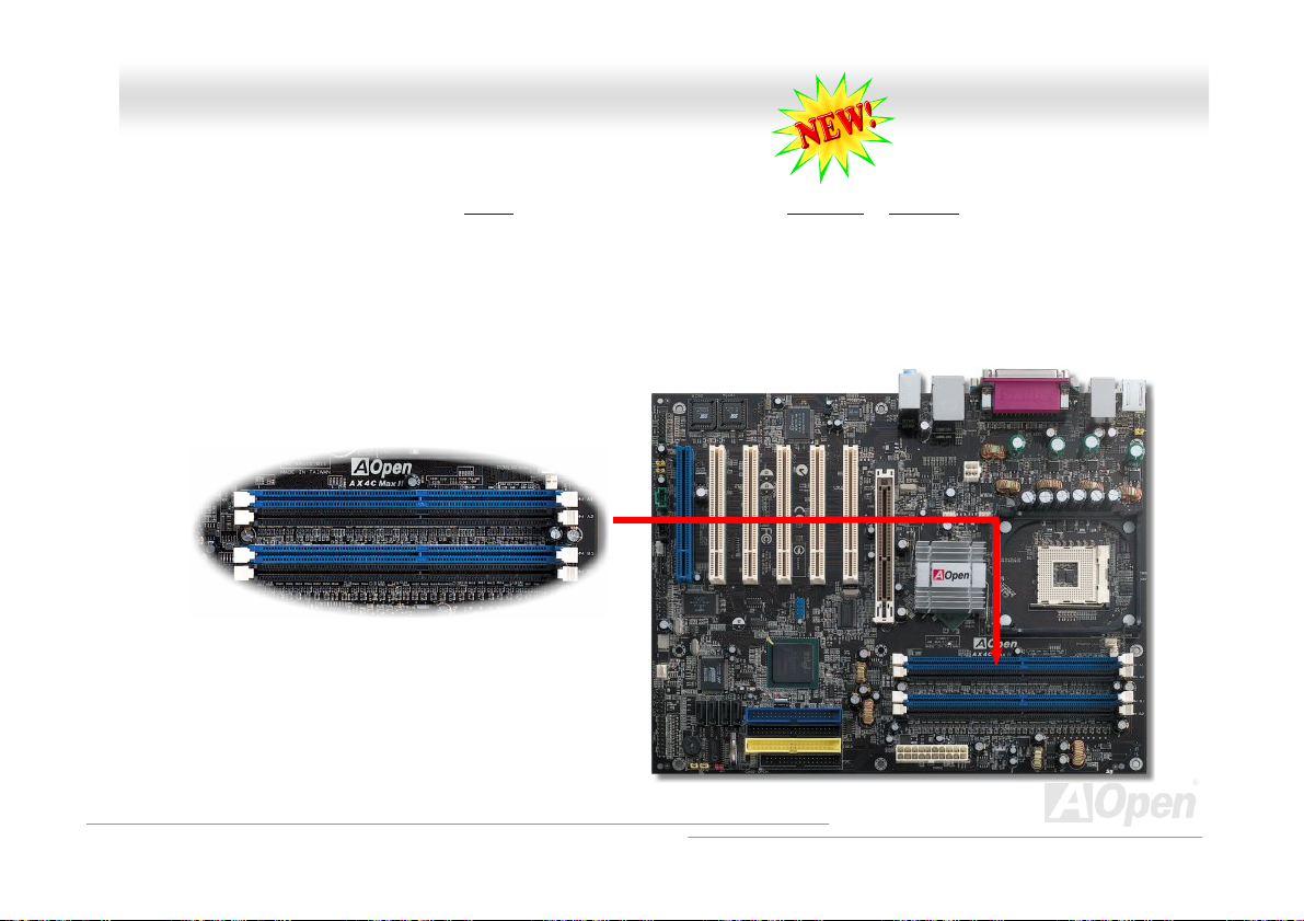
DDIIMMMM SSoocckkeettss ((112288--BBiitt DDDDRR DDuuaall CChhaannnneell))
This motherboard has four 184-pin DDR DIMM sockets that allow you to install DDR400 or DDR333 memory up to 4 GB. ECC
DDR RAM is supported. Newly implemented function, the Voltage of memory on this motherboard is adjustable from 2.5V to
2.85V (such as 2.5V, 2.55V, 2.6V, 2.65V, 2.7V, 2.75V, 2.8V, 2.85V) for over clocking purpose, but default value here is 2.55V.
In the past, we used to have 64-bit memory bandwidth for memory access. No matter how many memory modules have been
installed, though capacity added, the speed of access remains the same. With 128-bit dual channel introduced, it doubles the
memory bandwidth up to 5.4GB in advanced 128-bit mode. This motherboard supports DDR400/333 with Maximum capacity up
to 4GB.
DIMM1
DIMM2
DIMM3
DIMM4
128-bit DDR Dual Channel Memory
module
31
Page 32

AAXX44CC MMaaxx IIII O
Onnlliinnee MMaannuuaall
MMaaxxiimmuumm tthhee ppeerrffoorrmmaannccee ooff DDuuaall CChhaannnneell
Dual Channel memory configuration provides higher performance than single channel configuration. To get the highest
Dual Channel memory configuration provides higher performance than single channel configuration. To get the highest
performance of Dual Channel, the DIMM modules you’re using must meet the following conditions:
performance of Dual Channel, the DIMM modules you’re using must meet the following conditions:
● Same DRAM technology (128Mb, 256Mb, or 512Mb) ● Same DRAM technology (128Mb, 256Mb, or 512Mb)
● Same Density (128MB, 256MB, 512MB, etc.) ● Same DRAM bus width (x8 or x16) ● Same Density (128MB, 256MB, 512MB, etc.) ● Same DRAM bus width (x8 or x16)
● Matched DIMM configuration in each channel ● Both either single-sided or dual-sided ● Matched DIMM configuration in each channel ● Both either single-sided or dual-sided
Note: Memory interface speed will be set to the lowest speed of memory populated. Note: Memory interface speed will be set to the lowest speed of memory populated.
Optimize performance for dual channel is obtained with matched DIMM population. Table below shows DIMMs with same
Optimize performance for dual channel is obtained with matched DIMM population. Table below shows DIMMs with same
Organization and Density, but are non-matching as bus width, technology and/or external banks are different. Mixing these
Organization and Density, but are non-matching as bus width, technology and/or external banks are different. Mixing these
DIMMs will put platform into single channel mode.
DIMMs will put platform into single channel mode.
Non-Matched
128MB DIMMs
Non-Matched
256MB DIMMs
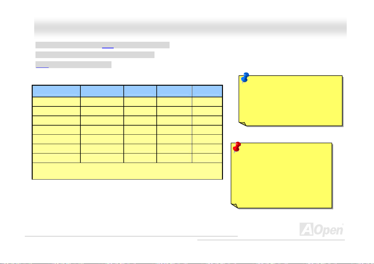
Organization Density Composition Technology External
16Mx64 128MB 16Mx8 *8 pcs 128MB 1
16Mx64 128MB 16Mx16 *4 pcs 256MB 1
32Mx64 256MB 16Mx8 *16 pcs 128MB 2
32Mx64 256MB 32Mx8 *8 pcs 256MB 1
Maaxxiimmuumm tthhee ppeerrffoorrmmaannccee ooff DDuuaall CChhaannnneell
Different
Bus Width
Different
Technology
Different
Technology
Different # of
DRAM Banks
32
Page 33

AAXX44CC MMaaxx IIII O
Onnlliinnee MMaannuuaall
HHooww ttoo IInnssttaallll MMeemmoorryy MMoodduulleess
Please follow the procedure as shown below to finish memory installation. Please follow the procedure as shown below to finish memory installation.
1. Make sure the DIMM module’s pin face down and match the socket’s size as depicted below. 1. Make sure the DIMM module’s pin face down and match the socket’s size as depicted below.
2. Insert the module straight down to the DIMM slot with both hands and press down firmly until the DIMM module is securely
2. Insert the module straight down to the DIMM slot with both hands and press down firmly until the DIMM module is securely
in place.
in place.
3. Repeat step 2 to finish additional DIMM modules installation. 3. Repeat step 2 to finish additional DIMM modules installation.
Ta b
Hooww ttoo IInnssttaallll MMeemmoorryy MMoodduulleess
52 pins 40 pins
Note: The tabs of the DIMM slot
will close-up to hold the DIMM in
place when the DIMM touches
the slot’s bottom.
33
Page 34

AAXX44CC MMaaxx IIII O
Onnlliinnee MMaannuuaall
FFrroonntt PPaanneell CCoonnnneeccttoorr
Pin1
Attach the power LED, speaker, power and reset switch connectors to the
corresponding pins. If you enable “Suspend Mode” item in BIOS Setup, the ACPI
& Power LED will keep flashing while the system is in suspend mode.
Locate the power switch cable from your ATX housing. It is 2-pin female
connector from the housing front panel. Plug this connector to the soft-power
switch connector marked SPWR.
Suspend Type ACPI LED
Power on Suspend (S1) or Suspend to RAM (S3) Blinking between green and red.
Suspend to Disk (S4) The LED will be turned off
NC
NC
+5V
IDE LED
IDE LED
+5V
+5V
GND
NC
1
SPWR
GND
ACPI LE D GND
ACPILED
NC
ACPI_B
GND
RESET
GND
IDE LED
Speaker
1
SPWR
ACPI & PWR
LED
ACPI LED (BLUE)
Reset
SPEAKER
34
Page 35

AAXX44CC MMaaxx IIII O
Onnlliinnee MMaannuuaall
AATTXX PPoowweerr CCoonnnneeccttoorr
This motherboard comes with a 20-pin and 4-pin ATX power connector. Make sure you plug in the right direction. We strongly
recommend you to connect the 4-pin 12V ATX connector before connecting the 20-pin ATX power connector and use standard
power supply specially designed for Pentium 4 system.
4-Pin 12V ATX Power Connector
20-Pin Power Connector
35
Page 36

AAXX44CC MMaaxx IIII O
Onnlliinnee MMaannuuaall
AACC PPoowweerr AAuuttoo RReeccoovveerryy
A traditional ATX system should remain at power off stage when AC power resumes from power failure. This design is
inconvenient for a network server or workstation, without an UPS, that needs to keep power-on. This motherboard implements
an AC Power Auto Recovery function to solve this problem.
36
Page 37

AAXX44CC MMaaxx IIII O
Onnlliinnee MMaannuuaall
SSTTBBYY LLEEDD aanndd BBOOOOTT LLEEDD
Both STBY LED and BOOT LED are AOpen’s considerate designs that aim at providing you friendly system information. The
STBY LED will light up when power is provided to the motherboard. This is a convenient indication for you to check the system
power status in many circumstances such as power on/off, stand-by mode and RAM power status during Suspend to RAM
mode.
BOOT LED will keep blinking when you power the system on and when your system is under
POST diagnoses everything alright and finishes the booting, the LED will stay on otherwise it will remain flashing to warn you
that mistakes have occurred during POST.
STBY LED
POST (Power-On Self Test). After
BOOT LED
Warning: Do not install or remove the
DIMM module or others devices when
the STBY LED lights on.
37
Page 38

(
(
)
(
AAXX44CC MMaaxx IIII O
Onnlliinnee MMaannuuaall
IIDDEE aanndd FFllooppppyy CCoonnnneeccttoorr
Connect 34-pin floppy cable and 40-pin IDE cable to floppy connector FDD and IDE connector. The blue connector is IDE1 for
clear identification. Be careful of the pin1 orientation. Wrong orientation may cause system damage.
Primary
Slave (2nd)
Pin 1
ATA1 33
IDE Connector
Pin 1
Secondary
Slave
Pin 1
4th
ATA 33/66/100
IDE Connector
FDD Connector
Primary
Master
Secondary
Master
1st)
IDE 1 (Primary)
IDE 2 (Secondary)
3rd)
38
Page 39

AAXX44CC MMaaxx IIII O
IDE1 is also known as the primary channel, IDE2 and IDE3 are known as the secondary and third channel. Each channel
supports two IDE devices that make a total of six devices. In order to work together, the two devices on each channel must be
set differently to Master and Slave mode. Either one can be the hard disk or the CDROM. The setting as master or slave mode
depends on the jumper on your IDE device, so please refer to your hard disk and CDROM manual accordingly.
Wa
rning: The specification of the IDE cable is a maximum
of 46
Tip:
3. For better signal quality, it is recommended to set the far end
4. To achieve the best performance of Ultra DMA 66/100/133 hard
cm (18 inches); make sure your cable does not exceed
this length.
side device to master mode and follow the suggested sequence
to install your new device. Please refer to above diagram
disks, a special 80-wires IDE cable for Ultra DMA 66/100/133
is required.
Tip for ATA133 IDE:
1. It is not recommend using CD-ROM
for ATA133 IDE.
2. Please set it to Master when there is
only ONE device connected.
Onnlliinnee MMaannuuaall
39
Page 40

AAXX44CC MMaaxx IIII O
By the strength of Promise PDC29378, you will find an extra IDE 3 onboard for the scalability of hard disks capacity. All you
have to do is to simply set the following configuration to make full advantage of it.
1. Please press Ctrl-F to get into the Promise PDC29378 BIOS during POST.
2. Select Auto Setup for the system to recognize your hard disk, and done.
The Auto Setup will select the best mode for your hard disk. But of course, you may set your preferred Mode to Stripe or Mirror
according to the numbers of your hard disks as well.
Auto Setup
Onnlliinnee MMaannuuaall
Mode
40
Page 41

AAXX44CC MMaaxx IIII O
Onnlliinnee MMaannuuaall
AATTAA//113333 SSuuppppoorrtteedd
This motherboard supports ATA 66 , ATA100 or ATA1 33 IDE devices. Following table lists the transfer rate of IDE PIO and DMA
modes. The IDE bus is 16-bit, which means every transfer is two bytes. As the hard drive industry introduces faster and higher
capacity hard drives, the current Ultra ATA/100 interface causes a data bottleneck between the drive and the host computer.
To avoid this problem, hard disk manufacturers have introduced the new Ultra ATA-133 interface technology. Compared to
traditional ATA/100, ATA/133 has up to 33 percent increase in interface speed with transfer rate of 133MB/s. ATA/133
performance is ideal for new operating systems, such as Window XP, that demand more storage space and faster data transfer
rates from more responsive computing experiences.
To make good use of this new technology and enjoy its best performance, we recommend you to pair your system with a hard
disk equipped with ATA/133 technology so that your system's need for speeding on this motherboard can be satisfied.
Mode Clock Period Clock Count Cycle TimeData Transfer Rate
PIO mode 0 30ns 20 600ns (1/600ns) x 2byte = 3.3MB/s
PIO mode 1 30ns 13 383ns (1/383ns) x 2byte = 5.2MB/s
PIO mode 2 30ns 8 240ns (1/240ns) x 2byte = 8.3MB/s
PIO mode 3 30ns 6 180ns (1/180ns) x 2byte = 11.1MB/s
PIO mode 4 30ns 4 120ns (1/120ns) x 2byte = 16.6MB/s
DMA mode 0 30ns 16 480ns (1/480ns) x 2byte = 4.16MB/s
DMA mode 1 30ns 5 150ns (1/150ns) x 2byte = 13.3MB/s
DMA mode 2 30ns 4 120ns (1/120ns) x 2byte = 16.6MB/s
ATA33 30ns 4 120ns (1/120ns) x 2byte x 2 = 33MB/s
ATA66 30ns 2 60ns (1/60ns) x 2byte x 2 = 66MB/s
ATA100 20ns 2 40ns (1/40ns) x 2byte x 2 = 100MB/s
ATA133 15ns 2 30ns (1/30ns) x 2byte x 2 = 133MB/s
41
Page 42
AAXX44CC MMaaxx IIII O
Onnlliinnee MMaannuuaall
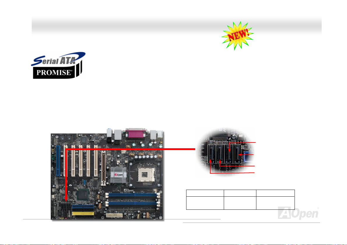
SSeerriiaall AATTAA SSuuppppoorrtteedd ((wwiitthh RRAAIIDD ffuunnccttiioonn))
The traditional parallel ATA specification has defined the standard storage interface for PCs with its
original speed of just 3 Mbytes/second since the protocol was introduced in the 1980s. And the latest
generation of the interface, Ultra ATA-133, has been developed further with a burst data transfer rate
of 133 Mbytes/second. However, while ATA has enjoyed an illustrious track record, the specification is
now showing its age and imposes some serious design issues on today’s developers, including a 5-volt signaling requirement,
high pin count, and serious cabling headaches.
The Serial ATA specification is designed to overcome these design limitations while enabling the storage interface to scale with
the growing media rate demands of PC platforms. Serial ATA is to replace parallel ATA with the compatibility with existing
operating systems and drivers, adding performance headroom for years to come. It reduces voltage and pins count
requirements and can be implemented with thin and easy to route cables.
SATA port 2 (ICH5R)
SATA port 1 (ICH5R)
SATA port 3 (PDC20378)
SATA port 4 (PDC20378)
Serial ATA Ports
Motherboard SATA 1 & 2 SATA 3 & 4
AX4C Max II RAID 0, 1 RAID 0, 1, 0+1
(With ATA133)
42
Page 43
AAXX44CC MMaaxx IIII O
Onnlliinnee MMaannuuaall
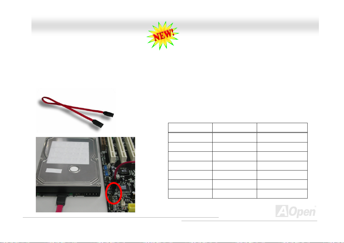
CCoonnnneeccttiinngg SSeerriiaall AATTAA DDiisskk
To connect a Serial ATA disk, you have to have a 7-pin serial ATA cable. Connect two ends of the serial ATA cable to the serial
To connect a Serial ATA disk, you have to have a 7-pin serial ATA cable. Connect two ends of the serial ATA cable to the serial
ATA header on the motherboard and the disk. Like every other traditional disk, you also have to connect a power cable. Please
ATA header on the motherboard and the disk. Like every other traditional disk, you also have to connect a power cable. Please
be noted that it is a jumper free implement; you don’t need to set jumpers to define a master or slave disk. When connecting
be noted that it is a jumper free implement; you don’t need to set jumpers to define a master or slave disk. When connecting
two serial ATA disks, the system will automatically take the one connected to “Serial ATA 1” header as a master disk. Please be
two serial ATA disks, the system will automatically take the one connected to “Serial ATA 1” header as a master disk. Please be
noted that it doesn’t support Hot-Plug in function.
noted that it doesn’t support Hot-Plug in function.
Coonnnneeccttiinngg SSeerriiaall AATTAA DDiisskk
Comparison between Parallel ATA and Serial ATA
Parallel ATA Serial ATA
Bandwidth 100/133 MB/Secs 150/300/600 MB/Secs
Vol ts 5V 250mV
Pins 40 7
Length Limitation 18 inch (45.72cm) 1 meter (100cm)
Cable Wide Thin
Ventilation Bad Good
Peer-to-Peer No Yes
43
Page 44

AAXX44CC MMaaxx IIII
O
Onnlliinnee MMaannuuaall
AAddjjuussttiinngg YYoouurr HHaarrdd DDiisskk
Except its original 2 sets of parallel IDE, this motherboard does come with the support for the latest Serial ATA hard disk. If you
are unable to find your newly installed Serial ATA hard disks on your operating system after you have had installed them on, the
problem mainly lies in the BIOS setting. You may simply adjust BIOS settings to have them work properly.
After having properly installed your hard disks, you may directly get into the BIOS setting screen for adjustment. You may simply
press “Integrated Peripherals Æ OnChip IDE Device Æ On-Chip Serial ATA” to choose your preferable mode. If you have no
intention of changing its setting, the default would be Auto.
44
Page 45

AAXX44CC MMaaxx IIII O
If you intend to change the default setting, simply press Enter for a list of selection:
1. Disabled: You may choose this item if you’re sure that only traditional IDE hard
disks had been installed on your system. Disabling this item may also cancel
the detection to Serial ATA hard disk during POST, which theoretically, could
speed up your boot-up timing for a little bit; however, please remember to
re-adjust the settings here if you intend to use Serial ATA hard disk later.
2. Auto: This is the default setting upon receipt of the motherboard. Basically, if
your system functions properly, it’s not necessary to change it. The system will
automatically recognize the first hard disk on IDE1 as the first boot device.
Note: Please be informed that when you are using Windows98/ME with six hard
disks fully installed, Auto mode is not able to function properly, it’s just because Windows98/Me is not able to energize
Enhanced Mode to detect all hard disks.
3. Combined Mode: If you have had installed traditional IDE hard disks and Serial ATA hard disks at the same time, then you
may choose this Combined Mode. Under this mode, you may randomly choose either IDE hard disks or Serial ATA had disk
as your first boot device. But please be aware that Serial ATA will exist with IDE in a mapping way, which also means it will
occupy one of the IDE Channel and left you with one IDE Channel only.
4. Enhanced Mode: If you are using the latest operating system (say, WindowsXP, Windows.NET Server), it is highly
recommended to select Enhanced Mode. The system would be able to detect all six devices (traditional IDE x4, Serial ATA
x 2) completely and functions perfectly under this mode. But please be noted that it is defaulted with using traditional IDE
as the first boot device.
Note: From our practical lab tests, we found no obvious problem or mistakes happened under Windows2000 operating
system, but, however, it is not within the regulation recommended by Intel.
5. SATA Only: You may select this SATA Only mode if you have had installed Serial ATA hard disks only. It also allows you to
select booting sequence from Port0(SerialATA1) or Port1(SerialATA2).
Onnlliinnee MMaannuuaall
45
Page 46

AAXX44CC MMaaxx IIII O
Onnlliinnee MMaannuuaall
IIrrDDAA CCoonnnneeccttoorr
The IrDA connector can be configured to support wireless infrared module, with this module and application software such as
Laplink or Windows 95 Direct Cable Connection, the user can transfer files to or from laptops, notebooks, PDA devices and
printers. This connector supports HPSIR (115.2Kbps, 2 meters) and ASK-IR (56Kbps).
Install the infrared module onto the IrDA connector and enable the infrared function from BIOS Setup, UART Mode, make sure
to have the correct orientation when you plug in the IrDA connector.
Pin 1
NC
+5V
IR_TX
IIrrDDAA CCoonnnneeccttoorr
KEY
GND
IR_RX
46
Page 47
AAXX44CC MMaaxx IIII
O
O
nnlliinnee MMaannuuaall
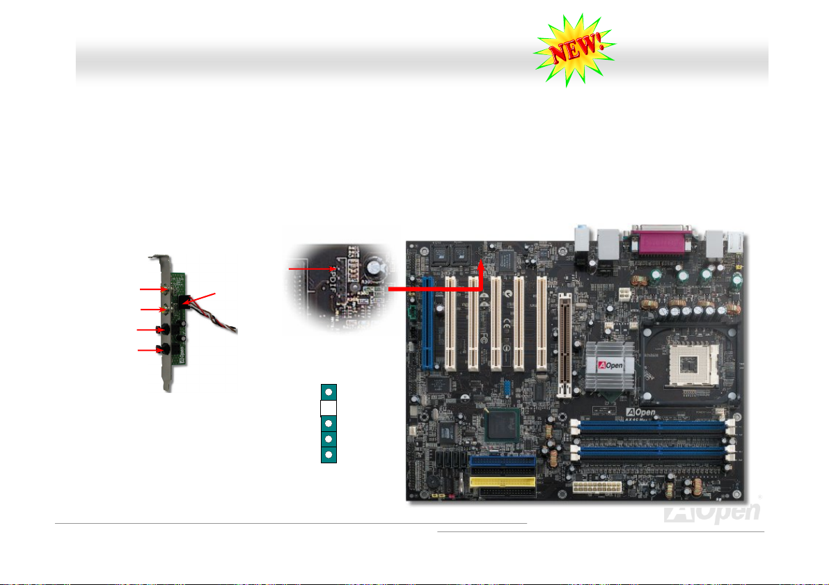
SS//PPDDIIFF ((SSoonnyy//PPhhiilliippss DDiiggiittaall IInntteerrffaaccee)) CCoonnnneeccttoorr
S/PDIF (Sony/Philips Digital Interface) is a newest audio transfer file format, which provides impressive audio quality through
optical fiber and allows you to enjoy digital audio instead of analog audio. Normally there are two S/PDIF outputs as shown, one
for RCA connector, the most common one used for consumer audio products, and the other for optical connector with better
audio quality. Through a specific audio cable, you can connect the S/PDIF connector to other end of the S/PDIF audio module,
which bears S/PDIF digital output. However, you must have a S/PDIF supported speaker/amplifier/decoder with S/PDIF digital
input to connect to the S/PDIF digital output to make the most out of this function.
(RCA)
F OUT
S/PDI
S/PDIF IN
S/PDIF OUT
S/PDIF IN
(Optical)
S/PDIF Module
(User Upgrade Optional)
S/PDIF
Cable
Pin 1
S/PDIF
Connector
+5V
1
NC
S/PDIFOUT
GND
47
Page 48

AAXX44CC MMaaxx IIII
O
Onnlliinnee MMaannuuaall
SSuuppeerr 55..11 CChhaannnneell AAuuddiioo EEffffeecctt
This motherboard comes with an ALC650 CODEC, which supports high quality of 5.1 Channel audio effects, bringing you a
brand new audio experience. On the strength of the innovative design of ALC650, you're able to use standard line-jacks for
surround audio output without connecting any external module. To apply this function, you have to install the audio driver in the
Bonus Pack CD as well as an audio application supporting 5.1 Channel. Picture bellow represents the standard location of all
speakers in 5.1Channel sound track. Please connect the plug of your front speakers to the green “Speaker out” port, rear
speakers’ plug to the blue “Line in” port and both of the center and subwoofer speakers to the red “MIC in” port.
48
Page 49

AAXX44CC MMaaxx IIII
O
Onnlliinnee MMaannuuaall
AAGGPP 88XX SSlloott
With Intel 875P (Canterwood) chipset implemented, this motherboard supports AGP function of 8X, it supports 1.5V AGP card
only (adjustable by 0.033 steps, such as 1.5V, 1.55V, 1.6V, 1.65V, 1.7V, 1.75V, 1.8V and 1.85V), please do not insert 3.3V AGP
card, otherwise, it could cause serious damage to the motherboard. Other than that, you could even adjust frequency between
variations from 64MHz to 100MHz through BIOS.
Additionally, AOpen provide sets of AGP/PCI frequencies for overclockers to manually overclock AGP/PCI frequency while
taking care of the system stability at the same time (but will be automatically disabled when connecting any Serial ATA device).
49
Page 50

AAXX44CC MMaaxx IIII O
Onnlliinnee MMaannuuaall
AAGGPP PPrrootteeccttiioonn TTeecchhnnoollooggyy aanndd AAGGPP LLEEDD
WWiitthh tthhee oouuttssttaannddiinngg RR&&DD aabbiilliittyy ooff AAOOppeenn aanndd iittss s
pprrootteecctt yyoouurr mmootthheerrbbooaarrdd
s mmootthheerrbbooaarrdd wwiillll aauuttoommaattiiccaallllyy ddeetteecctt tthhee vvoollttaaggee
tthhiis
tthhaatt iiff yyoouu iinnssttaallll aa AAGGPP cca
o
ssssiibbllee ddaammaaggee ooff tthhee eexxcceeeeddiinngg vvoollttaaggee.. YYoouu mmaayy ccoon
ppo
ffrroomm bbeeiinngg ddaammaaggeedd bbyy oovveerr--vvoollttaaggiinngg ooff AAGGPP ccaarrdd..
a
rrdd wwiitthh 33..33VV,, wwhhiicchh iiss nnoott ssuuppppoorrtteedd,, tthhee AAGGPP LLEEDD o
sppeecciiaallllyy ddeevveellooppeedd cciirrccuuiitt,, tthhiiss mmooddeell iimmpplleemmeennttss
ooff AAGGPP ccaarrdd aanndd pprreevveenntt yyoouurr cchhiippsseettss ffrroomm bbeeiinngg b
nttaacctt yyoouurr AAGGPP ccaarrdd vveennddoorr ffoorr ffuurrtthheerr ssuuppppoorrtt..
aa bblleenndd nneeww tteecchhnnoollooggyy ttoo
WWhheenn AAGGPP PPrrootteeccttiioonn TTeecchhnnoollooggyy iiss iimmpplleemmeenntteedd,,
buurrnntt oouutt.. PPlleeaassee nnoottee
onn tthhee mmootthheerrbbooaarrdd wwiillll lliigghhtt uupp ttoo wwaarrnn yyoouu tthhee
AGP LED
Warning: It is strongly recommended not
to install a 3.3V AGP card, which is not
supported. When you do so, the AGP LED
on the motherboard will light up to warn you
the possible damage.
50
Page 51

AAXX44CC MMaaxx IIII
O
Onnlliinnee MMaannuuaall
SSeellff--PPoowweerreedd PPCCII SSlloott
Spotted easily among other PCI slots onboard, this Self-Powered PCI slot comes in a special BLUE color to illustrate its
uniqueness and usefulness.
As independent as it is, Self-Powered PCI comes in a separate set of 3.3 volt power circuitry which supplies needed current and
making it virtually free from the “loading issue” of traditional PCI slot. In addition, traces around this specially designed slot
power delivery are upgraded in terms of their trace thickness, making its signals much more robust than their fellow PCI slots
onboard.
When building machines with PCI cards which requires higher power, such as SCSI and RAID cards, the card installed on this
slot will never be affected under heavy loading conditions such as all onboard PCI slots being fully populated. Self-Powered PCI
keeps supplying you best performance and stability.
Last but not least, if your computer comes with an ordinary SPS (Switching Power Supply), Self-Powered PCI Slot demonstrates
superior compatibility and reliability.
Independent 3.3 volt
power circuitry
Self-Powered PCI slot
51
Page 52

AAXX44CC MMaaxx IIII O
Onnlliinnee MMaannuuaall
WWOOMM ((ZZeerroo VVoollttaaggee WWaakkee oonn MMooddeemm)) CCoonnnneeccttoorr
This motherboard implements special circuit to support Wake On Modem, both internal modem card and external box modem
are supported. Since internal modem card consumes no power when system power is off, it is recommended to use an internal
modem. To use internal modem, connect 4-pin cable from RING connector of modem card to the WOM connector on the
motherboard.
WOM Connector
+5VSB
NC
RI-
GND
52
Page 53

AAXX44CC MMaaxx IIII O
WWOOMM bbyy EExxtteerrnnaall BBooxx MMooddeem
Traditional Green PC suspend mode does not really turn off the system power supply, it uses external box modem to trigger MB
COM port and resume back to active.
Note: This picture is for example only; it may not exactly be the same motherboard.
Pin 1
Pin 1
m
Onnlliinnee MMaannuuaall
Serial Port
(Modem Side)
Serial Port
(Motherboard Side)
53
Page 54

)
AAXX44CC MMaaxx IIII O
WWOOMM bbyy IInntteerrnnaall MMooddeemm CCaarrd
With the help of the ATX soft power On/Off, it is possible to have a system totally power off, and wakeup to automatically answer
a phone call as an answering machine or to send/receive a fax. You may identify whether or not your system is in true power off
mode by checking to see if the fan of your power supply is off. Both an external box modem and an internal modem card can be
used to support Modem Wake Up, but if you use an external modem, you have to leave your box modem on.
WOM Connector
(Motherboard Side)
Note: This picture is for example only; it may not exactly be the same motherboard.
d
Onnlliinnee MMaannuuaall
WOM Connector
(Modem Card
Side
54
Page 55

AAXX44CC MMaaxx IIII O
Onnlliinnee MMaannuuaall
WWOOLL ((WWaakkee oonn LLAANN))
This feature is very similar as Wake On Modem, but it goes through local area network. To use Wake On LAN function, you
must have a network card with chipset that supports this feature, and connect a cable from LAN card to motherboard WOL
connector. The system identification information (probably IP address) is stored on network card and because there is a lot of
traffic on the Ethernet, you need to install network management software, such as ADM, for the checking of how to wake up the
system. Note that, at least 600mA ATX standby current is required to support the LAN card for this function.
WOL Connector
+5VSB
GND
LID
55
Page 56

AAXX44CC MMaaxx IIII O
WOL Connector
(Motherboard Side)
Note: This picture is for example only, it may not exactly be the same motherboard. Note: This picture is for example only, it may not exactly be the same motherboard.
Onnlliinnee MMaannuuaall
WOL Connector
(Ethernet Card Side)
56
Page 57

AAXX44CC MMaaxx IIII O
Onnlliinnee MMaannuuaall
PPCC9999 CCoolloorr CCooddeedd BBaacckk PPaanneell
The onboard I/O devices are PS/2 Keyboard, PS/2 Mouse, COM1 and COM2, RJ45 LAN, Printer, USB2.0, AC97 sound and
game ports. The view angle of drawing shown here is from the back panel of the housing.
PS/2 Keyboard: For standard keyboard, which is using a PS/2 plug.
PS/2 Mouse: For PC-Mouse, which is using a PS/2 plug.
USB Port: Available for connecting USB devices.
Parallel Port: To connect with SPP/ECP/EPP printer.
COM1/COM2 Port: To connect with pointing devices, modem or others serial devices.
VGA Connector: To connect with PC monitor.
Speaker Out: To External Speaker, Earphone or Amplifier.
Line-In: Comes from the signal sources, such as CD/Tape player.
MIC-In: From Microphone.
PS/2 Mouse
Connector
PS/2 Keyboard
Connector
USB Port
(2.0)
COM 1 Port COM 2 Port
SPP/EPP/ECP
Parallel Port
RJ45 LAN Jack
USB Port
(2.0)
Line-In
Speaker Out
MIC-In
57
Page 58
AAXX44CC MMaaxx IIII O
Onnlliinnee MMaannuuaall
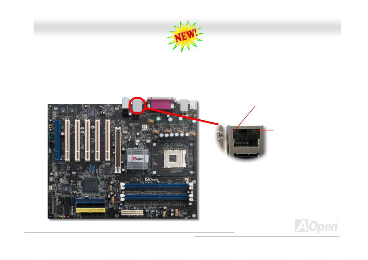
SSuuppppoorrtt GGiiggaabbiitt LLAANN oonnbbooaarrdd
On the strength of Broadcom Gigabit LAN controller on board, which is a highly-integrated Platform LAN Connect device, it
provides Gigabits Ethernet for office and home use, the Ethernet RJ45 connector is located on top of USB connectors. The
right-hand side LED indicates the link mode, it blinks in orange whenever linking to network. The left-hand side LED indicates
the Connecting mode, and it lights in green when 100Mbps LAN is connected (never lights while 10Mbps is connected), but
lights in orange when Gigabits LAN is connected. To enable or disable this function, you may simply adjust it through BIOS.
Connecting (Left)
Green (100Mbps)
Orange (Gigabit)
Linking (Right)
Orange
58
Page 59
AAXX44CC MMaaxx IIII O
Onnlliinnee MMaannuuaall
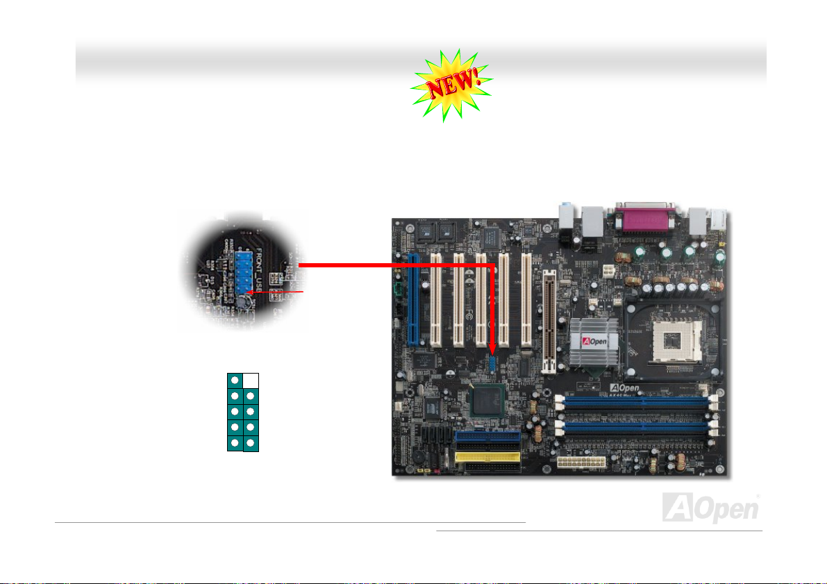
SSuuppppoorrtt EEiigghhtt UUSSBB22..00 CCoonnnneeccttoorrss
Compared to traditional USB 1.0/1.1 with the speed of 12Mbps, USB 2.0 has a fancy speed up to 480Mbps, which is 40 times
faster than the traditional one. Except for the speed increase, USB 2.0 supports old USB 1.0/1.1 software and peripherals,
offering impressive and even better compatibility to customers. On this motherboard, all eight USB connectors support USB 2.0
function. To connect those two headers, you have to use proper USB cables and connect them to any USB models.
USB2 Connector
NC KEY
GND-
SBD3+
SBD3-
+5V
GND
SBD2+
SBD2
+5V
1
Pin 1
59
Page 60

AAXX44CC MMaaxx IIII O
Onnlliinnee MMaannuuaall
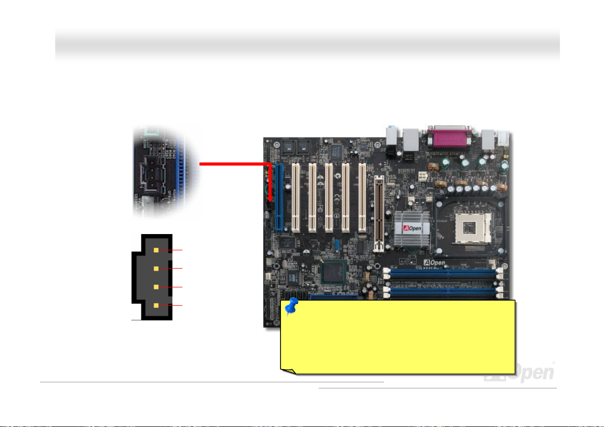
OOnnbbooaarrdd IIEEEEEE 11339944 CCoonnttrroolllleerr
This motherboard comes with AGERE 1394 Control Chip (FW323) onboard. The IEEE 1394 provides data transfer rate up to
400Mbps, and USB just has 12Mbps. Hence, the IEEE 1394 interface can connect with the devices that need high data
transferring performance, such as digital camera, scanner or others IEEE 1394 devices. Please use the proper cable to connect
with devices.
10 9
Shielding GND
1394_PWR
TPB-
Pin 1
IEEE 1394
Port 1 & 2
Warning: Please be noted that Hot-Plug in is not
allowed on IEEE 1394 header, because it will burn
the IC of the controller and damage the motherboard.
60
GND
TPA-
KEY
1394_PWR
TPB+
GND
TPA+
2 1
Page 61

AAXX44CC MMaaxx IIII O
Onnlliinnee MMaannuuaall
CChhaassssiiss IInnttrruussiioonn CCoonnnneeccttoorr
The “CASE OPEN” header provides chassis intrusion-monitoring function. To make this function works, you have to enable it in
the system BIOS, connect this header to a sensor somewhere on the chassis. So, whenever the sensor is triggered by lights or
the opening of the chassis, the system will send out beep sound to inform you. Please be informed that this useful function only
applies to advanced chassis, you may purchase an extra sensor, attach it on your chassis, and make a good use of this
function.
Pin 1
1
SENSOR
Chassis Intrusion
Connector
GND
61
Page 62
AAXX44CC MMaaxx IIII O
Onnlliinnee MMaannuuaall
CCDD AAuuddiioo CCoonnnneeccttoorr
This connector is used to connect CD Audio cable from CDROM or DVD drive to onboard sound.
CCDD--IINN CCoonnnneeccttoorr
L
GND
GND
R
Note: Though some of the latest version of Windows
support “Digital Audio” through IDE bus. However, in
order to use Open Jukebox player, which is driven
under BIOS, it is a MUST to insert audio cable to
CD-IN connector on the motherboard.
62
Page 63
AAXX44CC MMaaxx IIII O
Onnlliinnee MMaannuuaall
AAUUXX--IINN CCoonnnneeccttoorr
This connector is used to connect MPEG Audio cable from MPEG card to onboard sound.
AAUUXX--IINN CCoonnnneeccttoorr
L
GND
GND
R
63
Page 64

g
AAXX44CC MMaaxx IIII O
Onnlliinnee MMaannuuaall
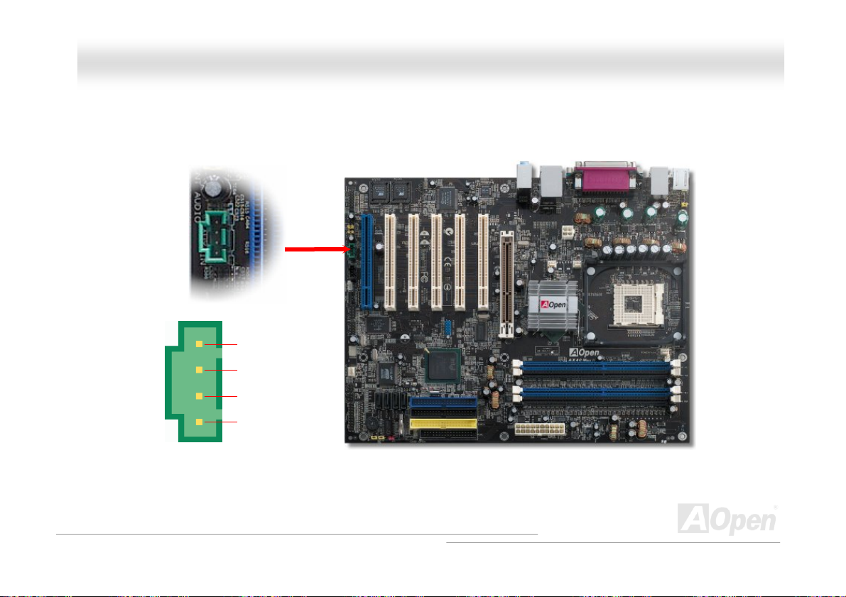
FFrroonntt AAuuddiioo CCoonnnneeccttoorr
If the housing has been designed with an audio port on the front panel, you’ll be able to connect onboard audio to front panel
through this connector. By the way, please remove 5-6 and 9-10 jumper caps from the Front Audio Connector before
connecting the cable. Please do not remove these 5-6 and 9-10 yellow jumper caps if there’s no audio port on the front
panel.
Pin 1
AUD_MIC
AUD_MIC_BIAS
AUD_FPOUT_R
NC
AUD_FROUT_L
1 2
AUD_GND
AUD_VCC
AUD_RET_R
KEY
AUD_RET_L
9 10
Note: Please remove the jumper cap from the Front Panel Audio Connector
before you connect the cable. Do not remove this yellow jumper cap if
housin
without an audio port on the front panel.
64
Page 65

AAXX44CC MMaaxx IIII O
Onnlliinnee MMaannuuaall
DDiiee--HHaarrdd BBIIOOSS IIII ((UUsseerr UUppggrraaddee OOppttiioonnaall))
Many viruses have been found that they may destroy bios code and data area lately. This motherboard implements a very
effective hardware protection method without any software or BIOS coding involved, therefore it is 100% virus free. You may
restore the originally mounted BIOS with 2
BIOS 2
nd
BIOS ROM by setting JP24 to pin 2-3 if it fails to work properly.
BIOS 1
JP24
Pin 1
BIOS Rescue Jumper
1
Normal
(Default)
JP24
1
Rescue
(BIOS 2)
65
Page 66

AAXX44CC MMaaxx IIII O
Onnlliinnee MMaannuuaall
EExxtteerrnnaall CCoonnttrroolllleerr ffoorr DDIIEE--HHAARRDD BBIIOOSS ((UUsseerr UUppggrraadde
External Controller provides you a better and convenience way to switch the BIOS status between “Rescue” and “Normal”
without opening the case of your computer. You have to plug the jumper cable to the connector pin (JP30) on the motherboard.
Be careful of the orientation when you connect, the red wire should correspond to Pin1.
Normal
To / From CPU
Read Only
Read/Write
Rescue ROM
Manual Switch
Flash ROM
e OOppttiioonnaall))
Note: If you suspect your BIOS is infected by virus, just rescue your bios by following steps:
66
Page 67

AAXX44CC MMaaxx IIII O
1. Turn off the system, set the External Controller to “Rescue” to read from rescue ROM. 1. Turn off the system, set the External Controller to “Rescue” to read from rescue ROM.
2. Boot the system and set the switch back to “Normal”. 2. Boot the system and set the switch back to “Normal”.
3. Follow the BIOS upgrade procedure to rehabilitate BIOS. 3. Follow the BIOS upgrade procedure to rehabilitate BIOS.
Reboot the system, and you should be able to go back to normal mode. Reboot the system, and you should be able to go back to normal mode.
Normal
(Read from normal
Flash ROM)
Tip: If you place the switch to the middle
rd
picture shows), you will not be
(as 3
able to boot your system, thus you can
protect your data from molesting.
Rescue
(Read from
Rescue ROM)
(Lock your computer
to protect your data)
Onnlliinnee MMaannuuaall
Lock
67
Page 68

AAXX44CC MMaaxx IIII O
Onnlliinnee MMaannuuaall
JJPP22 DDrr.. VVooiiccee OOuuttppuutt SSeelleecctt JJuummppeerr
This motherboard comes with another considerate function, which allows you to select the voice coming out from buzzer or
speaker, if Dr. Voice detects any errors that occurred in the operating system. If you want to enable buzzer, you may set JP2 to
pin 1-2, or pin 2-3 to enable speaker. For enabling different language versions of Dr Voice, please go to BIOS settings for
adjustment.
Pin 1
JP2 Dr. Voice Output
Select Jumper
1
Buzzer
(Default)
1
Speaker
68
Page 69

AAXX44CC MMaaxx IIII O
Onnlliinnee MMaannuuaall
DDrr.. LLEEDD CCoonnnneeccttoorr
In conjunction with Dr. LED (Upgrade Optional), which can easily shows what kind of problems may occur on your system during
assembly. It can clearly indicate whether there is a component issue or an installed issue by the 8 LEDs on the front panel of Dr.
LED. This can helps you to have a self-diagnostic to your system status quickly.
Pin 1
3.3V
KEY
GND
1 2
S1
S2
S3
5 6
69
Page 70

AAXX44CC MMaaxx IIII O
Dr. LED is a CD disc storage box with 8 LEDs on its front panel, the size of Dr. LED is exactly the same as 5.25 in floppy drive,
Dr. LED is a CD disc storage box with 8 LEDs on its front panel, the size of Dr. LED is exactly the same as 5.25 in floppy drive,
so that it can be mount into normal 5.25 in drive bay of any housing.
so that it can be mount into normal 5.25 in drive bay of any housing.
The total 8 LEDs light up alternatively if the system fails in one of eight stages. Once the LED7 (latest LED) is lit, this indicates
The total 8 LEDs light up alternatively if the system fails in one of eight stages. Once the LED7 (latest LED) is lit, this indicates
that the system has completed its boot-up procedure.
that the system has completed its boot-up procedure.
The 8 LEDs indicate the following messages when lit: The 8 LEDs indicate the following messages when lit:
LED 0 - Indicates that the CPU may have been installed incorrectly or is damaged.
LED 0 - Indicates that the CPU may have been installed incorrectly or is damaged.
LED 1 - Indicates that the memory may have been installed incorrectly or is damaged.
LED 1 - Indicates that the memory may have been installed incorrectly or is damaged.
LED 2 - Indicates that the AGP may have been installed incorrectly or is damaged.
LED 2 - Indicates that the AGP may have been installed incorrectly or is damaged.
LED 3 - Indicates that the PCI card may have been installed incorrectly or is damaged.
LED 3 - Indicates that the PCI card may have been installed incorrectly or is damaged.
LED 4 - Indicates that the floppy disk drive may have been installed incorrectly or is damaged.
LED 4 - Indicates that the floppy disk drive may have been installed incorrectly or is damaged.
LED 5 - Indicates that the HDD may have been installed incorrectly or is damaged.
LED 5 - Indicates that the HDD may have been installed incorrectly or is damaged.
LED 6 - Indicates that the keyboard may have been installed incorrectly or is damaged.
LED 6 - Indicates that the keyboard may have been installed incorrectly or is damaged.
LED 7 - Indicates that the system is OK.
LED 7 - Indicates that the system is OK.
567
Boot O.K.
KB
HDD
Floppy
PCI MemoryVideo CPU
01234
Onnlliinnee MMaannuuaall
Note: During POST (Power On Self Test) procedure, the
Debug LED will light on sequentially from LED0 to LED7 until
the system boot O.K
70
Page 71

AAXX44CC MMaaxx IIII O
Onnlliinnee MMaannuuaall
Auto Switch
RTC
CMOS
Baatttteerryy--lleessss aanndd LLoonngg LLiiffee DDeessiiggnn
Auto switching to ATX standby power as
long as AC power line is plugged. This
smart design increases battery life if you
still plug battery on motherboard.
Backup by EEPROM
BBaatttteerryy--lleessss aanndd LLoonngg LLiiffee DDeessiiggnn
This Motherboard implements Flash ROMThis Motherboard implements Flash ROM and a special circuit that allows you to save your current CPU and CMOS Setup
configurations without the need of a battery. The RTC (real time clock) can also keep running as long as the power cord is
plugged. If you lose your CMOS data by accident, you can just reload the CMOS configurations from Flash ROM and the system
will recover as usual.
Flash
ROM
ATX Stand-by Power Battery
(Real Time Clock)
00:00:00
71
Page 72

AAXX44CC MMaaxx IIII O
Onnlliinnee MMaannuuaall
CCPPUU OOvveerr--ccuurrrreenntt PPrrootteeccttiioonn
Over Current Protection has been popularly implemented on ATX 3.3V/5V/12V switching power supply for a while. However,
Over Current Protection has been popularly implemented on ATX 3.3V/5V/12V switching power supply for a while. However,
new generation CPU is able to use regulator of different voltages to transfer 12V to CPU voltage (for example, to 2.0V). This
new generation CPU is able to use regulator of different voltages to transfer 12V to CPU voltage (for example, to 2.0V). This
motherboard is with switching regulator onboard that supports CPU over-current protection, and it applies to 3.3V/5V/12V power
motherboard is with switching regulator onboard that supports CPU over-current protection, and it applies to 3.3V/5V/12V power
supply for providing full line over-current protection.
supply for providing full line over-current protection.
Note: Although we have implemented protection circuit try to prevent any human operating
mistake, there is still certain risk that CPU, memory, HDD, add-on cards installed on this
motherboard may be damaged because of component failure, human operating error or unknown
nature reason. AOpen cannot guaranty the protection circuit will always work perfectly.
ATX Switching Power
Supply
CPPUU OOvveerr--ccuurrrreenntt PPrrootteeccttiioonn
Onboard
Power
Regulator
5V (Protected by power supply)
3.3V (Protected by power supply)
12V (Protected by power supply)
Over-Current
Protection Circuit
72
CPU Core Voltage
Page 73

AAXX44CC MMaaxx IIII
O
Onnlliinnee MMaannuuaall
AAOOCCoonnffiigg UUttiilliittyy
AOpen always dedicated to provide users a much friendlier computer environment. We now bring you a comprehensive system
detective utility. AOconfig is a Windows based utility with user-friendly interface that allows users to obtain information of the
operation system and hardware such as motherboard, CPU, memory, PCI devices and IDE devices. The powerful utility also
displays the version of BIOS and firmware for your convenience of maintenance.
Moreover, AOconfig allows users to save information in *.BMP or *.TXT format which users may collect the system information
in detail and send them to AOpen directly for technical support or further diagnosis of system problem.
1. The system page shows the
detail information of the
motherboard, the operating
system, the processor, and
BIOS version.
2. The PCI device page shows
the configurations of all PCI
devices installed on your
motherboard.
73
Page 74
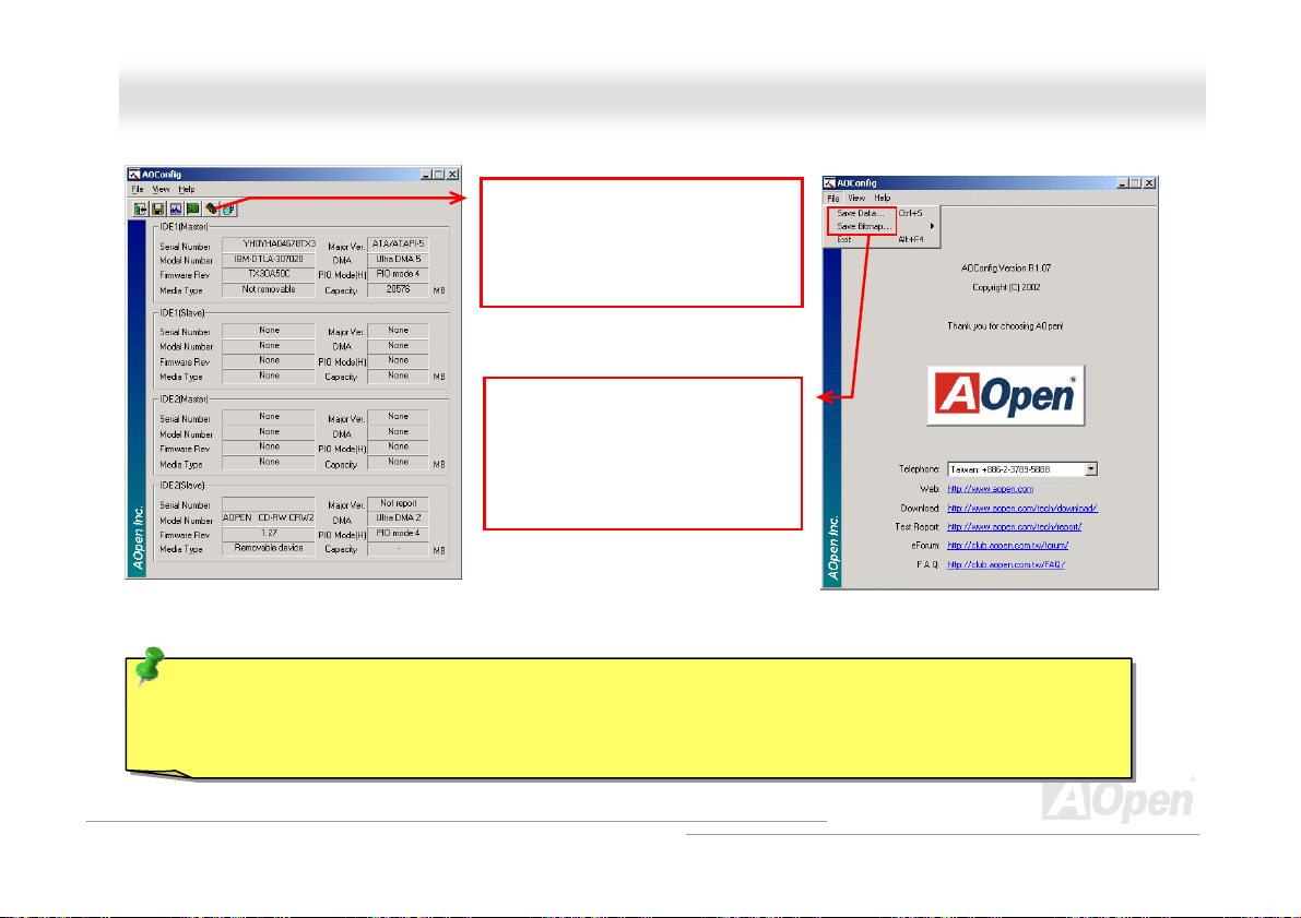
AAXX44CC MMaaxx IIII O
NOTE: AOconfig can be used in Windows 98SE/ME, NT4.0/2000, or even the latest Windows XP. Please be
informed that AOconfig can only be operated in a system equipped with an AOpen motherboard. Meanwhile, all
applications must be closed before starting AOconfig.
3. This page presents the IDE
devices information, such as
the serial number, the
manufacturer, the firmware
version, and capacity.
4. From this page, users may
obtain the technical support
information of AOpen.
Moreover, detailed information
could be saved in .bmp or .txt
format.
Onnlliinnee MMaannuuaall
74
Page 75
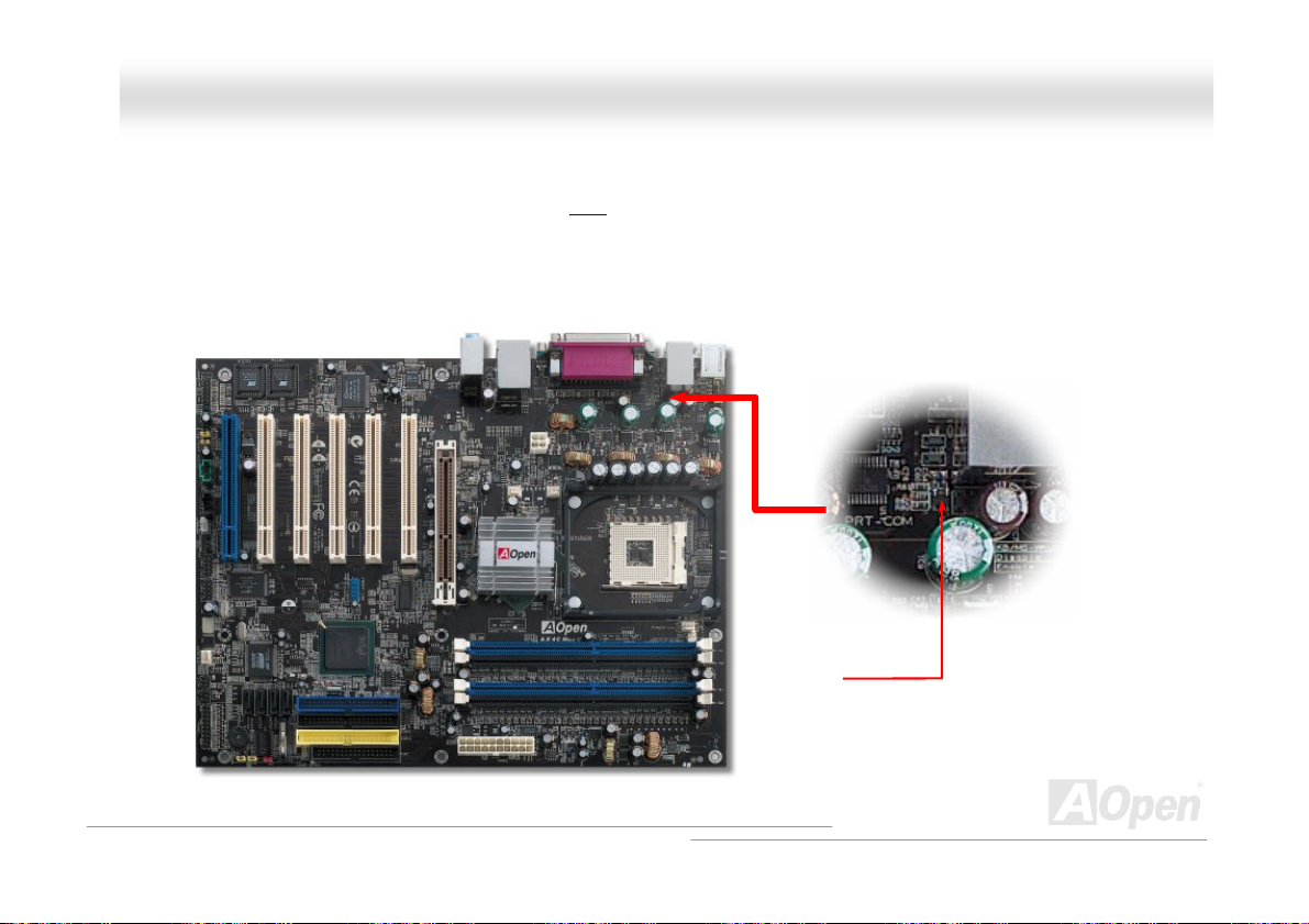
AAXX44CC MMaaxx IIII O
Onnlliinnee MMaannuuaall
RReesseettaabbllee FFuussee
Traditional motherboard has fuse for Keyboard and USB port to prevent over-current or shortage. These fuses are soldered
onboard that when it is broken (function as protecting the motherboard), user still cannot replace it and the motherboard is still
malfunctioning.
With expensive Resetable Fuse, the motherboard can be resumed back to normal function after the fuse had done its protection
job.
Resetable
Fuse
75
Page 76

AAXX44CC MMaaxx IIII O
0
3333000
The quality of low ESR capacitor (Low Equivalent Series Resistance) during high frequency operation is very important for the
stability of CPU power. The idea of where to put these capacitors is another know-how that requires experience and detail
calculation.
Not only that, AX4C Max II implements 3300μF capacitors, which is much larger than normal capacitor (1500 and 2200μf) and
it provides better stability for CPU power.
μ
μ
FF LLooww EESSRR CCaappaacciittoorr
Onnlliinnee MMaannuuaall
76
Page 77
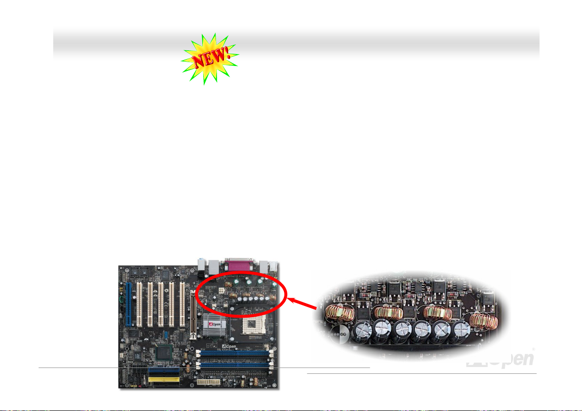
AAXX44CC MMaaxx IIII
O
Onnlliinnee MMaannuuaall
VV44 PPoowweerr EEnnggiinnee
While the market are flooded with low quality, cost-down power materials on motherboard by treacherous manufacturers that
subsequently cause the stability of your system, unknown system crashing, overheating of your motherboard, we, AOpen have
decided to maintain our long-lasting reputation of refined manufacturer by keep providing solid materials on our products.
As if V6 engine gives more horsepower to your car driving on the road, so as motherboard needed to have stronger and more
robust power to protect your system. Adopted 4 parelelled PWM (Pulse Width Modulation) controller channels in 4-phase form,
this motherboard provide optimized power density, transient response and thermal performance for satisfying the increasing
high CPU temperature. And one thing for sure, 4-phase PWM controller would definitely be better for 3-phase PWM controller as
the same theory of 3000c.c car would certainly be better than 2000c.c car. Therefore, It is a must for motherboard these days to
get prepared with stronger, more stable power.
If we take 60W power consumption shared by 3-phase PWM controller for example, testings shows that it transmits higher
temperature to its surrounding components and thus increasing the temperature of motherbaord, which is very frustrating for
CPU overclocking or for system stability concern at high loading. However, with 4-phase PWM controller implemented, voltage
are averagely shared in 4-phase PWM controller and transmit less temperature onto the board and thus cool down motherboard
temperature, so as to protect your system.
77
4-phase form PMW
Page 78
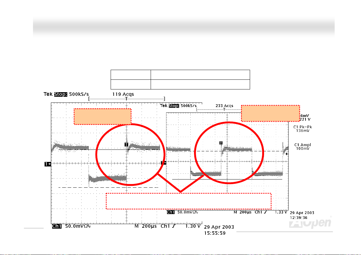
AAXX44CC MMaaxx IIII O
Onnlliinnee MMaannuuaall
Comprison Transient of 3-phase and 4-phase PWM Comprison Transient of 3-phase and 4-phase PWM
As test report shows, while most of the motherboards on the market are powered by 3-phase PWM controller, this motherboard
As test report shows, while most of the motherboards on the market are powered by 3-phase PWM controller, this motherboard
does comes with 4-phase PWM controller providing stronger power, and could lower down the temperature of motherboard from
does comes with 4-phase PWM controller providing stronger power, and could lower down the temperature of motherboard from
15℃ to 30℃.
15℃ to 30℃.
-phase
-phase
4
4
3-phase Vcore tolerance of - 126 mv
3-Phase PWM
Transient difference between 3-phas and 4-phase PWM
Vcore tolerance of - 116 mv Vcore tolerance of - 116 mv
4-Phase PWM
78
Page 79

AAXX44CC MMaaxx IIII
O
Onnlliinnee MMaannuuaall
OOppeenn JJuukkeeBBooxx PPllaayyeerr
without any hassle of entering Windows operation system.
Here we are pleased to provide you a brand-new powerful interface—Open JukeBox.
Without any cost you can have your PC turn into a fashionable CD player! This latest Open
JukeBox motherboard aims at helping you directly operate your CD player on the PC
79
Page 80

y
play
AAXX44CC MMaaxx IIII O
Onnlliinnee MMaannuuaall
How Your Open JukeBox Works
The operation of Open JukeBox Player is the same as other CD players. By pressing specific keys on the keyboard you will find
playing Open JukeBox Player couldn’t be easier than the traditional CD Players. Below is the function description of respective
buttons.
Power-Off Button
Operation System
Boot to
Power: Pressing
Boot: Pressing
Play: Pressing
Stop: Pressing
Pause: Pressing
Eject: Pressing
Repeat: Like other CD Players, pressing
Vol um e +/ -: Pressing + or – to adjust the volume of playing music.
Rewind/Forward Å / Æ: Pressing arrow keys, to rewind or forward the music.
O, to directly power off your computer with no hassle of entering Windows Operation System.
B, to intelligently boot to Windows Operation System for you.
A, to start playing CD music.
S, to stop the music playing.
P, to pause the music playing temporarily.
E, to eject CD tray for you to change CD disc.
R, to shift the repeat mode.
80
Note: Though some of the latest
version of Windows support “Digital
Audio” through IDE bus. However, in
order to use Open Jukebox player,
which is driven under BIOS, it is a
MUST to insert audio cable to CD-IN
connector on the motherboard.
Dis
Function Ke
Screen
Page 81

AAXX44CC MMaaxx IIII O
Onnlliinnee MMaannuuaall
Your Open JukeBox Settings in BIOS
There are three Open JukeBox settings in BIOS as follows.
Auto: The default setting is “Auto” with which the Open JukeBox will automatically check the CD player every time you power
on. The Open JukeBox will automatically be launched when it detects a music CD in your CD player.
Press Insert Key: Choosing this setting will allow a reminder message popped up on the screen during BIOS POST. It reminds
you of pressing “Ins” key on your keyboard to start Open JukeBox Player; otherwise the system will launch the Windows
Operation System.
CD Player: Choosing this setting allows the system to launch Open JukeBox Player every time you power on. However, by
pressing B on your keyboard the Windows Operation System will be launched.
81
Page 82

AAXX44CC MMaaxx IIII O
Onnlliinnee MMaannuuaall
Your Open JukeBox EzSkin
Except these powerful functions above, Open JukeBox Player is also equipped with another fancy feature for you to
change its “skin”. You can download as many skins as you want from AOpen Website, and changing them whenever
you want by using this useful utility – EzSkin – which may also be downloaded from our website.
Even more, you may design your own skins with innovative idea and sharing them to users around the world by uploading to our
website. For further technical information, we welcome you to visit our website at
http://english.aopen.com.tw/tech/download/skin
82
Page 83

AAXX44CC MMaaxx IIII O
Onnlliinnee MMaannuuaall
VViivviidd BBIIOOSS tteecchhnnoollooggyy
Unlike earlier graphic POST screen which could occupy the whole screen and mask text information during POST, AOpen
Unlike earlier graphic POST screen which could occupy the whole screen and mask text information during POST, AOpen
VividBIOS deals with graphics and texts separately, and makes them running simultaneously during POST. With this innovative
VividBIOS deals with graphics and texts separately, and makes them running simultaneously during POST. With this innovative
design, VividBios now brings you a beautiful and sleek 256 colors screen without missing any important information shown on
design, VividBios now brings you a beautiful and sleek 256 colors screen without missing any important information shown on
POST screen.
POST screen.
In addition, the limited space of BIOS ROM is another big issue. When all of the traditional BIOS can only show
In addition, the limited space of BIOS ROM is another big issue. When all of the traditional BIOS can only show
space-consuming and uncompressed Bitmap, AOpen has considerately tuned the BIOS to next generation, to recognize the
space-consuming and uncompressed Bitmap, AOpen has considerately tuned the BIOS to next generation, to recognize the
smaller-sized GIF format and even dynamic-showing GIF animation.
smaller-sized GIF format and even dynamic-showing GIF animation.
Vivid BIOS shares the same fundamental technology with Open JukeBox CD Player, you may use the same EzSkin utility to
change your Vivid BIOS screen or to download your favorite Open JukeBox skin. If you see this little logo
your model name on the BIOS download page,
motherboard supports this innovative feature!
Viivviidd BBIIOOSS tteecchhnnoollooggyy
Have you been fed up with the conservative and immutable POST screen? Let’s rule out
Have you been fed up with the conservative and immutable POST screen? Let’s rule out
the tradition idea that POST screen are stiff and frigid, and let AOpen show you the newly
the tradition idea that POST screen are stiff and frigid, and let AOpen show you the newly
developed VividBIOS to experience the lively vivid colorful POST screen!
developed VividBIOS to experience the lively vivid colorful POST screen!
shown beside
http://english.aopen.com.tw/tech/download/skin, it is assured that your
83
Page 84

AAXX44CC MMaaxx IIII O
Onnlliinnee MMaannuuaall
HHyyppeerr TThhrreeaaddiinngg TTeecchhnnoollooggyy
What is Hyper-Threading?
Hyper-Threading technology is an innovative design from Intel that enables multi-threaded software applications to process
threads in parallel within each processor resulting in increased utilization of processor execution resources. As a result, an
average improvement of ~40% in CPU resource utilization yields higher processing throughput.
How Hyper-Threading Works
A form of simultaneous multi-threading technology (SMT), Hyper-Threading technology allows multiple threads of software
applications to be run simultaneously on
one processor by duplicating the
architectural state on each processor
while the same processor execution
resources is shared. The figure below
represents how a Hyper-Threading based
processor differentiates a traditional
multiprocessor. The left-hand
configuration shows a traditional
multiprocessor system with two physical
processors. Each processor has its own
independent execution resources and
architectural state. The right-hand
configuration represents an Intel
Hyper-Threading technology based
processor. You can see that the architectural state for each processor is duplicated, while the execution resources is shared.
84
Page 85

AAXX44CC MMaaxx IIII O
For multiprocessor-capable software applications, the Hyper-Threading based processor is considered two separate logical
processors on which the software
applications can run without
modification. Also, each logical
processor responds to interrupts
independently. The first logical
processor can track one software
thread, while the second logical
processor tracks another software
thread simultaneously. Because the
two threads share the same
execution resources, the second
thread can use resources that would
be otherwise idle if only one thread
was executing. This results in an
increased utilization of the execution
resources within each physical
processor.
The figure below represents how
Hyper-Threading saves time when it works. With two logical processors available on every single physical processor,
multi-threaded applications can now take advantage of thread-level parallelism on each physical processor for additional
performance. As software applications continue to be optimized to take greater advantage of processor parallelism,
Hyper-Threading technology provides an additional boost for newer capabilities and the growing needs of today’s users.
Onnlliinnee MMaannuuaall
85
Page 86

AAXX44CC MMaaxx IIII O
Onnlliinnee MMaannuuaall
RRAAIIDD IInnttrroodduuccttiioonn
WWhhaatt’’ss RRAAIIDD??
Two major challenges facing the storage industry today are keeping pace with the increasing performance demands of computer
systems by improving disk I/O throughput and providing data accessibility in the face of hard disk failures.
The idea of RAID (Redundant Array of Independent Disks) was first introduced by David A. Patterson, Garth Gibson and Randy
H. Katz at the University California at Berkeley in 1988. RAID is a purpose of storing the same data in different places on
multiple
performance and/or data fault tolerance. Better performance is accomplished by sharing the workload in parallel among multiple
physical hard drives. Fault-tolerance is achieved through data redundant operation where if one (or more) drive fails or has a
sector failure, a mirrored copy of the data can be found on another drive(s).
A RAID appears to the operating system to be a single logical hard disk. The RAID controller manages how the data is stored
and accessed across the physical and logical arrays. The RAID controller help users to ensure that the operating system only
sees the logical drives and users do not need to worry about managing the complicated schema.
For optimal performance results, select identical hard drives to install in disk arrays. The drives’ matched performance allows
the array to function better as a single drive.
hard disks and improves storage subsystem performance. The advantage of RAID is to provide better throughput
Warning: The Serial ATA RAID function
can be supported under Windows XP
and Windows .Net environments.
86
Page 87

AAXX44CC MMaaxx IIII O
Onnlliinnee MMaannuuaall
WWhhaatt aarree tthhee RRAAIIDD lleevveellss??
SSttrriippiinngg // SSppaann ((RRAAIIDD 00))
SSttrriippiinngg // SSppaann ((RRAAIIDD 00))
RAID level 0, which is the fastest drive array you can have, is a performance-oriented disk mapping method. The data in this
RAID level 0, which is the fastest drive array you can have, is a performance-oriented disk mapping method. The data in this
array gets written across a stripe or different disks for a faster transfer. This technique has striping but no redundancy of data. It
array gets written across a stripe or different disks for a faster transfer. This technique has striping but no redundancy of data. It
offers the best performance but no fault-tolerance. Reads and writes sector of data interleaved between multiple drives. When
offers the best performance but no fault-tolerance. Reads and writes sector of data interleaved between multiple drives. When
any disk member fails, it affects the entire array. Performance is better than a single drive since the workload is balanced
any disk member fails, it affects the entire array. Performance is better than a single drive since the workload is balanced
between the array members. This array type is for high performance systems. Identical drives are recommended for
between the array members. This array type is for high performance systems. Identical drives are recommended for
performance as well as data storage efficiency. The disk array data capacity is equal to the number of members times the
performance as well as data storage efficiency. The disk array data capacity is equal to the number of members times the
smallest member capacity. For example, one 40GB and one 60GB drives will form an 80GB (40GBx2) disk array.
smallest member capacity. For example, one 40GB and one 60GB drives will form an 80GB (40GBx2) disk array.
Whhaatt aarree tthhee RRAAIIDD lleevveellss??
Block 1
Block 2
Block 3
Block 4
Striping
Block 1
Block 3
Block 5
Block 7
Block 5
Block 6
Block 7
Block 8
Block 2
Block 3
Block 5
Block 7
Logical Drive
87
Physical Disks
Page 88

AAXX44CC MMaaxx IIII O
Onnlliinnee MMaannuuaall
MMiirrrroorriinngg ((RRAAIIDD 11))
RAID level 1 uses at least two duplicate hard drives and store the exact
same blocks of information between them. This is the slowest form of
fault tolerance because the data has to be replicated onto two disks at
the same time. However, this is the simplest way to provide high
reliability.
If one of the mirrored drives suffers a mechanical failure or does not
respond, the remaining drive will continue to serve and provide correct
data. If one drive has a physical sector error, the mirrored drive will
continue to function.
Due to redundancy, the drive capacity of the array is half the total drive
capacity. For example, two 40GB drives that have a combined capacity
of 80GB would have 40GB of usable storage. With drives of different
capacities, there may be unused capacity on the larger drive. RAID 1
increases cost as it takes twice as much hard drives to build our arrays.
Block 1
Block 2
Block 3
Block 4
Block 5
Block 6
Block 7
Block 8
Logical Drive
Block 1
Block 2
Block 3
Block 4
Block 5
Block 6
Mirroring
Block 7
Block 8
Block 1
Block 2
Block 3
Block 4
Block 5
Block 6
Block 7
88
Physical Disks
Page 89

AAXX44CC MMaaxx IIII O
Onnlliinnee MMaannuuaall
SSttrriippiinngg wwiitthh MMiirrrroorriinngg ((RRAAIIDD 00++11))
As the name would suggest, RAID 0+1 is striping and mirroring combined. This RAID combines the best of both RAID 0 and
RAID 1. It takes a Disk stripe using two disks, and mirrors it to another set of disks for fault tolerance. Data is stripped across
several disks, each disk has partner with exactly the same data on it. You get the benefits of fast data access as in RAID 0, with
the fault tolerance of RAID 1. This configuration provides optimal speed and reliability. You need double the number of disks as
a RAID 0, half for each side of the mirror. At least 4 hard disks are needed while performing RAID 0+1. There are other RAID
configurations in addition to those described here, but these are the types most commonly used in the industry.
Block 1
Block 2
Block 3
Block 4
Block 5
Block 6
Block 7
Block 8
Logical Drive
Block 1
Block 3
Striping
Block 5
Block 7
Block 2
Block 4
Block 6
Block 8
Physical Disks
Mirroring
Mirroring
Block 1
Block 3
Block 5
Block 7
Block 2
Block 4
Block 6
Block 8
Physical Disks
89
Page 90
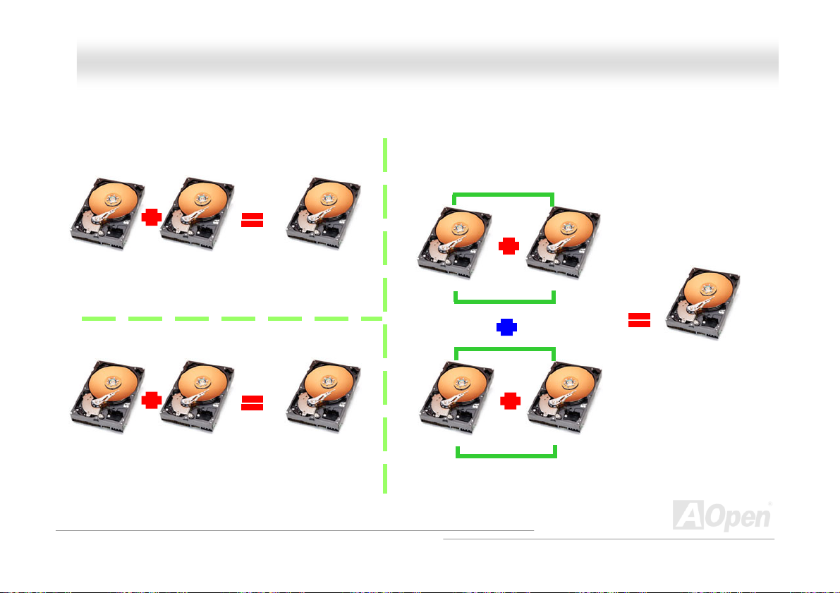
AAXX44CC MMaaxx IIII O
Onnlliinnee MMaannuuaall
HHDDDD CCaappaacciittyy ooff RRAAIIDD LLeevveellss
SSttrriippiinngg // SSppaann ((RRAAIIDD 00)) S
Physical Disks
40 GB
MMiirrrroorriinngg ((RRAAIIDD 11))
Physical Disks
40 GB
Physical Disks
40 GB
Physical Disks
40 GB
Logical Drive
80 GB
Logical Drive
40 GB
Physical Disks 40GB
Physical Disks 40GB
Sttrriippiinngg wwiitthh MMiirrrroorriinngg ((RRAAIIDD 00 ++11))
Striping
Physical Disks 40 GB
Mirroring
Logical Drive
80 GB
Physical Disks 40 GB
Striping
90
Page 91

AAXX44CC MMaaxx IIII O
Onnlliinnee MMaannuuaall
SSeerriiaall AATTAA RRAAIIDD ffoorr IInntteell IICCHH55RR
With the latest chipsets implemented, Intel ICH5R provides RAID 0 and RAID 1 function for the Serial ATA hard disks. You may
follow the steps shown below to setup your disk array.
AArroouussee RRAAIIDD ffuunnccttiioonn iinn BBIIOOSS
After having properly installed your Serial ATA hard disks, you may directly get into the BIOS setting screen for adjustment. You
may simply press “Integrated Peripherals Æ OnChip IDE Device Æ On-Chip Serial ATA” to choose Enhanced mode. In order
to utilize Serial ATA function, please select RAID in SATA Mode. Finally, do save the changes and exit BIOS setup screen.
91
Page 92

AAXX44CC MMaaxx IIII O
Onnlliinnee MMaannuuaall
RRAAIIDD CCoonnffiigguurraattiioonn UUttiilliittyy
In order to make sure your system can recognize and operate Serial ATA RAID device smoothly, we have to enter RAID
Configuration Utility to do some configuration. After finishing the BIOS setup and reboot, you will see [Press CTRL + I to enter
configuration Utility] about half way through the boot up. Please press these two buttons simultaneously. When you enter you
will be presented with a screen as shown below:
1. Create RAID Volume:
This section allows users to choose the strip
size and disk volume of RAID.
2. Delete RAID Volume:
This section allows users to delete the volume
of RAID. Please be noted that deleting a
volume will destroy volume data and cause
any member disks to become available as
non-RAID disks.
3. Reset Disks to Non-RAID:
Users can remove any internal RAID
structures from all RAID disks, including disks
with working volume. Select “Yes” will cause
all data on any disk to be lost.
92
Page 93
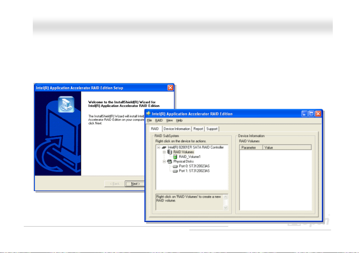
AAXX44CC MMaaxx IIII O
Onnlliinnee MMaannuuaall
IInnssttaalllliinngg IIAAAA DDrriivveerr ((IInntteell AApppplliiccaattiioonn AAcccceelleerraatto
You can install Intel IAA RAID Edition Driver to increase the performance of software applications and reduce PC boot times.
The IAA RAID Edition is designed to provide functionality for the Intel (R) ICH5R SATA RAID Controller. This product is available
for use on Pentium (R) 4 processor-based systems with an ICH5R I/O Controller Hub and running Microsoft Windows 2000/XP.
Software installation is flexible and fully automated for Windows 2000/XP. You can find it in the AOpen Bonus Pack.
orr RRAAIIDD EEddiittiioonn))
93
Page 94
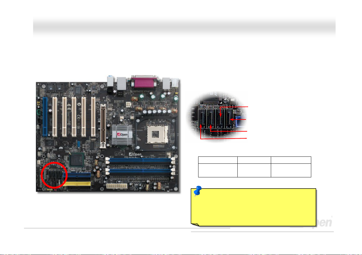
AAXX44CC MMaaxx IIII O
Onnlliinnee MMaannuuaall
SSeerriiaall AATTAA RRAAIIDD ffoorr PPrroommiissee PPDDCC2200337788
Integrated in ICH5R, this motherboard comes with the function of additional RAID 0 and RAID 1 function. Beside RAID 0 and
RAID 1, this motherboard is designed with Promise Serial ATA (PDC20378) controller onboard, which is capable of providing
you additional RAID 0, 1, 0+1 functioned by ATA133 IDE Connector.
SATA port 2 (ICH5R)
SATA port 1 (ICH5R)
SATA port 3 (PDC20378)
SATA port 4 (PDC20378)
Serial ATA Ports
Motherboard SATA 1 & 2 SATA 3 & 4
AX4C Max II RAID 0, 1 RAID 0, 1, 0+1
(With ATA133)
Note: Please be noted that "1MHz stepping
AGP/PCI Overclocking" will be automatically
disabled when SATA device is being connected,
for preventing any system instability.
94
Page 95
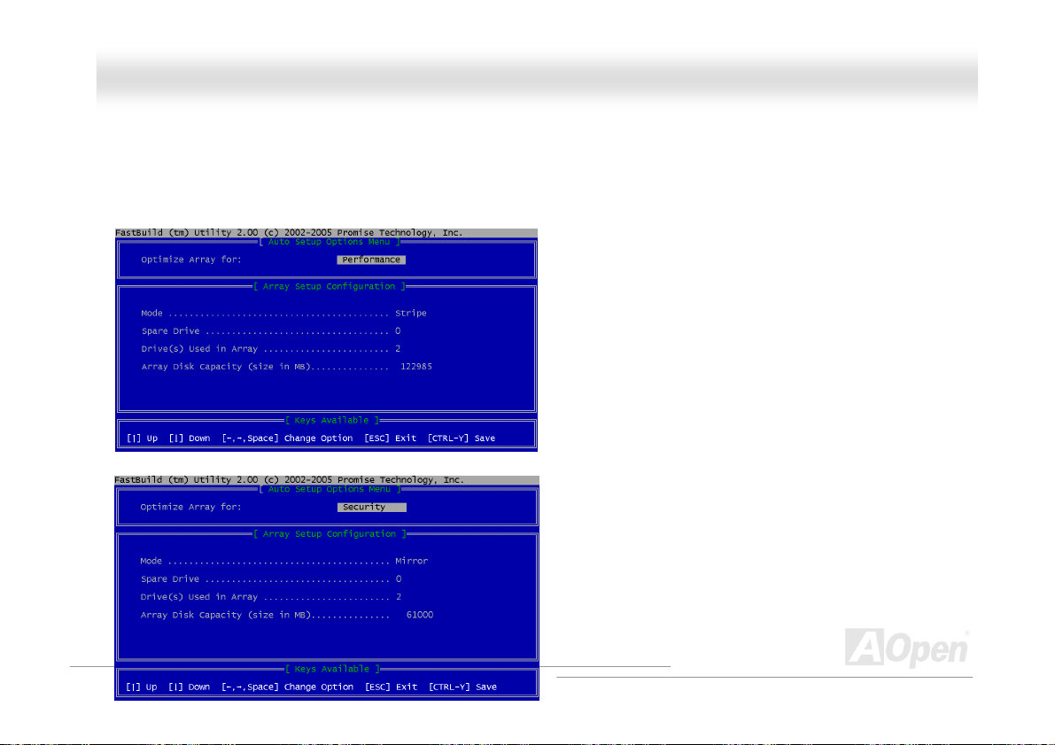
AAXX44CC MMaaxx IIII O
RRAAIIDD CCoonnffiigguurraattiioonn UUttiilliitty
Promise PDC29378 is capable of creating RAID function of 0, 1, 0+1 (by IDE3). Briefly shows you how FASTBUILD Utility
creates disk array for your different arrangement (For details, please refer to the RAID Utility Guide in Bonus CD).
1. To create the disk array for RAID 0 with 2 hard disks:
2. To create the disk array for RAID 1 with 2 hard disks:
y
Onnlliinnee MMaannuuaall
95
Page 96

AAXX44CC MMaaxx IIII O
3. To create the disk array for RAID 0, 1, 0 + 1 with 4 hard disks:
If this is the first time booting and drives installed, the Promise onboard BIOS will display the following screen.
FastBuild™ Utility Main Menu
Onnlliinnee MMaannuuaall
96
Page 97

AAXX44CC MMaaxx IIII O
Press “1” to display the Auto Setup Menu below. This is the fastest and easiest method to creating your first array.
For viewing Drive Assignment, Define Array, Delete Array, or Rebuild Array, please select the respective item for settings.
(For details, please refer to the RAID Utility Guide in Bonus CD)
Onnlliinnee MMaannuuaall
97
Page 98

AAXX44CC MMaaxx IIII O
IInntteell((RR)) AApppplliiccaattiioonn AAcccceelleerraattoorr
The Intel(R) Application Accelerator is designed to improve performance of the storage sub-system and overall system
performance. This software delivers improved performance through several ingredient technologies (components). Installation of
the Intel(R) Chipset Software Installation Utility prior to loading the Intel(R) Application Accelerator.
Onnlliinnee MMaannuuaall
98
Page 99

AAXX44CC MMaaxx IIII O
IInnssttaalllliinngg DDrriivveer
(For details, please refer to the RAID Utility Guide in Bonus CD)
r
Onnlliinnee MMaannuuaall
Promise FastTrak 378 Windows XP Installation
***************************
New Windows XP Installation
***************************
The following details the installation of the FastTrak 378 drivers while installing Windows XP.
1. Start the installation:
* Floppy Install: Boot the computer with the Windows XP installation diskettes.
* CD-ROM Install: Boot from the CD-ROM. Press F6 after the message "Press F6 if you need to install third party SCSI or
RAID driver" appears.
2. When the "Windows XP Setup" window is generated, press "S" to Specify an Additional Device(s)
3. Insert the Promise Technology driver diskette into drive A: and press "Enter" key.
4. Choose "WinXP Promise FastTrak 378 (tm) Controller" from the list that appears on screen, then press the "Enter" key.
5. Press Enter to continue with installation or if you need to specify any additional devices to be installed, do so at this time.
Once all devices are specified, Press Enter to continue with installation.
6. From the Windows XP Setup screen, press the Enter key. Setup will now load all device files and then continue the Windows
XP installation.
********************************
Existing Windows XP Installation
********************************
99
Page 100

AAXX44CC MMaaxx IIII O
After installing the FastTrak 378 and rebooting your system, Under Windows XP, "Mass Storage Controller" will be displayed.
1. In the A: drive, insert the FastTrak 378 driver diskette.
2. Click on "Next," and from the generated list box, choose "Install from a list or special location (Advanced)". Click on "Next,"
and from the generated choices, choose "Include this location in the search:"
1a. Insert the Bonus CD in CD-ROM.
2a. Choose "Specify a location." and then press "Next".
Type "[CD-ROM]:\Driver\Promise\PDC20378\Driver\WinXP" in the text box that appears. Press " OK ".
3. Choose "WinXP Promise FastTrak 378 (tm) Controller" from the list that appears on screen, then press the "Enter" key.
4. The Windows XP Setup screen will appear again saying "Setup will load support for the following mass storage devices WinXP Promise FastTrak 378 (tm) controller". The FastTrak 378 driver will now be copied on to the system and entered into the
Windows XP driver database.
5. When the "System Settings Change" dialog box appears, remove the floppy diskette and click on "Yes" to restart the system.
Windows XP will then restart for the driver installation to take effect.
6. Power off your system, then attach your hard drives to the FastTrak 378 controller.
**********************************
Confirming Windows XP Installation
**********************************
1. From Windows XP, open the Control Panel from "My Computer" followed by the System icon.
2. Choose the "Hardware" tab, then click the "Device Manager" tab.
3. Click the "+" in front of "SCSI & RAID Controllers" hardware type. The driver "WinXP Promise FastTrak 378 (tm) Controller"
should appear.
Onnlliinnee MMaannuuaall
100
 Loading...