

Page 1
r
r
r
r
r
®
A
r
r
r
A
(AOpen reserves the right to revise all
the specifications and information
contained in this documentation which
is subject to change without notice.)
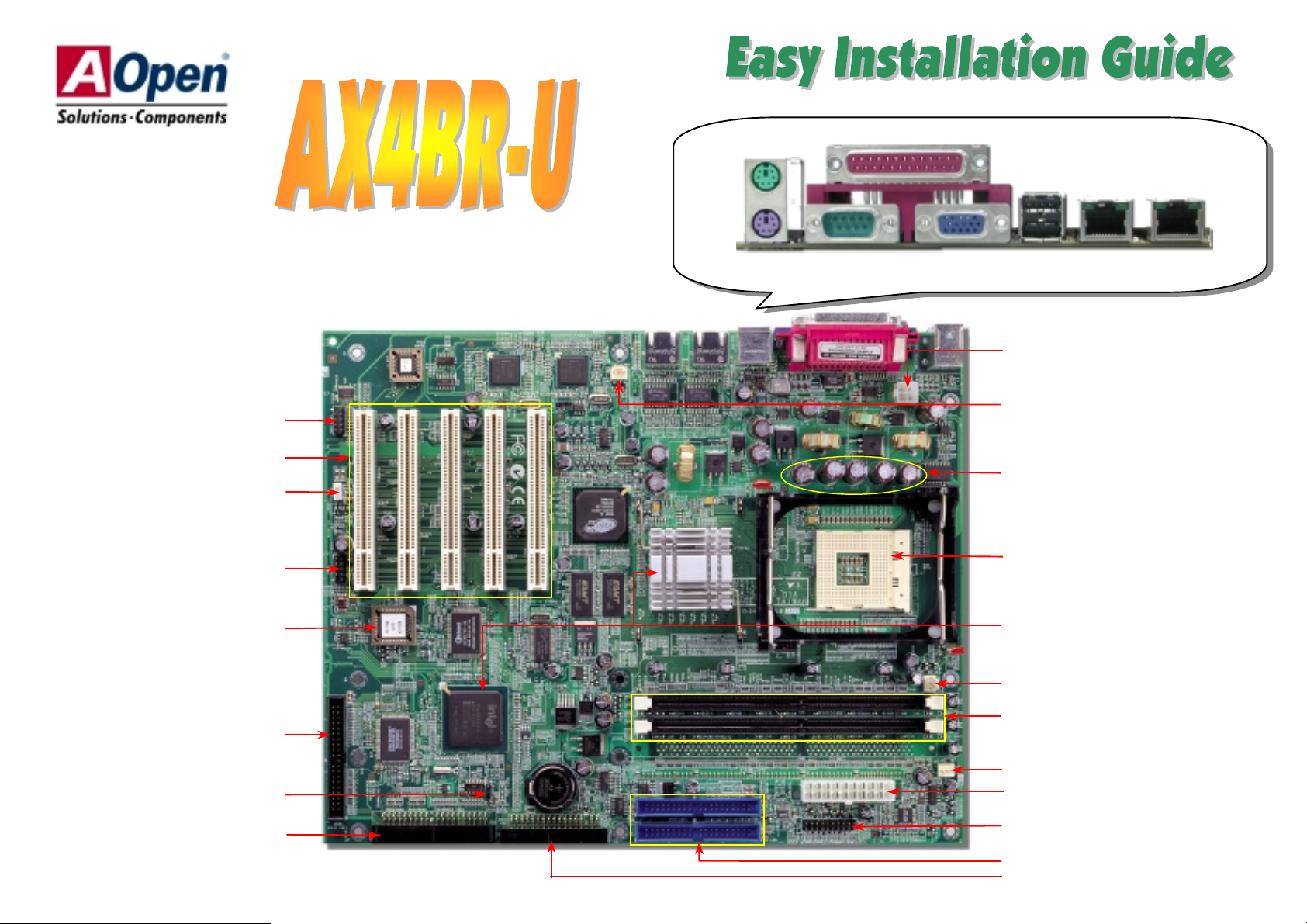
PS/2 Mouse
Connector
SPP/EPP/ECP Parallel Port
COM2 Connecto
32-bit PCI Expansion Slot x5
WOL Connecto
2nd USB Connecto
4Mbit Flash ROM
RAID IDE1 Connecto
PS/2 Keyboard
Connector
COM 1 Port
VGA Port
USB Ports
LAN Ports
4-pin 12V. ATX Power Connector
Resetable Fuse
SYSFAN2 Connector
2200μF Low ESR Capacitors
478-pin CPU socket with Voltage and
Frequency Aut o-det ect ion that supports
®
Pentium® 4 1.4~2.8GHz+ CPU
Intel
845E chipset
Intel
CPUFAN Connector
184-pin DIMM Socket x2 supports
PC-200/266 DDR SDRAM
maximum up to 2 GB
SYSFAN1 Connecto
JP14 CMOS Clear Jumpe
RAID IDE2 Connecto
TX Power Connector
Front Panel Connector
TA/33/66/100 IDE Connector x2
FDD Connecto
Page 2
Everything you need to boot this
(
motherboard is included in this
Easy Installation Guide. For more
information, a complete Online
User's Manual can be found in the
Bonus Pack CD. Thanks for the
help of saving our earth.
This Motherboard x1
This Easy Installation Guide x1
User Manual x 1
80-wire IDE Cable x2
Floppy Disk Drive Cable x1
COM2 Cable x1
I/O Port Bracket x1
Bonus Pack CD x1
NORTON AntiVirus CD x 1
Assembly Screw Pack x1
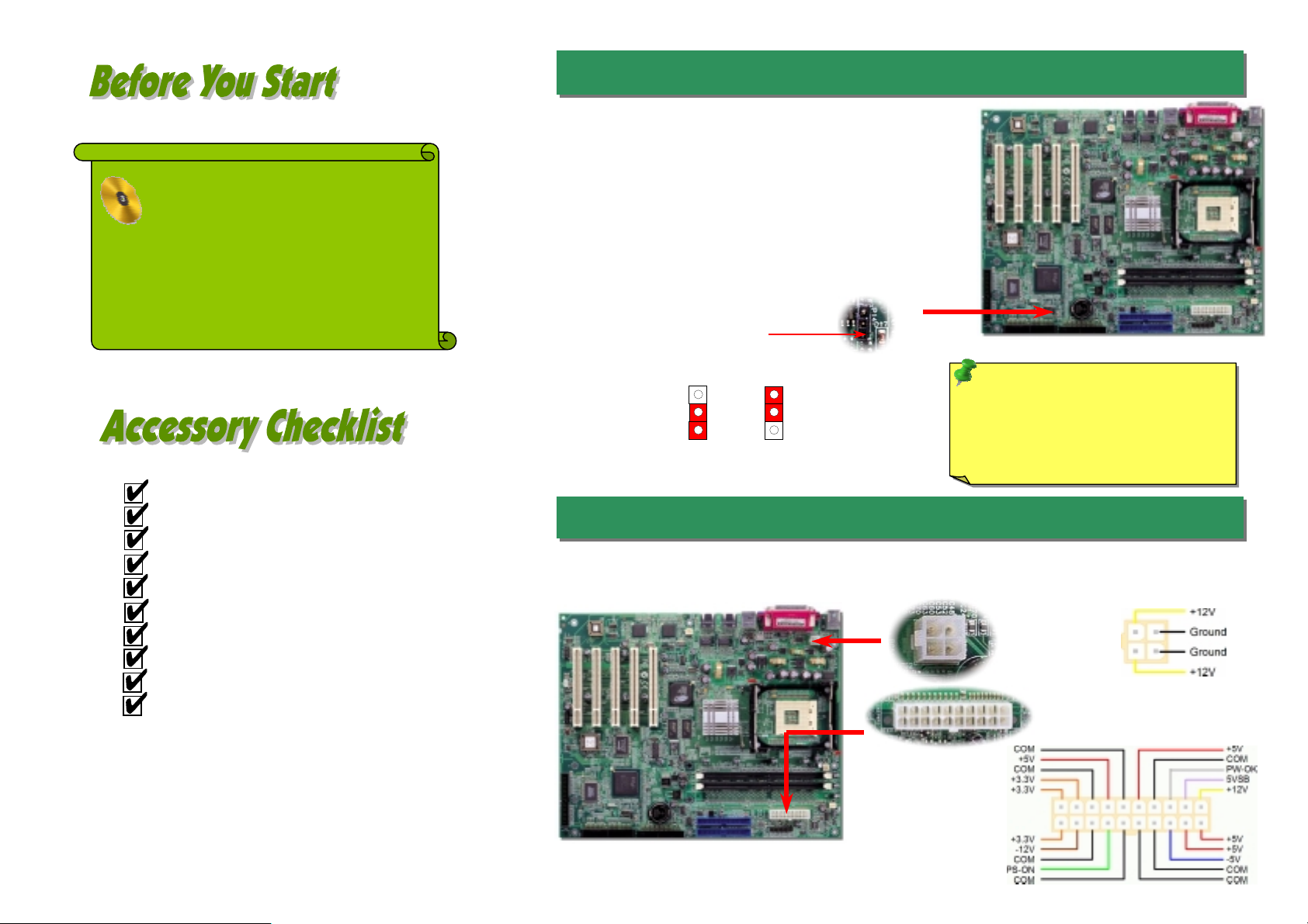
1. JP14 Clear CMOS
You can clear CMOS to restore system default setting. To
clear the CMOS, follow the procedure below.
1. Turn off the system and unplug the AC power.
2. Remove ATX power cable from connector PWR2.
3. Locate JP14 and short pins 2-3 for a few seconds.
4. Return JP14 to its normal setting by shorting pin 1 & pin 2.
5. Connect ATX power cable back to connector PWR2.
Pin 1
Tip: When should I Clear CMOS?
1. Boot fail because of overclocking…
2. Forget password…
Normal
default)
Clear CMOS
3. T roubleshooting…
2. Connecting ATX Power Connector
This motherboard comes with a 20-pin and 4-pin ATX power connector as shown below. Make sure you plug
in the right direction. We strongly recommend you to insert the 4-pin connector before connecting the 20-pin
connector.
PART NO: 90.51Q30.001 DOC. NO: AX4BRU-EG-E0209B
Page 3
r
r
y
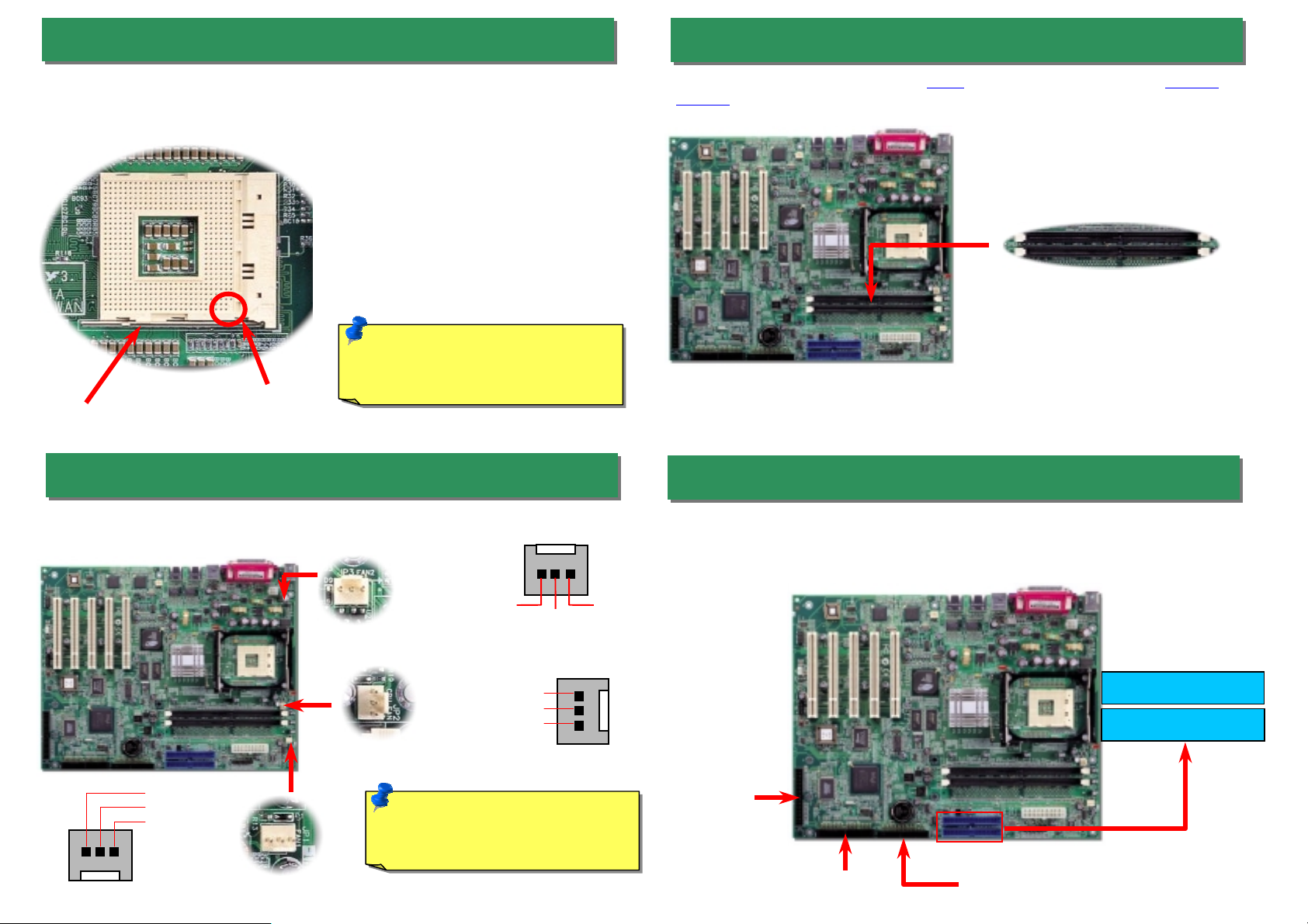
This socket supports Micro-FC-PGA2 package CPU, which is the latest CPU package
developed by Intel. Other forms of CPU package are impossible to be fitted in.
CPU socket lever
3. Installing Processor
1. Pull up the CPU socket lever and up to
90-degree angle.
2. Locate Pin 1 in the socket and look fo
a (golden) cut edge on the CPU uppe
interface. Match Pin 1 and cut edge.
Then insert the CPU into the socket.
3. Press down the CPU socket lever and
finish CPU installation.
Note: If you do not match the CPU
socket Pin 1 and CPU cut edge well, it
may damage the CP U.
CPU cut edge
5. Installing DIMM Module
This motherboard has two 184-pin DDR DIMM sockets that allow you to install DDR200 or
DDR266
memory up to 2GB.
DIMM1
DIMM2
4. Installing CPU & System Fan
Plug in the CPU fan cable to the 3-pin CPU FAN connector. If you have chassis fan, you
can also plug it on SYSFAN2 or FAN3 (AUX Fan) connector.
SENSOR
CPUFAN Connector
SENSOR
SYSFAN2 Connector
GND
+12V
SENSOR
SYSFAN1 Connector
Note: Some CPU fans do not have
sensor pin so they cannot support fan
monitoring.
+12V
GND
+12V
GND
6. Installing CPU & System Fan
Connect 34-pin floppy cable and 40-pin IDE cable to floppy connector FDC and IDE
connector. Pin1 of cable is normally marked with red color. Addition to IDE connectors, we
also provide two RAID IDE connectors for you to connect RAID. Be careful of the pin1
orientation. Wrong orientation may cause system damage.
IDE Secondary (2nd)
IDE Primary (1st)
RAID primar
channel
ATA 66/100 IDE
Connector
RAID secondary
channel
FDD Connector
Page 4

Y
t
f
Pin 1
r
A
A
A
This motherboard provides four USB connectors to connect USB devices, such as mouse,
keyboard, modem, printer, etc. There are two connectors on the PC99 back panel. You can
use proper cable to connect the other USB connector to the back panel or front panel o
chassis.
7. Support 2nd USB Port
USB2 Connector
GND
KE
1 2
USBPWR0
USB_FP_P1-
USB_FP_P1+
GND
NC
8. Connecting COM2 Connector
USBPWR0
USB_FP_P0-
USB_FP_P0+
This motherboard comes with a COM1 connector on the back panel. However, we provide
an extra COM2 connector for your convenience. Once you need to connect a device via
COM2, just connect a suitable cable on it.
Pin 1
CTS#
DSR#
DTR#
SIN
RTS#
RI#
GND
SOUT
DCD#
2 1
9. Connecting WOL
To use Wake On LAN function, you must have a network card with chipset that supports
this feature, and connect a cable from LAN card to motherboard WOL connector. The
system identification information (probably IP address) is stored on network card and
because there is a lot of traffic on the Ethernet, you need to install network managemen
software, such as ADM, for the checking of how to wake up the system. Note that, at least
600mA ATX standby current is required to support the LAN card for this function.
LID
GND
+5VSB
WOL Connecto
10. Connecting Front Panel Cable
Attach the power LED, speaker, and reset switch connectors to the corresponding pins. If
you enable “Suspend Mode” item in BIOS Setup, the ACPI & Power LED will keep
flashing while the system is in suspend mode.
Locate the power switch cable from your ATX housing. It is 2-pin female connector from
the housing front panel. Plug this connector to the soft-power switch connector marked
SPWR.
RESET
+5V
+5V
GND
GND
SPEAKER
GND
RESET
GND
ATX_ON
GND
SPEAKER
IDE LED
CPI &
Power LED
Power
Switch
IDE LED
IDE LED
+5V
GND
INTRUDER
PWR BN
GND
CPILED-
GND
CPILED
Page 5

11. STBY LED
13. PC99 Color Coded Back Panel
STBY LED is AOpen’s considerate design that we aim at providing you friendly system
information. The STBY LED will light up when power is provided to the motherboard. This is
a convenient indication for you to check the system power status in many circumstances
such as power on/off, stand-by mode and RAM power status during Suspend to RAM
mode.
System
Warning: Do not install or
remove the DIMM module
or others devices when the
STBY LED lights on.
12. Support 10/100Mbps LAN Onboard
The Intel 82551QM includes a fast Ethernet controller on chip. On the strength of this LAN
controller on board, which is a highly-integrated Platform LAN Connect device, it provides
10/100M bps Ethernet for office and home use, the Ethernet RJ45 connector is located on
top of USB connectors. The green LED indicates the link mode, it lights when linking to
network and blinking when transferring data. The orange LED indicates the transfer mode,
and it lights when data is transferring in 100Mbps mode. To enable or disable this function,
you may simply adjust it through BIOS.
The onboard I/O devices are PS/2 Keyboard, PS/2 Mouse, COM1, VGA port, Printer, USB, and
LAN ports. The view angle of drawing shown here is from the back panel of the housing.
PS/2 Mouse
Connector
PS/2 Keyboard
Connector
COM 2 Port
SPP/EPP/ECP
Parallel Port
VGA Port
USB
Connectors
LAN Port
LAN Port
PS/2 Keyboard: For standard keyboard, which is using a PS/2 plug.
PS/2 Mouse: For PC-Mouse, which is using a PS/2 plug.
USB Port: Available for connecting USB devices.
Parallel Port: To connect with SPP/ECP/EPP printer.
COM1/COM2 Port: To connect with pointing devices, modem or others serial devices.
VGA Connector: To connect with PC monitor.
14. Enlarged Aluminum Heatsink
Cool down CPU and Chipset is important for system reliability. Enlarged aluminum heat sink
provides better heat consumption especially when you are trying to over clocking the CPU.
Green/ACT
100/10Mb Ethernet Port
Orange/Speed
Page 6

A
15. Power-on and Load BIOS Setup
17. Installing Intel IA A Driver
Del
fter you fini sh the setting of jump ers and connect correc t cables. Power on
and enter the BIOS Setup, press <Del> during POST (Power On Self Test).
Choose "Load Setu p Defaults" for recommended optimal performance.
16. Installing Intel IN F Uti lity
Windows 95/98 cannot recognize this chipset, because it was released before the Intel
845E chipset. You can install the Intel INF Update Utility from the Bonus Pack CD auto-run
menu to eliminate the “?” marks.
You can install Intel IAA Driver to increase the performance of software applications and
reduce PC boot times. You can find it in the AOpen Bonus Pack CD.
18. Model name and BIOS version
Model name and BIOS version can be found on upper left corner of first boot screen
(POST screen). For example:
AX4BR-U R1.02 Sep. 01. 2002
AX4BR is model name of motherboard; R1.02 is BIOS version
Page 7

Part Number and Serial Number
r
r
y
If you encounter any trouble to boot you system, follow the procedures
accordingly to resolve the problem.
Turn off the power and unplug the AC power cable, then remov e all
of the addon cards and cables, including VGA, IDE, FDD, COM1,
COM2 and Printer.
Make sure if the jumper settings for CPU and DRAMs are correct.
Install the VGA card. Then connect your monitor and keyboard.
Turn on the power, and check if
Start
Clear CMOS.
the power supply and CPU fan
work properly.
Check if there is display.
Yes
Yes
The Part Number and Serial number are printed on bar code label. You can find this bar
code label on the outside packing or on component side of PCB. For example:
Part No.
Serial No.
Part No. Serial No.
P/N: 91.88110.201 is part number, S/N: 91949378KN73 is serial number.
No
The problem was probably caused
by power supply or motherboard
failure. Please contact your r eselle
or local distributor for repairing.
No
Perhaps your VGA card or monito
is defective.
Press Ctrl, and Alt key at the
same time, hold them and then
press Del to see if the
stem reboots.
s
During system rebooting, press Del to enter BIOS Setup. Choose
“Load Setup Default".
Turn off the system and
re-connect the IDE cable.
Check if the system can
reboot successfully.
Re-install Windows 95, Windows 98 or Windows NT.
End
Yes
Yes
No
It is very possible that your keyboard
is defective.
No
The problem should be caused by the
IDE cables or HDD itself.
Page 8

p
A
Dear Customer,
Thanks for choosing AOpen products. To provide the best and fastest service to
our customer is our first priority. However, we receive numerous emails and
hone-calls worldwide everyday, it is very hard for us to serve everyone on time.
We recommend you follow the procedures below and seek help before contact
us. With your help, we can then continue to provide the best quality service to
more customers.
Thanks very much for your underst and ing!
Open Technical Supporting Team
1
1
Online Manual: Please check the manual carefully and make sure the
jumper settings and installation procedure are correct.
http://english.aopen.com.tw/tech/download/manual/default.htm
Test Report: We recommend to choose board/card/device from the
compatibility test reports for assembling your PC.
http://english.aopen.com.tw/tech/report/default.htm
FAQ: The latest FAQ (Frequently Asked Questions) may contain a
solution to your problem.
http://english.aopen.com.tw/tech/faq/default.htm
3
3
2
2
Pacific Rim
AOpen Inc.
Tel: 886-2-3789-5888
Fax: 886-2-3789-5899
China
艾爾鵬國際貿易(上海)有限公司
Tel: 86-21-6225-8622
Fax: 86-21-6225-7926
America
AOpen America Inc.
Tel: 1-510-489-8928
Fax: 1-510-489-1998
Web Site: http://www.aopen.com.tw
E-mail: Send us email by going through the contact form below.
English http://english.aopen.com.tw/tech/default.htm
Japanese http://www.aopen.co.jp/tech/default.htm
Chinese http://www.aopen.com.tw/tech/default.htm
German http://www.aopencom.de/tech/default.htm
Simplified Chinese http://www.aopen.com.cn/tech/default.htm
Europe
AOpen Computer b.v.
Tel: 31-73-645-9516
Fax: 31-73-645-9604
Germany
AOpen Computer GmbH.
Tel: 49-1805-559191
Fax: 49-2102-157799
Japan
AOpen Japan Inc.
Tel: 81-048-290-1800
Fax: 81-048-290-1820
5
5
Download Software: Check out this table to get the latest updated
4
4
News Group: Your problem probably had been answered by our support
engineer or professional users on the news group.
http://english.aopen.com.tw/tech/newsgrp/default.htm
7
7
BIOS/utility and drivers.
http://english.aopen.com.tw/tech/download/default.htm
Contact Distributors/Resellers: We sell our products through resellers
6
6
and integrators. They should know your system configuration very well and
should be able to solve your problem efficiently and provide important
reference for you if next time you want to buy something else from them.
Contact Us: Please prepare detail system configuration and error symptom
before contacting us. The part number, serial number and BIOS version
are also very helpful.
 Loading...