

Page 1

Chapter 1
Overview
AX3L is a new generation Socket 370 based system board that utilizes Intel
82440LX AGPset on ATX PCI/ISA platform. This AGPset is designed for
Pentium II CPU, and supports new architectures such as high speed AGP
graphic port, SDRAM, Ultra DMA/33, Bus master IDE and USB port. It has
three Dual in-line Memory Module (DIMM) that allow to install SDRAM
memory and expand up to a maximum of 768MB. Since the cache is on the
Pentium II CPU card (connector SLOT1), there is no second level cache
onboard Also, AX3L uses 2M bit Flash ROM BIOS to reserve for future new
functions.
Not only above features, AX3L also implements many special features as
following.
Jumper-less Design Celeron PPGA VID signal and SMbus clock generator
provide CPU voltage auto-detection and allows user to set CPU frequency
through CMOS setup, no jumper or switch is needed. The correct CPU
information is saved into EEPROM, with these technologies, the
disadvantages of Pentium base jumper-less design are eliminated. There will
be no worry of wrong CPU voltage detection and no need to re-open the
housing if CMOS battery loss. The only jumper left is to clear CMOS, which is
a safety hook if you forget the password.
Battery-less AX3L implements EEPROM and special circuit (patent applied)
that allows you to save your current CPU and CMOS Setup configurations
without the need of battery. The RTC (real time clock) can also keep running
as long as power cord is plugged. If you lose your CMOS data by accident, you
can just reload the CMOS configurations from EEPROM and the system will
recover as usual.
APM Suspend To Hard Drive "Immediately" turns on system and goes back
to the original screen before power down. You can resume your original work
directly from hard disk without go through the Win95 booting process and run
your application again. Suspend to Hard Drive saves your current work
(system status, memory image) into hard disk. Note that you have to use
1-1
Page 2

Overview
VESA compatible PCI VGA, Sound Blaster compatible sound card with APM
driver, for Suspend to Hard Drive to work properly.
Zero Voltage Wake on Modem In conjunction with ATX soft power On/Off, it
is possible to have system totally power off and wakeup to automatically
answer a phone call such as answering machine or to send/receive fax. The
most important break through is not only external box modem but also internal
modem card can be used to support Wake On Modem. The AX3L and MP56
internal modem card implement special circuit (patent applied) to make sure
the modem card work properly without any power.
Wake on LAN This feature is very similar as Wake On Modem, but it is
through local area network. To use Wake on LAN function, you must have a
network card that supports this feature and also need to install a network
management software.
Wake on RTC Timer The Wake Up Timer is more like an alarm, which
wakes up and power on your system at a pre-defined time for specific
application. It can be set to wake up everyday or on specific date within a
month. The date/time accuracy is second.
Wake on Keyboard This feature allows you power on your system by clicking
the hot key that you specified. Besides, you also may disable the function of
power button and let the system can only be powered on through the preset
keys (like a password).
Wake on Mouse This function allows you wake up the system by clicking
mouse button twice successively.
AC Power Auto Recovery A traditional ATX system should remain at power
off stage when AC power resumes from power failure. This design is
inconvenient for a network server or workstation, without an UPS, that needs
to keep power-on. This motherboard implements an AC Power Auto Recovery
function to solve this problem. In BIOS Setup setting the item to Enabled lets
the system can automatically power-on after AC power resumes.
High Efficient Synchronous Switching Regulator Most of the current
switching designs are Asynchronous mode, which from the technical point of
view, still consumes very high power as well as heat. AX3L implements high
efficient synchronous switching design that the temperature of MOS FET is far
less than Schottky diode of asynchronous design.
Over Current Protection The Over Current Protection was very popular
implemented on the Baby AT or ATX 3.3V/5V/12V switching power supply.
However, the new generation Celeron PPGA CPU uses different voltage that
have regulator to transfer 5V to CPU voltage (for example, 2.0V), and make 5V
over current protection useless. AX3L with switching regulator onboard support
CPU over current protection, in conjunction with 3.3V/5V/12V power supply
provide the full line over current protection.
1-2
Page 3

Overview
CPU and Housing Fan Monitoring AX3L has one more "fan monitoring"
function to prevent system overheat. There are two fan connectors, one is for
CPU and the other can be an extra housing fan. The system will report and
alarm fan malfunction though utility software such as Hardware Monitor utility
(Small Icon for Hardware Monitoring).
CPU Thermal Protection AX3L has a special thermal detection circuit to have
warning through application software when the temperature is higher than a
predefined value.
System Voltage Monitoring Further more, AX3L implements a voltage
monitoring system, As you turn on your system, this smart design will continue
to monitor your system working voltage. If any of the system voltage is over
the component's standard. There will be alarm though utility software such as
Hardware Monitor utility (Small Icon for Hardware Monitoring) for a warning to
user.
Full-range CPU core voltage This motherboard supports the CPU core
voltage from 1.3V to 2.05V, that can be applied to various CPU type in future.
Resetable Fuse This motherboard implements resetable fuses to prevent any
accidental short circuit caused by keyboard or USB devices hot plug.
FCC DoC certificate AX3L has passed FCC DoC test. The radiation is very
low, you can use any kind of housing.
Powerful Utility Software AOpen Bonus Pack CD disc contains many useful
utilities, such as Norton Antivirus, AOchip, Hardware Monitoring Utility, and
Suspend to Hard Drive utility.
Note: This motherboard is battery-less, that means the RTC
(real time clock) can keep running without battery as long as
the power cord is plugged. But in case of power failure or the
power cord unplugged, you need to reset date and time from
"Standard CMOS Setup" section of BIOS Setup. For more
information, please see "Chapter 3 BIOS Setup".
1.1 Specifications
Form Factor
Board Size
CPU
1-3
ATX
305 mm x 190 mm
Celeron PPGA
Page 4

Overview
System Memory
Chipset
Expansion Slots
Serial Port
Parallel Port
Floppy Interface
IDE Interface
USB Interface
PS/2 Mouse
Keyboard
RTC and Battery
BIOS
168-pin DIMM x3, maximum 768MB EDO or 384
SDRAM.
Intel 82440LX AGPset
ISA x2, PCI x4 and AGP x1
Two serial ports UART 16C550 compatible, and the
3rd UART for IR function.
One parallel port supports standard parallel port (SPP),
enhanced parallel port (EPP) or extended capabilities
port (ECP).
Floppy interface supports 3.5 inches drives with
720KB, 1.44MB or 2.88MB format or 5.25 inches
drives with 360KB, 1.2MB format.
Dual-channel IDE interface support maximum 4 IDE
hard disks or CDROM, mode 4, bus master hard disk
drives and Ultra DMA/33 mode hard drives are also
supported.
Two USB ports supported by USB bracket, the BIOS
also supports USB driver to simulate legacy keyboard.
Mini-Din PS/2 mouse connector onboard.
Mini-Din PS/2 keyboard connector onboard.
RTC within Intel PIIX4E chipset. Lithium (CR-2032)
battery is an option, no battery is needed if power cord
is plugged.
AWARD Plug-and-Play, 2M bit Flash ROM BIOS.
1.2 APM Suspend to Hard Drive
Suspend to Hard Drive saves your current work (system status, memory and
screen image) into hard disk, and then the system can be totally power off.
Next time, when power is on, you can resume your original work directly from
hard disk within few seconds without go through the Win95 booting process
and run your application again. If your memory is 16MB, normally, you need to
reserve at least 16MB HDD space to save your memory image. Note that you
have to use VESA compatible PCI VGA (AOpen PV70/PT70), Sound Blaster
compatible sound card and sound driver that supports APM (AOpen
AW32/AW35) for Suspend to Hard Drive to work properly. Of course, we
recommend choosing AOpen products for best compatibility.
To use Suspend to Hard Drive:
1-4
Page 5

Overview
1. Go into BIOS setup, Power Management Æ Suspend Mode Option, select
"Suspend to Disk".
2. Go into BIOS setup, PNP/PCI Configuration Æ PnP OS Installed, select
"No". This can give BIOS the capability to allocate system resources for
Suspend to Hard Drive.
3. Boot up your system into DOS command prompt. If you are Win'95 user,
Please restart your Windows 95 under "Command Prompt" by pressing
"F8" while system shows "Windows 95 Starting ...". Choose "Safe Mode
Command Prompt Only" from selection so that system will start in DOS
command prompt.
4. Copy AOZVHDD.EXE to the root directory of your C: drive.
5. Option 1: Use /file switch (applied to FAT16 file system):
Please use following command to create a hidden file in the root directory
of your hard disk for Suspend to Hard Drive to save the system status and
memory image.
C:>AOZVHDD /c /file
Please make sure that you have enough continuous HDD space for
creating this hidden file. For example, if you have 32MB of system memory
and 4MB of VGA memory, you need at least 36MB (32MB + 4MB) of
continuous HDD space. If AOZVHDD failed to allocate the HDD space, you
may run "DEFRAG" Utility or "Disk Defragmenter" which come with MSDOS or Win'95 to free HDD space.
1-5
Page 6

Overview
Option2: Use /partition switch (applied to FAT16/FAT32 file system):
To create a separate partition for Suspend to Hard Drive, please make sure
you have reserved a free partition. We suggest you reserve the free
partition which space is appropriate for your future memory expansion. For
example, if you have 32MB of system memory and 4MB of VGA memory
currently, but you plan to upgrade system memory to 64MB in the near
future, then you may reserve a 68MB (64MB+4MB) space by using a disk
utility (such as fdisk). Next, use following command to create a suspend
partition:
C:>AOZVHDD /c /partition
If there is no extra free partition and you don't want your data lost, please
do not use this partition method.
6. After creating above partition or hidden file, please reboot your system.
7. Push suspend switch (momentary mode) or use Win95 Suspend icon to
force system goes into Suspend to Hard Drive mode and then turn system
power off by power switch of your power supply.
8. Next time when you turn on your system, it will resume to your original work
automatically.
Warning: Note that Intel Bus Master and Ultra DMA/33
IDE driver are not fully compatible with Suspend to Hard
Drive function, installing these drivers may cause the
system unstable. Under this situation, please uninstall the
drivers.
1-6
Warning: This function does not support SCSI hard disks.
Page 7

Tip: The following VGA cards have been tested &
recognized as VESA compatible VGA device.
AOpen PV90 (Trident 9680)
AOpen PT60 (S3 Virge/BIOS R1.00-01)
AOpen PV60 (S3 Tiro64V+)
AOpen PT70 (S3 Virge/DX)
ProLink Trident GD-5440
ProLink Cirrus GD-5430
ProLink Cirrus GD-5446
ATI Mach 64 GX
ATI 3D RAGE II
Diamond Stealth64D (S3 868)
Diamond Stealth64V (S3 968)
KuoWei ET-6000
ATI 3D RAGE PRO 2x (AGP)
PLOTECH 3D IMAGE 9850 (AGP)
CARDEX S3 Virge/GX (AGP)
Tip: The following sound cards have been tested OK
for Suspend to Hard Drive.
Creative Sound Blaster PCI 64
Creative Ensoniq
Creative Sound Blaster PCI 128
Videologic Sonic Storm
Overview
If your sound card can not work after resume from
Suspend to Hard Drive, check your sound card vendor see
if there is driver to support APM, and install it again.
Note: The USB function has not been tested for
Suspend to Hard Drive. If you find any unstable
problem, please go into BIOS, Integrated Peripherals
Æ
USB Legacy Support. Disable the USB Legacy
function.
1-7
Page 8
Overview
p
(
)
p
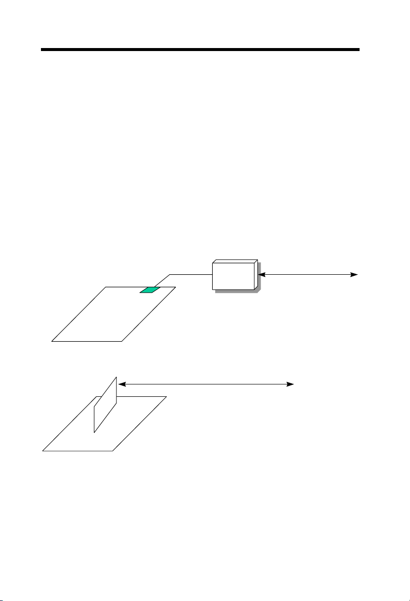
1.3 Zero Voltage Wake on Modem
The Wake on Modem discussed here is to wakeup from true power off
(identified by fan of power supply is off), This motherboard still supports
traditional green PC suspend mode but it is not discussed here.
With the help ATX soft power On/Off, it is possible to have system totally
power off (The traditional suspend mode of power management function does
not really turn off the system power supply), and wakeup to automatically
answer a phone call such as answering machine or to send/receive fax. You
may identify the true power off by checking fan of your power supply. Both
external box modem and internal modem card can be used to support Wake
on Modem, but if you use external modem, you have to keep the box modem
always power-on. AOpen AX3L and internal modem card implement special
circuit (patent applied) and make sure the modem card works properly without
any power. We recommend choosing AOpen modem card (MP56) for Wake
on Modem applications.
TEL Line
COM port
External Box Modem
External Modem WakeU
TEL Line
Internal Modem Card WakeU
1-8
such as MP56
Page 9

Overview
For Internal Modem Card (AOpen MP56):
1. Go into BIOS setup, Power Management Æ 0V W ake on Modem, select
Enable.
2. Setup your application, put into Windows 95 StartUp or use Suspend to
Hard Drive function.
3. Turn system power off by soft power switch.
4. Connect 4-pin Wake On Modem cable from MP56 RING connector to
AX3L WOM connector.
5. Connect telephone line to MP56. You are now ready to use Wake On
Modem.
For External Box Modem:
1. Go into BIOS setup, Power Management Æ 0V W ake on Modem, select
Enable.
2. Setup your application, put into Windows 95 StartUp or use Suspend to
Hard Drive function.
3. Turn system power off by soft power switch.
4. Connect RS232 cable of external box Modem to COM1 or COM2.
5. Connect telephone line to external box Modem. Turn on Modem power
(you must keep Modem power always on). You are now ready to use Wake
On Modem.
Tip: External Wake on Modem signal is detected through
COM1 or COM2. Internal modem card wake up signal is
detected through cable from connector RING (on modem card)
to WOM (on mainboard).
Note: If you use external modem, the power of external modem
must be kept on to receive signal from telephone line. Internal
modem card has no such limitation.
1.4 System Voltage Monitoring
This motherboard implements a voltage monitoring system. As you turn on
your system, this smart design will continue to monitor your system working
voltage. If any of the system voltage is over the component's standard. There
will be alarm through application software such as Hardware Monitoring Utility
for a warning to user. System voltage monitoring function monitors CPU core
1-9
Page 10

Overview
voltage. It is automatically implemented by BIOS and Hardware Monitoring
Utility (the file name is like aohw100.exe, where 100 means the version
number), no hardware installation is needed.
1.5 Fan Monitoring
There are three fan connectors, two is for CPU, the other can be connected to
a housing fan. The fan monitoring function is implemented by connecting fan
to 3-pin fan connector CPUFAN1 or FAN and installing Hardware Monitoring
Utility.
Note: You need 3-pin fan that supports SENSE signal
for fan monitoring function to work properly.
1.6 CPU Thermal Protection
This mainboard implements special thermal protection circuits. When
temperature is higher than a predefined value, there will be warning through
application software such as Hardware Monitoring Utility to notify user. It is
automatically implemented by BIOS and Hardware Monitoring Utility, no extra
hardware installation is needed.
1-10
Page 11

Overview
1.7 Battery-less Design
To preserve the earth, AOpen AX3L implements the battery-less motherboard
design. There is no need to have battery for RTC (real time clock) and CMOS
Setup as long as ATX power cable is plugged. In case of the AC power is
shutdown or power cord is removed by accident, the CMOS Setup and system
configuration can be restored from EEPROM, only the system clock needed to
be re-set to current date/time.
For the convenience of end user, AX3L still shipped with one Lithium (CR-
2032) battery. If you prefer to use battery, you can still insert it into battery
socket. The RTC will still keep running even power cord is removed.
1-11
Page 12

Chapter 2
Hardware Installation
This chapter gives you a step-by-step procedure on how to install your system.
Follow each section accordingly.
Caution: Electrostatic discharge (ESD) can
damage your processor, disk drives,
expansion boards, and other components.
Always observe the following precautions
before you install a system component.
1. Do not remove a component from its
protective packaging until you are ready
to install it.
2. Wear a wrist ground strap and attach it to
a metal part of the system unit before
handling a component. If a wrist strap is
not available, maintain contact with the
system unit throughout any procedure
requiring ESD protection.
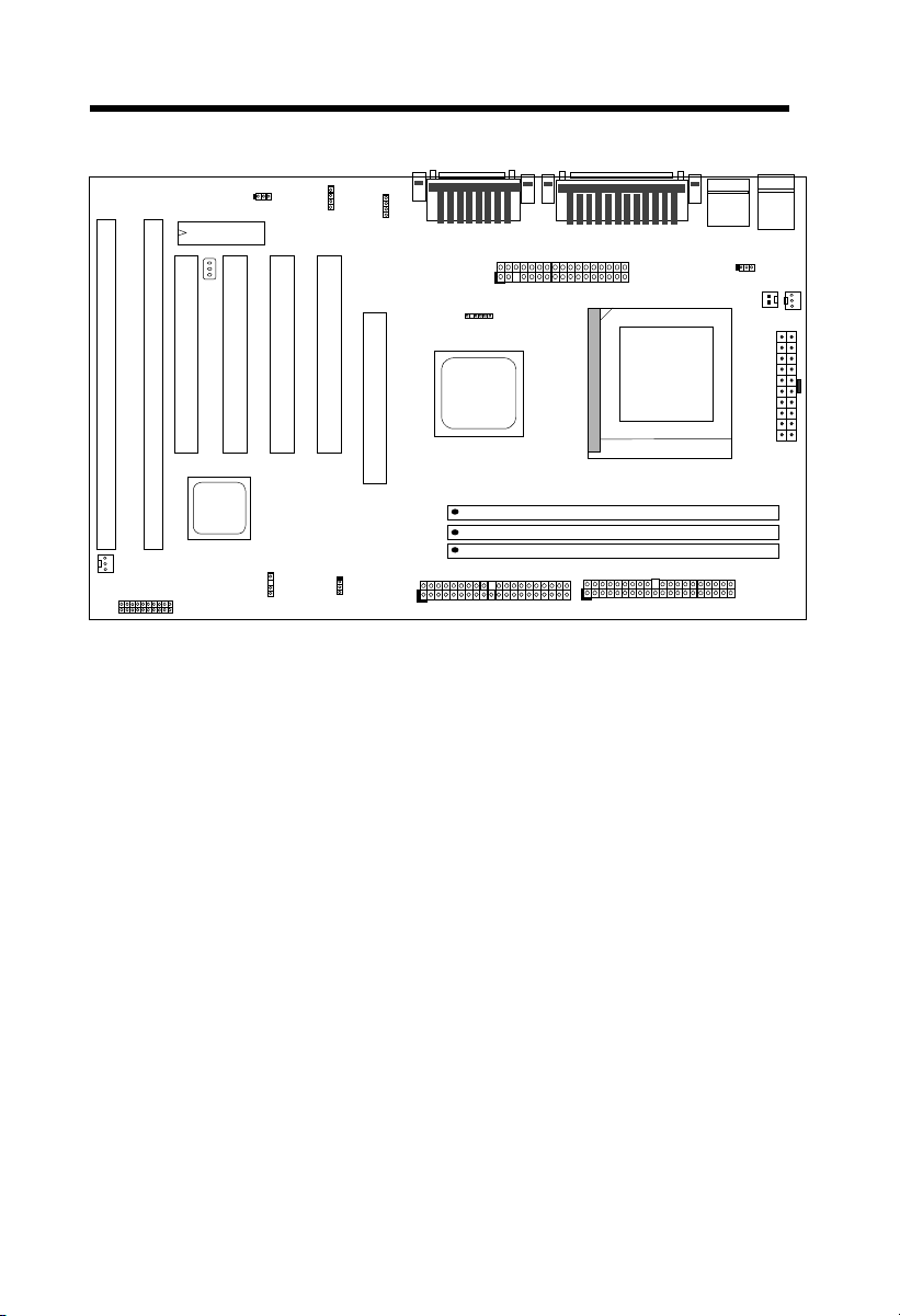
2.1 Jumper and Connector Locations
The following figure shows the locations of the jumpers and connectors on the
system board:
2-1
Page 13
Hardware Installation
CDIN1
JP12
FAN
I
S
A
2
PANEL
WOL
S
A
P
1
P
C
C
I
I
4
3
BIOS
I
WOM
P
C
I
2
MODEM-CN
P
C
I
1
JP14
A
G
P
IrDA
IDE2
COM2
FDC
PRINTER
IDE1
COM1
USB
CPU FAN2
DIMM1
DIMM2
DIMM3
JP28
CPU FAN1
KB
PS/2
PWR2
2-2
Page 14

Hardware Installation
Jumpers:
JP12: Enable/Disable Sound
JP14: Clear CMOS
JP28: KB/MS-WKUP
Connectors:
PS2: PS/2 mouse connector
KB: PS/2 keyboard connector
COM1: COM1 connector
COM2: COM2 connector
PRINTER: Printer connector
PWR2: ATX power connector
USB: USB connector
FDC: Floppy drive connector
IDE1: IDE1 primary channel
IDE2: IDE2 secondary channel
CPUFAN1: CPU fan connector
CDUFAN2: CPU fan connector
FAN: Housing Fan Connector
IrDA: IrDA (Infrared) connector
PANEL: Front panel (Multifunction) connector
CD-IN: CD-audio connector
MODEM-CN: Mono in (Pin 1-2) and Mic out (Pin 3-4)
WOM: Wake On Modem connector
WOL: Wake On LAN connector
2.2 Jumpers
With the help of Celeron PPGA VID signal and SMbus, this motherboard is
jumper-less design.
2-3
Page 15

Hardware Installation
2.2.1 Selecting the CPU Frequency
Celeron PPGA VID signal and SMbus clock generator provide CPU voltage
auto-detection and allow user to set CPU frequency through CMOS setup, no
jumper or switch is needed. The correct CPU information is saved into
EEPROM, with these technologies, the disadvantages of Pentium base
jumper-less design are eliminated. There will be no worry of wrong CPU
voltage detection and no need to re-open the housing if CMOS battery loss.
The CPU frequency selection is set by going into:
BOIS Setup Æ Chipset Features Setup Æ CPU Clock Frequency
(The possible setting is 66.8, 68.5, 70, 73.8, 75, 78.5, 83.3 MHz)
BOIS Setup Æ Chipset Features Setup Æ CPU Clock Ratio
(The possible setting is 1.5x, 2x, 2.5x, 3x, 3.5x, 4x, 4.5x, 5x, 5.5x, 6x, 6.5x, 7x, 7.5x,
and 8x)
Core frequency = Ratio * External bus clock
INTEL Celeron PPGA CPU Core Frequency Ratio External Bus Clock
Celeron PPGA 300A 300MHz= 4.5x 66MHz
Celeron PPGA 333 333MHz= 5x 66MHz
Celeron PPGA 366 366MHz= 5.5x 66MHz
Celeron PPGA 400 400MHz= 6x 66MHz
Celeron PPGA 433 433MHz= 6.5x 66MHz
Warning: INTEL 440LX chipset supports maximum 66MHz external
CPU bus clock, the higher clock settings are for internal test only. These
settings exceed the specification of LX chipset, which may cause
serious system damage.
2-4
Page 16
Hardware Installation
2.2.2 Setting the CPU Voltage
This motherboard supports Celeron PPGA VID function, the CPU core voltage
is automatically detected, the range is from 1.3V to 3.5V.
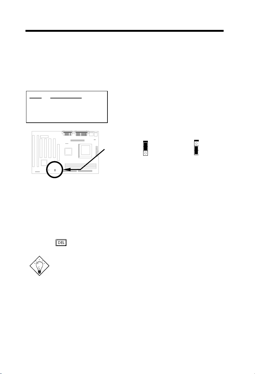
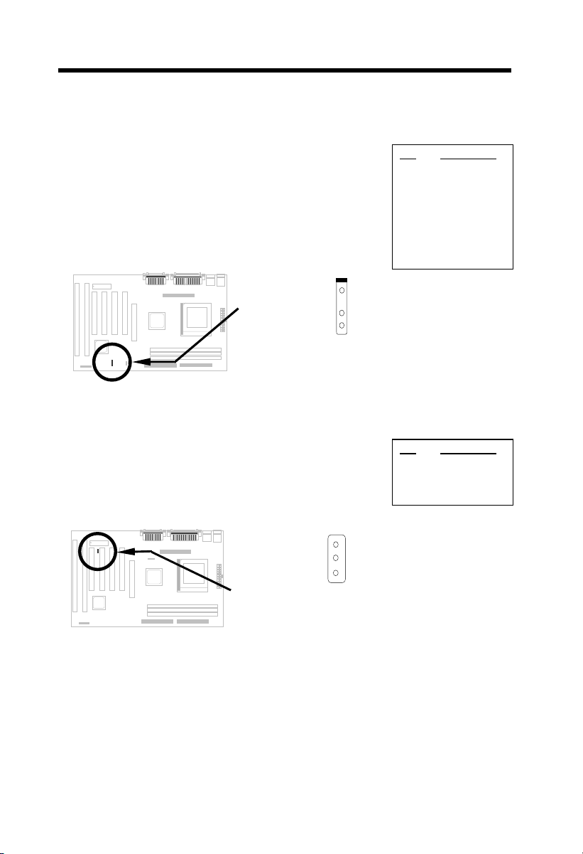
2.2.3 Clearing the CMOS
JP14
1-2
2-3
Clear CMOS
Normal operation
(default)
Clear CMOS
You need to clear the CMOS if you forget your
system password. To clear the CMOS, follow
below procedures:
JP14
1
2
3
Normal Operation
(default)
The procedure to clear CMOS:
1. Turn off the system and unplug the AC power.
2. Remove ATX power cable from connector PWR2.
3. Locate JP14 and short pins 2-3 for a few seconds.
4. Return JP14 to its normal setting by shorting pins 1-2.
5. Connect ATX power cable back to connector PWR2.
6. Turn on the system power.
7. Press
during bootup to enter the BIOS Setup Utility and specify a
new password, if needed.
Tip: If your system hangs or fails to boot because of over-clocking,
please clear CMOS and the system will go back to default setting
(300MHz).
Tip: If your system hangs or fails to boot because of over-clocking,
simply use <Home> key to restore to the default setting (300MHz).
By this smart design, it would be more convenient to clear CPU
frequency setting. For using this function, you just need to press
<Home> key first and then press Power button at the same time.
Note that do not release <Home> key until POST screen appearing.
JP14
1
2
3
Clear CMOS
2-5
Page 17
Hardware Installation
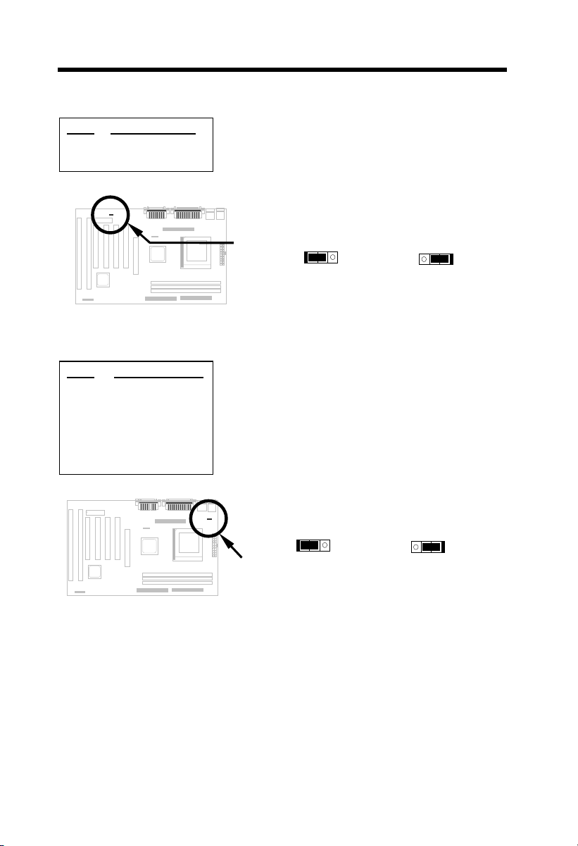
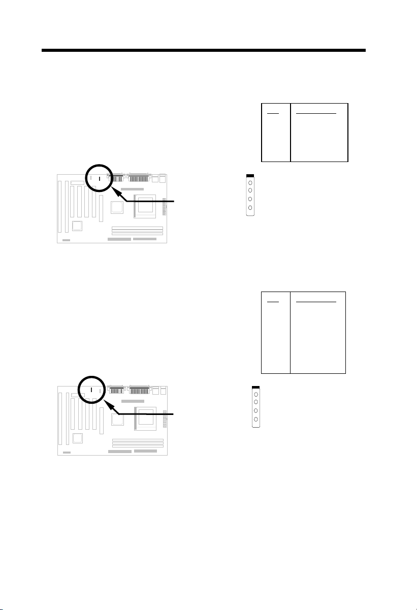
2.2.4 Onboard Audio
JP12
1-2
2-3
Onboard Audio
Enabled (default)
Disabled
If you want to install another sound card, you have
to disable the onboard audio by setting this
jumper to Disabled.
2.2.5 KB/MS Wakeup
JP28
1-2
2-3
KB/MS Wakeup
Disabled
Enabled
This jumper is used to enable or disable
Keyboard/Mouse Power ON function. If you select
Enabled, you may decide the wakeup mode from
BIOS Setup. To implement this function, the 5V
Stand By current must be greater than 800mA.
Note that only PS/2 mouse supports Wake On
Mouse function.
Enabled (default)
JP12
1 2 3
JP28
1 2 3
Disabled
JP12
1 2 3
Disabled
Enabled
JP28
1 2 3
2.3 Connectors
2.3.1 Power Cable
The ATX power supply uses 20-pin connector shown below. Make sure you
2-6
Page 18
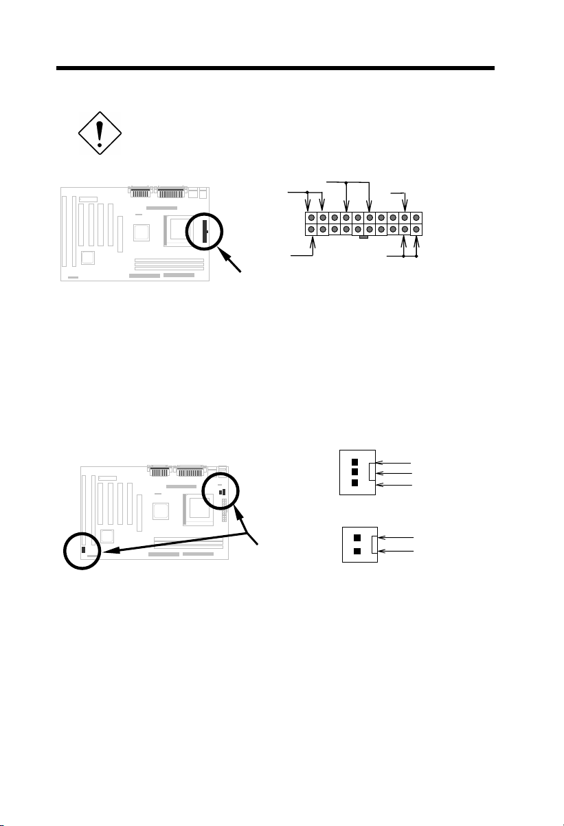
plug in the right direction.
Caution: Make sure that the power supply is off before
connecting or disconnecting the power cable.
Hardware Installation
+5V
3.3V
5V SB
3.3V
+5V
PWR2
2.3.3 Fan
Plug in the fan cable to the fan connectors onboard. The fan connectors are
marked CPUFAN1, CPUFAN2 and FAN on the system board. You can plug
the CPU fan cable to both the 2-pin fan connector CPUFAN1 and the 3-pin fan
connector CPUFAN2. FAN can be reserved for the housing fan. Note that only
CPUFAN2 and FAN support the fan monitoring function, because 3-pin fan
has an extra pin called SENSE, which periodically sends fan signal out.
SENSE
+12V
GND
CPUFAN1 & FAN
GND
+12V
CPUFAN2
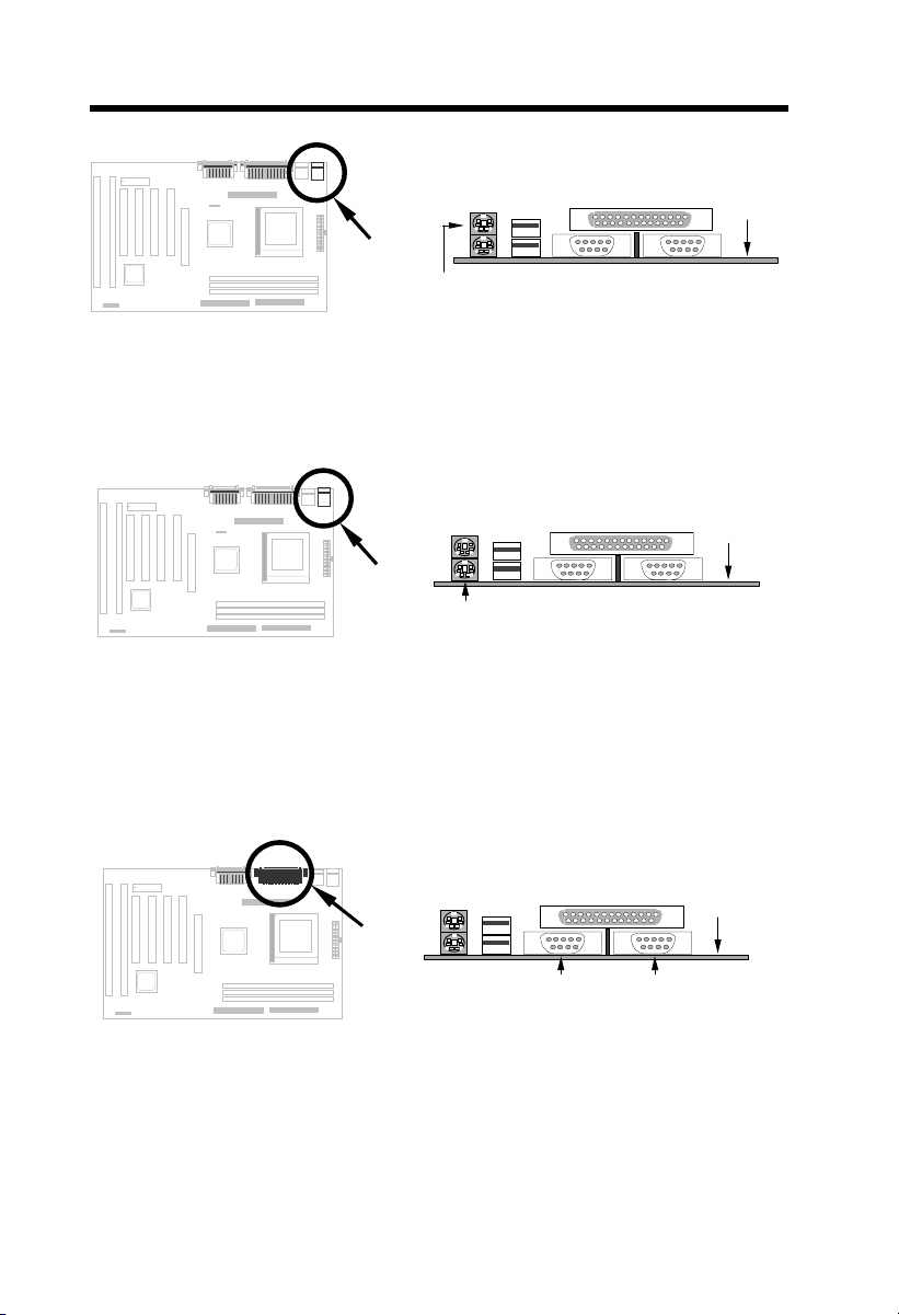
2.3.4 PS/2 Mouse
The onboard PS/2 mouse connector is a 6-pin Mini-Din connector marked
PS2. The view angle of drawing shown here is from back panel of the housing.
2-7
Page 19
Hardware Installation
PCB
PS/2 Mouse
2.3.5 Keyboard
The onboard PS/2 keyboard connector is a 6-pin Mini-Din connector marked
KB2. The view angle of drawing shown here is from back panel of the housing.
PCB
PS/2 KB
2.3.6 Serial Devices (COM1/COM2)
The onboard serial connectors are 9-pin D-type connectors on the back panel
of mainboard. The serial port 1 connector is marked as COM1 and the serial
port 2 connector is marked as COM2.
PCB
COM1
COM2
2.3.7 Printer
The onboard printer connector is a 25-pin D-type connector marked
PRINTER. The view angle of drawing shown here is from back panel of the
2-8
Page 20
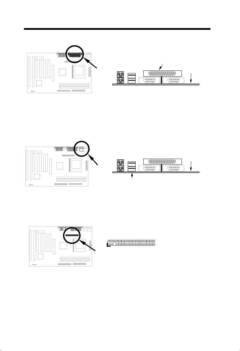
Hardware Installation
housing.
PRINTER
PCB
2.3.8 USB Device
You can attach USB devices to the USB connector. The motherboard
contains two USB connectors, which are marked as USB.
PCB
USB
2.3.9 Floppy Drive
Connect the 34-pin floppy drive cable to the floppy drive connector marked as
FDC on the system board.
342
1
FDC
33
2-9
Page 21
Hardware Installation
(
)
(
)
2.3.10 IDE Hard Disk and CD ROM
This mainboard supports two 40 pin IDE connectors marked as IDE1 and
IDE2. IDE1 is also known as primary channel and IDE2 as secondary
channel, each channel supports two IDE devices that make total of four
devices.
In order to work together, the two devices on each channel must be set
differently to master and slave mode, either one can be hard disk or CDROM.
The setting as master or slave mode depends on the jumper on your IDE
device, please refer to your hard disk and CDROM manual accordingly.
Connect your first IDE hard disk to master mode of the primary channel. If
you have second IDE device to install in your system, connect it as slave
mode on the same channel, and the third and fourth device can be connected
on secondary channel as master and slave mode respectively.
1
IDE2
402
39
402
2-10
1
IDE1
Caution: The specification of IDE cable is
maximum 46cm (18 inches), make sure your cable
does not excess this length.
Caution: For better signal quality, it is
recommended to set far end side device to master
mode and follow the suggested sequence to install
your new device. Please refer to the following
figure.
IDE1 (Primary Channel)
Slave
2nd
IDE2 (Second Channel)
Slave
(4th)
39
Master
1st
Master
(3rd)
Page 22

2.3.12 Panel Connector
Hardware Installation
The Panel (multifunction) connector is
a 20-pin connector marked as PANEL
on the board. Attach the power LED,
keylock, speaker, SPWR, IDE LED
and reset switch to the corresponding
pins as shown in the figure. Some
housings have a five-pin connector for
the keylock and power LED. Since
power LED and keylock are aligned
together, you can still use this kind of
connector. If your ATX housing
supports ACPI specification, the ACPI
& Power LED will keep flashing if you
have enabled “suspend mode” item in
BIOS Setup.
1
11
GND
KEYLOCK
+5V
IDE LED
IDE LED
+5V
+5V
GND
NC
SPEAKER
10 20
PANEL
1
Keylock
IDE LED
+
+
+
Speaker
10 20
PANEL
SPWR
GND
ACPI & POWER LED
GND
+5V
NC
NC
GND
RESET
GND
11
+
SPWR
+
ACPI &
Power LED
+
Reset
2-11
Page 23

Hardware Installation
5
2.3.13 IrDA Connector
The IrDA connector can be configured to support wireless infrared module,
with this module and application software such as Laplink or Win95 Direct
Cable Connection, user can transfer files to or from laptops, notebooks,
PDA and printers. This connector supports HPSIR (115.2Kbps, 2 meters),
ASK-IR (56Kbps) and Fast IR (4Mbps, 2 meters).
Install infrared module onto IrDA
connector and enable infrared function
from BIOS setup, make sure to have
correct orientation when you plug onto
IrDA connector.
Pin
1
2
3
4
5
6
Description
+5V
NC
IRRX
GND
IRTX
NC
2-12
1
2
6
3
4
IrDA
Page 24
Hardware Installation
2.3.14 Wake On Modem Connector
This mainboard implements special circuit to support
Modem Ring-On, both Internal Modem Card (AOpen
MP56) and external box Modem are supported. Since
Internal Modem card consumes no power when system
power is off, it is recommended to use Internal Modem.
To use AOpen MP56, connect 4-pin cable from RING
connector of MP56 to WOM connector on the
mainboard.
1
2
3
4
WOM
2.3.15 Wake On LAN Connector
This mainboard implements a WOL connector. To use
Wake On LAN function, you need a network card that
supports this feature. In addition, you also need to
install a network management software, such as ADM.
Pin
1
2
3
4
Pin
1
2
3
Description
+5V SB
NC
RING
GND
Description
+5V SB
GND
LID
1
2
3
WOL
2-13
Page 25
Hardware Installation
2.3.16 CD Audio Connector
This connector is used to connect CD audio cable.
1
2
3
4
2.3.17 Mono In/Mic Out Connector
This connector is used to connect Mono In/Mic Out
connector of an internal modem card. The pin 1-2 is
Mono In, and the pin 3-4 is Mic Out. Please note
that there is no standard for this kind of connector
yet, only some internal modem cards implement
this connector.
Please see the pin definitions to connect the cable.
CD-IN
Pin
Description
1
L
2
GND
3
GND
4
R
Pin
Description
1
Mono In
2
GND
3
GND
4
Mic Out
2-14
1
2
3
4
MODEM-CN
Page 26

Hardware Installation
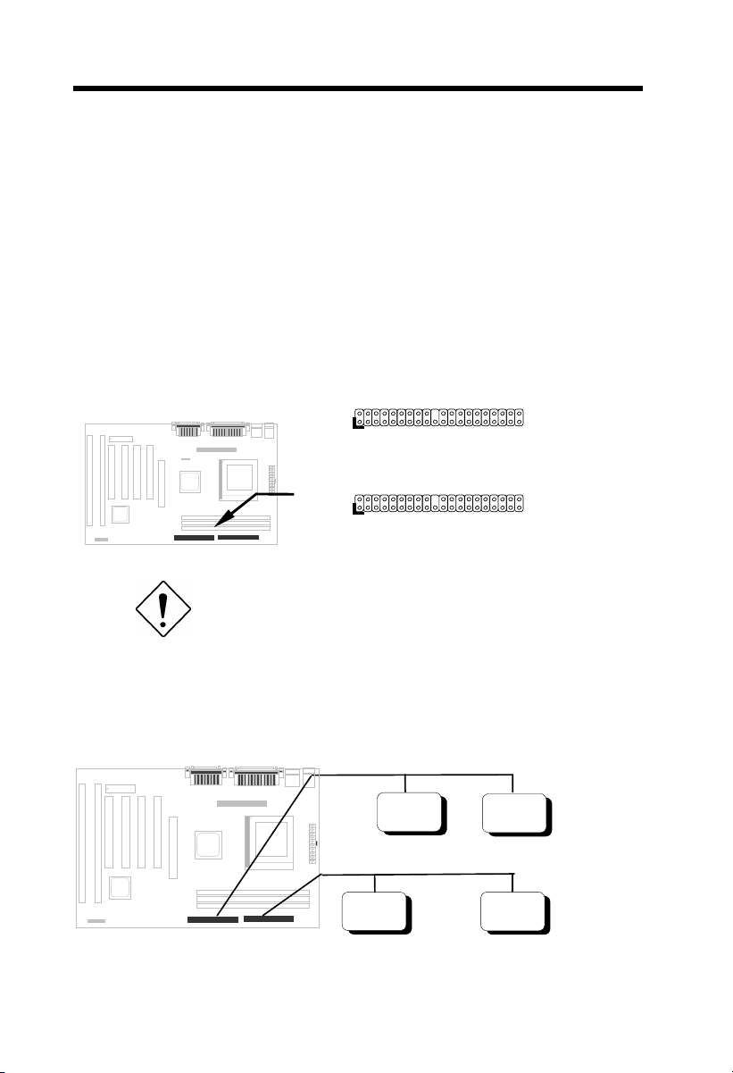
2.4 Configuring the System Memory
The DIMM types supported are EDO
(Extended Data Out) and SDRAM
(Synchronous DRAM). This mainboard has
three 168-pin DIMM sockets (Dual-in-line
Memory Module) that allow you to install
system memory up to 768MB EDO DRAM
or 384MB SDRAM.
Pin1
DIMM modules can be identified by the following factors:
I. Size: single side, 1Mx64 (8MB), 2Mx64 (16MB), 4Mx64 (32MB), 8Mx64
(64MB), 16Mx64 (128MB), and double side, 1Mx64x2 (16MB), 2Mx64x2
(32MB), 4Mx64x2 (64MB), 8Mx64x2 (128MB).
Tip: Here is a trick to check if your DIMM is singleside or double-side -- if there are traces connected to
golden finger pin 114 and pin 129 of the DIMM, the
DIMM is probably double-side; otherwise, it is singleside. The following figure is for your reference.
168
Pin 129
II. Speed:
SDRAM: normally marked as -12, which means the clock cycle time is 12ns
and maximum clock of this SDRAM is 83MHz. Sometimes you can also
find the SDRAM marked as -67, which means maximum clock is 67MHz.
EDO: the access time of EDO RAM can be 50ns or 60ns.
Pin 114
2-15
Page 27

Hardware Installation
III. Buffered and non-buffered: This motherboard supports non-buffered
DIMMs. You can identify non-buffered DIMMs and buffered DIMMs
according to the position of the notch, following figure is for your reference:
buffered
non-buffere d
Reserved
Because the positions are different, only non-buffered DIMMs can be
inserted into the DIMM sockets on this motherboard. Although most of
DIMMs on current market are non-buffered, we still suggest you to ask your
dealer for the correct type.
IV. 2-clock and 4-clock signals: Although both of 2-clock and 4-clock signals
are supported by this motherboard, we strongly recommend choosing 4clock SDRAM in consideration of reliability.
Tip: To identify 2-clock and 4-clock SDRAM, you
may check if there are traces connected to golden
finger pin 79 and pin 163 of the SDRAM. If there are
traces, the SDRAM is probably 4-clock; Otherwise, it
is 2-clock.
V. Parity: This motherboard supports standard 64 bit wide (without parity) and
72-bit wide (with parity) DIMM modules.
There is no jumper setting required for the memory size or type. It is
automatically detected by the system BIOS, and the total memory size is to
add them together. The maximum is 768MB.
LX chipset can only use 3V EDO or SDRAM, so we can mix EDO and SDRAM.
Every DIMM socket can be EDO or SDRAM. For EDO, maximum is 256MB.
For SDRAM, maximum is 128MB.
Total Memory Size = Size of DIMM1 + Size of DIMM2 + Size of DIMM3
Note: 768MB memory is achieved by using double-sided
buffered EDO DIMMs.
2-16
Page 28

Hardware Installation
The following table lists the recommended DRAM combinations of DIMM:
DIMM
Data chip
1M by 16 1Mx64 x1 4 8MB Yes
1M by 16 1Mx64 x2 8 16MB Yes
2M by 8 2Mx64 x1 8 16MB Yes
2M by 8 2Mx64 x2 16 32MB Yes
4M by 16 4Mx64 x1 4 32MB Yes
4M by 16 4Mx64 x2 8 64MB Yes
8M by 8 8Mx64 x1 8 64MB Yes
8M by 8 8Mx64 x2 16 128MB Yes
Bit size
per side
Single/
Double side
Chip
count
DIMM size Recommended
DIMM
Data chip
2M by 32 2Mx64 x1 2 16MB Yes, but not tested.
2M by 32 2Mx64 x2 4 32MB Yes, but not tested.
Bit size
per side
Single/
Double side
Chip
count
DIMM size Recommended
The following table lists the possible DRAM combinations that is NOT
recommended:
DIMM
Data chip
4M by 4 4Mx64 x1 16 32MB No
4M by 4 4Mx64 x2 32 64MB No
16M by 4 16Mx64 x1 16 128MB No
16M by 4 16Mx64 x2 32 256MB No
Bit size
per side
Single/
Double side
Chip
count
DIMM
size
Recommended
Tip: The parity mode uses 1 parity bit for each byte, normally it is
even parity mode, that is, each time the memory data is updated,
parity bit will be adjusted to have even count "1" for each byte.
When next time, if memory is read with odd number of "1", the
parity error is occurred and this is called single bit error detection.
2.5 Onboard Audio
This motherboard comes with a 16-bit sound processor (ESS Solo-1) onboard.
2-17
Page 29

Hardware Installation
r
Game Port
PCB
SPK
MIC
LINE-IN
To fully utilize the audio functions, you may connect various peripheral devices
that the audio chip supports. The following figure shows the different devices
that you can connect.
SPK
Line-in
Mic
Stereo
Amplifier
Microphone
Headphones
Speakers
CD Playe
Tape Deck,
Synthesizer,
etc.
2-18
Page 30

Hardware Installation
The onboard audio has the following features:
Advanced technology support
ESS Solo-1 PCI audio accelerator in 16 bits stereo chip
High-quality ESFM music synthesizer
64 voices software wavetable
3-D stereo effects processor
Support DLS (downloadable sound)
Support Microsoft DirectMusic
Support Microsoft positional 3D
Support DirectSound and DirectSound 3D
ADPCM data compression
Internal modem connector
Full DOS game compatibility
Plug and Play
Record, compress, and play back voice, sound, and music
16-bit stereo ADC and DAC
Programmable independent sample rate from 6 KHz up to 48 KHz for
record and playback
Full duplex operation for simultaneous record and playback
Support full DOS compatible modes: PC/PCI, TDMA, DDMA
Sound Blaster Pro & Windows Sound System compatible
Stereo Input for Line-in, CD-Audio, Auxiliary in and a mono microphone in
MPU-401(UART mode) interface for wavetable synthesizers and MIDI
devices
Integrated dual game port
Separate mono input (MONO-IN) and mono output (MONO-OUT) for
speakerphone
Support windows95/98 or windows NT 4.0
WDM streaming driver support windows98 and windows NT 5.0
Software-controllable audio
Supports various audio devices all controllable through software
Adjusts master volume, CD audio, line-in, AUX, mono in, mono out,
synthesis wave and microphone inputs
Stereo digitized voice channel
Full-duplex operation for simultaneous record and playback
2-19
Page 31

Hardware Installation
2.5.1 Setting Up in Windows 95/98
This motherboard comes with CD disc (AOpen Bonus Pack) containing the
Windows 95/98 drivers and software (including the Music Center application).
Refer to their online help for details.
Note: Refer to your Windows 95/98 manual or
online help for any questions on Windows 95/98.
Installing the Drivers and the Application
After turning on the system, Windows 95/98 begins loading and starts
detecting new hardware installed on the system.
1. When Windows 95/98 detects the presence of the onboard audio chip, it
begins to build the driver database. The New Hardware Found dialog box
displays.
2. Select Driver from disk provided by hardware manufacturer and click
on OK. Windows 95/98 prompts you for the driver disk.
3. Insert the driver disk in the appropriate drive and specify another drive, if
required. Then click on OK. The system copies the necessary driver files
to your hard disk drive.
Tip: Prepare the Windows 95/98 CD disk before
setting up the sound card. Windows 95/98 will
4. Windows 95/98 makes changes to the system settings and begins
detecting the following new hardware components:
• ES1941 PCI AudioDrive
• ES1941 DOS Enumlation
• Gameport Joystick
Windows 95/98 makes final changes to the system settings.
2-20
prompt you to insert the Windows 95/98 CD-ROM
disk when you install the joystick or MIDI device.
Note: If the file being copied is older than the file
currently existing in your system, we recommend
that you keep the existing file.
Page 32

Hardware Installation
Install the Application
1. Insert AOpen Bonus Pack disc, setup the applications from “Motherboard
Drivers” of the autorun program, or browse CD and select X:\AX3L\
Sound\Setup.exe.
Dos Legacy mode Setup
1. Insert AOpen Bonus Pack disc, setup the applications from “Motherboard
Drivers” of the autorun program, or browse CD and select X:\AX3L\
Sound\Setup.exe. Select Application button from setup menu.
2. Choose Dos Legacy Support item to begin setup.
3. If the system reboot under windows98, please select the driver form
Windows98 instead of AOpen Bonus Pack disc.
2.5.2 Setting Up in NT4.0
The card package also comes with NT4.0 drivers. Please refer to your NT4.0
manual or online help for any questions on NT4.0.
Installing the Audio Drivers
Follow these steps to install the audio drivers:
1. Select MULTIMEDIA from control panel and click on the Devices tab.
2. Press the ADD button. Select Unlisted or Updated Drivers and press
OK.
3. Browse and select X:\AX3L\Sound\Driver\NT40.
4. Press OK to continue with the installation.
5. An Audio Setup dialog box will appear. Select the default configuration
resource and press OK.
6. Click on the Restart Now button.
Install MPU-401/Joystick Driver
Follow these steps to install the MPU401 or joystick drivers:
1. Select MULTIMEDIA from control panel and click on the Devices tab.
2. Press the ADD button. Select MPU-401 Compatible Driver /Microsoft
Sidewinder 3D Pro Joystick and press OK..
2-21
Page 33

Hardware Installation
3. Place your NT4.0 installation CD and press OK (the default path is the
i386 directory).
4. The Generic MPU-401/Joystick Setup dialog box will pop up. Select the
default configuration resource and press OK.
5. Click on the Restart Now button.
Note: X: means your CD drive letter, please change it
according to the actual drive letter.
2-22
Page 34

Chapter 3
Award BIOS
This chapter tells how to configure the system parameters. You may update
your BIOS via AWARD Flash Utility.
Important: Because the BIOS code is the most often
changed part of the mainboard design, the BIOS
information contained in this chapter (especially the
Chipset Setup parameters) may be a little different
compared to the actual BIOS that came with your
mainboard.
3.1 Entering the Award BIOS Setup Menu
The BIOS setup utility is a segment of codes/routines residing in the BIOS
Flash ROM. This routine allows you to configure the system parameters and
save the configuration into the 128 byte CMOS area, (normally in the RTC chip
or directly in the main chipset). To enter the BIOS Setup, press
POST (Power-On Self Test). The BIOS Setup Main Menu appears as follows.
3-1
during
Page 35

AWARD BIOS
Tip: Choose "Load Setup Defaults" for
recommended optimal performance. Choose "Load
Turbo Defaults" for best performance with light
system loading. Refer to section 3.7.
The section at the bottom of the screen tells how to control the screen. Use the
arrow keys to move between items, F9 to change language, ESC to exit, and
F10 to save the changes before exit. Another section at the bottom of the
screen displays a brief description of the highlighted item.
After selecting an item, press Enter to select or enter a submenu.
3.2 Standard CMOS Setup
The "Standard CMOS Setup" sets the basic system parameters such as the
date, time, and the hard disk type. Use the arrow keys to highlight an item and
or to select the value for each item.
3-2
Page 36

AWARD BIOS
Standard CMOS Æ Date
To set the date, highlight the Date parameter. Press or to set the
current date. The date format is month, date, and year.
Standard CMOS Æ Time
To set the time, highlight the Time parameter. Press or to set the
current time in hour, minute, and second format. The time is based on the 24
hour military clock.
3-3
Page 37

AWARD BIOS
Standard CMOS Æ Primary Master Æ Type
Standard CMOS Æ Primary Slave Æ Type
Standard CMOS Æ Secondary Master Æ Type
Standard CMOS Æ Secondary Slave Æ Type
Type
Auto
User
None
This item lets you select the IDE hard disk parameters
that your system supports. These parameters are Size,
Number of Cylinder, Number of Head, Start Cylinder for
Pre-compensation, Cylinder number of Head Landing
Zone and Number of Sector per Track. The default
setting is Auto, which enables BIOS to automatically
detect the parameters of installed HDD at POST (PowerOn Self Test). If you prefer to enter HDD parameters
manually, select User. Select None if no HDD is
connected to the system.
The IDE CDROM is always automatically detected.
Tip: For an IDE hard disk, we recommend that you
use the "IDE HDD Auto Detection" to enter the
drive specifications automatically. See the section
"IDE HDD Auto Detection".
Standard CMOS Æ Primary Master Æ Mode
Standard CMOS Æ Primary Slave Æ Mode
Standard CMOS Æ Secondary Master Æ Mode
Standard CMOS Æ Secondary Slave Æ Mode
Mode
Auto
Normal
LBA
Large
The enhanced IDE feature allows the system to use a
hard disk with a capacity of more than 528MB. This is
made possible through the Logical Block Address (LBA)
mode translation. The LBA is now considered as a
standard feature of current IDE hard disk on the market
because of its capability to support capacity larger than
528MB. Note that if HDD is formatted with LBA On, it will
not be able to boot with LBA Off.
3-4
Page 38

Standard CMOS Æ Drive A
Standard CMOS Æ Drive B
AWARD BIOS
Drive A
None
360KB 5.25"
1.2MB 5.25"
720KB 3.5"
1.44MB 3.5"
2.88MB 3.5"
These items select floppy drive type. The available settings
and types supported by the mainboard are listed on the
left.
Standard CMOS Æ Video
Video
EGA/VGA
CGA40
CGA80
Mono
This item specifies the type of video card in use. The
default setting is VGA/EGA. Since current PCs use VGA
only, this function is almost useless and may be
disregarded in the future.
Standard CMOS Æ Halt On
Halt On
No Errors
All Errors
All, But Keyboard
All, But Diskette
All, But Disk/Key
This parameter enables you to control the system stops in
case of Power-On Self Test (POST) error.
3.3 BIOS Features Setup
This screen appears when you select the option "BIOS Features Setup" from
the main menu.
3-5
Page 39

AWARD BIOS
BIOS Features Æ Virus Warning
Virus Warning
Enabled
Disabled
Type "Y" to accept write, or "N" to abort write
3-6
Set this parameter to Enabled to activate the warning
message. This feature protects the boot sector and partition
table of your hard disk from virus intrusion. Any attempt during
boot up to write to the boot sector of the hard disk drive stops
the system and the following warning message appears on the
screen. Run an anti-virus program to locate the problem.
! WARNING !
Disk Boot Sector is to be modified
Award Software, Inc.
Page 40

BIOS Features Æ External Cache
AWARD BIOS
External Cache
Enabled
Disabled
Enabling this parameter activates the secondary cache
(currently, PBSRAM cache). Disabling the parameter
slows down the system. Therefore, we recommend that
you leave it enabled unless you are troubleshooting a
problem.
BIOS Features Æ CPU L2 Cache ECC Checking
CPU L2 Cache
ECC Checking
Enabled
Disabled
This item lets you enable or disable L2 Cache ECC
checking.
BIOS Features Æ Quick Power On Self Test
Quick Power on
Self test
Enable
Disabled
This parameter speeds up POST by skipping some items
that are normally checked.
BIOS Features Æ Boot Sequence
Boot Sequence
A,C,SCSI
C,A,SCSI
C,CDROM,A
CDROM,C,A
CDROM,A,C
D,A,SCSI
E,A,SCSI
F,A,SCSI
SCSI,A,C
SCSI,C,A
C only
LS/ZIP,C
This parameter allows you to specify the system boot up
search sequence. The hard disk ID are listed below:
C: Primary master
D: Primary slave
E: Secondary master
F: Secondary slave
LS: LS120
Zip: IOMEGA ZIP Drive
3-7
Page 41

AWARD BIOS
BIOS Features Æ Swap Floppy Drive
Swap Floppy Drive
Enabled
Disabled
This item allows you to swap floppy drives. For
example, if you have two floppy drives (A and B), you
can assign the first drive as drive B and the second
drive as drive A or vice-versa.
BIOS Features Æ Boot Up NumLock Status
Boot Up NumLock
Status
On
Off
Setting this parameter to On enables the numeric
function of the numeric keypad. Set this parameter to
Off to disregard the function. Disabling the numeric
function allows you to use the numeric keypad for
cursor control.
BIOS Features Æ Security Option
Security Option
Setup
System
The System option limits access to both the System boot
and BIOS setup. A prompt asking you to enter your
password appears on the screen every time you boot the
system.
The Setup option limits access only to BIOS setup.
To disable the security option, select Password Setting
from the main menu, don't type anything and just press
<Enter>.
BIOS Features Æ PCI/VGA Palette Snoop
PCI/VGA Palette
Snoop
Enabled
Disabled
3-8
Enabling this item informs the PCI VGA card to keep
silent (and to prevent conflict) when palette register is
updated (i.e., accepts data without responding any
communication signals). This is useful only when two
display cards use the same palette address and plugged
in the PCI bus at the same time (such as MPEQ or Video
capture). In such case, PCI VGA is silent while
MPEQ/Video capture is set to function normally.
Page 42

BIOS Features Æ OS Select for DRAM > 64MB
AWARD BIOS
OS Select for
DRAM > 64MB
OS/2
Non-OS/2
Set to OS/2 if your system is utilizing an OS/2
operating system and has a memory size of more than
64 MB.
BIOS Features Æ Show Logo On Screen
Show Logo On
Screen
Enabled
Disabled
This item lets you decide if AOpen logo will appear in
the POST screen.
BIOS Features Æ Video BIOS Shadow
Video BIOS
Shadow
Enabled
Disabled
VGA BIOS Shadowing means to copy video display
card BIOS into the DRAM area. This enhances system
performance because DRAM access time is faster than
ROM.
BIOS Features Æ C800-CBFF Shadow
BIOS Features Æ CC00-CFFF Shadow
BIOS Features Æ D000-D3FF Shadow
BIOS Features Æ D400-D7FF Shadow
BIOS Features Æ D800-DBFF Shadow
BIOS Features Æ DC00-DFFF Shadow
C8000-CBFFF
Shadow
Enabled
Disabled
3-9
These six items are for shadowing ROM code on other
expansion cards. Before you set these parameters, you
need to know the specific addresses of that ROM code.
If you do not know this information, enable all the ROM
shadow settings.
Note: The F000 and E000 segments are always
shadowed because BIOS code occupies these
areas.
Page 43

AWARD BIOS
3.4 Chipset Features Setup
The "Chipset Features Setup" includes settings for the chipset dependent
features. These features are related to system performance.
3-10
Caution: Make sure you fully understand the items
contained in this menu before you try to change
anything. You may change the parameter settings to
improve system performance. However, it may
cause system unstable if the setting is not correct for
your system configuration.
Page 44

Chipset Features Æ Auto Configuration
AWARD BIOS
Auto Configuration
Enabled
Disabled
When Enabled, the DRAM and cache related timing
are set to pre-defined value according to CPU type
and clock. Select Disable if you want to specify your
own DRAM timing.
Chipset Features Æ DRAM Speed Selection
DRAM Speed
Selection
50 ns
60 ns
There are two sets of DRAM timing parameters can
be automatically set by BIOS, 50ns and 60ns.
Chipset Features Æ MA Wait State
MA Wait State
Slow
Fast
To enable or disable one additional MA (DRAM
memory address) wait state. The default setting is
Slow. Set it to Fast if you have heavy loading (many
chip count) or lower speed DRAM.
Chipset Features Æ EDO RAS# to CAS# Delay
EDO RAS# to CAS#
Delay
2
3
This option allows you to set the wait state between
row address strobe (RAS) and column address
strobe (CAS) signals.
Chipset Features Æ EDO RAS# Precharge Time
EDO RAS#
Precharge Time
3
4
3-11
This parameter specifies the number of clocks
required to deassert the RAS signal to prevent DRAM
from losing data after performing a read. This
operation is called Precharge.
Page 45

AWARD BIOS
Chipset Features Æ EDO DRAM Read Burst
EDO DRAM Read
Burst
x333
x222
Read Burst means to read four continuous memory
cycles on four predefined addresses from the DRAM.
The default value is x222 for 60ns EDO DRAM.
Which means the 2nd,3rd and 4th memory cycles
are 2 CPU clocks for EDO. The value of x is the
timing of first memory cycle.
Chipset Features Æ EDO DRAM Write Burst
EDO DRAM Write
Burst
x333
x222
Write Burst means to write four continuous memory
cycles on four predefined addresses to the DRAM.
The default value is x222 for 60ns EDO DRAM.
Which means the 2nd,3rd and 4th memory cycles
are 2 CPU clocks for EDO. The value of x is the
timing of first memory cycle.
Chipset Features Æ SDRAM(CAS Lat/RAS-to-CAS)
SDRAM(CAS
Lat/RAS-to-CAS)
2/2
3/3
These are timing of SDRAM CAS Latency and RAS
to CAS Delay, calculated by clocks. They are
important parameters affects SDRAM performance,
default is 2 clocks. If your SDRAM has unstable
problem, change 2/2 to 3/3.
Chipset Features Æ SDRAM RAS Precharge Time
SDRAM RAS
Prechatge Time
2T
3T
The RAS Precharge means the timing to inactive
RAS and the timing for DRAM to do precharge before
next RAS can be issued. RAS is the address latch
control signal of DRAM row address. The default
setting is 3 clocks.
3-12
Page 46

Chipset Features Æ DRAM ECC Function
AWARD BIOS
DRAM ECC
Function
Enabled
Disabled
This item lets you enable or disable DRAM ECC
function. The ECC algorithm has the ability to detect
double bit error and automatically correct single bit
error.
Chipset Features Æ CPU-to-PCI IDE Posting
CPU-to-PCI IDE
Posting
Enabled
Disabled
To enable or disable CPU to PCI IDE post write
cycle. The IDE write cycles will be queued in the
FIFO or buffer, and CPU can be released to do next
job. Disable it, if you find any IDE compatibility
problem.
Chipset Features Æ Video BIOS Cacheable
Video BIOS
Cacheable
Enabled
Disabled
Allows the video BIOS to be cached to allow faster
video performance.
Chipset Features Æ Video RAM Cacheable
Video RAM
Cacheable
Enabled
Disabled
This item lets you cache Video RAM A000 and B000.
3-13
Page 47

AWARD BIOS
Chipset Features Æ 8 Bit I/O Recovery Time
8 Bit I/O Recovery
Time
1
2
3
4
5
6
7
8
NA
For some old I/O chips, after the execution of an I/O
command, the device requires a certain amount of
time (recovery time) before the execution of the next
I/O command. Because of new generation CPU and
mainboard chipset, the assertion of I/O command is
faster, and sometimes shorter than specified I/O
recovery time of old I/O devices. This item lets you
specify the delay of 8-bit I/O command by count of
ISA bus clock. If you find any unstable 8-bit I/O card,
you may try to extend the I/O recovery time via this
item. The BIOS default value is 4 ISA clock. If set to
NA, the chipset will insert 3.5 system clocks.
Chipset Features Æ 16 Bit I/O Recovery Time
16 Bit I/O Recovery
Time
1
2
3
4
NA
The same as 16-bit I/O recovery time. This item lets
you specify the recovery time for the execution of 16bit I/O commands by count of ISA bus clock. If you
find any of the installed 16-bit I/O cards unstable, try
extending the I/O recovery time via this item. The
BIOS default value is 1 ISA clocks. If set to NA, the
chipset will automatically insert 3.5 system clocks.
Chipset Features Æ Memory Hole At 15M-16M
Memory Hole At
15M-16M
Enabled
Disabled
This option lets you reserve system memory area for
special ISA cards. The chipset accesses code/data
of these areas from the ISA bus directly. Normally,
these areas are reserved for memory mapped I/O
card.
Chipset Features Æ Passive Release
Passive Release
Enabled
Disabled
3-14
This item lets you control the Passive Release
function of the PIIX4 chipset (Intel PCI to ISA bridge).
This function is used to meet latency of ISA bus
master. Try to enable or disable it, if you have ISA
card compatibility problem.
Page 48

Chipset Features Æ Delayed Transaction
AWARD BIOS
Delayed Transaction
Enabled
Disabled
This item lets you control the Delayed Transaction
function of the PIIX4 chipset (Intel PCI to ISA bridge).
This function is used to meet latency of PCI cycles to
or from ISA bus. Try to enable or disable it, if you
have ISA card compatibility problem.
Chipset Features Æ AGP Aperture Size (MB)
AGP Aperture Size
(MB)
4
8
16
32
64
128
256
This item lets you determine the effective size of the
Graphic Aperture.
Chipset Features Æ Pentium II Micro Codes
Pentium II Micro
Codes
Enabled
Disabled
The micro codes are used to fix bugs of Pentium II
CPU, we strongly recommend to enable this item for
system reliability reason. However, this microcode
may slightly reduce CPU performance. We provide
this option for your convenience if you like to test it.
Chipset Features Æ Manufacture Frequency Default
Manufacture
Frequency Default
Depends on the CPU
type
3-15
This item only reminds you of the actual CPU
frequency while clearing CMOS or pressing "Home”
key. The default setting is 233 MHz, you can modify it
to match the actual CPU frequency by using the utility
- flash.exe.
Page 49

AWARD BIOS
Chipset Features Æ System Frequency
System Frequency
300 MHz
333 MHz
366 MHz
400 MHz
433 MHz
466 MHz
500 MHz
533 MHz
Manual
Chipset Features Æ CPU Clock Frequency
CPU Clock
Frequency
66.8 MHz
68.5 Mhz
75.0 Mhz
83.3 Mhz
Chipset Features Æ CPU Clock Ratio
CPU Clock Ratio
1.5
2.0
2.5
3.0
3.5
4.0
4.5
5.0
5.5
6.0
6.5
7.0
7.5
8.0
This item lets you set CPU frequency. If you want to
set other value, please choose "Manual " to set CPU
clock frequency and clock ratio manually.
This item lets you set external clock (bus clock). The
possible settings of current Klamath CPU available
on the market are 66.8 MHz, the correct setting may
vary because of new CPU product, refer to your CPU
specification for more details.
Intel Pentium II (Klamath) is designed to have
different Internal (Core) and External (Bus)
frequency. This item lets you select the ratio of
Core/Bus frequency. The default value is 3.5x.
3-16
Page 50

AWARD BIOS
3.5 Power Management Setup
The Power Management Setup screen enables you to control the mainboard
green features. See the following screen.
Power Management Æ Power Management
Power Management
Max Saving
Mix Saving
User Define
Disabled
Mode Doze Standby Suspend HDD Power Down
Min Saving 1 hour 1 hour 1 hour 15 min
Max Saving 1 min 1 min 1 min 1 min
3-17
This function allows you to set the default parameters
of power-saving modes. Set to Disable to turn off
power management function. Set to User Define to
choose your own parameters.
Page 51

AWARD BIOS
Power Management Æ PM Controlled by APM
PM Controlled by
APM
Yes
No
If "Max Saving" is selected, you can turn on this item,
transfer power management control to APM
(Advanced Power Management) and enhance power
saving function. For example, stop CPU internal
clock.
Power Management Æ Video Off Method
Video Off Method
V/H SYNC + Blank
DPMS
Blank Screen
This determines the way that monitor is off. Blank
Screen writes blanks to video buffer. V/H
SYNC+Blank allows BIOS to control VSYNC and
HSYNC signals. This function applies only for DPMS
(Display Power Management Standard) monitor. The
DPMS mode uses DPMS function provided by VGA
card.
Power Management Æ Video Off After
Video Off After
N/A
Doze
Standby
Suspend
To turn off video monitor at which power down mode.
Power Management Æ Modem Use IRQ
Modem Use IRQ
3
4
5
7
9
10
11
N/A
3-18
This item lets you set an IRQ for the modem.
Page 52

Power Management Æ Doze Mode
AWARD BIOS
Doze Mode
Disabled
1 Min
2 Min
4 Min
8 Min
12 Min
20 Min
30 Min
40 Min
1 Hour
This item lets you set the period of time after which
the system enters into Doze mode. The system
activity (or event) is detected by monitoring the IRQ
signals or other events (such as I/O).
Power Management Æ Standby Mode
Standby Mode
Disabled
1 Min
2 Min
4 Min
8 Min
12 Min
20 Min
30 Min
40 Min
1 Hour
This item lets you set the period of time after which
the system enters into Standby mode. In this mode,
the monitor power-saving feature activates. Any
activity detected returns the system to full power.
The system activity (or event) is detected by
monitoring the IRQ signals or other events (such as
I/O).
Power Management Æ Suspend Mode
Suspend Mode
Disabled
1 Min
2 Min
4 Min
8 Min
12 Min
20 Min
30 Min
40 Min
1 Hour
This item lets you set the period of time after which
the system enters into Suspend mode. The Suspend
mode can be Power On Suspend or Suspend to Hard
Drive, selected by "Suspend Mode Option".
3-19
Page 53

AWARD BIOS
Power Management Æ HDD Power Down
HDD Power Down
Disabled
1 Min
.....
15 Min
This option lets you specify the IDE HDD idle time
before the device enters the power down state. This
item is independent from the power states previously
described in this section (Standby and Suspend).
Power Management Æ Suspend Mode Option
Suspend Modem
Option
PowerOn Suspend
Suspend to Disk
You can select suspend mode by this item. Power
On Suspend is the traditional Green PC suspend
mode, the CPU clock is stop, all other devices are
shut off. But power must be kept On to detect
activities from modem, keyboard/mouse and returns
the system to full power. The system activities is
detected by monitoring the IRQ signals or I/O.
Suspend to Hard Drive saves system status,
memory and screen image into hard disk, then the
power can be totally Off. Next time, when power is
turned On, the system goes back to your original
work within just few seconds, which depending on
your memory size. You need utility AOZVHDD to
reserve disk space.
Power Management Æ 0V Wake On Modem
0V Wake On Modem
Enabled
Disabled
This option lets you specify enable or disable Modem
Wake Up function.
Power Management Æ Wake On LAN
Wake On LAN
Enabled
Disabled
3-20
This option lets you specify enable or disable LAN
Wake Up function.
Page 54

Power Management Æ Throttle Duty Cycle
AWARD BIOS
Throttle Duty Cycle
12.5 %
25.0 %
37.5 %
50.0 %
62.5 %
75.0 %
87.5 %
Clock Throttling means at the Doze/Standby state,
the CPU clock count in a given time (not the
frequency) is reduced to the ratio specified in this
parameter. Actually, the period per CPU clock is not
changed. For example, a 66MHz CPU clock remains
the same 30ns clock period when system goes into
Doze/Suspend. The chipset generates the STPCLK
(stop clock) signal periodically to prevent CPU for
accepting clock from clock generator. For full power
on, the CPU can receive 66M count in one second. If
the Slow Clock Ratio is set to 50%, the CPU will only
receive 33M clock count in one second. This will
effectively reduce CPU speed as well as CPU power.
Power Management Æ VGA Active Monitor
VGA Active Monitor
Enabled
Disabled
To enable or disable the detection of VGA activity for
power down state transition.
Power Management Æ Soft-Off by PWR-BTTN
Soft-Off by PWRBTTN
Delay 4 sec.
Instant-Off
This is a specification of ACPI and supported by
hardware. When Delay 4 sec. is selected, the soft
power switch on the front panel can be used to
control power On, Suspend and Off. If the switch is
pressed less than 4 sec during power On, the system
will go into Suspend mode. If the switch is pressed
longer than 4 sec, the system will be turned Off. The
default setting is Instant-Off, soft power switch is only
used to control On and Off, there is no need to press
4 sec, and there is no Suspend.
Power Management Æ Wake On RTC Timer
Wake On RTC
Timer
Enabled
Disabled
3-21
This option lets you enable or disable the RTC Wake
Up function.
Page 55

AWARD BIOS
Power Management Æ Date (of Month) Alarm
Date (of Month)
Alarm
0
1
.....
31
This item is displayed when you enable the Wake On
RTC Timer option. Here you can specify what date
you want to wake up the system. For Example,
setting to 15 will wake up the system on the 15th day
of every month.
Note: Setting this item to 0 will wake up the
system on the specified time (which can be set in
the Wake On RTC Timer item) every day.
Power Management Æ Time (hh:mm:ss) Alarm
Time (hh:mm:ss)
Alarm
hh:mm:ss
This item is displayed when you enable the Wake ON
RTC Timer option. Here you can specify what time
you want to wake up the system.
Power Management Æ IRQ 8 Break Suspend
IRQ 8 Break Suspend
Enabled
Disabled
To enable or disable the detection of IRQ8 (RTC)
event for power down state transition. OS2 has
periodically IRQ8 (RTC) interruptions, If IRQ8 is not
set to Disabled, OS/2 may fail to go into
Doze/Standby/Suspend mode.
Power Management Æ IRQ [3-7,9-15],NMI
IRQ [3-7,9-15],NMI
Enabled
Disabled
3-22
To enable or disable the detection of IRQ3-7, IRQ915 or NMI interrupts events for power down state
transition.
Page 56

Power Management Æ Primary IDE 0
Power Management Æ Primary IDE 1
Power Management Æ Secondary IDE 0
Power Management Æ Secondary IDE 1
Power Management Æ Floppy Disk
Power Management Æ Serial Port
Power Management Æ Parallel Port
AWARD BIOS
Primary IDE 0
Enabled
Disabled
These items enable or disable the detection of IDE,
floppy, serial and parallel port activities for power
down state transition. Actually it detects the
read/write to/from I/O port.
3.6 PNP/PCI Configuration Setup
The PNP/PCI Configuration Setup allows you to configure the ISA and PCI
devices installed in your system. The following screen appears if you select
the option "PNP/PCI Configuration Setup" from the main menu.
3-23
Page 57

AWARD BIOS
PNP/PCI Configuration Æ PnP OS Installed
PnP OS Installed
Yes
No
Normally, the PnP resources are allocated by BIOS
during POST (Power-On Self Test). If you are using
a PnP operating system (such as Windows 95), set
this item to Yes to inform BIOS to configure only the
resources needed for booting (VGA/IDE or SCSI).
The rest of system resources will be allocated by PnP
operating system.
3-24
Page 58

AWARD BIOS
PNP/PCI Configuration Æ Resources Controlled By
Resources Controlled
by
Auto
Manual
Setting this option to Manual allows you to
individually assign the IRQs and DMAs to the ISA
and PCI devices. Set this to Auto to enable the autoconfiguration function.
PNP/PCI Configuration Æ Reset Configuration Data
Reset Configuration
Data
Enabled
Disabled
In case conflict occurs after you assign the IRQs or
after you configure your system, you can enable this
function, allow your system to automatically reset
your configuration and reassign the IRQs, DMAs, and
I/O address.
PNP/PCI Configuration Æ IRQ3 (COM2)
PNP/PCI Configuration Æ IRQ4 (COM1)
PNP/PCI Configuration Æ IRQ5 (Network/Sound or Others)
PNP/PCI Configuration Æ IRQ7 (Printer or Others)
PNP/PCI Configuration Æ IRQ9 (Video or Others)
PNP/PCI Configuration Æ IRQ10 (SCSI or Others)
PNP/PCI Configuration Æ IRQ11 (SCSI or Others)
PNP/PCI Configuration Æ IRQ12 (PS/2 Mouse)
PNP/PCI Configuration Æ IRQ14 (IDE1)
PNP/PCI Configuration Æ IRQ15 (IDE2)
IRQ 3
Legacy ISA
PCI/ISA PnP
If your ISA card is not PnP compatible and requires a
special IRQ to support its function, set the selected
IRQ to Legacy ISA. This setting informs the PnP
BIOS to reserve the selected IRQ for the installed
legacy ISA card. The default is PCI/ISA PnP. Take
note that PCI cards are always PnP compatible
(except old PCI IDE card).
3-25
Page 59

AWARD BIOS
PNP/PCI Configuration Æ DMA 0
PNP/PCI Configuration Æ DMA 1
PNP/PCI Configuration Æ DMA 3
PNP/PCI Configuration Æ DMA 5
PNP/PCI Configuration Æ DMA 6
PNP/PCI Configuration Æ DMA 7
DMA 0
Legacy ISA
PCI/ISA PnP
If your ISA card is not PnP compatible and requires a
special DMA channel to support its function, set the
selected DMA channel to Legacy ISA. This setting informs
the PnP BIOS to reserve the selected DMA channel for the
installed legacy ISA card. The default is PCI/ISA PnP.
Take note that PCI card does not require DMA channel.
PNP/PCI Configuration Æ PCI IDE IRQ Map To
PCI IDE IRQ Map
To
ISA
PCI-Slot1
PCI-Slot2
PCI-Slot3
PCI-Slot4
PCI-Auto
Some old PCI IDE add-on cards are not fully PnP
compatible. These cards require you to specify the
slot in use to enable BIOS to properly configure the
PnP resources. This function allows you to select the
PCI slot for any PCI IDE add-on card present in your
system. Set this item to
automatically configure the installed PCI IDE card(s).
Auto to allow BIOS to
PNP/PCI Configuration Æ Primary IDE INT#
PNP/PCI Configuration Æ Secondary IDE INT#
Primary IDE INT#
A
B
C
D
These two items, in conjunction with item "PCI IDE
IRQ Map To", specify the IRQ routing of the primary
or secondary channel of the PCI IDE add-on card
(not the onboard IDE). Each PCI slot has four PCI
interrupts aligned as listed in the table below. You
must specify the slot in the "PCI IDE IRQ Map To",
and set the PCI interrupt (INTx) here according to the
interrupt connection on the card.
3-26
Page 60

AWARD BIOS
PCI Slot Location 1
(pin A6)
Slot 1 INTA INTB INTC INTD
Slot 2 INTB INTC INTD INTA
Slot 3 INTC INTD INTA INTB
Slot 4 INTD INTA INTB INTC
Slot 5 (if any) INTD INTA INTB INTC
PNP/PCI Configuration Æ Assign IRQ for USB
Location 2
(pin B7)
Location 3
(pin A7)
Location 4
(pin B8)
Assign IRQ for USB
Enabled
Disabled
This item lets you set an IRQ for USB.
PNP/PCI Configuration Æ Used MEM Base Addr
Used MEM Base
Addr
N/A
C800
CC00
D000
D400
D800
DC00
This item, in conjunction with the "Used MEM
Length", lets you set a memory space for non-PnP
compatible ISA card. This item specifies the memory
base (start address) of the reserved memory space.
The memory size is specified in the "Used MEM
Length"
.
PNP/PCI Configuration Æ Used MEM Length
Used MEM Length
8K
16K
32K
64K
If your ISA card is not PnP compatible and requires
special memory space to support its function, specify
the memory size in this parameter to inform the PnP
BIOS to reserve the specified memory space for
installed legacy ISA card.
3-27
Page 61

AWARD BIOS
PNP/PCI Configuration Æ PCI Slot1 IRQ (Right)
PNP/PCI Configuration Æ PCI Slot2 IRQ
PNP/PCI Configuration Æ PCI Slot3 IRQ
PCI Slot1 IRQ
3
4
5
7
9
10
11
12
14
15
Auto
This item is reserved for engineering purpose to let
you assign an IRQ manually to the add-on card on
each PCI slot. If you select Auto, system will
automatically assign an available value to the device.
It is suggested to use default setting, which is Auto,
in order to comply with PnP specification completely.
3.7 Load Setup Defaults
The "Load Setup Defaults" option loads optimized settings for optimum system
performance. Optimal settings are relatively safer than the Turbo settings.
We recommend you to use the Optimal settings if your system has large
memory size and fully loaded with add-on card (for example, a file server using
double-sided 8MB DIMM x4 and SCSI plus Network card occupying the PCI
and ISA slots).
Optimal is not the slowest setting for this mainboard. If you need to verify a
unstable problem, you may manually set the parameter in the "BIOS Features
Setup" and "Chipset Features Setup" to get slowest and safer setting.
3.8 Load Turbo Defaults
The "Load Turbo Defaults" option gives better performance than Optimal
values. However, Turbo values may not be the best setting of this mainboard
but these values are qualified by the AOpen RD and QA department as the
reliable settings especially if you have limited loading of add-on card and
memory size (for example, a system that contains only a VGA/Sound card and
two DIMMs).
3-28
Page 62

AWARD BIOS
To attain the best system performance, you may manually set the parameters
in the "Chipset Features Setup" to get proprietary setting. Make sure that you
know and understand the functions of every item in Chipset Setup menu. The
performance difference of Turbo from Optimal is normally around 3% to 10%,
depending on the chipset and the application.
3.9 Integrated Peripherals
The following screen appears if you select the option "Integrated Peripherals"
from the main menu. This option allows you to configure the I/O features.
Integrated Peripherals Æ IDE HDD Block Mode
IDE HDD Block
Mode
Enabled
Disabled
3-29
This feature enhances disk performance by allowing
multisector data transfers and eliminates the interrupt
handling time for each sector. Most IDE drives,
except with old designs, can support this feature.
Page 63

AWARD BIOS
Integrated Peripherals Æ IDE Primary Master PIO
Integrated Peripherals Æ IDE Primary Slave PIO
Integrated Peripherals Æ IDE Secondary Master PIO
Integrated Peripherals Æ IDE Secondary Slave PIO
IDE Primary Master
PIO
Auto
Mode 1
Mode 2
Mode 3
Mode 4
Setting this item to Auto activates the HDD speed
auto-detect function. The PIO mode specifies the
data transfer rate of HDD. For example: mode 0 data
transfer rate is 3.3MB/s, mode 1 is 5.2MB/s, mode 2
is 8.3MB/s, mode 3 is 11.1MB/s and mode 4 is
16.6MB/s. If your hard disk performance becomes
unstable, you may manually try the slower mode.
Caution: It is recommended that you connect the
first IDE device of each channel to the endmost
connector of the IDE cable. Refer to section
"Connectors" for details on how to connect IDE
device(s).
Integrated Peripherals Æ IDE Primary Master UDMA
Integrated Peripherals Æ IDE Primary Slave UDMA
Integrated Peripherals Æ IDE Secondary Master UDMA
Integrated Peripherals Æ IDE Secondary Slave UDMA
IDE Primary Master
UDMA
Auto
Disabled
This item allows you to set the Ultra DMA/33 mode
supported by the hard disk drive connected to your
primary IDE connector.
Integrated Peripherals Æ On-Chip Primary PCI IDE
Integrated Peripherals Æ On-Chip Secondary PCI IDE
On-Chip Primary
PCI IDE
Enabled
Disabled
3-30
This parameter lets you enable or disable the IDE
device connected to the primary IDE connector.
Page 64

AWARD BIOS
Integrated Peripherals Æ USB Keyboard Support
USB Keyboard
Support
Enabled
Disabled
This item lets you enable or disable the USB
keyboard driver within the onboard BIOS. The
keyboard driver simulates legacy keyboard
command and let you use USB keyboard during
POST or after boot if you don't have USB driver in
the operating system.
Caution: You can not use both USB driver and
USB legacy keyboard at the same time. Disable
"USB Legacy Support" if you have USB driver in
the operating system.
Integrated Peripherals Æ Init Display First
Init Display First
PCI
AGP
If you installed a PCI VGA card and an AGP card at
the same time, this item lets you decide which one is
the initial display card.
Integrated Peripherals Æ Power On Function
Power On Function
Button Only
Keyboard 98
Password
Hot Key
Mouse Left
Mouse Right
This item is used to select Wake on
Keyboard/Mouse mode.
Button Only: Disable W ake on KB/MS function. You
can boot up your system by power button only.
Keyboard 98: If selecting this option, you can boot
up the system by power button and the “Wake” key
on Keyboard 98.
Password: Disable the function of power button and
let the system can only be powered on through the
preset keys (like a password).
Hot Key: If selecting this option, you also need to
specify the hot key from “Hot Key Power On” item.
Mouse Left: This function allows you wake up the
system by clicking left mouse button twice
successively.
Mouse Right: This function allows you wake up the
system by clicking right mouse button twice
successively.
3-31
Page 65

AWARD BIOS
Caution: To implement Wake On Keyboard/Mouse
function, you must set JP28 to Enabled.
Caution: Wake On Mouse function applies to PS/2
mouse only.
Caution: If you set a Password but forget it, please clear
CMOS.
Integrated Peripherals Æ Keyboard Power On Password
Keyboard Power On
Password
You can specify 1-5 keys as a password.
Integrated Peripherals Æ Hot Key Power On
Hot Key Power On
Ctrl-F1
Ctrl-F2
Ctrl-F3
Ctrl-F4
Ctrl-F5
Ctrl-F6
Ctrl-F7
Ctrl-F8
Ctrl-F9
Ctrl-F10
Ctrl-F11
Ctrl-F12
If you select “Hot Key” option in “Power On
Function” Item, you need to specify a hot key here.
3-32
Page 66

AWARD BIOS
Power Management Æ AC PWR Auto Recovery
AC PWR Auto
Recovey
Former-Sts
On
Off
A traditional ATX system should remain at power off
stage when AC power resumes from power failure.
This design is inconvenient for a network server or
workstation, without an UPS, that needs to keep
power-on. This item is used to solve this problem.
Selecting On lets the system can automatically
power-on after AC power resumes; in the other hand,
the system will power-off if you select Off. If FormerSts option is selected, the system will power-on or
power-off based on the original state.
Integrated Peripherals Æ Onboard FDC Controller
Onboard FDC
Controller
Enabled
Disabled
Setting this parameter to Enabled allows you to
connect your floppy disk drives to the onboard floppy
disk connector instead of a separate controller card.
Change the setting to Disabled if you want to use a
separate controller card.
Integrated Peripherals Æ Onboard Serial Port 1
Integrated Peripherals Æ Onboard Serial Port 2
Onboard Serial Port 1
Auto
3F8/IRQ4
2F8/IRQ3
3E8/IRQ4
2E8/IRQ3
Disabled
This item allow you to assign address and interrupt
for the board serial port. Default is Auto.
Note: If you are using a network card, make sure
that the interrupt does not conflict.
3-33
Page 67

AWARD BIOS
Integrated Peripherals Æ UART Mode Select
UART Mode Select
Standard
HPSIR
ASKIR
This item is configurable only if the "Onboard UART
is enabled. This allows you to specify the mode
2"
of serial port2. The available mode selections are:
• Standard - Sets serial port 2 to operate in normal mode. This is the
default setting.
• HPSIR - Select this setting if you installed an Infrared module in your
system via IrDA connector (refer to section 2.3 "Connectors"). This
setting allows infrared serial communication at a maximum baud rate of
115K baud.
• ASKIR - Select this setting if you installed an Infrared module via IrDA
connector (refer to section 2.3 "Connectors"). This setting allows infrared
serial communication at a maximum baud rate of 19.2K baud.
Integrated Peripherals Æ Onboard Parallel Port
Onboard Parallel
Port
3BC/IRQ7
378/IRQ7
278/IRQ5
Disabled
This item controls the onboard parallel port address
and interrupt.
3-34
Note: If you are using an I/O card with a parallel
port, make sure that the addresses and IRQ do not
conflict.
Page 68

Integrated Peripherals Æ Parallel Port Mode
AWARD BIOS
Parallel Port Mode
SPP
EPP
ECP
ECP + EPP
This item lets you set the parallel port mode. The
mode options are SPP (Standard and Bidirection
Parallel Port), EPP (Enhanced Parallel Port) and
ECP (Extended Parallel Port). SPP is the IBM AT
and PS/2 compatible mode. EPP enhances the
parallel port throughput by directly writing/reading
data to/from parallel port without latch. ECP supports
DMA and RLE (Run Length Encoded) compression
and decompression.
Integrated Peripherals Æ ECP Mode Use DMA
ECP Mode Use DMA
3
1
This item lets you set the DMA channel of ECP
mode.
Integrated Peripherals Æ EPP Mode Select
EPP Mode Select
EPP1.7
EPP1.9
This item lets you select EPP mode.
3.10 Password Setting
Password prevents unauthorized use of your computer. If you set a password,
the system prompts for the correct password before boot or access to Setup.
To set a password:
1. At the prompt, type your password. Your password can be up to 8
alphanumeric characters. When you type the characters, they appear as
asterisks on the password screen box.
2. After typing the password, press.
3. At the next prompt, re-type your password and press again to confirm the
new password. After the password entry, the screen automatically reverts
to the main screen.
3-35
Page 69

AWARD BIOS
To disable the password, press when prompted to enter the password. The
screen displays a message confirming that the password has been disabled.
3.11 IDE HDD Auto Detection
If your system has an IDE hard drive, you can use this function to detect its
parameters and enter them into the "Standard CMOS Setup" automatically.
This routine only detects one set of parameters for your IDE hard drive. Some
IDE drives can use more than one set of parameters. If your hard disk is
formatted using different parameters than those detected, you have to enter
the parameters manually. If the parameters listed do not match the ones used
to format the disk, the information on that disk will not be accessible. If the
auto-detected parameters displayed do not match those that used for your
drive, ignore them. Type
manually from the Standard CMOS Setup screen.
N to reject the values and enter the correct ones
3.12 Save & Exit Setup
This function automatically saves all CMOS values before leaving Setup.
3.13 Load EEPROM Default
Except "Load Setup Default" and "Load Turbo Default", you may also use
"Save EEPROM Default " to save your own settings into EEPROM, and reload
by using this item.
3.14 Save EEPROM Default
You may use this item to save your own settings into EEPROM. Then, if the
data in CMOS is lost or you forget the previous settings, you may use "Load
EEPROM Default " to reload.
3-36
Page 70

AWARD BIOS
3.15 Exit without Saving
Use this function to exit Setup without saving the CMOS value changes. Do
not use this option if you want to save the new configuration.
3.16 NCR SCSI BIOS and Drivers
The NCR 53C810 SCSI BIOS resides in the same flash memory chip as the
system BIOS. The onboard NCR SCSI BIOS is used to support NCR 53C810
SCSI control card without BIOS code.
The NCR SCSI BIOS directly supports DOS, Windows 3.1 and OS/2. For
better system performance, you may use the drivers that come with the NCR
SCSI card or with your operating system. For details, refer to the installation
manual of your NCR 53C810 SCSI card.
3.17 BIOS Flash Utility
AOpen Easy Flash is more user friendly than traditional flash method. The
BIOS binary file and flash routine are combined together and you simply run a
single file to complete the flash process.
1. Get new BIOS upgrade program from AOpen's web site. For example,
AX3L200.EXE.
2. Reboot the system to DOS mode without loading any memory handler (such as
EMM386) or device driver. It needs around 520K free memory space.
3. Execute A:> AX3L200
DO NOT turn off the power during FLASH PROCESS.
4. Reboot the system by turn off the power after flash is completed.
5. Reload the "BIOS SETUP DEFAULT" and reconfigure other items as
previous set. Save & Exit. Done!
Note: The upgrade of new BIOS will permanently
replace your original BIOS content after flashing.
The original BIOS setting and Win95/Win98 PnP
information will be refreshed and you probably
need to re-configure your system.
3-37
 Loading...