

Page 1

Chapter 1
Overview
The AP57 is a high-performance Pentium-based system board that utilizes
the PCI/ISA architecture. It integrates the SiS 5571 PCIset, a super I/O
controller, and a PCI mode 4 enhanced IDE controller with bus master
support to enhance system performance. It has four single in-line memory
module (SIMM) sockets that allow system memory expansion up to a
maximum of 256MB. It also supports 256KB and 512KB pipelined-burst
second-level cache.
One main feature of AP57 is the green power-management function that
extends energy conservation from system components to display monitor. It
complies with the power-saving standards of the U.S. Environmental
Protection Agency (EPA) Energy Star program.
The AP57 board measures 220 mm x 250 mm.
1-1
Page 2
Overview
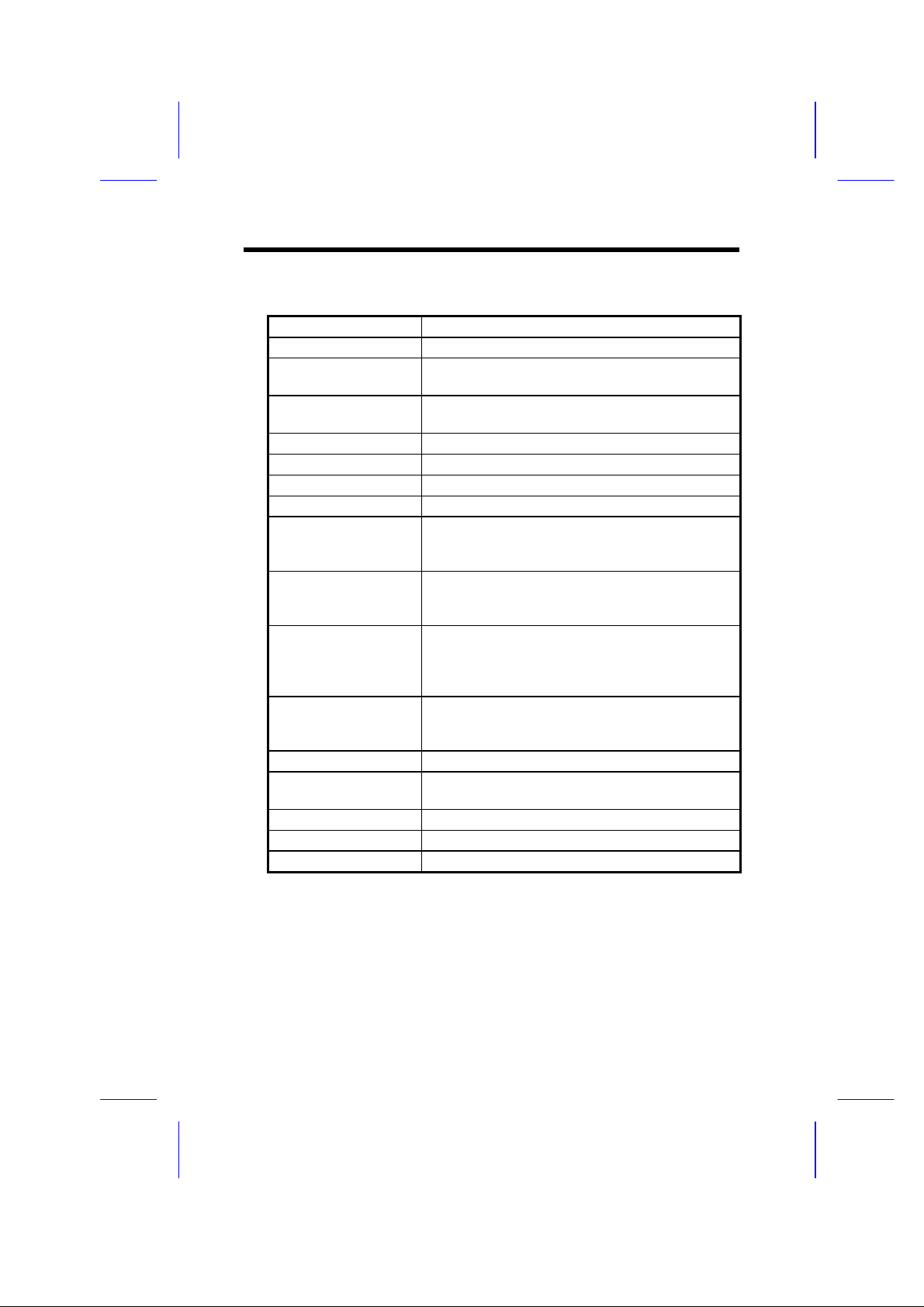
1.1 Specifications
Form Factor
Board Size
CPU
System Memory
Second-level Cache
Chipset
Expansion Slots
Serial Port
Parallel Port
Floppy Interface
IDE Interface
USB Interface
(optional)
PS/2 Mouse
Keyboard
BIOS
RTC
Battery
Baby AT
220mm x 250mm
Intel Pentium Processor P54C, PP/MT (P55C), AMD
K5 and Cyrix 6x86
FPM (Fast Page Mode) or EDO (Extended Data
Output) 72-pin SIMM x4, maximum 256MB.
256KB or 512KB pipelined-burst cache onboard
SiS 5571 PCIset (480-pin BGA Package)
ISA x3 and PCI x4
Two serial ports UART 16C550 compatible
One parallel port supports standard parallel port
(SPP), enhanced parallel port (EPP) or extended
capabilities port (ECP).
Floppy interface supports 3.5-inch drive with 720KB,
1.44MB or 2.88MB format or
5.25-inch drive with 360KB, 1.2MB format
Dual-channel IDE interface supports a maximum of 4
IDE hard disks or CDROM.
Mode 4 and bus master hard disk drives are also
supported.
USB bracket that supports two USB ports . The
BIOS also supports USB driver to simulate
legacy keyboard.
Via PS/2 mouse bracket
Default: AT compatible keyboard
Mini-DIN PS/2 keyboard connector is optional.
Award Plug-and-Play Flash ROM BIOS
RTC build in chipset
Lithium (CR2032)
1-2
Page 3

1.2 Board Layout
10
7 8 9
6
5
4
3
2
1
Overview
11 12
13
24
23
22
21
1 Keyboard connector: The default is AT-compatible keyboard. The
2 Power connector: Provides mainboard power.
3 FDC connector: Connects to 3.5-inch/5.25-inch floppy drives.
4 Printer connector: Connects to parallel printer.
5 IDE1 connector: Primary channel for IDE hard disk or CDROM,
6 SIMM sockets: Accepts 72-pin fast page mode or EDO
7 IDE2 connector: Secondary channel for IDE hard disk or
8 SiS chipset: SiS 5571 cache/memory controller in BGA
9 Battery: CR2032-compatible
10 Pipelined-burst cache: 256/512KB secondary level cache. Cache is
11 CPU socket: Accepts Intel Pentium P54C, PP/MT (P55C),
20
1819
P/2-compatible mini-DIN keyboard connector is
optional.
accepts a maximum of two devices.
DRAM module for system main memory.
CDROM, accepts a maximum of two devices.
package.
used to enhance memory performance.
AMD K5, and Cyrix 6x86 CPUs.
17
16
15
14
1-3
Page 4

Overview
12 Voltage Regulators w/ Heatsink: The regulator is used to supply CPU
voltage.
13 IrDA connector: Wireless Infrared connector, used as COM2.
14 Front-panel connector: Connector for front panel power reset,
suspend switches and power or green LED.
15 IDE LED connector: For front panel IDE LED.
16 CPU fan connector: +12V 2-pin connector for CPU fan.
17 ISA slots: Accepts 8-MHz ISA bus expansion cards.
18 PCI slots: Accepts 33-MHz PCI bus expansion cards
19 Keyboard controller: Controls keyboard input/output functions.
20 USB connector (optional):Universal Serial Bus (USB). The USB is a
new 4-pin serial interface that allows easy
installation and cascading of USB devices..
21 Super I/O controller: SMC 669-compatible I/O control chip including
two serial ports (COM1/COM2), one parallel
port (printer), and floppy controller.
22 COM1 connector: Serial port 1.
23 COM2 connector: Serial port 2.
24 PS/2 mouse connector: Connects to PS/2 mouse bracket for
PS/2-compatible mouse. Unlike serial mouse
from COM1/COM2, the PS/2 mouse signal is
similar as the keyboard and is also controlled
by the keyboard controller.
1-4
 Loading...