

Page 1

AP53
Mainboard
User Guide
Page 2

Copyright
Copyright 1996 by this company. All rights reserved. No part of this
publication may be reproduced, transmitted, transcribed, stored in a retrieval
system, or translated into any language or computer language, in any form or
by any means, electronic, mechanical, magnetic, optical, manual or otherwise,
without the prior written permission of this company.
ii
Page 3

Disclaimer
This company makes no representations or warranties, either expressed or
implied, with respect to the contents hereof and specifically disclaims any
warranties, merchantability or fitness for any particular purpose. Any software
described in this manual is sold or licensed "as is". Should the programs prove
defective following their purchase, the buyer (and not this company, its
distributor, or its dealer) assumes the entire cost of all necessary servicing,
repair, and any incidental or consequential damages resulting from any defect
in the software. Further, this company reserves the right to revise this
publication and to make changes from time to time in the contents hereof
without obligation to notify any person of such revision or changes.
Intel and Pentium are registered trademarks of Intel Corporation.
XT/AT is a registered trademark of International Business Machines Corporation.
AMI is a registered trademark of American Megatrends Inc.
Other brand and product names are trademarks and/or registered trademarks of their respective
holders.
iii
Page 4

FCC Statement
FCC Class B Radio Frequency
Interference Statement
Note:
This equipment has been tested and found to comply with the limits for
a Class B digital device, pursuant to Part 15 of FCC Rules. These
limits are designed to provide reasonable protection against harmful
interference in a residential installation. This equipment generates,
uses, and can radiate radio frequency energy and, if not installed and
used in accordance with the instructions, may cause harmful
interference to radio communications. However, there is no guarantee
that interference will not occur in a particular installation. If this
equipment does cause harmful interference to radio or television
reception, which can be determined by turning the equipment off and
on, the user is encouraged to try to correct the interference by one or
more of the following measures:
1. Reorient or relocate the receiving antenna.
2. Increase the separation between the equipment and receiver.
3. Connect the equipment into an outlet on a circuit different from that to
which the receiver is connected.
4. Consult the dealer or an experienced radio/television technician for help.
Notice 1:
The changes or modifications not expressly approved by the party
responsible for compliance could void the user's authority to operate
the equipment.
Notice 2:
Shielded interface cables, if any, must be used in order to comply with
emission limits.
iv
Page 5

About This Manual
Purpose and Scope
This manual tells how to install and configure the system board.
Organization
This manual consists of three chapters and one appendix:
Chapter 1, Overview, covers the specifications, layout, and components of the
system board.
Chapter 2, Hardware Installation, tells how to install the hardware
components, configure the system by resetting the jumpers, install the system
board and add expansion cards.
Chapter 3, AMI BIOS Utility, explains the system BIOS and tells how to
configure the system by setting the BIOS parameters.
Appendix A, Jumper and Connector Summary, gives you a tabular
summary of the jumper settings and onboard connectors discussed in Chapter
2.
v
Page 6
About This Manual
Conventions
The following conventions are used in this manual:
Text entered by user,
default settings,
recommended
selections
a, e, s, etc
Represent text input by the user, default
settings and recommended selections
Represent the actual keys that you have
to press on the keyboard.
NOTE
Gives bits and pieces of additional
information related to the current topic.
WARNING
Alerts you to any damage that might
result from doing or not doing specific
actions.
CAUTION
Suggests precautionary measures to
avoid potential hardware or software
problems.
IMPORTANT
Reminds you to take specific action
relevant to the accomplishment of the
procedure at hand.
TIP
Tells how to accomplish a procedure
with minimum steps through little
shortcuts.
vi
Page 7

Table of Contents
Chapter 1 Overview
1.1 Board Layout.........................................1-2
1.2 Specifications .......................................1-3
1.3 System Board Parts..............................1-4
1.3.1 Microprocessor ................................. 1-4
1.3.2 ASICs ...............................................1-4
1.3.3 BIOS.................................................1-4
1.3.4 Expansion Slots................................ 1-5
1.3.5 DRAM Sockets .................................1-5
1.3.6 Second-level Cache .........................1-5
1.3.7 Two-channel PCI Mode 4
Enhanced IDE Interface...................1-5
1.3.8 Super I/O Controller..........................1-6
1.3.9 Keyboard Connector.........................1-6
1.3.10 Mouse Connector .............................1-6
Chapter 2 Hardware Installation
2.1 ESD Precautions...................................2-1
2.2 Jumper Locations.................................2-2
2.3 Setting the Jumper ...............................2-3
2.4 Installing a Microprocessor .................2-3
vii
Page 8

Table of Contents
2.5 Upgrading the Microprocessor............2-7
2.6 Configuring the System Memory.........2-7
2.6.1 Installing a SIMM .............................. 2-9
2.6.2 Removing a SIMM ..........................2-10
2.7 Customizing your
Hardware Setup ..................................2-11
2.7.1 Selecting the Flash ROM Type.......2-11
2.7.2 Disabling the Onboard Super I/O
Controller .......................................2-11
2.7.3 Selecting the ECP DMA Channel ...2-12
2.7.4 Clearing the CMOS ........................2-12
2.7.5 Disabling the
PS/2 Mouse Function.....................2-13
2.7.6 Setting the Keyboard Clock ............2-13
2.8 Installing the System Board...............2-14
2.9 Connecting Peripherals......................2-15
2.9.1 Power Cable...................................2-15
2.9.2 Mouse.............................................2-15
2.9.3 Serial Devices (COM1/COM2)........2-16
2.9.4 Floppy Drives..................................2-16
2.9.5 Printer.............................................2-17
2.9.6 IDE Devices.................................... 2-17
2.9.7 Front-panel Switches and LEDs .....2-18
2.9.8 Keyboard ........................................2-19
viii
Page 9

Table of Contents
2.10 Installing Expansion Boards..............2-20
Chapter 3 AMI BIOS Utility
3.1 Entering the AMI BIOS Setup............... 3-1
3.2 Setup Menu ...........................................3-2
3.2.1 Standard Setup ................................3-3
3.2.2 Advanced CMOS Setup ...................3-7
3.2.3 Chipset Features Setup.................. 3-13
3.2.4 Power Management Setup ............. 3-17
3.2.5 PCI/PnP Setup ...............................3-20
3.2.6 Peripheral Setup.............................3-24
3.3 Security Setup..................................... 3-26
3.3.1 Supervisor Password......................3-27
3.3.2 User Password ............................... 3-28
3.3.3 Anti-virus.........................................3-29
3.4 Utility Setup ......................................... 3-29
3.4.1 Color Set ........................................3-30
3.4.2 Language .......................................3-30
3.5 Default Setup.......................................3-31
3.5.1 Original ...........................................3-31
3.5.2 Optimal ...........................................3-32
3.5.3 Fail-safe..........................................3-32
3.6 Exiting Setup.......................................3-33
ix
Page 10

Table of Contents
3.7 NCR SCSI BIOS and Drivers ..............3-34
Appendix A Jumper and Connector Summary
x
Page 11

Chapter 1
Overview
The AP53 is a high-performance Pentium-based system board that utilizes
the PCI/ISA architecture. It integrates the Intel 430HX PCIset, a super I/O
controller, a PCI mode 4 enhanced IDE controller with bus master support and
a 256-KB pipelined-burst cache to enhance system performance. It also has
four single in-line memory module (SIMM) sockets that allow memory
expansion up to a maximum of 512 MB.
One main feature of AP53 is the green power-management function that
extends energy conservation from system components to display monitor. It
complies with the power-saving standards of the U.S. Environmental Protection
Agency (EPA) Energy Star program.
The AP53 board measures 220 mm x 250 mm and may come with or without a
voltage regulator module (VRM). The VRM enables the board to support future
2.5V processors.
1-1
Page 12
Overview
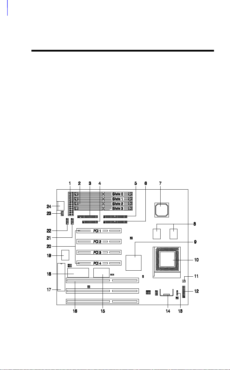
1.1 Board Layout
1 Power connector 14 Voltage regulator with heatsink
2 SIMM sockets 15 Real-time clock and battery
3 Floppy disk drive connector 16 ISA slots
4 Parallel port connector 17 Keyboard controller
5 Primary IDE connector 18 BIOS
6 Secondary IDE connector 19 Super I/O controller
7 Intel 82439 chip 20 PCI slots
8 Pipelined-burst cache 21 COM1 connector
9 Intel 82371 chip 22 COM2 connector
10 CPU socket 23 PS/2 mouse connector
11 Two-pin fan connector 24 AT-keyboard connector
12 Multifunction connector
13 HDD LED connector
1-2
Page 13

1.2 Specifications
Overview
Microprocessor
Memory
SIMM Sockets
ASICs
Bus Architecture
Expansion Slots
Ports
Secondary Cache
BIOS
RTC & Battery
Board Size
Pentium (3.3V) Processor
75/90/100/120/133/150/166/200 MHz
512 MB (maximum)
72-pin SIMM x 4
Intel 430HX PCIset
ISA, PCI
Three ISA and four PCI slots
One parallel port (SPP/ECP/EPP)
Two serial ports (UART 16C550)
Two-channel PCI mode 4 IDE ports
(bus master transfer support)
One floppy disk drive port
(360/720 K, 1.2/1.44/2.88 MB)
256-KB pipelined-burst cache
AMI Plug-and-Play Flash ROM BIOS
Dallas DS12887A
220 mm x 250 mm
1-3
Page 14

Overview
1.3 System Board Parts
1.3.1 Microprocessor
The AP53 system board uses an Intel Pentium (3.3V) processor running at 75,
90, 100, 120, 133, 150, 166, or 200 Hz. Chapter 2 tells how to install and
upgrade a Pentium processor.
1.3.2 ASICs
The application-specific integrated circuits (ASICs) are the Intel 82439 and Intel
82371 that belong to the Intel 430HX PCIset. This chipset allows the system to
support a higher memory (512 MB) and a pipelined-burst cache. It also offers
an error checking and correction (ECC) feature that enables the system to
detect, as well as correct the DRAM errors.
The Intel 82439 that comes in a unique ball-grid array (BGA) packaging, acts
as the memory controller data path and the DRAM data bus buffer. The Intel
82371 operates as the PCI/ISA bridge and IDE controller.
1.3.3 BIOS
The board supports the AMI basic input-output system (BIOS). The BIOS is a
program that performs the power-on self test (POST) upon booting. During
POST, this program activates the peripheral devices, tests onboard memory
and prepares the system for operation. For more information on AMI BIOS,
see Chapter 3.
1-4
Page 15

Overview
1.3.4 Expansion Slots
The board has three ISA and four PCI expansion slots. The ISA expansion
slots are the black parallel bars on the system board. The PCI slots are those
with white color and are shorter than the ISA slots. There are rows of golden
pins inside each slot that serve as a clutch to secure the contacts of the
expansion board. For information on how to install the expansion boards, see
Chapter 2.
1.3.5 DRAM Sockets
The system board has four 72-pin SIMM sockets that allow you to expand
system memory to a maximum of 512 MB. These sockets accept both singledensity and double-density SIMMs. Chapter 2 tells how to install memory
modules and the different memory configurations available.
1.3.6 Second-level Cache
The AP53 motherboard comes with an onboard 256-KB pipelined-burst
second-level cache. This pipelined-burst cache improves system performance
by shortening the DRAM read prefetch time resulting to a faster data transfer
rate.
1.3.7 Two-channel PCI Mode 4 Enhanced IDE Interface
The AP53 board integrates a two-channel PCI mode 4 enhanced integrated
drive electronics (E-IDE) interface that allows the system to support four
E-IDE devices (including hard disks with more than 528-MB capacity) via two
onboard IDE connectors (see section 1.1). This feature offers users increased
data storage capacity.
1-5
Page 16

Overview
1.3.8 Super I/O Controller
The onboard super I/O controller accommodates the following:
• Two UART 16450/16550-compatible fast serial ports
• A parallel port with standard parallel port (SPP), enhanced parallel port
(EPP) or extended capabilities port (ECP) support. Both the EPP and
ECP comply with the IEEE 1284 standards.
• 3.5-inch floppy disk drives with 720-KB, 1.44-MB or 2.88-MB format.
• 5.25-inch floppy disk drives with 360-KB, 1.2-MB format
1.3.9 Keyboard Connector
The onboard keyboard connector allows you to connect any AT-compatible
keyboard. See the board layout figure for the location of the keyboard
connector. Chapter 2 tells how to connect an AT keyboard.
A PS/2 keyboard connector is an option.
1.3.10 Mouse Connector
The board supports both serial and PS/2 mouse connectors. See Chapter 2 for
details on how to connect a serial and a PS/2 mouse connector.
1-6
Page 17

Chapter 2
Hardware Installation
This chapter gives you a step-by-step procedure on how to install your system.
Follow each section accordingly.
2.1 ESD Precautions
Electrostatic discharge (ESD) can damage your processor, disk drives,
expansion boards, and other components. Always observe the following
precautions before you install a system component.
1. Do not remove a component from its protective packaging until you are
ready to install it.
2. Wear a wrist ground strap and attach it to a metal part of the system unit
before handling a component. If a wrist strap is not available, maintain
contact with the system unit throughout any procedure requiring ESD
protection.
2-1
Page 18
Hardware Installation
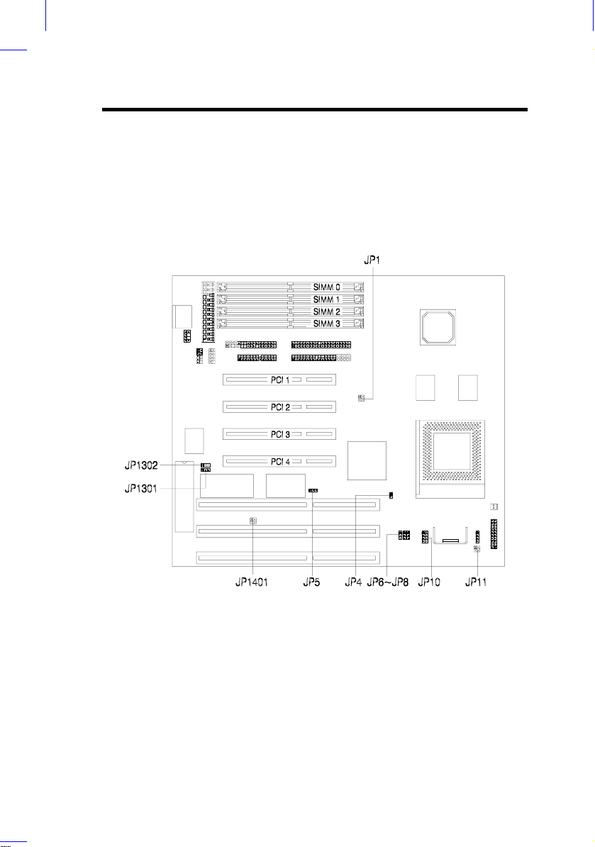
2.2 Jumper Locations
The following figure shows the locations of the jumpers on the system board:
2-2
Page 19

2.3 Setting the Jumper
Set a jumper switch as follows:
• To open a jumper, remove the
jumper cap.
Hardware Installation
• To close a jumper, insert the plastic
jumper cap over two pins of a
jumper.
The conventions in the figure are used to
represent the proper jumper settings.
Open
Closed
-
2-3
Page 20
Hardware Installation
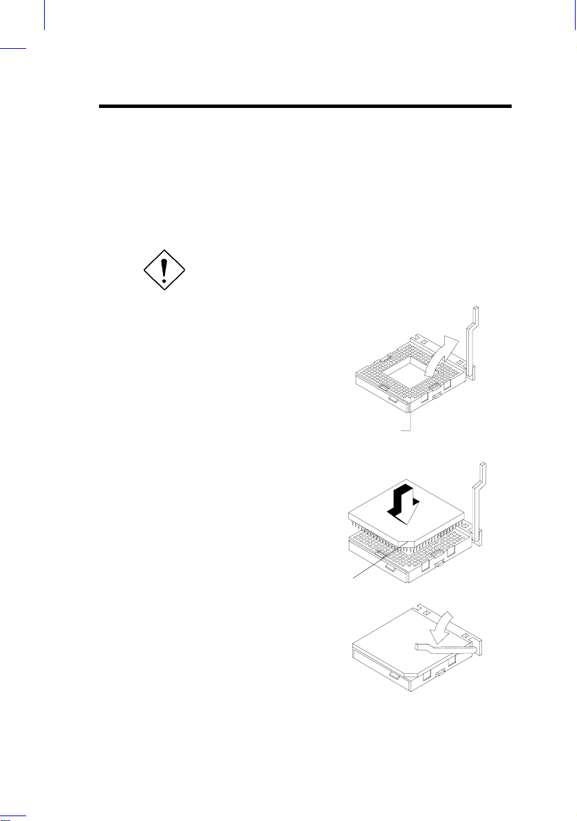
2.4 Installing a Microprocessor
The motherboard comes with a zero-insertion force (ZIF) microprocessor
socket that allows you to install a CPU without using any tool.
Follow these steps to install a CPU into a ZIF-type CPU socket:
Make sure that the system power is OFF before
installing a component.
1. Locate the CPU socket on the
system board and pull up the socket
lever.
Hole 1
2. Gently insert the CPU. Make sure
that pin 1 of the CPU aligns with
hole 1 of the socket. The notched
corner on the CPU indicates the
location of pin 1.
3. Pull down the socket lever to lock
the CPU into the socket.
2-4
Pin 1 indicator
Page 21
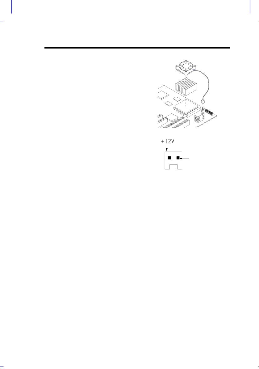
4. Attach the heatsink and fan to the
)
CPU.
5. Plug the fan cable onto the two-pin
fan connector onboard. The fan
connector is marked CN15 on the
system board.
Hardware Installation
GND
GND
2-pin fan power connector (J2
2-5
Page 22

Hardware Installation
6. Set jumpers JP1 and JP10
according to the frequency of the
CPU that you install.
CPU FREQUENCY SELECT
JP1 JP10
75 MHz
90 MHz
100 MHz
(default)
120 MHz
133 MHz
150 MHz
166 MHz
7. Set jumper JP11 according to the
CPU voltage.
2-6
CPU VOLTAGE SELECT
JP11
3.45V
(default)
3.52V
Page 23

Hardware Installation
2.5 Upgrading the Microprocessor
To upgrade a CPU:
1. Turn off the system power and remove the housing cover.
2. Locate the CPU socket on the system board.
3. Pull up the socket lever.
4. Remove the installed CPU, if any.
5. Install the upgrade CPU. Refer to section 2.3 for instructions on how to
install a CPU.
2.6 Configuring the System Memory
The system board has four 72-pin SIMM sockets that allow you to expand the
system memory to 512 MB. The SIMM sockets accept single-density and
double-density SIMMs with 60 or 70-ns DRAM speed. See the figure in
section 1.1 for the location of the SIMM sockets.
The following table lists the possible SIMM configurations:
Memory Configurations
Total Memory SIMM0SIMM
4 MB 2 MB 2 MB
8 MB 2 MB 2 MB 2 MB 2 MB
8 MB 4 MB 4 MB
12 MB 2 MB 2 MB 4 MB 4 MB
16 MB 4 MB 4 MB 4 MB 4 MB
Memory Configurations (continued)
Total Memory SIMM0SIMM
SIMM2SIMM
1
SIMM2SIMM
1
3
3
2-7
Page 24

Hardware Installation
16 MB 8 MB 8 MB
20 MB 2 MB 2 MB 8 MB 8 MB
24 MB 4 MB 4 MB 8 MB 8 MB
32 MB 8 MB 8 MB 8 MB 8 MB
32 MB 16 MB 16 MB
36 MB 2 MB 2 MB 16 MB 16 MB
40 MB 4 MB 4 MB 16 MB 16 MB
48 MB 8 MB 8 MB 16 MB 16 MB
64 MB 16 MB 16 MB 16 MB 16 MB
64 MB 32 MB 32 MB
68 MB 2 MB 2 MB 32 MB 32 MB
72 MB 4 MB 4 MB 32 MB 32 MB
80 MB 8 MB 8 MB 32 MB 32 MB
96 MB 16 MB 16 MB 32 MB 32 MB
128 MB 32 MB 32 MB 32 MB 32 MB
128 MB 64 MB 64 MB
136 MB 4 MB 4 MB 64 MB 64 MB
144 MB 8 MB 8 MB 64 MB 64 MB
160 MB 16 MB 16 MB 64 MB 64 MB
256 MB 64 MB 64 MB 64 MB 64 MB
256 MB 128 MB 128 MB
264 MB 4 MB 4 MB 128 MB 128 MB
272 MB 8 MB 8 MB 128 MB 128 MB
288 MB 16 MB 16 MB 128 MB 128 MB
320 MB 32 MB 32 MB 128 MB 128 MB
384 MB 64 MB 64 MB 128 MB 128 MB
512 MB 128 MB 128 MB 128 MB 128 MB
2-8
Page 25

2.6.1 Installing a SIMM
Observe the ESD precautions when installing
components.
Follow these steps to install a SIMM:
1. Slip a SIMM at a 45° angle into a
socket. If the SIMM does not
completely fit into the socket,
reverse the SIMM orientation. The
SIMM has a curved edge indicating
pin 1 that ensures installation in
one direction only.
Be careful when inserting or removing SIMMs.
Forcing a SIMM in or out of a socket can
damage the socket or the SIMM (or both).
Hardware Installation
curved edge
2. Gently push the SIMM up until the
pegs of the socket slip into the
holes on the SIMM and the holding
clips lock the SIMM into a vertical
position.
The SIMM should be at a 90° angle when
installed.
2-9
Page 26

Hardware Installation
2.6.2 Removing a SIMM
To remove a SIMM:
1. Press the holding clips on both
sides of the SIMM outward to
release it.
2. Press the SIMM downward to
about a 45° angle.
3. Gently pull the SIMM out of the
socket.
2-10
Page 27

Hardware Installation
2.7 Customizing your Hardware Setup
You may customize your hardware setup according to your desired system
performance. However, doing so requires resetting of several jumpers. The
onboard jumpers are normally set to its default setting. See the figure in
section 2.2 for the location of the jumpers on the system board.
The following sections tell how to configure the system board to meet the
desired performance:
2.7.1 Selecting the Flash ROM Type
The AP53 board supports both the 5V
and 12V Flash ROM types. Normally,
the board comes with a 5V Flash ROM
and with the jumpers JP1301 and
JP1302 set to 1-2. Reset JP1301 to 2-3
if you want to install a 12V Flash ROM.
5V
(default)
12V
JP1301 JP1302
2.7.2 Disabling the Onboard Super I/O Controller
The board is preset by the manufacturer
with the onboard I/O controller enabled.
In case you wish to use an external I/O
controller, you need to disable the
onboard I/O before the external I/O card
functions. To disable, you need to reset
jumper JP8 to 2-3.
Enabled
(default)
Disabled
JP8
2-11
Page 28

Hardware Installation
2.7.3 Selecting the ECP DMA Channel
The available ECP DMA channel
selections are DRQ3/DACK3 and
DRQ1/DACK1. The default is
DRQ3/DACK3. To select
DRQ1/DACK1, reset jumpers JP6 and
JP7 to 2-3.
The onboard I/O controller may either be SMC
665 or SMC 669. If you have SMC 669, JP6
and JP7 must be set to open.
2.7.4 Clearing the CMOS
You need to clear the CMOS if you
forget your system password. To do
this, shut off the system power and short
pins 2-3 of JP5 for a few seconds. Reset
the jumper to normal setting by shorting
pins 1-2. Enter Setup to specify a new
password.
DRQ3/DACK3
(default)
Normal
(default)
Clear CMOS
JP6 JP7
JP5
2-12
Page 29

Hardware Installation
2.7.5 Disabling the PS/2 Mouse Function
The PS/2 mouse function is normally
enabled and occupies IRQ12. To
reassign IRQ12 to another function, you
need to disable the PS/2 mouse function
by opening jumper JP4 and changing the
BIOS setup. For detailed information on
BIOS, see Chapter 3.
2.7.6 Setting the Keyboard Clock
The jumper JP1401 enables you to set
the keyboard clock. The clock
selections are ISA clock and 12 MHz.
Set JP1401 to 1-2 to select the ISA
clock. Reset it to 3-4 to set the keyboard
clock to 12 MHz.
Enabled
(default)
Disabled
ISA clock
(default)
JP4
JP1401
12 MHz
2-13
Page 30

Hardware Installation
2.8 Installing the System Board
Make sure that you have already installed the
system board components like the CPU and
memory, and have set the appropriate jumpers
before you proceed.
Follow these steps to install a system board into a housing:
1. Open the system housing. Refer to
the housing documentation for
steps on how to remove the housing
cover.
2. Install the board into the housing
and secure it with the screws that
come with the housing.
3. Attach the cables and install the
necessary peripherals. See the
following section for information
on how to connect the peripherals.
2-14
Refer to your housing documentation for more
information on the system housing.
Page 31

Hardware Installation
2.9 Connecting Peripherals
2.9.1 Power Cable
A standard power supply has two cables
with six wires each. Plug these cables to
the onboard power connector in such a
way that all the black wires are in the
center. The power connector is marked
CN3 on the system board.
Make sure that the power supply is off before
connecting or disconnecting the power cable.
2.9.2 Mouse
PS/2 Mouse
To connect a PS/2 mouse, simply insert
the PS/2 bracket connector onto CN4 on
the system board. Plug a PS/2 mouse
into the mouse port on the bracket.
Refer to section 3.2.2 for the proper
BIOS setting.
2-15
Page 32

Hardware Installation
Serial Mouse
To connect a serial mouse, plug in the serial bracket connectors onto the CN6
and CN7. Insert the serial mouse connector into the appropriate COM port on
the bracket. See section 2.9.3.
2.9.3 Serial Devices (COM1/COM2)
To support serial devices, insert the
serial device connector into the serial
port on the bracket. Plug in the serial
port bracket connectors onto the
appropriate onboard connectors. The
COM1 connector is marked CN7 and the
COM2 connector is marked CN6 on the
system board.
2.9.4 Floppy Drives
Connect the floppy drive cable onto the
floppy drive connector marked CN8 on
the system board. See section 1.1 for the
location of the connector. Refer to the
figure on how to connect the cables.
2-16
Page 33

2.9.5 Printer
Plug in the printer bracket connector
onto the onboard parallel connector
marked CN9 on the board. Refer to the
figure.
The printer port on the bracket accepts
the printer cable.
2.9.6 IDE Devices
Primary IDE Connector
The primary IDE connector marked
CN10 on the system board supports
two IDE devices - one IDE hard disk
and one additional IDE device.
Connect your IDE HDD into the
master port of the primary IDE cable.
Plug in the slave port into another IDE
device, if any.
Hardware Installation
HDD 1
HDD 2
2-17
Page 34

Hardware Installation
( Turbo Switch )
Secondary IDE Connector
The secondary IDE connector is marked
CN11 on the board. This connector also
supports two IDE devices. To install an
IDE CD-ROM drive into your system,
insert master port of the secondary IDE
cable into the CD-ROM drive connector.
If you have more than two hard disks,
connect your third hard disk into the
master port. Connect your CD-ROM
drive into the slave port.
2.9.7 Front-panel Switches and LEDs
HDD LED
The HDD LED connector is marked
CN12 on the board. Plug the HDD LED
socket onto this four-pin connector. See
the figure.
Multifunction Connector
Speaker Power LED Keylock
The multifunction connector is a 20-pin
connector marked CN16 on the board.
Attach the green mode LED, keylock,
reset switch, turbo switch, and turbo
LED connectors onto the corresponding
pins as shown in the figure.
Break Switch Green Mode LEDReset
( Turbo LED )
2-18
Page 35

Hardware Installation
Ground
Some housings have a five-pin connector
for the keylock and power LED.
Other housings may have a 12-pin
connector. If your housing has this type
of connector, plug it onto CN16 as
shown in the following figure. Make
sure that the red wire of the connector
connects to pin 11.
2.9.8 Keyboard
The onboard keyboard connector is a
five-pin AT-compatible connector
marked CN2. Refer to the figure on how
to connect an AT keyboard.
Speaker Keylock & Power LED
Break Switch Green Mode LED
Reset
( Turbo Switch ) ( Turbo LED )
Ground
Reset
Res-VCC
Speaker
Break Switch
( Turbo Switch )
Keylock
Ground
VCC
The PS/2 keyboard connector is optional.
2-19
Page 36

Hardware Installation
2.10 Installing Expansion Boards
Before you install any expansion board, make sure that you have secured the
system board in the housing.
Follow these steps to install an expansion board:
1. Observe the ESD precautions
before removing the expansion
board from its protective
packaging.
2. Locate an empty expansion slot on
the system board.
3. Remove the bracket opposite the
slot that you want to use. Save the
cover and screw for future use.
4. Remove the board from its
protective packaging.
5. Gently insert the golden edge of the
board into the slot until it fits into
place.
6 Secure the bracket to the housing
with a screw.
Golden edge
ISA slot
Golden edge
2-20
PCI slot
Page 37

Chapter 3
AMI BIOS Utility
This chapter tells how to configure the system by setting the BIOS parameters.
3.1 Entering the AMI BIOS Setup
To enter the AMI BIOS Setup, press c. The AMI BIOS Setup Main Menu
appears as shown below.
The AMI BIOS is in Windows form. You can use either the keyboard or a
mouse to move between the items.
To select among the Setup menu groups, use v to highlight the selected group
or simply click on the icon of the selected Setup menu.
3-1
Page 38

AMI BIOS Utility
To select among the options, you can either use the arrow keys to move the
highlight bar or simply click on the icon of the desired option.
After making your selection, press e or double-click on the icon to open the
selected menu option.
You can press h to enter the BIOS Setup screen. This
also enables you to do the following:
• Resolve an address conflict due to an IRQ
address assigned to multiple slots. For more
information on IRQ assignment, see the section
3.2.3 (Chipset Features Setup).
• Return to the BIOS default settings if the PnP
BIOS does not recognize the hardware
modifications under Windows 95.
3.2 Setup Menu
The figure below shows the Setup window. Use the arrow keys to highlight
an option.
3.2.1 Standard Setup
The following screen appears if you select Standard from the Setup
options:
3-2
Page 39

AMI BIOS Utility
You can input configuration values such as date, time and disk types in this
menu.
PRIMARY MASTER AND SLAVE/
SECONDARY MASTER AND SLAVE
These parameters allow you to configure the hard disks and the IDE devices
connected to your IDE connectors. To configure the hard disk connected to
the master port of the primary IDE connector, select Primary Master
and press e. The following screen appears:
To configure the hard disk connected to the slave port of the primary IDE
connector, select Primary Slave.
The secondary IDE connector also supports two IDE devices. To configure
the hard disk or the IDE device connected to the master port, select
Secondary Master. Choose Secondary Slave to configure the
device connected to the slave port.
The following are the parameters that you need to set to configure your hard
disks or the IDE devices:
Type
This parameter lets you set the IDE device type that your system supports.
The options are User, Auto, CD-ROM, Type 1-46, and Not
3-3
Page 40

AMI BIOS Utility
Installed. Select Auto to automatically configure the installed hard
disk or IDE device. Select CD-ROM if you have a CD-ROM installed in your
system. If you have an old type HDD installed, you may need to enter the
HDD parameters manually. To do this, you must set this parameter to User.
Set this to Not Installed to bypass the function.
LBA/Large Mode
This enhanced IDE feature allows the system to use a hard disk with a capacity
of more than 504 MB. This is made possible through the Logical Block
Address (LBA) mode translation. Set the parameter to Off to disregard the
feature.
This parameter becomes nonconfigurable when the HDD Type parameter is set
to Auto.
3-4
Page 41

AMI BIOS Utility
Block Mode
This function enhanced disk performance depending on the hard disk in use. If
enabled, it allows data transfers in block (multiple sectors) by increasing the
data transfer rate to 256 bytes/cycle. However, if your hard disk does not
support this function, set this parameter to Off.
This parameter becomes nonconfigurable when the HDD Type parameter is set
to Auto.
32-bit Mode
Enabling this parameter improves system performance by increasing the hard
disk access to 32-bit mode. However, make sure that your hard disk supports
this function before you enable the parameter. Otherwise, set this parameter to
Off.
PIO Mode
Setting this parameter to On allows the system to use a faster hard disk drive.
If your hard disk does not support the PIO mode feature, set this parameter to
Off.
This parameter becomes nonconfigurable when the HDD Type parameter is set
to Auto.
3-5
Page 42

AMI BIOS Utility
HARD DISK TYPES
After you have set all the necessary parameters, press e. A list of the HDD
drive parameters appears:
Select your hard disk type. Press the w or y to move among the selections.
After you have made your selection, press e.
If you cannot find your hard disk drive type on the list, select User. This
allows you to enter the disk parameters manually.
DATE/TIME
To set the date and time, highlight Date/Time and press e. The following
screen appears:
Select the arrow keys to move among the items. Press or click on + or - to set
the current time and date. Press e or double-click on the Control menu box in
the upper-left corner of the window.
3-6
Page 43

AMI BIOS Utility
FLOPPY DRIVES A AND B
To configure the first floppy drive, select Floppy A. The following values
appear on screen:
After selecting the proper setting, press e.
Select Floppy B and follow the same procedure to configure the second
floppy drive.
3.2.2 Advanced CMOS Setup
The following screen appears if you select the option Advanced from the
Setup menu:
The first screen does not show all the parameters of the Advanced
Configuration menu. To scroll down the rest of the parameters, press }. Press
w or y to highlight the desired parameter.
3-7
Page 44

AMI BIOS Utility
Do not change the settings of the Advanced Setup
parameters if you are not a qualified technician.
Doing so may cause fatal system failure.
Quick Boot
During boot-up, the system performs power-on self test (POST) routines.
Enable the parameter if you want to skip some POST routines during the boot
process. Set this to Disabled to let the system perform all the POST
routines and follow the specified boot-up sequence.
Power-on Delay
This parameter lets you set the POST waiting time for the HDD motor to
stabilize before boot up. The settings are from 1 to 15 seconds and
Disabled. The default setting is Disabled.
3-8
Page 45

AMI BIOS Utility
Boot-up Sequence
The boot-up sequence allows you to specify the system search sequence. The
selections are C:, A:, CD-ROM / A:, CD-ROM, C: / A:,
C:, CD-ROM / C:, CD-ROM, A: / CD-ROM, A:, C: and
CD-ROM, C:, A:. If you have a bootable CD-ROM installed, you may
set the CD-ROM as the first priority. The default is A:, C:, CD-ROM.
Boot-up Numlock
Setting this parameter to On enables the numeric function of the numeric
keypad. Set this parameter to Off to disregard the function. Disabling the
numeric function allows you to use the cursor control numeric keypad. The
default setting is On.
Floppy Drive Swap
This parameter allows you to swap floppy drives. For example, if you have
two floppy drives (A and B), you can assign the first drive as drive B and the
second drive as drive A or vice-versa. Disable the parameter to bypass the
function. The default is Disabled.
Floppy Drive Seek
When enabled, the BIOS detects whether there is a floppy disk drive installed
in the system. Disable the parameter to skip the function.
PS/2 Mouse
Setting this parameter to Enabled lets you enable the PS/2 mouse function
and assign IRQ12 for the said function. Set this to Disabled to bypass the
function and to reserve IRQ12 for other functions.
Typematic Rate
This parameter determines the typematic rate. Select Fast to increase the
typematic rate. Select Slow to decrease it.
3-9
Page 46

AMI BIOS Utility
System Keyboard
Set this parameter to Present if there is a keyboard connected to the
system. Otherwise, select Absent.
Primary Display
This function detects the type of VGA in use. The selections are VGA/EGA,
CGA 40 x 25, CGA 80 x 25, Mono, and Absent. The
default setting is VGA/EGA.
Password Check
This parameter allows you to use the password feature. When set to
Always, a user-password prompt appears every time you turn on the
computer. When set to Setup, the password prompt appears when you try to
enter setup. The optimal and fail-safe default setting is Setup.
Parity Check
Set this parameter to Enabled if you install SIMMs with parity in your
system. Otherwise, set this parameter to Disabled. Since the DRAM can
still operate without using the parity scheme for SIMMs with parity, this
function is normally set to Disabled.
OS/2 Compatible Mode
Enable the parameter if you have an OS/2 operating system installed in your
system. Otherwise, set this to Disabled. The default setting is
Disabled.
Internal Cache
This function lets you enable or disable the internal cache.
External Cache
This function lets you enable or disable the external cache.
3-10
Page 47

AMI BIOS Utility
System BIOS Cacheable
Enabling this parameter allows you to change the system BIOS from ROM to
RAM. When the system boots, the BIOS routines are copied into the RAM
area. This enhances system performance as information access is faster in
RAM than in ROM. Disabling the parameter prevents the system BIOS from
being cached. The default setting is Enabled.
C000 ~ DC00, 16K Shadow
These parameters are for shadowing expansion cards with ROM. You need to
know the specific addresses that ROMs use to shadow the expansion cards
before you set any of these parameters. If you do not know this information,
enable all the ROM shadow settings. This ensures shadowing of any present
ROMs and reduces the available memory . Select Cached if the data in the
chosen addresses are already copied into RAM. The default setting is
Disabled.
The F000 and E000 addresses are exclusively
shadowed for BIOS.
3-11
Page 48

AMI BIOS Utility
3.2.3 Chipset Features Setup
The Chipset Features Setup controls the board chipset settings. The controls
for this menu are the same as for the previous screens. The Chipset Features
Setup screen appears as follows.
To scroll down the rest of the parameters, press }. Use w or y to highlight the
desired parameter.
3-12
Page 49

AMI BIOS Utility
Memory Hole
This option lets you assign the system memory area to avoid memory conflicts.
The settings are 512~640K, 15~16M and Disabled.
8-bit I/O Recovery Time (Sysclk)
This parameter allows you to set the response time of the 8-bit I/O devices
connected to your system. The settings range from 1-7 SYSCLK and
Disabled.
16-bit I/O Recovery Time (Sysclk)
This parameter allows you to set the response time of the 16-bit I/O devices
connected to your system. The settings range from 1-4 SYSCLK and
Disabled.
DRAM Timing
The selections for this parameter are 60 ns, 70 ns, and Manual. If
you select either 60 ns or 70 ns, the DRAM Timing subparameters
become nonconfigurable since BIOS automatically sets the values. Select
Manual if you want to specify your own parameter settings.
DRAM REFRESH RATE
This option lets you specify the DRAM refresh rate. The selections are 50
MHz, 60 MHz, 66 MHz, and Reserved.
ISA CLOCK DIVISOR
This option specifies the system bus clock divisor. The selections are
PCICLK/4 and PCICLK/3.
TURBO READ LEAD OFF
When enabled, the BIOS skips the first input register in the DRAM when
reading data and therefore, speeds up the data read timings. Disable the option
to bypass the feature.
DRAM READ BURST TIMING
This parameter adjusts the read wait state between L2 and DRAM cache.
Everytime the CPU reads L2 cache miss, it reads four continuous memory
3-13
Page 50

AMI BIOS Utility
cycles on four continues addresses from the DRAM cache. Therefore, it has
four settings to adjust.
The parameter settings are X-4-4-4, X-3-3-3, and X-2-2-2.
Faster DRAMs require shorter wait states. The value of X depends on the
DRAM Lead-off Timing parameter setting. The default is X-4-4-4.
DRAM WRITE BURST TIMING
This parameter adjusts the write wait state between L2 and DRAM cache. The
L2 cache is processed through write-back method and each cache write process
consists of four continuous cache write cycles. Therefore, it has four settings
to adjust.
The parameter settings are X-4-4-4, X-3-3-3, and X-2-2-2.
Faster DRAMs require shorter wait states. The value of X depends on the
DRAM Lead-off Timing parameter setting. The default is X-3-3-3.
FAST RAS TO CAS DELAY (CLOCKS)
This option specifies the wait state between the row address strobe (RAS) and
column address strobe (CAS) signals. The settings are 3 and 2. The default is
3.
DRAM LEAD-OFF TIMING (DLT)
This option specifies the lead-off time before data can be accessed. Some
DRAMs may require a longer delay to access data. The default is
7/6/4/5.
SPECULATIVE LEAD OFF
Enable the parameter to speed up the data read action by presenting the
DRAM controller read request before the controller chip decodes the data to
the final memory target (i.e., cache, DRAM or PCI).
TURN AROUND INSERTION
Enabling this option allows the CPU to insert one turn-around clock cycle to
the MD signals after asserting the MWE signal before enabling the MD
buffers. Set this to Disabled to select the back-to-back DRAM cycles for
asserting MWE signal.
3-14
Page 51

AMI BIOS Utility
Peer Concurrency
Enable the parameter to allow the CPU to run secondary DRAM PCI master
cycles to target PCI peer devices. Select Disabled to hold the CPU bus.
The default setting is Disabled.
Memory Error Check Mode
BIOS automatically detects the memory error check mode supported by the
secondary cache installed in your system. Therefore, this parameter is
nonconfigurable and is for display only.
3-15
Page 52

AMI BIOS Utility
3.2.4 Power Management Setup
To take advantage of the power-management feature, select Power
Management from the Setup menu. The following screen appears:
To scroll down the rest of the parameters, press }. Use w or y to highlight the
desired parameter.
3-16
Page 53

AMI BIOS Utility
Power Management/APM
This parameter enables or disables the advanced power-management function.
Instant On Timeout (Minutes)
This parameter is configurable only if the Power Management/APM parameter
is set to Instant On. This lets you specify when to resume system power
after being in power-saving mode for a certain period of time.
Green Monitor Power-down State
This function lets you set when to power down your green PC monitor. The
options are Standby, Suspend and Disabled. The default is
Standby.
Display Card Power-down Mode
This option allows you to set when to power down your system display card.
The card function returns to full power once the system resumes to normal
mode. The selections are Standby, Suspend and Disabled. The
default setting is Standby.
3-17
Page 54

AMI BIOS Utility
Hard Disk Power-down Mode
This option lets you set when to “spin down your IDE hard disk. The disk
returns to full speed once the system resumes to normal mode. The available
settings are Standby, Suspend and Disabled. The default setting
is Suspend.
Hard Disk Timeout (Minutes)
This option lets you specify when to set the hard disk to the specified powerdown mode.
Standby Timeout (Minutes)
This function lets you set when to put the system into standby mode. In
standby mode, the CPU clock slows down. Any event detected returns the
system to full power. The settings are 10 sec, 30 sec, 1 min, 5
min, 10 min, 20 min, 30 min and Disabled.
Suspend Timeout (Minutes)
This function lets you set when to put the system into suspend mode. In
suspend mode, the CPU clock stops. Any event detected returns the system to
full power. The settings are 10 sec, 30 sec, 1 min, 5 min,
10 min, 20 min, 30 min and Disabled.
Slow Clock Ratio
When the system enters the standby mode, the CPU clock starts to slow down.
This parameter lets you set the “slow down” clock ratio. The settings are
1:2, 1:4, 1:8, 1:16, 1:32, 1:64 and 1:128.
IRQ 3, 4, 5, 7, 8, 9, 10, 11, 12, 13, 14, 15
These parameters enable or disable specific I/O devices as wake up events in
the power management mode.
You must enable at least one IRQ activity.
Otherwise, the system stays in suspend mode.
3-18
Page 55

AMI BIOS Utility
3.2.5 PCI/PnP Setup
The PCI/PNP Setup allows you to specify the setting for your PCI devices.
The screen below appears on screen if you select PCI/PnP from the Setup
menu.
To scroll down the rest of the parameters, press }. Use w or y to highlight the
desired parameter.
3-19
Page 56

AMI BIOS Utility
Plug and Play Aware O/S
This parameter lets you enable or disable the Plug and Play feature.
PCI VGA Palette Snoop
PCI devices support the palette snooping technique that enables the device to
control access to their palette registers. Enable this parameter to activate the
palette snooping function in the PCI VGA devices installed in the system.
Check your VGA card manual for more information about his function. The
default setting is Disabled.
PCI IDE Bus Master
This option lets you enable or disable the bus master function of the PCI IDE
device installed in your system.
PCI IDE Card
This function allows you to select the PCI slots that you want to enable, if
there are any offboard PCI IDE card present. Set this parameter to Auto to
automatically configure the installed PCI card.
PCI IDE Primary IRQ
This parameter lets you assign an IRQ for the IDE device connected to your
primary IDE connector. The settings are INTA, INTB, INTC,
3-20
Page 57

AMI BIOS Utility
INTD, Hardwired and Disabled. If the PCI IDE Card parameter is
set to Auto, this parameter becomes nonconfigurable.
PCI IDE Secondary IRQ
This parameter lets you assign an IRQ for the IDE device connected to your
secondary IDE connector. The settings are INTA, INTB, INTC,
INTD, Hardwired and Disabled. If the PCI IDE Card parameter is
set to Auto, this parameter becomes nonconfigurable.
PCI Slot 1/2/3/4 IRQ Priority
These parameters let you specify the appropriate interrupt for each occupied
PCI slots.
DMA Channels 0, 1, 3, 5, 6, 7
These lines allow you to assign the available DMA channels to either PnP or
ISA functions.
IRQs 3, 4, 5, 7, 9, 10, 11, 14, 15
These lines allow you to assign the available IRQs to either PCI/PnP or ISA
devices.
Reserved for Memory Size
This option lets you specify the memory area reserved for PCI devices.
Reserved Memory Address
This option lets you specify the memory address of the specified memory area
reserved for PCI devices.
3-21
Page 58

AMI BIOS Utility
3.2.6 Peripheral Setup
Select Peripheral from the Setup menu and the following screen appears.
Onboard FDC
This parameter enables or disables the floppy drive controller.
Onboard Serial Port 1
This parameter allows you to select the address for the first serial port.
Selecting Disabled deactivates the port.
Onboard Serial Port 2
This parameter allows you to select the address for the second serial port.
Selecting Disabled deactivates the port.
SERIAL PORT 2 MODE
This parameter is configurable only if the Onboard Serial Port 2 parameter is
enabled. This allows you to specify the serial port 2 mode.
3-22
Page 59

AMI BIOS Utility
Onboard Parallel Port
This parameter allows you to select the address for the parallel port. Selecting
Disabled deactivates the parallel port.
PARALLEL PORT IRQ
This parameter is configurable only if the Onboard Parallel Port is NOT set to
Auto. This allows you to set an IRQ for the parallel port function. The
available IRQ selections are 5 and 7.
PARALLEL PORT ECP DMA
This parameter is configurable only if the Onboard Parallel Port is NOT set to
Auto. and the Parallel Port Mode is set to ECP. This allows you to set an
ECP DMA channel for the parallel port function. The selections are 1 and 3.
PARALLEL PORT MODE
This parameter specifies the parallel port mode. The mode options are SPP,
EPP and ECP.
Onboard IDE
This parameter enables or disables the IDE controller.
3-23
Page 60

AMI BIOS Utility
3.3 Security Setup
The Security window contains the password and anti-virus features.
3-24
Page 61

AMI BIOS Utility
3.3.1 Supervisor Password
The use of password prevents unauthorized use of your computer. If you
enabled the Supervisor password, the system prompts for the correct password
before granting access to Setup.
To set a Supervisor password, select Supervisor from the Security
window. The following screen appears:
Follow these steps to set up a password using the keyboard:
1. Type in a six-character password using letters, numbers, or a combination
of both. When you type the characters, they appear as asterisks on the
password screen boxes.
2. Press e.
3. Retype the password when a password confirmation box appears asking
you to retype the password.
You may also use the mouse and the characters on the screen to set up a
password.
1. Click on six characters from the password screen. The characters appear
on the boxes as asterisks.
2. Click on e.
3-25
Page 62

AMI BIOS Utility
3. Enter the password when a confirmation box appears.
3.3.2 User Password
If you enabled the User password, it is impossible to boot the computer and
enter Setup without entering the correct password.
To set a User password, select User from the Security window. The
following screen appears:
For instructions on how to enter a password, follow the procedures listed in
section 3.3.1.
3.3.3 Anti-virus
Select Anti-Virus from the Security window to display the following
option box.
The virus protection options allow you to enable or disable the virus protection
feature.
3-26
Page 63

AMI BIOS Utility
3.4 Utility Setup
The Utility window lets you change WinBIOS Setup colors and language
setting.
3-27
Page 64

AMI BIOS Utility
3.4.1 Color Set
Select Color Set from the Utility window to display the following screen.
Use the arrow keys or simply click an option to select your desired background
color for WinBIOS.
3.4.2 Language
Select Language from the Utility window to display the following screen.
The system language currently supported is only English.
3.5 Default Setup
The Default window allows you to select a group of settings for all WinBIOS
Setup options.
3-28
Page 65

AMI BIOS Utility
3.5.1 Original
When you select Original, a dialog box prompts you restore the old
values. Select No to keep your current settings or Yes to restore the original
values.
3-29
Page 66

AMI BIOS Utility
3.5.2 Optimal
When you select Optimal, a dialog box prompts you load the optimal
values. Select No to keep your current settings or Yes to load the optimal
values.
3.5.3 Fail-safe
When you select Fail-safe, a dialog box prompts you load the fail-safe
values. Select No to keep your current settings or Yes to load the fail-safe
values.
3.6 Exiting Setup
Carefully check your new settings when you have finished configuring the
system. If correct, write them down and keep the recorded values in a safe
place. If in the future, the battery loses power or the CMOS chip is damaged,
you will know what values to enter when you rerun setup.
Press ^ to display the following screen.
3-30
Page 67

AMI BIOS Utility
Use the y or w key then press e or simply click on an option to select. Select
Save changes and Exit to save the changes that you made. Select
Do not save changes and Exit to leave setup without saving
your changes. Select Continue if you want to make any more
configuration changes.
3.7 NCR SCSI BIOS and Drivers
The NCR 53C810 SCSI BIOS resides on the same flash memory chip as the
system BIOS. To use the onboard NCR BIOS, you need to install an NCR
53C810 SCSI controller card in your system.
All SCSI devices that you install in your system require software drivers. The
NCR SCSI BIOS directly supports SCSI hard disks under DOS, Windows and
OS/2. It also uses DOS-format and SCO UNIX-format support floppy disk
device drivers that come with the NCR 53C810 SCSI controller card. The
DOS-format device drivers are for SCSI devices used with DOS, Windows
NT, Novell NetWare and OS/2. The SCO UNIX-format device drivers are for
SCSI devices used with SCO UNIX. These drivers offer higher performance
than the direct BIOS support.
To use the device drivers, you must install them in your system hard disk drive
and add them to your system configuration files. For detailed installation
instructions, see the README files that come with the drivers.
3-31
Page 68

AMI BIOS Utility
The system board also supports the AMI Flash
Memory Writer Utility that allows you to
upgrade the system BIOS. For more
information on this utility, contact your local
distributor.
3-32
Page 69

Appendix A
Jumper and Connector Summary
CPU Frequency
CPU Frequency JP1 JP10
75 MHz 1-2, 3-4 1-2, 3-4
90 MHz 1-2 1-2, 3-4
100 MHz 3-4 * 1-2, 3-4 *
120 MHz 1-2 3-4, 5-6
133 MHz 3-4 3-4, 5-6
150 MHz 1-2 5-6, 7-8
166 MHz 3-4 5-6, 7-8
CPU Voltage
CPU Voltage JP11
3.45V 1-2 *
3.52V 3-4
* Default setting
A-1
Page 70

Jumper and Connector Summary
Flash ROM Type
Flash ROM Type JP1301 JP1302
5V 1-2 * 1-2 *
12V 2-3 2-3
Super I/O Controller
Super I/O Controller JP8
SMC665 Enabled
SMC669 Enabled
ECP DMA Channel
Super I/O
Controller
SMC665 DRQ3/DACK3 1-2 * 1-2 *
SMC669 Auto-
CMOS
Function JP5
Normal 1-2 *
Clear CMOS 2-3
1-2
Disabled
Disabled
ECP/DMA
Channel JP6 JP7
DRQ1/DACK1 2-3 2-3
configured
2-3
1-2
2-3
Open Open
* Default setting
A-2
Page 71

Jumper and Connector Summary
PS/2 Mouse
Function JP4
Enabled Closed *
Disabled Open
Keyboard Clock
Clock JP1401
ISA clock 1-2 *
12 MHz 3-4
Onboard Connectors
Connector Function
CN1 PS/2 keyboard (optional)
CN2 AT keyboard
CN3 Power
CN4 PS/2 mouse header
CN6 COM2
CN7 COM1
CN8 FDC
CN9 Printer/Parallel
CN10 IDE1
CN11 IDE2
CN12 HDD LED
CN13 VRM (optional)
CN14 IR (optional)
CN15 Fan
CN16 Multifunction
* Default setting
A-3
 Loading...