

Page 1

AAKK7799GG MMAAXX // AAKK7799DD MMAAXX OOnnlliinnee MMaannuuaall
AK79G MAX/AK79D MAX
DOC. NO.: AK79GMAX-OL-E0212A
1
Page 2

AAKK7799GG MMAAXX//AAKK7799DD MMAAXX OOnnlliinnee MMaannuuaall
WWhhaatt’’ss iinn tthhiiss mmaannuuaall
AK79G MAX/AK79D MAX.................................................................................................................. 1
What’s in this manual ...................................................................................................................................................... 2
You Must Notice .............................................................................................................................................................. 8
Before You Start..............................................................................................................................................................9
Overview ....................................................................................................................................................................... 10
AK79G MAX/AK79D MAX Comparison Table ................................................................................................................ 11
Feature Highlight........................................................................................................................................................... 12
Quick Installation Procedure .........................................................................................................................................16
Motherboard Map ..........................................................................................................................................................17
Block Diagram ...............................................................................................................................................................18
Hardware Installation................................................................................................................19
JP14 Clear CMOS Data ................................................................................................................................................ 20
CPU Installation ............................................................................................................................................................ 21
AOpen Overheat Protection (O.H.P.) Technology .......................................................................................................... 23
CPU Jumper-less Design .............................................................................................................................................. 24
CPU and Housing Fan Connector .................................................................................................................................27
JP28 Keyboard/Mouse Wakeup Jumpers ...................................................................................................................... 28
DIMM Sockets ............................................................................................................................................................... 29
2
Page 3

AAKK7799GG MMAAXX//AAKK7799DD MMAAXX OOnnlliinnee MMaannuuaall
STBY LED .....................................................................................................................................................................31
Front Panel Connector .................................................................................................................................................. 32
ATX Power Connector................................................................................................................................................... 33
AC Power Auto Recovery ..............................................................................................................................................33
IDE and Floppy Connector ............................................................................................................................................ 34
Serial ATA Connector .................................................................................................................................................... 36
S/PDIF (Sony/Philips Digital Interface) Connector......................................................................................................... 37
Super 5.1 Channel Audio Effect .................................................................................................................................... 38
TV Output Connector ( for AK79G MAX ) ......................................................................................................................39
IrDA Connector .............................................................................................................................................................40
AGP (Accelerated Graphic Port) 8X Expansion Slot......................................................................................................41
AGP Protection Technology and AGP LED....................................................................................................................42
Support 10/100 Mbps LAN Onboard.............................................................................................................................. 43
ACR (Audio and Communication Riser) Expansion Slot ................................................................................................44
Game Port Bracket Supported ...................................................................................................................................... 45
Color Coded Back Panel ...............................................................................................................................................46
COM2 Connector ..........................................................................................................................................................47
Support Front USB 2.0 Connector................................................................................................................................. 48
IEEE 1394 Connectors ..................................................................................................................................................49
3
Page 4

AAKK7799GG MMAAXX//AAKK7799DD MMAAXX OOnnlliinnee MMaannuuaall
Case Open Connector................................................................................................................................................... 50
CD Audio Connector ..................................................................................................................................................... 51
AUX-IN Connector.........................................................................................................................................................52
Front Audio Connector .................................................................................................................................................. 53
Battery-less and Long Life Design................................................................................................................................. 54
CPU Over-current Protection......................................................................................................................................... 55
AOConfig Utility .............................................................................................................................................................56
Resetable Fuse ............................................................................................................................................................. 58
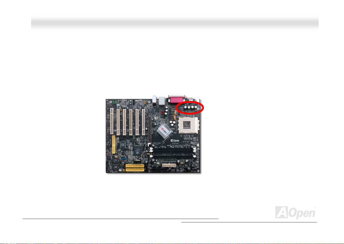
2200μF Low ESR Capacitor.........................................................................................................................................59
Enlarged Aluminum Heatsink ........................................................................................................................................ 60
Open JukeBox Player.................................................................................................................................................... 61
Vivid BIOS technology................................................................................................................................................... 65
The noise is gone!! ---- SilentTek ..................................................................................................................................66
EzClock.........................................................................................................................................................................69
Driver and Utility .......................................................................................................................73
Auto-run Menu from Bonus CD .....................................................................................................................................73
nVIDIA nForce Drivers .................................................................................................................................................. 74
NVIDIA Windows 98/ME/2000/XP Display Driver .......................................................................................................... 75
Installing Promise SATA150 Driver in Existing Windows XP/2000/ME/98/NT4.0 System............................................... 76
4
Page 5

AAKK7799GG MMAAXX//AAKK7799DD MMAAXX OOnnlliinnee MMaannuuaall
Installing USB2.0 Driver in Existing Windows XP System ............................................................................................. 88
Installing USB 2.0 Driver in Existing Windows 98/ME/2000 System ..............................................................................89
Phoenix Award BIOS..................................................................................................................90
How To Use Phoenix Award™ BIOS Setup Program.....................................................................................................91
How To Enter BIOS Setup ............................................................................................................................................. 93
WinBIOS Utility ............................................................................................................................................................. 94
BIOS Upgrade under Windows environment .................................................................................................................96
Glossary ....................................................................................................................................98
AC97 CODEC ............................................................................................................................................................... 98
ACPI (Advanced Configuration & Power Interface) .......................................................................................................98
ACR (Advanced Communication Riser)......................................................................................................................... 98
AGP (Accelerated Graphic Port).................................................................................................................................... 99
AMR (Audio/Modem Riser)............................................................................................................................................ 99
ATA (AT Attachment) .....................................................................................................................................................99
BIOS (Basic Input/Output System) .............................................................................................................................. 100
Bluetooth.....................................................................................................................................................................100
CNR (Communication and Networking Riser).............................................................................................................. 101
DDR (Double Data Rate) RAM .................................................................................................................................... 101
ECC (Error Checking and Correction) ......................................................................................................................... 101
5
Page 6

AAKK7799GG MMAAXX//AAKK7799DD MMAAXX OOnnlliinnee MMaannuuaall
EEPROM (Electronic Erasable Programmable ROM).................................................................................................. 101
EPROM (Erasable Programmable ROM)..................................................................................................................... 102
EV6 Bus ...................................................................................................................................................................... 102
FCC DoC (Declaration of Conformity) ......................................................................................................................... 102
FC-PGA (Flip Chip-Pin Grid Array) .............................................................................................................................. 102
FC-PGA2 (Flip Chip-Pin Grid Array) ............................................................................................................................ 102
Flash ROM .................................................................................................................................................................. 103
Hyper Threading ......................................................................................................................................................... 103
IEEE 1394...................................................................................................................................................................103
Parity Bit ..................................................................................................................................................................... 104
PCI (Peripheral Component Interface) Bus .................................................................................................................104
PDF Format................................................................................................................................................................. 104
PnP (Plug and Play) ....................................................................................................................................................104
POST (Power-On Self Test) ........................................................................................................................................105
PSB (Processor System Bus) Clock............................................................................................................................105
RDRAM (Rambus Dynamic Random Access Memory)................................................................................................ 105
RIMM (Rambus Inline Memory Module) ......................................................................................................................105
SDRAM (Synchronous DRAM) .................................................................................................................................... 105
SATA (Serial ATA) .......................................................................................................................................................106
6
Page 7

AAKK7799GG MMAAXX//AAKK7799DD MMAAXX OOnnlliinnee MMaannuuaall
SMBus (System Management Bus) ............................................................................................................................. 106
SPD (Serial Presence Detect).....................................................................................................................................106
USB 2.0 (Universal Serial Bus) ................................................................................................................................... 106
VCM (Virtual Channel Memory)...................................................................................................................................107
Wireless LAN – 802.11b .............................................................................................................................................. 107
ZIP file......................................................................................................................................................................... 107
Troubleshooting....................................................................................................................... 108
Technical Support ...................................................................................................................112
Product Registration ...............................................................................................................115
How to Contact Us .................................................................................................................. 116
7
Page 8

AAKK7799GG MMAAXX//AAKK7799DD MMAAXX OOnnlliinnee MMaannuuaall
YYoouu MMuusstt NNoottiiccee
Adobe, the Adobe logo, Acrobat is trademarks of Adobe Systems Incorporated.
AMD, the AMD logo, Athlon and Duron are trademarks of Advanced Micro Devices, Inc.
Intel, the Intel logo, Intel Celeron, Pentium II, Pentium III, Pentium 4 are trademarks of Intel Corporation.
Microsoft, Windows, and Windows logo are either registered trademarks or trademarks of Microsoft Corporation in the United
States and/or other countries.
All product and brand names used on this manual are used for identification purposes only and may be the registered
trademarks of their respective owners.
All of the specifications and information contained in this manual are subject to change without notice. AOpen reserves the right
to revise this publication and to make reasonable changes. AOpen assumes no responsibility for any errors or inaccuracies that
may appear in this manual, including the products and software described in it.
This documentation is protected by copyright law. All rights are reserved.
No part of this document may be used or reproduced in any form or by any means, or stored in a database or retrieval
system without prior written permission from AOpen Corporation.
Copyright
©
1996-2003, AOpen Inc. All Rights Reserved.
8
Page 9

AAKK7799GG MMAAXX//AAKK7799DD MMAAXX OOnnlliinnee MMaannuuaall
BBeeffoorree YYoouu SSttaarrtt
This Online Manual will introduce to the user how this product is installed. All useful information will be described in later
chapters. Please keep this manual carefully for future upgrades or system configuration changes. This Online Manual is saved
in PDF format
get free download from Adobe web site
Although this Online Manual is optimized for screen viewing, it is still capable for hardcopy printing, you can print it by A4 paper
size and set 2 pages per A4 sheet on your printer. To do so, choose File > Page Setup and follow the instruction of your printer
driver.
Thanks for the help of saving our earth.
, we recommend using Adobe Acrobat Reader 5.0 for online viewing, it is included in Bonus CD disc or you can
.
9
Page 10

AAKK7799GG MMAAXX//AAKK7799DD MMAAXX OOnnlliinnee MMaannuuaall
OOvveerrvviieeww
Thank you for choosing AOpen AK79G MAX/AK79D MAX. The AK79G MAX/AK79D MAX is based on AMD® Socket 462
motherboard with ATX form factor featuring the AMD Duron/Athlon/Athlon XP CPU. As high performance chipset built in the M/B,
the AK79G MAX/AK79D MAX supports AMD
Overheat Protection circuit to Athlon™XP CPU only). The motherboard also support 333/266/200MHz EV6 bus. For better
graphic performance, GeForce4 MX Graphics is integrated for delivering fastest speed, multi-display functionality and multiple
configurations of CRTs and TVs. Hence, AK79G MAX supports TV-OUT function which supports TV-Out card. It also supports
1.5V AGP interface of AGP 8x/4x with Fast Write data transfer.
According to different customers’ requirements, this motherboard
supports DDR400
up to 3GB maximum. The on-board IDE controller supports Ultra
DMA 66/100/133 mode and the transfer rate is up to 133MB/s.
Besides, the AK79G MAX/AK79D MAX has an AC97 CODEC
RealTek ALC650 chipset onboard to provide high performance and
magic surround stereo sound to let people enjoy working with it.
More than that, this motherboard supports USB 2.0
fancy speed up to 480Mbps. Now, enjoy all features from AOpen
AK79G MAX/AK79D MAX.
®
Socket 462 series Athlon™, Duron™ and AthlonXP™ processor. (with CPU
, DDR333 and DDR266 dual channel DDRAM
function with a
10
Page 11

AAKK7799GG MMAAXX//AAKK7799DD MMAAXX OOnnlliinnee MMaannuuaall
AAKK7799GG MMAAXX//AAKK7799DD MMAAXX CCoommppaarriissoonn TTaabbllee
Following we list functions of all models. “V” represents those functions that the model equips with and “X” represents
functions that models don’t have. Please always refer to this page to see the functions of your model.
Chipset
VGA Onboard
VGA Connector
LAN Onboard
LAN Port
IEEE 1394 Function
IEEE 1394 Connector
TV Out Header
AK79D MAX AK79G MAX
nForce2-ST nForce2-GT
X V
X V
V V
V V
V V
V V
X V
11
Page 12

AAKK7799GG MMAAXX//AAKK7799DD MMAAXX OOnnlliinnee MMaannuuaall
FFeeaattuurree HHiigghhlliigghhtt
CPU
Supports AMD® Socket 462 series CPU with 200MHz, 266MHz and 333MHz, EV6 Bus designed for Socket 462 technology.
Athlon: 600MHz~1.4GHz
Duron: 600MHz~1.2GHz
AthlonXP: 1500+(1.33GHz)~2800+(2.25GHz)
Chipset
NVIDIA nForce™2-ST/GT are excellent in providing amazing digital media performance, such as 400MHz DDR memory
controller, optimized 128-bit architecture reducing overall system memory latency. What nForce™2-GT integrated in this
excellent chipset is the GeForce4 MX Graphics, which provides the fastest integrated graphics performance and the most
comprehensive set of features. Of five PCI slots provided, this model supports all five master PCI slots with arbitration and
decoding for all integrated functions and LPC bus.
Ultra DMA 66/100/133 Bus Master IDE
Embedded within NVIDIA MCP/MCP-T, this motherboard equips with Ultra DMA 66/100/133 that supports three connectors, and
that means six IDE devices in three channels, and supports Enhanced IDE devices.
12
Page 13

AAKK7799GG MMAAXX//AAKK7799DD MMAAXX OOnnlliinnee MMaannuuaall
Expansion Slots
Including five 32-bit/33MHz PCI slots and one AGP 8X slot which supports AGP card. The PCI local bus throughput can be up to
132MB/s. The
with data transfer rate up to 2.1GB/s.
Accelerated Graphics Port (AGP)
specification provides a new level of video display sophistication and speed
Memory
With NVIDIA nForce™2 chipsets, the AK79G MAX/AK79D MAX can support dual channel Double-Data-Rate (DDR) RAM. The
dual channel mode allows chipsets to get data in 128 bit. The DDR RAM interface allows zero wait state bursting between the
SDRAM and the data buffers at 333/266/200MHz. The three slots of DDR RAM can be composed of an arbitrary mixture of 64,
128, 256, 512MB or 1GB DDR RAM and maximum up to 3GB. The AK79G MAX/AK79D MAX allows DDR RAM to run at either
synchronous or pseudo-synchronous mode with the host CPU bus frequency (400/333/266MHz).
On-board AC97 Sound
AK79G MAX/AK79D MAX uses the AC97 CODEC RealTek ALC650 chip. This on-board audio includes a complete audio
recording and playback system.
LAN Port
LAN MAC embedded in nForce2 chipsets and a Realtek RTL8201BL PHY onboard, which support 10/100Mbps BaseT Fast
Ethernet and is IEEE802.3 compliant.
13
Page 14

AAKK7799GG MMAAXX//AAKK7799DD MMAAXX OOnnlliinnee MMaannuuaall
Six USB 2.0 Connectors
Provides three ports, six USB 2.0 connectors with transfer rates at high speed of 480Mbps for USB interface devices, such as
mouse, keyboard, modem, scanner, etc.
1MHz Stepping CPU Frequency Adjustment
Provides “1MHz Stepping Frequency Adjustment” function in the BIOS. This magic function allows you adjust CPU FSB
frequency from 100~200 by 1MHz stepping, and lets your system can get maximum performance.
Power Management/Plug and Play
Supports the power management function that confirms to the power-saving standards of the U.S. Environmental Protection
Agency (EPA) Energy Star program. It also offers
making the system much more user-friendly.
Plug-and-Play
, which helps saving users from configuration problems, thus
Hardware Monitoring Management
Supports CPU or system fans status, temperature and voltage monitoring and alert, through the on-board hardware monitor
module and
Aopen Hardware Monitoring Utility.
SilentTek
Combines “Hardware-Status Monitoring”, “Overheat Warning” and “Fan Speed Control” with user-friendly interfaces to provide a
perfect balance among noises, system performance and stability.
14
Page 15

AAKK7799GG MMAAXX//AAKK7799DD MMAAXX OOnnlliinnee MMaannuuaall
Enhanced ACPI
Fully implement the ACPI standard for Windows® 95/98/ME/NT/2000/XP series compatibility, and supports Soft-Off, STR
(Suspend to RAM, S3), STD (Suspend to Disk, S4) features.
15
Page 16

AAKK7799GG MMAAXX//AAKK7799DD MMAAXX OOnnlliinnee MMaannuuaall
QQuuiicckk IInnssttaallllaattiioonn PPrroocceedduurree
This page gives you a quick procedure on how to install your system. Follow each step accordingly.
1. Installing CPU and Fan
2. Installing System Memory (DIMM)
3. Connecting Front Panel Cable
4. Connecting IDE and Floppy Cable
5. Connecting ATX Power Cable
6. Connecting Back Panel Cable
7. Power-on and Load BIOS Setup Default
8. Setting CPU Frequency
9.
Reboot
Installing Driver and Utility
10.
16
Page 17

p
AAKK7799G
Realtek LAN Controller
CD-IN Connector
Onboar
JP2 Speaker output Jumper
32-bit PCI Expansio lot x5
d AC’97 CODEC
S/PDIF Connector
AUX-IN Connector
COM2 Connector
IrDAConnector
ACR Expansion slot
Game Port Connector
G MAX/AK79D MA
MAX/AK79D MA
n S
Case Open Connector
Serial ATA Connector
Promise Serial ATA Controller
JP30/JP31 BIOS Rescue Jumper
Language Selection Jumper
JP 14 CMOS
Data Clear Jumper
USB 2.0 Connector
Dr. LED Connector
Front Panel Connector
AGP Protection LED
SYSFAN3 Connector
JP15/JP16 Dr. Voice II
XX OOnnlliinnee MMaannuuaall
p
MMootthheerrbbooaarrdd MMaap
PS. Here we use AK79G MAX motherboard as illustration.
Front Audio Connector
Colored Back Panel
JP28 KB/MouseWakeup Jumper
ut Connector
TV Out
SYSFAN2 Connector
462-pin CPU Socket
supports AMD Athlon /
Duron / Athlon XP
(with CPU Overheat
Protection circuit to
Athlon
AGP 8x Expansion Slot
Up to 2.1 GB/s Translate rate
nForce2-GT Chipsets
support 333MHz FSB,DDR 400
AGP 8X
Integrate nVidia Geforce4 MX
CPUFAN1 Connector
184-pin DIMMx3
Supports 128bit dual channel
DDR400/333/266 Max. to 3GB
ATX Power Connector
IEEE1394 Connector x 2
FDD Connector
IDE Connector x 3
(ATA/66/100/133 supported)
TM TM
TM TM
TM
XP CPU only)
17
Page 18

AAKK7799GG MMAAXX//AAKK7799DD MMAAXX OOnnlliinnee MMaannuuaall
BBlloocckk DDiiaaggrraamm
Athlon/Duron/AthlonXP
Socket 462
AMD
CPU
VGA onboard
For AK79G MAX
200/266/333MHz
System Bus
AGP 8X Slot
128bit dual channel
DDR400/333/266 Up to 3GB
DDR SDRAM Socket x3
AGP Bus
LAN connect Component
nVidia nForce2
IGP
PCI Bus
RealTek
RTL8201BL
1stUSB Port
2ndUSB Port
3rdUSB Port
USB Port x6
32-bit PCI Slot x5
ATA
66/100/133
Primary
Channel
Secondary
Channel
SATA
150
nVidia
nForce2
MCP2- T
AC’97 Link
Winbond
Super I/O
IDE Drive x4
IDE Drive x2
Serial ATA x2
Audio CODEC
4Mb Flash EEPROM
4Mb Flash EEPROM
Parallel Port
Serial Port x2
IEEE 1394 x2
Floppy Disk Drive x2
18
Page 19

AAKK7799GG MMAAXX//AAKK7799DD MMAAXX OOnnlliinnee MMaannuuaall
HHaarrddwwaarree IInnssttaallllaattiioonn
This chapter describes jumpers, connectors and hardware devices of this motherboard.
Note: Electrostatic discharge (ESD) can damage your processor, disk drives, expansion boards,
and other components. Always observe the following precautions before you install a system
component.
1. Do not remove a component from its protective packaging until you are ready to install it.
2. Wear a wrist ground strap and attach it to a metal part of the system unit before handling a
component. If a wrist strap is not available, maintain contact with the system unit throughout
any procedures requiring ESD protection.
19
Page 20

AAKK7799GG MMAAXX//AAKK7799DD MMAAXX OOnnlliinnee MMaannuuaall
JJPP1144 CClleeaarr CCMMOOSS DDaattaa
You can clear CMOS to restore system default setting. To clear the CMOS, follow the procedures below.
1. Turn off the system and unplug the AC power.
2. Remove ATX power cable from connector PWR2.
3. Locate JP14 and short pins 2-3 for a few seconds.
4. Return JP14 to its normal setting by shorting pin 1 & pin 2.
5. Connect ATX power cable back to connector PWR2.
1
Normal Operation
(default)
Pin 1
1
Clear CMOS
Tip: When should I Clear CMOS?
1. Boot fail because of overclocking…
2. Forget password…
3. Troubleshooting…
20
Page 21

AAKK7799GG MMAAXX//AAKK7799DD MMAAXX OOnnlliinnee MMaannuuaall
CCPPUU IInnssttaallllaattiioonn
This motherboard supports AMD® Athlon and Duron Socket 462 series CPU. Be careful of CPU orientation when you plug it into
CPU socket (with CPU Overheat Protection function implemented, the system will be automatically power off when the
temperature of CPU reached 97 degree, but works on AthlonXP CPU only).
1. Pull up the CPU socket lever and
up to 90-degree angle.
2. Locate Pin 1 in the socket and look for a black dot or cut edge on the
CPU upper interface. Match Pin 1 and cut edge, then insert the CPU into
the socket.
CPU socket
Lever
Note: This picture is for example only; it may not exactly be the same motherboard.
CPU pin 1
and cut edge
Black dot
and cut edge
21
Page 22

y
AAKK7799GG MMAAXX//AAKK7799DD MMAAXX OOnnlliinnee MMaannuuaall
3. Press down the CPU socket lever and finish
CPU installation.
Note: This picture is for example only; it may not exactly be the same motherboard.
CPU cut edge
Note: If you do not match the CPU
socket Pin 1 and CPU cut edge well,
ou may damage the CPU.
22
Page 23

AAKK7799GG MMAAXX//AAKK7799DD MMAAXX OOnnlliinnee MMaannuuaall
AAOOppeenn OOvveerrhheeaatt PPrrootteeccttiioonn ((OO..HH..PP..)) TTeecchhnnoollooggyy
With AMD platform substantially keeps increasing the speed of its CPU, it inevitably led to the annoying problem of high CPU
operation temperature at the same time. In order to prevent accidental failure of CPU fan, which could cause the burning down
of the AthlonXP CPU, we, AOpen, have meticulously developed a new technology, named, O.H.P. (Overheat Protection)
Technology to protect them. Thanks to the intelligent monitoring design of AOpen O.H.P. technology, user can now finally set
their mind at ease even when fan failed to work without fearing the possible damage of CPU.
Under the circumstances that CPU fan is running properly, AthlonXP temperature should be way below the highest temperature
limit of 97℃. However, if CPU fan accidentally becomes
malfunction or improperly installed, the CPU temperature
would rocket abruptly, and you may find your system hang
up or crying over the smoking CPU if you haven’t installed
AOpen O.H.P. previously. With AOpen O.H.P. technology
applied, the specific thermal detection pins on AthlonXP
CPU would sense voltage difference when processor is
overheated with fan failed, and the overheat protection
system would immediately send out a signal to abort your
system by cutting CPU electricity before any damage is
done. Unlike other manufacturers who use BIOS or
software to control the power supply of CPU, AOpen O.H.P.
Technology is purely hardware-controlled the minute after
system boot-up, and occupies no system resource. We are
pleasant to phase in this practical function on all AOpen
AMD series motherboards to protect customer’s valuable
hardware and personal data.
23
Page 24

AAKK7799GG MMAAXX//AAKK7799DD MMAAXX OOnnlliinnee MMaannuuaall
CCPPUU JJuummppeerr--lleessss DDeessiiggnn
CPU VID signal and SMbus clock generator provide CPU voltage auto-detection and allows the user to set the CPU frequency
through the BIOS setup
designs are eliminated. There will be no worry of wrong CPU voltage detection.
CPU voltage
Socket 462 CPU
Power Regulator
, therefore no jumpers or switches are used. The disadvantages of the Pentium based jumper-less
AMD
CPU VID signal
Attansic
ATXP3
VID signal
nForce2 IGP
nVIDIA
SMbus
(Automatically generates CPU voltage)
nVIDIA
nForce2 MCP2-T
BIOS
CPU Freq
24
Page 25

AAKK7799GG MMAAXX//AAKK7799DD MMAAXX OOnnlliinnee MMaannuuaall
FFuullll--rraannggee AAddjjuussttaabbllee CCPPUU CCoorree VVoollttaaggee
This motherboard supports CPU VID function. The CPU core voltage will be automatically detected and the range is from 1.1V
to 1.85V. It is not necessary to set CPU Core Voltage.
SSeettttiinngg CCPPUU FFrreeqquueennccy
This motherboard is CPU jumper-less design, you can set CPU frequency through the BIOS setup, and no jumpers or switches
are needed.
BIOS Setup > Frequency/Voltage Control > CPU Speed Setting
CPU Ratio From 5.5x to 16x step 0.5x
CPU FSB (Adjustment
manually)
Home
FSB=100~200 by 1MHz Stepping CPU Overclocking
Warning: nForce2-ST/GT chipsets support 166MHz FSB (with performance reaches
maximum 333MHz EV6 system bus) and 66MHz AGP clock, higher clock setting may
cause serious system damage.
y
Tip: If your system hangs or fails to boot because of overclocking, simply use <Home>
key to restore the default setting or you can wait the AOpen “Watch Dog Timer” reset
the system after few seconds and system will auto-detect hardware again.
25
Page 26

AAKK7799GG MMAAXX//AAKK7799DD MMAAXX OOnnlliinnee MMaannuuaall
SSuuppppoorrtteedd CCPPUU FFrreeqquueennccyy
Core Frequency = CPU Bus Clock * CPU Ratio EV6 Bus Speed = CPU external bus clock x 2
PCI Clock = CPU Bus Clock / Clock Ratio AGP Clock = PCI Clock x 2
CPU CPU Core Frequency EV6 Bus Clock Ratio
Athlon 1G 1GHz 266MHz 7.5x
Athlon 1.13G 1.13GHz 266MHz 8.5x
Athlon 1.2G 1.2GHz 266MHz 9.0x
Athlon 1.33G 1.33GHz 266MHz 10.0x
Athlon 1.4G 1.4GHz 266MHz 10.5x
AthlonXP 1500+ 1.3GHz 266MHz 10.0x
AthlonXP 1600+ 1.4GHz 266MHz 10.5x
AthlonXP 1700+ 1.46GHz 266MHz 11.0x
AthlonXP 1800+ 1.53GHz 266MHz 11.5x
AthlonXP 1900+ 1.6GHz 266MHz 12.0x
AthlonXP 2000+ 1.667GHz 266MHz 12.5x
AthlonXP 2100+ 1.73GHz 266MHz 13x
AthlonXP 2200+ 1.80GHz 266MHz 13.5x
AthlonXP 2400+ 2.0GHz 266MHz 15x
AthlonXP 2600+ 2.13GHz 266MHz 16x
AthlonXP 2700+ 2.16GHz 333MHz 13x
AthlonXP 2800+ 2.25GHz 333MHz 13.5x
Duron 1G 1GHz 200MHz 10.0x
Duron 1.1G 1.1GHz 200MHz 11.0x
Duron 1.2G 1.2GHz 200MHz 12.0x
Duron 1.3G 1.3GHz 200MHz 13.0x
Note: With CPU speed changing rapidly, there might be fastest CPU on
the market by the time you received this installation guide. This table is
kindly for your references only.
Note: You have to adjust CPU
FSB in BIOS after installing
CPU; otherwise CPU will run at
default speed of CPU FSB
value.
Note: : Due to the limitation of
nVidia chipset itself, if the FSB
overclocking frequency is
extremely high, (for example,
over 160MHz), the WatchDog
ABS and Home key function
may not be able to automatically
recover your motherboard. In
such case, please clear CMOS
by JP14.
26
Page 27

AAKK7799GG MMAAXX//AAKK7799DD MMAAXX OOnnlliinnee MMaannuuaall
CCPPUU aanndd HHoouussiinngg FFaann CCoonnnneeccttoorr
Plug in the CPU fan cable to the 3-pin CPUFAN1 connector. If you have chassis fan, you can also plug it on SYSFAN2 or
SYSFAN3 connector.
SYSFAN3 Connector
GND
+12V
SENSOR
SYSFAN2 Connector
GND
+12V
SENSOR
CPUFAN1 Connector
GND
+12V
SENSOR
Note: Some CPU fans do not have
sensor pin, so that they cannot support
fan monitoring.
27
Page 28

AAKK7799GG MMAAXX//AAKK7799DD MMAAXX OOnnlliinnee MMaannuuaall
JJPP2288 KKeeyybbooaarrdd//MMoouussee WWaakkeeuupp JJuummppeerrss
This motherboard provides keyboard / mouse wake-up function. You can use JP28 to enable or disable this function, which
could resume your system from suspend mode with keyboard or mouse. The factory default setting is “Disable”(1-2), and you
may enable this function by setting the jumper to 2-3.
1
(Default)
Pin 1
JP28
1
Enable Disable
28
Page 29

AAKK7799GG MMAAXX//AAKK7799DD MMAAXX OOnnlliinnee MMaannuuaall
DDIIMMMM SSoocckkeettss
This motherboard has three 184-pin DDR DIMM sockets that allow you to install 128bit dual channel DDR400 or DDR333 or
DDR266
Non-ECC DDR RAM is supported, otherwise, it will cause serious damage on memory sockets or SDRAM module. For over
clocking purpose, you can adjust memory voltage in BIOS from 2.5V to 2.65V.
memory up to 3GB. To reach maximal performance, you had better install at least 2 RAM in the sockets. Only
Warning: This motherboard supports DDR
RAM. Please do not install the SDRAM on
the DDR RAM sockets, otherwise, it will
cause serious damage on memory sockets
or SDRAM module.
DIMM1
DIMM2
DIMM3
DDR RAM
29
Page 30

AAKK7799GG MMAAXX//AAKK7799DD MMAAXX OOnnlliinnee MMaannuuaall
HHooww ttoo IInnssttaallll MMeemmoorryy MMoodduulleess
Please follow the procedure as shown below to finish memory installation.
1. Make sure the DIMM module’s pin face down and match the socket’s size as depicted below.
2. Insert the module straight down to the DIMM slot with both hands and press down firmly until the DIMM module is securely
in place.
3. Repeat step 2 to finish additional DIMM modules installation.
Pin 1
Ta b
Key
52 pins 40 pins
Note: The tabs of the DIMM slot
will close-up to hold the DIMM in
place when the DIMM touches
the slot’s bottom.
Pin 1
30
Page 31
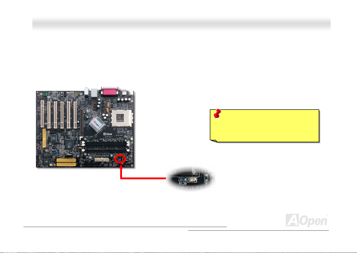
AAKK7799GG MMAAXX//AAKK7799DD MMAAXX OOnnlliinnee MMaannuuaall
SSTTBBYY LLEEDD
STBY LED is AOpen’s considerate design that aims at providing you friendly system information. The STBY LED will light up
when power is connected to the motherboard. This is a convenient indication for you to check the system power status in many
circumstances such as power on/off, stand-by mode and RAM power status during Suspend to RAM mode.
Warning: Do not install or remove the
DIMM module or others devices when
the STBY LED lights on.
STBY LED
31
Page 32
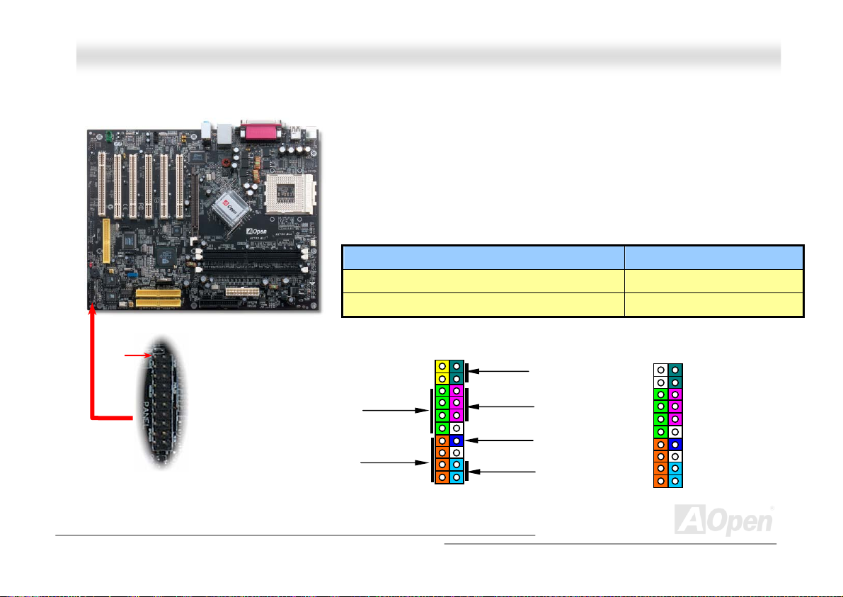
AAKK7799GG MMAAXX//AAKK7799DD MMAAXX OOnnlliinnee MMaannuuaall
FFrroonntt PPaanneell CCoonnnneeccttoorr
Pin 1
Attach the power LED, speaker, power and reset switch connectors to the
corresponding pins. If you enable “Suspend Mode” item in BIOS Setup, the ACPI
& Power LED will keep flashing while the system is in suspend mode.
Locate the power switch cable from your ATX housing. It is 2-pin female
connector from the housing front panel. Plug this connector to the soft-power
switch connector marked SPWR.
Suspend Type ACPI LED
Power on Suspend (S1) or Suspend to RAM (S3) Blinking between green and red.
Suspend to Disk (S4) The LED will be turned off
IDE LED
Spea ker
1
SPWR
ACPI & PWR
LED
Reset
SPEAKER
NC
NC
+5V
IDE LED
IDE LED
+5V
+5V
GND
NC
1
5VSB
SPWR
ACPI LED-
GND
ACPILED
NC
ACPI_B
GND
RESET
GND
32
Page 33
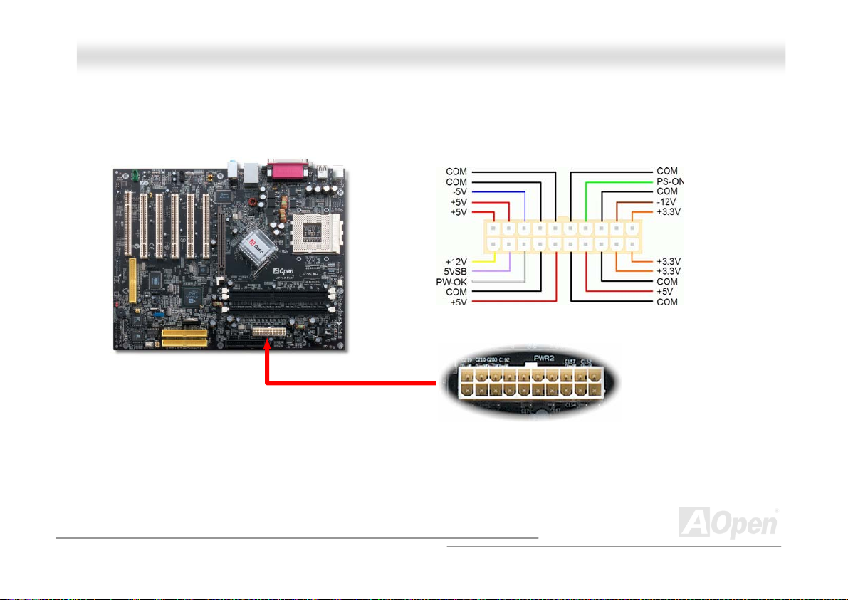
AAKK7799GG MMAAXX//AAKK7799DD MMAAXX OOnnlliinnee MMaannuuaall
AATTXX PPoowweerr CCoonnnneeccttoorr
The ATX power supply uses 20-pin connector shown below. Make sure you plug in the right direction.
AACC PPoowweerr AAuuttoo RReeccoovveerryy
A traditional ATX system should remain at power off stage when AC power resumes from power failure. This design is
inconvenient for a network server or workstation, without an UPS, that needs to keep power-on. This motherboard implements
an AC Power Auto Recovery function to solve this problem.
20-Pin Power Connector
33
Page 34
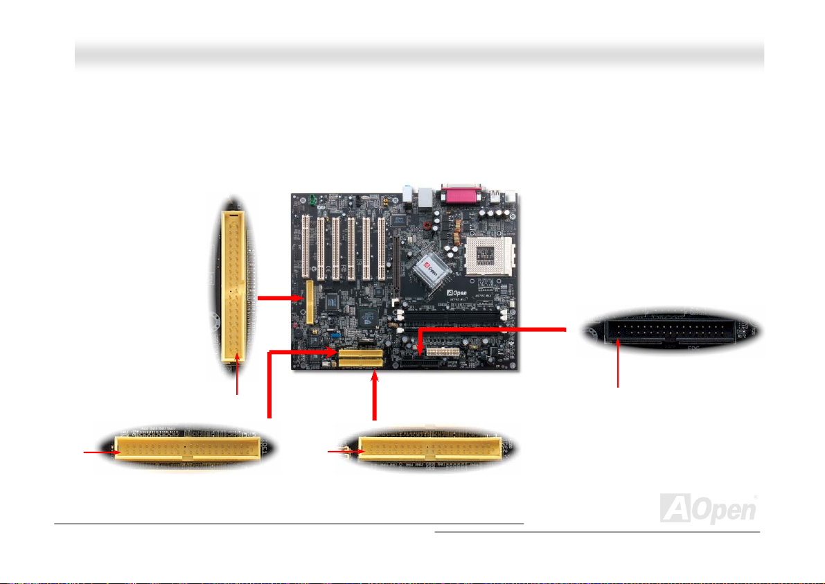
y
)
AAKK7799GG MMAAXX//AAKK7799DD MMAAXX OOnnlliinnee MMaannuuaall
IIDDEE aanndd FFllooppppyy CCoonnnneeccttoorr
Connect 34-pin floppy cable and 40-pin IDE cable to floppy connector FDC connector. Be careful of the pin1 orientation. Wrong
orientation may cause system damage.
ATA 66/100/133
Pin 1
IDE Connector
IDE3
Pin 1
Pin 1
IDE2 (Primar
Pin 1
FDD Connector
Pin1
IDE2 (Secondary)
34
Page 35
66/100
/133is required
AAKK7799GG MMAAXX//AAKK7799DD MMAAXX OOnnlliinnee MMaannuuaall
IDE1 is also known as the primary channel and IDE2 as the secondary channel. Each channel supports two IDE devices that
make a total of four devices. In order to work together, the two devices on each channel must be set differently to Master and
Slave mode. Either one can be the hard disk or the CDROM. The setting as master or slave mode depends on the jumper on
your IDE device, so please refer to your hard disk and CDROM manual accordingly.
This motherboard supports ATA66
modes. The IDE bus is 16-bit, which means every transfer is two bytes.
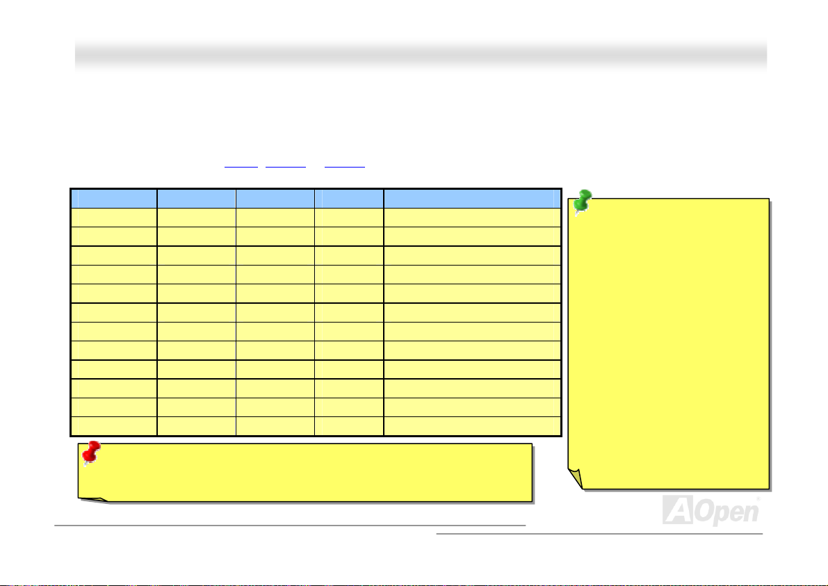
Mode Clock Period Clock Count Cycle TimeData Transfer Rate
PIO mode 0 30ns 20 600ns (1/600ns) x 2byte = 3.3MB/s
PIO mode 1 30ns 13 383ns (1/383ns) x 2byte = 5.2MB/s
PIO mode 2 30ns 8 240ns (1/240ns) x 2byte = 8.3MB/s
PIO mode 3 30ns 6 180ns (1/180ns) x 2byte = 11.1MB/s
PIO mode 4 30ns 4 120ns (1/120ns) x 2byte = 16.6MB/s
DMA mode 0 30ns 16 480ns (1/480ns) x 2byte = 4.16MB/s
DMA mode 1 30ns 5 150ns (1/150ns) x 2byte = 13.3MB/s
DMA mode 2 30ns 4 120ns (1/120ns) x 2byte = 16.6MB/s
ATA33 30ns 4 120ns (1/120ns) x 2byte x 2 = 33MB/s
ATA66 30ns 2 60ns (1/60ns) x 2byte x 2 = 66MB/s
ATA100 20ns 2 40ns (1/40ns) x 2byte x 2 = 100MB/s
ATA133 15ns 2 30ns (1/30ns) x 2byte x 2 = 133MB/s
Warning: The specification of the IDE cable is a maximum of 46cm (18 inches);
make sure your cable does not exceed this length.
, ATA100 or ATA 133 IDE devices. Following table lists the transfer rate of IDE PIO and DMA
Tip:
1. For better signal quality,
it is recommended to set
the far end side device
to master mode and
follow the suggested
sequence to install your
new device. Please refer
to above diagra m
2. To achieve the best
performance of Ultra
DMA 66/100/133 hard
disks, a special 80-wires
IDE cable for Ultra DMA
.
35
Page 36
AAKK7799GG MMAAXX//AAKK7799DD M
M
AAXX
OOnnlliinnee MMaannuuaall
SSeerriiaall AATTAA CCoonnnneeccttoorr
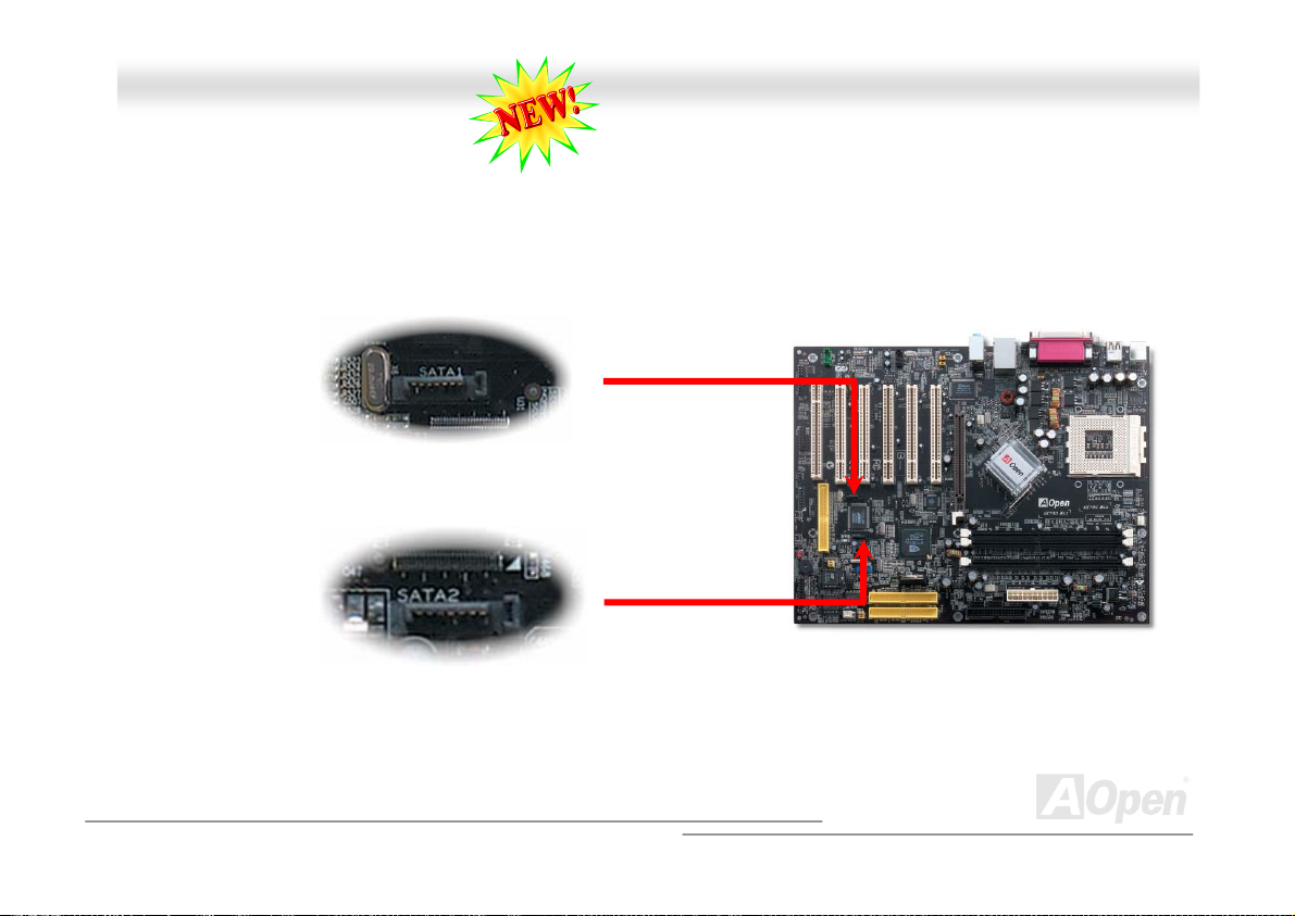
To connect a Serial ATA disk, you must use a 7-pin serial ATA cable. Connect two ends of the serial ATA cable to the serial ATA
header on the main board and the disk. Like every other traditional disk, you also have to connect a power cable. Please note
that it is a jumper free implement; you don’t need to set jumpers to define a master or slave disk. When connecting two serial
ATA disks, the system will automatically take the one connected to “Serial ATA 1” header as a master disk
SATA Header 1
SATA Header 2
36
Page 37
AAKK7799GG MMAAXX//AAKK7799DD MMAAXX
OOn
nl
liinnee MMaannuuaall
SS//PPDDIIFF ((SSoonnyy//PPhhiilliippss DDiiggiittaall IInntteerrffaaccee)) CCoonnnneeccttoorr
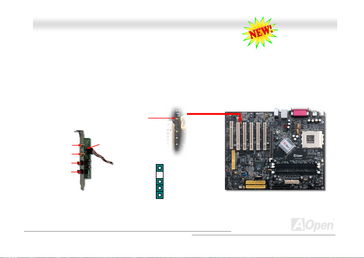
S/PDIF (Sony/Philips Digital Interface) is a newest audio transfer file format, which provides impressive audio quality through
optical fiber and allows you to enjoy digital audio instead of analog audio. Through a specific audio cable, you can connect the
S/PDIF connector to other end of the S/PDIF audio module, which bears S/PDIF digital output. Normally there are two S/PDIF
outputs as shown, one for RCA connector, the most common one used for consumer audio products, and the other for optical
connector with better audio quality. Same as outputs, you can also connect RCA or optical audio products to input connectors
on the module and have the voice or music come out from your computer. However, you must have a S/PDIF supported
speaker/amplifier/decoder with S/PDIF digital input/output to connect to the S/PDIF digital input/output to make the most out of
this function.
S/PDIF OUT
S/PDIF IN
S/PDIF OUT
S/PDIF IN
(Optical)
S/PDIF Module
(User Upgrade Optional)
S/PDIF
Cable
Pin 1
1
5
+5V
NC
SPDIFOUT
GND
SPDIFIN
37
Page 38
AAKK7799GG MMAAXX//AAKK7799DD MMAAXX
OOnnlliinnee MMaannuuaall
SSuuppeerr 55..11 CChhaannnneell AAuuddiioo EEffffeecctt
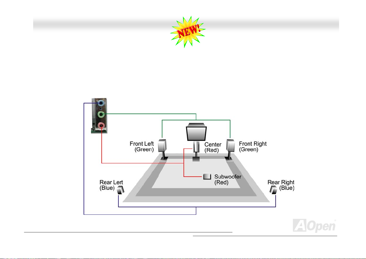
This motherboard comes with an ALC650 CODEC, which supports high quality of 5.1 Channel audio effects, bringing you a
brand new audio experience. On the strength of the innovative design of ALC650, you're able to use standard line-jacks for
surround audio output without connecting any external module. To apply this function, you have to install the audio driver in the
Bonus Pack CD as well as an audio application supporting 5.1 Channel. Picture bellow represents the standard location of all
speakers in 5.1Channel sound track. Please connect the plug of your front speakers to the green “Speaker out” port, rear
speakers’ plug to the blue “Line in” port and both of the center and subwoofer speakers to the red “MIC in” port.
38
Page 39
AAKK7799GG MMAAXX//AAKK7799DD MMAAXX
OOnnlliinnee MMaannuuaall
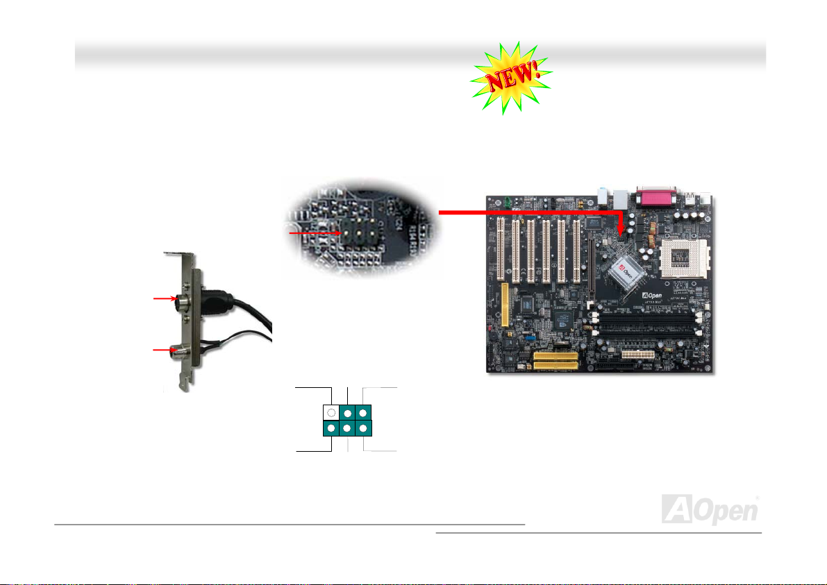
TTVV OOuuttppuutt CCoonnnneeccttoorr (( ffoorr AAKK7799GG MMAAXX ))
This motherboard comes with a TV Output connector which allows you to accept digital graphic input signal, and encodes, and
transmit data through DVI or TV Output. Both NTSC and PAL TV formats are supported for this function. You may just install a
TV Output module (as shown) to your back panel, connect S-Terminal or AV-terminal to your TV, then use it as your another
monitor.
S-Terminal
AV-Term inal
(User Upgrade Optional)
Composite Video
Pin 1
TV Output Connector
Key
2
1
GND
Chroma
6
5
Luma
GND
39
Page 40
AAKK7799GG MMAAXX//AAKK7799DD MMAAXX OOnnlliinnee MMaannuuaall
Pin 1
1
NC
+5V
IR_TX
KEY
GND
IR_RX
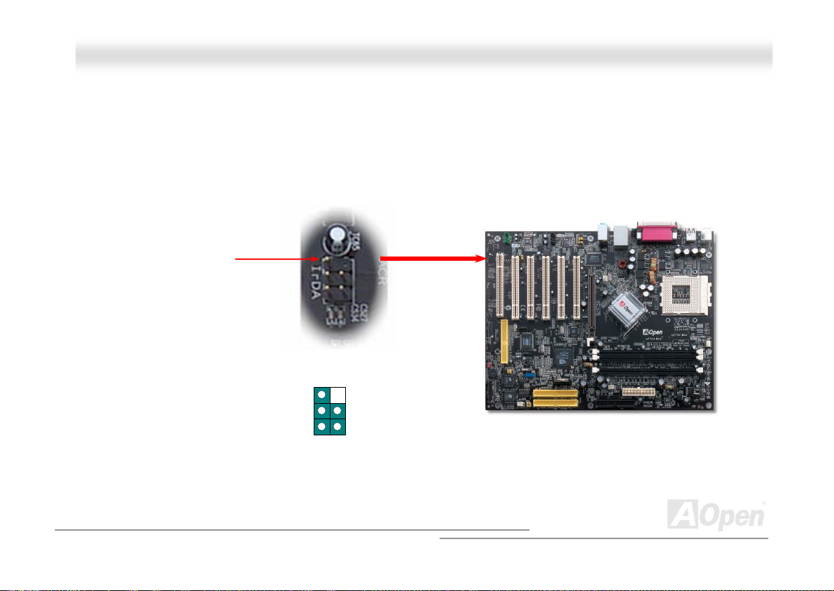
IIrrDDAA CCoonnnneeccttoorr
The IrDA connector can be configured to support wireless infrared module, with this module and application software such as
Laplink or Windows 95 Direct Cable Connection, the user can transfer files to or from laptops, notebooks, PDA devices and
printers. This connector supports HPSIR (115.2Kbps, 2 meters) and ASK-IR (56Kbps).
Install the infrared module onto the IrDA connector and enable the infrared function from BIOS Setup, UART2 Mode, make sure
to have the correct orientation when you plug in the IrDA connector.
40
Page 41
AAKK7799GG MMAAXX//AAKK7799DD MMAAXX
OOnnlli
i
nnee MMaannuuaall
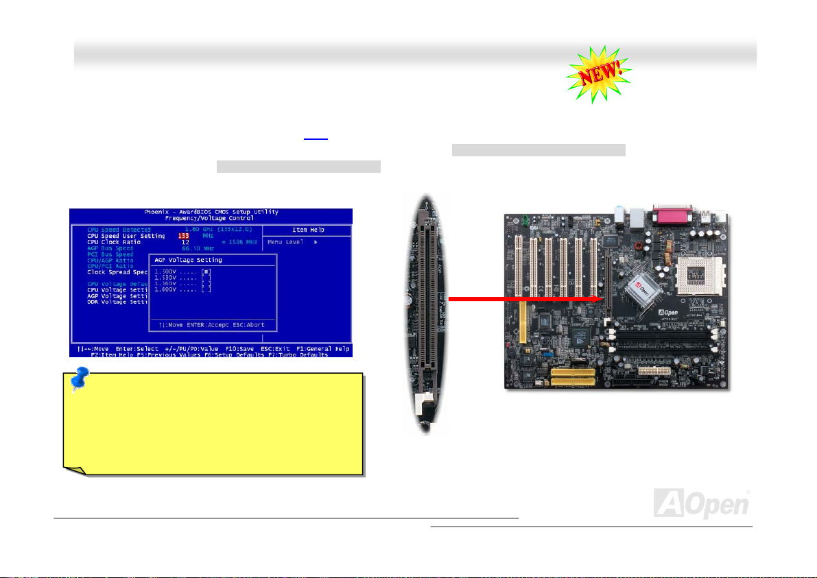
AAGGPP ((AAcccceelleerraatteedd GGrraapphhiicc PPoorrtt)) 88XX EExxppaannssiioonn SSlloott
Integrated GeForce4 MX Graphics, which provides the fastest integrated graphics performance and the most comprehensive set
of features. This motherboard provides an AGP
falling edge of the 66MHz clock, for 4X AGP, the data transfer rate is 66MHz x 4bytes x 4 = 1056MB/s. AGP is now moving
to AGP 8x mode, which is 66MHz x 4bytes x 8 =2.1GB/s. You can also adjust AGP voltage in BIOS within a rage from 1.5V to
1.6V.
Note: Please note that when an extra AGP card is
installed and the onboard AGP function in BIOS is
disabled, the system can support
DDR400/333/266; otherwise it only supports up to
DDR333.
8x slot targeted for high-performance 3D graphic. AGP uses both rising and
41
Page 42
AAKK7799GG MMAAXX//AAKK7799DD MMAAXX OOnnlliinnee MMaannuuaall
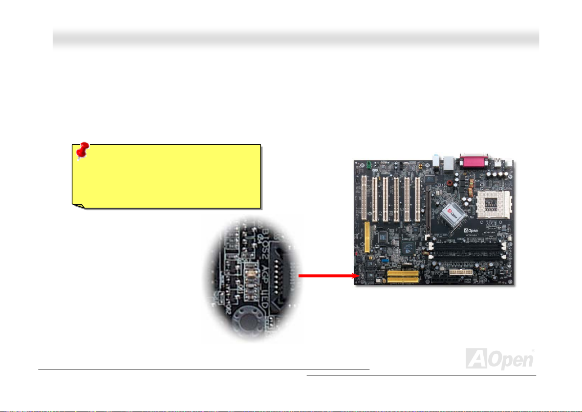
AAGGPP PPrrootteeccttiioonn TTeecchhnnoollooggyy aanndd AAGGPP LLEEDD
With the outstanding R&D ability of AOpen and its specially developed circuit, this model implements a blend new technology to
protect your motherboard from being damaged by over-voltaging of AGP card. When AGP Protection Technology is implemented,
this motherboard will automatically detect the voltage of AGP card and prevent your chipsets from being burnt out. Please note
that if you install a AGP card with 3.3V, which is not supported, the AGP LED on the motherboard will light up to warn you the
possible damage of the exceeding voltage. You may contact your AGP card vendor for further support.
Warning: It is strongly recommended not
to install a AGP card with 3.3V, which is not
supported, the LED3 will light up to warn
you the possible damage.
AGP LED
42
Page 43
AAKK7799GG MMAAXX//AAKK7799DD MMAAXX OOnnlliinnee MMaannuuaall
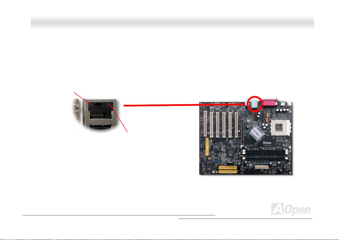
SSuuppppoorrtt 1100//110000 MMbbppss LLAANN OOnnbbooaarrdd
On the strength of nVIDIA nForce2 LAN controller on chip (with RealTek RTL8201BL PHY), which is a highly-integrated Platform
LAN Connect device, it provides 10/100M bps Ethernet for office and home use, the Ethernet RJ45 connector is located on top
of USB connectors. The orange LED indicates the link mode, it lights when linking to network. The green LED indicates the
transfer mode, and it lights when data is transferring. To enable or disable this function, you may simply adjust it through BIOS.
Green/Transfer
Orange/Link
43
Page 44
AAKK7799GG MMAAXX//AAKK7799DD MMAAXX OOnnlliinnee MMaannuuaall
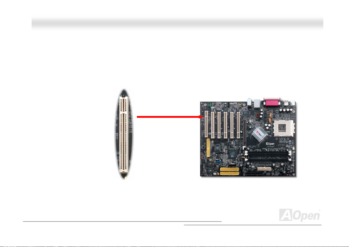
AACCRR ((AAuuddiioo aanndd CCoommmmuunniiccaattiioonn RRiisseerr)) EExxppaannssiioonn SSlloott
Building on the PC motherboard riser architecture, ACR slot is backward compatible with AMR but beyond the limitation of it.
The ACR specification is designed to support modem, audio, Local Area Network (LAN) and Digital Subscriber Line (DSL). On
the strength of nVIDIA MCP-D controller on chip, which is a highly integrated Platform LAN Connect device, it provides 10/100M
bps Ethernet for office and home use.
ACR Connector
44
Page 45
AAKK7799GG MMAAXX//AAKK7799DD MMAAXX OOnnlliinnee MMaannuuaall
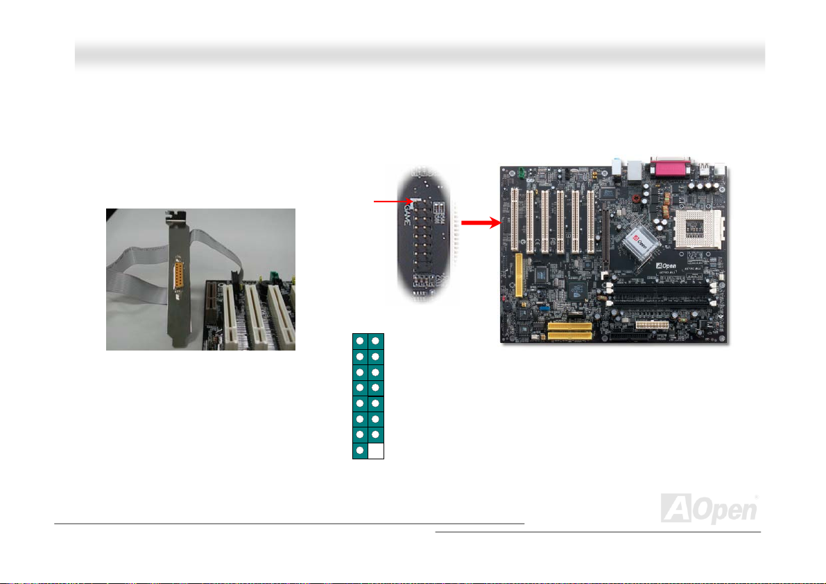
GGaammee PPoorrtt BBrraacckkeett SSuuppppoorrtteedd
This motherboard comes with a game port (Joystick-Midi) for you to connect any midi devices or joysticks. To use this function
you have to have a joystick module and connect it with a game port cable to this port on the motherboard.
Note: This picture is for example only; it may not exactly look the same with the motherboard you purchased.
Joystick Module
(User Upgrade Optional)
+5V
JAB1
JACX
GND
GND
JACY
JAB2
+5V
Pin1
Game Port Connector
1
+5V
JBB1
JBCX
MIDI_TXD
JBCY
JBB2
MIDI_RXD
KEY
45
Page 46
y
VGA
AAKK7799GG MMAAXX//AAKK7799DD MMAAXX OOnnlliinnee MMaannuuaall
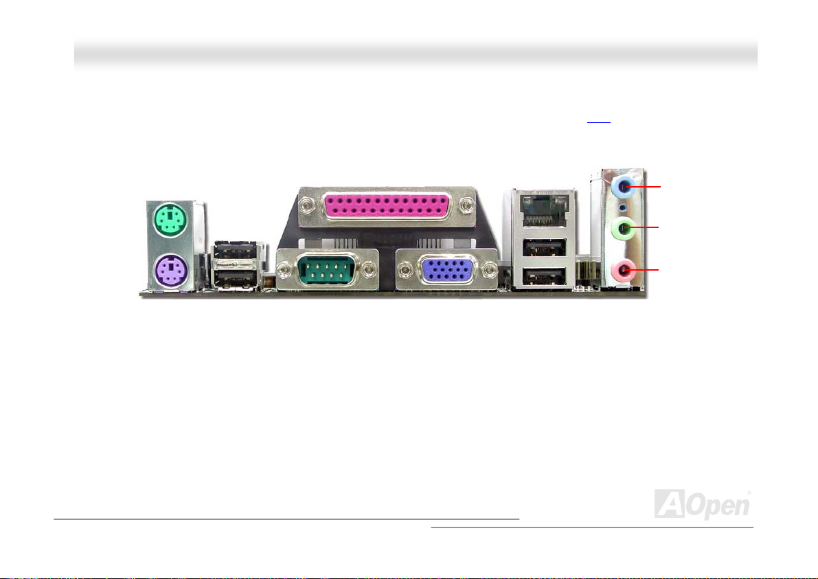
CCoolloorr CCooddeedd BBaacckk PPaanneell
The onboard I/O devices are PS/2 Keyboard, PS/2 Mouse, serial ports COM1 and VGA, Printer, USB, AC97 sound and game
port. The view angle of drawing shown here is the back panel of the housing.
PS/2 Keyboard: For standard keyboard, which is using a PS/2 plug.
PS/2 Mouse: For PC-Mouse, which is using a PS/2 plug.
USB Port: Available for connecting USB devices.
Parallel Port: To connect with SPP/ECP/EPP printer.
COM1 Port: To connect with pointing devices, modem or others serial devices.
VGA Connector: To connect with PC monitor.
Speaker Out: To External Speaker, Earphone or Amplifier.
Line-In: Comes from the signal sources, such as CD/Tape player.
MIC-In: From Microphone.
LAN Port: Available for 10/100 LAN connection.
PS/2 Mouse
Connector Line-In
USB2.0
Ports
PS/2
board
Ke
SPP/EPP/ECP Parallel Port
COM 1 Port
(for AK79G MAX only)
Port
LAN Port
Spea ker Out
MIC-In
USB2.0 Ports
46
Page 47
AAKK7799GG MMAAXX//AAKK7799DD MMAAXX OOnnlliinnee MMaannuuaall
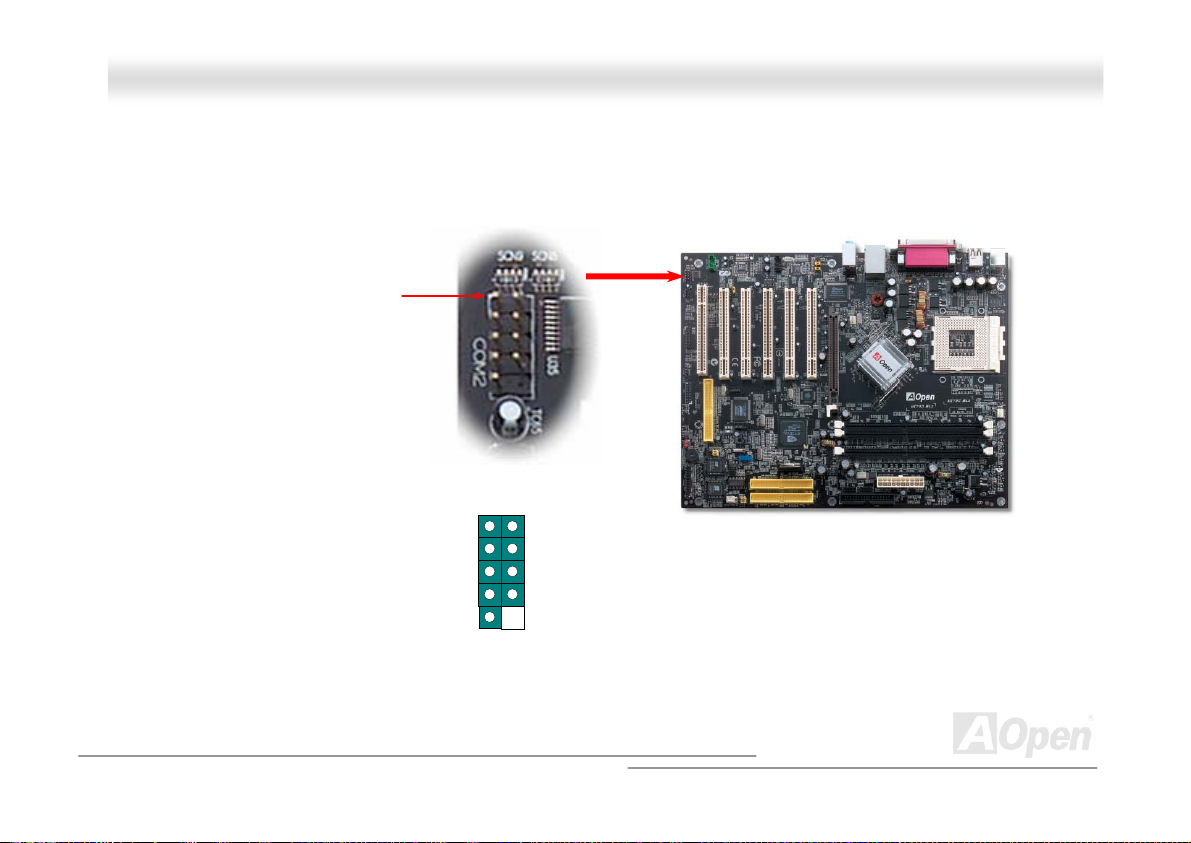
CCOOMM22 CCoonnnneeccttoorr
This motherboard provides two serial ports. One of them is on back panel connector, and the other is on the upper left of board.
With proper cable, you can connect it to the back panel of chassis.
Pin 1
DCD#
SOUT
1 2
SIN
DTR#
GND
RI#
RTS#
COM2 Connector
DSR#
CTS#
47
Page 48
AAKK7799GG MMAAXX//AAKK7799DD MMAAXX
OOnnlliinnee MMaannuuaall
SSuuppppoorrtt FFrroonntt UUSSBB 22..00 CCoonnnneeccttoorr
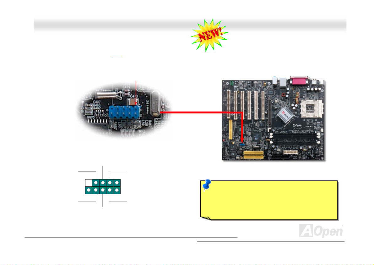
This motherboard provides six USB 2.0 connectors to connect USB devices, such as mouse, keyboard, modem, printer, etc.
There are four connectors on the back panel. You can use proper cables to connect the Front USB connector to USB modules
or front panel of chassis.
GND
Key
NC
GND
USB 2.0 Connector
SBD2+
SBD3+
Pin 1
SBD2-
1
2
SBD3-
Note: Please note that if you would like to use
USB devices (Example: keyboard, mouse etc.)
under DOS environment, you must install driver
comes with the devices to make it work.
48
Page 49
AAKK7799GG MMAAX
X/
/AAKK7799DD MMAAXX
OOnnlliinnee MMaannuuaall
IIEEEEEE 11339944 CCoonnnneeccttoorrss
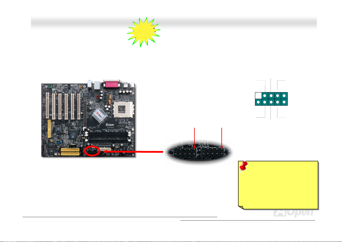
With IEEE1394 MAC Embedded in nForce2-GT/ST (with AGERE FW802A), the IEEE 1394 provides data transfer rate up to
400Mb/s, and USB just has 12Mbps. Hence, the IEEE 1394 interface can connect with the devices that need high data
transferring performance, such as digital camera, scanner or others IEEE 1394 devices. Please use the proper cable to connect
with devices.
TPB+
GND
TPA+
1
2
TPA-
GND
TPB-
Warning: Please be noted
that Hot-Plug in is not
allowed on IEEE 1394
header, because it will burn
the IC of the controller and
Pin 1
IEEE 1394
Port 1 & 2
+12V(fused)
9
10
SHIELD GND
-12V(fused)
Pin 1
49
Page 50
Pin 1
AAKK7799GG MMAAXX//AAKK7799DD MMAAXX OOnnlliinnee MMaannuuaall
CCaassee OOppeenn CCoonnnneeccttoorr
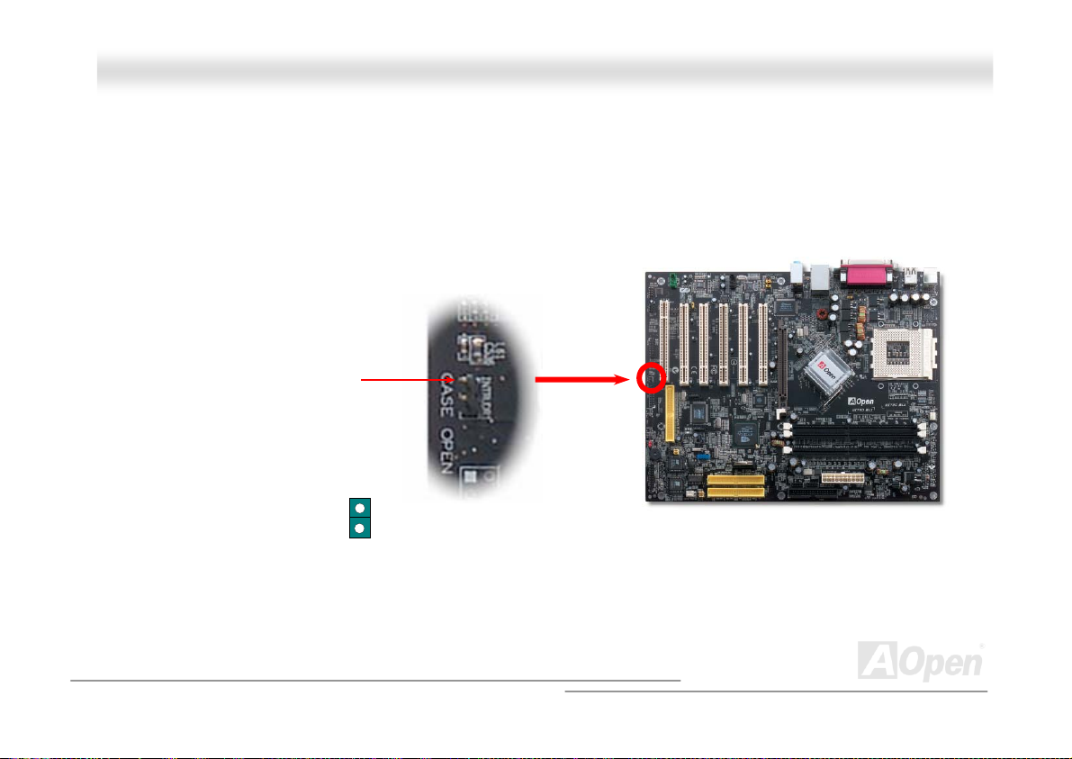
The “CASE OPEN” header provides chassis intrusion-monitoring function. To make this function works, you have to enable it in
the system BIOS, connect this header to a sensor somewhere on the chassis. So, whenever the sensor is triggered by lights or
the opening of the chassis, the system will send out beep sound to inform you. Please be informed that this useful function only
applies to advanced chassis, you may purchase an extra sensor, attach it on your chassis, and make a good use of this
function.
GND
Sensor
50
Page 51
AAKK7799G
G
MMAAXX//AAKK7799DD MMAAXX OOnnlliinnee MMaannuuaall
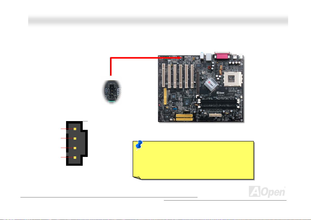
CCDD AAuuddiioo CCoonnnneeccttoorr
This connector is used to connect CD Audio cable from CD-ROM or DVD drive to onboard sound.
R
GND
GND
L
CCDD--IINN CCoonnnneeccttoorr
Note: Though some of the latest version of Windows
support “Digital Audio” through IDE bus. However, in
order to use Open Jukebox player, which is driven
under BIOS, it is a MUST to insert audio cable to
CD-IN connector on the motherboard.
51
Page 52
AAKK779
9
GG MMAAXX//AAKK7799DD MMAAXX OOnnlliinnee MMaannuuaall
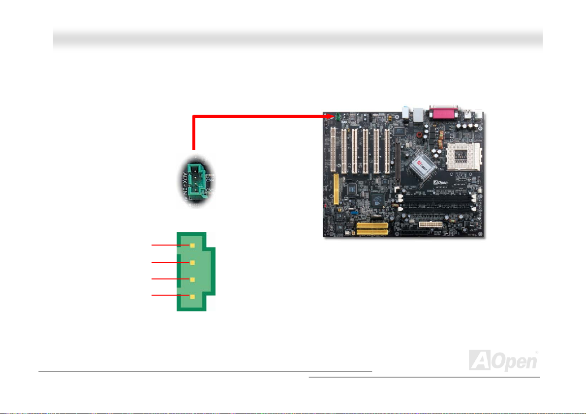
AAUUXX--IINN CCoonnnneeccttoorr
This connector is used to connect MPEG Audio cable from MPEG card to onboard sound.
R
GND
GND
L
AUX-IN
52
Page 53
AAKK7799GG MMAAXX//AAKK7799DD MMAAXX OOnnlliinnee MMaannuuaall
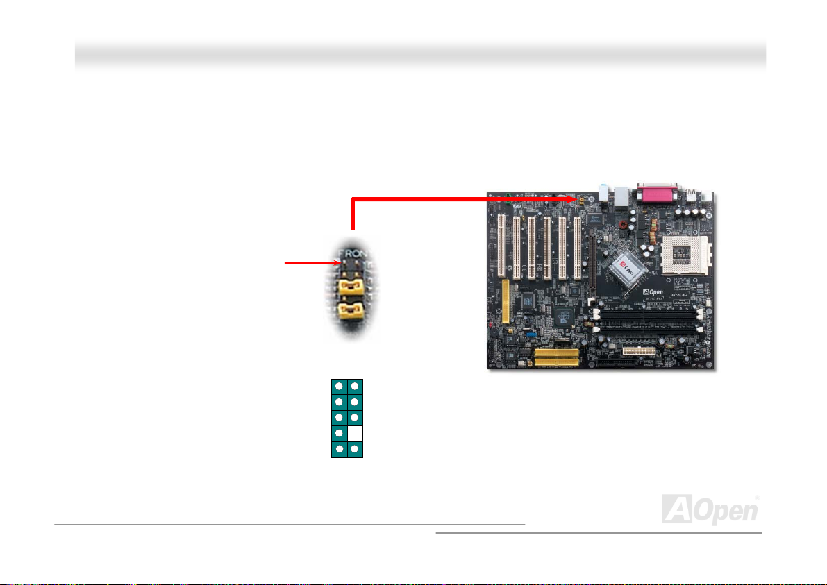
FFrroonntt AAuuddiioo CCoonnnneeccttoorr
If the housing has been designed with an audio port on the front panel, you’ll be able to connect onboard audio to front panel
through this connector. By the way, please remove 5-6 and 9-10 jumper caps from the Front Audio Connector before connecting
the cable. Please do not remove these 5-6 and 9-10 yellow jumper caps if there’s no audio port on the front panel.
Pin 1
AUD_MIC_BIAS
AUD_FPOUT_R
AUD_FPOUT_L
AUD_MIC
NC
1
AUD_GND
AUD_VCC
AUD_RET_R
KEY
AUD_RET_L
53
Page 54
AAKK7799GG MMAAXX//AAKK7799DD MMAAXX
OOnnlliinnee MMaannuuaall
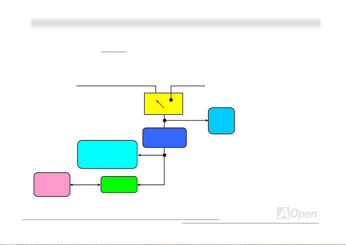
BBaatttteerryy--lleessss aanndd LLoonngg LLiiffee DDessiiggnn
This Motherboard implements Flash ROM and a special circuit that allows you to save your current CPU and CMOS Setup
configurations without using the battery. The RTC (real time clock) can also keep running as long as the power cord is plugged.
If you lose your CMOS data by accident, you can just reload the CMOS configurations from Flash ROM and the system will
recover as usual.
Flash
ROM
ATX Stand-by Power Battery
Auto Switch
RTC
(Real Time Clock)
00:00:00
CMOS
e
S817
Regulator
Backup by EEPROM
LPC
Super I/O
Auto switching to ATX standby
power as long as AC power
line is plugged. This smart
design can increases battery
life if you still had battery
plugged on motherboard.
54
Page 55
AAKK7799GG MMAAXX//AAKK7799DD MMAAXX OOnnlliinnee MMaannuuaall
CCPPUU OOvveerr--ccuurrrreenntt PPrrootteeccttiioonn
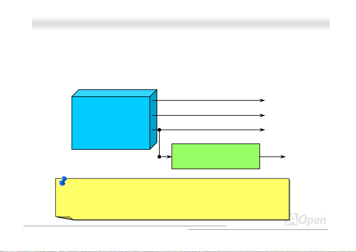
Over Current Protection has been popularly implemented on ATX 3.3V/5V/12V switching power supply for a while. However,
new generation CPU is able to use regulator of different voltages to transfer 12V to CPU voltage (for example, to 2.0V). This
motherboard is with switching regulator onboard that supports CPU over-current protection, and it applies to 3.3V/5V/12V power
supply for providing full line over-current protection.
ATX Switching Power Supply
Note: Although we have implemented protection circuit try to prevent any human operating
mistake, there is still certain risk that CPU, memory, HDD, add-on cards installed on this
motherboard may be damaged because of component failure, human operating error or unknown
nature reason. AOpen cannot guaranty the protection circuit will always work perfectly.
12V (Protected by power supply)
3.3V (Protected by power supply)
5V (Protected by power supply)
Onboard Power Regulator
(Over-Current Protection)
CPU Core Voltage
55
Page 56
AAKK7799GG MMAAXX//AAKK7
7
99DD MMAAXX
OOnnlliinnee MMaannuuaall
AAOOCCoonnffiigg UUttiilliittyy
hardware such as motherboard, CPU, memory, PCI devices and IDE devices. The powerful utility also displays the version of
BIOS and firmware for your convenience of maintenance.
Moreover, AOconfig allows users to save information in *.BMP or *.TXT format which users may collect the system information
in detail and send them to AOpen directly for technical support or further diagnosis of system problem.
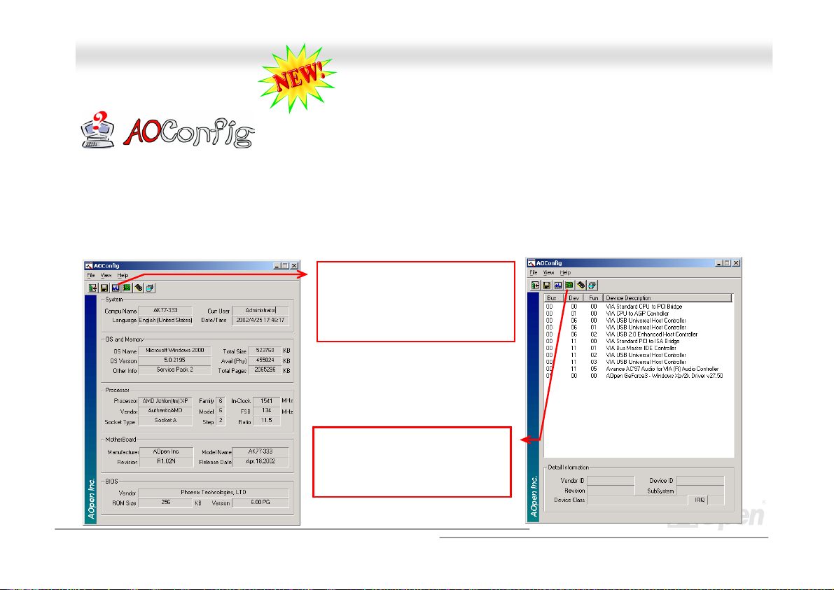
AOpen always dedicated to provide users a much friendlier computer environment. We now
bring you a comprehensive system detective utility. AOconfig is a Windows based utility with
user-friendly interface that allows users to obtain information of the operation system and
1. The system page shows the
detail information of the
motherboard, the operating
system, the processor, and
BIOS version.
2. The PCI device page shows
the configurations of all PCI
devices installed on your
motherboard.
56
Page 57
A
AAKK7799GG MMAAXX//AAKK7799DD MMAAXX OOnnlliinnee MMaannuuaall
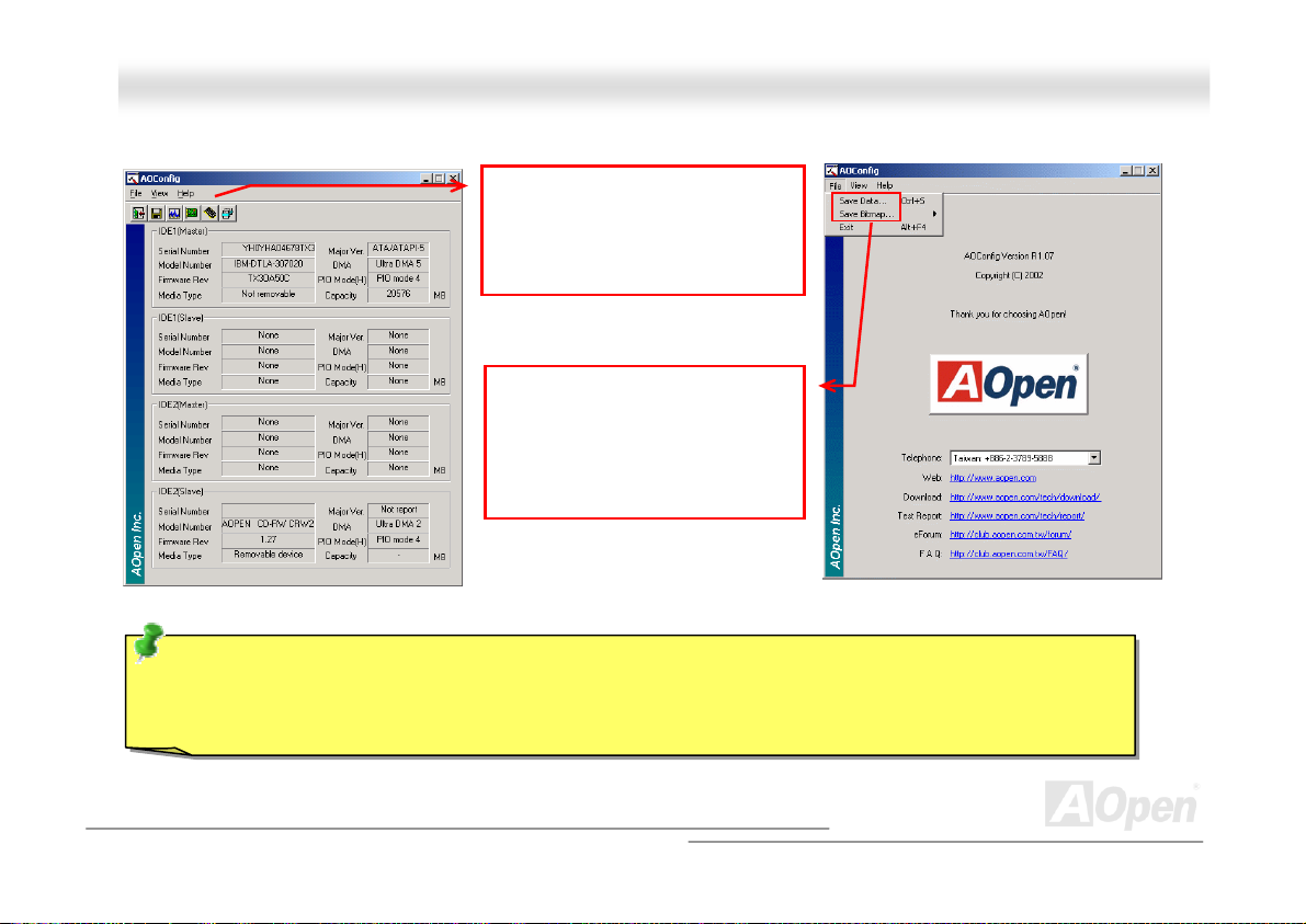
3. This page presents the IDE
devices information, such as
the serial number, the
manufacturer, the firmware
version, and capacity.
4. From this page, users may
obtain the technical support
information of AOpen.
Moreover, detailed information
could be saved in .bmp or .txt
format.
NOTE: AOconfig can be used in Windows 98SE/ME, NT4.0/2000 and Windows XP. Please be informed that
Oconfig can only be operated in a system equipped with an AOpen motherboard. Meanwhile, all applications must
be closed before starting AOconfig.
57
Page 58
AAKK7799GG MMAAXX//AAKK7799DD MMAAXX OOnnlliinnee MMaannuuaall
RReesseettaabbllee FFuussee
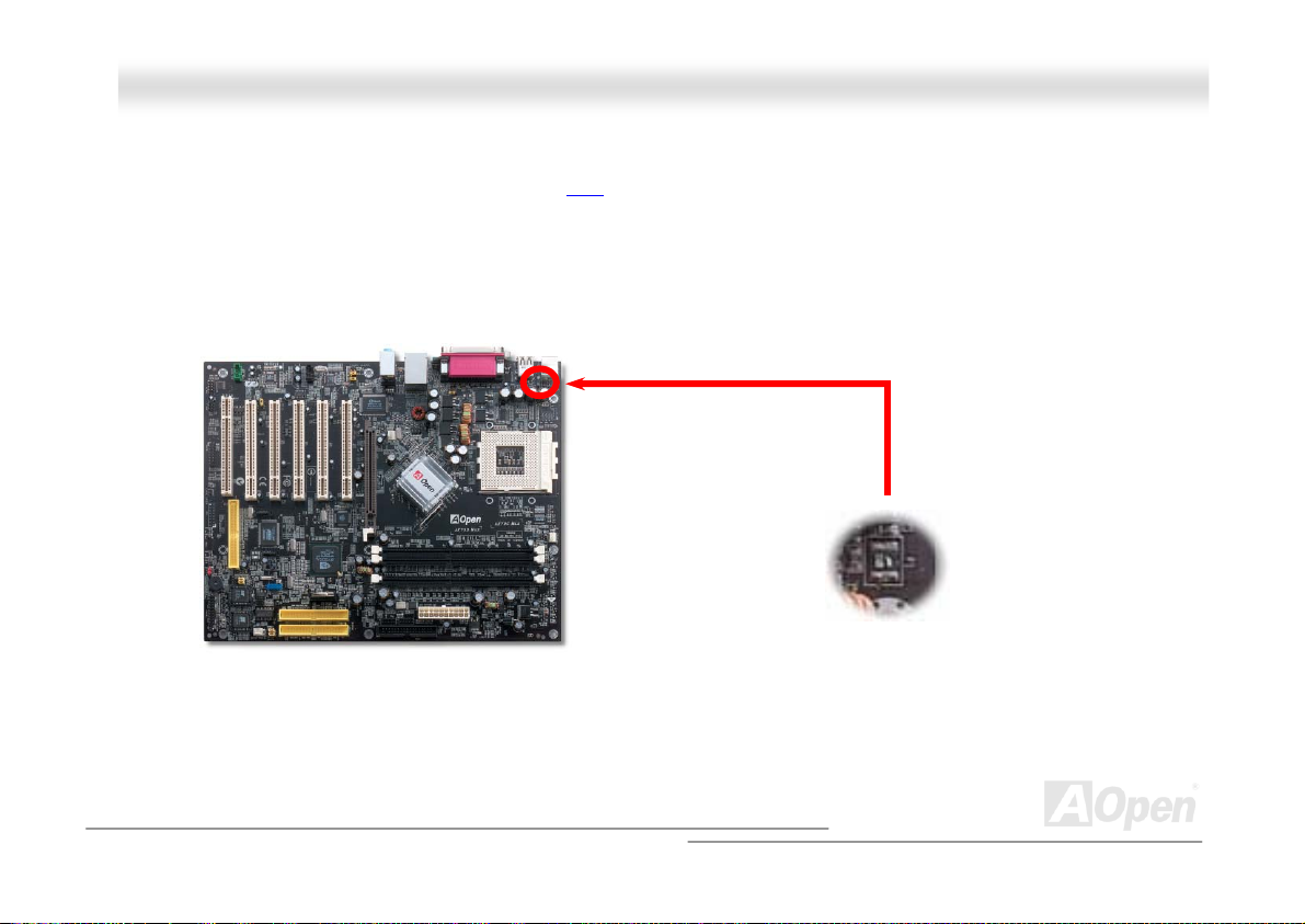
Traditional motherboard has fuse for Keyboard and USB port to prevent over-current or shortage. These fuses are soldered
onboard that user cannot replace it when it is damaged (did the job to protect motherboard), and the motherboard remains
malfunction.
With expensive Resetable Fuse, the motherboard can resume back to normal function after fuse had done its protection job.
58
Page 59
AAKK7799GG MMAAXX//AAKK7799DD MMAAXX OOnnlliinnee MMaannuuaall
0
μ
F
2222000
The quality of low ESR capacitor (Low Equivalent Series Resistance) during high frequency operation is very important for the
stability of CPU power. The idea of where to put these capacitors is another know-how that requires experience and detail
calculation.
Not only that, this motherboard implements 2200μF capacitor, which is much larger than normal capacitor (1000 or 1500μF)
and it provides better stability for CPU power.
μ
F
LLooww EESSRR CCaappaacciittoorr
59
Page 60
AAKK7799GG MMAAXX//AAKK7799DD MMAAXX OOnnlliinnee MMaannuuaall
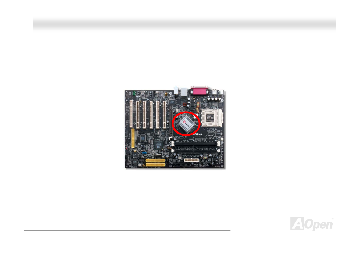
EEnnllaarrggeedd AAlluummiinnuumm HHeeaattssiinnkk
Cool down CPU and Chipset is important for system reliability. Enlarged aluminum heat sink provides better heat consumption
especially when you are trying to over clocking the CPU.
60
Page 61
AAKK7799GG MMAAXX//AAKK7799DD M
M
AAXX
OOnnlliinnee MMaannuuaall
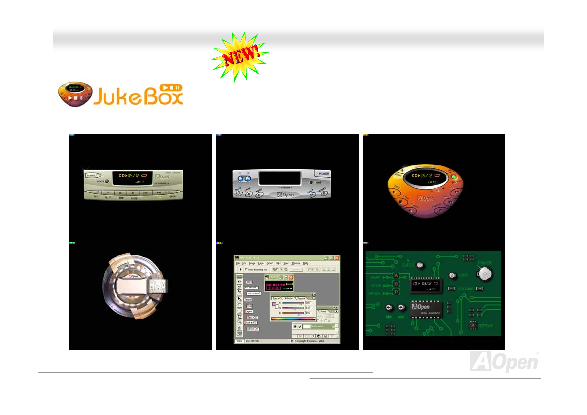
OOppeenn JJuukkeeBBooxx PPllaayyeerr
without any hassle of entering Windows operation system.
Here we are pleased to provide you a brand-new powerful interface—Open JukeBox.
Without any cost you can have your PC turn into a fashionable CD player! This latest Open
JukeBox motherboard aims at helping you directly operate your CD player on the PC
61
Page 62
play
A
AAKK7799GG MMAAXX//AAKK7799DD MMAAXX
OOnnlliinnee MMaannuuaall
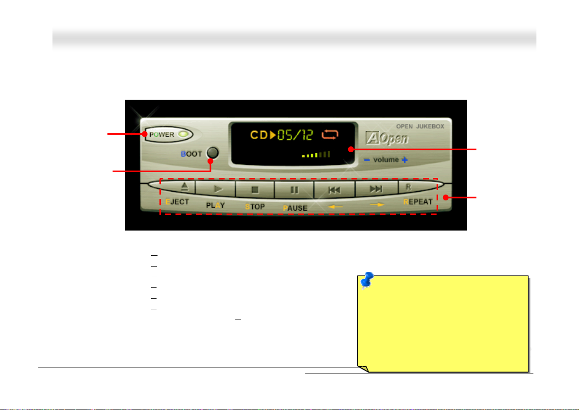
How Your Open JukeBox Works
The operation of Open JukeBox Player is the same as other CD players. By pressing specific keys on the keyboard you will find
playing Open JukeBox Player couldn’t be easier than the traditional CD Players. Below is the function description of respective
buttons.
Power-Off Button
Operation System
Boot to
Power: Pressing O
Boot: Pressing B
Play: Pressing A
Stop: Pressing S
Pause: Pressing P
Eject: Pressing E
Repeat: Like other CD Players, pressing R
Vol um e +/ -: Pressing + or – to adjust the volume of playing music.
Rewind/Forward Å / Æ: Pressing arrow keys, to rewind or forward the music.
, to directly power off your computer with no hassle of entering Windows Operation System.
, to intelligently boot to Windows Operation System for you.
, to start playing CD music.
, to stop the music playing.
, to pause the music playing temporarily.
, to eject CD tray for you to change CD disc.
, to shift the repeat mode.
62
Note: Though some of the latest
version of Windows support “Digital
udio” through IDE bus. However, in
order to use Open Jukebox player,
which is driven under BIOS, it is a
MUST to insert audio cable to CD-IN
connector on the motherboard.
Dis
Function Key
Screen
Page 63
AAKK7799GG MMAAXX//AAKK7799DD MMAAXX OOnnlliinnee MMaannuuaall
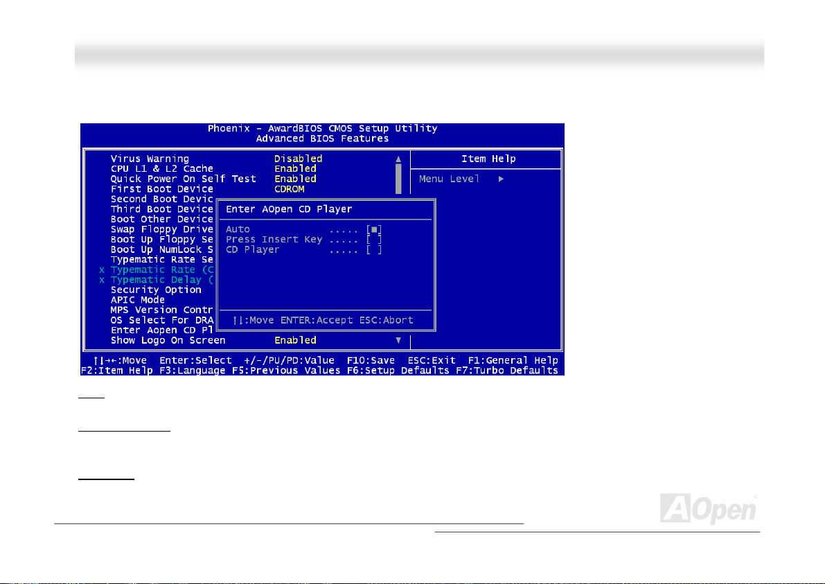
Your Open JukeBox Settings in BIOS
There are three Open JukeBox settings in BIOS as follows.
Auto
: The default setting is “Auto” with which the Open JukeBox will automatically check the CD player every time you power
on. The Open JukeBox will automatically be launched when it detects a music CD in your CD player.
Press Insert Key
you of pressing “Ins” key on your keyboard to start Open JukeBox Player; otherwise the system will launch the Windows
Operation System.
CD Player
pressing B on your keyboard the Windows Operation System will be launched.
: Choosing this setting will allow a reminder message popped up on the screen during BIOS POST. It reminds
: Choosing this setting allows the system to launch Open JukeBox Player every time you power on. However, by
63
Page 64
AAKK7799GG MMAAXX//AAKK7799DD MMAAXX OOnnlliinnee MMaannuuaall
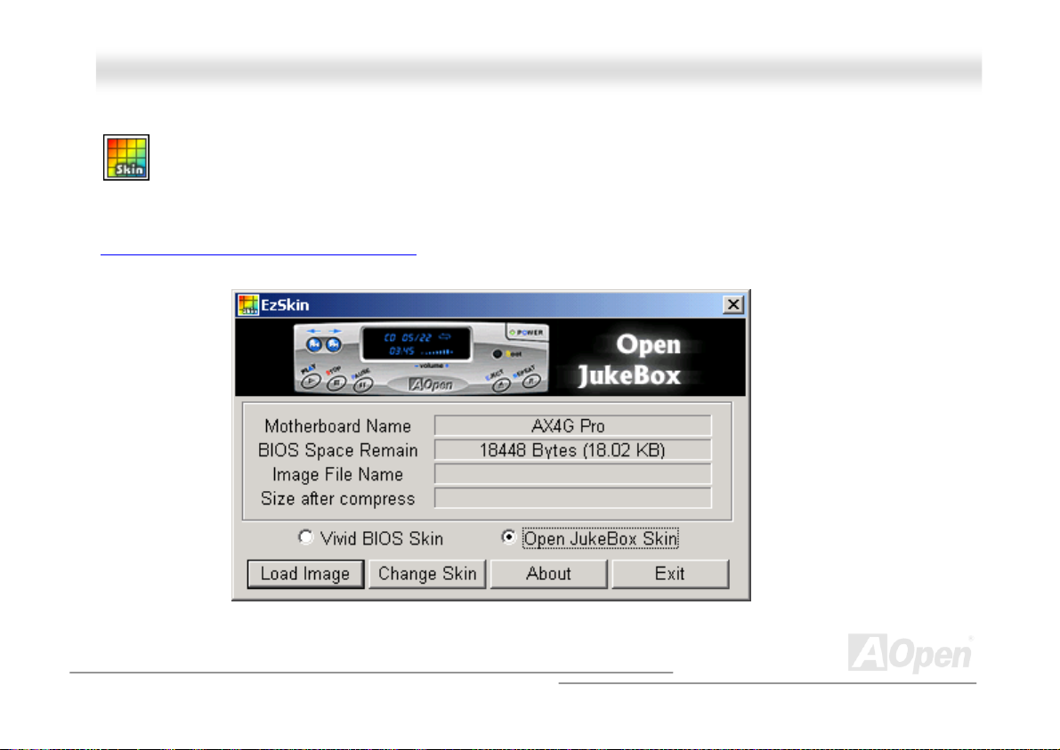
Your Open JukeBox EzSkin
Except these powerful functions above, Open JukeBox Player is also equipped with another fancy feature for you to
change its “skin”. You can download as many skins as you want from AOpen Website, and changing them whenever
you want by using this useful utility – EzSkin – which may also be downloaded from our website.
Even more, you may design your own skins with innovative idea and sharing them to users around the world by uploading to our
website. For further technical information, we welcome you to visit our website at
http://english.aopen.com.tw/tech/download/skin
64
Page 65

AAKK7799GG MMAAXX//AAKK7799DD M
M
AAXX
OOnnlliinnee MMaannuuaall
VViivviidd BBIIOOSS tteecchhnnoollooggyy
Unlike earlier graphic POST screen, which could occupy the whole screen and mask text information during POST, AOpen
VividBIOS deals with graphics and texts separately, and makes them running simultaneously during POST. With this innovative
design, VividBios now brings you a beautiful and sleek 256 colors screen without missing any important information shown on
POST screen.
In addition, the limited space of BIOS ROM is another big issue. When all of the traditional BIOS can only show
space-consuming and uncompressed Bitmap, AOpen has considerately tuned the BIOS to next generation, to recognize the
smaller-sized GIF format and even dynamic-showing GIF animation.
Vivid BIOS shares the same fundamental technology with Open JukeBox CD Player, you may use the same EzSkin utility to
change your Vivid BIOS screen or to download your favorite Open JukeBox skin. If you see this little logo
your model name on the BIOS download page, http://english.aopen.com.tw/tech/download/skin
motherboard supports this innovative feature!
Have you been fed up with the conservative and immutable POST screen? Let’s rule out
the tradition idea that POST screen are stiff and frigid, and let AOpen show you the newly
developed VividBIOS to experience the lively vivid colorful POST screen!
shown beside
, it is assured that your
65
Page 66
AAKK7799GG MMAAXX//AAKK7799DD MMAAXX OOnnlliinnee MMaannuuaall
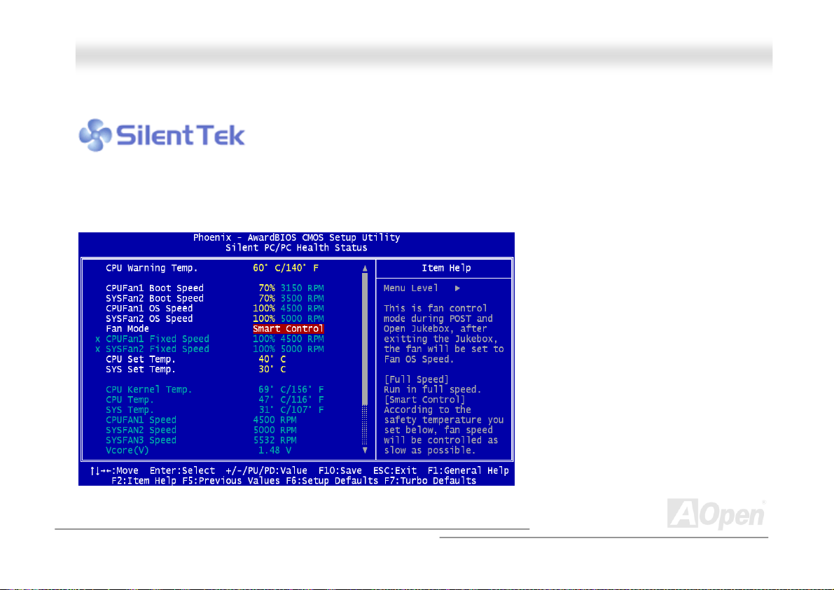
TThhee nnooiissee iiss ggoonnee!!!! -------- SSiilleennttTTeekk
As the clock of CPU keeps rocketing higher and higher, it inevitably brings higher heat and
system temperature in a relative way. The way we deal with this heat problem, however, is to
spare no effort to add one fan after another to protect our pampered system, expecting these
fans could cool down our machine as much as they could.
But at the same time, we believe that same users are affected terribly by the irritating noises of these fans while working with
their PC. As a matter of fact, we do not have to get our fans running at such a high speed in most cases; on the contrary, we
discovered that having your fans running
at appropriate time and speed not only
reduces the noise, but also consumes the
least power the system needs, so as to
prevent over-wasting of energy resource.
Today, AOpen Motherboard is honored to
bring you a new overall solution, SilentTek,
to make your system quiet. To collocate
with hardware circuit, BIOS and the utility
under Windows, SilentTek combined
“Hardware-Status Monitoring”, “Overheat
Warning” and “Fan Speed Control” with
user-friendly interfaces to provide you a
perfect balance among noises, system
performance and stability.
66
Page 67
AAKK7799GG MMAAXX//AAKK7799DD MMAAXX OOnnlliinnee MMaannuuaall
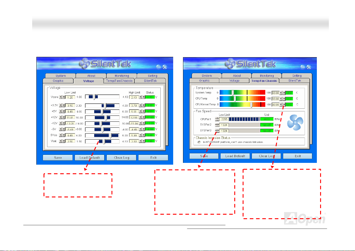
The first image you have here is the Voltage Status
page. You can find current status of all voltages and set
your expected margins of warning level.
You may check your
system voltage from the
indicating bar here.
In “Temp/Fan/Case” page, you may get aware of the
current temperature of CPU and the heat inside chassis.
Also, you can check if fans are running properly.
Of course, you may set your
defaulted lowest margin for
your fans and SilentTek would
also pop up a message box to
alarm you when the fan is
rotating slower than this
specified speed.
You may set the highest
margin of your CPU and
system temperature as
default, and SilentTek would
pop up a message box to alert
you with alarm when the
temperature goes beyond the
specified margin.
67
Page 68
AAKK7799GG MMAAXX//AAKK7799DD MMAAXX OOnnlliinnee MMaannuuaall
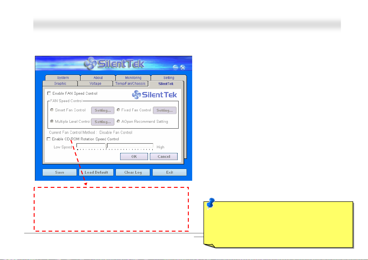
The following page is surely the most important part of this utility. You may control the rotation speed of specific fans that you
have got the options inside in this page.
1. Smart FAN Control: This is the default setting of
SilentTek and can be used for any branded computer
housing. With a special algorithm developed by
AOpen, the fan speed is automatically adjusted by
the factors of CPU and ambient temperature.
Ease-of-use and trouble free at your service.
2. Fixed FAN Control: Under this setting, a desired fan
speed is set fixed when operating.
3. Multiple Level Control: This is the most versatile
setting that allows you to set fan speed in relation to
temperature. You may find that this setting fits you
best.
4. AOpen Recommend Setting: This setting is
designed specifically for AOpen housing. A series of
lab tests were conducted under the real world
scenario to determine optimum fan speed to reduce
noise level within CPU working condition and
temperature. Most of the time, the fan would remain
CD-ROM Rotation Speed Control: by enabling the CD-ROM
Rotation Speed Control, you can adjust the rotation speed of
your CD-ROM. When you set the speed to high level, the
CD-ROM will work at its fastest speed and it will run at basic
required speed while you set the value to low speed.
68
still when CPU is not fully utilized.
Note: Due to hundreds different brands of fan on the
market, inaccuracy may happen in some cases when
you had your rotation speed adjusted. It is still under the
criterion and please rest assured that it won’t cause any
problem to your system.
Page 69
AAKK7799G
G
MMAAXX//AAKK7
7
99DD MMAAXX OOnnlliinnee MMaannuuaall
EEzzCClloocckk
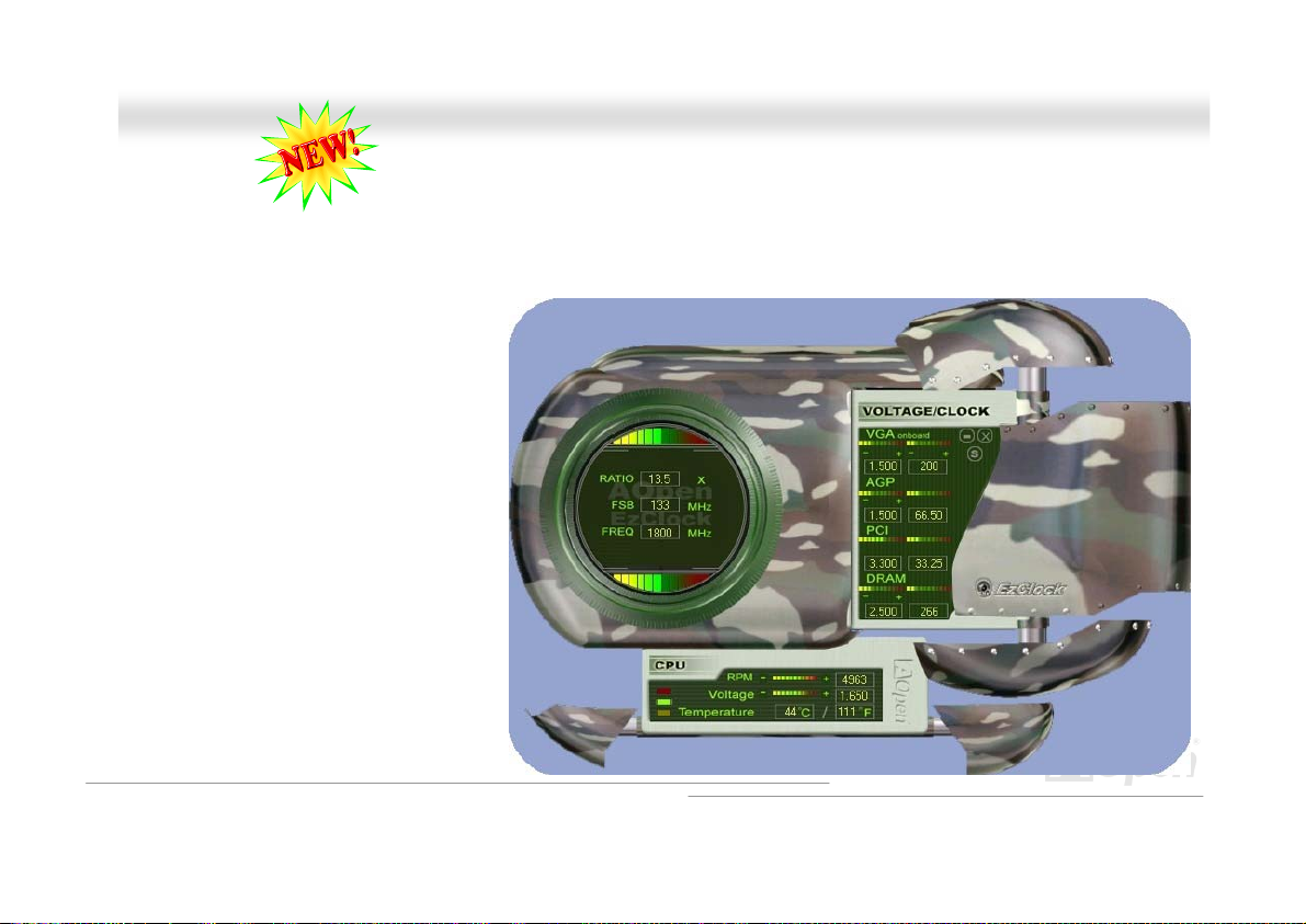
Have you ever thought how great it would be if you can adjust the frequency setting on your motherboard under Windows environment
and be a real master of your system? Everybody knows that the ratio and frequency setting are key factors to influence the system
performance, however, it’s absolutely not an easy task for an amateur to adjust the setting value. On most traditional motherboards, you
have to get into BIOS screen for the frequency
and reboot the system again and again. But
from now on, you don’t have to surfer the
boring stuffs anymore.
With brand-new and user-friendly EzClock that
AOpen specially designs for his users, you can
adjust those important values as you please
and think of suitable. This tailor-made EzClock
allows you to set the voltage and frequency of
CPU, VGA, PCI and memory under Windows
environment as well as in BIOS setting page;
even better, those settings will be displayed
realtime. Having this handy EzClock, you can
monitor the system when you’re fine-tuning the
performance of your system. It provides you
detailed and necessary information. Now let’s
take a look how it works on utility, BIOS and
POST.
69
Page 70
AAKK7799GG MMAAXX//AAKK7799DD MMAAXX OOnnlliinnee MMaannuuaall
How You Adjust the Settings in EzClock Utility
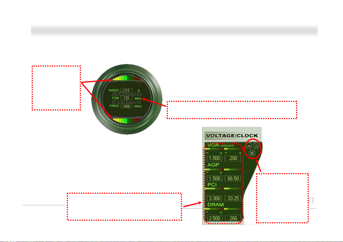
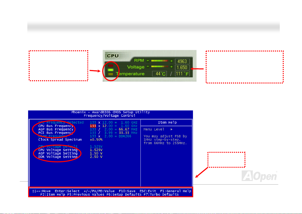
In EzClock utility, you can adjust CPU Front Side Bus (FSB), the voltage and frequency of VGA, AGP, PCI and DRAM. Besides, the
CPU related information such as CPU voltage, temperature and CPUFAN rotation speed will also be displayed on this utility.
CPU Color Bars:
The color bar will
light on and show
different colors as
values change. On
default values, it
will show green.
On the right part of the panel is the section that you adjust the settings of
VGA, AGP, PCI and memory. To adjust the voltage and clock frequency of
those installments, you can press “-“ or “+” on corresponding items. The
color parts represent the situation of values. The higher value you set, the
light on the color bar goes to right and turns red. After finishing those value
settings, you can press “S” button on the upper right hand corner to save
changes to CMOS.
VGA, AGP, PCI and DRAM Voltage / Clock Area:
Pressing “_” and “+” buttons, you can adjust the
voltage and clock frequency values of onboard
VGA, AGP, PCI and DRAM.
On the left circle area shows Ratio, FSB and frequency information
about CPU. When the values are set to factory default, the light on
the top and bottom of the circle will show green and it will vary as you
change these CPU settings.
CPU Ratio, FSB and frequency displaying area:
You can adjust CPU FSB here by entering preferred value.
70
Control buttons:
“_” button allows
you to minimize the
utility and “X” button
to close the utility.
Pressing “S” button
you can save the
changes to CMOS.
Page 71
p
AAKK7799GG MMAAXX//AAKK7799DD MMAAXX OOnnlliinnee MMaannuuaall
On the bottom rectangular panel represents CPU fan speed, CPU voltage and CPU temperature. The three color bars on the right hand
side will light on according to operation temperature. Please refer to the picture shown above.
CPU Color Bars:
The color bars will light on
according to CPU operation
erature.
tem
CPU Fan, Voltage and Temperature:
representing CPU fan speed, CPU
voltage and CPU temperature in
Celsius and Fahrenheit degrees.
How You Adjust the Settings in BIOS
Apart from EzClock utility, the voltage and frequency values of CPU, PCI and memory can also be adjusted on BIOS page. By pressing
“+”, “-“, “PgUp” or “PgDn” keys, you can adjust the frequency values of CPU Bus, PCI Bus and DRAM.
Also, the same keys help you adjust the
voltage of CPU and DDR settings. Some
values may change while you adjust the
settings. You can press “F10” to save the
changes you’ve made.
Function Keys
Description
71
Page 72
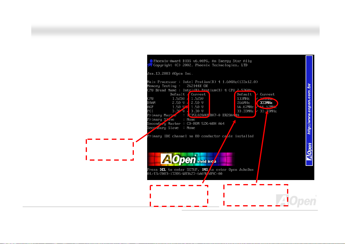
AAKK7799GG MMAAXX//AAKK7799DD MMAAXX OOnnlliinnee MMaannuuaall
How Your Boot Screen Looks Like
After you finish setting BIOS, these setting values will
be displayed on the boot screen like the shown
picture here.
Every time you boot your system, both default and
current settings will pop up on the screen. Your
personal settings that had been adjusted earlier will
be highlighted; thus, you can have clear idea how
your system functions and monitor your system more
easily.
Current values of
your system
Default settings of this
motherboard
72
The highlighted setting
value you manually adjust
Page 73
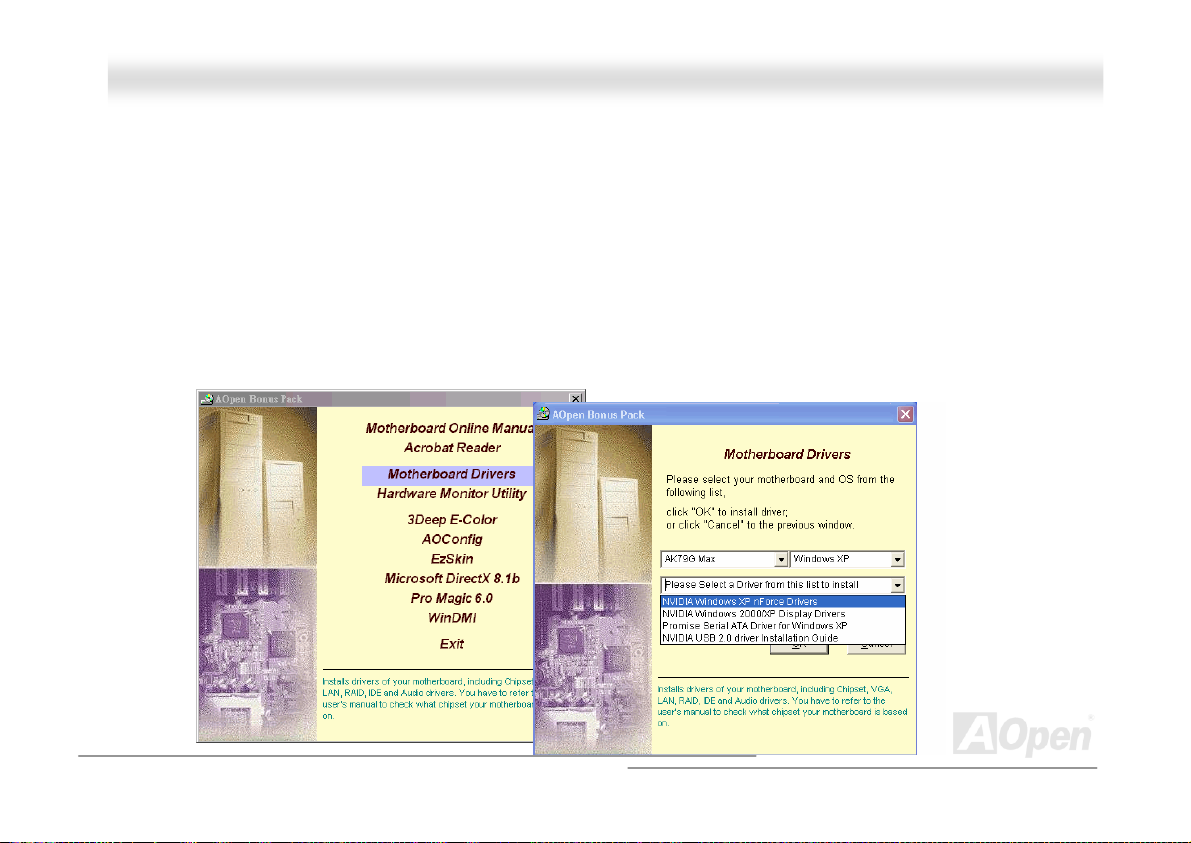
AAKK7799GG MMAAXX//AAKK7799DD MMAAXX OOnnlliinnee MMaannuuaall
DDrriivveerr aanndd UUttiilliittyy
There are motherboard drivers and utilities included in AOpen Bonus CD. You don’t need to install all of them in order to boot
your system. But after you finish the hardware installation, you have to install your operation system first (such as Windows
2000/XP) before you can install any drivers or utilities. Please refer to your operation system’s installation guide.
AAuuttoo--rruunn MMeennuu ffrroomm BBoonnuuss CCDD
You can use the auto-run menu of Bonus CD. Choose the utility and driver and select model name.
73
Page 74
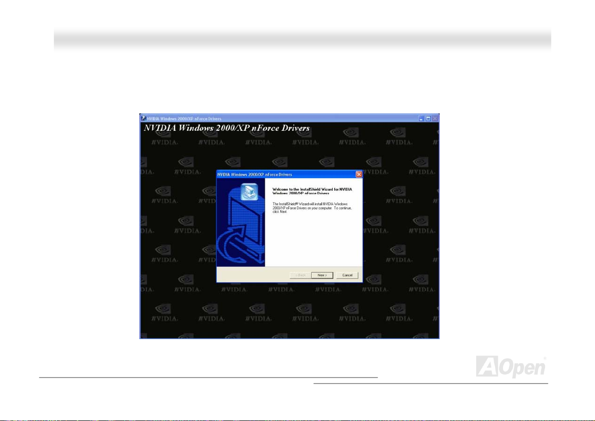
AAKK7799GG MMAAXX//AAKK7799DD MMAAXX OOnnlliinnee MMaannuuaall
rs
nnVVIIDDIIAA nnFFoorrccee DDrriivveer
This nForce driver is an all in one package, which contains the below components:
GPU driver, Audio driver, Audio utilities, Network driver, GART driver, SMBus driver, Memory controller driver
s
74
Page 75
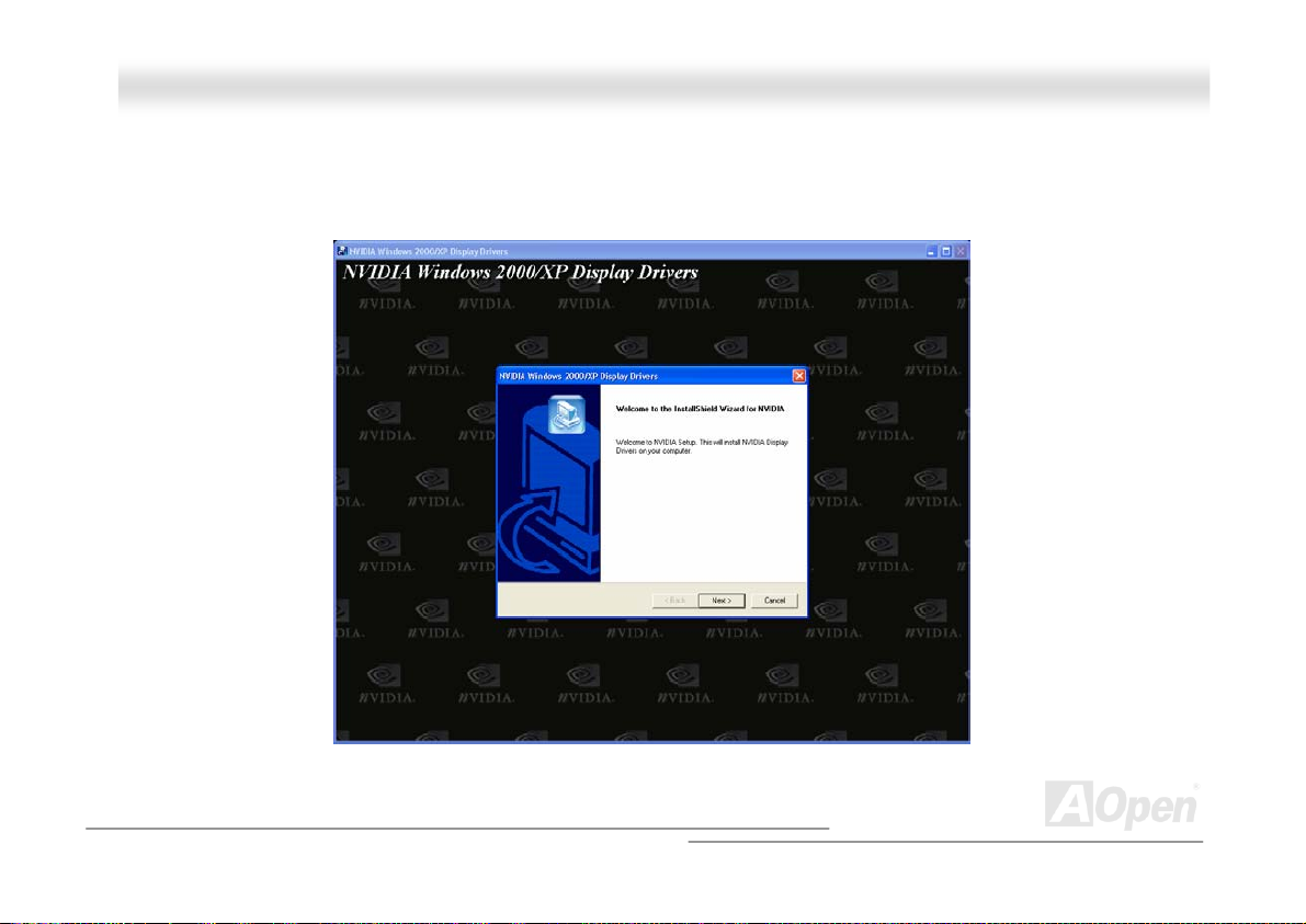
AAKK7799GG MMAAXX//AAKK7799D
D
MMAAXX OOnnlliinnee MMaannuuaall
NNVVIIDDIIAA WWiinnddoowwss 9988//MMEE//22000000//XXPP DDiissppllaayy DDrriivveerr
For Display Driver of 98/ME/2000/XP, please use this driver for installation
75
Page 76

AAKK7799GG MMAAXX//AAKK7799DD MMAAXX OOnnlliinnee MMaannuuaall
IInnssttaalllliinngg PPrroommiissee SSAATTAA115500 DDrriivveerr iinn EExxiissttiinngg WWiinnddoowwss
XXPP//22000000//MMEE//9988//NNTT44..00 SSyysstteemm
Windows XP Installation Guide
******************************************************
Installing Driver in Existing Windows XP System
******************************************************
WARNING: If you will be moving the boot drive containing the existing Windows XP operating system to the SATA150 connector,
the SATA150 driver MUST be loaded on to this hard drive while it is still attached to your existing hard drive
controller. Do not attach this drive or any other hard drive to the SATA150 controller before completing this step.
After enabling the SATA150, Windows XP setup will show a "Found New Hardware" dialog box. Under Windows XP, "Mass
Storage Controller" will be displayed.
1. Click on "Next," and from the generated list box, choose "Install from a list or special location (Advanced)"
2. Click on "Next," and from the generated choices, choose "Include this location in the search:"
3. Insert the Promise SATA150 driver diskette into drive A:.
4. Type "A:\" in the text box that appears. Press "OK ".
3a. Insert the Bonus CD in CD-ROM.
4a. Type "[CD-ROM]:\Driver\Promise\SATA150\Driver\WinXP" in the text box that appears. Press "OK ".
76
Page 77

AAKK7799GG MMAAXX//AAKK7799DD MMAAXX OOnnlliinnee MMaannuuaall
5. Click on "Next." A message informing you that Windows XP has found "WinXP Promise SATA TX2plus (tm) IDE Controller"
should appear.
6. When the New Hardware Wizard has finished installing the Promise SATA150 software, click on "Finish"
*****************************************
Confirming Windows XP Installation
*****************************************
1. From Windows XP, open the Control Panel from "My Computer".
2. Click on "Performance and maintenance".
3. Click on the "System" icon.
4. Choose the "Hardware" tab, and then click the "Device Manager" tab.
5. Click the "+" in front of "SCSI controllers". "WinXP Promise SATA TX2plus (tm) IDE Controller" should appear.
77
Page 78

AAKK7799GG MMAAXX//AAKK7799DD MMAAXX OOnnlliinnee MMaannuuaall
Windows 2000 Installation Guide
**************************************************************
Installing Driver During New Windows 2000 Installation
**************************************************************
1. Start the installation:
a. Floppy Install: Boot the computer with the Windows 2000 installation diskettes.
b. Floppyless Install: Boot from floppy and type "WINNT". After files have been copied, the system will reboot. On the reboot,
press <F6> after the message "Setup is inspecting your computer's hardware configuration..." appears.
c. CD-ROM Install: Boot from the CD-ROM. Press <F6> after the message "Press F6 if you need to install third party SCSI or
RAID driver" appears.
2. When the "Windows 2000 Setup" window is generated, press "S" to Specify an Additional Device(s)
3. Insert the Promise SATA150 driver diskette into drive A: and press "Enter" key.
4. Use "↑" or "↓" to choose "Win2000 Promise SATA TX2plus (tm) IDE Controller" from the list that appears on screen, and
then press the "Enter" key.
5. The Windows 2000 Setup screen will appear again saying "Setup will load support for the following mass storage devices:"
The list will include "Win2000 Promise SATA TX2plus (tm) IDE Controller".
78
Page 79

AAKK7799GG MMAAXX//AAKK7799DD MMAAXX OOnnlliinnee MMaannuuaall
NOTE: If you need to specify any additional devices to be installed, do so at this time. Once all devices are specified, continue
to the next step -
6. From the Windows 2000 Setup screen, press the Enter key. Setup will now load all device files and then continue the
Windows 2000 installation.
*********************************************************
Installing Driver in Existing Windows 2000 System
*********************************************************
WARNING: If you will be moving the boot drive containing the existing Windows 2000 operating system to the SATA150
connector, the SATA150 driver MUST be loaded on to this hard drive while it is still attached to your existing hard
drive controller. Do not attach this drive or any other hard drive to the SATA150 connector before completing this
step.
After enabling the SATA150 IDE controller and rebooting your system, Windows 2000 setup will show a "New Hardware Found"
dialog box. Under Windows 2000, "PCI Mass Storage Controller" will be displayed.
1. Choose "Search for a suitable driver for my device (Recommended)". from the list, and then press "Enter".
2. Choose "Specify a location." and then press "Next"
3. Choose "Mass Storage controller" and press "next" and next screen press "finish"
79
Page 80

AAKK7799GG MMAAXX//AAKK7799DD MMAAXX OOnnlliinnee MMaannuuaall
4. Insert the Promise SATA150 driver diskette into drive A:.
5. Type "A:\" in the text box that appears. Press " OK ".
4a. Insert the Bonus CD in CD-ROM.
5a. Type "[CD-ROM]:\Driver\Promise\SATA150\Driver\Win2000" in the text box that appears. Press "OK ".
6. Click on "Next." A message informing you that Windows has found "Win2000 Promise SATA TX2plus (tm) IDE Controller"
should appear.
7. Click on "Next," and then on "Finish."
*******************************************
Confirming Windows 2000 Installation
*******************************************
1. From Windows 2000, open the Control Panel from "My Computer" followed by the System icon.
2. Choose the "Hardware" tab, and then click the "Device Manager" tab.
3. Click the "+" in front of "SCSI controllers". "Win2000 Promise SATA TX2plus (tm) IDE Controller" should appear.
80
Page 81

AAKK7799GG MMAAXX//AAKK7799DD MMAAXX OOnnlliinnee MMaannuuaall
*******************************************************
Installing Drivers During Windows Me Installation
*******************************************************
The following details the installation of the Serial ATA drivers while installing Windows Me (with the Serial ATA controller is
enabled already).
1. Install Windows Me fully.
2. After installation, go the "Start" menu and choose "Settings."
3. From the "Settings" menu, choose "Control Panel."
4. In the "Control Panel" window, double-click on the "System" icon.
5. In the "System" window, choose the "Device Manager" tab.
6. In the hierarchical display under "Other Devices" is a listing for "PCI Mass Storage Controller." Choose it and then press the
"Properties" button.
7. Choose "Reinstall Driver," and then press "Next."
8. Choose "Specify the location of the driver (Advanced)," then press "Next".
9. Insert the Promise SATA150 driver diskette into drive A:
10. Choose "Specify a Location," and then type "A:\"
9a. Insert the "Bonus CD" in CD-ROM.
10a. Choose "Specify a Location," and then type "[CD-ROM]:\Driver\Promise\SATA150\Driver\Win98-Me" in the text
81
Page 82

AAKK7799GG MMAAXX//AAKK7799DD MMAAXX OOnnlliinnee MMaannuuaall
box.
11. Press the "Next" button. A message informing you that Windows Me has found "Win98-ME Promise SATA150 TX2plus(tm)
IDE Controller" should appear.
12. Press "Next," then "Finish".
**************************************************
Confirming Driver Installation in Windows Me
**************************************************
To confirm that the driver has been properly loaded in Windows Me, perform the following steps:
1. Choose "Settings" from the "Start" menu.
2. Choose "Control Panel," and then double-click on the "System" icon.
3. Choose the "Device Manager" tab, and then click the "+" in front of "SCSI & RAID controllers".
"Win98-ME Promise SATT150 TX2plus(tm) IDE Controller" should appear.
82
Page 83

AAKK7799GG MMAAXX//AAKK7799DD MMAAXX OOnnlliinnee MMaannuuaall
***********************************************************
Installing Drivers During Windows 98 SE Installation
***********************************************************
The following details the installation of the Serial ATA drivers while installing Windows 98 SE (with the SATA controller is
enabled already).
1. After enabling the Serial ATA controller and configuring the hard drive(s), partition and format your hard drive(s), if necessary.
2. Install Windows 98 SE normally.
3. After installation, go the "Start" menu and choose "Settings."
4. From the "Settings" menu, choose "Control Panel."
5. In the "Control Panel" window, double-click on the "System" icon.
6. In the "System" window, choose the "Device Manager" tab.
7. In the hierarchical display under "Other Devices" is a listing for "PCI Mass Storage Controller." Choose it and then press the
"Properties" button.
8. Choose "Reinstall Driver," and then press "Next."
9. Choose "Search for a better driver than the one your device is using now (recommended)," then press "Next."
10. Insert the Promise SATA150 driver diskette into drive A:.
11. Choose "Specify a Location," and then type "A:\"
83
Page 84

AAKK7799GG MMAAXX//AAKK7799DD MMAAXX OOnnlliinnee MMaannuuaall
10a. Insert the "Bonus CD" in CD-ROM.
11a. Choose "Specify a Location," and then type"[CD-ROM]:\Driver\Promise\SATA150\Driver\Win98-Me" in the text box.
12. Press the "Next" button. A message informing you that Windows has found "Win98-ME Promise SATA150 TX2plus(tm) IDE
Controller" should appear.
13. Press "Next," then "Finish".
***************************************************
Confirming Driver Installation in Windows 98
***************************************************
To confirm that the driver has been properly loaded in Windows 98, perform the following steps:
1. Choose "Settings" from the "Start" menu.
2. Choose "Control Panel," and then double-click on the "System" icon.
3. Choose the "Device Manager" tab, and then click the "+" in front of "SCSI controllers." "Win98-ME Promise SATA150
TX2plus(tm) IDE Controller" should appear.
84
Page 85

AAKK7799GG MMAAXX//AAKK7799DD MMAAXX OOnnlliinnee MMaannuuaall
Windows NT 4.x Installation Guide
*****************************************************************
Installing Drivers During New Windows NT 4.0 Installation
*****************************************************************
1. Start the system installation by booting from the Windows NT disk:
a. Floppy install: boot the system with the Windows NT installation diskettes.
b. Floppyless install: boot from floppy and type "WINNT /B". After files have been copied, the system will reboot. On the
reboot, press the "F6" key when the message "Setup is inspecting your computer's hardware configuration…" appears.
c. CD-ROM disk install: boot from the CD-ROM disk and press the "F6" key when the message "Setup is inspecting your
computer's hardware configuration…" appears.
2. When the "Windows NT Setup" window is generated, press "S" to specify an Additional Device(s).
3. Use "↑" or "↓" to select "Other" and press the "Enter" key.
4. Insert the driver diskette into drive A: and press the "Enter" key.
5. Choose "WinNT Promise SATA TX2plus (tm) IDE Controller" from the list that appears on screen, and then press the "Enter"
key.
6. The Windows NT Setup screen will appear again saying, "Setup will load support for the following mass storage devices:" The
list will include "WinNT Promise SATA TX2plus (tm) IDE Controller".
85
Page 86

AAKK7799GG MMAAXX//AAKK7799DD MMAAXX OOnnlliinnee MMaannuuaall
NOTE: If you need to specify any additional devices to be installed, do so at this time. Once all devices are specified, continue
to the next step.
7. From the Windows NT Setup screen, press the Enter key. Setup will now load all device files and then continue the Windows
NT installation.
8. After a successful installation, the "SCSI Adapter Setup" box will show that the "WinNT Promise SATA TX2plus (tm) IDE
Controller" driver has been installed.
*****************************************************
Installing Drivers with Existing Windows NT 4.0
*****************************************************
WARNING: If you wish to use your current bootable drive with the Windows NT4 operating system on the SATA150, perform the
steps below while the boot drive is still attached to your existing onboard IDE controller. Do not attach any drives to
your SATA150 until the steps below are complete.
1. Choose "Settings" from the "Start" menu.
2. Choose "Control Panel" from the "Settings" menu.
3. Double-click on the "SCSI Adapters" icon, which generates the "SCSI Adapters" dialog box.
4. Choose "Drivers," and then press "Add."
86
Page 87

AAKK7799GG MMAAXX//AAKK7799DD MMAAXX OOnnlliinnee MMaannuuaall
5. In the "Install Drivers" dialog box, press "Have Disk…"
6. When the "Install From Disk" appears, Insert the driver diskette into drive A:, then choose "OK."
7. When the "Install Driver" dialog box appears, select "WinNT Promise SATA TX2plus (tm) IDE Controller" and then press "OK".
8. When the "Select SCSI Adapter Option" dialog box appears, press "Install."
9. After a successful installation, the "SCSI Adapter Setup" box will show that the "WinNT Promise SATA TX2plus (tm) IDE
Controller" driver has been installed.
10. Power off your system, and then attach your hard drive(s) to the SATA150 controller.
87
Page 88

AAKK7799GG MMAAXX//AAKK7799DD MMAAXX OOnnlliinnee MMaannuuaall
IInnssttaalllliinngg UUSSBB22..00 DDrriivveerr iinn EExxiissttiinngg WWiinnddoowwss XXPP SSyysstteemm
* Windows XP Installation Guide
NOTICE:
If you have install Windows XP Service Pack1 , it is not necessary to install USB 2.0 driver.
Because USB2.0 driver was packaged in Service Pack1
*******************************************************
Installing Driver in Existing Windows XP System
*******************************************************
Please follow these directions for a smooth installation of the USB 2.0 package.
After enabling the USB 2.0, Windows XP setup will show a "Found New Hardware" dialog box. Under Windows XP, "Universal
Serial Bus (USB) Controller" will be displayed.
1. Click on "Next," and from the generated list box, choose "Install from a list or special location (Advanced)", click "Next"
2. Click on "Next," and from the generated choices, choose "Include this location in the search:"
3. Insert the Bonus CD in CD-ROM.
4. Type "[CD-ROM]:\Driver\Nvidia\USB2.0\WinXP" in the text box that appears.
5. Click on "Next." A message informing you that Windows XP has found "NVIDIA PCI to USB Enhanced Host Controller W/
Filter FPGA (3616)" should appear.
6. When the New Hardware Wizard has finished installing the USB driver, click on "Finish"
88
Page 89
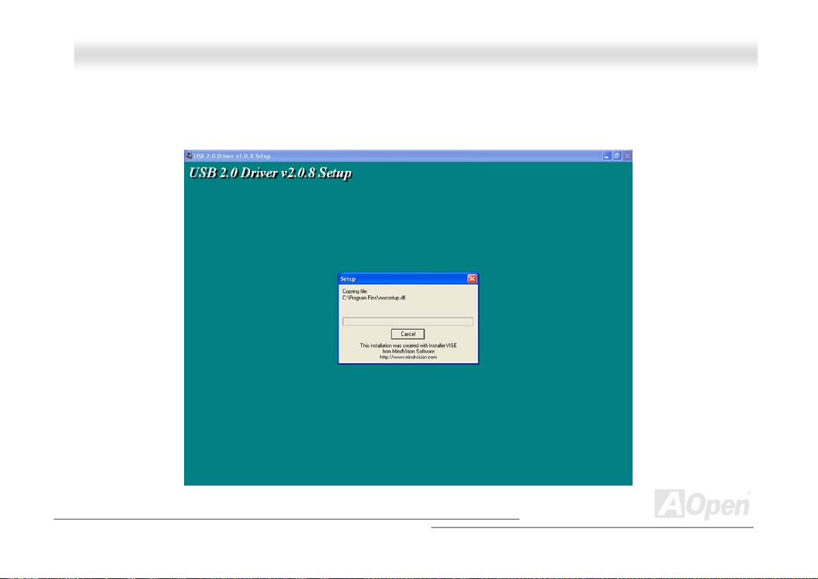
AAKK7799GG MMAAXX//AAKK7799DD M
M
AAXX OOnnlliinnee MMaannuuaall
IInnssttaalllliinngg UUSSBB 22..00 DDrriivveerr iinn EExxiissttiinngg WWiinnddoowwss 9988//MMEE//22000000 SSyysstteemm
For USB 2.0 driver for Windows 98/ME/2000, please use this driver for installation
89
Page 90
AAKK7799GG MMAAXX//AAKK7799DD MMAAXX OOnnlliinnee MMaannuuaall
PPhhooeenniixx AAwwaarrdd BBIIOOSS
System parameters can be modified by going into BIOS Setup menu, this menu allows you to configure the system parameters
and save the configuration into the 128 bytes CMOS area, (normally in the RTC chip or in the main chipset).
The Phoenix AwardBIOS™ that installed in the Flash ROM
The BIOS provides critical low-level support for standard devices such as hard disk drives, serial and parallel ports.
Most BIOS setting of this model had been optimized by AOpen’s R&D engineering team. But, the default setting of BIOS still
can’t fine-tune the chipset controlling the entire system. Hence, the rest of this chapter is intended to guide you through the
process of configuring your system using setup procedures.
To enter to BIOS setup menu
, press <Del> when POST (Power-On Self Test) screen is shown on your monitor.
Note: Because the BIOS code is the most often
changed part of the motherboard design, the BIOS
information contained in this manual may be
different with actual BIOS that come with your
motherboard.
of the motherboard is a custom version of an industry standard BIOS.
90
Page 91
AAKK7799GG MMAAXX//AAKK7799DD MMAAXX OOnnlliinnee MMaannuuaall
HHooww TToo UUssee PPhhooeenniixx AAwwaarrdd™™ BBIIOOSS SSeettuupp PPrrooggrraamm
Generally, you can use the arrow keys to highlight items that you want to choose, then press <Enter> key to select, and use the
<Page Up> and <Page Down> key to change setting value. You also can press <F1> key for help and press <Esc> key to quit
Phoenix Award™ BIOS setup program. The following table provides details about how to use keyboard in the Phoenix Award
BIOS setup program. By the way, all products of AOpen also provides a special function in the BIOS setup, you can press <F3>
key selecting preferred menu language to display.
Key Description
Page Up or + Changing setting to next value or increase the value.
Page Down or - Changing setting to previous value or decrease value.
Enter Select the item.
Esc 1. In main menu: Quit and don’t save any change.
2. In sub menu: Exit current menu to main menu.
Up Arrow Highlight previous item.
Down Arrow Highlight next item.
Left Arrow Move the light bar to left side of menu.
Right Arrow Move the light bar to right side of menu.
F1 Get menu or item help description.
F3 Changing menu language.
F5 Load previous setting value from CMOS.
91
Page 92
AAKK7799GG MMAAXX//AAKK7799DD MMAAXX OOnnlliinnee MMaannuuaall
Key Description
F6 Load Setup Defaults setting value from CMOS.
F7 Load turbo setting value from CMOS.
F10 Save changed setting and exit setup program.
92
Page 93
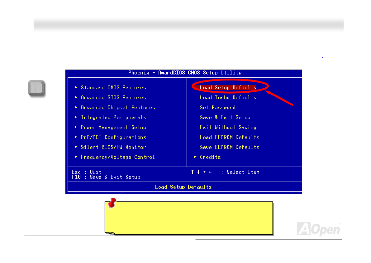
AAKK7799GG MMAAXX//AAKK7799DD MMAAXX OOnnlliinnee MMaannuuaall
HHooww TToo EEnntteerr BBIIOOSS SSeettuupp
After you finish the setting of jumpers and connect correct cables. Power on and enter the BIOS Setup, press <Del> during
POST (Power-On Self Test). Choose "Load Setup Defaults" for recommended optimal performance.
Del
Warning: Please avoid of using "Load Turbo Defaults", unless
you are sure your system components (CPU, SDRAM, HDD,
etc.) are good enough for turbo setting.
93
Page 94
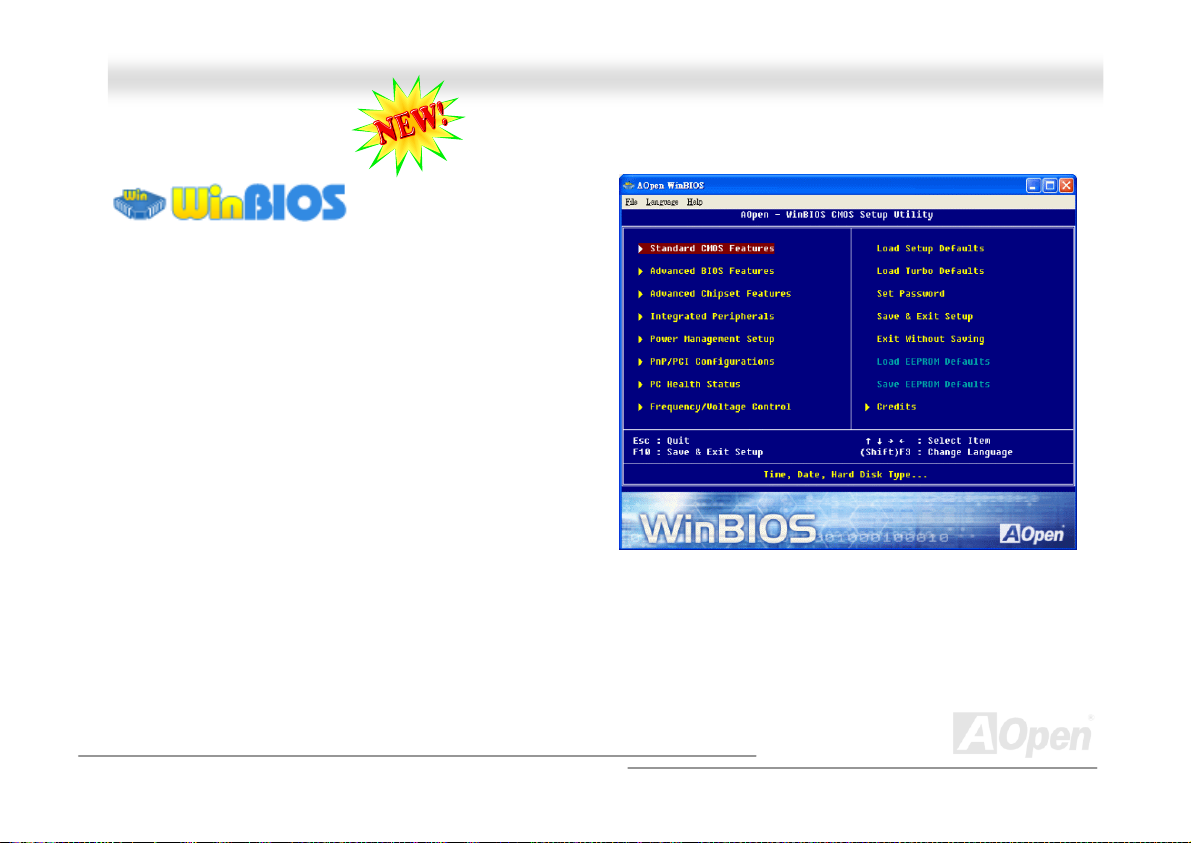
AAKK7799GG MMAAXX//AAK
K
7799DD MMAAX
X
OOnnlliinnee MMaannuuaall
WWiinnBBIIOOSS UUttiilliittyy
(Power-On-Self-Test) screen to get into the BIOS, which is
inconvenient and clumsy. From now on, AOpen provides an
easier way to configure your BIOS. WinBIOS is a customized
utility for running exclusively on AOpen motherboards, which
allows you to setup your BIOS under Windows environment.
Designed with traditional-BIOS-alike interface, you may adjust
BIOS parameter with clear descriptions for each item.
WinBIOS is natively designed with multi-language support. There
are various widely-use languages provided on our website for
your downloading, which also helps to prevent wrong settings
caused by misunderstanding of the languages. The only thing
you have to do is to visit our official website and download your
respective language pack (of few KB size), then double-click on it to activate the support with your chosen language.
Moreover, with high scalability, either for newly bought motherboard or the latest BIOS version with new function, you don’t have
to re-install the whole program again and again. All you have to do is to grab the latest profile from our website, simply
double-click on it as well to support the latest version of your BIOS. You don’t have to spend any extra effort to have your
motherboard supported by WinBIOS.
In the past, users have to keep
punching the DEL key at a
good timing during POST
94
Page 95
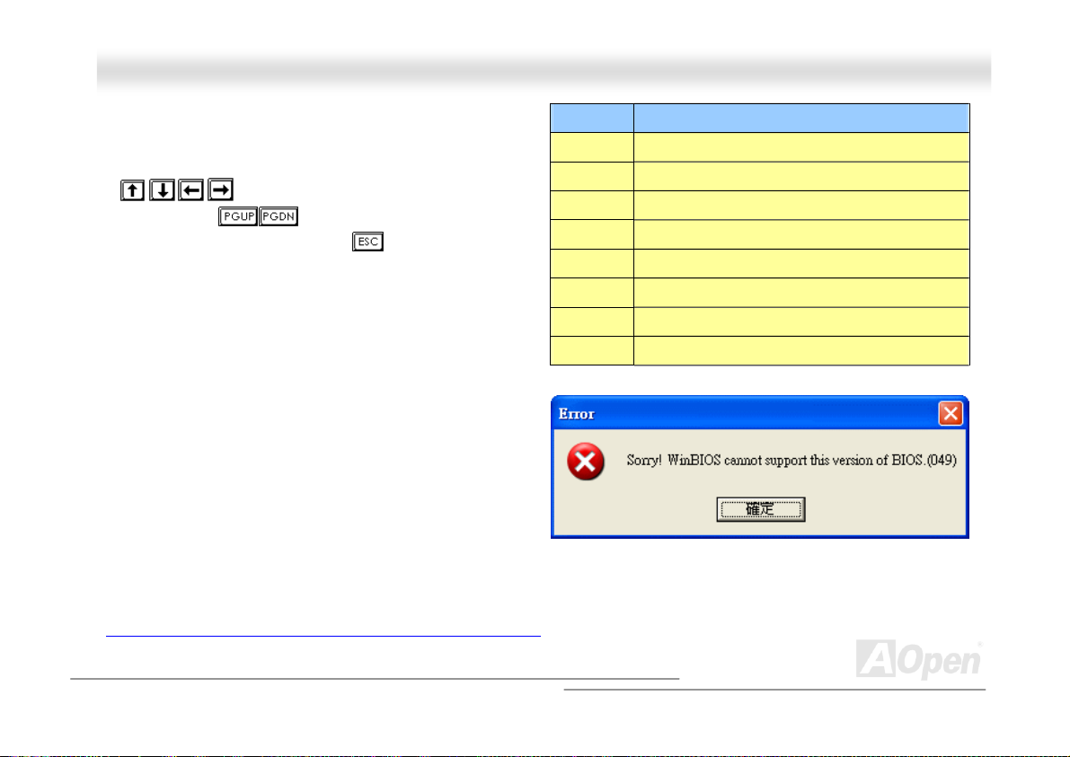
AAKK7799GG MMAAXX//AAKK7799DD MMAAXX OOnnlliinnee MMaannuuaall
Function keys:
It’s definitely easy to handle WinBIOS as if you’re using
traditional BIOS setting. Users can use the arrow keys such
as
screen. And use , “+” or “-” to change the setting
value if they are available. Press
previous screen. Furthermore, the hotkeys shown in the table
may help you and save your time. Some settings may not come
into effect until you reboot your system.
Caution: After updating your BIOS, please remember to
update WinBIOS profile as well. If the upgraded BIOS
version is newer than WinBIOS profile, WinBIOS will not be
able to launch and a dialog box with error message will pop
up. This verification is designed on purpose to protect your
BIOS from damaged by wrong profile version.
For the latest WinBIOS profile and language pack modules, you may find them from AOpen official web site as shown below:
(http://english.aopen.com.tw/tech/download/WinBIOS/default.htm)
to move around the items in WinBIOS
to get back to the
Hotkey Function Description
F1 Get help description.
F2 Item Help
F3 Changing menu language.
F5 Load previous setting
F6 Load setup default setting
F7 Load turbo setting
F10 Save changed setting and exit setup program.
F12 Full Screen / Normal Mode
95
Page 96
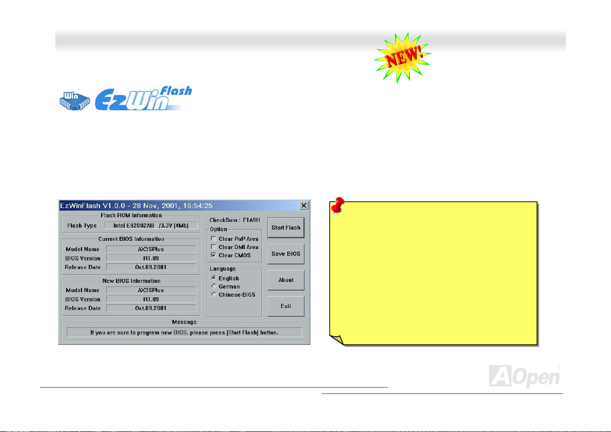
AAKK7799GG MMAAXX//AAKK7799DD MMAAXX OOnnlliinnee MMaannuuaall
BBIIOOSS UUppggrraaddee uunnddeerr WWiinnddoowwss eennvviirroonnmmeenntt
With outstanding R&D ability of AOpen, we now bring you a whole new BIOS Flash wizard
---- EzWinFlash. With an eye to users convenience, EzWinFlash combines the BIOS binary
code and flash module together, so the only thing you have to do is just clicking on the
utility you downloaded from web and let it helps you complete the flash process automatically. EzWinFlash detects your
motherboard and checks the BIOS version cleverly to prevent your system from any possible failure. Moreover, EzWinFlash has
been taken into consideration to go with any windows platform you might be using, no matter if you’re using Windows 95/98,
98SE/ME, NT4.0/2000, or even the latest Windows XP.
In the meanwhile, in order to provide a much more user-friendly operating environment, AOpen EzWinFlash is natively designed
to have multi-language function to provide easier way for users’ usage in changing BIOS setting.
Note: The model name on this BIOS picture is for reference only. It may not be the exact model name.
Caution: By updating your motherboard, you
are taking a risk of BIOS flash failure. If your
motherboard is working stable, and there are
no major bugs that had been fixed by a latter
BIOS revision, we recommend that you DO
NOT try to upgrade your BIOS.
If you intent on upgrading, PLEASE BE SURE
to get the right BIOS revision for the right
motherboard model to avoid any possibility
failure.
96
Page 97
AAKK7799GG MMAAXX//AAKK7799DD MMAAXX OOnnlliinnee MMaannuuaall
You may accomplish BIOS upgrade procedure with EzWinFlash by the following steps, and it’s STRONGLY RECOMMENDED to
close all the applications before you start the upgrading.
1. Download the new version of BIOS package zip file from AOpen official web site. (ex: http://english.aopen.com.tw/
2. Unzip the download BIOS package (ex: WAK79GMAX102.ZIP) with WinZip (http://www.winzip.com
environment.
3. Save the unzipped files into a folder, for example, WAK79GMAX102.EXE & WAK79GMAX102.BIN.
4. Double click on the WAK79GMAX102.EXE, EzWinFlash will detect the model name and BIOS version of your
motherboard. If you had got the wrong BIOS, you will not be allowed to proceed with the flash steps.
5. You may select preferred language in the main menu, then click [Start Flash] to start the BIOS upgrade procedure.
6. EzWinFlash will complete all the process automatically, and a dialogue box will pop up to ask you to restart Windows.
You may click [YES] to reboot Windows.
7. Press <Del> at POST to enter BIOS setup, choose "Load Setup Defaults", then “Save & Exit Setup”. Done!
It is strongly recommended NOT to turn off the power or run any application during FLASH PROCESS.
Warning: The new BIOS upgrade will
permanently replace your original
BIOS’s settings when flashing. You
may need to reconfigure your BIOS
setting so that your system can go
back to work as normal.
) in Windows
)
97
Page 98

AAKK7799GG MMAAXX//AAKK7799DD MMAAXX OOnnlliinnee MMaannuuaall
GGlloossssaarryy
AACC9977 CCOODDEECC
Basically, AC97 CODEC is the standard structure of PCI sound card. As we know, computer is digital-based, but music is based
on analog-based. Therefore, there must be a process to turn digital into analog during the last stage processing of sound in
computer. Hence, the component on sound card that play this important task is what we called CODEC.
Audio CODEC 97 (briefly called AC97) is the specification regulated by Intel, and it’s about the structure of audio conversion.
The special place about CODEC is that it is separated from sound card (CODEC is an independent chipset). Therefore, PCI
sound card could possess with 90db and do other application process as well. We called CODEC that meets this structure AC97
CODEC.
AACCPPII ((AAddvvaanncceedd CCoonnffiigguurraattiioonn && PPoowweerr IInntteerrffaaccee))
ACPI is the power management specification of PC97 (1997). It intends to save more power by taking full control of power
management to operating system and bypass
to operating system (such as Windows 98). This is a bit similar as the
power switch to control the power state transition.
AACCRR ((AAddvvaanncceedd CCoommmmuunniiccaattiioonn RRiisseerr))
Building on the PC motherboard riser architecture, ACR slot is backward compatible with AMR but beyond the limitation of it.
The ACR specification is designed to support modem, audio, Local Area Network (LAN) and Digital Subscriber Line (DSL).
. The chipset or super I/O chip needs to provide standard register interface
BIOS
register interface. ACPI defines ATX momentary soft
PnP
98
Page 99

AAKK7799GG MMAAXX//AAKK7799DD MMAAXX OOnnlliinnee MMaannuuaall
AAGGPP ((AAcccceelleerraatteedd GGrraapphhiicc PPoorrtt))
The main function of AGP simply put is to tell monitor what screen information had to be shown, a visual transmission device
actually. With the rapid developing of AGP card, we can see that it had been developed from single colorful AGP card to 2D and
3D graphic. AGP supports only memory read/write operation and single-master single-slave one-to-one only. Though AGP and
PCI share the same algorithm of 32-bit, its frequencies are 66MHz and 33MHz respectively. AGP interface had been
developed from 2X to 8x.
1X AGP, data transfer rate is 66MHz x 4byte x 1 = 264MB/s
2X AGP, data transfer rate is 66MHz x 4byte x 2 = 528MB/s
4X AGP, data transfer rate is 66MHz x 4byte x 4 = 1056MB/s.
8X AGP, data transfer rate is 66MHz x 4byte x 8 = 2112MB/s.
AAMMRR ((AAuuddiioo//MMooddeemm RRiisseerr))
The CODEC circuit of AC97 sound/modem solution can be put on motherboard or put on a riser card (AMR card) that connects
to motherboard through AMR connector.
AATTAA ((AATT AAttttaacchhmmeenntt))
Before talking about ATA (AT Attachment), we must understand DMA (Direct Memory Access), which allows devices to skip the
CPU devices and access memory directly. DMA specification could not only eliminate the workload of CPU, but also accelerate
the transmission of data. DMA begins with a data transfer rate of 16.6MB/Sec, but afterward developed to new data rate of
33.3MB/Sec, which is twice the data rate and we called it Ultra DMA. ATA details power and data signals between the drive
and integrated drive controller and the computer's motherboard. Two drives (master and slave) are supported. The ATA
specification allows the drive to connect directly to the ISA bus on the computer. ATA transfer rate then had been developed to
133MHz/Sec and would come out with fastest rate later (please refer to
DMA, data transfer rate is 16.6MHz/s.
Serial ATA
).
99
Page 100

AAKK7799GG MMAAXX//AAKK7799DD MMAAXX OOnnlliinnee MMaannuuaall
Ultra DMA, data transfer rate is 16.6MHz x 2 = 33MB/s.
ATA/6 6, data transfer rate is 16.6MHz x 4 = 66MB/s.
ATA/100, data transfer rate is 16.6MHz x 6 = 100MB/s.
ATA/133, data transfer rate is 16.6MHz x 8 = 133MB/s.
(ATA/133 uses both rising edge and falling edge as ATA/66 but clock cycle time is reduced to 30ns.)
BBIIOOSS ((BBaassiicc IInnppuutt//OOuuttppuutt SSyysstteemm))
BIOS, is a set of assembly routine/program that reside in EPROM or Flash ROM. BIOS controls Input/output devices and other
hardware devices of motherboard. In general, to provide hardware independent portability, operation system and drivers is
required to access BIOS without directly access hardware devices.
h
BBlluueettooootth
Bluetooth is a wireless transferring technology that enables short-range wireless connections between desktop and laptop
computers, personal digital assistants (PDAs), cellular phones, printers, scanners, digital cameras and even home
appliances. The principle of Bluetooth (a chipset) is to transfer information and voices at the frequency of ISM Band. Every
Bluetooth technology devices do come with a standard address for you to connect one-to-one or one-to-seven (to form a
Pico-net), with transferring range up to 10 meters (100 meters to follow), using low power radio. Bluetooth do not only possess
high transfer rate of 1MB/s, it also could be encrypted with pin code. With hopping rate of 1600 hops per second, it’s difficult to
be intercepted and are less interrupted by electromagnetic wave.
100
 Loading...