

Page 1

AAKK7777--660000 MMaaxx
Overview
OOnnlliinnee MMaannuuaal
l
AK77-600 Max
DOC. NO.: AK77600MAX-OL-E0310C
1
Installation
Hardware
Drivers &
Utilities
BIOS Setup
AWARD
Glossary
Troub
Tech
nical Support
leshooting &
Page 2

AAKK7777--660000 MMaaxx
OOnnlliinnee MMaannuuaal
l
WWhhaatt’’ss iinn tthhiiss mmaannuuaall
AK77-600 Max.................................................................................................................................1
What’s in this manual......................................................................................................................................................2
You Must Notice.............................................................................................................................................................. 9
Before You Start............................................................................................................................................................10
Overview....................................................................................................................................................................... 11
Feature Highligh t ...........................................................................................................................................................12
Quick Installation Pr ocedu re .........................................................................................................................................17
Motherboard Map.......................................................................................................................................................... 18
Block Diagram............................................................................................................................................................... 1 9
Hardware Instal lation ...............................................................................................................20
About “Manufacturer Upgrade Optional” and “User Upgrade Optional”…...................................................................... 2 1
CPU Installation ............................................................................................................................................................22
EzColor.........................................................................................................................................................................24
AOpen Overheat Protection (O.H.P.) Technology..........................................................................................................26
CPU Over-current Prot ectio n ........................................................................................................................................27
Enlarged Aluminum Heatsink ........................................................................................................................................ 28
Full-range Adjustable CPU Core Voltage.......................................................................................................................29
Setting CPU Frequency.................................................................................................................................................30
2
Page 3

AAKK7777--660000 MMaaxx
Supported CPU Frequency ...........................................................................................................................................31
AOpen “Watch Dog ABS”..............................................................................................................................................32
CPU and Housing Fan Connector (with H/W Monitoring) .............................................................................................. 33
DIMM Sockets...............................................................................................................................................................34
ATX Power Connector...................................................................................................................................................36
AC Power Auto Reco very..............................................................................................................................................36
IDE and Floppy Connector............................................................................................................................................37
ATA/133 Supported ....................................................................................................................................................... 39
Serial ATA Supported(With RAID Function) ................................................................................................................... 40
Connecting Serial ATA Disk...........................................................................................................................................41
Front Panel Connector..................................................................................................................................................42
IrDA Connector ............................................................................................................................................................. 43
AGP (Accelerated Graphic Port) 8X Expansion Slot......................................................................................................44
WOL (Wake on LAN) Connector....................................................................................................................................45
10/100/1000 Mbps LAN onboard................................................................................................................................... 47
Support Eight USB 2.0 Port...........................................................................................................................................48
Color Coded Back Panel...............................................................................................................................................49
Super 5.1 Channel Audio Effect....................................................................................................................................50
Front Audio Connector .................................................................................................................................................. 5 1
OOnnlliinnee MMaannuuaal
l
3
Page 4

AAKK7777--660000 MMaaxx
S/PDIF (Sony/Phili ps Digital In terfac e) Co nnect or......................................................................................................... 52
Dr. LED Connector (User Upgrade Optional) ................................................................................................................53
IEEE 1394 Connector....................................................................................................................................................55
Case Open Connector...................................................................................................................................................56
CD Audio Connector .....................................................................................................................................................57
AUX-IN Connector ........................................................................................................................................................58
Game Port Bracket Supported ......................................................................................................................................59
JP2 Speaker / Bu zzer Sel ect J umper............................................................................................................................60
JP14 Clear CMOS D ata Jumpe r .................................................................................................................................... 61
Dr. Voice II & JP15, 16..................................................................................................................................................62
JP21 K7 Host Clock Selec tion.......................................................................................................................................63
JP28 KB/Mouse Wake -up J ump er.................................................................................................................................64
Die-Hard BIOS and J P24 S elect Jumper.......................................................................................................................65
STBY LED ..................................................................................................................................................................... 66
AGP Protection Technology and AGP LED....................................................................................................................67
Battery-less and Long Life Design ................................................................................................................................68
2200μF
RAID Introduction...................................................................................................................... 71
What’s RAID?................................................................................................................................................................ 71
Low ESR Capacito r......................................................................................................................................... 69
OOnnlliinnee MMaannuuaal
l
4
Page 5

AAKK7777--660000 MMaaxx
What are the RAID l evel s?............................................................................................................................................72
HDD Capacity of RAID Levels....................................................................................................................................... 75
Serial ATA RAID for VIA VT8237...................................................................................................................................76
Serial ATA RAID for Promise PDC20378....................................................................................................................... 77
PHOENIX-AWARD BIO S..............................................................................................................80
How To Use Phoenix-Award™ BIOS Setup Program ....................................................................................................81
How To Enter BIOS Setup.............................................................................................................................................82
WinBIOS Utility .............................................................................................................................................................83
BIOS Upgrade under Windows environment .................................................................................................................85
Vivid BIOS technology................................................................................................................................................... 87
Driver and Utility .......................................................................................................................88
Auto-run Menu from Bonus CD ..................................................................................................................................... 88
Installing VIA 4 in 1 Driver.............................................................................................................................................89
Installing Audio Driver...................................................................................................................................................90
Installing USB2.0 Driver ................................................................................................................................................ 91
Installing LAN D rive r .....................................................................................................................................................92
Installing VIA Serial ATA RAID Driver............................................................................................................................95
Installing Promise PDC 20378 Serial ATA RAID Driver..................................................................................................97
AOConfig Utility ........................................................................................................................................................... 110
OOnnlliinnee MMaannuuaal
l
5
Page 6

AAKK7777--660000 MMaaxx
The noise is gone!! ---- SilentTek................................................................................................................................ 112
EzClock ....................................................................................................................................................................... 115
Glossar y ..................................................................................................................................119
AC97 CODEC ............................................................................................................................................................. 119
ACPI (Advanced Configurat ion & Power I nterf ace) ..................................................................................................... 119
ACR (Advanced C ommuni cati on Ri ser) ....................................................................................................................... 119
AGP (Accelerated Graphic Port) .................................................................................................................................120
AMR (Audio/Modem Riser) .......................................................................................................................................... 120
ATA (AT Attachment)...................................................................................................................................................120
BIOS (Basic Input/Output System)..............................................................................................................................121
Bluetooth ..................................................................................................................................................................... 121
CNR (Communication and Networking Riser)..............................................................................................................122
DDR (Double Data Rate) RAM....................................................................................................................................122
ECC (Error Checking and Correctio n) .........................................................................................................................123
EEPROM (Electronic Erasabl e Prog rammabl e ROM)..................................................................................................123
EPROM (Erasable Program mabl e ROM) .................................................................................................................... 123
EV6 Bus......................................................................................................................................................................123
FCC DoC (Declarati on of C onfo rmity ) ......................................................................................................................... 124
FC-PGA (Flip Chip-Pin Grid Array) .............................................................................................................................. 12 4
OOnnlliinnee MMaannuuaal
l
6
Page 7

AAKK7777--660000 MMaaxx
FC-PGA2 (Flip Chip-Pin Grid Array) ............................................................................................................................ 1 24
Flash ROM..................................................................................................................................................................124
Hyper Threading .........................................................................................................................................................124
IEEE 1394................................................................................................................................................................... 12 5
Parity Bit .....................................................................................................................................................................125
PCI (Peripheral Component Interface) Bus ................................................................................................................. 126
PDF Format.................................................................................................................................................................126
PnP (Plug and Play)....................................................................................................................................................126
POST (Power-On Self Test)........................................................................................................................................126
PSB (Processor Syst em Bu s) Cloc k............................................................................................................................127
RDRAM (Rambus Dynamic Random Access Me mory)................................................................................................127
RIMM (Rambus Inline Memory Module) ...................................................................................................................... 12 7
SDRAM (Synchronous DRAM)....................................................................................................................................127
SATA (Serial ATA) .......................................................................................................................................................128
SMBus (System Management Bus).............................................................................................................................128
SPD (Serial Presen ce Det ect).....................................................................................................................................128
USB 2.0 (Universal Se rial Bus) ...................................................................................................................................128
VCM (Virtual Channel Memory) ................................................................................................................................... 129
Wireless LAN – 80 2.11b .............................................................................................................................................. 12 9
OOnnlliinnee MMaannuuaal
l
7
Page 8

AAKK7777--660000 MMaaxx
ZIP file.........................................................................................................................................................................129
Troubleshooting.......................................................................................................................130
Technical Support ...................................................................................................................134
Product Registr ation ...............................................................................................................137
How to Contact Us ..................................................................................................................138
OOnnlliinnee MMaannuuaal
l
8
Page 9

AAKK7777--660000 MMaaxx
OOnnlliinnee MMaannuuaal
l
YYoouu MMuusstt NNoottiiccee
Adobe, the Adobe logo, Acrobat is trademarks of Adobe Systems Incorporated.
AMD, the AMD logo, Athlon and Duron are trademarks of Advanced Micro Devices, Inc.
Intel, the Intel logo, Intel Celeron, Pentium II, Pentium III, Pentium 4 are trademarks of Intel Corporation.
Microsoft, Windows, and Windows logo are either registered trademarks or trademarks of Microsoft Corporation in the United
States and/or other countries.
All product and brand names used on this manual are used for identification purposes only and may be the registered
trademarks of their respective owners.
All of the specifications and information contained in this manual are subject to change without notice. AOpen reserves the right
to revise this publication and to make reasonable changes. AOpen assumes no responsibility for any errors or inaccuracies that
may appear in this manual, including the products and software described in it.
This documentation is protected by copyright law. All rights are reserved.
No part of this document may be used or reproduced in any form or by any means, or stored in a database or retrieval
system without prior written permission from AOpen Corporation.
Copyright
©
1996-2003, AOpen Inc. All Rights Reserved.
9
Page 10

AAKK7777--660000 MMaaxx
OOnnlliinnee MMaannuuaal
l
BBeeffoorree YYoouu SSttaarrtt
This Online Manual will introduce to the user how this product is installed. All useful information will be described in later
chapters. Please keep this manual carefully for future upgrades or system configuration changes. This Online Manual is saved
PDF format, we recommend using Adobe Acrobat Reader 5.0 for online viewing, it is included in Bonus CD disc or you can
in
get free download from
Although this Online Manual is optimized for screen viewing, it is still capable for hardcopy printing, you can print it by A4 paper
size and set 2 pages per A4 sheet on your printer. To do so, choose File > Page Setup and follow the instruction of your printer
driver.
Thanks for the help of saving our earth.
Adobe web site.
10
Page 11

AAKK7777--660000 MMaaxx
OOnnlliinnee MMaannuuaal
l
OOvveerrvviieeww
Thank you for choosing AOpen AK77-600 Max. The AK77-600 Max is AMD® Socket 462 motherboard (M/B) based on the ATX
form featuring the
Socket 462 series Athlon™ & Duron™ and AthlonXP™ processor (with CPU Overheat Protection circuit to Athlon™XP CPU only)
and 200/266/333/400 MHz
pipelined spilt-transaction long burst transfer up to 2.1GB/sec. With high bandwidth 266/533MB/s 8-bit V-Link Host Controller,
DDR400(PC3200), DDR333(PC2700) and DDR266(PC2100) DDR RAM can be applied to the AK77-600 Max and DDR400
maximum memory size can be up to 2GB and
DDR333/266 up to 3GB. The on-board IDE controller
supports Ultra DMA 66/100/133 mode and the transfer
rate up to 133MB/s. With SouthBridge VIA VT8237
Promise Serial ATA controller onboard, it aims to
and
provide you an even faster transfer rate of 150
Mbytes/second. Beside, the AK77-600 Max has an
AC97 CODEC RealTek ALC650 chipset onboard for
provides high performance and magic surround stereo
sound to let people enjoy working with it. More than
that, this motherboard supports
a fancy speed of up to 480Mbps, and
controller to provide data transfer rate up to 400Mbps.
Now, enjoy all features from AOpen AK77-600 Max.
VIA Apollo KT600 chipset. As high performance chipset built in the M/B, the AK77-600 Max comes with AMD®
EV6 system bus. In the AGP performance, it has one AGP slot and supports AGP 8X/4X mode and
USB 2.0 function with
IEEE 1394
11
Page 12

AAKK7777--660000 MMaaxx
OOnnlliinnee MMaannuuaal
l
FFeeaattuurree HHiigghhlliigghhtt
CPU
Supports AMD® Socket 462 series CPU with both 200/266/333/400 MHz EV6 Bus designed for Socket 462 technology.
Athlon: 600MHz~1.4GHz
Duron: 600MHz~1.2GHz
AthlonXP: 1500+(1.33GHz)~3200+(2.2GHz)
Chipset
The VIA Apollo KT600 consists of the KT600 V-Link DDR Host system controller and the VT8237 highly integrated V-Link Client
PCI/LPC controller. The Host system controller provides superior performance between the CPU, SDRAM, AGP bus, and V-Link
interface with pipelined, burst, and concurrent operation. The VT8237 V-Link Client controller is a highly integrated PCI/LPC
controller. Its internal bus structure is based on 66MHz PCI bus that provides 8x bandwidth compare to previous generation
PCI/ISA bridge chips. The VT8237 integrated Client V-Link controller with 266/533MB/s bandwidth between Host/Client V-Link
interface, providing a V-Link-PCI and V-Link-LPC controller.
Ultra DMA 66/100/133 Bus Master IDE, Promise 133 IDE
Comes with an on-board PCI Bus Master IDE controller with two connectors that supports four IDE devices in two channels,
supports Ultra DMA 66/100/133, PIO Modes 3 and 4 and Bus Master IDE DMA Mode 4, and supports Enhanced IDE devices.
Besides, this motherboard comes with Promise IDE controller that provides an additional IDE channel and supports ATA133
mode.
12
Page 13

AAKK7777--660000 MMaaxx
OOnnlliinnee MMaannuuaal
Serial ATA
This motherboard comes with an integrated SATA controller in VIA VT8237 and a Promise Serial ATA controller, aiming to
provide you an even faster transfer rate of 150 Mbytes/second. The SATA connectors (port 1 and port2) provided by Promise
SATA controller support RAID 0, RAID 1 and RAID 0+1, and The SATA connectors (port 3 and port 4) provided by VIA VT8237
support RAID 0 and RIAD 1.
LAN Port
On the strength of Broadcom BCM5705 controller on board, which is a highly-integrated Platform LAN Connect device, it
provides 10/100/1000 Mbps Ethernet for office and home use.
Expansion Slots
Including six 32-bit/33MHz PCI and one AGP 8X slots. The PCI local bus throughput can be up to 132MB/s. The Accelerated
Graphics Port (AGP) specification provides a new level of video display sophistication and speed. The AGP video cards support
data transfer rate up to 2.1GB/s. AK77-600 Max includes one AGP expansion slot for a bus mastering AGP graphic card, For AD
and SBA signaling, AK77-600 Max can support 133MHz 4X/8X mode. Of six PCI slots provided, AK77-600 Max supports five
master PCI slots for arbitration and decoding functions and one slave PCI slot.
l
13
Page 14

AAKK7777--660000 MMaaxx
Memory
With VIA Apollo KT600 chipset, AK77-600 Max can support Double-Data-Rate (DDR) RAM. The DDR RAM interface allows zero
wait state bursting between the RAM and the data buffers at 400/333/266/200 MHz. The six banks of DDR RAM can be
composed of an arbitrary mixture of 64, 128, 256, 512MB, 1GB x N DDR RAM and DDR400 maximum up to 2GB and
DDR333/266 up to 3GB. The AK77-600 Max allows DDR RAM to run at either synchronous or pseudo-synchronous mode with
the host CPU bus frequency (400/333/266/200MHz).
On-board AC97 Sound
AK77-600 Max uses the AC97 CODEC RealTek ALC650 chip, which supports high quality of 5.1 Channel audio effects. This
on-board audio includes a complete audio recording and playback system.
Eight USB 2.0 Connectors
Provides eight USB connectors for USB interface devices, such as mouse, keyboard, modem, scanner, etc. Please note that
USB 2.0, with fancy speed up to 480Mbps, is 40 times faster than the traditional ones. Except for the speed increase, USB 2.0
supports old USB 1.0/1.1 software and peripherals, offering impressive and even better compatibility to customers.
IEEE 1394
This motherboard comes with IEEE 1394 controller Agere FW323 onboard, which provides data transfer rate up to 400Mbps. to
connect with the devices that need high data transferring performance, such as digital camera, scanner or others IEEE 1394
devices.
OOnnlliinnee MMaannuuaal
l
14
Page 15

AAKK7777--660000 MMaaxx
1MHz Stepping CPU Frequency Adjustment
Provides “1MHz Stepping CPU Frequency Adjustment” function in the BIOS. This magic function allows you adjust CPU FSB
frequency from 100~248MHz by 1MHz stepping, and lets your system can get maximum performance.
Watch Dog ABS
Includes AOpen “Watch Dog ABS” function that can auto-reset system in 4.8 seconds when you fail the system overclocking.
Die-Hard BIOS
The Die-Hard BIOS technology is a very effective hardware protection method that doesn’t involve any software or BIOS coding.
Hence, it is 100% virus free.
Dr. LED (User Upgrade Optional)
Dr. LED has 8 LEDs on AK77-600 Max, which can easily show what kind of problem you may encounter.
Power Management/Plug and Play
AK77-600 Max supports the power management function that confirms to the power-saving standards of the U.S. Environmental
Protection Agency (EPA) Energy Star program. It also offers
problems, thus making the system much more user-friendly.
Plug-and-Play, which helps saving users from configuration
OOnnlliinnee MMaannuuaal
l
15
Page 16

AAKK7777--660000 MMaaxx
Hardware Monitoring Management
Supports CPU or system fans status, temperature and voltage monitoring and alert, through the on-board hardware monitor
module and AOpen Hardware Monitoring Utility.
Enhanced ACPI
Fully implement the ACPI standard for Windows® 95/98/ME/NT/2000/XP series compatibility, and supports Soft-Off, STR
(Suspend to RAM, S3), STD (Suspend to Disk, S4), WOM (Wake On Modem), WOL (Wake On LAN) features.
Super Multi-I/O
AK77-600 Max provides two high-speed UART compatible serial ports and one parallel port with EPP and ECP capabilities.
UART2 can also be directed from COM2 to the Infrared Module for the wireless connections.
OOnnlliinnee MMaannuuaal
l
16
Page 17

AAKK7777--660000 MMaaxx
OOnnlliinnee MMaannuuaal
l
QQuuiicckk IInnssttaallllaattiioonn PPrroocceedduurree
This page gives you a quick procedure on how to install your system. Follow each step accordingly.
1. Installing CPU and Fan
2. Installing System Memory (DIMM)
3. Connecting Front Panel Cable
4. Connecting IDE and Floppy Cable
5. Connecting ATX Power Cable
6. Connecting Back Panel Cable
7. Power-on and Load BIOS Setup Default
8. Setting CPU Frequency
9. Reboot
10. Installing Operating System (such as Windows XP)
11. Installing Driver and Utility
17
Page 18
p
AAKK7777--660000 MMaaxx
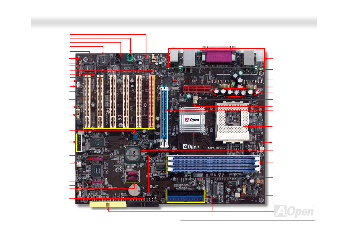
AC97 CODEC
AUX-IN Connector
CD-IN Connector
Die Hard BIOS (BIOS 2)
Die Hard BIOS (BIOS1)
SmartEAR Connector
JP24 Die Hard BIOS Jumper
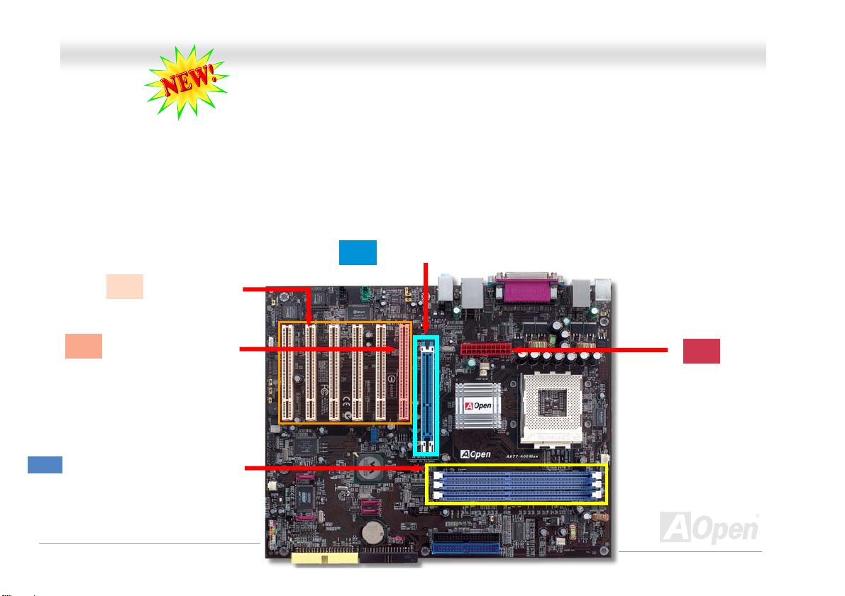
32-bit PCI Expansion Slot x6
(PCI 1 supports slave mode PCI
JP2 Dr. Voice II Speaker/
Language Selection Jumper
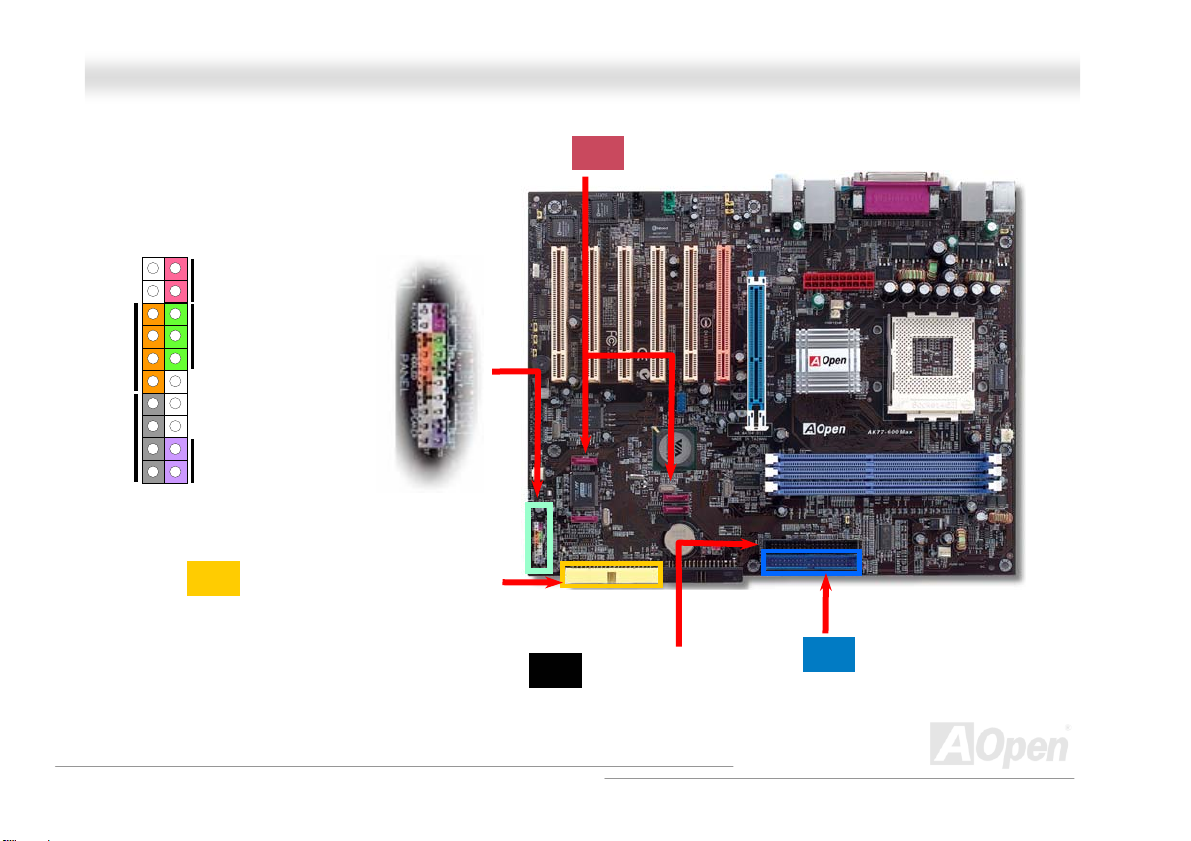
S/PDIF Connector
Front Audio Connector
Case Open Connector
Game Port Connector
IrDA Connector
WOL Connector
Dr. LED Connector
card only)
buzzer Output Jumper
JP15 & JP16 Dr. Voice II
USB 2.0 Connector
IEEE 1394 Connector x 2
JP14 Clear CMOS Jum
SYSFAN2 Connector
er
Promise Serial ATA Connectors
SATA Connectors(provided by
Front Panel Connector
VIA VT8237)
FDD Connector
Motherboard Map
18
OOnnlliinnee MMaannuuaal
Colored Back Panel
JP28 Keyboard/Mouse
Wakeup Jumper
Broadcom BCM5705
ATX Power Connector
2200μF Low ESR Capacitors
SYSFAN Connector
Power temperature Connector
AGP 8x Slot
462-pin CPU Socket with
Voltage and Frequency
Auto-Detection that supports
TM
AthlonTM / DuronTM /
AMD
and AthlonTMXP (with CPU
Overheat Protection circuit to
TM
XP CPU only)
Athlon
CPUFAN Connector
VIA® Apollo KT600
Chipset and VT8237 SB
184-pin DIMMx3 supports
DDR400 max. up to 2GB and
DDR333/DDR266 max up to
3GB
JP21 K7 Host Clock Jumper
Power Fan connector
IDE Connector x 3
(ATA/66/ 100/ 133 suppo rted)
l
Page 19
AAKK7777--660000 MMaaxx
OOnnlliinnee MMaannuuaal
l
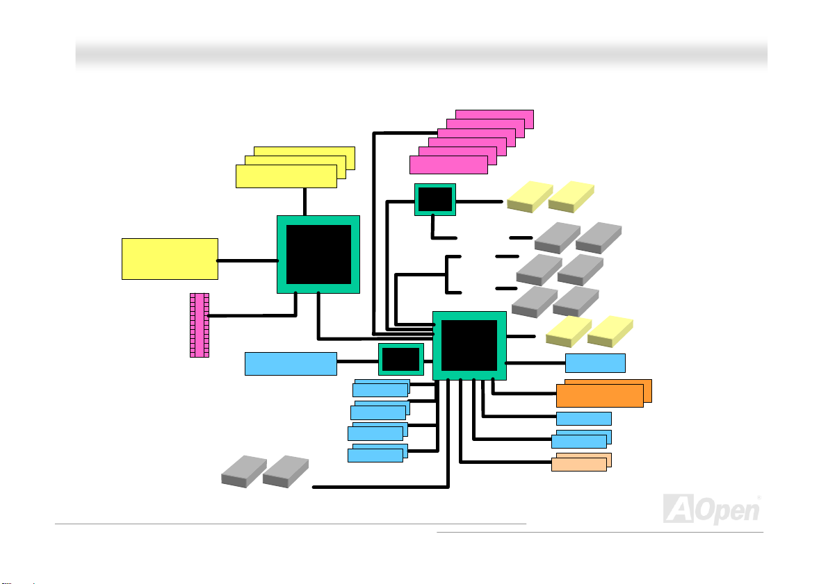
BBlloocckk DDiiaaggrraamm
Socket 462
AMD
Athlon/Duron/AthlonXP
CPU
AGP 8X Slot
DDR400 RAM Up to 3GB and
DDR333/266 RAM to 2GB
DDR SDRAM Socket x3
100/133/166/200
MHz System
Bus
AGP Bus
LAN connect Component
Floppy Disk Dri ve x2
VIA KT600
PCI Bus
Broardcom
BCM5705
1stUSB Port
2ndUSB Port
3rdUSB Port
4th USB Port
USB connector x8
32-bit PCI Slot x6
Promise
PDC20378
ATA
66/100/133
ATA
66/100/133
Serial ATA
Third Channel
Primary
Channel
Secondary
Channel
VT8237
Serial ATA Devices x2
Serial ATA
AC’97 Link
IEEE 1394 connector x2
IDE Drive x6
Audio CODEC
4MBit Flash EEPRO M
Parallel Port
Serial Port x2
IEEE 1394 x2
19
Page 20

AAKK7777--660000 MMaaxx
OOnnlliinnee MMaannuuaal
l
HHaarrddwwaarree IInnssttaallllaattiioonn
This chapter describes jumpers, connectors and hardware devices of this motherboard.
Note: Electrostatic discharge (ESD) can damage your processor, disk drives, expansion boards, and
other components. Always observe the following precautions before you install a system component.
1. Do not remove a component from its protective packaging until you are ready to install it.
2. Wear a wrist ground strap and attach it to a metal part of the system unit before handling a
component. If a wrist strap is not available, maintain contact with the system unit throughout any
procedures requiring ESD protection.
20
Page 21

AAKK7777--660000 MMaaxx
OOnnlliinnee MMaannuuaal
l
AAbboouutt ““MMaannuuffaaccttuurreerr UUppggrraaddee OOppttiioonnaall”” aanndd ““UUsseerr UUppg
When you read this online manual and start to assemble your computer system, you may find some of functions are called “Manufacturer
Upgrade Optional”, and some are called “User Upgrade Optional”. Though all AOpen motherboards include many amazing and powerful
features, in some situations, these powerful features are not used to every user. Hence, we changed some key features as “Manufacturer
Upgrade Optional” for you to choose. Some optional functions that can be upgraded by users, we call them “User Upgrade Optional”. As for
those optional functions that can’t be upgraded by ourselves, we call them “Manufacturer Upgrade Optional”. If needed, you can contact our
local distributors or resellers for purchasing “User Upgrade Optional” components, and again you can visit AOpen official web site:
http://english.aopen.com.tw/ for more detail information.
grraaddee OOppttiioonnaall””……
21
Page 22
AAKK7777--660000 MMaaxx
OOnnlliinnee MMaannuuaal
l
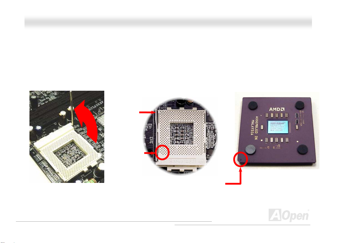
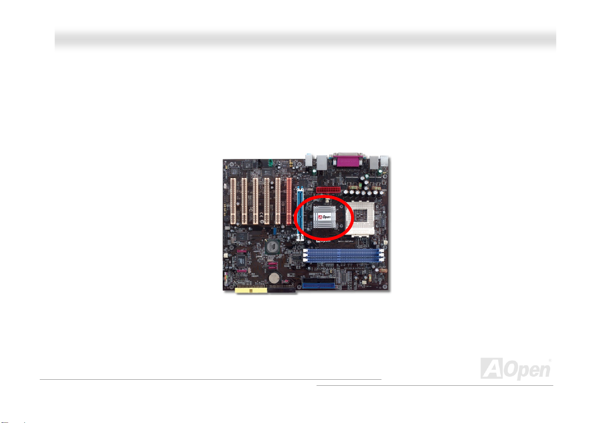
CCPPUU IInnssttaallllaattiioonn
This motherboard supports AMD Athlon XP, Athlon and Duron Socket 462 series CPU. Be careful of CPU orientation when you plug it into
CPU socket (with CPU Overheat Protection function implemented, the system will be automatically power off when the temperature of
CPU reached 97 degree, but works on AthlonXP CPU only).
1. Pull up the CPU socket lever and
up to 90-degree angle.
2. Locate Pin 1 in the socket and look for a black dot or cut edge on the CPU
upper interface. Match Pin 1 and cut edge, then insert the CPU into the
socket.
CPU socket
Lever
Note: This picture is for example only; it may not exactly be the same motherboard.
CPU pin 1 and
cut edge
Black dot and
cut edge
22
Page 23
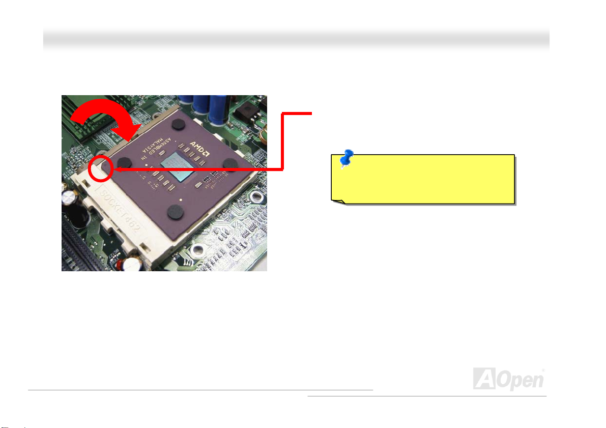
y
AAKK7777--660000 MMaaxx
3. Press down the CPU socket lever and finish CPU
installation.
Note: This picture is for example only; it may not exactly be the same motherboard.
CPU cut edge
OOnnlliinnee MMaannuuaal
Note: If you do not match the CPU
socket Pin 1 and CPU cut edge well, it
ma
damage the CPU.
l
23
Page 24
AAKK7777-
-
660000 MMaaxx
OOnnlliinnee MMaannuuaal
l
EEzzCCoolloorr
Breaking through traditional outlook of motherboard, AOpen now brings you a new fresh look of motherboard! – EzColor!
Fancy? You may think so, but actually it is a practical and useful feature for amateur or even power-users. Coming in specific color for
specific connector and module, components on motherboard are now born with their respective colors. Users may now easily recognize
what jumper or cable should match with specific jumper or cable by COLOR, without having the trouble of holding user guide in one hand
and connecting jumpers with the other hand.
And what makes this feature so great is that, even the easy-to-get-confused front panel connector is differentiated now with different light
colors!
Polish Orange: PCI Slave
Electric Blue: Memory Module
Sky Blue: AGP Slot
Sand: PCI Master
Flame Red: ATX Power Connector
24
Page 25
AAKK7777--660000 MMaaxx
1
IDE LED
SPEAKER
Note: Colors setting varies on different motherboards, the color setting here applies only to AK77-600 Max
Power Switch
ACPI & Power LED
RESET
Light Y ellow : IDE 3 Connector
Claret: Serial A TA connector
Black: IDE 2 Connector
OOnnlliinnee MMaannuuaal
Navy Blue: IDE 1 Connector
l
25
Page 26
AAKK7777--660000 MMaaxx
OOnnlliinnee MMaannuuaal
l
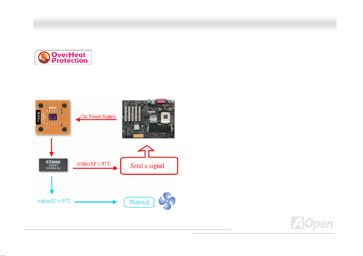
AAOOppeenn OOvveerrhheeaatt PPrrootteeccttiioonn ((OO..HH..PP..)) TTeecchhnnoollooggyy
With AMD platform substantially keeps increasing the speed of its CPU, it inevitably led to the
annoying problem of high CPU operation temperature at the same time. In order to prevent
accidental failure of CPU fan, which could cause the burning down of the AthlonXP CPU, we, AOpen, have meticulously
developed a new technology, named, O.H.P. (Overheat Protection) Technology to protect them. Thanks to the intelligent
monitoring design of AOpen O.H.P. technology, user can now finally set their mind at ease even when fan failed to work without
fearing the possible damage of CPU.
Under the circumstances that CPU fan is running properly,
AthlonXP temperature should be way below the highest
temperature limit of 97℃. However, if CPU fan accidentally
becomes malfunction or improperly installed, the CPU
temperature would rocket abruptly, and you may find your
system hang up or crying over the smoking CPU if you haven’t
installed AOpen O.H.P. previously. With AOpen O.H.P.
technology applied, the specific thermal detection pins on
AthlonXP CPU would sense voltage difference when processor
is overheated with fan failed, and the overheat protection
system would immediately send out a signal to abort your
system by cutting CPU electricity before any damage is done.
Unlike other manufacturers who use BIOS or software to
control the power supply of CPU, AOpen O.H.P. Technology is
purely hardware-controlled the minute after system boot-up,
and occupies no system resource. We are pleasant to phase in
this practical function on all AOpen AMD series motherboards to protect customer’s valuable hardware and personal data.
26
Page 27
AAKK7777--660000 MMaaxx
OOnnlliinnee MMaannuuaal
l
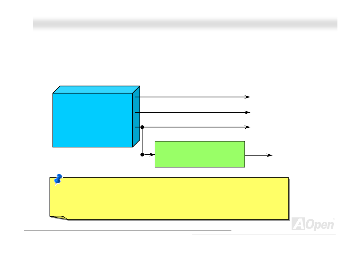
CCPPUU OOvveerr--ccuurrrreenntt PPrrootteeccttiioonn
Over Current Protection has been popularly implemented on ATX 3.3V/5V/12V switching power supply for a while. However,
new generation CPU is able to use regulator of different voltages to transfer 12V to CPU voltage (for example, to 2.0V). This
motherboard is with switching regulator onboard that supports CPU over-current protection, and it applies to 3.3V/5V/12V power
supply for providing full line over-current protection.
ATX Switching Power Supply
Note: Although we have implemented protection circuit try to prevent any human operating
mistake, there is still certain risk that CPU, memory, HDD, add-on cards installed on this
motherboard may be damaged because of component failure, human operating error or unknown
nature reason. AOpen cannot guaranty the protection circuit will always work perfectly.
12V (Protected by power supply)
3.3V (Protected by power supply)
5V (Protected by power supply)
Onboard Power Regulator
(Over-Current Protection)
CPU Core Voltage
27
Page 28
AAKK7777--660000 MMaaxx
OOnnlliinnee MMaannuuaal
l
EEnnllaarrggeedd AAlluummiinnuumm HHeeaattssiinnkk
Cool down CPU and Chipset is important for system reliability. Enlarged aluminum heat sink provides better heat consumption
especially when you are trying to over clocking the CPU.
28
Page 29
AAKK7777--660000 MMaaxx
OOnnlliinnee MMaannuuaal
l
FFuullll--rraannggee AAddjjuussttaabbllee CCPPUU CCoorree VVoollttaaggee
This function is dedicated to overclockers. The CPU core voltage of this motherboard is adjustable 1.10V to 1.85V by 0.05V
stepping. But this motherboard can also automatically detect CPU VID signal and generates proper CPU core voltage.
BIOS Setup > Frequency/Voltage Control > CPU Voltage Setting
Warning: Higher CPU core voltage may be
able to increase CPU speed for overclocking,
but you may damage the CPU or reduce the
CPU lifecycle.
29
Page 30
AAKK7777--660000 MMaaxx
OOnnlliinnee MMaannuuaal
l
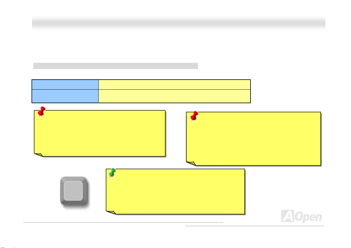
SSeettttiinngg CCPPUU FFrreeqquueennccyy
This motherboard is CPU jumper-less design, you can set CPU frequency through the BIOS setup, and no jumpers or switches
are needed.
BIOS Setup > Frequency/Voltage Control > CPU Speed Setting
CPU Ratio
CPU FSB
(By manual Adjustment)
Warning: VIA® Apollo KT600 chipset supports
200MHz FSB (with performance reaches maximum
400MHz EV6 system bus) and 66MHz AGP clock,
higher clock setting may cause serious system
damage.
Home
From 5x to 18x step 0.5x
100~248 by 1MHz stepping adjustment technology
Warnin g: Supposed you have had adjusted CPU
Speaker
ratio on your current CPU, and you plan to replace a
new CPU. Please use <Home> key or Clear CMOS
to restore the default setting when changing a new
CPU, because the system will still implement the
previous CPU setting on the new one.
Tip: If your system hangs or fails to boot because of
overclocking, simply use <Home> key to restore the
default setting or you can wait the AOpen “Watch Dog
ABS” reset the system after five seconds and system
will auto-detect hardware again.
30
Page 31

AAKK7777--660000 MMaaxx
OOnnlliinnee MMaannuuaal
l
SSuuppppoorrtteedd CCPPUU FFrreeqquueennccyy
Core Frequency = CPU Bus Clock * CPU Ratio PCI Clock = CPU Bus Clock / Clock Ratio
AGP Clock = PCI Clock x 2 EV6 Bus Speed = CPU external bus clock x 2
CPU
Athlon 1.33G 1.33GHz 266MHz 10.0x
Athlon 1.4G 1.4GHz 266MHz 10.5x
AthlonXP 1500+ 1.3GHz 266MHz 10.0x
AthlonXP 1600+ 1.4GHz 266MHz 10.5x
AthlonXP 1700+ 1.46GHz 266MHz 11.0x
AthlonXP 1800+ 1.53GHz 266MHz 11.5x
AthlonXP 1900+ 1.6GHz 266MHz 12.0x
AthlonXP 2000+ 1.667GHz 266MHz 12.5x
AthlonXP 2100+ 1.73GHz 266MHz 13x
AthlonXP 2200+ 1.80GHz 266MHz 13.5x
AthlonXP 2400+ 2.0GHz 266MHz 15x
AthlonXP 2500+ (Barton) 1.833GHz 333MHz 11x
AthlonXP 2600+ 2.13GHz 266MHz 16x
AthlonXP 2600+ 2.08GHz 333MHz 12.5x
AthlonXP 2700+ 2.16GHz 333MHz 13x
AthlonXP 2800+ (Barton) 2.083GHz 333MHz 12.5x
AthlonXP 3000+ (Barton) 2.167GHz 333MHz 13x
AthlonXP 3200+ (Barton) 2.2GHz 400MHz 11x
Note: With CPU speed changing rapidly, there might be fastest CPU on the market
by the time you received this installation guide. This table is kindly for your
references only.
CPU Core
Frequency
EV6 Bus
Clock
Ratio
Note: This motherboard support
CPU auto-detection function.
Hence, you don’t need to setup
the CPU frequency manually.
31
Page 32

AAKK7777--660000 MMaaxx
OOnnlliinnee MMaannuuaal
l
AAOOppeenn ““WWaattcchh DDoogg AABBSS””
FSB frequency by user’s setting that stored in the BIOS. If system failed in BIOS POST, the “Watch Dog ABS” will reset the
CPU
system to reboot in five seconds. Then, BIOS will detect the CPU’s default frequency and POST again. With this special feature,
you can easily overclock your system to get higher system performance without removing the cover of system housing, and be
able to set the jumper to clear CMOS data when your system hanged.
AOpen
Watch Dog ABS
Enable/Disable Signal
With this motherboard, AOpen provides a very special, useful feature for overclockers.
When you power-on the system, the BIOS will check last system
succeeded, the BIOS will enable “Watch Dog ABS” function immediately, and set the
from BIOS
BIOS
Reset Signal
Clock Generator
Countdown about
5 seconds if fails
in POST
CPU
POST status. If it
CPU ID Signal
32
Page 33

AAKK7777--660000 MMaaxx
OOnnlliinnee MMaannuuaal
l
CCPPUU aanndd HHoouussiinngg FFaann CCoonnnneeccttoorr ((wwiitthh HH//WW MMoonniittoorriinngg)
Plug in the CPU fan cable to the 3-pin CPUFAN connector. If you have chassis fan, you can also plug it on SYSFAN1 or
SYSFAN2 connector.
SYSFAN2 Connector
GND
+12V
SENSOR
Note: Some CPU fans do not have
sensor pin, so that cannot support fan
monitoring.
SYSFAN1 Connector
GND
+12V
SENSOR
CPUFAN Connector
)
GND
+12V
SENSOR
33
Page 34

AAKK7777--660000 MMaaxx
OOnnlliinnee MMaannuuaal
l
DDIIMMMM SSoocckkeettss
This motherboard has three 184-pin DDR DIMM sockets that allow you to install DDR266/333 memory up to 3 GB and DDR400
memory up to 2GB. Non-ECC DDR RAM is supported. Otherwise, it will cause serious damage on memory sockets or RAM
module. Newly implemented function, the Voltage of memory on this motherboard is adjustable from 2.5V to 2.7V for over
clocking purpose.
Warning: This motherboard supports DDR
RAM. Please do not install the SDRAM on
the DDR RAM sockets; otherwise it will
cause serious damage on memory sockets
or SDRAM module.
DDR
RAM
Note: According to the standard DDR400 specification from
JEDEC (Joint Electron Device Engineering Council), it is
regulated that DDR400 supports only 2x DIMM on the memory
module for a maximum 2GB capacity, and DDR333 supports
up to 3x DIMM for a maximum of 3GB capacity. Please be
noted that KT600 series motherboards follow this standard
specification on memory as well.
34
Page 35

AAKK7777--660000 MMaaxx
OOnnlliinnee MMaannuuaal
l
HHooww ttoo IInnssttaallll MMeemmoorryy MMoodduulleess
Please follow the procedure as shown below to finish memory installation.
1. Make sure the DIMM module’s pin face down and match the socket’s size as depicted below.
2. Insert the module straight down to the DIMM slot with both hands and press down firmly until the DIMM module is securely
in place.
3. Repeat step 2 to finish additional DIMM modules installation.
Pin 1
Tab
Key
52 pins 40 pins
Note: The tabs of the DIMM slot
will close-up to hold the DIMM in
place when the DIMM touches
the slot’s bottom.
Pin 1
35
Page 36

AAKK7777--660000 MMaaxx
OOnnlliinnee MMaannuuaal
l
AATTXX PPoowweerr CCoonnnneeccttoorr
The ATX power supply uses 20-pin connector shown below. Make sure you plug in the right direction.
AACC PPoowweerr AAuuttoo RReeccoovveerryy
A traditional ATX system should remain at power off stage when AC power resumes from power failure. This design is
inconvenient for a network server or workstation, without an UPS, that needs to keep power-on. This motherboard implements
an AC Power Auto Recovery function to solve this problem.
36
Page 37

AAKK7777--660000 MMaaxx
OOnnlliinnee MMaannuuaal
l
IIDDEE aanndd FFllooppppyy CCoonnnneeccttoorr
Connect 34-pin floppy cable and 40-pin IDE cable to floppy connector FDD connector. Be careful of the pin1 orientation. Wrong
orientation may cause system damage.
IDE3 (Third)
37
Pin 1
Secondary
Slave (4th)
Primary
Slave (2nd)
Secondary
Master (3rd)
Primary
Master (1st)
FDD
Connector
IDE2 (Secondary)
IDE1 (Primary)
ATA 66/100/133
IDE Connectors
Page 38

AAKK7777--660000 MMaaxx
IDE1 is also known as the primary channel, IDE2 and IDE3 are known as the secondary and third channel. Each channel
supports two IDE devices that make a total of six devices. In order to work together, the two devices on each channel must be
set differently to Master and Slave mode. Either one can be the hard disk or the CDROM. The setting as master or slave mode
depends on the jumper on your IDE device, so please refer to your hard disk and CDROM manual accordingly.
Warning: The specification of the IDE cable is a maximum
of 46cm (18 inches); make sure your cable does not exceed
this length.
Tip:
1. For better signal quality, it is recommended to set the far end
side device to master mode and follow the suggested sequence
to install your new device. Please refer to above diagram
2. To achieve the best performance of Ultra DMA 66/100/133 hard
disks, a special 80-wires IDE cable for Ultra DMA 66/100/133
is required.
OOnnlliinnee MMaannuuaal
l
38
Page 39

AAKK7777--660000 MMaaxx
OOnnlliinnee MMaannuuaal
l
AATTAA//113333 SSuuppppoorrtteedd
This motherboard supports ATA66, ATA100 or ATA133 IDE devices. Following table lists the transfer rate of IDE PIO and DMA
modes. The IDE bus is 16-bit, which means every transfer is two bytes. As the hard drive industry introduces faster and higher
capacity hard drives, the current Ultra ATA/100 interface causes a data bottleneck between the drive and the host computer.
To avoid this problem, hard disk manufacturers have introduced the new Ultra ATA-133 interface technology.
traditional ATA/100, ATA/133 has up to 33 percent increase in interface speed with transfer rate of 133MB/s. ATA/133
performance is ideal for new operating systems, such as Window XP, that demand more storage space and faster data transfer
rates from more responsive computing experiences.
To make good use of this new technology and enjoy its best performance, we recommend you to pair your system with a hard
disk equipped with ATA/133 technology so that your system's need for speeding on this motherboard can be satisfied.
Mode Clock Period Clock Count Cycle Time Data Transfer Rate
PIO mode 0 30ns 20 600ns (1/600ns) x 2byte = 3.3MB/s
PIO mode 1 30ns 13 383ns (1/383ns) x 2byte = 5.2MB/s
PIO mode 2 30ns 8 240ns (1/240ns) x 2byte = 8.3MB/s
PIO mode 3 30ns 6 180ns (1/180ns) x 2byte = 11.1MB/s
PIO mode 4 30ns 4 120ns (1/120ns) x 2byte = 16.6MB/s
DMA mode 0 30ns 16 480ns (1/480ns) x 2byte = 4.16MB/s
DMA mode 1 30ns 5 150ns (1/150ns) x 2byte = 13.3MB/s
DMA mode 2 30ns 4 120ns (1/120ns) x 2byte = 16.6MB/s
ATA33 30ns 4 120ns (1/120ns) x 2byte x 2 = 33MB/s
ATA66 30ns 2 60ns (1/60ns) x 2byte x 2 = 66MB/s
ATA100 20ns 2 40ns (1/40ns) x 2byte x 2 = 100MB/s
ATA133 15ns 2 30ns (1/30ns) x 2byte x 2 = 133MB/s
Compared to
39
Page 40

AAKK7777--660000 MMaaxx
OOnnlliinnee MMaannuuaal
l
SSeerriiaall AATTAA SSuuppppoorrtteedd((WWiitthh RRAAIIDD FFuunnccttiioonn))
The traditional parallel ATA specification has defined the standard storage interface for PCs with its original speed of just 3
Mbytes/second since the protocol was introduced in the 1980s. And the latest generation of the interface, Ultra ATA-133, has
been developed further with a burst data transfer rate of 133 Mbytes/second. However, while ATA has enjoyed an illustrious
track record, the specification is now showing its age and imposes some serious design issues on today’s developers, including
a 5-volt signaling requirement, high pin count, and serious cabling headaches.
The Serial ATA specification is designed to overcome these design limitations while enabling the storage interface to scale with
the growing media rate demands of PC platforms. Serial ATA is to replace parallel ATA with the compatibility with existing
operating systems and drivers, adding performance headroom for years to come. It reduces voltage and pins count
requirements and can be implemented with thin and easy to route cables.
SATA port 2 (promise)
Promise PDC20378
SATA port 1 (promise)
SATA port 3 (VIA VT8237)
SATA port 4 (VIA VT8237)
40
Page 41

AAKK7777--660000 MMaaxx
OOnnlliinnee MMaannuuaal
l
CCoonnnneeccttiinngg SSeerriiaall AATTAA DDiisskk
To connect a Serial ATA disk, you have to have a 7-pin Serial ATA cable. Connect two ends of the Serial ATA cable to the Serial
ATA header on the motherboard and the disk. Like every other traditional disk, you also have to connect a power cable. Please
note that it is a jumper free implement; you don’t need to set jumpers to define a master or slave disk. When connecting two
Serial ATA disks, the system will automatically take the one connected to “Serial ATA 1” header as a master disk.
Note: This picture is for example only; it may not exactly be the same motherboard.
Serial AT A Cable
Parallel ATA Serial ATA
Comparison between Parallel ATA and Serial ATA
Bandwidth 100/133 MB/Secs 150/300/600 MB/Secs
Volts 5V 250mV
Pins 40 7
Length Limitation 18 inch (45.72cm) 1 meter (100cm)
Cable Wide Thin
Ventilation Bad Good
Peer-to-Peer No Yes
41
Page 42

AAKK7777--660000 MMaaxx
OOnnlliinnee MMaannuuaal
l
FFrroonntt PPaanneell CCoonnnneeccttoorr
Attach the power LED, speaker, power and reset switch connectors to the
corresponding pins. If you enable “Suspend Mode” item in BIOS Setup, the ACPI
& Power LED will keep flashing while the system is in suspend mode.
Locate the power switch cable from your ATX housing. It is 2-pin female
connector from the housing front panel. Plug this connector to the soft-power
switch connector marked SPWR.
Suspend Type ACPI LE D
Power on Suspend (S1) Blinking between green and red
Suspend to RAM (S3) or Suspend to Disk (S4) Blinking between green and red
NC
NC
+5V
+5V
+5V
GND
NC
1
SPWR
GND
ACPILEDGND
ACPILED+
NC
NC
GND
RESET
GND
IDE LED
SPEAKER
1
Power Switch
ACPI & Power LED
RESET
IDE LED
IDE LED
SPEAKER
42
Page 43

AAKK7777--660000 MMaaxx
OOnnlliinnee MMaannuuaal
l
IIrrDDAA CCoonnnneeccttoorr
The IrDA connector can be configured to support wireless infrared module, with this module and application software such as
Laplink or Windows 95 Direct Cable Connection, the user can transfer files to or from laptops, notebooks, PDA devices and
printers. This connector supports HPSIR (115.2Kbps, 2 meters) and ASK-IR (56Kbps).
Install the infrared module onto the IrDA connector and enable the infrared function from BIOS Setup, UART2 Mode, make sure
to have the correct orientation when you plug in the IrDA connector.
Pin 1
IR_TX
IrDA Connector
1
NC
+5V
KEY
GND
IR_RX
43
Page 44

AAKK7777--660000 MMaaxx
OOnnlliinnee MMaannuuaal
l
AAGGPP ((AAcccceelleerraatteedd GGrraapphhiicc PPoorrtt)) 88XX EExxppaannssiioonn SSlloott
The AK77-600 Max provides an AGP 8x slot. The AGP 8x is a bus interface targeted for high-performance 3D graphic. AGP
supports only memory read/write operation and single-master single-slave one-to-one only. AGP uses both rising and falling
edge of the 66MHz clock, for 4X AGP, the data transfer rate is 66MHz x 4bytes x 4 = 1056MB/s. AGP is now moving to AGP 8x
mode, which is 66MHz x 4bytes x 8 =2.1GB/s, This AGP expansion slot is for 1.5V-1.6V AGP card only.
44
Page 45

AAKK7777--660000 MMaaxx
OOnnlliinnee MMaannuuaal
l
WWOOLL ((WWaakkee oonn LLAANN)) CCoonnnneeccttoorr
This feature is very similar as Wake On Modem, but it goes through local area network. To use Wake On LAN function, you must
have a network card with chipset that supports this feature, and connect a cable from LAN card to motherboard WOL connector.
The system identification information (probably IP address) is stored on network card and because there is a lot of traffic on the
Ethernet, you need to install network management software, such as ADM, for the checking of how to wake up the system. Note
that, at least 600mA ATX standby current is required to support the LAN card for this function.
+5VSB
GND
LID
45
Page 46

AAKK7777--660000 MMaaxx
WOL Connector
(Motherboard Side)
Note: This picture is for example only; it may not exactly be the same motherboard.
OOnnlliinnee MMaannuuaal
WOL Connector
(Ethernet Card Side)
l
46
Page 47

AAKK7777--660000 MMaaxx
OOnnlliinnee MMaannuuaal
l
1100//110000//11000000 MMbbppss LLAANN oonnbbooaarrdd
The South Bridge VT8237 includes a fast Ethernet controller on chip. On the strength of Broadcom BCM5705 LAN controller on
board, which is a highly-integrated Platform LAN Connect device, it provides 10/100/1000M bps Ethernet for office and home
use. The Ethernet RJ45 connector is located on top of USB connectors. The right-hand side LED indicates the link mode, it
blinks in orange whenever linking to network. The left-hand side LED indicates the Connecting mode, and it lights in green when
100Mbps LAN is connected (never lights while 10Mbps is connected), but lights in orange when Gigabits LAN is connected. To
enable or disable this function, you may simply adjust it through BIOS.
Connecting (Left)
Green (100Mbps)
Orange (Gigabit)
Linking (Right)
Orange
47
Page 48

AAKK7777--660000 MMaaxx
OOnnlliinnee MMaannuuaal
l
SSuuppppoorrtt EEiigghhtt UUSSBB 22..00 PPoorrtt
This motherboard provides eight USB ports to connect USB devices, such as mouse, keyboard, modem, printer, etc. There are
six connectors on the PC99 back panel. You can use proper cables to connect the other USB connectors to the USB modules or
front panel of chassis. Please note that USB 2.0, with fancy speed up to 480Mbps, is 40 times faster than the traditional ones.
Except for the speed increase, USB 2.0 supports old USB 1.0/1.1 software and peripherals, offering impressive and even better
compatibility to customers.
+5V
SBD2-
SBD2+
GND
KEY
UUSSBB22 CCoonnnneeccttoorr
Pin 1
USB2 Connector
1
+5V
SBD3SBD3+
GND
NC
Note: Please note that if you would like to use
USB devices (Example: keyboard, mouse etc.)
under DOS environment, you must install driver
that comes with the devices to make it work.
48
Page 49

AAKK7777--660000 MMaaxx
OOnnlliinnee MMaannuuaal
l
CCoolloorr CCooddeedd BBaacckk PPaanneell
The onboard I/O devices are PS/2 Keyboard, PS/2 Mouse, serial ports COM1 and COM2, RJ45 LAN Jack, Printer, USB, AC97
sound. The view angle of drawing shown here is the back panel of the housing.
PS/2 Keyboard: For standard keyboard, which is using a PS/2 plug.
PS/2 Mouse: For PC-Mouse, which is using a PS/2 plug.
USB Port: Available for connecting USB devices.
Parallel Port: To connect with SPP/ECP/EPP printer.
COM1&2 Port: To connect with pointing devices, modem or others serial devices.
RJ-45 LAN connector To connect Ethernet for home or office use.
Speaker Out: To External Speaker, Earphone or Amplifier.
Line-In: Comes from the signal sources, such as CD/Tape player.
MIC-In: From Microphone.
PS/2 Mouse
Connector
PS/2 Keyboard
Connector
USB Port
(2.0)
SPP/EPP/ECP
Parallel Port
COM 1 Port COM 2 Port
RJ45 LAN Jack
USB Port
(2.0)
Line-In
Speaker Out
MIC-In
49
Page 50

AAKK7777--660000 MMaaxx
OOnnlliinnee MMaannuuaal
l
SSuuppeerr 55..11 CChhaannnneell AAuuddiioo EEffffeecctt
This motherboard comes with an ALC650 CODEC, which supports high quality of 5.1 Channel audio effects, bringing you a
brand new audio experience. On the strength of the innovative design of ALC650, you're able to use standard line-jacks for
surround audio output without connecting any external module. To apply this function, you have to install the audio driver in the
Bonus Pack CD as well as an audio application supporting 5.1 Channel. Picture bellow represents the standard location of all
speakers in 5.1 Channel sound tracks. Please connect the plug of your front speakers to the green “Speaker out” port, rear
speakers’ plug to the blue “Line in” port and both of the center and subwoofer speakers to the red “MIC in” port.
50
Page 51

AAKK7777--660000 MMaaxx
OOnnlliinnee MMaannuuaal
l
FFrroonntt AAuuddiioo CCoonnnneeccttoorr
If the housing has been designed with an audio port on the front panel, you’ll be able to connect onboard audio to front panel
through this connector. By the way, please remove 5-6 and 9-10 jumper caps from the Front Audio Connector before connecting
the cable. Please do not remove these 5-6 and 9-10 yellow jumper caps if there’s no audio port on the front panel.
Pin 1
AUD_MIC
AUD_MIC_BIAS
AUD_FPOUT_R
NC
AUD_FPOUT_L
1
AUD_GND
AUD_VCC
AUD_RET_R
KEY
AUD_RET_L
51
Page 52

AAKK7777--660000 MMaaxx
SS//PPDDIIFF ((SSoonnyy//PPhhiilliippss DDiiggiittaall IInntteerrffaaccee)) CCoonnnneeccttoor
S/PDIF (Sony/Philips Digital Interface) is a newest audio transfer file format, which provides impressive audio quality through
optical fiber and allows you to enjoy digital audio instead of analog audio. Through a specific audio cable, you can connect the
S/PDIF connector to other end of the S/PDIF audio module, which bears S/PDIF digital output. Normally there are two S/PDIF
outputs as shown, one for RCA connector, the most common one used for consumer audio products, and the other for optical
connector with better audio quality. Same as outputs, you can also connect RCA or optical audio products to input connectors
on the module and have the voice or music come out from your computer. However, you must have a S/PDIF supported
speaker/amplifier/decoder with S/PDIF digital input/output to connect to the S/PDIF digital input/output to make the most out of
this function.
(RCA)
S/PDIF OUT
S/PDIF IN
S/PDIF OUT
S/PDIF IN
(Optical)
S/PDIF Module
S/PDIF
Cable
Pin 1
1
+5V
NC
S/PDIFOUT
GND
S/PDIFIN
S/PDIF
Connector
r
Onnlliinnee MMaannuuaall
O
52
Page 53

Pin 1
AAKK7777--660000 MMaaxx
OOnnlliinnee MMaannuuaal
l
DDrr.. LLEEDD CCoonnnneeccttoorr ((UUsseerr UUppggrraaddee OOppttiioonnaall))
In conjunction with Dr. LED (User Upgrade Optional), which can easily show what kind of problem you may incur on your system
during assembly. It can clearly indicate whether there is a component issue or an installed issue by the 8 LEDs on the front
panel of Dr. LED. This helps you quickly self-diagnose your system status.
1 2
3.3V S1
KEY
GND
5 6
S2
S3
53
Page 54

AAKK7777--660000 MMaaxx
Dr. LED is a CD disc storage box with 8 LEDs on its front panel, the size of Dr. LED is exactly the same as 5.25 in floppy drive,
so that it can be mount into normal 5.25 in drive bay of any housing.
The total 8 LEDs light up alternatively if the system fails in one of eight stages. Once the LED7 (latest LED) is lit, this indicates
that the system has completed its boot-up procedure.
The 8 LEDs indicate the following messages when lit:
LED 0 - Indicates that the CPU may have been installed incorrectly or is damaged.
LED 1 - Indicates that the memory may have been installed incorrectly or is damaged.
LED 2 - Indicates that the AGP may have been installed incorrectly or is damaged.
LED 3 - Indicates that the PCI card may have been installed incorrectly or is damaged.
LED 4 - Indicates that the floppy disk drive may have been installed incorrectly or is damaged.
LED 5 - Indicates that the HDD may have been installed incorrectly or is damaged.
LED 6 - Indicates that the keyboard may have been installed incorrectly or is damaged.
LED 7 - Indicates that the system is OK.
013 25 467
Boot O.K.
KB
MemoryVideo CPUFloppy PCI HDD
OOnnlliinnee MMaannuuaal
Note: During POST (Power On Self Test) procedure, the
Debug LED will light on sequentially from LED0 to LED7 until
the system boot O.K
l
54
Page 55

AAKK7777--660000 MMaaxx
OOnnlliinnee MMaannuuaal
l
IIEEEEEE 11339944 CCoonnnneeccttoorr
This motherboard comes with IEEE 1394 controller Agere FW323 onboard. The IEEE 1394 provides data transfer rate up to
400Mb/s, and USB just has 12Mb/s. Hence, the IEEE 1394 interface can connect with the devices that need high data
transferring performance, such as digital camera, scanner or others IEEE 1394 devices. Please use the proper cable to connect
with devices.
IEEE 1394
Port 1
Pin 1
IEEE 1394
Port 2
10 9
Shielding GND
1394_PWR
TPB-
GND
TPA+
KEY
1394_PWR
TPB+
GND
TPA-
2 1
55
Page 56

AAKK7777--660000 MMaaxx
OOnnlliinnee MMaannuuaal
l
CCaassee OOppeenn CCoonnnneeccttoorr
The “CASE OPEN” header provides chassis intrusion-monitoring function. To make this function work, you have to enable it in
the system BIOS, connect this header to a sensor somewhere on the chassis. So, whenever the sensor is being triggered by
light or opening of the chassis, the system will send out beep sound to inform you. Please be informed that this useful function
only applies to advanced chassis, you may purchase an extra sensor, attach it on your chassis, and make a good use of this
function.
Pin 1
1
SENSOR
GND
Case Open
Sensor Connector
56
Page 57

AAKK7777--660000 MMaaxx
OOnnlliinnee MMaannuuaal
l
CCDD AAuuddiioo CCoonnnneeccttoorr
This connector is used to connect CD Audio cable from CD-ROM or DVD drive to onboard sound.
R
GND
GND
L
CD-IN
57
Page 58

AAKK7777--660000 MMaaxx
OOnnlliinnee MMaannuuaal
l
AAUUXX--IINN CCoonnnneeccttoorr
This connector is used to connect MPEG Audio cable from MPEG card to onboard sound.
R
GND
GND
L
AUX-IN
58
Page 59

AAKK7777--660000 MMaaxx
OOnnlliinnee MMaannuuaal
l
+5V
JAB1
JACX
GND
GND
JACY
JAB2
+5V
1
+5V
JBB1
JBCX
MIDI_TXD
JBCY
JBB2
MIDI_RXD
KEY
GGaammee PPoorrtt BBrraacckkeett SSuuppppoorrtteedd
This motherboard comes with a game port (Joystick-Midi) for you to connect any midi devices or joysticks. To use this function
you have to have a joystick module and connect it with a game port cable to this port on the motherboard.
Note: This picture is for example only; it may not exactly look the same with the motherboard you purchased.
Joystick Module
(User Upgrade Optional)
Pin1
59
Page 60

AAKK7777--660000 MMaaxx
OOnnlliinnee MMaannuuaal
l
JJPP22 SSppeeaakkeerr // BBuuzzzzeerr SSeelleecctt JJuummppeerr
This motherboard comes with another considerate function, which allows you to select the voice coming out from buzzer or
speaker when Dr. Voice detects any errors occurred in the operating system. If you want to enable buzzer, you may set JP2 to
pin 1-2, or pin 2-3 to enable speaker.
1
Buzzer
(Default)
Pin 1
JP2 Speaker/Buzzer
Select Jumper
1
Speaker
60
Page 61

(
)
AAKK7777--660000 MMaaxx
OOnnlliinnee MMaannuuaal
l
JJPP1144 CClleeaarr CCMMOOSS DDaattaa JJuummppeerr
You can clear CMOS to restore system default setting. To clear the CMOS, follow the procedures below.
1. Turn off the system and unplug the AC power.
2. Remove ATX power cable from connector PWR2.
3. Locate JP14 and short pins 2-3 for a few seconds.
4. Return JP14 to its normal setting by shorting pin 1 & pin 2.
5. Connect ATX power cable back to connector PWR2.
Pin 1
1 1
Normal
default
Clear
Tip: When should I Clear CMOS?
1. Boot fail because of overclocking…
2. Forget password…
3. Troubleshooting…
61
Page 62

AAKK7777--660000 MMaaxx
OOnnlliinnee MMaannuuaal
l
DDrr.. VVooiiccee IIII && JJPP1155,, 1166
Dr. Voice II is a great feature of this motherboard, which can identifies what kind of problems had occurred in the operating
system. It can even clearly “tell” you whether there is a component issue or an installed issue, such as CPU, memory module,
VGA, PCI add-on card, FDD, HDD or keyboard by voice. Dr. Voice provides four language versions, English, German,
Japanese and Chinese for your choice. You can select preferred language version by JP15 & JP16 jumpers. Please note that
the voice volume can be adjusted through speaker.
JP15
JP16
1
1
English
(Default)
JP15
Pin 1
Pin 1
JP16
Dr. Voice II
Language
Select Jumper
Chinese
Japanese
German
62
Page 63

(
)
AAKK7777--660000 MMaaxx
OOnnlliinnee MMaannuuaal
l
JJPP2211 KK77 HHoosstt CClloocckk SSeelleeccttiioonn
This jumper is used to specify the relationship of PCI and FSB clock. Generally speaking, if you are not an over-clocker, we
recommend you to set it to the default setting. Additionally, this motherboard also provides “1MHz Stepping Adjustment” feature
for overclockers to adjust CPU FSB frequency via BIOS setup program. If you fix the CPU FSB frequency by JP21, the “1MHz
Stepping Adjustment” range will be changed to 100MHz~248MHz.
Pin 1
JP21 K7 Host Clock
Select Jumper
1
Auto detect
default
1
100MHz
63
Page 64

(
)
AAKK7777--660000 MMaaxx
OOnnlliinnee MMaannuuaal
l
JJPP2288 KKBB//MMoouussee WWaakkee--uupp JJuummppeerr
This motherboard provides keyboard / mouse wake-up function. You can use JP28 to enable or disable this function, which
could resume your system from suspend mode with keyboard or mouse installed. The factory default setting is set to
“Disable”(1-2), and you may enable this function by setting the jumper to pin2-3.
JP28 KB/Mouse
Wake-up Jumper
1
Disable
Default
Enable
64
Page 65

AAKK7777--660000 MMaaxx
OOnnlliinnee MMaannuuaal
l
DDiiee--HHaarrdd BBIIOOSS aanndd JJPP2244 SSeelleecctt JJuummppeerr
Many viruses which destroy bios code and data area have been increasingly found these days. This motherboard implements a
very effective hardware protection method without any software or BIOS coding involved, therefore it is 100% virus free. Once
your BIOS is crashed, it is easy to save it back. First step is to set JP24 to Pin2-3 to boot up the system with BIOS 2. After that,
please set the JP24 back to Pin1-2, go to AOpen website (
suited for your motherboard, and have it downloaded. There are two kind of ways to flash the BIOS 1, you may flash it under
Window environment with EZWinflash or under DOS system. For flashing under Window environment is easy, you may just
download the BIOS version and implement it with EZWinflash. For Flashing BIOS under DOS system, please unzip the BIOS
version after downloading from website, and execute it under DOS. These two version of BIOS have been provided on our
website for your downloading.
Pin 1
JP24
1
Normal
(Default)
BIOS 1
1
Boot from
BIOS 2
BIOS 2
http://download.aopen.com.tw/downloads) to get your BIOS version
65
Page 66

AAKK7777--660000 MMaaxx
OOnnlliinnee MMaannuuaal
l
SSTTBBYY LLEEDD
STBY LED is AOpen’s considerate design that aims at providing you friendly system information. The STBY LED will light up
when power is provided to the motherboard. This is a convenient indication for you to check the system power status in many
circumstances such as power on/off, stand-by mode and RAM power status during Suspend to RAM mode.
System
Power LED
Warning: Do not install or remove the
DIMM module or others devices when
the STBY LED lights on.
66
Page 67

AAKK7777--660000 MMaaxx
OOnnlliinnee MMaannuuaal
l
AAGGPP PPrrootteeccttiioonn TTeecchhnnoollooggyy aanndd AAGGPP LLEEDD
WWiitthh tthhee oouuttssttaannddiinngg RR&&DD aabbiilliittyy ooff AAOOppeenn aanndd iittss s
pprrootteecctt yyoouurr mmootthheerrbbooaarrdd
s mmootthheerrbbooaarrdd wwiillll aauuttoommaattiiccaallllyy ddeetteecctt tthhee vvoollttaaggee
tthhiis
tthhaatt iiff yyoouu iinnssttaallll aa AAGGPP cca
o
ssssiibbllee ddaammaaggee ooff tthhee eexxcceeeeddiinngg vvoollttaaggee.. YYoouu mmaayy ccoon
ppo
ffrroomm bbeeiinngg ddaammaaggeedd bbyy oovveerr--vvoollttaaggiinngg ooff AAGGPP ccaarrdd..
a
rrdd wwiitthh 33..33VV,, wwhhiicchh iiss nnoott ssuuppppoorrtteedd,, tthhee AAGGPP LLEEDD o
sppeecciiaallllyy ddeevveellooppeedd cciirrccuuiitt,, tthhiiss mmooddeell iimmpplleemmeennttss
ooff AAGGPP ccaarrdd aanndd pprreevveenntt yyoouurr cchhiippsseettss ffrroomm bbeeiinngg b
nttaacctt yyoouurr AAGGPP ccaarrdd vveennddoorr ffoorr ffuurrtthheerr ssuuppppoorrtt..
aa bblleenndd nneeww tteecchhnnoollooggyy ttoo
WWhheenn AAGGPP PPrrootteeccttiioonn TTeecchhnnoollooggyy iiss iimmpplleemmeenntteedd,,
buurrnntt oouutt.. PPlleeaassee nnoottee
onn tthhee mmootthheerrbbooaarrdd wwiillll lliigghhtt uupp ttoo wwaarrnn yyoouu tthhee
AGP LED
Warning: It is strongly recommended not
to install a 3.3V AGP card, which is not
supported. When you do so, the AGP LED
on the motherboard will light up to warn you
the possible damage.
67
Page 68

AAKK7777--660000 MMaaxx
OOnnlliinnee MMaannuuaal
l
Auto Sw itc h
RTC
CMOS
Battery
Auto switching to ATX standby power as long as
AC power line is plugged. This smart design can
increases battery life if you still had battery
plugged on motherboard.
Backup by EEPROM
BBaatttteerryy--lleessss aanndd LLoonngg LLiiffee DDeessiiggnn
This Motherboard implements Flash ROM and a special circuit that allows you to save your current CPU and CMOS Setup
configurations without using the battery. The RTC (real time clock) can also keep running as long as the power cord is plugged.
If you lose your CMOS data by accident, you can just reload the CMOS configurations from Flash ROM and the system will
recover as usual.
Flash
ROM
ATX Stand-by Power
(Real Time Clock)
00:00:00
68
Page 69

AAKK7777--660000 MMaaxx
0
μ
F
2222000
The quality of low ESR capacitor (Low Equivalent Series Resistance) during high frequency operation is very important for the
stability of CPU power. The idea of where to put these capacitors is another know-how that requires experience and detail
calculation.
Not only that, this motherboard implements 2200μF capacitor, which is much larger than normal capacitor (1000 or 1500μF)
and it provides better stability for CPU power.
μ
F
LLooww EESSRR CCaappaacciittoorr
OOnnlliinnee MMaannuuaal
l
69
Page 70

AAKK7777--660000 MMaaxx
The power circuit of the CPU core voltage must be checked to ensure system stability for high speed CPUs (such as the new
Pentium III, or when overclocking). A typical CPU core voltage is 2.0V, so a good design should control voltage between 1.860V
and 2.140V. That is, the transient must be below 280mV. Below is a timing diagram captured by a Digital Storage Scope, it
shows the voltage transient is only 143mv even when maximum 60 current is applied.
Note: This diagram for example only; it may not exactly be the same motherboard.
OOnnlliinnee MMaannuuaal
l
70
Page 71

AAKK7777--660000 MMaaxx
OOnnlliinnee MMaannuuaal
l
RRAAIIDD IInnttrroodduuccttiioonn
WWhhaatt’’ss RRAAIIDD??
Two major challenges facing the storage industry today are keeping pace with the increasing performance demands of computer
systems by improving disk I/O throughput and providing data accessibility in the face of hard disk failures.
The idea of RAID (Redundant Array of Independent Disks) was first introduced by David A. Patterson, Garth Gibson and Randy
H. Katz at the University California at Berkeley in 1988. RAID is a purpose of storing the same data in different places on
multiple
performance and/or data fault tolerance. Better performance is accomplished by sharing the workload in parallel among multiple
physical hard drives. Fault-tolerance is achieved through data redundant operation where if one (or more) drive fails or has a
sector failure, a mirrored copy of the data can be found on another drive(s).
A RAID appears to the operating system to be a single logical hard disk. The RAID controller manages how the data is stored
and accessed across the physical and logical arrays. The RAID controller help users to ensure that the operating system only
sees the logical drives and users do not need to worry about managing the complicated schema.
For optimal performance results, select identical hard drives to install in disk arrays. The drives’ matched performance allows
the array to function better as a single drive.
hard disks and improves storage subsystem performance. The advantage of RAID is to provide better throughput
Warning: The Serial ATA RAID functi on
can be supported under Windows XP
and Windows .Net environments.
71
Page 72

AAKK7777--660000 MMaaxx
OOnnlliinnee MMaannuuaal
l
WWhhaatt aarree tthhee RRAAIIDD lleevveellss??
SSttrriippiinngg // SSppaann ((RRAAIIDD 00))
RAID level 0, which is the fastest drive array you can have, is a performance-oriented disk mapping method. The data in this
array gets written across a stripe or different disks for a faster transfer. This technique has striping but no redundancy of data. It
offers the best performance but no fault-tolerance. Reads and writes sector of data interleaved between multiple drives. When
any disk member fails, it affects the entire array. Performance is better than a single drive since the workload is balanced
between the array members. This array type is for high performance systems. Identical drives are recommended for
performance as well as data storage efficiency. The disk array data capacity is equal to the number of members times the
smallest member capacity. For example, one 40GB and one 60GB drives will form an 80GB (40GBx2) disk array.
Block 1
Block 2
Block 3
Block 4
Striping
Block 1
Block 3
Block 5
Block 7
Block 8
Block 5
Block 6
Block 7
Block 8
Logical Drive
Block 2
Block 4
Block 6
Block 8
Physical Disks
72
Page 73

AAKK7777--660000 MMaaxx
OOnnlliinnee MMaannuuaal
l
MMiirrrroorriinngg ((RRAAIIDD 11))
RAID level 1 uses at least two duplicate hard drives and store the exact
same blocks of information between them. This is the slowest form of
fault tolerance because the data has to be replicated onto two disks at
the same time. However, this is the simplest way to provide high
reliability.
If one of the mirrored drives suffers a mechanical failure or does not
respond, the remaining drive will continue to serve and provide correct
data. If one drive has a physical sector error, the mirrored drive will
continue to function.
Due to redundancy, the drive capacity of the array is half the total drive
capacity. For example, two 40GB drives that have a combined capacity
of 80GB would have 40GB of usable storage. With drives of different
capacities, there may be unused capacity on the larger drive. RAID 1
increases cost as it takes twice as much hard drives to build our arrays.
Block 1
Block 2
Block 3
Block 4
Block 5
Block 6
Block 7
Block 8
Logical Drive
Block 1
Block 2
Block 3
Block 4
Block 5
Block 6
Mirroring
Block 7
Block 8
Block 1
Block 2
Block 3
Block 4
Block 5
Block 6
Block 7
Block 8
Physical Disks
73
Page 74

AAKK7777--660000 MMaaxx
OOnnlliinnee MMaannuuaal
l
SSttrriippiinngg wwiitthh MMiirrrroorriinngg ((RRAAIIDD 00++11))
As the name would suggest, RAID 0+1 is striping and mirroring combined. This RAID combines the best of both RAID 0 and
RAID 1. It takes a Disk stripe using two disks, and mirrors it to another set of disks for fault tolerance. Data is stripped across
several disks, each disk has partner with exactly the same data on it. You get the benefits of fast data access as in RAID 0, with
the fault tolerance of RAID 1. This configuration provides optimal speed and reliability. You need double the number of disks as
a RAID 0, half for each side of the mirror. At least 4 hard disks are needed while performing RAID 0+1. There are other RAID
configurations in addition to those described here, but these are the types most commonly used in the industry.
Block 1
Block 2
Block 3
Block 4
Block 5
Block 6
Block 7
Block 8
Logical Drive
Block 1
Block 3
Striping
Block 5
Block 7
Block 2
Block 4
Block 6
Block 8
Physical Disks
Mirroring
Mirroring
Block 1
Block 3
Block 5
Block 7
Block 2
Block 4
Block 6
Block 8
Physical Disks
74
Page 75

AAKK7777--660000 MMaaxx
OOnnlliinnee MMaannuuaal
l
HHDDDD CCaappaacciittyy ooff RRAAIIDD LLeevveellss
SSttrriippiinngg // SSppaann ((RRAAIIDD 00)) S
Physical Disks
40 GB
MMiirrrroorriinngg ((RRAAIIDD 11))
Physical Disks
40 GB
Physical Disks
40 GB
Physical Disks
40 GB
Logical Drive
80 GB
Logical Drive
40 GB
Physical Disks 40GB
Physical Disks 40GB
Sttrriippiinngg wwiitthh MMiirrrroorriinngg ((RRAAIIDD 00 ++11))
Striping
Physical Disks 40 GB
Mirroring
Logical Drive
80 GB
Physical Disks 40 GB
Striping
75
Page 76

AAKK7777--660000 MMaaxx
OOnnlliinnee MMaannuuaal
l
SSeerriiaall AATTAA RRAAIIDD ffoorr VVIIAA VVTT88223377
With the latest chipsets implemented, VIA VT8237 provides RAID 0 and RAID 1 function for the Serial ATA hard disks. You may
use RAID BIOS Setting Utility provided by VIA to setup your disk array.
RRAAIIDD BBIIOOSS SSeettttiinngg UUttiilliittyy
In order to make sure your system can recognize and operate Serial ATA RAID device smoothly, we have to enter RAID BIOS
Setting Utility to do some configuration. After finishing the BIOS setup and reboot, you will see [Press <Tab> into User Window]
about half way through the boot up. When you enter you will be presented with a screen as shown below. You can use this utility
to create or delete your disk arrays.
76
Page 77

AAKK7777--660000 MMaaxx
OOnnlliinnee MMaannuuaal
l
SSeerriiaall AATTAA RRAAIIDD ffoorr PPrroommiissee PPDDCC2200337788
Integrated in VIA VT8237, this motherboard comes with the function of additional RAID 0 and RAID 1 function. Beside RAID 0
and RAID 1, this motherboard is designed with Promise Serial ATA (PDC20378) controller onboard, which is capable of
providing you additional RAID 0, 1, 0+1 functioned by ATA133 IDE Connector.
RRAAIIDD CCoonnffiigguurraattiioonn UUttiilliitty
Promise PDC20378 is capable of creating RAID function of 0, 1, 0+1 (by IDE3). Briefly shows you how FASTBUILD Utility
creates disk array for your different arrangement (For details, please refer to the RAID Utility Guide in Bonus CD).
1. To create the disk array for RAID 0 with 2 hard disks:
y
77
Page 78

AAKK7777--660000 MMaaxx
2. To create the disk array for RAID 1 with 2 hard disks:
3. To create the disk array for RAID 0, 1, 0 + 1 with 4 hard disks:
If this is the first time booting and drives installed, the Promise onboard BIOS will display the following screen.
OOnnlliinnee MMaannuuaal
l
78
Page 79

AAKK7777--660000 MMaaxx
FastBuild™ Utility Main Menu
Press “1” to display the Auto Setup Menu below. This is the fastest and easiest method to creating your first array.
For viewing Drive Assignment, Define Array, Delete Array, or Rebuild Array, please select the respective item for settings.
(For details, please refer to the RAID Utility Guide in Bonus CD)
OOnnlliinnee MMaannuuaal
l
79
Page 80

AAKK7777--660000 MMaaxx
OOnnlliinnee MMaannuuaal
l
PPHHOOEENNIIXX--AAWWAARRDD BBIIOOSS
System parameters can be modified by going into BIOS Setup menu, this menu allows you to configure the system parameters
and save the configuration into the 128 bytes CMOS area, (normally in the RTC chip or in the main chipset).
The Phoenix-Award BIOS™ that installed in the
BIOS. The BIOS provides critical low-level support for standard devices such as hard disk drives, serial and parallel ports.
Most BIOS setting of this motherboard had been optimized by AOpen’s R&D engineering team. But, the default setting of BIOS
still can’t fine-tune the chipset controlling entire system. Hence, the rest of this chapter is intended to guide you through the
process of configuring your system using setup.
Currently there are two kinds of beep sound when system fails to boot at POST. The first type of beep sound consists of a single
long beep and two short beeps, indicating a video error has failed BIOS from initializing video screen for displaying any
additional information. The 2
occurred. You may look over the indicated error according to different beep significances.
To enter to BIOS setup menu, press <Del> when POST (Power-On Self Test) screen is shown on your monitor.
nd
type of beep sound is a single long beep that beeping repeatedly, signaling a DRAM error has
Note: Because the BIOS code is the most often
changed part of the motherboard design, the BIOS
information contained in this manual may be
different with actual BIOS that come with your
motherboard.
Flash ROM of the motherboard is a custom version of an industry standard
80
Page 81

AAKK7777--660000 MMaaxx
OOnnlliinnee MMaannuuaal
l
HHooww TToo UUssee PPhhooeenniixx--AAwwaarrdd™™ BBIIOOSS SSeettuupp PPrrooggrraamm
Generally, you can use the arrow keys to highlight items that you want to choose, then press <Enter> key to select, and use the
<Page Up> and <Page Down> key to change setting value. You also can press <F1> key for help and press <Esc> key to quit
Phoenix-Award™ BIOS setup program. The following table provides details about how to use keyboard in the Phoenix-Award
BIOS setup program. By the way, all products of AOpen also provides a special function in the BIOS setup, you can press <F3>
key selecting preferred menu language to display.
Key Description
Page Up or + Changing setting to next value or increase the value.
Page Down or - Changing setting to previous value or decrease value.
Enter Select the item.
Esc 1. In main menu: Quit and don’t save any change.
2. In sub menu: Exit current menu to main menu.
Up Arrow Highlight previous item.
Down Arrow Highlight next item.
Left Arrow Move the light bar to left side of menu.
Right Arrow Move the light bar to right side of menu.
F6 Load Setup Default setting value from CMOS.
F7 Load turbo setting value from CMOS.
F10 Save changed setting and exit setup program.
81
Page 82

AAKK7777--660000 MMaaxx
OOnnlliinnee MMaannuuaal
l
HHooww TToo EEnntteerr BBIIOOSS SSeettuupp
After you finish the setting of jumpers and connect correct cables. Power on and enter the BIOS Setup, press <Del> during
POST (Power-On Self Test). Choose "Load Setup Defaults" for recommended optimal performance.
Del
Warning: Please avoid of using "Load Turbo Defaults", unless
you are sure your system components (CPU, SDRAM, HDD,
etc.) are good enough for turbo setting.
82
Page 83

AAKK7777--660000 MMaaxx
OOnnlliinnee MMaannuuaal
l
WWiinnBBIIOOSS UUttiilliittyy
(Power-On-Self-Test) screen to get into the BIOS, which is
inconvenient and clumsy. From now on, AOpen provides an
easier way to configure your BIOS. WinBIOS is a customized
utility for running exclusively on AOpen motherboards, which
allows you to setup your BIOS under Windows environment.
Designed with traditional-BIOS-alike interface, you may adjust
BIOS parameter with clear descriptions for each item.
WinBIOS is natively designed with multi-language support. There
are various widely-use languages provided on our website for
your downloading, which also helps to prevent wrong settings
caused by misunderstanding of the languages. The only thing
you have to do is to visit our official website and download your
respective language pack (of few KB size), then double-click on
it to activate the support with your chosen language.
Moreover, with high scalability, either for newly bought motherboard or the latest BIOS version with new function, you don’t have
to re-install the whole program again and again. All you have to do is to grab the latest profile from our website, simply
double-click on it as well to support the latest version of your BIOS. You don’t have to spend any extra effort to have your
motherboard supported by WinBIOS.
In the past, users have to keep
punching the DEL key at a
good timing during POST
83
Page 84

AAKK7777--660000 MMaaxx
OOnnlliinnee MMaannuuaal
l
Function keys:
It’s definitely easy to handle WinBIOS as if you’re using
traditional BIOS setting. Users can use the arrow keys such
as
screen. And use , “+” or “-” to change the setting
value if they are available. Press
previous screen. Furthermore, the hotkeys shown in the table
may help you and save your time. Some settings may not come
into effect until you reboot your system.
Caution: After updating your BIOS, please remember to
update WinBIOS profile as well. If the upgraded BIOS
version is newer than WinBIOS profile, WinBIOS will not be
able to launch and a dialog box with error message will pop
up. This verification is designed on purpose to protect your
BIOS from damaged by wrong profile version.
For the latest WinBIOS profile and language pack modules, you
may find them from AOpen official web site as shown below:
http://english.aopen.com.tw/tech/download/WinBIOS/default.htm)
(
to move around the items in WinBIOS
to get back to the
Hotkey Function Description
F1 Get help description.
F2 Item Help
F3 Changing menu language.
F5 Load previous setting
F6 Load setup default setting
F7 Load turbo setting
F10 Save changed setting and exit setup program.
F12 Full Screen / No rmal Mode
Note: Due to BIOS versions are updated in an extremely
fast speed, it's strongly recommended to download the
latest BIOS version and WinBIOS profile from our
website upon receipt of the motherboard.
84
Page 85

AAKK7777--660000 MMaaxx
OOnnlliinnee MMaannuuaal
l
BBIIOOSS UUppggrraaddee uunnddeerr WWiinnddoowwss eennvviirroonnmmeenntt
With outstanding R&D ability of AOpen, we now bring you a whole new BIOS Flash wizard
---- EzWinFlash. With an eye to users convenience, EzWinFlash combines the BIOS binary
code and flash module together, so the only thing you have to do is just clicking on the
utility you downloaded from web and let it helps you complete the flash process automatically. EzWinFlash detects your
motherboard and checks the BIOS version cleverly to prevent your system from any possible failure. Moreover, EzWinFlash has
been taken into consideration to go with any windows platform you might be using, no matter if you’re using Windows 95/98,
98SE/ME, NT4.0/2000, or even the latest Windows XP.
In the meanwhile, in order to provide a much more user-friendly operating environment, AOpen EzWinFlash is natively designed
to have multi-language function to provide easier way for users’ usage in changing BIOS setting.
Note: The model name on this BIOS picture is for reference only. It may not be the exact model name.
Caution: By updating your motherboard, you
are taking a risk of BIOS flash failure. If your
motherboard is working stable, and there are no
major bugs that had been fixed by a latter BIOS
revision, we recommend that you DO NOT try to
upgrade your BIOS.
If you intent on upgrading, PLEASE BE SURE to
get the right BIOS revision for the right
motherboard model to avoid any possibility
failure.
85
Page 86

AAKK7777--660000 MMaaxx
You may accomplish BIOS upgrade procedure with EzWinFlash by the following steps, and it’s STRONGLY RECOMMENDED to
close all the applications before you start the upgrading.
1. Download the new version of BIOS package
2. Unzip the download BIOS package (ex: WAK77600MAX102.ZIP) with WinZip (
environment.
3. Save the unzipped files into a folder, for example, WAK77600MAX102.EXE & WAK77600MAX102.BIN.
4. Double click on the WAK77600MAX102.EXE, EzWinFlash will detect the model name and BIOS version of your
motherboard. If you had got the wrong BIOS, you will not be allowed to proceed with the flash steps.
5. You may select preferred language in the main menu, then click [Start Flash] to start the BIOS upgrade procedure.
6. EzWinFlash will complete all the process automatically, and a dialogue box will pop up to ask you to restart Windows.
You may click [YES] to reboot Windows.
7. Press <Del> at POST to
It is strongly recommended NOT to turn off the power or run any application during FLASH PROCESS.
enter BIOS setup, choose "Load Setup Defaults", then “Save & Exit Setup”. Done!
zip file from AOpen official web site. (ex: http://english.aopen.com.tw/)
Warning: The new BIOS upgrade will
permanently replace your original
BIOS’s settings when flashing. You
may need to reconfigure your BIOS
setting so that your system can go
back to work as normal.
OOnnlliinnee MMaannuuaal
http://www.winzip.com) in Windows
l
86
Page 87

AAKK7777--660000 MMaaxx
OOnnlliinnee MMaannuuaal
l
VViivviidd BBIIOOSS tteecchhnnoollooggyy
Unlike earlier graphic POST screen which could occupy the whole screen and mask text information during POST, AOpen
VividBIOS deals with graphics and texts separately, and makes them running simultaneously during POST. With this innovative
design, VividBios now brings you a beautiful and sleek 256 colors screen without missing any important information shown on
POST screen.
In addition, the limited space of BIOS ROM is another big issue. When all of the traditional BIOS can only show
space-consuming and uncompressed Bitmap, AOpen has considerately tuned the BIOS to next generation, to recognize the
smaller-sized GIF format and even dynamic-showing GIF animation.
You may use EzSkin utility to change your Vivid BIOS screen. If you see this little logo shown beside your model name
on the BIOS download page,
innovative feature!
http://english.aopen.com.tw/tech/download/skin, it is assured that your motherboard supports this
Have you been fed up with the conservative and immutable POST screen? Let’s rule out
the tradition idea that POST screen are stiff and frigid, and let AOpen show you the newly
developed VividBIOS to experience the lively vivid colorful POST screen!
87
Page 88

AAKK7777--660000 MMaaxx
OOnnlliinnee MMaannuuaal
l
DDrriivveerr aanndd UUttiilliittyy
There are motherboard drivers and utilities included in AOpen Bonus CD. You don’t need to install all of them in order to boot
your system. But after you finish the hardware installation, you have to install your operation system first (such as Windows XP)
before you can install any drivers or utilities. Please refer to your operation system’s installation guide.
AAuuttoo--rruunn MMeennuu ffrroomm BBoonnuuss CCDD
You can use the auto-run menu of Bonus CD. Choose the utility and driver and select model name.
88
Page 89

AAKK7777--660000 MMaaxx
OOnnlliinnee MMaannuuaal
l
IInnssttaalllliinngg VVIIAA 44 iinn 11 DDrriivveerr
You can install the VIA 4 in 1 driver (IDE Bus master (For Windows NT use), VIA ATAPI Vendor Support Driver, VIA AGP, IRQ
Routing Driver (For Windows 98 use), VIA Registry (INF) Driver) from the Bonus Pack CD auto-run menu.
Warning: To take advantage of ATA133, it is a must to
install the latest version of VIA 4in1 driver in the Bonus CD.
For Windows2000, it cannot support ATA133 even after
installing the latest version of VIA 4-in-1 driver until the
new release of Service-Pack 3 from Microsoft.
89
Page 90

AAKK7777--660000 MMaaxx
OOnnlliinnee MMaannuuaal
l
IInnssttaalllliinngg AAuuddiioo DDrriivveerr
This motherboard comes with RealTek ALC650 AC97 CODEC and the sound controller is in VIA South Bridge chipset. You can
find the audio driver from the Bonus Pack CD auto-run menu.
90
Page 91

AAKK7777--660000 MMaaxx
OOnnlliinnee MMaannuuaal
l
IInnssttaalllliinngg UUSSBB22..00 DDrriivveerr
This motherboard comes with USB2.0 function. You can install USB2.0 Driver under Windows 98SE, Windows ME, Windows
2000 and Windows XP from the Bonus Pack CD auto-run menu.
Note: After installing USB 2.0 driver under WinME, there would be a "green question
mark" on "VIA USB 2.0 Enhanced Host Controller" item. Please rest assured that it is
not an error message. You may just ignore it.
91
Page 92

AAKK7777--660000 MMaaxx
OOnnlliinnee MMaannuuaal
l
IInnssttaalllliinngg LLAANN DDrriivveerr
This motherboard comes with BroadCom BCM5705 controller on board, which is a highly-integrated Platform LAN connect
device providing 10/100/1000 Mbps Ethernet for office and home use. In Windows XP, you can install the LAN driver form the
Bonus Pack CD auto-run menu.
92
Page 93

AAKK7777--660000 MMaaxx
*************************************
Installing Driver under Win98SE/ME
***************************************
1. Open the Device Manager and check if there is a "PCI Ethernet Controller" in "Other devices"
2. Insert the supplied "Bonus CD "
3. Click "PCI Ethernet Controller " -> "Driver " -> "Update Driver" and Select "Install the software automatically
(Recommended) "
And then Click "Next".
4. When prompted, insert the media to be searched into your CD-ROM drive, type the path to the driver, and select OK.
Example: e:\Driver\Lan\BCM5705\Win98MENT Where " e:\Driver\Lan\BCM5705\Win98MENT" is the designation of
the driver on your system.
5. In the Driver Files Search Results window, verify that the correct path to the driver software is shown, then click Next.
6.Then OS will request to insert the Bonus CD into CD-ROM Drive
7. Type the path of the BroadCom Ethernet driver and select " OK "
Example: e:\Driver\Lan\BCM5705\Win98MENT Where " e:\Driver\Lan\BCM5705\Win98MENT" is the designation of
the " b57w2k.sys " on your Bonus CD.
8. BroadCom Ethernet driver installation finish
******************************************
Installing Driver under Windows NT 4.0
******************************************
OOnnlliinnee MMaannuuaal
l
93
Page 94

AAKK7777--660000 MMaaxx
1. Verify that the Windows NT system is upgraded with Service Pack 4 or later.
2. Start your Windows NT system and log in. You must have System Administrator privileges to install the driver software.
3. Open the Control Panel.
4. In the Control Panel, double-click the Network icon.
5. When the Network window opens, select the Adapters tab.
6. Click "Add" to install a new adapter. All previously installed drivers are listed under Network Adapters.
7. When the Select Network Adapter window opens, click "Have Disk"....
8. When prompted, insert the driver installation media, or choose a location to install the driver from. Type the path to the
driver, and click "OK".
For example, to install the adapter driver software for Windows NT, type D:\Driver\Lan\BCM5705\Win98MENT in the Insert Disk
location box (where "d:\Driver\Lan\BCM5705\Win98MENT" is the designation of the Lan driver on Bonus CD).
9. With "Gigabit Ethernet Controller" highlighted in the Select OEM Option window, click "OK".
The adapter files are installed, then the Network window is displayed showing the newly installed adapter.
10. Click "Close", then the Microsoft TCP/IP Properties window appears.
11. Configure the TCP/IP protocol and click "OK".
12. When prompted to restart your computer, click "Yes".
OOnnlliinnee MMaannuuaal
l
94
Page 95

AAKK7777--660000 MMaaxx
OOnnlliinnee MMaannuuaal
l
IInnssttaalllliinngg VVIIAA SSeerriiaall AATTAA RRAAIIDD DDrriivveerr
This Motherboard has two SATA ports which is provided by the south bridge VIA VT8237. The two ports support RAID 0 and
RAID 1. You can install the SATA RAID driver from the Bonus Pack CD auto-run menu.
95
Page 96

AAKK7777--660000 MMaaxx
****************************************************
Install Operating System into SATA HDD of VT8237 Guide
****************************************************
1. When you want to install Windows 98SE or Me by using one or more SATA HDD
* Make sure VT6420 RAID BIOS Setting Utility is executed by the system BIOS.
* Make sure the SATA HDD for installing the OS in the first hard disk drive (C:\).
* Install OS.
* Run setup.exe of VIA SATA RAID driver from Bonus CD after OS is installed.
2. When you want install Windows NT 4.0, 2000, or XP by using on e or more SATA HDD
* Prepare the VIA SATA driver floppy disk.
* Boot system.
* Make sure VT6420 RAID BIOS Setting Utility is executed by the system BIOS.
* Put on the Windows Setup CD then start setup.
* Press "F6" when OS installer starts running. The OS will remind you if you want to install third party of SCSI/RAID
driver
* Please insert VIA SATA RAID driver floppy disk.
* Please Choose the driver (VIA VT6420 IDE Controller Driver/VIA VT6420 SATA RAID Controller Driver) you want
to install.
* Install OS.
* Run setup.exe of VIA SATA RAID driver from Bonus CD after OS is installed.
OOnnlliinnee MMaannuuaal
l
96
Page 97

AAKK7777--660000 MMaaxx
OOnnlliinnee MMaannuuaal
l
IInnssttaalllliinngg PPrroommiissee PPDDCC2200337788 SSeerriiaall AATTAA RRAAIIDD DDrriivveerr
Promise FastTrak 378 Windows XP Installation Guide
***************************
New Windows XP Installation
***************************
The following details the installation of the FastTrak 378 drivers while installing Windows XP.
1. Start the installation:
* Floppy Install: Boot the computer with the Windows XP installation diskettes.
* CD-ROM Install: Boot from the CD-ROM. Press F6 after the message "Press F6 if you need to install third party SCSI or
RAID driver" appears.
2. When the "Windows XP Setup" window is generated, press "S" to Specify an Additional Device(s)
3. Insert the Promise Technology driver diskette into drive A: and press "Enter" key.
4. Choose "WinXP Promise FastTrak 378 (tm) Controller" from the list that appears on screen, then press the "Enter" key.
5. Press Enter to continue with installation or if you need to specify any additional devices to be installed, do so at this time.
Once all devices are specified, Press Enter to continue with installation.
6. From the Windows XP Setup screen, press the Enter key. Setup will now load all device files and then continue the Windows
XP installation.
97
Page 98

AAKK7777--660000 MMaaxx
********************************
Existing Windows XP Installation
********************************
After installing the FastTrak 378 and rebooting your system, Under Windows XP, "Mass Storage Controller" will be displayed.
1. In the A: drive, insert the FastTrak 378 driver diskette.
2. Click on "Next," and from the generated list box, choose "Install from a list or special location (Advanced)". Click on "Next,"
and from the generated choices, choose "Include this location in the search:"
1a. Insert the Bonus CD in CD-ROM.
2a. Choose "Specify a location." and then press "Next". Type "[CD-ROM]:\Driver\Promise\PDC20378\Driver\WinXP" in
the text box that appears. Press " OK ".
3. Choose "WinXP Promise FastTrak 378 (tm) Controller" from the list that appears on screen, then press the "Enter" key.
4. The Windows XP Setup screen will appear again saying "Setup will load support for the following mass storage devices WinXP Promise FastTrak 378 (tm) controller". The FastTrak 378 driver will now be copied on to the system and entered into the
Windows XP driver database.
5. When the "System Settings Change" dialog box appears, remove the floppy diskette and click on "Yes" to restart the system.
Windows XP will then restart for the driver installation to take effect.
6. Power off your system, then attach your hard drives to the FastTrak 378 controller.
OOnnlliinnee MMaannuuaal
l
98
Page 99

AAKK7777--660000 MMaaxx
**********************************
Confirming Windows XP Installation
**********************************
1. From Windows XP, open the Control Panel from "My Computer" followed by the System icon.
2. Choose the "Hardware" tab, then click the "Device Manager" tab.
3. Click the "+" in front of "SCSI & RAID Controllers" hardware type. The driver "WinXP Promise FastTrak 378 (tm) Controller"
should appear.
Promise FastTrak 378 Windows 2000 Installation Guide
*****************************
New Windows 2000 Installation
*****************************
The following details the installation of the FastTrak 378 drivers while installing Windows 2000.
1. Start the installation:
* Floppy Install: Boot the computer with the Windows 2000 installation diskettes.
* CD-ROM Install: Boot from the CD-ROM. Press F6 after the message "Press F6 if you need to install third party SCSI or
RAID driver" appears.
OOnnlliinnee MMaannuuaal
l
99
Page 100

AAKK7777--660000 MMaaxx
2. When the "Windows 2000 Setup" window is generated, press "S" to Specify an Additional Device(s)
3. Insert the Promise TechnologyO driver diskette into drive A: and press "Enter" key.
4. Choose "Win2000 Promise FastTrak 378 (tm) Controller" from the list that appears on screen, then press the "Enter" key.
5. Press Enter to continue with installation or if you need to specify any additional devices to be installed, do so at this time.
Once all devices are specified, Press Enter to continue with installation.
6. From the Windows 2000 Setup screen, press the Enter key. Setup will now load all device files and then continue the
Windows 2000 installation.
**********************************
Existing Windows 2000 Installation
**********************************
After installing the FastTrak 378 and rebooting your system, Windows 2000 setup will show a "Found New Hardware" dialog
box.
1. In the A: drive, insert the FastTrak 378 driver diskette.
2. Choose Install the software automatically and press the Enter key.
1a. Insert the Bonus CD in CD-ROM.
2a. Choose "Specify a location." and then press "Next". Type "[CD-ROM]:\Driver\Promise\PDC20378\Driver\Win2000" in
the text box that appears. Press " OK ".
3. Choose "Win2000 Promise FastTrak 378 (tm) Controller" from the list that appears on screen, then press the "Enter" key.
OOnnlliinnee MMaannuuaal
l
100
 Loading...