

Page 1
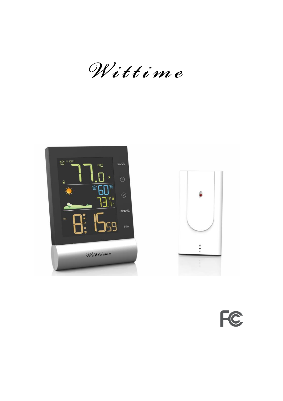
Digital Wireless Thermometer & Hygrometer
With High Precision Sensor
OPERATING INSTRUCTION
Base unit: WT2079
Wireless sensor: WT2022B
Remove the protective film from the display before use.
Page 2

Safety
Read the following advice carefully and store these operating instructions in case you want
to reread something later. If you give the item to someone else, give them these operating
instructions as well.
• This device may be used by children over 8 years of age and over, as well as by persons
with reduced physical, sensory or mental abilities, or lack of experience and / or knowledge
if they are supervised or instructed regarding the safe use of the equipment and have
understood the resulting hazards.
• Keep the device and power adapter away from children under the age of 8.
• Cleaning and user maintenance may not be carried out by children unless they are
supervised.
• Children must be supervised to make sure that they do not play with the device.
• The wireless base unit and power adapter must not be immersed in water or other liquids.
Electric shock hazard! Do not use the base unit in areas where it may be wet, such as a sink.
• Only use the power adapter included in the delivery. The adapter must only be used in dry,
indoor spaces and protected from moisture.
• The power cable cannot be replaced. If the cable or power adapter is damaged, they must
be disposed of and replaced by a power adapter of the same type.
Danger from electricity (when using the power adapter)
• Connect the device to a properly installed power socket with a voltage that corresponds to
the Technical Data.
• Ensure that the socket is easily accessible, so that you can quickly remove the power
adapter if necessary.
• Do not use the wireless base unit if the power adapter or power cable is damaged.
• Do not cover the power adapter with curtains, newspapers, etc. and ensure that it is
sufficiently ventilated. The power adapter can become hot.
• Uncoil the power cable fully before connecting. Be careful not to damage the cable with
sharp edges or hot objects.
• Remove the power adapter from the socket:
- Before cleaning the wireless base unit,
- When a fault occurs during operation,
- During thunderstorms.
- Always pull the power adapter, not the cable.
• Do not modify the items or the power cable. Only allow repairs to be carried out by a
specialist workshop as improperly repaired devices endanger the user.
Page 3

Unpacking and checking
1. Remove the device from the packaging, remove all protective films and keep the
packaging materials out of the reach of children.
2. Dispose of the materials separately according to type.
3. Check that all the items that should be included in the delivery are present and whether
the base unit displays any damage.
Items included in the delivery
• Base unit and wireless sensor
• 3 batteries - LR03 type (AAA) / 1.5 V (base unit)
• 2 batteries - LR6 type (AA) / 1.5 V (wireless sensor)
• Power adapter for base unit
• Operating instructions
Product functions
Base unit
• High-definition color display
• 12- or 24-hour display
• Date, time and day of week display
• 2 alarms can be set, with snooze function
• Indoor temperature display in °C/°F
• Indoor humidity display
• Outdoor temperature display in °C/°F with up to three wireless sensors at different
measurement sites (delivery includes one wireless sensor)
• Minimum/maximum display for temperature and humidity
• Indoor and outdoor temperature trend display
• Weather forecast symbols in Sunny, Partly sunny, Cloudy, Rainy, Heavy rain, Snow and
Heavy snow. (It is possible to manually change the symbols for the prediction)
• Low battery indicator
• Battery or power mains operation
• Adjustable backlight (Bright >> Muted >> Off) when operated by power adaptor
Wireless sensor
• Range of up to 328 ft (100 meters) (in open area)
• Wall mounting bracket
Page 4
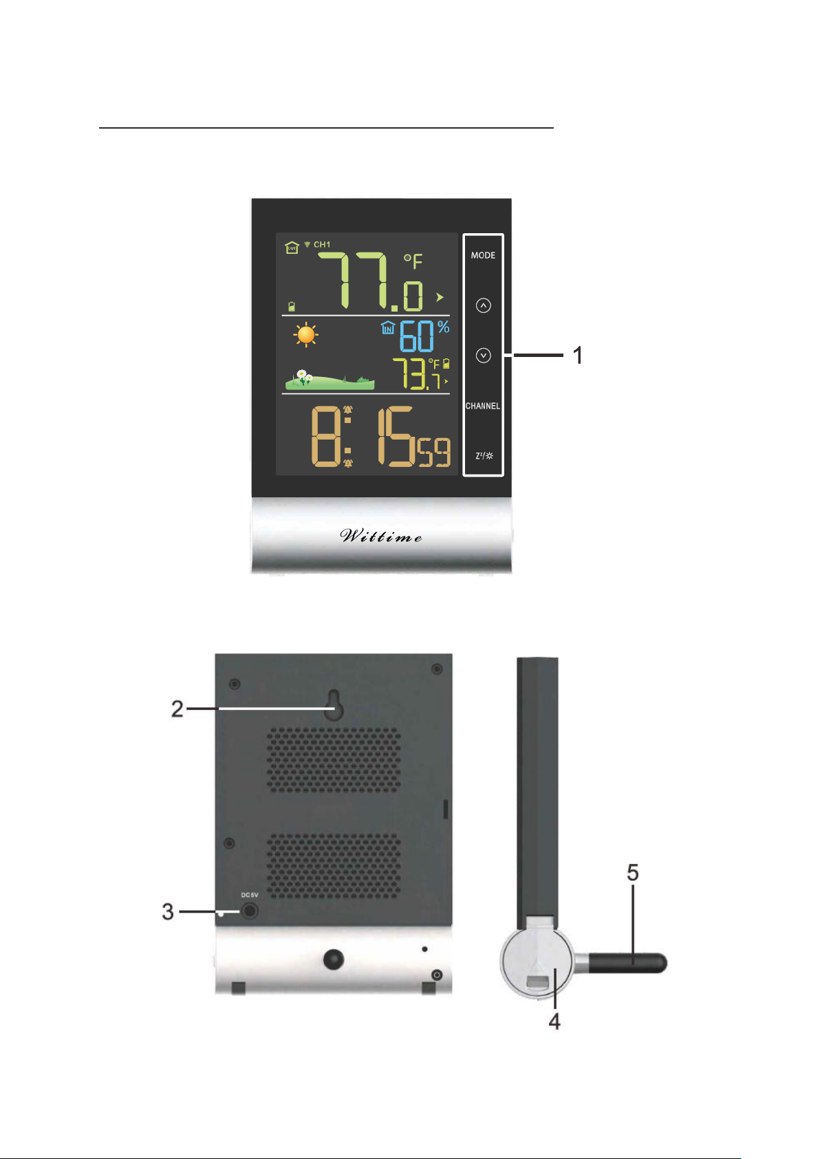
Overview of the thermometer & hygrometer
Base unit – front
Base unit –Back & Side
Page 5
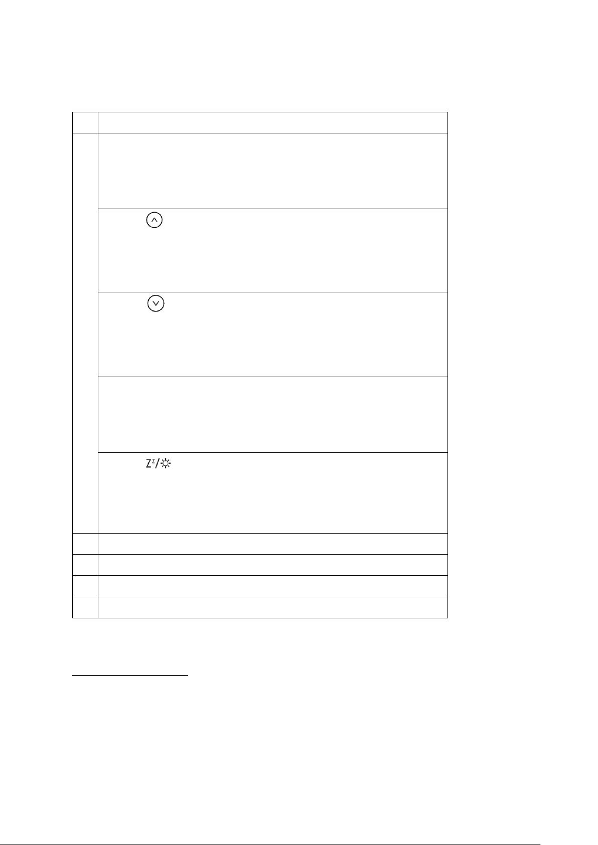
Operating elements and parts of the base unit
1
Operating buttons
Button
MODE
* Display alarm time
* Activate settings mode
* Save changes to settings
Button (Up)
* Set values (increase)
* Display stored MAX and MIN values
* Activate/Deactivate alarm (on alarm mode)
Button (Down)
* Set values (decrease)
* Display: Time, year, month, date and day of week
* Activate/Deactivate alarm (on alarm mode)
Button
CHANNEL
* Display weather data from various wireless sensors ( channel 1.2.3
and automatic)
* Reconnect wireless sensor connection
Button (Snooze/light)
* Illuminate backlight
* Activate snooze function (when the alarm sounds)
* Activate setting mode for weather symbol
2
Loop for hanging
3
Power adaptor port
4
Battery compartment
5
Detachable stand
Wireless sensor
Page 6
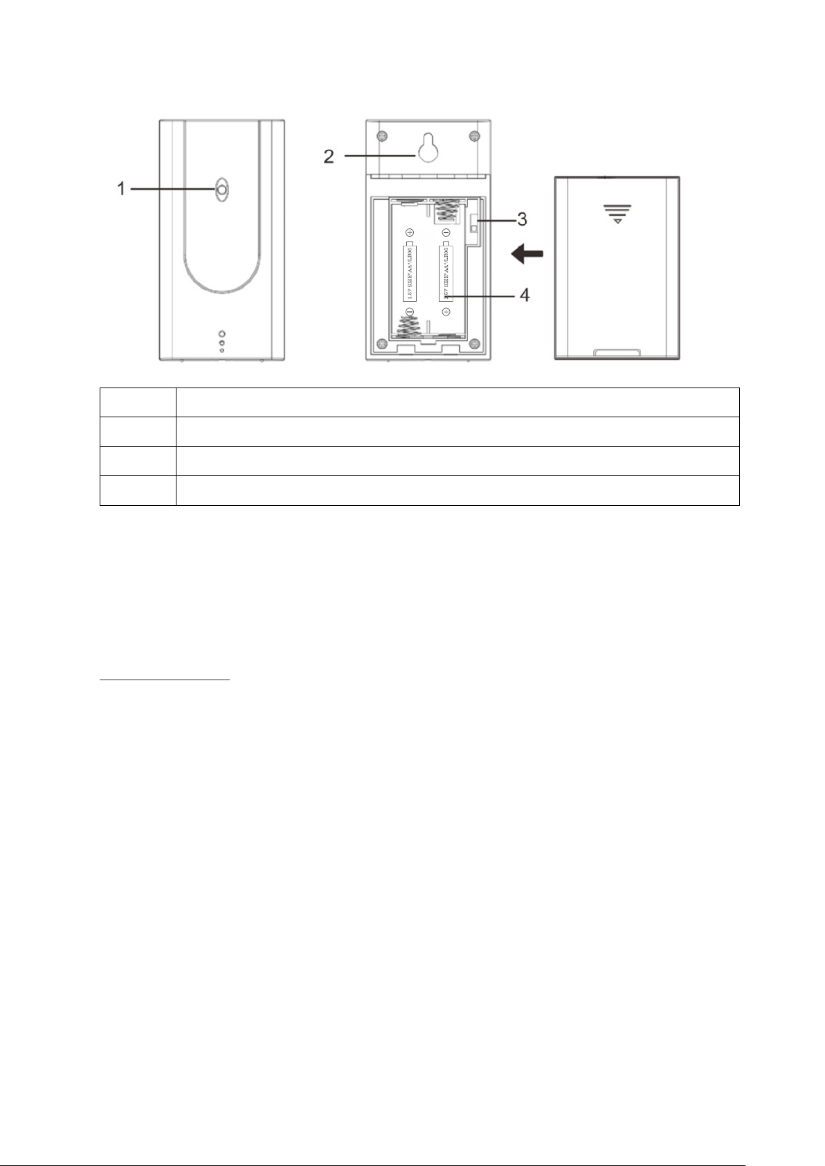
1
Red pilot light
2
Loop for hanging
3
Sliding switch 1 2 3: Set sensor number (transmission channel)
4
Battery compartment
If you wish to use only the wireless sensor included in the delivery, as a general rule, the
transmission channel does not need to be changed.
This is only necessary if you wish to use additional wireless sensors; see “Using additional
wireless sensors”.
Initial setup
Follow the instructions in the order described and first put the batteries in the wireless
sensor. This is the only way for the device to function without any problems. Do not press
any buttons while switching the device on.
Wireless sensor
1. Remove the battery compartment cover on the back of the wireless sensor.
2. Insert 2 LR6 (AA) / 1.5 V batteries facing in the direction indicated on the bottom of the
battery compartment. Make sure that the poles of the batteries are correct (+/-). As soon as
the wireless sensor is receiving power, the red pilot light will light up and thus display that
data is being transmitted to the base unit.
3. Put the battery compartment cover back in place.
- Do not use batteries that have a voltage that is too low (only 1.2 V instead of 1.5 V). This
affects the accuracy of the measurements, among other things.
Page 7

- If possible, use alkaline batteries instead of zinc-carbon batteries. Alkaline batteries last
longer, particularly outside in low temperatures.
Using addition wireless sensors
The device comes with one wireless sensor. However, you can operate it with up to three
wireless sensors. Additional wireless sensors are available via our online shop.
• The wireless sensors can be located in different rooms or outdoors.
• Every sensor must be assigned its own sensor number (= number of the transmission
channel) (1 to 3).
• For the snow and frost warning, the base unit only analyses the information from the
sensor with the lowest number (by default 1). If only one sensor is connected to channel 1, 2
or 3, the display will function on all 3 channels.
Procedure:
1. Remove the battery compartment cover on the back of the wireless sensor.
2. Set a different sensor number for each wireless sensor with the sliding switches.
3. Put the battery compartment cover back in place on the wireless sensors. If adding
another sensor later or after changing the batteries:
4. Press and hold the
CHANNEL
button on the base unit until the radio frequency symbol
flashes. The base unit will now retrieve the weather information from all available
wireless sensors.
Base unit
You can operate the wireless base unit using the power adapter or with batteries. If the base
unit is connected to a power socket, it will be operated using the power mains, even if there
are batteries in the device. Remove depleted batteries from the battery compartment, as
they can leak.
A) Power mains operation
ATTENTION
Use only the power adapter included in the delivery for power mains operation.
1. Insert the power adapter included in the delivery into the base unit port.
2. Plug the power adapter into a socket that corresponds to the voltage listed in the
Technical Data.
3. Wait several minutes. The base unit needs this time to collect all the weather data.
Page 8
B) Battery operation
1. Open the battery compartment cover.
2. Insert 3 LR03 (AAA) / 1.5 V batteries facing in the direction indicated on the bottom of the
battery compartment. Make sure that the poles of the batteries are correct (+/-).
3. Put the battery compartment cover back in place and close it.
4. Wait several minutes. The base unit needs this time to collect all the weather data.
Information
:
The device will lose all information when switching it on again.
Set weather symbol manually
After the base unit power on, the weather symbol will flash on the display.
1. Set the appropriate weather symbol with the
and buttons.
2. Press the
button to select.
Information
:
The weather symbol will only be automatically displayed 24 hours later.
Radio frequency signal connection
After weather symbol selected, radio frequency symbol will flash on the display and the
device will start to receive RF signal from wireless sensor for 3 minutes, the corresponding
outdoor temperature value will be displayed.
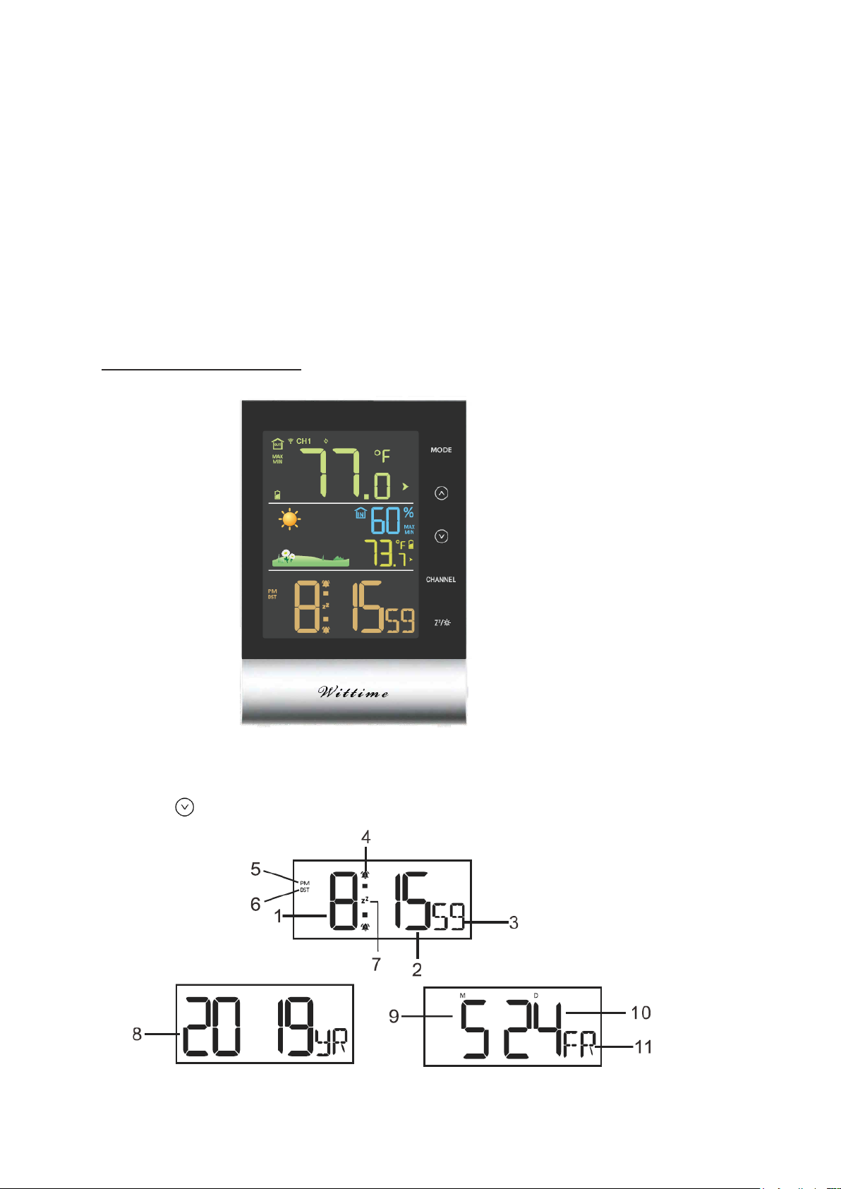
If NOT received successfully, press and hold the
CHANNEL
button to reconnect.
Setting the time and date manually
1. Press and hold the
MODE
button until the display for the year begins to flash.
2. Set the year with the and buttons.
3. Press
MODE
to store the setting. The date format will flash on the display.
4. Set the date format with the and buttons (Month/Day or Day/Month).
5. Press
MODE
to store the setting.
6. Continue as described:
- Set a value with and .
- Store a setting with
MODE
.
7. Set the following settings one after another:
- Month
- Day
Page 9

- Hours
- Minutes
- 12/24 Hour format (in the 12-hour format, the afternoon hours are shown with “PM” on
the display)
- DST ON/OFF (If on, DST will be shown on the display)
- Temperature unit (°C or °F)
- Language (only refers to how the days of the week are displayed)
8. Then press
MODE
to store the changed setting.
Information:
Press and hold or button, the value will increase or decrease fast.
Choosing the location
ATTENTION
- Protect the base unit and wireless sensor from dust, shocks, extreme temperatures and
direct sunlight.
- Protect the base unit from moisture. Only place the base unit in a dry, enclosed space.
- The wireless sensor is protected against moisture but must be protected against water, e.g.
rain.
General
The base unit and wireless sensor exchange information over a radio frequency. For this
reason, the location is important for the range of the wireless connection. Note:
• The maximum distance between the base station and wireless sensor is 328 ft (100
meters). However, this range is only possible in open area.
• Shielding building materials such as reinforced concrete reduce or prevent the radio
reception between the base station and wireless sensor.
• Devices such as televisions, cordless phones, computers and fluorescent tubes can also
interfere with the wireless reception.
• Do not place the base unit and wireless sensors directly on the floor. This restricts the
range.
• In low temperatures in winter the battery performance of the wireless sensors can be
significantly reduced. This reduces the transmitter range.
Base unit
DANGER
Page 10
When installing the device on a wall, there must be no electrical cables, gas or water pipes
in the wall at the installation site. Otherwise there is a risk of electric shock!
• You can put the base unit on the desk or hang it up.
Wireless sensor
• Place or hang the wireless sensor in a place where it is protected from direct weather (rain,
sun, wind, etc.). Suitable locations include e.g. under a porch or in a carport.
Display indicators
Time function
Press the button to switch: Time, year, month, date and day of week display.
Page 11
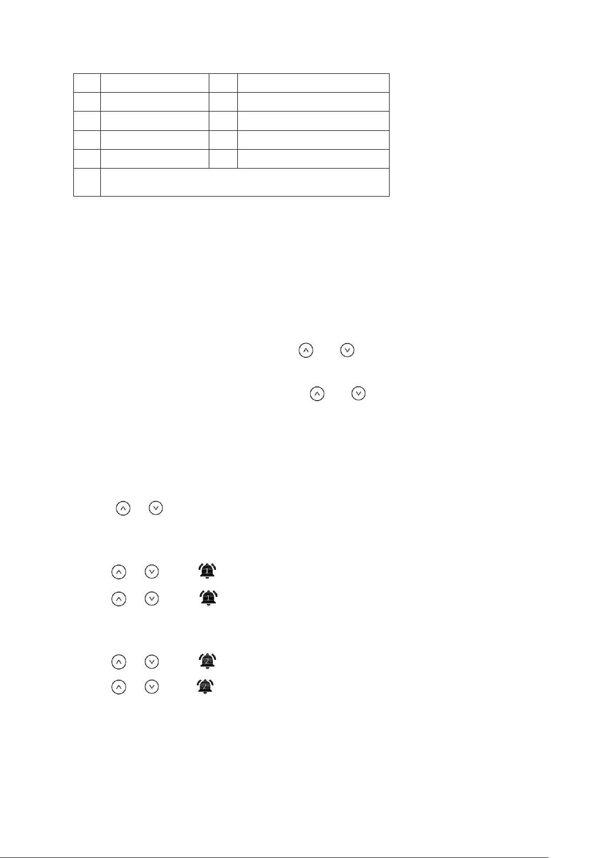
1
Hour
6
Daylight saving time (DST)
2
Minute
7
Snooze symbol
3
Second
8
Year
4
Alarm symbol
9
Month
5
PM symbol
10
Date
11
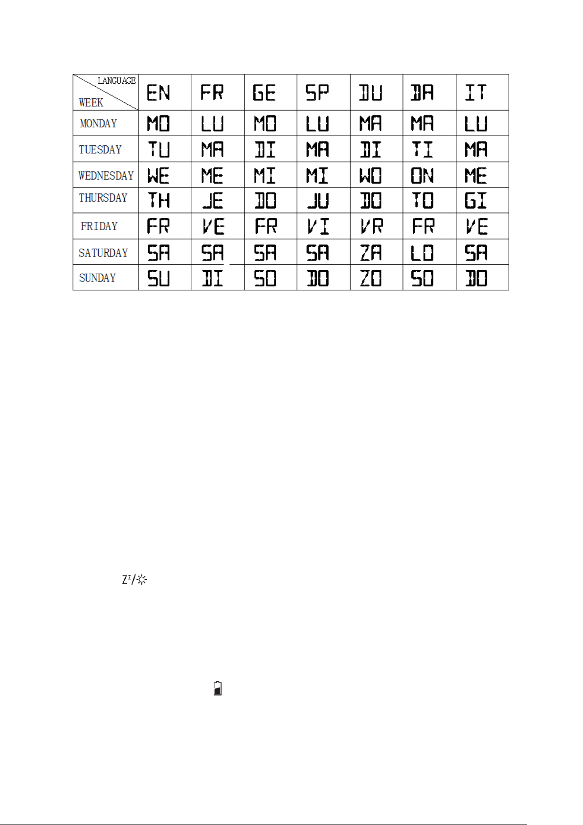
Languages (only refer to day of week)
Alarm function
The base unit allows you to set two different alarm times. For example, you can set an alarm
for the morning and for after an afternoon nap by activating both alarm times.
1. Use the
MODE
button to select the desired alarm time (A1 or A2).
2. Hold and press the
MODE
button for approx. 2 seconds once you have chosen the
desired alarm time. The hour indicator of the alarm time (A1 or A2) will flash.
3. Set the desired hour for the alarm with the and buttons.
4. Press
MODE
to store the setting. The minute indicator will flash on the display.
5. Set the desired minute for the alarm with the and buttons.
6. Press
MODE
to store the setting. The alarm time is set and activated.
Switching the alarm on and off
Use the
MODE
button to switch the alarm 1 or alarm 2.
Use the or button to switch the alarm on and off.
On ALARM 1:
• press
or once: on the display, A1 is activated
• press or twice: disappear, A1 is deactivated
On ALARM 2:
• press
or once: on the display, A2 is activated
• press or twice: disappear, A2 is deactivated
Stopping the alarm
Page 12
You will be woken by the alarm at the set time, and the sound will become more and more
intense as the alarm continues.
• Snooze - Press the
button to stop the alarm for approx. 5 minutes.
• Switch off the alarm completely - Press any button on the base unit (apart from ), to
stop the alarm. The alarm will go off again after 24 hours.
• Automatic stop function- If you do not press any buttons, the alarm will automatically switch
off after 2 minutes. The alarm will go off again after 24 hours.
Snooze function
Press the button once when the alarm sounds.
The alarm signal is paused for approx. 5 minutes, and the alarm symbol and symbol will
flash on the display. Afterwards, the alarm will sound and wake you up again. You can
repeat this process multiple times.
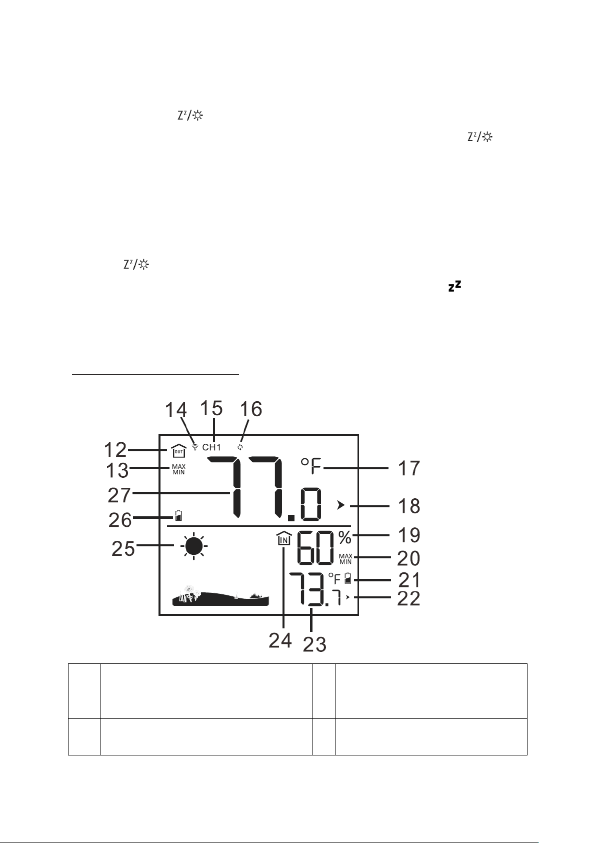
Weather information
12
Outdoor symbol
20
Stored maximum and minimum
values for indoor temperature
and humidity
13
Stored maximum and minimum values
for outdoor temperature
21
Indoor low battery indicator
14
Page 13
Radio frequency signal reception symbol
22
Indoor temperature trend
15
Current transmission channel to the
base unit
23
Indoor temperature
16
Transmission channel automatic
switching mode
24
Indoor symbol
17
Temperature unit: °C or °F
25
Weather symbol
18
Outdoor temperature trend
26
Outdoor low battery indicator
19
Indoor humidity
27
Outdoor temperature
The highest and lowest temperature and humidity values by repeatedly pressing the
button.
• press once: the maximum values are shown
• press again: the minimum values are shown
• press again: returns to normal display
Press and hold the button to delete the highest and lowest temperature and humidity
values.
Information:
It also has an ice alert. For more information about this, see ice alert section.
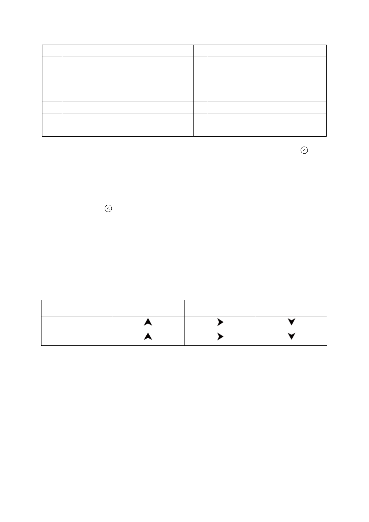
Weather trend
For the temperature and humidity values measured by the base unit and the wireless sensor,
the trend is displayed in the form of an arrow:
Trend
rising
constant
falling
Temperature
Humidity
Weather forecast
After setting up initially, the weather forecast can not be used for about 12 hours, as the
device needs this time to collect and evaluate the weather data.
The weather forecast is a result of the collected data and the measured changes in air
pressure.
The forecast refers to the area around the device with a radius of about 30 to 50 km for the
next 12 to 24 hours.
The accuracy of the weather forecast is around 75 %.
Page 14
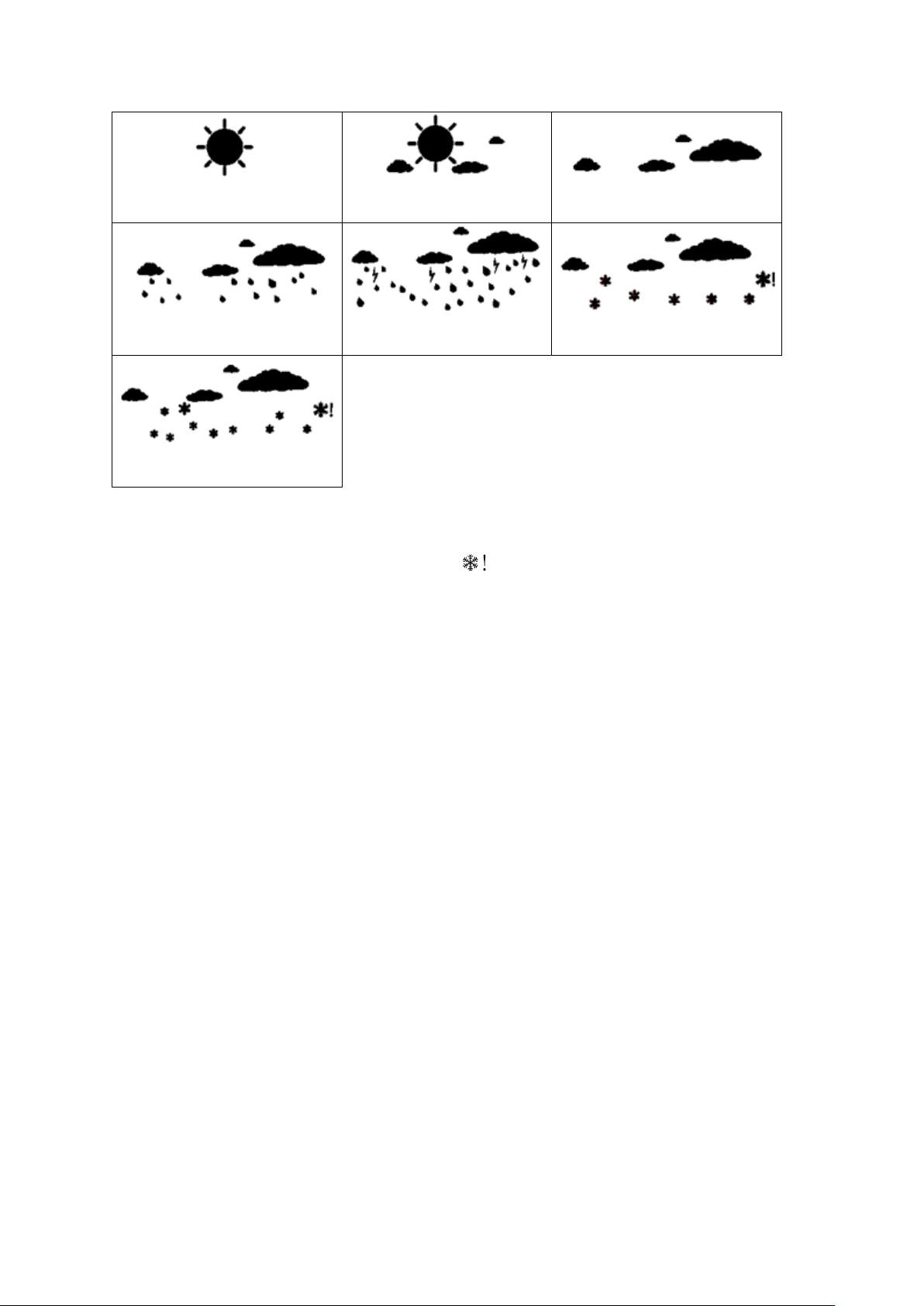
Sunny
Partly sunny
Cloudy
Rainy
Heavy rain
Snow
Heavy snow
Ice alert
- If the wireless sensor measures a temperature between 33.8 °F and 30.2°F,
there is a risk of frost and a snowflake symbol will flash. If the temperature falls below
30.0°F for an extended period of time, the snowflake symbol will be constantly displayed.
Note: Even if the ice alert is not displayed, when the temperature is around freezing point,
there is generally always a risk of frost and/or black ice. The outdoor sensor can only
measure the local temperature in the place where it is installed.
Information:
Only applies if more than one wireless sensor is in use: For the temperature
alarm, the wireless sensor with the lowest sensor number is always analysed.
Languages of day of week
The language options are English (EN), German (GE), French (FR), Italian (IT), Spanish
(SP), Dutch (DU) and Danish (DA).
Page 15
DST function
The device will adapt to winter / summer time automatically if DST switches ON.
Summer time: the second Sunday of March at 1:59 59’ changes to 3:00 00’
Winter time: the first Sunday of November at 1:59 59’ changes to 1:00 00’
Switching the light on
A) Battery operation
Press any buttons to light up the display for 10 seconds.
B) Power mains operation
When the base unit is powered through the power adapter, the display is constantly
illuminated.
Press the button repeatedly to select the following settings for the display illumination:
Bright >> Muted >> Off.
Low battery indicator
For the base unit and the wireless sensor, there is a separate low battery indicator.
When the low battery symbol is shown on the display, you have to replace the batteries in
the base unit or the wireless sensor with new batteries.
Note:
Page 16

• The low battery symbol for the wireless sensor shows that the batteries need changing for
Problem
Possible cause and remedy
Display screen not
working.
Check the batteries in main unit are inserted or power
adaptor is plugged in correctly
The temperature from the
sensor seems to be too
high.
- Check if the sensor is exposed to direct sunlight.
The display shows HH,
LL, HH.H or LL.L instead
of measured values for
temperature or humidity.
- The values are above or below the measuring range, see
Technical Data.
* Indoor temperature: Below 14.2°F , “LL.L” will display; Over
122°F , “HH.H” will display.
* Indoor humidity: Below 1%, “1%” will display; Over 99%,
“99%” will display.
The base unit is not
receiving any signal from
the wireless sensor.
- Make sure that there are no electrical sources of
disturbance near the wireless sensor or the base unit.
- Check the batteries in the sensor.
- Start the search for the wireless sensor manually: Press
and hold the
CHANNEL
button on the base unit until the
display for the weather information flashes
- Move the base unit closer to the sensor or vice versa.
The display is illegible, the
function is not clear or the
values are clearly wrong.
- Reset the device to the factory settings
the channel number shown.
• When you change the batteries all the settings are lost.
• Always exchange all batteries and only use those listed in the ‘Technical Data’.
• Even if the base unit is being powered by the power mains, you should still remove any
empty batteries present from the base unit.
• Make sure that the poles of the batteries are correct (+/-) when inserting.
• Clean the battery and device contacts if necessary before inserting.
• Dispose of the old batteries in an environmentally manner
.
Troubleshooting
Page 17

Cleaning
1. When operating using the power mains: Remove the power adapter plug from the base
unit.
2. Wipe the base unit with a slightly damp cloth when required.
3. Dry off the device completely before connecting it with the power adapter again.
Technical Data
Base unit
Model: WT2079
Power consumption: 5.0V 150 mA
Power supply: 3 x LR03 (AAA) / 1.5 V
Temperature measuring range: 14.2°F ~ 122°F
Resolution: 0.2°F
Humidity measuring range: 1 % to 99 % relative humidity
Humidity measuring accuracy: +/-1 %
Resolution: 1 %
Wireless sensor
Model: WT2022B
Batteries: 2 x LR6 type (AA) 1.5 V
Temperature measuring range: - 40°F to 158°F
Protection type: IPX4: Protection against splash water from all directions
Humidity measuring accuracy: +/- 1%
Transmission frequency: 433.92 MHz
Range: max. 328 ft (100 meters) (in open area)
Power adapter
Input: 120VAC 60Hz 50mA 7W
Output: 5.0VDC 150mA
As our products are constantly evolving and improving, changes in the design and
technology are possible.
Page 18

FCC Statement
This device complies with Part 15 of the FCC Rules. Operation is subject to the following
two conditions: (1) This device may not cause harmful interference, and (2) This device must
accept any interference received, including interference that may cause undesired operation
WARNING:
responsible for compliance could void the user’s authority to operate the equipment.
NOTE:
digital device, pursuant to Part 15 of the FCC Rules. These limits are designed to provide
reasonable protection against harmful interference in a residential installation.
This equipment generates uses and can radiate radio frequency energy and, if not installed
and used in accordance with the instructions, may cause harmful interference to radio
communications. However, there is no guarantee that interference will not occur in a
particular installation. If this equipment does cause harmful interference to radio or television
reception, which can be determined by turning the equipment off and on, the user is
encouraged to try to correct the interference by one or more of the following measures:
• Reorient or relocate the receiving antenna.
• Increase the separation between the equipment and receiver.
• Connect the equipment into an outlet on a circuit different from that to which the receiver is
connected.
Changes or modifications to this unit not expressly approved by the party
This equipment has been tested and found to comply with the limits for a Class B
• Consult the dealer or an experienced radio / TV technician for help.
•
This equipment complies with FCC radiation exposure limits set forth for an
uncontrolled environment. This transmitter must not be co-located or operating in
conjunction with any other antenna or transmitter.
Disclaimers
Manufacturer reserves the right to change specifications of the product.
Manufacturer and supplier are not responsible for malfunction where interference occurs.
 Loading...