

Page 1
19" LCD Color Monitor HP W19
Service
Service
Service
Horizontal Frequency
30- 83 kHz
TABLE OF CONTENTS
Description Page Description Page
Table Of Contents.......……..............................…........1
Revision List.…........................................……......2
1. Monitor Specification..............................………........3
2. LCD Monitor Description…………………………….......4
3. Operation Instruction…………...............……...........5
3.1. General Instructions...........................…...........5
3.2. Control Button…………….…..............……...............5
3.3 Adjusting the Picture...........................…............6
4. Input/Output Specification............……………............7
4.1. Input Signal Connector............………….................7
4.2. Factory Preset Display Modes......…..................8
5. Panel Specification.....………………..................9
5.1. General Feature…….....………………..................9
5.2. Optical Characteristics………………………………9
6. Block Diagram……...................…………................10
6.1. Monitor Exploded View…………………....….......10
6.2 Software Flow Chart…………………….……….11
6.3. Electrical Block Diagram……………..….......13
7. Schematic……………......................................15
7.1 Main Board....……….......................................15
7.2 Power Board.….……....................................21
8.PCB Layout..………….......................................24
8.1. Main Board………........................................24
8.2. Power Board….......................................27
8.3. Adapter Board………............….......................30
9. Maintainability……….......................................31
9.1. Equipments and Tools Requirement..............31
9.2. Trouble Shooting………..............................32
10. White-Balance, Luminance adjustment...36
11. BOM List….....................................................37
12. Different Parts List…………………………………47
SAFETY NOTICE
ANY PERSON ATTEMPTING TO SERVICE THIS CHASSIS MUST FAMILIARIZE HIMSELF WITH THE CHASSIS
AND BE AWARE OF THE NECESSARY SAFETY PRECAUTIONS TO BE USED WHEN SERVICING ELECTRONIC
EQUIPMENT CONTAINING HIGH VOLTAGES.
CAUTION: USE A SEPARATE ISOLATION TRANSFOMER FOR THIS UNIT WHEN SERVICING
1
Page 2
19" LCD Color Monitor HP W19
Revision List
Version Date Revision History TPV Model Name
A00 Jun.-03-2007 first release T97MM2HKWEHANE
A01 Jun.-19-2007 Add TPVDW Model in Item 12 T97SM2HKWEHANE
A02 Sep.-04-2007 Add TPVDW Model in Item 12
T97MM2HTWEHPNNE
T97SM2HTWEHPNNE
2
Page 3
19" LCD Color Monitor HP W19
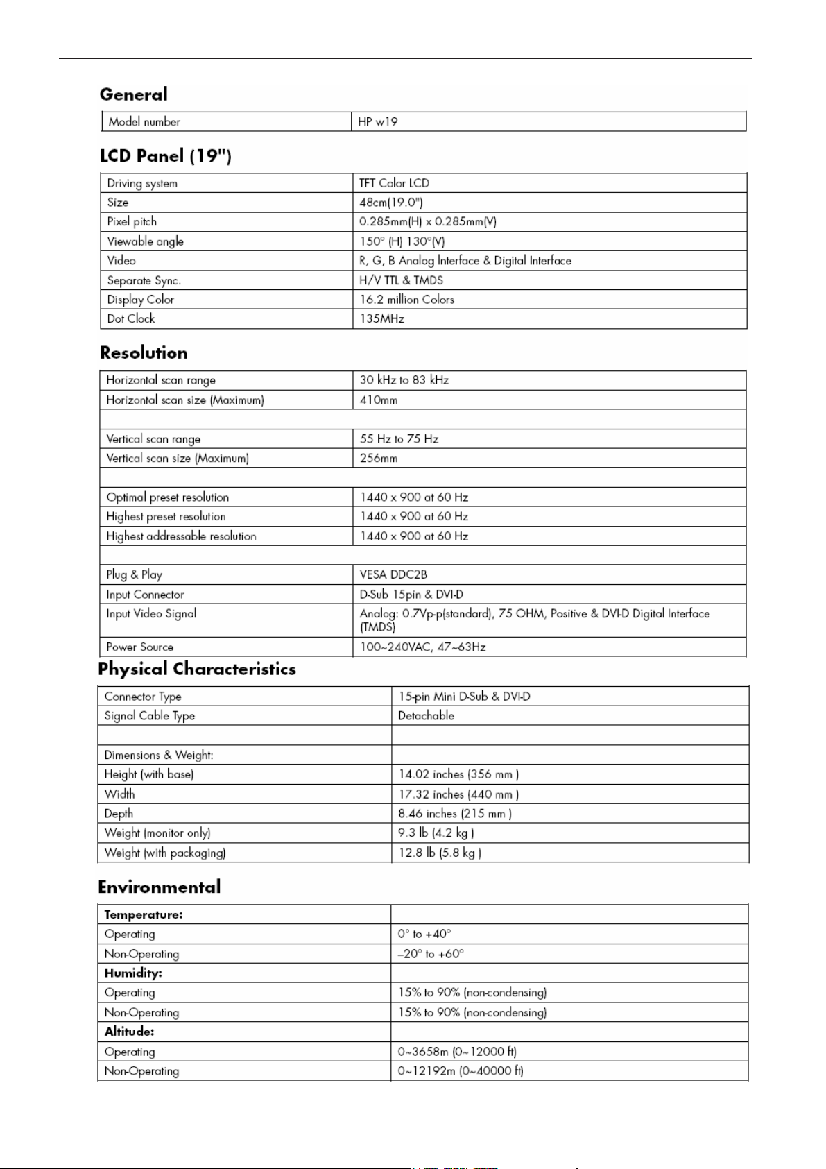
1. Monitor Specification
3
Page 4
19" LCD Color Monitor HP W19
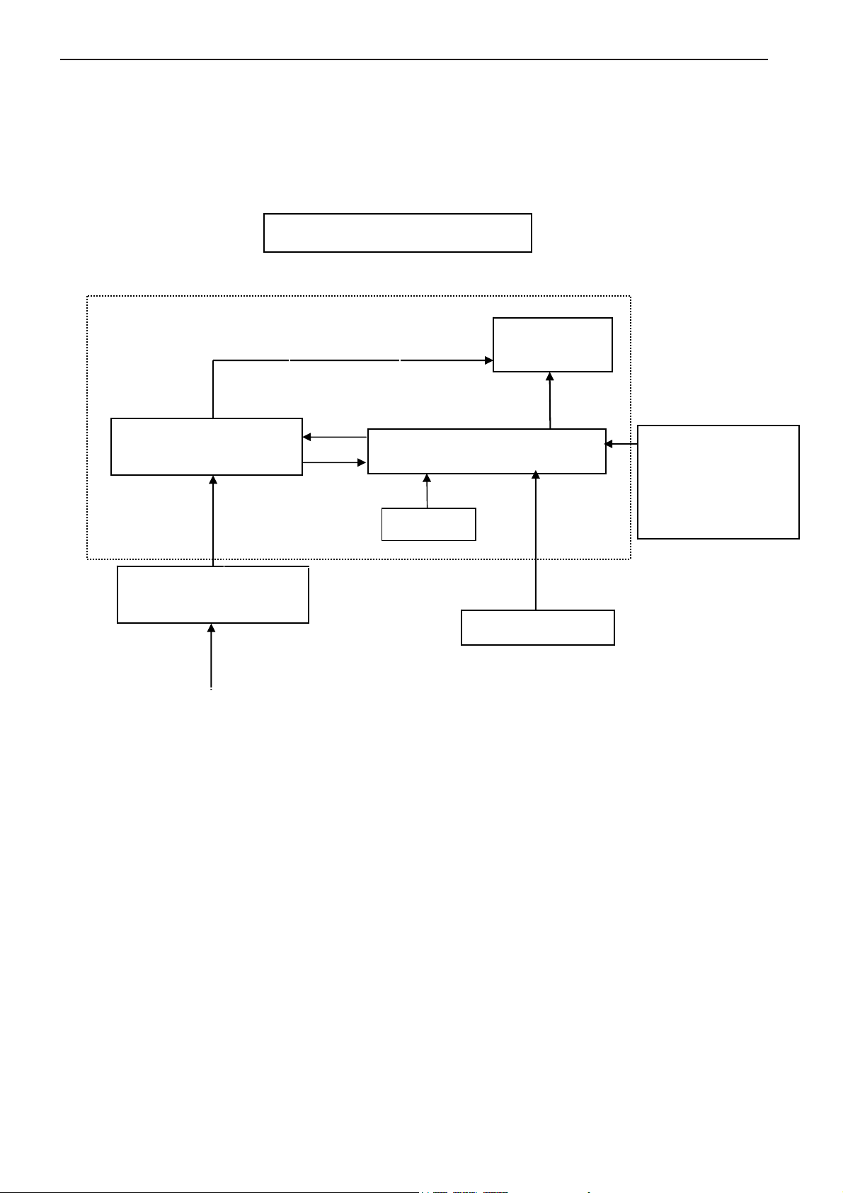
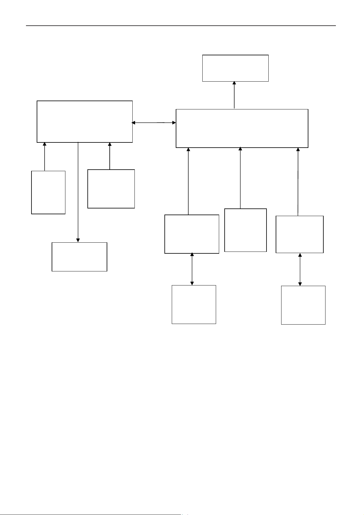
2. LCD Monitor Description
The LCD Monitor will contain main board, power board, key board and an audio board which house the flat panel
control logic, brightness control logic and DDC.
The power board will provide AC to DC Inverter voltage to drive the backlight of panel and the main board chips each
voltage.
Inverter board
Adaptor board
DC-IN
12V
Monitor Block Diagram
CCFL Drive.
Main Board
Keyboard
HOST Computer
Flat Panel and
CCFL backlight
RS232 Connector
For white balance
adjustment in factory
mode
Video signal
AC-IN
100V-240V
4
Page 5
19" LCD Color Monitor HP W19
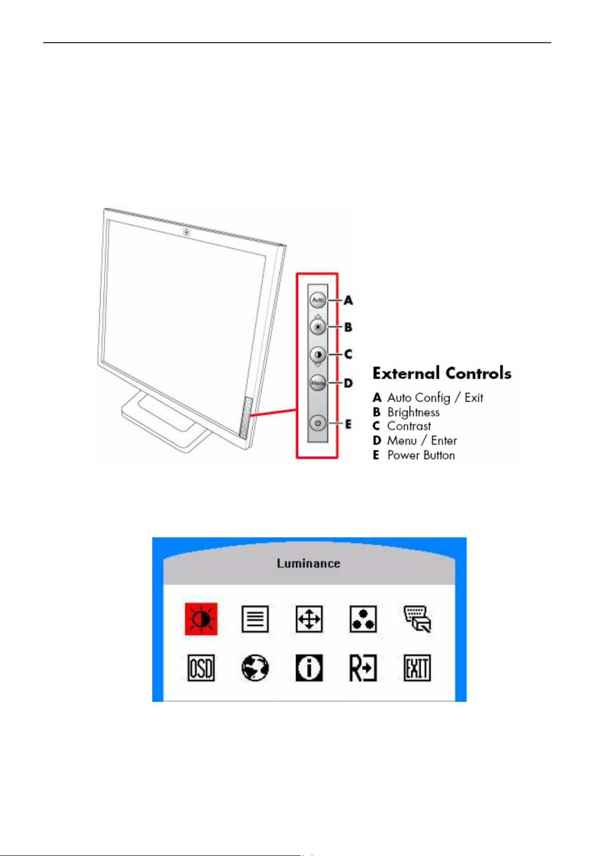
3. Operation Instructions
3.1 General Instructions
Press the power button to turn the monitor on or off. The other control buttons are located at front of the panel. By
changing these settings, the picture can be adjusted to your personal performance.
The power cord should be connected and insert to adaptor.
-
Connect the video cable from the monitor to the computer VGA card.
-
- Press the power button to turn on the monitor, the power indicator will light up to Green.
3.2 Control Buttons
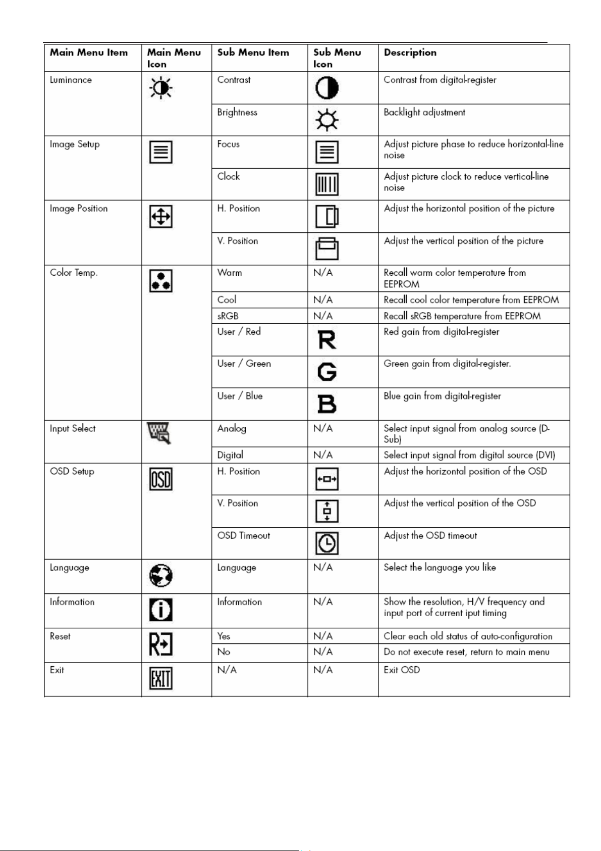
3.3 Adjust the Picture
5
Page 6
19" LCD Color Monitor HP W19
6
Page 7
19" LCD Color Monitor HP W19
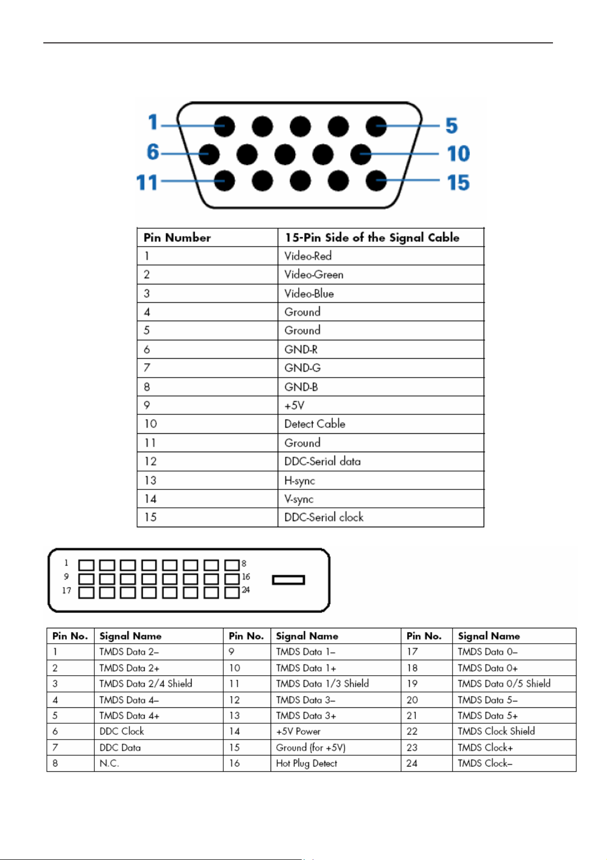
4. Input/Output Specification
4.1 Input Signal Connector
7
Page 8
19" LCD Color Monitor HP W19
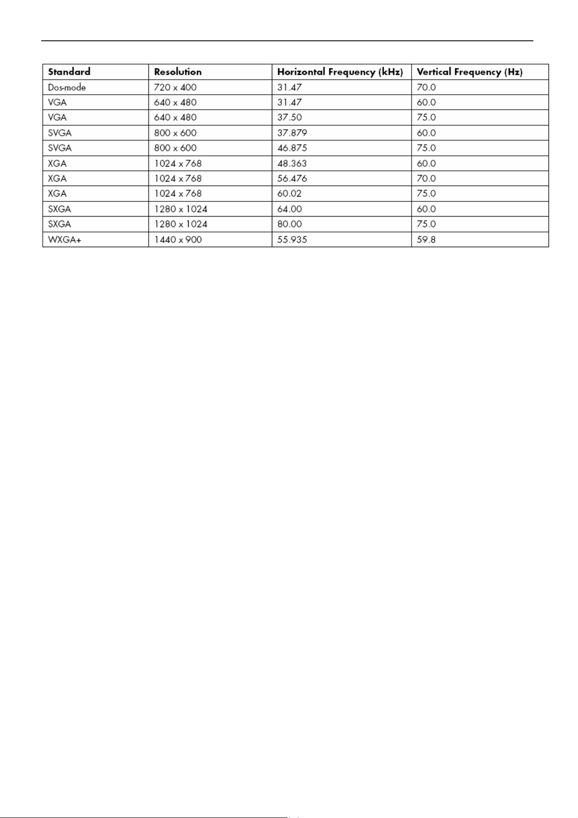
4.2 Factory Preset Display Modes
8
Page 9
19" LCD Color Monitor HP W19
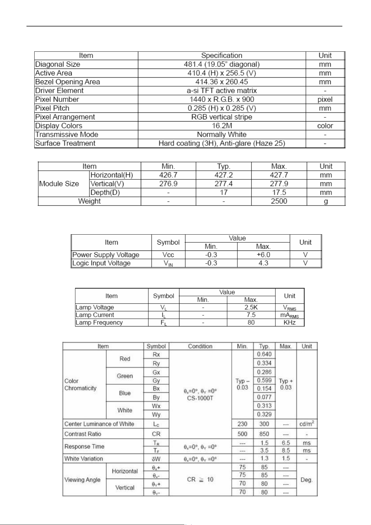
5. Panel Specification
5.1 General Feature
Mechanical Information
5.2 Optical Characteristics
TFT LCD Module:
Back Light Unit:
Optical Specification
9
Page 10
19" LCD Color Monitor HP W19
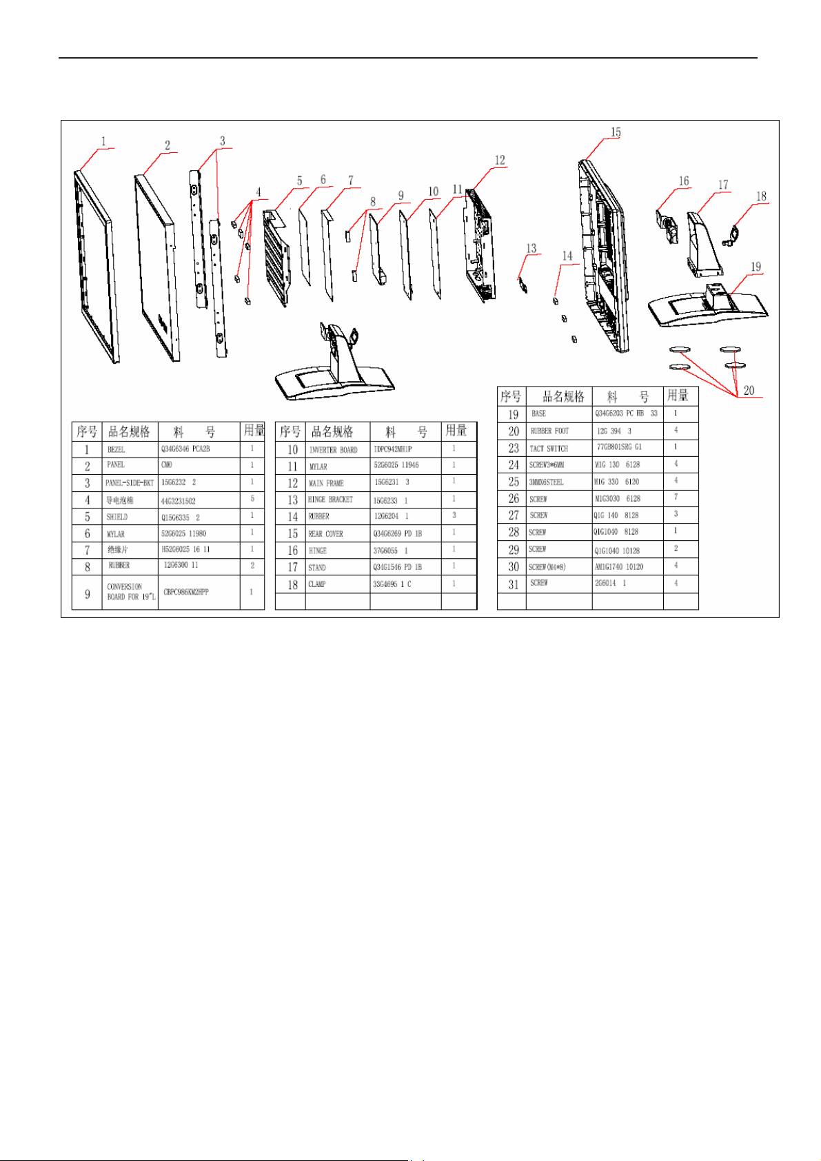
6. Block Diagram
6.1 Monitor Exploded View
10
Page 11
19" LCD Color Monitor HP W19
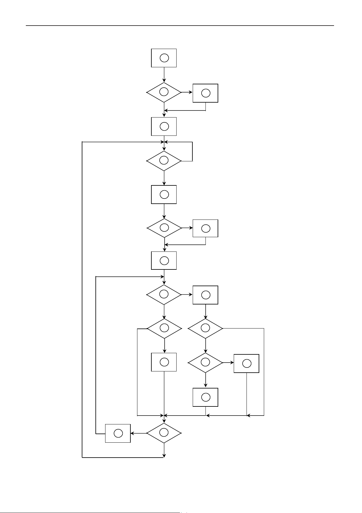
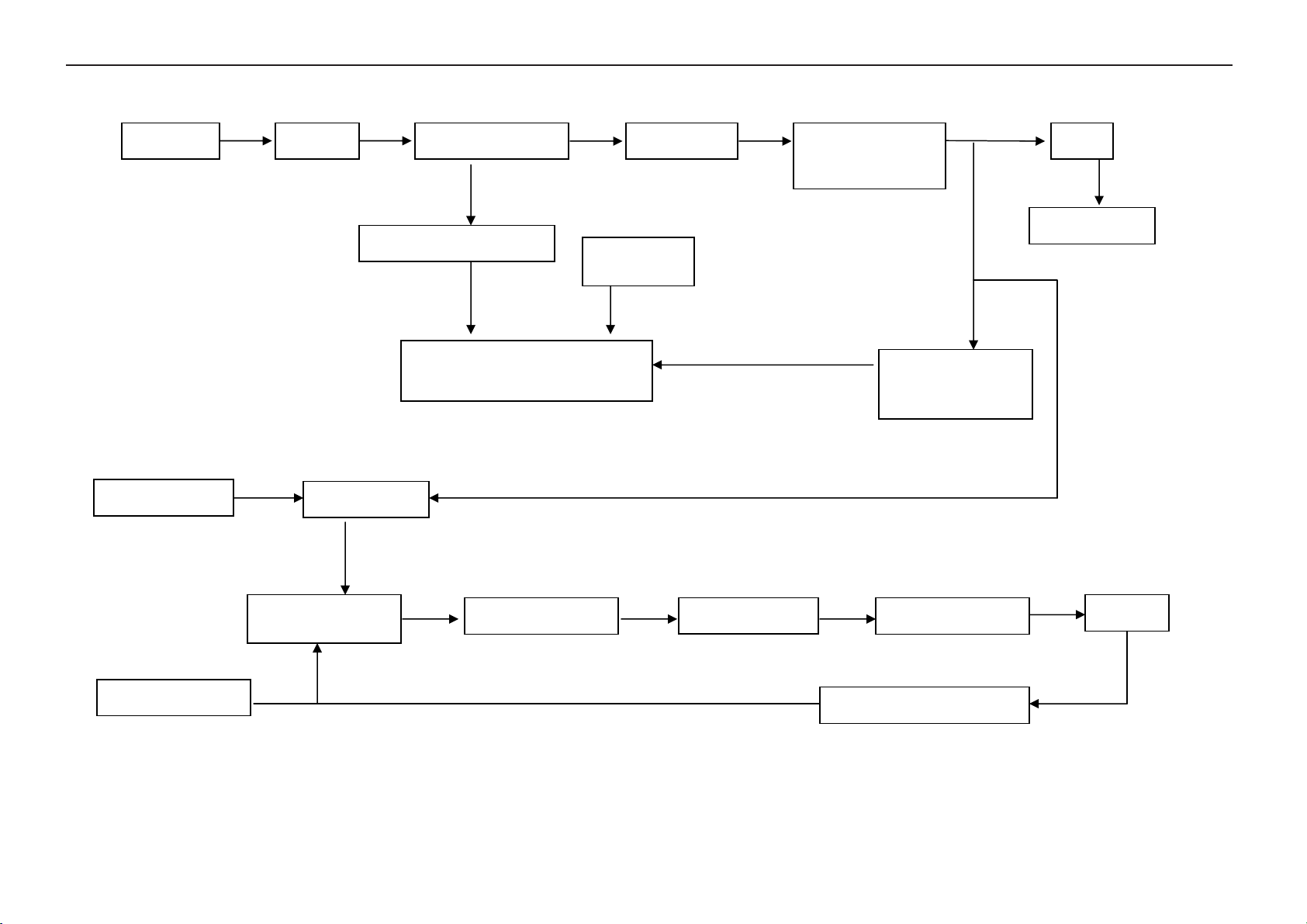
6.2 Software Flow Chart
1
Y
2
N
3
4
5
N
Y
6
N
7
8
Y
9
10
N
11
12
Y
13
N
N
Y
14
15
Y
N
16
Y
17
18
N
19
Y
11
Page 12
19" LCD Color Monitor HP W19
REMARK:
1) MCU initialize.
2) Is the EEprom blank?
3) Program the EEprom by default values.
4) Get the PWM value of brightness from EEprom.
5) Is the power key pressed?
6) Clear all global flags.
7) Are the AUTO and SELECT keys pressed?
8) Enter factory mode.
9) Save the power key status into EEprom.
Turn on the LED and set it to green color.
Scalar initialize.
10) In standby mode?
11) Update the lifetime of back light.
12) Check the analog port, are they’re any signals coming?
13) Does the scalar send out an interrupt request?
14) Wake up the scalar.
15) Are there any signals coming from analog port?
16) Display "No connection Check Signal Cable" message. And go into standby mode after the message
disappear.
17) Program the scalar to be able to show the coming mode.
18) Process the OSD display.
19) Read the keyboard. Is the power key pressed?
12
Page 13
19" LCD Color Monitor HP W19
_
6.3 Electrical Block Diagram
6.3.1 Scalar Board
LCD Interface
(CN503)
MCU
MTV512GMV PLCC-44
(U601)
Crystal
X601
24Mhz
Key Board
CN602
EEPROM
M24C16
(U602)
EPR_SDA
EPR_SCL
DB15_SDA,
DB15
H sync
V sync
RGB
Connector
SCL
D-Sub
(CN301)
EEPROM
M24C02
(U301)
TSU56AK-LF
(Include ADC, OSD)
(U401)
14.318Mhz
Crystal
X401
RGB
CLK+
CLK-
SDA,
SCL
DVI
Connector
(CN302)
EEPROM
M24C02
(U302)
13
Page 14
19" LCD Color Monitor HP W19
6.3.2 Inverter / Power Board
AC inlet filter Rectifier and filter
Start circuit R903;R904
Switching circuit
PWM control IC&MOSFET
On/off control
Start circuit
PWM control IC
BUCK and chock
Dimming control
OVP
Transformer
LC royer circuit
Rectifier and filter
D904;D905
Feedback circuit
IC902;IC903
Ballast capacitor
Feebback circuit
12V
To main board
12V
lamp
14
Page 15
19" LCD Color Monitor HP W19
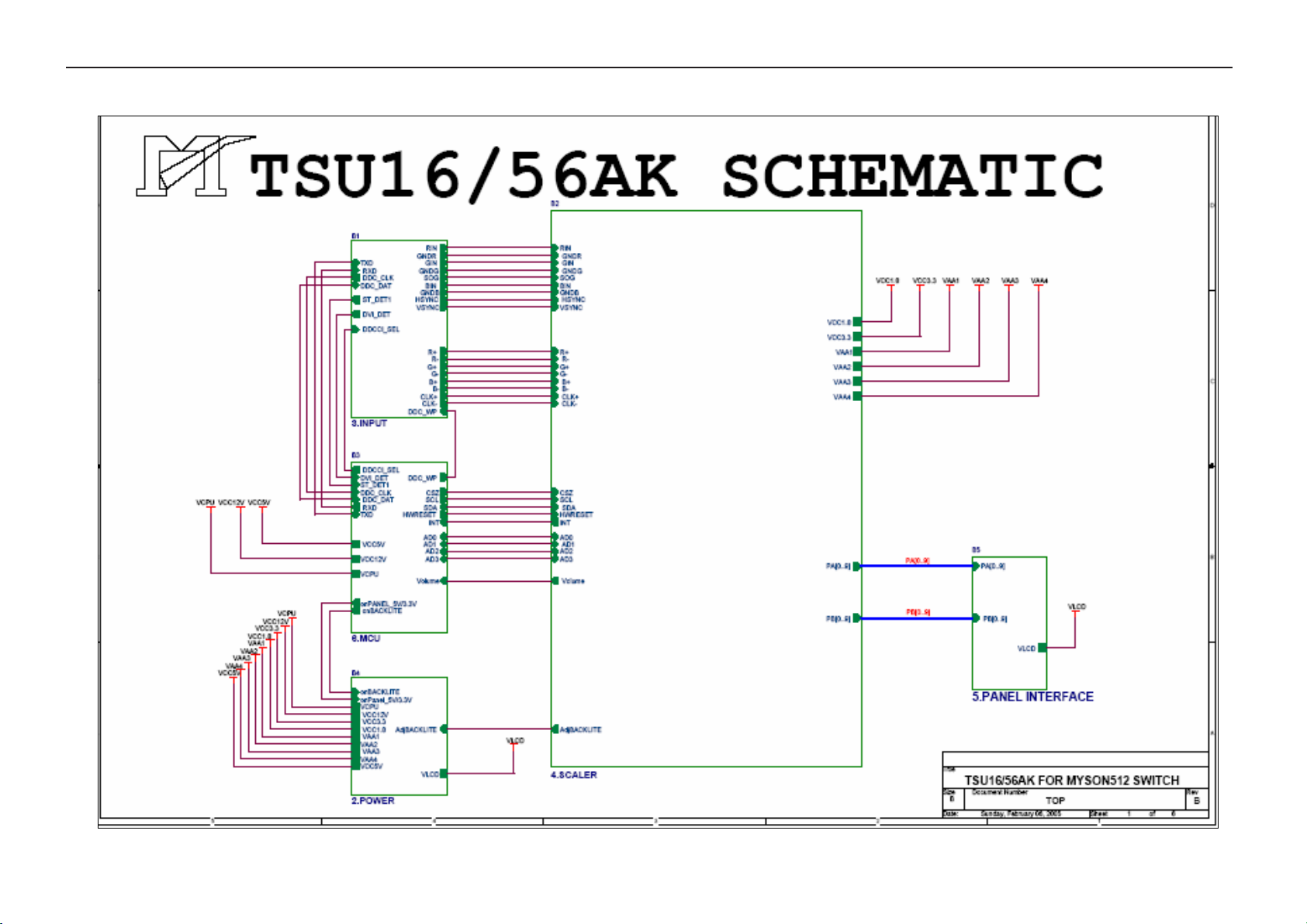
7. Schematic
7.1 Main Board
15
Page 16

19" LCD Color Monitor HP W19
16
Page 17

19" LCD Color Monitor HP W19
17
Page 18

19" LCD Color Monitor HP W19
18
Page 19

19" LCD Color Monitor HP W19
19
Page 20

19" LCD Color Monitor HP W19
20
Page 21

19" LCD Color Monitor HP W19
7.2 Power Board
Adapter
LED1
R925
472/1206
C910
102/500V/1206
R922
R923
470/1206/0.5W
470/1206/0.5W
1 2
3
O
4
R903
624/1206
1
12V
C914
C913
0.1UF/0805/X7R
+
1000UF/16V
L903
2
1
C920
73A-253-91L
+
C912
+
1000UF/25V
1000UF/25V
C911
+
1000UF/25V
D904
20A/100V
11.1267.8
1 2
3
R908
R907
204/1206
R906
204/1206
R905
204/1206
C905
204/1206
152/1KV
C904
+
150UF/400V
3
2
GND
ZD902
RJ1
copper-manganese /8m
12V/SMD
R924
241/DIP
D905
20A/100V
O
3
R909
D901
3R3/1206
FR107
D902
PS102R
R910
471/0805
R904
624/1206
BD901
-+
R911
472/0805
GBU 4A/600V
4
2 3
R933
R930
9311/0805/+-1%
152/0805
R926
102/0805
C919
T901
PQ26/22.5
O
4700PF/275V
2
C906
+
ZD901
22UF/25V
20V/SMD
R912
472/0805
L902
1 4
1 2
VFB
Q902
2N3906
C907
474/0805/Y5V
R902
105/1206
R901
105/1206
R928
102/0805
R927
2
223/0805
-
C915
1
103/0805/X7R
IC903
PC-123
C908
R913
474/0805/Y5V
332/0805
Q903
2N3904
C903
0.47uF/300V
R934
R931
2431/0805/+-1%
134/0805/+-5%
R
IC904
TL431
3
2.5V
+
ST LM358
C918
104/0805/X7R(N.C)
34
R914
open/0805(N.C)
VDD
7
Vin
3
C902
102PF/250V
C901
2 3
102PF/250V
AK
5
+
2
3
1
5
RT
D903
1N4148/SMD
L901
1 4
C921
R932
104/0805/X7R
302/0805/+-5%
6
-
IC902
7
D906
BAW56/SMD
Q901
2SK2843
GATE
8
4
RI
R915
R916
103/0805
NR902
2402/0805
NR901
NR
5ohm/5A
F901
R929
153/0805
48
竲
MOSFET S
﹃
R917
0/1206
SG6841
3
SENSE
BiCOMS
FB
12
R921
R920
1R5/1206
R919
1R5/1206
R918
1R5/1206
R935
1R5/1206
1R5/1206
IC901
6
1
2
D907
1N4148/SMD
C909
R936
105/0805/X7R
683/0805
CN901
PLUG AC MALE
C917
105/0805/X7R
C916
471/0805/X7R
VFB
21
2.5A/250V
Page 22

19" LCD Color Monitor HP W19
Inverter
L103
BEAD 71L55 19
+
C103
470uF/16V
+5V
C110
0.1uF/25V
+12V
2
CN101
F101
1
84L52-5
JACK 88L304 1S
ON/OFF
DIM
L101
BEAD 71L55 28
CON102
CONN 33L8009-12L-H
2
4
6
8
10
12
1
3
5
7
9
11
+12V
C101
+
220uF/25V
+
+12V
C102
220uF/25V
+5V
U101 SI-8050SD
1 2
+VIN VOUT
S.S
GND
C108
0.1uF/25V
C109
0.1uF/25V
5
3
R101
NC
VOS
150UH 73L 253 138
4
L102
D101
SR34
R102
0 1/16W
R103
NC
R104
NC
R109
NC
is power GND
is signal GND
22
AOC (Top Victory) Electronics Co., Ltd.
Title
Size Document Number Rev
A
琍戳 , る
Date: Sheet of
IDPC1942SEL1(715L1299-1)
17, 2004
1.POWER
21
A
Page 23

19" LCD Color Monitor HP W19
T
T
T
C
+12V
ON/OFF
DIM
F201 4A63V
R201
30K 1/16W
C203
1uF/25V
R202
5.1K 1/16W
OPEN 1/16W
C207
4.7uF/16V
47K 1/16W
C205
R204
10K 1/16W
5.1K 1/16W
C202
0.1uF/25V
R207
+
R205
0.1uF/25V
TL1451ACDR
U201
C208
330pF
R206
47K 1/16W
R203
C206
0.1uF/25V
Q201
DTC144WKA
SCP
REF
2IN+
CTRT1IN+
1234567
Q202
DTA144WKA
C204
0.1uF/25V
R210
15K 1/16W
R208
4.7K 1/16W
C209
1uF/25V
10111213141516
2IN-
2FBK
2OUT
2DTC
1IN-
1FBK
1DTC
1OUT
8 9
C210
1uF/25V
R209
4.7K 1/16W
R211
15K 1/16W
GND Vcc
C201
+
150uF/25V
C223
150uF/25V
Q203
1
S1
2
S1
3
S1
220 1/16W
3 2
Q205
R214
3.9K 1/16W
R213
220 1/16W
3 2
Q206
R215
3.9K 1/16W
4
G1
AO4411
R216
PMBS3904
1
1
R218
470 1/16W
Q204
1
S1
2
S1
3
S1
4
G1
AO4411
R217
PMBS3904
1
1
R219
470 1/16W
C211
1uF/25V
C212
1uF/25V
C230
OPEN
R212
3.9K 1/16W
3.9K 1/16W
C231
+
OPEN
D1
D1
D1
D1
Q207
3 2
D1
D1
D1
D1
Q208
3 2
L201
8
7
6
120UH
5
D201
SR24
PMBS3906
L202
8
7
6
120UH
5
D202
SR24
PMBS3906
D203
RLZ11B
R220
15K 1/16W
R222
12K 1/16W
D204
RLZ11B
R221
15K 1/16W
R223
15K 1/16W
C222
0.47uF/25V
R224
2K 1/4W
Q209
2SC5706
Q210
2SC5706
51K 1/16W
C221
0.47uF/25V
R228
2K 1/4W
Q211
2SC5706
Q212
2SC5706
R241
51K 1/16W
R240
R225
R229
2K 1/4W
2K 1/4W
R226
2K 1/4W
2K 1/4W
C213
0.18uF/250V
R238
12K 1/16W
R230
2K 1/4W
2K 1/4W
C214
0.18uF/250V
D208
R239
12K 1/16W
R227
80AL15T-7-YS
D207
R231
5
3
4
2
6
80AL15T-7-YS
1N4148
C220
1uF/25V
PT201
5
3
4
2
6
1N4148
C219
1uF/25V
PT202
9
R232
1K 1/4W
71
D205
D209
R234
620 1/16W
9
R233
71
1K 1/4W
1N4148
R235
620 1/16W
R237
510 1/16W
TP1 HVL
1N4148
1N4148
R236
510 1/16W
D206
D210
OPEN
1
C224
OPEN
1N4148
C225
TP2 HVL
1
C216
22pF/3KV
C215
22pF/3KV
TP4 HVL
1
C218
22pF/3KV
TP3 HVL
1
33L8020-2D & 33L8021-2D LAYOUT
4
3
TP5 HVL
C217
1
22pF/3KV
TP6 HVL
1
1
4
L204
2
3
1
2
33L8020-2D & 33L8021-2D LAYOU
1
2
1
L203
L
2
1
2
33L8020-2D & 33L8021-2D LAYOU
1
2
33L8020-2D & 33L8021-2D LAYOU
L
CN201
CN202
CN203
CN204
AOC (Top Victory) Electronics Co., Ltd.
Title
2. FOR 17"&19" 4 LAMPS INVERTER
Size Document Number Rev
IDPC1942SEL1(715L1299-1)
Tuesday, February 17, 2004
Date: Sheet of
22
is power GND
A
is signal GND
23
Page 24

19" LCD Color Monitor HP W19
8. PCB Layout
8.1 Main Board
24
Page 25

19" LCD Color Monitor HP W19
25
Page 26

19" LCD Color Monitor HP W19
26
Page 27

19" LCD Color Monitor HP W19
8.2 Inverter Board
27
Page 28

19" LCD Color Monitor HP W19
28
Page 29

19" LCD Color Monitor HP W19
29
Page 30

19" LCD Color Monitor HP W19
8.3 Adapter Board
30
Page 31

19" LCD Color Monitor HP W19
9. Maintainability
9.1 Equipments and Tools Requirement
1. Multi-meter.
2. Oscilloscope.
3. Pattern Generator.
4. DDC Tool with an IBM Compatible Computer.
5. Alignment Tool.
6. LCD Color Analyzer.
7. Service Manual.
8. User Manual.
31
Page 32

19" LCD Color Monitor HP W19
9.2 Trouble Shooting
9.2.1 Main Board
1. No Screen Appear
Measured CN201 pin5/6 = 12V?
Measured CN201 pin 9/10= 5V?
Measured U202 pin 2= 3.3V?
Yes. There is OSD show Yes, all DC level exist
Check Correspondent component.
Is there any shortage or cold solder?
Disconnected the Signal cable (Loose the
Signal cable), Is the screen show “Cable Not
Connected”?
Show noting
Connected the Signal cable
again Check LED status.
Led Green
Check the Wire-Harness from CN503
OK, Wire tight enough
Check Panel-Power Circuit Block
Led Orange
OK, Panel Power OK
Connected the Signal cable again,
Check LED status.
Check Power switch is in Power-on
status, and check if Power switch had
been stuck?
OK, Keyboard no stuck
Measured RGB (R301, R302, R303) H,V
Input at U401 pin 37,38 ,was there have
signal ?
Led Green
Replace U601
Led orange
Check Correspondent
component short/open
(Protection Diode)
NG
OK, input Normal
Check U401 Data-output Block
OK
Replace Power board and Check
Inverter control relative circuit
Measured Crystal X401 (14.318MHz)
OK, clock normal
Replace U401
Re-do White balance adjust
OK
Note:1. If replace “MAIN-BOARD”, Please re-do “DDC-content” programmed & “WHITE-Balance”.
2. If replace “Power Board” only, Please re-do “ WHITE-Balance”
32
Page 33

19" LCD Color Monitor HP W19
2. Panel Power Circuit
Check C509 should have response from 0V to 5V
When we switch the power switch from off to on
Check Q204, Q203 is broken or CN503 solder abnormal?
OK
Replace Panel
3. Inverter Control Relative Circuit
NG
OK
NG
Replace Q204, Q203 or re-solder CN503
Measured X601 waveform is normal?
NG
OK
Replace U601
Replace X601
(24MHz)
Measured the inverter connector
CN602
Pin1 on/off control=5V (on)
Pin2 PWM signal control dim 0V-5V
Replace Power board
& Re-do white balance
4. U4-Data Output
Check TSU56AK (U401)
Signal output (PIN102-103, 106-113,118-125,128,1)
Is the waveform ok?
Measured X401 waveform is
normal?
OK
OK
NG
NG
Check the Bklt-On relative circuit, R201, Q201,
In normal operation, when LED =green,
Base of Q201 should =0 v,
In saving mode, when LED=orange,
Base of Q201 should =5 v,
OK
Replace U201
Replace X401(14.318MHz)
OK
Check relative circuit to panel
NG
Check HS/VS input signal are normal?
OK
Replace U401
NG
Check relative component
33
Page 34

19" LCD Color Monitor HP W19
9.2.2 Power Board
No power
Check AC line volt 110V or 220V
OK
Check the voltage of C904(+)
OK
Check start voltage for the Pin7 of IC901
OK
Check the auxiliary voltage is between 10V-16V
OK
NG
NG
NG
NG
Check AC line
Check F901, bridge rectified circuit
Check R903~R904,IC901
Check IC901,T901,Check ZD901
Check D904,D905,IC903
34
Page 35

19" LCD Color Monitor HP W19
9.2.3 Key Board
OSD is unstable or not working
Is Keypad board connecting normally?
NG
Connect Keypad Board
Is Button Switch normally?
OK
NG
Replace Button Switch
Is Keypad board normally?
OK
NG
Replace Keypad Board
OK
Check main board
35
Page 36

19" LCD Color Monitor HP W19
10. White- Balance, Luminance Adjustment
Approximately 30 minutes should be allowed for warm up before proceeding white balance adjustment.
Before started adjust white balance , please set the Chroma-7120 MEM Channel 9 to 6500 color, and
MEM Channel 10 to 7800 color. ( our 6500 parameter is x = 313 ±28, y = 329 ±28, Y = 200 ±10 cd/m2 , 7800
parameter is x = 296 ±28, y = 311 ±28, Y = 200 ±10 cd/m2)
How to setting MEM channel you can reference to chroma 7120 user guide or simple use “ SC” key and
“ NEXT” Key to modify xyY value and use “ID” key to modify the TEXT description Following is the procedure
to do white-balance adjust .
Turn on power, press the MENU button, pull out the power cord, and then plug the power cord. Then the factory OSD will
be at the left top of the panel.
1. Bias adjustment :
Set the contrast
Adjust the Brightness
2. Gain adjustment :
Move cursor to “-F-” and press MENU key
A. adjust 6500 color-temperature
1. Switch the chroma-7120 to RGB-mode (with press “MODE” button )
2. Switch the MEM channel to Channel9 ( with up or down arrow on chroma 7120 )
3. The LCD-indicator on chroma 7120 will show x = 313 ±28, y = 329 ±28,Y = 200 ±10 cd/m2
4. Adjust the RED of color1 on factory window until chroma 7120 indicator reached the value R=100
5. Adjust the GREEN of color1 on factory, until chroma 7120 indicator reached G=100
6. Adjust the BLUE of color1 on factory, until chroma 7120 indicator reached B=100
7. Repeat above procedure ( item 5,6,7) until chroma 7120 RGB value meet the tolerance =100±2
to 50.
to 90.
B. Adjust 7800 color-temperature
1. Switch the chroma-7120 to RGB-mode (with press “MODE” button )
2. Switch the MEM channel to Channel10 ( with up or down arrow on chroma 7120 )
3.The LCD-indicator on chroma 7120 will show x = 296±28, y = 311±28, Y = 200 ±10 cd/m2
4. Adjust the RED of color2 on factory window until chroma 7120 indicator reached the value R=100
5. Adjust the GREEN of color2 on factory, until chroma 7120 indicator reached G=100
6. Adjust the BLUE of color2 on factory, until chroma 7120 indicator reached B=100
7. Repeat above procedure ( item 5,6,7) until chroma 7120 RGB value meet the tolerance =100±2
36
Page 37

19" LCD Color Monitor HP W19
11. BOM List
T97MM2HKWEHANE
Location Part No. Description
CBPC986KM2HPP MAIN BOARD
IDPC942MH1P INVERTER BOARD
E095 S95G801830715 LVDS ASS'Y
12G6300 11 RUBBER
15G6231 3 MAIN FRAME
15G6232 2 PANEL-SIDE-BKT
40G 58162435A MANUAL LABEL
50G 600 2 HANDLE1
50G 600 3 HANDLE2
52G 1185 MIDDLE TAPE
52G 1186 SMALL TAPE
52G6025 11946 INSULATE SHEET
52G6025 11980 INSULATE SHEET
89G 745GAA AV SIGNAL CABLE DVI GREATL
89G1738HAA 21 SIGNAL CABLE
E089A 89G402A19N IS AC POWER CABLE
H2G8001 1 SCREW
M1G 130 6120 SCREW M3X6
M1G 330 6120 3MMX6 STEEL
M1G3030 6120 SCREW
705G980KP34010 19" STAND ASS'Y
750GLM90A1211Z000H PANEL M190A1-L02 C1 CMO
H12G6200 6 RUBBER
H40G 19E690 1D RATING LABEL
H40G581H690 2A CARTON LABEL
H41G1606690 1A DOC KIT FOR NA (439848 H41G7800690B20 QSG(417324-B21)
H41G7806690 8A SCREEN RESOLUTION(41732
H44G3933690 2C CARTON FOR w19(416688-0
H45G 87 1 4H R EPE COVER
H45G 87 4 H R PE BAG FOR BASE
H52G6025 16 11 INSULATE SHEET
Q15G6335 2 SHIELD
Q34G6203 PC HB 33 BASE
Q41G7800690A25 RTF CARD(419441-B21)
Q44G3933 5 U TYPE SHEET
Q44G3952 3 EPE
Q44G3952 4 EPE
Q45G 76 28 H R PE BAG FOR MANUAL
AD1260ASMTPK LCD ADAPTER ASS'Y FOR S
40G 154501 1 HI-POT GND LABEL FOR MO
40G 45762412B CBPC LABEL
45G 88525 E PE BAG
P051 51G 6 4502 RTV
52G6025 11631 INSULATE SHEET
IC903 56G 139 3A PC123Y22FZOF
NR901 61G 58050 WT6872 RST NTCR 5 OHM 5A
C903 63G107K474 HS6319 X2 CAP 0.47UF K 275VAC
C901 65G305M1022E26W29 1000P 400VAC/250VAC
C902 65G305M1022E26W29 1000P 400VAC/250VAC
C919 65G306M4722BP6W29 4700PF +-20% 400VAC
C911 67G215C1024KV6366 ELCAP 1000UF +-20% 25V
ADPC1260A6PK ADAPTER
37
Page 38

19" LCD Color Monitor HP W19
C912 67G215C1024KV6366 ELCAP 1000UF +-20% 25V
C920 67G215C1024KV6366 ELCAP 1000UF +-20% 25V
71G 55500 S FERRITE BEAD 3.5*3*1.3
L903 73G 253 91 H CHOKE COIL
L901 73L 174 29LSG LINE FILITER LISHIN
L902 73L 174 31LSG CHOKE COIL
T901 80LL17T 5 TG X'FMR
LED1 81G 2 3D 2P6356 LED
CN901 87G 501 11 RF AC SOCKET
89G 171513 1.2M 16AWG 1185 STYLE
90G6063500 T HEAT SINK
90G6083 1 HEAT SINK
RJ1 95G 90 26 COPPER MANGANESE WIRE
M1G 330 6128 CR3 SCREW
705G 990 57 01 Q901 ASS'Y
705G 990 95 01 WIRE ASS'Y
705GH9K0 84001 F901 ASS'Y
Q40G500B690 1C ADAPTER LABEL
W33G6045 B T 30 TOP COVER
W33G6046 B T COVER
C904 67G305S15114K6366 ELCAP 150UF +-20% 400V
BD901 93G 50460900 GBU408
D904 93G 60237 SRF20100C
D905 93G 60237 SRF20100C
D901 93G 6026T52T RECTIFIER DIODE FR107
D902 93G 6038P52T PS102R
ADPC1260AAIP LCD ADAPTER ASS'Y FOR A
IC902 56G 192 10 LM358DT
IC901 56G 379 74 SG5841SZ
Q903 57G 417 4 PMBS3904/PHILIPS-SMT(04
Q902 57G 417 6 PMBS3906/PHILIPS-SMT(06
R933 61G0805100 2F6857 RST CHIPR 10KOHM +-1% 1
R926 61G0805102 6857 RST CHIPR 1KOHM +-5% 1/
R928 61G0805102 6857 RST CHIPR 1KOHM +-5% 1/
R930 61G0805152 6857 RST CHIPR 1.5KOHM +-5%
R929 61G0805153 6865 RST CHIPR 15KOHM +-5% 1
R931 61G0805154 6857 RST CHIPR 150KOHM +-5%
R915 61G0805240 2F6857 RST CHIPR 24KOHM +-1% 1
R934 61G0805249 1F6857 RST CHIPR 2.49KOHM +-1%
R913 61G0805332 6857 RST CHIPR 3.3KOHM +-5%
R932 61G0805332 6857 RST CHIPR 3.3KOHM +-5%
R927 61G0805363 6857 RST CHIPR 36KOHM +-5% 1
R910 61G0805471 6857 RST CHIPR 470 OHM +-5%
R911 61G0805472 6857 RST CHIPR 4.7KOHM +-5%
R912 61G0805472 6857 RST CHIPR 4.7KOHM +-5%
R936 61G0805683 6857 RST CHIPR 68KOHM +-5% 1
R917 61G1206100 6857 RST CHIPR 10 OHM +-5% 1
R901 61G1206105 6857 RST CHIPR 1MOHM +-5% 1/
R902 61G1206105 6857 RST CHIPR 1MOHM +-5% 1/
R918 61G1206159 6857 RST CHIPR 1.5 OHM +-5%
R919 61G1206159 6857 RST CHIPR 1.5 OHM +-5%
R920 61G1206159 6857 RST CHIPR 1.5 OHM +-5%
R921 61G1206159 6857 RST CHIPR 1.5 OHM +-5%
R935 61G1206159 6857 RST CHIPR 1.5 OHM +-5%
R905 61G1206204 6857 RST CHIPR 200KOHM +-5%
R906 61G1206204 6857 RST CHIPR 200KOHM +-5%
38
Page 39

19" LCD Color Monitor HP W19
R907 61G1206204 6857 RST CHIPR 200KOHM +-5%
R908 61G1206204 6857 RST CHIPR 200KOHM +-5%
R922 61G1206470 6857 RST CHIPR 47 OHM +-5% 1
R923 61G1206470 6857 RST CHIPR 47 OHM +-5% 1
R925 61G1206472 6857 RST CHIPR 4.7KOHM +-5%
R909 61G1206519 6857 RST CHIPR 5.1 OHM +-5%
R903 61G1206624 6857 RST CHIPR 620KOHM +-5%
R904 61G1206624 6857 RST CHIPR 620KOHM +-5%
C915 65G0805103 226029 CHIP 0.01uF 25V X7R 080
C909 65G0805104 226826 0.1UF +-10% 25V X7R 080
C914 65G0805104 226826 0.1UF +-10% 25V X7R 080
C921 65G0805104 226826 0.1UF +-10% 25V X7R 080
C917 65G0805105 126826 1UF +-10% 16V X7R
C916 65G0805221 216857 220PF 25V 5%
C907 65G0805474 276826 CHIP 0.47UF 25V Y5V
C908 65G0805474 276826 CHIP 0.47UF 25V Y5V
C923 65G1206101 716805 100PF 500V 1/8W
C922 65G1206102 326826 CHIP 1000PF/XTR +-5%
C910 65G1206102 726805 CHIP 1000PF 500V X7R
D906 93G 64 38 P BAW56
D903 93G 6432S 1N4148W
D907 93G 6432S 1N4148W
ZD902 93G 39S 3 T BZT52-C11
ZD901 93G 39S 12 T RLZ20B BY ROHM
T901 6G 31502 1.5MM RIVET
715G 901 1 86437 ADAPTER BOARD PCB
J901 95G 90 23 TINCOATEDCOPPER
J902 95G 90 23 TINCOATEDCOPPER
R924 61G 17224152T6363 RST CFR 240 0HM +-5% 1/
IC904 56G 158 4 T H431BA
C924 65G 1K101 5T6921 100PF/1KV
C905 65G 1K152 1T6052 1.5nF /1K Y5P+-10%
C906 67G 305220 7T6420 ELCAP 22UF +-20% 50V 10
C913 67G 305471 3T6420 ELCAP 470UF +-20% 16V 1
Q901 57G 724 8 2SK2843(SC)
M1G1030 5120 SCREW
Q90G0078 1 HEAT SINK
95G 205390321 WIRE HARNESS
96G 29 6 SHRINK TUBE UL/CSA
F901 84G 53 2 H 2A/250V
96G 29 6 SHRINK TUBE UL/CSA
CN602 33G8019 8C 6F14 FPC/FFC CONN
CN201 33G8027 12 6065 WAFER 2*6P 2.0MM R/A
CN503 33G8027 24 H6W61 CONNW TOB12P*2P*2.0 45
40G 45762412B CBPC LABEL
C208 67G215V100 7R ELCAP 10UF +-20% 50V 10
C405 67G215V100 7R ELCAP 10UF +-20% 50V 10
C414 67G215V100 7R ELCAP 10UF +-20% 50V 10
C419 67G215V100 7R ELCAP 10UF +-20% 50V 10
C422 67G215V100 7R ELCAP 10UF +-20% 50V 10
C424 67G215V100 7R ELCAP 10UF +-20% 50V 10
C427 67G215V100 7R ELCAP 10UF +-20% 50V 10
C603 67G215V100 7R ELCAP 10UF +-20% 50V 10
C204 67G215V221 4R ELCAP 220UF +-20% 25V 1
C211 67G215V470 4R ELCAP 47UF +-20% 25V 10
C215 67G215V470 4R ELCAP 47UF +-20% 25V 10
39
Page 40

19" LCD Color Monitor HP W19
C509 67G215Y2207RV ELCAP 22UF +-20% 50V 10
CN301 88G 35315F H D-SUB 15PIN
CN302 88G 35424F H DVID CONN. 24P FEMALE
U401 90G 444 1 HEAT SINK
X601 93G 22 45 H 24MHZ/30PF/49US
X401 93G 22 53 14.31818MHZ HC-49US
40G 457624 1B CPU LABEL
U401 56G 562538 TSU56AK-LF-1
U202 56G 563 7 AIC1084-33PM
U201 56G 563 31 AZ1117D-1.8-E1
U601 56G1125543 X MTV512GMV PLCC-44
U301 56G1133 34 M24C02-WMN6TP
U302 56G1133 34 M24C02-WMN6TP
U602 56G1133 56 M24C16-WMN6TP
Q201 57G 417 4 PMBS3904/PHILIPS-SMT(04
Q202 57G 417 4 PMBS3904/PHILIPS-SMT(04
Q204 57G 417 4 PMBS3904/PHILIPS-SMT(04
Q605 57G 417 4 PMBS3904/PHILIPS-SMT(04
Q601 57G 417 6 PMBS3906/PHILIPS-SMT(06
Q602 57G 417 6 PMBS3906/PHILIPS-SMT(06
Q203 57G 763 1 AO3401L SOT23 BY AOS(A1
RN601 61G 125103 86857 RST CHIPR 10KOHM +-5% 1
RN602 61G 125103 86857 RST CHIPR 10KOHM +-5% 1
FB301 61G0603000 6857 RST CHIPR 0 OHM +-5% 1/
FB302 61G0603000 6857 RST CHIPR 0 OHM +-5% 1/
FB303 61G0603000 6857 RST CHIPR 0 OHM +-5% 1/
R209 61G0603000 6857 RST CHIPR 0 OHM +-5% 1/
R341 61G0603000 6857 RST CHIPR 0 OHM +-5% 1/
R342 61G0603000 6857 RST CHIPR 0 OHM +-5% 1/
R502 61G0603000 6857 RST CHIPR 0 OHM +-5% 1/
R637 61G0603000 6857 RST CHIPR 0 OHM +-5% 1/
R343 61G0603100 6857 RST CHIPR 10 OHM +-5% 1
R344 61G0603100 6857 RST CHIPR 10 OHM +-5% 1
R345 61G0603100 6857 RST CHIPR 10 OHM +-5% 1
R346 61G0603100 6857 RST CHIPR 10 OHM +-5% 1
R347 61G0603100 6857 RST CHIPR 10 OHM +-5% 1
R348 61G0603100 6857 RST CHIPR 10 OHM +-5% 1
R349 61G0603100 6857 RST CHIPR 10 OHM +-5% 1
R350 61G0603100 6857 RST CHIPR 10 OHM +-5% 1
R309 61G0603101 6857 RST CHIPR 100 OHM +-5%
R312 61G0603101 6857 RST CHIPR 100 OHM +-5%
R315 61G0603101 6857 RST CHIPR 100 OHM +-5%
R316 61G0603101 6857 RST CHIPR 100 OHM +-5%
R319 61G0603101 6857 RST CHIPR 100 OHM +-5%
R320 61G0603101 6857 RST CHIPR 100 OHM +-5%
R402 61G0603101 6857 RST CHIPR 100 OHM +-5%
R608 61G0603101 6857 RST CHIPR 100 OHM +-5%
R609 61G0603101 6857 RST CHIPR 100 OHM +-5%
R636 61G0603101 6857 RST CHIPR 100 OHM +-5%
R639 61G0603101 6857 RST CHIPR 100 OHM +-5%
R203 61G0603102 6857 RST CHIPR 1KOHM +-5% 1/
R311 61G0603102 6857 RST CHIPR 1KOHM +-5% 1/
R332 61G0603102 6857 RST CHIPR 1KOHM +-5% 1/
R624 61G0603102 6857 RST CHIPR 1KOHM +-5% 1/
R202 61G0603103 6857 RST CHIPR 10KOHM +-5% 1
R204 61G0603103 6857 RST CHIPR 10KOHM +-5% 1
40
Page 41
19" LCD Color Monitor HP W19
R208 61G0603103 6857 RST CHIPR 10KOHM +-5% 1
R211 61G0603103 6857 RST CHIPR 10KOHM +-5% 1
R308 61G0603103 6857 RST CHIPR 10KOHM +-5% 1
R317 61G0603103 6857 RST CHIPR 10KOHM +-5% 1
R318 61G0603103 6857 RST CHIPR 10KOHM +-5% 1
R321 61G0603103 6857 RST CHIPR 10KOHM +-5% 1
R323 61G0603103 6857 RST CHIPR 10KOHM +-5% 1
R324 61G0603103 6857 RST CHIPR 10KOHM +-5% 1
R331 61G0603103 6857 RST CHIPR 10KOHM +-5% 1
R335 61G0603103 6857 RST CHIPR 10KOHM +-5% 1
R336 61G0603103 6857 RST CHIPR 10KOHM +-5% 1
R404 61G0603103 6857 RST CHIPR 10KOHM +-5% 1
R405 61G0603103 6857 RST CHIPR 10KOHM +-5% 1
R406 61G0603103 6857 RST CHIPR 10KOHM +-5% 1
R407 61G0603103 6857 RST CHIPR 10KOHM +-5% 1
R601 61G0603103 6857 RST CHIPR 10KOHM +-5% 1
R602 61G0603103 6857 RST CHIPR 10KOHM +-5% 1
R603 61G0603103 6857 RST CHIPR 10KOHM +-5% 1
R604 61G0603103 6857 RST CHIPR 10KOHM +-5% 1
R605 61G0603103 6857 RST CHIPR 10KOHM +-5% 1
R606 61G0603103 6857 RST CHIPR 10KOHM +-5% 1
R607 61G0603103 6857 RST CHIPR 10KOHM +-5% 1
R613 61G0603103 6857 RST CHIPR 10KOHM +-5% 1
R644 61G0603103 6857 RST CHIPR 10KOHM +-5% 1
R645 61G0603103 6857 RST CHIPR 10KOHM +-5% 1
R646 61G0603103 6857 RST CHIPR 10KOHM +-5% 1
R652 61G0603103 6857 RST CHIPR 10KOHM +-5% 1
R617 61G0603121 6857 RST CHIPR 120 OHM +-5%
R618 61G0603121 6857 RST CHIPR 120 OHM +-5%
R201 61G0603203 6857 RST CHIPR 20KOHM +-5% 1
R610 61G0603221 6857 RST CHIPR 220 OHM +-5%
R611 61G0603221 6857 RST CHIPR 220 OHM +-5%
R313 61G0603222 6857 RST CHIPR 2.2KOHM +-5%
R314 61G0603222 6857 RST CHIPR 2.2KOHM +-5%
R647 61G0603223 6857 RST CHIPR 22KOHM +-5% 1
R301 61G0603330 6857 RST CHIPR 33 OHM +-5% 1
R302 61G0603330 6857 RST CHIPR 33 OHM +-5% 1
R303 61G0603330 6857 RST CHIPR 33 OHM +-5% 1
R403 61G0603390 0F6857 RST CHIPR 390 OHM +-1%
R304 61G0603471 6857 RST CHIPR 470 OHM +-5%
R620 61G0603471 6857 RST CHIPR 470 OHM +-5%
R621 61G0603471 6857 RST CHIPR 470 OHM +-5%
R622 61G0603471 6857 RST CHIPR 470 OHM +-5%
R623 61G0603471 6857 RST CHIPR 470 OHM +-5%
R205 61G0603472 6857 RST CHIPR 4.7KOHM +-5%
R207 61G0603472 6857 RST CHIPR 4.7KOHM +-5%
R212 61G0603472 6857 RST CHIPR 4.7KOHM +-5%
R616 61G0603472 6857 RST CHIPR 4.7KOHM +-5%
R619 61G0603472 6857 RST CHIPR 4.7KOHM +-5%
R305 61G0603510 6857 RST CHIPR 51 OHM +-5% 1
R306 61G0603510 6857 RST CHIPR 51 OHM +-5% 1
R307 61G0603510 6857 RST CHIPR 51 OHM +-5% 1
R215 61G0603513 6857 RST CHIPR 51KOHM +-5% 1
R310 61G0603561 6857 RST CHIPR 560 OHM +-5%
R325 61G0603750 6857 RST CHIPR 75 OHM +-5% 1
R326 61G0603750 6857 RST CHIPR 75 OHM +-5% 1
41
Page 42

19" LCD Color Monitor HP W19
R327 61G0603750 6857 RST CHIPR 75 OHM +-5% 1
R503 61G0603750 6857 RST CHIPR 75 OHM +-5% 1
R651 61G0603912 6857 RST CHIPR 9.1KOHM +-5%
C307 65G0603102 326857 1000PF +-10% 50V X7R
C606 65G0603102 326857 1000PF +-10% 50V X7R
C607 65G0603102 326857 1000PF +-10% 50V X7R
C608 65G0603102 326857 1000PF +-10% 50V X7R
C609 65G0603102 326857 1000PF +-10% 50V X7R
C610 65G0603102 326857 1000PF +-10% 50V X7R
C201 65G0603104 326857 CHIP 0.1UF 50V X7R
C205 65G0603104 326857 CHIP 0.1UF 50V X7R
C207 65G0603104 326857 CHIP 0.1UF 50V X7R
C210 65G0603104 326857 CHIP 0.1UF 50V X7R
C212 65G0603104 326857 CHIP 0.1UF 50V X7R
C214 65G0603104 326857 CHIP 0.1UF 50V X7R
C216 65G0603104 326857 CHIP 0.1UF 50V X7R
C217 65G0603104 326857 CHIP 0.1UF 50V X7R
C313 65G0603104 326857 CHIP 0.1UF 50V X7R
C314 65G0603104 326857 CHIP 0.1UF 50V X7R
C315 65G0603104 326857 CHIP 0.1UF 50V X7R
C318 65G0603104 326857 CHIP 0.1UF 50V X7R
C319 65G0603104 326857 CHIP 0.1UF 50V X7R
C320 65G0603104 326857 CHIP 0.1UF 50V X7R
C321 65G0603104 326857 CHIP 0.1UF 50V X7R
C322 65G0603104 326857 CHIP 0.1UF 50V X7R
C323 65G0603104 326857 CHIP 0.1UF 50V X7R
C324 65G0603104 326857 CHIP 0.1UF 50V X7R
C325 65G0603104 326857 CHIP 0.1UF 50V X7R
C401 65G0603104 326857 CHIP 0.1UF 50V X7R
C404 65G0603104 326857 CHIP 0.1UF 50V X7R
C406 65G0603104 326857 CHIP 0.1UF 50V X7R
C407 65G0603104 326857 CHIP 0.1UF 50V X7R
C408 65G0603104 326857 CHIP 0.1UF 50V X7R
C409 65G0603104 326857 CHIP 0.1UF 50V X7R
C410 65G0603104 326857 CHIP 0.1UF 50V X7R
C411 65G0603104 326857 CHIP 0.1UF 50V X7R
C412 65G0603104 326857 CHIP 0.1UF 50V X7R
C413 65G0603104 326857 CHIP 0.1UF 50V X7R
C415 65G0603104 326857 CHIP 0.1UF 50V X7R
C416 65G0603104 326857 CHIP 0.1UF 50V X7R
C417 65G0603104 326857 CHIP 0.1UF 50V X7R
C418 65G0603104 326857 CHIP 0.1UF 50V X7R
C420 65G0603104 326857 CHIP 0.1UF 50V X7R
C421 65G0603104 326857 CHIP 0.1UF 50V X7R
C423 65G0603104 326857 CHIP 0.1UF 50V X7R
C425 65G0603104 326857 CHIP 0.1UF 50V X7R
C426 65G0603104 326857 CHIP 0.1UF 50V X7R
C428 65G0603104 326857 CHIP 0.1UF 50V X7R
C510 65G0603104 326857 CHIP 0.1UF 50V X7R
C601 65G0603104 326857 CHIP 0.1UF 50V X7R
C618 65G0603104 326857 CHIP 0.1UF 50V X7R
C619 65G0603104 326857 CHIP 0.1UF 50V X7R
C402 65G0603220 316857 CHIP 22PF 50V NPO
C403 65G0603220 316857 CHIP 22PF 50V NPO
C602 65G0603220 316857 CHIP 22PF 50V NPO
C312 65G0603221 316857 CAP:CER 220PF 5% 50V SM
42
Page 43

19" LCD Color Monitor HP W19
C605 65G0603224 176857 CAP:CER 0.22UF-20%-80%
C604 65G0603270 316805 CHIP 27P 50V NPO
C311 65G0603330 316805 33PF+-5% 50V NPO
C304 65G0603473 326857 CHIP 0.047UF 50V X7R
C305 65G0603473 326857 CHIP 0.047UF 50V X7R
C306 65G0603473 326857 CHIP 0.047UF 50V X7R
C308 65G0603473 326857 CHIP 0.047UF 50V X7R
C309 65G0603473 326857 CHIP 0.047UF 50V X7R
C310 65G0603473 326857 CHIP 0.047UF 50V X7R
C206 65G0805105 226805 CHIP 1UF 25V X7R 0805
FB202 71G 56Z601 6457 CHIP BEAD 600 OHM 0805
FB401 71G 56Z601 6457 CHIP BEAD 600 OHM 0805
FB402 71G 56Z601 6457 CHIP BEAD 600 OHM 0805
FB403 71G 56Z601 6457 CHIP BEAD 600 OHM 0805
FB404 71G 56Z601 6457 CHIP BEAD 600 OHM 0805
FB405 71G 56Z601 6457 CHIP BEAD 600 OHM 0805
FB406 71G 56Z601 6457 CHIP BEAD 600 OHM 0805
FB304 71G 59B431 BK1608 HW 431
D314 93G 39147 TZMC5V6
D315 93G 39147 TZMC5V6
D316 93G 39147 TZMC5V6
D318 93G 39147 TZMC5V6
D319 93G 39147 TZMC5V6
D320 93G 39147 TZMC5V6
D321 93G 39147 TZMC5V6
D325 93G 39147 TZMC5V6
D304 93G 64 42 P BAV70 SOT-23
D305 93G 64 42 P BAV70 SOT-23
C301 93G 64 49 SU EGA10603 V05
C302 93G 64 49 SU EGA10603 V05
C303 93G 64 49 SU EGA10603 V05
D601 93G 6432V LL4148-GS08
D301 93G 6433P BAV99
D302 93G 6433P BAV99
D303 93G 6433P BAV99
D306 93G 6433P BAV99
D307 93G 6433P BAV99
D308 93G 6433P BAV99
D309 93G 6433P BAV99
D310 93G 6433P BAV99
D311 93G 6433P BAV99
D312 93G 6433P BAV99
D313 93G 6433P BAV99
D324 93G 6433P BAV99
D201 93G1004 3 SS14
D202 93G1020 1 S GS1D
715G1423 2512 2 MAIN BOARD PCB
L203 S73G17430VA TRANSFORMER
L204 S73G17430VA TRANSFORMER
PT201 S80LL15T7VH TRANSFORMER
PT202 S80LL15T7VH TRANSFORMER
CON201 33G8021 2E U WAFER
CON202 33G8021 2E U WAFER
CON203 33G8021 2E U WAFER
CON204 33G8021 2E U WAFER
40G 45762412B CBPC LABEL
43
Page 44

19" LCD Color Monitor HP W19
C213 63G210J1842AC FILM CAP 0.18UF J 250V
C214 63G210J1842AC FILM CAP 0.18UF J 250V
C215 65G 3J2206ET H 22PF 5% SL 3KV TDK
C216 65G 3J2206ET H 22PF 5% SL 3KV TDK
C217 65G 3J2206ET H 22PF 5% SL 3KV TDK
C218 65G 3J2206ET H 22PF 5% SL 3KV TDK
C103 67G215B4713KV6366 ELCAP 470UF +-20% 16V 1
C101 67G215V221 4K6366 ELCAP 220UF +-20% 25V 1
C102 67G215V221 4K6366 ELCAP 220UF +-20% 25V 1
C201 67G215V221 4R ELCAP 220UF +-20% 25V 1
C223 67G215V221 4R ELCAP 220UF +-20% 25V 1
L101 71G 55 28 6100 FERRITE BEAD 7.62*5.08*
L102 73G 253138 Y CHOKE
L201 73G 253138 Y CHOKE
L202 73G 253138 Y CHOKE
CON101 88G 3041CF 6141 DC JACK
CON102 95G8014 65126176 WIRE HARNESS
P051 Q51G 6 4508
Q209 57G 761 7 KTD1691/P
Q210 57G 761 7 KTD1691/P
Q211 57G 761 7 KTD1691/P
Q212 57G 761 7 KTD1691/P
C207 67G 305479 7T6420 ELCAP 4.7UF +-20% 50V 1
U101 56G 563 20 AP1501-50K5A
U201 56G 622 1 BA9741F-SMT
Q205 57G 417 4 PMBS3904/PHILIPS-SMT(04
Q206 57G 417 4 PMBS3904/PHILIPS-SMT(04
Q207 57G 417 6 PMBS3906/PHILIPS-SMT(06
Q208 57G 417 6 PMBS3906/PHILIPS-SMT(06
Q202 57G 760 4 DTA144WKA BY ROHM SMT
Q201 57G 760 5 DTC144WKA BY ROHM SMT
Q203 57G 763 3 AO4411L SO-8
Q204 57G 763 3 AO4411L SO-8
R102 61G0603000 6865 RST CHIPR 0 OHM +-5% 1/
R208 61G0603000 6865 RST CHIPR 0 OHM +-5% 1/
R209 61G0603000 6865 RST CHIPR 0 OHM +-5% 1/
R222 61G0603123 6865 RST CHIPR 12KOHM +-5% 1
R223 61G0603123 6865 RST CHIPR 12KOHM +-5% 1
R238 61G0603123 6865 RST CHIPR 12KOHM +-5% 1
R239 61G0603123 6865 RST CHIPR 12KOHM +-5% 1
R210 61G0603153 6865 RST CHIPR 15KOHM +-5% 1
R211 61G0603153 6865 RST CHIPR 15KOHM +-5% 1
R220 61G0603153 6865 RST CHIPR 15KOHM +-5% 1
R221 61G0603153 6865 RST CHIPR 15KOHM +-5% 1
R216 61G0603221 6865 RST CHIPR 220 OHM +-5%
R217 61G0603221 6865 RST CHIPR 220 OHM +-5%
R201 61G0603303 6865 RST CHIPR 30KOHM +-5% 1
R212 61G0603392 6865 RST CHIPR 3.9KOHM +-5%
R213 61G0603392 6865 RST CHIPR 3.9KOHM +-5%
R214 61G0603392 6865 RST CHIPR 3.9KOHM +-5%
R215 61G0603392 6865 RST CHIPR 3.9KOHM +-5%
R218 61G0603471 6865 RST CHIPR 470 OHM +-5%
R219 61G0603471 6865 RST CHIPR 470 OHM +-5%
R205 61G0603473 6865 RST CHIPR 47KOHM +-5% 1
R206 61G0603473 6865 RST CHIPR 47KOHM +-5% 1
R236 61G0603511 6865 RST CHIPR 510 OHM +-5%
RTV 胶
44
Page 45

19" LCD Color Monitor HP W19
R237 61G0603511 6865 RST CHIPR 510 OHM +-5%
R202 61G0603512 6865 RST CHIPR 5.1KOHM +-5%
R203 61G0603512 6865 RST CHIPR 5.1KOHM +-5%
R240 61G0603513 6865 RST CHIPR 51KOHM +-5% 1
R241 61G0603513 6865 RST CHIPR 51KOHM +-5% 1
R234 61G0603621 6865 RST CHIPR 620 OHM +-5%
R235 61G0603621 6865 RST CHIPR 620 OHM +-5%
R204 61G0805150 2F6865 RST CHIPR 15KOHM +-1% 1
F201 61G1206000 46865 RST CHIPR 0 OHM +-5% 1/
C108 65G0805104 226826 0.1UF +-10% 25V X7R 080
C109 65G0805104 226826 0.1UF +-10% 25V X7R 080
C110 65G0805104 226826 0.1UF +-10% 25V X7R 080
C202 65G0805104 226826 0.1UF +-10% 25V X7R 080
C204 65G0805104 226826 0.1UF +-10% 25V X7R 080
C205 65G0805104 226826 0.1UF +-10% 25V X7R 080
C206 65G0805104 226826 0.1UF +-10% 25V X7R 080
C203 65G0805105 276826 CHIP 1UF Y5V 0805
C209 65G0805105 276826 CHIP 1UF Y5V 0805
C210 65G0805105 276826 CHIP 1UF Y5V 0805
C211 65G0805105 276826 CHIP 1UF Y5V 0805
C212 65G0805105 276826 CHIP 1UF Y5V 0805
C219 65G0805105 276826 CHIP 1UF Y5V 0805
C220 65G0805105 276826 CHIP 1UF Y5V 0805
C208 65G0805331 316857 CHIP 330pF 50V NPO
C221 65G0805474 276857 CHIP 0.47UF 25V Y5V
C222 65G0805474 276857 CHIP 0.47UF 25V Y5V
D205 93G 6432S 1N4148W
D206 93G 6432S 1N4148W
D207 93G 6432S 1N4148W
D208 93G 6432S 1N4148W
D209 93G 6432S 1N4148W
D210 93G 6432S 1N4148W
D203 93G 39S 3 T BZT52-C11
D204 93G 39S 3 T BZT52-C11
D101 93G3004 2 SR34 PAN JIT
D201 93G3004 2 SR34 PAN JIT
D202 93G3004 2 SR34 PAN JIT
L102 6G 31502 1.5MM RIVET
L201 6G 31502 1.5MM RIVET
L202 6G 31502 1.5MM RIVET
PT201 6G 31502 1.5MM RIVET
PT202 6G 31502 1.5MM RIVET
715G1299 6 6403 INVERTER BOARD PAB
J202 95G 90 23 TINCOATEDCOPPER
J203 95G 90 23 TINCOATEDCOPPER
J204 95G 90 23 TINCOATEDCOPPER
J205 95G 90 23 TINCOATEDCOPPER
J206 95G 90 23 TINCOATEDCOPPER
J207 95G 90 23 TINCOATEDCOPPER
J208 95G 90 23 TINCOATEDCOPPER
J209 95G 90 23 TINCOATEDCOPPER
J210 95G 90 23 TINCOATEDCOPPER
J211 95G 90 23 TINCOATEDCOPPER
J212 95G 90 23 TINCOATEDCOPPER
J213 95G 90 23 TINCOATEDCOPPER
J214 95G 90 23 TINCOATEDCOPPER
45
Page 46

19" LCD Color Monitor HP W19
J215 95G 90 23 TINCOATEDCOPPER
J216 95G 90 23 TINCOATEDCOPPER
J217 95G 90 23 TINCOATEDCOPPER
J218 95G 90 23 TINCOATEDCOPPER
J219 95G 90 23 TINCOATEDCOPPER
J220 95G 90 23 TINCOATEDCOPPER
J221 95G 90 23 TINCOATEDCOPPER
J222 95G 90 23 TINCOATEDCOPPER
J223 95G 90 23 TINCOATEDCOPPER
J229 95G 90 23 TINCOATEDCOPPER
RJ101 95G 90 23 TINCOATEDCOPPER
RJ202 95G 90 23 TINCOATEDCOPPER
R224 61G 17210252T6363 RST CFR 1K0HM +-5% 1/4W
R225 61G 17210252T6363 RST CFR 1K0HM +-5% 1/4W
R226 61G 17210252T6363 RST CFR 1K0HM +-5% 1/4W
R227 61G 17210252T6363 RST CFR 1K0HM +-5% 1/4W
R228 61G 17210252T6363 RST CFR 1K0HM +-5% 1/4W
R229 61G 17210252T6363 RST CFR 1K0HM +-5% 1/4W
R230 61G 17210252T6363 RST CFR 1K0HM +-5% 1/4W
R231 61G 17210252T6363 RST CFR 1K0HM +-5% 1/4W
R232 61G 17210252T6363 RST CFR 1K0HM +-5% 1/4W
R233 61G 17210252T6363 RST CFR 1K0HM +-5% 1/4W
L103 71G 55 19 T6100 FERRITE BEAD D9X3. 5X0.
33F 206 24 DF11-24DS-2C
33F303SM24K30 PK2407P30/TD00-30LH
12G6204 1 RUBBER
15G6233 1 HINGE BRACKET
33G4695 1 C CLAMP
37G6055 1 HINGE
77GB801SRG G1 TACT SWITCH
Q1G 140 8128 CR3 SCREW
Q1G1040 10128 CR3 SCREW
AM1G1740 10120 SCREW(M4*8)
Q34G1546 PD 1B STAND
Q34G6269 PD 1B REAR COVER
Q34G6346 PCA2B BEZEL
46
Page 47

19" LCD Color Monitor HP W19
12. Different Parts List
Diversity of T97SM2HKWEHANE Compared with T97MM2HKWEHANE
Location Part No. Description
CBPC6SM2HPQ1P MAIN BOARD FOR 19
15G6232 1 PANEL BRACKET
M1G 330 5120 SCREW(M3*5)
705GH9K0P34004 ASS'Y
E750L 750GLS90M3111Z000H PANEL LTM190M2-L31 00
C901 65G305M1022EP 1000P 400VAC/250VAC
C902 65G305M1022EP 1000P 400VAC/250VAC
H90G0004 1 HEAT SINK
SMTC6SM2HPQ1P MAIN BOARD FOR 19"LCD
C402 65G0603220 316805 CHIP 22PF 50V NPO
C403 65G0603220 316805 CHIP 22PF 50V NPO
C602 65G0603220 316805 CHIP 22PF 50V NPO
C312 65G0603221 316805 CAP:CER 220PF 5% 50V SM
C304 65G0603473 326805 CHIP 0.047UF 50V X7R
C305 65G0603473 326805 CHIP 0.047UF 50V X7R
C306 65G0603473 326805 CHIP 0.047UF 50V X7R
C308 65G0603473 326805 CHIP 0.047UF 50V X7R
C309 65G0603473 326805 CHIP 0.047UF 50V X7R
C310 65G0603473 326805 CHIP 0.047UF 50V X7R
ID942MH1SMTP INVERTER BOARD FOR SMT
ID942MH1AIP INVERTER BOARD FOR AI
Q34G6346 PCABB BEZEL
Diversity of T97MM2HTWEHPNNE Compared with T97MM2HKWEHANE
Location Part No. Description
ADPC1260A6P ADAPTER
89G 715HAA D2 SIGNAL CABLE
M1G 930 6120 SCREW
H40G 45769013A TAI WAN LABEL
H41G160669019A DOC KIT FOR TAI WAN(439
AD1260ASMTP LCD ADAPTER ASS'Y FOR S
C903 63G107K474 US 0.47UF +-10%
C901 65G305M1022EP 1000P 400VAC/250VAC
C902 65G305M1022EP 1000P 400VAC/250VAC
C911 67G215C1024KV ELCAP 1000UF +-20% 25V
C912 67G215C1024KV ELCAP 1000UF +-20% 25V
C920 67G215C1024KV ELCAP 1000UF +-20% 25V
C904 67G305Z15114K ELCAP 150UF +-20% 400V
LED1 81G 2 3D 2P LED
47
Page 48

19" LCD Color Monitor HP W19
H40G500B690 1D ADAPTER LABEL(1260AB)
H90G0004 1 HEAT SINK
CN301 88G 35315F HJ SOC SUBD H 15P F
CN302 88G 35424F N DVI 24PIN CONN F
C604 65G0603270 316785 CHIP 27P 50V NPO
C311 65G0603330 316857 33PF+-5% 50V NPO
C206 65G0805105 226857 CHIP 1UF 25V X7R 0805
C215 65G 3J2206ET 22PF 5% SL 3KV TDK
C216 65G 3J2206ET 22PF 5% SL 3KV TDK
C217 65G 3J2206ET 22PF 5% SL 3KV TDK
C218 65G 3J2206ET 22PF 5% SL 3KV TDK
C103 67G215B4713KV ELCAP 470UF +-20% 16V 1
C101 67G215V221 4K ELCAP 220UF +-20% 25V 1
C102 67G215V221 4K ELCAP 220UF +-20% 25V 1
715G1299 7 6403 POWER BOARD PCB
Diversity of T97SM2HTWEHPNNE Compared with T97MM2HKWEHANE
Location Part No. Description
ADPC1260A6P ADAPTER
CBPC6SM2HPQ1P MAIN BOARD FOR 19
15G6232 1 PANEL BRACKET
89G 715HAA D2 SIGNAL CABLE
M1G 930 5120 SCREW
705GH9K0P34004 ASS'Y
E750L 750GLS90M3111Z000H PANEL LTM190M2-L31 00
H40G 45769013A TAI WAN LABEL
H41G160669019A DOC KIT FOR TAI WAN(439
AD1260ASMTP LCD ADAPTER ASS'Y FOR S
C903 63G107K474 US 0.47UF +-10%
C901 65G305M1022EP 1000P 400VAC/250VAC
C902 65G305M1022EP 1000P 400VAC/250VAC
C911 67G215C1024KV ELCAP 1000UF +-20% 25V
C912 67G215C1024KV ELCAP 1000UF +-20% 25V
C920 67G215C1024KV ELCAP 1000UF +-20% 25V
C904 67G305Z15114K ELCAP 150UF +-20% 400V
LED1 81G 2 3D 2P LED
H40G500B690 1D ADAPTER LABEL(1260AB)
H90G0004 1 HEAT SINK
CN301 88G 35315F HJ SOC SUBD H 15P F
CN302 88G 35424F N DVI 24PIN CONN F
C312 65G0603221 316785 CAP:CER 220PF 5% 50V SM
C604 65G0603270 316785 CHIP 27P 50V NPO
48
Page 49

19" LCD Color Monitor HP W19
C311 65G0603330 316857 33PF+-5% 50V NPO
C304 65G0603473 326785 CHIP 0.047UF 50V X7R
C305 65G0603473 326785 CHIP 0.047UF 50V X7R
C306 65G0603473 326785 CHIP 0.047UF 50V X7R
C308 65G0603473 326785 CHIP 0.047UF 50V X7R
C309 65G0603473 326785 CHIP 0.047UF 50V X7R
C310 65G0603473 326785 CHIP 0.047UF 50V X7R
C206 65G0805105 226857 CHIP 1UF 25V X7R 0805
C215 65G 3J2206ET 22PF 5% SL 3KV TDK
C216 65G 3J2206ET 22PF 5% SL 3KV TDK
C217 65G 3J2206ET 22PF 5% SL 3KV TDK
C218 65G 3J2206ET 22PF 5% SL 3KV TDK
C103 67G215B4713KV ELCAP 470UF +-20% 16V 1
C101 67G215V221 4K ELCAP 220UF +-20% 25V 1
C102 67G215V221 4K ELCAP 220UF +-20% 25V 1
715G1299 7 6403 POWER BOARD PCB
Q34G6346 PCABB BEZEL
49
 Loading...