

Page 1
17" LCD Color Monitor HP VS17X
Service
Service
Service
Horizontal Frequency
30- 83 kHz
TABLE OF CONTENTS
Description Page Description Page
Table Of Contents.......……..............................…........1
Revision List.…........................................……......2
1. Monitor Specification..............................………........3
2. LCD Monitor Description…………………………….......4
3. Operation Instruction…………...............……...........4
3.1. General Instructions...........................…...........4
3.2. Control Button…………….…..............……...............4
3.3 Adjusting the Picture...........................…............6
4. Input/Output Specification............……………............7
4.1. Input Signal Connector............………….................7
4.2. Factory Preset Display Modes......….........................8
4.3. Power Supply Requirements...............................8
5. Panel Specification.....……………….............................9
5.1. General Feature…….....………………..................9
5.2. Optical Characteristics………………………………10
6. Block Diagram……...................…………................11
6.1. Monitor Exploded View…………………....….......11
6.2 Software Flow Chart………………………….……….12
6.3. Electrical Block Diagram……………..….......14
7. Schematic……………......................................16
7.1 Main Board....……….......................................16
7.2 Power Board.….……....................................23
8.PCB Layout..………….......................................25
8.1. Main Board………................................................25
8.2. Power Board….......................................28
8.3. Key Board………............….......................30
9. Maintainability………...............................................31
9.1. Equipments and Tools Requirement.....................31
9.2. Trouble Shooting………...................................32
9.2.1 Main Board…………........................................32
9.2.2 Power Board………………….............................34
9.2.3 Key Board……………………..............................36
10 White-Balance, Luminance adjustment...37
11. Check List.……………………………..…………….39
12. BOM List……………………..………………………44
13. Different Parts List….............................................59
SAFETY NOTICE
ANY PERSON ATTEMPTING TO SERVICE THIS CHASSIS MUST FAMILIARIZE HIMSELF WITH THE CHASSIS
AND BE AWARE OF THE NECESSARY SAFETY PRECAUTIONS TO BE USED WHEN SERVICING ELECTRONIC
EQUIPMENT CONTAINING HIGH VOLTAGES.
CAUTION: USE A SEPARATE ISOLATION TRANSFOMER FOR THIS UNIT WHEN SERVICING
1
Page 2
17" LCD Color Monitor HP VS17X
Revision List
Version Date Revision History TPV Model Name
A00 Sep.-14-06 Initial release
T76CM4DKAJHPAE
T76CM4DKAJHAAS
2
Page 3
17" LCD Color Monitor HP VS17X
1. Monitor Specification
Items Description
Driving system TFT Color LCD
Panel CLAA170EA 07
Display area 337.920(H) x270.336 (V) (17.0")
Pixel pitch 0.264mm(H) x 0.264mm(V)
LCD Panel
Viewable angle 140˚ (H) 130˚ (V)
Response time (typ.) 12ms
Brightness 300cd/m²
Contrast 500:1
Terminals VGA 15-Pin D-type connector
Video Analog
Input
Display Colors 16.2 million Colors
Max. Resolution 1280 x 1024 (75Hz)
Plug & Play VESA DDC2BTM
Power Consumption
Power Source 100~240VAC,50~60Hz
Relative Humidity 20% to 80%
Environmental
Considerations
Sync. Type H/V TTL
H-Frequency 30kHz – 83kHz
V-Frequency 50-76Hz
ON Mode
Sleep Mode
OFF Mode
Operating Temp: 5°C to 35°C
Storage Temp.: -20°C to 60°C
Operating Humidity : 20% to 80%
37W
≤
2W
≤
1W
≤
3
Page 4
17" LCD Color Monitor HP VS17X
(
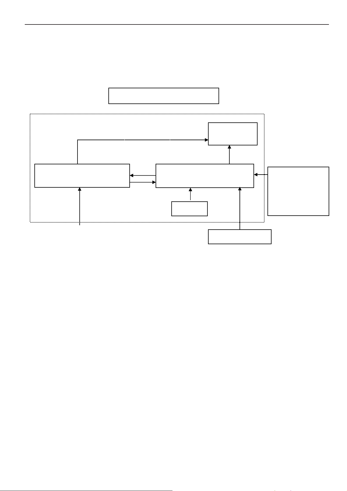
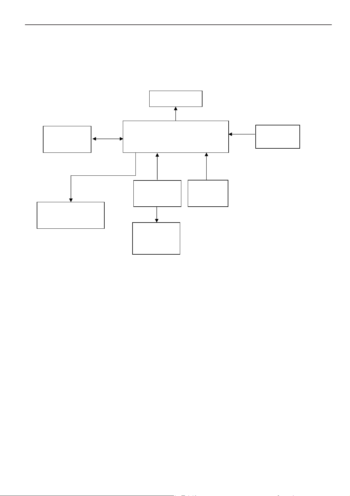
2. LCD Monitor Description
The LCD Monitor will contain main board, power board, a key board which house the flat panel control logic, brightness
control logic and DDC.
The power board will provide AC to DC Inverter voltage to drive the backlight of panel and the main board chips each
voltage.
Power Board
Include adapter board)
AC-IN
110V-240V
Monitor Block Diagram
CCFT Drive.
Main Board
Keyboard
Flat Panel and
CCFL backlight
RS232 Connector
For white balance
adjustment in
factory mode
Video signal, DDC
HOST Computer
4
Page 5
17" LCD Color Monitor HP VS17X
3. Operation Instructions
3.1 General Instructions
Press the power button to turn the monitor on or off. The other control buttons are located at front of the panel. By
changing these settings, the picture can be adjusted to your personal performance.
The power cord should be connected and insert to adaptor.
-
Connect the video cable from the monitor to the computer VGA card.
-
- Press the power button to turn on the monitor, the power indicator will light up to Green.
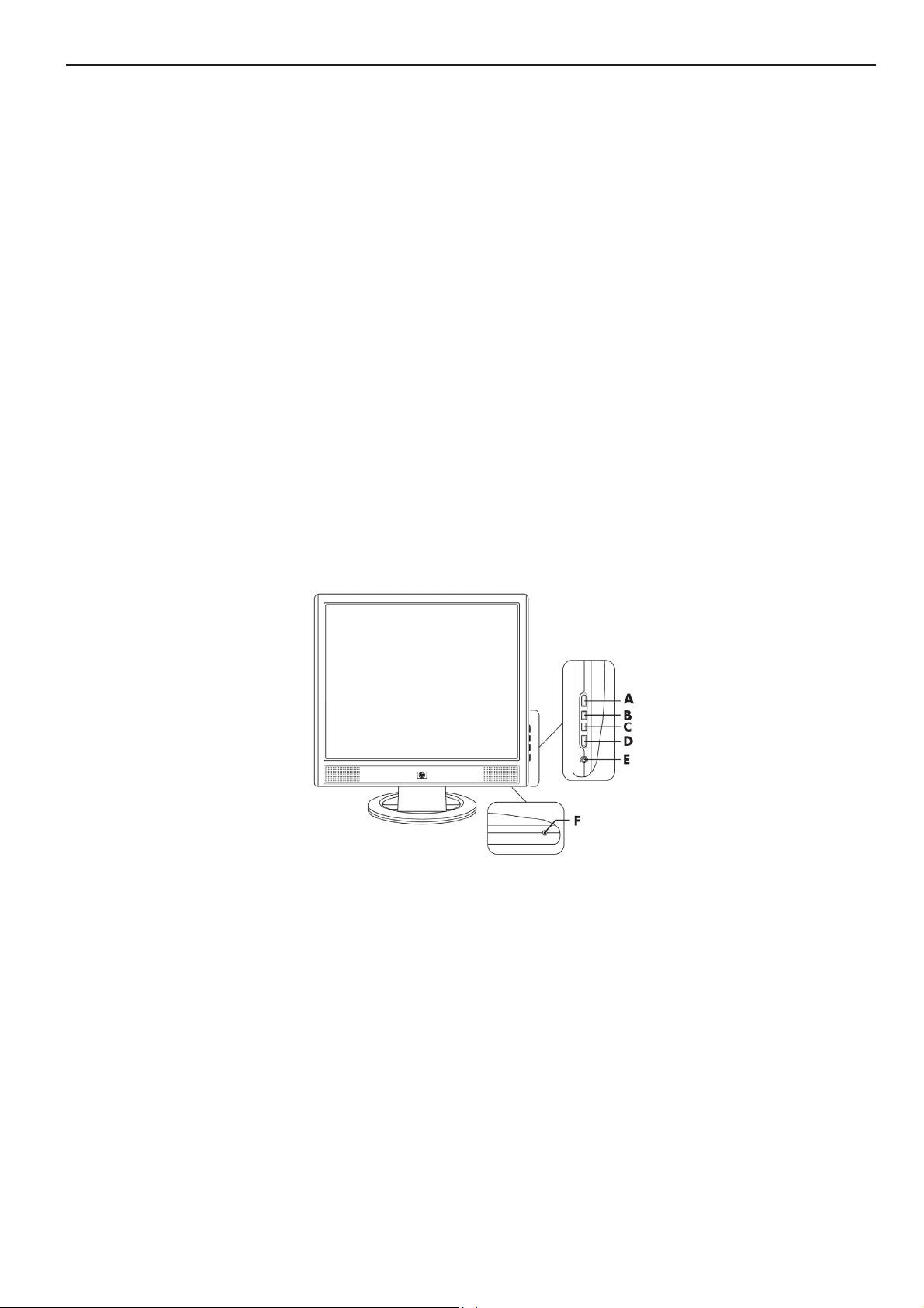
3.2 Control Buttons
- Power Button:
When pressed, the monitor enters the off mode, and the LED turns blank. Press again to restore normal status.
- Left / Right Button:
When the OSD show on screen, Left/Right Button are used to control the monitor functions. Press to switch
functions or adjust settings. And if the OSD off, Left buttons is used to automatically set the H Position, V Position,
Clock and Phase.
- Power Indicator:
Green — Power On mode.
Orange — Power Saving mode.
Blank — Power Off Mode.
5
Page 6
17" LCD Color Monitor HP VS17X
6
Page 7
17" LCD Color Monitor HP VS17X
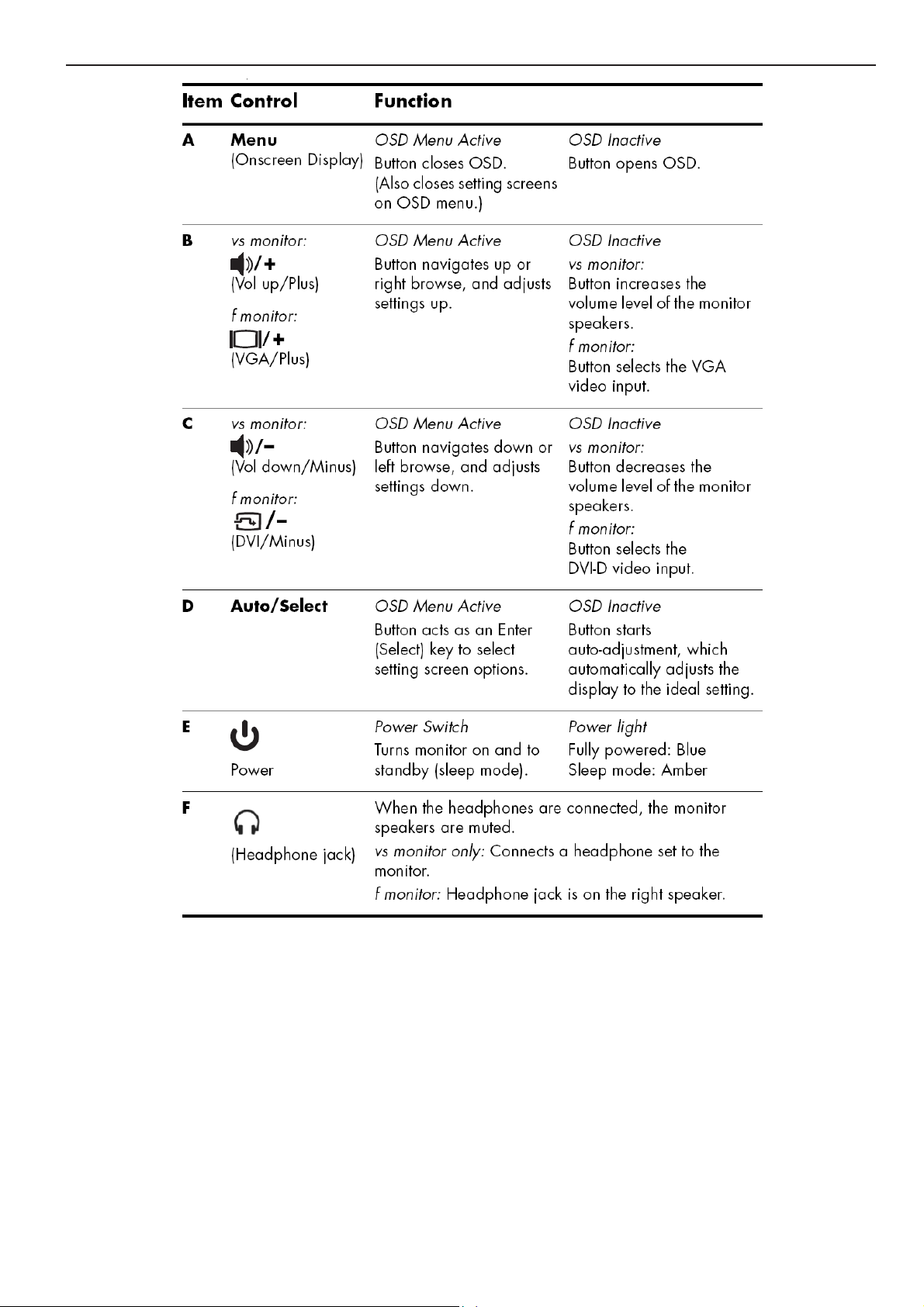
3.3 Adjust the Picture
NO. Control Icons NO. Control Icons
1 Brightness
2 Contrast
3 Auto Adjustment
4 Image Control
5 Color
6 Custom Color
7 Language
8 Management
9 OSD Control
10 Information 25 Vertical OSD Position
11 Factory Reset
12 Default Video Input
13 Horizontal Position
14 Vertical Position
15 Clock
16 Clock Phase
17 Power Saver
18 Mode Display
19 Power-On Status Display
20 Sleep Timer
21 Basic Menu
22 Advanced Menu
23 Power On Recall
24 Horizontal OSD Position
26 OSD Timeout
27 OSD Transparency
28 Volume
29 Exit
7
Page 8
17" LCD Color Monitor HP VS17X
4. Input/Output Specification
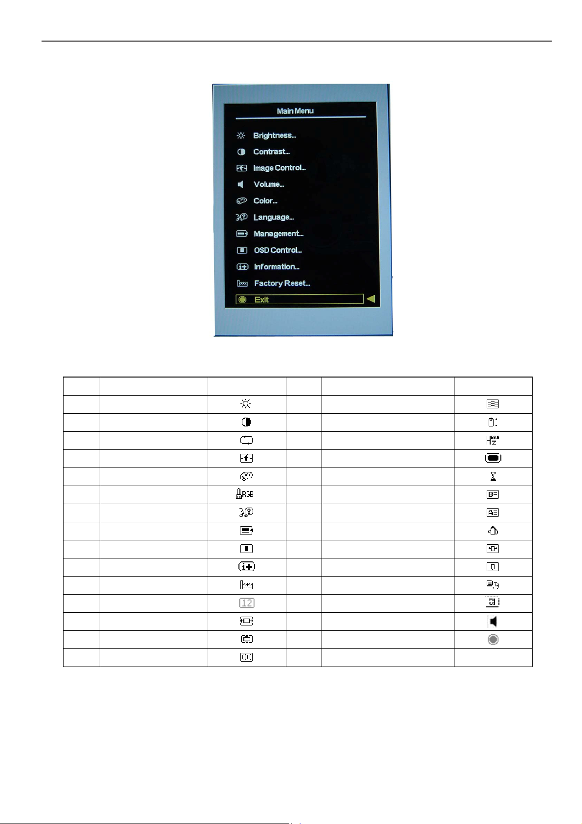
4.1 Input Signal Connector
Pin Mnemonic Signal Pin Mnemonic Signal
1 RV Red Video 9 +3.3/+5 V 3.3/+5 V (from PC)
2 GV Green Video 10 SG Sync Ground
3 BV Blue Video 11 NC None
4 NC None 12 SDA DDC Data
5 GND Ground (DDC Return) 13 HS Horizontal Sync
6 RG Red GND 14 VS Vertical Sync
7 GG Green GND 15 SCL DDC Clock
8 BG Blue GND
VGA connector layout
PIN 1
PIN 11
PIN 5
8
Page 9
17" LCD Color Monitor HP VS17X
4.2 Factory Preset Display Modes
Pixel
Preset
1 640 x 480 31.469 - 59.940 - 25.175 VGA
2 640 x 480 37.861 - 72.809 - 31.500 VESA
3 640 x 480 37.500 - 75.000 - 31.500 VESA
4 720 x 400 31.469 - 70.087 + 28.322 VGA
5 800 x 600 37.879
6 800 x 600 48.077 + 72.188 + 50.000 VESA
7 800 x 600 46.875 + 75.000 + 49.500 VESA
8 832 x 624 49.726 ± 74.551 ± 57.284 MAC
9 1024 x 768 48.363 - 60.004 - 65.000 VESA
10 1024 x 768 56.476 - 70.069 - 75.000 VESA
11 1024 x 768 60.023 + 75.029 + 78.750 VESA
12 1152 x 870 68.68 - 75.06 - 100.000 Mac
13 1152 x 900 71.71 - 76.05 - 105.561 Sun
14 1280 x 1024 63.98 + 60.02 + 108.000 VESA
Format
Horz Freq
(KHz)
Horz
Polarity
+
Vert Freq
(Hz)
60.317 + 40.000 VESA
Vert
Polarity
Pixel Clk
(MHz) Source
15 1280 x 1024 79.97 + 75.02 + 135.000 VESA
4.3 Power Supply Requirements
Parameter Range
AC Input Voltage 90 to 265V
AC Input Frequency 47 to 63 Hz
Inrush Current 50A MAX AT 220VAC and 30A AT 120VAC
Leakage Current 5 mA MAX at 120VAC
Power Consumption
≤37W
9
Page 10
17" LCD Color Monitor HP VS17X
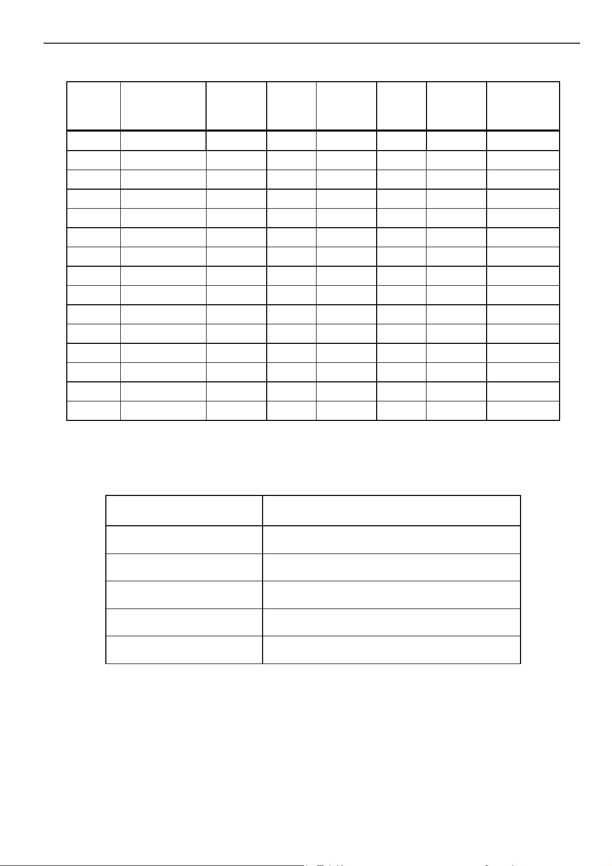
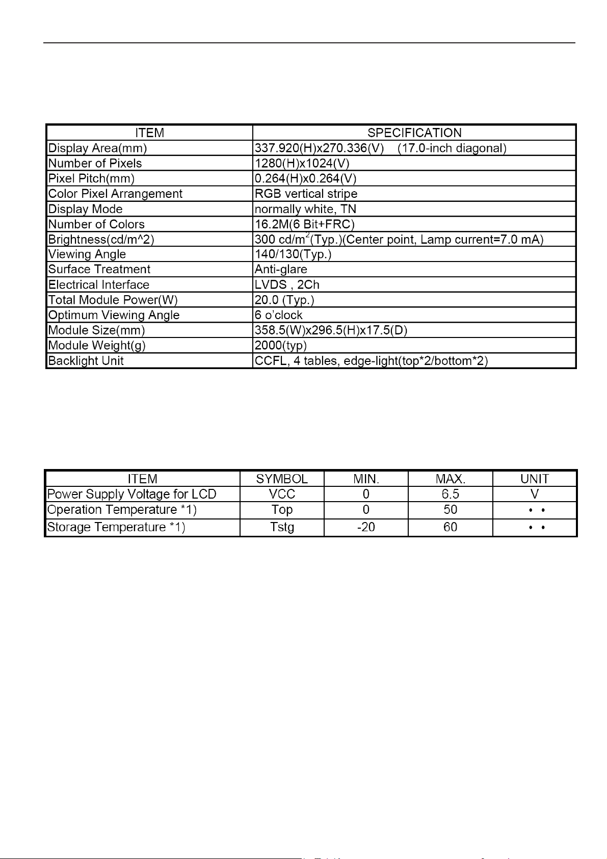
5. Panel Specification
5.1 General Feature
absolute maximum ratings
10
Page 11

17" LCD Color Monitor HP VS17X
5.2 Optical Characteristics
Ta=25℃,VCC=5.0V
11
Page 12
17" LCD Color Monitor HP VS17X
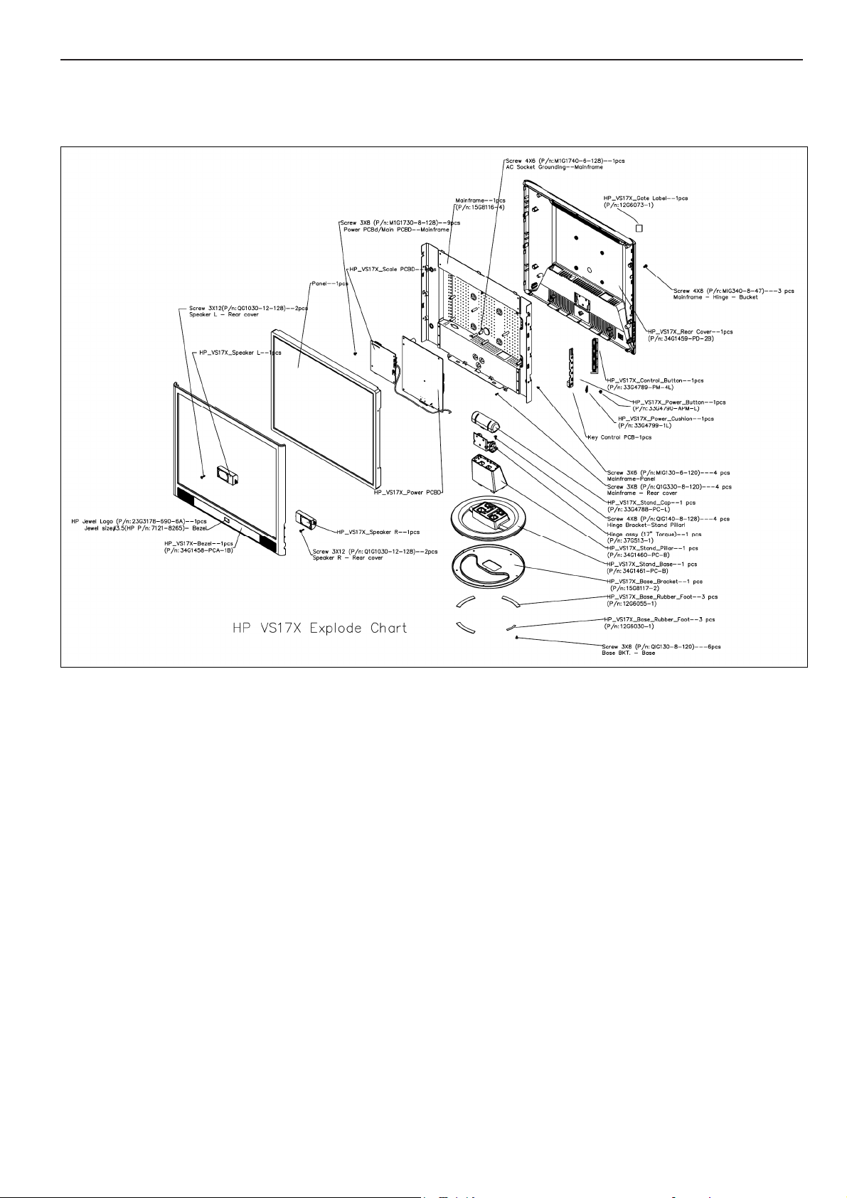
6. Block Diagram
6.1 Monitor Exploded View
.
12
Page 13
17" LCD Color Monitor HP VS17X
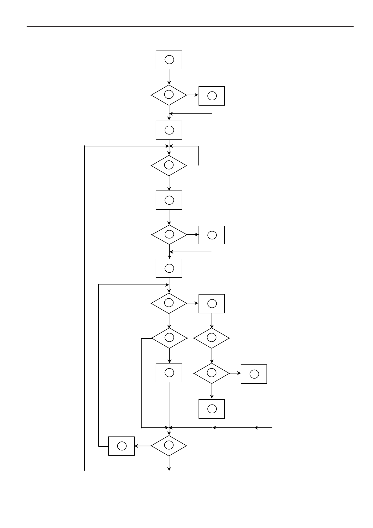
6.2 Software Flow Chart
1
Y
2
N
3
4
5
N
Y
6
N
7
8
Y
9
10
N
11
12
Y
13
N
N
Y
14
15
Y
N
16
Y
17
18
N
19
Y
13
Page 14
17" LCD Color Monitor HP VS17X
REMARK:
1) MCU initialize.
2) Is the EEprom blank?
3) Program the EEprom by default values.
4) Get the PWM value of brightness from EEprom.
5) Is the power key pressed?
6) Clear all global flags.
7) Are the AUTO and SELECT keys pressed?
8) Enter factory mode.
9) Save the power key status into EEprom.
Turn on the LED and set it to green color.
Scalar initialize.
10) In standby mode?
11) Update the lifetime of back light.
12) Check the analog port, are they’re any signals coming?
13) Does the scalar send out an interrupt request?
14) Wake up the scalar.
15) Are there any signals coming from analog port?
16) Display "No connection Check Signal Cable" message. And go into standby mode after the message
disappear.
17) Program the scalar to be able to show the coming mode.
18) Process the OSD display.
19) Read the keyboard. Is the power key pressed?
14
Page 15
17" LCD Color Monitor HP VS17X
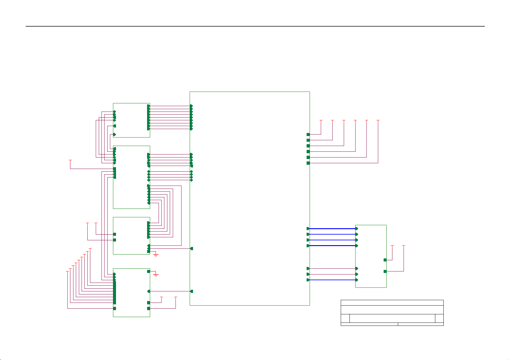
6.3 Electrical Block Diagram
6.3.1 Scalar Board
W78E65P-40
44PIN-PLCC
OSD Control
Interface (Keypad)
LCD Interface
Scalar MST8116B
(Include: ADC, OSD,MCU etc)
D-SUB
Connector
EEPROM
24C02
EEPROM
AT24C16
Crystal
14.318MHZ
15
Page 16
17" LCD Color Monitor HP VS17X
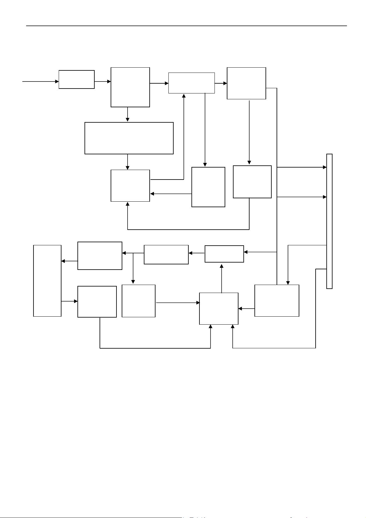
6.3.2 Inverter / Power Board
AC input
EMI filter
Bridge
Rectifier
and Filter
StartCircuit
PWM
Control IC
Transformer
Over
Voltage
Protect
Rectifier
diodes
CN902
12V
Feedback
Circuit
5V
Lamp
LC
Resonance
Transformer
MOSFET
Feedback
Circuit
Over
Voltage
PWM
Control IC
ON/OFF
Control
DIM
ON/OFF
16
Page 17
17" LCD Color Monitor HP VS17X
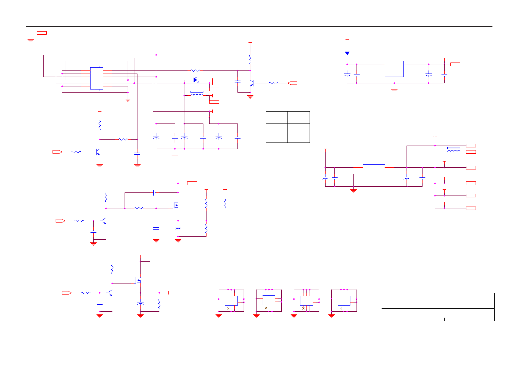
7. Schematic
7.1 Main Board
SCHEMATIC
B2
VCPU
VAA4
5V
VAA3
VAA2
VCC3.3
VCC1.8
VAA1
5V
VCC5V
VCPU
VCC5V
B1
TXD
RXD
DDC_DAT
ST_DET1 HSYNC
DDC_WP
3.INPUT
B3
DDC_WP
ST_DET1
DDC_CLK
DDC_DAT
RXD
TXD
VCPU
onPANEL_5V/3.3V
onBACKLITE
onPANEL_12V
6.MCU
B6
VCC5V
5V
AUDIO_SD
7.AUDIO
B4
onPanel_12V
onBACKLITE
onPanel_5V/3.3V
VCPU
VCC5V
VCC3.3
AdjBACKLITE
VCC1.8
VAA1
VAA2
VAA3
VAA4
5V
2.POWER
RIN
GNDR
GIN
GNDG
SOGDDC_CLK
GNDB
VSYNC
CSZ
SCL
SDA
HWRESET
INT
AD0
AD1
AD2
AD3
AUDIO_SD
ROUT+1
LOUT+1
OUT-L-
OUT-L+
OUT-R+
OUT-R-
OUT-ROUT-R+
OUT-L+
OUT-L-
LOUT+1
ROUT+1
VOLUME
GND
GND
VLCD_12V
VLCD
RIN
GNDR
GIN
GNDG
SOG
BIN
VLCD_12V
VLCD
BIN
GNDB
HSYNC
VSYNC
CSZ
SCL
SDA
HWRESET
INT
AD0
AD1
AD2
AD3
VOLUME
AdjBACKLITE
VCC1.8
VCC3.3
PA[0..9]
PB[0..9]
GA[0..3]
BA[0..5]
GPO[0..4]
VCC1.8
VAA1
VAA2
VAA3
VAA4
ESP
OSP
4.SCALER
VAA1
VCC3.3
PA[0..9]
PB[0..9]
GA[0..3]
BA[0..5]
ESP
OSP
GPO[0..4]
Title
Size Document Number Rev
B
Date: Sheet
VAA3
PA[0..9]
PB[0..9]
GA[0..3]
BA[0..5]
ESP
OSP
GPO[0..4]
VAA4
VLCD
VLCD
VLCD_12V
VAA2
B5
5.PANEL INTERFACE
TOP
VLCD_12V
17Monday, September 13, 2004
A
of
17
Page 18
17" LCD Color Monitor HP VS17X
AdjBACKLITE4
onPanel_5V/3.3V6
GND 3,4,5,6,7
Brightness
GND
1
GND
3
VCC12V
5
5V
7
VCC5V
9
GND
11
R205 4.7K 1/16W
1
R207 4.7K 1/16W
C207
0.1uF
CN201
CONN
VCC5V
32
1
2
4
6
8
10
12
R203
1K 1/16W
Q202
PMBS3904
VCC5V
R208
10K 1/16W
32
Q204
PMBS3904
ON_OFF
DIM
VCC12V
5V
VCC5V
GND
R204
10K 1/16W
220uF/25V
10K 1/16W
R
C206
1uF
C202
VCC12V
C230
NC 0.47uF
VCC5V
R202
10K 1/16W
R201 4.7K 1/16W
D201 DIODE SCHOTTKY
C203
+
0.1uF
VLCD
Q203
AO3401
C
+
C208
0.1uF
10uF/16V
FB201
NC
C204
+
220uF/25V
C205
0.1uF
VLCD 5
VCC5V
VCC5V+
VCC5V
VCC5V 3,4,7
VCPU
VCPU 6
5V
5V 7
+
VCC3.3
R209
NC
R211
10K 1/16W
C219
220uF/25V
R210
0 1/16W
C201
0.1uF
C220
0.1uF
32
R212 4.7K 1/16W
1
Q201
PMBS3904
5V
VS19
onBACKLITE 6
VCC5V
VS17
VCC5V+
C213
47uF/16V
+
C209
47uF/16V
C214
0.1uF
VCC5V+
+
D202
DIODE
C210
0.1uF
TO-263
U202
3
1
AIC1084-33M
VIN
ADJ
TO-252
U201
AZ1117D-1.8
3 2
VI VO
2
VOUT
GND
1
C215
47uF/16V
U201 change to 1.8V
+
C211
47uF/16V
VCC3.3
+
C216
0.1uF
VCC1.8
VAA1
VAA2
VAA3
VAA4
C212
0.1uF
FB202
600 OHM
VCC1.8 4
VCC3.3 4,7
VCPU 6
VAA1 4,7
VAA2 4,7
VAA3 4,7
VAA4 4,7
VCC12V
R215
10K 1/16W
C217
0.1uF
32
Q205
1
PMBS3904
R214 4.7K 1/16W
onPanel_12V6
VLCD_12V
VLCD_12V 5
Q206
AO3407
+
10uF/16V
C218
VCC12V
R216
4.7K 1/16W
H1
678
9
123
123
5
678
5
4
4
H8D3.5-2LX
9
H2
678
9
123
123
5
678
5
4
4
H8D3.5-2LX
9
H3
678
9
123
123
5
678
5
4
4
H8D3.5-2LX
9
H4
678
9
123
123
5
678
5
4
4
H8D3.5-2LX
Title
Size Document Number Rev
B
Date: Sheet
POWER
27Thursday, November 18, 2004
of
A
9
18
Page 19

17" LCD Color Monitor HP VS17X
D323
MLL5232B 5.6V
D322
MLL5232B 5.6V
11
12
13
14
15
HSI
VSI
D319
MLL5232B 5.6V
CN301
DB15
1
6
2
7
3
8
4
9
PC5V
5
VGA_CON
10
D320
MLL5232B 5.6V
D321
MLL5232B 5.6V
RXD 6
TXD 6
3
D301
BAV99
2
C315
0.1uF/16V
C316
0.1uF/16V
Add 0.1uf 10-22 FOR ESD
FB304 150 OHM
R312 100 1/16W
D318
MLL5232B 5.6V
FB301 0 1/16W
FB302 0 1/16W
FB303 0 1/16W
D302
BAV99
1
C317
3
2
3
2
1
0.1uF/16V
D303
BAV99
1
R313
2.2K 1/16W
75 1/ 16W
VCC5V
CLK_DDC
DAT_DDC
R325
C311
33pF
C301
NC
R326
75 1/16W
R314
2.2K 1/16W
C302
NC
R327
C312
220pF
C303
NC
75 1/16W
R301 33 1/16W
R302 33 1/16W
R303 33 1/16W
R304 470 1/16W
R305 68 1/16W
R306 68 1/16W
R307 68 1/16W
VCC5V
R308
10K 1/ 16W
R309 100 1/16W
R310 1K 1/16W
R311 1K 1/16W
D317
MLL5232B 5.6V
C304 0.047uF
C305 0.047uF
C306 0.047uF
C307 0.001uF
C308 0.047uF
C309 0.047uF
C310 0.047uF
RIN 4
GIN 4
BIN 4
SOG 4
GNDR 4
GNDG 4
GNDB 4
ST_DET1 6
HSYNC 4
VSYNC 4
R315 33 1/16W
R316 33 1/16W
DDC_DAT6
DDC_CLK6
R317
4.7K 1/16W
R318
4.7K 1/16W
VCC5V
2
R328
4.7K 1/16W
3
PC5V
1
BAT54C-GS08
8
7
6
D304
U301
A0
VCC
A1
WP
A2
SCL
GNDSDA
AT24C02N-10SC
C313
1
0.1uF
2
3
45
19
modify ddc_wp circuit
R319
22 1/ 16W
R329
NC
Title
Size Document Number Rev
B
Date: Sheet
0.1uF/16V
INPUT
C314
PMBS3904
CE
Q301
B
37Friday, October 22, 2004
DDC_WP 6
of
D
Page 20

17" LCD Color Monitor HP VS17X
VCC1.8
VAA1
VAA2
VAA3
VAA4
FB402
600 OHM
C414
10uF/16V
FB403
600 OHM
10uF/16V
FB404
600 OHM
10uF/16V
FB405
600 OHM
10uF/16V
FB406
600 OHM
10uF/16V
C419
C422
C424
C427
VDD
+
VAD
VPLL
VDVI
VDPLL
47Monday, December 06, 2004
+
+
+
+
C415
0.1uF
C420
0.1uF
C423
0.1uF
C425
0.1uF
C428
0.1uF
of
C416
0.1uF
C421
0.1uF
C426
0.1uF
C417
0.1uF
C418
0.1uF
A
Direct Bus
3-WIRE
AD06
AD16
AD26
AD36
VOLUME7
R401
NC
4.7K
VCC5V
R407
10K 1/16W
10K 1/16W
R402
4.7K
R405
10K 1/16W
R409
C430
100pF
NC
R404
10K 1/16W
R408
1K 1/16W
C429
1uF
R406
10K 1/16W
VCC5V
32
VCC3.3
R402
R401
1
PMBS3904
Q401
VDVI
4.7K 1/16W
NC
HWRESET6
RIN3
GNDR3
GIN3
GNDG3
SOG3
BIN3
GNDB3
HSYNC3
VSYNC3
R403 390 1/16W
C401
0.1uF
CSZ6
SCL6
SDA6
INT6
AdjBACKLITE2
R410 4.7K 1/16W
C402 22pF
X401
14.318MHz
C403 22pF
C404 0.1uF
U401
MST8116B
VAD
55
63
RIN0
62
RIN0M
60
GIN0
59
GIN0M
61
SOGIN0
58
BIN0
57
BIN0M
37
HSYNC0
38
VSYNC0
29
DDC1_CLK/GPO8
28
DDC1_DAT/GPO7
40
R+
41
R-
43
G+
44
G-
46
B+
47
B-
49
CK+
50
CK-
52
REXT
66
REFP
67
REFM
6
BUS TYPE
69
CSZ
71
SCL
70
SDA
32
HWRESETZ
72
INT
30
AD0
77
AD1
78
AD2
31
AD3
73
PWM0
74
PWM1
33
XIN
34
XOUT
BYPASS
AVSS_LPLL
68
65
AVDD
AVSS
56
VPLL
AVDD
AVSS
64
35
AVSS
VDVI
AVDD_MPLL
AVSS_MPLL
36254
45351
AVDD_DVI
VDPLL
53
AVDD_DVI
AVDD_PLL
AVSS_PLL
AVSS_DVI
39
4210208595
VPO
11218494104
VDDP
VDDP
VDDP
AVSS_DVI
GNDP
AVSS_DVI
48
114
126188797117
VDDP
VDDP
VDDP
VDDP
VDDC
LVA3M/GA3N
LVA2M/RA1N
LVA0M/RA3N
LVB3P/CLKAP
LVB3M/CLKAN
LVBCKMP/NC/CLKBP
LVBCKP/NC/CLKBN
LVB1P/NC/BB1P
LVB1M/NC/BB1N
LVB0P/NC/BB2P
LVB0M/NC/BB2N
GNDP
GNDP
GNDP
GNDP
GNDP
GNDP
115
1271986
105
VDD
VDDC
VDDC
VDDC
LVA3p/GA3P
LVACKP/NC
LVACKM/NC
LVA2P/RA1P
LVA1P/RA2P
LVA1MRA2N
LVA0P/RA3P
GA1P
GA1N
GA2P
GA2N
BA1P
BA1N
BA2P
BA2N
BA3P
BA3N
NC/RB1P
NC/RB1N
NC/RB2P
NC/RB2N
NC/RB3P
NC/RB3N
NC/GB1P
NC/GB1N
NC/GB2P
NC/GB2N
NC/GB3P
NC/GB3N
LVB2P/NC
LVB2M/NC
NC/BB3P
NC/BB3N
NC/ESP
OSP
GPO0
GPO1
GPO2
GPO3
GPO4
GNDC
GNDC
GNDC
96
116
GNDC
FB401
600 OHM
C405
10uF/16V
VPO
+
PA[0..9] 5
GA[0..3] 5
BA[0..5] 5
PB[0..9] 5
ESP 5
OSP 5
GPO[0..4] 5
C406
0.1uF
C407
0.1uF
C408
0.1uF
C409
0.1uF
C410
0.1uF
C411
0.1uF
VCC1.82
C413
C412
0.1uF
0.1uF
VAA12,7
VAA22,7
VAA32,7
VAA42,7
Title
Size Document Number Rev
B
Date: Sheet
SCALER
VCC3.3
VCC3.32,7
PA0
102
PA1
103
PA2
106
PA3
107
PA4
108
PA5
109
PA6
110
PA7
111
PA8
112
PA9
113
GA0
98
GA1
99
GA2
100
GA3
101
BA0
88
BA1
89
BA2
90
BA3
91
BA4
92
BA5
93
16
17
22
23
24
25
8
9
12
13
14
15
PB0
118
PB1
119
PB2
120
PB3
121
PB4
122
PB5
123
PB6
124
PB7
125
PB8
128
PB9
1
4
5
75
76
83
82
81
80
79
GPO0
GPO1
GPO2
GPO3
GPO4
PA[0..9]
GA[0..3]
BA[0..5]
PB[0..9]
ESP
OSP
GPO[0..4]
20
Page 21

17" LCD Color Monitor HP VS17X
CN501
1
2
3
4
5
6
7
8
9
10
11
12
13
14
15
16
17
18
19
20
21
22
23
24
25
26
27
28
29
30
31
32
33
34
35
36
37
38
39
40
41
42
43
44
45
46
47
48
49
50
CONN
LVB0M
LVB1M
LVB2M
LVBCKM
LVB3M
LVA0M
LVA1M
LVA2M
LVACKM
LVA3M
C509
22uF/16V
RXO0RXO1RXO2RXOCRXO3RXE0RXE1RXE2RXECRXE3-
+
CN503
RXO0+
RXO1+
RXO2+
RXOC+
RXO3+
RXE0+
RXE1+
RXE2+
RXEC+
RXE3+
VLCD 2
LVB0P
LVB1P
LVB2P
LVBCKP
LVB3P
LVA0P
LVA1P
LVA2P
LVACKP
LVA3P
C511
0.1uF
2
1
4
3
6
5
8
7
10
9
CONN
C510
0.1uF
VLCD
12
14
16
18
20
22
24
11
13
15
17
19
21
23
C503
NC
C504
NC
PA[0..9]
GA[0..3]
PA[0..9]
BA[0..5]
PB[0..9]
C505
NC
GPOO0
GPOO1
GPOO2
GPOO3
GPOO4
PA4
PA5
PA6
PA7
PA8
PA9
GA0
GA1
GA2
GA3
PA0
PA1
BA0
BA1
BA2
BA3
BA4
BA5
PB0
PB1
RA1P
RA1N
RA2P
RA2N
RA3P
RA3N
GA1P
GA1N
GA2P
GA2N
GA3P
GA3N
BA1P
BA1N
BA2P
BA2N
BA3P
BA3N
CLKAP
CLKAN
VLCD_12V2
OSP4
ESP4
VLCD2
VLCD
VLCD_12V
OSP
ESP
C512
22uF/16V
R506 0 1/16W
R507 NC
C508
+
0.1uF
C506
NC
RA3N
RA3P
RA2N
RA2P
RA1N
RA1P
GA3N
GA3P
GA2N
GA2P
GA1N
GA1P FG2P
CLKAN
CLKAP
BA3N
BA3P
BA2N
BA2P
BA1N
BA1P
GPOO1
GPOO0
GPOO3
C507
GPOO2
NC
GPOO4
R508 0 1/16W
R510 0 1/16W
R512 0 1/16W
R509
NC
R511
NC
R513
R514
NC
NC
FB0N
FB0P
FB1N
FB1P
FB2N
FB2P
FG0N
FG0P
FG1NPB1
FG1P
FG2N
FCLKN
FCLKP
FR0N
FR0P
FR1N
FR1P
FR2N
FR2P
STH
LP
POL
HMS
CLKV
STV
OE
C501
NC
PA[0..9]4
GA[0..3]4
PA[0..9]4
BA[0..5]4
C502
NC
PB[0..9]4
PA[0..9]4
PB[0..9]4
GPO[0..4]4
PA[0..9]
PB[0..9]
GPO[0..4]
PA0
PA1
PA2
PA3
PA4
PA5
PA6
PA7
PA8
PA9
PB0
PB2
PB3
PB4
PB5
PB6
PB7
PB8
PB9
GPO0
GPO1
GPO2
GPO3
GPO4
LVA3P
LVA3M
LVACKP
LVACKM
LVA2P
LVA2M
LVA1P
LVA1M
LVA0P
LVA0M
LVB3P
LVB3M
LVBCKP
LVBCKM
LVB2P
LVB2M
LVB1P
LVB1M
LVB0P
LVB0M
R501 0 1/16W
R502 0 1/16W
R503 0 1/16W
R504 0 1/16W
R505 0 1/16W
AU 17
QDI 17
CPT 17
INNOLUX 15
HannStar 15
CPT 15
LG 15
21
R508
3.3V
3.3V
3.3V
3.3V
R510
3.3V
3.3V
3.3V
R511
5V
5V
0R
0R
NC
NC
0R
NC
NC
0R
NC
0R
R512
NC
12V
0R
NC
12V
0R
NC
R513
R514
5V
NC
0RNC
12V
0R
NC
NC
NC
NC
NC
NC
NC
Title
Size Document Number Rev
B
Date: Sheet
PANEL INTERFACE
57Friday, August 13, 2004
A
of
R509
NC
12V
0R
0R
NC
0R
0R
NC
NC
0R
Page 22

17" LCD Color Monitor HP VS17X
VCPU
VCPU2
123
4
123
VCPU
Reset
Circuit
U603 MAX810STR (NC)
AUDIO_SD7
23
RSTVCC
GND
1
C605
1
0.1uF
2
3
4 5
U602
A0
A1
A2
GND SDA
24C16
X601 CHANGE TO 24M HZ
R643 NC
8
VCC
7
WP
6
SCL
C612
10uF/16V
D601
LL4148
VCPU
R605 10K 1/16W
R604 10K 1/16W
R615 10K 1/16W
R641 0 1/16W
R642
NC
R626 10K 1/16W
+
10uF/16V
AUDIO_SD17
C603
+
10K 1/16W
onPANEL_12V2
R603
ST_DET13
R601
10K 1/16W
C602
22pF
Y601
24MHz
C604
22pF
INT4
R609 100 1/16W
R646 NC
R608 100 1/16W
R602
C601
0.1uF
10K 1/16W
U601
35
EA/VP
21
XTAL1
20
XTAL2
10
RESET
12
P4.3
14
INT0/P3.2
33
ALE/P
32
PSEN
17
T1/P3.5
2
P1.0
3
P1.1
4
P1.2
5
P1.3
6
P1.4
7
P1.5
8
P1.6
9
P1.7
W78E65P-40
R645 10K 1/16W
22 44
VCPU
INT1/P3.3
P3.6/WR
P3.7/RD
P3.1/TXD
P3.0/RXD
VSS VCC
10K 1/16W
P0.0
P0.1
P0.2
P0.3
P0.4
P0.5
P0.6
P0.7
P2.0
P2.1
P2.2
P2.3
P2.4
P2.5
P2.6
P2.7
T0/P3.4
4
RP601
5
43
42
41
40
39
38
37
36
24
25
26
27
28
29
30
31
16
15
18
19
13
11
RP602
10K 1/16W
876
5
876
R610 22 1/16W
R611 22 1/16W
R634 NC
R635 NC
VCPU
10K 1/16W
R610,R611 CHANGE TO 22 OHM
CN603
1
2
3
4
NC
R606
10K 1/16W
R607
10K 1/16W
RP603
4
5
RP604
10K 1/16W
876
5
876
R644
10K 1/16W
LED_G
R636
100 1/16W
POWER
MENU
RIGHT
LEFT
AUTO
LED_O
R613
10K 1/16W
AD0 4
AD1 4
AD2 4
AD3 4
CSZ 4
SCL 4
SDA 4
HWRESET 4
onPANEL_5V/3.3V 2
onBACKLITE 2
DDC_WP 3
DDC_DAT 3
DDC_CLK 3
TXD 3
RXD 3
C613
0.1uF
123
4
123
audio modify pop noise 1103
LED_G
4.7K 1/16W
R616
AUTO
RIGHT
POWER
VCPU
B
OUT-L-7
C E
C608
0.001uF
LOUT+17
R622 0 1/16W
R620 0 1/16W
R621 0 1/16W
R617
390 1/16W
Q601
PMBS3906
C606
0.001uF
C607
0.001uF
LED_GRN
K_AUTO
K_RIGHT
K_POWER
CN602
1 2
3 4
5 6
7 8
9 10
11 12
13 14
15 16
CON16A
22
LED_ORANGE
K_MENU
K_LEFT
C610
0.001uF
C609
0.001uF
ROUT+1 7
OUT-R- 7
OUT-L+ 7
OUT-R+ 7
R623 0 1/16W
R624 0 1/16W
VCPU
R628
470 1/16W
4.7K 1/16W
R629
Q603
B
PMBS3906
C E
MENU
LEFT
Title
Size Document Number Rev
B
Date: Sheet
MPU
LED_O
of
67Wednesday, November 10, 2004
A
Page 23

17" LCD Color Monitor HP VS17X
CN701
1
5
4
3
2
LINE IN GREEN
OUT-L+6
OUT-L-6
ADD C728,C729 EMI SOLUTION CHANGE R701,R702 BEAD 300 OHM
AGND
AGND
C728
470pF
AGND
AGND
R701
R702
C729
470pF
AGND
C706 0.001uF
C711 0.001uF
AGND
OUT-R-6
OUT-R+6
AGND
AGND
OUT-L+6
OUT-L-6
AGND
300 OHM
300 OHM
1K 1/16W
1K 1/16W
RIN
U701
R725
R726
R731
10K 1/16W
L701 50 OHM
R724
1K 1/16W
L703 50 OHM
R732
AGND
10K 1/16W
C701 0.1uF/16V
C703 0.1uF/16V
AUDIO_SD6
+5VA
C707 1uF/50V
+
C713
220pF
C709
470uF/16V
R703
LIN
AGND
120K 1/16W
1
LINN
2
LINP
3
SHUTDOWN
4
PVDDL
5
LOUTP
6
PGNDL
7
PGNDL
8
LOUTN
9
PVDDL
10
COSC
11
ROSC
12 13
AGND VDD
TPA2008D2
CROSS TALK-pull-down resistors (1Kohms) on the input of the op amp1022
R704
C716 0.047uF
R705 100 1/16W
R707 100 1/16W
C721 0.047uF
C723 0.047uF
R714 100 1/16W
R718 100 1/16W
C727 0.047uF
C717 1uF/50V
C719 1uF/50V
AGND
C724 1uF/50V
C726 1uF/50V
R706 20K 1/16W
R708 20K 1/16W
C722 2.2uF/16V
R715 20K 1/16W
R719 20K 1/16W
R711 10K 1/16W
R713 10K 1/16W
10K 1/16W
R720
10K 1/16W
2
3
4
7
8
U702
IN1-
IN1+
BYPASS
IN2+
IN2-
TPA6112A2
BYPASS
PVDDR
ROUTP
PGNDR
PGNDR
ROUTN
PVDDR
VOLUME
AGND
VDD
SHUTDOWN
GND
24
RINN
23
RINP
22
21
20
19
18
17
16
15
NC
14
10-22 Modify vcc5v
10
1
VO1
6
9
VO2
5
AGND
C705 1uF/50V
C710 1uF/50V
C714
1uF/50V
VCC3.3
L707
600 OHM
C702 0.1uF/16V
C704 0.1uF/16V
AGND
+5VA
+5VDD
C715 1uF/50V
+
C718
100uF
+
C720
220uF
+
C725
220uF
AGND
L702
L704 50 OHM
C730
2.2uF/16V
AGND
AGND
R709 100 1/16W
R716 100 1/16W
50 OHM
R723
1K 1/16W
VOLUME 4
+5VDD
ROUT+1 6
LOUT+1 6
R727
1K 1/16W
R728
1K 1/16W
R729 R730
0805 TYPE
5V
R710
C708 0.001uF
C712 0.001uF
R729
0 1/10W
VCC3.3
10K 1/16W
R712 100 1/16W
R717
NC
AGND
VCC5V
R730
0 1/10W
OUT-R+ 6
OUT-R- 6
AGND
AGND
AUDIO_SD1 6
AGND
L705 0
GND 2,3,4,5,6
modify headhone sound to small 1015
+5VA
L706 600 OHM
L708 600 OHM
VCC5V
5V
VCC5V 2,3,4
5V 2
23
VCC5V
5V
VS19
VS17/VS15
Title
Size Document Number Rev
B
Date: Sheet
AUDIO
of
77Monday, November 29, 2004
D
Page 24

17" LCD Color Monitor HP VS17X
7.2 Power Board
R935
100 1206
4
1
-+
2
2 3
L902
LF-000783
1 4
VAR901 470V
2 3
L901
CC-001331
1 4
C903 0.47uF/275V
R901
680K/1206
DB901
U4KB80R
3
R903
680K/1206
C902
102PF/250V
C901
102PF/250V
+
C914
0.1uF/0805
C905
100uF/450V
C923
NC
R930
24K 0805
+
1uF/1206
SG6841
10K 0805
R909
430K 1206
R910
430K 1206
R931
430K 1206
C934
R917
C933
NC
72
8
4
SG6841
56
13
C917
103/0805
IC901
R907
510K 1206
R908
510K 1206
R932
510K 1206
D907
NC
R918
10 0805
R928
220 0805
10K 0805
C919
470PF/0805
R919
+
C922
10uF/50V
C930
1500P/1KV
D906
PS102R
ZD905
18V
R905
100K 2W
D901
FR107
5.1 1206
23
Q903
AP 2761-I1
FB901
BEAD
R904
0.39 2W
R914
T9011
O
3
5
O
6
C921
102PF/250V
R934
100 1206
R906
100 1206
1
3
9
R936
100 1206
R937
100 1206
O
7
R916
100 1206
0.001uF/500V/1206
8
10
1
3
D904
SRF20100C
C931
0.001uF/500V/1206
2
D902
SRF20150C
470uF/25V
C932
2
R927
47 1206
C904
C908
+
470uF/25V
+
+
470uF/25V
L904
R920
33K 0805
L903
C909
C911
470uF/25V
R921
3.6K 0805
+12V
+
C906
470uF/25V
ZD903
SML4736
+
ZD902
HZ12B
ZD904
HZ5.1
0.1uF/0805
+5V
C907
C910
0.1uF/0805
680K/1206
R902
3
CN901
NR901
61L58-050-WT
F901
3.15A/250V
12
ZD901
24V
R915
100 0805
R911
4.7K 0805
Q901
PMBS3906
C916
0.1uF/0805
C915
104/ 0805
R913
4.7K 0805
R912
4.7K 0805
Q902
PMBS3904
D903
IN4148
IC903
AZ431
R926
1K 0805
R925
C918
1uF/0805
R924
1K 0805
R923
1K 0805
CN902
ON/OFF
DIM
R922
2.4K 0805
AOC (Top Victory) Electronics Co., Ltd.
2
4
6
8
10
12
33L8027-12
1
3
5
7
9
11
+12V
+5V
12
43
IC902
PC123FY82 4P
0 0805
24
Page 25

17" LCD Color Monitor HP VS17X
+12V
R739
0 1206
DTA144WKA
Q707
C733
C748
0.1uF/0805
IC_DIM
DTC144WKA
R736
200K 0805
R730
75K 0805
R731
NC
C731
0.001uF/0805
1
C734
0.1uF/0805
ON/OFF
DIM
R733
200K 0805
0.1uF/0805
MODEL:PWPC1742LGH3
MODEL:PWPC1742SEH3
Q706
1
32
C738
0.1uF/0805
C739
1uF/0805
C736
0.47uF/0805
C735
1uF/0805
C732 0.0047uF/25V
3 2
R737
1K 0805
ZD705
RLZ5.6B
10 1206
OVP
R729
AOC (Top Victory) Electronics Co., Ltd.
Title
715L1420-B FOR HP 17''
Size Document Number Rev
A3
Date: Sheet
Friday, September 24, 2004
22
of
Q712
PMBS3904
1uF/25V
C719
1
2
3
4
5
6
7
9
10
B
1
CTIMR
OVP
ENA
SST
VDDA
GNDA
REF
FB
CMP
1N4148
Q703
RK7002
R738
470 1206
32
R732
10K 0805
C737
0.1uF/0805
IC201
R725
200K/0805
D714
VDD
NDRV_B
PDRV_A
PWRGND
OZ960G
LPWMRT1
PDRV_C
NDRV_D
VDD
C708
0.1uF/0805
CN701
SM02B-BHSS-1-TB
3
R703
470 0805
R744
470 0805
3
R719
470 0805
1
2
CN702
1
2
SM02B-BHSS-1-TB
CN704
1
2
SM02B-BHSS-1-TB
CN703
1
2
SM02B-BHSS-1-TB
C728
RLZ5.6B
RLZ5.6B
C740
470uF/25V
R724
10K 0805
R715
R709
68K/0805
10K 0805
+
0.1UF/1206
C713
0.1UF/1206
C724
0.1UF/1206
R710
NC
C720
0.1UF/1206
ZD703
FB
Q708
SP8M3
4 5
G2P D2P
3
S2P
D2P
2
G1N
D1N
1
S1N
D1N
4 5
G2P D2P
3
S2P
D2P
2
G1N
D1N
1
S1N
D1N
Q709
SP8M3
R726
RLZ5.6B
10K 0805
Q710
SP8M3
4 5
G2P D2P
3
S2P
D2P
2
G1N
D1N
1
S1N
D1N
4 5
G2P D2P
3
S2P
D2P
2
G1N
D1N
1
S1N
D1N
Q711
SP8M3
R718
1K 0805
1M 0805
R735
6
7
8
6
7
8
6
7
8
6
7
8
C705 2.2uF/1206
C706 2.2uF/1206
C707 2.2uF/1206
OVP
2.2uF/1206
2.2uF/1206
2.2uF/1206
OVP
BAV99
2
D706
1
C741
C746
C747
C723
0.1uF/0805
1
D702
BAV99
2
3
R701
6.2K 0805
80LL17T-16-LC
2
1
D713
BAV99
1
D712
BAV99
2
6.2 K 0805
PT701
80LL17T-16-LC
3
OPT1
OPT2
FB
PT702
R721
3
3
R723
6M 1/2W
R702
82K 0805
R727
6M 1/2W
R722
82K 0805
C702
332/0805
1K 0805
C743
10pF/3KV
C718
10pF/3KV
R705
C744
10pF/3KV
C725
10pF/3KV
C715
332/0805
C701
152/0805
C726
5pF/3KV
C717
152 0805
C727
5pF/3KV
D703
BAV99
C742
5pF/3KV
C730
5pF/3KV
OPT3
D708
BAV99
2
1
2
1
R704
470 0805
2
1
R716
470 0805
R745
470 0805
D710
2
1
BAV99
3
D701
BAV99
3
+
C745
470uF/25V
R734
NC
R707
1M 0805
R706
1M 0805
R717
1M 0805
R720
1M 0805
C711 470PF/0805
R713 NC
R714
30K 0805
C710
4700PF/0805
IC_DIM
R712
33K 0805
R711
51K 0805
C709 0.1uF/0805
C704
0.1uF/0805
C703
0.1uF/25V
C714
0.1uF/0805
20
19
18
CT
17
RT
16
15
LCT
14
DIM
138
12
11
R708
1M 0805
Q702
RK7002
Q701
RK7002
Q704
RK7002
Q705
RK7002
4.7K 1206
C716
0.1uF/0805
R741
4.7K 0805
R740
4.7K 0805
R743
4.7K 0805
R742
ZD702
RLZ5.6B
0.047uF/0805
C712
D704
1N4148
D709
1N4148
R728
C729
10K 0805
ZD701
C721
0.047uF/0805
C722
0.047uF/0805
0.047uF/0805
ZD704
OPT1
OPT2
OPT3
25
Page 26
17" LCD Color Monitor HP VS17X
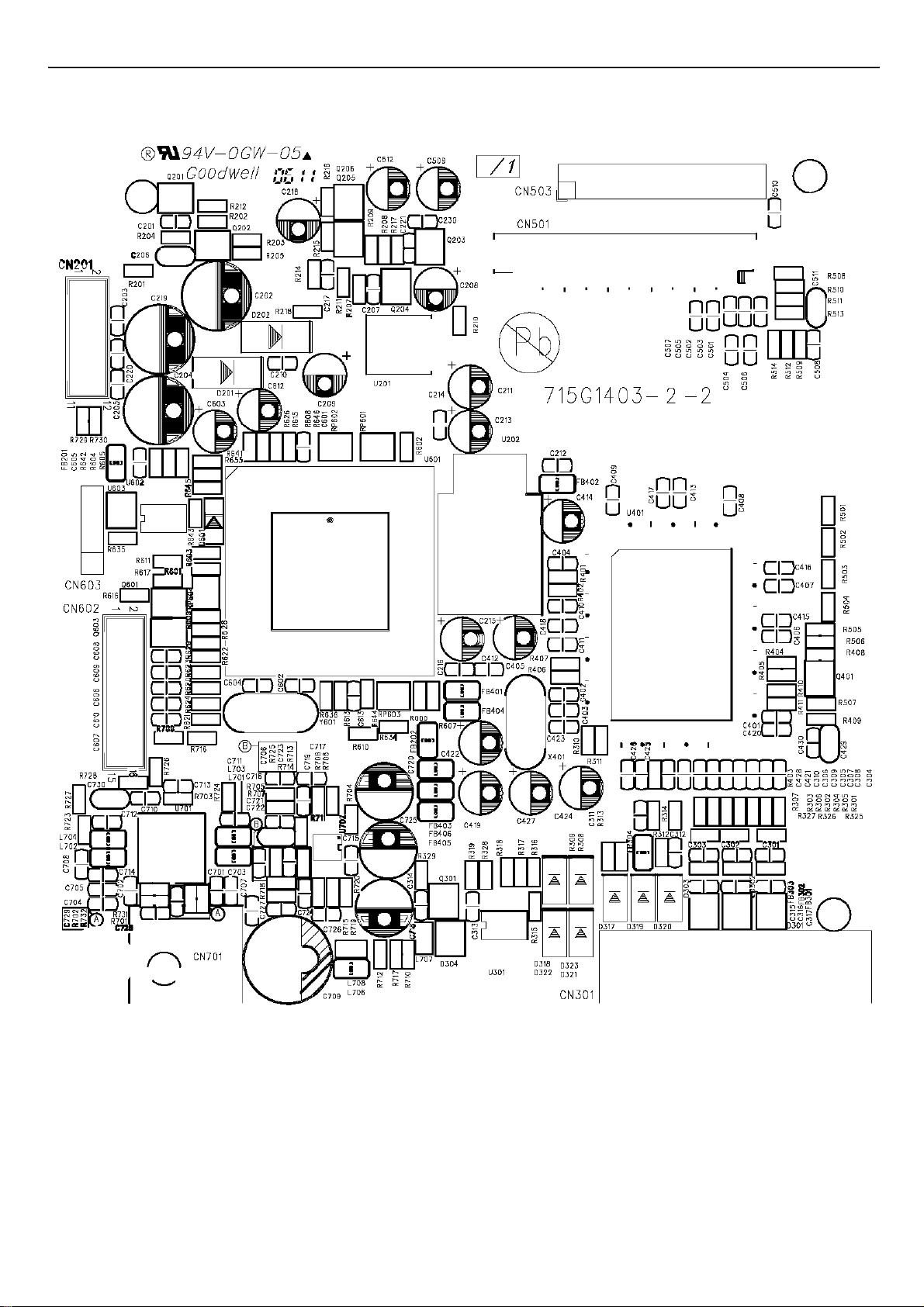
8. PCB Layout
8.1 Main Board
26
Page 27

17" LCD Color Monitor HP VS17X
27
Page 28

17" LCD Color Monitor HP VS17X
28
Page 29

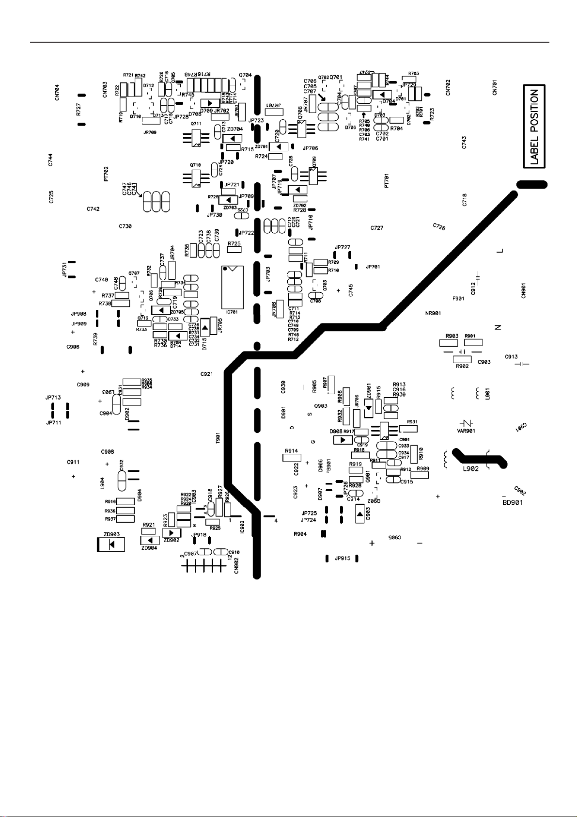
17" LCD Color Monitor HP VS17X
8.2 Power Board
29
Page 30
17" LCD Color Monitor HP VS17X
30
Page 31

17" LCD Color Monitor HP VS17X
8.3 Key Board
31
Page 32

17" LCD Color Monitor HP VS17X
9. Maintainability
9.1Equipments and Tools Requirement
1. Multi-meter.
2. Oscilloscope.
3. Pattern Generator.
4. DDC Tool with an IBM Compatible Computer.
5. Alignment Tool.
6. LCD Color Analyzer.
7. Service Manual.
8. User Manual.
32
Page 33

17" LCD Color Monitor HP VS17X
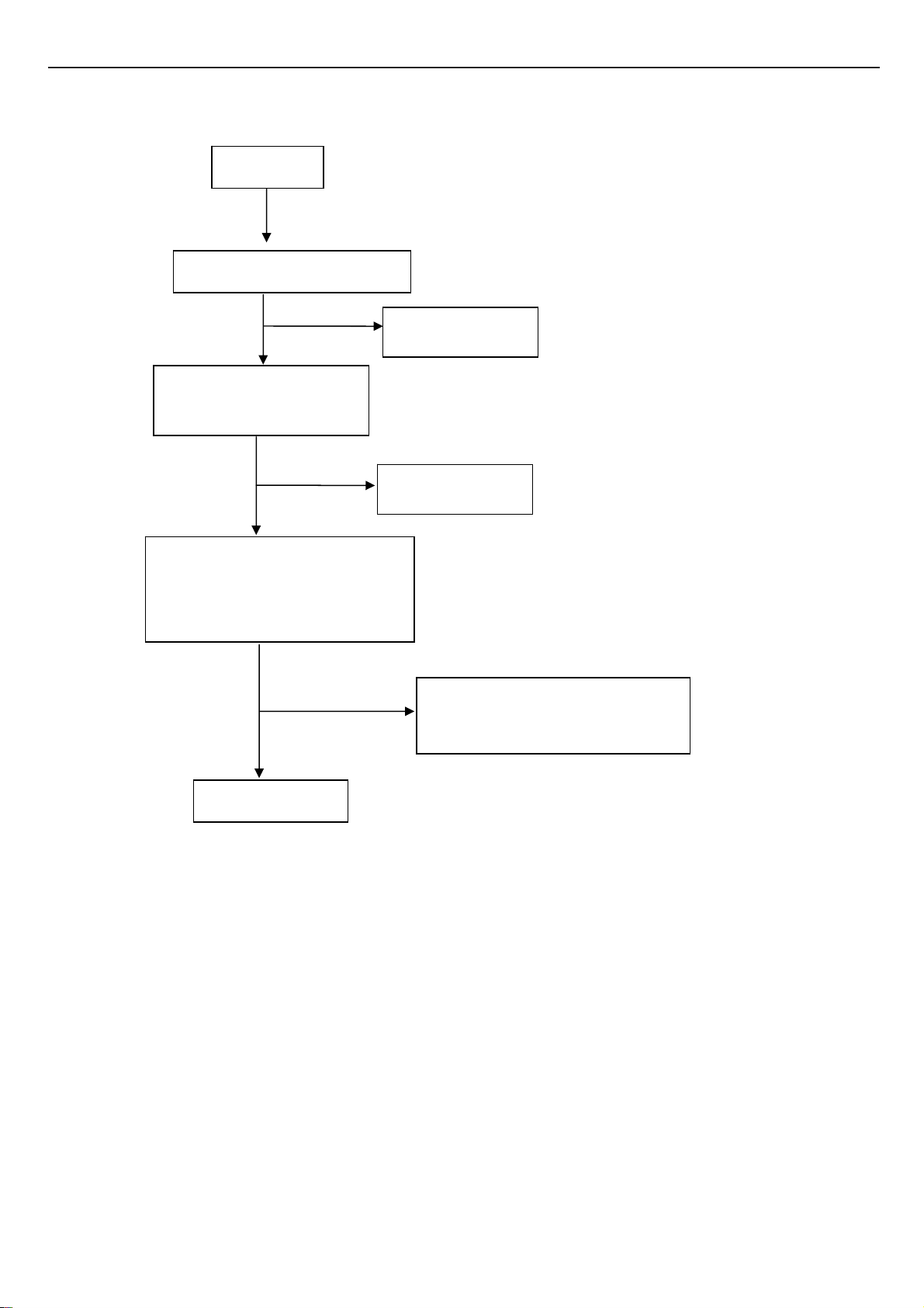
9.2 Trouble Shooting
9.2.1 Main Board
1、No power
Press power key and look if the
picture is normal
Please reinsert and make sure the
AC of 100-240 is normal
Measure U202 PIN 2=3.3V
X401 oscillate waveforms are
normal
No power
NG
OK
OK
OK
NG
NG
NG
Replace X401
Reinsert or check the
power section
Measure CN201 PIN5/6=12V?
Measure CN201 PIN9/10=5V?
NG
Replace U401
33
Check power section
Page 34
17" LCD Color Monitor HP VS17X
No picture (LED is orange)
No picture
Measure U202 PIN2=3.3V
OK
NG
Replace U202
X401 oscillate waveforms
are normal
NG
OK
Replace X401
Check if the sync signal from
computer is output and video cable
is connected normally
OK
NG
Input the sync signal of computer, or
change the cable
Replace U401
34
Page 35

17" LCD Color Monitor HP VS17X
p
Panel Power Circuit
Check CN503 PIN 23-24 should have
response from 0V to 5V When we
switch the power switch from on to off
OK
Replace panel
9.2.2 Power Board
1. No Power
No power
Check the PPWR panel power relative circuit,Q204, Q203
NG
In normal operation, when LED =green, R207
Should =5 V,
If PPWR no-response when the power switch
Turn on and turn off, re
lace the U401-MST8116B
Check AC line volt 110V or 220V
OK
NG
Check AC line
Check the voltage of C905(+)
OK
NG
Check F901, bridge rectified circuit
Check start voltage for the pin3 of IC901
NG
OK
Check the auxiliary voltage is between 10V-16V
Check R909,R910,R931,IC901
OK
NG
Check IC901,T901,D901,D906,D907
Check ZD901,ZD902,IC902,Q903
35
Page 36

17" LCD Color Monitor HP VS17X
2. W/LED No Backlight
Check C907 (+) =12V
OK
NG
Check Power 12+ circuit
Check ON/OFF signal
NG
OK
Check Interface board
Check IC201 pin5=5V ?
Check the pin20,pin19,pin11,pin12 of IC201 have saw
OK
NG
Change Q707,Q706,Q712
NG
OK
Change IC201
Check the resonant wave of pin2 & pin5 for PT701/ PT702
OK
NG
Check Q708/Q709/Q710/Q711
Check the output of PT701/PT702
OK
NG
Change PT701/PT702
Check connecter & lamp
36
Page 37

17" LCD Color Monitor HP VS17X
9.2.3 Key Board
OSD is unstable or not working
Is Keypad board connecting normally?
NG
Connect Keypad Board
OK
Is Button Switch normally?
NG
Replace Button Switch
OK
Is Keypad board normally?
NG
Replace Keypad Board
OK
Check main board
37
Page 38

17" LCD Color Monitor HP VS17X
10. White- Balance, Luminance Adjustment
Approximately 30 minutes should be allowed for warm up before proceeding
White-Balance adjustment.
1. How to do the Chroma-7120 MEM .Channel setting
A. Reference to chroma 7120 user guide
B. Use “ SC” key and “ NEXT” key to modify xyY value and use “ID” key to modify the
TEXT description Following is the procedure to do white-balance adjust
2. Setting the color temp. You want
A. 9300 color:
9300 color temp. parameter is x = 283 ±20, y = 297 ±20, Y > 180 cd/m
B. sRGB color:
sRGB color temp. parameter is x = 313±20, y = 329 ±20, Y>200 cd/m
C. 6500K color:
2 ,
2
)
Don’t adjustment,Custom requires.
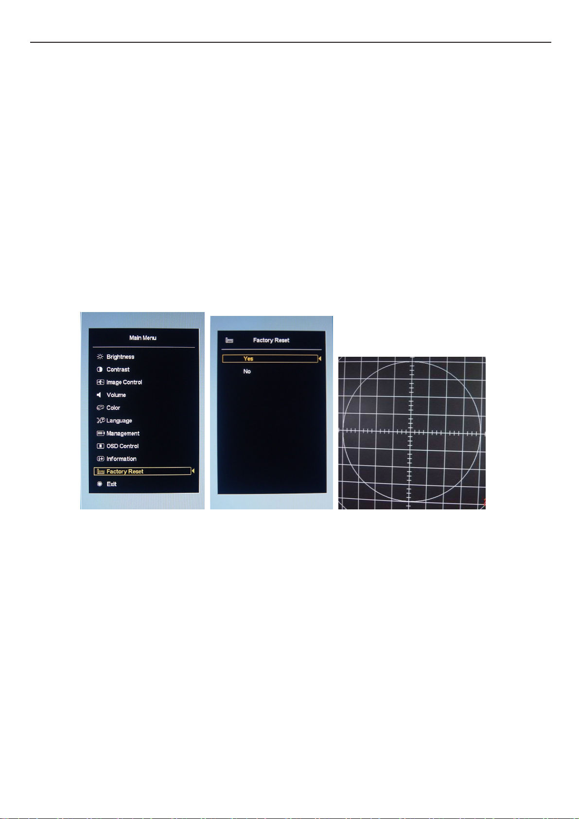
3. Into factory mode of HP VS17X
A. Turn on power, press the down (+) button, pull out the power cord, and then plug the power cord. Then the
factory OSD will be at the left top of the panel.
4. Bias adjustment:
Set the Contrast
Adjust the Brightness
to 80
to 90.
5. Gain adjustment :
Move cursor to “-F-” and press MENU key
A. Adjus 9300k color-temperature
1. Switch the Chroma-7120 to 9300k channel.
2. The chroma 7120 will show x = 283±20, y = 297 ±20, Y>180 cd/m
3. Switch the chroma-720 to RGB MODE (with press “MODE” button to change )
4. Adjust the RED of color 9300K on factory window until chroma 7120 indicator reached
2
the value R=100
5. Adjust the GREEN of color 9300K on factory window until chroma 7120 indicator reached
the value G=100
6. Adjust the BLUE of color 9300K on factory window until chroma 7120 indicator reached
the value B=100
7. Repeat above procedure ( item 4,5,6) until chroma 7120 RGB value meet the
tolerance =100±2
38
Page 39

17" LCD Color Monitor HP VS17X
B. Adjust sRGB color-temperature
1. Switch the chroma-7120 to sRGB channel.
2. The chroma 7120 will show x = 313 ±20, y = 329 ±20, Y >200 cd/m
3. Switch the chroma 7120 l to RGB MODE ( with press “MODE” button to change )
4. Adjust the RED of color sRGB on factory window until chroma 7120 indicator reached
the value R=100
5. Adjust the GREEN of color sRGB on factory window until chroma 7120 indicator reached
the value G=100
6. Adjust the BLUE of color sRGB on factory window until chroma 7120 indicator reached
the value B=100
7. Repeat above procedure ( item 4,5,6) until chroma 7120 RGB value meet the
tolerance =100±2
C. Press reset key and Turn the Power-button “off to on” to quit from factory mode.
2
39
Page 40
17" LCD Color Monitor HP VS17X
11. Check List After Replacing LCD Main Board
Check if white-balance is within the specs after replacing Main board and panel,then re-writing DDC is
necessary.
Ⅰ. Check white -balance
The white-balance value for each common color temperature:
9300K: x=283± 20 ; y = 297± 20;
sRGB: x = 313± 20 ; y = 329 ± 20;
The color temperature value above must be up to the situation of x<y. The value of Y should be confirmed
according to different customers. 15 ”LCD is commonly 180±20cd/cm
larger than 200cd/cm
different customers and different models.
2
(Center). The exact brightness values are confirmed by the checking-regulations of
Ⅱ. Steps of white-balance adjustment for LCD:(Take 17” HP LCD for example)
1. Required instruments: Chroma7120、Chroma2325(BGA265A)。
2. First connect the instruments together and turn on the LCD power, then warm up for 30 minutes under full
2
(Center)and 17” LCD is required to be
white screen mode. First press the “Reset” key in the menu to recover factory set as following.
a) Set Chroma2325 at round-windows mode and make the detecting-head of Chroma7120 aim at the cross in the
middle, the distance between the detecting-head and the cross is 20cm.
b) Set Chroma2325(BGA265A)to be T144(1280*1024/60HZ)and P105 of full white screen. Test if the
white-balance value is within the specs. Please follow the steps below to adjust if it is beyond the specs.
c) Cut the power. Then press Minus (“-“) key and supply power at the same time to enter into the factory mode.
See the following pictures.
40
Page 41

17" LCD Color Monitor HP VS17X
d) Test white-balance again after Auto Level. Adjustment with hand is necessary if it is beyond the specs just the
same.
e) Select 7x00 item to adjust cool color-temperature and select 6x00 to adjust warm color- temperature. It can
reach to the best effect through adjusting R/G/B value if it inclines to green or blue.
f) Select Exit to the upper menu after completing the adjustment. Then press POWER OFF to exit and save it.
Ⅲ. Steps for writing DDC:
1. Employ PC, and connect the DDC-writing instrument and the instrument that is ready for writing into DDC to
the power of 12v. Connect the signal cable of the latter to D-USB or DVI of DDC-writing instrument (The data-writing of
monitor needs transfer-interface) and link the DDC-writing instrument with PC through printer interface. (See the
schematic picture below)
Connection of DDC-writing instrument for VGA.
2. Seek the document with the expanded name of .BAT in DDC file of this model. It appears the indication of “Input
Serial No.:"after dual-click the document to be ready for DDC-writing.
41
Page 42

17" LCD Color Monitor HP VS17X
3.Input the serial number of the product (For instance: AOC LM729 is 13 bits), then press ENTER to start writing
4.Check the indication of DDC-writing program at the end. When you see the picture as the schematic picture above,
the “Data compare OK!” means being written well and that’s the end. Please check if the Manufacturer Name,
Vendor Assigned Code, Monitor Name, Serial Number, Week of Manufacture, Year of Manufacture are right. It will
appear “Data compare error !” to indicate failure if the DDC-writing doesn’t perform well. Please check the
power resource and the connection of the signal cable, then return to step 3 by pressing ENTER and re-do it.
5.You can exit the program by pressing Ctrl plus C, then cut the signal cable and the power.
6.The following picture is taking Acer AL1721 EDID for example.
Notes:
1、Make sure the system time of PC is in accordance with the real time before writing.
2、The schematic picture is just as an example for description, the exact content of the DDC is dependent on the
serial number of the BARCORD of this model.
3、Data DDC-writing needs a transfer interface.
42
Page 43

17" LCD Color Monitor HP VS17X
Instruction:DDC-writing needs 4 files:
1. Barcode.txt (Supply Barcode length and flow number)
2. *.EXE (DDC-writing program)
3. WR.bat (Group order file for cycling utilization of *EXE, and dual-click this file when perform
DDC-writing)
4、w.dat The content with 128 bits of DDC
43
Page 44

17" LCD Color Monitor HP VS17X
12. BOM List
T76CM4DKAJHPAE
Location Part No. Description
CBPC781KC4HPAP CONVERSION BOARD
KEPC782KD4P KEY BOARD
PWPC1742CPH3P POWER BOARD
15G8116 4 MAIN FRAME
23G3178690 6A LOGO
33G4788 PC L STAND-CAP
41G160069017F DOC KIT VS17 FOR NA
41G780069064B QSP
41G780069074E SCRECN FLYER
44G3751 1 EPS
44G3751 2 EPS
44G3751 5BRO PAPER BOARD
45G 88606 H PE BAG FOR BASE
45G 88607 H PE BAG(MONITOR)
45G 88609 2 EPE COVER
52G 1185 MIDDLE TAPE FOR CARTON
52G 1186 SMALL TAPE
52G 1211 B AL TAPE
52G6022 1500 SMALL TAPE
52G6025 11780 MRLAR
52G6025 11897 MYLAR
89G 173 56507 AUDIO CABLE
E089B 89G1738CAAE01 SIGNAL CABLE
89G402A19N IS AC POWER CABLE
95G8014 16588 KEY BOARD HARNESS
E095 95G8018 30E02 LVDS CABLE
M1G 130 6120 SCREW M3X6
M1G 340 8 47 SCREW
M1G1730 8128 UCREW M3x8
M1G1740 6128 SCREW
Q1G 330 8120 SCREW 3X8mm
705G780KB34 81 REAR COVER ASS'Y
E750L 750GLC70A7Q23M000H CPT 17" 2A2 PANEL
H34G1458 PCA1B FRONT PANEL
H40G 170690 4D RATING LABEL
H40G581H690 2A CARTON LABEL
AIC781KC4HPAP MAIN BOARD
44
Page 45

17" LCD Color Monitor HP VS17X
CN201 33G8027 12 6176 WAFER 2*6P 2.0MM R/A
CN602 33G8027 16 6W61 WAFER 16PIN 2.0mm DIP
CN503 33G8043 24 H6176 WAFER
40G 457624 1B CPU LABEL
40G 45762412B CBPC LABEL
C709 67G215B4713KV6366 LOWESR 470UF 16V
C718 67G215V101 4R6F73 LOW E.S.R 100UF +/-20%
C204 67G215V221 4R6F73 LOW E.S.R 220UF +/-20%
C405 67G405V100 3P6069 10UF 16V
C414 67G405V100 3P6069 10UF 16V
C419 67G405V100 3P6069 10UF 16V
C422 67G405V100 3P6069 10UF 16V
C424 67G405V100 3P6069 10UF 16V
C427 67G405V100 3P6069 10UF 16V
C603 67G405V100 3P6069 10UF 16V
C509 67G405V220 3P6069 22UF 16V
C612 67G405V220 3P6069 22UF 16V
C209 67G405V470 3P6069 47UF 16V
C211 67G405V470 3P6069 47UF 16V
C213 67G405V470 3P6069 47UF 16V
C215 67G405V470 3P6069 47UF 16V
CN701 88G 30214K 6141 PHONE JACK 5PIN
CN301 88G 35315F H6818 D-SUB 15PIN
Y601 93G 22 45 J 24MHZ/30PF/49US
X401 93G 22 53 J 14.31818MHZ/32PF/49US
U401 56G 562 86 TSU16AK PQFP-128 BY MST
U202 56G 563 21 AP1084K33LA
U201 56G 563 31 AZ1117D-1.8-EI
U702 56G 616 19 TPA6112A2 MSOP-10
U701 56G 616 20 TPA2008D2PWPRG4 HTSQP 2
U601 56G1125543CH6 MTV512MV
U602 56G1133 24 AT24C16N-10SC-2.7
U301 56G1133 34 M24C02-WMN6TP
Q201 57G 417 4 PMBS3904/PHILIPS-SMT(04
Q202 57G 417 4 PMBS3904/PHILIPS-SMT(04
Q204 57G 417 4 PMBS3904/PHILIPS-SMT(04
Q301 57G 417 4 PMBS3904/PHILIPS-SMT(04
Q401 57G 417 4 PMBS3904/PHILIPS-SMT(04
Q601 57G 417 6 PMBS3906/PHILIPS-SMT(06
Q603 57G 417 6 PMBS3906/PHILIPS-SMT(06
45
Page 46

17" LCD Color Monitor HP VS17X
Q203 57G 763 1 AO3401L SOT23 BY AOS(A1
RP601 61L 125103 86865 CHIP AR 8P4R 10KOHM +-5
RP602 61L 125103 86865 CHIP AR 8P4R 10KOHM +-5
RP603 61L 125103 86865 CHIP AR 8P4R 10KOHM +-5
RP604 61L 125103 86865 CHIP AR 8P4R 10KOHM +-5
FB301 61L0603000 6865 RST SM 0603 JUMP MAX 0R
FB302 61L0603000 6865 RST SM 0603 JUMP MAX 0R
FB303 61L0603000 6865 RST SM 0603 JUMP MAX 0R
R209 61L0603000 6865 RST SM 0603 JUMP MAX 0R
R501 61L0603000 6865 RST SM 0603 JUMP MAX 0R
R502 61L0603000 6865 RST SM 0603 JUMP MAX 0R
R503 61L0603000 6865 RST SM 0603 JUMP MAX 0R
R504 61L0603000 6865 RST SM 0603 JUMP MAX 0R
R505 61L0603000 6865 RST SM 0603 JUMP MAX 0R
R507 61L0603000 6865 RST SM 0603 JUMP MAX 0R
R641 61L0603000 6865 RST SM 0603 JUMP MAX 0R
R730 61L0603000 6865 RST SM 0603 JUMP MAX 0R
R704 61L0603100 2F6865 10K 1%
R711 61L0603100 2F6865 10K 1%
R713 61L0603100 2F6865 10K 1%
R720 61L0603100 2F6865 10K 1%
R309 61L0603101 6865 RST SM 0603 RC0603 100R
R312 61L0603101 6865 RST SM 0603 RC0603 100R
R319 61L0603101 6865 RST SM 0603 RC0603 100R
R608 61L0603101 6865 RST SM 0603 RC0603 100R
R609 61L0603101 6865 RST SM 0603 RC0603 100R
R636 61L0603101 6865 RST SM 0603 RC0603 100R
R646 61L0603101 6865 RST SM 0603 RC0603 100R
R705 61L0603101 6865 RST SM 0603 RC0603 100R
R707 61L0603101 6865 RST SM 0603 RC0603 100R
R709 61L0603101 6865 RST SM 0603 RC0603 100R
R714 61L0603101 6865 RST SM 0603 RC0603 100R
R716 61L0603101 6865 RST SM 0603 RC0603 100R
R718 61L0603101 6865 RST SM 0603 RC0603 100R
R203 61L0603102 6865 RST SM 0603 RC0603 1K P
R310 61L0603102 6865 RST SM 0603 RC0603 1K P
R311 61L0603102 6865 RST SM 0603 RC0603 1K P
R408 61L0603102 6865 RST SM 0603 RC0603 1K P
R725 61L0603102 6865 RST SM 0603 RC0603 1K P
R726 61L0603102 6865 RST SM 0603 RC0603 1K P
46
Page 47

17" LCD Color Monitor HP VS17X
R727 61L0603102 6865 RST SM 0603 RC0603 1K P
R728 61L0603102 6865 RST SM 0603 RC0603 1K P
R202 61L0603103 6865 CHIPR 10K OHM +-5% 1/16
R204 61L0603103 6865 CHIPR 10K OHM +-5% 1/16
R208 61L0603103 6865 CHIPR 10K OHM +-5% 1/16
R211 61L0603103 6865 CHIPR 10K OHM +-5% 1/16
R308 61L0603103 6865 CHIPR 10K OHM +-5% 1/16
R404 61L0603103 6865 CHIPR 10K OHM +-5% 1/16
R405 61L0603103 6865 CHIPR 10K OHM +-5% 1/16
R406 61L0603103 6865 CHIPR 10K OHM +-5% 1/16
R407 61L0603103 6865 CHIPR 10K OHM +-5% 1/16
R409 61L0603103 6865 CHIPR 10K OHM +-5% 1/16
R601 61L0603103 6865 CHIPR 10K OHM +-5% 1/16
R602 61L0603103 6865 CHIPR 10K OHM +-5% 1/16
R603 61L0603103 6865 CHIPR 10K OHM +-5% 1/16
R604 61L0603103 6865 CHIPR 10K OHM +-5% 1/16
R605 61L0603103 6865 CHIPR 10K OHM +-5% 1/16
R606 61L0603103 6865 CHIPR 10K OHM +-5% 1/16
R607 61L0603103 6865 CHIPR 10K OHM +-5% 1/16
R613 61L0603103 6865 CHIPR 10K OHM +-5% 1/16
R615 61L0603103 6865 CHIPR 10K OHM +-5% 1/16
R626 61L0603103 6865 CHIPR 10K OHM +-5% 1/16
R644 61L0603103 6865 CHIPR 10K OHM +-5% 1/16
R645 61L0603103 6865 CHIPR 10K OHM +-5% 1/16
R701 61L0603103 6865 CHIPR 10K OHM +-5% 1/16
R702 61L0603103 6865 CHIPR 10K OHM +-5% 1/16
R710 61L0603103 6865 CHIPR 10K OHM +-5% 1/16
R703 61L0603124 6865 CHIP 120KOHM 1/10W
R706 61L0603200 2F6865 CHIPR 20KOHM +-1% 1/16W
R708 61L0603200 2F6865 CHIPR 20KOHM +-1% 1/16W
R715 61L0603200 2F6865 CHIPR 20KOHM +-1% 1/16W
R719 61L0603200 2F6865 CHIPR 20KOHM +-1% 1/16W
R610 61L0603220 6865 RST SM 0603 RC0603 22R
R611 61L0603220 6865 RST SM 0603 RC0603 22R
R712 61L0603220 6865 RST SM 0603 RC0603 22R
R313 61L0603222 6865 RST SM 0603 RC0603 2K2
R314 61L0603222 6865 RST SM 0603 RC0603 2K2
R301 61L0603330 6865 CHIPR 33 OHM +-5% 1/16W
R302 61L0603330 6865 CHIPR 33 OHM +-5% 1/16W
R303 61L0603330 6865 CHIPR 33 OHM +-5% 1/16W
47
Page 48

17" LCD Color Monitor HP VS17X
R315 61L0603330 6865 CHIPR 33 OHM +-5% 1/16W
R316 61L0603330 6865 CHIPR 33 OHM +-5% 1/16W
R403 61L0603390 0F6865 CHIP 390 OHM 1/10W 1%
R617 61L0603391 6865 CHIP 390 OHM 1/16W
R217 61L0603471 6865 CHIPR 470 OHM+-5% 1/16W
R304 61L0603471 6865 CHIPR 470 OHM+-5% 1/16W
R628 61L0603471 6865 CHIPR 470 OHM+-5% 1/16W
R201 61L0603472 6865 RST SM 0603 RC0603 4K7
R205 61L0603472 6865 RST SM 0603 RC0603 4K7
R207 61L0603472 6865 RST SM 0603 RC0603 4K7
R212 61L0603472 6865 RST SM 0603 RC0603 4K7
R317 61L0603472 6865 RST SM 0603 RC0603 4K7
R318 61L0603472 6865 RST SM 0603 RC0603 4K7
R328 61L0603472 6865 RST SM 0603 RC0603 4K7
R402 61L0603472 6865 RST SM 0603 RC0603 4K7
R410 61L0603472 6865 RST SM 0603 RC0603 4K7
R616 61L0603472 6865 RST SM 0603 RC0603 4K7
R629 61L0603472 6865 RST SM 0603 RC0603 4K7
R655 61L0603472 6865 RST SM 0603 RC0603 4K7
R305 61L0603680 6865 CHIPR 68OHM +-5% 1/10W
R306 61L0603680 6865 CHIPR 68OHM +-5% 1/10W
R307 61L0603680 6865 CHIPR 68OHM +-5% 1/10W
R325 61L0603750 6865 CHIPR 75 OHM+-5% 1/16W
R326 61L0603750 6865 CHIPR 75 OHM+-5% 1/16W
R327 61L0603750 6865 CHIPR 75 OHM+-5% 1/16W
R731 61L0603823 6865 CHIPR 82KOHM +-5% 1/16W
R732 61L0603823 6865 CHIPR 82KOHM +-5% 1/16W
C511 61L0805102 6865 CHIPR 1K OHM +-5% 1/10W
FB304 61L0805201 6865 200OHM 0805
C307 65G0603102 326805 1000PF +-10% 50V X7R
C706 65G0603102 326805 1000PF +-10% 50V X7R
C708 65G0603102 326805 1000PF +-10% 50V X7R
C711 65G0603102 326805 1000PF +-10% 50V X7R
C712 65G0603102 326805 1000PF +-10% 50V X7R
C315 65G0603104 126805 0.1UF +-10% 16V X7R
C316 65G0603104 126805 0.1UF +-10% 16V X7R
C317 65G0603104 126805 0.1UF +-10% 16V X7R
C701 65G0603104 126805 0.1UF +-10% 16V X7R
C702 65G0603104 126805 0.1UF +-10% 16V X7R
C703 65G0603104 126805 0.1UF +-10% 16V X7R
48
Page 49

17" LCD Color Monitor HP VS17X
C704 65G0603104 126805 0.1UF +-10% 16V X7R
C201 65G0603104 326805 CHIP 0.1UF 50V X7R
C207 65G0603104 326805 CHIP 0.1UF 50V X7R
C210 65G0603104 326805 CHIP 0.1UF 50V X7R
C212 65G0603104 326805 CHIP 0.1UF 50V X7R
C214 65G0603104 326805 CHIP 0.1UF 50V X7R
C216 65G0603104 326805 CHIP 0.1UF 50V X7R
C313 65G0603104 326805 CHIP 0.1UF 50V X7R
C314 65G0603104 326805 CHIP 0.1UF 50V X7R
C401 65G0603104 326805 CHIP 0.1UF 50V X7R
C404 65G0603104 326805 CHIP 0.1UF 50V X7R
C406 65G0603104 326805 CHIP 0.1UF 50V X7R
C407 65G0603104 326805 CHIP 0.1UF 50V X7R
C408 65G0603104 326805 CHIP 0.1UF 50V X7R
C409 65G0603104 326805 CHIP 0.1UF 50V X7R
C410 65G0603104 326805 CHIP 0.1UF 50V X7R
C411 65G0603104 326805 CHIP 0.1UF 50V X7R
C412 65G0603104 326805 CHIP 0.1UF 50V X7R
C413 65G0603104 326805 CHIP 0.1UF 50V X7R
C415 65G0603104 326805 CHIP 0.1UF 50V X7R
C416 65G0603104 326805 CHIP 0.1UF 50V X7R
C417 65G0603104 326805 CHIP 0.1UF 50V X7R
C418 65G0603104 326805 CHIP 0.1UF 50V X7R
C420 65G0603104 326805 CHIP 0.1UF 50V X7R
C421 65G0603104 326805 CHIP 0.1UF 50V X7R
C423 65G0603104 326805 CHIP 0.1UF 50V X7R
C425 65G0603104 326805 CHIP 0.1UF 50V X7R
C426 65G0603104 326805 CHIP 0.1UF 50V X7R
C428 65G0603104 326805 CHIP 0.1UF 50V X7R
C601 65G0603104 326805 CHIP 0.1UF 50V X7R
C606 65G0603104 326805 CHIP 0.1UF 50V X7R
C607 65G0603104 326805 CHIP 0.1UF 50V X7R
C608 65G0603104 326805 CHIP 0.1UF 50V X7R
C609 65G0603104 326805 CHIP 0.1UF 50V X7R
C610 65G0603104 326805 CHIP 0.1UF 50V X7R
C613 65G0603104 326805 CHIP 0.1UF 50V X7R
C717 65G0603104 326805 CHIP 0.1UF 50V X7R
C719 65G0603104 326805 CHIP 0.1UF 50V X7R
C724 65G0603104 326805 CHIP 0.1UF 50V X7R
C726 65G0603104 326805 CHIP 0.1UF 50V X7R
49
Page 50

17" LCD Color Monitor HP VS17X
C203 65G0603104 376805 CHIP 0.1UF 50V/Y5V
C205 65G0603104 376805 CHIP 0.1UF 50V/Y5V
C705 65G0603105 176805 1UF 16V Y5V
C707 65G0603105 176805 1UF 16V Y5V
C710 65G0603105 176805 1UF 16V Y5V
C714 65G0603105 176805 1UF 16V Y5V
C715 65G0603105 176805 1UF 16V Y5V
C402 65G0603220 316785 CHIP 22PF 50V NPO
C403 65G0603220 316785 CHIP 22PF 50V NPO
C602 65G0603220 316785 CHIP 22PF 50V NPO
C604 65G0603220 316785 CHIP 22PF 50V NPO
C312 65G0603221 316805 CAP:CER 220PF 5% 50V SM
C713 65G0603221 316805 CAP:CER 220PF 5% 50V SM
C605 65G0603224 126805 CHIP 0.22UF 50V X7R
C728 65G0603471 316805 CAP:CER 470PF 5%50V SMT
C729 65G0603471 316805 CAP:CER 470PF 5%50V SMT
C304 65G0603473 326805 CHIP 0.047UF 50V X7R
C305 65G0603473 326805 CHIP 0.047UF 50V X7R
C306 65G0603473 326805 CHIP 0.047UF 50V X7R
C308 65G0603473 326805 CHIP 0.047UF 50V X7R
C309 65G0603473 326805 CHIP 0.047UF 50V X7R
C310 65G0603473 326805 CHIP 0.047UF 50V X7R
C716 65G0603473 326805 CHIP 0.047UF 50V X7R
C721 65G0603473 326805 CHIP 0.047UF 50V X7R
C723 65G0603473 326805 CHIP 0.047UF 50V X7R
C727 65G0603473 326805 CHIP 0.047UF 50V X7R
C230 65G0603474 176805 CHIP CAP.CER 0.47UF -20
C311 65G0603680 316785 CHIP 68PF 50V NPO
C206 65G0805105 376805 CHIP 1UF 50V Y5V
C429 65G0805225 176857 CHIP 2.2UF 16V Y5V
C722 65G0805225 176857 CHIP 2.2UF 16V Y5V
FB202 71G 56K121 M6888 CHIP BEAD
FB401 71G 56K121 M6888 CHIP BEAD
FB402 71G 56K121 M6888 CHIP BEAD
FB403 71G 56K121 M6888 CHIP BEAD
FB404 71G 56K121 M6888 CHIP BEAD
FB405 71G 56K121 M6888 CHIP BEAD
FB406 71G 56K121 M6888 CHIP BEAD
L706 71G 56K121 M6888 CHIP BEAD
L707 71G 56K121 M6888 CHIP BEAD
50
Page 51

17" LCD Color Monitor HP VS17X
R620 71G 59G301 6457 CHIP BEAD 300OHM
R621 71G 59G301 6457 CHIP BEAD 300OHM
R622 71G 59G301 6457 CHIP BEAD 300OHM
R623 71G 59G301 6457 CHIP BEAD 300OHM
R624 71G 59G301 6457 CHIP BEAD 300OHM
D317 93G 39147SEM ZMM5V6ST
D318 93G 39147SEM ZMM5V6ST
D319 93G 39147SEM ZMM5V6ST
D320 93G 39147SEM ZMM5V6ST
D321 93G 39147SEM ZMM5V6ST
D304 93G 64 42 P BAV70 SOT-23
D601 93G 6432P LL4148
D301 93G 6433P BAV99
D302 93G 6433P BAV99
D303 93G 6433P BAV99
D201 93G1004 3 SS14
D202 93G1020 1 S GS1D
715G1403 2 2 MAIN BOARD PCB
12G6082 1 PORON
JP101 88G 30224U 6141 PHONE JACK
JP102 33G8032 4C 6W34 WAFER
JP103 33G803415D 6W34 WAFER
C101 65G0603121 316826 CHIP 120PF 50V NPO
C102 65G0603121 316826 CHIP 120PF 50V NPO
C103 65G0603121 316826 CHIP 120PF 50V NPO
C104 65G0603121 316826 CHIP 120PF 50V NPO
C105 65G0603471 316805 CAP:CER 470PF 5%50V SMT
C106 65G0603471 316805 CAP:CER 470PF 5%50V SMT
FB101 71G 59G301 6457 CHIP BEAD 300OHM
FB102 71G 59G301 6457 CHIP BEAD 300OHM
SW1 77G 607 1 FD3837 TACT SWITCH
SW2 77G 607 1 FD3837 TACT SWITCH
SW3 77G 607 1 FD3837 TACT SWITCH
SW4 77G 607 1 FD3837 TACT SWITCH
SW5 77G 607 1 FD3837 TACT SWITCH
DP1 81G0603 B KB6F1R KP-1608QBC-C-AOC 5MA
DP2 81G0603 Y KB6F1R KP-1608SYCK-5MAV-AOC
ZD101 93G 39S 34 T UDZS5.6B
ZD102 93G 39S 34 T UDZS5.6B
ZD103 93G 39S 34 T UDZS5.6B
51
Page 52
17" LCD Color Monitor HP VS17X
ZD104 93G 39S 34 T UDZS5.6B
ZD105 93G 39S 34 T UDZS5.6B
ZD106 93G 39S 34 T UDZS5.6B
ZD107 93G 39S 34 T UDZS5.6B
715G1404 3 KEY BOARD PCB
11G6049 2 GP TIE MOUNT(S)
CN701 33G8021 2D U6W34 3.5mm WAFER
CN702 33G8021 2D U6W34 3.5mm WAFER
CN703 33G8021 2D U6W34 3.5mm WAFER
CN704 33G8021 2D U6W34 3.5mm WAFER
40G 45762420A ID LABEL
IC902 56G 139 3A PC123Y22FZOF
VAR901 61G 46 10 6872 VARISTOR
NR901 61G 58080 WT6872 8 OHM NCT
R904 61G152M39858F6W56 0.39 OHM 5% 2W
C718 65G 3J1006EM 10PF +-5% 3KV SL
C725 65G 3J1006EM 10PF +-5% 3KV SL
C743 65G 3J1006EM 10PF +-5% 3KV SL
C744 65G 3J1006EM 10PF +-5% 3KV SL
C726 65G 3J5096ET H 5PF 5% 3KV TDK
C727 65G 3J5096ET H 5PF 5% 3KV TDK
C730 65G 3J5096ET H 5PF 5% 3KV TDK
C742 65G 3J5096ET H 5PF 5% 3KV TDK
C901 65G306M1022BM Y1.CAP.001UF 250VAC MUR
C902 65G306M1022BM Y1.CAP.001UF 250VAC MUR
C921 65G306M4722BP6W29 4700PF +-20% 400VAC
C908 67G215S1023KV6366 ED 1000UF 16V
C740 67G215V471 4N GP KY25VB470M-L10*16
C745 67G215V471 4N GP KY25VB470M-L10*16
C906 67G215V471 4N GP KY25VB470M-L10*16
C909 67G215V471 4N GP KY25VB470M-L10*16
C911 67G215V471 4N GP KY25VB470M-L10*16
C905 67G215Z10115K6366 100UF 450V
FB901 71G 55 29 6100 FERRITE BEAD
L903 73G 253 91 H6100 CHOKE COIL
L904 73G 253 91 H6100 CHOKE COIL
L901 73L 174 53 LG GP CHOKE
L902 73L 174 55 LG GP LINE FILTER BY LITAI
PT701 80LL17T 16DNG6360 TRANSFORMER DARFOW
PT702 80LL17T 16DNG6360 TRANSFORMER DARFOW
52
Page 53

17" LCD Color Monitor HP VS17X
T901 80LL19T 7LSG GP TRANSFORMER
BD901 93G 50460900 GBU408
D901 93G 6026T52T RECTIFIER DIODE FR107
D906 93G 6038T52T FR103
CN902 95G8021 125366176 CONNECTOR
705G 780 57 S1 Q903 ASS'Y
705G 780 61 36 R905 ASS'Y
705G 780 87 03 CN901 ASS'Y
705G 780 93 15 D902/D904 ASS'Y
PW1742CPH3AIP POWER BOARD
IC901 56G 379 33 1 SG6841SZ3
IC701 56G 608 7 OZT1060GN SOIC-20
Q712 57G 417 4 PMBS3904/PHILIPS-SMT(04
Q902 57G 417 4 PMBS3904/PHILIPS-SMT(04
Q901 57G 417 6 PMBS3906/PHILIPS-SMT(06
Q708 57G 60040A AM4512C-T1-PF SO-8
Q709 57G 60040A AM4512C-T1-PF SO-8
Q710 57G 60040A AM4512C-T1-PF SO-8
Q711 57G 60040A AM4512C-T1-PF SO-8
Q701 57G 759 2 RK7002
Q702 57G 759 2 RK7002
Q703 57G 759 2 RK7002
Q704 57G 759 2 RK7002
Q705 57G 759 2 RK7002
Q706 57G 760 4B PDTA144WK SOT346
Q707 57G 760 5B PDTC144WK SOT346
R925 61L0805000 6865 CHIP O OHM 1/8W
R915 61L0805101 6865 CHIPR 100 OHM +-5% 1/10
R705 61L0805102 6865 CHIPR 1K OHM +-5% 1/10W
R718 61L0805102 6865 CHIPR 1K OHM +-5% 1/10W
R737 61L0805102 6865 CHIPR 1K OHM +-5% 1/10W
R923 61L0805102 6865 CHIPR 1K OHM +-5% 1/10W
R924 61L0805102 6865 CHIPR 1K OHM +-5% 1/10W
R926 61L0805102 6865 CHIPR 1K OHM +-5% 1/10W
R715 61L0805103 6865 CHIPR 10K OHM +-5% 1/10
R724 61L0805103 6865 CHIPR 10K OHM +-5% 1/10
R726 61L0805103 6865 CHIPR 10K OHM +-5% 1/10
R728 61L0805103 6865 CHIPR 10K OHM +-5% 1/10
R732 61L0805103 6865 CHIPR 10K OHM +-5% 1/10
R917 61L0805103 6865 CHIPR 10K OHM +-5% 1/10
53
Page 54

17" LCD Color Monitor HP VS17X
R919 61L0805103 6865 CHIPR 10K OHM +-5% 1/10
R706 61L0805105 6865 CHIP 1M OHM 5% 1/8W
R707 61L0805105 6865 CHIP 1M OHM 5% 1/8W
R708 61L0805105 6865 CHIP 1M OHM 5% 1/8W
R717 61L0805105 6865 CHIP 1M OHM 5% 1/8W
R720 61L0805105 6865 CHIP 1M OHM 5% 1/8W
R735 61L0805105 6865 CHIP 1M OHM 5% 1/8W
R725 61L0805134 6865 CHIP 130KOHM+-5% 1/8W
R733 61L0805204 6865 200K OHM 1/10W
R736 61L0805204 6865 200K OHM 1/10W
R928 61L0805221 6865 CHIPR 220 OHM +-5% 1/8W
R930 61L0805240 2F6865 CHIP 24KOHM 1% 1/10W
R922 61L0805242 6865 CHIP 2.4KOHM 5% 1/8W
R714 61L0805301 2F6865 30.1KOHM 1% 0805 1/8W
R712 61L0805333 6865 CHIP 33KOHM 5% 1/8W
R920 61L0805333 6865 CHIP 33KOHM 5% 1/8W
R921 61L0805362 6865 CHIP 3.6KOHM 5% 1/8W
R744 61L0805431 6865 CHIP 430OHM 5% 0805 1/8
R745 61L0805431 6865 CHIP 430OHM 5% 0805 1/8
R703 61L0805471 6865 CHIPR 470 OHM+-5% 1/8W
R704 61L0805471 6865 CHIPR 470 OHM+-5% 1/8W
R716 61L0805471 6865 CHIPR 470 OHM+-5% 1/8W
R719 61L0805471 6865 CHIPR 470 OHM+-5% 1/8W
R740 61L0805472 6865 CHIRP 4.7K OHM +-5% 1/1
R741 61L0805472 6865 CHIRP 4.7K OHM +-5% 1/1
R743 61L0805472 6865 CHIRP 4.7K OHM +-5% 1/1
R911 61L0805472 6865 CHIRP 4.7K OHM +-5% 1/1
R912 61L0805472 6865 CHIRP 4.7K OHM +-5% 1/1
R913 61L0805472 6865 CHIRP 4.7K OHM +-5% 1/1
R711 61L0805513 6865 CHIP 51KOHM 1/8W
R701 61L0805622 6865 CHIP 6.2K OHM 1/10W
R721 61L0805622 6865 CHIP 6.2K OHM 1/10W
R709 61L0805683 6865 CHIPR 68K OHM+-5% 1/10W
R730 61L0805753 6857 75K 1/10W
R702 61L0805823 6865 chip 82kohm 1/8w
R722 61L0805823 6865 chip 82kohm 1/8w
JR701 61L1206000 6857 RST SM 1206 JUMP MAX 0R
JR702 61L1206000 6857 RST SM 1206 JUMP MAX 0R
JR703 61L1206000 6857 RST SM 1206 JUMP MAX 0R
JR704 61L1206000 6857 RST SM 1206 JUMP MAX 0R
54
Page 55

17" LCD Color Monitor HP VS17X
JR705 61L1206000 6857 RST SM 1206 JUMP MAX 0R
JR706 61L1206000 6857 RST SM 1206 JUMP MAX 0R
JR707 61L1206000 6857 RST SM 1206 JUMP MAX 0R
JR708 61L1206000 6857 RST SM 1206 JUMP MAX 0R
JR709 61L1206000 6857 RST SM 1206 JUMP MAX 0R
R729 61L1206100 6865 CHIPR 10 OHM+-5% 1/8W
R918 61L1206100 6865 CHIPR 10 OHM+-5% 1/8W
R906 61L1206101 6857 CHIP 100 OHM 5% 1/8W
R916 61L1206101 6857 CHIP 100 OHM 5% 1/8W
R934 61L1206101 6857 CHIP 100 OHM 5% 1/8W
R935 61L1206101 6857 CHIP 100 OHM 5% 1/8W
R936 61L1206101 6857 CHIP 100 OHM 5% 1/8W
R937 61L1206101 6857 CHIP 100 OHM 5% 1/8W
R909 61L1206434 6857 430K 1206 1/4W 5%
R910 61L1206434 6857 430K 1206 1/4W 5%
R931 61L1206434 6857 430K 1206 1/4W 5%
R927 61L1206470 6857 CHIP 47OHM 5% 1/4W
R738 61L1206471 6857 CHIPR 470 OHM+-5% 1/8W
R742 61L1206472 6857 CHIP 4.7KOHM 5% 1/8W
R907 61L1206514 6857 CHIP 510K OHM +-5% 1/8W
R908 61L1206514 6857 CHIP 510K OHM +-5% 1/8W
R932 61L1206514 6857 CHIP 510K OHM +-5% 1/8W
R914 61L1206519 6857 CHIPR 5.1OHM +-5% 1/4W
R901 61L1206684 6857 CHIPR 680K OHM+-5% 1/8W
R902 61L1206684 6857 CHIPR 680K OHM+-5% 1/8W
R903 61L1206684 6857 CHIPR 680K OHM+-5% 1/8W
C731 65G0805102 326857 CHIP 1000P 50VX7R 0805
C723 65G0805103 226857 CHIP 0.01uF 25V X7R 080
C917 65G0805103 226857 CHIP 0.01uF 25V X7R 080
C703 65G0805104 226826 0.1UF +-10% 25V X7R 080
C704 65G0805104 226826 0.1UF +-10% 25V X7R 080
C709 65G0805104 226826 0.1UF +-10% 25V X7R 080
C713 65G0805104 226826 0.1UF +-10% 25V X7R 080
C714 65G0805104 226826 0.1UF +-10% 25V X7R 080
C716 65G0805104 226826 0.1UF +-10% 25V X7R 080
C720 65G0805104 226826 0.1UF +-10% 25V X7R 080
C724 65G0805104 226826 0.1UF +-10% 25V X7R 080
C728 65G0805104 226826 0.1UF +-10% 25V X7R 080
C733 65G0805104 226826 0.1UF +-10% 25V X7R 080
C734 65G0805104 226826 0.1UF +-10% 25V X7R 080
55
Page 56

17" LCD Color Monitor HP VS17X
C737 65G0805104 226826 0.1UF +-10% 25V X7R 080
C738 65G0805104 226826 0.1UF +-10% 25V X7R 080
C748 65G0805104 226826 0.1UF +-10% 25V X7R 080
C907 65G0805104 226826 0.1UF +-10% 25V X7R 080
C910 65G0805104 226826 0.1UF +-10% 25V X7R 080
C914 65G0805104 226826 0.1UF +-10% 25V X7R 080
C916 65G0805104 226826 0.1UF +-10% 25V X7R 080
C719 65G0805105 226826 CHIP 1UF 25V X7R 0805
C735 65G0805105 226826 CHIP 1UF 25V X7R 0805
C739 65G0805105 226826 CHIP 1UF 25V X7R 0805
C918 65G0805105 226826 CHIP 1UF 25V X7R 0805
C701 65G0805392 316826 CHIP 3900PF 50V X7R 080
C717 65G0805392 316826 CHIP 3900PF 50V X7R 080
C919 65G0805471 216826 CHIP 470PF 25V NPO
C711 65G080547121G6857 470PF G 25V NPO
C710 65G0805472 226805 CHIP 0.0047UF 25V X7R 0
C732 65G0805472 226805 CHIP 0.0047UF 25V X7R 0
C712 65G0805473 226857 SMD 47nf +-10%25V XTR
C721 65G0805473 226857 SMD 47nf +-10%25V XTR
C722 65G0805473 226857 SMD 47nf +-10%25V XTR
C729 65G0805473 226857 SMD 47nf +-10%25V XTR
C736 65G0805474 226805 CHIP 0.47UF 25V X7R 080
C931 65G1206102 726805 CHIP 1000PF 500V X7R
C932 65G1206102 726805 CHIP 1000PF 500V X7R
C934 65G1206105 326826 CHIP 1UF 50V X7R 1206
C705 65G1206225 176826 C/2U2/16V/Y5V
C706 65G1206225 176826 C/2U2/16V/Y5V
C707 65G1206225 176826 C/2U2/16V/Y5V
C741 65G1206225 176826 C/2U2/16V/Y5V
C746 65G1206225 176826 C/2U2/16V/Y5V
C747 65G1206225 176826 C/2U2/16V/Y5V
D704 93G 6432P LL4148
D709 93G 6432P LL4148
D714 93G 6432P LL4148
D903 93G 6432P LL4148
D701 93G 6433P BAV99
D702 93G 6433P BAV99
D703 93G 6433P BAV99
D706 93G 6433P BAV99
D708 93G 6433P BAV99
56
Page 57

17" LCD Color Monitor HP VS17X
D710 93G 6433P BAV99
D712 93G 6433P BAV99
D713 93G 6433P BAV99
D908 93G 39S 12 T RLZ20B BY ROHM
ZD902 93G 39S 17 T RLZ12B LLDS
ZD903 93G 39S 19 T PTZ7.5B
ZD701 93G 39S 24 T RLZ 5.6B LLDS
ZD702 93G 39S 24 T RLZ 5.6B LLDS
ZD703 93G 39S 24 T RLZ 5.6B LLDS
ZD704 93G 39S 24 T RLZ 5.6B LLDS
ZD705 93G 39S 24 T RLZ 5.6B LLDS
ZD904 93G 39S 25 T RLZ5.1B BY ROHM
ZD901 93G 39S505 TZMC24
CN901 6G 31500 6176 EYELET
C905 6G 31502 6176 1.5MM RIVET
L901 6G 31502 6176 1.5MM RIVET
L902 6G 31502 6176 1.5MM RIVET
NR901 6G 31502 6176 1.5MM RIVET
PT701 6G 31502 6176 1.5MM RIVET
PT702 6G 31502 6176 1.5MM RIVET
Q903 6G 31502 6176 1.5MM RIVET
T901 6G 31502 6176 1.5MM RIVET
715G1420 4 IP POWER PCB
D907 95G 90 23 TINCOATEDCOPPER
JP701 95G 90 23 TINCOATEDCOPPER
JP703 95G 90 23 TINCOATEDCOPPER
JP706 95G 90 23 TINCOATEDCOPPER
JP707 95G 90 23 TINCOATEDCOPPER
JP709 95G 90 23 TINCOATEDCOPPER
JP710 95G 90 23 TINCOATEDCOPPER
JP711 95G 90 23 TINCOATEDCOPPER
JP713 95G 90 23 TINCOATEDCOPPER
JP719 95G 90 23 TINCOATEDCOPPER
JP720 95G 90 23 TINCOATEDCOPPER
JP721 95G 90 23 TINCOATEDCOPPER
JP722 95G 90 23 TINCOATEDCOPPER
JP723 95G 90 23 TINCOATEDCOPPER
JP724 95G 90 23 TINCOATEDCOPPER
JP725 95G 90 23 TINCOATEDCOPPER
JP726 95G 90 23 TINCOATEDCOPPER
57
Page 58

17" LCD Color Monitor HP VS17X
JP727 95G 90 23 TINCOATEDCOPPER
JP728 95G 90 23 TINCOATEDCOPPER
JP729 95G 90 23 TINCOATEDCOPPER
JP730 95G 90 23 TINCOATEDCOPPER
JP731 95G 90 23 TINCOATEDCOPPER
JP908 95G 90 23 TINCOATEDCOPPER
JP909 95G 90 23 TINCOATEDCOPPER
JP915 95G 90 23 TINCOATEDCOPPER
JP918 95G 90 23 TINCOATEDCOPPER
R739 95G 90 23 TINCOATEDCOPPER
R723 61G212Y625 KT3876 6.2M 3KV KAMAYA
R727 61G212Y625 KT3876 6.2M 3KV KAMAYA
IC903 56G 158 10 T AZ431AZ-AE1 TO-92
C930 65G 1K152 1T6921 1.5nF/1K Y5P +-10%
C922 67G 2151007RT6F73 LOW E.S.R 10UF +/-20% 5
F902 84G 55 7 GP FUSE 3.15A 250V
Q903 57G 600 35 STP8NK80ZFP TO-220FP
90G6064 1 HEAT SINK
AM1G1730 8128 GP SCREW M3*8
R905 61G152M10458F6W56 100K OHM 5% 2W
CN901 87G 501 12 CJ6425 AC SOCKET
95G 900582 6176 HARNES
96G 29 6 SHRINK TUBE UL/CSA
D904 93G 60247 FME-220A
D902 93G 60252 SP20150
M1G1730 8128 UCREW M3x8
12G6073 1 GATE LABEL
33G4789 PM 4L CONTROL BUTTON
33G4790APM L POWER BUTTON
33G4799 1 L LENS
34G1459 PD 2B REAR COVER
E078 78G 441 1A SPEAKER 4 OHM 2W
Q1G1030 12128 SCREW
12G6055 1 BASE RUBBER
12G6063 1 RUBBER
34G1460 PC B STAND PILLAR
34G1461 PC B BASE
37G 513 1 HINGE
Q1G 130 8120 SCREW
Q1G 140 8128 SCREW
58
Page 59

17" LCD Color Monitor HP VS17X
13. Different Parts List
Diversity of T76CM4DKAJHAAS Compared with T76CM4DKAJHPAE
Location Part No. Description
PWPC1742CPH3PK POWER BOARD
45G 88614 11 OUT PE BAG
M1G 340 8 47 CR3 SCREW
M1G1730 8128 CR3 SCREW
M1G1740 6128 CR3 SCREW
H41G160069017G VS*DOC KIT NA(379444-NN
H45G 87 1 2H PE BAG FOR MONITOR
H45G 87 4 H PE BAG FOR BASE/MANUAL
C720 67G305V221 36420 220UF 16V
C725 67G305V221 36420 220UF 16V
U602 56G1133 56 M24C16-WMN6TP
AIK782KD4SMTP KEY BOARD FOR SMT
715G1404 3 6905 KEY BOARD
PW1742CPH3SMTPK POWER BOARD
IC901 56G 379 74 SG5841SZ
R922 61L0805240 1F6865 CHIPR 2.4KOHM +-1% 1/8W
R921 61L0805360 1F6865 CHIP 3.6KOHM 1/8W 1%
M1G1730 8128 CR3 SCREW
Q1G1030 12128 CR3 SCREW
Q1G 140 8128 CR3 SCREW
59
 Loading...