

AOC VP17 Service Manual
17" LCD Color Monitor |
HP VP17 |
Service
Service
Service
|
|
Horizontal Frequency |
|
|
2483 kHz |
|
TABLE OF CONTENTS |
|
Description |
Page Description |
Page |
Table Of Contents.......……..............................…........1
Revision List.…........................................……......2
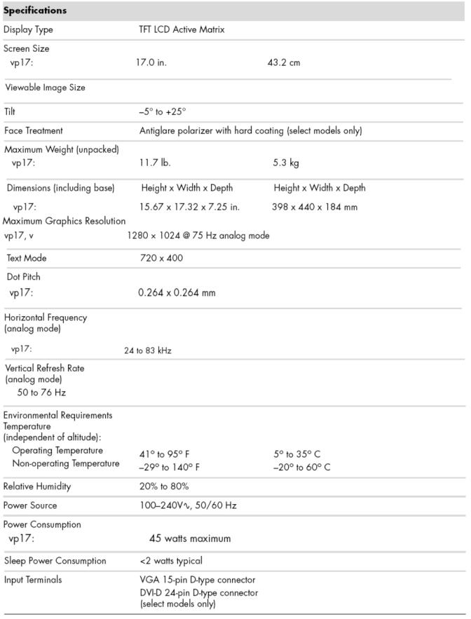
1.Monitor Specification..............................………........4
2.LCD Monitor Description…………………………….......5
3.Operation Instruction…………...............……...........6
3.1.General Instructions...........................…...........6
3.2.Control Button…………….…..............……...............6 3.3 Adjusting the Picture...........................…............7
4.Input/Output Specification............……………............10
4.1.Input Signal Connector............………….................10
4.2.Factory Preset Display Modes......…..................11
4.3.Power Supply Requirements...............................11
5.Panel Specification.....………………..................12
5.1.General Feature…….....………………..................12
5.2.Optical Characteristics………………………………13
6.Block Diagram……...................…………................14 6.1 Software Flow Chart………………………………...14 6.2.Electrical Block Diagram……………..….......16
7. Schematic……………......................................18
7.1Main Board....……………......................................18
7.2Power Board.….…………......................................22
7.3Key Board.….…………..…....................................25 8.PCB Layout..…….......................................26
8.1.Main Board………................................................26
8.2.Power Board….....................................................28
8.3.Key Board……….......................….......................30 9. Maintainability……….......................................31
9.1.Equipments and Tools Requirement…….............31
9.2.Trouble Shooting…….........................................32 9.2.1 Main Board…………...........................................32 9.2.2 Power Board……………...…..............................34 9.2.3 Key Board…………............................................36 10 White-Balance, Luminance adjustment..................37 11.Mechanical Instructions……………..…...….......39 12. Monitor Exploded View………………..…....….......46 13. BOM List………………………………..……………47
SAFETY NOTICE
ANY PERSON ATTEMPTING TO SERVICE THIS CHASSIS MUST FAMILIARIZE HIMSELF WITH THE CHASSIS AND BE AWARE OF THE NECESSARY SAFETY PRECAUTIONS TO BE USED WHEN SERVICING ELECTRONIC EQUIPMENT CONTAINING HIGH VOLTAGES.
CAUTION: USE A SEPARATE ISOLATION TRANSFOMER FOR THIS UNIT WHEN SERVICING
1

17" LCD Color Monitor |
|
HP VP17 |
|||
|
|
|
Revision List |
|
|
|
|
|
|
|
|
|
Version |
Date |
Revision History |
TPV Model Name |
|
|
|
|
|
|
|
|
A00 |
Dec.-04-07 |
Initial release |
T77CMLMMH6HADN |
|
|
|
|
|
|
|
|
|
|
|
|
|
|
|
|
|
|
|
|
|
|
|
|
|
|
|
|
|
|
|
|
|
|
|
|
|
|
|
|
|
|
|
|
|
|
|
|
|
|
|
|
|
|
|
|
|
|
|
|
|
|
|
|
|
|
|
|
|
|
|
|
|
|
|
|
|
|
|
|
|
|
|
|
|
|
|
|
|
|
|
|
|
|
|
|
|
|
|
|
|
|
|
|
|
|
|
|
|
|
|
|
|
|
|
|
|
|
|
|
|
|
|
|
|
|
|
|
|
|
|
|
|
|
|
|
|
|
|
|
|
|
|
|
|
|
|
|
|
|
|
|
|
|
|
|
|
|
|
|
|
|
|
|
|
|
|
|
|
|
|
|
|
|
|
|
|
|
|
|
|
|
|
|
|
|
|
|
|
|
|
|
|
|
|
|
|
|
|
|
|
|
|
|
|
|
|
|
|
|
|
2

17" LCD Color Monitor |
HP VP17 |
Important Safety Notice
Proper service and repair is important to the safe, reliable operation of all AOC Company Equipment. The service procedures recommended by AOC and described in this service manual are effective methods of performing service operations. Some of these service operations require the use of tools specially designed for the purpose. The special tools should be used when and as recommended.
It is important to note that this manual contains various CAUTIONS and NOTICES which should be carefully read in order to minimize the risk of personal injury to service personnel. The possibility exists that improper service methods may damage the equipment. It is also important to understand that these CAUTIONS and NOTICES ARE NOT EXHAUSTIVE. AOC could not possibly know, evaluate and advise the service trade of all conceivable ways in which service might be done or of the possible hazardous consequences of each way. Consequently, AOC has not undertaken any such broad evaluation. Accordingly, a servicer who uses a service procedure or tool which is not recommended by AOC must first satisfy himself thoroughly that neither his safety nor the safe operation of the equipment will be jeopardized by the service method selected.
Hereafter throughout this manual, AOC Company will be referred to as AOC.
WARNING
Use of substitute replacement parts, which do not have the same, specified safety characteristics may create shock, fire, or other hazards.
Under no circumstances should the original design be modified or altered without written permission from AOC. AOC assumes no liability, express or implied, arising out of any unauthorized modification of design.
Servicer assumes all liability.
FOR PRODUCTS CONTAINING LASER:
DANGER-Invisible laser radiation when open AVOID DIRECT EXPOSURE TO BEAM.
CAUTION-Use of controls or adjustments or performance of procedures other than those specified herein may result in hazardous radiation exposure.
CAUTION -The use of optical instruments with this product will increase eye hazard.
TO ENSURE THE CONTINUED RELIABILITY OF THIS PRODUCT, USE ONLY ORIGINAL MANUFACTURER'S REPLACEMENT PARTS, WHICH ARE LISTED WITH THEIR PART NUMBERS IN THE PARTS LIST SECTION OF THIS SERVICE MANUAL.
Take care during handling the LCD module with backlight unit
-Must mount the module using mounting holes arranged in four corners.
-Do not press on the panel, edge of the frame strongly or electric shock as this will result in damage to the screen. -Do not scratch or press on the panel with any sharp objects, such as pencil or pen as this may result in damage to the panel.
-Protect the module from the ESD as it may damage the electronic circuit (C-MOS). -Make certain that treatment person’s body is grounded through wristband.
-Do not leave the module in high temperature and in areas of high humidity for a long time.
-Avoid contact with water as it may a short circuit within the module. -If the surface of panel becomes dirty, please wipe it off with a soft material. (Cleaning with a dirty or rough cloth may damage the panel.)
3
17" LCD Color Monitor |
HP VP17 |
1. Monitor Specification
4

17" LCD Color Monitor |
HP VP17 |
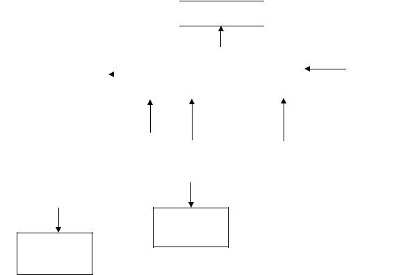
2. LCD Monitor Description
The LCD Monitor will contain main board, power board and a key board which house the flat panel control logic, brightness control logic and DDC.
The power board will provide AC to DC Inverter voltage to drive the backlight of panel and the main board chips each voltage.
Monitor Block Diagram
CCFT Drive. |
Flat Panel and |
|
CCFL backlight |
||
|
||
|
|
Power Board |
|
|
Main Board |
|
|
|
|
|
|
|
|
RS232 Connector |
|||
(Include adapter board) |
|
|
|
|
|
|
|
|
|
|
|
|
|
For white balance |
|
|
|
|
|
|
|
|
|
|
|
|
|
|
|
|
adjustment in |
|
|
|
|
|
|
|
factory mode |
|
|
|
Keyboard |
|
|
|
|
|
|
|
|
|
|
||
|
|
|
|
|
|
|
|
AC-IN |
|
|
|
|
|
|
Video signal, DDC |
|
|
|
HOST Computer |
|
|||
|
|
|
|
|
|||
|
|
|
|
|
|
||
110V-240V |
|
|
|
|
|
|
|
|
|
|
|
|
|
|
|
5
17" LCD Color Monitor |
HP VP17 |
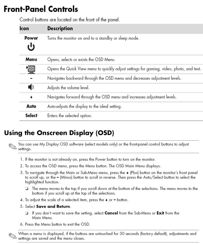
3. Operation Instructions
3.1 General Instructions
Press the power button to turn the monitor on or off. The other control buttons are located at front of the panel. By changing these settings, the picture can be adjusted to your personal performance.
-The power cord should be connected and insert to adaptor.
-Connect the video cable from the monitor to the computer VGA card.
-Press the power button to turn on the monitor, the power indicator will light up to Green.
3.2Control Button
6
17" LCD Color Monitor |
HP VP17 |
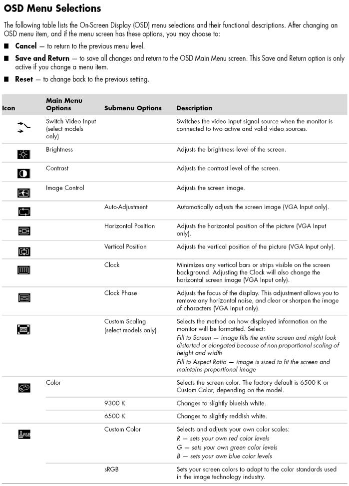
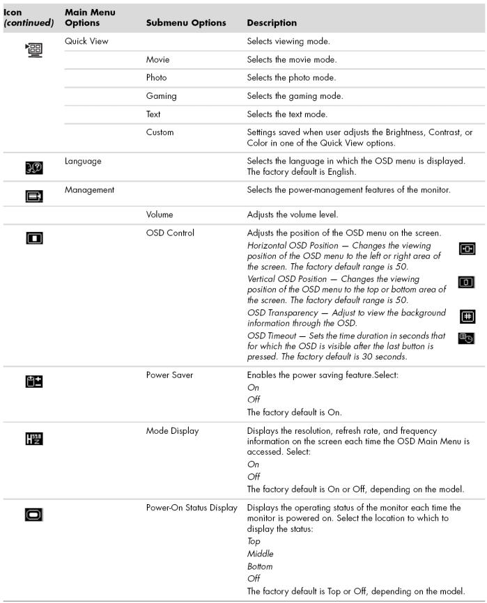
3.3 Adjust the Picture
7
17" LCD Color Monitor |
HP VP17 |
8
17" LCD Color Monitor |
HP VP17 |
9
17" LCD Color Monitor |
|
HP VP17 |
||
4. Input/Output Specification |
|
|
||
4.1 Input Signal Connector |
|
|
||
|
|
|
|
|
|
Pin |
Signal |
Pin |
Signal |
|
|
|
|
|
1 |
Red Video |
9 |
3.3/+5 V (from PC) |
|
|
|
|
|
|
2 |
Green Video |
10 |
Sync Ground |
|
|
|
|
|
|
3 |
Blue Video |
11 |
None |
|
|
|
|
|
|
4 |
None |
12 |
DDC Data |
|
|
|
|
|
|
5 |
Ground (DDC Return) |
13 |
Horizontal Sync |
|
|
|
|
|
|
6 |
Red GND |
14 |
Vertical Sync |
|
|
|
|
|
|
7 |
Green GND |
15 |
DDC Clock |
|
|
|
|
|
|
8 |
Blue GND |
|
|
|
|
|
|
|
|
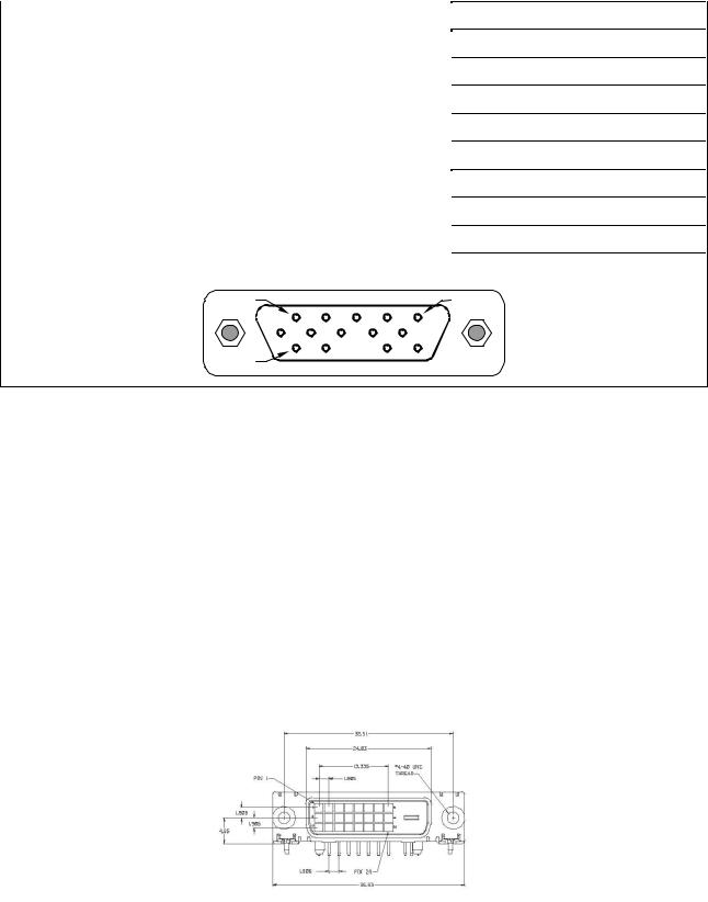
VGA connector layout
PIN 1 |
PIN 5 |
PIN 11 |
|
Pin |
Signal |
Pin |
Signal |
Pin |
Signal |
|
|
|
|
|
|
1 |
TMDS Data 2 - |
9 |
TMDS Data 1 - |
17 |
TMDS Data 0 - |
|
|
|
|
|
|
2 |
TMDS Data 2 + |
10 |
TMDS Data 1 + |
18 |
TMDS Data 0 + |
|
|
|
|
|
|
3 |
TMDS Data 2 / 4 Shield |
11 |
TMDS Data 1 / 3 Shield |
19 |
TMDS Data 0 / 5 Shield |
|
|
|
|
|
|
4 |
TMDS Data 4 - |
12 |
TMDS Data 3 - |
20 |
TMDS Data 5 - |
|
|
|
|
|
|
5 |
TMDS Data 4 + |
13 |
TMDS Data 3 + |
21 |
TMDS Data 5 + |
|
|
|
|
|
|
6 |
DDC Clock |
14 |
+3.3/+5V Power (from PC) |
22 |
TMDS Clock Shield |
|
|
|
|
|
|
7 |
DDC Data |
15 |
Ground (Return for +5V) |
23 |
TMDS Clock + |
|
|
|
|
|
|
8 |
No Connect |
16 |
Hot Plug Detect (connect internally to pin-14) |
24 |
TMDS Clock - |
|
|
|
|
|
|
|
|
|
DVI-D digital connector layout |
|
|
|
|
|
|
|
|
10
17" LCD Color Monitor |
HP VP17 |
4.2 Factory Preset Display Modes
4.3 Power Supply Requirements
Parameter |
Range |
|
|
AC Input Voltage |
90 to 265V |
|
|
AC Input Frequency |
45 to 63 Hz |
|
|
Inrush Current |
50A MAX AT 220VAC and 30A AT 120VAC |
|
|
Leakage Current |
5 mA MAX at 120VAC |
|
|
Power Consumption |
≤37W |
|
|
11
17" LCD Color Monitor |
HP VP17 |
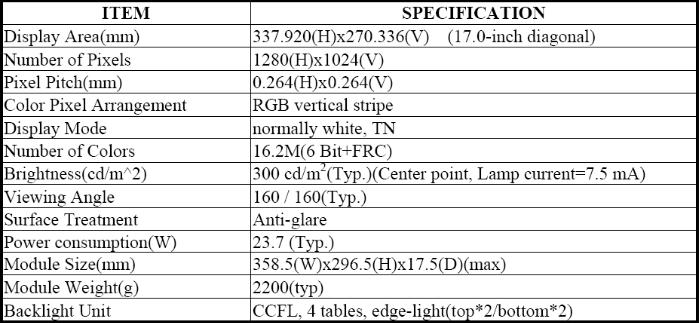
5. Panel Specification
5.1 General Feature
CLAA170EA07P is 17.0” color TFT-LCD (Thin Film Transistor Liquid Crystal Display) module composed of LCD panel, driver ICs, control circuit and backlight. By applying 8 bit digital data, 1280×1024, 16.2M-color images are displayed on the 17.0” diagonal screen. Input power voltage is 5.0V for LCD driving. Inverter for backlight is not included in this module. General specification are summarized in the following table:
12

17" LCD Color Monitor |
HP VP17 |
5.2 Optical Characteristics
Ta=25 VCC=5.0V
5.3 Electrical Characteristics
13
17" LCD Color Monitor |
HP VP17 |
6. Block Diagram
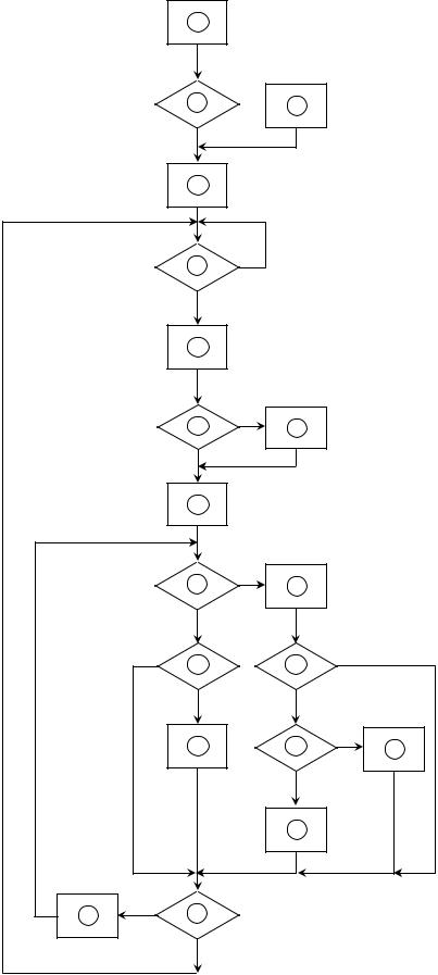
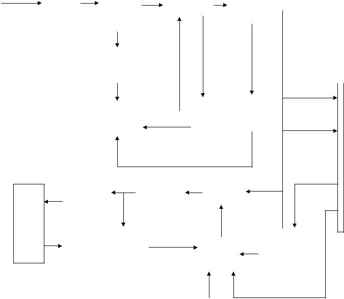
6. 1 Software Flow Chart
1
Y
2  3
3
N
4
5 |
N |
|
|
Y |
|
6 |
|
N
7 8
Y
9
|
10 |
N |
11 |
|
|
|
|
||
|
Y |
|
|
|
N |
12 |
|
13 |
N |
|
|
|
||
|
Y |
|
Y |
|
|
14 |
|
15 |
N |
|
|
16 |
||
|
|
|
Y |
|
|
|
|
17 |
|
18 N 19
Y
14

17" LCD Color Monitor |
HP VP17 |
REMARK:
1)MCU initialize.
2)Is the EEprom blank?
3)Program the EEprom by default values.
4)Get the PWM value of brightness from EEprom.
5)Is the power key pressed?
6)Clear all global flags.
7)Are the AUTO and SELECT keys pressed?
8)Enter factory mode.
9)Save the power key status into EEprom. Turn on the LED and set it to green color. Scalar initialize.
10)In standby mode?
11)Update the lifetime of back light.
12)Check the analog port, are they’re any signals coming?
13)Does the scalar send out an interrupt request?
14)Wake up the scalar.
15)Are there any signals coming from analog port?
16)Display "No connection Check Signal Cable" message. And go into standby mode after the message disappear.
17)Program the scalar to be able to show the coming mode.
18)Process the OSD display.
19)Read the keyboard. Is the power key pressed?
15
17" LCD Color Monitor |
HP VP17 |
6.2 Electrical Block Diagram
6.2.1 Main Board

 LCD
LCD Interface


|
|
Scalar TSUM56AWHL |
|
|
OSD Control |
|
|
|
|
|
|
Crystal |
||
Interface (Keypad) |
|
(Include: MCU, ADC, OSD etc) |
|
|
|
|
14.318MHZ |
||
|
|
|
|
|
|
|
|
|
|
|
|
|
|
|
|
|
|
|
|
|
|
|
|
|
|
D-SUB |
|
EEPROM |
|
|
|
|
Connector |
|
PM25LV010-25 |
DVI-SIGNAL |
|
|
|
|||
|
|
|
|
|
||
Connector |
|
|
|
|
||
|
|
|
|
|
|
|
EEPROM
24C02
EEPROM 24C02
16
17" LCD Color Monitor |
HP VP17 |
6.2.2 Inverter / Power Board
AC input |
|
|
Bridge |
|
|
|
Rectifier |
|
EMI filter |
|
|
Transformer |
|
|
|||
|
|
|
|
|
||||
|
|
Rectifier |
|
|
diodes |
|
||
|
|
|
|
|
|
|||
|
|
|
|
|
|
|
||
|
|
|
and Filter |
|
|
|
|
|
|
|
|
|
|
|
|
|
|
|
|
|
|
|
|
|
|
|
|
|
|
|
|
|
|
|
|
Start Circuit |
|
|
|
|
|
|
|
|
||
|
|
|
|
|
|
|
|
CN902 |
||
|
|
|
|
|
|
|
|
12V |
|
|
|
|
|
|
|
|
|
|
|
||
|
|
|
|
|
Over |
|
Feedback |
|
||
|
PWM |
|
|
|
|
|||||
|
|
|
|
|
Circuit |
|
|
|
||
|
|
|
|
Voltage |
|
5V |
||||
|
Control IC |
|
|
|
|
|||||
|
|
|
|
|
|
|||||
|
|
|
|
|
|
|
||||
|
|
|
|
|
Protect |
|
|
|
|
|
|
|
|
|
|
|
|
|
|||
|
|
|
|
|
|
|
|
|
|
|
ON/OFF
LC |
|
|
|
|
|
Transformer |
|
MOSFET |
|
Resonance |
|
|
||
|
|
|
|
|
|
|
|
|
|
|
|
|
|
|
Lamp
|
|
|
Over |
|
|
|
|
ON/OFF |
Feedback |
|
|
|
|
|
|||
|
PWM |
|
||||||
Circuit |
|
Voltage |
|
|
|
Control |
||
|
|
Control IC |
|
|||||
|
|
|
|
|
|
|
||
|
|
|
|
|
|
|
|
DIM |
|
|
|
|
|
|
|
|
|
|
|
|
|
|
|
|
|
|
17
17" LCD Color Monitor |
HP VP17 |
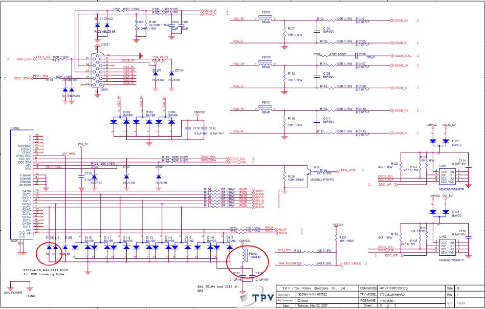
7. Schematic
7.1 Main Board
18
 Loading...