

AOC LM 722 Schematic
LM722
SERVICE MANUAL
17” LCD Monitor
LM722
THESE DOCUMENTS ARE FOR REPAIR SERVICE INFORMATION ONLY. EVERY REASONABLE EFFORT
HAS BEEN MADE TO ENSURE THE ACCURACY OF THIS MANUAL; WE CANNOT GUARANTEE THE
ACCURACY OF THIS INFORMATION AFTER THE DATE OF PUBLICATION AND DISCLAIMS RE LIABILITY FOR
CHANGES, ERRORS OR OMISSIONS.
Page 1 of 48

LM722
Content List
CONTENT LIST.............................................................................................................................. 2
Revision List ……………………………..…………………………………………………………….…..3
1. MONITOR SPECIFICATIONS .................................................................................................... 5
2. LCD MONITOR DESCRIPTION .................................................................................................5
3. OPERATING INSTRUCTIONS................................................................................................... 6
3.1 GENERAL INSTRUCTIONS .................................................................................................................6
3.2 FRONT PANEL CONTROL ...................................................................................................................6
3.3 ADJUSTING THE PICTURE .................................................................................................................6
4. INPUT/OUTPUT SPECIFICATION ............................................................................................. 8
4.1 INPUT SIGNAL CONNECTOR .....................................................................................................................8
4.2 FACTORY PRESET DISPLAY MODES..........................................................................................................8
4.3 POWER SUPPLY REQUIREMENT ...............................................................................................................9
4.4 PANEL SPECIFICATION.......................................................................................................................9
4.4.1 Display Characteristics .................................................................................................................................... 9
4.4.2 Optical Specification.................................................................................................... ...................................10
4.4.3 ELECTRICAL SPECIFICATIONS.................................................................................................................. 10
5. BLOCK DIAGRAM................................................................................................................... 10
5.1 MONITOR EXPLORED.............................................................................................................................10
5.2 Software flowing Chart ...........................................................................................................................11
5.2 ELECTRICAL BLOCK DIAGRAM................................................................................................................13
5.2.1 Main Board..................................................................................................................................................... 13
5.2.2 Inverter/Power Board..................................................................................................................................... 14
6. SCHEMATIC............................................................................................................................. 16
6.1 MAIN BOARD.........................................................................................................................................16
6.2 POWER BOARD .....................................................................................................................................21
6.3 KEY BOARD........................................................................................................................................... 23
6.4 AUDIO BOARD .......................................................................................................................................24
7. LAYOUT ................................................................................................................................... 25
7.1 MAIN BOARD.........................................................................................................................................25
7.2 AUDIO BOARD .......................................................................................................................................25
7.3 POWER BOARD .....................................................................................................................................26
8. MAINTAINABILITY................................................................................................................... 27
8.1 EQUIPMENTS AND TOOLS REQUIREMENT................................................................................................27
8.2 TROUBLE SHOOTING .............................................................................................................................28
8.2.1 KEYPAD BOARD........................................................................................................................................... 31
Page 2 of 48

LM722
8.2.2 POWER/INVERTER BOARD........................................................................................................................ 32
9. WHITE- BALANCE, LUMINANCE ADJUSTMENT.................................................................. 34
10. EDID ....................................................................................................................................... 35
11. BOM LIST............................................................................................................................... 36
Page 3 of 48
LM722
Revision List
Revision Date Modification
A00 Mar-24-2004
Page 4 of 48
LM722
(
1. MONITOR SPECIFICATIONS
43.2 cm (17”) a-si TFT Active matrix LCD p anel, 0.264mm pixel pitch.
Microprocessor controlled scan technology
17 factory presets
Vertical refresh rate 55Hz to 75 Hz
Horizontal frequency 30kHz to 80kHz
Resolutions: 640 x 480 up to 1280 x 1024
Universal power supply designed for worldwide application
CE mark
TCO99 mark
VESA DPMS compliant
VESA DDC2B compliant
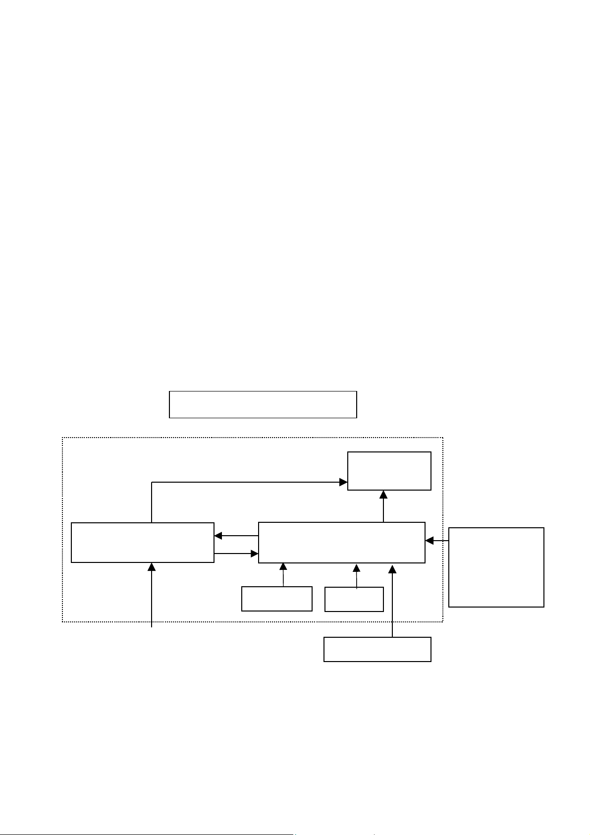
2. LCD MONITOR DESCRIPTION
The LCD MONITOR will contain a main board, a power board, a keypad board and an Audio board which house
the flat panel control logic, brightness control logic and DDC.
The power board will provide AC to DC Inverter voltage to drive the backlight of panel and the main board chips
each voltage.
Include: adapter, inverter)
Power board
Monitor Block Diagram
CCFT Drive.
Audio board
Flat Panel and
CCFL backlight
Main Board
Keyboard
RS232 Connector
For white balance
adjustment in
factory mode
AC-IN
100V-240V
Page 5 of 48
HOST Computer
Video signal, DDC
LM722
3. OPERATING INSTRUCTIONS
3.1 GENERAL INSTRUCTIONS
Press the power button to turn the monitor on or off. The other control buttons are located at front panel of the monitor.
By changing these settings, the picture can be adjusted to your personal preferences.
• The power cord should be connected.
• Connect the video cable from the monitor to the video card.
• Press the power button to turn on the monitor position. The power indicator will light up.
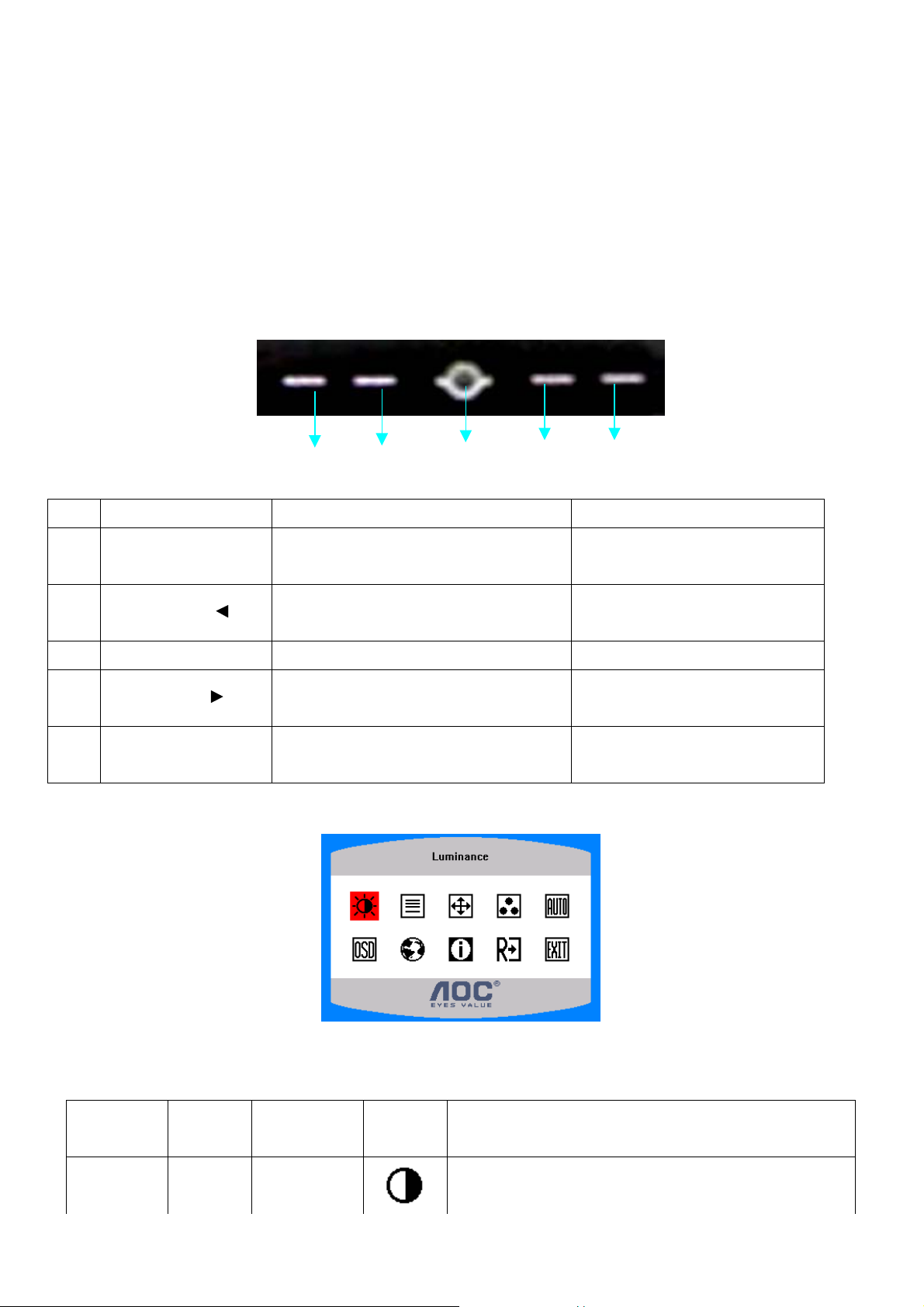
3.2 FRONT PANEL CONTROL
NO. Name Within OSD Without OSD
1 Auto
1. Exit Sub menu
2. Exit the menu item
1.Move the cursor to down
2 VOL - /
2.Adjust down when menu item selected
3 Power Turn on/off Turn on/off
1.Move the cursor to up
4 VOL + /
2.Adjust up when menu item selected
1.Enter the OSD sub menu
5 MENU
2.Select the OSD menu
Run the Auto Adjust when this
button keep to push for 2 second
decreasing volume
increasing volume
Open OSD menu
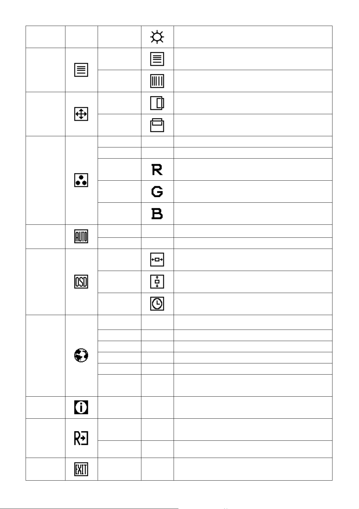
3.3 ADJUSTING THE PICTURE
The description for control function:
Main Menu
Item
Main Menu
Icon
Sub Menu Item
Contrast
Sub Menu
Description
Icon
Contrast from Digital-register
Page 6 of 48
LM722
Image Setup
Image
Position
Color Temp.
Brightness
H. Position
V. Position
User / Red
User / Green
Focus
Clock
Warm N/A Recall Warm Color Temperature from EEPROM.
Cool N/A Recall Cool Color Temperature from EEPROM.
Adjust Picture Phase to reduce Horizontal-Line noise
Adjust picture Clock to reduce Vertical-Line noise.
Adjust the horizontal position of the picture.
Adjust the vertical position of the picture.
Backlight Adjustment
Red Gain from Digital-register.
Green Gain Digital-register.
Auto Config
OSD Setup
Language
User / Blue
Yes N/A Auto Adjust the H/V Position, Focus and Clock of picture.
No N/A Do not execute Auto Config, return to main menu.
H. Position
V. Position
OSD Timeout
English N/A Set OSD display language to English.
Deutsch N/A Set OSD display language to German.
Français N/A Set OSD display language to French.
Español N/A Set OSD display language to Spain.
Italiano N/A Set OSD display language to Italian.
Simplified
Chinese
N/A Set OSD display language to Simplified Chinese.
Blue Gain from Digital-register.
Adjust the horizontal position of the OSD.
Adjust the vertical position of the OSD.
Adjust the OSD timeout.
Information
Reset
Exit
Information N/A
Yes N/A
No N/A Do not execute reset, return to main menu.
N/A N/A Exit OSD
Show the resolution, H/V frequency and input port of
current input timing.
Clear each old status of Auto-configuration and set the
color temperature to Cool.
Page 7 of 48
LM722
4. Input/Output Specification
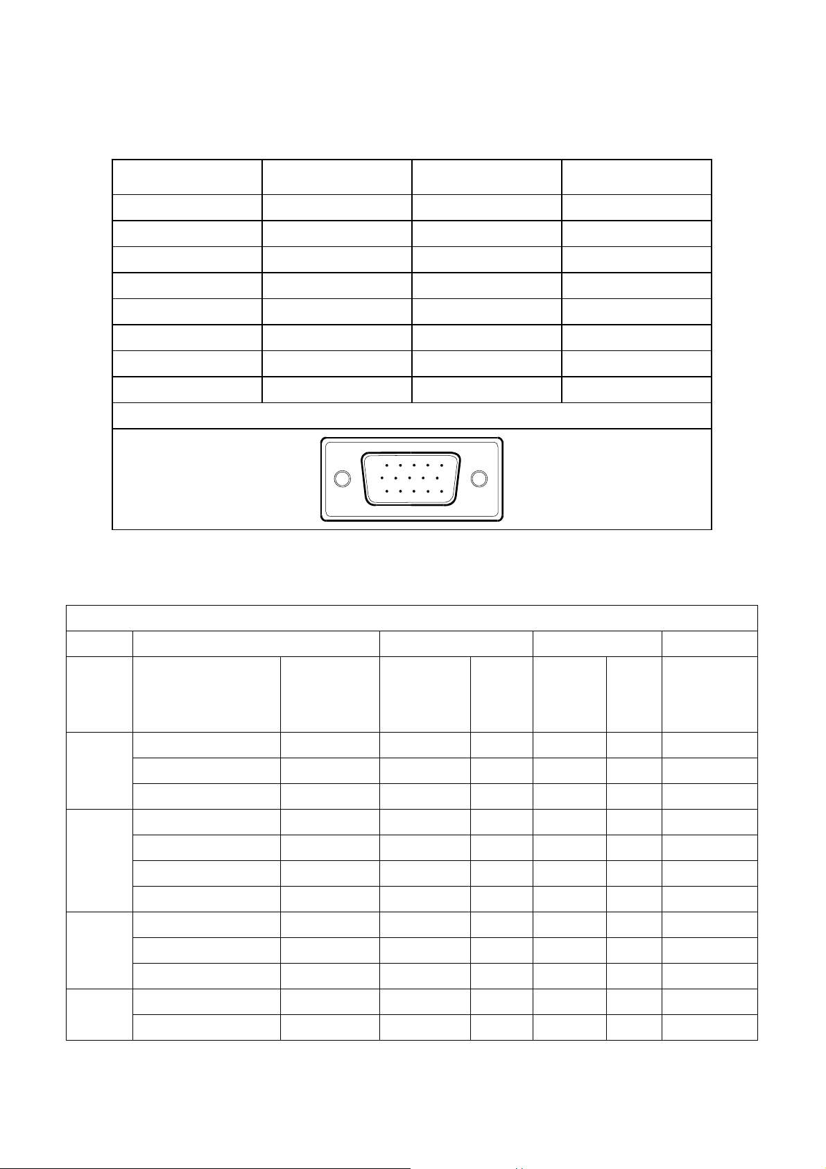
4.1 Input Signal Connector
4.1.1 Analog D-SUB Connector
PIN NO. DESCRIPTION PI N NO. DESCRIPTION
1. Red 9. +5V
2. Green 10. Logic Ground
3. Blue 11. RXD
4. TXD 12. DDC-Serial Data
5. DDC-Return 13. H-Sync
6. R-Ground 14. V-Sync
7. G-Ground 15. DDC-Serial Clock
8. B-Ground
VGA connector layout
4.2 Factory Preset Display Modes
Horizontal Vertical
Mode Resolution Total
640x480@60Hz 800 x 525 31.469 N 59.940 N 25.175
VGA
SVGA
640x480@72Hz 832 x 520 37.861 N 72.809 N 31.500
640x480@75Hz 840 x 500 37.500 N 75.00 N 31.500
800x600@56Hz 1024 x 625 35.156 N/P 56.250 N/P 36.000
800x600@60Hz 1056 x 628 37.879 P 60.317 P 40.000
800x600@72Hz 1040 x 666 48.077 P 72.188 P 50.000
15
6
11 15
10
VESA MODES
Nominal
Frequency
Sync
Polarity
+/- 0.5kHz
Nominal
Freq.
+/- 1 Hz
Sync
Polarit
y
Nominal
Pixel Clock
(MHz)
XGA
SXGA
800x600@75Hz 1056x625 46.875 P 75.000 P 49.500
1024x768@60Hz 1344x806 48.363 N 60.004 N 65.000
1024x768@70Hz 1328x806 56.476 N 70.069 N 75.000
1024x768@75Hz 1312x800 60.023 P 75.029 P 78.750
1280x1024@60Hz 1688x1066 63.981 P 60.020 P 108.000
1280x1024@75Hz 1688x1066 79.976 P 75.025 P 135.000
Page 8 of 48
LM722
IBM MODES
Horizontal Vertical
Nominal
2Mode Resolution Total
DOS* 720x400@70Hz 900 x 449 31.469 N 70.087 P 28.322
DOS** 640x400@70Hz 800 x 449 31.469 N 70.087 P 25.175
DOS 640x350@70Hz 800 x 449 31.469 P 70.087 N 25.175
VGA 640x480@67Hz 864x525 35.000 N 66.667 N 30.240
SVGA 832x624@75Hz 1152x667 49.725 N 74.551 N 57.2832
*, ** - The two complimentary modes feature the sam e horizontal and vertical sync frequencies and polarities,
and therefore require manual selection.
Frequency
+/- 0.5kHz
MAC MODES
Sync
Polarity
Nominal
Sync
Freq.
Polarity
+/- 1 Hz
Nominal
Pixel
Clock
(MHz)
4.3 Power Supply Requirement
A/C Line voltage range : 100 V ~ 240 V
A/C Line frequency range
: 50 ± 3Hz, 60 ± 3Hz
Current : TBD
Peak surge current : < 55A peak at 240 VAC and cold starting
Leakage current : < 3.5mA
Power line surge : No advance effects (no loss of information or defect)
Voltage
CURRENT : 3.5 Amp (max)
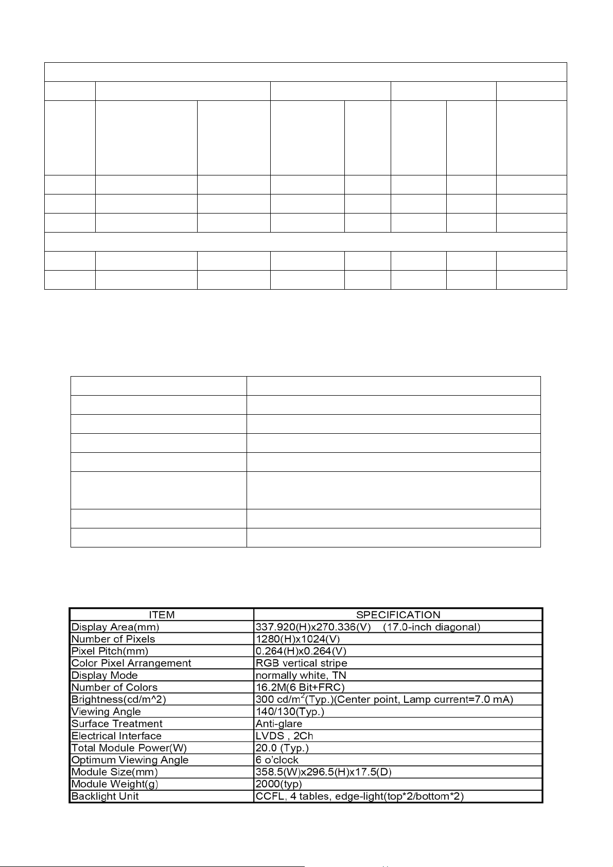
4.4 PANEL SPECIFICATION
4.4.1 Display Characteristics
with a maximum of 1 half-wave missing per second
: 12VDC ± 5
Page 9 of 48
LM722
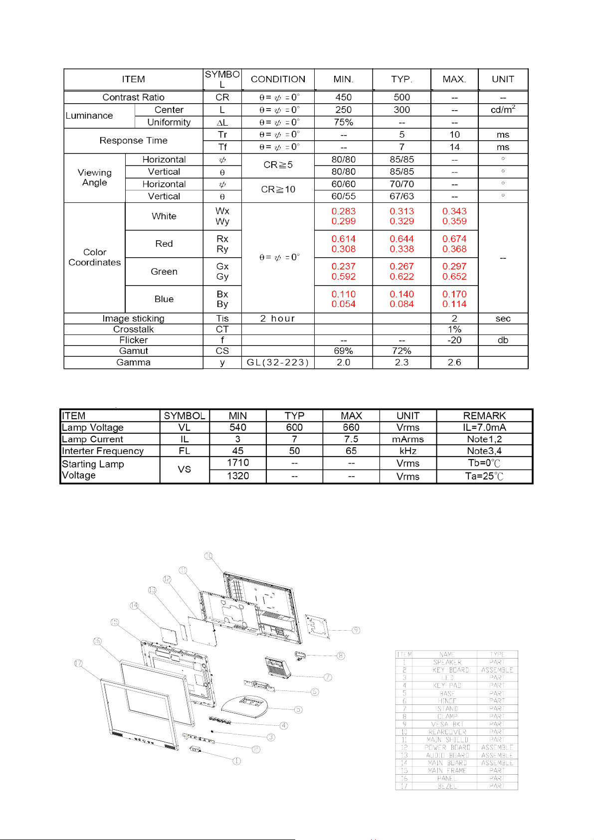
4.4.2 Optical Specification
4.4.3 ELECTRICAL SPECIFICATIONS
5. Block Diagram
5.1 Monitor Explored
Page 10 of 48
LM722
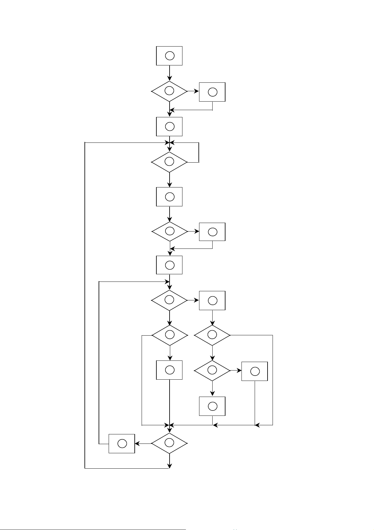
5.2 Software flowing Chart
1
2
4
Y
3
N
N
5
6
7
9
10
12
Y
Y
Y
N
N
N
8
11
13
N
18
N
Y
14
19
Y
Page 11 of 48
15
17
Y
N
16
Y
LM722
Remark:
1) MCU initialize.
2) Is the EEprom blank?
3) Program the EEprom by default values.
4) Get the PWM value of brightness from EEprom.
5) Is the power key pressed?
6) Clear all global flags.
7) Are the AUTO and SELECT keys pressed?
8) Enter factory mode.
9) Save the power key status into EEprom.
Turn on the LED and set it to green color.
Scalar initialize.
10) In standby mode?
11) Update the lifetime of back light.
12) Check the analog port, are they’re any signals coming?
13) Does the scalar send out an interrupt request?
14) Wake up the scalar.
15) Are there any signals coming from analog port?
16) Display "No connection Check Signal Cable" message. And go into standby mode after the message
disappear.
17) Program the scalar to be able to show the coming mode.
18) Process the OSD display.
19) Read the keyboard. Is the power key pressed?
Page 12 of 48

LM722
5.2 Electrical Block Diagram
5.2.1 Main Board
LCD Interface
SM5964C40J
OSD Control
Interface
MCU
(U101)
EPR_SDA
EPR_SCL
Scalar GMZAN3/SL (BD) PQFB-100
(Include ADC, OSD)
(U102)
RXD
TXD
RGB
H sync
V sync
EEPROM
24C16
DB15_SDA,
DB15_SCL
D-Sub
Connector
(CN301)
EEPROM
24C02
Page 13 of 48
LM722
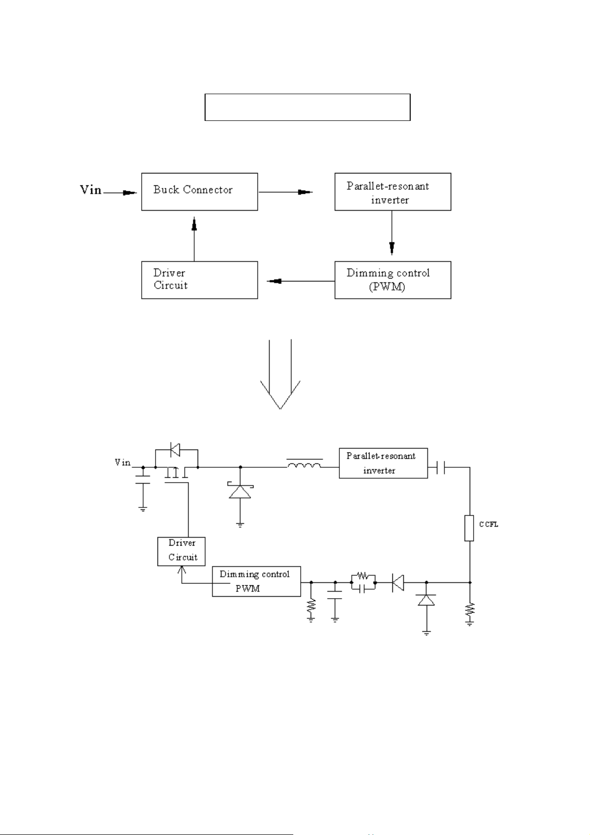
5.2.2 Inverter/Power Board
Inverter Block Diagram
Page 14 of 48
LM722
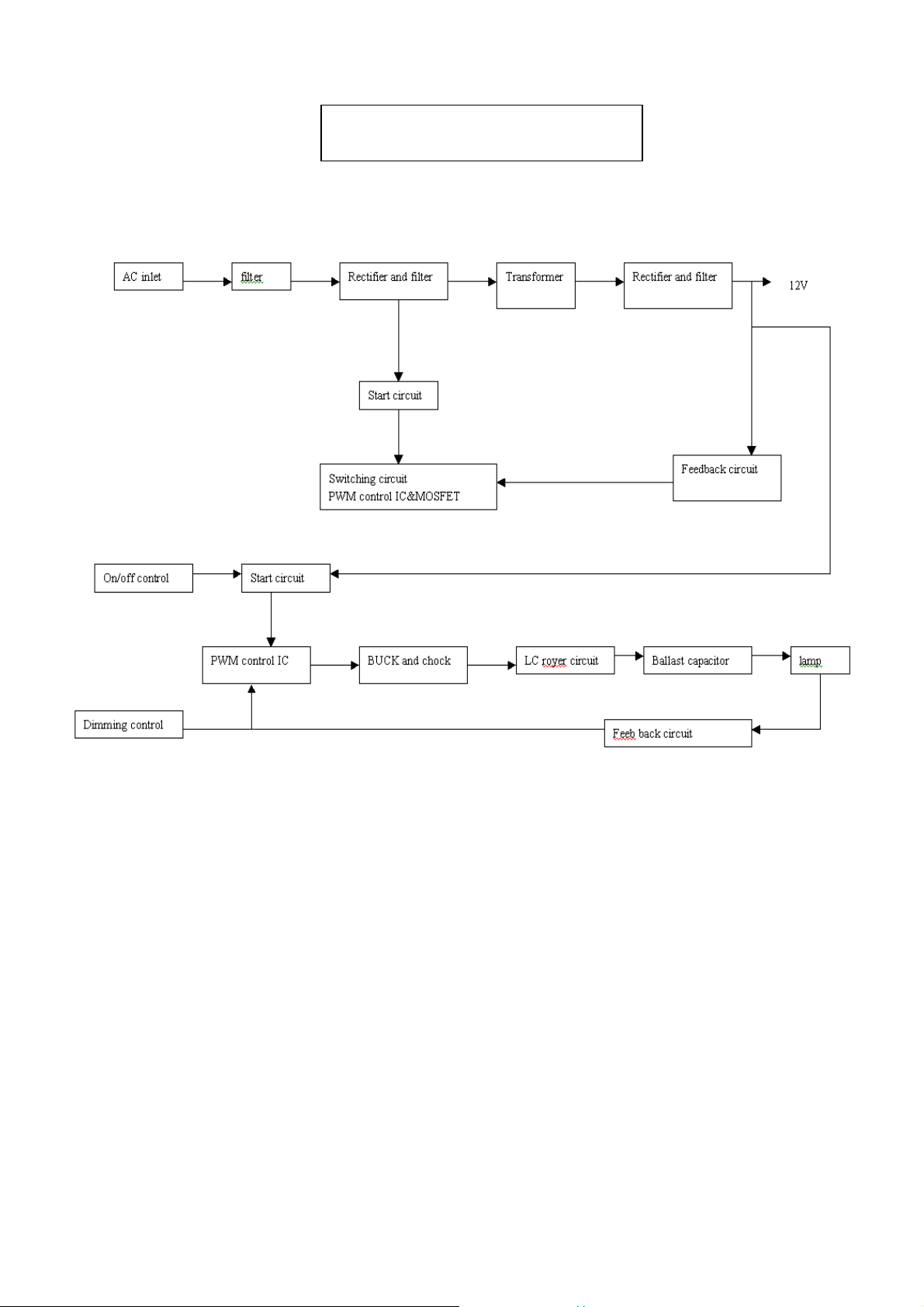
Power Block Diagram
Page 15 of 48
 Loading...