


AOC LM540
SERVICE MANUAL
15” LCD Monitor
LM540
http://www.wjel.net
THESE DOCUMENTS ARE FOR REPAIR SERVICE INFORMATION ONLY. EVERY REASONABLE EFFORT
HAS BEEN MADE TO ENSURE THE ACCURACY OF THIS MANUAL; WE CANNOT GUARANTEE THE
ACCURACY OF THIS INFORMATION AFTER THE DATE OF PUBLICATION AND DISCLAIMS RE LIABILITY
FOR CHANGES, ERRORS OR OMISSIONS.
MANUFACTURE DATE: Sep-15-2005
Page 1 of 51

AOC LM540
REVISION DATE MODIFIACTION
A00 Sep-15-2005 Initial release
http://www.wjel.net
Page 2 of 51

AOC LM540
TABLE OF CONTENTS
Revision List ---------------------------------------------------------------------------------- 02
Table of Contents ---------------------------------------------------------------------------------------- 03
1. Monitor Specifications --------------------------------------------------------------------------------04
2.LCD Monitor Description -----------------------------------------------------------------------05
3.Operation Instructions --------------------------------------------------------------------------06
3.1 General Instructions -----------------------------------------------------------------------06
3.2 Control Button ------------------------------------------------------------------------------06
3.3 Adjusting The Picture ---------------------------------------------------------------------07~ 08
4. Input/Output Specification ------------------------------------------------------------------- 09
4.1 Input Signal Connector -------------------------------------------------------------------09
4.2 Factory Preset Display Modes ----------------------------------------------------------10
4.3 Power Supply Requirements ------------------------------------------------------------10
5.Panel Specification----------------------------------------------------------------------------------11
5.1 General Feature ----------------------------------------------------------------------------11
5.2 Optical Characteristics --------------------------------------------------------------------12
6. Block Diagram -----------------------------------------------------------------------------------13
6.1 Software Flow Chart -----------------------------------------------------------------------13~ 14
6.2 Electrical Block Diagram -----------------------------------------------------------------15~ 16
7. Schematic -----------------------------------------------------------------------------------------17
7.1 Main Board ---------------------------------------------------------------------------------17~ 21
7.2 Power Board -------------------------------------------------------------------------22~ 23
8. PCB Layout ---------------------------------------------------------------------------------------24
8.1 Main Board ----------------------------------------------------------------------------------24
8.2 Power Board --------------------------------------------------------------------------------25
8.3 KEY Board ------------------------------------------------------------------------------ 25
9. Maintainability -----------------------------------------------------------------------------------26
9.1 Equipments and Tools Requirements -------------------------------------------------26
9.2 Trouble Shooting ---------------------------------------------------------------------------27~ 32
http://www.wjel.net
10. White-Balance, Luminance Adjustment ----------------------------------------------- 33
11. Check List after replacing LCD Main board----------------------------------------------- 34~36
12. EDID Content ---------------------------------------------------------------37
13. BOM List ----------------------------------------------------------------------------------38~51
Page 3 of 51
1. MONITOR SPECIFICATIONS
Driving system TFT LCD
Size 38cm(15.0")
AOC LM540
LCD Panel
Input signals
Type
Pixel pitch 0.297mm(H) x 0.297mm(V)
Viewing angle 130(H) 100(V) (R>10)
Luminance 250cd/ m2
Contrast Ratio 400:1
Response time 35ms (typ)
Display colors 6-bits driver
R G B Analog 0.7Vp-p
H/V separate TTL level
H/V composite TTL level
Horizontal frequency 30kHz–60kHz
Vertical rate 55-75Hz
Recommend resolution 1024 x768 @60HZ
HSD150SX84-C(HSD)
Power consumption
Power supply AC voltage
Operating condition Temperature 5-50°C
Storage Condition Temperature -20-60°C
Dimension Unpackaged 356 mm (W) x360mm (H) x 150mm (D)
Maximum Screen Size
ON MODEL
OFF MODEL
Horizontal: 304.1mm,Vertical: 228.1mm
≤30W
≤1W
100~240VAC,50~60Hz
http://www.wjel.net
Page 4 of 51
AOC LM540
(
)
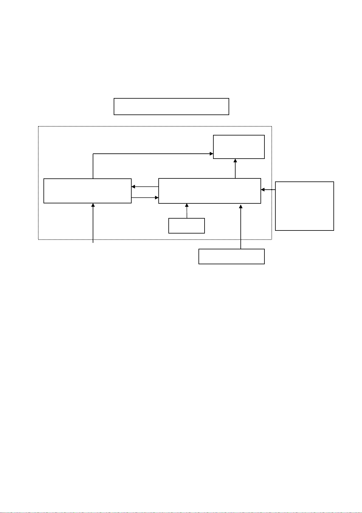
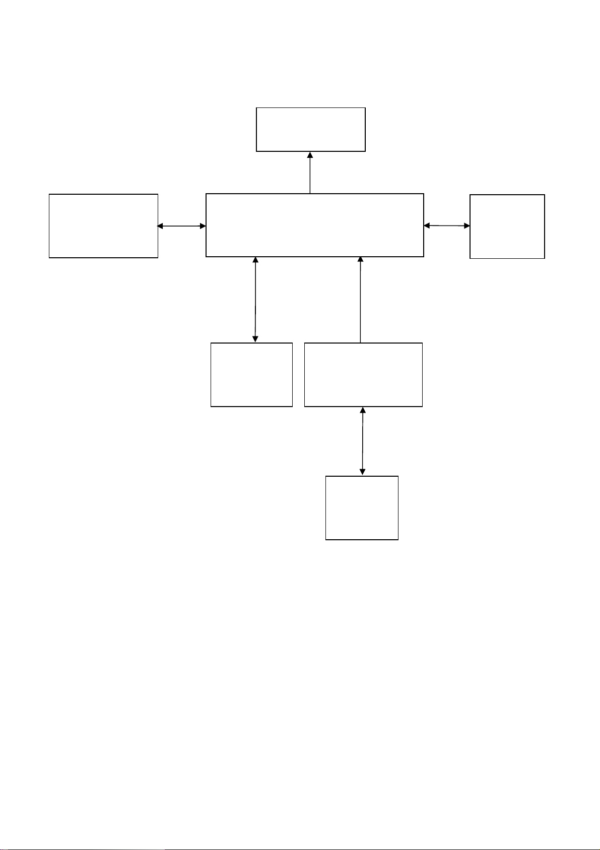
2. LCD MONITOR DESCRIPTION
The LCD MONITOR will contain a main board, a power board and a keypad board which house the flat panel control
logic, brightness control logic and DDC.
The power board will provide AC to DC Inverter voltage to drive the backlight of panel and the main board chips each
voltage.
PWPC board
Include: adapter, inverter
AC-IN
100V-240V
Monitor Block Diagram
CCFT Drive
.
Main Board
Keyboard
Flat Panel and
CCFL backlight
HOST Computer
RS232 Connector
For white balance
adjustment in
factory mode
Video signal, DDC
http://www.wjel.net
Page 5 of 51
AOC LM540
3. OPERATING INSTRUCTIONS
3.1 GENERAL INSTRUCTIONS
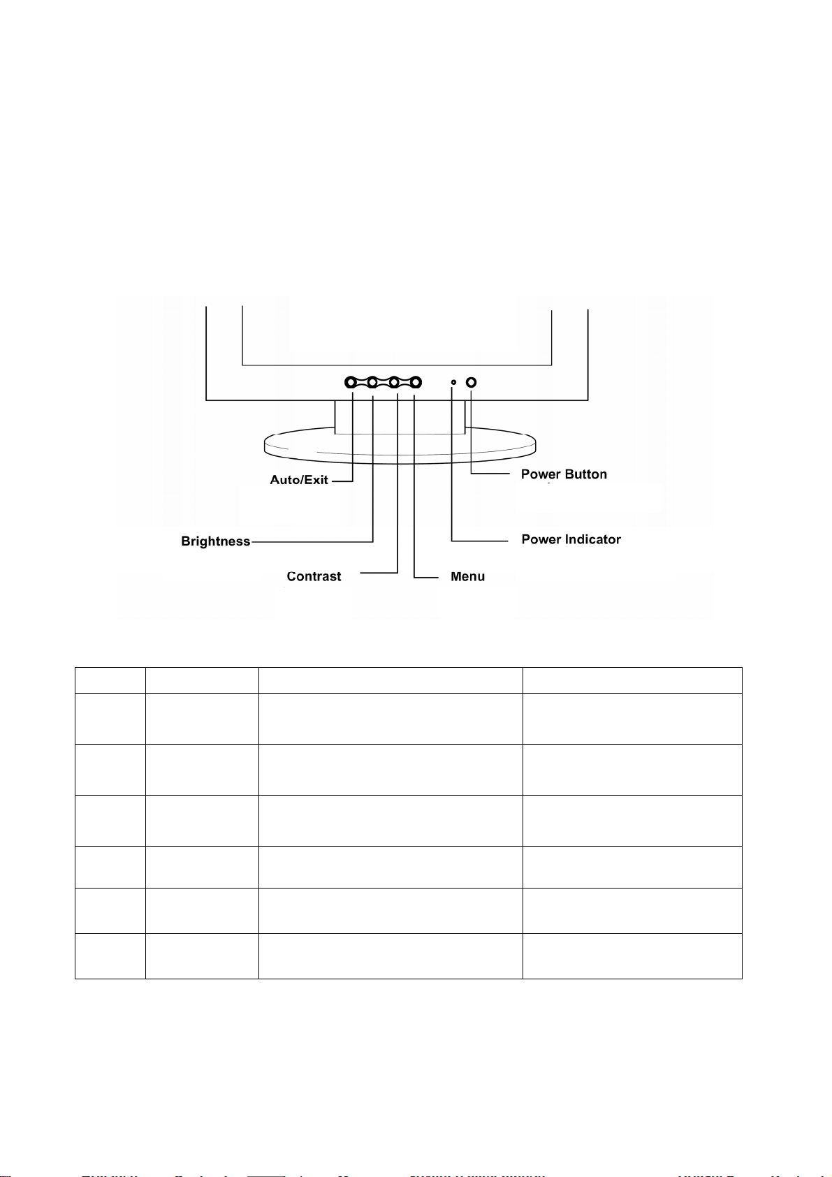
Press the power button to turn the monitor on or off. The other control buttons are located at front panel of the
monitor. By changing these settings, the picture can be adjusted to your personal preferences.
• The power cord should be connected.
• Connect the video cable from the monitor to the video card.
• Press the power button to turn on the monitor position. The power indicator will light up.
3.2 FRONT PANEL CONTROL
NO. Name Within OSD Without OSD
1 Auto/Exit
1. Exit Sub menu
2. Exit the menu item
1.Move the cursor to left
2 Brightness
2.Adjust down when menu item selected
1.Move the cursor to right
3 Contrast
2.Adjust up when menu item selected
Run the Auto Adjust when this
button keep to push for 2 second
Open the Brightness menu
Open the contrast menu
http://www.wjel.net
4 MENU Select Function or select Sub menu Activate OSD main menu
5 Indicator Green—On Red—Save Green—On Red—Save
6 Power Power On / Off Power On / Off
Page 6 of 51
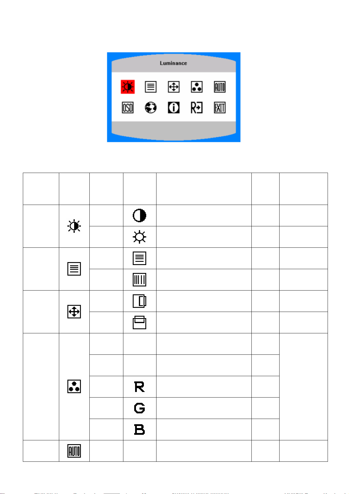
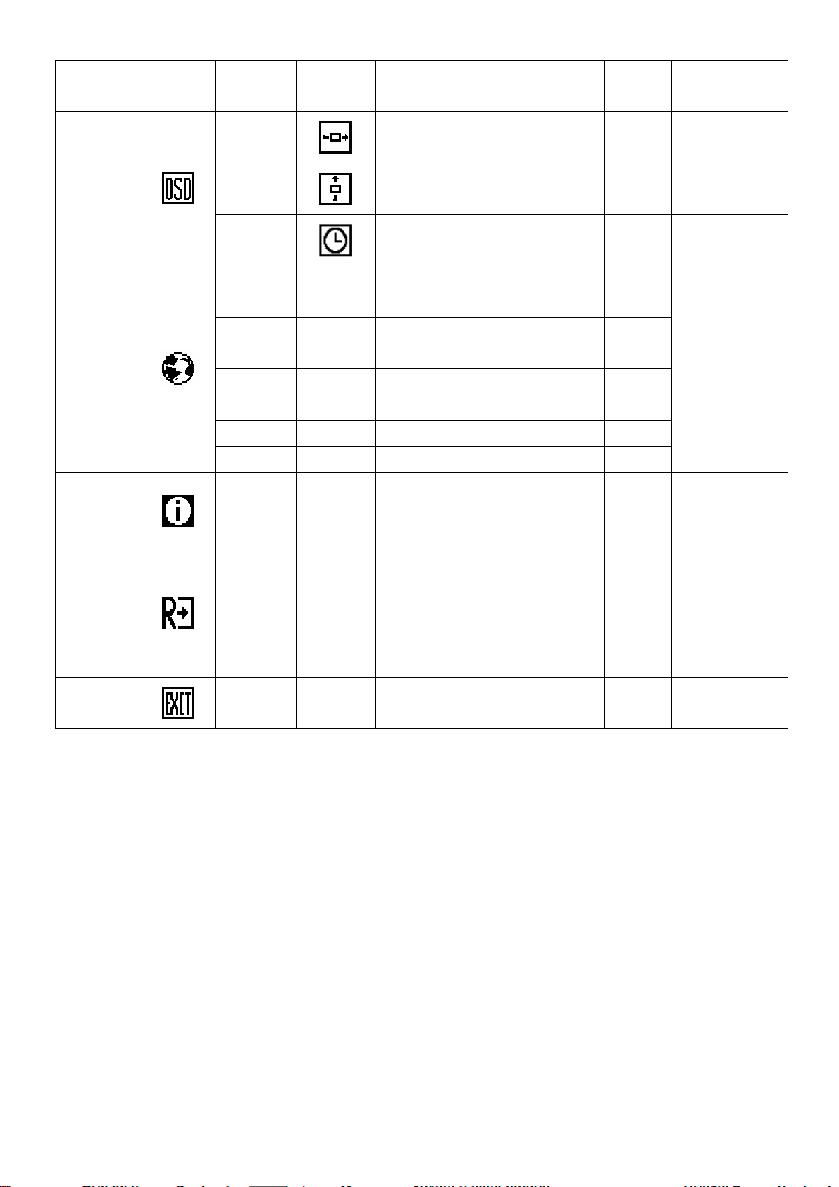
3.3 ADJUSTING THE PICTURE
A
THE DESCRIPTION FOR CONTROL FUNCTION:
AOC LM540
Main Menu
Item
Luminance
Image Setup
Image
Position
Main
Menu
Icon
Sub Menu
Item
Contrast
Brightness
Focus
Clock
H. Position
V. Position
C1 N/A
http://www.wjel.net
C2 N/A
Sub Menu
Icon
Description
Contrast from Digital-register. 0-100
Backlight Adjustment 0-100
Adjust Picture Phase to reduce
Horizontal-Line noise
Adjust picture Clock to reduce
Vertical-Line noise.
Adjust the horizontal position of the
picture.
Adjust the vertical position of the
picture.
Recall warm Color Temperature
from EEPROM.
Recall cool Color Temperature from
EEPROM.
Adjust
Range
0-100 Do Auto Config
0-100 Do Auto Config
0-100 Do Auto Config
0-100 Do Auto Config
N/A
N/A
Reset Value
Recall Cool
Contrast Value
Recall Cool
Brightness Value
The Color
Temperature will
be set to Cool.
Color Temp.
Auto Config
(Analog-Only
User / Red
User /
Green
User / Blue
Green Gain from Digital-register. 0-100
uto Adjust the H/V Position, Focus
Yes N /A
Page 7 of 51
Red Gain from Digital-register. 0-100
Blue Gain from Digital-register. 0-100
N/A N/A
and Clock of picture.
The User R/G/B
value (default is
100) will not be
Modified by Reset
function.
AOC LM540
Model)
OSD Setup
Language
No N/A
H. Position
V. Position
OSD
Timeout
English N/A
Deutsch N/A
Français N/A
Español N/A Set OSD display language to Spain. N/A
Italiano N/A Set OSD display language to Italian. N/A
Do not execute Auto Config, return
to main menu.
Adjust the horizontal position of the
Adjust the vertical position of the
Adjust the OSD timeout. 10-120 10
Set OSD display language to
Set OSD display language to
Set OSD display language to
OSD.
OSD.
English.
German.
French.
N/A N/A
0-100 50
0-100 50
N/A
N/A
N/A
The Language
will be set to
English.
Information
Reset
Exit
Show the resolution, H/V frequency
Information N/A
Yes N /A
No N/A
N/A N/A Exit OSD N/A N/A
and input port of current input
timing.
Clear each old status of
Auto-configuration and set the color
temperature to Cool.
Do not execute reset, return to main
menu.
N/A N/A
N/A N/A
N/A N/A
http://www.wjel.net
Page 8 of 51
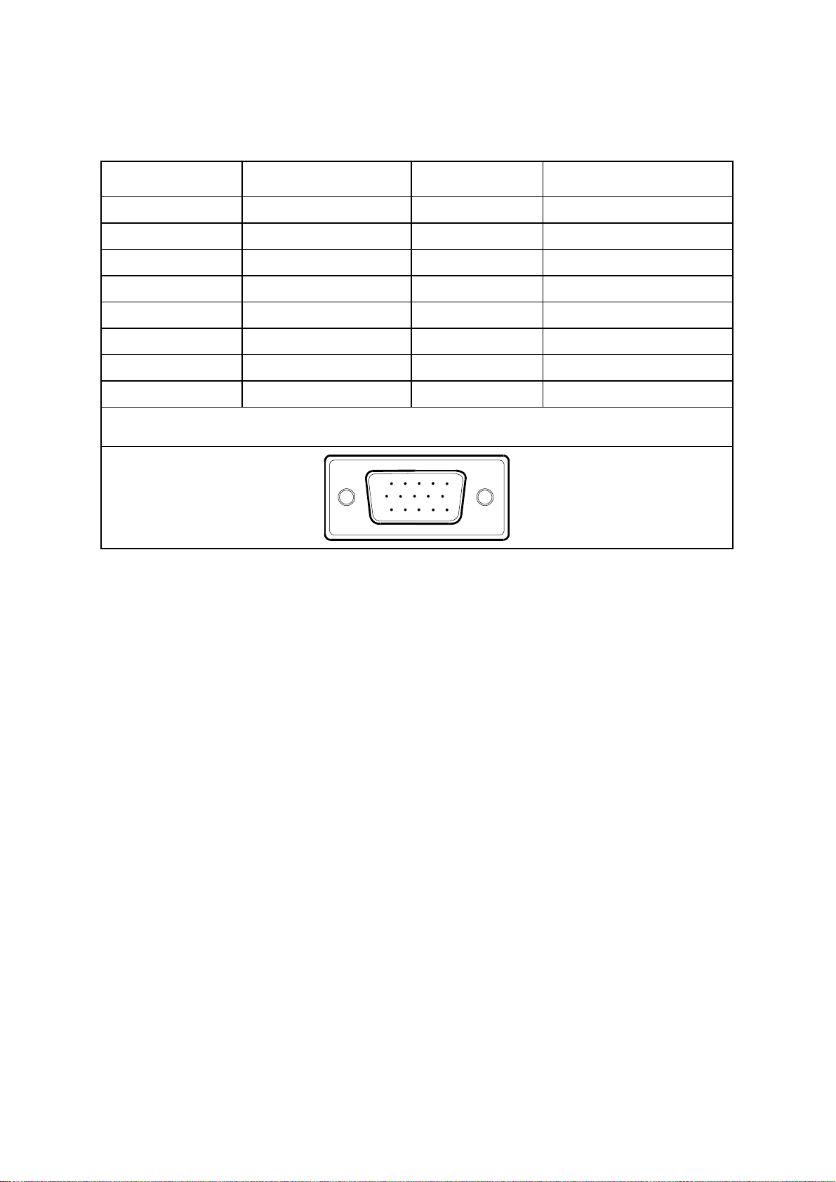
4. INPUT/OUTPUT SPECIFICATION
4.1 INPUT SIGNAL CONNECTOR
ANALOG D-SUB CONNECTOR
PIN NO. DESCRIPTION PI N NO. DESCRIPTION
AOC LM540
1.
2.
3.
4.
5.
6.
7.
8.
Red
Green
Blue
TXD
Ground
R-Ground
G-Ground
B-Ground
VGA connector layout
9.
10.
11.
12.
13.
14.
15.
15
6
11 15
10
+5V
VGA-CON
RXD
DDC-Serial Data
H-Sync
V-Sync
DDC-Serial Clock
http://www.wjel.net
Page 9 of 51
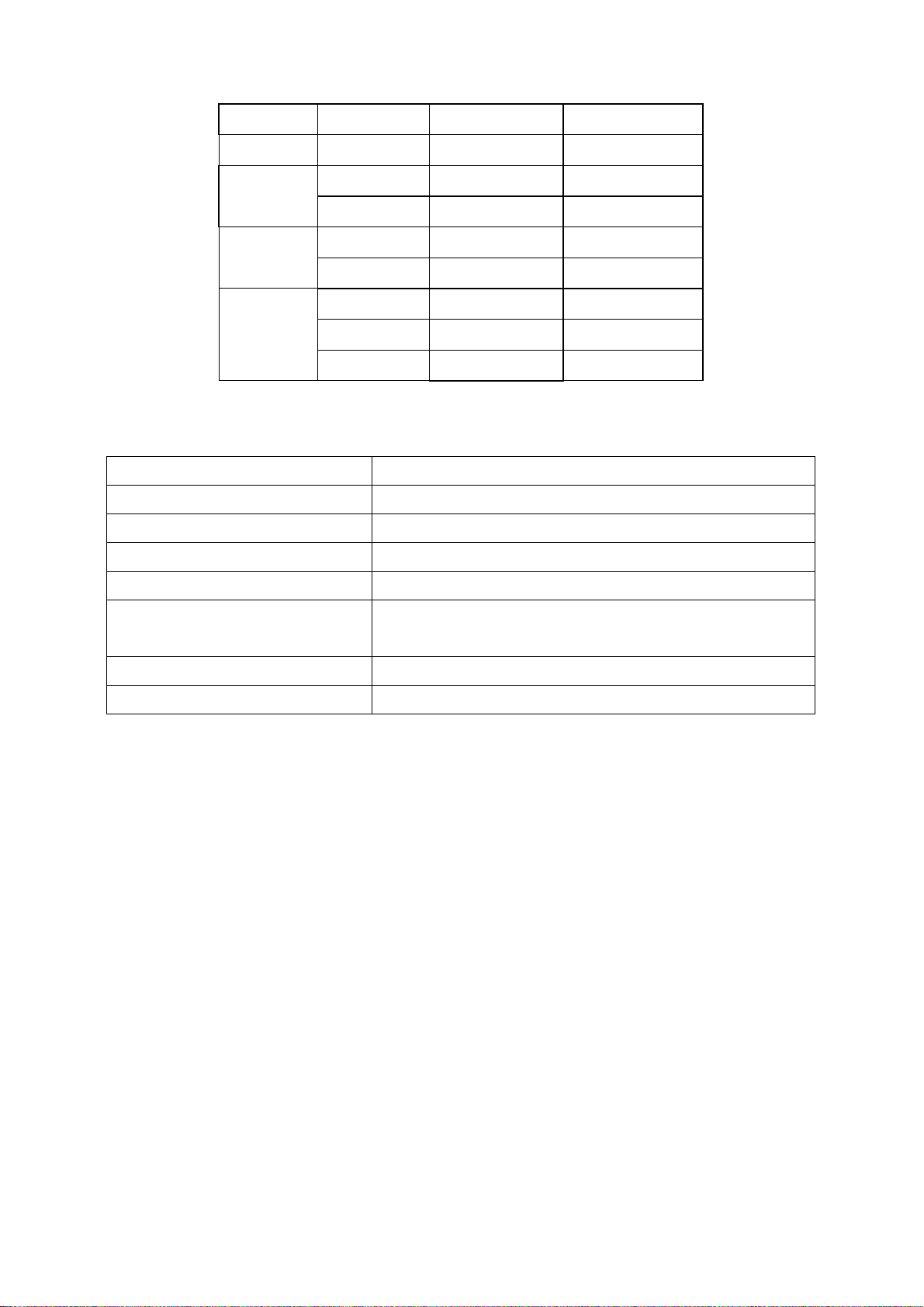
4.2 FACTORY PRESET DISPLAY MODES
AOC LM540
STANDARD
Dos-mode 720 x 400
VGA
SVGA
XGA
FREQUENCY HORIZONTAL VERTICAL
640 × 480 31.47kHz 60.0Hz
640 × 480 37.50kHz 75.0Hz
800 × 600 37.879kHz 60.0Hz
800 × 600 46.875kHz 75.0Hz
1024 × 768 48.363kHz 60.0Hz
1024 × 768 56.476kHz 70.0Hz
1024 × 768 60.021kHz 75.0Hz
4.3 POWER SUPPLY REQUIREMENT
A/C Line voltage range : 100 V ~ 240 V
A/C Line frequency range
Current : 0.6A max. at 100V , 0.35A max. at 240 V <0.3A
Peak surge current : < 55A peak at 240 VAC and cold starting
31.47kHz 70.0Hz
: 50 ± 3Hz, 60 ± 3Hz
Leakage current : < 3.5mA
Power line surge
Voltage
CURRENT : 3.5 Amp (max)
http://www.wjel.net
: No advance effects (no loss of information or defect)
with a maximum of 1 half-wave missing per second
: 12VDC ± 5%
Page 10 of 51
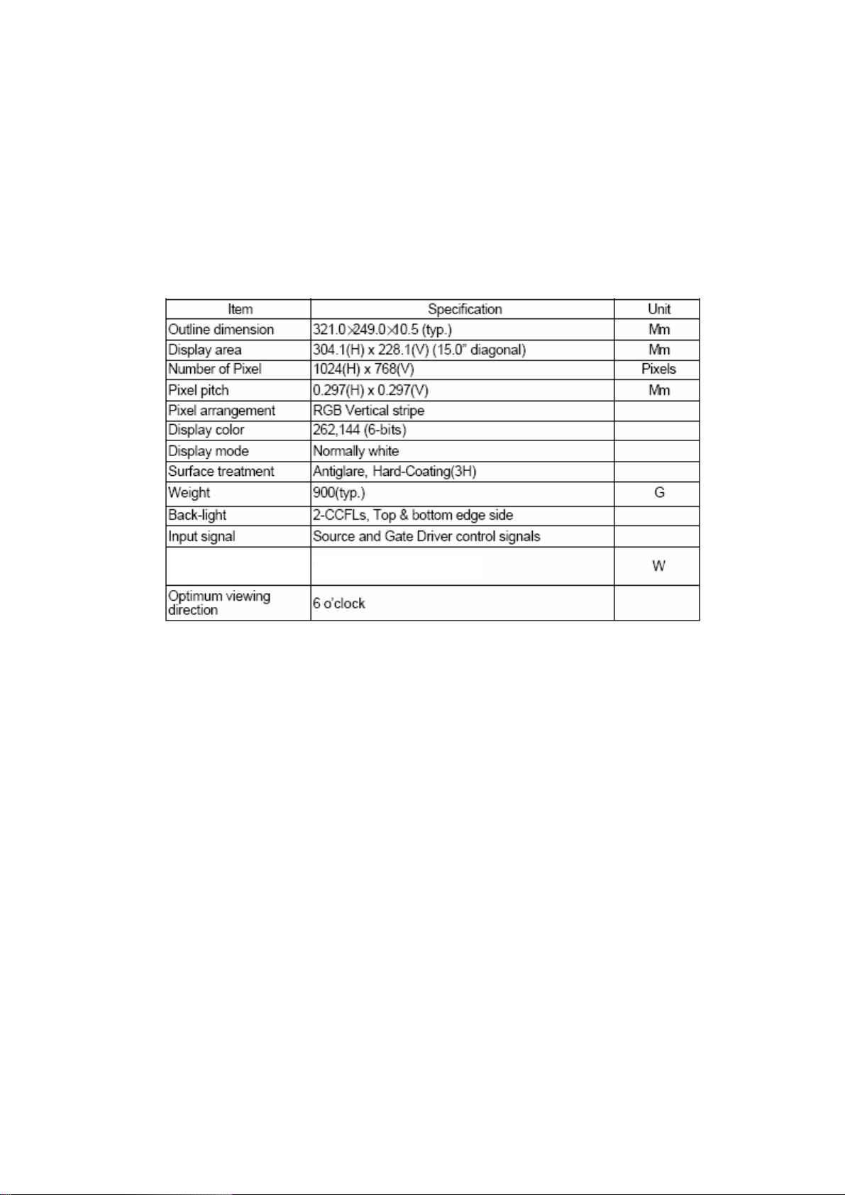
5. PANEL SPECIFICATION
5.1 GENERAL FEATURE
z 15” XGA TFT LCD panel
z 2 CCFLs Backlight system
z Supported XGA (V: 768 lines, H: 1024 pixels) resolution
z Supported to 75Hz refresh rate
z Without LCD Timing Controller
Display Characteristics
AOC LM540
Power consumption
http://www.wjel.net
11.0 (type.)
Page 11 of 51
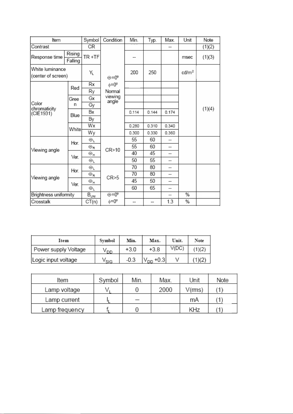
5.2 OPTICAL SPECIFICATION
(5)
AOC LM540
400
35
(1)
ELECTRICAL SPECIFICATIONS
0.593
0.305
0.263
0.569 0.599
0.083 0.113
0.623
0.335
0.293
75
0.365
0.323
0.629
0.143
(6)
http://www.wjel.net
Page 12 of 51
7.0
100
6. BLOCK DIAGRAM
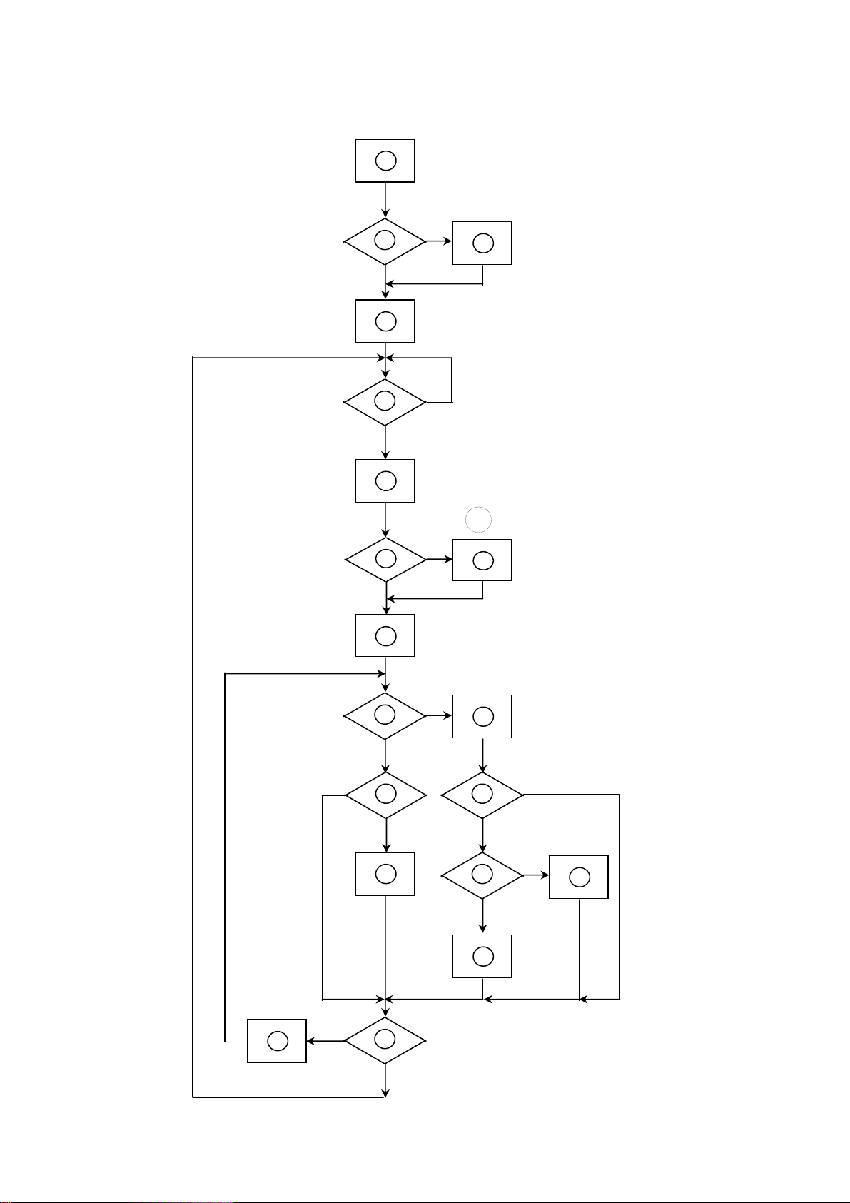
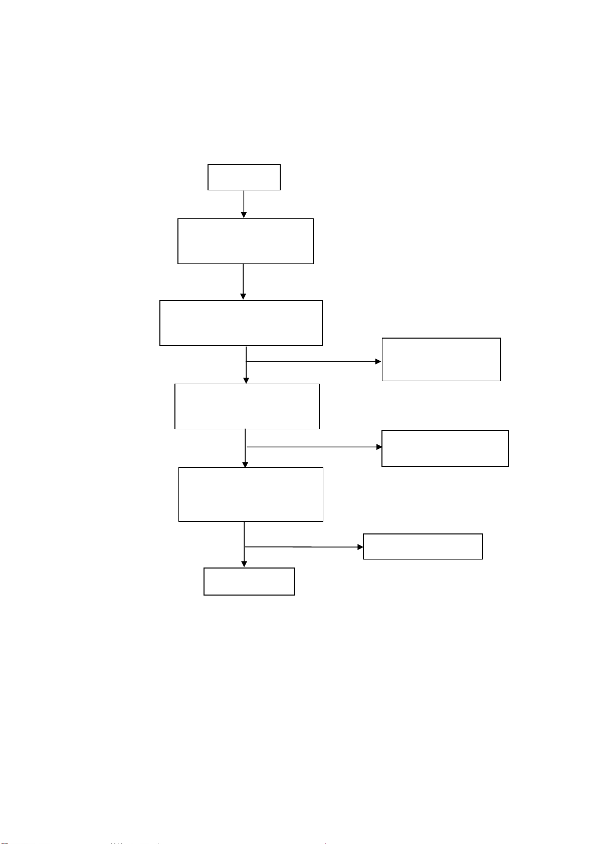
6.1 SOFTWARE FLOWING CHART
AOC LM540
1
2
4
Y
3
N
N
5
6
9
10
12
N
Y
6
N
7
Y
N
Y
8
11
13
N
Y
http://www.wjel.net
18
N
14
19
Y
Page 13 of 51
15
17
Y
N
16
Y

REMARK:
1) MCU initialize.
2) Is the EEprom blank?
3) Program the EEprom by default values.
4) Get the PWM value of brightness from EEprom.
5) Is the power key pressed?
6) Clear all global flags.
7) Are the AUTO and SELECT keys pressed?
8) Enter factory mode.
9) Save the power key status into EEprom.
Turn on the LED and set it to green color.
Scalar initialize.
10) In standby mode?
AOC LM540
11) Update the lifetime of back light.
12) Check the analog port, are they’re any signals coming?
13) Does the scalar send out an interrupt request?
14) Wake up the scalar.
15) Are there any signals coming from analog port?
16) Display "No connection Check Signal Cable" message. And go into standby mode after the message
disappear.
17) Program the scalar to be able to show the coming mode.
18) Process the OSD display.
19) Read the keyboard. Is the power key pressed?
http://www.wjel.net
Page 14 of 51
6.2 ELECTRIAL BLOCK DIAGRAM
6.2.1 MAIN BOARD
AOC LM540
Flash Memory
W49F002
(U202)
EPR_SDA
EPR_SCL
EEPROM
24C16
(U204)
LCD Interface
(CN501, CN502)
Scalar gm2115
(Include MCU, ADC, OSD)
(U203)
D-Sub
Connector
(CN1)
H sync
V sync
RGB
OSD Control
Interface
(CN503)
http://www.wjel.net
DB15_SDA,
DB15_SCL
EEPROM
M24C02
(U104)
Page 15 of 51
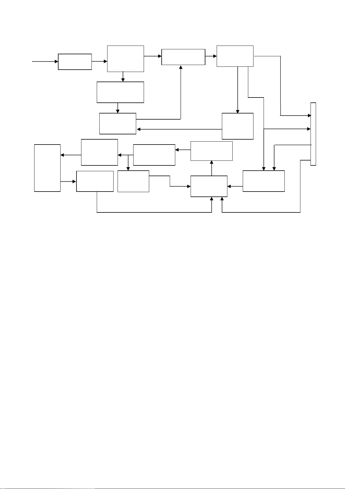
6.2.2 INVERTER/POWER BOARD
AC input
EMI filter
Bridge
Rectifier
and Filter
Transformer
AOC LM540
Rectifier
CMOS
Lamp
Start Circuit
R906, R907
OSC and
Output
Circuit
Feedback
Circuit
PWM
Control IC
Over
Voltage
DC Convert
Circuit
MOSFET
Q203/Q204
PWM
Control IC
Over
Voltage
Protect
CON102
5V
12V
ON/OFF
ON/OFF
Control
DIM
http://www.wjel.net
Page 16 of 51

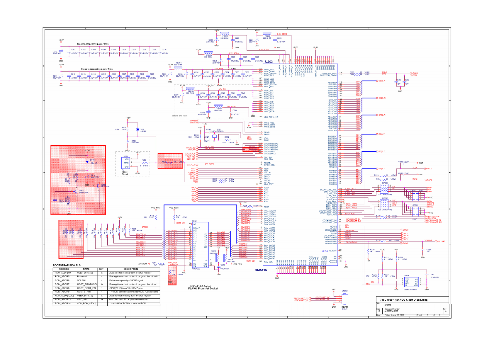
7. SCHEMATIC
7.1 MAIN BOARD
715L1039-1
AOC LM540
http://www.wjel.net
Page 17 of 51
AOC LM540
http://www.wjel.net
Page 18 of 51

AOC LM540
http://www.wjel.net
Page 19 of 51

AOC LM540
http://www.wjel.net
Page 20 of 51

AOC LM540
http://www.wjel.net
Page 21 of 51

7.2 POWER BOARD
715L1034-1A-1
AOC LM540
http://www.wjel.net
Page 22 of 51

AOC LM540
http://www.wjel.net
Page 23 of 51
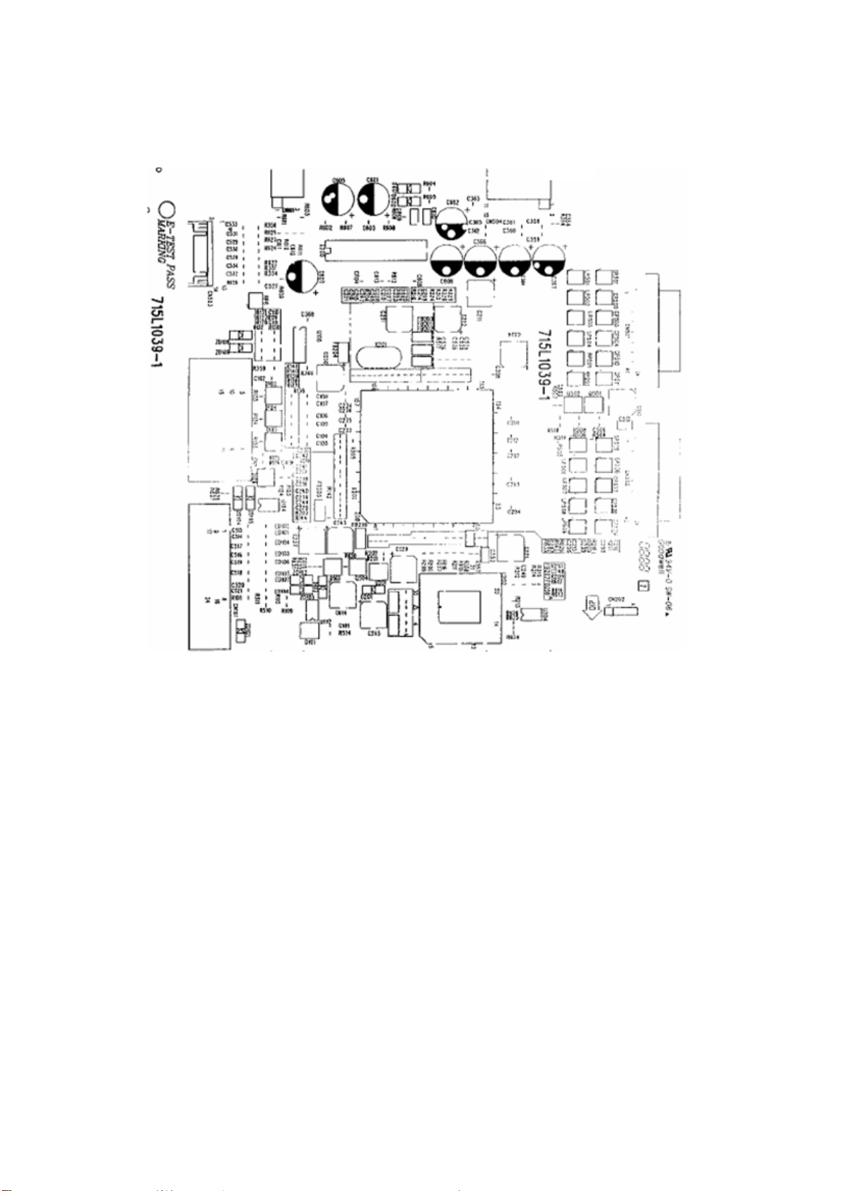
8. LAYOUT
8.1 MAIN BOARD
715L1239-1
AOC LM540
http://www.wjel.net
Page 24 of 51

8.2 POWER BOARD
715L1034-1A-1
AOC LM540
8.3 KEY BOARD
715L707-1-1
http://www.wjel.net
Page 25 of 51

9. Maintainability
9.1 Equipments and Tools Requirement
1. Voltmeter.
2. Oscilloscope.
3. Pattern Generator.
4. DDC Tool with an IBM Compatible Computer.
5. Alignment Tool.
6. LCD Color Analyzer.
7. Service Manual.
8. User Manual.
AOC LM540
http://www.wjel.net
Page 26 of 51
9.2 TROUBLE SHOOTING
9.2.1 MAIN BOARD
NO power
AOC LM540
Press power key and look
if the picture is normal
Please reinsert and make sure
the AC of 100-240 is normal
Measure
U106D PIN14=3.3V
No power
NG
OK
OK
NG
NG
Reinsert or check the
Adapter/Inverter
section
Check CN504 or replace
U106D
X201 oscillate waveforms
are normal
OK
Replace U203
NG
Replace X201
http://www.wjel.net
Page 27 of 51

No picture (LED orange)
No picture
AOC LM540
The button if
under control
OK
Measure
U106D PIN14=3.3V
NG
OK
X201 oscillate
waveform is normal
NG
Replace
U106D
X201 oscillate
waveform is normal
OK
Check reset circuit of
U203 is normal
OK
Replace U203
NG
NG
Replace X201
Check Correspondent
component
OK
Check HS/VS from
Replace U401
CN1is normal
OK
NG
NG
Replace X201
Check Correspondent
component
http://www.wjel.net
Replace U203
Page 28 of 51

White screen
AOC LM540
White screen
Measure Q502 base
is high level?
OK
Check Q502 and Q501 are
broken?
NG
Check Correspondent
component.
OK
NG
X201 oscillate
waveform is normal
OK
Check reset circuit of
U203 is normal
OK
NG
NG
Check Correspondent
component.
Replace X201
Replace PANEL
http://www.wjel.net
Replace U203
Page 29 of 51

9.2.3 POWER/INVERTER BOARD
1.) No power
AOC LM540
Check AC line volt 110V or 220V
Check the voltage of C905(+)
Check start voltage for the pin3 of IC901=16v
No power
OK
OK
NG
NG
Check AC line
Check F901, BD901
The auxiliary voltage (pin 7) is between 10V-16V jumping
1) Check IC901,T901
2) Check D902, D903, ZD904
3) Check IC902, IC903
OK
OK
http://www.wjel.net
NG
Check R906, R907, IC901
NG (Stable)
Check D910, D911
Page 30 of 51

2.) W / LED, No Backlight
AOC LM540
Check C201 (+) =12V
Check U201 pin9=12V voltage
Check the pin7/10 of U201 if have waveforms
OK
Check ON/OFF signal
OK
OK
NG
NG
NG
NG
Check F201
Check D201/Q209/Q210
Check Interface board
Change Q201 or Q202
Short Q203/Q204 if the picture normal
OK
NG
Connect PIN15 of U201 to the ground and check Q209/Q210/ Q211/Q212 collector waveforms
NG
OK
http://www.wjel.net
Check feedback circuit
Change U201
Change Q209/Q210/PT201
Change Q211/Q212/PT202
NG
Check connecter & lamp
Page 31 of 51

9.2.2 KEYPAD BOARD
AOC LM540
Is Key Pad Board connecting normally?
OSD is unstable or not working
Y
Is Button Switch normally?
Y
Is Key Pad Board normally?
Y
N
Connect Key Pad Board
N
Replace Button Switch
N
Replace Key Pad Board
Check Main Board
http://www.wjel.net
Page 32 of 51

AOC LM540
10. WHITE- BALANCE, LUMINANCE ADJUSTMENT
Approximately 30 minutes should be allowed for warm up before proceeding White-Balance adjustment.
1. How to do the Chroma-7120 MEM. Channel setting
A. Reference to chroma 7120 user guide
B. Use “ SC” key and “ NEXT” key to modify XyY value and use “ID” key to modify the
TEXT description Following is the procedure to do white-balance adjust
2. Setting the color temp. you want
A. MEM.CHANNEL 3 (7800 color):
7800 color temp. parameter is x = 296 ±20, y = 311 ±20, Y = 180 cd/m
B. MEM.CHANNEL 4 (6500 color):
6500 color temp. parameter is x = 313±20, y = 329 ±20, Y =180 cd/m2
3. Into factory mode of LM540
Turn on power, press the MENU button, pull out the power cord, and then plug the power cord. Then the factory
2 ,
OSD will be at the left top of the panel.
4. Bias adjustment:
Set the Contrast
5. Gain adjustment:
Move cursor to “-F-” and press MENU key
A. Adjust C2 (7800) color-temperature
1. Switch the Chroma-7120 to RGB-Mode (with press “MODE” button)
2. Switch the MEM. Channel to Channel 3 (with up or down arrow on chroma 7120)
3. The LCD-indicator on chroma 7120 will show x = 296 ±20, y = 311 ±20, Y =180 cd/m
4. Adjust the RED of color1 on factory window until chroma 7120 indicator reached the value R=100
5. Adjust the GREEN of color1 on factory window until chroma 7120 indicator reached the value G=100
6. Adjust the BLUE of color1 on factory window until chroma 7120 indicator reached the value B=100
7. Repeat above procedure (item 4,5,6) until chroma 7120 RGB value meet the tolerance =100±2
B. Adjust C1 (6500) color-temperature
1. Switch the chroma-7120 to RGB-Mode (with press “MODE” button)
2. Switch the MEM.channel to Channel 4(with up or down arrow on chroma 7120)
3. The LCD-indicator on chroma 7120 will show x = 313 ±20, y = 329 ±20, Y = 180 cd/m
to 50; Adjust the Brightness to 80.
http://www.wjel.net
2
2
4. Adjust the RED of color3 on factory window until chroma 7120 indicator reached the value R=100
5. Adjust the GREEN of color3 on factory window until chroma 7120 indicator reachedthe value G=100
6. Adjust the BLUE of color3 on factory window until chroma 7120 indicator reached the value B=100
7. Repeat above procedure (item 4,5,6) until chroma 7120 RGB value meet the tolerance =100±2
C. Turn the Power-button off to quit from factory mode.
Page 33 of 51

11.CHECK LIST AFTER REPLACING LCD MAIN BOARD
Check if white-balance is within the specs after replacing Main board and panel,
AOC LM540
then re-writing DDC is necessary.
11.1 THE WHITE-BALANCE VALUE FOR EACH COMMON COLOR TEMPERATURE:
C1/6500 º K: x = 313±20 ; y = 329±20;
C2/7800 º K: x = 296±20 ; y = 311±20;
Remark: The value of Y should be confirmed according to different customers. If Customer is AOC so that it’s
required to be larger than 170cd/cm
checking-regulations of different customers and different models.
2
(Center). The exact brightness values are confirmed by the
11.2 STEPSOF WHITE-BALANCE ADJUSTMENT FOR LCD:( example for 17” AOC LCD)
1. Required instruments: Chroma7120、Chroma2325(BGA265A)。
2. First connect the instruments together and turn on the LCD power, then warm up for 30 minutes under full
white screen mode. First press the “Reset” key in the menu to recover factory set as following.
3. Set Chroma2325 at round-windows mode and make the detecting-head of Chroma7120 aim at the cross
in the middle, the distance between the detecting-head and the cross is 20cm.
4. Set Chroma2325(BGA265A)to be T144(1280*1024/60HZ)and P105 of full white screen. Test if the
white-balance value is within the specs. Please follow the steps below to adjust if it is beyond the specs.
5. Cut the power. Then press MENU key and supply power at the same time to enter into the factory mode.
See the following pictures.
http://www.wjel.net
Select“F”,then
select AUTO
LEVEL item
6. Test white-balance again after Auto Level. Adjustment with hand is necessary if it is beyond the specs just
the same.
Page 34 of 51

AOC LM540
7. Select 7x00 item to adjust cool color-temperature and select 6x00 to adjust warm color- temperature. It
can reach to the best effect through adjusting R/G/B value if it inclines to green or blue.
8. Select Exit to the upper menu after completing the adjustment. Then press POWER OFF to exit and save
it.
11.3 STEPS FOR WRITING DDC:
1. Employ PC, and connect the DDC-writing instrument and the instrument that is ready for writing into DDC to
the power of 12v. Connect the signal cable of the latter to D-USB or DVI of DDC-writing instrument (The
data-writing of monitor needs transfer-interface) and link the DDC-writing instrument with PC through printer
interface. (See the schematic picture below)
Connection of DDC-writing instrument for VGA.
2. Seek the document with the expanded name of .BAT in DDC file of this model. It appears the indication of
“Input Serial No.:”after dual-click the document to be ready for DDC-writing.
http://www.wjel.net
3.Input the serial number of the product (For instance: AOC LM729 is 13 bits), then press ENTER to start
writing
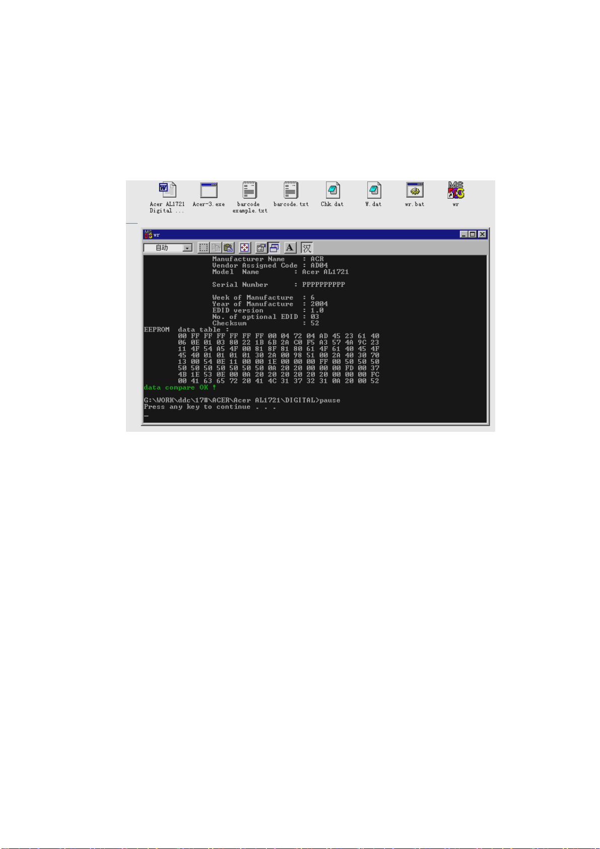
4.Check the indication of DDC-writing program at the end. When you see the picture as the schematic picture
above, the “Data compare OK!” means being written well and that’s the end. Please check if the
Manufacturer Name, Vendor Assigned Code, Monitor Name, Serial Number, Week of Manufacture, Year of
Page 35 of 51
AOC LM540
Manufacture are right. It will appear “Data compare error !” to indicate failure if the DDC-writing doesn’t
perform well. Please check the power resource and the connection of the signal cable, then return to step 3 by
pressing ENTER and re-do it.
5.You can exit the program by pressing Ctrl plus C, then cut the signal cable and the power.
Notes:
6.The following picture is taking Acer AL1721 EDID for example.
1、Make sure the system time of PC is in accordance with the real time before writing.
2、The schematic picture is just as an example for description, the exact content of the DDC is dependent on
the serial number of the BARCORD of this model.
3、Data DDC-writing needs a transfer interface.
Instruction:DDC-writing needs 4 files:
1. Barcode.txt (Supply Barcode length and flow number)
2. *.EXE (DDC-writing program)
3. WR.bat (Group order file for cycling utilization of *EXE, and dual-click this file when
perform DDC-writing)
4. w.dat The content with 128 bits of DDC
http://www.wjel.net
Page 36 of 51

AOC LM540
12. EDID
00 01 02 03 04 05 06 07 08 09 10 11 12 13 14 15
0: 00 FF FF FF FF FF FF 00 05 E3 64 A5 0B 95 0D 00
16: 27 0E 01 03 68 1E 17 82 2A 8F 3D A4 58 4D 90 24
32: 15 4F 51 BF EE 00 01 01 01 01 01 01 01 01 01 01
48: 01 01 01 01 01 01 64 19 00 40 41 00 26 30 18 88
64: 36 00 30 E4 10 00 00 18 00 00 00 FF 00 31 32 33
80: 34 35 36 37 38 39 30 31 32 33 00 00 00 FD 00 37
96: 4B 1E 3F 08 00 0A 20 20 20 20 20 20 00 00 00 FC
112: 00 4C 4D 35 34 30 0A 20 20 20 20 20 20 20 00 DD
http://www.wjel.net
Page 37 of 51

13. BOM LIST
T562KHDNKDACN
Part NO for TPV Description Quantity Unit
CBPC560KHCA2 CONVERSION BOARD T560K* 1 PCS
KEPC562KD9 KEY BOARD 1 PCS
PWPC5216A1 POWER BOARD FOR T560K* 1 PCS
15G5838 2 MAIN FRAME 1 PCS
15G5908 2 BRACKET 1 PCS
26G 800504 7 BARCODE 1 PCS
33G4362 1 LENS 1 PCS
33G4470 U2 2L KEY PAD 1 PCS
34G1000BD7A2L FRONT PANEL 1 PCS
40G 15061573C ID LABEL 1 PCS
40G 58162435A LABEL 1 PCS
AOC LM540
41G780061513B INPUT NOT SUPPORT CARD 1 PCS
41G780061518B EASE PROGRAM 1 PCS
41G780061532C SA CENTER LIST 1 PCS
41G780061541A AOC-Kensington Card 1 PCS
41G780061576D QSG 1 PCS
41G780061577A WARRANTY CARD 1 PCS
44G3231 12 A EVA WASHER 1 PCS
44G3231 15528 EVA WASHER 1 PCS
44G3525615 5B CARTON 1 PCS
44G3539 1 EPS 1 PCS
44G3539 2 EPS 1 PCS
44G3539 3EPE EPE 1 PCS
45G 76 28 C PE Bag For Manual 2 PCS
45G 88607 PE BAG FOR MONITOR 1 PCS
45G 88609 EPE COVER 1 PCS
http://www.wjel.net
50G 600 2 HANDLE1 1 PCS
50G 600 3 HANDLE2 1 PCS
52G 1185 MIDDLE TAPE FOR CARTON 92 CM
52G 1186 SMALL TAPE 8 CM
52G 1207 A ALUMINIUM TAPE 2 PCS
52G 1208 A ALUMINIUM TAPE 1 PCS
52G6025 11523 INSULATE SHEET 1 PCS
70G L15516AOC drive disk 1 PCS
85G 634 8 SHIELD 1 PCS
Page 38 of 51

AOC LM540
89L 176 40 3 FFC CABLE 40P 2 PCS
M1G 325 4120 SCREW M2.5X4 4 PCS
M1G 330 4128 SCREW M3X4 1 PCS
M1G1130 6128 SCREW 8 PCS
M1G1140 6128 SCREW 4X6 1 PCS
Q1G 330 8120 SCREW 3X8mm 14 PCS
750LLH50X84 C HANNSTAR 15" SI PANEL 1 PCS
89G402A15N LS POWER CORD 1 PCS
89G1735GAA D1 SIGNAL CABLE 1 PCS
http://www.wjel.net
Page 39 of 51

AOC LM540
PART LIST FOR MAIN BOARD
Location Part NO for TPV Description Quantity Units
AIC560KHCA2 MAIN BOARD FOR T560K* 1 PCS
40G 457624 1B LABEL-CPU 1 PCS
40G 45762412B CBPC LABEL 1 PCS
C364 67G 309471 3T 470UF +-20% 16V 1 PCS
C366 67G 309471 3T 470UF +-20% 16V 1 PCS
C367 67G 309471 3T 470UF +-20% 16V 1 PCS
CN1 88G 35315FHAS D-SUB 15PIN 1 PCS
CN503 33G8027 14 H WAFER 14P 2.0MM DIP 1 PCS
CN504 33G8022 12 H PIN HEADER FEMALE 2*6 9 1 PCS
U202 56L1133 35H3P W49F002UP-12B 1 PCS
X201 93G 22 53 CRYSTAL 14.318MHzHC-49U 1 PCS
715L1039 1 PCB BOARD 1 PCS
C102 65G0603104 12 CER2 0603 X7R 16V 100N 1 PCS
C103 65G0603103 32 0.01UF +-10% 50V X7R 1 PCS
C104 65G0603103 32 0.01UF +-10% 50V X7R 1 PCS
C105 65G0603103 32 0.01UF +-10% 50V X7R 1 PCS
C106 65G0603103 32 0.01UF +-10% 50V X7R 1 PCS
C107 65G0603103 32 0.01UF +-10% 50V X7R 1 PCS
C108 65G0603103 32 0.01UF +-10% 50V X7R 1 PCS
C109 65G0603104 12 CER2 0603 X7R 16V 100N 1 PCS
C201 65G0603104 12 CER2 0603 X7R 16V 100N 1 PCS
C202 65G0603104 12 CER2 0603 X7R 16V 100N 1 PCS
C203 65G0603104 12 CER2 0603 X7R 16V 100N 1 PCS
C204 65G0603104 12 CER2 0603 X7R 16V 100N 1 PCS
C205 65G0603104 12 CER2 0603 X7R 16V 100N 1 PCS
C206 65G0603104 12 CER2 0603 X7R 16V 100N 1 PCS
C207 65G0603104 12 CER2 0603 X7R 16V 100N 1 PCS
C208 65G0603104 12 CER2 0603 X7R 16V 100N 1 PCS
http://www.wjel.net
C209 65G0603104 12 CER2 0603 X7R 16V 100N 1 PCS
C210 65G0603104 12 CER2 0603 X7R 16V 100N 1 PCS
C211 67G 312220 3 SMD 22UF +-20% 16V 1 PCS
C212 65G0603104 12 CER2 0603 X7R 16V 100N 1 PCS
C213 65G0603104 12 CER2 0603 X7R 16V 100N 1 PCS
C214 65G0603104 12 CER2 0603 X7R 16V 100N 1 PCS
C215 65G0603104 12 CER2 0603 X7R 16V 100N 1 PCS
C216 65G0603104 12 CER2 0603 X7R 16V 100N 1 PCS
Page 40 of 51

AOC LM540
C217 65G0603104 12 CER2 0603 X7R 16V 100N 1 PCS
C218 65G0603104 12 CER2 0603 X7R 16V 100N 1 PCS
C219 65G0603104 12 CER2 0603 X7R 16V 100N 1 PCS
C220 65G0603104 12 CER2 0603 X7R 16V 100N 1 PCS
C221 67G 312220 3 SMD 22UF +-20% 16V 1 PCS
C222 67G 312220 3 SMD 22UF +-20% 16V 1 PCS
C223 65G0603104 12 CER2 0603 X7R 16V 100N 1 PCS
C224 67G 312220 3 SMD 22UF +-20% 16V 1 PCS
C225 65G0603104 12 CER2 0603 X7R 16V 100N 1 PCS
C226 65G0603104 12 CER2 0603 X7R 16V 100N 1 PCS
C227 65G0603104 12 CER2 0603 X7R 16V 100N 1 PCS
C228 65G0603104 12 CER2 0603 X7R 16V 100N 1 PCS
C229 67G 312220 3 SMD 22UF +-20% 16V 1 PCS
C230 67G 312220 3 SMD 22UF +-20% 16V 1 PCS
C231 65G0603104 12 CER2 0603 X7R 16V 100N 1 PCS
C232 65G0603104 12 CER2 0603 X7R 16V 100N 1 PCS
C233 65G0603104 12 CER2 0603 X7R 16V 100N 1 PCS
C234 65G0603104 12 CER2 0603 X7R 16V 100N 1 PCS
C235 65G0603104 12 CER2 0603 X7R 16V 100N 1 PCS
C236 65G0603104 12 CER2 0603 X7R 16V 100N 1 PCS
C237 67G 312220 3 SMD 22UF +-20% 16V 1 PCS
C238 65G0603104 12 CER2 0603 X7R 16V 100N 1 PCS
C239 65G0603104 12 CER2 0603 X7R 16V 100N 1 PCS
C240 65G0603104 12 CER2 0603 X7R 16V 100N 1 PCS
C241 65G0603104 12 CER2 0603 X7R 16V 100N 1 PCS
C242 65G0603104 12 CER2 0603 X7R 16V 100N 1 PCS
C243 67G 312220 3 SMD 22UF +-20% 16V 1 PCS
C244 65G0603104 12 CER2 0603 X7R 16V 100N 1 PCS
C245 67G 312220 3 SMD 22UF +-20% 16V 1 PCS
C246 65G0603509 31 CHIP 5PF +-0.5PF 50V NP 1 PCS
http://www.wjel.net
C247 65G0603509 31 CHIP 5PF +-0.5PF 50V NP 1 PCS
C248 65G0603104 12 CER2 0603 X7R 16V 100N 1 PCS
C249 65G0603104 12 CER2 0603 X7R 16V 100N 1 PCS
C250 65G0805105 37 CHIP 1UF 50V Y5V 1 PCS
C251 67G 312220 3 SMD 22UF +-20% 16V 1 PCS
C353 65G0805105 37 CHIP 1UF 50V Y5V 1 PCS
C358 65G0603104 12 CER2 0603 X7R 16V 100N 1 PCS
C359 65G0603104 12 CER2 0603 X7R 16V 100N 1 PCS
Page 41 of 51

AOC LM540
C360 65G0603104 12 CER2 0603 X7R 16V 100N 1 PCS
C361 65G0603104 12 CER2 0603 X7R 16V 100N 1 PCS
C362 65G0603104 12 CER2 0603 X7R 16V 100N 1 PCS
C363 65G0603104 12 CER2 0603 X7R 16V 100N 1 PCS
C365 65G0603104 12 CER2 0603 X7R 16V 100N 1 PCS
C368 65G0603104 12 CER2 0603 X7R 16V 100N 1 PCS
C506 65G0603104 12 CER2 0603 X7R 16V 100N 1 PCS
C512 67G 312220 3 SMD 22UF +-20% 16V 1 PCS
C513 65G0805105 37 CHIP 1UF 50V Y5V 1 PCS
C526 65G0603220 31 CER1 0603 NP0 50V 22P P 1 PCS
C527 65G0603102 32 1000PF +-10% 50V X7R 1 PCS
C528 65G0603102 32 1000PF +-10% 50V X7R 1 PCS
C529 65G0603102 32 1000PF +-10% 50V X7R 1 PCS
C530 65G0603102 32 1000PF +-10% 50V X7R 1 PCS
C531 65G0603102 32 1000PF +-10% 50V X7R 1 PCS
C532 65G0603102 32 1000PF +-10% 50V X7R 1 PCS
C533 65G0603102 32 1000PF +-10% 50V X7R 1 PCS
C534 65G0603102 32 1000PF +-10% 50V X7R 1 PCS
C535 65G0603220 31 CER1 0603 NP0 50V 22P P 1 PCS
C536 65G0603220 31 CER1 0603 NP0 50V 22P P 1 PCS
C614 67G 312220 3 SMD 22UF +-20% 16V 1 PCS
C615 65G0603101 32 100PF +-10% 50V X7R 1 PCS
CN501 33G8019 40 CONNECTOR 40P SMT 1 PCS
CN502 33G8019 40 CONNECTOR 40P SMT 1 PCS
CP501 65L602K220 8T IRRAY CAP 22PF +-10% 16 1 PCS
CP502 65L602K220 8T IRRAY CAP 22PF +-10% 16 1 PCS
CP503 65L602K220 8T IRRAY CAP 22PF +-10% 16 1 PCS
CP504 65L602K220 8T IRRAY CAP 22PF +-10% 16 1 PCS
CP505 65L602K220 8T IRRAY CAP 22PF +-10% 16 1 PCS
CP506 65L602K220 8T IRRAY CAP 22PF +-10% 16 1 PCS
http://www.wjel.net
CP507 65L602K220 8T IRRAY CAP 22PF +-10% 16 1 PCS
CP508 65L602K220 8T IRRAY CAP 22PF +-10% 16 1 PCS
CP509 65L602K220 8T IRRAY CAP 22PF +-10% 16 1 PCS
CP510 65L602K220 8T IRRAY CAP 22PF +-10% 16 1 PCS
CP511 65L602K220 8T IRRAY CAP 22PF +-10% 16 1 PCS
D103 93G 6433P BAV99 1 PCS
D104 93G 6433P BAV99 1 PCS
D105 93G 6433P BAV99 1 PCS
Page 42 of 51

AOC LM540
D106 93G 60230 BAT54C(L43) 1 PCS
D201 93G 6432V LL4148-GS08 1 PCS
D603 93G 6432V LL4148-GS08 1 PCS
FB201 71G 57G601 TI3216JIG 1 PCS
FB202 71G 57G601 TI3216JIG 1 PCS
FB203 71G 57G601 TI3216JIG 1 PCS
FB204 71G 57G601 TI3216JIG 1 PCS
FB205 71G 57G601 TI3216JIG 1 PCS
FB206 71G 57G601 TI3216JIG 1 PCS
FB207 71G 57G601 TI3216JIG 1 PCS
LP501 71G 56A121 8T CHIP BEAD ARRAY 120 OHM 1 PCS
LP502 71G 56A121 8T CHIP BEAD ARRAY 120 OHM 1 PCS
LP503 71G 56A121 8T CHIP BEAD ARRAY 120 OHM 1 PCS
LP504 71G 56A121 8T CHIP BEAD ARRAY 120 OHM 1 PCS
LP505 71G 56A121 8T CHIP BEAD ARRAY 120 OHM 1 PCS
LP506 71G 56A121 8T CHIP BEAD ARRAY 120 OHM 1 PCS
LP507 71G 56A121 8T CHIP BEAD ARRAY 120 OHM 1 PCS
LP508 71G 56A121 8T CHIP BEAD ARRAY 120 OHM 1 PCS
LP509 71G 56A121 8T CHIP BEAD ARRAY 120 OHM 1 PCS
Q501 57G 763 1 A03401 SOT23 BY AOS(A1) 1 PCS
Q502 57G 417 4 PMBS3904/PHILIPS-SMT(04 1 PCS
Q503 57G 417 4 PMBS3904/PHILIPS-SMT(04 1 PCS
Q504 57G 417 4 PMBS3904/PHILIPS-SMT(04 1 PCS
R123 61L0603203 CHIPR 20K OHM+-5% 1/10W 1 PCS
R124 61L0603203 CHIPR 20K OHM+-5% 1/10W 1 PCS
R125 61L0603470 RST SM 0603 RC0603 47R 1 PCS
R126 61L0603470 RST SM 0603 RC0603 47R 1 PCS
R129 61L0603470 RST SM 0603 RC0603 47R 1 PCS
R130 61L0603470 RST SM 0603 RC0603 47R 1 PCS
R131 61L0603222 RST SM 0603 RC0603 2K2 1 PCS
http://www.wjel.net
R132 61L0603222 RST SM 0603 RC0603 2K2 1 PCS
R133 61L0603750 RST SM 0603 RC22H 75R P 1 PCS
R134 61L0603750 RST SM 0603 RC22H 75R P 1 PCS
R135 61L0603750 RST SM 0603 RC22H 75R P 1 PCS
R136 61L0603101 RST SM 0603 RC0603 100R 1 PCS
R137 61L0603101 RST SM 0603 RC0603 100R 1 PCS
R138 61L0603101 RST SM 0603 RC0603 100R 1 PCS
R139 61L0603101 RST SM 0603 RC0603 100R 1 PCS
Page 43 of 51

AOC LM540
R140 61L0603101 RST SM 0603 RC0603 100R 1 PCS
R141 61L0603101 RST SM 0603 RC0603 100R 1 PCS
R142 61L0603103 RST SM 0603 RC0603 10K 1 PCS
R144 61L0603472 RST SM 0603 RC0603 4K7 1 PCS
R201 61L0603472 RST SM 0603 RC0603 4K7 1 PCS
R203 61L0603103 RST SM 0603 RC0603 10K 1 PCS
R204 61L0603272 RST SM 0603 RC22H 2K7 P 1 PCS
R205 61L0603102 RST SM 0603 RC0603 1K P 1 PCS
R207 61L0603103 RST SM 0603 RC0603 10K 1 PCS
R208 61L0603103 RST SM 0603 RC0603 10K 1 PCS
R209 61L0603103 RST SM 0603 RC0603 10K 1 PCS
R210 61L0603103 RST SM 0603 RC0603 10K 1 PCS
R211 61L0603103 RST SM 0603 RC0603 10K 1 PCS
R213 61L0603000 RST SM 0603 JUMP MAX 0R 1 PCS
R214 61L0603103 RST SM 0603 RC0603 10K 1 PCS
R215 61L0603103 RST SM 0603 RC0603 10K 1 PCS
R216 61L0603472 RST SM 0603 RC0603 4K7 1 PCS
R217 61L0603472 RST SM 0603 RC0603 4K7 1 PCS
R218 61L0603103 RST SM 0603 RC0603 10K 1 PCS
R220 61L0603102 RST SM 0603 RC0603 1K P 1 PCS
R224 61L0603220 RST SM 0603 RC0603 22R 1 PCS
R225 61L0603220 RST SM 0603 RC0603 22R 1 PCS
R350 61L0603221 RST SM 0603 RC0603 220R 1 PCS
R351 61L0603221 RST SM 0603 RC0603 220R 1 PCS
R354 61L0603472 RST SM 0603 RC0603 4K7 1 PCS
R356 61L0603472 RST SM 0603 RC0603 4K7 1 PCS
R357 61L0603103 RST SM 0603 RC0603 10K 1 PCS
R358 61L0603102 RST SM 0603 RC0603 1K P 1 PCS
R359 61L0603102 RST SM 0603 RC0603 1K P 1 PCS
R360 61L0603102 RST SM 0603 RC0603 1K P 1 PCS
http://www.wjel.net
R506 61L0603104 RST SM 0603 RC0603 100K 1 PCS
R507 61L0603103 RST SM 0603 RC0603 10K 1 PCS
R508 61L0603104 RST SM 0603 RC0603 100K 1 PCS
R509 61L0603472 RST SM 0603 RC0603 4K7 1 PCS
R513 61L0603220 RST SM 0603 RC0603 22R 1 PCS
R516 61L0603470 RST SM 0603 RC0603 47R 1 PCS
R517 61L0603470 RST SM 0603 RC0603 47R 1 PCS
R519 61L0603000 RST SM 0603 JUMP MAX 0R 1 PCS
Page 44 of 51

AOC LM540
R622 61L0603103 RST SM 0603 RC0603 10K 1 PCS
R623 61L0603103 RST SM 0603 RC0603 10K 1 PCS
R624 61L0603103 RST SM 0603 RC0603 10K 1 PCS
R625 61L0603103 RST SM 0603 RC0603 10K 1 PCS
R626 61L0603103 RST SM 0603 RC0603 10K 1 PCS
R627 61L0603470 RST SM 0603 RC0603 47R 1 PCS
R628 61L0603470 RST SM 0603 RC0603 47R 1 PCS
R629 61L0603102 RST SM 0603 RC0603 1K P 1 PCS
R630 61L0603103 RST SM 0603 RC0603 10K 1 PCS
R631 61L0603103 RST SM 0603 RC0603 10K 1 PCS
R632 61L0603103 RST SM 0603 RC0603 10K 1 PCS
R633 61L0603103 RST SM 0603 RC0603 10K 1 PCS
RP201 71G 56A121 8T CHIP BEAD ARRAY 120 OHM 1 PCS
RP202 71G 56A121 8T CHIP BEAD ARRAY 120 OHM 1 PCS
RP6 61L 125472 8 CHIP AR 8P4R 4.7K OHM+- 1 PCS
U104 56G1133 34 M24C02-WMN6TP 1 PCS
U106 56G4LVC 14 P 74LVC14ADT 1 PCS
U202 87L 202 32 PLCC CONN 32PIN 1 PCS
U203 56G 562 25 gm2115(CG) 1 PCS
U204 56G1133 56 M24C16-WMN6TP 1 PCS
ZD104 93G 39147 TZMC5V6 1 PCS
ZD105 93G 39147 TZMC5V6 1 PCS
ZD108 93G 39147 TZMC5V6 1 PCS
ZD109 93G 39147 TZMC5V6 1 PCS
http://www.wjel.net
Page 45 of 51
PART LIST FOR KEY BOARD
Location Part NO for TPV Description Quantity Unit
AIK562KD1 KEY BOARD FOR T562K* 1 PCS
JP801 95G8014 14623 WIRE HARNESS 1 PCS
LED1 81G 12 1 GP GP32032ME 1 PCS
SW101 77L 600 1GHJ KEY SWITCH 1 PCS
SW102 77L 600 1GHJ KEY SWITCH 1 PCS
SW103 77L 600 1GHJ KEY SWITCH 1 PCS
SW104 77L 600 1GHJ KEY SWITCH 1 PCS
SW105 77L 600 1GHJ KEY SWITCH 1 PCS
715L 707 1 1 TF-1560 KEY BOARD (SMD) 1 PCS
R108 61G 60210152T 100OHM +- 5% 1/6W 1 PCS
AOC LM540
http://www.wjel.net
Page 46 of 51

AOC LM540
PART LIST FOR POWER BOARD
Location Part NO for TPV Description Quantity Unit
PWPC5216A1SMT LCD POWER ASS'Y FOR SMT 1 PCS
40G 45762412B CBPC LABEL 1.03 PCS
705L 780 5602B IC905,IC906 ASS'Y 1 PCS
705L 780 57 02 CN901 ASS'Y 1 PCS
BD901 93G 50460502 KBP206G 1 PCS
C213 63G210J1542A2 0.15UF +-5% 250V 1 PCS
C215 65G 3J2206ET 22PF 5% SL 3KV TDK 1 PCS
C216 65G 3J2206ET 22PF 5% SL 3KV TDK 1 PCS
C901 65L305M1022E3 1000PF +-20% 400VAC BY 1 PCS
C902 65L305M1022E3 1000PF +-20% 400VAC BY 1 PCS
C904 63G 107474 HS 0.47UF +-20% 275VAC 1 PCS
C905 67G305S10115K 100UF +-20% 450V 1 PCS
C906 65G 2K152 5E6921 1500 PF 10% 2KV Y5P 1 PCS
C913 65G306M4722BP 4700PF +-20% 400VAC 1 PCS
C922 67G215L102 3R LOW E.S.R 1000UF +/-20% 1 PCS
C924 67G 2154713RT LOW E.S.R 470UF +/-20% 1 PCS
C925 67G215L102 3R LOW E.S.R 1000UF +/-20% 1 PCS
C926 67G 2154713RT LOW E.S.R 470UF +/-20% 1 PCS
C929 67G 2154713RT LOW E.S.R 470UF +/-20% 1 PCS
C930 67G 2154713RT LOW E.S.R 470UF +/-20% 1 PCS
C932 67G 2154713RT LOW E.S.R 470UF +/-20% 1 PCS
C933 67G 2154713RT LOW E.S.R 470UF +/-20% 1 PCS
CN102 33G800912L H HEADER 2*6P 1 PCS
CN201 33G8020 2D AC CONN.2P R/A DIP BY ACES 1 PCS
CN202 33G8020 2D AC CONN.2P R/A DIP BY ACES 1 PCS
D910 93G3010 1 31DQ10FC 1 PCS
D912 93G3006 1 31DQ06FC 1 PCS
F901 84G 7H200 SL 250V/2A LIHEL FUSE 1 PCS
http://www.wjel.net
IC901 56G 379 32 SG6841DZ DIP-8 1 PCS
IC902 56G 139 3A PC123Y22FZOF 1 PCS
L201 73G 253139 HA CHOKE COIL 1 PCS
L202 73G 174 30YSA FILTER 1 PCS
L902 73L 174 26LSG COMMON CHOKE 1 PCS
L903 73G 253 91 H CHOKE COIL 1 PCS
L904 73G 253 91 H CHOKE COIL 1 PCS
NR901 61G 58080 WT 8 OHM NCT 1 PCS
Page 47 of 51

AOC LM540
PT201 80LL15T 9YSG TRANSFORMER 1 PCS
Q209 57G 761 6 2SC5706-P-E 1 PCS
Q210 57G 761 6 2SC5706-P-E 1 PCS
Q903 57G 724 4 2SK2996 1 PCS
R903 61G152M104 64 100KOHM 5% 2W 1 PCS
R919 61G 2J398 64 0.39 OHM 5% 2W 1 PCS
R936 61G152M43952F 4.3 OHM 5% 2W 1 PCS
R937 61G152M43957F 4.3 OHM 5% 2W 1 PCS
T901 80LL17T 2LSG ADAPTOR BY LISHIN 1 PCS
PWPC5216A1AI LCD POWER ASS'Y FOR AI 1 PCS
C202 65G0805104 22 0.1UF +-10% 25V X7R 080 1 PCS
C203 65G0805105 27 CHIP 1UF Y5V 0805 1 PCS
C205 65G0805104 22 0.1UF +-10% 25V X7R 080 1 PCS
C208 65G0805331 31 CHIP 330pF 50V NPO 1 PCS
C209 65G0805105 27 CHIP 1UF Y5V 0805 1 PCS
C211 65G0805105 27 CHIP 1UF Y5V 0805 1 PCS
C219 65G0805105 27 CHIP 1UF Y5V 0805 1 PCS
C221 65G0805474 27 CHIP 0.47UF 25V Y5V 1 PCS
C225 65G0805105 27 CHIP 1UF Y5V 0805 1 PCS
C910 65G0603104 37 CHIP 0.1UF 50V/Y5V 1 PCS
C927 65G0603104 37 CHIP 0.1UF 50V/Y5V 1 PCS
C928 65G0603104 37 CHIP 0.1UF 50V/Y5V 1 PCS
C931 65G0603104 37 CHIP 0.1UF 50V/Y5V 1 PCS
C934 65G0603104 37 CHIP 0.1UF 50V/Y5V 1 PCS
D201 93G2004 2A SM240A DO-214AC 1 PCS
D203 93G 39S 3 T BZT52-C11 1 PCS
F902 61L1206000 4 0 OHM 4A 1/4W 1 PCS
Q201 57G 760 5B PDTC144WK SOT346 1 PCS
Q202 57G 760 4B PDTA144WK SOT346 1 PCS
Q203 57G 763 3B AM9435P.T1-PF SO-8 1 PCS
http://www.wjel.net
R204 61L0603103 RST SM 0603 RC0603 10K 1 PCS
R208 61L0603000 RST SM 0603 JUMP MAX 0R 1 PCS
R210 61L0603123 CHIP 12K OHM 1/10W 1 PCS
R212 61L0603392 CHIP 3.9K OHM 1/10W 1 PCS
R214 61L0603222 RST SM 0603 RC0603 2K2 1 PCS
R216 61L0603221 RST SM 0603 RC0603 220R 1 PCS
R218 61L0603101 RST SM 0603 RC0603 100R 1 PCS
R219 61L1206102 CHIP 1K OHM 5% 1/4W 1 PCS
Page 48 of 51

AOC LM540
R222 61L0603103 RST SM 0603 RC0603 10K 1 PCS
R224 61L1206152 CHIPR 1.5K OHM+-5%1/4W 1 PCS
R225 61L1206152 CHIPR 1.5K OHM+-5%1/4W 1 PCS
R226 61L1206152 CHIPR 1.5K OHM+-5%1/4W 1 PCS
R227 61L1206152 CHIPR 1.5K OHM+-5%1/4W 1 PCS
R232 61L1206102 CHIP 1K OHM 5% 1/4W 1 PCS
R234 61L0603911 CHIP 910 OHM 1/10W 1 PCS
R236 61L0603621 CHIPR 620 OHM+-5% 1/10W 1 PCS
R238 61L0603123 CHIP 12K OHM 1/10W 1 PCS
R240 61L0603513 CHIP 51K OHM 1/10W 1 PCS
R901 61L1206105 CHIP 1MOHM 5% 1/4W 1 PCS
R902 61L1206105 CHIP 1MOHM 5% 1/4W 1 PCS
R904 61L1206105 CHIP 1MOHM 5% 1/4W 1 PCS
R905 61L1206105 CHIP 1MOHM 5% 1/4W 1 PCS
R906 61L1206684 CHIPR 680K OHM+-5% 1/4W 1 PCS
R907 61L1206684 CHIPR 680K OHM+-5% 1/4W 1 PCS
R909 61L1206472 CHIP 4.7KOHM 5% 1/4W 1 PCS
R910 61L1206472 CHIP 4.7KOHM 5% 1/4W 1 PCS
R911 61L1206472 CHIP 4.7KOHM 5% 1/4W 1 PCS
R912 61L1206101 CHIP 100 OHM 5% 1/4W 1 PCS
R915 61L1206103 CHIP 10KOHM 5% 1/4W 1 PCS
R916 61L0805240 2F CHIP 24KOHM 1% 1/8W 1 PCS
R924 61L0805330 2F CHIP 33KOHM 1/8W 1% 1 PCS
R925 61L0805360 1F CHIP 3.6KOHM 1/8W 1% 1 PCS
R926 61L0805240 1F CHIPR 2.4KOHM +-1% 1/8W 1 PCS
R927 61L0805102 CHIPR 1K OHM +-5% 1/8W 1 PCS
R928 61L0805102 CHIPR 1K OHM +-5% 1/8W 1 PCS
R929 61L0603000 RST SM 0603 JUMP MAX 0R 1 PCS
R931 61L0603102 RST SM 0603 RC0603 1K P 1 PCS
R933 61L0603000 RST SM 0603 JUMP MAX 0R 1 PCS
http://www.wjel.net
R934 61L0603151 CHIPR 150 OHM +-5% 1/10 1 PCS
R935 61L0603151 CHIPR 150 OHM +-5% 1/10 1 PCS
U201 56G 608 1 TL1451ACD 1 PCS
ZD901 93G 39S 23 T GLZ22B 1 PCS
ZD904 93G 39S 19 T PTZ7.5B 1 PCS
715L1034 1A 1 PCB VER:D 1 PCS
C201 67G215C1514KT 150UF +-20% 25V 1 PCS
C204 64G700J1040AT 0.1UF 50V PEN 1 PCS
Page 49 of 51

AOC LM540
C207 67G 305330 7T
C905 6G 31502 1.5MM RIVET 2 PCS
C907 67G 305220 7T
C908 65G 450104 7T 0.1UF +80-20% 50V Y5V 1 PCS
C909 64G700J1040AT 0.1UF 50V PEN 1 PCS
C911 64G700J1020AT 1000PF 50V PEN 1 PCS
C920 65L517K102 5T6213 1000PF 10% Y5P 500V 1 PCS
C921 65L517K102 5T6213 1000PF 10% Y5P 500V 1 PCS
C936 64G700J1040AT 0.1UF 50V PEN 1 PCS
D205 93G 64 1152T 1N4148 1 PCS
D207 93G 64 1152T 1N4148 1 PCS
D209 93G 64 1152T 1N4148 1 PCS
D901 93G 6026T52T RECTIFIER DIODE FR107 1 PCS
D902 93G 6038T52T FR103 1 PCS
D903 93G 64 1152T 1N4148 1 PCS
33UF 105
105 尼ん 22UF +-20% 50
1 PCS
1 PCS
FB901 71G 55 29 FERRITE BEAD 1 PCS
FB902 71G 55 19 T FERRITE BEAD D9X3. 5X0. 1 PCS
FB903 71G 55 19 T FERRITE BEAD D9X3. 5X0. 1 PCS
IC903 56G 158 4 T A H431BA 1 PCS
L902 6G 31502 1.5MM RIVET 4 PCS
PT201 6G 31502 1.5MM RIVET 2 PCS
Q205 57G 417 3 T MPS3904 1 PCS
Q207 57G 414 2 MPS3906 1 PCS
Q901 57G 420 PP T 2PA733P 1 PCS
Q902 57G 419 PP T 2PC945P 1 PCS
R201 61G 60247352T 47KOHM 5% 1/6W 1 PCS
R205 61G 60247352T 47KOHM 5% 1/6W 1 PCS
R220 61G 60218352T 18KOHM 5% 1/6 1 PCS
R908 61G 17268952T 6.8OHM 5% 1/4W 1 PCS
R917 61G 17210052T 100HM 5% 1/4W 1 PCS
http://www.wjel.net
R918 61G 17210352T CFR 10KOHM +-5% 1/4W 1 PCS
R920 61G 20747052T 47 OHM 1/2W 1 PCS
R922 61G 20747052T 47 OHM 1/2W 1 PCS
R930 61G 17210152T 100 OHM 5% 1/4W 1 PCS
T901 6G 31502 1.5MM RIVET 4 PCS
ZD902 93G 39 5452T HZ12B2-E 1 PCS
ZD903 93G 39 7752T HZ5C1-E 1 PCS
2G6003 1 SCREW NUT 2 PCS
Page 50 of 51

AOC LM540
12G 372 1 SILICONE RUBBER 2 PCS
90G 407 1 HEAT SINK 1 PCS
M1G1730 10128 SCREW M3x10 2 PCS
IC905 56G 563 17 AP1084T33L 1 PCS
IC906 56G 563 18 AP1084TL 1 PCS
95G205S354022 HARNESS 1 PCS
96G 29 6 SHRINK TUBE UL/CSA 20 MM
CN901 87G 501 12 CJ AC SOCKET 1 PCS
15G5786 1 VRSA BRACKET 1 PCS
33G4339 U0 1L HINGE COVER (L) 1 PCS
33G4339 U0 2L HINGE COVER (R) 1 PCS
34G 911 U0 L STAND COVER F 1 PCS
34G 912 U0 L STAND COVER B 1 PCS
34G 913 U0 L BASE 1 PCS
34G1100 U0A6L BACK COVER 1 PCS
37G 446 1 LCD HINGE (L501-C) 1 PCS
M1G 340 8128 SCREW 2 PCS
Q1G 330 8120 SCREW 3X8mm 2 PCS
Q1G 340 8128 SCREW 4X8mm 1 PCS
AM1G1740 12128 SCREW 4 PCS
http://www.wjel.net
Page 51 of 51
 Loading...