

Page 1

46″ LCD TV AOC LE46H158I
Service
Service
Service
31~68 KHz
TABLE OF CONTENTS
Description Page Description Page
Table of Contents.......……....................................…........1
Important Safety Notice.......................................……......2
Revision List…………………………………………………3
1. General Specification..............................……...…........4
2. Operating Instructions………………...…….……….......5
3. Input/Output Specification…………....................…......6
4. Mechanical Instructions……………………...................8
5. Repair Flow Chart.……………………….…….…….....12
6. PCB Layout.………………..…………………....….......19
6.1 Main Board………………..…………...…….…….......19
6.2 Power Board……...……….………..…….……….......21
6.3 LED Board..………………………..……..……….......26
SAFETY NOTICE
ANY PERSON ATTEMPTING TO SERVICE THIS CHASSIS MUST FAMILIARIZE HIMSELF WITH THE CHASSIS
6.4 Key Board………….…………..……..……….......26
6.5 IR Board………………………….……..……….......27
7. Adjustment..............................................................28
8. Block Diagram.…….................................................29
9. Schematic Diagram…..…………....………………...30
9.1 Main Board…………………………………...….......30
9.2 Power Board…………..….….……...………….......52
9.3 LED Board……...……….……….…………….........57
9.4 Key Board……………….……….…………….........58
9.5 IR Board……...………….……….…………….........59
10. Exploded View………………………………….…...60
11. BOM List……………….………………….………….62
Horizontal Frequency
AND BE AWARE OF THE NECESSARY SAFETY PRECAUTIONS TO BE USED WHEN SERVICING
ELECTRONIC EQUIPMENT CONTAINING HIGH VOLTAGES.
CAUTION: USE A SEPARATE ISOLATION TRANSFOMER FOR THIS UNIT WHEN SERVICING
1
Page 2

Important Safety Notice
Proper service and repair is important to the safe, reliable operation of all AOC Company Equipment. The service
procedures recommended by AOC and described in this service manual are effective methods of performing service
operations. Some of these service operations require the use of tools specially designed for the purpose. The
special tools should be used when and as recommended.
It is important to note that this manual contains various CAUTIONS and NOTICES which should be carefully read in
order to minimize the risk of personal injury to service personnel. The possibility exists that improper service
methods may damage the equipment. It is also important to understand that these CAUTIONS and NOTICES ARE
NOT EXHAUSTIVE. AOC could not possibly know, evaluate and advise the service trade of all conceivable ways in
which service might be done or of the possible hazardous consequences of each way. Consequently, AOC has not
undertaken any such broad evaluation. Accordingly, a servicer who uses a service procedure or tool which is not
recommended by AOC must first satisfy himself thoroughly that neither his safety nor the safe operation of the
equipment will be jeopardized by the service method selected.
Hereafter throughout this manual, AOC Company will be referred to as AOC.
WARNING
Use of substitute replacement parts, which do not have the same, specified safety characteristics might create
shock, fire, or other hazards.
Under no circumstances should the original design be modified or altered without written permission from AOC.
AOC assumes no liability, express or implied, arising out of any unauthorized modification of design.
Servicer assumes all liability.
FOR PRODUCTS CONTAINING LASER:
DANGER-Invisible laser radiations when open AVOID DIRECT EXPOSURE TO BEAM.
CAUTION-Use of controls or adjustments or performance of procedures other than those specified herein may
result in hazardous radiation exposure.
CAUTION -The use of optical instruments with this product will increase eye hazard.
TO ENSURE THE CONTINUED RELIABILITY OF THIS PRODUCT, USE ONLY ORIGINAL MANUFACTURER'S
REPLACEMENT PARTS, WHICH ARE LISTED WITH THEIR PART NUMBERS IN THE PARTS LIST SECTION OF
THIS SERVICE MANUAL.
Take care during handling the LCD module with backlight unit
-Must mount the module using mounting holes arranged in four corners.
-Do not press on the panel, edge of the frame strongly or electric shock as this will result in damage to the screen.
-Do not scratch or press on the panel with any sharp objects, such as pencil or pen as this may result in damage to
the panel.
-Protect the module from the ESD as it may damage the electronic circuit (C-MOS).
-Make certain that treatment person’s body is grounded through wristband.
-Do not leave the module in high temperature and in areas of high humidity for a long time.
-Avoid contact with water as it may a short circuit within the module.
-If the surface of panel becomes dirty, please wipe it off with a soft material. (Cleaning with a dirty or rough cloth may
damage the panel.)
2
Page 3

Revision List
Version Release Date Revision Instructions TPV Model
A00 Aug.19,2011 Initial release E46BATNSAJB16N
3
Page 4

1. General Specification
Please refer to user manual.
4
Page 5

2. Operating Instructions
Please refer to user manual.
5
Page 6
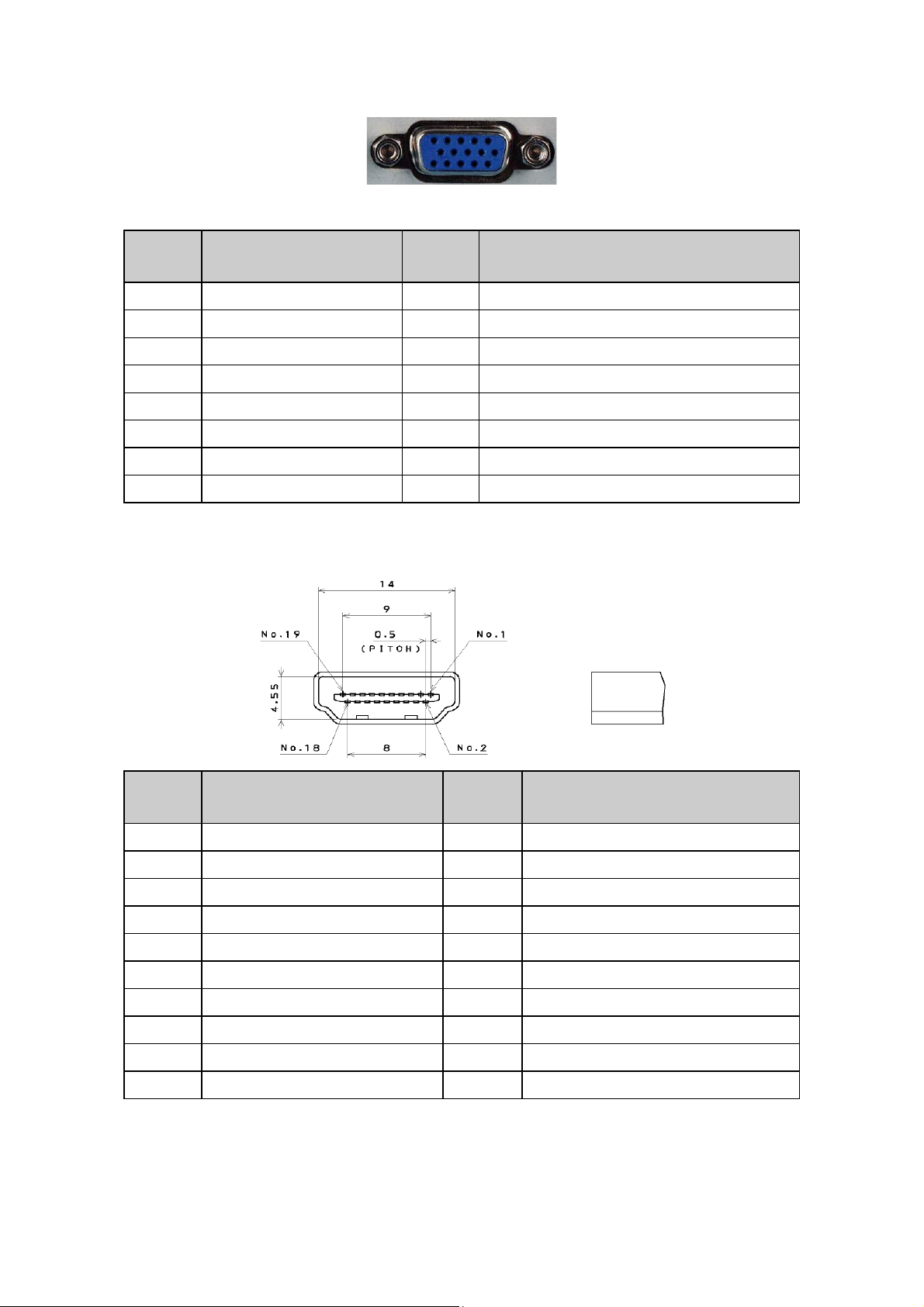
3. Input/Output Specification
3.1 RGB Signal Input
15 - Pin Color Display Signal Cable
Pin No. Description Pin No. Description
1 Red Video 9 No Pin!
2 Green Video 10 Sync Ground
3 Blue Video 11 RXD
4 TXD 12 Serial Data for DDC
5 Ground 13 H-Sync.
6 Red Ground 14 V-Sync.
7 Green Ground 15 Serial Clock for DDC
8 Blue Ground
3.2 HDMI Digital Connector Pin Assignments
Pin No. Description Pin No. Description
1 TMDS Data2+ 2 TMDS Data2 Shield
3 TMDS Data2- 4 TMDS Data1+
5 TMDS Data1 Shield 6 TMDS Data1-
7 TMDS Data0+ 8 TMDS Data0 Shield
9 TMDS Data0- 10 TMDS Clock+
11 TMDS Clock Shield 12 TMDS Clock13 CEC 14 NC
15 SCL 16 SDA
17 DDC/CEC Ground 18 +5V Power
19 Hot Plug Detect
6
Page 7
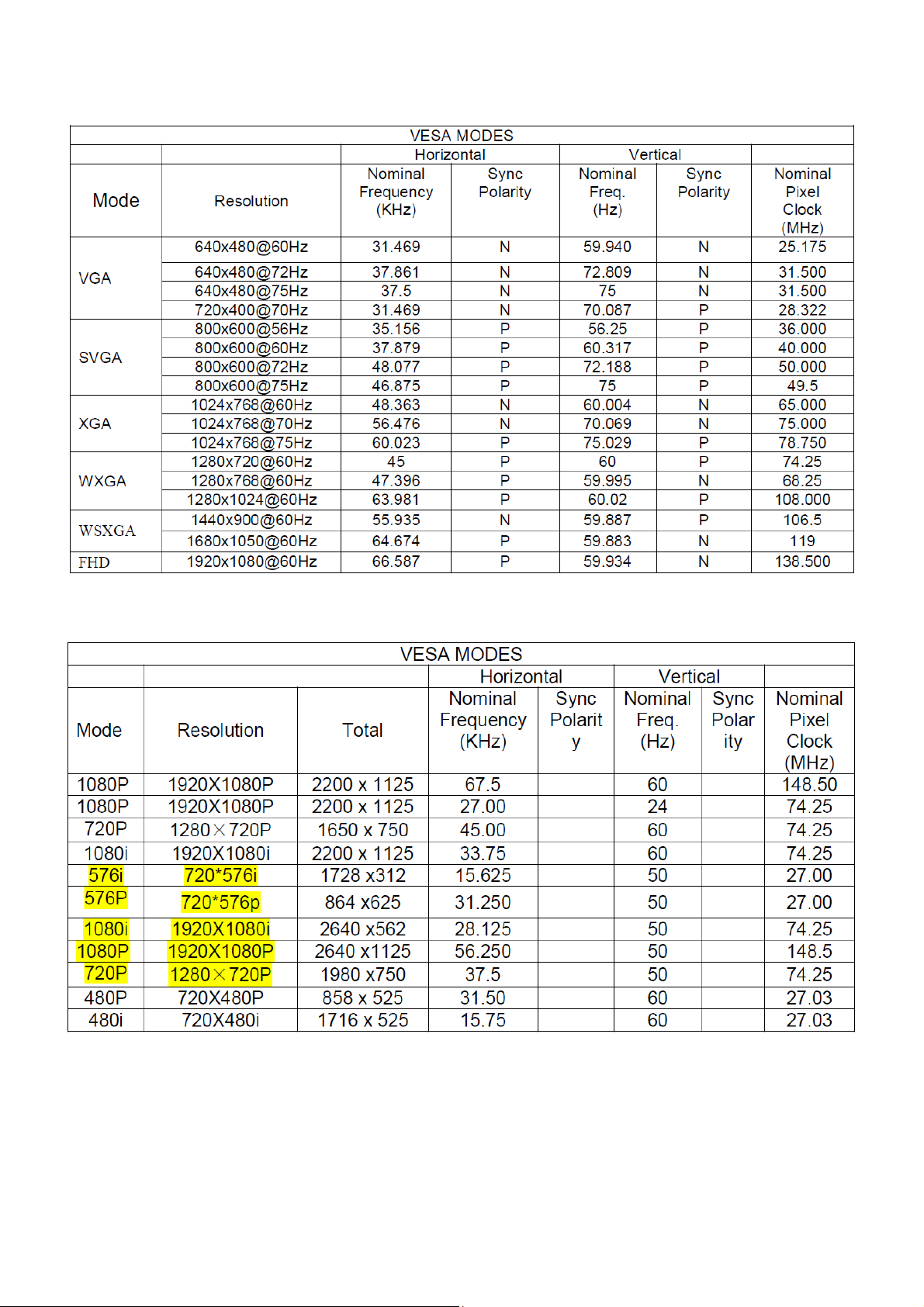
3.3 Compatible Mode Table
RGB Input Signal Timing
HDMI Input Signal Timing
7
Page 8
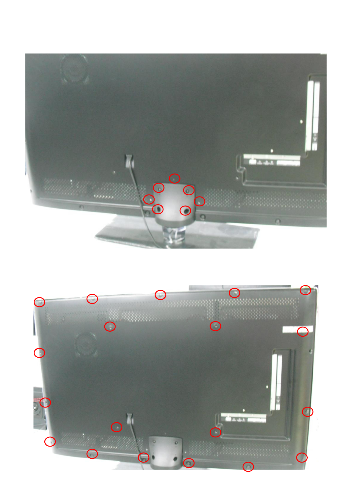
4. Mechanical Instructions
1. Remove the screws to remove STAND BASE.
2. Remove the screws to remove REAR COVER.
8
Page 9
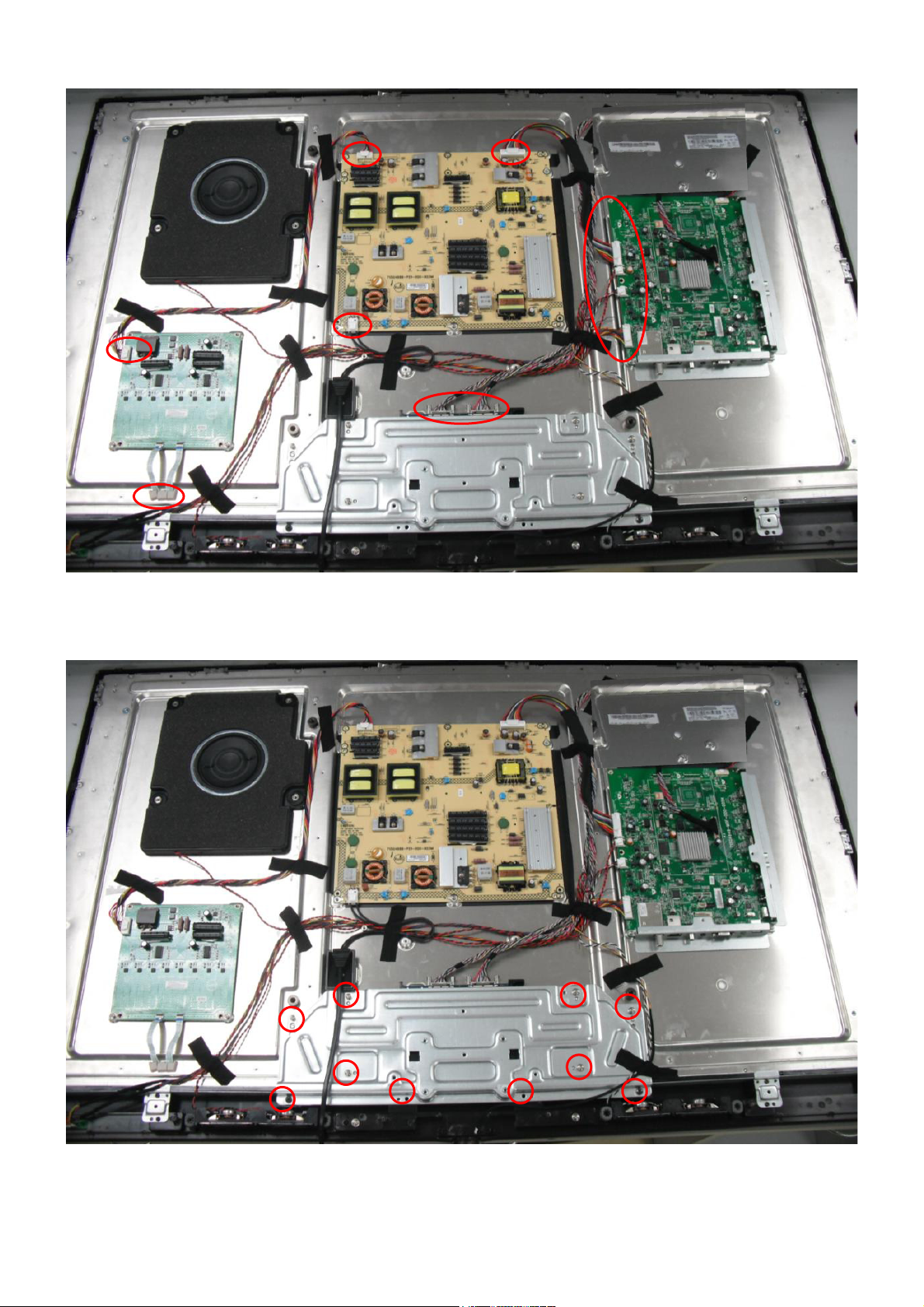
3. Disconnect the harness in red.
4. Remove the screws to remove BRACKET_STAND.
9
Page 10
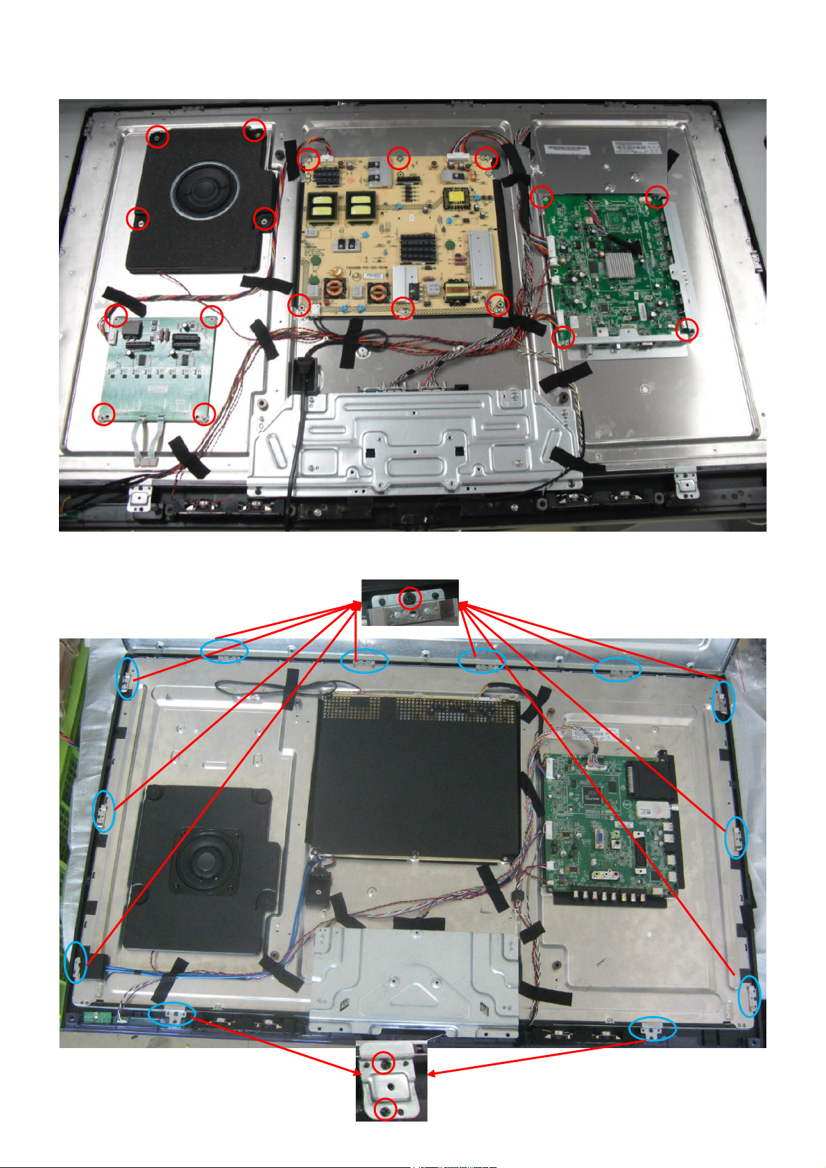
5. Remove the screws to remove Speaker, BKT, MAIN BOARD and POWER BOARD.
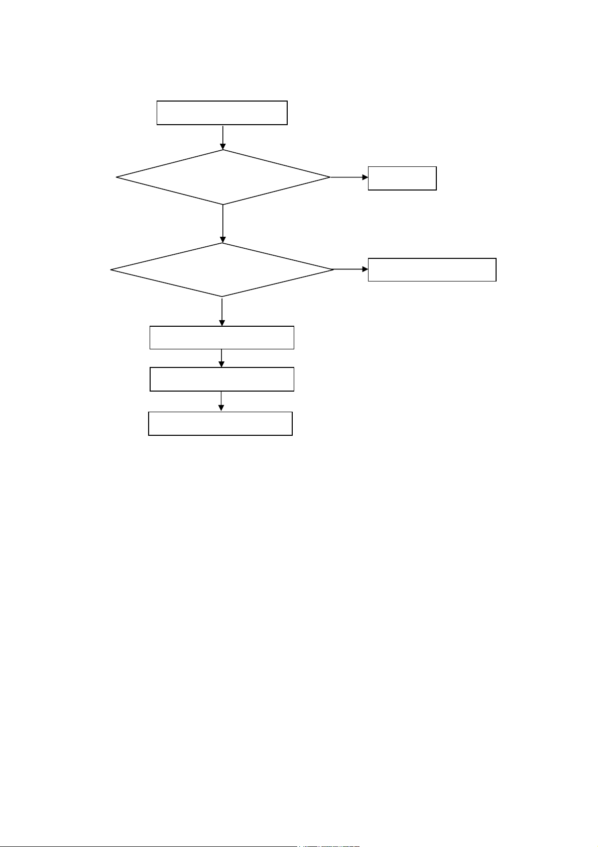
6. Remove the screws to remove BKT and separate PANEL and BEZEL.
10
Page 11
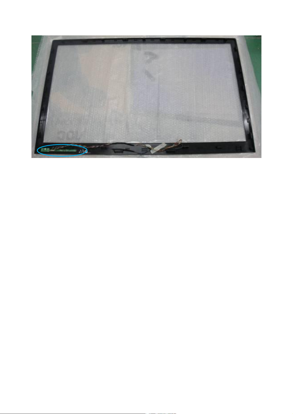
7. Remove the screws to remove KEY BOARD.
11
Page 12
p
p
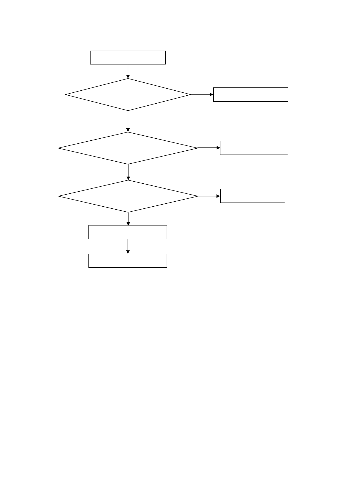
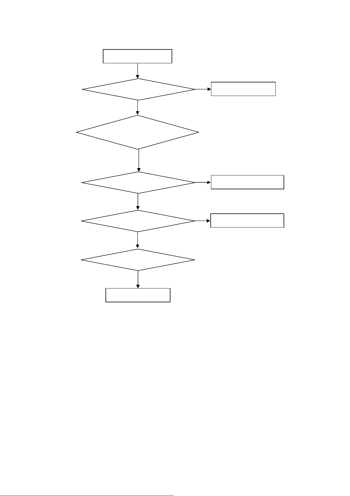
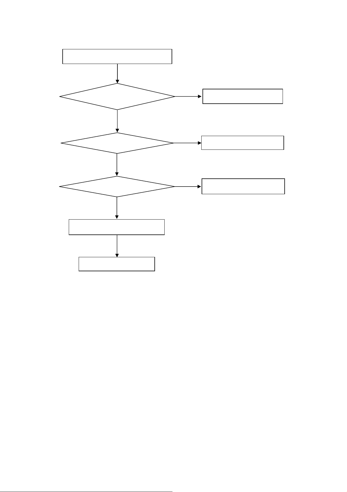
5. Repair Flow Chart
1. No power
No power (LED “Off”)
Check the AC input and
ower is “ON”?
the
Yes
Power board
ut=5.2V?
out
Yes
Check the IR board and LED
Replace the IR board
No
Replace the main board
No
Power “On”
No
Replace the power board
12
Page 13
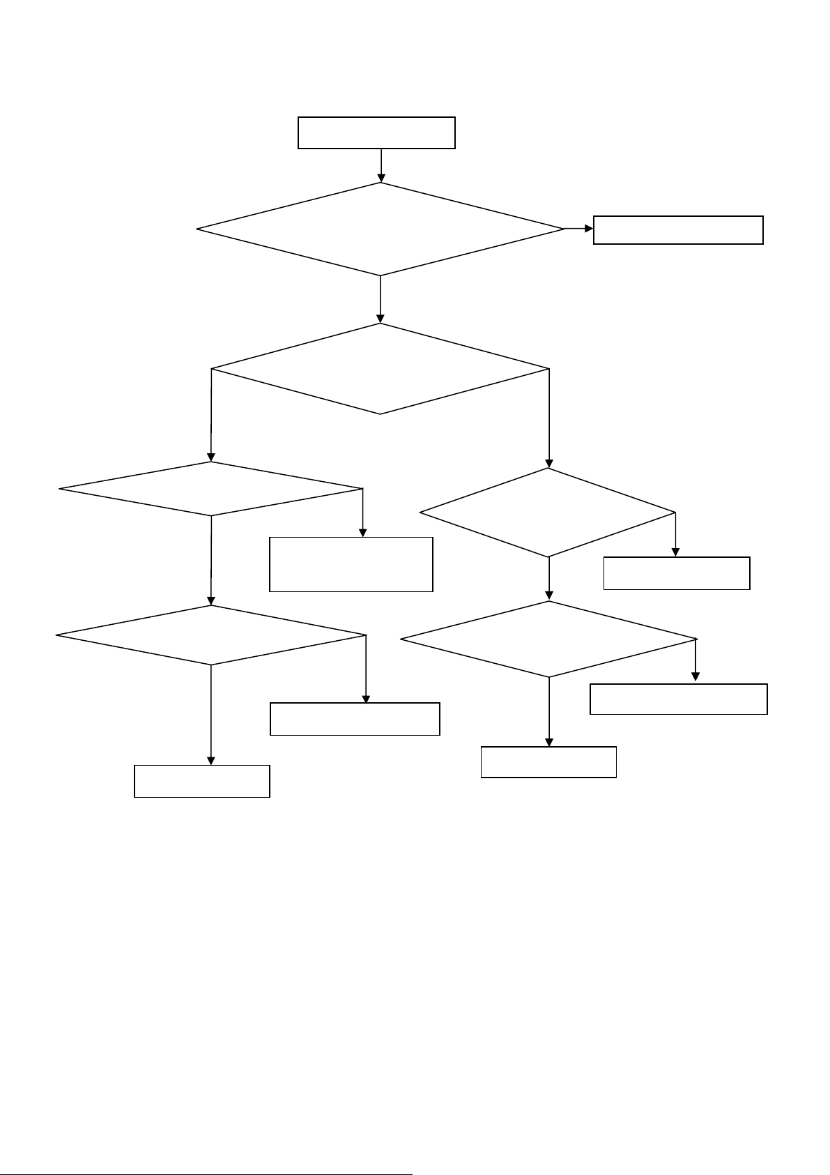
2. Can’t start
Can’t start
Power board output=24V?
Yes
Check the power key is under control?
No
Check the IR receiver is normal?
No
Replace the power board
Yes
Replace the key board
Yes
Replace the IR board
No
Replace the main board
No
Replace the Power board
13
Page 14
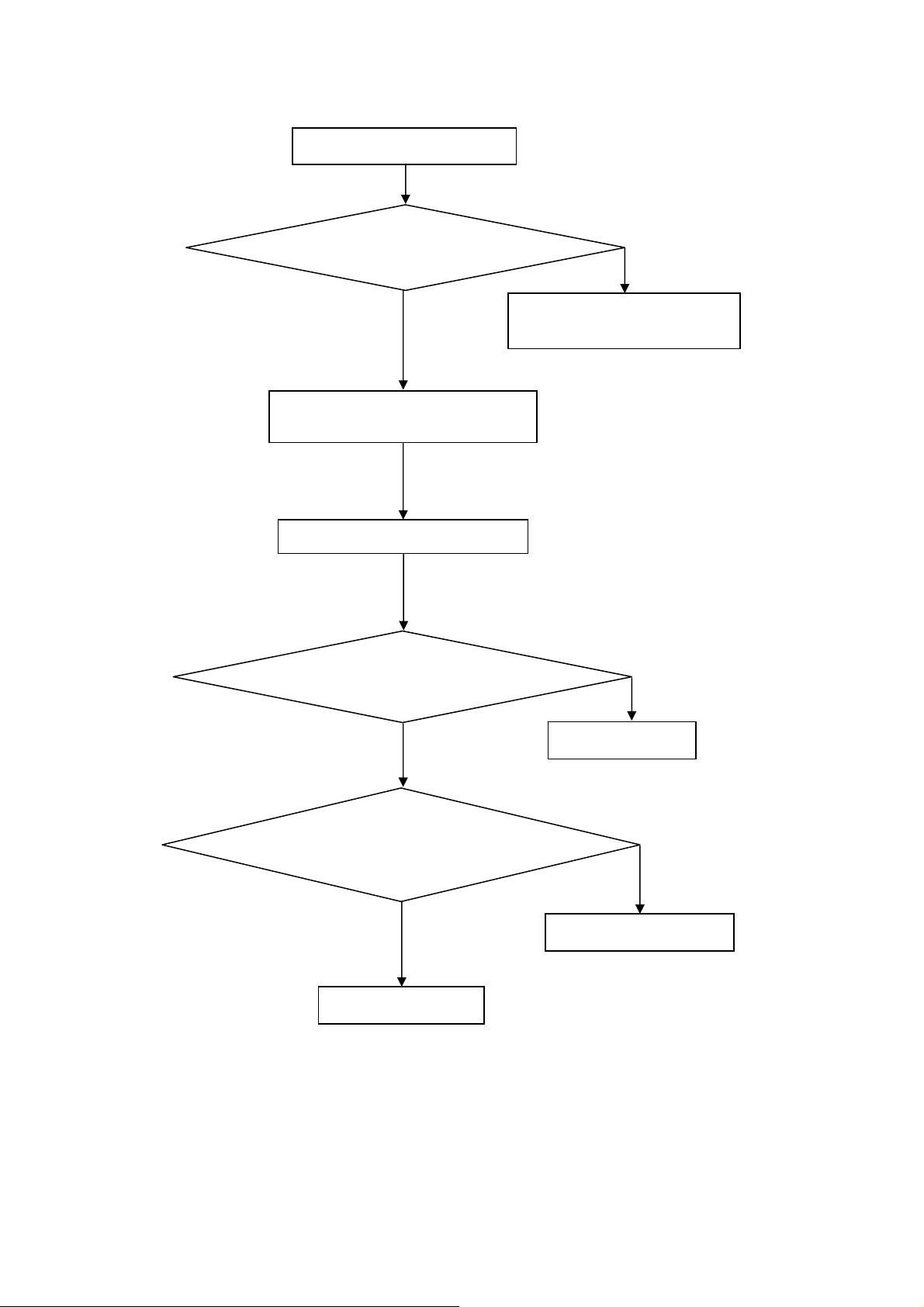
3. Abnormal display
Abnormal Display
Check the source
Yes
Enter factory mode to do
“EEPROM initial”&“Reset”
No
No
Reset the source
Check the main board
Yes
Check the LVDS cable
Yes
Check the panel
No
Replace the panel
No
Replace the main board
No
Replace the LVDS cable
14
Page 15
4. No display
No display (LED blue)
Check TV is under control and power
on/off by remote control and power key?
Yes
Check the LVDS cable
Yes
Yes
Check the backlight is
“On”?
No
Reinsert or replace the
LVDS cable
No
No
Check the B/L
signal is available?
Yes
Replace the main board
No
Replace main board
Panel Vcc = 12V?
Yes
Replace the Panel
No
Replace the main board
Power board output=24V?
Yes
Replace the Panel
Replace the power board
No
15
Page 16
5. Sound problem
No sound or sound abnormal
Check the audio source connection
and the TV system are correct?
Yes
Check the TV is muted, adjust the
volume or enter the menu to reset?
No
No
Reinsert the audio cable or
change the TV system
Enter factory mode to do “Reset”
No
Check the cable between the
speakers and main board is OK?
Yes
Check the speaker resistance value is in spec
(Remark: The value is marked on the speaker)?
Yes
Replace the cable
Replace the main board
No
No
Replace the speaker
16
Page 17
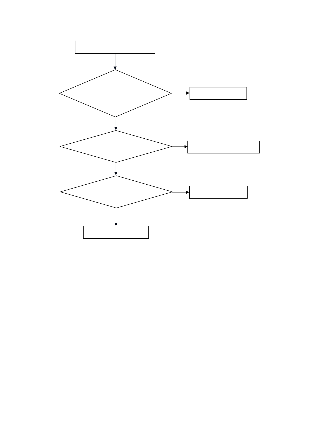
6. Remote control malfunction
Remote Control malfunction
Check the remote control battery is
not properly placed or no power?
No
Use the other remote controls
No
Whether the IR board is
abnormal?
No
Replace the main board
Yes
Replace the battery
Yes
Replace the remote control
Yes
Replace the IR board
17
Page 18
7. OSD is unstable or can’t work normally
OSD is unstable or can’t work normally
Key board connected properly?
Yes
Buttons are OK?
Yes
Key board is OK?
Yes
Enter factory mode to do “Reset”
No
No
No
No
Reconnect the key board
Replace the button function
Replace the key board
Replace the main board
18
Page 19
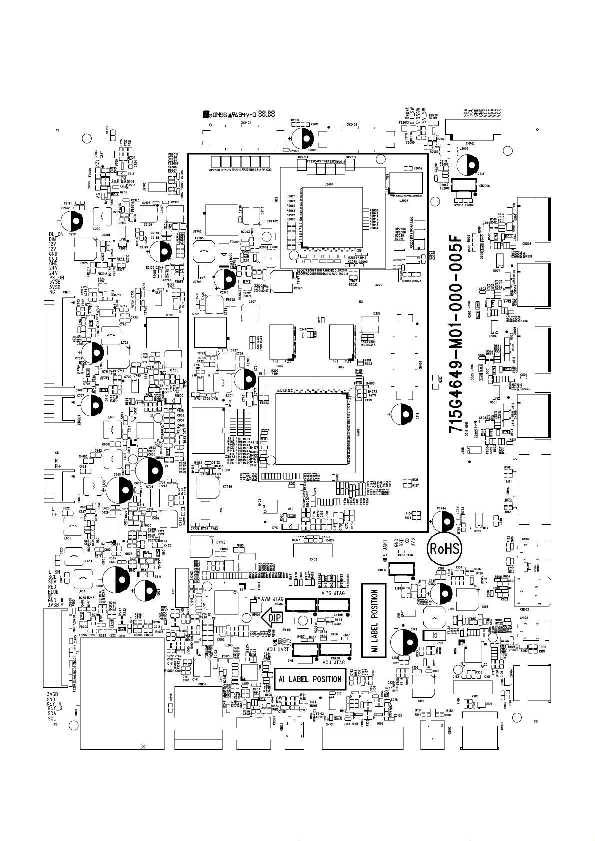
6. PCB Layout
6.1 Main Board
715G4649M01000005F
19
Page 20
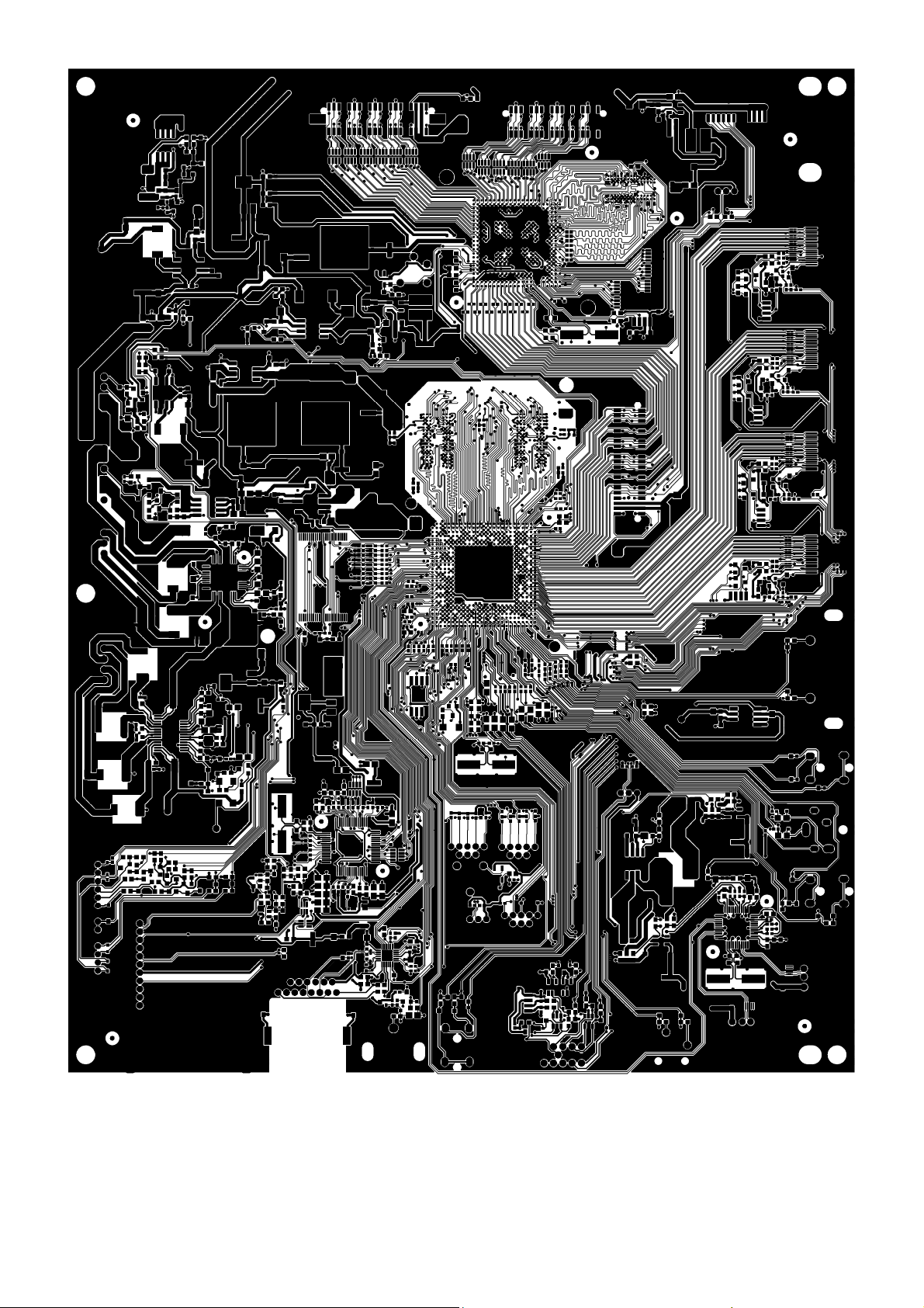
20
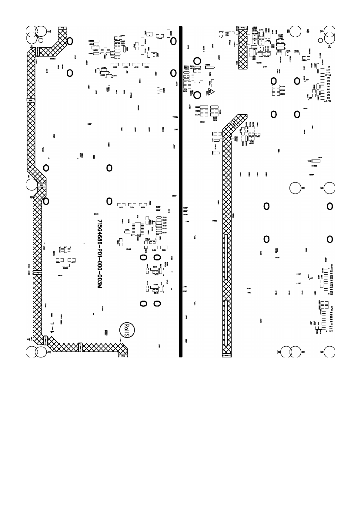
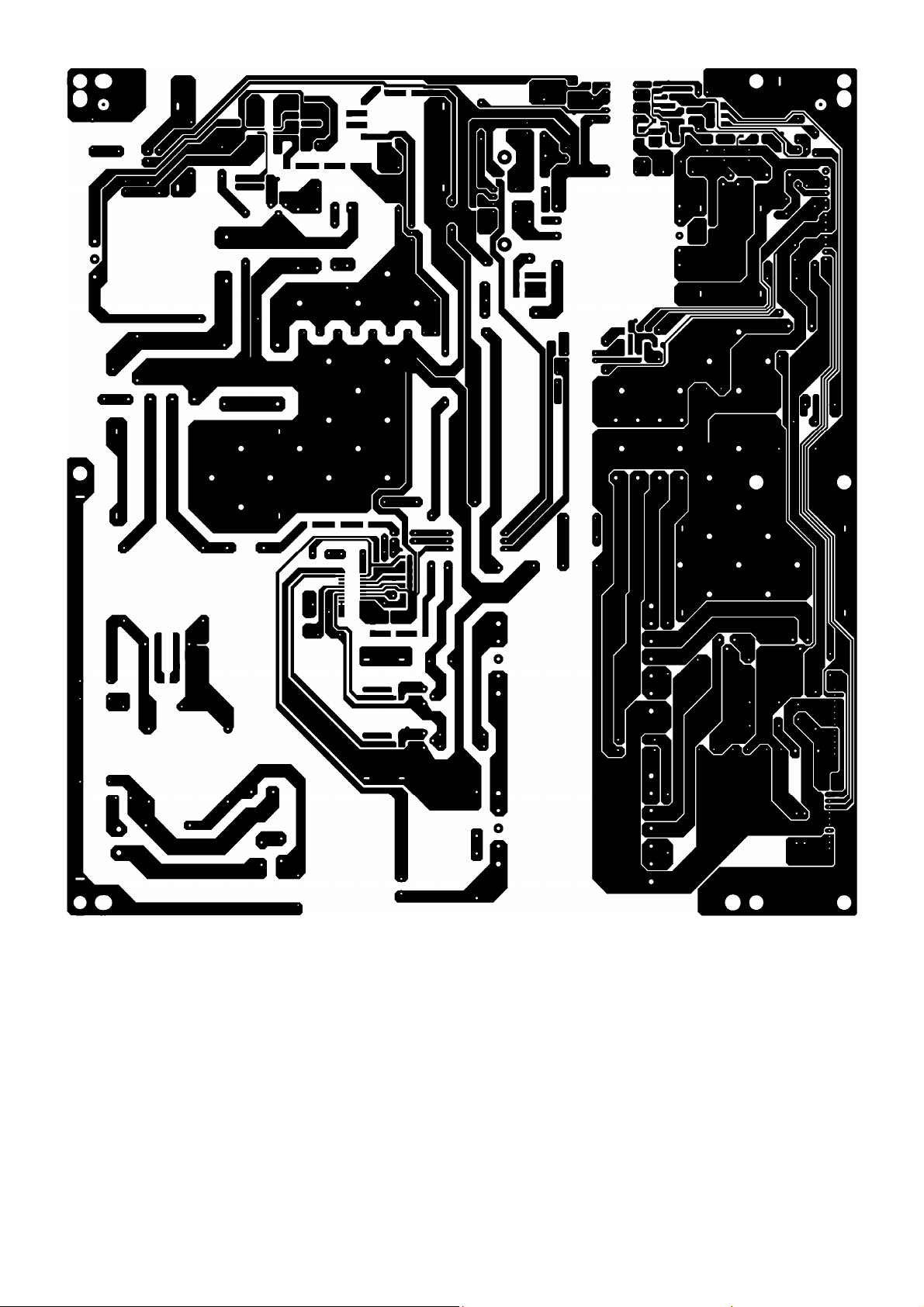
Page 21
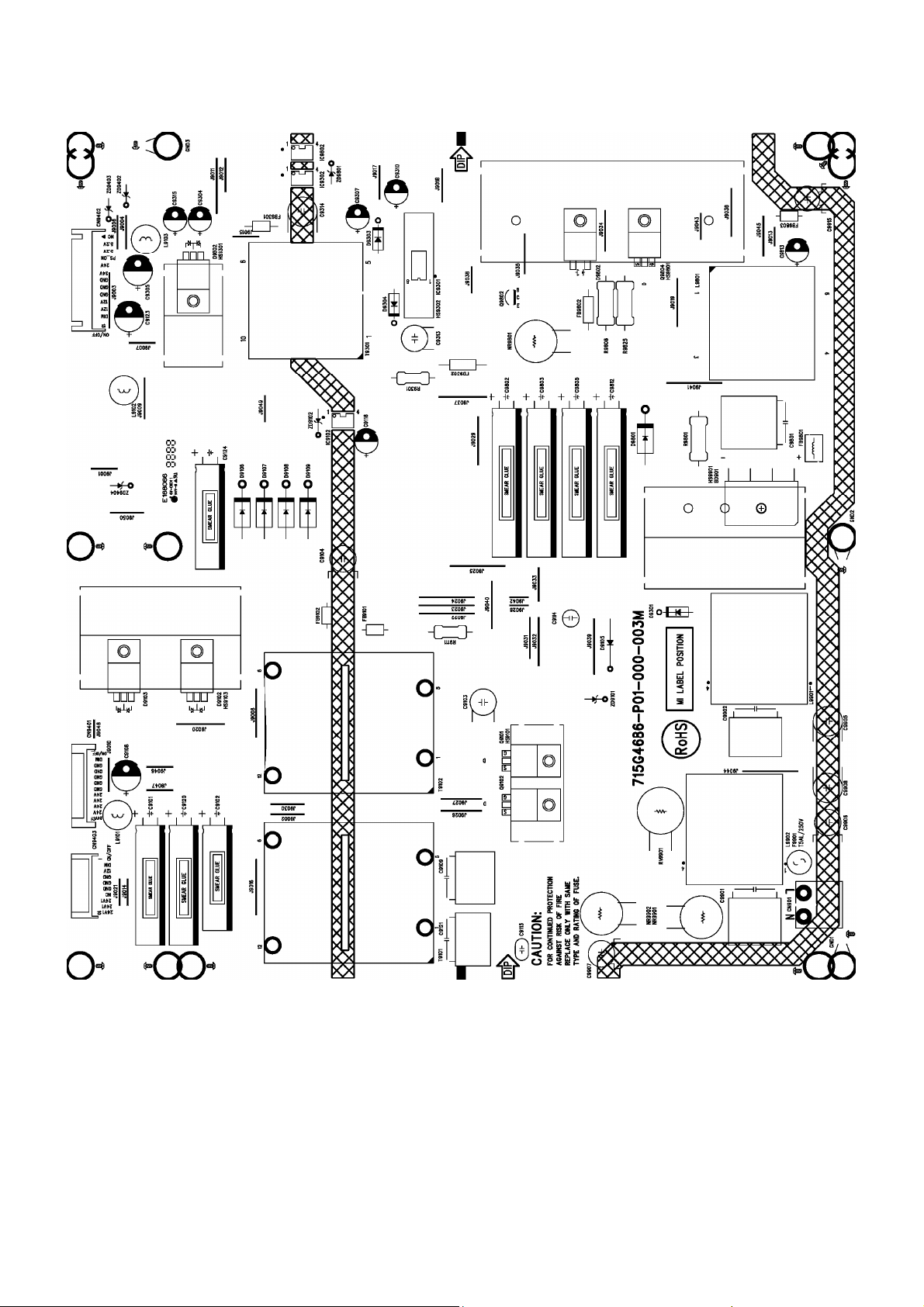
6.2 Power Board
715G4686P01000003M
21
Page 22
22 23
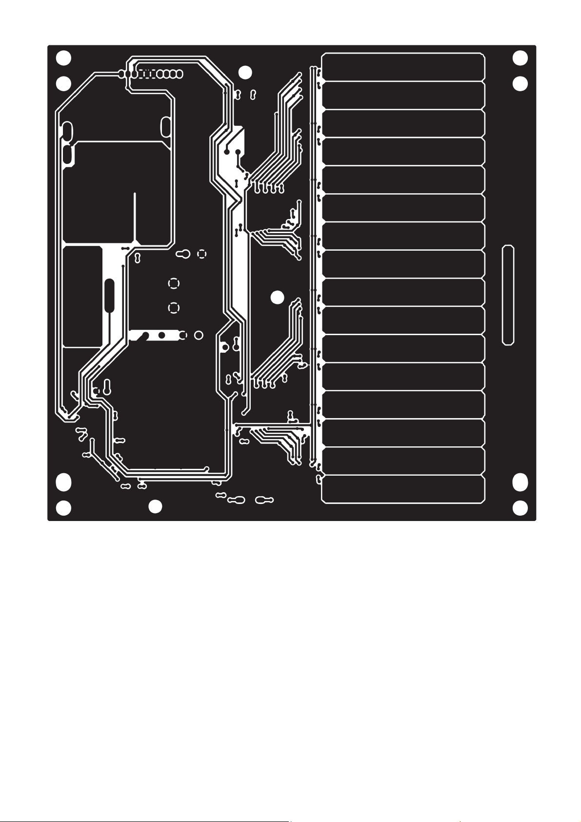
Page 23
Page 24
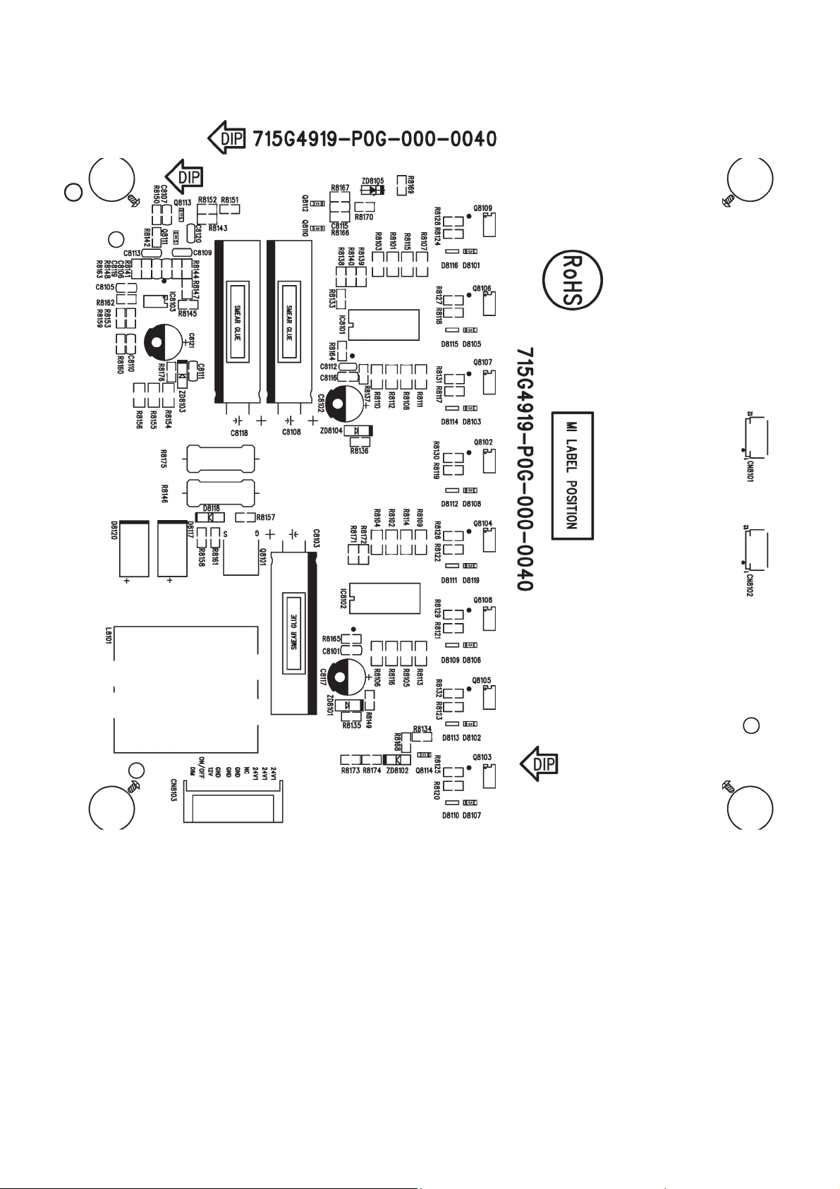
715G4919P0G0000040
24
Page 25
25 26
Page 26
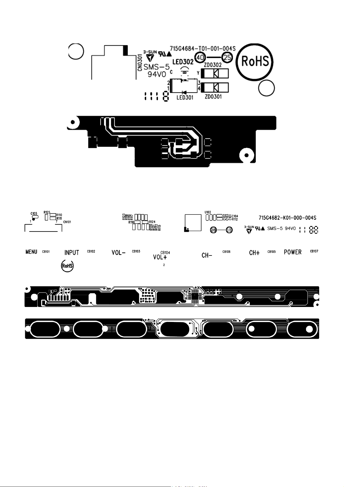
6.3 LED Board
715G4684T01001004S
6.4 Key Board
715G4682K01000004S
Page 27
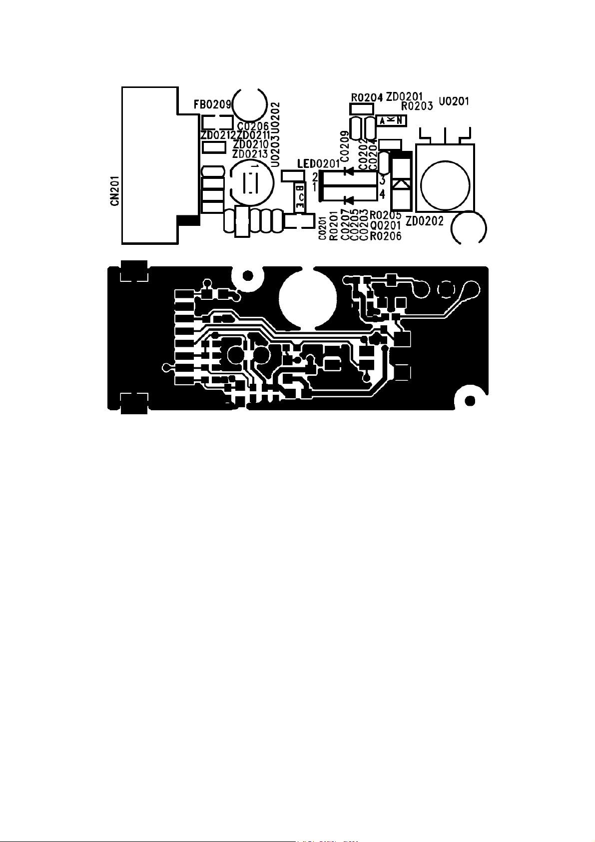
6.5 IR Board
715G4781R02000005F
27
Page 28

7. Adjustment
No need to adjust ADC and White Balance.
28
Page 29
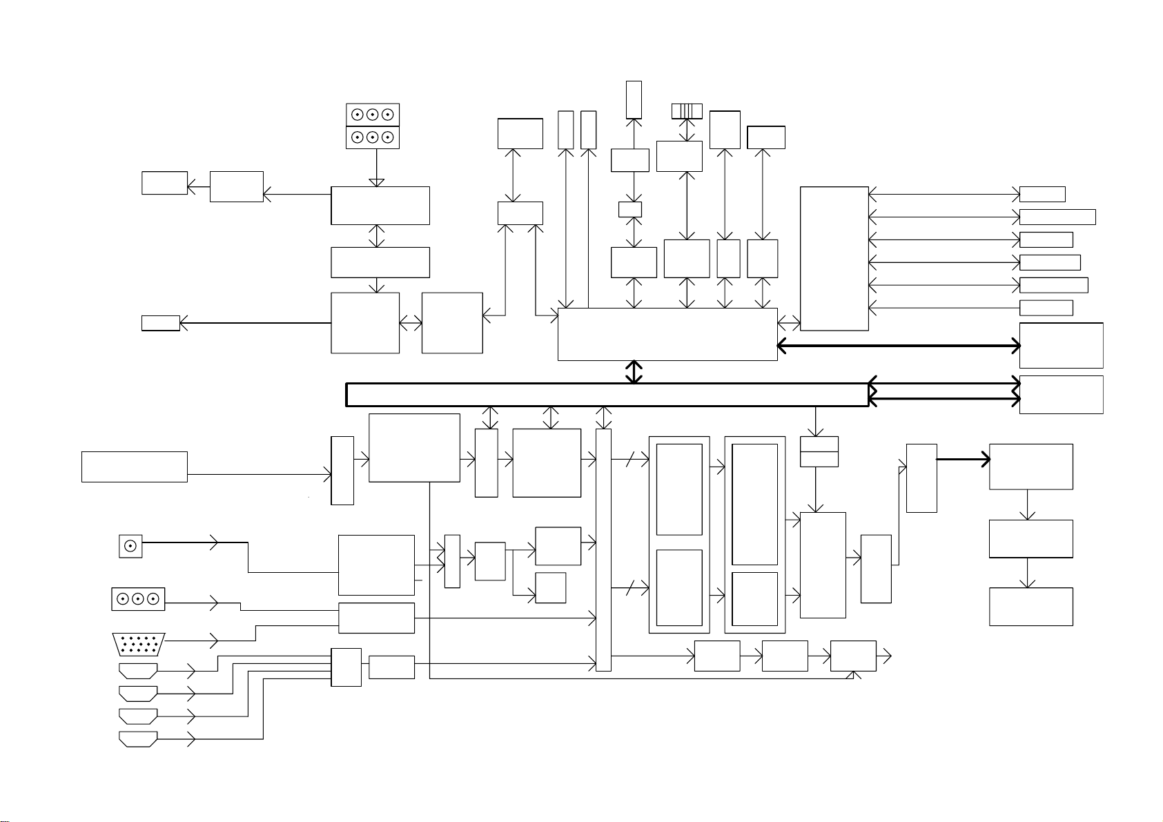
8. Block Diagram
2 Speakers
SPDIF
OUTPUT
EUA2110
AUDIO AMP
AUDIO IN
Analog Audio A FE
Audio
Post-processing
MSP
AV MIPS
EJTAG
EJT A G
GPIO
GPIO
PWM
USB HUB
PWM(3)
UMAC
10M/100M
Ethernet
USB
PHY
LAN8720A
PHY
USB
MA C
Ethernet
MA C
Main CPU
MIPS 24Kc @ 500MHz
I2C
BUS
I2C
UART
UA RT
STANDBY
MCU
(8051)
RTC
IR Decode
Key Pad
CEC
Slow ADC
UART
I2C
SPI Interface
GPIO
MIPS b us
MD: 32bits
MA: 15bits
IR IN
RS232
DDC Channel
SPI Flash
STB GPIO
HDMI CEC
IR Sensor
NAND flash
DDR3(1066)
CVBS IN
YPbPr IN
PC RGB
HDMI_1
HDMI_2
HDMI_3
HDMI_4
LG: TDTK-H801F
VIF/SIF
ATSC,DVB-T/C
VSB/QAM
Demodulator
AFE
10-bit,54MHz
Analog Video Mux
AFE:108MHz
10-bits
Analog Video Mux
MUX
HDMI 1. 4
Transport Demux
10-Bit
3-D
Comb
MUX
Component/PC RGB
Multi-Format
Video decoder
MPEG-2,H.264
VC-1 ,DivX
JPEG Assist
etc.
Video
Decoder
RM
VBI
Slicer
29
1080p@60Hz
30 bits
1080p@60Hz
SELECT
30 bits
MAIN
1:Y UV/RGB
Of fset &Gain
2:IC SC
3:H f ilter
4:H/ V Scaler
5:Mov ie Motor
Edge
PIP
1:Y UV/RGB
Of fset &Gain
2:IC SC
3:Scaler
CV BS
Out
Scaler
MAIN
1:ESR I I
2:DCRe
9th genration
3:IPC
4:Super Scaler
5:Color
6:HV s harpness
7:TNR,SNR
MMR, MBN R
PIP
Brightness
Color
Contrast
Tint
TV
Encoder
H&V
OSD sc aler
H&V
Blender
1:Gamma
2:Whit e
balance
3:12-bit
resolution
4:RGB
process ing
5:xv YCC
6:2x c olor
Mat rix
OSD1-2
RGB
Video
DA C
Hal o
Fr ee
ME/MC
FRC
Dua l
LVDS
1:SSC
2:10-bits
3:1080p
Mux&6B
LVDS OU T
1080P 10-bit 60Hz
FRC9459S
LVDS OUT
1080P 120HZ
Gain
Page 30
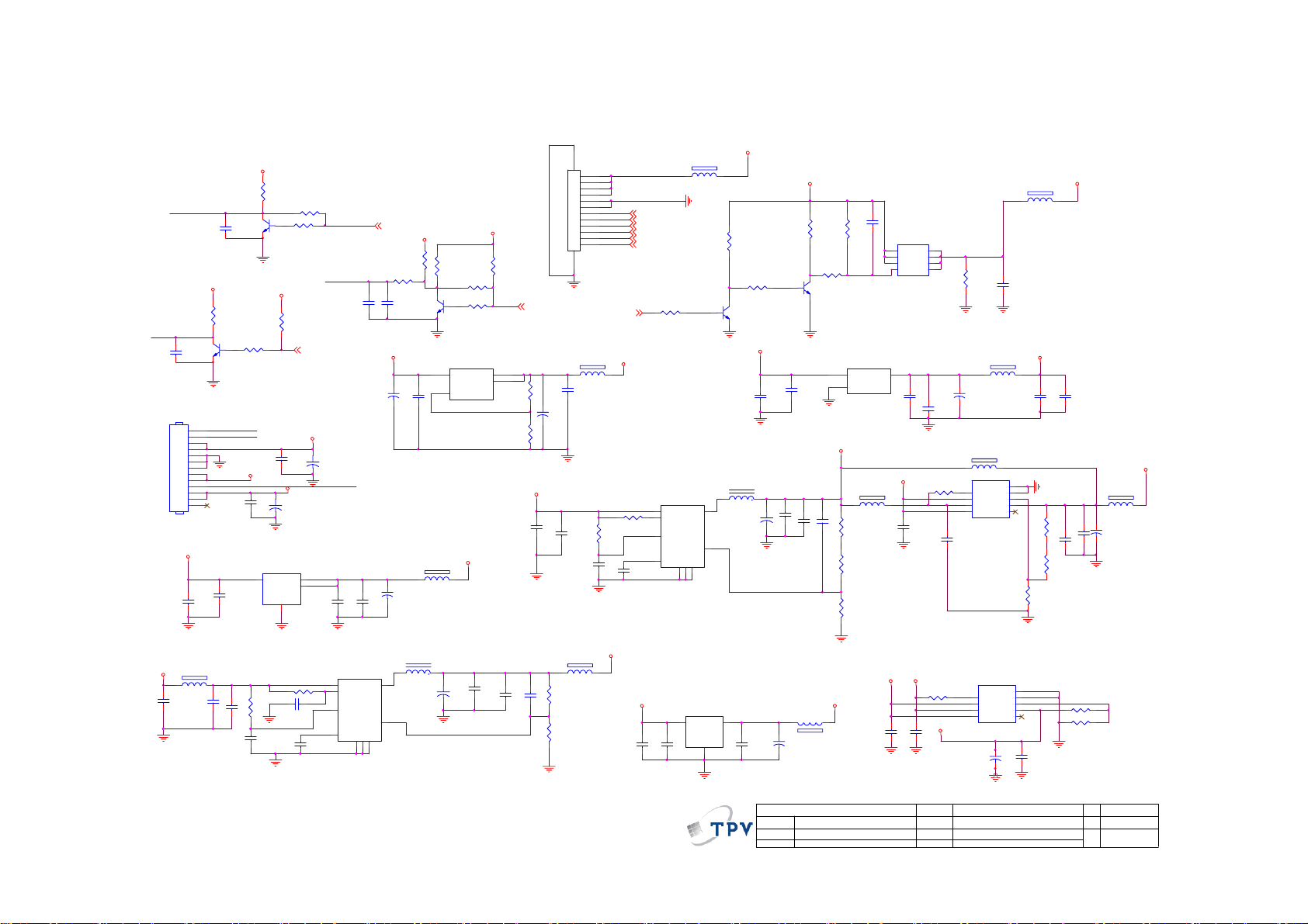
9. Schematic Diagram
9.1 Main Board
715G4649M01000005F
5VSB_IN
R703
10K 1/10W
PWR_ON
C708
0.1uF 50V
Q702
PMBS3904
BL_ON1
CN701
C723
0.1uF 50V
5V_SW
C705
0.1uF 50V
CONN
5VSB_IN
0 OHM
FB701
1 2
C722
0.1uF 50V
5V_SW
R702
10K 1/10W
1
2
3
4
5
6
7
8
9
10
11
12
13
0.1uF 50V
C712
10uF 10V
Vout = 0.8x(1+ R712/R713)=1.066V
V_3.3
R701
Q701
1K 1/16W
PMBS3904
BL_ON1
BL_PWM
C703
0.1uF 50V
+24V_AMP
C706
10 OHM 1/10W
C713
1UF16V
0.1uF 50V
+
G1117-33T63Uf 1A/3.3V SOT-223
U704
VI3VO
C724
10uF 10V
C714
1
R716
0.1uF 50V
GND
10K 1/10W
C718
R709
R724
10K 1/10W
5VSB_IN
C707
470uF 10V
4
R711
0.1uF 50V
NC
R704
1K 1/16W
BL_PWM
100P 50V
BL_ON/OF F# 15
V12
C704
+
470uF 16V
PWR_ON
C725
2
4
0.1uF 50V
8
5
1
2
C715
C711
10uF 10V
AT1529F11U
VIN
EN
VCC
REF
PS_ON# 17
5V_SW R749
10K 1/10W
R705
1K 1/10W
R706
C710
NC 4.7UF 16V
V_3.3
0.1uF 50V
C7737
C7740
+
100uF/16V
Linear equation: Vout=1.25v *(1+Rdown/Rup)
33mA Max
C726
PWM 1M
U705
PGND
6
LX
FB
GND
Thermal Pad
3
9
FB719
1 2
120R/3000mA
+
C747
47uF/16V
L701 2.2uH 30%
7
C721
470uF 10V
4
75% Efficent at 1.05V 2.3A
R714
NC
R707
R708
Q703
PMBS3904
U715
3
VIN
VOUT
1
GND/adj
G1117T63Uf
10 OHM +-1% 1/ 10W
3.3VSB
+
C743
22uF 10V
V_3.3
NC
1K 1/16W
2
4
TH
R710
10K 1/10W
470OHM1/10W
R753
C748
10uF 10V
0.1uF 50V
C717
NC 150pF 50V
C720
CN702
NC
BRT_CTRL 14,15
R754
C7739
+
100uF/16V
5V_SW
C733
1UF16V
2300mA Max
1 2
R712
3.3K +- 1% 1/10W
R713
9.1KOHM + -1% 1/10W
12
11
10
9
8
7
6
5
4
3
2
1
13 14
60mA Max
120OHM
FB114
1 2
C7738
0.1uF 50V
R720
10 OHM 1/10W
C742
0.1uF 50V
SX_PWRON#17
+1.2V
10K 1/10W
R721
0.1uF 50V
For demodulator
C751
MEMC_ SCL 16 ,24
MEMC_ SDA 16, 24
MEMC5V_SW# 16,23
V105_SW# 16,23
V105DLL_SW# 16,23
RESET_FRC# 17 ,24
R746
10K 1/10W
PWM 1M
AT1529F11U
U707
8
VIN
5
EN
1
VCC
2
REF
PGND
6
1 2
Vout = 0.8x(1+ (R719+R723)/R718)=1.52V
95% Efficent at 3.3V 1A
120OHM
VD_CORE
FB702
5V_SW
C739
C738
0.1uF 50V
10uF 10V
NC
FB720
7
LX
4
FB
GND
Thermal Pad
3
9
G1084-25TU3Uf
U708
VIN3VOUT
GND
1
MEMC_ 5V1
5VSB_IN
R745
10K 1/10W
10K 1/10W
R748
10K 1/10W
Q711
PMBS3904
5V_SW
C729
0.1uF 50V
L702 2.2uH 30%
C749
100uF/16V
500mA Max
2
C737
0.1uF 50V
0.1uF 50V
C719
+
C745
22uF 10V
NC 150pF 50V
1 2
FB703
+
C736
47uF/16V
T P V ( Top Victory Electronics Co . , Ltd. )
絬 隔 瓜 絪 腹
Key Component
03: Main Power
Date
PMBS3904
C727
10uF 10V
C734
0 OHM
NC 100K 1/10W
R234
0.1uF 50V
R743
100K 1/10W
Q710
U706
3
1
AIC1084-33GMTR
3V3_SW
R719
R723
300R 1/10W 1%
2.4KOHM + -1% 1/10W
R718
3K +-% 1/10W
V_2.5
C709
AO4449 -7A/-30V
Q709
1
S
D
2
S
D
3
S
D
4
G
D
450mA Max
10uF
C730
2
VIN
VOUT
ADJ
C728
0.1uF 50V
5V_SW
NC 120OHM
FB706
1 2
C7743
NC
5V_SW
V_2.5
10K+-5%1/16W
C740
C7742
10uF
1UF 10V
Vo=0.8(1+R752/R751)=1.14V
OEM MODEL
TPV MO DEL
PCB NAME
Sheet
8
7
6
5
1200mA Max
NC
R755
R750
VA_1.1
R744
10K 1/10W
C7741
1UF 10V
120OHM
FB722
1 2
+
C750
47uF/16V
120OHM
FB707
1 2
U703
9
E-Pad
C752
NC
1
2
3
NC
POK
VEN
VIN
VPP4NC
NC
GND
ADJ
8
7
6
VO
5
NC
R722
Vo=1.25(1+R_down/R_up)
U701
E-Pad
1
POK
GND
2
VEN
ADJ
3
VIN
VO
VPP4NC
G9661
+
C741
C7744
10uF
47uF/16V
of
425Thursday , March 24, 2011
5V_SW
120OHM
FB721
1 2
V_3.3
C732
10uF
C731
0.1uF 50V
101 Max from 3.3V
℃
73 Max from 2.8V
℃
Out current 771mA Max
drop-V min 1V 73 /W TO263
10uF
C735
R715
202mA 50 /W
9
8
7
6
5
C716
0.1uF 50V
R717
NC
℃
R752
390 OHM +-1% 1/10W
R751
910 OHM +-1% 1/10W
+
Size
Rev
称爹
℃
120OHM
FB705
1 2
C744
47uF/16V
A3
B
<
称爹
>
V_1.5
30
Page 31

NC 0R05 1/10W
R222
3.3VSB
nc
Key _SDA
CN401
CONN
3.3VSB
R247
4.7K 1/10W
1
2
3
4
5
6
7
8
9
10
11
12
13
14
R248
R235 nc
spec 100mA max
12
Key _SDA
LightSensor_Key _SCL
for Touch key
TouchKey _VCC
Q402
2N7002
ZD208 MLVG0402
12
12
ZD207 MLVG0402
ZD209 NC MLVG0402
NC 0R05 OHM
NC
R250
4.7K 1/10W
BC857C
Q210
R233
1K 1/10W
R603
LightSensor_Key _SCL
LightSensor_Key _SDA
L_R
L_B
ZD206
1 2
LightSensor_Key _SDA
0.1uF 50V
C218
Key _POR# 13, 17
for light sensor
ZD204
NC
1 2
When you want to Write touch key(IT7235),
you should set GPIO11 (KEY_SDA_SW) to high to turn on I2C SDA switch,
when you finished touch key i2C operation,
Set GPIO 11 to low to avoid abnormal data to touch key
絬 隔 瓜 絪 腹
Key Component
TouchKey _VCC
120 OHM
FB203
L_R
1 2
L_B
SPDIF _Mute/s ensor 17,19
SCL_Dem od 12,16
SDA_Dem od 12,16
KEY_SD A_SW 13,17
T P V ( Top Victory Electronics Co . , Ltd. )
05: Key and IR
Date
TouchKey _VCC
ZD201
MLVG0402
C217
0.1uF 50V
1 2
1 2
120 OHM
31
220
R220
120 OHM
FB202
1 2
ZD205
MLVG0402
1 2
FB206
1 2
1 2
FB205
120 OHM
ZD202
MLVG0402
OEM MOD EL
TPV MODEL
PCB NAME
Sheet
PMBS3906
R242
220
3.3VSB
R218
20K 1/10W
C213
0.1uF 50V
525Monday, April 18, 2011
Q201
3.3VSB
23
Q202
PMBS3906
R243
10K 1/10W
C215
0.1uF 50V
R246
20K 1/10W
of
1
23
C216
0.1uF 50V
4.7K 1/10W
R219
4.7K 1/10W
1
R241
4.7K 1/10W
IR_D
R244
IR_D 17
R240
4.7K 1/10W
LED_R# 13,17
LED_B# 13,17
KEY_PW _SU_MENU 13, 17
KEY_VOL_C H 13,17
Custom
Size
Rev
B
<
称爹
称爹
>
Page 32

VA_1.1
V_3.3
V_2.5
FB405
120R/600mA
C409
4.7UF 10V
12
FB403
1 2
120R/600mA
C410
100N 16V
For BE test
FB407
1 2
120R/600mA
FB409
1 2
120R/600mA
FB401
12
120R/600mA
C411
10N 50V
C412
1N 50V
C403
4.7UF 10V
C402
4.7UF 10V
R401
R402
C419
4.7UF 10V
C423
4.7UF 10V
0R05 OHM
0R05 OHM
C401
100N 16V
C406
100N 16V
C415 100N 16V
C416 100N 16V
C420
100N 16V
C424
100N 16V
H21
L18
J21
L17
G23
G22
F21
K18
K17
J18
F22
E22
G21
D23
K21
N18
AVDD25 _SP16
AVSS25_SP16
AVDD33 _SP16
AVSS33_SP16
AVDD11 _SP2
AVDD11 _SP3
AVDD11 _SP4
AVSS11_SP2
AVSS11_SP3
AVSS11_SP4
INN16
INN234
AVDD33_SP234
AVSS33_SP234
VDD33_VD AC
VSS33_VDAC
Power for_
ADC1-4,6
ASXL
Analog 3.3V for DAC
27x27
(1/8)
3.3V power_
for DRX AFE
1.1V power_
for DRX AFE
3.3V analog power_
for CODEC
3.3V analog power_
for CODEC
2.5V Analog power_
for KMNP LL
2.5V Analog power_
for LPLL
SCALER TSXLFF-B1AF FFH BGA 27* 27
AVSSH_DRX
AVDDL_DRX
AVSSL_DRX
VREFAU
SGNDAU
AVDD
AVDD
AVSS
AVSS
AVSS
VSSA_LPLL
P21
P18
P24
P25
L24
L21
M24
M21
N21
N24
P22
AC24
AB21
K22
M17
AVDDH_DRX
AVDDKMNPLL
AVSSKMNPLL
VDD25_LPLL
C404
100N 16V
C407
100N 16V
C413
100N 16V
C417
100N 16V
C421
100N 16V
C425
100N 16V
C405
4.7UF 10V
C408
4.7UF 10V
C414
4.7UF 10V
C418
4.7UF 10V
C422
4.7UF 10V
C426
4.7UF 10V
FB402
120R/600mA
FB404
120R/600mA
FB406
120R/600mA
FB408
1 2
120R/600mA
FB410
1 2
120R/600mA
VA_1.1 V_2.5V_3.3
12
12
12
VD_COR EV_3.3 V_2.5
FB412
1 2
120R/600mA
FB411
1 2
120R/600mA
FB415
1 2
120R/600mA
120R/3000mA
FB417
1 2
FB418
120R/600mA
U401G SCALER TSXLFF-B1AFFFH BGA 27*27
M5
PLL_VDD
C427
4.7UF 10V
C432
4.7UF 10V
C428
1UF 10V
C433
100N 16V
C429
100N 16V
M6
AC2
AC3
PLL_VSS
AVDD_MCK2
AVSS_MCK2
2.5V Analog power
for DDRPLL
2.5V Analog power_
for DDR MCLK2 P LL
ASXL
D15
VDD33A
D16
D14
AB20
E15
E14
F14
V18
C436
4.7UF 10V
C440
10UF
12
C442
4.7UF 10V
C437
100N 16V
C441
100N 16V
C443
100N 16V
VDD33A
VSS33A
VSS33A
VDD10A
VSS10A
VDD33
3.3V power for_
USB Comm on Bloc k
VSSAC
3.3V HDMI power
1.0V HDMI power
27x27
(2/8)
2.5V power_
for LVDS1 PLL
2.5V power _
for LVDS
2.5V power_
for USB
2.5V Analog Power_
for Video AFE
AVDD25_REF_BG
AVSS25_REF_BG
VDDP
GNDP
LVDS_VDD
LVDS_VDD
LVDS_GND
LVDS_GND
VDD25
VSSA
E6
C430
J10
100N 16V
D6
F6
J9
C434
J11
100N 16V
AC21
C438
100N 16V
V17
J22
C444
M18
100N 16V
T P V ( Top Victory Electronics Co . , Ltd. )
絬 隔 瓜 絪 腹
Key Component
06: SXL power 1,2
Date
C431
4.7UF 10V
C435
4.7UF 10V
C439
4.7UF 10V
C445
4.7UF 10V
1 2
1 2
FB413
120R/600mA
FB414
120R/600mA
FB416
120R/600mA
FB419
120R/600mA
OEM MODEL
TPV MOD EL
PCB NAME
12
12
Sheet
V_2.5
heatsink
heatsink
625Wednesday , March 16, 2011
of
1
1
SHIELD
1
2
3
4
GND
GND
HS2
HS1
GND
GND
GND
GND
For U2401
2
GND
For U401
2
GND
H1
5
GND
6
GND
7
GND
8
GND
Size
A3
Rev
B
称爹
称爹
>
<
32
Page 33

U401H
VSSA1VSS
A26
AF1
FRA1116,17
F_WE16, 17
F_OE16,17
FRA816,17
FRA1416,17
FRA1316,17
FRA1516
FRA1016,17
FRA616,17
FRA716,17
FRA1216,17
FRA016,17
FRA516,17
D10
VDDCD7VDDCD8VDDCD9VDDC
VSS
VSS
VSS
VSS
J12
J13
AF26
D11
D17
D18
D19
VDDC
VDDC
VDDC
VDDC
VSS
VSS
VSS
VSS
J14
J15
J16
J17
K10
E10
E11
E17
E18
E16
VDDCE7VDDCE8VDDCE9VDDC
VDDC
VDDC
VDDC
VDDC
VSS
VSS
VSS
VSS
VSS
VSS
VSS
VSS
L10
K11
R403 4.7K 1/16W
R406 4.7K 1/16W
R409 4.7K 1/16W
R412 4.7K 1/16W
R415 4.7K 1/16W
R418 4.7K 1/16W
R421 4.7K 1/16W
R426 4.7K 1/16W
R431 4.7K 1/16W
R436 4.7K 1/16W
R441 4.7K 1/16W
R444 4.7K 1/16W
R447 4.7K 1/16W
L11
K12
K13
K14
K15
K16
F10
F11
F16
F17
VDDCF7VDDCF8VDDCF9VDDC
VDDC
VDDC
VSS
VSS
VSS
VSS
VSS
VSS
L12
L13
L14
L15
L16
R404 0R05 OHM
R407 0R05 OHM
R410 0R05 OHM
R413 NC 0R 05 OHM
R416 NC 0R 05 OHM
R419 0R05 OHM
R422 0R05 OHM
R427 0R05 OHM
R432 0R05 OHM
R437 0R05 OHM
R442 NC 0R 05 OHM
R445 0R05 OHM
R448 0R05 OHM
F18
VDDC
VDDC
VSSM9VSS
M10
3.3VSBVD_CORE V_3.3
T24
VDDF4
AB4
AC4
VDDF LASH
VDDF LASH
AA20
VDDF_STB
VDDF_STB
VDD F_ST B: fo r
3.3V STB IO
J6
VDDMG4VDDMG5VDDMH4VDDMH5VDDMH6VDDMN5VDDMP5VDDMN6VDDMP6VDDMW4VDDMW5VDDMW6VDDMY4VDDMY5VDDMY6VDDM
VDDM
VDDM: 1.5V, memory I/O powerVDDC: 1.0V, core power
SCALER TSXLFF-B1AFF FH BGA 27*27
AA7
AA17
AA18
AB18
AC18
F15
AA16
AA13
AA14
AA15
VDDC
VDDC
VDDC
VDDC
VDDC
VDDF1D5VDDF2
F20
VDDF3
VDDF3
VDDF3
VDDF3
VDD F: fo r
3.3V digital IO
ASXL
V_1.5
AA4
AA6
AA5
G6
VDDM
VDDM
VDDMR6VDDMR5VDDM
C446
4.7UF 10V
V_1.5
C455
10UF
V_3.3
4.7UF 10V
C447
10UF
C456
100N 16V
C448
10UF
C457
100N 16V
C449
10UF
C458
100N 16V
C450
10UF
C459
100N 16V
C451
100N 16V
C460
100N 16V
C452
100N 16V
C475
100N 16V
C462
100N 16V
C463
C453
10UF
100N 16V
C464
3.3VSB
100N 16V
C465
10N 50V
C466
C454
10N 50V
10N 50V
C467
10N 50V
C468
10N 50V
C476
27x27
10UF
C477
10UF
VD_COR E
10N 50V
C487
10N 50V
C488
C478
10N 50V
(3/8)
POWER/GROUND
VSS
VSS
VSS
VSS
VSS
VSS
VSSN9VSS
VSS
VSS
VSS
VSS
VSS
VSS
VSSP9VSS
VSS
VSS
VSS
VSS
VSS
VSS
VSS
VSSR9VSS
VSS
VSS
VSS
VSS
VSS
VSS
VSS
VSS
VSS
VSS
VSS
VSS
VSS
VSS
VSS
VSSU9VSS
VSS
VSS
VSS
VSS
VSS
VSS
VSS
VSS
VSSV9VSS
VSS
VSS
VSS
VSS
P10
P11
P12
P13
P14
P15
P16
N10
N11
N12
N13
N14
N16
N17
M11
M12
M13
M14
M15
M16
N15
P17
R10
R11
R12
R13
R14
R15
R16
VSS
T10
T11
T12
T14
T15
T16
T17
T13
R17
R18
U10
U11
U12
U13
U14
U15
U16
U17
VSS
VSS
VSS
VSST9VSSL9VSS
V10
U18
K9
V11
V12
V13
V14
V15
V16
C489
10UF
C479
10N 50V
C490
10UF
C480
10N 50V
C491
100N 16V
C481
Boot from SPI (System Config NAND+SPI)
R405 NC 4. 7K 1/16W
V_3.3
R408 NC 4. 7K 1/16W
R411 NC 4. 7K 1/16W
R414 4.7K 1/16W
R417 4.7K 1/16W
R420 NC 4. 7K 1/16W
R423 NC 4. 7K 1/16W
R428 NC 4. 7K 1/16W
R433 NC 4. 7K 1/16W
R438 NC 4. 7K 1/16W
R443 4.7K 1/16W
R446 NC 4. 7K 1/16W
R449 NC 4. 7K 1/16W
No Con figu re Pin
PIN
1 0 : 8bit 1 : 16bit(* )
FRA11
2
F_W E
F_OE
3
4
FRA8
5 Int erna l 8051 bu s Ma ste r/Slav e s elect ion
FRA 14 0 : Slav e 8051 1 : M ast er 8051 (*)
FRA13
6
FRA15
7
8
9
FRA_[7:6]
FRA12
10
11
FRA0
FRA5
12
MIPS Boot ROM width selectio n
Internal E2PROM or EFUSS burning mode selection
(Option 1 only used in Chip production)
EJTAG Mode Selection
Sec let int ern al 8051 bus or Sla ve I2C fo r de bug
OneNand Flash sync mode clock enable
Boot from SPI or Parallel Flash
NAND b oot e nab leFRA10
NAND T YPE
CPU Little En dian Mode enab le 0 : little endian 1 : big endian(*)
Con trol Co re M IPS Clock Sw itch
Con trol CPU_ CLK Cloc k Switch
Lexru Bus Master SelectMA STSEL
STB_EN
StandBy Mode Enable
Description & Setting(* as default setting)
0 : normal fu nction (*)
1 : burn code for eep rom
0 : non-daisy chain mode(*) 1 : dais y chain mode
0 : Disa ble Slav e I2C/Ena ble 8051
1 : Enab le Slav e I2C/ Disa ble 8051(* )
0 : ASYNC mode 1 : SYNC mod e(* )
0 : SPI Ena bled 1 : Par ralle l FLAS H Enab led (* )
0 : Disable boot from Nand(*)
1 : Ena ble b oo t fro m Nand
00 : ad dre ss mapp ing mo de 1(* )
01 : ad dre ss mapp ing mode 2
10 : ad dre ss mapp ing mode 3
11 : ad dre ss mapp ing mode 4
0 : Normal(*) 1 : Int ernal Switc h Inve rted
0 : Normal(*) 1 : Int ernal Switc h Inve rted
0 : Int ernal 8051(* ) 1 : Extern al 8051(A TE mode )
0 : disable 1 : enable(*)
100N 16V
C482
10N 50V
C492
SX_TESTMOD17
SX_TESTCON17
100N 16V
C483
10N 50V
10N 50V
C494
C493
Simulation Mode(ATE)
MASTSEL16
STB_EN17
100N 16V
100N 16V
C484
C485
10N 50V
C495
Work Mode
Normal Mo de
EJT A G Mo de
Scan Mode
100N 16V
C486
10N 50V
10N 50V
C497
C496
TESTMOD TESTCON
0
0
1
R424 0R 05 OHM
R429
0R05 1/10W
R439
NC 0R05 OHM
0
1
0
11
3.3VSB
R425 N C 4.7K 1/16W
R430
4.7K 1/16W
R435 N C 4.7K 1/16WR434 0R 05 OHM
R440 4. 7K 1/16W
33
T P V ( Top Victory Electronics Co . , Ltd. )
絬 隔 瓜 絪 腹
Key Component
07: SXL power 3
Date
OEM MODEL
TPV MO DEL
PCB NAME
Sheet
A3
Size
Rev
B
<
称爹
称爹
725Wednesday , March 16, 2011
of
>
Page 34

Modify @10/12
HP_RXD13,15
VGA_SDA_IN
VGA_SCL_IN
U105
I/O1
I/O4
GND
VDD
I/O23I/O3
4.7K+-5%1/16W
2/R, 5/L,3/V
Modify @10/12
PHONEJ ACK
CN122
R104
1
2
6
5
4
AZC199-04S
12
FB102
120R/600mA
12
FB101
120R/600mA
Place 75 Ohm at Connector side
CVBS & R/L
3
5
4
2
1
ZD103
MLVG0402
1 2
VGA_HSIN
VGA_VSIN
1 2
FB113
R105
4.7K+-5%1/16W
CVBS2
AV2_L
AV2_R
120 OHM
R149
R148
2.2K 1/10W
2.2K 1/10W
R138
10K+-5%1/16W
CVBS2
MLVG0402
10N 50V
CN101
11
12
13
14
15
D-SUB 15P
HP_TXD13, 15
Modify @10/12
C154
22pF 50V
I2C Address: 1010 000x
8
VCC
7
WP
6
SCL
5
M24C02-WMN6TP
ZD106
1 2
AV2_L
AV2_R
C1105
1716
1
6
2
7
3
8
4
9
5
10
U103
C155
22pF 50V
U102
1
A0
2
A1
3
A2
VSS4SDA
5VSB_IN
R1122
75OHM +-5% 1/10W
CVBS2_GND
R1111
82K 1/10W
R1108
82K 1/10W
C1106
10N 50V
VGA_RIN
5VSB_IN
2 4
100K 1/10W
Place 75 Ohm at Connec tor side
VGA_GIN
VGA_BIN
VGA_5V
C143
0.1uF 50V
C142
0.1uF 50 V
3 5
SN74LVC1G17DBVR
VGA_5V
VGA_VCC
layout close to U401
100OHM1/16W
R1109
C101
220N16V
R1121
2
1
5VSB_IN
2 4
D101
1
BAT54C
R1110
100K 1/10W
U106
4
I/O23I/O3
5
GND
VDD
6
I/O1
I/O4
AZC199-04S
U104
3 5
SN74LVC1G17D BVR
5VSB_IN
2
3
75OHM +-5% 1/10W
AV2_LIN 15
AV2_RIN 15
R101
R102
75OHM +-5% 1/10W
VGA_VCC
1K 1/10W
R167
1K 1/10W
R166
CVBS2_IN 15
Close to U401
R1123
R1124
R1125
R103
75OHM +-5% 1/10W
PC_VS_IN 17
C157
NC 22pF 50V
PC_HS_I N 17
C156
NC 22pF 50V
0R05 1/10W
0R05 1/10W
0R05 1/10W
PHONEJ ACK
CN112
YPBPR Video
YPBPR Audio
CVBS & R/L
PHONEJ ACK
CN121
34
layout close to U401
100OHM1/16W
C227 NC 22pF 50V
C226
NC 22pF 50V
NC 22pF 50V
C225
Modify @10/12
Y
3
PB
5
4
PR
2
1
JACK
B
A
CN116
Place 75 Ohm at Connector side
Modify @10/12
3
5
4
2
1
R139
CVBS1
AV1_L
AV1_R
R140100OHM1/16W
PC_R_IN 15
PC_G_IN 15
R141100OHM1/16W
PC_B_IN 1 5
Y
Y_GND
MLVG0402
PB_GND
PR_GND
CVBS1
ZD105
MLVG0402
10N 50V
08: Analog input
ZD101
PB
ZD102
PR
ZD104
COM_AUR
COM_AUL
1 2
AV1_L
AV1_R
C1107
MLVG0402
MLVG0402
3
4
1
2
T P V ( Top Victory Electronics Co . , Ltd. )
絬 隔 瓜 絪 腹
Key Component
Date
PHONEJ ACK
CN102
R162
75OHM +-5% 1/10W
1 2
R164
75OHM +-5% 1/10W
1 2
R172
75OHM +-5% 1/10W
1 2
82K 1/10W
R169
R168
82K 1/10W
100K 1/10W
R174
75OHM +-5% 1/10W
CVBS1_GND
82K 1/10W
C1108
10N 50V
R170
R175
82K 1/10W
R176
R177
100K 1/10W
2
3
1
OEM MOD EL
TPV MODEL
PCB NAME
VGA_AUR_O
VGA_AUL_O
R171
100K 1/10W
Sheet
180K 1/10W 5%
R147
R150
180K 1/10W 5%
R152
100K 1/10W
100OHM1/16W
R173
layout close to U401
R178
100K 1/10W
825Monday, April 18, 2011
of
R151
100K 1/10W
100OHM1/16W
HD_RIN 15
HD_LIN 15
CVBS1_IN 15
AV1_LIN 15
AV1_RIN 15
PC_RIN 15
PC_LIN 15
R161
R163
100OHM1/16W
R165
100OHM1/16W
Y1_IN 15
PB1_IN 15
PR1_IN 15
layout close to U401
A3
Size
Rev
B
<
称爹
称爹
>
Page 35

HDMI INPUT 0
21
SHLD1
23
SHLD3
22
SHLD2
20
SHLD0
cost down 0.034
DDC_GND
TMDSCCSHLD0
TMDS C+
TMDSD0-
DSHLD2
TMDSD0+
TMDSD1-
DSHLD1
TMDSD1+
TMDSD2-
DSHLD0
TMDSD2+
CN506
HDMI
VCC5
HPD
SDA
SCL
CEC
3.3VSB
5VSB_IN
NC M24C0 2-WMN 6TP
HDMI0_HPD
HDMI0_5VIN
19
18
17
16
15
14
NC
13
12
11
10
9
8
7
6
5
4
3
2
1
HDMI0_RXC-
HDMI0_RXC+
HDMI0_RX0-
HDMI0_RX0+
HDMI0_RX1-
HDMI0_RX1+
HDMI0_RX2-
HDMI0_RX2+
HDMI0_SDA
HDMI0_SCL
C501 10 0N 16V
HDMI0_CEC
R538 0R05 OHM
R539 0R05 OHM
R541 0R05 OHM
U501
1
A0
VCC
2
A1
WP
3
A2
SCL
VSS4SDA
I2C Address: 1010 000x
HDMI0_DDC_SDA
HDMI0_DDC_SCL
HDMI_HEAC+ 15
HDMI_CEC 10,17
8
7
6
5
R533 NC 4.7K 1/ 16W
R535
NC
R537 4.7K 1/10W
R542 4.7K 1/10W
5VSB_IN
FB501
1 2
120R/600mA
HDMI0_5VIN
HDMI0_HPD
C502
220N16V
HDMI0_CEC HDMI0_CEC
HDMI0_SCL HDMI0_SCL
HDMI0_5VI N HDMI0_5VIN
D501
1
R536
1K 1/16W
HDMI0_5VI N
2
3
BAT54C
R544 10K+-5%1/16W
Q501
PMBS3904
1
IN1
2
IN2
4
IN3
IN45OUT4
U513 NC RClamp0524P.TCT
8
GND
OUT1
OUT2
OUT3
GND
3
R540
10K+-5%1/16W
R543
100OHM1/16W
10
9
7
6
HDMI0_5VI N 15
RX0_HOTPLUG 17
HDMI0_SDAHDMI0_SDA
HDMI0_D DC_SCL
HDMI0_D DC_SDA
HDMI0_RXCHDMI0_RXC+
HDMI0_RX0HDMI0_RX0+
HDMI0_RX1HDMI0_RX1+
HDMI0_RX2HDMI0_RX2+
1
2
4
U502 NC R Clamp0524P.TCT
1
2
4
U503 NC R Clamp0524P.TCT
R532 4 .7K 1/10W
Q505
2N7002
R534 4 .7K 1/10W
Q506
2N7002
IN1
OUT1
IN2
OUT2
IN3
OUT3
IN45OUT4
GND
GND
3
8
IN1
OUT1
IN2
OUT2
IN3
OUT3
IN45OUT4
GND
GND
3
8
DDC0_SCL 17
DDC0_SDA 17
10
9
7
6
10
9
7
6
HDMI0_RXC- 15
HDMI0_RXC+ 15
HDMI0_R X0- 15
HDMI0_R X0+ 15
HDMI0_R X1- 15
HDMI0_R X1+ 15
HDMI0_R X2- 15
HDMI0_R X2+ 15
HDMI INPUT 1
SHLD1
SHLD3
SHLD2
SHLD0
CN507
HDMI
HPD
VCC5
DDC_GND
CEC
TMDSCCSHLD0
TMDS C+
TMDSD0-
DSHLD2
TMDSD0+
TMDSD1-
DSHLD1
TMDSD1+
TMDSD2-
DSHLD0
TMDSD2+
21
23
22
20
SDA
SCL
5VSB_IN
NC M24C0 2-WMN 6TP
HDMI1_HPD
HDMI1_5VIN
19
18
17
16
15
14
NC
13
HDMI1_RXC-
12
11
HDMI1_RXC+
10
HDMI1_RX0-
9
8
HDMI1_RX0+
7
HDMI1_RX1-
6
5
HDMI1_RX1+
4
HDMI1_RX2-
3
2
HDMI1_RX2+
1
HDMI1_SDA
HDMI1_SCL
HDMI1_CEC
R549 0 R05 OHM R501
R551 0 R05 OHM
R502 0 R05 OHM
U504
1
A0
VCC
2
A1
WP
3
A2
SCL
VSS4SDA
I2C Address: 1010 000x
HDMI1_D DC_SDA
HDMI1_D DC_SCL
HDMI_CEC 10,17
8
7
6
5
R545 N C 4.7K 1/16W
R547
NC
R550 4.7K 1/10W
R503
5VSB_IN
4.7K 1/10W
FB502
1 2
120R/600mA
HDMI1_HPD
C503
220N16V
HDMI1_CEC HDMI1_CEC
HDMI1_SCL
HDMI1_SDA HDMI1_SDA
HDMI1_5VI N HDMI1_5VI N
D502
1
HDMI1_5VI N
R548
1K 1/16W
HDMI1_5VIN
2
3
BAT54C
R504 10 K+-5%1/16W
Q502
PMBS3904
1
IN1
2
IN2
4
IN3
IN45OUT4
8
U514 NC RC lamp0524P.TCT
HDMI1_5VI N 15
10K+-5%1/16W
100OHM1/16W
10
HDMI1_SCL
9
7
6
09: HD MI port 1, 2
RX1_HOTPLUG 17
R505
OUT1
OUT2
OUT3
GND
GND
3
T P V ( Top Victory Electronics Co . , Ltd. )
絬 隔 瓜 絪 腹
Key Component
Date
HDMI1_DDC_SCL
HDMI1_DDC_SDA
HDMI1_RXCHDMI1_RXC+
HDMI1_RX0HDMI1_RX0+
HDMI1_RX1HDMI1_RX1+
HDMI1_RX2HDMI1_RX2+
OEM MO DE L
TPV MODEL
PCB NAME
Sheet
925Tuesday , March 01, 2011
3.3VSB
R552 4.7K 1/10W
Q507
2N7002
R546 4.7K 1/10W
Q508
2N7002
1
IN1
2
IN2
4
IN3
IN45OUT4
U505 NC R Clamp0524P.TCT
1
IN1
2
IN2
4
IN3
IN45OUT4
U506 NC RClamp0524P.TCT
of
10
OUT1
9
OUT2
7
OUT3
6
GND
GND
3
8
10
OUT1
9
OUT2
7
OUT3
6
GND
GND
3
8
DDC1_SCL 17
DDC1_SDA 17
HDMI1_RXC- 15
HDMI1_RXC+ 15
HDMI1_RX0- 15
HDMI1_RX0+ 15
HDMI1_RX1- 15
HDMI1_RX1+ 15
HDMI1_RX2- 15
HDMI1_RX2+ 15
Size
A3
Rev
B
称爹
称爹
>
<
35
Page 36

HDMI INPUT 2
21
23
22
20
HDMI INPUT 3
21
SHLD1
23
SHLD3
22
SHLD2
20
SHLD0
CN509
SHLD1
SHLD3
SHLD2
SHLD0
CN508
HDMI
VCC5
DDC_GND
TMDSCCSHLD0
TMDSC+
TMDSD0-
DSHLD2
TMDSD0+
TMDSD1-
DSHLD1
TMDSD1+
TMDSD2-
DSHLD0
TMDSD2+
HDMI
VCC5
DDC_GND
TMDSCCSHLD0
TMDSC+
TMDSD0-
DSHLD2
TMDSD0+
TMDSD1-
DSHLD1
TMDSD1+
TMDSD2-
DSHLD0
TMDSD2+
HPD
SDA
SCL
NC
CEC
HPD
SDA
SCL
CEC
19
18
17
16
15
14
13
12
11
10
9
8
7
6
5
4
3
2
1
5VSB_IN
NC M24C02-WMN6TP
HDMI2_HPD
HDMI2_5VIN
19
18
17
16
15
14
NC
13
HDMI2_RXC-
12
11
HDMI2_RXC+
10
HDMI2_RX0-
9
8
HDMI2_RX0+
7
HDMI2_RX1-
6
5
HDMI2_RX1+
4
HDMI2_RX2-
3
2
HDMI2_RX2+
1
HDMI3_RXC-
HDMI3_RXC+
HDMI3_RX0-
HDMI3_RX0+
HDMI3_RX1-
HDMI3_RX1+
HDMI3_RX2-
HDMI3_RX2+
HDMI3_HPD
HDMI3_5VIN
HDMI3_SDA
HDMI3_SCL
HDMI3_CEC
HDMI2_SDA
HDMI2_SCL
HDMI2_CEC
R511 0R05 OHM
R513 0R05 OHM
R515 0R05 OHM
R524 0R05 OHM R525 4. 7K 1/10W
R526 0R05 OHM
R528 0R05 O HM
U507
1
A0
VCC
2
A1
WP
3
A2
SCL
VSS4SDA
I2C Address: 1010 000x
HDMI2_DDC_SDA
HDMI2_DDC_SCL
HDMI_CEC 9,17
NC M24C02-WMN6TP
U508
1
A0
VCC
2
A1
WP
3
A2
SCL
VSS4SDA
I2C Address: 1010 000x
HDMI3_DD C_SDA
HDMI3_DD C_SCL
HDMI_CEC 9,17
8
7
6
5
8
7
6
5
R507 N C 4.7K 1/16W
R509
NC
R512 4. 7K 1/10W
R516
4.7K 1/10W
R520 N C 4.7K 1/16W
R522
NC
R529
4.7K 1/10W
HDMI3_CEC HDMI3_CEC
HDMI3_SCL
HDMI3_SDA
HDMI3_5VIN HDMI3_5VIN
5VSB_IN
5VSB_IN
FB503
1 2
120R/600mA
HDMI2_HPD
C504
220N16V
HDMI2_CEC H DMI2_CEC
HDMI2_SCL
HDMI2_SDA HDMI2_SDA
HDMI2_5VIN H DMI2_5VIN
U515 NC RClamp0524P.TCT
5VSB_IN
FB504
1 2
120R/600mA
HDMI3_HPD
C505
220N16V
1
IN1
2
IN2
4
IN3
IN45OUT4
GND
8
U516 NC R Clamp0524P.TCT
1
3
HDMI2_5VIN
R510
1K 1/16W
1
IN1
2
IN2
4
IN3
IN45OUT4
8
1
3
HDMI3_5VIN
R523
1K 1/16W
OUT1
OUT2
OUT3
GND
3
D503
2
BAT54C
OUT1
OUT2
OUT3
GND
GND
3
D504
2
BAT54C
Q504
PMBS3904
10
9
7
6
HDMI2_5VIN
R514
10K+-5%1/16W
R517 10K+-5%1/16W
Q503
PMBS3904
10
9
7
6
HDMI3_5VIN
R527
10K+-5%1/16W
R530 10K+-5%1/16W
HDMI3_SCL
HDMI3_SDA
R518
HDMI2_SCL
R531
100OHM1/16W
HDMI2_5VIN 15
100OHM1/16W
HDMI3_5VIN 15
RX2_HOTPLUG 17
RX3_HOTPLUG 17
HDMI2_DD C_SCL
HDMI2_DDC_SDA
HDMI2_RXC-
HDMI2_RXC+
HDMI2_RX0HDMI2_RX0+
HDMI2_RX1HDMI2_RX1+
HDMI2_RX2HDMI2_RX2+
HDMI3_DD C_SCL
HDMI3_DD C_SDA
HDMI3_RXCHDMI3_RXC+
HDMI3_RX0HDMI3_RX0+
HDMI3_RX1HDMI3_RX1+
HDMI3_RX2HDMI3_RX2+
3.3VSB
R506 4. 7K 1/10W
Q509
2N7002
R508 4. 7K 1/10W
Q510
2N7002
1
IN1
2
IN2
4
IN3
IN45OUT4
8
U509 NC R Clamp0524P.TCT
1
IN1
2
IN2
4
IN3
IN45OUT4
U510 NC RClamp0524P.TCT
3.3VSB
Q511
2N7002
Q512
2N7002
1
IN1
2
IN2
4
IN3
IN45OUT4
U511 NC RClamp0524P.TCT
1
IN1
2
IN2
4
IN3
IN45OUT4
8
U512 NC R Clamp0524P.TCT
10
OUT1
9
OUT2
7
OUT3
6
GND
GND
3
10
OUT1
9
OUT2
7
OUT3
6
GND
GND
3
8
R519 4. 7K 1/10W
R521 4. 7K 1/10W
10
OUT1
9
OUT2
7
OUT3
6
GND
GND
3
8
10
OUT1
9
OUT2
7
OUT3
6
GND
GND
3
DDC3_SCL 17
DDC3_SDA 17
DDC2_SCL 17
DDC2_SDA 17
HDMI2_RXC- 15
HDMI2_RXC+ 15
HDMI2_RX0- 15
HDMI2_RX0+ 15
HDMI2_RX1- 15
HDMI2_RX1+ 15
HDMI2_RX2- 15
HDMI2_RX2+ 15
HDMI3_RXC- 15
HDMI3_RXC+ 15
HDMI3_RX0- 15
HDMI3_RX0+ 15
HDMI3_RX1- 15
HDMI3_RX1+ 15
HDMI3_RX2- 15
HDMI3_RX2+ 15
36
T P V ( Top Victory Electronics Co . , Ltd. )
絬 隔 瓜 絪 腹
Key Component
10: HDMI port 2,3
Date
OEM MOD EL
TPV MO DEL
PCB NAME
Sheet
Size
A3
Rev
B
称爹
称爹
>
of
10 25Tuesday , March 01, 2011
<
Page 37

V_5_T
C141
+
47uF/16V
Tune r_SD A
C190
TU1 01
ANT(+5V)
RF AGC
+B(5V)
15
TH4
14
13
12
TH3
TH2
TH1
TDTK-H801F
IF AGC
DIF(+)
DIF( )
NC
NC
SDA
SCL
NC
V_5_T
1
2
3
4
5
Tuner_SDA
6
Tuner_SCL
7
8
9
IF+
10
IF-
11
⌒
18P 50V
0R05 OHM
R184
R185
0R05 OHM
V_5_T
Tuner_SCL
C191
18P 50V
T_R FAG C
T_I FAG C
modify @10/12
TSD A 12
TSC L 1 2
Tuner SDA/ACL
H: 2.3 to 5.5V
L: 0 to 1.0V
Level shift is not necessary!
pull up with 3.3V is OK
C193
10uF 10V
NC 120R /3000mA
FB115
1 2
1 2
FB123
120R/3000mA
5V power Consumption:
LG: typ. 230mA, Max. 260mA
Panasonic: typ.120mA, Max. 150mA
1N 50V
C194
220 OHM 1/10W
R193
IF+
NC
C192
1N 50V
NC
R1089
R1090
R1091
0 Ohm
NC
Q101
R1092
NC
V_5_T
USB_5V
C220
1UF16V
MEMC _5V1
V_5_T
C1070
100N 16V
V_5_T
C1073
NC 100N 16V
R190 150 OHM 1/10W
IF+
IF-
R200 150 OHM 1/10W
D_IFP 12
AIF & DIF switch
U1004
IF_CTL
T_I FAG C
R1096
10K+-5%1/16W
IF_CTL
T_R FAG C
TS5A3157DCKR
6
NO
IN
5
GND
V+
4
NC
COM
U1005
NC TS5A3157DCKR
6
NO
IN
5
GND
V+
4
NC
COM
C186
68pF 50V
L1060.33uH 10%
Layout Close to U401(SXL)
1
2
3
1
2
3
68pF 50V
C185
IF_CTL
6.8kOH M +-5% 1/10W
C189
1N 50V
R194
D_IF_AGC 12
C188
1N 50V
IF_CTRL 16
V_3.3
R128
0R05 1/10W
C107
22N 50V
D_RF_AGC 12
A_IF P 17
A_IF N 17
A_IF_AGC 17
R1098
NC
C222
IF-
1N 50V
R1099
NC
R1093
0 Ohm
NC
Q102
1N 50V
C223
R1100
NC
L105
0.22uH 10%
220 OHM 1/10W
R195
C221
56P 50V
C224
1UF16V
D_IFN 12
T P V ( Top Victory Electronics Co . , Ltd. )
絬 隔 瓜 絪 腹
Key Component
11: Tuner LG
Date
OEM MO DE L
TPV MODEL
PCB N AME
Sheet
Custom
Size
Rev
B
称爹
称爹
>
of
11 2 5Friday , February 18, 2011
<
37
Page 38

+3.3 VD
+3.3V D
R126
4.7K 1/10W
TSC L11
TSD A11
I2C address is 0x30
D_IF_AGC11
C1049
0.1uF 50V
D_RF_AGC11
C1048
NC 0. 1uF 16V
XT_O
R192
X10 1
XT_I
C104
27P 50V
D_IFN11
D_IFP11
V_2.5
1M 1/10W
R191
1.2K 1/10W
1 2
C103
27P 50V
Power Consumption
1.2V for core
2.5V for ADC/PLL
1K 1/10W
R1034
1 2
FB121
0 OHM
Max Current
60mA
8mA3.3V For IO
R127
4.7K 1/10W
TNS CL
TNSD A
C1051
0.1uF 50V
R1033
NC 1K 1/10W
V_2.5VD
20mA
Crystal is 16MHZ
R111 10K+-5%1/16W
R112
R113 NC 0R 05 OHM
SLADRS1
SLADRS0
AGCCNTI
AGCCNTR
C1050
NC 0.1uF 16V
FB103
300OHM 4A
1 2
FB105
300OHM 4A
1 2
FB107
300OHM 4A
1 2
FB109
300OHM 4A
1 2
R109
10K+-5%1/16W
NC 0R05 OHM
XT_O
XT_I
C105 1.5nF 50V
C106 100N 16V
C110 100N 16V
C111 100N 16V
C112 100N 16V
C113 100N 16V
C117
C118
1UF16V
100N 16V
C124
C125
1UF16V
100N 16V
C131
C132
1UF16V
100N 16V
C137
C136
100N 16V
1UF16V
R110
10K+-5%1/16W
1
TSMD O
2
XSEL1
3
XSEL0
R114 10K+-5%1/16W
R115 10K+-5%1/16W
R117 10K+-5%1/16W
R118 10K+-5%1/16W
R119 2 0K OHM 1/16W 1%
R120 N C 20K OHM 1/16W 1%
R121 1 0K OHM 1/16W 1%
TNS CL
TNS DA
C138
1N 50V
32
31
43
22
23
20
17
5
6
7
8
9
10
11
12
14
18
19
21
24
25
26
27
28
29
30
U101-2
AD_DVDD
AD_DVSS
DR2VDD
AD_AVDD
AD_AVSS
PLLVDD
PLLVSS
TC90517FG
SLADRS1
SLADRS0
AGC1
S_INFO
AGCCNTI
AGCCNTR
CKI
TNS CL
TNS DA
XO
XI
FIL
AD_VREFP
AV_VREFN
AD_VREF
ADQ_AIN
ADQ_AIP
ADI_AIN
ADI_AIP
U101-1
TC90517FG
SRCK
SRDT
SBYTE
PBVAL
RSEORF
RLOCK
RERR
FLOCK
STSFLG0
SYR STN
TSMD 1
DTMB
DTCLK
STSFLG1
VDDS
VDDS
VDDS
VDDS
VDDC
VDDC
VDDC
VDDC
DR1VDD
DR1VDD
VSS
VSS
VSS
VSS
VSS
VSS
VSS
VSS
VSS
T P V ( Top Victory Electronics Co . , Ltd. )
絬 隔 瓜 絪 腹
Key Component
Date
60
59
58
55
54
53
52
51
46
SDA
45
SCL
42
41
40
R130 4.7K 1/ 16W
39
38
13
35
49
64
16
36
56
63
48
34
4
15
33
37
44
47
50
57
62
12: Dem odulator TC90517
SRDT_ORR
SBYTE_ORR
PBVAL_ORR
R116
0R05 OHM
RERR_ORR
SLOCK_ORR
STSFLG0_ORR
100OHM1/16W
R131
R132 10K+-5%1/16W
R135 10K+-5%1/16W
C119
100N 16V
C126
100N 16V
C133
100N 16V
STSFLG1_ORR
C120
100N 16V
C127
100N 16V
C134
100N 16V
SRCK_ORR
61
38
10uF
C1104
+3.3V D
C121
100N 16V
C128
100N 16V
C135
1UF16V
SLADRS0
+3.3 VD
R122
4.7K 1/10W
C122
100N 16V
C129
100N 16V
C139
100N 16V
OEM MODEL
TPV MOD EL
PCB NAME
Sheet
5
6
7
8
5
6
7
8
R123
4.7K 1/10W
R124 100OHM1/16W
R125 100OHM1/16W
+3.3VD
R129
10K 1/10W
C1103
10N 50V
FB104
300OHM 4A
1 2
C123
1UF16V
FB106
300OHM 4A
1 2
C130
1UF16V
FB108
300OHM 4A
1 2
+3.3V D
C140
+
47uF/16V
of
12 25Monday, February 21, 2011
TS1_ D0
TS1_ D1
4
TS1_ D2
3
TS1_ D3
2
TS1_ D4
1
RP101
33 OHM +-5% 1/16W
4
TS1_ D5STSFLG1_ORR
3
TS1_ D6
2
TS1_ D7SLADRS1
1
RP102
33 OHM +-5% 1/16W
SDA_Demod 5,16
SCL_Demod 5, 16
1
GND
2
RESET
G692L293TCUf 2.91V
U20 3
VCC
4
3
MR
Reset_demo# 16
MR has internal pull-up with 20K
+3.3V D
+1.2V
V_3.3
FB110
300OHM 4A
12
Size
Custom
Rev
B
称爹
<
TS1_C LK 17
TS1_SYNC 17
TS1_D EN 17
TS1_ D[ 0. .7] 1 7
称爹
>
Page 39

EJTAG(Core MIPS)
CN405
2
1
4
3
6
5
8
7
10
9
NC
NC 1K 1/ 16W
R450
4.7K 1/16W
R459
NC 1K 1/16W
4.7K 1/16W
R451
R460
NC 1K 1/ 16W
R452
4.7K 1/16W
R461
V_3.3
4.7K 1/16W
NC 1K 1/ 16W
R453
R462
R463
1K 1/16W
R454
NC 4. 7K 1/16W
JTAG_TDI 15
JTAG_RSTN 15
JTAG_TMS 15
JTAG_TDO 15
JTAG_TCK 15
CN412
NC
V_3.3
R458
R455
4.7K 1/16W
1
2
3
4
4.7K 1/16W
HP_TXD 8,15
HP_RXD 8,15
CN411
NC
1
2
3
4
UART Port for STB MCU
3.3VSB
R456
4.7K 1/16W
R457
4.7K 1/16W
STB_MCU_TXD 17
STB_MCU_RXD 17
UART Port for SA1
JTAG FOR STB MODE
NC
STB_JTAG_TCK
10
9
7
5
3
1
CN406
8
6
4
2
STB_JTAG_TDO
STB_JTAG_TMS
STB_JTAG_TDI
EJTAG for AV MIPS
CN407
AVM_ JTAG _TDI
2
1
3
5
7
9
NC
4
6
8
10
AVM_ JTAG _RS TN
AVM_ JTAG _TMS
AVM_ JTAG _TDO
AVM_ JTAG _TCK
R466
NC 1K 1/ 16W
R468NC 4. 7K 1/16W
3.3VSB
NC 4. 7K 1/16W
R469
R464
NC 4. 7K 1/16W
R467
NC 1K 1/ 16W
V_3.3
R470
NC 4. 7K 1/16W
NC 4. 7K 1/16W
R471
STB_JTAG_TCK 5,17
STB_JTAG_TDO 5,17
STB_JTAG_TMS 5, 17
STB_JTAG_TDI 5, 17
R472
NC 4. 7K 1/16W
AVM_ JTAG _TDI 17
AVM_JTAG_RSTN 17
AVM_ JTAG _TMS 1 7
AVM_ JTAG _TDO 1 7
AVM_ JTAG _TCK 1 7
R473
1K 1/16W
3.3VSB
R474
10K 1/10W
SXL_RESET#17
R465
100OHM1/16W
C474
10N 50V
1
2
U202
VCC
4
3
MR
GND
RESET
G692L293TCUf 2.91V
SW401
2
1 3
NC
45
MR has internal pull-up with 20K
39
T P V ( Top Victory Electronics Co . , Ltd. )
絬 隔 瓜 絪 腹
Key Component
13: Debug I nterface
Date
OEM MO DEL
TPV MODEL
PCB NAME
Sheet
Size
A3
Rev
B
<
称爹
称爹
13 25Wednesday , February 16, 2011
of
>
Page 40

NC 10K+-5%1/16W
TCON _O N15
V_3.3
EN_RX_ER15
EN_CRS_DV15
EN_REFC LK15
R4274
RESET#
EN_TXD015
EN_TXD115
EN_RXD015
EN_RXD115
EN_TXEN15
EN_MDC15
EN_MDI O15
RESET#17
100BASE-T
120R/600mA
1 2
FB208
C202
10uF
R230 100OHM1/16W
R231 100OHM1/16W
R236 100OHM1/16W
0R05 OHM
R217
R216
NC
4.7K 1/16W
R221
5VSB_IN
100N 16V
C201
10BASE-T
21mA46mA
5VSB_IN
R214
NC
R215
4.7K 1/16W
Q205
NC
V_3.3_ETH
V12
FB201
1 2
120R/600mA
1.5K 1/10W
R224
U201 LAN8720A
17
TXD0
18
TXD1
8
RXD0/MODE0
7
RXD1/MODE1
16
TXEN
13
MDC
12
MDI O
15
nRST
10
RXER/PHYAD0
11
CRS_DV/MODE2
5
XTAL1/CLKI N
4
XTA L2
300OHM 4A
FB209
1 2
1 2
R209
10K 1/10W
12V_DET
9
VDDIO
FB207
NC
R213 180KOHM 1/10W
Q204
PMBS3904
V12
1
19
VDD2A
VDD1A
VSS
25
C212
220 PF 50V
6
VDDCR
1.2V Voltage
nINT/R EFCLKO
LED2/nINTSEL
LED1/R EGOFF
I Rush 3.6A with 100k 100n
TXP
TXN
RXP
RXN
RBIAS
R238
12.1K 1%
AO4449 -7A/-30V
1
S
2
S
3
S
4
G
R210
100K 1/10W
C203
1UF16V
21
20
23
22
14
2
3
24
Q203
R223
10K+-5%1/16W
C204
C205
100N 16V
100N 16V
LAN_TX+
LAN_TX-
LAN_RX+
LAN_RX-
0R05 OHM
R232
ET_LED2
ET_LED1
LED1 = LINK/ACTIVITY Green
LED2 = LINK SPEED Yellow
Reg ON, LED Active High
PANEL_VCC
C4135
8
D
7
D
+
6
D
5
D
10uF 16V
C214
NC
DRC_EN16,25
C206
10uF
PHY_R ef_CLK_SEL 16
R212
NC
R208
NC
Pull-up Resistors should close to
PHY chip ( <400 mil )
49.9 OHM 1% 1/16W
R225
C207
10P 50V
49.9 OHM 1% 1/16W
R226
49.9 OHM 1% 1/16W
C208
C209
10P 50V
10P 50V
R227
Common mode caps should close to
transformer ( <400 mil )
V_3.3
R202
NC 4.7K 1/10W
Panel_DRC
PANEL_VCC
BRT_CTRL4,15
NC 0R 05 1/10W
R2030R05 1/10W
R228
49.9 OHM 1% 1/16W
C210
10P 50V
TX0AP15,25
TX1AP15,25
TX2AP15,25
TXCKAP15,25
TX3AP15,25
TX4AP15,25
TX0BP15,25
TX1BP15,25
TX2BP15,25
TXCKBP15,25
TX3BP15,25
TX4BP15,25
PWM_OUT
R207
Transformer should
close to RJ45( <1000
mil )
ET_LED2
ET_LED1
43
2
4
6
8
44
and far away from
PHY chip( >1000 mil)
R239 270OHM 1/10W
R237 270OHM 1/10W
CN408
1
3
5
7
9
11
13
15
17
19
21
23
25
27
29
31
33
35
37
39
PWM_IN
41
NC
TX0AN 15, 25
TX1AN 15, 25
TX2AN 15, 25
TXCKAN 15 ,25
TX3AN 15, 25
TX4AN 15, 25
TX0BN 15, 25
TX1BN 15, 25
TX2BN 15, 25
TXCKBN 15 ,25
TX3BN 15, 25
TX4BN 15, 25
R206
0R05 1/10W
R229
0R05 OHM
C211
22N 50V
10
12
14
16
18
20
22
24
26
28
30
32
34
36
38
40
42
Label "LVDS" in silk screen.
16
LAN_TX+
LAN_TXLAN_RX+
LAN_RX-
R245 0R05 1/ 10W
R249 0R05 1/ 10W
1
2
3
4
5
6
7
8
9
10
11
12
13
14
15
TCT P 1
TD+ P 2
TD- P3
RD+ P4
RD- P5
RCT P6
NC P7
NC P8
NC P9
NC P10
NC P11
Y- P12
Y+ P13
G- P14
G+ P15
CN131
TH1
couplier ass embly
TH2
17
GND_R J45
GND_RJ45 should be shorted to GND
of system shell in ESD test
V_3.3
R204
NC
SELLVDS
R205
NC
PWM_OUT
PWM_IN
SELLVDS
PANEL_VCC
R201 4.7K 1/10W
V_3.3
PANEL_PWM_IN 15
PANEL_PWM_OUT 25
PANEL_PWM 25
DRC _EN 16,25
220 OHM 1/10W
R732
R725
360R 1/10W 5%
R726
390 OHM 1/10W
R731
220 OHM 1/10W
AZ809ANSTR-E1
U709
3
Vcc
C754
100N 50V
RESET
GND
D713
RB501V-40
12V_DET
2
1
12
T P V ( Top Victory Electronics Co . , Ltd. )
絬 隔 瓜 絪 腹
Key Component
14. Ethernet and LVDS
Date
OEM MODEL
TPV MODEL
PCB NAME
Sheet
14 21Thursday , March 24, 2011
of
Size
Rev
称爹
A3
B
称爹
>
<
40
Page 41

CVBS1_IN8
CVBS2_IN8
PC_G_IN8
PC_B_IN8
PC_R_IN8
Y1_IN8
PB1_IN8
PR1_IN8
HDMI0_5V IN9
HDMI1_5V IN9
HDMI2_5V IN10
HDMI3_5V IN10
R495 10K+-5%1/16W
R496 10K+-5%1/16W
R497 10K+-5%1/16W
R498 10K+-5%1/16W
R4101
NC 27K 1/ 16W 5%
10N 50V
C4108
C174 100N 16V
C169 100N 16V
C151 100N 16V
C152 100N 16V
C150 100N 16V
C168 100N 16V
C170 100N 16V
C171 100N 16V
Layout Close to U401
HDMI0_RX0-9
HDMI0_RX0+9
HDMI0_RX1-9
HDMI0_RX1+9
HDMI0_RX2-9
HDMI0_RX2+9
HDMI0_RXC-9
HDMI0_RXC+9
HDMI1_RX0-9
HDMI1_RX0+9
HDMI1_RX1-9
HDMI1_RX1+9
HDMI1_RX2-9
HDMI1_RX2+9
HDMI1_RXC-9
HDMI1_RXC+9
HDMI2_RX0-10
HDMI2_RX0+10
HDMI2_RX1-10
HDMI2_RX1+10
HDMI2_RX2-10
HDMI2_RX2+10
HDMI2_RXC-10
HDMI2_RXC+10
HDMI3_RX0-10
HDMI3_RX0+10
HDMI3_RX1-10
HDMI3_RX1+10
HDMI3_RX2-10
HDMI3_RX2+10
HDMI3_RXC-10
HDMI3_RXC+10
10N 50V
C4109
NC 27K 1/ 16W 5%
R487 0R05 OHM
R488 0R05 OHM
R489 0R05 OHM
R490 0R05 OHM
R491 0R05 OHM
R492 0R05 OHM
R493 0R05 OHM
R494 0R05 OHM
R4103
DDC0_SDA9
DDC0_SCL9
DDC1_SDA9
DDC1_SCL9
DDC2_SDA10
DDC2_SCL10
DDC3_SDA10
DDC3_SCL10
R4102
NC 27K 1/ 16W 5%
HDMI_HEAC+9
10N 50V
C4120
0R05 OHM
R4110
0R05 OHM
R4113
10K+-5%1/16W
R4115
R4104
NC 27K 1/ 16W 5%
ARCD_O
10N 50V
C4121
RREF
U401C
C19
C18
A18
B18
B17
A17
B19
A19
A16
B16
B15
A15
C15
C14
C17
C16
B13
A13
C13
C12
A12
B12
A14
B14
B21
A21
C21
C20
A20
B20
A22
B22
A23
C24
C22
C23
E21
D21
A24
B25
B24
B23
D22
A25
D20
E19
F19
E20
J26
G25
G26
H22
H23
D26
F26
E26
D25
F25
E25
C26
F24
E24
D24
F23
E23
G24
J23
H25
H24
H26
U401A
VDAC_OU T
CVBS
CVBS2
CVBS3
CVBS4
Y_G1
PB_B1
PR_R1
Y_G2
PB_B2
PR_R2
Y_G3
PB_B3
PR_R3
Y_G4
PB_B4
PR_R4
CHROMA
FS1
FB1
FS2
FB2
RX0D0N
RX0D0P
RX0D1N
RX0D1P
RX0D2N
RX0D2P
RX0CN
RX0CP
RX1D0N
RX1D0P
RX1D1N
RX1D1P
RX1D2N
RX1D2P
RX1CN
RX1CP
RX2D0N
RX2D0P
RX2D1N
RX2D1P
RX2D2N
RX2D2P
RX2CN
RX2CP
RX3D0N
RX3D0P
RX3D1N
RX3D1P
RX3D2N
RX3D2P
RX3CN
RX3CP
DSDA0
DSCL0
DSDA1
DSCL1
DSDA2
DSCL2
DSDA3
DSCL3
PWR5V0
PWR5V1
PWR5V2
PWR5V3
HEAC
FSOURCE
FSOURCE
REXT
SCALER TSXLFF-B1AF FFH BGA 27*2 7
ASXL
Analog_
Video_In
27x27
(4/8)
I2C
SCALER TSXLFF-B1AF FFH BGA 27*2 7
ASXL
HDMI
27x27
IN
(5/8)
Digital_
Audio_Out
Analog
Audio
Out
Analog
Video
Out
Analog_
Audio_In
LVDS
OUT
USB
Port
Ethernet
PANEL
EJTAG
UART
_Port
SPDIF _O
I2SCLK
MAIN _O L
MAIN _O R
SUBO
SPK_AOR1
SPK_AOL1
AOR2
AOL2
CVBS_OUT1
CVBS_OUT2
TA1N
TA1P
TB1N
TB1P
TC1 N
TC1 P
TCLK1N
TCLK1P
TD1 N
TD1 P
TE1N
TE1P
TA2N
TA2P
TB2N
TB2P
TC2 N
TC2 P
TCLK2N
TCLK2P
TD2 N
TD2 P
TE2N
TE2P
USBPPON
TXRTUNE
EN_RXD0
EN_RXD1
EN_TXD0
EN_TXD1
EN_MDC
EN_TXEN
EN_MDIO
EN_CRS_DV
EN_REF CLK
EN_RX_ER
H_BK_LITE
PWM0
PWM1
BOOST
BKLGON
TCON _ON
TRS TN
AE23
SCK
AD23
WS
AF23
SD1
AE24
SD2
AD22
AF24
P23
N25
N26
K23
K24
K25
K26
J24
J25
N22
AR1
N23
AL1
M25
AR2
M26
AL2
M22
AR3
M23
AL3
L25
AR4
L26
AL4
L22
AR5
L23
AL5
B4
A4
C4
C5
A5
B5
B6
A6
C6
C7
A7
B7
B8
A8
C8
C9
A9
B9
B10
A10
C10
C11
A11
B11
AF20
DP
AE20
DN
AA19
AD20
AF17
AD18
AC19
AD19
AE19
AB19
AE18
AE17
AF19
AF18
B3
PWM0
A3
PWM1
A2
B2
B1
C1
AD25
TCK
AD26
TMS
AE25
TDO
AE26
TDI
AD24
D3
RXD
D2
TXD
R475 0R05 OHM
C471 10uF 16V
C469 10uF 16V
C470 10uF 16V
R500
NC 1K 1/16W
R478
0R01 1/16 W
R479
0R01 1/16 W
R480
0R01 1/16 W
R481
0R01 1/16 W
R482
0R01 1/16 W
R483
0R01 1/16 W
R484
0R01 1/16 W
R485
0R01 1/16 W
R476
NC
R477
NC
TX0AN 14,25
TX0AP 14, 25
TX1AN 14,25
TX1AP 14, 25
TX2AN 14,25
TX2AP 14, 25
TXCKA N 1 4,2 5
TXCKA P 14,25
TX3AN 14,25
TX3AP 14, 25
TX4AN 14,25
TX4AP 14, 25
TX0BN 14,25
TX0BP 14, 25
TX1BN 14,25
TX1BP 14, 25
TX2BN 14,25
TX2BP 14, 25
TXCKB N 1 4,2 5
TXCKB P 14,25
TX3BN 14,25
TX3BP 14, 25
TX4BN 14,25
TX4BP 14, 25
USB_DP 21
USB_DN 21
R486 43R2 +-1% 1/ 10W
R4119 0R05 OHM
R499 0R05 OHM
R4105 0R05 OHM
R4106 0R05 OHM
R4107 33 OHM 1/16W
R4108 33 OHM 1/16W
R4109 33 OHM 1/16W
R4111 33 OHM 1/16W
R4112 33 OHM 1/16W
R4114 0R05 OHM
R4116 0R05 OHM
Key Component
USB_PPON 21
EN_RXD0 14
EN_RXD1 14
EN_TXD0 14
EN_TXD1 14
EN_MDC 14
EN_TXEN 14
EN_MDIO 14
EN_CR S_DV 14
EN_REF CLK 14
EN_RX_ER 14
T P V ( Top Victory Electronics Co . , Ltd. )
絬 隔 瓜 絪 腹
15. SXL input and output
Date
SPDIF _OUT 19
HP_LOUT 19
HP_ROUT 19
Subwoofer 20
AOUT_R 19
AOUT_L 19
C153 4.7UF 10V
C158 4.7UF 10V
C177 4.7UF 10V
C176 4.7UF 10V
C175 4.7UF 10V
C187 4.7UF 10V
C173 4.7UF 10V
C172 4.7UF 10V
R4171 NC 0R 05 1/10W
R4273 0R 05 1/10W
BL_ON/OFF# 4
TCON _ON 14
JTAG_TCK 13
JTAG_TMS 13
JTAG_TDO 13
JTAG_TDI 13
JTAG_RSTN 13
HP_RXD 8,13
HP_TXD 8,13
Only MAIN_OL/R intergated
headphone Amp
Layout Close to U401
PANEL_PWM_IN 14
BRT_CTRL 4,14
OEM MO DEL
TPV MOD EL
PCB NAME
15 25Wednesday , March 16, 2011
Sheet
of
PC_RI N 8
PC_LIN 8
AV1_RIN 8
AV1_LIN 8
AV2_RIN 8
AV2_LIN 8
HD_RIN 8
HD_LIN 8
Size
Rev
称爹
Custom
B
称爹
<
>
41
Page 42

V_3.3
R134 4. 7K 1/10W
R133 4. 7K 1/10W
R136 N C 4. 7K 1/10W
R137 N C 4. 7K 1/10W
MEMC _SC L
MEMC _SD A
SCL_M3
SDA_M3
FRA07,17
FRA57,17
FRA67,17
FRA77,17
FRA87,17
FRA107,17
FRA117,17
FRA127,17
NAND _CLE7,17
NAND_ALE7,17
FRA137,17
FRA147,17
FRA157
FRA13
FRA14
FRA15
F_OE7,17
F_WE7,17
F_CE17
F_RDY17
FRA13
FRA14
FRA15
U401B
AE3
FRD0/PODD0
AD4
FRD1/PODD1
AF4
FRD2/PODD2
AC5
FRD3/PODD3
AE5
FRD4/PODD4
AB6
FRD5/PODD5
AD6
FRD6/PODD6
AF6
FRD7/PODD7
AD3
FRD8/PODA0
AE4
FRD9/PODA1
AB5
FRD10/PODA2
AD5
FRD11/PODA3
AF5
FRD12/PODA10
AC6
FRD13/PODA11
AE6
FRD14/PODA12
AC7
FRD15/PODA13
AD8
FRA0/ FAD0
AB11
FRA1/PODWE
AA11
FRA2/PODIORD
AF10
FRA3/PODIOWR
AE10
FRA4/PODREG
AE8
FRA5/ FAD1
AF8
FRA6/ FAD2
AA9
FRA7/ FAD3
AB9
FRA8/ FAD4
AD10
FRA9/PODOE
AC9
FRA10/FAD5
AD9
FRA11/FAD6
AE9
FRA12/FAD7
AF9
FRA13/CLE/FAD8
AA10
FRA14/ ALE/FAD9
AB10
FRA15/ FAD10/PODA14
AB8
FOE#
AC8
FWE#
AB7
BOOTCS
AD7
FCE2#
AF7
FINT1
AA8
FINT2
AE7
FCLK
AF3
FAVD/ POD_A6
AC10
FRDY
SCALER TSXLFF-B1AFFFH BGA 27*27
POD
ASXL
FLASH
/POD
27x27
(6/8)
GPIO_
PORT
POD_A7
POD_A8
POD_A9
POD_IREQ
POD_RST
POD_VS1
POD_WAIT
POD_DIR
POD_CE1
POD_CE2
POD_CD1
POD_CD2
POD_VCC_EN
POD_VPP_EN
HPD
GPIO0
GPIO1
GPIO2
GPIO3
GPIO4
GPIO5
GPIO6
GPIO7
GPIO8
GPIO9
GPIO10
GPIO11
GPIO12
GPIO13
POD_A4/GPIO14
POD_A5/GPIO15
SCLM1
SDAM1
I2C
SCLM2
SDAM2
SCLM3
SDAM3
MASTSEL
SDIO_CLK
AE1
AD2
AD1
AC11
AA12
AF11
AD11
AB13
AB12
AC12
AE11
AF12
AD12
AE12
AF25
D13
E13
F13
D12
E12
F12
C2
C3
D1
AD21
AF21
AE21
AF22
AE22
AE2
AF2
C25
B26
F5
F4
D4
E4
E5
AC20
R4117 0R05 OHM
R4118 0R05 OHM
R4120 0R05 OHM
R4121 0R05 OHM
R4173 1K 1/16W
R4174 0R05 OHM
R4124 0R05 OHM
R4125 0R05 OHM
R4126 0R05 OHM
R4127 0R05 OHM
R4130 0R05 OHM
R4175 0R05 OHM
R4131 33 OHM 1/16W
R4132 33 OHM 1/16W
R4133 33 OHM 1/16W
R4134 33 OHM 1/16W
V_3.3
R419010K 1/10W
R419110K 1/10W
R419210K 1/10W
R419410K 1/10W
R419610K 1/10W
R419710K 1/10W
R419910K 1/10W
MEMC 5V_ SW#
V105_SW#
V105DLL_SW#
AMP_SD
Sub_AMP_Mute
IF_CTRL
Sub_AMP_SD
SCL_M3
SDA_M3
HPH_DETECT 19
Sub_AMP_Mute 20
DRC_EN 14,25
Reset _demo# 12
PHY _Ref_CLK_SEL 14
AMP_SD 19
IF_CTRL 11
USB_OC 21
MEMC5V_SW# 4,23
V105_SW# 4,23
V105DLL_SW# 4,23
Sub_AMP_SD 20
SCL_Dem od 5, 12
SDA_Dem od 5, 12
MEMC_SCL 4,24
MEMC_SDA 4,24
MASTSEL 7
T P V ( Top Victory Electronics Co . , Ltd. )
絬 隔 瓜 絪 腹
Key Component
Date
15. SXL Flash/GPI O
42
OEM MODEL
TPV MODEL
PCB NAME
Sheet
Size
Custom
Rev
B
称爹
称爹
>
16 25Wednesday , March 16, 2011
of
<
Page 43

KEY_PW_SU_MENU
Voltage
0.9V
0.6V
0V
KEY_VOL_CH
Voltage
0.9V
0.6V
0.3V
0V
HDMI_CEC9,10
Key Function
Menu
Source
Power
Key Function
V+
V-
CH+
CH-
27K 1/10W
R4150 100OHM1/16W
1UF16V
NAND_CLE7,16
NAND_ALE7,16
R565
C4128
F_RDY16
TS1_ D[ 0. .7]12
10K 1/10W
R4198
KEY_VOL_CH5,13
KEY_PW_SU _MENU5,13
12
D712
SS0520
SPDIF _Mute/sensor5,19
C4129
100N 16V
F_OE7,16
F_CE16
F_WE7,16
Q401
2N7002
RESET_FRC#4,24
R4161
4.7K 1/16W
R4166
0R05 OHM
LED_B#5, 13
3.3VSB
R4162
4.7K 1/16W
R4193
NC 10K 1/ 10W
R4145
47K 1/16W
R4169
NC
3.3VSB
STB_JTAG_TDI5,13
STB_JTAG_TMS5, 13
STB_JTAG_TCK5,13
Key_POR #20
STB_MCU_TXD13
STB_MCU_RXD13
STB_JTAG_TDO5,13
IR_D5
V_3.3_Fl ash
R4163
4.7K 1/16W
F_RDY
V_3.3_Flas h
RESET_FRC#
PS_ON#
A_IFN11
A_IFP11
RX1_HOTPLUG9
DDC1_SCL9
DDC1_SDA9
DDC2_SCL10
DDC3_SCL10
DDC2_SDA10
DDC3_SDA10
DDC0_SDA9
DDC0_SCL9
LED_R#5,13
RX2_HOTPLUG10
RX3_HOTPLUG10
SX_PWRON#4
3.3VSB
PC_VS_IN8
PC_HS_IN8
RESET#14
RX0_HOTPLUG9
PS_ON#4
1 2
F_OE
C4131
100N 16V
NAND_CLE
NAND_ALE
F_WE
FB210
120R/600mA
TS1_ D0
TS1_ D1
TS1_ D2
TS1_ D3
TS1_ D4
TS1_ D5
TS1_ D6
TS1_ D7
TS1_ CLK12
TS1_ SY NC12
TS1_ DEN12
R4146 0R05 OHM
R4142 0R05 OHM
R4143 0R05 OHM
R4144 0R05 OHM
R4147 0R05 O HM
R4148 100OHM1/16W
R4151 100OHM1/16W
R4172 4.7K 1/16W
R4153 NC 0R05 OHM
R4154 0R05 OHM
R4155 0R05 OHM
R4156 0R05 OHM
V_3.3
U405
1
NC1
NC29
2
NC2
NC28
3
NC3
NC27
4
NC4
NC26
5
NC5
I/O7
6
I/O6
NC6
7
RY/BY1
I/O5
8
RE
I/O4
9
NC25
CE1
10
NC24
NC7
11
NC8
NC23
12
VCC1
VCC2
13
VSS2
VSS1
14
NC9
NC22
15
NC10
NC21
16
CLE
NC20
17
ALE
I/O3
18
WE
I/O2
19
WP
I/O1
20
NC11
I/O0
21
NC19
NC12
22
NC18
NC13
23
NC17
NC14
NC1524NC16
48
47
46
45
44
43
42
41
40
39
38
37
36
35
34
33
32
31
30
29
28
27
26
25
HY 27UF082G2B-TPCB
AC13
AD13
AE13
AF13
AB14
AC14
AD14
AE14
AF14
AC15
AB15
R26
P26
V23
V24
V25
V26
Y25
Y26
W26
W25
W24
W23
W22
AA21
Y21
U23
U24
AA23
AA24
V21
V22
U26
U25
U22
U21
T26
T25
Y24
Y22
Y23
C4132
100N 16V
U401D
TS1_ D0
TS1_ D1
TS1_ D2
TS1_ D3
TS1_ D4
TS1_ D5
TS1_ D6
TS1_ D7
TS1_ CLK
TS1_ SY NC
TS1_ DEN
INN
INP
STB_GP0
STB_GP1
STB_GP2
STB_GP3
STB_GP4
STB_GP5
STB_GP6
STB_GP7
STB_GP8
STB_GP9
STB_GP10
STB_TXD
STB_RXD
STB_SDA
STB_SCL
LED
IR
KYBRD
LGSEN
CEC
PWRON
AVLINK1
AVLINK2
PCVS
PCHS
STB_RSTO
HP_DETECT
MUTE
FRA12
FRA11
FRA10
FRA8
V_3.3_Fl ash
FRA7
FRA6
FRA5
FRA0
SCALER TSXLFF-B1AFFFH BGA 27*27
Parallel _Parallel_
TS In TS Out
IF_ In
ASXL
27x27
(7/8)
SPI_IO
STB_MCU
STB_IO
Program
SPI Flash 12 mA
NAND Flash
FRA12 7,16
FRA11 7,16
FRA10 7,16
FRA8 7,16
FRA7 7,16
FRA6 7,16
FRA5 7,16
FRA0 7,16
20 mA
30 mA
43
Config
3.3V Analog
ST B P ow er
3.3V power_
for DRX PLL
Read
30 mA
絬 隔 瓜 絪 腹
Key Component
AD15
TS2_ D0
AE15
TS2_ D1
AF15
TS2_ D2
AB16
TS2_ D3
AC16
TS2_ D4
AD16
TS2_ D5
TS2_ D6
TS2_ D7
TS2_ CLK
TS2_SYNC
TS2_ DEN
PD_IO
PDQ_IO
TAGC O_IF
DRX
TAGC O_R F
DGPIO1
DGPIO2
Reset
Xtal
RSTN
SF_SI
SF_SO
SF_WPN
SF_HOL DN
SF_CES
SF_SCK
TESTCON
TESTMOD
STB_EN
XTLI24M
XTL O2 4 M
AVDD33_STB
AVSS_STB
VDD33_XTAL
VSSA_XTAL
SF_CS
SF_SO
SF_WP#
SF_SI
SF_SCK
SF_HOLD#
T P V ( Top Victory Electronics Co . , Ltd. )
17. SXL STB MCU SPI
Date
TS2_D6
AE16
TS2_D7
AF16
AB17
AD17
AC17
R22
C4133 100N 16V
R23
C4134 100N 16V
R25
R24
R4176
1K 1/16W
AC26
AC25
AA25
AB25
AB24
AB23
AB22
AB26
AA26
AC22
AC23
AA22
T22
T21
W21
T18
R21
T23
R4149
NC 1M 1/16W
0R05 1/16W
R4152
C4125
100N 16V
C4126
100N 16V
R4157
4.7K 1/16W
R4164 33R 1/10W 5 %
R4165 33R 1/10W 5 %
R4167 33R 1/10W 5 %
R4168 33R 1/10W 5 %
R4170 33R 1/10W 5 %
R4140 0R05 OHM
R4141 0R05 OHM
R4135 0R05 OHM
R4138 0R05 OHM
R4139 0R05 OHM
A_IF_A GC 11
C4122
10N 50V
SF_SI
SF_SO
SF_WP#
SF_HOLD#
SF_CS
SF_SCK
C4123 18P 50V
X40 2
24MHz
FB420
1 2
120 OHM
1 2
C4127
10UF
R4158
4.7K 1/16W
OEM MO DE L
TPV MO DEL
PCB NAME
Sheet
120 OHM
R4159
C412418P 50V
FB421
4.7K 1/16W
17 25F riday, March 25, 2011
AVM_JTAG_TDI 13
AVM_JTAG_TDO 13
AVM_JTAG_TMS 13
AVM_JTAG_RSTN 13
AVM_JTAG_TCK 13
SXL_RESET# 13
SX_TESTCON 7
SX_TESTMOD 7
STB_EN 7
3.3VSB
4.7K 1/16W
R4160
1
2
3
4
of
U406
CS#
SO
HOLD#
W#
GND
MX25L4006E
VCC
SCK
SI
8
7
6
5
C4130
100N 16V
3.3VSB
Size
Rev
称爹
A3
B
称爹
>
<
Page 44
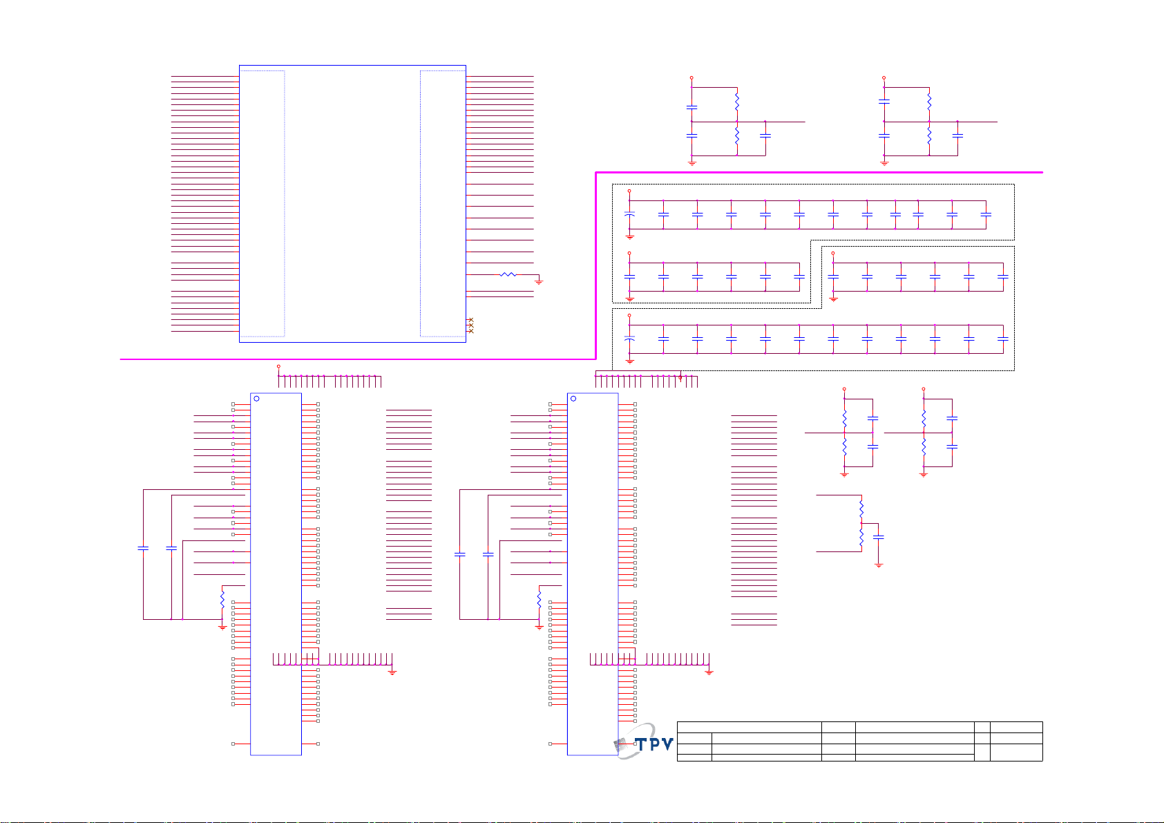
MD0
MD1
MD2
MD3
MD4
MD5
MD6
MD7
MD8
MD9
MD10
MD11
MD12
MD13
MD14
MD15
MD16
MD17
MD18
MD19
MD20
MD21
MD22
MD23
MD24
MD25
MD26
MD27
MD28
MD29
MD30
MD31
DQM0
DQM1
DQM2
DQM3
DQS0
DQS#0
DQS1
DQS#1
DQS2
DQS#2
DQS3
DQS#3
MCLK 0
MCLK0#
DQS0
DQS#0
DQS1
DQS#1
DQM0
DQM1
DDR_MVREF 21
DDR_MVREF 21
RAS#
CAS#
WE#
ODT
C349
C348
100N 16V
100N 16V
CKE
MMRST#
240 OHM +-1% 1/16W
R312
E3
E2
E1
F3
G2
G3
H3
H2
H1
J5
J4
J3
K4
K3
K2
K1
U2
U3
U4
U5
V4
V5
W1
W2
W3
Y1
Y2
Y3
AB1
AB2
AB3
AC1
G1
K5
V3
AA3
F1
F2
J2
J1
V1
V2
AA1
AA2
U401E
MMDQ 0
MMDQ 1
MMDQ 2
MMDQ 3
MMDQ 4
MMDQ 5
MMDQ 6
MMDQ 7
MMDQ 8
MMDQ 9
MMDQ 10
MMDQ 11
MMDQ 12
MMDQ 13
MMDQ 14
MMDQ 15
MMDQ 16
MMDQ 17
MMDQ 18
MMDQ 19
MMDQ 20
MMDQ 21
MMDQ 22
MMDQ 23
MMDQ 24
MMDQ 25
MMDQ 26
MMDQ 27
MMDQ 28
MMDQ 29
MMDQ 30
MMDQ 31
MMDM0
MMDM1
MMDM2
MMDM3
MMDQ S0P
MMDQ S0N
MMDQ S1P
MMDQ S1N
MMDQ S2P
MMDQ S2N
MMDQ S3P
MMDQ S3N
U403
E3
DQ0
F7
DQ1
F2
DQ2
F8
DQ3
H3
DQ4
H8
DQ5
G2
DQ6
H7
DQ7
D7
DQ8
C3
DQ9
C8
DQ10
C2
DQ11
A7
DQ12
A2
DQ13
B8
DQ14
A3
DQ15
C7
UDQS
B7
UDQS#
F3
LDQS
G3
LDQS#
D3
UDM
E7
LDM
T2
RESET#
L8
ZQ
A1
VDDQ_0
A8
VDDQ_1
C1
VDDQ_2
C9
VDDQ_3
D2
VDDQ_4
E9
VDDQ_5
F1
VDDQ_6
H2
VDDQ_7
H9
VDDQ_8
B2
VDD_0
D9
VDD_1
G7
VDD_2
VDD_3K2VSS_3
K8
VDD_4
N1
VDD_5
N9
VDD_6
R9
VDD_8
R1
VDD_7
H1
VREFDQ
NT5CB128M16BP-CG
SCALER TSXLFF-B1AFFFH BGA 27*27
ASXL
DDR3 INTERFACE
V_1.5
N3
A0
P7
A1
P3
A2
N2
A3
P8
A4
P2
A5
R8
A6
R2
A7
T8
A8
R3
A9
L7
A10/AP
R7
A11
N7
A12/BC#
T3
A13
J1
NC_0
J9
NC_1
L1
NC_2
L9
NC_3
M7
NC_4
T7
NC_6
M2
BA0
N8
BA1
M3
BA2
J7
CK
K7
CK#
L2
CS#
K3
CAS#
K1
ODT
J3
RAS#
L3
WE#
K9
CKE
B1
VSSQ_0
B9
VSSQ_1
D1
VSSQ_2
D8
VSSQ_3
E2
VSSQ_4
E8
VSSQ_5
F9
VSSQ_6
G1
VSSQ_7
G9
VSSQ_8
A9
VSS_0
B3
VSS_1
E1
VSS_2
G8
J2
VSS_4
J8
VSS_5
M1
VSS_6
M9
VSS_7
P1
VSS_8
P9
VSS_9
T1
VSS_10
T9
VSS_11
M8
VREFCA
27x27
(8/8)
MMDI G_TES T0
MMDI G_TES T1
MMANA_TEST
MD3
MD7
MD0
MD4
MD1
MD6
MD2
MD5
MD1 3
MD8
MD1 4
MD9
MD1 1
MD1 0
MD1 5
MD1 2
MA0
MA1
MA2
MA3
MA4
MA5
MA6
MA7
MA8
MA9
MA10
MA11
MA12
MA13
MA14
BA0
BA1
BA2
MMA0
MMA1
MMA2
MMA3
MMA4
MMA5
MMA6
MMA7
MMA8
MMA9
MMA10
MMA11
MMA12
MMA13
MMA14
MMBA0
MMBA1
MMBA2
MMCAS#
MMRAS#
MMWE#
MMCKE
MMODT
MMCKP
MMCKN
MMRESETN
MMVREF0
MMVREF1
C350
100N 16V
M2
R4
M4
M3
T1
L1
T3
L3
T4
L2
R1
T2
R2
L4
U1
M1
R3
N4
P2
P3
N2
P4
N3
N1
P1
L5
T5
MZQ
K6
V6
L6
T6
U6
C351
100N 16V
MA0
MA1
MA2
MA3
MA4
MA5
MA6
MA7
MA8
MA9
MA10
MA11
MA12
MA13
MA14
BA0
BA1
BA2
CAS#
RAS#
WE#
CKE
ODT
MCLK 0
MCLK0#
MMRST#
R305 240 OH M +-1% 1/16W
MVRE F0
MVRE F1
MCL K0
MCLK0#
DQS3
DQS#3
DQS2
DQS#2
DQM3
DQM2
DDR_MVREF22
DDR_MVREF22
RAS#
CAS#
WE#
ODT
CKE
MMRS T#
R313
240 OHM +-1% 1/16W
U402
E3
DQ0
F7
DQ1
F2
DQ2
F8
DQ3
H3
DQ4
H8
DQ5
G2
DQ6
H7
DQ7
D7
DQ8
C3
DQ9
C8
DQ10
C2
DQ11
A7
DQ12
A2
DQ13
B8
DQ14
A3
DQ15
C7
UDQS
B7
UDQS#
F3
LDQS
G3
LDQS#
D3
UDM
E7
LDM
T2
RESET#
L8
ZQ
A1
VDDQ_0
A8
VDDQ_1
C1
VDDQ_2
C9
VDDQ_3
D2
VDDQ_4
E9
VDDQ_5
F1
VDDQ_6
H2
VDDQ_7
H9
VDDQ_8
B2
VDD_0
D9
VDD_1
G7
VDD_2
VDD_3K2VSS_3
K8
VDD_4
N1
VDD_5
N9
VDD_6
R9
VDD_8
R1
VDD_7
H1
VREFDQ
NT5CB128M16BP-CG
A10/AP
A12/BC#
NC_0
NC_1
NC_2
NC_3
NC_4
NC_6
CAS#
ODT
RAS#
WE#
CKE
VSSQ_0
VSSQ_1
VSSQ_2
VSSQ_3
VSSQ_4
VSSQ_5
VSSQ_6
VSSQ_7
VSSQ_8
VSS_0
VSS_1
VSS_2
VSS_4
VSS_5
VSS_6
VSS_7
VSS_8
VSS_9
VSS_10
VSS_11
VREFCA
A11
A13
BA0
BA1
BA2
CK
CK#
CS#
A0
A1
A2
A3
A4
A5
A6
A7
A8
A9
V_1.5
DDR3-1 De-cap
C307
+
47uF/16V
V_1.5
DDR3-1 De-cap
C319
100N 16V
V_1.5
DDR3-2 De-cap
C331
+
47uF/16V
N3
P7
P3
N2
P8
P2
R8
R2
T8
R3
L7
R7
N7
T3
J1
J9
L1
L9
M7
T7
M2
N8
M3
J7
K7
L2
K3
K1
J3
L3
K9
B1
B9
D1
D8
E2
E8
F9
G1
G9
A9
B3
E1
G8
J2
J8
M1
M9
P1
P9
T1
T9
M8
V_1.5 V_1.5
R301
C301
100N 16V
C303
100N 16V
C308
10uF
C320
100N 16V
C332
10uF
20K OHM 1/16W 1%
20K OHM 1/16W 1%
R303
C309
10uF
C321
100N 16V
C333
10uF
V_1.5
T P V ( Top Victory Electronics Co . , Ltd. )
絬 隔 瓜 絪 腹
Key Component
18. SXL DDR3
Date
Place each D-cap close
to each MVREF ball
C304
100N 16V
C310
C311
100N 16V
100N 16V
C322
C323
10N 50V
10N 50V
C335
C334
100N 16V
100N 16V
MD27
MD29
MD26
MD28
MD24
MD31
MD25
MD30
MD21
MD16
MD20
MD19
MD22
MD18
MD23
MD17
MA0
MA1
MA2
MA3
MA4
MA5
MA6
MA7
MA8
MA9
MA10
MA11
MA12
MA13
MA14
BA0
BA1
BA2
MVRE F0
C312
100N 16V
V_1.5
C324
10N 50V
C336
100N 16V
R306
1KOHM +-1% 1/16W
DDR_MVREF21
R308
1KOHM +-1% 1/16W
MCLK 0
MCLK 0#
OEM MODEL
TPV MODEL
PCB NAME
Sheet
R302
20K OHM 1/16W 1%
C302
100N 16V
20K OHM 1/16W 1%
C314
100N 16V
R304
C315
10N 50V
C313
100N 16V
C305
100N 16V
DDR3-2 De-cap
C326
100N 16V
C338
10N 50V
of
C327
100N 16V
C339
10N 50V
R307
1KOHM +-1% 1/16W
DDR_MVREF22
R309
1KOHM +-1% 1/16W
C347
10N 50V
C325
100N 16V
C337
100N 16V
V_1.5 V_1.5
C343
100N 16V
C345
100N 16V
R310
75 OHM +-1% 1/16W
R311
75 OHM +-1% 1/16W
18 25Saturday , April 09, 2011
C316
10N 50V
C306
100N 16V
C328
10N 50V
C340
10N 50V
C344
100N 16V
C346
100N 16V
C317
10N 50V
MVR EF 1
C329
10N 50V
C341
10N 50V
Size
Rev
称爹
C318
10N 50V
Custom
B
称爹
<
C330
10N 50V
C342
10N 50V
>
44
Page 45

+24V_AMP
Amp_VCC
0.1uF 50 V
4.7K 1/10W
R640
AMP_SD16
AMP_STBY
AOUT_L15
AOUT_R15
+24V_AMP
AOUT_L
AOUT_R
D613
NC
R613
NC 10K 1/10W
D610
NC
R623 10OHM1/16W
R616 10OHM1/16W
1
C640
R614
NC
Q601
2 3
NC
C604
+
NC
R633
10K 1/10W
Q604
PMBS3904
R627 10K(N C)
R628 10K(N C)
C607 220NF 25V
C621
33P 50V(NC)
C614 220NF 25V
C619
33P 50V(NC)
R610
NC
NC 10K 1/10W
R622 0R 05 1/10W
V_3.3
C616
220NF 25V
R621
R619 10K 1/ 10W
+24V_AMP
FB618
120OHM
NC 0R05 1/10W
R620
1 2
C620
1uF
C618
1uF
R630
6.8K +-1% 1/10W
C617
220NF 25V
R629
3.3K 1/10W
10
11
12
13
14
1
2
3
4
5
6
7
8
9
U601
SDZ
FAULTZ
LINP
LINN
GAIN0
GAIN1
AVCC
AGND
GVDD
PLIMIT
RINN
RINP
NC
PBTL
EUA2110
Therm al Pad
PVCCL
PVCCL
BSPL
OUTPL
PGND
OUTNL
BSNL
BSNR
OUTNR
PGND
OUTPR
BSPR
PVCC
PVCC
29
1uF
28
C608
27
26
C612
1uF 25V
25
24
23
22
C615
1uF 25V
21
C626
1uF 25V
20
19
18
17
C627
1uF 25V
16
15
1uF
C629
R617
330PF50V
R626
330pF 50V
R624
330PH
R618
330pF 50V
C628
1N 50V
C630
100OHM
C633
1N 50V
+24V_AMP
+
C610
150UF 35V
C613
100OHM 50V
C631
100OHM 50V
C632
100OHM
+24V_AMP
L604
22uH
L605
22uH
L606
22uH
C609
+
150UF 35V
L603
22uH
LOUT-
C623
330nF 50V
C622
ROUT+
LOUT+
C625
ROUT-
330nF 50V
C624
330nF 50V
330nF 50V
CN601
1
2
3
4
CONN
CN603
HP_ROUT15
HP_LOUT15
R606 0R05 OHM
R609 0R05 OHM
C601
10uF
C602
10uF
100K 1/16W
R602
R607
100K 1/16W
PHONEJ ACK
5
4
3
2
6
7
1
CN602
V_3.3
10K+-5%1/16W
R608
HPH_DETECT 16
JACK
T P V ( Top Victory Electronics Co . , Ltd. )
絬 隔 瓜 絪 腹
Key Component
Date
1
2
19. AUDI O Amp and audio out
10N 50V
C605
22 OHM 1/8W
C606
100P 50V
OEM MODEL
TPV MODEL
PCB NAME
Sheet
R615
SPDIF _OUT 15
R601
NC 0R05 OHM
19 25Saturday, April 09, 2011
of
SPDIF_Mute/s ensor 5,17
A3
Size
Rev
B
<
称爹
称爹
>
45
Page 46

+24V_A MP
5V_SW
R625
NC 0R05 1/10W
1 2
R637 10K+- 5%1/16W
Amp_VCC
0.1uF 50V
C639
C635
100N 50V
C636
+
150UF 35 V
SH600
SH601
SH602
SH603
ZD600
RLZ18B
R612
4.7K 1/1 0W
+24V_AMP
STBY
Sub_AMP_SD16
Subwoof er15
Sub_AMP_Mute16
R632
1K 1/10W
R644
8.2K 1/10W
C670
100P 50V
Q602
PMBS3904
R631
10K 1/10W
SW_AMP_LIN
Amp_VCC
47K 1/16W
Q605
PMBS3904
VD14VD1
C638
100N 50V
2
3
NC
OUT11OUT1
48
NC
47
VS1
46
VS1
45
NC
44
HB1
43
NC
42
DVDD
41
HB2
40
NC
39
VS2
38
VS2
37
NC
36
C657
100N 50V
100N 50V
SPK L C
R639
NC
C643
1uF
R634
NC
C644 10uF 16V
R635 33K 1/ 10W
C646
C651 10uF 16V
C652 1uF
R638
AMP5VO
10uF 16V
U602
R2A15112F P
DVDD
270K 1/10W
13
14
15
16
17
18
19
20
21
22
23
24
12
49
10
11
IN1
TGND
GAIN 1
CBIAS
ROSC
AVCC
GND
NC
NC
NC
NC
NC
CLOCK
VREF
PROT
IN225GAIN 226MUTEL27NC28NC29NC30NC31VD232VD233NC34OUT235OUT2
R636
0 Ohm
R643
9
STBYL
C667
0.1uF 50V
5
NC6NC7NC8NC
+24V_AMP
8 OHM
C665
DVDD
L602
22uH
C641
100N 50V
C653
L601
22uH
22uH
10uF 16V
C642
0.47UF 50V
C668
0.47UF 50V
W-
0.47uF
W+
W+
W-
Close to U602
3
2
1
CONN
CN604
T P V ( Top Victory Electronics Co . , Ltd. )
絬 隔 瓜 絪 腹
Key Component
20.AU DIO AMP R 2A15112FP
Date
46
6 OHM
16 OHM
33UH L70X70 073G M58901 T
15 uH
33 uH
OEM MO DE L
TPV MOD EL
PCB NAME
Sheet
0.68 uF
0.24 uF
Custom
Size
Rev
B
<
称爹
称爹
of
20 25Saturday , April 09, 2011
>
Page 47

C164 100N 16V
C165
100N 16V
R145
680R 1/10W 1%
C162 100N 16V
C159 1UF 16V
33P 50V
V12
USB_DN
USB_DP
USB2_DN
USB2_DP
33P 50V
C163
C161
USB_DN15
USB_DP15
537mA Max
120R/3000mA
FB111
C178
4.7UF 16V
1 2
12
V_3.3USB
X102
12MHz 20P
USB_DN
USB_DP
C179
47uF/16V
R106NC/0R 05 1/16W
R108NC/0R 05 1/10W
U1003
1
AVDD
2
GND
3
DM0
4
DP0
5
DM1
6
DP1
7
GL852G-MNG12
AVDD
8
GND
9
DM2
10
DP2
11
RREF
12
AVDD
R158
NC 1M
suspend
Full-Speed
Power Consumption
10K 1/10W
R198
+
C180
NC 22uF 10V
3V3_P
R1114
10K+-5%1/16W
45
42
47
44
48
41
V5
V33
SEL27
AMBER146GREEN1
OVCUR1#
PWREN1#43PWREN2#
GND13X114X215AVDD16DM317DP318AVDD19GND20DM421DP4
C167 100N 16V
C183 100N 16V
V_3.3USB
2 port
706uA
G5655P12U
U111
IN2LX
7
EN
1
NC
FB
6
COMP
SS
GND
C166
180P 50V
R199
0R05 1/10W
USB_5V
USB_POW
1UF16V
PWREN4
USB_OVCUR4#
100N 16V
C146
5VSB_IN
USB_POW2
5
IN
4
EN
G5250M1T1U
1 2
5
IN
4
EN
G5250M1T1U
U112
OUT
GND
OC
120R/3000mA
FB112
10uF
C148
U113
OUT
GND
OC
1
2
3
FB116
1 2
120R/3000mA
NC 120R/ 3000mA
1 2
FB117
1
2
3
10K 1/10W
USB_POW
R1102
10K 1/10W
100N 16V
USB_POW
R159
100N 16V
C198
100N 16V
C149
USB_POW
C195
100uF/16V
+
C199
100uF/16V
+
C196
1UF16V
C1102
1UF16V
C1101
3V3_P
NC 1K 1/10W
R196
NC 1K 1/10W
R160
USB4_DN
USB4_DP
USB2_DN
USB2_DP
RClamp0524P. TCT
U108
1
2
4
RClamp0524P. TCT
U109
1
IN1
2
IN2
4
IN3
IN45OUT4
5VSB_IN
IN1
OUT1
IN2
OUT2
IN3
OUT3
IN45OUT4
GND
GND
3
8
USB2_5V
OUT1
OUT2
OUT3
GND
GND
3
8
USB_5V
USB4_5V
10
9
7
6
cost down 0.01
10
9
7
6
FB118
1 2
120R/3000mA
1 2
NC 120R/ 3000mA
FB119
USB CONN
1
2
3
4
USB CONN
1
2
3
4
CN105
1234
6 5
CN104
1234
6 5
USB_POW2
R142->H:self-powered R142->L:Bus-powered
R157=100K to VCC: Gang: input 1, output 0@normal, 1@ suspend
10K 1/10W
R142
R1107 NC 100OHM1/16W
R157
TEST
R1116 10K+-5%1/16W
15K 1/10W
36
35
34
33
32
R1113 10K+-5%1/16W
31
30
R1112 NC 100OH M1/16W
29
R1106 NC 100OH M1/16W
28
27
26
25
100K 1/10W
40
38
39
37
DVDD
PSELF
PGANG
OVCUR2#
AMBER2
GREEN2
DVDD
AMBER3
GREEN3
PWREN3#
OVCUR3#
PWREN4#
OVCUR4#
RESET#
SEL48
GREEN423AMBER4
22
24
1 port
706uA
R157=100K to GND: Individual: input 1, output 1@normal,0 @suspend
PWREN2
USB_OVCUR2#
R1105NC 100OHM1/16W
3V3_P
USB_OC16
R153
USB_OC16
1 2
120R/600mA
1K 1/10W
4.7K 1/10W
85 mA
FB122
4.7K 1/10W
R154
R1104
1K 1/10W
C145
10uF
R182
R1115 10K+-5%1/16W
USB_RESET#
USB4_DP
USB4_DN
USB_RESET#
R156
47K +-5% 1/10W
3V3_P
3V3_P
3V3_P
PWREN4
USB_OVCUR4#
R197
10K 1/10W
C109
1UF16V
Active High
USB_PPON15
Active High
USB_PPON15
1K 1/10W
V_3.3
R1101
R1103
R146
1K 1/10W
1UF16V
C108
PWREN2
V_3.3USB
C197
USB_OVCUR2#
83 mA85 mA
USB_5V
100N 16V
C144
100N 16V
C147
C184
100N 16V
C200
100N 16V
C219
100N 16V
1.2A Max
L104
10uH
D102
SJPW-T4VL
1 2
3
5
8
4
2KOHM 1% 1/10W
C160
1UF16V
R181
R179
120K 1/10W 1%
R180
27K 1/10W 1%
+
C182
220uF 16V
C181
1UF16V
10uF 10V
SEL48 SEL27 Clock source
----------------------------------- 0 1 48MHz OSC-in
1 0 27MHz OSC-in
C746
1 1 12MHz Xtal / OSC In
Note: 0: use 15K pull down
1: connect to DVDD
pin 36 R182 :Amber2 Power switch type
------------------------------0 default setting: power switch Low active
1 ,15K pull to DVDD: power switch High active
Port # Amber3 Amber4
----------------------------- 4 0 0
3 0 1
2 1 0
1 1 1
Note: 0: default setting
1: use 15K pull high to DVDD
vout= 0.92*(1+(R179+R180)/R181))=5.07V
93% efficient @5V, 1.2A
47
T P V ( Top Victory Electronics Co . , Ltd. )
絬 隔 瓜 絪 腹
Key Component
20. USB_Hub
Date
OEM MOD EL
TPV MODEL
PCB NAME
Sheet
Custom
Size
Rev
B
称爹
称爹
>
21 25Monday, April 18, 2011
of
<
Page 48

DRAM_VREF
DRAM_TEST_D1
DRAM_TEST_D2
DRAM_TEST_AN
DRAM_DQ16
DRAM_DQ17
DRAM_DQ18
DRAM_DQ19
DRAM_DQ20
DRAM_DQ21
DRAM_DQ22
DRAM_DQ23
DRAM_DQ24
DRAM_DQ25
DRAM_DQ26
DRAM_DQ27
DRAM_DQ28
DRAM_DQ29
DRAM_DQ30
DRAM_DQ31
DRAM_DQS2
DRAM_DQS2_N
DRAM_DQS3
DRAM_DQS3_N
DRAM_DM2
DRAM_DM3
DRAM_DQ0
DRAM_DQ1
DRAM_DQ2
DRAM_DQ3
DRAM_DQ4
DRAM_DQ5
DRAM_DQ6
DRAM_DQ7
DRAM_DQ8
DRAM_DQ9
DRAM_DQ10
DRAM_DQ11
DRAM_DQ12
DRAM_DQ13
DRAM_DQ14
DRAM_DQ15
DRAM_DQS0
DRAM_DQS0_N
DRAM_DQS1
DRAM_DQS1_N
DRAM_DM0
DRAM_DM1
DRAM_A0
DRAM_A1
DRAM_A2
DRAM_A3
DRAM_A4
DRAM_A5
DRAM_A6
DRAM_A7
DRAM_A8
DRAM_A9
DRAM_A10
DRAM_A11
DRAM_A12
DRAM_BA0
DRAM_BA1
DRAM_BA2
DRAM_CK
DRAM_CK_N
DRAM_ODT
DRAM_CAS_N
DRAM_CKE
DRAM_RAS_N
DRAM_WE_N
DRAM_CS_N
W12
R2061 NC
W6
R2062 NC
W7
W5
R2063 NC
AB2
V2
AA2
V3
U1
AB6
W3
AA6
Y5
W2
Y4
AA1
W1
Y6
Y1
AA5
Y3
AA3
AA4
AB4
AB1
Y2
V20
Y17
V21
AA20
AB16
U21
AA17
W22
W20
AA18
AB21
AA19
Y18
W21
AB18
Y21
AB20
AA21
AB22
AA22
Y20
Y19
AA9
AB8
AA8
Y9
Y8
AA7
Y7
AA14
Y14
Y15
AA15
AA16
Y16
AA11
Y11
Y10
AA10
AB10
AA12
Y13
Y12
AB14
AA13
AB12
100N 16V
C2040
AA1
AA2
AA3
AA4
AA5
AA6
AA7
AA8
AA9
AA11
AA12
AA13
AA14
AA15
AA16
AA17
AA18
AA19
AA20
AA21
AA22
A0
A1
A2
A3
A4
A5
A6
A7
A8
A9
A10
A11
A12
A13
A14
A15
A16
A17
A18
A19
A20
A21
A22
A23
AA6
AA8
AA14
AA16
AA9
AA20
AA19
AA11
AA18
AA17
AA1
AA21
AA3
AA12
AA22
AA15
AA10
AA13
AA7
AA2
AA4
AA5
R2027 62R 1/16W 5%
R2028 62R 1/16W 5%
R2029 62R 1/16W 5%
R2030 62R 1/16W 5%
R2031 62R 1/16W 5%
R2032 62R 1/16W 5%
R2033 62R 1/16W 5%
R2034 62R 1/16W 5%
R2035 62R 1/16W 5%
R2036 62R 1/16W 5%
R2037 62R 1/16W 5%
R2038 62R 1/16W 5%
R2039 62R 1/16W 5%
R2040 62R 1/16W 5%
R2041 62R 1/16W 5%
R2042 62R 1/16W 5%
R2044 33 OHM 1/16W
R2045 33 OHM 1/16W
R2046 62R 1/16W 5%
R2047 62R 1/16W 5%
R2048 62R 1/16W 5%
R2049 62R 1/16W 5%
R2050 62R 1/16W 5%
R2051 62R 1/16W 5%
VDD18
R2002
1K 1/16W 1%
C2041
100P 50V
R2003
1K 1/16W 1%
5
6
7
8
5
6
7
8
5
6
7
8
5
6
7
8
5
6
7
8
R2043 1K 1/16W
R2053 1K 1/16W
DRAM_DQ10
DRAM_DQ11
DRAM_DQ12
DRAM_DQ13
DRAM_DQ14
DRAM_DQ15
DRAM_DQS0_P
DRAM_DQS0_N
DRAM_DQS1_P
DRAM_DQS1_N
DRAM_DM0
DRAM_DM1
4
3
2
1
4
3
2
1
4
3
2
1
4
3
2
1
4
3
2
1
DRAM_DQ0
DRAM_DQ1
DRAM_DQ2
DRAM_DQ3
DRAM_DQ4
DRAM_DQ5
DRAM_DQ6
DRAM_DQ7
DRAM_DQ8
DRAM_DQ9
R2052
330OHM 1/10W
1 KOHM +-5% 1/16W
RP2302
1 KOHM +-5% 1/16W
RP2303
1 KOHM +-5% 1/16W
RP2304
1 KOHM +-5% 1/16W
RP2305
1 KOHM +-5% 1/16W
RP2306
DRAM_A0
DRAM_A1
DRAM_A2
DRAM_A3
DRAM_A4
DRAM_A5
DRAM_A6
DRAM_A7
DRAM_A8
DRAM_A9
DRAM_A10
DRAM_A11
DRAM_A12
DRAM_BA0
DRAM_BA1
DRAM_BA2
DRAM_CK_P
DRAM_CK_N
DRAM_ODT
DRAM_CAS
DRAM_CKE
DRAM_RAS
DRAM_WE
DRAM_CS
VDD18
R2004
R2005
1K 1/16W 1%
C2094
10uF
VDD18
DRAM_CK_P
DRAM_CK_N
1K 1/16W 1%
100N 16V
C2063
C2064
100P 50V
VDD18
VDD18
330pF 50V
330pF 50V
C2057
DRAM_DQS0_P
DRAM_DQS0_N
DRAM_DQS1_P
DRAM_DQS1_N
DRAM_DM0
DRAM_DM1
DDR_MVREF1
DRAM_RAS
DRAM_CAS
DRAM_WE
DRAM_CS
DRAM_ODT
DRAM_CKE
DRAM_BA2
C2042
330pF 50V
1N 50V
C2051
1N 50V
C2044
C2053
J8
K8
F7
E8
B7
A8
F3
B3
J2
K7
L7
K3
L8
K9
K2
A2
E2
L1
R3
R7
R8
100N 16V
C2058
100N 16V
VDD18
U2004
VDDQG9VDDQG7VDDQG3VDDQG1VDDQE9VDDQC9VDDQC7VDDQC3VDDQC1VDDQ
CK
CK#
LDQS
LDQS#
UDQS
UDQS#
LDM
UDM
VREF
RAS#
CAS#
WE#
CS#
ODT
CKE
NC_A2
NC_E2
BA2
NC_R3
NC_R7
NC_R8
VSSQH2VSSQF8VSSQF2VSSQE7VSSQD8VSSQD2VSSQB8VSSQB2VSSQA7VSSN1VSSJ3VSSE3VSS
VSSQ
H8
C2043
100N 16V
C2052
VDD18
C2059
330pF 50V
A9
VDD18
C2045
330pF 50V
330pF 50V
M9
P9
VDD18
C2054
C2060
100N 16V
VDDJ9VDDR1VDDE1VDD
VDD
VSS
VDD18
A1
A3
1N 50V
C2047
J1
J7
1N 50V
C2056
VDDL
VSSDL
DQ10
DQ11
DQ12
DQ13
DQ14
DQ15
C2065
100N 16V
G8
DQ0
G2
DQ1
H7
DQ2
H3
DQ3
H1
DQ4
H9
DQ5
F1
DQ6
F9
DQ7
C8
DQ8
C2
DQ9
D7
D3
D1
D9
B1
B9
M8
A0
M3
A1
M7
A2
N2
A3
N8
A4
N3
A5
N7
A6
P2
A7
P8
A8
P3
A9
M2
A10
P7
A11
R2
A12
L2
BA0
L3
BA1
NT5TU64M16GG-BE
C2046
100N 16V
C2055
100N 16V
VDD18
C2061
330pF 50V
VDD18
C2048
330pF 50V
C2066
100P 50V
DRAM_DQ10
DRAM_DQ11
DRAM_DQ12
DRAM_DQ13AA10
DRAM_DQ14
DRAM_DQ15
DRAM_DQ0
DRAM_DQ1
DRAM_DQ2
DRAM_DQ3
DRAM_DQ4
DRAM_DQ5
DRAM_DQ6
DRAM_DQ7
DRAM_DQ8
DRAM_DQ9
DRAM_A0
DRAM_A1
DRAM_A2
DRAM_A3
DRAM_A4
DRAM_A5
DRAM_A6
DRAM_A7
DRAM_A8
DRAM_A9
DRAM_A10
DRAM_A11
DRAM_A12
DRAM_BA0
DRAM_BA1
1N 50V
C2050
C2062
100N 16V
C2049
100N 16V
T P V ( Top Victory Electronics Co . , Ltd. )
絬 隔 瓜 絪 腹
Key Component
Date
48
OEM MOD EL
TPV MODEL
PCB N AME
Sheet
715G4649-D
of
22 25Tuesday, March 15, 2011
Size
Rev
称爹
<
Custom
01
称爹
>
Page 49

10R 1/10W 5%
U2001
AT1529F11U
1
2
3
0.1uF 50V
Thermal Pad
C2137
0.1uF 50V
C2134
Vout = 0.8x(1+ R727/R728)=1.066V
MEMC_5V 1
205mA
FB2013
33 OHM
R2076
C2118
2.2U10V
3rd Power up
all power should power up less than 1s
10K 1/10W
C2095
NC 0.1uF 16V
G5628ADJT1U
MEMC_5V 1 V105AN
2.2U10V
C2122
FB2014
33 OHM
VDD105DLL_SW
C2124
NC 10uF
G5628ADJT1U
C2110
100N 16V
MEMC_5V 1
+
C2107
47uF/16V
V12
V12
R2085
10K 1/10W
M5VSW
Q2705
PMBS3904
0.1uF 50V
R2093
VCC
REF
GND
FB4EN
C2136
2.2uH 30%
L2001
8
VIN
7
LX
6
PGND
VDD105_SW
5
9
470uF 10V
OUTPUT 1.12A
U2704
L2002 4.7uH
4
3
VIN
LX
1A
1
5
EN
VFB
GND
R2059
2
10K +-1% 1/ 10W
VO=0.6(1+R1/R2)=1.8
OUTPUT 100mA
Max 150mA, Normal: 100mA
U2705
L2003 4.7uH
4
3
VIN
LX
1A
1
5
EN
VFB
GND
2
R2060
10K +-1% 1/ 10W
VO=0.6(1+R1/R2)=1.05
0.4V drop @1000mA
0.6V drop @2000mA
OUTPUT 400mA
MEMC_5V 1
U2703
VIN3VOUT
GND
1
C2152
22uF 10V
liner regulator must be used
for analogue PLL
For IO and Oscillator
OUTPUT 100mA
0.2V drop @100mA
0.4V drop @500mA
U2702
2
VI3VO
4
4
GND
C2106
100N 16V
1
120R/3000mA
FB2022
12
C2145
4.7UF 16V
NC 22uF 10V
+
C2146
47uF/16V
1K 1/10W
R2086
MEMC5V_SW# 4,16
120OHM
5VSB_IN
FB2017
1 2
+
10uF
C2120
C2125
100uF/16V
C2141
0.1uF 50V
C2117
+
1 2
500mA
FB2018
NC 120OHM
C2139
1nF 50V
R2095
9.1KOHM +- 1% 1/10W
100N 16V
C2096
500mA
C2115
NC
100N 16V
C2097
C2119
NC
C2076
100N 16V
C2080
100N 16V
MEMC_5V1
R2094
3K +-% 1/10 W
120R/3000mA
FB2005
1 2
100N 16V
120R/3000mA
FB2007
1 2
R2057
20K 1/10W
R2058
7.5K +-1% 1/10W
C2101
C2121
10uF
2
100N 16V
4.7UF 16V
C2135
For LVDS
C2126
+
220uF 16V
10uF
C2142
C2151
+
+
C2113
47uF/16V
LOW ESR
LOW ESR
100uF/16V
MEMC2V5
CLOSE TO CHIP
120R/3000mA
FB2009
1 2
C2084
100N 16V
120R/3000mA
FB2011
1 2
C2088
100N 16V
3
5
FB
8
SS
4
GND
1 2
C2143
1UF16V
85%@3.3V 62K/24K
U2708
vout= 0.92*(1+(R179+R180)/R181))=5.07V
C2147
C2108
100N 16V
M5VSW
MEMC3V3
+
C2109
47uF/16V
G5655P12U
IN2LX
7
EN
1
NC
6
COMP
C2144
180P 50V
R2100
0R05 1/10W
100N 16V
Low ESR EC
2nd Power up
VDD1V8
C2067
100N 16V
100N 16V
C2074
100N 16V
VDDLZ25
C2075
C2079
100N 16V
C2083
100N 16V
L2005
10uH
D2001
SJPW-T4VL
1st Power up
VCC105
120OHM
FB2015
1 2
C2112
100N 16V
120OHM
FB2016
1 2
C2068
100N 16V
120R/3000mA
FB2002
1 2
C2069
120R/3000mA
FB2004
1 2
CLOSE TO CHIP
VDDLXY25
VDD33OSC
8mA
3V3DIG
C2086
100N 16V
C2087
100N 16V
220uF 16V
C2149
+
R2098
27K 1/10W 1%
C2123
100N 16V
C2078
100N 16V
100N 16V
C2148
0.1uF 50V
VDD18
C2070
C2082
VDD105
VDD105PLL
VDD105DLL
20mA
C2073
100N 16V
120R/3000mA
FB2006
1 2
120R/3000mA
FB2008
1 2
120R/3000mA
FB2010
1 2
C2150
10uF 10V
24K
R2072
NC 10K 1/10W
VDD105_SW
PMBS3904
VDD105DLL_SW
Q2712
PMBS3904
CLOSE TO CHIP
CLOSE TO CHIP
13mA
C2072
100N 16V
CLOSE TO CHIP
CLOSE TO CHIP
VDDLZ25PLL
C2077
100N 16V
VDDLXY25PLL
C2081
100N 16V
VDD33
10mA
C2085
100N 16V
MEMC_5V1
R2097
120K 1/10W 1%
R2099
2KOHM 1% 1/10W
MEMC_5V1
5V_SW
Q2710
MEMC_5V1
R2075
10K 1/10W
120R/3000mA
FB2003
1 2
62K
R2070
10K 1/10W
R2071
100 OHM 1/10W
R2074
100 OHM 1/10W
VDD105MPLL
7mA
C2071
100N 16V
T P V ( Top Victory Elec tronics Co . , Ltd. )
絬 隔 瓜 絪 腹
Key Component
Date
V105_SW# 4,16
V105DLL_SW# 4,16
CLOSE TO CHIP
VDD18
VDD105
VDD105
VDD105
100N 16V
100N 16V
100N 16V
100N 16V
VDD105DLL
C2025
VDDLXY25PLL
VDDLXY25PLL
VDD33OSC
VDD33
C2009
C2014
C2019
VDDLXY25
VDD105MPLL
C2020
330pF 50V
C2024
100N 16V
VDDLZ25PLL
VDDLXY25
VDD105PLL
C2013
100N 16V
C2018
100N 16V
100N 16V
VDDLZ25
330pF 50V
330pF 50V
C2008
100N 16V
C2021
330pF 50V
100N 16V
100N 16V
100N 16V
C2001
C2003
100N 16V
C2005
C2010
C2015
100N 16V
100N 16V
C2034
100N 16V
OEM MODE L
TPV MODE L
PCB NAME
Sheet
R4
C2002
100N 16V
T4
T9
C2004
T10
100N 16V
G7
100N 16V
G8
C2007
G9
G14
G15
G16
H7
H8
C2006
H9
100N 16V
H14
H15
H16
100N 16V
J16
C2012
J8
J9
J10
J13
J14
J15
C2011
C2016
C2026
100N 16V
C2027
100N 16V
715G4649-D
23 25Saturday, April 09, 2011
C2028
100N 16V
C2033
100N 16V
100N 16V
of
C2030
100N 16V
C2031
100N 16V
C2035
C2036
100N 16V
K9
K10
K13
K14
N9
N10
N13
N14
P8
P9
P10
P13
P14
P15
R7
R8
R9
R14
R15
R16
T7
T14
T16
J7
G10
T13
R13
P7
T8
T12
T15
P16
V4
J4
C5
H4
G3
D12
D16
C13
D14
C17
H19
M19
F20
K19
L20
P4
N4
D7
D8
M4
C7
100N 16V
100N 16V
C2017
100N 16V
100N 16V
C2023
C2022
C2029
C2032
C2037
VDD105PLL
VSS105PLL
VDD105MPLL
VSS105MPLL
VDD105
VDD105
VDD105
VDD105
VDD105
VDD105
VDD105
VDD105
VDD105
VDD105
VDD105
VDD105
VDD105
VDD105
VDD105
VDD105
VDD105
VDD105
VDD105
VDD105
VDD105
VDD105
VDD105
VDD105
VDD105
VDD105
VDD105
VDD105
VDD105
VDD105
VDD105
VDD105
VDD105
VDD105
VDD105
VDD105
VDD105
VDD105
VDD105
VDD105
VDD105
VDD105
VDD105_S
VSS
VDD105DLL
VSS
VDD18
VDD18
VDD18
VDD18
VDD18
VSS
VDDLZ25
VSS
VDDLZ25PLL
VSS
VDDLX25
VDDLX25
VSS
VDDLX25PLL
VSS
VDDLY25
VDDLY25
VSS
VDDLY25PLL
VSS
VDD33OSC
VSS33OSC
VDD33
VDD33
VDD33
VSS
C6
VSS
C8
VSS
C9
VSS
C10
VSS
C11
VSS
C12
VSS
C14
VSS
C15
VSS
C16
VSS
C18
VSS
C19
VSS
C20
VSS
D3
VSS
D4
VSS
D5
VSS
D6
VSS
D9
VSS
D10
VSS
D11
VSS
D13
VSS
D15
VSS
D20
VSS
E3
VSS
E4
VSS
E19
VSS
E20
VSS
F3
VSS
F4
VSS
G19
VSS
G20
VSS
H3
VSS
D17
VSS
H20
VSS
J3
VSS
D18
VSS
J19
VSS
J20
VSS
K3
VSS
D19
VSS
K20
VSS
L3
VSS
L4
VSS
F19
VSS
M20
VSS
N20
VSS
P19
VSS
P20
VSS
R20
VSS
T19
VSS
T20
VSS
U20
VSS
U22
VSS
V19
VSS
W9
VSS
W11
VSS
W14
VSS
W16
VSS
W18
VSS
G11
VSS
G12
VSS
G13
VSS
H10
VSS
H11
VSS
H12
VSS
H13
VSS
J11
VSS
J12
VSS
K16
VSS
K8
VSS
K11
VSS
K12
VSS
K15
VSS
L7
VSS
L8
VSS
L9
VSS
L10
VSS
L11
VSS
L12
VSS
L13
VSS
L14
VSS
L15
VSS
L16
VSS
M7
VSS
M8
VSS
M9
VSS
M10
VSS
M11
VSS
M12
VSS
M13
VSS
M14
VSS
M15
VSS
M16
VSS
N7
VSS
N8
VSS
N11
VSS
N12
VSS
N15
VSS
N16
VSS
P11
VSS
P12
VSS
R10
VSS
R11
VSS
R12
VSS
T11
VSS
T2
VSS
T3
VSS
U2
VSS
U3
VSS
L19
VSS
N19
VSS
R19
VSS
U19
VSS
W19
VSS
W17
VSS
W15
VSS
W13
VSS
W10
VSS
W8
VSS
W4
VSS
U4
VSS
K4
VSS
G4
VSS
K7
VSS_S
Custom
Size
Rev
01
<
称爹
>
称爹
49
Page 50

3V3DIG
3V3DIG
R20202K 1/10W
MSC L
MSD A
SSCL
SSDA
TCL K
TMS
TDI
TRS T_N
TDO
XI N
XOU T
RESET_N
GPIO00
GPIO01
GPIO02
GPIO03
GPIO04
GPIO05
GPIO06
GPIO07
GPIO08
GPIO09
GPIO10
GPIO11
GPIO12
PWM
R20212K 1/10W
N3
M3
N1
N2
B4
A5
A4
A3
B5
R2024 NC
R1
X2201
27MHz
P1
B6
A6
TM
A11
B10
A10
B9
A9
B8
A8
B7
A7
P2
P3
R2
R3
B11
A12
V
B12
H
10K 1/10W
12
R2026
10K 1/10W
10K 1/10W
R2066
R2067
C2089
27P 50V
WP
R2022
R2023
2K 1/10W
2K 1/10W
C209027P 50V
3V3DIG
10N 50V
C2091
C2039
100N 16V
10K 1/10W
R2064
R2065
10K 1/10W
3V3DIG
10K 1/10W
R2001
NC
WP
4.7K 1/10W
R2088
for External I2C
R2084 0R05 1/10W
1
GND
2
RESET
U2003
NC G692L293TCUf 2.91V
R2025
VCC
MR
0R05 1/10W
R2082
R2083
0R05 1/10W
4,17
RESET_FRC#
3V3DIG
4
3
C2038 220NF 25V
U2002
8
E0
VCC
7
E1
WC
6
E2
SCL
5
VSS
SDA
M24512_RMN6TPA
3V3DIG
SCL
SDA
1
2
3
4
SW2402
2
1 3
NC
1
2
3
4
CN2006
NC
45
MEMC_SCL 4, 16
MEMC_SDA 4, 16
T P V ( Top Victory Electronics Co . , Ltd. )
絬 隔 瓜 絪 腹
Key Component
Date
50
OEM MO D EL
TPV MO DEL
PCB NAME
Sheet
715G4649-D
24 25Friday , February 18, 2011
of
Size
Rev
称爹
Custom
01
<
称爹
>
Page 51

TX0AP_O A
TX1AP_O A
TX2AP_O A
0R 1/16W 5%
A13
P_ XA_ TX0 _ N
P_ XA_ TX0 _ P
P_ XA_ TX1 _ N
P_ XA_ TX1 _ P
P_ XA_ TX2 _ N
P_ XA_ TX2 _ P
P_XA_CLK_N
P_XA_CLK_P
P_ XA_ TX3 _ N
P_ XA_ TX3 _ P
P_ XA_ TX4 _ N
P_ XA_ TX4 _ P
P_ XB_ TX0 _ N
P_ XB_ TX0 _ P
P_ XB_ TX1 _ N
P_ XB_ TX1 _ P
P_ XB_ TX2 _ N
P_ XB_ TX2 _ P
P_XB_CLK_N
P_XB_CLK_P
P_ XB_ TX3 _ N
P_ XB_ TX3 _ P
P_ XB_ TX4 _ N
P_ XB_ TX4 _ P
TX0AP14, 15
TX1AP_I N
TX1AP14, 15
TX2AP_I N
TX2AP14, 15
TXCKAP_IN
TXCKAP14, 15
TX3AP_I N
TX3AP14, 15
TX4AP_I N
TX4AP14, 15
TX0BP_I N TX0BN _I N
TX0BP14, 15
TX1BP_I N
TX1BP14, 15
TX2BP_I N
TX2BP14, 15
TXCKBP_IN
TXCKBP14, 15
TX3BP_I N
TX3BP14, 15
TX4BP_I N
TX4BP14, 15
B13
A14
B14
A15
B15
A16
B16
A17
B17
A18
B18
A19
B19
A20
B20
A22
A21
B22
B21
C22
C21
D22
D21
5 RP2308
6
7
8
0R 1/16W 5%
5 RP2309
6
7
8
0R 1/16W 5%
5 RP2310
6
7
8
0R 1/16W 5%
5 RP2311
6
7
8
0R 1/16W 5%
5 RP2312
6
7
8
0R 1/16W 5%
5 RP2313
6
7
8
TX0AN_ OA
4
TX0AP_OA
3
TX1AN_ OA
2
TX1AP_OA
1
TX2AN_ OA
4
TX2AP_OA
3
TXCKAN_OA
2
TXCKAP_OA
1
TX3AN_ OA
4
TX3AP_OA
3
TX4AN_ OA
2
TX4AP_OA
1
TX0BN_ OA
4
TX0BP_OA
3
TX1BN_ OA
2
TX1BP_OA
1
TX2BN_ OA
4
TX2BP_OA
3
TXCKBN_OA
2
TXCKBP_OA
1
TX3BN_ OA
4
TX3BP_OA
3
TX4BN_ OA
2
TX4BP_OA
1
DRC_EN14,16
PANEL_VCC
PANEL_PWM_OUT14
R2019100OHM1/16W
R2018100OHM1/16W
R2015100OHM1/16W
R2014100OHM1/16W
R2013100OHM1/16W
R2012100OHM1/16W
R2011100OHM1/16W
R2010100OHM1/16W
R2009100OHM1/16W
R2008100OHM1/16W
R2007100OHM1/16W
R2006100OHM1/16W
TXCKAP_OA
TX3AP_O A
TX4AP_O A
TX0BP_O A
TX1BP_O A
TX2BP_O A
TXCKBP_OA
TX3BP_O A
TX4BP_O A
C2092
100N 16V
+
C2093
220uF 16V
TX0AP_OB
TX1AP_OB
TX2AP_OB
TXCKAP_OB
TX3AP_OB
TX4AP_OB TX4A N_O B
TX0BP_OB
TX1BP_OB
TX2BP_OB
TXCKBP_OB
TX4BP_OB
TX0AN _I NTX0AP_I N
TX1AN _I N
TX2AN _I N
TXCKAN_IN
TX3AN _I N
TX4AN _I N
TX1BN _I N
TX2BN _I N
TXCKBN_IN
TX3BN _I N
TX4BN _I N
CONN
2
1
4
3
6
5
8
10
12
14
16
18
20
22
24
26
28
30
32
34
36
38
40
2
4
6
8
10
12
14
16
18
20
22
24
26
28
30
32
34
36
7
9
11
13
15
17
19
21
23
25
27
29
31
33
35
37
39
CN2401
37
CN2402
CONN
TX0AN_ OB
TX1AN_ OB
TX2AN_ OB
TXCKAN_OB
TX3AN_ OB
TX0BN_ OB
TX1BN_ OB
TX2BN_ OB
TXCKBN_OB
TX3BN_ OBTX3BP_OB
TX4BN_ OB
1
3
5
7
9
11
13
15
17
19
21
23
25
27
29
31
33
35
38
TX0AN 14,15
TX1AN 14,15
TX2AN 14,15
TXCKAN 14,15
TX3AN 14,15
TX4AN 14,15
TX0BN 14,15
TX1BN 14,15
TX2BN 14,15
TXCKBN 14,15
TX3BN 14,15
TX4BN 14,15
T P V ( Top Victory Electronics Co . , Ltd. )
絬 隔 瓜 絪 腹
Key Component
Date
TX0AN_ OA
TX1AN_ OA
TX2AN_ OA
TXCKAN _OA
TX3AN_ OA
TX4AN_ OA
TX0BN_ OA
TX1BN_ OA
TX2BN_ OA
TXCKBN _OA
TX3BN_ OA
TX4BN_ OA
LVDS_SEL
PANEL_PWM 14
PANEL_VCC
TX0AN_ IN
TX0AP_IN
TX1AN_ IN
TX1AP_IN
TX2AN_ IN
TX2AP_IN
TXCKAN_IN
TXCKAP_IN
TX3AN_ IN
TX3AP_IN
TX4AN_ IN
TX4AP_IN
TX0BN_ IN
TX0BP_IN
TX1BN_ IN
TX1BP_IN
TX2BN_ IN
TX2BP_IN
TXCKBN_IN
TXCKBP_IN
TX3BN_ IN
TX3BP_IN
TX4BN_ IN
TX4BP_IN
MEMC3 V3
R2016
NC
R2017
NC
OEM MODEL
TPV MOD EL
PCB NAME
Sheet
A2
A1
B2
B1
C2
C1
D2
D1
E2
E1
F2
F1
G2
G1
H2
H1
J2
J1
K2
K1
L2
L1
M2
M1
715G4649-D
P_YA_C LK_N
P_YA_CLK_P
P_YB_C LK_N
P_YB_CLK_P
P_ZA_RX0_N
P_ZA_RX0_P
P_ZA_RX1_N
P_ZA_RX1_P
P_ZA_RX2_N
P_ZA_RX2_P
P_ZA_C LK_N
P_ZA_C LK_P
P_ZA_RX3_N
P_ZA_RX3_P
P_ZA_RX4_N
P_ZA_RX4_P
P_ZB_RX0_N
P_ZB_RX0_P
P_ZB_RX1_N
P_ZB_RX1_P
P_ZB_RX2_N
P_ZB_RX2_P
P_ZB_C LK_N
P_ZB_C LK_P
P_ZB_RX3_N
P_ZB_RX3_P
P_ZB_RX4_N
P_ZB_RX4_P
of
25 25Thursday , March 24, 2011
P_YA_TX0_N
P_YA_TX0_P
P_YA_TX1_N
P_YA_TX1_P
P_YA_TX2_N
P_YA_TX2_P
P_YA_TX3_N
P_YA_TX3_P
P_YA_TX4_N
P_YA_TX4_P
P_YB_TX0_N
P_YB_TX0_P
P_YB_TX1_N
P_YB_TX1_P
P_YB_TX2_N
P_YB_TX2_P
P_YB_TX3_N
P_YB_TX3_P
P_YB_TX4_N
P_YB_TX4_P
E22
E21
F22
F21
G22
G21
H22
H21
J22
J21
K22
K21
L22
L21
M22
M21
N22
N21
P22
P21
R22
R21
T22
T21
0R 1/16W 5%
5 RP2314
6
7
8
0R 1/16W 5%
5 RP2315
6
7
8
0R 1/16W 5%
5 RP2316
6
7
8
0R 1/16W 5%
5 RP2317
6
7
8
0R 1/16W 5%
5 RP2318
6
7
8
0R 1/16W 5%
5 RP2319
6
7
8
4
3
2
1
4
3
2
1
4
3
2
1
4
3
2
1
4
3
2
1
4
3
2
1
Size
Rev
称爹
TX0AN _OB
TX0AP_ OB
TX1AN _OB
TX1AP_ OB
TX2AN _OB
TX2AP_ OB
TXCKAN_OB
TXCKAP_OB
TX3AN _OB
TX3AP_ OB
TX4AN _OB
TX4AP_ OB
TX0BN _OB
TX0BP_ OB
TX1BN _OB
TX1BP_ OB
TX2BN _OB
TX2BP_ OB
TXCKBN_OB
TXCKBP_OB
TX3BN _OB
TX3BP_ OB
TX4BN _OB
TX4BP_ OB
01
称爹
<
Custom
>
51
Page 52

9.2 Power Board
715G4686P01000003M
F9901
FUSE
C9906
NC
C9907
NC
1
2
CN901
L
N
RV9901
Varistor
C9901
470NF 30 5V
10MH
L9902
1
4
R9901
430K 1/4W
C9905
2
3
1
2
3
IC9901
NC
NC
D1
D2
D1
D2
NC4NC
CAP004DG
8
7
6
5
R9903
430K 1/4W
R9902
430K 1/4W
C9902
220NF
470PF 250V
C9908
470PF 250V
L9901
1
4
10MH
2
3
2
+
-
4
BD901
TS10B06G-06-X0
3
1
R+
NR9901
2 1
NTCR
BO
NR9902
t
t
NTCR
12
HEAT SINK (D 9302)
HEAT SINK (B D901)
HS9901
1
2
HS9301
1
2
HEAT SINK (Q9801,D9802)
HS9801
1
2
FB9803
1 2
1NF 250V
C9915
HEAT SINK(Q91 01,Q9102)
HS9101
1
2
HEAT SINK (IC9301)
1
2
HEAT SIN K (D9102, D9102)
HS9103
1
2
HS9302
52
T P V ( Top Victory Electronics Co . , Ltd. )
Date
G4686-P01-X-X-2-110519
Thursday , May 19, 2011
絬 隔 瓜 絪 腹
Key Component
OEM MO DE L
TPV MODEL
PCB NAME
Sheet
715G4686-P01-000-0030
15
of
Size
Rev
称爹
B
1
<
称爹
>
Page 53

B+
BEAD
FB9302
1 2
1.5M 1/4W
1.5M 1/4W
1.5M 1/4W
C9313
10NF
R9309
R9313
R9316
4.7 OHM 1W
R9301
2200pF630V
2200pF630V
D9301
PR1007
2.4 OHM 1/4W
R9311
C9311
220N 50V
C9301
C9302
R9312
2.4 OHM 1/4 W
R9320
560K 1/8W
1
2
3
C9309
10N 50V
R9303
100K 1/4W
R9306
100K 1/4W
S/OCP
BR
GND
FB/OLP4VCC
R9304
100K 1/4W
R9307
100K 1/4W
D9304
PR1007
IC9301
8
D/ST
7
D/ST
5
A6069H
R9318
4.7M OHM +-5% 1/4W
C9312
100N 50V
470PF 250V
C9314
3.3 OHM 1/4 W
D9303
PR1007
C9307
+
100UF 35V
12
D9305
RB160M-60TE 25
FB9301
1 2
BEAD
R9308
+
VCC
C9310
10UF 50V
Protect
POWER X'FMR
1
2
3
4
5
43
VCC_1
Q9401
2N3904S-RTK/PS
T9301
6
7
9
10
12
IC9302
PC123X8YFZ OF
IC9303
AS431AN-E1
3
1
R9407
5.1K +-5%1/8W
R9302
47 OHM 1/4W
R9305
47 OHM 1/4W
D9302
FMW-2156
2
1K 1/8W
R9315
C9308
220N 50V
RB160M-60TE 25
ZD9402
MTZJ T-72
1 2
12
D9402
R9310
220 OHM 1/4W
Protect
R9317
2K 1/8W 5%
C9303
2N2 500V
+
C9304
470UF 10V
R9314
2K2 1/8W 1%
R9319
2K2 1/8W 1%
12V5.2V
ZD9403
MTZJ T-72 15B
1 2
12
D9403
RB160M-60TE 25
+
L9103
3.5uH
C9315
470UF 10V
24V
+
R9321
NC/ 22K 1/8W 5%
Q9301
NC/ RK7002FD5T116
ZD9404
MTZJ 27B
1 2
12
D9404
RB160M-60TE 25
C9305
270UF 25V
5.2VBO
C9306
100N 50V
R9322
NC/ 22K 1/8W 5%
PS_ON
24V
ON/OF F
DIM
PS_ON
5.2V
24V1
12V
24V
12V
10
12
11
10
13
12
11
10
9
8
7
6
5
4
3
2
1
9
8
7
6
5
4
3
2
1
9
8
7
6
5
4
3
2
1
CN9403
CONN
CN9401
CONN
CN9402
CONN
C9410
100N 50V
R9408
1KOHM +-1% 1/8W
53
T P V ( Top Victory Electronics Co . , Lt d. )
絬 隔 瓜 絪 腹
Key Component
Date
G4686-P01-X-X-2-110519
Thursday , May 19, 2011
OEM MO DE L
TPV MOD EL
PCB NAME
Sheet
715G4686-P01-000-0030
of
35
Size
Rev
称爹
B
1
称爹
>
<
Page 54

LV
1 2
R+
VCC1
FB9801
BEAD
C9813
10UF 50 V
680NF
C9801
+
C9807
100N 50V
R9812
47K 1/8W
68K 1/4W
C9806
47P 50V
R9805
L9801
236UH
3 4
6
1
6
8
OUT7VCC
INV1COMP2RAMP3CS
R9814
6.8K 1/8W
5
ZCD
GND
4
R9813
10K 1/8W
C9810
100N 50V
R9801 10 OH M +-5% 3WS
51OHM +-5% 1/8W
IC9801
LD7591GS
R9802
R9803
51OHM +-5% 1/8W
C9808
220pF 50V
C9811
1UF 50V
D9803
12
RB160M-60 TE25
R9806
10K 1/8W
R9810
470 OHM 1/4W
D98011N5408-11
Q9804
TK15A60U
R9808
0.1R
D9802
FMN-1106S
R9825
0.1R
1 2
FB9802
BEAD
t
NR98 01
NTCR
BO_DC
C9809
220pF 50V
12
+
C9802
47UF 4 50V
R9804
680K OHM +-1% 1/4W
R9807
680K OHM +-1% 1/4W
R9809
680K OHM +-1% 1/4W
R9811
13K 1/8W 1%
+
C9805
47UF 450V
+
C9803
47UF 450 V
+
C9812
47UF 450 V
BO_DC
B+
Q9801
NC/ PBHV9050T
BO_DC
NC/ PMBTA45
R9824
0R05 1/ 4W
NC/ KTA733P
Q9803
Q9802
B+
R9822
NC/ 3.3M 1/4W
NC/ 33K 1/4W
R9823
R9819
NC/ 100K 1/8W
R9820
NC/ 3.3M 1/4W
R9821
NC/ 3.3M 1/4W
VCC1
VCC1
VCC
R9815
10K 1/8W
Q9806
2SD1624T-TD-E
MTZJ T-72 1 6B
ZD9801
43
1 2
1K 1/8W
R9816
12
IC9802
PC123X8YF ZOF
Q9805
2N3904S-R TK/PS
R9817
10K 1/8W
5.2V
C9804
100N 50V
R9818
27K 1/8W
PS_ON
54
T P V ( Top Victory Electronics Co . , Ltd. )
絬 隔 瓜 絪 腹
Key Component
Date
G4686-P01-X-X-2-110519
Thursday, May 19, 2011
OEM MODEL
TPV M OD EL
PCB NAME
Sheet
DC CUT OFF
715G4686-P01-000-0030
of
15
Size
Rev
称爹
B
1
<
称爹
>
Page 55

B+
2M 1% 1/4W
R9113
R9117
24K 1/8W
R9111
0.1 ohm
C9105
100N 50V
VCC1
C9107
1UF 50V
C9103
10NF
R9114
2M 1% 1/4W
C9106
100N 50V
C9111
1N 50V
FB9101
1 2
BEAD
R9112
2Mohm 1/4W +/-1%
1
Vsen
2
Vcc
3
FB
4
GND
5
Css
6
OC
7
RC
8
Reg
RV9COM
SSC9512S-TL
C9104
330PF 250V
1 2
BO_DC
IC9101
FB9102
BEAD
R9115
2K 1/4W
NC
NC
VGH
VS
VB
NC
NC
VGL
18
17
16
15
14
13
12
11
10
C9112
1uF 25V
D9101
RB160M-60T E25
R9116
10 OHM 1/8W
R9118
47OHM +-5% 1/8W
D9104
RB160M-60T E25
R9120
10 OHM 1/8W
R9122
47OHM +-5% 1/8W
D9105
EG01A
7.5 OH M 1/4W
R9103
470 OHM 1/8W
C9116
CAP NP
R9108
24KOHM +-1% 1/8W
C9118
4.7UF 50V
12
12
R9102
Q9101
2SK4101FS-V
R9119
10K 1/8W
Q9102
2SK4101FS-V
R9121
10K 1/8W
C9113
1UF 50V
C9114
10pF3KV
R9105
120OHM +-5% 1/8W
C9117
100N 50V
+
1 2
R9107
NC
ZD9101
MTZJ T-72 15B
C9115
100PF 2KV
R9104
5.1K OH M
PC123X8YFZOF
IC9102
12
43
C9109
NC
IC9103
AS431AN-E1
C9121
33NF
R9106
3K OHM
100N 50V
C9119
4
5
1
2
POWER X'FMR
4
5
1
2
POWER X'FMR
R9109
5K1 +-5% 1/8W
T910 2
T910 1
6
8
9
10
11
12
7
6
8
9
10
11
12
7
ZD9102
1 2
MTZJ 27B
R9101
13K OHM 1%
R9110
2K 1/8W
3
1
2
1
3
12V
D9103
FMWN-2308
D9102
FMWN-2308
2
D9109
SR506
D9108
SR506
D9107
SR506
D9106
SR506
R9125
43K 1/8W 1%
24V
C9102
1000uF 35V
R9129
R
+
24V1
L9101
3.5uH
+
C9101
560UF 63V
C9108
150UF 35V
+
100N 50V
+
C9124
1000uF 35V
+
C9120
560UF 63V
C9110
L9102
3.5uH
NC
R9123
R9126
5.1K 1/4W
C9123
+
270UF 25V
NC
R9124
R9127
5.1K 1/ 4W
C9122
100N 50V
24V1
R9128
5.1K 1/4W
R9130
1.5K 1/ 4W
24V
12V
T P V ( Top Victory Electronics C o . , Ltd. )
Date
G4686-P01-X-X-2-110519
Thursday, May 19, 2011
絬 隔 瓜 絪 腹
Key Component
OEM MO DE L
TPV MODEL
PCB NAME
Sheet
715G4686-P01-000-0030
of
15
Size
Rev
称爹
B
1
称爹
>
<
55
Page 56

715G4919P0G0000040
G4
G2
R8126
D8116
R8101
6.2R
R8102
6.2R
R8140
10K 1/8W
BAW56
1
2
3
1
2
3
LED1 LED4LED2
2
2
3
Q8109
S2
G2
S1
G14D1
AO4828L
S2
S10
22 OHM 1/8W
R8128
R8124
22 OHM 1/8W
S4
G10 G14
G12
22 OHM 1/8W
R8122
22 OHM 1/8W
S12 S16
12V
R8138
10K 1/8W
R8139
1K 1/8W
12V
R8133
100K 1/8W
LED2
D2
D2
D1
Q8104
S2
G2
S1
G14D1
AO4828L
3
1
LED1
8
7
6
5
8
D2
7
D2
6
D1
5
1
D8101
BAV70
D8115
BAW56
G6 LED4
G8
22 OHM 1/8W
R8118
22 OHM 1/8W
S8
R8103
6.2R
LED9
G16
LED10 LED11
22 OHM 1/8W
R8121
22 OHM 1/8W
R8104
6.2R
LED3
1
2
D8105
BAV70
3
1K5 1/8W 5%
1K5 1/8W 5%
VSET
LED4LED3LED 2LED1
2
2
1
D8114
3
BAW56
R8127
LED3
Q8106
1
8
S2
D2
2
7
G2
D2
3
6
S1
D1
5
G14D1
AO4828L
S6
R8107
6.2R
Q8108
1
S14
R8109
6.2R
1
D8103
12V
ZD8102
RLZ4.7BTE-11
1 2
LED7LED6 LED 8LED5
BAW56
2
3
BAV70
Q8114
PMBS3906
2
3
S2
G2
S1
G14D1
AO4828L
LED8 LED7LED6LED 5
8
D2
7
D2
6
D1
5
2
3
SLP
1
R8129
2
3
R8173
R8174
1
D8112
3
G7
22 OHM 1/8W
R8117
22 OHM 1/8W
S5
R8115
6.2R
LED12
G15
22 OHM 1/8W
R8123
22 OHM 1/8W
S13
R8114
6.2R
1
D8111
1
2
D8108
BAV70
3
R8134
1M OHM +-5% 1/8W
R8168
330K OHM
LED9 LED11LED10 LED 12
2
1
D8109
3
BAW56
R8131
D8119
BAW56
2
R8132
BAV70
S7
R8108
6.2R
S15
R8105
6.2R
LED12LED10 LED11LED 9
2
3
1
3
LED6G5 LED5
G3
Q8107
1
8
S2
D2
2
7
G2
D2
3
6
S1
D1
5
G14D1
AO4828L
LED13
Q8105
1
8
S2
D2
2
7
G2
D2
3
6
S1
D1
5
G14D1
AO4828L
1
2
D8106
BAV70
2
D8113
3
BAW56
22 OHM 1/8W
R8130
R8119
22 OHM 1/8W
R8111
6.2R
G9
G11G13 LED 16
LED14
22 OHM 1/8W
R8125
R8120
22 OHM 1/8W
S9
R8113
6.2R
LED15LED13 LED16LED 14
2
1
D8102
BAV70
D8110
LED15LED14 LED16LED 13
BAW56
3
2
1
3
3
1
1
D8107
BAV70
51OHM +-5% 1/8W
R8110
6.2R
R8106
6.2R
LED7G1
LED8
Q8102
1
8
S2
D2
2
7
G2
D2
3
6
S1
D1
5
G14D1
AO4828L
S3S1
S11
R8136
ZD8104
RLZ13B
R8112
6.2R
VLED
R8169
25UH
NC
R8159
NC
R8160
OUT7VCC
FB1GM2RT3CS
R8146
6
0.1R
5
DIM
GND
4
VFB
VSET
SLP
G2
S2
G4
S4
G6
S6
G8
S8
R8170
36KOHM +-1% 1/8W
Q8101
AOD482
R8175
0.1R
R8162
IC8103
1K 1/8W
PF7900S
1N 50V
C8105
2011/3/21 change for
L8101 choke audio
noise
Q8113
NC
51OHM +-5% 1/8W
75KOHM +-1% 1/8W
LED15
Q8103
1
8
S2
D2
2
7
G2
D2
3
6
S1
D1
5
G14D1
AO4828L
12V
+
C8102
10UF 50V
1 2
R8116
6.2R
R8137
510 OHM
C8116
100N 50V
12V
COMP
ON/OFF
DIM
G1
S1
G3
S3
G5
S5
G7
S7
24V1
C8103
1000uF 35V
R8176
51OHM +-5% 1/8W
ZD8103
RLZ13B
1
2
3
4
5
6
7
8
9
10
11
IC8101
COMP
DIM
EN
VCC
OUT1
CS1
OUT3
CS3
OUT5
CS5
OUT7
CS712CS8
PF7008
+
100N 50V
1 2
C8111
C8110
OUT2
OUT4
OUT6
OUT8
1
2
L8101
3
4
NC
8
+
C8121
10UF 50V
R8163
200K 1/8W
24
VFB
23
VSET
22
SLP
21
GND
20
19
CS2
18
17
CS4
16
15
CS6
14
13
MTZJ 12B
ZD8105
R8157
10K 1/8W
0R05OHM1/ 8W
R8153
1K 1/8W
R8148
C8119
100N 50V
C8107
NC
R8135
ZD8101
RLZ13B
12
D8120
SK510C
1 2
1 2
D8117
SK510C
R8158
22 OHM 1/8W
12V
1 2
12V
R8161
2R2 +-5% 1/8W
12
D8118
RB160M-60TE25
C8113
1N 50V
R8150
NC
+
C8117
10UF 50V
1K 1/8W
R8167
R8145
820K 1%
DIM
510 OHM
R8149
100N 50V
10K 1/8W
R8166
R8147
750K 1%
100KOHM +-1% 1/8W
C8106
47PF 50V
DIM
ON/OFF
G9
S9
G11
S11
C8101
G13
S13
G15
S15
C8115
100N 50V
C8118
220UF 100V
+
R8141
R8151
NC
R8152
NC
Q8112
PMBT3904
+
C8108
220UF 100V
680K 1%
R8144
R8165
NC
VLED
1
2
3
4
5
6
7
8
9
10
11
R8154
100K 1/4W
C8109
NC
Q8110
2N7002
IC8102
COMP
DIM
EN
VCC
OUT1
CS1
OUT3
CS3
OUT5
CS5
OUT7
CS712CS8
PF7008
R8155
100K 1/4W
VFB
VSET
SLP
GND
OUT2
CS2
OUT4
CS4
OUT6
CS6
OUT8
On/Of f
R8156
100K 1/4W
C8120
NC
Q8111
2N7002
10K 1/8W
R8171
24
23
22
21
20
19
18
17
16
15
14
13
VLED
LED1
LED2
LED3
LED4
LED5
LED6
LED7
LED8
VLED
VLED
LED9
LED10
LED11
LED12
LED13
LED14
LED15
LED16
2011/3/21 change for
backlight shut down
R8143
10K 1/8W
R8142
10K 1/8W
24V1
12V
ON/OFF
DIM
R8172
10K 1/8W
SLP
G10
S10
G12
S12
G14
S14
G16
S16
CN8101
12
CONN
11
10
9
8
7
6
5
4
3
2
1
13 14
CN8102
12
CONN
11
10
9
8
7
6
5
4
3
2
1
13 14
COMP
C8112
NC
R8164
NC
CN8103
10
9
8
7
6
5
4
3
2
1
CONN
T P V ( Top Victory Electronics Co . , Ltd. )
絬 隔 瓜 絪 腹
VFB
G4919-P0E-000-0040-1-110511
Key Component
02.LED Driv er 715G4919-P0E-000-0040
Tuesday, June 14, 2011
Date
OEM MOD EL
TPV MODEL
PCB NAME
Sheet
of
22
C
Size
E
Rev
<
称爹
>
称爹
56
Page 57

9.3 LED Board
715G4684T01001004S
CN0301
CONN
45
1
2
3
LED302
Red
2 3
1
Blue
4
ZD0302
RLZ5.6B
1 2
ZD0301
RLZ5.6B
1 2
T P V ( Top Victory Electronics Co . , Ltd. )
絬 隔 瓜 絪 腹
Key Component
Date
01. LIGHT BOARD
57
OEM MOD E L
TPV MODEL
PCB NAME
Sheet
Size
A
Rev
B
<
称爹
称爹
of
11Monday, April 11, 2011
>
Page 58

9.4 Key Board
715G4682K01000004S
58
Page 59

9.5 IR Board
715G4781R02000005F
ZD0213MLVG0402
ZD0210MLVG0402
ZD0211MLVG0402
ZD0212MLVG0402
CN201
910
1
2
3
4
5
6
7
8
CONN
L_SEN
12
12
12
12
SDA
LED_R
LED_B
FB0209
600R/200mA
1 2
DVCC
C0209
DVCC
SDA
SCL
L_SEN
IR
C0201
1UF 10V
C0206
NC 20pF 50V
NC ALS-PDIC144-6C/L378
U0203
R0201
560K 1/10W
1
GND
SDAT2SCLK
VCC1VOUT
2
U0202
VDD
CM3217A3OG
LED_R
VCC_LSEN
4
3
NC 4. 7K 1/16W
R0205
C0205
100N 16V
SCL
C0207
NC 20pF 50V
100mA max
NC BC857C
Q0201
1UF 10V
SCL
DVCC
R0206
0R05 1/ 10W
C0203
1UF 10V
R0203
4.7K 1/16W
IR
C0202
C0204
100P 50V
1 2
1UF 10V
RLZ5.6B
ZD0202
R0204
220R 1%
IRM-3638TF16
3
VS
1
OUT
2
GND
U0201
ZD0201
BZX84-C5V1
1 3
T P V ( Top Victory Electronics Co . , Ltd. )
絬 隔 瓜 絪 腹
Key Component
Date
01. IR BOARD
NC LED
BLUE
2 3
1
RED
LED0201
OEM MOD E L
TPV MOD EL
PCB NAME
Sheet
LED_B
LED_R
4
AOC Ult ra Slim IR BOARD A
of
11Monday, April 11, 2011
Size
Rev
称爹
1
<
称爹
>
59
Page 60

10. Exploded View
60
Page 61

Item Description
1 BEZEL
2 DECO
3 SPONGE
6 BRACKET _SIDE SHIP
9 INSULATING SHEET
10 INSULATING SHEET
11 BRACKET
12 BRACKET
13 INSULATING SHEET
15 COVER AC 4 0Q1G1030 6120 SCREW(LED BOARD/BEZEL/IR BOARD) 3
17 BRACKET _PANEL 5 0Q1G1040 8120 SCREW(SPEAKER/BEZEL) 4
18 INSULATING SHEET 7 0Q1G 330 8 47 CR3 SCREW(BKT/PANEL) 14
22 BRACKET STAND BKT 8 X01G8000 4 SCREW(SPEAKER/PANEL) 4
23 REAR_COVER 14 0M1G1730 6120 SCREW(MAIN BOARD/PANEL/POWER BOARD) 14
27 NECK_COVER 16 0M1G 940 6 47 CR3 SCREW(COVER AC/POWER BOARD) 1
29 HINGE ASS'Y 19 0M1G1740 8125 SCREW(BKT/PANEL) 4
31 COVER_NECK 20 0Q1G 940 10 47 CR3 SCREW(REAR COVER/BEZEL) 23
32 CLIP_PING 21 0M1G1740 6125 SCREW(BKT/PANEL) 2
33 BASE 24 0M1G 960 8 47 CR3 SCREW(REAR COVER/PANEL) 4
35 BRACKET _BASE 25 0M1G 930 6 47 CR3 SCREW(REAR COVER) 2
36 FOOT PAD 26 0M1G 940 6 47 CR3 SCREW(REAR COVER/BKT) 3
38 IR_LENS 28 0M1G1740 12225 SCREW(NECK_COVER/BKT) 4
39 LENS_POWER 30 0Q1G 140 12120 SCREW(NECK_COVER/HINGE) 4
40 TAPE_DOUBLE 34 0Q1G 940 12120 SCREW(BASE/BKT) 4
41 LABEL IO_SIDE 37 0Q1G 130 8120 SCREW(BASE/BKT) 8
42 BACK IO LABEL 43 0M1G 140 6120 SCREW(HINGE/BKT) 1
Item Part No. Description Qty
61
Page 62

11. BOM List
Note: The parts information listed below are for reference only, and are subject to change without notice.
Please go to http://cs.tpv.com.cn/hello1.asp
E46BATNSAJB16N
Location Part No. Description Remark
705TQBBCP64 705 ASS'Y FOR BRAZIL PACKING
040G 581689 4A BARCODE LABEL FOR 1
045G 77500 BARCODE RIBBON
045G 77501 BARCODE RIBBON
052G 1186 SMALL TAPE
052G 2191 A PAPER TAPE
SP01 078G0120 37YLE 16 OHM 12W ОLВКПЮУГ300- 20KHZ
SP02 078G0120 37YRE 16 OHM 12W ОLВКПЮУГ300- 20KHZ
ECN122 089G 17356G583 RCA CABLE 200MM
ECN121 089G 17356G583 RCA CABLE 200MM
ECN112 089G 17356GX01 RCA CABLE 100MM
E08901 089G224A15NHLU X9 AC POWER CORD 1500+80MM
ECN701 095G801313RY06 HARNESS 13P-13P 320MM
095G801410WY02 HARNESS 10P-10P 650MM
ECN401 095G801414RY13 HARNESS 14P-7P+8P+3P 850/850/550MM
ECN2402 095G801841D506 LVDS CABLE 41P-36P(1.25MM) 600MM
ECN2401 095G801851XX09 HARNESS 51P-40P 510MM
0M1G 140 6120 SCREW M4X6
0M1G 930 6 47 CR3 SCREW 3X6
0M1G 940 6 47 CR3 SCREW 4X6
0M1G 960 8 47 CR3 SCREW
0M1G1730 6120 SCREW 3X6
0M1G1740 6125 SCREW 4.0X6.0
0M1G1740 8125 SCREW
0M1G1740 12225 SCREW 4.0X12.0
0Q1G 130 8120 SCREW 3X8
0Q1G 140 12120 SCREW 4X12
0Q1G 330 8 47 CR3 SCREW 3X8
0Q1G 940 10 47 CR3 SCREW 4X10
0Q1G1030 6120 SCREW 3X6
0Q1G1040 8120 SCREW 4X8
705TXA78006 SPEAKER ASS'Y
078G0160 2A YA CKD SPEAKER 8 OHM 16W 256*215 800
Q12G7160 3 PLUG
Q16G0001 30 20 SPONGE
Q16G0001 30 21 SPONGE
750TBU460H8B13N000 LCD T460HW08 VBA0 XM AUO
A33T1159 GM 1L0100 COVER AC
P15T0869101CKD BRACKET _BASE
P15T0870201CKD BRACKET _SIDE SHIP
P15T0944201XAF CKD REAR_COVER
P15T0945101CKD BRACKET STAND BKT
P15T1057101CKD BRACKET _WALL MOUNT
P15T1111101CKD BRACKET _PANEL
P33T0183BCC 1L0100 CLIP_PING
P33T0186ABV 1C0100 IR_LENS
P33T0187 1 1C0100 LENS_POWER
for the latest information.
62
Page 63

P34T0578AME 1C0100 COVER_NECK
P34T0579ADT 1L0100 BASE 42
P34T0596ADTA1L0100 BEZEL
P34T0597AMD 1C0100 DECO
P34T0601ADT 1L0100 NECK_COVER
Q11G7010 1 PCB-SUPPORT
Q12G6300 25 1 FOOT PAD
Q15T1076101CKD BRACKET
Q15T1077101CKD BRACKET
Q36T 600 35 3 GP NONWOVEN FABRIC
Q36T 600 35 3 GP NONWOVEN FABRIC
Q36T 600 36 11 GP NONWOVEN FABRIC
Q36T 600 37 16 GP NONWOVEN FABRIC
Q36T 600 37 16 GP NONWOVEN FABRIC
Q40G2011 32103 BACK IO LABEL
Q40G2011 46001 LABEL IO_SIDE
Q41G7800615B92 WARRANTY CARD
Q45G 76 28NV2 R PE BAG FOR BASE SCREW SZ02742
Q45G2010M0201A P.E. BAG (INSTR. BOOK)
Q45G8801 TV006 PE PACKINGX340X290X0.04
Q45G8801 TV008 PE PACKINGX630X380X0.04
Q45G9901 TV012 P.E. BAGX1200X900X0.02+0.5 0.02
Q50G 4 10 TIE (Y1900221)
Q52G 1185 92 HCL TAPE
Q52G1201 TV 7 TAPE_DOUBLE
Q52G1501150523 W INSULATING PLATE
Q52G1801 TV0260100 INSULATING SHEET
Q52G1801 TV030 INSULATING SHEET
Q52G1801 TV0310200 INSULATING SHEET
Q52G1801 TV0320200 INSULATING SHEET
SP37T0121011B HINGE ASS'Y
028F1025120 SHAFTS
015F0121020 BRACKET
033F0121010 COVET_SWIVEL
015F0121010 BRACKET
004F1220052 01 WASHERS
004F102215M 01 WASHERS
004F102112T 01 WASHERS
002F0910200 NUT
0M1F 140 7120 SCREW
015F0121030 BRACKET
X01G8000 4 SCREW M4X5
X40G 460615 4A RATING LABEL
X44GPA17101 CUSHION-TL EPS
X44GPA17201 CUSHION-TR EPS
X44GPA17301 CUSHION-BL EPS
X44GPA17401 CUSHION-BR EPS
052G 1185 MIDDLE TAPE (Y1200141)
0M1G 940 6 47 CR3 SCREW 4X6
0Q1G 940 12120 SCREW
Q45G 76 28NV2 R PE BAG FOR BASE SCREW SZ02742
Q45G 76 28NV2 R PE BAG FOR BASE SCREW SZ02742
LNTV1R46GAXA1S POWER BOARD G4919-P0E-X-X-2-110512
040G 45762412B CBPC LABEL
63
Page 64

CN8103 033G380210B YH WAFER 2.0MM 10P W2015-10RVA-S01
R8175 061G153M10859B SY RST MOF 0.1R 5% 3WS PITCH=20MM
R8146 061G153M10859B SY RST MOF 0.1R 5% 3WS PITCH=20MM
C8121 067G215C1007KE EC 10UF 20% 50V 8*9
C8117 067G215C1007KE EC 10UF 20% 50V 8*9
C8102 067G215C1007KE EC 10UF 20% 50V 8*9
C8103 067G215Z102 6K LOW ESR EC 1000UF M 35V 10*35MM
C8108 067G305Z221 9K EC 220UF 20% 100V 10*35
C8118 067G305Z221 9K EC 220UF 20% 100V 10*35
L8101 073G 174238CP1 BOOST CHOKE 25UH 10% L020313-6 V02
709T4919 XM001 COMSUPTIVE ASS'Y
Q49G 51100 CLEANER
Q51G 6 4509 GLUE_RTV
Q55G 23524 WELDING FLUX WITHOUT PB
IC8102 056G 700 18 TEST ONLY LED DRIVER PF7008 S SOP-24
IC8101 056G 700 18 TEST ONLY LED DRIVER PF7008 S SOP-24
IC8103 056G 700 23 TEST ONLY LED DRIVER PF7900S SOP-8
Q8114 057G 417 6 PMBS3906/PHILIPS-SMT(06)
Q8101 057G 600941 MOSFET AOD482 32A 100V TO-252
Q8103 057G 763 6 AO4828 SOIC-8 BY AOS
Q8104 057G 763 6 AO4828 SOIC-8 BY AOS
Q8105 057G 763 6 AO4828 SOIC-8 BY AOS
Q8106 057G 763 6 AO4828 SOIC-8 BY AOS
Q8107 057G 763 6 AO4828 SOIC-8 BY AOS
Q8108 057G 763 6 AO4828 SOIC-8 BY AOS
Q8109 057G 763 6 AO4828 SOIC-8 BY AOS
Q8102 057G 763 6 AO4828 SOIC-8 BY AOS
Q8111 057G 763904 TRA FET 2N7002 SOT-23 PHILIPS
R8141 061G08051003FF RST CHIPR 100KOHM +-1% 1/8W FENGHUA
R8141 061G08051003FT RST CHIP 100K 1/8W 1%
R8162 061G0805102 JF RST CHIPR 1K OHM +-5% 1/8W FENGHUA
R8148 061G0805102 JF RST CHIPR 1K OHM +-5% 1/8W FENGHUA
R8139 061G0805102 JF RST CHIPR 1K OHM +-5% 1/8W FENGHUA
R8139 061G0805102 JT RST CHIPR 1K OHM +- 5% 1/8W TZAI YUAN
R8148 061G0805102 JT RST CHIPR 1K OHM +- 5% 1/8W TZAI YUAN
R8162 061G0805102 JT RST CHIPR 1K OHM +- 5% 1/8W TZAI YUAN
R8172 061G0805103 JF RST CHIPR 10K OHM +-5% 1/8W FENGHUA
R8171 061G0805103 JF RST CHIPR 10K OHM +-5% 1/8W FENGHUA
R8157 061G0805103 JF RST CHIPR 10K OHM +-5% 1/8W FENGHUA
R8143 061G0805103 JF RST CHIPR 10K OHM +-5% 1/8W FENGHUA
R8142 061G0805103 JF RST CHIPR 10K OHM +-5% 1/8W FENGHUA
R8140 061G0805103 JF RST CHIPR 10K OHM +-5% 1/8W FENGHUA
R8138 061G0805103 JF RST CHIPR 10K OHM +-5% 1/8W FENGHUA
R8143 061G0805103 JT RST 0805 10K 5% 1/8W
R8157 061G0805103 JT RST 0805 10K 5% 1/8W
R8171 061G0805103 JT RST 0805 10K 5% 1/8W
R8172 061G0805103 JT RST 0805 10K 5% 1/8W
R8138 061G0805103 JT RST 0805 10K 5% 1/8W
R8140 061G0805103 JT RST 0805 10K 5% 1/8W
R8142 061G0805103 JT RST 0805 10K 5% 1/8W
R8133 061G0805104 JT RST CHIPR 100KOHM +- 5% 1/8W TZAI YUAN
R8133 061G0805104 JY RST CHIPR 100KOHM 1/8W YAGEO
R8134 061G0805105 JF RST CHIPR 1M OHM +- 5% 1/8W FENGHUA
R8134 061G0805105 JY RST CHIPR 1000KOHM 1/8W YAGEO
64
Page 65

R8173 061G0805152 JI RST 0805 1.5K 5% 1/8W
R8173 061G0805152 JT RST CHIP 1K5 1/8W 5% TZAI YUAN
R8163 061G0805204 JF RST CHIPR 200KOHM +-5% 1/8W FENGHUA
R8163 061G0805204 JT RST CHIP R 200KOHM 1/8W +/-5% TZAI YUAN
R8123 061G0805220 JF RST CHIPR 22 OHM +-5% 1/8W FENGHUA
R8124 061G0805220 JF RST CHIPR 22 OHM +-5% 1/8W FENGHUA
R8125 061G0805220 JF RST CHIPR 22 OHM +-5% 1/8W FENGHUA
R8126 061G0805220 JF RST CHIPR 22 OHM +-5% 1/8W FENGHUA
R8127 061G0805220 JF RST CHIPR 22 OHM +-5% 1/8W FENGHUA
R8129 061G0805220 JF RST CHIPR 22 OHM +-5% 1/8W FENGHUA
R8130 061G0805220 JF RST CHIPR 22 OHM +-5% 1/8W FENGHUA
R8158 061G0805220 JF RST CHIPR 22 OHM +-5% 1/8W FENGHUA
R8132 061G0805220 JF RST CHIPR 22 OHM +-5% 1/8W FENGHUA
R8131 061G0805220 JF RST CHIPR 22 OHM +-5% 1/8W FENGHUA
R8128 061G0805220 JF RST CHIPR 22 OHM +-5% 1/8W FENGHUA
R8122 061G0805220 JF RST CHIPR 22 OHM +-5% 1/8W FENGHUA
R8121 061G0805220 JF RST CHIPR 22 OHM +-5% 1/8W FENGHUA
R8120 061G0805220 JF RST CHIPR 22 OHM +-5% 1/8W FENGHUA
R8119 061G0805220 JF RST CHIPR 22 OHM +-5% 1/8W FENGHUA
R8118 061G0805220 JF RST CHIPR 22 OHM +-5% 1/8W FENGHUA
R8117 061G0805220 JF RST CHIPR 22 OHM +-5% 1/8W FENGHUA
R8123 061G0805220 JT RST CHIPR 22OHM +-5% 1/8W TZAI YUAN
R8124 061G0805220 JT RST CHIPR 22OHM +-5% 1/8W TZAI YUAN
R8125 061G0805220 JT RST CHIPR 22OHM +-5% 1/8W TZAI YUAN
R8126 061G0805220 JT RST CHIPR 22OHM +-5% 1/8W TZAI YUAN
R8127 061G0805220 JT RST CHIPR 22OHM +-5% 1/8W TZAI YUAN
R8128 061G0805220 JT RST CHIPR 22OHM +-5% 1/8W TZAI YUAN
R8129 061G0805220 JT RST CHIPR 22OHM +-5% 1/8W TZAI YUAN
R8130 061G0805220 JT RST CHIPR 22OHM +-5% 1/8W TZAI YUAN
R8131 061G0805220 JT RST CHIPR 22OHM +-5% 1/8W TZAI YUAN
R8132 061G0805220 JT RST CHIPR 22OHM +-5% 1/8W TZAI YUAN
R8158 061G0805220 JT RST CHIPR 22OHM +-5% 1/8W TZAI YUAN
R8122 061G0805220 JT RST CHIPR 22OHM +-5% 1/8W TZAI YUAN
R8121 061G0805220 JT RST CHIPR 22OHM +-5% 1/8W TZAI YUAN
R8120 061G0805220 JT RST CHIPR 22OHM +-5% 1/8W TZAI YUAN
R8119 061G0805220 JT RST CHIPR 22OHM +-5% 1/8W TZAI YUAN
R8118 061G0805220 JT RST CHIPR 22OHM +-5% 1/8W TZAI YUAN
R8117 061G0805220 JT RST CHIPR 22OHM +-5% 1/8W TZAI YUAN
R8161 061G0805229 JF RST CHIPR 2R2 +-5% 1/8W FENGHUA
R8161 061G0805229 JT RST CHIPR 2R2 +-5% 1/8W TZAI YUAN
R8136 061G0805510 JF RST CHIPR 51OHM +-5% 1/8W FENGHUA
R8135 061G0805510 JF RST CHIPR 51OHM +-5% 1/8W FENGHUA
R8135 061G0805510 JT RST CHIPR 51OHM +-5% 1/8W TZAI YUAN
R8136 061G0805510 JT RST CHIPR 51OHM +-5% 1/8W TZAI YUAN
R8168 061G0805753 JF RST CHIPR 75KOHM +-5% 1/8W FENGHUA
R8168 061G0805753 JT RST CHIPR 75K +-5% 1/8W TZAI YUAN
R8145 061G08058203FT RST 0805 820K 1% 1/8W
R8145 061G08058203FY RST CHIP 820K 1/8W 1%
R8156 061G1206104 JF RST CHIPR 100KOHM +-5% 1/4W FENGHUA
R8155 061G1206104 JF RST CHIPR 100KOHM +-5% 1/4W FENGHUA
R8154 061G1206104 JF RST CHIPR 100KOHM +-5% 1/4W FENGHUA
R8156 061G1206104 JT RST CHIPR 100KOHM +-5% 1/4W TZAI YUAN
R8155 061G1206104 JT RST CHIPR 100KOHM +-5% 1/4W TZAI YUAN
R8154 061G1206104 JT RST CHIPR 100KOHM +-5% 1/4W TZAI YUAN
65
Page 66

C8113 065G060310232K F CAP CHIP 0603 1NF K 50V X7R
C8113 065G060310232K Y CAP CHIP 0603 1N 50V X7R +/-10%
C8105 065G080510232K F CAP 0805 1000PF 10% 50V X7R
C8105 065G080510232K Y CAP CHIP 0805 1N 50V X7R +/-10%
C8111 065G080510432K 3 CAP CHIP 0805 100N 50V X7R +/-10%
C8101 065G080510432K 3 CAP CHIP 0805 100N 50V X7R +/-10%
C8116 065G080510432K 3 CAP CHIP 0805 100N 50V X7R +/-10%
C8107 065G080510432K F CAP CHIP 0805 0.1UF K 50V X7R
C8101 065G080510432K F CAP CHIP 0805 0.1UF K 50V X7R
C8119 065G080510432K F CAP CHIP 0805 0.1UF K 50V X7R
C8116 065G080510432K F CAP CHIP 0805 0.1UF K 50V X7R
C8111 065G080510432K F CAP CHIP 0805 0.1UF K 50V X7R
C8107 065G080510432K Y CAP CHIP 0805 100N 50V X7R +/-10%
C8119 065G080510432K Y CAP CHIP 0805 100N 50V X7R +/-10%
C8106 065G080547031J F CAP CHIP 0805 47PF J 50V NPO
C8106 065G080547031J Y CAP CHIP 0805 47P 50V NP0 +/-5%
D8116 093G 64 38 P BAW56
D8115 093G 64 38 P BAW56
D8114 093G 64 38 P BAW56
D8113 093G 64 38 P BAW56
D8112 093G 64 38 P BAW56
D8111 093G 64 38 P BAW56
D8110 093G 64 38 P BAW56
D8109 093G 64 38 P BAW56
D8119 093G 64 42 P BAV70 SOT23 BY PAN JIT
D8108 093G 64 42 P BAV70 SOT23 BY PAN JIT
D8107 093G 64 42 P BAV70 SOT23 BY PAN JIT
D8106 093G 64 42 P BAV70 SOT23 BY PAN JIT
D8105 093G 64 42 P BAV70 SOT23 BY PAN JIT
D8103 093G 64 42 P BAV70 SOT23 BY PAN JIT
D8102 093G 64 42 P BAV70 SOT23 BY PAN JIT
D8101 093G 64 42 P BAV70 SOT23 BY PAN JIT
ZD8101 093G 39GA28 T RLZ13B
ZD8104 093G 39GA28 T RLZ13B
D8118 093G 60S 15 T SCHOTTKY RB160M 60 TR 1A 60V SOD-123
CN8101 311GF050N12ADP FFC CONN 0.5MM 12P 196357-12041-3
CN8102 311GF050N12ADP FFC CONN 0.5MM 12P 196357-12041-3
715G4919P0G0000040 PWR PCB FR4 DS 150X154X1.6MM
R8153 061G0805000 JF RST CHIPR 0 OHM +-5% 1/8W FENGHUA
R8153 061G0805000 JT RST 0805 0.05R MAX 1/8W
ZD8103 093G 39GA28 T RLZ13B
R8176 061G0805510 JF RST CHIPR 51OHM +-5% 1/8W FENGHUA
R8176 061G0805510 JT RST CHIPR 51OHM +-5% 1/8W TZAI YUAN
R8101 061G1206629 JT RST CHIPR 6.2 OHM +-5% 1/4W TZAI YUAN
R8102 061G1206629 JT RST CHIPR 6.2 OHM +-5% 1/4W TZAI YUAN
R8103 061G1206629 JT RST CHIPR 6.2 OHM +-5% 1/4W TZAI YUAN
R8104 061G1206629 JT RST CHIPR 6.2 OHM +-5% 1/4W TZAI YUAN
R8105 061G1206629 JT RST CHIPR 6.2 OHM +-5% 1/4W TZAI YUAN
R8106 061G1206629 JT RST CHIPR 6.2 OHM +-5% 1/4W TZAI YUAN
R8107 061G1206629 JT RST CHIPR 6.2 OHM +-5% 1/4W TZAI YUAN
R8108 061G1206629 JT RST CHIPR 6.2 OHM +-5% 1/4W TZAI YUAN
R8109 061G1206629 JT RST CHIPR 6.2 OHM +-5% 1/4W TZAI YUAN
R8110 061G1206629 JT RST CHIPR 6.2 OHM +-5% 1/4W TZAI YUAN
R8111 061G1206629 JT RST CHIPR 6.2 OHM +-5% 1/4W TZAI YUAN
66
Page 67

R8112 061G1206629 JT RST CHIPR 6.2 OHM +-5% 1/4W TZAI YUAN
R8113 061G1206629 JT RST CHIPR 6.2 OHM +-5% 1/4W TZAI YUAN
R8114 061G1206629 JT RST CHIPR 6.2 OHM +-5% 1/4W TZAI YUAN
R8115 061G1206629 JT RST CHIPR 6.2 OHM +-5% 1/4W TZAI YUAN
R8116 061G1206629 JT RST CHIPR 6.2 OHM +-5% 1/4W TZAI YUAN
R8101 061G1206629 JI RST 1206 6.2R 5% 1/4W
R8102 061G1206629 JI RST 1206 6.2R 5% 1/4W
R8103 061G1206629 JI RST 1206 6.2R 5% 1/4W
R8104 061G1206629 JI RST 1206 6.2R 5% 1/4W
R8105 061G1206629 JI RST 1206 6.2R 5% 1/4W
R8106 061G1206629 JI RST 1206 6.2R 5% 1/4W
R8107 061G1206629 JI RST 1206 6.2R 5% 1/4W
R8108 061G1206629 JI RST 1206 6.2R 5% 1/4W
R8109 061G1206629 JI RST 1206 6.2R 5% 1/4W
R8110 061G1206629 JI RST 1206 6.2R 5% 1/4W
R8111 061G1206629 JI RST 1206 6.2R 5% 1/4W
R8112 061G1206629 JI RST 1206 6.2R 5% 1/4W
R8113 061G1206629 JI RST 1206 6.2R 5% 1/4W
R8114 061G1206629 JI RST 1206 6.2R 5% 1/4W
R8115 061G1206629 JI RST 1206 6.2R 5% 1/4W
R8116 061G1206629 JI RST 1206 6.2R 5% 1/4W
D8117 093G 60S952 T SCHOTTKY SK510C R6 5A 100V SMC
D8120 093G 60S952 T SCHOTTKY SK510C R6 5A 100V SMC
ZD8102 093G 39S 65 T RLZ4.7B
R8174 061G0805152 JT RST CHIP 1K5 1/8W 5% TZAI YUAN
R8174 061G0805152 JI RST 0805 1.5K 5% 1/8W
R8144 061G08056803FT RST 0805 680K 1% 1/8W
R8147 061G08057503FT RST 0805 750K 1% 1/8W
709T4919 XS001 COMSUPTIVE ASS'Y
052G 2191 A PAPER TAPE
R8137 061G0805511 JT RST CHIPR 510OHM +-5% 1/8W TZAI YUAN
R8149 061G0805511 JT RST CHIPR 510OHM +-5% 1/8W TZAI YUAN
R8137 061G0805511 JF RST CHIPR 510OHM +-5% 1/8W FENGHUA
R8149 061G0805511 JF RST CHIPR 510OHM +-5% 1/8W FENGHUA
Q45G 99606 24 ESD INSULATING PE BAG
ADTV18515XAVS ADAPTER BOARD G4686-P01-X-X-2-110519
040G 45762412B CBPC LABEL
GND2 009G6005 1 GROUND TERMINAL
GND1 009G6005 1 GROUND TERMINAL
CN9403 033G380210B YH WAFER 2.0MM 10P W2015-10RVA-S01
IC9102 056G 139 3B IC PC123Y82FZ0F
IC9302 056G 139 3B IC PC123Y82FZ0F
IC9802 056G 139 3B IC PC123Y82FZ0F
IC9301 056G 379121 IC STR- A6069H DIP-8
RV9901 061G 46 20 W VARISTOR 560V 10% 14*5
NR9901 061G 58159MYW 8A NTCR 1.5R 20% 3.6W SCK151R58MTY501
NR9902 061G 58159MYW 8A NTCR 1.5R 20% 3.6W SCK151R58MTY501
NR9801 061G 58259MYW 8A NTCR 2.5R 20% 3.6W
R9801 061G153M10059B SY RST MOF 10R 5% 3WS PITCH=20MM
R9808 061G153M10859B SY RST MOF 0.1R 5% 3WS PITCH=20MM
R9825 061G153M10859B SY RST MOF 0.1R 5% 3WS PITCH=20MM
C9902 063G107K224AUZ CAP X2 220NF 10% 305V
C9901 063G107K474AUZ E CAP X2 470NF 10% 305V
C9801 063G210K684BZU E CAP MPP 680NF 10% 520V BULK ( B )
67
Page 68

C9121 063G211J3334ZU E CAP MPP 33NF 5% 630V
C9313 065G 1M1033ZS CAP CER 10NF 20% 1KV Y5U
C9103 065G 1M1033ZS CAP CER 10NF 20% 1KV Y5U
C9114 065G 3J1006ES CAP CER 10PF J 3KV SL
C9104 065G306K3312ZS CAP Y1 330PF 10% 250V Y5P
C9314 065G306K4712ZS CAP Y1 470PF 10% 250V Y5P
C9905 065G306K4712ZS CAP Y1 470PF 10% 250V Y5P
C9908 065G306K4712ZS CAP Y1 470PF 10% 250V Y5P
C9915 065G306M1023ZS CAP Y1 1NF 20% 250V Y5U
C9803 067G 42Z47015K EC 47UF 20% 450V LF 10*50
C9805 067G 42Z47015K EC 47UF 20% 450V LF 10*50
C9812 067G 42Z47015K EC 47UF 20% 450V LF 10*50
C9802 067G 42Z47015K EC 47UF 20% 450V LF 10*50
C9304 067G204S4712KE CAP CS 470UF 20% 10V 8*7 2000 HR
C9315 067G204S4712KE CAP CS 470UF 20% 10V 8*7 2000 HR
C9813 067G215C1007KE EC 10UF 20% 50V 8*9
C9310 067G215C1007KE EC 10UF 20% 50V 8*9
C9307 067G215C1016KE EC 100UF 20% 35V 8*9
C9118 067G215C4797KE EC 4.7UF 20% 50V 8*9
C9102 067G215Z102 6K LOW ESR EC 1000UF M 35V 10*35MM
C9124 067G215Z102 6K LOW ESR EC 1000UF M 35V 10*35MM
C9101 067G515Z561 8K EC 560UF 20% 63V 10*40 5000 HR
C9120 067G515Z561 8K EC 560UF 20% 63V 10*40 5000 HR
FB9801 071G 55906 FERRITE CORE 510R C8B R6H 6X9.2(A)
L9901 073G 174201 H1 LINE FILTER 10MH MIN LCL-12511 HA 3A 38
L9902 073G 174201 H1 LINE FILTER 10MH MIN LCL-12511 HA 3A 38
L9801 073G 174235 YS PFC CHOKE 236UH 10% 75UH YS04120081
L9101 073G 253 91 H2 CHOKE COIL 3.5UH 10% ,HF
L9102 073G 253 91 H2 CHOKE COIL 3.5UH 10% ,HF
L9103 073G 253 91 H2 CHOKE COIL 3.5UH 10% ,HF
T9301 080GL52P 27 L1 X'FMR 1MH 8% 36UH PT-014165-2 EFD35
T9101 080GL52P 37 H X'FMR 220UH 10% 63UH BCK-14509-HA EFD45
T9102 080GL52P 37 H X'FMR 220UH 10% 63UH BCK-14509-HA EFD45
D9801 093G 52910 RECTIFIER 1N5408-11 3A 1000V DO-201AD
D9109 093G 60981 RECTIFIER SR506-47 X0 5A 60V DO-201AD
D9108 093G 60981 RECTIFIER SR506-47 X0 5A 60V DO-201AD
D9107 093G 60981 RECTIFIER SR506-47 X0 5A 60V DO-201AD
D9106 093G 60981 RECTIFIER SR506-47 X0 5A 60V DO-201AD
CN9402 311GW250B13BBX WAFER 2.5MM 13P R/A 35MM 7MM
CN901 311GW396B03BBX WAFER 3.96MM 3(2N)P R/A 11.88MM 9.5MM
705TXA57113 Q9804/D9802 ASS'Y
Q9804 057G 667932 MOSFET TK15A60U SC-67
D9802 093G 52 56 DIODE FMN-1106S 10A/600V TO-220
0M1G 930 8120 SCREW 3X8
HS9801 Q90T0190 2 HEAT SINK
705TXA57114 Q9101/Q9102 ASS'Y
Q9101 057G 667942 MOSFET 2SK4101FS-V 7 680 TO-220F
Q9102 057G 667942 MOSFET 2SK4101FS-V 7 680 TO-220F
0M1G1730 8120 SCREW 3X8
HS9101 Q90T0237 1 HEAT SINK
705TXA93147 D9302 ASS'Y
D9302 093G1506 2 SCHOTTKY FMW-2156 15A 60V TO-220
0M1G1730 8120 SCREW 3X8
HS9301 Q90T0236 1 HEAT SINK
68
Page 69

705TXA93148 D9102/D9103 ASS'Y
D9102 093G 60324 SCHOTTKY FMWN-2308 30A 80V TO-220
D9103 093G 60324 SCHOTTKY FMWN-2308 30A 80V TO-220
0M1G1730 8120 SCREW 3X8
HS9103 Q90T0236 2 HEAT SINK
705TXA93149 BD901 ASS'Y
BD901 093G 50460937 BRIDGE TS10B06G-06-X0 10A 800V KBJ
0M1G1730 8120 SCREW 3X8
HS9901 Q90T0222 7 HEAT SINK
709T4686 XM001 COMSUPTIVE ASS'Y
051G 200 1 OIL FOR DISAPPEAR
055G 23520 IPA
055G 23524 WELDING FLUX WITHOUT PB
Q49G 51100 CLEANER
Q51G 6 4509 GLUE_RTV
Q55G 100625 TIN STICK_LOW ARGENTUM
IC9103 056G 158501 IC AS431AN-E1 SOT23
IC9303 056G 158501 IC AS431AN-E1 SOT23
IC9801 056G 379172 IC LD7591GS SOP-8
IC9101 056G 379176 IC SSC9512S-TL SOP-18
Q9401 057G 417525 SMALLTRAN MMBT3904 200MA 40V SOT-23
Q9805 057G 417525 SMALLTRAN MMBT3904 200MA 40V SOT-23
Q9806 057G 419912 T TRANSISTOR 2SD1624T-TD-E PCP
R9120 061G0805100 JF RST CHIPR 10 OHM +-5% 1/8W FENGHUA
R9116 061G0805100 JF RST CHIPR 10 OHM +-5% 1/8W FENGHUA
R9116 061G0805100 JT RST CHIP 10R 1/8W 5% TZAI YUAN
R9120 061G0805100 JT RST CHIP 10R 1/8W 5% TZAI YUAN
R9408 061G08051001FF RST CHIPR 1KOHM +-1% 1/8W FENGHUA
R9408 061G08051001FT RST CHIP 1K 1/8W 1%
R9315 061G0805102 JF RST CHIPR 1K OHM +-5% 1/8W FENGHUA
R9816 061G0805102 JF RST CHIPR 1K OHM +-5% 1/8W FENGHUA
R9315 061G0805102 JT RST CHIPR 1K OHM +- 5% 1/8W TZAI YUAN
R9816 061G0805102 JT RST CHIPR 1K OHM +- 5% 1/8W TZAI YUAN
R9817 061G0805103 JF RST CHIPR 10K OHM +-5% 1/8W FENGHUA
R9815 061G0805103 JF RST CHIPR 10K OHM +-5% 1/8W FENGHUA
R9806 061G0805103 JF RST CHIPR 10K OHM +-5% 1/8W FENGHUA
R9121 061G0805103 JF RST CHIPR 10K OHM +-5% 1/8W FENGHUA
R9119 061G0805103 JF RST CHIPR 10K OHM +-5% 1/8W FENGHUA
R9817 061G0805103 JT RST 0805 10K 5% 1/8W
R9815 061G0805103 JT RST 0805 10K 5% 1/8W
R9806 061G0805103 JT RST 0805 10K 5% 1/8W
R9121 061G0805103 JT RST 0805 10K 5% 1/8W
R9119 061G0805103 JT RST 0805 10K 5% 1/8W
R9105 061G0805121 JF RST CHIPR 120 OHM +- 5% 1/8W FENGHUA
R9105 061G0805121 JT RST CHIPR 120OHM +- 5% 1/8W TZAI YUAN
R9811 061G08051302FT RST CHIP 13K 1/8W 1%
R9811 061G08051302FY RST CHIP 13K 1/8W 1%
R9110 061G0805202 JF RST CHIPR 2KOHM +-5% 1/8W FENGHUA
R9317 061G0805202 JF RST CHIPR 2KOHM +-5% 1/8W FENGHUA
R9110 061G0805202 JT RST CHIP 2K 1/8W 5% TZAI YUAN
R9317 061G0805202 JT RST CHIP 2K 1/8W 5% TZAI YUAN
R9319 061G08052201FF RST CHIPR 2.2KOHM +-1% 1/8W FENGHUA
R9319 061G08052201FT CHIP 2K2 1/8W 1%
R9108 061G08052402FF RST CHIPR 24KOHM +-1% 1/8W FENGHUA
69
Page 70

R9108 061G08052402FT RST CHIP 24K 1/8W 1%
R9117 061G0805243 JF RST CHIPR 24KOHM +-5% 1/8W FENGHUA
R9117 061G0805243 JT RST CHIP 24K 1/8W 5% TZAI YUAN
R9818 061G0805273 JF RST CHIPR 27KOHM +-5% 1/8W FENGHUA
R9818 061G0805273 JT RST CHIP 27K 1/8W 5% TZAI YUAN
R9118 061G0805470 JF RST CHIPR 47OHM +-5% 1/8W FENGHUA
R9122 061G0805470 JF RST CHIPR 47OHM +-5% 1/8W FENGHUA
R9122 061G0805470 JT RST CHIPR 47OHM +-5% 1/8W TZAI YUAN
R9118 061G0805470 JT RST CHIPR 47OHM +-5% 1/8W TZAI YUAN
R9103 061G0805471 JF RST CHIPR 470 OHM +-5% 1/8W FENGHUA
R9103 061G0805471 JT RST CHIPR 470OHM +-5% 1/8W TZAI YUAN
R9803 061G0805510 JF RST CHIPR 51OHM +-5% 1/8W FENGHUA
R9802 061G0805510 JF RST CHIPR 51OHM +-5% 1/8W FENGHUA
R9803 061G0805510 JT RST CHIPR 51OHM +-5% 1/8W TZAI YUAN
R9802 061G0805510 JT RST CHIPR 51OHM +-5% 1/8W TZAI YUAN
R9407 061G0805512 JT RST CHIPR 5K1 +-5% 1/8W TZAI YUAN
R9320 061G0805564 JF RST CHIPR 560KOHM +-5% 1/8W FENGHUA
R9320 061G0805564 JT RST CHIPR 560K +-5% 1/8W TZAI YUAN
R9814 061G0805682 JF RST CHIPR 6.8KOHM +-5% 1/8W FENGHUA
R9814 061G0805682 JT RST CHIPR 6K8 +-5% 1/8W TZAI YUAN
JR9002 061G1206000 JF RST CHIPR MAX0R05 1/4W FENGHUA
JR9003 061G1206000 JF RST CHIPR MAX0R05 1/4W FENGHUA
JR9004 061G1206000 JF RST CHIPR MAX0R05 1/4W FENGHUA
JR9001 061G1206000 JF RST CHIPR MAX0R05 1/4W FENGHUA
JR9004 061G1206000 JT RST CHIPR MAX0R05 1/4W TZAI YUAN
JR9003 061G1206000 JT RST CHIPR MAX0R05 1/4W TZAI YUAN
JR9002 061G1206000 JT RST CHIPR MAX0R05 1/4W TZAI YUAN
JR9001 061G1206000 JT RST CHIPR MAX0R05 1/4W TZAI YUAN
R9824 061G12060004JI RST 1206 MAX 5% 1/4W
R9824 061G12060004JT RST CHIPR 1206 MAX0R05 4A 1/4W TZAI YUAN
R9303 061G1206104 JF RST CHIPR 100KOHM +-5% 1/4W FENGHUA
R9304 061G1206104 JF RST CHIPR 100KOHM +-5% 1/4W FENGHUA
R9306 061G1206104 JF RST CHIPR 100KOHM +-5% 1/4W FENGHUA
R9307 061G1206104 JF RST CHIPR 100KOHM +-5% 1/4W FENGHUA
R9307 061G1206104 JT RST CHIPR 100KOHM +-5% 1/4W TZAI YUAN
R9306 061G1206104 JT RST CHIPR 100KOHM +-5% 1/4W TZAI YUAN
R9304 061G1206104 JT RST CHIPR 100KOHM +-5% 1/4W TZAI YUAN
R9303 061G1206104 JT RST CHIPR 100KOHM +-5% 1/4W TZAI YUAN
R9130 061G1206152 JF RST CHIPR 1.5KOHM +-5% 1/4W FENGHUA
R9130 061G1206152 JT RST CHIPR 1.5KOHM +-5% 1/4W TZAI YUAN
R9309 061G1206155 JF RST CHIPR 1.5MOHM +-5% 1/4W FENGHUA
R9313 061G1206155 JF RST CHIPR 1.5MOHM +-5% 1/4W FENGHUA
R9316 061G1206155 JF RST CHIPR 1.5MOHM +-5% 1/4W FENGHUA
R9309 061G1206155 JT RST CHIPR 1.5MOHM +-5% 1/4W TZAI YUAN
R9313 061G1206155 JT RST CHIPR 1.5MOHM +-5% 1/4W TZAI YUAN
R9316 061G1206155 JT RST CHIPR 1.5MOHM +-5% 1/4W TZAI YUAN
R9112 061G12062004FF RST CHIPR 2MOHM 1% 1/4W FENGHUA
R9114 061G12062004FF E HITACHI-ASSIGN RST CHIP 2M 1% 1/16W
R9113 061G12062004FF E HITACHI-ASSIGN RST CHIP 2M 1% 1/16W
R9112 061G12062004FT RST CHIP R 2MOHM 1/4W +/-1%
R9115 061G1206202 JF RST CHIPR 2KOHM +-5% 1/4W FENGHUA
R9115 061G1206202 JT RST CHIP R 2KOHM 1/4W +/-5%
R9310 061G1206221 JF RST CHIPR 220 OHM +-5% 1/4W FENGHUA
R9310 061G1206221 JT RST CHIPR 220 OHM +-5% 1/4W TZAI YUAN
70
Page 71

R9312 061G1206249 JF RST CHIPR 2.4 OHM +-5% 1/4W FENGHUA
R9311 061G1206249 JF RST CHIPR 2.4 OHM +-5% 1/4W FENGHUA
R9311 061G1206249 JT RST CHIPR 2.4 OHM +-5% 1/4W TZAI YUAN
R9312 061G1206249 JT RST CHIPR 2.4 OHM +-5% 1/4W TZAI YUAN
R9308 061G1206339 JF RST CHIPR 3.3 OHM +-5% 1/4W FENGHUA
R9308 061G1206339 JT RST CHIPR 3.3 OHM +-5% 1/4W TZAI YUAN
R9901 061G1206434 JF RST CHIPR 430KOHM +-5% 1/4W FENGHUA
R9902 061G1206434 JF RST CHIPR 430KOHM +-5% 1/4W FENGHUA
R9903 061G1206434 JF RST CHIPR 430KOHM +-5% 1/4W FENGHUA
R9903 061G1206434 JT RST 1206 430K 5% 1/4W
R9902 061G1206434 JT RST 1206 430K 5% 1/4W
R9901 061G1206434 JT RST 1206 430K 5% 1/4W
R9302 061G1206470 JF RST CHIPR 47 OHM +-5% 1/4W FENGHUA
R9305 061G1206470 JF RST CHIPR 47 OHM +-5% 1/4W FENGHUA
R9302 061G1206470 JT RST CHIPR 47 OHM +-5% 1/4W TZAI YUAN
R9305 061G1206470 JT RST CHIPR 47 OHM +-5% 1/4W TZAI YUAN
R9810 061G1206471 JF RST CHIPR 470 OHM +-5% 1/4W FENGHUA
R9810 061G1206471 JT RST CHIPR 470 OHM +-5% 1/4W TZAI YUAN
R9318 061G1206475 JF RST CHIPR 4.7 MOHM +-5% 1/4W FENGHUA
R9318 061G1206475 JT RST CHIPR 4.7 MOHM +-5% 1/4W TZAI YUAN
R9126 061G1206512 JF RST CHIPR 5.1KOHM +-5% 1/4W FENGHUA
R9127 061G1206512 JF RST CHIPR 5.1KOHM +-5% 1/4W FENGHUA
R9128 061G1206512 JF RST CHIPR 5.1KOHM +-5% 1/4W FENGHUA
R9128 061G1206512 JT RST CHIPR 5.1 KOHM +-5% 1/4W TZAI YUAN
R9127 061G1206512 JT RST CHIPR 5.1 KOHM +-5% 1/4W TZAI YUAN
R9126 061G1206512 JT RST CHIPR 5.1 KOHM +-5% 1/4W TZAI YUAN
R9804 061G12066803FF RST CHIPR 680KOHM +-1% 1/4W FENGHUA
R9807 061G12066803FF RST CHIPR 680KOHM +-1% 1/4W FENGHUA
R9809 061G12066803FF RST CHIPR 680KOHM +-1% 1/4W FENGHUA
R9809 061G12066803FY RST CHIPR 680KOHM +-1% 1/4W YAGEO
R9804 061G12066803FY RST CHIPR 680KOHM +-1% 1/4W YAGEO
R9807 061G12066803FY RST CHIPR 680KOHM +-1% 1/4W YAGEO
R9805 061G1206683 JF RST CHIPR 68KOHM +-5% 1/4W FENGHUA
R9805 061G1206683 JT RST CHIPR 68 KOHM +-5% 1/4W TZAI YUAN
R9102 061G1206759 JF RST CHIPR 7.5 OHM +-5% 1/4W FENGHUA
R9102 061G1206759 JT RST CHIPR 7.5 OHM +-5% 1/4W TZAI YUAN
C9112 065G060310525K 3 MLCC CAP 0603 1UF 25V X5R +/-10%
C9111 065G080510232K 3 CAP CHIP 0805 1N 50V X7R +/-10%
C9111 065G080510232K F CAP 0805 1000PF 10% 50V X7R
C9309 065G080510332K 3 CAP CHIP 0805 10N 50V X7R +/-10%
C9309 065G080510332K F CAP 0805 10NF K 50V X7R
C9808 065G080522131J F CAP CHIP 0805 220PF J 50V NPO
C9808 065G080522131J Y CAP CHIP 0805 220P 50V NP0 +/-5%
C9311 065G080522432K 3 CAP CHIP 0805 220N 50V X7R +/-10%
C9308 065G080522432K 3 CAP CHIP 0805 220N 50V X7R +/-10%
C9308 065G080522432K F CAP 0805 220NF 10% 50V X7R
C9311 065G080522432K F CAP 0805 220NF 10% 50V X7R
C9806 065G080547031J F CAP CHIP 0805 47PF J 50V NPO
C9806 065G080547031J Y CAP CHIP 0805 47P 50V NP0 +/-5%
C9303 065G1206222B2K 3 CER 1206 2N2 500V X7R 10%
C9303 065G1206222B2K M CAP 1206 2.2NF 10% 630V X7R
D9101 093G 60S 15 T SCHOTTKY RB160M 60 TR 1A 60V SOD-123
D9104 093G 60S 15 T SCHOTTKY RB160M 60 TR 1A 60V SOD-123
D9305 093G 60S 15 T SCHOTTKY RB160M 60 TR 1A 60V SOD-123
71
Page 72

D9402 093G 60S 15 T SCHOTTKY RB160M 60 TR 1A 60V SOD-123
D9403 093G 60S 15 T SCHOTTKY RB160M 60 TR 1A 60V SOD-123
D9404 093G 60S 15 T SCHOTTKY RB160M 60 TR 1A 60V SOD-123
D9803 093G 60S 15 T SCHOTTKY RB160M 60 TR 1A 60V SOD-123
T9102 006G 31500 EYELET
T9101 006G 31500 EYELET
CN901 006G 31500 EYELET
R9111 061G 30310852T GP FUSER 0.1OHM +-5% 1W
R9301 061G 30347852T GP RST FUSER 0.47 OHM +-5% 1W
C9115 065G 2K101 9T6213 CAP CER 100PF 5% 2KV SL
C9108 067G215P1516KT EC 150UF 20% 35V 10*9
C9305 067G215P2714KT EC 270UF 20% 25V 10*9
C9123 067G215P2714KT EC 270UF 20% 25V 10*9
FB9802 071G 55 23 S FERRITE BEAD LB 3.5*0.8*7.5A
FB9302 071G 55 23 S FERRITE BEAD LB 3.5*0.8*7.5A
FB9803 071G 55 29 FERRITE BEAD
FB9301 071G 55 29 FERRITE BEAD
FB9102 071G 55 29 FERRITE BEAD
FB9101 071G 55 29 FERRITE BEAD
F9901 084G 55 4 FUSE 5A 250V
ZD9403 093G 3916652T MTZJ15B (13.89-14.62)
ZD9101 093G 3916652T MTZJ15B (13.89-14.62)
ZD9801 093G 3916752T MTZJ T-72 16B
ZD9402 093G 3919652T ZENER MTZJT-725.6B 5.6V 0.5W DO-34
D9105 093G 52 6452T RECTIFIER EG01AV1 0.5A 600V AXIAL-LEAD
ZD9404 093G 39G 6 DIODE MTZJ27B DO-34
D9301 093G110050152T DIODE PR1007 1A/1000V 500NS DO-41
D9303 093G110050152T DIODE PR1007 1A/1000V 500NS DO-41
D9304 093G110050152T DIODE PR1007 1A/1000V 500NS DO-41
J9025 095G 90 23 JUMPER WIRE
J9024 095G 90 23 JUMPER WIRE
J9023 095G 90 23 JUMPER WIRE
J9022 095G 90 23 JUMPER WIRE
J9021 095G 90 23 JUMPER WIRE
J9020 095G 90 23 JUMPER WIRE
J9018 095G 90 23 JUMPER WIRE
J9017 095G 90 23 JUMPER WIRE
J9016 095G 90 23 JUMPER WIRE
J9015 095G 90 23 JUMPER WIRE
J9014 095G 90 23 JUMPER WIRE
J9013 095G 90 23 JUMPER WIRE
J9012 095G 90 23 JUMPER WIRE
J9011 095G 90 23 JUMPER WIRE
J9010 095G 90 23 JUMPER WIRE
J9009 095G 90 23 JUMPER WIRE
J9008 095G 90 23 JUMPER WIRE
J9001 095G 90 23 JUMPER WIRE
J9002 095G 90 23 JUMPER WIRE
J9003 095G 90 23 JUMPER WIRE
J9004 095G 90 23 JUMPER WIRE
J9006 095G 90 23 JUMPER WIRE
J9007 095G 90 23 JUMPER WIRE
J9026 095G 90 23 JUMPER WIRE
J9048 095G 90 23 JUMPER WIRE
72
Page 73

J9047 095G 90 23 JUMPER WIRE
J9046 095G 90 23 JUMPER WIRE
J9045 095G 90 23 JUMPER WIRE
J9044 095G 90 23 JUMPER WIRE
J9042 095G 90 23 JUMPER WIRE
J9041 095G 90 23 JUMPER WIRE
J9040 095G 90 23 JUMPER WIRE
J9039 095G 90 23 JUMPER WIRE
J9038 095G 90 23 JUMPER WIRE
ZD9102 095G 90 23 JUMPER WIRE
J9037 095G 90 23 JUMPER WIRE
J9027 095G 90 23 JUMPER WIRE
J9028 095G 90 23 JUMPER WIRE
J9029 095G 90 23 JUMPER WIRE
J9030 095G 90 23 JUMPER WIRE
J9031 095G 90 23 JUMPER WIRE
J9032 095G 90 23 JUMPER WIRE
J9033 095G 90 23 JUMPER WIRE
J9034 095G 90 23 JUMPER WIRE
J9035 095G 90 23 JUMPER WIRE
J9036 095G 90 23 JUMPER WIRE
J9050 095G 90 23 JUMPER WIRE
J9049 095G 90 23 JUMPER WIRE
C9109 095G 90 23 JUMPER WIRE
J9043 095G 90 23 JUMPER WIRE
J9019 095G 90 23 JUMPER WIRE
709T4686 XA001 COMSUPTIVE ASS'Y
715G4686P01000003M PWR PCB CEM1 SS 291X271X1.6MM
R9302 061G1206470 JI RST 47 OHM 5% 1/4W TA-I
R9305 061G1206470 JI RST 47 OHM 5% 1/4W TA-I
R9804 061G12066803FI RST 680K OHM 1% 1/4W TA-I
R9807 061G12066803FI RST 680K OHM 1% 1/4W TA-I
R9809 061G12066803FI RST 680K OHM 1% 1/4W TA-I
R9813 061G0805103 JF RST CHIPR 10K OHM +-5% 1/8W FENGHUA
R9813 061G0805103 JT RST 0805 10K 5% 1/8W
R9101 061G08051302FI RST CHIPR 13KOHM +-1% 1/8W TA-I
R9101 061G08051302FT RST CHIP 13K 1/8W 1%
R9314 061G08052201FF RST CHIPR 2.2KOHM +-1% 1/8W FENGHUA
R9314 061G08052201FT CHIP 2K2 1/8W 1%
R9106 061G0805302 JI RST CHIPR 3K OHM +-5% 1/8W
R9106 061G0805302 JT RST CHIP 3K 1/8W 5% TZAI YUAN
R9125 061G08054302FI RST 0805 43K 1% 1/8W
R9125 061G08054302FT RST CHIP 43K 1/8W 1%
R9812 061G0805473 JF RST CHIPR 47K OHM +-5% 1/8W FENGHUA
R9812 061G0805473 JT RST CHIPR 47K +-5% 1/8W TZAI YUAN
R9109 061G0805512 JF RST CHIPR 5.1KOHM +-5% 1/8W FENGHUA
R9109 061G0805512 JT RST CHIPR 5K1 +-5% 1/8W TZAI YUAN
R9107 061G1206000 JF RST CHIPR MAX0R05 1/4W FENGHUA
R9107 061G1206000 JT RST CHIPR MAX0R05 1/4W TZAI YUAN
R9104 061G1206512 JI RST 5.1K OHM 5% 1/4W TA-I
R9104 061G1206512 JT RST CHIPR 5.1 KOHM +-5% 1/4W TZAI YUAN
C9807 065G080510432K 3 CAP CHIP 0805 100N 50V X7R +/-10%
C9804 065G080510432K 3 CAP CHIP 0805 100N 50V X7R +/-10%
C9410 065G080510432K 3 CAP CHIP 0805 100N 50V X7R +/-10%
73
Page 74

C9312 065G080510432K 3 CAP CHIP 0805 100N 50V X7R +/-10%
C9306 065G080510432K 3 CAP CHIP 0805 100N 50V X7R +/-10%
C9122 065G080510432K 3 CAP CHIP 0805 100N 50V X7R +/-10%
C9117 065G080510432K 3 CAP CHIP 0805 100N 50V X7R +/-10%
C9110 065G080510432K 3 CAP CHIP 0805 100N 50V X7R +/-10%
C9106 065G080510432K 3 CAP CHIP 0805 100N 50V X7R +/-10%
C9105 065G080510432K 3 CAP CHIP 0805 100N 50V X7R +/-10%
C9810 065G080510432K 3 CAP CHIP 0805 100N 50V X7R +/-10%
C9119 065G080510432K F CAP CHIP 0805 0.1UF K 50V X7R
C9810 065G080510432K F CAP CHIP 0805 0.1UF K 50V X7R
C9105 065G080510432K F CAP CHIP 0805 0.1UF K 50V X7R
C9106 065G080510432K F CAP CHIP 0805 0.1UF K 50V X7R
C9110 065G080510432K F CAP CHIP 0805 0.1UF K 50V X7R
C9117 065G080510432K F CAP CHIP 0805 0.1UF K 50V X7R
C9122 065G080510432K F CAP CHIP 0805 0.1UF K 50V X7R
C9306 065G080510432K F CAP CHIP 0805 0.1UF K 50V X7R
C9312 065G080510432K F CAP CHIP 0805 0.1UF K 50V X7R
C9410 065G080510432K F CAP CHIP 0805 0.1UF K 50V X7R
C9804 065G080510432K F CAP CHIP 0805 0.1UF K 50V X7R
C9807 065G080510432K F CAP CHIP 0805 0.1UF K 50V X7R
C9119 065G080510432K Y CAP CHIP 0805 100N 50V X7R +/-10%
C9107 065G080510532K M CAP 0805 1UF 10% 50V X7R
C9113 065G080510532K M CAP 0805 1UF 10% 50V X7R
C9811 065G080510537Z 3 CAP 0805 1UF -20%+80% 50V Y5V
C9809 065G080522131J F CAP CHIP 0805 220PF J 50V NPO
C9809 065G080522131J Y CAP CHIP 0805 220P 50V NP0 +/-5%
C9301 065G1206222B2K 3 CER 1206 2N2 500V X7R 10%
C9302 065G1206222B2K 3 CER 1206 2N2 500V X7R 10%
709T4686 XS001 COMSUPTIVE ASS'Y
052G 2191 A PAPER TAPE
R9407 061G0805512 JF RST CHIPR 5.1KOHM +-5% 1/8W FENGHUA
Q45G 99606 25 ESD INSULATING PE BAG
705TQBBCA64 705 ASS'Y FOR BRAZIL PCBA
756TXBCB TS022 02 MAIN BOARD-CBPFATASX5C
SMTF-U405 100TATAN006S2X MCU ASS'Y-056G1133127
SMTF-U406 100TATAN007S2X MCU ASS'Y-056G2233X01
SMTF-U2002 100TATAN008S1X MCU ASS'Y-056G1133528
SMTF-U102 100TATANV01S2D MCU ASS'Y-056G1133 34
040G 45762412B CBPC LABEL
CN401 033T380214B YH CONNECTOR 14P 2.0PITCH
C2101 067G204S4712KE CAP CS 470UF 20% 10V 8*7 2000 HR
C707 067G204S4712KE CAP CS 470UF 20% 10V 8*7 2000 HR
C721 067G204S4712KE CAP CS 470UF 20% 10V 8*7 2000 HR
C721 067G204S4712LE CAP CS 470UF 20% 10V 8*7 2000 HR
C707 067G204S4712LE CAP CS 470UF 20% 10V 8*7 2000 HR
C2101 067G204S4712LE CAP CS 470UF 20% 10V 8*7 2000 HR
C704 067G215C4713KE EC 470UF 20% 16V 8*9
C182 067G215H2213CE EC 220UF 20% 16V 8*7 2000 HR
C2093 067G215H2213CE EC 220UF 20% 16V 8*7 2000 HR
C2149 067G215H2213CE EC 220UF 20% 16V 8*7 2000 HR
C2151 067G215H2213CE EC 220UF 20% 16V 8*7 2000 HR
C179 067G215P1017KE EC 100UF 20% 50V 10*9
C179 067G215P1017LE EC 100UF 20% 50V 10*9
C609 067G215P1516KE EC 150UF 20% 35V 10*9
74
Page 75

C610 067G215P1516KE EC 150UF 20% 35V 10*9
C636 067G215P1516KE EC 150UF 20% 35V 10*9
C2146 067G315M1016KE EC 100UF 20% 35V 8*7 3000 HR
C7744 067G315M1016KE EC 100UF 20% 35V 8*7 3000 HR
CN121 088G 302506 C PHONE JACK 4P BLACK CN122 088G 302506 C PHONE JACK 4P BLACK CN102 088G 30288C PHONE JACK 3P GREEN - 1 1
CN112 088G 302X01 CL PHONE JACK 5P GREEN 1*5 R/A 15
CN131 088G 342 13 AT RJ45 CONN + LED R/A 15P BLACK H=8.45
CN603 088G 78F115ACL RCA JACK 4P BLACK 1*2 R/A 8.5
CN116 088G 78F123YCL RCA JACK 4P R/W 1*4 R/A 8.5
CN602 088G302G7B1ACL PHONE JACK R/A 7P BLACK H=10.5
CN105 088G352F6B2ACL USB CONN R/A 6P BLACK 8.4MM
CN104 088G352F6B2ACL USB CONN R/A 6P BLACK 8.4MM
CN101 088G353GFF1AXH D-SUB CONN 15P BLUE - R/A 10
TU101 094GNTAT M 1G TUNER USA TDTK-H801F
CN604 311GW250B03BBX WAFER 2.5MM 3P R/A 10MM 10.5MM
CN601 311GW250B04BBX WAFER 2.5MM 4P
CN701 311GW250B13BBX WAFER 2.5MM 13P R/A 35MM 7MM
709T4649 XM002 COMSUPTIVE ASS'Y
055G 23524 WELDING FLUX WITHOUT PB
Q55G 100620500 TIN STICK(SN-0.5AG)
X90T8008 2 HEAT SINK
X90T8018 1 HEAT SINK
CN2401 033G8033 40 X CON. V 2*20P M 1.25 SM S1312-40SVA-1R
U406 056G2233X01 FLASH MX25L4006EM2I-12G 4M SOP8L 200 MIL
R712 061G06033601FI TEST ONLY RST 0603 3.6K 1% 1/10W TA-I
R712 061G06033601FY RST CHIPR 3.6KOHM 1/10W YAGEO
R644 061G0603432 JF RST CHIPR 4.3KOHM 5% 1/10W FENGHUA
R644 061G0603432 JY RST CHIPR 4K3 +-5% 1/10W YAGEO
R181 061G0603472 JF RST CHIPR 4.7KOHM +-5% 1/10W FENGHUA
R181 061G0603472 JY RST CHIPR 4.7KOHM £«-5£¥ 1/10W YAGEO
C215 065G060310131J A CAP CHIP 0603 100PF J 50V NPO SAMSUNG
C215 065G060310131J Y CAP CHIP 0603 100P 50V NP0 +/-5%
C620 065G080510532K M CAP 0805 1UF 10% 50V X7R
C618 065G080510532K M CAP 0805 1UF 10% 50V X7R
C608 065G080510532K M CAP 0805 1UF 10% 50V X7R
C629 065G080510532K M CAP 0805 1UF 10% 50V X7R
C643 065G080510532K M CAP 0805 1UF 10% 50V X7R
C652 065G080510532K M CAP 0805 1UF 10% 50V X7R
C629 065G080510532K T CAP 0805 1UF 10% 50V X7R
C643 065G080510532K T CAP 0805 1UF 10% 50V X7R
C652 065G080510532K T CAP 0805 1UF 10% 50V X7R
C620 065G080510532K T CAP 0805 1UF 10% 50V X7R
C618 065G080510532K T CAP 0805 1UF 10% 50V X7R
C608 065G080510532K T CAP 0805 1UF 10% 50V X7R
C2107 067G311F4703NT CAP S105C 47UF M 16V
C141 067G311F4703NT CAP S105C 47UF M 16V
C140 067G311F4703NT CAP S105C 47UF M 16V
C2109 067G311F4703NT CAP S105C 47UF M 16V
C2113 067G311F4703NT CAP S105C 47UF M 16V
C307 067G311F4703NT CAP S105C 47UF M 16V
C331 067G311F4703NT CAP S105C 47UF M 16V
C736 067G311F4703NT CAP S105C 47UF M 16V
75
Page 76

C744 067G311F4703NT CAP S105C 47UF M 16V
C747 067G311F4703NT CAP S105C 47UF M 16V
C750 067G311F4703NT CAP S105C 47UF M 16V
C2120 067G311R1013LT EC SMD 100UF 20% 16V 6.3*5.3
C199 067G311R1013LT EC SMD 100UF 20% 16V 6.3*5.3
C196 067G311R1013LT EC SMD 100UF 20% 16V 6.3*5.3
C2125 067G311R1013LT EC SMD 100UF 20% 16V 6.3*5.3
C749 067G311R1013LT EC SMD 100UF 20% 16V 6.3*5.3
C7739 067G311R1013LT EC SMD 100UF 20% 16V 6.3*5.3
C7740 067G311R1013LT EC SMD 100UF 20% 16V 6.3*5.3
FB209 071G 56G301 MA CHIP BEAD 0805 300OHM 4A
FB110 071G 56G301 MA CHIP BEAD 0805 300OHM 4A
FB109 071G 56G301 MA CHIP BEAD 0805 300OHM 4A
FB108 071G 56G301 MA CHIP BEAD 0805 300OHM 4A
FB107 071G 56G301 MA CHIP BEAD 0805 300OHM 4A
FB106 071G 56G301 MA CHIP BEAD 0805 300OHM 4A
FB105 071G 56G301 MA CHIP BEAD 0805 300OHM 4A
FB104 071G 56G301 MA CHIP BEAD 0805 300OHM 4A
FB103 071G 56G301 MA CHIP BEAD 0805 300OHM 4A
FB722 071G 56K121 M CHIP BEAD 120OHM 6A MGLB2012-120T-LF
FB721 071G 56K121 M CHIP BEAD 120OHM 6A MGLB2012-120T-LF
FB707 071G 56K121 M CHIP BEAD 120OHM 6A MGLB2012-120T-LF
FB705 071G 56K121 M CHIP BEAD 120OHM 6A MGLB2012-120T-LF
FB702 071G 56K121 M CHIP BEAD 120OHM 6A MGLB2012-120T-LF
FB618 071G 56K121 M CHIP BEAD 120OHM 6A MGLB2012-120T-LF
FB2017 071G 56K121 M CHIP BEAD 120OHM 6A MGLB2012-120T-LF
FB2016 071G 56K121 M CHIP BEAD 120OHM 6A MGLB2012-120T-LF
FB2015 071G 56K121 M CHIP BEAD 120OHM 6A MGLB2012-120T-LF
FB114 071G 56K121 M CHIP BEAD 120OHM 6A MGLB2012-120T-LF
FB2017 071G 56K121 TA CHIP BEAD 120R/6000MA HCB2012KF-121T60
FB618 071G 56K121 TA CHIP BEAD 120R/6000MA HCB2012KF-121T60
FB2016 071G 56K121 TA CHIP BEAD 120R/6000MA HCB2012KF-121T60
FB2015 071G 56K121 TA CHIP BEAD 120R/6000MA HCB2012KF-121T60
FB114 071G 56K121 TA CHIP BEAD 120R/6000MA HCB2012KF-121T60
FB702 071G 56K121 TA CHIP BEAD 120R/6000MA HCB2012KF-121T60
FB705 071G 56K121 TA CHIP BEAD 120R/6000MA HCB2012KF-121T60
FB707 071G 56K121 TA CHIP BEAD 120R/6000MA HCB2012KF-121T60
FB721 071G 56K121 TA CHIP BEAD 120R/6000MA HCB2012KF-121T60
FB722 071G 56K121 TA CHIP BEAD 120R/6000MA HCB2012KF-121T60
FB421 071G 59C121 TA CHIP BEAD 0603 120R 25% 300MA
FB420 071G 59C121 TA CHIP BEAD 0603 120R 25% 300MA
FB206 071G 59C121 TA CHIP BEAD 0603 120R 25% 300MA
FB205 071G 59C121 TA CHIP BEAD 0603 120R 25% 300MA
FB203 071G 59C121 TA CHIP BEAD 0603 120R 25% 300MA
FB202 071G 59C121 TA CHIP BEAD 0603 120R 25% 300MA
FB113 071G 59C121 TA CHIP BEAD 0603 120R 25% 300MA
FB103 071T 56G301 TA CHIP BEAD 2012 300R 25% 4000MA
FB104 071T 56G301 TA CHIP BEAD 2012 300R 25% 4000MA
FB105 071T 56G301 TA CHIP BEAD 2012 300R 25% 4000MA
FB106 071T 56G301 TA CHIP BEAD 2012 300R 25% 4000MA
FB107 071T 56G301 TA CHIP BEAD 2012 300R 25% 4000MA
FB108 071T 56G301 TA CHIP BEAD 2012 300R 25% 4000MA
FB109 071T 56G301 TA CHIP BEAD 2012 300R 25% 4000MA
FB110 071T 56G301 TA CHIP BEAD 2012 300R 25% 4000MA
76
Page 77

FB209 071T 56G301 TA CHIP BEAD 2012 300R 25% 4000MA
709T4649 XS002 COMSUPTIVE ASS'Y
055G 100610 TIN CREAM W/O PB
E715 715G4649M01000005F MAIN PCB FR4 4L 193*246*1.6MM
E715 715G4649M01000005K MAIN PCB FR4 4L 193*246*1.6MM 2nd Source
040G 457624 1B LABEL-CPU
U2401 056G 562F12 SCALER FRC9459S-EF-A2-T PBGA372-1
U401 056G 562X08 SCALER TSXL68-B1A11-H BGA 27*27
U706 056G 563 7 B LDO AIC1084-33GMTR 5A 3.3V TO-263
U704 056G 563114 IC G1117-33T63UF 1A/3.3V SOT-223
U2702 056G 563114 IC G1117-33T63UF 1A/3.3V SOT-223
U2703 056G 563122 IC G1084-25TU3UF TO-263T
U708 056G 563122 IC G1084-25TU3UF TO-263T
U715 056G 563126 IC G1117T63UF SOT-223
U2705 056G 563157 IC G5628ADJT1U SOT23-5
U2704 056G 563157 IC G5628ADJT1U SOT23-5
U2708 056G 563172 DC/DC G5655P12U 2A SOP-8
U111 056G 563172 DC/DC G5655P12U 2A SOP-8
U2001 056G 563344 DC/DC AT1529F11U 3.2A SOP-8
U705 056G 563344 DC/DC AT1529F11U 3.2A SOP-8
U707 056G 563344 DC/DC AT1529F11U 3.2A SOP-8
U701 056G 563X01 LDO G9661-25ADJF11U 2A 300MV DROP SOP-8
U101 056G 575515 DECODER TC90517FG£¨BS,DRY) LQFP-64
U402 056G 615127 DRAM NT5CB128M16BP-CG 2GB BGA-96
U403 056G 615127 DRAM NT5CB128M16BP-CG 2GB BGA-96
U2004 056G 615150 DRAM NT5TU64M16GG-BE 1GB BGA-84
U601 056G 616 54 IC TPA3110D2 15W TSSOP-28
U602 056G 616518 IC R2A15112FP HTQFP48
U1004 056G 623904 IC TS5A3157DCKR SC70
U202 056G 643 27 IC G692L293TCUF 2.91V SOT-143
U203 056G 643 27 IC G692L293TCUF 2.91V SOT-143
U709 056G 643 46 IC RESET AZ809ANSTR-E1 SOT-23 2.93V
U110 056G 659 35 USB GL852G-MNG12 LQFP48
U106 056G 662502 IC ESD AZC199-04S.R7G SOT23-6L
U105 056G 662502 IC ESD AZC199-04S.R7G SOT23-6L
U112 056G 665528 OTHERS IC G5250M1T1U 1A SOT23-5
U113 056G 665528 OTHERS IC G5250M1T1U 1A SOT23-5
U201 056G 777501 LAN LAN8720A-CP-TR QFN-24
U102 056G1133 34 EEPROM M24C02-WMN6TP 2KB SO-8
U405 056G1133127 IC HY27UF082G2B-TPCB 2GB TSOP1-48
U2002 056G1133528 EEPROM M24512-RMN6TP 2MB SO8
U104 056G4LVCG17 TI IC SN74LVC1G17DBVR STO-23
U103 056G4LVCG17 TI IC SN74LVC1G17DBVR STO-23
Q711 057G 417 4 PMBS3904/PHILIPS-SMT(04)
Q710 057G 417 4 PMBS3904/PHILIPS-SMT(04)
Q703 057G 417 4 PMBS3904/PHILIPS-SMT(04)
Q702 057G 417 4 PMBS3904/PHILIPS-SMT(04)
Q204 057G 417 4 PMBS3904/PHILIPS-SMT(04)
Q2705 057G 417 4 PMBS3904/PHILIPS-SMT(04)
Q2710 057G 417 4 PMBS3904/PHILIPS-SMT(04)
Q2712 057G 417 4 PMBS3904/PHILIPS-SMT(04)
Q501 057G 417 4 PMBS3904/PHILIPS-SMT(04)
Q502 057G 417 4 PMBS3904/PHILIPS-SMT(04)
Q503 057G 417 4 PMBS3904/PHILIPS-SMT(04)
77
Page 78

Q504 057G 417 4 PMBS3904/PHILIPS-SMT(04)
Q602 057G 417 4 PMBS3904/PHILIPS-SMT(04)
Q604 057G 417 4 PMBS3904/PHILIPS-SMT(04)
Q605 057G 417 4 PMBS3904/PHILIPS-SMT(04)
Q701 057G 417 4 PMBS3904/PHILIPS-SMT(04)
Q202 057G 417 6 PMBS3906/PHILIPS-SMT(06)
Q201 057G 417 6 PMBS3906/PHILIPS-SMT(06)
Q210 057G 420519 T BC857C
Q203 057G 763 79 FET AO4449 -7A/-30V SOIC-8
Q709 057G 763 79 FET AO4449 -7A/-30V SOIC-8
Q401 057G 763904 TRA FET 2N7002 SOT-23 PHILIPS
Q505 057G 763904 TRA FET 2N7002 SOT-23 PHILIPS
Q506 057G 763904 TRA FET 2N7002 SOT-23 PHILIPS
Q507 057G 763904 TRA FET 2N7002 SOT-23 PHILIPS
Q402 057G 763904 TRA FET 2N7002 SOT-23 PHILIPS
Q512 057G 763904 TRA FET 2N7002 SOT-23 PHILIPS
Q511 057G 763904 TRA FET 2N7002 SOT-23 PHILIPS
Q508 057G 763904 TRA FET 2N7002 SOT-23 PHILIPS
Q509 057G 763904 TRA FET 2N7002 SOT-23 PHILIPS
Q510 057G 763904 TRA FET 2N7002 SOT-23 PHILIPS
RP2308 061G 1250008JF RST CHIP AR 8P4R 0 OHM 1/16W
RP2309 061G 1250008JF RST CHIP AR 8P4R 0 OHM 1/16W
RP2310 061G 1250008JF RST CHIP AR 8P4R 0 OHM 1/16W
RP2318 061G 1250008JF RST CHIP AR 8P4R 0 OHM 1/16W
RP2319 061G 1250008JF RST CHIP AR 8P4R 0 OHM 1/16W
RP2317 061G 1250008JF RST CHIP AR 8P4R 0 OHM 1/16W
RP2316 061G 1250008JF RST CHIP AR 8P4R 0 OHM 1/16W
RP2315 061G 1250008JF RST CHIP AR 8P4R 0 OHM 1/16W
RP2314 061G 1250008JF RST CHIP AR 8P4R 0 OHM 1/16W
RP2313 061G 1250008JF RST CHIP AR 8P4R 0 OHM 1/16W
RP2312 061G 1250008JF RST CHIP AR 8P4R 0 OHM 1/16W
RP2311 061G 1250008JF RST CHIP AR 8P4R 0 OHM 1/16W
RP2308 061G 1250008JY RST CHIP AR 8P4R 0 OHM 1/16W
RP2309 061G 1250008JY RST CHIP AR 8P4R 0 OHM 1/16W
RP2310 061G 1250008JY RST CHIP AR 8P4R 0 OHM 1/16W
RP2311 061G 1250008JY RST CHIP AR 8P4R 0 OHM 1/16W
RP2312 061G 1250008JY RST CHIP AR 8P4R 0 OHM 1/16W
RP2313 061G 1250008JY RST CHIP AR 8P4R 0 OHM 1/16W
RP2314 061G 1250008JY RST CHIP AR 8P4R 0 OHM 1/16W
RP2315 061G 1250008JY RST CHIP AR 8P4R 0 OHM 1/16W
RP2316 061G 1250008JY RST CHIP AR 8P4R 0 OHM 1/16W
RP2319 061G 1250008JY RST CHIP AR 8P4R 0 OHM 1/16W
RP2318 061G 1250008JY RST CHIP AR 8P4R 0 OHM 1/16W
RP2317 061G 1250008JY RST CHIP AR 8P4R 0 OHM 1/16W
RP2302 061G 1251028JF RST CHIP AR 8P4R 1 KOHM +-5% 1/16W
RP2303 061G 1251028JF RST CHIP AR 8P4R 1 KOHM +-5% 1/16W
RP2304 061G 1251028JF RST CHIP AR 8P4R 1 KOHM +-5% 1/16W
RP2305 061G 1251028JF RST CHIP AR 8P4R 1 KOHM +-5% 1/16W
RP2306 061G 1251028JF RST CHIP AR 8P4R 1 KOHM +-5% 1/16W
RP2303 061G 1251028JY RST CHIP AR 8P4R 1 KOHM +-5% 1/16W
RP2304 061G 1251028JY RST CHIP AR 8P4R 1 KOHM +-5% 1/16W
RP2305 061G 1251028JY RST CHIP AR 8P4R 1 KOHM +-5% 1/16W
RP2306 061G 1251028JY RST CHIP AR 8P4R 1 KOHM +-5% 1/16W
RP2302 061G 1251028JY RST CHIP AR 8P4R 1 KOHM +-5% 1/16W
78
Page 79

RP101 061G 1253308JF RST CHIP AR 8P4R 33 OHM +-5% 1/16W
RP102 061G 1253308JF RST CHIP AR 8P4R 33 OHM +-5% 1/16W
RP102 061G 1253308JY RST CHIP AR 8P4R 33 OHM +-5% 1/16W
RP101 061G 1253308JY RST CHIP AR 8P4R 33 OHM +-5% 1/16W
R402 061G0402000 JF RST CHIPR MAX0R05 1/16W FENGHUA
R401 061G0402000 JF RST CHIPR MAX0R05 1/16W FENGHUA
R232 061G0402000 JF RST CHIPR MAX0R05 1/16W FENGHUA
R229 061G0402000 JF RST CHIPR MAX0R05 1/16W FENGHUA
R217 061G0402000 JF RST CHIPR MAX0R05 1/16W FENGHUA
R185 061G0402000 JF RST CHIPR MAX0R05 1/16W FENGHUA
R184 061G0402000 JF RST CHIPR MAX0R05 1/16W FENGHUA
R116 061G0402000 JF RST CHIPR MAX0R05 1/16W FENGHUA
R4120 061G0402000 JF RST CHIPR MAX0R05 1/16W FENGHUA
R404 061G0402000 JF RST CHIPR MAX0R05 1/16W FENGHUA
R407 061G0402000 JF RST CHIPR MAX0R05 1/16W FENGHUA
R410 061G0402000 JF RST CHIPR MAX0R05 1/16W FENGHUA
R4105 061G0402000 JF RST CHIPR MAX0R05 1/16W FENGHUA
R4106 061G0402000 JF RST CHIPR MAX0R05 1/16W FENGHUA
R4110 061G0402000 JF RST CHIPR MAX0R05 1/16W FENGHUA
R4113 061G0402000 JF RST CHIPR MAX0R05 1/16W FENGHUA
R4114 061G0402000 JF RST CHIPR MAX0R05 1/16W FENGHUA
R4116 061G0402000 JF RST CHIPR MAX0R05 1/16W FENGHUA
R4117 061G0402000 JF RST CHIPR MAX0R05 1/16W FENGHUA
R4156 061G0402000 JF RST CHIPR MAX0R05 1/16W FENGHUA
R4140 061G0402000 JF RST CHIPR MAX0R05 1/16W FENGHUA
R4139 061G0402000 JF RST CHIPR MAX0R05 1/16W FENGHUA
R4138 061G0402000 JF RST CHIPR MAX0R05 1/16W FENGHUA
R4135 061G0402000 JF RST CHIPR MAX0R05 1/16W FENGHUA
R4130 061G0402000 JF RST CHIPR MAX0R05 1/16W FENGHUA
R4127 061G0402000 JF RST CHIPR MAX0R05 1/16W FENGHUA
R4126 061G0402000 JF RST CHIPR MAX0R05 1/16W FENGHUA
R4125 061G0402000 JF RST CHIPR MAX0R05 1/16W FENGHUA
R4124 061G0402000 JF RST CHIPR MAX0R05 1/16W FENGHUA
R4121 061G0402000 JF RST CHIPR MAX0R05 1/16W FENGHUA
R4141 061G0402000 JF RST CHIPR MAX0R05 1/16W FENGHUA
R4142 061G0402000 JF RST CHIPR MAX0R05 1/16W FENGHUA
R4143 061G0402000 JF RST CHIPR MAX0R05 1/16W FENGHUA
R4144 061G0402000 JF RST CHIPR MAX0R05 1/16W FENGHUA
R4146 061G0402000 JF RST CHIPR MAX0R05 1/16W FENGHUA
R4147 061G0402000 JF RST CHIPR MAX0R05 1/16W FENGHUA
R4152 061G0402000 JF RST CHIPR MAX0R05 1/16W FENGHUA
R4154 061G0402000 JF RST CHIPR MAX0R05 1/16W FENGHUA
R4155 061G0402000 JF RST CHIPR MAX0R05 1/16W FENGHUA
R4118 061G0402000 JF RST CHIPR MAX0R05 1/16W FENGHUA
R4175 061G0402000 JF RST CHIPR MAX0R05 1/16W FENGHUA
R4174 061G0402000 JF RST CHIPR MAX0R05 1/16W FENGHUA
R4166 061G0402000 JF RST CHIPR MAX0R05 1/16W FENGHUA
R419 061G0402000 JF RST CHIPR MAX0R05 1/16W FENGHUA
R422 061G0402000 JF RST CHIPR MAX0R05 1/16W FENGHUA
R424 061G0402000 JF RST CHIPR MAX0R05 1/16W FENGHUA
R427 061G0402000 JF RST CHIPR MAX0R05 1/16W FENGHUA
R432 061G0402000 JF RST CHIPR MAX0R05 1/16W FENGHUA
R434 061G0402000 JF RST CHIPR MAX0R05 1/16W FENGHUA
R437 061G0402000 JF RST CHIPR MAX0R05 1/16W FENGHUA
79
Page 80

R445 061G0402000 JF RST CHIPR MAX0R05 1/16W FENGHUA
R448 061G0402000 JF RST CHIPR MAX0R05 1/16W FENGHUA
R475 061G0402000 JF RST CHIPR MAX0R05 1/16W FENGHUA
R478 061G0402000 JF RST CHIPR MAX0R05 1/16W FENGHUA
R479 061G0402000 JF RST CHIPR MAX0R05 1/16W FENGHUA
R480 061G0402000 JF RST CHIPR MAX0R05 1/16W FENGHUA
R481 061G0402000 JF RST CHIPR MAX0R05 1/16W FENGHUA
R482 061G0402000 JF RST CHIPR MAX0R05 1/16W FENGHUA
R483 061G0402000 JF RST CHIPR MAX0R05 1/16W FENGHUA
R484 061G0402000 JF RST CHIPR MAX0R05 1/16W FENGHUA
R485 061G0402000 JF RST CHIPR MAX0R05 1/16W FENGHUA
R487 061G0402000 JF RST CHIPR MAX0R05 1/16W FENGHUA
R551 061G0402000 JF RST CHIPR MAX0R05 1/16W FENGHUA
R492 061G0402000 JF RST CHIPR MAX0R05 1/16W FENGHUA
R491 061G0402000 JF RST CHIPR MAX0R05 1/16W FENGHUA
R490 061G0402000 JF RST CHIPR MAX0R05 1/16W FENGHUA
R489 061G0402000 JF RST CHIPR MAX0R05 1/16W FENGHUA
R488 061G0402000 JF RST CHIPR MAX0R05 1/16W FENGHUA
R4119 061G0402000 JF RST CHIPR MAX0R05 1/16W FENGHUA
R493 061G0402000 JF RST CHIPR MAX0R05 1/16W FENGHUA
R494 061G0402000 JF RST CHIPR MAX0R05 1/16W FENGHUA
R499 061G0402000 JF RST CHIPR MAX0R05 1/16W FENGHUA
R502 061G0402000 JF RST CHIPR MAX0R05 1/16W FENGHUA
R511 061G0402000 JF RST CHIPR MAX0R05 1/16W FENGHUA
R606 061G0402000 JF RST CHIPR MAX0R05 1/16W FENGHUA
R609 061G0402000 JF RST CHIPR MAX0R05 1/16W FENGHUA
R549 061G0402000 JF RST CHIPR MAX0R05 1/16W FENGHUA
R541 061G0402000 JF RST CHIPR MAX0R05 1/16W FENGHUA
R539 061G0402000 JF RST CHIPR MAX0R05 1/16W FENGHUA
R538 061G0402000 JF RST CHIPR MAX0R05 1/16W FENGHUA
R513 061G0402000 JF RST CHIPR MAX0R05 1/16W FENGHUA
R515 061G0402000 JF RST CHIPR MAX0R05 1/16W FENGHUA
R524 061G0402000 JF RST CHIPR MAX0R05 1/16W FENGHUA
R528 061G0402000 JF RST CHIPR MAX0R05 1/16W FENGHUA
R526 061G0402000 JF RST CHIPR MAX0R05 1/16W FENGHUA
R232 061G0402000 JT RST CHIPR MAX0R05 1/16W TZAI YUAN
R229 061G0402000 JT RST CHIPR MAX0R05 1/16W TZAI YUAN
R401 061G0402000 JT RST CHIPR MAX0R05 1/16W TZAI YUAN
R402 061G0402000 JT RST CHIPR MAX0R05 1/16W TZAI YUAN
R217 061G0402000 JT RST CHIPR MAX0R05 1/16W TZAI YUAN
R185 061G0402000 JT RST CHIPR MAX0R05 1/16W TZAI YUAN
R184 061G0402000 JT RST CHIPR MAX0R05 1/16W TZAI YUAN
R116 061G0402000 JT RST CHIPR MAX0R05 1/16W TZAI YUAN
R4120 061G0402000 JT RST CHIPR MAX0R05 1/16W TZAI YUAN
R404 061G0402000 JT RST CHIPR MAX0R05 1/16W TZAI YUAN
R407 061G0402000 JT RST CHIPR MAX0R05 1/16W TZAI YUAN
R410 061G0402000 JT RST CHIPR MAX0R05 1/16W TZAI YUAN
R4105 061G0402000 JT RST CHIPR MAX0R05 1/16W TZAI YUAN
R4106 061G0402000 JT RST CHIPR MAX0R05 1/16W TZAI YUAN
R4110 061G0402000 JT RST CHIPR MAX0R05 1/16W TZAI YUAN
R4113 061G0402000 JT RST CHIPR MAX0R05 1/16W TZAI YUAN
R4114 061G0402000 JT RST CHIPR MAX0R05 1/16W TZAI YUAN
R4116 061G0402000 JT RST CHIPR MAX0R05 1/16W TZAI YUAN
R4117 061G0402000 JT RST CHIPR MAX0R05 1/16W TZAI YUAN
80
Page 81

R4156 061G0402000 JT RST CHIPR MAX0R05 1/16W TZAI YUAN
R4140 061G0402000 JT RST CHIPR MAX0R05 1/16W TZAI YUAN
R4139 061G0402000 JT RST CHIPR MAX0R05 1/16W TZAI YUAN
R4138 061G0402000 JT RST CHIPR MAX0R05 1/16W TZAI YUAN
R4135 061G0402000 JT RST CHIPR MAX0R05 1/16W TZAI YUAN
R4130 061G0402000 JT RST CHIPR MAX0R05 1/16W TZAI YUAN
R4127 061G0402000 JT RST CHIPR MAX0R05 1/16W TZAI YUAN
R4126 061G0402000 JT RST CHIPR MAX0R05 1/16W TZAI YUAN
R4125 061G0402000 JT RST CHIPR MAX0R05 1/16W TZAI YUAN
R4124 061G0402000 JT RST CHIPR MAX0R05 1/16W TZAI YUAN
R4121 061G0402000 JT RST CHIPR MAX0R05 1/16W TZAI YUAN
R4141 061G0402000 JT RST CHIPR MAX0R05 1/16W TZAI YUAN
R4142 061G0402000 JT RST CHIPR MAX0R05 1/16W TZAI YUAN
R4143 061G0402000 JT RST CHIPR MAX0R05 1/16W TZAI YUAN
R4144 061G0402000 JT RST CHIPR MAX0R05 1/16W TZAI YUAN
R4146 061G0402000 JT RST CHIPR MAX0R05 1/16W TZAI YUAN
R4147 061G0402000 JT RST CHIPR MAX0R05 1/16W TZAI YUAN
R4152 061G0402000 JT RST CHIPR MAX0R05 1/16W TZAI YUAN
R4154 061G0402000 JT RST CHIPR MAX0R05 1/16W TZAI YUAN
R4155 061G0402000 JT RST CHIPR MAX0R05 1/16W TZAI YUAN
R4118 061G0402000 JT RST CHIPR MAX0R05 1/16W TZAI YUAN
R4166 061G0402000 JT RST CHIPR MAX0R05 1/16W TZAI YUAN
R4174 061G0402000 JT RST CHIPR MAX0R05 1/16W TZAI YUAN
R4175 061G0402000 JT RST CHIPR MAX0R05 1/16W TZAI YUAN
R419 061G0402000 JT RST CHIPR MAX0R05 1/16W TZAI YUAN
R422 061G0402000 JT RST CHIPR MAX0R05 1/16W TZAI YUAN
R424 061G0402000 JT RST CHIPR MAX0R05 1/16W TZAI YUAN
R427 061G0402000 JT RST CHIPR MAX0R05 1/16W TZAI YUAN
R432 061G0402000 JT RST CHIPR MAX0R05 1/16W TZAI YUAN
R434 061G0402000 JT RST CHIPR MAX0R05 1/16W TZAI YUAN
R437 061G0402000 JT RST CHIPR MAX0R05 1/16W TZAI YUAN
R445 061G0402000 JT RST CHIPR MAX0R05 1/16W TZAI YUAN
R487 061G0402000 JT RST CHIPR MAX0R05 1/16W TZAI YUAN
R485 061G0402000 JT RST CHIPR MAX0R05 1/16W TZAI YUAN
R484 061G0402000 JT RST CHIPR MAX0R05 1/16W TZAI YUAN
R483 061G0402000 JT RST CHIPR MAX0R05 1/16W TZAI YUAN
R482 061G0402000 JT RST CHIPR MAX0R05 1/16W TZAI YUAN
R481 061G0402000 JT RST CHIPR MAX0R05 1/16W TZAI YUAN
R480 061G0402000 JT RST CHIPR MAX0R05 1/16W TZAI YUAN
R479 061G0402000 JT RST CHIPR MAX0R05 1/16W TZAI YUAN
R478 061G0402000 JT RST CHIPR MAX0R05 1/16W TZAI YUAN
R475 061G0402000 JT RST CHIPR MAX0R05 1/16W TZAI YUAN
R448 061G0402000 JT RST CHIPR MAX0R05 1/16W TZAI YUAN
R551 061G0402000 JT RST CHIPR MAX0R05 1/16W TZAI YUAN
R4119 061G0402000 JT RST CHIPR MAX0R05 1/16W TZAI YUAN
R488 061G0402000 JT RST CHIPR MAX0R05 1/16W TZAI YUAN
R489 061G0402000 JT RST CHIPR MAX0R05 1/16W TZAI YUAN
R490 061G0402000 JT RST CHIPR MAX0R05 1/16W TZAI YUAN
R491 061G0402000 JT RST CHIPR MAX0R05 1/16W TZAI YUAN
R492 061G0402000 JT RST CHIPR MAX0R05 1/16W TZAI YUAN
R493 061G0402000 JT RST CHIPR MAX0R05 1/16W TZAI YUAN
R494 061G0402000 JT RST CHIPR MAX0R05 1/16W TZAI YUAN
R499 061G0402000 JT RST CHIPR MAX0R05 1/16W TZAI YUAN
R502 061G0402000 JT RST CHIPR MAX0R05 1/16W TZAI YUAN
81
Page 82

R511 061G0402000 JT RST CHIPR MAX0R05 1/16W TZAI YUAN
R513 061G0402000 JT RST CHIPR MAX0R05 1/16W TZAI YUAN
R515 061G0402000 JT RST CHIPR MAX0R05 1/16W TZAI YUAN
R524 061G0402000 JT RST CHIPR MAX0R05 1/16W TZAI YUAN
R526 061G0402000 JT RST CHIPR MAX0R05 1/16W TZAI YUAN
R528 061G0402000 JT RST CHIPR MAX0R05 1/16W TZAI YUAN
R606 061G0402000 JT RST CHIPR MAX0R05 1/16W TZAI YUAN
R609 061G0402000 JT RST CHIPR MAX0R05 1/16W TZAI YUAN
R549 061G0402000 JT RST CHIPR MAX0R05 1/16W TZAI YUAN
R541 061G0402000 JT RST CHIPR MAX0R05 1/16W TZAI YUAN
R539 061G0402000 JT RST CHIPR MAX0R05 1/16W TZAI YUAN
R538 061G0402000 JT RST CHIPR MAX0R05 1/16W TZAI YUAN
C613 061G0402100 JF RST CHIPR 10 OHM +-5% 1/16W FENGHUA
C630 061G0402100 JF RST CHIPR 10 OHM +-5% 1/16W FENGHUA
C631 061G0402100 JF RST CHIPR 10 OHM +-5% 1/16W FENGHUA
C632 061G0402100 JF RST CHIPR 10 OHM +-5% 1/16W FENGHUA
R616 061G0402100 JF RST CHIPR 10 OHM +-5% 1/16W FENGHUA
R623 061G0402100 JF RST CHIPR 10 OHM +-5% 1/16W FENGHUA
C613 061G0402100 JT RST CHIP 10R 1/16W 5% TZAI YUAN
C630 061G0402100 JT RST CHIP 10R 1/16W 5% TZAI YUAN
C631 061G0402100 JT RST CHIP 10R 1/16W 5% TZAI YUAN
C632 061G0402100 JT RST CHIP 10R 1/16W 5% TZAI YUAN
R616 061G0402100 JT RST CHIP 10R 1/16W 5% TZAI YUAN
R623 061G0402100 JT RST CHIP 10R 1/16W 5% TZAI YUAN
R307 061G04021001FF RST CHIPR 1KOHM +-1% 1/16W FENGHUA
R308 061G04021001FF RST CHIPR 1KOHM +-1% 1/16W FENGHUA
R309 061G04021001FF RST CHIPR 1KOHM +-1% 1/16W FENGHUA
R306 061G04021001FF RST CHIPR 1KOHM +-1% 1/16W FENGHUA
R2005 061G04021001FF RST CHIPR 1KOHM +-1% 1/16W FENGHUA
R2004 061G04021001FF RST CHIPR 1KOHM +-1% 1/16W FENGHUA
R2003 061G04021001FF RST CHIPR 1KOHM +-1% 1/16W FENGHUA
R2002 061G04021001FF RST CHIPR 1KOHM +-1% 1/16W FENGHUA
R2005 061G04021001FY RST CHIP 1K 1/16W 1%
R2004 061G04021001FY RST CHIP 1K 1/16W 1%
R309 061G04021001FY RST CHIP 1K 1/16W 1%
R308 061G04021001FY RST CHIP 1K 1/16W 1%
R307 061G04021001FY RST CHIP 1K 1/16W 1%
R306 061G04021001FY RST CHIP 1K 1/16W 1%
R2002 061G04021001FY RST CHIP 1K 1/16W 1%
R2003 061G04021001FY RST CHIP 1K 1/16W 1%
R124 061G0402101 JF RST CHIPR 100 OHM +-5% 1/16W FENGHUA
R125 061G0402101 JF RST CHIPR 100 OHM +-5% 1/16W FENGHUA
R131 061G0402101 JF RST CHIPR 100 OHM +-5% 1/16W FENGHUA
R139 061G0402101 JF RST CHIPR 100 OHM +-5% 1/16W FENGHUA
R140 061G0402101 JF RST CHIPR 100 OHM +-5% 1/16W FENGHUA
R141 061G0402101 JF RST CHIPR 100 OHM +-5% 1/16W FENGHUA
R161 061G0402101 JF RST CHIPR 100 OHM +-5% 1/16W FENGHUA
R163 061G0402101 JF RST CHIPR 100 OHM +-5% 1/16W FENGHUA
R165 061G0402101 JF RST CHIPR 100 OHM +-5% 1/16W FENGHUA
R173 061G0402101 JF RST CHIPR 100 OHM +-5% 1/16W FENGHUA
R2006 061G0402101 JF RST CHIPR 100 OHM +-5% 1/16W FENGHUA
R2007 061G0402101 JF RST CHIPR 100 OHM +-5% 1/16W FENGHUA
R2008 061G0402101 JF RST CHIPR 100 OHM +-5% 1/16W FENGHUA
R2009 061G0402101 JF RST CHIPR 100 OHM +-5% 1/16W FENGHUA
82
Page 83

R2013 061G0402101 JF RST CHIPR 100 OHM +-5% 1/16W FENGHUA
R2012 061G0402101 JF RST CHIPR 100 OHM +-5% 1/16W FENGHUA
R2011 061G0402101 JF RST CHIPR 100 OHM +-5% 1/16W FENGHUA
R2014 061G0402101 JF RST CHIPR 100 OHM +-5% 1/16W FENGHUA
R2015 061G0402101 JF RST CHIPR 100 OHM +-5% 1/16W FENGHUA
R2018 061G0402101 JF RST CHIPR 100 OHM +-5% 1/16W FENGHUA
R2019 061G0402101 JF RST CHIPR 100 OHM +-5% 1/16W FENGHUA
R230 061G0402101 JF RST CHIPR 100 OHM +-5% 1/16W FENGHUA
R231 061G0402101 JF RST CHIPR 100 OHM +-5% 1/16W FENGHUA
R236 061G0402101 JF RST CHIPR 100 OHM +-5% 1/16W FENGHUA
R1121 061G0402101 JF RST CHIPR 100 OHM +-5% 1/16W FENGHUA
R2010 061G0402101 JF RST CHIPR 100 OHM +-5% 1/16W FENGHUA
R518 061G0402101 JF RST CHIPR 100 OHM +-5% 1/16W FENGHUA
R531 061G0402101 JF RST CHIPR 100 OHM +-5% 1/16W FENGHUA
R543 061G0402101 JF RST CHIPR 100 OHM +-5% 1/16W FENGHUA
R505 061G0402101 JF RST CHIPR 100 OHM +-5% 1/16W FENGHUA
R465 061G0402101 JF RST CHIPR 100 OHM +-5% 1/16W FENGHUA
R4151 061G0402101 JF RST CHIPR 100 OHM +-5% 1/16W FENGHUA
R4150 061G0402101 JF RST CHIPR 100 OHM +-5% 1/16W FENGHUA
R4148 061G0402101 JF RST CHIPR 100 OHM +-5% 1/16W FENGHUA
R161 061G0402101 JT RST CHIP 100R 1/16W 5% TZAI YUAN
R141 061G0402101 JT RST CHIP 100R 1/16W 5% TZAI YUAN
R140 061G0402101 JT RST CHIP 100R 1/16W 5% TZAI YUAN
R139 061G0402101 JT RST CHIP 100R 1/16W 5% TZAI YUAN
R131 061G0402101 JT RST CHIP 100R 1/16W 5% TZAI YUAN
R125 061G0402101 JT RST CHIP 100R 1/16W 5% TZAI YUAN
R124 061G0402101 JT RST CHIP 100R 1/16W 5% TZAI YUAN
R2009 061G0402101 JT RST CHIP 100R 1/16W 5% TZAI YUAN
R2008 061G0402101 JT RST CHIP 100R 1/16W 5% TZAI YUAN
R2007 061G0402101 JT RST CHIP 100R 1/16W 5% TZAI YUAN
R2006 061G0402101 JT RST CHIP 100R 1/16W 5% TZAI YUAN
R173 061G0402101 JT RST CHIP 100R 1/16W 5% TZAI YUAN
R165 061G0402101 JT RST CHIP 100R 1/16W 5% TZAI YUAN
R163 061G0402101 JT RST CHIP 100R 1/16W 5% TZAI YUAN
R231 061G0402101 JT RST CHIP 100R 1/16W 5% TZAI YUAN
R230 061G0402101 JT RST CHIP 100R 1/16W 5% TZAI YUAN
R2019 061G0402101 JT RST CHIP 100R 1/16W 5% TZAI YUAN
R2018 061G0402101 JT RST CHIP 100R 1/16W 5% TZAI YUAN
R2015 061G0402101 JT RST CHIP 100R 1/16W 5% TZAI YUAN
R2014 061G0402101 JT RST CHIP 100R 1/16W 5% TZAI YUAN
R2013 061G0402101 JT RST CHIP 100R 1/16W 5% TZAI YUAN
R2012 061G0402101 JT RST CHIP 100R 1/16W 5% TZAI YUAN
R2011 061G0402101 JT RST CHIP 100R 1/16W 5% TZAI YUAN
R236 061G0402101 JT RST CHIP 100R 1/16W 5% TZAI YUAN
R1121 061G0402101 JT RST CHIP 100R 1/16W 5% TZAI YUAN
R2010 061G0402101 JT RST CHIP 100R 1/16W 5% TZAI YUAN
R543 061G0402101 JT RST CHIP 100R 1/16W 5% TZAI YUAN
R531 061G0402101 JT RST CHIP 100R 1/16W 5% TZAI YUAN
R518 061G0402101 JT RST CHIP 100R 1/16W 5% TZAI YUAN
R505 061G0402101 JT RST CHIP 100R 1/16W 5% TZAI YUAN
R465 061G0402101 JT RST CHIP 100R 1/16W 5% TZAI YUAN
R4151 061G0402101 JT RST CHIP 100R 1/16W 5% TZAI YUAN
R4150 061G0402101 JT RST CHIP 100R 1/16W 5% TZAI YUAN
R4148 061G0402101 JT RST CHIP 100R 1/16W 5% TZAI YUAN
83
Page 84

R708 061G0402102 JF RST CHIPR 1KOHM +-5% 1/16W FENGHUA
R704 061G0402102 JF RST CHIPR 1KOHM +-5% 1/16W FENGHUA
R2043 061G0402102 JF RST CHIPR 1KOHM +-5% 1/16W FENGHUA
R2053 061G0402102 JF RST CHIPR 1KOHM +-5% 1/16W FENGHUA
R701 061G0402102 JF RST CHIPR 1KOHM +-5% 1/16W FENGHUA
R548 061G0402102 JF RST CHIPR 1KOHM +-5% 1/16W FENGHUA
R536 061G0402102 JF RST CHIPR 1KOHM +-5% 1/16W FENGHUA
R523 061G0402102 JF RST CHIPR 1KOHM +-5% 1/16W FENGHUA
R510 061G0402102 JF RST CHIPR 1KOHM +-5% 1/16W FENGHUA
R473 061G0402102 JF RST CHIPR 1KOHM +-5% 1/16W FENGHUA
R463 061G0402102 JF RST CHIPR 1KOHM +-5% 1/16W FENGHUA
R4176 061G0402102 JF RST CHIPR 1KOHM +-5% 1/16W FENGHUA
R4173 061G0402102 JF RST CHIPR 1KOHM +-5% 1/16W FENGHUA
R2043 061G0402102 JY RST CHIPR 1KOHM +-5% 1/16W YAGEO
R2053 061G0402102 JY RST CHIPR 1KOHM +-5% 1/16W YAGEO
R4173 061G0402102 JY RST CHIPR 1KOHM +-5% 1/16W YAGEO
R4176 061G0402102 JY RST CHIPR 1KOHM +-5% 1/16W YAGEO
R536 061G0402102 JY RST CHIPR 1KOHM +-5% 1/16W YAGEO
R523 061G0402102 JY RST CHIPR 1KOHM +-5% 1/16W YAGEO
R510 061G0402102 JY RST CHIPR 1KOHM +-5% 1/16W YAGEO
R473 061G0402102 JY RST CHIPR 1KOHM +-5% 1/16W YAGEO
R548 061G0402102 JY RST CHIPR 1KOHM +-5% 1/16W YAGEO
R708 061G0402102 JY RST CHIPR 1KOHM +-5% 1/16W YAGEO
R704 061G0402102 JY RST CHIPR 1KOHM +-5% 1/16W YAGEO
R701 061G0402102 JY RST CHIPR 1KOHM +-5% 1/16W YAGEO
R463 061G0402102 JY RST CHIPR 1KOHM +-5% 1/16W YAGEO
R110 061G0402103 JF RST CHIPR 10KOHM +-5% 1/16W FENGHUA
R111 061G0402103 JF RST CHIPR 10KOHM +-5% 1/16W FENGHUA
R1113 061G0402103 JF RST CHIPR 10KOHM +-5% 1/16W FENGHUA
R1114 061G0402103 JF RST CHIPR 10KOHM +-5% 1/16W FENGHUA
R1115 061G0402103 JF RST CHIPR 10KOHM +-5% 1/16W FENGHUA
R1116 061G0402103 JF RST CHIPR 10KOHM +-5% 1/16W FENGHUA
R114 061G0402103 JF RST CHIPR 10KOHM +-5% 1/16W FENGHUA
R115 061G0402103 JF RST CHIPR 10KOHM +-5% 1/16W FENGHUA
R117 061G0402103 JF RST CHIPR 10KOHM +-5% 1/16W FENGHUA
R118 061G0402103 JF RST CHIPR 10KOHM +-5% 1/16W FENGHUA
R121 061G0402103 JF RST CHIPR 10KOHM +-5% 1/16W FENGHUA
R132 061G0402103 JF RST CHIPR 10KOHM +-5% 1/16W FENGHUA
R135 061G0402103 JF RST CHIPR 10KOHM +-5% 1/16W FENGHUA
R1096 061G0402103 JF RST CHIPR 10KOHM +-5% 1/16W FENGHUA
R504 061G0402103 JF RST CHIPR 10KOHM +-5% 1/16W FENGHUA
R501 061G0402103 JF RST CHIPR 10KOHM +-5% 1/16W FENGHUA
R498 061G0402103 JF RST CHIPR 10KOHM +-5% 1/16W FENGHUA
R497 061G0402103 JF RST CHIPR 10KOHM +-5% 1/16W FENGHUA
R496 061G0402103 JF RST CHIPR 10KOHM +-5% 1/16W FENGHUA
R495 061G0402103 JF RST CHIPR 10KOHM +-5% 1/16W FENGHUA
R4115 061G0402103 JF RST CHIPR 10KOHM +-5% 1/16W FENGHUA
R223 061G0402103 JF RST CHIPR 10KOHM +-5% 1/16W FENGHUA
R138 061G0402103 JF RST CHIPR 10KOHM +-5% 1/16W FENGHUA
R514 061G0402103 JF RST CHIPR 10KOHM +-5% 1/16W FENGHUA
R109 061G0402103 JF RST CHIPR 10KOHM +-5% 1/16W FENGHUA
R750 061G0402103 JF RST CHIPR 10KOHM +-5% 1/16W FENGHUA
R637 061G0402103 JF RST CHIPR 10KOHM +-5% 1/16W FENGHUA
R608 061G0402103 JF RST CHIPR 10KOHM +-5% 1/16W FENGHUA
84
Page 85

R544 061G0402103 JF RST CHIPR 10KOHM +-5% 1/16W FENGHUA
R540 061G0402103 JF RST CHIPR 10KOHM +-5% 1/16W FENGHUA
R530 061G0402103 JF RST CHIPR 10KOHM +-5% 1/16W FENGHUA
R527 061G0402103 JF RST CHIPR 10KOHM +-5% 1/16W FENGHUA
R517 061G0402103 JF RST CHIPR 10KOHM +-5% 1/16W FENGHUA
R110 061G0402103 JY RST CHIPR 10KOHM +-5% 1/16W YAGEO
R111 061G0402103 JY RST CHIPR 10KOHM +-5% 1/16W YAGEO
R1113 061G0402103 JY RST CHIPR 10KOHM +-5% 1/16W YAGEO
R1114 061G0402103 JY RST CHIPR 10KOHM +-5% 1/16W YAGEO
R1115 061G0402103 JY RST CHIPR 10KOHM +-5% 1/16W YAGEO
R1116 061G0402103 JY RST CHIPR 10KOHM +-5% 1/16W YAGEO
R114 061G0402103 JY RST CHIPR 10KOHM +-5% 1/16W YAGEO
R115 061G0402103 JY RST CHIPR 10KOHM +-5% 1/16W YAGEO
R117 061G0402103 JY RST CHIPR 10KOHM +-5% 1/16W YAGEO
R118 061G0402103 JY RST CHIPR 10KOHM +-5% 1/16W YAGEO
R121 061G0402103 JY RST CHIPR 10KOHM +-5% 1/16W YAGEO
R132 061G0402103 JY RST CHIPR 10KOHM +-5% 1/16W YAGEO
R135 061G0402103 JY RST CHIPR 10KOHM +-5% 1/16W YAGEO
R1096 061G0402103 JY RST CHIPR 10KOHM +-5% 1/16W YAGEO
R495 061G0402103 JY RST CHIPR 10KOHM +-5% 1/16W YAGEO
R496 061G0402103 JY RST CHIPR 10KOHM +-5% 1/16W YAGEO
R497 061G0402103 JY RST CHIPR 10KOHM +-5% 1/16W YAGEO
R498 061G0402103 JY RST CHIPR 10KOHM +-5% 1/16W YAGEO
R501 061G0402103 JY RST CHIPR 10KOHM +-5% 1/16W YAGEO
R504 061G0402103 JY RST CHIPR 10KOHM +-5% 1/16W YAGEO
R4115 061G0402103 JY RST CHIPR 10KOHM +-5% 1/16W YAGEO
R223 061G0402103 JY RST CHIPR 10KOHM +-5% 1/16W YAGEO
R138 061G0402103 JY RST CHIPR 10KOHM +-5% 1/16W YAGEO
R514 061G0402103 JY RST CHIPR 10KOHM +-5% 1/16W YAGEO
R109 061G0402103 JY RST CHIPR 10KOHM +-5% 1/16W YAGEO
R750 061G0402103 JY RST CHIPR 10KOHM +-5% 1/16W YAGEO
R637 061G0402103 JY RST CHIPR 10KOHM +-5% 1/16W YAGEO
R608 061G0402103 JY RST CHIPR 10KOHM +-5% 1/16W YAGEO
R544 061G0402103 JY RST CHIPR 10KOHM +-5% 1/16W YAGEO
R540 061G0402103 JY RST CHIPR 10KOHM +-5% 1/16W YAGEO
R530 061G0402103 JY RST CHIPR 10KOHM +-5% 1/16W YAGEO
R527 061G0402103 JY RST CHIPR 10KOHM +-5% 1/16W YAGEO
R517 061G0402103 JY RST CHIPR 10KOHM +-5% 1/16W YAGEO
R607 061G0402104 JF RST CHIPR 100KOHM +-5% 1/16W FENGHUA
R602 061G0402104 JF RST CHIPR 100KOHM +-5% 1/16W FENGHUA
R607 061G0402104 JY RST CHIPR 100KOHM +-5% 1/16W YAGEO
R602 061G0402104 JY RST CHIPR 100KOHM +-5% 1/16W YAGEO
R238 061G04021212FF RST 0402 12.1K 1% 1/16W FENGHUA
R238 061G04021212FT RST 0402 12.1K 1% 1/16W TZAI YUAN
R303 061G04022002FF RST CHIPR 20KOHM +-1% 1/16W FENGHUA
R304 061G04022002FF RST CHIPR 20KOHM +-1% 1/16W FENGHUA
R119 061G04022002FF RST CHIPR 20KOHM +-1% 1/16W FENGHUA
R301 061G04022002FF RST CHIPR 20KOHM +-1% 1/16W FENGHUA
R302 061G04022002FF RST CHIPR 20KOHM +-1% 1/16W FENGHUA
R303 061G04022002FT RST 0402 20K 1% 1/16W
R302 061G04022002FT RST 0402 20K 1% 1/16W
R301 061G04022002FT RST 0402 20K 1% 1/16W
R119 061G04022002FT RST 0402 20K 1% 1/16W
R304 061G04022002FT RST 0402 20K 1% 1/16W
85
Page 86

R305 061G04022400FF RST CHIPR 240 OHM +-1% 1/16W FENGHUA
R312 061G04022400FF RST CHIPR 240 OHM +-1% 1/16W FENGHUA
R313 061G04022400FF RST CHIPR 240 OHM +-1% 1/16W FENGHUA
R313 061G04022400FT RST CHIPR 240 OHM +-1% 1/16W TZAI YUAN
R312 061G04022400FT RST CHIPR 240 OHM +-1% 1/16W TZAI YUAN
R305 061G04022400FT RST CHIPR 240 OHM +-1% 1/16W TZAI YUAN
R2044 061G0402330 JF RST CHIPR 33 OHM +-5% 1/16W FENGHUA
R2045 061G0402330 JF RST CHIPR 33 OHM +-5% 1/16W FENGHUA
R4107 061G0402330 JF RST CHIPR 33 OHM +-5% 1/16W FENGHUA
R4111 061G0402330 JF RST CHIPR 33 OHM +-5% 1/16W FENGHUA
R4112 061G0402330 JF RST CHIPR 33 OHM +-5% 1/16W FENGHUA
R4131 061G0402330 JF RST CHIPR 33 OHM +-5% 1/16W FENGHUA
R4132 061G0402330 JF RST CHIPR 33 OHM +-5% 1/16W FENGHUA
R4133 061G0402330 JF RST CHIPR 33 OHM +-5% 1/16W FENGHUA
R4134 061G0402330 JF RST CHIPR 33 OHM +-5% 1/16W FENGHUA
R4108 061G0402330 JF RST CHIPR 33 OHM +-5% 1/16W FENGHUA
R4109 061G0402330 JF RST CHIPR 33 OHM +-5% 1/16W FENGHUA
R4134 061G0402330 JY RST CHIPR 33 OHM £«-5£¥ 1/16W YAGEO
R4133 061G0402330 JY RST CHIPR 33 OHM £«-5£¥ 1/16W YAGEO
R4132 061G0402330 JY RST CHIPR 33 OHM £«-5£¥ 1/16W YAGEO
R4131 061G0402330 JY RST CHIPR 33 OHM £«-5£¥ 1/16W YAGEO
R2044 061G0402330 JY RST CHIPR 33 OHM £«-5£¥ 1/16W YAGEO
R2045 061G0402330 JY RST CHIPR 33 OHM £«-5£¥ 1/16W YAGEO
R4107 061G0402330 JY RST CHIPR 33 OHM £«-5£¥ 1/16W YAGEO
R4108 061G0402330 JY RST CHIPR 33 OHM £«-5£¥ 1/16W YAGEO
R4109 061G0402330 JY RST CHIPR 33 OHM £«-5£¥ 1/16W YAGEO
R4111 061G0402330 JY RST CHIPR 33 OHM £«-5£¥ 1/16W YAGEO
R4112 061G0402330 JY RST CHIPR 33 OHM £«-5£¥ 1/16W YAGEO
R4172 061G0402472 JF RST CHIPR 4.7KOHM +-5% 1/16W FENGHUA
R415 061G0402472 JF RST CHIPR 4.7KOHM +-5% 1/16W FENGHUA
R414 061G0402472 JF RST CHIPR 4.7KOHM +-5% 1/16W FENGHUA
R412 061G0402472 JF RST CHIPR 4.7KOHM +-5% 1/16W FENGHUA
R409 061G0402472 JF RST CHIPR 4.7KOHM +-5% 1/16W FENGHUA
R406 061G0402472 JF RST CHIPR 4.7KOHM +-5% 1/16W FENGHUA
R403 061G0402472 JF RST CHIPR 4.7KOHM +-5% 1/16W FENGHUA
R221 061G0402472 JF RST CHIPR 4.7KOHM +-5% 1/16W FENGHUA
R417 061G0402472 JF RST CHIPR 4.7KOHM +-5% 1/16W FENGHUA
R4163 061G0402472 JF RST CHIPR 4.7KOHM +-5% 1/16W FENGHUA
R4162 061G0402472 JF RST CHIPR 4.7KOHM +-5% 1/16W FENGHUA
R4161 061G0402472 JF RST CHIPR 4.7KOHM +-5% 1/16W FENGHUA
R4160 061G0402472 JF RST CHIPR 4.7KOHM +-5% 1/16W FENGHUA
R4159 061G0402472 JF RST CHIPR 4.7KOHM +-5% 1/16W FENGHUA
R4158 061G0402472 JF RST CHIPR 4.7KOHM +-5% 1/16W FENGHUA
R4157 061G0402472 JF RST CHIPR 4.7KOHM +-5% 1/16W FENGHUA
R215 061G0402472 JF RST CHIPR 4.7KOHM +-5% 1/16W FENGHUA
R444 061G0402472 JF RST CHIPR 4.7KOHM +-5% 1/16W FENGHUA
R443 061G0402472 JF RST CHIPR 4.7KOHM +-5% 1/16W FENGHUA
R441 061G0402472 JF RST CHIPR 4.7KOHM +-5% 1/16W FENGHUA
R440 061G0402472 JF RST CHIPR 4.7KOHM +-5% 1/16W FENGHUA
R436 061G0402472 JF RST CHIPR 4.7KOHM +-5% 1/16W FENGHUA
R431 061G0402472 JF RST CHIPR 4.7KOHM +-5% 1/16W FENGHUA
R430 061G0402472 JF RST CHIPR 4.7KOHM +-5% 1/16W FENGHUA
R426 061G0402472 JF RST CHIPR 4.7KOHM +-5% 1/16W FENGHUA
R421 061G0402472 JF RST CHIPR 4.7KOHM +-5% 1/16W FENGHUA
86
Page 87

R418 061G0402472 JF RST CHIPR 4.7KOHM +-5% 1/16W FENGHUA
R447 061G0402472 JF RST CHIPR 4.7KOHM +-5% 1/16W FENGHUA
R130 061G0402472 JF RST CHIPR 4.7KOHM +-5% 1/16W FENGHUA
R105 061G0402472 JF RST CHIPR 4.7KOHM +-5% 1/16W FENGHUA
R104 061G0402472 JF RST CHIPR 4.7KOHM +-5% 1/16W FENGHUA
R458 061G0402472 JF RST CHIPR 4.7KOHM +-5% 1/16W FENGHUA
R457 061G0402472 JF RST CHIPR 4.7KOHM +-5% 1/16W FENGHUA
R456 061G0402472 JF RST CHIPR 4.7KOHM +-5% 1/16W FENGHUA
R455 061G0402472 JF RST CHIPR 4.7KOHM +-5% 1/16W FENGHUA
R453 061G0402472 JF RST CHIPR 4.7KOHM +-5% 1/16W FENGHUA
R452 061G0402472 JF RST CHIPR 4.7KOHM +-5% 1/16W FENGHUA
R451 061G0402472 JF RST CHIPR 4.7KOHM +-5% 1/16W FENGHUA
R450 061G0402472 JF RST CHIPR 4.7KOHM +-5% 1/16W FENGHUA
R415 061G0402472 JY RST CHIPR 4.7KOHM +-5% 1/16W YAGEO
R414 061G0402472 JY RST CHIPR 4.7KOHM +-5% 1/16W YAGEO
R412 061G0402472 JY RST CHIPR 4.7KOHM +-5% 1/16W YAGEO
R409 061G0402472 JY RST CHIPR 4.7KOHM +-5% 1/16W YAGEO
R406 061G0402472 JY RST CHIPR 4.7KOHM +-5% 1/16W YAGEO
R403 061G0402472 JY RST CHIPR 4.7KOHM +-5% 1/16W YAGEO
R221 061G0402472 JY RST CHIPR 4.7KOHM +-5% 1/16W YAGEO
R4157 061G0402472 JY RST CHIPR 4.7KOHM +-5% 1/16W YAGEO
R4158 061G0402472 JY RST CHIPR 4.7KOHM +-5% 1/16W YAGEO
R4159 061G0402472 JY RST CHIPR 4.7KOHM +-5% 1/16W YAGEO
R4160 061G0402472 JY RST CHIPR 4.7KOHM +-5% 1/16W YAGEO
R4161 061G0402472 JY RST CHIPR 4.7KOHM +-5% 1/16W YAGEO
R4162 061G0402472 JY RST CHIPR 4.7KOHM +-5% 1/16W YAGEO
R4163 061G0402472 JY RST CHIPR 4.7KOHM +-5% 1/16W YAGEO
R417 061G0402472 JY RST CHIPR 4.7KOHM +-5% 1/16W YAGEO
R215 061G0402472 JY RST CHIPR 4.7KOHM +-5% 1/16W YAGEO
R443 061G0402472 JY RST CHIPR 4.7KOHM +-5% 1/16W YAGEO
R441 061G0402472 JY RST CHIPR 4.7KOHM +-5% 1/16W YAGEO
R440 061G0402472 JY RST CHIPR 4.7KOHM +-5% 1/16W YAGEO
R436 061G0402472 JY RST CHIPR 4.7KOHM +-5% 1/16W YAGEO
R431 061G0402472 JY RST CHIPR 4.7KOHM +-5% 1/16W YAGEO
R430 061G0402472 JY RST CHIPR 4.7KOHM +-5% 1/16W YAGEO
R426 061G0402472 JY RST CHIPR 4.7KOHM +-5% 1/16W YAGEO
R421 061G0402472 JY RST CHIPR 4.7KOHM +-5% 1/16W YAGEO
R418 061G0402472 JY RST CHIPR 4.7KOHM +-5% 1/16W YAGEO
R4172 061G0402472 JY RST CHIPR 4.7KOHM +-5% 1/16W YAGEO
R444 061G0402472 JY RST CHIPR 4.7KOHM +-5% 1/16W YAGEO
R447 061G0402472 JY RST CHIPR 4.7KOHM +-5% 1/16W YAGEO
R450 061G0402472 JY RST CHIPR 4.7KOHM +-5% 1/16W YAGEO
R451 061G0402472 JY RST CHIPR 4.7KOHM +-5% 1/16W YAGEO
R452 061G0402472 JY RST CHIPR 4.7KOHM +-5% 1/16W YAGEO
R457 061G0402472 JY RST CHIPR 4.7KOHM +-5% 1/16W YAGEO
R458 061G0402472 JY RST CHIPR 4.7KOHM +-5% 1/16W YAGEO
R130 061G0402472 JY RST CHIPR 4.7KOHM +-5% 1/16W YAGEO
R456 061G0402472 JY RST CHIPR 4.7KOHM +-5% 1/16W YAGEO
R453 061G0402472 JY RST CHIPR 4.7KOHM +-5% 1/16W YAGEO
R455 061G0402472 JY RST CHIPR 4.7KOHM +-5% 1/16W YAGEO
R4145 061G0402473 JF RST CHIPR 47KOHM +-5% 1/16W FENGHUA
R638 061G0402473 JF RST CHIPR 47KOHM +-5% 1/16W FENGHUA
R638 061G0402473 JY RST CHIPR 47KOHM +-5% 1/16W YAGEO
R4145 061G0402473 JY RST CHIPR 47KOHM +-5% 1/16W YAGEO
87
Page 88

R225 061G04024999FF RST 0402 49.9R 1% 1/16W
R226 061G04024999FF RST 0402 49.9R 1% 1/16W
R227 061G04024999FF RST 0402 49.9R 1% 1/16W
R228 061G04024999FF RST 0402 49.9R 1% 1/16W
R228 061G04024999FT RST 0402 49.9R 1% 1/16W
R227 061G04024999FT RST 0402 49.9R 1% 1/16W
R225 061G04024999FT RST 0402 49.9R 1% 1/16W
R226 061G04024999FT RST 0402 49.9R 1% 1/16W
R2028 061G0402620 JF RST CHIP 62R 1/16W 5% FENGHUA
R2029 061G0402620 JF RST CHIP 62R 1/16W 5% FENGHUA
R2030 061G0402620 JF RST CHIP 62R 1/16W 5% FENGHUA
R2031 061G0402620 JF RST CHIP 62R 1/16W 5% FENGHUA
R2032 061G0402620 JF RST CHIP 62R 1/16W 5% FENGHUA
R2033 061G0402620 JF RST CHIP 62R 1/16W 5% FENGHUA
R2034 061G0402620 JF RST CHIP 62R 1/16W 5% FENGHUA
R2035 061G0402620 JF RST CHIP 62R 1/16W 5% FENGHUA
R2037 061G0402620 JF RST CHIP 62R 1/16W 5% FENGHUA
R2038 061G0402620 JF RST CHIP 62R 1/16W 5% FENGHUA
R2039 061G0402620 JF RST CHIP 62R 1/16W 5% FENGHUA
R2040 061G0402620 JF RST CHIP 62R 1/16W 5% FENGHUA
R2041 061G0402620 JF RST CHIP 62R 1/16W 5% FENGHUA
R2042 061G0402620 JF RST CHIP 62R 1/16W 5% FENGHUA
R2046 061G0402620 JF RST CHIP 62R 1/16W 5% FENGHUA
R2047 061G0402620 JF RST CHIP 62R 1/16W 5% FENGHUA
R2048 061G0402620 JF RST CHIP 62R 1/16W 5% FENGHUA
R2049 061G0402620 JF RST CHIP 62R 1/16W 5% FENGHUA
R2050 061G0402620 JF RST CHIP 62R 1/16W 5% FENGHUA
R2051 061G0402620 JF RST CHIP 62R 1/16W 5% FENGHUA
R2036 061G0402620 JF RST CHIP 62R 1/16W 5% FENGHUA
R2027 061G0402620 JF RST CHIP 62R 1/16W 5% FENGHUA
R2028 061G0402620 JY RST CHIPR 62 OHM 5% 1/16W YAGEO
R2029 061G0402620 JY RST CHIPR 62 OHM 5% 1/16W YAGEO
R2030 061G0402620 JY RST CHIPR 62 OHM 5% 1/16W YAGEO
R2031 061G0402620 JY RST CHIPR 62 OHM 5% 1/16W YAGEO
R2032 061G0402620 JY RST CHIPR 62 OHM 5% 1/16W YAGEO
R2033 061G0402620 JY RST CHIPR 62 OHM 5% 1/16W YAGEO
R2034 061G0402620 JY RST CHIPR 62 OHM 5% 1/16W YAGEO
R2035 061G0402620 JY RST CHIPR 62 OHM 5% 1/16W YAGEO
R2040 061G0402620 JY RST CHIPR 62 OHM 5% 1/16W YAGEO
R2039 061G0402620 JY RST CHIPR 62 OHM 5% 1/16W YAGEO
R2038 061G0402620 JY RST CHIPR 62 OHM 5% 1/16W YAGEO
R2037 061G0402620 JY RST CHIPR 62 OHM 5% 1/16W YAGEO
R2041 061G0402620 JY RST CHIPR 62 OHM 5% 1/16W YAGEO
R2042 061G0402620 JY RST CHIPR 62 OHM 5% 1/16W YAGEO
R2046 061G0402620 JY RST CHIPR 62 OHM 5% 1/16W YAGEO
R2047 061G0402620 JY RST CHIPR 62 OHM 5% 1/16W YAGEO
R2048 061G0402620 JY RST CHIPR 62 OHM 5% 1/16W YAGEO
R2049 061G0402620 JY RST CHIPR 62 OHM 5% 1/16W YAGEO
R2050 061G0402620 JY RST CHIPR 62 OHM 5% 1/16W YAGEO
R2051 061G0402620 JY RST CHIPR 62 OHM 5% 1/16W YAGEO
R2036 061G0402620 JY RST CHIPR 62 OHM 5% 1/16W YAGEO
R2027 061G0402620 JY RST CHIPR 62 OHM 5% 1/16W YAGEO
R310 061G04027509FF RST CHIPR 75 OHM +-1% 1/16W FENGHUA
R311 061G04027509FF RST CHIPR 75 OHM +-1% 1/16W FENGHUA
88
Page 89

R310 061G04027509FY RST CHIP 75R 1/16W 1%
R311 061G04027509FY RST CHIP 75R 1/16W 1%
R203 061G0603000 JF RST CHIPR MAX 0R05 1/10W FENGHUA
R199 061G0603000 JF RST CHIPR MAX 0R05 1/10W FENGHUA
R128 061G0603000 JF RST CHIPR MAX 0R05 1/10W FENGHUA
R1125 061G0603000 JF RST CHIPR MAX 0R05 1/10W FENGHUA
R1124 061G0603000 JF RST CHIPR MAX 0R05 1/10W FENGHUA
R1123 061G0603000 JF RST CHIPR MAX 0R05 1/10W FENGHUA
R1093 061G0603000 JF RST CHIPR MAX 0R05 1/10W FENGHUA
R2100 061G0603000 JF RST CHIPR MAX 0R05 1/10W FENGHUA
R2084 061G0603000 JF RST CHIPR MAX 0R05 1/10W FENGHUA
R2083 061G0603000 JF RST CHIPR MAX 0R05 1/10W FENGHUA
R2082 061G0603000 JF RST CHIPR MAX 0R05 1/10W FENGHUA
R206 061G0603000 JF RST CHIPR MAX 0R05 1/10W FENGHUA
R245 061G0603000 JF RST CHIPR MAX 0R05 1/10W FENGHUA
R1091 061G0603000 JF RST CHIPR MAX 0R05 1/10W FENGHUA
R636 061G0603000 JF RST CHIPR MAX 0R05 1/10W FENGHUA
R622 061G0603000 JF RST CHIPR MAX 0R05 1/10W FENGHUA
R429 061G0603000 JF RST CHIPR MAX 0R05 1/10W FENGHUA
R4273 061G0603000 JF RST CHIPR MAX 0R05 1/10W FENGHUA
R249 061G0603000 JF RST CHIPR MAX 0R05 1/10W FENGHUA
R1091 061G0603000 JT RST CHIP MAX 0R05 1/10W TZAI YUAN
R1093 061G0603000 JT RST CHIP MAX 0R05 1/10W TZAI YUAN
R1123 061G0603000 JT RST CHIP MAX 0R05 1/10W TZAI YUAN
R1124 061G0603000 JT RST CHIP MAX 0R05 1/10W TZAI YUAN
R1125 061G0603000 JT RST CHIP MAX 0R05 1/10W TZAI YUAN
R128 061G0603000 JT RST CHIP MAX 0R05 1/10W TZAI YUAN
R199 061G0603000 JT RST CHIP MAX 0R05 1/10W TZAI YUAN
R206 061G0603000 JT RST CHIP MAX 0R05 1/10W TZAI YUAN
R2082 061G0603000 JT RST CHIP MAX 0R05 1/10W TZAI YUAN
R2083 061G0603000 JT RST CHIP MAX 0R05 1/10W TZAI YUAN
R2084 061G0603000 JT RST CHIP MAX 0R05 1/10W TZAI YUAN
R2100 061G0603000 JT RST CHIP MAX 0R05 1/10W TZAI YUAN
R245 061G0603000 JT RST CHIP MAX 0R05 1/10W TZAI YUAN
R249 061G0603000 JT RST CHIP MAX 0R05 1/10W TZAI YUAN
R4273 061G0603000 JT RST CHIP MAX 0R05 1/10W TZAI YUAN
R429 061G0603000 JT RST CHIP MAX 0R05 1/10W TZAI YUAN
R622 061G0603000 JT RST CHIP MAX 0R05 1/10W TZAI YUAN
R636 061G0603000 JT RST CHIP MAX 0R05 1/10W TZAI YUAN
R203 061G0603000 JT RST CHIP MAX 0R05 1/10W TZAI YUAN
R2093 061G0603100 JF RST CHIPR 10 OHM 5% 1/10W FENGHUA
R716 061G0603100 JF RST CHIPR 10 OHM 5% 1/10W FENGHUA
R720 061G0603100 JF RST CHIPR 10 OHM 5% 1/10W FENGHUA
R720 061G0603100 JT RST CHIP 10R 1/10W 5% TZAI YUAN
R2093 061G0603100 JT RST CHIP 10R 1/10W 5% TZAI YUAN
R716 061G0603100 JT RST CHIP 10R 1/10W 5% TZAI YUAN
R2059 061G06031002FF RST CHIPR 10 KOHM +-1% 1/10W FENGHUA
R2060 061G06031002FF RST CHIPR 10 KOHM +-1% 1/10W FENGHUA
R2060 061G06031002FT RST CHIP 10K 1/10W 1%
R2059 061G06031002FT RST CHIP 10K 1/10W 1%
R753 061G06031009FF RST CHIPR 10 OHM +-1% 1/10W FENGHUA
R753 061G06031009FT RST CHIP R 10OHM +/-1% 1/10W
R2071 061G0603101 JF RST CHIPR 100 OHM +-5% 1/10W FENGHUA
R2074 061G0603101 JF RST CHIPR 100 OHM +-5% 1/10W FENGHUA
89
Page 90

R2071 061G0603101 JT RST CHIP 100R 1/10W 5% TZAI YUAN
R2074 061G0603101 JT RST CHIP 100R 1/10W 5% TZAI YUAN
R706 061G0603102 JF RST CHIPR 1K OHM +-5% 1/10W FENGHUA
R632 061G0603102 JF RST CHIPR 1K OHM +-5% 1/10W FENGHUA
R233 061G0603102 JF RST CHIPR 1K OHM +-5% 1/10W FENGHUA
R2086 061G0603102 JF RST CHIPR 1K OHM +-5% 1/10W FENGHUA
R1034 061G0603102 JF RST CHIPR 1K OHM +-5% 1/10W FENGHUA
R1101 061G0603102 JF RST CHIPR 1K OHM +-5% 1/10W FENGHUA
R146 061G0603102 JF RST CHIPR 1K OHM +-5% 1/10W FENGHUA
R153 061G0603102 JF RST CHIPR 1K OHM +-5% 1/10W FENGHUA
R154 061G0603102 JF RST CHIPR 1K OHM +-5% 1/10W FENGHUA
R166 061G0603102 JF RST CHIPR 1K OHM +-5% 1/10W FENGHUA
R167 061G0603102 JF RST CHIPR 1K OHM +-5% 1/10W FENGHUA
R1034 061G0603102 JT RST CHIP 1K 1/10W 5% TZAI YUAN
R1101 061G0603102 JT RST CHIP 1K 1/10W 5% TZAI YUAN
R146 061G0603102 JT RST CHIP 1K 1/10W 5% TZAI YUAN
R233 061G0603102 JT RST CHIP 1K 1/10W 5% TZAI YUAN
R632 061G0603102 JT RST CHIP 1K 1/10W 5% TZAI YUAN
R706 061G0603102 JT RST CHIP 1K 1/10W 5% TZAI YUAN
R2086 061G0603102 JT RST CHIP 1K 1/10W 5% TZAI YUAN
R167 061G0603102 JT RST CHIP 1K 1/10W 5% TZAI YUAN
R166 061G0603102 JT RST CHIP 1K 1/10W 5% TZAI YUAN
R154 061G0603102 JT RST CHIP 1K 1/10W 5% TZAI YUAN
R153 061G0603102 JT RST CHIP 1K 1/10W 5% TZAI YUAN
R2065 061G0603103 JF RST CHIPR 10K OHM +-5% 1/10W FENGHUA
R2064 061G0603103 JF RST CHIPR 10K OHM +-5% 1/10W FENGHUA
R2026 061G0603103 JF RST CHIPR 10K OHM +-5% 1/10W FENGHUA
R2001 061G0603103 JF RST CHIPR 10K OHM +-5% 1/10W FENGHUA
R198 061G0603103 JF RST CHIPR 10K OHM +-5% 1/10W FENGHUA
R197 061G0603103 JF RST CHIPR 10K OHM +-5% 1/10W FENGHUA
R159 061G0603103 JF RST CHIPR 10K OHM +-5% 1/10W FENGHUA
R142 061G0603103 JF RST CHIPR 10K OHM +-5% 1/10W FENGHUA
R129 061G0603103 JF RST CHIPR 10K OHM +-5% 1/10W FENGHUA
R4190 061G0603103 JF RST CHIPR 10K OHM +-5% 1/10W FENGHUA
R243 061G0603103 JF RST CHIPR 10K OHM +-5% 1/10W FENGHUA
R209 061G0603103 JF RST CHIPR 10K OHM +-5% 1/10W FENGHUA
R2085 061G0603103 JF RST CHIPR 10K OHM +-5% 1/10W FENGHUA
R2076 061G0603103 JF RST CHIPR 10K OHM +-5% 1/10W FENGHUA
R2075 061G0603103 JF RST CHIPR 10K OHM +-5% 1/10W FENGHUA
R2070 061G0603103 JF RST CHIPR 10K OHM +-5% 1/10W FENGHUA
R2067 061G0603103 JF RST CHIPR 10K OHM +-5% 1/10W FENGHUA
R2066 061G0603103 JF RST CHIPR 10K OHM +-5% 1/10W FENGHUA
R703 061G0603103 JF RST CHIPR 10K OHM +-5% 1/10W FENGHUA
R4192 061G0603103 JF RST CHIPR 10K OHM +-5% 1/10W FENGHUA
R4194 061G0603103 JF RST CHIPR 10K OHM +-5% 1/10W FENGHUA
R4196 061G0603103 JF RST CHIPR 10K OHM +-5% 1/10W FENGHUA
R4197 061G0603103 JF RST CHIPR 10K OHM +-5% 1/10W FENGHUA
R4198 061G0603103 JF RST CHIPR 10K OHM +-5% 1/10W FENGHUA
R4199 061G0603103 JF RST CHIPR 10K OHM +-5% 1/10W FENGHUA
R474 061G0603103 JF RST CHIPR 10K OHM +-5% 1/10W FENGHUA
R619 061G0603103 JF RST CHIPR 10K OHM +-5% 1/10W FENGHUA
R631 061G0603103 JF RST CHIPR 10K OHM +-5% 1/10W FENGHUA
R633 061G0603103 JF RST CHIPR 10K OHM +-5% 1/10W FENGHUA
R702 061G0603103 JF RST CHIPR 10K OHM +-5% 1/10W FENGHUA
90
Page 91

R1102 061G0603103 JF RST CHIPR 10K OHM +-5% 1/10W FENGHUA
R4191 061G0603103 JF RST CHIPR 10K OHM +-5% 1/10W FENGHUA
R749 061G0603103 JF RST CHIPR 10K OHM +-5% 1/10W FENGHUA
R748 061G0603103 JF RST CHIPR 10K OHM +-5% 1/10W FENGHUA
R746 061G0603103 JF RST CHIPR 10K OHM +-5% 1/10W FENGHUA
R745 061G0603103 JF RST CHIPR 10K OHM +-5% 1/10W FENGHUA
R744 061G0603103 JF RST CHIPR 10K OHM +-5% 1/10W FENGHUA
R724 061G0603103 JF RST CHIPR 10K OHM +-5% 1/10W FENGHUA
R721 061G0603103 JF RST CHIPR 10K OHM +-5% 1/10W FENGHUA
R711 061G0603103 JF RST CHIPR 10K OHM +-5% 1/10W FENGHUA
R710 061G0603103 JF RST CHIPR 10K OHM +-5% 1/10W FENGHUA
R705 061G0603103 JF RST CHIPR 10K OHM +-5% 1/10W FENGHUA
R2065 061G0603103 JT RST CHIP 10K 1/10W 5% TZAI YUAN
R2064 061G0603103 JT RST CHIP 10K 1/10W 5% TZAI YUAN
R2026 061G0603103 JT RST CHIP 10K 1/10W 5% TZAI YUAN
R2001 061G0603103 JT RST CHIP 10K 1/10W 5% TZAI YUAN
R198 061G0603103 JT RST CHIP 10K 1/10W 5% TZAI YUAN
R197 061G0603103 JT RST CHIP 10K 1/10W 5% TZAI YUAN
R159 061G0603103 JT RST CHIP 10K 1/10W 5% TZAI YUAN
R142 061G0603103 JT RST CHIP 10K 1/10W 5% TZAI YUAN
R129 061G0603103 JT RST CHIP 10K 1/10W 5% TZAI YUAN
R4190 061G0603103 JT RST CHIP 10K 1/10W 5% TZAI YUAN
R243 061G0603103 JT RST CHIP 10K 1/10W 5% TZAI YUAN
R209 061G0603103 JT RST CHIP 10K 1/10W 5% TZAI YUAN
R2085 061G0603103 JT RST CHIP 10K 1/10W 5% TZAI YUAN
R2076 061G0603103 JT RST CHIP 10K 1/10W 5% TZAI YUAN
R2075 061G0603103 JT RST CHIP 10K 1/10W 5% TZAI YUAN
R2070 061G0603103 JT RST CHIP 10K 1/10W 5% TZAI YUAN
R2067 061G0603103 JT RST CHIP 10K 1/10W 5% TZAI YUAN
R2066 061G0603103 JT RST CHIP 10K 1/10W 5% TZAI YUAN
R703 061G0603103 JT RST CHIP 10K 1/10W 5% TZAI YUAN
R4192 061G0603103 JT RST CHIP 10K 1/10W 5% TZAI YUAN
R4194 061G0603103 JT RST CHIP 10K 1/10W 5% TZAI YUAN
R4196 061G0603103 JT RST CHIP 10K 1/10W 5% TZAI YUAN
R4197 061G0603103 JT RST CHIP 10K 1/10W 5% TZAI YUAN
R4198 061G0603103 JT RST CHIP 10K 1/10W 5% TZAI YUAN
R4199 061G0603103 JT RST CHIP 10K 1/10W 5% TZAI YUAN
R474 061G0603103 JT RST CHIP 10K 1/10W 5% TZAI YUAN
R619 061G0603103 JT RST CHIP 10K 1/10W 5% TZAI YUAN
R631 061G0603103 JT RST CHIP 10K 1/10W 5% TZAI YUAN
R633 061G0603103 JT RST CHIP 10K 1/10W 5% TZAI YUAN
R702 061G0603103 JT RST CHIP 10K 1/10W 5% TZAI YUAN
R1102 061G0603103 JT RST CHIP 10K 1/10W 5% TZAI YUAN
R4191 061G0603103 JT RST CHIP 10K 1/10W 5% TZAI YUAN
R749 061G0603103 JT RST CHIP 10K 1/10W 5% TZAI YUAN
R748 061G0603103 JT RST CHIP 10K 1/10W 5% TZAI YUAN
R746 061G0603103 JT RST CHIP 10K 1/10W 5% TZAI YUAN
R745 061G0603103 JT RST CHIP 10K 1/10W 5% TZAI YUAN
R744 061G0603103 JT RST CHIP 10K 1/10W 5% TZAI YUAN
R724 061G0603103 JT RST CHIP 10K 1/10W 5% TZAI YUAN
R721 061G0603103 JT RST CHIP 10K 1/10W 5% TZAI YUAN
R711 061G0603103 JT RST CHIP 10K 1/10W 5% TZAI YUAN
R710 061G0603103 JT RST CHIP 10K 1/10W 5% TZAI YUAN
R705 061G0603103 JT RST CHIP 10K 1/10W 5% TZAI YUAN
91
Page 92

R1109 061G0603104 JF RST CHIPR 100KOHM 5% 1/10W FENGHUA
R1110 061G0603104 JF RST CHIPR 100KOHM 5% 1/10W FENGHUA
R151 061G0603104 JF RST CHIPR 100KOHM 5% 1/10W FENGHUA
R152 061G0603104 JF RST CHIPR 100KOHM 5% 1/10W FENGHUA
R157 061G0603104 JF RST CHIPR 100KOHM 5% 1/10W FENGHUA
R170 061G0603104 JF RST CHIPR 100KOHM 5% 1/10W FENGHUA
R171 061G0603104 JF RST CHIPR 100KOHM 5% 1/10W FENGHUA
R177 061G0603104 JF RST CHIPR 100KOHM 5% 1/10W FENGHUA
R178 061G0603104 JF RST CHIPR 100KOHM 5% 1/10W FENGHUA
R210 061G0603104 JF RST CHIPR 100KOHM 5% 1/10W FENGHUA
R743 061G0603104 JF RST CHIPR 100KOHM 5% 1/10W FENGHUA
R1109 061G0603104 JT RST CHIP 100K 1/10W 5% TZAI YUAN
R1110 061G0603104 JT RST CHIP 100K 1/10W 5% TZAI YUAN
R151 061G0603104 JT RST CHIP 100K 1/10W 5% TZAI YUAN
R152 061G0603104 JT RST CHIP 100K 1/10W 5% TZAI YUAN
R157 061G0603104 JT RST CHIP 100K 1/10W 5% TZAI YUAN
R210 061G0603104 JT RST CHIP 100K 1/10W 5% TZAI YUAN
R743 061G0603104 JT RST CHIP 100K 1/10W 5% TZAI YUAN
R170 061G0603104 JT RST CHIP 100K 1/10W 5% TZAI YUAN
R171 061G0603104 JT RST CHIP 100K 1/10W 5% TZAI YUAN
R177 061G0603104 JT RST CHIP 100K 1/10W 5% TZAI YUAN
R178 061G0603104 JT RST CHIP 100K 1/10W 5% TZAI YUAN
R192 061G0603105 JF RST CHIPR 1M OHM +-5% 1/10W FENGHUA
R192 061G0603105 JT RST CHIP 1M 1/10W 5% TZAI YUAN
R179 061G06031203FT RST CHIP 120K 1/10W 1%
R2097 061G06031203FT RST CHIP 120K 1/10W 1%
R179 061G06031203FY RST CHIP 120K 1/10W 1%
R2097 061G06031203FY RST CHIP 120K 1/10W 1%
R191 061G0603122 JF RST CHIPR 1.2KOHM 5% 1/10W FENGHUA
R191 061G0603122 JT RST CHIP 1K2 1/10W 5% TZAI YUAN
R190 061G0603151 JF RST CHIPR 150 OHM +-5% 1/10W FENGHUA
R200 061G0603151 JF RST CHIPR 150 OHM +-5% 1/10W FENGHUA
R200 061G0603151 JT RST CHIP 150R 1/10W 5% TZAI YUAN
R190 061G0603151 JT RST CHIP 150R 1/10W 5% TZAI YUAN
R224 061G0603152 JF RST CHIPR 1.5KOHM +-5% 1/10W FENGHUA
R224 061G0603152 JT RST CHIP 1K5 1/10W 5% TZAI YUAN
R182 061G0603153 JF RST 0603 15K 5% 1/10W
R182 061G0603153 JT RST CHIPR 15KOHM 1/10W TZAI YUAN
R213 061G0603184 JF RST CHIPR 180KOHM 5% 1/10W FENGHUA
R150 061G0603184 JF RST CHIPR 180KOHM 5% 1/10W FENGHUA
R147 061G0603184 JF RST CHIPR 180KOHM 5% 1/10W FENGHUA
R213 061G0603184 JT RST CHIP 180K 1/10W 5% TZAI YUAN
R147 061G0603184 JT RST CHIP 180K 1/10W 5% TZAI YUAN
R150 061G0603184 JT RST CHIP 180K 1/10W 5% TZAI YUAN
R2099 061G06032001FF RST CHIP 2KOHM 1% 1/10W FENGHUA
R2099 061G06032001FT RST CHIP R 2KOHM 1/10W +/-1%
R2057 061G06032002FF RST CHIPR 20KOHM +-1% 1/10W FENGHUA
R218 061G06032002FF RST CHIPR 20KOHM +-1% 1/10W FENGHUA
R246 061G06032002FF RST CHIPR 20KOHM +-1% 1/10W FENGHUA
R246 061G06032002FY RST CHIP 20K 1/10W 1%
R218 061G06032002FY RST CHIP 20K 1/10W 1%
R2057 061G06032002FY RST CHIP 20K 1/10W 1%
R2020 061G0603202 JF RST CHIPR 2K OHM +-5% 1/10W FENGHUA
R2023 061G0603202 JF RST CHIPR 2K OHM +-5% 1/10W FENGHUA
92
Page 93

R2022 061G0603202 JF RST CHIPR 2K OHM +-5% 1/10W FENGHUA
R2021 061G0603202 JF RST CHIPR 2K OHM +-5% 1/10W FENGHUA
R2020 061G0603202 JY RST CHIPR 2K +-5% 1/10W YAGEO
R2021 061G0603202 JY RST CHIPR 2K +-5% 1/10W YAGEO
R2023 061G0603202 JY RST CHIPR 2K +-5% 1/10W YAGEO
R2022 061G0603202 JY RST CHIPR 2K +-5% 1/10W YAGEO
R732 061G0603221 JF ST CHIPR 220 OHM +-5% 1/10W FENGHUA
R731 061G0603221 JF ST CHIPR 220 OHM +-5% 1/10W FENGHUA
R195 061G0603221 JF ST CHIPR 220 OHM +-5% 1/10W FENGHUA
R193 061G0603221 JF ST CHIPR 220 OHM +-5% 1/10W FENGHUA
R220 061G0603221 JF ST CHIPR 220 OHM +-5% 1/10W FENGHUA
R242 061G0603221 JF ST CHIPR 220 OHM +-5% 1/10W FENGHUA
R242 061G0603221 JT RST CHIPR 220OHM 1/10W TZAI YUAN
R220 061G0603221 JT RST CHIPR 220OHM 1/10W TZAI YUAN
R731 061G0603221 JY RST 0603 220R 5% 1/10W
R732 061G0603221 JY RST 0603 220R 5% 1/10W
R193 061G0603221 JY RST 0603 220R 5% 1/10W
R195 061G0603221 JY RST 0603 220R 5% 1/10W
R148 061G0603222 JF RST CHIPR 2.2K OHM +-5% 1/10W FENGHUA
R149 061G0603222 JF RST CHIPR 2.2K OHM +-5% 1/10W FENGHUA
R149 061G0603222 JT RST CHIP 2K2 1/10W 5% TZAI YUAN
R148 061G0603222 JT RST CHIP 2K2 1/10W 5% TZAI YUAN
R719 061G06032401FT RST 0603 2.4K 1% 1/10W TZAI YUAN
R719 061G06032401FY RST CHIPR 2.4KOHM +-1% 1/10W YAGEO
R2098 061G06032702FT RST CHIP 27K 1/10W 1%
R180 061G06032702FT RST CHIP 27K 1/10W 1%
R2098 061G06032702FY RST CHIP 27K 1/10W 1%
R180 061G06032702FY RST CHIP 27K 1/10W 1%
R237 061G0603271 JF RST CHIPR 270OHM 1/10W FENGHUA
R239 061G0603271 JF RST CHIPR 270OHM 1/10W FENGHUA
R239 061G0603271 JT RST CHIP 270R 1/10W 5% TZAI YUAN
R237 061G0603271 JT RST CHIP 270R 1/10W 5% TZAI YUAN
R565 061G0603273 JF RST CHIPR 27KOHM 5% 1/10W FENGHUA
R565 061G0603273 JT RST CHIP 27K 1/10W 5% TZAI YUAN
R643 061G0603274 JF RST CHIPR 270KOHM 5% 1/10W FENGHUA
R723 061G06033000FT RST CHIP 300R 1/10W 1%
R2094 061G06033001FF RST CHIPR 3KOHM +-1% 1/10W FENGHUA
R718 061G06033001FF RST CHIPR 3KOHM +-1% 1/10W FENGHUA
R2094 061G06033001FY RST CHIPR 3KOHM 1/10W YAGEO
R718 061G06033001FY RST CHIPR 3KOHM 1/10W YAGEO
R4165 061G0603330 JT RST CHIP 33R 1/10W 5% TZAI YUAN
R4167 061G0603330 JT RST CHIP 33R 1/10W 5% TZAI YUAN
R4168 061G0603330 JT RST CHIP 33R 1/10W 5% TZAI YUAN
R4170 061G0603330 JT RST CHIP 33R 1/10W 5% TZAI YUAN
R4164 061G0603330 JT RST CHIP 33R 1/10W 5% TZAI YUAN
R4164 061G0603330 JY RST CHIPR 33 OHM 1/10W YAGEO
R4165 061G0603330 JY RST CHIPR 33 OHM 1/10W YAGEO
R4167 061G0603330 JY RST CHIPR 33 OHM 1/10W YAGEO
R4168 061G0603330 JY RST CHIPR 33 OHM 1/10W YAGEO
R4170 061G0603330 JY RST CHIPR 33 OHM 1/10W YAGEO
R2052 061G0603331 JT RST 0603 330R 5% 1/10W
R2052 061G0603331 JY RST CHIPR 330 OHM +-5% 1/10W YAGEO
R629 061G0603332 JF RST CHIPR 3.3KOHM 5% 1/10W FENGHUA
R629 061G0603332 JT RST CHIPR 3.3KOHM 1/10W TZAI YUAN
93
Page 94

R635 061G0603333 JT RST CHIP 33K 1/10W 5% TZAI YUAN
R635 061G0603333 JY RST CHIPR 33KOHM 1/10W YAGEO
R725 061G0603361 JT RST CHIP 360R 1/10W 5% TZAI YUAN
R752 061G06033900FT RST CHIP 390R 1/10W 1%
R752 061G06033900FY RST CHIP 390R 1/10W 1%
R726 061G0603391 JF RST CHIPR 390 OHM +-5% 1/10W FENGHUA
R486 061G06034329FF RST 0603 43.2 OHM 1% 1/10W
R486 061G06034329FI RST 0603 43.2R 1% 1/16W
R754 061G0603471 JF RST CHIPR 470OHM +-5% 1/10W FENGHUA
R754 061G0603471 JY RST CHIPR 470 OHM 5% 1/10W YAGEO
R1104 061G0603472 JF RST CHIPR 4.7KOHM +-5% 1/10W FENGHUA
R122 061G0603472 JF RST CHIPR 4.7KOHM +-5% 1/10W FENGHUA
R123 061G0603472 JF RST CHIPR 4.7KOHM +-5% 1/10W FENGHUA
R126 061G0603472 JF RST CHIPR 4.7KOHM +-5% 1/10W FENGHUA
R127 061G0603472 JF RST CHIPR 4.7KOHM +-5% 1/10W FENGHUA
R133 061G0603472 JF RST CHIPR 4.7KOHM +-5% 1/10W FENGHUA
R134 061G0603472 JF RST CHIPR 4.7KOHM +-5% 1/10W FENGHUA
R201 061G0603472 JF RST CHIPR 4.7KOHM +-5% 1/10W FENGHUA
R2025 061G0603472 JF RST CHIPR 4.7KOHM +-5% 1/10W FENGHUA
R219 061G0603472 JF RST CHIPR 4.7KOHM +-5% 1/10W FENGHUA
R240 061G0603472 JF RST CHIPR 4.7KOHM +-5% 1/10W FENGHUA
R241 061G0603472 JF RST CHIPR 4.7KOHM +-5% 1/10W FENGHUA
R244 061G0603472 JF RST CHIPR 4.7KOHM +-5% 1/10W FENGHUA
R247 061G0603472 JF RST CHIPR 4.7KOHM +-5% 1/10W FENGHUA
R521 061G0603472 JF RST CHIPR 4.7KOHM +-5% 1/10W FENGHUA
R519 061G0603472 JF RST CHIPR 4.7KOHM +-5% 1/10W FENGHUA
R516 061G0603472 JF RST CHIPR 4.7KOHM +-5% 1/10W FENGHUA
R512 061G0603472 JF RST CHIPR 4.7KOHM +-5% 1/10W FENGHUA
R508 061G0603472 JF RST CHIPR 4.7KOHM +-5% 1/10W FENGHUA
R506 061G0603472 JF RST CHIPR 4.7KOHM +-5% 1/10W FENGHUA
R525 061G0603472 JF RST CHIPR 4.7KOHM +-5% 1/10W FENGHUA
R529 061G0603472 JF RST CHIPR 4.7KOHM +-5% 1/10W FENGHUA
R532 061G0603472 JF RST CHIPR 4.7KOHM +-5% 1/10W FENGHUA
R534 061G0603472 JF RST CHIPR 4.7KOHM +-5% 1/10W FENGHUA
R1103 061G0603472 JF RST CHIPR 4.7KOHM +-5% 1/10W FENGHUA
R503 061G0603472 JF RST CHIPR 4.7KOHM +-5% 1/10W FENGHUA
R612 061G0603472 JF RST CHIPR 4.7KOHM +-5% 1/10W FENGHUA
R640 061G0603472 JF RST CHIPR 4.7KOHM +-5% 1/10W FENGHUA
R250 061G0603472 JF RST CHIPR 4.7KOHM +-5% 1/10W FENGHUA
R552 061G0603472 JF RST CHIPR 4.7KOHM +-5% 1/10W FENGHUA
R550 061G0603472 JF RST CHIPR 4.7KOHM +-5% 1/10W FENGHUA
R546 061G0603472 JF RST CHIPR 4.7KOHM +-5% 1/10W FENGHUA
R542 061G0603472 JF RST CHIPR 4.7KOHM +-5% 1/10W FENGHUA
R537 061G0603472 JF RST CHIPR 4.7KOHM +-5% 1/10W FENGHUA
R122 061G0603472 JY RST CHIPR 4.7KOHM £«-5£¥ 1/10W YAGEO
R123 061G0603472 JY RST CHIPR 4.7KOHM £«-5£¥ 1/10W YAGEO
R126 061G0603472 JY RST CHIPR 4.7KOHM £«-5£¥ 1/10W YAGEO
R127 061G0603472 JY RST CHIPR 4.7KOHM £«-5£¥ 1/10W YAGEO
R133 061G0603472 JY RST CHIPR 4.7KOHM £«-5£¥ 1/10W YAGEO
R134 061G0603472 JY RST CHIPR 4.7KOHM £«-5£¥ 1/10W YAGEO
R201 061G0603472 JY RST CHIPR 4.7KOHM £«-5£¥ 1/10W YAGEO
R2025 061G0603472 JY RST CHIPR 4.7KOHM £«-5£¥ 1/10W YAGEO
R219 061G0603472 JY RST CHIPR 4.7KOHM £«-5£¥ 1/10W YAGEO
R240 061G0603472 JY RST CHIPR 4.7KOHM £«-5£¥ 1/10W YAGEO
94
Page 95

R241 061G0603472 JY RST CHIPR 4.7KOHM £«-5£¥ 1/10W YAGEO
R244 061G0603472 JY RST CHIPR 4.7KOHM £«-5£¥ 1/10W YAGEO
R247 061G0603472 JY RST CHIPR 4.7KOHM £«-5£¥ 1/10W YAGEO
R1104 061G0603472 JY RST CHIPR 4.7KOHM £«-5£¥ 1/10W YAGEO
R529 061G0603472 JY RST CHIPR 4.7KOHM £«-5£¥ 1/10W YAGEO
R525 061G0603472 JY RST CHIPR 4.7KOHM £«-5£¥ 1/10W YAGEO
R521 061G0603472 JY RST CHIPR 4.7KOHM £«-5£¥ 1/10W YAGEO
R519 061G0603472 JY RST CHIPR 4.7KOHM £«-5£¥ 1/10W YAGEO
R516 061G0603472 JY RST CHIPR 4.7KOHM £«-5£¥ 1/10W YAGEO
R512 061G0603472 JY RST CHIPR 4.7KOHM £«-5£¥ 1/10W YAGEO
R508 061G0603472 JY RST CHIPR 4.7KOHM £«-5£¥ 1/10W YAGEO
R506 061G0603472 JY RST CHIPR 4.7KOHM £«-5£¥ 1/10W YAGEO
R503 061G0603472 JY RST CHIPR 4.7KOHM £«-5£¥ 1/10W YAGEO
R532 061G0603472 JY RST CHIPR 4.7KOHM £«-5£¥ 1/10W YAGEO
R534 061G0603472 JY RST CHIPR 4.7KOHM £«-5£¥ 1/10W YAGEO
R537 061G0603472 JY RST CHIPR 4.7KOHM £«-5£¥ 1/10W YAGEO
R542 061G0603472 JY RST CHIPR 4.7KOHM £«-5£¥ 1/10W YAGEO
R552 061G0603472 JY RST CHIPR 4.7KOHM £«-5£¥ 1/10W YAGEO
R612 061G0603472 JY RST CHIPR 4.7KOHM £«-5£¥ 1/10W YAGEO
R1103 061G0603472 JY RST CHIPR 4.7KOHM £«-5£¥ 1/10W YAGEO
R640 061G0603472 JY RST CHIPR 4.7KOHM £«-5£¥ 1/10W YAGEO
R546 061G0603472 JY RST CHIPR 4.7KOHM £«-5£¥ 1/10W YAGEO
R550 061G0603472 JY RST CHIPR 4.7KOHM £«-5£¥ 1/10W YAGEO
R156 061G0603473 JF RST CHIPR 47KOHM +-5% 1/10W FENGHUA
R156 061G0603473 JY RST CHIPR 47KOHM 1/10W YAGEO
R145 061G06036800FT RST CHIP 680R 1/10W 1%
R630 061G0603682 JF RST CHIPR 6.8KOHM +-5% 1/10W FENGHUA
R630 061G0603682 JI RST 0603 6.8K 5% 1/10W
R194 061G0603682 JT RST CHIP 6K8 1/10W 5% TZAI YUAN
R101 061G0603750 JF RST CHIPR 75OHM +- 5% 1/10W FENGHUA
R102 061G0603750 JF RST CHIPR 75OHM +- 5% 1/10W FENGHUA
R162 061G0603750 JF RST CHIPR 75OHM +- 5% 1/10W FENGHUA
R1122 061G0603750 JF RST CHIPR 75OHM +- 5% 1/10W FENGHUA
R164 061G0603750 JF RST CHIPR 75OHM +- 5% 1/10W FENGHUA
R172 061G0603750 JF RST CHIPR 75OHM +- 5% 1/10W FENGHUA
R174 061G0603750 JF RST CHIPR 75OHM +- 5% 1/10W FENGHUA
R103 061G0603750 JF RST CHIPR 75OHM +- 5% 1/10W FENGHUA
R101 061G0603750 JI RST 0603 75R 5% 1/16W TA-I
R102 061G0603750 JI RST 0603 75R 5% 1/16W TA-I
R103 061G0603750 JI RST 0603 75R 5% 1/16W TA-I
R1122 061G0603750 JI RST 0603 75R 5% 1/16W TA-I
R162 061G0603750 JI RST 0603 75R 5% 1/16W TA-I
R174 061G0603750 JI RST 0603 75R 5% 1/16W TA-I
R172 061G0603750 JI RST 0603 75R 5% 1/16W TA-I
R164 061G0603750 JI RST 0603 75R 5% 1/16W TA-I
R2058 061G06037501FF RST CHIPR 7.5KOHM +-1% 1/10W FENGHUA
R2058 061G06037501FT RST CHIP 7K5 1/10W 1%
R1108 061G0603823 JF RST CHIPR 82KOHM 5% 1/10W FENGHUA
R1111 061G0603823 JF RST CHIPR 82KOHM 5% 1/10W FENGHUA
R168 061G0603823 JF RST CHIPR 82KOHM 5% 1/10W FENGHUA
R176 061G0603823 JF RST CHIPR 82KOHM 5% 1/10W FENGHUA
R175 061G0603823 JF RST CHIPR 82KOHM 5% 1/10W FENGHUA
R169 061G0603823 JF RST CHIPR 82KOHM 5% 1/10W FENGHUA
R1111 061G0603823 JI RST 0603 82K 5% 1/10W
95
Page 96

R1108 061G0603823 JI RST 0603 82K 5% 1/10W
R175 061G0603823 JI RST 0603 82K 5% 1/10W
R169 061G0603823 JI RST 0603 82K 5% 1/10W
R168 061G0603823 JI RST 0603 82K 5% 1/10W
R176 061G0603823 JI RST 0603 82K 5% 1/10W
R751 061G06039100FF RST CHIPR 910 OHM +-1% 1/10W FENGHUA
R751 061G06039100FY RST CHIPR 910OHM +-1% 1/10W YAGEO
R2095 061G06039101FF RST CHIPR 9.1KOHM +-1% 1/10W FENGHUA
R713 061G06039101FF RST CHIPR 9.1KOHM +-1% 1/10W FENGHUA
R713 061G06039101FY RST CHIPR 9.1KOHM +-1% 1/10W YAGEO
R2095 061G06039101FY RST CHIPR 9.1KOHM +-1% 1/10W YAGEO
FB121 061G0805000 JI RST 0805 MAX0.05R 5% 1/8W TA-I
FB701 061G0805000 JI RST 0805 MAX0.05R 5% 1/8W TA-I
FB703 061G0805000 JI RST 0805 MAX0.05R 5% 1/8W TA-I
FB703 061G0805000 JY RST CHIPR MAX 0R05 OHM 1/8W YAGEO
FB701 061G0805000 JY RST CHIPR MAX 0R05 OHM 1/8W YAGEO
FB121 061G0805000 JY RST CHIPR MAX 0R05 OHM 1/8W YAGEO
R615 061G0805220 JF RST CHIPR 22 OHM +-5% 1/8W FENGHUA
R615 061G0805220 JI RST 0805 22R 5% 1/8W
C210 065G040210031D 3 CAP 0402 10PF 0.5PF 50V NP0
C209 065G040210031D 3 CAP 0402 10PF 0.5PF 50V NP0
C208 065G040210031D 3 CAP 0402 10PF 0.5PF 50V NP0
C207 065G040210031D 3 CAP 0402 10PF 0.5PF 50V NP0
C711 065G040210131J A CAP CHIP 0402 100PF J 50V NPO
C606 065G040210131J A CAP CHIP 0402 100PF J 50V NPO
C670 065G040210131J A CAP CHIP 0402 100PF J 50V NPO
C711 065G040210131J Y CAP CHIP 0402 100P 50V NP0 +/-5%
C670 065G040210131J Y CAP CHIP 0402 100P 50V NP0 +/-5%
C606 065G040210131J Y CAP CHIP 0402 100P 50V NP0 +/-5%
C2044 065G040210232K A CAP 0402 1NF 10% 50V X7R
C2053 065G040210232K A CAP 0402 1NF 10% 50V X7R
C2056 065G040210232K A CAP 0402 1NF 10% 50V X7R
C412 065G040210232K A CAP 0402 1NF 10% 50V X7R
C2047 065G040210232K A CAP 0402 1NF 10% 50V X7R
C2050 065G040210232K A CAP 0402 1NF 10% 50V X7R
C2044 065G040210232K Y CAP CHIP 0402 1N 50V X7R +/-10%
C2047 065G040210232K Y CAP CHIP 0402 1N 50V X7R +/-10%
C2050 065G040210232K Y CAP CHIP 0402 1N 50V X7R +/-10%
C2053 065G040210232K Y CAP CHIP 0402 1N 50V X7R +/-10%
C2056 065G040210232K Y CAP CHIP 0402 1N 50V X7R +/-10%
C412 065G040210232K Y CAP CHIP 0402 1N 50V X7R +/-10%
C328 065G040210332K A CAP 0402 10NF 10% 50V X7R
C324 065G040210332K A CAP 0402 10NF 10% 50V X7R
C323 065G040210332K A CAP 0402 10NF 10% 50V X7R
C322 065G040210332K A CAP 0402 10NF 10% 50V X7R
C318 065G040210332K A CAP 0402 10NF 10% 50V X7R
C317 065G040210332K A CAP 0402 10NF 10% 50V X7R
C316 065G040210332K A CAP 0402 10NF 10% 50V X7R
C315 065G040210332K A CAP 0402 10NF 10% 50V X7R
C4108 065G040210332K A CAP 0402 10NF 10% 50V X7R
C347 065G040210332K A CAP 0402 10NF 10% 50V X7R
C342 065G040210332K A CAP 0402 10NF 10% 50V X7R
C341 065G040210332K A CAP 0402 10NF 10% 50V X7R
C340 065G040210332K A CAP 0402 10NF 10% 50V X7R
96
Page 97

C339 065G040210332K A CAP 0402 10NF 10% 50V X7R
C338 065G040210332K A CAP 0402 10NF 10% 50V X7R
C330 065G040210332K A CAP 0402 10NF 10% 50V X7R
C329 065G040210332K A CAP 0402 10NF 10% 50V X7R
C411 065G040210332K A CAP 0402 10NF 10% 50V X7R
C4120 065G040210332K A CAP 0402 10NF 10% 50V X7R
C4121 065G040210332K A CAP 0402 10NF 10% 50V X7R
C4122 065G040210332K A CAP 0402 10NF 10% 50V X7R
C454 065G040210332K A CAP 0402 10NF 10% 50V X7R
C466 065G040210332K A CAP 0402 10NF 10% 50V X7R
C467 065G040210332K A CAP 0402 10NF 10% 50V X7R
C468 065G040210332K A CAP 0402 10NF 10% 50V X7R
C474 065G040210332K A CAP 0402 10NF 10% 50V X7R
C476 065G040210332K A CAP 0402 10NF 10% 50V X7R
C487 065G040210332K A CAP 0402 10NF 10% 50V X7R
C488 065G040210332K A CAP 0402 10NF 10% 50V X7R
C1103 065G040210332K A CAP 0402 10NF 10% 50V X7R
C4109 065G040210332K A CAP 0402 10NF 10% 50V X7R
C497 065G040210332K A CAP 0402 10NF 10% 50V X7R
C496 065G040210332K A CAP 0402 10NF 10% 50V X7R
C495 065G040210332K A CAP 0402 10NF 10% 50V X7R
C494 065G040210332K A CAP 0402 10NF 10% 50V X7R
C493 065G040210332K A CAP 0402 10NF 10% 50V X7R
C492 065G040210332K A CAP 0402 10NF 10% 50V X7R
C491 065G040210332K A CAP 0402 10NF 10% 50V X7R
C490 065G040210332K A CAP 0402 10NF 10% 50V X7R
C489 065G040210332K A CAP 0402 10NF 10% 50V X7R
C328 065G040210332K Y CAP CHIP 0402 10N 50V X7R +/-10%
C324 065G040210332K Y CAP CHIP 0402 10N 50V X7R +/-10%
C323 065G040210332K Y CAP CHIP 0402 10N 50V X7R +/-10%
C322 065G040210332K Y CAP CHIP 0402 10N 50V X7R +/-10%
C318 065G040210332K Y CAP CHIP 0402 10N 50V X7R +/-10%
C317 065G040210332K Y CAP CHIP 0402 10N 50V X7R +/-10%
C316 065G040210332K Y CAP CHIP 0402 10N 50V X7R +/-10%
C315 065G040210332K Y CAP CHIP 0402 10N 50V X7R +/-10%
C4108 065G040210332K Y CAP CHIP 0402 10N 50V X7R +/-10%
C347 065G040210332K Y CAP CHIP 0402 10N 50V X7R +/-10%
C342 065G040210332K Y CAP CHIP 0402 10N 50V X7R +/-10%
C341 065G040210332K Y CAP CHIP 0402 10N 50V X7R +/-10%
C340 065G040210332K Y CAP CHIP 0402 10N 50V X7R +/-10%
C339 065G040210332K Y CAP CHIP 0402 10N 50V X7R +/-10%
C338 065G040210332K Y CAP CHIP 0402 10N 50V X7R +/-10%
C330 065G040210332K Y CAP CHIP 0402 10N 50V X7R +/-10%
C329 065G040210332K Y CAP CHIP 0402 10N 50V X7R +/-10%
C476 065G040210332K Y CAP CHIP 0402 10N 50V X7R +/-10%
C474 065G040210332K Y CAP CHIP 0402 10N 50V X7R +/-10%
C468 065G040210332K Y CAP CHIP 0402 10N 50V X7R +/-10%
C467 065G040210332K Y CAP CHIP 0402 10N 50V X7R +/-10%
C466 065G040210332K Y CAP CHIP 0402 10N 50V X7R +/-10%
C454 065G040210332K Y CAP CHIP 0402 10N 50V X7R +/-10%
C4122 065G040210332K Y CAP CHIP 0402 10N 50V X7R +/-10%
C4121 065G040210332K Y CAP CHIP 0402 10N 50V X7R +/-10%
C4120 065G040210332K Y CAP CHIP 0402 10N 50V X7R +/-10%
C411 065G040210332K Y CAP CHIP 0402 10N 50V X7R +/-10%
97
Page 98

C487 065G040210332K Y CAP CHIP 0402 10N 50V X7R +/-10%
C488 065G040210332K Y CAP CHIP 0402 10N 50V X7R +/-10%
C1103 065G040210332K Y CAP CHIP 0402 10N 50V X7R +/-10%
C4109 065G040210332K Y CAP CHIP 0402 10N 50V X7R +/-10%
C497 065G040210332K Y CAP CHIP 0402 10N 50V X7R +/-10%
C496 065G040210332K Y CAP CHIP 0402 10N 50V X7R +/-10%
C495 065G040210332K Y CAP CHIP 0402 10N 50V X7R +/-10%
C494 065G040210332K Y CAP CHIP 0402 10N 50V X7R +/-10%
C493 065G040210332K Y CAP CHIP 0402 10N 50V X7R +/-10%
C492 065G040210332K Y CAP CHIP 0402 10N 50V X7R +/-10%
C491 065G040210332K Y CAP CHIP 0402 10N 50V X7R +/-10%
C490 065G040210332K Y CAP CHIP 0402 10N 50V X7R +/-10%
C489 065G040210332K Y CAP CHIP 0402 10N 50V X7R +/-10%
C147 065G040210412K 3 CAP CHIP 0402 100N 16V X7R +/-10%
C106 065G040210412K 3 CAP CHIP 0402 100N 16V X7R +/-10%
C1070 065G040210412K 3 CAP CHIP 0402 100N 16V X7R +/-10%
C110 065G040210412K 3 CAP CHIP 0402 100N 16V X7R +/-10%
C111 065G040210412K 3 CAP CHIP 0402 100N 16V X7R +/-10%
C112 065G040210412K 3 CAP CHIP 0402 100N 16V X7R +/-10%
C113 065G040210412K 3 CAP CHIP 0402 100N 16V X7R +/-10%
C118 065G040210412K 3 CAP CHIP 0402 100N 16V X7R +/-10%
C119 065G040210412K 3 CAP CHIP 0402 100N 16V X7R +/-10%
C120 065G040210412K 3 CAP CHIP 0402 100N 16V X7R +/-10%
C121 065G040210412K 3 CAP CHIP 0402 100N 16V X7R +/-10%
C122 065G040210412K 3 CAP CHIP 0402 100N 16V X7R +/-10%
C2058 065G040210412K 3 CAP CHIP 0402 100N 16V X7R +/-10%
C126 065G040210412K 3 CAP CHIP 0402 100N 16V X7R +/-10%
C127 065G040210412K 3 CAP CHIP 0402 100N 16V X7R +/-10%
C128 065G040210412K 3 CAP CHIP 0402 100N 16V X7R +/-10%
C129 065G040210412K 3 CAP CHIP 0402 100N 16V X7R +/-10%
C132 065G040210412K 3 CAP CHIP 0402 100N 16V X7R +/-10%
C133 065G040210412K 3 CAP CHIP 0402 100N 16V X7R +/-10%
C134 065G040210412K 3 CAP CHIP 0402 100N 16V X7R +/-10%
C137 065G040210412K 3 CAP CHIP 0402 100N 16V X7R +/-10%
C139 065G040210412K 3 CAP CHIP 0402 100N 16V X7R +/-10%
C144 065G040210412K 3 CAP CHIP 0402 100N 16V X7R +/-10%
C146 065G040210412K 3 CAP CHIP 0402 100N 16V X7R +/-10%
C2008 065G040210412K 3 CAP CHIP 0402 100N 16V X7R +/-10%
C2009 065G040210412K 3 CAP CHIP 0402 100N 16V X7R +/-10%
C150 065G040210412K 3 CAP CHIP 0402 100N 16V X7R +/-10%
C151 065G040210412K 3 CAP CHIP 0402 100N 16V X7R +/-10%
C152 065G040210412K 3 CAP CHIP 0402 100N 16V X7R +/-10%
C162 065G040210412K 3 CAP CHIP 0402 100N 16V X7R +/-10%
C164 065G040210412K 3 CAP CHIP 0402 100N 16V X7R +/-10%
C165 065G040210412K 3 CAP CHIP 0402 100N 16V X7R +/-10%
C167 065G040210412K 3 CAP CHIP 0402 100N 16V X7R +/-10%
C168 065G040210412K 3 CAP CHIP 0402 100N 16V X7R +/-10%
C169 065G040210412K 3 CAP CHIP 0402 100N 16V X7R +/-10%
C170 065G040210412K 3 CAP CHIP 0402 100N 16V X7R +/-10%
C125 065G040210412K 3 CAP CHIP 0402 100N 16V X7R +/-10%
C149 065G040210412K 3 CAP CHIP 0402 100N 16V X7R +/-10%
C183 065G040210412K 3 CAP CHIP 0402 100N 16V X7R +/-10%
C184 065G040210412K 3 CAP CHIP 0402 100N 16V X7R +/-10%
C195 065G040210412K 3 CAP CHIP 0402 100N 16V X7R +/-10%
98
Page 99

C198 065G040210412K 3 CAP CHIP 0402 100N 16V X7R +/-10%
C200 065G040210412K 3 CAP CHIP 0402 100N 16V X7R +/-10%
C2002 065G040210412K 3 CAP CHIP 0402 100N 16V X7R +/-10%
C2004 065G040210412K 3 CAP CHIP 0402 100N 16V X7R +/-10%
C2005 065G040210412K 3 CAP CHIP 0402 100N 16V X7R +/-10%
C2006 065G040210412K 3 CAP CHIP 0402 100N 16V X7R +/-10%
C2007 065G040210412K 3 CAP CHIP 0402 100N 16V X7R +/-10%
C201 065G040210412K 3 CAP CHIP 0402 100N 16V X7R +/-10%
C2010 065G040210412K 3 CAP CHIP 0402 100N 16V X7R +/-10%
C2011 065G040210412K 3 CAP CHIP 0402 100N 16V X7R +/-10%
C2012 065G040210412K 3 CAP CHIP 0402 100N 16V X7R +/-10%
C2013 065G040210412K 3 CAP CHIP 0402 100N 16V X7R +/-10%
C2014 065G040210412K 3 CAP CHIP 0402 100N 16V X7R +/-10%
C2015 065G040210412K 3 CAP CHIP 0402 100N 16V X7R +/-10%
C2016 065G040210412K 3 CAP CHIP 0402 100N 16V X7R +/-10%
C2017 065G040210412K 3 CAP CHIP 0402 100N 16V X7R +/-10%
C2018 065G040210412K 3 CAP CHIP 0402 100N 16V X7R +/-10%
C2019 065G040210412K 3 CAP CHIP 0402 100N 16V X7R +/-10%
C2021 065G040210412K 3 CAP CHIP 0402 100N 16V X7R +/-10%
C2025 065G040210412K 3 CAP CHIP 0402 100N 16V X7R +/-10%
C2026 065G040210412K 3 CAP CHIP 0402 100N 16V X7R +/-10%
C2027 065G040210412K 3 CAP CHIP 0402 100N 16V X7R +/-10%
C2024 065G040210412K 3 CAP CHIP 0402 100N 16V X7R +/-10%
C2023 065G040210412K 3 CAP CHIP 0402 100N 16V X7R +/-10%
C2022 065G040210412K 3 CAP CHIP 0402 100N 16V X7R +/-10%
C2028 065G040210412K 3 CAP CHIP 0402 100N 16V X7R +/-10%
C2029 065G040210412K 3 CAP CHIP 0402 100N 16V X7R +/-10%
C2030 065G040210412K 3 CAP CHIP 0402 100N 16V X7R +/-10%
C2031 065G040210412K 3 CAP CHIP 0402 100N 16V X7R +/-10%
C2032 065G040210412K 3 CAP CHIP 0402 100N 16V X7R +/-10%
C2033 065G040210412K 3 CAP CHIP 0402 100N 16V X7R +/-10%
C2074 065G040210412K 3 CAP CHIP 0402 100N 16V X7R +/-10%
C2036 065G040210412K 3 CAP CHIP 0402 100N 16V X7R +/-10%
C2037 065G040210412K 3 CAP CHIP 0402 100N 16V X7R +/-10%
C2039 065G040210412K 3 CAP CHIP 0402 100N 16V X7R +/-10%
C204 065G040210412K 3 CAP CHIP 0402 100N 16V X7R +/-10%
C2040 065G040210412K 3 CAP CHIP 0402 100N 16V X7R +/-10%
C2043 065G040210412K 3 CAP CHIP 0402 100N 16V X7R +/-10%
C2046 065G040210412K 3 CAP CHIP 0402 100N 16V X7R +/-10%
C2049 065G040210412K 3 CAP CHIP 0402 100N 16V X7R +/-10%
C205 065G040210412K 3 CAP CHIP 0402 100N 16V X7R +/-10%
C2052 065G040210412K 3 CAP CHIP 0402 100N 16V X7R +/-10%
C2055 065G040210412K 3 CAP CHIP 0402 100N 16V X7R +/-10%
C2035 065G040210412K 3 CAP CHIP 0402 100N 16V X7R +/-10%
C2060 065G040210412K 3 CAP CHIP 0402 100N 16V X7R +/-10%
C2062 065G040210412K 3 CAP CHIP 0402 100N 16V X7R +/-10%
C2063 065G040210412K 3 CAP CHIP 0402 100N 16V X7R +/-10%
C2065 065G040210412K 3 CAP CHIP 0402 100N 16V X7R +/-10%
C2067 065G040210412K 3 CAP CHIP 0402 100N 16V X7R +/-10%
C2068 065G040210412K 3 CAP CHIP 0402 100N 16V X7R +/-10%
C2069 065G040210412K 3 CAP CHIP 0402 100N 16V X7R +/-10%
C2070 065G040210412K 3 CAP CHIP 0402 100N 16V X7R +/-10%
C2071 065G040210412K 3 CAP CHIP 0402 100N 16V X7R +/-10%
C2072 065G040210412K 3 CAP CHIP 0402 100N 16V X7R +/-10%
99
Page 100

C2073 065G040210412K 3 CAP CHIP 0402 100N 16V X7R +/-10%
C171 065G040210412K 3 CAP CHIP 0402 100N 16V X7R +/-10%
C2087 065G040210412K 3 CAP CHIP 0402 100N 16V X7R +/-10%
C2077 065G040210412K 3 CAP CHIP 0402 100N 16V X7R +/-10%
C2076 065G040210412K 3 CAP CHIP 0402 100N 16V X7R +/-10%
C2075 065G040210412K 3 CAP CHIP 0402 100N 16V X7R +/-10%
C2078 065G040210412K 3 CAP CHIP 0402 100N 16V X7R +/-10%
C2079 065G040210412K 3 CAP CHIP 0402 100N 16V X7R +/-10%
C2080 065G040210412K 3 CAP CHIP 0402 100N 16V X7R +/-10%
C2081 065G040210412K 3 CAP CHIP 0402 100N 16V X7R +/-10%
C2082 065G040210412K 3 CAP CHIP 0402 100N 16V X7R +/-10%
C2083 065G040210412K 3 CAP CHIP 0402 100N 16V X7R +/-10%
C2084 065G040210412K 3 CAP CHIP 0402 100N 16V X7R +/-10%
C2085 065G040210412K 3 CAP CHIP 0402 100N 16V X7R +/-10%
C301 065G040210412K 3 CAP CHIP 0402 100N 16V X7R +/-10%
C349 065G040210412K 3 CAP CHIP 0402 100N 16V X7R +/-10%
C2088 065G040210412K 3 CAP CHIP 0402 100N 16V X7R +/-10%
C2092 065G040210412K 3 CAP CHIP 0402 100N 16V X7R +/-10%
C2096 065G040210412K 3 CAP CHIP 0402 100N 16V X7R +/-10%
C2097 065G040210412K 3 CAP CHIP 0402 100N 16V X7R +/-10%
C2106 065G040210412K 3 CAP CHIP 0402 100N 16V X7R +/-10%
C2108 065G040210412K 3 CAP CHIP 0402 100N 16V X7R +/-10%
C2110 065G040210412K 3 CAP CHIP 0402 100N 16V X7R +/-10%
C2112 065G040210412K 3 CAP CHIP 0402 100N 16V X7R +/-10%
C2123 065G040210412K 3 CAP CHIP 0402 100N 16V X7R +/-10%
C2126 065G040210412K 3 CAP CHIP 0402 100N 16V X7R +/-10%
C219 065G040210412K 3 CAP CHIP 0402 100N 16V X7R +/-10%
C2086 065G040210412K 3 CAP CHIP 0402 100N 16V X7R +/-10%
C302 065G040210412K 3 CAP CHIP 0402 100N 16V X7R +/-10%
C303 065G040210412K 3 CAP CHIP 0402 100N 16V X7R +/-10%
C304 065G040210412K 3 CAP CHIP 0402 100N 16V X7R +/-10%
C305 065G040210412K 3 CAP CHIP 0402 100N 16V X7R +/-10%
C306 065G040210412K 3 CAP CHIP 0402 100N 16V X7R +/-10%
C310 065G040210412K 3 CAP CHIP 0402 100N 16V X7R +/-10%
C320 065G040210412K 3 CAP CHIP 0402 100N 16V X7R +/-10%
C319 065G040210412K 3 CAP CHIP 0402 100N 16V X7R +/-10%
C314 065G040210412K 3 CAP CHIP 0402 100N 16V X7R +/-10%
C313 065G040210412K 3 CAP CHIP 0402 100N 16V X7R +/-10%
C312 065G040210412K 3 CAP CHIP 0402 100N 16V X7R +/-10%
C311 065G040210412K 3 CAP CHIP 0402 100N 16V X7R +/-10%
C321 065G040210412K 3 CAP CHIP 0402 100N 16V X7R +/-10%
C325 065G040210412K 3 CAP CHIP 0402 100N 16V X7R +/-10%
C326 065G040210412K 3 CAP CHIP 0402 100N 16V X7R +/-10%
C327 065G040210412K 3 CAP CHIP 0402 100N 16V X7R +/-10%
C334 065G040210412K 3 CAP CHIP 0402 100N 16V X7R +/-10%
C335 065G040210412K 3 CAP CHIP 0402 100N 16V X7R +/-10%
C336 065G040210412K 3 CAP CHIP 0402 100N 16V X7R +/-10%
C337 065G040210412K 3 CAP CHIP 0402 100N 16V X7R +/-10%
C343 065G040210412K 3 CAP CHIP 0402 100N 16V X7R +/-10%
C344 065G040210412K 3 CAP CHIP 0402 100N 16V X7R +/-10%
C345 065G040210412K 3 CAP CHIP 0402 100N 16V X7R +/-10%
C346 065G040210412K 3 CAP CHIP 0402 100N 16V X7R +/-10%
C348 065G040210412K 3 CAP CHIP 0402 100N 16V X7R +/-10%
C4131 065G040210412K 3 CAP CHIP 0402 100N 16V X7R +/-10%
100
 Loading...