

Page 1

46″LED TV AOC LE46D7840
Service
Service
Service
TABLE OF CONTENTS
Description Page Description Page
Table of Contents.......……....................................…........1
Important Safety Notice.......................................……......2
Revision List…………………………………………………3
1. General Specification..............................……...…........4
2. Operating Instructions………………...…….……….......5
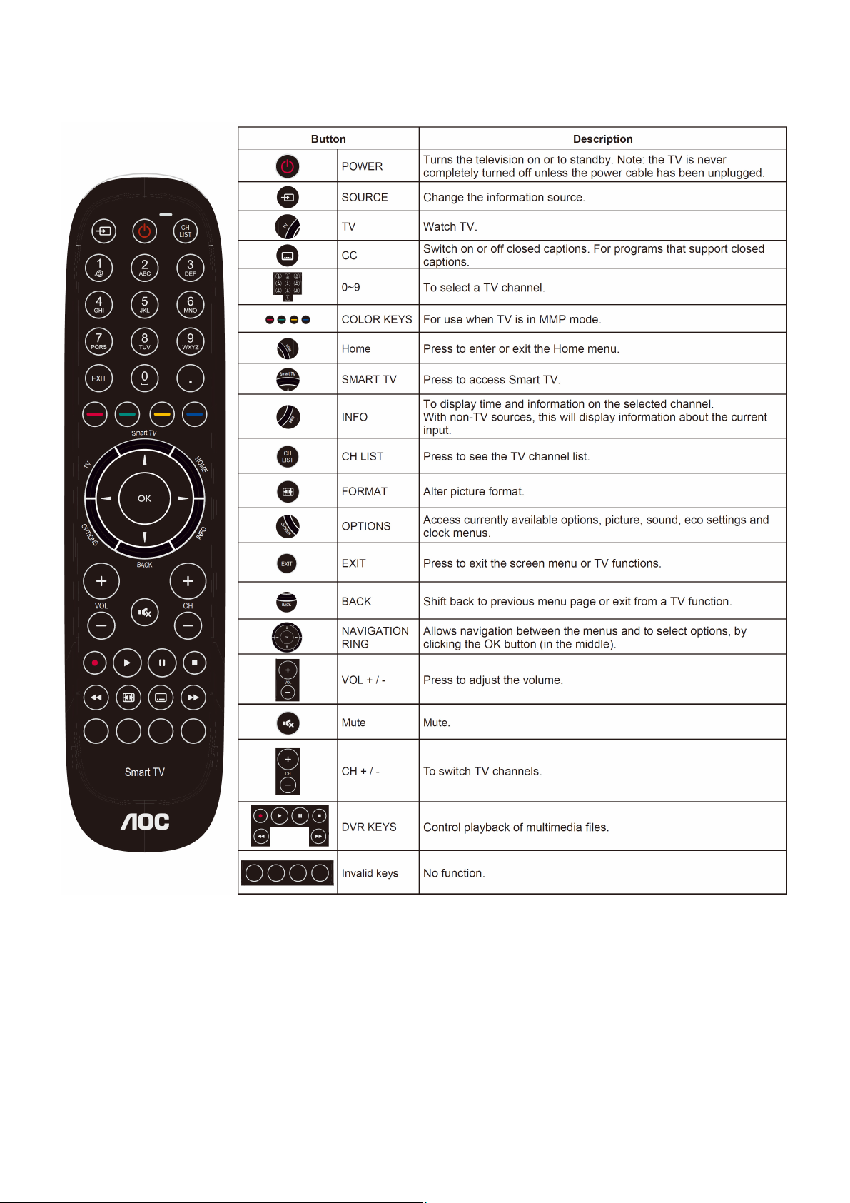
2.1 The Use of Remote Control…….…..……….…….......5
2.2 To Use the Menus….....………………….…..…….......6
2.3 How to Connect……..……………….…….……….....15
2.4 Front Panel Control Knobs…….………….………....17
3. Input/ Output Specification………....................…....18
4. Mechanical Instructions…………………….................19
5. Repair Flow Chart ……………………….…….…….....22
6. PCB Layout ………………..………………....….......28
6.1 Main Board……...…………..….…….……….......28
SAFETY NOTICE
ANY PERSON ATTEMPTING TO SERVICE THIS CHASSIS MUST FAMILIARIZE HIMSELF WITH THE CHASSIS
6.2 Power Board……...…………..….…….……….......29
6.3 IR Board…...…………………………………….......32
6.4 KEY Board…...…………………….…................….32
7. Adjustment..............................................................33
7.1 WB Adjustment……………………...……...………33
7.2 FW Upgrade.………………………………...….…34
8. Block Diagram…..…………....………………...35
9. Schematic Diagram…..…………....………………...36
9.1 Main Board…………..….….……...………….......36
9.2 Power Board…………..….….……...………….......37
9.3 IR Board…...…………….……….…………….........41
9.4 KEY Board…...………………………………….…. .42
10. Exploded View………………………………….…...43
11. BOM List……………….…..…………….………….45
AND BE AWARE OF THE NECESSARY SAFETY PRECAUTIONS TO BE USED WHEN SERVICING
ELECTRONIC EQUIPMENT CONTAINING HIGH VOLTAGES.
CAUTION: USE A SEPARATE ISOLATION TRANSFOMER FOR THIS UNIT WHEN SERVICING
Copyright © 2013 by TPV Corporation. All rights reserved. Specifications are subject to change without notice.
No part of this publication may be reproduced in any form or means, without the prior written permission of TPV Corporation.
Otherwise we will reserve the right to investigate the legal responsibility.
1
Page 2

Important Safety Notice
Proper service and repair is important to the safe, reliable operation of all AOC Company Equipment. The service
procedures recommended by AOC and described in this service manual are effective methods of performing service
operations. Some of these service operations require the use of tools specially designed for the purpose. The
special tools should be used when and as recommended.
It is important to note that this manual contains various CAUTIONS and NOTICES which should be carefully read in
order to minimize the risk of personal injury to service personnel. The possibility exists that improper service
methods may damage the equipment. It is also important to understand that these CAUTIONS and NOTICES ARE
NOT EXHAUSTIVE. AOC could not possibly know, evaluate and advise the service trade of all conceivable ways in
which service might be done or of the possible hazardous consequences of each way. Consequently, AOC has not
undertaken any such broad evaluation. Accordingly, a servicer who uses a service procedure or tool which is not
recommended by AOC must first satisfy himself thoroughly that neither his safety nor the safe operation of the
equipment will be jeopardized by the service method selected.
Hereafter throughout this manual, AOC Company will be referred to as AOC.
WARNING
Use of substitute replacement parts, which do not have the same, specified safety characteristics might create
shock, fire, or other hazards.
Under no circumstances should the original design be modified or altered without written permission from AOC.
AOC assumes no liability, express or implied, arising out of any unauthorized modification of design.
Servicer assumes all liability.
FOR PRODUCTS CONTAINING LASER:
DANGER-Invisible laser radiations when open AVOID DIRECT EXPOSURE TO BEAM.
CAUTION-Use of controls or adjustments or performance of procedures other than those specified herein may
result in hazardous radiation exposure.
CAUTION -The use of optical instruments with this product will increase eye hazard.
TO ENSURE THE CONTINUED RELIABILITY OF THIS PRODUCT, USE ONLY ORIGINAL MANUFACTURER'S
REPLACEMENT PARTS, WHICH ARE LISTED WITH THEIR PART NUMBERS IN THE PARTS LIST SECTION OF
THIS SERVICE MANUAL.
Take care during handling the LCD module with backlight unit
-Must mount the module using mounting holes arranged in four corners.
-Do not press on the panel, edge of the frame strongly or electric shock as this will result in damage to the screen.
-Do not scratch or press on the panel with any sharp objects, such as pencil or pen as this may result in damage to
the panel.
-Protect the module from the ESD as it may damage the electronic circuit (C-MOS).
-Make certain that treatment person’s body is grounded through wristband.
-Do not leave the module in high temperature and in areas of high humidity for a long time.
-Avoid contact with water as it may a short circuit within the module.
-If the surface of panel becomes dirty, please wipe it off with a soft material. (Cleaning with a dirty or rough cloth may
damage the panel.)
2
Page 3

Revision List
Version Release Date Revision Instructions Customer Model TPV Model
A00 Otc.25, 2013 Initial release LE46D7840 E46D42NSDLE7NNX
3
Page 4
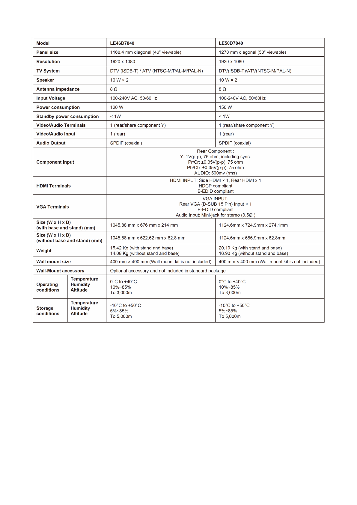
1. General Specification
4
Page 5
2. Operating Instructions
2.1 The Use of Remote Control
5
Page 6
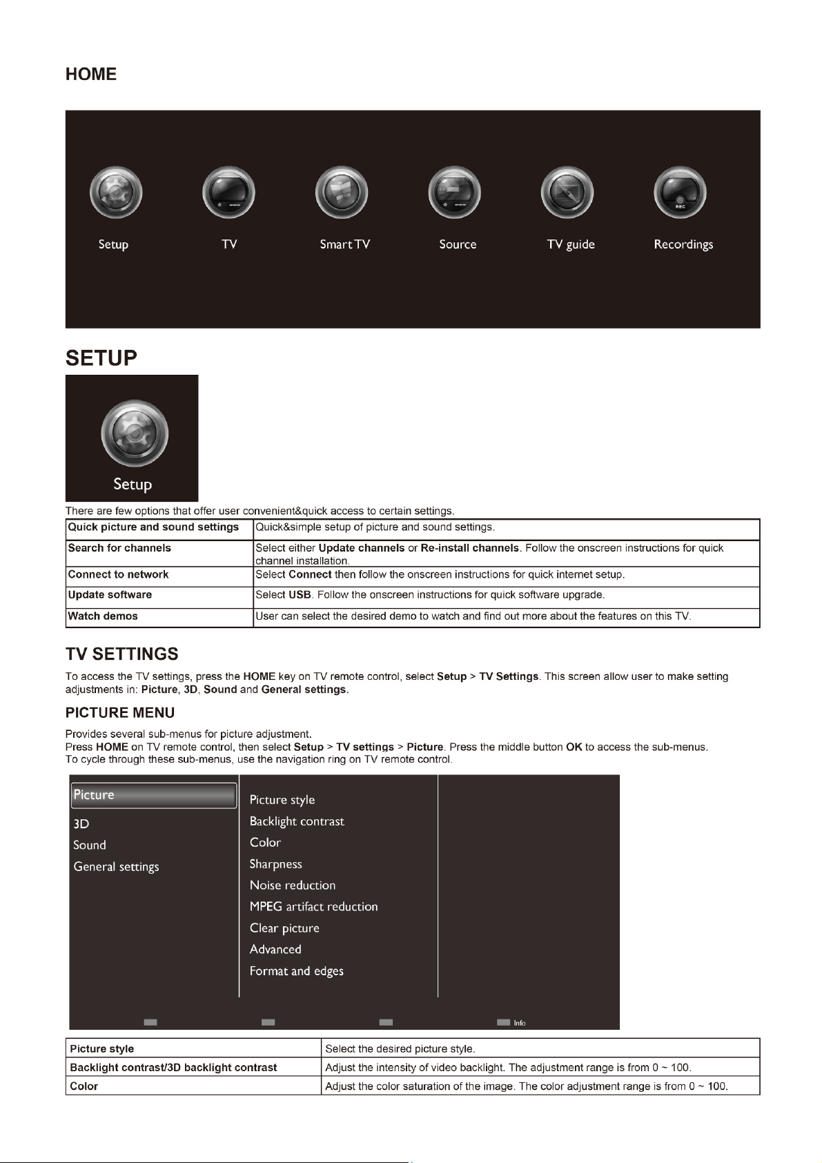
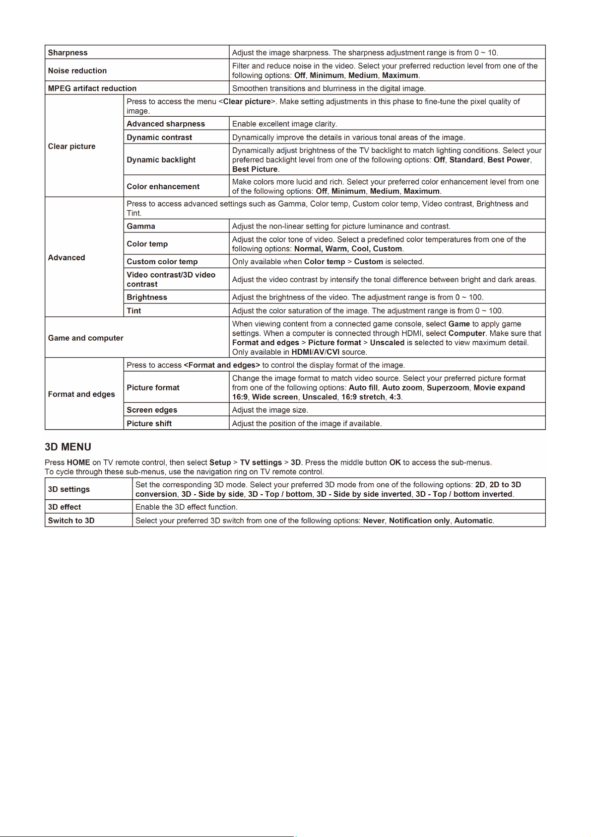
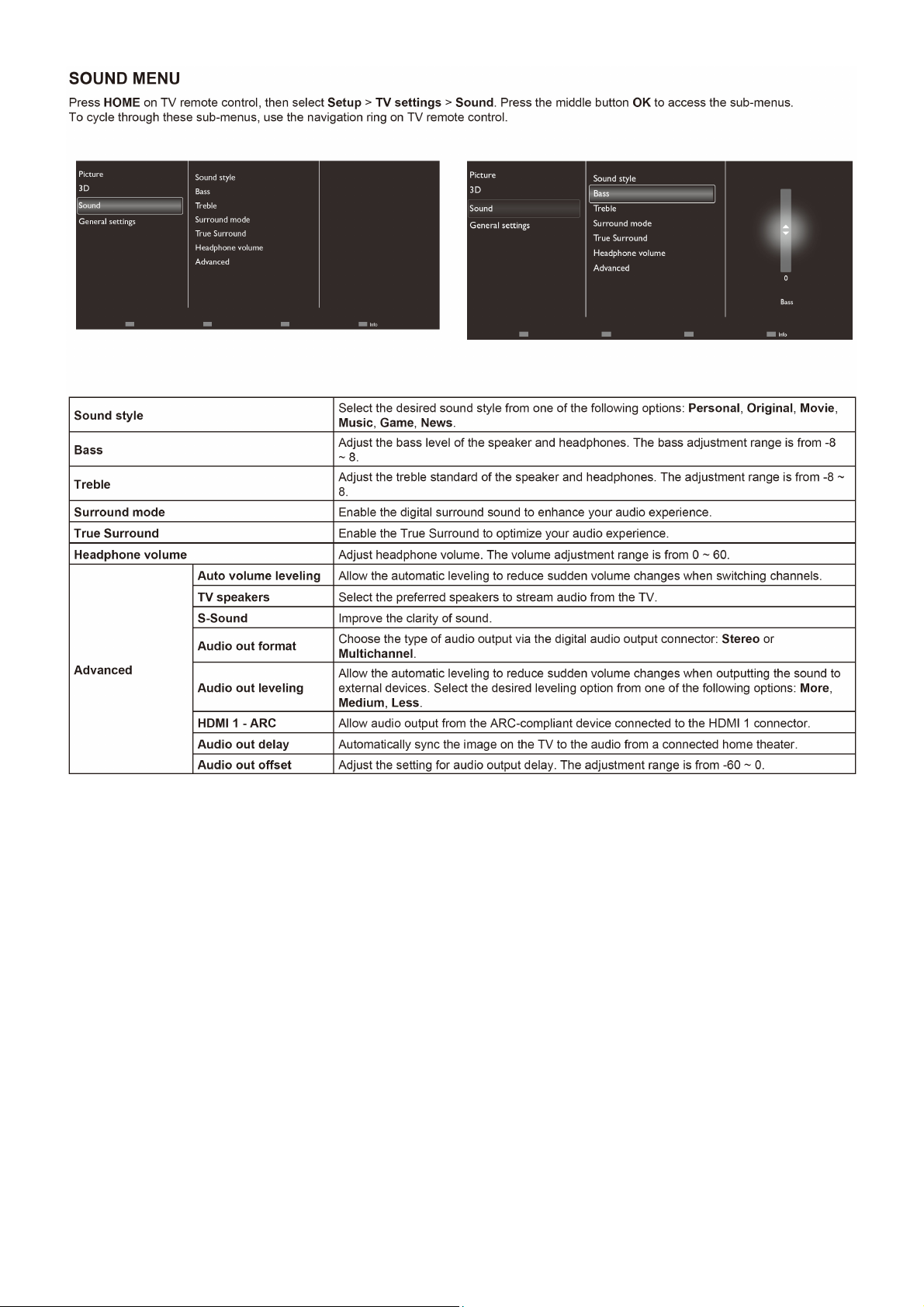
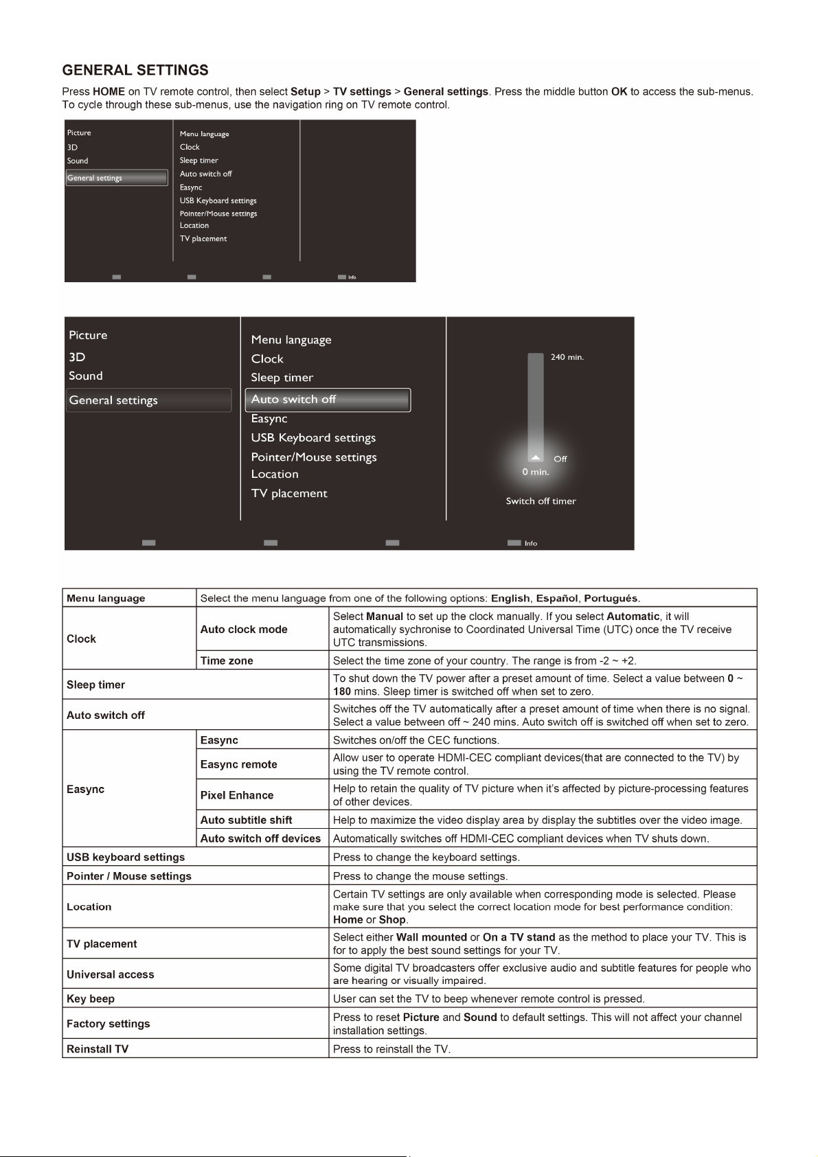
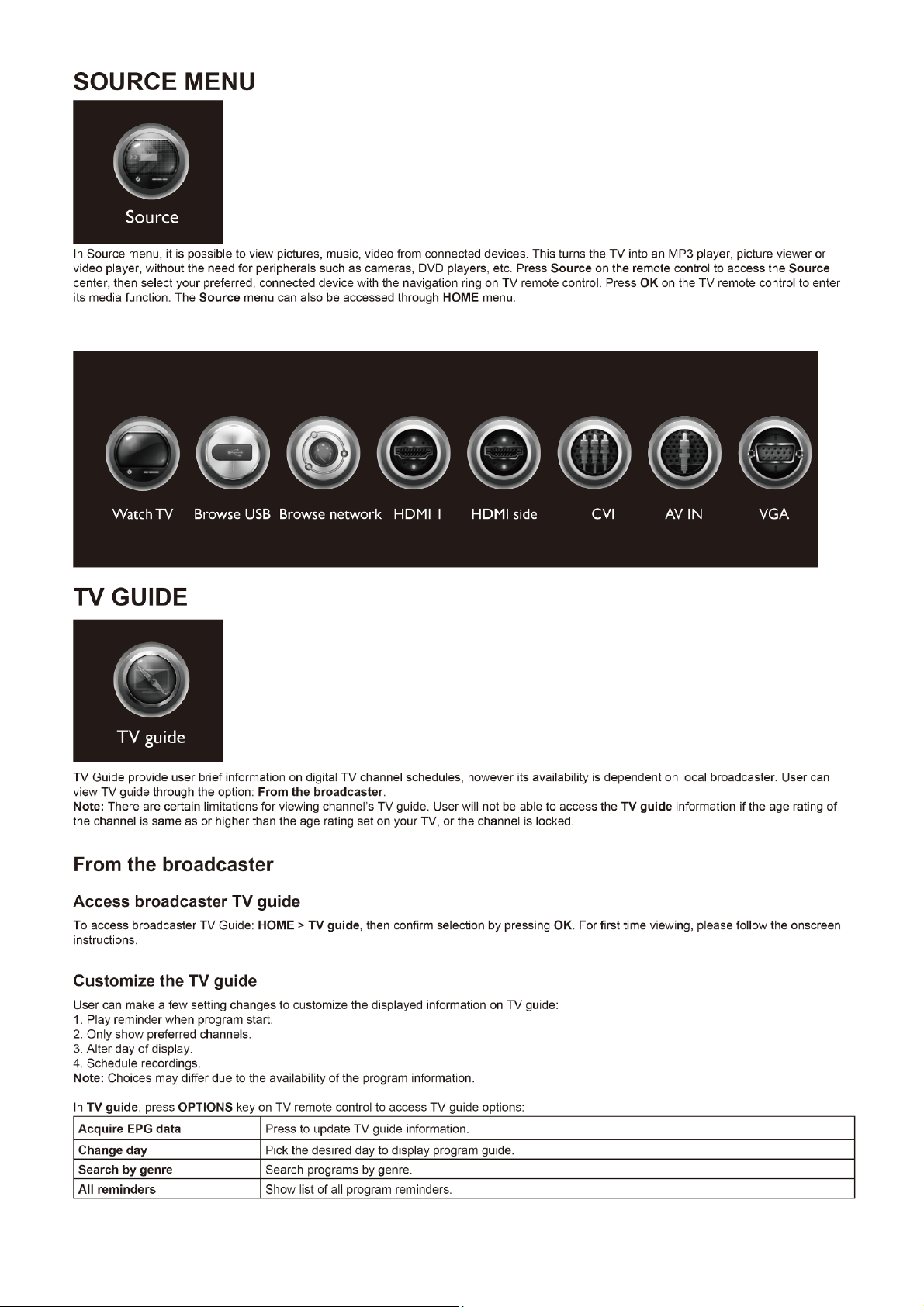
2.2 To Use the Menus
6
Page 7
7
Page 8
8
Page 9
9
Page 10
10
Page 11
11
Page 12

12
Page 13
13
Page 14

14
Page 15

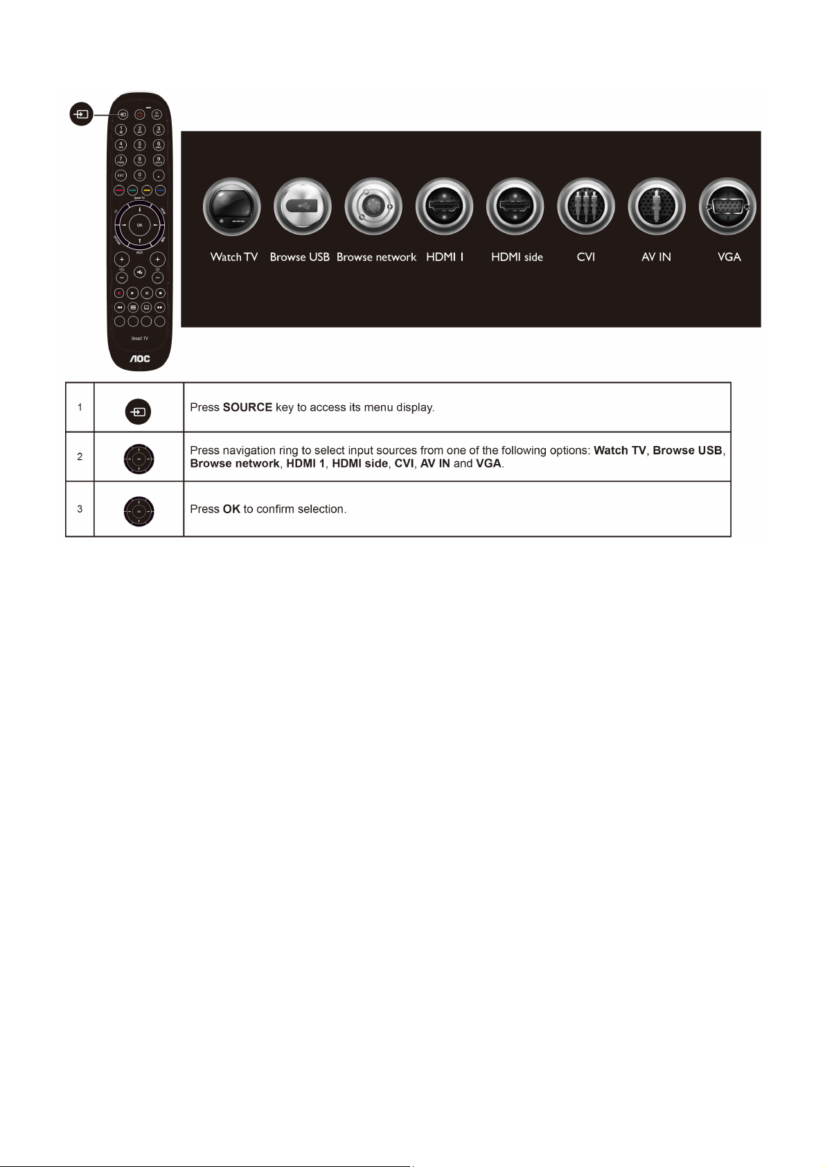
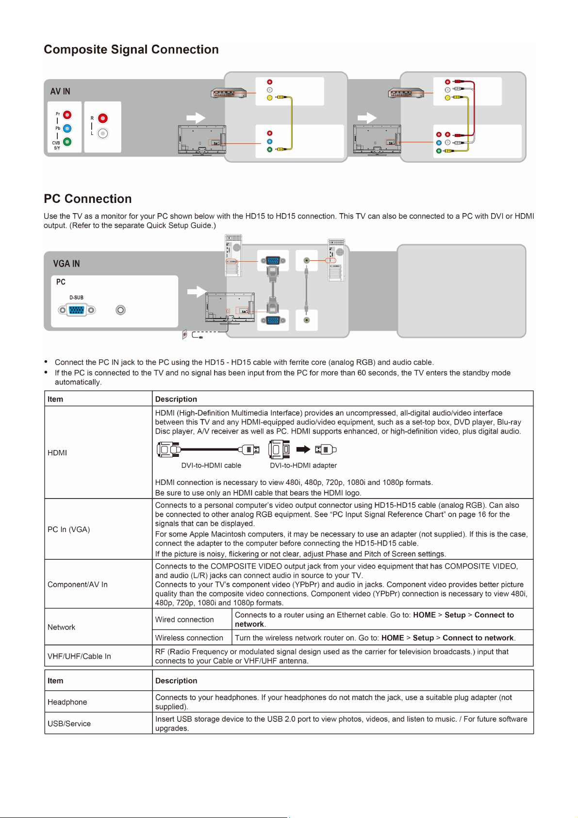
2.3 How to Connect
15
Page 16
16
Page 17
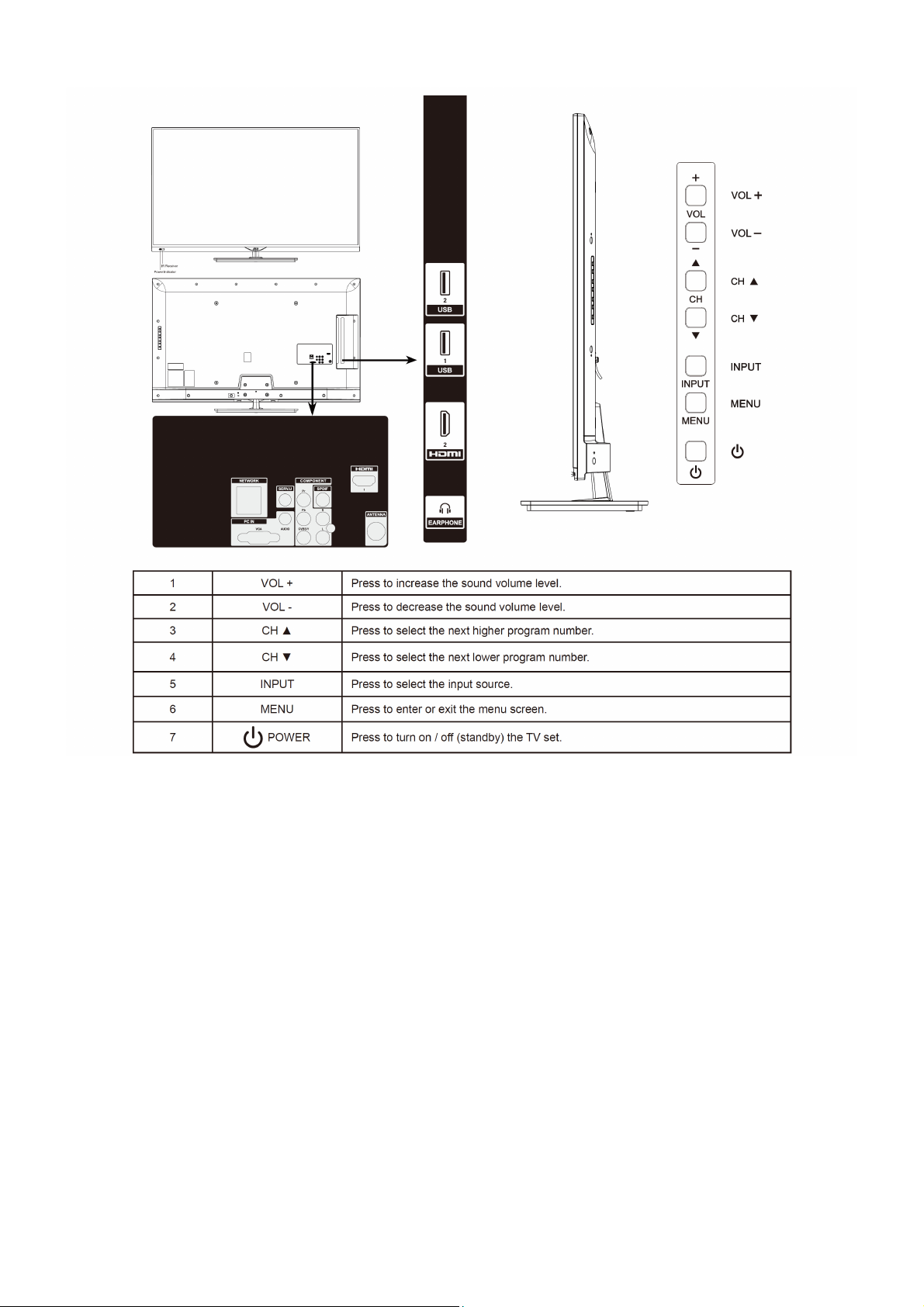
2.4 Front Panel Control Knobs
17
Page 18
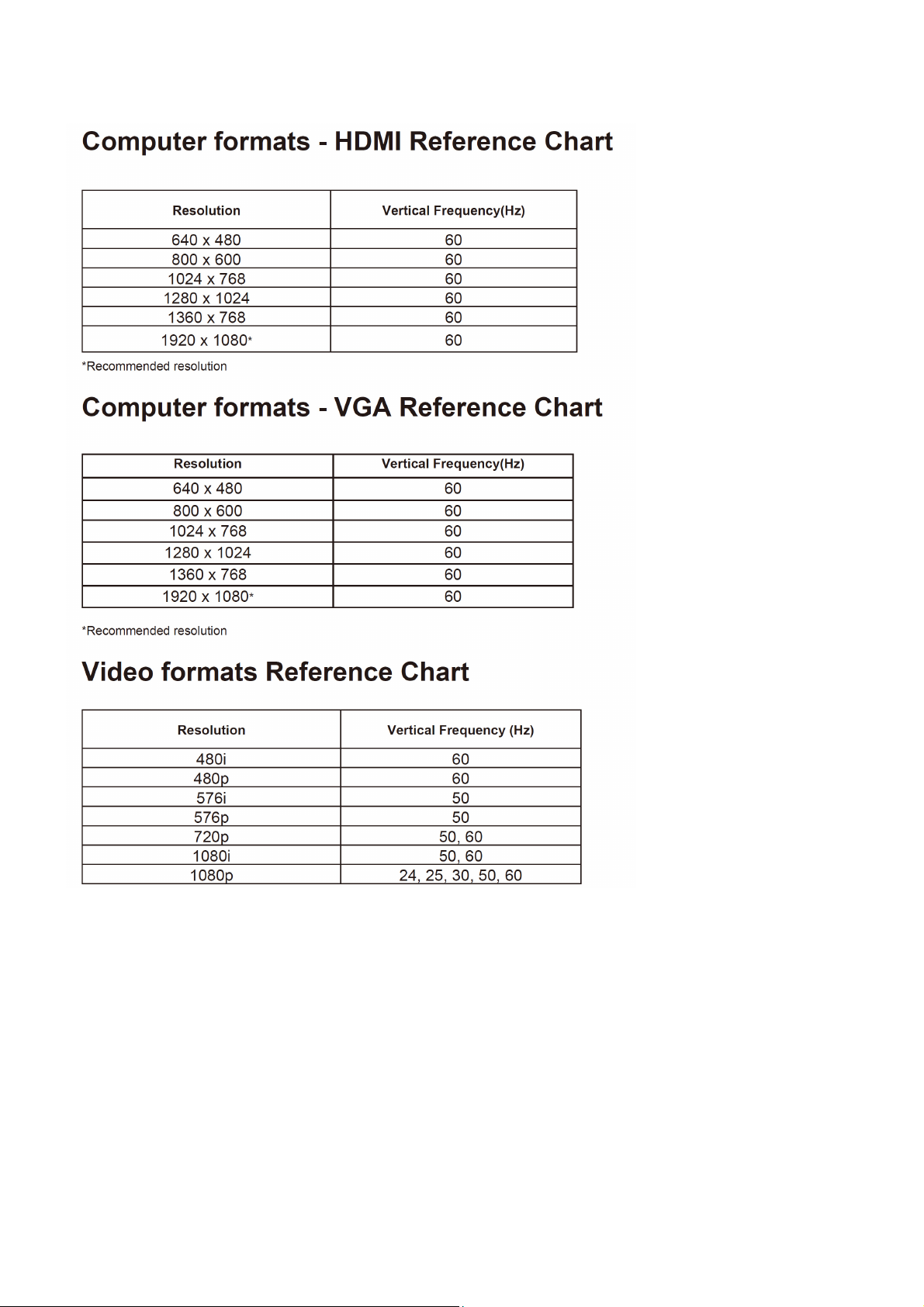
3. Input / Output Specification
18
Page 19
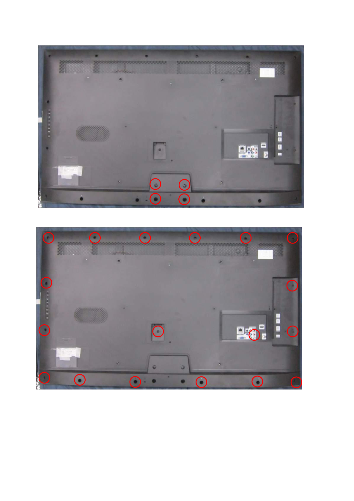
4. Mechanical Instructions
1.Remove the screws to remove BASE.
2.Remove the screws to remove REAR COVER.
19
Page 20
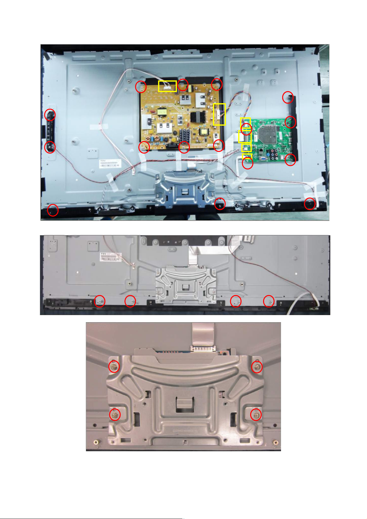
3. Disconnect the PINS marked in yellow. Remove the screws marked in red to remove MAIN BOARD,POWER
BOARD,KEY BOARD,SPEAKER,BKT_IO_SIDE.
4. Remove the screws to remove BKT_ STAND, COVER_HINGE, DECO.
20
Page 21
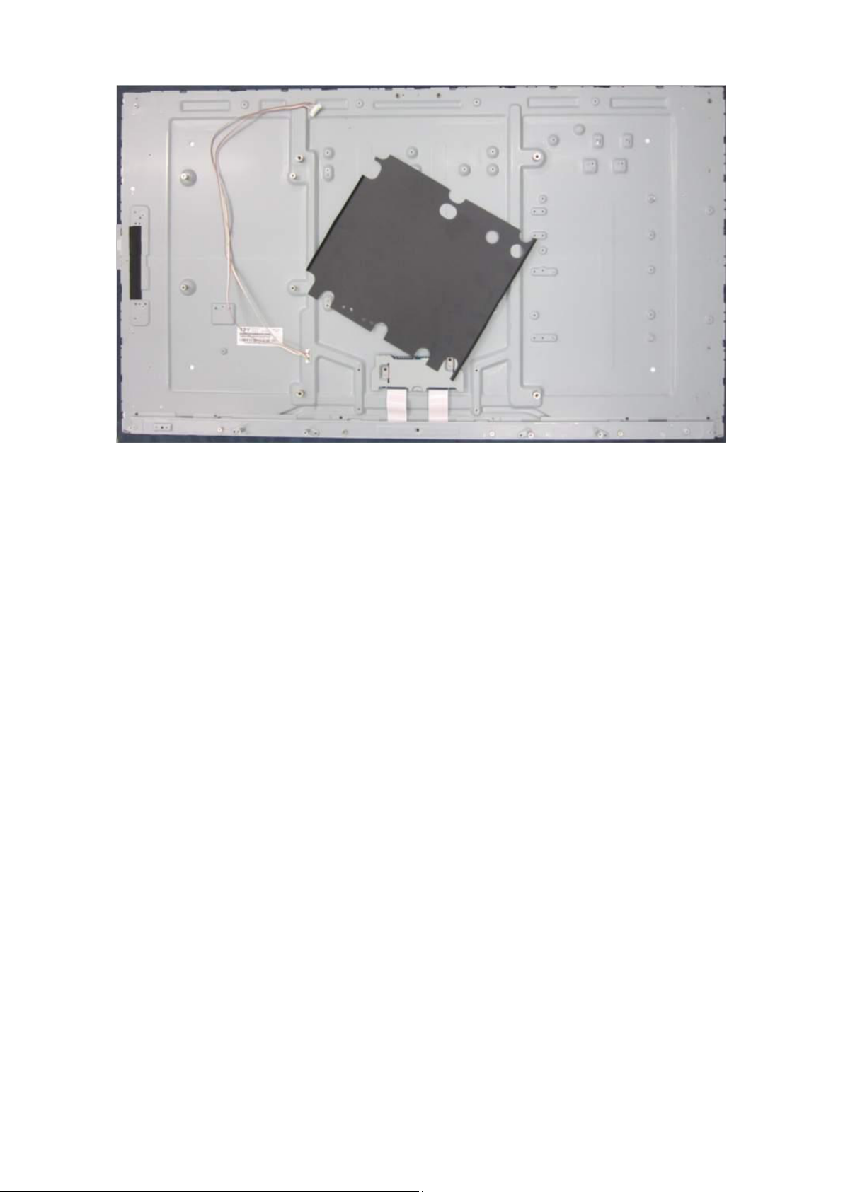
5. Remove the Mylar from PANEL.
21
Page 22
p
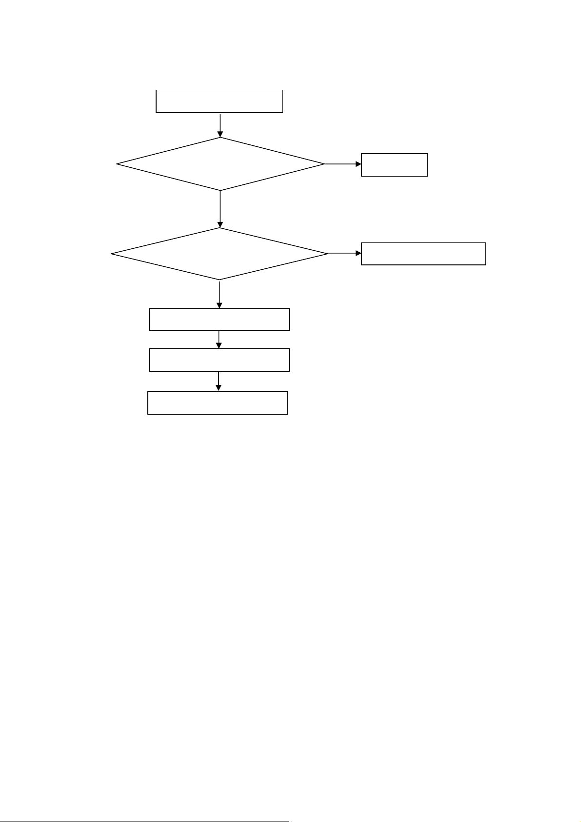
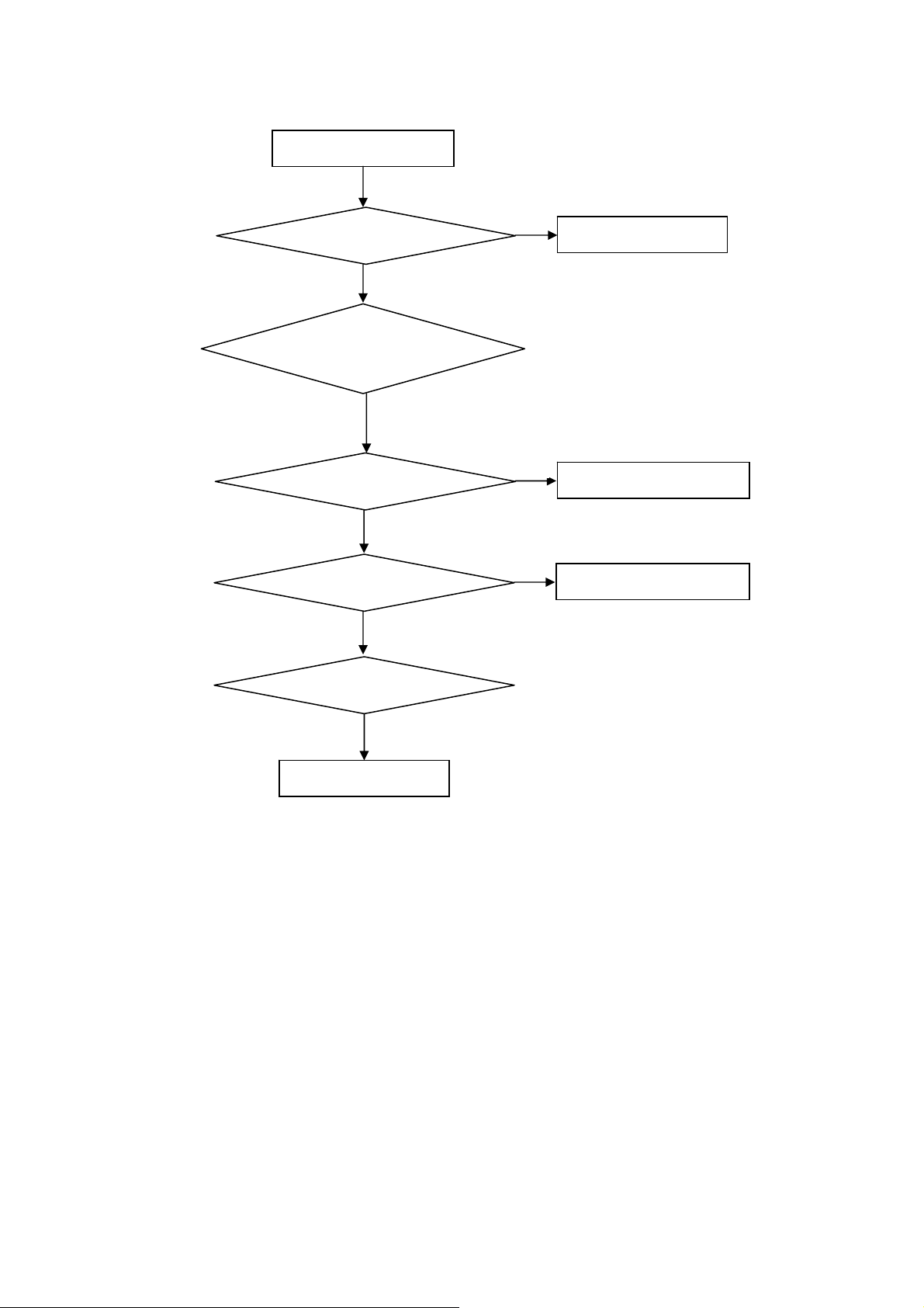
5. Repair Flow Chart
1. No power
No power (LED “Off”)
Check the AC input and
the
ower is “ON”?
Yes
Power board output=5V?
Yes
Check the IR board and LED
Replace the IR board
No
Replace the main board
No
Power “On”
No
Replace the power board
22
Page 23

2. Can’t start
Can’t start (LED red)
Power board output=12/24V?
Yes
Check the power key is under control?
No
Check the IR receiver is normal?
No
Replace the power board
Yes
Replace the main board
Yes
Replace the IR board
No
Replace the main board
No
Replace the Power board
23
Page 24
3. Abnormal display
Abnormal Display
Check the source
Yes
Enter factory mode to do
“EEPROM initial”&“Reset”
No
No
Reset the source
Check the main board
Yes
Check the LVDS cable
Yes
Check the panel
No
Replace the panel
No
Replace the main board
No
Replace the LVDS cable
24
Page 25
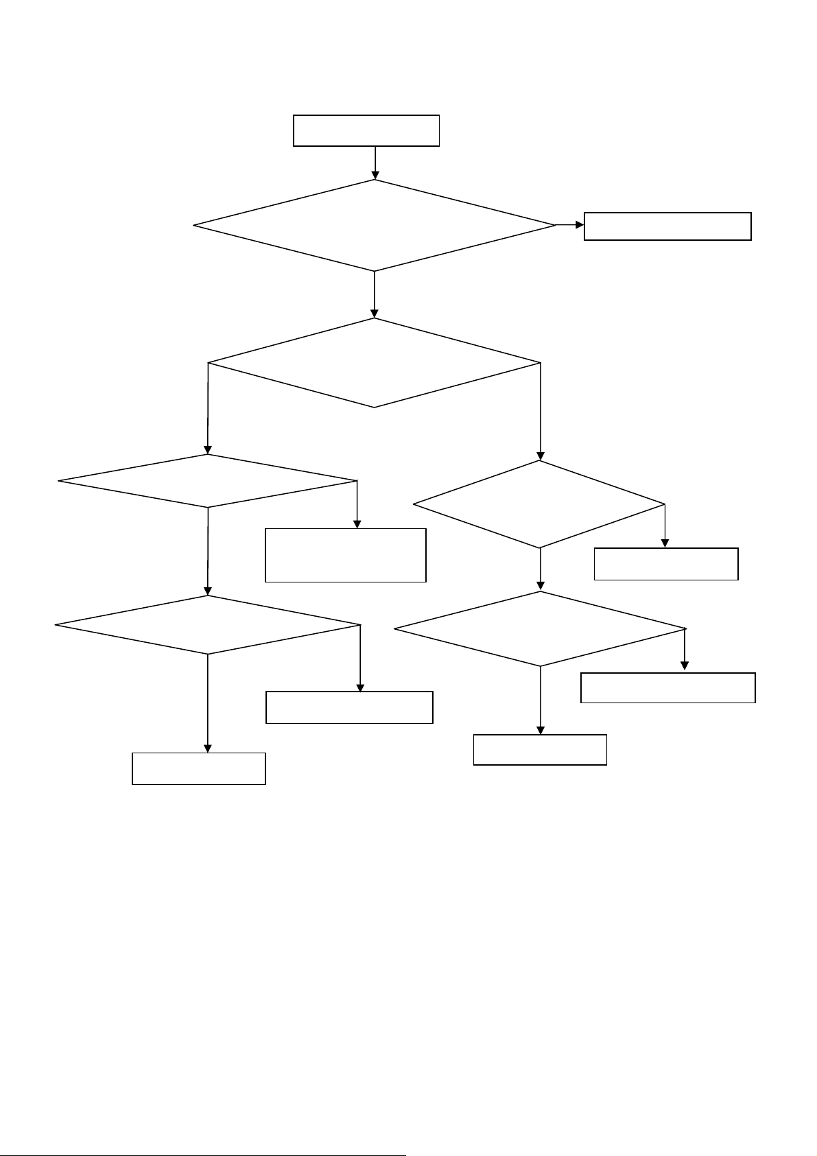
4. No display
No display (No LED)
Check TV is under control and power
on/off by remote control and power key?
Yes
Check the LVDS cable
Yes
Yes
Check the backlight is
“On”?
No
Reinsert or replace the
LVDS cable
No
No
Check the B/L
signal is available?
Yes
Replace the main board
No
Replace main board
Panel Vcc = 12V?
Yes
Replace the Panel
No
Replace the main board
Power board output=12/24V?
Yes
Replace the Panel
Replace the power board
No
25
Page 26

5. Sound problem
No sound or sound abnormal
Check the audio source connection
and the TV system are correct?
Yes
Check the TV is muted, adjust the
volume or enter the menu to reset?
No
No
Reinsert the audio cable or
change the TV system
Enter factory mode to do “Reset”
No
Check the cable between the
speakers and main board is OK?
Yes
Check the speaker resistance value is in spec
(Remark: The value is marked on the speaker)?
Yes
Replace the cable
Replace the main board
No
No
Replace the speaker
26
Page 27

6. Remote control malfunction
Remote Control malfunction
Check the remote control battery is
not properly placed or no power?
No
Use the other remote controls
No
Whether the IR board is
abnormal?
No
Replace the main board
Yes
Replace the battery
Yes
Replace the remote control
Yes
Replace the IR board
27
Page 28

6. PCB Layout
6.1 Main Board
715G6257M0A000005K(Not produce by TPV)
N/A
28
Page 29

6.2 Power Board
715G5778P03W21002M
29
Page 30

30
Page 31

31
Page 32
6.3 IR Board
715G6116R01000004S
6.4 Key Board
715G6115K01000004S
32
Page 33

7. Adjustment
7.1 White Balance Adjustment
It is not need to adjust White Balance.
33
Page 34
7.2 Firmware Instruction
Step 1: Ready for F/W Upgrade
1.1 Prepare a USB memory. Copy the software file to the USB memory root directory, and remove it from computer’s
USB port!
Step 2: F/W Upgrade
2.1 Insert USB flash disk into TV’S USB.
2.2 AC on the TV, the indicator light will shine after about tens of seconds, and the software will update automatically.
TV will auto restart after update the software.
34
Page 35

8. Block Diagram
N/A
35
Page 36

9. Schematic Diagram
9.1 Main Board
715G6257M0A000005K(Not produce by TPV)
N/A
36
Page 37
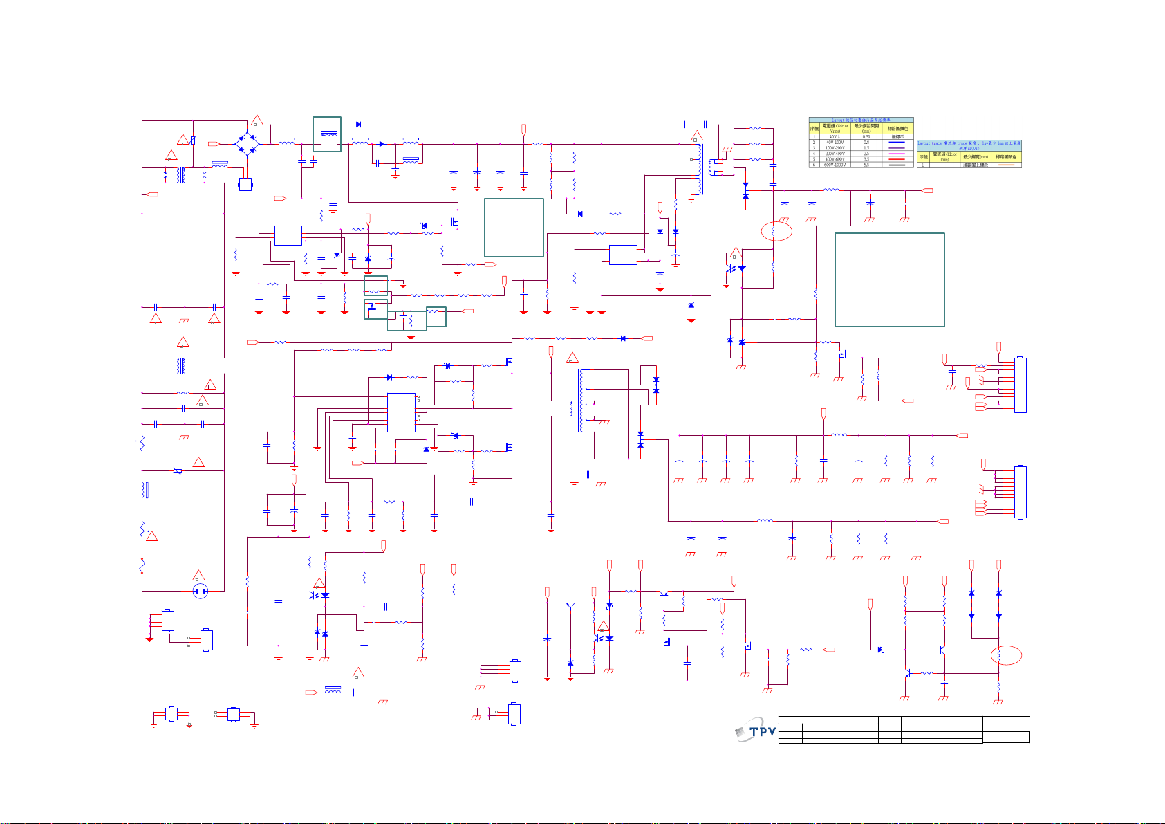
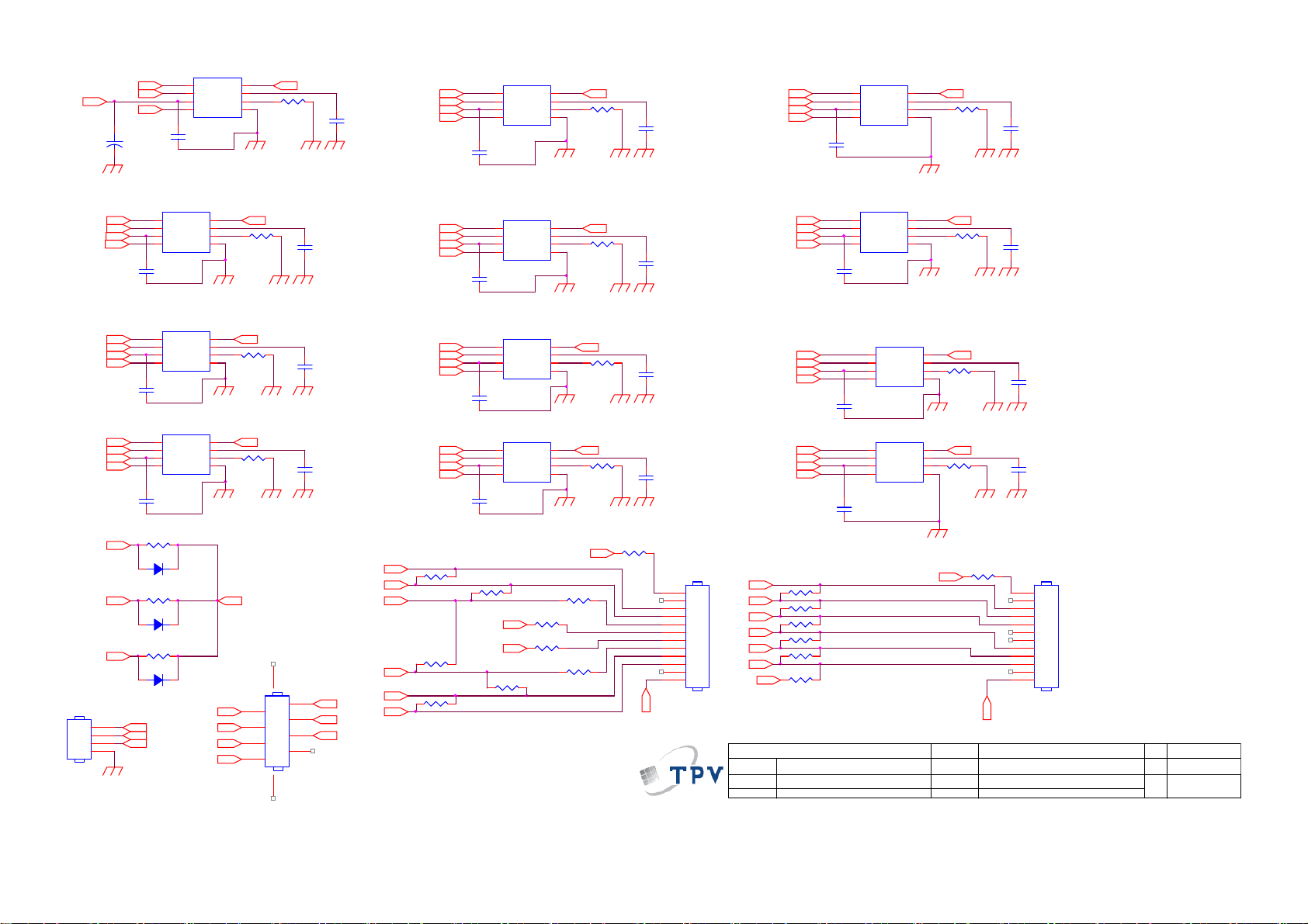
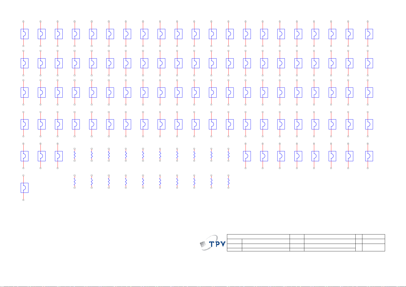
9.2 Power Board
715G5778P03W21002M
RV9902
560V
!
!
L9903
124
12mH
SG9905
DSPL-501N-A21F
3
BOX
C9911
330NF 275V
C9906
150PF 250V
!
!
L9901
124
12mH
3
R9901
1MOHM +-5% 1/2W
!
C9910
HS9901
1
2
3
4
341
330NF 275V
RV9907
560V
HS9101
HEAT SINK
C9909
150PF 250V
!
!
1 2
HEAT SINK(Q9801,D9801)
1
2
3
4
2
HS9801
HEAT SINK
C9908
150PF 250V
t
NR9902
NTCR
1 2
12
FB9999
BEAD
12
NR9901
NTCR
t
!
F9901
FUSE
HEAT SINK(BD9901)
HEAT SINK
HEAT
SINK(D8120,Q8101)
R-
1 2
SG9904
DSPL-501N-A21F
C9907
150PF 250V
!
!
CN901
SOCKET
HEAT
SINK(Q9101,Q9102)
4
FB9996
NC
HS9102
341
HEAT SINK
!
2
BD9901
+
-
TS10B06G-06-X0
3
1
2
L
N
CN904
NC
R9805
200KOHM 1/8W +/ -5%
B1+
C9145
100N 50V
C9146
100N 50V
R9146
2K43 1/8W 1%
C9148
4.7uF 10V
2
1
1 2
R-
R2A20113A
IC9801
1
FB
2
COMP
3
RT
NC4CS
R2A20133ESP
R9806
56K 1/8W
C9824
22N 50V
R9141
0.1R
18K 1/8W 1%
FB9810
BEAD
1UF 450V
R9145
VCC1
VCC
D9306
1N4148
BOX
1
3
D9116
FMW-2156
2
R9178
5K1 +-5% 1/8W
Q9304
2N7002K
+
C9336
10UF 50V
D9115
FMEN-2308
2
Q9305
MMBT3906 PNP
R9307
10K 1% 1/8W
C9345
100N 50V
C9980
470PF 250V
R9332
2R2 +-5% 1/4W
D9307
FR107
+
C9337
47UF 50V
C9160
330UF 35V
+
R9308
10K 1/8W 1%
1
2
3
5
4
1 2
!
ZD9303
+
C9981
470PF 250V
T9301
POWER X'FMR
GDZJ15B
ZD9304
NC
C9174
330UF 35V
+
C9168
470UF 25V
6
7
9
10
!
43
1 2
C9161
NC
+
+
C9163
NC
3.3V
R9311
NC
3.3V
R9309
20KOHM +-1% 1/8W
R9310
100KOHM +-1% 1/8W
47 OHM 1/4W
47 OHM 1/4W
47 OHM 1/4W
1
3
12
IC9303
PS2561DL1-1
1
IC9304
2 3
AZ432AZTR-G1
R9399
R9330
R9331
C9395
2N2 50V
D9308
FMW-2156
C9338
2
2N2 50V
+
R9334
220 OHM 1/4W
R9335
3K3 1/8W 5%
12.7 KOHM +-1% 1/8W
C9343
R9336
220N 50V
1Kohm +-1% 1/4W
7.5KOHM +-1% 1/ 8W
+
C9172
NC
L9106
3UH
Q9302
RK7002BM
C9301
100N 50V
T P V ( Top Victory Electronics Co . , Ltd. )
絬 隔 瓜 絪 腹
Key Component
Date
L9304
NC
C9340
+
470UF 25V
R9337
R9338
R9174
5.1K 1/4W
C9344
470UF 25V
R9339
NC
19V
+
C9341
470UF 25V
EMI solution 5/8:
C9903/C9908/C9909 form 470pf
change to 220pf, FB903 add jump,
C9904 add 220pf, L9801 form
240uH change to 450uH, T9301
form 080GL52P 48 YS change to
080GL52P 54 CP
Q9301
NC
R9340
R9341
NC
NC
L9105
3UH
C9164
+
330UF 35V
C9165
100N 50V
R9171
5.1K 1/4W
C9342
100N 50V
DV5
R9172
5.1K 1/4W
change to 150uF
+
C9169
470UF 25V
R9175
1.5K 1/4W
20K OHM
R9303
R9304
100K 1/8W 1%
PS-On
G5778-P02-000-0020_12111 4
POWER CIRCUIT 715G5778-P02-000-0020_121114
Wednesday , Nov ember 14, 201 2
R9176
1.5K 1/4W
Main_ov
D9301
SS1060FL
1 2
OEM MOD EL
TPV MODEL
PCB NAME
Q9103
PMBS3904
Sheet
R9177
1.5K 1/4W
DV5
R9143
NC
R9333
2K 1/8W 1%
1Kohm +-1% 1/4W
42PFL4508G
PLTVCQ696XAJ2
of
13
R9138
C9170
100N 50V
3.3V
1N 50V
DIM
C8550
R9173
5.1K 1/4W
12V
3.3V
R9111
0 OHM +-5% 1/8W
R9324
1K 1/8W 1%
Q9106
MMBT3906 PNP
C9144
100N 50V
R8550
1Kohm +-1% 1/4W
12V
19VA
PS-On
3.3V
P_Scan
19VA
12V
P_Scan
DIM
On/Off
19V
GDZJ30B
1 2
D9109
1N4148
24V
ZD9101
On/Off
CN902
13
12
11
10
9
8
7
6
5
4
3
2
1
CONN
CN903
12
11
10
9
8
7
6
5
4
3
2
1
NC
12V
ZD9102
GDZJ15B
1 2
D9110
1N4148
R9139
100R 1%
R9140
1K 1/8W 1%
A2
Size
C
Rev
称爹
>
<
称爹
D9802
IN5408G-04
L9801
240UH
FB9804
BEAD
1 2
6
1
C9820
C9875
NC
C9831
NC
R9807
0 OHM +-5% 1/8W
200 OHM 1/4W
8
VCC
7
OUT
6
GND
5
R9804
NC
C9825
220NF 50V
+
C9147
22UF 50V
43
C9149
1uF
ZD9105
GDZJ30B
R-
ZD9106
BZT52-B3V6
R9144
1.5M 1% 1/4W
R9147
470 OHM
!
12
1 2
FB9302
1 2
BEAD
12
C9826
3.3NF 50V
C9827
1NF 50V
C9150
0.47UF 50 V
R9158
5.6K
IC9106
PS2561DL1-1
IC9107
AS431AZTR-E1
R9888
R9810
16K 1% 1/8W
R9150
1.5M 1% 1/4W
VBoot
R9148
NC
C9955
220PF 250V
ZD9107
BZT52-B22
C9828
100N 50V
C9151
1UF
C9152
10PF
!
STTH10LCD06FP
C9833
VCC1
1 2
R9811
NC
Q9802
AOD1N60
1.5M 1% 1/4W
R9159
20K 1/4W
C9159
330NF 50V
C9166
NC
D9801
47pF
C9171
1.5NF
R9808
10R 1/8W 5%
R9142
UF4007
D9114
1
2
3
4
5
6
7
8
C9153
1uF
470 OHM 1/8W
R9149
C9154
560P 50V
19V
C9158
NC
+
C9829
100N 50V
C9832
100N 50V
IC9101
Vsen
Vcc
FB
GND
Css
OC
RC
Reg
RV9COM
SSC9522S
R9160
1K 1/8W 1%
FB9801
BEAD
1 2
FB9802
1 2
BEAD
C9830
10UF 50V
R9817
100K 1%
R9151
10 OHM
NC
NC
VGH
VS
VB
NC
NC
VGL
ZD9104
GDZJ15B
R9101
180R 1%
D9803
SS1060FL
R9809
200 OHM 1/4W
R9813
10K 1/4W
R9819
10KOHM
18
17
16
15
14
13
12
11
10
1 2
12V
R9161
24K 1/8W 1%
R9163
2K 1/8W 1%
STF24NM60N
12
R9816
R9818
1K
D9113
SS1060FL
47OHM +-5% 1/8W
47OHM +-5% 1/8W
C9155
1N 50V
C9801
68uF 450V
+
Q9801
680K OHM +-1% 1/4W
R9815
680K OHM +-1% 1/4W
VCC1
12
R9152
D9112
SS1060FL
12
R9154
R9156
10K 1/8W 1%
19V
R9180
20KOHM +-1% 1/8W
R9801
0.07R
C9156
100PF1KV
+
C9877
47pF
1M 1/4W 1%
R9153
10K 1/8W 1%
C9804
C9802
68uF 450V
68uF 450V
+
power saving 5/7
R9811 form 0ohm to
NC, Q9802 form NC
to TK2P60D, C9832
form NC to 100nF,
R9819 form NC to
10K, R9818 form NC
to 1K
R-
B1+
R9814
R9102
10 OHM
R9103
10 OHM
HS9301
HEAT SINK (D9308)
1
2
3
4
HS9103
1
2
3
4
HEAT SINK
B1+
C9803
470PF1KV
C9333
0.47UF 50V
R9317
1.5M 1% 1/4W
Q9101
STF8NM50N
Q9102
STF8NM50N
22UF 50V
HEAT
SINK(D9115,D9116)
R9329
0.1R
R9325
R9327
100K
100K
C9331
D9305
FR107
!
T9101
NEW
2K 1/8W 1%
ZD9301
GDZJ18B
1 2
R9328
100K
4.7M OHM +-5% 1/4W
R9301
3.3R
R9319
1.5M 1% 1/4W
C9912
470PF 250V
VCC
R9306
R9323
14
12
13
8
9
10
11
15
43
R9302
100K 1/6W 5%
Main_ov
!
1NF
R9390
1
2
3
C9334
1N 50V
12
12
0R05
IC9301
A6069H
S/OCP
BR
GND
FB/OLP4VCC
D9304
FR107
D9302
SS1060FL
IC9302
PS2561DL1-1
R9346
220R
D/ST
D/ST
100N 50V
8
7
5
C9335
1
3
DV5
R9326
100K
R9320
560K 1/8W 1%
R9318
1.5M 1% 1/4W
VBoot
2
6
C9157
22NF
VCC1
Q9303
BTC4672M3
+
C9302
37
Page 38

12V
19V
0 OHM 1/8W
R8176
ZD8103
NC
100N 50V
1 2
+
C8111
1
C8170
330UF 35V
22UF 50V
220K OHM 1%
C8121
+
3
NC
C8177
8
R8163
L8101
33uH
R8175
0.03R
5
6
OUT7VCC
GND
FB1GM2RT3CS
4
IC8103
DIM
C8105
1N 50V
R8162
1Kohm +-1% 1/4W
PF7900S
Q8101
AOTF454FL
R8157
10K 1/8W 1%
0 OHM 1/8W
R8148
100K 1/8W 1%
C8119
1N 50V
1
2
3
R8158
10R 1/8W 5%
R8153
D8120
FME-220B
680K 1/4W 1%
560K 1/8W 1%
R8161
NC
12
D8118
NC
C8113
100N 50V
DIM
R8145
R8147
C8106
NC
R8188
NC
C8188
NC
R8144
75K 1%
R8141
82K +-1% 1/8W
C8118
120UF 100V
+
+
C8109
120UF 100V
LED-COMP
R9322
R8154
100K
10K 1% 1/4W
R8155
100K
C9346
100N 50V
VLED
R8156
100K
ENOn/Of f
38
Page 39
DIM
12V
LED-1
+
C8158
NC
IC8501
1
DIM
2
EN
3
VCC
LED4GND
C8157
100N 50V
COMP
PF7700A
ISET
8
7
GM
6
5
LED-COMP
R8501
9.53KOHM +-1% 1/8W
C8501
470NF 5 0V
DIM DIM
EN
12V
LED-2
IC8502
1
DIM
2
EN
3
VCC
LED4GND
PF7700A
C8523
100N 50V
COMP
GM
ISET
8
7
6
5
R8502
9.53KOHM +-1% 1/8W
LED-COMP
C8502
470NF 50V
12V
EN
LED-3
IC8503
1
DIM
2
EN
3
VCC
LED4GND
PF7700A
C8529
100N 50V
COMP
ISET
8
7
GM
6
5
LED-CO MPEN
R8503
9.53KOHM +-1% 1/8W
C8503
470NF 50V
IC8504
DIM
EN
12V
LED-4 LED-6
PWM_C
EN
12V
LED-7
PWM_B
EN
12V
LED-10
PWM_C
PWM_B
PWM_A
CN8503
1
2
3
4
NC
1
2
3
1
2
3
1
2
3
R8513 NC
D8555 NC
R8514 NC
D8556 NC
R8515 NC
D8557 NC
PWM_A
PWM_B
PWM_C
DIM
EN
VCC
LED4GND
PF7700A
C8518
100N 50V
DIM
EN
VCC
LED4GND
C8519
NC
DIM
EN
VCC
LED4GND
C8520
NC
COMP
IC8507
COMP
NC
IC8510
COMP
NC
GM
ISET
GM
ISET
GM
ISET
LED-8
LED-10
LED-12
VLED
8
7
6
5
R8504
9.53KOH M +-1% 1/8W
8
7
6
5
R8507NC
8
7
6
5
R8510NC
DIM
LED-COMP
LED-COMP
LED-COMP
910
2
4
6
8
CN8504
1
3
5
7
NC
C8504
470NF 50V
C8507
NC
C8510
NC
LED-7
LED-9
LED-11
DIM LED-COMP
EN
12V
LED-5
PWM_C
EN
12V
LED-8
PWM_A
EN
12V 12V
LED-11
LED-1
LED-2
LED-3
LED-4
LED-5
LED-6
R8519 NC
R8520 NC
R8521 NC
1
2
3
C8524
100N 50V
1
2
3
C8525
NC
1
2
3
C8526
NC
R8541 NC
LED-11
LED-12
R8540 NC
IC8505
DIM
COMP
EN
VCC
ISET
LED4GND
PF7700A
IC8508
DIM
COMP
EN
VCC
ISET
LED4GND
NC
IC8511
DIM
COMP
EN
VCC
ISET
LED4GND
NC
8
7
GM
6
5
8
7
GM
6
5
8
7
GM
6
5
R8555
0 OHM +-5% 1/8W
R8542 NC
R8543 NC
R8546
0 OHM +-5% 1/8W
R8505
9.53KOHM +-1% 1/8W
LED-COMP
R8508NC
LED-COMP
R8511NC R8512NC
VLED
0R05 1/4W
R8548
VLED
C8505
470NF 50V
C8508
NC
C8511
NC
12
11
10
9
8
7
6
5
4
3
2
1
CN8506
LED-7
LED-8
LED-9
LED-10
LED-11
LED-12
LED-1
CONN
T P V ( Top Victory Electronics Co . , Ltd. )
絬 隔 瓜 絪 腹
Key Component
Date
IC8506
DIM
EN
12V
PWM_B
EN
12V
LED-9
PWM_A
EN
LED-12
R8522 NC
R8545 NC
R8523 NC
R8544 NC
R8524 NC
R8547 NC
G5778-P02-000-0020_ 121114
POWER CI RCU IT 715G5778-P02-000-0020_121114
Wednesday , Novem ber 14, 2012
1
DIM
2
EN
3
VCC
LED4GND
C8530
100N 50V
C8531
NC
C8532
NC
PF7700A
1
DIM
2
EN
3
VCC
LED4GND
1
DIM
2
EN
3
VCC
LED4GND
COMP
ISET
IC8509
NC
IC8512
NC
GM
COMP
ISET
COMP
ISET
8
7
6
5
8
7
GM
6
5
8
7
GM
6
5
VLED
LED-COMP
R8506
9.53KOHM +-1% 1/8W
LED-COMP
R8509NC
LED-COMP
R8549 NC
VLED
OEM MO DE L
TPV MODEL
PCB NAME
42PFL4508G
Sheet
C8506
470NF 50V
C8509
NC
C8512
NC
CN8501
12
11
10
9
8
7
6
5
4
3
2
1
NC
PLTVCQ696XAJ2
of
13
Size
Rev
称爹
B
C
称爹
>
<
39
Page 40
J901
JUMPER
1 2
J943
JUMPER
1 2
J944
JUMPER
1 2
J965
JUMPER
1 2
J993
JUMPER
1 2
J902
JUMPER
1 2
J942
JUMPER
1 2
J945
JUMPER
1 2
J967
JUMPER
1 2
J994
JUMPER
1 2
J903
JUMPER
1 2
J941
JUMPER
1 2
J946
JUMPER
1 2
J968
JUMPER
1 2
J995
JUMPER
1 2
1 2
1 2
1 2
1 2
0R05 1/4W
J904
J940
J947
J970
RJ910
JUMPER
JUMPER
JUMPER
JUMPER
1 2
1 2
1 2
1 2
0R05 1/4W
RJ909
J905
JUMPER
J939
JUMPER
J948
JUMPER
J971
JUMPER
1 2
1 2
1 2
1 2
0R05 1/4W
J906
J938
J949
J972
RJ908
JUMPER
JUMPER
JUMPER
JUMPER
1 2
1 2
1 2
1 2
0R05 1/4W
J907
J937
J950
J973
RJ907
JUMPER
JUMPER
JUMPER
JUMPER
1 2
1 2
1 2
1 2
0R05 1/4W
J908
J936
J951
J974
RJ906
JUMPER
JUMPER
JUMPER
JUMPER
1 2
1 2
1 2
1 2
RJ905
0R05 1/4W
J909
JUMPER
J935
JUMPER
J952
JUMPER
J975
JUMPER
1 2
1 2
1 2
1 2
RJ904
0R05 1/4W
J910
JUMPER
J934
JUMPER
J953
JUMPER
J976
JUMPER
1 2
1 2
1 2
1 2
0R05 1/4W
RJ903
J911
JUMPER
J932
JUMPER
J954
JUMPER
J977
JUMPER
1 2
1 2
1 2
1 2
0R05 1/4W
J912
J931
J955
J978
RJ902
JUMPER
JUMPER
JUMPER
JUMPER
1 2
1 2
1 2
1 2
0R05 1/4W
RJ901
J913
JUMPER
J930
JUMPER
J956
JUMPER
J933
JUMPER
J914
JUMPER
1 2
J929
JUMPER
1 2
J957
JUMPER
1 2
J966
JUMPER
1 2
J992
JUMPER
1 2
J915
JUMPER
1 2
J928
JUMPER
1 2
J958
JUMPER
1 2
J969
JUMPER
1 2
J991
JUMPER
1 2
J916
JUMPER
1 2
J927
JUMPER
1 2
J959
JUMPER
1 2
J979
JUMPER
1 2
J990
JUMPER
1 2
J917
JUMPER
1 2
J926
JUMPER
1 2
J960
JUMPER
1 2
J980
JUMPER
1 2
J989
JUMPER
1 2
J918
JUMPER
1 2
J925
JUMPER
1 2
J961
JUMPER
1 2
J981
JUMPER
1 2
J988
JUMPER
1 2
J919
JUMPER
1 2
J924
JUMPER
1 2
J962
JUMPER
1 2
J982
JUMPER
1 2
J987
JUMPER
1 2
J920
JUMPER
1 2
J923
JUMPER
1 2
J963
JUMPER
1 2
J983
JUMPER
1 2
J986
JUMPER
1 2
J921
JUMPER
1 2
J922
JUMPER
1 2
J964
JUMPER
1 2
J984
JUMPER
1 2
J985
JUMPER
1 2
RJ911
J996
JUMPER
1 2
0R05 1/4W
RJ912
0R05 1/4W
RJ913
0R05 1/4W
RJ914
0R05 1/4W
RJ915
0R05 1/4W
RJ916
0R05 1/4W
RJ917
0R05 1/4W
RJ919
0R05 1/4W
RJ920
0R05 1/4W
RJ921
0R05 1/4W
T P V ( Top Victory Electronics Co . , Ltd. )
絬 隔 瓜 絪 腹
Key Component
G5778-P02-000-0020_121114
POWER C IRC UIT 715G5778-P02-000-0020_121114
Wednesday , Nov ember 14, 2012
Date
OEM MODEL
TPV MO DE L
PCB NAME
Sheet
42PFL4508G
PLTVCQ696XAJ2
of
13
Size
Rev
称爹
B
C
称爹
>
<
40
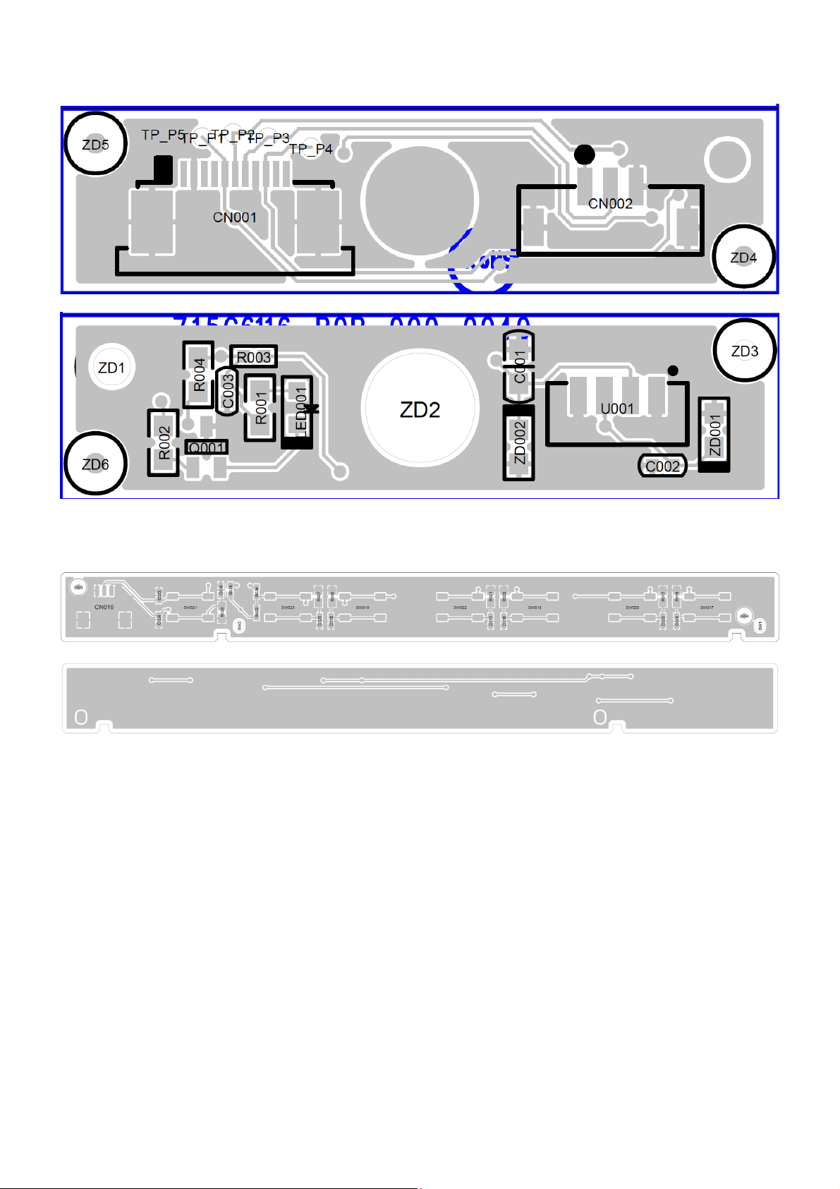
Page 41

9.3 IR Board
715G6116R01000004S
+3V3_STBY
R001
100R 1/10W 5%
From M/B
CONN
CN001
CN002
1
2
3
4
5
6
7
8
9
10
11
CONN
12 13
2013/01/17 Release
TP_P5э
45
1
2
3
KEYBOAR D_IRQ-CR P
TP_ P5
GND
代刚翴
.
+3V3_STBY
KEYBOARD_IRQ-CRP
IR_IRQ-RF4CEn
+3V3_STBY
LED2
TP_P 4
Active: LOW
TP_P 3
TP_P 2TP_P 1
R002
10K 1/10W 5%
R003
NC/ 2K7 1/16W 5%
C002
NC/100P 50V
STANDBY:
HIGH
+3V3_STBY
Q001
BC857BW
R004
100R 1/ 10W 5%
C001
1UF16V
--------><----|
----><----|
ZD002
VPORT0603100KV05
LED001
1 2
LED
12
Red
ZD001
Close to U1
1
2
3
4
VPORT0603100KV05
1 2
IR RECEIVER
U001
GND
Vs
OUT
GND
TSOP75436WTT
Close to U1
+3V3_ STBY
C003
100N 16V
Close to CN1
41
Page 42

9.4 KEY Board
715G6115K01000004S
45
1
CN016
CONN
PIN1 US ED TO BE VCC for PHI LIP S5000 HTV
KEY2
2
KEY1
3
C023
100N 50V
C024
100N 50V
R023
NC/ 0R05 1/10W
R025
NC/ 1K 1/10W 1%
R024
0R05 1/ 10W
2013/01/16 Modify
----><----|
INPUT
TACT SW FWRD H1.5MM
SW019
----><----|
C019
R016
NC/ 100N 50V
5K6 +-1% 1/8W
ITEM
2013/01/16 Modify
TACT SW FWRD H1.5MM
MENU
SW023
VOL-
TACT SW FWRD H1.5MM
SW020
TACT SW FWRD H1.5MM
VOL+
SW017
POWER
CH+
CH-
INPUT
VOL-
VOL+
----><----|
8K2 1/8W 1%
C020
NC/ 100N 50V
R017
----><----|
R018
C021
18K 1/8W 1%
NC/100N 50V
----><----|
R027
C025
22K 1/8W 1%
NC/100N 50V
MENU
R020
R022
R021
R016
R017
R018
R025
R024
R023
0R
1K5
3K9
5K6
8K2
18K
OPEN
0R
OPEN
22KR027
2013/01/14 Modify
----><----|
TACT SW FWRD H1.5MM
SW021
TACT SW FWRD H1.5MM
CH- CH+POWER
SW022
TACT SW FWRD H1.5MM
SW016
POWER
CH+
CH-
SOURCE
VOL-
Key Function
----><----|
0R051/8W
R020
NC/ 100N 50V
C016
----><----|
R021
3K9 1/8W 1%
C017
NC/ 100N 50V
----><----|
VOL+
MENU
R022
C018
1K5 +-1% 1/8W
NC/100N 50V
NO funtion
Volt.
0~0.001V
0.59V
∮
5%
∮
1.20V
5%
1.49V
∮
5%
1.80V
∮
5%
∮
2.39V
5%
3.3V
The item of this page start from "016~030"
T P V ( Top Victory Electronics Co . , Ltd. )
絬 隔 瓜 絪 腹
Key Component
715G6115-K0A-000-0040-1-130116
02. KEY
Date
OEM MO DE L
TPV MO DEL
PCB NAME
Sheet
PHILI PS5000 KEY BOARD Cust om
715G5771-K0A-000-0040
22
of
Size
Rev
称爹
A
XX
42
Page 43

10. Exploded View
43
Page 44

Item Part No Description Qty
1 P34T1345ADTZ1L0100 DECO_BEZEL 1
4 P33T0440AKZ01C0100 LENS_IR 1
5 IRPFDAAN IR BOARD 1
6 LCA460HVD02A09030X PANEL TPT460H1-HVD02 0F0B XM TPV 1
7 378G0110567YBE 8 OHM 11W 132X34 100 NO 2
8 Q52G18010TV09200JY INSULATING SHEET 1
9 X15T846210100000BL BKT_STAND 1
11 P33T0417ADTY1L0100 COVER_KEY 1
12 P33T0416ADT01L0100 KEY 1
13 KEPFDAAD KEY BOARD 1
14 P34T1078ADT01L0100 BASE 1
15 P20G0028001 DIE-CASTING 1
16 P15T1616102 BKT_BASE ŸO SGCC 1.0 MM 42 HAIER 1
18 Q12G6300 25 3 FOOT PAD 6
21 CBPF313929717311PA AS SHIELD DDR MTK MT5396 2K13 1
22 PLTVDO718XAA3 POWER BOARD 1
23 X15T8743202000GMAJ BKT_IO 1
26 P34T1270ADT0AL0300 REAR_COVER 1
44
Page 45

11. BOM List
Note: The following information of initial version BOM are only for reference of repair, not place the order as the
basis and are subject to change without notice. Please base on RSPL or Service BOM (http://cs.tpv.com.cn),
thank you!
E46D42NSDLE7NNX
Location Part No. Description Remark
Q52G1501150523AWBK TAPE_INSULATING
036T 600 18102 NONWOVEN FABRTC
036T 600 18107 NONWOVEN FABRTC
036T 600 18122 NONWOVEN FABRTC
0M1G1030 6 47 CR3 SCREW
0M1G1730 6120 SCREW 3X6
0M1G1740 8125 SCREW
0Q1G 130 6120 SCREW (T3X6)
0Q1G 330 10 47 CR3 SCREW
317GA3DG020GTS 3D GLASSES GTS61-001
SP01 378G0110567YBE 8 OHM 11W 132X34 100 NO
E1C20 395G176E011M22 FFC CABLE 11PIN TO 11PIN 900MM 0.5MM
E1G51 395G179H51NM37 FFC CABLE 51P 405MM 0.5MM
E1D01 395G801404DM64 HARNESS 4P-2P+2P 700/400
E1M89 395G801414RM63 HARNESS 14P-13P 230 2nd Source
E1M89 395G801414XM63 HARNESS 14P-13P 290
ECN2 395G802203XM17 HARNESS 3P-3P 1400
708GPA620CPX01 AOC 40(320 SA)
052G 1185 1 BIG TAPE(Y1200141)
Q45G 77511 PROTECT BAG
Q50G 4 10 TIE (Y1900221)
E750 750TFV460V20B8N000 LCD TPT460H1-HVD02 0F0B XM TPV 2nd Source
CBPF313929717311PA AS SHIELD DDR MTK MT5396 2K13
040G 45762412B OTHER LABEL
CBP1-7700 070G2000500ECD CD ECD KEY
CBP2-7700 070GHDCP500HDC HDCP CODE
PR-7700 370G00PR500PHP CD PLAYREADY KEY
MLN-7700 370G0MLN500PHP CD MARLIN KEY FOR NETTV(SUSHI )
WMDR-7700 370GWMDR500PHP CD WMDRM KEY
SMTF313929717331PA PNL SSB LT MT5396 2K13 R3 60S2.0 WRE NAL
1G51 311G242202520117PH CON H 51P F 0.5 SM FI-RE R
1D01 311G242202521245PH CON H 4P M 2.00 WH 2041145 B
1G51 311G242202521797PH CON H 51P F 0.50 SMIS050-C51B-C39-S R
1M88 311G242202521881PH CON H 14P M 2.00 WH W2012 Y
1C20 311GF050A11BDL FFC CONN 0.5MM 11P R/A B0506F11UDM3
1F04 353G242254901642PH FIL CM SM 50V 0A4 0R19 ACM2012 R
1F03 353G242254901642PH FIL CM SM 50V 0A4 0R19 ACM2012 R
1F03 353G242254990377PH FIL CM SM 50V 0A33 90R SDCW2012 R
1F04 353G242254990377PH FIL CM SM 50V 0A33 90R SDCW2012 R
7220 356G932216732668PH IC SM LD1117S25 (ST00) R
7216 356G932216733668PH IC SM LD1117S33 (ST00) R
7113 356G932221524668PH IC SM LD1117DT12 (ST00) R
7705 356G932223182668PH IC SM M24C64-RDW6P (ST00) R
7800 356G932225387668PH IC SM TPA6111A2DGN (TI00) R
7800 356G932225744668PH IC SM TS489IS (ST00) R
7700 356G932228003668PH IC SM H27U4G8F2DTR-BC (HYNX) R
7700 356G932228060668PH IC SM MT29F4G08ABADAWP:D (MRN0) R
7705 356G932228108668PH IC SM AT24C64D-XHM (ATME) R
7400 356G932228600668PH IC SM TAS5731PHP (TI00) R
7110 356G932228676668PH IC SM RT8288AZSP (RICHTE) R
45
Page 46

7210 356G932228830668PH IC SM CXD2828ER (SONY) R
7300 356G932228881671PH 932228881671 IC SM MT5396JDNJ (MEDI) Y
7118 356G932229564668PH IC SM RT7297AHZSP (RICHTE) R
7116 356G932229564668PH IC SM RT7297AHZSP (RICHTE) R
7117 356G932229564668PH IC SM RT7297AHZSP (RICHTE) R
7113 356G932230029668PH IC SM AZ1117CD-1.2G1(BCDSEM) R
7220 356G932230030668PH IC SM AZ1117CH-2.5G1(BCDSEM) R
7216 356G932230031668PH IC SM AZ1117CH-3.3G1(BCDSEM) R
7B31 357G319801042310PH TRA SIG SM BC847BW (COL) R
7B21 357G319801042310PH TRA SIG SM BC847BW (COL) R
7A01 357G319801042310PH TRA SIG SM BC847BW (COL) R
7703 357G319801042310PH TRA SIG SM BC847BW (COL) R
7702 357G319801042310PH TRA SIG SM BC847BW (COL) R
7504 357G319801042310PH TRA SIG SM BC847BW (COL) R
7503 357G319801042310PH TRA SIG SM BC847BW (COL) R
7500 357G319801042310PH TRA SIG SM BC847BW (COL) R
7D02 357G319801042320PH TRA SIG SM BC857BW (COL) R
7501 357G319801042330PH TRA SIG SM BC847BS (COL) R
7D03 357G319801042330PH TRA SIG SM BC847BS (COL) R
7801 357G319801044400PH TRA SIG SM PUMD12 (COL) R
7401 357G319801044430PH TRA SIG SM PUMH2 (COL) R
7D00 357G932228643668PH FET POW SM SI4835DDY-GE3 (VISH) R
7402 357G932228852685PH ET POW SM AO3406 (AOSEMI) R
7D00 357G932228853668PH FET POW SM AO4435 (AOSEMI) R
7402 357G934056633215PH FET POW SM SI2304DS (NXP0) R
4D06 361G319802190030PH RST SM 0603 JUMP. 0R05 COL
4D05 361G319802190030PH RST SM 0603 JUMP. 0R05 COL
4D04 361G319802190030PH RST SM 0603 JUMP. 0R05 COL
3A27 361G319803101010PH RST SM 0402 100R PM5 COL R
3A26 361G319803101010PH RST SM 0402 100R PM5 COL R
3A25 361G319803101010PH RST SM 0402 100R PM5 COL R
3A24 361G319803101010PH RST SM 0402 100R PM5 COL R
3976 361G319803101010PH RST SM 0402 100R PM5 COL R
3951 361G319803101010PH RST SM 0402 100R PM5 COL R
3950 361G319803101010PH RST SM 0402 100R PM5 COL R
3949 361G319803101010PH RST SM 0402 100R PM5 COL R
3751 361G319803101010PH RST SM 0402 100R PM5 COL R
3765 361G319803101010PH RST SM 0402 100R PM5 COL R
3938 361G319803101010PH RST SM 0402 100R PM5 COL R
3939 361G319803101010PH RST SM 0402 100R PM5 COL R
3940 361G319803101010PH RST SM 0402 100R PM5 COL R
3941 361G319803101010PH RST SM 0402 100R PM5 COL R
3944 361G319803101010PH RST SM 0402 100R PM5 COL R
3946 361G319803101010PH RST SM 0402 100R PM5 COL R
3D09 361G319803101020PH RST SM 0402 1K PM5 COL R
3D08 361G319803101020PH RST SM 0402 1K PM5 COL R
3B33 361G319803101020PH RST SM 0402 1K PM5 COL R
3B30 361G319803101020PH RST SM 0402 1K PM5 COL R
3B23 361G319803101020PH RST SM 0402 1K PM5 COL R
3B20 361G319803101020PH RST SM 0402 1K PM5 COL R
37AY 361G319803101020PH RST SM 0402 1K PM5 COL R
3794 361G319803101020PH RST SM 0402 1K PM5 COL R
3771 361G319803101020PH RST SM 0402 1K PM5 COL R
3426 361G319803101020PH RST SM 0402 1K PM5 COL R
3200 361G319803101020PH RST SM 0402 1K PM5 COL R
3206 361G319803101030PH RST SM 0402 10K PM5 COL R
3223 361G319803101030PH RST SM 0402 10K PM5 COL R
46
Page 47

3401 361G319803101030PH RST SM 0402 10K PM5 COL R
3427 361G319803101030PH RST SM 0402 10K PM5 COL R
3507 361G319803101030PH RST SM 0402 10K PM5 COL R
3738 361G319803101030PH RST SM 0402 10K PM5 COL R
3758 361G319803101030PH RST SM 0402 10K PM5 COL R
3770 361G319803101030PH RST SM 0402 10K PM5 COL R
3773 361G319803101030PH RST SM 0402 10K PM5 COL R
3780 361G319803101030PH RST SM 0402 10K PM5 COL R
3781 361G319803101030PH RST SM 0402 10K PM5 COL R
3782 361G319803101030PH RST SM 0402 10K PM5 COL R
37AC 361G319803101030PH RST SM 0402 10K PM5 COL R
37AP 361G319803101030PH RST SM 0402 10K PM5 COL R
3A20 361G319803101030PH RST SM 0402 10K PM5 COL R
3A21 361G319803101030PH RST SM 0402 10K PM5 COL R
3A22 361G319803101030PH RST SM 0402 10K PM5 COL R
3A23 361G319803101030PH RST SM 0402 10K PM5 COL R
3D05 361G319803101030PH RST SM 0402 10K PM5 COL R
3D06 361G319803101030PH RST SM 0402 10K PM5 COL R
3508 361G319803101030PH RST SM 0402 10K PM5 COL R
3526 361G319803101030PH RST SM 0402 10K PM5 COL R
3534 361G319803101030PH RST SM 0402 10K PM5 COL R
3535 361G319803101030PH RST SM 0402 10K PM5 COL R
3536 361G319803101030PH RST SM 0402 10K PM5 COL R
3719 361G319803101030PH RST SM 0402 10K PM5 COL R
3720 361G319803101030PH RST SM 0402 10K PM5 COL R
3726 361G319803101030PH RST SM 0402 10K PM5 COL R
3727 361G319803101030PH RST SM 0402 10K PM5 COL R
3728 361G319803101030PH RST SM 0402 10K PM5 COL R
3729 361G319803101030PH RST SM 0402 10K PM5 COL R
3731 361G319803101030PH RST SM 0402 10K PM5 COL R
3732 361G319803101030PH RST SM 0402 10K PM5 COL R
3736 361G319803101030PH RST SM 0402 10K PM5 COL R
3737 361G319803101030PH RST SM 0402 10K PM5 COL R
3B34 361G319803101040PH RST SM 0402 100K PM5 COL R
3B24 361G319803101040PH RST SM 0402 100K PM5 COL R
3B07 361G319803101040PH RST SM 0402 100K PM5 COL R
37A7 361G319803101040PH RST SM 0402 100K PM5 COL R
3170 361G319803101040PH RST SM 0402 100K PM5 COL R
3116 361G319803101040PH RST SM 0402 100K PM5 COL R
3108 361G319803101040PH RST SM 0402 100K PM5 COL R
3104 361G319803101040PH RST SM 0402 100K PM5 COL R
3100 361G319803101040PH RST SM 0402 100K PM5 COL R
3900 361G319803101080PH RST SM 0402 1R PM5 COL R
3901 361G319803101080PH RST SM 0402 1R PM5 COL R
3907 361G319803101080PH RST SM 0402 1R PM5 COL R
3936 361G319803101080PH RST SM 0402 1R PM5 COL R
3937 361G319803101080PH RST SM 0402 1R PM5 COL R
3971 361G319803101080PH RST SM 0402 1R PM5 COL R
3973 361G319803101080PH RST SM 0402 1R PM5 COL R
3A10 361G319803101080PH RST SM 0402 1R PM5 COL R
3792 361G319803101080PH RST SM 0402 1R PM5 COL R
3786 361G319803101080PH RST SM 0402 1R PM5 COL R
3785 361G319803101080PH RST SM 0402 1R PM5 COL R
3754 361G319803101080PH RST SM 0402 1R PM5 COL R
3412 361G319803101080PH RST SM 0402 1R PM5 COL R
3411 361G319803101080PH RST SM 0402 1R PM5 COL R
3115 361G319803101080PH RST SM 0402 1R PM5 COL R
47
Page 48

3109 361G319803101080PH RST SM 0402 1R PM5 COL R
3102 361G319803101080PH RST SM 0402 1R PM5 COL R
37AL 361G319803101090PH RST SM 0402 10R PM5 COL R
3A19 361G319803101210PH RST SM 0402 120R PM5 COL R
3107 361G319803101230PH RST SM 0402 12K PM5 COL R
3113 361G319803101230PH RST SM 0402 12K PM5 COL R
3222 361G319803101510PH RST SM 0402 150R PM5 COL R
3217 361G319803101590PH RST SM 0402 15R PM5 COL R
3218 361G319803101590PH RST SM 0402 15R PM5 COL R
3418 361G319803101890PH RST SM 0402 18R PM5 COL R
3410 361G319803101890PH RST SM 0402 18R PM5 COL R
3409 361G319803101890PH RST SM 0402 18R PM5 COL R
3408 361G319803101890PH RST SM 0402 18R PM5 COL R
3228 361G319803102230PH RST SM 0402 22K PM5 COL R
3230 361G319803102230PH RST SM 0402 22K PM5 COL R
3805 361G319803102230PH RST SM 0402 22K PM5 COL R
3806 361G319803102230PH RST SM 0402 22K PM5 COL R
3814 361G319803102230PH RST SM 0402 22K PM5 COL R
3741 361G319803102290PH RST SM 0402 22R PM5 COL R
3740 361G319803102290PH RST SM 0402 22R PM5 COL R
3975 361G319803102410PH RST SM 0402 240R PM5 COL R
3204 361G319803103320PH RST SM 0402 3K3 PM5 COL R
3205 361G319803103320PH RST SM 0402 3K3 PM5 COL R
3502 361G319803103320PH RST SM 0402 3K3 PM5 COL R
3130 361G319803103330PH RST SM 0402 33K PM5 COL R
3121 361G319803103340PH RST SM 0402 330K PM5 COL R
3210 361G319803103390PH RST SM 0402 33R PM5 COL R
3739 361G319803103390PH RST SM 0402 33R PM5 COL R
3749 361G319803103390PH RST SM 0402 33R PM5 COL R
3750 361G319803103390PH RST SM 0402 33R PM5 COL R
3774 361G319803103390PH RST SM 0402 33R PM5 COL R
3168 361G319803103930PH RST SM 0402 39K PM5 COL R
3406 361G319803104710PH RST SM 0402 470R PM5 COL R
3405 361G319803104710PH RST SM 0402 470R PM5 COL R
3742 361G319803104720PH RST SM 0402 4K7 PM5 COL R
3735 361G319803104720PH RST SM 0402 4K7 PM5 COL R
3734 361G319803104720PH RST SM 0402 4K7 PM5 COL R
3715 361G319803104720PH RST SM 0402 4K7 PM5 COL R
3714 361G319803104720PH RST SM 0402 4K7 PM5 COL R
3514 361G319803104720PH RST SM 0402 4K7 PM5 COL R
3512 361G319803104720PH RST SM 0402 4K7 PM5 COL R
3510 361G319803104720PH RST SM 0402 4K7 PM5 COL R
3509 361G319803104720PH RST SM 0402 4K7 PM5 COL R
3506 361G319803104720PH RST SM 0402 4K7 PM5 COL R
3229 361G319803104720PH RST SM 0402 4K7 PM5 COL R
3214 361G319803104720PH RST SM 0402 4K7 PM5 COL R
3209 361G319803104720PH RST SM 0402 4K7 PM5 COL R
3D21 361G319803104720PH RST SM 0402 4K7 PM5 COL R
3B55 361G319803104720PH RST SM 0402 4K7 PM5 COL R
3B52 361G319803104720PH RST SM 0402 4K7 PM5 COL R
3977 361G319803104720PH RST SM 0402 4K7 PM5 COL R
37AF 361G319803104720PH RST SM 0402 4K7 PM5 COL R
37AE 361G319803104720PH RST SM 0402 4K7 PM5 COL R
37AA 361G319803104720PH RST SM 0402 4K7 PM5 COL R
3788 361G319803104720PH RST SM 0402 4K7 PM5 COL R
3787 361G319803104720PH RST SM 0402 4K7 PM5 COL R
3775 361G319803104720PH RST SM 0402 4K7 PM5 COL R
48
Page 49

3755 361G319803104720PH RST SM 0402 4K7 PM5 COL R
3748 361G319803104720PH RST SM 0402 4K7 PM5 COL R
3747 361G319803104720PH RST SM 0402 4K7 PM5 COL R
3D03 361G319803104730PH RST SM 0402 47K PM5 COL R
3D01 361G319803104730PH RST SM 0402 47K PM5 COL R
3B32 361G319803104730PH RST SM 0402 47K PM5 COL R
3B31 361G319803104730PH RST SM 0402 47K PM5 COL R
3B22 361G319803104730PH RST SM 0402 47K PM5 COL R
3B21 361G319803104730PH RST SM 0402 47K PM5 COL R
3400 361G319803104730PH RST SM 0402 47K PM5 COL R
3201 361G319803104790PH RST SM 0402 47R PM5 COL R
3202 361G319803104790PH RST SM 0402 47R PM5 COL R
3226 361G319803104790PH RST SM 0402 47R PM5 COL R
3227 361G319803104790PH RST SM 0402 47R PM5 COL R
3231 361G319803104790PH RST SM 0402 47R PM5 COL R
3232 361G319803104790PH RST SM 0402 47R PM5 COL R
3402 361G319803104790PH RST SM 0402 47R PM5 COL R
3403 361G319803104790PH RST SM 0402 47R PM5 COL R
3500 361G319803104790PH RST SM 0402 47R PM5 COL R
3759 361G319803104790PH RST SM 0402 47R PM5 COL R
37A9 361G319803104790PH RST SM 0402 47R PM5 COL R
3D02 361G319803104790PH RST SM 0402 47R PM5 COL R
3752 361G319803106810PH RST SM 0402 680R PM5 COL R
3767 361G319803106820PH RST SM 0402 6K8 PM5 COL R
3126 361G319803106890PH RST SM 0402 68R PM5 COL R
3127 361G319803106890PH RST SM 0402 68R PM5 COL R
3129 361G319803106890PH RST SM 0402 68R PM5 COL R
3117 361G319803108220PH RST SM 0402 8K2 PM5 COL R
3B08 361G319803108290PH RST SM 0402 82R PM5 COL R
3530 361G319803121020PH RST NETW 0804 4X 1K PM5 COL R
3772 361G319803121030PH RST NETW 0804 4X 10K PM5 COL R
3961 361G319803121090PH RST NETW 0804 4X 10R PM5 COL R
3211 361G319803122290PH RST NETW 0804 4X 22R PM5 COL R
3807 361G319803123390PH RST NETW 0804 4X 33R PM5 COL R
3756 361G319803124720PH RST NETW 0804 4X 4K7 PM5 COL R
3123 361G319803190010PH RST SM 0402 JUMP. 0R05 COL
3146 361G319803190010PH RST SM 0402 JUMP. 0R05 COL
3163 361G319803190010PH RST SM 0402 JUMP. 0R05 COL
3208 361G319803190010PH RST SM 0402 JUMP. 0R05 COL
3D11 361G319803190010PH RST SM 0402 JUMP. 0R05 COL
3D12 361G319803190010PH RST SM 0402 JUMP. 0R05 COL
3D13 361G319803190010PH RST SM 0402 JUMP. 0R05 COL
3D14 361G319803190010PH RST SM 0402 JUMP. 0R05 COL
4401 361G319803190010PH RST SM 0402 JUMP. 0R05 COL
4701 361G319803190010PH RST SM 0402 JUMP. 0R05 COL
4710 361G319803190010PH RST SM 0402 JUMP. 0R05 COL
4B00 361G319803190010PH RST SM 0402 JUMP. 0R05 COL
3701 361G319804210010PH RST SM 0402 100R PM1 COL R
3695 361G319804210010PH RST SM 0402 100R PM1 COL R
3666 361G319804210010PH RST SM 0402 100R PM1 COL R
3656 361G319804210010PH RST SM 0402 100R PM1 COL R
3650 361G319804210010PH RST SM 0402 100R PM1 COL R
3524 361G319804210010PH RST SM 0402 100R PM1 COL R
3523 361G319804210010PH RST SM 0402 100R PM1 COL R
3521 361G319804210010PH RST SM 0402 100R PM1 COL R
3520 361G319804210010PH RST SM 0402 100R PM1 COL R
3519 361G319804210010PH RST SM 0402 100R PM1 COL R
49
Page 50

3225 361G319804210010PH RST SM 0402 100R PM1 COL R
3224 361G319804210010PH RST SM 0402 100R PM1 COL R
3702 361G319804210010PH RST SM 0402 100R PM1 COL R
37AT 361G319804210010PH RST SM 0402 100R PM1 COL R
37AJ 361G319804210010PH RST SM 0402 100R PM1 COL R
3779 361G319804210010PH RST SM 0402 100R PM1 COL R
3778 361G319804210010PH RST SM 0402 100R PM1 COL R
3764 361G319804210010PH RST SM 0402 100R PM1 COL R
3733 361G319804210010PH RST SM 0402 100R PM1 COL R
3730 361G319804210010PH RST SM 0402 100R PM1 COL R
3712 361G319804210010PH RST SM 0402 100R PM1 COL R
3710 361G319804210010PH RST SM 0402 100R PM1 COL R
3709 361G319804210010PH RST SM 0402 100R PM1 COL R
3708 361G319804210010PH RST SM 0402 100R PM1 COL R
3705 361G319804210010PH RST SM 0402 100R PM1 COL R
3162 361G319804210020PH RST SM 0402 1K PM1 COL R
3504 361G319804210020PH RST SM 0402 1K PM1 COL R
3505 361G319804210020PH RST SM 0402 1K PM1 COL R
3511 361G319804210020PH RST SM 0402 1K PM1 COL R
3513 361G319804210020PH RST SM 0402 1K PM1 COL R
3613 361G319804210020PH RST SM 0402 1K PM1 COL R
3614 361G319804210020PH RST SM 0402 1K PM1 COL R
3623 361G319804210020PH RST SM 0402 1K PM1 COL R
3624 361G319804210020PH RST SM 0402 1K PM1 COL R
3627 361G319804210020PH RST SM 0402 1K PM1 COL R
3628 361G319804210020PH RST SM 0402 1K PM1 COL R
3634 361G319804210020PH RST SM 0402 1K PM1 COL R
3635 361G319804210020PH RST SM 0402 1K PM1 COL R
3812 361G319804210030PH RST SM 0402 10K PM1 COL R
3811 361G319804210030PH RST SM 0402 10K PM1 COL R
3112 361G319804210030PH RST SM 0402 10K PM1 COL R
3813 361G319804210030PH RST SM 0402 10K PM1 COL R
3106 361G319804215020PH RST SM 0402 1K5 PM1 COL R
3D07 361G319804215030PH RST SM 0402 15K PM1 COL R
3503 361G319804215030PH RST SM 0402 15K PM1 COL R
3404 361G319804215030PH RST SM 0402 15K PM1 COL R
3120 361G319804215030PH RST SM 0402 15K PM1 COL R
3111 361G319804215030PH RST SM 0402 15K PM1 COL R
3B09 361G319804218010PH RST SM 0402 180R PM1 COL R
3122 361G319804218030PH RST SM 0402 18K PM1 COL R
37A3 361G319804218030PH RST SM 0402 18K PM1 COL R
3925 361G319804218090PH RST SM 0402 18R PM1 COL R
3904 361G319804218090PH RST SM 0402 18R PM1 COL R
3905 361G319804218090PH RST SM 0402 18R PM1 COL R
3407 361G319804218230PH RST SM 0402 18K2 PM1 COL R
3966 361G319804220030PH RST SM 0402 20K PM1 COL R
3965 361G319804220030PH RST SM 0402 20K PM1 COL R
3114 361G319804222020PH RST SM 0402 2K2 PM1 COL R
3131 361G319804222020PH RST SM 0402 2K2 PM1 COL R
3213 361G319804222020PH RST SM 0402 2K2 PM1 COL R
3212 361G319804222020PH RST SM 0402 2K2 PM1 COL R
3696 361G319804224010PH RST SM 0402 240R PM1 COL R
3688 361G319804224010PH RST SM 0402 240R PM1 COL R
3667 361G319804224010PH RST SM 0402 240R PM1 COL R
3608 361G319804224010PH RST SM 0402 240R PM1 COL R
3B50 361G319804224030PH RST SM 0402 24K PM1 COL R
3D00 361G319804224030PH RST SM 0402 24K PM1 COL R
50
Page 51

3952 361G319804230030PH RST SM 0402 30K PM1 COL R
3953 361G319804230030PH RST SM 0402 30K PM1 COL R
3970 361G319804230030PH RST SM 0402 30K PM1 COL R
3972 361G319804230030PH RST SM 0402 30K PM1 COL R
3105 361G319804247020PH RST SM 0402 4K7 PM1 COL R
3902 361G319804256090PH RST SM 0402 56R PM1 COL R
3903 361G319804256090PH RST SM 0402 56R PM1 COL R
3906 361G319804256090PH RST SM 0402 56R PM1 COL R
3A16 361G319804275090PH RST SM 0402 75R PM1 COL R
3A14 361G319804275090PH RST SM 0402 75R PM1 COL R
3A15 361G319804275090PH RST SM 0402 75R PM1 COL R
3795 361G319804282040PH RST SM 0402 820K PM1 COL R
2143 365G202055297025PH CER2 0402 X5R 50V 100N PM10 R
2427 365G202055297056PH CER2 0402 X5R 35V 100N PM10 R
2424 365G202055297056PH CER2 0402 X5R 35V 100N PM10 R
2418 365G202055297056PH CER2 0402 X5R 35V 100N PM10 R
2417 365G202055297056PH CER2 0402 X5R 35V 100N PM10 R
2201 365G202055297058PH CER1 0402 NP0 50V 8P PM0P25 R
2200 365G202055297058PH CER1 0402 NP0 50V 8P PM0P25 R
2201 365G202055297059PH CER1 0402 NP0 50V 8P PM0P25 R
2200 365G202055297059PH CER1 0402 NP0 50V 8P PM0P25 R
2143 365G202055297184PH CER2 0402 X5R 50V 100NPM10 R
25AC 365G202204000003PH SOLCAP SM OCV 6V3 330UPM20 R
2647 365G202204000003PH SOLCAP SM OCV 6V3 330UPM20 R
2C18 365G202204000004PH SOLCAP SM OCV 6V3100U PM20 R
2C20 365G202204000004PH SOLCAP SM OCV 6V3100U PM20 R
2417 365G223891715649PH CER2 0402 X7R 25V 100N PM10 R
2418 365G223891715649PH CER2 0402 X7R 25V 100N PM10 R
2424 365G223891715649PH CER2 0402 X7R 25V 100N PM10 R
2427 365G223891715649PH CER2 0402 X7R 25V 100N PM10 R
2443 365G319801702240PH CER2 0805 X7R 50V 220N COL R
2442 365G319801702240PH CER2 0805 X7R 50V 220N COL R
2437 365G319801702240PH CER2 0805 X7R 50V 220N COL R
2436 365G319801702240PH CER2 0805 X7R 50V 220N COL R
2422 365G319801702240PH CER2 0805 X7R 50V 220N COL R
2413 365G319801702240PH CER2 0805 X7R 50V 220N COL R
2411 365G319801731050PH CER2 0603 X7R 16V 1U PM10 COL
2D11 365G319801731050PH CER2 0603 X7R 16V 1U PM10 COL
2408 365G319801790030PH CER2 0603 X7R 50V 33N PM10 COL
2409 365G319801790030PH CER2 0603 X7R 50V 33N PM10 COL
2410 365G319801790030PH CER2 0603 X7R 50V 33N PM10 COL
2462 365G319801790030PH CER2 0603 X7R 50V 33N PM10 COL
2182 365G319802702290PH CER2 0805 X5R 6V3 22U PM20 COL R
2169 365G319802702290PH CER2 0805 X5R 6V3 22U PM20 COL R
2168 365G319802702290PH CER2 0805 X5R 6V3 22U PM20 COL R
2117 365G319802702290PH CER2 0805 X5R 6V3 22U PM20 COL R
2116 365G319802702290PH CER2 0805 X5R 6V3 22U PM20 COL R
2115 365G319802702290PH CER2 0805 X5R 6V3 22U PM20 COL R
2114 365G319802702290PH CER2 0805 X5R 6V3 22U PM20 COL R
2105 365G319802702290PH CER2 0805 X5R 6V3 22U PM20 COL R
2104 365G319802702290PH CER2 0805 X5R 6V3 22U PM20 COL R
2183 365G319802702290PH CER2 0805 X5R 6V3 22U PM20 COL R
2501 365G319802702290PH CER2 0805 X5R 6V3 22U PM20 COL R
25AB 365G319802702290PH CER2 0805 X5R 6V3 22U PM20 COL R
2131 365G319802721090PH CER2 0805 X5R 16V 10U PM10 COL R
2177 365G319802721090PH CER2 0805 X5R 16V 10U PM10 COL R
2178 365G319802721090PH CER2 0805 X5R 16V 10U PM10 COL R
51
Page 52

2101 365G319802721090PH CER2 0805 X5R 16V 10U PM10 COL R
2102 365G319802721090PH CER2 0805 X5R 16V 10U PM10 COL R
2110 365G319802721090PH CER2 0805 X5R 16V 10U PM10 COL R
2112 365G319802721090PH CER2 0805 X5R 16V 10U PM10 COL R
2123 365G319802721090PH CER2 0805 X5R 16V 10U PM10 COL R
2125 365G319802721090PH CER2 0805 X5R 16V 10U PM10 COL R
2808 365G319802741080PH CER2 0603 X5R 6V3 1U PM10 COL R
2809 365G319802741080PH CER2 0603 X5R 6V3 1U PM10 COL R
2571 365G319802741090PH CER2 0603 X5R 6V3 10U PM20 COL R
2568 365G319802741090PH CER2 0603 X5R 6V3 10U PM20 COL R
2561 365G319802741090PH CER2 0603 X5R 6V3 10U PM20 COL R
2543 365G319802741090PH CER2 0603 X5R 6V3 10U PM20 COL R
2463 365G319802741090PH CER2 0603 X5R 6V3 10U PM20 COL R
2405 365G319802741090PH CER2 0603 X5R 6V3 10U PM20 COL R
2192 365G319802741090PH CER2 0603 X5R 6V3 10U PM20 COL R
2191 365G319802741090PH CER2 0603 X5R 6V3 10U PM20 COL R
25A9 365G319802741090PH CER2 0603 X5R 6V3 10U PM20 COL R
2616 365G319802741090PH CER2 0603 X5R 6V3 10U PM20 COL R
2646 365G319802741090PH CER2 0603 X5R 6V3 10U PM20 COL R
2682 365G319802741090PH CER2 0603 X5R 6V3 10U PM20 COL R
2693 365G319802741090PH CER2 0603 X5R 6V3 10U PM20 COL R
2900 365G319802741090PH CER2 0603 X5R 6V3 10U PM20 COL R
2903 365G319802741090PH CER2 0603 X5R 6V3 10U PM20 COL R
2984 365G319802741090PH CER2 0603 X5R 6V3 10U PM20 COL R
2987 365G319802741090PH CER2 0603 X5R 6V3 10U PM20 COL R
2544 365G319802754780PH CER2 0603 X5R 10V 4U7 PM10 COL R
2661 365G319802754780PH CER2 0603 X5R 10V 4U7 PM10 COL R
2683 365G319802754780PH CER2 0603 X5R 10V 4U7 PM10 COL R
2694 365G319802754780PH CER2 0603 X5R 10V 4U7 PM10 COL R
2A14 365G319802782280PH CER2 0402 X5R 6V3 2U2 PM20 COL R
25AK 365G319802782280PH CER2 0402 X5R 6V3 2U2 PM20 COL R
25AJ 365G319802782280PH CER2 0402 X5R 6V3 2U2 PM20 COL R
25AH 365G319802782280PH CER2 0402 X5R 6V3 2U2 PM20 COL R
25AG 365G319802782280PH CER2 0402 X5R 6V3 2U2 PM20 COL R
25AF 365G319802782280PH CER2 0402 X5R 6V3 2U2 PM20 COL R
25AE 365G319802782280PH CER2 0402 X5R 6V3 2U2 PM20 COL R
25AD 365G319802782280PH CER2 0402 X5R 6V3 2U2 PM20 COL R
2504 365G319802782280PH CER2 0402 X5R 6V3 2U2 PM20 COL R
2503 365G319802782280PH CER2 0402 X5R 6V3 2U2 PM20 COL R
2502 365G319802782280PH CER2 0402 X5R 6V3 2U2 PM20 COL R
2990 365G319802791040PH CER2 0402 X5R 10V 100N PM10 COL R
2219 365G319802791080PH CER2 0402 X5R 10V 1U PM10 COL R
2220 365G319802791080PH CER2 0402 X5R 10V 1U PM10 COL R
2239 365G319802791080PH CER2 0402 X5R 10V 1U PM10 COL R
2240 365G319802791080PH CER2 0402 X5R 10V 1U PM10 COL R
2542 365G319802791080PH CER2 0402 X5R 10V 1U PM10 COL R
2B01 365G319802791080PH CER2 0402 X5R 10V 1U PM10 COL R
2978 365G319802791080PH CER2 0402 X5R 10V 1U PM10 COL R
2962 365G319802791080PH CER2 0402 X5R 10V 1U PM10 COL R
2810 365G319802791080PH CER2 0402 X5R 10V 1U PM10 COL R
2805 365G319802791080PH CER2 0402 X5R 10V 1U PM10 COL R
2719 365G319802791080PH CER2 0402 X5R 10V 1U PM10 COL R
2695 365G319802791080PH CER2 0402 X5R 10V 1U PM10 COL R
2684 365G319802791080PH CER2 0402 X5R 10V 1U PM10 COL R
2662 365G319802791080PH CER2 0402 X5R 10V 1U PM10 COL R
2558 365G319802791080PH CER2 0402 X5R 10V 1U PM10 COL R
2D12 365G319802792240PH CER2 0402 X5R 10V 220N PM10 COL R
52
Page 53

25A8 365G319802792240PH CER2 0402 X5R 10V 220N PM10 COL R
2193 365G319802792240PH CER2 0402 X5R 10V 220N PM10 COL R
2132 365G319803401010PH CER1 0402 NP0 50V 100P PM5 COL
2133 365G319803401010PH CER1 0402 NP0 50V 100P PM5 COL
2134 365G319803401010PH CER1 0402 NP0 50V 100P PM5 COL
2714 365G319803401010PH CER1 0402 NP0 50V 100P PM5 COL
2725 365G319803401010PH CER1 0402 NP0 50V 100P PM5 COL
2728 365G319803401010PH CER1 0402 NP0 50V 100P PM5 COL
2729 365G319803401010PH CER1 0402 NP0 50V 100P PM5 COL
2471 365G319803401020PH CER1 0402 NP0 50V 1N PM5 COL
2704 365G319803401090PH CER1 0402 NP0 50V 10P PM0P5 COL
2705 365G319803401090PH CER1 0402 NP0 50V 10P PM0P5 COL
2906 365G319803401090PH CER1 0402 NP0 50V 10P PM0P5 COL
2907 365G319803401090PH CER1 0402 NP0 50V 10P PM0P5 COL
2908 365G319803401090PH CER1 0402 NP0 50V 10P PM0P5 COL
2A07 365G319803401090PH CER1 0402 NP0 50V 10P PM0P5 COL
2A08 365G319803401090PH CER1 0402 NP0 50V 10P PM0P5 COL
2A09 365G319803401090PH CER1 0402 NP0 50V 10P PM0P5 COL
2B07 365G319803401090PH CER1 0402 NP0 50V 10P PM0P5 COL
2221 365G319803402290PH CER1 0402 NP0 50V 22P PM5 COL
2222 365G319803402290PH CER1 0402 NP0 50V 22P PM5 COL
2720 365G319803402790PH CER1 0402 NP0 50V 27P PM5 COL
2721 365G319803402790PH CER1 0402 NP0 50V 27P PM5 COL
2991 365G319803403390PH CER1 0402 NP0 50V 33P PM5 COL
2804 365G319803404790PH CER1 0402 NP0 50V 47P PM5 COL
2803 365G319803404790PH CER1 0402 NP0 50V 47P PM5 COL
2245 365G319803404790PH CER1 0402 NP0 50V 47P PM5 COL
2244 365G319803404790PH CER1 0402 NP0 50V 47P PM5 COL
2A13 365G319803405680PH CER1 0402 NP0 50V 5P6 PM0P5 COL
2A12 365G319803405680PH CER1 0402 NP0 50V 5P6 PM0P5 COL
2205 365G319803408290PH CER1 0402 NP0 50V 82P PM5 COL
2204 365G319803408290PH CER1 0402 NP0 50V 82P PM5 COL
2A15 365G319803501020PH CER2 0402 X7R 50V 1N COL
2813 365G319803501020PH CER2 0402 X7R 50V 1N COL
2812 365G319803501020PH CER2 0402 X7R 50V 1N COL
2802 365G319803501020PH CER2 0402 X7R 50V 1N COL
2801 365G319803501020PH CER2 0402 X7R 50V 1N COL
2711 365G319803501020PH CER2 0402 X7R 50V 1N COL
2710 365G319803501020PH CER2 0402 X7R 50V 1N COL
2145 365G319803501020PH CER2 0402 X7R 50V 1N COL
2136 365G319803501020PH CER2 0402 X7R 50V 1N COL
2944 365G319803501520PH CER2 0402 X7R 50V 1N5 COL
2945 365G319803501520PH CER2 0402 X7R 50V 1N5 COL
2404 365G319803502220PH CER2 0402 X7R 50V 2N2 COL
2412 365G319803503310PH CER2 0402 X7R 50V 330P COL
2419 365G319803503310PH CER2 0402 X7R 50V 330P COL
2420 365G319803503310PH CER2 0402 X7R 50V 330P COL
2421 365G319803503310PH CER2 0402 X7R 50V 330P COL
2107 365G319803503320PH CER2 0402 X7R 50V 3N3 COL
2120 365G319803503320PH CER2 0402 X7R 50V 3N3 COL
2164 365G319803503320PH CER2 0402 X7R 50V 3N3 COL
2977 365G319803511030PH CER2 0402 X7R 25V 10N PM10 COL
2425 365G319803511030PH CER2 0402 X7R 25V 10N PM10 COL
2416 365G319803511030PH CER2 0402 X7R 25V 10N PM10 COL
2400 365G319803514720PH CER2 0402 X7R 25V 4N7 COL
2403 365G319803514720PH CER2 0402 X7R 25V 4N7 COL
2954 365G319803521030PH CER2 0402 X7R 16V 10N COL
53
Page 54

2951 365G319803521030PH CER2 0402 X7R 16V 10N COL
2949 365G319803521030PH CER2 0402 X7R 16V 10N COL
2948 365G319803521030PH CER2 0402 X7R 16V 10N COL
2947 365G319803521030PH CER2 0402 X7R 16V 10N COL
2946 365G319803521030PH CER2 0402 X7R 16V 10N COL
2565 365G319803521030PH CER2 0402 X7R 16V 10N COL
2234 365G319803521030PH CER2 0402 X7R 16V 10N COL
2233 365G319803521030PH CER2 0402 X7R 16V 10N COL
2185 365G319803521030PH CER2 0402 X7R 16V 10N COL
2157 365G319803521030PH CER2 0402 X7R 16V 10N COL
2955 365G319803521030PH CER2 0402 X7R 16V 10N COL
2958 365G319803521030PH CER2 0402 X7R 16V 10N COL
2D17 365G319803521030PH CER2 0402 X7R 16V 10N COL
2557 365G319803521040PH CER2 0402 X7R 16V 100N COL
2552 365G319803521040PH CER2 0402 X7R 16V 100N COL
2551 365G319803521040PH CER2 0402 X7R 16V 100N COL
2538 365G319803521040PH CER2 0402 X7R 16V 100N COL
2537 365G319803521040PH CER2 0402 X7R 16V 100N COL
2536 365G319803521040PH CER2 0402 X7R 16V 100N COL
2505 365G319803521040PH CER2 0402 X7R 16V 100N COL
2429 365G319803521040PH CER2 0402 X7R 16V 100N COL
2428 365G319803521040PH CER2 0402 X7R 16V 100N COL
2407 365G319803521040PH CER2 0402 X7R 16V 100N COL
2680 365G319803521040PH CER2 0402 X7R 16V 100N COL
2679 365G319803521040PH CER2 0402 X7R 16V 100N COL
2559 365G319803521040PH CER2 0402 X7R 16V 100N COL
2614 365G319803521040PH CER2 0402 X7R 16V 100N COL
2613 365G319803521040PH CER2 0402 X7R 16V 100N COL
2612 365G319803521040PH CER2 0402 X7R 16V 100N COL
2611 365G319803521040PH CER2 0402 X7R 16V 100N COL
2608 365G319803521040PH CER2 0402 X7R 16V 100N COL
2602 365G319803521040PH CER2 0402 X7R 16V 100N COL
2601 365G319803521040PH CER2 0402 X7R 16V 100N COL
2570 365G319803521040PH CER2 0402 X7R 16V 100N COL
2569 365G319803521040PH CER2 0402 X7R 16V 100N COL
2566 365G319803521040PH CER2 0402 X7R 16V 100N COL
2564 365G319803521040PH CER2 0402 X7R 16V 100N COL
2562 365G319803521040PH CER2 0402 X7R 16V 100N COL
2644 365G319803521040PH CER2 0402 X7R 16V 100N COL
2643 365G319803521040PH CER2 0402 X7R 16V 100N COL
2642 365G319803521040PH CER2 0402 X7R 16V 100N COL
2641 365G319803521040PH CER2 0402 X7R 16V 100N COL
2640 365G319803521040PH CER2 0402 X7R 16V 100N COL
2639 365G319803521040PH CER2 0402 X7R 16V 100N COL
2638 365G319803521040PH CER2 0402 X7R 16V 100N COL
2618 365G319803521040PH CER2 0402 X7R 16V 100N COL
2617 365G319803521040PH CER2 0402 X7R 16V 100N COL
2615 365G319803521040PH CER2 0402 X7R 16V 100N COL
2C19 365G319803521040PH CER2 0402 X7R 16V 100N COL
2C17 365G319803521040PH CER2 0402 X7R 16V 100N COL
2727 365G319803521040PH CER2 0402 X7R 16V 100N COL
2645 365G319803521040PH CER2 0402 X7R 16V 100N COL
2666 365G319803521040PH CER2 0402 X7R 16V 100N COL
2665 365G319803521040PH CER2 0402 X7R 16V 100N COL
2664 365G319803521040PH CER2 0402 X7R 16V 100N COL
2663 365G319803521040PH CER2 0402 X7R 16V 100N COL
2658 365G319803521040PH CER2 0402 X7R 16V 100N COL
54
Page 55

2657 365G319803521040PH CER2 0402 X7R 16V 100N COL
2656 365G319803521040PH CER2 0402 X7R 16V 100N COL
2654 365G319803521040PH CER2 0402 X7R 16V 100N COL
2653 365G319803521040PH CER2 0402 X7R 16V 100N COL
2652 365G319803521040PH CER2 0402 X7R 16V 100N COL
2651 365G319803521040PH CER2 0402 X7R 16V 100N COL
2650 365G319803521040PH CER2 0402 X7R 16V 100N COL
2649 365G319803521040PH CER2 0402 X7R 16V 100N COL
2687 365G319803521040PH CER2 0402 X7R 16V 100N COL
2688 365G319803521040PH CER2 0402 X7R 16V 100N COL
2689 365G319803521040PH CER2 0402 X7R 16V 100N COL
2D15 365G319803521040PH CER2 0402 X7R 16V 100N COL
2667 365G319803521040PH CER2 0402 X7R 16V 100N COL
2668 365G319803521040PH CER2 0402 X7R 16V 100N COL
2669 365G319803521040PH CER2 0402 X7R 16V 100N COL
2673 365G319803521040PH CER2 0402 X7R 16V 100N COL
2674 365G319803521040PH CER2 0402 X7R 16V 100N COL
2675 365G319803521040PH CER2 0402 X7R 16V 100N COL
2676 365G319803521040PH CER2 0402 X7R 16V 100N COL
2677 365G319803521040PH CER2 0402 X7R 16V 100N COL
2678 365G319803521040PH CER2 0402 X7R 16V 100N COL
2686 365G319803521040PH CER2 0402 X7R 16V 100N COL
2718 365G319803521040PH CER2 0402 X7R 16V 100N COL
2715 365G319803521040PH CER2 0402 X7R 16V 100N COL
2707 365G319803521040PH CER2 0402 X7R 16V 100N COL
2703 365G319803521040PH CER2 0402 X7R 16V 100N COL
2699 365G319803521040PH CER2 0402 X7R 16V 100N COL
2698 365G319803521040PH CER2 0402 X7R 16V 100N COL
2697 365G319803521040PH CER2 0402 X7R 16V 100N COL
2696 365G319803521040PH CER2 0402 X7R 16V 100N COL
2692 365G319803521040PH CER2 0402 X7R 16V 100N COL
2691 365G319803521040PH CER2 0402 X7R 16V 100N COL
2690 365G319803521040PH CER2 0402 X7R 16V 100N COL
2681 365G319803521040PH CER2 0402 X7R 16V 100N COL
2685 365G319803521040PH CER2 0402 X7R 16V 100N COL
2406 365G319803521040PH CER2 0402 X7R 16V 100N COL
2100 365G319803521040PH CER2 0402 X7R 16V 100N COL
2103 365G319803521040PH CER2 0402 X7R 16V 100N COL
2109 365G319803521040PH CER2 0402 X7R 16V 100N COL
2113 365G319803521040PH CER2 0402 X7R 16V 100N COL
2122 365G319803521040PH CER2 0402 X7R 16V 100N COL
2154 365G319803521040PH CER2 0402 X7R 16V 100N COL
2166 365G319803521040PH CER2 0402 X7R 16V 100N COL
2174 365G319803521040PH CER2 0402 X7R 16V 100N COL
2175 365G319803521040PH CER2 0402 X7R 16V 100N COL
2179 365G319803521040PH CER2 0402 X7R 16V 100N COL
2206 365G319803521040PH CER2 0402 X7R 16V 100N COL
2207 365G319803521040PH CER2 0402 X7R 16V 100N COL
2228 365G319803521040PH CER2 0402 X7R 16V 100N COL
2224 365G319803521040PH CER2 0402 X7R 16V 100N COL
2218 365G319803521040PH CER2 0402 X7R 16V 100N COL
2216 365G319803521040PH CER2 0402 X7R 16V 100N COL
2215 365G319803521040PH CER2 0402 X7R 16V 100N COL
2214 365G319803521040PH CER2 0402 X7R 16V 100N COL
2213 365G319803521040PH CER2 0402 X7R 16V 100N COL
2211 365G319803521040PH CER2 0402 X7R 16V 100N COL
2210 365G319803521040PH CER2 0402 X7R 16V 100N COL
55
Page 56

2209 365G319803521040PH CER2 0402 X7R 16V 100N COL
2208 365G319803521040PH CER2 0402 X7R 16V 100N COL
2F24 365G319803522230PH CER2 0402 X7R 16V 22N COL
2246 365G319803524730PH CER2 0402 X7R 16V 47N COL
2401 365G319803524730PH CER2 0402 X7R 16V 47N COL
2402 365G319803524730PH CER2 0402 X7R 16V 47N COL
2957 365G319803524730PH CER2 0402 X7R 16V 47N COL
2217 365G319804504790PH CER2 1206 X5R 6V3 47U PM20 COL R
2C18 367G202002800013PH SOLCAP SM SS 6V3 100U PM20 R
2C20 367G202002800013PH SOLCAP SM SS 6V3 100U PM20 R
25AC 367G202002800015PH SOLCAP SM SS 6V3 330U PM20 R
2647 367G202002800015PH SOLCAP SM SS 6V3 330U PM20 R
2474 367G202203100502PH ELCAP SM VZH 25V 100U PM20 R
2475 367G202203100502PH ELCAP SM VZH 25V 100U PM20 R
2476 367G202203100502PH ELCAP SM VZH 25V 100U PM20 R
2477 367G202203100502PH ELCAP SM VZH 25V 100U PM20 R
2807 367G319803011010PH ELCAP SM 4V 100U PM20 COL R
2806 367G319803011010PH ELCAP SM 4V 100U PM20 COL R
2156 367G319803022290PH ELCAP SM 6V3 22U PM20 COL R
2230 367G319803022290PH ELCAP SM 6V3 22U PM20 COL R
2563 367G319803024790PH ELCAP SM 6V3 47U PM20 COL R
2D16 367G319804121010PH ELCAP SM 16V 100U 105 PM20 COL
2225 367G319804121090PH ELCAP SM 16V 10U 105 PM20 COL
5101 371G242254901582PH IND FXD 0603 EMI 100MHZ 33R R
5103 371G242254901582PH IND FXD 0603 EMI 100MHZ 33R R
5D02 371G242254901582PH IND FXD 0603 EMI 100MHZ 33R R
5D01 371G242254901582PH IND FXD 0603 EMI 100MHZ 33R R
5D00 371G242254901582PH IND FXD 0603 EMI 100MHZ 33R R
5700 371G242254901582PH IND FXD 0603 EMI 100MHZ 33R R
5506 371G242254901582PH IND FXD 0603 EMI 100MHZ 33R R
5503 371G242254901582PH IND FXD 0603 EMI 100MHZ 33R R
5416 371G242254901582PH IND FXD 0603 EMI 100MHZ 33R R
5415 371G242254901582PH IND FXD 0603 EMI 100MHZ 33R R
5414 371G242254901582PH IND FXD 0603 EMI 100MHZ 33R R
5408 371G242254901582PH IND FXD 0603 EMI 100MHZ 33R R
5406 371G242254901582PH IND FXD 0603 EMI 100MHZ 33R R
5405 371G242254901582PH IND FXD 0603 EMI 100MHZ 33R R
5404 371G242254901582PH IND FXD 0603 EMI 100MHZ 33R R
5106 371G242254901582PH IND FXD 0603 EMI 100MHZ 33R R
5105 371G242254901582PH IND FXD 0603 EMI 100MHZ 33R R
5A06 371G242254942979PH IND FXD 0603 EMI 100MHZ 60R R
5A02 371G242254942979PH IND FXD 0603 EMI 100MHZ 60R R
5A01 371G242254942979PH IND FXD 0603 EMI 100MHZ 60R R
5A00 371G242254942979PH IND FXD 0603 EMI 100MHZ 60R R
5902 371G242254942979PH IND FXD 0603 EMI 100MHZ 60R R
5901 371G242254942979PH IND FXD 0603 EMI 100MHZ 60R R
5900 371G242254942979PH IND FXD 0603 EMI 100MHZ 60R R
5701 371G242254942979PH IND FXD 0603 EMI 100MHZ 60R R
5503 371G242254943769PH IND FXD 0603 EMI 100MHZ 30R R
5A05 371G242254943769PH IND FXD 0603 EMI 100MHZ 30R R
5A04 371G242254943769PH IND FXD 0603 EMI 100MHZ 30R R
5700 371G242254943769PH IND FXD 0603 EMI 100MHZ 30R R
5506 371G242254943769PH IND FXD 0603 EMI 100MHZ 30R R
5505 371G242254943769PH IND FXD 0603 EMI 100MHZ 30R R
5500 371G242254943769PH IND FXD 0603 EMI 100MHZ 30R R
5416 371G242254943769PH IND FXD 0603 EMI 100MHZ 30R R
5415 371G242254943769PH IND FXD 0603 EMI 100MHZ 30R R
56
Page 57

5414 371G242254943769PH IND FXD 0603 EMI 100MHZ 30R R
5408 371G242254943769PH IND FXD 0603 EMI 100MHZ 30R R
5406 371G242254943769PH IND FXD 0603 EMI 100MHZ 30R R
5405 371G242254943769PH IND FXD 0603 EMI 100MHZ 30R R
5404 371G242254943769PH IND FXD 0603 EMI 100MHZ 30R R
5701 371G242254945618PH IND FXD 0603 EMI 100MHZ 60R R
5900 371G242254945618PH IND FXD 0603 EMI 100MHZ 60R R
5901 371G242254945618PH IND FXD 0603 EMI 100MHZ 60R R
5902 371G242254945618PH IND FXD 0603 EMI 100MHZ 60R R
5101 371G242254945843PH IND FXD 0603 EMI 100MHZ 30R R
5D02 371G242254945843PH IND FXD 0603 EMI 100MHZ 30R R
5D01 371G242254945843PH IND FXD 0603 EMI 100MHZ 30R R
5D00 371G242254945843PH IND FXD 0603 EMI 100MHZ 30R R
5700 371G242254945843PH IND FXD 0603 EMI 100MHZ 30R R
5506 371G242254945843PH IND FXD 0603 EMI 100MHZ 30R R
5505 371G242254945843PH IND FXD 0603 EMI 100MHZ 30R R
5503 371G242254945843PH IND FXD 0603 EMI 100MHZ 30R R
5500 371G242254945843PH IND FXD 0603 EMI 100MHZ 30R R
5416 371G242254945843PH IND FXD 0603 EMI 100MHZ 30R R
5415 371G242254945843PH IND FXD 0603 EMI 100MHZ 30R R
5414 371G242254945843PH IND FXD 0603 EMI 100MHZ 30R R
5408 371G242254945843PH IND FXD 0603 EMI 100MHZ 30R R
5406 371G242254945843PH IND FXD 0603 EMI 100MHZ 30R R
5405 371G242254945843PH IND FXD 0603 EMI 100MHZ 30R R
5404 371G242254945843PH IND FXD 0603 EMI 100MHZ 30R R
5106 371G242254945843PH IND FXD 0603 EMI 100MHZ 30R R
5105 371G242254945843PH IND FXD 0603 EMI 100MHZ 30R R
5103 371G242254945843PH IND FXD 0603 EMI 100MHZ 30R R
5B01 371G319801890120PH FXDIND 0402 EMI 100MHZ 30R COL R
5201 371G319801890140PH FXDIND 0402 EMI 100MHZ 1K COL R
5202 371G319801890140PH FXDIND 0402 EMI 100MHZ 1K COL R
5203 371G319801890140PH FXDIND 0402 EMI 100MHZ 1K COL R
5204 371G319801890140PH FXDIND 0402 EMI 100MHZ 1K COL R
5200 373G242253600738PH IND FXD SM 1210 4U7 PM20 R
5100 373G242253601567PH IND FXD SM NR8040 10U PM20 R
5102 373G242253601567PH IND FXD SM NR8040 10U PM20 R
5400 373G242253601634PH IND FXD SM NR6045 10U PM20 R
5401 373G242253601634PH IND FXD SM NR6045 10U PM20 R
5402 373G242253601634PH IND FXD SM NR6045 10U PM20 R
5403 373G242253601634PH IND FXD SM NR6045 10U PM20 R
5104 373G242253601786PH IND FXD SM NR8040 3U6 PM30 R
5107 373G242253601849PH IND FXD SM NR8040 2U PM30 R
5107 373G242253602208PH IND FXD SM SWPA8040S 2U PM30 R
5102 373G242253602214PH IND FXD SM SWPA8040S 10U PM20 R
5100 373G242253602214PH IND FXD SM SWPA8040S 10U PM20 R
5403 373G242253602225PH IND FXD SM SWPA6045S 10U PM20 R
5402 373G242253602225PH IND FXD SM SWPA6045S 10U PM20 R
5401 373G242253602225PH IND FXD SM SWPA6045S 10U PM20 R
5400 373G242253602225PH IND FXD SM SWPA6045S 10U PM20 R
5104 373G242253602379PH IND FXD SM SWPA8040S 3U6 PM30 R
5200 373G242253602562PH IND FXD SM SDWL3225FD4U7 PM20 R
37A1 384G212266200166PH PTC SM 1206 6V 0R3 0A75 PM R
3C11 384G212266200166PH PTC SM 1206 6V 0R3 0A75 PM R
3C21 384G212266200166PH PTC SM 1206 6V 0R3 0A75 PM R
1D11 384G242208600807PH FUSE SM T 3A 32V UL 468 R
3C21 384G242254990558PH RESETTABLE FUSE SM 1206 750MA 8V R
3C11 384G242254990558PH RESETTABLE FUSE SM 1206 750MA 8V R
57
Page 58

37A1 384G242254990558PH RESETTABLE FUSE SM 1206 750MA 8V R
1C03 388G242202521531PH SOC USB H 4P F 2.0/2.5 USB-16-PBT HF Y
1C02 388G242202521531PH SOC USB H 4P F 2.0/2.5 USB-16-PBT HF Y
1A01 388G242202521796PH SOC SUBD V 15P F HF MDS-15P-H-06 Y
1F01 388G242202521823PH SOC MOD JACK V 8P F MAGN 5450 Y
1F01 388G242202521887PH SOC MOD JACK V 8P F MAGN
1C03 388G242202521896PH SOC USB H 4P F 2.0/2.5 319AFWA31BN HF Y
1C02 388G242202521896PH SOC USB H 4P F 2.0/2.5 319AFWA31BN HF Y
1A01 388G242202521899PH SOC SUBD V 15P F 31015FB1AYD HF Y
1C02 388G242202521907PH SOC USB H 4P F 2.0/2.5 USB-16-PBT
1C03 388G242202521907PH SOC USB H 4P F 2.0/2.5 USB-16-PBT
1A01 388G242202521954PH SOC SUBD V 15P FDB15-V22-0013S HF Y
1F01 388G242202521977PH SOC MOD JACK V 8P F MAGN JVF110680000 Y
1VA2 388G242202606201PH SOC CINCH V 3P F 1L3 GNBURD Y
1701 388G242202606207PH SOC PHONE V 1P F 3.5 ST MSJ HF Y
1401 388G242202606218PH SOC PHONE H 1P F 3.5 ST MSJ HF B
1A02 388G242202606268PH SOC PHONE V 1P F 3.5 ST MSJ BU HF Y
1VA3 388G242202606288PH SOC CINCH V 3P F 1L3 BKRDWH Y
1VA3 388G242202606301PH SOC CINCH V 3P F 1L3BKRDWH HF Y
1VA2 388G242202606302PH SOC CINCH V 3P F 1L3 GNBURDHF Y
1401 388G242202606303PH SOC PHONE H 1P F 3.5 ST PJ-3510A HF Y
1701 388G242202606305PH SOC PHONE V 1P F 3.5 ST PJ-3581 HF Y
1VA3 388G242202606306PH SOC CINCH V 3P F 1L3 BKRDWH HF Y
1701 388G242202606307PH SOC PHONE V 1P F 3.5 ST CKX BK HF B
1VA2 388G242202606308PH SOC CINCH V 3P F 1L3 GNBURD HF Y
1A02 388G242202606309PH SOC PHONE V 1P F 3.5 ST CKX4 BU HF B
1401 388G242202606311PH SOC PHONE H 1P F 3.5 ST CKX BK HF B
1A02 388G242202606312PH SOC PHONE V 1P F 3.5 ST PJ-3580 BU HF Y
1B04 388G242203300776PH SOC HDMI H 19P F SM 105156 R
1B01 388G242203300804PH SOC HDMI V 19P F SM 48307-5022 R
1B01 388G242203300823PH SOC HDMI V 19P F SM161010292 R
1703 393G242254389037PH RES XTL SM 27MHZ 18P 3225 R
1205 393G242254389055PH RES XTL SM 41MHZ 8P NX3225GA R
1205 393G242254389056PH RES XTL SM 41MHZ 8P 3225 R
1703 393G242254389092PH RES XTL SM 27MHZ 18P NX3225GA R
6A06 393G319801010630PH DIO SIG SM BAS316 (COL) R
6A07 393G319801010630PH DIO SIG SM BAS316 (COL) R
6A08 393G319801010630PH DIO SIG SM BAS316 (COL) R
6400 393G319802052780PH DIO REG SM PDZ2.7B COL R
6D00 393G319802056880PH DIO REG SM PDZ6.8B COL R
6501 393G319802058280PH DIO REG SM PDZ8.2B COL R
6902 393G934058004115PH DIO SUP SM PESD5V0S1BA (PHSE) R
6903 393G934058004115PH DIO SUP SM PESD5V0S1BA (PHSE) R
6904 393G934058004115PH DIO SUP SM PESD5V0S1BA (PHSE) R
1201 394G242254290163PH TUN IF V+U PLL F ANA+DIG SUT-RA214TN Y
230 705T313918777811PC AS SHIELD DDR ASSY
235 X12G313913404681PH HEAT PAD 31X31X0.15 DB SIDE
231 X85T313912141641PH SHIELD DDR MTK MT5396 2K13
7600 705T313929717671PC AS DDR3 HYNIX D-DIE
7603 356G932228151668PH IC SM H5TQ1G63DFR-H9C (HYNX) R
7604 356G932228151668PH IC SM H5TQ1G63DFR-H9C (HYNX) R
7601 356G932229534668PH IC SM H5TQ2G63DFR-H9C (HYNX) R
7602 356G932229534668PH IC SM H5TQ2G63DFR-H9C (HYNX) R
7600 705T313929717681PC AS DDR3 HYNIX E-DIE
7601 356G932229534668PH IC SM H5TQ2G63DFR-H9C (HYNX) R
7602 356G932229534668PH IC SM H5TQ2G63DFR-H9C (HYNX) R
7603 356G932230069668PH SM H5TQ1G63EFR-H9C (SKHYNX) R
58
Page 59

7604 356G932230069668PH SM H5TQ1G63EFR-H9C (SKHYNX) R
1 715G6257M0A000005K MAIN BOARD PCB
IRPFDAAN IR BOARD
Q001 057G 761902 T TRA BC857BW 100MA/50V SOT-323
R004 061G0603101 JT RST CHIP 100R 1/10W 5% TZAI YUAN
R001 061G0603101 JT RST CHIP 100R 1/10W 5% TZAI YUAN
R002 061G0603103 JT RST CHIP 10K 1/10W 5% TZAI YUAN
C003 065G040210412K Y CAP 0402 100NF 10% 16V X7R
C001 065G060310512K T CAP 0603 1UF 10% 16V X7R
LED001 081G 63R 1 EL CHIP LED RED 19-21B/R6C-BL1M2VY/3T
ZD002 093G 64 37 N VPORT0603100KV05
ZD001 093G 64 37 N VPORT0603100KV05
CN001 311GF050J11ADJ FFC CONN 0.5MM 11P R/A 0.5S-1X-11PWB
CN002 311GW125D03AAX CONN 1.25MM 3P
U001 356GS927052 IR RECEIVER TSOP75436WTT 36 KHZ
E715 715G6116R01000004S KEY BOARD PCB
KEPFDAAD KEY BOARD
CN016 033G8032 3F X WAFER 3P 1.25MM
R024 061G0603000 JT RST CHIP MAX 0R05 1/10W TZAI YUAN
R020 061G0805000 JY RST CHIPR MAX 0R05 OHM 1/8W YAGEO
R021 061G08051001FT RST CHIP 1K 1/8W 1%
R016 061G08051002FT RST CHIP 10K 1/8W 1%
R027 061G08051802FT RST 0805 18K 1% 1/8W
R022 061G08052001FY RST CHIP 2K 1/8W 1%
R017 061G08053901FT RST CHIP 3K9 1/8W 1%
R018 061G08056801FF RST CHIPR 6.8KOHM +-1% 1/8W FENGHUA
C024 065G060310432K Y CAP 0603 100NF 10% 50V X7R
C023 065G060310432K Y CAP 0603 100NF 10% 50V X7R
SW017 077G 607 2 FD CHIP TACT SW BY FORWARD SFKQGMA2125T-PL
SW021 077G 607 2 FD CHIP TACT SW BY FORWARD SFKQGMA2125T-PL
SW016 077G 607 2 FD CHIP TACT SW BY FORWARD SFKQGMA2125T-PL
SW020 077G 607 2 FD CHIP TACT SW BY FORWARD SFKQGMA2125T-PL
SW019 077G 607 2 FD CHIP TACT SW BY FORWARD SFKQGMA2125T-PL
SW022 077G 607 2 FD CHIP TACT SW BY FORWARD SFKQGMA2125T-PL
SW023 077G 607 2 FD CHIP TACT SW BY FORWARD SFKQGMA2125T-PL
E715 715G6115K01000004S KEY BOARD PCB
E750 LCA460HVD02A09030X PANEL TPT460H1-HVD02 0F0B XM TPV
P15T1616102 BKT_BASE O SGCC 1.0 MM 42 HAIER
P20G0028001 DIE-CASTING
P33T0416ADT01L0100 KEY
P33T0417ADTY1L0100 COVER_KEY
P33T0440AKZ01C0100 LENS_IR
P34T1078ADT01L0100 BASE
P34T12140GM01K0100 COVER_HINGE
P34T1270ADT0AL0300 REAR_COVER
P34T1345ADTZ1L0100 DECO_BEZEL
PLTVDO718XAA3 POWER BOARD
Z40G0002ALL01A OTHER LABEL
CN8506 033G380212B YH WAFER 12P 2.0 DIP
IC9106 056G 139 8 PHOTO-COUPLER PS2561DL1-1 CTR Q100~200%
IC9303 056G 139 8 PHOTO-COUPLER PS2561DL1-1 CTR Q100~200%
IC9302 056G 139 8 PHOTO-COUPLER PS2561DL1-1 CTR Q100~200%
IC9301 056G 379121 IC STR- A6069H DIP-8
R9801 061G3SWJ70759B SY RST WD 0.07R 5% 3W
FB9999 071G 55906 FERRITE CORE 510R C8B R6H 6X9.2(A)
L9901 073G 174270 H1 LINE FILTER 12MH MIN -- LCL-11821 HA
L9903 073G 174270 H1 LINE FILTER 12MH MIN -- LCL-11821 HA
59
Page 60

L9801 073G 174275 H PFC CHOKE 240UH 10% ATQ32 2A GL-13213 HA
T9301 080GL32P 89 H1 X'FMR 1MH 10% 40UH 0003610002
CN901 087G 50147D HC AC SOKET R/A 2P 12DEGREE H=12.8
D9802 093G 52918 RECTIFIER 1N5408G-04 X0 3A 1000V DO201AD
0Q1G 340 8140 SCREW Q1-SELF TAPING SCREW :Q X8.0
CN902 311GW250B13BBX WAFER 2.5MM 13P R/A 35MM 7MM
RV9902 361G0046681KZW VARISTOR 680V 10%
RV9907 361G0046681KZW VARISTOR 680V 10%
NR9902 361G0058259MYN008A NTCR 2.5OHM 20% 3.6W MF71-2.5D-15-MOL
NR9901 361G0058259MYN008A NTCR 2.5OHM 20% 3.6W MF71-2.5D-15-MOL
R8175 361G3SWJ30759B00SY RST WD 0.03R 5% 3W NWS03JR030C200NH
R8175 361G3SWJ30759B00TZ RST WD 0.03R 5% 3W NKNP3WS0R03JMS10
R9801 361G3SWJ70759B00TZ RST WD 0.07R 5% 3W NKNP3WS0R07JMS10
C9910 363G107M334BEC CAP X2 330NF 20% 275V 18*7*12.5 B32922E2
C9911 363G107M334BEC CAP X2 330NF 20% 275V 18*7*12.5 B32922E2
C9820 363G210J105GHP CAP MPP 1UF 5% 450V
C9157A 363G210J223IHP CAP MPP 22NF 3% 800V 15.7*7.1*11.5 ECWH8
C9804 367G215X680PKZ000S EC 68UF 20% 450V 12.5*50 2000 HR 620MA -
C9801 367G215X680PKZ000S EC 68UF 20% 450V 12.5*50 2000 HR 620MA -
C9802 367G215X680PKZ000S EC 68UF 20% 450V 12.5*50 2000 HR 620MA -
C8118 367G515X121JKZ EC 120UF 20% 100V EV2A121MLT0830F5R
C8109 367G515X121JKZ EC 120UF 20% 100V EV2A121MLT0830F5R
L9105 373G0253247H00 CHOKE COIL 3UH 15% DR8*8 5A
L9106 373G0253247H00 CHOKE COIL 3UH 15% DR8*8 5A
L8101 373G0253257CP0 BOOST CHOKE 33UH 10% 2.5A L0212170-8
L8101 373G0253257H00 BOOST CHOKE 33UH 10% 2.5A GL-12503 HA
T9101 380GL52P068T00 X'FMR 830UH 12% 150UH EE4213 SRV4213EE-
705TAD57001 BD9901 ASS'Y
0M1G1730 8120 SCREW
BD9901 393G0050460A06 BRIDGE TS10K80-02 10A 800V KBJ
HS9901 Q90T0222 7 HEAT SINK
705TAD57002 D9115 D9116 ASSY
D9115 093G 60323 DIODE FCHS30A08 30A/80V TO-220AB
D9116 093G 60931 DIODE MBRF1560CT ITO-220AB
D9115 093G 60987 SCHOTTKY FMEN-2308 30A 80V TO-22OF
D9116 093G1506 2 SCHOTTKY FMW-2156 15A 60V TO-220
0M1G1730 8120 SCREW
HS9103 Q90T0236 2 HEAT SINK
705TAD57003 D9308 ASS'Y
D9308 093G 60931 DIODE MBRF1560CT ITO-220AB
D9308 093G1506 2 SCHOTTKY FMW-2156 15A 60V TO-220
0M1G1730 8120 SCREW
HS9301 Q90T0236 1 HEAT SINK
705TAD93007 D8120 Q8102 ASSY
D8120 093G 60258 DIODE FME-220B TO-220 SANKEN
0M1G1730 8120 SCREW
Q8101 357G0600980 MOSFET AOTF454L 13A 150V 41W TO-220F
HS9101 Q90T0236 7 HEAT SINK
705TAD93011
Q9801 057G 667932 MOSFET TK15A60U 15A 600V SC-67
0M1G1730 8120 SCREW
D9801 393G0060A13 RECTIFIER STTH10LCD06FP 600V TO-220FPAC
HS9801 Q90T0236 2 HEAT SINK
705TAD93012
Q9101 057G 667914 MOSFET TK10A50D TO220
Q9102 057G 667914 MOSFET TK10A50D TO220
0M1G1730 8120 SCREW
Q9801、D9801 ASSY
Q9101、Q9102 ASSY
60
Page 61

HS9102 Q90T0237 1 HEAT SINK
705TQ184005 F9901 ASS'Y
EF9901 084G 34 10 FUSE CLIP
EF9901 084G 34 14 BSE -- -- --
F9901 084G 41 7 FUSE 5A 250V 0215005M LITTELFUSE
F9901 084G 41 7 C FUSE 5A 250V UDA005(PF)
IC9101 056G 379211 AC/DC SSC9522S-TL SOP-18
IC8103 056G 700 23 LED DRIVER PF7900S SOP-8
Q9103 057G 417 4 PMBS3904/PHILIPS-SMT(04)
Q9305 057G 417907 T TRA PMBT3906 PNP -200MA/-40V SOT-23
Q9106 057G 417907 T TRA PMBT3906 PNP -200MA/-40V SOT-23
Q9302 057G 763532 MOSFET RK7002BM 0.25A 60V SOT-23
R8153 061G0805000 JF RST CHIPR 0 OHM +-5% 1/8W FENGHUA
R8555 061G0805000 JF RST CHIPR 0 OHM +-5% 1/8W FENGHUA
R9888 061G0805000 JF RST CHIPR 0 OHM +-5% 1/8W FENGHUA
R8176 061G0805000 JF RST CHIPR 0 OHM +-5% 1/8W FENGHUA
R8546 061G0805000 JF RST CHIPR 0 OHM +-5% 1/8W FENGHUA
R9111 061G0805000 JF RST CHIPR 0 OHM +-5% 1/8W FENGHUA
R8555 061G0805000 JT RST 0805 0.05R MAX 1/8W
R9111 061G0805000 JT RST 0805 0.05R MAX 1/8W
R8546 061G0805000 JT RST 0805 0.05R MAX 1/8W
R8153 061G0805000 JT RST 0805 0.05R MAX 1/8W
R8515 061G0805000 JT RST 0805 0.05R MAX 1/8W
R9888 061G0805000 JT RST 0805 0.05R MAX 1/8W
R8176 061G0805000 JT RST 0805 0.05R MAX 1/8W
R8543 061G0805000 JT RST 0805 0.05R MAX 1/8W
R8542 061G0805000 JT RST 0805 0.05R MAX 1/8W
R9151 061G0805100 JF RST CHIPR 10 OHM +-5% 1/8W FENGHUA
R9102 061G0805100 JF RST CHIPR 10 OHM +-5% 1/8W FENGHUA
R9103 061G0805100 JF RST CHIPR 10 OHM +-5% 1/8W FENGHUA
R9808 061G0805100 JF RST CHIPR 10 OHM +-5% 1/8W FENGHUA
R8158 061G0805100 JF RST CHIPR 10 OHM +-5% 1/8W FENGHUA
R9102 061G0805100 JT RST CHIP 10R 1/8W 5% TZAI YUAN
R9103 061G0805100 JT RST CHIP 10R 1/8W 5% TZAI YUAN
R9151 061G0805100 JT RST CHIP 10R 1/8W 5% TZAI YUAN
R9808 061G0805100 JT RST CHIP 10R 1/8W 5% TZAI YUAN
R8158 061G0805100 JT RST CHIP 10R 1/8W 5% TZAI YUAN
R9324 061G08051001FF RST CHIPR 1KOHM +-1% 1/8W FENGHUA
R9140 061G08051001FF RST CHIPR 1KOHM +-1% 1/8W FENGHUA
R9160 061G08051001FT RST CHIP 1K 1/8W 1%
R9140 061G08051001FT RST CHIP 1K 1/8W 1%
R9324 061G08051001FT RST CHIP 1K 1/8W 1%
R9160 061G08051001FY RST CHIP 1K 1/8W 1%
R9307 061G08051002FF RST CHIPR 10KOHM +-1% 1/8W FENGHUA
R8157 061G08051002FT RST CHIP 10K 1/8W 1%
R9153 061G08051002FT RST CHIP 10K 1/8W 1%
R9308 061G08051002FT RST CHIP 10K 1/8W 1%
R9156 061G08051002FT RST CHIP 10K 1/8W 1%
R9307 061G08051002FT RST CHIP 10K 1/8W 1%
R9153 061G08051002FY RST CHIP 10K 1/8W 1%
R9308 061G08051002FY RST CHIP 10K 1/8W 1%
R9156 061G08051002FY RST CHIP 10K 1/8W 1%
R8157 061G08051002FY RST CHIP 10K 1/8W 1%
R8148 061G08051003FF RST CHIPR 100KOHM +-1% 1/8W FENGHUA
R9304 061G08051003FT RST CHIP 100K 1/8W 1%
R8148 061G08051003FT RST CHIP 100K 1/8W 1%
R9310 061G08051003FT RST CHIP 100K 1/8W 1%
61
Page 62

R9304 061G08051003FY RST CHIP 100K 1/8W 1%
R9818 061G0805102 JT RST CHIPR 1K OHM +- 5% 1/8W TZAI YUAN
R9818 061G0805102 JY RST CHIPR 1K OHM 5% 1/8W YAGEO
R9819 061G0805103 JT RST 0805 10K 5% 1/8W
R9819 061G0805103 JY RST CHIPR 10KOHM +-5% 1/8W YAGEO
R8503 061G08051202FT RST CHIP 12K 1/8W 1%
R8504 061G08051202FT RST CHIP 12K 1/8W 1%
R8505 061G08051202FT RST CHIP 12K 1/8W 1%
R8501 061G08051202FT RST CHIP 12K 1/8W 1%
R8511 061G08051202FT RST CHIP 12K 1/8W 1%
R8512 061G08051202FT RST CHIP 12K 1/8W 1%
R8506 061G08051202FT RST CHIP 12K 1/8W 1%
R8502 061G08051202FT RST CHIP 12K 1/8W 1%
R9337 061G08051272FT RST CHIPR 12.7 KOHM +-1% 1/8W TZAI YUAN
R9810 061G08051602FF RST CHIPR 16KOHM +-1% 1/8W FENGHUA
R9810 061G08051602FT RST CHIPR 16K +-1% 1/8W TZAI YUAN
R9101 061G08051800FF RST CHIPR 180 OHM +-1% 1/8W FENGHUA
R9101 061G08051800FT RST 0805 180R 1% 1/8W TZAI YUAN
R9145 061G08051802FT RST 0805 18K 1% 1/8W
R9145 061G08051802FY RST CHIP 18K 1/8W 1%
R9333 061G08052001FF RST CHIPR 2KOHM +-1% 1/8W FENGHUA
R9306 061G08052001FT RST CHIP 2K 1/8W 1%
R9163 061G08052001FT RST CHIP 2K 1/8W 1%
R9333 061G08052001FT RST CHIP 2K 1/8W 1%
R9163 061G08052001FY RST CHIP 2K 1/8W 1%
R9306 061G08052001FY RST CHIP 2K 1/8W 1%
R9309 061G08052002FT RST CHIP 20K 1/8W 1%
R9180 061G08052002FT RST CHIP 20K 1/8W 1%
R9805 061G0805204 JF RST CHIPR 200KOHM +-5% 1/8W FENGHUA
R9805 061G0805204 JT RST CHIP R 200KOHM 1/8W +/-5% TZAI YUAN
R8163 061G08052203FF RST CHIPR 220KOHM +-1% 1/8W FENGHUA
R9161 061G08052402FF RST CHIPR 24KOHM +-1% 1/8W FENGHUA
R9161 061G08052402FT RST CHIP 24K 1/8W 1%
R9146 061G08052431FF RST CHIPR 2.43KOHM +-1% 1/8W FENGHUA
R9146 061G08052431FT RST CHIP 2K43 1/8W 1%
R9335 061G0805332 JF RST CHIPR 3.3KOHM +-5% 1/8W FENGHUA
R9335 061G0805332 JT RST CHIP 3K3 1/8W 5% TZAI YUAN
R9152 061G0805470 JF RST CHIPR 47OHM +-5% 1/8W FENGHUA
R9154 061G0805470 JF RST CHIPR 47OHM +-5% 1/8W FENGHUA
R9152 061G0805470 JT RST CHIPR 47OHM +-5% 1/8W TZAI YUAN
R9154 061G0805470 JT RST CHIPR 47OHM +-5% 1/8W TZAI YUAN
R9149 061G0805471 JF RST CHIPR 470 OHM +-5% 1/8W FENGHUA
R9149 061G0805471 JT RST CHIPR 470OHM +-5% 1/8W TZAI YUAN
R9178 061G0805512 JF RST CHIPR 5.1KOHM +-5% 1/8W FENGHUA
R9178 061G0805512 JT RST CHIPR 5K1 +-5% 1/8W TZAI YUAN
R9320 061G08055603FF RST CHIPR 560KOHM +-1% 1/8W FENGHUA
R8147 061G08055603FF RST CHIPR 560KOHM +-1% 1/8W FENGHUA
R9320 061G08055603FT RST CHIP 560K 1/8W 1%
R9806 061G0805563 JF RST CHIPR 56KOHM +-5% 1/8W FENGHUA
R9806 061G0805563 JT RST CHIPR 56K +-5% 1/8W TZAI YUAN
R8141 061G08056802FF RST 0805 68K 1% 1/8W
R9338 061G08057501FT RST CHIP R 7K5 1/8W +/-1%
R9390 061G1206000 JF RST CHIPR MAX0R05 1/4W FENGHUA
RJ917 061G1206000 JF RST CHIPR MAX0R05 1/4W FENGHUA
RJ920 061G1206000 JF RST CHIPR MAX0R05 1/4W FENGHUA
RJ910 061G1206000 JF RST CHIPR MAX0R05 1/4W FENGHUA
RJ913 061G1206000 JF RST CHIPR MAX0R05 1/4W FENGHUA
62
Page 63

RJ909 061G1206000 JF RST CHIPR MAX0R05 1/4W FENGHUA
RJ921 061G1206000 JF RST CHIPR MAX0R05 1/4W FENGHUA
RJ902 061G1206000 JF RST CHIPR MAX0R05 1/4W FENGHUA
RJ914 061G1206000 JF RST CHIPR MAX0R05 1/4W FENGHUA
RJ915 061G1206000 JF RST CHIPR MAX0R05 1/4W FENGHUA
RJ919 061G1206000 JF RST CHIPR MAX0R05 1/4W FENGHUA
RJ916 061G1206000 JF RST CHIPR MAX0R05 1/4W FENGHUA
RJ911 061G1206000 JF RST CHIPR MAX0R05 1/4W FENGHUA
R8548 061G1206000 JF RST CHIPR MAX0R05 1/4W FENGHUA
RJ912 061G1206000 JF RST CHIPR MAX0R05 1/4W FENGHUA
RJ903 061G1206000 JF RST CHIPR MAX0R05 1/4W FENGHUA
RJ904 061G1206000 JF RST CHIPR MAX0R05 1/4W FENGHUA
RJ905 061G1206000 JF RST CHIPR MAX0R05 1/4W FENGHUA
RJ906 061G1206000 JF RST CHIPR MAX0R05 1/4W FENGHUA
RJ908 061G1206000 JF RST CHIPR MAX0R05 1/4W FENGHUA
RJ907 061G1206000 JF RST CHIPR MAX0R05 1/4W FENGHUA
RJ917 061G1206000 JT RST CHIPR MAX0R05 1/4W TZAI YUAN
RJ920 061G1206000 JT RST CHIPR MAX0R05 1/4W TZAI YUAN
RJ910 061G1206000 JT RST CHIPR MAX0R05 1/4W TZAI YUAN
RJ913 061G1206000 JT RST CHIPR MAX0R05 1/4W TZAI YUAN
RJ909 061G1206000 JT RST CHIPR MAX0R05 1/4W TZAI YUAN
RJ914 061G1206000 JT RST CHIPR MAX0R05 1/4W TZAI YUAN
RJ915 061G1206000 JT RST CHIPR MAX0R05 1/4W TZAI YUAN
RJ919 061G1206000 JT RST CHIPR MAX0R05 1/4W TZAI YUAN
RJ916 061G1206000 JT RST CHIPR MAX0R05 1/4W TZAI YUAN
RJ911 061G1206000 JT RST CHIPR MAX0R05 1/4W TZAI YUAN
R8548 061G1206000 JT RST CHIPR MAX0R05 1/4W TZAI YUAN
RJ907 061G1206000 JT RST CHIPR MAX0R05 1/4W TZAI YUAN
R8549 061G1206000 JT RST CHIPR MAX0R05 1/4W TZAI YUAN
RJ903 061G1206000 JT RST CHIPR MAX0R05 1/4W TZAI YUAN
RJ904 061G1206000 JT RST CHIPR MAX0R05 1/4W TZAI YUAN
RJ905 061G1206000 JT RST CHIPR MAX0R05 1/4W TZAI YUAN
RJ906 061G1206000 JT RST CHIPR MAX0R05 1/4W TZAI YUAN
RJ908 061G1206000 JT RST CHIPR MAX0R05 1/4W TZAI YUAN
R9390 061G1206000 JT RST CHIPR MAX0R05 1/4W TZAI YUAN
RJ912 061G1206000 JT RST CHIPR MAX0R05 1/4W TZAI YUAN
RJ902 061G1206000 JT RST CHIPR MAX0R05 1/4W TZAI YUAN
RJ921 061G1206000 JT RST CHIPR MAX0R05 1/4W TZAI YUAN
R9139 061G12061000FF RST CHIPR 100 OHM +-1% 1/4W FENGHUA
R9139 061G12061000FT RST 1206 100R 1% 1/4W
R9336 061G12061001FT RST CHIP R 1KOHM +-1% 1/4W
R8162 061G12061001FT RST CHIP R 1KOHM +-1% 1/4W
R8550 061G12061001FT RST CHIP R 1KOHM +-1% 1/4W
R9138 061G12061001FT RST CHIP R 1KOHM +-1% 1/4W
R9336 061G12061001FY RST CHIPR 1KOHM +-1% 1/4W YAGEO
R9138 061G12061001FY RST CHIPR 1KOHM +-1% 1/4W YAGEO
R8162 061G12061001FY RST CHIPR 1KOHM +-1% 1/4W YAGEO
R9322 061G12061002FT RST CHIPR 10KOHM +-1% 1/4W 1206
R9817 061G12061003FF RST CHIPR 100KOHM +-1% 1/4W FENGHUA
R9817 061G12061003FT RST 1206 100K 1% 1/4W SMD1206100KF
R9814 061G12061004FF RST CHIPR 1 MOHM +-1% 1/4W FENGHUA
R9814 061G12061004FT RST CHIP R 1 MOHM +-1% 1/4W
R9813 061G1206103 JF RST CHIPR 10KOHM +-5% 1/4W FENGHUA
R9813 061G1206103 JT RST CHIPR 10KOHM +-5% 1/4W TZAI YUAN
R8155 061G1206104 JF RST CHIPR 100KOHM +-5% 1/4W FENGHUA
R8154 061G1206104 JF RST CHIPR 100KOHM +-5% 1/4W FENGHUA
R9325 061G1206104 JF RST CHIPR 100KOHM +-5% 1/4W FENGHUA
63
Page 64

R9326 061G1206104 JF RST CHIPR 100KOHM +-5% 1/4W FENGHUA
R9328 061G1206104 JF RST CHIPR 100KOHM +-5% 1/4W FENGHUA
R9327 061G1206104 JF RST CHIPR 100KOHM +-5% 1/4W FENGHUA
R8156 061G1206104 JF RST CHIPR 100KOHM +-5% 1/4W FENGHUA
R9326 061G1206104 JT RST CHIPR 100KOHM +-5% 1/4W TZAI YUAN
R8156 061G1206104 JT RST CHIPR 100KOHM +-5% 1/4W TZAI YUAN
R8155 061G1206104 JT RST CHIPR 100KOHM +-5% 1/4W TZAI YUAN
R8154 061G1206104 JT RST CHIPR 100KOHM +-5% 1/4W TZAI YUAN
R9327 061G1206104 JT RST CHIPR 100KOHM +-5% 1/4W TZAI YUAN
R9325 061G1206104 JT RST CHIPR 100KOHM +-5% 1/4W TZAI YUAN
R9328 061G1206104 JT RST CHIPR 100KOHM +-5% 1/4W TZAI YUAN
R9319 061G12061504FT RST CHIP 1M5 1/4W 1%
R9150 061G12061504FT RST CHIP 1M5 1/4W 1%
R9317 061G12061504FT RST CHIP 1M5 1/4W 1%
R9142 061G12061504FT RST CHIP 1M5 1/4W 1%
R9144 061G12061504FT RST CHIP 1M5 1/4W 1%
R9318 061G12061504FT RST CHIP 1M5 1/4W 1%
R9317 061G12061504FY RST CHIP 1M5 1/4W 1%
R9144 061G12061504FY RST CHIP 1M5 1/4W 1%
R9142 061G12061504FY RST CHIP 1M5 1/4W 1%
R9319 061G12061504FY RST CHIP 1M5 1/4W 1%
R9318 061G12061504FY RST CHIP 1M5 1/4W 1%
R9150 061G12061504FY RST CHIP 1M5 1/4W 1%
R9175 061G1206152 JF 3ST CHIPR 1.5KOHM +-5% 1/4W FENGHUA
R9177 061G1206152 JF 3ST CHIPR 1.5KOHM +-5% 1/4W FENGHUA
R9176 061G1206152 JF 3ST CHIPR 1.5KOHM +-5% 1/4W FENGHUA
R9175 061G1206152 JT RST CHIPR 1.5KOHM +-5% 1/4W TZAI YUAN
R9176 061G1206152 JT RST CHIPR 1.5KOHM +-5% 1/4W TZAI YUAN
R9177 061G1206152 JT RST CHIPR 1.5KOHM +-5% 1/4W TZAI YUAN
R9807 061G1206201 JF RST CHIPR 200 OHM 5% 1/4W FENGHUA
R9809 061G1206201 JF RST CHIPR 200 OHM 5% 1/4W FENGHUA
R9807 061G1206201 JT RST CHIPR 200 OHM +-5% 1/4W TZAI YUAN
R9809 061G1206201 JT RST CHIPR 200 OHM +-5% 1/4W TZAI YUAN
R9159 061G1206203 JF RST CHIPR 20KOHM +-5% 1/4W FENGHUA
R9303 061G1206203 JF RST CHIPR 20KOHM +-5% 1/4W FENGHUA
R9159 061G1206203 JT RST CHIPR 20KOHM +-5% 1/4W TZAI YUAN
R9303 061G1206203 JT RST CHIPR 20KOHM +-5% 1/4W TZAI YUAN
R9334 061G1206221 JF RST CHIPR 220 OHM +-5% 1/4W FENGHUA
R9346 061G1206221 JF RST CHIPR 220 OHM +-5% 1/4W FENGHUA
R9334 061G1206221 JT RST CHIPR 220 OHM +-5% 1/4W TZAI YUAN
R9346 061G1206221 JT RST CHIPR 220 OHM +-5% 1/4W TZAI YUAN
R9332 061G1206229 JF RST CHIPR 2.2 OHM +-5% 1/4W FENGHUA
R9332 061G1206229 JT RST CHIPR 2R2 +-5% 1/4W TZAI YUAN
R9330 061G1206470 JF RST CHIPR 47 OHM +-5% 1/4W FENGHUA
R9331 061G1206470 JF RST CHIPR 47 OHM +-5% 1/4W FENGHUA
R9331 061G1206470 JT RST CHIPR 47 OHM +-5% 1/4W TZAI YUAN
R9399 061G1206470 JT RST CHIPR 47 OHM +-5% 1/4W TZAI YUAN
R9330 061G1206470 JT RST CHIPR 47 OHM +-5% 1/4W TZAI YUAN
R9147 061G1206471 JF RST CHIPR 470 OHM +-5% 1/4W FENGHUA
R9147 061G1206471 JT ST CHIPR 470 OHM +-5% 1/4W TZAI YUAN
R9323 061G1206475 JF RST CHIPR 4.7 MOHM +-5% 1/4W FENGHUA
R9323 061G1206475 JT RST CHIPR 4.7 MOHM +-5% 1/4W TZAI YUAN
RJ901 061G1206479 JF RST CHIPR 4.7OHM +-5% 1/4W FENGHUA
RJ901 061G1206479 JT RST 1206 4.7R 5% 1/4W
R9172 061G1206512 JF .ST CHIPR 5.1KOHM +-5% 1/4W FENGHUA
R9171 061G1206512 JF .ST CHIPR 5.1KOHM +-5% 1/4W FENGHUA
R9173 061G1206512 JF .ST CHIPR 5.1KOHM +-5% 1/4W FENGHUA
64
Page 65

R9174 061G1206512 JF .ST CHIPR 5.1KOHM +-5% 1/4W FENGHUA
R9174 061G1206512 JT RST CHIPR 5.1 KOHM +-5% 1/4W TZAI YUAN
R9171 061G1206512 JT RST CHIPR 5.1 KOHM +-5% 1/4W TZAI YUAN
R9172 061G1206512 JT RST CHIPR 5.1 KOHM +-5% 1/4W TZAI YUAN
R9173 061G1206512 JT RST CHIPR 5.1 KOHM +-5% 1/4W TZAI YUAN
R9816 061G12066803FT RST CHIP 680K 1/4W 1%
R9815 061G12066803FT RST CHIP 680K 1/4W 1%
R9816 061G12066803FY RST CHIPR 680KOHM +-1% 1/4W YAGEO
R9815 061G12066803FY RST CHIPR 680KOHM +-1% 1/4W YAGEO
R8145 061G12067503FT RST 1206 750K 1% 1/4W
R8144 061G12068202FT RST CHIPR 82KOHM +-1% 1/4W TZAI YUAN
R9158 061G12069101FF RST 1206 9.1K 1% 1/4W FENGHUA
R9158 061G12069101FT RST 1206 9.1K 1% 1/4W TZAI YUAN
C9827 065G080510231J F CAP 0805 1NF 5% 50V NPO
C9827 065G080510231J Y N0-SUGGEST CAP 0805 1NF 50V NP0 +/-5%
C8119 065G080510232K F CAP 0805 1000PF 10% 50V X7R
C9155 065G080510232K F CAP 0805 1000PF 10% 50V X7R
C8550 065G080510232K F CAP 0805 1000PF 10% 50V X7R
C8105 065G080510232K F CAP 0805 1000PF 10% 50V X7R
C9334 065G080510232K F CAP 0805 1000PF 10% 50V X7R
C9155 065G080510232K Y CAP CHIP 0805 1N 50V X7R +/-10%
C9334 065G080510232K Y CAP CHIP 0805 1N 50V X7R +/-10%
C8105 065G080510232K Y CAP CHIP 0805 1N 50V X7R +/-10%
C8119 065G080510232K Y CAP CHIP 0805 1N 50V X7R +/-10%
C8550 065G080510232K Y CAP CHIP 0805 1N 50V X7R +/-10%
C9301 065G080510432K F CAP CHIP 0805 0.1UF K 50V X7R
C9832 065G080510432K F CAP CHIP 0805 0.1UF K 50V X7R
C8530 065G080510432K F CAP CHIP 0805 0.1UF K 50V X7R
C8529 065G080510432K F CAP CHIP 0805 0.1UF K 50V X7R
C9335 065G080510432K F CAP CHIP 0805 0.1UF K 50V X7R
C9170 065G080510432K F CAP CHIP 0805 0.1UF K 50V X7R
C8523 065G080510432K F CAP CHIP 0805 0.1UF K 50V X7R
C8524 065G080510432K F CAP CHIP 0805 0.1UF K 50V X7R
C9345 065G080510432K F CAP CHIP 0805 0.1UF K 50V X7R
C9145 065G080510432K F CAP CHIP 0805 0.1UF K 50V X7R
C9828 065G080510432K F CAP CHIP 0805 0.1UF K 50V X7R
C9346 065G080510432K F CAP CHIP 0805 0.1UF K 50V X7R
C9342 065G080510432K F CAP CHIP 0805 0.1UF K 50V X7R
C9146 065G080510432K F CAP CHIP 0805 0.1UF K 50V X7R
C8157 065G080510432K F CAP CHIP 0805 0.1UF K 50V X7R
C8113 065G080510432K F CAP CHIP 0805 0.1UF K 50V X7R
C9144 065G080510432K F CAP CHIP 0805 0.1UF K 50V X7R
C8518 065G080510432K F CAP CHIP 0805 0.1UF K 50V X7R
C9165 065G080510432K F CAP CHIP 0805 0.1UF K 50V X7R
C8111 065G080510432K F CAP CHIP 0805 0.1UF K 50V X7R
C8526 065G080510432K F CAP CHIP 0805 0.1UF K 50V X7R
C8532 065G080510432K F CAP CHIP 0805 0.1UF K 50V X7R
C9829 065G080510432K F CAP CHIP 0805 0.1UF K 50V X7R
C8532 065G080510432K Y CAP CHIP 0805 100N 50V X7R +/-10%
C9301 065G080510432K Y CAP CHIP 0805 100N 50V X7R +/-10%
C8518 065G080510432K Y CAP CHIP 0805 100N 50V X7R +/-10%
C8157 065G080510432K Y CAP CHIP 0805 100N 50V X7R +/-10%
C9146 065G080510432K Y CAP CHIP 0805 100N 50V X7R +/-10%
C9335 065G080510432K Y CAP CHIP 0805 100N 50V X7R +/-10%
C9342 065G080510432K Y CAP CHIP 0805 100N 50V X7R +/-10%
C9346 065G080510432K Y CAP CHIP 0805 100N 50V X7R +/-10%
C9828 065G080510432K Y CAP CHIP 0805 100N 50V X7R +/-10%
65
Page 66

C9145 065G080510432K Y CAP CHIP 0805 100N 50V X7R +/-10%
C9345 065G080510432K Y CAP CHIP 0805 100N 50V X7R +/-10%
C8524 065G080510432K Y CAP CHIP 0805 100N 50V X7R +/-10%
C8111 065G080510432K Y CAP CHIP 0805 100N 50V X7R +/-10%
C8526 065G080510432K Y CAP CHIP 0805 100N 50V X7R +/-10%
C8523 065G080510432K Y CAP CHIP 0805 100N 50V X7R +/-10%
C9165 065G080510432K Y CAP CHIP 0805 100N 50V X7R +/-10%
C9829 065G080510432K Y CAP CHIP 0805 100N 50V X7R +/-10%
C9170 065G080510432K Y CAP CHIP 0805 100N 50V X7R +/-10%
C8113 065G080510432K Y CAP CHIP 0805 100N 50V X7R +/-10%
C9144 065G080510432K Y CAP CHIP 0805 100N 50V X7R +/-10%
C8529 065G080510432K Y CAP CHIP 0805 100N 50V X7R +/-10%
C8530 065G080510432K Y CAP CHIP 0805 100N 50V X7R +/-10%
C9832 065G080510432K Y CAP CHIP 0805 100N 50V X7R +/-10%
C9151 065G080510522K M CAP 0805 1UF 10% 25V X7R
C9151 065G080510522K T CAP 0805 1UF 10% 25V X7R
C9149 065G080510532K M CAP 0805 1UF 10% 50V X7R
C9153 065G080510532K M CAP 0805 1UF 10% 50V X7R
C9149 065G080510532K T CAP 0805 1UF 10% 50V X7R
C9153 065G080510532K T CAP 0805 1UF 10% 50V X7R
C9338 065G080522232K F CAP 0805 2.2NF 10% 50V X7R
C9395 065G080522232K F CAP 0805 2.2NF 10% 50V X7R
C9395 065G080522232K Y CAP CHIP 0805 2N2 50V X7R +/-10%
C9338 065G080522232K Y CAP CHIP 0805 2N2 50V X7R +/-10%
C9824 065G080522332K F CAP 0805 22NF K 50V X7R
C9824 065G080522332K Y CAP CHIP 0805 22N 50V X7R +/-10%
C9343 065G080522432K F CAP 0805 220NF 10% 50V X7R
C9825 065G080522432K F CAP 0805 220NF 10% 50V X7R
C9343 065G080522432K Y CAP CHIP 0805 220N 50V X7R +/-10%
C9825 065G080522432K Y CAP CHIP 0805 220N 50V X7R +/-10%
C9826 065G080533232K F CAP 0805 3.3NF 10% 50V X7R
C9826 065G080533232K Y CAP 0805 3.3NF 10% 50V X7R
C9159 065G080533432K A CAP 0805 330NF 10% 50V X7R
C9159 065G080533432K F CAP 0805 330NF 10% 50V X7R
C8511 065G080547432K F 0805 0.47UF K 50V X7R
C8512 065G080547432K F 0805 0.47UF K 50V X7R
C9150 065G080547432K F 0805 0.47UF K 50V X7R
C8505 065G080547432K F 0805 0.47UF K 50V X7R
C8504 065G080547432K F 0805 0.47UF K 50V X7R
C8502 065G080547432K F 0805 0.47UF K 50V X7R
C8503 065G080547432K F 0805 0.47UF K 50V X7R
C8501 065G080547432K F 0805 0.47UF K 50V X7R
C9333 065G080547432K F 0805 0.47UF K 50V X7R
C8506 065G080547432K F 0805 0.47UF K 50V X7R
C8505 065G080547432K M CAP 0805 470NF 10% 50V X7R
C8504 065G080547432K M CAP 0805 470NF 10% 50V X7R
C8506 065G080547432K M CAP 0805 470NF 10% 50V X7R
C8502 065G080547432K M CAP 0805 470NF 10% 50V X7R
C8503 065G080547432K M CAP 0805 470NF 10% 50V X7R
C8511 065G080547432K M CAP 0805 470NF 10% 50V X7R
C8512 065G080547432K M CAP 0805 470NF 10% 50V X7R
C8501 065G080547432K M CAP 0805 470NF 10% 50V X7R
C9333 065G080547432K M CAP 0805 470NF 10% 50V X7R
C9150 065G080547432K M CAP 0805 470NF 10% 50V X7R
C9148 065G0805475A2K M MLCC 0805 CAP 4.7UF 10V X7R
C9148 065G0805475A2K T CAP CHIP 0805 4.7UF K 10V X7R
C9154 065G080556131J F CAP CHIP 0805 560PF J 50V NPO
66
Page 67

C9154 065G080556131J Y CAP CHIP 0805 560P 50V NP0 +/-5%
IC9801 356G0379008222 PFC R2A20133ESP SOP8
IC8503 356G0700008052 LED DRIVER PF7700A S SOP-8
IC8501 356G0700008052 LED DRIVER PF7700A S SOP-8
IC8512 356G0700008052 LED DRIVER PF7700A S SOP-8
IC8504 356G0700008052 LED DRIVER PF7700A S SOP-8
IC8502 356G0700008052 LED DRIVER PF7700A S SOP-8
IC8505 356G0700008052 LED DRIVER PF7700A S SOP-8
IC8506 356G0700008052 LED DRIVER PF7700A S SOP-8
IC8511 356G0700008052 LED DRIVER PF7700A S SOP-8
Q9802 357G0667A12 MOSFET AOD1N60 1.3A 600V 45W DPAK
Q9303 357G0761A0100T SMALLTRAN BTC4672M3 5A 50V 0.6W SOT-89
Q9304 357G07630620HF HF MOSFET 2N7002K_R1_00001 0.3A 60V
ZD9106 393G039S95400T00HF ZENER BZT52-B3V6_R1_00001 3.6V 0.41W SOD
ZD9107 393G039SA1200T ZENER BZT52-B22 22V 0.41W SOD-123 150C
D9112 393G060S50000T00HF HF SS1060FL_R1_00001 1A 60V SOD123FL
D9803 393G060S50000T00HF HF SS1060FL_R1_00001 1A 60V SOD123FL
D9302 393G060S50000T00HF HF SS1060FL_R1_00001 1A 60V SOD123FL
D9301 393G060S50000T00HF HF SS1060FL_R1_00001 1A 60V SOD123FL
D9113 393G060S50000T00HF HF SS1060FL_R1_00001 1A 60V SOD123FL
IC9304 056G 563216 IC DC/DC AZ432AZTR-G1 TO-92
T9301 006G 31 4 1.7MM RIVET
BD9901 006G 31 4 1.7MM RIVET
NR9902 006G 31 4 1.7MM RIVET
NR9901 006G 31 4 1.7MM RIVET
T9101 006G 31500 EYELET
CN901 006G 31500 EYELET
L9801 006G 31500 EYELET
L9901 006G 31502 EYELET
L9903 006G 31502 EYELET
C9801 006G 31502 EYELET
C9911 006G 31502 EYELET
C9802 006G 31502 EYELET
C9910 006G 31502 EYELET
RV9907 006G 31502 EYELET
RV9902 006G 31502 EYELET
C9804 006G 31502 EYELET
IC9107 056G 158 10 T DC/DC AS431AZTR-E1 150MA 40V TO-92
R9329 061G 1SJ10852T SY RST WD 0.1R 5% 1W
R9141 061G 1SJ10852T SY RST WD 0.1R 5% 1W
R9302 061G 60210452T TZ RST CFR 100K 1/6W 5%
R9901 061G212Y10552T SY RST MGFR 1MOHM +-5% 1/2W FUTABA
C9156 065G 1K101 2T6921 CAP CER 100PF 1KV K Y5P
C9331 065G 1K10293T CAP CER 1NF 10% 1KV R
C9331 065G 1K1029ST CAP CER 1NF 10% 1KV R
C9171 065G 1K15293T CAP CER 1.5NF 10% 1KV R
C9877 065G 1K470 2T6921 CAP CER 47PF K 1KV
C9833 065G 1K470 2T6921 CAP CER 47PF K 1KV
C9803 065G 1K471 2T6921 CAP CER 470PF 1KV K Y5P
C9955 065G306K22123R CAP Y1 220PF 10% 250V Y5P
C9955 065G306K2212MR CAP Y1 220PF 10% 250V Y5P DE1B3KX221KREA
C9981 065G306K47123R CAP Y1 470PF 10% 250V Y5P
C9980 065G306K47123R CAP Y1 470PF 10% 250V Y5P
C9912 065G306K47123R CAP Y1 470PF 10% 250V Y5P
C9912 065G306K4712MR CAP Y1 470PF 10% 250V Y5P DE1B3KX471KRE
C9980 065G306K4712MR CAP Y1 470PF 10% 250V Y5P DE1B3KX471KRE
C9981 065G306K4712MR CAP Y1 470PF 10% 250V Y5P DE1B3KX471KRE
67
Page 68

C9336 067G 3151007KB A EC 10UF 20% 50V 6.3*7 3000 HR
C9830 067G 3151007KB A EC 10UF 20% 50V 6.3*7 3000 HR
C9337 067G 3154707KT EC 47UF 20% 50V ER1H470MPN1007RU
C9174 067G 5153316KT EC 330UF 20% 35V 10*12 5000 HR
C9160 067G 5153316KT EC 330UF 20% 35V 10*12 5000 HR
C9164 067G 5153316KT EC 330UF 20% 35V 10*12 5000 HR
C8170 067G 5153316KT EC 330UF 20% 35V 10*12 5000 HR
C9344 067G 5154714KT EC 470UF 20% 25V EV1E471MPN1012RSU
C9340 067G 5154714KT EC 470UF 20% 25V EV1E471MPN1012RSU
C9341 067G 5154714KT EC 470UF 20% 25V EV1E471MPN1012RSU
C9168 067G 5154714KT EC 470UF 20% 25V EV1E471MPN1012RSU
C9169 067G 5154714KT EC 470UF 20% 25V EV1E471MPN1012RSU
C8121 067G315M2207KB EC 22UF 20% 50V 6.3*7 3000 HR
C9147 067G315M2207KB EC 22UF 20% 50V 6.3*7 3000 HR
C9302 067G315M2207KB EC 22UF 20% 50V 6.3*7 3000 HR
FB9804 071G 55 8 BEAD 3.5*4.5 80R 25% BF-I35045W-699, HF
FB9801 071G 55 23 S FERRITE BEAD LB 3.5*0.8*7.5A
FB9302 071G 55 23 S FERRITE BEAD LB 3.5*0.8*7.5A
FB9802 071G 55 23 S FERRITE BEAD LB 3.5*0.8*7.5A
FB9810 071G 55 23 S FERRITE BEAD LB 3.5*0.8*7.5A
ZD9101 093G 3995652T DIODE GDZJ30B DO-35
ZD9105 093G 3995652T DIODE GDZJ30B DO-35
ZD9301 093G 39A0852T GDZJ18B
D9114 093G 52908 RECTIFIER UF4007 A0 1 1000 DO-41
D9305 093G 6026T52T CTIFIER DIODE FR107
D9304 093G 6026T52T CTIFIER DIODE FR107
D9307 093G 6026T52T CTIFIER DIODE FR107
D9306 093G 6451652T 1N4148
D9109 093G 6451652T 1N4148
D9110 093G 6451652T 1N4148
ZD9104 093G 39G 7 ZENER GDZJ15B 15 0.5 DO-35
ZD9303 093G 39G 7 ZENER GDZJ15B 15 0.5 DO-35
ZD9102 093G 39G 7 ZENER GDZJ15B 15 0.5 DO-35
J911 095G 90 23 JUMP WIRE - -
J975 095G 90 23 JUMP WIRE - -
J990 095G 90 23 JUMP WIRE - -
J951 095G 90 23 JUMP WIRE - -
J974 095G 90 23 JUMP WIRE - -
J982 095G 90 23 JUMP WIRE - -
J917 095G 90 23 JUMP WIRE - -
J968 095G 90 23 JUMP WIRE - -
J927 095G 90 23 JUMP WIRE - -
J949 095G 90 23 JUMP WIRE - -
J954 095G 90 23 JUMP WIRE - -
J973 095G 90 23 JUMP WIRE - -
J983 095G 90 23 JUMP WIRE - -
J908 095G 90 23 JUMP WIRE - -
J972 095G 90 23 JUMP WIRE - -
J971 095G 90 23 JUMP WIRE - -
J905 095G 90 23 JUMP WIRE - -
J931 095G 90 23 JUMP WIRE - -
J945 095G 90 23 JUMP WIRE - -
J916 095G 90 23 JUMP WIRE - -
J993 095G 90 23 JUMP WIRE - -
J929 095G 90 23 JUMP WIRE - -
J980 095G 90 23 JUMP WIRE - -
J928 095G 90 23 JUMP WIRE - -
68
Page 69

J903 095G 90 23 JUMP WIRE - -
J948 095G 90 23 JUMP WIRE - -
J907 095G 90 23 JUMP WIRE - -
J915 095G 90 23 JUMP WIRE - -
J901 095G 90 23 JUMP WIRE - -
J976 095G 90 23 JUMP WIRE - -
J939 095G 90 23 JUMP WIRE - -
J918 095G 90 23 JUMP WIRE - -
J952 095G 90 23 JUMP WIRE - -
J902 095G 90 23 JUMP WIRE - -
J953 095G 90 23 JUMP WIRE - -
J992 095G 90 23 JUMP WIRE - -
J984 095G 90 23 JUMP WIRE - -
J965 095G 90 23 JUMP WIRE - -
J991 095G 90 23 JUMP WIRE - -
J943 095G 90 23 JUMP WIRE - -
J958 095G 90 23 JUMP WIRE - -
J981 095G 90 23 JUMP WIRE - -
J987 095G 90 23 JUMP WIRE - -
J957 095G 90 23 JUMP WIRE - -
J989 095G 90 23 JUMP WIRE - -
J942 095G 90 23 JUMP WIRE - -
J922 095G 90 23 JUMP WIRE - -
J913 095G 90 23 JUMP WIRE - -
J925 095G 90 23 JUMP WIRE - -
J914 095G 90 23 JUMP WIRE - -
J941 095G 90 23 JUMP WIRE - -
J985 095G 90 23 JUMP WIRE - -
J926 095G 90 23 JUMP WIRE - -
J912 095G 90 23 JUMP WIRE - -
J940 095G 90 23 JUMP WIRE - -
J924 095G 90 23 JUMP WIRE - -
J996 095G 90 23 JUMP WIRE - -
J950 095G 90 23 JUMP WIRE - -
J970 095G 90 23 JUMP WIRE - -
J959 095G 90 23 JUMP WIRE - -
J909 095G 90 23 JUMP WIRE - -
J995 095G 90 23 JUMP WIRE - -
J966 095G 90 23 JUMP WIRE - -
J919 095G 90 23 JUMP WIRE - -
J955 095G 90 23 JUMP WIRE - -
J956 095G 90 23 JUMP WIRE - -
J923 095G 90 23 JUMP WIRE - -
J967 095G 90 23 JUMP WIRE - -
J988 095G 90 23 JUMP WIRE - -
J906 095G 90 23 JUMP WIRE - -
J961 095G 90 23 JUMP WIRE - -
J962 095G 90 23 JUMP WIRE - -
J938 095G 90 23 JUMP WIRE - -
J994 095G 90 23 JUMP WIRE - -
J946 095G 90 23 JUMP WIRE - -
J921 095G 90 23 JUMP WIRE - -
J910 095G 90 23 JUMP WIRE - -
J963 095G 90 23 JUMP WIRE - -
J935 095G 90 23 JUMP WIRE - -
J947 095G 90 23 JUMP WIRE - -
J986 095G 90 23 JUMP WIRE - -
69
Page 70

J969 095G 90 23 JUMP WIRE - -
J936 095G 90 23 JUMP WIRE - -
J944 095G 90 23 JUMP WIRE - -
J934 095G 90 23 JUMP WIRE - -
J933 095G 90 23 JUMP WIRE - -
J930 095G 90 23 JUMP WIRE - -
J979 095G 90 23 JUMP WIRE - -
J977 095G 90 23 JUMP WIRE - -
J978 095G 90 23 JUMP WIRE - -
J932 095G 90 23 JUMP WIRE - -
J904 095G 90 23 JUMP WIRE - -
J960 095G 90 23 JUMP WIRE - -
J964 095G 90 23 JUMP WIRE - -
J937 095G 90 23 JUMP WIRE - -
J920 095G 90 23 JUMP WIRE - -
R9141 361G01SJ10852T00TZ RST WD 0.1R 5% 1W NKNP1WS0R1JT52E8
R9329 361G01SJ10852T00TZ RST WD 0.1R 5% 1W NKNP1WS0R1JT52E8
R9301 361G1SWJ10952T00SY RST NWR 1.0R 5% 1W NWS01J1R00A520NH
R9301 361G1SWJ10952T00TZ RST WD 1R 5% 1W NKNP1WS1RJT52E8
R9901 361G212Y10552T00TZ RST MGF 1M 5% 1/2W MG1/2W1MJT52E8
SG9905 362G0010501MIT SPARK GAP 500V -20/+30%
SG9904 362G0010501MIT SPARK GAP 500V -20/+30%
C9152 365G001D5096ST CAP CER 5PF 0.5PF 1KV SL 8SL5R0D102N56G
C9152 365G001D5096WT CAP CER 5PF 0.5PF 1KV SL CC81-1KV-06D-S
C9908 365G306K15123R CAP Y1 150PF 10% 250V Y5P CD70-B2GA151K
C9909 365G306K15123R CAP Y1 150PF 10% 250V Y5P CD70-B2GA151K
C9906 365G306K15123R CAP Y1 150PF 10% 250V Y5P CD70-B2GA151K
C9907 365G306K15123R CAP Y1 150PF 10% 250V Y5P CD70-B2GA151K
E715 715G5778P03W21002H POWER BOARD PCB 2nd Source
E715 715G5778P03W21002M POWER BOARD PCB
Q02G707105500100XL BOLT
Q02G708410000100XL NUT
Q11G701016000L00ZL PCB-SUPPORT
Q12G6300 25 3 FOOT PAD
Q36T 600 28 10 GP NONWOVEN FABRIC
Q36T 600 31 1 NONWOVEN FABRIC
Q36T 600 36 3 GP FIBER PLATE
Q36T 600 49 6 NON-WOVEN FABRIC
M04505 Q45G88010TV03500WN E PACKING
M04505 Q45G88010TV03500X1 PROTECT BAG
Q45G99010TV04200WN PROTECT BAG
Q50G 500 TV005 CABLE TIE
Q52G130118600000YY TAPE
Q52G160119100A00YY TAPE
Q52G18010TV09200JY INSULATING SHEET
Q52G18010TV17200HK INSULATING SHEET
X15T846210100000BL BKT_STAND
X15T8743202000GMAJ BKT_IO
X40G0002615A37 OTHER LABEL TVD LABEL
X40G2013046X0300YI SIDE LABEL
X40G2013046X040AYI LABEL IO
X44GPA621010SY CUSHION-T
X44GPA622010SY CUSHION-B
X44GPA6261501C ARTWORK CARTON
E08901 089G204A15N HL AC POWER CORD 1500 FOR EUROPE
E08901 089G204A15N IS AC POWER CORD 1500MM 2nd Source
092GB1JX1A3EGC BATTERY 1.5V LR03 AAA£¨LR03£© ALKALI
70
Page 71

0M1G1740 10225 CR3 SCREW
0M1G1740 12225 CR3 SCREW M1-MACHINE SCREW X12.0
398GRABD8NEACR REMOTE AOC RC2414705/01 ENGLISH
Q41G780061532H SHEET-FLYER SA SERVICE CENTER LIST
Q45G2010M0101A PE BAG FOR MANUAL
Q45T 76 28NV2 R PE BAG FOR BASE SCREW SZ02742
X41G46MV67302B MANUAL LE46_50D7840/30 SA
X41G78DV61503C WARRANTY CARD SA ALL REGION
X41G78SV67324C QSG LE46_50D7840/30 SA
040G 58162435A MANUAL P/N LABEL
Q40G 581689 4B SN LABEL(58X35MM)
Q40G0001624 5A CARTON LABEL 60*60MM
X40G0001624 2A LABEL FOR SCREW PE BAG
X40G046061513A RATING LABEL LE46D7840/30
71
 Loading...