

Page 1

LCD TV with LED backlight
User Manual
LE43U7970
LE50U7970
LE55U7970
HIGH-DEFINITION MULTIMEDIA INTERFACE
TM
www.aoc.com
2017 AOC. All Rights Reserved.
Page 2

Contents
1 Using help 4
2 Troubleshooting 5
2.1 Channels 5
2.2 General 5
2.3 Picture 5
2.4 Sound 5
2.5 HDMI and USB 6
2.6 Wi-Fi and Internet 6
2.7 Wrong menu language 6
3 Setting up 7
3.1 Read safety 7
3.2 TV stand and wall mounting 7
3.3 Tips on placement 8
3.4 Power cable 8
3.5 Antenna cable 8
4 Connect devices 9
4.1 About connections 9
4.2 Receiver - Set-Top Box 11
4.3 Home Theater System - HTS 11
4.4 Smartphones and tablets 13
4.5 Blu-ray disc player 13
4.6 DVD player 13
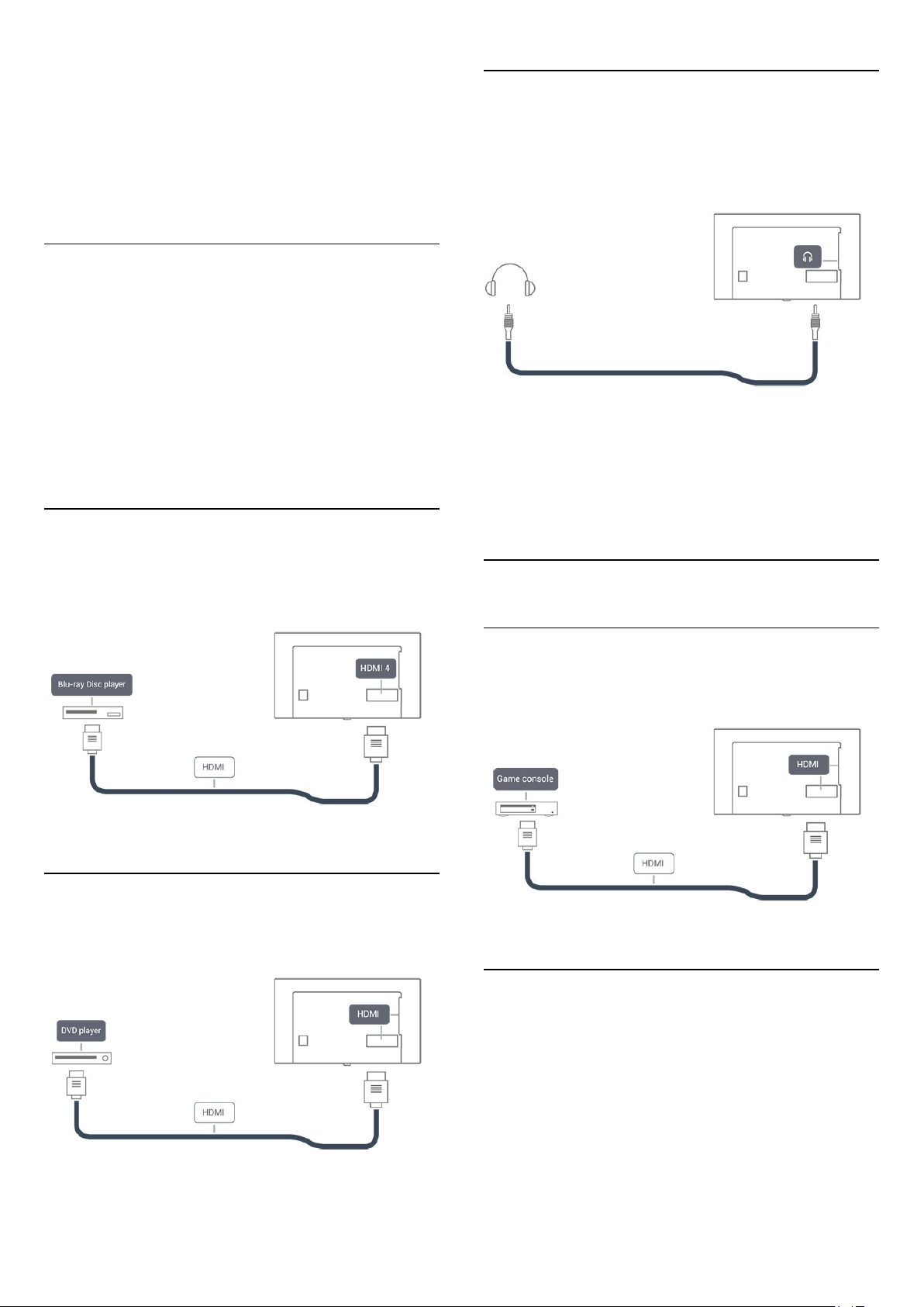
4.7 Headphones 13
4.8 Game console 13
4.9 USB hard drive 14
4.10 USB keyboard 15
4.11 USB mouse 15
4.12 USB flash drive 15
4.13 Photo camera 16
4.14 Camcorder 16
4.15 Computer 16
5 Home menu 18
5.1 About the Home menu 18
5.2 Open the Home menu 18
6 Network 19
6.1 Network and Internet 19
7 Switching On and Off 22
7.1 On or standby 22
7.2 Keys on TV 22
7.3 Sleep timer 22
7.4 Switch off timer 22
8 Remote control 23
8.1 Key overview 23
8.2 IR sensor 24
8.3 Batteries 24
8.4 Cleaning 24
9 Channels 25
9.1 Install Channels 25
9.2 Switch channels 25
9.3 Channel lists 25
9.4 Watching channels 25
9.5 Favorite Channels 27
9.6 Closed captioning (CC) and language 27
10 TV guide 29
10.1 What you need 29
10.2 TV guide data 29
10.3 Using the TV guide 29
11 Recording and Pause TV 31
11.1 Recording 31
11.2 Pause TV 32
12 Utilities 33
13 Netflix 34
13.1 Netflix 34
14 Sources 35
14.1 Switch to a device 35
14.2 Options for TV Input 35
14.3 Scan connections 35
14.4 Game or computer 35
15 Internet 36
15.1 Start Internet 36
15.2 Internet Options 36
16 Your music, movies and photos 37
16.1 From a USB connection 37
16.2 Menu bar and sorting 37
16.3 Play your music 37
16.4 Play your movie 37
16.5 View your photos 38
17 Smartphones and tablets 39
17.1 MHL 39
17.2 Smart TV 39
18 Settings 42
18.1 Quick settings 42
18.2 Picture 42
18.3 Sound 45
18.4 Eco settings 47
18.5 General settings 48
18.6 Clock 50
18.7 Universal Access 50
19 Channel installation 52
19.1 Antenna/cable installation 52
19.2 Channel list copy 52
20 Software 54
20.1 Update software 54
20.2 Software version 54
20.3 Local updates 54
20.4 Open source license 54
21 Specifications 55
21.1 Environmental 55
21.2 Power 55
21.3 Reception 55
21.4 Display type 55
2
Page 3

21.5 Display input resolution 55
21.6 Dimensions and Weights 56
21.7 Connectivity 56
21.8 Sound 56
21.9 Multimedia 56
22 Safety and care 57
22.1 Safety 57
22.2 Screen care 58
23 Copyrights 59
23.1 MHL 59
23.2 HDMI 59
23.3 Dolby 59
23.4 ANATEL 59
23.5 Microsoft 59
23.6 Wi-Fi Alliance 59
23.7 Kensington 59
23.8 Other trademarks 59
Index 61
3
Page 4

1
Using help
Open Help
Press the key (blue) to open Help immediately. Help will
open to the chapter that is most relevant to what you are doing
or what is selected on TV. To look up topics alphabetically, press
the color key
Keywords
.
To read the Help as a book, select
Before you execute the Help instructions, close Help.
To close Help, press the color key
TV Help on your tablet, smartphone or computer
To carry out extended sequences of instructions more
easily, you can download the TV Help in PDF format to read on
your smartphone, tablet or computer. Alternatively, you can
print the relevant Help page from your computer.
Book
Close
.
.
4
Page 5

2
Troubleshooting
minutes before you reconnect the power cable. If the blinking
reoccurs, contact AOC TV Consumer Care.
2.1
Channels
No digital channels found during the installation
Make sure that all cables are properly connected and that the
correct network is selected.
Previously installed channels are not in the channel list
Make sure that the correct channel list is selected.
2.2
General
The TV does not switch on
• Disconnect the power cable from the power outlet. Wait for
one minute then reconnect it.
• Make sure that the power cable is securely connected.
Creaking sound at startup or power off
When you are turning the TV on, off or to standby, you hear a
creaking sound from the TV chassis. The creaking sound is due
to the normal expansion and contraction of the TV as it cools
and warms up. This does not affect performance.
TV does not respond to the remote control
The TV requires some time to start up. During this time, the TV
does not respond to the remote control or TV controls. This is
normal behavior.
If the TV continues to be unresponsive to the remote control,
you can check if the remote control is working by means of a
mobile phone camera. Put the phone in camera mode and point
the remote control to the camera lens. If you press any key on
the remote control and you notice the infra-red LED flicker
through the camera, the remote control is working. The TV
needs to be checked.
If you do not notice the flickering, the remote control might be
broken or its batteries are low.
This method of checking the remote control is not possible with
remote controls which are wirelessly paired with the TV.
The TV goes back to standby after showing the startup
screen
2.3
Picture
No picture / distorted picture
• Make sure that the antenna is properly connected to the TV.
• Make sure that the correct device is selected as the display
source.
• Make sure that the external device or source is properly
connected.
Sound but no picture
• Make sure that the picture settings are set correctly.
Poor antenna reception
• Make sure that the antenna is properly connected to the TV.
• Loud speakers, unearthed audio devices, neon lights, high
buildings and other large objects can influence reception quality.
If possible, try to improve the reception quality by changing the
antenna direction or moving devices away from the TV.
Poor picture from a device
• Make sure that the device is connected properly.
• Make sure that the picture settings are set correctly.
Picture settings change after a while
Make sure that
save settings in this mode.
A commercial banner appears
Make sure that
Picture does not fit the screen
Change to a different picture format. Press
key on remote control.
Picture format keeps changing with different channels
Select a non "Auto" picture format.
Picture position is incorrect
Picture signals from some devices may not fit the screen
correctly. Check the signal output of the connected device.
Computer picture is not stable
Make sure that your PC uses the supported resolution and
refresh rate.
Location
Location
is set to
is set to
Home
Home
. You can change and
.
PICTURE FORMAT
When the TV is in standby, a startup screen is displayed, then
the TV returns to standby mode. This is normal behavior. When
the TV is disconnected and reconnected to the power supply,
the startup screen is displayed at the next startup. To turn the
TV on from standby, press on the remote control or the TV.
The standby light keeps on blinking
Disconnect the power cable from the power outlet. Wait 5
2.4
Sound
No sound or poor sound quality
If no audio signal is detected, the TV automatically switches the
audio output off — this does not indicate malfunction.
5
Page 6

• Make sure that the sound settings are correctly set.
• Make sure that all cables are properly connected.
• Make sure that the volume is not muted or set to zero.
• Make sure that the TV audio output is connected to the audio
input on the Home Theater System.
Sound should be heard from the HTS speakers.
• Some devices may require you to manually enable HDMI
audio output. If HDMI audio is already enabled, but you still do
not hear audio, try changing the digital audio format of the
device to PCM (Pulse Code Modulation). Refer to the
documentation accompanying your device for instructions.
2.5
Internet does not work
• If the connection to the router is OK, check the router
connection to the Internet.
The PC and Internet connection are slow
• Look in your wireless router's user manual for information on
indoor range, transfer rate and other factors of signal quality.
• Use a high-speed (broadband) Internet connection for your
router.
DHCP
• If the connection fails, you can check the DHCP (Dynamic
Host Configuration Protocol) setting of the router. DHCP
should be switched on.
HDMI and USB
HDMI
• Note that HDCP (High-bandwidth Digital Content Protection)
support can delay the time taken for a TV to display content
from an HDMI device.
• If the TV does not recognize the HDMI device and no picture
is displayed, switch the source from one device to another and
back again.
• If there are intermittent sound disruptions, make sure that
output settings from the HDMI device are correct.
HDMI E-Link does not work
• Make sure that your HDMI devices are HDMI-CEC
compatible. E-Link features only work with devices that are
HDMI-CEC compatible.
No volume icon shown
• When an HDMI-CEC audio device is connected this behavior
is normal.
Photos, movies, and music from a USB device do not play
• Make sure that the USB storage device is set to Mass Storage
Class compliant, as described in the storage device's
documentation.
• Make sure that the USB storage device is compatible with the
TV.
• Make sure that the audio and picture file formats are
supported by the TV.
Choppy playback of USB files
• The transfer performance of the USB storage device may limit
the data transfer rate to the TV which causes poor playback.
2.7
Wrong menu language
Change the language back to your language.
To change the language of the TV menus and messages…
1 - Press the
2 - Select
press
3 - Select the language you need.
4 - Press (left) repeatedly if necessary, to close the menu.
Settings
General settings
OK.
key.
>
Language
>
Menu Language
and
2.6
Wi-Fi and Internet
Wi-Fi network not found or distorted
• Microwave ovens, DECT phones or other Wi-Fi 802.11b/g/n
devices in your proximity might disturb the wireless network.
• Make sure that the firewalls in your network allow access to
the TV's wireless connection.
• If the wireless network does not work properly in your home,
try the wired network installation.
6
Page 7

3
Setting up
3.1
Read safety
Read the safety instructions first before you use the TV.
To read the instructions, in
key
3.2
Keywords
and look up
, press the color
Help
Safety instructions
.
TV stand and wall mounting
You can find the instructions for mounting the TV stand in the
Quick Start Guide that came with the TV.
Your TV is also prepared for a VESA-compliant wall
mount bracket (sold separately).
Use the following VESA code when purchasing the wall mount .
. .
7
Page 8
• For 43-inch TV:
• For 50-inch TV:
• For 55-inch TV:
Caution
Wall mounting the TV requires special skills and should only be
performed by qualified personnel. The TV wall mounting should
meet safety standards according to the TVs weight. Also read
the safety precautions before positioning the TV.
VESA MIS-F 200x200, M6
VESA MIS-F 400x200, M6
VESA MIS-F 400x200, M6
Although this TV has a very low standby power consumption,
unplug the power cable to save energy if you do not use the TV
for a long period of time.
For more information, in
key
information.
3.5
Keywords
and look up
, press the color
Help
Switching on
for more
Antenna cable
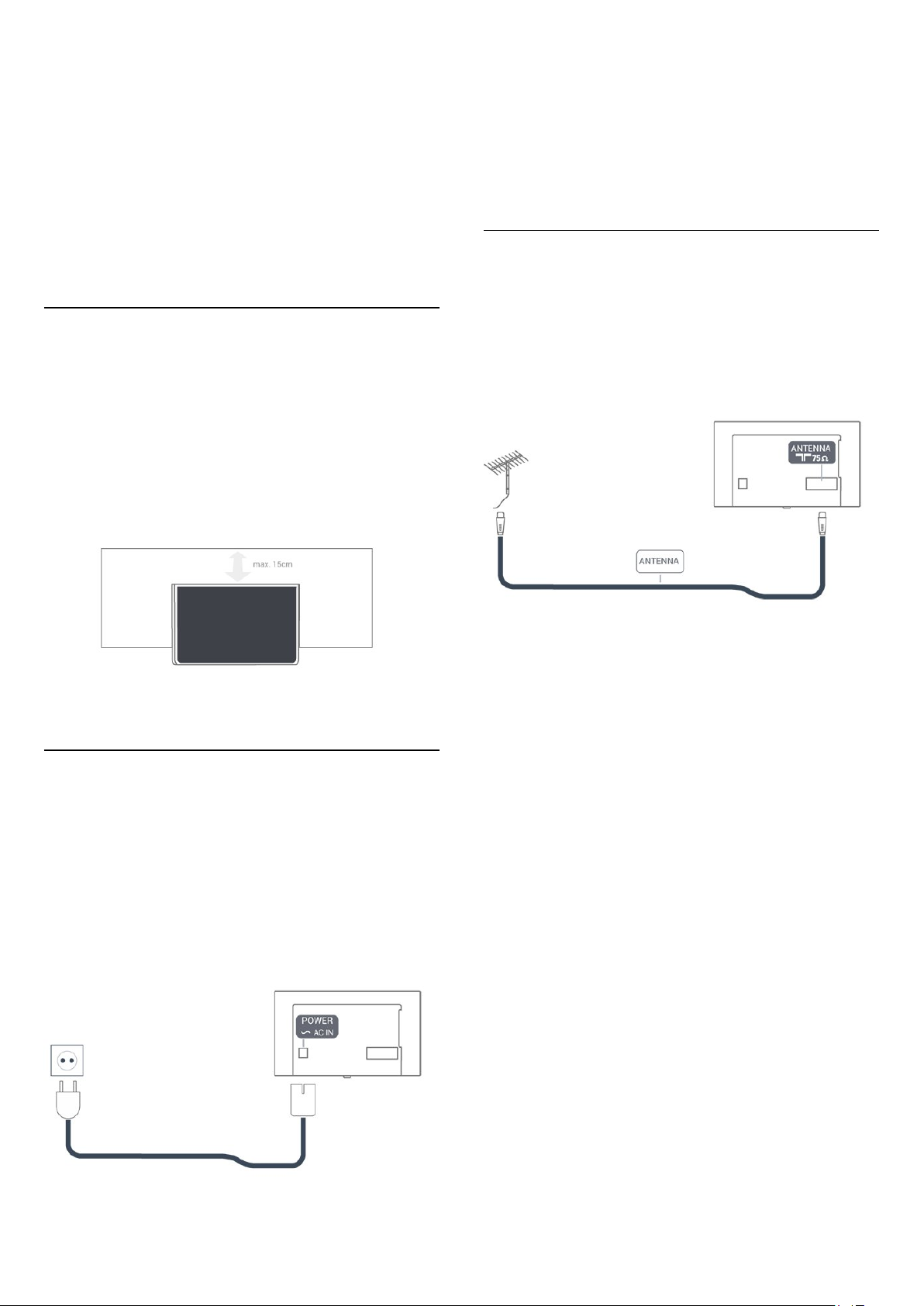
3.3
Tips on placement
• Position the TV where light does not shine directly on the
screen.
• Position the TV up to 6 inches away from the wall.
• The ideal distance to watch TV is 3 times its diagonal screen
size. When seated, your eyes should be level with the center of
the screen.
Insert the antenna plug firmly into the
back of the TV.
You can connect your own antenna or an antenna signal from
an antenna distribution system. Use an IEC Coax 75 Ohm RF
antenna connector.
Antenna
socket at the
3.4
Power cable
• Insert the power cable into the
back of the TV.
• Make sure the power cable is securely inserted in the
connector.
• Make sure that the power plug, in the wall socket, is accessible
at all times.
• When you unplug the power cable, always pull the plug, never
pull the cable.
POWER
connector on the
8
Page 9
4
connection, and press OK.
Connect devices
4.1
About connections
Antenna port
If you have a Set-top box (a digital receiver) or Recorder,
connect the antenna cables to run the antenna signal through
the Set-top box and/or Recorder first before it enters the TV. In
this way, the antenna and the Set-top box can send possible
additional channels to the Recorder to record.
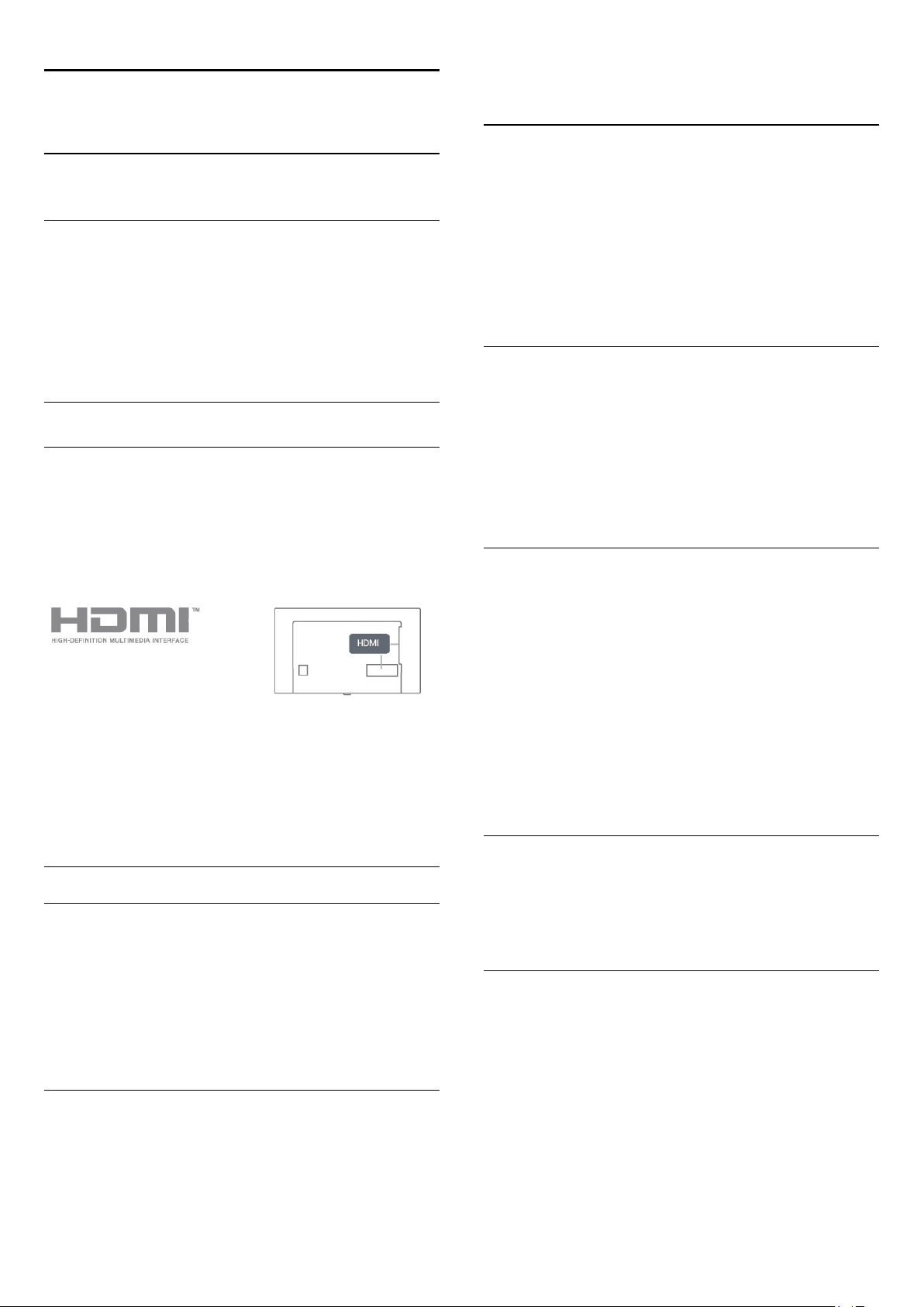
HDMI ports
HDMI quality
An HDMI connection has the best picture and sound quality.
One HDMI cable combines video and audio signals. Use an
HDMI cable for TV signal.
For best signal quality transfer, use a High speed HDMI cable
and do not use an HDMI cable longer than 5 m.
E-Link settings
To switch off E-Link completely…
1 - Press the
press (right) to enter the menu.
2 - Select
further.
3 - Select
4 - Press (left) repeatedly if necessary, to close the menu.
E-Link remote control
To switch E-Link Remote Control on or off…
1 - Press the
press (right) to enter the menu.
2 - Select
3 - Select On or
4 - Press (left) repeatedly if necessary, to close the menu.
Pixel Plus Link
Some devices, such as a DVD or Blu-ray Disc player, might have
their own picture quality processing. To avoid bad picture quality
caused by interference with the TV's processing, picture
processing should be disabled on these devices.
Settings
E-Link
.
Off
Settings
E-Link
key, select
, press (right) and select
key, select
>
E-Link Remote Control
and press OK.
Off
General settings
General settings
and
one step
E-Link
and
and press OK.
Copy protection
HDMI cables support HDCP (High-bandwidth Digital Content
Protection). HDCP is a copy protection signal that prevents
copying content from a DVD disc or Blu-ray Disc. Also referred
to as DRM (Digital Rights Management).
HDMI CEC
E-Link
E-Link HDMI CEC
If your devices are connected with HDMI and have E-Link, you
can operate them with the TV remote control. E-Link HDMI
CEC must be switched On on the TV and the connected
device.
Operate devices
To operate a device connected to HDMI and set up with E-Link,
select the device or its activity in the list of TV connections.
Press
SOURCES
, select a device connected to an HDMI
To switch
1 - Press the
press (right) to enter the menu.
2 - Select
3 - Select On or
4 - Press (left) repeatedly if necessary, to close the menu.
Auto turn off devices
You can set the TV to turn off the connecting HDMI-CEC
compliant devices if they are not the active source. The TV turns
the connected device to standby after 5 minutes of inactivity.
HDMI ARC
Only
Channel).
If the device, typically a Home Theater System (HTS), also has
the HDMI ARC connection, connect it to the
connection on this TV. With the HDMI ARC connection, you
4
do not need to connect the extra audio cable that sends the TV
sound to the HTS. The HDMI ARC connection combines both
signals.
Pixel Plus Link
Settings
E-Link
HDMI 4
>
Off
on the TV has
on or off…
key, select
Pixel Plus Link
and press OK.
HDMI ARC
General settings
and press OK.
(Audio Return
HDMI
, and
9
Page 10

In case you prefer to disable ARC on the HDMI connections,
press
Settings
Select Sound and press (right) to enter the menu. Select
Advanced
HDMI MHL
With
HDMI MHL
smartphone or tablet to a TV screen.
The
HDMI 1
(Mobile High-Definition Link).
2.0
This wired connection offers great stability and bandwidth, low
latency, no wireless interference and good quality sound
reproduction. On top of that, the MHL connection will charge
the battery of your smartphone or tablet. Although connected,
your mobile device will not be charging when the TV is on
standby.
Inform yourself regarding which passive MHL cable is suited for
your mobile device. In particular, with the HDMI connector for
the TV on one side, the type of connector you need to connect
to your smartphone or tablet.
key.
>
HDMI 4 - ARC
, you can send what you see on your Android
connection on this TV incorporates
and press OK.
MHL
Y Pb Pr - Component
Y Pb Pr - Component Video is a high quality connection.
The YPbPr connection can be used for High Definition (HD) TV
signals. Next to the Y, Pb and Pr signals, add the Audio Left and
Right signals for sound.
Match the YPbPr (green, blue, red) connector colors with the
cable plugs when you make the connections.
Use an Audio L/R cinch cable if your device also has sound.
MHL, Mobile High-Definition Link and the MHL Logo are
trademarks or registered trademarks of the MHL, LLC.
DVI to HDMI
If you still own a device that only has a DVI connection, you can
connect the device to any of the
to HDMI adapter.
Use a DVI to HDMI adapter if your device only has a DVI
connection. Use one of the HDMI connections and add an
Audio L/R cable (mini-jack 3.5mm) to Audio In for sound on the
back of the TV.
Copy protection
DVI and HDMI cables support HDCP (High-bandwidth Digital
Content Protection). HDCP is a copy protection signal that
prevents copying content from a DVD disc or Blu-ray Disc. Also
referred to as DRM (Digital Rights Management).
connections with a DVI
HDMI
CVBS - Audio L R
CVBS - Composite Video is a high quality connection. Next to
the CVBS signal, add the Audio Left and Right signals for sound.
• Y shares the same jack with CVBS.
• Component and Composite share audio jacks.
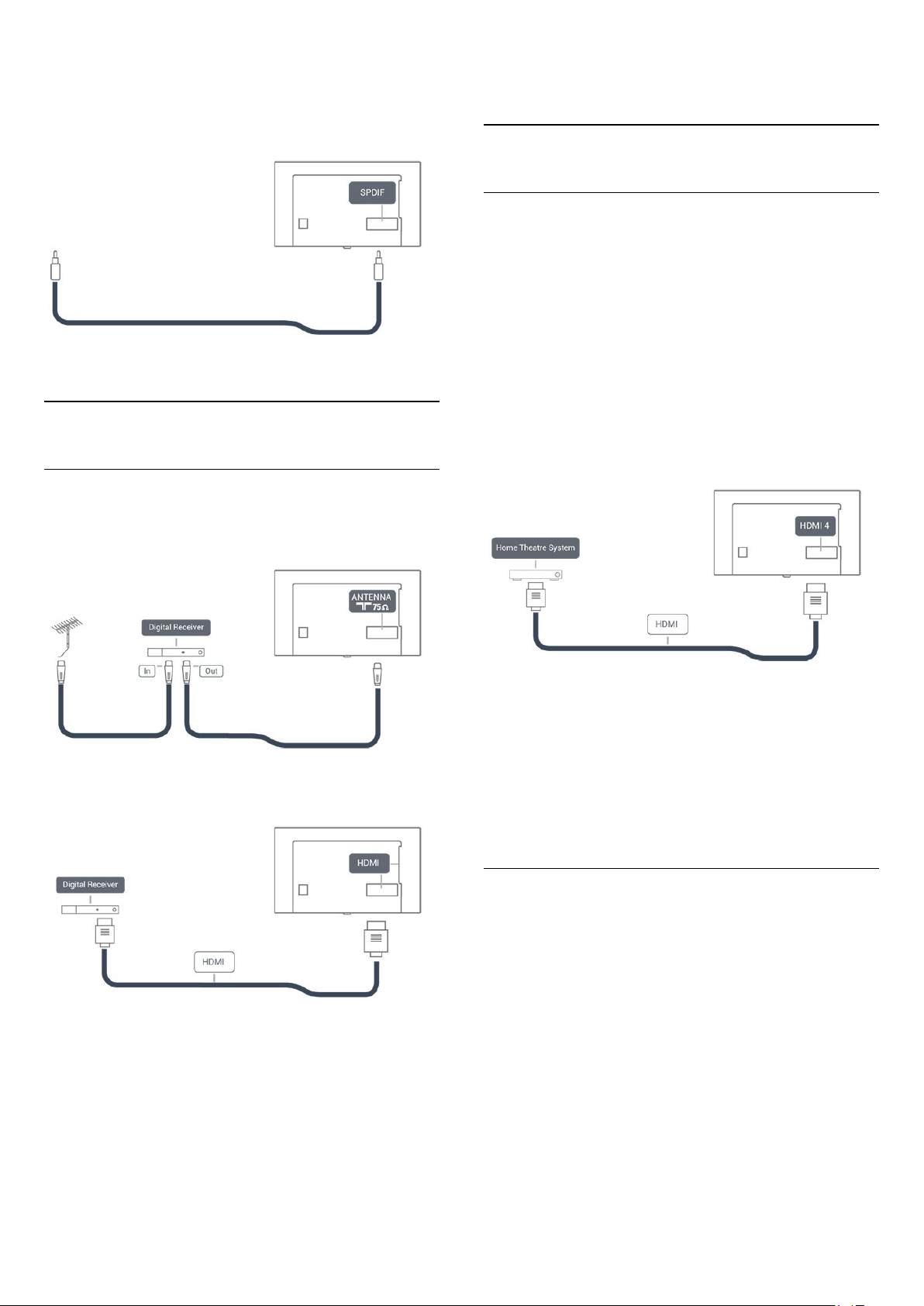
SPDIF
SPDIF is a high quality sound connection.
This optical connection can carry 5.1 audio channels. If your
device, typically a Home Theater System (HTS), has no HDMI
ARC connection, you can use this connection with the SPDIF
connection on the HTS. The SPDIF connection sends the sound
from the TV to the HTS.
You can set the type of the audio out signal to fit the audio
capabilities of your Home Theater System.
For more information, in
key
Keywords
and look up
, press the color
Help
Audio out settings
.
10
Page 11
If the sound does not match the video on screen, you can adjust
the audio to video synchronization.
For more information, in
key
Keywords
and look up
, press the color
Help
Audio to video sync
.
information.
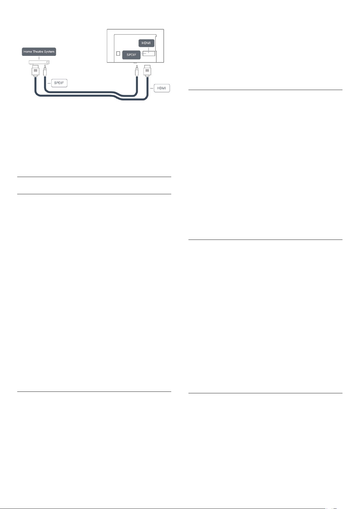
4.3
Home Theater System - HTS
Connect with HDMI ARC
Use an HDMI cable to connect a Home Theater System (HTS)
to the TV. You can connect a Soundbar or an HTS with a builtin disc player.
4.2
Receiver - Set-Top Box
Cable box
Use 2 antenna cables to connect the antenna to the Set-top box
(a digital receiver) and the TV.
Next to the antenna connections, add an HDMI cable to
connect the Set-top box to the TV.
HDMI ARC
If your Home Theater System has an HDMI ARC connection,
you can use
you do not need to connect the extra audio cable. The HDMI
ARC connection combines both signals.
HDMI 4
signal, but once you have connected the Home Theater System,
the TV can only send the ARC signal to this HDMI connection.
Audio to video synchronization (sync)
If the sound does not match the video on screen, you can set a
delay on most Home Theater Systems with a disc player to
match the sound with the video.
For more information, in
key
HDMI 4
on the TV can offer the Audio Return Channel (ARC)
on the TV to connect. With HDMI ARC,
, press the color
Help
Keywords
and look up
Audio to video sync
.
Switch Off Timer
Switch off this automatic timer if you only use the remote
control for the Set-top box. Switching this timer off prevents the
TV from switching off automatically after a 4-hour period
without a key press on the TV's remote control.
For more information, in
key
Keywords
Help
and look up
, press the color
Switch off timer
for more
Connect with HDMI
Use an HDMI cable to connect a Home Theater System (HTS)
to the TV. You can connect a Soundbar or an HTS with a builtin disc player.
If the Home Theater System has no HDMI ARC connection,
add an SPDIF cable to send the TV sound to the Home Theater
System.
11
Page 12
To synchronize the sound on the TV…
Audio to video synchronization (sync)
If the sound does not match the video on screen, you can set a
delay on most Home Theater Systems with a disc player to
match the sound with the video.
For more information, in
key
Keywords
and look up
, press the color
Help
Audio to video sync
.
Audio out settings
Audio out delay
With a Home Theater System (HTS) connected to the TV, the
picture on the TV and the sound from the HTS should be
synchronized.
1 - Press the
enter the menu.
2 - Select
3 - Use the slider bar to set the sound offset and press OK.
4 - Press (left) repeatedly if necessary, to close the menu.
Audio out format
If you have a Home Theater System (HTS)
with multichannel sound processing capabilities such as Dolby
Digital or similar, set the Audio Out Format to Multichannel.
With Multichannel, the TV can send the compressed
multichannel sound signal from a TV channel or connected
player to the Home Theater System. If you have a Home
Theater System without multichannel sound processing, select
Stereo.
To set
1 - Press the
enter the menu.
2 - Select
3 - Select
then press OK.
4 - Press (left) repeatedly if necessary, to close the menu.
Settings
Advanced
Audio out format
Settings
Advanced
Multichannel, Stereo
key, select
>
Audio out offset
key, select
>
Audio out format
Sound
…
Sound
or
and press (right) to
and press OK.
and press (right) to
and press OK.
Multichannel (bypass)
,
Automatic audio to video sync
With recent Home Theater Systems, the audio to video sync is
done automatically and is always correct.
Audio sync delay
For some Home Theater Systems you may need to adjust the
audio sync delay to synchronize the audio to the video. On the
HTS, increase the delay value until there is a match between
picture and sound. A delay value of 180ms may be required.
Read the user manual of the HTS. With a delay value set up on
the HTS, you need to switch off Audio Out delay on the TV.
To switch off Audio Out Delay…
1 - Press the
enter the menu.
2 - Select
3 - Select
4 - Press (left) repeatedly if necessary, to close the menu.
Audio out offset
If you cannot set a delay on the Home Theater System, you can
set the TV to sync the sound. You can set an offset that
compensates for the time necessary for the Home Theater
System to process the sound of the TV picture. You can set the
value in steps of 5ms. Maximum setting is -60ms.
The
Audio out delay
Settings
Advanced
.
Off
key, select
>
Audio out delay
setting should be switched on.
Sound
and press (right) to
and press OK.
Audio out leveling
Use the Audio Out Leveling setting to level the volume
(loudness) of the TV and the Home Theater System when you
switch over from one to another. Volume differences can be
caused by differences in sound processing.
To level the difference in volume…
1 - Press the
enter the menu.
2 - Select
3 - Select
4 - If the volume difference is large, select
difference is small, select
5 - Press (left) repeatedly if necessary, to close the menu.
Audio Out Leveling affects both the Audio Out - Optical and
HDMI ARC sound signals.
Settings
Advanced
More, Medium
key, select
>
Audio out leveling
Less
, or
Sound
, then press OK.
Less
.
and press (right) to
and press OK.
. If the volume
More
Problems with HTS sound
Sound with loud noise
If you watch a video from a plugged-in USB flash drive or
connected computer, the sound from your Home Theater
System might be distorted. You can fix this by setting the
out format
of the TV to
Stereo
Audio
.
12
Page 13
Press the
Select
No sound
If you cannot hear the sound from the TV on your Home
Theater System, check if you connected the HDMI cable to
an
4.4
Settings
Sound
HDMI4 ARC
key.
>
Advanced
connection on the Home Theater System.
>
Audio out format
.
Smartphones and tablets
To connect a smartphone or tablet to the TV, you can use a
wired connection.
Wired
For a wired connection, use the HDMI 1 MHL connection on
the back of the TV. In
key
Keywords
information.
4.5
and look up
, press the color
Help
HDMI MHL
for more
4.7
Headphones
You can connect a set of headphones to the connection on
the back of the TV. The connection is a mini-jack 3.5mm. You
can adjust the volume of the headphones separately.
To adjust the volume…
1 - Press the
volume
2 - Press the arrows (up) or (down) to adjust the value.
3 - Press (left) repeatedly if necessary, to close the menu.
Settings
and press OK.
key, select
Sound
>
Headphone
Blu-ray disc player
Use a
High speed HDMI
player to the TV.
4.6
cable to connect the Blu-ray Disc
DVD player
Use an HDMI cable to connect the DVD player to the TV.
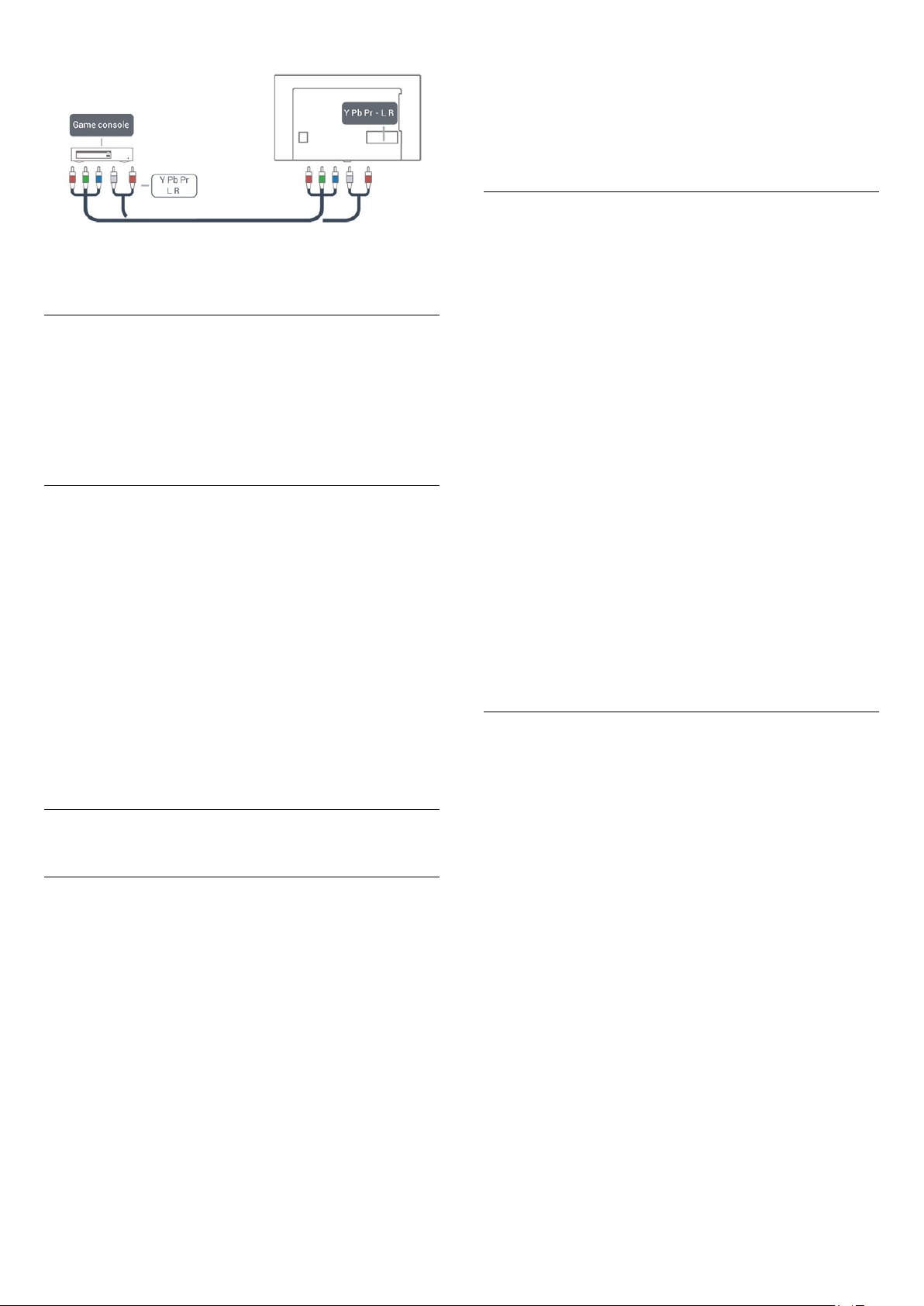
4.8
Game console
HDMI
For best quality, connect the game console with a high-speed
HDMI cable to the TV.
Y Pb Pr - Component
Connect the game console with a component video cable (Y Pb
Pr) and an audio L/R cable to the TV.
13
Page 14
CVBS - Audio L R
CVBS - Composite Video is a high quality connection. Next to
the CVBS signal, add the Audio Left and Right signals for sound.
• Y shares the same jack with CVBS.
• Component and Composite share audio jacks.
Best settings
Before you start playing a game from a connected game console,
we suggest you set the TV to the ideal
When you finish playing a game and start watching TV again,
remember to switch the
to
.
Off
To set the TV to the ideal setting…
1 - Press the
enter the menu.
2 - Select
device type you want to use. To switch back to TV, select
3 - Press (left) repeatedly if necessary, to close the menu.
4.9
Settings
Advanced
Game or Computer
key, select
>
Game or Computer
Picture
setting.
Game
setting back
and press (right) to
, and select the
Off
.
USB hard drive
What you need
If you connect a USB Hard Drive, you can pause or record a TV
broadcast. The TV broadcast must be a digital broadcast (DVB
broadcast or similar).
To Pause
To pause a broadcast, you need a USB-compatible Hard Drive
with a minimum of 4GB of disk space.
Drive.
For more information on how to install a USB Hard Drive,
in
, press the color key
Help
hard drive, installation
Keywords
.
and look up
USB
Installation
Before you can pause or record a broadcast, you must connect
and format a USB Hard Drive. Formatting removes all files from
the USB Hard Drive.
1 - Connect the USB Hard Drive to one of
the
device to the other USB ports when formatting.
2 - Switch on the USB Hard Drive and the TV.
3 - When the TV is tuned to a digital TV channel,
press (Pause). Trying to pause will start the formatting.
Follow the instructions on screen.
When the USB Hard Drive is formatted, leave it connected
permanently.
Warning
The USB Hard Drive is formatted exclusively for this TV, you
cannot use the stored recordings on another TV or PC. Do not
copy or change recording files on the USB Hard Drive with any
PC application. This will corrupt your recordings. When you
format another USB Hard Drive, the content on the former will
be lost. A USB Hard Drive installed on your TV will need
reformatting for use with a computer.
connections on the TV. Do not connect another USB
USB
Formatting
Before you can pause or record a broadcast, you must connect
and format a USB Hard Drive. Formatting removes all files from
the USB Hard Drive. If you want to record broadcasts with TV
Guide data from the Internet, you must first set up the Internet
connection before you install the USB Hard Drive.
Warning
The USB Hard Drive is formatted exclusively for this TV, you
cannot use the stored recordings on another TV or PC. Do not
copy or change recording files on the USB Hard Drive with any
PC application. This will corrupt your recordings. When you
format another USB Hard Drive, the content on the former will
be lost. A USB Hard Drive installed on your TV will need
reformatting for use with a computer.
To format a USB Hard Drive…
To Record
To pause and record a broadcast, you need a minimum of
250GB disk space. If you want to record a broadcast with TV
guide data from the Internet, you need to have the Internet
connection installed on your TV before you install the USB Hard
1 - Connect the USB Hard Drive to one of the
connections on the TV. Do not connect another USB device to
the other USB ports when formatting.
2 - Switch on the USB Hard Drive and the TV.
3 - When the TV is tuned to a digital TV channel, press
(Pause). Trying to pause will start the formatting. Follow the on-
14
USB
Page 15

screen instructions.
4 - The TV will ask if you want to use the USB Hard Drive to
store apps. Select Agree if you do.
5 - When the USB Hard Drive is formatted, leave it connected
permanently.
4.10
4.11
USB mouse
Connect USB mouse
You can connect a USB mouse (USB-HID type) to navigate
pages on the Internet.
USB keyboard
Connect
Connect a USB keyboard (USB-HID type) to enter text on your
TV.
Use one of the
Configure
To install the USB keyboard, switch on the TV and connect the
USB keyboard to one of the
the TV detects the keyboard for the first time, you can select
your keyboard lay-out and test your selection. If you select a
Cyrillic or Greek keyboard layout first, you can select a
secondary Latin keyboard layout.
To change the keyboard layout setting when a layout was
selected…
1 - Press the
press (right) to enter the menu.
2 - Select
keyboard setup.
USB keyboard settings
Special keys
connections to connect.
USB
Settings
key, select
connections on the TV. When
USB
General settings
, and press OK to start the
and
On an Internet page, you can select and click on links more
easily.
Connect the mouse
Switch the TV on and connect the USB mouse to one of
the
mouse to a connected USB keyboard.
Mouse clicks
• Left click = OK
You can use the scroll wheel to scroll pages up and down.
connections on the TV. You can also connect the USB
USB
Mouse speed
To install the USB keyboard, switch on the TV and connect the
USB keyboard to one of the
the TV detects the keyboard for the first time, you can select
your keyboard lay-out and test your selection. If you select a
Cyrillic or Greek keyboard layout first, you can select a
secondary Latin keyboard layout.
To change the keyboard layout setting when a layout was
selected…
1 - Press the
press (right) to enter the menu.
2 - Select
setup.
Settings
Mouse settings
key, select
, and press OK to start the keyboard
connections on the TV. When
USB
General settings
and
Keys for entering text
• Enter key = OK
• Backspace = delete character before cursor
• Arrow keys = navigate within a text field
• To switch between keyboard layouts, if a secondary layout is
set, press the
Keys for apps and Internet pages
• Tab and Shift + Tab = Next and Previous
• Home = scroll to the top of the page
• End = scroll to the bottom of the page
• Page Up = jump one page up
• Page Down = jump one page down
• + = zoom in one step
• - = zoom out one step
• * = fit the web page to the screen width
Ctrl + Spacebar
keys simultaneously.
4.12
USB flash drive
You can view photos or play your music and videos from a
connected USB flash drive.
Insert a USB flash drive in one of the
TV while the TV is switched on.
The TV detects the flash drive and opens a list showing its
content.
If the contents list does not appear automatically,
press
SOURCES
15
and select
USB
.
connections on the
USB
Page 16
To stop watching the USB flash drive content, press
select another activity.
To disconnect the USB flash drive, you can pull out the flash
drive anytime.
EXIT
or
Ultra HD on USB
You can view photos in Ultra HD resolution from a connected
USB device or flash drive. The TV will downscale the resolution
to Ultra HD if the resolution of the photo is higher. You cannot
play a native Ultra HD video on any of the USB connections.
For more information on watching or playing content from a
USB flash drive, in
look up
4.13
Photos, movies and music
, press the color key
Help
Keywords
.
and
Photo camera
To view photos stored on your digital photo camera, you can
connect the camera directly to the TV.
Use one of the
on the camera after you have made the connection.
If the contents list does not appear automatically,
press
SOURCES
Your camera might need to be set to transfer its content with
PTP (Picture Transfer Protocol). Read the user manual of the
digital photo camera.
connections on the TV to connect. Switch
USB
, and select
USB
.
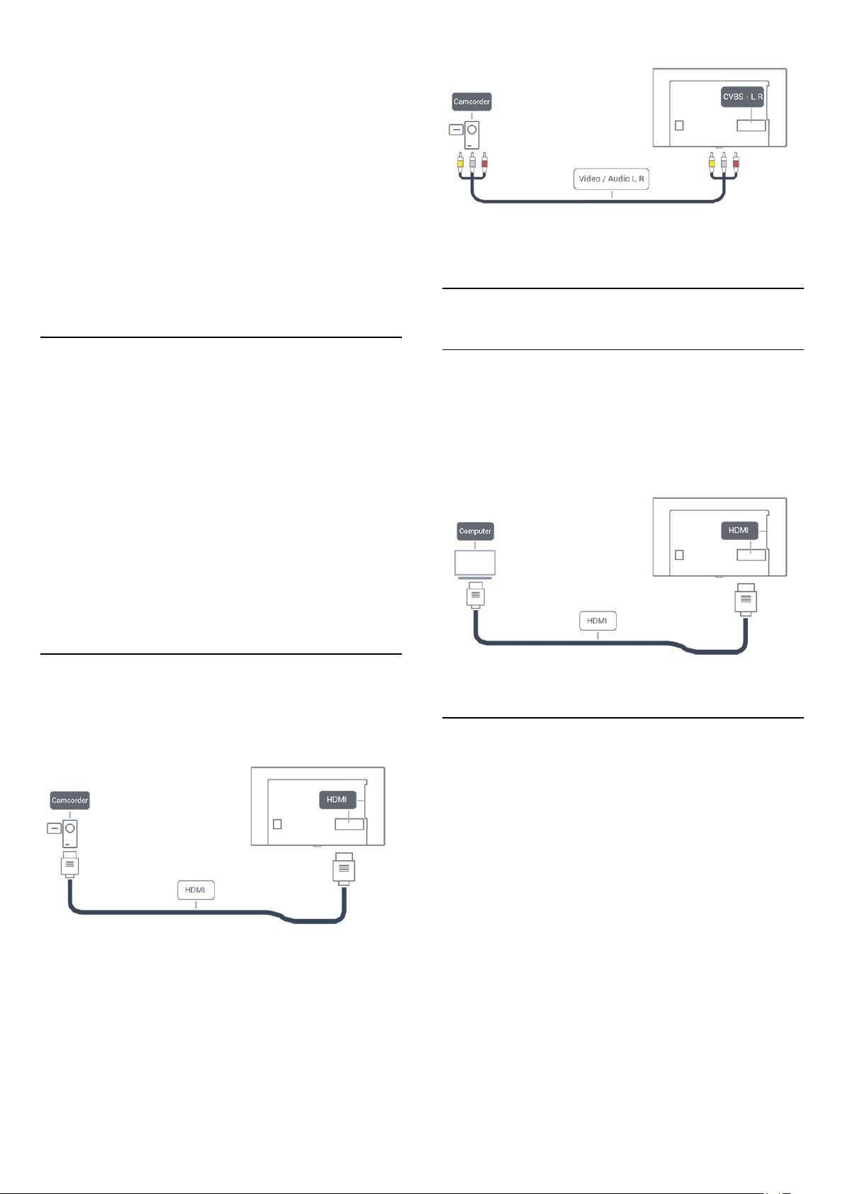
4.15
Computer
Connect
You can connect your computer to the TV and use the TV as a
PC monitor.
With HDMI
Use an HDMI cable to connect the computer to the TV.
For more information on viewing photos, in
color key
4.14
Keywords
and look up
Photos movies and music
Help
, press the
Camcorder
For best quality, use an HDMI cable to connect the camcorder
to the TV.
You can use a YPbPr connection to connect the camcorder to
the TV.
.
Ideal setting
If you connect a computer, we advise you to give the
connection, to which the computer is connected, the correct
device type name in the Source menu. If you then switch
to
Computer
the ideal settings for a computer.
You can manually switch the ideal setting to
or
Game
(remember to switch back to Off when you stop playing a
game).
If you switch to a source and change the
Computer
To set the TV to the ideal setting…
in the Source menu, the TV is automatically set to
for watching TV
Off
for playing a game from a connected game console
Game or
setting, it will be stored for this selected source.
1 - Press the
enter the menu.
2 - Select
3 - Select
16
Settings
Advanced
Game
key, select
>
Game or computer
(for gaming) or select
and press (right) to
Picture
, and press OK.
Computer
(for watching
Page 17

a movie).
4 - Press (left) repeatedly if necessary, to close the menu.
Remember to set
Game or computer
stop playing the game.
setting to
when you
Off
17
Page 18

5
Home menu
5.1
About the Home menu
Channels
This row contains all channels.
Sources
This row contains available sources on this TV.
Utilities
This row contains TV functions available to the user.
Quick settings
This row contains settings available to the user.
5.2
Open the Home menu
To open the Home menu and open an item…
1 - Press
2 - Select an item and press OK to open or start it.
3 - Press
anything.
Home
BACK
.
to close the Home menu without starting
18
Page 19

6
Network
6.1
Network and Internet
Home network
To enjoy the full capabilities of your TV, your TV must be
connected to the Internet.
Connect the TV to a home network with a high-speed Internet
connection. You can connect your TV wirelessly or wired to
your network router.
Connect to network
Wireless connection
What you need
To connect the TV to the Internet wirelessly, you need a Wi-Fi
router with a connection to the Internet.
Use a high-speed (broadband) Internet connection.
router). The TV might find several wireless networks in your
proximity.
•
WPS
If your router has WPS, you can directly connect to the router
without scanning. Go to the router, press the WPS button and
return to the TV within 2 minutes. Then press
the connection.
If you have devices in your wireless network that use the WEP
security encryption system, you cannot use WPS.
If you must use the
instead of WPS.
- From the list of networks found, select your wireless
Step 7
network and press OK.
If your network is not in the list because the network name is
hidden (you turned off the SSID broadcast of the router), select
Manual entry
- Depending on the type of router, you can now enter
Step 8
your encryption key (WEP, WPA or WPA2). If you have
entered the encryption key for this network before, you can
select
If your router supports WPS or WPS PIN, you select
WPS PIN
•
Standard
Select
passphrase, or security key) manually. You can use the keyboard
on the remote control to enter the encryption key. Once you
have entered the key, press
•
WPS PIN
To make a secured WPS connection with a PIN code, select
WPS PIN
shown and enter it in the router software on your PC. Return to
the TV and press
to enter the PIN code in the router software.
to make the connection immediately.
Next
or
Standard
and press OK. Write down the 8-digit PIN code
WPS PIN code
to enter the network name yourself.
Standard
. Select your choice and press OK.
to enter the encryption key (password,
Connect
. Consult the router manual on where
to connect, select
Connect
.
Connect
to make
Scan
WPS
,
Make the connection
To make a wireless connection…
- Make sure that your wireless network router is
Step 1
switched on.
- Press the
Step 2
(right) to enter the menu.
- Select
Step 3
.
OK
- Select
Step 4
- Select
Step 5
- Select
Step 6
have a router with WPS (Wi-Fi Protected Setup), you can select
. Select your choice and press OK.
WPS
•
Scan
Select
Scan
Settings
Connect to network
Connect
Wireless
Scan
to scan for your wireless network (your wireless
key, select
and press OK.
and press OK.
to scan for your wireless network. If you
Network
>
Start now
and press
and press
- A message will be shown when the connection is
Step 9
successful.
Problems
Wireless network not found or distorted
• Microwave ovens, DECT phones or other Wi-Fi 802.11b/g/n
devices in your proximity might disturb the wireless network.
• Make sure that the firewalls in your network allow access to
the TV's wireless connection.
• If the wireless network does not work properly in your home,
try the wired network installation.
Internet does not work
• If the connection to the router is OK, check the router
connection to the Internet.
The PC and Internet connection are slow
• Look in your wireless router's user manual for information on
indoor range, transfer rate and other factors of signal quality.
• Use a high-speed (broadband) Internet connection for your
router.
DHCP
19
Page 20

• If the connection fails, you can check the DHCP (Dynamic
Host Configuration Protocol) setting of the router. DHCP
should be switched on.
Wired connection
What you need
To connect the TV to the Internet, you need a network router
with an internet connection.
Use a high-speed (broadband) Internet connection.
Make the connection
To make a wired connection…
1 - Connect the router to the TV with a network cable
(Ethernet cable**).
2 - Make sure that the router is turned on.
3 - Press the
enter the menu.
4 - Select
5 - Select
the network connection.
6 - A message will be shown when the connection is successful.
Settings
Connect to network
Wired
key, select
and press OK. The TV constantly searches for
Network
and press
and press (right) to
OK.
3 - Select
configuration
4 - Select
5 - You can set the number for
address, Netmask, Gateway, DNS 1
6 - Press (left) repeatedly if necessary, to close the menu.
Switch On with Wi-Fi (WoWLAN)
You can switch this TV on from your smartphone or tablet if the
TV is on Standby. The setting
(WoWLAN)
To switch on WoWLAN…
1 - Press the
enter the menu.
2 - Select
3 - Select On and press OK.
4 - Press (left) repeatedly if necessary, to close the menu.
Digital Media Renderer - DMR
If your media files do not play on your TV, make sure that the
Digital Media Renderer is turned on. As a factory setting, DMR is
turned on.
Static IP
Static IP configuration
Switch on with Wi-Fi (WoWLAN)
and press OK to enable
.
and configure the connection.
IP
Switch On with Wi-Fi
must be switched on.
Settings
key, select
Network
Static IP
, or
.
DNS 2
and press (right) to
and press OK.
If the connection fails, you can check the DHCP setting of the
router. DHCP should be switched on.
**To fulfill EMC regulations, use a shielded FTP Cat. 5E Ethernet
cable.
Network settings
View network settings
You can view all current network settings here. The IP and
MAC address, signal strength, speed, encryption method, etc.
To view the current network settings…
1 - Press the
enter the menu.
2 - Select
3 - Select
Close
Network configuration
If you are an advanced user and want to install your network
with Static IP addressing, set the TV to
To set the TV to Static IP…
1 - Press the
enter the menu.
2 - Select
Settings
View network settings
Next
to close the menu.
Settings
Network configuration
key, select
to view the current network settings, or select
key, select
Network
and press OK.
Network
and press OK.
and press (right) to
Static IP
.
and press (right) to
To switch on DMR…
1 - Press the
enter the menu.
2 - Select
3 - Select On and press OK.
4 - Press (left) repeatedly if necessary, to close the menu.
Switch on Wi-Fi connection
You can switch the Wi-Fi connection on your TV on or off.
To switch on Wi-Fi…
1 - Press the
enter the menu.
2 - Select
3 - Select On and press OK.
4 - Press (left) repeatedly if necessary, to close the menu.
TV network name
If you have more than one TV in your home network, you can
give the TV a unique name.
To change the TV name…
1 - Press the
enter the menu.
2 - Select
3 - Enter the name with the on-screen keyboard.
Settings
Digital Media Renderer - DMR
Settings
Wi-Fi On/Off
Settings
TV network name
key, select
key, select
and press OK.
key, select
and press OK.
Network
Network
Network
and press (right) to
and press OK.
and press (right) to
and press (right) to
20
Page 21

4 - Select
5 - Press (left) repeatedly if necessary, to close the menu.
Netflix settings
to confirm the change.
Done
With
Netflix settings
deactivate a Netflix device.
To enter
1 - Press the
enter the menu.
2 - Select
3 - Press (left) repeatedly if necessary, to close the menu.
Clear Internet memory
With
logins stored on your TV, such as passwords, cookies, and
history.
To clear the Internet memory…
1 - Press the
enter the menu.
2 - Select
3 - Select OK to confirm.
4 - Press (left) repeatedly if necessary, to close the menu.
Netflix settings
Settings
Netflix settings
Clear Internet Memory
Settings
Clear Internet memory
, you can view the ESN number or
…
key, select
and press OK.
, you can clear all Internet files and
key, select
Network
Network
and press OK.
and press (right) to
and press (right) to
File sharing
The TV can connect to other devices in your wireless network,
like your computer or smartphone. You can use a computer
with Microsoft Windows or Apple OS X.
On this TV, you can open photos, movies and music stored on
your computer.
21
Page 22

7
7.3
Switching On and Off
7.1
On or standby
Before you switch on the TV, make sure you plugged the wall
power into the
With the TV in Standby, press on the remote control to
switch the TV on. You can also press the small joystick key on
the back of the TV to switch the TV on in case you can't find
the remote control or its batteries are empty.
Switch to standby
To switch the TV to standby, press on the remote control.
You can also press the small joystick key on the back of the TV.
In standby mode, the TV is still connected to the wall power but
consumes very little energy.
To switch off the TV completely, disconnect the power plug.
When disconnecting the power plug, always pull the power plug,
never the cord. Ensure that you have full access to the power
plug, power cord and outlet socket at all times.
7.2
POWER
Keys on TV
If you lost the remote control or its batteries are empty, you can
still do some basic TV operations.
To open the basic menu…
1 - With the TV switched on, press the joystick key on the back
of the TV to bring up the basic menu.
2 - Press left or right to select Volume, Channel or
Sources.
3 - Press up or down to adjust the volume or tune to the next
or previous channel. Press up or down to go through the list of
sources, including the tuner selection. Press the joystick key to
start the demo movie.
4 - The menu will disappear automatically.
connector on the back of the TV.
Sleep timer
With the
automatically after a preset time.
To set the Sleep Timer…
1 - Press the
timer
2 - With the slider bar you can set the time up to 180 minutes
in 5-minute increments. If set to 0 minutes, the Sleep Timer is
switched off. You can always switch off your TV earlier or reset
the time during the countdown.
3 - Press
7.4
Sleep Timer
Settings
and press OK.
BACK
, you can set the TV to switch to Standby
key, select
to close the menu.
General settings
>
Sleep
Switch off timer
If the TV receives a TV signal, but you don't press a key on the
remote control during a 4 hour period, the TV switches off
automatically to save energy. Also, if the TV does not receive a
TV signal or a remote control command for 10 minutes, the TV
switches off automatically.
If you use the TV as a monitor or use a digital receiver to watch
TV (a Set-Top Box - STB) and you do not use the remote
control of the TV, you should deactivate this automatic switch
off.
To deactivate the Switch Off Timer …
1 - Press the
to enter the menu.
2 - Select
3 - Press the arrows (up) or (down) to adjust the
value. The value 0 deactivates the automatic switch off.
4 - Press (left) repeatedly if necessary, to close the menu.
For more information on environmentally friendly TV settings,
in
Help
settings
Settings
Switch off timer
, press the color key
.
key, select
and press OK.
Eco settings
Keywords
and press (right)
and look up
Eco
To switch the TV on standby, select and press the joystick
key.
22
Page 23
8
Remote control
8.1
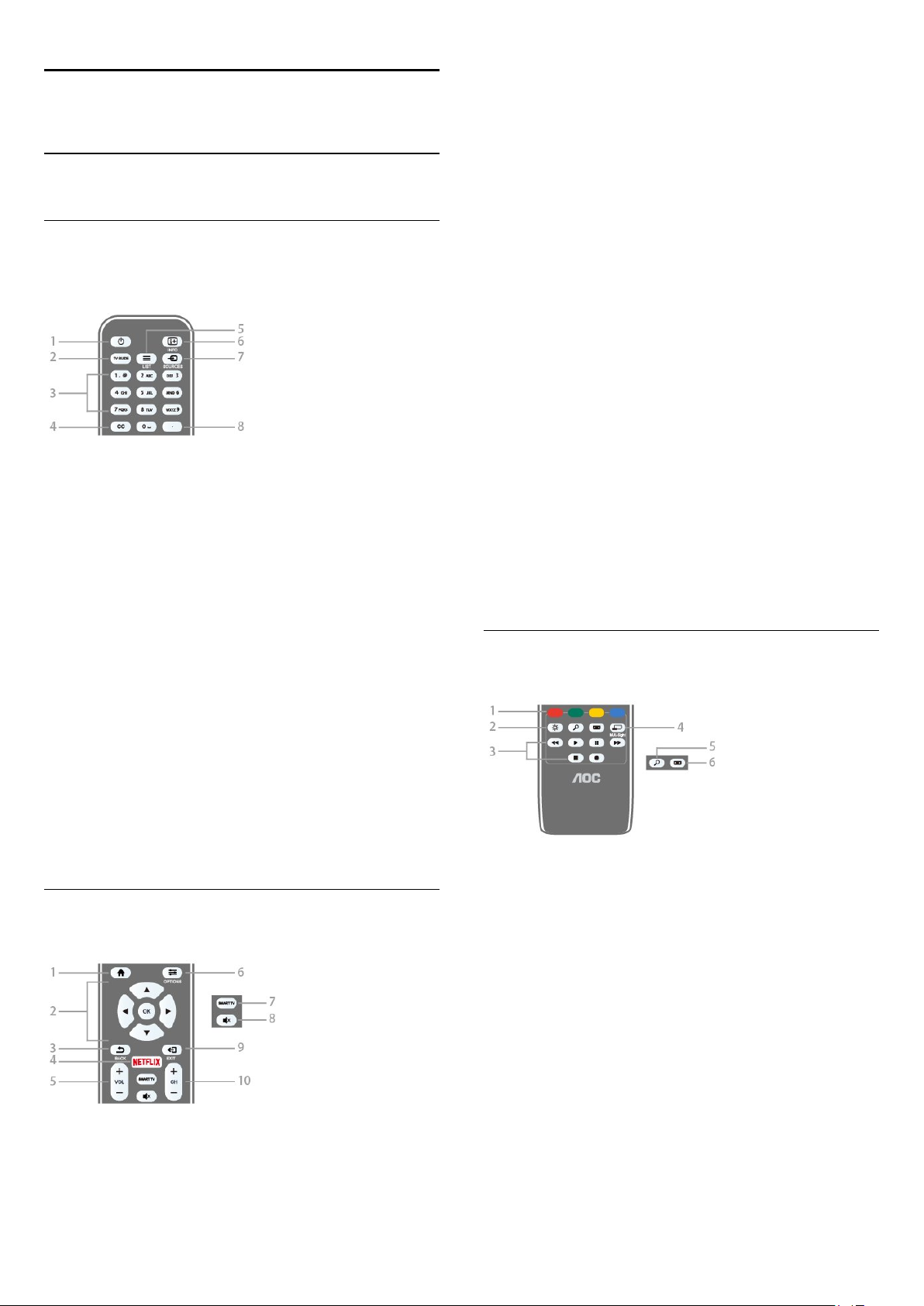
Key overview
Top
-
1
Standby
To switch the TV On or back to Standby.
-
2
TV GUIDE
To open or close the TV guide.
-
3
Number keys
To select a TV channel directly.
/
On
-
2
Arrow / navigation / OK
To navigate up, down, left or right. To confirm a selection or
setting.
-
3
BACK
To switch back to the previous channel you selected.
To close a menu without changing a setting.
To go back to the previous Smart TV page.
-
4
NETFLIX
To open NETFLIX.
5 - Volume
To adjust the volume level.
-
6
OPTIONS
To open or close the Options menu.
7 - SMART TV
To open the Smart TV start page.
-
8
Mute
To mute the sound or to restore it.
-
9
EXIT
To switch back to watching TV.
-
10
Channel
To switch to the next or previous channel in the channel list.
To open the next or previous page in Text or start the next or
previous chapter on a disk.
keys
-
4
CC
To switch subtitles on, off, or on during mute.
-
5
LIST
To open or close the channel list.
-
6
INFO
To open or close program info.
-
7
SOURCES
To open or close the Sources menu - the list of connected
devices.
-
8
(Dot)
To enter digital sub-channels.
Middle
Bottom
-
1
Color keys
Follow the on-screen instructions.
-
2
Settings
To open the Settings menu.
-
3
Playback and record
• Play , to playback.
• Pause , to pause playback
• Stop , to stop playback
• Rewind , to rewind
• Forward , to fast forward
• Record , to record now
key
keys
-
1
HOME
To open or close the home menu.
-
4
MULTI-Sight
To open an extra small screen.
-
5
SEARCH
23
Page 24

To open the Popular searches page.
-
6
Picture format
To open or close the Picture format menu.
8.2
IR sensor
The TV can receive commands from a remote control that uses
infrared (IR) to send commands. If you use this kind of remote
control, always point it at the infrared sensor on the front of the
TV.
Warning
Do not put any objects in front of IR sensor of the TV as it may
block the IR signal.
8.3
Batteries
If the TV does not react on a key press on the remote control,
the batteries might be empty.
To replace the batteries, open the battery compartment on the
back of the remote control.
1 - Slide the battery door in the direction shown by the arrow.
2 - Replace the old batteries with 2
the + and - terminals line up correctly.
3 - Reposition the battery door and slide it back until it clicks.
Remove the batteries if you are not using the remote control for
a long time.
Safely dispose of your old batteries according to the end of use
directions.
For more information, in
key
Keywords
and look up
, press the color
Help
End of use
batteries. Make sure
AAA
.
8.4
Cleaning
Your remote control is treated with a scratch-resistant coating.
To clean the remote control, use a soft damp cloth. Never use
substances such as alcohol, chemicals or household cleaners on
the remote control.
24
Page 25

9
Channels
9.1
Install Channels
For more information, in
key
Keywords
installation
9.2
and look up
or
Channel, Cable installation
Switch channels
• To watch TV channels, press
TV channel you last watched.
• Alternatively, press
select
Channels
• To switch channels, press
channel number, enter it using the number keys. Press OK after
entering the number to switch channels.
• To switch back to the previous channel, press
To switch to a channel from a channel list
While watching a TV channel, press
channel lists.
The channel list can have several pages with channels. To view
the next or previous page, press
To close the channel lists without switching channels,
press
LIST
and press OK.
again.
, press the color
Help
Channel, Antenna
.
to open the Home menu and
Home
CH
. The TV tunes to the
LIST
or
CH
LIST
or
CH
to open the
CH
. If you know the
BACK
.
.
tune to the selected channel.
4 - Press (left) to go back one step or press
close the menu.
BACK
to
Filter a channel list
To set a filter on a list with all channels...
1 - Press
then press OK.
2 - Press
press (right) to enter the menu.
3 - Select the filter you want and press OK to activate it. The
name of the filter appears as part of the channel list name on
top of the channel list.
4 - Press (left) to go back one step or press
close the menu.
to open the current channel list and select
LIST
OPTIONS
and select
Digital + Analog
and
BACK
All
to
Search for a channel
You can search for a channel to find it in a long list of channels.
To search for a channel…
1 - Press
2 - Press
3 - Select
4 - Select the list you want to filter and press OK.
5 - Press the color key
press OK to open a text field.
6 - Enter a number, a name, or part of a name, select
press OK. The TV will search for matching channel names in the
list you selected.
to open the current channel list and select
LIST
OPTIONS
Digital + Analog
.
and press OK.
(green) to open
Find Channel
Done
All
and
and
,
.
9.3
Channel lists
About channel lists
After a channel installation, all channels appear the channel list.
Channels are shown with their name and logo if this information
is available.
With a channel list selected, you can only tune to the channels in
that list by pressing the
Open a channel list
To open the current channel list...
1 - Press
then press OK.
2 - Press
press (right) to enter the menu.
3 - Select a channel in any of the lists and press OK. The TV will
to open the current channel list and select
LIST
OPTIONS
or
CH
and select
keys.
CH
Digital + Analog
All
and
Search results are listed as a channel list - see the list name at
the top. The search results disappear once you select another
channel list or close the list with search results.
9.4
Watching channels
Tune to a channel
To start watching TV channels, press
the channel you last watched.
BACK
CH
.
Switch Channels
To switch channels, press
If you know the channel number, type in the number with the
,
number keys. Press OK after you entered the number to switch
immediately.
Previous channel
To switch back to the previously tuned channel,
press
or
CH
. The TV tunes to
LIST
.
25
Page 26

Lock a channel
Lock and unlock a channel
with a higher rating. The parental age rating is set for all channels.
Channels may be locked to prevent children from watching a
specific channel. To watch a locked channel, you must enter the
4-digit
Child lock
from connected devices.
To lock a channel…
1 - Press
2 - Change the channel list, if necessary.
3 - Select the channel you want to lock.
4 - Press
5 - Enter your 4-digit PIN code if the TV asks for it. A locked
channel is marked with a (lock).
6 - Press (left) to go back one step or press
close the menu.
To unlock a channel…
1 - Press
2 - Press OK to open the channel list. If necessary, change the
channel list.
3 - Select the channel you want to unlock.
4 - Press
press OK.
5 - Enter your 4-digit PIN code if the TV asks for it.
6 - Press (left) to go back one step or press
close the menu.
If you lock or unlock channels in a channel list, you only have to
enter the PIN code just once until you close the channel list.
PIN code first. You cannot lock programs
to open the current channel list and select
LIST
OPTIONS
LIST
OPTIONS
and select
to open the current channel list and select
and select
Channel lock
Unlock channel
and press OK.
BACK
and
BACK
All
to
All
to
Channel options
Open options
While watching a channel, you can set some options.
.
.
Depending on the type of channel you are watching (analog or
digital) or depending on your TV settings, some options are
available.
To open the options menu…
1 - While watching a channel, press
2 - Press
Closed captions
Turn
options. Select
when the sound is muted with .
Caption service
Select the correct type of closed-caption services.
For more information, in
up
Closed captions
OPTIONS
Closed captions on
On during mute
again to close.
or
Help
.
Closed captions off
to show closed captions only
, press
OPTIONS
Keywords
.
with this
and look
For more information, in
key
Keywords
Age Ratings
To prevent children from watching a program not suitable for
their age, you can set an age rating.
Digital channels may have age-rated programs. When the age
rating of a program is equal to or higher than the age rating you
set for your child, the program will be locked. To watch a locked
program, you must enter the
To set an age rating…
1 - Press the
and press OK.
lock
2 - Enter a 4-digit Child lock code. If you have not yet set a
code, select
lock code and confirm. You can now set an age rating.
3 - Back in
4 - Press (left) repeatedly if necessary, to close the menu.
To switch off the parental age rating, select
some countries you must set an age rating.
and look up
Settings
Change code
Age ratings lock
key, select
, press the color
Help
Child lock
Age ratings lock
Child lock
in
Child lock
, select the age and press OK.
for more information.
code first.
>
Age ratings
. Enter a 4-digit Child
. However, in
Free
Audio language
For digital broadcast, you can select an available audio language
temporarily if none of your preferred languages are available.
For more information, in
up
Audio language
Status
Select
Status
analog or digital) or a connected device you are watching.
To view the technical information for a channel…
1 - Tune to the channel.
2 - Press
3 - To close this screen, press OK.
Share
Enables the user to communicate their activity on their social
networks (such as Twitter or email).
.
to view technical information on the channel (if it is
OPTIONS
Help
, select
, press
Status
Keywords
and press OK.
and look
For some broadcasters/operators, the TV only locks programs
26
Page 27

Mono / Stereo
You can switch the sound of an analog channel to Mono or
Stereo.
To switch to Mono or Stereo…
1 - Tune to an analog channel.
2 - Press
3 - Select
4 - Press (left) to go back one step or press
close the menu.
OPTIONS
Mono
or
, select
Stereo
Mono/Stereo
and press OK.
and press (right).
to
BACK
Remove a Favorites List
You can only remove a Favorites List.
To remove a Favorites List…
1 - Press
select
2 - Open the Favorites List you want to remove.
3 - Press
4 - Press
Favorites
to open the current channel list and
LIST
.
Remove
BACK
to remove the list.
to close the channel list.
9.5
Favorite Channels
About favorite Channels
In a favorite channel list, you can collect the channels you like.
With a Favorites List selected, you can only tune to the channels
in that list by pressing the
Create a Favorites List
You can create a favorite channel list that only holds the
channels you want to watch. With the Favorite channel list
selected, you will only see your favorite channels when you
switch through channels.
Create your favorite channel list
1 - Press
2 - Select the channel and press
3 - The selected channel is marked with a .
4 - To finish, press
Favorites list.
To remove a channel from the favorites list, select the channel
with , then press again to unmark as favorite.
to open the current channel list and select
LIST
BACK
CH
or
CH
keys.
Mark as favorite
. The channels are added to the
All
.
9.6
Closed captioning (CC) and
language
Closed captions
You can display closed captions at all times or only when the TV
is muted.
To open
Note:
• Not all TV programs, commercials and features include closed
captioning information. See your local TV program
listings for channels with closed captions. Captioned programs
are typically listed with service marks, such
as 'CC,' in the TV listings.
Switch on closed captions
.
1 - While you watch TV, press
2 - Select
Select type of closed captions
1 - While you watch TV, press
2 - Select
3 - Select the correct type of closed captions and press OK.
Closed captions
Closed captions
Caption service
, press CC.
OPTIONS
> On and press OK.
OPTIONS
.
.
.
Rename a Favorites List
You can only rename a Favorites List.
To rename a Favorites List…
1 - Press
select
2 - Open the Favorite List you want to rename and
press
3 - Delete the current name and enter a new name.
4 - When done, select
5 - Press
Favorites
Rename
to open the current channel list and
LIST
.
.
and press OK.
Done
to close the channel list.
BACK
Audio Language
If the TV channel broadcasts multiple or dual audio languages,
you can select your preferred audio language.
1 - While you watch TV, press
2 - For digital channels, select
channels, select
selection.
3 - Select from the available languages, then press OK.
Note:
If you have selected
between:
•
: Primary audio language or
Main
•
: Secondary audio language
SAP
27
Alternate Audio
Alternate Audio
OPTIONS
Audio Language
. Press OK to confirm your
for analog channels, select
.
. For analog
Page 28

Menu language
To change the language of the TV menus and messages…
1 - Press the
settings
2 - Select your desired language and press OK.
3 - Press (left) repeatedly if necessary, to close the menu.
>
Language
Settings
key, select
>
Menu language
General
and press OK.
28
Page 29

10
TV guide
1 - Press
2 - Press
INFO
.
BACK
to close.
10.1
What you need
With the TV Guide you can view a list of the current and
scheduled TV programs of your channels. Depending on where
the TV guide information (data) is coming from, analog and
digital channels or only digital channels are shown. Not all
channels offer TV Guide information.
The TV can collect TV Guide information for the channels that
are installed on the TV. The TV cannot collect the TV Guide
information for channels viewed from a digital receiver or
decoder.
10.2
TV guide data
TV Guide information may not be available in some regions and
for some channels. The TV can collect TV Guide information for
the channels that are installed on the TV. The TV cannot collect
the TV Guide information from channels viewed from a digital
receiver or decoder.
The TV comes with the information set to
broadcaster
.
From the
Change day
The TV guide can show scheduled programs for the upcoming
days (maximum up to 8 days).
If the TV guide information comes from the broadcaster, you
can press
Press
CH
Alternatively, you can press
.
day
Select
Previous day, Today
the day of the schedule.
The TV guide can show scheduled programs for the upcoming
days (maximum up to 8 days).
If the TV guide information comes from the broadcaster, you
can press
Press
CH
To change the day…
1 - Press
2 - Press
3 - Select
and press OK.
day
4 - Press
to view the schedule for one of the next days.
CH
to go back to the previous day.
OPTIONS
, or
Next day
to view the schedule for one of the next days.
CH
to go back to the previous day.
TV GUIDE
Change day
.
OPTIONS
, select
to close the menu.
BACK
.
Previous day, Today
and select
and press OK to select
or
Change
Next
10.3
Using the TV guide
Open the TV guide
To open the TV Guide, press
the channels of the selected tuner.
Press
TV GUIDE
The first time you open the TV Guide, the TV scans all TV
channels for program information. This may take several minutes.
TV Guide data is stored on the TV.
again to close.
TV GUIDE
Tune to a program
From the TV Guide, you can tune to a current program.
To switch to the program (channel), select the program and
press OK.
View program details
To call up the details of the selected program…
. The TV Guide shows
Set a reminder
You can set reminders that alert you of the start of a program
with a message on screen.
• To set a reminder, select the program in the schedule and
press for
• To cancel the reminder, press the for
• To view a list of all reminders you have set,
press
Set reminder
OPTIONS
. The program is marked with a clock.
Clear reminder
, and select
All reminders
.
.
Search by genre
If the information is available, you can look up scheduled
programs by genre like movies, sports, etc.
To search for programs by genre…
1 - Press
2 - Press
3 - Select
4 - Select the genre you want and press OK. A list with the
found programs appears.
5 - You can set reminders or schedule a recording on a selected
program.
6 - Press
TV GUIDE
Search by genre
.
OPTIONS
to close the menu.
BACK
.
and press OK.
29
Page 30

Set a recording
You can set a recording in the TV Guide*.
To see the recording list, press
be recorded is marked with a (black dot) before the
program's name.
To record a program…
1 - Press
2 - Press the color key
3 - Press
To cancel a recording…
1 - Press
2 - Press the color key
3 - Press
TV GUIDE
TV GUIDE
and select a future or ongoing program.
to close the menu.
BACK
and select the program set for recording.
to close the menu.
BACK
Recordings
Record
Clear Recording
.
, a program set to
.
30
Page 31

11
Recording and Pause
TV
11.1
Recording
What you need
You can record a digital TV broadcast and watch it later.
To record a TV program you need…
• a connected USB Hard Drive formatted on this TV
• digital TV channels installed on this TV
• to receive channel information for the on-screen TV Guide
• a reliable TV clock setting. If you reset the TV clock manually,
recordings may fail.
You cannot record when you are using Pause TV.
Some digital TV operators do not allow the recording of
channels.
For more information on installing a USB Hard Drive, in
press the color key
installation
.
Keywords
and look up
USB hard drive,
Help
To change the date of the list, press
select
Change day
press OK. If the TV guide comes from the Internet, you can
select the date at the top of the page and press OK.
2 - With the program highlighted, press
adds some time buffer at the end of the program. You can add
some extra buffer if needed.
3 - Select
recording. A warning will appear automatically when overlapping
recordings are scheduled.
If you plan to record a program in your absence, remember to
leave the TV switched to standby and the USB Hard Drive
turned on.
List of recordings
To view the list of recordings and scheduled recordings,
press
In this list, you can select a recording to watch, remove recorded
programs, adjust the end time of an ongoing recording, or check
the free disk space. Also in this list, if the TV guide comes from
the Internet, you can schedule a recording for which you set the
beginning and end time yourself, as a timed recording not linked
,
to a program. To set a timed recording, select
recording
date, and time span. To confirm the recording,
select
Schedule
Home
at the top of the page and press OK. Set the channel,
Schedule
. In the list, select the desired day and
and press OK. The program is scheduled for
, select
Utilities
and press OK.
>
Recordings
OPTIONS
Record
and
. The TV
and press OK.
Schedule
Record a program
Record now
To record the program you are watching, press (Record) on
the remote control.
If you receive TV guide information from the Internet, you can
adjust the end time of the recording in the pop-up window
before you confirm the recording.
If you receive TV guide information from the broadcaster, the
recording starts immediately. You can adjust the end time of the
recording in the list of recordings.
To stop recording, press (Stop).
Schedule a recording
You can schedule a recording of an upcoming program for today
or a few days from today (maximum of 8 days away).
1 - To schedule a recording, press
On the TV guide page, select the channel and program you wish
to record.
You can enter the channel number to jump to the channel in
the list.
Press (Right) or (Left) to scroll through a channel's
programs.
TV GUIDE
.
Remove a scheduled recording
Select the scheduled recording, press
.
OK
Specifics
• While recording a program, you can watch a previously
recorded program.
• While recording, you cannot switch TV channels.
• While recording, you cannot pause the TV broadcast.
• To Record, broadcasters need a reliable clock setting. If you
reset the TV clock manually, recordings may fail.
Remove
and press
Watch a recording
To watch a recording . . .
1 - Press
2 - In the list, select the recording and press (Play) to start the
playback. You can use the (Forward), (Rewind), (Pause)
or (Stop) keys on the remote control.
Expired recording
Broadcasters can limit the number of days a recording can be
viewed. A recording in the list can show the number of days
before it expires.
Home
, select
Utilities
>
Recordings
and press OK.
31
Page 32

Failed recording
When a scheduled recording was prevented by the broadcaster
or when the broadcast was interrupted, a recording is marked
as
Failed
.
Delete a recording
To delete an existing recording, select the recording in the list,
press
Remove
For more information, press
a program
11.2
.
and press OK.
Keywords
and look up
Record
Pause TV
You can pause a TV broadcast and resume watching it later.
Only digital TV channels can be paused. You must connect a
USB Hard Drive to buffer the broadcast. You can pause a
broadcast for a maximum time span of 90 minutes.
For more information, press
hard drive
Pause or resume a broadcast
To pause a broadcast, press (Pause). A progress bar appears
briefly on screen.
To call up the progress bar, press (Pause) again.
To resume watching, press (Play). The icon on screen
indicates you are watching a paused broadcast.
.
Keywords
and look up
USB
Back to the actual TV broadcast
To switch back to the actual TV broadcast, press (Stop).
The moment you switch to a digital channel, the USB Hard
Drive starts buffering the broadcast. When you switch to
another digital channel, the broadcast of the new channel is
buffered and the broadcast of the previous channel is cleared.
When you switch to a connected device (a Blu-ray Disc player
or digital receiver) the USB Hard Drive stops buffering and the
broadcast is cleared. Also when you switch the TV to standby
the broadcast is cleared.
While recording a program on the USB Hard Drive, you cannot
pause a broadcast.
Instant replay
While watching a broadcast from a digital TV channel, you can
easily instant replay the broadcast.
To replay the last 10 seconds of a broadcast,
press (Pause) and press (Left).
You can press repeatedly until you reach the start of the
broadcast buffer or the maximum time span.
Progress bar
With the progress bar on screen, press (Rewind) or
press (Forward) to select from where you want to start
viewing the paused broadcast. Press these keys repeatedly to
change speed.
32
Page 33

12
Utilities
Smart TV
Open Smart TV page.
TV guide
For more information, in
key
Recordings
For more information, in
key
Channels
View channel list.
Update software
For more information, in
key
Keywords
Keywords
Keywords
and look up
and look up
and look up
, press the color
Help
TV guide
, press the color
Help
Recording
, press the color
Help
Update software
.
.
.
33
Page 34

13
Netflix
13.1
Netflix
If you have a Netflix subscription, you can enjoy Netflix on this
TV. Your TV must be connected to the Internet.
To open Netflix, press
open Netflix immediately from a TV in standby.
www.netflix.com
to open the Netflix App. You can
34
Page 35

14
14.3
Sources
14.1
Switch to a device
From the list of Sources, you can switch to any of the connected
devices. You can switch to a tuner to watch TV, open the
content of a connected USB Flash Drive or see the recordings
you made on a connected USB Hard Drive. You can switch to
your connected devices to watch their programs, or to a digital
receiver, or Blu-ray Disc player.
To switch to a connected device…
1 - Press
2 - Select one of the items in the source list and press OK. The
TV will show the program or content of the device.
3 - Press
One Touch Play
With the TV on standby, you can switch on a disc player with
your TV remote control.
To switch on both the disc player and TV from standby and
start playing the disc immediately, press (Play) on the TV
remote control. The device must be connected with an HDMI
cable and both the TV and the device must have HDMI CEC
switched on.
14.2
SOURCES
SOURCES
Options for TV Input
Some TV input devices offer specific settings.
To set the options for a specific TV input…
to open the Sources menu.
again to close the menu.
Scan connections
To rescan connections and update the Sources menu,
press
of the screen.)
14.4
Scan connections
. (if key is available on the bottom
Game or computer
The device type determines picture and sound styles, resolution
values and other specifics. You don't have to worry about the
ideal settings.
For some devices the device type is unclear. A game console can
have a built-in Blu-ray Disc player, so the type is set to Player
because it is used as a disc player most of the time. For this kind
of device, you can temporarily switch to the ideal settings for
gaming. Or alternatively, switch to the ideal settings for a
connected computer.
You can only use the setting
switch to a connected device in the Sources menu. The Game
or Computer setting is stored for the selected device.
To switch to the ideal settings for gaming or computer
manually…
1 - Press the
press OK.
2 - Select
3 - Select
4 - Press (left) to go back one step or press
close the menu.
Remember to set this setting back to
the game.
Settings
Game or Computer
Game, Computer
Game or Computer
key, select
Picture
and press OK.
or
Off
>
.
when you stop playing
Off
when you
Advanced
BACK
and
to
1 - Press
2 - Select the TV input from the list and press OK.
3 - Press
selected TV input here.
4 - Press
Possible options…
Controls
With this option you can operate the connected device with the
TV remote control. The device must be connected with an
HDMI cable and both the TV and the device must have HDMI
CEC switched on.
SOURCES
.
OPTIONS
OPTIONS
. You can set the options for the
again to close the Options menu.
35
Page 36

15
Internet
15.1
Start Internet
You can browse the Internet on your TV. You can view any
Internet website but most of them are not prepared for a TV
screen.
• Some plug-ins (e.g., to view pages or videos) are not available
on your TV.
• You cannot send or download files.
• Internet pages are shown one page at a time and full screen.
To start the Internet browser…
1 - Press
2 - Select
3 - Enter an Internet address and press OK.
4 - To close Internet, press
15.2
SMART TV
Open Internet go to
>
, and press OK.
Apps
and press OK.
Home
or
EXIT
.
Internet Options
Some extras are available for the Internet.
To open the extras…
1 - With the website open, press
2 - Select one of the items and press OK.
3 - Press (left) repeatedly if necessary, to close the menu.
• Add to Speed Dial
• Add to Bookmarks
• Page Security
• New Private Tab
• Settings
• Help
• Exit Internet Browser
OPTIONS
.
36
Page 37

16
16.3
Your music, movies and
photos
16.1
From a USB connection
You can view your photos or play your music and videos from a
connected USB flash drive or USB Hard Drive.
With the TV turned on, plug in a USB flash drive or a USB Hard
Drive to one of the USB connections. The TV detects the
device and will list your media files.
If the list of files does not appear automatically…
1 - Press
2 - Select
USB device.
3 - You can browse your files in the folder structure you have
organized on the drive.
4 - To stop playing videos, photos and music, press
Warning
If you try to pause or record a program with a USB Hard Drive
connected, the TV will ask you to format the USB Hard Drive.
This formatting will delete all current files on the USB Hard
Drive.
SOURCES
USB Devices
, select
and press (right) to select the desired
and press OK.
USB
EXIT
.
Play your music
Play music
• To play music, select
press OK.
• If there are more songs in the same folder, press
play all songs in this folder.
• To jump to the next or previous song, press
.
CH
• To pause the music, press OK. Press OK again to continue.
• To make a 10-second jump forward or back in a song,
press or .
• To rewind or fast forward, press or . Press the keys
several times to speed up - 2x, 4x, 8x, 16x, 32x.
• To stop the music playback, press (Stop).
Info
To view the song info (title, artist, duration, etc.), select the song
and press
Press again to hide the info.
INFO
.
Music options
Options for playing music...
•
– Play all songs in this folder once or continuously.
Repeat
in the menu bar, select a song and
Music
CH
Play all
or
to
16.2
Menu bar and sorting
With a USB device connected, the TV sorts the files by type.
Navigate to the menu bar and select the type of file you are
looking for.
If you browse files from a computer, you can only browse the
files and folders as they are organized on the computer.
The menu bar
Navigate to the menu bar and select the type of file you want to
watch or play.
Select
Music, Movie
the
Folders
Sorting
To browse your photos by date, month, year, or alphabetically
by name, press
To browse your music by album, artist, genre, or alphabetically
by name, press
Videos are sorted alphabetically.
or
view and browse your folders to look for a file.
. Alternatively, you can open
Photos
Sort
Sort
.
.
16.4
Play your movie
Play movie
• To play a video, select
and press OK.
• If there are more videos in the same folder, press
to play all videos in this folder.
all
• To jump to the next or previous
video, press
• To pause the video, press OK. Press OK again to continue.
• To make a 10-second jump forwards or backwards in a
video, press or .
• To rewind or fast forward, press or . Press the keys
several times to speed up to 2x, 4x, 8x, 16x, 32x.
• To stop the video playback, press (Stop).
Info
To view video info (playhead position, duration, title, date, etc.),
select the video and press
Press again to hide the info.
CH
or
CH
in the menu bar, select a video
Movie
.
.
INFO
Play
37
Page 38

Movie options
During the video playback, press
•
Subtitles
•
Subtitle language
•
Audio language
•
Character set
•
Status
•
Repeat
•
Subtitle settings
16.5
OPTIONS
to…
View your photos
View photos
To view photos, select
thumbnail and press OK.
If there are several photos in the same folder, select a photo and
press
Slide show
folder.
To jump to the next or previous photo, press
To stop the slide show or close the photo, press (Stop).
to start a slide show of all photos in this
in the menu bar, select a photo
Photos
CH
or
CH
.
Info
To view photo info (size, creation date, file path, etc.), select a
photo and press
Press again to hide the info.
INFO
.
Slideshow with music
You can watch a slideshow of your photos and listen to your
music at the same time. You must start the music before you
start the photo slideshow.
To play music with the slide show…
1 - Select a song or a folder with songs and press OK.
2 - Press
3 - Press
4 - Now use the navigation arrows to select the folder with
photos.
5 - Select the folder with photos and press
6 - To stop the slideshow, press
to hide the browser list.
INFO
BACK
.
BACK
.
Play All
.
Photo options
With a photo on screen, press
•
•
•
•
– Play your files in a random order.
Shuffle
– Play the slide show once or continuously.
Repeat
Slide show speed
Slide show transition
– Set the speed of the slide show.
– Set the style of the photo transitions.
OPTIONS
to…
38
Page 39

17
Smartphones and
convenient services.
What you need
tablets
17.1
MHL
This TV is MHL™ compliant.
If your mobile device is also MHL compliant, you can connect
your mobile device with a MHL cable to the TV. With the MHL
cable connected you can share what's on your mobile device on
the TV screen. Your mobile device charges its battery at the
same time. The MHL connection is ideal for watching movies or
playing games from your mobile device on TV for a longer time.
Charging
With the MHL cable connected, your device will charge while
the TV is switched on (not in standby).
MHL Cable
You need a passive MHL cable (HDMI to Micro USB) to
connect your mobile device to the TV. You might need an extra
adapter to connect to your mobile device. To connect the MHL
cable to the TV use the
HDMI 1 MHL
connection.
To enjoy
with a high-speed (broadband) internet connection. You can use
a home network connected to the Internet. You do not need a
computer.
For more information, press
up
Tip
To enter text or to navigate an Internet page more easily, you
can consider connecting a USB keyboard and a USB mouse to
the TV.
For more information, press
keyboard
Smart TV Apps
Network
or
.
USB mouse
, you must connect the TV to a router
and look
and look up
USB
.
Keywords
Keywords
Setup Smart TV
The first time you open Smart TV, you need to configure your
connection. Read and agree to the terms and conditions to
continue. If you do not want to set up Smart TV,
press
Parental control
BACK
.
MHL, Mobile High-Definition Link and the MHL Logo are
trademarks or registered trademarks of the MHL, LLC.
In
, press
Help
information.
17.2
Keywords
and look up HDMI MHL for more
Smart TV
About Smart TV
Connect this TV to the Internet and discover a new world of
television. You can install a wired connection to your router or
you can link up wirelessly with Wi-Fi.
With the TV connected to your home network, a smartphone
can show a photo on TV, you can play videos stored on your
computer or control the TV with your tablet.
To lock Adult 18+ rated apps . . .
1 - Turn on Smart TV parental control by selecting
then press OK.
2 - Enter an unlock PIN code of your choice.
3 - Confirm your PIN code.
Adult 18+ rated apps are now locked. To open a locked app,
select the app and press OK. The TV will ask you to enter your
4-digit code.
Enable
and
Smart TV Apps
Open Smart TV
The Smart TV start page is your link to the Internet. You can
rent movies online, read newspapers, watch videos, listen to
music, shop online, or watch TV programs whenever you want
with Online TV.
To do this, you use Apps, which are Internet sites tailored for
TV. With your TV connected to the Internet, you can open
Smart TV.
Open Smart TV
With your TV connected to the Internet, you can watch a rental
video from an online video store, read the online TV guide or
record your favorite TV show on a USB Hard Drive. The Smart
TV Apps add to the fun with all sorts of entertainment and
To open the Smart TV start page, press
Alternatively, you can press
select
Smart TV
39
and press OK.
Home
Smart TV
>
Utilities
.
,
Page 40

The TV connects to the Internet and opens the Smart TV start
page. This may take a few seconds.
pages long. Use the arrow keys to go to the next or previous
page.
Close Smart TV
To close the Smart TV start page, press
another activity.
Smart TV start page
1 - Now on your TV
2 - Your Apps
3 - App gallery
4 - Internet
5 - Recommended Apps
6 - Search
7 - Color keys for control
Your Apps
You start Apps from the Smart TV start page. If the start page
does not hold any Apps yet, you can add Apps from the App
gallery.
App gallery
In the App gallery you find all available Apps.
Internet
The Internet App opens the World Wide Web on your TV.
On your TV, you can view any Internet website but most of
them are not tailored for a TV screen.
- Some plug-ins (e.g. to view pages or videos) are not available
on your TV.
- Internet pages are shown one page at a time and full screen.
Recommended Apps
This window presents a range of recommended Apps for your
country, Apps for Online TV, or a selection of rental movies
from Video stores. You can select and open them from the
Recommended Apps window.
Search
With Search, you can search the App gallery for relevant Apps.
Enter a keyword in the text field, select and press OK to start
searching. You can enter names, titles, genres, and description
keywords to search.
Alternatively, you can leave the text field empty and search for
the most popular searches/keywords for a range of categories. In
the list of found keywords, select a keyword and press OK to
search for items with that keyword.
Home
and select
Open an App
To open an App . . .
- Press
1
- On the start page, select an App icon and press OK.
2
In an App, press
Close an App
To close an App and return to the Smart TV start page,
press
Reload an App page
If an App page did not load properly, press
select
Zoom
To zoom in on an App page . . .
- Press
1
- Use the slider bar to set the zoom level.
2
- Return to normal view by resetting the slider bar.
3
View security info
You can check the security level of an App page.
On an App page, press
If a lock is shown next to the loading animation on the
bottom of the screen while loading a page, the transfer is
secured.
Feedback on an App
Select the App and press
'dislike' button and send a suggestion or comment to us. You
can also report an App malfunction.
Manage your Apps
From the list of Apps on the Smart TV start page you can . . .
•
Remove an App
To remove an App from the list, select the App icon and
press
•
Move an App
To reposition an App in the list, select the App icon,
press
Press OK to confirm the position.
•
Manage an App
To manage an App from the list, select the App icon and
press
Home
Smart TV
to reload the page.
Reload
OPTIONS
Remove
and use the arrow keys to reposition the App.
Move
Manage
.
>
BACK
.
Utilities
>
Smart TV
to go back one step or page.
.
and
and select
Zoom page
OPTIONS
.
OPTIONS
and select
Security info
Feedback
to select a 'like' or
. The App is still available in the App gallery.
.
Open an App
To open an App, you must add it to your list of Apps in the
Smart TV start page first. You can add Apps to your list from the
App gallery.
The list of your Apps on the Smart TV start page can be several
App gallery
Open the
collection of tailored websites for TV.
Find the App for YouTube videos, a national newspaper, an
online photo album, etc. There are Apps to rent a video from an
40
App gallery
in Smart TV to browse the Apps, the
Page 41

online video store and Apps for watching programs you missed.
If the App gallery does not have what you are looking for, try
the World Wide Web and surf the Internet on your TV.
Rental video Apps
MULTI-Sight
You can watch the current TV channel while in a Smart TV App
or on the Internet.
channel next to the Smart TV screen.
To open MULTI-Sight…
MULTI-Sight
opens a small screen for the TV
With the video store Apps in Smart TV, you can rent your
favorite movie from an online rental video store. You can pay
securely with your credit card.
Rent a movie
1 - Open a Video store App in your list of Apps, or select a
recommended video on the Smart TV start page.
2 - Select a movie.
3 - Make the online payment.
4 - Start watching. You can use the (Play) and (Pause) keys.
Most Video stores ask you to create a login account.
Streaming video
With this TV, you can watch rental movies sent as a streaming
video format. You can almost instantly watch the movie. You
might need a USB Hard Drive to store some video buffer. If you
have a USB Hard Drive connected, you can also download
rental movies from video stores that offer movie downloading
only. You can pause or restart a downloaded rental movie.
Consult the video store regarding the rental duration of rental
movies.
Internet traffic
1 - Press
2 - Press
3 - Press
small screen.
SMART TV
CH
MULTI-Sight
to open Smart TV.
to open the small screen.
or
to change the TV channel in the
CH
Reset Smart TV
To reset your connection with Smart TV, clear the Internet
memory on the TV.
You will clear your Smart TV registration and parental rating
setting, your video store app logins, all Smart TV app favorites,
Internet bookmarks, and history.
To clear the Internet memory…
1 - Press the
enter the menu.
2 - Select
3 - Select OK to confirm.
4 - Press (left) repeatedly if necessary, to close the menu.
Settings
Clear Internet memory
key, select
Network
and press OK.
and press (right) to
Streaming or downloading many videos may exceed your
monthly Internet traffic limit.
Online TV
With the Online TV App on the Smart TV start page*, you can
watch TV programs you missed or watch programs whenever it
suits you best.
Open Online TV
To open the Online TV App . . .
1 - Press
2 - On the start page, select the
press OK.
3 - Select a program on the page and press OK to start
watching. You can use the (Play) and (Pause) keys.
List per broadcaster
To view Online TV programs ordered by broadcaster,
press
Select a broadcaster and press OK.
* If available in your region.
Smart TV
All broadcasters
.
Online TV
icon and
.
41
Page 42

18
Sleep timer
Settings
18.1
Quick settings
Eco settings
For more information, in
key
Keywords
Picture style
For more information, in
key
Keywords
Picture format
For more information, in
key
Keywords
Sound style
and look up
and look up
and look up
, press the color
Help
Eco settings
, press the color
Help
Picture style
, press the color
Help
Picture format
For more information, in
key
18.2
Keywords
and look up
, press the color
Help
Sleep timer
.
Picture
.
.
.
Picture style
Select a style
For easy picture adjustment, you can select a preset Picture style.
1 - While watching a TV channel, press
2 - Select
the list.
3 - Press (left) repeatedly if necessary, to close the menu.
The available styles are…
•
Personal
start up.
•
- Ideal for daylight viewing
Vivid
•
Football
•
Standard
•
•
- Ideal for watching movies
Movie
- Ideal for viewing photos
Photo
>
Picture
- The picture preferences you set during the first
- Natural picture settings
- Most energy conscious setting - Factory setting
Picture style
Settings
, and select one of the styles in
key.
For more information, in
key
Keywords
Help
and look up
Headphones volume
For more information, in
key
Keywords
Help
and look up
Speakers
For more information, in
key
Keywords
Help
and look up
Clock
For more information, in
key
Keywords
Help
and look up
, press the color
Sound style
, press the color
Headphones volume
, press the color
TV speakers
, press the color
Clock
.
.
.
Customize a style
Any picture setting you adjust, such as Color or Contrast, is
stored in the currently selected
customize each style.
Only the
.
device in the Sources menu.
Restore a style
The selected style will store the changes you made. We
recommend that you adjust the picture settings for the
style
settings for each individual connected device in Sources menu.
To restore the style to its original setting…
1 - While watching a TV channel, press
2 - Select
to restore.
3 - Press the color key
style is restored.
4 - Press (left) repeatedly if necessary, to close the menu.
Personal
Personal
Picture
style can save settings for each connected
only. The Picture Style - Personal can save its
>
Picture style
Picture style
, and select the style you want
Restore style
. This allows you to
Settings
, and press OK. The
key.
42
Page 43

Home or Store
If the
Picture style
switch on the TV, the TV location is set to
for in-store promotion.
To set the TV for Home use…
1 - Press the
press (right) to enter the menu.
2 - Select
3 - Press (left) repeatedly if necessary, to close the menu.
Picture settings
Color
With
To adjust the color…
1 - Press the
enter the menu.
2 - Select
3 - Press the (up) or (down) arrows to adjust the value.
4 - Press (left) repeatedly if necessary, to close the menu.
Location
Color
Color
is switched back to
Settings
, you can adjust the color saturation of the picture.
Settings
key, select
>
Home
key, select
and press (right).
General settings
and press OK.
Picture
every time you
Vivid
, a setting meant
Shop
and
and press (right) to
Advanced picture settings
Game or computer
When you connect a device, the TV recognizes its type and
gives each device a correct type name. You can change the type
name if you wish. If a correct type name for a device is set, the
TV automatically switches to the ideal TV settings when you
switch to this device in the Sources menu.
If you have a game console with a built-in Blu-ray Disc player,
the type name may have been set to Blu-ray Disc. With
or computer
manually. Don't forget to switch the Game or Computer setting
off when you go back to watching TV.
To switch to the ideal settings for gaming or computer
manually…
1 - Press the
press
2 - Select
3 - Select
4 - Press (left) to go back one step or press
close the menu.
you can switch to the ideal settings for gaming
Settings
OK.
Game or computer
Game, Computer
key, select
and press OK.
or TV.
Picture
>
Advanced
and
BACK
Game
to
Contrast
With
Contrast
To adjust the contrast…
1 - Press the
enter the menu.
2 - Select
3 - Press the arrows (up) or (down) to adjust the value.
4 - Press (left) repeatedly if necessary, to close the menu.
Sharpness
With
Sharpness
detail of the picture.
To adjust the sharpness…
1 - Press the
enter the menu.
2 - Select
3 - Press the arrows (up) or (down) to adjust the value.
4 - Press (left) repeatedly if necessary, to close the menu.
, you can adjust the contrast of the picture.
Settings
Contrast
Settings
Sharpness
key, select
and press (right).
, you can adjust the level of sharpness in fine
key, select
and press (right).
and press (right) to
Picture
and press (right) to
Picture
Color settings
Color enhancement
With
Color enhancement
and the details in bright colors.
To adjust the level…
1 - Press the
enter the menu.
2 - Select
press OK.
3 - Select
4 - Press (left) repeatedly if necessary, to close the menu.
Color temperature
With
color temperature or select
setting yourself with
Temperature and Custom Color Temperature are settings
intended for expert users.
To select a preset…
Settings
Advanced
Maximum, Medium, Minimum
Color temperature
, you can enhance the color intensity
key, select
>
Custom color temperature
>
Color
Color enhancement
, you can set the picture to a preset
Custom
and press (right) to
Picture
or
.
Off
to set a temperature
. Color
and
1 - Press the
enter the menu.
2 - Select
press OK.
3 - Select
want to customize a color temperature yourself.
4 - Press (left) repeatedly if necessary, to close the menu.
43
Settings
Advanced
Normal, Warm
key, select
>
Color
or
and press (right) to
Picture
>
Color temperature
. Or select
Cool
Custom
and
if you
Page 44

Custom color temperature
With
Custom color temperature
, you can set the color
temperature yourself. To set a custom color temperature, first
select
Custom
in the Color Temperature menu. Custom Color
Temperature is a setting intended for expert users.
To set a custom color temperature…
enter the menu.
2 - Select
Advanced
>
Contrast
>
Brightness
, and press OK.
3 - Press the arrows (up) or (down) to adjust the value.
4 - Press (left) repeatedly if necessary, to close the menu.
Video contrast
1 - Press the
Settings
key, select
and press (right) to
Picture
enter the menu.
2 - Select
Advanced
temperature
>
Color
and press OK.
>
Custom color
3 - Press the arrows (up) or (down) to adjust the value.
4 - Press (left) repeatedly if necessary, to close the menu.
Contrast settings
Contrast modes
With
Contrast Mode
, you can set the level at which power
consumption can be reduced by dimming the intensity of the
screen. Choose for the best power consumption or for the
picture with the best intensity.
To adjust the level…
1 - Press the
Settings
key, select
and press (right) to
Picture
enter the menu.
2 - Select
Advanced
>
Contrast
>
Contrast mode
and
press OK.
3 - Select
Standard, Best power, Best picture
, or
Off
.
4 - Press (left) repeatedly if necessary, to close the menu.
With
Video Contrast
, you can decrease the range of the video
contrast.
To adjust the level…
1 - Press the
Settings
key, select
and press (right) to
Picture
enter the menu.
2 - Select
Advanced
>
Contrast
>
Video contrast
, and
press OK.
3 - Press the arrows (up) or (down) to adjust the value.
4 - Press (left) repeatedly if necessary, to close the menu.
Gamma
With
Gamma
, you can set a non-linear setting for picture
luminance and contrast. Gamma is a setting intended for expert
users.
To adjust the level…
1 - Press the
Settings
key, select
and press (right) to
Picture
enter the menu.
2 - Select
Advanced
>
Contrast
>
Gamma
, and press OK.
3 - Press the arrows (up) or (down) to adjust the value.
4 - Press (left) repeatedly if necessary, to close the menu.
Dynamic contrast
With
Dynamic Contrast
, you can set the level at which the TV
automatically enhances the details in the dark, middle and light
areas of the picture.
To adjust the level…
1 - Press the
Settings
key, select
and press (right) to
Picture
enter the menu.
2 - Select
Advanced
>
Contrast
>
Dynamic contrast
and
press OK.
3 - Select
Maximum, Medium, Minimum
or
Off
.
4 - Press (left) repeatedly if necessary, to close the menu.
Brightness
With
Brightness
, you can set the level of brightness of the
picture signal. Brightness is a setting intended for expert users.
We recommend non-expert users to adjust the brightness of
the picture with the
Contrast
setting.
To adjust the level…
1 - Press the
Settings
key, select
and press (right) to
Picture
Sharpness settings
Ultra resolution
With
Ultra resolution
, you can turn on a superior sharpness in
line edges and contours.
To turn on or off . . .
1 - Press
Settings
key, select
and press (right) to enter
Picture
the menu.
2 - Select
Advanced
>
Sharpness
>
Ultra Resolution
, and
press OK.
3 - Select On or
Off
.
4 - Press (left) repeatedly if necessary, to close the menu.
Noise reduction
With
Noise reduction
, you can filter out and reduce the level of
image noise.
To adjust the noise reduction…
1 - Press the
Settings
key, select
and press (right) to
Picture
enter the menu.
44
Page 45

2 - Select
press OK.
3 - Select
4 - Press (left) repeatedly if necessary, to close the menu.
MPEG artifact reduction
With
transitions in the picture. MPEG artifacts are mostly visible as
small blocks or jagged edges in images.
To reduce the MPEG artifacts…
1 - Press the
enter the menu.
2 - Select
reduction
3 - Select On and press OK.
4 - Press (left) repeatedly if necessary, to close the menu.
Motion Settings
Natural Motion
With
in movies on TV. HD Natural Motion makes any movement
smooth and fluent.
To adjust the motion judder…
1 - Press the
enter the menu.
2 - Select
press OK.
3 - Select
4 - Press (left) repeatedly if necessary, to close the menu.
Advanced
Maximum, Medium, Minimum
MPEG artifact reduction
Advanced
, and press (right) to enter the menu.
Natural Motion
Advanced
Maximum, Medium, Minimum
Settings
Settings
>
Sharpness
key, select
>
Sharpness
, you can reduce the motion judder visible
key, select
>
Motion
>
Noise reduction
or
Off
, you can smooth the digital
and press (right) to
Picture
>
MPEG artifact
and press (right) to
Picture
>
Natural Motion
or
Off
, and
.
, and
.
•
Fit to screen
screen without distortion. Black bars may be visible. Not suitable
for PC input.
Advanced
If the two basic settings are inadequate to format the picture
you want, you can use the advanced settings. With the advanced
settings you manually format the picture on your screen.
You can zoom, stretch and shift the picture until it shows what
you need – e.g. missing subtitles or scrolling text banners . If you
format the picture for a specific Source – like a connected game
console – you can return to this setting the next time you use
the game console. The TV stores your last settings for each
connection.
To format the picture manually…
1 - Press the
enter the menu.
2 - Select
3 - Press
4 - Use
picture. Select
when you opened
• Last setting – Select to return to the last setting.
•
– Select on the arrows to shift the picture. You can only
Shift
shift the picture when it is zoomed in.
•
Zoom
•
Stretch
or horizontally.
•
Original
This is a 1:1 pixel on pixel format. Expert mode for HD and PC
input.
•
Undo
with.
– automatically zooms in the picture to fill the
Settings
Picture format
Advanced
Shift, Zoom, Stretch
– Select on the arrows to zoom in.
– Select on the arrows to stretch the picture vertically
– Shows the original format of the incoming picture.
– Select to return to the picture format you started
key, select
and press (right).
and press OK.
or
Original
to return to the setting the picture had
Undo
Picture Format
and press (right) to
Picture
to adjust the
.
Picture format
Fill the screen settings
If the picture is not filling the whole screen, if black bars are
showing on the top or bottom or at both sides, you can adjust
the picture to fill the screen completely.
To select one of the basic settings to fill the screen…
1 - Press the
enter the menu.
2 - Select
3 - Select
press OK.
4 - Press
•
Fill screen
screen. Picture distortion is minimal, subtitles remain visible. Not
suitable for PC input. Some extreme picture formats may still
show black bars.
Settings
Picture format
Fill screen, Fit to screen
BACK
– automatically enlarges the picture to fill the
key, select
and press (right).
to close the menu.
Picture
or
and press (right) to
Wide screen
, and
18.3
Sound
Sound style
Select a style
For easy sound adjustment, you can select a preset setting with
Sound Style.
1 - While watching a TV channel, press
2 - Select
3 - Select
4 - Press (left) repeatedly if necessary, to close the menu.
The available styles are…
•
Personal
up.
•
Original
45
and press (right) to enter the menu.
Sound
Sound style
- The sound preferences you set during the first start
- Most neutral sound setting
, and select one of the styles in the list.
Settings
key.
Page 46

•
•
•
•
Restore a style
With a Sound Style selected, you can adjust any sound setting
in
The selected style will store the changes you made. We
recommend that you adjust the sound settings for the
style
for each individual connected device in the Sources menu.
To restore the style to its original setting…
1 - While watching a TV channel, press
2 - Select
3 - Select
restore.
4 - Press the color key
5 - Press (left) repeatedly if necessary, to close the menu.
- Ideal for watching movies
Movie
- Ideal for listening to music
Music
- Ideal for gaming
Game
- Ideal for speech
News
Setup
Personal
>
…
Sound
only. The Sound Style - Personal can save settings
and press (right) to enter the menu.
Sound
Sound style
, and select the Sound Style you want to
Restore style
Settings
. The style is restored.
key.
enter the menu.
2 - Select
menu.
3 - Select
4 - Press (left) repeatedly if necessary, to close the menu.
Surround mode
or
Stereo
and press (right) to enter the
Incredible surround
.
Advanced sound settings
Auto volume leveling
With
Auto Volume Leveling
automatically level out sudden volume differences, typically at
the beginning of adverts or when you are switching channels.
To switch on or off…
1 - Press the
enter the menu.
2 - Select
3 - Select
menu.
4 - Select On or
5 - Press (left) repeatedly if necessary, to close the menu.
Settings
Advanced
Auto volume leveling
and press (right) to enter the menu.
.
Off
, you can set the TV to
key, select
Sound
and press (right) to enter the
and press (right) to
Sound settings
Bass
With
To adjust the level…
1 - Press the
enter the menu.
2 - Select
3 - Press the arrows (up) or (down) to adjust the value.
4 - Press (left) repeatedly if necessary, to close the menu.
Treble
With
To adjust the level…
1 - Press the
enter the menu.
2 - Select
3 - Press the arrows (up) or (down) to adjust the value.
4 - Press (left) repeatedly if necessary, to close the menu.
, you can adjust the level of low tones in the sound.
Bass
Settings
Bass
, you can adjust the level of high tones in the sound.
Treble
Settings
Treble
key, select
and press (right).
key, select
and press (right).
and press (right) to
Sound
and press (right) to
Sound
Delta volume
With
Delta volume
out sudden volume differences.
To adjust the value…
1 - Press the
enter the menu.
2 - Select
3 - Select
4 - Press the arrows (up) or (down) to adjust the value.
5 - Press (left) repeatedly if necessary, to close the menu.
TV speakers
You can send the TV sound to a connected audio device - a
Home Theater System or audio system.
You can select where you want to hear the TV sound and how
you want to control it.
• If you select
the TV speakers.
• If you select
on.
Advanced
Delta volume
, you can set the TV to automatically level
Settings
key, select
and press (right) to enter the menu.
and press (right) to enter the menu.
TV speakers
TV speakers
>
Off
> On, the TV speakers are always
and press (right) to
Sound
, you permanently switch off
Surround mode
With
Surround Mode
speakers.
To set the surround mode…
1 - Press the
Settings
, you can set the sound effect of the TV
key, select
and press (right) to
Sound
With an audio device connected with HDMI CEC, you can use
one of the E-Link settings.
• If you select
device. The TV will switch off the TV speakers when the device
is playing the sound.
• If you select
device, send the TV sound to the device and switch off the TV
speakers.
46
, the TV sends the TV sound to the audio
E-Link
E-Link autostart
, the TV will switch on the audio
Page 47

With E-Link or E-Link Autostart selected, you can still switch to
TV speakers if necessary.
To set the TV speakers…
1 - Press the
enter the menu.
2 - Select
3 - Select
4 - Select On,
5 - Press (left) repeatedly if necessary, to close the menu.
To switch to speakers directly…
Settings
Advanced
TV speakers
key, select
and press (right) to enter the menu.
and press (right) to enter the menu.
Off, E-Link
, or
E-Link autostart
and press (right) to
Sound
.
off
Audio Out Delay
To switch off Audio Out Delay…
1 - Press the
enter the menu.
2 - Select
3 - Select
4 - Press (left) repeatedly if necessary, to close the menu.
For more information, in
key
Settings
Advanced
Off
Keywords
.
and look up
on the TV.
key, select
>
Audio out delay
, press the color
Help
Audio out delay
and press (right) to
Sound
and press OK.
.
1 - While watching TV, press the
2 - Select
select TV or
3 - Press (left) repeatedly if necessary, to close the menu.
Clear sound
With
news programs. You can switch the speech improvement on or
off.
To switch on or off…
1 - Press the
enter the menu.
2 - Select
3 - Select On or
4 - Press (left) repeatedly if necessary, to close the menu.
Audio out format
For more information, in
key
Audio out leveling
Quick settings
Clear Sound
Advanced
Keywords
Amplifier
Settings
Off
>
(audio system).
, you improve the sound for speech. Ideal for
key, select
>
Clear sound
, then press OK.
Help
and look up
Settings
Speakers
Sound
, press the color
Audio out format
key.
and
and press (right) to
and press OK.
.
Audio out offset
If you cannot set a delay on the Home Theater System, you can
set a delay on the TV with
To synchronize the sound on the TV…
1 - Press the
enter the menu.
2 - Select
3 - Use the slider bar to set the sound offset and press OK.
4 - Press (left) repeatedly if necessary, to close the menu.
For more information, in
key
Settings
Advanced
Keywords
and look up
Audio Out Offset
key, select
>
Audio out offset
, press the color
Help
Audio out offset
Sound
.
and press (right) to
and press OK.
.
Headphone volume
With
Headphones Volume
connected headphones separately.
To adjust the volume…
1 - Press the
enter the menu.
2 - Select
3 - Press the arrows (up) or (down) to adjust the value.
4 - Press (left) repeatedly if necessary, to close the menu.
Settings
Headphones volume
, you can set the volume of
key, select
and press OK.
and press (right) to
Sound
For more information, in
key
Keywords
HDMI 4 - ARC
To switch on or off…
1 - Press the
enter the menu.
2 - Select
3 - Select On or
4 - Press (left) repeatedly if necessary, to close the menu.
Audio out delay
If you set an Audio sync delay on your Home Theater System,
to synchronize the sound with the picture, you must switch
Advanced
and look up
Settings
Off
key, select
>
, then press OK.
, press the color
Help
Audio out leveling
Sound
HDMI 4 - ARC
.
and press (right) to
and press OK.
TV placement
As part of the first installation, this setting is set to either
TV stand
the TV since then, adjust this setting accordingly for best sound
reproduction.
1 - Press the
enter the menu.
2 - Select
3 - Select
4 - Press (left) repeatedly if necessary, to close the menu.
47
or
On the Wall
Settings
TV placement
On a TV stand
. If you have changed the placement of
key, select
and press OK.
or On the Wall
and press (right) to
Sound
On a
Page 48

18.4
Eco settings
Energy saving
Eco settings
Energy Saving
If you select Energy Saving, the TV switches to Picture Style Standard automatically, the most ideal energy conscious setting
for the picture.
To set the TV in Energy Saving…
1 - Press the
press (right) to enter the menu.
2 - Select
automatically.
3 - Press (left) repeatedly if necessary, to close the menu.
adjusts the settings to help the environment.
Settings
Energy saving
key, select
, the
Picture style
Eco settings
and
is set to
Standard
settings
18.5
.
General settings
Languages
For more information, in
up
Language settings
Clock
For more information, in
Clock settings
.
Sleep timer
Help
.
Help
, press
, press
Keywords
Keywords
and look
and look up
Screen off
If you only listen to music, you can switch off the TV screen to
save energy.
To only switch off the TV screen…
1 - Press the
press (right) to enter the menu.
2 - Select
3 - Press (left) repeatedly if necessary, to close the menu.
To switch the screen back on, press any key on the remote
control.
Settings
Screen off
key, select
.
Eco settings
and
Switch off timer
If the TV receives a TV signal, but you don't press a key on the
remote control during a 4 hour period, the TV switches off
automatically to save energy. Also, if the TV does not receive a
TV signal or a remote control command for 10 minutes, the TV
switches off automatically.
If you use the TV as a monitor or use a digital receiver to watch
TV (a Set-Top Box - STB) and you do not use the remote
control of the TV, you should deactivate this automatic switch
off.
For more information, in
key
Keywords
and look up
, press the color
Help
Sleep timer
.
Switch off timer
For more information, in
key
Keywords
and look up
, press the color
Help
Switch off timer
.
E-Link
For more information, in
key
Keywords
and look up
, press the color
Help
E-Link
.
HDMI Ultra HD
This TV can display Ultra HD signals. Some devices, connected
via HDMI, do not recognize a TV with Ultra HD and might not
work correctly or might show distorted picture or sound. To
keep such devices from malfunctioning, you can set the signal
quality to a level that the device can handle. If the device is not
using Ultra HD signals, you can switch off Ultra HD for this
HDMI connection.
To deactivate the Switch Off Timer …
1 - Press the
to enter the menu.
2 - Select
3 - Press the arrows (up) or (down) to adjust the
value. The value 0 deactivates the automatic switch off.
4 - Press (left) repeatedly if necessary, to close the menu.
For more information on environmentally friendly TV settings,
in
Help
Settings
Switch off timer
, press the color key
key, select
and press OK.
Eco settings
Keywords
and press (right)
and look up
Eco
The setting
signals. The setting
To set the signal quality…
1 - Press the
press (right) to enter the menu.
2 - Select
3 - Select
press OK.
4 - Press (left) repeatedly if necessary, to close the menu.
48
UHD 4:4:4/4:2:2
UHD 4:2:0
Settings
HDMI Ultra HD
UHD 4:4:4/4:2:2, UHD 4:2:0
allows UHD YCbCr 4:4:4 / 4:2:2
allows UHD YCbCr 4:2:0 signals.
key, select
General settings
and press OK.
or
UHD Off
and
and
Page 49

USB keyboard settings
Channel logos
To install the USB keyboard, switch on the TV and connect the
USB keyboard to one of the
the TV detects the keyboard for the first time, you can select
your keyboard lay-out and test your selection. If you select a
Cyrillic or Greek keyboard layout first, you can select a
secondary Latin keyboard layout.
To change the keyboard layout setting when a layout was
selected…
1 - Press the
press (right) to enter the menu.
2 - Select
keyboard setup.
Settings
USB keyboard settings
key, select
connections on the TV. When
USB
General settings
, and press OK to start the
and
Mouse settings
To adjust the motion speed of the USB mouse.…
1 - Press the
press (right) to enter the menu.
2 - Select
speed setup.
Settings
Mouse settings
key, select
General settings
, and press OK to start the mouse
and
In some countries, the TV can show the channel logos.
If you do not want these logos to appear, you can switch them
off.
To switch off the logos…
1 - Press the
press (right) to enter the menu.
2 - Select
3 - Select
4 - Press (left) repeatedly if necessary, to close the menu.
Settings
Channel logos
and press OK.
Off
key, select
and press (right) to enter the menu.
General settings
and
Factory settings
You can set the TV back to the original TV settings (factory
settings).
To switch back to the original settings…
1 - Press the
press (right) to enter the menu.
2 - Select
3 - Press (left) repeatedly if necessary, to close the menu.
Settings
Factory settings
key, select
and press
General settings
OK.
and
Home or Store
If the TV is installed in a shop, you can set the TV to display an
in store promotion banner.
to
To set the TV to Store location…
1 - Press the
press (right) to enter the menu.
2 - Select
3 - Press (left) repeatedly if necessary, to close the menu.
If you use the TV at home, set the TV in Home location.
automatically.
Vivid
Location
Settings
>
Picture style
Switch off timer
key, select
, and press OK.
Store
is set
is switched off.
General settings
and
Shop setup
If the TV is set to
demo for in store use.
1 - Press the
press (right) to enter the menu.
2 - Select
3 - Select
or
Promotional banner
4 - Press (left) repeatedly if necessary, to close the menu.
Settings
Shop setup
banner
, you can set the availability of a specific
Store
key, select
and press (right) to enter the menu.
, and select
as in store demo.
General settings
Commercial banner
and
Reinstall TV
You can redo the full TV installation. The TV is completely
reinstalled.
To redo the full TV installation…
1 - Press the
press (right) to enter the menu.
2 - Select
3 - Follow the instructions on screen. The installation may take a
few minutes.
Settings
Reinstall TV
key, select
and press OK.
General settings
and
Channel list copy
For more information, in
key
Keywords
and look up
, press the color
Help
Channel List Copy, copy
.
Universal Access
For more information, in
key
Keywords
and look up
, press the color
Help
Universal access
.
49
Page 50

Child lock
Time zone
Age ratings lock
To set a minimum age to watch rated programs...
1 - Press the
to enter the menu.
2 - Select
3 - Press (left) repeatedly if necessary, to close the menu.
Set code / Change code
The Child lock PIN code is used to lock or unlock channels or
programs.
To set the lock code or to change the current code…
1 - Press the
to enter the menu.
2 - Select
3 - Enter a 4-digit code of your choice. If a code is set already,
enter the current Child lock code and then enter the new code
twice.
4 - Press (left) repeatedly if necessary, to close the menu.
The new code is set.
Forgot your Child lock PIN code?
If you forgot your PIN code, you can override the current code
and enter a new code.
Settings
Age ratings lock
Settings
Set code
key, select
, and select one of the ages in the list.
key, select
or
Change code
Child lock
Child lock
and press OK.
and press (right)
and press (right)
To set the time zone…
1 - Press the
settings
2 - Select one of the time zones.
3 - Press (left) repeatedly if necessary, to close the menu.
18.7
>
Settings
Clock
key, select
>
Time zone
General
, and press OK.
Universal Access
Switch on
With
Universal access
for the deaf, hard of hearing, blind, or visually impaired people.
Switch on
If you did not switch on
you can still enable it in
To switch on Accessibility…
1 - Press the
press (right) to enter the menu.
2 - Select
3 - Select On and press OK.
4 - Press (left) repeatedly if necessary, to close the menu.
With
access
Settings
Universal access
Universal access
is added in the Options menu.
switched on, the TV is prepared for use
Universal access
Universal access
key, select
switched on, the option
Universal access
one step further.
during the installation,
menu.
and
Universal
1 - Press the
to enter the menu.
2 - Select
3 - Enter the overriding code
4 - Now enter a new Child lock PIN code and enter it again to
confirm.
5 - Press (left) repeatedly if necessary, to close the menu.
The new code is set.
18.6
Settings
Change code
key, select
and press OK.
Child lock
8888
and press (right)
.
Clock
Manual
To set the TV clock manually…
1 - Press the
settings
2 - Select
3 - Press (left) repeatedly if necessary, to close the menu.
>
Settings
Clock
Date
key, select
>
Auto clock mode
and
Time
to adjust.
General
, and select
Manual
.
Audio description
Switch on
Digital TV channels can broadcast special audio commentary
describing what is happening on screen.
To be able to set audio and effects for the visually impaired, you
must first enable
Also, before you can switch on
enable
Universal access
With
Audio description
the normal audio.
To switch on the commentary (if available)…
To switch on
1 - Press the
press (right) to enter the menu.
2 - Select
menu.
3 - Select
4 - Select On and press OK.
5 - Press (left) repeatedly if necessary, to close the menu.
Audio description
in setup menu.
, a narrator's commentary is added to
Audio description
Settings
Audio description
Audio description
key, select
.
Audio description
…
Universal access
and press (right) to enter the
one step further
, you have to
and
To switch on
50
Audio description
while watching TV...
Page 51

- While watching a TV channel, press
1
select
Universal access
- Select
2
Audio description
and press OK.
, and select On.
OPTIONS
You can check if an audio commentary is available.
In the Options menu, select
Audio language
and look for an
audio language marked with a AD.
Speakers/headphones
,
2 - Select
3 - Select
Audio description
Descriptive
or
Subtitles
>
Speech
and press OK.
and press OK.
4 - Press (left) repeatedly if necessary, to close the menu.
With
Speakers/Headphones
, you can select where you want to
hear the audio commentary.
On the TV speakers only, on the headphones only or on both.
To set Speakers/Headphones…
1 - Press the
Settings
key, select
Universal access
and
press (right) to enter the menu.
2 - Select
Audio Description
>
Speakers/Headphones
and
press OK.
3 - Select
Speakers, Headphones
Headphones
and press OK.
or
Speakers +
4 - Press (left) repeatedly if necessary, to close the menu.
Mixed volume
You can mix the volume of the normal audio with the audio
commentary.
To mix the volume…
1 - Press the
Settings
key, select
Universal access
and
press (right) to enter the menu.
2 - Select
Audio Description
>
Mixed volume
and press OK.
3 - Press the arrows (up) or (down) to adjust the value.
4 - Press (left) repeatedly if necessary, to close the menu.
Audio effect
Some audio commentary can hold extra audio effects, like
stereo or fading sound.
To switch on
1 - Press the
Audio effects
Settings
(if available)…
key, select
Universal access
and
press (right) to enter the menu.
2 - Select
Audio description
>
Audio effects
> On and
press OK.
3 - Press (left) repeatedly if necessary, to close the menu.
Speech
The audio commentary can also hold subtitles for the words
which are spoken.
To switch on these subtitles (if available) . . .
1 - Press the
Settings
key, select
Universal access
and
press (right) to enter the menu.
51
Page 52

19
Channel installation
19.1
Antenna/cable installation
Search for channels
Update channels
be reset and installed channels will be replaced. The installation
can take a few minutes.
5 - Press
to close the menu.
BACK
Service navigation
Switch the availability to navigate through primary channels only
or all channels, on or off.
You can always start a channel update yourself.
To start a channel update manually…
1 - Press the
press OK.
2 - Enter your PIN code if necessary.
3 - Select
4 - Select
5 - Select
6 - Press
Settings
Search for channels
Start now
Update channels
BACK
key, select
and press OK.
to close the menu.
Antenna/cable installation
and press OK.
and press OK.
and
Reinstall channels
Reinstall all channels
You can reinstall all channels and leave all other TV settings
untouched.
If a PIN code is set, you will need to enter this code before you
can reinstall channels.
To reinstall channels…
1 - Press the
press OK.
2 - Enter your PIN code if necessary.
3 - Select
4 - Select
5 - Select
6 - Select your country and press OK.
7 - Select
a few minutes.
8 - Press
Reinstall TV
Settings
Search for channels
Start now
Reinstall channels
Start
BACK
key, select
and press
and press OK to update channels. This can take
to close the menu.
Antenna/cable installation
and press OK.
OK.
and press OK.
and
Install digital channels
If you know the channel frequency of the channels you want to
install, you can search and store digital channels one by one. For
best results, contact the service provider.
1 - Press the
press OK.
2 - Enter your PIN code if necessary.
3 - Select
4 - Press the numbered buttons to enter the channel frequency.
5 - Select
6 - When the channel is found, select
Settings
Digital: Reception test
Search
key, select
and press OK.
Antenna/cable installation
>
Search
Store
and press OK.
and press OK.
and
Antenna connection
During the channel installation, just before you search for
channels, you selected Antenna or Cable. Antenna searches for
terrestrial analogue channels and digital channels. Cable searches
for analogue and digital channels available from a cable
operator.
19.2
Channel list copy
Introduction
Channel List Copy is intended for dealers and expert users.
With Channel List Copy, you can copy the channels installed on
one TV onto another AOC TV of the same range, thereby
avoiding time-consuming channel searches by uploading a
predefined channel list to a TV. Use a USB flash drive with a
storage capacity of at least 1 GB.
You can redo the full TV installation. The TV is completely
reinstalled.
To redo the full TV installation…
1 - Press the
and press OK.
TV
2 - Enter your PIN code if necessary.
3 - Select
4 - The TV will perform a complete reinstallation. All settings will
Settings
and press OK to confirm.
Yes
key, select
General settings
>
Reinstall
Conditions
• Both TVs must be from the same year range.
• Both TVs have the same hardware type. Check the hardware
type on the TV type plate on the back of the TV. Typically
noted as Q . . . LA
• Both TVs have compatible software versions.
Current software version
To check the current version of the TV software…
52
Page 53

1 - Press the
press (right) to enter the menu.
2 - Select
3 - The version, release notes, and creation date are shown.
Also, the Netflix ESN Number is shown, if available.
4 - Press (left) repeatedly if necessary, to close the menu.
Settings
Current Software Info
key, select
Update Software
and press OK.
and
Copy a channel list
To copy a channel list…
1 - Switch on the TV. This TV should have channels installed.
2 - Plug in a USB flash drive.
3 - Press the
List Copy
4 - Select
enter the Child Lock PIN code to copy the channel list.
5 - When copying is done, unplug the USB flash drive.
6 - Press (left) repeatedly if necessary, to close the menu.
Now you can upload the copied channel list onto another AOC
TV.
Settings
and press OK.
Copy to USB
key, select
and press OK. You might be asked to
General settings
>
Channel
To installed TVs
Depending on whether your TV is already installed or not, you
must use a different method to upload a channel list.
To an already installed TV
1 - Verify the country setting of the TV. (To verify this setting,
see chapter Reinstall All Channels. Start this procedure until you
reach the country setting. Press
installation.)
If the country is correct continue with step 2.
If the country is not correct, you will need to start a
reinstallation. See chapter Reinstall All Channels and start the
installation. Select the correct country and skip the channels
search. Finish the installation. When done, continue with step 2.
2 - Plug in the USB flash drive that holds the channel list of the
other TV.
3 - To start the channel list upload, press the
select
General settings
4 - Select
Enter your PIN code if necessary.
5 - The TV notifies you if the channel list is copied to the TV
successfully. Unplug the USB flash drive.
Channel List Copy
BACK
and press OK.
>
Copy to TV
to cancel the
Settings
and press OK.
key,
Channel list version
Check the current version of the channel list...
1 - Press the
List Copy
2 - Select
3 - Press (left) repeatedly if necessary, to close the menu.
Settings
and press OK.
Current version
key, select
, then press OK.
General settings
>
Channel
Upload a channel list
To TVs that are not installed
Depending on whether your TV is already installed or not, you
must use a different method to upload a channel list.
To a TV that is not yet installed
1 - Plug in the power plug to start the installation and select
language and country. You can skip the channel search. Finish the
installation.
2 - Plug in the USB flash drive that holds the channel list of the
other TV.
3 - To start the channel list upload, press the
select
General settings
4 - Select
Enter your PIN code if necessary.
5 - The TV notifies you if the channel list is copied to the TV
successfully. Unplug the USB flash drive.
Channel List Copy
and press OK.
>
Copy to TV
Settings
and press OK.
key,
53
Page 54

20
20.4
Software
20.1
Update software
Update from Internet
If the TV is connected to the Internet, you may receive a
message from TP Vision to update the TV software. You need a
high-speed (broadband) Internet connection.
If you receive this message, we recommend you carry out the
update.
Select Update. Follow the instructions on screen.
You can also look for new updates yourself.
To look for an update . . .
1 - Press the
updates
2 - Select
screen.
When the update is complete, the TV turns off and back on
again automatically.
Wait for the TV to turn itself back on.
Settings
, then press OK.
Internet
key, select
, then press OK. Follow the instructions on
Update software
>
Search for
Open source license
About open source license
Acknowledgements and License Texts for any open source
software used in this TV.
This is a document describing the distribution of the source
code used on the TV, which fall either under the GNU General
Public License (the GPL), or the GNU Lesser General Public
License (the LGPL), or any other open source license.
Instructions to obtain source code for this software can be
found in the user manual.
WE MAKES NO WARRANTIES WHATSOEVER, EITHER
EXPRESS OR IMPLIED, INCLUDING ANY WARRANTIES OF
MERCHANTABILITY OR FITNESS FOR A PARTICULAR
PURPOSE, REGARDING THIS SOFTWARE. We offers no
support for this software. The preceding does not affect your
warranties and statutory rights regarding any product(s) you
purchased. It only applies to this source code made available to
you.
For more information, in
key
Keywords
on connecting the TV to a network.
20.2
and look up
, press the color
Help
Network
, for more information
Software version
To view the current TV software version…
1 - Press the
Software Info
2 - The version,
Number is shown, if available.
3 - Press (left) repeatedly if necessary, to close the menu.
20.3
Settings
and press OK.
key, select
Release Version
Update Software
is shown. Also, the Netflix ESN
>
Current
Local updates
For dealers and expert users…
1 - Press the
updates
2 - Follow the instructions on screen.
3 - Press (left) repeatedly if necessary, to close the menu.
Settings
and press OK.
key, select
Update Software
>
Local
54
Page 55

21
21.2
Specifications
21.1
Environmental
Energy Label
The
Energy Label
of this product. The greener the energy efficiency class of this
product is, the lower the amount of energy it consumes.
On the label, you can find the energy efficiency class, the average
power consumption of this product in use, and the average
energy consumption for one year.
End of use
Disposal of your old product and batteries
Your product is designed and manufactured with high quality
materials and components, which can be recycled and reused.
informs you about the energy efficiency class
Power
Product specifications are subject to change without notice.
Power
• Line power: AC 110-240V +/-10%
• Ambient temperature: 5°C to 35°C
• Power saving features: Eco mode, Picture mute (for radio),
Auto turn-off timer, Eco settings menu.
The power rating stated on the product typeplate is the power
consumption for this product during normal household use (IEC
62087 Ed.2). The maximum power rating, stated between
brackets, is used for electrical safety (IEC 60065 Ed. 8.0).
21.3
Reception
• Antenna input: 75 ohm coaxial (F-type)
• TV system: PAL-M, PAL-N, NTSC-M, SATVD-T, SBTVD-T
• Video playback: NTSC; PAL
Note: See selected countries on the TV type plate
When this crossed-out trash container symbol is attached to a
product, it means that the product is covered by the European
Directive 2012/19/EC.
Please inform yourself about the local separate collection system
for electrical and electronic products.
Please act according to your local rules and do not dispose of
your old products with your normal household waste. Correct
disposal of your old product helps to prevent potential negative
consequences for the environment and human health.
Your product contains batteries covered by the European
Directive 2006/66/EC, which cannot be disposed with normal
household waste.
Please find out for yourself about the local rules on separate
collection of batteries because correct disposal will help to
prevent negative consequences for the environment and human
health.
21.4
Display type
Diagonal screen size
• LE43U7970 : 107 cm / 43 inch
• LE50U7970 : 126 cm / 50 inch
• LE55U7970 : 139 cm / 55 inch
Display resolution
• 3840 x 2160p
21.5
Display input resolution
Video formats
Resolution — Refresh rate
• 480i - 60 Hz
• 480p - 60 Hz
• 576i - 50 Hz
• 576p - 50 Hz
• 720p - 50 Hz, 60 Hz
• 1080i - 50 Hz, 60 Hz
• 1080p - 24 Hz, 25 Hz, 30 Hz
• 2160p - 24 Hz, 25 Hz, 30 Hz, 50 Hz, 60 Hz
Computer formats
Resolutions (among others)
• 640 x 480p - 60 Hz
55
Page 56

• 800 x 600p - 60 Hz
• 1024 x 768p - 60 Hz
• 1280 x 768p - 60 Hz
• 1360 x 765p - 60 Hz
• 1360 x 768p - 60 Hz
• 1280 x 1024p - 60 Hz
• 1920 x 1080p - 60 Hz
• 3840 x 2160p - 24 Hz, 25 Hz, 30 Hz, 50 Hz, 60 Hz
21.8
Sound
HD Stereo wOOx
• Output power (RMS): 16W
21.9
21.6
Dimensions and Weights
LE43U7970
• without TV stand:
Width 38.1 in (968.2 mm) - Height 22.7 in (575.8 mm) - Depth
3.3 in (84.3 mm) - Weight ± 19.6 lb (8.9 kg)
• with TV stand:
Width 38.1 in (968.2 mm) - Height 24.6 in (625.1 mm) - Depth
10.6 in (270.5 mm) - Weight ± 11.4 lb (9.3 kg)
LE50U7970
• without TV stand:
Width 44.2 in (1123.6 mm) - Height 26 in (660.2 mm) - Depth
3 in (77 mm) - Weight ± 26 lb (11.8 kg)
• with TV stand:
Width 44.2 in (1123.6 mm) - Height 28.1 in (713.1 mm) Depth 10.2 in (258.2 mm) - Weight ± 27.6 lb (12.2 kg)
LE55U7970
• without TV stand:
Width 48.8 in (1239.2 mm) - Height 28.5 in (724.9 mm) Depth 3.4 in (86.6 mm) - Weight ± 33.5 lb (15.2 kg)
• with TV stand:
Width 48.8 in (1239.2 mm) - Height 30.5 in (774.3 mm) Depth 10.6 in (270.5 mm) - Weight ± 34.4 lb (15.6 kg)
21.7
Connectivity
TV Side
• HDMI 1 in - MHL
• HDMI 2 in
• HDMI 3 in
• 2x USB
• 1x Serv.U
• Headphones - Stereo mini-jack 3.5mm
TV Rear
• CVBS/Y Pb Pr: CVBS/Y Pb Pr, Audio L/R
• HDMI 4 in - ARC
• SPDIF: Digital Audio Out-Optical
• Network LAN: RJ45
• Antenna (75 ohm)
Multimedia
Connections
• USB 2.0 / USB 3.0
• Ethernet LAN RJ-45
• Wi-Fi 802.11b/g/n (built-in)
Supported USB file systems
• FAT 32, NTFS
Playback formats
• Containers: 3GP, AVCHD, AVI, MPEG-PS, MPEG-TS,
MPEG-4, Matroska (MKV), QuickTime (MOV, M4V, M4A),
Windows Media (ASF/WMV/WMA)
• Video codecs: MPEG-1, MPEG-2, MPEG-4 Part 2, MPEG-4
Part 10 AVC (H264), VC-1, WMV9
• Audio Codecs: AAC, HE-AAC (v1/v2), AMR-NB, Dolby
Digital, Dolby Digital Plus, MPEG-1/2/2.5 Layer I/II/III (includes
MP3), WMA (v2 to v9.2), WMA Pro (v9/v10)
• Subtitles:
– Formats: SAMI, SubRip (SRT), SubViewer (SUB), MicroDVD
(TXT), mplayer2 (TXT), TMPlayer (TXT)
– Character encodings: UTF-8, Central Europe and Eastern
Europe (Windows-1250), Cyrillic (Windows-1251), Greek
(Windows-1253), Turkish (Windows-1254), Western Europe
(Windows-1252)
• Image Codecs: JPEG, GIF, PNG, BMP
• Limitations:
– Maximum supported total bit rate for a media file is 30Mbps.
– Maximum supported video bit rate for a media file is 20Mbps.
– MPEG-4 AVC (H.264) is supported up to High Profile @ L4.1.
– VC-1 is supported up to Advanced Profile @ L3.
Supported media server software (DMS)
• PC - Microsoft Windows XP, Vista or Windows 7
– Microsoft - Windows Media Player
• Mobile devices
– Interoperability and performance may vary, depending on the
capabilities of the mobile device and the software used.
56
Page 57

22
Safety and care
22.1
Safety
Important
Read and understand all safety instructions before you use the
TV. If damage is caused by failure to follow instructions, the
warranty does not apply.
Secure the TV from falling over
Always use the supplied wall bracket to secure the TV from
falling over. Mount the bracket and secure the TV onto the
bracket, even if you put the TV on the floor.
You can find the mounting instructions in the Quick Start Guide
that came with the TV.
Risk of electric shock or fire
improper wall mounting that results in accident, injury or
damage.
• Parts of this product are made of glass. Handle with care to
avoid injury or damage.
Risk of damage to the TV!
Before you connect the TV to the power outlet, ensure that the
power voltage matches the value printed on the back of the TV.
Never connect the TV to the power outlet if the voltage is
different.
Risk of injury to children
Follow these precautions to prevent the TV from toppling over
and causing injury to children:
• Never place the TV on a surface covered by a cloth or other
material that can be pulled away.
• Ensure that no part of the TV hangs over the edge of the
mounting surface.
• Never place the TV on tall furniture, such as a bookcase,
without anchoring both the furniture and TV to the wall or a
suitable support.
• Teach children about the dangers of climbing on furniture to
reach the TV.
Risk of swallowing batteries!
• Never expose the TV to rain or water. Never place liquid
containers, such as vases, near the TV.
If liquids are spilled on or into the TV, disconnect the TV from
the power outlet immediately.
• Never expose the TV, remote control or batteries to
excessive heat. Never place them near burning candles, naked
flames or other heat sources, including direct sunlight.
• Never insert objects into the ventilation slots or other
openings on the TV.
• Never place heavy objects on the power cord.
• Avoid force coming onto power plugs. Loose power plugs can
cause arcing or fire. Ensure that no strain is exerted on the
power cord when you swivel the TV screen.
• To disconnect the TV from the main power, the power plug
of the TV must be disconnected. When disconnecting the
power, always pull the power plug, never the cord. Ensure that
you have full access to the power plug, power cord and outlet
socket at all times.
Risk of injury or damage to the TV
• Two people are required to lift and carry a TV that weighs
more than 25 kg or 55 lbs.
• If you mount the TV on a stand, only use the supplied stand.
Secure the stand to the TV tightly.
Place the TV on a flat, level surface that can support the weight
of the TV and the stand.
• When wall mounted, ensure that the wall mount can safely
bear the weight of the TV set. We bear no responsibility for
The remote control may contain coin-type batteries which can
easily be swallowed by small children. Keep these batteries out
of reach of children at all times.
Risk of overheating
Never install the TV in a confined space. Always leave a space of
at least 10 cm or 4 inches around the TV for ventilation. Ensure
curtains or other objects never cover the ventilation slots on the
TV.
Lightning storms
Disconnect the TV from the power outlet and antenna before
lightning storms.
During lightning storms, never touch any part of the TV, power
cord or antenna cable.
Risk of hearing damage
Avoid using earphones or headphones at high volumes or for
prolonged periods of time.
57
Page 58

Low temperatures
If the TV is transported in temperatures below 5°C or 41°F,
unpack the TV and wait until the TV temperature reaches room
temperature before connecting the TV to the power outlet.
Humidity
In rare occasions, depending on temperature and humidity,
minor condensation can occur on the inside of the TV glass
front (on some models). To prevent this, do not expose the TV
to direct sunlight, heat or extreme humidity. If condensation
occurs, it will disappear spontaneously while the TV is playing for
a few hours.
The condensation moisture will not harm the TV or cause
malfunction.
22.2
Screen care
• Never touch, push, rub or strike the screen with any object.
• Unplug the TV before cleaning.
• Clean the TV and frame with a soft damp cloth and wipe
gently. Never use substances such as alcohol, chemicals, or
household cleaners on the TV.
• To avoid deformations and color fading, wipe off water drops
as quickly as possible.
• Avoid stationary images as much as possible. Stationary images
are images that remain on screen for extended periods of time.
Stationary images include on screen menus, black bars, time
displays, etc. If you must use stationary images, reduce screen
contrast and brightness to avoid screen damage.
58
Page 59

23
23.5
Copyrights
23.1
MHL
MHL, Mobile High-Definition Link and the MHL Logo are
trademarks or registered trademarks of the MHL, LLC.
23.2
HDMI
The terms HDMI and HDMI High-Definition Multimedia
Interface, and the HDMI Logo are trademarks or registered
trademarks of HDMI Licensing LLC in the United States and
other countries.
Microsoft
Windows Media
Windows Media is either a registered trademark or trademark of
Microsoft Corporation in the United States and/or other
countries.
Microsoft PlayReady
Content owners use Microsoft PlayReady™ content access
technology to protect their intellectual property, including
copyrighted content.
This device uses PlayReady technology to access PlayReadyprotected content and/or WMDRM-protected content. If the
device fails to properly enforce restrictions on content usage,
content owners may require Microsoft to revoke the device's
ability to consume PlayReady-protected content. Revocation
should not affect unprotected content or content protected by
other content access technologies. Content owners may require
you to upgrade PlayReady to access their content. If you decline
an upgrade, you will not be able to access content that requires
the upgrade.
23.3
Dolby
Manufactured under license from Dolby Laboratories. Dolby,
Dolby Audio, and the double-D symbol are trademarks of Dolby
Laboratories.
23.4
ANATEL
Este produto está homologado pela ANATEL de acordo com
os procedimentos regulamentados pela Resolução 242/2000, e
atende aos requistos técnicos aplicados.
Este equipamento opera em caráter secundário, isto é, não tem
direito à proteção contra interferência prejudicial, mesmo de
estações do mesmo tipo, e não pode causar interferência a
sistemas operando em caráter primário.
23.6
Wi-Fi Alliance
Wi-Fi®
registered trademarks of the Wi-Fi Alliance.
23.7
, the Wi-Fi CERTIFIED logo, the Wi-Fi logo are
Kensington
Kensington and Micro Saver are registered US trademarks of
ACCO World Corporation with issued registrations and
pending applications in other countries throughout the world.
59
Page 60

23.8
Other trademarks
All other registered and unregistered trademarks are the
property of their respective owners.
60
Page 61

Index
A
Age Ratings 26
Antenna connection 8
App gallery 40
Audio commentary 50
Audio Description 50
Audio Out Delay 12
Audio Out Format 12
Audio Out Leveling 12
Audio Out Offset 12
Audio Out Settings 12
Audio to Video Sync 12
Auto Volume Leveling 46
Automatic switch off 22
B
Backlight Contrast 43
Bass 46
Blu-ray Disc player, connect 13
C
Camcorder, connect 16
Channel 25
Channel List Copy 52
Channel List Copy, copy 53
Channel List Copy, current version 53
Channel List Copy, upload 53
Channel List, search 25
Channel logos 49
Channel, age ratings 26
Channel, Antenna installation 52
Channel, Cable Installation 52
Channel, Channel List 25
Channel, Channel List, about 25
Channel, Channel List, filter 25
Channel, Channel List, open 25
Channel, Manual channel update 52
Channel, Options 26
Channel, Radio stations 25
Channel, Reinstall 52
Channel, switch to a channel 25
Channel, TV guide 29
Child Lock 50
Clear Internet Memory 21
Clear Sound 47
Clock settings 50
Closed captions 27
Color 43
Color, Color enhancement 43
Color, color temperature 43
Color, custom color temperature 44
Computer, connect 16
Contrast 43
Contrast, Contrast Mode 44
Contrast, Dynamic Contrast 44
Contrast, Gamma 44
Contrast, Video Contrast 44
DMR, Digital Media Renderer 20
E
E-Link 9
E-Link, On or Off 9
E-Link, Remote control 9
E-Link, settings 9
Eco settings 48
End of use 55
European Ecolabel 55
G
Game Console, connect 13
Game or Computer 35
Game or Computer setting 43
Gamma 44
H
HDMI, DVI connection 10
HDMI, Ultra HD 48
Headphone Volume 47
Headphones, connect 13
Home Menu 18
Home Theater System, Multichannel 12
Home Theater System, problems 12
Home Theater System, volume leveling 12
I
Incredible Surround 46
K
Keys on TV 22
L
Language settings 28
M
Media 37
Media files, from a USB drive 37
Menu language 28
Motion, Natural Motion 45
MPEG Artifact Reduction 45
N
Natural Motion 45
Network installation 19
Network, connect 19
Network, problem 19
Network, settings 20
Network, static IP 20
Network, Switch on Wi-Fi 20
Network, TV Network Name 20
Network, view settings 20
Network, wired 20
Network, wireless 19
Network, WoWLAN 20
Network, WPS 19
Network, WPS with PIN code 19
Noise Reduction 44
D
Disposal of TV or batteries 55
O
61
Page 62

On a TV stand, TV Placement 47
On the Wall, TV Placement 47
Options on a Channel 26
TV Guide, data and information 29
TV Guide, Reminder 29
TV Installation 52
P
Parental Rating 26
Pause TV 32
Photo camera, connect 16
Photos, movies and music 37
Picture Format 45
Picture Format, advanced 45
Picture Format, basic 45
Picture Style 42
Picture, Backlight Contrast 43
Picture, Color 43
Picture, Sharpness 43
Pixel Plus link 9
Placement, TV placement 8
Placement, viewing distance 8
Power connection 8
Problems 5
Problems, Channels 5
Problems, Connection, Internet 6
Problems, Connection, Wi-Fi 6
Problems, Menu language 6
Problems, Picture 5
Problems, Sound 5
R
Record a program 31
Recording 31
Recording, record now 31
Recording, schedule a recording 31
Recording, TV Guide data 29
Recording, watch a recording 31
Reinstall TV 52
Remote control and batteries 24
Rental videos 41
U
Ultra HD, connection 48
Universal access 50
Universal Access, Speakers/Headphones 51
USB Hard Drive, disk space 14
USB Hard Drive, Installation 14
USB Keyboard 15
USB Keyboard, connect 15
W
Watch TV 25
Wi-Fi 19
Wired network 20
Wireless network 19
WoWLAN 20
Y
YPbPr connection, tips 10
S
Safety instructions 57
Screen care 58
Sharpness 43
Sharpness, MPEG Artifact Reduction 45
Sharpness, Noise reduction 44
Sharpness, ultra resolution 44
Sleep Timer 22
Smart TV 39
Software, Update 54
Sound Style 45
Sound, Auto Volume Leveling 46
Sound, Bass 46
Sound, Clear Sound 47
Sound, Headphone Volume 47
Sound, surround mode 46
Sound, Treble 46
SPDIF, tips 10
Surround Mode 46
Switch off timer 48
Synchronize Audio and Video 12
T
Treble 46
Turning on 22
TV guide 29
62
Page 63

5
CONTENTS
SCHEMATIC NAME
01. COVER
02.Power Tree
03. BLOCK DIAGRAM
D D
04. GPIO list
05.System power
06. Peripheral
07. Audio IO/SPDIF/Video
08. Speaker/Headphone
09. SCART Input
10. LVDS
11. DRAM Interface
12. MII/GPIO/Serv/AD
13. T2 Demod / CI Card
14. HDMI SW / Connector
15. DVBT2/C/S2 Tuner
C C
16. Ambient Light
SHEET
1
2
3
4
5
6
7
8
9
10
11
12
13
14
15
16
REVISION HISTORY
Date Author Ver
CH.Chiu B2015/12/02
4
CCH.Chiu2015/12/25
Reviser reason
Circuit update
3
2
1
B B
A A
5
4
3
2
1
Page 64

5
4
3
2
1
POWER TREE
FB703
AU_18V
POWER SWITCH
OPWRSB_PWR
AON4421
Q705
D D
STB_PWR
BUCK CONVERTER
SY8366QNC
U707
+18V_AUDIO
LDO CONVERTER
U712
G9091
R707
R713
AVDD1V0_STB AVDD1V0_1
FB601
If +5V_STB=STB_PWR, Than
R710 add 0R
C C
B B
A A
2016-09-22
MAIN_18V
OPWRSB_PWR
FB705
R8058
POWER SWITCH
AON4421
Q704
BUCK CONVERTER
SY8366QNC
U708
PGOOD
BUCK CONVERTER
SY8366QNC
U706
+18V
BUCK CONVERTER
SY8234FCC
U713
OPWRSB_PWR
FB704
FB706
FB707
+18V
+5V_STB
VCCK
+5V_USB
USB 2.0 * 2
USB 3.0 * 1
LDO CONVERTER
NC/AD1084CD
U707
FB707
POWER SWITCH
AON4421
Q705
VCCK
PVDD
STB_PWR
AUDIO AMP
AD87588
3V3SB
+5V_SW
BUCK CONVERTER
SY8366QNC
U709
FB706
POWER MOS
AO3401A
Q701
DDR_PWR_EN
R716
R717
R760
BUCK CONVERTER
RT8079ZQW
U705
DVDD3V3
AVDD3V3
VCC3.3V_FRC
FB701
FB711
DDRV
1.5V
LDO CONVERTER
G9661
U704
LDO CONVERTER
G9141
U709
R8077
VCC1.8V_FRC
R726
LDO_PWR
AVDD1V2
T P V ( Top Victory Electronics Co . , Ltd. )
T P V ( Top Victory Electronics Co . , Ltd. )
T P V ( Top Victory Electronics Co . , Ltd. )
Key Component
Key Component
Key Component
5
4
3
Date
Date
Date
02. Power Tree
02. Power Tree
02. Power Tree
2
OEM MODEL
OEM MODEL
OEM MODEL
TPV MODEL
TPV MODEL
TPV MODEL
PCB NAME
PCB NAME
PCB NAME
Sheet
Sheet
Sheet
2K16 PHILIPS EU 6101 SERIES B
2K16 PHILIPS EU 6101 SERIES B
2K16 PHILIPS EU 6101 SERIES B
715G8132-M0B-B00-0050
715G8132-M0B-B00-0050
715G8132-M0B-B00-0050
2
2
2
of
27Friday, September 23, 2016
of
27Friday, September 23, 2016
of
27Friday, September 23, 2016
Size
Size
Size
Rev
Rev
Rev
1
Page 65

5
+18V to +5V_SB by PGOOD(U708)
Main_18V
R798
C778
100K 1/16W 5%
10UF 25V
C777
NC/100NF 25V
Big plane
10UF 25V
R744
15K 1/16W
C779
C780
4.7UF 6.3V
U708
8
IN
7
IN
1
EN
5
VC
9
GND
SY8366QNC
6A(Spec.)
PG
ILMT
PGOOD
Main_18V
R746
100K 1/16W 5%
R748
0R05 1/16W
R751
33K 1/16W 5%
D D
Vout=0.768x (1+75K/13K) = 5.199V
C C
If PSU has 3V3SB, all
8/20 Add for PHP
NC/12KOHM +-5% 1/16W
OPWRSB_PWR
Normal:High
Stand_By:Low
B B
OPWRSB_PWR OPWRSB_PWR
R741
R729
NC/10K 1/16W 5%
FB702
1 2
120R 6A
Q704 NC/AON4421
8
7
6
5
C709 NC/1uF 25V
R736
NC/6.2K 1%
Q708
NC/2N7002K
357G07630620HF
+18VMain_18V +18V_AUDIOAU_18V
conponents are
existing.
R730
NC/6K8 1/10W 5%
If PSU has 3V3SB, all
conponents are NC.
OPWRSB_PWR
Normal:High
Stand_By:Low
1
D
D
2
D
D
3
D
D
G4S
4
3V3SB by +5V_STB or
STB_PWR
If PSU has 3V3SB, all
conponents are
existing.
2
C781
6
BS
100N 50V FB706
R7005
2.2R 1%
10
LX
FB
4
3
Big plane
10K 1%
R796
NC/12KOHM +-5% 1/16W
R2
NC/10K 1/16W 5%
R742
L702
3.3UH
R795
3K3 1%
R731
R1
R794
100K 1/10W 1%
FB703
1 2
120R 6A
Q705 NC/AON4421
8
7
6
5
C710 NC/1uF 25V
NC/6K8 1/10W 5%
R737
NC/6.2K 1%
Q709
NC/2N7002K
D
D
D
C785
470pF 50V
R70061K 1/10W 1%
D
D
D
G4S
R732
Q755:357G07630620HF
8/20 Add for PHP
C787
22UF 10V
MAX=3A
C786
22UF 10V
C8095
Big plane
ZD704
1 2
NC/RLZ6V2B
Vout = 0.6V × (1+( R1/R2 ))
Vout = 0.6V × (1+( 100/(10+3.3) ))=5.1V
1
2
3
R722
10KOHM
3
C720
2.2UF 10V
+5V_STB
1 2
120R 6A
C8094
NC/10UF 25V
NC/10UF 25V
C724
NC/2.2UF 10V
VIN3VOUT
U707
TO252GOI
If PSU has 3V3SB, U706 is NC
+5V_STB TO +5V_SW BY PGOOD
If PSU has 3V3SB, all
conponents are
existing.
If PSU has 3V3SB, all
conponents are NC.
NC/33K 1/10W 5%
VCCK
R740
NC/2K7 1/16W 5%
C701
NC/100N 16V
+5V_STB +5V_SW
R733
If PSU has 3V3SB, all
conponents are
existing.
U712
1
VIN
2
GND
EN3NC
G9091-330T11U
2
GND/ADJ
NC/AZ1084CD-3.3TRG1
1
5.0A(Spec.)
FB704
1 2
120R 6A
Q706
8
D
7
D
6
D
5
NC/AON4421
C716
NC/1UF16V
R738
NC/22KOHM 1/10W
Q707
NC/MMBT3904
2
ZD706
1 2
C729
10UF 10V
NC/BZT52-B3V6
3V3SBSTB_PWR
C725
10UF 10V
VOUT
R750
NC/0R051/8W
MAX=0.12A
5
4
8/20 Add for PHP
MAX=2.0A
1
D
2
D
3
D
G4S
C713
NC/10uF 10V
PGOOD
Normal:open drain by pull-up vlotage timing
Abnormal:low
1
PGOOD
18Vto12V
+5V_STB
+18V
+18V_AUDIO
VCCK
AVDD1V2
DDRV
AVDD3V3
DVDD3V3
3V3SB
+5V_SW
AVDD1V0_1
AVDD1V0_STB
VCC1.8V_FRC
VCC3.3V_FRC
OPWRSB
OPWRSB_PWR
BRIGHT_ADJ
INVERTER_ON_OFF
STB_PWR
GND 5,6,7,8,9,10,11,12,13,14,15,16 ,17,18,19,20,21,22,23,24,26,2 7
PGOOD 5
18Vto12V 24
+5V_STB 5,9,12
+18V 5,24,27
+18V_AUDIO 10
VCCK 5,6,7,19
AVDD1V2 5,9
DDRV 5,7,8
AVDD3V3 5,9,11,12,18
DVDD3V3 5,6,7,9,10,12,13,14 ,15,17,19,27
3V3SB 5,6,9,10,12,16,17,1 8,27
+5V_SW 5,9,12,13,15,18,20 ,27
AVDD1V0_1 5,11,12,18
AVDD1V0_STB 5,6,12,18
VCC1.8V_FRC 5,21,23
VCC3.3V_FRC 5,21,22,24
OPWRSB 5,6
OPWRSB_PWR 5,18,27
BRIGHT_ADJ 5,17
INVERTER_ON_OFF 5,17
STB_PWR 5,16
MAX=2.3A
Main_18V
OPWRSB_PWR
A A
R786
NC/10K 1/16W 5%
Vout = 0.6V × (1+( 100/(5.1+0.16) ))=12V
Big plane
C766
NC/10UF 25V
R787
C768
NC/100K 1/16W 5%
NC/100N16V
NC/10UF 25V
C767
DC_Panel_EN
C769
NC/4.7UF 6.3V
U701
8
IN
7
IN
1
EN
5
VC
9
GND
NC/SY8366QNC
6A(Spec.)
Vout = 0.6V × (1+( R1/R2 ))
5
ILMT
2
PG
C770
6
BS
NC/100N 50V
R7047
NC/2.2R 1%
10
LX
Big plane
4
FB
3
R791
NC/160R 1/16W
L705
NC/3.3UH
R1
R2
R790
NC/5.1K 1%
16V to 12V for Panel Vcc
For PSU 16V only
Big plane
C771
R789
NC/100K 1/10W 1%
NC/1K 1/10W 1%
4
NC/470PF
R792
MAX=3A
C774
NC/10UF 25V
18Vto12V
C775
NC/10UF 25V
ANALOG POWER AVDD1V05 For reserve
10KOHM
U703
1
2
3
G9661
2.0A(Spec.)
C717
1uF 10V
POK
VEN
VIN
VPP4NC
DVDD3V3
+5V_SW
R723
10KOHM
C711
10UF
R763
(1A/60mil)
0.8 x (1+ 1.6K/5.1K) = 1.05V
9
E-Pad
8
GND
7
ADJ
6
VO
5
1.65K 1%
R734
5.1K 1%
AVDD3V3 to AVDD1V0
T P V ( Top Victory Electron ics Co . , Ltd. )
T P V ( Top Victory Electron ics Co . , Ltd. )
T P V ( Top Victory Electron ics Co . , Ltd. )
Key Component
Key Component
Key Component
Date
Date
3
Date
Sony request
ZD702
NC/MMSZ4678
04. Power 1
04. Power 1
04. Power 1
MAX=0.44A
TYP=0.32A
(0.32A/25mil)
AVDD1V0_1
R725
NC/0R05R727
C714
10UF
1 2
Block Diagram
OEM MODEL
OEM MODEL
OEM MODEL
TPV MODEL
TPV MODEL
TPV MODEL
PCB NAME
PCB NAME
PCB NAME
2
2K16 PHILIPS EU 6101 SERIES Custom
2K16 PHILIPS EU 6101 SERIES Custom
2K16 PHILIPS EU 6101 SERIES Custom
715G8132-M0B-B00-005 0
715G8132-M0B-B00-005 0
715G8132-M0B-B00-005 0
3
3
3
Sheet
Sheet
Sheet
of
27Friday, September 23, 201 6
of
27Friday, September 23, 201 6
of
27Friday, September 23, 201 6
1
Size
Size
Size
Rev
Rev
Rev
Page 66

5
4
3
2
1
GPIO LIST
PIN NAME
CI_A0
CI_A1
CI_A2
CI_A3
CI_A4
D D
CI_A5
CI_A6
CI_A7
CI_A8
CI_A9
CI_A10
CI_A11
CI_A12
CI_A13
CI_A14
CI_MCLKI
CI_MIVAL
CI_MISTRT
CI_MDI0
CI_MDI1
CI_MDI2
CI_MDI3
CI_MDI4
CI_MDI5
C C
CI_MDI6
CI_MDI7
CI_D0
CI_D1
CI_D2
CI_D3
CI_D4
CI_D5
CI_D6
CI_D7
CI_MDO0
CI_MDO1
CI_MDO2
CI_MDO3
CI_MDO4
CI_MDO5
CI_MDO6
CI_MDO7
GPIO_42
B B
GPIO_43
GPIO_44
GPIO_45
GPIO_46
GPIO_47
GPIO_48
GPIO_49
GPIO_50
GPIO_51
GPIO_52
GPIO_53
GPIO_54
GPIO_55
GPIO_56 JTDOJTAG
GPIO_57 JTCK
GPIO_58 JTMS
GPIO_59 JTDI
GPIO_60 JTRST#
GPIO_61
A A
GPIO_62
GPIO_63 SDIO_PWR_CTRLSDIO POWER CONTROL
GPIO_64
GPIO_65
GPIO_66
Function Definition
CI Interface
CI Interface
CI Interface
CI Interface
CI Interface
CI Interface
CI Interface
CI Interface
CI Interface
CI Interface
CI Interface
CI Interface
CI Interface
CI Interface
CI Interface
CI Interface
CI Interface
CI Interface
CI Interface
CI Interface
CI Interface
CI Interface
CI Interface
CI Interface
CI Interface
CI Interface
CI Interface
CI Interface
CI Interface
CI Interface
CI Interface
CI Interface
CI Interface
CI Interface
CI Interface
CI Interface
CI Interface
CI Interface
CI Interface
CI Interface
CI Interface
CI Interface
CI Over Current Protect CI_OCP
USB Power Enable
USB Power Enable USB_PWR_EN2
SYSTEM EEPROM write protect
CI Interface
CI POWER CONTROL CI_POWER_EN
VB1
VB1
JTAG
JTAG
JTAG
JTAG
USB Power Enable USB_PWR_EN0
5
GPIO Function
CI_A0
CI_A1
CI_A2
CI_A3
CI_A4
CI_A5
CI_A6
CI_A7
CI_A8
CI_A9
CI_A10
CI_A11
CI_A12
CI_A13
CI_A14
CI_MCLKI
CI_MIVAL
CI_MISTRT
CI_MDI0
CI_MDI1
CI_MDI2
CI_MDI3
CI_MDI4
CI_MDI5
CI_MDI6
CI_MDI7
CI_D0
CI_D1
CI_D2
CI_D3
CI_D4
CI_D5
CI_D6
CI_D7
CI_MDO0
CI_MDO1
CI_MDO2
CI_MDO3
CI_MDO4
CI_MDO5
CI_MDO6
CI_MDO7
(GPIO_0)
(GPIO_1)
(GPIO_2)
(GPIO_3)
(GPIO_4)
(GPIO_5)
(GPIO_6)
(GPIO_7)
(GPIO_8)
(GPIO_9)
(GPIO_10)
(GPIO_11)
(GPIO_12)
(GPIO_13)
(GPIO_14)
(GPIO_15)
(GPIO_16)
(GPIO_17)
(GPIO_18)
(GPIO_19)
(GPIO_20)
(GPIO_21)
(GPIO_22)
(GPIO_23)
(GPIO_24)
(GPIO_25)
(GPIO_26)
(GPIO_27)
(GPIO_28)
(GPIO_29)
(GPIO_30)
(GPIO_31)
(GPIO_32)
(GPIO_33)
(GPIO_34)
(GPIO_35)
(GPIO_36)
(GPIO_37)
(GPIO_38)
(GPIO_39)
(GPIO_40)
(GPIO_41)
USB_PWR_EN1
SYS_EEPROM_WP
CI_RESET
VB1_REQVB1
VB1_HTPDN_OSD
VB1_LOCKN_OSD
4
PIN NAME
ADIN0_SRV
ADIN1_SRV
ADIN2_SRV
ADIN3_SRV
ADIN4_SRV
ADIN5_SRV
ADIN6_SRV
ADIN7_SRV
ADIN8_SRV
ADIN9_SRV
PIN NAME
OPWM0
OPWM1
OPWM2
OPWM3
OPWM4
OPWM5
OPWM6
OPWM7
OPWM8
PIN NAME
LED_PWM0
LED_PWM1
LED_PWM2
LED_PWM3
PIN NAME
OPCTRL0
OPCTRL1
OPCTRL2
OPCTRL3
OPCTRL4
OPCTRL5
OPCTRL6
OPCTRL7
OPCTRL8
OPCTRL9
OPCTRL10
OPCTRL11
PCBA version ID
Function define
Function Select SCART_FS
KEY_PAD
KEY_PAD KEY_PAD1
MHL Over Current Protect USB_MHL_OC
USB over current detect
USB over current detect
Demod
SD Card Detect
Function define
Backlight DIMMING
LNA_AGC switch
Strapping / Standby mode LED
Strapping / Power On LED
Function define
PHY LED
PHY LED PHYLED3
SCART
Fast Boot Control FB_PWR_CTRL
Backlight Control
PWM AMP MUTE
Headphone Detect
MHL_PWR_EN MHL_PWR_EN
LVDS Power Control
USB Power Enable
Audio Mute Control
3
PCBA version ID
GPIO Function
KEY_PAD0
USB_OC_P0/P1
USB_OC_P2/P3
RF AGCI
SD_DET
GPIO Function
BL_DIMMING
LNASW_AGCSW
GPIO FunctionFunction define
/ LED_PWM0
Strap[3]
/ LED_PWM1
Strap[2]
Strap[1]Strapping
GPIO Function
PHYLED2
AV_LINK
BL_ON/OFF
AMP_MUTE
HP_DET
LVDS_PWR_EN
USB_PWR_EN3
MUTE_CTL
T P V ( Top Vict ory Electronics Co . , Ltd. )
T P V ( Top Vict ory Electronics Co . , Ltd. )
T P V ( Top Vict ory Electronics Co . , Ltd. )
Key Component
Key Component
Key Component
03.GPIO LIST
03.GPIO LIST
03.GPIO LIST
Date
Date
Date
2
OEM MODEL
2K16 PHILIPS EU 6101 SERIES C
OEM MODEL
2K16 PHILIPS EU 6101 SERIES C
OEM MODEL
2K16 PHILIPS EU 6101 SERIES C
TPV MODEL
TPV MODEL
TPV MODEL
PCB NAME
PCB NAME
PCB NAME
715G8132-M0B-B00-0050
715G8132-M0B-B00-0050
715G8132-M0B-B00-0050
4
4
4
Sheet
of
Sheet
Sheet
27Friday, September 23, 2016
of
27Friday, September 23, 2016
of
27Friday, September 23, 2016
Size
Size
Size
Rev
Rev
Rev
1
Page 67

5
4
3
2
1
2K15 MT5596L platform
Q710
MMBT3904
3V3SB
OPWRSB:
Normal: Low
Stand_by: Hi
R709
20K 1/16W 5%
R767
OPWRSB
4.7K1/16W
8A DC/DC
Vout=0.6x (1+16K/24K) = 1.0V for VCCK
R715
47K 1/16W 5%
Big plane
R8073
10R 1/10W 5%
R8074 1R 1%
ZD712
1 2
C758
C757
NC/MMSZ4678
22uF 6.3V
22uF 6.3V
DRAM Power
Vout=0.827 x (1+27K/33K) = 1.5V)
L701
1.5uH
R749
C726 10N 50V
24K 1%
R1
1 2
R753
2.4K 1%
R2
R701
33K 1/16W 1%
18Vto12V
+5V_STB
+18V
VCCK
AVDD1V2
DDRV
AVDD3V3
DVDD3V3
3V3SB
+5V_SW
AVDD1V0_1
AVDD1V0_STB
VCC1.8V_FRC
VCC3.3V_FRC
OPWRSB
OPWRSB_PWR
BRIGHT_ADJ
INVERTER_ON_OFF
DDR_PWR_EN
STB_PWR
PGOOD
ZD701
C733
C734
NC/BZT52H-C2V7
C735
10UF
10UF
10UF
18Vto12V 3,24
+5V_STB 3,9,12
+18V 3,24,27
VCCK 3 ,6,7,19
AVDD1V2 9
DDRV 7,8
AVDD3V3 9,11,12,18
DVDD3V3 3,6,7,9,10,12,13,14 ,15,17,19,27
3V3SB 3,6,9,10,12,16,17,1 8,27
+5V_SW 3,9,12,13,15,18,2 0,27
AVDD1V0_1 3,11,12,18
AVDD1V0_STB 6,12,18
VCC1.8V_FRC 21,23
VCC3.3V_FRC 21,22,24
OPWRSB 6
OPWRSB_PWR 3,18,27
BRIGHT_ADJ 17
INVERTER_ON_OFF 17
DDR_PWR_EN 17
STB_PWR 3,16
PGOOD 3
C759
C760
22uF 6.3V
22uF 6.3V
FB701 120R 3A
1 2
FB711
1 2
C736
10UF
FB707
0R05
120R 3A
MAX=1.6A
3
BL_DIG_DIM
VCCK
DDRV
DVDD3V3 DVDD3V3
R712
100R 1/10W 5%
Q703
MMBT3904
R706
10K 1/16W 5%
R711
R714
R705
4.7K1/16W
NC/0R05 1/16W
BRIGHT_ADJ
4.7K1/16W
BRIGHT_ADJ:
Normal:Max:+3V3, Min:0V
Stand_By:0V
ANALOG POWER AVDD1V05_STB
STB_PWR
C798
C797
100N 16V
2.2UF 10V
R762
+5V_SW
+5V_SW
C706
10uF 16V
R752
3K3 1/16W 5%
DVDD3V3
R724 1 0KOHM
C712
10UF
3K3 1/16W 5%
AU_18V
R761
NC/100K1/16W
C792
NC/100N 16V
AVDD1V0_STB AVDD1V0_1
C727
U702 G5719TBIU
4
VIN
100N 16V
1
EN
C738
R764
NC/100N 16V
10KOHM
GND2NC
R739
100K 1/16W 5%
U704
E-Pad
1
POK
2
VEN
3
VIN
VPP4NC
G9661
C718
2.0A(Spec.)
1uF 10V
R735
1.65K 1%
GND 3,6,7,8, 9,10,11,12,13,14,15,16,17,18, 19,20,21,22,23,24,26,27
AU_18V
T P V ( Top Victory Electronics Co . , Ltd. )
T P V ( Top Victory Electronics Co . , Ltd. )
T P V ( Top Victory Electronics Co . , Ltd. )
Key Component
Key Component
Key Component
Date
Date
Date
U710 G5725ADJT11U
4
VIN
LX
1
EN
VFB
GND
2
R713 0R05
3
L707 2.2 uH
LX
R759
NC/100OHM
6
VFB
C739
5
9
8
GND
7
ADJ
6
VO
5
R2
05. System Power
05. System Power
05. System Power
2
BL_ON/OFF:
Inverter on: Low
Inverter off: High
INVERTER_ON_OFF
3
5
R773
R757
NC/10NF 50V
1K5 1%
eMMC 1V8
(1A/60mil)
R728
2K 1%
R1
R766
100R 1/16W 5%
BL_ON/POK
BL_DIG_DIM
CN701
16
15
14
13
12
11
10
9
8
AU_18V
D D
Main_18V
7
6
5
4
3
2
1
CONN
OPWRSB_PWR
MAIN POWER
R8076
C745
10UF 25V
10K
Big plane
C746
10UF 25V
PWR_EN+18V
C747
NC/100NF 25V
C748
4.7UF 6.3V
U706
8
IN
7
IN
1
EN
5
LDO
9
GND
SY8368QNC
FB705
Main_18V
C C
120R 6A
R8075 51K 1/16 W 5%
SY8368QNC: Max:8A
Vin 4V~25V
Vout = 0.6V × (1+( R1/R2 ))
NC/BZT52-B22
NC/BZT52-B22
ZD707
ZD708
C707 100N 16V
C708 100N 16V
Modify by EMI
2
PG
6
BS
10
LX
4
FB
3
ILMT
12
12
R8072
36K 1%
AU_18V
Main_18V
STB_PWR
PGOOD
C749
100N 50V
R743
2.2R 1%
Big plane
OPWRSB_PWR
C704
NC/10uF 6.3V
PGOOD
Normal:open drain by pull-up vlotage timing
Abnormal:low
L703
0.68uH
R1
C750
220P 50V
R8071
24K 1%
R2
Vout = 0.6V × (1+( 24/36 ))=1.0V
+5V_STB=STB_PWR, R710 add 0R
2016-09-22
STB_PWR
+5V_STB
R708
R710
0R05 1/10W
NC/0R05 1/10W
3V3SB
OUT
1 2
Q701
AO3401A
5
4
R747
B B
DDR_PWR_EN
Fast boot mode enable, DDR_PWR_EN = 0,systemstandby mode D702, Q701, U705 DDRV
Fast boot mode disable, DDR_PWR_EN = 1,systemstandby mode DDRV=0; Normal mode D701 DDRV
DVDD3V3 AVDD1V2
C743
1uF 10V
A A
10K 1/10W 5%
R772 0R05 1/10 W
DDR_PWR_EN
FB enable(power off):low
FB disable(power on):high
U709
1
IN
2
GND
SHDN3SET
G9141T11U
R7002
10K +-1% 1/16W
D702
FB340M
1K 1/16W 1%
C722
100N 16V
R7003
+5V_SW
12
D701
FB340M
C765
10UF 10V
3.0A(Spec.)
1K 1/16W 1%
R7001
C723
10UF 10V
C740
R755 180K 1%
1 2
ZD711
NC/MMSZ4678
R745 1 00K 1/16W 5%
U705
RT8079ZQW
1
VIN
2
VIN
3
GND
4
GND
R754
7K5 1/10W 5%
3.3NF 50V
C744
10UF 6.3V 20%
16
17
GND
AGND5FB6COMP7RT/SYNC
C719
100N 16V
13
14EN15
VIN
BOOT
12
PGOOD
SW
11
SW
10
SW
9
SS/TR
8
Vout=1.0(1+R1/R2)_SPEC 600mA
5
4
3V3SB
R768
4.7K1/16W
4.7K1/16W
DVDD3V3
R765
NC/0R05 1/16W
R770
TYP = 300mA
L710 2.2 uH
R775
NC/100OHM
C793
NC/10NF 50V
2Kohm 1/16W +/-1 %
C794
NC/22P 50V
R704
24K 1%
R702
20K 1%
1 2
Vout=0.6 x (1+20000/2600 0)= 1.06 V
1000 mA
C728
NC/22P 50V
Vout=0.6 x (1+100000/220 00)= 3.32 V
1 2
R758
C721
100K 1%
NC/10UF 10V
R756
20K 1%
ZD710
NC/BZT52H-C2V7
R8077
R726
C715
10UF
0R05
0R05
VCC1.8V_FRC
LDO_PWR
0.8 x (1+ 2.1K/1.65K) = 1.8V
OEM MODEL
2K16 PHILIPS EU 6101 SERIES Custom
OEM MODEL
2K16 PHILIPS EU 6101 SERIES Custom
OEM MODEL
2K16 PHILIPS EU 6101 SERIES Custom
TPV MODEL
TPV MODEL
TPV MODEL
PCB NAME
PCB NAME
PCB NAME
715G8132-M0B-B00- 0050
715G8132-M0B-B00- 0050
715G8132-M0B-B00- 0050
5
5
5
Sheet
Sheet
Sheet
of
of
of
R769
4.7K1/16W
Q711
MMBT3904
ZD705
NC/MMSZ4678
C705
10UF 16V
Sony request
27Friday, September 23, 2016
27Friday, September 23, 2016
27Friday, September 23, 2016
R771
100R 1/10W 5%
C796
NC/10uF 6.3V
AVDD1V0_STB
R707
0R05
C799
C790
10uF 16V
NC/10UF 10V
(1A/60mil)
R716
0R051/8W
R717
0R051/8W
R760
ZD703
0R051/8W
NC/BZT52-B3V6
1 2
DIGITAL POWER
DVDD3V3/AVDD3V3
1
BL_ON/POK
Size
Size
Size
Rev
Rev
Rev
DVDD3V3
AVDD3V3
VCC3.3V_FRC
Page 68

5
U401-7
POR_OPT
AM33
AN33
AA28
AA27
AH33
D32
D33
L24
K25
L22
L23
F28
R28
OSDA0
OSCL0
OSDA1
OSCL1
XTALI
XTALO
AVDD33_PDW_STB
VCC3IO_EMMC
AVDD33_RGB_STB
AVSS33_RGB
AVDD33_PLL_STB
AVDD10_PDW_STB
POR_OPT
MT5596L
OSDA0
OSCL0
OSDA1
C8063
1uF 10V
OSCL1
XTALI
XTALO
AVDD33_PDW_STB
VCC3IO_EMMC
AVDD33_RGB_STB
AVSS33_RGB
AVDD33_PLL_STB
AVDD10_PDW_STB
Modify by 8/28
D D
Close to main chip
U0TX
U0RX
POWE__B
POOE__B
POCE1__B
POCE0__B
PDD7
PDD6
PDD5
PDD4
PDD3
PDD2
PDD1
PDD0
PARB__B
PACLE
PAALE
EMMC_CLK
EMMC_RSTB
EMMC_DS
OPWRSB
ORESETB
FSRC_WR
STB_SCL
STB_SDA
AA32
AA31
AD33
AC33
AD28
AG30
AE30
AD31
AD30
AH32
AG32
AF32
AG31
AF29
AC30
AD32
AF33
AE31
AH30
AE29
V28
P31
V29
OIRI
F17
AB33
AB32
4
U0TX
U0RX
POWE#
POOE#
POCE1#
PDD7
PDD6
PDD5
PDD4
PDD3
PDD2
PARB#
PACLE
PAALE
EMMC_CLK
EMMC_RST#
OPWRSB
Close to SOC
R520 1K 1/16W 5%
RC6
FSRC_WR
E-Fuse
R4005
4.7K1/16W
DVDD3V3
R5027
ORESETB
NC/4K7 1/16W 5%
C423
100N 16V
R5028
NC/4K7 1/16W 5%
R5029
NC/4K7 1/16W 5%
PARB#
POOE#
POCE1#
R518
0R05 1/16W
C8071
4.7PF 50V
3
UART Port 0
3V3SB
R401
R402
4.7K1/16W
U0TX
U0RX
4.7K1/16W
R405 10R 1/16W 5%
R410 10R 1/16W 5%
FOR CODE DOWNLOAD AND DEBUG
DS
24MHz CRYSTAL
XTALI
C4005
12P 50V
1
3
X401
1
3
C4006
2 4
24MHz
12P 50V
2
3V3SB
D401
BAV99
XTALO
2
VCCK
3V3SB
DVDD3V3
1
2
D402
BAV99
3
AVDD1V0_STB
CN403
CONN
1
2
3
OPWRSB5
SYS_EEPROM_WP17
OSCL010
OSDA010
OSCL111,22
OSDA111,22
LED_PWM117
LED_PWM016,17
LED_PWM216,17
RC616,27
U0TX12,27
U0RX12,27
VCCK 3,5,7,19
3V3SB 3,5,9,10,12,16,17,18,27
DVDD3V3 3,5,7,9,10,12,13,14,15,17,19,27
AVDD1V0_STB 5,12,18
OPWRSB
SYS_EEPROM_WP
OSCL0
OSDA0
OSCL1
OSDA1
LED_PWM1
LED_PWM0
LED_PWM2
RC6
U0TX
U0RX
GND 3,5,7,8,9,10,11,12,13,14,15,16,17,18,19,20,21,22,23,24,26,27
1
MT5596L HEAT SINK
HS401
1
2
C4015
R4029
22R 1/10W 5%
HEAT SINK
NC/33P50V
EMI modify 12/01
EMMC
C C
PAALE
PACLE
POWE#
PDD2
PDD3
PDD4
PDD5
PDD6
PDD7
B B
VCCK
+
R50360R05 1/16W
R50400R05 1/16W
R50920R05 1/16W
R51350R05 1/16W
R51360R05 1/16W
R51370R05 1/16W
R51380R05 1/16W
VCC3IO_EMMC
EMMC_RST#
Core Power
C4012
NC/100UF 16V
C4008
10UF 6.3V 20%
R4030
4.7K1/16W
C4033
100N 16V
VCC3IO_EMMC
VCC_EMMC
1uF 10V
C4009
100N 16V
POWE#1
C4035
3V3 IO Power
A A
C4014
100N 16V
R50300R05 1/16W
TP4430
TP4431
TP4432
C4010
100N 16V
VCC3IO_ABDVDD3V3
EMMC_CLK#EMMC_CLK
R4041 NC/10K 1/16W 5%
R4034 NC/10K 1/16W 5%
R4038 NC/10K 1/16W 5%
R4037 NC/10K 1/16W 5%
R4039 NC/10K 1/16W 5%
R4033 NC/10K 1/16W 5%
R4036 NC/10K 1/16W 5%
R4035 NC/10K 1/16W 5%
R4040 NC/10K 1/16W 5%
R51390R05 1/16W
R51400R05 1/16W
C4013
100N 16V
VCC3IO_EMMC
A3
DAT0
A4
DAT1
A5
DAT2
A6
VSS
A7
NC
B2
DAT3
B3
DAT4
B4
DAT5
B5
DAT6
B6
DAT7
C2
VDDI
C4
Vssq
C5
NC
C6
Vccq
D4
A1 index
E5
NC
E6
Vcc
E7
Vss
E8
NC
E9
NC
E10
NC
F5
Vcc
F10
NC
G3
NC
NCB1NCC1NC
N1
12/25 thermal issue, c426, c446, c4007
C4036
100N 16V
C4011
100N 16V
POR
Vssq
Vccq
Vssq
Vccq
Vssq
Vccq
Vssq
CMD
Vccq
RSTN
VSS
POR_OPT
Close to Main Chip
5
EMMC VCC/VCCQ Power
DVDD3V3
R4027
NC/0R05 1/10W
DVDD3V3 VCC_EMMC
VCC_EMMC
U4052
VCC3IO_EMMC
P10
NC
P7
NC
P6
P5
P4
P3
N5
N4
N2
M6
CLK
M5
M4
K10
NC
K9
Vcc
K8
Vss
K7
NC
K6
NC
K5
J10
Vcc
J5
H10
Vss
H5
DS
G10
NC
G5
Vss
THGBMBG5D1KBAIT
EMMC_CLK#
POWE#1
EMMC_RST#
DS
Close to Main Chip
R4028
0R05 1/10W
R4031
NC/10K 1/16W 5%
LDO_PWR
Reset delay
C4007
22uF 6.3V
3V3SB
R4015
NC/4K7 1/16W 5%
R4016
0R05 1/16W
Internal POR External Reset
R4015: NA
R4016: Mount
4
R4015: Mount
R4016: NA
VCC3IO_EMMC
VCC_EMMC
VCC_EMMC
VCC3IO_EMMC
ORESETB
VCC3IO_EMMC
C4021
NC/100NF 16V
C4024
100N 16V
C4027
10UF 6.3V 20%
C4030
100N 16V
C4022
10UF 6.3V 20%
C4025
100N 16V
C4028
10UF 6.3V 20%
C4031
100N 16V
3V3SB
R4013
27K 1/16W 1%
R4014
20K 1%
C4023
10UF 6.3V 20%
C4026
100N 16V
C4029
10UF 6.3V 20%
C4032
100N 16V
Analog Power
3
SYSTEM EEPROM
SYS_EEPROM_WP
Low: write
High: Write protection
3V3SB
ICE moce + 24M + ROM to eMMC b oot from
eMMC pins (share pins w/s NAND )
ICE mode + 24M + serial boot
ICE moce + 24M + ROM to 60bit ECC Nand boot
ICE mode + 24M + serial boot(w ith GPIO)
Boundary scan mode
OLT mode
scan mode
cpu model mode
PCB Power merge
DVDD3V3
R4025
2.2K 1/16W
C5090
33P50V
R4018 10K 1/16W 5%
LED_PWM0
R4019 10K 1/16W 5%
LED_PWM1
R4017 10K 1/16W 5%
LED_PWM2
R4026
2.2K 1/16W
C5091
33P50V
SYS_EEPROM_WP
OSCL0
OSDA0
R4022
NC/4K7 1/16W 5%
R4021
NC/4K7 1/16W 5%
R4020
NC/4K7 1/16W 5%
4.7K1/16W
R4023
R4024
0R05 1/16W
STRAPPING LED_PWM2LED_PWM1LED_PWM0
AVDD1V0_STB3V3SB
PCB Power merge
AVDD10_PDW_STBAVDD33_PDW_STB AVDD33_RGB_STB AVDD33_PLL_STB
C8061
10UF
T P V ( Top Victory Electronics Co . , Ltd. )
T P V ( Top Victory Electronics Co . , Ltd. )
T P V ( Top Victory Electronics Co . , Ltd. )
Key Component
Key Component
Key Component
06. Peripheral
06. Peripheral
06. Peripheral
Date
Date
Date
2
DVDD3V3
C4020
220NF 16V
I2C ADDRESS "A0"
U409
1
8
E0
VCC
2
7
E1
WC
3
6
E2
SCL
5
VSS4SDA
M24128-BRMN6TP
STRAPPING
0
0
0
1
0
0
1
0
1
1
1
1
1
C8062
1uF 10V
OEM MODEL
2K16 PHILIPS EU 6101 SERIES Custom
OEM MODEL
2K16 PHILIPS EU 6101 SERIES Custom
OEM MODEL
2K16 PHILIPS EU 6101 SERIES Custom
TPV MODEL
TPV MODEL
TPV MODEL
PCB NAME
PCB NAME
PCB NAME
715G8132-M0B-B00-0050
715G8132-M0B-B00-0050
715G8132-M0B-B00-0050
6
6
6
Sheet
Sheet
Sheet
00
1
0
110
0
1
0
1
Size
Size
Size
Rev
Rev
Rev
of
27Friday, September 23, 2016
of
27Friday, September 23, 2016
of
27Friday, September 23, 2016
1
Page 69

5
U401-1
ARA0
ARA1
ARA2
ARA3
ARA4
ARA5
ARA6
ARA7
ARA8
ARA9
ARA10
ARA11
ARA12
D D
ARA13
ARA14
ARBA0
ARBA1
ARBA2
ARCS
ARCSD
ARRAS
ARCAS
ARWE
ARODT
ARCKE
ARRESET#
ARCLK0
ARCLK0B
DDRVREF_A1
DDRVREF_A2
ARTN
R460
47R 1/16W 5%
DDRV
C C
DVDD3V3
B B
DDRV
C429
100N 16V
DDRV
C435
10uF 6.3V
A A
DDRV
C446
10uF 6.3V
R5
ARA0
AB6
ARA1
W7
ARA2
Y6
ARA3
AC6
ARA4
R7
ARA5
AD6
ARA6
T5
ARA7
Y5
ARA8
U5
ARA9
AC7
ARA10
AA5
ARA11
AC5
ARA12
R6
ARA13
U7
ARA14
AB5
ARBA0
AD5
ARBA1
P6
ARBA2
N2
ARCS
N3
ARCSD
N6
ARRAS
P7
ARCAS
AA6
ARWE
N4
ARODT
U6
ARCKE
V6
ARRESET#
M2
ARCLK
M1
ARCLK#
L2
DDRVREF_A1
AL1
DDRVREF_A2
M8
ARTN
AK4
DDRV
AJ5
DDRV
AK5
DDRV
AL5
DDRV
AH6
DDRV
DDRV
DDRV
DDRV
DDRV
DDRV
DDRV
DDRV
DDRV_CKA
MT5596L
AVDD33_DDR
AVDD10_DDR
AVDD33_DDR
AVDD10_DDRVCCK
R463
0R05 1/16W
R464
0R05 1/16W
AJ6
AG7
AH7
AF8
V9
W9
AB9
U9
AVDD33_DDR
AVSS33_DDR
AVDD10_DDR
AVSS_DDR
DRAM#1/2 Bypass Cap
C430
100N 16V
C436
10UF
0112 Modify
C447
10UF
ARDQM0
ARDQS0
ARDQS0#
ARDQM1
ARDQS1
ARDQS1#
ARDQ10
ARDQ11
ARDQ12
ARDQ13
ARDQ14
ARDQ15
ARDQM2
ARDQS2
ARDQS2#
ARDQ16
ARDQ17
ARDQ18
ARDQ19
ARDQ20
ARDQ21
ARDQ22
ARDQ23
ARDQM3
ARDQS3
ARDQS3#
ARDQ24
ARDQ25
ARDQ26
ARDQ27
ARDQ28
ARDQ29
ARDQ30
ARDQ31
AVSS_DDR
AVSS_DDR
C426
1UF 6.3V
C427
100N 16V
C431
100N 16V
C437
100N 16V
C448
100N 16V
N5
ARDQM0ARDQM0
V1
ARDQS0ARDQS0
V2
ARDQS0BARDQS0B
R2
AB2
R1
AB3
P1
AC3
P3
AC1
N7
W2
W3
Y3
T3
AA2
T2
Y1
U1
AA1
U3
AG4
AH2
AH3
AE3
AL2
AE2
AM1
AD1
AN1
AD2
AM2
AF5
AJ1
AK3
AJ3
AF3
AK2
AF1
AG5
AG1
AK1
AG2
L1
AC18
L4
AC17
ARDQ0ARDQ0
ARDQ1ARDQ1
ARDQ2ARDQ2
ARDQ3ARDQ3
ARDQ4ARDQ4
ARDQ5ARDQ5
ARDQ6ARDQ6
ARDQ7ARDQ7
ARDQM1ARDQM1
ARDQS1ARDQS1
ARDQS1BARDQS1B
ARDQ8ARDQ8
ARDQ9ARDQ9
ARDQ10ARDQ10
ARDQ11ARDQ11
ARDQ12ARDQ12
ARDQ13ARDQ13
ARDQ14ARDQ14
ARDQ15ARDQ15
ARDQM2ARDQM2
ARDQS2ARDQS2
ARDQS2BARDQS2B
ARDQ16ARDQ16
ARDQ17ARDQ17
ARDQ18ARDQ18
ARDQ19ARDQ19
ARDQ20ARDQ20
ARDQ21ARDQ21
ARDQ22ARDQ22
ARDQ23ARDQ23
ARDQM3ARDQM3
ARDQS3ARDQS3
ARDQS3BARDQS3B
ARDQ24ARDQ24
ARDQ25ARDQ25
ARDQ26ARDQ26
ARDQ27ARDQ27
ARDQ28ARDQ28
ARDQ29ARDQ29
ARDQ30ARDQ30
ARDQ31ARDQ31
AVDD33_DDRAVDD33_DDR
AVDD10_DDRAVDD10_DDR
R461
240R 1%
ARDQ0
ARDQ1
ARDQ2
ARDQ3
ARDQ4
ARDQ5
ARDQ6
ARDQ7
ARDQ8
ARDQ9
DRAM K4B4G1646E-BCMA 4Gb FBGA-96
C433
100N 16V
C439
100N 16V
C450
100N 16V
AVDD10_DDR
AVSS_DDR
C434
100N 16V
R465 0R05 1/16W
R466 0R05 1/16W
Reseved on bottom side.
C432
100N 16V
Bottom Side DRAM#1 Bypass Cap
C438
100N 16V
Bottom Side DRAM#2 Bypass Cap
C449
100N 16V
0112 Modify
5
1_A01_A0
1_A11_A1
1_A21_A2
1_A31_A3
1_A41_A4
1_A51_A5
1_A61_A6
1_A71_A7
1_A81_A8
1_A91_A9
1_A101_A10
1_A111_A11
1_A121_A12
1_A13
1_A14
1_BA01_BA0
1_BA11_BA1
1_BA21_BA2
ARCLK0ARCLK0
ARCLK0BARCLK0B
1_CKE1_CKE
1_ARCS1_ARCS
1_RAS#1_RAS#
1_CAS#1_CAS#
1_WE#1_W E#
1_RREST_MEM
A_ZQ1
AVDD10_DDRVCCK
C440
100N 16V
C451
100N 16V
4
DDRV DDRV
3
DDR3#1
R9
N3
VDDB2VDDD9VDDG7VDDK2VDDK8VDDN1VDDN9VDDR1VDD
A0
P7
A1
P3
A2
N2
A3
P8
A4
P2
A5
R8
A6
R2
A7
T8
A8
R3
A9
L7
A10/AP
R7
A11
N7
A12/BC
T3
A13
T7
A14
M7
NC_A15
M2
BA0
N8
BA1
M3
BA2
J7
CK
K7
CK
K9
CKE
L2
CS
J3
RAS
K3
CAS
L3
WE
T2
RST
L8
ZQ
VSSA9VSSB3VSSE1VSSG8VSSJ2VSSJ8VSSM1VSSM9VSSP1VSSP9VSST1VSST9VSSQB1VSSQB9VSSQD1VSSQD8VSSQE2VSSQE8VSSQF9VSSQG1VSSQ
1_A10 ARA10ARA10
1_BA1 ARBA1ARBA1
1_A12 ARA12ARA12
1_A4 ARA4ARA4
1_A7 ARA7ARA7
1_A13 ARA13ARA13
1_A9 ARA9ARA9
1_RREST_MEM ARRESET#ARRESET#
1_A6 ARA6ARA6
1_A1 ARA1ARA1
C441
100N 16V
C452
100N 16V
1_A8 ARA8ARA8
1_A11 ARA11ARA11
1_BA2 ARBA2ARBA2
1_A0 ARA0ARA0
1_A5 ARA5ARA5
1_A14 ARA14ARA14
1_RAS# ARRASARRAS
1_A2 ARA2ARA2
1_BA0 ARBA0ARBA0
1_A3 ARA3ARA3
1_WE# ARW EARWE
DDRVREF_A1 A_VREFCA1
ARCKE 1_CKE
ARODT 1_ODT 2_ODT
DDRV
ARRESET#
C442
100N 16V
C453
100N 16V
C428
1uF 10V
4
VDDQA1VDDQA8VDDQC1VDDQC9VDDQD2VDDQE9VDDQF1VDDQH2VDDQ
1_ARCSARCS
2_ARCSDARCSD
R467
R468
R469
R470
R471
C443
100N 16V
C454
100N 16V
H9
VREF_DQ
VREF_CA
DQL0
DQL1
DQL2
DQL3
DQL4
DQL5
DQL6
DQL7
DQU0
DQU1
DQU2
DQU3
DQU4
DQU5
DQU6
DQU7
LDQS
LDQS
UDQS
UDQS
LDM
UDM
ODT
G9
NC/0R05 1/16W
NC/0R05 1/16W
47R 1/16W 5%
47R 1/16W 5%
NC/47K +-1% 1/16W
U402
K4B4G1646E-BCMA
H1
DDRVREF_A1
M8
A_VREFCA1
E3
ARDQ0
F7
ARDQ1
F2
ARDQ2
F8
ARDQ3
H3
ARDQ4
H8
ARDQ5
G2
ARDQ6
H7
ARDQ7
D7
ARDQ8
C3
ARDQ9
C8
ARDQ10
C2
ARDQ11
A7
ARDQ12
A2
ARDQ13
B8
ARDQ14
A3
ARDQ15
F3
ARDQS0
G3
ARDQS0B
C7
ARDQS1
B7
ARDQS1B
E7
ARDQM0
D3
ARDQM1
K1
1_ODT1_ODT
2_A10 ARA10
2_BA1 ARBA1
2_A12 ARA12
2_A4 ARA4
2_A7 ARA7
2_A13 ARA13
2_A9 ARA9
2_RREST_MEM ARRESET#
2_A6 ARA6
2_A1 ARA1
2_A8 ARA8
2_A11 ARA11
2_CAS# ARCAS1_CAS# ARCASARCAS
2_BA2 ARBA2
2_A0 ARA0
2_A5 ARA5
ARRAS 2_RAS#
ARA14 2_A14
2_A2 ARA2
2_BA0 ARBA0
2_A3 ARA3
2_WE# ARW E
A_VREFCA2DDRVREF_A2
2_CKE
C406
NC/100NF 16V
C444
100N 16V
C455
100N 16V
C445
100N 16V
2_A02_A0
2_A12_A1
2_A22_A2
2_A32_A3
2_A42_A4
2_A52_A5
2_A62_A6
C424
2_A72_A7
2_A82_A8
100N 16V
2_A92_A9
2_A102_A10
2_A112_A11
2_A122_A12
2_A132_A13
2_A142_A14
2_BA02_BA0
2_BA12_BA1
2_BA22_BA2
ARCLK0ARCLK0
ARCLK0BARCLK0B
2_CKE2_CKE
2_ARCSD2_ARCSD
2_RAS#2_RAS#
2_CAS#2_CAS#
2_WE#2_W E#
2_RREST_MEM
A_ZQ2
R462
240R 1%
DDRV
C456
100NF 16V
Differential Clock
3
2
DDR3#2
R9
N3
VDDB2VDDD9VDDG7VDDK2VDDK8VDDN1VDDN9VDDR1VDD
A0
P7
A1
P3
A2
N2
A3
P8
A4
P2
A5
R8
A6
R2
A7
T8
A8
R3
A9
L7
A10/AP
R7
A11
N7
A12/BC
T3
A13
T7
A14
M7
NC_A15
M2
BA0
N8
BA1
M3
BA2
J7
CK
K7
CK
K9
CKE
L2
CS
J3
RAS
K3
CAS
L3
WE
T2
RST
L8
ZQ
VSSA9VSSB3VSSE1VSSG8VSSJ2VSSJ8VSSM1VSSM9VSSP1VSSP9VSST1VSST9VSSQB1VSSQB9VSSQD1VSSQD8VSSQE2VSSQE8VSSQF9VSSQG1VSSQ
VDDQA1VDDQA8VDDQC1VDDQC9VDDQD2VDDQE9VDDQF1VDDQH2VDDQ
DRAM#1/2 Bottom Layer
C457
100NF 16V
NEAR Main Chip
ARCLK0
ARCLK0B
DDRV DDRV
DDR3#1 Ref Volt.
R473
1K 1/16W 5%
A_VREFCA1 A_VREFCA2
R474
1K 1/16W 5%
Bottom Side Capacitors close to IC
DDRV
C464
NC/10UF
C460
100N 16V
C461
100N 16V
Near DRAM
C465
NC/10UF
C458
100NF 16V
NEAR DRAM
ARCLK0ARCLK0
R472
100R 1/16W 1%
ARCLK0BARCLK0B
C466
100NF 16V
T P V ( Top Victory Electronics Co . , Ltd. )
T P V ( Top Victory Electronics Co . , Ltd. )
T P V ( Top Victory Electronics Co . , Ltd. )
Key Component
Key Component
Key Component
07. DDR3x2
07. DDR3x2
07. DDR3x2
Date
Date
Date
U403
H9
K4B4G1646E-BCMA
H1
VREF_DQ
M8
VREF_CA
E3
DQL0
F7
DQL1
F2
DQL2
F8
DQL3
H3
DQL4
H8
DQL5
G2
DQL6
H7
DQL7
D7
DQU0
C3
DQU1
C8
DQU2
C2
DQU3
A7
DQU4
A2
DQU5
B8
DQU6
A3
DQU7
F3
LDQS
G3
LDQS
C7
UDQS
B7
UDQS
E7
LDM
D3
UDM
K1
ODT
G9
C459
100NF 16V
0112 Modify
DDR3#2 Ref Volt.
R475
C462
100N 16V
1K 1/16W 5%
C463
R476
100N 16V
1K 1/16W 5%
Near DRAM
C467
100NF 16V
2
DDRVREF_A2
A_VREFCA2
ARDQ16
ARDQ17
ARDQ18
ARDQ19
ARDQ20
ARDQ21
ARDQ22
ARDQ23
ARDQ24
ARDQ25
ARDQ26
ARDQ27
ARDQ28
ARDQ29
ARDQ30
ARDQ31
ARDQS2
ARDQS2B
ARDQS3
ARDQS3B
ARDQM2
ARDQM3
2_ODT2_ODT
C468
100NF 16V
1
GND 3,5,6,8,9,10,11,12,13,14,15,16,17,18,19,20,21,22,23,24,26,27
C425
100N 16V
C469
1UF 6.3V
DDRV
DVDD3V3
VCCK
DDRV 5,8
DVDD3V3 3,5,6,9,10,12,13,14,15,17,19,27
VCCK 3,5,6,19
0112 Modify
OEM MODEL Size
2K16 PHILIPS EU 6101 SERIES Custom
OEM MODEL Size
2K16 PHILIPS EU 6101 SERIES Custom
OEM MODEL Size
2K16 PHILIPS EU 6101 SERIES Custom
TPV MODEL
TPV MODEL
TPV MODEL
PCB NAME
PCB NAME
PCB NAME
715G8132-M0B-B00-0050
715G8132-M0B-B00-0050
715G8132-M0B-B00-0050
7
7
7
Sheet of
Sheet of
Sheet of
27Friday, September 23, 2016
27Friday, September 23, 2016
27Friday, September 23, 2016
1
Rev
Rev
Rev
Page 70

5
U401-2
AH9
BRA0
BRA1
BRA2
BRA3
BRA4
BRA5
BRA6
BRA7
BRA8
BRA9
BRA10
BRA11
BRA12
BRA13
D D
C C
BRA14
BRBA0
BRBA1
BRBA2
BRCS
BRCSD
BRRAS#
BRCAS#
BRWE#
BRODT
BRCKE
BRRESET#
BRCLK0
BRCLK0#
B_VERFDQ1
B_VERFDQ2
BRTN
DDRV
R477
47R 1/16W 5%
AH17
AJ14
AJ16
AH19
AG9
AJ19
AH11
AG17
AH13
AG21
AH18
AJ20
AJ11
AJ13
AJ17
AH20
AJ10
AH16
AK12
AH14
AM5
AM24
AD16
AD10
AE10
AE11
AE12
AE15
AK9
AK6
AK7
AJ8
AJ7
AL6
AN2
AC9
AD9
AE9
BRA0
BRA1
BRA2
BRA3
BRA4
BRA5
BRA6
BRA7
BRA8
BRA9
BRA10
BRA11
BRA12
BRA13
BRA14
BRBA0
BRBA1
BRBA2
BRCS
BRCSD
BRRAS
BRCAS
BRWE
BRODT
BRCKE
BRRESET#
BRCLK
BRCLK#
DDRVREF_B1
DDRVREF_B2
BRTN
DDRV
DDRV
DDRV
DDRV
DDRV
DDRV
DDRV
DDRV_CKB
BRDQM0
BRDQS0
BRDQS0#
BRDQ0
BRDQ1
BRDQ2
BRDQ3
BRDQ4
BRDQ5
BRDQ6
BRDQ7
BRDQM1
BRDQS1
BRDQS1#
BRDQ8
BRDQ9
BRDQ10
BRDQ11
BRDQ12
BRDQ13
BRDQ14
BRDQ15
BRDQM2
BRDQS2
BRDQS2#
BRDQ16
BRDQ17
BRDQ18
BRDQ19
BRDQ20
BRDQ21
BRDQ22
BRDQ23
BRDQM3
BRDQS3
BRDQS3#
BRDQ24
BRDQ25
BRDQ26
BRDQ27
BRDQ28
BRDQ29
BRDQ30
BRDQ31
AM6
AL9
AM9
AM4
AM13
AN4
AN13
AM3
AN14
AN3
AL14
AN5
AM10
AN10
AN11
AN7
AM12
AM7
AL11
AL8
AL12
AN8
AH21
AM19
AN19
AN16
AM22
AM16
AN22
AL15
AM23
AM15
AN23
AK21
AL20
AN20
AH22
AN17
AM21
AL17
AJ22
AL18
AL21
AM18
BRDQM0
BRDQS0
BRDQS0#
BRDQ0
BRDQ1
BRDQ2
BRDQ3
BRDQ4
BRDQ5
BRDQ6
BRDQ7
BRDQM1
BRDQS1
BRDQS1#
BRDQ8
BRDQ9
BRDQ10
BRDQ11
BRDQ12
BRDQ13
BRDQ14
BRDQ15
BRDQM2
BRDQS2
BRDQS2#
BRDQ16
BRDQ17
BRDQ18
BRDQ19
BRDQ20
BRDQ21
BRDQ22
BRDQ23
BRDQM3
BRDQS3
BRDQS3#
BRDQ24
BRDQ25
BRDQ26
BRDQ27
BRDQ28
BRDQ29
BRDQ30
BRDQ31
4
DDRV DDRV
DDR3#3 DDR3#4
N3
3_A0
3_A1
3_A2
3_A3
3_A4
3_A5
3_A6
3_A7
3_A8
3_A9
3_A10
3_A11
3_A12
3_A13
3_A14
3_BA0
3_BA1
3_BA2
BRCLK0
BRCLK0#
3_CKE
3_ARCS
3_RAS#
3_CAS#
3_WE#
3_RREST_MEM
B_ZQ1
R478
240R 1%
A0
VDDB2VDDD9VDDG7VDDK2VDDK8VDDN1VDDN9VDDR1VDD
P7
A1
P3
A2
N2
A3
P8
A4
P2
A5
R8
A6
R2
A7
T8
A8
R3
A9
L7
A10/AP
R7
A11
N7
A12/BC
T3
A13
T7
A14
M7
NC_A15
M2
BA0
N8
BA1
M3
BA2
J7
CK
K7
CK
K9
CKE
L2
CS
J3
RAS
K3
CAS
L3
WE
T2
RST
L8
ZQ
VSSA9VSSB3VSSE1VSSG8VSSJ2VSSJ8VSSM1VSSM9VSSP1VSSP9VSST1VSST9VSSQB1VSSQB9VSSQD1VSSQD8VSSQE2VSSQE8VSSQF9VSSQG1VSSQ
R9
VDDQA1VDDQA8VDDQC1VDDQC9VDDQD2VDDQE9VDDQF1VDDQH2VDDQ
H9
VREF_DQ
VREF_CA
DQL0
DQL1
DQL2
DQL3
DQL4
DQL5
DQL6
DQL7
DQU0
DQU1
DQU2
DQU3
DQU4
DQU5
DQU6
DQU7
LDQS
LDQS
UDQS
UDQS
LDM
UDM
ODT
3
U404
K4B2G1646Q-BCMA
H1
M8
E3
F7
F2
F8
H3
H8
G2
H7
D7
C3
C8
C2
A7
A2
B8
A3
F3
G3
C7
B7
E7
D3
K1
G9
B_VERFDQ1
B_VREFCA1
BRDQ0
BRDQ1
BRDQ2
BRDQ3
BRDQ4
BRDQ5
BRDQ6
BRDQ7
BRDQ8
BRDQ9
BRDQ10
BRDQ11
BRDQ12
BRDQ13
BRDQ14
BRDQ15
BRDQS0
BRDQS0#
BRDQS1
BRDQS1#
BRDQM0
BRDQM1
3_ODT
C470
100N 16V
4_A0
4_A1
4_A2
4_A3
4_A4
4_A5
4_A6
4_A7
4_A8
4_A9
4_A10
4_A11
4_A12
4_A13
4_A14
4_BA0
4_BA1
4_BA2
BRCLK0
BRCLK0#
4_CKE
4_ARCSD
4_RAS#
4_CAS#
4_WE#
4_RREST_MEM
B_ZQ2
R479
240R 1%
2
R9
N3
A0
VDDB2VDDD9VDDG7VDDK2VDDK8VDDN1VDDN9VDDR1VDD
P7
A1
P3
A2
N2
A3
P8
A4
P2
A5
R8
A6
R2
A7
T8
A8
R3
A9
L7
A10/AP
R7
A11
N7
A12/BC
T3
A13
T7
A14
M7
NC_A15
M2
BA0
N8
BA1
M3
BA2
J7
CK
K7
CK
K9
CKE
L2
CS
J3
RAS
K3
CAS
L3
WE
T2
RST
L8
ZQ
VSSA9VSSB3VSSE1VSSG8VSSJ2VSSJ8VSSM1VSSM9VSSP1VSSP9VSST1VSST9VSSQB1VSSQB9VSSQD1VSSQD8VSSQE2VSSQE8VSSQF9VSSQG1VSSQ
VDDQA1VDDQA8VDDQC1VDDQC9VDDQD2VDDQE9VDDQF1VDDQH2VDDQ
VREF_DQ
VREF_CA
DQL0
DQL1
DQL2
DQL3
DQL4
DQL5
DQL6
DQL7
DQU0
DQU1
DQU2
DQU3
DQU4
DQU5
DQU6
DQU7
LDQS
LDQS
UDQS
UDQS
LDM
UDM
ODT
U405
K4B2G1646Q-BCMA
H9
H1
M8
E3
F7
F2
F8
H3
H8
G2
H7
D7
C3
C8
C2
A7
A2
B8
A3
F3
G3
C7
B7
E7
D3
K1
G9
B_VERFDQ2
B_VREFCA2
BRDQ16
BRDQ17
BRDQ18
BRDQ19
BRDQ20
BRDQ21
BRDQ22
BRDQ23
BRDQ24
BRDQ25
BRDQ26
BRDQ27
BRDQ28
BRDQ29
BRDQ30
BRDQ31
BRDQS2
BRDQS2#
BRDQS3
BRDQS3#
BRDQM2
BRDQM3
4_ODT
1
C471
100N 16V
MT5596L
3_A2 BRA2
3_BA0 BRBA0
3_A3 BRA3
3_WE# BRWE#
3_A14 BRA14 4_A14 BRA14
3_RAS# BRRAS#
3_CAS# BRCAS#
3_BA2 BRBA2
3_A0 BRA0
3_A5 BRA5
3_A6 BRA6
3_A1 BRA1
3_A8 BRA8
3_A11 BRA11
3_A10 BRA10
3_BA1 BRBA1
3_A12 BRA12
3_A4 BRA4
3_A7 BRA7
3_A13 BRA13
B B
3_A9 BRA9
3_RREST_MEM BRRESET#
DDRV
C474
10UF
C475
10uF 6.3V
4_A2 BRA2
4_BA0 BRBA0
4_A3 BRA3
4_WE# BRWE#
4_RAS# BRRAS#
4_CAS# BRCAS#
4_BA2 BRBA2
4_A0 BRA0
4_A5 BRA5
4_A6 BRA6
4_A1 BRA1
4_A8 BRA8
4_A11 BRA11
4_A10 BRA10
4_BA1 BRBA1
4_A12 BRA12
4_A4 BRA4
4_A7 BRA7
4_A13 BRA13
4_A9 BRA9
4_RREST_MEM BRRESET#
Bottom Side DRAM#3 Bypass Cap
C476
100N 16V
C477
100N 16V
3_ARCSBRCS
4_ARCSDBRCSD
B_VERFDQ2 B_VREFCA2
DDRV
BRRESET#
C478
100N 16V
R480 NC/0R05 1/16W
R481 NC/0R05 1/16W
R482 47R 1/16W 5%
3_ODTBRODT 4_ODT
R483 47R 1/16W 5%
R484 NC/47K +-1% 1/16W
C407 NC/100NF 16V
C479
100N 16V
C480
100N 16V
B_VREFCA1B_VERFDQ1
4_CKEBRCKE 3_CKE
C481
100N 16V
0112 Modify
DDRV
C484
10UF
A A
C485
NC/10UF
Bottom Side DRAM#4 Bypass Cap
C486
100N 16V
C487
100N 16V
C488
100N 16V
C489
100N 16V
C490
100N 16V
C491
100N 16V
DRAM K4B2G1646Q-BCMA 2Gb FBGA-96
DRAM#3/4 Bypass Cap
DDRV
C472
100N 16V
C482
100N 16V
C492
100N 16V
C483
100N 16V
C493
100N 16V
C473
100N 16V
DDR3#3 Ref Volt.
DRAM#3/4 Bottom Layer
DDRV
C494
100NF 16V
C495
100NF 16V
DDRV
R488
1K 1/16W 5%
B_VREFCA1 B_VREFCA2
R489
1K 1/16W 5%
Near DRAM
DDRV
DDRV
C496
100NF 16V
C497
100NF 16V
0112 Modify
C498
100N 16V
C499
100N 16V
GND 3,5 ,6,7,9,10,11,12,13,14,15,16,1 7,18,19,20,21,22,23,24,26,27
DDRV 5,7
Damping and Termination for CL K
Close to MainChip
BRCLK0
BRCLK0#
Close to DRAM
R485
100R 1/16W 1%
DDR3#4 Ref Volt.
DDRV
R486
1K 1/16W 5%
R487
1K 1/16W 5%
Near DRAM
BRCLK0
BRCLK0#
C405
100N 16V
C409
100N 16V
T P V ( Top Victory Electron ics Co . , Ltd. )
T P V ( Top Victory Electron ics Co . , Ltd. )
T P V ( Top Victory Electron ics Co . , Ltd. )
Key Component
Key Component
Key Component
08. DDR3x2
08. DDR3x2
08. DDR3x2
Date
Date
5
4
3
Date
2
OEM MODEL
2K16 PHILIPS EU 6101 SERIES Custom
OEM MODEL
2K16 PHILIPS EU 6101 SERIES Custom
OEM MODEL
2K16 PHILIPS EU 6101 SERIES Custom
TPV MODEL
TPV MODEL
TPV MODEL
PCB NAME
PCB NAME
PCB NAME
715G8132-M0B-B00-005 0
715G8132-M0B-B00-005 0
715G8132-M0B-B00-005 0
8
8
8
Sheet
Sheet
Sheet
of
27Friday, September 23, 201 6
of
27Friday, September 23, 201 6
of
27Friday, September 23, 201 6
Size
Size
Size
Rev
Rev
Rev
1
Page 71

5
U401-4
C1002
1uF 10V
AVSS33_CLN
R119 0R05 1/16 W
R120 0R05 1/16 W
C1011
IF_AGC_5593
CI_PWR_OC
Tuner/DEMOD
OSCL2
OSDA2
CVBS3P
CVBS2P
A32
C33
A33
C32
B32
A31
B31
B33
K21
E29
K22
C1012
NC/100N 16V
CVBS_COM
CVBS1P
CVBS0P
SIF_COM
AIN_R0
AIN_L0
AIN_R1
AIN_L1
AIN_R2
AIN_L2
AIN_R3
AIN_L3
AVDD33_AADC
VMID_AADC
AVSS33_CLN
MT5596L
E33
F32
D10
D14
E14
H32
H33
K29
J29
G33
G32
U401-5
ADCINP_DEMOD
ADCINN_DEMOD
C9
IF_AGC
RF_AGC
OSCL2
OSDA2
CVBS_COM
CVBS3P
CVBS2P
CVBS1P
CVBS0P
SIF_COM
MT5596L
AVDD33_ADAC
AIN_R0
AIN_L0
SCART1_R_IN
SCART1_L_IN
AIN_R2
AIN_L2
D D
AVDD33_AADC
VMID_AADC
C1032
100N 16V
ADCINP_DEMOD
ADCINN_DEMOD
NC/100N 16V
C C
CVBS_COMCVBS3PCN116
C1031 1uF 10V
R104
0R05 1/16W
TP104
TP105
TP107
C31
AR0_ADAC
C30
AL0_ADAC
D31
AR1_ADAC
D30
AL1_ADAC
E31
AR2_ADAC
E30
AL2_ADAC
J21
Y32
ASPDIFO0
E17
ASPDIFO1
AL33
AOBCK
AK32
AOLRCK
AL32
AOMCLK
AJ32
AOSDATA1
AK33
AOSDATA0
HSYNC
VSYNC
COM
SOG
VGA_SDA
VGA_SCL
COM1
PB1P
PR1P
SOY1
COM0
PB0P
PR0P
SOY0
VDACX_OUT
AVDD33_VIDEO_STB
AVDD33_DEMOD_STB
AVDD33_DTMB
AVDD1V2_DTMB
AVSS33_DEMOD
GP
Y1P
Y0P
4
AR0O
AL0O
AL1O
AR1O
AR2O
AL2O
AVDD33_ADAC AOMCLK
AOBCK
AOLRCK
AOSDATA1
AOSDATA0
R30
R31
M31
RP
N33
P33
BP
N32
P32
T31
T30
L32
L33
K31
L31
M32
J31
J32
H31
K32
K33
J30
J24
J25
L20
AN24
L21
HP Audio out
SCART Audio out
TP101
HP_EN
AMP_PWRDN
COM1
PB1P
PR1P
Y1P
SOY1
COM0
PB0P
PR0P
Y0P
SOY0
10R 1/16W 5%
R5168
TUNER_BYPASS_OUT
AVDD33_VIDEO_STB
AVDD33_DEMOD_STB
AVDD33_DTMB
AVDD1V2_DTMB
AVSS33_DEMOD
Analog Power
AVDD3V3 AVDD3V3
1 2
C8054
FB114 120R
Modify by EMI
close to U401
R101
22R 1/16W 5%
AOMCLK
10PF 50V
Analog Power
3V3SB
AVDD33_VIDEO_STB
SCART IN
AVDD33_DEMOD_STB AVDD1V2_DTMB
C1010
10uF 6.3V
R1004
NC/75 OHM +-5% 1/16W
C1003
100N 16V
3
ARC
C1033
33P50V
Modify by EMI
close to U401
C1004
10uF 6.3V
FB115 120R
C1006
100N 16V
1 2
AVDD3V3
AVDD33_DTMB
2
GND 3,5,6,7, 8,10,11,12,13,14,15,16,17,18, 19,20,21,22,23,24,26,27
AVDD3V3
3V3SB
+5V_SW
+5V_STB
AVDD1V2
DVDD3V3
AVDD33_AADCAVDD33_ADAC AL0O
C1005
100N 16V
SPDIF_OUT
C1043
10PF 50V
Modify by EMI
close to U401
AR0O10
AL0O10
AR2O10
AL2O10
AL1O27
AR1O27
ARC12
AOMCLK10
AOBCK10
AOLRCK1 0
AOSDATA010
ADCINP_DEMOD13
ADCINN_DEMOD13
IF_AGC_559313
YPBPR_DETECT117
CI_PWR_OC15
VIDEO_DET17
SCART Audio Input
SCART Video Output
AVDD1V2
TUNER_BYPASS_OUT
SCART Video Input
C1007
100N 16V
C1008
100N 16V
C1013
10UF 6.3V 20%
Audio in
YPBPR_DETECT117
DVDD3V3
AVDD3V3 5,11,12,18
3V3SB 3,5,6,10,12,16,17,1 8,27
+5V_SW 3,5,12,13,15,18,2 0,27
+5V_STB 3,5,12
AVDD1V2 5
DVDD3V3 3,5,6,7,10,12,13,14 ,15,17,19,27
OSCL213,14
OSDA213,14
SCART1_R_IN
SCART1_L_IN
AMP_PWRDN
HP_EN
+5V_SW
AIN_R2
AIN_L2
SOY026
Y0P26
COM026
PB0P26
PR0P26
CVBS2P26
SCART1_R_IN 26
SCART1_L_IN 26
TUNER_BYPASS_OUT 26
SOY0
Y0P
COM0
PB0P
AIN_R2 10
AIN_L2 10
AMP_PWRDN 10
HP_EN 10
AR0O
AR2O
AL2O
AL1O
AR1O
ARC
AOBCK
AOLRCK
AOSDATA0
OSCL2
OSDA2
ADCINP_DEMOD
ADCINN_DEMOD
IF_AGC_5593
YPBPR_DETECT1
CI_PWR_OC
VIDEO_DET
PR0P
CVBS2P
YPBPR_DETECT1
1
Spdif Out
CN1004
OPTICAL
4
TH1
5
GND
TH2
6
VCC
TH3
7
VIN
TH4
Source_DET
H:Pr Plug-in (YPbPr)
L:Pr Plug-out (AV)
Vedio_DET
H:Pr Plug-in (Cable detect)
L:Pr Plug-out (Non Cable)
D101
BAV99
D102
BAS316WS
with GND
R1005
75R 1/16W 1%
with GND
R1010
75R 1/16W 1%
R1011
75R 1/16W 1%
with GND
with GND
with GND
C1034
10PF 50V
C1040
10PF 50V
C1041
10PF 50V
R1001
10R 1/16W 1%
R1002
100R 1/16W 5%
R1003
100R 1/16W 5%
R1007
100R 1/16W 5%
R1009
100R 1/16W 5%
with GND
R1015
100R 1/16W 5%
with GND
R1139 30K OHM +-1% 1/16W
R1140 30K OHM +-1% 1/16W
Near ScalerNEAR YPbPr CONNECTOR
C1035
1.5nF 50V
C1036
47nF 16V
C1037
10N 50V
C1038
10N 50V
C1039
10N 50V
C1042
10N 50V
SOY1
CVBS3P
Y1P
COM1
PB1P
PR1P
AIN_R0
AIN_L0
Rear YPbPr /CVBS + R/L
CN1001
6
C
7
Y_DET
8
Y_IN_1
4
B
B B
A A
RCA 8P
CN1002
CONN
5
PB_IN_1
1
A
2
YPBPR_DETECT
3
PR_IN_1
R1013 0R05 1/16W
12
ZD101
NC/AZ5123-01H
2
A
B
YPbPrL_IN
1
4
YPbPrR_IN
3
12
ZD106
NC/AZ5123-01H
12
12
ZD104
ZD105
NC/AZ5123-01H
NC/AZ5123-01H
11/23 exchange
+5V_STB
C109
1uF 10V
12
ZD102
NC/AZ5123-01H
12
ZD103
NC/AZ5123-01H
C1044
1N 50V
Modify by EMI
C1045
1N 50V
3
1
2
R1008
0R05 1/10W
R1012
0R05 1/10W
C1029 1uF 1 0V
C1030 1uF 1 0V
3
2
1
R1016
100R 1/16W 5%
R114
R142
NC/22R 1/16W 5%
12
C1026
100N 16V
DVDD3V3
100R 1/16W 5%
R123
0R05 1/16W
R1138
33R 1/16W 5%
ZD128
NC/TVM1G5R5M100R
R1017
47K 1/16W 5%
YPBPR_DETECT1YPBPR_DETECT
DVDD3V3
R106
47K 1/16W 5%
VIDEO_DETY_DET
with GND
SPDIF_OUT
T P V ( Top Victory Electronics Co . , Ltd. )
T P V ( Top Victory Electronics Co . , Ltd. )
T P V ( Top Victory Electronics Co . , Ltd. )
Key Component
Key Component
Key Component
09. YPbPr/CVBS/SPIDIF
09. YPbPr/CVBS/SPIDIF
09. YPbPr/CVBS/SPIDIF
Date
Date
5
4
3
Date
2
OEM MODEL
2K16 PHILIPS EU 6101 SERIES Custom
OEM MODEL
2K16 PHILIPS EU 6101 SERIES Custom
OEM MODEL
2K16 PHILIPS EU 6101 SERIES Custom
TPV MODEL
TPV MODEL
TPV MODEL
PCB NAME
PCB NAME
PCB NAME
715G8132-M0B-B00- 0050
715G8132-M0B-B00- 0050
715G8132-M0B-B00- 0050
9
9
9
Sheet
Sheet
Sheet
of
27Friday, September 23, 2016
of
27Friday, September 23, 2016
of
27Friday, September 23, 2016
Size
Size
Size
Rev
Rev
Rev
1
Page 72

5
8x10.2mm(IO)
AD87588-LG48NAY:356G0616048163
AD83586B-LG48NAY:356G0616048602
2.0 CH
24V
INDUCTOR
AD82588
10uH
12V
073G253S 81 Y
AD83586
15uH
2.1 CH
373G253S247Y00
AD83586
All Path
Grounding
AR2O
SCART1R_PA
HP_EN
22uH
373G253S147Y00
R615 NC/0R05 OH M
R616 0R05 1/10W
1
2
HEAT SINK
C651
1uF 10V
AMP_CFG0
AMP_CFG1
DVDD3V3
SDI
LRCLKI
BICKI
MCLK
HS601
R647
16K 1%
C655
330PF 50V
R646
10R 1/10W 5%
R650
10R 1/10W 5%
C627
100N 16V
U601
49
1
2
3
4
5
6
7
8
9
10
11
12
C656
68PF 50V
R648
43K 1/16W
R651
51K 1%
D D
C C
HP
C682
AR0O
All Path
B B
Grounding(20mil)
+
100UF 16V
for PCB
space
C683
+
AL0O OUTL
100UF 16V
DVI 1/2/3/4 Audio Input
BAV99
D604
CN603
3
2
1
PHONE JACK
A A
GND 3,5,6,7,8,9,11,12,13,14,15,16,17,18,19,20,21, 22,23,24,26,27
R675
22K 1/16W 5%
1
2
3
C601
470pF 50V
OUTR HPOUTR
10R 1/10W 5%
10R 1/10W 5%
R676
22K 1/16W 5%
3V3SB
1
2
3
DVI_AudioLIN
DVI_AudioRIN
C604
470pF 50V
Modify by EMI
C610
LA
45LA46
C652
1uF 10V
C660
NC/6.8NF 50V
HPOUTL
C661
NC/6.8NF 50V
100N 50V
LB
43LB44
GNDL
AD87588-LG48NAY
C646
1uF 10V
C647
100N 16V
AU_VDD_HP
with GND
C685
1uF 10V
C684
1uF 10V
C611
100N 50V
42
VDDLB
VDDRB
RB
40RB41
GNDR
R655
1K 1/16W 5%
R634
1K5 1/16W 5%
CFG1
0
0 1
1 0
1
C609
100N 50V
47NC48
VDDLA
THERMALPAD
SDATA1
MS
PLL
CFG0
CFG1
CLK_OUT
DGND
DVDD
SDATA0
LRCIN
BCLK
MCLK
RINN13OUTR14VSS15EN16PVSS17CN18CP19PVDD20PGND21UVP22OUTL23LINN
C663
1uF 10V
R653
R654
Close to CONN.
BAV99
D605
C612
100N 50V
RA
37
38RA39
NC
VDDRA
36
LINEIN
35
LREX
34
RESET#
33
ERROR#
32
PD#
31
DVDD
30
DGND
29
DEF
28
SA1
27
SA0
26
SCL
25
SDA
24
C657
R656
68PF 50V
30K OHM
PWRDN-HP
HP_DET
Low: normal
High: HP detect
HP_DET
FB613 120R/ 500mA
HPOUTR
HPOUTL
with GND
Close to IC
R658
30Kohm 1/16W +/-5%
R657
30Kohm 1/16W +/-5%
CFG0
Reserved
0
2.1CH
Stereo
1
Mono
4
PVDD
+
C614
R608
100uF 35V
10K 1/4W
RESET#
PWRDN
C625
R617
100N 16V
0R05 1/10W
AMP_DEF
AMP_SA0
AMP_SA1
A_SCL
R620
A_SDA
R621
C632
C633
22R 1/16W 5%
22R 1/16W 5%
NC/22P 50V
NC/22P 50V
R643
43K 1/16W
R642
16K 1%
C648
1uF 10V
C649
330PF 50V
R652
51K 1%
R637
10R 1/10W 5%
SCART OUT Gain
R:-(R651/R647)=51/16=3.1875
L:-(R652/R642)=51/16=3.1875
R619 NC/0R05 1/ 16W
1 2
1 2
FB614 120R/500mA
AIN_L2
AIN_R2
C653
100N 16V
+18V_AUDIO
Mode
AU_VDD3V3
All Path
Grounding
AL2O
SCART1L_PA
C654
100N 16V
Modify by EMI
FB601
120R 6A
FB602
1 2
120R 3A
FB605
1 2
120R 3A
OSCL0
OSDA0
C626
22UF
DVDD3V3
C662
NC/470pF 50V
12
I2SAMP_RESET
Low: reset
High: normal
Reset (pull-up)
I2SAMP_RESET
I2C address
Write=0110"SA0"0"SA1"0=0x60
AMP_SA0
AMP_SA1
R641
NC/4K7 1/16W 5%
R618 0R05 1/16W
3
4
2
5
1
PVDD
AU_VDD3V3DVDD3V3
C602
10UF 6.3V 20%
AU_VDD_HPDVDD3V3
C606
10UF 6.3V 20%
R610
C619
0R05 1/16W
1uF 10V
DVDD3V3 DVDD3V3
R625
R624
NC/10K
NC/10K
R629
R630
10K 1/16W 5%
10K 1/16W 5%
CN602
PHONE JACK 5P
DVDD3V3
R601
0R05 1/16W
R604
NC/0R05 OHM
3
For EMI, close to MT5593
All Path Grounding(20mil)
1 2
AOMCLK
FB603 120R
Modify by EMI
AOBCK
R603
0R05 1/16W
DVDD3V3
R660
NC/10K 1/16W 5%
RESET#
R609
10K 1/16W 5%
R626
NC/10K 1/16W 5%
AMP_DEF
R631
10K 1/16W 5%
R602
NC/0R05 1/16W R659
AMP_CFG0
AMP_CFG1
R605
0R05 1/16W
AOLRCK
AOSDATA0
RA
RB
LA
LB
Option
PVDD
Anti-pop
R645
470K
1
R640
180K
R606
0R05 1/16W
R607
0R05 1/16W
HCB3216KF-121T30
R611
10 OHM
R613
10 OHM
HCB3216KF-121T30
R622
10 OHM
R627
10 OHM
DVDD3V3
23
Q603
LMBT3906LT1G
C603
NC/33P50V
C605
NC/33P50V
LRCLKI
C607
NC/33P50V
C608
NC/33P50V
SCART Audio Output
1 2
FB606
C616
470pF 50V
C623
470pF 50V
1 2
FB609
C630
470pF 50V
C642
470pF 50V
1 2
DVDD3V3
R649
1K
R639
0R05 1/16W
MCLK
Grounding
BICKI
Grounding
Grounding
SDI
Grounding
8/20 Add for PHP
NC/HCB3216KF-121T30
12
FB608
HCB3216KF-121T30
1 2
NC/HCB3216KF-121T30
12
FB611
HCB3216KF-121T30
AMP_PWRDN
R632
10K
DVDD3V3
R638
NC\10K
Q602
MMBT3904
R636
10K
FB607
FB610
R612
10 OHM
R614
10 OHM
R623
10 OHM
R628
10 OHM
R633
R644
NC/0R05 1/16W
Q601
MMBT3904
NC\0R05 1/16W
2
3V3SB
DVDD3V3
+5V_SW
+18V_AUDIO
+5V_STB
+18V
Audio Output Interface
GPIO & I2C Control
OSDA0
OSCL0
HP_DET
I2SAMP_RESET
I2S Control
AOMCLK9
AOBCK9
AOLRCK9
AOSDATA09
PWRDN
L601
22uH
C615
100N 50V
C618
220N 50V
C621
220N 50V
C624
100N 50V
L602
22uH
L603
22uH
C629
100N 50V
C634
220N 50V
C640
220N 50V
C643
100N 50V
L604
22uH
0R05 1/16W
PWRDN
R635
10K
PWRDN-HP
AIN_R2
AIN_L2
AL0O
AR0O
AL2O
AR2O
SCART1R_PA
SCART1L_PA
C620
100N 50V
C635
100N 50V
C617
10N 50V
C622
10N 50V
C628 NC/330nF
C631
10N 50V
C641
10N 50V
3V3SB 3,5,6,9,12,16,17,18,27
DVDD3V3 3,5,6,7,9,12,13,14,15,17,19,27
+5V_SW 3,5,9,12, 13,15,18,20,27
+18V_AUDIO 3
+5V_STB 3,5,9,12
+18V 3,5,24,27
AIN_R2 9
AIN_L2 9
AL0O 9
AR0O 9
AL2O 9
AR2O 9
OSDA0 6
OSCL0 6
HP_DET 17
I2SAMP_RESET 17
AOMCLK
AOBCK
AOLRCK
AOSDATA0
PWRDN 27
SCART1R_PA 26
SCART1L_PA 26
Stereo mode:
FB607, FB610,
C628: NC
56
1
R-
2
R+
3
L-
4
L+
CN601
CONN
4 ohm: 10uH, 470nF
6 ohm: 15uH, 470nF
8 ohm: 22uH, 470nF
AMP_PWRDN
HP_EN
R
RR+
LL+
L
AMP_PWRDN 9
HP_EN 9
1
T P V ( Top Vict ory Electronics Co . , Ltd. )
T P V ( Top Vict ory Electronics Co . , Ltd. )
T P V ( Top Vict ory Electronics Co . , Ltd. )
Key Component
Key Component
Key Component
10. Speaker/Headphone
10. Speaker/Headphone
10. Speaker/Headphone
Date
Date
5
4
3
Date
2
OEM MODEL
2K16 PHILIPS EU 6101 SERIES C
OEM MODEL
2K16 PHILIPS EU 6101 SERIES C
OEM MODEL
2K16 PHILIPS EU 6101 SERIES C
TPV MODEL
TPV MODEL
TPV MODEL
PCB NAME
PCB NAME
PCB NAME
715G8132-M0B-B00-0050
715G8132-M0B-B00-0050
715G8132-M0B-B00-0050
10
10
10
Sheet
of
Sheet
Sheet
27Friday, September 23, 2016
of
27Friday, September 23, 2016
of
27Friday, September 23, 2016
1
Size
Size
Size
Rev
Rev
Rev
Page 73

5
4
3
2
1
AVDD3V3
DVDD3V3
U401-3
MT5596L Vx1 OUTPUT
D D
C C
AVDD10_LVDS_STB
AVDD33_LVDSA
REXT_VPLL
R459
6K8 1/16W 5%
AJ24
AVDD10_LVDS_STB
K20
AVDD33_LVDSA
AF22
REXT_VPLL
MT5596L
AE0P
AE0N
AE1P
AE1N
AE2P
AE2N
AECKP
AECKN
AE3P
AE3N
AE4P
AE4N
AO0P
AO0N
AO1P
AO1N
AO2P
AO2N
AOCKP
AOCKN
AO3P
AO3N
AO4P
AO4N
AN28
AM28
AL27
AK27
AL26
AK26
AN26
AM26
AL25
AK25
AL24
AK24
AN32
AM32
AL31
AK31
AL30
AK30
AN30
AM30
AL29
AK29
AL28
AK28
LVDSTX_AE0P
LVDSTX_AE0N
LVDSTX_AE1P
LVDSTX_AE1N
LVDSTX_AE2P
LVDSTX_AE2N
LVDSTX_AECKP
LVDSTX_AECKN
LVDSTX_AE3P
LVDSTX_AE3N
LVDSTX_AE4P
LVDSTX_AE4N
LVDSTX_AO3P
LVDSTX_AO3N
LVDSTX_AO4P
LVDSTX_AO4N
C4939 100N 16V
C4940 100N 16V
C4941 100N 16V
C4942 100N 16V
C4943 100N 16V
C4944 100N 16V
C4945 100N 16V
C4946 100N 16V
C4947 100N 16V
C4948 100N 16V
C4949 100N 16V
C4950 100N 16V
C4959 100N 16V
C4960 100N 16V
C4961 100N 16V
C4962 100N 16V
Close to U401 Scaler
To CN408 To MSD7484
SOC-VB1-TX2p
SOC-VB1-TX2n
SOC-VB1-TX3p
SOC-VB1-TX3n
SOC-VB1-TX4p
SOC-VB1-TX4n
SOC-VB1-TX5p
SOC-VB1-TX5n
SOC-VB1-TX6p
SOC-VB1-TX6n
SOC-VB1-TX7p
SOC-VB1-TX7n
SOC-VB1-TX0p
SOC-VB1-TX0n
SOC-VB1-TX1p
SOC-VB1-TX1n
VBY1_R2P 25
VBY1_R2N 25
VBY1_R3P 25
VBY1_R3N 25
VBY1_R4P 25
VBY1_R4N 25
VBY1_R5P 25
VBY1_R5N 25
VBY1_R6P 25
VBY1_R6N 25
VBY1_R7P 25
VBY1_R7N 25
VBY1_R0P 25
VBY1_R0N 25
VBY1_R1P 25
VBY1_R1N 25
Panel_12V
AVDD1V0_1
D_Fomat0
D_Fomat1
Bit_SEL
LD_EN_SOC
OSDA16,22
OSCL16,22
HTPDN17,22
LOCKN17,22
D_Fomat0
D_Fomat1
Bit_SEL
LD_EN_SOC
Analog Power
AVDD1V0_1 AVDD3V3
AVDD33_LVDSAAVDD10_LVDS_STB
C422
B B
C417
10UF 6.3V 20%
C418
1uF 10V
C419
100N 16V
100N 16V
AVDD3V3 5,9, 12,18
DVDD3V3 3,5,6,7,9,10,12, 13,14,15,17,19,27
Panel_12V 24
AVDD1V0_1 3 ,5,12,18
D_Fomat0 24
D_Fomat1 24
Bit_SEL 24
LD_EN_SOC 17
GND 3,5,6,7 ,8,9,10,12,13,14,15,16, 17,18,19,20,21,22,23,2 4,26,27
Panel_12V
R3202 0R05 1/16W
R3215 0R05 1/16W
R3204 0R05 1/16W
R3205 0R05 1/16W
R3207 0R05 1/16W
R3216 0R05 1/16W
HTPDN
LOCKN
R3219 0R05 1/16W
R3213 100R 1/16W 5%
R3214 100R 1/16W 5%
SOC-VB1-TX0n
SOC-VB1-TX0p
SOC-VB1-TX1n
SOC-VB1-TX1p
SOC-VB1-TX2n
SOC-VB1-TX2p
SOC-VB1-TX3n
SOC-VB1-TX3p
SOC-VB1-TX4n
SOC-VB1-TX4p
SOC-VB1-TX5n
SOC-VB1-TX5p
SOC-VB1-TX6n
SOC-VB1-TX6p
SOC-VB1-TX7n
SOC-VB1-TX7p
CN408
51
50
49
48
47
46
45
44
43
42
41
40
39
38
37
36
35
34
33
32
31
30
29
28
27
26
25
24
23
22
21
20
19
18
17
16
15
14
13
12
11
10
9
8
7
6
5
4
3
2
1
61
60
59
58
57
56
55
54
53
52
A A
T P V ( Top Vict ory Electronics Co . , L td. )
T P V ( Top Vict ory Electronics Co . , L td. )
T P V ( Top Vict ory Electronics Co . , L td. )
Key Component
Key Component
Key Component
5
4
3
Date
Date
Date
11. VB1 outpu t
11. VB1 outpu t
11. VB1 outpu t
2
OEM MODEL
OEM MODEL
OEM MODEL
TPV MODEL
TPV MODEL
TPV MODEL
PCB NAME
PCB NAME
PCB NAME
Sheet
Sheet
Sheet
2K16 PHILIPS EU 6101 SERIES Custom
2K16 PHILIPS EU 6101 SERIES Custom
2K16 PHILIPS EU 6101 SERIES Custom
715G8132-M0 B-B00-0050
715G8132-M0 B-B00-0050
715G8132-M0 B-B00-0050
11
11
11
of
27Friday, Septem ber 23, 2016
of
27Friday, Septem ber 23, 2016
of
27Friday, Septem ber 23, 2016
Size
Size
Size
Rev
Rev
Rev
1
Page 74

R501
100R 1/16W 5%
HDMI_CEC CEC
R517 100R 1/16W 5%
TP106
HDMI_0_SC L
HDMI_1_SC L
HDMI_2_SC L
HDMI_3_SC L
HDMI_0_SD A
HDMI_1_SD A
HDMI_2_SD A
HDMI_3_SD A
D D
HDMI_0_PW R5V
HDMI_0_HP D_CBUS
HDMI_1_HP D
HDMI_2_HP D
HDMI_3_HP D
MHL_SENS E
AVDD10_H DMI_STB
AVDD10_H DMI_STB
AVDD10_E CBUS_STB
AVDD33_H DMI
AVDD33_H DMI
AVDD33_E CBUS_STB
5
U401-6
G19
HDMI_CEC_1
G21
HDMI_CEC_2
E20
HDMI_0_SCL
F22
HDMI_1_SCL
G23
HDMI_2_SCL
F23
HDMI_3_SCL
F20
HDMI_0_SDA
F21
HDMI_1_SDA
E22
HDMI_2_SDA
E24
HDMI_3_SDA
F19
HDMI_0_PWR5V
E19
HDMI_0_HPD_CBUS
E21
HDMI_1_HPD
E23
HDMI_2_HPD
F24
HDMI_3_HPD
E18
MHL_SENSE
B16
AVDD10_HDMI_STB
A16
AVDD10_HDMI_STB
E27
AVDD10_ECBUS_STB
J19
AVDD33_HDMI
J20
AVDD33_HDMI
K24
AVDD33_ECBUS_STB
MT5596L
HDMI_0_RX_0
HDMI_0_RX_0B
HDMI_0_RX_1
HDMI_0_RX_1B
HDMI_0_RX_2
HDMI_0_RX_2B
HDMI_0_RX_C
HDMI_0_RX_CB
HDMI_1_RX_0
HDMI_1_RX_0B
HDMI_1_RX_1
HDMI_1_RX_1B
HDMI_1_RX_2
HDMI_1_RX_2B
HDMI_1_RX_C
HDMI_1_RX_CB
HDMI_2_RX_0
HDMI_2_RX_0B
HDMI_2_RX_1
HDMI_2_RX_1B
HDMI_2_RX_2
HDMI_2_RX_2B
HDMI_2_RX_C
HDMI_2_RX_CB
HDMI_3_RX_0
HDMI_3_RX_0B
HDMI_3_RX_1
HDMI_3_RX_1B
HDMI_3_RX_2
HDMI_3_RX_2B
HDMI_3_RX_C
HDMI_3_RX_CB
A19
RX_0_0
B19
RX_0_0B
D18
RX_0_1
C18
RX_0_1B
A17
RX_0_2
B17
RX_0_2B
D20
RX_0_C
C20
RX_0_CB
A23
RX_1_0
B23
RX_1_0B
D22
RX_1_1
C22
RX_1_1B
A21
RX_1_2
B21
RX_1_2B
D24
RX_1_C
C24
RX_1_CB
C26
RX_2_0
D26
RX_2_0B
C25
RX_2_1
D25
RX_2_1B
A25
RX_2_2
B25
RX_2_2B
A27
RX_2_C
B27
RX_2_CB
A29
RX_3_0
B29
RX_3_0B
C28
RX_3_1
D28
RX_3_1B
C27
RX_3_2
D27
RX_3_2B
C29
RX_3_C
D29
RX_3_CB
Analog Power
+5V_SW
CEC
Side HDMI/MHL Port 1 (HDMI 1.4/MHL)
388G340FJ05FAT0001: BPR 1.6mm
CN501
20
SHLD0
TMDSD2+
C C
B B
22
23
21
SHLD2
SHLD3
SHLD1
HDMI 19P
DSHLD0
TMDSD2-
TMDSD1+
DSHLD1
TMDSD1-
TMDSD0+
DSHLD2
TMDSD0-
TMDSC+
CSHLD0
TMDSC-
DDC_GND
VCC5
CEC
NC
SCL
SDA
HPD
1
2
3
4
5
6
7
8
9
10
11
12
13
14
15
16
17
18
19
MHL_PW R_EN
SCL0
SDA0
OPWR0_ 5V
FB502
NC/120R 3 A
90
R519 4 7R 1/16W 5%
R5404.7R
R5414.7R
R5424.7R
R5434.7R
R5444.7R
R5454.7R
R5464.7R
R5474.7R
HDMI_CEC_0
R515 1 00R 1/16W 5%
R516 1 00R 1/16W 5%
+5V_SW
+5V_STB
FB501
120R 3A
Modify 11/24
1 2
1 2
C509
R512
10UF 10V
300K
RX_0_2
RX_0_2B
RX_0_1
RX_0_1B
RX_0_0
RX_0_0B
RX_0_C
RX_0_CB
MHL_SENS E
OPWR0_ 5V + 5V_STB
R509 2 2R 1/16W 5%
R521 4 .7R
U501
IN3OUT
2
GND
OUT
1
EN
OC
G529A1TB 1U
1
R513
4
5
6
2
LBAT54CLT1G
3
R514
47K 1/16 W 5%
47K 1/16 W 5%
HDMI_0_PW R5V
HDMI_0_HP D_CBUS
USB_MHL_ OC
D506
Side HDMI port 2 (HDMI 2.0 & HDCP 2.2)
CN502
20
SHLD0
TMDSD2+
22
DSHLD0
SHLD2
TMDSD2-
TMDSD1+
DSHLD1
TMDSD1-
TMDSD0+
DSHLD2
TMDSD0-
TMDSC+
CSHLD0
TMDSC-
DDC_GND
23
VCC5
SHLD3
21
SHLD1
HDMI 19P
A A
8/20 modify
1
2
3
4
5
6
7
8
9
10
11
12
13
CEC
14
NC
15
SCL
SDA
HPD
SCL1 HDMI_1_SC L
16
SDA1
17
18
19
90
R5484.7R
R5494.7R
R5514.7R
R5504.7R
R5544.7R
R5524.7R
R5564.7R
R5554.7R
OPWR1_ 5V
R5112
75R 1/16 W 1%
R5113
100K 1/1 6W 5%
RX_1_0
RX_1_0B
RX_1_C
RX_1_CB
HDMI_CEC_1
RX_1_2
RX_1_2B
RX_1_1
RX_1_1B
R5110 47K
R5111
910R
HDMI_1_HP D
Q5005
MMBT3904
OPWR1_ 5V
R8032
47K 1/16 W 5%
R8033100R 1/1 6W 5%
R8031100R 1/1 6W 5%
Q5006
BC847C
R8030
47K 1/16 W 5%
R5114 47K
R553
1K 1/16W 5%
HDMI_CEC
C506
6.8PF 50 V
HDMI_0_SC L
HDMI_0_SD A
HDMI_1_SD A
3V3SB
4
AVDD3V3
C501
NC/10NF 50 V
with GND
R505 0 R05 1/16W
R504 0 R05 1/16W
R503 0 R05 1/16W
R8034 0R05 1/16W
Modify by EMI
USB_MHL_ OC
C510
10UF 10V
AVDD33_H DMI
Q508
R506
100K 1/16W 5%
MHL_SENS E
R522
300K
AO3414
3V3SB
C502
C511
100N 16V
100N 16V
Prevent HDMI leakage from HDMI device.
HDMI_CEC_0
HDMI_CEC_1
HDMI_CEC_2
HDMI_CEC_3
R510
10K 1/16 W 5%
AVDD1V0_ 1
AVDD10_H DMI_STB
C503
100N 16V
Close to connector
RX_0_2
RX_0_2B
GND
RX_0_1
RX_0_1B
RX_0_0
RX_0_0B
GND
RX_0_C
RX_0_CB
HDMI_CEC_0
SCL0
SDA0
OPWR0_ 5V
U506
1
CH1
2
CH2
3
VN
4
CH3
CH45NC
NC/TVU1240R 1A
U507
1
CH1
2
CH2
3
VN
4
CH3
CH45NC
NC/TVU1240R 1A
U508
1
CH1
2
CH2
3
VN
4
CH3
CH45NC
NC/TVU1240R 1A
C504
1uF 10V
NC
NC
VN
NC
NC
NC
VN
NC
AVDD1V0_ STB 3V3SB
AVDD10_E CBUS_STB AVDD3 3_ECBUS_S TB
10
RX_0_2
9
RX_0_2B
8
7
RX_0_1
6
RX_0_1B
10
RX_0_0
9
RX_0_0B
8
7
RX_0_C
6
RX_0_CB
10
HDMI_CEC_0
NC
9
SCL0
NC
8
VN
7
SDA0
NC
6
OPWR0_ 5V
Close to connector
U509
1
CH1
2
CH2
3
VN
4
CH3
CH45NC
NC/TVU1240R 1A
U510
1
CH1
2
CH2
3
VN
4
CH3
CH45NC
NC/TVU1240R 1A
U511
1
CH1
2
CH2
3
VN
4
CH3
CH45NC
NC/TVU1240R 1A
10
RX_2_2
NC
9
RX_2_2B
NC
8
VN
7
RX_2_1
NC
6
RX_2_1B
10
RX_2_0
NC
9
RX_2_0B
NC
8
VN
7
RX_2_C
NC
6
RX_2_CB
10
NC
9
NC
8
VN
7
NC
6
OPWR2_ 5V
R511
10K 1/16W 5%
RX_2_2
RX_2_2B
GND
RX_2_1
RX_2_1B
RX_2_0
RX_2_0B
GND
RX_2_C
RX_2_CB
HDMI_CEC_2
SCL2
SDA2
OPWR2_ 5V
Side HDMI port 3 (HDMI 2.0 & HDCP 2.2)
20
22
23
21
CN503
SHLD0
SHLD2
SHLD3
SHLD1
HDMI 19P
TMDSD2+
DSHLD0
TMDSD2-
TMDSD1+
DSHLD1
TMDSD1-
TMDSD0+
DSHLD2
TMDSD0-
TMDSC+
CSHLD0
TMDSC-
DDC_GND
VCC5
CEC
NC
SCL
SDA
HPD
1
2
3
4
5
6
7
8
9
10
11
12
13
14
R568 0 R05 1/10W
15
SCL2 HDMI_SCL2 /RX
16
SDA2
17
18
19
90
RX_2_2
R5574.7R
RX_2_2B
R5584.7R
RX_2_1
R5594.7R
RX_2_1B
R5604.7R
RX_2_0
R5614.7R
RX_2_0B
R5624.7R
RX_2_C
R5634.7R
RX_2_CB
R5734.7R
HDMI_CEC_2
UART_SEL
R538 100R 1/16W 5%
R539 100R 1/16W 5%
OPWR2_ 5V
R5119
910R
R502
75R 1/16 W 1%
R507
100K 1/1 6W 5%
HDMI_2_HP D
Q5001
MMBT3904
3
HDMI_CEC_2
SCL2
SDA2
R5118 47K
C512
10UF
Close to connector
RX_3_2
RX_3_2B
GND
RX_3_1
RX_3_1B
RX_3_0
RX_3_0B
GND
RX_3_C
RX_3_CB
HDMI_CEC_3
SCL3
SDA3
OPWR3_ 5V
Close to connector
RX_1_2
RX_1_2B
GND
RX_1_1
RX_1_1B
RX_1_0
RX_1_0B
GND
RX_1_C
HDMI_CEC_1
SCL1
SDA1
OPWR1_ 5V
OPWR2_ 5V
R537
R536
47K 1/16 W 5%
47K 1/16 W 5%
HDMI_SDA2 /TX
Q5002
BC847C
U512
1
CH1
2
CH2
3
VN
4
CH3
CH45NC
NC/TVU1240R 1A
U513
1
CH1
2
CH2
3
VN
4
CH3
CH45NC
NC/TVU1240R 1A
U514
1
CH1
2
CH2
3
VN
4
CH3
CH45NC
NC/TVU1240R 1A
U516
1
CH1
2
CH2
3
VN
4
CH3
CH45NC
NC/TVU1240R 1A
U517
1
CH1
2
CH2
3
VN
4
CH3
CH45NC
NC/TVU1240R 1A
1
2
3
4
R5104
47K
C513
100N 16V
10
NC
9
NC
8
VN
7
NC
6
10
NC
9
NC
8
VN
7
NC
6
10
NC
9
NC
8
VN
7
NC
6
10
NC
9
NC
8
VN
7
NC
6
10
NC
9
NC
8
VN
7
NC
6
U518
CH1
NC
CH2
NC
VN
VN
CH3
NC
CH45NC
NC/TVU1240R 1A
3V3SB
2
Audio Return Channel (ARC)
DVDD3V3
R577
RX_3_2
RX_3_2B
RX_3_1
RX_3_1B
RX_3_0
RX_3_0B
RX_3_C
RX_3_CB
HDMI_CEC_3
SCL3
SDA3
OPWR3_ 5V
RX_1_2
RX_1_2B
RX_1_1
RX_1_1B
RX_1_0
RX_1_0B
RX_1_C
RX_1_CBRX_1_CB
10
9
8
7
6
OPWR1_ 5V
HDMI_CEC_1
SCL1
SDA1
47K 1/16 W 5%
ARC_HDMI
47K 1/16 W 5%
HDMI Pin-14 for Factory WB & debug
Factory UART & I2C Switch IC
Side HDMI port 4 ( ARC / HDMI 2.0 & HDCP 2.2)
R579
UART_SEL
20
22
23
21
C505
1uF 10V
R569
NC/60.4K 1%
CN504
SHLD0
SHLD2
SHLD3
SHLD1
HDMI 19P
TMDSD2+
DSHLD0
TMDSD2TMDSD1+
DSHLD1
TMDSD1TMDSD0+
DSHLD2
TMDSD0-
TMDSC+
CSHLD0
TMDSC-
DDC_GND
from Scaler ARC
180ohm 1 /16W +/-5%
R530
Modify by
SAC Ben
R529
82R
+5V_STB
Q514
R570
NC/40.2K 1/16W 1%
+5V_STB
NC/BAS31 6WS
1
2
3
4
5
6
7
8
9
10
11
12
13
CEC
14
NC
15
SCL
16
SDA
17
18
VCC5
19
HPD
GND 3,5,6 ,7,8,9,10,1 1,13,14,15 ,16,17,18, 19,20,21,22 ,23,24,26, 27
R531
0R05 1/1 6W
R571
NC/10K 1/ 16W 5%
NC/MMBT3904
HDMI_SCL2 /RX
HDMI_SDA2 /TX
D508
C408
NC/100N 1 6V
ARC
with GND
+5V_STB
R572
NC/10K 1/ 16W 5%
S0 U0RX
90
R5744.7R
R5784.7R
R5804.7R
R5814.7R
R5824.7R
R5834.7R
R5844.7R
R5854.7R
HDMI_CEC_3
ARC_HDMI
SCL3
OPWR3_ 5V
R5107
75R 1/16 W 1%
R5108
100K 1/1 6W 5%
6
/E
9
S1
S1
10
S0
3
2Z
13
1Z
8
GND
7
VEE
16
VCC
R575 0 R05 1/16W
R576 0 R05 1/16W
RX_3_2
RX_3_2B
RX_3_1
RX_3_1B
RX_3_0
RX_3_0B
RX_3_C
RX_3_CB
100R 1/16W 5%
100R 1/16W 5%
R5106
910R
HDMI_3_HP D
Q5003
MMBT3904
U515
+5V_STB
+5V_SW
3V3SB
AVDD3V3
DVDD3V3
AVDD1V0_ STB
AVDD1V0_ 1
MHL_PW R_EN
ARC
USB_MHL_ OC
NC/74HC40 52PW
R5105 47K
Q5004
BC847C
U0TX
U0RX
OPWR3_ 5V
R566
R567
1
+5V_STB 3,5,9
+5V_SW 3,5,9,13,1 5,18,20,27
3V3SB 3,5 ,6,9,10,16, 17,18,27
AVDD3V3 5,9,11,18
DVDD3V3 3,5,6,7 ,9,10,13,14 ,15,17,19,2 7
AVDD1V0_ STB 5,6,18
AVDD1V0_ 1 3,5,11,1 8
MHL_PW R_EN 17
ARC 9
U0TX 6,27
U0RX 6,2 7
USB_MHL_ OC 17
4
HDMI_2_SC L
2Y3
11
HDMI_2_SD A
1Y3
2
2Y2
15
U0TX
1Y2
5
2Y1
14
1Y1
1
2Y0
12
1Y0
R564
R565
47K 1/16W 5%
47K 1/16W 5%
HDMI_3_SC L
HDMI_3_SD ASDA3
3V3SB
R5109
47K
388G340FJ05FAT0001: BPR 1.6mm
T P V ( Top Victory Electronics Co . , Ltd. )
T P V ( Top Victory Electronics Co . , Ltd. )
T P V ( Top Victory Electronics Co . , Ltd. )
Key Component
Key Component
Key Component
12_MHL/HD MI Input
12_MHL/HD MI Input
12_MHL/HD MI Input
Date
Date
5
4
3
Date
2
OEM MODEL
2K16 PHI LIPS EU 610 1 SERIES Custom
OEM MODEL
2K16 PHI LIPS EU 610 1 SERIES Custom
OEM MODEL
2K16 PHI LIPS EU 610 1 SERIES Custom
TPV MODEL
TPV MODEL
TPV MODEL
PCB NAME
PCB NAME
PCB NAME
715G813 2-M0B-B00-00 50
715G813 2-M0B-B00-00 50
715G813 2-M0B-B00-00 50
12
12
12
Sheet
of
Sheet
Sheet
27Friday, Septemb er 23, 2016
of
27Friday, Septemb er 23, 2016
of
27Friday, Septemb er 23, 2016
1
Size
Size
Size
Rev
Rev
Rev
Page 75

5
4
3
2
1
+5V_SW TO TUNER3.3V
(Near Tuner)
+5V_SW
D D
Close to MT5561
C C
R102
0R051/8W
C102
1UF 10% 16V
IFOUT1P
IFOUT1N
FB101 120R
C106
22P 50V
FB102 120R
C107
22P 50V
Close to Tuner
3
1 2
1 2
U102
G960T63Uf
VOUT
VIN
4
GND14
0.25A 20mil
2
10UF 6.3V 20%
C115 1uF 10V
C118 1uF 10V
All Path
Grounding(20mil)
C138
1uF 10V
C140
1uF 10V
C103
Close to tuner Pin
TUNER3.3V
C105
C104
100N 16V
1UF 10% 16V
R116 0R05 1/16W
R188 0R05 1/16W
Close to MT5593
R193
0R05 1/16W
R196
0R05 1/16W
debug
Close to SONY DEMOD
T2
R189 47R 1/16W 5%
R191 47R 1/16W 5%
R194
C141
0R05 1/16W
22P 50V
R197
0R05 1/16W
C142
22P 50V
TU101
Ant.PWR
+B1(3.3V)
SDA
SCL
DIF_(N)
8
TH1
9
DIF_(P)
TH2
10
TH3
11
12
13
IF AGC
TH4
TH5
TH6
NC/SUT-RE231ZN
T2 DIF
R190 47R 1/16W 5%
C114
22P 50V
R192 47R 1/16W 5%
C1014
22P 50V
AIF/ TC IF
R195
NC/150R 1/16W 1%
R154
0R05 1/16W
1
ANT_5V
2
3
T_SDA
4
T_SCL
5
IFOUT1N
6
IFOUT1P
7
IFAGC
T2_IF_P
All Path
Grounding(20mil)
T2_IF_N
ADCINP_DEMOD
ADCINN_DEMOD
TUNER3.3V
C139
100N 16V
All Path
Grounding(20mil)
TU102
T2/S2
18
ANT_5V/GND
VCC
SDA
SCL
IF_N
IF_P
AGC_T
IOUT
QOUT
AGC_S
LNB_IN
TH112TH213TH314TH415TH516TH617TH7
1
2
3
4
5
6
7
8
9
10
11
SUT-PE231AN
ANT_5V
T_SDA
T_SCL
IFOUT1N
IFOUT1P
IFAGC
PIN8
C8064 1uF 10V
C8065 1uF 10V
AGC_S
TUNER_LNB
C8066
1N 50V
TUNER3.3V
S2 Silicon Tuner
CO-LAY with
TU 102
Close to CXD2842
C1071
IOUTP
QOUTP
C1072
22pF 50V
22pF 50V
R1097
R1098
47 OHM 1/16W
47 OHM 1/16W
Close to Tuner
B B
R449, R450,
I2C
R160, R159
SMTT2/S2
DVDD3V3
T/C NC
R159
R160
3.3K 1/16W
3.3K 1/16W
To Tuner
T_SCL
T_SDA
22P 50V
C155
R162
R165
22P 50V
100R 1/16W 5%C154
100R 1/16W 5%
R449
R450
0R05 1/16W
0R05 1/16W
From Demod
T2S2_TUNER_SCL
T2S2_TUNER_SDA
From SoC
R1089
A A
R1090
NC/0R05 1/16W
NC/0R05 1/16W
OSCL2
OSDA2
AGC Control
with GND
Close to MT5593
Close to Demod.
T2_IF_AGC_TUNER
with GND
R185 10K +-1% 1/16W
R103 10K +-1% 1/16W
R110
0R05 1/16W
C116
22N 25V
C146
22N 25V
with GND
R105
22K 1/16W
Close to Tuner
R111
1K 1/16W 5%
C117
4N7 50V
IFAGCIF_AGC_5593
R186
NC/10K +-1% 1/16W
To SOC Interface
IF_AGC_55939
ADCINP_DEMOD9
ADCINN_DEMOD9
OSCL29,14
OSDA29,14
To DEMODE Interface
T2S2_TUNER_SCL14
T2S2_TUNER_SDA14
T2_IF_AGC_TUNER14
T2_IF_P14
T2_IF_N14
S2 Interface
IOUTP14
QOUTP14
AGC_S14
TUNER_LNB14
IF_AGC_5593
ADCINP_DEMOD
ADCINN_DEMOD
OSCL2
OSDA2
T2S2_TUNER_SCL
T2S2_TUNER_SDA
T2_IF_AGC_TUNER
T2_IF_P
T2_IF_N
IOUTP
QOUTP
AGC_S
TUNER_LNB
GND 3,5,6,7,8,9,10,11,12,14,15,16,17,18,19,20,21,22,23,24,26,27
DVDD3V33,5,6,7,9,10,12,14,15,17,19,27
+5V_SW3,5,9,12,15,18,20,27
5
DVDD3V3
+5V_SW
T P V ( Top Victory Electronics Co . , Ltd. )
T P V ( Top Victory Electronics Co . , Ltd. )
T P V ( Top Victory Electronics Co . , Ltd. )
Key Component
Key Component
Key Component
4
3
Date
Date
Date
13. Tuner
13. Tuner
13. Tuner
2
OEM MODEL Size
OEM MODEL Size
OEM MODEL Size
TPV MODEL
TPV MODEL
TPV MODEL
PCB NAME
PCB NAME
PCB NAME
2K16 PHILIPS EU 6101 SERIES Custom
2K16 PHILIPS EU 6101 SERIES Custom
2K16 PHILIPS EU 6101 SERIES Custom
715G8132-M0B-B00-0050
715G8132-M0B-B00-0050
715G8132-M0B-B00-0050
13
13
13
Sheet of
Sheet of
Sheet of
27Friday, September 23, 2016
27Friday, September 23, 2016
27Friday, September 23, 2016
Rev
Rev
Rev
1
Page 76

5
C1302
SONY DEMOD
SLVADR0
SLVADR3
(PIN
25)
NM(L)
NM(L)
D D
0ohm(H)
0ohm(H)
C C
SlaveAddres
(PIN30
(Write)
)
NM(H)
0ohm(L)
NM(H)
0ohm(L)
0xD8
0xC8
0xDA
0xCA
TAINP and TAINM can be
connected to IF input(-) and IF
input(+) respectively
T2_IF_P
T2_IF_N IOUTP
13/18V_SW
T2_IF_AGC_TUNER
LNB_EN
SlaveAddres
(Read)
0xD9
0xC9
0xDB
0xCB
R174 0R05 1/16W
R175 0R05 1/16W
T2S2_TUNER_SDA
T2S2_TUNER_SCL
This shcematic assumes that customer will not use
the RFAGC
monitoring function, so RFAIN(41pin) is connected to
GND.
Please make sure that you have to connect the pin
to a module/LSI you use when you use the RFAGC
monitoring function.
T2_FEAINP
T2_FEAINN
C163
C165
R183 3.3K 1 /16W
R1080
0R05 1/16W
15PF 50V
41.0MHz
C1303
15PF 50V
100N 16V
100N 16V
*All bypass capacitors should be right close to
CXD2837/2839
B B
LNB POWER SUPPLY
DVDD3V3DVDD3V3DVDD3V3
R718
10K 1/16W 5%
LNB_EN 13/18V_SW
R719
NC/100K 1/16W 5%
LNB_EN:
Low: disable
High: enable
MP8124 Enable Selection
A A
R720
10K 1/16W 5%
LNB_LINEDROP
R721
NC/100K 1/16W 5%
LINEDROP:
Low: 13.3/18.3V
High: 14.3/19.3V
Compensation Selection
R774
10K 1/16W 5%
R7775
NC/100K 1/16W 5%
13/18V_SW:
High: 18V
Low: 13V
37
38
39
40
41
42
43
44
45
46
47
48
49
Core
1
X101
24
3
TAINP
TAINM
AVSS
TESTMODE
RFAIN
AVDD
VSS
CVDD
TTUSDA
TTUSCL
GPIO1
TIFAGC
PAD
4
DEMOD_RST
R168
10K 1/16W 5%
QOUTP
32
5
SQAIN
R227
60.4K 1%
R8049
0R05 1/16W
R173
IOUTP
0R05 1/16W
29
31
30
SIAIN
RST_X
SLVADR3
6
C166
100N 16V
R1091 NC/2 2 OHM 1/16W
R1092 0R0 5 1/16W
+12V_LNB
LNB_EN
LNB_LINEDROP
13/18V_SW
C161100N 16V
28
27
VSS
CVDD
C167
100N 16V
C249 220NF 1 6V
+12V_LNB
499 OHM +-1 % 1/16W
R169
C160
100N 16V
33
36
34
35
XVSS
XVDD
XTALI
XTALO
TSVALID4TSCLK
GPIO01GPIO22TSSYNC
3
S_DEMOD_GPIO2 DMD_TSERR
C253
3.3NF 50V
26
R223
R171
0R05 1/16W
SAGC
NC/100K 1/16W 5%
R172
10K 1/16W 5%
25
SLVADR0
TSDATA212VSS11CVDD10TSDATA19TSDATA08DVDD7VSS
C250
100NF 25V
C8067
100N 16V
Core
DSQIN
DSQOUT
CVDD
SDA
SCL
DVDD
VSS
TSDATA7
TSDATA6
TSDATA5
TSDATA4
TSDATA3
Core
S_TSCLK
S_DEMOD_TSVALID
S_DEMOD_TSSYNC
C298
10UF 16V
U202
8
AGND
11
BYPASS
12
VDD
10
COMP
2
EN
1
LINEDROP
13V/18V14EXTM
MP8124GD–Z
R214
NC/100K 1/16W 5%
3
ESD
CVDD_1V1
U101
CXD2844ER
24
23
22
21
20
19
18
17
16
15
14
13
LNB_LINEDROP
L201 10uH
VBOOST
R1068
C1301
10K 1/16W 5%
2.2nF 50V
FB105
120R 3A
1 2
R1031 0R05 1/16W
R1084
0R05 1/16W
C162 100N 16 V
R1087
R1088
C164 100N 16 V
R1307 47R 1/16W 5%
R1308 47R 1/16W 5%
R1309 47R 1/16W 5%
R1310 47R 1/16W 5%
D4013
1 2
FB340M
4
PGND
3
SW
5
C248 100NF 2 5V
BST
6
7
VOUT
9
C245 22N 2 5V
TCAP
13
R224
R213
33 OHM 1/16 W
100K 1%
AGC_S
DISEQC_OUT
0R05 1/16W
0R05 1/16W
T2/S2
T/C
DEMOD_TSCLK
C243
10uF 35V
DISEQC_OUT
Parts
R171
R1068
C1301
R1084NCNC
R1031
DVDD3V3
DVDD3V3
R1086
R1085
3.3K 1/16W
3.3K 1/16W
OSDA2
OSCL2
R1087
R1088
DEMOD_TSDATA0S_TSDATA0
DEMOD_TSVAL
DEMOD_TSSYNC
C240
C244
10uF 35V
10uF 35V
C297
100NF 25V
T2 T2+S2
CXD2837
0ohm
SMT
NC
D504
FB340M
1 2
D503
FB340M
1 2
2
CXD2844
NC
NC
10K
NC
2.2nF
0ohm
0ohm
R1089
R1090
NC
SMT
C703
1uF 10V
ESD & Surge
Protect
ZD201
NC/PJSD24CW
R216
2.2K 1/4W
1 2
DVDD3V33,5,6,7,9,10, 12,13,15,17,19,27
+18V3,5,24 ,27
Tuner to Demod.
T2_IF_P13
T2_IF_N13
T2S2_TUNER_SCL13
T2S2_TUNER_SDA13
AGC_S13
Scaler to Demod.
OSCL2
OSCL2 9,13
OSDA2
T2_IF_AGC_TUNER
LMB to Scaler
TUN_LNB17
LNB to S2 Tuner
TUNER_LNB13
S2 Interface
QOUTP13
IOUTP13
OSDA2 9,13
T2_IF_AGC_TUNER 13
QOUTP
LNB control
DMD_TSERR
Scaler to Demod.
DEMOD_RST
DEMOD_TSCLK
DEMOD_TSVAL
DEMOD_TSSYNC
DEMOD_TSDATA0
+12V_LNB
GND 3,5,6 ,7,8,9,10,11,12,13,1 5,16,17,18,19,20,2 1,22,23,24,26,27
Vout=1.0(1+R1/R2)_SPEC 600mA
CVDD SPEC 451mA
DVDD3V3
R217
2.2K 1/4W
U4252
1
IN
2
GND
SHDN3SET
G9141T11U
R8052 10K +-1% 1/16 W
ZD202
R221
NC/PJSD24CW
33K 1%
1 2
R225
5.1K 1%
OUT
TUNER_LNB
ZD203
1 2
5
4
TUN_LNB
NC/PJSD24CW
+12V_LNB 24
DMD_TSERR 17
DEMOD_RST 17
DEMOD_TSCLK 17
DEMOD_TSVAL 17
DEMOD_TSSYNC 17
DEMOD_TSDATA0 17
R8053
1K 1/16W 1%
1
DVDD3V3
+18V
T2_IF_P
T2_IF_N
T2S2_TUNER_SCL
T2S2_TUNER_SDA
AGC_S
TUN_LNB
TUNER_LNB
CVDD_1V1
C8070
10UF 6.3V 20 %
T P V ( Top Victory Electronics Co . , Ltd. )
T P V ( Top Victory Electronics Co . , Ltd. )
T P V ( Top Victory Electronics Co . , Ltd. )
Key Component
Key Component
Key Component
14. Silabs DEMOD
14. Silabs DEMOD
14. Silabs DEMOD
Date
Date
5
4
3
Date
2
OEM MODEL
2K16 PHILIPS EU 61 01 SERIES Custom
OEM MODEL
2K16 PHILIPS EU 61 01 SERIES Custom
OEM MODEL
2K16 PHILIPS EU 61 01 SERIES Custom
TPV MODEL
TPV MODEL
TPV MODEL
PCB NAME
PCB NAME
PCB NAME
715G8132-M 0B-B00-0050
715G8132-M 0B-B00-0050
715G8132-M 0B-B00-0050
14
14
14
Sheet
Sheet
Sheet
of
27Friday, September 23, 2016
of
27Friday, September 23, 2016
of
27Friday, September 23, 2016
Size
Size
Size
Rev
Rev
Rev
1
Page 77

5
3,5,6,7,8,9,10,11,12,13,14,16,17,18,19,20,21,22,23,24,26,27
CLOSE TO CI CONNECTOR
CI_DVDD3V3+5V_SW
CI_PWR_EN
H:EN
L: OFF
D D
R1195
CI_PWR_EN
4.7K1/16W
C173
1UF 10V
U711
5
IN
4
EN
VOUT
FLG
GND
2
G524D3T11U
1
3
R1196
10K 1/16W 5%
FB106
220R/2000mA
1 2
CI_PWR_OC
HI = > NORMAL
LO=> OC
CI Slot
CN159
1
GND
CI_CD1#
CI_CD2#
CI_IORD#
CI_IOWR#
CI_REG#
CI_CE1#
CI_OE#
CI_WE#
CI_IREQ#
CI_WAIT#
CI_VS1#
2
D3
3
D4
4
D5
5
D6
6
D7
7
CE1#
8
A10
9
OE#
10
A11
11
A9
12
A8
13
A13
14
A14
15
WE#
16
READY#:IREQ#
17
VCC
18
VPP1
19
A16
20
A15
21
A12
22
A7
23
A6
24
A5
25
A4
26
A3
27
A2
28
A1
29
A0
30
D0
31
D1
32
D2
33
WP#
34
GND
PCMICA CARD
R1141 0R05 1/16W
R1142 0R05 1/16W
R1143 0R05 1/16W
R1144 0R05 1/16W
R1145 0R05 1/16W
R1146 0R05 1/16W
R1147 0R05 1/16W
R1148 0R05 1/16W
R1149 0R05 1/16W
R1150 0R05 1/16W
R1151 0R05 1/16W
R1152 0R05 1/16W
PCMCIA
BVD2#:SPKR
BVD1#:STSCHG
696970
7071717272
CI_D3
CI_D4
C C
CI2_VCC
CI2_VCC
B B
A A
CI_D5
CI_D6
CI_D7
CI_CE1#
CI_A10
CI_OE#
CI_A11
CI_A9
CI_A8
CI_A13
CI_A14
CI_WE#
CI_IREQ#
CI_MIVAL_R
CI_MCLKI_R
CI_A12
CI_A7
CI_A6
CI_A5
CI_A4
CI_A3
CI_A2
CI_A1
CI_A0
CI_D0
CI_D1
CI_D2
Closed to CI SLOT
5
GND
CD1#
D11
D12
D13
D14
D15
CE2#
VS1#
IORD#
IOWR#
A17
A18
A19
A20
A21
VCC
VPP2
A22
A23
A24
A25
VS2#
RESET
WAIT#
INPACK
REG#
D10
CD2#
GND
D8
D9
35
36
37
38
39
40
41
42
43
44
45
46
47
48
49
50
51
52
53
54
55
56
57
58
59
60
61
62
63
64
65
66
67
68
CI_CD1#
CI_MDO3_R
CI_MDO4_R
CI_MDO5_R
CI_MDO6_R
CI_MDO7_R
CI_CE2#
CI_VS1#
CI_IORD#
CI_IOWR#
CI_MISTRT_R
CI_MDI0_R
CI_MDI1_R
CI_MDI2_R
CI_MDI3_R
CI_MDI4_R
CI_MDI5_R
CI_MDI6_R
CI_MDI7_R
CI_MCLKO_R
CI_RESET
CI_WAIT#
CI_REG#
CI_MOVAL_R
CI_MOSTRT_R
CI_MDO0_R
CI_MDO1_R
CI_MDO2_R
CI_CD2#
SPI_CLK
SPI_CLK1
SPI_DATA
SPI_CLE
CI_INT
CI_TSCLK
CI_TSVAL
CI_TSSYNC
PVR_TSDATA0
PVR_TSDATA1
PVR_TSVAL
CI_RSTCI_RESET
4
C172
10UF 10V
4
CI2_VCC
C186
10UF 10V
CI2_VCC
CI2_VCC
CI_DVDD3V3
R1187
10K 1/16W 5%
C169
100N 16V
3
CI_DVDD3V3 C I2_VCC
R1188
10K 1/16W 5%
C170
100N 16V
CI_DVDD3V3
R1189
10K 1/16W 5%
CI_VS1#CI_CD1# CI_WAIT# CI_PWR_OCCI_CD2# CI_CE2#
Closed to CI Connector
CI_MDI5
CI_MDI4
CI_MIVAL
CI_MDI3
CI_MISTRT
CI_MDI0
CI_MDI1
CI_MDI2
CI_MDI6
CI_MDI7
CI_MCLKI
with GND
PVR_TSCLK
CI_TSDATA0
CI_MDO0
CI_MDO1
CI_MDO2
CI_MDO3
CI_MDO4
CI_MDO5
CI_MDO6
CI_MDO7
PVR_TSSYNC
Modify by EMI
C188
10PF 50V
Closed to Main Chip
3
R1190
10K 1/16W 5%
R1153
R1154
R1155
R1156
R1157
R1158
R1159
R1160
R1161
R1162
R1163
CI2_VCC
R1193
10K 1/16W 5%
CI_IREQ#
47R 1/16W 5%
47R 1/16W 5%
47R 1/16W 5%
47R 1/16W 5%
47R 1/16W 5%
47R 1/16W 5%
47R 1/16W 5%
47R 1/16W 5%
47R 1/16W 5%
47R 1/16W 5%
47R 1/16W 5%
DVDD3V3
Closed to Main Chip
R1164 47R 1/16W 5%
R1165 47R 1/16W 5%
R1166 47R 1/16W 5%
R1167 47R 1/16W 5%
R1168 47R 1/16W 5%
R1169 47R 1/16W 5%
R1170 47R 1/16W 5%
R1171 47R 1/16W 5%
R1172 47R 1/16W 5%
R1173 47R 1/16W 5%
R1174 47R 1/16W 5%
Closed to CI SLOT
T P V ( Top Victory Electronics Co . , Ltd. )
T P V ( Top Victory Electronics Co . , Ltd. )
T P V ( Top Victory Electronics Co . , Ltd. )
Key Component
Key Component
Key Component
Date
Date
Date
15. Internal CI
15. Internal CI
15. Internal CI
R1194
0R05 1/10W
CI_MDI5_R
CI_MDI4_R
CI_MIVAL_R
CI_MDI3_R
CI_MISTRT_R
CI_MDI0_R
CI_MDI1_R
CI_MDI2_R
CI_MDI6_R
CI_MDI7_R
CI_MCLKI_R
Closed to CI SLOT
CI_MOVAL_R
CI_MOSTRT_R
CI_MDO0_R
CI_MDO1_R
CI_MDO2_R
CI_MDO3_R
CI_MDO4_R
CI_MDO5_R
CI_MDO6_R
CI_MDO7_R
CI_MCLKO_R
2
CI2_VCC
R1192
10K 1/16W 5%
CI_DVDD3V3
Modify by EMI
C187
10PF 50V
with GND
2
6/24
C171
100N 16V
OEM MODEL
OEM MODEL
OEM MODEL
TPV MODEL
TPV MODEL
TPV MODEL
PCB NAME
PCB NAME
PCB NAME
Sheet
Sheet
Sheet
1
DVDD3V33,5,6,7,9,10 ,12,13,14,17,19,27
+5V_SW3,5,9,12,13,18,20,27
Control Interface
CI_PWR_EN
CI_A0
CI_A1
CI_A2
CI_A3
CI_A4
CI_A5
CI_A6
CI_A7
CI_A8
CI_A9
CI_A10
CI_A11
CI_A12
CI_A13
CI_A14
CI_MCLKI
CI_MIVAL
CI_MISTRT
CI_MDI0
CI_MDI1
CI_MDI2
CI_MDI3
CI_MDI4
CI_MDI5
CI_MDI6
CI_MDI7
CI_D0
CI_D1
CI_D2
CI_D3
CI_D4
CI_D5
CI_D6
CI_D7
CI_MDO0
CI_MDO1
CI_MDO2
CI_MDO3
CI_MDO4
CI_MDO5
CI_MDO6
CI_MDO7
SPI_CLK
SPI_CLK1
SPI_DATA
SPI_CLE
CI_INT
CI_TSCLK
CI_TSVAL
CI_TSSYNC
CI_TSDATA0
PVR_TSSYNC
PVR_TSCLK
PVR_TSDATA0
PVR_TSDATA1
PVR_TSVAL
CI_RST
2K16 PHILIPS EU 6101 SERIES B
2K16 PHILIPS EU 6101 SERIES B
2K16 PHILIPS EU 6101 SERIES B
715G8132-M0B-B00-0050
715G8132-M0B-B00-0050
715G8132-M0B-B00-0050
15
15
15
of
27Friday, September 23, 2016
of
27Friday, September 23, 2016
of
27Friday, September 23, 2016
CI_PWR_OC 9
CI_PWR_EN 17
CI_A0 17
CI_A1 17
CI_A2 17
CI_A3 17
CI_A4 17
CI_A5 17
CI_A6 17
CI_A7 17
CI_A8 17
CI_A9 17
CI_A10 17
CI_A11 17
CI_A12 17
CI_A13 17
CI_A14 17
CI_MCLKI 17
CI_MIVAL 17
CI_MISTRT 17
CI_MDI0 17
CI_MDI1 17
CI_MDI2 17
CI_MDI3 17
CI_MDI4 17
CI_MDI5 17
CI_MDI6 17
CI_MDI7 17
CI_D0 17
CI_D1 17
CI_D2 17
CI_D3 17
CI_D4 17
CI_D5 17
CI_D6 17
CI_D7 17
CI_MDO0 17
CI_MDO1 17
CI_MDO2 17
CI_MDO3 17
CI_MDO4 17
CI_MDO5 17
CI_MDO6 17
CI_MDO7 17
SPI_CLK 17
SPI_CLK1 17
SPI_DATA 17
SPI_CLE 17
CI_INT 17
CI_TSCLK 17
CI_TSVAL 17
CI_TSSYNC 17
CI_TSDATA0 17
PVR_TSSYNC 17
PVR_TSCLK 17
PVR_TSDATA0 17
PVR_TSDATA1 17
PVR_TSVAL 17
CI_RST 17
Size
Size
Size
Rev
Rev
Rev
1
GND
DVDD3V3
+5V_SW
Page 78

5
4
3
2
1
D D
IR/KEY BOARD
8/20 OTS Key
R163
6K8 1%
LED_PWM2
LED_PWM0
RC6
KEY_PAD0
KEY_PAD1
IR_SSB
IR_RC
8/20 PHP SR
C C
3V3SB 3V3SB
R108
R109
NC/6K8 1%
10K +-1% 1/16W
R118 NC/100R 1/ 16W 5%
R117 100R 1/16W 5%
R112 100R 1/16W 5%
R113 100R 1/16W 1%
R170 NC/100R 1/16W 1%
C157
C194
C108
C156
100P 50V
NC/100pF 50V
100P 50V
C112
100P 50V
C158
NC/100N 16V
100N 16V
Modify by EMI
8/20 OTS Key
LED_GE
LED_RE
IR
KEY1_IN
KEY2_IN
12
12
ZD126
ZD125
AZ5123-01H
EMI & ESD solution
GND 3,5,6,7,8,9,10,11,12,13,14,15,17,18,19,20,21, 22,23,24,26,27
12
FB403
30R/600mA
CN401
2
1
4
3
6
5
8
7
10
9
CONN
C195
NC/AZ5123-01H
100N 16V
AVDD3V3
3V3SB
+5V_STB
+5V_SW
8/20 PHP SR
Grounding(20mil)
IR_SSB6,27
IR_RC27
STB_PWR3,5
KEY_PAD117
KEY_PAD017,27
LED_PWM06,17
LED_PWM26,17
RC66,27
WoWLAN_IRQ17
WIFI_PWR_EN17
WoWBLE_IRQ17
WIFI_RESET17
USB_DP_P318
USB_DM_P318
AVDD3V3 5,9,11,12,18
3V3SB 3,5,6,9,10,12,17,18,27
+5V_STB 3,5,9,12
+5V_SW 3,5,9,12, 13,15,18,20,27
IR_SSB
IR_RC
STB_PWR
KEY_PAD1
KEY_PAD0
LED_PWM0
LED_PWM2
RC6
WoWLAN_IRQ
WIFI_PWR_EN
WoWBLE_IRQ
WIFI_RESET
USB_DP_P3
USB_DM_P3
2K17 Wi-Fi Standard Module
2016-09-22
Wi-Fi Power Control [3V5 boost to 5V]
Wi-Fi_VCC
1 2
NC/120R/3000mA
IF +5V_STB=STB_PWR
B B
1 2
120R/3000mA
TP4403
WIFI-PWR-EN :
Enable : High
Disable : Low
STB_PWR
FB8007
2016-09-22
CLOSE TO CONNECTOR
FB4403
C4436
C4439
C4440
22uF 6.3V
22uF 6.3V
100K 1/16W
WIFI-OCP :
Disable : Low
TP4421
22uF 6.3V
R4433
L4303
TP4438
1
2
3
4
5
WIFI-OCP
U4418
SW
SW
VOUT
VOUT
PG
1.5uH
11
VIN
EN
HYS
FB
SS
GND
TPS61230DRCR
R4440
NC/10K+-5%1/16W
10
9
8
7
6
C4453
TP4440
C4460
R4431
220K 1%
R4434
120K 1%
R4438
10K+-5%1/16W
18pF 50V
STB_PWR
+3V5-SB from STB_PWR
C4435
TP4422
10N 50V
22UF 6.3V
R4441
4.7K 1/16W
R404
NC/10K 1/16W 5%
WIFI_PWR_EN
TP4439
R4425
TP4423
NC/4.7K 1/16W
WIFI_RESET
3V3SB
R5116
10K 1/16W 5%
R5117
NC/10K 1/16W 5%
R5115
100R 1/16W 5%
WIFI_RSTn
CN4605
2
4
6
8
CONN
311GW200C08ABL
Vout=1*(1+220/(120//100))=5.03 V
NC/10K 1/16W 5%
EMI request
90 ohm
3
2
L103
1
3
5
7
R5102
WoWLAN_IRQn
Wi-Fi_VCC
R5099
NC/10K 1/16W 5%
R4273
100R 1/16W 5%
NC/10K 1/16W 5%
R5101
NC/0R05 1/16W
4
1
R5103
R4268
R4267
3V3SB
WoWBLE_IRQ
2R2 1/16W 5%
2R2 1/16W 5%
R5100
10K 1/16W 5%
WoWLAN_IRQ
USB_DM_P3
USB_DP_P3
Wi-Fi_VCC
A A
T P V ( Top Vict ory Electronics Co . , Ltd. )
T P V ( Top Vict ory Electronics Co . , Ltd. )
T P V ( Top Vict ory Electronics Co . , Ltd. )
Key Component
Key Component
Key Component
16. Wifi/Key pad/RS232
16. Wifi/Key pad/RS232
16. Wifi/Key pad/RS232
Date
Date
5
4
3
Date
2
OEM MODEL
2K16 PHILIPS EU 6101 SERIES C
OEM MODEL
2K16 PHILIPS EU 6101 SERIES C
OEM MODEL
2K16 PHILIPS EU 6101 SERIES C
TPV MODEL
TPV MODEL
TPV MODEL
PCB NAME
PCB NAME
PCB NAME
715G8132-M0B-B00-0050
715G8132-M0B-B00-0050
715G8132-M0B-B00-0050
16
16
16
Sheet
of
Sheet
Sheet
27Friday, September 23, 2016
of
27Friday, September 23, 2016
of
27Friday, September 23, 2016
1
Size
Size
Size
Rev
Rev
Rev
Page 79

5
3,5,6,7,8,9,10,11,12,13,14,15,16,18,19,20,21,22,23,24,26,27
U401-8
F16
E15
E16
F15
B10
F11
AJ29
AH29
AG29
AJ31
AC27
AC28
AC29
AB29
AB30
H4
G1
F2
E2
D2
C1
B1
K5
D5
C5
B3
C3
J6
D4
E4
K6
G4
D3
C4
E3
F3
G3
G5
H5
J5
K4
H3
J4
J1
A7
C7
D6
B5
B4
J3
J2
K2
B7
C6
A5
A4
A3
C2
CI_A0
CI_A1
CI_A2
CI_A3
CI_A4
CI_A5
CI_A6
CI_A7
CI_A8
CI_A9
CI_A10
CI_A11
CI_A12
CI_A13
CI_A14
CI_MCLKI
CI_MIVAL
CI_MISTRT
CI_MDI0
CI_MDI1
CI_MDI2
CI_MDI3
CI_MDI4
CI_MDI5
CI_MDI6
CI_MDI7
CI_D0
CI_D1
CI_D2
CI_D3
CI_D4
CI_D5
CI_D6
CI_D7
CI_MDO0
CI_MDO1
CI_MDO2
CI_MDO3
CI_MDO4
CI_MDO5
CI_MDO6
CI_MDO7
CI_RST
GPIO42
GPIO43
GPIO44
GPIO45
GPIO46
GPIO48
GPIO49
GPIO50
GPIO52
GPIO95
GPIO56
GPIO57
GPIO58
GPIO59
GPIO60
GPIO0
GPIO1
GPIO2
GPIO3
GPIO4
GPIO5
GPIO6
GPIO7
GPIO8
GPIO9
GPIO10
GPIO11
GPIO12
GPIO13
GPIO14
GPIO15
GPIO16
GPIO17
GPIO18
GPIO19
GPIO20
GPIO21
GPIO22
GPIO23
GPIO24
GPIO25
GPIO26
GPIO27
GPIO28
GPIO29
GPIO30
GPIO31
GPIO32
GPIO33
GPIO34
GPIO35
GPIO36
GPIO37
GPIO38
GPIO39
GPIO40
GPIO41
GPIO47
DEMOD_RST
DEMOD_TSCLK
DEMOD_TSDATA0
DEMOD_TSDATA1
DEMOD_TSDATA2
DEMOD_TSDATA3
DEMOD_TSDATA4
DEMOD_TSDATA5
DEMOD_TSDATA6
DEMOD_TSDATA7
DEMOD_TSSYNC
DEMOD_TSVAL
CI_TSDATA0
CI_TSSYNC
PVR_TSCLK
PVR_TSVAL
PVR_TSSYNC
PVR_TSDATA0
PVR_TSDATA1
VCC3IO_SD
LED_PWM0
LED_PWM1
LED_PWM2
CI_A0
CI_A1
CI_A2
CI_A3
CI_A4
CI_A5
CI_A6
CI_A7
CI_A8
D D
C C
DVDD3V3
10K 1/16W 5%
R4968
LOCKN
HTPDN
TP4437
B B
LD_EN_SOC
CI_A9
CI_A10
CI_A11
CI_A12
CI_A13
CI_A14
CI_MCLKI
CI_MIVAL
CI_MISTRT
CI_MDI0
CI_MDI1 PVR_TSCLK
CI_MDI2
CI_MDI3
CI_MDI4
CI_MDI5
CI_MDI6
CI_MDI7
CI_D0
CI_D1
CI_D2
CI_D3
CI_D4
CI_D5
CI_D6
CI_D7
CI_MDO0
CI_MDO1
CI_MDO2
CI_MDO3
CI_MDO4
CI_MDO5
CI_MDO6
CI_MDO7
CI_RST
10K 1/16W 5%
R4969
CI_PWR_EN
DDC_RCR
VIDEO_DET
USB_PWR_EN2
SOC_RESET
USB_PWR_EN1
DMD_TSERR
I2SAMP_RESET
YPBPR_DETECT1
R4988 33R 1/16W 5%
3V3SB
R407
20K 1/16W
SCART_FS0
KEY_PAD0
KEY_PAD1
USB_PWR_OCP2
USB_PWR_OCP0/OCP1
TUN_LNB
AMBI_TEMP_CTL
R408
10K 1/16W 5%
A A
K30
N30
L29
M30
K28
L28
H30
T32
ADIN0_SRV
ADIN1_SRV
ADIN2_SRV
ADIN3_SRV
ADIN4_SRV
ADIN5_SRV
ADIN6_SRV
ADIN7_SRV
MT5596L
CI_INT
CI_TSCLK
CI_TSVAL
SPI_CLK1
SPI_CLK
SPI_DATA
SPI_CLE
OPWM0
OPWM1
OPWM2
SD_D0
SD_D1
SD_D2
SD_D3
SD_CMD
SD_CLK
OPCTRL0
OPCTRL1
OPCTRL2
OPCTRL3
OPCTRL4
OPCTRL5
OPCTRL6
OPCTRL7
OPCTRL8
OPCTRL9
OPCTRL10
OPCTRL11
4
C11
DEMOD_RST
F10
R1032 22R 1/16W 5%
E10
DEMOD_TSDATA0
G11
G13
F12
E12
E13
F13
G16
E11
D11
E1
B8
G2
F4
B2
F1
A2
K7
F5
D1
K3
A8
A1
E5
AB31
AJ30
AB28
G10
D7
E8
F8
F9
C8
A10
U29
T29
Y33
P29
P30
P28
W29
W28
R29
M29
N31
J28
U30
Y31
T33
EMI modify 12/01
DEMOD_TSSYNC
DEMOD_TSVAL
CI_INT
CI_TSCLK
CI_TSDATA0
CI_TSSYNC
CI_TSVAL
PVR_TSVAL
PVR_TSSYNC
PVR_TSDATA0
PVR_TSDATA1
SPI_CLK1
SPI_CLK
SPI_DATA
SPI_CLE
BRIGHT_ADJ BRIGHT_ADJ
OPWM1
OPWM2
VCC3IO_SD
LED_PWM0
LED_PWM1
LED_PWM2
DVDD3V3
TP4433
TP1505
SD_D0
SD_D2
R406 0R05 1/16W
R4989
R4990
WoWLAN_IRQ
WIFI_PWR_EN
WIFI_RESET
DDR_PWR_EN
WoWBLE_IRQ
HP_DET
SYS_EEPROM_WP
MHL_PWR_EN
INVERTER_ON_OFF
USB_PWR_EN0
USB_MHL_OC
Close to Main Chip
SOC CONTROL BL OPTION
DEMOD_TSCLK
C1503
22P 50V
AMBIL_SPI_DO
NC/33R 1/16W 5%
AMBIL_SPI_CLK
NC/33R 1/16W 5%
PANEL_VCC_ON/OFF
3
8/20 Add for PHP
LOCKN
HTPDN
SOC_RESET
DDC_RCR
WIFI_RESET1 6
DEMOD_RST14
USB_MHL_OC12
INVERTER_ON_OFF5
PANEL_VCC_ON/OFF22,24
I2SAMP_RESET10
KEY_PAD116
KEY_PAD016,27
HP_DET10
WoWLAN_IRQ16
WIFI_PWR_EN16
WoWBLE_IRQ16
LED_PWM06,16
LED_PWM16
LED_PWM26,16
DDR_PWR_EN5
MHL_PWR_EN12
VIDEO_DET9
SYS_EEPROM_WP6
BRIGHT_ADJ5
USB_PWR_OCP2
USB_PWR_OCP0/OCP1
USB_PWR_EN1
USB_PWR_EN2
USB_PWR_EN0
SCART_FS0
YPBPR_DETECT19
DMD_TSERR
LD_EN_SOC
CI_PWR_EN
CI_RST
VCC3IO_SD
C1501
100N 16V
C1502
NC/100NF 16V
2
3V3SB
DVDD3V3
LOCKN 11,22
HTPDN 11,22
SOC_RESET 22
DDC_RCR 22
WIFI_RESET
DEMOD_RST
USB_MHL_OC
INVERTER_ON_OFF
PANEL_VCC_ON/OFF
I2SAMP_RESET
KEY_PAD1
KEY_PAD0
HP_DET
WoWLAN_IRQ
WIFI_PWR_EN
WoWBLE_IRQ
LED_PWM0
LED_PWM1
LED_PWM2
DDR_PWR_EN
MHL_PWR_EN
VIDEO_DET
BootStrape
SYS_EEPROM_WP
USB_PWR_OCP2 18
USB_PWR_OCP0/OCP1 18
USB_PWR_EN1 18
USB_PWR_EN2 18
USB_PWR_EN0 18
SCART_FS0 26
YPBPR_DETECT1
8/20 Add for PHP
DMD_TSERR 14
LD_EN_SOC 11 AMBIL_SPI_CLK 22,27
CI_PWR_EN 15
CI_RST 15
GND
3V3SB 3,5,6,9,10,12,16,18,27
DVDD3V3 3,5,6,7,9,10,12,13,14 ,15,19,27
CI_A0
CI_A1
CI_A2
CI_A3
CI_A4
CI_A5
CI_A6
CI_A7
CI_A8
CI_A9
CI_A10
CI_A11
CI_A12
CI_A13
CI_A14
CI_MCLKI
CI_MIVAL
CI_MISTRT
CI_MDI0
CI_MDI1
CI_MDI2
CI_MDI3
CI_MDI4
CI_MDI5
CI_MDI6
CI_MDI7
CI_D0
CI_D1
CI_D2
CI_D3
CI_D4
CI_D5
CI_D6
CI_D7
CI_MDO0
CI_MDO1
CI_MDO2
CI_MDO3
CI_MDO4
CI_MDO5
CI_MDO6
CI_MDO7
AMBIL_SPI_DO
AMBIL_SPI_CLK
AMBI_TEMP_CTL
SPI_CLK
SPI_CLK1
SPI_DATA
SPI_CLE
CI_INT
CI_TSCLK
CI_TSVAL
CI_TSSYNC
CI_TSDATA0
PVR_TSSYNC
PVR_TSCLK
PVR_TSDATA0
PVR_TSDATA1
PVR_TSVAL
CI_RST
TUN_LNB
DEMOD_RST14
DEMOD_TSCLK14
DEMOD_TSDATA014
DEMOD_TSSYNC14
DEMOD_TSVAL14
1
CI_A0 15
CI_A1 15
CI_A2 15
CI_A3 15
CI_A4 15
CI_A5 15
CI_A6 15
CI_A7 15
CI_A8 15
CI_A9 15
CI_A10 15
CI_A11 15
CI_A12 15
CI_A13 15
CI_A14 15
CI_MCLKI 15
CI_MIVAL 15
CI_MISTRT 15
CI_MDI0 15
CI_MDI1 15
CI_MDI2 15
CI_MDI3 15
CI_MDI4 15
CI_MDI5 15
CI_MDI6 15
CI_MDI7 15
CI_D0 15
CI_D1 15
CI_D2 15
CI_D3 15
CI_D4 15
CI_D5 15
CI_D6 15
CI_D7 15
CI_MDO0 15
CI_MDO1 15
CI_MDO2 15
CI_MDO3 15
CI_MDO4 15
CI_MDO5 15
CI_MDO6 15
CI_MDO7 15
AMBIL_SPI_DO 22,27
AMBI_TEMP_CTL 27
SPI_CLK 15
SPI_CLK1 15
SPI_DATA 15
SPI_CLE 15
CI_INT 15
CI_TSCLK 15
CI_TSVAL 15
CI_TSSYNC 15
CI_TSDATA0 15
PVR_TSSYNC 15
PVR_TSCLK 15
PVR_TSDATA0 15
PVR_TSDATA1 15
PVR_TSVAL 15
CI_RST 15
TUN_LNB 14
DEMOD_RST
DEMOD_TSCLK
DEMOD_TSDATA0
DEMOD_TSSYNC
DEMOD_TSVAL
Modify 11/25
5
T P V ( Top Victory Electronics Co . , Ltd. )
T P V ( Top Victory Electronics Co . , Ltd. )
T P V ( Top Victory Electronics Co . , Ltd. )
Key Component
Key Component
Key Component
4
3
Date
Date
Date
17. GPIO/ServAD
17. GPIO/ServAD
17. GPIO/ServAD
2
OEM MODEL
OEM MODEL
OEM MODEL
TPV MODEL
TPV MODEL
TPV MODEL
PCB NAME
PCB NAME
PCB NAME
Sheet
Sheet
Sheet
2K16 PHILIPS EU 6101 SERIES B
2K16 PHILIPS EU 6101 SERIES B
2K16 PHILIPS EU 6101 SERIES B
715G8132-M0B-B00-0050
715G8132-M0B-B00-0050
715G8132-M0B-B00-0050
17
17
17
of
27Friday, September 23, 2016
of
27Friday, September 23, 2016
of
27Friday, September 23, 2016
Size
Size
Size
Rev
Rev
Rev
1
Page 80

5
ETHERNET PHY
U401-10
D D
5K1 1/16W 5%
C C
B B
A A
AVDD33_ETH_STB
AVDD10_ETH_STB
MT5596L
USB_DP_P316
USB_DM_P316
R115
R1101
5K1 1/16W 5%
AVDD1V0_STB 3V3SB
AVDD10_ETH_STB AVDD33_ETH_STB
+5V_SW
R1029
10K 1/16W 5%
AVDD3V3
R1030
NC/0R05 1/16W
3V3SB
AVDD1V0_1
AVDD10_SSUSB_STB
AO3414
Q102
Near IC
AVDD33_USB_STB
TXVP_0
TXVN_0
RXVP_1
RXVN_1
PHYLED1
PHYLED0
REXT
USB_DP_P0
USB_DM_P0
USB_DP_P1
USB_DM_P1
USB_DP_P2
USB_DM_P2
USB_DP_P3
USB_DM_P3
SSUSB_TXP
SSUSB_TXN
SSUSB_RXP
SSUSB_RXN
SSUSB_VRT
AVDD33_USB
AVDD33_SSUSB
AVDD33_USB_STB
AVDD10_SSUSB_STB
USB_VRT_P0
C1009
100N 16V
AVDD33_USB
Near IC
C1105
100N 16V
U32
U33
V30
V31
Y29
Y28
R27
K23
E28
B11
A11
D12
C12
A12
B12
W32
W33
B15
A15
B13
A13
J15
L19
K19
L25
A14
J13
Near IC
C101
100N 16V
TXVP_0
TXVN_0
RXVP_1
RXVN_1
REXT
AVDD33_ETH_STB
AVDD10_ETH_STB
U401-9
USB_DP_P0
USB_DM_P0
USB_DP_P1
USB_DM_P1
USB_DP_P2
USB_DM_P2
USB_DP_P3
USB_DM_P3
SSUSB_TXP
SSUSB_TXN
SSUSB_RXP
SSUSB_RXN
SSUSB_VRT
AVDD33_USB
AVDD33_SSUSB
AVDD33_USB_STB
AVDD10_SSUSB_STB
USB_VRT_P0
MT5596L
AVDD33_SSUSB
C1101
10UF 6.3V 20%
C1106
10UF
R4601
24K 1/16W 5%
C145
100N 16V
C1102
1uF 10V
All Path
Grounding(20mil)
All Path
Grounding(20mil)
Must be differential 100ohm
SEPARATE GROUND
USB PORT 1
+5V_USB
500mA
+5V_USB
40mil
C111
1uF 10V
USB_PWR_EN0
R1047
4.7K1/16W
for SONY
USB PORT 3
+5V_USB
1 2
TH4101 NC/PTCR
500mA
HI = > POWER ON
LO = > POWER
OFF
R1039
4.7K1/16W
for SONY
+5V_SW
3V3SB
AVDD3V3
AVDD1V0_STB
AVDD1V0_1
OPWRSB_PWR
USB_PWR_EN1
USB_PWR_EN2
USB_PWR_EN0
USB_PWR_OCP2
USB_PWR_OCP0/OCP1
4
C4602
C4601
10N 50V
100N 16V
TXVP_0
TXVN_0
RXVP_1
RXVN_1
C4603
100N 16V
All Path
Grounding(20mil)
USB_DP_P0
t
1 2
TH4103 NC/PTCR
U106
G529A1TB1U
IN3OUT
2
GND
1
EN
HI = > POWER ON
LO = > POWER OFF
All Path
Grounding(20mil)
t
+5V_USB
40mil
C110
1uF 10V
Min 1.2A
+5V_SW 3,5,9,12, 13,15,20,27
3V3SB 3,5,6,9,10,12,16,17,27
AVDD3V3 5,9,11,12
AVDD1V0_STB 5,6,12
AVDD1V0_1 3,5, 11,12
OPWRSB_PWR 3,5, 27
USB_PWR_EN1 17
USB_PWR_EN2 17
USB_PWR_EN0 17
USB_PWR_OCP2 17
USB_PWR_OCP0/OCP1 17
GND 3,5,6,7,8,9,10,11,12,13,14,15,16, 17,19,20,21,22,23,24,26,27
USB_DM_P0 USB_DM_P0_R
USB_PORT0_5V
3V3SB
4
5
OUT
6
OC
R1049 8.2K 1/16W
H=> NORMAL
L =>OCP
USB_DP_P1
USB_DM_P1
USB_PORT1_5V
C1113
100UF 16V
G529A1TB1U
4
IN3OUT
2
1
5
GND
OUT
6
EN
OC
U104
C4604
10N 50V
EQUAL LENGTH and
DIFFERENTIAL
IMPEDANCE 90ohm
R1025 2R2 1/16W 5%
R1026 2R2 1/16W 5%
C1015
+
100UF 16V
R1046
3.3K 1/16W
USB_PWR_OCP0/OCP1
EQUAL LENGTH and
90 ohm
4
1
L102
USB_PORT1_5V
USB_PWR_OCP0/OCP1USB_PWR_EN1
H=> NORMAL
L =>OCP
DIFFERENTIAL
IMPEDANCE 90ohm
C1114
Modify by EMI
3
2
+
R1041 4.7K1/16W
RJ45
CN4601
1
P1
2
P2
3
P3
4
P4
5
P5
6
P6
7
P7 NC
8
P8
C1016
10PF 50V
10PF 50V
9
TH1
TH2
RJ45 8P
10
C1017
10PF 50V
USB_DP_P1_R
USB_DM_P1_R
C1115
10PF 50V
C4605
100N 16V
USB_DP_P0_R
12
NC/AZ5123-01H
12
ZD1107
NC/AZ5123-01H
ZD107
C4606
12
10N 50V
12
4
3
2
1
3
CN1103
USB CONN
ZD1108
65
4
3
2
1234
1
ZD108
NC/AZ5123-01H
65
1234
NC/AZ5123-01H
USB PORT 2
(USB 3.0)
900mA
HI = > POWER ON
LO = > POWER
OFF
+5V_USB
1 2
TH4102 NC/PTCR
All Path
Grounding(20mil)
SSUSB_RXN
SSUSB_RXP
SSUSB_TXP
SSUSB_TXN
USB_PWR_EN2
All Path
Grounding(20mil)
4.7K1/16W
for SONY
CN1101
USB CONN
18V TO 5V
Main_18V
R8058
0R05
Vout = 0.6V × (1+( R1/R2 ))
Vout = 0.6V × (1+( 100/13.3 ))=5.1V
2
USB_DP_P2
USB_DM_P2
t
USB_PORT2_5V VBUS2
C1108
+
100UF 16V
EQUAL LENGTH and
DIFFERENTIAL
IMPEDANCE 90ohm
C1111 100N 16V
C1112 100N 16V
SIDE USB1
+5V_USB
C1018
C8083
100N 50V
G529A1TB1U
IN3OUT
2
GND
1
EN
U108
C8080
100NF 25V
1uF 10V
R1027
C8079
10UF 25V
C1109
10uF 16V
R1115
R1118
R1116
R1117
OUT
OC
H=> NORMAL
L =>OCP
C8082 47pF 50V
R8064
0R05 1/16W
R8057
13.3K 1%
C1110
10uF 16V
0R05 1/16W
0R05 1/16W
0R05 1/16W
0R05 1/16W
4
5
6
R11052R2 1/16W 5%
R11062R2 1/16W 5%
8
7
6
5
USB_DP_P2_R
USB_DM_P2_R
C1119
C1120
10PF 50V
10PF 50V
SSUSB_RXN_R
SSUSB_RXP_R
SSUSB_TXP_R
SSUSB_TXN_R
ZD4103
NC/AZ5123-01H
USB_PORT2_5V
R1028
USB_PWR_OCP2
4.7K1/16W
R107
3.3K 1/16W
R8061
R8059 100K 1%
U713
SY8234FCC
LX
IN
BS
SS
EN
SGND
NC
FB
PGND
9
12
ZD1102
CN1102
USB CONN 9P
12
0R05 1/16W
1
C8081
2
3
4
12
ZD1101
NC/AZ5123-01H
12
ZD4105
NC/AZ5123-01H
ZD4104
NC/AZ5123-01H
3V3SB
100N 50V
R8062
100K 1/16W 5%
NC/AZ5123-01H
1D+3
4D-2
VCC
GND
USB2.0
USB3.0
RXN5RXP6GND7TXN8TXP
12
12
ZD4106
NC/AZ5123-01H
8/20 Swap
Vout = 0.6x(1+100/13)=5.21V
R8060
2.2 OHM 1/10W
R8063
10K 1/16W 5%
C8086
10N 50V
11
HAND110HAND2
9
L803
4.7uH
OPWRSB_PWR
3.3A
C8084
10UF 16V
1
+5V_USB
C8085
10UF 16V
T P V ( Top Vict ory Electronics Co . , Ltd. )
T P V ( Top Vict ory Electronics Co . , Ltd. )
T P V ( Top Vict ory Electronics Co . , Ltd. )
Key Component
Key Component
Key Component
18. USB/Ethernet PHY
18. USB/Ethernet PHY
18. USB/Ethernet PHY
Date
Date
5
4
3
Date
2
OEM MODEL
2K16 PHILIPS EU 6101 SERIES C
OEM MODEL
2K16 PHILIPS EU 6101 SERIES C
OEM MODEL
2K16 PHILIPS EU 6101 SERIES C
TPV MODEL
TPV MODEL
TPV MODEL
PCB NAME
PCB NAME
PCB NAME
715G8132-M0B-B00-0050
715G8132-M0B-B00-0050
715G8132-M0B-B00-0050
18
18
18
Sheet
of
Sheet
Sheet
27Friday, September 23, 2016
of
27Friday, September 23, 2016
of
27Friday, September 23, 2016
1
Size
Size
Size
Rev
Rev
Rev
Page 81

5
4
3
2
1
AC19
AD19
AC20
AD20
AC21
AD21
AC22
AD22
W23
Y23
AA23
AG27
AF27
AH27
AE27
AJ26
AH26
AG26
K1
AJ33
VCCKVCCK
VCC3IO_A
VCC3IO_B
C143
100N 16V
3
VCC3IO_AB
C144
100N 16V
VCCK3,5,6,7
DVDD3V33,5,6,7,9,10,12,13,14,15,17,27
T P V ( Top Victory Electronics Co . , Ltd. )
T P V ( Top Victory Electronics Co . , Ltd. )
T P V ( Top Victory Electronics Co . , Ltd. )
Key Component
Key Component
Key Component
Date
Date
Date
19. VCCK & DVSS
19. VCCK & DVSS
19. VCCK & DVSS
GND 3,5,6,7,8,9,10,11,12,13,14,15,16,17,18,20,21,22,23,24,26,27
VCCK
VCC3IO_AB
OEM MODEL
2K16 PHILIPS EU 6101 SERIES Custom
OEM MODEL Size
2K16 PHILIPS EU 6101 SERIES Custom
OEM MODEL Size
2K16 PHILIPS EU 6101 SERIES Custom
TPV MODEL
TPV MODEL
TPV MODEL
PCB NAME
PCB NAME
PCB NAME
715G8132-M0B-B00-0050
715G8132-M0B-B00-0050
715G8132-M0B-B00-0050
19
19
19
Sheet of
Sheet of
2
Sheet of
27Friday, September 23, 2016
27Friday, September 23, 2016
27Friday, September 23, 2016
Size
Rev
Rev
Rev
1
U401-11
P2
DVSS
U2
DVSS
Y2
DVSS
AC2
DVSS
AF2
DVSS
AJ2
DVSS
M3
DVSS
R3
DVSS
V3
D D
C C
B B
A A
AA3
AD3
AG3
AL3
AH4
AL4
AE5
AH5
AE6
AG6
AB7
AF7
AL7
AB8
AC8
AE8
AK8
AM8
C10
AH10
AL10
M11
N11
P11
R11
AF11
U17
V17
W17
Y17
AA17
AM17
N18
P18
R18
U18
V18
W18
Y18
AA18
C19
D19
N19
P19
W19
Y19
AA19
AF19
AG19
AL19
N20
P20
V21
W21
Y21
AA21
N22
P22
R22
U22
V22
W22
Y22
AF31
H28
F29
G29
AD29
F30
G30
Y30
AA30
AF30
F31
AH31
E32
AC32
DVSS
DVSS
DVSS
DVSS
DVSS
DVSS
AJ4
DVSS
DVSS
P5
DVSS
V5
DVSS
DVSS
DVSS
E6
DVSS
F6
DVSS
T6
DVSS
W6
DVSS
DVSS
DVSS
E7
DVSS
F7
DVSS
H7
DVSS
M7
DVSS
DVSS
DVSS
DVSS
D8
DVSS
G8
DVSS
R8
DVSS
T8
DVSS
V8
DVSS
W8
DVSS
DVSS
DVSS
DVSS
DVSS
DVSS
D9
DVSS
AJ9
DVSS
DVSS
DVSS
DVSS
DVSS
DVSS
DVSS
DVSS
T11
DVSS
DVSS
T17
DVSS
DVSS
DVSS
DVSS
DVSS
DVSS
DVSS
DVSS
DVSS
DVSS
T18
DVSS
DVSS
DVSS
DVSS
DVSS
DVSS
DVSS
DVSS
DVSS
DVSS
DVSS
DVSS
DVSS
DVSS
DVSS
DVSS
DVSS
DVSS
DVSS
DVSS
DVSS
DVSS
DVSS
DVSS
DVSS
T22
DVSS
DVSS
DVSS
DVSS
DVSS
DVSS
DVSS
DVSS
DVSS
DVSS
DVSS
DVSS
DVSS
DVSS
DVSS
DVSS
DVSS
DVSS
DVSS
MT5596L
5
DVSS
DVSS
DVSS
DVSS
DVSS
DVSS
DVSS
DVSS
DVSS
DVSS
DVSS
DVSS
DVSS
DVSS
DVSS
DVSS
DVSS
DVSS
DVSS
DVSS
DVSS
DVSS
DVSS
DVSS
DVSS
DVSS
DVSS
DVSS
DVSS
DVSS
DVSS
DVSS
DVSS
DVSS
DVSS
DVSS
DVSS
DVSS
DVSS
DVSS
DVSS
DVSS
DVSS
DVSS
DVSS
DVSS
DVSS
DVSS
DVSS
DVSS
DVSS
DVSS
DVSS
DVSS
DVSS
DVSS
DVSS
DVSS
DVSS
DVSS
DVSS
DVSS
DVSS
DVSS
DVSS
DVSS
DVSS
DVSS
DVSS
DVSS
DVSS
DVSS
DVSS
DVSS
DVSS
DVSS
DVSS
DVSS
DVSS
DVSS
DVSS
DVSS
DVSS
DVSS
DVSS
DVSS
DVSS
DVSS
DVSS
DVSS
DVSS
DVSS
DVSS
DVSS
DVSS
DVSS
DVSS
DVSS
DVSS
DVSS
DVSS
DVSS
DVSS
DVSS
DVSS
DVSS
DVSS
R19
V12
W12
Y12
AA12
AB12
AF12
AJ12
M13
N13
P13
U12
T12
R12
P12
N12
M12
AM11
R13
T13
U13
V13
W13
Y13
AA13
AB13
AL13
B14
C14
M14
N14
P14
R14
T14
U14
V14
W14
Y14
AA14
AB14
AM14
M15
N15
P15
R15
T15
U15
V15
W15
Y15
AA15
AB15
AF15
M16
N16
P16
R16
T16
U16
V16
W16
Y16
AA16
AE16
AF16
AL16
C17
D17
N17
P17
R17
T19
U19
V19
R20
T20
U20
V20
W20
Y20
AA20
AF20
AG20
AM20
C21
D21
N21
P21
R21
T21
U21
AA22
AL22
C23
D23
AL23
E25
F25
E26
H27
G28
G31
U31
W31
AC31
AE32
F33
AB23
AC23
AD23
AE23
W24
Y24
AA24
AB24
AC24
AD24
AE24
AJ27
AB25
AC25
AD25
AE25
AF25
AD26
AE26
AF26
U401-12
VCCK
VCCK
VCCK
VCCK
VCCK
VCCK
VCCK
VCCK
VCCK
VCCK
VCCK
VCCK
VCCK
VCCK
VCCK
VCCK
VCCK
VCCK
VCCK
VCCK
MT5596L
4
VCCK
VCCK
VCCK
VCCK
VCCK
VCCK
VCCK
VCCK
VCCK
VCCK
VCCK
VCCK
VCCK
VCCK
VCCK
VCCK
VCCK
VCCK
VCC3IO_A
VCC3IO_B
Page 82

5
FRC Core Power 0.9V
4
3
2
1
D D
R908
R913
33K 1/16W 1%
VIN_U717
C951
1uF 10V
C944
10UF 10V
1
EN
2
VFB
3
VREG5
4
SS
C952
U809
TPS54528DDAR
10N 50V
5A(Spec.)
+5V_SW
0R051/8W
layout trace from MST IC
VIN_U717
C C
VDDC_FB
R909 100K 1%
R911
R1
5.6K 1%
220ohm 1/16W +/-1%
C948 22P 50V
R910
100K 1%
R912
EN_U717
C947
100N 16V
R2
Vout=0.765*( R1+R2)/R2 =>0.9V
VIN
SW
GND
C946
100N 16V
9
8
7
C949 100N 16V
6
5
L802
4.7uH 32mOHM 5.5A
4.8A
C953
100N 16V
C954
10UF
VCC0.9V_FRC
C955
C956
10UF
10UF
C945
1uF 10V
E-Pad
VBST
B B
Close IC(U801)
side or C8016
+5V_SW
VCC0.9V_FRC
VDDC_FB
GND 3,5,6,7,8,9,10,11,12,13,14,15,16,17,18,19,21,22,23,24,26,27
A A
T P V ( Top Victory Electronics Co . , Ltd. )
T P V ( Top Victory Electronics Co . , Ltd. )
T P V ( Top Victory Electronics Co . , Ltd. )
Key Component
Key Component
Key Component
Date
Date
5
4
Date
20. MST7470DY Power
20. MST7470DY Power
20. MST7470DY Power
3
OEM MODEL Size
OEM MODEL Size
OEM MODEL Size
TPV MODEL
TPV MODEL
TPV MODEL
PCB NAME
PCB NAME
PCB NAME
Sheet of
Sheet of
Sheet of
2K16 PHILIPS EU 6101 SERIES A
2K16 PHILIPS EU 6101 SERIES A
2K16 PHILIPS EU 6101 SERIES A
715G8132-M0B-B00-0050
715G8132-M0B-B00-0050
715G8132-M0B-B00-0050
+5V_SW 3,5,9,12,13,15,18,27
VCC0.9V_FRC 21
VDDC_FB 21
20
20
20
27Friday, September 23, 2016
27Friday, September 23, 2016
27Friday, September 23, 2016
2
Rev
Rev
Rev
1
Page 83

5
VCC0.9V_FRC
+
C8001
C8002
220UF 16V
10UF 10V
D D
FB8001
120R 3A
VDDC
4000mA
C8004
C8003
10UF 10V
AVDDL_MOD_D RV
12
C8012
1uF 10V
C8006
C8005
10UF 10V
10UF 10V
10UF 10V
30mA
Close to ball AA4 on the TOP
C8013
100N 16V
C8007
1uF 10V
C8014
1uF 10V
C8008
100N 16V
C8015
100N 16V
C8009
100N 16V
Reserve at Bottom side close to ball V4
DVDD_DD R
FB8002
120R 3A
FB8003
120R 3A
50mA
12
C8017
10UF 10V
C8018
10UF 10V
C8019
1uF 10V
C8020
100N 16V
C8021
100N 16V
Close to ball A10/A11 on the TOP
AVDDL_RX
60mA
12
C8024
C8025
C8026
100N 16V
C8027
100N 16V
1uF 10V
100N 16V
Reserve at Bottom side.
Reserve at Bottom side.
C C
VCC1.8V_FRC
C8028
10UF 10V
FB8004
120R 3A
12
C8035
10UF 10V
VCC3.3V_FRC
B B
+
C8039
C8040
C8041
100UF 16V
10UF 10V
A A
1uF 10V
C8042
100N 16V
DDR POWER
AVDD_DDR
400mA
C8030
C8031
C8029
100N 16V
100N 16V
1uF 10V
Reserve at Bottom side.
close to BALL H14
AVDD_15_MOD
50mA
Close to BALL A7 on the TOP
C8036
C8038
C8037
1uF 10V
100N 16V
100N 16V
Reserve at Bottom side.
close to chip
R8007 0R05 1/10W
FB8005
120R 3A
FB8006
120R 3A
F8007
120R 3A
C8043
10UF 10V
12
12
12
AVDD_DDR _1 AV DD_DDR_2
C8032
100N 16V
VDDP
C8044
100N 16V
AVDD_ALLRX
C8046
C8045
1uF 10V
10UF 10V
AVDD_PLL
C8050
C8049
100N 16V
1uF 10V
AVDD_MOD
C8051
C8052
10UF 10V
1uF 10V
C8033
100N 16V
20mA
50mA
C8047
100N 16V
50mA
close to chip
350mA
C8053
100N 16V
4
VDDC_FB
C8011
C8010
100N 16V
100N 16V
C8016
100N 16V
Reserve at Bottom side.
C8022
C8023
1uF 10V
100N 16V
C8034
100N 16V
Reserve at Bottom side.
close to BALL D5
C8048
100N 16V
Reserve at Bottom side.
VDDC
AVDDL_MOD_D RV
AVDD_15_MOD
AVDD_MOD
VDDP
AVDD_PLL
AVDD_ALLRX
AVDD_DDR
AVDD_DDR _1
AVDD_DDR _2
AVDDL_RX
DVDD_DD R
AVDD_DDR
TP83
TP84
3
U801D MST7484GC
P5
VDDC
R5
VDDC
P6
VDDC
R6
VDDC
P7
VDDC
R7
VDDC
F8
VDDC
G8
VDDC
H8
VDDC
J8
VDDC
K8
VDDC
G9
VDDC
H9
VDDC
J9
VDDC
K9
VDDC
N12
VDDC
P12
VDDC
N13
VDDC
P13
VDDC
U7
AVDDL_RX
V7
AVDDL_RX
V4
AVDDL_MOD
W4
AVDDL_MOD
Y4
AVDDL_MOD
AA4
AVDDL_MOD
A10
DVDD_DDR
A11
DVDD_DDR
H11
DVDD_DDR
J11
DVDD_DDR
H13
AVDD_DDR0
J13
AVDD_DDR0
K13
AVDD_DDR0
L13
AVDD_DDR0
H14
AVDD_DDR0
J14
AVDD_DDR0
K14
AVDD_DDR0
L14
AVDD_DDR0
A18
AVDD_DDR0
B18
AVDD_DDR0
C18
AVDD_DDR0
A19
AVDD_DDR0
B19
AVDD_DDR0
C19
AVDD_DDR0
F20
AVDD_DDR0
F21
AVDD_DDR0
D11
AVDD_15_MOD
E11
AVDD_15_MOD
F11
AVDD_15_MOD
R14
AVDD_MOD
T13
AVDD_MOD
T15
VDDP
U15
VDDP
V15
VDDP
U13
AVDD_PLL
V13
AVDD_XTAL
T14
AVDD_RX
U14
AVDD_RX
V14
AVDD_RX
A20
DRAM_VDD_A
B20
DRAM_VDD_A
C20
DRAM_VDD_A
B21
DRAM_VDD_A
C21
DRAM_VDD_A
A7
DRAM_VDD_A
D5
DRAM_VDD_A
A15
NC
B15
NC
H1
VSS
R1
VSS
U1
VSS
G2
VSS
J2
VSS
P2
VSS
T2
VSS
V2
VSS
L3
VSS
M3
VSS
N3
VSS
Y3
VSS
C4
VSS
D4
VSS
P4
VSS
R4
VSS
T4
VSS
U4
VSS
M5
VSS
N5
VSS
T5
VSS
U5
VSS
V5
VSS
W5
VSS
Y5
VSS
AA5
VSS
A6
VSS
B6
VSS
C6
VSS
D6
VSS
M6
VSS
N6
VSS
T6
VSS
U6
VSS
V6
VSS
W6
VSS
B7
VSS
C7
VSS
D7
VSS
E7
VSS
F7
VSS
G7
VSS
H7
VSS
J7
VSS
K7
VSS
L7
VSS
M7
VSS
N7
VSS
T7
VSS
W7
VSS
Y7
VSS
AA7
VSS
2
A8
VSS
B8
VSS
C8
VSS
D8
VSS
E8
VSS
L8
VSS
M8
VSS
N8
VSS
P8
VSS
R8
VSS
T8
VSS
U8
VSS
V8
VSS
A9
VSS
B9
VSS
C9
VSS
D9
VSS
E9
VSS
F9
VSS
L9
VSS
M9
VSS
N9
VSS
P9
VSS
R9
VSS
V9
VSS
B10
VSS
C10
VSS
D10
VSS
E10
VSS
F10
VSS
G10
VSS
H10
VSS
J10
VSS
K10
VSS
L10
VSS
M10
VSS
N10
VSS
P10
VSS
R10
VSS
B11
VSS
C11
VSS
G11
VSS
K11
VSS
L11
VSS
M11
VSS
N11
VSS
P11
VSS
R11
VSS
A12
VSS
B12
VSS
C12
VSS
D12
VSS
E12
VSS
F12
VSS
G12
VSS
H12
VSS
J12
VSS
K12
VSS
L12
VSS
M12
VSS
R12
VSS
T12
VSS
U12
VSS
V12
VSS
A13
VSS
B13
VSS
C13
VSS
G13
VSS
M13
VSS
R13
VSS
A14
VSS
B14
VSS
C14
VSS
G14
VSS
M14
VSS
N14
VSS
P14
VSS
C15
VSS
D15
VSS
G15
VSS
H15
VSS
J15
VSS
K15
VSS
L15
VSS
M15
VSS
N15
VSS
R15
VSS
B16
VSS
C16
VSS
D16
VSS
E16
VSS
F16
VSS
G16
VSS
H16
VSS
R16
VSS
T16
VSS
U16
VSS
V16
VSS
C17
VSS
D17
VSS
E17
VSS
F17
VSS
G17
VSS
H17
VSS
R17
VSS
T17
VSS
W17
VSS
D18
VSS
E18
VSS
F18
VSS
G18
VSS
H18
VSS
P18
VSS
R18
VSS
T18
VSS
W18
VSS
D19
VSS
E19
VSS
F19
VSS
G19
VSS
R19
VSS
T19
VSS
Y19
VSS
D20
VSS
E20
VSS
G20
VSS
P20
VSS
U20
VSS
W20
VSS
D21
VSS
E21
VSS
G21
VSS
P21
VSS
V21
VSS
VCC3.3V_FRC
VCC1.8V_FRC
VCC0.9V_FRC
AVDD_DDR
VDDC_FB
HS801
HEAT SINK
1
2
GND 3,5,6,7,8,9,10,11,12,13,14,15,16,17,18,19,20,22,23,24,26, 27
VCC3.3V_FRC 5,22,24
VCC1.8V_FRC 5,23
VCC0.9V_FRC 20
AVDD_DDR 5,23
VDDC_FB 20
Heat sink
1
T P V ( Top V ictory Electronics C o . , Ltd. )
T P V ( Top V ictory Electronics C o . , Ltd. )
T P V ( Top V ictory Electronics C o . , Ltd. )
Key Component
Key Component
Key Component
21. MST7470DY Power 2
21. MST7470DY Power 2
21. MST7470DY Power 2
Date
Date
5
4
3
Date
2
OEM MODEL
2K16 PHILIPS EU 6101 SERIES Custom
OEM MODEL
2K16 PHILIPS EU 6101 SERIES Custom
OEM MODEL
2K16 PHILIPS EU 6101 SERIES Custom
TPV MODEL
TPV MODEL
TPV MODEL
PCB NAME
PCB NAME
PCB NAME
715G8132-M0B-B00-00 50
715G8132-M0B-B00-00 50
715G8132-M0B-B00-00 50
21
21
21
Sheet
of
Sheet
Sheet
27Friday, Septem ber 23, 2016
of
27Friday, Septem ber 23, 2016
of
27Friday, Septem ber 23, 2016
Size
Size
Size
Rev
Rev
Rev
1
Page 84

5
VCC3.3V_FRC
R803
R802
VCC3.3V_FRC
R815
R816
10K 1/16W 5%
10K 1/16W 5%
R808 33R 1/16W 5%
R811 33R 1/16W 5%
R818 33R 1/16W 5%
R819 33R 1/16W 5%
from scaler
OSDA16,11
OSCL16,11
D D
R807 0R05 1/16W
R810 0R05 1/16W
I2CM_SDA24
I2CM_SCL24
10K 1/16W 5%
I2CS_SDA
I2CS_SCL
10K 1/16W 5%
[SPI Flash] 4MB
R828
GPIO0
UART2_TX
C C
R831 NC/1K
10K 1/16W 5%
R834
NC/10K
SPI_CZ
SPI_DO
R829
R830
10R 1/16W 5%
10R 1/16W 5%
U802
1
CS#
2
SO/SIO1
HOLD#
3
WP#
GND4SI/SIO0
MX25L3206EM2I-12G
VCC
SCLK
8
7
6
5
[I2C / UART]
I2C_S Port
45
CN800
CONN
1
2
3
Modify by EMI
R835 22 OHM 1/16W
R836 22 OHM 1/16W
I2CS_SCL
I2CS_SDA
I2CS_SDA_U
I2CS_SCL_U
I2CM_SDA_U
I2CM_SCL_U
VCC3.3V_FRC
R832
R833
10R 1/16W 5%
10R 1/16W 5%
4
C805
100N 16V
SPI_CK
SPI_DI
8/20 Add for PHP
SPI3_DI AMB IL_SPI_DO
R871 33R 1/16W 5%
SPI3_CK AMBIL_SPI_CLK
R872 33R 1/16W 5%
SOC_RESET
Low: normal
High: reset
SOC_RESET
PANEL_VCC_ON/OF F
SBL interface
VX1_RX_HTPD_V
VX1_RX_LOCK_V
R849 33R 1/16W 5%
R850 33R 1/16W 5%
R851 33R 1/16W 5%
TP4436
TP4434
TP4435
R854
R855
3
HW_RES ET
TP85
TP57
TP58
TP56
TP60
TP61
TP62
33R 1/16W 5%
TP63
TP64
33R 1/16W 5%
TP65
R245 NC/0R05 O HM
XOUT
XIN
I2CS_SDA_U
I2CS_SCL_U
I2CM_SDA_U
I2CM_SCL_U
UART2_TX
UART2_RX
UART1_TX
UART1_RX
GPIO03
SPI_CZ
SPI_CK
SPI_DI
SPI_DO
GPIO42
GPIO41
CHIP_VDET
GPIO4
GPIO5
GPIO6
GPIO7
GPIO8
GPIO9
GPIO10
GPIO11
GPIO12
GPIO13
GPIO14
GPIO15
GPIO16
GPIO17
2
GND 3,5,6,7,8,9,10,11,12,13,1 4,15,16,17,18,19,20,21,23,24,26,27
8/20 Add for PHP
AMBIL_SPI_DO
AMBIL_SPI_CLK
U801C MST7484GC
E13
RESET
Y6
XOUT
AA6
XIN
V17
I2C_S_SDA
U17
I2C_S_SCL
L16
I2C_M_SDA
L17
VSYNC_LIKE_SP1/I2C_M_SCL
E5
GPIO00 / UART2_TX
E6
GPIO01 / UART2_RX
F4
GPIO02/UART1_TX
F5
IRE / UART1_RX
G5
GPIO03
J21
SPI_CZ
H20
SPI_CK
H21
SPI_DI
J19
SPI_DO
D14
INT_R20
E14
INT_R21
G4
CHIP_VDET
D13
TESTPIN
N4
EFUSE
M16
GPIO04
N16
GPIO05
M18
GPIO06
N17
GPIO07
N18
GPIO08
M17
GPIO09/PWM4
K20
GPIO10
L19
GPIO11
F15
GPIO12
V18
GPIO13/VX1R_HTPD_V
E15
GPIO14
F14
GPIO15
U18
GPIO16/VX1R_LOCK_V
F13
GPIO17
AMBIL_SPI_DO 1 7,27
VSYNC_LIKE_SP2
VSYNC_LIKE_SP3
SPI1_CK/PWM2
SPI1_DI/PWM3
SPI2_CK/PWM0
SPI2_DI/PWM1
VSYNC_LIKE_SP0/PWM5
VX1T_HTPDN/GPIO18
VX1T_LOCKN/GPIO19
SPI3_CK
SPI3_DI
SPI4_CK
SPI4_DI
DIM00
DIM01
DIM02
DIM03
DIM04
DIM05
DIM06
DIM07
GPIO43
GPIO44
GPIO45
GPIO46
GPIO47
GPIO48
GPIO49
GPIO50
GPIO20
GPIO21
GPIO22
GPIO23
GPIO24
GPIO25
UFC_CS
UFC_SDO
UFC_SCL
UFC_SDI
P16
P17
J16
K16
J18
J17
K18
K17
J20
K19
P15
L20
L21
M19
M21
M20
N19
N20
P19
L5
L6
K6
J6
K4
K5
J4
J5
T9
U9
U10
V10
U11
V11
T10
T11
F6
G6
H5
H6
VCC3.3V_FRC5,21,24
PANEL_VCC_ON/OF F
LD_EN
VX1_RX_LOCK_V
VX1_RX_HTPD_V
I2CS_SCL
I2CS_SDA
DDC_RCR
SOC_RESET
SPI3_CK
SPI3_DI
DIM0
R800 10K 1/16W 5%
DIM1
R809 10K 1/16W 5%
DIM2
R814 10K 1/16W 5%
DIM3
VX1T_HTPDN_R
VX1T_LOCKN_R
DDC_RCR_R
SBL interface
pull-down: 0x98;
pull-high: 0x92;
TP66
TP67
TP68
TP69
TP70
TP71
TP72
33R 1/16W 5%
TP73
33R 1/16W 5%
R856
R857
TP74
TP75
TP76
R858
TP77
33R 1/16W 5%
TP78
TP79
TP80
TP81
TP82
1
VCC3.3V_FRC
PANEL_VCC_ON/OF F 17,24
LD_EN 24
LOCKN 11, 17
HTPDN 11, 17AM BIL_SPI_CLK 17,27
I2CS_SCL 24
I2CS_SDA 24
DDC_RCR 17
SOC_RESET 17
VCC3.3V_FRC
VCC3.3V_FRC
R820
NC/10K
R823
10K 1/16W 5%
VX1T_HTPDN
VX1T_LOCKNLD_EN
DDC_RCR
For DDC read command Ready.
connect to SoC.
DDC_RCR
Normal: high
Abnormal:low
VX1T_HTPDN 24
VX1T_LOCKN 24
B B
[UART1 Port]
UART1 Port
8/1
(modify)
5
UART1_RX
UART1_TX
UART2_RX
UART2_TX
R839 NC/33R 1/16W 5%
R840 NC/33R 1/16W 5%
R841 NC/0R05 OHM
R842 NC/0R05 OHM
A A
VCC3.3V_FRC
R801
100K 1/16W 5%
R805
10K 1/16W 5%
C801
2.2uF 6.3V
D800
LBAV99LT1G
2
Q800
MMBT3906
R806
1K 1/16W 5%
R812
100K 1/16W 5%
4
RESET
C800
2.2uF 6.3V
HW_RES ET
C802
2.2uF 6.3V
3
3
1
* all I/O without 5V tolerance
T P V ( Top Victory Electronics Co . , Ltd. )
T P V ( Top Victory Electronics Co . , Ltd. )
T P V ( Top Victory Electronics Co . , Ltd. )
Key Component
Key Component
Key Component
22. MST7470DY GPIO
22. MST7470DY GPIO
22. MST7470DY GPIO
Date
Date
Date
2
OEM MODEL
OEM MODEL
OEM MODEL
TPV MODEL
TPV MODEL
TPV MODEL
PCB NAME
PCB NAME
PCB NAME
Sheet
Sheet
Sheet
R821
22R 1/16W 5%
R824
1 MOHM 1% 1/ 16W
1
2 4
C803
24MHz
12P 50V
2K16 PHILIPS EU 6101 SE RIES Cus tom
2K16 PHILIPS EU 6101 SE RIES Cus tom
2K16 PHILIPS EU 6101 SE RIES Cus tom
715G8132-M0B-B00-0050
715G8132-M0B-B00-0050
715G8132-M0B-B00-0050
22
22
22
of
27Friday, September 23, 2016
of
27Friday, September 23, 2016
of
27Friday, September 23, 2016
X801
XOUT
XIN
3
C804
12P 50V
Size
Size
Size
Rev
Rev
Rev
1
Page 85

5
4
3
2
1
U801A MST7484GC
D D
AVDD_DDR AVDD-DDR
R846 0R05
+
C808
100UF 16V
C809
10UF 6.3V 20%
C C
MIU0
AVDD-DDR
R847
A-MVREFDQ
1K 1/16W 1%
R848
1K 1/16W 1%
R825 240R 1%
A-ZQ-A
A-MVREFDQ
R826 240R 1%
B B
A-ZQ-B
B17
A16
A17
A_DDR_ZQ_A
A_DDR_VREF_A
A_DDR_ZQ_B
C810
100N 16V
C811
1N 50V
GND 3 ,5,6,7,8,9,10,11,12,13,14,15,16,17,18,19,20,21,22,24,26,27
AVDD_DDR
A A
AVDD_DDR 5,21
T P V ( Top Victory Electronics Co . , Ltd. )
T P V ( Top Victory Electronics Co . , Ltd. )
T P V ( Top Victory Electronics Co . , Ltd. )
Key Component
Key Component
Key Component
5
4
3
Date
Date
Date
23. MST7470DY DDR
23. MST7470DY DDR
23. MST7470DY DDR
2
OEM MODEL
OEM MODEL
OEM MODEL
TPV MODEL
TPV MODEL
TPV MODEL
PCB NAME
PCB NAME
PCB NAME
Sheet
Sheet
Sheet
2K16 PHILIPS EU 6101 SERIES B
2K16 PHILIPS EU 6101 SERIES B
2K16 PHILIPS EU 6101 SERIES B
715G8132-M0B-B00-0050
715G8132-M0B-B00-0050
715G8132-M0B-B00-0050
23
23
23
of
27Friday, September 23, 2016
of
27Friday, September 23, 2016
of
27Friday, September 23, 2016
Size
Size
Size
Rev
Rev
Rev
1
Page 86

5
0.1uF for VB1 Out
C911100N 16V
A0N25
A0P25
A1N25
D D
C C
B B
A1P25
A2N25
A2P25
ACKN25
ACKP25
A3N25
A3P25
A4N25
A4P25
B0N25
B0P25
B1N25
B1P25
VX1T_HTPDN22
VX1T_LOCKN22
I2CM_SDA22
I2CM_SCL22
I2CS_SDA22
I2CS_SCL22
A0N
A0P
A1N
A1P
A2N
A2P
ACKN
ACKP
A3P
A4N
A4P
B0N
B0P
B1N
B1P
VCC3.3V_FRC
R873
R878
R879
R874
10K 1/16W 5%
10K 1/16W 5%
NC/0R05 OHM
NC/0R05 OHM
R880
R881
NC/0R05 OHM
NC/0R05 OHM
VBY0N_2
VBY0P_2
C912100N 16V
C913100N 16V
VBY1N_2
VBY1P_2
C914100N 16V
C915100N 16V
VBY2N_2
VBY2P_2
C916100N 16V
C917100N 16V
VBY3N_2
VBY3P_2
C918100N 16V
C919100N 16V
VBY4N_2A3N
VBY4P_2
C920100N 16V
C921100N 16V
VBY5N_2
VBY5P_2
C922100N 16V
C923100N 16V
VBY6N_2
VBY6P_2
C924100N 16V
C925100N 16V
VBY7N_2
VBY7P_2
C926100N 16V
All Path
Grounding(20mil)
HTPDN_TX
LOCKN_TX
SDA_VB1_out
SCL_VB1_out
All Path
Grounding(20mil)
VCC3.3V_FRC
NC/10K+-5%1/16W
R1034
NC/10K 1/16W 5%
R1033
PANEL_POW ER
AGP
4
VB1 output
VBY7P_2 VB1_TX7P
VBY6P_2 VB1_TX6P
VBY5P_2 VB1_TX5P
VBY5N_2 VB1_TX5N
VBY4P_2 VB1_TX4P
VBY3P_2 VB1_TX3P
VBY3N_2 VB1_TX3N
VBY2P_2 VB1_TX2P
VBY1P_2 VB1_TX1P
VBY0N_2 VB1_TX0N
R5004 NC/0R05 1/16W
R5005 4.7K1/16W
FB4278
1 2
120R 3A
FB4279
1 2
120R 3A
NEAR CN408 311GF050P51ADP
VCC3.3V_FRC
R1021
R1022
NC/10K+-5%1/16W
10K 1/16W 5%
R1020
R1023
R1018
10K 1/16W 5%
10K 1/16W 5%
D_Fomat0
D_Fomat1
Bit_SEL
R1024
NC/10K+-5%1/16W
NC/10K+-5%1/16W
VB1_TX7NVBY7N_2
VB1_TX6NVBY6N_2
VB1_TX4NVBY4N_2
VB1_TX2NVBY2N_2
VB1_TX1NVBY1N_2
VB1_TX0PV BY0P_2
R5013 0R05 1/16W
R5010 0R05 1/16W
R5011 0R05 1/16W
Panel_12V
C4816
10UF 25V
Modify by EMI
H or NC = 10bit
L = 8bit
LOCKN_TX
HTPDN_TX
AGP
LD_EN
Bit_SEL
SCL_VB1_out
SDA_VB1_out
D_Fomat1
D_Fomat0
Panel_12V
R4739
10K OHM +-5% 1/8W
CN418
CONN
1
2
3
4
5
6
7
8
9
10
11
12
13
14
15
16
17
18
19
20
21
22
23
24
25
26
27
28
29
30
31
32
33
34
35
36
37
38
39
40
41
42
43
44
45
46
47
48
49
50
51
3
+18V
VCC3.3V_FRC
18Vto12V
52
53
54
55
56
57
58
59
60
61
Panel_12V
PANEL_VCC_ON/OF F
LD_EN
D_Fomat0
D_Fomat1
Bit_SEL
+12V_LNB
+18V +12V_LNB
Panel VCC=12V
PANEL_VCC ON/OFF
Normal:High
Stand_By:Low
PANEL_VCC_ON/OF F
10K 1/16W 5%
LOCKN_TX
GND 3,5,6,7,8,9,10,11,12,13,1 4,15,16,17,18,19,20,21,22,23,26,27
+18V 3,5,27
VCC3.3V_FRC 5 ,21,22
18Vto12V 3
Panel_12V 11
PANEL_VCC_ON/OF F 17,22
LD_EN 22
D_Fomat0 11
D_Fomat1 11
Bit_SEL 11
+12V_LNB 14
FB710
1 2
120R 6A
+18V
FB709
1 2
FB708
18Vto12V
1 2
5.1KOHM +-5% 1/10W
10K 1/16W 5%
R783
R784
GPTS06033GC1-PB
R3217
750R 1/16W 5%
120R 6A
NC/120R 6A
10K 1/10W 5%
LED302
2
R780
R782
C784
NC/4.7UF 10V
VCC3.3V_FRC
R3218
470R 1/16W 5%
12
Q3201
BC857C
Q780
BC847C
Q781 AON442 1
8
D
7
D
6
D
5
C783
1UF 10% 16V
6K8 1/10W 5%
1
PANEL_POW ER
1
D
2
D
3
D
G4S
R781
Panel
T/S
P/B
NC/1K 1/16W 1%
+
C782
220UF 16V
12V
T/T2
12V
FB710
FB709
FB708
Panel
T/S
P/B
SMT
NC
12V
T/T2
16V
FB710
FB709
FB708
NC
SMT
R883
Panel_12V
R882
NC/470R 1/10W 1%
Q782
NC/2N7002K
For Panel
T6&T7
12V
S2
12V
SMTNC
SMT
NC
12V
S2
16V
SMTNC
NC
SMT
A A
T P V ( Top Victory Electronics Co . , Ltd. )
T P V ( Top Victory Electronics Co . , Ltd. )
T P V ( Top Victory Electronics Co . , Ltd. )
Key Component
Key Component
Key Component
24. MST7484 VB1 TX interface
24. MST7484 VB1 TX interface
24. MST7484 VB1 TX interface
Date
Date
5
4
3
Date
2
OEM MODEL
2K16 PHILIPS EU 6101 SE RIES Cus tom
OEM MODEL
2K16 PHILIPS EU 6101 SE RIES Cus tom
OEM MODEL
2K16 PHILIPS EU 6101 SE RIES Cus tom
TPV MODEL
TPV MODEL
TPV MODEL
PCB NAME
PCB NAME
PCB NAME
715G8132-M0B-B00-0050
715G8132-M0B-B00-0050
715G8132-M0B-B00-0050
24
24
24
Sheet
Sheet
Sheet
of
27Friday, September 23, 2016
of
27Friday, September 23, 2016
of
27Friday, September 23, 2016
Size
Size
Size
Rev
Rev
Rev
1
Page 87

5
U801B MST7484GC
W8
NC
AA8
NC
Y8
NC
W9
NC
Y9
NC
W10
NC
Y10
NC
AA10
NC
W11
D D
C C
AA11
W12
W13
AA13
W14
AA14
W15
W16
AA16
Y11
Y12
Y13
Y14
Y15
Y16
NC
NC
NC
NC
NC
NC
NC
NC
NC
NC
NC
NC
NC
NC
NC
NC
From SOC
VBY1_R0N11
VBY1_R0P11
VBY1_R1N11
VBY1_R1P11
VBY1_R2N11
VBY1_R2P11
VBY1_R3N11
B B
VBY1_R3P11
VBY1_R4N11
VBY1_R4P11
VBY1_R5N11
VBY1_R5P11
VBY1_R6N11
VBY1_R6P11
VBY1_R7N11
VBY1_R7P11
VBY1_R0N
VBY1_R0P
VBY1_R1N
VBY1_R1P
VBY1_R2N
VBY1_R2P
VBY1_R3N
VBY1_R3P
VBY1_R4N
VBY1_R4P
VBY1_R5N
VBY1_R5P
VBY1_R6N
VBY1_R6P
VBY1_R7N
VBY1_R7P
R8008 0R05 1/16W
R8009 0R05 1/16W
R8010 0R05 1/16W
R8011 0R05 1/16W
R8012 0R05 1/16W
R8013 0R05 1/16W
R8014 0R05 1/16W
R8015 0R05 1/16W
R8016 0 R05 1/16W
R8017 0 R05 1/16W
R8018 0R05 1/16W
R8019 0 R05 1/16W
R8020 0 R05 1/16W
R8021 0 R05 1/16W
R8022 0 R05 1/16W
R8023 0 R05 1/16W
AA17
W19
AA19
AA20
W21
Y17
Y18
Y20
Y21
V20
V19
U21
U19
T20
R20
R21
VBY1_1_RXM[0]
VBY1_1_RXP[0]
VBY1_1_RXM[1]
VBY1_1_RXP[1]
VBY1_1_RXM[2]
VBY1_1_RXP[2]
VBY1_1_RXM[3]
VBY1_1_RXP[3]
VBY1_1_RXM[4]
VBY1_1_RXP[4]
VBY1_1_RXM[5]
VBY1_1_RXP[5]
VBY1_1_RXM[6]
VBY1_1_RXP[6]
VBY1_1_RXM[7]
VBY1_1_RXP[7]
4
3
2
1
To Panel
AA2
VX1_0+
AA3
VX1_0-
Y2
VX1_1+
Y1
VX1_1-
W3
VX1_2+
W2
VX1_2-
V3
VX1_3+
V1
VX1_3-
U3
VX1_4+
MOD
VB1RX
VX1_4-
VX1_5+
VX_5-
VX1_6+
VX1_6-
VX1_7+
VX1_7-
U2
R2
T3
P1
R3
N2
P3
M1
NC
M2
NC
L2
NC
L1
NC
K3
NC
K2
NC
J3
NC
J1
NC
L4
NC
M4
NC
H3
NC
H2
NC
F2
NC
G3
NC
F3
NC
F1
NC
E2
NC
E1
NC
D2
NC
E3
NC
C2
NC
D3
NC
C3
NC
C1
NC
B2
NC
B1
NC
B3
NC
A2
NC
B4
NC
A3
NC
B5
NC
A4
NC
C5
NC
A5
NC
A0P
A0N
A1P
A1N
A2P
A2N
ACKP
ACKN
A3P
A3N
A4P
A4N
B0P
B0N
B1P
B1N
A0P 24
A0N 24
A1P 24
A1N 24
A2P 24
A2N 24
ACKP 24
ACKN 24
A3P 24
A3N 24
A4P 24
A4N 24
B0P 24
B0N 24
B1P 24
B1N 24
Close to
CN408
Modify by
MTK 6/22
A A
T P V ( Top Victory Electronics Co . , Ltd. )
T P V ( Top Victory Electronics Co . , Ltd. )
T P V ( Top Victory Electronics Co . , Ltd. )
Key Component
Key Component
Key Component
5
4
3
25.MST7484 RX_TX interface
25.MST7484 RX_TX interface
25.MST7484 RX_TX interface
Date
Date
Date
2
OEM MODEL
OEM MODEL
OEM MODEL
TPV MODEL
TPV MODEL
TPV MODEL
PCB NAME
PCB NAME
PCB NAME
Sheet
Sheet
Sheet
2K16 PHILIPS EU 6101 SERIES B
2K16 PHILIPS EU 6101 SERIES B
2K16 PHILIPS EU 6101 SERIES B
715G8132-M0B-B00-0050
715G8132-M0B-B00-0050
715G8132-M0B-B00-0050
25
25
25
of
27Friday, September 23, 2016
of
27Friday, September 23, 2016
of
27Friday, September 23, 2016
Size
Size
Size
Rev
Rev
Rev
1
Page 88

5
3,5,6,7,8,9,10,11,12,13,14,15,16,17,18,19,20,21,22,23,24,27
4
3
2
1
SCART 1(Full SCART) -- CVBS+SV+RGB+TV OUT
Near CONNECTOR
SCART CVBS IN
D D
SCT1_AV_IN
ZD119
NC/AZ5123-01H
12
0R05 1/16W
75R 1/16W 1%
R121
R124
C123
47pF 50V
100R 1/16W 5%
Near MT5561
R122
C119
CVBS2P
47nF 16V
with GND
TUNER_BYPASS_OUT
Near MT5561
with GND
Near MT5561Near CONNECTOR
CN151
R133
R135
SCT1_B
C125
10PF 50V
COM_2
SCT1_G
C128
10PF 50V
C129
10PF 50V
SCT1_R
R126
100R 1/16W 5%
R130
100R 1/16W 5%
R132
100R 1/16W 5%
R138
100R 1/16W 5%
1
SCT1_AUR_IN
SCT1_AUL_IN
C C
B B
SCT1_FS_IN
SCT1_FB_IN
SCT1_AVI_GND
SCT1_AV_IN
2
4
6
8
10
12
14
16
18
20
H:8.5mm
BPR
SCART 21P
SCT1_AUR_OUT
3
SCT1_AUL_OUT
5
SCT1_GB_GND
7
SCT1_B_IN
9
SCT1_GB_GND
11
SCT1_G_IN
13
SCT1_R_GND
15
SCT1_R_IN
17
SCT1_AVO_GND
19
SCT1_AV_OUT
21
SCT1_B_IN
SCT1_G_IN PB0P
SCT1_R_IN
12
0R05 1/16W
ZD120
NC/AZ5123-01H
12
0R05 1/16W
ZD110
NC/AZ5123-01H
ZD111
NC/AZ5123-01H
1 2
0R05 1/16W
R125
R131
R137
R127
75R 1/16W 1%
75R 1/16W 1%
75R 1/16W 1%
Near CONNECTOR
Near CONNECTOR
L101
NC/2.2UH
C120
NC/220pF 50V
Y0P
C122
10N 50V
with GND
COM0
C126
10N 50V
C127
10N 50V
with GND
PR0P
C130
10N 50V
SCART CVBS OUT
R141
NC/10R 1/16W 5%
C121
NC/220PF 50V
12
FAST BLANKING
SCT1_FB_IN
12
ZD109
AZ5123-01H
Function Select
SCT1_FS_IN
12
ZD112
AZ4012-01H.R7G
>12V ESD
component
R134
51K 1/16W 5%
SCT1_AV_OUT
ZD118
NC/AZ5123-01H
R128
0R05 1/16W
R129
75R 1/16W 1%
R136
10K 1/16W 5%
SOY0
SCART_FS0
SCART Audio Output
SCART Audio Input
SCART Video Output
SCART1R_PA
SCART1L_PA
SCART1_R_IN
SCART1_L_IN
TUNER_BYPASS_OUT
SCART1R_PA 10
SCART1L_PA 10
SCART1_R_IN 9
SCART1_L_IN 9
TUNER_BYPASS_OUT 9
SCART Video Input
SOY09
Y0P9
COM09
PB0P9
PR0P9
SCART_FS017
CVBS2P9
GND
SOY0
Y0P
COM0
PB0P
PR0P
SCART_FS0
CVBS2P
Near CONNECTOR
R139
NC/470R 1/16W 5%
with GND
SCART1R_PA
A A
R146
NC/470R 1/16W 5%
5
SCART1 Audio Output
12
C131
NC/470pF 50V
C137
NC/470pF 50V
ZD113
NC/AZ5123-01H
ZD117
NC/AZ5123-01H
12
R1123
NC/100K 1%
R1124
NC/100K 1%
R140
NC/0R05 1/16W
C124
NC/10N 50V
R147
NC/0R05 1/16W
C133
NC/10N 50V
4
SCT1_AUL_OUTSCART1L_PA
8/20 EMI SR
SCT1_AUR_OUT
8/20 EMI SR
SCART Audio Input
Near CONNECTOR
SCT1_AUR_IN
SCT1_AUL_IN
C135
NC/1nF 50V
3
12
C136
NC/1nF 50V
ZD114
NC/AZ5123-01H
Key Component
Key Component
Key Component
Near MT5561
C132 1uF 10V
C134 1uF 10V
12
ZD115
NC/AZ5123-01H
T P V ( Top Victory Electronics Co . , Ltd. )
T P V ( Top Victory Electronics Co . , Ltd. )
T P V ( Top Victory Electronics Co . , Ltd. )
26. SCART
26. SCART
26. SCART
Date
Date
Date
R143
30K OHM +-1% 1/16W
R144
30K OHM +-1% 1/16W
2
SCART1_R_IN
SCART1_L_IN
OEM MODEL
OEM MODEL
OEM MODEL
TPV MODEL
TPV MODEL
TPV MODEL
PCB NAME
PCB NAME
PCB NAME
with GND
2K16 PHILIPS EU 6101 SERIES B
2K16 PHILIPS EU 6101 SERIES B
2K16 PHILIPS EU 6101 SERIES B
715G8132-M0B-B00-0050
715G8132-M0B-B00-0050
715G8132-M0B-B00-0050
26
26
26
Sheet
Sheet
Sheet
of
27Friday, September 23, 2016
of
27Friday, September 23, 2016
of
27Friday, September 23, 2016
Size
Size
Size
Rev
Rev
Rev
1
Page 89

5
4
3
2
1
Add ZD127 / 0119
D D
AL+KEY
1112
CN412
CONN
1
2
3
4
5
6
7
8
9
10
Key1
AMBIL_SPI_CLK
AMBIL_SPI_DO
+12V_AMBI
AMBI_TEMP
AMBI_3V3
C403
NC/1nF 50V
R4501 100R 1/16W 5%
12
ZD127
AZ5123-01H
C404
C402
NC/470pF 50V
F1401 NC/T 2A 63V
R4502
NC/0R05 1/16W
NC/1nF 50V
1 2
FB715 NC/120R 3A
KEY_PAD0
+18V
AMBI_TEMP_CTL
DVDD3V3
+18V
3V3SB
+5V_SW
DVDD3V3
8/20 Add for PHP
GND 3 ,5,6,7,8,9,10,11,12,13,14,15,16,17,18,19,20,21,22,23,24,26
+18V 3,5,24
3V3SB 3,5,6,9,10,12,16,17,18
+5V_SW 3,5,9,12,13,15,18,20
DVDD3V3 3,5,6,7,9,10 ,12,13,14,15,17,19
AMBIL_SPI_DO
AMBIL_SPI_CLK
AMBI_TEMP_CTL
KEY_PAD0
OPWRSB_PWR
PWRDN
AL1O
AR1O
IR_SSB6,16
IR_RC16
U0TX6,12
U0RX6,12
AMBIL_SPI_DO 17,22
AMBIL_SPI_CLK 17,22
AMBI_TEMP_CTL 17
KEY_PAD0 16,17
OPWRSB_PWR 3,5,18
PWRDN 10
AL1O 9
AR1O 9
IR_SSB
IR_RC
U0TX
U0RX
Modify by EMI
C C
2W Mono Speaker output for BUH Hotel TV
Close to MT5593
AL1O
B B
AR1O
R4504
NC/200R 1/16W 5%
R4506
NC/200R 1/16W 5%
R4505
NC/510R 1/16W 5%
C4501
NC/1nF 50V
C4503
NC/1nF 50V
R4507
NC/510R 1/16W 5%
C4502
NC/10NF 50V
C4504
NC/10NF 50V
3V3SB
+5V_SW
For shutdown 12V
1210 pin updated
12
11
10
OPWRSB_PWR
IR_SSB
IR_RC
SPK_SD
U0TX
U0RX
9
8
7
6
5
4
3
2
1
NC/CONN
13 14
CN413
PWRDN SPK_SD
A A
5
R4503
0R05 1/16W
T P V ( Top Victory Electronics Co . , Ltd. )
T P V ( Top Victory Electronics Co . , Ltd. )
T P V ( Top Victory Electronics Co . , Ltd. )
Key Component
Key Component
Key Component
4
3
Date
Date
Date
27. AMBILIGHT & Hotel TV
27. AMBILIGHT & Hotel TV
27. AMBILIGHT & Hotel TV
2
OEM MODEL
OEM MODEL
OEM MODEL
TPV MODEL
TPV MODEL
TPV MODEL
PCB NAME
PCB NAME
PCB NAME
Sheet
Sheet
Sheet
2K16 PHILIPS EU 6101 SERIES B
2K16 PHILIPS EU 6101 SERIES B
2K16 PHILIPS EU 6101 SERIES B
715G8132-M0B-B00-0050
715G8132-M0B-B00-0050
715G8132-M0B-B00-0050
27
27
27
of
27Friday, September 23, 2016
of
27Friday, September 23, 2016
of
27Friday, September 23, 2016
Size
Size
Size
Rev
Rev
Rev
1
Page 90

5
4
3
2
1
CONTENTS
SCHEMATIC NAME
01. COVER
02. GPIO List
D D
03. System Power 1
04. System Power 2
05. Periperal
06. Connector/USB
07. Audio IO/SPDIF/Video
08. Speaker/Headphone
09. SCART Input
10. LVDS
11. DRAM Interface
12. MII/GPIO/Serv/AD
13. T2 Demod / CI Card
14. HDMI SW / Connector
C C
15. DVBT2/C/S2 Tuner
16. Ambient Light
SHEET
1
2
3
4
5
6
7
8
9
10
11
12
13
14
15
16
REVISION HISTORY
Date
2014/03/21
Author
AndyCy Wu
Ver
A
Reviser reason
Initial Drawing
B B
A A
T P V ( Top Victory Electronics Co . , Ltd. )
T P V ( Top Victory Electronics Co . , Ltd. )
T P V ( Top Victory Electronics Co . , Ltd. )
G8071-M0A-B00-0040 M0A
G8071-M0A-B00-0040 M0A
Key Component
Key Component
Key Component
Date
Date
5
4
3
Date
G8071-M0A-B00-0040 M0A
01. Cover
01. Cover
01. Cover
2
OEM MODEL
OEM MODEL
OEM MODEL
TPV MODEL
TPV MODEL
TPV MODEL
PCB NAME
PCB NAME
PCB NAME
Sheet
Sheet
Sheet
2K17 NA-SA-AP iPTV B
2K17 NA-SA-AP iPTV B
2K17 NA-SA-AP iPTV B
ODM-OBM
ODM-OBM
ODM-OBM
715G8071-M0A
715G8071-M0A
715G8071-M0A
1
1
1
of
27Wednesday, January 04, 2017
of
27Wednesday, January 04, 2017
of
27Wednesday, January 04, 2017
Size
Size
Size
Rev
Rev
Rev
1
Page 91

5
4
3
2
1
POWER TREE
Ambi-Light
Main_18V
Power
Board
D D
Q704
ON
PSU_12V
ON
FB701
ON
U701
FB708FB703
NCNC
12V~18V
AU_18V
PSU_12V
C C
ON
ON
NC
NCON
Cost Down
PWR
Switch
Q704
ON
NC
ON
NC
ON
PSU_18V
U701
DCDC
18V->12V
Reserve for 12V
DCDC
18V->5V
FB708
Reserve for 18V
for cost down
4A
STB
5V
FB701
Q706
PWR
Switch
+SW5V
3.06A
1.5A
0.85A
LDO
5V->3V3
1084_263
PWR
Switch
Panel
DVDD3V3
LDO
3V3->1V8
LDO
3V3->1V05
LDO
3V3->1V1
LDO
3V3->1V2
USB2.0+3.0
DVDD3V3
eMMC
AVDD
100mA
100mA
100mA
Demod. 450mA
DTMB
100mA
1.5AUSB
0.47A
LDO
5V->3V3
+18V
1117
0.24A
0.4A
B B
100mA
PWR
340mA
Switch
5V->3V3
DCDC
5V->1V5
LDO
STB
3V3
DDR_Power
STR_mode
FRC3V3
DC/DC
5V->1V8
DCDC
12V->0V9
LDO
3V3->1V05
FRC3V3
470mA
FRC1V8 600mA
4AFRC0.9V
STB
1V05
Reserve
1000mA
PWR
FB703
500mA
Switch
0.5A
PWREN
MHL
DCDC
18V->1V0
500mA
VCCK
6A
A A
Audio18V
1.86A
T P V ( Top Victory Electronics Co . , Ltd. )
T P V ( Top Victory Electronics Co . , Ltd. )
T P V ( Top Victory Electronics Co . , Ltd. )
G8071-M0A-B00-0040 M0A
G8071-M0A-B00-0040 M0A
Key Component
Key Component
Key Component
Date
Date
Date
5
4
3
G8071-M0A-B00-0040 M0A
02. Power Tree
02. Power Tree
02. Power Tree
AMP_20W
RL
2
OEM MODEL
OEM MODEL
OEM MODEL
TPV MODEL
TPV MODEL
TPV MODEL
PCB NAME
PCB NAME
PCB NAME
Sheet
Sheet
Sheet
2K17 NA-SA-AP iPTV B
2K17 NA-SA-AP iPTV B
2K17 NA-SA-AP iPTV B
ODM-OBM
ODM-OBM
ODM-OBM
715G8071-M0A
715G8071-M0A
715G8071-M0A
2
2
2
of
27Wednesday, January 04, 2017
of
27Wednesday, January 04, 2017
of
27Wednesday, January 04, 2017
Size
Size
Size
Rev
Rev
Rev
1
Page 92

5
4
3
2
1
Block Diagram
EMMC 4GB
D D
DDR3
TDSY H480F
HD& FHD LCD PANEL
ATV
VB1
VB1
MST7484
DVB-T2
C C
YPbPr+L/R
DEMOD
Si2168
MT5596L
RJ45
HDMI1
HDMI2
B B
HDMI3
I2S
AUDIO AMP
AD87588
HDMI4
3W/5W/10W SPK
Headphone
USB 3.0
USB 2.0
WiFi
USB
ARC
SPDIF
RC
A A
SPI for Scanning
backlight
5
4
UARTKEY
T P V ( Top Victory Electronics Co . , Ltd. )
T P V ( Top Victory Electronics Co . , Ltd. )
T P V ( Top Victory Electronics Co . , Ltd. )
G8071-M0A-B00-0040 M0A
G8071-M0A-B00-0040 M0A
Key Component
Key Component
Key Component
Date
Date
Date
3
G8071-M0A-B00-0040 M0A
03. Block Diagram
03. Block Diagram
03. Block Diagram
2
OEM MODEL
OEM MODEL
OEM MODEL
TPV MODEL
TPV MODEL
TPV MODEL
PCB NAME
PCB NAME
PCB NAME
Sheet
Sheet
Sheet
2K17 NA-SA-AP iPTV B
2K17 NA-SA-AP iPTV B
2K17 NA-SA-AP iPTV B
ODM-OBM
ODM-OBM
ODM-OBM
715G8071-M0A
715G8071-M0A
715G8071-M0A
3
3
3
of
27Wednesday, January 04, 2017
of
27Wednesday, January 04, 2017
of
27Wednesday, January 04, 2017
Size
Size
Size
Rev
Rev
Rev
1
Page 93

5
4
3
2
1
GPIO LIST
PIN NAME
CI_A0
CI_A1
CI_A2
CI_A3
CI_A4
D D
CI_A5
CI_A6
CI_A7
CI_A8
CI_A9
CI_A10
CI_A11
CI_A12
CI_A13
CI_A14
CI_MCLKI
CI_MIVAL
CI_MISTRT
CI_MDI0
CI_MDI1
CI_MDI2
CI_MDI3
CI_MDI4
CI_MDI5
C C
CI_MDI6
CI_MDI7
CI_D0
CI_D1
CI_D2
CI_D3
CI_D4
CI_D5
CI_D6
CI_D7
CI_MDO0
CI_MDO1
CI_MDO2
CI_MDO3
CI_MDO4
CI_MDO5
CI_MDO6
CI_MDO7
GPIO_42
B B
GPIO_43
GPIO_44
Function Definition
CI Interface
CI Interface
CI Interface
CI Interface
CI Interface
CI Interface
CI Interface
CI Interface
CI Interface
CI Interface
CI Interface
CI Interface
CI Interface
CI Interface
CI Interface
CI Interface
CI Interface
CI Interface
CI Interface
CI Interface
CI Interface
CI Interface
CI Interface
CI Interface
CI Interface
CI Interface
CI Interface
CI Interface
CI Interface
CI Interface
CI Interface
CI Interface
CI Interface
CI Interface
CI Interface
CI Interface
CI Interface
CI Interface
CI Interface
CI Interface
CI Interface
CI Interface
GPIO Function
CI_A0
CI_A1
CI_A2
CI_A3
CI_A4
CI_A5
CI_A6
CI_A7
CI_A8
CI_A9
CI_A10
CI_A11
CI_A12
CI_A13
CI_A14
CI_MCLKI
CI_MIVAL
CI_MISTRT
CI_MDI0
CI_MDI1
CI_MDI2
CI_MDI3
CI_MDI4
CI_MDI5
CI_MDI6
CI_MDI7
CI_D0
CI_D1
CI_D2
CI_D3
CI_D4
CI_D5
CI_D6
CI_D7
CI_MDO0
CI_MDO1
CI_MDO2
CI_MDO3
CI_MDO4
CI_MDO5
CI_MDO6
CI_MDO7
CI Over Current Protect CI_OCP
USB Power Enable
USB_PWR_EN1
USB Power Enable USB_PWR_EN2
(GPIO_0)
(GPIO_1)
(GPIO_2)
(GPIO_3)
(GPIO_4)
(GPIO_5)
(GPIO_6)
(GPIO_7)
(GPIO_8)
(GPIO_9)
(GPIO_10)
(GPIO_11)
(GPIO_12)
(GPIO_13)
(GPIO_14)
(GPIO_15)
(GPIO_16)
(GPIO_17)
(GPIO_18)
(GPIO_19)
(GPIO_20)
(GPIO_21)
(GPIO_22)
(GPIO_23)
(GPIO_24)
(GPIO_25)
(GPIO_26)
(GPIO_27)
(GPIO_28)
(GPIO_29)
(GPIO_30)
(GPIO_31)
(GPIO_32)
(GPIO_33)
(GPIO_34)
(GPIO_35)
(GPIO_36)
(GPIO_37)
(GPIO_38)
(GPIO_39)
(GPIO_40)
(GPIO_41)
PIN NAME
ADIN0_SRV
ADIN1_SRV
ADIN2_SRV
ADIN3_SRV
ADIN4_SRV
ADIN5_SRV
ADIN6_SRV
ADIN7_SRV
ADIN8_SRV
ADIN9_SRV
PIN NAME
OPWM0
OPWM1
OPWM2
OPWM3
OPWM4
OPWM5
OPWM6
OPWM7
OPWM8
PIN NAME
LED_PWM0
LED_PWM1
LED_PWM2
LED_PWM3
PIN NAME
OPCTRL0
OPCTRL1
OPCTRL2
OPCTRL3
OPCTRL4
OPCTRL5
OPCTRL6
OPCTRL7
OPCTRL8
OPCTRL9
OPCTRL10
OPCTRL11
PCBA version ID
Function define
Function Select SCART_FS
KEY_PAD
KEY_PAD KEY_PAD1
MHL Over Current Protect USB_MHL_OC
USB over current detect
USB over current detect
Demod
SD Card Detect
Function define
Backlight DIMMING
LNA_AGC switch
Strapping / Standby mode LED
Strapping / Power On LED
Function define
PHY LED
PHY LED PHYLED3
SCART
Fast Boot Control FB_PWR_CTRL
Backlight Control
PWM AMP MUTE
Headphone Detect
MHL_PWR_EN MHL_PWR_EN
LVDS Power Control
USB Power Enable
Audio Mute Control
PCBA version ID
GPIO Function
KEY_PAD0
USB_OC_P0/P1
USB_OC_P2/P3
RF AGCI
SD_DET
GPIO Function
BL_DIMMING
LNASW_AGCSW
GPIO FunctionFunction define
Strap[3]
Strap[2]
/ LED_PWM0
/ LED_PWM1
Strap[1]Strapping
GPIO Function
PHYLED2
AV_LINK
BL_ON/OFF
AMP_MUTE
HP_DET
LVDS_PWR_EN
USB_PWR_EN3
MUTE_CTL
GPIO_45
GPIO_46
GPIO_47
GPIO_48
SYSTEM EEPROM write protect
CI Interface
CI POWER CONTROL CI_POWER_EN
SYS_EEPROM_WP
CI_RESET
GPIO_49
GPIO_50
VB1_REQVB1
GPIO_51
GPIO_52
GPIO_53
GPIO_54
VB1
VB1
VB1_HTPDN_OSD
VB1_LOCKN_OSD
GPIO_55
GPIO_56 JTDOJTAG
GPIO_57 JTCK
GPIO_58 JTMS
GPIO_59 JTDI
GPIO_60 JTRST#
GPIO_61
A A
JTAG
JTAG
JTAG
JTAG
GPIO_62
GPIO_63 SDIO_PWR_CTRLSDIO POWER CONTROL
GPIO_64
GPIO_65
GPIO_66
USB Power Enable USB_PWR_EN0
5
T P V ( Top Victory Electronics Co . , Ltd. )
T P V ( Top Victory Electronics Co . , Ltd. )
T P V ( Top Victory Electronics Co . , Ltd. )
G8071-M0A-B00-0040 M0A
G8071-M0A-B00-0040 M0A
Key Component
Key Component
Key Component
4
3
G8071-M0A-B00-0040 M0A
04.GPIO LIST
04.GPIO LIST
04.GPIO LIST
Date
Date
Date
2
OEM MODEL
OEM MODEL Size
OEM MODEL Size
TPV MODEL
TPV MODEL
TPV MODEL
PCB NAME
PCB NAME
PCB NAME
2K17 NA-SA-AP iPTV C
2K17 NA-SA-AP iPTV C
2K17 NA-SA-AP iPTV C
ODM-OBM
ODM-OBM
ODM-OBM
715G8071-M0A
715G8071-M0A
715G8071-M0A
4
4
4
Sheet of
Sheet of
Sheet of
27Wednesday, January 04, 2017
27Wednesday, January 04, 2017
27Wednesday, January 04, 2017
1
Size
Rev
Rev
Rev
Page 94

5
4
3
2
1
2K15 MT5596L platform
MAIN POWER
CN701
16
15
14
13
12
11
10
9
8
AU_18V
Main_18V
D D
CN703
2
1
4
3
6
5
nc/CONN
R741 NC/47K 1/16W 5%
BL_DIG_DIM
BL_DIG_DIM2
C708
NC/100NF 16V
R729
NC/10K 1/16W 5%
R745
Nc/5K1 1/16W 5%
BL_DIG_DIM1
BL_ON/POK
C C
OPWRSB_PWR
Normal:High
Stand_By:Low
OPWRSB_PWR
6
4
2
STB_PWR
Q708
NC/MMBT3904
7
5
3
1
CONN
1 2
C709
NC/1UF 10% 16V
NC/10K 1/16W 5%
R730
FB702
SMT
NC
NC
FB708
120R 6A
BL_ON/POK
BL_DIG_DIM
OPWRSB_PWR
D703
1 2
FB340M
FB710 FB709
SMT
NC
SMT
SMT
Q704
1
S
D
2
S
D
3
S
D
4
G
D
NC/AO4449 -7A/-30V
NC
NC
8
7
6
5
AU_18V
+18VMain_18V
C713
NC/10UF 25V
+5V_STB
FB708
NC
NC
SMT
C718
10UF 25V
U701
NC
SMT
SMT
C717
10UF 25V
Q704
SMT
SMT
NC
Main_18V
12V_PW
18V_PW
18V_PW
CD
AU_18V +18V_AUDIO
1 2
FB703
120R 6A
R722
10K 1/4W
4.7K 1/16W
BRIGHT_ADJ
OPWRSB_PWR
R705
MMBT3904
R711
NC/0R05 1/16W
R714
4.7K 1/16W
3V3SB
OPWRSB:
Normal: Low
Stand_by: Hi
R709
1K 1/16W 5%
R767
Q710
DVDD3V3DVDD3V3
OPWRSB
4.7K 1/16W
BRIGHT_ADJ:
Normal:Max:+3V3, Min:0V
Stand_By:0V
R706
10K 1/16W 5%
BL_DIG_DIM
Q703
MMBT3904
R715
47K 1/16W 5%
BL_ON/OFF:
Inverter on: Low
Inverter off: High
INVERTER_ON_OFF
NC/4.7K 1/16W
OPWM1
3V3SB
R768
4.7K 1/16W
R765
NC/0R05 1/16W
R770
4.7K 1/16W
DVDD3V3 DVDD3V3
R8116
NC/4.7K 1/16W
R8118
NC/0R05 1/16W
R8119
R8117
NC/10K 1/16W 5%
Q5008
NC/MMBT3904
DVDD3V3
R769
1K 1/16W 5%
Q711
MMBT3904
BL_DIG_DIM1
BL_ON/POK
DVDD3V3 DVDD3V3
R8112
+5V_SW
C706
10uF 16V
3
NC/4.7K 1/16W
OPWM2
TO263GOI
U702 AZ1084S2-3.3TRG1
OUTPUT(TAB)
INPUT
1
R8114
NC/0R05 1/16W
R8115
NC/4.7K 1/16W
2
C705
22UF 20% 6.3V
ADJ/GND
DVDD3V3 From +5V_SW
R8113
NC/10K 1/16W 5%
Q5007
NC/MMBT3904
Sony request
C707
ZD703
100NF 16V
NC/BZT52-B3V6
1 2
DIGITAL POWER
DVDD3V3/AVDD3V3
BL_DIG_DIM2
MAX=2.0AMAX=2.0A
(1A/60mil)
DVDD3V3
AVDD3V3
Modify
151210
P12V
+5V_STB
+18V
+18V_AUDIO
VCCK
AVDD1V2_DTMB
DDRV
AVDD3V3
DVDD3V3
3V3SB
+5V_SW
AVDD1V0_1
AVDD1V0_STB
OPWRSB
BRIGHT_ADJ
INVERTER_ON_OFF
DDR_PWR_EN
OPWRSB_PWR
OPWM15
5
OPWM2
OPWM1
OPWM2
P12V
+5V_STB
+18V
+18V_AUDIO
VCCK
AVDD1V2_DTMB
DDRV
AVDD3V3
DVDD3V3
3V3SB
+5V_SW
AVDD1V0_1
AVDD1V0_STB
OPWRSB
BRIGHT_ADJ 17
INVERTER_ON_OFF17
DDR_PWR_EN
OPWRSB_PWR
11,27
12,16
20
10
6,7,19
9
7,8
6,7,9,10,11,12,14,17,18,19,26,27
6,7,9,10,11,12,14,17,18,19,26,27
6,9,12,16,17,18,27
9,12,13,18,20,27
11,12,18
6,12,18
6
17
27
Vout=1.0(1+R1/R2)_SPEC 600mA
Main_18V
FB701
1 2
120R 6A
DVDD3V3
P12V
C711
NC/1uF 10V
U703
1
2
AVDD1V0_STB AVDD1V0_1
IN
GND
SHDN3SET
NC/G9141T11U
OUT
NC/20K 1%
R713
0R05 1/16W
5
4
R734
AVDD1V0_1
NC/1Kohm 1/16W +/-1%
R727
ZD702
C714
NC/10UF 6.3V 20%
1 2
NC/BZT52H-C2V7
Main_18V
R8102
47K 1/16W 5%
R8101
BL_ON/POK
100 OHM 1/16W
B B
A A
C8091
100NF 16V
R8100
Q403
Q712
DTC114EN3/S
+5V_STB
10K 1/16W 5%
DDR_PWR_EN
Single PWR,D701 & FB714-->off, FB713: on
Dual PWR,D701 & FB714-->on, FB713: off
Fast boot mode enable, DDR_PWR_EN = 0,systemstandby mode D702, Q701, U705 DDRV
Fast boot mode disable, DDR_PWR_EN = 1,systemstandby mode DDRV=0; Normal mode D701
DDRV
47K 1/16W 5%
RLZ9V1B
2N7002K
100NF 25V
D702
BAS316WS
R708
ZD713
C777
Main_18V
C778
10UF 25V
R798
10K 1/16W 5%
C780
R744
10K 1/16W 5%
4.7UF 6.3V
Vout = 0.6V × (1+( R1/R2 ))
Vout = 0.6V × (1+(36/4.87))=5.04V
+5V_SW
12
D701
FB340M
C730
C765
22UF 20% 6.3V
100NF 16V
5
1 2
Q701
AO3401A
U708
8
IN
7
IN
1
EN
5
LDO
9
GND
SY8368QNC
8A(Spec.)
R737
4.7K 1/16W
U705
1
FB
2
PG
3
IN
4
PGND
9
PGND
SY8003ADFC
2
PG
C781
6
BS
0.1uF 50V
R7005
2.2R 1%
10
LX
Big plane
4
FB
3
ILMT
8
SGND
7
EN
6
LX
5
NC
DDR_PWR_FB
R701
R753
0R05 1/16W
22K 1%
Vout=
0.6x(1+33K/22K)=
1.5V
L702
4.7uH 32mOHM 5.5A
L701
4.7uH
R749
33K 1%
MAX=0.12A
(0.12A/15mil)
2
ZD706
ADJ(GND)
1
1 2
Big plane
C746
10UF 25V
PWR_EN
4.7UF 6.3V
C747
100NF 25V
SY8368QNC: Max:6A
Vin 4V~25V
Vout = 0.6V × (1+( R1/R2 ))
Vout = 0.6V × (1+( 24/36 ))=1.0V
C784
10uF 16V
Modify
151210
C785
10uF 16V
C702 1uF 10V
4
FB706
1 2
120R 6A
MAX=3A
C722
470PF 50V
R794
R1
36K 1%
R7006
1K 1/16W 5%
ZD704
R795
R2
4.87K 1%
C733
C740
22P 50V
RLZ6V2B
1 2
DDRV
C734
C704
22UF 20% 6.3V
22UF 20% 6.3V
1uF 10V
C786
100NF 16V
+18V
FB704 120R 6A
OPWRSB_PWR
+5V_STB
C725
1uF 10V
10K 1/16W 5%
R8075
51K 1/16W 5%
R8076
U707
AP1084D33LA
VIN3VOUT
TO252GOI
3V3SB
C726
C727
22UF 20% 6.3V
BZT52-B3V6
U706
8
7
1
5
C748
9
SY8366QNC
100NF 16V
VCCK
120 OHM 5% 1/16W
C701
100NF 16V
2
IN
PG
6
C749
BS
IN
EN
VC
GND
0.1uF 50V
R743
2.2R 1%
10
LX
4
FB
3
ILMT
2.2uH
L703
C750
220pF 50V
R2
3
+5V_STB
C716
R733
10K 1/16W 5%
R740
R8073
10 OHM 1/16W
NC/1uF 10V
R738
NC/10K 1/16W 5%
Q707
MMBT3904
6A DC/DC
V=0.6x(1+16K/24K)=1.0V
ZD712
1 2
NC/MMSZ4678
R8071
24K 1%
R1
R8072
36K 1%
Q706
1
S
2
S
3
S
4
G
AO4449 -7A/-30V
C758
22UF 20% 6.3V
2R2 1/16W 5%
R8074
+5V_SW
8
MAX=2.0A
D
7
D
6
D
D
C759
C728
5
100NF 16V
VCCK
C760
22UF 20% 6.3V
22UF 20% 6.3V
ANALOG POWER AVDD1V05_STB
3V3SB
C797
1uF 10V
R707
100K 1%
1
2
U710
VIN
GND
EN3VFB
G5695T11U
5
LX
4
Vout = 0.6x(1+R1/R2)=1.05V
eMMC 1V8
Vout=1.0(1+R1/R2)_SPEC 600mA
C712
1uF 10V
C743
1uF 10V
DVDD3V3
DVDD3V3
U704
1
2
1
2
Vout=1.0(1+R1/R2)_SPEC 600mA
IN
OUT
GND
SHDN3SET
G9141T11U
R735
30K OHM +-1% 1/16W
U709
IN
OUT
GND
SHDN3SET
G9141T11U
R7002
10K 1% 1/16W
2
5
R728
24K 1%
4
5
4
R704
24K 1%
R7003
2K 1%
L704
2.2UH
R2
LDO_PWR
C715
10UF 6.3V 20%
ZD710
NC/BZT52H-C2V7
1 2
AVDD1V2_DTMB
ZD711
NC/MMSZ4678
R1
R702
18K OHM 1% 1/16W
1 2
10UF 6.3V 20%
C744
10UF 6.3V 20%
AVDD1V0_STB
ZD705
C731
NC/BZT52H-C2V7
100NF 16V
C799
Key Component
Key Component
Key Component
1 2
T P V ( Top Victory Electronics Co . , Ltd. )
T P V ( Top Victory Electronics Co . , Ltd. )
T P V ( Top Victory Electronics Co . , Ltd. )
G8071-M0A-B00-0040 M0A
G8071-M0A-B00-0040 M0A
G8071-M0A-B00-0040 M0A
05. System Power
05. System Power
05. System Power
Date
Date
Date
OEM MODEL
2K17 NA-SA-AP iPTV D
OEM MODEL
2K17 NA-SA-AP iPTV D
OEM MODEL
2K17 NA-SA-AP iPTV D
ODM-OBM
ODM-OBM
ODM-OBM
TPV MODEL
TPV MODEL
TPV MODEL
715G8071-M0A
715G8071-M0A
715G8071-M0A
PCB NAME
PCB NAME
PCB NAME
5
5
5
Sheet
of
Sheet
Sheet
27Wednesday, January 04, 2017
of
27Wednesday, January 04, 2017
of
27Wednesday, January 04, 2017
1
Size
Size
Size
Rev
Rev
Rev
Page 95

5
UM1-7
OSDA0
OSCL0
OSDA1
OSCL1
XTALI
XTALO
EMMC_CLK
R4030
4.7K 1/16W
C4033
100NF 16V
AVDD33_PDW_STB
VCC3IO_EMMC
AVDD33_RGB_STB
AVDD33_PLL_STB
AVDD10_PDW_STB
POR_OPT
D D
Close to main chip
C8063
1UF 6.3V
EMMC
C C
POWE#
R582 0R05 OHM
PAALE
R583 0R05 OHM
PACLE
R584 0R05 OHM
PDD2
R585 0R05 OHM
PDD3
R586 0R05 OHM
PDD4
R587 0R05 OHM
PDD5
R588 0R05 OHM
PDD6
R589 0R05 OHM
PDD7
R590 0R05 OHM
VCC3IO_EMMC
EMMC_RST#
B B
AM33
AN33
AA28
AA27
D32
D33
L24
AH33
K25
L22
L23
F28
R28
R591 0R05 OHM
POWE#1
TP90
TP91
D0
T92
D1
D2
TP93
D3
TP94
D4
TP95
D5
D6
D7
TP96
VCC3IO_EMMC
C4035
C402
100NF 16V
2.2uF 6.3V
DVDD3V3
OSDA0
OSCL0
OSDA1
OSCL1
XTALI
XTALO
AVDD33_PDW_STB
VCC3IO_EMMC
AVDD33_RGB_STB
AVSS33_RGB
AVDD33_PLL_STB
AVDD10_PDW_STB
POR_OPT
MT5596LGEJ
EMMC_CLK#
R4041 NC/10K 1/16W 5%
R4034 NC/10K 1/16W 5%
R4038 NC/10K 1/16W 5%
R4037 NC/10K 1/16W 5%
R4039 NC/10K 1/16W 5%
R4033 NC/10K 1/16W 5%
R4036 NC/10K 1/16W 5%
R4035 NC/10K 1/16W 5%
R4040 NC/10K 1/16W 5%
A3
A4
A5
A6
A7
B2
B3
B4
B5
B6
C2
C4
E10
F10
C5
C6
D4
E5
E6
E7
E8
E9
F5
G3
TP97
POWE__B
POCE1__B
POCE0__B
EMMC_CLK
EMMC_RSTB
EMMC_DS
ORESETB
FSRC_WR
VCC3IO_EMMC
THGBMDG5D1LBAIT
DAT0
DAT1
DAT2
VSS
NC
DAT3
DAT4
DAT5
DAT6
DAT7
VDDI
Vssq
NC
Vccq
A1 index
NC
Vcc
Vss
NC
NC
NC
Vcc
NC
NC
U0TX
U0RX
POOE__B
PDD7
PDD6
PDD5
PDD4
PDD3
PDD2
PDD1
PDD0
PARB__B
PACLE
PAALE
OPWRSB
OIRI
STB_SCL
STB_SDA
U4052
NCB1NCC1NC
AA32
AA31
AD33
AC33
AD28
AG30
AE30
AD31
AD30
AH32
AG32
AF32
AG31
AF29
AC30
AD32
AF33
AE31
AH30
AE29
V28
P31
V29
F17
FSRC_WR
AB33
AB32
P10
NC
P7
NC
P6
Vssq
P5
Vccq
P4
Vssq
P3
Vccq
N5
Vssq
N4
Vccq
N2
Vssq
M6
CLK
M5
CMD
M4
Vccq
K10
NC
K9
Vcc
K8
Vss
K7
NC
K6
NC
K5
RSTN
J10
Vcc
J5
VSS
H10
Vss
H5
DS
G10
NC
G5
Vss
N1
4
U0TX
U0RX
POWE#
POOE#
POCE1#
POCE0#
PDD7
PDD6
PDD5
PDD4
PDD3
PDD2
PARB#
PACLE
PAALE
EMMC_CLK
EMMC_RST#
OPWRSB
RC6
TP117
TP116
TP115
TP114
TP113
TP112
TP111
TP110
TP100
Close to SOC
R520
1K 1/16W 5%
E-Fuse
R4005
4.7K 1/16W
OSDA1
OSCL1
ORESETB
EMMC VCC/VCCQ Power
DVDD3V3
NC/0R05 1/16W
VCC3IO_EMMC
DVDD3V3
EMMC_RST#
R4027
EMMC_CLK#
POWE#1
DS
R4028
0R05 1/16W
R4031
NC/10K 1/16W 5%
TP99
LDO_PWR
VCC3IO_EMMC
TP98
VCC3IO_EMMC
C423
100NF 16V
DVDD3V3
DVDD3V3
R417
10K 1/16W 5%
VCC3IO_EMMC
C4024
100NF 16V
C4030
100NF 16V
R418
10K 1/16W 5%
R518 47 OHM 1/16W
C8071
NC/4.7PF 50V
DVDD3V3
R503
4.7K 1/16W
C4022
10UF 6.3V 20%
C4025
100NF 16V
C4028
10UF 6.3V 20%
C4031
100NF 16V
R504
NC/4.7K 1/16W
C4026
100NF 16V
C4032
100NF 16V
R505
DS
3
3V3SB
R517
4.7K 1/16W
4.7K 1/16W
PARB#
POCE0#
POOE#
POCE1#
R404
NC/47 OHM 1/16W
C401
NC/100NF 16V
U410
GND
3
Vcc
RESET
NC/AZ809ANSTR-E1
1
2
2
ORESETB
3V3SB
R4013
27K 1/16W 1%
R4014
20K 1%
5
17
SYS_EEPROM_WP
10
10
11,22,24
11,22,24
17
16,17
16,17
16,27
12,27
12,27
VCCK
3V3SB
DVDD3V3
AVDD1V0_STB
OPWRSB
OSCL0
OSDA0
OSCL1
OSDA1
LED_PWM1
LED_PWM0
LED_PWM2
RC6
U0TX
U0RX
1
VCCK
3V3SB
DVDD3V3
AVDD1V0_STB
OPWRSB
SYS_EEPROM_WP
OSCL0
OSDA0
OSCL1
OSDA1
LED_PWM1
LED_PWM0
LED_PWM2
RC6
U0TX
U0RX
5,7,19
5,9,12,16,17,18,27
5,7,9,10,11,12,14,17,18,19,26,27
5,12,18
Reset IC
24MHz CRYSTAL
XTALI
SYSTEM EEPROM
4.7K 1/16W
SYS_EEPROM_WP
OSCL0
OSDA0
SYS_EEPROM_WP
Low: write
High: Write protection
R4024
0R05 1/16W
STRAPPING
C4005
10PF 50V
R419
3V3SB
1
DVDD3V3
R4025
2.2K 1/16W
R4022
NC/4.7K 1/16W
R4021
NC/4.7K 1/16W
R4020
NC/4.7K 1/16W
2 4
X401
24MHz
3
R4026
2.2K 1/16W
XTALO
C4006
10PF 50V
DVDD3V3
C4020
220NF 16V
I2C ADDRESS "A0"
U409
8
E0
VCC
7
E1
WC
6
E2
SCL
5
VSS
SDA
M24128-BRMN6TP
LED_PWM0
LED_PWM1
LED_PWM2
HS402
1
2
NC/HEAT SINK
MT5596L Heat sink
Q90G0279001A0100HG
X90G201003000000SY
1
2
3
4
R4018
10K 1/16W 5%
R4019
10K 1/16W 5%
R4017
10K 1/16W 5%
HS801
HEAT SINK
1
2
Heat sink
MT5596L HEAT SINK
Core Power
VCCK
C4003
22uF 6.3V
C4008
10uF 6.3V
3V3 IO Power
DVDD3V3
C4009
100NF 16V
C4010
100NF 16V
C4007
22uF 6.3V
STRAPPING LED_PWM2LED_PWM1LED_PWM0
ICE moce + 24M + ROM to eMMC boot from
eMMC pins (share pins w/s NAND)
ICE mode + 24M + serial boot
ICE moce + 24M + ROM to 60bit ECC Nand boot
ICE mode + 24M + serial boot(with GPIO)
Boundary scan mode
OLT mode
scan mode
cpu model mode
0
0
0
0
1
00
1
0
110
1
1
1
1
0
0
1
1
0
1
0
1
R4015
NC/4.7K 1/16W
3V3SB
OEM MODEL Size
OEM MODEL Size
OEM MODEL Size
TPV MODEL
TPV MODEL
TPV MODEL
PCB NAME
PCB NAME
PCB NAME
2K17 NA-SA-AP iPTV C
2K17 NA-SA-AP iPTV C
2K17 NA-SA-AP iPTV C
ODM-OBM
ODM-OBM
ODM-OBM
715G8071-M0A
715G8071-M0A
715G8071-M0A
6
6
6
Sheet of
Sheet of
Sheet of
27Wednesday, January 04, 2017
27Wednesday, January 04, 2017
27Wednesday, January 04, 2017
1
Rev
Rev
Rev
C4014
100NF 16V
A A
Close to Main Chip
Analog Power
PCB Power merge
5
C4013
100NF 16V
C8061
10uF 6.3V
POR
POR_OPT
Internal POR External Reset
R4015: NA
R4016: Mount
AVDD1V0_STB3V3SB
PCB Power merge
AVDD10_PDW_STBAVDD33_PDW_STB AVDD33_RGB_STB AVDD33_PLL_STB
4
C8062
1uF 10V
3
R4015: Mount
R4016: NA
R4016
0R05 1/16W
T P V ( Top Victory Electronics Co . , Ltd. )
T P V ( Top Victory Electronics Co . , Ltd. )
T P V ( Top Victory Electronics Co . , Ltd. )
G8071-M0A-B00-0040 M0A
G8071-M0A-B00-0040 M0A
Key Component
Key Component
Key Component
G8071-M0A-B00-0040 M0A
06. Peripheral
06. Peripheral
06. Peripheral
Date
Date
Date
2
Page 96

5
4
3
2
1
UM1-1
ARA0
ARA1
ARA2
ARA3
ARA4
ARA5
ARA6
ARA7
ARA8
ARA9
ARA10
ARA11
ARA12
ARA13
D D
ARA14
ARBA0
ARBA1
ARBA2
ARCS
ARCSD
ARRAS
ARCAS
ARWE
ARODT
ARCKE
ARRESET#
ARCLK0
ARCLK0B
DDRVREF_A1
DDRVREF_A2
ARTN
DDRV
C C
R5
AB6
W7
Y6
AC6
R7
AD6
T5
Y5
U5
AC7
AA5
AC5
R6
U7
AB5
AD5
P6
N2
N3
N6
P7
AA6
N4
U6
V6
M2
M1
L2
AL1
M8
RM158
47R 1/16W 5%
AK4
AJ5
AK5
AL5
AH6
AJ6
AG7
AH7
AF8
V9
W9
AB9
U9
MT5596LGEJ
ARA0
ARA1
ARA2
ARA3
ARA4
ARA5
ARA6
ARA7
ARA8
ARA9
ARA10
ARA11
ARA12
ARA13
ARA14
ARBA0
ARBA1
ARBA2
ARCS
ARCSD
ARRAS
ARCAS
ARWE
ARODT
ARCKE
ARRESET#
ARCLK
ARCLK#
DDRVREF_A1
DDRVREF_A2
ARTN
DDRV
DDRV
DDRV
DDRV
DDRV
DDRV
DDRV
DDRV
DDRV
DDRV
DDRV
DDRV
DDRV_CKA
AVDD33_DDR
AVDD10_DDR
AVSS_DDR
AVSS_DDR
ARDQM0
ARDQS0
ARDQS0#
ARDQ0
ARDQ1
ARDQ2
ARDQ3
ARDQ4
ARDQ5
ARDQ6
ARDQ7
ARDQM1
ARDQS1
ARDQS1#
ARDQ8
ARDQ9
ARDQ10
ARDQ11
ARDQ12
ARDQ13
ARDQ14
ARDQ15
ARDQM2
ARDQS2
ARDQS2#
ARDQ16
ARDQ17
ARDQ18
ARDQ19
ARDQ20
ARDQ21
ARDQ22
ARDQ23
ARDQM3
ARDQS3
ARDQS3#
ARDQ24
ARDQ25
ARDQ26
ARDQ27
ARDQ28
ARDQ29
ARDQ30
ARDQ31
N5
V1
V2
R2
AB2
R1
AB3
P1
AC3
P3
AC1
N7
W2
W3
Y3
T3
AA2
T2
Y1
U1
AA1
U3
AG4
AH2
AH3
AE3
AL2
AE2
AM1
AD1
AN1
AD2
AM2
AF5
AJ1
AK3
AJ3
AF3
AK2
AF1
AG5
AG1
AK1
AG2
L1
AC18
L4
AC17
ARDQM0ARDQM0
ARDQS0ARDQS0
ARDQS0BARDQS0B
ARDQ0ARDQ0
ARDQ1ARDQ1
ARDQ2ARDQ2
ARDQ3ARDQ3
ARDQ4ARDQ4
ARDQ5ARDQ5
ARDQ6ARDQ6
ARDQ7ARDQ7
ARDQM1ARDQM1
ARDQS1ARDQS1
ARDQS1BARDQS1B
ARDQ8ARDQ8
ARDQ9ARDQ9
ARDQ10ARDQ10
ARDQ11ARDQ11
ARDQ12ARDQ12
ARDQ13ARDQ13
ARDQ14ARDQ14
ARDQ15ARDQ15
ARDQM2ARDQM2
ARDQS2ARDQS2
ARDQS2BARDQS2B
ARDQ16ARDQ16
ARDQ17ARDQ17
ARDQ18ARDQ18
ARDQ19ARDQ19
ARDQ20ARDQ20
ARDQ21ARDQ21
ARDQ22ARDQ22
ARDQ23ARDQ23
ARDQM3ARDQM3
ARDQS3ARDQS3
ARDQS3BARDQS3B
ARDQ24ARDQ24
ARDQ25ARDQ25
ARDQ26ARDQ26
ARDQ27ARDQ27
ARDQ28ARDQ28
ARDQ29ARDQ29
ARDQ30ARDQ30
ARDQ31ARDQ31
AVDD33_DDRAVDD33_DDR
AVDD10_DDRAVDD10_DDR
CH1 AD/CM Damping
ARA101_A10
ARBA11_BA1
1_A4 ARA4
1_A7 ARA7
1_RREST_MEM ARRESET#
1_A1 ARA1
1_CAS# ARCAS
1_A0 ARA0
1_A14 ARA14
1_RAS# ARRAS
1_A2 ARA2
DDRVREF_A1
DDRVREF_A2
DDRV
ARRESET#
ARA121_A12
ARA131_A13
ARA91_A9
ARA61_A6
ARA81_A8
ARA111_A11
ARBA21_BA2
ARA51_A5
ARBA01_BA0
ARA31_A3
ARWE1_WE#
1_ARCSARCS
2_ARCSDARCSD
RD80 NC/0R05 1/16W
RD82 NC/0R05 1/16W
RM70 NC/47K 1% 1/16W
RD23 47R 1/16W 5%
RM139 47R 1/16W 5%
2_A10 ARA10
2_A7 ARA7
2_A13 ARA13
2_RREST_MEM ARRESET#
2_A6 ARA6
2_A8 ARA8
2_A11 ARA11
2_CAS# ARCAS
2_A0 ARA0
2_A5 ARA5
2_RAS# ARRAS
2_A2 ARA2
2_BA0 ARBA0
2_A3 ARA3
2_WE# ARWE
A_VREFCA1
A_VREFCA2
2_CKE1_CKEARCKE
2_ODT1_ODTARO DT
CD142 100NF 16V
ARBA12_BA1
ARA122_A12
ARA42_A4
ARA92_A9
ARA12_A1
1_A01_A0
ARBA22_BA2
ARA142_A14
1_A11_A1
1_A21_A2
1_A31_A3
1_A41_A4
1_A51_A5
1_A61_A6
1_A71_A7
1_A81_A8
1_A91_A9
1_A101_A10
1_A111_A11
1_A121_A12
1_A13
1_A14
1_BA01_BA0
1_BA11_BA1
1_BA21_BA2
ARCLK0ARCLK0
ARCLK0BARCLK0B
1_CKE1_CKE
1_ARCS1_ARCS
1_RAS#1_RAS#
1_CAS#1_CAS#
1_WE#1_WE#
1_RREST_MEM
A_ZQ1
RD1
240R 1%
DDRV
R9
N3
VDDB2VDDD9VDDG7VDDK2VDDK8VDDN1VDDN9VDDR1VDD
A0
P7
A1
P3
A2
N2
A3
P8
A4
P2
A5
R8
A6
R2
A7
T8
A8
R3
A9
L7
A10/AP
R7
A11
N7
A12/BC
T3
A13
T7
A14
M7
NC_A15
M2
BA0
N8
BA1
M3
BA2
J7
CK
K7
CK
K9
CKE
L2
CS
J3
RAS
K3
CAS
L3
WE
T2
RST
L8
ZQ
VSSA9VSSB3VSSE1VSSG8VSSJ2VSSJ8VSSM1VSSM9VSSP1VSSP9VSST1VSST9VSSQB1VSSQB9VSSQD1VSSQD8VSSQE2VSSQE8VSSQF9VSSQG1VSSQ
VDDQA1VDDQA8VDDQC1VDDQC9VDDQD2VDDQE9VDDQF1VDDQH2VDDQ
H9
VREF_DQ
VREF_CA
DQL0
DQL1
DQL2
DQL3
DQL4
DQL5
DQL6
DQL7
DQU0
DQU1
DQU2
DQU3
DQU4
DQU5
DQU6
DQU7
LDQS
LDQS
UDQS
UDQS
LDM
UDM
ODT
DDR3#1
UD1
NT5CB256M16DP-EK
H1
DDRVREF_A1
M8
A_VREFCA1
E3
ARDQ0
F7
ARDQ1
F2
F8
ARDQ3
H3
ARDQ4
H8
ARDQ5
G2
ARDQ6
H7
ARDQ7
D7
ARDQ8
C3
ARDQ9
C8
ARDQ10
C2
ARDQ11
A7
ARDQ12
A2
ARDQ13
B8
ARDQ14
A3
ARDQ15
F3
ARDQS0
G3
ARDQS0B
C7
ARDQS1
B7
ARDQS1B
E7
ARDQM0
D3
ARDQM1
K1
1_ODT1_ODT
G9
CD60
100NF 16V
RD2
240R 1%
2_A02_A0
2_A12_A1
2_A22_A2
2_A32_A3
2_A42_A4
2_A52_A5
2_A62_A6
2_A72_A7
2_A82_A8
2_A92_A9
2_A102_A10
2_A112_A11
2_A122_A12
2_A132_A13
2_A142_A14
2_BA02_BA0
2_BA12_BA1
2_BA22_BA2
ARCLK0ARCLK0
ARCLK0BARCLK0B
2_CKE2_CKE
2_ARCSD2_ARCSD
2_RAS#2_RAS#
2_CAS#2_CAS#
2_WE#2_WE#
2_RREST_MEM
A_ZQ2
DDRV
DVDD3V3
VCCK
DDRV
DVDD3V3
VCCK
DDRV
N3
VDDB2VDDD9VDDG7VDDK2VDDK8VDDN1VDDN9VDDR1VDD
A0
P7
A1
P3
A2
N2
A3
P8
A4
P2
A5
R8
A6
R2
A7
T8
A8
R3
A9
L7
A10/AP
R7
A11
N7
A12/BC
T3
A13
T7
A14
M7
NC_A15
M2
BA0
N8
BA1
M3
BA2
J7
CK
K7
CK
K9
CKE
L2
CS
J3
RAS
K3
CAS
L3
WE
T2
RST
L8
ZQ
VSSA9VSSB3VSSE1VSSG8VSSJ2VSSJ8VSSM1VSSM9VSSP1VSSP9VSST1VSST9VSSQB1VSSQB9VSSQD1VSSQD8VSSQE2VSSQE8VSSQF9VSSQG1VSSQ
5,6,9,10,11,12,14,17,18,19,26,27
5,6,19
R9
VDDQA1VDDQA8VDDQC1VDDQC9VDDQD2VDDQE9VDDQF1VDDQH2VDDQ
5,8
H9
VREF_DQ
VREF_CA
DQL0
DQL1
DQL2
DQL3
DQL4
DQL5
DQL6
DQL7
DQU0
DQU1
DQU2
DQU3
DQU4
DQU5
DQU6
DQU7
LDQS
LDQS
UDQS
UDQS
LDM
UDM
ODT
UD2
NT5CB256M16DP-EK
H1
DDRVREF_A2
M8
A_VREFCA2
E3
ARDQ16
F7
ARDQ17
F2
ARDQ18ARDQ2
F8
ARDQ19
H3
ARDQ20
H8
ARDQ21
G2
ARDQ22
H7
ARDQ23
D7
ARDQ24
C3
ARDQ25
C8
ARDQ26
C2
ARDQ27
A7
ARDQ28
A2
ARDQ29
B8
ARDQ30
A3
ARDQ31
F3
ARDQS2
G3
ARDQS2B
C7
ARDQS3
B7
ARDQS3B
E7
ARDQM2
D3
ARDQM3
K1
2_ODT2_ODT
G9
DDR3#2
CD61
100NF 16V
DRAM K4B4G1646E-BCMA 4Gb FBGA-96
DRAM#1/2 Bottom Layer
DDRV
AVDD10_DDRVCCK
AVDD10_DDRVCCKDVDD3V3 AVDD33_DDR
RM192 0R05 1/16W
B B
Top Side DRAM#1/2 Bypass Cap
DDRV
CD16
100NF 16V
AVDD33_DDR AVDD10_DDR
CM61
1uF 10V
CD20
100NF 16V
CD14
100NF 16V
CD19
100NF 16V
RM193 0R05 1/16W
CD30
100NF 16V
CD31
NC/100NF 16V
CM60
100NF 16V
RM194 0R05 1/16W
RM346
0R05 1/16W
AVDD10_DDR
CM66
100NF 16V
CD39
100NF 16V
DDR3#1 Ref Volt.
CD41
NC/100NF 16V
1Kohm 1/16W +/-1%
1Kohm 1/16W +/-1%
RD16
RD20
CD38
NC/100NF 16V
DDRV DDRV
A_VREFCA1
CD40
NC/100NF 16V
CD3
100NF 16V
CD15
100NF 16V
Near DRAM
DDRV
CD162
10UF 6.3V 20%
CD164
NC/10UF 6.3V 20%
CD5
100NF 16V
Bottom Side DRAM#1 Bypass Cap
CD6
100NF 16V
CD7
100NF 16V
CD163
100NF 16V
CD9
100NF 16V
CD10
100NF 16V
CD11
100NF 16V
CD12
100NF 16V
CD136
100NF 16V
DDRV
Cap close to DDRV power source.
CEM6
CEM7
22UF 20% 6.3V
NC/22UF 20% 6.3V
Differential Clock
NEAR Main Chip
ARCLK0B ARCLK0B
DDR3#2 Ref Volt.
1Kohm 1/16W +/-1%
1Kohm 1/16W +/-1%
Near DRAM
CM47
10UF 6.3V 20%
CD121
4.7UF 6.3V
RD18
RD22
NEAR DRAM
ARCLK0ARCLK0
ARCLK0
RD8
100R 1/16W 1%
ARCLK0B
A_VREFCA2
CD4
100NF 16V
CD17
100NF 16V
A A
DDRV
CD13
10UF 6.3V 20%
CD165
10uF 6.3V
5
CD18
100NF 16V
Bottom Side DRAM#2 Bypass Cap
CD158
100NF 16V
CD21
100NF 16V
CD22
100NF 16V
4
CD23
100NF 16V
CD24
100NF 16V
CD25
100NF 16V
CD159
100NF 16V
CM48
1uF 10V
T P V ( Top Victory Electronics Co . , Ltd. )
T P V ( Top Victory Electronics Co . , Ltd. )
T P V ( Top Victory Electronics Co . , Ltd. )
G8071-M0A-B00-0040 M0A
G8071-M0A-B00-0040 M0A
Key Component
Key Component
Key Component
3
G8071-M0A-B00-0040 M0A
07. DDR3x2
07. DDR3x2
07. DDR3x2
Date
Date
Date
2
CM49
100NF 16V
CM50
100NF 16V
OEM MODEL Size
OEM MODEL Size
OEM MODEL Size
TPV MODEL
TPV MODEL
TPV MODEL
PCB NAME
PCB NAME
PCB NAME
Sheet of
Sheet of
Sheet of
CM51
100NF 16V
2K17 NA-SA-AP iPTV C
2K17 NA-SA-AP iPTV C
2K17 NA-SA-AP iPTV C
ODM-OBM
ODM-OBM
ODM-OBM
715G8071-M0A
715G8071-M0A
715G8071-M0A
7
7
7
27Wednesday, January 04, 2017
27Wednesday, January 04, 2017
27Wednesday, January 04, 2017
1
CM55
100NF 16V
Rev
Rev
Rev
Page 97

5
UM1-2
AH9
BRA0
BRA1
BRA2
BRA3
BRA4
BRA6
BRA7
BRA8
BRA9
BRA10
BRA11
BRA12
BRA13 BRDQS1
BRA14
D D
C C
BRBA0
BRBA1
BRCS
BRCSD
BRRAS#
BRCAS#
BRWE#
BRCKE
BRRESET#
BRCLK0
BRCLK0#
B_VERFDQ1
B_VERFDQ2
47R 1/16W 5%
RM129
DDRV
BRTN
AH17
AJ14
AJ16
AH19
AG9
AJ19
AH11
AG17
AH13
AG21
AH18
AJ20
AJ11
AJ13
AJ17
AH20
AK9
AK6
AK7
AJ8
AJ10
AH16
AJ7
AK12
AH14
AM5
AL6
AN2
AM24
AD16
AC9
AD9
AE9
AD10
AE10
AE11
AE12
AE15
BRA0
BRA1
BRA2
BRA3
BRA4
BRA5
BRA6
BRA7
BRA8
BRA9
BRA10
BRA11
BRA12
BRA13
BRA14
BRBA0
BRBA1
BRBA2
BRCS
BRCSD
BRRAS
BRCAS
BRWE
BRODT
BRCKE
BRRESET#
BRCLK
BRCLK#
DDRVREF_B1
DDRVREF_B2
BRTN
DDRV
DDRV
DDRV
DDRV
DDRV
DDRV
DDRV
DDRV_CKB
MT5596LGEJ
BRDQM0
BRDQS0
BRDQS0#
BRDQ0
BRDQ1
BRDQ2
BRDQ3
BRDQ4
BRDQ5
BRDQ6
BRDQ7
BRDQM1
BRDQS1
BRDQS1#
BRDQ8
BRDQ9
BRDQ10
BRDQ11
BRDQ12
BRDQ13
BRDQ14
BRDQ15
BRDQM2
BRDQS2
BRDQS2#
BRDQ16
BRDQ17
BRDQ18
BRDQ19
BRDQ20
BRDQ21
BRDQ22
BRDQ23
BRDQM3
BRDQS3
BRDQS3#
BRDQ24
BRDQ25
BRDQ26
BRDQ27
BRDQ28
BRDQ29
BRDQ30
BRDQ31
AM6
AL9
AM9
AM4
AM13
AN4
AN13
AM3
AN14
AN3
AL14
AN5
AM10
AN10
AN11
AN7
AM12
AM7
AL11
AL8
AL12
AN8
AH21
AM19
AN19
AN16
AM22
AM16
AN22
AL15
AM23
AM15
AN23
AK21
AL20
AN20
AH22
AN17
AM21
AL17
AJ22
AL18
AL21
AM18
BRDQM0
BRDQS0
BRDQS0#
BRDQ0
BRDQ1
BRDQ2BRA5
BRDQ3
BRDQ4
BRDQ5
BRDQ6
BRDQ7
BRDQM1
BRDQS1#
BRDQ8
BRDQ9
BRDQ10
BRDQ11
BRDQ12
BRDQ13
BRDQ14
BRDQ15
BRDQM2
BRDQS2
BRDQS2#
BRDQ16
BRDQ17
BRDQ18
BRDQ19
BRDQ20
BRDQ21
BRDQ22
BRDQ23
BRDQM3
BRDQS3
BRDQS3#
BRDQ24
BRDQ25
BRDQ26
BRDQ27
BRDQ28
BRDQ29
BRDQ30
BRDQ31
3_A3 BRA3
3_A14 BRA14
3_RAS# BRRAS#
3_CAS# BRCAS#
3_BA2 BRBA2
3_A0 BRA0
3_A6 BRA6
3_A1 BRA1
3_A10 BRA10
3_BA1 BRBA1
3_A12 BRA12
3_A4 BRA4
3_A9 BRA9
4
BRA23_A2
BRBA03_BA0
BRWE#3_WE#
BRA53_A5
BRA83_A8
BRA113_A11
BRA73_A7
BRA133_A13
BRRESET#3_RREST_MEM
B_VERFDQ1
B_VERFDQ2
BRCKE 3_CKE 4_CKE
4_A2 BRA2
4_A14 BRA14
4_CAS# BRCAS#
4_BA2 BRBA2
4_A0 BRA0
4_A6 BRA6
4_A1 BRA1
4_A8 BRA8
4_A10 BRA10
4_A4 BRA4
4_A7 BRA7
4_RREST_MEM BRRESET#
3_ARCSBRCS
4_ARCSDBRCSD
RD84 NC/0R05 1/16W
RD86 NC/0R05 1/16W
3_ODTBRODT 4_ODT
B_VREFCA1
B_VREFCA2
RD49
47R 1/16W 5%
RM141
47R 1/16W 5%
3
BRBA04_BA0
BRA34_A3
BRWE#4_WE#
BRRAS#4_RAS#
DDR3#3
BRA54_A5
BRA114_A11
BRBA14_BA1
BRA124_A12
BRA134_A13
BRA94_A9
3_A0
3_A1
3_A2BRBA2
3_A3
3_A4
3_A5
3_A6
3_A7
3_A8
3_A9BRODT
3_A10
3_A11
3_A12
3_A13
3_A14
3_BA0
3_BA1
3_BA2
BRCLK0
BRCLK0#
3_CKE
3_ARCS
3_RAS#
3_CAS#
3_WE#
3_RREST_MEM
B_ZQ1
RD69
240R 1%
DDRV
R9
N3
VDDB2VDDD9VDDG7VDDK2VDDK8VDDN1VDDN9VDDR1VDD
A0
P7
A1
P3
A2
N2
A3
P8
A4
P2
A5
R8
A6
R2
A7
T8
A8
R3
A9
L7
A10/AP
R7
A11
N7
A12/BC
T3
A13
T7
A14
M7
NC_A15
M2
BA0
N8
BA1
M3
BA2
J7
CK
K7
CK
K9
CKE
L2
CS
J3
RAS
K3
CAS
L3
WE
T2
RST
L8
ZQ
VSSA9VSSB3VSSE1VSSG8VSSJ2VSSJ8VSSM1VSSM9VSSP1VSSP9VSST1VSST9VSSQB1VSSQB9VSSQD1VSSQD8VSSQE2VSSQE8VSSQF9VSSQG1VSSQ
VDDQA1VDDQA8VDDQC1VDDQC9VDDQD2VDDQE9VDDQF1VDDQH2VDDQ
H9
VREF_DQ
VREF_CA
DQL0
DQL1
DQL2
DQL3
DQL4
DQL5
DQL6
DQL7
DQU0
DQU1
DQU2
DQU3
DQU4
DQU5
DQU6
DQU7
LDQS
LDQS
UDQS
UDQS
LDM
UDM
ODT
UD3
NT5CB128M16IP-EK
H1
M8
E3
F7
F2
F8
H3
H8
G2
H7
D7
C3
C8
C2
A7
A2
B8
A3
F3
G3
C7
B7
E7
D3
K1
G9
2
B_VERFDQ1
B_VREFCA1
BRDQ0
BRDQ1
BRDQ2
BRDQ3
BRDQ4
BRDQ5
BRDQ6
BRDQ7
BRDQ8
BRDQ9
BRDQ10
BRDQ11
BRDQ12
BRDQ13
BRDQ14
BRDQ15
BRDQS0
BRDQS0#
BRDQS1
BRDQS1#
BRDQM0
BRDQM1
3_ODT
CD62
100NF 16V
DDR3#4
4_A0
4_A1
4_A2
4_A3
4_A4
4_A5
4_A6
4_A7
4_A8
4_A9
4_A10
4_A11
4_A12
4_A13
4_A14
4_BA0
4_BA1
4_BA2
BRCLK0
BRCLK0#
4_CKE
4_ARCSD
4_RAS#
4_CAS#
4_WE#
4_RREST_MEM
B_ZQ2
RD70
240R 1%
DDRV
DDRV
R9
N3
VDDB2VDDD9VDDG7VDDK2VDDK8VDDN1VDDN9VDDR1VDD
A0
P7
A1
P3
A2
N2
A3
P8
A4
P2
A5
R8
A6
R2
A7
T8
A8
R3
A9
L7
A10/AP
R7
A11
N7
A12/BC
T3
A13
T7
A14
M7
NC_A15
M2
BA0
N8
BA1
M3
BA2
J7
CK
K7
CK
K9
CKE
L2
CS
J3
RAS
K3
CAS
L3
WE
T2
RST
L8
ZQ
VSSA9VSSB3VSSE1VSSG8VSSJ2VSSJ8VSSM1VSSM9VSSP1VSSP9VSST1VSST9VSSQB1VSSQB9VSSQD1VSSQD8VSSQE2VSSQE8VSSQF9VSSQG1VSSQ
VDDQA1VDDQA8VDDQC1VDDQC9VDDQD2VDDQE9VDDQF1VDDQH2VDDQ
1
H9
VREF_DQ
VREF_CA
DQL0
DQL1
DQL2
DQL3
DQL4
DQL5
DQL6
DQL7
DQU0
DQU1
DQU2
DQU3
DQU4
DQU5
DQU6
DQU7
LDQS
LDQS
UDQS
UDQS
LDM
UDM
ODT
DDRV
UD4
NT5CB128M16IP-EK
H1
B_VERFDQ2
M8
B_VREFCA2
E3
BRDQ16
F7
BRDQ17
F2
BRDQ18
F8
BRDQ19
H3
BRDQ20
H8
BRDQ21
G2
BRDQ22
H7
BRDQ23
D7
BRDQ24
C3
BRDQ25
C8
BRDQ26
C2
BRDQ27
A7
BRDQ28
A2
BRDQ29
B8
BRDQ30
A3
BRDQ31
F3
BRDQS2
G3
BRDQS2#
C7
BRDQS3
B7
BRDQS3#
E7
BRDQM2
D3
BRDQM3
K1
G9
4_ODT
5,7
CD63
100NF 16V
DDRV
BRRESET#
Bottom Side Capacitors close to IC for reserve
DDRV
CD106
B B
10uF 6.3V
Top Side DRAM#1/2 Bypass Cap
DDRV
CD27
100NF 16V
DDRV
CD171
10UF 6.3V 20%
CD175
10UF 6.3V 20%
CD29
100NF 16V
CD176
10UF 6.3V 20%
CD64
100NF 16V
CD53
100NF 16V
CD144
100NF 16V
CD71
100NF 16V
Bottom Side DRAM#3 Bypass Cap
CD118
100NF 16V
CD127
100NF 16V
CD73
NC/100NF 16V
CD172
100NF 16V
RM116 NC/47K 1% 1/16W
CD54
100NF 16V
CD135
100NF 16V
CD143 100NF 16V
CD55
100NF 16V
CD137
100NF 16V
DRAM#3/4 Bottom Layer
DDRV
CD34
NC/100NF 16V
CD36
100NF 16V
CD35
NC/100NF 16V
DDR3#3 Ref Volt.
DDRV
1Kohm 1/16W +/-1%
1Kohm 1/16W +/-1%
RD60
B_VREFCA1
RD67
CM57
100NF 16V
CD45
100NF 16V
CD37
100NF 16V
Damping and Termination for CLK
Close to MainChip
BRCLK0
BRCLK0#
Close to DRAM
DDR3#4 Ref Volt.
DDRV
1Kohm 1/16W +/-1%
1Kohm 1/16W +/-1%
RD61
B_VREFCA2
RD65
BRCLK0
RD71
100R 1/16W 1%
BRCLK0#
CM65
100NF 16V
CD117
100NF 16V
A A
DDRV
CD124
10UF 6.3V 20%
CD177
NC/10UF 6.3V 20%
5
CD128
100NF 16V
Bottom Side DRAM#4 Bypass Cap
CD130
100NF 16V
CD139
100NF 16V
CD125
100NF 16V
CD129
100NF 16V
4
CD134
100NF 16V
CD131
100NF 16V
CD138
100NF 16V
3
Near DRAM
T P V ( Top Victory Electronics Co . , Ltd. )
T P V ( Top Victory Electronics Co . , Ltd. )
T P V ( Top Victory Electronics Co . , Ltd. )
G8071-M0A-B00-0040 M0A
G8071-M0A-B00-0040 M0A
Key Component
Key Component
Key Component
G8071-M0A-B00-0040 M0A
08. DDR3x2
08. DDR3x2
08. DDR3x2
Date
Date
Date
2
Near DRAM
OEM MODEL Size
OEM MODEL Size
OEM MODEL Size
TPV MODEL
TPV MODEL
TPV MODEL
PCB NAME
PCB NAME
PCB NAME
2K17 NA-SA-AP iPTV C
2K17 NA-SA-AP iPTV C
2K17 NA-SA-AP iPTV C
ODM-OBM
ODM-OBM
ODM-OBM
715G8071-M0A
715G8071-M0A
715G8071-M0A
8
8
8
Sheet of
Sheet of
Sheet of
27Wednesday, January 04, 2017
27Wednesday, January 04, 2017
27Wednesday, January 04, 2017
1
Rev
Rev
Rev
Page 98

5
AIN_R0
AIN_L0
D D
C C
AVDD33_AADC
VMID_AADC
C1032
100NF 16V
ADCINP_DEMOD
ADCINN_DEMOD
DVDD3V3
R1085
2.2K 1/16W
CVBS_COMCVBS3PCN1001
R104
0R05 1/16W
C1031 1uF 10V
A32
C33
A33
C32
B32
A31
B31
B33
K21
E29
C1002
1uF 10V
K22
C1011
68PF 50V
R1086
2.2K 1/16W
TP104
TP105
TP107
UM1-4
AIN_R0
AIN_L0
AIN_R1
AIN_L1
AIN_R2
AIN_L2
AIN_R3
AIN_L3
AVDD33_AADC
VMID_AADC
AVSS33_CLN
MT5596LGEJ
R119 0 R05 1/16W
R120 0 R05 1/16W
C1012
68PF 50V
IF_AGC_5593
OSCL2
OSDA2
CVBS3P
CVBS1P
CVBS0P
SIF_COM
AVDD33_ADAC
UM1-5
E33
ADCINP_DEMOD
F32
ADCINN_DEMOD
C9
IF_AGC
D10
RF_AGC
D14
OSCL2
E14
OSDA2
H32
CVBS_COM
H33
CVBS3P
K29
CVBS2P
J29
CVBS1P
G33
CVBS0P
G32
SIF_COM
MT5596LGEJ
AR0_ADAC
AL0_ADAC
AR1_ADAC
AL1_ADAC
AR2_ADAC
AL2_ADAC
ASPDIFO0
ASPDIFO1
AOBCK
AOLRCK
AOMCLK
AOSDATA1
AOSDATA0
C31
C30
D31
D30
E31
E30
J21
Y32
E17
AL33
AK32
AL32
AJ32
AK33
AVDD33_DEMOD_STB
YPbPr /CVBS + R/L
4
AR2O
AL2O
AVDD33_ADAC
AOBCK
AOLRCK
AOSDATA1
AOSDATA0
HSYNC
VSYNC
COM
SOG
VGA_SDA
VGA_SCL
COM1
PB1P
PR1P
Y1P
SOY1
COM0
PB0P
PR0P
Y0P
SOY0
VDACX_OUT
AVDD33_VIDEO_STB
AVDD33_DTMB
AVDD1V2_DTMB
AVSS33_DEMOD
3
Analog Power
AVDD3V3AVDD3V3
AVDD33_ADAC AVDD33_AADC
C1003
100NF 16V
1 2
FB114 120R
AOMCLK
TP101
R30
R31
M31
RP
N33
GP
P33
BP
N32
P32
T31
T30
L32
L33
K31
L31
M32
J31
J32
H31
K32
K33
J30
J24
J25
L20
AN24
L21
R101
22R 1/16W 5%
VGASDA
VGASCL
COM1
PB1P
PR1P
Y1P
SOY1
10 OHM 1/16W
R5168
AVDD33_VIDEO_STB
AVDD33_DEMOD_STBCVBS_COM
AVDD33_DTMB
AVDD1V2_DTMB
with GND
C8054
NC/10PF 50V
TUNER_BYPASS_OUT
TP102
TP103
Modify by EMI
close to U401
R102
75R 1/16W 1%
R1001
10 OHM 1/16W
ARC
C1033
33pF 50V
Modify by EMI
close to U401
C1035
1.5nF 50V
C1004
10uF 6.3V
1 2
FB115 120R
SOY1
SPDIF_OUT
C1043
10PF 50V
Modify by EMI
close to U401
Analog Power
3V3SB
C1005
100NF 16V
2
C1010
10uF 6.3V
4
5
6
7
388G359G09A0AT
CN1004
TH1
TH2
TH3
TH4
JACK
AVDD3V3
C1006
100NF 16V
GND
VCC
VIN
AVDD1V2_DTMB
AVDD33_DTMB AVDD1V2_DTMBAVDD33_VIDEO_STB AV DD33_DEMOD_STB
Spdif Out
3
R1141
2
1
0R05 1/16W
12
AVDD3V3
3V3SB
+5V_SW
+5V_STB
DVDD3V3
10
12
ARC
10
AOMCLK
10
AOBCK
10
AOLRCK
10
AOSDATA0
13,14
OSCL2
13,14
OSDA2
13
ADCINP_DEMOD
13
ADCINN_DEMOD
13
IF_AGC_5593
17
VIDEO_DET
TUNER_BYPASS_OUT
C1007
100NF 16V
+5V_SW
33R 1/16W 5%
C1026
100NF 16V
ZD109
AZ5123-01H
AVDD3V3
3V3SB
+5V_SW
+5V_STB
DVDD3V3
AVDD1V2_DTMB
AR2O
AL2O10
AVDD1V2_DTMB
with GND
R1138
1
5,6,7,10,11,12,14,17,18,19,26,27
5,6,12,16,17,18,27
5,12,13,18,20,27
5,12,16
5,6,7,10,11,12,14,17,18,19,26,27
5
AR2O
AL2O
ARC
AOMCLK
AOBCK
AOLRCK
AOSDATA0
OSCL2
OSDA2
ADCINP_DEMOD
ADCINN_DEMOD
IF_AGC_5593
VIDEO_DET
TUNER_BYPASS_OUT
C1008
100NF 16V
SPDIF_OUT
26
C1013
10UF 6.3V 20%
CN116
E
D
B B
C
B
A
RCA JACK 13P
A A
13
12
11
10
9
8
7
6
5
4
3
2
1
Y_IN_1
Y_DET
PB_IN_1
PR_IN_1
YPBPR_DETECT
YPBPRL_IN
YPBPRR_IN
R105 NC/0R05 1 /16W
NC/0R05 1/16W
R1015
ZD101
AZ5123-01H
ZD104
AZ5123-01H
+5V_SW
C101
1uF 10V
12
12
ZD106
AZ5123-01H
12
ZD102
AZ5123-01H
12
ZD103
AZ5123-01H
12
12
ZD105
AZ5123-01H
2
C10451NF
C10441NF
R1004
0R05 1/16W
3
D101
LBAV99LT1G
1
R1008
0R05 1/16W
R1012
0R05 1/16W
C1030 1uF 10V
C1029 1uF 10V
D102
BAS316WS
R1005
75R 1/16W 1%
with GND
R1010
75R 1/16W 1%
R1011
75R 1/16W 1%
with GND
with GND
with GND
C1034
10PF 50V
C1040
10PF 50V
C1041
10PF 50V
CO_PR
CO_CVBS
R1003
100 OHM 1/16W
R1002
100 OHM 1/16W
R1007
100 OHM 1/16W
R1009
100 OHM 1/16W
with GND
R1013
100 OHM 1/16W
with GND
R1014
NC/0R05 1/16W
R1140 30K OHM
R1139 30K OHM
Near ScalerNEAR YPbPr CONNECTOR
C1037
10N 50V
C1036
47nF 16V
C1038
10N 50V
C1039
10N 50V
C1042
10N 50V
CO_CVBSCO_PR
Y1P
CVBS3P
COM1
PB1P
PR1P
AIN_L0
AIN_R0
Vedio_DET
L:Pr Plug-in (Cable detect)
H:Pr Plug-out (Non Cable)
DVDD3V3
R143
1K 1/16W 5%
Q102
MMBT3904
YPBPR_DETECT
Y_DET
R138
10K 1/16W 5%
DVDD3V3
R122
10K 1/16W 5%
DVDD3V3
R145
6K8 1/16W 5%
R106
4.7K 1/16W
Q103
MMBT3904
R114
100 OHM 1/16W
VIDEO_DET
T P V ( Top Victory Electronics Co . , Ltd. )
T P V ( Top Victory Electronics Co . , Ltd. )
Modify by EMI
5
4
3
T P V ( Top Victory Electronics Co . , Ltd. )
G8071-M0A-B00-0040 M0A
G8071-M0A-B00-0040 M0A
Key Component
Key Component
Key Component
G8071-M0A-B00-0040 M0A
09. YPbPr/CVBS/SPIDIF
09. YPbPr/CVBS/SPIDIF
09. YPbPr/CVBS/SPIDIF
Date
Date
Date
2
OEM MODEL
OEM MODEL
OEM MODEL
TPV MODEL
TPV MODEL
TPV MODEL
PCB NAME
PCB NAME
PCB NAME
Sheet
Sheet
Sheet
2K17 NA-SA-AP iPTV Cus tom
2K17 NA-SA-AP iPTV Cus tom
2K17 NA-SA-AP iPTV Cus tom
ODM-OBM
ODM-OBM
ODM-OBM
715G8071-M0A
715G8071-M0A
715G8071-M0A
9
9
9
of
27Wednesday, January 04, 2017
of
27Wednesday, January 04, 2017
of
27Wednesday, January 04, 2017
Size
Size
Size
Rev
Rev
Rev
1
Page 99

5
4
3
2
1
3V3SB
FB602
DVDD3V3
1 2
120R 3A
FB605
D D
1 2
120R 3A
AU_VDD3V3
AU_VDD_HPDVDD3V3
C606
10UF 6.3V 20%
R601
0R05 1/16W
CFG1
DVDD3V3
R605
0R05 1/16W
CFG0
0
0 1
1 0
1
AMP_CFG1
AMP_CFG0
0
1
Mode
Reserved
2.1CH
Stereo
Mono
For EMI, close to MT5593
All Path Grounding(20mil)
1 2
AOMCLK
AOBCK
AOLRCK
AOSDATA0
FB603 120R
R603
0R05 1/16W
R606
0R05 1/16W
R607
0R05 1/16W
Modify by EMI
C603
33pF 50V
C605
33pF 50V
LRCLKI
C607
33pF 50V
C608
33pF 50V
MCLK
BICKI
DVDD3V3
+18V_AUDIO
+5V_STB
Grounding
Grounding
Grounding
SDI
Grounding
SCART Audio Output
DVDD3V3
AMP_SA1
R629
10K 1/16W 5%
I2SAMP_RESET
Low: reset
High: normal
R609
10K 1/16W 5%
RESET#
C619
1uF 10V
AMP_DEF
R630
10K 1/16W 5%
R631
10K 1/16W 5%
RA
C616
470PF 50V
R611
10 OHM
R613
10 OHM
C623
470PF 50V
RB
LA
C630
470PF 50V
R622
10 OHM
R627
10 OHM
C642
LB
470PF 50V
L601
22uH
R612
10 OHM
R614
10 OHM
L602
22uH
L603
22uH
R623
10 OHM
R628
10 OHM
L604
22uH
C615
0.1uF 50V
C618
220N 50V
C621
220N 50V
C624
0.1uF 50V
C629
0.1uF 50V
C634
220N 50V
C640
220N 50V
C643
0.1uF 50V
C620
0.1uF 50V
C635
0.1uF 50V
AMP_MUTE
C617
10N 50V
C622
10N 50V
C631
10N 50V
C641
10N 50V
Stereo mode:
FB607, FB610,
C628: NC
RR+
L-
L+
4 ohm: 10uH, 470nF
6 ohm: 15uH, 470nF
8 ohm: 22uH, 470nF
R635
33 OHM 1/16W
17
2.0 CH
24V
AD82588
12V
AD83586
2.1 CH
AD83586
INDUCTOR
DVDD3V3
AR2O
SCART1R_PA
10uH
073G253S 81 Y
15uH
373G253S247Y00
22uH
373G253S147Y00
C651
1uF 10V
C C
All Path
Grounding
B B
AD87588-LG48NAY:356G0616048163
AD83586B-LG48NAY:356G0616048602
AMP_CFG0
AMP_CFG1
R615 NC/0R05 OHM
R616 0R05 1/16W
SDI
LRCLKI
BICKI
MCLK
HS601
1
2
HEAT SINK
R648
R647
16K OHM
C655
330PF 50V
R646
10 OHM 1/16W
C610
C609
0.1uF 50V
0.1uF 50V
LA
U601
49
1
2
3
4
5
6
7
C627
100NF 16V
8
9
10
11
12
C656
68PF 50V
43K 1/16W
51K 1/16W 5%
R651
PWRDN-HP
THERMALPAD
SDATA1
MS
PLL
CFG0
CFG1
CLK_OUT
DGND
DVDD
SDATA0
LRCIN
BCLK
MCLK
45LA46
47NC48
GNDL
VDDLA
AD87588-LG48NAY
RINN13OUTR14VSS15EN16PVSS17CN18CP19PVDD20PGND21UVP22OUTL23LINN
C652 1UF 10% 16V
C663
1uF 10V
LB
43LB44
1UF 10% 16V
C647
100NF 16V
AU_VDD_HP
C611
0.1uF 50V
42
VDDLB
VDDRB
C646
8x10.2mm(
C612
0.1uF 50V
RA
RB
40RB41
GNDR
LINEIN
LREX
RESET#
ERROR#
DVDD
DGND
DEF
SDA
R656 30K OHM
68PF 50V
1K 1/16W 5%
R634
1K5 1/16W 5%R655
38RA39
PD#
SA1
SA0
SCL
24
VDDRA
C657
37
NC
R652
36
35
34
33
32
31
30
29
28
27
26
25
43K 1/16W
51K 1/16W 5%
+
A_SCL
A_SDA
R643
C613
220uF 25V
C632 NC/22P 50V
10 OHM 1/16W
IO
+
PWRDN
C625
100NF 16V
AMP_DEF
AMP_SA0
AMP_SA1
R642
16K OHM
C649
330PF 50V
R637
+18V_AUDIO
)
C614
220uF 25V
RESET#
R620 22R 1/16W 5%
R621 22R 1/16W 5%
C633 NC/22P 50V
All Path
Grounding
C648
1uF 10V
R608
10K 1/4W
R617
0R05 1/16W
AL2O
SCART1L_PA
Reset (pull-up)
I2SAMP_RESET
R610
0R05 1/16W
AU_VDD3V3
C626
22UF 20% 6.3V
OSCL0
OSDA0
I2C address
Write=0110"SA0"0"SA1"0=0x60
AMP_SA0
SCART OUT Gain
R:-(R651/R647)=51/16=3.1875
L:-(R652/R642)=51/16=3.1875
3V3SB
Audio Output Interface
PWRDN
AL2O
AR2O
GPIO & I2C Control
OSDA0
OSCL0
HP_DET
I2SAMP_RESET
I2S Control
9
AOMCLK
9
AOBCK
9
AOLRCK
9
AOSDATA0
SCART1R_PA
SCART1L_PA
56
1
CN601
2
CONN
3
4
DVDD3V3
R632
10K 1/16W 5%
DVDD3V3
+18V_AUDIO
+5V_STB
R
RR+
LL+
L
PWRDN
6,9,12,16,17,18,27
5,6,7,9,11,12,14,17,18,19,26,27
5
5,12,16
PWRDN
AL2O
AR2O
OSDA0
OSCL0
HP_DET
I2SAMP_RESET
AOMCLK
AOBCK
AOLRCK
AOSDATA0
SCART1R_PA
SCART1L_PA
27
9
9
6
6
17,26
17
26
26
+18V_AUDIO
R1
R633
301K 1%
A A
DVDD3V3
R645
100K 1/16W 5%
R639
1K 1/16W 5%
Q1
Q603
MMBT3906
R649
1K 1/16W 5%
Q601
MMBT3904
R650
10K 1/16W 5%
DVDD3V3
R636
10K 1/16W 5%
Q602
MMBT3904
PWRDN-HP
MUTE Circuit
AMPVCC=12V,R1=301K
Q1 OFF :Normal
Q1 ON :Mute
T P V ( Top Victory Electronics Co . , Ltd. )
T P V ( Top Victory Electronics Co . , Ltd. )
T P V ( Top Victory Electronics Co . , Ltd. )
G8071-M0A-B00-0040 M0A
G8071-M0A-B00-0040 M0A
G8071-M0A-B00-0040 M0A
Key Component
Key Component
Key Component
10. Speaker/Headphone
10. Speaker/Headphone
10. Speaker/Headphone
Date
Date
5
4
3
Date
2
OEM MODEL
2K17 NA-SA-AP iPTV Custom
OEM MODEL
2K17 NA-SA-AP iPTV Custom
OEM MODEL
2K17 NA-SA-AP iPTV Custom
ODM-OBM
ODM-OBM
ODM-OBM
TPV MODEL
TPV MODEL
TPV MODEL
715G8071-M0A
715G8071-M0A
715G8071-M0A
PCB NAME
PCB NAME
PCB NAME
10
10
10
Sheet
Sheet
Sheet
of
27Wednesday, January 04, 2017
of
27Wednesday, January 04, 2017
of
27Wednesday, January 04, 2017
1
Size
Size
Size
Rev
Rev
Rev
Page 100

5
UM1-3
AVDD1V0_1
AVDD10_LVDS_STB
C417
10UF 6.3V 20%
D D
C418
1uF 10V
AVDD10_LVDS_STB
C419
100NF 16V
AVDD3V3
AVDD33_LVDSA
AJ24
K20
100NF 16V
AVDD10_LVDS_STB
AVDD33_LVDSA
Analog Power
REXT_VPLL
R459
6K8 1/16W 5%
C C
Port AO Port AE
LVDS(Ball Name)
MTK
V
B B
TPV
AO0
CH0 CH1 CH2
AO1
AO2
PANEL_VCC ON/OFF
Normal:High
Stand_By:Low
A A
PANEL_VCC_ON/OFF17
5
PANEL_VCC_ON/OFF
R784
10K 1/16W 5%
10K 1/16W 5%
R783
4.7UF 10V
AF22
REXT_VPLL
AOCK AO3 AO4 AE0
CH3 CH4 CH5 CH6
CH0 CH1
P12V
MT5596LGEJ
R780
10K 1/16W 5%
R782
5K1 1/16W 5%
C782
4
C783
1UF 10% 16V
R781
6K8 1/16W 5%
Q780
MMBT3904
4
AE0P
AE0N
AE1P
AE1N
AE2P
AE2N
AECKP
AECKN
AE3P
AE3N
AE4P
AE4N
AO0P
AO0N
AO1P
AO1N
AO2P
AO2N
AOCKP
AOCKN
AO3P
AO3N
AO4P
AO4N
AE1
CH7 CH8
CH3
Q781
1
S
2
S
3
S
4
G
AO4449 -7A/-30V
AN28
LVDSTX_AE0P
AM28
LVDSTX_AE0N
AL27
LVDSTX_AE1P
AK27
LVDSTX_AE1N
AL26
LVDSTX_AE2P SOC-VB1-TX4p
AK26
LVDSTX_AE2N
AN26
LVDSTX_AECKP
AM26
LVDSTX_AECKN
AL25
LVDSTX_AE3P
AK25
LVDSTX_AE3N
AL24
LVDSTX_AE4P
AK24
LVDSTX_AE4N
AN32
AM32
AL31
AK31
AL30
AK30
AN30
AM30
AL29
LVDSTX_AO3P
AK29
LVDSTX_AO3N
AL28
LVDSTX_AO4P
AK28
LVDSTX_AO4N
AE2 AECK AE3
CH9
CH4 CH5 CH6
8
D
7
D
6
D
5
D
R882
NC/470 OHM 1% 1/10W
R883
NC/1K 1/16W 1%
3
MT5593 Vx1 OUTPUT
C4939 100NF 16V
C4940 100NF 16V
C4941 100NF 16VC422
C4942 100NF 16V
C4943 100NF 16V
C4944 100NF 16V
C4945 100NF 16V
C4946 100NF 16V
C4947 100NF 16V
C4948 100NF 16V
C4949 100NF 16V
C4950 100NF 16V
Close to U401 Scaler
C4959 100NF 16V
C4960 100NF 16V
C4961 100NF 16V
C4962 100NF 16V
AE4
CH10 CH11
CH7CH2
FB709
1 2
120R 6A
R703
10K 1/8W
Q782
NC/2N7002K
For Panel
T6&T7
SOC-VB1-TX3n
SOC-VB1-TX4n
SOC-VB1-TX5p
SOC-VB1-TX5n
SOC-VB1-TX6p
SOC-VB1-TX6n
SOC-VB1-TX7p
SOC-VB1-TX7n
SOC-VB1-TX0p
SOC-VB1-TX0n
SOC-VB1-TX1p
SOC-VB1-TX1n
PANEL_POWER
C710
10uF 16V
3
SOC-VB1-TX2p
SOC-VB1-TX2n
SOC-VB1-TX3p
VBY1_R2P
VBY1_R2N
VBY1_R3P
VBY1_R3N
VBY1_R4P
VBY1_R4N
VBY1_R5P
VBY1_R5N
VBY1_R6P
VBY1_R6N
VBY1_R7P
VBY1_R7N
VBY1_R0P
VBY1_R0N
VBY1_R1P
VBY1_R1N
Key Component
Key Component
Key Component
2
25
25
25
25
25
25
25
25
25
25
25
25
25
25
25
25
6,22,24
6,22,24
T P V ( Top Victory Electronics Co . , Ltd. )
T P V ( Top Victory Electronics Co . , Ltd. )
T P V ( Top Victory Electronics Co . , Ltd. )
G8071-M0A-B00-0040 M0A
G8071-M0A-B00-0040 M0A
G8071-M0A-B00-0040 M0A
11. VB1 output
11. VB1 output
11. VB1 output
Date
Date
Date
17,22
17,22
OSDA1
OSCL1
HTPDN
LOCKN
2
Bit_SEL
LD_EN_SOC
D_Fomat0
D_Fomat1
HTPDN
LOCKN
1
AVDD3V3
DVDD3V3
AVDD1V0_1
P12V
D_Fomat0
D_Fomat1
Bit_SEL
LD_EN_SOC
R3202 0R05 1/16W
R3215 0R05 1/16W
R3204 0R05 1/16W
R3205 0R05 1/16W
R3207 0R05 1/16W
R3208 0R05 1/16W
R3209 0R05 1/16W
SOC-VB1-TX0n
SOC-VB1-TX0p
SOC-VB1-TX1n
SOC-VB1-TX1p
SOC-VB1-TX2n
SOC-VB1-TX2p
SOC-VB1-TX3n
SOC-VB1-TX3p
SOC-VB1-TX4n
SOC-VB1-TX4p
SOC-VB1-TX5n
SOC-VB1-TX5p
SOC-VB1-TX6n
SOC-VB1-TX6p
SOC-VB1-TX7n
SOC-VB1-TX7p
OEM MODEL
OEM MODEL Size
OEM MODEL Size
TPV MODEL
TPV MODEL
TPV MODEL
PCB NAME
PCB NAME
PCB NAME
Sheet of
Sheet of
Sheet of
2K17 NA-SA-AP iPTV Custom
2K17 NA-SA-AP iPTV Custom
2K17 NA-SA-AP iPTV Custom
ODM-OBM
ODM-OBM
ODM-OBM
715G8071-M0A
715G8071-M0A
715G8071-M0A
11
11
11
27Wednesday, January 04, 2017
27Wednesday, January 04, 2017
27Wednesday, January 04, 2017
AVDD3V3
DVDD3V3
AVDD1V0_1
P12V
D_Fomat0
D_Fomat1
Bit_SEL
LD_EN_SOC
R3213100 OHM 1/16W
R3214100 OHM 1/16W
PANEL_POWER
5,6,7,9,10,12,14,17,18,19,26,27
5,6,7,9,10,12,14,17,18,19,26,27
5,12,18
5,27
24
24
24
17
51
50
49
48
47
46
45
44
43
42
41
40
39
38
37
36
35
34
33
32
31
30
29
28
27
26
25
24
23
22
21
20
19
18
17
16
15
14
13
12
11
10
9
8
7
6
5
4
3
2
1
Size
Rev
Rev
Rev
1
CN408
CONN 51P
52 53
 Loading...