

Page 1

42″&46″LCD TV AOC LE42(46)H057D
Service
Service
Service
Horizontal Frequency
31~68 KHz
Table of Contents
Description Page
Table of Contents………………………………………....1
Description Page
6.2. Power Board…....................................................41
Important Safety Notice……………………………….…2
Revision List…………………………………..…….……3
1. General Specification...............................…….......4
2. Operating Instructions..............................................6
2.1. The Front Control Panel………..............................6
2.2. Connections……………………..............................7
2.3. Remote Control...................................................8
2.4. Instructions for Use..............................................9
2.5. Visualization Menu...............................................18
3. Input /Output Specification..........……………........20
3.1. Input Signal Connector............……....................20
3.2. Factory Preset Display Modes….........................21
4. Mechanical Instruction…………….………….….....22
5. Repair Flow Chart................................................30
6. PCB Layout...……..............................................37
6.1. Main Board….......................................................37
SAFETY NOTICE
ANY PERSON ATTEMPTING TO SERVICE THIS CHASSIS MUST FAMILIARIZE HIMSELF WITH THE CHASSIS
6.3. Key Board…........................................................47
6.4. IR Board………....................................................47
6.5. MEMC Board.......…..........................................48
7. Adjustment.....….....................................................50
7.1 White Balance Adjustment…………………………50
7.2. Firmware Instructions .........................................52
7.3. DDC Instructions……..........................................55
8. Block Diagram….....................................................56
9. Schematic Diagram...……......................................57
9.1. Main Board…………............................................57
9.2. Power Board……….............................................72
9.3. Key Board…........................................................84
9.4. IR Board…...........................................................85
9.5. MEMC Board…...................................................86
10. Exploded View…..................................................92
11. BOM List……….………….………………..............96
AND BE AWARE OF THE NECESSARY SAFETY PRECAUTIONS TO BE USED WHEN SERVICING
ELECTRONIC EQUIPMENT CONTAINING HIGH VOLTAGES.
CAUTION: USE A SEPARATE ISOLATION TRANSFOMER FOR THIS UNIT WHEN SERVICING
1
Page 2

Important Safety Notice
Proper service and repair is important to the safe, reliable operation of all AOC Company Equipment. The service
procedures recommended by AOC and described in this service manual are effective methods of performing service
operations. Some of these service operations require the use of tools specially designed for the purpose. The
special tools should be used when and as recommended.
It is important to note that this manual contains various CAUTIONS and NOTICES which should be carefully read in
order to minimize the risk of personal injury to service personnel. The possibility exists that improper service
methods may damage the equipment. It is also important to understand that these CAUTIONS and NOTICES ARE
NOT EXHAUSTIVE. AOC could not possibly know, evaluate and advise the service trade of all conceivable ways in
which service might be done or of the possible hazardous consequences of each way. Consequently, AOC has not
undertaken any such broad evaluation. Accordingly, a servicer who uses a service procedure or tool which is not
recommended by AOC must first satisfy himself thoroughly that neither his safety nor the safe operation of the
equipment will be jeopardized by the service method selected.
Hereafter throughout this manual, AOC Company will be referred to as AOC.
WARNING
Use of substitute replacement parts, which do not have the same, specified safety characteristics, might create
shock, fire, or other hazards.
Under no circumstances should the original design be modified or altered without written permission from AOC.
AOC assumes no liability, express or implied, arising out of any unauthorized modification of design.
Servicer assumes all liability.
FOR PRODUCTS CONTAINING LASER:
DANGER-Invisible laser radiations when open AVOID DIRECT EXPOSURE TO BEAM.
CAUTION-Use of controls or adjustments or performance of procedures other than those specified herein may
result in hazardous radiation exposure.
CAUTION -The use of optical instruments with this product will increase eye hazard.
TO ENSURE THE CONTINUED RELIABILITY OF THIS PRODUCT, USE ONLY ORIGINAL MANUFACTURER'S
REPLACEMENT PARTS, WHICH ARE LISTED WITH THEIR PART NUMBERS IN THE PARTS LIST SECTION OF
THIS SERVICE MANUAL.
Take care during handling the LCD module with backlight unit
¾ Must mount the module using mounting holes arranged in four corners.
¾ Do not press on the panel, edge of the frame strongly or electric shock as this will result in damage to the screen.
¾ Do not scratch or press on the panel with any sharp objects, such as pencil or pen as this may result in damage
to the panel.
¾ Protect the module from the ESD as it may damage the electronic circuit (C-MOS).
¾ Make certain that treatment person’s body is grounded through wristband.
¾ Do not leave the module in high temperature and in areas of high humidity for a long time.
¾ Avoid contact with water as it may a short circuit within the module.
¾ If the surface of panel becomes dirty, please wipe it off with a soft material. (Cleaning with a dirty or rough cloth
may damage the panel.)
2
Page 3

Revision List
Version Release Date Revision Instructions Customer Model TPV Model
E42AATNSWRE6NN
LE42H057D
E42AATNSWRE7NN
A00 Sep.26,2010 Initial Release
E46AATNSWRE6NN
LE46H057D
E46AATNSWRE7NN
3
Page 4
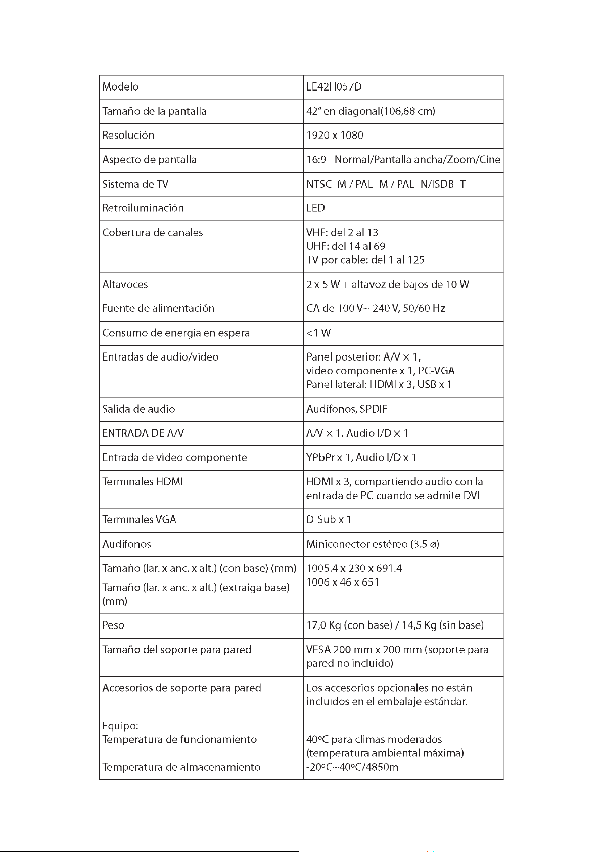
1. General Specification
4
Page 5

5
Page 6

2. Operating Instructions
2.1 The Front Control Panel
6
Page 7

2.2 Connections
7
Page 8
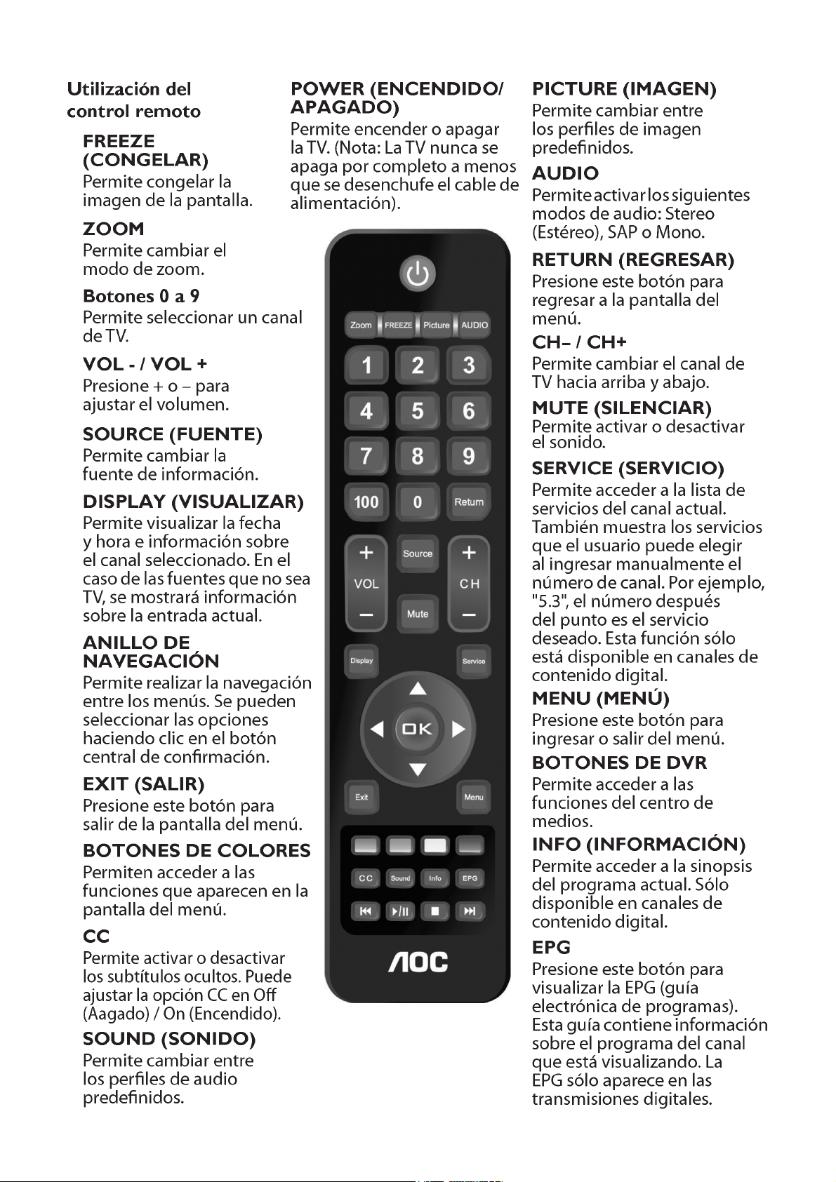
2.3 Remote Control
8
Page 9
2.4 Instructions for Use
9
Page 10

10 11 12 13 14 15 16 17
Page 11

Page 12
Page 13
Page 14

Page 15
Page 16

Page 17
Page 18
2.5 Visualization Menu
18
Page 19

19
Page 20

3. Input /Output Specification
3.1 Input Signal Connector
VGA Connector
Pin No. Description Pin No. Description Pin No. Description
1 Red Video 6 Red Ground 11 RXD
2 Green Video 7 Green Ground 12 Serial Data for DDC
3 Blue Video 8 Blue Ground 13 H-Sync.
4 TXD 9 No Pin! 14 V-Sync.
5 Ground 10 Sync Ground 15 Serial Clock for DDC
HDMI Connector
Pin No. Description Pin No. Description Pin No. Description
1 TMDS Data2+ 8 TMDS Data0 Shield 15 SCL
2 TMDS Data2 Shield 9 TMDS Data0- 16 SDA
3 TMDS Data2- 10 TMDS Clock+ 17 DDC/CEC Ground
4 TMDS Data1+ 11 TMDS Clock Shield 18 +5V Power
5 TMDS Data1 Shield 12 TMDS Clock- 19 Hot Plug Detect
6 TMDS Data1- 13 CEC
7 TMDS Data0+ 14 NC
1
6
11 15
5
10
USB Connector
Pin No. Description Pin No. Description
1 VCC 3 DATA+
2 DATA- 4 GND
20
Page 21

3.2 Factory Preset Display Modes
21
Page 22
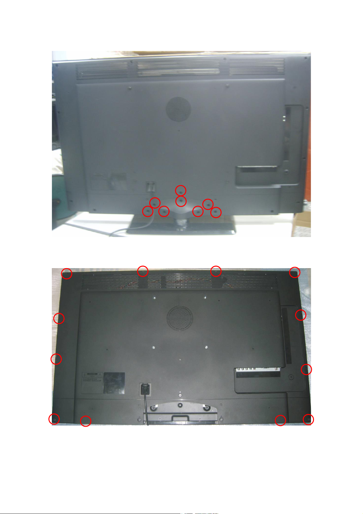
4. Mechanical Instructions
1. Remove the screws to remove the base.
2. Remove the screws to remove the rear cover.
22
Page 23

For LE42H057D
3. Disconnect the power cord and remove the screw to remove the ground wire.
4. Remove the screws to remove the hinge BKT and AC cover
23
Page 24

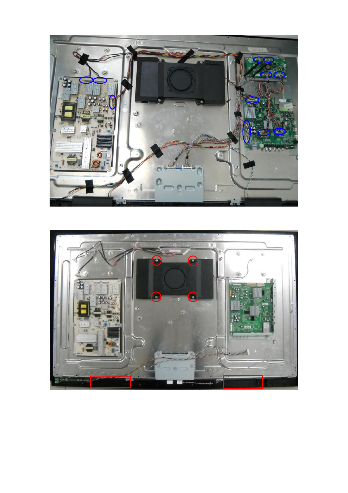
5. Remove all the connectors.
6. Remove the speakers.
24
Page 25

7. Remove the screws to remove the power board, main board and MEMC board.
8. Remove the screws to remove the BKTs.
25
Page 26

For LE46H057D
3. Disconnect the power cord and remove the screw to remove the ground wire.
4. Remove the screws to remove the hinge BKT and AC cover
26
Page 27
5. Remove all the connectors.
6. Remove the speakers.
27
Page 28

7. Remove the screws to remove the power board, main board and MEMC board.
8. Remove the screws to remove the BKTs.
28
Page 29
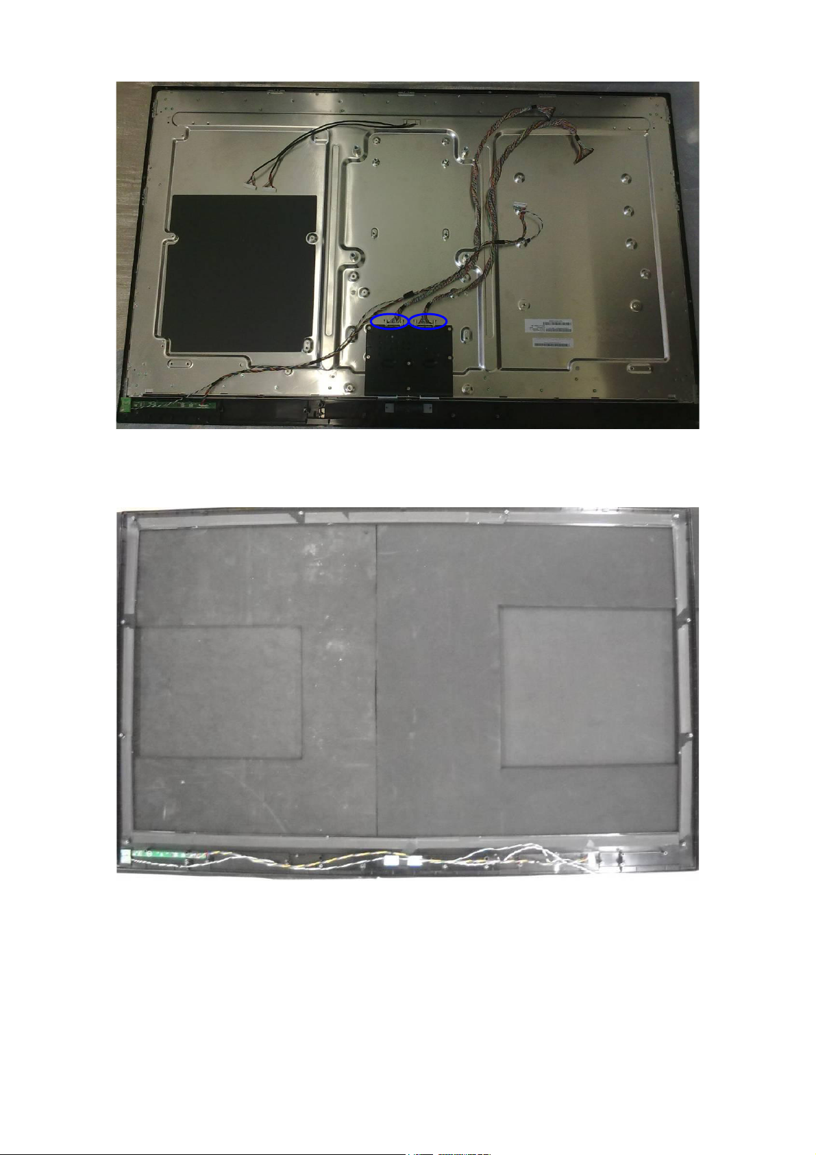
9. Remove the LVDS cables from the panel.
10. The bezel
29
Page 30

5. Repair Flow Chart
1. Sin Energía
Sin Energía (LED “Apagado”)
Revise la entrada AC. ¿La
energía está en “encendida”?
Si
Salida Power board =5V?
Si
Revise IR board y LED
No
Reemplace IR board
No
No
Enciéndalo
No
Reemplace power board
Reemplace main board
30
Page 31

2. No Enciende
(Chequee tecla power del control remoto, si
equipo no responde significa que es anormal).
No inicia (LED naranjo)
Salida Power board=24V?
Si
Revise si el botón de power funciona
No
Revise si el receptor IR es normal
No
No
Reemplace power board
Si
Reemplace key board
Si
Reemplace IR board
Reemplace main board
No
Reemplace la Power board
31
Page 32

3. Imagen Anormal
Entre al menú modo de fábrica para hacer
Imagen Anormal
Revise la fuente
Si
“EEPROM initial”&“Reset”
No
No
Reinicie la fuente
Revise main board
Si
Revise el cable LVDS
Si
Revise el panel
No
Reemplace panel
No
Reemplace main board
No
Reemplace LVDS cable
32
Page 33

4. Sin Imagen
Revise si el TV funciona, si enciende/apaga
vía control remoto y botón de power.
Si
Revise cable LVDS
Si
Panel Vcc = 12V?
Sin imagen (LED verde)
Si
Revise si la luz del panel está
encendida= “On”
No
Vuelva a insertar o
Reemplace el cable LVDS
No
No
Reemplace main board
No
Revise señal L/P si
está disponible
Si
Salida de Power board=24 V?
Reemplace main board
No
No
Si
Reemplace the Panel
Reemplace main board
33
Si
Reemplace Panel
Reemplace power board
Page 34

5. Problema de Sonido
Revise la conexión de la fuente de audio y si norma de
Sin sonido o sonido anormal
TV es correcto (NTSC-PAL N/M/ISTB)
Si
Revise si TV está mudo (muted), ajuste el volume o
entre al modo menú para reinicio?
No
Entre al modo menú de fábrica para reinicar
No
Revise el cable entre los parlantes y main
board si están OK
Si
No
Vuelva a insertar el cable de audio o cambie
la norma del TV
No
Reemplace cable
Revise los valores de Resistencia en el parlante que se encuentran en
las especificaciones (Nota: El valor está marcado en el parlante)
Si
Reemplace parlante
34
Reemplace main board
No
Page 35

6. Control Remoto - mal funcionamiento
Control remoto - mal funcionamiento
Revise la batería del control remoto si está
bien colocada o no tiene energía
No
Use otros controles remotos, ¿funciona?
Si
Reemplace batería
Si
Reemplace el control remoto
No
¿Es anormal la IR board?
No
Reemplace main board
Si
Reemplace IR board
35
Page 36

7. OSD es inestable o no trabaja de forma normal
OSD es inestable o no trabaja normalmente
La botonera está conectada correctamente?
Si
Los botones están OK?
Si
Botonera está OK?
Si
Entre al modo menú de fábrica para reinicar
No
No
No
Reconecte el key board
Reemplace la función del botón
Reemplace la botonera
No
Reemplace el main board
36
Page 37

6. PCB Layout
6.1 Main Board
715G4243M01000005F
37
Page 38

38
Page 39

39
Page 40

40
Page 41

6.2 Power Board
715G3899P02L30003H
41
Page 42

42
Page 43

43
Page 44

715G3906P02L30003H
44
Page 45

45
Page 46

46
Page 47

6.3 Key Board
715G3852K0C001004S
6.4 IR Board
715G4086R01001005F
47
Page 48

6.5 MEMC Board
715G4242M01000005K
48
Page 49

49
Page 50

7. Adjustment
7.1 White-Balance Adjustment
Approximately 60 minutes should be allowed for warm up before proceeding white balance adjustment.
Before started adjust white balance, please set the CA210 Channel to 05 Channel and set it’s mode to x, y, Lv mode
Color Temp. Cool (12000) Normal (9300) Warm (6500)
x 272 ± 0.020 285 ± 0.020 313 ± 0.020
AV/HDMI/VGA/Component
Mode
How to setting the CA210 channel, you can reference to CA210 user guide or simple use the “Memory CH” up or
down to set the channel to 05 channel, and use the “Mode” key to set the mode to x, y, Lv.
Enter into the factory mode
Press the “MENU” key and then press number key 1 Æ 9 Æ 9 Æ 9ÆEnter, It will achieve the factory mode. The
factory menu follow picture:
y 278 ± 0.020 293 ± 0.020 329 ± 0.020
Y More than 360cd/cm2 (at full white)
50
Page 51

In the White Balance you can adjust 3 items.
SCALER GAIN R, G, B Æ R, G, B Gain adjust
Adjust AV Source:
1. Set the pattern generator to timing 307 or PAL-M timing. And Select the item of Current Source and select
composite Source
2. Switch the Ca210 to x, y, Lv-mode (with press “MODE” button)
3. Switch the Ca210 channel to Channel 05 (with up or down “MEMORY CH” button)
4. The LCD-indicator on Ca210 will show x =285, y =293, Lv can adjust to More than 350cd/cm2 (at full white).
5. Enter the item “Color Temp” to select Normal to adjust.
6. Use the item R Gain, G Gain or B Gain to adjust white balance: use 80 IRE (Pattern 141) signal, and adjust the
white balance, until the Ca210 show x =285, y =293.
Adjust HDMI Source:
1. Set the pattern generator to timing 347 or HDMI-720P@60Hz timing. And Select the item of Current Source and
select HDMI Source
2. Switch the Ca210 to x, y, Lv-mode (with press “MODE” button)
3. Switch the Ca210 channel to Channel 05 (with up or down “MEMORY CH” button)
4. The LCD-indicator on Ca210 will show x =285, y =293, Lv can adjust to More than 350cd/cm2 (at full white).
5. Enter the item “Color Temp” to select Normal to adjust.
6. Use the item R Gain, G Gain or B Gain to adjust white balance: use 80 IRE (Pattern 141) signal, and adjust the
white balance, until the Ca210 show x =285, y =293.
Adjust VGA Source:
1. Set the pattern generator to timing 137 or 1024*768@60Hz timing. And Select the item of Current Source and
select VGA Source
2. Switch the Ca210 to x, y, Lv -mode (with press “MODE” button)
3. Switch the Ca210 channel to Channel 05 (with up or down “MEMORY CH” button)
4. The LCD-indicator on Ca210 will show x =285, y =293, Lv can adjust to More than 350cd/cm
5. Enter the item “Color Temp” to select Normal to adjust.
6. Use the item R Gain, G Gain or B Gain to adjust white balance: use 80 IRE (Pattern 141) signal, and adjust the
white balance, until the Ca210 show x =285, y =293.
Adjust Component Source:
1. Set the pattern generator to timing 314 or HDTV-720p@60Hz timing. And Select the item of Current Source and
select Component Source
2. Switch the Ca210 to x, y, Lv -mode (with press “MODE” button)
3. Switch the Ca210 channel to Channel 05 (with up or down “MEMORY CH” button)
4. The LCD-indicator on Ca210 will show x =285, y =293, Lv can adjust to More than 350cd/cm2 (at full white).
5. Enter the item “Color Temp” to select Normal to adjust.
6. Use the item R Gain, G Gain or B Gain to adjust white balance: use 80 IRE (Pattern 141) signal, and adjust the
white balance, until the Ca210 show x =285, y =293.
7. Enter the item “Color Temp” to select Cool to adjust.
8. Use the item R Gain, G Gain or B Gain to adjust white balance: use 80 IRE (Pattern 141) signal, and adjust the
white balance, until the Ca210 show x =272, y =278.
9. Enter the item “Color Temp” to select Warm to adjust.
10. Use the item R Gain, G Gain or B Gain to adjust white balance: use 80 IRE (Pattern 141) signal, and adjust the
white balance, until the Ca210 show x =313, y =329
2
(at full white).
51
Page 52

7.2 Firmware Instruction
Note: Because the process of the LE46H057 updating is the same as the LE42H057’s, so take the
LE42H057 for example:
Step 1: Ready for F/W Upgrade
1.1 Change the FW “.img1” file name to” safe-kernel.img1” and “.tgz” file name to “update_demo.tgz”.
e.g.:
Before change:
After change:
1.2 Prepare a USB memory (The file system of USB memory must be FAT16 or FAT 32).
1.3 Copy the files (asafe-kernel.img1 & updte_demo.tgz) from your computer to the USB memory, and remove it
from computer’s USB port!
Note:
1. Note the version of this F/W is L42.01 before you change the software files name.
2. The software files name must be changed, or TV can’t detect the F/W.
;
Step 2: F/W Upgrade
1.1 AC on (Power plug Figure 2.1/2.2)
Figure 2.1 Figure 2.2
1.2 Plug the USB memory on the USB port on the left side I/O port of TV as figure 2.3.
Figure 2.3
52
Page 53

1.3 Press the power key on the Remote Control or the right side of TV to turn on TV as figure2.4 and figure2.5
Figure 2.4 figure 2.5
1.4 When the TV detects the USB memory, the LED light is blue and flickers as figure 2.6.
For a moment the LED light becomes red and flickers as figure 2.7 which represents the TV is updating.
The update is ok until the LED becomes blue again as figure2.6. Unplug U-disk from TV and restart TV.
Figure 2.6 Figure 2.7
Step 3: Check the F/W version and reset to default.
1.1 Turn on the TV, press the “MENU” button on the remote control, and then press the number key 1→9→9→9.
You will enter into the factory mode (Figure 3.1).
1.2 Check the F/W version on the second row of the factory mode info (e.g.: the “Ver.” info is V42.01). If F/W
version is incorrect, please re-update FW, else turn off BURN IN and do EEPROM initialize as figure 3.2 and
figure 3.3.
53
Page 54

Figure 3.1
Do the following steps rapidly:
1. Press the “MENU”
2. Press the number key ”1”+”9” +”9” +”9”
Figure 3.2
1. If BURN IN is ON, turn it off as figure 3.3.
2. After updating, do EEPROM initialize by
selecting the “EEPROM INT” and pressing “ok”
to start as figure 3.3.
54
Page 55

Figure 3.3
7.3 DDC Instruction
As the DDC data was included in the software, this model does not need a separate DDC Upgrade.
55
Page 56

8. Block Diagram
Panasonic
Tuner
HDMI 1
HDMI 2
HDMI 3
IF
TC90517F
YP b P r +A udi o IN
CVBS+Audio IN
SII9187ACNU
VGA RGB +Audio IN
TS Stream
HDMI
HIDTV_PRO_SX27
IIS
STA339BWTR
Audio Speaker Amp
APA2176
Headphone Amp
SPDIF out
SPEAKER
2.1Ch
BD8012FVJ
U701 power
USB
64Mx16_DDR2
64Mx16_DDR2
MX25L4005
SPI Flash
56
NAND Flash
512Mb
Panel
Page 57

9. Schematic Diagram
9.1 Main Board
715G4243M01000005F
TS1_D[0..7]
TS1_CLK
TS1_SYNC
TS1_DEN
TS1_CLK
TS1_D0
TS1_SYNC
TS1_DEN
T1_SIF
C207
20P 50V
5
6
TS1_D0
7
8
RP101
8P4R 33 OHM +-5% 1/16W
NC 8P4R 33 OH M +-5% 1/16W
5V
R204
R205
4.7K 1/10W
4.7K 1/10W
CVBS1_IN
PC_R_IN
PC_G_IN
PC_B_IN
PC_HS_IN
PC_VS_IN
Y1_IN
PB1_IN
PR1_IN
TV_C VBS
C206
100N 50V
1M 1/10W
R207
24MHz
X200
12
4
3
2
1
RP106
5
6
7
8
HDMI_RX0HDMI_RX0+
HDMI_RX1HDMI_RX1+
HDMI_RX2HDMI_RX2+
HDMI_RXCHDMI_RXC+
HDMITX_5V
R208
33 OHM 1/10W
C208
20P 50V
4
3
2
1
TS1_D0
TS1_D1
TS1_D2
TS1_D3
TS1_D4
TS1_D5
TS1_D6
TS1_D7
C205
100N 50V
AE5
AF5
AF6
AE6
AD6
AC6
AB6
AF7
AE7
AC7
AD7
AF2
AF3
AE3
AD3
AF4
AE4
AD4
AC4
AC5
AB5
AD5
AD1
AC3
AD2
AE1
D10
A10
B10
C10
ANT SIF
D2
D1
E2
E1
F2
F1
C2
C1
B1
B3
A1
B2
B5
A3
A2
B9
B8
D4
C4
B7
D8
A7
D9
C8
C9
D7
C6
D5
D6
C5
A4
B4
A6
B6
T1
R1
E3
E4
TS1D 0
TS1D 1
TS1D 2
TS1D 3
TS1D 4
TS1D 5
TS1D 6
TS1D 7
TS1CLK
TS1SY N C
TS1D EN
TS2D 0
TS2D 1
TS2D 2
TS2D 3
TS2D 4
TS2D 5
TS2D 6
TS2D 7
TS2CLK
TS2SY N C
TS2D EN
TSS_CLK
TSS_DI
TSS_SYNC
TSS_DEN
RX0RX0+
RX1RX1+
RX2RX2+
RXCRXC+
ANTS TO
PWR5V
DSDA
DSCL
CVBS1
CVBS_OUT1
CVBS_OUT2
PCR
PCG
PCB
PCHS
PCVS
YG1
PBB1
PRR1
YG2
PBB2
PRR2
YG3
PBB3
PRR3
C
FS1
FB1
FS2
FB2
FS3
FS4
SIFN
SIFP
XTLI24M
XTLO24M
INTN
RSTO
RESET_Demo_#
U200A
HiDTV-Pro_SXB
(1/5)
TS_IN
HDMI_IN
ANALOG_IN
LVDS_OUT
I2S PORT
I2C PORT
UART PORT
USB PORT
ADC
MISC
T P V ( Top Victory Electronics Co . , Ltd. )
絬 隔 瓜 絪 腹
Key Component
Date
57
HIDTV
*****
04:HiDPRO SX-1
USBPPON
RREF EXT
I2SCLKIN
PC
AV
YPBPR
Side
SCART2
TESTCON
TESTMOD
MASTSEL
TA1M
TA1P
TB1M
TB1P
TC1M
TC1P
TD1M
TD1P
TE1M
TE1P
TCLK1M
TCLK1P
TA2M
TA2P
TB2M
TB2P
TC2M
TC2P
TD2M
TD2P
TE2M
TE2P
TCLK2M
TCLK2P
USBOC
TXD2
RXD2
SCKIN
WSI2S
SDI2S
I2SCLK
SPDIF
MUTE
SCLM1
SDAM1
SCLM2
SDAM2
SPKOR
SPKOL
HPHOR
HPHOL
AOR1
AOL1
AOR2
AOL2
TXD
RXD
SCK
SD1
SD2
SD3
AR1
AR2
AR3
AR4
AR5
A15
B15
C16
C15
B16
A16
C18
C17
B18
A18
A17
B17
A19
B19
C20
C19
B20
A20
C22
C21
B22
A22
A21
B21
AC1
DP
AB1
DN
AB3
AB2
AC2
AF20
AF21
Y1
AA1
AA3
AA4
AB4
AC21
AD21
WS
AF22
AE22
AD22
AF23
AA2
AE21
D21
Y3
Y2
C24
A23
B11
A11
AL1
D11
C11
AL2
C12
D12
AL3
A12
B12
AL4
B13
A13
AL5
B14
A14
D17
D16
D14
C14
D15
E14
M3
HP_TESTCON
HP_TESTMOD
M2
HP_MASTSEL
B24
R201 6.04K +-1% 1/10W
HID_TXD
HID_RXD
3.3V
R275 10K 1/ 10W
R247 10K 1/ 10W
C203 1uF 25V
C204 1uF 25V
3VSB
OEM MO DEL Size
G4243-D-X-X-2-100726
TPV MO DEL
***** 01
715G4243-M0A-000-0050
PCB NAME
418Monday, J uly 26, 2010
Sheet
of
HP_SPDIF
SCL_MST1
SDA_MST1
R200
4.7K 1/10W
R202
0R05 1/10W
I2S_CLK
HID_TXD
HID_RXD
PULL DOWN : LED
PULL HIGH: JTAG
TX0AN
TX0AP
TX1AN
TX1AP
TX2AN
TX2AP
TX3AN
TX3AP
TX4AN
TX4AP
TXCKAN
TXCKAP
TX0BN
TX0BP
TX1BN
TX1BP
TX2BN
TX2BP
TX3BN
TX3BP
TX4BN
TX4BP
TXCKBN
TXCKBP
USB_DP
USB_DN
USB_PPON
USB_OC
HID_TXD
HID_RXD
I2S_CK
I2S_WS
I2S_SD
R287
2K 1/10W
PC_RI N
PC_LIN
AV_RIN
AV_LIN
HD_RIN
HD_LI N
AX_HP_OUTR
AX_HP_OUTL
3.3V
CN705
1
2
3
4
NC
3.3V
R288
2K 1/10W
HDMI_SCL
HDMI_SDA
Custom
Rev
<
称爹
称爹
>
Page 58

4.7K 1/ 10W
AMP_SD
AMP_MUTE
HP_MUTE
HDMITX_INT
HDMI_I2C_SW
SW_AMP_RSTN
RESET_FRC
V18_SW
MEMC 5V_S W
V105DLL_SW
DRC_EN
FRA[ 19..22]
3.3V
R220
FRD[0..7]
FRA13
FRA14
FRA18
FRA23
FOE#
FWE#
GCS0
GCS2
4.7K 1/10W
R236
R222 N C 4. 7K 1/10W
R226 4. 7K 1/10W
R246 4.7K 1/ 10W
R1840 0R05 1/10W
SF_SI
SF_SO
SF_WP#
SF_HOLD#
SF_CS
SF_SCK
3.3V
U200B HIDTV
FRD0
FRD1
FRD2
FRD3
FRD4
FRD5
FRD6
FRD7
FRA13
FRA14
FRA18
FRA19
FRA20
FRA21
FRA22
FRA23
R278 4. 7K 1/10W
R277 4. 7K 1/10W
R276 4. 7K 1/10W
R279 4. 7K 1/10W
AC9
AF10
AD10
AB10
AE11
AC11
AF12
AD12
AB9
AC10
AE10
AF11
AD11
AB11
AE12
AB12
AF9
AF18
AB17
AC17
AD17
AE17
AF17
AB16
AD15
AE15
AF15
AB14
AC14
AD14
AE14
AF14
AF13
AC16
AD16
AC15
AB15
AE16
AB13
AC13
AD13
AD9
AF16
AE9
AE2
AF1
AC12
AE23
AD23
AB7
AF8
AE8
AD8
AC8
AB8
AE18
AF19
AB18
AD18
F3
G1
G2
G3
G4
H1
H2
H3
H4
J4
J3
J2
J1
FRD0/PODD0
FRD1/PODD1
FRD2/PODD2
FRD3/PODD3
FRD4/PODD4
FRD5/PODD5
FRD6/PODD6
FRD7/PODD7
FRD8/PODA0
FRD9/PODA1
FRD10/PODA2
FRD11/PODA3
FRD12/PODA10
FRD13/PODA11
FRD14/PODA12
FRD15/PODA13
FRA0
FRA1/PODWE
FRA2/PODIORD
FRA3/PODIOWR
FRA4/PODREG
FRA5
FRA6
FRA7
FRA8
FRA9/PODOE
FRA10
FRA11
FRA12
FRA13
FRA14
FRA15
FRA16
FRA17
FRA18
FRA19
FRA20
FRA21
FRA22
FRA23
FRA24
FOE#
FWE#
GCS0
GCS1
GCS2
BOOTCS
GPIO0
GPIO1
GPIO2
GPIO3
GPIO4
GPIO5
GPIO6
GPIO7
GPIO8
GPIO9
GPIO10
GPIO11
GPIO12
GPIO13
GPIO14
POD_A4
POD_A5
POD_A6
POD_A7
POD_A8
POD_A9
POD_IR EQ
POD_RST
POD_VS1
POD_WAI T
HiDTV-Pro_SXB
(2/5)
FLASH INTERFACE
GPIO PORT
HP_DETECT
POD_VCC_EN
POD_VCC_ENB
POD_VPP_EN
POD_VPP_ENBPOD_OVERLOAD
SF_SI
SF_SO
SF_WPN
SF_HOLDN
SF_C ES
SF_SC K
TD0
TMS
TCK
TRS TN
LED
KYBR D
LGSEN
CEC
PWRO N
AVLINK1
AVLINK2
STB_RSTO
RXIP
RXIN
TXOP
TXON
RSET_BG
H_BK_LITE
PWM0
PWM1
BOOST
BKLGON
TCO N_ON
FSOURCE
HPD
STB_GP0
STB_GP1
STB_GP2
STB_GP3
STB_TXD
STB_RXD
STB_EN
SPI_EN
STB_SDA
STB_SCL
RSTN
ET_LED1
ET_LED2
PLL_TEST
POD_CE2
POD_CE1
POD_CD2
POD_CD1
TDI
IR
NC
L3
L2
L1
K5
L4
L5
W4
W3
W2
W1
Y4
K1
K2
N1
P1
K4
P5
N3
N2
K3
U2
U1
V1
V2
T3
D24
B23
C23
D23
E23
D22
E22
C3
D3
P2
P3
P4
R3
N5
N4
M4
M5
T4
U4
M1
V3
V4
T2
AE13
AD19
AE19
AE20
AC18
AC19
AC20
AB19
AD20AB20
MIPS_JTAG_TDI
MIPS_JTAG_TDO
MIPS_JTAG_TMS
MIPS_JTAG_TCK
MIPS_JTAG_TRSTN
IR_D
KYBR D
12K4 1/10W 1%
HP_STB_EN
HP_SPI_EN
HP_RESET#
LED_STB
LAN_RXIN+
LAN_RXINLAN_TXIN+
LAN_TXIN-
R218
MCU _TXD
MCU _R XD
876
123
R1834
NC 0R 05 1/10W
4.7K 1/ 10W
R231
4.7K 1/10W
R1836
0R05 1/10W
5
4
R223
RP103
4.7 K 1/1 6W
3VSB
3VSB
LED_R
0R05 1/10W
LED_STB
R224
4.7K 1/10W
4.7K 1/10W
C212
10N 50V
LED
R1835
3VSB
3VSB
R227
R253
4.7K 1/10W
MIP S_J TAG_TC K
MIP S_J TAG_TD O
MIP S_J TAG_TMS
MIP S_J TAG_TR STN
MIP S_J TAG_TD I
LED
33 OHM 1/10W
R211
4.7K 1/10W
R1837 NC 0R05 1/10W
R1839 NC 0R05 1/10W
R1838 0R 05 1/10W
R219
4.7K 1/ 10W
R228
4.7K 1/10W
3VSB
10K 1/10W
R225
1
GND
2
RESET
IC G692L293TCUf
R1144
R244
STB_SDA
STB_SCL
3VSB
R214
4.7K 1/ 10W
10K 1/10W
VCC
MR
U20 2
MIPS _JTA G_TR STN
0R05 1/10W
NC
CN201
10
8
6
4
2
MCU_JTAG_TDO
IR_D
KYBR D
PW_KEY
HDMI_CEC
STB_HS_DET
STB_VS_DET
AUX_POWER _ON#
LED_B
BL_ADJ
PANEL_PWM
BL_ON#
PANEL_ON
PHONE_D ET
MCU_JTAG_TDI
MCU_JTAG_TMS
MCU_JTAG_TCK
POWER_ON
3VSB
R245
10K 1/10W
1
2
3
4
3VSB
SW101
4
3
NC
R210
9
7
5
3
1
CN702
NC
T P V ( Top Victory Electronics Co . , Ltd. )
*****
絬 隔 瓜 絪 腹
Key Component
Date
05:HiD PRO SX-2
58
OEM MO DE L Size
TPV MOD EL
PCB NAME
G4243-D-X-X-2-100726
***** 01
715G4243-M0A-000-0050
Sheet
of
518Monday, August 09, 2010
Rev
称爹
称爹
<
Custom
>
Page 59

HP_MD[0..31]
HP_WDQS[0..3]
HP_RDQS[0..3]
HP_MD0
HP_MD1
HP_MD2
HP_MD3
HP_MD4
HP_MD5
HP_MD6
HP_MD7
HP_MD8
HP_MD9
HP_MD10
HP_MD11
HP_MD12
HP_MD13
HP_MD14
HP_MD15
HP_MD16
HP_MD17
HP_MD18
HP_MD19
HP_MD20
HP_MD21
HP_MD22
HP_MD23
HP_MD24
HP_MD25
HP_MD26
HP_MD27
HP_MD28
HP_MD29
HP_MD30
HP_MD31
HP_WDQS0
HP_RDQS0
HP_WDQS1
HP_RDQS1
HP_WDQS2
HP_RDQS2
HP_WDQS3
HP_RDQS3
U200C HIDTV
AF25
MD 0
AF26
MD 1
AE25
MD 2
AE26
MD 3
AC24
MD 4
AB24
MD 5
AB25
MD 6
AB26
MD 7
AA25
MD 8
AA26
MD 9
HiDTV-Pro_SXB
Y25
MD 10
Y26
MD 11
W24
MD 12
V24
MD 13
V25
MD 14
V26
MD 15
K24
J24
J25
J26
G26
G25
G24
F25
E24
E25
E26
D26
B25
B26
A25
A26
AD26
AD25
W25
W26
H25
H24
C26
C25
MD 16
MD 17
MD 18
MD 19
MD 20
MD 21
MD 22
MD 23
MD 24
MD 25
MD 26
MD 27
MD 28
MD 29
MD 30
MD 31
WDQS0_DQS0
RDQS0_DQS0#
WDQS1_DQS1
RDQS1_DQS1#
WDQS2_DQS2
RDQS2_DQS2#
WDQS3_DQS3
RDQS3_DQS3#
DDR2 INTERFACE
(3/5)
MAA0
MAA1
MAA2
MAA3
MAA4
MAA5
MAA6
MAA7
MAA8
MAA9
MAA10
MAA11
MAA12
BA0
BA1
BA2
DQM0
DQM1
DQM2
DQM3
MC LK0
MCLK0#
MVR EF 2
MVR EF 1
CAS
RAS
WE
CS0
CKE
ODT
MZQ
MR ES
L26
P24
K26
L24
N24
P25
N26
M25
N25
M24
K25
L25
U23
U26
T26
R24
AC25
Y24
H26
D25
R26
P26
A24
AD24
U25
U24
R25
T24
T25
M26
AF24
F26
402ohm 1/ 10W +/-1%
HP_MA0
HP_MA1
HP_MA2
HP_MA3
HP_MA4
HP_MA5
HP_MA6
HP_MA7
HP_MA8
HP_MA9
HP_MA10
HP_MA11
HP_MA12
HP_BA0
HP_BA1
HP_BA2
HP_DQM0
HP_DQM1
HP_DQM2
HP_DQM3
HP_MVREF2
HP_MVREF1
R239
HP_MVREF2
C214
100N 50V
Near to IC
HP_MVREF1
C317
100N 50V
Near to IC
1K1/10W
1K1/10W
R237
R238
R255
1K1/10W
1K1/10W
HP_VCC_18
R254
HP_MA[0. .12]
HP_BA[0..2]
HP_DQM[0..3]
HP_MCLK0
HP_MCLK0#
C213
100N 50V
C216
100N 50V
HP_VCC_18
HP_CAS#
HP_RAS#
HP_WE#
HP_CS0#
HP_CKE
HP_ODT
C319
100N 50V
C318
100N 50V
T P V ( Top Victory Electronics Co . , Ltd. )
絬 隔 瓜 絪 腹
Key Component
Date
*****
06:H iDPR O SX-3
59
OEM MO D EL Size
TPV MOD EL
PCB NAME
Sheet
G4243-D-X-X-2-100726
***** 01
715G4243-M0A-000-0050
of
618Thursday , July 08, 2010
Rev
称爹
Custom
称爹
<
>
Page 60

this GND should be
connect to Cleanly GND
HP_VCC_25
120OHM
FB210
1 2
120OHM
FB211
1 2
120OHM
FB214
1 2
120OHM
FB216
1 2
120OHM
FB217
1 2
120OHM
VDDI_25
FB219
1 2
120OHM
FB220
3.3V
1 2
120OHM
3.3V
FB205
1 2
3VSB
1 2
FB208
120OHM
0R05 1/10W
0R05 1/10W
9/1 at shanghai
R273
R274
C270
10uF 6.3V
10uF 6.3V
10uF 6.3V
2.2U25V
2.2U25V
10uF 6.3V
C239
10uF 6.3V
C249
10uF 6.3V
C253
10uF 6.3V
C259
10uF 6.3V
C263
10uF 6.3V
C224
C221
C222
C233
C237
AGND_LAN
AGND_LAN
3.3V POWER FOR ADC OUTPUT BUFFER
120OHM
3.3V
FB221
1 2
3.3V FOR TMDS RECEIVER
C272
100N 50V
AVDD33_OUTBUF
C271
100N 50V
C273
10uF 16V
C219
100N 50V
C226
100N 50V
C223
100N 50V
C234
100N 50V
C238
100N 50V
C240
100N 50V
C250
100N 50V
C254
100N 50V
C260
100N 50V
C264
100N 50V
AVSSOUTBUF
AVCC33RX
U200D HIDTV
H5
AVDD33_SP
J6
R4
R2
C13
F13
D13
F14
E12
J13
E13
J14
E15
F15
T5
U5
U3
V6
AC22
AB21
E6
F7
K6
AGND_LAN
3.3V Analog Power for ADC AFE
AVDD33_SP
AVDD33
3.3V Analog Power for STANDBY
AVSS33
VCM_ADC
VCM for ADC
VSS25_AUDIO_AD C
VCM_DAC
VCM for DAC
VSS25_AUDIO_D AC
VCC25A
2.5V Analog Power for Audio CODEC
VSS25A
2.5V Power for Switch Circuits in ADC and DAC.
VCC25D
VSS25D
VCC25HP
2.5V Power for Head Phone
VSS25HP
VCC25A_BG
2.5V Analog Power for Ethernet BG
GNDA
VCC25A_TX
2.5V Analog Power for Ethernet TX
GNDA_TX
AVDD_MCK2
2.5V Analog Power for MCLK2 PLL
AVSS_MCK2
AVDD33OUTBUF
AVSSOUTBUF
AVCC33RX
3.3V Analog Power for OUTBUF
3.3V Analog power for T MDS receiver
HiDTV-Pro_SXB
2.5V LDO out for PLL & Analog core
3.3V for LDO & USB Analog Core
1.8V power shielding for MVREF1
1.8V power shielding for MVREF2
2.5V Analog power for LVDS PLL
(4/5)
2.5V Analog powr for LVDS
2.5V Analog powr for ANAPLL/APLL
2.5V Analog power for PLL
2.5V Power for ADCs
2.5V Analog power for T MDS receiver
PAVDDLLPLL
AVDD25_ADC 1
AVDD25_ADC 2
AVDD25_ADC 3
AVDD25_ADC 4
2.5V for TMDS PLL
2.5V for Audio PLL
VDDREG
AGNDREG
VDDA33
VDDR1
VDDR2
VSSR1
VSSR2
VDDP
GNDP
LVDS_VDD
LVDS_VDD
LVDS_GND
LVDS_GND
PAVSSLLPLL
AVDDPLL
AVSSPLL
AVSSADC1
INN1
AVSSADC2
INN2
AVSSADC3
INN3
AVSSADC4
INN4
AVCC
AVCC
AGND
AGND
PVCC
DGND
REGVCC
AA5
W6
AA6
AC23
G22
AE24
F22
E16
F16
D20
E20
F20
F21
E11
F12
R5
U6
E7
F8
A5
E9
F10
A8
E10
F11
A9
E8
F9
C7
F4
G5
G6
H6
F5
F6
E5
100N 50V
C220
HP_VDDP_USB
C227
100N 50V
C231
100N 50V
HP_LVDS_VDDP
C235
100N 50V
HP_LVDS_VDD
C241
100N 50V
PAVDDLLPLL
PAVSSLLPLL
AVDDPLL
AVSSPLL
AVDD25_ADC 1
INN1
AVDD25_ADC 2
INN2
AVDD25_ADC 3
INN3
AVDD25_ADC 4
INN4
AVCC
PVCC
REGVCC
C242
100N 50V
C225
10uF 6.3V
C228
10uF 6.3V
C232
100N 50V
C236
10uF 6.3V
C243
100N 50V
C255 100N 50V
C258 100N 50V
C261 100N 50V
C262 100N 50V
C244
100N 50V
AVSSADC1
INN1_GND
AVSSADC2
INN2_GND
AVSSADC3
INN3_GND
AVSSADC4
INN4_GND
C245
10uF 6.3V
AVDD25_ADC 1
120OHM
FB206
1 2
HP_VCC_18
HP_VCC_25
120OHM
FB209
1 2
120OHM
FB212
1 2
10uF 6.3V
3.3V
C246
ANALOG PLL 2.5V POWER
PAVDDLLPLL
PAVSSLLPLL
C217
100N 50V
PLL 2.5V POWER
AVDDPLL
AVSSPLL
C229
100N 50V
HDMI Analog 2.5V POWER
AVCC
C247
100N 50V
2.5V FOR HDMI PLL
PVCC
C251
100N 50V
HDMI AUDIO PLL 2.5V
REGVCC
C256
100N 50V
C265
C266
100N 50V
100N 50V
C267
100N 50V
C218
10uF 6.3V
C230
10uF 6.3V
C248
10uF 6.3V
C252
10uF 6.3V
C257
10uF 6.3V
C268
22uF 10V
120OHM
FB204
120OHM
FB207
1 2
120OHM
FB213
1 2
120OHM
FB215
1 2
FB218
1 2
120OHM
HP_VCC_25
12
2.2uH
R240
C269
22uF 10V
HP_VCC_25
60
T P V ( Top Victory Electronics Co . , Ltd. )
*****
絬 隔 瓜 絪 腹
Key Component
07:HiDPRO SX-4
Date
OEM MOD EL Size
G4243-D-X-X-2-100726
TPV MODEL
***** 01
715G4243-M0A-000-0050
PCB NAME
718Thursday, July 08, 2010
of
Sheet
Custom
Rev
<
称爹
称爹
>
Page 61

10uF 6.3V
C296
10uF 6.3V
HP_VCC _25
HP_VCC1V
C274
HP_VCC _18
HP_VCC1V
D18
D19
E17
E18
E19
F17
F18
F19
AA10
AA11
AA12
AA13
AA14
AA15
AA16
AA9
AA17
H21
J21
V21
W21
U21
K21
3VSB
E21
W5
AA7
AA8
AA18
AA19
AA20
10uF 6.3V
C297
100NF 25V
120OHM
FB222
1 2
L6
M6
N6
R6
T6
J5
V5
Y5
Y6
C275
U200E
VDDC
VDDC
VDDC
VDDC
VDDC
VDDC
VDDC
VDDC
VDDC
VDDC
VDDC
VDDC
VDDC
VDDC
VDDC
VDDC
VDDC
VDDC
VDDC
VDDC
VDDC
VDDC
VDDC
VDDC
VDDC
VDDC
VDDC
VDDC
VDDC
VDDF
VDDF
VDDF
VDDF
VDDF
VDDF
VDDF
VDDF
VDDF
VDDF
VDDF
100NF 25V
VDDI _25
F23
VDDC: 1.0V, core power
VDDF: 3.3V I/O power
AC26
C276
10uF 6.3V
C298
C299
10uF 6.3V
VDDI_25
F24
AA24
AB23
VDDI 25
VDDI 25
VDDI 25
VDDI 25
G23
H23
J22
J23
K22
G21
H22
VDDM
VDDM
VDDM
VDDM
VDDM
VDDM
VDDI25: 2.5V digital power for memory
VSS
VSS
VSS
VSS
VSS
VSS
VSS
VSS
VSS
VSS
J16
J17
J18K9K10
100NF 25V
C302
100NF 25V
C280
VSS
K11
K12
C303
100NF 25V
HP_VCC 1V
VSS
C278
100NF 25V
VDDI _25
J9
100NF 25V
C300
10uF 6.3V
J10
C279
J11
J12
J15
K23
L22
L23
M22
M23
N22
N23
P22
P23
R22
R23
T22
T23
U22
V22
V23
W22
Y21
Y22
Y23
AA21
AA23
AB22
AA22
N21
M21
W23
VDDM
VDDM
VDDM
VDDM
VDDM
VDDM
VDDM
VDDM
VDDM
VDDM
VDDM
VDDM
VDDM
VDDM
VDDM
VDDM
VDDM
VDDM
VDDM
L21P6T21
VDDM
VDDM
VDDM
VDDM
VDDM
VDDM
VDDM
VDDM
VDDM
VDDM: 1.8V, memory I/O power
HiDTV-Pro_SXB
(5/5)
POWER/GROUND
VSS
VSS
VSS
VSS
VSS
VSS
VSS
VSS
VSS
VSS
VSS
VSS
VSS
VSS
VSS
VSS
VSS
VSS
VSS
VSS
VSS
VSS
VSS
VSS
VSS
VSS
VSS
VSS
K13
K14
K15
K16
K17
K18L9L10
L11
L12
L13
L14
L15
L16
L17
L18M9M10
M11
M12
M13
M14
M15
M16
M17
M18N9N10
C281
100NF 25V
100NF 25V
C304
100NF 25V
1 2
C282
100NF 25V
120OHM
FB223
C305
C283
10N 16V
10N 16V
C306
10uF 6.3V
C284
3VSB
VDDL
C285
10N 16V
C307
100NF 25V
HP_VCC_18
VDDL
VDDM
VSS
VSS
VSS
N13
N14
N15
C308
100NF 25V
VSS
VSS
N16
N17
C287
10N 16V
VSS
VSS
P9
R21
VDDL
VSS
VSS
P10
P11
P12
C288
10N 16V
C309
100NF 25V
VSS
N18
VSSL
VSS
VSS
VSS
VSS
P13
P14
P15
P16
P17
C289
10N 16V
C310
100NF 25V
P21
VDDM
VDDM
VDDL: 1.0V, DLL and DDR Delay Line
VSS
VSS
N11
N12
C286
10N 16V
VSS
3.3V
3.3K 1/10W
R270
C312
100NF 25V
R269
NC 3. 3K 1/10W
R265
0R05 1/10W
R266
NC 0R 05 1/10W
R256
NC
R260
0R05 1/10W
No
1
2
3
4
5
6
7
8
0R05 1/10W
3.3V
NC 0R 05 1/10W
PIN
USB_PPON
FRA19/GCS0
FWE
FOE
FRA20
FRA21
FRA22
FRA23
V18
VSS
V17
VSS
V16
VSS
V15
VSS
V14
VSS
V13
VSS
V12
VSS
V11
VSS
V10
VSS
V9
VSS
U18
VSS
U17
VSS
U16
VSS
U15
VSS
U14
VSS
U13
VSS
U12
VSS
U11
VSS
U10
VSS
U9
VSS
T18
VSS
T17
VSS
T16
VSS
T15
VSS
T14
VSS
T13
VSS
T12
VSS
T11
VSS
T10
VSS
T9
VSS
R18
VSS
R17
VSS
R16
VSS
R15
VSS
R14
VSS
R13
VSS
R12
VSS
R11
VSS
R10
VSS
R9
VSS
VSS
HIDTV
P18
C290
C320
10N 16V
10uF 16V
C311
100NF 25V
NC
R271
R267
3.3K 1/10W
R257
R261
Con figu re P in
ROM SIZE
VCO _ PC_ H W [1 :0]
EEPRO M_ BUR N
EJT AG_ SEL
CONM_SN
SYNC_MODE
PA RR_EN
I2C_8051_ SEL
NC
R264
R268
0R05 1/10W
NC 3. 3K 1/10W
R258
R262
0R05 1/10W
R249
NC
R272
0R05 1/10W
R259
NC 3. 3K 1/10W
4.7 KOHM +-5% 1/16W
RP104
4
3
2
1
R263
0R05 1/10W
R241 4.7K 1/ 10W
R248 4.7K 1/ 10W
R250 4.7K 1/ 10W
R251 4.7K 1/ 10W
R252 4.7K 1/ 10W
FRA19
5
6
FRA20
FRA21
7
FRA22
8
USB_PPON
FRA23
FWE#
GCS0
FOE#
FRA[ 19..22]
Description & Setting(* as default setting)
0 : 8bit(* ) 1 : 16bit
00 : aut o (fro m proc ess dete cto r)
01 : ss corn er(*)
10 : tt corner
11 : ff corner
0 : normal fu nc tion 1 : bu rn cod e for eep rom(*)
0 : non-daisy chain mode(*) 1 : daisy chain mode
0 : Slav e 8051 1 : M as ter 8051 (* )
0 : ASYNC mode (*) 1 : SYNC mode
0 : SPI Ena bled 1 : Parr allel FLA SH Ena bled (*)
0 : Disa ble Slav e I2C/Ena ble 8051
1 : Enab le Slave I2C/Disa ble 8051(*)
C291
10uF 6.3V
C293
100N 50V
C294
100N 50V
C315
10uF 6.3V
C316
100N 50V
61
T P V ( Top Victory Electronics Co . , Ltd. )
Date
*****
08:HiDPRO SX-5
絬 隔 瓜 絪 腹
Key Component
OEM MODEL Size
G4243-D-X-X-2-100726
TPV MOD EL
***** 01
PCB NAME
715G4243-M0D-000-0050
818Thursday , July 08, 2010
Sheet of
Rev
称爹
<
Custom
称爹
>
Page 62

HP_WDQS[0..3]
HP_RDQS[0..3]
HP_DQM[0..3]
HP_BA[0.. 2]
HP_VDDM
HP_MD[0..31]
HP_VDDM
HP_MCLK0
HP_MCLK0#
HP_RAS#
HP_CAS#
HP_WE#
HP_CS0#
HP_ODT
HP_CKE
HP_MCLK0
HP_MCLK0#
HP_WDQS1
HP_RDQS1
HP_WDQS0
HP_RDQS0
HP_DQM1
HP_DQM0
DDR_MVREF
HP_RAS#
HP_CAS#
HP_WE#
HP_CS0#
HP_ODT
HP_CKE
HP_BA2
G9G7G3G1E9C9C7C3C1A9J9R1E1
U400
VDDQ
VDDQ
J8
K8
F7
E8
B7
A8
F3
B3
J2
K7
L7
K3
L8
K9
K2
A2
E2
L1
R3
R7
R8
VDDQ
CK
CK#
LDQS
LDQS#
UDQS
UDQS#
LDM
UDM
VREF
RAS#
CAS#
WE#
CS#
ODT
CKE
NC_A2
NC_E2
BA2
NC_R3
NC_R7
NC_R8
VSSQ
VSSQ
VSSQ
H2F8F2E7D8D2B8B2A7N1J3E3A3
H8
VDDQ
VSSQ
VDDQ
VSSQ
VDDQ
VSSQ
VDDQ
VSSQ
VDDQ
VSSQ
VDDQ
VSSQ
VDDQ
VSSQ
A1
J1
M9P9
VDDVSS
VDD
VDD
VDD
VDD
VDDL
DQ0
DQ1
DQ2
DQ3
DQ4
DQ5
DQ6
DQ7
DQ8
DQ9
DQ10
DQ11
DQ12
DQ13
DQ14
DQ15
A0
A1
A2
A3
A4
A5
A6
A7
A8
A9
A10
A11
A12
BA0
BA1
VSS
VSS
VSS
VSS
VSSDL
J7
NT5TU64M16DG-BE
HP_MA[0. .12]
HP_MD14
G8
G2
HP_MD9
H7
HP_MD15
H3
HP_MD11
H1
HP_MD8
H9
HP_MD13
F1
HP_MD10
F9
HP_MD12
HP_MD5
C8
C2
HP_MD1
D7
HP_MD6
D3
HP_MD2
D1
HP_MD3
D9
HP_MD7
B1
HP_MD0
B9
HP_MD4
M8
HP_MA0
HP_MA1
M3
M7
HP_MA2
N2
HP_MA3
HP_MA4
N8
HP_MA5
N3
N7
HP_MA6
P2
HP_MA7
P8
HP_MA8
P3
HP_MA9
M2
HP_MA10
P7
HP_MA11
R2
HP_MA12
L2
HP_BA0
L3
HP_BA1
HP_MCLK0
HP_MCLK0#
HP_WDQS2
HP_RDQS2
HP_WDQS3
HP_RDQS3
HP_DQM2
HP_DQM3
DDR_MVREF
HP_RAS#
HP_CAS#
HP_WE#
HP_CS0#
HP_ODT
HP_CKE
HP_BA2
HP_VDDM
G9G7G3G1E9C9C7C3C1A9J9R1E1
U401
VDDQ
VDDQ
J8
K8
F7
E8
B7
A8
F3
B3
J2
K7
L7
K3
L8
K9
K2
A2
E2
L1
R3
R7
R8
VDDQ
CK
CK#
LDQS
LDQS#
UDQS
UDQS#
LDM
UDM
VREF
RAS#
CAS#
WE#
CS#
ODT
CKE
NC_A2
NC_E2
BA2
NC_R3
NC_R7
NC_R8
VSSQ
VSSQ
VSSQ
H2F8F2E7D8D2B8B2A7N1J3E3A3
H8
VDDQ
VSSQ
VDDQ
VSSQ
VDDQ
VSSQ
VDDQ
VSSQ
VDDQ
VSSQ
VDDQ
VSSQ
VDDQ
VSSQ
A1
J1
M9P9
VDDVSS
VDD
VDD
VDD
VDD
VDDL
VSS
VSS
VSS
VSS
VSSDL
J7
G8
DQ0
G2
DQ1
H7
DQ2
H3
DQ3
H1
DQ4
H9
DQ5
F1
DQ6
F9
DQ7
C8
DQ8
C2
DQ9
D7
DQ10
D3
DQ11
D1
DQ12
D9
DQ13
B1
DQ14
B9
DQ15
M8
A0
M3
A1
M7
A2
N2
A3
N8
A4
N3
A5
N7
A6
P2
A7
P8
A8
P3
A9
M2
A10
P7
A11
R2
A12
L2
BA0
L3
BA1
NT5TU64M16DG-BE
HP_MD22
HP_MD19
HP_MD20
HP_MD18
HP_MD16
HP_MD23
HP_MD17
HP_MD21
HP_MD28
HP_MD26
HP_MD29
HP_MD24
HP_MD25
HP_MD31
HP_MD27
HP_MD30
HP_MA0
HP_MA1
HP_MA2
HP_MA3
HP_MA4
HP_MA5
HP_MA6
HP_MA7
HP_MA8
HP_MA9
HP_MA10
HP_MA11
HP_MA12
HP_BA0
HP_BA1
C415
47uF/16V
HP_VDDM
+
HP_VDDM
47uF/16 V
C416
10uF 16V
C400
+
C431
10uF 16V
C405
10uF 16V
C417
100NF 25 V
C406
10uF 16V
C418
100NF 25 V
C407
100NF 2 5V
C419
100NF 25V
C408
100NF 25V
C420
100NF 2 5V
C409
100NF 25 V
C421
10N 50V
C410
100NF 25V
10N 50V
C422
C411
10N 50V
10N 50V
C423
10N 50V
C412
C424
10N 50V
C413
10N 50V
C414
10N 50V
DDR_MVREF
62
R400
1K 1/16W 1 %
R401
1K 1/16W 1 %
T P V ( Top Victory Electronics Co . , Ltd. )
絬 隔 瓜 絪 腹
Key Component
Date
C402
100NF 25V
*****
09:GDDR2
C401
100NF 25 V
C403
100NF 2 5V
C430
100NF 25V
HP_MCLK0#
75R 1/16W 1%
R403
75R 1/16 W 1%
C404
10N 50V
OEM MODEL Size
TPV MODEL
PCB NAME
G4243-D-X-X-2-100726
***** 01
715G4243-M0D-000-0050
918Thursday , July 08, 2010
Sheet
of
HP_MCLK0
R402
Rev
称爹
<
称爹
Custom
>
Page 63

D502
HDMI2_5V
10R 1/10W
10R 1/10W
R573
3.3K 1/10W
R574
R572
R4H6
R4H1
3.3K 1/10W
1
2
BAV70
D503
1
2
BAV70
R4H2
3.3K 1/10W
3
3
3.3K 1/10W
C529
1UF16V
HDMI_5V_DET
R4H3
C534
1UF16V
C530
1UF16V
HDMI1_5V
HDMI3_5V
CN502
GND
HP DET
HDMI
GND
HP DET
HDMI
CN504
D2+
D2-
D1+
D1-
D0+
D0-
CK+
CK-
NC
GND
+5V
D2+
D2-
D1+
D1-
D0+
D0-
CK+
CK-
+5V
D2+
D2-
D1+
D1-
D0+
D0-
CK+
CK-
+5V
NC
CN503
NC
HDMI2
1
HDMI1_D2P
2
3
HDMI1_D2N
4
HDMI1_D1P
5
6
HDMI1_D1N
7
HDMI1_D0P
8
HDMI1_D0N
9
10
HDMI1_CLKP
11
HDMI1_CLKN
12
13
CEC
14
15
DDC1_SCL
16
DDC1_SDA
17
18
19
HDMI1PW
HDMI_HPD1
R556
47K 1/10W
HDMI1_5V
HDMI3
R554
47K 1/10W
HDMI2_5V
1
HDMI2_D2P
2
3
HDMI2_D2N C1052
4
HDMI2_D1P
5
HDMI2_D1N
6
7
HDMI2_D0P
8
HDMI2_D0N
9
HDMI2_CLKP
10
11
HDMI2_CLKN
12
CEC
13
14
DDC2_SCL
15
16
DDC2_SDA
17
18
19
HDMI2PW
HDMI_HPD2
HDMI4
R545
47K 1/10W
HDMI3_5V
1
HDMI3_D2P
2
HDMI3_D2N
3
4
HDMI3_D1P
5
6
HDMI3_D1N
HDMI3_D0P
7
8
HDMI3_D0N
9
10
HDMI3_CLKP
11
12
HDMI3_CLKN
13
CEC
14
DDC3_SCL
15
DDC3_SDA
16
17
18
19
HDMI3PW
HDMI_HPD3
R559
47K 1/10W
R555
47K 1/10W
R544
47K 1/10W
120 OHM
FB511
1 2
C533
100N 50V
120 OHM
FB510
1 2
C532
100N 50V
120 OHM
FB508
1 2
C521
100N 50V
HDMI1PW
HDMI1_5V
HDMI2PW
HDMI2_5V
HDMI3_5V
10R 1/10W
HDMI3PW
20
TH1
22
TH3
D2 Shield
D1 Shield
D0 Shield
CK Shield
CE Remote
DDC CLK
DDC DATA
23
TH4
21
TH2
20
TH1
22
TH3
D2 Shield
D1 Shield
D0 Shield
CK Shield
CE Remote
DDC CLK
DDC DATA
23
TH4
21
TH2
20
TH1
22
TH3
D2 Shield
D1 Shield
D0 Shield
CK Shield
CE Remote
DDC CLK
DDC DATA
23
TH4
HP DET
21
TH2
HDMI
4.7K 1/10W
R203
HDMITX_5V
C528
100N 50V
HDMI SWITCH
3.3V
120 OHM
FB502
1 2
DDC2_SDA
DDC2_SCL
HDMI2_CLKN
HDMI2_CLKP
HDMI2_D0N
HDMI2_D0P
HDMI2_D1N
HDMI2_D1P
HDMI2_D2N
HDMI2_D2P
HDMI_HPD2
DDC3_SDA
DDC3_SCL
HDMI3_CLKN
HDMI3_CLKP
HDMI3_D0N
HDMI3_D0P
HDMI3_D1N
HDMI3_D1P
HDMI3_D2N
HDMI3_D2P
HDMI_HPD3
10uF 16V
C523
DDC1_SDA
DDC1_SCL
HDMI1_CLKN
HDMI1_CLKP
HDMI1_D0N
HDMI1_D0P
HDMI1_D1N
HDMI1_D1P
HDMI1_D2N
HDMI1_D2P
HDMI_HPD1
100N 50V
C514
29
30
65
66
67
68
69
70
71
72
31
32
33
34
1
2
3
4
5
6
7
8
35
36
39
40
11
12
13
14
15
16
17
18
41
42
43
44
19
20
21
22
23
24
25
26
45
46
100N 50V
C516
U505
DSDA0
DSCL0
R0XCR0XC+
R0X0R0X0+
R0X1R0X1+
R0X2R0X2+
CBUS_HPD0
R0PWR5V
DSDA1
DSCL1
R1XCR1XC+
R1X0R1X0+
R1X1R1X1+
R1X2R1X2+
CBUS_HPD1
R1PWR5V
DSDA2
DSCL2
R2XCR2XC+
R2X0R2X0+
R2X1R2X1+
R2X2R2X2+
CBUS_HPD2
R2PWR5V
DSDA3
DSCL3
R3XCR3XC+
R3X0R3X0+
R3X1R3X1+
R3X2R3X2+
CBUS_HPD3
R3PWR5V
NC 1K OH M 1/16W
HD3V3
C515
100N 50V
9
27
64
VCC33
VCC33
VCC33
SII9187ACNU
T P V ( Top Victory Electronics Co . , Ltd. )
*****
絬 隔 瓜 絪 腹
Key Component
Date
5VSB
R507
1UF16V
NC 2N 7002
Q502
C525
38
SBVCC
CEC
MICOM
37
MICOM_VCC33
63
3VSB
R1820
NC 27K 1/ 10W
R510
NC 1M 1/16W 5%
HDMI_CEC
3VSB
R564
NC
R4PWR5V
DSCL4
DSDA4
CEC_D
CEC_A
CSCL
CSDA
TPWR/CI2CA
SBMODE
RSVD
2N7002
CSDA
Q501
OEM MO DEL Size
TPV MODEL
PCB NAME
VGA_VCC
R553
10R 1/10W
C522
1UF16V
R548 100 OHM 1/1 0W
49
48
47
R549 100 OHM 1/1 0W
57
56
59
58
61
60
63
62
51
R561
50
6.8K 1/10W
54
R560
53
0R05 1/10W
55
52
10
28
73
Q709
PMBS3904
G4243-D-X-X-2-100726
***** 01
715G4243-M0D-000-0050
10 18Thursday, J uly 08, 2010
of
MIC OM
0R05 1/10W
CSDA
C1094
NC 18P 50V
R543 0R05 1/10 W
R546 0R05 1/10 W
R547 4.7K 1/1 0W
C526 NC
3VSB
R552
4.7K 1/10W
HDMI_SDA 7
HDMI_RX2HDMI_RX2+
HDMI_RX1HDMI_RX1+
HDMI_RX0HDMI_RX0+
HDMI_RXCHDMI_RXC+
TX2+
TX1+
TX0+
TXC-
TXC+
ePAD
Sheet
TX2-
TX1-
TX0-
INT
C524
100N 50V
NC 18P 50V
VGA_SCL
VGA_SDA
R557
R558
NC 0R05 1/10W
R580
1K 1/10W
HDMI_SCL 7
HDMI_SDA 7
HD3V3
R541
4.7K 1/10W
HDMITX_INT
R542
NC 33 OHM 1/10W
HDMI_I2C_SW
Rev
称爹
<
Custom
称爹
8
>10:HDMI SWITCH
Page 64

RX
VGA_SDA
VGA_HIN
VGA_VIN
VGA_SCL
BLU
11
12
13
14
15
DB15P
U100
1
I/O1
I/O4
2
GND
VDD
3 4
I/O2 I/O3
AZC199-04S
6
5
CN103
1716
100OHM1/16W
R1001
R1005
R/G/B : 75 Ohm Trac e
VGA_VCC
GRN
R1004
75 OHM 1/10W
GRN_GN D
RED
R1009
75 OHM 1/10W
RED_GND
1
RED
6
RED_GND
GRN
2
GRN_GN D
7
3
BLU
8
BLU_GND
4
9
5
10
1 2
VGA_SDA
VGA_SCL
ZD100
MLVG0402
VGA_5V
U101
AZC199-04 S
RX
VGA_HIN
1234
I/O1
I/O2I/O3
GND
VDD
I/O4
5
6
0R05 1/10W
R1002
C1000
NC 180pF 50V
0R05 1/10W
R1007
C1004
NC 180pF 50V
100OHM1/16W
C1002
NC 180pF 50V
C1005
NC 180pF 50V
R1003
100OHM1/16W
100OHM1/16W
R1008
100N 50V
C1001
100N 50V
C1003
HID_RXD
HID_TXD
PC_G_IN
PC_R_IN
CN101
PHONEJACK
Near to IC
PC_HS_IN
PC_VS_IN
3VSB
U711
SN74LVC1G17DBVR
3 5
R1102
NC 1K 1/ 10W
C1006
100N 50V
1K 1/10W
R1101
C1093
NC 22P 50V
Rev
称爹
PC_B_IN
VGA_SCL
VGA_SDA
STB_HS_DET
Custom
<
称爹
>
1K 1/10W
R1100
NC 180pF 50V
1K 1/10W
R1071
0R05 1/10 W
C1007
C1100
NC 22P 50V
C1075
NC 22P 50V
R1010
STB_VS_DET
C1109
NC 22P 50V
C1008
NC180pF 50V
OEM MOD EL Size
TPV MOD EL
PCB NAME
D100
1
2
BAV70
R1025
180K 1/10W
R1026
100K 1/10W
3
10K 1/10W
R1024
2.2K 1/10W
VGA_VIN
R1021
2.2K 1/10W
180K 1/10W
R1023
VGA_VCC
R1017
4.7uF K 25V
C1011
C1013
4.7uF K 25V
R1027
100K 1/10W
R1016
10K 1/10W
VGA_HSYN_I N
C1012
22P 50V
C1010
22P 50V
PC_RI N
PC_LIN
100N 50V
C433
100N 50V
100N 50V
VGA_VIN
3.3V
C436
2 4
3.3V
U710
2 4
SN74LVC1G17DBVR
3 5
C434
SN74LVC1G17DBVR
3 5
2 4
VGA_5V
5VSB
120 OHM
FB100
1 2
1
VGA_AUR_O
2
3
VGA_AUL_O
BLU
R1012
75 OHM 1/10W
BLU_GND
U709
1K 1/10W
R1020
3VSB
SN74LVC1G17DBVR
U712
3 5
R1103
NC 1K 1/10W
T P V ( Top Victory Electronics Co . , Ltd. )
*****
絬 隔 瓜 絪 腹
Key Component
11:ANALOG _VGA
Date
100OHM1/16W
R1011
C435
100N 50V
VGA_HSYN_I N
Sheet
2 4
G4243-D-X-X-2-100726
***** 01
715G4243-M0D-000-0050
11 18Thursday, July 08, 2010
of
64
Page 65

4.7K 1/10 W
3.3V
VCC_F LASH
R413
120OHM
FB400
1 2
SPI_IO1
SPI_IO2
NAND_WP#
3VSB
U402
1
VCC
CS#
2
HOLD#
SO
3
4
FRA18
FOE#
GCS2
VCC_F LASH
FRA13
FRA14
FWE#
SCK
W#
SI
GND
MX25L4005AM2C-12G
FRA13
FRA14
120OHM
FB401
1 2
8
SPI_IO3
7
6
SPI_SCK
SPI_IO0
5
4.7K 1/ 10W
0R05 1/ 10W
R415
VCC_F LASH
100N 50V
C425
3V_SF
4.7K 1/10 W
R412 33 OH M 1/10W
R411 33 OH M 1/10W
VCC_F LASH
R414
4.7K 1/ 10W
R405
R404
U403
1
NC
2
NC
3
NC
4
NC
5
NC
6
7
8
9
10
11
12
13
14
15
16
17
18
19
20
21
22
23
24 25
NAND512W3A2CN6E
I/O7
NC
I/O6
RB
I/O5
R
I/O4
E
NC
NC
VDD
VDD
VSS
VSS
NC
NC
CL
AL
I/O3
W
I/O2
WP
I/O1
NC
I/O0
NC
NC
NC
NC NC
NC
NC
NC
NC
NC
NC
NC
NC
NC
NC
NC
NC
NC
4.7K 1/ 10W
R406
48
47
46
45
44
43
42
41
40
39
38
37
36
35
34
33
32
31
30
29
28
27
26
R407
4.7K 1/ 10W
NC
VCC_F LASH
NC
R410
R409
FRD7
FRD6
FRD5
FRD4
FRD3
FRD2
FRD1
FRD0
R408 33 OH M 1/10W
SF_HOLD #
SF_SCK
SF_SI
SF_WP#
SF_SO
SF_C S
FRD[0..7]
C426
10uF 16V
C427
100N 50V
C428
100N 50V
C429
100N 50V
T P V ( Top Victory Electronics Co . , Ltd. )
絬 隔 瓜 絪 腹
Key Component
Date
*****
12:HP_SX_ROM/FLASH
65
OEM MODEL Size
TPV MODEL
PCB N AME
Sheet
G4243-D-X-X-2-100726
***** 01
715G4243-M0D-000-0050
of
12 18Friday , July 23, 2010
Rev
称爹
Custom
称爹
<
>
Page 66

3-RF AGC Monitor
TH1
TH2
TH3
TH4
222324
25
5V_TUNER
C752
+
220uF/10V
BT Monitor
9-SIF out
10-VB
11-Video out
12-NC
13-SCL
14-SDA
15-AFT
16-IF AGC
17-+B
18-NC
19-IFD out 1
20-IFD out 2
21-IF Monitor
TU100
TUNER
1-NC
2-BB
4-NC
5-NC
7-NC
8-NC
C1066
10uF 16V
1
2
3
4
5
6
7
8
9
10
11
12
13
14
15
16
17
18
19
20
21
100N 50V
A5V-A
SIF
A5V-B
TV_VI DE O
A5V-C
100N 50V
C1065
C1041
82K 1%
R1061
C1043
18P 50V
A5V-C
C1045
100N 50V
MT_SI F
R1062
10K1/10W
300 OHM
FB110
1 2
C1042
+
10uF/50V
RFAGC
C1040
100N 50V
MTDI FON
MTDI FOP
100N 50V
C1053
R1093
6.8KOHM +-1% 1/10W
MTSCL
MTSDA
C1044
18P 50V
+
5
NC
6
VO
7
FB
8
GND
SC4215HSETRT
5V_TUNER
100N 50V
MTIF AGC
C1047
100N 50V
300 OHM
FB111
1 2
C1046
10uF/50V
R1051
47 OHM 1/10W
9
NC
TH1
VIN
EN
NC
U105
C1038
100 OHM 1/10W
R1029
R1030
100 OHM 1/10W
4
3
2
1
1K 1/10W
R1033
C1048
100N 50V
R1041
4.7K 1/10W
5V_TUNER
0R05 1/10W
R1059
0R05 1/10W
3.3V
R1056
10uF/50V
C1039
+3.3V O
C1057
47P 50V
+
1K 1/10W
120OHM
5V
R1060
10K 1/10W
FB103
300 OHM
1 2
300 OHM
FB109
1 2
R1028
R1042
4.7K 1/10W
1.2K 1/10W
18P 50V
L100
NC
FB112
5V_TUNER
R1148
C1054
12
C1021
220uF/16V
5VSB
TNSC L
TNSD A
R1049 1M 1/10W
20P 16MHZ
X100
1 2
C1061
NC
HP_VCC_25
C1064
10uF 16V
+
AGCCNTI
AGCCNTR
C1049
100N 50V
R1034
10K 1/10W
SLADRS1
SLADRS0
C1055
18P 50V
C1062
1UF16V
C1063
1UF16V
+3.3VO
C1050
100N 50V
MT_CVBS
C1029
100N 50V
300 OHM
FB101
1 2
300 OHM
FB104
1 2
300 OHM
FB106
1 2
300 OHM
FB108
1 2
R1077
10K 1/10W
10K 1/10W
R1031
R1032 NC
R1035
10K 1/10W
R1036
NC
R1037 10K 1/10W
R1038 10K 1/10W
R1039 20K 1/ 10W
R1040 20K 1/ 10W
R1043 10K 1/ 10W
C10561.5nF 50V
100N 50V
C323
+
10uF/16V
10uF 16V
C1014
1uF 25V
C1022
1uF 25V
C1030
1uF 25V
C1035
1uF 25V
66
C1058100N 50V
C1059100N 50V
C1060100N 50V
C1084100N 50V
C1085100N 50V
C1814
+3.3VO
C322
R1078
10K 1/10W
U106-1
1
TSMDO
2
3
5
6
7
8
9
10
11
12
14
18
19
21
24
25
26
27
28
29
30
R234
22K 1/10W
0R05 1/10W
R233
22K 1/10W
C1015
100N 50V
C1023
100N 50V
C1031
100N 50V
C1036
100N 50V
SRCK
XSEL1
SRDT
XSEL0
SBYTE
PBVAL
SLADRS1
SLADRS0
RSEORF
AGC1
RLOCK
S_INFO
RERR
AGCCNTI
FLOCK
AGCCNTR
STSFLG0
CKI
TNSC L
TNSD A
XO
SDA
SCL
XI
FIL
AD_VREFP
AV_VREFN
AD_VREF
SYRSTN
ADQ_AIN
TSMD1
ADQ_AIP
DTMB
ADI_AIN
DTCLK
ADI_AIP
STSFLG1
TC90517FG
R232
R230
75OHM +-5% 1/10W
R235 NC 0R 05 1/10W
C1037
1nF 50V
U106-2
32
AD_DVDD
31
AD_DVSS
43
DR2VDD
22
AD_AVDD
23
AD_AVSS
20
PLLVDD
17
PLLVSS
TC90517FG
T P V ( Top Victory Electronics Co . , Ltd. )
絬 隔 瓜 絪 腹
Key Component
Date
SRCK_ORR
61
SRDT_ORR
60
59
SBYTE_ORR
58
PBVAL_ORR
0R05 1/10W
R1099
55
54
RLOCK_ORR
RERR_ORR
53
SLOCK_ORR
52
51
STSFLG0_ORR
46
45
42
41
40
39
STSFLG1_ORR
38
FB227
1 2
120R/600mA
2SC2412KR
Q202
0R05 1/10W
DR1VDD
DR1VDD
*****
13:Demodulator/ TUNER
VDDS
VDDS
VDDS
VDDS
VDDC
VDDC
VDDC
VDDC
R1094
VSS
VSS
VSS
VSS
VSS
VSS
VSS
VSS
VSS
100 OHM 1/10W
R1048
R1050
100 OHM 1/10W
R1055
10K 1/10W
R1058
10K 1/10W
5V_TUNER
13
35
49
64
16
36
56
63
48
34
4
15
33
37
44
47
50
57
62
TS1_D 0
TS1_D 1
4
5
3
6
TS1_D 2
TS1_D 3
2
7
TS1_D 4
1
8
RP100
8P4R 33 OHM +-5% 1/16W
1
8
TS1_D 5
2
7
STSFLG1_ORR
SLADRS0
SLADRS1
+3.3VO
R1046
4.7K 1/10W
+3.3VO
R1053
4.7K 1/10W
R1057
10K 1/10W
L101
0R05 1/10W
C1017
C1016
100N 50V
100N 50V
C1025
C1024
100N 50V
100N 50V
C1032
100N 50V
OEM MOD EL Si ze
TPV MODEL
PCB NAME
Sheet
3
6
TS1_D 6
TS1_D 7
4
5
RP102
8P4R 33 OHM +-5% 1/16W
R1047
4.7K 1/10W
0 OHM 1/10W
R1054
C1068
4.7uF K 25V
100 OHM 1/10W
R280
C1067
NC 220pF 50V
1uF 25V
C1020
C1018
C1019
100N 50V
100N 50V
C1026
C1027
100N 50V
100N 50V
C1033
100N 50V
G4243-D-X-X-2-100726
***** 01
715G4243-M0D-000-0050
13 18Thursday, July 08, 2010
C1034
1uF 25V
of
SDA_MST1
SCL_MST1
RESET_Demo_#
100N 50V
C1051
FB102
300 OHM
0 OHM
FB105
C1028
1uF 25V
FB107
0 OHM
Rev
称爹
T1_SIF
12
12
TS1_C LK
TS1_S YN C
TS1_D EN
TS1_D[0..7]
TV_CVBS
+3.3VO
+1.2V
12
<
Custom
称爹
>
Page 67

VCC33_AMP
C1616
47uF/16V
AMP_SD
C652
100N 16V
2R2 +-5% 1/8W
R693
R694
0R051/8W
3.3V
+
AMP_MUTE
1 2
C1605
100N 50V
1uF 25V
5V
PHONE_D ET 7
PLL_Vdd
120OHM
FB607
C1613
C653
100N 16V
R636 NC
R638
10K 1/10W
I2S_CLK
I2S_WS
SW_AMP_RSTN
HDMI_SDA7
HDMI_SCL7
VCC33_AMP
100N 50V
C1615
C654
NC
I2S_CK
I2S_SD
VCC33_AMP
C1610
1uF 25V
D711
5.1K 1/10W
C1609
NC
VCC33_AMP
R634
10K 1/10W
Q604
MMBT3904
VCC33_AMP
1 2
C647 100N 16V
R6472.2KOHM 1/10W
C655
4N7 50V
SW_AMP_RSTN
FB613
1 2
30 OHM
C666 100N 16V
0402
5V
10uF/50V
C1614
+
16
1
CP+
2
PGND
3
CP-
4
NC
567
BAS32L
R1619
D604 LL4148
C6A1
NC
R642 NC
R644 10K 1/10W
FB608
30 OHM
0402
C656
680pF 50V
R1104 100 OHM 1/10W
R1105 100 OHM 1/10W
R1106 100 OHM 1/10W
R1107 100 OHM 1/10W
R650 100R 1/10W 1%
R652 100R 1/10W 1%
R654 100R 1/10W 1%
C668
330P 50V
MUTE_PHONE
13
14
15
U602
APA2176
NC
GND
/LSD
PVDD
APA2176A
CVSS
12
RIN
11
/RSD
10
LIN
9
ROUT
VSS
LOUT
VDD
8
C1607
100N 50V
R1617
20K 1/10W
PD_MUTE
VCC33_AMP
R640
NC
R646
NC
C649 330P 50V
PLL_FILTER
PLL_GND
C1631
100N 50V
C1611 1uF 25V
C1612 1uF 25V
100N 50V
R641
10K 1/10W
Q606
NC
C1608
A_ONSEL
A_GAIN
C665
100N 16V
0402
47K 1/10W
PLL_Vdd
R1628
Q607
C641
NC
U60 3
20
TWAR N/ OU T4B
21
VDD_DIG
22
GND_DIG
23
PWRDN
24
VDD_PLL
25
FILTER_PLL
26
GND_PLL
27
XTI
28
BICKI
29
LRCKI
30
SDI
31
RESET
32
INT_LINE
33
SDA
34
SCL
35
GND_DIG
36
VDD_DIG
37
Thermal Pad
STA3 39 BW1 3TR
PMBS3904
R1629
470OHM1/10W
20K 1/10W
20K 1/10W
C676
100N 50V
GND_REG
TEST_MODE
+
C638
100N 50V
OUT3AEAPD/OU T4A
OUT3B
CONFIG
VDD
OUT1A
GND1
VCC1
OUT1B
OUT2A
VCC2
GND2
OUT2B
VCC_REG
GND_SUB
C1096
10uF/50V
R1611
R1610
24V
R661
C670
0.47UF 50V
24V
R629
51K 1/10W
HEAT SI NK
P90T0051-101
3.4KOHM +-1% 1/10W
R665
3.4KOHM +-1% 1/10W
R668
3.4KOHM +-1% 1/10W
3.4KOHM +-1% 1/10W
R669
C658
1N 50V
C662
1N 50V
C664
1N 50V
+
C634
330uF 35V
D603 LL4148
R635
22KOHM 1/10W
2.8 +- 0.1mm
38.5 +- 0.15mm
C640
1N 50V
C644
NC/1N
C646
1N 50V
R675 NC/0R051/8W
R678 NC/0R051/8W
WSPK+
WSPK-
R676 NC/0R051/8W
LSPK-
4R677 0R051/8W
3
2
1
33G3278 4D
4P S/T 2.5mm
RSPK-
WSPK+
WSPK-
CN602
CONN
2
1
L+
L-
R+
R-
CN604
CONN
L
R
Woofer
24V
PD_MUTE
+
+
C672
330uF 35V
LSPK-
C674
330uF 35V
24V
+
+
Satellite
3 +- 0.1mm
40 +- 0.15mm
OEM MO DEL Size
G4243-D-X-X-2-100726
TPV MOD EL
***** 01
715G4243-M0D-000-0050
PCB NAME
Sheet
14 18Thursday, July 08, 2010
of
C673
330uF 35V
C675
330uF 35V
RSPK-
Custom
Rev
<
称爹
>
称爹
47uH
L601
C639
100N 50V
C642
100N 50V
C648 100N 50V
C651
100N 50V
C660
100N 50V
C669
100N 50V
24V
12V
R632
R630
NC
NC
R637
1K 1/10W
2.8 +- 0.1m m
R645
6.2 OHM +-5% 1/4W
C695
NC
C643
0.47UF 50V
R649
6.2 OHM +-5% 1/4W
R653
C661
0.47UF 50V
6.2 OHM +-5% 1/4W
R656
6.2 OHM +-5% 1/4W
24V
12
D602
RB160M-60TE25
5VSB
R628
10K 1/10W
R633
680OHM +-5% 1/10W
U605
C635
AS4 31AN- E1
100N 50V
O=2- 2 mm
3.6 +- 0 .1mm
T P V ( Top Victory Electronics Co . , Ltd. )
*****
絬 隔 瓜 絪 腹
Key Component
14:AD5 2582
Date
47uH
L603
47uH
L604
R663
NC/22 OHM
C694
NC/330P
47uH
L602
C657 100N 50V
C667 100N 50V
R662
HP_MUTE
PHONEJ ACK
CN601
22 OHM 1/4W
C671
330P 50V
C645
330P 50V
R643
22 OHM 1/4W
R651
22 OHM 1/4W
C663
330P 50V
AX_HP_OUTR
AX_HP_OUTL
24V
C6A3
C6A2
1U50V
1819
17
16
15
14
13
12
11
10
9
8
7
6
5
4
VSS
3
2
SA
1
R1630
3.3K 1/10W
1 2
1U50V
24V
C650 100N 50V
C659 100N 50V
BAS32L
D707
0R05 1/10W
ZD606
NC RLZ3.3B
R1615
1K 1/10W
R1616
1K 1/10W
R1634
+
5
4
3
2
6
7
1
C636
330uF 35V
LOUT+
LOUTROUT+
ROUT-
5V
67
Page 68

USB_PPON
USB_OC
USB_DN
USB_DP
PANEL POWER
1:ON ;
0:OFF
4.7K 1/ 10W
5VSB
R1155
1K 1/10W
NC RClam p0524P. TCT
U702
1
IN1
2
IN2
4
IN3
5 6
IN4 OUT4
GND
8
12V
PANEL_ON8
NC 4. 7K 1/10W
R702
10
OUT1
9
OUT2
7
OUT3
GND
3
FB701300 OHM 1 2
FB702NC 300 OHM 1 2
R704
USB_POW
4.7K 1/ 10W
R706
4.7K 1/ 10W
1UF1 6V
C701
R703
BD8012F VJ
U701
1
GND
2
VIN
3
VIN
4 5
EN OC
USB_POW
VCC5_PAN EL_IN
R705
180K 1/10W
Q702
PMBS3904
OUT
OUT
OUT
NC 0 OHM
FB119
FB120
0 OHM
100K 1/10W
R1818
C704
0.22pF 25V
8
7
6
1
2
3
4
12
12
CONN
CN701
5V_2
5V
R701
10K 1/10W
1234
6 5
5VSB
1
S
2
S
3
S
4
G
AO4449 -7A/-30V
100N 50V
C702
DRC_EN
D
D
D
D
Q701
VCCH1
100uF 16V
8
7
6
5
C705
100N 50V
+
C703
R2088
0R05 1/10 W
Panel Power
R707
NC 1K 1/ 10W
TX0AP
TX1AP
TX2AP
TXCKAP
TX3AP
4.7K 1/ 10W
R2084
PANEL_VC C
3.3V
+
C706
*****
15:Peripheral1
TX4AP
TX0BP
TX1BP
TX2BP
TXCKBP
TX3BP
TX4BP
BL_ADJ
R2072
NC
SELLVDS
R2073
NC
3.3V
R2085
NC
PANEL_VC C
220uF/ 25V
T P V ( Top Victory Electronics Co . , Ltd. )
絬 隔 瓜 絪 腹
Key Component
Date
CN704
43
2
4
6
8
10
12
14
16
18
20
22
24
26
28
30
32
34
36
38
40
42
R20870R05 1/ 10W R743 4. 7K 1/10W
3VSB
NC
CN703
9
7
5
3
1
10
8
6
4
2
R710
1K 1/10W
OEM MO D EL Size
TPV MO D EL
PCB NAME
Sheet
1
3
5
7
9
11
13
15
17
19
21
23
25
27
29
31
33
35
37
39
41
CONN
44
R708
1K 1/10W
R709
NC
G4243-D-X-X-2-100726
715G4243-M0D-000-0050
of
15 18Friday , July 23, 2010
SELLVDS
0R05 1/ 10W
R2086
MCU_JTAG_TCK
MCU_JTAG_TDO
MCU_JTAG_TMS
MCU_JTAG_TDI
Rev
称爹
TX0AN
TX1AN
TX2AN
TXCKAN
TX3AN
TX4AN
TX0BN
TX1BN
TX2BN
TXCKBN
TX3BN
TX4BN
PANEL_VCC
PANEL_PW M
01
称爹
<
3.3V
Custom
>
68
Page 69

5VSB
+
+
C722
10N 50V
AZ1084S-3. 3TREI
U700
AIC1117- 33PY
C734
100N 50V
C739
100N 50V
C721
100N 50V
47uF/16V
5V
C735
47uF/16V
C738
3.3V
Linear equation: Vout=1.25v *(1+Rdow n/Rup)
SYS_PW
Normal: High
Stand_By: Low
POWER _ON
10K 1/10W
R713
VOUTVI N
VOUT
ADJ
1
U705
AGND
G1084T43Uf
10R 1/10W 5%
U706
VOUTVI N
1
23
4
10N 50V
ADJ
C736
100N 50V
C740
+
100uF 16V
R714
AZ1084S2-AD JG1
U703
OUTPUTINPUT
ADJ/GN D
1
3VSB
+
C737
47uF/16V
+1.2V
C741
100N 50V
5VSB
R715 100KOHM 1/10W
Q704
PMBS3904
23
R733
100 OHM 1% 1/10W
R741
47 OHM +-1% 1/10W
Vout=1.25v*( 1+Rdown/Rup)=1.25*(1+4.7k/10k)=1.837V
24V
12V
5V
C742
100N 50V
NC 100K 1/ 10W
R1819
0.47UF
C708
3.3V HP_VDDM
C723
C724
100N 50V
4
23
4
VOUTVIN
VSS
1
470OHM1/10W
R729
23
R730
22K 1/10W
1K 1/10W
R716
NC 0 OHM
FB121
FB122
NC
C743
10N 50V
AO4449 -7A/-30V
1
2
3
4
C709
NC 4.7uF K 25V
R740
NC
C725
100N 50V
12
12
U707
3 2
VIN VOUT
GND
1
Q700
8
S
D
7
S
D
6
S
D
5
G
D
C744
100N 50V
5V
HP_VCC _18
+
C707
100uF 16V
+
C726
47uF/16V
CN710
56
1
2
3
4
HP_VCC _25
+
C745
47uF/16V
R721
4.7K 1/10 W
1K 1/10W
R723
Q707
PMBS3904
NC 4. 7K 1/10W
1
4.7K 1/10W
2 3
R728
9.1KOHM +-1% 1/10W
5V
FB704
R719
R720
NC 4.7K 1/ 10W
R738
R724
1K 1/10W
120 OHM
1 2
C748
100pF 50V
R727
3K +-% 1/10W
C730
150pF 50V
C729
10uF 16V
3.3V
4.7K 1/10W
R734
NC 4. 7K 1/10W
Q708
NC PMBS3904
R742
0R05 1/10W
R722
5V
HP_VCC1V
+
3.3V
R744
NC 4.7K 1/ 10W
0 OHM 1/10W
R739
NC 1K 1/ 10W
C731
470uF/16V
3.3V
R737
AUX_POWER_ON#
R736
4.7K 1/10W
BL_ON#
BL_ADJ
0 OHM
5V_1
FB113
12
11
10
9
8
7
R655 10 0R 1/10W 1%
6
R657 10 0R 1/10W 1%
5
4
3
2
1
CN706
CONN
13 14
1
2
3
4
5
6
7
8
9
10
11
NC
CONN
CN700
100N 50V
0 OHM
5V
1 2
C732
100N 50V
C700
FB703
12
C717
100uF/16V
5VSB
+
1U 25V
+
C718
FB114
0 OHM
100N 50V
C714
220uF/25V
R726
10K 1/10W
5V
12
12
HDMI_SCL
HDMI_SDA
V18_SW
MEMC5 V_SW
V105DLL_SW
RESET_FRC
C713
POWER_ON /OFF
C719
1U 25V
24V
100N 50V
+
C712
47uF 35V
APW7080KAITRL
U704
1
VIN
2
EN
3
UGND
4 5
VCC LX
C720
1U 25V
Vout = 0.8x(1+ R727/R728) =1.066V
20100419:G5627 Change to 7080!
5V_2
GND
COMP
LX
9
C710
FB
NC 0 OHM
FB115
FB116
NC 0 OHM
8
7
6
5V_1
12V
12
12
+
4.7K 1/10 W
C728
3.3nF 25V
D701
SM340A
BL_ON/OF F
C715
100N 50V
C711
220uF/25V
R718
Q706
PMBS3904
R725
33K 1/10W 5%
C716
22pF 50V
L700
10uH
10uF 16V
5VSB
C727
69
T P V ( Top Victory Electronics Co . , Ltd. )
*****
絬 隔 瓜 絪 腹
Key Component
Date
16:Power
OEM MODEL Size
G4243-D-X-X-2-100726
TPV MODEL
***** 01
715G4243-M0D-000-0050
PCB NAME
Sheet
16 18Monday, J uly 26, 2010
of
Rev
称爹
<
Custom
称爹
>
Page 70

JACK
CN102
A
B
C
0R05 1/10W
Y
MLVG0402
2
1
4
3
6
5
MLVG0402
PB_GND
MLVG0402
ZD101
Y_GND
PB
ZD102
PR
ZD104
PR_GND
1 2
1 2
1 2
R1065
75 OHM 1/10W
R1068
75 OHM 1/10W
R1072
75 OHM 1/10W
R1063
0R05 1/10W
R1066
0R05 1/10W
R1069
C1071
NC
C1074
NC
C1078
NC
R1064
0R05OHM1/16W
R1067
0R05OHM1/16 W
R1070
0R05OHM1/16W
Near to IC
C1069
100N 50V
C1072
100N 50V
C1076
100N 50V
Y1_I N
PB1_IN
PR1_IN
C1102
100N 50V
CONNNECTOR
5V
22 OHM 1/8W
R1110
CN603
5
Shield
GND
4
Vcc
123
GND
Shield
Vin
10N 50V
C1077
22 OHM 1/8W
R1079
C1101
100P 50V
HP_SPDI F
JACK
B
A
CN104
PHONEJ ACK
CN105
2
5
4
3
1
CVBS & R/L
AV_R
AV_L
CVBS1
HP_VCC_25
CVBS1
ZD105
MLVG0402
AV_L
AV_R
82K 1/10W
R1074
R1073
82K 1/10W
1 2
R1075
100K 1/10W
2.2uH
L102
R1081
75 OHM 1/10W
CVBS1_GND
R1091
82K 1/10W
R1092
82K 1/10W
R1076
100K 1/10W
R1095
100K 1/10W
3
COM_AUR
4
1
COM_AUL
2
4U7 10V
C1080
C1079
4U7 10V
100OHM1/16W
R1080
C1083 220pF 50V
R1096
100K 1/10W
100N 50V
C1082
C1091
4U7 10V
C1092
4U7 10V
HD_RIN
HD_LIN
CVBS1_IN
AV_LIN
AV_RIN
LAN_RXIN+ LAN_TXIN+
LAN_RXIN-
T P V ( Top Victory Electronics Co . , Ltd. )
絬 隔 瓜 絪 腹
Key Component
*****
17:ANALOG_VI DEO
Date
1 2
ETH_VCC_25
NC
R1808
NC
C1810
NC
NC
FB1805
C1812
NC
C1805
OEM MODEL Size
TPV MODEL
PCB N AME
Sheet
ETH_VCC_25
C1813
NC
CN707
R1R2R3R4R5R6R7R8L1L2L3
1234567891011
C1806
NC
R1809
NC
G4243-D-X-X-2-100726
***** 01
715G4243-M0D-000-0050
17 18Friday, July 23, 2010
of
NC
R1811
NC
C1811
NC
For Debug Use
NC
FB1809
1 2
1 2
FB1810
GND_ETH
NC
1413
TH2TH1
L4
12
GND_ETH
C1807
C1808
NC
NC
R1810
NC
LAN_TXIN-
Rev
称爹
称爹
<
Custom
>
70
Page 71

3VSB
5VSB
C751
47uF/16V
NC
CN402
23
IR_D
C215
100N 50V
4.7K 1/10W
1
R215
4.7K 1/10W
R212
IR_D
LED_R
LED_B
PW_KEY
KYBR D
LED_R
LED_B
R216
3VSB
Q200
PMBS3906
R217
10K 1/10W
C210
100N 50V
+1.2VSB
23
1
Q201
R229
10K1/10W
120OHM
1 2
1 2
ZD611
RLZ5.6B
1 2
C277
100N 50V
1 2
1 2
1 2
1 2
FB201
ZD610
RLZ5.6B
120OHM
FB225
120OHM
ZD609
RLZ5.6B
R221
1K 1/10W
+1.2 VSB
C747
100N 50V
3VSB
C292
100N 50V
STB_SDA
STB_SCL
ZD608
RLZ5.6B
L_B
RLZ5.6B
L_R
ZD612
1 2
U715
3 2
VI VO
+
C749
100N 50V
L_R
3
L_B
2
1
CN401
CONN
GND
1
47uF/16V
1
2
3
4
5
6
7
8
9
10
11
12
13
+
C750
L_R
L_B
R551 100 OHM 1/10W
R550 100 OHM 1/10W
1K 1/10W
1 2
FB202
120OHM
1 2
FB224
R213
120OHM
FB200
PMBS3906
1K 1/10W
R209
10K1/10W
C209
100N 50V
T P V ( Top Victory Electronics Co . , Ltd. )
絬 隔 瓜 絪 腹
Key Component
Date
*****
18:KEY AND IR IN TERFACE
71
OEM MODEL Size
TPV MODEL
PCB NAME
Sheet
G4243-D-X-X-2-100726
***** 01
715G4243-M0D-000-0050
of
18 18F riday , July 23, 2010
Rev
称爹
Custom
称爹
<
>
Page 72

9.2 Power Board
715G3899P02L30003H
CN901
N
CONN
!
t
NR901
NTCR
12
t
NTCR
!
NR902
12
!
BO
F901
FUSE
!
1
L
2
!
RV901
NC
!
C901
220pF +-10%
C903
0.47U F
C905
220pF +-10%
!
!
!
C902
220pF +-10%
2
3
L901
8mH
1
4
!
C906
220pF +-10%
!
!
R901
330K 1/4W
!
R902
330K 1/4W
!
R903
330K 1/4W
C904
0.47U F
!
2
!
2
3
2
L903
15mH
1
1
4
!
3
L902
N.A
4
4
C912
!
470pF/ 1KV
-
3
+
BD901
KBJ1008G-F
1
!
C908
470pF/ 1KV
R+
!
C932
470pF/ 1KV
T P V ( Top Victory Electronics Co . , Ltd. )
絬 隔 瓜 絪 腹
Key Component
Date
G3899-P01-L30-003-1-100322
02.AC input
72
OE M MOD E L Size
TPV MODEL
PCB N AME
Sheet
715G3899P01L300030
27Sunday , March 21, 2010
of
Rev
称爹
A
1.0
Page 73

!
B+
BO
D930
1N4007-E3/ 73
R9146
1M5 1/4W 1%
R9137
0.47 OHM +-5% 1W
!
C986
10nF
B++
!
R9138
100K 1/4W
R9142
100K 1/4W
R9139
100K 1/4W
!
!
!
R9143
100K 1/4W
!
D931
!
PR1007
!
C985
0.001uF/ 1KV
T903
10
9
8
7
6
POWER X'FMR
2
1
5
4
!
47 OHM 1/4W
47 OHM 1/4W
D932
3
FMWN-2308
2
1
R9140
R9144
R9141
47 OHM 1/4W
R9145
47 OHM 1/4W
C988
2200pF
+
C990
470uF 10V
+
C991
470uF 10V
L909
5uH
C992
470uF 16V
5V
+
C993
0.47UF 50V
B+
R9160
NC
R9163
NC
R9167
NC
R9170
NC
R9147
1M5 1/4W 1%
R9150
1M5 1/4W 1%
!
ZD912
NC
4.7 MOHM +-5% 1/4W
R9153
1.2 OHM 2W
R9152
620KOHM +-1% 1/8W
VCC1
R9169
NC
12
R9148
R9158
NC
R9171
NC
R9157
NC
Q928
NC
NC
R9149
4.7 MOHM +-5% 1/4W
IC922
A6069H
1
S/OCP
2
BR
3
GND
4 5
FB/OLP VC C
1 2
12
R9164
Q927
NC
D/ST
D/ST
ZD907
NC
4R7 1/8W 5%
VCC
!
8
7
C996
100N 50V
5V
43
IC924
NC
R9168
NC
R9172
NC
C995
1N 50V
1N4148
D934
+
C994
22uF/50V
1 2
ACD
R9151
ZD909
NC
+
D935
AU02Z
C997
100UF 50V
IC923
PC123X8YFZ OF
R9154
470 OHM +-1% 1/4W
12
43
T P V ( Top Victory Electronics Co . , Ltd. )
絬 隔 瓜 絪 腹
Key Component
Date
R9155
3.3KOHM +-5% 1/ 8W
IC925
KIA431A-AT/ P
30KOHM +-1% 1/8W
G3899-P01-L30-003-1-100322
03.Standby power
100N 50V
R9165
C999
R9156
2.4K OHM 1/4 W
C998
NC
R9161
1KOHM +-5% 1/8W
2.4KOHM +-1% 1/8W
OEM MO DE L Size
TPV MODEL
PCB NA ME
R9166
Sheet
5V
1 2
715G3899P01L300030
of
37Sunday , March 21, 2010
+12V
ZD906
MTZJ T-72
D936
1N4148
Q926
2N3904S-R TK/PS
C9100
100N 50V
ZD908
MTZJ T-72 18B
1 2
D937
1N4148
R9159
1KOHM +-1% 1/8W
R9162
10KOHM +-1% 1/8W
+24V
ZD910
MTZJ T-72 33B
1 2
D938
1N4148
Rev
称爹
+80V
ZD911
MTZJ T-72 27B
1 2
D939
1N4148
PS_ON
B
1.0
80V
+12V
+24V
ACD
DIM
5V
CN903
14
13
12
11
10
9
8
7
6
5
4
3
2
1
CONN
ON/OF F
ON/OFF
DIM
CN904
1
2
3
4
5
6
7
8
9
10
11
12
13
CONN
73
Page 74

D921
R+
FB903
1 2
BEAD
!
C941
0.47uF 520V
125
10
R990
200K 1/4W
R981
20K 1/8W
4
!
L910
236uH
9
R998
56K 1/8W
C942
47P 50V
+
C946
10uF/50V
C958
100pF50V
C945
100N 50V
VCC1
R977
0R05 1/4W
C943
100N 50V
R9190
13K 1/8W 1%
R9100
56K 1/8W
C956
220N 16V
VCC
INV
123
678
OUT
COMP
GND
MOT
CS ZCD
4 5
C957
10nF50V
!
IC917
FAN7529MX
1N5408-E3/73
C949
1N 50V
R994
1K 1/8W
100301
D924
FMN-1106S
!
R983
100 OHM 1%
R984
100 OHM 1%
100301
D925
1N4148
20K 1/8W
R9174
FB907
1 2
BEAD
!
!
Q922
TK15A 60U
R986
0.1 OHM +-5% 2WS
!
!
R982
680K OHM +-1% 1/4W
R985
680K OHM +-1% 1/4W
R989
680K OHM +-1% 1/4W
C938
39uF 450V
+
C939
39uF 450V
! !
+
FB902
1 2
BEAD
!
C9101
39uF 450V
+
C973
220PF
!
!
C9102
39uF 450V
+
C963
0.001uF/ 1KV
!
12
B+
C940
1000PF1KV
FB904
BEAD
VCC1
+
C961
10uF/50V
Q923
KTD1691/P
ZD905
MTZJ T-72 18B
1 2
1 2
FB905
BEAD
VCC
R9103
1K 1/8W
C960
0.001uF/ 250V
43
5V
R9104
220R 1/8W 5%
12
IC918
PC123X8YFZ OF
Q924
2N3904S-RTK/P S
PS_ON
R9105
10K OHM 1/8W
C962
100N 50V
R9106
10K OHM 1/8W
74
T P V ( Top Victory Electronics Co . , Ltd. )
絬 隔 瓜 絪 腹
Key Component
04.PFC Stage
Date
G3899-P01-L30-003-1-100322
OEM MO DE L S ize
TPV MODEL
PCB NA ME
Sheet
715G3899P01L300030
47Sunday , March 21, 2010
of
Rev
称爹
B
1.0
Page 75

R9125
13K 1/8W
R9180
1 MOHM 1/4W
FB1
C978
NC
R9179
1 MOHM 1/4W
C975
0.1uF 50V
B++
R9121
1 MOHM +-5% 1/4W
1
2
3
4 5
C976
10N 50V
!
IC919
BNO
OVP
COMP
VCC
NC
OUT
CS GND
LD7523GS
R9126
NC
R9107
NC
R9108
NC
3
2
D926
FME-210B
FB1
1
D927
FMEN-220A
3
R9119
1
100 OHM 1/4W
100 OHM 1/4W
43
2
R9120
R9123
2.4K 1/ 4W
12
PC123X8YFZOF
IC921
AZ431AZ -AE1
IC920
R9133
10K 1/8W
!
T902
2
1
3
4
58
R9134
10
9
POWER X'FMR
!
Q925
STP10NK70ZFP
!
R9113
!
C969
1500PF 1KV
100K 1/4W
R9115
100K 1/4W
!
VCC1
8
7
6
+
R9127
10K 1/8W
C983
220pF 50V
C980
NC
R9132
470 OHM 1/8W
C984
470pF/ 250V
C977
10uF/50V
10 OHM 1/8W
FB906
!
1 2
BEAD
R9122
C979
0.1uF 50V
!
D929
1N4148
R9124
22 OHM 1/8W
10K 1/8W
0.47 OH M +-5% 2WS
!
R9114
100K 1/4W
R9116
100K 1/4W
!
D928
PR1007
R9129
C964
NC
C974
1500PF2KV
R9128
3.9K 1/ 8W
C981
NC
C982
0.33uF 50V
+
C965
470UF 35V
+
C944
470UF 3 5V
+12V
R9130
24KOHM +-1% 1/8W
R9135
2KOHM +-1% 1/8W
R9109
NC
+
+
C970
470UF 35V
L907
5uH
C966
470UF 35V
L908
5uH
R9110
10K 1/4W
+24V
R9131
27K +-1% 1/8W
R9136
NC
+
C967
470UF 35V
+
C971
470UF 16V
R9181
10K 1/4W
R9182
10K 1/4W
C968
0.1uF 50V
C972
0.1uF 50V
R9111
1.5K 1/ 4W
R9117
1.5K 1/ 4W
+24V
+12V
R9183
NC
R9184
10K 1/4W
R9112
1.5K 1/ 4W
R9118
1.5K 1/ 4W
+24V
+24V
+12V
75
T P V ( Top Victory Electronics C o . , Lt d. )
絬 隔 瓜 絪 腹
Key Component
05.Sec ond power
Date
G3899-P01-L30-003-1-100322
OEM MOD EL Size
TPV MODEL
PCB NAME
Sheet
715G3899P01L300030
of
57Sunday , March 21, 2010
Rev
称爹
B
1.0
Page 76

FB908
1 2
B+
BEAD
C925
1N 50V
C919
100N 50V
C987
10nF
1M 1/4W 1%
R964
20.5KOHM +-1% 1/8W
C920
10uF/50V
+
R962
!
0.1 ohm
R948
R953
1M 1/4W 1%
VCC1
C927
4U7 16V
!
R952
1M 1/4W 1%
R965
NC
10pF/3KV
R949
10R 1/8W 5%
D914
EG01A
C914
1U 25V
IC914
1
Vsen
NC
2
Vcc
NC
3
FB
VGH
4
GND
VS
5
Css
VB
6
OC
NC
7
RC
NC
8
Reg
VGL
9 10
RV COM
SSC9502S
C922
R966
680OHM +-5% 1/8W
C929
100P 50V
18
17
16
15
14
13
12
11
VBoot
C915
1U 25V
12
ZD902
MTZJ T-72 15B
D915
1N4148
R950
47OHM +-5% 1/8W
10KOHM +-5% 1/8W
D918
1N4148
R960
47OHM +-5% 1/8W
10KOHM +-5% 1/8W
R967
200 OHM +-1% 1/8W
R951
R961
C930
1N 50V
VBoot
C926
100PF1KV
!
Q919
2SK4097LS 9.5A/500V
VBoot
1
2
Q920
2SK4097LS 9.5A/500V
5
6
0.027uF 5% 1000V
C935
470pF/250V
!
T901
POWER X'FMR
C928
FB901
1 2
BEAD
D916
3
FMX-23S
2
C9103
39UF 160V
80V1
R955
100K 1/4W
C916
39UF 160V
+
C918
39UF 160V
+
R956
100K 1/4W
L904
5uH
R957
100K 1/4W
1
NC
D919
NC
D917
3
1
2
D920
FMX-23S
+
R954
100K 1/4W
7
8
9
10
11
12
C917
39UF 160V
+
R958
100K 1/4W
80V
C921
NC(100N 50V)
80V
R959
100K 1/4W
R963
2K43 1/8W 1%
+
C924
4.7uF 50V
R9187
560 OHM 1/8W
C923
100N 50V
ZD913
NC
1 2
R9188
0R05 1/4W
C931
NC
R974
3.3KOHM +-1% 1/8W
R968
R973
9.1K 1/8W
R975
NC
ZD904
MTZJ T-72 27 B
1 2
C936
100pF50V
ZD903
MTZJ T-72 27B
1 2
R969
12K 1/8W 5%
12
43
IC915
PC123X8YFZ OF
IC916
AS431AZTR-E1
R970
3.3KOHM +-1% 1/8W
C934
1uF 50V
NC(0R 05 1/4W)
C933
NC
ZD914
NC
1 2
0R05 1/4W
R971
110K 1/8W +/-1%
VFB
R9186
80V
R972
68KOHM +-1% 1/8W
R976
16K9 1/8W 1%
+80V
80V1
T P V ( Top Victory Electronics Co . , Ltd. )
絬 隔 瓜 絪 腹
Key Component
Date
G3899-P01-L30-003-1-100322
06.Main power
OEM MO DEL Size
TPV MODEL
PCB NAME
Sheet
715G3899P01L300030
of
67Sunday , March 21, 2010
Rev
称爹
B
1.0
76
Page 77

VCON
VCON
R904
3K3 1/4W 5%
IC901
AS431AZTR-G1
R910
3K3 1/4W 5%
IC907
AS431AZTR-G1
LED1
LED7
Q901
AOTF12N50
R916
10OHM1/2W
Q907
AOTF12N50
R922
10OHM1/2W
VCON
VCON
R905
3K3 1/4W 5%
IC902
AS431AZTR-G1
R911
3K3 1/4W 5%
IC908
AS431AZTR-G1
LED2
LED8
Q902
AOTF12N50
R917
10OHM1/2W
Q908
AOTF12N50
R923
10OHM1/2W
VCON
R906
3K3 1/4W 5%
IC903
AS431AZTR-G1
R912
NC
IC909
NC
LED3
LED9
Q903
AOTF12N50
R918
10OHM1/2W
Q909
NC
R924
NC
VCON
VCON
R907
3K3 1/4W 5%
IC904
AS431AZTR-G1
R913
NC
IC910
NC
LED4VCON
LED10
Q904
AOTF12N50
R919
10OHM1/2W
Q910
NC
R925
NC
VCON
VCON
R908
3K3 1/4W 5%
IC905
AS431AZTR-G1
R914
NC
IC911
NC
LED5
LED11
Q905
AOTF12N50
R920
10OHM1/2W
Q911
NC
R926
NC
VCON
VCON
R909
3K3 1/4W 5%
IC906
AS431AZTR-G1
R915
NC
IC912
NC
LED6
LED12
Q906
AOTF12N50
R921
10OHM1/2W
Q912
NC
R927
NC
LED1
ON/OFF
LED3
LED2
1
2
3
D901
BAV70
LED4
1
2
3
LED5
2
D902
BAV70
Q913
2N3904S-RTK/PS
LED6
1
3
R930
10KOHM +-5% 1/8W
D903
BAV70
R929
10K 1/8W
LED7
LED8
LED9
1
2
2
D904
BAV70
3
C907
NC
LED10
3
R931
20K 1/8W
1
D905
NC
R928
100K 1/8W
LED11
LED12
1
2
D906
NC
3
ZD901
MTZJ T-72 2 7B
1 2
LED short
protector
Q914
+12V
2N3906S-RTK/PS
VCON
DIM
12 channel self-feedback balance
loops
LED5
D908
BAW56
C910
10uF/50V
LED6
2
1
3
R937
10K 1/8W
R943
9.1KOHM +-1% 1/8W
R945
22K 1/8W
LED2
LED3
D907
BAW56
R939
10K 1/8W
LED4
2
1
3
+
C913
NC
LED1
2
1
+12V
R936
1K 1/8W
R941
5.6K 1/8W
IC913
KIA431A-AT/P
3
Q917
2N3904S-RTK/PS
10K 1/8W
R947
D909
BAW56
R946
NC
LED7
2
LED8
1
D910
BAW56
3
R940
68KOHM +-1% 1/8W
R944
10K 1/8W
C911
100P 50V
LED9
2
3
LED10
1
D911
NC
IC926
1
1OUT
2
1IN-
3
1IN+
4 5
GND 2IN+
LM258D
2OUT
D913
1N4148
VCC
2IN-
LED11
LED12
2
1
D912
NC
3
VDECT
R9175
1K 1/8W
+12V
R935
8
7
6
4.3K 1/8W
C909
NC
C989
1nF 50V
VFB
Q915
2N7002
R933
43K 1/8W 1%
ON/OF F
LED12
LED11
LED10
LED9
R942
220R 1/8W 5%
R9185
91K 1/8W
Balance Circuit
controller
80V
CN906
11
10
9
8
7
6
5
4
3
2
1
CONN
80V
R9178
1M OHM +-5% 1/8W
LED8
LED7
LED9
LED10
LED6
LED5
Q918
2N7002
100 OHM 1%
R938
80V
80V
CN905
12
11
10
9
8
7
6
5
4
3
2
1
CONN
R932
100K 1/8W
R9177
10KOHM +-1% 1/8W
LED4
LED3
LED11
LED12
LED2
LED1
R934
10K 1/8W
Q916
LMBT3904LT1G
80V
80V
R9176
10K 1/8W
CN902
13
12
11
10
9
8
7
6
5
4
3
2
1
CONN
Output
Compensation
T P V ( Top Victory Electronics Co . , Ltd. )
絬 隔 瓜 絪 腹
G3899-P01-L30-003-1-100322
Key Component
07.LED
Date
OEM MODEL Size
TPV MO DEL
715G3899P01L30003 0
PCB NAME
of
17Sunday , March 21, 2010
Sheet
C
1.0
Rev
称爹
77
Page 78

715G3906P02L30003H
!
F901
FUSE
!
CN901
CONN
1
L
2
N
!
C901
220pF +-10%
!
C903
0.47U F
!
C905
220pF +-10%
BO
!
!
L901
8mH
2
1
3
4
!
C902
220pF +-10%
!
RV901
Varist or
!
C906
220pF +-10%
R901
330K 1/4W
!
R902
330K 1/4W
!
R903
330K 1/4W
!
C904
0.47UF
NC
2
1
NC
SG903
!
L903
15mH
SG904
!
1
!
C9119
470pF/1KV
R+
!
-
2
+
!
3
C9120
470pF/ 1KV
BD901
3
2
L902
NC
1
4
KBJ1008G-F
3
4
4
T P V ( Top Victory Electronics Co . , Ltd. )
絬 隔 瓜 絪 腹
Key Component
Date
G3906-P01-L30-003-1-100322
02.AC input
78
OEM MOD E L Si ze
TPV MOD EL
PCB NAME
Sheet
715G3906P01L300030
of
27Sunday , March 21, 2010
Rev
称爹
A
1.0
Page 79

BO
C993
0.47UF 50V
D930
1N4007-E3/73
R9146
1M5 1/4W 1%
R9147
1M5 1/4W 1%
R9150
1M5 1/4W 1%
R9152
620KOHM +-1% 1/8W
B+
R9160
1M5 1/4W 1%
R9163
1M5 1/4W 1%
R9167
1M5 1/4W 1%
ZD912
MTZJ T-72
ZD075
R9170
91KOHM +-1% 1/8W
B+
12
10K 1/8W
51K +-5% 1/8W
R9137
0.47 OHM +-5% 1W
4.7 MOHM +-5% 1/4W
R9153
1.2OHM 2W
R9169
R9171
B+B
10nF
R9148
1
2
3
4 5
C995
1N 50V
VCC1
R9157
10K 1/4W
R9158
10KOHM +-5% 1/8W
R9164
100K 1/4W
Q928
2N3904S-RTK/P S
C986
0.001uF/ 1KV
R9149
4.7 MOHM +-5% 1/4W
IC922
D/ST
S/OCP
D/ST
BR
GND
FB/OLP VCC
A6069H
ZD907
MTZJ T-72 30B
5V
12
43
Q927
2N3906S-RTK/P S
C985
!
8
7
C996
100N 50V
1 2
IC924
PC123X8YFZ OF
R9168
16K9 1/8W 1%
ACD
R9172
33KOHM +-5% 1/8W
R9138
100K 1/4W
R9142
100K 1/4W
+
C994
22uF/50V
D934
1N4148
Vcc
D931
RGP10M
R9139
100K 1/4W
R9143
100K 1/4W
AU02Z
C997
+
100UF 50V
ZD909
NC/MTZJ T-72 15B
1 2
D935
!
T903
POWER X'FMR
10
9
8
7
6
R9151
4R7 +-5% 1/4W
change to 1206
!
IC923
PC123X8YFZ OF
43
4
5
1
2
R9154
470 OHM +-1% 1/4W
12
C999
100N 50V
IC925
KIA431A-AT/P
R9140
47 OHM 1/4W
R9144
47 OHM 1/4W
FMWN-2308
30KOHM +-1% 1/8W
HS3: P/N 90G6084-1
D911
R9141
47 OHM 1/4W
R9145
47 OHM 1/4W
3
R9165
2
1
+
D932
R9155
3.3KOHM +-5% 1/8W
C998
NC
R9161
1KOHM +-5% 1/8W
change output to 5.2V
C990
470uF 10V
R9156
2.49KOHM +-1% 1/8W
R9166
2.49KOHM +-1% 1/8W
C988
2200pF
+
C991
470uF 10V
470uF 16V
Q926
2N3904S-RTK/PS
L909
5uH
C992
C9100
100N 50V
+
R9159
1KOHM +-1% 1/4W
R9162
10KOHM +-1% 1/8W
5.2V/2.5A
5V
ZD906
MTZJ T-72
1 2
D936
1N4148
D937
1N4148
D938
1N4148
D939
1N4148
1 2
ZD908
MTZJ T-72 18B
1 2
ZD910
MTZJ T-72 33B
1 2
ZD911
MTZJ T-72 27B
+12V
+24V
OVP
DIM
+24V
+12V
PS_ON
5V
ACD
ON/OFF
DIM
ON/OFF
CN904
1
2
3
4
5
6
7
8
9
10
11
12
13
CONN
79
T P V ( Top Victory Electronics Co . , Ltd. )
絬 隔 瓜 絪 腹
G3906-P01-L30-003-1-100322
Key Component
03.Standby power
Date
OEM MOD EL Size
TPV MO DEL
715G3906P01L300030
PCB NAME
37Sunday , March 21, 2010
of
Sheet
C
1.0
Rev
称爹
Page 80

L910
POWER X'FMR
R977
10 OHM 3W
1 2
!
!
FB902
BEAD
!
L906
236uH
125
4
R+
D924
R983
100 OHM 1%
100301
9107
VCC1
D925
1N4148-B4006
R984
100 OHM 1%
100301
0.1 OH M +-5%
R9174
10K 1/8W
R9193
FMN-1106S
!
Q922
TK15A60U
Rsense
1
2
3
4
5
6
7
8
9
10
C9121
470pF/ 1KV
Interleave DCM
C941
0.47uF 520V
R981
15K 1/4W
D921
1N5408-E3/ 73
FB903
BEAD
1 2
!
NR901
NTCR
t
R982
680K 1/4W
R985
680K 1/4W
R989
680K 1/4W
!
12
C939
C938
+
+
39uF 450V
39uF 450V
1 2
!
FB905
BEAD
C9101
+
39uF 450V
C9102
+
39uF 450V
!
C960
220pF +-10%
C940
1000PF1KV
FB904
BEAD
1 2
B+
R990
NC(220K 1/4W )
R998
20K 1/8W
C956
220NF 50V
R9194
1.5K 1/8W
R9100
56K 1/8W
VCC
INV
123
678
OUT
GND
COMP
RAMP
CS ZCD
4 5
C957
10nF 50V
C943
100N 50V
IC917
LD7591GS
C958
100P 50V
+
C944
22uF/ 50V
C949
680P 50V
R996
13KOHM +-1% 1/8W
Rsense
R994
1K OHM
T P V ( Top Victory Electronics Co . , Ltd. )
絬 隔 瓜 絪 腹
Key Component
Date
G3906-P01-L30-003- 1-100322
04.PF C St age
VCC1
C961
10uF/50V
80
Q923
KTD1691/P
+
ZD905
MTZJ T-72 18B
1 2
OEM MO DE L Size
TPV MODEL
PCB NAME
Sheet
715G3906P01L300030
47Sunday, March 21, 2010
of
Vcc
R9103
1K 1/8W
PC123X8YF ZOF
12
43
IC918
2N3904S-R TK/PS
R9104
220 OHM 1/4W
Q924
5V
R9106
10K OHM 1/8W
Rev
称爹
10K OHM 1/8W
R9105
C962
100N 50V
B
1.0
PS_ON
Page 81

R9178
1M5 1/4W 1%
R9177
1M5 1/4W 1%
B+B
VCC1
B+B
C969
1500PF 1KV
D928
PR1007
R9113
R9115
R9114
R9116
10
9
8
7
!
T902
POWER X'FMR
R9107
NC(220 OH M 1/4W)
R9108
NC(220 OH M 1/4W)
3
2
D926
FME-210B
1
2
1
3
4
56
3
2
D927
FMEN-220A
1
R9119
220 OHM 1/4W
R9120
220 OHM 1/4W
C964
NC(2N 2 500V)
C974
2N2 500V
+
C965
470UF 35V
+
C970
470UF 35V
+
C966
470UF 35V
+
C9173
470UF 35V
L907
5uH
L908
5uH
+
C967
470UF 35V
+
C971
470uF 16V
R9111
R9117
5.6KOHM +-5% 1/4W
R9109 R9180
R9112
R9118
R9110
R9183
R9184
R9179
R9185
R9181
+12V
C972
0.1uF 50V
+24V
R9182
1.5A
1.5A
C968
0.1uF 50V
C978
0.1uF 50V
R9121
1M5 1/4W 1%
R9125
20K5 1/8W 1%
C975
0.1uF 50V
FB1
C976
10N 50V
C983
220pF 50V
IC919
LD7523GS
1
BNO
OVP
2
COMP
VCC
3
NC
OUT
4 5
CS GND
R9126
51K 1/8W
8
7
6
C979
0.1uF 50V
470 OHM 1/4W
R9132
C977
10uF/50V
+
R9122
10 OHM 1/8W
R9127
1K 1/8W
D929
1N4148-B4006
R9124
22 OHM 1/8W
C980
R9129
NC
10K 1/8W
R9134
0.43 OHM +-5% 2WS
!
Q925
2SK4097LS 9.5A/500V
R9123
1K 1/4W
FB1
R9128
R9133
3.9K 1/8W
C981
NC
C982
0.33uF 50V
T P V ( Top Victory Electronics Co . , Ltd. )
絬 隔 瓜 絪 腹
Key Component
Date
12
43
!
IC920
PC123X8YFZ OF
10K 1/8W
IC921
AZ431AZ-AE1
+12V
R9130
24KOHM +-1% 1/8W
R9135
2KOHM +-1% 1/8W
G3906-P01-L30-003-1-100322
05.Second power
+24V
R9131
27K +-1% 1/8W
R9136
NC
OEM MOD EL S ize
TPV MO DE L
PCB NAME
Sheet
715G3906P01L300030
of
57Sunday , March 21, 2010
Rev
称爹
B
1.0
81
Page 82

B+
R948
0.1 ohm
R952
1M 1/4W 1%
R953
1M 1/4W 1%
R962
1M 1/4W 1%
R964
14.3KOHM +-1% 1/8W
VCC1
C925
1N 50V
C919
100N 50V
C920
+
10uF 50V
R963
2K43 1/8W 1%
4.7uF 50V
+
C924
C923
100N 50V
R965
NC
C927
4.7uF 25V
C914
1U 25V
IC914
1
Vsen
NC
2
Vcc
NC
3
FB
VGH
4
GND
VS
5
Css
VB
6
OC
NC
7
RC
NC
8
Reg
VGL
9 10
RV COM
SSC9512S-TL
100P 50V
680OHM +-5% 1/8W
C929
18
17
16
15
14
13
12
11
R966
D915
1N4148-B4006
R950
47OHM +-5% 1/8W
D918
1N4148-B4006
R960
47OHM +-5% 1/8W
R967
150OHM +-1% 1/8W
D914
UF4007
R9187
0R051/ 8W
C930
1N 50V
R949
10R 1/8W 5%
!
R951
10KOHM +-5% 1/8W
!
R961
10KOHM +-5% 1/8W
C926
100PF1KV
Q919
C915
2SK4097LS 9.5A/ 500V
1U 25V
Q920
2SK4097LS 9.5A/ 500V
C922
10pF/3KV
C928
0.027uF 5% 1000V
ZD902
MTZJ T-72 15B
1 2
T901
POWER X'FMR
6
5
2
1
D940
3
FMXA-2202S
2
!
1
12
11
NC(SB5150)
D917
10
9
D919
8
7
NC
3
D941
FMXA-2202S
2
1
VLEDV1 VLED
L904
5uH
R957
+
C9103
39UF 160V
+
C916
39UF 160V
+
C917
39UF 160V
+
C918
39UF 160V
R954
100K 1/4W
R955
100K 1/4W
R956
100K 1/4W
100K 1/4W
R958
100K 1/4W
R959
100K 1/4W
!
C9122
0.001uF/250V
!
FB906
BEAD
12
!
C935
470pF/250 V
470pF/250 V
!
FB901
BEAD
1 2
!
C984
R9186
560 OHM 1/4W
!
IC916
AS431AZTR-E1
T P V ( Top Victory Electronics Co . , Ltd. )
絬 隔 瓜 絪 腹
Key Component
Date
R969
9.1KOHM +-1% 1/ 8W
12
43
IC915
PC123X8YF ZOF
C934
1U 25V
G3906-P01-L30-003-1-100322
06.Main power
C933
NC
82
ZD903
1 2
MTZJ T-72 2 7B
R970
3.3KOHM +-1% 1/ 8W
R973
9.1KOHM +-1% 1/ 8W
ZD904
1 2
MTZJ T-72 27B
VLED
R971
100KOHM +-1% 1/8W
R974
C936
4.32KOHM +-1% 1/8W
100pF50V
OEM MO D EL Si ze
TPV MODEL
PCB NAME
Sheet
VLEDV1
R975
51K 1/8W 1%
715G3906P01L300030
67Sund ay , March 21, 2010
of
VFB
R972
51K 1/8W 1%
OVP
R976
20KOHM +-1% 1/8W
Rev
称爹
B
1.0
Page 83

VCON
LED1
VCON
LED1
VCON
LED2
VCON
LED3
LED4
VCON
LED4
VCONVCON
LED5
VCON
LED5
VCON
LED6
VCON
LED7
VCON
LED8
VCON
LED8
DR1
R904
12K 1/8W
FBLED1
VCON
1K5 1/8W 5%
R9175
LED1
BAW56
+12V
R905
Q901
12K 1/8W
DR2
FBLED2
R916
6.8 OHM +-1% 1/4W
ZD913
RLZ7.5B
1 2
LED3
LED2
2
1
D907
3
R936
1K 1/8W
C9104
100N 50V
LED4
2
D908
BAW56
3
5.6K 1/8W
KIA431A-AT/P
R906
Q902
12K 1/8W
DR3
FBLED3
R917
6.8 OHM +-1% 1/4W
FBLED3
DR3
DRI3
VDD
123
DR1 DR7
LED6
LED5
2
1
1
D909
3
VDECT
Q917
2N3904S-RTK/PS
R941
IC913
R907
Q903
12K 1/8W
DR4 DR11
FBLED4
R918
6.8 OHM +-1% 1/4W
DR2
DR6 DR5
FBLED2
678
IC901
FB3
DRI2
RT9174GS
DRI1
FB1
GND F B2
4 5
FBLED1
LED8
LED7
2
1
D910
BAW56
BAW56
3
R939
10K 1/8W
C913
NC
R947
10K 1/8W
FBLED6
123
DR4
+
10uF/50V
Q904
DR5
R919
6.8 OHM +-1% 1/4W
FBLED5
678
FB3
DRI2
DRI3
VDD
DRI1
FB1
GND F B2
4 5
FBLED4
R943
9.1KOHM
C910
5.6KOHM +-1% 1/8W
R908
12K 1/8W
FBLED5
DR9
IC902
RT9174GS
R937
10K 1/8W
R945
R909
Q905
12K 1/8W
DR6 DR8
FBLED6
R920
6.8 OHM +-1% 1/4W
FBLED9
DR8
FBLED8
678
IC903
FB3
RT9174GS
DRI2
DRI3
VDD
DRI1
FB1
GND F B2
123
4 5
FBLED7
VFB
VDECT
R944
10K 1/8W
R946
C911
NC
100pF50V
6.8 OHM +-1% 1/4W
FBLED12
DR12
DRI3
VDD
123
DR10
Q915
2N7002
R9191
1K 1/8W
R9192
56KOHM +-1% 1/8W
Q906
R921
FBLED10
1N4148
R910
12K 1/8W
DR7
FBLED7
FBLED11DR11
678
IC904
FB3
RT9174GS
DRI2
DRI1
FB1
GND F B2
4 5
R933
43K2 +-1% 1/8W
R935
4.3K 1/8W
C91051N 50V
D913
IC926
1
1OUT
VCC
2
1IN-
2OUT
3
1IN+
2IN-
4 5
GND 2IN +
LM258D
Q907
R922
6.8 OHM +-1% 1/4W
8
7
6
R911
12K 1/8W
FBLED8
+12V
LED1
2
D901 BAV70
ON/OFF
C909
100N 50V
Q908
DR9
FBLED9
R923
6.8 OHM +-1% 1/4W
LED3LED2
1
2
D902 BAV70
3
2N3904S-RTK/PS
R912
12K 1/8W
3
Q913
DIM
LED4
ON/OFF
Q909
R924
6.8 OHM +-1% 1/4W
LED5
2
1
D903 BAV70
3
R929
10K 1/8W
R930
10KOHM +-5% 1/8W
1M OHM +-5% 1/8W
DR10
FBLED10
LED7
LED6
1
1 2
+12V
Q918
2N7002K
R942
220R 1/8W 5%
R9189
R913
12K 1/8W
LED8
2
D904 BAV70
3
ZD901
MTZJ T-72 36B
R928
100K 1/8W
R931
20K 1/8W
R938
100 OHM 1%
Q910
R925
6.8 OHM +-1% 1/4W
1
C907
NC
LED short protector
R932
100K 1/8W
R9188
10KOHM +-1% 1/8W
R914
12K 1/8W
FBLED11
Q914
2N3906S-RTK/PS
Balance Circuit controller
R934
10K 1/8W
Q916
PMBS3904
Q911
R926
6.8 OHM +-1% 1/4W
R9190
9.1K 1/8W
DR12
VCON
R915
12K 1/8W
FBLED12
Q912
R927
6.8 OHM +-1% 1/4W
VLED
LED1
LED2
VLED
LED3
LED4
VLED
VLED
LED5
LED6
VLED
LED7
LED8
VLED
CN905
1
2
3
4
5
6
7
8
9
10
11
12
CONN
CN902
1
2
3
4
5
6
7
8
9
10
11
12
13
CONN
DR4
DR1
C9107
C9106
NC
NC
DR3
DR2
C9108
NC
C9109
NC
DR5
DR6 DR9
C9111
C9110
NC
NC
C9112
NC
DR8
DR7
C9114
C9113
NC
NC
C9115
DR10
C9116
NC
NC
DR11
C9117
DR12
NC
T P V ( Top Victory Electronics Co . , Ltd. )
絬 隔 瓜 絪 腹
G3906-P01-L30-003-1-100322
Key Component
07.LED
Date
OEM MOD EL Size
TPV MODEL
715G3906P01L300030
PCB NAME
Sheet
of
77Sunday, March 21, 2010
C
Rev
1.0
称爹
83
Page 84

9.3 Key Board
715G3852K0C001004S
Buttons
CHMENU
Input
Power
VOL+
VOLCH+
220 OHM 1/10W 5%
T02
T07
T01
T06
T05
T04
T03
R010
VCC
1
BlueRed
2
3
VCC
C001
100N 16V
LED001
12-22/BHR6C-C31/2C
R011
330 OHM 1/10W
C002
1uF 25V
R012 NC
R013 NC
R014 0R05 1/16W
31
32
33
1
SI[0]
2
SI[1]
PWMO_SLT
SI[4]
SI[5]
SI[6]
SI[7]
SI[8]
SI[11]
Thermal Pad
TEST
9101112131415
3
4
5
6
7
8
PWMO_EN
INT
30
29
SENSE[1]
SENSE[2]
MTM
SLOW_MODE_N
27
28
VDD
VSS
25
26
OUT [1]
OUT [0]
SENSE[0]
PWMO[0]
PWMO[1]
WIN_CTL
OUT[ 11]
OUT[ 8]
5701-UG320W T
16
U001
OUT[4]
OUT[5]
SCL
SDA
OUT[6]
OUT[7]
R007
20K 1/10W
R006
10K1/10W
24
23
22
21
20
19
18
17
0.901V
MENU
0.603V
Input
0.012V
Power
I2C_SCL
I2C_SDA
R002
R009
R016
NC
I2C_SDA
KEY_IN
PKEY_OUT
VCC
Q003
NC
R015 0R 05 1/ 16W
R001
NC
VCC
KEY_IN
PKEY_OUT
I2C_SCL
I2C _SDA_X
LED_B
LED_R
I2C _SDA_X
VCC
R008
NC
10
9
8
7
6
5
4
3
2
1
CN001
CONN
CH-
0.012V
R003
3K3 1/10W 1%
CH+
0.304V
R005
6.8KOHM +-1% 1/10W
VOL-
0.606V
R004
20K 1/10W
0.901V
VOL+
100R 1/10W 1%
100R 1/10W 1%
Q001
LMBT3904LT1G
LED_B
Q002
LMBT3904LT1G
LED_R
T P V ( Top Victory Electronics Co . , Ltd. )
絬 隔 瓜 絪 腹
Key Component
Date
G3852-A-X-X-3-100505
2.0.k ey
84
OE M MOD E L Size
TPV MODEL
PCB NAME
Sheet
xxxx E
715G3852-K0E
of
22Wednesday , May 05, 2010
Rev
称爹
<
A
称爹
>
Page 85

9.4 IR Board
715G4086R01001005F
CN201
CONN
3
IRRV
2
1
4 5
33G8032 3F HR
IRRX
VCC
R202 0R 05 1/10W
R201 15K 1/10W
C201
0.1uF 50V
VCC
R205 NC 1K 1/10W
R203
NC 4.7K 1/10W
R204 NC 1K 1/10W
C202
NC 100pF 50V
IRRX
U201
1
VOUT
2
GND
3
VCC
KSM-603TM2M
56G 627911
Q201
NC PMBS3904
IRRV
R206
NC 1K 1/10W
T P V ( Top Victory Electronics Co . , Ltd. )
絬 隔 瓜 絪 腹
Key Component
Date
G 4086-R0C-000-0040-100210
02-IR
OEM MOD EL Size
TPV MODEL
PCB NAME
Sheet
X
TV2469W-8AD C
715G4086
of
11Wednesday , June 02, 2010
85
Rev
称爹
<
A
称爹
>
Page 86

9.5 MEMC Board
715G4242M01000005K
U2401E
DRAM_TEST_D2
DRAM_TEST_AN
DRAM_DQS2
DRAM_DQS2_N
DRAM_DQS3
DRAM_DQS3_N
DRAM_DQS0
DRAM_DQS0_N
DRAM_DQS1
DRAM_DQS1_N
DRAM_CK_N
DRAM_CAS_N
DRAM_RAS_N
DRAM_WE_N
DRAM_CS_N
FRC9459S
DRAM_DQ16
DRAM_DQ17
DRAM_DQ18
DRAM_DQ19
DRAM_DQ20
DRAM_DQ21
DRAM_DQ22
DRAM_DQ23
DRAM_DQ24
DRAM_DQ25
DRAM_DQ26
DRAM_DQ27
DRAM_DQ28
DRAM_DQ29
DRAM_DQ30
DRAM_DQ31
DRAM_DM2
DRAM_DM3
DRAM_DQ0
DRAM_DQ1
DRAM_DQ2
DRAM_DQ3
DRAM_DQ4
DRAM_DQ5
DRAM_DQ6
DRAM_DQ7
DRAM_DQ8
DRAM_DQ9
DRAM_DQ10
DRAM_DQ11
DRAM_DQ12
DRAM_DQ13
DRAM_DQ14
DRAM_DQ15
DRAM_DM0
DRAM_DM1
DRAM_A0
DRAM_A1
DRAM_A2
DRAM_A3
DRAM_A4
DRAM_A5
DRAM_A6
DRAM_A7
DRAM_A8
DRAM_A9
DRAM_A10
DRAM_A11
DRAM_A12
DRAM_BA0
DRAM_BA1
DRAM_BA2
DRAM_CK
DRAM_ODT
DRAM_CKE
W12
W6
R2061 NC
R2062 NC
W7
R2063 NC
W5
AB2
DRAM_VREF
V2
AA2
V3
U1
DRAM _TEST_D1
AB6
W3
AA6
Y5
W2
Y4
AA1
W1
Y6
Y1
AA5
Y3
AA3
AA4
AB4
AB1
Y2
V20
Y17
V21
AA20
AB16
U21
AA17
W22
W20
AA18
AB21
AA19
Y18
W21
AB18
Y21
AB20
AA21
AB22
AA22
Y20
Y19
AA9
AB8
AA8
Y9
Y8
AA7
Y7
AA14
Y14
Y15
AA15
AA16
Y16
AA11
Y11
Y10
AA10
AB10
AA12
Y13
Y12
AB14
AA13
AB12
VDD18
100N 16V
C2040
C2041
100P 50V
1
8
2
7
3
6
4
5
1
8
2
7
3
6
4
5
1
8
2
7
3
6
4
5
1
8
2
7
3
6
4
5
1
8
2
7
3
6
4
5
1
8
2
7
3
6
4
5
R2027 62R 1/ 16W 5%
R2028 62R 1/ 16W 5%
R2029 62R 1/ 16W 5%
R2030 62R 1/ 16W 5%
R2031 62R 1/ 16W 5%
R2032 62R 1/ 16W 5%
R2033 62R 1/ 16W 5%
R2034 62R 1/ 16W 5%
R2035 62R 1/ 16W 5%
R2036 62R 1/ 16W 5%
R2037 62R 1/ 16W 5%
R2038 62R 1/ 16W 5%
R2039 62R 1/ 16W 5%
R2040 62R 1/ 16W 5%
R2041 62R 1/ 16W 5%
R2042 62R 1/ 16W 5%
R2044 33 OHM 1/16W
R2045 33 OHM 1/16W
R2046 62R 1/ 16W 5%
R2047 62R 1/ 16W 5%
R2048 62R 1/ 16W 5%
R2049 62R 1/ 16W 5%
R2050 62R 1/ 16W 5%
R2051 62R 1/ 16W 5%
R2002
1K 1/16W 1%
R2003
1K 1/16W 1%
DRAM_DQ0
DRAM_DQ1
DRAM_DQ2
DRAM_DQ3
DRAM_DQ4
DRAM_DQ5
DRAM_DQ6
DRAM_DQ7
DRAM_DQ8
DRAM_DQ9
DRAM_DQ10
DRAM_DQ11
DRAM_DQ12
DRAM_DQ13
DRAM_DQ14
DRAM_DQ15
DRAM_DQS0_P
DRAM_DQS0_N
DRAM_DQS1_P
DRAM_DQS1_N
DRAM_DM0
DRAM_DM1
RP2302
1 KOHM +-5% 1/16W
RP2303
1 KOHM +-5% 1/16W
RP2304
1 KOHM +-5% 1/16W
RP2305
1 KOHM +-5% 1/16W
RP2306
1 KOHM +-5% 1/16W
RP2307
1 KOHM +-5% 1/16W
DRAM_A0
DRAM_A1
DRAM_A2
DRAM_A3
DRAM_A4
DRAM_A5
DRAM_A6
DRAM_A7
DRAM_A8
DRAM_A9
DRAM_A10
DRAM_A11
DRAM_A12
DRAM_BA0
DRAM_BA1
DRAM_BA2
DRAM_CK_P
DRAM_CK_N
DRAM_ODT
DRAM_CAS
DRAM_CKE
DRAM_RAS
DRAM_WE
DRAM_CS
R2052
330 OHM 1/10W
1K 1/16W 1%
R2005
1K 1/16W 1%
R2004
VDD18
C2094
10uF 16V
C2064
100P 50V
VDD18
VDD18
330pF 50V
DRAM_CK_P
DRAM_CK_N
100N 16V
C2063
VDD18
C2057
DRAM_DQS0_N
DRAM_DQS1_N
C2042
330pF 50V
C2051
330pF 50V
DRAM_DQS0_P
DRAM_DQS1_P
DRAM_DM0
DRAM_DM1
DDR_MVREF1
DRAM_RAS
DRAM_CAS
DRAM_WE
DRAM_CS
DRAM_ODT
DRAM_CKE
DRAM_BA2
1N 50V
C2044
1N 50V
C2053
100N 16V
C2058
100N 16V
VDD18
G9G7G3G1E9C9C7C3C1A9J9R1E1
U2004
VDDQ
VDDQ
J8
K8
F7
E8
B7
A8
F3
B3
J2
K7
L7
K3
L8
K9
K2
A2
E2
L1
R3
R7
R8
100N 16V
C2052
VDDQ
CK
CK#
LDQS
LDQS#
UDQS
UDQS#
LDM
UDM
VREF
RAS#
CAS#
WE#
CS#
ODT
CKE
NC_A2
NC_E2
BA2
NC_R3
NC_R7
NC_R8
VSSQ
VSSQ
VSSQ
H2F8F2E7D8D2B8B2A7N1J3E3A3
H8
C2043
VDD18
C2059
330pF 50V
VDD18
VDD18
C2048
330pF 50V
C2066
100P 50V
DRAM_DQ10
DRAM_DQ11
DRAM_DQ12
DRAM_DQ13
DRAM_DQ14
DRAM_DQ15
DRAM_DQ0
DRAM_DQ1
DRAM_DQ2
DRAM_DQ3
DRAM_DQ4
DRAM_DQ5
DRAM_DQ6
DRAM_DQ7
DRAM_DQ8
DRAM_DQ9
DRAM_A0
DRAM_A1
DRAM_A2
DRAM_A3
DRAM_A4
DRAM_A5
DRAM_A6
DRAM_A7
DRAM_A8
DRAM_A9
DRAM_A10
DRAM_A11
DRAM_A12
DRAM_BA0
DRAM_BA1
1N 50V
C2050
C2062
100N 16V
C2049
100N 16V
C2065
100N 16V
A1
J1
M9P9
VDDVSS
VDD
VDD
VDD
VDD
VDDQ
VDDQ
VDDQ
VDDQ
VDDQ
VDDQ
VDDQ
VSSQ
VSSQ
VSSQ
VSSQ
VSSQ
VSSQ
VSSQ
VDD18
C2045
330pF 50V
VDD18
C2054
330pF 50V
C2060
100N 16V
VDDL
G8
DQ0
G2
DQ1
H7
DQ2
H3
DQ3
H1
DQ4
H9
DQ5
F1
DQ6
F9
DQ7
C8
DQ8
C2
DQ9
D7
DQ10
D3
DQ11
D1
DQ12
D9
DQ13
B1
DQ14
B9
DQ15
M8
A0
M3
A1
M7
A2
N2
A3
N8
A4
N3
A5
N7
A6
P2
A7
P8
A8
P3
A9
M2
A10
P7
A11
R2
A12
L2
BA0
L3
BA1
VSS
VSS
VSS
VSS
VSSDL
J7
NT5TU64M16DG-BE
1N 50V
C2047
C2046
100N 16V
1N 50V
C2056
C2055
100N 16V
VDD18
C2061
330pF 50V
86
T P V ( Top Victory Electronics Co . , Ltd. )
*****
絬 隔 瓜 絪 腹
Key Component
18:KEY AND IR INTERFACE
Date
OEM MO DEL Size
G4242-C-X-X-2-100726
TPV MO DEL
***** 01
PCB NAME
715G3787-M01-000-0050
18 18Monday, July 26, 2010
Sheet
of
Custom
Rev
<
称爹
称爹
>
Page 87

300 OHM
5V
FB2012
1 2
1U 25V
+
C2096
C2097
100uF/16V
Vout = 0.8x(1+ R2055/R2053)=1.066V
5V_SW
205mA
FB2013
33 OHM
C2118
2U2 16V
5V
FB2014
33 OHM
VDD105DLL_S W
C2110
100N 16V
5V_SW
+
C2107
47uF/16V
MEMC5V_ SW
NC 10K 1/10W
R2043
C2098
1U 25V
VDD105_SW
U2704
4
VINENLX
R2076
1A
10K 1/10W
1
VFB
GND
G5628ADJT1U
2
VO=0.6(1+R1/R2)=1.8
Max 150mA, Normal: 100mA
2U2 16V
C2122
413
R2077
NC 10K 1/10W
G5628ADJT1U
VO=0.6(1+R1/R2)=1.05
OUTPUT 400mA
5V_SW
3 2
C2111
10N 50V
OUTPUT 100mA
AIC1117-33PY
U2702
C2106
100N 16V
10K 1/10W
R2078
APW7080KAITRL
U2701
1
VIN
2
EN
3
UGND
4 5
VCC LX
C2095
1U 25V
OUTPUT 1.12A
L2002 2.2uH
3
C2115 NC
R2057
5
20K 1/10W
R2059
10K +-1% 1/10W
OUTPUT 100mA
U2705
VINENLX
1A
5
VFB
GND
2
U2703
VIN VOUT
GND
1
C2212
100N 16V
4
23
4
VOUTVIN
VSS
1
C2108
100N 16V
22K 1/10W
1K 1/10W
R2081
8
GND
7
FB
6
COMP
LX
9
C2117
10uF 16V
L2003 2.2u H
C2119 NC
R2058
7.5K +-1% 1/10W
R2060
10K +-1% 1/10W
+
C2113
47uF/16V
3V3
+
R2079
500mA
2V5
C2109
47uF/16V
5V
R208033KOHM 1/10W
Q2704
PMBS3904
R2054
33K 1/10W 5%
C2100
3.3nF 25V
D2001
SM340A
LOW ESR
C2104
22pF 50V
L2001
10uH
VDD1V8
+
C2116
100uF/16V
500mA
C2121
10uF 16V
100N 16V
100N 16V
100K 1/10W
R1819
C2076
C2080
C2084
100N 16V
C2088
100N 16V
V105AN
+
LOW ESR
1 2
100N 16V
C2214
100N 16V
C2120
100uF/16V
R2053
9.1KOHM +-1% 1/10W
C2103
10uF 16V
C2067
120OHM
FB2005
C2075
100N 16V
120OHM
FB2007
1 2
C2079
100N 16V
120OHM
FB2009
1 2
100N 16V
120OHM
FB2011
1 2
AO4449 -7A/-30V
1
2
3
4
R2055
3K +-% 1/10W
C2102
150pF 50V
1 2
100N 16V
VDDLZ25
C2083
Q2701
S
S
S
G
120OHM
FB2001
C2069
100N 16V
C2074
VDDLXY25
D
D
D
D
VDD33OSC
3V3DIG
VCC105
C2112
100N 16V
R2056
0R05 1/10W
C2105
+
C2099
470UF 16V
10uF 16V
VDD18
C2068
100N 16V
120OHM
FB2002
1 2
C2070
100N 16V
120OHM
FB2004
1 2
CLOSE TO CHIP
C2078
100N 16V
C2082
100N 16V
1 2
C2086
100N 16V
C2087
100N 16V
5V_SW
8
7
+
6
C2213
5
100uF/16V
120OHM
FB2015
1 2
100N 16V
VDD105PLL
CLOSE TO CHIP
VDD105DLL
CLOSE TO CHIP
C2073
100N 16V
120OHM
FB2006
1 2
100N 16V
120OHM
FB2008
1 2
100N 16V
120OHM
FB2010
C2123
100N 16V
C2077
C2081
VDD33
VDD105
1 2
C2072
VDDLZ25PLL
CLOSE TO CHIP
VDDLXY25PLL
CLOSE TO CHIP
C2085
100N 16V
87
120OHM
FB2003
VDD105MPLL
CLOSE TO CHIP
C2071
100N 16V
5V
R2075
10K 1/10W
VDD105DLL_SW
Q2712
PMBS3904
VDD105MPLL
VDD105
C2009
100N 16V
VDD105
C2014
100N 16V
VDD105
C2019
100N 16V
VDD105DLL
VDD18
C2025
100N 16V
VDDLXY25
VDDLXY25PLL
VDDLXY25
VDDLXY25PLL
VDD33OSC
VDD33
0 OHM
FB2020
CONN
12
11
10
9
8
7
6
5
4
3
2
1
CN2005
13 14
12
MEMC_ SC L
MEMC_ SD A
MEMC5 V_S W
V105_SW
V105DLL_SW
RESET_FRC
T P V ( Top Victory Electronics Co . , Ltd. )
*****
絬 隔 瓜 絪 腹
Key Component
18:KEY AND IR INTERF ACE
Date
R2074
100 OHM 1/10W
C2020
330pF 50V
C2024
100N 16V
VDDLZ25PLL
5V
VDD105PLL
+
C2008
100N 16V
C2013
100N 16V
C2018
100N 16V
100N 16V
C2021
VDDLZ25
C2124
100uF/16V
5V
VDD105_SW
Q2710
V105DLL_SW
PMBS3904
C2001
330pF 50V
330pF 50V
100N 16V
100N 16V
330pF 50V
C2002
100N 16V
C2003
C2004
100N 16V
100N 16V
100N 16V
C2007
C2005
C2006
100N 16V
100N 16V
C2010
C2012
C2011
100N 16V
C2015
C2016
100N 16V
C2017
100N 16V
100N 16V
C2023
C2022
100N 16V
C2026
100N 16V
C2027
100N 16V
C2029
C2028
100N 16V
100N 16V
C2030
100N 16V
C2032
C2031
100N 16V
100N 16V
C2033
100N 16V
C2034
C2035
100N 16V
C2037
C2036
100N 16V
100N 16V
OEM MOD EL S ize
G4242-C-X-X-2-100726
TPV MODEL
***** 01
PCB NAME
715G3787-M01-000-0050
Sheet
18 18Monday, J uly 26, 2010
R2070
10K 1/10W
R4
T4
T9
T10
G7
G8
G9
G14
G15
G16
H7
H8
H9
H14
H15
H16
J16
J8
J9
J10
J13
J14
J15
K9
K10
K13
K14
N9
N10
N13
N14
P8
P9
P10
P13
P14
P15
R7
R8
R9
R14
R15
R16
T7
T14
T16
J7
G10
T13
R13
P7
T8
T12
T15
P16
V4
J4
C5
H4
G3
D12
D16
C13
D14
C17
H19
M19
F20
K19
L20
P4
N4
D7
D8
M4
C7
of
U2401F
VDD105PLL
VSS105PLL
VDD105MPLL
VSS105MPLL
VDD105
VDD105
VDD105
VDD105
VDD105
VDD105
VDD105
VDD105
VDD105
VDD105
VDD105
VDD105
VDD105
VDD105
VDD105
VDD105
VDD105
VDD105
VDD105
VDD105
VDD105
VDD105
VDD105
VDD105
VDD105
VDD105
VDD105
VDD105
VDD105
VDD105
VDD105
VDD105
VDD105
VDD105
VDD105
VDD105
VDD105
VDD105
VDD105
VDD105
VDD105
VDD105
VDD105_S
VSS
VDD105DLL
VSS
VDD18
VDD18
VDD18
VDD18
VDD18
VSS
VDDLZ25
VSS
VDDLZ25PLL
VSS
VDDLX25
VDDLX25
VSS
VDDLX25PLL
VSS
VDDLY25
VDDLY25
VSS
VDDLY25PLL
VSS
VDD33OSC
VSS33OSC
VDD33
VDD33
VDD33
VSS
FRC9459S
R2071
100 OHM 1/10W
VSS_S
V105_SW
C6
VSS
C8
VSS
C9
VSS
C10
VSS
C11
VSS
C12
VSS
C14
VSS
C15
VSS
C16
VSS
C18
VSS
C19
VSS
C20
VSS
D3
VSS
D4
VSS
D5
VSS
D6
VSS
D9
VSS
D10
VSS
D11
VSS
D13
VSS
D15
VSS
D20
VSS
E3
VSS
E4
VSS
E19
VSS
E20
VSS
F3
VSS
F4
VSS
G19
VSS
G20
VSS
H3
VSS
D17
VSS
H20
VSS
J3
VSS
D18
VSS
J19
VSS
J20
VSS
K3
VSS
D19
VSS
K20
VSS
L3
VSS
L4
VSS
F19
VSS
M20
VSS
N20
VSS
P19
VSS
P20
VSS
R20
VSS
T19
VSS
T20
VSS
U20
VSS
U22
VSS
V19
VSS
W9
VSS
W11
VSS
W14
VSS
W16
VSS
W18
VSS
G11
VSS
G12
VSS
G13
VSS
H10
VSS
H11
VSS
H12
VSS
H13
VSS
J11
VSS
J12
VSS
K16
VSS
K8
VSS
K11
VSS
K12
VSS
K15
VSS
L7
VSS
L8
VSS
L9
VSS
L10
VSS
L11
VSS
L12
VSS
L13
VSS
L14
VSS
L15
VSS
L16
VSS
M7
VSS
M8
VSS
M9
VSS
M10
VSS
M11
VSS
M12
VSS
M13
VSS
M14
VSS
M15
VSS
M16
VSS
N7
VSS
N8
VSS
N11
VSS
N12
VSS
N15
VSS
N16
VSS
P11
VSS
P12
VSS
R10
VSS
R11
VSS
R12
VSS
T11
VSS
T2
VSS
T3
VSS
U2
VSS
U3
VSS
L19
VSS
N19
VSS
R19
VSS
U19
VSS
W19
VSS
W17
VSS
W15
VSS
W13
VSS
W10
VSS
W8
VSS
W4
VSS
U4
VSS
K4
VSS
G4
VSS
K7
Custom
Rev
称爹
>
<
称爹
Page 88

U2401A
MSC L
MSD A
SSCL
SSDA
TC LK
TRS T_N
XOU T
RESET_N
GPIO00
GPIO01
GPIO02
GPIO03
GPIO04
GPIO05
GPIO06
GPIO07
GPIO08
GPIO09
GPIO10
GPIO11
GPIO12
FRC 9459S
TMS
TD I
TDO
XI N
TM
PWM
3V3DIG
R20202K 1/10W
R20212K 1/10W
N3
M3
N1
N2
B4
A5
A4
A3
B5
R2024 NC
R1
X2201
27MHz
P1
B6
A6
A11
B10
A10
B9
A9
B8
A8
B7
A7
P2
P3
R2
R3
B11
A12
V
B12
H
10K 1/10W
12
R2026
10K 1/10W
10K 1/10W
R2066
R2067
C2089
18P 50V
WP
R2022
R2023
2KOHM
2KOHM
C209018P 50V
3V3DIG
10N 50V
C2091
C2039
100N 16V
10K 1/10W
R2064
R2065
10K 1/10W
3V3DIG
10K 1/10W
R2001
0R05 1/10 W
WP
4.7K 1/ 10W
R2088
for External I2C
R2084 0R05 1/ 10W
1
GND
2
RESET
U200 3
NC G692L2 9 3 TCUf 2 .91V
3V3DIG
R2025
0R05 1/ 10W
R2082
R2083
0R05 1/ 10W
RESET_FRC
3V3DIG
4
VCC
3
MR
NC TACT SW FWRD H1.5MM
T P V ( Top Victory Electronics Co . , Ltd. )
絬 隔 瓜 絪 腹
Key Component
Date
C2038 220N F 25V
U2002
8
VCC
7
WC
6
SCL
M24512_RMN6TPA
3V3DIG
SCL
SDA
SW2101
1
E0
2
E1
3
E2
45
VSSSDA
CN200 6
1
2
3
4
*****
18:KEY AND IR INTERFACE
88
3V3DIG
R2068
0 OHM 1/10W
Q25012N7002
2N7002
56
NC
Q2502
R2069
0 OHM 1/10W
3V3DIG
OEM MODEL Size
TPV MO D EL
PCB NAME
Sheet
G4242-C-X-X-2-100726
***** 01
715G3787-M01-000-0050
of
18 18Monday, July 26, 2010
MEMC _SC L
MEMC _SD A
Rev
称爹
Custom
称爹
<
>
Page 89

U2401C
P_ XA _T X0_ N
P_ XA _T X0_ P
P_ XA _T X1_ N
P_ XA _T X1_ P
P_ XA _T X2_ N
P_ XA _T X2_ P
P_XA_CLK_N
P_XA_CLK_P
P_ XA _T X3_ N
P_ XA _T X3_ P
P_ XA _T X4_ N
P_ XA _T X4_ P
P_ XB _T X0_ N
P_ XB _T X0_ P
P_ XB _T X1_ N
P_ XB _T X1_ P
P_ XB _T X2_ N
P_ XB _T X2_ P
P_XB_CLK_N
P_XB_CLK_P
P_ XB _T X3_ N
P_ XB _T X3_ P
P_ XB _T X4_ N
P_ XB _T X4_ P
FRC 9459S
A13
B13
A14
B14
A15
B15
A16
B16
A17
B17
A18
B18
A19
B19
A20
B20
A22
A21
B22
B21
C22
C21
D22
D21
TX0AN _OA
TX0AP_ OA
TX1AN _OA
TX1AP_ OA
TX2AN _OA
TX2AP_ OA
TXCKAN_OA
TXCKAP_OA
TX3AN _OA
TX3AP_ OA
TX4AN _OA
TX4AP_ OA
TX0BN _OA
TX0BP_ OA
TX1BN _OA
TX1BP_ OA
TX2BN _OA
TX2BP_ OA
TXCKBN_OA
TXCKBP_OA
TX3BN _OA
TX3BP_ OA
TX4BN _OA
TX4BP_ OA
DRC_EN
PANEL_VC C
PANEL_PW M_OUT
100N 16V
PANEL_VC C
C2092
TX0AP_OB
TX1AP_OB
TX2AP_OB
TXCKAP_OB
TX3AP_OB
TX4AP_OB
TX0BP_OB
TX1BP_OB
TX2BP_OB
TXCKBP_OB
TX3BP_OB
TX4BP_OB
TX0AP_OA
TX1AP_OA
TX2AP_OA
TXCKA P_OA
TX3AP_OA
TX4AP_OA
TX0BP_OA
TX1BP_OA
TX2BP_OA
TXCKB P_OA
TX3BP_OA
TX4BP_OA
+
C2093
100uF 25V
CONN
2
4
6
8
10
12
14
16
18
20
22
24
26
28
30
32
34
36
38
40
37
2
4
6
8
10
12
14
16
18
20
22
24
26
28
30
32
34
36
38
CN 4004
CN 4001
1
3
5
7
9
11
13
15
17
19
21
23
25
27
29
31
33
35
CONN
1
3
5
7
9
11
13
15
17
19
21
23
25
27
29
31
33
35
37
39
TX0AN _OA
TX1AN _OA
TX2AN _OA
TXCK AN_ OA
TX3AN _OA
TX4AN _OA
TX0BN _OA
TX1BN _OA
TX2BN _OA
TXCK BN_ OA
TX3BN _OA
TX4BN _OA
LVDS_SEL
PANEL_PW M
TX0AN _OB
TX1AN _OB
TX2AN _OB
TXCKA N_OB
TX3AN _OB
TX4AN _OB
TX0BN _OB
TX1BN _OB
TX2BN _OB
TXCKB N_OB
TX3BN _OB
TX4BN _OB
PANEL_VC C
PANEL_VC C
3V3
R2016
NC
R2017
NC
U2401D
P_YA_TX0_N
P_YA_TX0_P
P_YA_TX1_N
P_YA_TX1_P
P_YA_TX2_N
P_YA_TX2_P
P_Y A_CLK_N
P_YA_C LK_P
P_YA_TX3_N
P_YA_TX3_P
P_YA_TX4_N
P_YA_TX4_P
P_YB_TX0_N
P_YB_TX0_P
P_YB_TX1_N
P_YB_TX1_P
P_YB_TX2_N
P_YB_TX2_P
P_Y B_CLK_N
P_YB_C LK_P
P_YB_TX3_N
P_YB_TX3_P
P_YB_TX4_N
P_YB_TX4_P
FRC9459S
E22
E21
F22
F21
G22
G21
H22
H21
J22
J21
K22
K21
L22
L21
M22
M21
N22
N21
P22
P21
R22
R21
T22
T21
TX0AN _OB
TX0AP _OB
TX1AN _OB
TX1AP _OB
TX2AN _OB
TX2AP _OB
TXCK AN_ OB
TXCK AP_O B
TX3AN _OB
TX3AP _OB
TX4AN _OB
TX4AP _OB
TX0BN _OB
TX0BP _OB
TX1BN _OB
TX1BP _OB
TX2BN _OB
TX2BP _OB
TXCK BN_ OB
TXCK BP_O B
TX3BN _OB
TX3BP _OB
TX4BN _OB
TX4BP _OB
T P V ( Top Victory Electronics Co . , Ltd. )
絬 隔 瓜 絪 腹
Key Component
Date
*****
18:KEY AN D I R I NTERF ACE
89
OE M MOD E L Si ze
TPV MO D EL
PCB NAME
Sheet
G4242-C-X-X-2-100726
***** 01
715G3787-M01-000-0050
18 18Monday, July 26, 2010
of
Rev
称爹
Custom
称爹
<
>
Page 90

TX0AP_I N
TX1AP_I N
TX2AP_I N
TXCKAP _IN
TX3AP_I N
TX4AP_I N
TX0BP_I N
TX1BP_I N
TX2BP_I N
TXCKBP _IN
TX3BP_I N
TX4BP_I N
DRC_EN
PANEL_VCC
PANEL_PW M_OUT
R2019100OHM1/16W
R2018100OHM1/16W
R2015100OHM1/16W
R2014100OHM1/16W
R2013100OHM1/16W TX1AP_I N
R2012100OHM1/16W
R2011100OHM1/16W
R2010100OHM1/16W
R2009100OHM1/16W
R2008100OHM1/16W
R2007100OHM1/16W
R2006100OHM1/16W
CN4003
43
2
4
6
8
10
12
14
16
18
20
22
24
26
28
30
32
34
36
38
40
42
1
3
5
7
9
11
13
15
17
19
21
23
25
27
29
31
33
35
37
39
41
PANEL_PW M
TX0AN _I N
TX1AN _I N
TX2AN _I N
TXCKAN_I N
TX3AN _I N
TX4AN _I N
TX0BN _I N
TX1BN _I N
TX2BN _I N
TXCKBN_I N
TX3BN _I N
TX4BN _I N
PANEL_VC C
TX0AN _I N
TX0AP_I N
TX1AN _I N
TX2AN _I N
TX2AP_I N
TXCKAN _I N
TXCKAP_IN
TX3AN _I N
TX3AP_I N
TX4AN _I N
TX4AP_I N
TX0BN _I N
TX0BP_I N
TX1BN _I N
TX1BP_I N
TX2BN _I N
TX2BP_I N
TXCKBN _I N
TXCKBP_IN
TX3BN _I N
TX3BP_I N
TX4BN _I N
TX4BP_I N
A2
A1
B2
B1
C2
C1
D2
D1
E2
E1
F2
F1
G2
G1
H2
H1
J2
J1
K2
K1
L2
L1
M2
M1
U2401B
FRC9459S
P_ZA_R X0_N
P_ZA_R X0_P
P_ZA_R X1_N
P_ZA_R X1_P
P_ZA_R X2_N
P_ZA_R X2_P
P_ZA_C LK_N
P_ZA_C LK_P
P_ZA_R X3_N
P_ZA_R X3_P
P_ZA_R X4_N
P_ZA_R X4_P
P_ZB_R X0_N
P_ZB_R X0_P
P_ZB_R X1_N
P_ZB_R X1_P
P_ZB_R X2_N
P_ZB_R X2_P
P_ZB_C LK_N
P_ZB_C LK_P
P_ZB_R X3_N
P_ZB_R X3_P
P_ZB_R X4_N
P_ZB_R X4_P
CONN
44
T P V ( Top Victory Electronics Co . , Ltd. )
絬 隔 瓜 絪 腹
Key Component
Date
*****
18:KEY AND IR INTERFACE
90
OEM MODEL Size
TPV MODEL
PCB NAME
Sheet
G4242-C-X-X-2-100726
***** 01
715G3787-M01-000-0050
of
18 18Monday , J uly 26, 2010
Rev
称爹
<
A
称爹
>
Page 91

12V
NC
FB2021
12
NC
C2216
NC
C2217
5V
L2004
C2218
NC
U2006
9
GND
8
SW
7
VIN
6
GND
+
NC
BS
NC
NC
FBEN
1
2
3
45
1 2
D2002
NC
NC
NC
R2092
R2090
NC
R2091
NC
+
C2220
NC
C2219
NC
12V
CN2008
56
1
2
3
4
NC
vout= 1.222*(1+R2090/(R2091+R2092))=5.08V
Tit le
Size Document Number Rev
Date: Sheet
<Titl e>
<Doc> <Rev Code>
A
11Monday, J uly 26, 2010
of
91
Page 92

10. Exploded View
LE42H057D
92
Page 93

Explode Parts List
No.
Description
No.
Description
1
2
3
4
5
6
7
8
9
10
11
12
BEZEL
IR BOARD
KEY BOARD
DECO_BEZEL_TV 42"
PANEL-FIX BKT_AUO
SPEAKER 16 OHM 15W
PANEL
HINGE BKT
MB-SUPPERT BKT_L
MB-SUPPERT BKT_R
BKT-MEMC-L
BKT-MEMC-R
13
14
15
16
17
18
19
20
21
22
23
MEMC BOARD
MAIN BOARD
MB IO BRACKET (SIDE)
MB IO BRACKET (BOTTOM)
SPEAKER 8 OHM 10W
POWER BOARD
REAR COVER_42"
AC COVER
HINGE
BASE-AOC
BASE BRACKET
Screw List
No. Part No. Description QTY.
24 0M1G 940 8 47 CR3 SCREW FOR STAND COVER & HINGE BKT 3
25 0M1G1740 8 47 CR3 SCREW FOR AC COVER & PANEL 1
26 0M1G 940 8 47 CR3 SCREW FOR REAR COVER & HINGE BKT 1
27 0M1G1740 8 47 CR3 SCREW FOR HINGE BKT & PANEL 4
28 0M1G1740 8 47 CR3 SCREW FOR POWER BOARD & PANEL 1
29 0M1G1140 8120 SCREW FOR GROUND WIRE & HINGE BKT 1
30 0Q1G1030 8120 SCREW FOR DECO_BEZEL & BEZEL 8
31 0M1G1730 8120 SCREW FOR MAIN/MEMC BOARD & PANEL 8
32 0M1G1730 6120 SCREW FOR POWER BOARD & PANEL 3
33 0M1G 930 6 47 CR3 SCREW FOR PANEL-FIX BKT & BEZEL 9
34 0Q1G 330 8 47 CR3 SCREW FOR PANEL-FIX BKT & BEZEL 9
35 0Q1G 940 10 47 CR3 SCREW FOR REAR COVER & BEZEL 12
36 Q01G6145 1 SCREW FOR BASE BRACKET & HINGE 4
37 0Q1G 130 8 47 CR3 SCREW FOR BASE BRACKET & BASE-AOC 8
38 0M1G1840 8120 SCREW FOR SPEAKER & PANEL 4
39
0M1G 930 6 47 CR3 SCREW FOR MB IO BRACKET (SIDE) & MAIN BOARD 3
0Q1G 930 8 47 CR3 SCREW FOR MB IO BRACKET (BOTTOM) & MAIN BOARD 1
40 0M1G 960 10 47 CR3 SCREW FOR VESA BKT & REAR COVER 4
41 0M1G 130 6125 SCREW FOR MB-SUPPERT BKT & PANEL 4
42 0Q1G 940 12 47 CR3 SCREW FOR STAND COVER & HINGE BKT 2
43 0Q1G 940 12 47 CR3 SCREW FOR REAR COVER & BEZEL 2
44 0M1G 930 6 47 CR3 SCREW FOR BKT-MEMC & MB-SUPPERT BKT 4
93
Page 94

LE46H057D
94
Page 95

Explode Parts List
No.
Description
No.
Description
1
2
3
4
5
6
7
8
9
10
11
MB IO BRACKET (BOTTOM)
MB IO BRACKET (SIDE)
BRACKET FIX PANEL
2K10-BKT-PCB_HOLDER-L-AOC
2K10-BKT-PCB_HOLDER-R-AOC
HINGE BKT
AC COVER
BEZEL FOR 46AOC
DECO
STAND COVER
REAR COVER
12
13
14
15
29
30
31
32
33
34
35
DECO TRIM BEZEL23.6
3M DOUBLE FACE TYPE
MYLAR
CABLE TIE
BLOT-SPK
BLOT-VESA
TV46W-AOC 2K10-46-Memc-BKT
HINGE
BASE-AOC
46 2K10 AOC Base BKT
RUBBER FOOT
Screw List
No. Part No. Description QTY.
16 0Q1G1030 8120 SCREW FOR DECO & BEZEL 10
17 0Q1G 130 8 47 CR3 SCREW FOR DECO & BEZEL 1
18 0M1G 130 6120 SCREW FOR BKT-PCB & PANEL 4
19 0M1G1730 8120 SCREW FOR POWER/MAIN BOARD & PANEL 10
20 0M1G 330 6 47 CR3 SCREW FOR MB IO BRACKET& MAIN BOARD 4
21 0M1G1140 6120 SCREW FOR GROUND WIRE & HINGE BKT 1
22 0M1G1740 8 47 CR3 SCREW FOR HINGE BKT & PANEL 6
23 0M1G1740 10 47 CR3 SCREW FOR STAND COVER & HINGE BKT 3
24 0Q1G 930 8 47 CR3 SCREW FOR BRACKET FIX PANEL & BEZEL 2
25 0Q1G 940 10 47 CR3 SCREW FOR REAR COVER & BEZEL 14
26 0Q1G 940 12 47 CR3 SCREW FOR STAND COVER & HINGE BK 2
27 0M1G1840 10120 SCREW FOR SPEAKER & PANEL 4
28 0M1G 960 10 47 CR3 SCREW FOR VESA BKT & REAR COVER 4
36 Q01G6145 1 SCREW FOR BASE BKT & HINGE 4
37 0Q1G 130 8 47 CR3 SCREW FOR BASE BKT & BASE 8
95
Page 96

11. BOM List
Note: The parts information listed below are for reference only, and are subject to change without notice. Please go
to http://cs.tpv.com.cn/hello1.asp
LE42H057D E42AATNSWRE6NN
Location Part No. Description Remark
052G 1185 1 BIG TAPE(Y1200141)
052G 1186 SMALL TAPE
052G 2191 A PAPER TAPE
SP01 078G010012A SH SPEAKER 8 OHM 10W 126*32.4mm 600*350mm
SP02 078G0150 3A SH SPEAKER 16 OHM 15W 250mm 255*150
ECN901 089G402A18NCX4 F1 AC POWER CORD 1800mm 2nd source
ECN901 089G402A18NHL4 F1 AC POWER CORD 1800+140MM
ECN700 095G801313D635 HARNESS 13P(2506H)-12P(2506H) 800 2nd source
ECN700 095G801313X635 HARNESS 13P(2506H)-12P(2506H) 800
ECN706 095G801412D933 HARNESS 12P-12P 260mm FQE91463I
ECN4001 095G801841D506 LVDS CABLE 41P-36P(1.25MM) 600MM 2nd source
for the latest information.
ECN4001 095G801841L506 LVDS CABLE 41P-36P(1.25MM) 600MM
ECN704 095G801842D500 LVDS CABLE 42P-42P 400MM 2nd source
ECN704 095G801842L500 LVDS CABLE 42P-42P 400MM
ECN4004 095G801851D559 LVDS CABLE 51P-40P(1.25MM) 600MM
ECN4004 095G801851L559 HARNESS 51P-40P(1.25MM) 530 2nd source
098GRABD2NEACD REMOTE CONTROL AOC 90-364100T4416
0M1G 130 6125 SCREW
0M1G 930 6 47 CR3 SCREW
0M1G 930 6 47 CR3 SCREW
0M1G 930 6 47 CR3 SCREW
0M1G 940 8 47 CR3 SCREW
0M1G 960 10 47 CR3 SCREW
0M1G1140 8120 SCREW
0M1G1730 6120 SCREW,42-D020523
0M1G1730 8120 SCREW
0M1G1730 8120 SCREW
0M1G1740 8 47 CR3 SCREW FOR GROUND 42-D000649
0M1G1740 8 47 CR3 SCREW FOR GROUND 42-D000649
0M1G1740 8 47 CR3 SCREW FOR GROUND 42-D000649
0M1G1840 8120 SCREW
0Q1G 330 8 47 CR3 SCREW
0Q1G 930 8 47 CR3 SCREW
0Q1G 940 10 47 CR3 SCREW
0Q1G 940 12 47 CR3 SCREW
0Q1G 940 12 47 CR3 SCREW
705TQ949001 COMSUPTIVE ASS'Y-A4
E750 750TVU420H7121N000 PANEL T420HW07 V111 TW AUO
96
Page 97

756TQACB TS029 00 MAIN BOARD-CBPFATSSQ2
SMTF-U402 100TATAM006S11 MCU ASS'Y-056G1133923 1
SMTF-U403 100TATAM008S11 FLASH ASS'Y-056T1133111
756TQAPT TS009 00 MEMC BOARD-PTPFAQA4
SPTP-U2002 100TATAM007S11 EEPROM ASS'Y-056G1133528
A34T2158ADT 1A0100 STAND COVER
ADTVA8020AE6 POWER BOARE G3899-P01-L30-003-4-100630
040G 45762412B CBPC LABEL
009G6005 1 GP GROUND TERMINAL
CN904 033G327813D CONNECTOR
CN905 033G380212H WAFER 2.0mm 12P
CN902 033G380213H WAFER 13P RIGHT ANGLE PITCH
CN901 033G8029 3A H B2P3S-VH
IC923 056G 139 7 1 IC EL817MA M-TYPE
IC920 056G 139 7 1 IC EL817MA M-TYPE
IC918 056G 139 7 1 IC EL817MA M-TYPE
IC915 056G 139 7 1 IC EL817MA M-TYPE
IC915 056G 139 10 IC TLP781F PHOTOCOUPLER DIP-4
IC918 056G 139 10 IC TLP781F PHOTOCOUPLER DIP-4
IC920 056G 139 10 IC TLP781F PHOTOCOUPLER DIP-4
IC923 056G 139 10 IC TLP781F PHOTOCOUPLER DIP-4
IC915 056G 139 3B IC PC123Y82FZ0F
IC918 056G 139 3B IC PC123Y82FZ0F
IC920 056G 139 3B IC PC123Y82FZ0F
IC923 056G 139 3B IC PC123Y82FZ0F
IC922 056T 379121 IC STR- A6069H DIP-8
Q923 057G 761 7 KTD1691P
Q923 057G 761502 SMALLTRAN BTD1805AD3 5A 60V TO-126ML
Q923 057G 761909 T SMALLTRAN KSD1691YSTU 5A 60V TO-126
NR901 061G 58309MYW 5A NTCR 3R 20% 2.4W
NR902 061G 58309MYW 5A NTCR 3R 20% 2.4W
NR901 061T 58030 WL NO-SUGGEST RST NTCR 3 OHM +-20% 5A THINK
NR902 061T 58030 WL NO-SUGGEST RST NTCR 3 OHM +-20% 5A THINK
C903 063G107K474 UU NO-SUGGEST 470NF 10% 305V
C904 063G107K474 UU NO-SUGGEST 470NF 10% 305V
C903 063G107M47410M CAP X2 0.47UF 20% 275VAC
C904 063G107M47410M CAP X2 0.47UF 20% 275VAC
C903 063G107M474AUM CAP X2 470NF 20% 305V
C904 063G107M474AUM CAP X2 470NF 20% 305V
C941 063G210K474 BC 10 MPP CAP 0.47uF 520V P=15mm ARCO
C941 063G210K474BCC MPP CAP 0.47UF 10% 520V
C928 063G211J273 5C 10 CAP MPP 27NF 5% 1KV
C985 065G 1K1021AT CK45-R3AD102K-NR 1000PF / 1KV R-type P
97
Page 98

C986 065G 1K103 2E6213 CAP CER 10NF K 1KV
C987 065G 1K103 2E6213 CAP CER 10NF K 1KV
C987 065G 1M1033E3 CAP CER 10NF 20% 1KV Y5U
C986 065G 1M1033E3 CAP CER 10NF 20% 1KV Y5U
C922 065G 3J1006ET 10PF 5% SL 3KV
C973 065G306K2212B3 Y1 CAP 220pF +-10% 250VAC
C906 065G306K2212B3 Y1 CAP 220pF +-10% 250VAC
C905 065G306K2212B3 Y1 CAP 220pF +-10% 250VAC
C902 065G306K2212B3 Y1 CAP 220pF +-10% 250VAC
C901 065G306K2212B3 Y1 CAP 220pF +-10% 250VAC
C973 065G306K2212BM CAP Y1 220PF 10% Y5P 250VAC KX
C906 065G306K2212BM CAP Y1 220PF 10% Y5P 250VAC KX
C905 065G306K2212BM CAP Y1 220PF 10% Y5P 250VAC KX
C902 065G306K2212BM CAP Y1 220PF 10% Y5P 250VAC KX
C901 065G306K2212BM CAP Y1 220PF 10% Y5P 250VAC KX
C935 065G306K4712B3 Y1 CAP 470pF +-10% 250VAC CD SERIES
C984 065G306K4712B3 Y1 CAP 470pF +-10% 250VAC CD SERIES
C935 065G306K4712BM Y1 CAP 470PF +-10% 250V AC KX
C984 065G306K4712BM Y1 CAP 470PF +-10% 250V AC KX
C960 065G306M1022B3 Y1 CAP 1000PF M 250VAC TDK
C960 065G306M1022BP Y1 1000PF M 250VAC
C910 067G 3151007KV CAP 105C 10UF M 50V
C920 067G 3151007KV CAP 105C 10UF M 50V
C946 067G 3151007KV CAP 105C 10UF M 50V
C961 067G 3151007KV CAP 105C 10UF M 50V
C977 067G 3151007KV CAP 105C 10UF M 50V
C994 067G 3152207KV NO-SUGGEST CAP 105C 22UF M 50V
C971 067G 315471 3K EC CAP 470UF 20% 16V 8*9
C924 067G 3154797KV EC 105C CAP 4.7UF M 50V
C9103 067G 41539010K EC 39UF 20% 160V LK 12.5*12
C916 067G 41539010K EC 39UF 20% 160V LK 12.5*12
C917 067G 41539010K EC 39UF 20% 160V LK 12.5*12
C918 067G 41539010K EC 39UF 20% 160V LK 12.5*12
C944 067G 4154716KV EC 470UF 20% 35V EP 12.5*12
C965 067G 4154716KV EC 470UF 20% 35V EP 12.5*12
C966 067G 4154716KV EC 470UF 20% 35V EP 12.5*12
C970 067G 4154716KV EC 470UF 20% 35V EP 12.5*12
C939 067G 42Z39015K EC 39uF M 450V 18*36mm
C938 067G 42Z39015K EC 39uF M 450V 18*36mm
C9102 067G 42Z39015K EC 39uF M 450V 18*36mm
C9101 067G 42Z39015K EC 39uF M 450V 18*36mm
C990 067G204V471 2K CS CAP 470uF 10V 8*8 mm
C991 067G204V471 2K CS CAP 470uF 10V 8*8 mm
98
Page 99

C992 067G215C4713KV LOW ESR EC 470uF 16V 8*9mm
C967 067G515S471 6K EC CAP 470UF 20% 35V 12.5*12
L901 073G 174159 H LINE FILTER 8mH MIN LCL-11611 HA
L901 073G 174159 L LINE FILTER 8mH MIN CC-013105
L901 073G 174159 S LINE FILTER 8mH MIN LCL-CT14-03409
L901 073G 174159 X LINE FILTER 8mH MIN 3LFW619-802M
L903 073G 174162 L LINE FILTER 15mH 5% CC-012648-2
L903 073G 174162 S LINE FILTER 15mH 5% LCLCT25.00710
L903 073G 174162 X LINE FILTER 15mH 5% 3LFT25157-153M
L910 073G 174174 H PFC CHOKE 236uH 5% GL-13302 HA
L910 073G 174174 N PFC CHOKE 236uH 5% YUVA-1279
L904 073G 253203 H CHOKE COIL 5uH 15% 15mOHM DR8*10
L907 073G 253203 H CHOKE COIL 5uH 15% 15mOHM DR8*10
L908 073G 253203 H CHOKE COIL 5uH 15% 15mOHM DR8*10
L909 073G 253203 H CHOKE COIL 5uH 15% 15mOHM DR8*10
L908 073G 253203 S CHOKE COIL 5uH 15% 15mOHM DR8*10
L909 073G 253203 S CHOKE COIL 5uH 15% 15mOHM DR8*10
L904 073G 253203 S CHOKE COIL 5uH 15% 15mOHM DR8*10
L907 073G 253203 S CHOKE COIL 5uH 15% 15mOHM DR8*10
T901 080GL52P 4 H POWER X'FMR 500uH 10% BCK-14302-HA
T901 080GL52P 4 L POWER X'FMR 500uH 10% PT-013225
T901 080GL52P 4 N X'FMR 500UH 10% 125UH YUVA-1386
T901 080GL52P 4 S POWER X'FMR 500uH 10% BCK-EFD43-19409
T902 080GL52P 6 H POWER X'FMR 700uH 15% BCK-13317-HA
T902 080GL52P 6 L POWER X'FMR 700uH 15% PT-013228
T902 080GL52P 6 N POWER X'FMR 700uH 15% YUVA-1387
T902 080GL52P 6 S POWER X'FMR 700uH 15% BCK-P33-27109
T903 080GL52P 7 H POWER X'FMR 1mH 10% BCK-12304-HA
T903 080GL52P 7 L POWER X'FMR 1mH 10% PT-013227
T903 080GL52P 7 N POWER X'FMR 1mH 10% YUVA-1380
T903 080GL52P 7 S POWER X'FMR 1mH 10% BCK-P23-23409
D921 093G 52 70 1 1N5408-E(Short pin) 3A/1000V DO-201AD
D921 093G 52 73 DIODE 1N5408 3A/1000V DO-201AD
705TQ957067 Q925 ASS'Y
Q925 057G 667 21 NO-SUGGEST STP10NK70ZFP
0M1G1730 8120 SCREW
HS8 Q90T0195 1 HEAT SINK
705TQ957068 Q901 Q902 Q903 ASS'Y
Q903 057G 611903 MOSFET AOTF12N50 TO-220F
Q902 057G 611903 MOSFET AOTF12N50 TO-220F
Q901 057G 611903 MOSFET AOTF12N50 TO-220F
Q901 057G 667938 MOSFET TK12A60U SC-67
Q903 057G 667938 MOSFET TK12A60U SC-67
99
Page 100

Q902 057G 667938 MOSFET TK12A60U SC-67
0M1G1730 8120 SCREW
HS4 Q90T0194 1 HEAT SINK
705TQ957069 Q904 Q905 Q906 ASS'Y
Q906 057G 611903 MOSFET AOTF12N50 TO-220F
Q905 057G 611903 MOSFET AOTF12N50 TO-220F
Q904 057G 611903 MOSFET AOTF12N50 TO-220F
Q904 057G 667938 MOSFET TK12A60U SC-67
Q906 057G 667938 MOSFET TK12A60U SC-67
Q905 057G 667938 MOSFET TK12A60U SC-67
0M1G1730 8120 SCREW
HS3 Q90T0194 1 HEAT SINK
705TQ957070 Q907 Q908 ASS'Y
Q907 057G 611903 MOSFET AOTF12N50 TO-220F
Q908 057G 611903 MOSFET AOTF12N50 TO-220F
Q907 057G 667938 MOSFET TK12A60U SC-67
Q908 057G 667938 MOSFET TK12A60U SC-67
0M1G1730 8120 SCREW
HS2 Q90T0194 1 HEAT SINK
705TQ957071 Q919 Q920 ASS'Y
Q919 057G 611 9 FET 2SK4097LS 9.5A/500V TO-220FI(LS)
Q920 057G 611 9 FET 2SK4097LS 9.5A/500V TO-220FI(LS)
0M1G1730 8120 SCREW
HS11 Q90T0194 1 HEAT SINK
705TQ993093 D922 D924 ASS'Y
Q922 057G 667932 MOSFET TK15A60U SC-67
D924 093G 52 56 DIODE FMN-1106S 10A/600V TO-220
0M1G 930 8120 SCREW
HS9 Q90T0190 2 HEAT SINK
705TQA93023 D932 ASS'Y
D932 093G 60298 DIODE SBT15006JST 15A/60V TO-220ML(LS)
0M1G1730 8120 SCREW
HS5 Q90T0195 1 HEAT SINK
705TQA93039 BD901 ASS'Y
BD901 093G 50460916 BRIDGE KBJ1008G-F 10A/800V KBJ
BD901 093G 50460932 BRIDGE TS10B06G-04 X0 10A 800V KBJ
0M1G1730 10120 SCREW 42A9930016
HS10 Q90T0189 1 HEAT SINK
705TQA93087 D926/D927 ASS'Y
D926 093G 60239 FME-210B T0-220
D926 093G 60293 DIODE SBR20016JST 20A/160V TO-220ML(LS)
D927 093G 60300 DIODE SBR20010JST 20A/100V TO-220ML(LS)
D927 093G 60329 DIODE FMEN-220A 20A/100V TO-220
100
 Loading...