

Page 1

31.5″&39″LCD TV AOC LE32A1330/61-LE40A1330/61
Service
Service
Service
TABLE OF CONTENTS
Description Page Description Page
Table of Contents.......……....................................…........1
Important Safety Notice.......................................……......2
Revision List…………………………………………………3
1. General Specification..............................……...…........4
2. Operating Instructions………………...…….……….......5
2.1 The Use of Remote Control…….…..……….…….......5
2.2 To Use the Menus….....………………….…..…….......6
2.3 How to Connect……..……………….…….……….....17
2.4 Front Panel Control Knobs…….………….……….....19
3. Input/ Output Specification………....................…....20
4. Mechanical Instructions…………………….................22
5. Repair Flow Chart ……………………….…….…….....25
6. PCB Layout ………………..………………....….......32
SAFETY NOTICE
ANY PERSON ATTEMPTING TO SERVICE THIS CHASSIS MUST FAMILIARIZE HIMSELF WITH THE CHASSIS
6.1 Main Board…………..……………...…….…….......32
6.2 Power Board……...…………..….…….……….......35
6.3 Key Board…...………………………………….......37
6.4 IR Board…...…………………………………….......37
7. Adjustment..............................................................38
8. Block Diagram.…….................................................39
9. Schematic Diagram…..…………....………………...40
9.1 Main Board…………………………………...….......40
9.2 Power Board…………..….….……...………….......49
9.3 Key Board……………….……….…………….........51
9.4 IR Board…...…………….……….…………….........52
10. Exploded View………………………………….…...53
11. BOM List……………….………………….………….55
AND BE AWARE OF THE NECESSARY SAFETY PRECAUTIONS TO BE USED WHEN SERVICING
ELECTRONIC EQUIPMENT CONTAINING HIGH VOLTAGES.
CAUTION: USE A SEPARATE ISOLATION TRANSFOMER FOR THIS UNIT WHEN SERVICING
1
Page 2

Important Safety Notice
Proper service and repair is important to the safe, reliable operation of all AOC Company Equipment. The service
procedures recommended by AOC and described in this service manual are effective methods of performing service
operations. Some of these service operations require the use of tools specially designed for the purpose. The
special tools should be used when and as recommended.
It is important to note that this manual contains various CAUTIONS and NOTICES which should be carefully read in
order to minimize the risk of personal injury to service personnel. The possibility exists that improper service
methods may damage the equipment. It is also important to understand that these CAUTIONS and NOTICES ARE
NOT EXHAUSTIVE. AOC could not possibly know, evaluate and advise the service trade of all conceivable ways in
which service might be done or of the possible hazardous consequences of each way. Consequently, AOC has not
undertaken any such broad evaluation. Accordingly, a servicer who uses a service procedure or tool which is not
recommended by AOC must first satisfy himself thoroughly that neither his safety nor the safe operation of the
equipment will be jeopardized by the service method selected.
Hereafter throughout this manual, AOC Company will be referred to as AOC.
WARNING
Use of substitute replacement parts, which do not have the same, specified safety characteristics might create
shock, fire, or other hazards.
Under no circumstances should the original design be modified or altered without written permission from AOC.
AOC assumes no liability, express or implied, arising out of any unauthorized modification of design.
Servicer assumes all liability.
FOR PRODUCTS CONTAINING LASER:
DANGER-Invisible laser radiations when open AVOID DIRECT EXPOSURE TO BEAM.
CAUTION-Use of controls or adjustments or performance of procedures other than those specified herein may
result in hazardous radiation exposure.
CAUTION -The use of optical instruments with this product will increase eye hazard.
TO ENSURE THE CONTINUED RELIABILITY OF THIS PRODUCT, USE ONLY ORIGINAL MANUFACTURER'S
REPLACEMENT PARTS, WHICH ARE LISTED WITH THEIR PART NUMBERS IN THE PARTS LIST SECTION OF
THIS SERVICE MANUAL.
Take care during handling the LCD module with backlight unit
-Must mount the module using mounting holes arranged in four corners.
-Do not press on the panel, edge of the frame strongly or electric shock as this will result in damage to the screen.
-Do not scratch or press on the panel with any sharp objects, such as pencil or pen as this may result in damage to
the panel.
-Protect the module from the ESD as it may damage the electronic circuit (C-MOS).
-Make certain that treatment person’s body is grounded through wristband.
-Do not leave the module in high temperature and in areas of high humidity for a long time.
-Avoid contact with water as it may a short circuit within the module.
-If the surface of panel becomes dirty, please wipe it off with a soft material. (Cleaning with a dirty or rough cloth may
damage the panel.)
2
Page 3

Revision List
Version Release Date Revision Instructions Customer Model TPV Model
LE32A1330/61 E32C1KNCCQACNNX
A00 Sep.5,2012 Initial release
LE40A1330/61 E39C2KNCCQA1NNX
3
Page 4
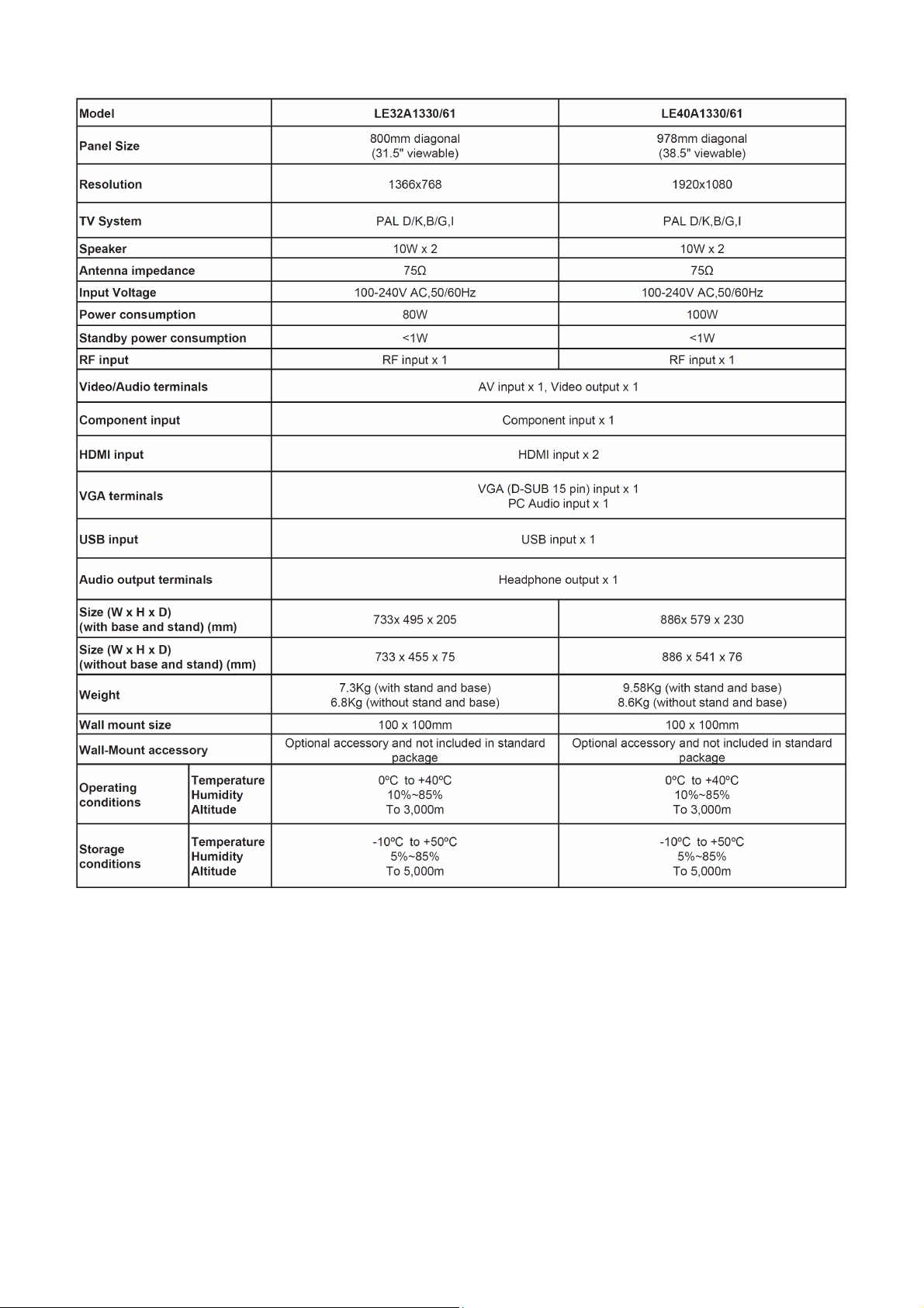
1. General Specification
Notes:
• Designs and specifications are subject to change without notice.
• This model may not be compatible with features and / or specifications that may be added in the future.
4
Page 5
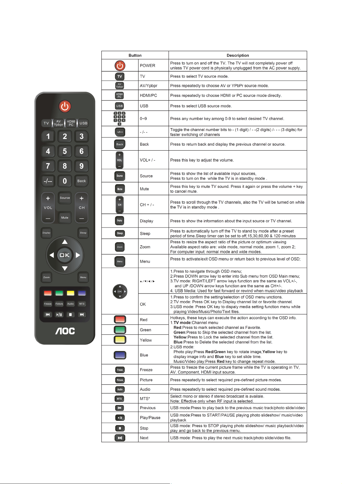
2. Operating Instructions
2.1 The Use of Remote Control
5
Page 6
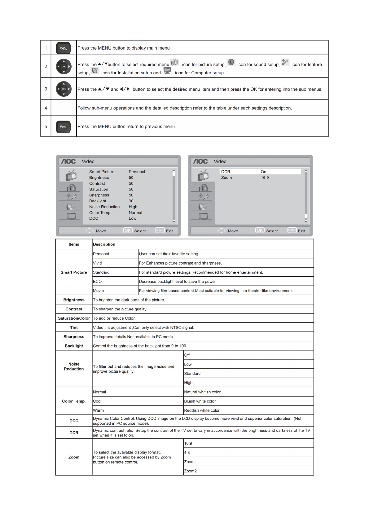
2.2 To Use the Menus
Picture Setup
Note: Certain screen setups may be unavailable or have different options in accordance with the input
sources.
6
Page 7
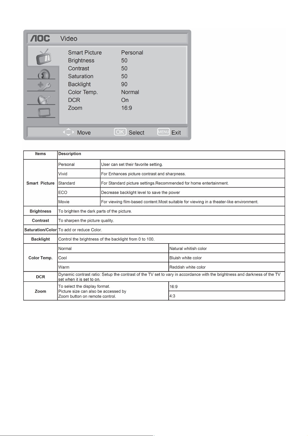
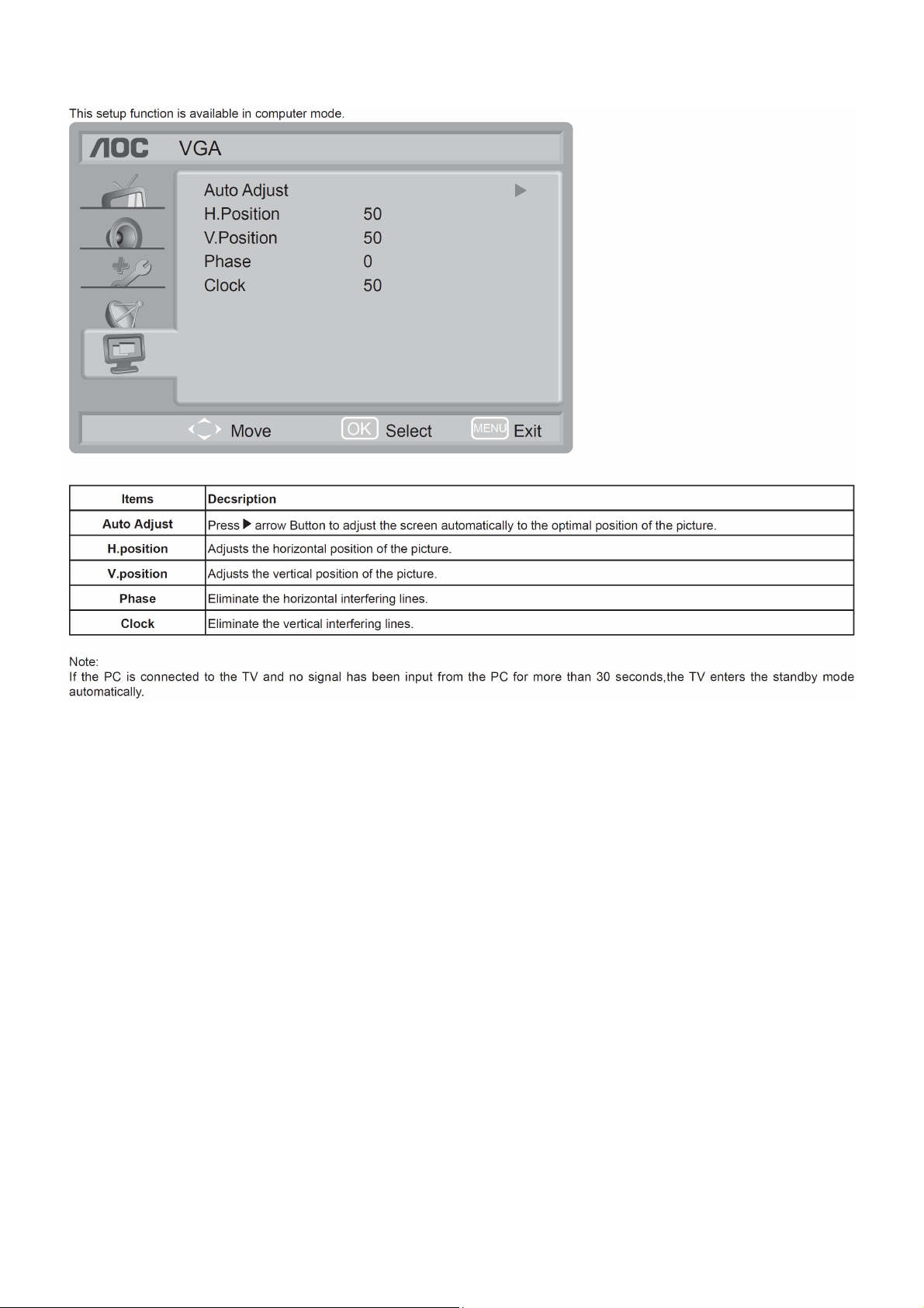
Picture Setup (For PC source only)
Note:
If the PC is connected to the TV and no signal has been input from the PC for more than 30 seconds, the TV enters
the standby mode automatically.
7
Page 8
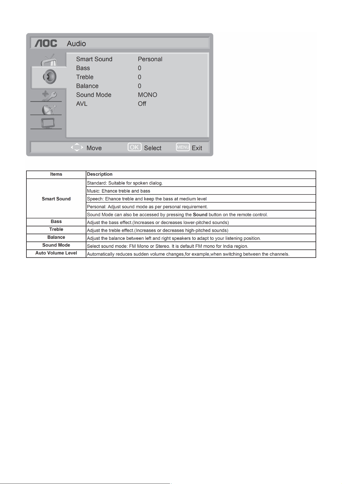
Audio Setup
8
Page 9
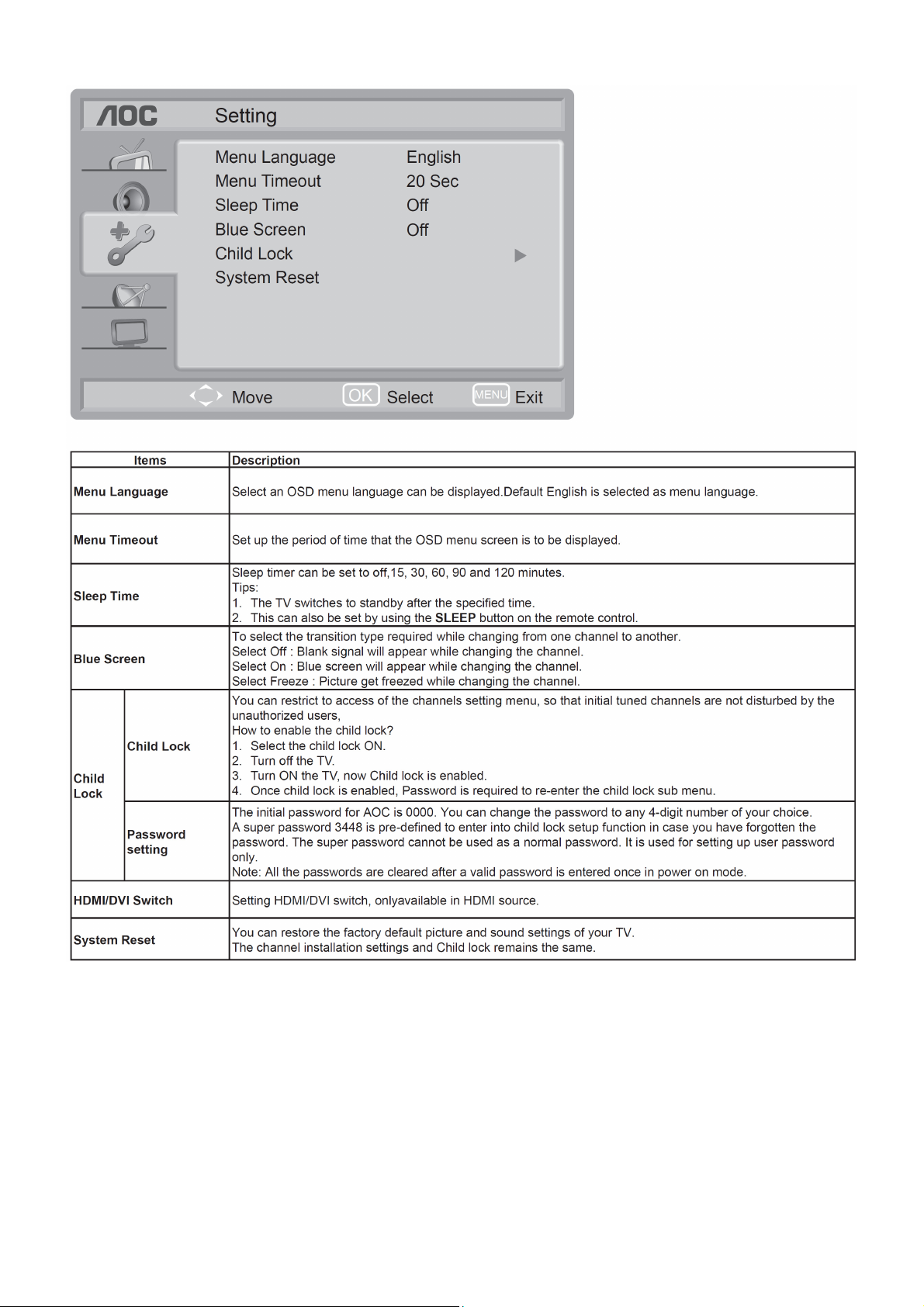
Features Setup
9
Page 10

Channel Search
This setup is available in TV mode only.
Note: Make sure you have connected RF signal cable before performing channel search.
10
Page 11
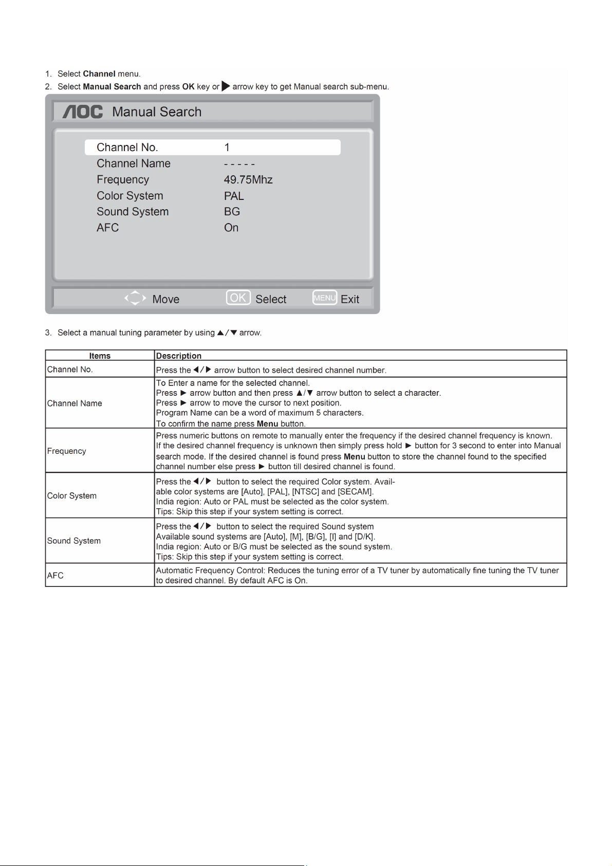
Manual search description
11
Page 12
Computer Setup
12
Page 13
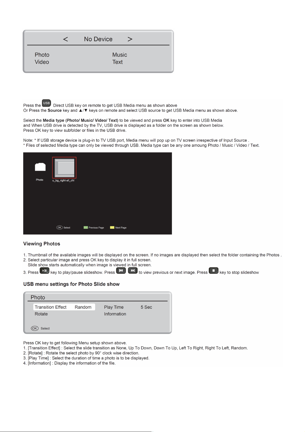
USB Media Center
TV USB port can be used to view JPEG photos, play mp3 music and Video files, and read text present in USB
devices.
Entering to USB Media:
13
Page 14
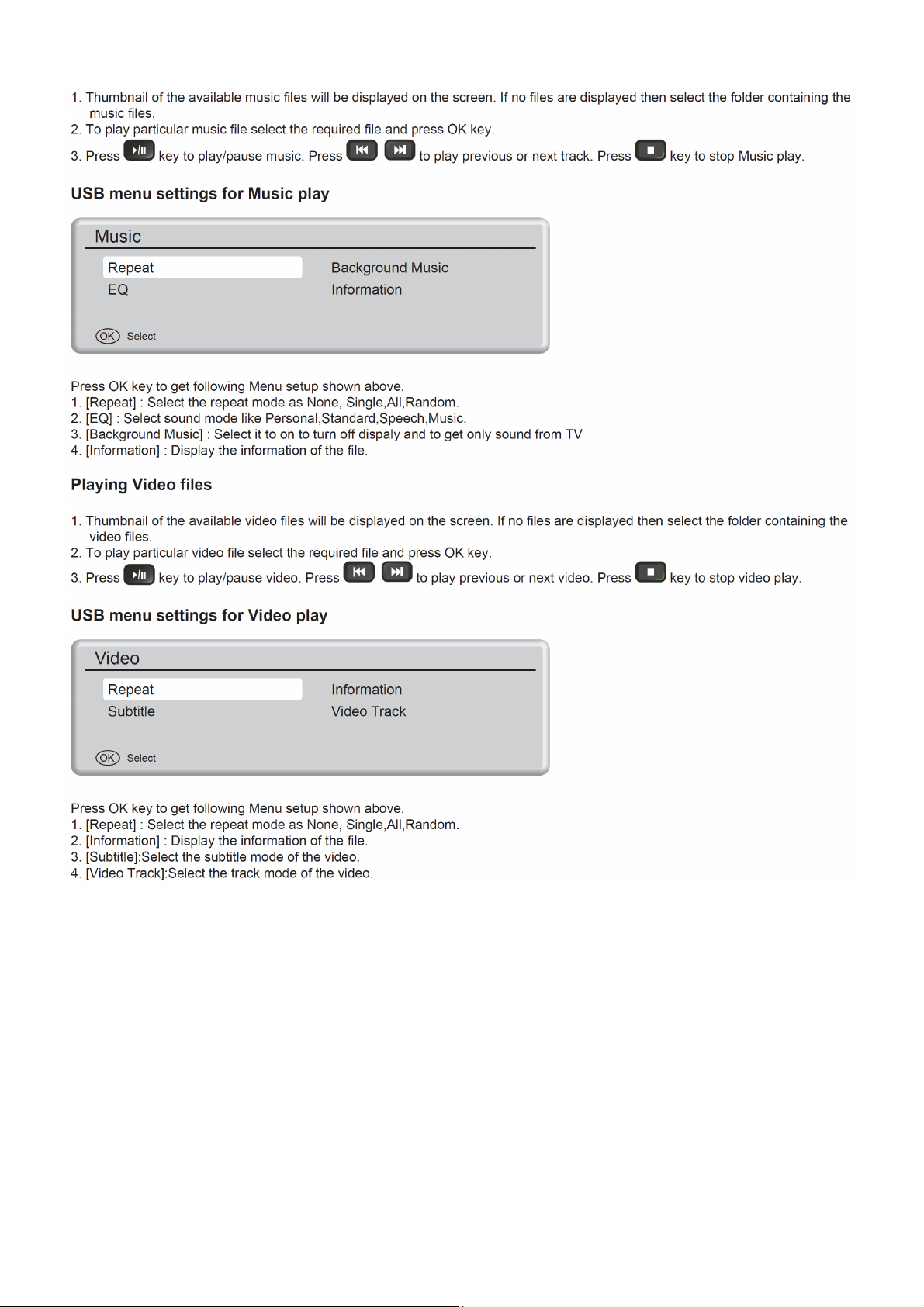
Play Music files
14
Page 15
Playing Music files
USB menu settings for Music play
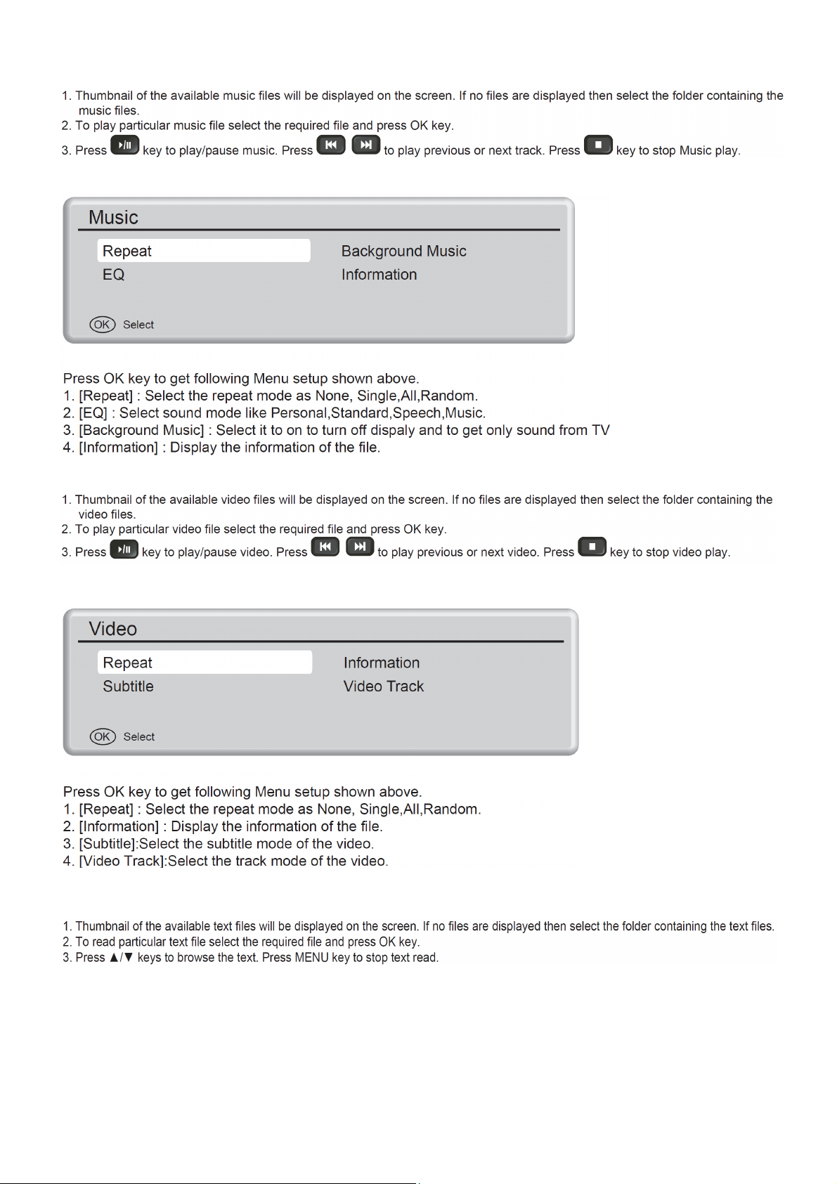
Playing Video files
USB menu setting for video play
Reading Text files
15
Page 16
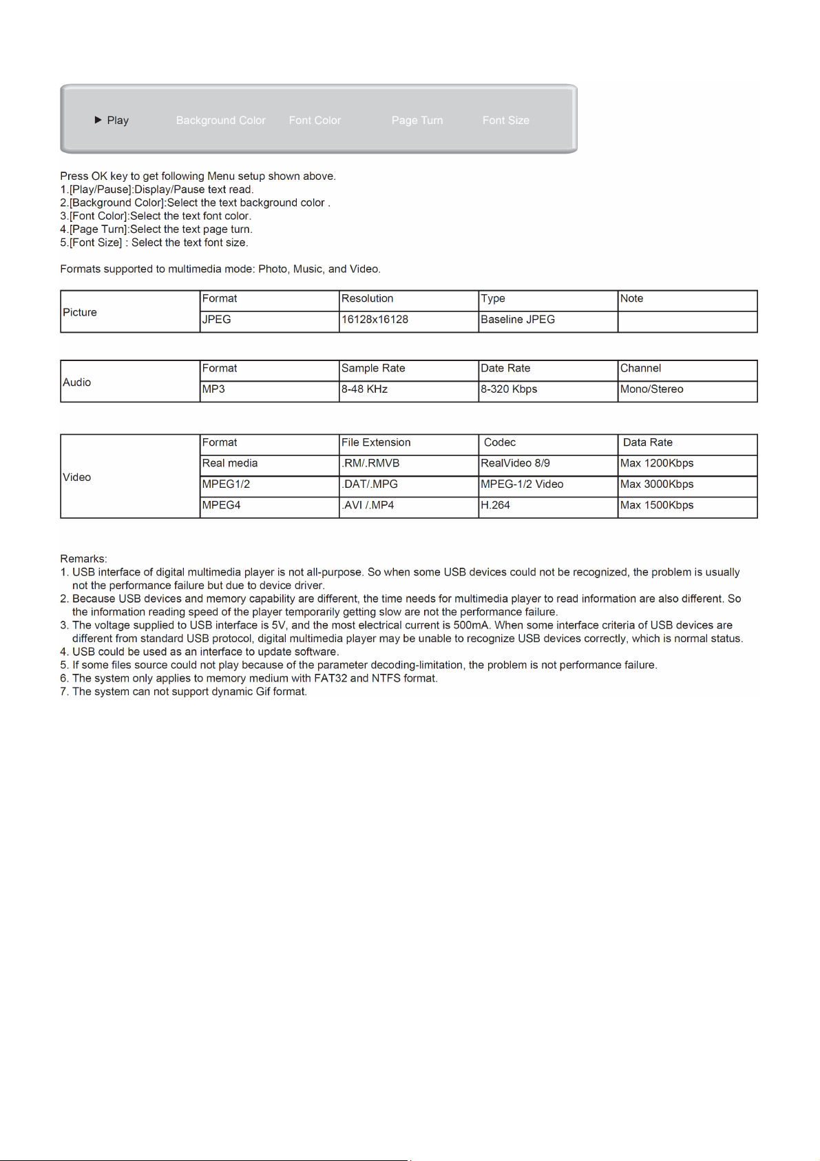
USB menu setting for text read
16
Page 17
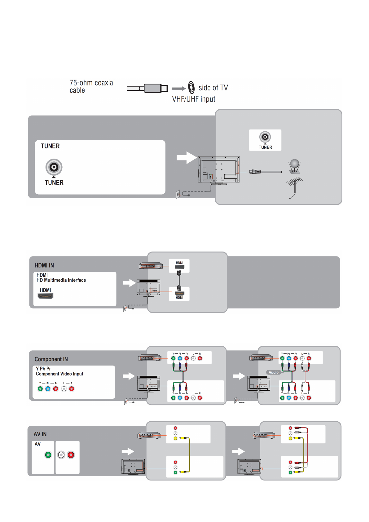
2.3 How to Connect
You can enjoy standard-definition and high-definition digital programming (if available in your area), along with
standard-definition analog programming.
It is strongly recommended that you connect the antenna/cable input using a 75-ohm coaxial cable to receive
optimum picture quality. A 300- ohm twin lead cable can be easily affected by radio frequency interference, resulting
in signal degradation.
Cable or VHF/UHF(or VHF only)
High Definition Interface
You can enjoy high-definition programming by subscribing to a high-definition cable service or a high-definition
satellite service. For the best possible picture, make sure you connect this equipment to your TV via the HDMI or
component video (with audio) input on the back of your TV.
HDMI Connection
If the equipment has a DVI jack and not an HDMI jack, connect the DVI jack to the HDMI IN (with DVI-to-HDMI cable
or adapter) jack and connect the audio jack to the PC AUDIO IN jacks.
Component Signal Connection
Composite Signal Connection
17
Page 18
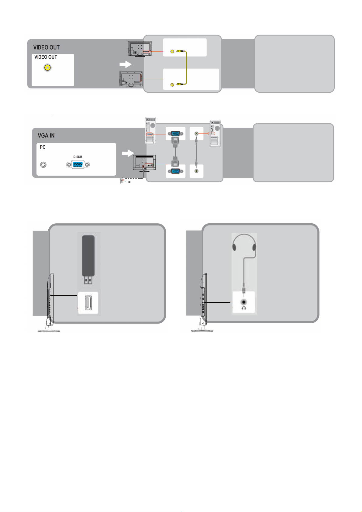
Video Out Signal Connection
PC Connection
Use the TV as a monitor for your PC shown below with the HD15 to HD15 connection. This TV can also be
connected to a PC with DVI or HDMI output.
• Connect the PC IN jack to the PC using the HD15- HD15 cable with ferrite core (analog RGB) and audio cable.
• If the PC is connected to the TV and no signal has been input from the PC for more than 30 seconds, the TV enters
the standby mode automatically.
Connecting USB drive Connecting Earphone
18
Page 19
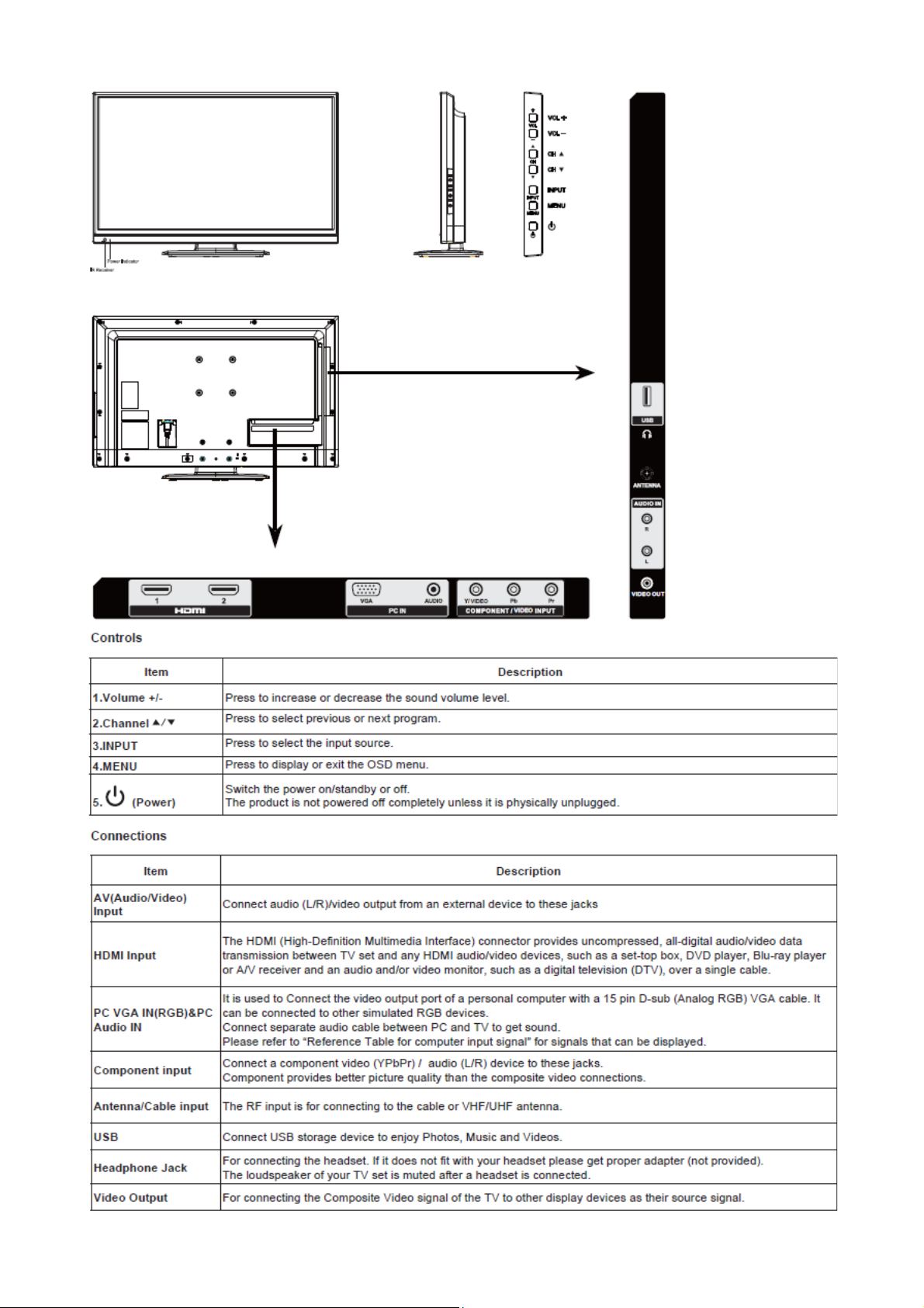
2.4 Front Panel Control Knobs
19
Page 20
3. Input / Output Specification
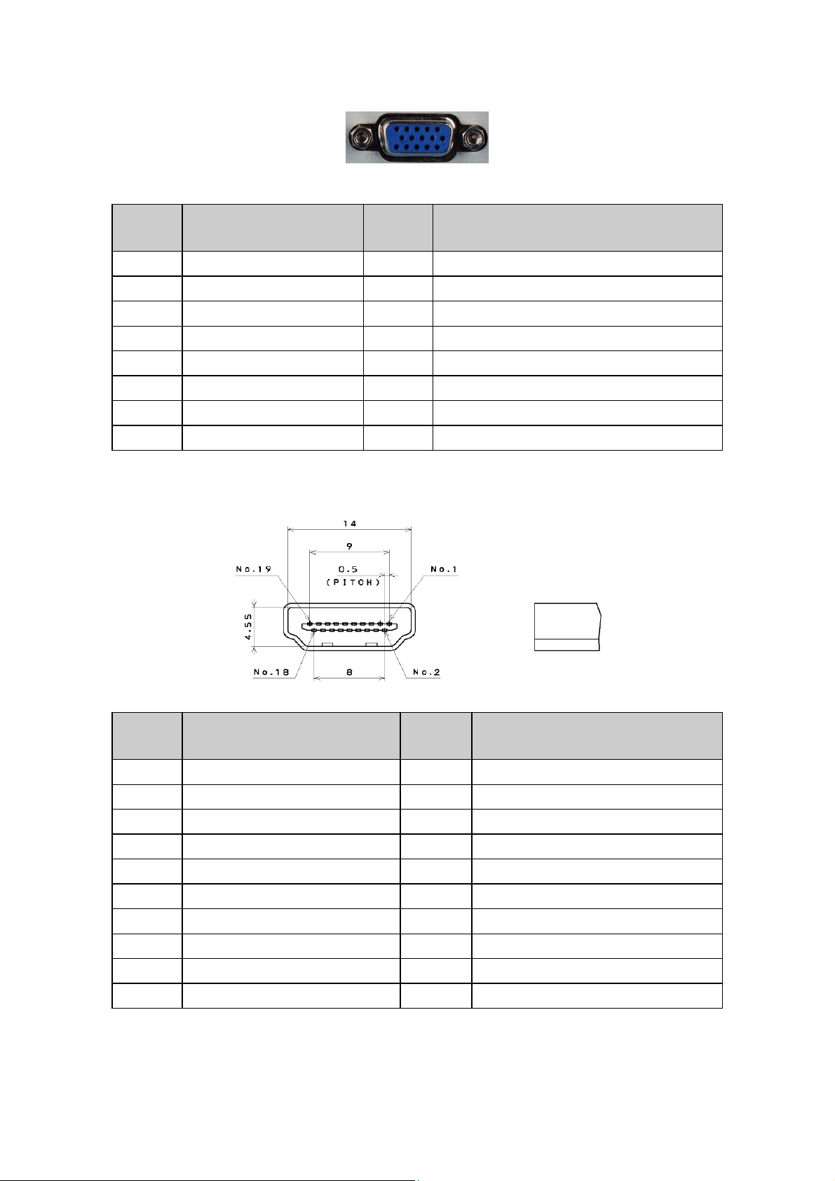
RGB Signal Input
15 - Pin Color Display Signal Cable
Pin No. Description Pin No. Description
1 Red Video 9 +5V
2 Green Video 10 Sync Ground
3 Blue Video 11 Not Used
4 Not Used 12 Serial Data for DDC
5 Ground 13 H-Sync.
6 Red Ground 14 V-Sync.
7 Green Ground 15 Serial Clock for DDC
8 Blue Ground
HDMI Digital Connector Pin Assignments
Pin No. Description Pin No. Description
1 TMDS Data2+ 2 TMDS Data2 Shield
3 TMDS Data2- 4 TMDS Data1+
5 TMDS Data1 Shield 6 TMDS Data1-
7 TMDS Data0+ 8 TMDS Data0 Shield
9 TMDS Data0- 10 TMDS Clock+
11 TMDS Clock Shield 12 TMDS Clock13 CEC 14 NC
15 SCL 16 SDA
17 DDC/CEC Ground 18 +5V Power
19 Hot Plug Detect
20
Page 21
Compatible Mode Table
LE32A1330/61
Analog RGB Input Signal Timing
Item
Resolution
1 720x400 31.5 N 70 P 28
2
3 800x600 37.9 P 60 P 40.0
4
5
HDMI Input Signal Timing
PC Timing
Item
1
2 800x600 37.9 P 60. P 40.0
3
4
Video Timing
No Mode Resolution V. Freq. (Hz) H. Freq. (KHz)
1 480i 720(1440)x480 60 35 27 4:3/16:9
2 480P 640x480 60 31.5 25 4:3
3 480p 720x480 60 31.5 27 4:3/16:9
4 576i 720(1440)x576 50 15.6 27 4:3/16:9
5 576p 720x576 50 31.3 27 4:3/16:9
6 720p 1280x720 60 45 74.2 16:9
7 720p 1280x720 50 37.5 74.3 16:9
8 1080i 1920x1080 50 28.1 74.3 16:9
9 1080i 1920x1080 60 67.4 148.4 16:9
10 1080p 1920x1080 60 67.5 148.5 16:9
11 1080p 1920x1080 50 56.3 148.5 16:9
LE40A1330/61
RGB Input Signal Timing
Dots × Lines
640 X 480 59.9 31.5 NEG NEG YES YES YES
720 X 400 69.6 31.3 NEG POS YES YES YES
800 X 600 60 37.9 POS POS YES YES YES
1024 x 768 60 48.3 NEG NEG YES YES YES
1360 X 768 60 47.7 POS POS YES YES YES
1920 X 1080 60 67.4 POS POS YES YES YES
640x480 31.5 N 60 N 25.2
1024x768 48.4 N 60 N 65.0
1360x768 47.7 P 60 p 85.8
Resolution
640x480 31.5 N 60 N 25.2
1024x768 48.4 N 60 N 65.0
1360x768 47.7 P 60 p 85.8
Vertical Horizontal Sync Polarity Presence
Frequency Frequency Horizontal Vertical Horizontal Vertical FULL
(Hz) (KHz) (16:9)
Horizontal Vertical
Nominal
Freq. (KHz)
Horizontal Vertical
Nominal
Freq. (KHz)
Sync
Polarity
Sync
Polarity
Nominal
Freq.(Hz)
Nominal
Freq.(Hz)
Sync
Polarity
Sync
Polarity
Pixel clock
(MHz)
Nominal Pixel
Clock (MHz)
Nominal Pixel
Clock (MHz)
Screen Mode
Screen
Mode
21
Page 22
4. Mechanical Instructions
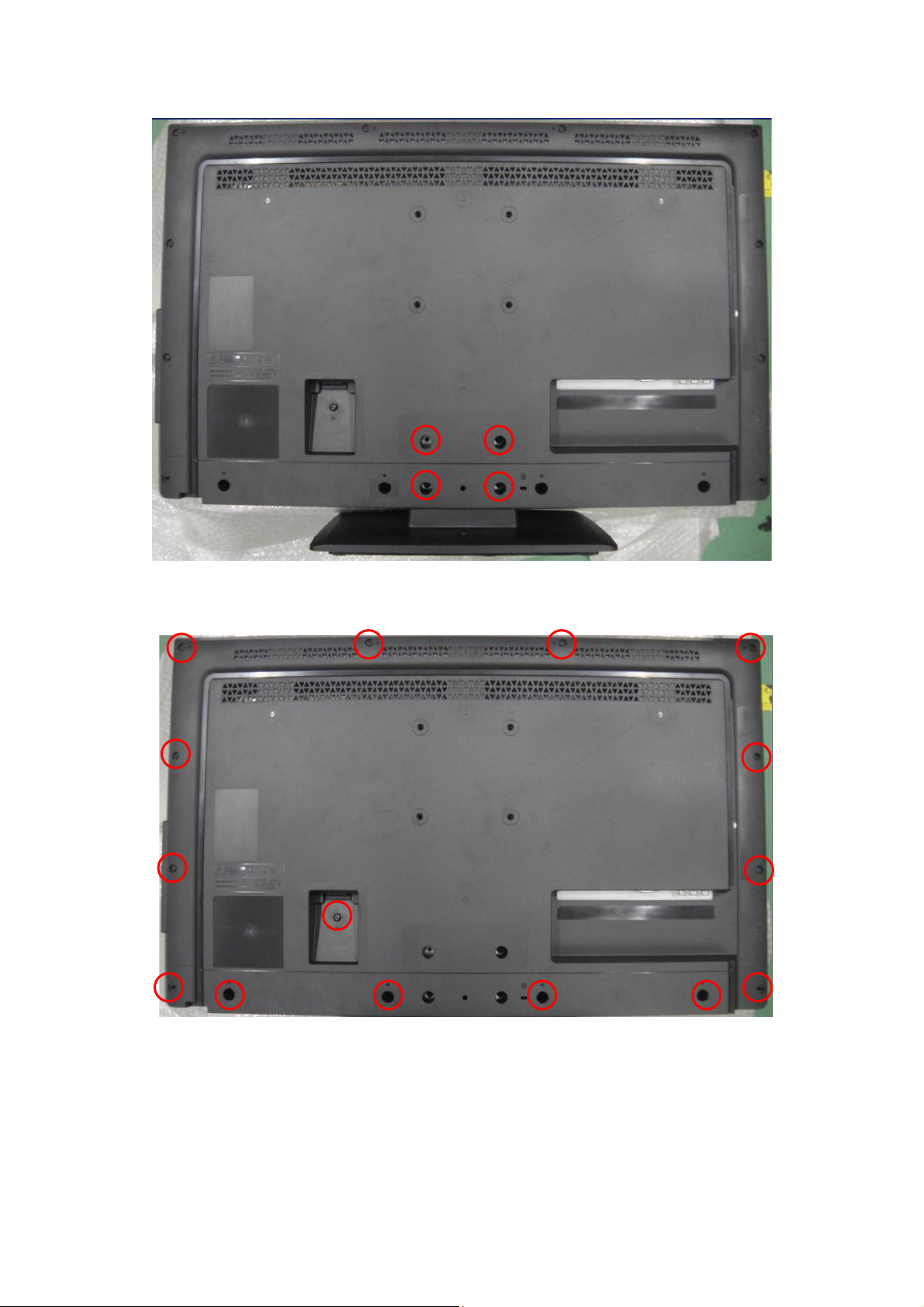
1. Remove the screws to remove BASE.
2. Remove the screws to remove REAR COVER.
22
Page 23
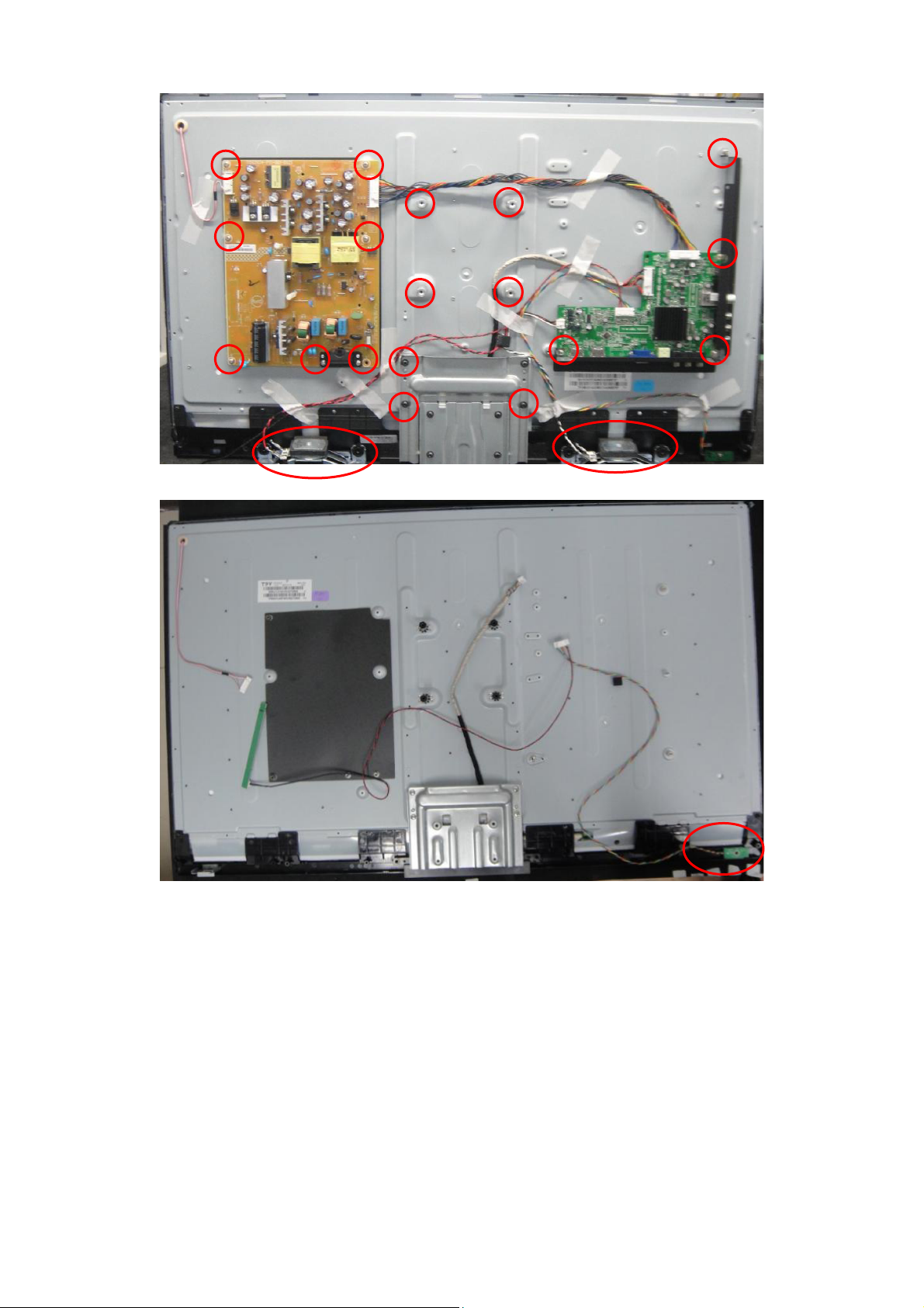
3. Remove the screws to remove SPEAKERS, MAIN BOARD and POWER BOARD.
4. Remove the IR board.
23
Page 24
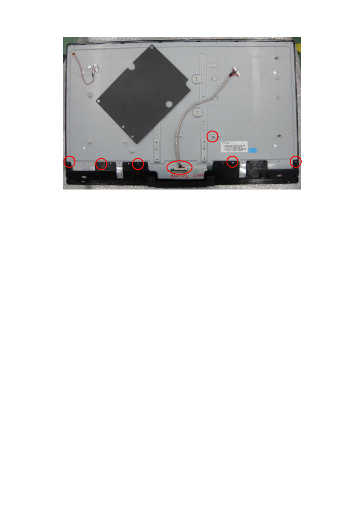
5. Remove the screws to remove the Panel.
24
Page 25
p
p
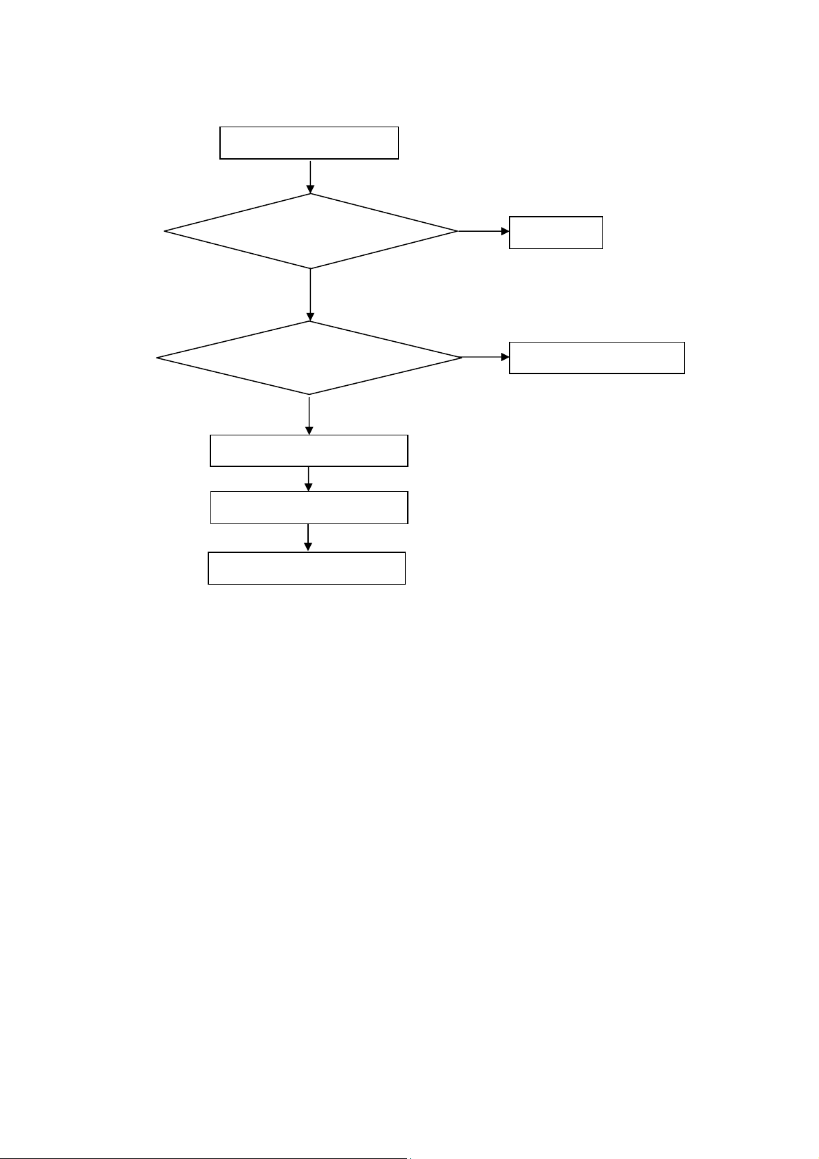
5. Repair Flow Chart
1. No power
No power (LED “Off”)
Check the AC input and
the
ower is “ON”?
Yes
Power board
out
ut=5.2V?
Yes
Check the IR board and LED
Replace the IR board
No
Replace the main board
No
Power “On”
No
Replace the power board
25
Page 26
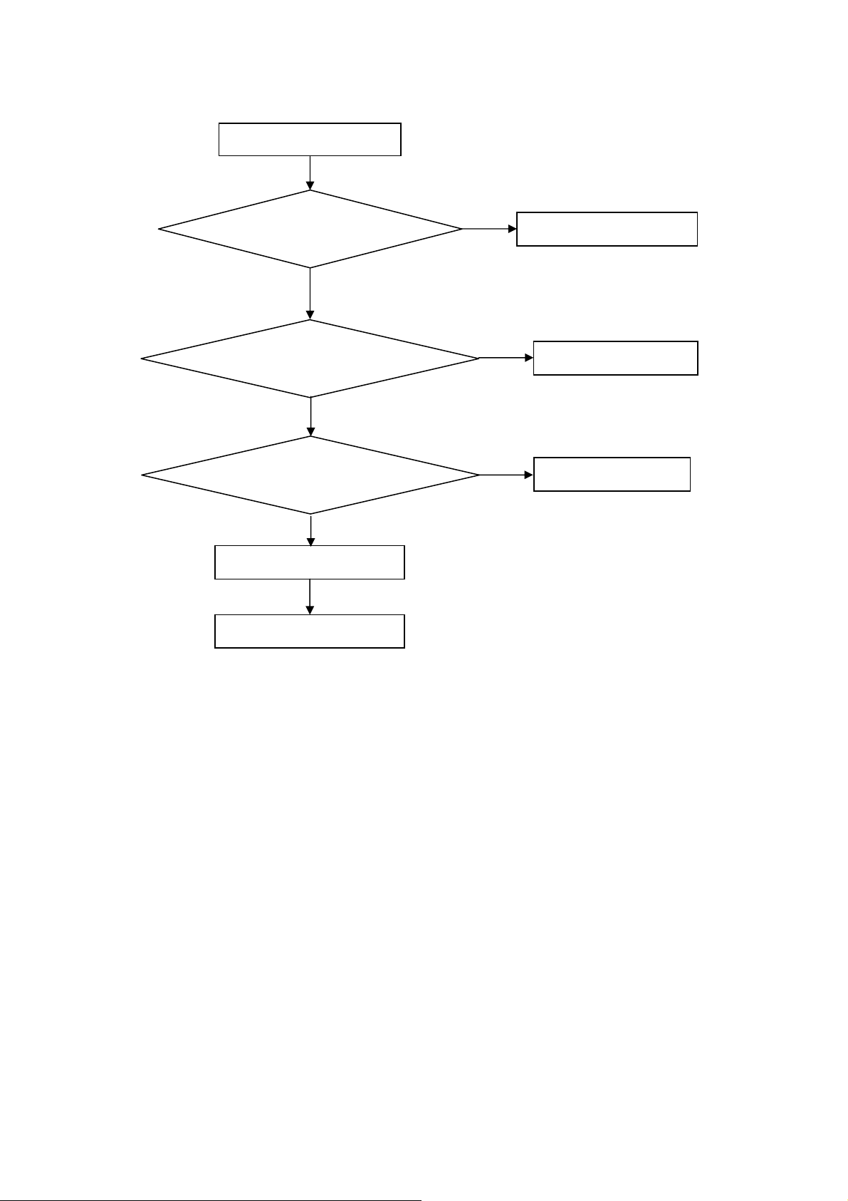
2. Can’t start
Can’t start (LED red)
Power board output=12/16V?
Yes
Check the power key is under control?
No
Check the IR receiver is normal?
No
Replace the power board
Yes
Replace the key board
Yes
Replace the IR board
No
Replace the main board
No
Replace the Power board
26
Page 27
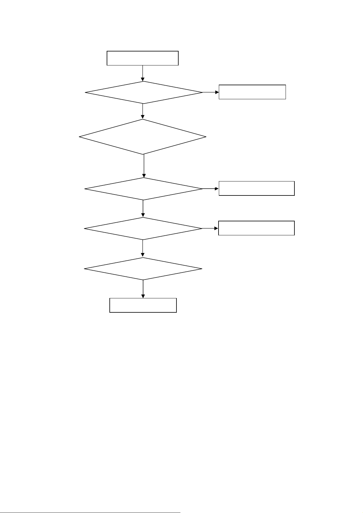
3. Abnormal display
Abnormal Display
Check the source
Yes
Enter factory mode to do
“EEPROM initial”&“Reset”
No
No
Reset the source
Check the main board
Yes
Check the LVDS cable
Yes
Check the panel
No
Replace the panel
No
Replace the main board
No
Replace the LVDS cable
27
Page 28
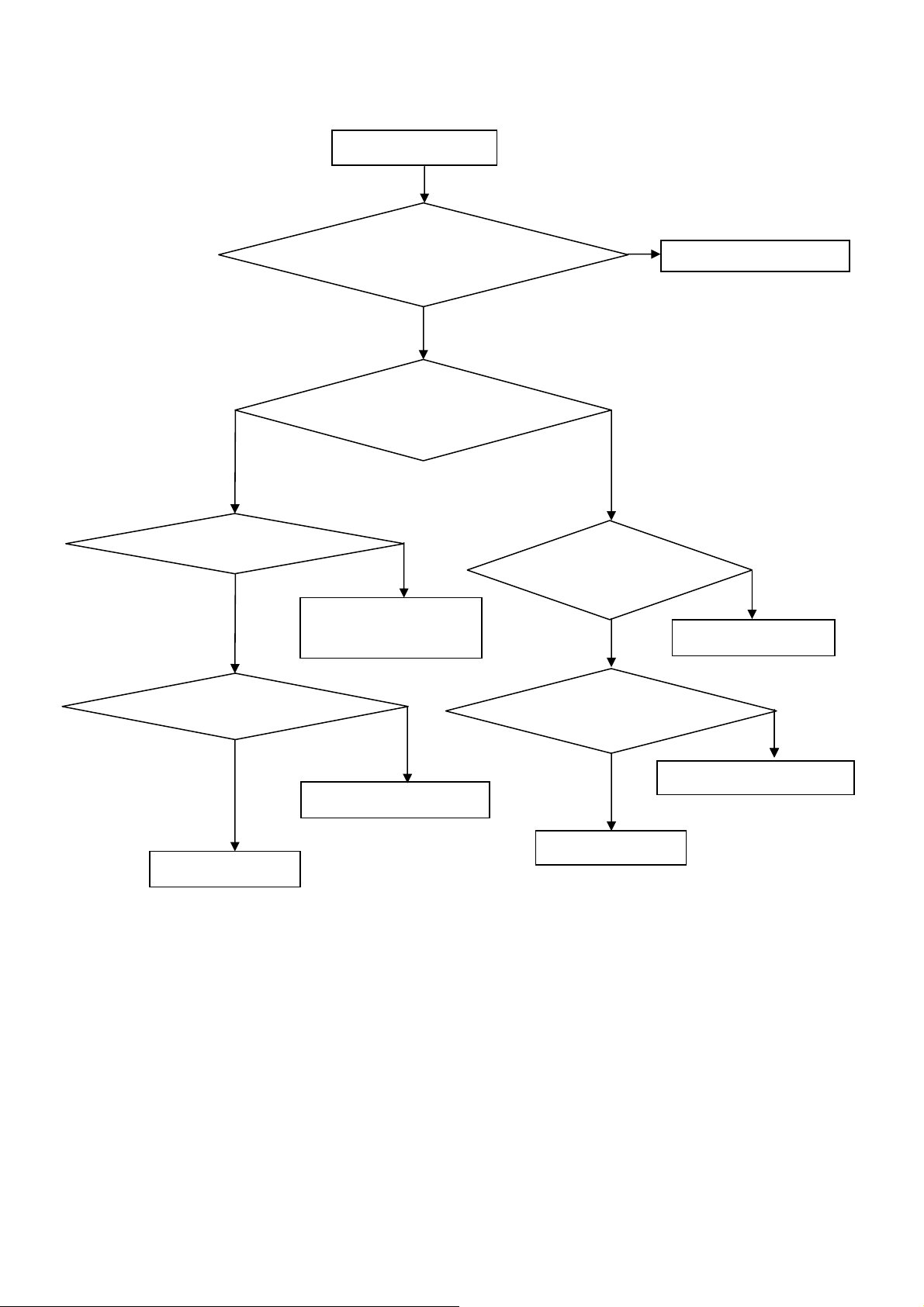
4. No display
No display (No LED)
Check TV is under control and power
on/off by remote control and power key?
Yes
Check the LVDS cable
Yes
Yes
Check the backlight is
“On”?
No
Reinsert or replace the
LVDS cable
No
No
Check the B/L
signal is available?
Yes
Replace the main board
No
Replace main board
Panel Vcc = 12V?
Yes
Replace the Panel
No
Replace the main board
Power board output=12/16V?
Yes
Replace the Panel
Replace the power board
No
28
Page 29

5. Sound problem
No sound or sound abnormal
Check the audio source connection
and the TV system are correct?
Yes
Check the TV is muted, adjust the
volume or enter the menu to reset?
No
No
Reinsert the audio cable or
change the TV system
Enter factory mode to do “Reset”
No
Check the cable between the
speakers and main board is OK?
Yes
Check the speaker resistance value is in spec
(Remark: The value is marked on the speaker)?
Yes
Replace the cable
Replace the main board
No
No
Replace the speaker
29
Page 30

6. Remote control malfunction
Remote Control malfunction
Check the remote control battery is
not properly placed or no power?
No
Use the other remote controls
No
Whether the IR board is
abnormal?
No
Replace the main board
Yes
Replace the battery
Yes
Replace the remote control
Yes
Replace the IR board
30
Page 31

7. OSD is unstable or can’t work normally
OSD is unstable or can’t work normally
Key board connected properly?
Yes
Buttons are OK?
Yes
Key board is OK?
Yes
Enter factory mode to do “Reset”
No
No
No
No
Reconnect the key board
Replace the button function
Replace the key board
Replace the main board
31
Page 32
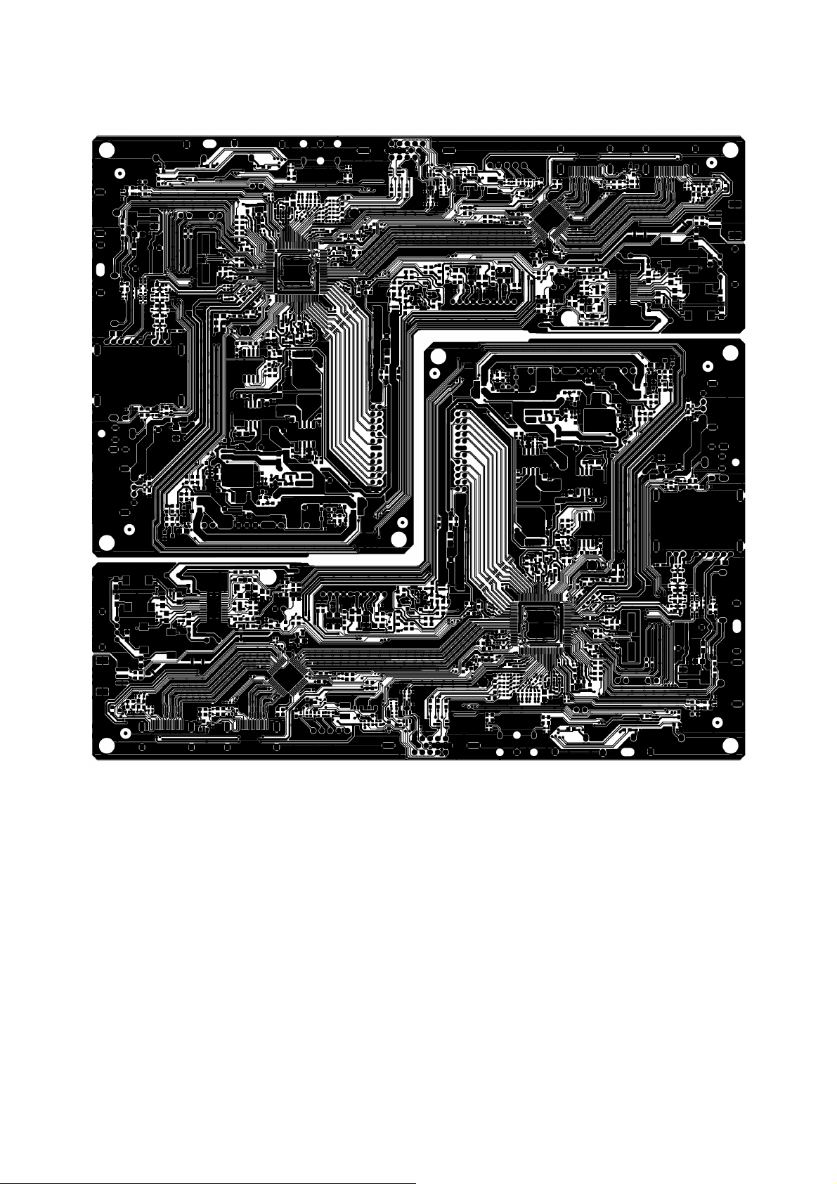
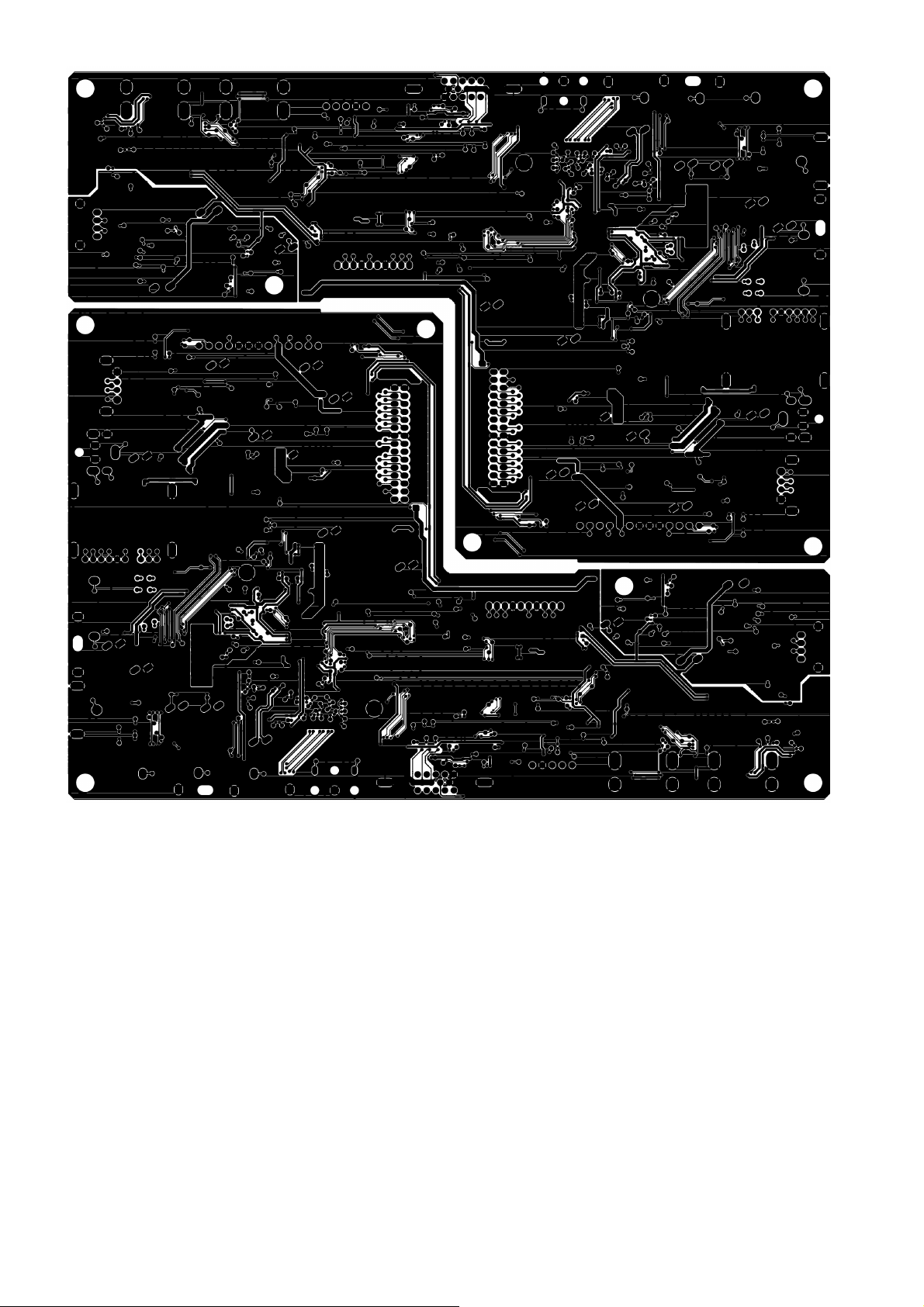
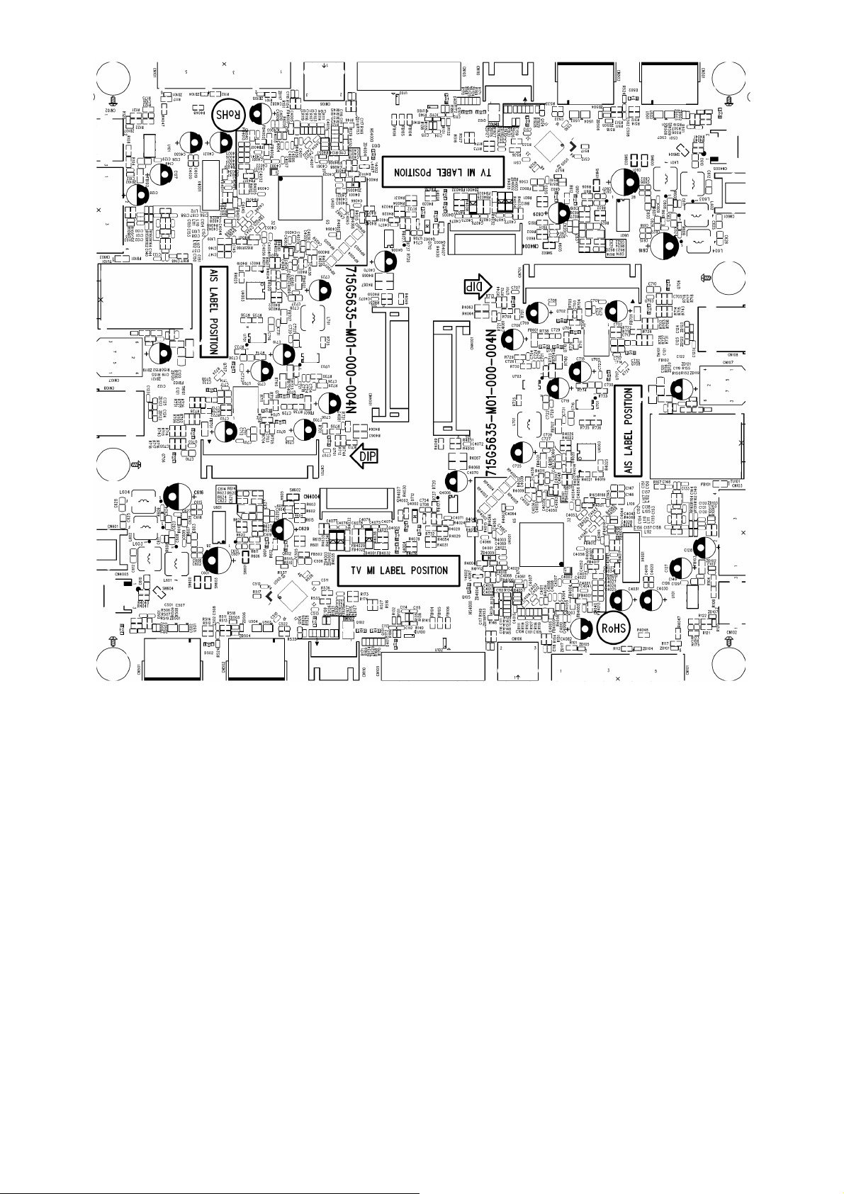
6. PCB Layout
6.1 Main Board
715G5635M01000004N
32
Page 33
33
Page 34
34
Page 35

6.2 Power Board
715G5654P01001002M
35
Page 36

36
Page 37

6.3 Key Board
715G5711K01000004X
6.4 IR Board
715G5471R02000004X
x
x
37
Page 38
7. Adjustment
(Take other model for example)
ADC Adjustment
1. Factory Mode
Turn on the TV. Press menu key and then press number key 1+9 +9+9+back. It will achieve the factory mode.
2. ADC Adjustment (It’s no need to adjust ADC.)
(1) Enter into the factory mode :(same as the above-mentioned)
(2) Select item “Source”: Ypbpr
a. Tim\pat. (COMPONENT mode: TIM = 314; PAT = 185,select item “auto color” and press ok key.
b. Tim\pat. (COMPONENT mode: TIM = 311; PAT = 185,select item “auto color” and press ok key.
(3) Select item “Source”: VGA
Tim\pat. (VGA mode: TIM = 137; PAT = 42,select item “auto color” and press ok key.
3. White Balance Adjustment
(1) Enter into the factory mode :(same as the above-mentioned).
(2) Just only adjust Ypbpr source.
a. Select item “Source”: Ypbpr and item “Color Temp”: Normal, Adjust gain of RGB to meet spec in the below
setting of Tim\pat. (COMPONENT mode: TIM = 314; PAT = 141(80IRE))
b. Select item “Source”: Ypbpr and item “Color Temp”:Warm, Adjust gain of RGB to meet spec in the below setting
of Tim\pat. (COMPONENT mode: TIM = 314; PAT = 141(80IRE))
c. Select item “Source”: Ypbpr and item “Color Temp”: Cool, Adjust gain of RGB to meet spec in the below setting
of Tim\pat. (COMPONENT mode: TIM = 314; PAT = 141(80IRE))
(3) check VGA TIM137,PAT141, AV TIM304 PAT141, HDMI TIM349 PAT141 , white balance whether or not meet
the specifications.
4.The following color specifications for reference, to RD engineering specifications.
Source VGA/YPbPr/AV/HDMI VGA/YPbPr/AV/HDMI VGA/YPbPr/AV/HDMI
Temp Normal/(8000K) Warm/(6500K) Cool/(9300K)
x (center) 0.285 0.030 0.313 0.030 0.271 0.030
y (center) 0.293 0.030 0.321 0.030 0.274 0.030
Note: 1、all models of color temperature within specification, but also ensure the brightness conform to
engineering specifications.
2、
RGB gain value cannot exceed 138,128,138
38
Page 39
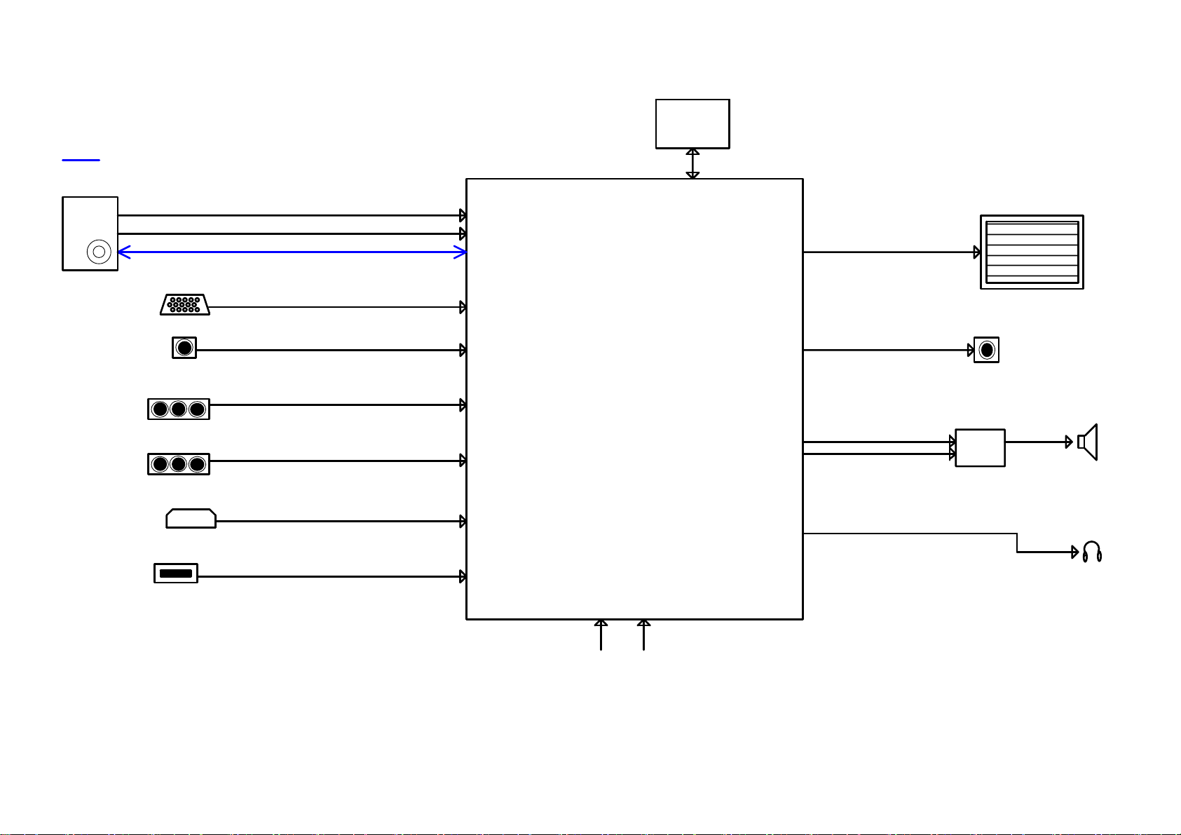
8. Block Diagram
I2C
W25Q32BVSSIG
U403
NOR FLA SH 3 2Mb
DT21 CN-2- E
TU101
D-SUB(PC IN)
PHONE JACK(PC R/L)
YPBPR
RC A(AV)
USB(Multimedia)
IF
HDMI
I2C
USB 2.0
MP3 & JPEG, SW UPDATE
IF1P
IF1N
VGA
PC AUDIO
YPbPr
CV BS
RTD2648
LVDS (50/60 Hz)
CV BS
monitor output
AOU T_L
AOU T_R
CVBS output
AUD IO AMP
AD52583
LCD PANEL T-CON
SPK X 2
SPK R/L
HEADPHONE
HP R/L
39
RCKEY
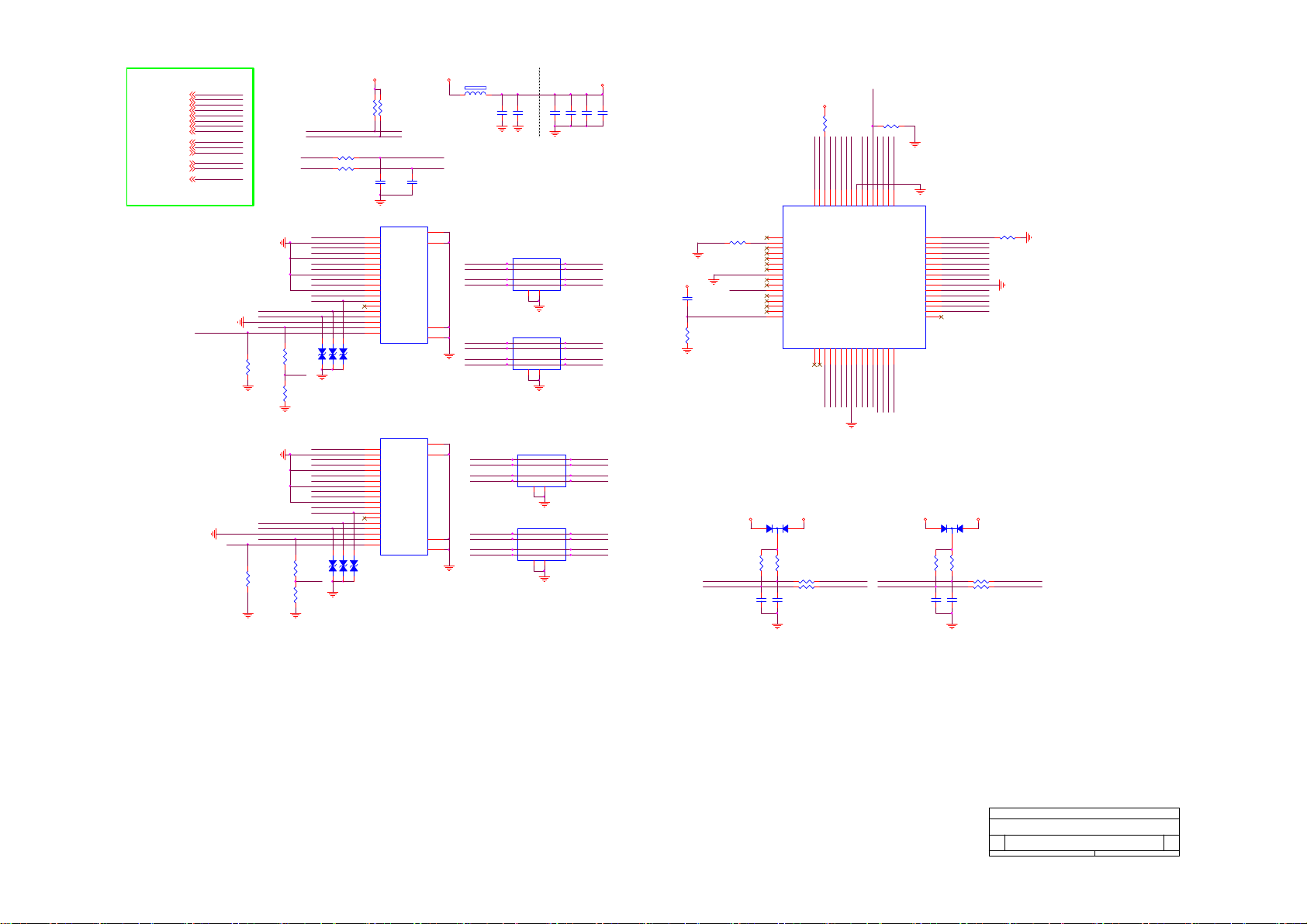
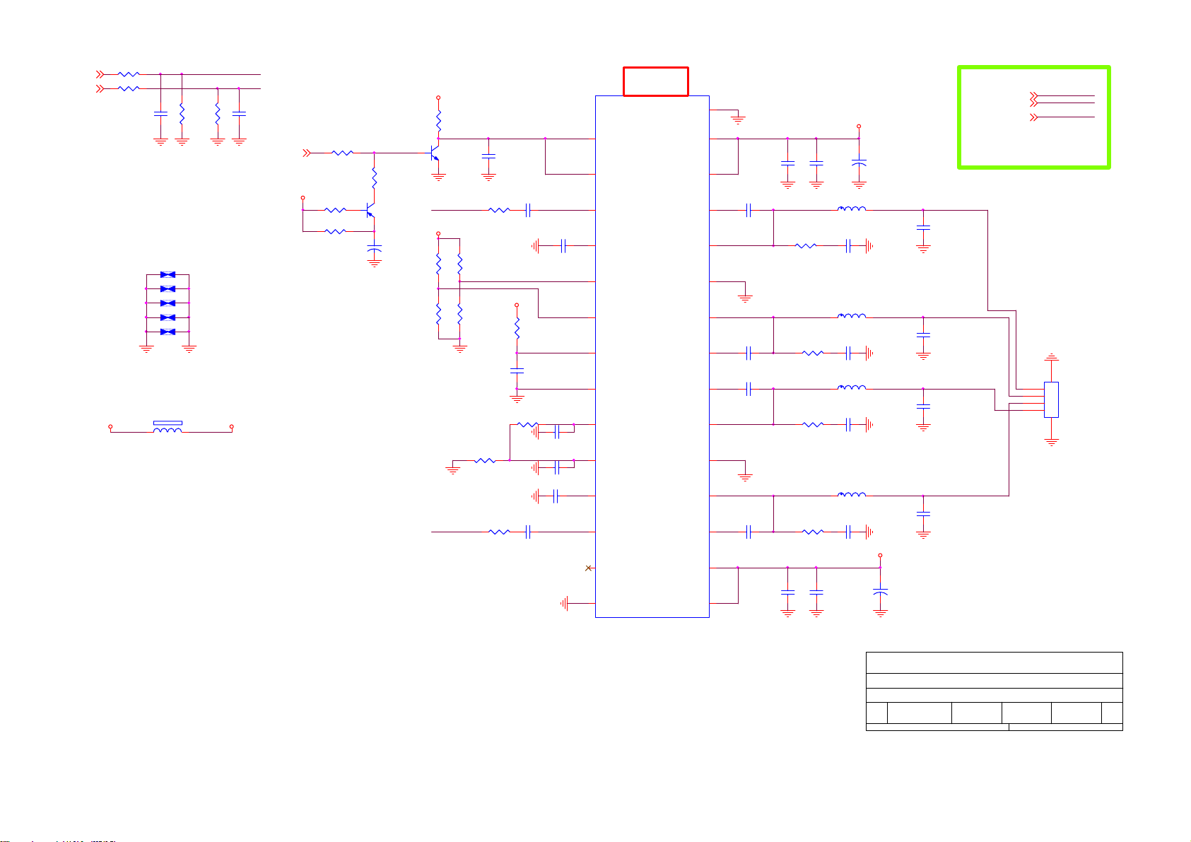
Page 40

9. Schematic Diagram
9.1 Main Board
715G5635M01000004N
CN701
1
2
3
4
5
6
7
8
DGND
9
10
11
12
13
CONN
C708
100N 16V
C715
100UF16V
C718
100N 16V
DGND
U703
1
VCC
2
REF
3
GND
C724
100N 16V
FB4EN
AT1527F11U
DGND
Vout = 0.8x(1+R1/R2)=1.0V
BL_ON1
BL_PWM
C701
+24V_AMP
100N 16V
100N 16V
D5V_STB
+
C709
100UF16V
DGND
DDR_POWER
Mac: 1.8V Pac': 2.5V
M3V3
10K 1/10W
R733
R734
+
10K 1/10W
C730
10UF 10V
DGND
DGND
Vddr=0.8*(1.5+1.2)/1.2=1.8V
R723
10 OHM 1/10W
R725
10K 1/10W
9
E-PAD
PGND
L701
8
2.2UH
VIN
7
LX
6
5
NC/1NF 50V
DGNDDGND
1
2
3
+
DGND
C707
U701
POK
VEN
VIN
VPP4NC
G9661
+
C719
100UF16V
C726
FB701
1 2
120R/6000mA
C702
100UF16V
0.5A
E-Pad
GND
ADJ
VO
C722
4U7 10V
D5V_STB
DGNDDGND
9
8
7
6
5
MMBT3904
+12V
R701
10K 1/10W
NC/0R05 OHM
Q701
R712
10K 1/10W
1.5K +-1% 1/10W
1.2KOHM 1%
DGND
FB704
120R/6000mA
1 2
C720
100N 16V
DGND
R729
100N 16V
R1
9K1 1/10W 1%
R730
24KOHM 1/10W
R2
DGND
DGND
R735
R736
C727
BL_ADJ
BL_ADJ
BL_EN
BL_EN
3/19 Realtek request
High / Low change define
change Pull high vol
+3V3
D5V_STB
R731
R702
NC/10K 1/10W
NC/1K 1/10W
Q703
0R05 OHM
NC/ MMBT3904
DGND
D5V_STB
+3V3
R715
4.7K
NC/0R05 OHM
Q706
R718
1K 1/10W
MMBT3904
BL_ADJ : MAC no 5V tolerance
DGND
R703
R706
NC/1K 1/10W
R717
BL_EN
+3V3
R743
10K 1/10W
POWER_ON_LV2
BL_ADJ
D5V_STB
C711
10UF 10V
100N 16V
G1084PT43U
DGND
Vout = 1.25x(1+Rd/Rup)=3.31V
R727
0R05 OHM
+24V_AMP
R738
33K 1/10W 5%
R739
20K
DGND
POWER_ON_LV2
Del co-layout U702
0.5A SOT-223 80C
VIN3VOUT
C712
+3V3
R726
1K 1/10W
D_5V Q709
BL_ON1
C705
100N 16V
BL_PWM
C710
NC/10K 1/10W
R716
1K 1/10W
DGND
DGND
R714
+3V3
R744
R709
10K 1/10W
POWER_ON_LV1
NC/4.7UF 10V
FB707
DDR_POWER
1 2
0R
C731
C716
100N 16V
10UF 10V
DGND
DGND
D_5V
DGND
C728
10UF 10V
100N 16V
C721
C725
220uF 16V
DGND
+
Make on board
D1V0
A1V0
A1V0
D1V0
R711
4.7K
U705
GND/ADJ
1
330 OHM +-1% 1/10W
R728
10K 1/10W
C729
100N 50V
10K 1/10W
200R 1% 1/10W
POWER_ON_LV2: High Active
Low Standby
D5V_STB
R704
C703
100N 16V
R708
47K
Q704
MMBT3904
DGND
2
R719
C713
10UF 10V
R722
DGND
+3V3
R724
47K
Q708
MMBT3904
C732
1UF16V
DGND
R740
NC/0oHM
Q710
AO3404
AO3404
Q702
LP3401LT1G
R705
NC/100K 1/10W
Del co-layout Q705
C717
10UF 10V
DGND
AO3401
Q707
100N 16V
D_5V
+
C706
NC/100UF16V
DGND
Make on board
0.5A
A3V3
+3V3
C714
100N 16V
M3V3
C723
DGND
USB_5V
100N 16V
D3V3
POWER_ON_LV1
POWER_ON_LV2
C704
BL_PWM
BL_PWM
POWER_ON_LV1
POWER_ON_LV2
40
Titl e
Power
Size Document Number Rev
<Doc> 1.0
C
Date: Sheet
of
12Saturday, J uly 28, 2012
Page 41

BL_ADJ
BL_ADJ
BL_EN
BL_EN
BL_PWM
BL_PWM
POWER_ON_LV 1
POWER_ON_LV 2
CN701
CONN
1
2
3
4
5
6
7
8
9
10
11
12
13
100N 16V
C708
DGND
C715
100UF16V
BL_ON1
BL_PWM
C701
+24V_AMP
100N 16V
100N 16V
DDR_POWER
Mac: 1.8V Pac': 2.5V
10K 1/10W
R733
R734
10K 1/10W
C730
10UF 10V
DGND
DGND
M3V3
DGND
D5V_STB
+
C709
100UF16V
+
Vddr=0.8*(1.5+1.2)/1.2=1.8V
1
2
3
+
DGND
C707
POK
VEN
VIN
VPP4NC
1 2
120R/6000mA
C702
100UF16V
0.5A
U701
E-Pad
GND
ADJ
VO
G9661
FB701
D5V_STB
MMBT3904
DGNDDGND
9
8
7
6
5
+12V
R701
10K 1/10W
Q701
NC/0R05 OHM
R712
10K 1/10W
DGND
R735
1.5K +-1% 1/10W
R736
1.2KOHM 1%
DGND
3/19 Realtek request
High / Low change define
change Pull high vol
BL_ON1
Q703
C705
NC/MMBT3904
100N 16V
BL_PWM
C710
NC/10K 1/10W
R716
1K 1/10W
DGND
DGND
R714
D5V_STB
Q706
MMBT3904
DGND
+3V3
R744
R709
10K 1/10W
POWER_ON_LV1
NC/4.7UF 10V
FB707
DDR_POWER
1 2
0R
C731
C716
100N 16V
10UF 10V
DGND
DGND
+3V3
D5V_STB
R731
R702
NC/10K 1/10W
NC/1K 1/10W
R703
0R05 OHM
DGND
+3V3
R715
4.7K
NC/0R05 OHM
R718
1K 1/10W
BL_ADJ : MAC no 5V tolerance
R706
NC/1K 1/ 10W
R717
BL_EN
+3V3
R743
10K 1/10W
BL_ADJ
POWER_ON_LV2
Del co-layout U702
D5V_STB
10UF 10V
DGND
0.5A SOT-223 80C
U705
VIN3VOUT
C711
C712
100N 16V
G1084PT43U
Vout = 1.25x(1+Rd/Rup)=3.31V
10K 1/10W
R711
4.7K
2
200R 1% 1/10W
GND/ADJ
1
330 OHM +-1% 1/10W
R704
POWER_ON_LV2: High Active
Low Standby
D5V_STB
DGND
R719
R722
100N 16V
47K
Q704
MMBT3904
DGND
C703
R708
C713
10UF 10V
Q702
LP3401LT1G
R705
NC/100K 1/10W
Del co-layout Q705
C717
10UF 10V
DGND
100N 16V
D_5V
100N 16V
+
C706
NC/100U F16V
DGND
Make on board
0.5A
A3V3
D3V3
+3V3
C714
POWER_ON_LV1
POWER_ON_LV2
C704
C724
100N 16V
C718
100N 16V
DGND
DGND
1
VCC
2
REF
3
GND
FB4EN
U703
AT1527F11U
Vout = 0.8x(1+R1/R2)=1.0V
E-PAD
PGND
VIN
LX
R723
10 OHM 1/10W
9
8
7
6
5
DGNDDGND
100UF16V
R725
10K 1/10W
L701
2.2UH
NC/1NF 50V
1UF16V
AO3404
C732
Q708
R740
NC/0oHM
+3V3
R724
47K
MMBT3904
DGND
Q710
AO3404
AO3401
Q707
M3V3
C723
100N 16V
DGND
USB_5V
Titl e
Power
Size Document Number Rev
<Doc> 1.0
C
Date: Sheet
of
12Saturday , July 28, 2012
FB704
D_5V
120R/6000m A
1 2
C727
100N 16V
DGND
C728
10UF 10V
C721
100N 16V
+
C726
4U7 10V
100N 16V
DGND
R729
R1
9K1 1/10W 1%
R730
24KOHM 1/10W
R2
DGND
C720
C722
C719
C725
220uF 16V
DGND
+
Make on board
A1V0
D1V0
A1V0
D1V0
POWER_ON_LV2
0R05 OHM
+24V_AMP
R727
R738
33K 1/10W 5%
R739
20K
DGND
+3V3
R726
1K 1/10W
R728
10K 1/10W
D_5V Q70 9
C729
100N 50V
41
Page 42

Add R4054 for panel enable default
status on 2/17'12
+12V
D5V_STB
R713
360R 1/10W 5%
R737
220 OHM 1/10W
RP400222 OHM
1
2
3
4
1
2
3
4
1
2
3
4
1
2
3
4
1
2
3
4
RP4004
RP4005
22 OHM
RP4001
22 OHM
22 OHM
8
TEAN_1
7
TEAP_1
6
TEBN_1
5
TEBP_1
RP400322 OHM
8
TECN_1
7
TEC P_1
6
TEDN_1
5
TED P_1
8
TOAN _1
7
TOAP_1
6
TOBN _1
5
TOBP_1
8
TOC N_1
7
TOC P_1
6
TOC LKN _1
5
TOCLKP_1
8
TOD N_1
7
TOD P_1
6
5
TEAN
TEAP
TEBN
TEBP
TEC N
TEC P
TED N
TED P
TOAN
TOAP
TOBN
TOBP
TOC N
TOC P
TOC LKN
TOC LKP
TOD N
TOD P
R4054
R4029
PANEL_EN
R721
NC/ 360R 1/ 10W 5%
R720
390 OHM 1/10W
R732
220 OHM 1/10W
NC/0R05 OHM
M3V3
3
C754
100N 50V
DGND
R4049
BL_PWM
TEAP_1
TEBP_1
TEC P_1
TOCLKP_1
TED P_1
TOAP_1
TOBP_1
TOC P_1
TOCLKP_1
TOD P_1
D5V_STB
NC/ 100N 16V
4.7K
NC/100 OHM
R4031
4.7K
U708
AZ809ANSTR-E1
RESET
Vcc
GND
PANEL_VCC
DGND
+12V
C4081
M3V3
R4027
4.7K
R4030
4.7K
Q4003
PMBS3904
DGND
D712
RB501V-40
2
1
CONN
30
28
26
24
22
20
18
16
14
12
10
8
6
4
2
LVDS(10-bit)
R4063
0oHM
R4064
NC/0oHM
DGND
10K 1/10W
12
29
27
25
23
21
19
17
15
13
11
9
7
5
3
1
CN4001
R4023
220N 16V
R4028
Q4002
PMBS3904
DGND
SELLVDS
TEAN_1
TEBN_1
TEC N_1
TOC LKN _1
TED N_1
TOAN _1
TOBN _1
TOC N_1
TOC LKN _1
TOD N_1
DGND
47K
C4071
+3V3
NC/4.7K
R4051
NC/4.7K
DGND
R4050
Del co-layout Q4001
AO4449 -7A/-30V
Q4006
1
S
D
2
S
D
3
S
D
4
G
D
C4070
NC/ 100UF16V
R4024
NC
42
From Main Chip
DGND
TED P
TED N
TEC P
TEC N
TEBP
TEBN
TEAP
TEAN
TOD P
TOD N
TOC LKP
TOC LKN
TOC P
TOC N
TOBP
TOBN
TOAP
TOAN
PANEL_EN
BL_PWM
SPI_DI
SPI_DO
SPI_SCLK
SPI_CS#
SPI_WP
23Wednesday , July 04, 2012
of
TED P
DGND
SPI_SCLK
SPI_DO
TED N
TEC P
TEC N
TEBP
TEBN
TEAP
TEAN
TOD P
TOD N
TOC LKP
TOC LKN
TOC P
TOC N
TOBP
TOBN
TOAP
TOAN
PANEL_EN
BL_PWM
SPI_DI
SPI_DO
SPI_SCLK
SPI_CS#
SPI_WP
C4080
10UF 10V
8
PANEL_VCC
7
6
5
R4067
+
100N 16V
C4072
NC/ 680R
DGND
4.7K
NC/ 0R05 OHM
R4068
NC/ 680R
M3V3
R4019
SPI_DI
R4025
DGND
For Rtice Check
22R 1/10W 5%
SPI_CS#
R4021
SPI_DI 0 SPI_HOLD
SPI_WP SPI_SCLK0
DGND
U4003
1
/CS
2
DO
3
/WP
4
GND
W25Q64FVSSI G
RM4 CM2 close to IC
Del co-layout U4004
3/19 Realtek request
Add 10uF Cap
M3V3
C4069
R4020
100N 16V
8
VCC
7
/HOLD
6
CLK
5
DI
Tit le
Size Document Number Rev
B
Date: Sheet
4.7K
DGND
22R 1/10W 5%
R4022
SPI_DO0
R4026
22R 1/10W 5%
C4073
5PF 50V
LVDS
<Doc > 1.0
Page 43

AV share with YPbPr
CN101
RCA JACK
YPbPr/AV Video in
2
A
1
4
B
3
6
C
5
AGND
ZD101
MLVG0402
12
12
MLVG0402
AGND
ZD104
12
ZD105
MLVG0402
Y1
PB1
PR1
AGND
AGND
AGND
R101
75 OHM
R112
75 OHM
R117
75 OHM
R103
C101
5PF 50V
C104
5PF 50V
C105
5PF 50V
100OHM1/16W
R107
100OHM1/16W
R111
100OHM1/16W
R114
100OHM1/16W
R116
100OHM1/16W
R119
100OHM1/16W
Close to Main Chip
Y0+Y1
YPbPr0-
PB0+PB1
YPbPr0-
PR0+PR1
YPbPr0-
AV INPUT & Video output
ZD107
MLVG0402
AGND
CN102
CONN
CN103
A
B
RCA JACK
3
2
1
2
1
4
3
MLVG0402
AGND
1 2
ZD102
R120
NC/75R
12
MLVG0402
0R05 1/10W
AGND
R175
12
ZD103
AGNDAGND AGND AGNDAGND
R122 75 OHM
R121
NC/ 0R05 1/ 10W
C106
NC
R104
6.8kOHM + -5% 1/10W
R105
6.8kOHM + -5% 1/10W
C103
C102
470pF 50V
470pF 50V
CVBS_OUT
AV1_CVBS+
R123
NC/10K 1/10W 5%
VIN_A0-
YPBPR 1_IN_L
YPBPR 1_IN_R
R108
10K 1/10W
R109
10K 1/10W
To Chip
PB0+
YPbPr0Y0+
PR0+
YPBPR1_IN_L
YPBPR1_IN_R
AV1_CVBS+
VIN_A0-
AV Output
CVBS_OUT
PB0+
YPbPr0Y0+
PR0+
YPBPR 1_IN_L
YPBPR 1_IN_R
AV1_CVBS+
VIN_A0-
CVBS_OUT
43
Tit le
YPbPr
Size Document Number Rev
<Doc > 1.0
B
Date: Sheet
of
14Thursday , May 10, 2012
Page 44

VGA_DDC_SCL
VGA_VS
VGA_HS
VGA_DDC_SDA
AGND
CONN
CN106
HS
VS
1
2
3
AGND
D_5V
BAT54C
R131
10K+- 5%1/16W
C112
NC/33P 50V
U100
1
I/O1
I/O4
2
GND
VDD
I/O23I/O3
AOZ8105C I
ZD117
MLVG0402
VGA_CON5V
1
2
D401
3
VGA_5V
R132
10K+- 5%1/16W
C114
C113
NC/33P 50V
22PF 50V
AGND AGND AGN D
For Lesson learn check list, change R140/R141
from 2k to 2.2k on 2/14
6
VGA_SDA
5
VGA_5V
4
VGA_SCL
12
12
ZD118
MLVG0402
AGND
R172 100OHM1/16W
R135 100OHM1/16W
R138 100OHM1/16W
C115
10PF 50V
C117
C118
470pF 50V
2.2K 1/16W
AGND
PC_LINE_IN
R149
6.8kOHM +- 5% 1/10W
R151
6.8kOHM +- 5% 1/10W
470pF 50V
AGND
Mark on board
D-sub
CONN
VGA_SCL
VS
HS
VGA_RX0
U102
1
I/O1
2
GND
I/O23I/O3
AOZ8105C I
R169
100OHM1/16W
I/O4
VDD
VGA_IN_R
VGA_IN_L
R154
10K 1/10W
VGA_SDA
6
5
4
12
ZD124
MLVG0402
AGND
VGA_BIN
VGA_5V
VGA_GIN
R186 100OHM1/16W
R140
R141
2.2K 1/16W
AGNDAGND AGND
VGA_RIN
R153
10K 1/10W
AGNDAGND AGN D
From Main Chip
DGND
VGA_B+
VGA_BVGA_G+
VGA_R+
VGA_HS
VGA_VS
VGA_DDC_SCL
VGA_DDC_SDA
VGA_IN _L
VGA_IN _R
HP_OUT_L
HP_OUT_R
HP_OUT_JD
USB1_DM
USB1_DP
TX0
RX0
VGA_TX0
VGA_RX0
USB_Shield_GN D
USB CONN
1
1234
2
3
4
6 5
USB_Shield_GN D
CN108
DGND
12
ZD122
MLVG0402
C122
+
100UF16V
VGA_B+
VGA_BVGA_G+
VGA_R+
VGA_HS
VGA_VS
VGA_DDC_SCL
VGA_DDC_SDA
VGA_IN _L
VGA_IN _R
HP_OUT_L
HP_OUT_R
HP_OUT_JD
USB1_DM
USB1_DP
TX0
RX0
VGA_TX0
VGA_RX0
C123
100N 16V
12
ZD123
MLVG0402
AGND
5
10
4
9
3
8
2
7
1
6
VGA_CON5V
VGA_BIN-
VGA_GIN -
VGA_RIN-
12
ZD125
MLVG0402
R168 100OHM1/16W
AGND
R170
4.7K 1/16W
VGA_TX0
VGA_RX0
AGND
VGA_BIN
VGA_GIN
VGA_RIN
D5V_STB
VGA_TX0
R171
4.7K 1/1 6W
2N7002
+3V3
+3V3
Q102
Q101
2N7002
TX0
RX0
AGND
15
14
13
12
11
17 16
CN105
1 2
FB104 60R 0. 6A
VGA_BIN -
1 2
FB105 60R 0. 6A
VGA_GIN-
1 2
FB106 60R 0. 6A
VGA_RIN-
C110
R130
75 OHM
5PF 50V
C111
R139
75 OHM
5PF 50V
C116
R146
75 OHM
5PF 50V
Close to Main Chip
USB_5V
1 2
TH1 01
C121
NC/ 22uF 10V
USB1_DM
USB1_DP
NC/4P7 50V
VGA_B+VGA_BIN
R129
100OHM1/16W
VGA_B-
R134
100OHM1/16W
VGA_G+VGA_GIN
R137
100OHM1/16W
VGA_B-
R143
100OHM1/16W
VGA_R+VGA_RIN
R145
100OHM1/16W
VGA_B-
R148
100OHM1/16W
t
1 2
C124
FB102
220R/2000mA
C125
NC/4P7 50V
CN107
CONN
1
7
6
2
3
4
5
Mark on board
HP OUT
AGND
R152
AGND
NC/10K 1/10W
+3V3
AGND
R150
10K 1/10W
ZD119
MLVG0402
1.65V: jack not plug in
0V: jack plug in
12
12
ZD120
ZD121
MLVG0402
12
MLVG0402
AGNDAGNDAGND
R155
1K 1/10W
AGND AGNDAGND
R156
1K 1/10W
C120
C119
NC/100N 16V
NC/ 100N 16V
AGND
HP_OUT_JD
HP_OUT_L
HP_OUT_R
Exchange L/R of headphone on 2/20'12
44
DGND
USB_Shield_GND
DGND DGND
Titl e
VGA
Size Document Number Rev
<Doc > 1 .0
B
Date: Sheet
DGNDDGND
of
24Wednesda y , June 27 , 2012
Page 45
SHLD0
SHLD2
SHLD3
SHLD1
SHLD0
SHLD2
SHLD3
SHLD1
HDMI_SCL
HDMI_SDA
C524
NC/12pF 50V
20
22
23
21
20
22
23
21
M3V3
DGND
DGND
FB502
1 2
120R
10UF 10V
HDMI0_D2+
HDMI0_D2-
HDMI0_D1+
HDMI0_D1-
HDMI0_D0+
HDMI0_D0-
HDMI0_CLK+
HDMI0_CLK-
HDMI1_D2+
HDMI1_D2-
HDMI1_D1+
HDMI1_D1-
HDMI1_D0+
HDMI1_D0-
HDMI1_CLK+
HDMI1_CLK-
C506
C505
100N 16V
DGND
DGND
NC/R Clamp0524P. TCT
1
IN1
2
IN2
4
IN3
IN45OUT4
NC/RClamp0524P.TCT
1
IN1
2
IN2
4
IN3
IN45OUT4
1
IN1
2
IN2
4
IN3
IN45OUT4
NC/R Clamp0524P. TCT
1
IN1
2
IN2
4
IN3
IN45OUT4
DV33_TMDS
C513
100N 16V
DGND
U501
OUT1
OUT2
OUT3
GND
GND
3
8
DGND
U502
OUT1
OUT2
OUT3
GND
GND
3
8
DGND
U503
NC/R Clamp0524P. TCT
OUT1
OUT2
OUT3
GND
GND
3
8
DGND
U504
OUT1
OUT2
OUT3
GND
GND
3
8
DGND
C511
100N 16V
10
HDMI0_D2+
9
HDMI0_D2-
7
HDMI0_D1+
6
HDMI0_D1-
10
HDMI0_D0+
9
HDMI0_D0-
7
HDMI0_CLK+
6
HDMI0_CLK-
10
9
7
6
10
9
7
6
DV33_TMDS
C510
100N 16V
HDMI1_D2+
HDMI1_D2-
HDMI1_D1+
HDMI1_D1-
HDMI1_D0+
HDMI1_D0-
HDMI1_CLK+
HDMI1_CLK-
C512
100N 16V
DGND
DV33_TMDS
R535
82K 1/10W
DGND
DGND
C522
1uF 16V
HDMI0_DDC_SDA
R533
499 +-1% 1/10W
DV33_TMDS
HDMI0_CON5V
NC/33 P 50V
RESET
C501
R506
4.7K
32
31
30
29
28
27
26
25
24
23
22
21
20
19
18
17
D501
132
R507
4.7K
C507
NC/33P 50V
DGND
U505
NC
REXT
ARX2P
ARX2M
NC
ARX1P
ARX1M
VSS
ARX0P
ARX0M
VCC
ARXCP
ARXCM
ASCL
ASDA
RESET
D5V_STB
BAT54C
R508
100 OHM
R509
100 OHM
DV33_TMDS
R536NC/22K OHM 1/10W
HDMI_SDA
HDMI_SCL
HDMI_D2-
HDMI_D2+
36
34
37
35
33
TX2P
PCSCL
PCSDA
PCADR0
IT6633E-P
AHPD
APWR5V
16
14
15
HDMI1_D2-
HDMI1_D2+
DV33_TM DS
HDMI0_DDC_SCL#
HDMI0_DDC_SDA#
HOTPLUG
R526 100K 1/16W
DGND
HDMI_D0+
HDMI_CLK+
HDMI_CLK-
HDMI_D1-
HDMI_D1+
HDMI_D0-
DV33_TM DS
38
TX2M
HDMI1_D1+
HDMI_DDC_SCL
HDMI_DDC_SDA
39
42
41
40
VSS
VCC
TX1P
TX0P
TX1M
HDMI 1_5V
HDMI1_D0-
HDMI1_D1-
HDMI1_D0+
DGND
DGND
47
46
48
45
44
TX0M43TXCP
TXCM
TXSCL
TXSDA
TXHPD
HDMI1_CLK-
HDMI1_CLK+
HDMI1_DDC_SCL
49
TXPWR5V
50
CHPD
51
CSDA
52
CSCL
53
CRXCM
54
CRXCP
55
CPWR5V
56
CRX0M
57
CRX0P
58
VSS
59
CRX1M
60
CRX1P
61
VCC
62
CRX2M
63
CRX2P
64
NC
BHPD1BSDA2BSCL3BRXCM4BRXCP5BRPWR5V6BRX0M7BRX0P8VSS9BRX1M10BRX1P11VCC12BRX2M13BRX2P
HOTPLUG1
HDMI1_DDC_SDA
132
R512
4.7K
HDMI1_DDC_SDA HDMI1_DDC_SDA#
C502
NC/33P 50V
HOTPLUG0
HDMI0_D DC_SDA
HDMI0_D DC_SCL
HDMI0_CLK-
HDMI0_CLK+
HDMI0_5V
HDMI0_D0-
HDMI0_D0+
HDMI0_D1-
HDMI0_D1+
DV33_TMDS
HDMI0_D2-
HDMI0_D2+
D5V_STBHDMI1_CON5V
D502
BAT54C
R514
4.7K
R511
100 OHM
C508
NC/33P 50V
DGND
R513
100 OHM
R537
100K 1/16W
DGND
DGND
HDMI1_DDC_SCL#HDMI1_DDC_SCLHDMI0_DDC_SCL
Del co-layout
(IE command)
To Main Chip
HDMI_D2+
HDMI_D2HDMI_D1+
HDMI_D1HDMI_D0+
HDMI_D0HDMI_CLK+
HDMI_CLK-
HDMI_DDC_SCL
HDMI_DDC_SDA
HOTPLUG
TUN_I2C_SCL
TUN_I2C_SDA
HDMI_CEC
HOTPLUG0
DGND
HDMI_D2+
HDMI_D2HDMI_D1+
HDMI_D1HDMI_D0+
HDMI_D0HDMI_CLK+
HDMI_CLK-
HDMI_DDC_SCL
HDMI_DDC_SDA
HOTPLUG
TUN_ I2C _SCL
TUN_ I2C _SDA
HDMI_CEC
DGND
R519
100K 1/16W
HOTPLUG1
DGND
HDMI0_DDC_SCL#
HDMI0_DDC_SDA#
HDMI0_C ON5V
R510
1.5KOHM +- 5% 1/16W
DGND
DGND
HDMI1_DDC_SCL#
HDMI1_DDC_SDA#
HDMI1_C ON5V
1.5KOHM +- 5% 1/16W
R524
100K 1/16W
3KOHM +-5
DGND
DGND
HDMI0_5V
HDMI0_5V
TUN_I2C_SCL
TUN_I2C_SDA
R515
3KOHM +- 5
R518
HDMI1_5V
R517
%
1/16W
DGND
HDMI_DDC_SCL
HDMI_DDC_SDA
22 OHM 1/10W
22 OHM 1/10W
HDMI0_D2+
HDMI0_D2HDMI0_D1+
HDMI0_D1HDMI0_D0+
HDMI0_D0HDMI0_CLK+
HDMI0_CLK-
HDMI_CEC
12
12
DGND
%
1/16W
HDMI1_D2+
HDMI1_D2HDMI1_D1+
HDMI1_D1HDMI1_D0+
HDMI1_D0HDMI1_CLK+
HDMI1_CLK-
HDMI_CEC
12
DGND
12
12
R173
R174
ZD501
ZD502
ZD503
MLVG0402
MLVG0402
MLVG0402
12
ZD504
ZD505
ZD506
MLVG0402
MLVG0402
MLVG0402
D_5V
CN501
10
11
12
13
14
15
16
17
18
19
CN502
10
11
12
13
14
15
16
17
18
19
DGND
1
2
3
4
5
6
7
8
9
1
2
3
4
5
6
7
8
9
R516
R527
47K
47K
C523
NC/12p F 50V
TMDSD2+
DSHLD0
TMDSD2TMDSD1+
DSHLD1
TMDSD1TMDSD0+
DSHLD2
TMDSD0TMDSC+
CSHLD0
TMDSCCEC
NC
SCL
SDA
DDC_GND
VCC5
HPD
HDMI
TMDSD2+
DSHLD0
TMDSD2TMDSD1+
DSHLD1
TMDSD1TMDSD0+
DSHLD2
TMDSD0TMDSC+
CSHLD0
TMDSCCEC
NC
SCL
SDA
DDC_GND
VCC5
HPD
HDMI
45
Titl e
HDMI
Size Document Number Rev
<Doc> 1. 0
C
Date: Sheet
of
12Friday, J une 15, 2012
Page 46
AOUT_L
AOUT_R
AMP_MUTE
Low: Mute disablde
High: Mute enable
R602
100 OHM
R603
100 OHM
C604
1NF 50V
SH600
SH601
SH602
SH603
SH604
DGND
120R/6000m A
FB601
1 2
AV_L_OUT#
AV_R_OUT#
R605 NC /100K 1/10W
R604
NC/100K 1/10W
PVDD+24V_AMP
C605
1NF 50V
AMP_MUTE
D5V_STB
R601
10K 1/10W
10K 1/10W
10K 1/10W
R613
R615
R612
10K 1/10W
Q602
MMBT3906
C629
+
100UF16V
D_5V
R606
10K 1/10W
Q601
MMBT3904
AV_L_OUT#
D_5V
R621
NC/ 10K 1/10W
R627
0R05 OHM
AV_R_OUT#
R611
100 OHM
R622
10K 1/10W
R626
NC
R623
6K8 1/10W 1%
R614
100 OHM
AMP_STB
C607
100N 50V
C613 1uF 25V
PVDD
R624
10 OHM 1/4W
C622
1UF 50V
R620
3.32KOH M +-1% 1/10W
C620
1uF 25V
C614 1uF 25V
C619
1uF 25V
C621
1UF 50V
C633
1UF 50V
10
11
12
13
14
1
2
3
4
5
6
7
8
9
U601
SDZ
FAULTZ
LINP
LINN
GAIN0
GAIN1
AVCC
AGND
GVDD
PLIMIT
RINN
RINP
NC
PBTL
TPA3110D2
1.2A Max
Thermal Pad
PVCCL
PVCCL
BSPL
OUTPL
PGND
OUTNL
BSNL
BSNR
OUTNR
PGND
OUTPR
BSPR
PVCC
PVCC
29
28
27
26
25
24
23
22
21
20
19
18
17
16
15
100N 50V
C603
0.22uF 50V
C608
0.22uF 50V
C623
0.22uF 50V
C626
0.22uF 50V
100N 50V
C602
C606
C618
1nF 50V
DGND DGND
R607
10OHM1/16W
R608
10OHM1/16W
R609
10OHM1/16W
R610
10OHM1/16W
C615
1nF 50V
DGND DGND DGND
PVDD
100UF 35V
+
C601
L601
47UH
C609
330pF 50V
L603
47UH
C611
330pF 50V
L602
47UH
C624
330pF 50V
L604
47UH
C627
330pF 50V
DGND
PVDD
100UF 35V
C616
+
C610
330nF
C612
330nF
C625
330nF
C628
330nF
AMP
CONN
4
3
2
1
AOUT_L
AOUT_R
AMP_MUTE
CN601
5 6
AOUT_L
AOUT_R
AMP_MUTE
L+
L-
R-
R+
46
Tit le
AUDIO AMP
Docum ent Num ber
Design Check Auditing
Size
B
Date: Sheet
Check of nameAudit ing of nameModif y Rev
Modify Rev
12Wednesday , June 27, 2012
Rev
00.00
of
Page 47

Silicon Tuner
TUN ER
TU1 01
FB101
NC/300 OHM
1
ANT
2
3.3V
3
SCL
4
SDA
5
GND
6
Xou t
7
IF_N
8
IF_P
9
IF_AGC
TH110TH211TH312TH4
13
AGND
IF_AGC Control Circuit
SCL_CAN
SDA_CAN
AIFAIF+
IF_AGC
AGND
AGND
12
100UF16V
Tuner3.3V
C128
C133
1NF 50V
Tuner3.3V
+
C130
1UF 10V
C131
1NF 50V
I2C for Tuner
+3V3
R159 4.7K
R160 4.7K
close to main chip
TUN_I2C_SCL
Form main chip
TUN_I2C_SDA
Form main chip
AGND
R162
100OHM
R164
100OHM
300mA
3.3V_TUNER
C132
470pF 50V
AGND
AGND
TUN_I2C_SCL
TUN_I2C_SDA
SCL_CAN
C140
10PF 50V
SDA_CAN
C144
10PF 50V
AIF+
AIF-
3.3V_TUNER
U101
VIN3VOUT
GND14
4
DGND
AGND
C152
NC/15PF 50V
C138
30PF
C153
NC/15PF 50V
AGND
FB103
2
DGND
C154
NC/15PF 50V
L110
0.82UH
L105
NC/0.82UH
L111
C155
NC/15PF 50V
C129
NC/10U F 10V
AGND
0.82UH
1 2
0R
C149
100N 16V
AGND
C157
15PF 50V
AGND
DGND
L102
C137
15PF 50V
L107
300mA
C126
1UF 10V
0.82UH
0.82UH
D_5V 3.3V_TUNER
C127
+
100UF16V
C150
1UF 10V
C151
1UF 10V
close Tuner
C156
NC/15PF 50V
C158
NC/15PF 50V
L112
NC/0.82U H
TUN _I F+
TUN _I F-
Main Chip <-->
TUN _I F+
TUN _I F-
ATV_IF_AGC
TUN _I 2C _SC L
TUN _I 2C _SD A
ATV_IF_AGC
TUN _I2 C_S CL
TUN _I2 C_S DA
TUN _I F+
TUN _I F-
Close to Main chip
+3V3
IF_AGC from IC
R165
NC/1K 1/10W
R166
10K 1/10W
L109 0 OHM
C145
10NF 50V
C146
NC/10UF 10V
AGNDAGND AGNDAGND
Close to Tuner
R167
1K 1/10W
C147
NC/10UF 10V
C148
100N 16V
IF_AGC trace shielding by GND
IF_AGCATV_IF_AGC
To tuner
47
Titl e
Tuner
Size Document Number Rev
<Doc > 1.0
Custom
Date: Sheet
of
34Thursday, May 10, 2012
Page 48

CN4004
1
2
3
4
5
6
7
8
KEY_AD C1
9
POWER_KEY
10
CONN
DGND
IR & KEYPAD CONNECTOR:
Pin01: LED-R
Pin02: LED-G
Pin03: IRRX1
Pin04/07: GND
Pin05/06: POWER
Pin08: KEY_ADC1
Pin09: POWER_KEY
CN4005
NC/CONN
45
1
LIGHT_R 1
2
LIGHT_G1
3
DGND
LED-R
LED-G
IRRX1
POWER
DGND
NC/300R 4A
R4040
NC/1K 1/10W
R4041
NC/1K 1/10W
FB4028
POWER_KEY
KEY_AD C1
LED-G
LED-R
IRRX1
POWER
100N 16V
LEDR_C TRL
LEDG_CTR L
D5V_STB +3V3
C4078
DGND
To Keypad
+3V3 +3V3
FB4029
300R 4A
1 2
1 2
C4074
100N 16V
C4079
100PF 50V
1 2
ZD4001
GLZ5. 6B
C4075
100N 16V
GLZ5. 6B
IRRX
VGA_RX0
VGA_TX0
R4032
2K2 1/10W 1%
1 2
ZD4002
1 2
FB4032
300R 4A
Q105
NC/2N7002
C4076
100N 16V
1 2
+3V3
R1926 NC/ 100R 1/ 16W 5%
R1927 NC/ 100R 1/ 16W 5%
最好将ZD及100PF电容放在靠CN4004端
R4033
4K7 1/10W 1%
R4034
100 OHM
LSADC1
ZD4003
GLZ5. 6B
DGND
IRRX
R4035
100 OHM
C4077
100N 16V
R1931 NC
R1929
NC/2N3906S-RTK/PS
ZD116
NC/MLVG0402
LSADC0
R1928
NC/ 10K 1/16W 5%
12
R4038
1K 1/10W
R4037
1K 1/10W
D5V_STB D5V_STB
R1930
NC/ 10K 1/16W 5%
Q104
23
NC/ 100R 1/ 16W 5%
1
AGND
12
ZD115
NC/MLVG0402
NC/ 100nF 50V
DGND
LEDG_CTR L
LEDR_C TRL
C159
12
NC/MLVG0402
ZD126
+3V3
t
Q4004
MMBT3906
12
TH1 02
NC/0R4
12
ZD127
NC/MLVG0402
Q4005
MMBT3906
DGNDDGNDDGNDDGNDDGND
R4036
4.7K
R4039
4.7K
1
2
3
4
5
DGND
CN110
NC/CONN
LEDG
LEDR
R4053
NC/4.7K
IRRX
LEDR
LEDG
LSADC1
LSADC0
VGA_RX0
VGA_TX0
IRRX
LEDR
LEDG
LSADC1
LSADC0
VGA_RX0
VGA_TX0
48
Tit le
Key pad
Size Document Number Rev
<Doc > 1.0
B
of
Date: Sheet
34Wednes day , J une 06, 2012
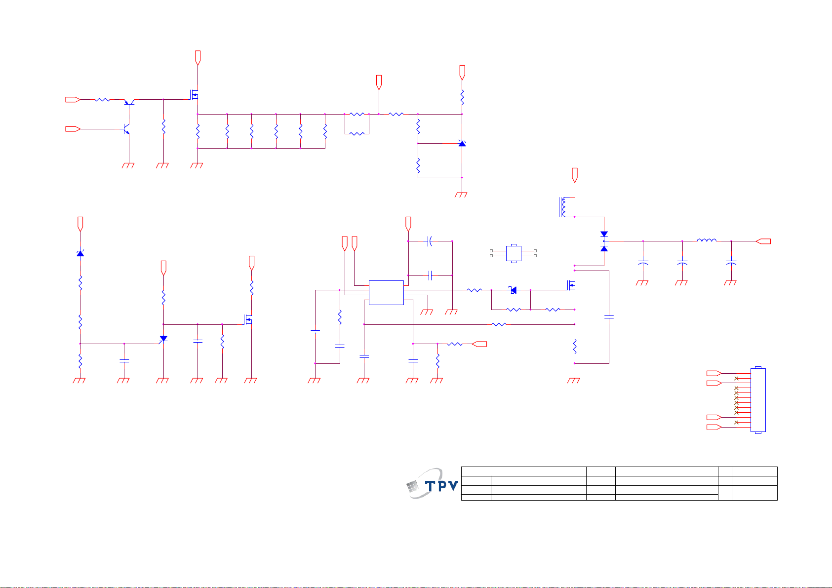
Page 49

9.2 Power Board
715G5654P01001002M
FOR BD9901
ECN issue list_20120620
12
BEAD
FB9910
ECN issue list_20120601
SG9903
DSPL201M-A21F_NC
C9902
470PF 250V
SG9901
DSPL201M-A21F_NC
ECN issue list_20120601
470NF 305V
R9901
ECN issue list_20120601
ECN issue list_20120620
FB9908 Jumper _20120620
510K 1/4W
R9904
510K 1/4W_NC
t
NTCR
NR9901
1 2
FB9901
BEAD
1 2
ECN issue list_20120620
C9908
NC
F9901
FUSE
1 2
3 4
ECN issue list_20120620
FB9909
NC
1 2
FB9908
BEAD
12
C9912
470PF 250V
ECN issue list_20120620
HS9901
HEAT SINK
1
2
124
L9902
13MH
3
C9904
470NF 305V
C9903
470PF 250V
124
L9901
13MH
3
C9901
ECN issue list_20120718
R9902
R9903
510K 1/4W
510K 1/4W
ECN issue list_20120601
R9905
R9906
510K 1/4W_NC
510K 1/4W_NC
IC9901
NC
1
8
NC
NC
2
7
D1
D2
3
6
D1
D2
5
NC4NC
C9907
NC
RV9901
Varistor
C9905
NC
CN9901
SOCKET
1 2
C9909
ECN issue list_20120620
NC
FB9907 Jumper _20120620
C9910
220PF 250V
B+
FB9906
BEAD
12
ECN issue list_20120620
2
BD9901
TS6B06G -01
+
-
4
3
BEAD
FB9911
1 2
2
1
SG9904
SG9902
12
FB9902
BEAD
FB9907
BEAD
12
C9911
NC
ECN issue list_20120621
FB9903
1
BEAD
CN9904
CONN
N
L
PFC_ZCD
R9813
DSPL201M-A21F_NC
47K OHM_NC
DSPL201M-A21F_NC
C9906
470pF 250V
R9806
HV
VCC_ON
12
C9801
1UF 450V_NC
R9801
10 OHM 1/8W_NC
VCC_ON
+
C9803
C9804
47PF 50V_NC
10UF 50V_NC
4.7K OHM_NC
R9101
0R1 5% 2W
C9114
1NF
R9106
20K OHM
R9107
2K 1/8W 1%
ECN issue list_20120601
D9801
1N5408G-04_NC
10
L9801
300UH_NC
1
2 6
D9803
SS0520_NC
12
R9803
33R 1/8W 5%_NC
10K 1% 1/8W_NC
R9802
IC9801
LD7591GS_NC
8
INV
VCC
7
COMP
OUT
6
RAMP
GND
5
R9808
C9806
10K 1% 1/8W_NC
0.22uF 50V_NC
C9807
C9805
0.1uF 50V_NC
100N 50V_NC
ECN issue list_20120601
+
C9103
C9102
10UF 50V
0.1UF 50V
C9104
0.1UF 50V
C9106
10nF 50V
PFC_ZCD
R9804
0.15R_NC
1
2
3
CS4ZCD
ECN issue list_20120613
82KOHM +-5% 2WS
C9101
2.2NF
ECN issue list_20120620
ECN issue list_20120620
IC9101
1
BNO
OVP
2
COMP
VCC
3
NC
OUT
CS4GND
LD7523GS
R9110
470R 1%
1N 50V
C9105
D9802
FMNS-1106S_NC
C9802
2200PF_NC
R9809
Q9801
STP10NK60ZFP_NC
R9810
R9805
470R 1%_NC
R9811
C9808
R9807
1NF_NC
33K OHM_NC
FOR Q9801 D9802
HS9801
HEAT SINK
1
2
3
4
FOR D9105 D9104
HS9102
HEAT SINK
R9102
8
7
33 OHM 1/8W
6
5
R9111
10K 1% 1/8W
HV
C9810
+
150uF 450V
680K OHM 1% 1/4W_NC
ECN issue list_20120717
680K OHM 1% 1/4W_NC
680K OHM 1% 1/4W_NC
C9809
R9812
100PF 50V_NC
13K OHM 1%_NC
PLTVCL621UAE1(CHH 32'' D-LED)T9101 change
1
2
to 380GL32P110CP0_ECN issue list_20120705
ECN issue list_20120620
R9103
D9101
0R05 1/4W
PR1007
R9108
22R 1/8W 1%
R9109
D9102
SS0520
12
ECN issue list_20120529
R9301
0.1R
D9301
PR1007
R9306
1M5 1/4W 1%
R9307
1M5 1/4W 1%
R9308
1M5 1/4W 1%
R9310
C9302
1R2 5% 2W
R9309
0.47UF 50V
620K 1/8W 1%
ECN issue list_20120601
FOR D9106 D9305
ECN issue list_20120601
6
4
2
FOR Q9101
HS9101
HEAT SINK
1
2
3
4
R9130
10K 1% 1/8W
R9112
0R33 5% 2W
ECN issue list_20120620
IC9102
PC123X8YFZOF
B+
R9302
R9303
100K 1%
100K 1%
R9304
R9305
100K 1%
100K 1%
C9301
1NF
R9311
4.7M 5% 1/8W
IC9301
A6069H
1
S/OCP
2
BR
3
GND
FB/OLP4VCC
ECN issue list_20120601
C9303
10nF50V
ECN issue list_20120515
HS9103
HEAT SINK
1
2
12
9
10
8
11
7
T9101
POWER X'FMR
ECN issue list_20120515
100 OHM 1/4W
100 OHM 1/4W
Q9101
STP10NK70ZFP
+12V
R9124
1K 1/8W 1%
12
43
R9125
22K 1% 1/8W
3K3 1/8W 1%
GDZJ16B
ZD9101
IC9103
1 2
AS431AZTR-E1
ECN issue list_20120620
D9302
PR1007
R9312
4R7 1/4W 5%
D9303
PR1007
8
D/ST
7
D/ST
5
C9304
GDZJ30B
ZD9301
0.1UF 50V
1 2
ECN issue list_20120718
R9132
220 OHM 1/4W
R9131
220 OHM 1/4W
3
D9104
FMX-23S
2
1
ECN issue list_20120515
R9113
100 OHM 1/4W
R9114
100 OHM 1/4W
D9105
3
FMXA-2202S
2
1
R9118
R9119
C9113
470PF
3
2
D9106
FMEN-220A
1
+12V
+24 LED
24K OHM 1%
R9127
R9126
C9118
0.47UF 50V
R9134
62K 1%_NC
T9301
1
POWER X'FMR
2
7
3
9
5
4
VCC
D9304
1N4148
+
+
C9305
10UF 50V
C9306
100uF/50V
C9121
100PF
+
C9107
330UF 50V
ECN issue list_20120718
+24VS
C9108
470PF
+
+
C9110
C9109
1000UF 35V
1000UF 35V
L9103
3.5uH
+
C9115
1000UF 25V
ECN issue list_20120620
+36V
R9133
120K
56K OHM 1%
R9128
ECN issue list_20120620
R9129
2.26K 1%
ECN issue list_20120529
R9314
100 OHM 1/4W
R9313
100 OHM 1/4W
3
D9305
FMEN-2308
2
1
ECN issue list_20120613
43
IC9302
PC123X8YFZOF
L9101
3.5uH
+
C9119
+
C9120
330UF 50V
330UF 50V
L9102
3.5uH
ECN issue list_20120718
+
C9111
C9123
330UF 35V
ECN issue list_20120515
+
C9116
C9117
0.1uF 50V
680UF 25V
R9121
1.5K OHM
VCC
VCC_ON
C9402
10UF 50V
Key Component
5.2V
C9307
+
470PF
C9308
330UF 16V
L9301
3.5uH
+
C9309
470UF 25V
ECN issue list_20120502
5.2V
R9315
470R 1%
12
3.3K 1% 1/8W
R9316
+36V
+24 LED
D9107
SR506
5.6K
5.6K
R9116
R9117
0.1uF 50V
C9312
R9317
220NF 50V
3.3K 1% 1/8W
ECN issue list_20120601
IC9303
AS431AZTR-E1
ECN issue list_20120718
+
C9122
R9115
330UF 35V
ECN issue list_20120515
+12V
R9123
1.5K OHM
R9122
1.5K OHM
2SD1624T-TD-E
Q9401
+
R9401
10K 1% 1/8W
+5.2V
R9402
330R 1%
12
43
IC9401
PC123X8YFZOF
Q9402
PMBS3904
GDZJ16B
ZD9401
1 2
ECN issue list_20120601
T P V ( Top Victory Electronics C o . , Ltd. )
G5654-P0E-001-0020
絬 隔 瓜 絪 腹
02.POWER 715G5654-P0E-001-0020
Wednesday, July 18, 2012
Date
OEM MOD EL
TPV MODEL
PCB NAME
+
C9310
270UF 25V
ECN issue list_20120601
+5.2V
R9319
6.2K OHM +-1% 1/8W
R9318
5.6K OHM 1%
5.6K
C9112
0.1uF 50V
C9401
0.1UF 50V
Sheet
of
23
+5.2V
C9311
0.1UF 50V
+12V
+5.2V
ZD9602
ZD9601
GDZJ20B
GDZJ6.2B
1 2
D9601
1N4148
ECN issue list_20120529
Q9601
3
BCR1002N3
2
1
C9601
1UF 50V
ECN issue list_20120502
ON/OFF
DIM
+12V
+24V aduio
PS_ON
+24V aduio
+5.2V
+12V
DIM
ON/OFF
ECN issue list_20120516
PS_ON
R9403
10K 1% 1/8W
R9404
10K 1% 1/8W
+24V aduio
ZD9603
GDZJ30B
1 2
1 2
1
2
D9602
BAV70
3
R9601
1K OHM 1%
R9602
1K OHM 1%
CN9902
CONN
13
12
11
10
9
8
7
6
5
4
3
2
1
+24 LED
CN9903
CONN_NC
12
11
10
9
8
7
6
5
4
3
2
1
Size
180*240*25mm
Rev
C
称爹
>
<
称爹
49
Page 50
R8206
+12V
DIM
5.1K OHM
LED-SOURC E
ZD8301
GDZJ 30B
1 2
R8301
82K OHM 1%
ECN issue list_20120529
R8302
0 OHM 1/8W
R8303
1K OHM 1%
LED-1
Q8201
DTA144WN3/ S
R8207
10K 1% 1/8W
DTC 144WN3/S
Q8202
ON/O FF
R8304
10K 1% 1/8W
3
2
1
Q8301
C8302
1uF
BCR1002N 3
ECN issue list_20120620
ECN issue list_20120529
Q8203
P0420ATF
R8201
20R 1%
R8202
20R 1%
ECN issue list_20120718
R8203
20R 1%
20R 1%
FOR D-LED32
EN
R8306
300K 1/4W
Q8302
2N7002
C8301
1nF 50V
300K OHM
R8305
R8204
FB
R8208
75K 1%
R8205
20R 1%
R8214
R8213
20R 1%
75K 1%
FB
EN
ECN issue list_20120601
1
FB
2
COMP
3
RFW
CS4DIM
R8101
30K OHM
NC
C8103
C8104
0.1UF 50V
C8105
ECN issue list_20120601
470PF 50V
R8211
100K 1% 1/8W
VCC
DRV
GND
IC8101
LD7400GS
+12V
8
7
6
5
R8210
100K 1% 1/8W
R8209
100K 1% 1/8W
C8101
10UF 50V
+
C8102
0.1UF 50V
C8106
1nF 50V
+12V
R8212
10K 1% 1/8W
ECN issue list_20120529
IC8201
AS431AN-E1
ECN issue list_20120529
FOR Q8101 D8103
HS8101
HEAT SINK
3
4
R8103
10K 1% 1/4W
R8102
300K OHM
R8104
33 OHM 1/4W
R8109
470R 1%
DIM
D8101
SS0520
R8105
33 OHM
1
2
12
L8101
33UH
R8106
10K 1% 1/8W
R8107
+36V
1
2
0R1 5% 2W
Q8101
AOTF454FL
D8103
3
FME-220B
2
1
+
C8107
47UF 100V
ECN issue list_20120529
C8110
470PF_NC
ECN issue list_20120502
LED-SOURCE
LED-SOURCE
+
L8102
5uH
C8108
47UF 100V
LED-1
LED-1
+
47UF 100V
LED-SOURC E
C8109
CN8901
CONN
12
11
10
9
8
7
6
5
4
3
2
1
50
T P V ( Top Victory Electronics Co . , Ltd. )
絬 隔 瓜 絪 腹
Key Component
G5654-P0E-001-0020
03. LED D RI VER 715G5654-P0E-001-0020
Wednesday , July 18, 2012
Date
OEM MODEL
TPV MO DE L
PCB NAME
Sheet
of
33
Size
180*240*25mm
Rev
称爹
C
称爹
>
<
Page 51
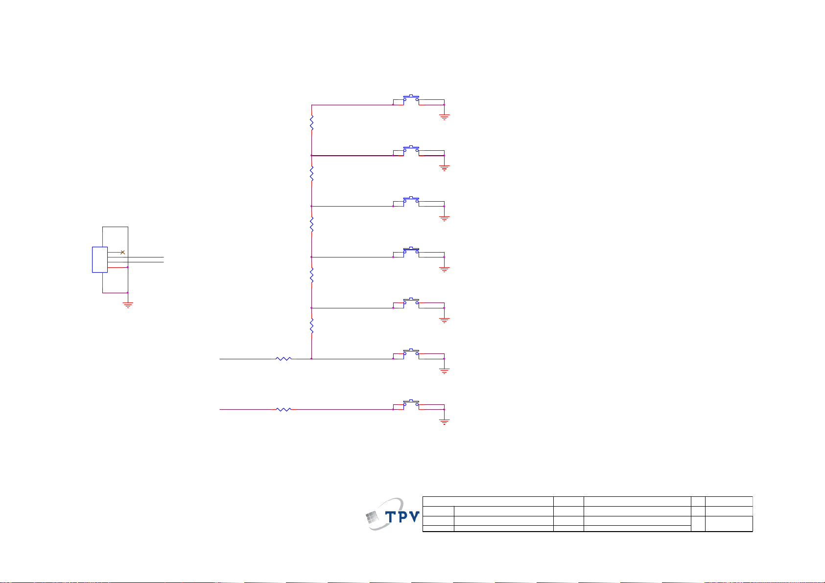
9.3 Key Board
715G5711K01000004X
SW01
CN01
65
CONN
33G8032 4F HR
R01
7K5 1/8W +/-1%
R02
2K7 1/8W 1%
R03
1K8 +/ -1% 1/8W
1
2
FUN C_KEY
3
4
PWR-SW
FUN C_KEY
R06
750OHM +- 1% 1/8W
R04
1K 1/8W 1%
R05
750OHM +- 1% 1/8W
TACT SW FWRD H1.5MM
SW02
TACT SW FWRD H1.5MM
SW03
TACT SW FWRD H1.5MM
SW04
TACT SW FWRD H1.5MM
SW05
TACT SW FWRD H1.5MM
SW06
TACT SW FWRD H1.5MM
VOL+
VOL-
CH+
CH-
MENU
Source Select
2.48V~2.72V
2.04V~2.22V
1.58V~1.79V
1.24~1.45V
0.85V~1.02V
0.47V~0.63V
PWR-SW
R07
750OHM +- 1% 1/8W
SW07
TACT SW FWRD H1.5MM
77G 607 2 FD
絬 隔 瓜 絪 腹
Key Component
51
Power ON/OFF
T P V ( Top Victory Electronics Co . , Ltd. )
02-Keypad
Date
OEM MO DE L
TPV MODEL
PCB NAME
Sheet
A
称爹
<
Custom
>
X
of
22Friday , April 27, 2012
Size
Rev
称爹
Page 52

9.4 IR Board
715G5471R02000004X
LED201
081G 14 24 EL
RED
033G8032 5F HR
CN201
67
1
2
3
4
5
CONN
LED_R
LED_B
IR
R202 220 OHM 1/10W
R203 220 OHM 1/10W
VCC
R201 15K 1/10W
C201
0.1uF 50V
BLUE
1
23
Top Vie w
U201
1
GND
2
GND
3
OUT
4
VCC
IRM-H636M3/TR2
16 mm
Dip LED
IR
4
LED
37mm
T P V ( Top Victory Electronics Co . , Ltd. )
絬 隔 瓜 絪 腹
Key Component
Date
715G5471-R0A-000-0040
02-IR&LED
52
OEM MODEL
TPV MOD EL
PCB NAME
Sheet
X
Dynex UFC Model
715G5471-R0A-000-0040
of
22Wednesday , January 18, 2012
Size
Rev
称爹
<
A
称爹
A
>
Page 53

10. Exploded View
53
Page 54

Item Description
1 BEZEL
2 DECO
3 SPEAKER
4 PANEL
5 BKT_STAND
6 COVER_STAND
7 KEY
8 REAR_COVER
9 BASE
10 KEY BOARD
11 IR BOARD
12 MAIN BOARD
13 BKT_IO
14 POWER BOARD
15 BOLT
16 BKT_IO
17 INSULATING SHEET 18 Q02G706100200100XL SCREW(FOR PANEL) 4
Item Part No. Description Qty
54
Page 55

11. BOM List
Note: The parts information listed below are for reference only, and are subject to change without notice.
Please go to http://cs.tpv.com.cn/hello1.asp
LE32A1330/61 E32C1KNCCQACNNX
Location Part No. Description Remark
052G 1186 SMALL TAPE
052G 2191 A PAPER TAPE
070GHDCP500HDC HDCP CODE
ECN701 095G801313DS05 HARNESS 13P-13P 400
ECN701 095G801313WS05 HARNESS 13P-13P 400MM 2nd Source
0M1G1030 8 47 CR3 SCREW
0M1G1030 8 47 CR3 SCREW
0M1G1030 8 47 CR3 SCREW
0M1G1730 8120 SCREW 3X8
0M1G1730 8120 SCREW 3X8
0M1G1730 8120 SCREW 3X8
0M1G1740 10225 CR3 SCREW M1-MACHINE SCREW X10.0
0Q1G 930 8 47 CR3 SCREW
0Q1G 930 8 47 CR3 SCREW
0Q1G 940 8 47 CR3 SCREW 4X8
0Q1G 940 12 47 CR3 SCREW 4X12
0Q1G1030 6120 SCREW 3X6
SP01 378G0110567YAH 16 OHM 11W 132X34 0 NO
ECN601 395G801404DY11 HARNESS 4P-B&R+B&W 450/260MM
ECN601 395G801404XY11 HARNESS 4P-B&R+B&W 450/260 2nd Source
ECN4004 395G801410WY39 HARNESS 10P-5P+4P 550/700 2nd Source
ECN4004 395G801410XY39 HARNESS 10P-5P+4P 550/700
ECN4001 395G801830LY46 LVDS CABLE 30P-30P 380MM 2nd Source
ECN4001 395G801830XY46 LVDS CABLE 30P-30P 380MM
756TXCCB0KC0250001 MCU ASSY-CBPFCK8DX6
SMTF-U4003 100TARVK026C1X AOC LE32A1330/61 NOR_FLASH V2.00 3797
U4003 356G2233073 MCU ASSY-100TARVK026C1X
040G 45762412B CBPC LABEL
CN4004 033G380210B YH L CONNECTOR 10P 2.0
C601 067G315M1016KV EC 100UF 20% 35V 8*7
C616 067G315M1016KV EC 100UF 20% 35V 8*7
CN102 088G 78G114ACL RCA JACK R/A YELLOW H=10.5
CN103 088G 78G121ACL RCA JACK R/A 4P W/R 1*2 H=10.5
CN101 088G 78G134ACL RCA JACK R/A 6P G/BL/R 1*3 H=10.5
CN106 088G302G3G2ACL PHONE JACK R/A 3P GREEN H=10MM
CN107 088G302G7B1ACL PHONE JACK R/A 7P BLACK H=10.5
CN108 088G352F6B2ACL USB CONN R/A 6P BLACK 8.4MM
CN105 088G353GFF1AXH D-SUB CONN 15P BLUE - R/A 10
TU101 094G PALALL10C TUNER ALL DMI21-C2I2RH
TU101 094G PALALL10L TUNER CHINA DT21WN-2-E
CN601 311GW200A04ABX WAFER 2.0MM 4P
CN4001 311GW200C30ABL WAFER 2.0MM 2*15P
CN701 311GW250B13BBX WAFER 2.5MM 13P R/A 35MM 7MM
AIFCK8DX6 MAIN BOARD FOR AI
C629 367G305S1013LB EC 100UF 10% 16V 6.3*7 2000 HR -- 000382
C709 367G305S1013LB EC 100UF 10% 16V 6.3*7 2000 HR -- 000382
C702 367G305S1013LB EC 100UF 10% 16V 6.3*7 2000 HR -- 000382
C127 367G305S1013LB EC 100UF 10% 16V 6.3*7 2000 HR -- 000382
C4031 367G305S1013LB EC 100UF 10% 16V 6.3*7 2000 HR -- 000382
C128 367G305S1013LB EC 100UF 10% 16V 6.3*7 2000 HR -- 000382
C4030 367G305S1013LB EC 100UF 10% 16V 6.3*7 2000 HR -- 000382
for the latest information.
55
Page 56

C4082 367G305S1013LB EC 100UF 10% 16V 6.3*7 2000 HR -- 000382
C719 367G305S1013LB EC 100UF 10% 16V 6.3*7 2000 HR -- 000382
C122 367G305S1013LB EC 100UF 10% 16V 6.3*7 2000 HR -- 000382
C715 367G305S1013LB EC 100UF 10% 16V 6.3*7 2000 HR -- 000382
C629 067G305S1013HB EC 100UF 20% 16V 6.3*7
C709 067G305S1013HB EC 100UF 20% 16V 6.3*7
C702 067G305S1013HB EC 100UF 20% 16V 6.3*7
C127 067G305S1013HB EC 100UF 20% 16V 6.3*7
C4031 067G305S1013HB EC 100UF 20% 16V 6.3*7
C128 067G305S1013HB EC 100UF 20% 16V 6.3*7
C4030 067G305S1013HB EC 100UF 20% 16V 6.3*7
C4082 067G305S1013HB EC 100UF 20% 16V 6.3*7
C719 067G305S1013HB EC 100UF 20% 16V 6.3*7
C122 067G305S1013HB EC 100UF 20% 16V 6.3*7
C715 067G305S1013HB EC 100UF 20% 16V 6.3*7
C725 067G305S2213HB EC 220UF 20% 16V 6.3*7
SMTFCK8DX6 MAIN BOARD FOR SMT
U705 056G 563143 C LDO G1084PT43U 5A ADJ TO-252
U101 056G 563149 IC G903T63UF 0.6A/3.3V SOT-223
U703 056G 563398 DC/DC AT1527F11U 3A
U701 056G 563X01 LDO G9661-25ADJF11U 2A 300MV DROP SOP-8
U601 056G 616 54 IC TPA3110D2 15W TSSOP-28
U708 056G 643 46 IC RESET AZ809ANSTR-E1 SOT-23 2.93V
U100 056G 662505 ESD PROTECT AOZ8105CI SOT-23-6
U102 056G 662505 ESD PROTECT AOZ8105CI SOT-23-6
Q4003 057G 417 4 PMBS3904/PHILIPS-SMT(04)
Q4002 057G 417 4 PMBS3904/PHILIPS-SMT(04)
Q708 057G 417511 MMBT3904
Q601 057G 417511 MMBT3904
Q704 057G 417511 MMBT3904
Q701 057G 417511 MMBT3904
Q706 057G 417511 MMBT3904
Q4004 057G 417512 MMBT3906
Q4005 057G 417512 MMBT3906
Q602 057G 417512 MMBT3906
Q707 057G 763 1 MOSFET A03401 4.2A 30V SOT-23
Q709 057G 763 39 FET AO3404 SOT-23 AOS
Q710 057G 763 39 FET AO3404 SOT-23 AOS
Q4006 057G 763 79 FET AO4449 -7A/-30V SOIC-8
Q101 057G 763904 TRA FET 2N7002 SOT-23 PHILIPS
Q102 057G 763904 TRA FET 2N7002 SOT-23 PHILIPS
Q702 057G 763940 MOSFET AO3401A SOT-23
RP4003 061G 1262208JY RST CHIP AR 8P4R 22 OHM +-5% 1/16W
RP4004 061G 1262208JY RST CHIP AR 8P4R 22 OHM +-5% 1/16W
RP4002 061G 1262208JY RST CHIP AR 8P4R 22 OHM +-5% 1/16W
RP4001 061G 1262208JY RST CHIP AR 8P4R 22 OHM +-5% 1/16W
RP4005 061G 1262208JY RST CHIP AR 8P4R 22 OHM +-5% 1/16W
TH101 061G 56A100 WT PTCR SMD 0.21R MAX 0.8W
R4062 061G0402000 JY RST CHIPR MAX 0R05 OHM 1/16W YAGEO
R4061 061G0402000 JY RST CHIPR MAX 0R05 OHM 1/16W YAGEO
R4060 061G0402000 JY RST CHIPR MAX 0R05 OHM 1/16W YAGEO
R4065 061G0402000 JY RST CHIPR MAX 0R05 OHM 1/16W YAGEO
R4058 061G0402000 JY RST CHIPR MAX 0R05 OHM 1/16W YAGEO
R4059 061G0402000 JY RST CHIPR MAX 0R05 OHM 1/16W YAGEO
R4056 061G0402000 JY RST CHIPR MAX 0R05 OHM 1/16W YAGEO
R4057 061G0402000 JY RST CHIPR MAX 0R05 OHM 1/16W YAGEO
R4055 061G0402000 JY RST CHIPR MAX 0R05 OHM 1/16W YAGEO
56
Page 57

R4066 061G0402000 JY RST CHIPR MAX 0R05 OHM 1/16W YAGEO
R610 061G0402100 JF RST CHIPR 10 OHM +-5% 1/16W FENGHUA
R609 061G0402100 JF RST CHIPR 10 OHM +-5% 1/16W FENGHUA
R608 061G0402100 JF RST CHIPR 10 OHM +-5% 1/16W FENGHUA
R607 061G0402100 JF RST CHIPR 10 OHM +-5% 1/16W FENGHUA
R134 061G0402101 JF RST CHIPR 100 OHM +-5% 1/16W FENGHUA
R135 061G0402101 JF RST CHIPR 100 OHM +-5% 1/16W FENGHUA
R129 061G0402101 JF RST CHIPR 100 OHM +-5% 1/16W FENGHUA
R143 061G0402101 JF RST CHIPR 100 OHM +-5% 1/16W FENGHUA
R169 061G0402101 JF RST CHIPR 100 OHM +-5% 1/16W FENGHUA
R148 061G0402101 JF RST CHIPR 100 OHM +-5% 1/16W FENGHUA
R186 061G0402101 JF RST CHIPR 100 OHM +-5% 1/16W FENGHUA
R172 061G0402101 JF RST CHIPR 100 OHM +-5% 1/16W FENGHUA
R119 061G0402101 JF RST CHIPR 100 OHM +-5% 1/16W FENGHUA
R103 061G0402101 JF RST CHIPR 100 OHM +-5% 1/16W FENGHUA
R107 061G0402101 JF RST CHIPR 100 OHM +-5% 1/16W FENGHUA
R116 061G0402101 JF RST CHIPR 100 OHM +-5% 1/16W FENGHUA
R145 061G0402101 JF RST CHIPR 100 OHM +-5% 1/16W FENGHUA
R114 061G0402101 JF RST CHIPR 100 OHM +-5% 1/16W FENGHUA
R168 061G0402101 JF RST CHIPR 100 OHM +-5% 1/16W FENGHUA
R111 061G0402101 JF RST CHIPR 100 OHM +-5% 1/16W FENGHUA
R138 061G0402101 JF RST CHIPR 100 OHM +-5% 1/16W FENGHUA
R137 061G0402101 JF RST CHIPR 100 OHM +-5% 1/16W FENGHUA
R164 061G0402101 JY RST CHIPR 100 OHM +-5% 1/16W YAGEO
R162 061G0402101 JY RST CHIPR 100 OHM +-5% 1/16W YAGEO
R132 061G0402103 JF RST CHIPR 10KOHM +-5% 1/16W FENGHUA
R131 061G0402103 JF RST CHIPR 10KOHM +-5% 1/16W FENGHUA
R524 061G0402104 JF RST CHIPR 100KOHM +-5% 1/16W FENGHUA
R526 061G0402104 JF RST CHIPR 100KOHM +-5% 1/16W FENGHUA
R537 061G0402104 JF RST CHIPR 100KOHM +-5% 1/16W FENGHUA
R519 061G0402104 JF RST CHIPR 100KOHM +-5% 1/16W FENGHUA
R518 061G0402152 JF RST CHIPR 1.5KOHM +-5% 1/16W FENGHUA
R510 061G0402152 JF RST CHIPR 1.5KOHM +-5% 1/16W FENGHUA
R140 061G0402222 JF RST CHIPR 2.2KOHM +-5% 1/16W FENGHUA
R141 061G0402222 JF RST CHIPR 2.2KOHM +-5% 1/16W FENGHUA
R515 061G0402302 JF RST 0402 3K 5% 1/16W
R517 061G0402302 JF RST 0402 3K 5% 1/16W
R170 061G0402472 JF RST CHIPR 4.7KOHM +-5% 1/16W FENGHUA
R171 061G0402472 JF RST CHIPR 4.7KOHM +-5% 1/16W FENGHUA
R160 061G0402472 JI TEST ONLY RST CHIP 4.7K 5% 1/16W TA-I
R159 061G0402472 JI TEST ONLY RST CHIP 4.7K 5% 1/16W TA-I
R627 061G0603000 JI RST 0603 0.05R MAX 1/10W TA-I
R175 061G0603000 JT RST CHIP MAX 0R05 1/10W TZAI YUAN
R627 061G0603000 JY RST CHIPR MAX0R05 1/10W YAGEO
FB4001 061G0603000 JY RST CHIPR MAX0R05 1/10W YAGEO
R4005 061G0603000 JY RST CHIPR MAX0R05 1/10W YAGEO
FB4004 061G0603000 JY RST CHIPR MAX0R05 1/10W YAGEO
R703 061G0603000 JY RST CHIPR MAX0R05 1/10W YAGEO
R727 061G0603000 JY RST CHIPR MAX0R05 1/10W YAGEO
R4001 061G0603000 JY RST CHIPR MAX0R05 1/10W YAGEO
R723 061G0603100 JF RST CHIPR 10 OHM 5% 1/10W FENGHUA
R4009 061G06031001FI 1EST ONLY RST 0603 1K 1% 1/10W TA-I
R4011 061G06031001FI 1EST ONLY RST 0603 1K 1% 1/10W TA-I
R4010 061G06031001FI 1EST ONLY RST 0603 1K 1% 1/10W TA-I
R4012 061G06031001FI 1EST ONLY RST 0603 1K 1% 1/10W TA-I
R602 061G0603101 JY RST CHIPR 100 OHM +-5% 1/10W YAGEO
R603 061G0603101 JY RST CHIPR 100 OHM +-5% 1/10W YAGEO
57
Page 58

R4034 061G0603101 JY RST CHIPR 100 OHM +-5% 1/10W YAGEO
R4035 061G0603101 JY RST CHIPR 100 OHM +-5% 1/10W YAGEO
R614 061G0603101 JY RST CHIPR 100 OHM +-5% 1/10W YAGEO
R611 061G0603101 JY RST CHIPR 100 OHM +-5% 1/10W YAGEO
R508 061G0603101 JY RST CHIPR 100 OHM +-5% 1/10W YAGEO
R513 061G0603101 JY RST CHIPR 100 OHM +-5% 1/10W YAGEO
R511 061G0603101 JY RST CHIPR 100 OHM +-5% 1/10W YAGEO
R509 061G0603101 JY RST CHIPR 100 OHM +-5% 1/10W YAGEO
R726 061G0603102 JY RST CHIPR 1KOHM +-5£¥ 1/10W YAGEO
R156 061G0603102 JY RST CHIPR 1KOHM +-5£¥ 1/10W YAGEO
R155 061G0603102 JY RST CHIPR 1KOHM +-5£¥ 1/10W YAGEO
R167 061G0603102 JY RST CHIPR 1KOHM +-5£¥ 1/10W YAGEO
R718 061G0603102 JY RST CHIPR 1KOHM +-5£¥ 1/10W YAGEO
R4038 061G0603102 JY RST CHIPR 1KOHM +-5£¥ 1/10W YAGEO
R716 061G0603102 JY RST CHIPR 1KOHM +-5£¥ 1/10W YAGEO
R4037 061G0603102 JY RST CHIPR 1KOHM +-5£¥ 1/10W YAGEO
R622 061G0603103 JI RST 0603 10K 5% 1/10W
R615 061G0603103 JT RST CHIP 10K 1/10W 5% TZAI YUAN
R613 061G0603103 JT RST CHIP 10K 1/10W 5% TZAI YUAN
R612 061G0603103 JT RST CHIP 10K 1/10W 5% TZAI YUAN
R606 061G0603103 JY RST CHIPR 10KOHM £«-5£¥ 1/10W YAGEO
R109 061G0603103 JY RST CHIPR 10KOHM £«-5£¥ 1/10W YAGEO
R108 061G0603103 JY RST CHIPR 10KOHM £«-5£¥ 1/10W YAGEO
R733 061G0603103 JY RST CHIPR 10KOHM £«-5£¥ 1/10W YAGEO
R734 061G0603103 JY RST CHIPR 10KOHM £«-5£¥ 1/10W YAGEO
R153 061G0603103 JY RST CHIPR 10KOHM £«-5£¥ 1/10W YAGEO
R150 061G0603103 JY RST CHIPR 10KOHM £«-5£¥ 1/10W YAGEO
R154 061G0603103 JY RST CHIPR 10KOHM £«-5£¥ 1/10W YAGEO
R612 061G0603103 JY RST CHIPR 10KOHM £«-5£¥ 1/10W YAGEO
R613 061G0603103 JY RST CHIPR 10KOHM £«-5£¥ 1/10W YAGEO
R615 061G0603103 JY RST CHIPR 10KOHM £«-5£¥ 1/10W YAGEO
R744 061G0603103 JY RST CHIPR 10KOHM £«-5£¥ 1/10W YAGEO
R728 061G0603103 JY RST CHIPR 10KOHM £«-5£¥ 1/10W YAGEO
R725 061G0603103 JY RST CHIPR 10KOHM £«-5£¥ 1/10W YAGEO
R601 061G0603103 JY RST CHIPR 10KOHM £«-5£¥ 1/10W YAGEO
R701 061G0603103 JY RST CHIPR 10KOHM £«-5£¥ 1/10W YAGEO
R704 061G0603103 JY RST CHIPR 10KOHM £«-5£¥ 1/10W YAGEO
R712 061G0603103 JY RST CHIPR 10KOHM £«-5£¥ 1/10W YAGEO
R4018 061G0603103 JY RST CHIPR 10KOHM £«-5£¥ 1/10W YAGEO
R166 061G0603103 JY RST CHIPR 10KOHM £«-5£¥ 1/10W YAGEO
R4023 061G0603103 JY RST CHIPR 10KOHM £«-5£¥ 1/10W YAGEO
R715 061G0603103 JY RST CHIPR 10KOHM £«-5£¥ 1/10W YAGEO
R743 061G0603103 JY RST CHIPR 10KOHM £«-5£¥ 1/10W YAGEO
R736 061G06031201FF RST CHIPR 1.2KOHM +-1% 1/10W
R735 061G06031501FF RST CHIPR 1.5K OHM +-1% 1/10W FENGHUA
R719 061G06032000FY RST CHIP 200R 1% 1/10W
R739 061G0603203 JY RST CHIP 20K 1/10W 5% YAGEO
R4022 061G0603220 JT RST CHIP 22R 1/10W 5% TZAI YUAN
R4026 061G0603220 JT RST CHIP 22R 1/10W 5% TZAI YUAN
R4021 061G0603220 JT RST CHIP 22R 1/10W 5% TZAI YUAN
R173 061G0603220 JY RST CHIPR 22 OHM £«-5£¥ 1/10W YAGEO
R174 061G0603220 JY RST CHIPR 22 OHM £«-5£¥ 1/10W YAGEO
R4032 061G06032201FT RST CHIP 2K2 1/10W 1%
R732 061G0603221 JF ST CHIPR 220 OHM +-5% 1/10W FENGHUA
R737 061G0603221 JF ST CHIPR 220 OHM +-5% 1/10W FENGHUA
R730 061G06032402FF RST CHIPR 24KOHM 1/10W FENGHUA
R730 061G06032402FY RST CHIPR 24KOHM +-1% 1/10W YAGEO
58
Page 59

R722 061G06033300FF RST CHIPR 330 OHM +-1% 1/10W FENGHUA
R620 061G06033321FF RST CHIPR 3.32KOHM +-1% 1/10W FENGHUA
R738 061G0603333 JT RST CHIP 33K 1/10W 5% TZAI YUAN
R713 061G0603361 JT RST CHIP 360R 1/10W 5% TZAI YUAN
R720 061G0603391 JF RST CHIPR 390 OHM +-5% 1/10W FENGHUA
R4033 061G06034701FT RST CHIP 4K7 1/10W 1%
R4020 061G0603472 JY
R4039 061G0603472 JY
R4030 061G0603472 JY
R4031 061G0603472 JY
R4027 061G0603472 JY
R4017 061G0603472 JY
R4014 061G0603472 JY
R4015 061G0603472 JY
R512 061G0603472 JY
R4036 061G0603472 JY
R4019 061G0603472 JY
R711 061G0603472 JY
R4054 061G0603472 JY
R514 061G0603472 JY
R506 061G0603472 JY
R507 061G0603472 JY
R4042 061G0603472 JY
R4048 061G0603472 JY
R4047 061G0603472 JY
R4016 061G0603472 JY
R724 061G0603473 JY RST CHIPR 47KOHM 1/10W YAGEO
R708 061G0603473 JY RST CHIPR 47KOHM 1/10W YAGEO
R527 061G0603473 JY RST CHIPR 47KOHM 1/10W YAGEO
R4028 061G0603473 JY RST CHIPR 47KOHM 1/10W YAGEO
R516 061G0603473 JY RST CHIPR 47KOHM 1/10W YAGEO
R533 061G06034990FF RST CHIPR 499OHM +-1% 1/10W FENGHUA
R533 061G06034990FI RST 0603 499R 1% 1/10W
R4003 061G0603622 JF RST CHIPR 6.2KOHM +-5% 1/10W FENGHUA
R623 061G06036801FY RST CHIP 6K8 1/10W 1%
R151 061G0603682 JF RST CHIPR 6.8KOHM +-5% 1/10W FENGHUA
R105 061G0603682 JF RST CHIPR 6.8KOHM +-5% 1/10W FENGHUA
R104 061G0603682 JF RST CHIPR 6.8KOHM +-5% 1/10W FENGHUA
R149 061G0603682 JF RST CHIPR 6.8KOHM +-5% 1/10W FENGHUA
R101 061G0603750 JY RST CHIPR 75 OHM +-5% 1/10W YAGEO
R130 061G0603750 JY RST CHIPR 75 OHM +-5% 1/10W YAGEO
R139 061G0603750 JY RST CHIPR 75 OHM +-5% 1/10W YAGEO
R112 061G0603750 JY RST CHIPR 75 OHM +-5% 1/10W YAGEO
R146 061G0603750 JY RST CHIPR 75 OHM +-5% 1/10W YAGEO
R117 061G0603750 JY RST CHIPR 75 OHM +-5% 1/10W YAGEO
R122 061G0603750 JY RST CHIPR 75 OHM +-5% 1/10W YAGEO
R535 061G0603823 JF RST CHIPR 82KOHM 5% 1/10W FENGHUA
R729 061G06039101FI TEST ONLY RST 0603 9.1K 1% 1/10W TA-I
R729 061G06039101FY RST CHIPR 9.1KOHM +-1% 1/10W YAGEO
L109 061G0805000 JF RST CHIPR 0 OHM +-5% 1/8W FENGHUA
FB707 061G0805000 JF RST CHIPR 0 OHM +-5% 1/8W FENGHUA
FB103 061G0805000 JF RST CHIPR 0 OHM +-5% 1/8W FENGHUA
FB4021 061G0805000 JF RST CHIPR 0 OHM +-5% 1/8W FENGHUA
R4063 061G08050004JT RST CHIPR 0805 0 OHM 4A
R624 061G1206100 JF RST CHIPR 10 OHM +-5% 1/4W FENGHUA
C144 065G040210031J T CAP 0402 10PF 5% 50V NP0
RST CHIPR 4.7KOHM +-5% 1/10W YAGEO
RST CHIPR 4.7KOHM +-5% 1/10W YAGEO
RST CHIPR 4.7KOHM +-5% 1/10W YAGEO
RST CHIPR 4.7KOHM +-5% 1/10W YAGEO
RST CHIPR 4.7KOHM +-5% 1/10W YAGEO
RST CHIPR 4.7KOHM +-5% 1/10W YAGEO
RST CHIPR 4.7KOHM +-5% 1/10W YAGEO
RST CHIPR 4.7KOHM +-5% 1/10W YAGEO
RST CHIPR 4.7KOHM +-5% 1/10W YAGEO
RST CHIPR 4.7KOHM +-5% 1/10W YAGEO
RST CHIPR 4.7KOHM +-5% 1/10W YAGEO
RST CHIPR 4.7KOHM +-5% 1/10W YAGEO
RST CHIPR 4.7KOHM +-5% 1/10W YAGEO
RST CHIPR 4.7KOHM +-5% 1/10W YAGEO
RST CHIPR 4.7KOHM +-5% 1/10W YAGEO
RST CHIPR 4.7KOHM +-5% 1/10W YAGEO
RST CHIPR 4.7KOHM +-5% 1/10W YAGEO
RST CHIPR 4.7KOHM +-5% 1/10W YAGEO
RST CHIPR 4.7KOHM +-5% 1/10W YAGEO
RST CHIPR 4.7KOHM +-5% 1/10W YAGEO
59
Page 60

C140 065G040210031J T CAP 0402 10PF 5% 50V NP0
C115 065G040210031J Y CAP 0402 10PF 5% 50V NP0
C4079 065G040210131J F CAP 0402 100PF 5% 50V NP0
C133 065G040210232K A CAP 0402 1NF 10% 50V X7R
C131 065G040210232K A CAP 0402 1NF 10% 50V X7R
C604 065G040210232K A CAP 0402 1NF 10% 50V X7R
C605 065G040210232K A CAP 0402 1NF 10% 50V X7R
C145 065G040210332K A CAP 0402 10NF 10% 50V X7R
C512 065G040210412K T CAP CHIP 0402 100NF 16V X7R
C511 065G040210412K T CAP CHIP 0402 100NF 16V X7R
C510 065G040210412K T CAP CHIP 0402 100NF 16V X7R
C513 065G040210412K T CAP CHIP 0402 100NF 16V X7R
C505 065G040210412K T CAP CHIP 0402 100NF 16V X7R
C4036 065G040210412K Y CAP 0402 100NF 10% 16V X7R
C4038 065G040210412K Y CAP 0402 100NF 10% 16V X7R
C4035 065G040210412K Y CAP 0402 100NF 10% 16V X7R
C4076 065G040210412K Y CAP 0402 100NF 10% 16V X7R
C4075 065G040210412K Y CAP 0402 100NF 10% 16V X7R
C4007 065G040210412K Y CAP 0402 100NF 10% 16V X7R
C705 065G040210412K Y CAP 0402 100NF 10% 16V X7R
C4054 065G040210412K Y CAP 0402 100NF 10% 16V X7R
C708 065G040210412K Y CAP 0402 100NF 10% 16V X7R
C4052 065G040210412K Y CAP 0402 100NF 10% 16V X7R
C701 065G040210412K Y CAP 0402 100NF 10% 16V X7R
C4050 065G040210412K Y CAP 0402 100NF 10% 16V X7R
C4051 065G040210412K Y CAP 0402 100NF 10% 16V X7R
C703 065G040210412K Y CAP 0402 100NF 10% 16V X7R
C4040 065G040210412K Y CAP 0402 100NF 10% 16V X7R
C4004 065G040210412K Y CAP 0402 100NF 10% 16V X7R
C4041 065G040210412K Y CAP 0402 100NF 10% 16V X7R
C704 065G040210412K Y CAP 0402 100NF 10% 16V X7R
C4059 065G040210412K Y CAP 0402 100NF 10% 16V X7R
C4058 065G040210412K Y CAP 0402 100NF 10% 16V X7R
C720 065G040210412K Y CAP 0402 100NF 10% 16V X7R
C4057 065G040210412K Y CAP 0402 100NF 10% 16V X7R
C712 065G040210412K Y CAP 0402 100NF 10% 16V X7R
C4045 065G040210412K Y CAP 0402 100NF 10% 16V X7R
C4044 065G040210412K Y CAP 0402 100NF 10% 16V X7R
C723 065G040210412K Y CAP 0402 100NF 10% 16V X7R
C724 065G040210412K Y CAP 0402 100NF 10% 16V X7R
C721 065G040210412K Y CAP 0402 100NF 10% 16V X7R
C4039 065G040210412K Y CAP 0402 100NF 10% 16V X7R
C148 065G040210412K Y CAP 0402 100NF 10% 16V X7R
C4061 065G040210412K Y CAP 0402 100NF 10% 16V X7R
C4060 065G040210412K Y CAP 0402 100NF 10% 16V X7R
C149 065G040210412K Y CAP 0402 100NF 10% 16V X7R
C4021 065G040210412K Y CAP 0402 100NF 10% 16V X7R
C4077 065G040210412K Y CAP 0402 100NF 10% 16V X7R
C4049 065G040210412K Y CAP 0402 100NF 10% 16V X7R
C714 065G040210412K Y CAP 0402 100NF 10% 16V X7R
C123 065G040210412K Y CAP 0402 100NF 10% 16V X7R
C4078 065G040210412K Y CAP 0402 100NF 10% 16V X7R
C4048 065G040210412K Y CAP 0402 100NF 10% 16V X7R
C4046 065G040210412K Y CAP 0402 100NF 10% 16V X7R
C4008 065G040210412K Y CAP 0402 100NF 10% 16V X7R
C4006 065G040210412K Y CAP 0402 100NF 10% 16V X7R
C731 065G040210412K Y CAP 0402 100NF 10% 16V X7R
60
Page 61

C4001 065G040210412K Y CAP 0402 100NF 10% 16V X7R
C4002 065G040210412K Y CAP 0402 100NF 10% 16V X7R
C727 065G040210412K Y CAP 0402 100NF 10% 16V X7R
C4072 065G040210412K Y CAP 0402 100NF 10% 16V X7R
C707 065G040210412K Y CAP 0402 100NF 10% 16V X7R
C4069 065G040210412K Y CAP 0402 100NF 10% 16V X7R
C4068 065G040210412K Y CAP 0402 100NF 10% 16V X7R
C4064 065G040210412K Y CAP 0402 100NF 10% 16V X7R
C4066 065G040210412K Y CAP 0402 100NF 10% 16V X7R
C4074 065G040210412K Y CAP 0402 100NF 10% 16V X7R
C718 065G040210412K Y CAP 0402 100NF 10% 16V X7R
C4065 065G040210412K Y CAP 0402 100NF 10% 16V X7R
C4062 065G040210412K Y CAP 0402 100NF 10% 16V X7R
C4063 065G040210412K Y CAP 0402 100NF 10% 16V X7R
C4028 065G0402105A5K T CAP 0402 1UF 10% 10V X5R
C151 065G0402105A5K T CAP 0402 1UF 10% 10V X5R
C4024 065G0402105A5K T CAP 0402 1UF 10% 10V X5R
C150 065G0402105A5K T CAP 0402 1UF 10% 10V X5R
C4042 065G0402105A5K T CAP 0402 1UF 10% 10V X5R
C126 065G0402105A5K T CAP 0402 1UF 10% 10V X5R
C4022 065G0402105A5K T CAP 0402 1UF 10% 10V X5R
C130 065G0402105A5K T CAP 0402 1UF 10% 10V X5R
C4003 065G0402105A5K T CAP 0402 1UF 10% 10V X5R
C157 065G040215031J F CAP 0402 15PF J 50V NPO
C137 065G040215031J F CAP 0402 15PF J 50V NPO
C114 065G040222031J A CAP 0402 22PF J 50V NPO
C4071 065G040222415K A CAP 0402 220NF 10% 16V X7R
C4034 065G040230031J A CAP 0402 30PF 5% 5% 50V NP0
C138 065G040230031J A CAP 0402 30PF 5% 5% 50V NP0
C4037 065G040230031J A CAP 0402 30PF 5% 5% 50V NP0
C627 065G040233131J T CAP CHIP 0402 330PF 50V J NPO
C611 065G040233131J T CAP CHIP 0402 330PF 50V J NPO
C624 065G040233131J T CAP CHIP 0402 330PF 50V J NPO
C609 065G040233131J T CAP CHIP 0402 330PF 50V J NPO
C132 065G040247131J A CAP CHIP 0402 470PF J 50V NPO
C118 065G040247131J A CAP CHIP 0402 470PF J 50V NPO
C103 065G040247131J A CAP CHIP 0402 470PF J 50V NPO
C102 065G040247131J A CAP CHIP 0402 470PF J 50V NPO
C117 065G040247131J A CAP CHIP 0402 470PF J 50V NPO
C4009 065G040247312K Y CAP 0402 47NF 10% 16V X7R
C4015 065G040247312K Y CAP 0402 47NF 10% 16V X7R
C4016 065G040247312K Y CAP 0402 47NF 10% 16V X7R
C4013 065G040247312K Y CAP 0402 47NF 10% 16V X7R
C4014 065G040247312K Y CAP 0402 47NF 10% 16V X7R
C4017 065G040247312K Y CAP 0402 47NF 10% 16V X7R
C4018 065G040247312K Y CAP 0402 47NF 10% 16V X7R
C4011 065G040247312K Y CAP 0402 47NF 10% 16V X7R
C4010 065G040247312K Y CAP 0402 47NF 10% 16V X7R
C4012 065G040247312K Y CAP 0402 47NF 10% 16V X7R
C101 065G040250931C Y CAP 0402 5PF 0.25PF 50V NP0
C104 065G040250931C Y CAP 0402 5PF 0.25PF 50V NP0
C105 065G040250931C Y CAP 0402 5PF 0.25PF 50V NP0
C116 065G040250931C Y CAP 0402 5PF 0.25PF 50V NP0
C111 065G040250931C Y CAP 0402 5PF 0.25PF 50V NP0
C4073 065G040250931C Y CAP 0402 5PF 0.25PF 50V NP0
C110 065G040250931C Y CAP 0402 5PF 0.25PF 50V NP0
C615 065G060310232K A CAP CHIP 0603 1000PF K 50V X7R
61
Page 62

C602 065G060310232K A CAP CHIP 0603 1000PF K 50V X7R
C754 065G060310432K Y CAP 0603 100NF 10% 50V X7R
C606 065G060310432K Y CAP 0603 100NF 10% 50V X7R
C607 065G060310432K Y CAP 0603 100NF 10% 50V X7R
C618 065G060310432K Y CAP 0603 100NF 10% 50V X7R
C729 065G060310432K Y CAP 0603 100NF 10% 50V X7R
C522 065G060310512K T CAP 0603 1UF 10% 16V X7R
C732 065G060310512K T CAP 0603 1UF 10% 16V X7R
C620 065G060310522K T CAP CHIP 0603 1UF K 25V X7R
C614 065G060310522K T CAP CHIP 0603 1UF K 25V X7R
C619 065G060310522K T CAP CHIP 0603 1UF K 25V X7R
C613 065G060310522K T CAP CHIP 0603 1UF K 25V X7R
C4047 065G060310605M A MLCC 0603 10UF 6.3V X5R +-20%
C4055 065G060310605M A MLCC 0603 10UF 6.3V X5R +-20%
C4029 065G060310605M A MLCC 0603 10UF 6.3V X5R +-20%
C4056 065G060310605M A MLCC 0603 10UF 6.3V X5R +-20%
C4020 065G0603225A5K T CAP 0603 2.2UF 10% 10V X5R
C4019 065G0603225A5K T CAP 0603 2.2UF 10% 10V X5R
C4025 065G0603225A5K T CAP 0603 2.2UF 10% 10V X5R
C4026 065G0603225A5K T CAP 0603 2.2UF 10% 10V X5R
C4027 065G0603225A5K T CAP 0603 2.2UF 10% 10V X5R
C4023 065G0603225A5K T CAP 0603 2.2UF 10% 10V X5R
C4053 065G060347506K M CAP 0603 4.7UF 10% 6.3V X6S
C4043 065G060347506K M CAP 0603 4.7UF 10% 6.3V X6S
C621 065G080510532K A CAP 0805 1UF 10% 50V X7R
C622 065G080510532K A CAP 0805 1UF 10% 50V X7R
C633 065G080510532K A CAP 0805 1UF 10% 50V X7R
C4005 065G0805106A5K A CAP 0805 10UF 10% 10V X5R
C506 065G0805106A5K A CAP 0805 10UF 10% 10V X5R
C713 065G0805106A5K A CAP 0805 10UF 10% 10V X5R
C716 065G0805106A5K A CAP 0805 10UF 10% 10V X5R
C717 065G0805106A5K A CAP 0805 10UF 10% 10V X5R
C711 065G0805106A5K A CAP 0805 10UF 10% 10V X5R
C730 065G0805106A5K A CAP 0805 10UF 10% 10V X5R
C728 065G0805106A5K A CAP 0805 10UF 10% 10V X5R
C4080 065G0805106A5K A CAP 0805 10UF 10% 10V X5R
C623 065G080522432K A CAP 0805 220NF 10% 50V X7R
C626 065G080522432K A CAP 0805 220NF 10% 50V X7R
C603 065G080522432K A CAP 0805 220NF 10% 50V X7R
C608 065G080522432K A CAP 0805 220NF 10% 50V X7R
C612 065G080533432K A CAP 0805 330NF 10% 50V X7R
C628 065G080533432K A CAP 0805 330NF 10% 50V X7R
C610 065G080533432K A CAP 0805 330NF 10% 50V X7R
C625 065G080533432K A CAP 0805 330NF 10% 50V X7R
C722 065G0805475A2K A MLCC 0805 4U7 10V X7R +-10%
070GHDCP500HDC HDCP CODE
FB102 071G 56A221 M CHIP BEAD 0805 220R/2000MA
FB4032 071G 56G301 MA CHIP BEAD 0805 300OHM 4A
FB4029 071G 56G301 MA CHIP BEAD 0805 300OHM 4A
FB704 071G 56K121 M CHIP BEAD 120OHM 6A MGLB2012-120T-LF
FB601 071G 56K121 M CHIP BEAD 120OHM 6A MGLB2012-120T-LF
FB701 071G 56K121 M CHIP BEAD 120OHM 6A MGLB2012-120T-LF
FB704 071G 56K121 TA CHIP BEAD 120R/6000MA HCB2012KF-121T60
FB601 071G 56K121 TA CHIP BEAD 120R/6000MA HCB2012KF-121T60
FB502 071G 59A121 M CHIP BEAD 0603 120R 25% 1608E121T3R0-LF
FB4025 071G 59B121 JM CHIP BEAD 0603 120R/1000MA
FB105 071G 59C600 M CHIP BEAD 60 OHM 0603 600MA
62
Page 63

FB106 071G 59C600 M CHIP BEAD 60 OHM 0603 600MA
FB104 071G 59C600 M CHIP BEAD 60 OHM 0603 600MA
FB4005 071G 59G301 M CHIP BEAD 0603 300R 25% 200MA
FB4015 071G 59G301 M CHIP BEAD 0603 300R 25% 200MA
FB4022 071G 59G301 M CHIP BEAD 0603 300R 25% 200MA
FB4010 071G 59G301 M CHIP BEAD 0603 300R 25% 200MA
FB4017 071G 59G301 M CHIP BEAD 0603 300R 25% 200MA
FB4014 071G 59G301 M CHIP BEAD 0603 300R 25% 200MA
FB4012 071G 59G301 M CHIP BEAD 0603 300R 25% 200MA
FB4018 071G 59G301 M CHIP BEAD 0603 300R 25% 200MA
FB4006 071G 59G301 M CHIP BEAD 0603 300R 25% 200MA
FB4002 073G 6310810M CHIP INDUCTOR 0.1UH +-10% 50MA
FB4013 073G 6333810M CHIP INDUCTOR 0.33UH 10% 0.75R 100MA
L107 073G 63828 5M CHIP INDUCTOR 0603 0.82UH+-5%
L102 073G 63828 5M CHIP INDUCTOR 0603 0.82UH+-5%
L110 073G 63828 5M CHIP INDUCTOR 0603 0.82UH+-5%
L111 073G 63828 5M CHIP INDUCTOR 0603 0.82UH+-5%
L701 073G253S 71 M SMD CHOKE 2.2UH 20% 0.020R 8.2A
L602 073G253S 83 M SMD CHOKE 47UH 20% 0.13R 1.4A
L601 073G253S 83 M SMD CHOKE 47UH 20% 0.13R 1.4A
L604 073G253S 83 M SMD CHOKE 47UH 20% 0.13R 1.4A
L603 073G253S 83 M SMD CHOKE 47UH 20% 0.13R 1.4A
CN501 088G 34019K AV HDMI HEADER R/A 19P BLACK H=8.4
CN502 088G 34019K AV HDMI HEADER R/A 19P BLACK H=8.4
D401 093G 60505 SCHOTTKY BAT54C 0.2A 30V SOT-23
D502 093G 60505 SCHOTTKY BAT54C 0.2A 30V SOT-23
D501 093G 60505 SCHOTTKY BAT54C 0.2A 30V SOT-23
X4001 093G 22S517 YC CRYSTAL HC-49U/SMD 27M 30PPM 20PF
ZD4001 093G 39S940 T ZENER GLZ5.6B 5.6 0.5 MINI-MELF LL-34
ZD4002 093G 39S940 T ZENER GLZ5.6B 5.6 0.5 MINI-MELF LL-34
ZD4003 093G 39S940 T ZENER GLZ5.6B 5.6 0.5 MINI-MELF LL-34
D712 093G 60S913 T DIODE RB501V-40 SOD-323
ZD101 093G 64S500 SU ESD MLVG04025R0QV05BP INPAQ
ZD102 093G 64S500 SU ESD MLVG04025R0QV05BP INPAQ
ZD103 093G 64S500 SU ESD MLVG04025R0QV05BP INPAQ
ZD4005 093G 64S500 SU ESD MLVG04025R0QV05BP INPAQ
ZD105 093G 64S500 SU ESD MLVG04025R0QV05BP INPAQ
ZD107 093G 64S500 SU ESD MLVG04025R0QV05BP INPAQ
ZD120 093G 64S500 SU ESD MLVG04025R0QV05BP INPAQ
ZD124 093G 64S500 SU ESD MLVG04025R0QV05BP INPAQ
ZD121 093G 64S500 SU ESD MLVG04025R0QV05BP INPAQ
ZD125 093G 64S500 SU ESD MLVG04025R0QV05BP INPAQ
ZD117 093G 64S500 SU ESD MLVG04025R0QV05BP INPAQ
ZD119 093G 64S500 SU ESD MLVG04025R0QV05BP INPAQ
ZD118 093G 64S500 SU ESD MLVG04025R0QV05BP INPAQ
ZD503 093G 64S500 SU ESD MLVG04025R0QV05BP INPAQ
ZD504 093G 64S500 SU ESD MLVG04025R0QV05BP INPAQ
ZD505 093G 64S500 SU ESD MLVG04025R0QV05BP INPAQ
ZD506 093G 64S500 SU ESD MLVG04025R0QV05BP INPAQ
ZD502 093G 64S500 SU ESD MLVG04025R0QV05BP INPAQ
ZD501 093G 64S500 SU ESD MLVG04025R0QV05BP INPAQ
ZD123 093G 64S500 SU ESD MLVG04025R0QV05BP INPAQ
ZD122 093G 64S500 SU ESD MLVG04025R0QV05BP INPAQ
ZD104 093G 64S500 SU ESD MLVG04025R0QV05BP INPAQ
U4001 356G0562X12 SCALER RTD2648 LQFP128
U505 356G0623X05 HDMI SWITCH IT6633E-P LQFP-64
U4003 356G2233073 FLASH W25Q64FVSSIG 64MB SOIC8 2.7~3.6V
63
Page 64

E715 715G5635M01000004K MAIN BOARD PCB
E715 715G5635M01000004N MAIN BOARD PCB 2nd Source
E715 715G5635M01000004X MAIN BOARD PCB 2nd Source
X12G8001 1 BGP HEAT PAD
HS4000 X90G8014 1 HEAT SINK
IRPFCXAC IR BOARD
CN201 033G8032 5F B CONN 1.25MM 5P R/A 11.2MM 5.7MM
CN201 033G8032 5F X WAFER 5P 1.25MM S1315-05RVB-S03-K
R201 061G0603153 JY RST CHIPR 15KOHM 1/10W YAGEO
R203 061G0603221 JF ST CHIPR 220 OHM +-5% 1/10W FENGHUA
R202 061G0603221 JF ST CHIPR 220 OHM +-5% 1/10W FENGHUA
C201 065G060310432K F CAP CHIP 0603 0.1UF K 50V X7R
LED201 081G 14 24 EL CHIP LED BLUE/DARK RED
U201 356GS927072 IR RECEIVER IRM-H638M3/TR2 38 KHZ
709T54710XS001 COMSUPTIVE ASS'Y
E715 715G5471R02000004S IR BOARD PCB
E715 715G5471R02000004X IR BOARD PCB 2nd Source
KEPFCXAE KEY BOARD
CN01 033G8032 4F B CONN 1.25MM 4P R/A 9.95MM 5.7MM
CN01 033G8032 4F X WAFER 4P 1.25MM
R04 061G08051001FT RST CHIP 1K 1/8W 1%
R03 061G08051801FY RST CHIP R 1K8 +/-1% 1/8W
R02 061G08052701FY RST CHIP 2K7 1/8W 1%
R06 061G08057500FF RST CHIPR 750 OHM +-1% 1/8W FENGHUA
R05 061G08057500FF RST CHIPR 750 OHM +-1% 1/8W FENGHUA
R07 061G08057500FF RST CHIPR 750 OHM +-1% 1/8W FENGHUA
R01 061G08057501FY RST CHIP R 7K5 1/8W +/-1%
SW04 077G 607 2 FD
SW03 077G 607 2 FD
SW06 077G 607 2 FD
SW02 077G 607 2 FD
SW05 077G 607 2 FD
SW01 077G 607 2 FD
SW07 077G 607 2 FD
SW07 077G 607 2 HC TACT SW 4P 1.5MM 160G TS-4402-1.58B-01
SW05 077G 607 2 HC TACT SW 4P 1.5MM 160G TS-4402-1.58B-01
SW04 077G 607 2 HC TACT SW 4P 1.5MM 160G TS-4402-1.58B-01
SW01 077G 607 2 HC TACT SW 4P 1.5MM 160G TS-4402-1.58B-01
SW06 077G 607 2 HC TACT SW 4P 1.5MM 160G TS-4402-1.58B-01
SW03 077G 607 2 HC TACT SW 4P 1.5MM 160G TS-4402-1.58B-01
SW02 077G 607 2 HC TACT SW 4P 1.5MM 160G TS-4402-1.58B-01
709T57110XS001 COMSUMPTIVE ASSY
Q05G6054 1 SHEET
Q09G6012 1 PIN
E715 715G5711K01000004S KEY BOARD PCB
E715 715G5711K01000004X KEY BOARD PCB 2nd Source
E750 LCV315TAT01AD8011X PANEL TPT315B5-TAT01 C1C XM TPV
P12G6311010 RUBBER PAD SILICONE
P33T0408ADT01L0100 KEY
P34T12010GMY3K01BA REAR_COVER
P34T1202ADT01L01BE DECO_BEZEL
CHIP TACT SW BY FORWARD
SFKQGMA2125T-PL
CHIP TACT SW BY FORWARD
SFKQGMA2125T-PL
CHIP TACT SW BY FORWARD
SFKQGMA2125T-PL
CHIP TACT SW BY FORWARD
SFKQGMA2125T-PL
CHIP TACT SW BY FORWARD
SFKQGMA2125T-PL
CHIP TACT SW BY FORWARD
SFKQGMA2125T-PL
CHIP TACT SW BY FORWARD
SFKQGMA2125T-PL
64
Page 65

P34T1203ADT01L01BA BASE
P34T1204ADT01L0100 STAND
P34T12050GM01K0100 COVER_STAND
PLTVCL621UXE6 POWER BOARD
Z40G0002ALL01A SFIS LABEL 35MM*9MM
CN8901 033G380212B YH WAFER 12P 2.0 DIP
IC9102 056G 139 3B PC123Y82FZOF SHARP
IC9302 056G 139 3B PC123Y82FZOF SHARP
IC9401 056G 139 3B PC123Y82FZOF SHARP
IC9301 056G 379121 IC STR- A6069H DIP-8
Q8203 057G 600948 MOSFET P0420ATF 4A 200V TO-220F
RV9901 061G 46621 P VARISTOR 620V 10% 16*7
NR9901 061G 58309MEW NTCR 3R 20% 3.6W SCK15037MMY502
C9904 063G107K474 EM CAP X2 470NF 10% 305V
C9901 063G107K474 EM CAP X2 470NF 10% 305V
FB9901 071G 55 21 H1 BEAD 6.0*10 700R 25% BF-I60100R-706B
FB9910 071G 55 21 H1 BEAD 6.0*10 700R 25% BF-I60100R-706B
FB9911 071G 55 21 H1 BEAD 6.0*10 700R 25% BF-I60100R-706B
FB9902 071G 55 21 H1 BEAD 6.0*10 700R 25% BF-I60100R-706B
L9902 073G 174106 X LINE FILTER 13MH MIN 3LFT201110-133M
L9901 073G 174106 X LINE FILTER 13MH MIN 3LFT201110-133M
L9102 073G 253 91 V CHOKE COIL 3.5UH+-10%
L9301 073G 253 91 V CHOKE COIL 3.5UH+-10%
L9103 073G 253 91 V CHOKE COIL 3.5UH+-10%
L9101 073G 253 91 V CHOKE COIL 3.5UH+-10%
L8102 073G 253203 X CHOKE COIL 5UH 15% -T9301 080GL52P 54 H X'FMR 1000UH 10% 40UH EQ30 BCK-13026-HA
CN9901 087G 50147D HC AC SOKET R/A 2P 12DEGREE H=12.8
D9107 093G 60334 SCHOTTKY SR506-44 5A 60V DO-201AD
CN9901 0Q1G 340 8140 SCREW Q1-SELF TAPING SCREW :Q X8.0
CN9902 311GW250B13BBX WAFER 2.5MM 13P R/A 35MM 7MM
C9810 367G315X151PKZ000S EC 150UF 20% 450V 18*45 3000 HR 1200MA -
L8101 373G0253249CP0 BOOST CHOKE 33UH 10% EQ25 0.5A L020692-6
T9101 380GL32P106N00 X'FMR 750UH 10% 18UH ER28 YUVA-2016-4
705TXC57330 Q9101 ASSY
Q9101 057G 667 21 MOSFET STP10NK70ZFP 8.6A 700V TO-220FP
0M1G1730 8120 SCREW 3X8
HS9101 Q90G0087 7 HEAT SINK ÆÄËÛ/OTHER
705TXC57331 Q8101 & D8103 ASSY
D8103 093G 60258 DIODE FME-220B TO-220 SANKEN
0M1G1730 8120 SCREW 3X8
Q8101 357G0600980 MOSFET AOTF454L 13A 150V 41W TO-220F
HS8101 Q90T0237 1 HEAT SINK
705TXC84040 F9901 ASSY
EF9901 084G 34 10 FUSE CLIP
EF9901 084G 34 14 FUSE CLIP 5*20MM
F9901 084G 41 3 C FUSE 3.15A 250V, TIME LAG FUSE
705TXC93969 BD9901 ASSY
HS9901 090G6064 1 HEAT SINK
BD9901 093G 50460925 BRIDGE TS6B06G-01 6A 800V KBJ
0M1G1730 8120 SCREW 3X8
705TXC93970 D9104 & D9105 ASSY
HS9102 090G6064 1 HEAT SINK
D9105 093G 52 57 RECTIFIER FMXA-2202S 20A 200V TO-220F
D9104 093G 52909 RECTIFIER SFF1006G 10A 400V ITO-220AB
D9104 093G 220 24 DIODE FMX-23S SANKEN
0M1G1730 8120 SCREW 3X8
65
Page 66

705TXC93971 D9106 & D9305 ASSY
HS9103 090G6064 1 HEAT SINK
D9106 093G 60329 DIODE FMEN-220A 20A/100V TO-220
D9305 093G 60987 SCHOTTKY FMEN-2308 30A 80V TO-22OF
0M1G1730 8120 SCREW 3X8
IC8201 056G 158501 IC AS431AN-E1 SOT23
IC9101 056G 379175 IC LD7523GS SOP-8
IC8101 056G 700 40 LED DRIVER LD7400GS SOP-8
Q9402 057G 417 4 PMBS3904/PHILIPS-SMT(04)
Q9401 057G 419912 T TRANSISTOR 2SD1624T-TD-E PCP
Q8302 057G 759 2A HF TANSISTOR 2N7002H SOT-23
Q8201 057G 760 4A DTA144WN3/S SOT-23
Q8202 057G 760 5A DTC 144WN3/S SOT-23
Q8301 057G 769900 SMALLTRAN BCR1002N3 0.2A 50V SOT23
Q9601 057G 769900 SMALLTRAN BCR1002N3 0.2A 50V SOT23
R8302 061G0805000 JI RST 0805 MAX0.05R 5% 1/8W TA-I
R9602 061G08051001FI RST CHIPR 1KOHM +-1% 1/8W TA-I
R8303 061G08051001FI RST CHIPR 1KOHM +-1% 1/8W TA-I
R9601 061G08051001FI RST CHIPR 1KOHM +-1% 1/8W TA-I
R9124 061G08051001FT RST CHIP 1K 1/8W 1%
R8207 061G08051002FI RST 0805 10K 1% 1/8W
R8212 061G08051002FI RST 0805 10K 1% 1/8W
R9111 061G08051002FI RST 0805 10K 1% 1/8W
R9404 061G08051002FI RST 0805 10K 1% 1/8W
R9401 061G08051002FI RST 0805 10K 1% 1/8W
R8106 061G08051002FI RST 0805 10K 1% 1/8W
R9130 061G08051002FI RST 0805 10K 1% 1/8W
R9403 061G08051002FI RST 0805 10K 1% 1/8W
R8304 061G08051002FI RST 0805 10K 1% 1/8W
R8211 061G08051003FI RST 0805 100K 1% 1/8W
R8210 061G08051003FI RST 0805 100K 1% 1/8W
R8209 061G08051003FI RST 0805 100K 1% 1/8W
R9107 061G08052001FT RST CHIP 2K 1/8W 1%
R9125 061G08052202FI RST 0805 22K 1% 1/8W
R9108 061G08052209FT RST 0805 22R 1% 1/8W
R9129 061G08052261FY RST 0805 2.26K 1% 1/8W RC0805FR-07 2K26L
R9127 061G08052402FI RST CHIPR 24 KOHM +-1% 1/8W
R8101 061G0805303 JI RST CHIPR 30 KOHM +-5% 1/8W
R8305 061G0805304 JI RST CHIPR 300K OHM +-5% 1/8W
R8102 061G0805304 JI RST CHIPR 300K OHM +-5% 1/8W
R9109 061G0805330 JF RST CHIPR 33 OHM +-5% 1/8W FENGHUA
R8105 061G0805330 JI RST CHIPR 33 OHM +-5% 1/8W 0805
R9317 061G08053301FI RST 0805 3.3K 1% 1/8W
R9316 061G08053301FI RST 0805 3.3K 1% 1/8W
R9126 061G08053301FT RST CHIP 3K3 1/8W 1%
R9311 061G0805475 JT RST CHIP 4.7M 5% 1/8W
R9318 061G08055601FI RST CHIPR 5.6 KOHM +-1% 1/8W 0805
R9128 061G08055602FI RST CHIPR 56 KOHM +-1% 1/8W 0805
R9319 061G08056201FT RST CHIPR 6.2KOHM +-1% 1/8W TZAI YUAN
R9309 061G08056203FT RST CHIP 620K 1/8W 1%
JR803 061G1206000 JI RST 1206 MAX0R05 5% 1/4W
JR903 061G1206000 JI RST 1206 MAX0R05 5% 1/4W
JR802 061G1206000 JI RST 1206 MAX0R05 5% 1/4W
JR901 061G1206000 JI RST 1206 MAX0R05 5% 1/4W
JR902 061G1206000 JI RST 1206 MAX0R05 5% 1/4W
JR906 061G1206000 JT RST CHIPR MAX0R05 1/4W TZAI YUAN
JR905 061G1206000 JT RST CHIPR MAX0R05 1/4W TZAI YUAN
66
Page 67

R9103 061G1206000 JT RST CHIPR MAX0R05 1/4W TZAI YUAN
R8103 061G12061002FI RST 1206 10K 1% 1/4W
R9304 061G12061003FT RST CHIP 100K 1/4W 1%
R9302 061G12061003FT RST CHIP 100K 1/4W 1%
R9303 061G12061003FT RST CHIP 100K 1/4W 1%
R9305 061G12061003FT RST CHIP 100K 1/4W 1%
R9119 061G1206101 JT RST CHIPR 100 OHM +-5% 1/4W TZAI YUAN
R9114 061G1206101 JT RST CHIPR 100 OHM +-5% 1/4W TZAI YUAN
R9314 061G1206101 JT RST CHIPR 100 OHM +-5% 1/4W TZAI YUAN
R9113 061G1206101 JT RST CHIPR 100 OHM +-5% 1/4W TZAI YUAN
R9313 061G1206101 JT RST CHIPR 100 OHM +-5% 1/4W TZAI YUAN
R9118 061G1206101 JT RST CHIPR 100 OHM +-5% 1/4W TZAI YUAN
R9133 061G1206124 JT RST CHIP 120K 5% 1/4W
R9121 061G12061501FT RST 1206 1.5K 1% 1/4W
R9122 061G12061501FT RST 1206 1.5K 1% 1/4W
R9123 061G12061501FT RST 1206 1.5K 1% 1/4W
R9308 061G12061504FT RST CHIP 1M5 1/4W 1%
R9307 061G12061504FT RST CHIP 1M5 1/4W 1%
R9306 061G12061504FT RST CHIP 1M5 1/4W 1%
R8205 061G12062009FI RST 1206 20R 1% 1/4W TA-I
R8202 061G12062009FI RST 1206 20R 1% 1/4W TA-I
R8201 061G12062009FI RST 1206 20R 1% 1/4W TA-I
R8203 061G12062009FI RST 1206 20R 1% 1/4W TA-I
R8213 061G12062009FI RST 1206 20R 1% 1/4W TA-I
R8204 061G12062009FI RST 1206 20R 1% 1/4W TA-I
R9106 061G1206203 JI RST 20K OHM 5% 1/4W TA-I
R9131 061G1206221 JT RST CHIPR 220 OHM +-5% 1/4W TZAI YUAN
R9132 061G1206221 JT RST CHIPR 220 OHM +-5% 1/4W TZAI YUAN
R8306 061G1206304 JI RST 1206 300K 5% 1/4W
R8104 061G1206330 JI RST 1206 33R 5% 1/4W
R9402 061G12063300FT RST 1206 330R 1% 1/4W
R9110 061G12064700FI RST 1206 470R 1% 1/4W TA-I
R8109 061G12064700FI RST 1206 470R 1% 1/4W TA-I
R9315 061G12064700FI RST 1206 470R 1% 1/4W TA-I
R9312 061G1206479 JT RST 1206 4.7R 5% 1/4W
R9902 061G12065103FT RST CHIPR 510 KOHM +-1% 1/4W TZAI YUAN
R8206 061G1206512 JI RST 5.1K OHM 5% 1/4W TA-I
R9901 061G1206514 JF RST CHIPR 510KOHM +-5% 1/4W FENGHUA
R9903 061G1206514 JF RST CHIPR 510KOHM +-5% 1/4W FENGHUA
R9115 061G1206562 JT RST 1206 5.6K 5% 1/4W TZAI YUAN
R9116 061G1206562 JT RST 1206 5.6K 5% 1/4W TZAI YUAN
R9117 061G1206562 JT RST 1206 5.6K 5% 1/4W TZAI YUAN
R8214 061G12067502FT RST CHIPR 75K 1/4W +/-1% TZAI YUAN
R8208 061G12067502FT RST CHIPR 75K 1/4W +/-1% TZAI YUAN
R8301 061G12068202FT RST CHIPR 82KOHM +-1% 1/4W TZAI YUAN
C8106 065G080510232K F CAP 0805 1000PF 10% 50V X7R
C8301 065G080510232K F CAP 0805 1000PF 10% 50V X7R
C9105 065G080510232K Y CAP CHIP 0805 1N 50V X7R +/-10%
C9303 065G080510332K A CAP CHIP 0805 10NF K 50V X7R
C9106 065G080510332K F CAP 0805 10NF K 50V X7R
C9123 065G080510432K F CAP CHIP 0805 0.1UF K 50V X7R
C9117 065G080510432K F CAP CHIP 0805 0.1UF K 50V X7R
C9112 065G080510432K F CAP CHIP 0805 0.1UF K 50V X7R
C8104 065G080510432K T 0.1UF K 50V X7R TAIYO YUDEN
C9311 065G080510432K T 0.1UF K 50V X7R TAIYO YUDEN
C8102 065G080510432K T 0.1UF K 50V X7R TAIYO YUDEN
C9304 065G080510432K T 0.1UF K 50V X7R TAIYO YUDEN
67
Page 68

C9103 065G080510432K T 0.1UF K 50V X7R TAIYO YUDEN
C9104 065G080510432K T 0.1UF K 50V X7R TAIYO YUDEN
C9401 065G080510432K T 0.1UF K 50V X7R TAIYO YUDEN
C9601 065G080510532K A CAP 0805 1UF 10% 50V X7R
C8302 065G080510532K M CAP 0805 1UF 10% 50V X7R
C9312 065G080522432K T CAP 0805 220NF K 50V X7R
C8105 065G080547131J A CAP 0805 470PF 5% 50V NP0
C9302 065G080547432K T CAP CHIP 0805 0.47UF K 50V X7R
C9118 065G080547432K T CAP CHIP 0805 0.47UF K 50V X7R
D9602 093G 64 42SEM SWITCHING BAV70 215MA 75V SOT-23
D8101 393G060S93400T00HF HF SS0520_R1_00001 0.5A 20V SOD-123
D9102 393G060S93400T00HF HF SS0520_R1_00001 0.5A 20V SOD-123
CN9901 006G 31500 EYELET
IC9103 056G 158 10 T DC/DC AS431AZTR-E1 150MA 40V TO-92
IC9303 056G 158 10 T DC/DC AS431AZTR-E1 150MA 40V TO-92
R9301 061G 30310852T SY RST FUSE 0.1R 5% 1W
R9101 061G152M10852T SY RST MOF 0R1 5% 2W
R8107 061G152M10852T SY RST MOF 0R1 5% 2W
R9310 061G152M12952T SY RST MOF 1R2 5% 2W
R9112 061G152M33852T SY RST MOF 0R33 5% 2W
R9102 061G152M82352T SY RST MOFR 82KOHM +-5% 2WS FUTABA
C9121 065G 1K1019ST CAP CER 100PF 10% 1KV R
C9114 065G 1K10293T CAP CER 1NF 10% 1KV R
C9301 065G 1K1029ST CAP CER 1NF 10% 1KV R
C9101 065G 1K22293S CAP CER 2.2NF 10% 1KV R TAPING
C9307 065G 1K4719ST CAP CER 470PF 10% 1KV R
C9113 065G 1K4719ST CAP CER 470PF 10% 1KV R
C9108 065G 1K4719ST CAP CER 470PF 10% 1KV R
C9910 065G306K2212SR CAP Y1 220PF 10% 250V Y5P
C9906 065G306K47123R CAP Y1 470PF 10% 250V Y5P
C9912 065G306K4712SR CAP Y1 470PF 10% 250V Y5P
C9903 065G306K4712SR CAP Y1 470PF 10% 250V Y5P
C9902 065G306K4712SR CAP Y1 470PF 10% 250V Y5P
C9402 067G 3151007KB A EC 10UF 20% 50V 6.3*7 3000 HR
C9305 067G 3151007KB A EC 10UF 20% 50V 6.3*7 3000 HR
C9102 067G 3151007KB A EC 10UF 20% 50V 6.3*7 3000 HR
C8101 067G 3151007KB A EC 10UF 20% 50V 6.3*7 3000 HR
C9107 067G 5151018KT EC 100UF 20% 63V EV1J101MPN1012RSU
C9119 067G 5151018KT EC 100UF 20% 63V EV1J101MPN1012RSU
C9111 067G 5153316KT EC 330UF 20% 35V 10*12 5000 HR
C9122 067G 5153316KT EC 330UF 20% 35V 10*12 5000 HR
C8107 067G 5154709KT EC 47UF 20% 100V 10*12
C8109 067G 5154709KT EC 47UF 20% 100V 10*12
C8108 067G 5154709KT EC 47UF 20% 100V 10*12
C9308 067G204S3313KT CAP CS 330UF 20% 16V 10*7 2000 HR
C9306 067G215D1017KT EC CAP 100UF 50V 8*12MM
C9115 067G215H1024KT EC 1000UF 20% 25V 10*20
C9310 067G215P2714KT EC 270UF 20% 25V 10*9
C9309 067G215P4714KT EC 470UF 20% 25V 10*16
FB9906 071G 55 9 T BEAD 3.5*0.8*6.0MM 110R HF
FB9903 071G 55 9 T BEAD 3.5*0.8*6.0MM 110R HF
ZD9602 093G 3957752T GDZJ6.2B
ZD8301 093G 3995652T DIODE GDZJ30B DO-35
ZD9603 093G 3995652T DIODE GDZJ30B DO-35
ZD9301 093G 3995652T DIODE GDZJ30B DO-35
ZD9601 093G 3996052T DIODE GDZJ20B DO-35
D9601 093G 6451652T 1N4148
68
Page 69

D9304 093G 6451652T 1N4148
ZD9401 093G 39G 8 ZENER GDZJ16B 16 0.5 DO-35
ZD9101 093G 39G 8 ZENER GDZJ16B 16 0.5 DO-35
D9303 093G110050152T DIODE PR1007 1A/1000V 500NS DO-41
D9101 093G110050152T DIODE PR1007 1A/1000V 500NS DO-41
D9301 093G110050152T DIODE PR1007 1A/1000V 500NS DO-41
D9302 093G110050152T DIODE PR1007 1A/1000V 500NS DO-41
J807 095G 90 23 JUMP WIRE - J917 095G 90 23 JUMP WIRE - J925 095G 90 23 JUMP WIRE - J920 095G 90 23 JUMP WIRE - J802 095G 90 23 JUMP WIRE - J805 095G 90 23 JUMP WIRE - J927 095G 90 23 JUMP WIRE - J804 095G 90 23 JUMP WIRE - J919 095G 90 23 JUMP WIRE - -
FB9907 095G 90 23 JUMP WIRE - -
J912 095G 90 23 JUMP WIRE - J907 095G 90 23 JUMP WIRE - J801 095G 90 23 JUMP WIRE - J929 095G 90 23 JUMP WIRE - J910 095G 90 23 JUMP WIRE - J803 095G 90 23 JUMP WIRE - J921 095G 90 23 JUMP WIRE - -
FB9908 095G 90 23 JUMP WIRE - -
J903 095G 90 23 JUMP WIRE - J905 095G 90 23 JUMP WIRE - J928 095G 90 23 JUMP WIRE - J918 095G 90 23 JUMP WIRE - J913 095G 90 23 JUMP WIRE - J902 095G 90 23 JUMP WIRE - J922 095G 90 23 JUMP WIRE - J911 095G 90 23 JUMP WIRE - J923 095G 90 23 JUMP WIRE - J909 095G 90 23 JUMP WIRE - J926 095G 90 23 JUMP WIRE - J901 095G 90 23 JUMP WIRE - J930 095G 90 23 JUMP WIRE - -
J906 095G 90 23 JUMP WIRE - C9120 367G415X3317KT EC 330UF 20% 50V 12.5*12
C9116 367G415X6814KT EC 680UF 20% 25V 12.5*12
C9110 367G515C102GKT EC 1000UF 20% 35V 12.5*20 6000HRS
C9109 367G515C102GKT EC 1000UF 20% 35V 12.5*20 6000HRS
E715 715G5654P01001002M POWER BOARD PCB 2nd Source
E715 715G5654P01001002S POWER BOARD PCB
Q02G7060001001 BOLT
M00201 Q02G706100200100HX BOLT
M00201 Q02G706100200100XL BOLT
Q11G701027000L PCB-SUPPORT
Q12G6300 25 3 FOOT PAD
Q12G714001100100HB HEAT PAD
Q12G714001100100HB HEAT PAD
Q16G0001 10 12 EVA WASHER
Q16G0001 20 8 EVA
Q36T 600 37 26 GP NON-WOVEN FABRIC
Q40G0003615D90 OTHER LABEL
Q44T3121510562 PU FOAM
69
Page 70

Q45G 77 5 PE PACKING
Q45G88010TV03500HW PROTECT BAG
Q45G99010TV03900WN PROTECT BAG
Q50G 4 10 TIE (Y1900221)
Q50G 500 TV005 CABLE TIE
Q52G 1185 99 BIG CARTON TAPE FOR AOC 72MM
Q52G1501150523 W INSULATING PLATE
Q52G18010TV08200ZA INSULATING SHEET
X15T841210100000Z1 BKT_STAND
X15T841310100000Z1 BKT_STAND
X15T8416101000GMZ1 BKT_IO
X15T8425101000GMZ1 BKT_IO
M03502 X35T8022001B1C01TS DECO_BEZEL
M03502 X35T8022001B1C01XD DECO_BEZEL
X40G000261587A OTHER LABEL --LE32A1330/61
M04001 X40G2012032X5900XY LABEL IO
M04001 X40G2012032X5900ZA LABEL IO
M04002 X40G2012032X6000XY LABEL IO
M04002 X40G2012032X6000ZA LABEL IO
X41G78DV61508A WARRANTY CARD
X44GJA661010SY CUSHION-TL
X44GJA662010SY CUSHION-TR
X44GJA663010SY CUSHION-BL
X44GJA664010SY CUSHION-BR
X44GJA6661501A ARTWORK CARTON AOC LE32A133061
E08901 089G217A18N IS AC POWER CORD 1800MM
092GB1JX1A3DGC BATTERY 1.5V BATTERY FOR LR03
098GRABD6NEACD REMOTE AOC 90-364100T4425
0M1G1740 16225 CR3 SCREW M1-MACHINE SCREW X16.0
Q45G2010M0101A PE BAG FOR MANUAL
Q45T 76 28NV2 R PE BAG FOR BASE SCREW SZ02742
X41G32MV61529B MANUAL LE32A1330/61 INDIA
040G 58162435A MANUAL P/N LABEL
Q40G 581689 4B SN LABEL(58X35MM)
Q40G0001954 1A S/N LABEL
X40G0001624 2A LABEL FOR SCREW PE BAG
X40G032061545A RATING LABEL --LE32A1330/61
70
Page 71

LE40A1330/61 E39C2KNCCQA1NNX
Location Part No. Description Remark
0Q1G 940 12 47 CR3 SCREW 4X12
036T 600 18111 NONWOVEN FABRTC
052G 1186 SMALL TAPE
052G 2191 A PAPER TAPE
070GHDCP500HDC HDCP CODE
ECN701 095G801313DS05 HARNESS 13P-13P 400
ECN701 095G801313WS05 HARNESS 13P-13P 400MM 2nd Source
0M1G1030 6 47 CR3 SCREW
0M1G1730 8120 SCREW 3X8
0M1G1740 8120 SCREW FOR STD/MF 42-D020715/42-D000649()
0Q1G 130 6120 SCREW (T3X6)
0Q1G 930 8 47 CR3 SCREW
0Q1G1030 6120 SCREW 3X6
SP01 378G0110567YAH 16 OHM 11W 132X34 0 NO
ECN601 395G801404DY11 HARNESS 4P-B&R+B&W 450/260MM 2nd Source
ECN601 395G801404XY11 HARNESS 4P-B&R+B&W 450/260
ECN4004 395G801410WY38 HARNESS 10P-5P+4P 650/750 2nd Source
ECN4004 395G801410XY38 HARNESS 10P-5P+4P 650/750
ECN4001 395G801851DY98 LVDS CABLE 51P-30P 400MM
ECN4001 395G801851RY98 LVDS CABLE 51P-30P 400 2nd Source
756TXCCB0KC0260000 MAIN BOARD-CBPFCK8DX6
SMTF-U4003 100TARVT007CTX AOC LE40A1330/61 FLASH -- --
U4003 356G2233073 MCU ASSY-100TARVT007CTX
040G 45762412B CBPC LABEL
CN4004 033G380210B YH L CONNECTOR 10P 2.0
C601 067G315M1016KV EC 100UF 20% 35V 8*7
C616 067G315M1016KV EC 100UF 20% 35V 8*7
CN102 088G 78G114ACL RCA JACK R/A YELLOW H=10.5
CN103 088G 78G121ACL RCA JACK R/A 4P W/R 1*2 H=10.5
CN101 088G 78G134ACL RCA JACK R/A 6P G/BL/R 1*3 H=10.5
CN106 088G302G3G2ACL PHONE JACK R/A 3P GREEN H=10MM
CN107 088G302G7B1ACL PHONE JACK R/A 7P BLACK H=10.5
CN108 088G352F6B2ACL USB CONN R/A 6P BLACK 8.4MM
CN105 088G353GFF1AXH D-SUB CONN 15P BLUE - R/A 10
TU101 094G PALALL10C TUNER ALL DMI21-C2I2RH
TU101 094G PALALL10L TUNER CHINA DT21WN-2-E
CN601 311GW200A04ABX WAFER 2.0MM 4P
CN4001 311GW200C30ABL WAFER 2.0MM 2*15P
CN701 311GW250B13BBX WAFER 2.5MM 13P R/A 35MM 7MM
C629 367G305S1013LB EC 100UF 10% 16V 6.3*7 2000 HR -- 000382
C709 367G305S1013LB EC 100UF 10% 16V 6.3*7 2000 HR -- 000382
C702 367G305S1013LB EC 100UF 10% 16V 6.3*7 2000 HR -- 000382
C127 367G305S1013LB EC 100UF 10% 16V 6.3*7 2000 HR -- 000382
C4031 367G305S1013LB EC 100UF 10% 16V 6.3*7 2000 HR -- 000382
C128 367G305S1013LB EC 100UF 10% 16V 6.3*7 2000 HR -- 000382
C4030 367G305S1013LB EC 100UF 10% 16V 6.3*7 2000 HR -- 000382
C4082 367G305S1013LB EC 100UF 10% 16V 6.3*7 2000 HR -- 000382
C719 367G305S1013LB EC 100UF 10% 16V 6.3*7 2000 HR -- 000382
C122 367G305S1013LB EC 100UF 10% 16V 6.3*7 2000 HR -- 000382
C715 367G305S1013LB EC 100UF 10% 16V 6.3*7 2000 HR -- 000382
C629 067G305S1013HB EC 100UF 20% 16V 6.3*7
C709 067G305S1013HB EC 100UF 20% 16V 6.3*7
C702 067G305S1013HB EC 100UF 20% 16V 6.3*7
C127 067G305S1013HB EC 100UF 20% 16V 6.3*7
C4031 067G305S1013HB EC 100UF 20% 16V 6.3*7
71
Page 72

C128 067G305S1013HB EC 100UF 20% 16V 6.3*7
C4030 067G305S1013HB EC 100UF 20% 16V 6.3*7
C4082 067G305S1013HB EC 100UF 20% 16V 6.3*7
C719 067G305S1013HB EC 100UF 20% 16V 6.3*7
C122 067G305S1013HB EC 100UF 20% 16V 6.3*7
C715 067G305S1013HB EC 100UF 20% 16V 6.3*7
C725 067G305S2213HB EC 220UF 20% 16V 6.3*7
U705 056G 563143 C LDO G1084PT43U 5A ADJ TO-252
U101 056G 563149 IC G903T63UF 0.6A/3.3V SOT-223
U703 056G 563398 DC/DC AT1527F11U 3A
U701 056G 563X01 LDO G9661-25ADJF11U 2A 300MV DROP SOP-8
U601 056G 616 54 IC TPA3110D2 15W TSSOP-28
U708 056G 643 46 IC RESET AZ809ANSTR-E1 SOT-23 2.93V
U102 056G 662505 ESD PROTECT AOZ8105CI SOT-23-6
U100 056G 662505 ESD PROTECT AOZ8105CI SOT-23-6
Q4003 057G 417 4 PMBS3904/PHILIPS-SMT(04)
Q4002 057G 417 4 PMBS3904/PHILIPS-SMT(04)
Q706 057G 417511 MMBT3904
Q701 057G 417511 MMBT3904
Q704 057G 417511 MMBT3904
Q708 057G 417511 MMBT3904
Q601 057G 417511 MMBT3904
Q4005 057G 417512 MMBT3906
Q4004 057G 417512 MMBT3906
Q602 057G 417512 MMBT3906
Q707 057G 763 1 MOSFET A03401 4.2A 30V SOT-23
Q709 057G 763 39 FET AO3404 SOT-23 AOS
Q710 057G 763 39 FET AO3404 SOT-23 AOS
Q4006 057G 763 79 FET AO4449 -7A/-30V SOIC-8
Q102 057G 763904 TRA FET 2N7002 SOT-23 PHILIPS
Q101 057G 763904 TRA FET 2N7002 SOT-23 PHILIPS
Q702 057G 763940 MOSFET AO3401A SOT-23
RP4005 061G 1262208JY RST CHIP AR 8P4R 22 OHM +-5% 1/16W
RP4001 061G 1262208JY RST CHIP AR 8P4R 22 OHM +-5% 1/16W
RP4002 061G 1262208JY RST CHIP AR 8P4R 22 OHM +-5% 1/16W
RP4004 061G 1262208JY RST CHIP AR 8P4R 22 OHM +-5% 1/16W
RP4003 061G 1262208JY RST CHIP AR 8P4R 22 OHM +-5% 1/16W
TH101 061G 56A100 WT PTCR SMD 0.21R MAX 0.8W
R4062 061G0402000 JY RST CHIPR MAX 0R05 OHM 1/16W YAGEO
R4061 061G0402000 JY RST CHIPR MAX 0R05 OHM 1/16W YAGEO
R4060 061G0402000 JY RST CHIPR MAX 0R05 OHM 1/16W YAGEO
R4065 061G0402000 JY RST CHIPR MAX 0R05 OHM 1/16W YAGEO
R4058 061G0402000 JY RST CHIPR MAX 0R05 OHM 1/16W YAGEO
R4059 061G0402000 JY RST CHIPR MAX 0R05 OHM 1/16W YAGEO
R4056 061G0402000 JY RST CHIPR MAX 0R05 OHM 1/16W YAGEO
R4057 061G0402000 JY RST CHIPR MAX 0R05 OHM 1/16W YAGEO
R4055 061G0402000 JY RST CHIPR MAX 0R05 OHM 1/16W YAGEO
R4066 061G0402000 JY RST CHIPR MAX 0R05 OHM 1/16W YAGEO
R610 061G0402100 JF RST CHIPR 10 OHM +-5% 1/16W FENGHUA
R609 061G0402100 JF RST CHIPR 10 OHM +-5% 1/16W FENGHUA
R608 061G0402100 JF RST CHIPR 10 OHM +-5% 1/16W FENGHUA
R607 061G0402100 JF RST CHIPR 10 OHM +-5% 1/16W FENGHUA
R111 061G0402101 JF RST CHIPR 100 OHM +-5% 1/16W FENGHUA
R138 061G0402101 JF RST CHIPR 100 OHM +-5% 1/16W FENGHUA
R137 061G0402101 JF RST CHIPR 100 OHM +-5% 1/16W FENGHUA
R172 061G0402101 JF RST CHIPR 100 OHM +-5% 1/16W FENGHUA
R186 061G0402101 JF RST CHIPR 100 OHM +-5% 1/16W FENGHUA
72
Page 73

R148 061G0402101 JF RST CHIPR 100 OHM +-5% 1/16W FENGHUA
R169 061G0402101 JF RST CHIPR 100 OHM +-5% 1/16W FENGHUA
R143 061G0402101 JF RST CHIPR 100 OHM +-5% 1/16W FENGHUA
R129 061G0402101 JF RST CHIPR 100 OHM +-5% 1/16W FENGHUA
R135 061G0402101 JF RST CHIPR 100 OHM +-5% 1/16W FENGHUA
R134 061G0402101 JF RST CHIPR 100 OHM +-5% 1/16W FENGHUA
R168 061G0402101 JF RST CHIPR 100 OHM +-5% 1/16W FENGHUA
R114 061G0402101 JF RST CHIPR 100 OHM +-5% 1/16W FENGHUA
R145 061G0402101 JF RST CHIPR 100 OHM +-5% 1/16W FENGHUA
R116 061G0402101 JF RST CHIPR 100 OHM +-5% 1/16W FENGHUA
R107 061G0402101 JF RST CHIPR 100 OHM +-5% 1/16W FENGHUA
R103 061G0402101 JF RST CHIPR 100 OHM +-5% 1/16W FENGHUA
R119 061G0402101 JF RST CHIPR 100 OHM +-5% 1/16W FENGHUA
R162 061G0402101 JY RST CHIPR 100 OHM +-5% 1/16W YAGEO
R164 061G0402101 JY RST CHIPR 100 OHM +-5% 1/16W YAGEO
R131 061G0402103 JF RST CHIPR 10KOHM +-5% 1/16W FENGHUA
R132 061G0402103 JF RST CHIPR 10KOHM +-5% 1/16W FENGHUA
R524 061G0402104 JF RST CHIPR 100KOHM +-5% 1/16W FENGHUA
R526 061G0402104 JF RST CHIPR 100KOHM +-5% 1/16W FENGHUA
R537 061G0402104 JF RST CHIPR 100KOHM +-5% 1/16W FENGHUA
R519 061G0402104 JF RST CHIPR 100KOHM +-5% 1/16W FENGHUA
R518 061G0402152 JF RST CHIPR 1.5KOHM +-5% 1/16W FENGHUA
R510 061G0402152 JF RST CHIPR 1.5KOHM +-5% 1/16W FENGHUA
R140 061G0402222 JF RST CHIPR 2.2KOHM +-5% 1/16W FENGHUA
R141 061G0402222 JF RST CHIPR 2.2KOHM +-5% 1/16W FENGHUA
R515 061G0402302 JF RST 0402 3K 5% 1/16W
R517 061G0402302 JF RST 0402 3K 5% 1/16W
R171 061G0402472 JF RST CHIPR 4.7KOHM +-5% 1/16W FENGHUA
R170 061G0402472 JF RST CHIPR 4.7KOHM +-5% 1/16W FENGHUA
R159 061G0402472 JI TEST ONLY RST CHIP 4.7K 5% 1/16W TA-I
R160 061G0402472 JI TEST ONLY RST CHIP 4.7K 5% 1/16W TA-I
R627 061G0603000 JI RST 0603 0.05R MAX 1/10W TA-I
R175 061G0603000 JT RST CHIP MAX 0R05 1/10W TZAI YUAN
R627 061G0603000 JY RST CHIPR MAX0R05 1/10W YAGEO
FB4001 061G0603000 JY RST CHIPR MAX0R05 1/10W YAGEO
R4005 061G0603000 JY RST CHIPR MAX0R05 1/10W YAGEO
FB4004 061G0603000 JY RST CHIPR MAX0R05 1/10W YAGEO
R703 061G0603000 JY RST CHIPR MAX0R05 1/10W YAGEO
R727 061G0603000 JY RST CHIPR MAX0R05 1/10W YAGEO
R4001 061G0603000 JY RST CHIPR MAX0R05 1/10W YAGEO
R723 061G0603100 JF RST CHIPR 10 OHM 5% 1/10W FENGHUA
R4009 061G06031001FI 1EST ONLY RST 0603 1K 1% 1/10W TA-I
R4011 061G06031001FI 1EST ONLY RST 0603 1K 1% 1/10W TA-I
R4010 061G06031001FI 1EST ONLY RST 0603 1K 1% 1/10W TA-I
R4012 061G06031001FI 1EST ONLY RST 0603 1K 1% 1/10W TA-I
R602 061G0603101 JY RST CHIPR 100 OHM +-5% 1/10W YAGEO
R603 061G0603101 JY RST CHIPR 100 OHM +-5% 1/10W YAGEO
R4034 061G0603101 JY RST CHIPR 100 OHM +-5% 1/10W YAGEO
R4035 061G0603101 JY RST CHIPR 100 OHM +-5% 1/10W YAGEO
R614 061G0603101 JY RST CHIPR 100 OHM +-5% 1/10W YAGEO
R611 061G0603101 JY RST CHIPR 100 OHM +-5% 1/10W YAGEO
R508 061G0603101 JY RST CHIPR 100 OHM +-5% 1/10W YAGEO
R513 061G0603101 JY RST CHIPR 100 OHM +-5% 1/10W YAGEO
R511 061G0603101 JY RST CHIPR 100 OHM +-5% 1/10W YAGEO
R509 061G0603101 JY RST CHIPR 100 OHM +-5% 1/10W YAGEO
R4037 061G0603102 JY RST CHIPR 1KOHM +-5£¥ 1/10W YAGEO
R716 061G0603102 JY RST CHIPR 1KOHM +-5£¥ 1/10W YAGEO
73
Page 74

R4038 061G0603102 JY RST CHIPR 1KOHM +-5£¥ 1/10W YAGEO
R718 061G0603102 JY RST CHIPR 1KOHM +-5£¥ 1/10W YAGEO
R167 061G0603102 JY RST CHIPR 1KOHM +-5£¥ 1/10W YAGEO
R155 061G0603102 JY RST CHIPR 1KOHM +-5£¥ 1/10W YAGEO
R156 061G0603102 JY RST CHIPR 1KOHM +-5£¥ 1/10W YAGEO
R726 061G0603102 JY RST CHIPR 1KOHM +-5£¥ 1/10W YAGEO
R622 061G0603103 JI RST 0603 10K 5% 1/10W
R612 061G0603103 JT RST CHIP 10K 1/10W 5% TZAI YUAN
R613 061G0603103 JT RST CHIP 10K 1/10W 5% TZAI YUAN
R615 061G0603103 JT RST CHIP 10K 1/10W 5% TZAI YUAN
R606 061G0603103 JY RST CHIPR 10KOHM £«-5£¥ 1/10W YAGEO
R109 061G0603103 JY RST CHIPR 10KOHM £«-5£¥ 1/10W YAGEO
R108 061G0603103 JY RST CHIPR 10KOHM £«-5£¥ 1/10W YAGEO
R733 061G0603103 JY RST CHIPR 10KOHM £«-5£¥ 1/10W YAGEO
R734 061G0603103 JY RST CHIPR 10KOHM £«-5£¥ 1/10W YAGEO
R153 061G0603103 JY RST CHIPR 10KOHM £«-5£¥ 1/10W YAGEO
R150 061G0603103 JY RST CHIPR 10KOHM £«-5£¥ 1/10W YAGEO
R154 061G0603103 JY RST CHIPR 10KOHM £«-5£¥ 1/10W YAGEO
R612 061G0603103 JY RST CHIPR 10KOHM £«-5£¥ 1/10W YAGEO
R613 061G0603103 JY RST CHIPR 10KOHM £«-5£¥ 1/10W YAGEO
R615 061G0603103 JY RST CHIPR 10KOHM £«-5£¥ 1/10W YAGEO
R744 061G0603103 JY RST CHIPR 10KOHM £«-5£¥ 1/10W YAGEO
R728 061G0603103 JY RST CHIPR 10KOHM £«-5£¥ 1/10W YAGEO
R725 061G0603103 JY RST CHIPR 10KOHM £«-5£¥ 1/10W YAGEO
R601 061G0603103 JY RST CHIPR 10KOHM £«-5£¥ 1/10W YAGEO
R701 061G0603103 JY RST CHIPR 10KOHM £«-5£¥ 1/10W YAGEO
R704 061G0603103 JY RST CHIPR 10KOHM £«-5£¥ 1/10W YAGEO
R712 061G0603103 JY RST CHIPR 10KOHM £«-5£¥ 1/10W YAGEO
R4018 061G0603103 JY RST CHIPR 10KOHM £«-5£¥ 1/10W YAGEO
R166 061G0603103 JY RST CHIPR 10KOHM £«-5£¥ 1/10W YAGEO
R4023 061G0603103 JY RST CHIPR 10KOHM £«-5£¥ 1/10W YAGEO
R715 061G0603103 JY RST CHIPR 10KOHM £«-5£¥ 1/10W YAGEO
R743 061G0603103 JY RST CHIPR 10KOHM £«-5£¥ 1/10W YAGEO
R736 061G06031201FF RST CHIPR 1.2KOHM +-1% 1/10W
R735 061G06031501FF RST CHIPR 1.5K OHM +-1% 1/10W FENGHUA
R719 061G06032000FY RST CHIP 200R 1% 1/10W
R739 061G0603203 JY RST CHIP 20K 1/10W 5% YAGEO
R4021 061G0603220 JT RST CHIP 22R 1/10W 5% TZAI YUAN
R4026 061G0603220 JT RST CHIP 22R 1/10W 5% TZAI YUAN
R4022 061G0603220 JT RST CHIP 22R 1/10W 5% TZAI YUAN
R173 061G0603220 JY RST CHIPR 22 OHM £«-5£¥ 1/10W YAGEO
R174 061G0603220 JY RST CHIPR 22 OHM £«-5£¥ 1/10W YAGEO
R4032 061G06032201FT RST CHIP 2K2 1/10W 1%
R732 061G0603221 JF ST CHIPR 220 OHM +-5% 1/10W FENGHUA
R737 061G0603221 JF ST CHIPR 220 OHM +-5% 1/10W FENGHUA
R730 061G06032402FF RST CHIPR 24KOHM 1/10W FENGHUA
R730 061G06032402FY RST CHIPR 24KOHM +-1% 1/10W YAGEO
R722 061G06033300FF RST CHIPR 330 OHM +-1% 1/10W FENGHUA
R620 061G06033321FF RST CHIPR 3.32KOHM +-1% 1/10W FENGHUA
R738 061G0603333 JT RST CHIP 33K 1/10W 5% TZAI YUAN
R713 061G0603361 JT RST CHIP 360R 1/10W 5% TZAI YUAN
R720 061G0603391 JF RST CHIPR 390 OHM +-5% 1/10W FENGHUA
R4033 061G06034701FT RST CHIP 4K7 1/10W 1%
R4020 061G0603472 JY
R4039 061G0603472 JY
R4030 061G0603472 JY
R4031 061G0603472 JY
RST CHIPR 4.7KOHM +-5% 1/10W YAGEO
RST CHIPR 4.7KOHM +-5% 1/10W YAGEO
RST CHIPR 4.7KOHM +-5% 1/10W YAGEO
RST CHIPR 4.7KOHM +-5% 1/10W YAGEO
74
Page 75

R4027 061G0603472 JY
R4017 061G0603472 JY
R4014 061G0603472 JY
R4015 061G0603472 JY
R512 061G0603472 JY
R4036 061G0603472 JY
R4019 061G0603472 JY
R711 061G0603472 JY
R4054 061G0603472 JY
R514 061G0603472 JY
R506 061G0603472 JY
R507 061G0603472 JY
R4042 061G0603472 JY
R4048 061G0603472 JY
R4047 061G0603472 JY
R4016 061G0603472 JY
R516 061G0603473 JY RST CHIPR 47KOHM 1/10W YAGEO
R4028 061G0603473 JY RST CHIPR 47KOHM 1/10W YAGEO
R527 061G0603473 JY RST CHIPR 47KOHM 1/10W YAGEO
R708 061G0603473 JY RST CHIPR 47KOHM 1/10W YAGEO
R724 061G0603473 JY RST CHIPR 47KOHM 1/10W YAGEO
R533 061G06034990FF RST CHIPR 499OHM +-1% 1/10W FENGHUA
R533 061G06034990FI RST 0603 499R 1% 1/10W
R4003 061G0603622 JF RST CHIPR 6.2KOHM +-5% 1/10W FENGHUA
R623 061G06036801FY RST CHIP 6K8 1/10W 1%
R151 061G0603682 JF RST CHIPR 6.8KOHM +-5% 1/10W FENGHUA
R105 061G0603682 JF RST CHIPR 6.8KOHM +-5% 1/10W FENGHUA
R104 061G0603682 JF RST CHIPR 6.8KOHM +-5% 1/10W FENGHUA
R149 061G0603682 JF RST CHIPR 6.8KOHM +-5% 1/10W FENGHUA
R101 061G0603750 JY RST CHIPR 75 OHM +-5% 1/10W YAGEO
R130 061G0603750 JY RST CHIPR 75 OHM +-5% 1/10W YAGEO
R139 061G0603750 JY RST CHIPR 75 OHM +-5% 1/10W YAGEO
R112 061G0603750 JY RST CHIPR 75 OHM +-5% 1/10W YAGEO
R146 061G0603750 JY RST CHIPR 75 OHM +-5% 1/10W YAGEO
R117 061G0603750 JY RST CHIPR 75 OHM +-5% 1/10W YAGEO
R122 061G0603750 JY RST CHIPR 75 OHM +-5% 1/10W YAGEO
R535 061G0603823 JF RST CHIPR 82KOHM 5% 1/10W FENGHUA
R729 061G06039101FI TEST ONLY RST 0603 9.1K 1% 1/10W TA-I
R729 061G06039101FY RST CHIPR 9.1KOHM +-1% 1/10W YAGEO
FB4021 061G0805000 JF RST CHIPR 0 OHM +-5% 1/8W FENGHUA
FB103 061G0805000 JF RST CHIPR 0 OHM +-5% 1/8W FENGHUA
FB707 061G0805000 JF RST CHIPR 0 OHM +-5% 1/8W FENGHUA
L109 061G0805000 JF RST CHIPR 0 OHM +-5% 1/8W FENGHUA
R4063 061G08050004JT RST CHIPR 0805 0 OHM 4A
R624 061G1206100 JF RST CHIPR 10 OHM +-5% 1/4W FENGHUA
C140 065G040210031J T CAP 0402 10PF 5% 50V NP0
C144 065G040210031J T CAP 0402 10PF 5% 50V NP0
C115 065G040210031J Y CAP 0402 10PF 5% 50V NP0
C4079 065G040210131J F CAP 0402 100PF 5% 50V NP0
C133 065G040210232K A CAP 0402 1NF 10% 50V X7R
C131 065G040210232K A CAP 0402 1NF 10% 50V X7R
C604 065G040210232K A CAP 0402 1NF 10% 50V X7R
C605 065G040210232K A CAP 0402 1NF 10% 50V X7R
C145 065G040210332K A CAP 0402 10NF 10% 50V X7R
C512 065G040210412K T CAP CHIP 0402 100NF 16V X7R
C511 065G040210412K T CAP CHIP 0402 100NF 16V X7R
RST CHIPR 4.7KOHM +-5% 1/10W YAGEO
RST CHIPR 4.7KOHM +-5% 1/10W YAGEO
RST CHIPR 4.7KOHM +-5% 1/10W YAGEO
RST CHIPR 4.7KOHM +-5% 1/10W YAGEO
RST CHIPR 4.7KOHM +-5% 1/10W YAGEO
RST CHIPR 4.7KOHM +-5% 1/10W YAGEO
RST CHIPR 4.7KOHM +-5% 1/10W YAGEO
RST CHIPR 4.7KOHM +-5% 1/10W YAGEO
RST CHIPR 4.7KOHM +-5% 1/10W YAGEO
RST CHIPR 4.7KOHM +-5% 1/10W YAGEO
RST CHIPR 4.7KOHM +-5% 1/10W YAGEO
RST CHIPR 4.7KOHM +-5% 1/10W YAGEO
RST CHIPR 4.7KOHM +-5% 1/10W YAGEO
RST CHIPR 4.7KOHM +-5% 1/10W YAGEO
RST CHIPR 4.7KOHM +-5% 1/10W YAGEO
RST CHIPR 4.7KOHM +-5% 1/10W YAGEO
75
Page 76

C510 065G040210412K T CAP CHIP 0402 100NF 16V X7R
C513 065G040210412K T CAP CHIP 0402 100NF 16V X7R
C505 065G040210412K T CAP CHIP 0402 100NF 16V X7R
C4054 065G040210412K Y CAP 0402 100NF 10% 16V X7R
C705 065G040210412K Y CAP 0402 100NF 10% 16V X7R
C4007 065G040210412K Y CAP 0402 100NF 10% 16V X7R
C4075 065G040210412K Y CAP 0402 100NF 10% 16V X7R
C4076 065G040210412K Y CAP 0402 100NF 10% 16V X7R
C4021 065G040210412K Y CAP 0402 100NF 10% 16V X7R
C4077 065G040210412K Y CAP 0402 100NF 10% 16V X7R
C4049 065G040210412K Y CAP 0402 100NF 10% 16V X7R
C714 065G040210412K Y CAP 0402 100NF 10% 16V X7R
C123 065G040210412K Y CAP 0402 100NF 10% 16V X7R
C4078 065G040210412K Y CAP 0402 100NF 10% 16V X7R
C4048 065G040210412K Y CAP 0402 100NF 10% 16V X7R
C4046 065G040210412K Y CAP 0402 100NF 10% 16V X7R
C708 065G040210412K Y CAP 0402 100NF 10% 16V X7R
C4041 065G040210412K Y CAP 0402 100NF 10% 16V X7R
C4004 065G040210412K Y CAP 0402 100NF 10% 16V X7R
C4040 065G040210412K Y CAP 0402 100NF 10% 16V X7R
C703 065G040210412K Y CAP 0402 100NF 10% 16V X7R
C4035 065G040210412K Y CAP 0402 100NF 10% 16V X7R
C4038 065G040210412K Y CAP 0402 100NF 10% 16V X7R
C4036 065G040210412K Y CAP 0402 100NF 10% 16V X7R
C704 065G040210412K Y CAP 0402 100NF 10% 16V X7R
C707 065G040210412K Y CAP 0402 100NF 10% 16V X7R
C4051 065G040210412K Y CAP 0402 100NF 10% 16V X7R
C4050 065G040210412K Y CAP 0402 100NF 10% 16V X7R
C701 065G040210412K Y CAP 0402 100NF 10% 16V X7R
C4052 065G040210412K Y CAP 0402 100NF 10% 16V X7R
C4008 065G040210412K Y CAP 0402 100NF 10% 16V X7R
C721 065G040210412K Y CAP 0402 100NF 10% 16V X7R
C4039 065G040210412K Y CAP 0402 100NF 10% 16V X7R
C148 065G040210412K Y CAP 0402 100NF 10% 16V X7R
C4061 065G040210412K Y CAP 0402 100NF 10% 16V X7R
C4060 065G040210412K Y CAP 0402 100NF 10% 16V X7R
C149 065G040210412K Y CAP 0402 100NF 10% 16V X7R
C4063 065G040210412K Y CAP 0402 100NF 10% 16V X7R
C4062 065G040210412K Y CAP 0402 100NF 10% 16V X7R
C4065 065G040210412K Y CAP 0402 100NF 10% 16V X7R
C718 065G040210412K Y CAP 0402 100NF 10% 16V X7R
C4074 065G040210412K Y CAP 0402 100NF 10% 16V X7R
C4066 065G040210412K Y CAP 0402 100NF 10% 16V X7R
C4064 065G040210412K Y CAP 0402 100NF 10% 16V X7R
C4068 065G040210412K Y CAP 0402 100NF 10% 16V X7R
C4069 065G040210412K Y CAP 0402 100NF 10% 16V X7R
C4006 065G040210412K Y CAP 0402 100NF 10% 16V X7R
C731 065G040210412K Y CAP 0402 100NF 10% 16V X7R
C4001 065G040210412K Y CAP 0402 100NF 10% 16V X7R
C4002 065G040210412K Y CAP 0402 100NF 10% 16V X7R
C727 065G040210412K Y CAP 0402 100NF 10% 16V X7R
C4072 065G040210412K Y CAP 0402 100NF 10% 16V X7R
C4059 065G040210412K Y CAP 0402 100NF 10% 16V X7R
C4058 065G040210412K Y CAP 0402 100NF 10% 16V X7R
C720 065G040210412K Y CAP 0402 100NF 10% 16V X7R
C4057 065G040210412K Y CAP 0402 100NF 10% 16V X7R
C712 065G040210412K Y CAP 0402 100NF 10% 16V X7R
76
Page 77

C4045 065G040210412K Y CAP 0402 100NF 10% 16V X7R
C4044 065G040210412K Y CAP 0402 100NF 10% 16V X7R
C723 065G040210412K Y CAP 0402 100NF 10% 16V X7R
C724 065G040210412K Y CAP 0402 100NF 10% 16V X7R
C4003 065G0402105A5K T CAP 0402 1UF 10% 10V X5R
C130 065G0402105A5K T CAP 0402 1UF 10% 10V X5R
C4022 065G0402105A5K T CAP 0402 1UF 10% 10V X5R
C126 065G0402105A5K T CAP 0402 1UF 10% 10V X5R
C4042 065G0402105A5K T CAP 0402 1UF 10% 10V X5R
C150 065G0402105A5K T CAP 0402 1UF 10% 10V X5R
C4024 065G0402105A5K T CAP 0402 1UF 10% 10V X5R
C151 065G0402105A5K T CAP 0402 1UF 10% 10V X5R
C4028 065G0402105A5K T CAP 0402 1UF 10% 10V X5R
C137 065G040215031J F CAP 0402 15PF J 50V NPO
C157 065G040215031J F CAP 0402 15PF J 50V NPO
C114 065G040222031J A CAP 0402 22PF J 50V NPO
C4071 065G040222415K A CAP 0402 220NF 10% 16V X7R
C4034 065G040230031J A CAP 0402 30PF 5% 5% 50V NP0
C138 065G040230031J A CAP 0402 30PF 5% 5% 50V NP0
C4037 065G040230031J A CAP 0402 30PF 5% 5% 50V NP0
C609 065G040233131J T CAP CHIP 0402 330PF 50V J NPO
C624 065G040233131J T CAP CHIP 0402 330PF 50V J NPO
C611 065G040233131J T CAP CHIP 0402 330PF 50V J NPO
C627 065G040233131J T CAP CHIP 0402 330PF 50V J NPO
C132 065G040247131J A CAP CHIP 0402 470PF J 50V NPO
C118 065G040247131J A CAP CHIP 0402 470PF J 50V NPO
C103 065G040247131J A CAP CHIP 0402 470PF J 50V NPO
C102 065G040247131J A CAP CHIP 0402 470PF J 50V NPO
C117 065G040247131J A CAP CHIP 0402 470PF J 50V NPO
C4009 065G040247312K Y CAP 0402 47NF 10% 16V X7R
C4015 065G040247312K Y CAP 0402 47NF 10% 16V X7R
C4016 065G040247312K Y CAP 0402 47NF 10% 16V X7R
C4013 065G040247312K Y CAP 0402 47NF 10% 16V X7R
C4014 065G040247312K Y CAP 0402 47NF 10% 16V X7R
C4017 065G040247312K Y CAP 0402 47NF 10% 16V X7R
C4018 065G040247312K Y CAP 0402 47NF 10% 16V X7R
C4011 065G040247312K Y CAP 0402 47NF 10% 16V X7R
C4010 065G040247312K Y CAP 0402 47NF 10% 16V X7R
C4012 065G040247312K Y CAP 0402 47NF 10% 16V X7R
C101 065G040250931C Y CAP 0402 5PF 0.25PF 50V NP0
C104 065G040250931C Y CAP 0402 5PF 0.25PF 50V NP0
C105 065G040250931C Y CAP 0402 5PF 0.25PF 50V NP0
C116 065G040250931C Y CAP 0402 5PF 0.25PF 50V NP0
C111 065G040250931C Y CAP 0402 5PF 0.25PF 50V NP0
C4073 065G040250931C Y CAP 0402 5PF 0.25PF 50V NP0
C110 065G040250931C Y CAP 0402 5PF 0.25PF 50V NP0
C615 065G060310232K A CAP CHIP 0603 1000PF K 50V X7R
C602 065G060310232K A CAP CHIP 0603 1000PF K 50V X7R
C754 065G060310432K Y CAP 0603 100NF 10% 50V X7R
C606 065G060310432K Y CAP 0603 100NF 10% 50V X7R
C607 065G060310432K Y CAP 0603 100NF 10% 50V X7R
C618 065G060310432K Y CAP 0603 100NF 10% 50V X7R
C729 065G060310432K Y CAP 0603 100NF 10% 50V X7R
C522 065G060310512K T CAP 0603 1UF 10% 16V X7R
C732 065G060310512K T CAP 0603 1UF 10% 16V X7R
C620 065G060310522K T CAP CHIP 0603 1UF K 25V X7R
C614 065G060310522K T CAP CHIP 0603 1UF K 25V X7R
77
Page 78

C619 065G060310522K T CAP CHIP 0603 1UF K 25V X7R
C613 065G060310522K T CAP CHIP 0603 1UF K 25V X7R
C4047 065G060310605M A MLCC 0603 10UF 6.3V X5R +-20%
C4055 065G060310605M A MLCC 0603 10UF 6.3V X5R +-20%
C4029 065G060310605M A MLCC 0603 10UF 6.3V X5R +-20%
C4056 065G060310605M A MLCC 0603 10UF 6.3V X5R +-20%
C4020 065G0603225A5K T CAP 0603 2.2UF 10% 10V X5R
C4019 065G0603225A5K T CAP 0603 2.2UF 10% 10V X5R
C4025 065G0603225A5K T CAP 0603 2.2UF 10% 10V X5R
C4026 065G0603225A5K T CAP 0603 2.2UF 10% 10V X5R
C4027 065G0603225A5K T CAP 0603 2.2UF 10% 10V X5R
C4023 065G0603225A5K T CAP 0603 2.2UF 10% 10V X5R
C4053 065G060347506K M CAP 0603 4.7UF 10% 6.3V X6S
C4043 065G060347506K M CAP 0603 4.7UF 10% 6.3V X6S
C621 065G080510532K A CAP 0805 1UF 10% 50V X7R
C622 065G080510532K A CAP 0805 1UF 10% 50V X7R
C633 065G080510532K A CAP 0805 1UF 10% 50V X7R
C4005 065G0805106A5K A CAP 0805 10UF 10% 10V X5R
C506 065G0805106A5K A CAP 0805 10UF 10% 10V X5R
C713 065G0805106A5K A CAP 0805 10UF 10% 10V X5R
C716 065G0805106A5K A CAP 0805 10UF 10% 10V X5R
C717 065G0805106A5K A CAP 0805 10UF 10% 10V X5R
C711 065G0805106A5K A CAP 0805 10UF 10% 10V X5R
C730 065G0805106A5K A CAP 0805 10UF 10% 10V X5R
C728 065G0805106A5K A CAP 0805 10UF 10% 10V X5R
C4080 065G0805106A5K A CAP 0805 10UF 10% 10V X5R
C623 065G080522432K A CAP 0805 220NF 10% 50V X7R
C626 065G080522432K A CAP 0805 220NF 10% 50V X7R
C603 065G080522432K A CAP 0805 220NF 10% 50V X7R
C608 065G080522432K A CAP 0805 220NF 10% 50V X7R
C612 065G080533432K A CAP 0805 330NF 10% 50V X7R
C628 065G080533432K A CAP 0805 330NF 10% 50V X7R
C610 065G080533432K A CAP 0805 330NF 10% 50V X7R
C625 065G080533432K A CAP 0805 330NF 10% 50V X7R
C722 065G0805475A2K A MLCC 0805 4U7 10V X7R +-10%
070GHDCP500HDC HDCP CODE
FB102 071G 56A221 M CHIP BEAD 0805 220R/2000MA
FB4029 071G 56G301 MA CHIP BEAD 0805 300OHM 4A
FB4032 071G 56G301 MA CHIP BEAD 0805 300OHM 4A
FB704 071G 56K121 M CHIP BEAD 120OHM 6A MGLB2012-120T-LF
FB601 071G 56K121 M CHIP BEAD 120OHM 6A MGLB2012-120T-LF
FB701 071G 56K121 M CHIP BEAD 120OHM 6A MGLB2012-120T-LF
FB704 071G 56K121 TA CHIP BEAD 120R/6000MA HCB2012KF-121T60
FB601 071G 56K121 TA CHIP BEAD 120R/6000MA HCB2012KF-121T60
FB502 071G 59A121 M CHIP BEAD 0603 120R 25% 1608E121T3R0-LF
FB4025 071G 59B121 JM CHIP BEAD 0603 120R/1000MA
FB106 071G 59C600 M CHIP BEAD 60 OHM 0603 600MA
FB104 071G 59C600 M CHIP BEAD 60 OHM 0603 600MA
FB105 071G 59C600 M CHIP BEAD 60 OHM 0603 600MA
FB4005 071G 59G301 M CHIP BEAD 0603 300R 25% 200MA
FB4006 071G 59G301 M CHIP BEAD 0603 300R 25% 200MA
FB4018 071G 59G301 M CHIP BEAD 0603 300R 25% 200MA
FB4012 071G 59G301 M CHIP BEAD 0603 300R 25% 200MA
FB4014 071G 59G301 M CHIP BEAD 0603 300R 25% 200MA
FB4017 071G 59G301 M CHIP BEAD 0603 300R 25% 200MA
FB4010 071G 59G301 M CHIP BEAD 0603 300R 25% 200MA
FB4022 071G 59G301 M CHIP BEAD 0603 300R 25% 200MA
78
Page 79

FB4015 071G 59G301 M CHIP BEAD 0603 300R 25% 200MA
FB4002 073G 6310810M CHIP INDUCTOR 0.1UH +-10% 50MA
FB4013 073G 6333810M CHIP INDUCTOR 0.33UH 10% 0.75R 100MA
L107 073G 63828 5M CHIP INDUCTOR 0603 0.82UH+-5%
L102 073G 63828 5M CHIP INDUCTOR 0603 0.82UH+-5%
L110 073G 63828 5M CHIP INDUCTOR 0603 0.82UH+-5%
L111 073G 63828 5M CHIP INDUCTOR 0603 0.82UH+-5%
L701 073G253S 71 M SMD CHOKE 2.2UH 20% 0.020R 8.2A
L602 073G253S 83 M SMD CHOKE 47UH 20% 0.13R 1.4A
L601 073G253S 83 M SMD CHOKE 47UH 20% 0.13R 1.4A
L604 073G253S 83 M SMD CHOKE 47UH 20% 0.13R 1.4A
L603 073G253S 83 M SMD CHOKE 47UH 20% 0.13R 1.4A
CN501 088G 34019K AV HDMI HEADER R/A 19P BLACK H=8.4
CN502 088G 34019K AV HDMI HEADER R/A 19P BLACK H=8.4
D501 093G 60505 SCHOTTKY BAT54C 0.2A 30V SOT-23
D502 093G 60505 SCHOTTKY BAT54C 0.2A 30V SOT-23
D401 093G 60505 SCHOTTKY BAT54C 0.2A 30V SOT-23
X4001 093G 22S517 YC CRYSTAL HC-49U/SMD 27M 30PPM 20PF
ZD4001 093G 39S940 T ZENER GLZ5.6B 5.6 0.5 MINI-MELF LL-34
ZD4002 093G 39S940 T ZENER GLZ5.6B 5.6 0.5 MINI-MELF LL-34
ZD4003 093G 39S940 T ZENER GLZ5.6B 5.6 0.5 MINI-MELF LL-34
D712 093G 60S913 T DIODE RB501V-40 SOD-323
ZD503 093G 64S500 SU ESD MLVG04025R0QV05BP INPAQ
ZD118 093G 64S500 SU ESD MLVG04025R0QV05BP INPAQ
ZD119 093G 64S500 SU ESD MLVG04025R0QV05BP INPAQ
ZD117 093G 64S500 SU ESD MLVG04025R0QV05BP INPAQ
ZD125 093G 64S500 SU ESD MLVG04025R0QV05BP INPAQ
ZD121 093G 64S500 SU ESD MLVG04025R0QV05BP INPAQ
ZD124 093G 64S500 SU ESD MLVG04025R0QV05BP INPAQ
ZD120 093G 64S500 SU ESD MLVG04025R0QV05BP INPAQ
ZD107 093G 64S500 SU ESD MLVG04025R0QV05BP INPAQ
ZD105 093G 64S500 SU ESD MLVG04025R0QV05BP INPAQ
ZD4005 093G 64S500 SU ESD MLVG04025R0QV05BP INPAQ
ZD101 093G 64S500 SU ESD MLVG04025R0QV05BP INPAQ
ZD102 093G 64S500 SU ESD MLVG04025R0QV05BP INPAQ
ZD103 093G 64S500 SU ESD MLVG04025R0QV05BP INPAQ
ZD104 093G 64S500 SU ESD MLVG04025R0QV05BP INPAQ
ZD122 093G 64S500 SU ESD MLVG04025R0QV05BP INPAQ
ZD123 093G 64S500 SU ESD MLVG04025R0QV05BP INPAQ
ZD501 093G 64S500 SU ESD MLVG04025R0QV05BP INPAQ
ZD502 093G 64S500 SU ESD MLVG04025R0QV05BP INPAQ
ZD506 093G 64S500 SU ESD MLVG04025R0QV05BP INPAQ
ZD505 093G 64S500 SU ESD MLVG04025R0QV05BP INPAQ
ZD504 093G 64S500 SU ESD MLVG04025R0QV05BP INPAQ
U4001 356G0562X12 SCALER RTD2648 LQFP128
U505 356G0623X05 HDMI SWITCH IT6633E-P LQFP-64
U4003 356G2233073 FLASH W25Q64FVSSIG 64MB SOIC8 2.7~3.6V
E715 715G5635M01000004K MAIN BOARD PCB
E715 715G5635M01000004N MAIN BOARD PCB 2nd Source
E715 715G5635M01000004X MAIN BOARD PCB 2nd Source
X12G8001 1 BGP HEAT PAD
HS4000 X90G8014 1 HEAT SINK
IRPFCXAC IR BOARD
CN201 033G8032 5F B CONN 1.25MM 5P R/A 11.2MM 5.7MM
CN201 033G8032 5F X WAFER 5P 1.25MM S1315-05RVB-S03-K
R201 061G0603153 JY RST CHIPR 15KOHM 1/10W YAGEO
R203 061G0603221 JF ST CHIPR 220 OHM +-5% 1/10W FENGHUA
79
Page 80

R202 061G0603221 JF ST CHIPR 220 OHM +-5% 1/10W FENGHUA
C201 065G060310432K F CAP CHIP 0603 0.1UF K 50V X7R
LED201 081G 14 24 EL CHIP LED BLUE/DARK RED
U201 356GS927072 IR RECEIVER IRM-H638M3/TR2 38 KHZ
709T54710XS001 COMSUPTIVE ASS'Y
E715 715G5471R02000004S IR BOARD PCB
E715 715G5471R02000004X IR BOARD PCB 2nd Source
KEPFCXAE KEY BOARD
CN01 033G8032 4F B CONN 1.25MM 4P R/A 9.95MM 5.7MM
CN01 033G8032 4F X WAFER 4P 1.25MM
R04 061G08051001FT RST CHIP 1K 1/8W 1%
R03 061G08051801FY RST CHIP R 1K8 +/-1% 1/8W
R02 061G08052701FY RST CHIP 2K7 1/8W 1%
R05 061G08057500FF RST CHIPR 750 OHM +-1% 1/8W FENGHUA
R07 061G08057500FF RST CHIPR 750 OHM +-1% 1/8W FENGHUA
R06 061G08057500FF RST CHIPR 750 OHM +-1% 1/8W FENGHUA
R01 061G08057501FY RST CHIP R 7K5 1/8W +/-1%
SW05 077G 607 2 FD
SW01 077G 607 2 FD
SW04 077G 607 2 FD
SW03 077G 607 2 FD
SW06 077G 607 2 FD
SW02 077G 607 2 FD
SW07 077G 607 2 FD
SW06 077G 607 2 HC TACT SW 4P 1.5MM 160G TS-4402-1.58B-01
SW07 077G 607 2 HC TACT SW 4P 1.5MM 160G TS-4402-1.58B-01
SW05 077G 607 2 HC TACT SW 4P 1.5MM 160G TS-4402-1.58B-01
SW02 077G 607 2 HC TACT SW 4P 1.5MM 160G TS-4402-1.58B-01
SW03 077G 607 2 HC TACT SW 4P 1.5MM 160G TS-4402-1.58B-01
SW04 077G 607 2 HC TACT SW 4P 1.5MM 160G TS-4402-1.58B-01
SW01 077G 607 2 HC TACT SW 4P 1.5MM 160G TS-4402-1.58B-01
709T57110XS001 COMSUMPTIVE ASSY
Q05G6054 1 SHEET
Q09G6012 1 PIN
E715 715G5711K01000004S KEY BOARD PCB
E715 715G5711K01000004X KEY BOARD PCB
E750 LCM390J1L01AD1010X TPT390-J1L01 C1E XM TPV
P12G6311010 RUBBER PAD SILICONE
P33T0408ADT01L0100 KEY
P34T1188ADT01L01BD DECO_BEZEL
P34T11890GMZ3K01BA REAR_COVER
P34T11900GM01K0100 COVER_STAND
P34T1191ADT01L0100 BASE
P34T1192ADT01L0100 STAND
PLTVCL801UXE7 ADAPTER BOARD
Z40G0002ALL01A SFIS LABEL 35MM*9MM
CN8901 033G380212B YH WAFER 12P 2.0 DIP
IC9102 056G 139 3B PC123Y82FZOF SHARP
IC9401 056G 139 3B PC123Y82FZOF SHARP
IC9302 056G 139 3B PC123Y82FZOF SHARP
IC9301 056G 379121 IC STR- A6069H DIP-8
CHIP TACT SW BY FORWARD
SFKQGMA2125T-PL
CHIP TACT SW BY FORWARD
SFKQGMA2125T-PL
CHIP TACT SW BY FORWARD
SFKQGMA2125T-PL
CHIP TACT SW BY FORWARD
SFKQGMA2125T-PL
CHIP TACT SW BY FORWARD
SFKQGMA2125T-PL
CHIP TACT SW BY FORWARD
SFKQGMA2125T-PL
CHIP TACT SW BY FORWARD
SFKQGMA2125T-PL
80
Page 81

Q8203 057G 600948 MOSFET P0420ATF 4A 200V TO-220F
RV9901 061G 46621 P VARISTOR 620V 10% 16*7
NR9901 061G 58309MEW NTCR 3R 20% 3.6W SCK15037MMY502
C9901 063G107K474 EM CAP X2 470NF 10% 305V
C9904 063G107K474 EM CAP X2 470NF 10% 305V
FB9901 071G 55 21 H1 BEAD 6.0*10 700R 25% BF-I60100R-706B
FB9902 071G 55 21 H1 BEAD 6.0*10 700R 25% BF-I60100R-706B
FB9910 071G 55 21 H1 BEAD 6.0*10 700R 25% BF-I60100R-706B
FB9911 071G 55 21 H1 BEAD 6.0*10 700R 25% BF-I60100R-706B
L9901 073G 174106 X LINE FILTER 13MH MIN 3LFT201110-133M
L9902 073G 174106 X LINE FILTER 13MH MIN 3LFT201110-133M
L9801 073G 174124 L PFC CHOKE 300UH 10% PT-009584 1 33
L9101 073G 253 91 V CHOKE COIL 3.5UH+-10%
L9103 073G 253 91 V CHOKE COIL 3.5UH+-10%
L9301 073G 253 91 V CHOKE COIL 3.5UH+-10%
L9102 073G 253 91 V CHOKE COIL 3.5UH+-10%
L8102 073G 253203 X CHOKE COIL 5UH 15% --
T9301 080GL52P 54 H X'FMR 1000UH 10% 40UH EQ30 BCK-13026-HA
CN9901 087G 50147D HC AC SOKET R/A 2P 12DEGREE H=12.8
D9801 093G 52918 RECTIFIER 1N5408G-04 X0 3A 1000V DO201AD
D9107 093G 60334 SCHOTTKY SR506-44 5A 60V DO-201AD
CN9901 0Q1G 340 8140 SCREW Q1-SELF TAPING SCREW :Q X8.0
CN9902 311GW250B13BBX WAFER 2.5MM 13P R/A 35MM 7MM
C9801 363G210J105GHN CAP MPP 1UF 5% 450V 18*9.1*12.5 --
C9810 367G315X151PKZ000S EC 150UF 20% 450V 18*45 3000 HR 1200MA -
L8101 373G0253249CP0 BOOST CHOKE 33UH 10% EQ25 0.5A L020692-6
T9101 380GL32P106N00 X'FMR 750UH 10% 18UH ER28 YUVA-2016-4
705TXC57330 Q9101 ASSY
Q9101 057G 667 21 MOSFET STP10NK70ZFP 8.6A 700V TO-220FP
0M1G1730 8120 SCREW 3X8
HS9101 Q90G0087 7 HEAT SINK ÆÄËÛ/OTHER
705TXC57331 Q8101 & D8103 ASSY
D8103 093G 60258 DIODE FME-220B TO-220 SANKEN
0M1G1730 8120 SCREW 3X8
Q8101 357G0600980 MOSFET AOTF454L 13A 150V 41W TO-220F
HS8101 Q90T0237 1 HEAT SINK
705TXC57883 Q9801/D9802 ASS'Y
Q9801 057G 667 50 TRA STP10NK60ZFP 10A/600V TO-220FP
D9802 093G 52905 DIODE FMNS-1106S TO-220
0M1G1730 8120 SCREW 3X8
HS9801 Q90G6241 1 GP HEAT SINK
705TXC84040 F9901 ASSY
EF9901 084G 34 10 FUSE CLIP
EF9901 084G 34 14 FUSE CLIP 5*20MM
F9901 084G 41 3 C FUSE 3.15A 250V, TIME LAG FUSE
705TXC93969 BD9901 ASSY
HS9901 090G6064 1 HEAT SINK
BD9901 093G 50460925 BRIDGE TS6B06G-01 6A 800V KBJ
0M1G1730 8120 SCREW 3X8
705TXC93970 D9104 & D9105 ASSY
HS9102 090G6064 1 HEAT SINK
D9105 093G 52 57 RECTIFIER FMXA-2202S 20A 200V TO-220F
D9104 093G 52909 RECTIFIER SFF1006G 10A 400V ITO-220AB
D9104 093G 220 24 DIODE FMX-23S SANKEN
0M1G1730 8120 SCREW 3X8
705TXC93971 D9106 & D9305 ASSY
HS9103 090G6064 1 HEAT SINK
81
Page 82

D9106 093G 60329 DIODE FMEN-220A 20A/100V TO-220
D9305 093G 60987 SCHOTTKY FMEN-2308 30A 80V TO-22OF
0M1G1730 8120 SCREW 3X8
IC8201 056G 158501 IC AS431AN-E1 SOT23
IC9801 056G 379172 IC LD7591GS SOP-8
IC9101 056G 379175 IC LD7523GS SOP-8
IC8101 056G 700 40 LED DRIVER LD7400GS SOP-8
Q9402 057G 417 4 PMBS3904/PHILIPS-SMT(04)
Q9401 057G 419912 T TRANSISTOR 2SD1624T-TD-E PCP
Q8302 057G 759 2A HF TANSISTOR 2N7002H SOT-23
Q8201 057G 760 4A DTA144WN3/S SOT-23
Q8202 057G 760 5A DTC 144WN3/S SOT-23
Q9601 057G 769900 SMALLTRAN BCR1002N3 0.2A 50V SOT23
Q8301 057G 769900 SMALLTRAN BCR1002N3 0.2A 50V SOT23
R8302 061G0805000 JI RST 0805 MAX0.05R 5% 1/8W TA-I
R9801 061G0805100 JF RST CHIPR 10 OHM +-5% 1/8W FENGHUA
R8303 061G08051001FI RST CHIPR 1KOHM +-1% 1/8W TA-I
R9601 061G08051001FI RST CHIPR 1KOHM +-1% 1/8W TA-I
R9602 061G08051001FI RST CHIPR 1KOHM +-1% 1/8W TA-I
R9124 061G08051001FT RST CHIP 1K 1/8W 1%
R8106 061G08051002FI RST 0805 10K 1% 1/8W
R8212 061G08051002FI RST 0805 10K 1% 1/8W
R9401 061G08051002FI RST 0805 10K 1% 1/8W
R9403 061G08051002FI RST 0805 10K 1% 1/8W
R9111 061G08051002FI RST 0805 10K 1% 1/8W
R8304 061G08051002FI RST 0805 10K 1% 1/8W
R9130 061G08051002FI RST 0805 10K 1% 1/8W
R9404 061G08051002FI RST 0805 10K 1% 1/8W
R8207 061G08051002FI RST 0805 10K 1% 1/8W
R9808 061G08051002FI RST 0805 10K 1% 1/8W
R9803 061G08051002FI RST 0805 10K 1% 1/8W
R8210 061G08051003FI RST 0805 100K 1% 1/8W
R8211 061G08051003FI RST 0805 100K 1% 1/8W
R8209 061G08051003FI RST 0805 100K 1% 1/8W
R9812 061G08051302FI RST CHIPR 13KOHM +-1% 1/8W TA-I
R9107 061G08052001FT RST CHIP 2K 1/8W 1%
R9125 061G08052202FI RST 0805 22K 1% 1/8W
R9108 061G08052209FT RST 0805 22R 1% 1/8W
R9129 061G08052261FY RST 0805 2.26K 1% 1/8W RC0805FR-07 2K26L
R9127 061G08052402FI RST CHIPR 24 KOHM +-1% 1/8W
R8101 061G0805303 JI RST CHIPR 30 KOHM +-5% 1/8W
R8102 061G0805304 JI RST CHIPR 300K OHM +-5% 1/8W
R8305 061G0805304 JI RST CHIPR 300K OHM +-5% 1/8W
R9109 061G0805330 JF RST CHIPR 33 OHM +-5% 1/8W FENGHUA
R8105 061G0805330 JI RST CHIPR 33 OHM +-5% 1/8W 0805
R9802 061G0805330 JT RST CHIP 33R 1/8W 5% TZAI YUAN
R9317 061G08053301FI RST 0805 3.3K 1% 1/8W
R9316 061G08053301FI RST 0805 3.3K 1% 1/8W
R9126 061G08053301FT RST CHIP 3K3 1/8W 1%
R9806 061G0805332 JI RST CHIPR 3.3KOHM +-5% 1/8W 0805
R9807 061G0805333 JI RST CHIPR 33KOHM +-5% 1/8W 0805
R9311 061G0805475 JT RST CHIP 4.7M 5% 1/8W
R9318 061G08055601FI RST CHIPR 5.6 KOHM +-1% 1/8W 0805
R9128 061G08055602FI RST CHIPR 56 KOHM +-1% 1/8W 0805
R9319 061G08056201FT RST CHIPR 6.2KOHM +-1% 1/8W TZAI YUAN
R9309 061G08056203FT RST CHIP 620K 1/8W 1%
JR901 061G1206000 JI RST 1206 MAX0R05 5% 1/4W
82
Page 83

JR902 061G1206000 JI RST 1206 MAX0R05 5% 1/4W
JR802 061G1206000 JI RST 1206 MAX0R05 5% 1/4W
JR803 061G1206000 JI RST 1206 MAX0R05 5% 1/4W
JR903 061G1206000 JI RST 1206 MAX0R05 5% 1/4W
R9103 061G1206000 JT RST CHIPR MAX0R05 1/4W TZAI YUAN
JR905 061G1206000 JT RST CHIPR MAX0R05 1/4W TZAI YUAN
JR906 061G1206000 JT RST CHIPR MAX0R05 1/4W TZAI YUAN
R8103 061G12061002FI RST 1206 10K 1% 1/4W
R9304 061G12061003FT RST CHIP 100K 1/4W 1%
R9303 061G12061003FT RST CHIP 100K 1/4W 1%
R9302 061G12061003FT RST CHIP 100K 1/4W 1%
R9305 061G12061003FT RST CHIP 100K 1/4W 1%
R9313 061G1206101 JT RST CHIPR 100 OHM +-5% 1/4W TZAI YUAN
R9314 061G1206101 JT RST CHIPR 100 OHM +-5% 1/4W TZAI YUAN
R9119 061G1206101 JT RST CHIPR 100 OHM +-5% 1/4W TZAI YUAN
R9113 061G1206101 JT RST CHIPR 100 OHM +-5% 1/4W TZAI YUAN
R9114 061G1206101 JT RST CHIPR 100 OHM +-5% 1/4W TZAI YUAN
R9118 061G1206101 JT RST CHIPR 100 OHM +-5% 1/4W TZAI YUAN
R8301 061G1206124 JT RST CHIP 120K 5% 1/4W
R9133 061G1206124 JT RST CHIP 120K 5% 1/4W
R9121 061G12061501FT RST 1206 1.5K 1% 1/4W
R9123 061G12061501FT RST 1206 1.5K 1% 1/4W
R9122 061G12061501FT RST 1206 1.5K 1% 1/4W
R9307 061G12061504FT RST CHIP 1M5 1/4W 1%
R9308 061G12061504FT RST CHIP 1M5 1/4W 1%
R9306 061G12061504FT RST CHIP 1M5 1/4W 1%
R9813 061G1206203 JI RST 20K OHM 5% 1/4W TA-I
R9106 061G1206203 JI RST 20K OHM 5% 1/4W TA-I
R9132 061G1206221 JT RST CHIPR 220 OHM +-5% 1/4W TZAI YUAN
R9131 061G1206221 JT RST CHIPR 220 OHM +-5% 1/4W TZAI YUAN
R8306 061G1206304 JI RST 1206 300K 5% 1/4W
R8104 061G1206330 JI RST 1206 33R 5% 1/4W
R9402 061G12063300FT RST 1206 330R 1% 1/4W
R9805 061G12064700FI RST 1206 470R 1% 1/4W TA-I
R9110 061G12064700FI RST 1206 470R 1% 1/4W TA-I
R8109 061G12064700FI RST 1206 470R 1% 1/4W TA-I
R9315 061G12064700FI RST 1206 470R 1% 1/4W TA-I
R9312 061G1206479 JT RST 1206 4.7R 5% 1/4W
R9902 061G12065103FT RST CHIPR 510 KOHM +-1% 1/4W TZAI YUAN
R8206 061G1206512 JI RST 5.1K OHM 5% 1/4W TA-I
R9903 061G1206514 JF RST CHIPR 510KOHM +-5% 1/4W FENGHUA
R9901 061G1206514 JF RST CHIPR 510KOHM +-5% 1/4W FENGHUA
R9117 061G1206562 JT RST 1206 5.6K 5% 1/4W TZAI YUAN
R9115 061G1206562 JT RST 1206 5.6K 5% 1/4W TZAI YUAN
R9116 061G1206562 JT RST 1206 5.6K 5% 1/4W TZAI YUAN
R9809 061G12066803FF E RST 1206 680K 1% 1/4W
R9810 061G12066803FF E RST 1206 680K 1% 1/4W
R9811 061G12066803FF E RST 1206 680K 1% 1/4W
R8201 061G12066808FT RST 1206 6.8R 1% 1/4W
R8202 061G12066808FT RST 1206 6.8R 1% 1/4W
R8213 061G12066808FT RST 1206 6.8R 1% 1/4W
R8205 061G12066808FT RST 1206 6.8R 1% 1/4W
R8204 061G12066808FT RST 1206 6.8R 1% 1/4W
R8203 061G12066808FT RST 1206 6.8R 1% 1/4W
R8208 061G12067503FI RST 1206 750K 1% 1/4W
R8214 061G12068202FT RST CHIPR 82KOHM +-1% 1/4W TZAI YUAN
C9809 065G080510131J F CAP CHIP 0805 100PF J 50V NPO
83
Page 84

C9808 065G080510231J F CAP 0805 1NF 5% 50V NPO
C8106 065G080510232K F CAP 0805 1000PF 10% 50V X7R
C8301 065G080510232K F CAP 0805 1000PF 10% 50V X7R
C9105 065G080510232K Y CAP CHIP 0805 1N 50V X7R +/-10%
C9303 065G080510332K A CAP CHIP 0805 10NF K 50V X7R
C9106 065G080510332K F CAP 0805 10NF K 50V X7R
C9807 065G080510432K A CAP CHIP 0805 0.1UF K 50V X7R
C9117 065G080510432K F CAP CHIP 0805 0.1UF K 50V X7R
C9112 065G080510432K F CAP CHIP 0805 0.1UF K 50V X7R
C9123 065G080510432K F CAP CHIP 0805 0.1UF K 50V X7R
C8102 065G080510432K T 0.1UF K 50V X7R TAIYO YUDEN
C9304 065G080510432K T 0.1UF K 50V X7R TAIYO YUDEN
C9401 065G080510432K T 0.1UF K 50V X7R TAIYO YUDEN
C9311 065G080510432K T 0.1UF K 50V X7R TAIYO YUDEN
C9103 065G080510432K T 0.1UF K 50V X7R TAIYO YUDEN
C9805 065G080510432K T 0.1UF K 50V X7R TAIYO YUDEN
C9104 065G080510432K T 0.1UF K 50V X7R TAIYO YUDEN
C8104 065G080510432K T 0.1UF K 50V X7R TAIYO YUDEN
C9601 065G080510532K A CAP 0805 1UF 10% 50V X7R
C8302 065G080510532K M CAP 0805 1UF 10% 50V X7R
C9806 065G080522432K A CAP 0805 220NF 10% 50V X7R
C9312 065G080522432K T CAP 0805 220NF K 50V X7R
C9803 065G080547031J F CAP CHIP 0805 47PF J 50V NPO
C8105 065G080547131J A CAP 0805 470PF 5% 50V NP0
C9118 065G080547432K T CAP CHIP 0805 0.47UF K 50V X7R
C9302 065G080547432K T CAP CHIP 0805 0.47UF K 50V X7R
D9602 093G 64 42SEM SWITCHING BAV70 215MA 75V SOT-23
D9102 393G060S93400T00HF HF SS0520_R1_00001 0.5A 20V SOD-123
D9803 393G060S93400T00HF HF SS0520_R1_00001 0.5A 20V SOD-123
D8101 393G060S93400T00HF HF SS0520_R1_00001 0.5A 20V SOD-123
CN9901 006G 31500 EYELET
IC9303 056G 158 10 T DC/DC AS431AZTR-E1 150MA 40V TO-92
IC9103 056G 158 10 T DC/DC AS431AZTR-E1 150MA 40V TO-92
R9301 061G 30310852T SY RST FUSE 0.1R 5% 1W
R8107 061G152M10852T SY RST MOF 0R1 5% 2W
R9101 061G152M10852T SY RST MOF 0R1 5% 2W
R9310 061G152M12952T SY RST MOF 1R2 5% 2W
R9804 061G152M15852T SY RST MOFR 0.15R 5% 2WS FUTABA
R9112 061G152M33852T SY RST MOF 0R33 5% 2W
R9102 061G152M82352T SY RST MOFR 82KOHM +-5% 2WS FUTABA
C9121 065G 1K1019ST CAP CER 100PF 10% 1KV R
C9114 065G 1K10293T CAP CER 1NF 10% 1KV R
C9301 065G 1K1029ST CAP CER 1NF 10% 1KV R
C9101 065G 1K22293S CAP CER 2.2NF 10% 1KV R TAPING
C9307 065G 1K4719ST CAP CER 470PF 10% 1KV R
C9113 065G 1K4719ST CAP CER 470PF 10% 1KV R
C9108 065G 1K4719ST CAP CER 470PF 10% 1KV R
C9910 065G306K2212SR CAP Y1 220PF 10% 250V Y5P
C9906 065G306K47123R CAP Y1 470PF 10% 250V Y5P
C9912 065G306K4712SR CAP Y1 470PF 10% 250V Y5P
C9902 065G306K4712SR CAP Y1 470PF 10% 250V Y5P
C9903 065G306K4712SR CAP Y1 470PF 10% 250V Y5P
C9804 067G 3151007KB A EC 10UF 20% 50V 6.3*7 3000 HR
C8101 067G 3151007KB A EC 10UF 20% 50V 6.3*7 3000 HR
C9402 067G 3151007KB A EC 10UF 20% 50V 6.3*7 3000 HR
C9305 067G 3151007KB A EC 10UF 20% 50V 6.3*7 3000 HR
C9102 067G 3151007KB A EC 10UF 20% 50V 6.3*7 3000 HR
84
Page 85

C9122 067G 5153316KT EC 330UF 20% 35V 10*12 5000 HR
C9111 067G 5153316KT EC 330UF 20% 35V 10*12 5000 HR
C8109 067G 5154709KT EC 47UF 20% 100V 10*12
C8108 067G 5154709KT EC 47UF 20% 100V 10*12
C8107 067G 5154709KT EC 47UF 20% 100V 10*12
C9308 067G204S3313KT CAP CS 330UF 20% 16V 10*7 2000 HR
C9306 067G215D1017KT EC CAP 100UF 50V 8*12MM
C9115 067G215H1024KT EC 1000UF 20% 25V 10*20
C9310 067G215P2714KT EC 270UF 20% 25V 10*9
C9309 067G215P4714KT EC 470UF 20% 25V 10*16
FB9903 071G 55 9 T BEAD 3.5*0.8*6.0MM 110R HF
FB9906 071G 55 9 T BEAD 3.5*0.8*6.0MM 110R HF
ZD9602 093G 3957752T GDZJ6.2B
ZD8301 093G 3995652T DIODE GDZJ30B DO-35
ZD9301 093G 3995652T DIODE GDZJ30B DO-35
ZD9603 093G 3995652T DIODE GDZJ30B DO-35
ZD9601 093G 3996052T DIODE GDZJ20B DO-35
D9304 093G 6451652T 1N4148
D9601 093G 6451652T 1N4148
ZD9101 093G 39G 8 ZENER GDZJ16B 16 0.5 DO-35
ZD9401 093G 39G 8 ZENER GDZJ16B 16 0.5 DO-35
D9101 093G110050152T DIODE PR1007 1A/1000V 500NS DO-41
D9301 093G110050152T DIODE PR1007 1A/1000V 500NS DO-41
D9302 093G110050152T DIODE PR1007 1A/1000V 500NS DO-41
D9303 093G110050152T DIODE PR1007 1A/1000V 500NS DO-41
J920 095G 90 23 JUMP WIRE - -
J930 095G 90 23 JUMP WIRE - -
J906 095G 90 23 JUMP WIRE - -
J929 095G 90 23 JUMP WIRE - -
J919 095G 90 23 JUMP WIRE - -
J928 095G 90 23 JUMP WIRE - -
J921 095G 90 23 JUMP WIRE - -
J924 095G 90 23 JUMP WIRE - -
J922 095G 90 23 JUMP WIRE - -
J925 095G 90 23 JUMP WIRE - -
J804 095G 90 23 JUMP WIRE - -
J901 095G 90 23 JUMP WIRE - -
J926 095G 90 23 JUMP WIRE - -
J923 095G 90 23 JUMP WIRE - -
J803 095G 90 23 JUMP WIRE - -
J911 095G 90 23 JUMP WIRE - -
J918 095G 90 23 JUMP WIRE - -
J802 095G 90 23 JUMP WIRE - -
J913 095G 90 23 JUMP WIRE - -
J902 095G 90 23 JUMP WIRE - -
J801 095G 90 23 JUMP WIRE - -
J910 095G 90 23 JUMP WIRE - -
J805 095G 90 23 JUMP WIRE - -
J905 095G 90 23 JUMP WIRE - -
J903 095G 90 23 JUMP WIRE - -
FB9907 095G 90 23 JUMP WIRE - -
FB9908 095G 90 23 JUMP WIRE - -
J909 095G 90 23 JUMP WIRE - -
J912 095G 90 23 JUMP WIRE - -
J907 095G 90 23 JUMP WIRE - -
J807 095G 90 23 JUMP WIRE - -
J917 095G 90 23 JUMP WIRE - -
85
Page 86

C9120 367G415X3317KT EC 330UF 20% 50V 12.5*12
C9107 367G415X3317KT EC 330UF 20% 50V 12.5*12
C9119 367G415X3317KT EC 330UF 20% 50V 12.5*12
C9116 367G415X6814KT EC 680UF 20% 25V 12.5*12
C9109 367G515C102GKT EC 1000UF 20% 35V 12.5*20 6000HRS
C9110 367G515C102GKT EC 1000UF 20% 35V 12.5*20 6000HRS
E715 715G5654P01001002M POWER BOARD PCB 2nd Source
E715 715G5654P01001002S POWER BOARD PCB
Q02G7060001001 BOLT
Q02G706100200100XL BOLT
Q12G6300 25 3 FOOT PAD
Q12G714001100100HB HEAT PAD
Q12G714001100100HB HEAT PAD
Q36T 600 49 7 NON-WOVEN FABRIC
Q40G0003615D90 OTHER LABEL
Q45G 77 5 PE PACKING
M04502 Q45G88010TV03500HW PROTECT BAG
M04502 Q45G88010TV03500X1 PROTECT BAG
M04501 Q45G99010TV04100HW PROTECT BAG
M04501 Q45G99010TV04100WN PROTECT BAG
Q50G 4 10 TIE (Y1900221)
Q50G 500 TV005 CABLE TIE
Q52G 1185 99 BIG CARTON TAPE FOR AOC 72MM
Q52G1501150523 W INSULATING PLATE
Q52G1501150523 W INSULATING PLATE
Q52G18010TV08200ZA INSULATING SHEET
X15T8415101000GMZ1 BKT_IO
X15T8416101000GMZ1 BKT_IO
X15T841710100000Z1 BKT_STAND
X15T841810100000Z1 BKT_HINGE
X15T841910200000AJ BKT_BASE
X35T8023001B1C01XD DECO_BEZEL
X40G000261589A POS STICKER LABEL --LE40A1330/61
X41G78DV61508A WARRANTY CARD
X44GTA071010SY CUSHION-TL
X44GTA072010SY CUSHION-TR
X44GTA073010SY CUSHION-BL
X44GTA074010SY CUSHION-BR
X44GTA0761501A ARTWORK CARTON ASA LE40A133061
E08901 089G217A18N IS AC POWER CORD 1800MM
092GB1JX1A3DGC BATTERY 1.5V BATTERY FOR LR03
098GRABD6NEACD REMOTE AOC 90-364100T4425
Q45G2010M0101A PE BAG FOR MANUAL
X41G32MV61529B MANUAL LE32A1330/61 INDIA
040G 58162435A MANUAL P/N LABEL
Q40G 581689 4B SN LABEL(58X35MM)
Q40G0001954 1A S/N LABEL
X40G040061506A RATING LABEL --LE40A1330/61
Q45T 76 28NV2 R PE BAG FOR BASE SCREW SZ02742
0M1G1740 10225 CR3 SCREW M1-MACHINE SCREW X10.0
M04002 X40G2012040X0300ZA SIDE LABEL
M04001 X40G2012032X5900ZA LABEL IO
X40G0001624 2A LABEL FOR SCREW PE BAG
0M1G1740 10225 CR3 SCREW M1-MACHINE SCREW X10.0
0Q1G 940 8 47 CR3 SCREW 4X8
M04001 X40G2012032X5900XY LABEL IO
M04002 X40G2012040X0300XY SIDE LABEL
86
Page 87

87
 Loading...