

Page 1

31.5″&40″LCD TV AOC LE32W157&LE40H157
Service
Service
Service
Horizontal Frequency
31~60KHz (D-SUB)
Table of Contents
Description Page Description Page
Table of Contents.......……....................................…...1
Important Safety Notice.......................................……..2
Revision List………………………………………………..3
1.General Specification..............................……...….....4
2.Operating Instructions………………...…….……….....5
3.Input/Output Specification…………..........................6
4.Mechanical Instructions……………………..............9
5.Repair Flow Chart ……………………….…….……...19
6.PCB Layout ………………..…………………....…....25
6.1 Main Board…………..……………...…….…….......25
6.2 Power Board………………..…….…….……….......28
SAFETY NOTICE
ANY PERSON ATTEMPTING TO SERVICE THIS CHASSIS MUST FAMILIARIZE HIMSELF WITH THE CHASSIS
6.3 Key Board………………………..……..……….......34
6.4 IR Board………………………….……..………........35
7.Adjustment……..………………………….................36
8.Block Diagram.……...............................................37
9.Schematic Diagram…..…………....………………...39
9.1 Main Board…………………………………...…......39
9.2 Power Board…………..….….……...………….......54
9.3 Key Board……………….……….…………….........65
9.4 IR Board……...………….……….……………........66
10.Exploded View………………………………….…...67
11.BOM List……………….………………….………….71
AND BE AWARE OF THE NECESSARY SAFETY PRECAUTIONS TO BE USED WHEN SERVICING
ELECTRONIC EQUIPMENT CONTAINING HIGH VOLTAGES.
CAUTION: USE A SEPARATE ISOLATION TRANSFOMER FOR THIS UNIT WHEN SERVICING
1
Page 2

Important Safety Notice
Proper service and repair is important to the safe, reliable operation of all AOC Company Equipment. The service
procedures recommended by AOC and described in this service manual are effective methods of performing service
operations. Some of these service operations require the use of tools specially designed for the purpose. The
special tools should be used when and as recommended.
It is important to note that this manual contains various CAUTIONS and NOTICES which should be carefully read in
order to minimize the risk of personal injury to service personnel. The possibility exists that improper service
methods may damage the equipment. It is also important to understand that these CAUTIONS and NOTICES ARE
NOT EXHAUSTIVE. AOC could not possibly know, evaluate and advise the service trade of all conceivable ways in
which service might be done or of the possible hazardous consequences of each way. Consequently, AOC has not
undertaken any such broad evaluation. Accordingly, a servicer who uses a service procedure or tool which is not
recommended by AOC must first satisfy himself thoroughly that neither his safety nor the safe operation of the
equipment will be jeopardized by the service method selected.
Hereafter throughout this manual, AOC Company will be referred to as AOC.
WARNING
Use of substitute replacement parts, which do not have the same, specified safety characteristics might create
shock, fire, or other hazards.
Under no circumstances should the original design be modified or altered without written permission from AOC.
AOC assumes no liability, express or implied, arising out of any unauthorized modification of design.
Servicer assumes all liability.
FOR PRODUCTS CONTAINING LASER:
DANGER-Invisible laser radiations when open AVOID DIRECT EXPOSURE TO BEAM.
CAUTION-Use of controls or adjustments or performance of procedures other than those specified herein may
result in hazardous radiation exposure.
CAUTION -The use of optical instruments with this product will increase eye hazard.
TO ENSURE THE CONTINUED RELIABILITY OF THIS PRODUCT, USE ONLY ORIGINAL MANUFACTURER'S
REPLACEMENT PARTS, WHICH ARE LISTED WITH THEIR PART NUMBERS IN THE PARTS LIST SECTION OF
THIS SERVICE MANUAL.
Take care during handling the LCD module with backlight unit
-Must mount the module using mounting holes arranged in four corners.
-Do not press on the panel, edge of the frame strongly or electric shock as this will result in damage to the screen.
-Do not scratch or press on the panel with any sharp objects, such as pencil or pen as this may result in damage to
the panel.
-Protect the module from the ESD as it may damage the electronic circuit (C-MOS).
-Make certain that treatment person’s body is grounded through wristband.
-Do not leave the module in high temperature and in areas of high humidity for a long time.
-Avoid contact with water as it may a short circuit within the module.
-If the surface of panel becomes dirty, please wipe it off with a soft material. (Cleaning with a dirty or rough cloth may
damage the panel.)
2
Page 3

Revision List
Version Release Date Revision Instructions Customer Model TPV Model
E32BATNSAFB16N
LE32W157
E32BATNSAFB66N
A00 Mar.12,2010 Initial Release
E40BXTNSAFB16N
LE40H157
E40BXTNSAFB66N
3
Page 4

1. General Specification
Note: For this content, pls refer to the user manual.
4
Page 5

2. Operating Instructions
Note: For this content, pls refer to the user manual.
5
Page 6
3. Input/Output Specification
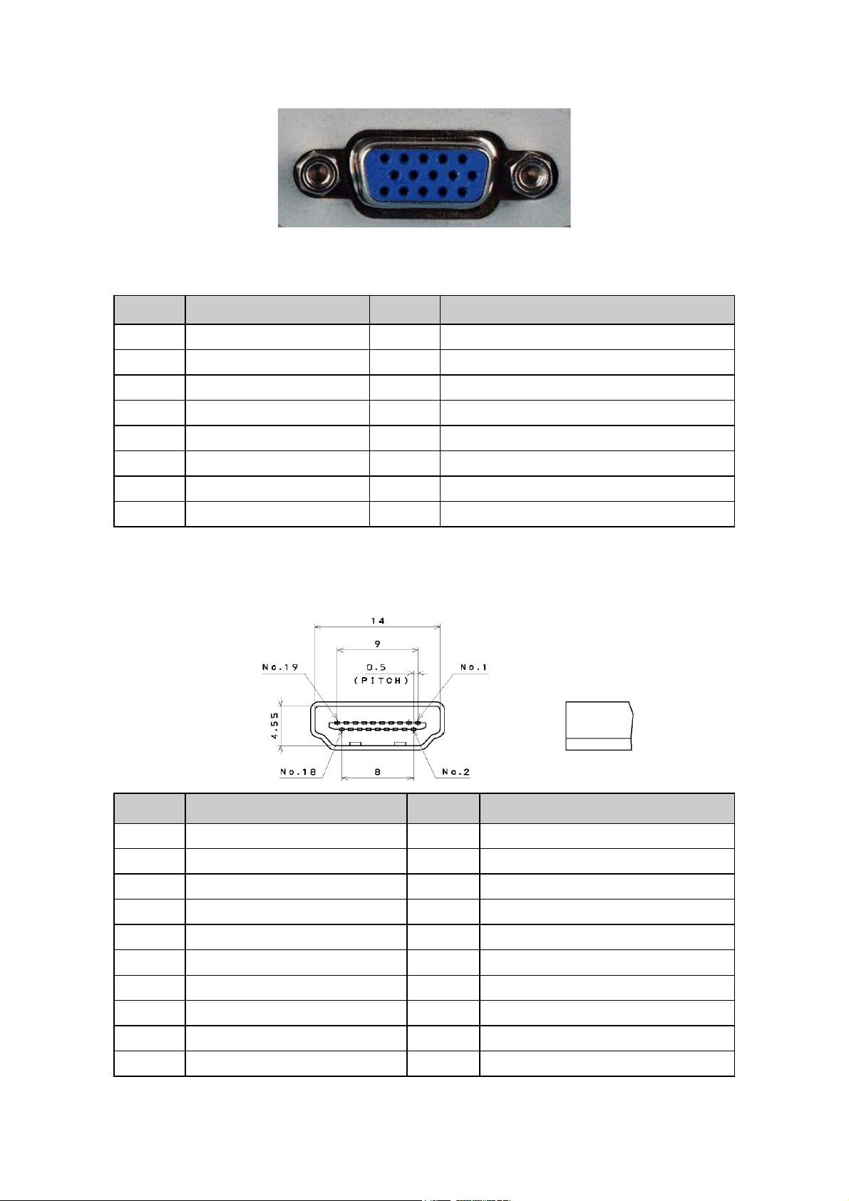
3.1 RGB Signal Input
15 - Pin Color Display Signal Cable
Pin No. Description Pin No. Description
1 Red Video 9 No Pin
2 Green Video 10 Sync Ground
3 Blue Video 11 SDA(Remote Control)
4 SCL(Remote Control) 12 Serial Data for DDC
5 Ground 13 H-Sync.
6 Red Video Ground 14 V-Sync.
7 Green Video Ground 15 Serial Clock for DDC
8 Blue Video Ground
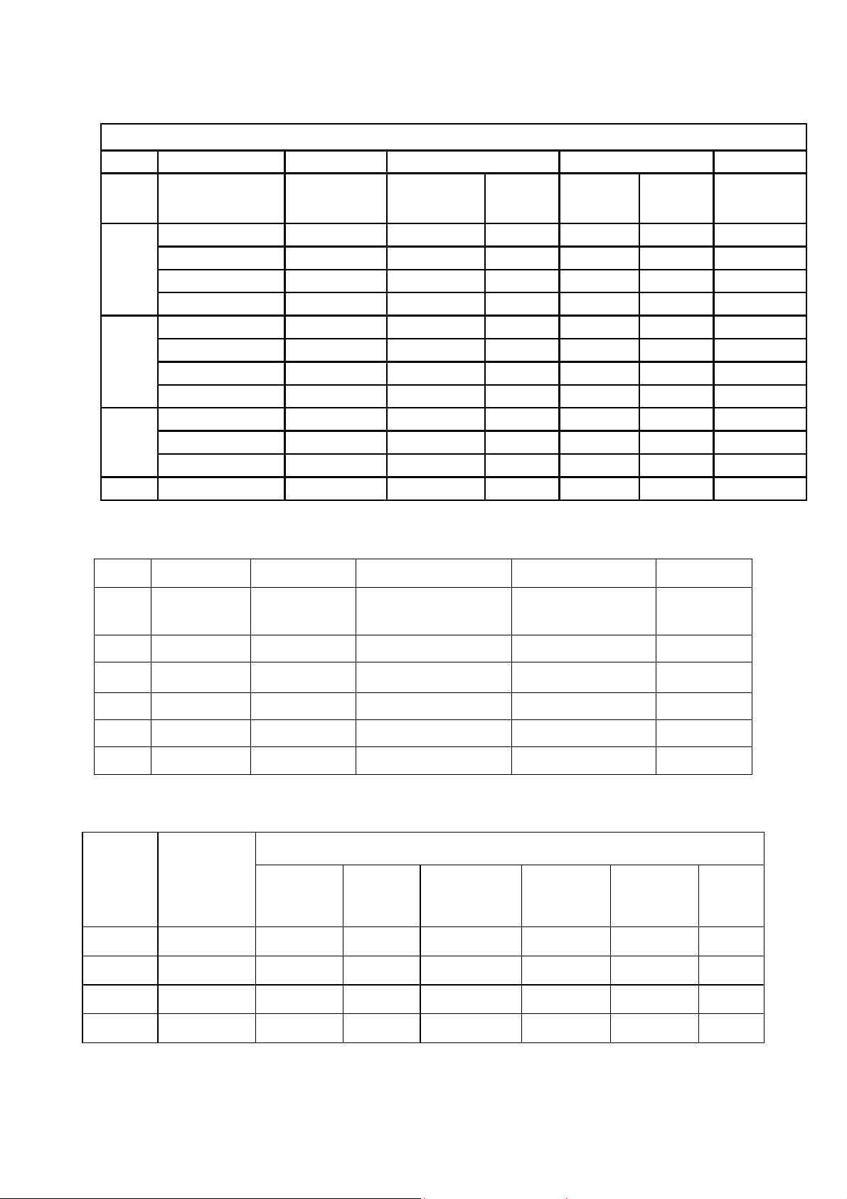
3.2 HDMI Digital Connector Pin Assignments
Pin No. Description Pin No. Description
1 TMDS Data2+ 2 TMDS Data2 Shield
3 TMDS Data2- 4 TMDS Data1+
5 TMDS Data1 Shield 6 TMDS Data1-
7 TMDS Data0+ 8 TMDS Data0 Shield
9 TMDS Data0- 10 TMDS Clock+
11 TMDS Clock Shield 12 TMDS Clock-
13 CEC 14 NC
15 SCL 16 SDA
17 DDC/CEC Ground 18 +5V Power
19 Hot Plug Detect
6
Page 7
3.3 Compatible Mode Table
LE32W157
Analog RGB:
VESA MODES
HDMI
Mode Resolution Total
VGA
SVGA
XGA
WXGA 1360x768@60 Hz 1792X795 47.712 P 60.015 P 85.5
Nominal Nominal Nominal
Horizontal Vertical
Nominal
Frequency
(KHz)
640x480@60Hz 800 x 525 31.469 N 59.940 N 25.175
640x480@72Hz 832 x 520 37.861 N 72.809 N 31.500
640x480@75Hz 840 x 500 37.5 N 75 N 31.500
720x400@70Hz 900 x 449 31.469 N 70.087 P 28.322
800x600@56Hz 1024 x 625 35.156 P 56.25 P 36.000
800x600@60Hz 1056 x 628 37.879 P 60.317 P 40.000
800x600@72Hz 1040 x 666 48.097 P 72.188 P 40.000
800x600@75Hz 1056 x 625 46.875 P 75 P 49.5
1024x768@60 Hz 1344x806 48.363 N 60.004 N 65.000
1024x768@70 Hz 1328x806 56.476 N 70.069 N 75.000
1024x768@75 Hz 1312x800 60.023 P 75.029 P 78.750
Sync
Polarity
Nominal
Freq. (Hz)
Sync
Polarity
Nominal
Pixel Clock
(MHz)
Mode Resolution Total
1080P 1920X1080 67.5 60 148.50
720P 1280×720 1650 x 750 45.00 60 74.25
1080i 1920X1080 2200 x 1125 33.75 60 74.25
480P 720X480 858 x 525 31.50 60 27.03
480i 720X480 1716 x 525 15.75 60 13.51
Horizontal
Frequency(KHz)
Vertical Frequency
(Hz)
Component
Display performance description
Industry
Code
720P
1080i
480i 720x480i 2:1 525 15.75 60 13.51
Input signal
Format
1280×720P*
1920×1080i*
Interlace
rate
Partition
1:1 750 45 60 74.25 16:9
2:1 1125 33.75 60 74.25 16:9
Total
Line Per
Frame
Horizontal
Frequency
(KHz)
Vertical
Frequency
(Hz)
Sampling
Frequency
(MHz)
Pixel Clock
(MHz)
Aspect
480P 720x483P 1:1 525 31.47 60 27.00
7
Page 8
LE40H157
Analog RGB:
Mode Resolution
VGA
SVGA
XGA
WXGA
WSXGA
FHD 1920x1080@60Hz 66.587 P 59.934 N 138.500
HDMI
VESA MODES
Horizontal Vertical
Nominal
Frequency
(KHz)
640x480@60Hz 31.469 N 59.940 N 25.175
640x480@72Hz 37.861 N 72.809 N 31.500
640x480@75Hz 37.5 N 75 N 31.500
720x400@70Hz 31.469 N 70.087 P 28.322
800x600@56Hz 35.156 P 56.25 P 36.000
800x600@60Hz 37.879 P 60.317 P 40.000
800x600@72Hz 48.077 P 72.188 P 50.000
800x600@75Hz 46.875 P 75 P 49.5
1024x768@60Hz 48.363 N 60.004 N 65.000
1024x768@70Hz 56.476 N 70.069 N 75.000
1024x768@75Hz 60.023 P 75.029 P 78.750
1280x720@60Hz 45 P 60 P 74.25
1280x768@60Hz 47.396 P 59.995 N 68.25
1280x1024@60Hz 63.981 P 60.02 P 108.000
1440x900@60Hz 55.935 N 59.887 P 106.5
1680x1050@60Hz 64.674 P 59.883 N 119
VESA MODES
Sync
Polarity
Nominal
Freq. (Hz)
Sync
Polarity
Nominal
Pixel Clock
(MHz)
Mode Resolution Total
1080P 1920X1080P 2200 x 1125 67.5 60 148.50
1080P 1920X1080P 2200 x 1125 24 59.4
720P 1280×720P 1650 x 750 45.00 60 74.25
1080i 1920X1080i 2200 x 1125 33.75 60 74.25
480P 720X480P 858 x 525 31.50 60 27.03
480i 720X480i 1716 x 525 15.75 60 27.03
Horizontal Vertical
Nominal
Frequency
(KHz)
Sync
Polarity
Nominal
Freq. (Hz)
Sync
Polarity
Pixel Clock
Component
Display performance description
Industry
Code
720P
1080i
480i 720x480i 2:1 525 15.75 60 13.51 4:3
Input signal
Format
1280× 720P*
1920× 1080i*
Interlace
rate
Partition
1:1 750 45 60 74.25 16:9
2:1 1125 33.75 60 74.25 16:9
Total Line Per
Frame
Horizontal
Frequency
(KHz)
Vertical
Frequency
(Hz)
Sampling
Frequency
(MHz)
Nominal
(MHz)
Aspect
480P 720x483 P 1:1 525 31.47 60 27.00 4:3
1080p 1920 x1080p 1:1 1125 67.5 60 148.50 16:9
8
Page 9
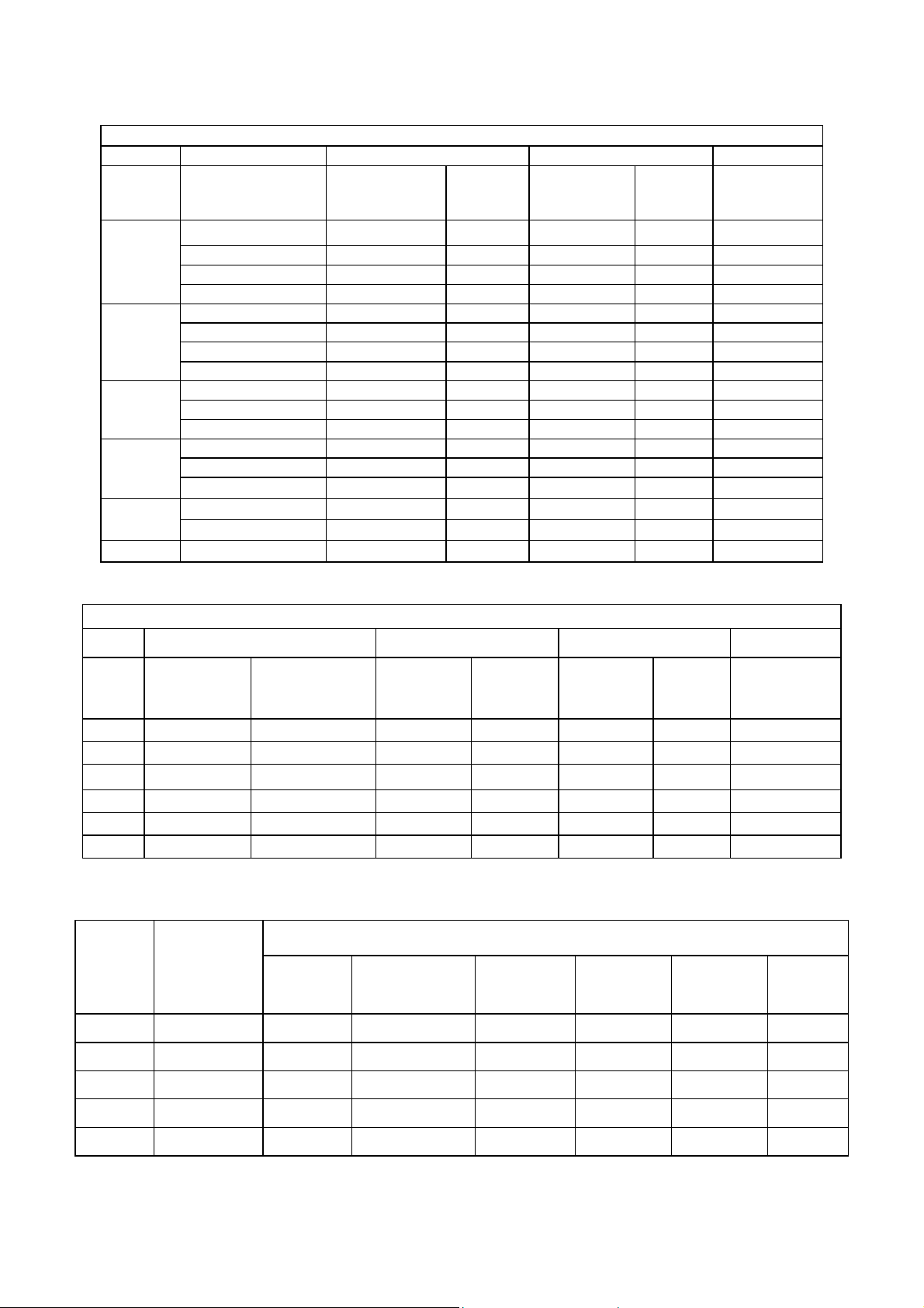
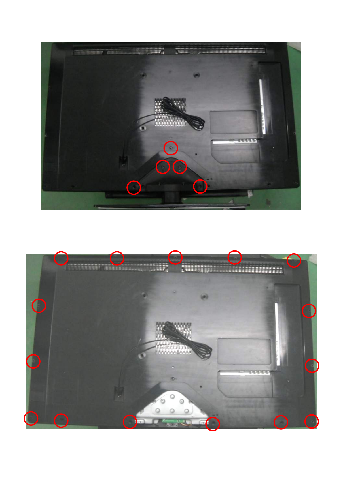
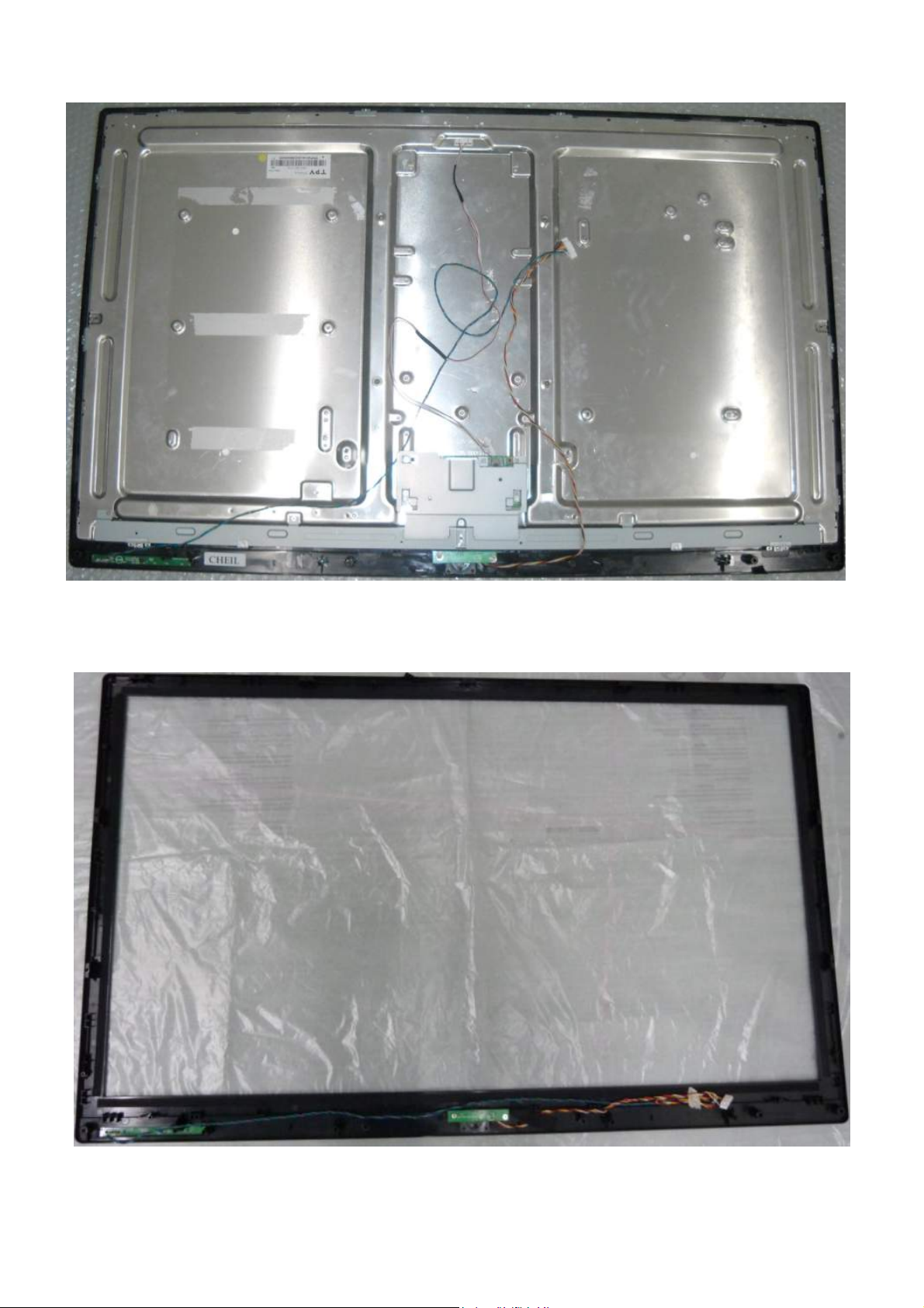
4. Mechanical Instructions
LE32W157
1. Unscrew the 5 screws to remove the COVER HINGE and STAND BASE ASS’Y.
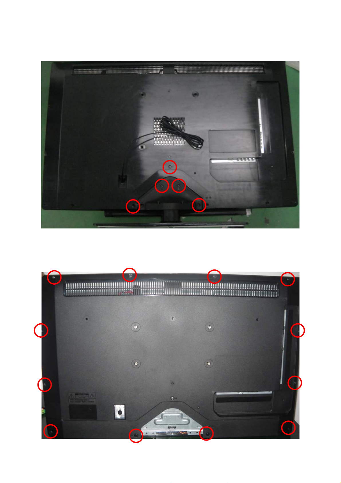
2. Unscrew the 12 screws to remove the REAR COVER.
9
Page 10
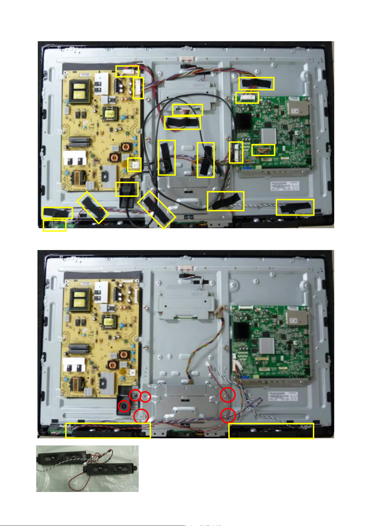
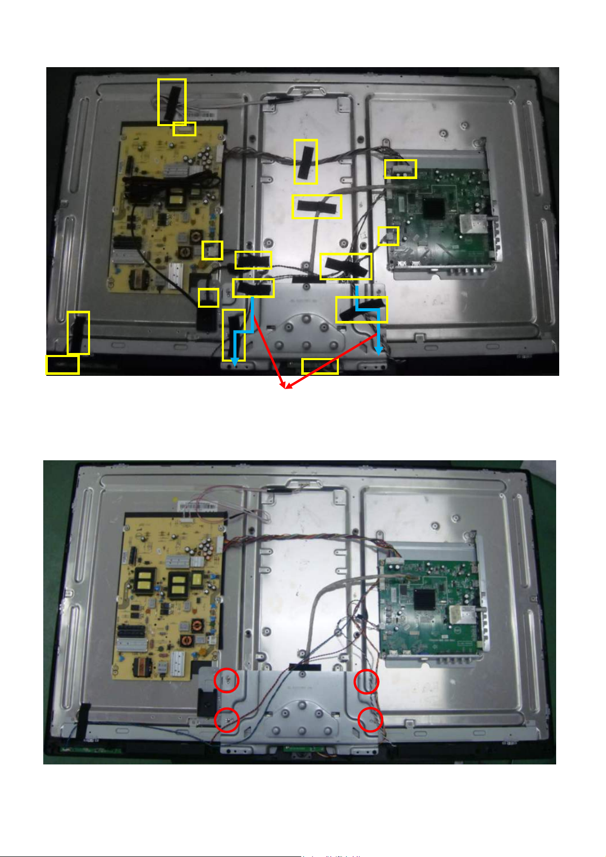
3. Disconnect all the WIRE HARNESS and TAPE_INSULATING.
4. Remove the BRACKET HINGE, AC COVER and SPEAKERS.
Note:
1. Speakers’ setting must follow the rule of Left: Red and Right: White.
2. Speakers’ PIN must face inside.
10
Page 11
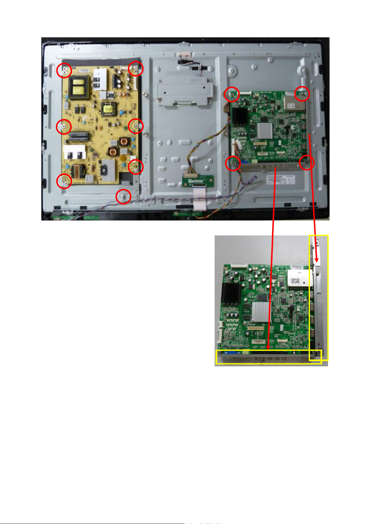
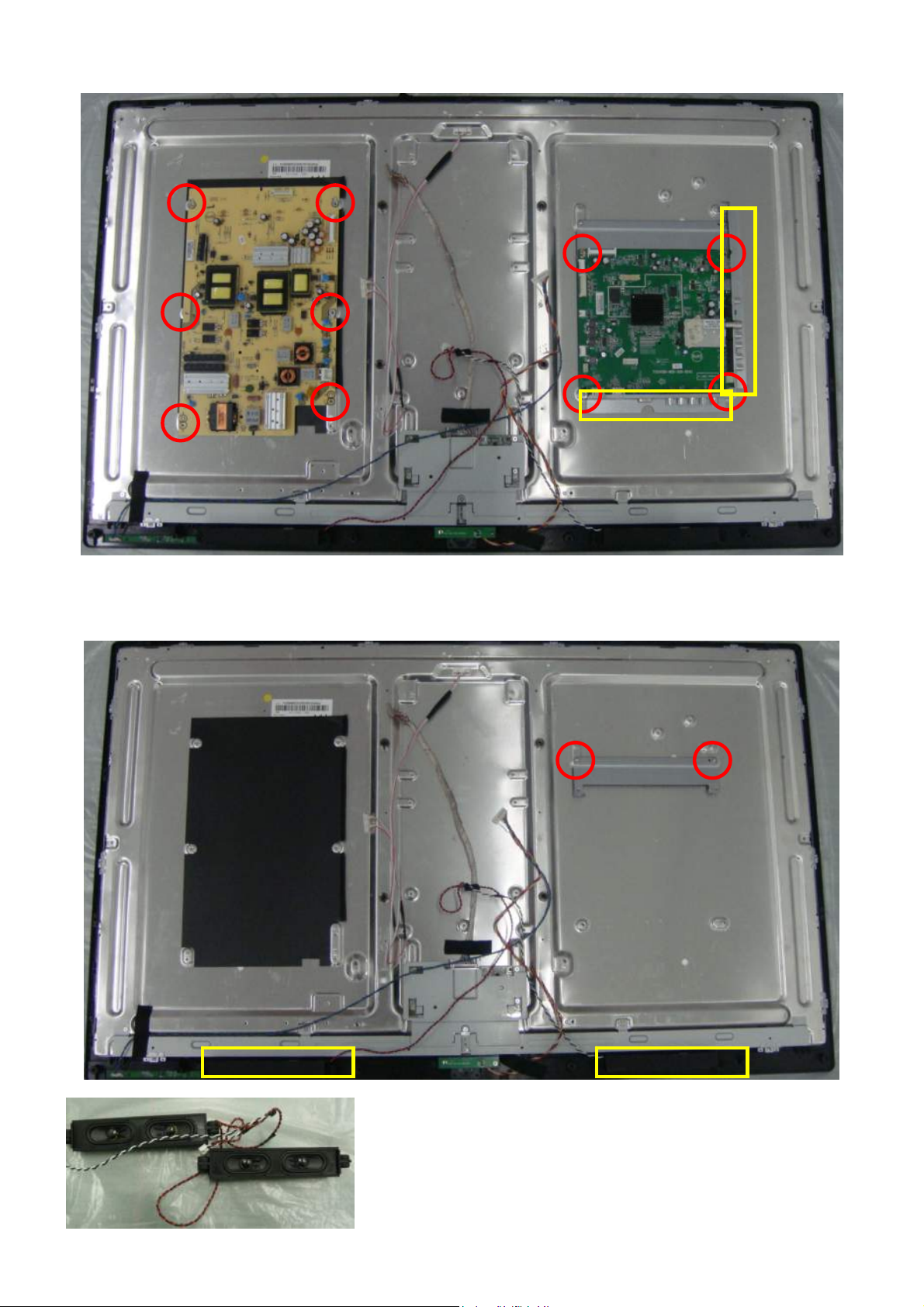
5. Remove the MAIN, POWER BOARD and BRACKET AC-IN, BRACKET BKT_SIDE, BRACKET BKT_IO_BTM.
11
Page 12
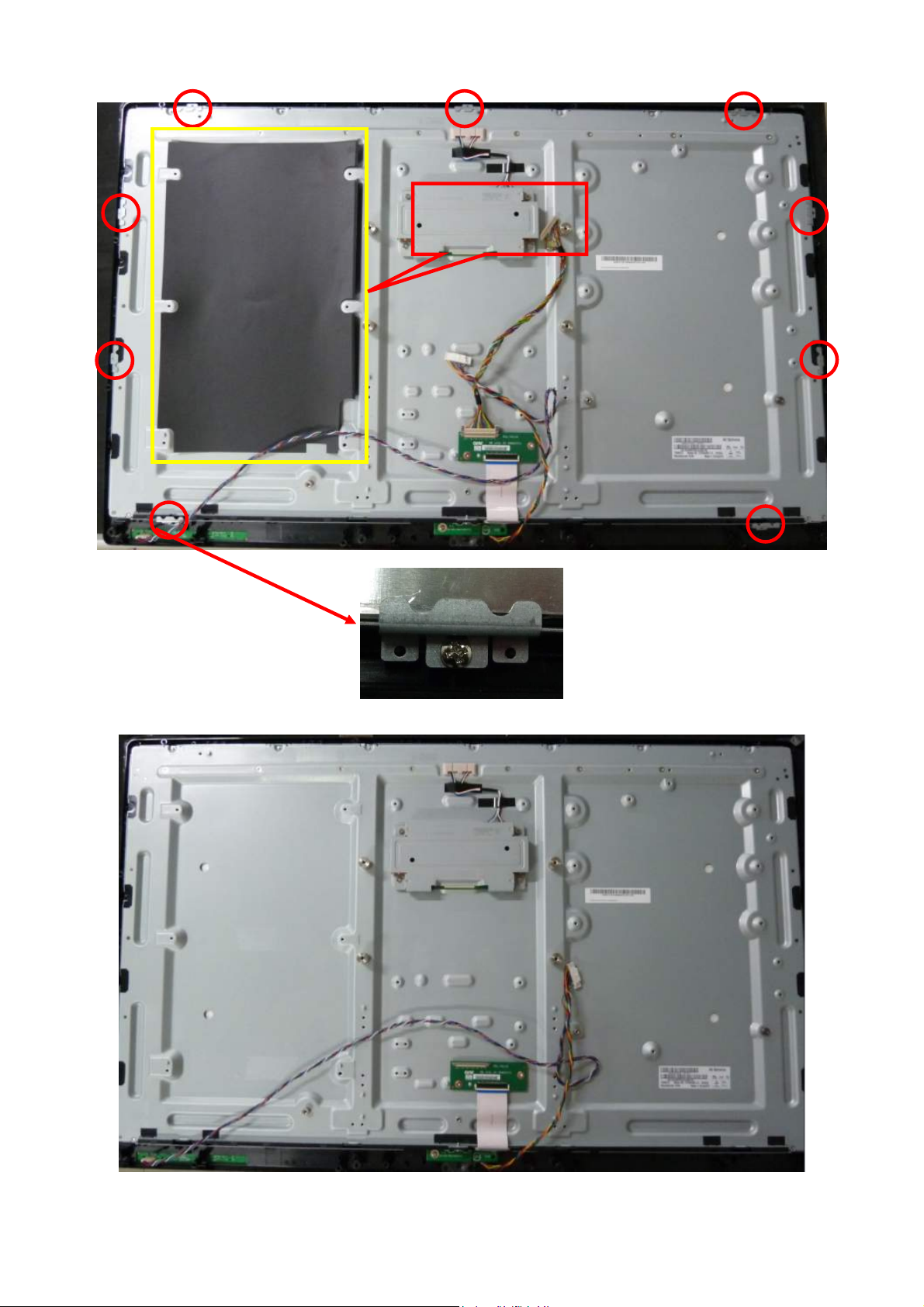
6. Remove the BRACKET PANEL-HOLDER and INSULATING SHEET.
INSULATING SHEET
7. The PANEL.
12
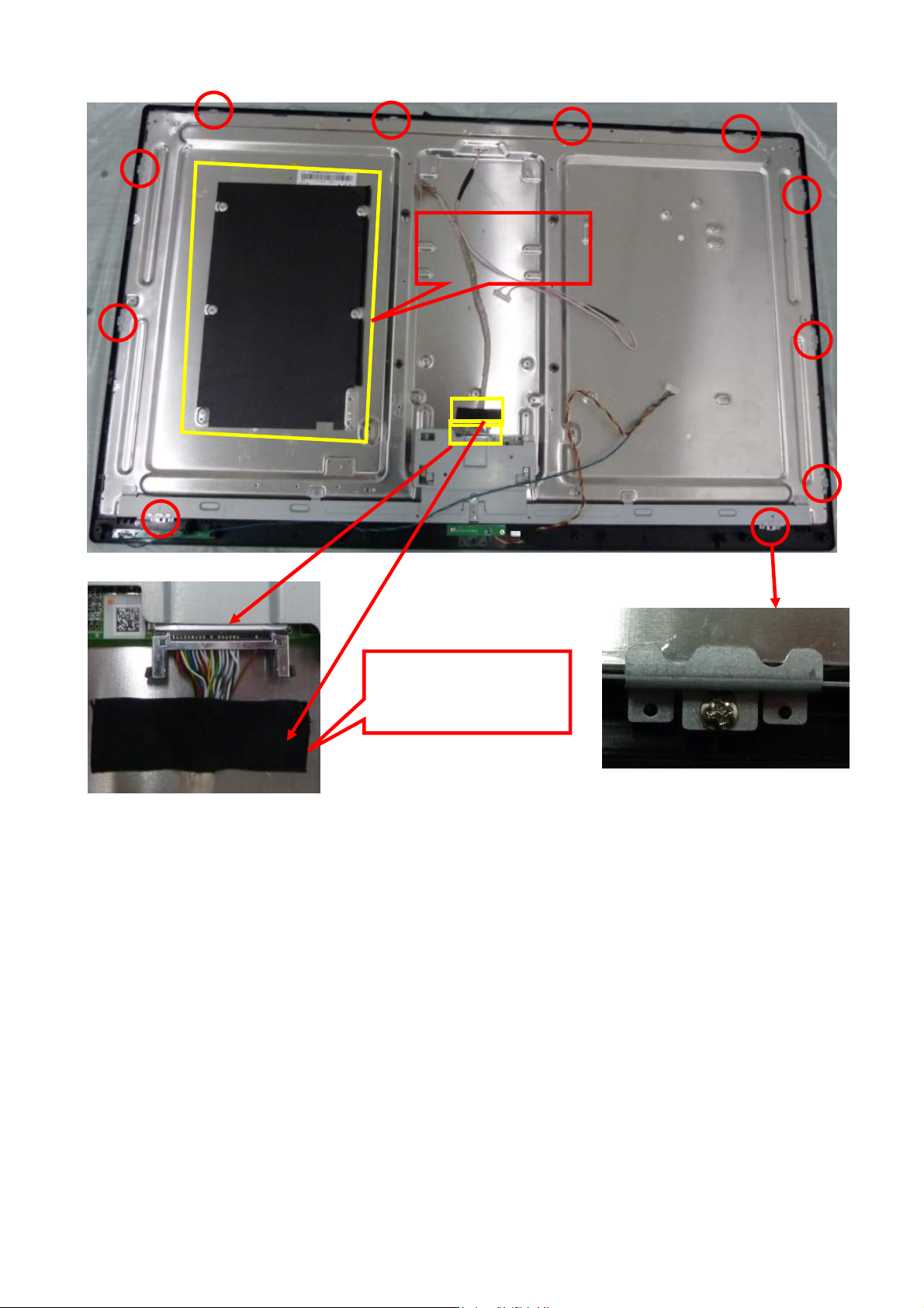
Page 13
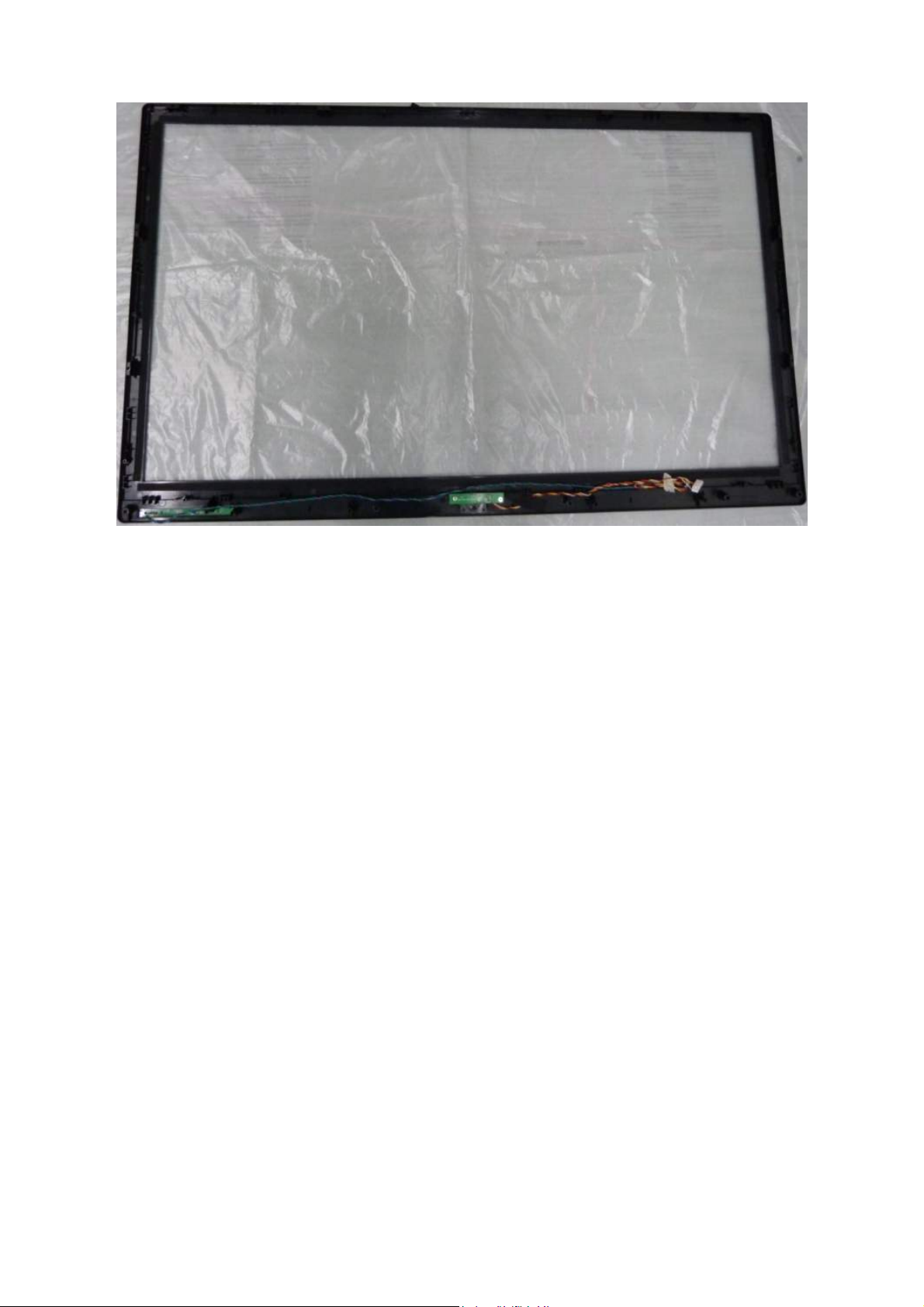
8. The BEZEL.
13
Page 14
LE40H157
1. Unscrew the 5 screws to remove the COVER HINGE and STAND BASE ASS’Y.
2. Unscrew the 15 screws to remove the REAR COVER.
14
Page 15
3. Disconnect all the WIRE HARNESS and TAPE_INSULATING.
Note: The 2 wire harnesses must be in the groove.
4. Unscrew to 4 screws to remove the BRACKET PANEL.
15
Page 16
5. Remove the MAIN, POWER BOARD and BRACKET IO-SIDE, BRACKET IO-DOWN.
6. Remove the BRACKET MAIN PCB-LEFT and SPEAKERS.
Note:
1. Speakers’ setting must follow the rule of Left: Red and Right: White.
2. Speakers’ PIN must face inside.
16
Page 17
7. Unscrew the 11 screws to remove the BRACKET PANEL-HOLDER and INSULATING SHEET.
INSULATING SHEET
INSULATING SHEET must
be stuck on the part where no
conductive fabric
17
Page 18
8. The PANEL and BEZEL, separate the PANEL from BEZEL.
9. The BEZEL.
18
Page 19
p
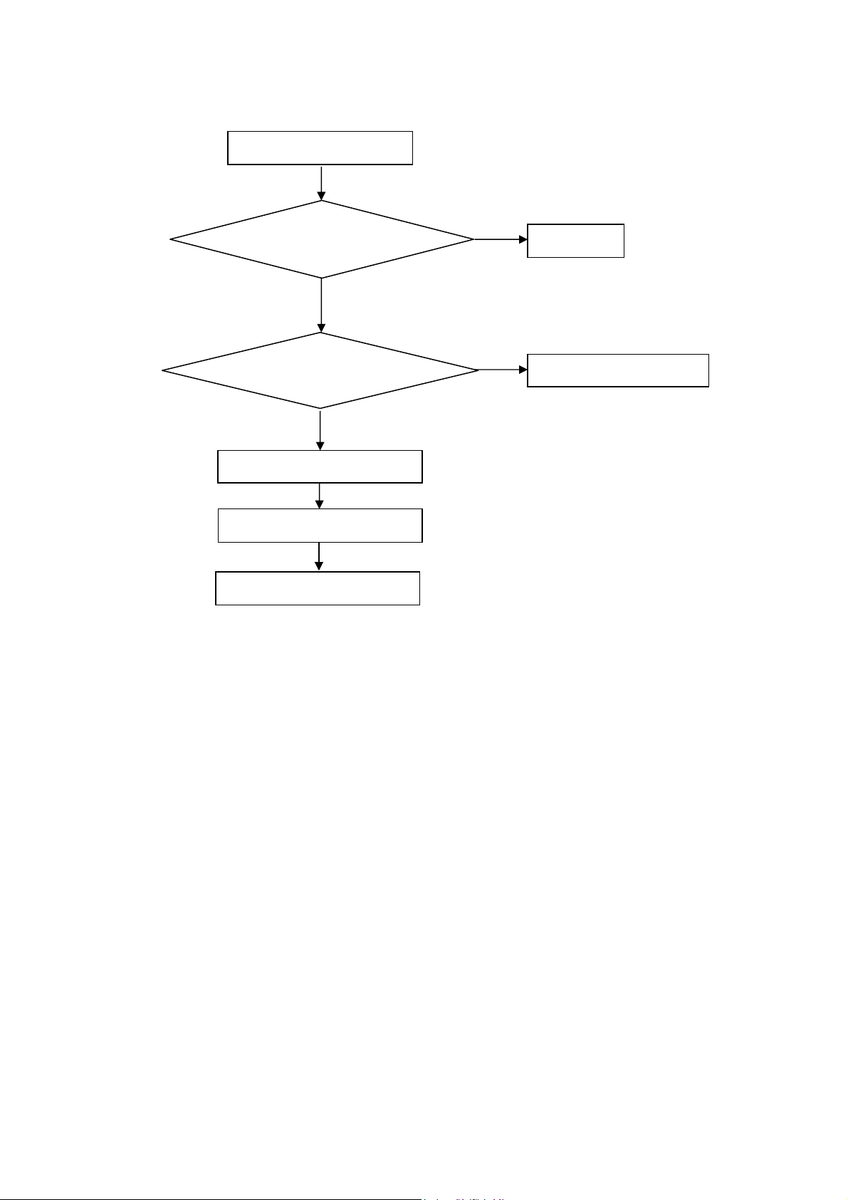
5. Repair Flow Chart
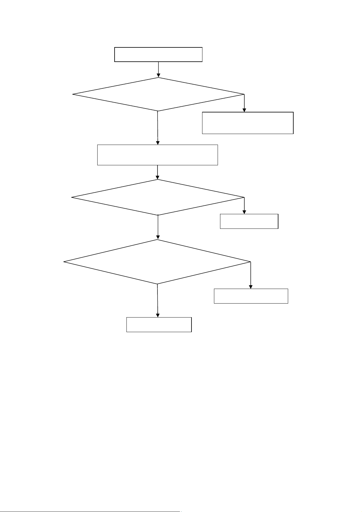
1. No power
No power (LED “Off”)
Check the AC input and
the
ower is “ON”?
Yes
Power board output=5V?
Yes
Check the IR board and LED
Replace the IR board
No
Replace the main board
No
Power “On”
No
Replace the power board
19
Page 20
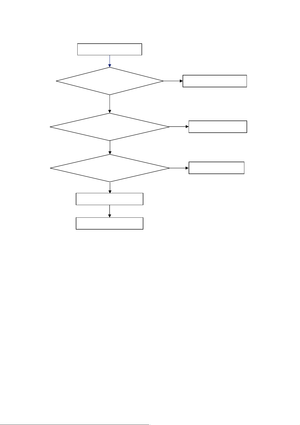
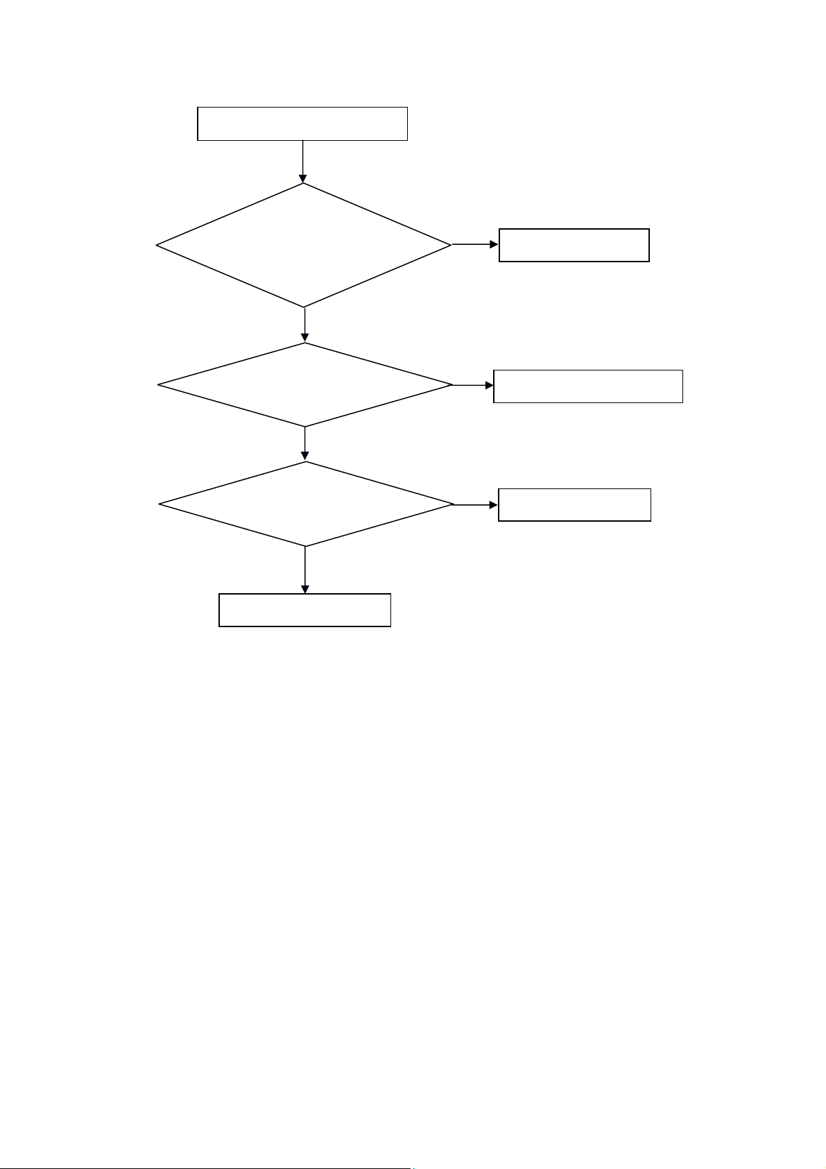
2. Can’t start
Can’t start(LED red)
Power board output=24V?
Yes
Check the power key is under control?
No
Check the IR receiver is normal?
No
Replace the power board
Yes
Replace the key board
Yes
Replace the IR board
No
Replace the main board
No
Replace the Power board
20
Page 21
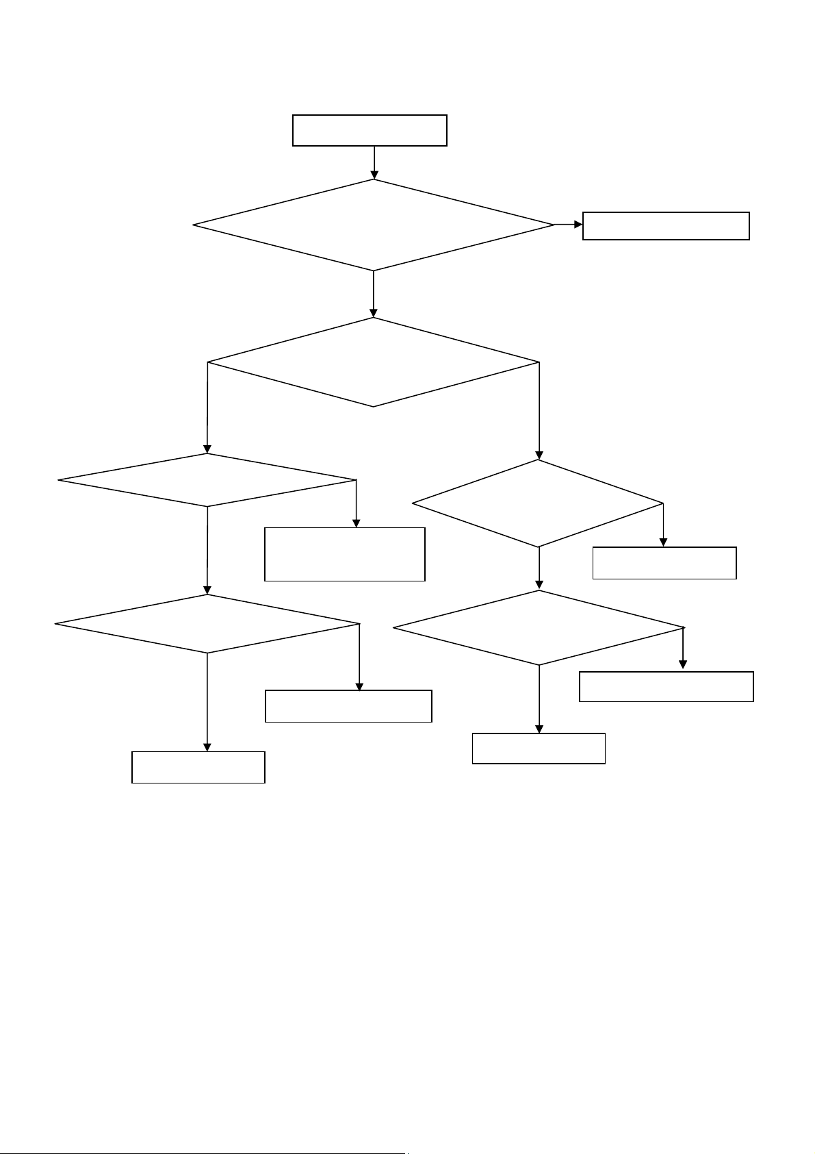
3. No display
No display (LED blue)
Check TV is under control and power
on/off by remote control and power key?
Yes
Check the LVDS cable
Yes
Yes
Check the backlight is
“On”?
No
Reinsert or replace the
LVDS cable
No
No
Check the B/L
signal is available?
Yes
Replace the main board
No
Replace main board
Panel Vcc = 12V?
Yes
Replace the Panel
No
Replace the main board
Power board output=24V?
Yes
Replace the Panel
Replace the power board
No
21
Page 22
4. Sound problem
No sound or sound abnormal
Check the audio source connection
and the TV system are correct?
Yes
Check the TV is muted, adjust the
volume or enter the menu to reset?
No
Check the cable between the
speakers and main board is ok?
No
Reinsert the audio cable or
change the TV system
No
Yes
Check the speaker resistance value is in spec
(Remark: The value is marked on the speaker)?
Yes
Replace the speaker
Replace the main board
Replace the cable
No
22
Page 23
5. Remote control malfunction
Remote Control malfunction
Check the remote control battery is
not properly placed or no power?
No
Use the other remote controls
No
Whether the IR board is
abnormal?
No
Replace the main board
Yes
Replace the battery
Yes
Replace the remote control
Yes
Replace the IR board
23
Page 24
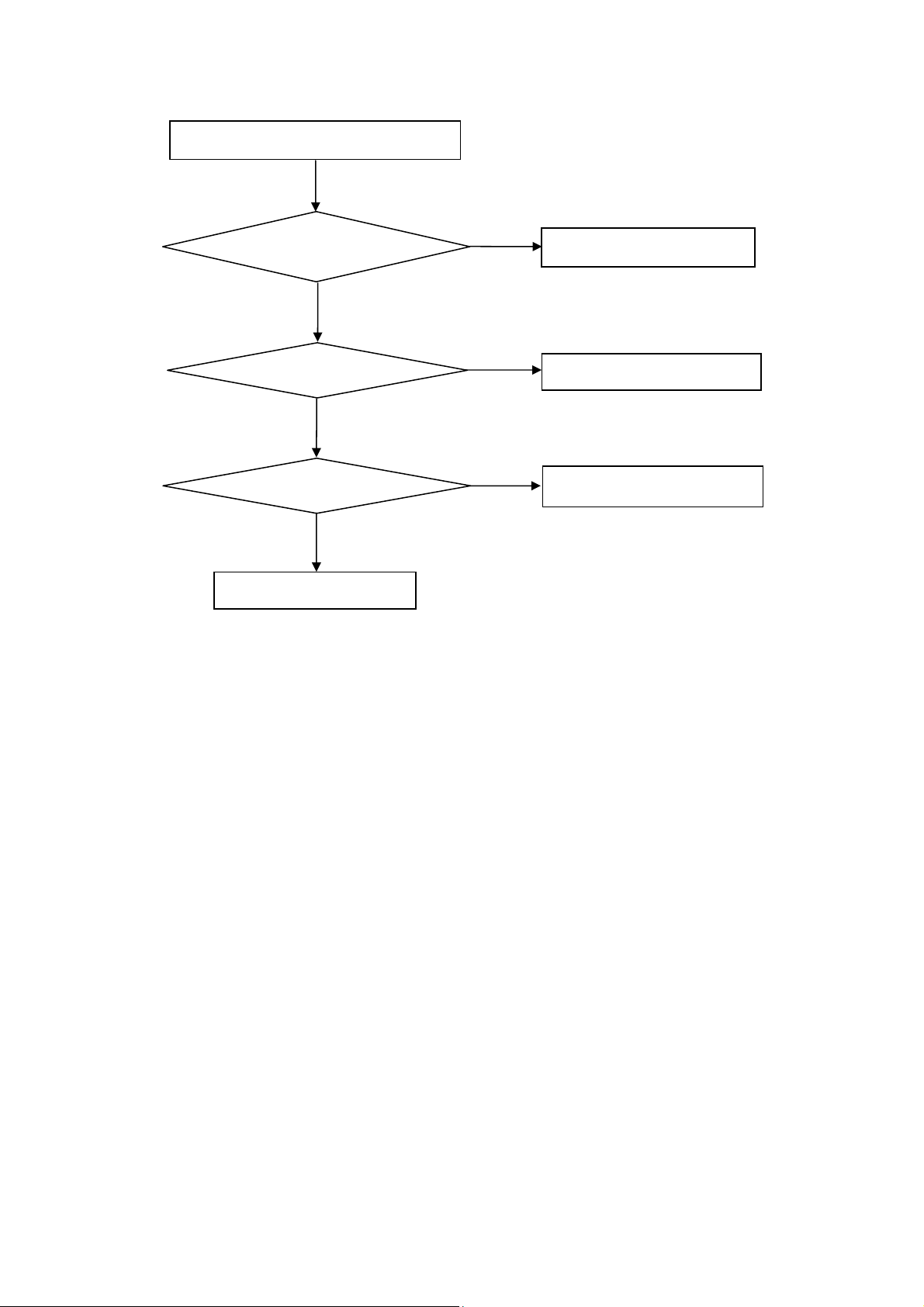
6. OSD is unstable or can’t work normally
OSD is unstable or can’t work normally
Key board connected properly?
Yes
Buttons are ok?
Yes
Key board is ok?
Yes
Replace the main board
No
Reconnect the key board
No
Replace the button function
No
Replace the key board
24
Page 25
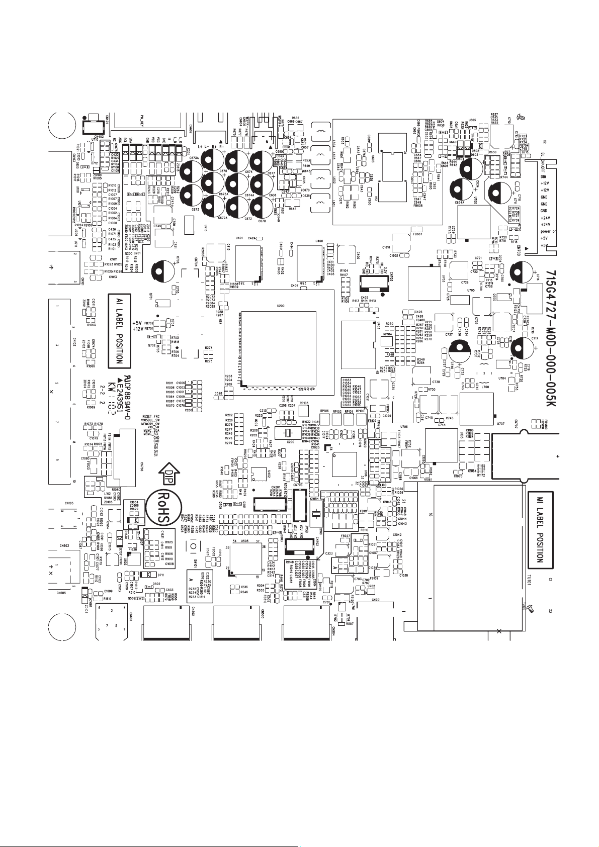
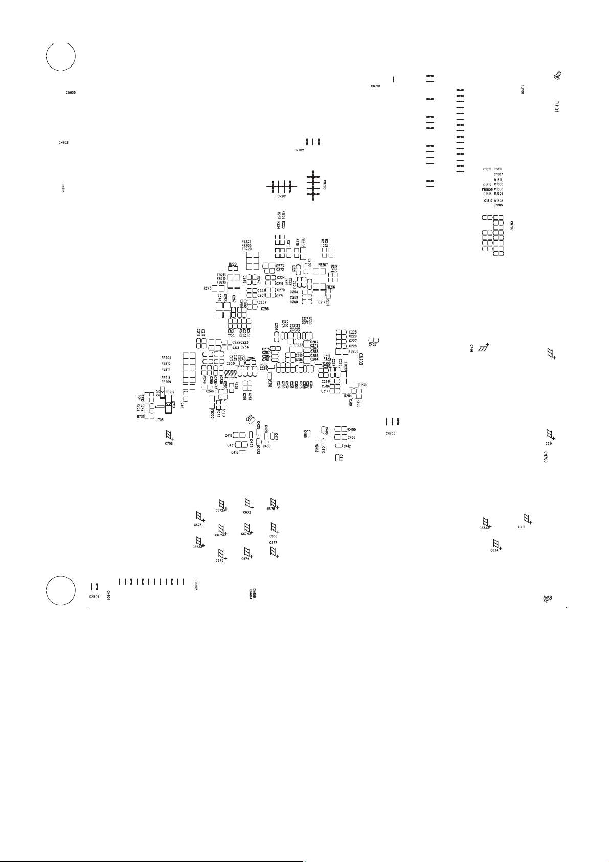
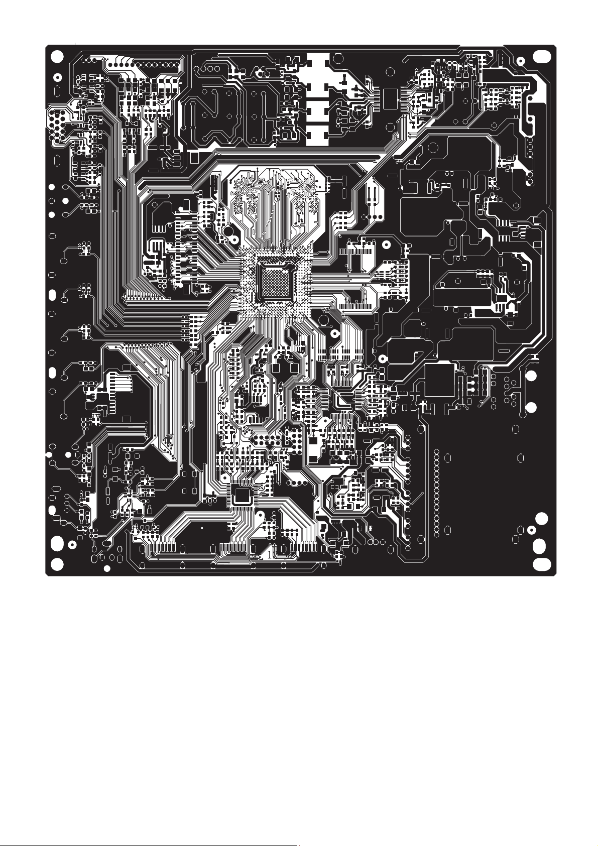
6. PCB Layout
6.1 Main Board
715G4727M0D000005K
25
Page 26
26 27
Page 27
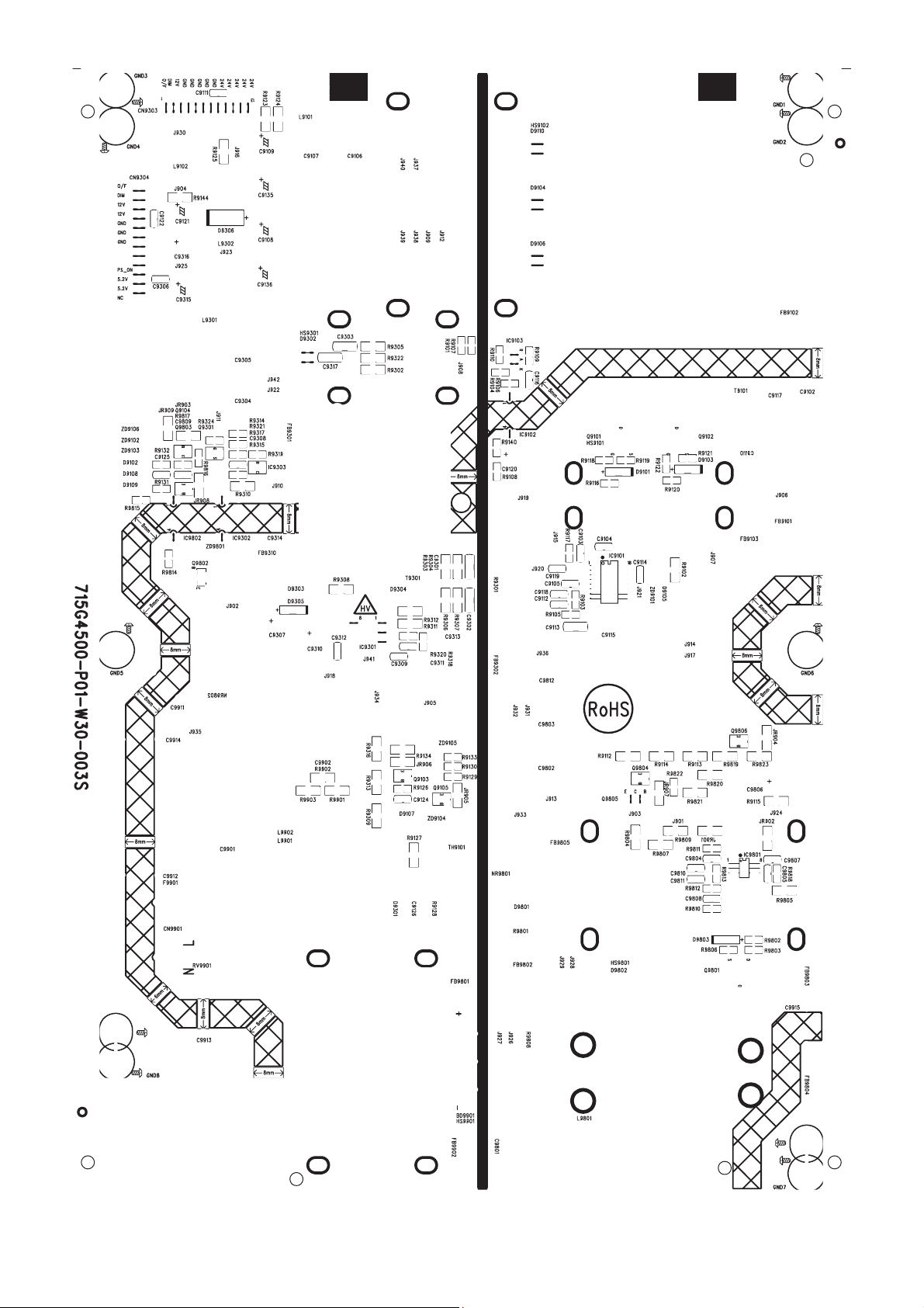
Page 28
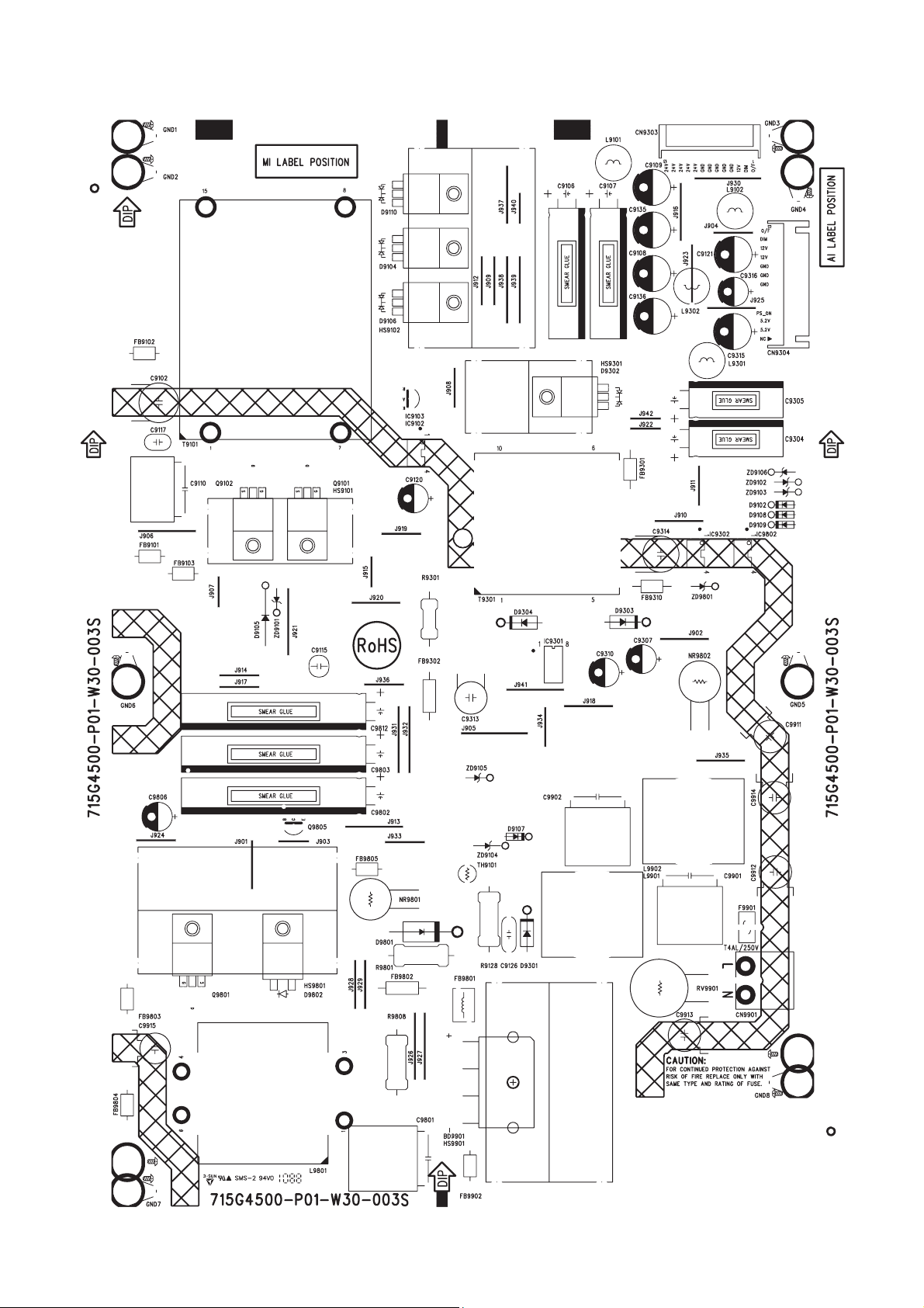
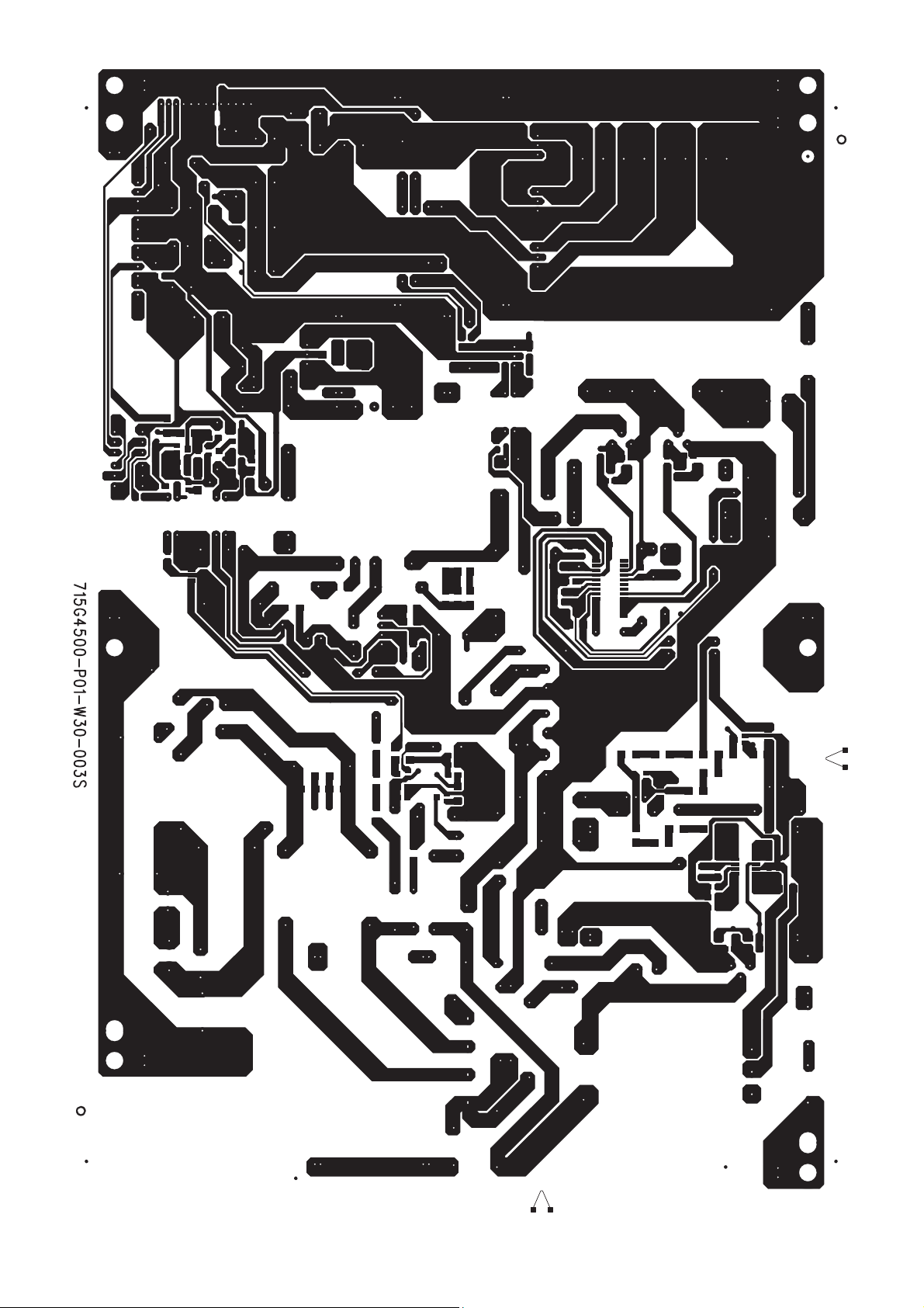
6.2 Power Board
LE32W157 715G4500P01W30003S
28
Page 29
29 30
Page 30
Page 31

LE40H157 715G4581P01W30003H
31
Page 32

32 33
Page 33

Page 34

6.3 Key Board
715G4682K0C000004S
34
Page 35

6.4 IR Board
715G4650R01001005I
35
Page 36

7. Adjustment
It’s no need ADC and WB adjustment for the two models.
36
Page 37

8. Block Diagram
Main Board Block
Panasonic
Tuner
HDMI 1
HDMI 2
HDMI 3
IF
TC90517F
YP b P r +A ud i o IN
CVBS+Audio IN
SII9187ACNU
VGA RGB +Audio IN
TS Stream
HDMI
HIDTV_PRO_SX27
IIS
STA339BWTR
Audio Speaker Amp
APA2176
Headphone Amp
SPDIF out
SPEAKER
2.1Ch
BD8012FVJ
U701 power
USB
64Mx16_DDR2
64Mx16_DDR2
MX25L4005
SPI Flash
37
Panel
NAND Flash
512Mb
Page 38

Main Power Block
CN700
24V
12V
5VSB
R632
NC
D602
?A:71G 56G301 EA
FB701
R630
NC
?A:71G 56K121 M
FB112
R507
NC
FB702
NC
93G 64 42 PP
D100
R633
680
56T 563146
U715
56G 659501
U701
BD8012FVJ
56G 563514
U705
AIC1117-33PY
30V/7A/40A:AO4449
Q700
57G 763 79
PD_MUTE circuit
R/L output circuit
PD_MUTE circuit
57G 763 79
Q701
PANEL_ON
5V
R1060
57G 763 79
PANEL_ON 30V/7A/40A:AO4449
VGA_VCC
+1.2VSB
5V
POWER_ON
PD_MUTE circuit
CEC circuit
VGA EDID pull up
PD_MUTE circuit
key AD pull up
VCCH1
?A:71G 56G301 EA
93G 64S3PH
BAS32L
56G 563 30
AZ1084S-3.3TREI
30V/7A/40A:AO4449
56G 563964
U105
SC4215HSETRT
Q701
Pin1
CN701
3VSB
FB703
D711
U700
3.3V
56G 616518
U603
STA339BW13TR
VCC2: Pin8
VCC1: Pin11
PANEL_VCC
FB227
?A:71G 57G301 MB
FB110
?A:71G 57G301 MB
5V_TUNER TUNER PIN17
PANEL_VCC
CN603 SPDIF VCC
U701 USB OC pull up
SX DSDA/DSCL pull up
HP_MUTE power supply
CN706 MEMC power supply
FB119
?A:71G 57G301 MB
FB111
?A:71G 56K121 M
FB401
?A:71G 56K121 M
FB208
56G 563513
U704
APW7080KAITRG
PVDD:16
56T 616516
U602
VDD:8
APA2176A
?A:71G 56K121 M
FB205
?A:71G 56K121 M
FB220
?A:71G 56K121 M
FB221
?A:71G 56K121 M
FB206
56G 563143
U706
+1.2V
G1084T43Uf
?A:71G 56K121 M
FB502
?A:71G 57G301 MB
FB103
SX AVDD33 power supply
HP_VCC1V
TV_CVBS?A:71G 59D121 TA
TUNER PIN10
TUNER PIN2
CN401 Pin5/6 IR&Key power supply
HDMI_CEC/HDMI_IIC_SW/HDMI SBVCC
MCU_JTAG_TCK
U711
56G4LVCG17 TI
Pin5
U712 SN74LVC1G17DBVR
Q200/Q201 LED power supply
HP_TESTCON pull up
SX MCU
SX VDDF power supply
56G1133923
U402
MX25L4005AM2C-12G
56G 643 27
U202 G692L293TCUF
?A:71G 56K121 M
FB223
56G 563122
U707
PANEL_PWM pull up
SX TXD/RXD/SCLM2/SDAM2/CN705 pull up
SX GPIO0-9/MIPS_JTAG pull up
56G 563246
U703
AZ1084S2-ADJG1 HP_VDDM/HP_VC_18
SX NAND FLASH I/O pull up
SX AVDD33_SP
SX AVDD33OUTBUF
SX AVCC33RX
SX VDDA33
?A:71G 56K121 M
FB607
?A:71G 57G301 MB
FB105
?A:71G 57G301 MB DR1VDD:Pin34/48
FB107
?A:71G 57G301 MB
FB102
SX VDDLVDDL
SX VDDC
HP_VCC_25
VCC33_AMP
Pin5 56G4LVCG17 TI
VDDS:Pin13/35+3.3VO
U106 SDA/SCL/XSEL1/XSEL0 pull up
38
FB1805
FB101
?A:71G 57G301 MB
FB104
?A:71G 57G301 MB
FB106
?A:71G 57G301 MB
FB108
FB222
?A:71G 56K121 M
FB210
?A:71G 56K121 M
FB211
?A:71G 56K121 M
FB214
?A:71G 56K121 M
FB216
?A:71G 56K121 M
FB217
?A:71G 56K121 M
FB209
?A:71G 56K121 M
FB212
?A:71G 56K121 M
FB204
?A:71G 56K121 M
FB207
?A:71G 56K121 M
FB213
?A:71G 56K121 M
FB215
?A:71G 56K121 M
FB218
?A:73G253S 94 M1
R240
?A:71G 56K121 M
FB400
?A:71G 59C300
FB613
?A:71G 59C300
FB608
?A:71G 59C300
R693
56T1133111
VDDC:Pin16/36/56/63
U106
TC90517FG
U709/u710 SN74LVC1G17DBVR
U106
56T1133111
Pin49/64
TC90517FG
ETH_VCC_25 CN707 RJ-45 Debug?A:71G 59D121 TA
VDDI_25 SX VDDI25?A:71G 56K121 M
PLL_Vdd
AD_DVDD: Pin32?A:71G 57G301 MB
DR2VDD: Pin43
AD_AVDD: Pin22
PLLVDD: Pin20
TC90517FG
?A:71G 56K121 M
VDDI_25 SX AVDD_MCK2
FB219
SX VCC25A
SX VCC25D
SX VCC25HP
SX VCC25A_BG
SX VCC25A_TX
SX VDDP
SX LVDS_VDD
SX PAVDDLLPLL
SX AVDDPLL
SX AVCC
SX PVCC
SX REGVCC
SX AVDD25_ADC1
SX VDDR1/2
SX VDDM
VDDQ/VDD
U400/U401
VDDL
VREF
SX MVREF1/2
VDD:Pin12/37VCC_FLASH
U403
PD_MUTE pull up
VDD_DIG:Pin36
U603
VDD_DIG:Pin21
VDD_PLL:Pin24
STA339BWTR
56G 634 25
VCC33:Pin9/27/64HD3V3
U505
SII9187ACNU
U106
56G 615505
NT5TU64M16DG-BE
56T1133111
NAND512W3A2DN6E
Page 39

9. Schematic Diagram
9.1 Main Board 715G4727M0D000005I
04: HiDPRO SX-1
TS1_D[0..7]
TS1_CLK
TS1_SYNC
TS1_ DE N
TS1_CLK
TS1_S YN C
TS1_DEN
T1_SI F
C207
20P 50V
TS1_D0
5
TS1_D0
6
7
8
RP101
8P4R 33 OHM +-5% 1/16W
NC 8P4R 33 OH M +-5% 1/16W
5V
R204
R205
4.7K 1/10W
4.7K 1/10W
CVBS1_IN
PC_R_IN
PC_G_IN
PC_B_IN
PC_HS_I N
PC_VS_IN
Y1_IN
PB1_IN
PR1_IN
TV_CVBS
C206
100N 50V
1M 1/10W
R207
24MHz
X20 0
12
4
3
2
1
RP106
5
6
7
8
HDMI_RX0HDMI_RX0+
HDMI_RX1HDMI_RX1+
HDMI_RX2HDMI_RX2+
HDMI_RXCHDMI_RXC+
HDMITX_5V
R208
33 OHM 1/10W
C208
20P 50V
TS1_D0
TS1_D1
TS1_D2
TS1_D3
TS1_D4
TS1_D5
TS1_D6
TS1_D7
4
3
2
1
C205
100N 50V
AE5
AF5
AF6
AE6
AD6
AC6
AB6
AF7
AE7
AC7
AD7
AF2
AF3
AE3
AD3
AF4
AE4
AD4
AC4
AC5
AB5
AD5
AD1
AC3
AD2
AE1
D10
A10
B10
C10
ANT SIF
D2
D1
E2
E1
F2
F1
C2
C1
B1
B3
A1
B2
B5
A3
A2
B9
B8
D4
C4
B7
D8
A7
D9
C8
C9
D7
C6
D5
D6
C5
A4
B4
A6
B6
T1
R1
E3
E4
TS1D 0
TS1D 1
TS1D 2
TS1D 3
TS1D 4
TS1D 5
TS1D 6
TS1D 7
TS1CLK
TS1SY N C
TS1D EN
TS2D 0
TS2D 1
TS2D 2
TS2D 3
TS2D 4
TS2D 5
TS2D 6
TS2D 7
TS2CLK
TS2SY N C
TS2D EN
TSS_CLK
TSS_DI
TSS_SYNC
TSS_DEN
RX0RX0+
RX1RX1+
RX2RX2+
RXCRXC+
ANTS TO
PWR5V
DSDA
DSCL
CVBS1
CVBS_OUT1
CVBS_OUT2
PCR
PCG
PCB
PCHS
PCVS
YG1
PBB1
PRR1
YG2
PBB2
PRR2
YG3
PBB3
PRR3
C
FS1
FB1
FS2
FB2
FS3
FS4
SIFN
SIFP
XTLI24M
XTLO24M
INTN
RSTO
RESET_Demo_#
U200A
HiDTV-Pro_SXB
(1/5)
TS_IN
HDMI_IN
ANALOG_IN
LVDS_OUT
I2S PORT
I2C PORT
UART PORT
USB PORT
ADC
MISC
39
HIDTV
USBPPON
RREFEXT
I2SCLKIN
PC
AV
YPBPR
Side
SCART2
TESTC ON
TESTMOD
MASTSEL
TA1M
TA1P
TB1M
TB1P
TC1 M
TC1P
TD1 M
TD1P
TE1M
TE1P
TCLK1M
TCLK1P
TA2M
TA2P
TB2M
TB2P
TC2 M
TC2P
TD2 M
TD2P
TE2M
TE2P
TCLK2M
TCLK2P
USBOC
RXD
TXD2
RXD2
SCKIN
WSI2S
SDI2S
SCK
I2SCLK
SPDIF
MUTE
SCLM1
SDAM1
SCLM2
SDAM2
SPKOR
SPKOL
HPHOR
HPHOL
AOR1
AOL1
AOR2
AOL2
A15
B15
C16
C15
B16
A16
C18
C17
B18
A18
A17
B17
A19
B19
C20
C19
B20
A20
C22
C21
B22
A22
A21
B21
AC1
DP
AB1
DN
AB3
AB2
AC2
AF20
TXD
AF21
Y1
AA1
AA3
AA4
AB4
AC21
AD21
WS
AF22
SD1
AE22
SD2
AD22
SD3
AF23
AA2
AE21
D21
Y3
Y2
C24
A23
B11
AR1
A11
AL1
D11
AR2
C11
AL2
C12
AR3
D12
AL3
A12
AR4
B12
AL4
B13
AR5
A13
AL5
B14
A14
D17
D16
D14
C14
D15
E14
M3
M2
B24
HID_TXD
HID_RXD
3.3V
HP_TESTCON
HP_TESTMOD
HP_MASTSEL
R201 6.04K +-1% 1/10W
R275 10K 1/10W
R247 10K 1/10W
C203 1uF 25V
C204 1uF 25V
3VSB
HP_SPDIF
SCL_MST1
SDA_MST1
R200
4.7K 1/10W
R202
0R05 1/10W
I2S_CLK
HID_TXD
HID_RXD
PULL DOWN : LED
PULL HIGH: JTAG
TX0AN
TX0AP
TX1AN
TX1AP
TX2AN
TX2AP
TX3AN
TX3AP
TX4AN
TX4AP
TXCKAN
TXCKAP
TX0BN
TX0BP
TX1BN
TX1BP
TX2BN
TX2BP
TX3BN
TX3BP
TX4BN
TX4BP
TXCKBN
TXCKBP
USB_DP
USB_DN
USB_PPON
USB_OC
HID_TXD
HID_RXD
I2S_CK
I2S_WS
I2S_SD
R287
2K 1/10W
PC_RI N
PC_LIN
AV_RIN
AV_LIN
HD_RIN
HD_LIN
AX_HP_OUTR
AX_HP_OUTL
3.3V
3.3V
CN705
1
2
3
4
NC
R288
2K 1/10W
HDMI_SCL
HDMI_SDA
Page 40

05: HiDPRO SX-2
FRA[19. .22]
3.3V
R220
4.7K 1/10W
AMP_SD
AMP_MUTE
HP_MUTE
HDMITX_INT
HDMI_ I2C_SW
SW_AMP_RSTN
RESET_FRC
V18_SW
MEMC 5V_SW
V105DLL_SW
DRC_EN
FRD[0..7]
FRA13
FRA14
FRA18
FRA23
FOE#
FWE#
GCS0
GCS2
4.7K 1/ 10W
R236
R222 NC 4.7K 1/ 10W
R226 4.7K 1/10W
R1840 NC/0R05 1/10W
R276 4.7K 1/ 10W
R246 4.7K 1/ 10W
SF_SI
SF_SO
SF_WP#
SF_HOLD #
SF_CS
SF_SCK
3.3V
FRD0
FRD1
FRD2
FRD3
FRD4
FRD5
FRD6
FRD7
FRA13
FRA14
FRA18
FRA19
FRA20
FRA21
FRA22
FRA23
R277 4.7K 1/ 10W
R278 4.7K 1/ 10W
R279 4.7K 1/ 10W
U200B HIDTV
AC9
FRD0/PODD0
AF10
FRD1/PODD1
AD10
FRD2/PODD2
AB10
FRD3/PODD3
AE11
FRD4/PODD4
AC11
FRD5/PODD5
AF12
FRD6/PODD6
AD12
FRD7/PODD7
AB9
FRD8/PODA0
AC10
FRD9/PODA1
AE10
FRD10/PODA2
AF11
FRD11/PODA3
AD11
FRD12/PODA10
AB11
FRD13/PODA11
AE12
FRD14/PODA12
AB12
FRD15/PODA13
AF9
FRA0
AF18
FRA1/PODWE
AB17
FRA2/PODIORD
AC17
FRA3/PODIOWR
AD17
FRA4/PODREG
AE17
FRA5
AF17
FRA6
AB16
FRA7
AD15
FRA8
AE15
FRA9/PODOE
AF15
FRA10
AB14
FRA11
AC14
FRA12
AD14
AE14
AF14
AF13
AC16
AD16
AC15
AB15
AE16
AB13
AC13
AD13
AD9
AF16
AE9
AE2
AF1
AC12
AE23
AD23
AB7
AF8
AE8
AD8
AC8
AB8
AE18
AF19
AB18
AD18
AB20
F3
G1
G2
G3
G4
H1
H2
H3
H4
J4
J3
J2
J1
FRA13
FRA14
FRA15
FRA16
FRA17
FRA18
FRA19
FRA20
FRA21
FRA22
FRA23
FRA24
FOE#
FWE#
GCS0
GCS1
GCS2
BOOTCS
GPIO0
GPIO1
GPIO2
GPIO3
GPIO4
GPIO5
GPIO6
GPIO7
GPIO8
GPIO9
GPIO10
GPIO11
GPIO12
GPIO13
GPIO14
POD_A4
POD_A5
POD_A6
POD_A7
POD_A8
POD_A9
POD_IR EQ
POD_RST
POD_VS1
POD_WAI T
POD_OVERLOAD
HiDTV-Pro_SXB
(2/5)
FLASH INTERFACE
GPIO PORT
SF_SI
SF_SO
SF_WPN
SF_HOLD N
SF_CES
SF_SCK
TDI
TD0
TMS
TCK
TRSTN
LED
KYBRD
LGSEN
CEC
PWRON
AVLINK1
AVLINK2
STB_RSTO
RXIP
RXIN
TXOP
TXON
RSET_BG
H_BK_LITE
PWM0
PWM1
BOOST
BKLGON
TCO N_ON
HP_DETECT
FSOURCE
HPD
STB_GP0
STB_GP1
STB_GP2
STB_GP3
STB_TXD
STB_RXD
STB_EN
SPI_EN
STB_SDA
STB_SCL
RSTN
ET_LED1
ET_LED2
PLL_TEST
POD_CE2
POD_CE1
POD_CD 2
POD_CD 1
POD_VCC _EN
POD_VCC _ENB
POD_VPP_EN
POD_VPP_ENB
L3
L2
L1
K5
L4
L5
MIPS_JTAG_TDI
W4
MIPS_JTAG_TDO
W3
MIPS_JTAG_TMS
W2
MIPS_JTAG_TCK
W1
MIPS_JTAG_TRSTN
Y4
K1
IR_D
K2
IR
NC
N1
P1
K4
P5
N3
N2
K3
U2
U1
V1
V2
T3
D24
B23
C23
D23
E23
D22
E22
C3
D3
P2
P3
P4
R3
N5
N4
M4
M5
T4
U4
M1
V3
V4
T2
AE13
AD19
AE19
AE20
AC18
AC19
AC20
AB19
AD20
KYBR D
12K4 1/10W 1%
HP_STB_EN
HP_SPI_EN
HP_RESET#
LED_STB
LAN_RXIN+
LAN_RXINLAN_TXIN+
LAN_TXIN-
R218
MCU _TXD
MCU _RXD
876
123
R1834
NC 0R05 1/ 10W
4.7K 1/ 10W
R231
4.7K 1/10W
R1836
0R05 1/10W
5
4
R223
RP103
4.7 K 1/16W
R1841
0R05 1/ 10W
3VSB
3VSB
LED_R
0R05 1/10W
LED_STB
R224
4.7K 1/10W
4.7K 1/10W
C212
10N 50V
R253
4.7K 1/10W
MIPS_JTAG_TCK
MIPS_JTAG_TDO
MIPS_JTAG_TMS
MIPS_JTAG_TRSTN
MIPS_JTAG_TDI
LED
LED
R1835
3VSB
LIGHT_SENSOR
3VSB
R227
33 OHM 1/10W
R1144
R211
4.7K 1/10W
R1837 0R05 1/10W
R1839 NC 0R05 1/ 10W
R1838 N C 0R 05 1/10W
R219
4.7K 1/10W
R244
R228
4.7K 1/ 10W
STB_SDA
STB_SCL
3VSB
10K 1/10W
R225
1
GND
2
RESET
U20 2
IC G692L293TCUf
3VSB
R214
4.7K 1/ 10W
10K 1/10W
VCC
MR
MIPS_JTAG_TRSTN
0R05 1/ 10W
NC/CONN
CN201
10
8
6
4
2
MCU _J TAG_ TDO
IR_D
KYBR D
PW_KEY
HDMI_CEC
STB_HS_DET
STB_VS_DET
AUX_POWER_ON#
LED_B
BL_ADJ
PANEL_PWM
BL_ON#
PANEL_ON
PHONE_D ET
MCU _J TAG_ TDI
MCU _J TAG_ TMS
MCU _J TAG_ TCK
POWER_ON
3VSB
R245
10K 1/10W
1
2
3
4
3VSB
SW101
4
3
NC/SWITCH
R210
9
7
5
3
1
CN702
NC/CONN
40
Page 41

06: HiDPRO SX-3
HP_MD[0. .31]
HP_WDQS[0..3]
HP_RDQS[0..3]
HP_MD0
HP_MD1
HP_MD2
HP_MD3
HP_MD4
HP_MD5
HP_MD6
HP_MD7
HP_MD8
HP_MD9
HP_MD10
HP_MD11
HP_MD12
HP_MD13
HP_MD14
HP_MD15
HP_MD16
HP_MD17
HP_MD18
HP_MD19
HP_MD20
HP_MD21
HP_MD22
HP_MD23
HP_MD24
HP_MD25
HP_MD26
HP_MD27
HP_MD28
HP_MD29
HP_MD30
HP_MD31
HP_WDQS0
HP_RDQS0
HP_WDQS1
HP_RDQS1
HP_WDQS2
HP_RDQS2
HP_WDQS3
HP_RDQS3
U200C HIDTV
AF25
MD0
AF26
MD1
AE25
MD2
AE26
MD3
AC24
MD4
AB24
MD5
AB25
MD6
AB26
MD7
AA25
MD8
AA26
MD9
HiDTV-Pro_SXB
Y25
MD10
Y26
MD11
W24
MD12
V24
MD13
V25
MD14
V26
MD15
K24
J24
J25
J26
G26
G25
G24
F25
E24
E25
E26
D26
B25
B26
A25
A26
AD26
AD25
W25
W26
H25
H24
C26
C25
MD16
MD17
MD18
MD19
MD20
MD21
MD22
MD23
MD24
MD25
MD26
MD27
MD28
MD29
MD30
MD31
WDQS0_D QS0
RDQS0_D QS0#
WDQS1_D QS1
RDQS1_D QS1#
WDQS2_D QS2
RDQS2_D QS2#
WDQS3_D QS3
RDQS3_D QS3#
DDR2 INTERFACE
(3/5)
MAA 0
MAA 1
MAA 2
MAA 3
MAA 4
MAA 5
MAA 6
MAA 7
MAA 8
MAA 9
MAA 10
MAA 11
MAA 12
BA0
BA1
BA2
DQM0
DQM1
DQM2
DQM3
MCLK0
MCLK0#
MVR EF 2
MVR EF 1
CAS
RAS
WE
CS0
CKE
ODT
MZQ
MRES
L26
P24
K26
L24
N24
P25
N26
M25
N25
M24
K25
L25
U23
U26
T26
R24
AC25
Y24
H26
D25
R26
P26
A24
AD24
U25
U24
R25
T24
T25
M26
AF24
F26
HP_MA0
HP_MA1
HP_MA2
HP_MA3
HP_MA4
HP_MA5
HP_MA6
HP_MA7
HP_MA8
HP_MA9
HP_MA10
HP_MA11
HP_MA12
HP_BA0
HP_BA1
HP_BA2
HP_DQM0
HP_DQM1
HP_DQM2
HP_DQM3
R239
402ohm 1/10W +/-1%
HP_MVREF2
HP_MVREF1
HP_MVREF2
C214
100N 50V
Near to IC
HP_MVREF1
C317
100N 50V
Near to IC
1K1/10W
1K1/10W
R237
R238
R255
1K1/10W
1K1/10W
HP_VCC _18
R254
HP_MA[0.. 12]
HP_BA[0. .2]
HP_DQM[0..3]
HP_MCLK0
HP_MCLK0#
C213
100N 50V
C216
100N 50V
HP_VCC _18
HP_CAS#
HP_RAS#
HP_WE#
HP_CS0#
HP_CKE
HP_ODT
C319
100N 50V
C318
100N 50V
41
Page 42

07: HiDPRO SX-4
3.3V
1 2
3VSB
1 2
FB208
120OHM
this GND should be
connect to Cleanly GND
120OHM
HP_VCC_25
VDDI_25
3.3V
FB210
1 2
120OHM
FB211
1 2
120OHM
FB214
1 2
120OHM
FB216
1 2
120OHM
FB217
1 2
120OHM
FB219
1 2
120OHM
FB220
1 2
0R05 1/10W
0R05 1/10W
9/1 at shanghai
3.3V POWER FOR ADC OUTPUT BUFFER
120OHM
FB221
3.3V
1 2
GND connection for
Balls, should be at
far end outside
De-caps.
See Trident reference
board for details.
120OHM
FB205
10UF 6.3V X5R +-20%
10UF 6.3V X5R +-20%
R273
2.2U25V
R274
2.2U25V
10UF 6.3V X5R +-20%
C239
10UF 6.3V X5R +-20%
C249
10UF 6.3V X5R +-20%
C253
10UF 6.3V X5R +-20%
C259
10UF 6.3V X5R +-20%
C263
10UF 6.3V X5R +-20%
C270
10UF 6. 3V X5R +-20%
3.3V FOR TMDS RECEIVER
C272
100N 50V
C224
C221
C222
C233
C237
AGND_LAN
AGND_LAN
AVDD33_O UTBUF
C271
100N 50V
C273
10uF 16V
C219
100N 50V
C226
100N 50V
C223
100N 50V
C234
100N 50V
C238
100N 50V
C240
100N 50V
C250
100N 50V
C254
100N 50V
C260
100N 50V
C264
100N 50V
AVSSOUTBUF
AVCC33RX
U200D HIDTV
H5
AVDD33_SP
J6
R4
R2
C13
F13
D13
F14
E12
J13
E13
J14
E15
F15
T5
U5
U3
V6
AC22
AB21
E6
F7
K6
AGND_LAN
3.3V Analog Power for ADC AFE
AVDD33_SP
AVDD33
3.3V Analog Power for STANDBY
AVSS33
VCM_ADC
VCM fo r A DC
VSS25_AUDIO_ADC
VCM_DAC
VCM fo r D AC
VSS25_AUDIO_DAC
VCC25A
2.5V Analog Power for Audio CODEC
VSS25A
2.5V P ower for Switch Circuits in A DC and DA C.
VCC25D
VSS25D
VCC25HP
2.5V Power for Head Phone
VSS25HP
VCC25A_BG
2.5V Analog Power for Ethernet BG
GNDA
VCC25A_TX
2.5V Analog Power for Ethernet TX
GNDA_TX
AVDD_MCK2
2.5V Analog Power for MCLK2 PLL
AVSS_MCK2
AVDD33OUTBUF
AVSSOUTBUF
AVCC33RX
3.3V Analog Power for OUTBUF
3.3V Analog power for TMDS receiver
HiDTV-Pro_SXB
2.5V LDO out for PLL & Analog core
3.3V for LDO & USB Analog Core
1.8V power shielding for MVREF1
1.8V power shielding for MVREF2
2.5V Analog power for LVDS PLL
(4/5)
2.5V Analog powr for LVDS
2.5V Analog powr for ANAPLL/APLL
2.5V Analog power for PLL
2.5V Power for ADCs
2.5V Analog power for TMDS receiver
PAVDDLLPLL
PAVSSLLPLL
AVDD25_AD C1
AVDD25_AD C2
AVDD25_AD C3
AVDD25_AD C4
2.5V for TMDS PLL
2.5V for Audio PLL
VDDREG
AGNDREG
VDDA33
VDDR 1
VDDR 2
VSSR1
VSSR2
VDDP
GNDP
LVDS_VDD
LVDS_VDD
LVDS_GND
LVDS_GND
AVDDPLL
AVSSPLL
AVSSADC1
INN1
AVSSADC2
INN2
AVSSADC3
INN3
AVSSADC4
INN4
AVCC
AVCC
AGND
AGND
PVCC
DGND
REGVCC
100N 50V
C220
AA5
W6
HP_VDDP_USB
AA6
C227
100N 50V
AC23
G22
C231
AE24
F22
100N 50V
HP_LVDS_VDDP
E16
F16
D20
E20
F20
F21
E11
F12
R5
U6
E7
F8
A5
E9
F10
A8
E10
F11
A9
E8
F9
C7
F4
G5
G6
H6
F5
F6
E5
C235
100N 50V
HP_LVDS_VDD
C242
C241
100N 50V
100N 50V
PAVDDLLPLL
PAVSSLLPLL
AVDDPLL
AVSSPLL
AVDD25_AD C1
INN1
AVDD25_AD C2
INN2
AVDD25_AD C3
INN3
AVDD25_AD C4
INN4
AVCC
PVCC
REGVCC
Balls INN1/2/3/4 are current loop gnd
balls for signal CVBS1/PRR1/PBB1/YG1
INN1/2/3/4_GND should be routed as
guardian GND trace along their
corresponding signal and should be
connected to ground plane only at far
end on connector. Se e Trident
reference board for details.
C225
10UF 6. 3V X5R +-20%
C228
10UF 6.3V X5R +-20%
C232
100N 50V
C236
10UF 6.3V X5R +-20%
C243
100N 50V
C255 100N 50V
C258 100N 50V
C261 100N 50V
C262 100N 50V
C244
100N 50V
AVSSADC1
INN1_GND
AVSSADC2
INN2_GND
AVSSADC3
INN3_GND
AVSSADC4
INN4_GND
C245
10UF 6.3V X5R +-20%
AVDD25_AD C1
120OHM
FB206
1 2
HP_VCC_18
HP_VCC_25
120OHM
FB209
1 2
120OHM
FB212
1 2
10UF 6. 3V X5R +-20%
3.3V
C246
ANALOG PLL 2.5V POWER
PAVDDLLPLL
PAVSSLLPLL
C217
100N 50V
PLL 2.5V POWER
AVDDPLL
AVSSPLL
C229
100N 50V
HDMI Analog 2.5V POWER
AVCC
C247
100N 50V
2.5V FOR HDMI PLL
PVCC
C251
100N 50V
HDMI AUDIO PLL 2.5V
REGVCC
C256
100N 50V
C266
C265
100N 50V
100N 50V
C267
100N 50V
120OHM
FB204
C218
10UF 6. 3V X5R +-20%
120OHM
FB207
1 2
C230
10UF 6. 3V X5R +-20%
120OHM
FB213
1 2
C248
10UF 6. 3V X5R +-20%
120OHM
FB215
1 2
C252
10UF 6. 3V X5R +-20%
FB218
1 2
120OHM
C257
10UF 6. 3V X5R +-20%
C268
22uF 10V
HP_VCC_25
12
HP_VCC_25
2.2uH
R240
C269
22uF 10V
42
Page 43

08: HiDPRO SX-5
HP_VCC1V
D18
D19
E17
E18
E19
F17
F18
F19
L6
M6
N6
P6
R6
T6
AA10
AA11
AA12
AA13
AA14
AA15
AA16
AA9
AA17
H21
J21
V21
W21
U21
K21
3VSB
E21
J5
V5
W5
Y5
Y6
AA7
AA8
AA18
AA19
AA20
HP_VCC1V
C274
10UF 6.3V X5R +-20%
C275
HP_VCC_18
C296
10UF 6.3V X5R +-20%
HP_VCC_25
10UF 6.3V X5R +-20%
C297
100NF 25V
120OHM
FB222
1 2
VDDI_25
U200E
VDDC
VDDC
VDDC
VDDC
VDDC
VDDC
VDDC
VDDC
VDDC
VDDC
VDDC
VDDC
VDDC
VDDC
VDDC
VDDC
VDDC
VDDC
VDDC
VDDC
VDDC
VDDC
VDDC
VDDC
VDDC
VDDC
VDDC
VDDC
VDDC
VDDF
VDDF
VDDF
VDDF: 3.3V I/O power
VDDF
VDDF
VDDF
VDDF
VDDF
VDDF
VDDF
VDDF
C276
10UF 6.3V X5R +-20%
C298
100NF 25V
VDDI_25
F24
AA24
AB23
F23
VDDI 25
VDDI 25
VDDI 25
VDDI 25
G21
VDDI25: 2.5V digital power for memory
VDDC: 1.0V, core power
VSSJ9VSS
VSS
VSS
VSS
AC26
C278
100NF 25V
C299
10UF 6. 3V X5R +-20%
VDDI _25
VSS
J10
J11
J12
J15
J16
C279
100NF 25V
C300
C302
10UF 6.3V X5R +-20%
100NF 25V
G23
H23
J22
J23
K22
K23
L22
L23
M22
M23
N22
N23
P22
P23
R22
R23
T22
T23
U22
V22
VDDM
H22
VDDM
VDDM
VDDM
VDDM
VDDM
VDDM
VDDM
VDDM
VDDM
VDDM
VDDM
VDDM
VDDM
VDDM
VDDM
VDDM
VDDM
VDDM
VDDM
VDDM
V23
VDDM
VDDM: 1.8V, memory I/O power
HiDTV-Pro_SXB
(5/5)
POWER/GROUND
VSS
VSS
VSS
VSSK9VSS
VSS
VSS
VSS
VSS
VSS
VSS
VSS
VSS
VSSL9VSS
VSS
VSS
VSS
VSS
VSS
VSS
VSS
J17
J18
K10
C280
100NF 25V
K11
K12
K13
100NF 25V
C303
100NF 25V
HP_VCC1V
K14
C281
K15
K16
K17
100NF 25V
L10
K18
C282
100NF 25V
C304
1 2
L11
L12
L13
100NF 25V
120OHM
FB223
L14
C305
L15
L16
C283
10N 16V
L17
L18
10UF 6. 3V X5R +-20%
VDDM
VSS
W22
VDDM
VSSM9VSS
C306
Y21
W23
VDDM
VDDM
VSS
M10
M11
C284
10N 16V
Y22
M12
VDDM
VSS
3VSB
Y23
VDDM
VSS
M13
VDDL
AA21
VDDM
VSS
M14
HP_VCC _18
AA23
AB22
AA22
P21
N21
M21
L21
T21
VDDM
VDDM
VDDM
VDDM
VDDM
VDDM
VDDM
VDDM
VDDL: 1.0V, DLL and DDR Delay Line
VSS
VSS
VSS
VSS
VSSN9VSS
VSS
VSS
VSS
VSS
VSS
N10
N11
N12
N13
N14
C286
10N 16V
N15
10N 16V
C308
100NF 25V
M15
M16
C285
10N 16V
M17
M18
C307
100NF 25V
N16
C287
VSS
VSS
N17
VDDL
R21
VDDL
VSSP9VSS
P10
P11
10N 16V
C309
100NF 25V
3.3V
3.3K 1/10W
N18
VSSL
VSS
VSS
VSS
VSS
VSS
VSS
P12
P13
P14
P15
P16
P17
C289
C288
10N 16V
C310
100NF 25V
V18
VSS
V17
VSS
V16
VSS
V15
VSS
V14
VSS
V13
VSS
V12
VSS
V11
VSS
V10
VSS
V9
VSS
U18
VSS
U17
VSS
U16
VSS
U15
VSS
U14
VSS
U13
VSS
U12
VSS
U11
VSS
U10
VSS
U9
VSS
T18
VSS
T17
VSS
T16
VSS
T15
VSS
T14
VSS
T13
VSS
T12
VSS
T11
VSS
T10
VSS
T9
VSS
R18
VSS
R17
VSS
R16
VSS
R15
VSS
R14
VSS
R13
VSS
R12
VSS
R11
VSS
R10
VSS
R9
VSS
VSS
VSS
HIDTV
P18
C320
C290
10uF 16V
10N 16V
C311
100NF 25V
C312
100NF 25V
R269
NC 3. 3K 1/10W
R265
0R05 1/10W
R270
R266
NC 0R 05 1/10W
3.3V
R256
NC
R260
0R05 1/ 10W
No
USB_PPON
1
2
FRA19/GCS0
FWE
3
FOE 0 : non-daisy chain mode(*) 1 : daisy chain modeEJT AG_ SEL
4
FRA20
5
FRA21
6
7
FRA22
8
FRA23
0R05 1/ 10W
NC 0R05 1/ 10W
PIN
NC
NC
R264
R271
R249
NC
R272
0R05 1/10W
R268
R267
0R05 1/10W
3.3K 1/10W
NC 3. 3K 1/10W
R257
R258
R259
NC 3.3K 1/ 10W
4.7 KOHM +-5% 1/16W
R263
0R05 1/10W
R261
R262
0R05 1/ 10W
Configure Pin
Description & Setting(* as default setting)
ROMS IZE 0 : 8bit (*) 1 : 16bit
00 : aut o (from pro ces s d etec tor)
VCO_PC_ HW[1:0]
EEPROM _BURN
CONM_SN
SYNC_M ODE
PARR_EN
I2C_8051_ SEL
01 : ss corn er(*)
10 : tt corner
11 : ff corne r
0 : normal function 1 : burn code for eeprom(*)
0 : Slav e 8051 1 : Mas ter 8051 (* )
0 : A SYNC mode(*) 1 : SYNC mode
0 : SPI En ab led 1 : Parra llel F LA SH Ena bled (*)
0 : Dis ab le Slave I2C/Ena ble 8051
1 : Ena ble Slave I 2C/Dis able 8051(*)
RP104
4
3
2
1
R241 4.7K 1/10W
R248 4.7K 1/10W
R250 4.7K 1/10W
R251 4.7K 1/10W
R252 4.7K 1/10W
FRA19
5
FRA20
6
FRA21
7
FRA22
8
USB_PPON
FRA23
FWE#
GCS0
FOE#
FRA[19. .22]
C291
10UF 6.3V X5R +-20%
C293
100N 50V
C294
100N 50V
C315
10UF 6. 3V X5R +-20%
C316
100N 50V
43
Page 44

09: DDR2
HP_WDQS[0..3]
HP_RDQS[0..3]
HP_DQM[0..3]
HP_BA[0..2]
HP_MCLK0
HP_MCLK0#
HP_RAS#
HP_CAS#
HP_WE#
HP_CS0#
HP_ODT
HP_CKE
HP_MCLK0
HP_MCLK0#
HP_WDQS1
HP_RDQS1
HP_WDQS0
HP_RDQS0
HP_DQM1
HP_DQM0
DDR_MVREF
HP_RAS#
HP_CAS#
HP_WE#
HP_CS0#
HP_ODT
HP_CKE
HP_MD[0..31]
HP_VDDM
U400
J8
K8
F7
E8
B7
A8
F3
B3
J2
K7
L7
K3
L8
K9
K2
A2
E2
L1
R3
R7
R8
VDDQG9VDDQG7VDDQG3VDDQG1VDDQE9VDDQC9VDDQC7VDDQC3VDDQC1VDDQ
CK
CK#
LDQS
LDQS#
UDQS
UDQS#
LDM
UDM
VREF
RAS#
CAS#
WE#
CS#
ODT
CKE
NC_A2
NC_E2
BA2
NC_R3
NC_R7
NC_R8
VSSQH2VSSQF8VSSQF2VSSQE7VSSQD8VSSQD2VSSQB8VSSQB2VSSQA7VSSN1VSSJ3VSSE3VSS
VSSQ
H8
A9
M9
P9
VDD
VSS
VDDJ9VDDR1VDDE1VDD
A1
A3
J1
VDDL
DQ0
DQ1
DQ2
DQ3
DQ4
DQ5
DQ6
DQ7
DQ8
DQ9
DQ10
DQ11
DQ12
DQ13
DQ14
DQ15
A0
A1
A2
A3
A4
A5
A6
A7
A8
A9
A10
A11
A12
BA0
BA1
VSSDL
J7
NT5TU64M16DG-BE
HP_MD14
G8
HP_MD9
G2
HP_MD15
H7
HP_MD11
H3
HP_MD8
H1
HP_MD13
H9
HP_MD10
F1
HP_MD12
F9
HP_MD5
C8
HP_MD1
C2
HP_MD6
D7
HP_MD2
D3
HP_MD3
D1
HP_MD7
D9
HP_MD0
B1
HP_MD4
B9
HP_MA0
M8
HP_MA1
M3
HP_MA2
M7
HP_MA3
N2
HP_MA4
N8
HP_MA5
N3
HP_MA6
N7
HP_MA7
P2
HP_MA8
P8
HP_MA9
P3
HP_MA10
M2
HP_MA11
P7
HP_MA12
R2
HP_BA0
L2
HP_BA1
L3
HP_MCLK0
HP_MCLK0#
HP_WDQS2
HP_RDQS2
HP_WDQS3
HP_RDQS3
HP_DQM2
HP_DQM3
DDR_MVREF
HP_RAS#
HP_CAS#
HP_WE#
HP_CS0#
HP_ODT
HP_CKE
HP_BA2HP_BA2
HP_VDDM
U401
J8
K8
F7
E8
B7
A8
F3
B3
J2
K7
L7
K3
L8
K9
K2
A2
E2
L1
R3
R7
R8
VDDQG9VDDQG7VDDQG3VDDQG1VDDQE9VDDQC9VDDQC7VDDQC3VDDQC1VDDQ
CK
CK#
LDQS
LDQS#
UDQS
UDQS#
LDM
UDM
VREF
RAS#
CAS#
WE#
CS#
ODT
CKE
NC_A2
NC_E2
BA2
NC_R3
NC_R7
NC_R8
VSSQH2VSSQF8VSSQF2VSSQE7VSSQD8VSSQD2VSSQB8VSSQB2VSSQA7VSSN1VSSJ3VSSE3VSS
VSSQ
H8
A9
M9
VDD
VSS
P9
VDDJ9VDDR1VDDE1VDD
A1
A3
J1
VDDL
DQ0
DQ1
DQ2
DQ3
DQ4
DQ5
DQ6
DQ7
DQ8
DQ9
DQ10
DQ11
DQ12
DQ13
DQ14
DQ15
A0
A1
A2
A3
A4
A5
A6
A7
A8
A9
A10
A11
A12
BA0
BA1
VSSDL
J7
NT5TU64M16DG-BE
G8
G2
H7
H3
H1
H9
F1
F9
C8
C2
D7
D3
D1
D9
B1
B9
M8
M3
M7
N2
N8
N3
N7
P2
P8
P3
M2
P7
R2
L2
L3
HP_MD22
HP_MD19
HP_MD20
HP_MD18
HP_MD16
HP_MD23
HP_MD17
HP_MD21
HP_MD28
HP_MD26
HP_MD29
HP_MD24
HP_MD25
HP_MD31
HP_MD27
HP_MD30
HP_MA0
HP_MA1
HP_MA2
HP_MA3
HP_MA4
HP_MA5
HP_MA6
HP_MA7
HP_MA8
HP_MA9
HP_MA10
HP_MA11
HP_MA12
HP_BA0
HP_BA1
C415
47uF/16 V
HP_VDDM
+
HP_VDDM
47uF/16V
C416
10uF 16V
C400
+
C431
10uF 16V
C405
10uF 16V
C417
100NF 25V
C406
10uF 16V
C418
100NF 25V
C407
100NF 25V
C419
100NF 25V
C408
100NF 25V
C420
100NF 25V
C409
100NF 25V
C421
10N 50V
C410
100NF 25V
C422
10N 50V
C411
10N 50V
10N 50V
C423
10N 50V
HP_MA[0. .12]
C412
10N 50V
C424
10N 50V
44
C413
C414
10N 50V
1K 1/16W 1 %
DDR_MVREF
1K 1/16W 1 %
R400
R401
HP_VDDM
C402
100NF 25V
C401
100NF 25V
C403
100NF 25V
C430
100NF 25V
HP_MCLK0#
75R 1/16W 1%
R403
C404
10N 50V
R402
75R 1/16W 1%
HP_MCLK0
Page 45

10: HDMI SWITCH
CN502
CEC
SDA
HPD
VCC5
HDMI
VCC5
HDMI
SCL
CEC
SCL
SDA
HPD
CEC
SCL
SDA
HPD
CN504
NC
NC
CN503
NC
1
2
3
4
5
6
7
8
9
10
11
12
13
14
15
16
17
18
19
1
2
3
4
5
6
7
8
9
10
11
12
13
14
15
16
17
18
19
1
2
3
4
5
6
7
8
9
10
11
12
13
14
15
16
17
18
19
HDMI4
HDMI2
20
SHLD0
TMDSD2+
22
DSHLD0
SHLD2
TMDSD2-
TMDSD1+
DSHLD1
TMDSD1-
TMDSD0+
DSHLD2
TMDSD0-
TMDS C+
CSHLD0
TMDSC-
DDC_GND
23
SHLD3
21
SHLD1
20
SHLD0
TMDSD2+
22
DSHLD0
SHLD2
TMDSD2-
TMDSD1+
DSHLD1
TMDSD1-
TMDSD0+
DSHLD2
TMDSD0-
TMDS C+
CSHLD0
TMDSC-
DDC_GND
23
SHLD3
21
SHLD1
20
SHLD0
TMDSD 2+
22
DSHLD0
SHLD2
TMDSD2-
TMDSD 1+
DSHLD1
TMDSD1-
TMDSD 0+
DSHLD2
TMDSD0-
TMDS C+
CSHLD0
TMDSC-
DDC_GND
23
21
SHLD3
SHLD1
VCC5
HDMI
HDMI1_D2P
HDMI1_D2N
HDMI1_D1P
HDMI1_D1N
HDMI1_D0P
HDMI1_D0N
HDMI1_CLKP
HDMI1_CLKN
CEC
DDC1_SCL
DDC1_SDA
HDMI3
HDMI2_D2P
HDMI2_D2N
HDMI2_D1P
HDMI2_D1N
HDMI2_D0P
HDMI2_D0N
HDMI2_CLKP
HDMI2_CLKN
CEC
DDC2_SCL
DDC2_SDA
HDMI3_D2P
HDMI3_D2N
HDMI3_D1P
HDMI3_D1N
HDMI3_D0P
HDMI3_D0N
HDMI3_CLKP
HDMI3_CLKN
CEC
DDC3_SCL
DDC3_SDA
HDMI3PW
HDMI_HPD3
HDMI1PW
HDMI_HPD1
HDMI2PW
HDMI_HPD2
47K 1/10W
47K 1/10W
R545
47K 1/10W
R556
R554
HDMI3_5V
HDMI1_5V
HDMI2_5V
R559
47K 1/10W
R555
47K 1/10W
R544
47K 1/10W
120 OHM
FB511
1 2
C533
100N 50V
120 OHM
FB510
1 2
C532
100N 50V
120 OHM
FB508
1 2
C521
100N 50V
HDMI1PW
HDMI2PW
HDMI3PW
HDMI1_5V
HDMI3_5V
HDMI2_5V
HDMI3_5V
HDMI2_5V
HDMI1_5V
R574
10R 1/10W
R572
10R 1/10W
10R 1/10W
R573
R4H6
3.3K 1/10W
3.3K 1/10W
3.3K 1/10W
R4H1
D502
1
2
BAV70
D503
1
2
BAV70
R4H2
3
3
C529
1UF16V
3.3K 1/10W
HDMI_5V_DET
R4H3
C534
1UF16V
C530
1UF16V
4.7K 1/10W
R203
HDMITX_5V
C528
100N 50V
HDMI SWITCH
120 OHM
3.3V
1 2
DDC2_SDA
DDC2_SCL
HDMI2_CLKN
HDMI2_CLKP
HDMI2_D0N
HDMI2_D0P
HDMI2_D1N
HDMI2_D1P
HDMI2_D2N
HDMI2_D2P
HDMI_HPD2
DDC3_SDA
DDC3_SCL
HDMI3_CLKN
HDMI3_CLKP
HDMI3_D0N
HDMI3_D0P
HDMI3_D1N
HDMI3_D1P
HDMI3_D2N
HDMI3_D2P
HDMI_HPD3
FB502
10uF 16V
C523
DDC1_SDA
DDC1_SCL
HDMI1_CLKN
HDMI1_CLKP
HDMI1_D0N
HDMI1_D0P
HDMI1_D1N
HDMI1_D1P
HDMI1_D2N
HDMI1_D2P
HDMI_HPD1
100N 50V
C514
29
30
65
66
67
68
69
70
71
72
31
32
33
34
1
2
3
4
5
6
7
8
35
36
39
40
11
12
13
14
15
16
17
18
41
42
43
44
19
20
21
22
23
24
25
26
45
46
100N 50V
C516
U505
DSDA0
DSCL0
R0XCR0XC+
R0X0R0X0+
R0X1R0X1+
R0X2R0X2+
CBUS_HPD0
R0PWR5V
DSDA1
DSCL1
R1XCR1XC+
R1X0R1X0+
R1X1R1X1+
R1X2R1X2+
CBUS_HPD1
R1PWR5V
DSDA2
DSCL2
R2XCR2XC+
R2X0R2X0+
R2X1R2X1+
R2X2R2X2+
CBUS_HPD2
R2PWR5V
DSDA3
DSCL3
R3XCR3XC+
R3X0R3X0+
R3X1R3X1+
R3X2R3X2+
CBUS_HPD3
R3PWR5V
C515
100N 50V
HD3V3
9
64
VCC33
VCC3327VCC33
SII9187ACNU
R507
NC 1K OH M 1/16W
CEC
C525
MICOM
1UF16V
37
MICOM_VCC33
5VSB
NC 2N7002
Q502
R564
NC
38
SBVCC
R510
NC 1M 1/16W 5%
3VSB
R4PWR5V
DSCL4
DSDA4
TX2-
TX2+
TX1-
TX1+
TX0TX0+
TXCTXC+
CEC_D
CEC_A
CSCL
CSDA
TPWR /C I2C A
INT
SBMODE
RSVD
ePAD
2N7002
CSDA
Q501
3VSB
R1820
NC 27K 1/10W
C524
100N 50V
49
48
47
57
56
59
58
61
60
63
62
51
50
54
53
C1052
NC 18P 50V
55
52
10
28
73
HDMI_CEC
VGA_VCC
R553
10R 1/10W
R548 100 OHM 1/10W
R549 100 OHM 1/10W
R561
6.8K 1/10W
R560
0R05 1/10W
R543 0R05 1/10 W
R546 0R05 1/10 W
R547 4.7K 1/10W
C526 NC
3VSB
Q709
PMBS3904
C522
1UF16V
MIC OM
CSDA
C1094
NC 18P 50V
R552
4.7K 1/10W
VGA_SCL
VGA_SDA
HDMI_RX2HDMI_RX2+
HDMI_RX1HDMI_RX1+
HDMI_RX0HDMI_RX0+
HDMI_RXCHDMI_RXC+
0R05 1/10W
R557
R558
NC 0R05 1/10W
R580
1K 1/10W
HDMI_SDA 7
HDMI_SCL 7
HDMI_SDA 7
HD3V3
R541
4.7K 1/10W
HDMITX_INT
R542
NC 33 OHM 1/10W
HDMI_I 2C_SW
8
45
Page 46

11: ANALOG _VGA
RX
VGA_SDA
VGA_HIN
VGA_VIN
VGA_SCL
100OHM1/16W
R1001
R1005
CN103
1716
11
12
13
14
15
D-SUB 15P
U100
1
6
I/O1
I/O4
2
5
GND
VDD
BLU
I/O23I/O3
AZC199-04S
4
RED
1
RED_GND
6
GRN
2
GRN_GND
7
BLU
3
BLU_GND
8
4
9
5
10
1 2
VGA_SDA
VGA_SCL
ZD100
MLVG0402
VGA_5V
U101
AZC199-04S
RX
VGA_HIN
R/G/B : 75 Ohm Trace
1
3
2
I/O1
I/O2
GND
I/O34VDD5I/O4
6
VGA_VCC
GRN
R1004
75 OHM 1/10W
GRN_GND
RED
R1009
75 OHM 1/10W
RED_GND
0R05 1/10W
R1002
C1000
NC 180pF 50V
0R05 1/10W
R1007
C1004
NC 180pF 50V
100OHM1/16W
C1002
NC 180pF 50V
C1005
NC 180pF 50V
R1003
100OHM1/16W
100OHM1/16W
R1008
100N 50V
C1001
100N 50V
C1003
HID_RXD
HID_TXD
PC_G_IN
PC_R_IN
CN101
PHONEJACK
Near to IC
PC_HS_I N
PC_VS_I N
3VSB
U711
2 4
3 5
SN74LVC1G17DBVR
R1102
NC 1K 1/10W
C1006
100N 50V
1K 1/10W
R1101
PC_B_IN
VGA_SCL
VGA_SDA
STB_HS_DET
C1093
NC 22P 50V
1K 1/10W
R1100
NC 180pF 50V
1K 1/10W
R1071
0R05 1/10W
C1007
C1100
NC 22P 50V
C1075
NC 22P 50V
R1010
STB_VS_DET
C1109
NC 22P 50V
C1008
NC180pF 50V
D100
1
2
BAV70
R1025
180K 1/10W
R1026
100K 1/10W
3
10K 1/10W
R1024
2.2K 1/10W
VGA_VIN
R1021
2.2K 1/10W
180K 1/10W
R1023
VGA_VCC
R1017
4.7uF K 25V
C1011
C1013
4.7uF K 25V
R1027
100K 1/10W
R1016
10K 1/10W
VGA_HSY N_IN
C1012
22P 50V
C1010
22P 50V
PC_RIN
PC_LIN
100N 50V
C433
100N 50V
100N 50V
VGA_VIN
C436
2 4
3.3V
U710
2 4
3 5
SN74LVC1G17DBVR
C434
3.3V
U709
3 5
SN74LVC1G17DBVR
3VSB
2 4
R1103
NC 1K 1/10W
VGA_5V
5VSB
120 OHM
FB100
1 2
1
VGA_AUR_O
2
VGA_AUL_O
3
SN74LVC1G17DBVR
U712
3 5
BLU
R1012
75 OHM 1/10W
BLU_GND
1K 1/10W
R1020
C435
100N 50V
VGA_HSY N_IN
100OHM1/16W
R1011
46
Page 47

12:HP_SX_ROM/FLASH
VCC_FLASH
R413
4.7K 1/10W
NAND_WP#
3.3V
120OHM
FB400
1 2
SPI_IO1
SPI_IO2
3VSB
U402
1
CS#
2
3
4
VCC
SO
HOLD#
W#
SCK
GND
MX25L4005AM2C-12G
FRA18
FOE#
GCS2
VCC_FLASH
FRA13
FRA14
FWE#
SI
FRA13
FRA14
120OHM
FB401
1 2
8
SPI_IO3
7
SPI_SCK
6
SPI_IO0
5
4.7K 1/10W
0R05 1/ 10W
R415
VCC_FLASH
100N 50V
C425
3V_SF
4.7K 1/10W
R412 33 OHM 1/10W
R411 33 OHM 1/10W
VCC_FLASH
R414
4.7K 1/10W
R405
R404
U403
1
NC
2
NC
3
NC
4
NC
5
NC
6
NC
7
RB
8
R
9
E
10
NC
11
NC
12
VDD
13
VSS
14
NC
15
NC
16
CL
17
AL
18
W
19
WP
20
NC
21
NC
22
NC
23
NC
24
NC
NAND512W3A2CN6E
NC
NC
NC
NC
I/O7
I/O6
I/O5
I/O4
NC
NC
NC
VDD
VSS
NC
NC
NC
I/O3
I/O2
I/O1
I/O0
NC
NC
NC
NC
4.7K 1/10W
R406
48
47
46
45
44
43
42
41
40
39
38
37
36
35
34
33
32
31
30
29
28
27
26
25
R407
4.7K 1/10W
NC
VCC_FLASH
NC
R410
R409
FRD7
FRD6
FRD5
FRD4
FRD3
FRD2
FRD1
FRD0
R408 33 OHM 1/10W
SF_HOLD #
SF_SCK
SF_SI
SF_WP#
SF_SO
SF_CS
FRD[0..7]
C426
10uF 16V
C427
100N 50V
C428
100N 50V
C429
100N 50V
47
Page 48

13: Demodulator/TUNER
3-RF AGC Monitor
25
20
BT Monitor
9-SIF out
11-Video out
16-IF AGC
19-IFD out 1
20-IFD out 2
21-IF Monitor
TH122TH223TH324TH4
RF_AGC
IF SOUND
TH117TH218TH319TH4
10-VB
12-NC
13-SCL
14-SDA
15-AFT
17-+B
18-NC
CVBS
TP IF
IF AGC
IF OUTIF OUT+
1-NC
2-BB
4-NC
5-NC
7-NC
8-NC
GND
SDA
C1041
100N 50V
TU100
TUN ER
1
A5V-A
2
3
4
5
6
7
8
SIF
9
A5V-B
10
TV_VI DE O
11
12
13
14
15
16
A5V-C
17
18
19
20
21
TU101
NC TCL TUN ER
RFAGC
1
A5V-A
2
+5V
3
AFT
4
VT
5
6
NC
7
NC
TV_VI DE O
8
9
NC
SIF
10
MTSCL
11
SCL
MTSDA
12
13
MTIF AGC
14
MTDI FO N
15
MTDI FO P
16
12V
R1165 0R05 1 /4W
R1175 15 OHM +-5% 1/4W
R1171 15 OHM +-5% 1/4W
R1172 15 OHM +-5% 1/4W
Vout= 1.25(1+R1/R2)
300 OHM
1 2
C1042
+
10UF 25V
RFAGC
C1040
100N 50V
C1043
18P 50V
A5V-C
C1045
100N 50V
MTDIF ON
MTDIF OP
100N 50V
C1053
MT_SIF
R1186 15 OHM +-5% 1/4W
R1182 15 OHM +-5% 1/4W
R1184 15 OHM +-5% 1/4W
FB110
10uF 16V
C1064
MTSCL
MTSDA
C1044
18P 50V
+
47 OHM 1/10W
C1070
100N 50V
5V_TUNER
C1039
+
10UF 25V
1K 1/10W
1K 1/10W
R1033
C1048
100N 50V
+3.3VO
R1041
4.7K 1/10W
100 OHM 1/10W
R1029
R1030
5V_TUNER
0R05 1/10W
R1056
R1059
0R05 1/10W
C1057
47P 50V
1K 1/10W 1%
R1061
C1066
10uF 16V
C1065
C752
+
100N 50V
220uF/16V
R10623K 1/10W 1%
FB103
3.3V +3.3V O
300 OHM
1 2
C1047
100N 50V
300 OHM
1 2
C1046
10UF 25V
R1051
U105
VIN3VOUT
1
C1038
100N 50V
MTIF AGC
FB111
GND
100 OHM 1/10W
G9084TU3U
TO-26 3T
2
300 OHM
FB109
1 2
R1028
R1042
4.7K 1/10W
1.2K 1/10W
18P 50V
L100
NC
5V_TUNER
R1148
C1054
TNSC L
TNSD A
R1049 1M 1/10W
20P 16MHZ
X10 0
1 2
C1061
NC
5V_TUNER
+
C1049
100N 50V
HP_VCC_25
C1021
220uF/16V
10K 1/10W
SLADRS1
AGCCNTI
AGCCNTR
C1055
18P 50V
C1062
1UF16V
C1063
1UF16V
R1034
SLADRS0
MT_CV BS
C1029
100N 50V
C1050
100N 50V
R1035
10K 1/10W
R1037 10K 1/10W
R1038 10K 1/10W
R1039 20K 1/10W
R1040 20K 1/10W
R1043 10K 1/10W
C323
10UF 25V
300 OHM
FB101
1 2
300 OHM
1uF 25V
FB104
1 2
1uF 25V
300 OHM
FB106
1 2
1uF 25V
300 OHM
FB108
1 2
1uF 25V
48
10K 1/10W
10K 1/10W
R1032 NC
C10561.5nF 50V
+
C1014
C1022
C1030
C1035
R1031
R1036
R1077
NC
100N 50V
10uF 16V
C1058100N 50V
C1059100N 50V
C1060100N 50V
C1084100N 50V
C1085100N 50V
C1814
+3.3VO
C322
R1078
10K 1/10W
U106-1
1
TSMDO
2
3
5
6
7
8
9
10
11
12
14
18
19
21
24
25
26
27
28
29
30
R234
22K 1/10W
R233
22K 1/10W
C1015
100N 50V
C1023
100N 50V
C1031
100N 50V
C1036
100N 50V
SRCK
XSEL1
SRDT
XSEL0
SBYTE
PBVAL
SLADRS1
SLADRS0
RSEORF
AGC1
RLOCK
S_INFO
RERR
AGCCNTI
FLOCK
AGCCNTR
STSFLG0
CKI
TNSC L
TNSD A
XO
XI
FIL
AD_VREFP
AV_VREFN
AD_VREF
SYRSTN
ADQ_AIN
TSMD1
ADQ_AIP
DTMB
ADI_AIN
DTCLK
ADI_AIP
STSFLG1
TC90517FG
R232
0R05 1/10W
R235 NC 0R05 1/10W
32
31
43
22
23
20
17
C1037
1nF 50V
SRCK_ORR
61
SRDT_ORR
60
SBYTE_ORR
59
PBVAL_ORR
58
0R05 1/10W
R1099
55
RLOCK_ORR
54
RERR_ORR
53
SLOCK_ORR
52
STSFLG0_ORR
51
46
SDA
45
SCL
42
41
40
39
STSFLG1_ORR
38
FB227
1 2
120R/600mA
2SC2412KR
Q202
R230
75OHM +-5% 1/10W
U106-2
AD_DVDD
AD_DVSS
DR2VDD
AD_AVDD
AD_AVSS
PLLVDD
PLLVSS
TC90517FG
0R05 1/10W
R1094
VDDS
VDDS
VDDS
VDDS
VDDC
VDDC
VDDC
VDDC
DR1VDD
DR1VDD
VSS
VSS
VSS
VSS
VSS
VSS
VSS
VSS
VSS
100 OHM 1/10W
R1048
R1050
100 OHM 1/10W
R1055
10K 1/10W
R1058
10K 1/10W
5V_TUNER
13
35
49
64
16
36
56
63
48
34
4
15
33
37
44
47
50
57
62
+3.3VO
4.7K 1/10W
R1053
4.7K 1/10W
C1016
100N 50V
C1024
100N 50V
C1032
100N 50V
R1046
+3.3VO
STSFLG1_ORR
SLADRS0
SLADRS1
0R05 1/10W
C1017
100N 50V
5
6
7
8
RP100
8P4R 33 OHM +-5% 1/16W
8
7
6
5
RP102
8P4R 33 OHM +-5% 1/16W
R1047
4.7K 1/10W
R1057
10K 1/10W
C1068
4.7uF K 25V
L101
C1018
100N 50V
C1026
C1025
100N 50V
100N 50V
C1033
100N 50V
4
3
2
1
1
2
3
4
0 OHM 1/10W
R1054
100 OHM 1/10W
C1067
NC 220pF 50V
TS1_D0
TS1_D1
TS1_D2
TS1_D3
TS1_D4
R280
C1019
100N 50V
C1027
100N 50V
C1034
1uF 25V
TS1_D5
TS1_D6
TS1_D7
1uF 25V
C1020
SDA_MST1
SCL_MST1
RESET_Demo_#
100N 50V
C1051
FB102
300 OHM
0 OHM
FB105
C1028
1uF 25V
FB107
0 OHM
T1_SI F
TS1_CLK
TS1_SYNC
TS1_DEN
TV_CVB S
12
12
12
TS1_D[0..7]
+3.3VO
+1.2V
Page 49

14. Amp/ST339BW
AMP_SD
VCC33_AMP
C652
100N 16V
3.3V
+
C1616
47uF/16V
2R2 +-5% 1/8W
R693
R694
0R051/8W
PHONE_DE T 7
AMP_MUTE
PLL_Vdd
120OHM
FB607
1 2
C1605
100N 50V
C1613
1uF 25V
5V
R636 NC
10K 1/10W
C653
100N 16V
R638
C654
NC
I2S_CLK
I2S_CK
I2S_WS
I2S_SD
SW_AMP_RSTN
HDMI_SDA7
HDMI_SCL7
VCC33_AMP
VCC33_AMP
100N 50V
C1615
VCC33_AMP
VCC33_AMP
C655
4N7 50V
1 2
C666 100N 16V
1
2
3
4
C1610
1uF 25V
BAS32L
D711
R1619
5.1K 1/10W
C1609
NC
R634
10K 1/10W
Q604
MMBT3904
R642 NC
R644 10K 1/10W
FB608
1 2
30 OHM
C647 100N 16V
R6472.2KOHM 1/10W
R1104 100 OHM 1/10W
R1105 100 OHM 1/10W
R1106 100 OHM 1/10W
R1107 100 OHM 1/10W
SW_AMP_RSTN
FB613
30 OHM
0402
5V
+
C1614
10UF 25V
15
16
PVDD
CP+
APA2176A
PGND
CP-
NC
CVSS5VSS6LOUT7VDD
D604 LL4148
C6A1
NC
0402
C656
680pF 50V
R650 100R 1/10W 1%
R652 100R 1/10W 1%
R654 100R 1/10W 1%
C668
330P 50V
MUTE_P HON E
13
NC
GND14/LSD
RIN
/RSD
LIN
ROUT
8
100N 50V
R1617
20K 1/10W
C649 330P 50V
U602
APA2176
12
11
10
9
C1607
PD_MUTE
VCC33_AMP
R640
NC
R646
NC
PLL_FILTER
PLL_GND
C1631
100N 50V
R641
10K 1/10W
Q606
NC
A_ONSEL
A_GAIN
C665
100N 16V
0402
47K 1/10W
C1611 1uF 25V
C1612 1uF 25V
C1608
100N 50V
PLL_Vdd
R1628
Q607
C638
C676
100N 50V
100N 50V
C641
NC
U60 3
19
EAPD/OUT4A
20
TWAR N/ OU T4B
21
VDD_DIG
22
GND_DIG
23
PWRDN
24
VDD_PLL
25
FILTER_PLL
26
GND_PLL
27
XTI
28
BICKI
29
LRCKI
30
SDI
31
RESET
32
INT_LINE
33
SDA
34
SCL
35
GND_DIG
36
VDD_DIG
37
Therm al Pad
STA3 39 BW 13 TR
PMBS3904
24V
C6A2
1U50V
TEST_MO DE
+
R1629
470OHM1/10W
20K 1/10W
20K 1/10W
C6A3
1U50V
OUT3A
OUT3B
CONFIG
VDD
GND_R EG
OUT1A
GND1
VCC1
OUT1B
OUT2A
VCC2
GND2
OUT2B
VCC_REG
GND_SUB
C1096
10UF 25V
R1611
R1610
VSS
SA
C636
+
100UF 35V
18
17
16
15
14
13
12
11
10
9
8
7
6
5
4
3
2
1
R1630
3.3K 1/10W
ZD606
NC RLZ3.3B
1 2
C677
+
100UF 35V
24V
C650 100N 50V
C659 100N 50V
BAS32L
D707
0R05 1/10W
R1634
R1615
1K 1/10W
R1616
1K 1/10W
C678
+
100UF 35V
LOUT+
LOUTROUT+
ROUT-
5V
5
4
3
2
6
7
1
49
HP_MUTE
PHONEJ ACK
CN601
R662
NC 22 OHM 1/4W
C671
NC 330P 50V
C645
NC 330P 50V
R643
NC 22 OHM 1/4W
R651
22 OHM 1/4W
C663
330P 50V
AX_HP_OUTR
AX_HP_OUTL
47uH
L603
47uH
L604
R663
22 OHM
C694
330P
47uH
L602
C657 100N 50V
C667 100N 50V
47uH
L601
C648 100N 50V
R630
NC
R637
1K 1/10W
C639
100N 50V
C642
100N 50V
0.22UF 50V
C651
100N 50V
C660
100N 50V
C669
100N 50V
24V12V
5VSB
R632
NC
2.8 +- 0.1mm
24V
R661
NC 3.4KOHM + -1% 1/10W
C670
R665
NC 3.4KOHM + -1% 1/10W
NC 0.47U F 50V
R645
6.2 OHM +-5% 1/4W
C643
NC 0.47U F 50V
C661
0.22UF 50V
24V
12
D602
RB160M-60TE25
R628
10K 1/10W
51K 1/10W
U60 5
AS431AN-E1
O=2- 2 mm
24V
R668
NC 3.4KOHM + -1% 1/10W
NC 3.4KOH M +-1% 1/10W
R669
C658
1N 50V
C664
1N 50V
C634
+
100UF 35V
R629
HEAT SINK
P90T0051-101
C695
R649
6.2 OHM +-5% 1/4W
R653
6.2 OHM +-5% 1/4W
R656
6.2 OHM +-5% 1/4W
R633
680OHM +-5% 1/10W
C635
100N 50V
3.6 +- 0.1mm 38.5 +- 0.15m m
R675 0R051/8W
R677 NC 0R051/8W
R678 0R051/8W
C662
1N 50V
R676 0R051/8W
WSPK+
WSPK-
C634A
+
NC 100UF 35V
D603 LL4148
R635
22KOHM 1/10W
2.8 +- 0. 1mm
C640
1N 50V
C646
1N 50V
WSPK+
WSPK-
NC CONN
3
2
1
CN606
PD_MUTE
3 +- 0.1mm
40 +- 0.15m m
C644
1N
LSPK-
CN602
CONN
4
3
2
1
33G3278 4D
4P S/T 2.5mm
RSPK-
WSPK+
2
WSPK-
1
Woofer
NC 100UF 35V
C672
+
NC 100UF 35V
C674
+
NC 100UF 35V
NC 100UF 35V
Satellite
2.1 MODE
2.0 MODE
L+
L-
R+
R-
CN604
NC CONN
C672A
+
C674A
+
L
R
24V24V
NC 100UF 35V
C673
+
NC 100UF 35V
C675
+
NC 100UF 35V
NC 100UF 35V
RSPK-LSPK-
C673A
+
C675A
+
Page 50

15:Peripheral1
USB_PPON
USB_OC
USB_D N
USB_D P
12V
R711
360R 1/10W 5%
R712
390 OHM 1/10W
R732
220 OHM 1/10W
R731
220 OHM 1/10W
4.7K 1/10W
AZ809ANSTR-E1
3
Vcc
C754
100N 50V
R1155
R702
1K 1/10W
NC RCla mp0524P. TCT
U702
1
IN1
2
IN2
4
IN3
5
IN4
GND
3
8
U708
2
RESET
1
GND
D713 R B501V-40 C705
PANEL_ON8
4.7K 1/10W
PANEL POWER
1:ON ;
0:OFF
10
OUT1
9
OUT2
7
OUT3
6
OUT4
GND
12V
5VSB
12
D712 N C SS0520
12
R704
USB_POW
300 OHM
1 2FB701
1 2FB702
NC 30 0 OHM
R706
4.7K 1/10W
1UF16V
C701
BD8012F VJ
1
GND
2
VIN
3
VIN
EN4OC
USB_POW
VCC5_PANEL_I N
4.7K 1/10W
R703
R705
180K 1/10W
Q702
PMBS3904
U701
OUT
OUT
OUT
NC 0 OHM
FB119
FB120
0 OHM
100K 1/10W
R1818
C704
0.22UF 25V
8
7
6
5
1
2
3
4
12
12
5V_2
5V
R701
10K 1/10W
USB CONN
1234
CN701
6 5
5VSB
1
S
2
S
3
S
4
G
AO4449 -7A/-30 V
100N 50V
C702
C703
100UF 16V
DRC_EN
D
D
D
D
Q701
VCCH 1
+
R2088
NC 0R 05 1/10W
Panel Power
8
7
6
5
100N 50V
3.3V
R2085
0 R
PANEL_VC C
50
R707
NC 1K 1/10W
NC 4. 7K 1/10W
R2084
PANEL_VC C
3.3V
C706
+
10UF 50V
TX0AP
TX1AP
TX2AP
TXCK AP
TX3AP
TX4AP
TX0BP
TX1BP
TX2BP
TXCK BP
TX3BP
TX4BP
BL_ADJ
R2072
NC
SELLVDS
R2073
NC
R2087NC 0R 05 1/10W
NC/CONN
CN703
9
7
5
3
1
10
8
6
4
2
R710
1K 1/10W
10
12
14
16
18
20
22
24
26
28
30
32
34
36
38
40
42
2
4
6
8
3VSB
CN704
43
1
3
5
7
9
11
13
15
17
19
21
23
25
27
29
31
33
35
37
39
41
CONN
44
R708
NC 1K 1/ 10W
R709
NC
SELLVDS
NC 0R 05 1/10W
R2086
MCU_JTAG_TCK
MCU_JTAG_TD O
MCU _J TAG_ TMS
MCU _J TAG_ TDI
TX0AN
TX1AN
TX2AN
TXCKA N
TX3AN
TX4AN
TX0BN
TX1BN
TX2BN
TXCKB N
TX3BN
TX4BN
PANEL_VC C
R743 NC 4.7K 1/10W
PANEL_PW M
3.3V
Page 51

16: Power
5V
C721
100N 50V
C735
47uF/16V
3.3V
C738
+
47uF/16V
Linear equation: Vout=1.25v *(1+Rdow n/Rup)
AZ1084S-3.3TREI
3
C722
10N 50V
+
SYS_PW
Normal: High
Stand_By: Low
POWER_ON
10K 1/10W
U700
VIN
AIC1117- 33PY
C734
100N 50V
3
C739
100N 50V
R713
VOUT
VOUT
ADJ
1
U705
3
VIN
AGND
G1084T43Uf
VIN
10R 1/10W 5%
U706
VOUT
1
2
4
10N 50V
ADJ
C723
4
4
VOUT
VSS
1
470OHM1/10W
2
R730
C724
100N 50V
2
R729
22K 1/10W
1K 1/10W
R716
AZ1084S2-ADJG1
U703
3
INPUT
3VSB5VSB
C736
100N 50V
+1.2V
C740
+
100UF 16V
5VSB 5V
R714
R715 100KOHM 1/10W
Q704
PMBS3904
2
OUTPUT
R740
NC
ADJ/G ND
1
R741
47 OHM +-1% 1/10W
R733
100 OHM 1% 1/10W
Vout=1.25v*( 1+Rdow n/Rup)=1.25*(1+4.7k/10k)=1.837V
+
C737
47uF/16 V
FB122
NC/0 OHM
12V
C741
100N 50V
C742
100N 50V
NC 100K 1/ 10W
R1819
0.47UF
C708
5V
C743
10N 50V
AO4449 -7A/-30V
1
2
3
4
C709
NC 4. 7uF K 25V
U707
VIN3VOUT
Q700
S
S
S
G
HP_VDDM3.3V HP_VCC_18
+
C725
100N 50V
2
C744
100N 50V
+
1
2
3
4
HP_VCC_25
C707
100UF 16V
12
GND
1
8
D
7
D
6
D
5
D
C726
47uF/16 V
CN710
65
NC/CONN
C745
+
47uF/16 V
C716
100N 50V
CN700
CONN
12
11
10
9
8
7
6
5
4
3
2
1
CN706
13 14
NC/CONN
1
2
3
4
5
6
7
8
9
10
11
12
13
100N 50V
100N 50V
C700
C728
NC 0 OHM
5V_1
FB113
R655 NC /100R 1/10W 1%
R657 NC /100R 1/10W 1%
5VSB
+
10R 1/10W 5%
R725
U70 4
G5627F11U
1
VCC
2
REF
3
GND
FB4EN
R728
9.1KOHM + -1% 1/10W
FB114
NC 0 OHM
100N 50V
C714
220uF 16V
VIN
LX
PGND
5V
12
12
HDMI_SCL
HDMI_SDA
V18_SW
MEMC5 V_SW
V105DLL_SW
RESET_FRC
C713
POWER_ON/ OFF
R726
10K 1/10W
8
7
6
5
C753
NC 10uF 16V
Vout = 0.8x(1+ R727/R728)=1 .066V
4.7uH
L700
24V
+
12V
+
C712
47uF 35V
C717
220uF 16V
C730
1nF 50V
5V_2
FB123
0 OHM
C710
100N 50V
4.7uF K 25V
C718
3.3K +- % 1/10W
NC 0 OHM
FB115
FB116
NC 0 OHM
R727
5V_1
12
12
12
5V_1
12V
+
4.7K 1/10W
100N 50V
C719
R742 NC
100N 50V
BL_ON/OF F
C715
100N 50V
C711
220uF 16V
R718
PMBS3904
C732
4.7K 1/10W
1K 1/10W
5VSB
Q706
2 3
300 OHM
FB703
1 2
C733
4.7uF K 25V
R721
R723
Q707
PMBS3904
NC 4. 7K 1/10W
1
4.7K 1/10W
5V
FB704
R719
R720
C731
22uF 10V
Low ESR EC
NC 4. 7K 1/10W
R738
R724
1K 1/10W
120 OHM
1 2
C748
100pF 50V
C720
100N 50V
3.3V
R722
4.7K 1/10W
R734
NC 4.7K 1/10W
Q708
NC PMBS3904
5V
C746
+
220uF 16V
4.7uF K 25V
5V
C727
3.3V
R744
NC 4. 7K 1/10W
0 OHM 1/10W
R739
NC 1K 1/10W
HP_VCC1V
3.3V
R737
AUX_POWER_ON#
C729
1UF16V
R736
4.7K 1/10W
BL_ON#
BL_ADJ
51
Page 52

17. Component/AV/SPDIF OUT/Ether
RCA JACK
A
B
C
D
E
CN102
PHONEJAC K
CN105
CVBS & R/L
0R05 1/10W
4.7uF 10V
C1080
C1079
4.7uF 10V
R1096
100K 1/10W
R1063
0R05 1/10W
R1066
0R05 1/10W
R1069
HD_RIN
HD_LI N
100N 50V
C1082
C1091
4.7uF 10V
C1092
4.7uF 10V
C1071
NC
C1074
NC
C1078
NC
Near to IC
CVBS1_IN
AV_LIN
AV_RIN
R1064
0R05OHM1/16W
R1067
0R05OHM1/16W
R1070
0R05OHM1/16W
C1069
100N 50V
C1072
100N 50V
C1076
100N 50V
Y1_I N
PB1_IN
PR1_IN
LAN_RXIN+
LAN_RXIN-
C1102
NC 100N 50V
RCA JACK
CN605
ETH_VCC_25
NC
NC CONNNECTOR
5V
R1110
NC 22 OHM 1/8W
NC
FB1805
1 2
NC
C1805
NC
R1808
C1810
NC
Y
Y_GND
PR
PR_GND
82K 1/10W
R1074
R1073
82K 1/10W
1 2
ZD101
1 2
PB
ZD102
1 2
ZD104
1 2
R1075
100K 1/10W
2.2uH
L102
75 OHM 1/10W
CVBS1_GND
R1091
82K 1/10W
R1092
82K 1/10W
C1086
10N 50V
R1065
75 OHM 1/10W
R1068
75 OHM 1/10W
R1072
75 OHM 1/10W
R1076
100K 1/10W
R1095
100K 1/10W
100OHM1/16W
R1080
C1083 220pF 50VR1081
MLVG0402
MLVG0402
PB_GND
1
2
3
4
5
6
7
8
9
10
AV_R
2
AV_L
5
4
CVBS1
3
1
COM_AUR
COM_AUL
MLVG0402
10N 50V
MLVG0402
CVBS1
ZD105
AV_L
AV_R
C1087
CN603
C1081
C1812
5
3
2
NC
1
CN707
13
C1806
NC
R1809
NC
GND
Shield4Shield
Vin1Vcc2GND
22 OHM 1/8W
10N 50V
C1077
C1101
100P 50V
ZD103
NC RLZ5.6B
1 2
ETH_VCC_25HP_VCC _25
C1813
NC
TH1
R11R22R33R44R55R66R77R88L19L210L311L4
NC
R1811
NC
C1811
NC
For Debug Use
R1079
NC
FB1809
1 2
1 2
FB1810
NC
14
TH2
12
GND_ETH
C1807
C1808
NC
NC
NC
R1810
HP_SPDIF
GND_ETH
LAN_TXIN+
LAN_TXIN-
52
Page 53

18. Key and IR interface
3VSB
5VSB
C751
NC 47uF/ 16V
NC
CN402
1
NC/4.7K 1/10W
IR_D
R242
20K 1/10W
C215
100N 50V
4.7K 1/10W
R212
R215
IR_D
3VSB
R243
20K 1/10W
PW_KEY
LED_R
LED_B
KYBRD
LED_R
LED_B
120OHM
1 2
ZD610
RLZ5.6B
1 2
ZD 611
NC/R LZ5. 6B
ZD612
1 2
1 2
120OHM
ZD609
RLZ5.6B
1 2
FB201
120OHM
FB225
FB224
R221
1 2
+1.2VSB
C747
NC 100N 50V
3VSB
1 2
C211 NC 100N 50V
ZD614 NC RLZ5.6B
ZD615 NC RLZ5.6B
C295 NC 100N 50V
C292
100N 50V
1 2
ZD 608
RLZ5.6B
L_R
L_B
RLZ5.6B
100 OHM 1/10W
R551
R550
100 OHM 1/10W
1 2
1 2
C277
100N 50V
U715
3
VI
+
C749
NC 100N 50V
CN401
CONN
L_R
3
L_B
2
1
2
VO
GND
C750
1
NC 47uF/ 16V
1
2
3
4
5
6
7
8
9
10
11
12
13
ZD613 RLZ5.6B
C201 NC 100N 50V
+
NC 1K 1/10W
L_R
L_B
200 1/10W
R213
1 2
FB202
NC/120OH M
120OHM
FB200
1 2
1 2
STB_SDA
STB_SCL
LIGHT_SENSOR
PMBS3906
R216
NC/200 1/10W
3VSB
R209
NC 10K1/10W
C209
100N 50V
Q200
NC/PMBS3906
R217
10K 1/10W
C210
100N 50V
+1.2VSB
23
1
23
Q201
R229
NC 10K1/10W
53
Page 54

9.2 Power Board
LE32W157 715G4500P01W30003S
F9901
FUSE
C9912
NC
C9901
470NF 305V
NC
C9913
HEAT SINK (BD 9901)
12
1
2
CN 9901
L
N
RV9901
Varistor
FB9902 BEAD
1
2
HS9901
2
1
L9902
12MH
3
4
t
2.5R 2. 4W
NR 9802
12
R9901
430K 1/4W
470NF 305V
R9902
430K 1/4W
R9903
430K 1/4W
1 2
C9902
FB9805
C9911
470PF 250V
C9914
470PF 250V
HEAT SIN K (Q9801 D 9802)
HS9801
1
2
2
1
L9901
12MH
BO
2
3
-
4
4
BD9901
TS10B06G-06-X0
+
1
3
HEAT SINK (D 9302)
1
2
R+
HS9301
FB9103
BEAD
FB9803
1 2
HEAT SIN K (Q9101, Q9102)
HS9101
12
1
2
T P V ( Top Victory Electronics Co . , Ltd. )
絬 隔 瓜 絪 腹
Key Component
Date
G4500-P0A-W30-0030-3-110221
02.AC side 715G4500-P0C-W30-0030
Monday, February 21, 2011
1NF 250V
C9915
HEAT SINK (D 9104,D 9106)
FB9804
1 2
HS9102
1
2
OEM MODEL
TPV MODEL
PCB NAME
Sheet
of
26
Size
Rev
称爹
A
A
54
Page 55

B+
BO
1.5M 1/4W
1.5M 1/4W
1.5M 1/4W
1 2
C9313
10NF
R9309
R9313
R9316
BEAD
FB9302
0.1 ohm
R9301
2200pF630V
C9302
2200pF630V
D9301
1N4007
2.4 OHM 1/4W
R9311
C9311
220N 50V
C9301
R9312
2.4 OHM 1/4W
R9320
560KOHM +-1% 1/8W
B+_LLC
1
2
3
C9309
1NF
R9303
100K 1/4W
R9306
100K 1/4W
D9304
PR1007
IC9301
S/OCP
BR
GND
FB/OLP4VCC
A6069H
R9318
4.7M 5% 1/8W
D/ST
D/ST
R9304
100K 1/4W
R9307
100K 1/4W
8
7
5
D9303
PR1007
+
C9307
100UF 35V
D9305
12
RB160M-60T E25
C9312
100N 50V
R9308
3.3 OHM 1/4W
VCC
+
C9310
10UF 50V
T9301
1
POWER X'FMR
2
3
4
5
12
43
6
7
9
10
IC9302
PC123X8YF ZOF
IC9303
AS431AN-E1
NC
R9322
47 OHM 1/4W
R9302
47 OHM 1/4W
R9305
47 OHM 1/4W
D9302
3
SBT15006JST
2
1
1K 1/8W
R9315
C9308
220N 50V
2N2 500V
C9303
R9310
220 OHM 1/4W
Protect
R9317
2K 1/8W 5%
2N2 500V
C9317
+
C9304
1000uF 25V
R9314
2K4 1/8W 1%
R9319
3K6 1/8W 1%
+
C9305
1000uF 25V
L9301
3.5uH
+
C9315
270UF 25V
R9321
5K6 +-1% 1/8W
RK7002F D5T116
Q9301
5.2V
C9306
0.47UF 50V
R9324
10K 1/8W
PS_ON
24V
D9306
SJPW-T4VL
L9302
3.5uH
NC
12
NC
NC
+
ON/OF F
PS_ON
C9316
100UF 35V
DIM
12V
5.2V
13
12
11
10
13
12
11
10
9
8
7
6
5
4
3
2
1
9
8
7
6
5
4
3
2
1
CN930 3
CONN
CN930 4
CONN
FB9310
1 2
BEAD
C9314
470PF 250V
FB9301
1 2
BEAD
55
T P V ( Top Victory Electronics Co . , Ltd. )
絬 隔 瓜 絪 腹
Key Component
G4500-P0A-W30-0030 -3-110221
03.Sta nd by 715G45 00-P0C-W3 0-0030
Monday , Febr uary 21, 2011
Date
OEM MODEL
TPV MODEL
PCB NAME
Sheet
of
36
Size
Rev
称爹
B
A
Page 56

LV
R+
VCC1
C9807
100N 50V
VCC
1 2
VCC1
FB9801
BEAD
C9801
680NF 520V
+
C9806
10UF 50V
20KOHM +-1% 1/8W
R9812
R9814
10K OHM +-5% 1/8W
Q9802
2SD1624T-TD-E
MTZJ T-72 16B
20K 1/4W
C9805
47P 50V
R9805
ZD9801
4
1
5
3
6
8
OUT7VCC
INV1COMP2RAMP3CS
43
1 2
L9801
270UH
2K 1/8W
5
ZCD
GND
4
10K 1/8W
R9813
C9810
47N 50V
12
R9818
R9801
10 OHM +-5% 3WS
22OHM +-5% 1/8W
IC9801
LD7591GS
C9811
470N 25V
1K 1/8W
R9815
IC9802
PC123X8YFZ OF
Q9803
2N3904S-RTK/PS
R9802
R9803
47OHM +-5% 1/8W
R9810
C9808
470 OHM 1/8W
220pF 50V
5.2V
R9816
2.7K 1/8W
C9809
1U 25V
D9803
12
RB160M-60T E25
R9806
10K 1/8W
R9817
22K 1/8W 5%
D98011N 5408-11
Q9801
2SK4087LS
R9808
0.1R
D9802
FMN-1106S
680K OHM +-1% 1/4W
PS_ON
1 2
FB9802
BEAD
R9809
NC
56
t
1 2
2.5R 2. 4W
NR9801
Q9804
PBHV9050T
R9807
680K OHM +-1% 1/4W
C9804
47P 50V
T P V ( Top Victory Electronics Co . , Ltd. )
絬 隔 瓜 絪 腹
Key Component
Date
R9811
13K 1/8W 1%
G4500-P0A-W30-0030-3-110221
04.DC M PFC 715G4500-P0C-W30-0030
Monday, February 21, 2011
R9804
680K OHM +-1% 1/4W
+
C9802
47UF 450V
BO_DC
Q9806
PMBTA45
Q9805
KTA733P
+
C9803
47UF 450V
NC
R9819
3.3M 1/4W
OEM MODEL
TPV MODEL
PCB NAME
Sheet
NC
+
C9812
47UF 450V
R9823
33K 1/4W
of
46
R9822
100K 1/8W
R9821
3.3M 1/4W
R9820
3.3M 1/4W
B+
B+
VCC1
Size
Rev
称爹
B
A
Page 57

B+_LLC BO_DC
R9113
2Mohm 1/4W +/-1%
C9103
1N 50V
R9117
24K 1/8W
C9105
0.47UF 50V
VCC1
R9112
2Mohm 1/4W +/-1%
R9114
2Mohm 1/4W +/-1%
C9104
100N 50V
C9112
1N 50V
FB9101
1 2
BEAD
1
2
3
4
5
6
7
8
R9115
2K 1/4W
Vsen
NC
Vcc
NC
FB
VGH
GND
VS
Css
VB
OC
NC
RC
NC
Reg
VGL
RV9COM
IC9101
SSC9512S-TL
C9118
1nF 50V
C9102
680PF 250V
R9116
10 OHM 1/8W
47OHM +-5% 1/8W
18
17
16
15
14
13
12
11
10
D9105
EG01A
C9113
1uF 50V
FB9102
1 2
BEAD
D9101
RB160M-60TE 25
12
R9118
D9103
RB160M-60TE 25
12
R9120
10 OHM 1/8W
R9122
47OHM +-5% 1/8W
7.5 OHM 1/4W
R9103
1K 1/8W
R9102
R9119
10K 1/8W
R9121
10K 1/8W
10pF3KV
R9105
240R 1/8W 5%
Q9101
2SK4097LS 9.5A/ 500V
Q9102
2SK4097LS 9.5A/ 500V
C9114
1U 50V
1 2
C9115
22NF
C9110
ZD9101
MTZJ T-72 15B
C9117
100PF 2KV
R9108
24KOHM +-1% 1/8W
C9120
4.7UF 50V
D9110
1
FMWN-2308
3
FMWN-2308
1000uF 35V
NC
D9106
R9106
3K 1/8W +/-1%
100N 50V
C9116
2
C9106
+
3
1
R9109
5.1KOHM +-1% 1/8W
2
C9107
1000uF 35V
+
3.5uH
L9101
+
R9107
20.5KOHM +-1% 1/8W
R9110
2KOHM +-1% 1/8W
+
C9109
150UF 35V
C9108
270UF 25V
NC
C9135
+
270UF 25V
C9111
0.47UF 50V
R9125
5.1K 1/4 W
L9102
3.5uH
C9136
+
270UF 25V
12V24V
R9101
56KOHM +-1% 1/8W
R9124
5.1K 1/ 4W
C9121
270UF 25V
+
24V
R9123
5.1K 1/ 4W
C9122
0.47UF 50V
12V
R9144
3.3K 1/ 4W
NC
T9101
8
10
11
6
7
1
2
POWER X'FMR
C9119
100N 50V
+
R9140
0R05OHM1/ 8W
14
15
13
12
9
PC123X8YF ZOF
IC9102
43
D9104
1
2
3
SBT15006JST
R9104
4.7KOHM +-1% 1/8W
12
IC9103
KIA431A-AT/P
57
T P V ( Top Victory Electronics Co . , Ltd. )
絬 隔 瓜 絪 腹
Key Component
G4500-P0A-W30-0 030-3-110221
05.LLC Power 715G4500-P0C-W 30-0030
Monday, February 21, 2011
Date
OEM MOD EL
TPV MOD EL
PCB NAME
Sheet
of
56
Size
Rev
称爹
B
A
Page 58

Protect
LV
BO
C9126
1500pF / 250V
R9128
2.2K OHM 3W
R9127
10K 1/4W
1 2
TH9101
1 2
150 OHM
24V 12V
ZD9103
MTZJ T-72 33B
1 2
ZD9104
BZX55-C9V1
t
ZD9102
MTZJ T-72 18B
1 2
VCC
D9107
1N4148
PMBTA45
Q9105
1 2
560K 1/8W
5.2V
ZD9106
MTZ J T-7 2
R9126
R9129
1K 1/8W
R9134
15K 1/4W
C9124
330N 25V
R9130
2.2K 1/8W
Q9103
BC857C
R9133
NC
1 2
ALL NC
ZD9105
MTZ J T-7 2
Q9104
2N3904S-RTK/PS
100N 50V
C9125
R9131
1K 1/8W
R9132
10K 1/8W
D9109
1N4148
T P V ( Top Victory Electronics Co . , Ltd. )
絬 隔 瓜 絪 腹
Key Component
Date
G4500-P0A-W30-0030-3-110221
06.AC disc harge and OVP 715G4500-P0C-W30-0030
Monday, February 21, 2011
D9108
1N4148
58
D9102
1N4148
OEM MO D EL
TPV MODEL
PCB NAME
Sheet
66
of
Size
Rev
称爹
A
A
Page 59

LE40H157 715G4581P01W30003H
F9901
FUSE
C9912
100PF 250V
C9913
100PF 250V
1
2
CN9901
L
N
RV9901
Varistor
NR9901
t
2.5R 2.4W
C9901
470NF 275V
12
R9901
430K 1/4W
4
1
3
L9902
2
12MH
430K 1/4W
R9902
R9903
430K 1/4W
C9902
470NF 275V
C9911
4
330PF 250V
1
C9914
330PF 250V
3
L9901
2
12MH
BO
3
4
-
2
BD9901
KBJ1008G-F
1
+
R+
HEAT SINK (BD9901)
FB9904 BEAD
12
HEAT SINK (D9201,D9204)
1
2
絬 隔 瓜 絪 腹
Key Component
1
2
HS9202
T P V ( Top Victory Electronics Co . , Ltd. )
Date
HEAT SINK (Q9801,D9802)
HS9901
FB9803
1 2
1NF 250V
G4581-F-X-X-2-110113
02.AC side 715G4581-P0F-W30-0030
Wednesday , January 12, 2011
HS9801
3
4
C9812
OEM MODEL
TPV MOD EL
PCB N AME
Sheet
of
27
59
HEAT SINK (D9302)
HS9301
1
2
Size
Rev
称爹
A
F
Page 60

B+
1 2
1.5M 1/4W
R9313
1.5M 1/4W
R9316
1.5M 1/4W
4.7 OHM 1W
R9301
BEAD
FB9302
C9313
10NF
R9309
2200pF630V
2200pF630V
D9301
PR1007
2.4 OHM 1/ 4W
R9311
C9311
220N 50V
B1+
C9301
C9302
R9312
2.4 OHM 1/ 4W
R9320
560K 1/8W
1
2
3
C9309
1N 50V
R9303
100K 1/4W
R9306
100K 1/4W
D9304
PR1007
IC9301
S/OC P
D/ST
BR
D/ST
GND
FB/OLP4VCC
A6069H
R9318
4.7M OHM +-5% 1/4W
R9304
100K 1/4W
R9307
100K 1/4W
8
7
5
3.3 OHM 1/4W
D9303
PR1007
C9307
+
100UF 35V
D9305
12
RB160M- 60TE25
C9312
100N 50V
R9308
+
VCC
C9310
10UF 50V
T9301
1
2
3
5
4
43
POWER X'FMR
12
IC9302
PC123X8YFZOF
IC9303
AS431AN-E1
R9302
47 OHM 1/4W
R9305
6
7
9
10
47 OHM 1/4W
D9302
3
SBT15006JST
2
1
1K 1/8W
R9315
C9308
220N 50V
C9303
2N2 500V
+
R9310
220 OHM 1/4W
Protect
R9317
2K 1/8W 5%
C9315
680uF 10V
Coil
L9301
+
C9304
680uF 10V
R9314
2K4 1/8W 1%
R9319
3K6 1/8W 1%
+
C9305
680uF 10V
R9321
5K6 +-1% 1/8W
RK7002FD5T116
5.2VBO
C9306
100N 50V
Q9301
R9322
10K 1/8W
PS_ON
470PF 250V
C9314
FB9301
1 2
BEAD
T P V ( Top Vict ory Elect ronics Co . , Lt d. )
絬 隔 瓜 絪 腹
Key Component
Date
G4581-F-X-X-2-110113
03.Stand by 715G4581-P0F-W30-0030
Wednesday , January 12, 2011
60
OE M MOD E L
TPV MO D EL
PCB NAME
Sheet
37
of
Size
Rev
称爹
B
F
Page 61

1 2
R+
VCC1
C9806
100N 50V
FB9801
BEAD
C9801
680NF
+
C9805
10UF 50V
R9805
20K 1/4W
C9804
47P 50V
4
1
R9812
36K 1/8W
5
3
8
6
OUT7VCC
INV1COMP2RAMP3CS
C9809
47N 50V
L9801
270UH
R9818
2K 1/8W
5
ZCD
GND
4
10K 1/8W
R9813
IC9801
LD7591GS
R9801 10R
R9802
51OHM +-5% 1/8W
R9803
51OHM +-5% 1/8W
C9807
220pF 50V
C9810
470N 25V
RB160M-60TE 25
D9803
R9806
10K 1/8W
R9810
470 OHM 1/8W
D98011N5408-11
D9802
FMN-1106S
12
Q9801
IPA60R190C 6
R9808
0.1R
1 2
FB9802
BEAD
680K OHM +-1% 1/4W
R9127
0R05OHM1/8W
47P 50V
R9809
C9808
NR9801
12
t
2.5R 2. 4W
R9804
680K OHM +-1% 1/4W
R9807
680K OHM +-1% 1/4W
IC9803
1
S1
2
D1
3
NC
S24D2
R9811
13K 1/8W 1%
VCC
G
NC
SEN012DG
B+
+
47UF 450V
8
7
6
5
VCC1
C9802
+
C9803
47UF 450V
VCC
VCC1
R9814
10K 1/8W
Q9802
2SD1624T-TD-E
MTZJ T-72 16B
ZD9801
43
1 2
1K 1/8W
R9815
12
IC9802
PC123X8YFZ OF
2N3904S-RTK/PS
Q9803
10K 1/8W
R9816
C9811
100NF 50V
5.2V
R9817
27K 1/8W 5%
PS_ON
T P V ( Top Victory Electronics Co . , Ltd. )
絬 隔 瓜 絪 腹
Key Component
G4581-F-X-X-2-110113
04.DC M PFC 715G4581-P0F-W30-0030
Wednesday , January 12, 2011
Date
61
OEM MO DE L
TPV MODEL
PCB N AME
Sheet
47
of
Size
Rev
称爹
B
F
Page 62

B1+
R9215
2Mohm 1/4W +/-1%
R9218
24K 1/8W
C9209
1N 50V
VCC1
C9211
1U 50V
R9216
2Mohm 1/4W +/-1%
C9210
100N 50V
C9213
1N 50V
Protect
Q9203
2N3904S-R TK/PS
R9214
2Mohm 1/4W +/-1%
1
Vsen
2
Vcc
3
FB
4
GND
5
Css
6
OC
7
RC
8
Reg
RV9COM
SSC9512S-TL
IC9201
Vsen
NC
NC
VGH
VS
VB
NC
NC
VGL
1K 1/8W
R9224
18
17
16
15
14
13
12
11
10
C9214
1uF 25V
D9202
R9217
RB160M-60 TE25
10 OHM 1/8W
R9219
47OHM +-5% 1/8W
D9203
RB160M-60 TE25
R9221
10 OHM 1/8W
R9223
47OHM +-5% 1/8W
D9205
EG01A
7.5 OHM 1/ 4W
R9206
680OHM +-5% 1/8W
C9219
220pF 50V
ZD9203
MTZJ T-72 3 0B
1 2
12
D9206
RB160M-60 TE25
12
12
R9205
12V24V
R9220
10K 1/8W
R9222
10K 1/8W
C9215
1U 50V
C9216
10pF3KV
R9208
270R
+57V~7 7V
ZD9204
MTZJ T-72 1 8B
1 2
12
D9207
RB160M-60 TE25
Q9201
2SK4101FS-V
Q9202
2SK4101FS-V
1 2
C9218
100PF 2KV
ZD9202
MTZJ 27B
1 2
12
D9208
RB160M- 60TE25
ZD9201
MTZJ T-7 2 15B
C9212
27NF
R9210
24KOHM +-1% 1/8W
C9221
4.7UF 50V
1
2
4
5
+
T920 1
6
9
10
8
12
7
11
POWER X'FMR
C9220
100N 50V
PC123X8YF ZOF
IC9202
43
D9201
1
SBT15006JST
2
3
R9207
4.7KOHM +-1% 1/8W
12
IC9203
KIA431A-AT/P
R9209
3K 1/8W +/-1%
D9204
1
FMWN-2308
2
3
100N 50V
C9217
+
C9202
150UF 35V
R9211
5.1KOHM +-1% 1/ 8W
+
C9224
NC
+
C9204
270UF 25V
R9204
20.5KOHM +-1% 1/8W
R9212
2K 1/8W
L9201 Coil
+
C9205
270UF 25V
+
C9206
100UF 35V
L9202Coil
+
C9223
NC
12V24V
R9203
56K 1/8W +/-1%
R9202
5.6K 1/ 4W
C9201
100N 50V
+
C9207
150UF 25V
24V
R9201
5.6K 1/ 4W
12V
C9203
100N 50V
C9222
100N 50V
R9225
10K 1/8W
62
T P V ( Top Victory Electronics Co . , Ltd. )
絬 隔 瓜 絪 腹
Key Component
G4581-F-X-X-2-110113
05.Sec ondary power 715G4581-P0F- W30-0030
Wednesday , January 12, 2011
Date
OEM MOD EL
TPV MO D EL
PCB NAME
Sheet
57
of
Size
Rev
称爹
B
F
Page 63

B+
R9120
NC
R9115
0.1 ohm
NC
R9117
C9103
1N 50V
C9105
1U 50V
VCC1
C9101
10NF
R9118
NC
C9104
100N 50V
C9108
1N 50V
R9116
NC
1
Vsen
2
Vcc
3
FB
4
GND
5
Css
6
OC
7
RC
8
Reg
RV9COM
IC9101
SSC9512S-TL
Vsen
VGH
VGL
D9103
12
RB160M-60 TE25
R9119
10 OHM 1/8W
R9121
47OHM +-5% 1/8W
18
NC
17
NC
16
15
VS
14
VB
13
NC
12
NC
11
10
C9109
1U 50V
D9104
RB160M-60TE 25
R9123
10 OHM 1/8W
R9125
47OHM +-5% 1/8W
D9105
EG01A
R9106
470 OHM 1/8W
C9114
220pF 50V
12
R9105
7.5 OHM 1/4W
10K 1/8W
10K 1/8W
R9122
R9124
C9110
1U 50V
C9111
10pF3KV
R9108
240R 1/8W 5%
Q9102
2SK4097LS 9.5A/500V
Q9103
2SK4097LS 9.5A/500V
MTZJ T-72 15B
1 2
C9113
100PF 2KV
FB9101
1 2
BEAD
C9107
22NF
ZD9104
24KOHM +-1% 1/8W
4.7UF 50V
R9111
C9116
C9102
680PF 250V
+
FB9102
1 2
BEAD
T9101
2
1
5
4
POWER X'FMR
C9115
100N 50V
12
10
8
6
PC123X8YFZOF
IC9102
43
D9102
SF35G-06-X0
D9101
SF35G-06-X0
R9107
6.2K 1/8W
12
IC9103
KIA431A-AT/P
ZD9101
MTZJ T-72 18B
ZD9102
MTZJ T-72 18B
R9109
3K 1/8W +/-1%
100N 50V
C9112
R9126
12K 1/8W 1%
1 2
1 2
R9112
5.1KOHM +-1% 1/8W
+
C9106
220UF 100V
R9104
47K 1/4W
18K OHM 1%
R9113
2K OHM 1%
R9103
C9117
0.22uF 50V
57V~77V
57V~77V
R9110
68KOHM +-1% 1/8W
R9114
36KOHM +-1% 1/8W
ON/OF F
PS_ON
Q9101
2N7002
DIM
12V
24V
5.2V
+57V~77V
R9102
10K 1/8W
R9101
10K 1/8W
13
12
11
10
9
8
7
6
5
4
3
2
1
CN9401
CONN
COMP1
63
T P V ( Top Victory Electronics Co . , Ltd. )
絬 隔 瓜 絪 腹
Key Component
G4581-F-X-X-2-110113
06.Main power 715G4581-P0F-W30-0030
Wednesday , January 12, 2011
Date
OEM MO DE L
TPV MODEL
PCB NAME
Sheet
67
of
Size
Rev
称爹
B
F
Page 64

LED1G1
G2 LED6
LED2
LED3
G3
G4 LED4
G5 LED5
G6
R8111
22 OHM 1/8W
S1
12V
R8133
510 oHM 1% 1/8W
ZD8104
GDJ13B
1 2
1
2
3
R8101
5.1R 1%
Q8101
S2
G2
S1
G14D1
AO4828L
D2
D2
D1
10UF 50V
8
7
6
5
100KOHM +-1% 1/8W
+
C8105
R8112
22 OHM 1/8W
R8118
C8102
100N 50V
Q8102
1
S2
D2
2
G2
D2
3
S1
D1
G14D1
C8106
AO4828L
R8102
5.1R 1%
COMP1
1UF
DIM
EN
G1
S1
G2
S2
S2
R8113
8
7
6
5
22 OHM 1/8W
S3
IC8102
1
COMP
VFB
2
DIM
VSET
3
EN
SLP
4
VCC
GND
5
OUT1
OUT2
6
CS1
CS2
7
OUT3
OUT4
CS38CS4
PF7004
R8121
100K 1/8W
16
15
14
13
12
11
10
9
1
2
3
R8103
5.1R 1%
12V
Q8103
S2
G2
S1
G14D1
AO4828L
VFB
VSET
SLP
G3
S3
G4
S4
R8114
8
D2
7
D2
6
D1
5
22 OHM 1/8W
S4
LED2 LED4LED1 LED3
2
1
D8106
BAW56
D8107
3
12V
R8123
10K 1/8W
R8126
1.2K 1/8W
2
BAW56
VFB
R8128
10K 1/8W
3
1
2
3
R8104
5.1R 1%
1
Q8104
S2
G2
S1
G14D1
AO4828L
D8108
8
D2
7
D2
6
D1
5
LED5 LED6
2
1
3
BAW56
COMP1
R8132
100KOHM +-5% 1/8W
VSET
R8115
22 OHM 1/8W
S5
12V SLP
R8139
3K 1/8W 5%
ZD8106
GDZJ4. 3B
1 2
2
1
2
3
R8130
5.1R 1%
1
3
12V
1 2
Q8105
8
S2
D2
7
G2
D2
6
S1
D1
5
G14D1
AO4828L
2
D8101
BAV70
Q8109
PMBS3906
R8134
510 oHM 1% 1/8W
ZD8103
GDJ13B
LED3LED4LED1 LED2
1
3
R8109
1M 1/8W
R8140
200K 1/8W 1%
D8102
BAV70
+
R8116
22 OHM 1/8W
2
C8101
10UF 50V
S6
LED6LED5
1
3
Q8106
1
S2
2
G2
3
S1
G14D1
AO4828L
R8106
5.1R 1%
D8103
BAV70
R8107
1K 1/4W
DIM
C8103
100N 50V
R8131
47KOHM +-1% 1/8W
8
D2
7
D2
6
D1
5
CN8101
57V~77V
LED3
LED4
LED5
LED6
LED2
LED1
57V~77V
IC8101
1
2
3
EN
4
5
6
7
COMP
DIM
VSET
EN
VCC
GND
OUT1
OUT2
CS1
OUT3
OUT4
CS38CS4
PF7004
16
VFB
15
14
SLP
CS2
SLP
13
12
G6
11
S6
10
G5
9
S5
1K 1/8W
R8105
R8108
1K 1/8W
12
11
10
9
8
7
6
5
4
3
2
1
CONN
57V~77V
EN
R8136
150K
R8137
36K OHM
ZD8105
MTZJ 12B
12
C8109
10nF 50V
R8138
1K 1/8W
5.2V
R8135
10K 1/8W
Q8108
PMBS3904
Q8107
2N7002
D8104
ON/OFF
1 2
RB160M-60TE25
D8109
RB160M-60TE25
R8141 NC
R8110
C8104
51K OHM
220N 50V
12
DIM
R8125
10K 1/8W
T P V ( Top Victory Electronics Co . , Ltd. )
G4581-F-X-X-2-110113
絬 隔 瓜 絪 腹
Key Component
07.LED driv er 715G4581-P0F-W30-0030
Wednesday , January 12, 2011
Date
OEM MOD EL
TPV MODEL
PCB NAME
Sheet
of
77
C
Size
Rev
F
称爹
64
Page 65

9.3 Key Board
715G4682K0C000004S
65
Page 66

9.4 IR Board
715G4650R01001005I
VCC
1
2
U02
VCC
VOUT
NC/ALS-PDIC144-6C/L378
LED02
23
CN01
6
5
4
3
2
1
7 8
CONN
33G8032 6F HR
C03
NC/3.3UF 10V
LED_B
IRRV
R002
NC/560R 1/10W 5%
VCC
LED_R
R001 15K 1/10W
C01
100N 50V
BLUE
RED
C02
NC/4.7uF/16V
4
4
1
RED
RED
81T 14 24 EL
12
RLZ5.6B
ZD01
1
2
3
LED
23
LED01
1
U01
VOUT
GND
VCC
KSM-603TM2M
LED
66
Page 67

10. Exploded View
LE32W157
67
Page 68

LE32W157
No. Description Q'ty
1 DECO_BEZEL_TV32WSL-11A-AOC1-A1 1
2 32"BEZEL_TV32WSL-AOC1 1
3 LENS_IR 1
4 KEY BOARD 1
5 SPEAKER 1
6 LENS_LED 1
7 IR BOARD 1
8 PANEL---LCD T315XW06 V301 SN AUO 1 S1 0Q1G1830 6120 SCREW 2
9 BRACKET PANEL-HOLDER 9 S2 0M1G1740 6120 SCREW 1
10 BRACKET AC-IN 1 S3 0M1G1730 6120 SCREW 1
11
12 AC COVER 1 S5 0M1G 940 8 47 CR3 SCREW 4X8 1
13 MAIN BOARD 1 S6 0Q1G 330 8120 SCREW 3X8 9
14 BRACKET HINGE 1 S7 0M1G 930 6120 SCREW 2
15 BRACKET BKT_IO_BTM_V6_BZ 1 S8 0M1G1730 8120 SCREW 3X8 4
16 BRACKET BKT_SIDE_V6_BZ 1 S9 0M1G1730 8125 SCREW 4
17 REAR COVER_TV32WSL-11A 1 S10 0Q1G 940 10 47 CR3 SCREW 4X10 12
18 COVER HINGE_TV32WSL-11A-AOC1-A1 1 S11 0M1G1740 8225 CR3 SCREW 4X8 1
19 HINGE ASS'Y 1 S12 0M1G1740 12225 CR3 SCREW 4X12 4
20 STAND_TV32WSL-11A-AOC1-A1 1 S13 0M1G1740 8225 CR3 SCREW 4X8 2
21 CASTINGS 1 S14 0Q1G 940 10 47 CR3 SCREW 4X10 2
22 BASE_TV32WSL-A1 1 S15 0M1F 940 10125 SCREW 2
23 BRACKET BASE 1 S16 0M1G 940 12225 CR3 SCREW 4X12 4
24 RUBBER FOOT 6 S17 0Q1G 130 6 47 CR3 SCREW 6
ADAPTER(POWER) BOARD
1 S4 0M1G1730 8120 SCREW 3X8 6
No. Part No. Description Q'ty
68
Page 69

LE40H157
69
Page 70

LE40H157
No. Description Q'ty
1 DECO
2 BEZEL 40
3 LENS_IR
4 LENS_LED
5 SPEAKER
6 KEY BOARD
7 IR BOARD
8 PANEL-LCD TPT400LA-2KX C1A XM TPV
9 BRACKET PANEL-HOLDER
10 BRACKET MAINPCB-LEFT
11 POWER BOARD
12 MAIN BOARD
13 BRACKET MAINPCB-RIGHT
14 AC COVER
15 BRACKET IO-SIDE ( BRAZIL )
16 BRACKET IO-DOWN( BRAZIL )
17 BRACKET PANEL-UDN-1
18 REAR COVER_TV40WSL-11A
19 BRACKET CHH 42"
20 COVER_STAND 40
21 HINGE ASS'Y
22 STAND NECK
23 BASE_TV40WSL-A1
24 BRACKET BASE
1
1
1
1
1
1
1
1
11
1
1
No. Part No. Description Q'ty
1
25 0M1G1760 12225 CR3 SCREW (FOR BASE) 4
1
26 0M1G 930 8 47 CR3 SCREW(FOR BRACKET MAINPCB-RIGHT) 1
1
27 0Q1G 940 12 47 CR3 SCREW(FOR REAR COVER) 4
1
28 0Q1G 940 10 47 CR3 SCREW 4X10(FOR REAR COVER) 11
1
29 0Q1G 130 8120 SCREW 3X8(FOR BASE&BRACKET BASE) 6
1
30 0M1G1740 12225 CR3 SCREW 4X12(FOR COVER_STAND&HINGE ASS'Y) 4
1
31 0M1G1740 12225 CR3 SCREW 4X12(FOR COVER_STAND) 5
1
32 0M1G1740 10125 SCREW 4X10(FOR BRACKET PANEL) 4
1
33 0M1G1740 6120 SCREW(FOR MAIN BOARD) 1
1
34 0M1G1730 6120 SCREW (FOR MAIN AND POWER BOARD) 14
1
35 0Q1G1030 6120 SCREW 3X6(FOR IR BOARD) 1
1
36 0Q1G 930 6120 SCREW 3X6(FOR PANEL) 11
1
70
Page 71

11. BOM List
Note: The parts information listed below are for reference only, and are subject to change without notice.
Please go to http://cs.tpv.com.cn/hello1.asp
LE32W157 E32BATNSAFB16N
Location Part No. Description Remark
705TQABCP38 705 ASS'Y FOR BRAZIL PACKING
040G 581689 4A BARCODE LABEL FOR 1
045G 77500 BARCODE RIBBON
045G 77501 BARCODE RIBBON
052G 1186 SMALL TAPE
052G 2191 A PAPER TAPE
SP01 078G0120X03 ML NO-SUGGEST SPEAKER 16 OHM 12W 152X20
SP01 078G0120X03 MR NO-SUGGEST SPEAKER 16 OHM 12W 152X20
089G 17356C553 AUDIO CABLE 1800MM
ECN105 089G 17356C583 RCA CABLE 200MM
089G 725CAA DB D-SUB CABLE
E08901 089G224A15NHLU X2 AC POWER CORD 1500+130MM 2nd source
E08901 089G224A15NISU X2 AC POWER CORD 1500+130MM
ECN700 095G801313DX07 HARNESS 13P-13P 360MM
ECN9303 095G801414DX02 HARNESS 14P-12P 300MM
ECN704 095G801842DX01 HARNESS 42P-30P 250MM
0M1G 930 6120 SCREW
0M1G 940 8 47 CR3 SCREW 4X8
0M1G1730 6120 SCREW,42-D020523
0M1G1730 8120 SCREW 3X8
0M1G1730 8120 SCREW 3X8
0M1G1730 8125 SCREW
0M1G1740 6120 SCREW
0M1G1740 8225 CR3 SCREW 4.0X8.0
0M1G1740 8225 CR3 SCREW 4.0X8.0
0M1G1740 12225 CR3 SCREW 4.0X12.0
0Q1G 330 8120 SCREW 3X8MM
0Q1G 940 10 47 CR3 SCREW 4X10
0Q1G 940 10 47 CR3 SCREW 4X10
0Q1G1830 6120 SCREW
750TBU315W631SN000 LCD T315XW06 V301 SN AUO
A15T1545101CKD BRACKET PANEL-HOLDER
A15T1570101CKD BRACKET AC-IN
A33T1157 ED 1C0100 LENS_IR
A33T1158BFD 1L0100 LENS_LED
A33T1159ADT 1A0100 AC COVER
A34T2447 GM 1L0100 COVER STAND_TV32WSL-11A-BBY1-A3
A34T2459 GM 1L0100 COVER HINGE_TV32WSL-11A-AOC1-A1
Q36T 600 18113 CLOTH_GRIDDING
Q36T 600 18114 CLOTH_GRIDDING
Q40G2011 32003 SIDE IO LABEL
Q40G2011 32006 LABEL IO
Q40G2011 32102 BACK IO LABEL
Q41G7800615B92 WARRANTY CARD
Q45G 99626 36 BC PE BAG
Q45G2010M0201A P.E. BAG (INSTR. BOOK)
Q45G9901 TV010 P.E. BAG 1000 680 0.02+0.3 0.02
Q50G 4 10 TIE (Y1900221)
Q50G 500523 CABLE TIE
for the latest information.
71
Page 72

Q52G 1150523 TAPE_INSULATING
Q52G 1185 92 HCL TAPE
Q52G1201 TV 7 TAPE_DOUBLE
Q52G1801 TV024 INSULATING SHEET
SX37T8007011CKDB HINGE ASS'Y
015F8007010 BRACKET
015F8007020 BRACKET
004F081510T 01 WASHERS
004F081615M 01 WASHERS
004F0816052 01 WASHERS
028F0819100 SHAFTS
002F7015 2 NUT
020F8007010 CASTINGS
0M1F 940 10125 SCREW
0M1F 940 10125 SCREW
X15T8057101CKD BRACKET BKT_SIDE_V6_BZ
X15T8058101CKD BRACKET BKT_IO_BTM_V6_BZ
X40G 32061513B RATING LABEL
X44GJA12101 CUSHION-TL EPS
X44GJA12201 CUSHION-TR EPS
X44GJA12301 CUSHION-BL EPS
X44GJA12401 CUSHION-BR EPS
X44GJA12615 1A CARTON
ADTVA8613XAU ADAPTER BOARD
040G 45762412B CBPC LABEL
GND2 009G6005 1 GROUND TERMINAL
GND4 009G6005 1 GROUND TERMINAL
GND5 009G6005 1 GROUND TERMINAL
GND6 009G6005 1 GROUND TERMINAL
GND7 009G6005 1 GROUND TERMINAL
GND8 009G6005 1 GROUND TERMINAL
CN9303 033G380213B YH WAFER 2.0MM 13P
CN9303 033G380213B YH W WAFER 2.0MM 13P
CN9901 033G8029 3A H B2P3S-VH
IC9102 056G 139 3B IC PC123Y82FZ0F
IC9302 056G 139 3B IC PC123Y82FZ0F
IC9802 056G 139 3B IC PC123Y82FZ0F
IC9301 056G 379121 IC STR- A6069H DIP-8
RV9901 061G 46 20 W VARISTOR 560V 10% 14*5
NR9802 061G 58259LXW 5A NTCR 2.5R 15% 2.4W
NR9801 061G 58259LXW 5A NTCR 2.5R 15% 2.4W
R9801 061G153M10059B SY RST MOF 10R 5% 3WS PITCH=20MM
R9808 061G153M10859B HX RST MOF 0.1R 5% 3WS PITCH=20MM
R9808 061G153M10859B SY RST MOF 0.1R 5% 3WS PITCH=20MM
C9901 063G107K474AUZ CAP X2 470NF 10% 305V
C9902 063G107K474AUZ CAP X2 470NF 10% 305V
C9902 063G107K474UUZ CAP X2 470NF 10% 305V
C9901 063G107K474UUZ CAP X2 470NF 10% 305V
C9801 063G210K684HZU CAP MPP 680NF 10% 500V BULK ( B )
C9110 063G211J2234ZU CAP MPP 22NF 5% 630V
C9313 065G 1M1033ZS CAP CER 10NF 20% 1KV Y5U
C9115 065G 3J1006ES CAP CER 10PF J 3KV SL
C9115 065G 3J1006ET 10PF 5% SL 3KV
C9912 065G306K1012ZS CAP Y1 100PF 10% 250V Y5P
72
Page 73

C9913 065G306K1012ZS CAP Y1 100PF 10% 250V Y5P
C9911 065G306K3312ZS CAP Y1 330PF 10% 250V Y5P
C9914 065G306K3312ZS CAP Y1 330PF 10% 250V Y5P
C9314 065G306K4712ZS CAP Y1 470PF 10% 250V Y5P
C9102 065G306K6812ZS CAP Y1 680PF 10% 250V Y5P
C9915 065G306M1023ZS CAP Y1 1NF 20% 250V Y5U
C9802 067G 42Z47015K EC 47UF 20% 450V LF 10*50
C9803 067G 42Z47015K EC 47UF 20% 450V LF 10*50
C9802 067G 42Z47015L EC 47UF 20% 450V 10*50
C9803 067G 42Z47015L EC 47UF 20% 450V 10*50
C9310 067G215C1007KV EC 10UF 20% 50V EM 8*9
C9806 067G215C1007KV EC 10UF 20% 50V EM 8*9
C9310 067G215C1007LV EC 10UF 20% 50V 8*9
C9806 067G215C1007LV EC 10UF 20% 50V 8*9
C9307 067G215C1016KV EC 100UF 20% 35V EM 8*9
C9307 067G215C1016LV EC 100UF 20% 35V 8*9
C9120 067G215C4797CV EC 4.7UF 20% 50V 8*9
C9120 067G215C4797KV EC 4.7UF 20% 50V EM 8*9
C9305 067G215Z102 4K EC 1000UF 20% 25V 10*25
C9304 067G215Z102 4K EC 1000UF 20% 25V 10*25
C9107 067G215Z102 6K LOW ESR EC 1000UF M 35V 10*35MM
C9107 067G215Z102 6L EC 1000UF 20% 35V RZW 10*35
FB9801 071G 55906 FERRITE CORE 510R C8B R6H 6X9.2(A)
L9901 073G 174231 H LINE FILTER 12MH MIN LCL-11816 HA
L9902 073G 174231 H LINE FILTER 12MH MIN LCL-11816 HA
L9801 073G 174234 YS 73G 174234 YS
L9301 073G 253 91 H IND CHOKE 3.5UH+-10% DADONG
L9102 073G 253 91 H IND CHOKE 3.5UH+-10% DADONG
L9101 073G 253 91 H IND CHOKE 3.5UH+-10% DADONG
L9301 073G 253 91 L CHOKE BY LI TA
L9102 073G 253 91 L CHOKE BY LI TA
L9101 073G 253 91 L CHOKE BY LI TA
L9301 073G 253 91 V CHOKE COIL 3.5UH+-10%
L9102 073G 253 91 V CHOKE COIL 3.5UH+-10%
L9101 073G 253 91 V CHOKE COIL 3.5UH+-10%
T9101 080GL32P 75 H X'FMR 520UH 10% 130UH BCK-15004-HA EFD50
T9301 080GL52P 27 L1 X'FMR 1MH 8% 36UH PT-014165-2 EFD35
T9301 080GL52P 27 N1 X'FMR 1MH 8% 36UH YUVA-1632 EFD35
D9801 093G 52 70 1 1N5408-E(SHORT PIN) 3A/1000V DO-201AD
D9801 093G 52910 RECTIFIER 1N5408-11 3A 1000V DO-201AD
CN9304 311GW250B13BBX WAFER 2.5MM 13P
705TXA57096 Q9101,Q9102 ASS'Y
Q9101 057G 611 9 MOSFET 2SK4097LS-MG5 9.5 500 TO-220FI
Q9102 057G 611 9 MOSFET 2SK4097LS-MG5 9.5 500 TO-220FI
705TXA57097 Q9801,D9802 ASS'Y
Q9801 057G 667932 MOSFET TK15A60U SC-67
D9802 093G 52 56 DIODE FMN-1106S 10A/600V TO-220
0M1G1730 8120 SCREW 3X8
HS9801 Q90T0236 2 HEAT SINK
705TXA93134 D9302 ASS'Y
D9302 093G1506 2 FMW-2156
0M1G1730 8120 SCREW 3X8
HS9301 Q90T0236 1 HEAT SINK
705TXA93135 BD9901 ASS'Y
73
Page 74

BD9901 093G 50460937 BRIDGE TS10B06G-06-X0 10A 800V KBJ
BD9901 093G 50460940 BRIDGE KBJ1008G-FU 10A 800V KBJ
0M1G1730 8120 SCREW 3X8
HS9901 Q90T0222 7 HEAT SINK
705TXA93136 D9104,D9106 ASS'Y
D9104 093G 60323 DIODE FCHS30A08 30A/80V TO-220AB
D9104 093G 60324 SCHOTTKY FMWN-2308 30A 80V TO-220
D9106 093G1506 2 FMW-2156
0M1G1730 8120 SCREW 3X8
HS9102 Q90T0236 3 HEAT SINK
709T4500 QM001 COMSUPTIVE ASS'Y
055G 23524 WELDING FLUX WITHOUT PB
Q55G 100625 TIN STICK_LOW ARGENTUM
IC9303 056G 158501 IC AS431AN-E1 SOT23
IC9801 056G 379172 IC LD7591GS SOP-8
IC9101 056G 379176 IC SSC9512S-TL SOP-18
Q9803 057G 417 4 PMBS3904/PHILIPS-SMT(04)
Q9104 057G 417 4 PMBS3904/PHILIPS-SMT(04)
Q9804 057G 417908 T SMALLTRAN PBHV9050T -0.25A -500V SOT-23
Q9802 057G 419912 T TRANSISTOR 2SD1624T-TD-E PCP
Q9806 057G 761906 T DARLITON TRAN PMBTA45 0.5A 30V SOT-23
R9116 061G0805100 JF RST CHIPR 10 OHM +-5% 1/8W FENGHUA
R9120 061G0805100 JF RST CHIPR 10 OHM +-5% 1/8W FENGHUA
R9116 061G0805100 JT RST CHIP 10R 1/8W 5% TZAI YUAN
R9120 061G0805100 JT RST CHIP 10R 1/8W 5% TZAI YUAN
R9131 061G0805102 JF RST CHIPR 1K OHM +-5% 1/8W FENGHUA
R9315 061G0805102 JF RST CHIPR 1K OHM +-5% 1/8W FENGHUA
R9815 061G0805102 JF RST CHIPR 1K OHM +-5% 1/8W FENGHUA
R9103 061G0805102 JF RST CHIPR 1K OHM +-5% 1/8W FENGHUA
R9131 061G0805102 JT RST CHIPR 1K OHM +- 5% 1/8W TZAI YUAN
R9315 061G0805102 JT RST CHIPR 1K OHM +- 5% 1/8W TZAI YUAN
R9815 061G0805102 JT RST CHIPR 1K OHM +- 5% 1/8W TZAI YUAN
R9103 061G0805102 JT RST CHIPR 1K OHM +- 5% 1/8W TZAI YUAN
R9119 061G0805103 JF RST CHIPR 10K OHM +-5% 1/8W FENGHUA
R9121 061G0805103 JF RST CHIPR 10K OHM +-5% 1/8W FENGHUA
R9132 061G0805103 JF RST CHIPR 10K OHM +-5% 1/8W FENGHUA
R9806 061G0805103 JF RST CHIPR 10K OHM +-5% 1/8W FENGHUA
R9813 061G0805103 JF RST CHIPR 10K OHM +-5% 1/8W FENGHUA
R9814 061G0805103 JF RST CHIPR 10K OHM +-5% 1/8W FENGHUA
R9814 061G0805103 JT RST 0805 10K 5% 1/8W
R9813 061G0805103 JT RST 0805 10K 5% 1/8W
R9806 061G0805103 JT RST 0805 10K 5% 1/8W
R9132 061G0805103 JT RST 0805 10K 5% 1/8W
R9121 061G0805103 JT RST 0805 10K 5% 1/8W
R9119 061G0805103 JT RST 0805 10K 5% 1/8W
R9822 061G0805104 JF RST CHIPR 100KOHM +-5% 1/8W FENGHUA
R9822 061G0805104 JT RST CHIPR 100KOHM +- 5% 1/8W TZAI YUAN
R9811 061G08051302FF RST CHIPR 13KOHM +-1% 1/8W FENGHUA
R9811 061G08051302FY RST CHIP 13K 1/8W 1%
R9110 061G08052001FF RST CHIPR 2KOHM +-1% 1/8W FENGHUA
R9110 061G08052001FT RST CHIP 2K 1/8W 1%
R9317 061G0805202 JF RST CHIPR 2KOHM +-5% 1/8W FENGHUA
R9818 061G0805202 JF RST CHIPR 2KOHM +-5% 1/8W FENGHUA
R9317 061G0805202 JT RST CHIP 2K 1/8W 5% TZAI YUAN
74
Page 75

R9818 061G0805202 JT RST CHIP 2K 1/8W 5% TZAI YUAN
R9107 061G08052052FF RST CHIPR 20.5KOHM +-1% 1/8W FENGHUA
R9107 061G08052052FT RST CHIP 20K5 1/8W 1%
R9319 061G08052201FF RST CHIPR 2.2KOHM +-1% 1/8W FENGHUA
R9319 061G08052201FT CHIP 2K2 1/8W 1%
R9817 061G0805223 JF RST CHIPR 22KOHM +-5% 1/8W FENGHUA
R9817 061G0805223 JT RST CHIP 22K 1/8W 5% TZAI YUAN
R9314 061G08052401FF RST CHIPR 2.4KOHM +-1% 1/8W FENGHUA
R9314 061G08052401FT RST CHIP R 2K4 +/-1% 1/8W
R9108 061G08052402FF RST CHIPR 24KOHM +-1% 1/8W FENGHUA
R9108 061G08052402FT RST CHIP 24K 1/8W 1%
R9105 061G0805241 JF RST CHIPR 240OHM +-5% 1/8W FENGHUA
R9105 061G0805241 JT RST CHIP 240R 1/8W 5% TZAI YUAN
R9117 061G0805243 JF RST CHIPR 24KOHM +-5% 1/8W FENGHUA
R9117 061G0805243 JT RST CHIP 24K 1/8W 5% TZAI YUAN
R9816 061G0805272 JF RST CHIPR 2.7KOHM +-5% 1/8W FENGHUA
R9816 061G0805272 JT RST CHIPR 2K7 +-5% 1/8W TZAI YUAN
R9106 061G08053001FF RST CHIPR 3KOHM +-1% 1/8W
R9106 061G08053001FY RST CHIP R 3K 1/8W +/-1%
R9812 061G08053602FF RST CHIPR 36KOHM +-1% 1/8W FENGHUA
R9812 061G08053602FT RST CHIP 36K 1/8W 1%
R9118 061G0805470 JF RST CHIPR 47OHM +-5% 1/8W FENGHUA
R9122 061G0805470 JF RST CHIPR 47OHM +-5% 1/8W FENGHUA
R9122 061G0805470 JT RST CHIPR 47OHM +-5% 1/8W TZAI YUAN
R9118 061G0805470 JT RST CHIPR 47OHM +-5% 1/8W TZAI YUAN
R9104 061G08054701FF RST CHIPR 4.7KOHM +-1% 1/8W FENGHUA
R9104 061G08054701FT RST CHIP 4K7 1/8W 1%
R9810 061G0805471 JF RST CHIPR 470 OHM +-5% 1/8W FENGHUA
R9810 061G0805471 JT RST CHIPR 470OHM +-5% 1/8W TZAI YUAN
R9318 061G0805475 JT RST CHIP 4.7M 5% 1/8W
R9802 061G0805510 JF RST CHIPR 51OHM +-5% 1/8W FENGHUA
R9802 061G0805510 JT RST CHIPR 51OHM +-5% 1/8W TZAI YUAN
R9109 061G08055101FF RST CHIPR 5.1KOHM +-1% 1/8W FENGHUA
R9109 061G08055101FT RST CHIP 5K1 1/8W 1%
R9101 061G08055602FF RST CHIPR 56KOHM +-1% 1/8W FENGHUA
R9101 061G08055602FT RST CHIP R 56K 1/8W +/-1%
R9320 061G08055603FF RST CHIPR 560KOHM +-1% 1/8W FENGHUA
R9320 061G08055603FT RST CHIP 560K 1/8W 1%
JR909 061G1206000 JF RST CHIPR MAX0R05 1/4W FENGHUA
JR908 061G1206000 JF RST CHIPR MAX0R05 1/4W FENGHUA
JR907 061G1206000 JF RST CHIPR MAX0R05 1/4W FENGHUA
JR904 061G1206000 JF RST CHIPR MAX0R05 1/4W FENGHUA
JR903 061G1206000 JF RST CHIPR MAX0R05 1/4W FENGHUA
JR902 061G1206000 JF RST CHIPR MAX0R05 1/4W FENGHUA
JR901 061G1206000 JF RST CHIPR MAX0R05 1/4W FENGHUA
JR901 061G1206000 JT RST CHIPR MAX0R05 1/4W TZAI YUAN
JR902 061G1206000 JT RST CHIPR MAX0R05 1/4W TZAI YUAN
JR903 061G1206000 JT RST CHIPR MAX0R05 1/4W TZAI YUAN
JR904 061G1206000 JT RST CHIPR MAX0R05 1/4W TZAI YUAN
JR907 061G1206000 JT RST CHIPR MAX0R05 1/4W TZAI YUAN
JR908 061G1206000 JT RST CHIPR MAX0R05 1/4W TZAI YUAN
JR909 061G1206000 JT RST CHIPR MAX0R05 1/4W TZAI YUAN
R9303 061G1206104 JF RST CHIPR 100KOHM +-5% 1/4W FENGHUA
R9304 061G1206104 JF RST CHIPR 100KOHM +-5% 1/4W FENGHUA
75
Page 76

R9306 061G1206104 JF RST CHIPR 100KOHM +-5% 1/4W FENGHUA
R9307 061G1206104 JF RST CHIPR 100KOHM +-5% 1/4W FENGHUA
R9303 061G1206104 JT RST CHIPR 100KOHM +-5% 1/4W TZAI YUAN
R9304 061G1206104 JT RST CHIPR 100KOHM +-5% 1/4W TZAI YUAN
R9306 061G1206104 JT RST CHIPR 100KOHM +-5% 1/4W TZAI YUAN
R9307 061G1206104 JT RST CHIPR 100KOHM +-5% 1/4W TZAI YUAN
R9309 061G1206155 JF RST CHIPR 1.5MOHM +-5% 1/4W FENGHUA
R9313 061G1206155 JF RST CHIPR 1.5MOHM +-5% 1/4W FENGHUA
R9316 061G1206155 JF RST CHIPR 1.5MOHM +-5% 1/4W FENGHUA
R9309 061G1206155 JT RST CHIPR 1.5MOHM +-5% 1/4W TZAI YUAN
R9313 061G1206155 JT RST CHIPR 1.5MOHM +-5% 1/4W TZAI YUAN
R9316 061G1206155 JT RST CHIPR 1.5MOHM +-5% 1/4W TZAI YUAN
R9112 061G12062004FF RST CHIPR 2MOHM 1% 1/4W FENGHUA
R9112 061G12062004FT RST CHIP R 2MOHM 1/4W +/-1%
R9115 061G1206202 JF RST CHIPR 2KOHM +-5% 1/4W FENGHUA
R9115 061G1206202 JT RST CHIP R 2KOHM 1/4W +/-5%
R9805 061G1206203 JF RST CHIPR 20KOHM +-5% 1/4W FENGHUA
R9805 061G1206203 JT RST CHIPR 20KOHM +-5% 1/4W TZAI YUAN
R9310 061G1206221 JF RST CHIPR 220 OHM +-5% 1/4W FENGHUA
R9310 061G1206221 JT RST CHIPR 220 OHM +-5% 1/4W TZAI YUAN
R9311 061G1206249 JF RST CHIPR 2.4 OHM +-5% 1/4W FENGHUA
R9311 061G1206249 JT RST CHIPR 2.4 OHM +-5% 1/4W TZAI YUAN
R9823 061G1206333 JF RST CHIPR 33KOHM +-5% 1/4W FENGHUA
R9821 061G1206335 JF RST CHIPR 3.3M OHM +-5% 1/4W FENGHUA
R9820 061G1206335 JF RST CHIPR 3.3M OHM +-5% 1/4W FENGHUA
R9819 061G1206335 JF RST CHIPR 3.3M OHM +-5% 1/4W FENGHUA
R9821 061G1206335 JT RST CHIPR 3.3 MOHM +-5% 1/4W TZAI YUAN
R9820 061G1206335 JT RST CHIPR 3.3 MOHM +-5% 1/4W TZAI YUAN
R9819 061G1206335 JT RST CHIPR 3.3 MOHM +-5% 1/4W TZAI YUAN
R9308 061G1206339 JF RST CHIPR 3.3 OHM +-5% 1/4W FENGHUA
R9308 061G1206339 JT RST CHIPR 3.3 OHM +-5% 1/4W TZAI YUAN
R9901 061G1206434 JF RST CHIPR 430KOHM +-5% 1/4W FENGHUA
R9902 061G1206434 JF RST CHIPR 430KOHM +-5% 1/4W FENGHUA
R9903 061G1206434 JF RST CHIPR 430KOHM +-5% 1/4W FENGHUA
R9901 061G1206434 JT RST 1206 430K 5% 1/4W
R9902 061G1206434 JT RST 1206 430K 5% 1/4W
R9903 061G1206434 JT RST 1206 430K 5% 1/4W
R9302 061G1206470 JF RST CHIPR 47 OHM +-5% 1/4W FENGHUA
R9305 061G1206470 JF RST CHIPR 47 OHM +-5% 1/4W FENGHUA
R9302 061G1206470 JT RST CHIPR 47 OHM +-5% 1/4W TZAI YUAN
R9305 061G1206470 JT RST CHIPR 47 OHM +-5% 1/4W TZAI YUAN
R9123 061G1206512 JF RST CHIPR 5.1KOHM +-5% 1/4W FENGHUA
R9124 061G1206512 JF RST CHIPR 5.1KOHM +-5% 1/4W FENGHUA
R9125 061G1206512 JF RST CHIPR 5.1KOHM +-5% 1/4W FENGHUA
R9125 061G1206512 JT RST CHIPR 5.1 KOHM +-5% 1/4W TZAI YUAN
R9124 061G1206512 JT RST CHIPR 5.1 KOHM +-5% 1/4W TZAI YUAN
R9123 061G1206512 JT RST CHIPR 5.1 KOHM +-5% 1/4W TZAI YUAN
R9809 061G12066803FF RST CHIPR 680KOHM +-1% 1/4W FENGHUA
R9807 061G12066803FF RST CHIPR 680KOHM +-1% 1/4W FENGHUA
R9804 061G12066803FF RST CHIPR 680KOHM +-1% 1/4W FENGHUA
R9809 061G12066803FY RST CHIPR 680KOHM +-1% 1/4W YAGEO
R9807 061G12066803FY RST CHIPR 680KOHM +-1% 1/4W YAGEO
R9804 061G12066803FY RST CHIPR 680KOHM +-1% 1/4W YAGEO
R9102 061G1206759 JF RST CHIPR 7.5 OHM +-5% 1/4W FENGHUA
76
Page 77

R9102 061G1206759 JT RST CHIPR 7.5 OHM +-5% 1/4W TZAI YUAN
C9118 065G080510231J 3 CAP 0805 1NF 5% 50V NPO
C9309 065G080510231J 3 CAP 0805 1NF 5% 50V NPO
C9309 065G080510231J F CAP 0805 1NF 5% 50V NPO
C9118 065G080510231J F CAP 0805 1NF 5% 50V NPO
C9112 065G080510232K 3 CAP CHIP 0805 1N 50V X7R +/-10%
C9103 065G080510232K 3 CAP CHIP 0805 1N 50V X7R +/-10%
C9103 065G080510232K F CAP 0805 1000PF 10% 50V X7R
C9112 065G080510232K F CAP 0805 1000PF 10% 50V X7R
C9104 065G080510432K 3 CAP CHIP 0805 100N 50V X7R +/-10%
C9116 065G080510432K 3 CAP CHIP 0805 100N 50V X7R +/-10%
C9119 065G080510432K 3 CAP CHIP 0805 100N 50V X7R +/-10%
C9125 065G080510432K 3 CAP CHIP 0805 100N 50V X7R +/-10%
C9312 065G080510432K 3 CAP CHIP 0805 100N 50V X7R +/-10%
C9807 065G080510432K 3 CAP CHIP 0805 100N 50V X7R +/-10%
C9104 065G080510432K F CAP CHIP 0805 0.1UF K 50V X7R
C9116 065G080510432K F CAP CHIP 0805 0.1UF K 50V X7R
C9119 065G080510432K F CAP CHIP 0805 0.1UF K 50V X7R
C9125 065G080510432K F CAP CHIP 0805 0.1UF K 50V X7R
C9312 065G080510432K F CAP CHIP 0805 0.1UF K 50V X7R
C9807 065G080510432K F CAP CHIP 0805 0.1UF K 50V X7R
C9809 065G080510522K 3 CAP CHIP 0805 1U 25V X7R +/-10%
C9809 065G080510522K Y CAP CHIP 0805 1U 25V X7R +/-10%
C9114 065G080510537Z 3 CAP 0805 1UF -20%+80% 50V Y5V
C9114 065G080510537Z T CAP 0805 1UF -20%+80% 50V Y5V
C9808 065G080522131J F CAP CHIP 0805 220PF J 50V NPO
C9808 065G080522131J Y CAP CHIP 0805 220P 50V NP0 +/-5%
C9311 065G080522432K 3 CAP CHIP 0805 220N 50V X7R +/-10%
C9308 065G080522432K 3 CAP CHIP 0805 220N 50V X7R +/-10%
C9308 065G080522432K Y CAP CHIP 0805 220N 50V X7R +/-10%
C9311 065G080522432K Y CAP CHIP 0805 220N 50V X7R +/-10%
C9805 065G080547031J F CAP CHIP 0805 47PF J 50V NPO
C9805 065G080547031J Y CAP CHIP 0805 47P 50V NP0 +/-5%
C9105 065G080547432K A CAP CHIP 0805 0.47UF K 50V X7R
C9111 065G080547432K A CAP CHIP 0805 0.47UF K 50V X7R
C9122 065G080547432K A CAP CHIP 0805 0.47UF K 50V X7R
C9306 065G080547432K A CAP CHIP 0805 0.47UF K 50V X7R
C9306 065G080547432K T CAP CHIP 0805 0.47UF K 50V X7R
C9122 065G080547432K T CAP CHIP 0805 0.47UF K 50V X7R
C9111 065G080547432K T CAP CHIP 0805 0.47UF K 50V X7R
C9105 065G080547432K T CAP CHIP 0805 0.47UF K 50V X7R
C9113 065G120610532K 3 CAP 1206 1UF 10% 50V X7R
C9113 065G120610532K M CAP CHIP 1206 1UF K 50V X7R
C9303 065G120622272K F CAP 1206 2.2NF 10% 500V X7R
C9303 065G120622272K Y CER 1206 2N2 500V X7R 10%
C9302 065G1206222B2K T CAP CHIP 1206 2200PF K 630V X7R
C9301 065G1206222B2K T CAP CHIP 1206 2200PF K 630V X7R
D9101 093G 60S 15 T DIODE RB160M-60TE25 SOD-123 ROHM
D9103 093G 60S 15 T DIODE RB160M-60TE25 SOD-123 ROHM
D9305 093G 60S 15 T DIODE RB160M-60TE25 SOD-123 ROHM
D9803 093G 60S 15 T DIODE RB160M-60TE25 SOD-123 ROHM
D9101 093G 60S500 T SCHOTTKY SS1060FL 1A 60V SOD123FL
D9103 093G 60S500 T SCHOTTKY SS1060FL 1A 60V SOD123FL
D9305 093G 60S500 T SCHOTTKY SS1060FL 1A 60V SOD123FL
77
Page 78

D9803 093G 60S500 T SCHOTTKY SS1060FL 1A 60V SOD123FL
CN9901 006G 31500 EYELET
T9101 006G 31502 1.5MM RIVET
L9801 006G 31502 1.5MM RIVET
IC9103 056G 158 10 T LDO IC AZ431AZ-AE1 TO-92 150MA 40V TO-92
R9301 061G 30310852T GP FUSER 0.1OHM +-5% 1W
C9109 067G215P1516KT EC 150UF 20% 35V 10*9
C9109 067G215P1516LT EC 150UF 20% 35V 10*9
C9315 067G215P2714KT EC 270UF 20% 25V 10*9
C9136 067G215P2714KT EC 270UF 20% 25V 10*9
C9121 067G215P2714KT EC 270UF 20% 25V 10*9
C9108 067G215P2714KT EC 270UF 20% 25V 10*9
C9315 067G215P2714LT EC 270UF 20% 25V RXK 10*9
C9136 067G215P2714LT EC 270UF 20% 25V RXK 10*9
C9121 067G215P2714LT EC 270UF 20% 25V RXK 10*9
C9108 067G215P2714LT EC 270UF 20% 25V RXK 10*9
FB9802 071G 55 9 T BEAD 3.5*0.8*6.0MM 110R HF
FB9302 071G 55 23 S FERRITE BEAD LB 3.5*0.8*7.5A
FB9902 071G 55 29 FERRITE BEAD
FB9310 071G 55 29 FERRITE BEAD
FB9301 071G 55 29 FERRITE BEAD
FB9103 071G 55 29 FERRITE BEAD
FB9102 071G 55 29 FERRITE BEAD
FB9101 071G 55 29 FERRITE BEAD
F9901 084G 56 4 B FUSE 4A 250V
ZD9101 093G 3916652T MTZJ15B (13.89-14.62)
ZD9801 093G 3916752T MTZJ T-72 16B
ZD9103 093G 3917252T MTZJ33B
ZD9102 093G 3918252T ZENER MTZJ T-72 18B 16.82 0.5 DO-34
ZD9106 093G 3919652T ZENER MTZJT-725.6B 5.6V 0.5W DO-34
D9105 093G 52 6452T DIODE EG01A 0.5A/600V AXIAL-LEAD
D9301 093G 5212T52T DIODE 1N4007-AO DO-41
D9108 093G 64 1152T 1N4148
D9102 093G 64 1152T 1N4148
D9109 093G 64 1152T PH SWITCH DIODE 1N4148 BY NXP
D9303 093G110050152T DIODE PR1007 1A/1000V 500NS DO-41
D9304 093G110050152T DIODE PR1007 1A/1000V 500NS DO-41
J913 095G 90 23 JUMPER WIRE
J912 095G 90 23 JUMPER WIRE
J911 095G 90 23 JUMPER WIRE
J910 095G 90 23 JUMPER WIRE
J909 095G 90 23 JUMPER WIRE
J908 095G 90 23 JUMPER WIRE
J907 095G 90 23 JUMPER WIRE
J906 095G 90 23 JUMPER WIRE
J905 095G 90 23 JUMPER WIRE
J904 095G 90 23 JUMPER WIRE
J903 095G 90 23 JUMPER WIRE
J902 095G 90 23 JUMPER WIRE
J901 095G 90 23 JUMPER WIRE
J929 095G 90 23 JUMPER WIRE
J930 095G 90 23 JUMPER WIRE
J931 095G 90 23 JUMPER WIRE
J932 095G 90 23 JUMPER WIRE
78
Page 79

J934 095G 90 23 JUMPER WIRE
J935 095G 90 23 JUMPER WIRE
J936 095G 90 23 JUMPER WIRE
J937 095G 90 23 JUMPER WIRE
J938 095G 90 23 JUMPER WIRE
J939 095G 90 23 JUMPER WIRE
FB9804 095G 90 23 JUMPER WIRE
J940 095G 90 23 JUMPER WIRE
J941 095G 90 23 JUMPER WIRE
FB9803 095G 90 23 JUMPER WIRE
J918 095G 90 23 JUMPER WIRE
J919 095G 90 23 JUMPER WIRE
J920 095G 90 23 JUMPER WIRE
J917 095G 90 23 JUMPER WIRE
J916 095G 90 23 JUMPER WIRE
J915 095G 90 23 JUMPER WIRE
J914 095G 90 23 JUMPER WIRE
J927 095G 90 23 JUMPER WIRE
J926 095G 90 23 JUMPER WIRE
J928 095G 90 23 JUMPER WIRE
J925 095G 90 23 JUMPER WIRE
J924 095G 90 23 JUMPER WIRE
J923 095G 90 23 JUMPER WIRE
J921 095G 90 23 JUMPER WIRE
C9117 065G 2K101 9T6213 100PF K 2KV SL
FB9805 071G 55 29 FERRITE BEAD
J942 095G 90 23 JUMPER WIRE
J922 095G 90 23 JUMPER WIRE
709T4500 QA001 COMSUPTIVE ASS'Y
715G4500P01W30003S PWR PCB CEM1 SS 195.5X301*1.6MM
R9803 061G0805510 JF RST CHIPR 51OHM +-5% 1/8W FENGHUA
R9803 061G0805510 JT RST CHIPR 51OHM +-5% 1/8W TZAI YUAN
R9140 061G0805000 JT RST 0805 0.05R MAX 1/8W
R9140 061G0805000 JF RST CHIPR 0 OHM +-5% 1/8W FENGHUA
R9144 061G1206332 JT RST CHIPR 3.3 KOHM +-5% 1/4W TZAI YUAN
R9144 061G1206332 JF RST CHIPR 3.3KOHM +-5% 1/4W FENGHUA
R9113 061G12062004FT RST CHIP R 2MOHM 1/4W +/-1%
R9114 061G12062004FT RST CHIP R 2MOHM 1/4W +/-1%
R9114 061G12062004FF RST CHIPR 2MOHM 1% 1/4W FENGHUA
R9113 061G12062004FF RST CHIPR 2MOHM 1% 1/4W FENGHUA
C9807 065G080510432K Y CAP CHIP 0805 100N 50V X7R +/-10%
C9312 065G080510432K Y CAP CHIP 0805 100N 50V X7R +/-10%
C9125 065G080510432K Y CAP CHIP 0805 100N 50V X7R +/-10%
C9119 065G080510432K Y CAP CHIP 0805 100N 50V X7R +/-10%
C9116 065G080510432K Y CAP CHIP 0805 100N 50V X7R +/-10%
C9104 065G080510432K Y CAP CHIP 0805 100N 50V X7R +/-10%
R9116 061G0805100 JI RST 0805 10R 5% 1/8W TA-I
R9120 061G0805100 JI RST 0805 10R 5% 1/8W TA-I
R9815 061G0805102 JT RST CHIPR 1K OHM +- 5% 1/8W TZAI YUAN
R9315 061G0805102 JT RST CHIPR 1K OHM +- 5% 1/8W TZAI YUAN
R9131 061G0805102 JT RST CHIPR 1K OHM +- 5% 1/8W TZAI YUAN
R9814 061G0805103 JI RST 0805 10K 5% 1/8W
R9813 061G0805103 JI RST 0805 10K 5% 1/8W
R9806 061G0805103 JI RST 0805 10K 5% 1/8W
79
Page 80

R9132 061G0805103 JI RST 0805 10K 5% 1/8W
R9121 061G0805103 JI RST 0805 10K 5% 1/8W
R9119 061G0805103 JI RST 0805 10K 5% 1/8W
R9110 061G08052001FT RST CHIP 2K 1/8W 1%
R9818 061G0805202 JI RST CHIPR 2K OHM +-5% 1/8W
R9108 061G08052402FT RST CHIP 24K 1/8W 1%
R9122 061G0805470 JI RST CHIPR 47 OHM +-5% 1/8W 0805
R9118 061G0805470 JI RST CHIPR 47 OHM +-5% 1/8W 0805
R9810 061G0805471 JI RST 0805 470R 5% 1/8W
JR909 061G1206000 JI RST 1206 MAX0R05 5% 1/4W
JR908 061G1206000 JI RST 1206 MAX0R05 5% 1/4W
JR907 061G1206000 JI RST 1206 MAX0R05 5% 1/4W
JR904 061G1206000 JI RST 1206 MAX0R05 5% 1/4W
JR903 061G1206000 JI RST 1206 MAX0R05 5% 1/4W
JR902 061G1206000 JI RST 1206 MAX0R05 5% 1/4W
JR901 061G1206000 JI RST 1206 MAX0R05 5% 1/4W
R9312 061G1206249 JF RST CHIPR 2.4 OHM +-5% 1/4W FENGHUA
R9312 061G1206249 JT RST CHIPR 2.4 OHM +-5% 1/4W TZAI YUAN
C9810 065G080547332K 3 CAP CHIP 0805 47N 50V X7R +/-10%
C9810 065G080547332K F CAP CHIP 0805 47NF K 50V X7R
C9811 065G080547422K 3 CAP 0805 470NF 10% 25V X7R
C9811 065G080547422K Y CAP CHIP 0805 0.47UF K 25V X7R
C9317 065G120622272K F CAP 1206 2.2NF 10% 500V X7R
C9317 065G120622272K Y CER 1206 2N2 500V X7R 10%
C9302 065G1206222B2K M CAP 1206 2.2NF 10% 630V X7R
C9301 065G1206222B2K M CAP 1206 2.2NF 10% 630V X7R
709T4500 QS001 COMSUPTIVE ASS'Y
Q45G 99606 25 ESD INSULATING PE BAG
ECN401 095G801413DX05 HARNESS 13P-6P+7P 280/590MM
0M1G 940 8120 SCREW
0M1G 940 12225 CR3 SCREW 4.0X12.0
0Q1G 130 6 47 CR3 SCREW
A15T1548101CKD BRACKET HINGE
A15T1549101CKD BRACKET BASE
A34T2443 GM 4K0100 REAR COVER_TV32WSL-11A
A34T2454ADTA1L0100 32"BEZEL_TV32WSL-AOC1
A34T2455XABA1L0100 DECO_BEZEL_TV32WSL-11A-AOC1-A1
A34T2457ADT 1L0100 BASE_TV32WSL-A1
A34T2458ADT 1L0100 STAND_TV32WSL-11A-AOC1-A1
Q12G6300 25 1 RUBBER FOOT
Q36T 600 28 4 GP NONWOVEN FABRIC
Q36T 600 29 1 CLOTH
Q36T 600 30 16 NONWOVEN FABRIC
Q36T 600 38 1 NONWOVEN FABRIC
705TQABCA38 705 ASS'Y FOR BRAZIL PCBA
756TXBCB TS001 01 MAIN BOARD(CBPFBT9SX4C)
U402 056G1133923 IC MX25L4005AM2C-12G SOP-8
U403 056T1133111 FLASH NAND512W3A2CN6E 512MB TSOP-48
SMTF-U402 100TATAK004S1X MCU ASS'Y(056G1133923)
SMTF-U403 100TATAK008S1X MCU ASS'Y(056T1133111)
CN401 033G380213B YH L WAFER 2.0MM 13P
055G 23524 WELDING FLUX WITHOUT PB
C711 067G215H221 3C EC 220UF 20% 16V 8*7
C714 067G215H221 3C EC 220UF 20% 16V 8*7
80
Page 81

C717 067G215H221 3C EC 220UF 20% 16V 8*7
C746 067G215H221 3C EC 220UF 20% 16V 8*7
C706 067G315M1007KV EC 10UF 20% 50V 8*7
C677 067G315M1016KV EC 100UF 20% 35V 8*7
C678 067G315M1016KV EC 100UF 20% 35V 8*7
C636 067G315M1016KV EC 100UF 20% 35V 8*7
C634 067G315M1016KV EC 100UF 20% 35V 8*7
CN601 088G 30211K PHONE JACK 7PIN
CN105 088G 302506 C PHONE JACK 4P BLACK -
CN101 088G 30265C PHONE JACK 3P GREEN -
CN605 088G 78F111UCL RCA JACK R/A 6DEGREE 2P BLACK 1*1 H=8.45
CN102 088G 78F151UCL RCA JACK R/A 6DEGREE 10P 1*5 H=8.5
CN701 088G352F6B1ACL USB CONN A TYPE R/A 6P BLACK H=8.4
CN103 088G353FFF1UCL D-SUB CONN WITH SCREW 15P BLUE 6 DEGREE
TU100 094GNPALALL 7M TUNER BRAZIL ENG36F16KF
CN602 311GW250B04BBX WAFER 2.5MM 4P
CN700 311GW250B13BBX WAFER 2.5MM 13P
Q55G 100620500 TIN STICK(SN-0.5AG)
052G 2191 A PAPER TAPE
052G6026 2 MESH PRINTTING PAPER
055G 23520 IPA
055G 100610 TIN CREAM W/O PB
U605 056G 158501 IC AS431AN-E1 SOT23
U704 056G 379 92 IC G5627F11U SOP-8(FD)
U200 056G 562F03 SCALER IC HIDTV PRO-SX 27*27 BGA
U700 056G 563 30 DC/DC CONVERTER -- -- -- --
U707 056G 563122 IC G1084-25TU3UF TO-263T
U105 056G 563124 IC G9084TU3U TO-263T
U706 056G 563143 IC G1084T43UF TO-252
U703 056G 563246 LDO AZ1084S2-ADJTRE1 5A ADJ TO-263-2
U705 056G 563514 IC AZ1117H-3.3TRG1 1A/3.3V SOT223
U106 056G 575515 DECODER TC90517FG£¨BS,DRY) LQFP-64
U603 056G 593 39 IC STA339BWTR POWERSSO36
U400 056G 615505 DRAM NT5TU64M16DG-BE(7-7-7)1066 1G BGA84
U401 056G 615505 DRAM NT5TU64M16DG-BE(7-7-7)1066 1G BGA84
U505 056G 634 25 IC SII9187ACNU QFN-72
U202 056G 643 27 IC G692L293TCUF 2.91V SOT-143
U708 056G 643 46 IC RESET AZ809ANSTR-E1 SOT-23 2.93V
U701 056G 659501 USB IC BD8012FVJ TSSOP-B8J
U100 056G 662502 IC ESD AZC199-04S.R7G SOT23-6L
U101 056G 662502 IC ESD AZC199-04S.R7G SOT23-6L
U402 056G1133923 IC MX25L4005AM2C-12G SOP-8
U709 056G4LVCG17 TI IC SN74LVC1G17DBVR STO-23
U710 056G4LVCG17 TI IC SN74LVC1G17DBVR STO-23
U711 056G4LVCG17 TI IC SN74LVC1G17DBVR STO-23
U712 056G4LVCG17 TI IC SN74LVC1G17DBVR STO-23
U602 056T 616516 IC APA2176AQBITRG TQFN3X3-16
U403 056T1133111 FLASH NAND512W3A2CN6E 512MB TSOP-48
Q607 057G 417 4 PMBS3904/PHILIPS-SMT(04)
Q702 057G 417 4 PMBS3904/PHILIPS-SMT(04)
Q704 057G 417 4 PMBS3904/PHILIPS-SMT(04)
Q706 057G 417 4 PMBS3904/PHILIPS-SMT(04)
Q707 057G 417 4 PMBS3904/PHILIPS-SMT(04)
Q709 057G 417 4 PMBS3904/PHILIPS-SMT(04)
81
Page 82

Q200 057G 417 6 PMBS3906/PHILIPS-SMT(06)
Q604 057G 417511 MMBT3904
Q700 057G 763 79 FET AO4449 -7A/-30V SOIC-8
Q701 057G 763 79 FET AO4449 -7A/-30V SOIC-8
Q501 057G 763904 TRA FET 2N7002 SOT-23 PHILIPS
Q202 057G 765 1 2SC2412K
RP102 061G 125330 8Y NO-SUGGEST RST CHIP AR 8P4R 33 OHM +-5%
RP101 061G 125330 8Y NO-SUGGEST RST CHIP AR 8P4R 33 OHM +-5%
RP100 061G 125330 8Y NO-SUGGEST RST CHIP AR 8P4R 33 OHM +-5%
RP104 061G 1254728JF RST CHIP AR 8P4R 4.7 KOHM +-5% 1/16W
RP103 061G 1254728JF RST CHIP AR 8P4R 4.7 KOHM +-5% 1/16W
R1064 061G0402000 JY RST CHIPR MAX 0R05 OHM 1/16W YAGEO
R1067 061G0402000 JY RST CHIPR MAX 0R05 OHM 1/16W YAGEO
R1070 061G0402000 JY RST CHIPR MAX 0R05 OHM 1/16W YAGEO
R400 061G04021001FY RST CHIP 1K 1/16W 1%
R401 061G04021001FY RST CHIP 1K 1/16W 1%
R1008 061G0402101 JF RST CHIPR 100 OHM +-5% 1/16W FENGHUA
R1005 061G0402101 JF RST CHIPR 100 OHM +-5% 1/16W FENGHUA
R1011 061G0402101 JF RST CHIPR 100 OHM +-5% 1/16W FENGHUA
R1080 061G0402101 JF RST CHIPR 100 OHM +-5% 1/16W FENGHUA
R1003 061G0402101 JF RST CHIPR 100 OHM +-5% 1/16W FENGHUA
R1001 061G0402101 JF RST CHIPR 100 OHM +-5% 1/16W FENGHUA
R403 061G04027509FT RST CHIP 75R 1/16W 1%
R402 061G04027509FT RST CHIP 75R 1/16W 1%
R2085 061G0603000 JF RST CHIPR MAX 0R05 1/10W FENGHUA
R210 061G0603000 JF RST CHIPR MAX 0R05 1/10W FENGHUA
R202 061G0603000 JF RST CHIPR MAX 0R05 1/10W FENGHUA
R1841 061G0603000 JF RST CHIPR MAX 0R05 1/10W FENGHUA
R232 061G0603000 JF RST CHIPR MAX 0R05 1/10W FENGHUA
R260 061G0603000 JF RST CHIPR MAX 0R05 1/10W FENGHUA
R262 061G0603000 JF RST CHIPR MAX 0R05 1/10W FENGHUA
R263 061G0603000 JF RST CHIPR MAX 0R05 1/10W FENGHUA
R265 061G0603000 JF RST CHIPR MAX 0R05 1/10W FENGHUA
R267 061G0603000 JF RST CHIPR MAX 0R05 1/10W FENGHUA
R268 061G0603000 JF RST CHIPR MAX 0R05 1/10W FENGHUA
R272 061G0603000 JF RST CHIPR MAX 0R05 1/10W FENGHUA
R273 061G0603000 JF RST CHIPR MAX 0R05 1/10W FENGHUA
R274 061G0603000 JF RST CHIPR MAX 0R05 1/10W FENGHUA
R415 061G0603000 JF RST CHIPR MAX 0R05 1/10W FENGHUA
R543 061G0603000 JF RST CHIPR MAX 0R05 1/10W FENGHUA
R739 061G0603000 JF RST CHIPR MAX 0R05 1/10W FENGHUA
R560 061G0603000 JF RST CHIPR MAX 0R05 1/10W FENGHUA
R557 061G0603000 JF RST CHIPR MAX 0R05 1/10W FENGHUA
R546 061G0603000 JF RST CHIPR MAX 0R05 1/10W FENGHUA
L101 061G0603000 JF RST CHIPR MAX 0R05 1/10W FENGHUA
R1002 061G0603000 JF RST CHIPR MAX 0R05 1/10W FENGHUA
R1007 061G0603000 JF RST CHIPR MAX 0R05 1/10W FENGHUA
R1010 061G0603000 JF RST CHIPR MAX 0R05 1/10W FENGHUA
R1054 061G0603000 JF RST CHIPR MAX 0R05 1/10W FENGHUA
R1056 061G0603000 JF RST CHIPR MAX 0R05 1/10W FENGHUA
R1059 061G0603000 JF RST CHIPR MAX 0R05 1/10W FENGHUA
R1063 061G0603000 JF RST CHIPR MAX 0R05 1/10W FENGHUA
R1837 061G0603000 JF RST CHIPR MAX 0R05 1/10W FENGHUA
R1836 061G0603000 JF RST CHIPR MAX 0R05 1/10W FENGHUA
82
Page 83

R1835 061G0603000 JF RST CHIPR MAX 0R05 1/10W FENGHUA
R1634 061G0603000 JF RST CHIPR MAX 0R05 1/10W FENGHUA
R1099 061G0603000 JF RST CHIPR MAX 0R05 1/10W FENGHUA
R1094 061G0603000 JF RST CHIPR MAX 0R05 1/10W FENGHUA
R1069 061G0603000 JF RST CHIPR MAX 0R05 1/10W FENGHUA
R1066 061G0603000 JF RST CHIPR MAX 0R05 1/10W FENGHUA
R573 061G0603100 JT RST CHIP 10R 1/10W 5% TZAI YUAN
R574 061G0603100 JT RST CHIP 10R 1/10W 5% TZAI YUAN
R725 061G0603100 JT RST CHIP 10R 1/10W 5% TZAI YUAN
R730 061G0603100 JT RST CHIP 10R 1/10W 5% TZAI YUAN
R572 061G0603100 JT RST CHIP 10R 1/10W 5% TZAI YUAN
R553 061G0603100 JT RST CHIP 10R 1/10W 5% TZAI YUAN
R733 061G06031000FF RST CHIPR 100 OHM +-1% 1/10W FENGHUA
R654 061G06031000FT RST CHIP 100R 1/10W 1%
R652 061G06031000FT RST CHIP 100R 1/10W 1%
R650 061G06031000FT RST CHIP 100R 1/10W 1%
R1061 061G06031001FT RST CHIP 1K 1/10W 1%
R255 061G06031001FY RST CHIPR 1KOHM +-1% 1/10W YAGEO
R254 061G06031001FY RST CHIPR 1KOHM +-1% 1/10W YAGEO
R238 061G06031001FY RST CHIPR 1KOHM +-1% 1/10W YAGEO
R237 061G06031001FY RST CHIPR 1KOHM +-1% 1/10W YAGEO
R551 061G0603101 JF RST CHIPR 100 OHM +-5% 1/10W FENGHUA
R550 061G0603101 JF RST CHIPR 100 OHM +-5% 1/10W FENGHUA
R549 061G0603101 JF RST CHIPR 100 OHM +-5% 1/10W FENGHUA
R548 061G0603101 JF RST CHIPR 100 OHM +-5% 1/10W FENGHUA
R280 061G0603101 JF RST CHIPR 100 OHM +-5% 1/10W FENGHUA
R1107 061G0603101 JF RST CHIPR 100 OHM +-5% 1/10W FENGHUA
R1106 061G0603101 JF RST CHIPR 100 OHM +-5% 1/10W FENGHUA
R1105 061G0603101 JF RST CHIPR 100 OHM +-5% 1/10W FENGHUA
R1104 061G0603101 JF RST CHIPR 100 OHM +-5% 1/10W FENGHUA
R1050 061G0603101 JF RST CHIPR 100 OHM +-5% 1/10W FENGHUA
R1048 061G0603101 JF RST CHIPR 100 OHM +-5% 1/10W FENGHUA
R1030 061G0603101 JF RST CHIPR 100 OHM +-5% 1/10W FENGHUA
R1029 061G0603101 JF RST CHIPR 100 OHM +-5% 1/10W FENGHUA
R580 061G0603102 JF RST CHIPR 1K OHM +-5% 1/10W FENGHUA
R1101 061G0603102 JY RST CHIPR 1KOHM +-5£¥ 1/10W YAGEO
R1615 061G0603102 JY RST CHIPR 1KOHM +-5£¥ 1/10W YAGEO
R1616 061G0603102 JY RST CHIPR 1KOHM +-5£¥ 1/10W YAGEO
R637 061G0603102 JY RST CHIPR 1KOHM +-5£¥ 1/10W YAGEO
R702 061G0603102 JY RST CHIPR 1KOHM +-5£¥ 1/10W YAGEO
R710 061G0603102 JY RST CHIPR 1KOHM +-5£¥ 1/10W YAGEO
R716 061G0603102 JY RST CHIPR 1KOHM +-5£¥ 1/10W YAGEO
R723 061G0603102 JY RST CHIPR 1KOHM +-5£¥ 1/10W YAGEO
R724 061G0603102 JY RST CHIPR 1KOHM +-5£¥ 1/10W YAGEO
R1100 061G0603102 JY RST CHIPR 1KOHM +-5£¥ 1/10W YAGEO
R1071 061G0603102 JY RST CHIPR 1KOHM +-5£¥ 1/10W YAGEO
R1033 061G0603102 JY RST CHIPR 1KOHM +-5£¥ 1/10W YAGEO
R1028 061G0603102 JY RST CHIPR 1KOHM +-5£¥ 1/10W YAGEO
R1020 061G0603102 JY RST CHIPR 1KOHM +-5£¥ 1/10W YAGEO
R1057 061G0603103 JF RST CHIPR 10K OHM +-5% 1/10W FENGHUA
R1058 061G0603103 JF RST CHIPR 10K OHM +-5% 1/10W FENGHUA
R1077 061G0603103 JF RST CHIPR 10K OHM +-5% 1/10W FENGHUA
R1078 061G0603103 JF RST CHIPR 10K OHM +-5% 1/10W FENGHUA
R217 061G0603103 JF RST CHIPR 10K OHM +-5% 1/10W FENGHUA
83
Page 84

R225 061G0603103 JF RST CHIPR 10K OHM +-5% 1/10W FENGHUA
R244 061G0603103 JF RST CHIPR 10K OHM +-5% 1/10W FENGHUA
R245 061G0603103 JF RST CHIPR 10K OHM +-5% 1/10W FENGHUA
R247 061G0603103 JF RST CHIPR 10K OHM +-5% 1/10W FENGHUA
R275 061G0603103 JF RST CHIPR 10K OHM +-5% 1/10W FENGHUA
R701 061G0603103 JF RST CHIPR 10K OHM +-5% 1/10W FENGHUA
R713 061G0603103 JF RST CHIPR 10K OHM +-5% 1/10W FENGHUA
R726 061G0603103 JF RST CHIPR 10K OHM +-5% 1/10W FENGHUA
R1016 061G0603103 JF RST CHIPR 10K OHM +-5% 1/10W FENGHUA
R1017 061G0603103 JF RST CHIPR 10K OHM +-5% 1/10W FENGHUA
R1031 061G0603103 JF RST CHIPR 10K OHM +-5% 1/10W FENGHUA
R1034 061G0603103 JF RST CHIPR 10K OHM +-5% 1/10W FENGHUA
R1035 061G0603103 JF RST CHIPR 10K OHM +-5% 1/10W FENGHUA
R1037 061G0603103 JF RST CHIPR 10K OHM +-5% 1/10W FENGHUA
R1038 061G0603103 JF RST CHIPR 10K OHM +-5% 1/10W FENGHUA
R1043 061G0603103 JF RST CHIPR 10K OHM +-5% 1/10W FENGHUA
R1055 061G0603103 JF RST CHIPR 10K OHM +-5% 1/10W FENGHUA
R644 061G0603103 JY RST CHIPR 10KOHM £«-5£¥ 1/10W YAGEO
R641 061G0603103 JY RST CHIPR 10KOHM £«-5£¥ 1/10W YAGEO
R638 061G0603103 JY RST CHIPR 10KOHM £«-5£¥ 1/10W YAGEO
R634 061G0603103 JY RST CHIPR 10KOHM £«-5£¥ 1/10W YAGEO
R628 061G0603103 JY RST CHIPR 10KOHM £«-5£¥ 1/10W YAGEO
R715 061G0603104 JF RST CHIPR 100KOHM 5% 1/10W FENGHUA
R1818 061G0603104 JF RST CHIPR 100KOHM 5% 1/10W FENGHUA
R1096 061G0603104 JF RST CHIPR 100KOHM 5% 1/10W FENGHUA
R1095 061G0603104 JF RST CHIPR 100KOHM 5% 1/10W FENGHUA
R1076 061G0603104 JF RST CHIPR 100KOHM 5% 1/10W FENGHUA
R1075 061G0603104 JF RST CHIPR 100KOHM 5% 1/10W FENGHUA
R1027 061G0603104 JF RST CHIPR 100KOHM 5% 1/10W FENGHUA
R1026 061G0603104 JF RST CHIPR 100KOHM 5% 1/10W FENGHUA
R207 061G0603105 JF RST CHIPR 1M OHM +-5% 1/10W FENGHUA
R1049 061G0603105 JF RST CHIPR 1M OHM +-5% 1/10W FENGHUA
R1148 061G0603122 JF RST CHIPR 1.2KOHM 5% 1/10W FENGHUA
R218 061G06031242FY RST CHIP 12K4 1/10W 1%
R1023 061G0603184 JF RST CHIPR 180KOHM 5% 1/10W FENGHUA
R1025 061G0603184 JF RST CHIPR 180KOHM 5% 1/10W FENGHUA
R705 061G0603184 JF RST CHIPR 180KOHM 5% 1/10W FENGHUA
R243 061G06032002FF RST CHIPR 20KOHM +-1% 1/10W FENGHUA
R242 061G06032002FF RST CHIPR 20KOHM +-1% 1/10W FENGHUA
R213 061G0603201 JY RST CHIPR 200 OHM +-5% 1/10W YAGEO
R287 061G0603202 JF RST CHIPR 2K OHM +-5% 1/10W FENGHUA
R288 061G0603202 JF RST CHIPR 2K OHM +-5% 1/10W FENGHUA
R1617 061G0603203 JF RST CHIPR 20K OHM +-5% 1/10W FENGHUA
R1611 061G0603203 JF RST CHIPR 20K OHM +-5% 1/10W FENGHUA
R1610 061G0603203 JF RST CHIPR 20K OHM +-5% 1/10W FENGHUA
R1040 061G0603203 JF RST CHIPR 20K OHM +-5% 1/10W FENGHUA
R1039 061G0603203 JF RST CHIPR 20K OHM +-5% 1/10W FENGHUA
R731 061G0603221 JI RST 0603 220R 5% 1/16W TA-I
R732 061G0603221 JI RST 0603 220R 5% 1/16W TA-I
R732 061G0603221 JT RST CHIPR 220OHM 1/10W TZAI YUAN
R731 061G0603221 JT RST CHIPR 220OHM 1/10W TZAI YUAN
R1021 061G0603222 JF RST CHIPR 2.2K OHM +-5% 1/10W FENGHUA
R1024 061G0603222 JF RST CHIPR 2.2K OHM +-5% 1/10W FENGHUA
R647 061G0603222 JF RST CHIPR 2.2K OHM +-5% 1/10W FENGHUA
84
Page 85

R714 061G0603223 JF RST CHIPR 22KOHM 5% 1/10W FENGHUA
R635 061G0603223 JF RST CHIPR 22KOHM 5% 1/10W FENGHUA
R234 061G0603223 JF RST CHIPR 22KOHM 5% 1/10W FENGHUA
R233 061G0603223 JF RST CHIPR 22KOHM 5% 1/10W FENGHUA
R1062 061G06033001FT RST CHIP 3K 1/10W 1%
R412 061G0603330 JY RST CHIPR 33 OHM 1/10W YAGEO
R411 061G0603330 JY RST CHIPR 33 OHM 1/10W YAGEO
R408 061G0603330 JY RST CHIPR 33 OHM 1/10W YAGEO
R208 061G0603330 JY RST CHIPR 33 OHM 1/10W YAGEO
R1144 061G0603330 JY RST CHIPR 33 OHM 1/10W YAGEO
R727 061G06033301FF RST CHIPR 3.3KOHM +-1% 1/10W FENGHUA
R4H1 061G0603332 JF RST CHIPR 3.3KOHM 5% 1/10W FENGHUA
R4H2 061G0603332 JF RST CHIPR 3.3KOHM 5% 1/10W FENGHUA
R4H3 061G0603332 JF RST CHIPR 3.3KOHM 5% 1/10W FENGHUA
R4H6 061G0603332 JF RST CHIPR 3.3KOHM 5% 1/10W FENGHUA
R270 061G0603332 JF RST CHIPR 3.3KOHM 5% 1/10W FENGHUA
R257 061G0603332 JF RST CHIPR 3.3KOHM 5% 1/10W FENGHUA
R1630 061G0603332 JF RST CHIPR 3.3KOHM 5% 1/10W FENGHUA
R711 061G0603361 JI RST 0603 360R 5% 1/10W
R711 061G0603361 JT RST CHIP 360R 1/10W 5% TZAI YUAN
R712 061G0603391 JF RST CHIPR 390 OHM +-5% 1/10W FENGHUA
R712 061G0603391 JI RST 0603 390R 5% 1/10W
R239 061G06034020FT RST CHIP R 402OHM 1/10W +/-1%
R1051 061G0603470 JY RST CHIPR 47 OHM 1/10W YAGEO
R741 061G06034709FF RST CHIPR 47 OHM +-1% 1/10W FENGHUA
R729 061G0603471 JF RST CHIPR 470OHM +-5% 1/10W FENGHUA
R1629 061G0603471 JF RST CHIPR 470OHM +-5% 1/10W FENGHUA
R704 061G0603472 JI RST 0603 4.7K 5% 1/10W TA-I
R704 061G0603472 JT RST CHIP 4K7 1/10W 5% TZAI YUAN
R406 061G0603472 JY RST CHIPR 4.7KOHM £«-5£¥ 1/10W YAGEO
R405 061G0603472 JY RST CHIPR 4.7KOHM £«-5£¥ 1/10W YAGEO
R404 061G0603472 JY RST CHIPR 4.7KOHM £«-5£¥ 1/10W YAGEO
R279 061G0603472 JY RST CHIPR 4.7KOHM £«-5£¥ 1/10W YAGEO
R278 061G0603472 JY RST CHIPR 4.7KOHM £«-5£¥ 1/10W YAGEO
R277 061G0603472 JY RST CHIPR 4.7KOHM £«-5£¥ 1/10W YAGEO
R276 061G0603472 JY RST CHIPR 4.7KOHM £«-5£¥ 1/10W YAGEO
R253 061G0603472 JY RST CHIPR 4.7KOHM £«-5£¥ 1/10W YAGEO
R252 061G0603472 JY RST CHIPR 4.7KOHM £«-5£¥ 1/10W YAGEO
R246 061G0603472 JY RST CHIPR 4.7KOHM £«-5£¥ 1/10W YAGEO
R248 061G0603472 JY RST CHIPR 4.7KOHM £«-5£¥ 1/10W YAGEO
R250 061G0603472 JY RST CHIPR 4.7KOHM £«-5£¥ 1/10W YAGEO
R251 061G0603472 JY RST CHIPR 4.7KOHM £«-5£¥ 1/10W YAGEO
R736 061G0603472 JY RST CHIPR 4.7KOHM £«-5£¥ 1/10W YAGEO
R722 061G0603472 JY RST CHIPR 4.7KOHM £«-5£¥ 1/10W YAGEO
R721 061G0603472 JY RST CHIPR 4.7KOHM £«-5£¥ 1/10W YAGEO
R720 061G0603472 JY RST CHIPR 4.7KOHM £«-5£¥ 1/10W YAGEO
R718 061G0603472 JY RST CHIPR 4.7KOHM £«-5£¥ 1/10W YAGEO
R706 061G0603472 JY RST CHIPR 4.7KOHM £«-5£¥ 1/10W YAGEO
R703 061G0603472 JY RST CHIPR 4.7KOHM £«-5£¥ 1/10W YAGEO
R552 061G0603472 JY RST CHIPR 4.7KOHM £«-5£¥ 1/10W YAGEO
R547 061G0603472 JY RST CHIPR 4.7KOHM £«-5£¥ 1/10W YAGEO
R541 061G0603472 JY RST CHIPR 4.7KOHM £«-5£¥ 1/10W YAGEO
R414 061G0603472 JY RST CHIPR 4.7KOHM £«-5£¥ 1/10W YAGEO
R413 061G0603472 JY RST CHIPR 4.7KOHM £«-5£¥ 1/10W YAGEO
85
Page 86

R407 061G0603472 JY RST CHIPR 4.7KOHM £«-5£¥ 1/10W YAGEO
R241 061G0603472 JY RST CHIPR 4.7KOHM £«-5£¥ 1/10W YAGEO
R1041 061G0603472 JY RST CHIPR 4.7KOHM £«-5£¥ 1/10W YAGEO
R1042 061G0603472 JY RST CHIPR 4.7KOHM £«-5£¥ 1/10W YAGEO
R1046 061G0603472 JY RST CHIPR 4.7KOHM £«-5£¥ 1/10W YAGEO
R1047 061G0603472 JY RST CHIPR 4.7KOHM £«-5£¥ 1/10W YAGEO
R1053 061G0603472 JY RST CHIPR 4.7KOHM £«-5£¥ 1/10W YAGEO
R1155 061G0603472 JY RST CHIPR 4.7KOHM £«-5£¥ 1/10W YAGEO
R200 061G0603472 JY RST CHIPR 4.7KOHM £«-5£¥ 1/10W YAGEO
R203 061G0603472 JY RST CHIPR 4.7KOHM £«-5£¥ 1/10W YAGEO
R204 061G0603472 JY RST CHIPR 4.7KOHM £«-5£¥ 1/10W YAGEO
R205 061G0603472 JY RST CHIPR 4.7KOHM £«-5£¥ 1/10W YAGEO
R211 061G0603472 JY RST CHIPR 4.7KOHM £«-5£¥ 1/10W YAGEO
R236 061G0603472 JY RST CHIPR 4.7KOHM £«-5£¥ 1/10W YAGEO
R231 061G0603472 JY RST CHIPR 4.7KOHM £«-5£¥ 1/10W YAGEO
R228 061G0603472 JY RST CHIPR 4.7KOHM £«-5£¥ 1/10W YAGEO
R227 061G0603472 JY RST CHIPR 4.7KOHM £«-5£¥ 1/10W YAGEO
R226 061G0603472 JY RST CHIPR 4.7KOHM £«-5£¥ 1/10W YAGEO
R224 061G0603472 JY RST CHIPR 4.7KOHM £«-5£¥ 1/10W YAGEO
R223 061G0603472 JY RST CHIPR 4.7KOHM £«-5£¥ 1/10W YAGEO
R220 061G0603472 JY RST CHIPR 4.7KOHM £«-5£¥ 1/10W YAGEO
R219 061G0603472 JY RST CHIPR 4.7KOHM £«-5£¥ 1/10W YAGEO
R214 061G0603472 JY RST CHIPR 4.7KOHM £«-5£¥ 1/10W YAGEO
R212 061G0603472 JY RST CHIPR 4.7KOHM £«-5£¥ 1/10W YAGEO
R559 061G0603473 JY RST CHIPR 47KOHM 1/10W YAGEO
R556 061G0603473 JY RST CHIPR 47KOHM 1/10W YAGEO
R555 061G0603473 JY RST CHIPR 47KOHM 1/10W YAGEO
R554 061G0603473 JY RST CHIPR 47KOHM 1/10W YAGEO
R545 061G0603473 JY RST CHIPR 47KOHM 1/10W YAGEO
R544 061G0603473 JY RST CHIPR 47KOHM 1/10W YAGEO
R1628 061G0603473 JY RST CHIPR 47KOHM 1/10W YAGEO
R1619 061G0603512 JY RST CHIPR 5.1KOHM +-5% 1/10W YAGEO
R629 061G0603513 JF RST CHIPR 51K OHM +-5% 1/10W FENGHUA
R201 061G06036041FF RST CHIPR 6.04KOHM +-1% 1/10W FENGHUA
R633 061G0603681 JF RST CHIPR 680OHM +-5% 1/10W FENGHUA
R561 061G0603682 JY RST CHIP 6K8 1/10W 5% YAGEO
R1081 061G0603750 JY RST CHIPR 75 OHM +-5% 1/10W YAGEO
R1072 061G0603750 JY RST CHIPR 75 OHM +-5% 1/10W YAGEO
R1068 061G0603750 JY RST CHIPR 75 OHM +-5% 1/10W YAGEO
R230 061G0603750 JY RST CHIPR 75 OHM +-5% 1/10W YAGEO
R1065 061G0603750 JY RST CHIPR 75 OHM +-5% 1/10W YAGEO
R1012 061G0603750 JY RST CHIPR 75 OHM +-5% 1/10W YAGEO
R1009 061G0603750 JY RST CHIPR 75 OHM +-5% 1/10W YAGEO
R1004 061G0603750 JY RST CHIPR 75 OHM +-5% 1/10W YAGEO
R1092 061G0603823 JF RST CHIPR 82KOHM 5% 1/10W FENGHUA
R1091 061G0603823 JF RST CHIPR 82KOHM 5% 1/10W FENGHUA
R1074 061G0603823 JF RST CHIPR 82KOHM 5% 1/10W FENGHUA
R1073 061G0603823 JF RST CHIPR 82KOHM 5% 1/10W FENGHUA
R728 061G06039101FF RST CHIPR 9.1KOHM +-1% 1/10W FENGHUA
R675 061G0805000 JY RST CHIPR MAX 0R05 OHM 1/8W YAGEO
R676 061G0805000 JY RST CHIPR MAX 0R05 OHM 1/8W YAGEO
R678 061G0805000 JY RST CHIPR MAX 0R05 OHM 1/8W YAGEO
R694 061G0805000 JY RST CHIPR MAX 0R05 OHM 1/8W YAGEO
R1079 061G0805220 JF RST CHIPR 22 OHM +-5% 1/8W FENGHUA
86
Page 87

R693 061G0805229 JF RST CHIPR 2R2 +-5% 1/8W FENGHUA
FB105 061G1206000 JF RST CHIPR MAX0R05 1/4W FENGHUA
FB107 061G1206000 JF RST CHIPR MAX0R05 1/4W FENGHUA
FB120 061G1206000 JF RST CHIPR MAX0R05 1/4W FENGHUA
FB123 061G1206000 JF RST CHIPR MAX0R05 1/4W FENGHUA
R1165 061G1206000 JT RST CHIPR MAX0R05 1/4W TZAI YUAN
R1186 061G1206150 JT RST CHIPR 15 OHM +-5% 1/4W TZAI YUAN
R1184 061G1206150 JT RST CHIPR 15 OHM +-5% 1/4W TZAI YUAN
R1171 061G1206150 JT RST CHIPR 15 OHM +-5% 1/4W TZAI YUAN
R1172 061G1206150 JT RST CHIPR 15 OHM +-5% 1/4W TZAI YUAN
R1175 061G1206150 JT RST CHIPR 15 OHM +-5% 1/4W TZAI YUAN
R1182 061G1206150 JT RST CHIPR 15 OHM +-5% 1/4W TZAI YUAN
R663 061G1206220 JF RST CHIPR 22 OHM +-5% 1/4W FENGHUA
R651 061G1206220 JF RST CHIPR 22 OHM +-5% 1/4W FENGHUA
R656 061G1206629 JY RST CHIPR 6.2 OHM +-5% 1/4W YAGEO
R653 061G1206629 JY RST CHIPR 6.2 OHM +-5% 1/4W YAGEO
R649 061G1206629 JY RST CHIPR 6.2 OHM +-5% 1/4W YAGEO
R645 061G1206629 JY RST CHIPR 6.2 OHM +-5% 1/4W YAGEO
C1101 065G040210131J A CAP CHIP 0402 100PF J 50V NPO
C1101 065G040210131J Y CAP CHIP 0402 100P 50V NP0 +/-5%
C664 065G040210232K A CAP 0402 1NF 10% 50V X7R
C662 065G040210232K A CAP 0402 1NF 10% 50V X7R
C658 065G040210232K A CAP 0402 1NF 10% 50V X7R
C646 065G040210232K A CAP 0402 1NF 10% 50V X7R
C644 065G040210232K A CAP 0402 1NF 10% 50V X7R
C640 065G040210232K A CAP 0402 1NF 10% 50V X7R
C646 065G040210232K Y CAP CHIP 0402 1N 50V X7R +/-10%
C658 065G040210232K Y CAP CHIP 0402 1N 50V X7R +/-10%
C662 065G040210232K Y CAP CHIP 0402 1N 50V X7R +/-10%
C664 065G040210232K Y CAP CHIP 0402 1N 50V X7R +/-10%
C644 065G040210232K Y CAP CHIP 0402 1N 50V X7R +/-10%
C640 065G040210232K Y CAP CHIP 0402 1N 50V X7R +/-10%
C290 065G040210312K Y CAP CHIP 0402 10N 16V X7R +/-10%
C289 065G040210312K Y CAP CHIP 0402 10N 16V X7R +/-10%
C288 065G040210312K Y CAP CHIP 0402 10N 16V X7R +/-10%
C287 065G040210312K Y CAP CHIP 0402 10N 16V X7R +/-10%
C286 065G040210312K Y CAP CHIP 0402 10N 16V X7R +/-10%
C285 065G040210312K Y CAP CHIP 0402 10N 16V X7R +/-10%
C284 065G040210312K Y CAP CHIP 0402 10N 16V X7R +/-10%
C283 065G040210312K Y CAP CHIP 0402 10N 16V X7R +/-10%
C421 065G040210332K A CAP 0402 10NF 10% 50V X7R
C422 065G040210332K A CAP 0402 10NF 10% 50V X7R
C423 065G040210332K A CAP 0402 10NF 10% 50V X7R
C424 065G040210332K A CAP 0402 10NF 10% 50V X7R
C414 065G040210332K A CAP 0402 10NF 10% 50V X7R
C413 065G040210332K A CAP 0402 10NF 10% 50V X7R
C412 065G040210332K A CAP 0402 10NF 10% 50V X7R
C411 065G040210332K A CAP 0402 10NF 10% 50V X7R
C404 065G040210332K A CAP 0402 10NF 10% 50V X7R
C424 065G040210332K Y CAP CHIP 0402 10N 50V X7R +/-10%
C423 065G040210332K Y CAP CHIP 0402 10N 50V X7R +/-10%
C422 065G040210332K Y CAP CHIP 0402 10N 50V X7R +/-10%
C421 065G040210332K Y CAP CHIP 0402 10N 50V X7R +/-10%
C414 065G040210332K Y CAP CHIP 0402 10N 50V X7R +/-10%
87
Page 88

C413 065G040210332K Y CAP CHIP 0402 10N 50V X7R +/-10%
C412 065G040210332K Y CAP CHIP 0402 10N 50V X7R +/-10%
C411 065G040210332K Y CAP CHIP 0402 10N 50V X7R +/-10%
C404 065G040210332K Y CAP CHIP 0402 10N 50V X7R +/-10%
C647 065G040210412K A CAP CHIP 0402 100NF K 16V X7R
C652 065G040210412K A CAP CHIP 0402 100NF K 16V X7R
C653 065G040210412K A CAP CHIP 0402 100NF K 16V X7R
C665 065G040210412K A CAP CHIP 0402 100NF K 16V X7R
C666 065G040210412K A CAP CHIP 0402 100NF K 16V X7R
C652 065G040210412K Y CAP 0402 100NF 10% 16V X7R
C653 065G040210412K Y CAP 0402 100NF 10% 16V X7R
C665 065G040210412K Y CAP 0402 100NF 10% 16V X7R
C666 065G040210412K Y CAP 0402 100NF 10% 16V X7R
C647 065G040210412K Y CAP 0402 100NF 10% 16V X7R
C309 065G040210425K T CAP 0402 0.1UF 10% 25V X5R
C310 065G040210425K T CAP 0402 0.1UF 10% 25V X5R
C311 065G040210425K T CAP 0402 0.1UF 10% 25V X5R
C312 065G040210425K T CAP 0402 0.1UF 10% 25V X5R
C401 065G040210425K T CAP 0402 0.1UF 10% 25V X5R
C402 065G040210425K T CAP 0402 0.1UF 10% 25V X5R
C403 065G040210425K T CAP 0402 0.1UF 10% 25V X5R
C407 065G040210425K T CAP 0402 0.1UF 10% 25V X5R
C408 065G040210425K T CAP 0402 0.1UF 10% 25V X5R
C409 065G040210425K T CAP 0402 0.1UF 10% 25V X5R
C410 065G040210425K T CAP 0402 0.1UF 10% 25V X5R
C417 065G040210425K T CAP 0402 0.1UF 10% 25V X5R
C418 065G040210425K T CAP 0402 0.1UF 10% 25V X5R
C419 065G040210425K T CAP 0402 0.1UF 10% 25V X5R
C420 065G040210425K T CAP 0402 0.1UF 10% 25V X5R
C430 065G040210425K T CAP 0402 0.1UF 10% 25V X5R
C308 065G040210425K T CAP 0402 0.1UF 10% 25V X5R
C278 065G040210425K T CAP 0402 0.1UF 10% 25V X5R
C279 065G040210425K T CAP 0402 0.1UF 10% 25V X5R
C280 065G040210425K T CAP 0402 0.1UF 10% 25V X5R
C281 065G040210425K T CAP 0402 0.1UF 10% 25V X5R
C282 065G040210425K T CAP 0402 0.1UF 10% 25V X5R
C297 065G040210425K T CAP 0402 0.1UF 10% 25V X5R
C298 065G040210425K T CAP 0402 0.1UF 10% 25V X5R
C302 065G040210425K T CAP 0402 0.1UF 10% 25V X5R
C303 065G040210425K T CAP 0402 0.1UF 10% 25V X5R
C304 065G040210425K T CAP 0402 0.1UF 10% 25V X5R
C305 065G040210425K T CAP 0402 0.1UF 10% 25V X5R
C307 065G040210425K T CAP 0402 0.1UF 10% 25V X5R
C1012 065G040222031J A CAP 0402 22PF J 50V NPO
C1010 065G040222031J A CAP 0402 22PF J 50V NPO
C1012 065G040222031J Y CAP CHIP 0402 22P 50V NP0 +/-5%
C1010 065G040222031J Y CAP CHIP 0402 22P 50V NP0 +/-5%
C748 065G060310131J A CAP CHIP 0603 100PF J 50V NPO SAMSUNG
C748 065G060310131J Y CAP CHIP 0603 100P 50V NP0 +/-5%
C1037 065G060310232K A CAP CHIP 0603 1000PF K 50V X7R
C730 065G060310232K A CAP CHIP 0603 1000PF K 50V X7R
C1037 065G060310232K Y CAP CHIP 0603 1N 50V X7R +/-10%
C730 065G060310232K Y CAP CHIP 0603 1N 50V X7R +/-10%
C743 065G060310332K A CAP 0603 10NF 10% 50V X7R
88
Page 89

C723 065G060310332K A CAP 0603 10NF 10% 50V X7R
C722 065G060310332K A CAP 0603 10NF 10% 50V X7R
C212 065G060310332K A CAP 0603 10NF 10% 50V X7R
C1077 065G060310332K A CAP 0603 10NF 10% 50V X7R
C743 065G060310332K Y CAP CHIP 0603 10N 50V X7R +/-10%
C723 065G060310332K Y CAP CHIP 0603 10N 50V X7R +/-10%
C722 065G060310332K Y CAP CHIP 0603 10N 50V X7R +/-10%
C212 065G060310332K Y CAP CHIP 0603 10N 50V X7R +/-10%
C1087 065G060310332K Y CAP CHIP 0603 10N 50V X7R +/-10%
C1086 065G060310332K Y CAP CHIP 0603 10N 50V X7R +/-10%
C1077 065G060310332K Y CAP CHIP 0603 10N 50V X7R +/-10%
C318 065G060310432K A CAP 0603 100NF 10% 50V X7R
C317 065G060310432K A CAP 0603 100NF 10% 50V X7R
C316 065G060310432K A CAP 0603 100NF 10% 50V X7R
C294 065G060310432K A CAP 0603 100NF 10% 50V X7R
C319 065G060310432K A CAP 0603 100NF 10% 50V X7R
C322 065G060310432K A CAP 0603 100NF 10% 50V X7R
C425 065G060310432K A CAP 0603 100NF 10% 50V X7R
C427 065G060310432K A CAP 0603 100NF 10% 50V X7R
C428 065G060310432K A CAP 0603 100NF 10% 50V X7R
C429 065G060310432K A CAP 0603 100NF 10% 50V X7R
C433 065G060310432K A CAP 0603 100NF 10% 50V X7R
C434 065G060310432K A CAP 0603 100NF 10% 50V X7R
C435 065G060310432K A CAP 0603 100NF 10% 50V X7R
C436 065G060310432K A CAP 0603 100NF 10% 50V X7R
C514 065G060310432K A CAP 0603 100NF 10% 50V X7R
C515 065G060310432K A CAP 0603 100NF 10% 50V X7R
C516 065G060310432K A CAP 0603 100NF 10% 50V X7R
C521 065G060310432K A CAP 0603 100NF 10% 50V X7R
C255 065G060310432K A CAP 0603 100NF 10% 50V X7R
C254 065G060310432K A CAP 0603 100NF 10% 50V X7R
C251 065G060310432K A CAP 0603 100NF 10% 50V X7R
C250 065G060310432K A CAP 0603 100NF 10% 50V X7R
C256 065G060310432K A CAP 0603 100NF 10% 50V X7R
C258 065G060310432K A CAP 0603 100NF 10% 50V X7R
C260 065G060310432K A CAP 0603 100NF 10% 50V X7R
C261 065G060310432K A CAP 0603 100NF 10% 50V X7R
C262 065G060310432K A CAP 0603 100NF 10% 50V X7R
C264 065G060310432K A CAP 0603 100NF 10% 50V X7R
C265 065G060310432K A CAP 0603 100NF 10% 50V X7R
C266 065G060310432K A CAP 0603 100NF 10% 50V X7R
C267 065G060310432K A CAP 0603 100NF 10% 50V X7R
C271 065G060310432K A CAP 0603 100NF 10% 50V X7R
C272 065G060310432K A CAP 0603 100NF 10% 50V X7R
C277 065G060310432K A CAP 0603 100NF 10% 50V X7R
C292 065G060310432K A CAP 0603 100NF 10% 50V X7R
C293 065G060310432K A CAP 0603 100NF 10% 50V X7R
C524 065G060310432K A CAP 0603 100NF 10% 50V X7R
C705 065G060310432K A CAP 0603 100NF 10% 50V X7R
C710 065G060310432K A CAP 0603 100NF 10% 50V X7R
C713 065G060310432K A CAP 0603 100NF 10% 50V X7R
C715 065G060310432K A CAP 0603 100NF 10% 50V X7R
C716 065G060310432K A CAP 0603 100NF 10% 50V X7R
C719 065G060310432K A CAP 0603 100NF 10% 50V X7R
89
Page 90

C720 065G060310432K A CAP 0603 100NF 10% 50V X7R
C721 065G060310432K A CAP 0603 100NF 10% 50V X7R
C724 065G060310432K A CAP 0603 100NF 10% 50V X7R
C725 065G060310432K A CAP 0603 100NF 10% 50V X7R
C728 065G060310432K A CAP 0603 100NF 10% 50V X7R
C732 065G060310432K A CAP 0603 100NF 10% 50V X7R
C734 065G060310432K A CAP 0603 100NF 10% 50V X7R
C736 065G060310432K A CAP 0603 100NF 10% 50V X7R
C744 065G060310432K A CAP 0603 100NF 10% 50V X7R
C742 065G060310432K A CAP 0603 100NF 10% 50V X7R
C741 065G060310432K A CAP 0603 100NF 10% 50V X7R
C739 065G060310432K A CAP 0603 100NF 10% 50V X7R
C528 065G060310432K A CAP 0603 100NF 10% 50V X7R
C532 065G060310432K A CAP 0603 100NF 10% 50V X7R
C533 065G060310432K A CAP 0603 100NF 10% 50V X7R
C635 065G060310432K A CAP 0603 100NF 10% 50V X7R
C638 065G060310432K A CAP 0603 100NF 10% 50V X7R
C639 065G060310432K A CAP 0603 100NF 10% 50V X7R
C642 065G060310432K A CAP 0603 100NF 10% 50V X7R
C648 065G060310432K A CAP 0603 100NF 10% 50V X7R
C650 065G060310432K A CAP 0603 100NF 10% 50V X7R
C651 065G060310432K A CAP 0603 100NF 10% 50V X7R
C657 065G060310432K A CAP 0603 100NF 10% 50V X7R
C659 065G060310432K A CAP 0603 100NF 10% 50V X7R
C660 065G060310432K A CAP 0603 100NF 10% 50V X7R
C667 065G060310432K A CAP 0603 100NF 10% 50V X7R
C669 065G060310432K A CAP 0603 100NF 10% 50V X7R
C676 065G060310432K A CAP 0603 100NF 10% 50V X7R
C700 065G060310432K A CAP 0603 100NF 10% 50V X7R
C702 065G060310432K A CAP 0603 100NF 10% 50V X7R
C247 065G060310432K A CAP 0603 100NF 10% 50V X7R
C1036 065G060310432K A CAP 0603 100NF 10% 50V X7R
C1038 065G060310432K A CAP 0603 100NF 10% 50V X7R
C1040 065G060310432K A CAP 0603 100NF 10% 50V X7R
C1041 065G060310432K A CAP 0603 100NF 10% 50V X7R
C1045 065G060310432K A CAP 0603 100NF 10% 50V X7R
C1047 065G060310432K A CAP 0603 100NF 10% 50V X7R
C1048 065G060310432K A CAP 0603 100NF 10% 50V X7R
C1049 065G060310432K A CAP 0603 100NF 10% 50V X7R
C1050 065G060310432K A CAP 0603 100NF 10% 50V X7R
C1051 065G060310432K A CAP 0603 100NF 10% 50V X7R
C1053 065G060310432K A CAP 0603 100NF 10% 50V X7R
C1058 065G060310432K A CAP 0603 100NF 10% 50V X7R
C1059 065G060310432K A CAP 0603 100NF 10% 50V X7R
C1060 065G060310432K A CAP 0603 100NF 10% 50V X7R
C1065 065G060310432K A CAP 0603 100NF 10% 50V X7R
C1069 065G060310432K A CAP 0603 100NF 10% 50V X7R
C1070 065G060310432K A CAP 0603 100NF 10% 50V X7R
C1001 065G060310432K A CAP 0603 100NF 10% 50V X7R
C1003 065G060310432K A CAP 0603 100NF 10% 50V X7R
C1006 065G060310432K A CAP 0603 100NF 10% 50V X7R
C1015 065G060310432K A CAP 0603 100NF 10% 50V X7R
C1016 065G060310432K A CAP 0603 100NF 10% 50V X7R
C1017 065G060310432K A CAP 0603 100NF 10% 50V X7R
90
Page 91

C1018 065G060310432K A CAP 0603 100NF 10% 50V X7R
C1019 065G060310432K A CAP 0603 100NF 10% 50V X7R
C1023 065G060310432K A CAP 0603 100NF 10% 50V X7R
C1024 065G060310432K A CAP 0603 100NF 10% 50V X7R
C1025 065G060310432K A CAP 0603 100NF 10% 50V X7R
C1026 065G060310432K A CAP 0603 100NF 10% 50V X7R
C1027 065G060310432K A CAP 0603 100NF 10% 50V X7R
C1029 065G060310432K A CAP 0603 100NF 10% 50V X7R
C1031 065G060310432K A CAP 0603 100NF 10% 50V X7R
C1032 065G060310432K A CAP 0603 100NF 10% 50V X7R
C1033 065G060310432K A CAP 0603 100NF 10% 50V X7R
C1072 065G060310432K A CAP 0603 100NF 10% 50V X7R
C217 065G060310432K A CAP 0603 100NF 10% 50V X7R
C219 065G060310432K A CAP 0603 100NF 10% 50V X7R
C220 065G060310432K A CAP 0603 100NF 10% 50V X7R
C223 065G060310432K A CAP 0603 100NF 10% 50V X7R
C226 065G060310432K A CAP 0603 100NF 10% 50V X7R
C227 065G060310432K A CAP 0603 100NF 10% 50V X7R
C229 065G060310432K A CAP 0603 100NF 10% 50V X7R
C231 065G060310432K A CAP 0603 100NF 10% 50V X7R
C232 065G060310432K A CAP 0603 100NF 10% 50V X7R
C234 065G060310432K A CAP 0603 100NF 10% 50V X7R
C235 065G060310432K A CAP 0603 100NF 10% 50V X7R
C238 065G060310432K A CAP 0603 100NF 10% 50V X7R
C240 065G060310432K A CAP 0603 100NF 10% 50V X7R
C241 065G060310432K A CAP 0603 100NF 10% 50V X7R
C242 065G060310432K A CAP 0603 100NF 10% 50V X7R
C243 065G060310432K A CAP 0603 100NF 10% 50V X7R
C244 065G060310432K A CAP 0603 100NF 10% 50V X7R
C1076 065G060310432K A CAP 0603 100NF 10% 50V X7R
C1082 065G060310432K A CAP 0603 100NF 10% 50V X7R
C1084 065G060310432K A CAP 0603 100NF 10% 50V X7R
C1085 065G060310432K A CAP 0603 100NF 10% 50V X7R
C1605 065G060310432K A CAP 0603 100NF 10% 50V X7R
C1607 065G060310432K A CAP 0603 100NF 10% 50V X7R
C1608 065G060310432K A CAP 0603 100NF 10% 50V X7R
C1615 065G060310432K A CAP 0603 100NF 10% 50V X7R
C1631 065G060310432K A CAP 0603 100NF 10% 50V X7R
C216 065G060310432K A CAP 0603 100NF 10% 50V X7R
C215 065G060310432K A CAP 0603 100NF 10% 50V X7R
C214 065G060310432K A CAP 0603 100NF 10% 50V X7R
C213 065G060310432K A CAP 0603 100NF 10% 50V X7R
C210 065G060310432K A CAP 0603 100NF 10% 50V X7R
C209 065G060310432K A CAP 0603 100NF 10% 50V X7R
C206 065G060310432K A CAP 0603 100NF 10% 50V X7R
C205 065G060310432K A CAP 0603 100NF 10% 50V X7R
C754 065G060310432K F CAP CHIP 0603 0.1UF K 50V X7R
C429 065G060310432K Y CAP 0603 100NF 10% 50V X7R
C428 065G060310432K Y CAP 0603 100NF 10% 50V X7R
C427 065G060310432K Y CAP 0603 100NF 10% 50V X7R
C425 065G060310432K Y CAP 0603 100NF 10% 50V X7R
C322 065G060310432K Y CAP 0603 100NF 10% 50V X7R
C319 065G060310432K Y CAP 0603 100NF 10% 50V X7R
C318 065G060310432K Y CAP 0603 100NF 10% 50V X7R
91
Page 92

C317 065G060310432K Y CAP 0603 100NF 10% 50V X7R
C316 065G060310432K Y CAP 0603 100NF 10% 50V X7R
C433 065G060310432K Y CAP 0603 100NF 10% 50V X7R
C434 065G060310432K Y CAP 0603 100NF 10% 50V X7R
C435 065G060310432K Y CAP 0603 100NF 10% 50V X7R
C436 065G060310432K Y CAP 0603 100NF 10% 50V X7R
C514 065G060310432K Y CAP 0603 100NF 10% 50V X7R
C515 065G060310432K Y CAP 0603 100NF 10% 50V X7R
C516 065G060310432K Y CAP 0603 100NF 10% 50V X7R
C521 065G060310432K Y CAP 0603 100NF 10% 50V X7R
C524 065G060310432K Y CAP 0603 100NF 10% 50V X7R
C294 065G060310432K Y CAP 0603 100NF 10% 50V X7R
C250 065G060310432K Y CAP 0603 100NF 10% 50V X7R
C251 065G060310432K Y CAP 0603 100NF 10% 50V X7R
C254 065G060310432K Y CAP 0603 100NF 10% 50V X7R
C255 065G060310432K Y CAP 0603 100NF 10% 50V X7R
C256 065G060310432K Y CAP 0603 100NF 10% 50V X7R
C258 065G060310432K Y CAP 0603 100NF 10% 50V X7R
C260 065G060310432K Y CAP 0603 100NF 10% 50V X7R
C261 065G060310432K Y CAP 0603 100NF 10% 50V X7R
C262 065G060310432K Y CAP 0603 100NF 10% 50V X7R
C264 065G060310432K Y CAP 0603 100NF 10% 50V X7R
C265 065G060310432K Y CAP 0603 100NF 10% 50V X7R
C266 065G060310432K Y CAP 0603 100NF 10% 50V X7R
C267 065G060310432K Y CAP 0603 100NF 10% 50V X7R
C271 065G060310432K Y CAP 0603 100NF 10% 50V X7R
C272 065G060310432K Y CAP 0603 100NF 10% 50V X7R
C277 065G060310432K Y CAP 0603 100NF 10% 50V X7R
C292 065G060310432K Y CAP 0603 100NF 10% 50V X7R
C293 065G060310432K Y CAP 0603 100NF 10% 50V X7R
C710 065G060310432K Y CAP 0603 100NF 10% 50V X7R
C713 065G060310432K Y CAP 0603 100NF 10% 50V X7R
C715 065G060310432K Y CAP 0603 100NF 10% 50V X7R
C716 065G060310432K Y CAP 0603 100NF 10% 50V X7R
C719 065G060310432K Y CAP 0603 100NF 10% 50V X7R
C720 065G060310432K Y CAP 0603 100NF 10% 50V X7R
C721 065G060310432K Y CAP 0603 100NF 10% 50V X7R
C724 065G060310432K Y CAP 0603 100NF 10% 50V X7R
C725 065G060310432K Y CAP 0603 100NF 10% 50V X7R
C728 065G060310432K Y CAP 0603 100NF 10% 50V X7R
C732 065G060310432K Y CAP 0603 100NF 10% 50V X7R
C734 065G060310432K Y CAP 0603 100NF 10% 50V X7R
C736 065G060310432K Y CAP 0603 100NF 10% 50V X7R
C739 065G060310432K Y CAP 0603 100NF 10% 50V X7R
C754 065G060310432K Y CAP 0603 100NF 10% 50V X7R
C744 065G060310432K Y CAP 0603 100NF 10% 50V X7R
C742 065G060310432K Y CAP 0603 100NF 10% 50V X7R
C741 065G060310432K Y CAP 0603 100NF 10% 50V X7R
C705 065G060310432K Y CAP 0603 100NF 10% 50V X7R
C528 065G060310432K Y CAP 0603 100NF 10% 50V X7R
C532 065G060310432K Y CAP 0603 100NF 10% 50V X7R
C533 065G060310432K Y CAP 0603 100NF 10% 50V X7R
C635 065G060310432K Y CAP 0603 100NF 10% 50V X7R
C638 065G060310432K Y CAP 0603 100NF 10% 50V X7R
92
Page 93

C639 065G060310432K Y CAP 0603 100NF 10% 50V X7R
C642 065G060310432K Y CAP 0603 100NF 10% 50V X7R
C648 065G060310432K Y CAP 0603 100NF 10% 50V X7R
C650 065G060310432K Y CAP 0603 100NF 10% 50V X7R
C651 065G060310432K Y CAP 0603 100NF 10% 50V X7R
C657 065G060310432K Y CAP 0603 100NF 10% 50V X7R
C659 065G060310432K Y CAP 0603 100NF 10% 50V X7R
C660 065G060310432K Y CAP 0603 100NF 10% 50V X7R
C667 065G060310432K Y CAP 0603 100NF 10% 50V X7R
C669 065G060310432K Y CAP 0603 100NF 10% 50V X7R
C676 065G060310432K Y CAP 0603 100NF 10% 50V X7R
C700 065G060310432K Y CAP 0603 100NF 10% 50V X7R
C702 065G060310432K Y CAP 0603 100NF 10% 50V X7R
C1038 065G060310432K Y CAP 0603 100NF 10% 50V X7R
C1040 065G060310432K Y CAP 0603 100NF 10% 50V X7R
C1041 065G060310432K Y CAP 0603 100NF 10% 50V X7R
C1045 065G060310432K Y CAP 0603 100NF 10% 50V X7R
C1047 065G060310432K Y CAP 0603 100NF 10% 50V X7R
C1048 065G060310432K Y CAP 0603 100NF 10% 50V X7R
C1049 065G060310432K Y CAP 0603 100NF 10% 50V X7R
C1050 065G060310432K Y CAP 0603 100NF 10% 50V X7R
C1051 065G060310432K Y CAP 0603 100NF 10% 50V X7R
C1053 065G060310432K Y CAP 0603 100NF 10% 50V X7R
C1058 065G060310432K Y CAP 0603 100NF 10% 50V X7R
C1059 065G060310432K Y CAP 0603 100NF 10% 50V X7R
C1060 065G060310432K Y CAP 0603 100NF 10% 50V X7R
C1065 065G060310432K Y CAP 0603 100NF 10% 50V X7R
C1069 065G060310432K Y CAP 0603 100NF 10% 50V X7R
C1070 065G060310432K Y CAP 0603 100NF 10% 50V X7R
C1072 065G060310432K Y CAP 0603 100NF 10% 50V X7R
C1036 065G060310432K Y CAP 0603 100NF 10% 50V X7R
C1001 065G060310432K Y CAP 0603 100NF 10% 50V X7R
C1003 065G060310432K Y CAP 0603 100NF 10% 50V X7R
C1006 065G060310432K Y CAP 0603 100NF 10% 50V X7R
C1015 065G060310432K Y CAP 0603 100NF 10% 50V X7R
C1016 065G060310432K Y CAP 0603 100NF 10% 50V X7R
C1017 065G060310432K Y CAP 0603 100NF 10% 50V X7R
C1018 065G060310432K Y CAP 0603 100NF 10% 50V X7R
C1019 065G060310432K Y CAP 0603 100NF 10% 50V X7R
C1023 065G060310432K Y CAP 0603 100NF 10% 50V X7R
C1024 065G060310432K Y CAP 0603 100NF 10% 50V X7R
C1025 065G060310432K Y CAP 0603 100NF 10% 50V X7R
C1026 065G060310432K Y CAP 0603 100NF 10% 50V X7R
C1027 065G060310432K Y CAP 0603 100NF 10% 50V X7R
C1029 065G060310432K Y CAP 0603 100NF 10% 50V X7R
C1031 065G060310432K Y CAP 0603 100NF 10% 50V X7R
C1032 065G060310432K Y CAP 0603 100NF 10% 50V X7R
C1033 065G060310432K Y CAP 0603 100NF 10% 50V X7R
C219 065G060310432K Y CAP 0603 100NF 10% 50V X7R
C220 065G060310432K Y CAP 0603 100NF 10% 50V X7R
C223 065G060310432K Y CAP 0603 100NF 10% 50V X7R
C226 065G060310432K Y CAP 0603 100NF 10% 50V X7R
C227 065G060310432K Y CAP 0603 100NF 10% 50V X7R
C229 065G060310432K Y CAP 0603 100NF 10% 50V X7R
93
Page 94

C231 065G060310432K Y CAP 0603 100NF 10% 50V X7R
C232 065G060310432K Y CAP 0603 100NF 10% 50V X7R
C234 065G060310432K Y CAP 0603 100NF 10% 50V X7R
C235 065G060310432K Y CAP 0603 100NF 10% 50V X7R
C238 065G060310432K Y CAP 0603 100NF 10% 50V X7R
C240 065G060310432K Y CAP 0603 100NF 10% 50V X7R
C241 065G060310432K Y CAP 0603 100NF 10% 50V X7R
C242 065G060310432K Y CAP 0603 100NF 10% 50V X7R
C243 065G060310432K Y CAP 0603 100NF 10% 50V X7R
C244 065G060310432K Y CAP 0603 100NF 10% 50V X7R
C247 065G060310432K Y CAP 0603 100NF 10% 50V X7R
C217 065G060310432K Y CAP 0603 100NF 10% 50V X7R
C1076 065G060310432K Y CAP 0603 100NF 10% 50V X7R
C1082 065G060310432K Y CAP 0603 100NF 10% 50V X7R
C1084 065G060310432K Y CAP 0603 100NF 10% 50V X7R
C1085 065G060310432K Y CAP 0603 100NF 10% 50V X7R
C1605 065G060310432K Y CAP 0603 100NF 10% 50V X7R
C1607 065G060310432K Y CAP 0603 100NF 10% 50V X7R
C1608 065G060310432K Y CAP 0603 100NF 10% 50V X7R
C1615 065G060310432K Y CAP 0603 100NF 10% 50V X7R
C1631 065G060310432K Y CAP 0603 100NF 10% 50V X7R
C216 065G060310432K Y CAP 0603 100NF 10% 50V X7R
C215 065G060310432K Y CAP 0603 100NF 10% 50V X7R
C214 065G060310432K Y CAP 0603 100NF 10% 50V X7R
C213 065G060310432K Y CAP 0603 100NF 10% 50V X7R
C210 065G060310432K Y CAP 0603 100NF 10% 50V X7R
C209 065G060310432K Y CAP 0603 100NF 10% 50V X7R
C206 065G060310432K Y CAP 0603 100NF 10% 50V X7R
C205 065G060310432K Y CAP 0603 100NF 10% 50V X7R
C729 065G060310512K A CAP 0603 1UF 10% 16V X7R
C701 065G060310512K A CAP 0603 1UF 10% 16V X7R
C534 065G060310512K A CAP 0603 1UF 10% 16V X7R
C530 065G060310512K A CAP 0603 1UF 10% 16V X7R
C529 065G060310512K A CAP 0603 1UF 10% 16V X7R
C525 065G060310512K A CAP 0603 1UF 10% 16V X7R
C522 065G060310512K A CAP 0603 1UF 10% 16V X7R
C1063 065G060310512K A CAP 0603 1UF 10% 16V X7R
C1062 065G060310512K A CAP 0603 1UF 10% 16V X7R
C729 065G060310512K T CAP 0603 1UF 10% 16V X7R
C701 065G060310512K T CAP 0603 1UF 10% 16V X7R
C534 065G060310512K T CAP 0603 1UF 10% 16V X7R
C530 065G060310512K T CAP 0603 1UF 10% 16V X7R
C529 065G060310512K T CAP 0603 1UF 10% 16V X7R
C525 065G060310512K T CAP 0603 1UF 10% 16V X7R
C522 065G060310512K T CAP 0603 1UF 10% 16V X7R
C1063 065G060310512K T CAP 0603 1UF 10% 16V X7R
C1062 065G060310512K T CAP 0603 1UF 10% 16V X7R
C1612 065G060310522K T CAP CHIP 0603 1UF K 25V X7R
C1613 065G060310522K T CAP CHIP 0603 1UF K 25V X7R
C203 065G060310522K T CAP CHIP 0603 1UF K 25V X7R
C204 065G060310522K T CAP CHIP 0603 1UF K 25V X7R
C1611 065G060310522K T CAP CHIP 0603 1UF K 25V X7R
C1610 065G060310522K T CAP CHIP 0603 1UF K 25V X7R
C1035 065G060310522K T CAP CHIP 0603 1UF K 25V X7R
94
Page 95

C1034 065G060310522K T CAP CHIP 0603 1UF K 25V X7R
C1030 065G060310522K T CAP CHIP 0603 1UF K 25V X7R
C1028 065G060310522K T CAP CHIP 0603 1UF K 25V X7R
C1022 065G060310522K T CAP CHIP 0603 1UF K 25V X7R
C1020 065G060310522K T CAP CHIP 0603 1UF K 25V X7R
C1014 065G060310522K T CAP CHIP 0603 1UF K 25V X7R
C1034 065G060310522K Y CAP CHIP 0603 1UF K 25V X7R
C1035 065G060310522K Y CAP CHIP 0603 1UF K 25V X7R
C1610 065G060310522K Y CAP CHIP 0603 1UF K 25V X7R
C1611 065G060310522K Y CAP CHIP 0603 1UF K 25V X7R
C1612 065G060310522K Y CAP CHIP 0603 1UF K 25V X7R
C1613 065G060310522K Y CAP CHIP 0603 1UF K 25V X7R
C203 065G060310522K Y CAP CHIP 0603 1UF K 25V X7R
C204 065G060310522K Y CAP CHIP 0603 1UF K 25V X7R
C1030 065G060310522K Y CAP CHIP 0603 1UF K 25V X7R
C1028 065G060310522K Y CAP CHIP 0603 1UF K 25V X7R
C1022 065G060310522K Y CAP CHIP 0603 1UF K 25V X7R
C1020 065G060310522K Y CAP CHIP 0603 1UF K 25V X7R
C1014 065G060310522K Y CAP CHIP 0603 1UF K 25V X7R
C230 065G060310605M 3 MLCC 0603 10UF 6.3V X5R +-20% TDK
C228 065G060310605M 3 MLCC 0603 10UF 6.3V X5R +-20% TDK
C225 065G060310605M 3 MLCC 0603 10UF 6.3V X5R +-20% TDK
C224 065G060310605M 3 MLCC 0603 10UF 6.3V X5R +-20% TDK
C221 065G060310605M 3 MLCC 0603 10UF 6.3V X5R +-20% TDK
C218 065G060310605M 3 MLCC 0603 10UF 6.3V X5R +-20% TDK
C315 065G060310605M 3 MLCC 0603 10UF 6.3V X5R +-20% TDK
C306 065G060310605M 3 MLCC 0603 10UF 6.3V X5R +-20% TDK
C236 065G060310605M 3 MLCC 0603 10UF 6.3V X5R +-20% TDK
C237 065G060310605M 3 MLCC 0603 10UF 6.3V X5R +-20% TDK
C239 065G060310605M 3 MLCC 0603 10UF 6.3V X5R +-20% TDK
C245 065G060310605M 3 MLCC 0603 10UF 6.3V X5R +-20% TDK
C246 065G060310605M 3 MLCC 0603 10UF 6.3V X5R +-20% TDK
C248 065G060310605M 3 MLCC 0603 10UF 6.3V X5R +-20% TDK
C249 065G060310605M 3 MLCC 0603 10UF 6.3V X5R +-20% TDK
C252 065G060310605M 3 MLCC 0603 10UF 6.3V X5R +-20% TDK
C253 065G060310605M 3 MLCC 0603 10UF 6.3V X5R +-20% TDK
C257 065G060310605M 3 MLCC 0603 10UF 6.3V X5R +-20% TDK
C259 065G060310605M 3 MLCC 0603 10UF 6.3V X5R +-20% TDK
C263 065G060310605M 3 MLCC 0603 10UF 6.3V X5R +-20% TDK
C270 065G060310605M 3 MLCC 0603 10UF 6.3V X5R +-20% TDK
C274 065G060310605M 3 MLCC 0603 10UF 6.3V X5R +-20% TDK
C275 065G060310605M 3 MLCC 0603 10UF 6.3V X5R +-20% TDK
C276 065G060310605M 3 MLCC 0603 10UF 6.3V X5R +-20% TDK
C291 065G060310605M 3 MLCC 0603 10UF 6.3V X5R +-20% TDK
C296 065G060310605M 3 MLCC 0603 10UF 6.3V X5R +-20% TDK
C299 065G060310605M 3 MLCC 0603 10UF 6.3V X5R +-20% TDK
C300 065G060310605M 3 MLCC 0603 10UF 6.3V X5R +-20% TDK
C274 065G060310605M M CAP 0603 10UF 20% 6.3V X5R
C270 065G060310605M M CAP 0603 10UF 20% 6.3V X5R
C263 065G060310605M M CAP 0603 10UF 20% 6.3V X5R
C259 065G060310605M M CAP 0603 10UF 20% 6.3V X5R
C257 065G060310605M M CAP 0603 10UF 20% 6.3V X5R
C253 065G060310605M M CAP 0603 10UF 20% 6.3V X5R
C252 065G060310605M M CAP 0603 10UF 20% 6.3V X5R
95
Page 96

C249 065G060310605M M CAP 0603 10UF 20% 6.3V X5R
C275 065G060310605M M CAP 0603 10UF 20% 6.3V X5R
C276 065G060310605M M CAP 0603 10UF 20% 6.3V X5R
C291 065G060310605M M CAP 0603 10UF 20% 6.3V X5R
C296 065G060310605M M CAP 0603 10UF 20% 6.3V X5R
C299 065G060310605M M CAP 0603 10UF 20% 6.3V X5R
C300 065G060310605M M CAP 0603 10UF 20% 6.3V X5R
C306 065G060310605M M CAP 0603 10UF 20% 6.3V X5R
C315 065G060310605M M CAP 0603 10UF 20% 6.3V X5R
C218 065G060310605M M CAP 0603 10UF 20% 6.3V X5R
C221 065G060310605M M CAP 0603 10UF 20% 6.3V X5R
C224 065G060310605M M CAP 0603 10UF 20% 6.3V X5R
C225 065G060310605M M CAP 0603 10UF 20% 6.3V X5R
C228 065G060310605M M CAP 0603 10UF 20% 6.3V X5R
C230 065G060310605M M CAP 0603 10UF 20% 6.3V X5R
C236 065G060310605M M CAP 0603 10UF 20% 6.3V X5R
C237 065G060310605M M CAP 0603 10UF 20% 6.3V X5R
C239 065G060310605M M CAP 0603 10UF 20% 6.3V X5R
C245 065G060310605M M CAP 0603 10UF 20% 6.3V X5R
C246 065G060310605M M CAP 0603 10UF 20% 6.3V X5R
C248 065G060310605M M CAP 0603 10UF 20% 6.3V X5R
C274 065G060310605M T CAP 0603 10UF 20% 6.3V X5R
C270 065G060310605M T CAP 0603 10UF 20% 6.3V X5R
C263 065G060310605M T CAP 0603 10UF 20% 6.3V X5R
C259 065G060310605M T CAP 0603 10UF 20% 6.3V X5R
C257 065G060310605M T CAP 0603 10UF 20% 6.3V X5R
C253 065G060310605M T CAP 0603 10UF 20% 6.3V X5R
C252 065G060310605M T CAP 0603 10UF 20% 6.3V X5R
C249 065G060310605M T CAP 0603 10UF 20% 6.3V X5R
C275 065G060310605M T CAP 0603 10UF 20% 6.3V X5R
C276 065G060310605M T CAP 0603 10UF 20% 6.3V X5R
C291 065G060310605M T CAP 0603 10UF 20% 6.3V X5R
C296 065G060310605M T CAP 0603 10UF 20% 6.3V X5R
C315 065G060310605M T CAP 0603 10UF 20% 6.3V X5R
C306 065G060310605M T CAP 0603 10UF 20% 6.3V X5R
C300 065G060310605M T CAP 0603 10UF 20% 6.3V X5R
C299 065G060310605M T CAP 0603 10UF 20% 6.3V X5R
C218 065G060310605M T CAP 0603 10UF 20% 6.3V X5R
C221 065G060310605M T CAP 0603 10UF 20% 6.3V X5R
C224 065G060310605M T CAP 0603 10UF 20% 6.3V X5R
C225 065G060310605M T CAP 0603 10UF 20% 6.3V X5R
C228 065G060310605M T CAP 0603 10UF 20% 6.3V X5R
C230 065G060310605M T CAP 0603 10UF 20% 6.3V X5R
C248 065G060310605M T CAP 0603 10UF 20% 6.3V X5R
C246 065G060310605M T CAP 0603 10UF 20% 6.3V X5R
C245 065G060310605M T CAP 0603 10UF 20% 6.3V X5R
C239 065G060310605M T CAP 0603 10UF 20% 6.3V X5R
C237 065G060310605M T CAP 0603 10UF 20% 6.3V X5R
C236 065G060310605M T CAP 0603 10UF 20% 6.3V X5R
C1056 065G060315232K 3 CAP 0603 1.5NF 10% 50V X7R
C1056 065G060315232K Y CAP CHIP 0603 1500PF 50V X7R
C1055 065G060318031J A CAP CHIP 0603 18PF J 50V NPO
C1054 065G060318031J A CAP CHIP 0603 18PF J 50V NPO
C1044 065G060318031J A CAP CHIP 0603 18PF J 50V NPO
96
Page 97

C1043 065G060318031J A CAP CHIP 0603 18PF J 50V NPO
C1055 065G060318031J Y CAP CHIP 0603 18P 50V NPO +/-5%
C1054 065G060318031J Y CAP CHIP 0603 18P 50V NPO +/-5%
C1043 065G060318031J Y CAP CHIP 0603 18P 50V NPO +/-5%
C1044 065G060318031J Y CAP CHIP 0603 18P 50V NPO +/-5%
C208 065G060320031J A CAP CHIP 0603 20PF J 50V NPO
C207 065G060320031J A CAP CHIP 0603 20PF J 50V NPO
C207 065G060320031J Y CAP CHIP 0603 20P 50V NP0 +/-5%
C208 065G060320031J Y CAP CHIP 0603 20P 50V NP0 +/-5%
C1083 065G060322131J A CAP 0603 220PF 5% 50V NP0
C1083 065G060322131J Y CAP CHIP 0603 220P 50V NP0 +/-5%
C704 065G060322422K T CAP CHIP0603 220NF K 25V X7R
C704 065G060322422K Y CAP 0603 220N 25V X7R 10%
C649 065G060333131J A CAP CHIP 0603 330PF J 50V NPO
C663 065G060333131J A CAP CHIP 0603 330PF J 50V NPO
C668 065G060333131J A CAP CHIP 0603 330PF J 50V NPO
C694 065G060333131J A CAP CHIP 0603 330PF J 50V NPO
C649 065G060333131J Y CAP CHIP 0603 330P 50V NP0 +/-5%
C663 065G060333131J Y CAP CHIP 0603 330P 50V NP0 +/-5%
C668 065G060333131J Y CAP CHIP 0603 330P 50V NP0 +/-5%
C694 065G060333131J Y CAP CHIP 0603 330P 50V NP0 +/-5%
C1057 065G060347031J A CAP 0603 47PF 5% 50V NP0
C1057 065G060347031J Y CAP CHIP 0603 47P 50V NP0 +/-5%
C655 065G060347232K F CAP CHIP 0603 4.7NF K 50V X7R
C655 065G060347232K Y CAP CHIP 0603 4N7 50V X7R +/-10%
C708 065G060347412K A CAP 0603 470NF 10% 16V X7R
C708 065G060347412K Y CAP CHIP 0.47UF 16V +/-10% X7R
C656 065G060368131J A CAP CHIP 0603 680PF J 50V NPO
C656 065G060368131J Y CAP CHIP 0603 680PF J 50V NP0
C6A2 065G080510537Z T CAP 0805 1UF -20%+80% 50V Y5V
C6A3 065G080510537Z T CAP 0805 1UF -20%+80% 50V Y5V
C431 065G080510615K A CAP 0805 10UF 10% 16V X5R
C523 065G080510615K A CAP 0805 10UF 10% 16V X5R
C426 065G080510615K A CAP 0805 10UF 10% 16V X5R
C416 065G080510615K A CAP 0805 10UF 10% 16V X5R
C406 065G080510615K A CAP 0805 10UF 10% 16V X5R
C405 065G080510615K A CAP 0805 10UF 10% 16V X5R
C320 065G080510615K A CAP 0805 10UF 10% 16V X5R
C273 065G080510615K A CAP 0805 10UF 10% 16V X5R
C523 065G080510615K M CAP CHIP 0805 10UF K 16V X5R
C431 065G080510615K M CAP CHIP 0805 10UF K 16V X5R
C426 065G080510615K M CAP CHIP 0805 10UF K 16V X5R
C416 065G080510615K M CAP CHIP 0805 10UF K 16V X5R
C406 065G080510615K M CAP CHIP 0805 10UF K 16V X5R
C405 065G080510615K M CAP CHIP 0805 10UF K 16V X5R
C320 065G080510615K M CAP CHIP 0805 10UF K 16V X5R
C273 065G080510615K M CAP CHIP 0805 10UF K 16V X5R
C695 065G080522432K 3 CAP CHIP 0805 220N 50V X7R +/-10%
C661 065G080522432K 3 CAP CHIP 0805 220N 50V X7R +/-10%
C661 065G080522432K Y CAP CHIP 0805 220N 50V X7R +/-10%
C695 065G080522432K Y CAP CHIP 0805 220N 50V X7R +/-10%
C222 065G080522522K T CAP 0805 2.2UF 10% 25V X7R
C233 065G080522522K T CAP 0805 2.2UF 10% 25V X7R
C222 065G080522522K Y CAP CHIP 0805 2U2 25V X7R +/-10%
97
Page 98

C233 065G080522522K Y CAP CHIP 0805 2U2 25V X7R +/-10%
C718 065G080547525K T CAP MLCC 0805 4.7UF K 25V X5R
C1068 065G080547525K T CAP MLCC 0805 4.7UF K 25V X5R
C727 065G080547525K T CAP MLCC 0805 4.7UF K 25V X5R
C733 065G080547525K T CAP MLCC 0805 4.7UF K 25V X5R
C1013 065G080547525K T CAP MLCC 0805 4.7UF K 25V X5R
C1011 065G080547525K T CAP MLCC 0805 4.7UF K 25V X5R
C1092 065G0805475A2K 3 CAP 0805 4.7UF 10% 10V X7R
C1091 065G0805475A2K 3 CAP 0805 4.7UF 10% 10V X7R
C1080 065G0805475A2K 3 CAP 0805 4.7UF 10% 10V X7R
C1079 065G0805475A2K 3 CAP 0805 4.7UF 10% 10V X7R
C1092 065G0805475A2K T CAP CHIP 0805 4.7UF K 10V X7R
C1079 065G0805475A2K T CAP CHIP 0805 4.7UF K 10V X7R
C1080 065G0805475A2K T CAP CHIP 0805 4.7UF K 10V X7R
C1091 065G0805475A2K T CAP CHIP 0805 4.7UF K 10V X7R
C1066 065G120610612K 3 CHIP 10UF 16V X7R 10%
C1814 065G120610612K 3 CHIP 10UF 16V X7R 10%
C1064 065G120610612K 3 CHIP 10UF 16V X7R 10%
C1814 065G120610612K Y CER 1206 10U 16V X7R 10%
C1064 065G120610612K Y CER 1206 10U 16V X7R 10%
C1066 065G120610612K Y CER 1206 10U 16V X7R 10%
C731 065G1206226A5K T CAP CHIP1206 22UF K 10V X5R
C269 065G1206226A5K T CAP CHIP1206 22UF K 10V X5R
C268 065G1206226A5K T CAP CHIP1206 22UF K 10V X5R
C731 065G1206226A5K Y CAP 1206 22UF 10% 10V X5R
C269 065G1206226A5K Y CAP 1206 22UF 10% 10V X5R
C268 065G1206226A5K Y CAP 1206 22UF 10% 10V X5R
C1021 067G311F2213LT X01 EC SMD 220UF 20% 16V 6.3*7.7
C752 067G311F2213LT X01 EC SMD 220UF 20% 16V 6.3*7.7
C1021 067G311F2213NT 220UF 16V 105 V TYPE 6.3*5.8
C752 067G311F2213NT 220UF 16V 105 V TYPE 6.3*5.8
C735 067G311F4703ST
C737 067G311F4703ST
C738 067G311F4703ST
C745 067G311F4703ST
C726 067G311F4703ST
C415 067G311F4703ST
C400 067G311F4703ST
C1616 067G311F4703ST
C712 067G311F4706LT EC SMD 47UF 20% 35V VEJ 8*10
C1614 067G311R1004CT EC SMD 10UF 20% 25V ZV 4*5.5
C1096 067G311R1004CT EC SMD 10UF 20% 25V ZV 4*5.5
C1046 067G311R1004CT EC SMD 10UF 20% 25V ZV 4*5.5
C1042 067G311R1004CT EC SMD 10UF 20% 25V ZV 4*5.5
C1039 067G311R1004CT EC SMD 10UF 20% 25V ZV 4*5.5
C323 067G311R1004CT EC SMD 10UF 20% 25V ZV 4*5.5
C703 067G311R1013CT EC SMD 100UF 20% 16V ZV 6.3*5.5
C707 067G311R1013CT EC SMD 100UF 20% 16V ZV 6.3*5.5
C740 067G311R1013CT EC SMD 100UF 20% 16V ZV 6.3*5.5
FB701 071G 56G301 EA CHIP BEAD 0805 300R 25% 4000MA
FB703 071G 56G301 EA CHIP BEAD 0805 300R 25% 4000MA
FB214 071G 56K121 M CHIP BEAD 120OHM 6A MGLB2012-120T-LF
FB215 071G 56K121 M CHIP BEAD 120OHM 6A MGLB2012-120T-LF
FB216 071G 56K121 M CHIP BEAD 120OHM 6A MGLB2012-120T-LF
CAP S105℃ 47UF M 16V
CAP S105℃ 47UF M 16V
CAP S105℃ 47UF M 16V
CAP S105℃ 47UF M 16V
CAP S105℃ 47UF M 16V
CAP S105℃ 47UF M 16V
CAP S105℃ 47UF M 16V
CAP S105℃ 47UF M 16V
98
Page 99

FB217 071G 56K121 M CHIP BEAD 120OHM 6A MGLB2012-120T-LF
FB218 071G 56K121 M CHIP BEAD 120OHM 6A MGLB2012-120T-LF
FB219 071G 56K121 M CHIP BEAD 120OHM 6A MGLB2012-120T-LF
FB220 071G 56K121 M CHIP BEAD 120OHM 6A MGLB2012-120T-LF
FB221 071G 56K121 M CHIP BEAD 120OHM 6A MGLB2012-120T-LF
FB222 071G 56K121 M CHIP BEAD 120OHM 6A MGLB2012-120T-LF
FB223 071G 56K121 M CHIP BEAD 120OHM 6A MGLB2012-120T-LF
FB224 071G 56K121 M CHIP BEAD 120OHM 6A MGLB2012-120T-LF
FB225 071G 56K121 M CHIP BEAD 120OHM 6A MGLB2012-120T-LF
FB400 071G 56K121 M CHIP BEAD 120OHM 6A MGLB2012-120T-LF
FB401 071G 56K121 M CHIP BEAD 120OHM 6A MGLB2012-120T-LF
FB607 071G 56K121 M CHIP BEAD 120OHM 6A MGLB2012-120T-LF
FB213 071G 56K121 M CHIP BEAD 120OHM 6A MGLB2012-120T-LF
FB200 071G 56K121 M CHIP BEAD 120OHM 6A MGLB2012-120T-LF
FB201 071G 56K121 M CHIP BEAD 120OHM 6A MGLB2012-120T-LF
FB204 071G 56K121 M CHIP BEAD 120OHM 6A MGLB2012-120T-LF
FB205 071G 56K121 M CHIP BEAD 120OHM 6A MGLB2012-120T-LF
FB206 071G 56K121 M CHIP BEAD 120OHM 6A MGLB2012-120T-LF
FB207 071G 56K121 M CHIP BEAD 120OHM 6A MGLB2012-120T-LF
FB208 071G 56K121 M CHIP BEAD 120OHM 6A MGLB2012-120T-LF
FB209 071G 56K121 M CHIP BEAD 120OHM 6A MGLB2012-120T-LF
FB210 071G 56K121 M CHIP BEAD 120OHM 6A MGLB2012-120T-LF
FB211 071G 56K121 M CHIP BEAD 120OHM 6A MGLB2012-120T-LF
FB212 071G 56K121 M CHIP BEAD 120OHM 6A MGLB2012-120T-LF
FB111 071G 57G301 MB BEAD 1206 300OHM 4A
FB110 071G 57G301 MB BEAD 1206 300OHM 4A
FB109 071G 57G301 MB BEAD 1206 300OHM 4A
FB108 071G 57G301 MB BEAD 1206 300OHM 4A
FB106 071G 57G301 MB BEAD 1206 300OHM 4A
FB104 071G 57G301 MB BEAD 1206 300OHM 4A
FB103 071G 57G301 MB BEAD 1206 300OHM 4A
FB102 071G 57G301 MB BEAD 1206 300OHM 4A
FB101 071G 57G301 MB BEAD 1206 300OHM 4A
FB704 071G 59B121 CHIP BEAD 0603 120R 25% 200MA
FB511 071G 59C121 B CHIP BEAD 0603 120R 25% 300MA
FB510 071G 59C121 B CHIP BEAD 0603 120R 25% 300MA
FB508 071G 59C121 B CHIP BEAD 0603 120R 25% 300MA
FB502 071G 59C121 B CHIP BEAD 0603 120R 25% 300MA
FB100 071G 59C121 B CHIP BEAD 0603 120R 25% 300MA
FB608 071G 59C300 CHIP BEAD
FB613 071G 59C300 CHIP BEAD
FB227 071G 59D121 TA CHIP BEAD 120R/600MA FCM1608KF-121T06
L700 073G253S 46 H SMD CHOKE 4.7UH
L604 073G253S 83 H SMD CHOKE 47UH 1.4A HF
L603 073G253S 83 H SMD CHOKE 47UH 1.4A HF
L602 073G253S 83 H SMD CHOKE 47UH 1.4A HF
L601 073G253S 83 H SMD CHOKE 47UH 1.4A HF
L602 073G253S 83 T SMD CHOKE 47UH 1.4A SLF7055-470M1R2-3PF
L601 073G253S 83 T SMD CHOKE 47UH 1.4A SLF7055-470M1R2-3PF
L603 073G253S 83 T SMD CHOKE 47UH 1.4A SLF7055-470M1R2-3PF
L604 073G253S 83 T SMD CHOKE 47UH 1.4A SLF7055-470M1R2-3PF
R240 073G253S 94 M1 SMD CHOKE 2.2UH 20% 400MA
L102 073T 6322910M CHIP INDUCTOR 0603 2.2UH 10%
CN502 088G340FJ01AAT HDMI HEADER R/A 19P BLACK H=8.4
99
Page 100

CN503 088G340FJ01AAT HDMI HEADER R/A 19P BLACK H=8.4
CN504 088G340FJ01AAT HDMI HEADER R/A 19P BLACK H=8.4
CN502 088G340FJ01ATE HDMI HEADER R/A 19P BLACK H=8.4
CN503 088G340FJ01ATE HDMI HEADER R/A 19P BLACK H=8.4
CN504 088G340FJ01ATE HDMI HEADER R/A 19P BLACK H=8.4
D503 093G 64 42 PP BAV70 SOT-23
D100 093G 64 42 PP BAV70 SOT-23
D502 093G 64 42 PP BAV70 SOT-23
D603 093G 6432P LL4148
D604 093G 6432P LL4148
X200 093G 22S503 H CRYSTAL HSX840GA 24MHZ 30PPM 18PF
X100 093G 22S910 H CRYSTAL HSX840GA 20P 16.00MHZ
ZD608 093G 39S 24 T RLZ 5.6B LLDS
ZD609 093G 39S 24 T RLZ 5.6B LLDS
ZD610 093G 39S 24 T RLZ 5.6B LLDS
ZD612 093G 39S 24 T RLZ 5.6B LLDS
ZD613 093G 39S 24 T RLZ 5.6B LLDS
D602 093G 60S 15 T DIODE RB160M-60TE25 SOD-123 ROHM
D713 093G 60S913 T DIODE RB501V-40 SOD-323
D707 093G 64S3PH BAS32L
D711 093G 64S3PH BAS32L
ZD105 093G 64S500 SU ESD MLVG04025R0QV05BP INPAQ
ZD104 093G 64S500 SU ESD MLVG04025R0QV05BP INPAQ
ZD102 093G 64S500 SU ESD MLVG04025R0QV05BP INPAQ
ZD101 093G 64S500 SU ESD MLVG04025R0QV05BP INPAQ
ZD100 093G 64S500 SU ESD MLVG04025R0QV05BP INPAQ
CN704 311GW125A42ACH WAFER 1.25MM 42P
E715 715G4727M0D000005I MAIN PCB FR4 4L 193X186X1.6MM
E715 715G4727M0D000005K MAIN PCB FR4 4L 193X186X1.6MM 2nd source
X90G8013 1 HEAT SINK For U200
X90G8014 1 HEAT SINK For U603
KEPFBXAAC KEY BOARD
CN101 033G8032 7F S HR CONNECTOR 7P 1.25
052G6026 2 MESH PRINTTING PAPER
U102 056G 669 32 TOUCH KEY IT7235BFN-3104/AX(R) QFN24
R110 061G0402000 FF RST CHIPR MAX0R01 1/16W FENGHUA
R111 061G0402000 FF RST CHIPR MAX0R01 1/16W FENGHUA
R125 061G0402000 FF RST CHIPR MAX0R01 1/16W FENGHUA
R115 061G04021000FT RST CHIP 100R 1/16W 1%
R117 061G04021000FT RST CHIP 100R 1/16W 1%
R112 061G0402101 JF RST CHIPR 100 OHM +-5% 1/16W FENGHUA
R122 061G04022001FF RST CHIPR 2KOHM +-1% 1/16W FENGHUA
R118 061G04024701FF RST CHIP 4K7 1/16W 1% FENGHUA
R120 061G04024701FF RST CHIP 4K7 1/16W 1% FENGHUA
R119 061G0402752 JF RST CHIP 7K5 1/16W 5% FENGHUA
R121 061G0402752 JF RST CHIP 7K5 1/16W 5% FENGHUA
C104 065G040210131J Y CAP CHIP 0402 100P 50V NP0 +/-5%
C101 065G040210427Z Y CAP 0402 100NF -20%+80% 25V Y5V
C102 065G040210427Z Y CAP 0402 100NF -20%+80% 25V Y5V
C103 065G040210427Z Y CAP 0402 100NF -20%+80% 25V Y5V
C105 065G040210427Z Y CAP 0402 100NF -20%+80% 25V Y5V
715G4682K0C000004S KEY PCB FR4 DS 10 X 124 X1.6MM
IRPFBXB5C IR BOARD
U01 056G 627911 IR 38KHZ KSM-603TM2M
100
 Loading...