

AOC LE32W131 Schematic
1.前言
1.1 适用范围
本调试说明适用于 KLXXNSXXU液晶电视机。
1.Preface
1.1 Applicable area
This test manual is applicable for KLXXNSXXU LCD TV.
1.2 调试注意事项及要求
1.2.1 请按下列调试步骤和指定的测试仪器进行调试,否则将不能调好电视机,为了保证满意
的测试结果,在调试中必须保证所指定的偏压值。
1.2.2 调试之前请务必戴好静电手套。
1.2 Test notes
1.2.1 Please follow the pointed test steps and choose the proper test equipment to conduct
adjustment, otherwise good effect of TV set could not be obtained. Pointed bias voltage value
should be ensured during test to get satisfied test result.
1.2.2 Be sure that you have the static electricity –protective glove in before test.
2. 调试环境
1)温度:15 ~ 35°C
2)相对湿度 45 ~ 75%
3)气压 86 ~ 106kPa
2. Test environment
1)Temperature:15 ~ 35°C
2)Relative humidity 45 ~ 75%
3)Air pressure: 86 ~ 106kPa
3. 调试仪器/设备
测试仪器(以下仪器必须经过校准)
1) 电脑(带串行,并行通讯口) 1 台
2) 万用表(VICTOR VC9801) 1 台
拟 制
审 核
工 艺
KLXXNSXXU 液晶电视
KLXXNSXXU LCD TV
KLXXNSXXU - TS
版本号 第 1 张 共 29 张
调试说明
标准化
批 准
首页 制图:陈海云 幅面 A4
Test Manual
1
3) 视频信号发生器 Chroma Model 2227/2327 VG859/SFU 1 台
4) 彩色分析仪(Chroma Model 7120 或同类产品) 1 台
5) TV 视频信号发生器 FLUKE PM54200 1 台
6) 带工厂设置键的遥控器 1 个
7) TV,VGA, HDMI,YPbPr, AV 信号线等 1 套
8) 烧录器 型号:ALL-11C2 1 套
3. Test equipment
1) Computer 1 set
2) Multi-meter (VICTOR VC9801) 1 set
3) Video Signal Generator(ChromaModel2227/2327/VG859/SFU) 1 set
4) Color Analyzer (Chroma Model 7120 ) 1 set
5) TV Video Signal Generator (FLUKE PM54200) 1 set
6) Remote controller with factory keys 1 set
7) TV,VGA, HDMI ,YPbPr, AV ,S-Vedio Signal line etc 1 set
8) ALL-11C2 1 set
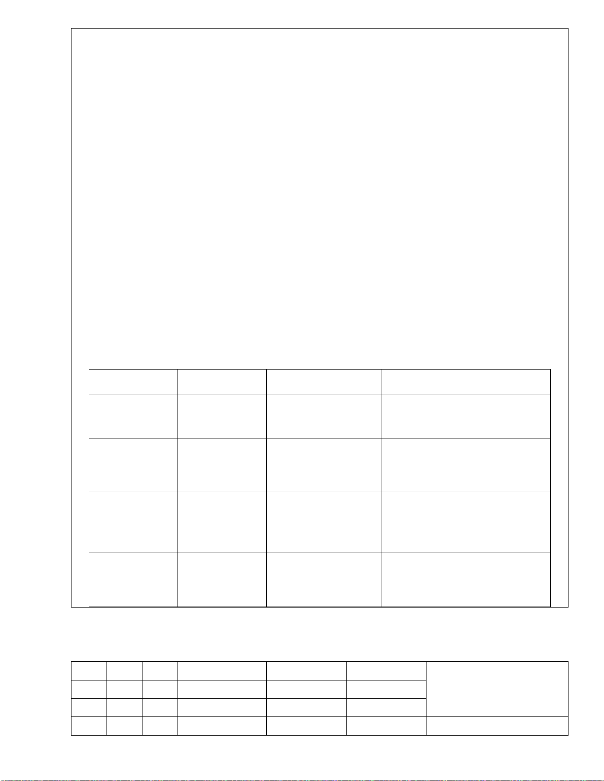
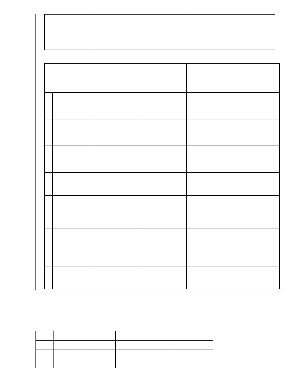
4.调试项目及调试方法
调整检查项目 仪器/设备 设定条件 调整方法及 SPEC
1. M/B电压确认 数位电表
2. 软件程序烧录
更新软体
3. HDMI EDID 的
烧录
4. HDCP KEY 的
烧录
PC
Debug Tool
PC,ALL-11 Debug
Tool 、 HDMI 信
号线
PC,ALL-11 Debug
Tool
34006383
*电源模块 KIP072U04-02
电源模块的输出电压应为
11.4 V~ 12.6V 之间
请参照附件 5.5 软件程序烧录
说明中一、烧录 FLASH程序步
骤或由 RD 工程師指导
请参照附件 5.5 软件程序烧录
说明中二、HDMI EDID 烧录操
作说明
请参照附件 5.5 软件程序烧录说
明中三、HDCP KEY 烧录操作
说明
拟 制
审 核
标记 数量 分区 更改标记 签名 日期 第 2 张
续页 制图:陈海云 幅面:A4
KLXXNSXXU - TS
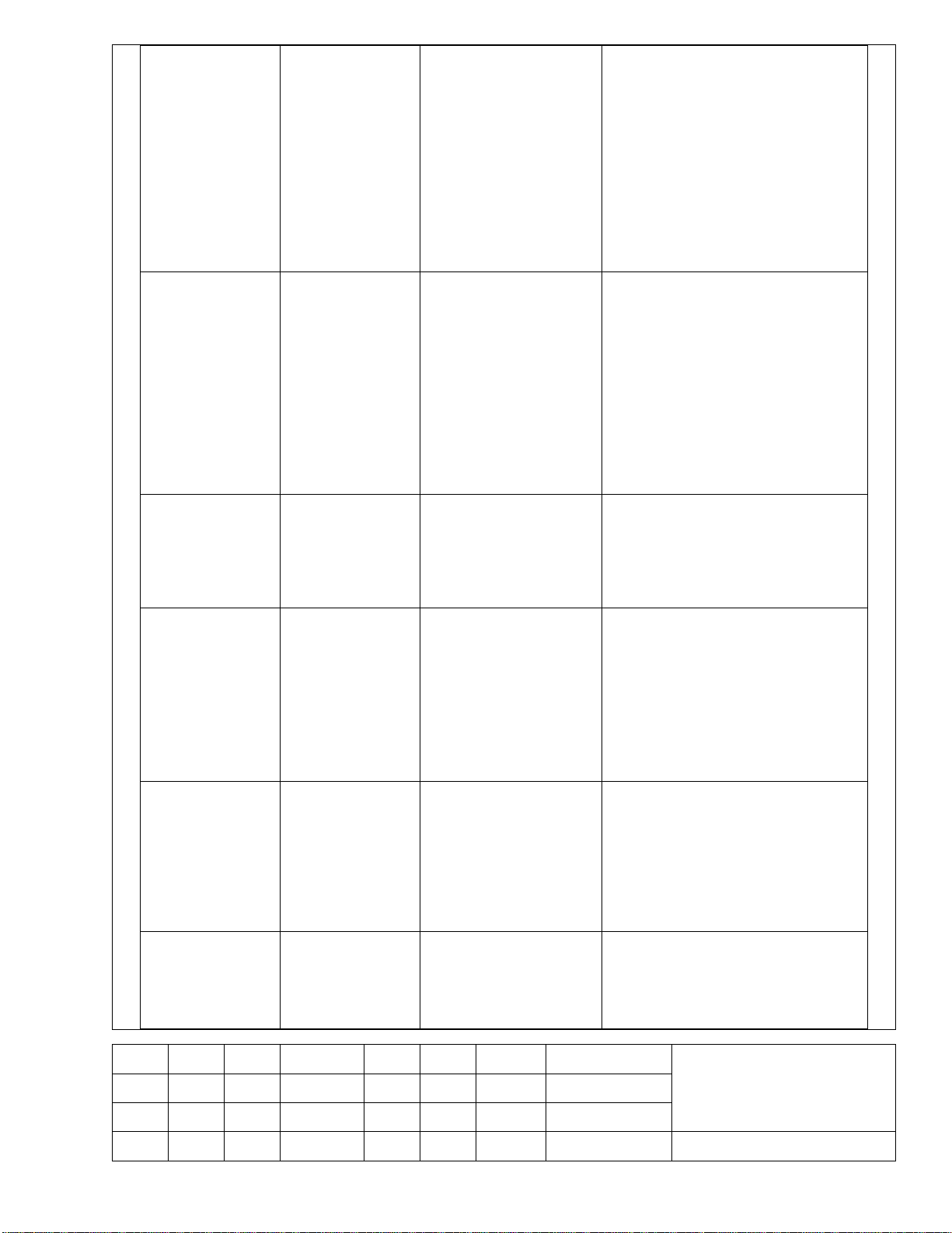
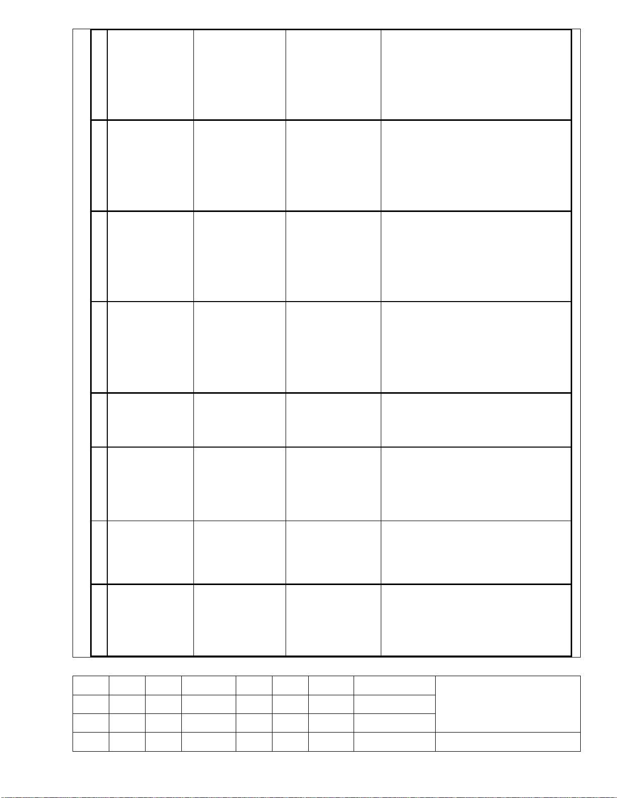
工厂菜单进入方法:在开机状
态下,先按一下“ MENU”
键,然后在三秒内连续按下
5. 工 厂 菜 单的 进
入
6. 调入缺省值
7. 色温调整
白平衡调整
“ 2” 、“ 0” 、“ 0” 、“ 8”
键,即可进入工厂菜单(使用
工厂遥控器时直接按工厂菜单
键即可)。
按 MUTE 键退出工厂菜单
进入菜单工厂方 法同上,在工
厂 菜 单 下, 选 择 “ CONTROL
OPTION” ,按方向键右键进入
其子菜单,然后选择“ RESET”,
再按方 向键 右键 ,等 待约 3-5
秒 , 电 视 机 会 自 动 关 机 再 开
启 , 动 作 完 成 。 然 后 手 动 关
机、开机
在工厂菜单中调整 color temp 到
Normal 状态,观察灰阶图像有
无偏色,若有偏色,请对应执
行下面 a、b、c 项的调整
在工厂菜单下,选择“ COLOR
a) AV 下 色 温 及
亮、暗平衡调整
b) YPbPr 下色 温
及 亮 、 暗平 衡 调
整
c) VGA 下色温及
亮、暗平衡调整
高 清 视 频信 号 发
生 器 ( VG859
等)
彩色信号分析仪
高 清 视 频信 号 发
生 器 ( VG859
等)
彩色信号分析仪
高 清 视 频信 号 发
生 器 ( VG859
等)
彩色信号分析仪
输入灰阶信号
输入灰阶信号
输入灰阶信号
TEMP” ,选择“ COLOR TEMP
NOMAL”
调整 R/G/B,使白场色平衡;
调整 R/G/B OFF,使暗场色平衡
在工厂菜单下,选择“ COLOR
TEMP” ,选择“ COLOR TEMP
NOMAL”
调整 R/G/B,使白场色平衡;
调整 R/G/B OFF,使暗场色平衡
在工厂菜单下,选择“ COLOR
TEMP” ,选择“ COLOR TEMP
NOMAL”
拟 制
审 核
KLXXNSXXU - TS
标记 数量 分区 更改标记 签名 日期 第 3 张
续页 制图:陈海云 幅面:A4
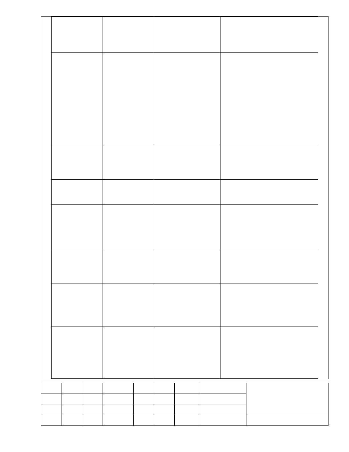
调整 R/G/B,使白场色平衡;
调整 R/G/B OFF,使暗场色平衡
在信号强度为 80duB 时,调整
可调电阻,使用万用表测量高
频头第一脚,使其直流电平为
2V
8. 射频(RF)检查 电视信号发生器
DVD
9. AV 和 S-Video
检查
10. YPbPr
SDTV: 576P/480P
HDTV: 720p/1080i
11. VGA INPUT
12. HDMI检查
AV线
S-Video线
DVD
VGA线
电脑主机
带 HDMI 的 DVD
HDMI Cable
输入 NTSC 制信号
播放 DVD
设定 DVD 为隔行/逐行
输出
播放 SDTV/HDTV
(YPbPr)
PC Mode,参见附表 5.5
HDMI Mode 参 見 附 表
5.6
在用户菜单下, 检查画面是否
正常显示,无信号出現蓝屏,
无信号几分钟后將会自动进入
待机状态。
检查 Auto Search /等是否正常。
画面清晰流畅,伴音输出清晰无
杂音。
画面清晰流畅,声音是否正常
各 Mode 均能正常显示。
确认 PC 可以自动识別机型
采用外接机顶盒收看电视节目,
画面应清晰
选 SOURCE 选到 HDMI
各 Mode 的画面均能正常显示,
画面清晰流畅,声音是否正常
带 HDMI 的
DVD, VG859 或
13. HDCP检查
同 等 级 被认 可 设
备
14. 耳机功能检查 耳机、DVD TV或 DVD IN
选 SOURCE 选到 HDMI
输 入 由 信 号 发 生 器 送 出 帶 有
HDMI/HDCP 的测试信号,检查
图像声音是否正常
插上耳机,主喇叭无声,耳机声音
正常,按 VOL+-,耳机声音是否
正常;检查左右声道是否正常
拨掉耳机, 主喇叭声音正常
拟 制
审 核
KLXXNSXXU - TS
标记 数量 分区 更改标记 签名 日期 第 4 张
续页 制图:陈海云 幅面:A4
tage of
Please refer to appendix 5.5 if there is
Debug
Please refer to appendix 5.5 if there is
Debug
Please refer to appendix 5.5 if there is
Press “MENU” button on the remote
control and then press “2”, “0”, “0”, “8” in
y menu in
button to exit the
CONTROL
s
press
turn off power , then
yed under
YPbPr and VGA source mixed with
color, there is
necessary
to do this step.
15. 遥控功能测试 电视信号发生器
检查各种模式下 各项功能是否
正常。
4.Test item and method
Test Item Equipments Requirements Procedure and SPEC
M/B Voltage
1
confirmation
2
Update NVRAM
Update HDMI
3
EEPROM
Digital Multimeter
PC
Debug Tool
PC,ALL-11
Tool、HDMI Cable
JSI-220401B(LF)
(34005123)
1. When the power is on, the output vol
JSI-220401B(LF) should between 11.4 V~ 12.6V
1.
abnormal phenomenon.
1.
abnormal phenomenon.
4
Update HDCP KEY
5
Enter factory menu
6
Load default setting
Color Temp. adjust
7
white-balance
calibrate
PC,ALL-11
Tool
1.
abnormal phenomenon.
3 seconds, and enter the factor
success. Press “MUTE”
factory menu.
1.In factory menu, Select “
OPTION” and press “►”button to enter it’
submenu. Then select “RESET” and
“►” button ,TV will turn off and turn on
automatically.Finally
turn on the power again.
1. If the gray step signal displa
AV 、
拟 制
审 核
标记 数量 分区 更改标记 签名 日期 第 5 张
续页 制图:陈海云 幅面:A4
KLXXNSXXU - TS
AV:
. and
COLOR
COLOR TEMP
COLOR
COLOR TEMP
COLOR
COLOR TEMP
User menu, Check whether the
or
2. Check Auto Search / Manual Search and
Video
to
if
if
Please refer
DVD with HDMI
Please
Color Temp
a
white-balance
calibrate adjust
YPbPr:
Color Temp and
b
white-balance
calibrate adjust
VGA Color Temp
and
c
white-balance
calibrate adjust
8 TV mode check
VG859 and
Color signal analyzer
VG859 and
Color Signal analyzer
VG859 and
Color Signal analyzer
Factory TV Signal or
TV Signal Generator
Enter gray step signal
Enter gray step signal
Enter gray step signal
Output PAL Signal
1. Enter factory menu, Select “
TEMP”, and select “
NORMAL”.
2. Adjustment R/G/B to get white calibration;
3. Adjustment R/G/B OFF to get black
calibration
1. Enter factory menu, select “
TEMP”, then select “
NORMAL”.
2. Adjustment R/G/B to get white calibration;
3. Adjustment R/G/B OFF to get black
calibration
1. Enter factory menu, select “
TEMP”, then select “
NORMAL”.
2. Adjustment R/G/B to get white calibration;
3. Adjustment R/G/B OFF to get black
calibration
1. Enter
pictures is normal or not, if no Signal
snowflake points coming forth , it would
enter standby state in several minutes
AV and S-
9
check
YPbPr
10
SDTV: 576P/480P
HDTV: 720p/1080i
11
VGA INPUT
12
HDMI check
DVD
Video cable
S-Video cable
DVD
PC
VGA Cable
output
HDMI cable
Play DVD
Set DVD
interlace/progress
output
Play DVD
SDTV/HDTV
(YPrPb)
PC Mode
to appendix 5.5
HDMI Mode
refer to appendix 5.6
etc. right or not.
1. Playing content is clear and fluent, check
the audio output is normal.
1. Playing content is clear and fluent, check
the audio output is normal.
1.Apiece Mode Screen is clear and fluent.
1. Select “SOURCE” and select “HDMI”
2. Apiece Mode: Screen is clear and fluent,
check if the audio output is normal.
拟 制
审 核
标记 数量 分区 更改标记 签名 日期 第 6 张
续页 制图:陈海云 幅面:A4
KLXXNSXXU - TS
HDCP check
DVD with HDMI
Earphone Output
if the
udio should
13
14
15
function check
Remote control
function check
output
HDMI cable
VG859
Earphone、DVD
PC 、 DVD Pattern
Generator
TV Signal Generator
HDTV Player
4.1 附件
4.1.1 电源板和 M/B 电压确认
4.1.2 电源的输入和输出回路特性调试
1. Select “SOURCE” and select “HDMI”
TV input or DVD
VCD or play DVD IN 1. Check if the apiece mode function normal.
check Signal Generator output HDMI/HDCP
Signal, checks if the output is OK
1. plug into Earphone,speaker aphonia,
Earphone Audio is normal, Press VOL+Key to set the sound volume,check
audio output is normal.
2. pull out Earphone,speaker a
4.1.3 调试目的:测量输入和输出回路有无短路
4.1 Accessories
4.1.1 Power Supply Board and M/B Voltage check
4.1.2 The input and output characteristic test of power
4.1.3 Intention of test: Check input and output to find whether short circuit or not.
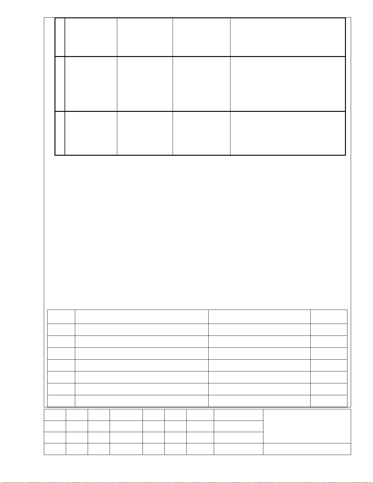
4.2 测试方法:
万用表选择电阻档,测量电源板的交流输入端, M/B 电压输入端是否对地短路
序号 项目 测试点 标准
电源
1 交流输入端接口 交流输入连接器XS904 无短路
2 12V输出端接口 12V输出端连接器XS951 无短路
M/B
1 12V输出 F802 无短路
2 5V 输出 N804 无短路
审 核
标记 数量 分区 更改标记 签名 日期 第 7 张
续页 制图:陈海云 幅面:A4
4 主芯片3.3V L823 无短路
拟 制
KLXXNSXXU - TS
5 主芯片1.26V N806 无短路
若有短路则为不良,检查线路找出短路处。
4.2 checking method:
use Multimeter (VICTOR VC9801) of resistor to check No/Yes short circuit
Number Item Test Point Standard
Power
Supply
1 The interface of AC input AC Input Connector XS904 No short circuit
2 The interface of 12V output 12V output of connector XS701 No short circuit
M/B
1 The fuse of 12V output F802 No short circuit
2 5V under control output N804 No short circuit
3 3.3V for MST739 L823 No short circuit
4 1.26V for MST739 N806 No short circuit
Please check short circuit point on the PCB board if you find short circuit.
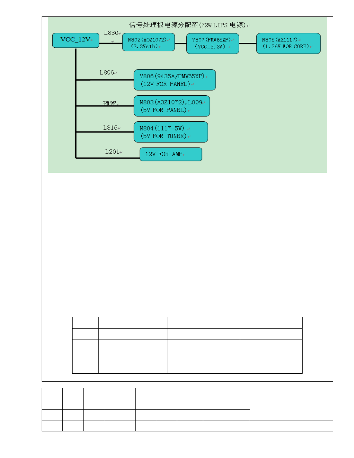
4.3 信号处理板
4.3.1 信号处理板电源部分
信号处理板电源分配图
拟 制
审 核
标记 数量 分区 更改标记 签名 日期 第 8 张
续页 制图:陈海云 幅面:A4
KLXXNSXXU - TS
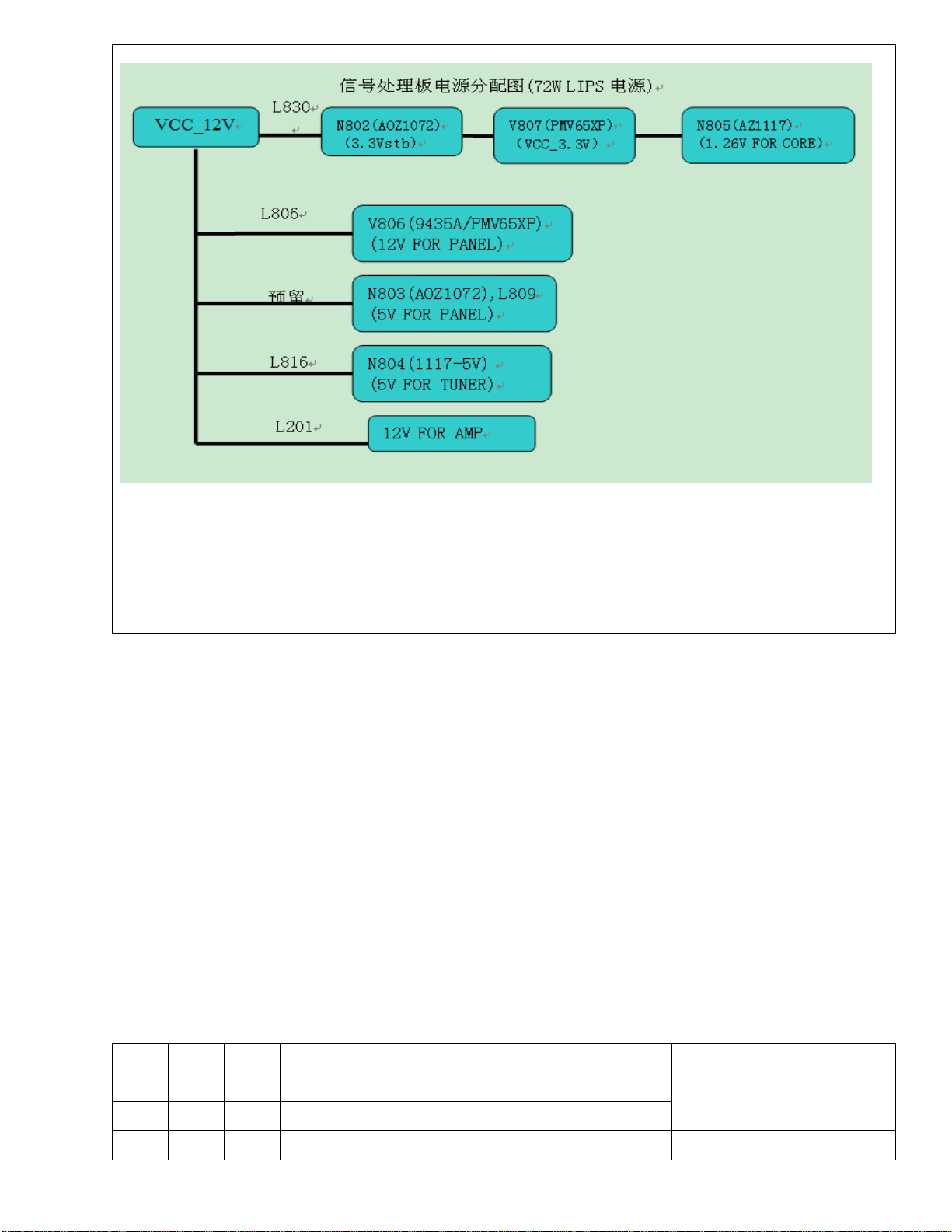
4.3 Signal Board part
4.3.1 Signal board power part
Signal Board power distribution
拟 制
审 核
标记 数量 分区 更改标记 签名 日期 第 9 张
续页 制图:陈海云 幅面:A4
KLXXNSXXU - TS
4.3.2 确认电视机状态
按下机子右侧的电源按键至通电状态,再检查指示灯的颜色,若为红色则处于待机状态,若
为绿色则处于工作状态。
4.3.2 Verify the state of TV set
Please switch the TV on by pressing the power button at the right side of TV Set, and then verify
the LED color. Red is standby state and green is working state.
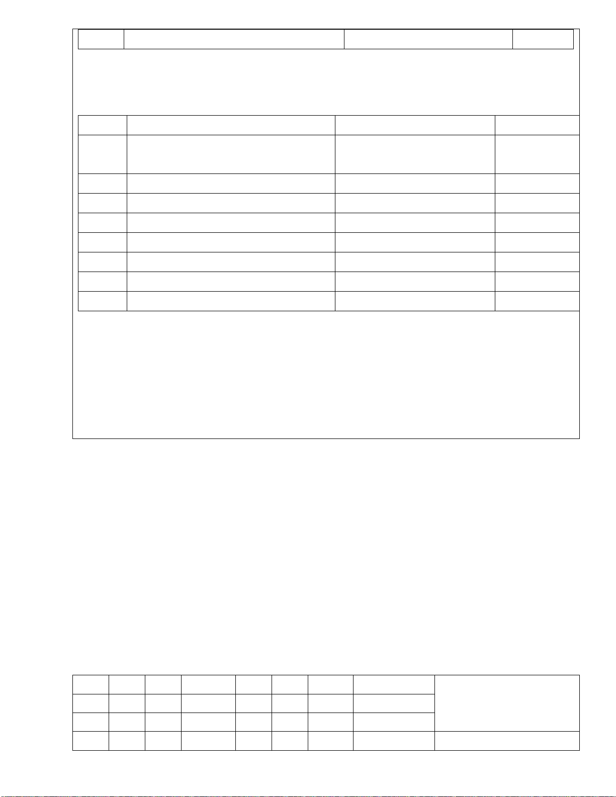
4.3.3 检查供电电压是否正常
若指示灯为绿色时,主板整个系统都处于工作状态,此时用万用表检查主板上下列各点的
电压是否正常:
序号 测试点 电压输出要求 备注
1 F802 12V
2 N804 5V
3 L823 3.3V
4 N806 1.26V
拟 制
审 核
标记 数量 分区 更改标记 签名 日期 第 10 张
续页 制图:陈海云 幅面:A4
KLXXNSXXU - TS
 Loading...