

Page 1
同方消费电子本部大中华事业部研发中心 内部资料 注意保密
清华同方 液晶电视
售后服务 维修手册
LE-32TX2000 LE-42TX2000 LE-46TX2800 LE-55TX2800
MTK5301C/V 方案机芯
审核:
批准:
编写:
深圳市同方多媒体科技有限公司
研发中心 研发一组
1
Page 2

同方消费电子本部大中华事业部研发中心 内部资料 注意保密
目录
一、 产品介绍………………………………………………………………..3-4
(1)产品外观介绍……………………………………………………………………...3
(2)产品功能及特点介绍……………………………………………………………..4
(3)产品功能差异介绍………………………………………………………………..4
二、产品方案概述………………………………………………………………5
三、主板实物图片及端口的定义.................................5-10
四、主板电路方框图构架……………………………………………………..10
五、整机电源框架图.............................................11
六、主板主要电路介绍……………………………………………………..11-18
1、控制部分………………………………………………………………………...11-14
2、存储部分及 DDR 部分………………………………………………………….14-15
3、网络接口部分……………………………………………………………………….15
4、高频头部分………………………………………………………………………15-16
5、数字电视 DEMOD IC 部分…………………………………………………………16
6、数字功放部分……………………………………………………………………16-17
7、LVDS 部分…………………………………………………………………………..17
8、按键及遥控部分…………………………………………………………………….18
七、主板原理图……………………………………………………………..19-25
八、软件升级,网络设置方法及说明…………………………………………25-32
九、MAC 烧写方式…………………………………………………………32-34
十.3D 操作及说明…………………………………………………………35—36
2
Page 3
同方消费电子本部大中华事业部研发中心 内部资料 注意保密
一、 产品介绍
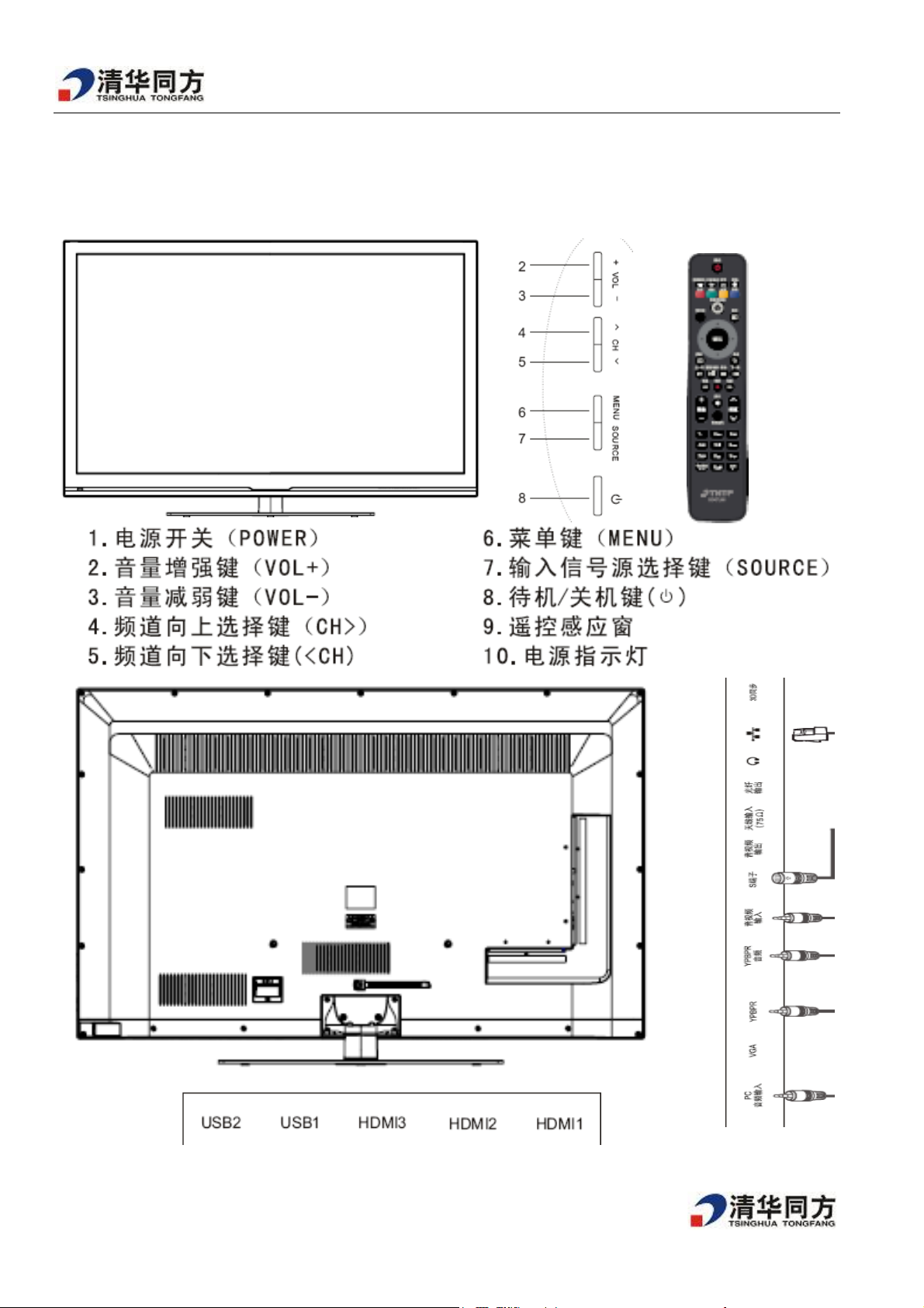
(1)产品外观介绍
3
Page 4
同方消费电子本部大中华事业部研发中心 内部资料 注意保密
(2)产品功能规格及特点介绍
型号
产品名称 有线模拟网络电视一体机 有线数字 DTMB-TH 网络一体机
屏幕尺寸 31.5 英寸 42 英寸 46 英寸 55 英寸
屏幕比例 16:9 16:9 16:9 16:9
屏幕类型
LE-32TX2000 LE-42TX2800 LE-46TX2800 LE-55TX2800
LED LED LED LED
屏幕显示
电源输入
整机功耗
接收标准
60Hz 120Hz FullHD 3D 120Hz FullHD 3D 120Hz FullHD
~50Hz 220V ( 110V~230V)
140W 150W 200W
PAL /SECAM /NTSC D/K I B/G M PAL /SECAM /NTSC D/K I B/G M DMB-TH
(3)、产品差异介绍
1、LE-32TX2000、LE-42TX2800、LE-46TX2800 和 LE-55TX2800 是不同尺寸的机型,采用不同型号的屏、电
源板和机壳。
2、LE-32TX2000/LE-42TX2800 的主板只支持接收模拟电视解码(即采用纯模拟高频头+MT5301CBSU 解码 IC),
而 LE-46TX2800/LE-55TX2800 的主板是在 LE-32TX2000/ LE-42TX2800 的主板基础上增加了 DTMB-TH数字信
号接收及其解码电路(即把纯模拟高频头改为数模一体高频头和把主解码 IC 改为 MT5301V.同时增加了
DTMB-TH 数字信号的 demod IC ATBM88848 及其外围电路)
4
Page 5
同方消费电子本部大中华事业部研发中心 内部资料 注意保密
二、产品方案概述
本机所采用 MT5301C/V 系列方案。
主要特点包括:
1. MT5301C 芯片支持 PAL、NTSC 和 SECAM 的接收; 而 MT5301V 芯片是在 MT5301C 芯片基础上增加
了 DTMB-T 数字信号接收及解码。
2. 支持 3 路 HIMI 输入、1路 YPbPr/RGB 输入、1 路Mini-Component(mini audio in), 1路PC-RGB(mini-audio),
1 路 Mini-AV IN, 1 路 S-VIDEO, 1 路 Mini-AV OUT, 1 路 SPDIF, 1 路 Earphone, 1 路 Ethernet(RJ45) 和 模拟/数字
TV 输入、2 路 USB 输入。可以采用 USB 进行升级;
3. 支持 MPEG-2、H.264、AV S 和 VC1 等多种解码;
4. 多媒体(USB2.0)功能,支持 JPEG、MP3、H.264 和 TXT 格式文件。
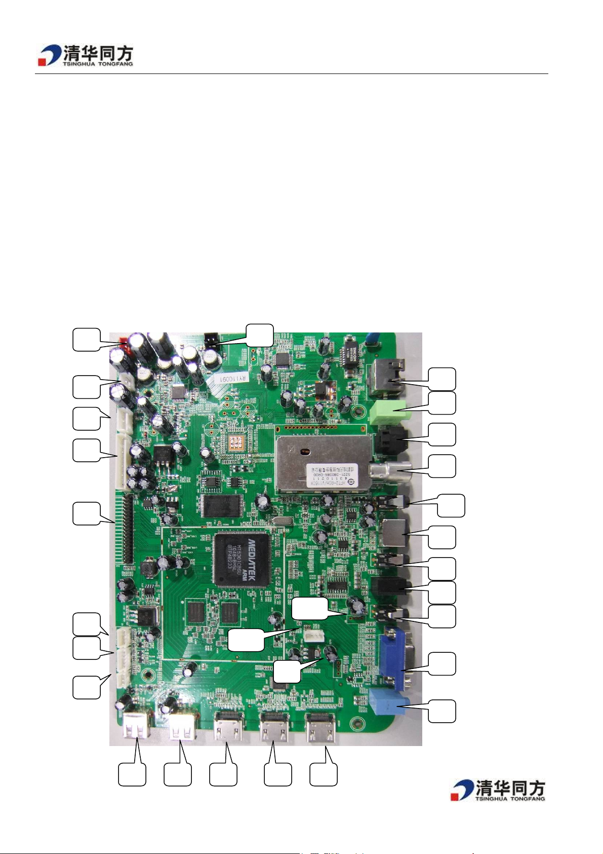
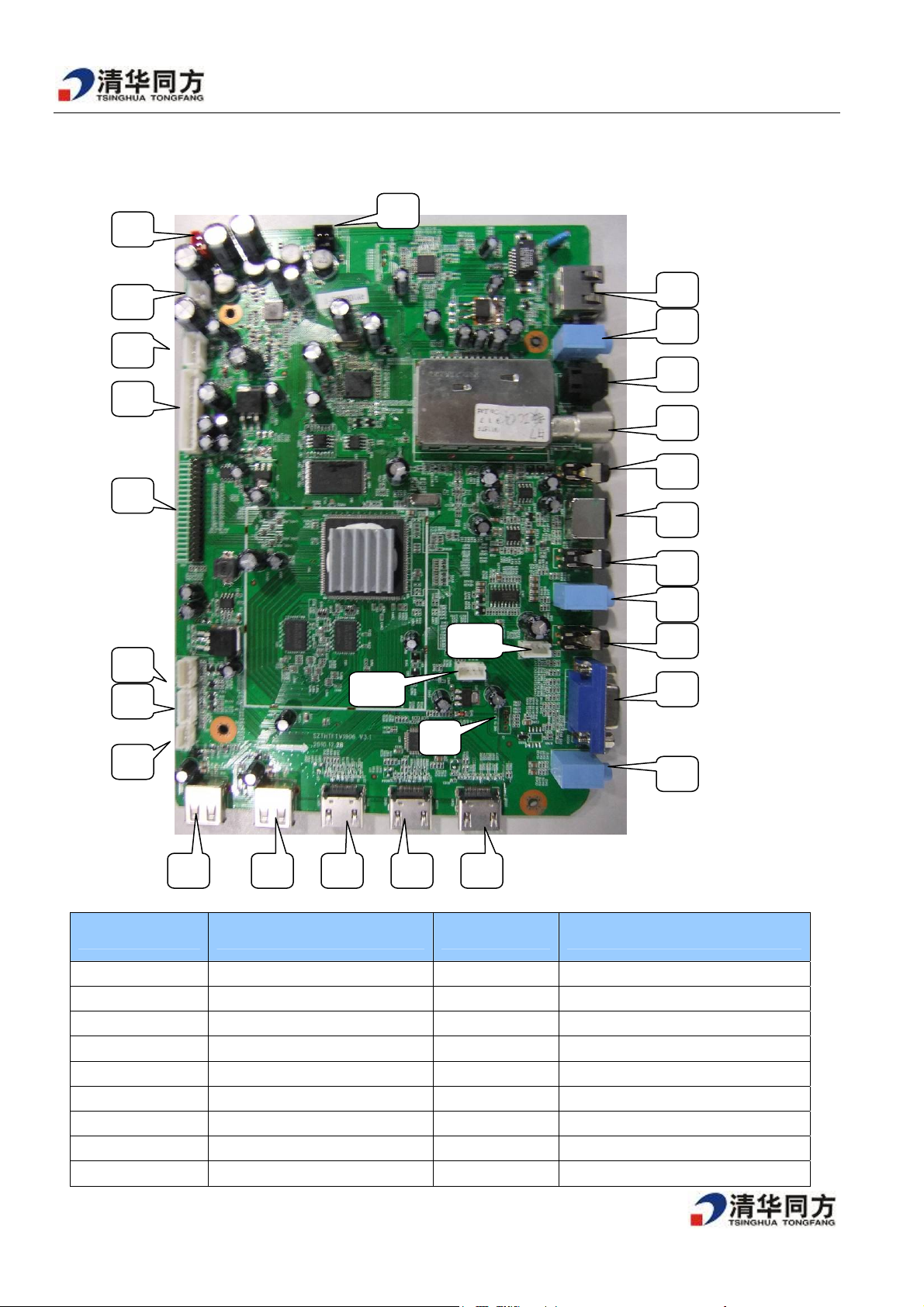
三、主板实物图片及端口的定义
LE-32TX2000/LE-42TX2800 的主板的图片如下 :
10
9
27
26
25
24
23
22
21
20
11
28
19
18
8
7
6
5
1
2
3
4
17
`
12 13 14 15 16
5
Page 6
同方消费电子本部大中华事业部研发中心 内部资料 注意保密
LE-46TX2800/LE-55TX2800的主板图片
8
9
7
27
26
6
25
5
24
23
1
22
21
20
11
19
2
3
10
18
28
4
17
12 13 14 15 16
序号 功能描述 序号 功能描述
1(CN8)
2(N5)
3(N10)
4(J4)
5(N6)
6(N5)
7(JA4)
8(JA3)
9(JA5)
LVDS 屏线连接端口
背光控制端口
遥控板线连接端口 t
按键板连接端口
电源板线连接端口
音频功放电源连接端口
左声道输出端口,
左声道输出端口
SUB 输出端口
15
16
17
18
19
20
21
22
23
6
HDMI2 输入端口
HDMI1输入端口
PC 音频输入端口
PC-RGB 输入端口
YPBPR 输入端口
YPBPR 音频输入端口
AV 输入端口
SVIDEO 输入端口
AV 输出端口
Page 7
同方消费电子本部大中华事业部研发中心 内部资料 注意保密
/10(J5)
/11(JA2)
12(JA1)
13
14
I/O 口
外部 AV2 输入端口
USB 输入端口
USB 输入端口
HDMI3 输入端口
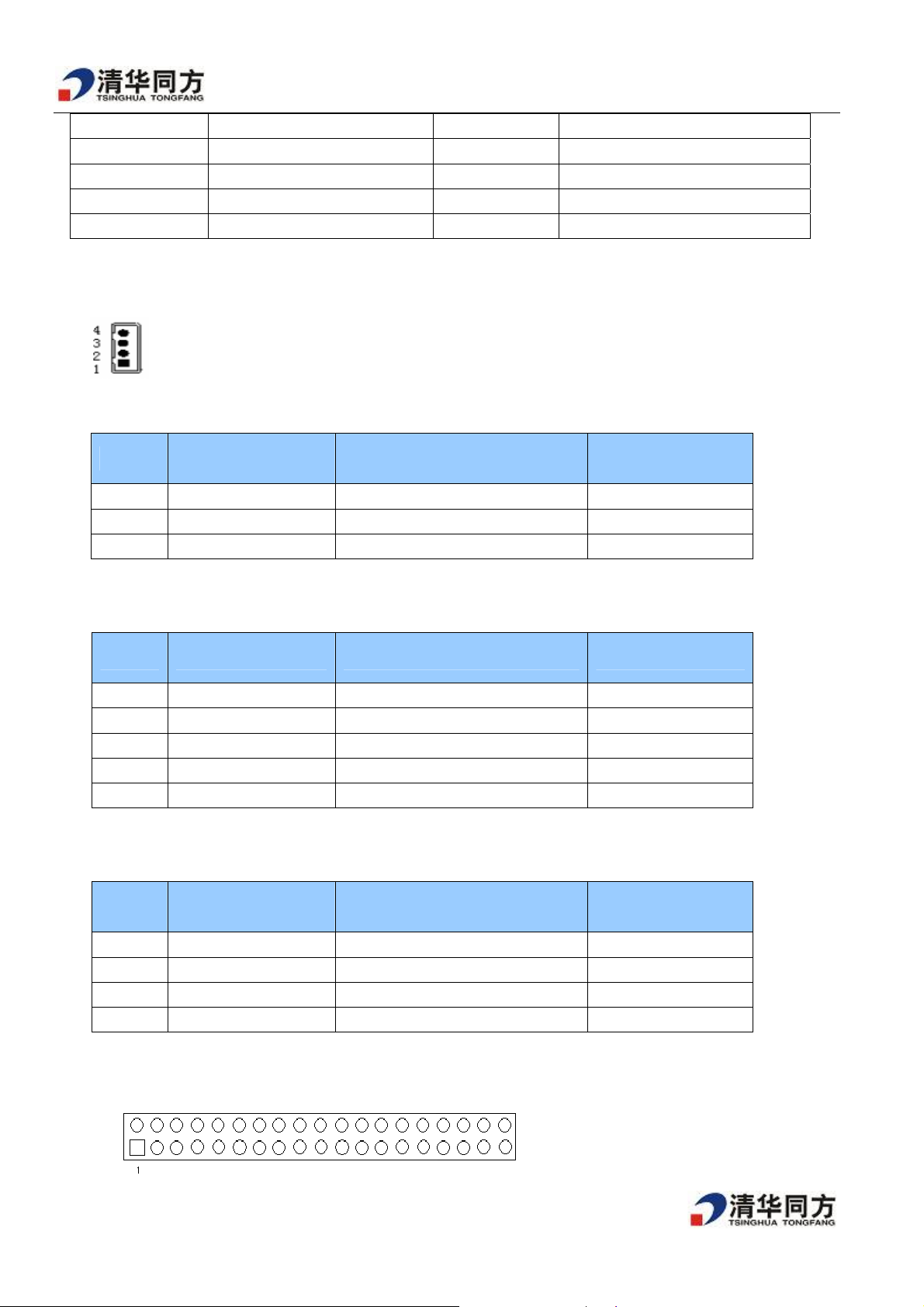
端口的定义
端口脚位序号定义图如下:
J4 按键板接口(3PIN/2.0MM)
脚位 引脚定义 功能描述 参数
1 GND Ground 0V
2 KEY1 Keyboard ADC 1 Max 3.3v
3 KEY2 Keyboard ADC 2 Max 3.3v
N10 遥控板接口(5PIN/2.0MM)
24
25 SPDIF
26
27 RJ45
/28
ATV&DTV RF 输入端口
E 耳机端口
升级软件串口
脚位 引脚定义 功能描述 参数
1 +5VSB Remote Power supply 5V
2 LED_R Red indicator ON:0V;OFF:2.2V
3 LED_G Green indicator ON:0V;OFF:2.2V
4 IR Remote receive 5V
5 GND Ground 0V
N5 背光板接口(4PIN/2.0MM)
脚位 引脚定义 功能描述 参数
1 BL_ON Black-Light ON/OFF Control ON:5V;OFF:0V
2 DIMMING Brightness Adjustment PWM(LED)
3 GND Ground 0V
4 GND Ground 0V
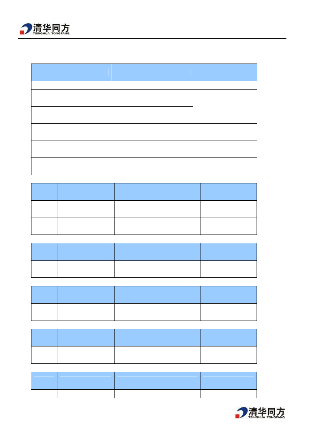
CN8 LVDS 线接口(2x19PIN/2.0MM)
7
Page 8
同方消费电子本部大中华事业部研发中心 内部资料 注意保密
You can refer to the chart above so as to determine which side the panel sequence is.
脚位 引脚定义 参数
1 PANEL POWER 5/12V Optional
2 PANEL POWER 5/12V Optional
3 PANEL POWER 5/12V Optional
4 GND 0V
5 GND 0V
6 GND 0V
7 E4N default
8 E4P default
9 E3N default
10 E3P default
11 ECKN default
12 ECKP default
13 E2N default
14 E2P default
15 E1N default
16 E1P default
17 E0N default
18 E0P default
19 O4N default
20 O4P default
21 O3N default
22 O3P default
23 OCKN default
24 OCKP default
25 O2N default
26 O2P default
27 O1N default
28 O1P default
29 O0N default
30 O0P default
31 GND 0V
32 GND 0V
33 SDA SYSTEM BUS SDA
34 SCL SYSTEM BUS SCL
35 BR-IN 0/3.3V(I/O control)
36 BR-OUT 0/3.3V(I/O control)
37 OSCL1 0/3.3V(I/O control)
38 OSCL2 0/3.3V(I/O control)
8
Page 9
同方消费电子本部大中华事业部研发中心 内部资料 注意保密
N6 电源供电接口(11PIN/2.5MM)
脚位 引脚定义 功能描述 参数
1 ON/OFF Power on or off control ON:5V;OFF:0V
2 5VSB Standby 5V supply +5V(150ma)
3 +5V Main board power 5V Supply
4 +5V Main board power 5V Supply
5 VP Panel power supply +5V/12V(optional)
6 VP Panel power supply +5V/12V(optional)
7 GND Ground 0V
8 GND Ground 0V
9 GND Ground 0V
10 +12V Main board power 12V Supply
11 +12V Main board power 12V Supply
N7 功放供电接口 (4PIN/2.54MM)
+5.2~5.3v(USB+1.5A)
12V
脚位 引脚定义 功能描述 参数
1 +24V Main board power 24V Supply +24V
2 +24V Main board power 24V Supply +24V
3 GND GND 0V
4 GND GND 0V
JA4 左声道喇叭输出接口(2PIN/2.5MM)
脚位 引脚定义 功能描述 参数
1 L+ Left speaker out positive
2 L- Left speaker out negative
JA3 右声道喇叭输出接口(2PIN/2.5MM)
脚位 引脚定义 功能描述 参数
1 R+ Right speaker out positive
2 R- Right speaker out negative
JA5 0.1 声道喇叭输出口(2PIN/2.5MM)
脚位 引脚定义 功能描述 参数
0-7W@8ohm
0-7W@8ohm
1 SUB+ Subwofe speaker out positive
2 SUB- Subwofe speaker out negative
N8 侧 AV 连接口(4PIN/2.0MM)
脚位 引脚定义 功能描述 参数
1 GND Ground 0V
0-10W@8ohm
9
Page 10
同方消费电子本部大中华事业部研发中心 内部资料 注意保密
2 AV2 CVBS input 1.0 Vp-p ±5%
7 AV_L_IN Side AV audio lift channel input 0.2~2Vrms
8 AV_R_IN Side AV audio right channel input
J3 软件升级口(4PIN/2.0MM)
脚位 引脚定义 功能描述 参数
1 3.3V 3.3V power supply 3.3V
2 RXD UART data Receive 3.3V
3 TXD UART data Send 3.3V
4 GND Ground 0V
J5 系统 I/O 口 (4PIN/2.0MM)
脚位 引脚定义 功能描述 参数
1 DMAACK 120HZ Driver board DMAACK 3.3V
2 RST# 120HZ Driver board RST# 3.3V
3 I/O1 I/O control 3.3V
4 GND GND 0V
0.2~2Vrms
四、主板电路方框图构架
10
Page 11
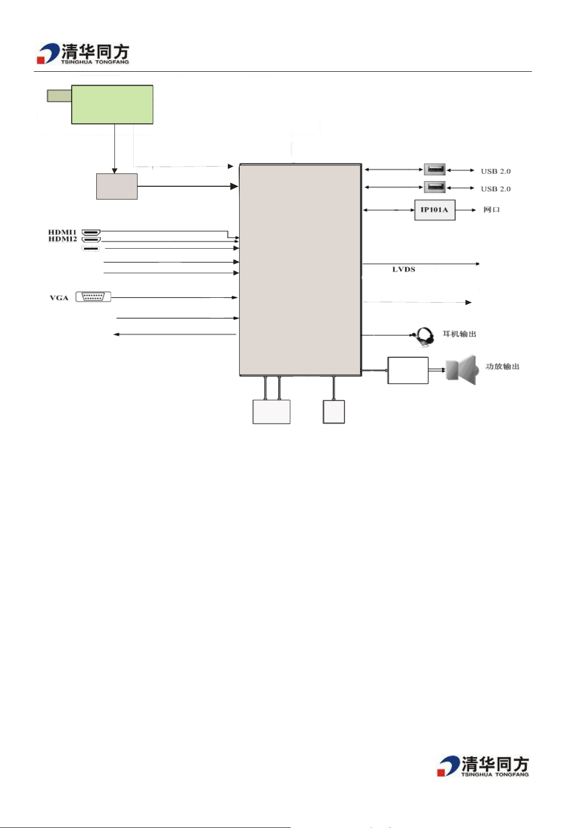
同方消费电子本部大中华事业部研发中心 内部资料 注意保密
DTMB-TH数模一体高频头
ATV
DEMOD IC
ATBM8848
HDMI3
AV IN
S_VIDEO
YPbPr
AV OUT
五、整机电源框架图
DTMB-TH
MT5301V
DDR3
FLASH
FLASH
5711
SPDIF
输出
11
Page 12

同方消费电子本部大中华事业部研发中心 内部资料 注意保密
Up2
1117-3.3
按键板
UpMp11
1482
Up8
1117-3.3
Up4
1084Ap
+5V
UD 4
AP1084
+V
24
屏背光
UA14
TAS5711功放
U
46
+12V
CEM9435
UT 2
7805
六、主板主要电路介绍
VCCK
DVDD3V3
AVDD3V3
MT5301V
Uw2
IP101A
Up6
1122Ap
USB1,USB2
UD1/UD2
NT5CB128M8CN
液晶屏
U6
高频头
AVDD1V 2
1、控制部分
主电源控制电路:
MAIN POWER
+5V
OPWRSB
LO = > PO W ER_ON
HI = > POW ER_OFF
屏背光控制电路:
5V_SW
CM57
NS/10pF/16V/X5R
C0402/SMD
+5VSB
R0402/SMD
R0402/SMD
RP3
10K/NC
R0402/SMD
RP64.7K
RP10
47K
1
+5VSB
RP2
1K
R0402/SMD
QP1
2N3904
SOT23/SMD
3 2
SW_POWER
12
Page 13

3V3SB
BL_ON/OFF
LO = > PO W ER_ON
HI = > POW ER_OFF
I2C 的读/写控制电路
同方消费电子本部大中华事业部研发中心 内部资料 注意保密
DVDD3V3
RL28
10K/NC
R0402/SMD
RL24
4.7K
R0402/SMD
R0402/SMD
1
SOT23/SMD
5V_SW
RL23
10K
QL5
2N3904
3 2
RL22
10K/NC
R0402/SMD
RL32
CL5 0.1uF
C0402/SMD
SOT23/SMD
5V_SW
RL31
10K
R0402/SMD
QL6
2N3904
BL_Control
0/NCR0402/SMD
1
3 2
SYSTEM EEPR OM
SYS_EEPROM_WP
OSCL0
OSDA0
H = > Write P rotect
L = > WRITE
Strapping 的逻辑控制电路
STRAPPING
3V3SB
DVDD3V3
RM13
4.7K
R0402/SMD
RW1 NS/10K
R0402/SMD
RW3 NS/10K
R0402/SMD
RW5 NS/10K
R0402/SMD
DVDD3V3 DVDD3V3 DVDD3V3DVDD3V3
RM14
2.7K
R0402/SM D
RM15
2.7K
R0402/SMD
OPCTRL5
OPCTRL4
AOSDATA1
I2C ADDRESS "A0"
UM5
8
VCC
7
WP
6
SCL
5
M24C32-W
RW2 10K
R0402/SMD
RW4 10K
R0402/SMD
RW6 10K
R0402/SMD
SDA
SOP8/SMD
GND
NC
NC
NC
1
2
3
4
电源指示灯的控制电路
13
Page 14

同方消费电子本部大中华事业部研发中心 内部资料 注意保密
R0402/SMD
ADC4
HI = > LE D RE D
LO => LED GRE EN
LE D O N when TV Sta ndby
LE D OFF whe n TV Work
3V3SB
R1777
10k
R1776 4.7K
R0402/SMD
R1778 4.7K
R0402/SMD
3V3SB
1
SOT23/SMD
3V3SB
1
SOT23/SMD
R90
1k
R0402/SMD
32
Q51
2N3906
R1779
1k R0402/SMD
Q68
2N3904
3 2
LED_RED#
12
D14
NC/EZJZ0V800AA
C0402/SMD
LED_GRE#
LED_GRE#
12
D18
NC/EZJZ0V800AA
C0402/SMD
USB1/ USB2 的电源逻辑控制电路:
R290 10K
1 2
R297
47K
JTRST#
JTRST#
JTRST# 3
JTRST#3
声音输入逻辑控制电路
Audio MUX Input
VGA_L_In
YPbPr_L_In1
AV1_L_In
AV2_L_In
UA10
1
Y0
2
Y2
3
Yout
Y34Xout
5
Y1
6
INH
7
VEE
CTL_A
8
CTL_B
VSS
TI-SN74LV4052A_5V
SOP16/SMD
JTCK
JTMS
1
1
0
0
1
0
VDD
X2
X1
X0
X3
VGA IN
AV IN
YPBPR I N
AV2 IN
16
15
14
13
12
11
10
9
AMUX_5V
YPbPr_R_In1
AV2_R_In
VGA_R_In
AV1_R_In
MUX_C TLA
MUX_C TLB
CA205
0.1uF
C0402/SMD
R296
4.7K
1
1 2
CEA3
470uF/16V
CE040_3.5
CEA30
+
10uF/10V/X5R 0805
C0805/SMD
+5V
1 2
Q26
2 3
2N3904
+
U17
RT9701 SOT-23-5
3
VIN
4
CE
+
CEA33
10uF/10V/X5R 0805
C0805/SMD
AIN0_R_AAD CAUD_ROUT
GND
2
VOUT
VOUT
JTDI3
12
1
5
LA1
D282
47
NC/EZ JZ0V800AA
+5V_USB1
JTDI
R291 10K
1 2
R300
47K
+5V
R298
4.7K
1 2
1
2 3
1 2
Audio MUX CTRL
5V_SW
RA194
10K
R0402/SMD
MUX_C TLB MUX_C TLA
1
QA24
3 2
2N3904
SOT23/SMD
RA196 10K
R0402/SMD
AIN_CTL1
Q27
2N3904
U18
RT9701 SOT-23-5
3
VIN
4
CE
+5V_USB2
1
VOUT
5
VOUT
GND
2
AMUX_5VAMUX_5V
RA195
10K
R0402/SMD
RA197 10K
1
QA25
3 2
2N3904
SOT23/SMD
AIN_CTL0
R0402/SMD
CEA32
AUD_LOUT
+
10uF/10V/X5R 0805
C0805/SMD
AIN0_L_AADC
14
Page 15

LVDS 电源控制电路
同方消费电子本部大中华事业部研发中心 内部资料 注意保密
U46
LVDS POWE R Control
PANEL_VCC
L18
BEAD/SMD/1206
FB_80_3A 1206
+
C0603/SMD
CE325_2.5
CE35
220uF/16V
CB33
1uF 0603
R292
47K
R0402/SMD
23
1
R293
47K
R0402/SMD
SOT23/SMD
AO3401/NC
Q19
1
S
2
S
3
S
4
G
CEM9435A
SOIC8-150-50
LVDSVDD
C196
0.1uF
C0402/SMD
8
D
7
D
6
D
5
D
C197
0.1uF
C0402/SMD
LVDSVDD
LVDS_PWR_EN
LO = > LVDS POWER OFF
HI = > L V DS POWER ON
2、存储部分及 DDR 部分
NAND Flash
RM3
RM4
4.7k
4.7K
R0402/SMD
POCE1#
R0402/SMD
PARB#
POOE#
NAND_CS#
PACLE
PAALE
POWE#
Flash_W P#
UM3
7
R/B
8
RE
9
CE
16
CLE
17
ALE
18
WE
19
WP
6
GND
13
VSS
36
VSS
NAND01GW3B2DN6
TSOP48/SMD
12
VCC
37
VCC
44
I/O7
43
I/O6
42
I/O5
41
I/O4
32
I/O3
31
I/O2
30
I/O1
29
I/O0
PDD7
PDD6
PDD5
PDD4
PDD3
PDD2
PDD1
PDD0
CM51
0.1uF
C0402/SMD
R294 20K
R0402/SMD
C0402/SMD
Serial Flash ( Co-Layout )
DVDD3V3
RM1
4.7K
R0402/SMD
R0402/SMD
NOR_CS#
PDD7
Flash_WP#
POCE0#
RM84 0
C99
0.1uF
NOR_CS#
PDD7
1
R295
1M
R0402/SMD
UM2
1
HOLD#
2
VCC
3
NC
4
PO2
5
PO1
6
PO0
7
CS#
SO/PO78WP#/ACC
NS/MX25L6405DMI
SO16W/SMD/ MX25L6405
UM4
1
CS#
2
DOUT
HOLD#
3
WP#/VPP
VSS4DIN
NS/MX25L6445EM2I-10G
CASON8/SMD_MOD
SCLK
GND
PO6
PO5
PO4
PO3
VCC
CLK
16
15
SI
14
13
12
11
10
9
8
7
6
5
Q20
2N3904
SOT23/SMD
3 2
POOE#
PDD6
Flash_W P#
DVDD3V3
POOE#
PDD6
DVDD3V3DVDD3V3 DVDD3V3 DVDD3V3DVDD3V3
R0402/SMD
DVDD3V3
RM5
CM52
4.7K
NS/0.1uF/25V/Y5V
C0402/SMD
15
Page 16

同方消费电子本部大中华事业部研发中心 内部资料 注意保密
DDRV
DDRV
RD32 0 0603
CD1
RD1
0.1uF
1K 1%
RVREF1
C0402/SMD
R0402/SMD
RD2
CD2
1K 1%
0.1uF
C0402/SMD
R0402/SMD
LDO for DRAM Power
DVDD3V3
+
CED2
100uF/16V
CE325_2.5
CD8
0.1uF
C0402/SMD
3
DDR3 X8 #1
UD1
RDQ0
B3
R_RDQ1
C7
RDQ2
C2
R_RDQ3
C8
RDQ4
E3
R_RDQ5
E8
RDQ6
D2
R_RDQ7
E7
RDQS0
C3
RDQS0#
D3
N7
J7
H9
H1
F9
F1
A3
A7
R_RDQM0
B7
A_ODT
G1
A_CS#
H2
A_WE#
H3
B9
C1
E2
E9
A2
A9
D7
G2
G8
K1
K9
1_DDRV_M1
M1
R0603/SMD
M9
E1
CAPs for DRAM IO Power ( Close to DRAM1 )
CD31
10uF/10V/X5R 08 05
C0805/SMD
UD4
LT1084 TO-252
2
IN
OUT
ADJ/GND
RD7
110 1%
1
R0402/SMD
TO-263-3/SMD
RD11
22 0603
DQ0
DQ1
DQ2
DQ3
DQ4
DQ5
DQ6
DQ7
DQS
DQS#
A10/AP
A11
A12/BC#
A13
NC_0
BA2
NC_1
BA1
NC_2
BA0
NC_3
NC_4
CAS#
NC_5
RAS#
NC_6
CK#
NU/TODS#
CK
DM/TDQS
CKE
ODT
CS#
RESET#
WE#
ZQ
VSSQ_0
VSSQ_1
VDDQ_0
VSSQ_2
VDDQ_1
VSSQ_3
VDDQ_2
VSSQ_4
VDDQ_3
VSS_0
VSS_1
VDD_0
VSS_2
VDD_1
VSS_3
VDD_2
VSS_4
VDD_3
VSS_5
VDD_4
VSS_6
VDD_5
VSS_7
VDD_6
VSS_8
VDD_7
VSS_9
VDD_8
VSS_10
VSS_11
VREFDQ
VRECA
FBGA78/SMD/P0.8/K4B1G0846E
FBGA78/SMD/P0.8/K4B1G0846E
DDRV
CD26
0.1uF
C0402/SMD
C0402/SMD
DDRV
CD24
0.1uF
C0402/SMD
C0402/SMD
DDRV
CD9
0.1uF
C0402/SMD
R0603/SMD
K3
A0
L7
A1
L3
A2
K2
A3
L8
A4
L2
A5
M8
A6
M2
A7
N8
A8
M3
A9
H7
M7
K7
N3
J3
K8
J2
G3
F3
G7
F7
G9
N2
H8
B2
B8
C9
D1
D9
A1
A8
B1
D8
F2
F8
J1
J9
L1
L9
N1
N9
J8
CD25
0.1uF
CD21
0.1uF
+
CEM5
100uF/16V
CE325_2.5
A_A0
A_A1
A_A2
A_A3
A_A4
A_A5
A_A6
A_A7
A_A8
A_A9
A_A10
A_A11
A_A12
A_A13
A_BA2
A_BA1
A_BA0
A_CAS#
A_RAS#
CLK0#
CLK0
A_CKE
A_RST#
ZQ1
C0402/SMD
C0402/SMD
1_DDRV_M1
C0402/SMD
R0402/SMD
RVREF2
C0402/SMD
CD14
0.1uF
CD23
0.1uF
CD22
0.1uF
Termination for CLK
DDR3 X8 #2
UD2
R_RDQ14
B3
DQ0
RDQ13
C7
DQ1
R_RDQ12
C2
DQ2
RDQ15
C8
DQ3
RDQ8
E3
DQ4
RDQ9
E8
DQ5
R_RDQ10
D2
DQ6
RDQ11
E7
DQ7
RDQS1
C3
DQS
RDQS1#
D3
DQS#
N7
NC_0
J7
NC_1
H9
NC_2
H1
NC_3
F9
NC_4
F1
NC_5
A3
NC_6
A7
NU/TODS#
R_RDQM1
B7
DM/TDQS
B_ODT
G1
ODT
B_CS#
H2
CS#
B_WE#
H3
DDRV
DDRV
R0402/SMD
R0402/SMD
CP2
10uF/10V/X5R 0805
C0805/SMD
RD13
1K 1%
RVREF3
RD16
1K 1%
DDRV
C0805/SMD
R0805/SMD
C0402/SMD
C0402/SMD
CD32
10uF/10V/X5R 0805
CP3
10uF/10V/X5R 0805
C0805/SMD
DDRV
R0805/SMD
CD28
0.1uF
CD13
0.1uF
RD26
0 0805
RD27
0 0805
CD30
10uF/10V/X5R 0805
C0805/SMD
RD17
240
DDRV
CD29
RD19
0.1uF
1K 1%
R0402/SMD
RD18
1K 1%
R0402/SMD
+
CEM4
100uF/16V
CE325_2.5
WE#
B9
VDDQ_0
C1
VDDQ_1
E2
VDDQ_2
E9
VDDQ_3
A2
VDD_0
A9
VDD_1
D7
VDD_2
G2
VDD_3
G8
VDD_4
2_DDRV_K1
K1
VDD_5
K9
VDD_6
RD28 0 0603
M1
VDD_7
M9
VDD_8
R0603/SMD
E1
VREFDQ
2_DDRV_M1
FBGA78/SMD/P0.8/K4B1G0846E
FBGA78/SMD/P0.8/K4B1G0846E
CAPs for DRAM IO Power ( Close to DRAM2 )
CD18
CD20
0.1uF
0.1uF
C0402/SMD
C0402/SMD
A0
A1
A2
A3
A4
A5
A6
A7
A8
A9
A10/AP
A11
A12/BC#
A13
BA2
BA1
BA0
CAS#
RAS#
CK#
CK
CKE
RESET#
ZQ
VSSQ_0
VSSQ_1
VSSQ_2
VSSQ_3
VSSQ_4
VSS_0
VSS_1
VSS_2
VSS_3
VSS_4
VSS_5
VSS_6
VSS_7
VSS_8
VSS_9
VSS_10
VSS_11
VRECA
C0402/SMD
2_DDRV_M1
C0402/SMD
RD5 0 0603
R0603/SMD
B_A0
K3
B_A1
L7
B_A2
L3
B_A3
K2
B_A4
L8
B_A5
L2
B_A6
M8
B_A7
M2
B_A8
N8
B_A9
M3
B_A10
H7
B_A11
M7
B_A12
K7
B_A13
N3
B_BA2
J3
B_BA1
K8
B_BA0
J2
B_CAS#
G3
B_RAS#
F3
CLK0#
G7
CLK0
F7
B_CKE
G9
B_RST#
N2
ZQ2
H8
B2
RD15
B8
240
C9
D1
D9
A1
A8
R0402/SMD
B1
D8
F2
F8
J1
J9
L1
L9
N1
N9
J8
CD19
0.1uF
CD15
0.1uF
C0402/SMD
C0402/SMD
C0402/SMD
DDRV
C0402/SMD
DDRV
RD12
CD27
1K 1%
0.1uF
RVREF4
R0402/SMD
RD14
CD12
1K 1%
0.1uF
R0402/SMD
CD17
0.1uF
CD16
0.1uF
RCLK0
RCLK0#
for x8 DRAM layout
R_RDQ7
R_RDQ5 RDQS1#
R_RDQ1
R_RDQ3
R_RDQ12
R_RDQ14
R_RDQ10
R_RDQM1
R_RDQM0
A_RST#
A_A7
A_A5
A_BA0
A_A3
A_A2
A_A9
A_A13
A_CS#
A_BA2
A_A0
A_WE#
A_ODT
A_CAS#
A_RAS#
A_A11
A_A8
A_A6
A_A1
A_A4
A_A12
A_BA1
A_A10
RD20 put at center of
DRAM 1/2
RD4 0
R0402/SMD
RD3 0
R0402/SMD
RDQ7
RNF0 0X4 0603
78
RDQ5
56
RDQ1
34
RDQ3
12
RDQ12
RNF1 0X4 0603
78
RN0603/SMD
56
RDQ14
34
RDQ10
12
RN0603/SMD
RDQM1
RD29 0 0603
RDQM0
RD30 0
R0603/SMD
R0402/SMD
Damping for ADDRESS/CMD
RNF7 150
1_RST#
1 2
1_A7
3 4
1_A5
5 6
1_BA0
7 8
RNF9 150
1_A3
1 2
RN0402/SMD/DTV
1_A2
3 4
1_A9
5 6
1_A13
7 8
RN0402/SMD/DTV
1_CS#
RD33 56
1_BA2
RD34 150
1_A0
RD35 150
R0402/SMD
R0402/SMD
R0402/SMD
RNF10 150
1_WE#
12
1_ODT
34
1_CAS#
56
1_RAS#
78
RNF4 150
1_A11
1 2
RN0402/SMD/DTV
1_A8
3 4
1_A6
5 6
1_A1
7 8
RNF8 150
1_A4
1 2
RN0402/SMD/DTV
1_A12
3 4
1_BA1
5 6
1_A10
7 8
RN0402/SMD/DTV
1_CKEA_CKE
RD25 150
R0402/SMD
CLK0
RD20
100
CLK0#
R0402/SMD
RNF6 150
RNF11 150
RN0402/SMD/DTV
RN0402/SMD/DTV
RD36 56
RD37 150
RD38 150
R0402/SMD
R0402/SMD
R0402/SMD
RNF12 150
7 8
5 6
3 4
1 2
RNF3 150
RN0402/SMD/DTV
RNF5 150
RN0402/SMD/DTV
RN0402/SMD/DTV
RD21 150
R0402/SMD
B_RST#
78
B_A7
56
B_A5
34
B_BA0
12
B_A3
78
B_A2
56
B_A9
34
B_A13
12
B_CS#
B_BA2
B_A0
B_WE#
B_ODT
B_CAS#
B_RAS#
B_A11
78
B_A8
56
B_A6
34
B_A1
12
B_A4
12
B_A12
34
B_BA1
56
B_A10
78
B_CKE
RDQ0
RDQ1
RDQ2
RDQ3
RDQ4
RDQ5
RDQ6
RDQ7
RDQ8
RDQ9
RDQ10
RDQ11
RDQ12
RDQ13
RDQ14
RDQ15
RDQS1
RDQS0
RDQS0#
RDQM1
RDQM0
RCLK0
RCLK0#
1_A0
1_A1
1_A2
1_A3
1_A4
1_A5
1_A6
1_A7
1_A8
1_A9
1_A10
1_A11
1_A12
1_A13
1_WE#
1_ODT
1_CAS#
1_RAS#
1_CKE
1_CS#
1_RST#
1_BA0
1_BA1
1_BA2
RCLK0 3
RCLK0# 3
GND 2,3,4,5,6,7,8,9,10,12,13,14,16
RDQ0 3
RDQ1 3
RDQ2 3
RDQ3 3
RDQ4 3
RDQ5 3
RDQ6 3
RDQ7 3
RDQ8 3
RDQ9 3
RDQ10 3
RDQ11 3
RDQ12 3
RDQ13 3
RDQ14 3
RDQ15 3
RDQS1 3
RDQS1# 3
RDQS0 3
RDQS0# 3
RDQM1 3
RDQM0 3
1_A0 3
1_A1 3
1_A2 3
1_A3 3
1_A4 3
1_A5 3
1_A6 3
1_A7 3
1_A8 3
1_A9 3
1_A10 3
1_A11 3
1_A12 3
1_A13 3
1_WE# 3
1_ODT 3
1_CAS# 3
1_RAS# 3
1_CKE 3
1_CS# 3
1_RST# 3
1_BA0 3
1_BA1 3
1_BA2 3
3、网络接口部分
YW1
RW41 0 0603
R0603/SMD
C0402/SMD
DVDD3V3_MII
CW19
0.1uF
R0402/SMD
CW6
NS/27pF
C0402/SMD
DVDD3V3_MII
GPIO_6
GPIO_12
GPIO_2
GPIO_10
+
CW17
100uF/16V
CE325_2.5
FBW4
FB_80_3A 0603
BEAD/SMD/0603
DVDD3V3_MII
RW53 0
RW54 0
RW42 NS/0R0402/SMD
RW43 NS/0
RW55 0 R0402/SMD
RW56 0
RW44 NS/0R0402/SMD
RW45 NS/0
RW40 NS/0
ETHERNET PHY
R M II Mode
DVDD3V3_MII
RW15
5.1K 0603
R0603/SMD
RW18
5.1K 0603
R0603/SMD
PHY_REFC LK
RW30 0
R0402/SMD
25MHz REF_CLK from MT5310
SET PHY A D DRESS 00001
LED0/PHYAD0
RW13 5.1K 0603
LED1/PHYAD1
RW8 5.1K 0603
LED2/PHYAD2
RW10 5.1K 0603
LED3/PHYAD3
RW14 5.1K 0603
LED4/PHYAD4
RW16 5.1K 0603
LED2/PHYAD 2
LINKED IN 10BT/ACT(BLINKING)
LED3/PHYAD 3
LINKED IN 100BT/ACT(BLINKING)
COL=1 , RMII
COL=0 , MII
RW47 0
R0402/SMD
CW5
NS/27pF
C0402/SMD
CE325_2.5
R0603/SMD
R0603/SMD
R0603/SMD
R0603/SMD
R0603/SMD
REGOUT
+
CEW1
47uF/16V
NS/25MHz
CRYS/DIP/P4.88
DVDD3V3
4、高频头部分
RW7
5.1K 0603
C0402/SMD
C50M_O
R0402/SMD
R0603/SMD
ETMDC
ETMDIO
R0402/SMD
R0402/SMD
R0402/SMD
ETTXEN
RMIIPHY_REF_CLK
ETRXDV
R0402/SMD
C50M_O
ETRXER
MII_XTAL_IN
MII_XTAL_OUT
LED0/PHYAD0
LED1/PHYAD1
LED2/PHYAD2
LED3/PHYAD3
LED4/PHYAD4
RW29
R0603/SMD
CW16
0.1uF
C0402/SMD
REGIN
CW20
10nF
Close to PHY
R0402/SMD
R0402/SMD
R0402/SMD
R0402/SMD
R0402/SMD
R0402/SMD
RW9
49.9 1%
R0402/SMD
RW20
49.9 1%
R0402/SMD
Close to
TRANSFORMER
CW1
0.1uF
C0402/SMD
RW12
49.9 1%
R0402/SMD
RW21
49.9 1%
R0402/SMD
CW10
0.1uF
C0402/SMD
REGOUT
CW11
0.1uF
C0402/SMD
TPL2
TP/SMD/D0.6
TEST POINT DIP1.0/NC
PHY_RST#
RW35 0
R0402/SMD
C0402/SMD
R0402/SMD
Release for GPIO
RW23
0
CW12
10nF
PHYRST#
GPIO_3ETRXCLK
R0402/SMD
RW22
0
REGOUT
CW13
0.1uF
C0402/SMD
GPIO_3 3
PHYRST# 3
1
4
3
2
7
6
5
8
TRC9016NLE
TD+
TDCT
TD-
NC
NC
RD+
RDCT
RD-
UW1
Close to RJ45
TRANSFORMER/16P/TLA-6T118LF
CW14
10nF
C0402/SMD
16
TX+
13
TXCT
14
TX-
15
NC
10
NC
11
RX+
12
RXCT
9
RX-
CW4
5pF
C0402/SMD
5pF
CW7
C0402/SMD
C0402/SMD
CW9 0.1uF/50V/Y 5V 1206
C1206/SMD
CW15 0.1uF/50V/Y 5V 120 6
C1206/SMD
FBW2 FB_80_3A 120 6
FB_80_3A 1206
FBW3
BEAD/SMD/1206
BEAD/SMD/1206
SEPARATE GROUND
CW3
5pF
C0402/SMD
5pF
CW8
RW25
75
R0402/SMD
RMII/GPIO
R0402/SMD
XS1
10
9
12
11
RJ45
1
Y-
TX+
G-
Y+
G+
2
TX-
3
RX+
4
REF
5
REF
6
RX-
7
REF
8
REF
RW27
RW28
RW26
75
75
75
R0402/SMD
R0402/SMD
CW18
100pF/3KV
L6-3-5
Frank Chi
ACTIVITY
R394
R376
NC/0
R379
LED3/PHYAD3
510 0603
DVDD3V3_MII
LINKON-OUT
R378
R377
0 0603
510/NC
510 0603
LED0/PHYAD0
LED0/PHYAD0
14
SGND
13
SGND
UW2
25
MDC
26
MDIO
ETTXD0
6
TXD0
ETTXD1
5
TXD1
IP101A
ETTXD2
4
TXD2
ETTXD3
3
TXD3
2
TX_EN
7
TX_CLK/REF_CLK
22
RX_DV/CRS_DV
ETRXD0
21
RXD0
ETRXD1
20
RXD1
ETRXD2
19
RXD2
ETRXD3
18
RXD3
16
RX_CLK/C50M_O
1
COL/RMII
ETCRS
23
CRS/LEDMOD
24
RX_ER/FIBMOD
46
X1
47
X2
9
LED0/PHYAD 0
10
LED1/PHYAD 1
12
LED2/PHYAD 2
13
LED3/PHYAD 3
15
LED4/PHYAD 4
8
REGIN
14
DVDD33
48
INTR/FIB_DIS
0 0603
11
DGND
17
DGND
45
DGND
IP101A
LQFP48/SMD
CW21
0.1uF
C0402/SMD
RMIIPHY_REF_CLK
RW50 0
ETTXCLK
0
R0402/SMD
RW52
R0402/SMD
DVDD3V3_MII
RW33
REGOUT
AVDD33
AGND
AGND
TEST_ON
MDI_TP
MDI_TN
MDI_R P
MDI_ RN
RTSET
RPTR
AN_ENA
MII_SN IB
RESET_N
R0402/SMD
2.2uF/6.3V 0603
ISOL
SPD
DPLX
APS
200K
C0603/SMD
32
36
29
35
27
34
33
31
30
28
43
40
39
38
37
41
44
42
PHY_RST#
CW22
REGOUT
AVDD3V3_MII
DVDD3V3_MII
RW11 0 0603
R0603/SMD
CW2
0.1uF
C0402/SMD
MDI_ TP
MDI_ TN
MDI_ RP
MDI_ RN
Bandgap Resistor
6.19K 1% for RMII
RW24
6.19K 1%
R0603/SMD
RW46 4.7K
DVDD3V3_MII
R0402/SMD
MII_SN IB
RW31 NS/4.7K
APS
RW32 4.7K
AN_ENA
RW34 4.7K
DPLX
RW36 4.7K R0402/SMD
SPD
RW37 4.7K
RPTR
RW38 4.7K
ISOL
RW39 4.7K
16
Page 17

同方消费电子本部大中华事业部研发中心 内部资料 注意保密
Tune r
HFT2_8CH_V116HR
UT26
RF_AGC
VT
AS
SDA
13
SCL
G
12
MB(+5 V)
G
11
BT(NC)
G
10
G
IF_OUT1
IF_OUT2
HFT2-8C/V116H/N C
LT119 NC/0
BEAD/SMD/0603
LT128 NC/0
BEAD/SMD/0603
LT125 NC/0
BEAD/SMD/0603
LT124 NC/0
BEAD/SMD/0603
LT123 NC/0
BEAD/SMD/0603
Uniformly distri buted around tuner,
First top layer,t hen S econd layer.
ATVT_SCL
ATVT_SCLATVT_SCL
ATVT_SDA
ATVT_SDA
CT111
220pF
C0402/SMD
C0402/SMD
TUNER POWER +5V_TUNER
+12V
+
CET12
CE325_2.5
47uF/16V
C0402/SMD
CT30
0.1uF
RF_AGC_T RF_AGCT
1
2
AS
3
RT81 NS
ATVT_SDA
4
ATVT_SCL
5
R0402/SMD
+5V_VCC
6
7
9
8
RT97 100
RT98 100
R0402/SMD
R0402/SMD
CT112
220pF
1
CT53
56pF
C0402/SMD
UT2 7805
IN
TO-263-3/SMD
GND
2
CT54
56pF
C0402/SMD
+5V_Tuner
R0402/SMD
RT67 NC/47RT66 NC/47
OUT
RT95
4.7K
3
TUN_ INP
TUN_ INN
R0402/SMD
RT96
4.7K
+
CET13
100uF/16v
CE325_2.5
RT159 10K
CT140
47nF
R0402/SMD
C0402/SMD
0
TUN_INP+
0
RT107
TUN_INN-
RT106
R0402/SMD
R0402/SMD
如果是DTMB Tuner,
不需要上件CT53/CT54/RT106/RT107
32
QFT3
2N7002
DVDD3V3
1
SOT23/SMD
32
DVDD3V3
2N7002
QFT4
1
SOT23/SMD
LT5 FB_80_3A 0805
BEAD/SMD/0805
CT29
1uF
C0402/SMD
5、数字电视 DEMOD IC 部分
N e a r to tu n e r
CT57
0.1uF
C0402/SMD
C0805/SMD
0
RT63
R0402/SMD
TUNER3V3_SCL
RT62 0
R0402/SMD
TUNER3V3_SDA
+5V_Tuner
CT31
0.1uF
C0402/SMD
GND_Tuner
ANT_PWR
CT58
4.7uF/16V 0805
OSCL0
OSDA0
IF B P F
N ea rly IF P a th
U6
RF AGC
IFA_OUT
IF_AGC
15
TH4
16
TH3
17
TH2
18
TH1
Xuguang DMT-10B/W116
DMT_10B_W116_A
Different signal ,keep the sam e trace
width ,space and gnd shielding on top layer
CT6
TUN_INP+
TUN_INN-
FBT3 0 0603
BEAD/SMD/0603
FBT4 0 0603
BEAD/SMD/0603
1
NC
2
NC
3
VCC1
4
VCC2
5
6
GND
7
SDA
8
SCL
9
AS
10
11
NC
12
13
IF-
14
IF+
ANT_PWR
AS/LNB/B3
ATVT_SDA
ATVT_SCL
IFAGC_T
TUN_ INN
TUN_ INP
NS/56pF
RT48 0
RT49 0 CT16 0
TP8
TP/SMD/D0.6
RF_AGC_T
GND_Tuner
RF_AGC_T
RT50 0
LT19
100R 0603/NC
RT54 0
CT9
NS/56pF
FAT_IN+
FAT_IN-
RF_AGCT
IFAGC_T
R0402/SMD
如果是DTMB Tuner,不需要衰减信号,Bypa ss 即可以了
N ea rly IC
CT8 0
LT2 0 0603
LT7 0 0603
RF_AGC _T
FAT_IN+ 3
FAT_IN- 3
GND 2,3,4,5,6,7,8,9,10,11,12,13,16
RF_AGCT 3
GND_Tuner 2,3,4,5, 6,7,8,9,10,11,12,13,16
CE325_2.5
CE13
220uF/16v
+
CE650
220uF/16v
R0402/SMD
10K
C60
1nF
C0402/SMD
C68
1nF
IF_AGCT
L88
2.2uH 0805
BEAD/SMD/0805
C0402/SMD
AS/LNB/B3
ANT_PWR
CE325_2.5
C0402/SMD
R329
NC / 4.7K
ANT_PWR
+
R335
C70
10nF
CT4
220pF/NC
CE325_2.5
L87
NC / 2.2uH
BEAD/SMD/0805
LT18
100nH 0603/NC
+
CE14
47uF/16v
+5V_Tuner
CT5 NS/39p
LT4 0 0603
LT9 0 0603
CT11 NS/39p
+5V_Tuner
C0402/SMD
CT10
10nF
CT12
NC
CT17
10nF
TUN_INP16
TUN_INN16
TUNER3V3_SCL
TUNER3V3_SDA
TUN_ INP16
C81
1nF
TUN_ INN16
IF_AGCT
RF_AGC_T
GND_Tuner
GND_Tuner
FAT_IN+
CT23
NS
CT22
NS
FAT_IN-
TUN_INP
TUN_INN
OSDA0
OSCL0
OSDA0 3,4,6,9,13,16
OSCL0 3,4,6,9,13,16
TUNER3V3_SCL 16
TUNER3V3_SDA 16
TUN_INP
TUN_INN
IF_AGCT 3,16
RF_AGC_T
GND_Tuner 2,3,4,5,6, 7,8,9,10,11,12,13,16
IFAGC_DTMB
VDD33
C43
R30 200
0.1uF
R0402/SMD
C0402/SMD
C7
0.1uF
L2
C0402/SMD
2.2uH 0603
BEAD/SMD/0603
C44
33pF
TSSYNC
TSVALID
TSCLK
VDD33
VDD12
TS0
R31 10K
VDD12
R0402/SMD
C3
1uF
C0402/SMD
R1 1M
30.4MHz
CRY S/DIP/P4.88
C0402/SMD
Y1
R0402/SMD
R0402/SMD
V3.3
R27 10K
C24 1uF
C0402/SMD
1
TSBSYNC
2
TSBVLD
3
TSBCLK
4
TSB7
5
TSB6
6
VDD33
7
TSB5
8
TSB4
9
TSB3
10
VDD12
11
TSB2
12
TSB1
13
TSB0
14
PWM0
15
VDD12
16
CLK_REF_OUT
17
VDD_DIV
18
REFCLKI0
ATBM8848_QFN_GND
C42
33pF
C0402/SMD
C0402/SMD
VDD33
DEMOD_RST
R5 100K
R13 100K
LOCK
VDD33
VDD33
VDD33
VDD12
69
72
70
68
73
GND
TEST071TEST1
VDD3367VDD12
DBGSEL
RESETN
R0402/SMD
64
66
65
PWM1
VDD33
R0402/SMD
62
63
VDD33
TESTIO20
VDD33
VDD33
60
TESTIO2261TESTIO21
U1
ATBM8848
REFCLKI119VDD_OSC20DVDD_ADC21ADVDD_ADC22QVINP23QVINN24IVINP25IVINN26AVDD_REF27REF_BIAS_EXT28VDD1229TESTIO1630TESTIO1531VDD3332TESTIO1433TESTIO1334TESTIO1235TESTIO11
ASIC_3V3
VDD33
ASIC_3V3
ASIC_3V3
R19 4.7K 1% 0603
R20 4.7K 1% 0603
R0603/SMD
C630
R0603/SMD
0.1uF
R259K 1% 0603
R0603/SMD
C1
0.1uF
VDD12
R17 10K 1%
R18 10K 1%
R0402/SMD
R0402/SMD
VDD33
C0402/SMD
TUN_INP
TUN_INN
58
VDD3359VDD33
VDD12
56
57
NC
VDD12
R0402/SMD
ASIC_3V3
NC55NC
TESTIO23
TESTIO24
VDD12
VDD33
TESTIO19
TESTIO18
TESTIO17
TESTIO25
TESTIO26
VDD33
TESTIO27
VDD12
I2CINT
TESTIO10
36
R26
10K
IF_AGC_SW
SDAS
SCLS
SDAM
SCLM
LED4
LOCK
LOCK
LED_G SMD 0805
R50
1N4148/SMD
100k
R0402/SMD
R22 100K
54
R10 100K
53
VDD12
52
R0402/SMD
VDD33
51
R0402/SMD
50
49
48
R16 100K
47
R69 100K
46
VDD33
R0402/SMD
45
R21 100K
44
R0402/SMD
43
R0402/SMD
42
VDD12
41
T_SD A
40
T_SC L
39
38
37
R24
2.7K/NC
R0402/SMD
V3.3
R23
2.7K/NC
DEMOD_SDA
DEMOD_SCL
R0402/SMD
R49
330
R0402/SMD
R28 100K
R0402/SMD
1
IFAGC_DTMB IF_AGCT
3 2
Q25
BC857
SOT23/SMD
R61
R0402/SMD
NC/0
IF_AGC_SW
IF_AGC_SW
IF_AGC_SW 4,14
ASIC_3V3
CE040_3.5
CE040_3.5
CE040_3.5
470UF/16V
VDD12
470UF/16V
VDD33
470UF/16V
CE2
C25
10uF/10V/X5R 0805
CE1
C29
0.1uF
C629
C66
0.1uF
C26
10uF/10V/X5R 0805
C0805/SMD
C0805/SMD
C32
0.1uF
C0402/SMD
C0402/SMD
C36
0.1uF
C0402/SMD
C0402/SMD
C62
C28
C27
0.1uF
0.1uF
10uF/10V/X5R 0805
C0402/SMD
C0805/SMD
C34
C33
C35
0.1uF
0.1uF
0.1uF
C0402/SMD
C0402/SMD
C38
C631
C37
0.1uF
0.1uF
0.1uF
C0402/SMD
C0402/SMD
C64
0.1uF
C0402/SMD
C0402/SMD
C87
0.1uF
C0402/SMD
C0402/SMD
C39
0.1uF
C0402/SMD
C0402/SMD
C69
0.1uF
C0402/SMD
C632
0.1uF
C0402/SMD
C21
0.1uF
C0402/SMD
C40
0.1uF
C0402/SMD
C41
0.1uF
C0402/SMD
6、数字功放部分
17
Page 18

AOMCLK
AOLRCK
AOBCLK
AOSDATA0
OSDA0
OSCL0
OPCTRL0
RA206 33
RA212 33
RA213 33
RA209 33
RA234 100
RA227 100
AMP_PD#
AOMCLK
AOBCLK
AOLRCK
AOSDATA0
AL1O
AR1O
MUTE_ ON
MUTE _CTL
OSDA0
OSCL0
2,3,4,5,7,8, 9, 10,11,12,13,14,16
OPCTRL0
DVDD3V3_AMP
L151
FB_80_3A 0603
4.7uF/ 16V 0805
MCLK
LRCLK
BCLK
SDIN
OSDA0#
OSCL0#
AOMCLK 3
AOBCLK 3
AOLRCK 3
AOSDATA0 3
AL1O 3
AR1O 3
MUTE_ON 5
MUTE_CTL 3
OSDA0 3,4,9,13,14,16
OSCL0 3,4,9,13,14,16
GND
OPCTRL0 3
RA229
RA228
同方消费电子本部大中华事业部研发中心 内部资料 注意保密
RA8
CA238
CA237
0.1uF 0603
C0805/SMD
RA236 15K/NC
RA238 18K2 1%
C0805/SMD
CA240 4.7uF / 16V 0805
CA239 0.1uF 0603
RA235
RA239
10K
10K
1K/NC
QA30
1
2N3904
10K
3 2
地址:
RA237
15K 1%
AMP_PD#
RA241
RA240
10K
10K
DVDD3V3_AMP
FB_80_3A 0603
DVDD3V3_AMP
RA225
470K
AMP_RESET#
CA234
1uF
0X36
MCLKMCLK
AMP_RESET#
L153
13
14
15
16
17
18
19
20
21
22
23
24
CA242
CA14
4.7nF
CA12
47nF
RA20
1K
AVDD
A_SEL
MCLK
OSC_RES
DVSSO
VR_DIG
PDN#
LRCLK
SCLK
SDIN
SDA
SCL
CA241
4.7uF/ 16V 0805
C0805/SMD
1K
CA3
4.7nF
47nF
11
12
VR_ANA
PLL_FLTP
RESET#25STEST26DVDD27DVSS28GND29AGND30VREG31GVDD_OUT32BST_D33PVDD-D34PVDD-D35OUT-D
0.1uF 0603
DVDD3V3
RA19
22K
CA11
RA21 0R
7
10
9
8
PBTL
AVSS
PLL_FLTM
UA14
TAS5711
CA244
FB_80_3A 0603
OC_ADJ
CA54
2.2nF
6
0.1uF
C0402/SMD
L152
5
SSTIMER
CA50
1uF 0603
CA38 33nF/50V
3
4
BST_A
GVDD_OUT
CA243
1uF
C0402/SMD
AMP_PWR
DVDD3V3_AMP
1
OUT_A
PVDD_A2PVDD_A
36
TCA1
100uF/35V
CA229
1uF 0603
MUTE_ CTL
MUTE
49
E-PAD
PGND_AB
PGND_AB
OUT_B
PVDD_B
PVDD_B
BST_B
BST_C
PVDD_C
PVDD_C
OUT_C
PGND_CD
PGND_CD
CA36 33nF/50V
+
CA230
0.1uF 0603
100uF/35V
RA220
RA233
1K
48
47
46
45
44
43
42
41
40
39
38
37
TCA6 9
+
330pF/50V 0805
DA16
1
0
2
BAT54C
AMP_PWR
CA39
0.1uF/50V
AMP_PWR
CA2333nF/50V
CA20
CA21
330pF/50V 0805
3
RA23 18 0603
RA22 18 0603
CA37
33nF/50V
RA10
18 0603
18 0603
MUTE_ON
RA226
LA16
22uH 3A
3
CA18 330pF/50 V 0805
LA17
22uH 3A
54
12
3
CA19
330pF/50V 0805
+12V
+24V
1
10K
54
12
TCA70
100uF/35V
LA14
22uH 3A
3
LA15
22uH 3A
3
FB_80_3A 1206
QA29
2N3904
3 2
CA15
680nF/50V 0805
L102
NC/ F B_80_3A 0805
CA16
680nF/50V 0805
CA40
+
0.1uF/50V
54
12
54
12
AMP_PWR
LA6
NS/F B_80_3A 12 06
LA7
DVDD3V3_AMP
RA216
10K
AMP_PD#
AMP_PWR
CA13 680nF/ 50V 0805
CA17 680nF/ 50V 0805RA18
CA225
CA226
0.1uF 0603
0.1uF 0603
CA233
1uF 0603
LOUT+
L OUT
L103 FB_80_3A 0805
R OUT
Subwoofer OUT
CA227
0.1uF 0603
XH2.5 2PIN(
1
2
R.A.
JA4
RA24
10K 0603
RA25
10K 0603
JA3
1
2
R.A.
XH2.5 2PIN
RA26
10K 0603
RA27
10K 0603
1
2
XH2.5 2PIN
CA228
0.1uF 0603
AMP_PWR
白)
+
TCA6 6
220uF/35V
+
TCA6 7
220uF/35V
AMP_PWR
(红)
TCA7 1
+
220uF/35V
TCA6 8
+
220uF/35V
JA5
R.A.
(黑)
7、LVDS 部分
R392
OPCTRL2
1K
R0402/SMD
R390
10K
R0402/SMD
R307
10K/NC
R0402/SMD
DVDD3V3
OSDA0
BL_DIMMING BRI_IN
ODSEL2
R387 100 R0402/SMD
R309
100
R0402/SMD
LVDSVDD
LVDSVDD
GND
A9N_E4N
A8N_E3N
ACK2N_ECKN
A7N_E2N
A6N_E1N
A5N_E0N
A4N_O4N
A3N_O3N
ACK1N_OCKN
A2N_O2N
A1N_O1N
A0N_O0N
GND
JP2X19P2.0MM_90
1 2
3 4
5 6
7 8
9 10
11 12
13 14
15 16
17 18
19 20
21 22
23 24
25 26
27 28
29 30
31 32
33 34
35 36
37 38
DP2.0 19x2
18
CN8
LVDSVDD
GND
GND
A9P_E4P
A8P_E3P
ACK2P_ECKP
A7P_E2P
A6P_E1P
A4P_O4P
A3P_O3P
ACK1P_OCKP
A2P_O2P
A1P_O1P
A0P_O0P
GND
R391
BRI_OUT
R306
A5P_E0P
100
R0402/SMD
DIMMING_OUT
ODSEL1
100
R0402/SMD
OSCL0
DVDD3V3
R299
NC
R0402/SMD
R332
10K
R0402/SMD
R393
1K
R0402/SMD
OPCTRL3
Page 19

同方消费电子本部大中华事业部研发中心 内部资料 注意保密
8、按键及遥控部分
TIP:ADC PORT PULL"3.3V" RES : 5.6K
CON3P2.0MM
XS001
1
2
3
XS002
CON5P2.0MM
5
4
3
2
1
KEY1
KEY2
GND
REMOTE
+5V
LED_R
IR
GND
R8 22R
R4 0R
SW4
POWER
1
2
R1 0R
R5 1.3K
POWER
0v
124
3
IR1
REMOTE
3
SW1
V+
SW5
MENU
R2 1.3K R3 2.4K
V+
0v
124
3
R6 2.4K R7 3.9K
MENU
0.5v
124
3
LED_GLED_G
SW2
V-
SW6
CH+
V-
3
CH+
3
124
124
VD1
LED_R_G
0.5v
1.0v
LED_R
SW3
AV/TV
SW7
CH-
SOURCE
1.0v
124
3
CH-
1.5v
124
3
+
C1
0.1uF_25V
C2
47uF_16v
19
Page 20

同方消费电子本部大中华事业部研发中心 内部资料 注意保密
七、主板原理图
MAIN POWER
OPWRSB
LO = > POWER_ON
HI = > PO WER_OFF
C0402/SMD
+5V
CORE POWER
LP7
+12V
NC
BEAD/SMD/0805
FB_80_3A 0805
LP4
BEAD/SMD/0805
CP10
10uF/10V/X5R 0805
+
C0805/SMD
XC14
100uF/16v
CE325_2.5
+5VSB
+5V
3
SPC11
+
SPC14
47uF/16v
0.1uF
C0402/SMD
CE325_2.5
3V3SB
RM55
RM6015K 1%
RM6115K 1%
RM5610K 1%
R0402/SMD
R0402/SMD
R0402/SMD
R0402/SMD
10K 1%
ADC0_Key
RM57
ADC1_Key
RM58
C79
C80
10pF/NC
10pF/NC
C0402/SMD
C0402/SMD
DVDD3V3
TP_AVDD12_VPLLAVDD12_VPLL
E-Fuse
RM33 4.7K
GPIO_14
TP_IO 3V3
R0402/SMD
TP_AVDD12_VPLL
TX_AE4P
TX_AE4N
TX_AE3P
TX_AE3N
TX_AECKP
TX_AECKN
TX_AE2P
TX_AE2N
TX_AE1P
TX_AE1N
TX_AE0P
TX_AE0N
AVDD33_LVDSTX
TX_AO4P
TX_AO4N
TX_AO3P
TX_AO3N
TX_AOCK P
TX_AOCK N
TX_AO2P
TX_AO2N
TX_AO1P
TX_AO1N
TX_AO0P
TX_AO0N
VCCK
AVDD12_MEMPLL
1_CKE
1_A10
1_BA1
1_A4
1_A1
1_A6
1_A8
1_A11
1_A12
1_RAS#
1_CAS#
1_WE#
DDRV
1_A0
1_A13
1_A9
1_RST#
1_A7
1_A2
1_A5
1_A3
1_BA2
1_BA0
1_CS#
1_ODT
DDRV
R0402/SMD
R0402/SMD
DDRV
DDRV
CM36
10uF/10V/X5R 0805
C0805/SMD
3.3V IO Power ( Close to MT5310 )
DVDD3V3
CM6
CM7
4.7uF/16V 0603
0.1uF
C0603/SMD
C0402/SMD
+5VSB
5V_SW+5V
RP3
10K/NC
R0402/SMD
R0402/SMD
RP64.7K
CM57
NS/10pF/16V/X5R
1
RP10
47K
R0402/SMD
7
R88 100K
6
R0402/SMD
C6
8
10nF
R12
C22
C0402/SMD
C15
0.1uF
C0402/SMD
2.2K
R0402/SMD
3
9
0.1uF
4
C0402/SMD
AP1117-ADJ
UP2
OUT2IN
ADJ/GND
1
SOT223/SMD
UP4
100
DIGITAL POWER DVDD3V3
AP1084-ADJ
2
IN
OUT
ADJ/GN D
SPR5
110 1%
1
TO-263 -3/SMD
RM61 和RM60
另外这两个
对于四个按键那组 ,按键电压取值为
0V 、 0.5V 、1.0V 、1.5v
ADC0_Key_in
R0402/SMD
ADC1_Key_in
R0402/SMD
RM48
1K 1%
RVREF5
RM49
1K 1%
DRAM IO Power ( Close to MT5310 )
C0402/SMD
R0402/SMD
SPR6
180 1% 0603
R0603/SMD
值需调试,
AD
口输入电压不能大于
2V
3V3SB
SIP-3P-2.0/HAIER_W
PH2.0 3PIN
3
2
100
1
J4
GPIO_14SYS_ EEPROM_WP
TP_IO3 V3
GPIO_6
GPIO_7
GPIO_4
GPIO_12
MUTE_CTL
CM9
0.1uFC0402/SMD
253
256
255
254
252
UM1
GPIO4
GPIO8
GPIO7
GPIO12
1
FSRC_WR
2
GPIO14
3
VCC3IO
4
AVDD12_VPLL
5
AE5P
6
AE5N
7
AE4P
8
AE4N
9
AE3P
10
AE3N
11
AECKP
12
AECKN
13
AE2P
14
AE2N
15
AE1P
16
AE1N
17
AE0P
18
AE0N
19
AVDD33_LVDSA
20
AVDD33_LVDSA
21
AO5P
22
AO5N
23
AO4P
24
AO4N
25
AO3P
26
AO3N
27
AOCKP
28
AOCKN
29
AO2P
30
AO2N
31
AO1P
32
AO1N
33
AO0P
34
AO0N
35
VCCK
36
VCCK
37
VCCK
38
AVDD12_MEMPLL
39
AVSS12_MEMPLL
40
RODT//RCKE
41
RA8//RA10
42
RA13//RBA1
43
RA11//RA4
44
RA4//RA1
45
RA6//RA6
46
RA0//RA8
47
RA2//RA11
48
RCAS_//RA12
49
RCS_//RRAS_
50
RRAS_//RCAS_
51
RA9//RWE_
52
VCC2IO
53
RA12//RA0
54
RA7//RA13
55
RA5//RA9
56
NC//RRESET_
57
RA3//RA7
58
RA1//RA2
59
RA10//RA5
60
RBA1//RA3
61
RBA0//RBA2
62
RBA2//RBA0
63
RWE_//RCS_
64
RCKE//RODT
VCCK65RVREF66RDQ4//RDQ467RDQ3//RDQ668VCC2IO69RDQ1//RDQ270RDQ6//RDQ071RDQ12//RDQ1172RDQ9//RDQ973VCC2IO74RDQ14//RDQ1375RDQ11//RDQ1576RDQM1//RDQM177VCCK78RDQS0//RDQS079RDQS0_//RDQS0_80RDQM0//RDQM081VCC2IO82RDQS1//RDQS183RDQS1_//RDQS1_84RDQ15//RDQ1285RDQ8//RDQ1486VCC2IO87RDQ10//RDQ1088RDQ13//RDQ889RDQ7//RDQ190RDQ0//RDQ391VCC2IO92RDQ2//RDQ793RDQ5//RDQ594VCC2IO95RCLK0//RCLK096RCLK0_//RCLK0_97VCCK98JTDO99JTCK
C0402/SMD
CM56
0.1uF
CM35
0.1uF
MT5301E
C0402/SMD
RDQ6
RDQ4
DDRV
VCCK
pin mux for 8x DRAM layout
CM38
CM37
0.1uF
0.1uF
C0402/SMD
C0402/SMD
C0402/SMD
CM8
CM33
0.1uF
0.1uF
C0402/SMD
+5VSB
UP11
MP1482
VCC2OUT
EN
COMP
SS
GND
GND
MP1484
GPIO_10
GPIO_3
GPIO_11
251
249
250
GPIO6
GPIO3
GPIO11
GPIO10
RDQ7
RDQ2
RDQ0
CM39
0.1uF
VCCK
CEM6
+
100uF/16V
CE325_2.5
SOT23/SMD
3 2
3V3SB
GPIO_2
GPIO_1
248
247
GPIO2
RDQ5
DDRV
Dimming
BL_Control
RP2
1K
R0402/SMD
SW_POWER
QP1
2N3904
3
1
BST
C0402/SMD
5
FB
SPR1
110 1%
R0402/SMD
SPR3
180 1% 0603
R0603/SMD
1.25 x (1+180/110) = 3.3V
+
SPC15
100uF/16v
CE325_2.5
RM38
10K R0402/SMD
GPIO_13
GPIO_0
PACLE
PAALE
POCE1#
PARB#
POOE#
POWE#
DVDD3V3
VCCK
243
242
239
240
238
245
241
244
237
246
VCCK
GPIO1
GPIO0
PAALE
PACLE
PARB_
GPIO13
POWE_
VCC3IO
POCE1_
RDQ1
RDQ3
RDQS0#
RDQS0
RDQS1
RDQM1
RDQM0
RDQS1#
DDRV
VCCK
CM40
0.1uF
C0402/SMD
VCCK
CM13
4.7uF/16V 0603
C0603/SMD
+5V
CPC31
CPC29
CPC30
CPC28
C23
10nF
470UF/16V
CE040_3.5
+
C0402/SMD
1uF
0.1uF
C0402/SMD
10nF
C0402/SMD
15uH 3A
L5
3
shielding of 20-mil GND
3V3SB
CEP6
+
100uF/16V
CE325_2.5
DVDD3V3
FB_80_3A 0805
LP5
BEAD/SMD/0805
AVDD3V3
LP6 F B_80_3A 0805
BEAD/SMD/0805
1.25 x (1+180/110) = 3.3V <1.8A
OPCTRL0
OPCTRL0
OPCTRL1
OPCTRL1
OPCTRL2
OPCTRL2
OPCTRL3
MUTE_C TL
OPCTRL3
PHYRST#
RF_AGC
PDD0
PDD2
PDD3
PDD4
PDD6
PDD7
PDD1
PDD5
POCE0#
DVDD3V3
235
233
232
231
236
234
PDD7
PDD6
PDD5
PDD4
POOE_
VCC3IO
POCE0_
OSDA0
OSCL0
AOLRCK
DEMOD_TSVAL
DEMOD_TSCLK
DEMOD_RST
DEMOD_TSSYNC
DEMOD_TSDATA0
LVDS_PWR_EN
BL_ON/OFF
DVDD3V3
VCCK
220
217
218
219
230
229
228
227
224
212
214
215
221
225
223
213
211
222
226
216
PDD3
PDD2
PDD1
PDD0
VCCK
OSCL2
CI_INT
OSDA2
IF_AGC
VCC3IO
SPI_CLE
SPI_CLK
RF_AGC
SPI_DATA
DEMOD_RST
DEMOD_TSVAL
DEMOD_TSCLK
DEMOD_TSSYNC
DEMOD_TSDATA0
MT5301C
JTMS
JTDI
JTRST_
OPWM0
VCC3IO
VCCK
USB_2P_DM1
USB_2P_DP1
USB_2P_DM0
100
101
102
103
104
105
106
107
108
109
110
OPWM0BL_DIMMING
RDQ9
RDQ11
RDQ13
RDQ15
RCLK0
RCLK0#
USB_DM1
RDQ12
C0402/SMD
RDQ14
RDQ8
RDQ10
DDRV
DDRV
CM41
0.1uF
C0402/SMD
C0402/SMD
JTCK
JTDO
JTMS
DDRV
VCCK
JTAG Can use for GPO
CM42
0.1uF
CM14
0.1uF
C0402/SMD
JTDI
JTRST#
R0402/SMD
CM15
0.1uF
USB_DP1
USB_DM0
USB_DP0
VCCK
DVDD3V3
RM43
10K
Close to MT5301C
Core Power ( Close to MT53101C)
C0402/SMD
PANEL_VCC
+5V
+12V
+5VSB
+5VSB
CEP3
+
100uF/16V
CE325_2.5
+12V
C17
+
CEP2
100uF/16V
0.1uF
CE325_2.5
C0402/SMD
54
12
R6
8.2K 1% 0603
R0603/SMD
R11
33K 1% 0603
R0603/SMD
0.925 x (1+Rup/Rdn) = 1.12V
0.925 x (1+8.2k/33k) = 1.173V
ANALOG POWER AVDD1V2
AVDD3V3
SPC17
+
47uF/16v
Vout=Fix ed 1.2V
CE325_2.5
ANALOG POWER for PWMDAC 3.3V
AR0O
202
119
M_RX1_1
AL1O
201
AR0_ADAC
RX_1
120
M_RX1_2B
RF_AGCT
AL0O
AVDD33_DAC
199
200
198
AL1_ADAC
AL0_ADAC
AVSS33_DAC
AVDD33_DAC
RX_2B
RX_2
AVDD12_HDMI
HDMI_CEC
121
122
123
M_RX1_2
HDMI_CEC
AVDD12_HDMI
CM17
0.1uF
RT52 10K
R0402/SMD
IF_AGCT
CT20 NS /47nF/25V/X5R
C0402/SMD
VMID_AADC
1uF 0603
C0603/SMD
AIN0_L_AADC
AIN0_R_AADC
AVDD33_AADC
197
196
194
195
193
LOUTP
VMID_AADC
AIN0_L_AADC
AIN0_R_AADC
AVDD33_AADC
AVDD33_XTAL_STB
AVDD33_DEMOD
AVSS33_DEMOD
AVSS12_DEMOD
AVDD33_IFPGA
ADCINN_DEMOD
ADCINP_DEMOD
AVDD12_DEMOD
AVDD33_CVBS
CVBS_COM
AVDD12_PLL
AVDD33_VDAC
VDAC_OUT1
VDAC_OUT2
AVSS12_RGB
AVDD12_RGB
AVDD33_VGA_STB
AVDD10_LDO
ADIN4_SRV
ADIN3_SRV
ADIN2_SRV
ADIN1_SRV
ADIN0_SRV
AVDD33_PDM_STB
EPAD_GND
HDMI_SDA
HDMI_SCL
HDMI_HPD
PWR5V
ORESET_
124
125
126
127
128
ORESET#
PWR5V_1
HDMI_HPD1
HDMI_SCL
HDMI_SDA
DEMOD_TSCLK 16
DEMOD_TSVAL 16
DEMOD_TSSYNC 16
DEMOD_TSDATA0 16
DEMOD_RST 16
RF_AGCT 14
CM18
0.1uF
C0402/SMD
CT19 47nF
CM25
CVBS0P
CVBS1P
FS_VDAC
HSYNC
VSYNC
VGA_SCL
VGA_SDA
OPWRSB
OPCTRL1
OPCTRL0
OPCTRL2
OPCTRL4
OPCTRL3
OPCTRL5
RF_AGCT
C0402/SMD
XTALI
XTALO
VCCK
PR0P
PB0P
COM0
SOY0
PR1P
PB1P
COM1
SOY1
COM
VCCK
U0TX
U0RX
SY0
SC0
SY1
SC1
Y0P
Y1P
RP
GP
SOG
BP
OIRI
RF_AGC
10K
IF_AGC
RT53
R0402/SMD
VCCK
AOMCLK
AOBCLK
AOSDATA1
AOSDATA0
AR1O
SPDIF_OUT
206
209
210
207
203
208
205
204
VCCK
VCCK
AOBCK
ASPDIF
AOLRCK
AOMCLK
AOSDATA0
AOSDATA1
AR1_ADAC
USB_2P_DP0
AVDD33_USB_2P
USB_2P_VRT
AVDD33_HDMI
RX_CB
RX_C
RX_0B
RX_0
RX_1B
111
112
113
114
115
116
117
118
USB_VRT
M_RX1_1B
M_RX1_C
M_RX1_CB
M_RX1_0
M_RX1_0B
AVDD33_USB_2P
AVDD33_HDMI
DEMOD_TSCLK
DEMOD_TSVAL
DEMOD_TSSYNC
DEMOD_TSDATA0
RM53
DEMOD_RST
5.1K 1% 0603
R0603/SMD
CM16
0.1uF
C0402/SMD
SW_POWER
+24V
N7
1
2
3
4
XH2.5 4PIN
CON4P2.5MM_90
+
CPC40
470uF/16v
CE040_3.5
UP6 AP1122
3
UP8 NS/G1 117-33
3
SOT223/SMD
C0402/SMD
CM24
0.1uF
U0RX
U0TX
C0402/SMD
C0402/SMD
CM62
CM63
CM70
NS/10pF
NS/10pF
NS/10pF
OPWRSB
VGASCL
C0402/SMD
C0402/SMD
CM67
CM68
CM69
NS/10pF
NS/10pF
NS/10pF
Near IC ,reserve for ESD
AVDD33_XTAL_STB
192
OXTALI
191
OXTALO
190
AVDD33_DEMOD
189
188
187
AVDD33_IFPGA
186
185
RT60 51
RT61 51
184
AVDD12_DEMOD
183
AVDD33_CVBS
182
CVBS1P
181
CVBS_COM
180
SY1
179
SC1
178
CVBS2P
177
176
CM64 0.1uF
175
CM65 0.1uF
AVDD12_PLL
174
VCCK
173
VDAC_FS
172
AVDD33_VDAC
171
MONITO R_OUT
170
169
168
AVDD12_RGB
167
166
165
164
163
162
PR1P
161
PB1P
160
COM1
159
Y1P
158
SOY1
157
RP
156
VGACOM
155
GP
154
SOG
153
BP
152
HSYNC
151
VSYNC
150
AVDD33_REG_STB
149
AVDD10_LDO
148
ADC4
147
PWR5V_3
146
PWR5V_2
145
ADC1_Key
144
ADC0_Key
143
VCCK
142
141
VGASDA#
140
OPWRSB
139
OPCTRL1
R0402/SMD
138
OPCTRL0
137
R0402/SMD
OIRI
136
U0TX
135
U0RX
134
AVDD33_PDM_STB
133
OPCTRL2
132
OPCTRL4
131
OPCTRL3
130
OPCTRL5
129
257
AADC Mux in
AIN0_R_AADC
AIN0_L_AADC
HDMI
M_RX1_C B
M_RX1_CB 13
M_RX1_C
M_RX1_C 13
M_RX1_0B
M_RX1_0B 13
M_RX1_0
M_RX1_0 13
M_RX1_1B
M_RX1_1B 13
M_RX1_1
M_RX1_1 13
M_RX1_2B
M_RX1_2B 13
M_RX1_2
M_RX1_2 13
HDMI_CEC
HDMI_CEC 13
HDMI_SDA
HDMI_SDA 13
HDMI_SCL
HDMI_SCL 13
HDMI_HPD1
HDMI_HPD1 13
PWR5V_1
PWR5V_1 13
USB
USB_DM1
USB_DP1
USB_DM0
USB_DP0
CM19
CM20
0.1uF
0.1uF
C0402/SMD
C0402/SMD
N6
1
2
3
4
5
6
7
BL_D IMMING
8
9
10
11
XH2 . 5 11P IN
CON11P2.5MM_90
VCCK
2A
CPC39
CPC43
CPC42
10nF
0.1uF
1uF
C0402/SMD
C0402/SMD
C0402/SMD
OUT2IN
GND
1
SOT223/SMD
ADAC_LDO
OUT2IN
ADJ/GND
1
OSDA0OSCL0
C0402/SMD
C0402/SMD
CM71
NS/10pF
VGASDA
C0402/SMD
FAT_IN-
FAT_IN+
C0402/SMD
C0402/SMD
RM41
560 1% 0603
R0603/SMD
3V3SB
RM36
1k
R0402/SMD
4.7uF/16V 0603
0~2.0 V Active for ADCIN0/ADCIN1
CM22
VGASCLVGASCL#
RV5 100
VGASDA
RV1 100
AIN0_R_AADC 5
AIN0_L_AADC 5
System IO
ORESET#
OXTALI
OXTALO
OIRI
U0TX
U0RX
OSDA0
OSCL0
SYS_EEPROM_WP
USB_DM1 4
PWR5V_2
USB_DP1 4
PWR5V_3
USB_DM0 4
ADC4
USB_DP0 4
CM48
0.1uF
C0402/SMD
C0402/SMD
5V_SW
3V3SB
XR21
R0402/SMD
10k
RL26
4.7K
BL_ON/OFF
LO = > POWER_ON
HI = > PO WER_OFF
CP1
10uF/10V/X5R 0805
C0805/SMD
AVDD1V2
+
CEP14
100uF/16V
CE325_2.5
AVDD3V3
RP32 0 0603
R0603/SMD
+
CEP16
100uF/16V
CE325_2.5
Analo g Normal Powe r
AVDD1V2
RM27
AVDD12_PLL
0 0603
R0603/SMD
C0402/SMD
AVDD1V2
RM47 0 0603R0603/SMD
AVDD12_VPLL
NS/0.1uF/16V/X7R
CM54
AVDD1V2
AVDD12_MEMPLL
C0402/SMD
C0402/SMD
AVDD3V3
RM51
AVDD33_HDMI
C0402/SMD
0 0603R0603/SMD
AVDD1V2
RM52
AVDD12_HDMI
0 0603R0603/SMD
AVDD1V2
RM35
AVDD12_RGB
0 0603R0603/SMD
AVDD3V3
AVDD33_CVBS
AVDD3V3
AVDD33_VDAC
Standby Power
3V3SB
RM25
AVDD33_XTAL_STB
0
R0402/SMD
CEM2
+
10uF/10V/X5R 0805
C0805/SMD
3V3SB
RM26
AVDD33_REG_STB
0
C0603/SMD
R0402/SMD
3V3SB
AVDD33_PDM_STB
SPDIF_OUT
AOMCLK
I2S & SPDIF Out
AOBCLK
AOLRCK
AOSDATA0
AOSDATA1
RMII Interface
GPIO_0
ORESET# 4
GPIO_1
GPIO_2
OXTALI 4
GPIO_3
OXTALO 4
GPIO_4
GPIO_6
OIRI 4
GPIO_7
U0TX 4, 10
GPIO_10
U0RX 4,10
GPIO_11
GPIO_12
OSDA0 4,6,9,13,14,16
GPIO_13
OSCL0 4,6,9,13,14,16
PHYRST#
SYS_EEPROM_WP 4
PWR5V_2
PWR5V_2
PWR5V_3
PWR5V_3
OPCTRL0
ADC4 4
OPCTRL1
OPCTRL2
OPCTRL3
CM49
CM50
0.1uF
0.1uF
C0402/SMD
DVDD3V3
BL_PWM
R0402/SMD
3V3SB
RL28
10K/NC
R0402/SMD
R0402/SMD
CM12
0.1uF
CM34
0.1uF
C2
NS/0.1uF/16V/X7R
CM43
0.1uF
C0402/SMD
CM44
0.1uF
C0402/SMD
CM45
0.1uF
C0402/SMD
CM26
0.1uF
C0402/SMD
CM28
0.1uF
C0402/SMD
CM10
NS/0.1uF/16V/X7R
C0402/SMD
CM11
0.1uF
C0402/SMD
CM46
0.1uF
C0402/SMD
SPDIF_OUT 5
AOMCLK 6
AOBCLK 6
AOLRCK 6
AOSDATA0 6
AOSDATA1 4
RM3910K
RM42 10K R0402/SMD
10K
RM45
RM44 10K R0402/SMD
RM5010K
RM46 10K R 0402/SMD
R0402/SMD
RL29 1K/NC
RL25 1K
R0402/SMD
1
RL24
4.7K
SOT23/SMD
ADAC_PWR
RM32
47 0603
R0603/SMD
AVDD3V3
RM34
0 0603R0603/SMD
AVDD3V3
RM37
0 0603R0603/SMD
AVDD3V3
AVDD1V2
RM40
0 0603
R0603/SMD
AVDD3V3
AVDD3V3
GPIO_0 12
GPIO_1 12
GPIO_2 12
GPIO_3 12
GPIO_4 12
GPIO_6 12
GPIO_7 12
GPIO_10 12
GPIO_11 12
GPIO_12 12
GPIO_13 12
PHYRST# 12
R0402/SMD
R0402/SMD
R0402/SMD
DVDD3V3
QL4
2N3904
3 2
SOT23/SMD
5V_SW
R0402/SMD
1
9
8
7
6
ADAC_PW R5V_SW
CE040_3.5
AVDD33_DAC
+
AVDD33_AADC
AVDD33_DEMOD
AVDD33_IFPGA
AVDD12_DEMOD
AVDD33_USB_2P
AVDD33_LVDSTX
DRAM
RDQ0
RDQ1
RDQ2
RDQ3
RDQ4
RDQ5
RDQ6
RDQ7
RDQ8
RDQ9
RDQ10
RDQ11
RDQ12
RDQ13
RDQ14
RDQ15
RDQS1
RDQS1#
RDQS0
RDQS0#
RDQM1
RDQM0
1_A0
1_A1
1_A2
1_A3
1_A4
1_A5
1_A6
1_A7
1_A8
1_A9
1_A10
1_A11
1_A12
1_A13
RCLK0
RCLK0#
1_WE#
1_ODT
1_CAS#
1_RAS#
1_CKE
1_CS#
1_RST#
1_BA0
1_BA1
1_BA2
ADAC
AR0O
AL0O
AL1O
AR1O
RL27 10K
R0402/SMD
RL23
10K
QL5
2N3904
3 2
H9
9
8
7
6
CEM3
470uF/16v
0.1uF
C0402/SMD
DVDD3V3
RL22
10K/NC
R0402/SMD
RL32
C0402/SMD
HOLE/GND
O_PCB_HOLE35
1
1
CM21
0.1uF
C0402/SMD
CM23
CM27
0.1uF
C0402/SMD
CM29
0.1uF
C0402/SMD
CM30
0.1uF
C0402/SMD
CM31
0.1uF
C0402/SMD
CM32
0.1uF
C0402/SMD
RDQ0 11
RDQ1 11
RDQ2 11
RDQ3 11
RDQ4 11
RDQ5 11
RDQ6 11
RDQ7 11
RDQ8 11
RDQ9 11
RDQ10 11
RDQ11 11
RDQ12 11
RDQ13 11
RDQ14 11
RDQ15 11
RDQS1 11
RDQS1# 11
RDQS0 11
RDQS0# 11
RDQM1 11
RDQM0 11
1_A0 11
1_A1 11
1_A2 11
1_A3 11
1_A4 11
1_A5 11
1_A6 11
1_A7 11
1_A8 11
1_A9 11
1_A10 11
1_A11 11
1_A12 11
1_A13 11
RCLK0 11
RCLK0# 11
1_WE# 11
1_ODT 11
1_CAS# 11
1_RAS# 11
1_CKE 11
1_CS# 11
1_RST# 11
1_BA0 11
1_BA1 11
1_BA2 11
AR0O 5
AL0O 5
AL1O 6
AR1O 6
CL50.1uF
SOT23/SMD
2
3
4
5
+
CEM7
C0805/SMD
DIMMING_OUT
Dimming
CL41uF
C0402/SMD
0/NCR0402/SMD
1
2
3
4
5
10uF/10V/X5R 0805
5V_SW
RL31
10K
R0402/SMD
QL6
2N3904
3 2
OPWRSB
VGA in
HSYNC
VSYNC
RP
GP
BP
VGACOM
SOG
VGASDA
VGASCL
BL_ON/OFF
LVDS_PWR_EN
MUTE_C TL
MONITO R_OUT
Demod IF
FAT_IN+
FAT_IN-
SY1
SC1
CVBS2P
CVBS1P
CVBS_COM
YPbPr
SOY1
Y1P
COM1
PB1P
PR1P
LVDS out
TX_AE0P
TX_AE0N
TX_AE1P
TX_AE1N
TX_AE2P
TX_AE2N
TX_AECKP
TX_AECKN
TX_AE3P
TX_AE3N
TX_AE4P
TX_AE4N
TX_AO0P
TX_AO0N
TX_AO1P
TX_AO1N
TX_AO2P
TX_AO2N
TX_AOCK P
TX_AOCK N
TX_AO3P
TX_AO3N
TX_AO4P
TX_AO4N
BL_DIMMING
Stand by GP I O
OPCTRL2
OPCTRL3
OPCTRL3
OPCTRL5
OPCTRL4
NAND/Ser i al Flash
POWE#
POCE0#
PAALE
PACLE
POCE1#
POOE#
PARB#
PDD7
PDD6
PDD5
PDD4
PDD3
PDD2
PDD1
PDD0
JTAG
JTDO
JTCK
JTMS
JTDI
JTRST#
9
8
7
6
9
8
7
6
AIN_CTL1JTCK
AIN_CTL0JTMS
BL_Control
IF_AGCT
IF_AGC_SWJTDO
H8
9
8
7
6
H10
9
8
7
6
HSYNC 10
VSYNC 10
RP 10
GP 10
BP 10
VGACOM 10
SOG 10
VGASDA 10
VGASCL 10
OPWRSB
BL_DI MMING
BL_ON/OF F
HOLE/GND
O_PCB_HOLE35
2
2
3
3
4
4
5
5
1
1
HOLE/GND
O_PCB_HOLE35
2
2
3
3
4
4
5
5
1
1
IF_AGCT 14,16
OPWRSB 2
GND 2,4,5,6,7,8,9,10,11,12,13,14,16
BL_ON/OFF 2
LVDS_PWR_EN 9
AIN_CTL1 4,5
AIN_CTL0 4,5
MUTE_C TL 6
IF_AGC_SW4,14
MONITO R_OUT 8
FAT_IN+ 14
FAT_IN- 14
SY1 7
SC1 7
CVBS2P 7
CVBS1P 7
CVBS_COM 7
SOY1 7
Y1P 7
COM1 7
PB1P 7
PR1P 7
TX_AE0P 9
TX_AE0N 9
TX_AE1P 9
TX_AE1N 9
TX_AE2P 9
TX_AE2N 9
TX_AECKP 9
TX_AECKN 9
TX_AE3P 9
TX_AE3N 9
TX_AE4P 9
TX_AE4N 9
TX_AO0P 9
TX_AO0N 9
TX_AO1P 9
TX_AO1N 9
TX_AO2P 9
TX_AO2N 9
TX_AOCK P 9
TX_AOCK N 9
TX_AO3P 9
TX_AO3N 9
TX_AO4P 9
TX_AO4N 9
BL_DI MMING 2, 9
OPCTRL2 3
OPCTRL3 3
OPCTRL3
OPCTRL5 4
OPCTRL4 4
POWE# 4
POCE0# 4
PAALE 4
PACLE 4
POCE1# 4
POOE# 4
PARB# 4
PDD7 4
PDD6 4
PDD5 4
PDD4 4
PDD3 4
PDD2 4
PDD1 4
PDD0 4
JTDO 4
JTCK 4,5
JTMS 4,5
JTDI 4
JTRST# 4
DIMMING_OUT
BL_Control
Dimming
DIMMING_OUT 9
OPWRSB 3
BL_DIMMING 3,9
BL_ON/OFF 3
GND 3,4,5,6,7,8,9,10,11,12,13,14,16
N5
1
2
3
4
PH2.0 4PIM
CON4P2.0MM_90
HEAT_FOR_MT5303G
JA13
1
7
G
G
2
6
G
G
3
5
G
G
G
4
20
Page 21

NAND Flash
DVDD3V3 DVDD3V3DVDD3V3DVDD3V3DVDD3V3
RM3
RM4
4.7k
4.7K
R0402/SMD
PARB#
POOE#
NAND_CS#
R0402/SMD
PACLE
PAALE
POWE#
Flash_WP#
POCE1#
JTAG Port
RN0402/SMD
JTDI
JTMS
JTCK
RM10
JTDO
NS/33
R0402/SMD
SYSTEM EEPROM
SYS_EEPROM_WP
OSCL0
OSDA0
H = > Write Protect
L = > WRITE
UART0
3V3SB3V3SB 3V3SB
RM24
RM23
4.7K
4.7K
R0402/SMD
R0402/SMD
U0RX
RM21 100
U0TX
RM22 100
R0402/SMD
R0402/SMD
Near Connector
+5V
+5V_USB1
0 0805
NC
FU2
FU5
BEAD/SMD/0805
BEAD/SMD/0805
JTRST#
JTRST#3
JTRST#
JTRST# 3
Audio MUX Input
UA10
VGA_L_In
1
Y0
2
Y2
3
Yout
Y34Xout
5
Y1
6
INH
7
VEE
8
VSS
TI-SN74LV4052A_5V
SOP16/SMD
JTCK
JTMS
1
1
0
0
1
0
VDD
X2
X1
X0
X3
CTL_A
CTL_B
VGA IN
AV IN
YPBPR IN
AV2 IN
YPbPr_L_In1
AV1_L_In
AV2_L_In
PWMDAC to Line out
AR0O
RA6
15K 1%
R0402/SMD
Close to MT5310
RA15
15K 1%
AL0O
R0402/SMD
SPDIF OUT
SPDIF_OUT
16
17
18
19
13
36
DVDD3V3
R0402/SMD
DIP4/W/H/P2.0
16
15
14
13
12
11
10
9
CA5
10uF/10V/X5R 0805
C0805/SMD
CA8
10uF/10V/X5R 0805
C0805/SMD
UM3
7
R/B
8
RE
9
CE
CLE
ALE
WE
WP
6
GND
VSS
VSS
NAND01GW3B2DN6
TSOP48/SMD
DVDD3V3
123456
78
RM13
4.7K
R0402/SMD
J3
1
2
3
4
NC/PH2.0 4PI N
AMUX_5V
YPbPr_R_In1
AV2_R_In
VGA_R_In
AV1_R_In
MUX_CTLA
MUX_CTLB
5V_SW
NS/10K
RNM1
+
CEU8
100uF/16V
RA9
NS/100K
R0402/SMD
RA17
NS/100K
R0402/SMD
C0402/SMD
RM14
2.7K
CE325_2.5
RA5 0
RA14 0
CA4
0.1uF
同方消费电子本部大中华事业部研发中心 内部资料 注意保密
CM51
0.1uF
C0402/SMD
12
VCC
37
VCC
PDD7
44
I/O7
PDD6
43
I/O6
PDD5
42
I/O5
PDD4
41
I/O4
PDD3
32
I/O3
PDD2
31
I/O2
PDD1
30
I/O1
PDD0
29
I/O0
DVDD3V3DVDD3V3DVDD3V3
I2C ADDRESS "A0"
RM15
2.7K
UM5
R0402/SMD
8
NC
VCC
7
NC
WP
6
NC
SCL
5
GND4SDA
M24C32-W
SOP8/SMD
RM291KR0402/SMD
RM301KR0402/SMD
OPCTRL1
RM311KR0402/SMD
PWR5V_2
PWR5V_3
R290 10K
1 2
R297
47K
1 2
CA205
0.1uF
CE040_3.5
C0402/SMD
CEA30
AUD_ROUT AIN0_R_AADC
10uF/10V/X5R 0805
C0805/SMD
CEA32
AUD_LOUT
10uF/10V/X5R 0805
C0805/SMD
R0402/SMD
R0402/SMD
R296
4.7K
1
470uF/16V
+
+
CA6
330pF
C0402/SMD
CA9
330pF
C0402/SMD
PWR5V_2
PWR5V_3
OPCTRL1
+5V
R0603/SMD
R0402/SMD
R0603/SMD
CU9
10uF/10V/X5R 0805
C0805/SMD
3
4
1 2
Q26
2 3
2N3904
+
CEA3
RA1
28K
RA7
45.3K
RA11
28K
RA16
45.3K
R0402/SMD
OPTICAL
DIP4/W/H/P2.0
PWR5V_2
PWR5V_3
OPCTRL1
U17
RT9701 SOT-23-5
VIN
CE
2
+
CEA33
10uF/10V/X5R 0805
C0805/SMD
AIN0_L_AADC
CA2
22pF
C0402/SMD
-
2
+
3
UA8A
NJM4558 OPA
8 4
OPAV120
SOP8/SMD
CA7
22pF
C0402/SMD
-
6
+
5
UA8B
NJM4558 OPA
8 4
OPAV120
SOP8/SMD
SPDIF
PH2.0 4PIN
GND
1
2
3
Serial Flash ( Co-Layout )
POCE0#
DVDD3V3
RM84 0
R0402/SMD
DVDD3V3
27M Hz CRYSTAL
RESET Circuit
1
2
3
STRAPPING
J5
1
2
3
4
EQUAL LENGTH and
DIFFERENTIAL
IMPEDANCE 90ohm
USB_DP1
USB_DM1
CU10
10uF/10V/X5R 0805
C0805/SMD
C0402/SMD
+5V_USB1
1
VOUT
5
VOUT
5V_SW
LA1
12
D282
47
NC/EZJZ0V800AA
+12V
LO1_R
1
OPA2VREF
G
G
G
4
3
2
1
4
6
5
LO1_L
COAXIAL
SPDIF CIRCUI T
R0402/SMD
R35 100
R36 100
R0402/SMD
CA235
CA236
COAXIAL
SPDIF-OUT
OPA2VREF
7
COAX_BAIHU_SPDIF
COXIAL
XS04
XS5
G
G
G
G7G
8
UM2
1
HOLD#
RM1
2
VCC
3
4.7K
NC
4
PO2
R0402/SMD
5
PO1
6
PO0
NOR_CS#
7
CS#
PDD7
SO/PO78WP#/ACC
NS/MX25L6405DMI
SO16W/SMD/MX25L6405
UM4
NOR_CS#
1
CS#
PDD7
2
DOUT
Flash_WP#
3
WP#/VPP
VSS4DIN
NS/MX25L6445EM2I-10G
CASON8/SMD_MOD
YM1 27MHz
OXTALI OXTALO
CRYS/D IP/P4.88
CM3
33pF
C0402/SMD
C0402/SMD
3V3SB 3V3SB 3V3SB
RM16
RM18
10K
12K
R0402/SMD
R0402/SMD
R0402/SMD
1
3 2
QM2
1
2N3904
SOT23/SMD
3 2
RM20
3.9K
SOT23/SMD
R0402/SMD
3V3SB
RW1 NS/10K
R0402/SMD
RW3 NS/10K
R0402/SMD
DVDD3V3
RW5 NS/10K
R0402/SMD
USB-A-1
USB TYPEA
1
4
2
3
3
2
4
1
12
12
XS003
5 6
DU5
DU6
EZJZ0V800AA
EZJZ0V800AA
C0402/SMD
Audio MUX CTRL
AMUX_5V
RA194
10K
R0402/SMD
RA196 10K
AIN_CTL1
1
QA24
3 2
2N3904
R0402/SMD
SOT23/SMD
R0402/SMD
OPAV120 OPA2VR EF
RA2
10 0603
R0603/SMD
+
CEA1
470uF/16V
CE040_3.5
NS/0.1uF/16V/Y 5V
C0402/SMD
10uF/10V/X5R 0805
C0805/SMD
10uF/10V/X5R 0805
C0805/SMD
RA13
RA12
47K
47K
R0402/SMD
R0402/SMD
SPDIF-OUT SPDI F _OUT
C031 0.1uF
12
D281
C0402/SMD
C032
330pF
C0402/SMD
EZJZ0V800AA
5V_SW
DVDD3V3
POOE#
16
SCLK
PDD6
15
SI
PO6
PO5
PO4
PO3
GND
VCC
HOLD#
CLK
CM4
33pF
RM19
7.5K
QM1
2N3904
4:VCC
3:D-
2:D+
1:GND
MUX_CTLAMUX_CTLB
RA3
47K
CA10
MUTE_O N
MUTE_O N
R026 100
R0402/SMD
R028
100_nc
R0402/SMD
RM5
14
13
12
11
10
9
8
7
6
5
+
CE325_2.5
AMUX_5V
R0402/SMD
R248 10K
R255 10K
CEM1
47uF/16V
RA4
47K
+5V
JTDI3
R0402/SMD
3 2
SOT23/SMD
Flash_WP#
DVDD3V3
POOE#
PDD6
FU4
BEAD/SMD/0805
RA195
10K
1
QA25
2N3904
+
1
1
RM28
CEA2
10uF/10V/X5R 0805
C0805/SMD
CM52
4.7K
NS/0.1uF/25V/ Y5V
C0402/SMD
R0402/SMD
IR Receiver & LED
CON5P2.0MM_90
+5VSB
CMR24
0.1uF
C0402/SMD
CM58
100pF
C0402/SMD
R0402/SMD OPCTRL4
1K
ORESET#
CM55
OPCTRL5
OPCTRL4
AOSDATA1
Near Connector
+5V_USB2
NC
FU3
BEAD/SMD/0805
JTDI
RA197 10K
AIN_CTL0
R0402/SMD
OPA2VREF
SCART2R_PA
SCART2L_PA
SCART2R_PA
Q17
2N3904
3 2
SCART2L_PA
Q21
2N3904
3 2
RW2 10K
R0402/SMD
RW4 10K
R0402/SMD
RW6 10K
R0402/SMD
0 0805
1 2
CA1
1uF 0603
C0603/SMD
R291 10K
R300
47K
0.1uF
C0402/SMD
1 2
+
CEU9
100uF/16V
CE325_2.5
+5V
U18
RT9701 SOT-23-5
3
VIN
4
CE
R298
4.7K
1 2
Q27
1
2 3
2N3904
MUTE_ON
ADC4
HI = > L ED RED
LO=> LED GREEN
LED ON when TV Standby
LED OFF when TV Work
CU11
10uF/10V/X5R 0805
C0805/SMD
1
VOUT
5
VOUT
GND
2
MUTE_ON 6
R0402/SMD
+5V_USB2
PH2.0 5PIN
5
4
3
2
1
N10
3V3SB
R1777
10k
R1776 4.7K
R0402/SMD
R1778 4.7K
R0402/SMD
EQUAL LENGTH and
DIFFERENTIAL
IMPEDANCE 90ohm
USB_DP0
USB_DM0
CU12
10uF/10V/X5R 0805
C0805/SMD
+5VSB
LED_RED#
LED_GRE#
C0402/SMD
1
1
CM53
100pF
3V3SB
SOT23/SMD
3V3SB
SOT23/SMD
12
C0402/SMD
R90
1k
R0402/SMD
32
Q51
2N3906
R1779
1k R0402/SMD
Q68
2N3904
3 2
C0402/SMD
D3
RP11 100
R0402/SMD
NC/EZJZ 0V800AA
12
C0402/SMD
LED_GRE#
LED_GRE#
12
C0402/SMD
12
DU7
EZJZ0V800AA
C0402/SMD
AV2_R_In
AV2_L_In
AV1_R_In
AV1_L_In
YPbPr_R_In1
YPbPr_L_In1
VGA_R_In
VGA_L_In
AIN0_R_AADC
AIN0_L_AADC
AIN_CTL0
AIN_CTL1
SPDIF_OUT
AL0O
AR0O
SCART2R_PA
SCART2L_PA
GND 2,3, 4,6,7,8,9,10,11,12,13,14,16
LED_RED#
D14
NC/EZJZ 0V800AA
D18
NC/EZJZ 0V800AA
4
3
2
1
12
DU8
AV2_R_In 7
AV2_L_In 7
AV1_R_In 7
AV1_L_In 7
YPbPr_R_In1 7
YPbPr_L_In1 7
VGA_R_In 10
VGA_L_In 10
AIN0_R_AADC 3
AIN0_L_AADC 3
AIN_CTL0 3,4
AIN_CTL1 3,4
SPDIF_OUT 3
AL0O 3
AR0O 3
SCART2R_PA 8
SCART2L_PA 8
OIRI
CM47
100pF
C0402/SMD
USB-A-1
USB TYPEA
1
2
3
4
XS004
5 6
EZJZ0V800AA
Peripheral
SYS_EEPROM_WP
GND 2,3,5,6,7,8, 9,10,11,12,13,14,16
POWE#
POCE0#
PAALE
PACLE
POCE1#
POOE#
PARB#
PDD7
PDD6
PDD5
PDD4
PDD3
PDD2
PDD1
PDD0
OSDA0
OSCL0
JTDO
JTCK
JTMS
JTDI
OXTALI
OXTALO
OIRI
U0TX
U0RX
ORESET#
OPCTRL5
AOSDATA1
ADC4
USB_DM1
USB_DP1
USB_DM0
USB_DP0
4:VCC
3:D-
2:D+
1:GND
Frank Chi
SYS_EEPROM_WP 3
POWE# 3
POCE0# 3
PAALE 3
PACLE 3
POCE1# 3
POOE# 3
PARB# 3
PDD7 3
PDD6 3
PDD5 3
PDD4 3
PDD3 3
PDD2 3
PDD1 3
PDD0 3
OSDA0 3,6, 9,13,14,16
OSCL0 3,6,9,13,14, 16
JTDO 3
JTCK 3,5
JTMS 3,5
JTDI 3
OXTALI 3
OXTALO 3
OIRI 3
U0TX 3,10
U0RX 3,10
ORESET# 3
OPCTRL4 3
OPCTRL5 3
AOSDATA1 3
ADC4 3
USB_DM1 3
USB_DP1 3
USB_DM0 3
USB_DP0 3
21
Page 22

HeadPhone Output
Close to MT5301B
RA42
20K
AL1O
AR1O
AL1
AR1
RA48
20K
C669
R2031 470 0603
10uF/10V/X5R 0805
C0805/SMD
C670
R2032 470 0603
10uF/10V/X5R 0805
C0805/SMD
AL1
AR1
C691
2.2nF 0603
C692
2.2nF 0603
5V_SW
CE325_2.5
C693
10uF/10V/X5R 0805
C0805/SMD
C694
R1781 3.9k 0603
10uF/10V/X5R 0805
C0805/SMD
FB_80_3A 0603
220uF/16v
R1780 3.9k 0603
VREF_PT2308
L148
CE644
同方消费电子本部大中华事业部研发中心 内部资料 注意保密
RA8
+
9
8
7
6
R146 3.9k 0603
R1783 3.9k 0603
VC5
R1775 47K 0603
CB999
0.1uF 0603
CA12
47nF
RA239
RA240
10K
DVDD3V3_AMP
地址:
RA237
15K 1%
AMP_PD#
RA241
10K
DVDD3V3_AMP
FB_80_3A 0603
RA225
470K
AMP_RESET#
CA234
1uF
MCLKMC LK
AMP_RESET#
L153
0X36
CA242
CA14
4.7nF
RA20
1K
13
AVDD
14
A_SEL
15
MCLK
16
OSC_RES
17
DVSSO
18
VR_DIG
19
PDN#
20
LRCLK
21
SCLK
22
SDIN
23
SDA
24
SCL
CA241
4.7uF/16V 0805
C0805/SMD
HOLE/GND
H11
O_PCB_HOLE35
2
2
9
3
3
8
4
4
7
5
5
6
1
1
REMOVE INDUCTO R
CE631
L149
HPOUT_L
+
VC5
8
1
U59
2
I/L
-
O/L
VDD
+
3
VREF
5
VREF
+
-
6
I/R
O/R7GND
4
PT2308
R1782
47K 0603
100uF/16v
CE635
+
100uF/16v
Change to 100uF to
improve low
frequency
feature.(old=22uF)
VREF_PT2308
CE645
+
47uF/16v
C650
0.1uF 0603
FB_80_3A 0603
L150
FB_80_3A 0603
HPOUT_R
AOMCLK
AOLRCK
AOBCLK
AOSDATA0
OSDA0
OSCL0
AMP_PD#
AOMCLK
AOBCLK
AOLRCK
AOSDATA0
OPCTRL0
RA206 33
RA212 33
RA213 33
RA209 33
RA234 100
RA227 100
AL1O
AR1O
MUTE_ON
MUTE_C TL
OSDA0
OSCL0
OPCTRL0
DVDD3V3_AMP
L151
FB_80_3A 0603
4.7uF/16V 0805
C0805/SMD
MCLK
LRCLK
BCLK
SDIN
OSDA0#
OSCL0#
AOMCLK 3
AOBCLK 3
AOLRCK 3
AOSDATA0 3
AL1O 3
AR1O 3
MUTE_ON 5
MUTE_C TL 3
OSDA0 3,4,9,13,14,16
OSCL0 3,4,9,13,14,16
GND
2,3,4,5,7, 8,9,10,11,12,13,14,16
OPCTRL0 3
RA229
1K/NC
RA228
10K
CA238
CA237
0.1uF 0603
RA236 15K/NC
RA238 18K2 1%
C0805/SMD
CA240 4.7uF/ 16V 0805
CA239 0.1uF 0603
RA235
10K
10K
QA30
1
2N3904
3 2
CA3
4.7nF
12
11
VR_ANA
RESET#25STEST26DVDD27DVSS28GND29AGND30VREG31GVDD_OUT32BST_D33PVDD-D34PVDD-D35OUT-D
0.1uF 0603
1K
CA11
47nF
10
PLL_FLTP
DVDD3V3
9
PLL_FLTM
RA19
22K
CA54
2.2nF
RA21 0R
8
7
6
PBTL
AVSS
OC_ADJ
SSTIMER
UA14
TAS5711
CA244
0.1uF
C0402/SMD
L152
FB_80_3A 0603
5
CA50
1uF 0603
GVDD_OUT
1uF
4
CA243
C0402/SMD
CA38 33nF/50V
3
1
BST_A
OUT_A
PVDD_A2PVDD_A
36
100uF/35V
AMP_PWR
DVDD3V3_AMP
CA229
1uF 0603
MUTE_C TL
TCA1
MUTE
PGND_AB
PGND_AB
PGND_CD
PGND_CD
49
E-PAD
OUT_B
PVDD_B
PVDD_B
BST_B
BST_C
PVDD_C
PVDD_C
OUT_C
CA36 33nF /50V
+
CA230
0.1uF 0603
RA220
100uF/35V
48
47
46
45
44
43
42
41
40
39
38
37
RA233
1K
TCA69
AMP_PWR
+
330pF/50V 0805
DA16
1
0
2
BAT54C
CA39
0.1uF/50V
CA20
CA21
AMP_PWR
CA2333nF/50V
330pF/50V 0805
3
RA23 18 0603
RA22 18 0603
RA10
18 0603
RA18
18 0603
MUTE_ON
RA226
LA16
22uH 3A
3
CA18 330pF/50V 0805
LA17
22uH 3A
3
CA19
330pF/50V 0805
CA37
33nF/50V
1
10K
54
12
54
12
22uH 3A
22uH 3A
+12V
+24V
TCA70
100uF/35V
LA14
3
LA15
3
3 2
CA40
+
0.1uF/50V
54
12
54
12
LA6
NS/FB_80_3A 1206
LA7
FB_80_3A 1206
QA29
2N3904
CA15
680nF/50V 0805
L102
NC/FB_80_3A 0805
CA16
680nF/50V 0805
AMP_PWR
AMP_PWR
DVDD3V3_AMP
RA216
10K
AMP_PD#
CA13 680nF/50V 0805
CA17 680nF/50V 0805
CA225
0.1uF 0603
XH2.5 2PIN(
LOUT+
1
2
L OUT
L103 FB_80_3A 0805
1
2
XH2.5 2PIN
R OUT
Subwoofer OUT
CA227
CA226
CA228
0.1uF 0603
0.1uF 0603
CA233
1uF 0603
JA4
10K 0603
10K 0603
JA3
10K 0603
10K 0603
XH2.5 2PIN
0.1uF 0603
AMP_PWR
白)
R.A.
RA24
+
TCA66
220uF/35V
+
TCA67
RA25
220uF/35V
AMP_PWR
R.A.
(红)
+
TCA71
RA26
220uF/35V
TCA68
+
RA27
220uF/35V
JA5
1
2
R.A.
(黑)
LINE_IN
PB_IN_1
XS007
1
L
2
3
4
R
5
PHONEJACK STERE O V ER
G_EARPHONE5-A
HPONE/AMP_IN
HPDET
R264 1K
5
5
7
7
PR_IN_1
1
1
Y_IN_1
6
6
YPbPr1 Audio Input
YBRL_IN 1
YBRR_IN1
EZJZ0V800AA
AV1 Video Input
AV1_IN
GND
4
C0402/SMD
12
2
NC3NC
DV7
DV13
EZJZ0V800AA
C0402/SMD
R259 47K
R0402/SMD
XS00 8
YPBPR
Y_IN_1
C166 1uF
PB_IN_1
12
DVDD3V3
R0402/SMD
R266
100K
R0402/SMD
C0402/SMD
12
12
1 2
Close to CONN.
YBRR_IN1
YBRL_IN1
12
DV8
EZJZ0V800AA
C0402/SMD
R0402/SMD
DV1
EZJZ0V800AA
C0402/SMD
DV2
EZJZ0V800AA
C0402/SMD
DV4
EZJZ0V800AA
C0402/SMD
RV26
75
R257
100
R0402/SMD
1
Q18
2N3904
3 2
SOT23/SMD
YPbPr1 Video Input
Close to CONN.
RV2 18
R0402/SMD
R0402/SMD
RV8 18
R0402/SMD
R0402/SMD
RV16 18
R0402/SMD
R0402/SMD
C0805/SMD
CEA17 10uF/ 10 V/ X5R 0805
RA109 10k
CEA19 10uF/ 10 V/ X5R 0805
R0402/SMD
RA146 10k
C0805/SMD
R0402/SMD
RA151
RA147
5.1k
5.1k
R0402/SMD
R0402/SMD
Close to CONN.
CVBS_1
CV16
47pF
C0402/SMD
AMP_PD#
RA68
10 0603
HPOUT_L
HPOUT_R
RA69
10 0603
SOY_1 SOY1
Y1
RV4
CV3
56
47pF
COM1X
C0402/SMD
PB1
RV12
CV7
56
47pF
C0402/SMD
RV14
CV9
56
47pF
C0402/SMD
PR1PR_IN_1
AMUX_5V
RA105 47K R0402/SMD
RA107 47K
R0402/SMD
YPbPr_R_In1
+
YPbPr_L_In1
+
RA106 47K R0402/SMD
RA108 47K
R0402/SMD
Close to MUX
CV15 47n F
RV24
100
C0402/SMD
R0402/SMD
CV17 1uF
C0402/SMD
CA47
NS/470pF
R0402/SMD
CVBS1P
CVBS_COM
RV3 100
RV6 100
R0402/SMD
RV9 100
R0402/SMD
RV17 100
R0402/SMD
Close to IC
HPOUTL
HPOUTR
RA65
RA64
CA48
1K
1K
NS/470pF
DA15
DZJZ0V800A A
CV1
1.5nF
C0402/SMD
CV2
10nF
C0402/SMD
CV4
10nF
C0402/SMD
CV5
10nF
C0402/SMD
CV10 10nF
C0402/SMD
AV1 Audio Input
EZJZ0V800AA
C0402/SMD
100K
R1872
47K
R0402/SMD
+
CE824
NS/100uF/16V
R1870
10K
R0402/SMD
CE325_2.5
MUTE_ ON
CE825 220uF/35V
32
+
Q1808
1
2N3906
SOT23/SMD
Q1809
2N3906
SOT23/SMD
R1874
100K
R0402/SMD
MUTE_ ON
MUTE
32
1
D186
1N4148
AMP_PWR
PA2
1
L
2
3
4
R
5
PHONEJAC K STER EO VER
12
12
HPDET
DA14
EZJZ0V800AA
R1873
+5VSB
R1871
100K
D187 1N4148
R0402/SMD
RA80
10K 0603
RA81
10K 0603
HPOUTL
2N3904
1
QA5
3 2
HPOUTR
2N3904
1
QA6
3 2
AV1_IN
AV1R_IN
AV1L_IN
AV2_R_In
AV2_L_In
AV1_R_In
AV1_L_In
YPbPr_R_In1
YPbPr_L_In1
AV2_R_In 5
AV2_L_In 5
AV1_R_In 5
AV1_L_In 5
YPbPr_R_In1 5
YPbPr_L_In1 5
GND 2,3,4,5,6,8,9,10,11,12,13,14,16
CVBS2P
CVBS2P 3
CVBS1P
CVBS1P 3
CVBS_COM
CVBS_COM 3
SOY1
SOY1 3
Y1P
Y1P 3
COM1
COM1 3
PB1P
PB1P 3
PR1P
PR1P 3
SY1
SY1 3
SC1
SC1 3
5
5
2
7
GND
7
1
1
6
6
NC3NC
4
XS9
YPBPR
SV1 Video Input
XS03
Y1P
COM1
PB1P
S-VIDEO VER
G_S
G G
SY1_IN
6
5
SY1_INSC1_IN
34
C Y
12
7
SC1_IN
Close to CONN.
AV2R_IN
RA123 10k
AV2L_IN
AV2_IN
AMUX_5V
RA110 47K R0402/SMD
RA111 47K R0402/SMD
CEA22 10uF/ 10V / X5R 0805
AV1_R_In
+
C0805/SMD
CEA23 10uF/ 10V / X5R 0805
AV1_L_In
+
C0805/SMD
RA135 47K
RA134 47K R0402/SMD
RA166
5.1k
Close to MUX
RA150 10k
R0402/SMD
PR1P
N8
AV2R_IN
4
AV2L_IN
3
AV2_IN
2
1
NC/PH4/2.0MM
DIP4/W/H/P2.0
Close to CONN.
AV1R_IN
RA164 10k
R0402/SMD
AV1L_IN
RA165 10k
R0402/SMD
12
12
DV15
C0402/SMD
DV14
EZJZ0V800AA
R0402/SMD
RA163
5.1k
R0402/SMD
12
12
R0402/SMD
DV9
EZJZ0V800AA
DV12
EZJZ0V800AA
RA153
5.1k
RV27
75
C0402/SMD
Close to CONN.
SY_1
CV12
RV20
47pF
75
SC_1
RV23
CV14
75
47pF
AMUX_5V
RA114 470k
RA113 470k
CEA24 10uF/ 10V / X5R 0805
AV2_R_In
+
CEA25 10uF/ 10V / X5R 0805
AV2_L_In
+
RA138 470k
RA139 470k
RA154
5.1k
Close to M UX
CV19 47n F
RV25
CVBS_2 CVBS2P
100
R0402/SMD
C0402/SMD
CV18
47pF
RV19
CV11 47nF
SY1
100
47nF
CV13
RV22
SC1
100
22
Page 23

同方消费电子本部大中华事业部研发中心 内部资料 注意保密
SCART2L_PA SCT2_AUL_OUT
SCART2R_PA
Close to CONNECTORClo se to IC
RA120 0
R0402/SMD
CA52
NS/470PF/50V/ X7R
C0402/SMD
RA122 0
R0402/SMD
CA53
NS/470PF/50V/ X7R C0402/SMD
Audio Out put
12
DA8
EZJZ0V800AA
C0402/SMD
SCT2_AUR_OUT
12
DA9
EZJZ0V800AA
C0402/SMD
MONITOR SCART CVBS BYPASS
NEARLY IC NEARL Y CONNECTOR
MONITOR_OUT
R0402/SMD
BEAD/SMD/0805
RV59
L89
1.8uH_0.05A 0805
R0402/SMD
C622
C621
R1838
75
C0402/SMD
NS/47pF
C0402/SMD
47pF
SCART2R_PA
SCART2R_PA 5
SCART2L_PA
SCART2L_PA 5
SCT2_AV_OUT
12
0
DV26
C623
EZJZ0V800AA
NS/47pF
C0402/SMD
C0402/SMD
MONITOR_OUT
MONITOR_OUT 3
SCT2_AUR_OUT Line_out_R
SCT2_AUL_OUT Line_out _L
SCT2_AV_OUT Line_OUT
TX_AO0 N
TX_AO0 P
TX_AO1 N
TX_AO1 P
TX_AO2 N
TX_AO2 P
TX_AOC KN
TX_AOC KP
TX_AO3N
TX_AO3P
TX_AO4N
TX_AO4P
R392
OPCTRL2
1K
R0402/SMD
VGA Input
EZJZ0V800AA
R367 100
U0TX
VGA Audi o Input
XS009
1
L
2
3
4
R
5
PHONEJACK STEREO VER
G_EARPHONE5-A
EZJZ0V800AA
LVDS_RN5
LVDS_RN3
RN0402/SMD
LVDS_RN4
RN0402/SMD
RN0402/SMD
R390
10K
R0402/SMD
R307
10K/NC
R0402/SMD
DV3
R0402/SMD
VGASDA
HSYNC#
VSYNC#
VGASCL
Close to CONN.
VGA_Audio_L_In
DA12
C0402/SMD
47x4
47x4
47x4
C0402/SMD
Line_OUT
Line_OUT
Line_out_R
Line_out_L
PANEL_VCC
L18
BEAD/SMD/1206
LVDS_PWR_EN
LO = > LV DS POWER OFF
HI = > L VDS P OWER ON
A0N_O0N
78
A0P_O0P
56
A1N_O1N
34
A1P_O1P
12
A2N_O2N
78
A2P_O2P
56
ACK1N_OCKN
34
ACK1P_OCKP
12
A3N_O3N
78
A3P_O3P
56
A4N_O4N
34
A4P_O4P
12
DVDD3V3
ODSEL2
12
XS002
D-SUB15 FEMALE
1617
6
1
11
7
2
12
8
3
13
9
4
14
10
5
15
DV5
C0402/SMD
RA176 10k
R0402/SMD
RA177 10k
R0402/SMD
12
12
RA175
DA13
EZJZ0V800AA
C0402/SMD
SCT2_AV_OUT
SCT2_AUR_OUT
Line_out_R
Line_out_L
SCT2_AUL_OUT
LVDS POWER Control
FB_80_3A 1206
+
CE35
220uF/16V
CB33
1uF 0603
C0603/SMD
CE325_2.5
R294 20K
C99
R0402/SMD
0.1uF
C0402/SMD
TX_AE0 N
TX_AE0 P
TX_AE1 N
TX_AE1 P
TX_AE2 N
TX_AE2 P
TX_AEC KN
TX_AEC KP
TX_AE3N
TX_AE3P
TX_AE4N
TX_AE4P
JP2X19P2.0MM_90
LVDSVDD
LVDSVDD
GND
A9N_E4N A9P_E4P
A8N_E3N
ACK2N_EC KN
A7N_E2N
A6N_E1N
A5N_E0N
A4N_O4N
A3N_O3N
ACK1N_OC KN
A2N_O2N
A1N_O1N
A0N_O0N
R387 100 R 0402/SMD
R309
100
RED
GRN
BLU
VGA_5V
VGA_5V
12
R0402/SMD
EZJZ0V800AA
SVGA
R0402/SMD
CEA28 10uF/10V/X5R 0805
VGA_L_In
+
C0805/SMD
VGA_R_InVGA_Audio_R_In
+
CEA29 10uF/10V/X5R 0805
C0805/SMD
RA178
5.1k
R0402/SMD
GND
BRI_INBL_D IMMING
U0RX
AMUX_5V
RA128
RA129
47K
47K
R0402/SMD
RA136
47K
RA137
47K
R0402/SMD
Close to M UX
R0402/SMD
OSDA0
R0402/SMD
R366 100
5.1k
R0402/SMD
R292
47K
R0402/SMD
1
R295
1M
R0402/SMD
LVDS_RN0
78
56
34
12
47x4
LVDS_RN1
RN0402/SMD
47x4
LVDS_RN2
RN0402/SMD
47x4
RN0402/SMD
CN8
1 2
3 4
5 6
7 8
9 10
11 12
13 14
15 16
17 18
19 20
21 22
23 24
25 26
27 28
29 30
31 32
33 34
35 36
37 38
DP2.0 19x2
78
56
34
12
78
56
34
12
5
7
1
6
23
SOT23/SMD
1
R293
47K
R0402/SMD
Q20
2N3904
SOT23/SMD
3 2
A5N_E0N
A5P_E0P
A6N_E1N
A6P_E1P
A7N_E2N
A7P_E2P
ACK2N_ECKN
ACK2P_ECKP
A8N_E3N
A8P_E3P
A9N_E4N
A9P_E4P
LVDSVDD
ACK1P_OCKP
BRI_OUT
5
7
1
6
4
AO3401/NC
Q19
GND
GND
ACK2P_ECKP
A4P_O4P
A3P_O3P
A2P_O2P
A1P_O1P
A0P_O0P
GND
BLU
GRN
RED
2
GND
NC3NC
PA8
AUDIO_L/R
U46
1
S
D
2
S
D
3
S
D
4
D
G
CEM9435A
SOIC8-150-50
LVDSVDD
C196
0.1uF
C0402/SMD
C0402/SMD
A8P_E3P
A7P_E2P
A6P_E1P
A5P_E0P
100
R0402/SMD
DIMMING_OUT
ODSEL1
100
R0402/SMD
OSCL0
R391
R306
Close to VGA CONN.
12
DV42
EZJZ0V800AA
C0402/SMD
12
DV43
EZJZ0V800AA
C0402/SMD
12
DV44
EZJZ0V800AA
C0402/SMD
8
7
6
5
C197
0.1uF
RM90 0
R0402/SMD
RM91 0
R0402/SMD
RM92 0
R0402/SMD
LVDSVDD
DVDD3V3
R0402/SMD
R0402/SMD
R0402/SMD
R299
NC
R0402/SMD
R332
10K
R0402/SMD
BLU1
RV81
75
GRN1
RV78
75
RED1
RV79
75
1
C0402/SMD
C0402/SMD
C0402/SMD
VGA_5V+5VSB
2
DD50
BAT54C
3
C280
10uF/10V/X5R 0805
R393
1K
R0402/SMD
CV49
47pF
CV52
47pF
RV76 0
R0402/SMD
CV57
47pF
VGA-5V
RV73 100
GND 2,3,4,5,6,7,8,10,11,12,13,14,16
DIMMING_OUT
DIMMING_OUT 2
BL_DIMMING
OSDA0
OSCL0
BL_DIMMIN G 2,3
OSDA0 3,4,6,13,14, 16
OSCL0 3,4, 6,13,14,16
LVDS out(From MT5301B)
TX_AE0P
TX_AE0P 3
TX_AE0N
TX_AE0N 3
TX_AE1P
TX_AE1P 3
TX_AE1N
TX_AE1N 3
TX_AE2P
TX_AE2P 3
TX_AE2N
TX_AE2N 3
TX_AECKP
TX_AECKP 3
TX_AECKN
TX_AECKN 3
TX_AE3P
TX_AE3P 3
TX_AE3N
TX_AE3N 3
TX_AE4P
TX_AE4P 3
TX_AE4N
TX_AE4N 3
TX_AO0 P
TX_AO0N
TX_AO1P
TX_AO1N
TX_AO2P
TX_AO2N
TX_AOCK P
TX_AOCK N
TX_AO3P
TX_AO3N
TX_AO4P
TX_AO4N
TX_AO0P 3
TX_AO0N 3
TX_AO1P 3
TX_AO1N 3
TX_AO2P 3
TX_AO2N 3
TX_AOCK P 3
TX_AOCK N 3
TX_AO3P 3
TX_AO3N 3
TX_AO4P 3
TX_AO4N 3
LVDS_PWR_EN
OPCTRL2
OPCTRL3
OPCTRL3
Close to MT5301E
CV55 10nF
R0402/SMD
RV70 0
R0402/SMD
RV69 100
R0402/SMD
RV80 100
R0402/SMD
SOG2
RV74 100
R0402/SMD
U8 N C/BL24C02
1
NC
2
NC
VCLK
3
NC
GND4SDA
VCC
SCL
C0402/SMD
CV53 1.5nF
C0402/SMD
CV50
C0402/SMD
CV54
C0402/SMD
CV5110nF
C0402/SMD
VGA-5V
8
7
6
5
LVDS_PWR_EN 3
OPCTRL2 3
OPCTRL3 3
BP
SOG
10nF
GP
10nF
VGACOM
RP
R121
10K
VGASCL
VGASDA
R127
NC
GND 2,3,4,5, 6,7,9,10,11,12,13,14,16
VGA SYNC SLICER
RV86 470
VSYNC #
12
R0402/SMD
DV47
EZJZ0V800AA
RV87 470
R0402/SMD
VGASCL
12
DV41
EZJZ0V800AA
C0402/SMD
VGASDA
VGASCL
U0RX 3,4
U0TX 3,4
VGA_R_In 5
VGA_L_In 5
HSYNC 3
VSYNC 3
RP 3
GP 3
BP 3
VGACOM 3
SOG 3
VGASDA 3
VGASCL 3
GND 2,3,4,5,6, 7,8,9,11,12,13,14,16
R0402/SMD
R0402/SMD
C0402/SMD
HSYNC# HSYNC
12
DV48
EZJZ0V800AA
C0402/SMD
MT5301 support Embedded EDID SRAM
VGASDA
12
DV37
EZJZ0V800AA
C0402/SMD
U0RX
U0TX
VGA_R_In
VGA_L_In
HSYNC
VSYNC
RP
GP
BP
VGACOM
SOG
VGASDA
VGASCL
R0402/SMD
RV72 0
VSYNC##
RV75
2K
CV58
5pF
C0402/SMD
HSYNC##
RV85
CV60
2K
5pF
C0402/SMD
VGA-5V
RV88
RV89
10K
10K
R0402/SMD
R0402/SMD
RV90 0
R0402/SMD
C0402/SMD
VGASDA
CV56
10pF
VSYNC
C0402/SMD
VGASCL
CV59
10pF
23
Page 24

同方消费电子本部大中华事业部研发中心 内部资料 注意保密
DDRV
DDRV
RD32 0 0603
CD1
RD1
0.1uF
1K 1%
RVREF1
R0402/SMD
RD2
1K 1%
R0402/SMD
LDO for DRAM Power
DVDD3V3
C0402/SMD
C0402/SMD
+
CED2
100uF/16V
CE325_2.5
R0603/SMD
CD2
0.1uF
UD4
LT1084 TO-252
3
IN
CD8
0.1uF
C0402/SMD
TO-263 -3/SMD
DDR3 X8 #1
UD1
RDQ0
B3
DQ0
R_RDQ1
C7
DQ1
RDQ2
C2
DQ2
R_RDQ3
C8
DQ3
RDQ4
E3
DQ4
R_RDQ5
E8
DQ5
RDQ6
D2
DQ6
R_RDQ7
E7
DQ7
RDQS0
C3
DQS
RDQS0#
D3
DQS#
N7
NC_0
J7
NC_1
H9
NC_2
H1
NC_3
F9
NC_4
F1
NC_5
A3
NC_6
A7
NU/TODS#
R_RDQM0
B7
DM/TDQS
A_ODT
G1
ODT
A_CS#
H2
CS#
A_WE#
H3
WE#
B9
VDDQ_0
C1
VDDQ_1
E2
VDDQ_2
E9
VDDQ_3
A2
VDD_0
A9
VDD_1
D7
VDD_2
G2
VDD_3
G8
VDD_4
K1
VDD_5
K9
VDD_6
1_DDRV_M1
M1
VDD_7
M9
VDD_8
E1
VREFDQ
FBGA78/SMD/P0.8/K4B1G0846E
FBGA78/SMD/P0.8/K4B1G0846E
CAPs for DRAM IO Power ( Close to DRAM1 )
C0805/SMD
OUT
ADJ/GND
1
CD31
10uF/10V/X5R 0805
DDRV
CD26
0.1uF
C0402/SMD
DDRV
CD24
0.1uF
C0402/SMD
DDRV
2
RD7
110 1%
R0402/SMD
RD11
22 0603
1.25 x (1+22/110) = 1.5V
R0603/SMD
CD9
0.1uF
C0402/SMD
A10/AP
A12/BC#
RESET#
VSSQ_0
VSSQ_1
VSSQ_2
VSSQ_3
VSSQ_4
VSS_10
VSS_11
VRECA
VSS_0
VSS_1
VSS_2
VSS_3
VSS_4
VSS_5
VSS_6
VSS_7
VSS_8
VSS_9
A11
A13
BA2
BA1
BA0
CAS#
RAS#
CK#
CK
CKE
ZQ
C0402/SMD
C0402/SMD
A_A0
K3
A0
A_A1
L7
A1
A_A2
L3
A2
A_A3
K2
A3
A_A4
L8
A4
A_A5
L2
A5
A_A6
M8
A6
A_A7
M2
A7
A_A8
N8
A8
A_A9
M3
A9
A_A10
H7
A_A11
M7
A_A12
K7
A_A13
N3
A_BA2
J3
A_BA1
K8
A_BA0
J2
A_CAS#
G3
A_RAS#
F3
CLK0#
G7
CLK0
F7
A_CKE
G9
A_RST#
N2
ZQ1
H8
B2
B8
C9
D1
D9
A1
A8
B1
D8
F2
F8
J1
J9
L1
L9
N1
N9
J8
C0402/SMD
CD25
0.1uF
C0402/SMD
1_DDRV_M1
CD21
0.1uF
C0402/SMD
+
CEM5
100uF/16V
CE325_2.5
R0402/SMD
RVREF2
C0402/SMD
CD14
0.1uF
CD23
0.1uF
CD22
0.1uF
Termination for CLK
DDR3 X8 #2
UD2
R_RDQ14
B3
DQ0
RDQ13
C7
DQ1
R_RDQ12
C2
DQ2
RDQ15
C8
DQ3
RDQ8
E3
DQ4
RDQ9
E8
DQ5
R_RDQ10
D2
DQ6
RDQ11
E7
DQ7
RDQS1
C3
DQS
RDQS1#
D3
DQS#
N7
NC_0
J7
NC_1
H9
NC_2
H1
NC_3
F9
NC_4
F1
NC_5
A3
NC_6
A7
NU/TODS#
R_RDQM1
B7
DM/TDQS
B_ODT
G1
ODT
B_CS#
H2
CS#
B_WE#
H3
DDRV
DDRV
R0402/SMD
R0402/SMD
RD13
1K 1%
RVREF3
RD16
1K 1%
R0805/SMD
C0402/SMD
C0402/SMD
CD28
0.1uF
CD13
0.1uF
DDRV
R0805/SMD
RD26
0 0805
RD27
0 0805
RD17
240
DDRV
CD29
RD19
0.1uF
1K 1%
R0402/SMD
RD18
1K 1%
R0402/SMD
DDRV
CD30
CD32
10uF/10V/X5R 0 80 5
10uF/10V/X5R 0805
C0805/SMD
C0805/SMD
WE#
B9
VDDQ_0
C1
VDDQ_1
E2
VDDQ_2
E9
VDDQ_3
A2
VDD_0
A9
VDD_1
D7
VDD_2
G2
VDD_3
G8
VDD_4
2_DDRV_K1
K1
VDD_5
K9
VDD_6
RD28 0 0603
M1
VDD_7
M9
VDD_8
R0603/SMD
E1
VREFDQ
2_DDRV_M1
FBGA78/SMD/P0.8/K4B1G0846E
FBGA78/SMD/P0.8/K4B1G0846E
CAPs for DRAM IO Power ( Close to DRAM2 )
CD18
CD20
0.1uF
0.1uF
C0402/SMD
C0402/SMD
RD5 0 0603
+
CEM4
100uF/16V
CE325_2.5
CP2
10uF/10V/ X5R 0805
C0805/SMD
CP3
10uF/10V/X5R 0805
C0805/SMD
A10/AP
A12/BC#
BA2
BA1
BA0
CAS#
RAS#
CK#
CKE
RESET#
VSSQ_0
VSSQ_1
VSSQ_2
VSSQ_3
VSSQ_4
VSS_0
VSS_1
VSS_2
VSS_3
VSS_4
VSS_5
VSS_6
VSS_7
VSS_8
VSS_9
VSS_10
VSS_11
VRECA
2_DDRV_M1
R0603/SMD
A0
A1
A2
A3
A4
A5
A6
A7
A8
A9
A11
A13
CK
ZQ
C0402/SMD
C0402/SMD
B_A0
K3
B_A1
L7
B_A2
L3
B_A3
K2
B_A4
L8
B_A5
L2
B_A6
M8
B_A7
M2
B_A8
N8
B_A9
M3
B_A10
H7
B_A11
M7
B_A12
K7
B_A13
N3
B_BA2
J3
B_BA1
K8
B_BA0
J2
B_CAS#
G3
B_RAS#
F3
CLK0#
G7
CLK0
F7
B_CKE
G9
B_RST#
N2
ZQ2
H8
B2
RD15
B8
C9
240
D1
D9
A1
A8
B1
R0402/SMD
D8
F2
F8
J1
J9
L1
L9
N1
N9
J8
CD19
0.1uF
CD15
0.1uF
C0402/SMD
C0402/SMD
C0402/SMD
DDRV
C0402/SMD
DDRV
RD12
CD27
1K 1%
0.1uF
RVREF4
R0402/SMD
RD14
CD12
1K 1%
0.1uF
R0402/SMD
CD17
0.1uF
CD16
0.1uF
RCLK0
RCLK0#
for x8 DRAM layout
R_RDQ7
R_RDQ5
R_RDQ1
R_RDQ3
R_RDQ12
R_RDQ14
R_RDQ10
R_RDQM1
R_RDQM0
A_RST#
A_A7
A_A5
A_BA0
A_A3
A_A2
A_A9
A_A13
A_CS#
A_BA2
A_A0
A_WE#
A_ODT
A_CAS#
A_RAS#
A_A11
A_A8
A_A6
A_A1
A_A4
A_A12
A_BA1
A_A10
A_CKE 1_CKE
RD20 put at center of
DRAM 1/2
RD4 0
R0402/SMD
RD3 0
R0402/SMD
RDQ7
RNF0 0X4 0603
78
RDQ5
56
RDQ1
34
RDQ3
12
RDQ12
RNF1 0X4 0603
78
RN0603/SMD
56
RDQ14
34
RDQ10
12
RN0603/SMD
RDQM1
RD29 0 0603
RDQM0
RD30 0
R0603/SMD
R0402/SMD
Damping for ADDRESS/CMD
RNF7 150
1_RST#
1 2
1_A7
3 4
1_A5
5 6
1_BA0
7 8
RNF9 150
1_A3
1 2
RN0402/SMD/DTV
1_A2
3 4
1_A9
5 6
1_A13
7 8
RN0402/SMD/DTV
1_CS#
RD33 56
1_BA2
RD34 150
1_A0
RD35 150
R0402/SMD
R0402/SMD
R0402/SMD
RNF10 150
1_WE#
12
1_ODT
34
1_CAS#
56
1_RAS#
78
RNF4 150
1_A11
1 2
RN0402/SMD/DTV
1_A8
3 4
1_A6
5 6
1_A1
7 8
RNF8 150
1_A4
1 2
RN0402/SMD/DTV
1_A12
3 4
1_BA1
5 6
1_A10
7 8
RN0402/SMD/DTV
RD25 150
R0402/SMD
CLK0
RD20
100
CLK0#
R0402/SMD
RNF6 150
RNF11 150
RN0402/SMD /DTV
RN0402/SMD /DTV
RD36 56
RD37 150
RD38 150
R0402/SMD
R0402/SMD
R0402/SMD
RNF12 150
7 8
5 6
3 4
1 2
RNF3 150
RN0402/SMD /DTV
RNF5 150
RN0402/SMD /DTV
RN0402/SMD /DTV
RD21 150
R0402/SMD
B_RST#
78
B_A7
56
B_A5
34
B_BA0
12
B_A3
78
B_A2
56
B_A9
34
B_A13
12
B_CS#
B_BA2
B_A0
B_WE#
B_ODT
B_CAS#
B_RAS#
B_A11
78
B_A8
56
B_A6
34
B_A1
12
B_A4
12
B_A12
34
B_BA1
56
B_A10
78
B_CKE
RDQ0
RDQ1
RDQ2
RDQ3
RDQ4
RDQ5
RDQ6
RDQ7
RDQ8
RDQ9
RDQ10
RDQ11
RDQ12
RDQ13
RDQ14
RDQ15
RDQS1
RDQS1#
RDQS0
RDQS0#
RDQM1
RDQM0
RCLK0
RCLK0#
1_A0
1_A1
1_A2
1_A3
1_A4
1_A5
1_A6
1_A7
1_A8
1_A9
1_A10
1_A11
1_A12
1_A13
1_WE#
1_ODT
1_CAS#
1_RAS#
1_CKE
1_CS#
1_RST#
1_BA0
1_BA1
1_BA2
GND
2,3,4,5, 6,7,8,9,10,12, 13,14,16
RDQ0 3
RDQ1 3
RDQ2 3
RDQ3 3
RDQ4 3
RDQ5 3
RDQ6 3
RDQ7 3
RDQ8 3
RDQ9 3
RDQ10 3
RDQ11 3
RDQ12 3
RDQ13 3
RDQ14 3
RDQ15 3
RDQS1 3
RDQS1# 3
RDQS0 3
RDQS0# 3
RDQM1 3
RDQM0 3
1_A0 3
1_A1 3
1_A2 3
1_A3 3
1_A4 3
1_A5 3
1_A6 3
1_A7 3
1_A8 3
1_A9 3
1_A10 3
1_A11 3
1_A12 3
1_A13 3
1_WE# 3
1_ODT 3
1_CAS# 3
1_RAS# 3
1_CKE 3
1_CS# 3
1_RST# 3
1_BA0 3
1_BA1 3
1_BA2 3
RCLK0 3
RCLK0# 3
ETHERNET PHY
RMII Mode
DVDD3V3_MII
RW15
5.1K 0603
R0603/SMD
RW18
5.1K 0603
R0603/SMD
PHY_REFCLK
RW30 0
R0402/SMD
25MHz REF_CLK from MT5310
SET PHY ADDRESS 00001
LED0/PHYAD0
RW13 5.1K 0603
LED1/PHYAD1
RW8 5. 1 K 06 03
LED2/PHYAD2
RW10 5.1K 0603
LED3/PHYAD3
RW14 5.1K 0603
LED4/PHYAD4
RW16 5.1K 0603
LED2/PHYAD2
LINKED IN 10BT/ACT(BLINK ING)
LED3/PHYAD3
LINKED IN 100BT/ACT(BLINKING)
RW47 0
R0402/SMD
CW5
NS/27pF
C0402/SMD
COL=1 , RM I I
COL=0 , M I I
CRYS/D IP/P4.88
REGOUT
+
CEW1
47uF/16V
CE325_2.5
R0603/SMD
R0603/SMD
R0603/SMD
R0603/SMD
R0603/SMD
YW1
NS/25MHz
DVDD3V3
DVDD3V3_MII
RW41 0 0603
R0603/SMD
C0402/SMD
CW19
0.1uF
R0402/SMD
CW6
NS/27pF
C0402/SMD
DVDD3V3_MII
BEAD/SMD/0603
+
GPIO_6
GPIO_12
GPIO_2
GPIO_10
CW17
100uF/16V
CE325_2.5
FBW4
FB_80_3A 0603
DVDD3V3_MII
RW7
R0603/SMD
5.1K 0603
ETMDC
ETMDIO
RW53 0
R0402/SMD
RW54 0
R0402/SMD
RW42 NS/0R0402/SMD
R0402/SMD
RW43 NS/0
ETTXEN
RMIIPHY _REF_CLK
ETRXDV
RW55 0 R0402/SMD
R0402/SMD
RW56 0
RW44 NS/0R0402/SMD
RW45 NS/0
R0402/SMD
C50M_O
RW40 NS/0
ETRXER
MII_XTAL_IN
MII_XTAL_OUT
LED0/PHY AD0
LED1/PHY AD1
LED2/PHY AD2
LED3/PHY AD3
LED4/PHY AD4
RW29
CW16
0.1uF
C0402/SMD
REGIN
CW20
10nF
C0402/SMD
C50M_O
R0603/SMD
Close to PHY
R0402/SMD
R0402/SMD
R0402/SMD
R0402/SMD
R0402/SMD
R0402/SMD
CW1
0.1uF
RW9
49.9 1%
R0402/SMD
R0402/SMD
RW20
49.9 1%
R0402/SMD
R0402/SMD
CW10
0.1uF
Close to
TRANSFORMER
C0402/SMD
RW12
49.9 1%
RW21
49.9 1%
C0402/SMD
REGOUT
CW11
0.1uF
C0402/SMD
TPL2
TP/SMD /D0.6
TEST POINT DIP1.0/NC
PHY_RST#
RW35 0
R0402/SMD
RW23
0
R0402/SMD
CW12
10nF
C0402/SMD
PHYRST#
Release fo r GPIO
GPIO_3ETRXCLK
R0402/SMD
RW22
0
CW13
0.1uF
C0402/SMD
GPIO_3 3
PHYRST# 3
REGOUT
TRC9016NLE
1
TD+
4
TDCT
3
TD-
2
NC
7
NC
6
RD+
5
RDCT
8
RD-
UW1
Close to RJ45
TRANSFORMER/ 16P/TLA-6T118LF
CW14
10nF
C0402/SMD
16
TX+
13
TXCT
14
TX-
15
NC
10
NC
11
RX+
12
RXCT
9
RX-
CW4
5pF
C0402/SMD
5pF
CW7
C0402/SMD
C0402/SMD
CW9 0.1uF/50V/ Y 5V 1206
C1206/SMD
CW15 0.1uF/50V/Y 5V 1206
C1206/SMD
FBW2 FB_80_3 A 1 206
FB_80_3A 1206
FBW3
BEAD/SMD/1206
BEAD/SMD/1206
SEPARATE GROUND
RMII/GPIO
R0402/SMD
XS1
12
10
9
11
RJ45
1
Y-
TX+
G-
Y+
G+
2
TX-
3
RX+
4
REF
5
REF
6
RX-
7
REF
8
REF
RW27
RW28
RW26
75
75
75
R0402/SMD
R0402/SMD
CW18
100pF/3KV
L6-3-5
ACTIVITY
R394
R376
NC/0
R379
14
SGND
13
SGND
LINKON-OUT
R378
R377
0 0603
510 0603
510/NC
LED3/PHYAD3
DVDD3V3_MII
LED0/PHYAD0
GPIO_0ETMDC
GPIO_0 3
GPIO_1ETRXDV
GPIO_1 3
GPIO_2
GPIO_2 3
GPIO_4PHY_REFC LK
GPIO_4 3
GPIO_6
GPIO_6 3
GPIO_7ETTXEN
GPIO_7 3
GPIO_10
GPIO_10 3
GPIO_11ETTXCLK
GPIO_11 3
GPIO_12
GPIO_12 3
GPIO_13ETMDIO
GPIO_13 3
GND 2,3,4,5,6,7,8,9,10,11,13,14,16
510 0603
LED0/PHYAD0
CW3
5pF
C0402/SMD
5pF
CW8
RW25
75
R0402/SMD
Frank Chi
UW2
25
MDC
26
MDIO
ETTXD0
6
TXD0
ETTXD1
5
TXD1
IP101A
ETTXD2
4
TXD2
ETTXD3
3
TXD3
2
TX_EN
7
TX_CLK/REF_CLK
22
RX_DV/CRS_DV
ETRXD0
21
RXD0
ETRXD1
20
RXD1
ETRXD2
19
RXD2
ETRXD3
18
RXD3
16
RX_CLK/C50M_O
1
COL/RMII
ETCRS
23
CRS/LEDMOD
24
RX_ER/FIBMOD
46
X1
47
X2
9
LED0/PHYAD0
10
LED1/PHYAD1
12
LED2/PHYAD2
13
LED3/PHYAD3
15
LED4/PHYAD4
8
REGIN
14
DVDD33
48
INTR/FIB_DIS
0 0603
11
DGND
17
DGND
45
DGND
IP101A
LQFP48/SMD
CW21
0.1uF
C0402/SMD
RMIIPHY_REF_CLK
RW50 0
ETTXCLK
0
R0402/SMD
RW52
R0402/SMD
DVDD3V3_MII
RW33
REGOUT
AVDD33
TEST_ON
MDI_TP
MDI_ TN
MDI_R P
MDI_R N
AN_ENA
MII_SNIB
RESET_N
R0402/SMD
AGND
AGND
RTSET
ISOL
RPTR
SPD
DPLX
APS
200K
2.2uF/6.3 V 06 03
C0603/SMD
32
36
29
35
27
34
33
31
30
28
43
40
39
38
37
41
44
42
PHY_RST#
CW22
REGOUT
AVDD3V3_MII
DVDD3V3_MII
RW11 0 0603
R0603/SMD
CW2
0.1uF
C0402/SMD
MDI_TP
MDI_TN
MDI_R P
MDI_R N
Bandgap Resistor
6.19K 1% for R MI I
RW24
6.19K 1%
R0603/SMD
RW46 4.7K
DVDD3V3_MII
R0402/SMD
MII_SNIB
RW31 NS/4.7K
APS
RW32 4.7K
AN_ENA
RW34 4.7K
DPLX
RW36 4.7K R0402/SMD
SPD
RW37 4.7K
RPTR
RW38 4.7K
ISOL
RW39 4.7K
24
Page 25

HDMI2-RXC-
C0402/SMD
20
21
22
23
DD94
NC/INPAQ-Vport
RX3BCLKN
DD75
NC/INPAQ-Vport
C0402/SMD
XS00 6
20
DATA2 SHIELD
21
22
DATA1 SHIELD
23
DATA0 SHIELD
DDC/CEC GND
HDMI
G_HDMI_3
CLK SHIELD
+5V POWER
HOT PLUG
HDMI2-RXC+
C0402/SMD
XS001
20
21
22
23
HDMI
G_HDMI_3
DATA2+
DATA2-
DATA1+
DAT1A-
DATA0+
DATA0-
CLK+
CLK-
CEC
NC
SCL
SDA
INPAQ-Vport
R0402/SMD
DD65
NC/IN PAQ-Vport
HOTPLUG2
C0402/SMD
20
DATA2 SHIELD
21
22
DATA1 SHIELD
23
DATA0 SHIELD
CLK SHIELD
DDC/CEC GND
+5V POWER
INPAQ-Vport
DD83
R168
100K
RX3BCLKP
DATA2+
DATA1+
DATA0+
HOT PLUG
R0402/SMD
1
2
3
4
5
6
7
8
9
10
11
12
13
14
15
16
17
18
19
HDMI2/5V
2N3904/NC
DD76
NC/INPAQ-Vport
DATA2-
DAT1A-
DATA0-
CLK+
CLKCEC
NC
SCL
SDA
DD87
R166
100K
CEC
HDMI2/5V
HOTPLUG2
1
2
3
4
5
6
7
8
9
10
11
12
13
14
15
16
17
18
19
C0402/SMD
C0402/SMD
R192
1K/NC
3 2
HDMI2-RX0-
R0402/SMD
R182 1K
Q29
SOT23/SMD
HOTPLUG3
C0402/SMD
DD72
NC/INPAQ-Vport
R0402/SMD
1
C0402/SMD
CEC
HDMI3/5V
C0402/SMD
C0402/SMD
R109 10K/NC
R0402/SMD
RX3B0N
DD78
NC/IN PAQ-Vport
DD86
NC/INPAQ-Vport
同方消费电子本部大中华事业部研发中心 内部资料 注意保密
OSDA0
100
100R628
DVDD3V3
OSCL0
OSDA0
POWERDOWN
HDMI2-RX2+
HDMI2-RX2HDMI2-RX1+
HDMI2-RX1HDMI2-RX0+
HDMI2-RX0HDMI2-RXC+
HDMI2-RXCHDMI2BSCL
HDMI2BSDA
3V3SB
OSCL0
M_RX1_CB
M_RX1_C
M_RX1_0B
M_RX1_0
M_RX1_1B
M_RX1_1
M_RX1_2B
M_RX1_2
HDMI_CEC
HDMI_SDA
HDMI_SCL
PWR5V_1
HDMI_HPD1
DH15
2 1
RB520S-30
1N4148/SMD
HDMI_CEC CEC
M_RX1_C
M_RX1_0
M_RX1_1
M_RX1_2
R621
NC/4.7k
I2C_CTL_ADDRESS
DVDD3V3
DVDD3V3
C47
10uF/10V/X5R 0805
C0805/SMD
HDMI2/5V
DD81
NC/INPAQ-Vport
HDMI2-RX0+
C0402/SMD
HDMI2/5V
HDMI2/5V
HDMI_HP2
R0402/SMD
DD80 NC/INPAQ-Vport
C0402/SMD
C0402/SMD
R242
DD49
NC/INPAQ-Vport
R165
10K/NC
RX3B0P
C0402/SMD
DD79 NC/INPAQ-Vport
22K
R0402/SMD
DD69
NC/INPAQ-Vport
HDMI3/5V
R241
C0402/SMD
DDC2BSCL
DDC2BSDA
R0402/SMD
C0402/SMD
HDMI2-RX1-
R193 47K
R0402/SMD
R238
R0402/SMD
22K
POWER2
DD88
NC/INPAQ-Vport
C0402/SMD
DD60
NC/INPAQ-Vport
47K
RX3B1N
C0402/SMD
DD89
NC/INPAQ-Vport
DD71
NC/INPAQ-Vport
POWER3
HDMI2-RX1+
C0402/SMD
R110 100
R94 100
DD82
NC/INPAQ-Vport
R0402/SMD
R0402/SMD
RX3B1P
DD73
NC/INPAQ-V port
C0402/SMD
HOTPLUG3
DDC2BSCL
DDC2BSDA
HDMI3/5V
2N3904/NC
HDMI2-RX2+
HDMI2-RX2HDMI2-RX1+
HDMI2-RX1HDMI2-RX0+
HDMI2-RX0HDMI2-RXC+
HDMI2-RXC-
HDMI2-RX2-
C0402/SMD
HDMI2BSCL
HDMI2BSDA
DD95
NC/INPAQ-Vport
RX3B2N
DD74
NC/INPAQ-Vport
RX3B2P
C0402/SMD
RX3B2N
RX3B1P
RX3B1N
RX3B0P
RX3B0N
RX3BCLKP
RX3BCLKN
DDC3BSCL
DDC3BSDA
R194
1K/NC
R0402/SMD
R186 1K
R0402/SMD
Q30
1
3 2
SOT23/SMD
HDMI2-RX2+
C0402/SMD
R112 10K/NC
R0402/SMD
DD48
NC/INPAQ-V port
RX3B2P
C0402/SMD
HDMI3/5V
HDMI3/5V
DD70
NC/INPAQ-Vport
R195 47K
R0402/SMD
R240
R0402/SMD
R185
10K/NC
R0402/SMD
HDMI_HP3
RX2BCLKP
RX2BCLKN
DD63
NC/IN PAQ-Vport
C0402/SMD
HDMI3BSCL
R113 100
HDMI3BSDA
R95 100
R0402/SMD
R0402/SMD
47K
CEC
RX2B0N
DD66
DD64
NC/INPAQ-Vport
NC/IN PAQ-Vport
XS00 5
1
21
C0402/SMD
C0402/SMD
DATA2+
21
2
DATA2 SHIELD
3
DATA2-
4
DATA1+
5
DATA1 SHIELD
6
DAT1A-
7
DATA0+
8
DATA0 SHIELD
9
DATA0-
10
CLK+
11
CLK SHIELD
12
CLK-
CEC
13
22
CEC
22
14
23
NC
23
15
SCL
16
SDA
17
DDC/CEC GND
HDMI1/5V
18
+5V POWER
20
HOT PLUG1920
HOTPLUG1
HDMI
G_HDMI_3
R167
DD85
100K
R0402/SMD
NC/INPAQ-Vport
DD84
INPAQ-Vport
C0402/SMD
C0402/SMD
Internal EDID,Sink_HPD_True of
CDF File Select "Power On"
HOTPLUG3
RX2B0P
C0402/SMD
DD68 NC/INPAQ-Vport
C0402/SMD
C0402/SMD
HDMI_Sink_SDA
HDMI_Sink_SCL
DD46
NC/INPAQ-Vport
DD67 NC/INPAQ-Vport
HDMI1/5V
R630
R0402/SMD
R0402/SMD
R239
PWR5V_1
R0402/SMD
HDMI_HP3
HDMI3BSDA
HDMI3BSCL
RX3BCLKN
RX3BCLKP
POWER3
RX3B0N
RX3B0P
RX3B1N
RX3B1P
RX3B2P
RX2B1N
C0402/SMD
22K
100
100R631
RX3B2N
DD59
NC/INPAQ-Vport
R638
10K
R0402/SMD
DVDD3V3
R632
C0603/SMD
5VHDMI1
DVDD3V3
R0402/SMD
POWER1
R639
10K
R0402/SMD
R236 47K
R237
RX2B2P
RX2B2N
RX2B1P
RX2B1N
RX2B0P
RX2B0N
RX2BCLKP
RX2BCLKN
R0402/SMD
R0402/SMD
1k
C620
2.2uF/6.3V 0603
47K
HDMI_SDA
HDMI_SCL
C0402/SMD
DD61
NC/INPAQ-Vport
HOTPLUG1
2N3904/NC
U601
49
POW_SINK
50
HPD3
51
SDA3
52
SCL3
53
B31
54
A31
55
POW3
56
B32
57
A32
58
GND
59
B33
60
A33
61
VCC
62
B34
63
A34
64
CEXT
PS331
DD62
NC/INPAQ-Vport
C0402/SMD
DDC1BSCL
R44 100
DDC1BSDA
R15 100
R0402/SMD
R0402/SMD
HDMI1/5V
R196
1K/NC
R0402/SMD
R188 1K
R0402/SMD
Q31
1
3 2
SOT23/SMD
HDMI_HPD1
R641
100
R640
R0402/SMD
M_RX1_0B
M_RX1_0
M_RX1_CB
HDMI_Sink_SCL
HDMI_Sink_SDA
M_RX1_C
44
48
47
43
46
Y145Z1
SCL-SINK
SDA-SINK
HPD-SINK
PS331
HPD21SDA22SCL23B214A215POW26B227A228GND9B2310A2311VCC12B2413A2414POW115HPD1
DDC1BSDA
DDC1BSCL
RX2BCLKP
RX2B0N
RX2BCLKN
HDMI_HP1
POWER1
R114 10K/NC
R0402/SMD
DVDD3V3
R0402/SMD
M_RX1_1
M_RX1_1B
41
40
Y242Z2
GND
RX2B0P
RX2B1N
Y339Z3
38
RX2B1P
RX2B2P
C0402/SMD
10K
M_RX1_2B
37
VCC
DD47
NC/INPAQ-Vport
HDMI1/5V
R0402/SMD
M_RX1_2
I2C_CTL_ADDRESS
34
35
Y436Z4
I2C-ADDRE
POWER2
RX2B2P
RX2B2N
R187
10K/NC
HDMI_HP1
M_RX1_CB
100/NCR626R0402/SMD
M_RX1_0B
100/NCR633R0402/SMD
M_RX1_1B
100/NCR634R0402/SMD
M_RX1_2B
100/NCR635R0402/SMD
R627
R0402/SMD
R0402/SMD
33
SCL-CTL
SDA-CTL
32
POWDN
31
REXT
30
A14
29
B14
28
NC
27
A13
26
B13
25
GND
24
A12
23
B12
22
VCC
21
A11
20
B11
19
SCL1
18
SDA1
17
I2C-RST
16
HDMI_HP2
RX2B2N
RX2B1P
OSDA0 3,4,6,9,14,16
OSCL0 3,4,6,9,14,16
M_RX1_CB 3
M_RX1_C 3
M_RX1_0B 3
M_RX1_0 3
M_RX1_1B 3
M_RX1_1 3
M_RX1_2B 3
M_RX1_2 3
HDMI_CEC 3
HDMI_SDA 3
HDMI_SCL 3
PWR5V_1 3
HDMI_HPD1 3
GND 2,3,4,5,6,7,8,9,10,11,12,14,16
RH9 1K
R0402/SMD
C0402/SMD
DVDD3V3
POWERDOWN
R625
R0402/SMD
10K
R0402/SMD
R607
R613
1K 1%
1K 1%
R0402/SMD
R0402/SMD
R101
10k
R0402/SMD
RH21
27K
DVDD3V3
R0402/SMD
NC/INPAQ-V port
DD77
DVDD3V3
R629
NC/100
R624
R0402/SMD
NC/100
R0402/SMD
C415
C399
C0402/SMD
C420
C394
0.1uF
0.1uF
0.1uF
0.1uF
C0402/SMD
C0402/SMD
C0402/SMD
C0603/SMD
C393
2.2uF/6.3V 0603
Tuner
HFT2_8CH_V116HR
UT26
RF_AGC_T RF_AGCT
1
RF_AGC
2
VT
3
AS
ATVT_SDA
4
SDA
ATVT_SCL
5
13
SCL
G
+5V_VCC
6
12
MB(+5V)
G
7
11
BT(NC)
G
10
9
G
IF_OUT1
8
IF_OUT2
HFT2-8C/V116H/NC
LT119 NC/0
CT53
BEAD/SMD/0603
56pF
LT128 NC/0
C0402/SMD
BEAD/SMD/0603
LT125 NC/0
BEAD/SMD/0603
LT124 NC/0
BEAD/SMD/0603
LT123 NC/0
BEAD/SMD/0603
Uniformly distributed around tuner,
First top l ayer,then Second l ayer.
ATVT_SCL
ATVT_SCLATVT_SCL
ATVT_SDA
ATVT_SDA
TUNER POWER +5V_TUNER
+12V
+
CET12
47uF/16V
CE325_2.5
RT97 100
RT98 100
R0402/SMD
R0402/SMD
CT111
CT112
220pF
220pF
C0402/SMD
C0402/SMD
RT66 NC/47 RT67 NC/47
UT2 7805
1
IN
CT30
0.1uF
TO-263-3/SMD
C0402/SMD
2
C0402/SMD
OUT
GND
RF_AGC_T
GND_Tuner
IF_AGCT
RF_AGC_T
GND_Tuner
RF_AGC_T
FAT_IN+
FAT_IN-AS
GND 2,3,4,5,6,7,8,9,10,11,12,13,16
RF_AGCT
TUN_ INP16
TUN_INN16
OSDA0
OSCL0
TUNER3V3_SCL
TUNER3V3_SDA
TUN_INP
TUN_INN
IF_AGCT 3,16
RF_AGC_T
GND_Tuner
FAT_IN+ 3
FAT_IN- 3
RF_AGCT 3
GND_Tuner 2,3,4,5,6,7,8,9,10,11,12,13,16
TUN_I NP
TUN_I NN
OSDA0 3,4, 6,9,13,16
OSCL0 3,4,6,9, 13,16
TUNER3V3_SCL 16
TUNER3V3_SDA 16
GND_Tuner 2,3,4,5,6,7,8,9,10,11,12,13,16
Near to tuner
RT81 NS
R0402/SMD
TUN_INP
TUN_INN
CT54
56pF
+5V_Tuner
RT95
4.7K
R0402/SMD
R0402/SMD
3
+
RT159 10K
CT140
47nF
R0402/SMD
0
C0402/SMD
TUN_INP+
RT107
0
TUN_INN-
RT106
R0402/SMD
R0402/SMD
如果是DTMB Tuner,
不需要上件CT53/CT54/RT106/RT107
QFT3
RT96
2N7002
4.7K
2N7002
QFT4
LT5 FB_80_3A 0805
BEAD/SMD/0 805
CET13
100uF/16v
CE325_2.5
SOT23/SMD
1
SOT23/SMD
DVDD3V3
1
32
32
DVDD3V3
C0402/SMD
C0402/SMD
RT63
+5V_Tuner
CT29
1uF
C0402/SMD
0.1uF
R0402/SMD
RT62 0
R0402/SMD
CT31
0.1uF
ANT_PWR
CT57
CT58
4.7uF/16V 0805
C0805/SMD
0
OSCL0
TUNER3V3_SCL
OSDA0
TUNER3V3_SDA
Different signal ,keep the sam e tr ace
width ,space and gnd shielding on top layer
IF BPF
TUN_INP+
TUN_INN-
Nearly IF Path
FBT3 0 0603
BEAD/SMD/0603
FBT4 0 0603
BEAD/SMD/0603
RT48 0
RT49 0
CT6
NS/56pF
LT19
100R 0603/NC
CT9
NS/56pF
U6
VCC1
VCC2
RF AGC
IFA_OUT
IF_AGC
15
TH4
16
TH3
17
TH2
18
TH1
Xuguang DMT-10B/W116
DMT_10B_W116_A
GND_Tuner
NC
NC
GND
SDA
SCL
AS
NC
IF-
IF+
RT50 0
RT54 0
1
2
3
4
5
6
7
8
9
10
11
12
13
14
ANT_PWR
AS/LNB/B3
ATVT_SDA
ATVT_SCL
IFAGC_T
TUN_INN
TUN_INP
Nearly IC
CT8 0 LT2 0 0603
CT16 0
LT7 0 0603
RF_AGC_T
TP8
TP/SMD/D0.6
如果是DTMB Tuner,不需要衰减信号,Bypass即可以了
CT4
220pF/NC
IFAGC_T
AS/LNB/B3
R0402/SMD
CE325_2.5
C0402/SMD
R329
NC / 4.7K
ANT_PWR
LT18
100nH 0603/NC
CE325_2.5
ANT_PWR
+
CE13
220uF/16v
R335
C70
10nF
CT5 NS/39p
LT4 0 0603
LT9 0 0603
CT11 NS/39p
+
CE650
220uF/16v
R0402/SMD
10K
C0402/SMD
L88
2.2uH 0805
C60
1nF
BEAD/SMD/0805
C68
1nF
C0402/SMD
IF_AGCT
CT10
10nF
CT17
10nF
CE325_2.5
L87
NC / 2.2uH
BEAD/SMD/0805
+5V_Tuner
FAT_IN+
CT23
NS
CT12
NC
CT22
NS
FAT_IN-
+5V_Tuner
+
CE14
C81
47uF/16v
1nF
C0402/SMD
TUN_I NP16
TUN_I NN16
25
Page 26

同方消费电子本部大中华事业部研发中心 内部资料 注意保密
R1 1M
R0402/SMD
DVDD3V3
R0402/SMD
V3.3
R27 10K
C24 1uF
C0402/SMD
1
TSBSYNC
2
TSBVLD
3
TSBCLK
4
TSB7
5
TSB6
6
VDD33
7
TSB5
8
TSB4
9
TSB3
10
VDD12
11
TSB2
12
TSB1
13
TSB0
14
PWM0
15
VDD12
16
CLK_REF_OUT
17
VDD_DIV
18
REFCLKI0
ATBM8848_QFN_GND
C42
33pF
C0402/SMD
VDD33
DEMOD_RST
R5 100K
R13 100K
LOCK
VDD33
VDD33
VDD33
VDD12
70
72
73
69
68
GND
TEST071TEST1
DBGSEL
RESETN
REFCLKI119VDD_OSC20DVDD_ADC21ADVDD_AD C22QVINP23QVINN24IVINP25IVINN26AVDD_REF27REF_BIAS_EXT28VDD1229TESTIO1630TESTIO1531VDD3332TESTIO1433TESTIO1334TESTIO1235TESTIO11
VDD33
ASIC_3V3
ASIC_3V3
R19 4.7K 1% 0603
R20 4.7K 1% 0603
R0603/SMD
R0603/SMD
C0402/SMD
TSCLK
TSSYNC
TSVALID
TS0
Serial TS to MT5301B
VDD33
R0402/SMD
R0402/SMD
62
64
66
60
63
65
PWM1
VDD33
VDD33
VDD3367VDD12
TESTIO2261TESTIO21
TESTIO20
U1
ATBM8848
ASIC_3V3
VDD12
R259K 1% 0603
R0603/SMD
R17 10K 1%
R18 10K 1%
R0402/SMD
C630
C1
R0402/SMD
0.1uF
0.1uF
C0402/SMD
TUN_INP
TUN_INN
R338 33
R0402/SMD
The system is configured to use
TSDATA7 in default.
VDD33
58
VDD3359VDD33
VDD33
VDD12
56
57
NC
VDD12
36
R0402/SMD
ASIC_3V3
R333 33
R1855 33
R1856 33
R0402/SMD
R0402/SMD
R0402/SMD
NC55NC
TESTIO23
TESTIO24
VDD12
VDD33
TESTIO19
TESTIO18
TESTIO17
TESTIO25
TESTIO26
VDD33
TESTIO27
SDAS
SCLS
VDD12
SDAM
SCLM
I2CINT
TESTIO10
R26
10K
IF_AGC_SW
C0402/SMD
54
53
52
51
50
49
48
47
46
45
44
43
42
41
40
39
38
37
C91
10pF
DEMOD_TSCLK
DEMOD_TSSYNC
DEMOD_TSVAL
DEMOD_TSDATA0
R22 100K
R10 100K
R0402/SMD
R0402/SMD
R16 100K
R69 100K
R0402/SMD
R21 100K
R0402/SMD
R0402/SMD
T_SDA
T_SCL
VDD12
VDD33
VDD33
VDD12
CE040_3.5
CE040_3.5
CE040_3.5
R24
2.7K/NC
R0402/SMD
ASIC_3V3
470UF/16V
VDD12
470UF/16V
VDD33
470UF/16V
C72
0.1uF
V3.3
R23
2.7K/NC
R0402/SMD
CE2
C25
10uF/10V/ X5R 080 5
CE1
C29
0.1uF
C629
C66
0.1uF
+5V
C0402/SMD
DEMOD_SDA
DEMOD_SCL
C26
10uF/10V/X5R 0805
C0805/SMD
C0805/SMD
C32
0.1uF
C0402/SMD
C0402/SMD
C36
0.1uF
C0402/SMD
C0402/SMD
CE5
220uF/16v
CE325_2.5
LED4
LOCK
LOCK
LED_G SMD 0805
R50
1N4148/SMD
100k
R0402/SMD
C28
C27
0.1uF
10uF/10V/ X5R 080 5
C0805/SMD
C34
C33
0.1uF
0.1uF
C0402/SMD
C631
C37
0.1uF
0.1uF
C0402/SMD
V3.3 V1.2
CE7
220U/16V
CE325_2.5
R0402/SMD
IFAGC_DTMB IF_AGCT
SOT23/SMD
R61
C62
C64
0.1uF
0.1uF
C0402/SMD
C0402/SMD
C0402/SMD
C87
C35
0.1uF
0.1uF
C0402/SMD
C0402/SMD
C0402/SMD
C38
C39
0.1uF
0.1uF
C0402/SMD
C0402/SMD
C0402/SMD
C88
0.1uF
C0402/SMD
R49
330
3 2
BC857
R0402/SMD
C69
0.1uF
C0402/SMD
C632
0.1uF
C0402/SMD
C89
0.1uF
C0402/SMD
1
Q25
NC/0
C21
0.1uF
C0402/SMD
LT31 0 0805
LT30 0 0805
BEAD/SMD/0805
IF_AGC_SW
R28 100K
R0402/SMD
C40
0.1uF
C0402/SMD
C41
0.1uF
C0402/SMD
AVDD1V2
VDD12
IF_AGC_SW
GND2,3,4, 5,6,7,8,9, 10,11,12,13, 14
IF_AGC_SW4,14
GND
IF_AGCT
TUN ER3V3 _SCL14
TUN ER3V3 _SDA14
Serial TS to MT5301C
DEMOD_TSCLK
DEMOD_TSVAL
DEMOD_TSSYNC
DEMOD_TSDATA0
DEMOD_RST
TUN_INN14
TUN_INP14
OSDA0
OSCL0
DEMOD_SCL OSCL0
DEMOD_SDA
C0402/SMD
IF_AGCT 3,14
TUNER3V3_SCL
TUNER3V3_SDA
DEMOD_TSCLK 3
DEMOD_TSVAL 3
DEMOD_TSSYNC 3
DEMOD_TSDATA0 3
DEMOD_RST 3
TUN _INN
TUN _INP
OSDA0 3,4,6,9,13,14
OSCL0 3,4,6,9,13,14
R39
100
R0402/SMD
C30
NC
C0402/SMD
R40
OSDA0
100
R0402/SMD
C31
NC
Demod I2C
V3.3
R54
2.7K
R37 0
TUNER3V3_SCL
TUNER3V3_SDA
R38
R0402/SMD
R0402/SMD
R0402/SMD
R0402/SMD
0
R55
2.7K
T_SCL
T_SDA
八、软件升级,网络设置方法及说明
(一)网络升级,通过网络连接访问服务器,进行网络升级。
1、检查网络的连接性,只要能访问外部网络的,才可能进行网络升级。
2、网络升级选择“网络升级”,系统会自动检查网络上是否有更新版本的软件,若有,便会自动下载软件
26
Page 27

同方消费电子本部大中华事业部研发中心 内部资料 注意保密
包,并同时升级。
升级图 1升级图 2
升级图 3升级图 4
3、升级完成 系统提示重启
升级图 5
4、升级完成后,第 1 次重开机,时间过长(约 1 分钟),
遥控开机时,其红灯会变成绿灯,但因系统在后台更新程序(时间约为 1 分钟),故屏不会立即亮,待更新完
成后便自动亮屏
5.升级完成后按”菜单”再接四个零“0000.”会弹出工厂菜单,选择设置项下面的清除存储项再选择按确定,进
行清存储设定。此步骤一定要进行。(如下图)
27
Page 28

同方消费电子本部大中华事业部研发中心 内部资料 注意保密
(二)U 盘升级
1、将升级文件(upgrade.pkg)拷贝到 U 盘的根目录下
2、电视开机,将 U 盘接入到电视的 USB2 口,系统便会自动识别到要更新版本的软件
3、升级出现的操作界面同网络升级中的“升级图 3‐5”
(三)网络设置
因为大部分客户所用网络为 ADSL,本节介绍 ADSL 设置相关问题,请按下图进行链接:
28
Page 29

同方消费电子本部大中华事业部研发中心 内部资料 注意保密
【1】 将 ADSL 猫引出的网线插入路由器的 WAN 接口 ,红色箭头所指位置。
【2】找两根非对等设备网线(就是以前连接你的猫和你的电脑的那种网线),一端接路由器,另一端插入你电脑的网卡接口 。
买网线时注意说明哪种接口。
【3】启动猫和路由器
【4】启动浏览器,地址栏内输入“192.168.1.1”回车,应该进入路由器登陆界面。不行的话输入“192.168.0.1”,如果还不行就去找
你的路由器的使用手册,查找路由器访问地址
【5】在路由器登陆页面输入用户名和密码(查你路由器的使用手册),回车
【6】接入方式选择“PPPoE”
【7】接下来要求你输入接入帐号和密码,就是你以前虚拟拨号用的帐号和密码,搞不清的话向 ISP(网通、铁通或联通等)咨询
【8】保存设置,路由器搞定
具体步骤请参考下图:
29
Page 30

同方消费电子本部大中华事业部研发中心 内部资料 注意保密
30
Page 31

同方消费电子本部大中华事业部研发中心 内部资料 注意保密
31
Page 32

同方消费电子本部大中华事业部研发中心 内部资料 注意保密
路由的 DHCP 功能要开启:
路由器设置好后,可用第八章第一节的方法检测是否链接正常。
有一点是值的注意的地方:
32
Page 33

同方消费电子本部大中华事业部研发中心 内部资料 注意保密
其中首选 DNS 为当地电信或其它服务商提供的,可询问当地 ISP 服务商 DNS 是多
少,再对比我们电视此项是多少,如果相一致,说明网络状态正常。否则不正常。
九、MAC 地址及 CNTV ID 号 维修板烧录方式
1 当维修更换主板时,其 MAC 地址或 CNTV ID 号都会因板卡变更,其与机身也就不对应。然本
着一机一号的原则,
2 查看机身 MAC 地址号 CNTVID 号(注:TX2000 的只有 MAC 地址,TX2800 两者都有)
3 将 MAC 地址及 CNTVID 号依如下格式进行书写文件
1) 先在 U 盘的根目录中建立名为 mac_address.txt 的文本文件,
2) 再将机身 MAC 地址如 00‐26‐EA‐93‐09‐54 依此格
式:0026EA930954 写在刚建立的文本文件中.
3) 在 U 盘的根目录中建立名为 cntv_id.txt 的文本文件
4) 再将机身上的 CNTVID 号,如 ID 号为 010106001000001 在文件内容中写:010106001000001
4 调主”菜单”,再按”0000”,进入工厂菜单
5 进入设置项中选择 MAC 烧写(注:选择后只要按一次右键,系统便会自动烧写,烧写时间约
为 5 钞)
选择 CNTVID 烧写(注:选择后只要按一次右键,系统便会自动烧写,烧写时间约为 5 钞)
6 烧写成功,其将会有提示 MAC 烧写成功(good) ,CNTVID 内容也会提示当前的 ID 号
33
Page 34

同方消费电子本部大中华事业部研发中心 内部资料 注意保密
注:烧写成功后,系统会自动会在原来基础上递增 1(如 0026EA930954 成功后为 0026EA930955,
010106001000001 成功后为 010106001000002),故每次售后更换主板,都要重新写 MAC 地址。
一定要保证与当前的 MAC 地址 ID 号与机身上相同,否则会影响其它电视的相同 号的冲突
7 TX2000 机型 MAC 地址查看方式
7 TX2800 机型 MAC 地址及 CNTV ID 号的查处方式
a 进入网络多媒体--CNTV--按确认进入“我的频道”
b 连续输入:9 8 7 6 ,(输入速度要稍快),即可显示(如下图)。
c 也可以进入主菜单中的”设置=>网络设置=>信息”中可以显示当前的 MAC.
注: 显示终端编号(CNTV ID 号)及 MAC 地址号依实际的机身为准,示图只做说明参考。
34
Page 35

同方消费电子本部大中华事业部研发中心 内部资料 注意保密
十:3D 操作与说明:
z 准备工作:
1. 连接好电视与外部播放器。打开电视,按“信号源”键将电视切换到相应的 HDMI 输入(根据
用户外部播放器的连接端口)。
2. 连接 3D 发射器,并摆放到合适的位置;如下示意图。电视配底座摆放时推荐参照(图一)摆
放,电视挂墙上时,推荐参照(图二)摆放。请注意发射器的正面朝向用户(接线端为背面)。
图一
图二
3. 佩戴好电视配备的 3D 眼镜。
35
Page 36

同方消费电子本部大中华事业部研发中心 内部资料 注意保密
z 设置 3D 输出:
1. 按“菜单”键打开设置菜单,如下图:
2. 用上下键选则“3D”选项行,按左右键切换 3D 开关,将“3D”设置为“开”。
当“3D”设置为“开”时,“3D 模式”选项显示为白色,可调;
当“3D”设置为“关”或“2D 转 3D”时,“3D 模式”选项显示为灰色,不可调;
3. 根据播放的片源类型,选择 3D 模式:3D 左右、3D 上下、3D 线性;
4. 退出菜单,开始播放 3D 影片。
注意:观看 3D 影片时,可能会出现 3D 效果轻微抖动的情况,请检查以下可能引起抖动的原因:
1. 外界有 50Hz 左右的信号干扰
2. 3D 眼镜接收与发射器不匹配,请将 3D 眼镜对着发射器,按一下眼镜右上角的复位按钮,重新
复位 3D 接收器
3. 目前 3D 支持的片源为 60Hz 片源,所以请确认外部播放器的 HDMI 输出设置为“1080/60Hz”
z 设置 2D 转 3D 输出:
1. 当信号源为普通 2D 片源,而又想得到 3D 的视觉效果时,我们可以选择 2D 转 3D 模式。
2. 佩戴好电视配备的 3D 眼镜。
3. 按“菜单”键打开设置菜单,如下图:
4. 用上下键选则“3D”选项行,按左右键切换 3D 开关,将“3D”设置为“2D 转 3D”。
5. 退出菜单,开始播放。
36
 Loading...