

Page 1

31.5″ & 42″ LCD TV AOC LE32K0D7D(U)/LE42K0D7D(U)
Service
Service
Service
31~67 KHz
TABLE OF CONTENTS
Description Page Description Page
Table of Contents.......……....................................…........1
Important Safety Notice.......................................……......2
Revision List…………………………………………………3
1. General Specification..............................……...…........4
2. Operating Instructions………………...…….……….......5
2.1 The Use of Remote Control…….…..……….…….......5
2.2 To Use the Menus….....………………….…..…….......6
2.3 How to Connect……..……………….…….……….....10
2.4 Front Panel Control Knobs…….………….……….....11
3. Input/Output Specification…………....................…....12
4. Mechanical Instructions…………………….................14
5. Repair Flow Chart ……………………….…….…….....18
6. PCB Layout ………………..…………………....….......25
SAFETY NOTICE
ANY PERSON ATTEMPTING TO SERVICE THIS CHASSIS MUST FAMILIARIZE HIMSELF WITH THE CHASSIS
6.1 Main Board…………..……………...…….…….......25
6.2 Power Board………………..…….…….……….......27
6.3 Key Board………………………..……..……….......33
6.4 IR Board………………………….……..……….......33
7. Adjustment……..………………………….................34
8. Block Diagram.…….................................................35
9. Schematic Diagram…..…………....………………...37
9.1 Main Board…………………………………...….......37
9.2 Power Board…………..….….……...………….......54
9.3 Key Board……………….……….…………….........63
9.4 IR Board……...………….……….…………….........65
10. Exploded View………………………………….…...66
11. BOM List……………….………………….………….70
Horizontal Frequency
AND BE AWARE OF THE NECESSARY SAFETY PRECAUTIONS TO BE USED WHEN SERVICING
ELECTRONIC EQUIPMENT CONTAINING HIGH VOLTAGES.
CAUTION: USE A SEPARATE ISOLATION TRANSFOMER FOR THIS UNIT WHEN SERVICING
1
Page 2

Important Safety Notice
Proper service and repair is important to the safe, reliable operation of all AOC Company Equipment. The service
procedures recommended by AOC and described in this service manual are effective methods of performing service
operations. Some of these service operations require the use of tools specially designed for the purpose. The
special tools should be used when and as recommended.
It is important to note that this manual contains various CAUTIONS and NOTICES which should be carefully read in
order to minimize the risk of personal injury to service personnel. The possibility exists that improper service
methods may damage the equipment. It is also important to understand that these CAUTIONS and NOTICES ARE
NOT EXHAUSTIVE. AOC could not possibly know, evaluate and advise the service trade of all conceivable ways in
which service might be done or of the possible hazardous consequences of each way. Consequently, AOC has not
undertaken any such broad evaluation. Accordingly, a servicer who uses a service procedure or tool which is not
recommended by AOC must first satisfy himself thoroughly that neither his safety nor the safe operation of the
equipment will be jeopardized by the service method selected.
Hereafter throughout this manual, AOC Company will be referred to as AOC.
WARNING
Use of substitute replacement parts, which do not have the same, specified safety characteristics might create
shock, fire, or other hazards.
Under no circumstances should the original design be modified or altered without written permission from AOC.
AOC assumes no liability, express or implied, arising out of any unauthorized modification of design.
Servicer assumes all liability.
FOR PRODUCTS CONTAINING LASER:
DANGER-Invisible laser radiations when open AVOID DIRECT EXPOSURE TO BEAM.
CAUTION-Use of controls or adjustments or performance of procedures other than those specified herein may
result in hazardous radiation exposure.
CAUTION -The use of optical instruments with this product will increase eye hazard.
TO ENSURE THE CONTINUED RELIABILITY OF THIS PRODUCT, USE ONLY ORIGINAL MANUFACTURER'S
REPLACEMENT PARTS, WHICH ARE LISTED WITH THEIR PART NUMBERS IN THE PARTS LIST SECTION OF
THIS SERVICE MANUAL.
Take care during handling the LCD module with backlight unit
-Must mount the module using mounting holes arranged in four corners.
-Do not press on the panel, edge of the frame strongly or electric shock as this will result in damage to the screen.
-Do not scratch or press on the panel with any sharp objects, such as pencil or pen as this may result in damage to
the panel.
-Protect the module from the ESD as it may damage the electronic circuit (C-MOS).
-Make certain that treatment person’s body is grounded through wristband.
-Do not leave the module in high temperature and in areas of high humidity for a long time.
-Avoid contact with water as it may a short circuit within the module.
-If the surface of panel becomes dirty, please wipe it off with a soft material. (Cleaning with a dirty or rough cloth may
damage the panel.)
2
Page 3

Revision List
Version Release Date Revision Instructions Customer Model TPV Model
LE32K0D7D E32AA2NBWEG12N
LE42K0D7D E42AA2NBWRG12N
A00 Aug.30,2010 Initial release
LE32K0D7DU E32AA2NBWEG22N
LE42K0D7DU E42AA2NBWRG22N
LE32K0D7D E32AA2NBWEG32N
LE42K0D7D E42AA2NBWRG32N
A01 May.13,2011 Add new model
LE32K0D7DU E32AA2NBWEG42N
LE42K0D7DU E42AA2NBWRG42N
3
Page 4
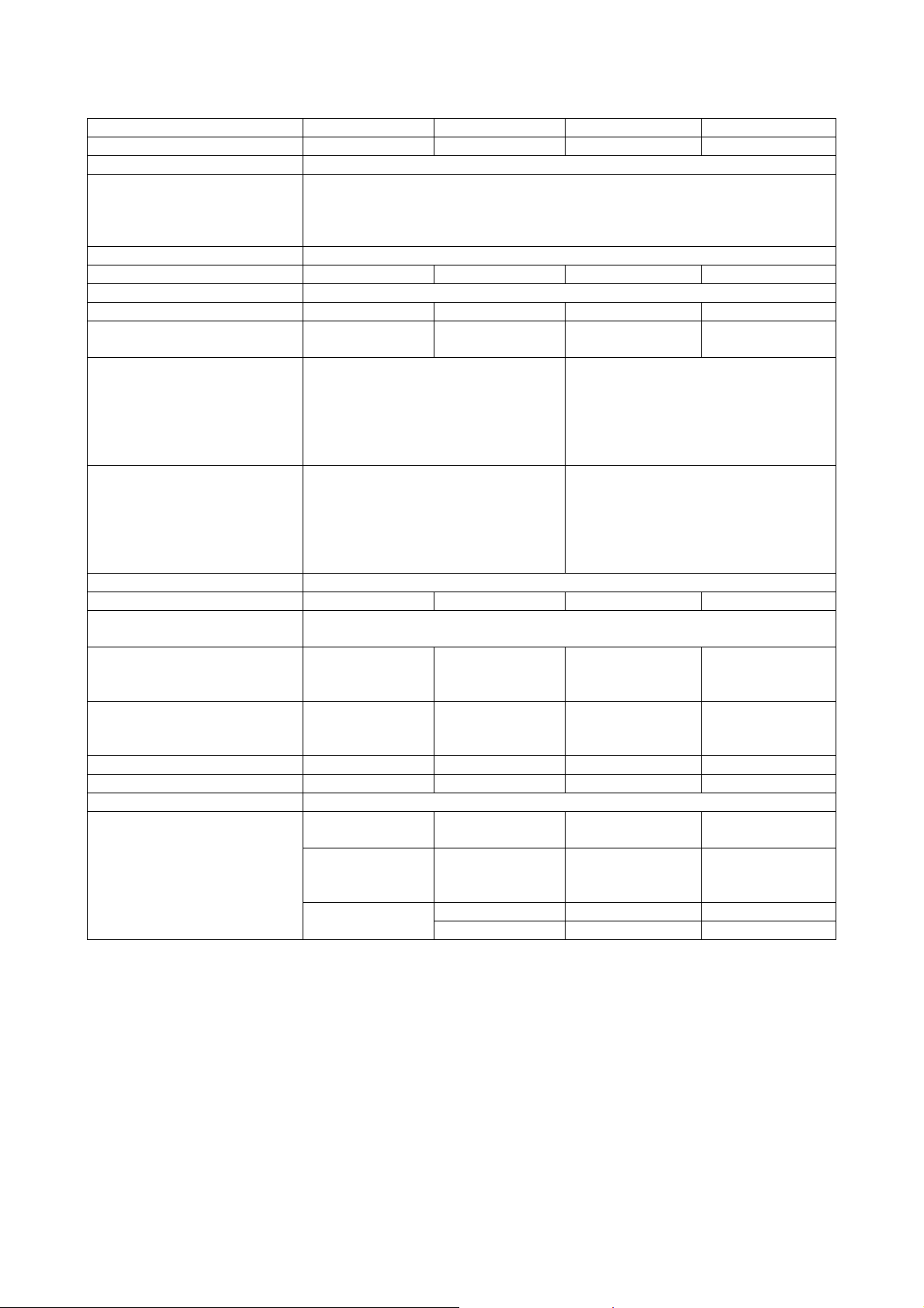
1. General Specification
Model LE32K0D7D(U) LE42K0D7D(U) LC32K0D3D LC42K0D3D
Screen Size
Resolution
OSD Language
View Angle
Brightness
Video System
Audio System
Speaker Output
Rear Connectors
Side Connectors
Input Voltage
Power Consumption
Standby Power
Consumption
Set Dimension(W X H X D)
(With Base And
Stand)(mm)
Set Dimension(W X H X D)
(W/O Base And
Stand)(mm)
Net Weight (Kg)
Wall Mount Size
Operation Temperature
USB Photo/Music/Video
Supported Formats
32” diagonal 42” diagonal 32” diagonal 42” diagonal
1920 x 1080
Bulgarian, Croatian, Czech, Danish, Dutch, English, Finnish, French,
Gaeilge, German, Greek, Hungarian, Italian, Norwegian, Polish,
Portuguese, Rumanian, Russian, Serbian, Slovakian, Slovenian, Spanish,
Swedish, Turkish, Latvian, Estonian, Lithuanian, Ukrainian
178°(H)/178°(V)
450 cd/m2 450 cd/m2 450 cd/m2 500 cd/m2
PAL/SECAM/DVBT/DVBC
B/G, D/K, I, LL’ B/G, D/K, I, LL’ B/G, D/K, I, LL’ B/G, D/K, I, LL’
10W x 2
Component Video & L/R Audio
Input
EXT(RGB/AV)
SPDIF Output
HDMI
Tuner Input
COMMON INTERFACE
PC IN: D-SUB & PC Audio
Earphone Output
HDMI
USB
≤100W ≤120W ≤115W ≤200W
775 x 563 x 210
775 x 521 x 46 1005 x 651 x 46 779 x 553 x 98 1011 x 650 x 108
10.5 17 12 20
200 x 100mm 200 x 200mm 200 x 200mm 400 x 200mm
Picture JPEG
Audio MP3 MPEG1 Layer 3
Video
Speaker: 8W x 2
Woofer: 10W
220-240V, 50/60Hz
≤0.5W
1005 x 691 x
230
0ºC~35ºC
MPEG1 MPG MPEG-1 Video
MPEG4 AVI, MP4 MPEG-4
10W x 2 10W x 2
Tuner Input
PC IN: D-SUB & PC Audio
Component Video & L/R Audio Input
SCART
SPDIF Output
HDMI
COMMON INTERFACE
AV In
Earphone Output
HDMI
USB
779 x 553 x 251 1011 x 698 x 278
Baseline
Progressive
8~48 KHz
8~576 Kbps
Mono/Stereo
4
Page 5
2. Operating Instructions
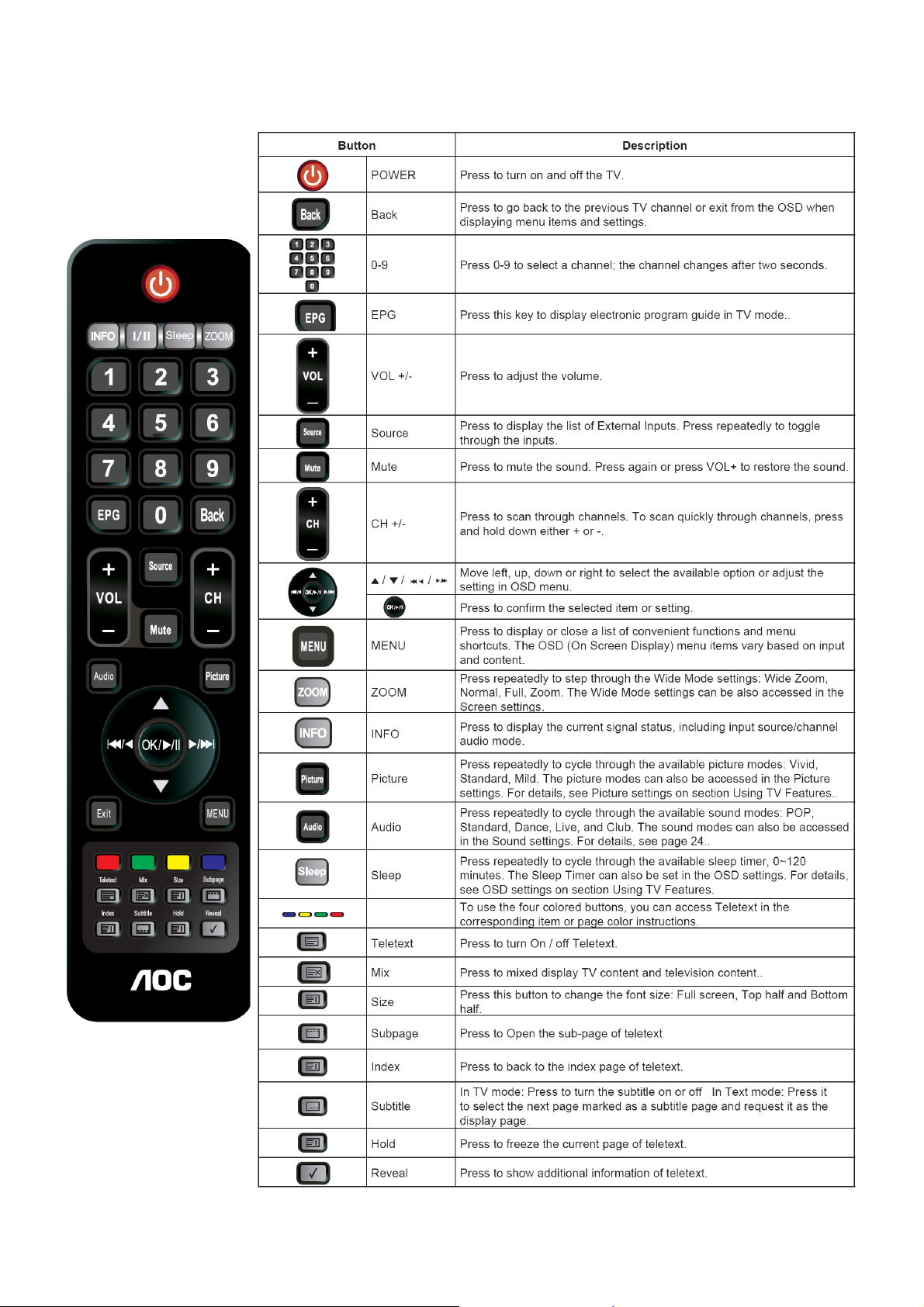
2.1 The Use of Remote Control
5
Page 6
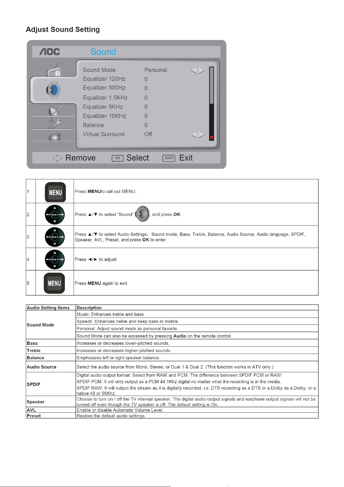
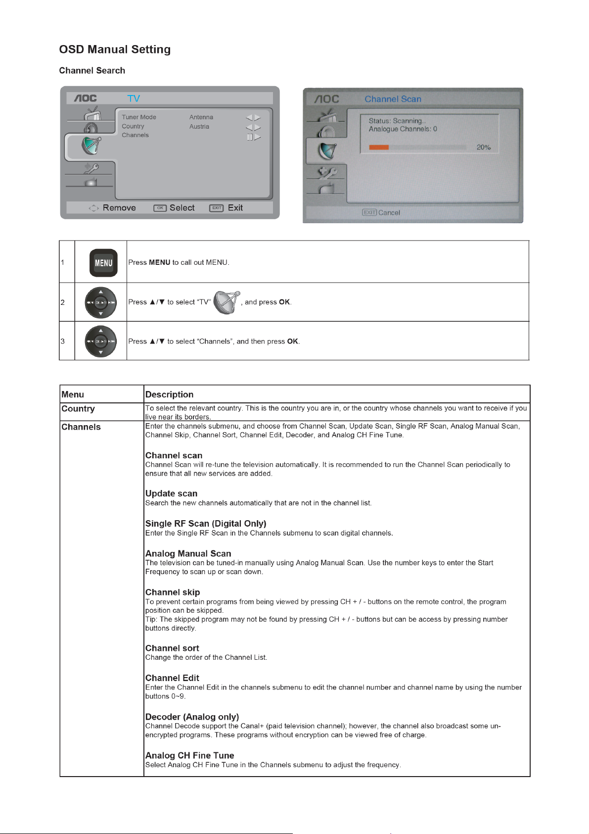
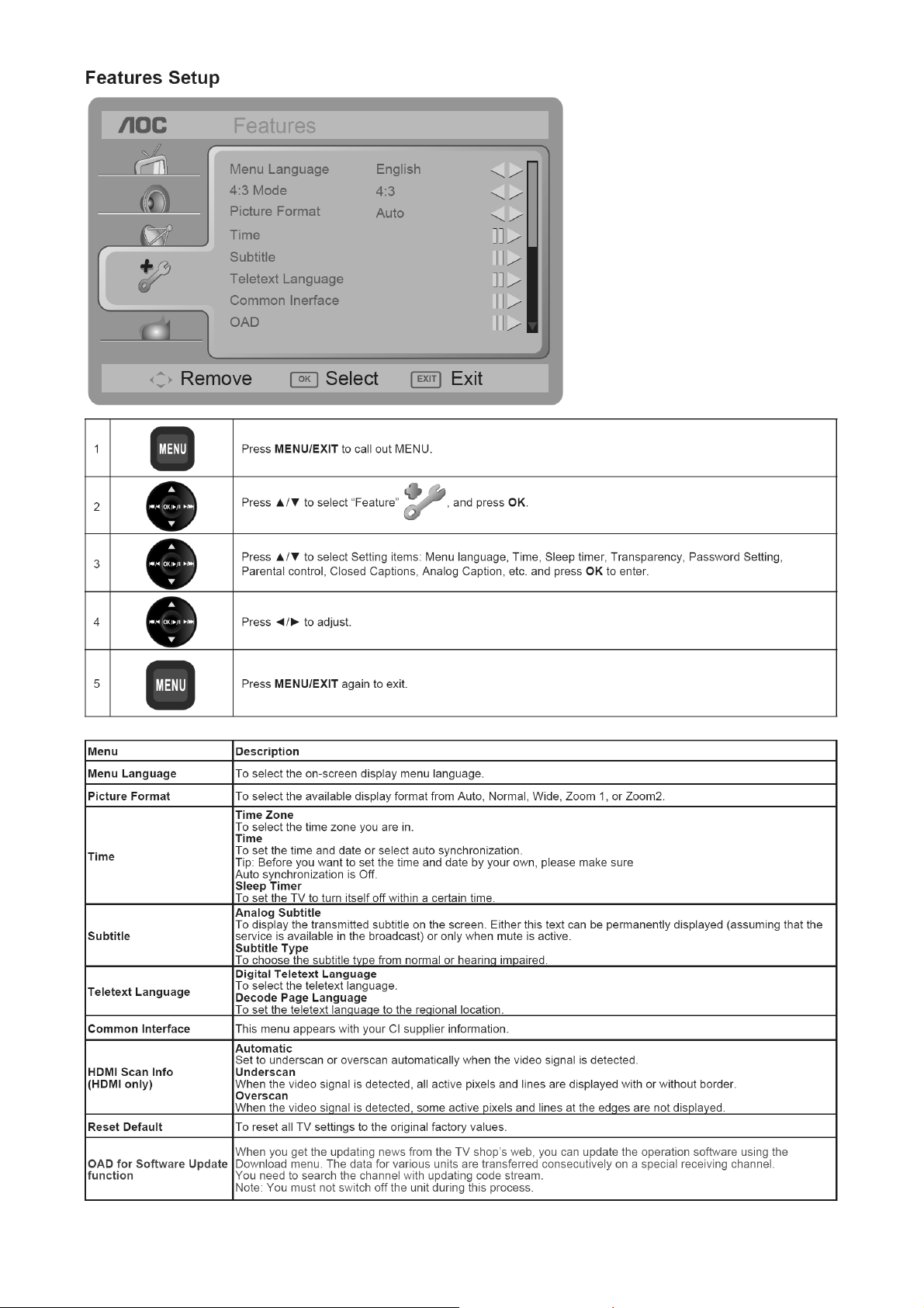
2.2 To Use the Menus
6
Page 7
7 8
Page 8
Page 9
9
Page 10
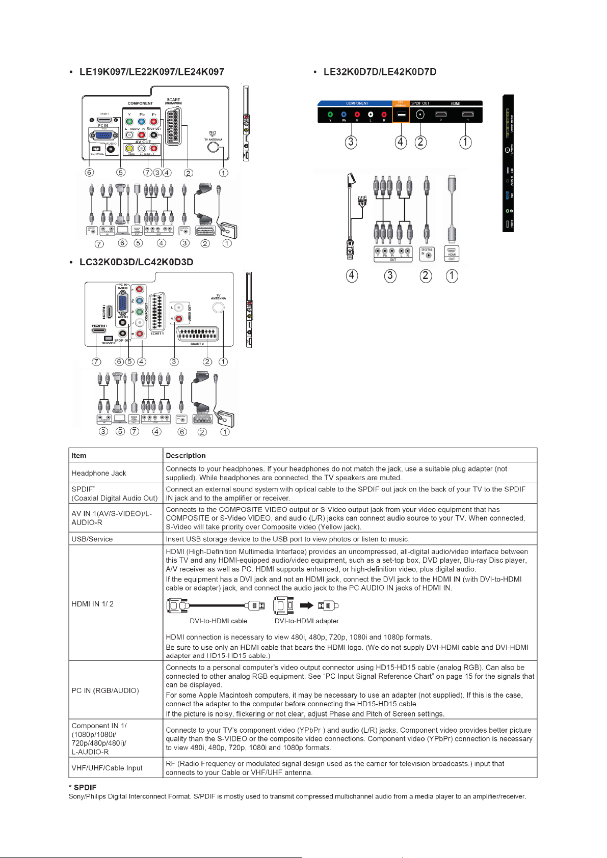
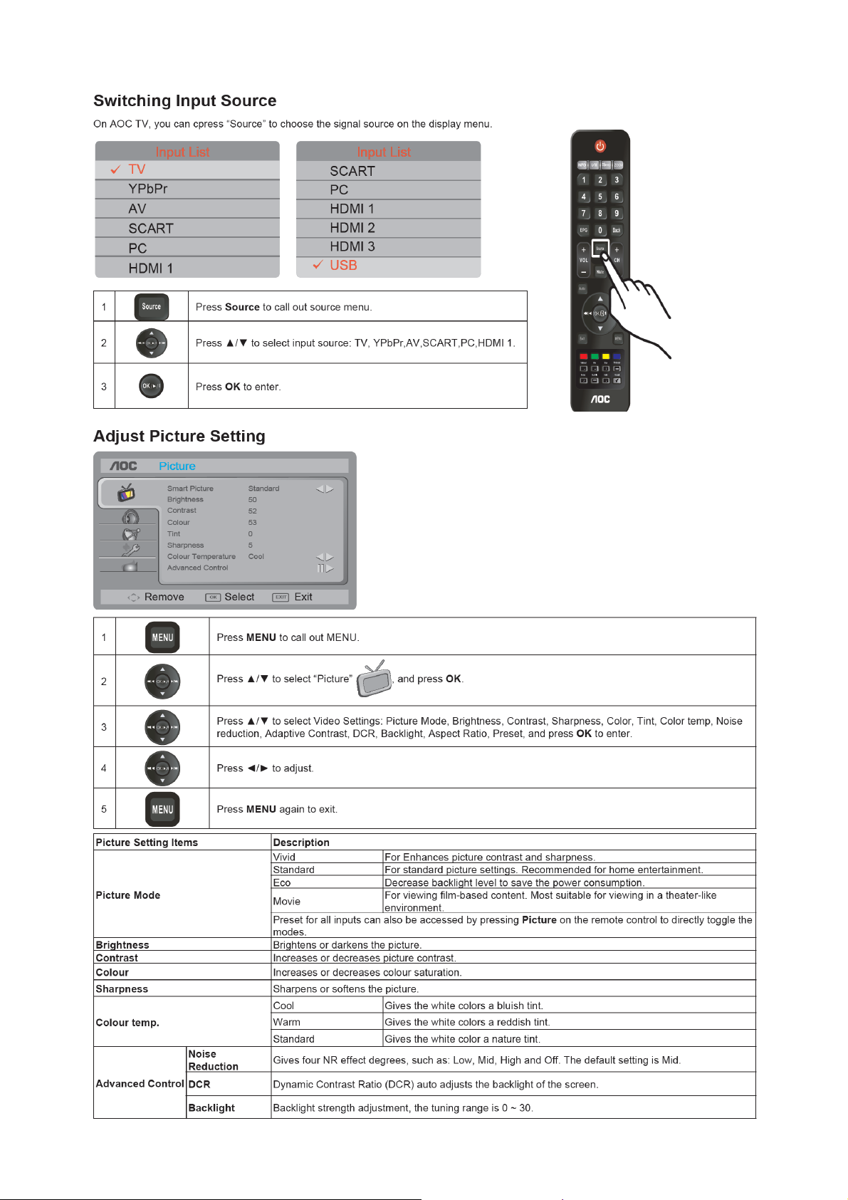
2.3 How to Connect
10
Page 11
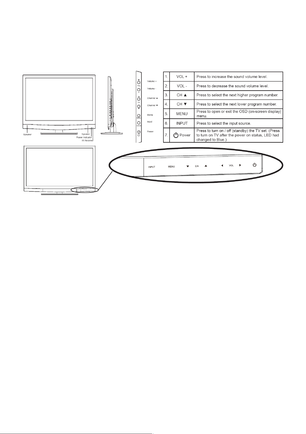
2.4 Front Panel Control Knobs
11
Page 12
3. Input/Output Specification
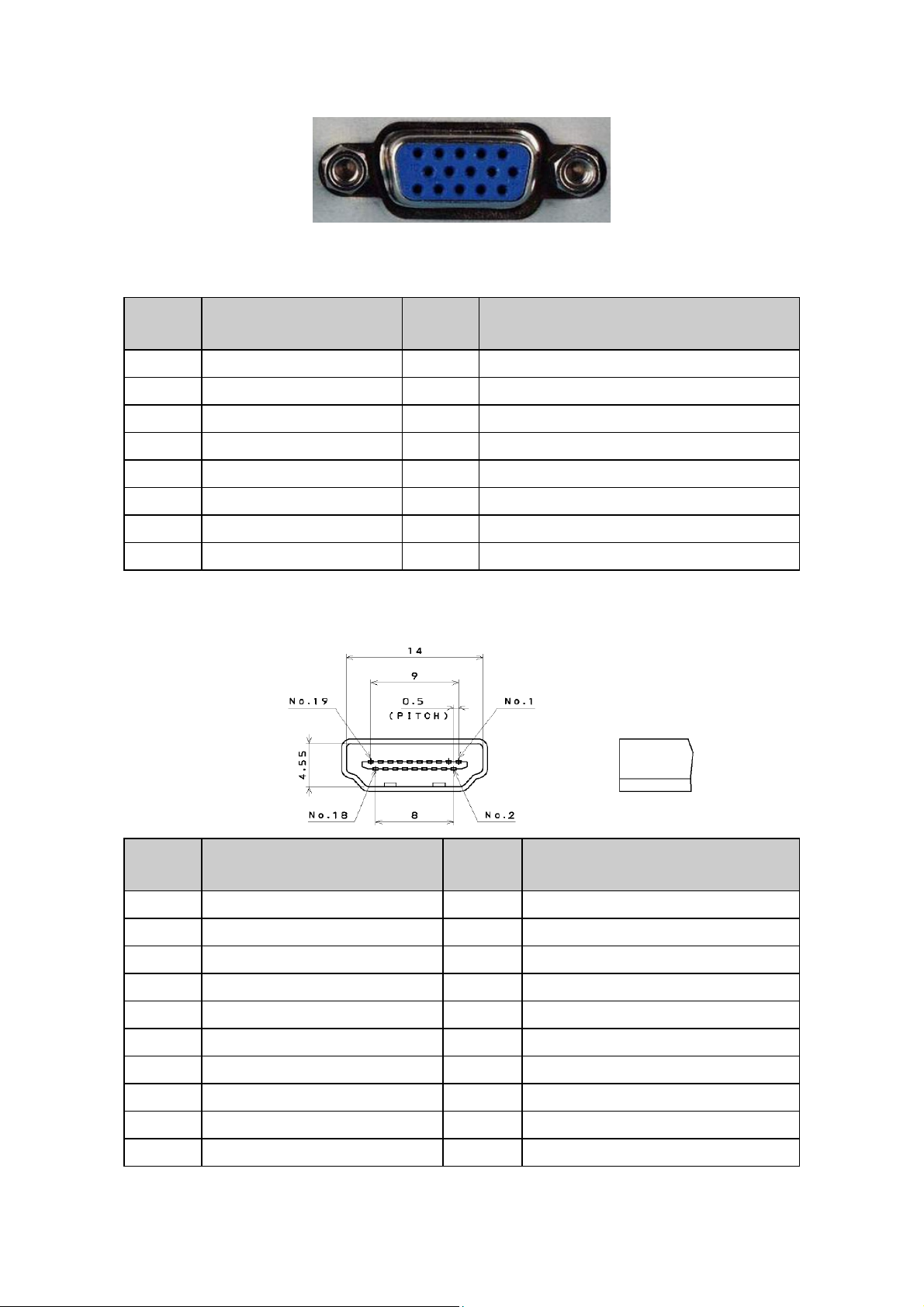
3.1 RGB Signal Input
15 - Pin Color Display Signal Cable
Pin No. Description Pin No. Description
1 Red 9 +5V (Supply from PC)
2 Green 10 Sync Ground
3 Blue 11 NC
4 NC 12 Bi-directional data(SDA)
5 Ground 13 H-Sync.
6 Red Ground 14 V-Sync. (VCLK)
7 Green Ground 15 Data clock(SCL)
8 Blue Ground
3.2 HDMI Digital Connector Pin Assignments
Pin No. Description Pin No. Description
1 TMDS Data2+ 2 TMDS Data2 Shield
3 TMDS Data2- 4 TMDS Data1+
5 TMDS Data1 Shield 6 TMDS Data1-
7 TMDS Data0+ 8 TMDS Data0 Shield
9 TMDS Data0- 10 TMDS Clock+
11 TMDS Clock Shield 12 TMDS Clock-
13 CEC 14 Reserved (N.C. on device)
15 SCL 16 SDA
17 DDC/CEC Ground 18 +5V Power
19 Hot Plug Detect
12
Page 13

3.3 Compatible Mode Table
Item H.Freq. (KHz) Mode Resolution V.Freq. (Hz)
1 31.469 IBM VGA 12H 640x480 59.940
2 35.156 VESA 800x600 56.250
3 37.879 VESA 800x600 60.317
4 48.363 VESA 1024x768 60.004
5 44.772 1280x720 59.855
6 47.776 CVT 2.3MA 1280x768 60
7 47.7 VESA 1360x768 60
8 63.981 VESA 1280x1024 60.020
9 65.29 VESA 1680x1050 60
10 66.587 VESA reduced blanking mode 1920x1080 60.0
13
Page 14

4. Mechanical Instructions
LE32K0D7D(U)
1. Remove the screws to remove the stand ass’y.
2. Remove the screws to remove rear cover.
14
Page 15
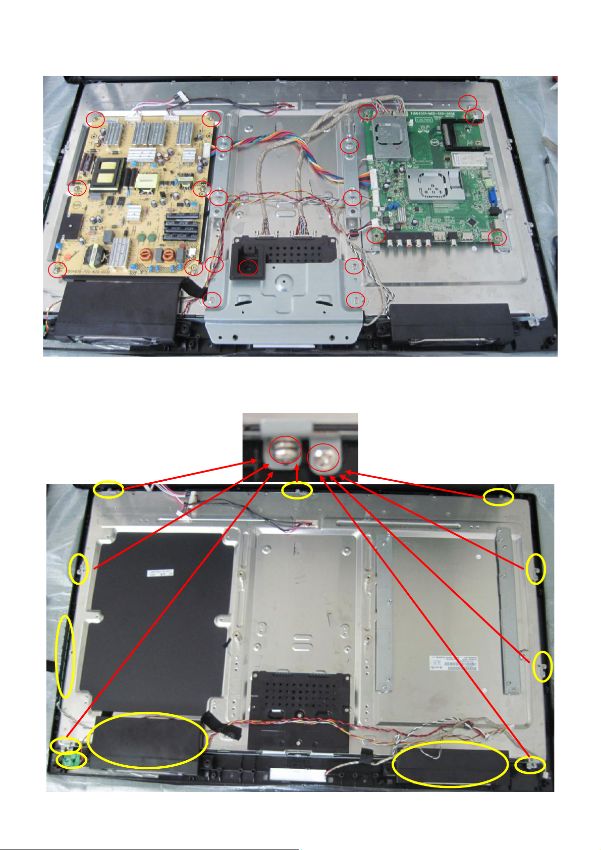
3. Remove the screws to remove bracket, AC cover, main board and power board.
4. Remove the screws to remove IR board, key board, speakers and bracket and separate the panel and bezel.
15
Page 16
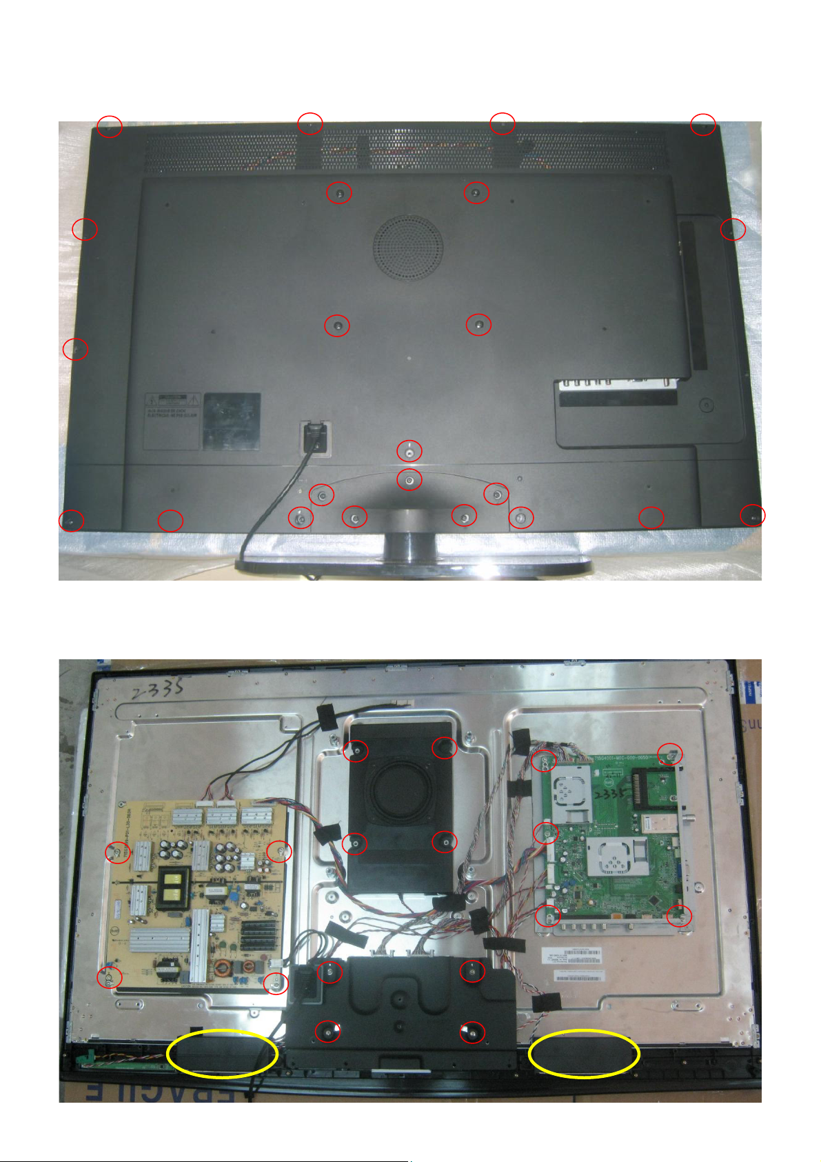
LE42K0D7D(U)
1. Remove the screws to remove the stand ass’y and rear cover.
2. Remove the screws to remove bracket, speakers, main board and power board.
16
Page 17
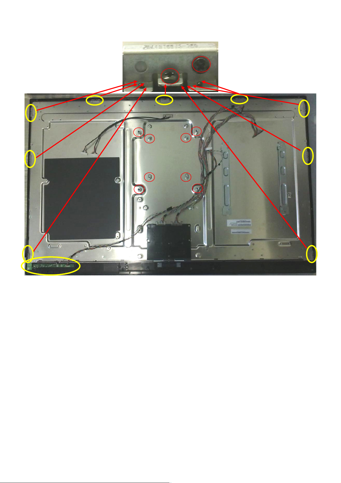
3. Remove the screws to remove IR board, key board and bracket and separate the panel and bezel.
17
Page 18
p
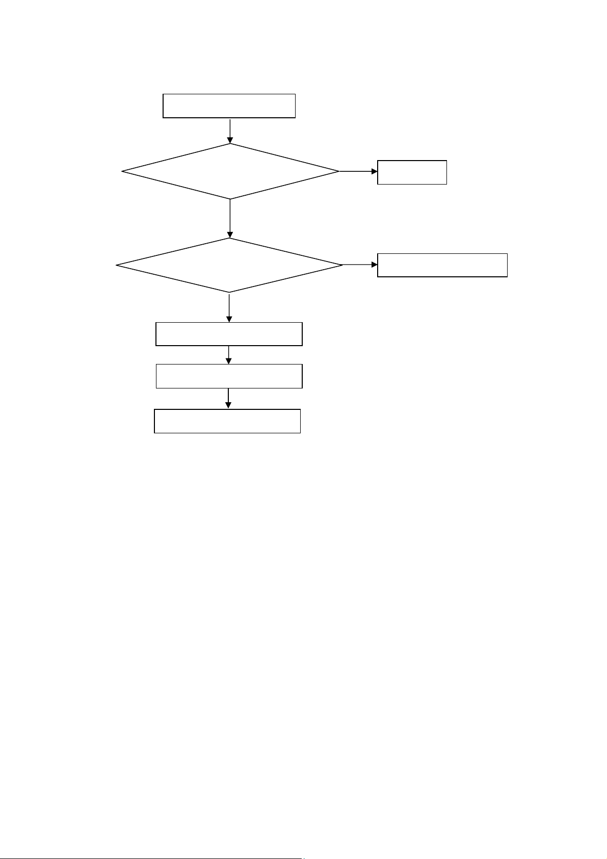
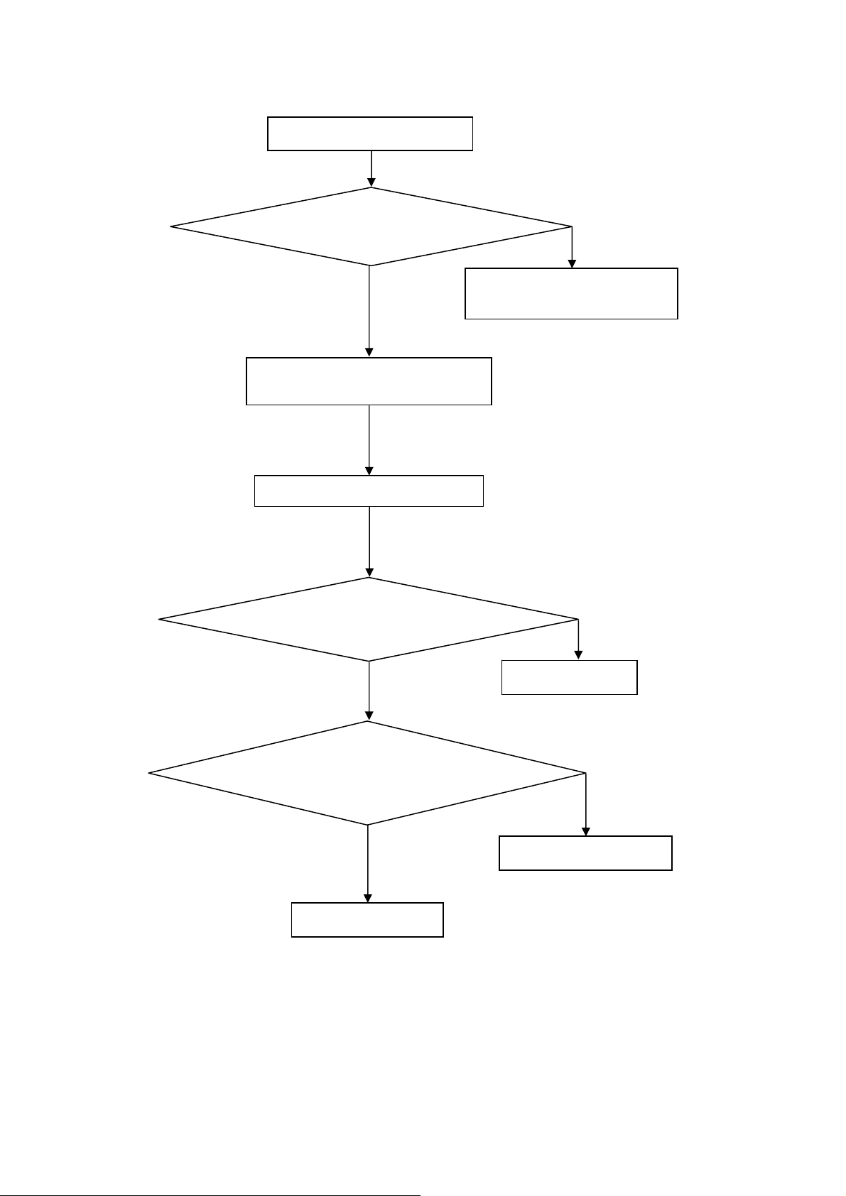
5. Repair Flow Chart
1. No power
No power (LED “Off”)
Check the AC input and
the
ower is “ON”?
Yes
Power board output=5V?
Yes
Check the IR board and LED
Replace the IR board
No
Replace the main board
No
Power “On”
No
Replace the power board
18
Page 19
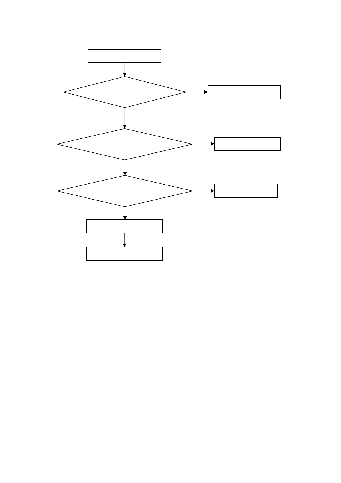
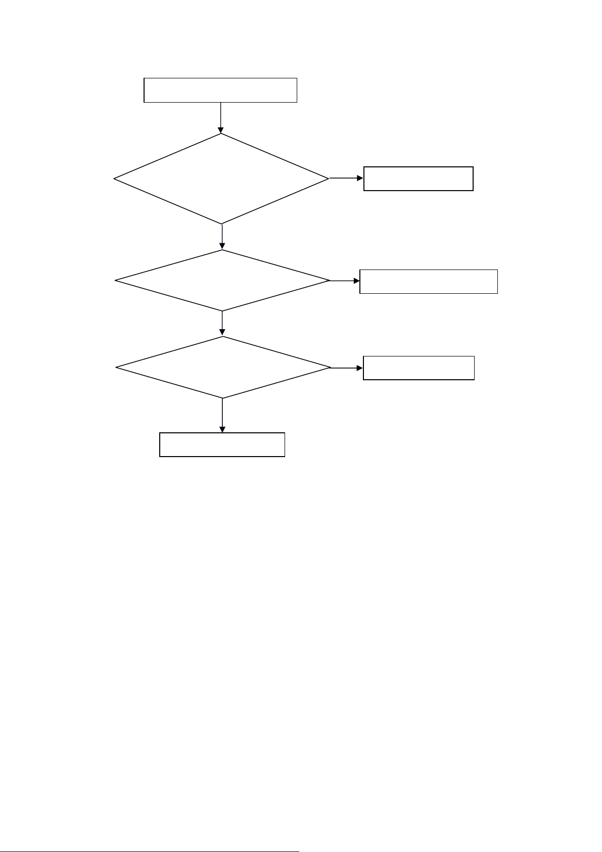
2. Can’t start
Can’t start(LED red)
Power board output=24V?
Yes
Check the power key is under control?
No
Check the IR receiver is normal?
No
Replace the power board
Yes
Replace the key board
Yes
Replace the IR board
No
Replace the main board
No
Replace the Power board
19
Page 20
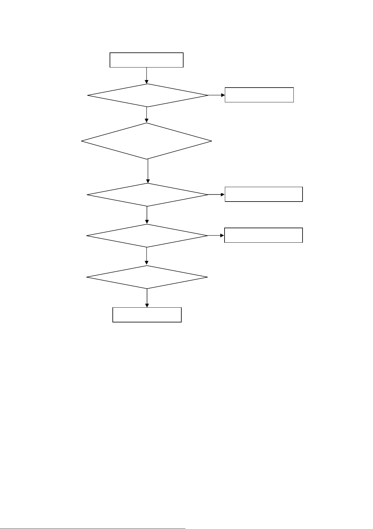
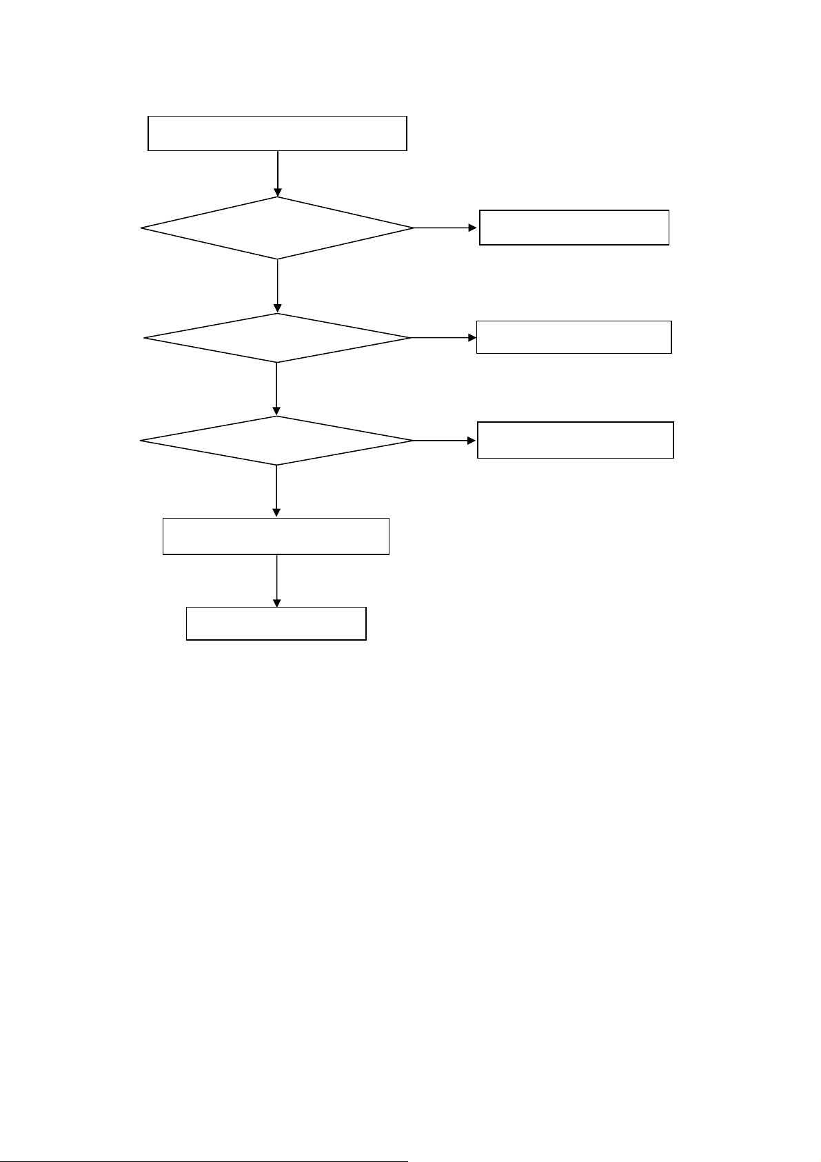
3. Abnormal Display
Abnormal Display
Check the source
Yes
Enter factory mode to do
“EEPROM initial”&“Reset”
No
No
Reset the source
Check the main board
Yes
Check the LVDS cable
Yes
Check the panel
No
Replace the panel
No
Replace the main board
No
Replace the LVDS cable
20
Page 21
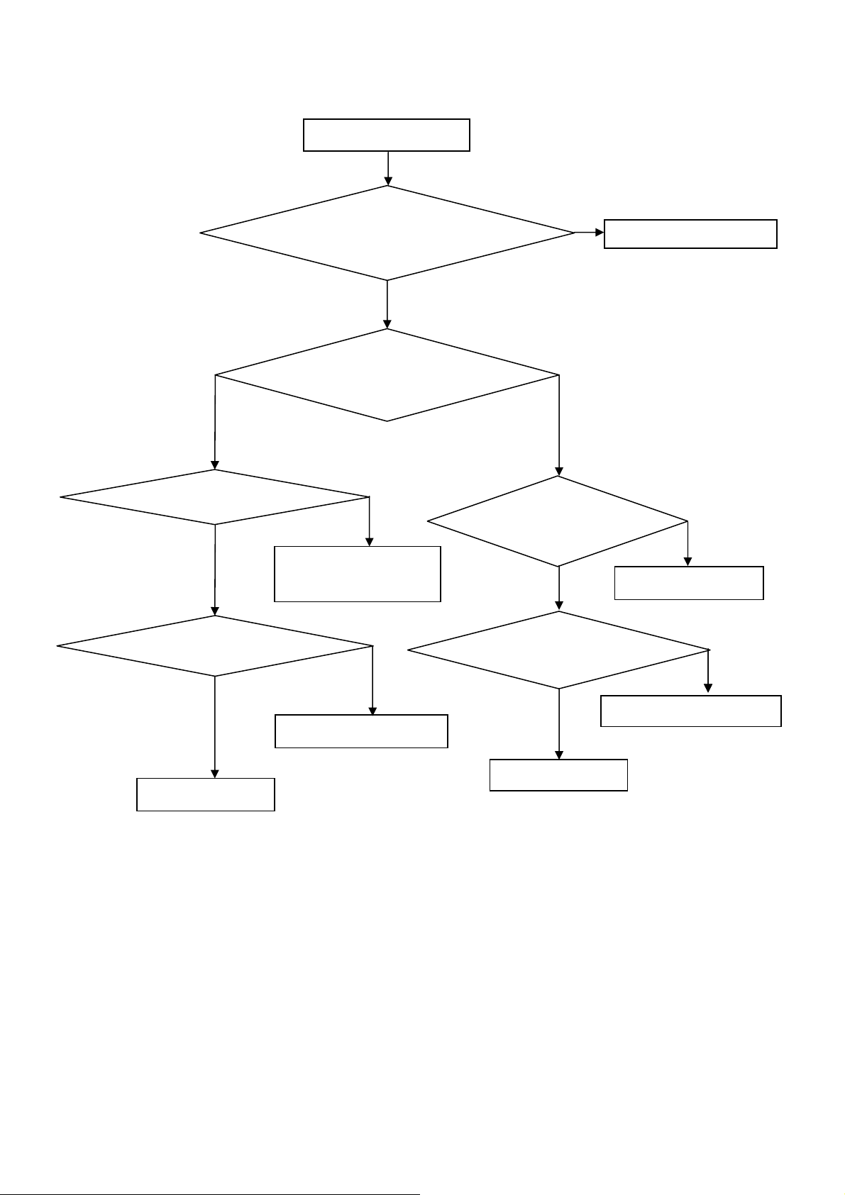
4. No display
No display (LED white)
Check TV is under control and power
on/off by remote control and power key?
Yes
Check the LVDS cable
Yes
Yes
Check the backlight is
“On”?
No
Reinsert or replace the
LVDS cable
No
No
Check the B/L
signal is available?
Yes
Replace the main board
No
Replace main board
Panel Vcc = 5V?
Yes
Replace the Panel
No
Replace the main board
Power board output=24V?
Yes
Replace the Panel
Replace the power board
No
21
Page 22
5. Sound problem
No sound or sound abnormal
Check the audio source connection
and the TV system are correct?
Yes
Check the TV is muted, adjust the
volume or enter the menu to reset?
No
No
Reinsert the audio cable or
change the TV system
Enter factory mode to do “Reset”
No
Check the cable between the
speakers and main board is OK?
Yes
Check the speaker resistance value is in spec
(Remark: The value is marked on the speaker)?
Yes
Replace the cable
Replace the main board
No
No
Replace the speaker
22
Page 23
6. Remote control malfunction
Remote Control malfunction
Check the remote control battery is
not properly placed or no power?
No
Use the other remote controls
No
Whether the IR board is
abnormal?
No
Replace the main board
Yes
Replace the battery
Yes
Replace the remote control
Yes
Replace the IR board
23
Page 24
7. OSD is unstable or can’t work normally
OSD is unstable or can’t work normally
Key board connected properly?
Yes
Buttons are OK?
Yes
Key board is OK?
Yes
Enter factory mode to do “Reset”
No
No
No
No
Reconnect the key board
Replace the button function
Replace the key board
Replace the main board
24
Page 25
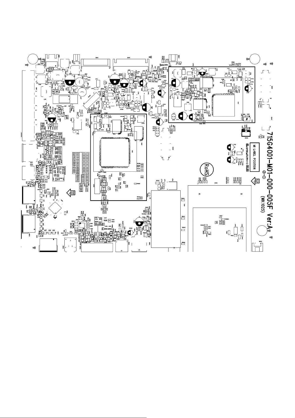
6. PCB Layout
6.1 Main Board
715G4001M01000005F
25
Page 26
26
Page 27
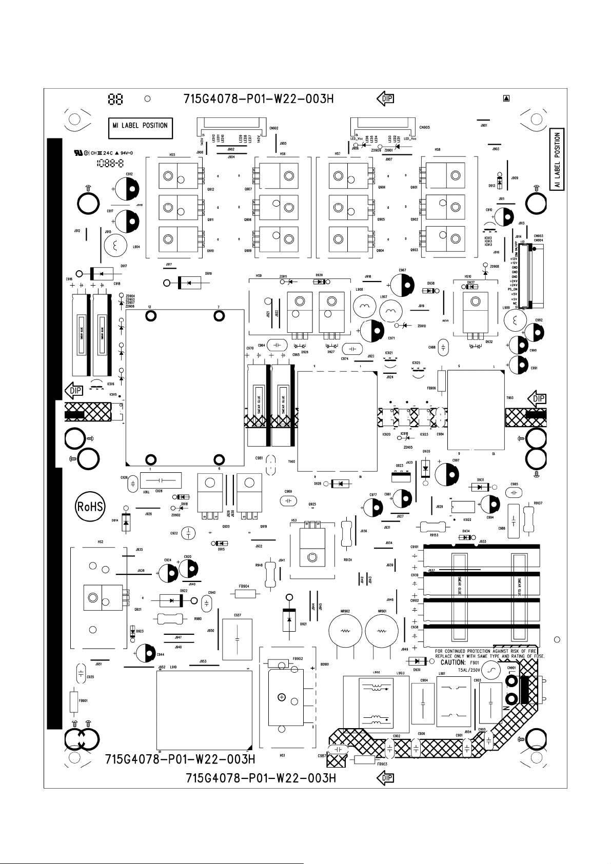
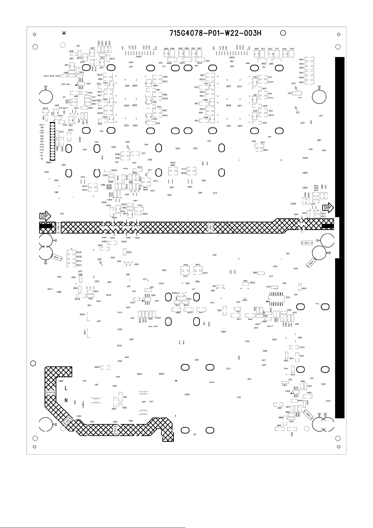
6.2 Power Board
LE32K0D7D(U) 715G4078P01W22003H
27
Page 28
28 29
Page 29
Page 30
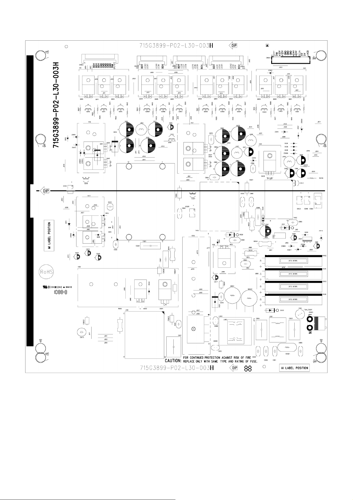
LE42K0D7D(U) 715G3899P02L30003H
30
Page 31

31 32
Page 32

Page 33

6.3 Key Board
LE32K0D7D(U) 715G4183K02000004M
LE42K0D7D(U) 715G4130K02000004S
6.4 IR Board
715G4098R02000004S
33
Page 34

7. Adjustment
It’s no need to adjust the white balance for this model.
1. Enter into the factory mode:
Turn on the TV, press MENU key with remote control, then press number key 1 Æ 9 Æ 9 Æ 9. It will achieve the
factory mode.
2. Click on "Auto Color" in the PC and Component modes:
PC mode: TIM = 137; PAT = 42
Component mode: TIM = 316; PAT = 185
3. Click on "Color temp" in the COMPONENT modes:
Component mode: TIM = 316; PAT = 105
Warm Temperature Spec
Warm_Spec_x = 314
Warm_Spec_y = 319
Normal Temperature Spec
Normal_Spec_x = 289
Normal_Spec_y = 291
Cool Temperature Spec
Cool_Spec_x = 278
Cool_Spec_y = 278
34
Page 35

8. Block Diagram
RF TUNER
TDTW-S8 16
(DVB-C+T)
IF
PCMCIA
CI CARD
SI2163
(DVB-C
DEMOD)
DVB-C TS(PARALLEL)
DVB-C TS (SERIAL)
TS OUT(PALL EL)
PCMC IA INTER FACE
DDR II X 2
1 Gb / 1066 MHz
IF
NOR FLASH
51 2K Byte
MT5363
NAND FLASH
16 M byte
DD R II X 1
512 Gb / 1 GHz
NOR FLASH
512K Byte
LCD PANEL T-CON
MT8282
LVDS (50/60 Hz)
LVDS (100/1 20 Hz)
PC IN
CVI
VIDE O
SCART
HDMI1
HDMI2
HDMI3
AUDIO R/L (PC)
AUD IO R /L ( CVI& AV)
AUD IO
R/L (HDMI)
24C02
RGB
YPbPr
CVB S
RGB
[RX0 : RX3]
CVB S
LINE OUT AMP
R/L
RC4580
SPDIF
AUDIO AMP
R/L
STA339BW
HP AMP HEADPHONE
R/L
TPA6132
I2C
NVM
UARTUSB
KEY R C
2.0
24C32
SCART CVBS output
SCART audio output
Digital Audio Output(COIXIAL)
SPK 2.1
DDC
DDC
24C02
TMDS
24C02
24C02
351
DDC
DDC
35
Page 36

+24V
+12V/5V
STB_PWR5V
POWER SWITCH
SI5403
PANEL_VCC_ON/OFF
BUCK DC CONVERTER
G5657
BUCK DC CONVERTER
G5657
M82_DV33
POWER SWITCH
SI3441
STANDBY
POWER SWITCH
SI5403
DV11
+5V_SW
M82_DV33
M82_DV33
M82_AV33
M82_AV33
+5V_SW
LDO
G1084-18
LDO
G1117
POWER SWITCH
G5250
CI_PWR_EN
BUCK DC CONVERTER
MP2212
DV33 & AV33
AUDIO _VDD
M82_DDRV
M82_AV12
M82_DV11
+5V1_TUN
+5V_SW
27 mA
550 mA
155 mA
64 mA
928 mA
200 mA
200 mA
DV33/AV33
AUDIO AMP
STA339BW
LVDS_VDD
MEMC Chip
MT8282
MEMC Chip
MT8282
MEMC Chip
MT8282
MEMC Chip
MT8282
MEMC Chip
MT8282
LG TUNER
TDTW-S816
TMDS SWITCH
TMDS351
CI CARD
PCMCIA CARD
MAIN CHIP
MT5363
30 mA
500 mA
DV33
NOR Flash
MX25L4005
DDRII X 2
NT5TU32M16
DVB-C Demod
SI2163
BUCK DC CONVERTER
MP2212
OPWRSB
LDO
G903T63
DV11
DV33SB
36
DV33
DV33
DV33
LDO
G1117
LDO
G1117
LDO
G1117
DV18_DDR
AV12
DV12
DV11
DV33SB
MAIN CHIP
MT5363
MAIN CHIP
MT5363
DVB-C Demod
SI2163
MAIN CHIP
MT5363
MAIN CHIP
MT5363
DDRII X 2
NT5TU64M16
Page 37

9. Schematic Diagram
9.1 Main Board
715G4001M01000005F
EU MT5363 - 4 LAYERS
BRIGHT_ADJ:
Normal:Max:+3V 3, Min:0V
TP705
TP704
TP706
TP707
Stand_B y:0V
INVERTER_ON_O FF:
Normal: High
Stand_B y: Low
INVERTER_ON_OF F
BRIGHT_ADJ
STB_PWR5V
DC POWER INPUT
TP702
TP701
TP703
CN701
1
2
3
4
5
6
7
8
9
10
11
12
13
R703
CONN
NC/10KOH M +-5% 1/8W
STANDBY:
Normal: High
Stand_by : Low
+12V/5 V
+24V
R704 100OHM1/ 16W
SMD/0402
C701
NC/22uF 10V
STANDBY
STB_PWR5V +5V_STB
FB701 120R/3000m A
1 2
FB702 120R/3000m A
1 2
DV33+5V_SW
R713
NC/1K1/16W
SMD/0402
STANDBY
BC847C
Q705
R712
1K1/16W
SMD/0402
R710 1K1/16W
SMD/0402
+
C702
470UF 10V
STAND_BY
STAND_BY:
Normal: Low
Stand_by : High
C708
100N 16V
SMD/0402
OPWRSB(+5V_SW ON/OFF):
Normal: High
Stand_By: Low
DV11
R705 2K7 1/16W 5%
SMD/0402
+5V_STB TO +5V_SW BY DV11
33K 1/10W
R708
21Q702
C730
100N 16V
SMD/0402
3
BC847C
8
7
6
5
Si5403DC-T1-GE3
C705 1UF 16V
R711
22KOHM 1/10W
+24V15
+12V/5 V5,12,15, 16
+5V_STB5,8,10,15
+5V_SW8,10,11,1 2,13,14,15, 16,20
DV18_DDR9
DV117
OPWRSB10
STAND_BY11
BRIGHT_ADJ20
INVERTER_ON_OFF20
+5V_SW+5V_STB
Q704
1
D
D
2
D
D
3
D
D
G4S
C712
10U 10V
DV335,6,7, 8,10,11,14, 15,20
AV338,14,20
DV33SB5,10,13, 14,15,20
GND5,6,7,8, 9,10,11, 12,13,14,1 5,16,17,18, 19,20
+5V1_TUN5
+24V
+12V/5 V
+5V_STB
+5V_SW
DV18_DDR
DV11
OPWRSB
STAND_BY
BRIGHT_ADJ
INVERTER_ON_OF F
DV33
AV33
DV33SB
GND
+5V1_TUN
ON OFF
C707
100N 50V
C711
100N 50V
OPWRSB
C723
22uF 10V
C726
22uF 10V
NC/22uF 10V
R714
4.7K1/16W
SMD/0402
NC/22uF 10V
1 2
C719
1UF16V
1 2
C724
FB705
220R/2000m A
C709
FB706
220R/2000m A
+5V_STB
D703 BAS316
MP2212DN
BS4VCC
3
IN
2
GND
1
FB
EN/SY NC
Thermal Pad
U701
+5V_SW
D704 BAS316
MP2212DN
BS4VCC
3
IN
2
GND
1
FB
EN/SY NC
Thermal Pad
U702
C725 1UF 16V
R716
0R05 1/10W
5
6
SW
7
SW
8
9
C717
100N 50V
1 2
D701
NC/SS3P4
OFF O N
Vout= 0.8x (1+ 4K/10K) = 1.12V for MP 2212
OFF O N
C727 1UF 16V
R725
0R05 1/10W
C718
5
6
SW
7
SW
8
9
100N 50V
1 2
D702
NC/SS3P4
Vout= 0.8x (1+ 31.5K/10K) = 3. 32V for MP 2212
L701
4.7uH
0R05 1/10W
560pF 50V
L702
4.7uH
0R05 1/10W
560pF 50V
1
D
2
D
G3S
21Q701
FB704
NC/220 R/2000mA
ON OFF
R701
NC/22KOH M 1/10W
3
NC/BC847C
+5V1_TUN+5V_SW
+5V1_TUN+5V_STB
12
FB703 NC/220R /2000mA
1 2
2
DV33
R717
120R 1% 1/10W
R731
56R 1/10W 1%
C729
10uF 10V
DV18_DDR
+
C734
100UF 25V
R702 NC/ 33K 1/10W
STANDBY
STANDBY :
Normal: High
Stand_by : Low
NC/SI 3441BDV
6
D
5
D
4
C706 NC/1UF16V
R707
NC/10K1/ 16W
SMD/0402
Q703
DV11
R718
1K 1/10W 1%
R720
3K 1/10W 1%
R721
10K 1/10W 1%
22uF 10V
R715
C720
C721
C713
22uF 10V
C715
100N 50V
10uF 10V
C733
FB707
220R/2000mA
1 2
U703
VIN3VOUT
GND/AD J
1
G1117T43
Vout=1 .25x (1+ 56/120)= 1.833V
AV33DV33
R727
0R05 4A 1/4W
C728
22uF 10V
R719
R726
1.5K +-1% 1/10W
C722
R723
30K 1/10W 1%
R722
10K 1/10W 1%
C714
22uF 10V
C716
100N 50V
T P V ( Top Victory Electronics Co . , Ltd. )
絬 隔 瓜 絪 腹
Key Component
04. POWER-1
Date
OEM MODEL
TPV MODEL
PCB NAME
Sheet
715G4001-1
420Tuesday, July 13, 2010
of
Size
Custom
Rev
1
xx
称爹
37
Page 38

+5V_STB DV33SB
U751
VI3VO
C765
1UF16V
GND14
G1117-33T63Uf
4
+5V_STB TO DV33SB
PANEL_VCC+12V/5 V
Panel VCC=12V
Q750
1
8
D
D
2
7
D
D
3
2
C767
10uF 10V
PANEL_V CC ON/OFF: (GPIO5)
Normal:High
Stand_B y:Low
PANEL_VCC_ON/OFF
5.1K 1/10W
R750 10K1/ 16W
SMD/0402
10K 1/10W
R755
R752
6
D
5
Si5403DC -T1-GE3
C754 1U F16V
R758 7K5 1/10W 5%
Q751
BC847C
D
G4S
ON OFF
+
100UF 16V
C768
+12V/5 V4,12,1 5,16
+5V_STB4, 8,10,15
+5V_SW4,8,10 ,11,12,13, 14,15,16, 20
+5V1_TUN4
+5V_TUNER6
DV334,6,7, 8,10,11, 14,15,20
AV334,8,14,20
DV33SB10,13, 14,15,20
AV127,8,9, 14,20
PANEL_VCC20
DV18_D DR4,9
DV126
PANEL_VCC_ON/OFF8
GND4,6,7,8, 9,10,11,12,13,14, 15,16,17,18,19,20
+12V/5 V
+5V_STB
+5V_SW
+5V1_TUN
+5V_TUNER
DV33
AV33
DV33SB
AV12
PANEL_VCC
DV18_DDR
DV12
PANEL_VCC_ON/OFF
GND
AV12DV33
2
R756
R757
C764
22uF 10V
C758
10uF 10V
VIN3VOUT
G1117T43
C757
NC/10U 10V
U753
GND/ADJ
120R 1% 1/ 10W
1
1 OHM 1/10W
Vo= 1.25 x (1+1R/120R) = 1. 25V
DV33 TO AV12
DV33
U754
G1117T63Uf
C766
10uF 10V
3
C759
NC/10U 10V
2
VIN
VOUT
GND
TH
1
4
R762
120R 1% 1/10W
R763
1 OHM 1/10W
Vo= 1.25 x (1+1R/120R) = 1. 25V
DV33 TO DV12 for DVBC Demod
DV12
C769
10uF 10V
+5V1_TUN +5V_TUNER
4
C752
+
NC/100U F 16V
3
2
1
EC060-25-AI
FB750 NC /220R/2000mA
1 2
9
NC
VIN
EN
NC
U755
NC/SC 4215HSETRT
0.5((39K+2.4K+4K7)/4K7)=4.90V
5
NC
6
TH1
GND
VO
7
FB
8
C756
NC/100N 16V
SMD/0402
R759
NC/39K 1/ 10W 1%
NC/2. 4K 1%
R760
R761
NC/ 4K7 OHM 1/10W 1%
+5V_TUNER FROM Regulator
T P V ( Top Victory Electronics Co . , Ltd. )
絬 隔 瓜 絪 腹
Key Component
Date
+
EC060-25-AI
05. POWER-2
C753
NC/100U F 16V
FB751 220R /2000mA
1 2
C774
330NF 16V
OEM MODEL
TPV MODEL
PCB NAME
Sheet
1
C775
10uF 16V
715G4001-1
520Tuesday , July 13, 2010
of
U752 AS7805DTR-E1
OUT
IN
GND
2
3
C773
100N 16V
+5V_TUNER+12V/ 5V
C776
22uF 10V
Size
Rev
称爹
Custom
2
CL90016
38
Page 39

FB1000 120R/3000mA
1 2
FB1001 120R/3000mA
1 2
FB1002 120R/3000mA
1 2
FB1005 120R/3000mA
1 2
FB1011 120R/3000mA
1 2
FB1012 120R/3000mA
1 2
FB1019 120R/3000mA
1 2
FB1022 120R/3000mA
1 2
GND_Tuner
FB1017 120R/3000mA
1 2
FB1018 120R/3000mA
1 2
FB1016 120R/3000mA
1 2
FB1015 120R/3000mA
1 2
FB1013 120R/3000mA
1 2
FB1014 120R/3000mA
1 2
FB1020 120R/3000mA
1 2
FB1021 120R/3000mA
1 2
GND_Tuner
LG TUNER
TU101
ANT[+5V]
LNA ON/O FF
+B(5V)
RF AGC
TU AS
DIF[+]
DIF[-]
IF AGC
TH117TH218TH319TH4
20
TDTW-S 817D
GND_Tuner
C1009
FAT+
FAT-
C1010
1N 50V
GND_Tuner GND_Tuner
C1031 100P 50V
SMD/0402
R1010 0R05 1/16W
R1013 0R05 1/16W
C1011
NC/39pF 50V
SMD/0402
GND_Tuner
1
LNA_ON/OFF_LG
2
3
GND
4
RF_AGC_LG
5
6
GND
T_SDA
7
SDA
T_SCL
8
SCL
9
FAT+
10
FAT-
11
IF_AGCT_T
12
13
NC
14
NC
15
NC
TUNER_CVBS1
16
NC
GND_Tuner
NC/39pF 50V
SMD/0402
R1007
10K1/16W
C1012 47N 16V
TU_MP X_P2
SMD/0402
SMD/0402
FB1007
120R/3000mA
LNA_ON/OFF
1 2
C1003
100N 16V
SMD/0402SMD/0402
SMD/0402
TU_F AT_IN 2+
TU_F AT_IN 2-
+5V_T1
C1048
C1001
100N 16V
10uF 10V
SMD/0402
GND_Tuner
GND_Tuner
R1015
SMD/0402 SMD/0402
GND_Tuner
39pF 50V
SMD/0402
IF_AGCT_T
C1013
47N 16V
SMD/0402
GND_Tuner
NC/4.7K1/16W
T_SC L
T_SD A
C1017
GND_Tuner
R1011 100R 1/10W 1%
R1012 100R 1/10W 1%
C1016
39pF 50V
SMD/0402
GND_Tuner
R1005
IF_AGC
10K1/16W
SMD/0402
RF_AGC_AD
R1020
NC/4.7K1/16W
GND_Tuner
C1014
47N 16V
SMD/0402
4.7K1/16W
SMD/0402
FB1006
220R/2000mA
1 2
R1002
RF_AGCRF_AGC
R1006
10K1/16W
SMD/0402
EC080-35
+5V_TUNER
R1003
4.7K1/16W
SMD/0402
も础
+5V_TUNER
+
C1000
NC/470UF 10V
NC/100K1/16W
SMD/0402
GND_Tuner
Close to MT5363
RFAGC Critical Signal
Place these two LPF closed to
main chip rather tha n tuner.
TUNER_CLK_Demod
TUNER_DATA_Demod
Place these two LPF closed to
main chip rather tha n tuner.
IF_AGCT
R1024
Q1001
NC/BC 857C
R1004
0R05 1/10W
RF_AGC_TUNER
Tuner
LG
Nutune
C1015
47N 16V
SMD/0402
R1004
R1008
10K1/16W
Q1001
R1024
Yes NC
Yes
NC
RF_AGCT
RF_AGC_AD10
+5V_SW4, 8,10,11, 12,13,14 ,15,16, 20
DV125
DV18_DDR4,9
+5V_TUN ER5
DV334,5,7,8,10,11,14, 15,20
GND4,5,7,8,9,10,11, 12,13,14,15,16,17,18,19,20
Tuner Control
LNA_ON/OFF11
TUNER _D ATA8
TUNER _C LK8
IF_AGCT8
RF_AGCT8
RF_AGC _TUNER11
SYS_RESET11
DVB-C TS to CI(PARALLEL)
CI_INDATA011
CI_INDATA111
CI_INDATA211
CI_INDATA311
CI_INDATA411
CI_INDATA511
CI_INDATA611
CI_INDATA711
CI_INVALID11
CI_INSYNC11
CI_INCLK11
DVB-C TS to MT5363(SER IAL)
TDO11
TVAVLI D11
TCK11
TSYN C11
RF_AGC_AD
+5V_SW
DV12
DV18_DD R
+5V_TUNER
DV33
LNA_ON/OFF
TUNER_DATA
TUNER_CLK
IF_AGCT
RF_AGCT
RF_AGC_TUNER
SYS_RESET
CI_INDATA0
CI_INDATA1
CI_INDATA2
CI_INDATA3
CI_INDATA4
CI_INDATA5
CI_INDATA6
CI_INDATA7
CI_INVALID
CI_INSYNC
CI_INCLK
TDO
TVAVLID
TCK
TSYN C
DV12
FB1009
120R/3000mA
12
10uF 6.3V
DVB_C Demod
IF_AGC_C
C1069
10N 50V
SMD/0402
CLOSE TO SI2163
TUNER_CLK_Demod
TUNER_DATA_Demod
SYS_RESET
R1031
10K1/16W
SMD/0402
R1034
W DVB-C
W/O DVB-C
C1071
FAT_IN-_C
FAT_IN+_C
DV33
NC
YES
DV12_VADC
C1072
100N 16V
R1019 1K1/16W
SMD/0402
R1043
0R05 1/10W
DV33_DVBC
R1035
DV12
120R/3000mA
R1017
SMD/0402
0R05 1/16W
R1018
SMD/0402
0R05 1/16W
R1014 150R 1/16W 1%
SMD/0402
R1009 150R 1/16W 1%
SMD/0402
R1042
0R05 1/16W
SMD/0402
FB1024
120R/3000m A
1 2
C1023
100N 16V
R1016
NC/4.7K1/16W
SMD/0402
NC
YES
FB1004
12
C1040
10uF 6.3V
37
36
35
34
33
32
31
30
29
SI2163_VDDH_ANA
C1024
10uF 6.3V
R1021
0R05 1/16W
100N 16V
GND
GPIO_0
RESSI_ADC
SCL_MAST
SDA_MAST
ADC_CN
ADC_CP
ADC_IN
ADC_IP
SMD/0402
C1039
2
1
GND
VDD_VADC28VDDH_ANA27ADDR26XTAL_I25XTAL_O24VDD_VCORE23RESETB22TS_ERR/GPIO_221TS_DATA720GND
DV12_VADC
123
C1005
27P 50V
100N 16V
3
AGC_IF
X10 01
16MHz
C1038
4
AGC_RF
SCL_HOST
NC/4.7K1/16W
100OHM1/16W
R1033
100OHM1/16W
DV12_DVBC
7
6
5
TS_VAL
SDA_HOST
VDD_CORE
TP1000
DV12_DVBC
4
DV12_DVBC
NC/100N 16V
R1037
R1032
8
10
9
TS_CLK
TS_SYNC
19
C1037
GND
TS_DATA 0
TS_DATA 1
TS_DATA 2
TS_DATA 3
VDD_HVIO
TS_DATA 4
TS_DATA 5
TS_DATA 6
Si2163
C1006
27P 50V
R1036
NC/4.7K1/16W
TUNER_DATA
U101
DV33
DV33_DVBC
TUNER_CLK
11
12
13
14
DV33_DVBC
15
16
17
18
TUNER_DATA
TUNER_CLK
1 2
120R/3000mA
RP1003
4
3
2
1
0OHM 1/16W
FB1003
C1036
100N 16V
100N 16V
TVAVL ID
5
TSY NC
6
7
TDO
8
0OHM 1/16W
4
3
2
1
4
3
2
1
0OHM 1/16W
0OHM 1/16W
TVAVLID
4
3
2
TDO
1
U102
DVB-CT_SW
6
DV33_DVBC
5
TCK
4
TS5A3157DCKR
SMD/0402
R1034NC/0R 05 1/16W
R1035NC/0R 05 1/16W
SMD/0402
C1035
C1042
NC/10pF50V
SMD/0402
RP1000
RP1001
RP1002
IN
GND
V+
NO
NC3COM
C1034
100N 16V
FB1023
12
60 OHM
CI_INDATA1
5
CI_INDATA2
6
CI_INDATA3
7
CI_INDATA4
8
CI_INDATA5
5
CI_INDATA6
6
CI_INDATA7
7
8
CI_INVALID
5
CI_INSYNCTS YN C
6
7
CI_INDATA0
8
CI_INCLK
1
2
TUNER_DATA_Demod
TUNER_CLK_Demod
TCK
C1049
10pF 50V
DV33_DVBC
C1033
100N 16V
Impedance Contrl 100ohm and
route these path w ith di fferen tial
pattern on top layer.
SMD/0402
C1020
TU_F AT_ IN 2+_ T
TU_F AT_ IN 2-_ T
TU_F AT_IN 2+_T
TU_F AT_IN 2-_T
R10250R 05 1/16W
TU_F AT_IN 2+
TU_F AT_IN 2-
22P 50V
R1047
51R 1/16W 5%
SMD/0402
SMD/0402
R1048
C1021
51R 1/16W 5%
SMD/0402
22P 50V
R10450R05 1/16W
R10460R05 1/16W
L1008 NC/0.22uH 10%
C1043 NC/56pF 50V
R10390R05 1/16W
SMD/0402
SMD/0402
R10380R05 1/16W
C1044 NC/56pF 50V
L1009 NC/0.22uH 10%
Close to DVB_C Demod
SMD/0402
SMD/0402
SMD/0402
SMD/0402
SMD/0402
L1002
0.33uH 10%
L1003
0.33uH 10%
TU_F AT_ IN 2+
TU_F AT_ IN 2-
IF_AGCIF_AGC_C
IF BPF
C1022
33P 50V
SMD/0402
SMD/0402
R10410R05 1/16W
R10440R05 1/16W
SMD/0402
C1018 33P 50V
SMD/0402
L1000
0.22uH 10%
L1001
0.22uH 10%
C1019 33P 50V
SMD/0402
BYPASS MUX
NC/100N 16V
C1046
SMD/0402
C1045
NC/100N 16V
SMD/0402
Close to MT5363
SMD/0402
C110510N 50V
L1005
NC/0.33uH 10%
C110610N 50V
SMD/0402
FAT_IN+_C
FAT_IN-_C
FAT_IN+
FAT_IN-
A/V Filter (RES ERVE)
NC/0R05 1/16W
C1025
NC/15PF50V
SMD/0402
NC/0R05 1/16W
GND_Tuner
TUNER_CVBS1
R1001
NC/75OHM1/16W
SMD/0402
GND_Tuner
T P V ( Top Victory Electronics Co . , Ltd. )
絬 隔 瓜 絪 腹
Key Component
06. TUNER
Date
R1026
SMD/0402
R1027
SMD/0402
R1028
NC/0R05 1/16W
SMD/0402
TUNER IF to MT5363
FAT_IN-8
FAT_IN+8
TUNER AV OUTP UT to MT5363
(RESERVE)
MPX_P8
MPX_N8
TUNER_BYPASS_In8
CVBS0P8
MPX_P1TU_MPX_P2
MPX_N 1
TUNER_CVBS
C1026
R1000
SMD/0402
OEM MOD EL
TPV MODEL
PCB NAME
Sheet
NC/47pF 50V
SMD/0402
715G4001-1
620Tuesday, July 13, 2010
of
NC/75OHM1/16W
FAT_INFAT_IN+
MPX_P
MPX_N
TUNER_BYPASS_In
CVBS0P
C1027
NC/100N 16V
SMD/0402
C1028
NC/100N 16V
SMD/0402
C1029 NC/47N16V
R1029
NC/100R 1/16W 5%
SMD/0402
C1030 NC/47N16V
R1030
NC/100R 1/16W 5%
SMD/0402
DVB-CT_SW
SMD/0402
TUNER_BYPASS_In
SMD/0402
DVB-CT_SW10
As Closed as to Ma in Chip
MPX_P
MPX_N
CVBS0P
Custom
Size
Rev
2
CL90016
称爹
39
Page 40

M_AOLRCK
M_AOB CK
M_AOSDATA0
M_SPD IF _Ou t
M_OPW M1
M_OPC TRL 3
R4000
4.7K1/16W
SMD/0402
R4001
4.7K1/16W
SMD/0402
R4002
NC/4. 7K1/16W
SMD/0402
R4003
4.7K1/16W
SMD/0402
R4005
4.7K1/16W
SMD/0402
+5V_STB
+5V_SW
DV33SB
DV18_DDR
DV33
AV33
AV12
DV11
W16
AB15
AC14
W14
AD13
AB13
AB21
AC20
AA20
W20
AB19
AB17
AC18
AA18
W18
AA16
AC16
AC22
AA22
W22
AD21
AB23
AD23
P15
U16
V15
T15
R14
N14
G10
U20
AF9
AE8
Y21
V21
T21
P21
D21
B21
R20
N20
Y19
V19
T19
U18
R18
Y17
V17
T17
U22
R22
G22
E22
P23
T23
V23
Y23
R24
U24
F9
D9
G8
E8
C8
W6
L6
J6
W4
L4
J4
Y3
U401A
DVSS
DVSS
DVSS
DVSS
DVSS
DVSS
DVSS
DVSS
DVSS
DVSS
DVSS
DVSS
DVSS
DVSS
DVSS
DVSS
DVSS
DVSS
DVSS
DVSS
DVSS
DVSS
DVSS
DVSS
DVSS
DVSS
DVSS
DVSS
DVSS
DVSS
DVSS
DVSS
DVSS
DVSS
DVSS
DVSS
DVSS
DVSS
DVSS
DVSS
DVSS
DVSS
DVSS
DVSS
DVSS
DVSS
DVSS
DVSS
DVSS
DVSS
DVSS
DVSS
DVSS
DVSS
DVSS
DVSS
DVSS
DVSS
DVSS
DVSS
DVSS
DVSS
DVSS
DVSS
DVSS
DVSS
DVSS
DVSS
DVSS
DVSS
DVSS
MT5363LIMG
Power
&
Ground
39 MM
MT5363
HEAT-SINK
P90T0059201
AVDD12_APLL
AVDD12_ADCPLL
AVDD12_SY SPLL
AVDD12_TVDPLL
AVSS12_PLL
AVSS12_PLL
VCCIO33
VCCIO33
VCCIO33
VCCIO33
VCCIO33
VCCIO33
VCCIO33
VCCIO33
VCCIO33
VCCK
VCCK
VCCK
VCCK
VCCK
VCCK
VCCK
VCCK
VCCK
VCCK
VCCK
VCCK
VCCK
VCCK
VCCK
VCCK
VCCK
VCCK
VCCK
VCCK
VCCK
VCCK
VCCK
VCCK
VCCK
VCCK
VCCK
VCCK
VCCK
VCCK
VCCK
VCCK
VCCK
VCCK
VCCK
VCCK
VCCK
VCCK
DVSS
DVSS
DVSS
DVSS
AG30
AH33
AG32
AF29
AH29
AH31
AF13
W36
W34
W32
V31
H31
J30
H23
AF15
AD15
V25
T25
AA24
N24
AE22
R16
AD17
AD19
AE18
AE20
AE16
N22
W24
Y15
AE14
AA14
U14
Y13
V13
AG12
AL8
AJ8
AM7
AK7
AH7
AL6
AJ6
AM5
AK5
AN4
AL4
AM3
AN2
AL2
AM1
Y25
AB25
AD25
P25
AE24
AC24
42 MM
DV11
AVDD1V25_PLL
AVDD1V25_PLL
C4000
100N 16V
SMD/0402
SMD/0402
C4001
100N 16V
1 2
120R/3000mA
Bottom Side
C4003
C4002
100N 16V
SMD/0402
SMD/0402
DV11
C4007
100N 16V
SMD/0402
Strapping Mode
ICE Mode + Serial Boot
ICE mode + ROM Boot
Strapping Mode
XTAL 54MHz
PDWNC Normal
C4004
100N 16V
100N 16V
SMD/0402
C4008
100N 16V
SMD/0402 SMD/0402 SMD/0402 SMD/0402 SMD/0402
FB4000
SMD/0402
C4009
100N 16V
C4005
100N 16V
AV12
DV33
C4006
100N 16V
SMD/0402
Bo tto m Side
C4010
100N 16V
AOSDATA0 OPWM1
OPCTRL3(O)Strapping Mode
C4011
100N 16V
0
01
0
C4012
100N 16V
HW Strap Setting
C4013
100N 16V
SMD/0402
ASPDIFAOBCKAOLRCK
000
10
DV33
+5V_STB4,5,8,10, 15
+5V_SW4,8,10,11,12,13,14,15, 16,20
DV33SB5,10, 13,14,15,20
DV18_DDR4, 9
DV334,5,6, 8,10,11, 14,15,20
AV334,8,14,20
AV125,8,9, 14,20
DV114
GND4,5,6,8, 9,10,11,12,13,14,15, 16,17,18,19,20
M_AOL RC K8,15
M_AOBCK8, 15
M_AOSDATA08,15
M_SPDIF_Out8,13
M_OPW M111,20
M_OPC TRL 310,13,14
C4014
C4015
100N 16V
100N 16V
SMD/0402 SMD/0402
C4016
10uF 10V
MT 5363 ST RAPPING MODE
M_AOL RC K
M_AOBCK
R4006
4.7K1/16W
SMD/0402
R4004
4.7K1/16W
SMD/0402
M_SPDIF_Out
M_AOSDATA0
M_OPW M1
M_OPC TRL 3
40
T P V ( Top Victory Electronics Co . , Ltd. )
絬 隔 瓜 絪 腹
Key Component
07. MT5362 BYPASS/TRAP.
Date
OEM MODEL
TPV MODEL
PCB NAME
Sheet
715G4001-1
of
720Tuesday, July 13, 2010
Size
Rev
称爹
Custom
1
xx
Page 41

+5V_STB
+5V_SW
DV33SB
DV33
AV33
AV12
DV11
VGA_L_IN
VGA_R_IN
SCART1_L_IN
SCART1_R_IN
AV1_R_In
AV1_L_In
YPbPr_L_IN
YPbPr_R_IN
MPX_N
MPX_P
HP_Out_R
HP_Out_L
SCART1_Out_L
SCART1_Out_R
TUNER_BYPASS_In
CVBS0P
SIDE_C VBS_IN
SC1_CVBS_Y_IN
SIDE_C _IN
SIDE_Y _IN
CVBS0N
SOY0
Y0P
PB0P
COM0
PR0P
SOY1
Y1P
PB1P
COM1
PR1P
VSYNC
HSYNC
BP
SOG
GP
COM
RP
Moniter_Out
FAT_INFAT_IN+
TUNER_DATA
TUNER_CLK
IF_AGCT
RF_AGCT
BL_ON/OFF
PANEL_VCC_ON/O FF
LVDSCTRL1
MCHIP_RST#
M_SPD IF_ Out
M_AOLR CK
M_AOMCL K
M_AOBC K
M_AOSDATA0
USB_PWR_EN
USB_PWR_OCP
USB_DP
USB_DM
VGA_RX_TX_EN
Custom
Size
Rev
1
xx
称爹
I2S
output
AVDD3V3_REFP_AADC
AVDD3V3_ADAC 0
AVDD3V3_ADAC 1
AVDD3V3_AADC
VIMD_AADC
ADAC_VCM
M_SPD I F_O ut
M_AOL RC K
M_AOMC LK
M_AOSDATA0
M_AOBCK
BL_ON/OF F
MCH IP_ RS T#
PANEL_VC C_ON/OF F
VGA_RX_TX_EN
AVDD3V3_DI G
AVDD3V3_SIF
MPX_N
MPX_P
R4050
560R 1/10W 1%
USB_DP
USB_DM
C4064
10U 10V
USB_PWR_EN
U401F
W30
AVDD33_REF_AADC
AF33
AVDD33_ ADAC0
T31
AVDD33_ ADAC1
Y31
AVDD33_AADC
Y29
AVSS33_REF_AADC
AE34
AVSS33_ADAC0
U30
AVSS33_ADAC1
Y33
AVSS33_AADC
AA30
VMID_AADC
AF35
AVICM
K33
ASPDIF
L32
ALIN
M37
AOLRCK
M35
AOMCLK
L36
AOSDATA0
L34
AOBCK
K31
AOSDATA3
P35
AOSDATA1
P37
AOSDATA2
N32
AOSDATA4
AK31
AVDD33_DI G
AJ30
AVSS33_DIG
AL30
AVDD33_SIF
AK29
AVSS33_SIF
AM33
AF
AN36
MPXN
AN34
MPXP
AVDD1V25_RGB
AM25
AN26
AVDD3V3_CVBS
AN32
AR32
AVDD3V3_VDAC
AN30
AR30
AM29
AT31
Monit er _Out
AP31
TP4050
AM31
AVDD3V3_DEMOD
AG34
AG36
FAT_IN-
AH35
FAT_IN+
AH37
TUNER_DATA
TUNER_CLK
IF_AGCT
RF_AGCT
+5V_SW
5
4
R4054
NC/4.7K1/16W
SMD/0402 SMD/0402
R4051 0R05 1/ 16W
R4052 0R05 1/ 16W
R4066
NC/0R 051/8W
TH4050
PTCR
1 2
U105
OUT
IN
GND
OC3EN
NC/G5250M1T1U
N34
N36
M31
M33
1
2
USB_PWR_OCP
NC/4.7K1/16W
Audio I/F
MT5363LIMG
U401D
AVDD12_RGB
AVSS12_RGB
AVDD33_CVBS
AVSS33_CVBS
AVDD33_VDAC
AVSS33_VDAC
FS_VDAC
VDAC_OU T2
VDAC_OU T1
BYPASS0
AVDD33_DEMOD1
AVSS33_DEMOD1
ADCINN_DEMOD
ADCINP_DEMOD
TUNER_DATA
TUNER_CLK
IF_AGC
RF_AGC
BAV99
D4051
SMD/0402
SMD/0402
t
R4053
MT5363LIMG
1
3
+5V_US B
DV33
AIN6_L_AADC
AIN6_R_AAD C
AIN5_L_AADC
AIN5_R_AAD C
AIN4_L_AADC
AIN4_R_AAD C
AIN3_L_AADC
AIN3_R_AAD C
AIN2_L_AADC
AIN2_R_AAD C
AIN1_L_AADC
AIN1_R_AAD C
AIN0_L_AADC
AIN0_R_AAD C
Video I/F
2
+5V_STB
FB4060
220R/2000mA
1 2
C4065
NC/10U 10V
AA36
Y37
AA34
Y35
AA32
AB33
AC36
AB37
AD35
AB35
AB31
AC32
AD33
AC34
U36
AR3
V37
AL3
U34
AR2
V35
AL2
V33
AR1
U32
AL1
AE36
AR0
AF37
AL0
TUNER_BYPASS
2
3
VGA_L_IN
VGA_R_IN
SCART1_L_IN
SCART1_R_IN
AV1_L_In
AV1_R_In
YPbPr_L_IN
YPbPr_R_IN
HP_Out_R
HP_Out_L
SCART1_Out_R
SCART1_Out_L
CVBS0P
CVBS1P
CVBS2P
CVBS3P
SY0
SC0
SY1
SC1
CVBS0N
SOY0
Y0P
PB0P
COM0
PR0P
SOY1
Y1P
PB1P
COM1
PR1P
VSYN C
HSYNC
BP
SOG
GP
COM
RP
1
BAV99
D4050
C4066
NC/100N 16V
SMD/0402
TUNER_BYPASS_I n
AP37
AT37
AU36
AP35
AT35
AP33
AT33
AR34
AU34
AR36
AU28
AR28
AP29
AT29
AU30
AP25
AU26
AT27
AR26
AP27
AU22
AR22
AT23
AP23
AU24
AR24
AT25
4
3
2
1
C4063
+
100uF 10V
CVBS0P
SIDE_CVBS_IN
SIDE_Y _IN
SIDE_C_I N
SC1_CVBS_Y_IN
CVBS0N
SOY0
Y0P
PB0P
COM0
PR0P
SOY1
Y1P
PB1P
COM1
PR1P
VSYNC
HSYNC
BP
SOG
GP
COM
RP
5
78
CONN
6
R4055
NC/10K 1/ 10W
CN103
USB 2.0
+5V_STB4,5,10,15
+5V_SW4,10,11,12, 13,14,15,16, 20
DV33SB5,10,13,14, 15,20
DV334,5,6,7, 10,11,14,15, 20
AV334,14,20
AV125,7,9,14,20
DV114,7
GND4,5,6,7, 9,10,11,12, 13,14,15,16, 17,18,19,20
VGA_L_IN13
VGA_R_IN13
SCART1_L_IN12
SCART1_R_IN12
AV1_R_In13
AV1_L_In13
YPbPr_L_IN13
YPbPr_R_IN13
MPX_N6
MPX_P6
HP_Out_R15
HP_Out_L15
SCART1_Out_L12
SCART1_Out _R12
TUNER_BYPASS_In6
CVBS0P6
SIDE_CVBS_IN13
SC1_CVBS_Y_IN12
SIDE_C_I N13
SIDE_Y _IN13
CVBS0N13
SOY012
Y0P12
PB0P12
COM012
PR0P12
SOY113
Y1P13
PB1P13
COM113
PR1P13
VSYNC13
HSYNC13
BP13
SOG13
GP13
COM13
RP13
R4056
0R05 1/10W
R4057
0R05 1/10W
R4058
0R05 1/10W
Near IC
AVDD3V3_AADC
AVDD3V3_REF P_AADC
AVDD3V3_DIG
VIMD_AADC
C4069
1UF16V
AV33
AV33
AV33
C4052
100N 16V
SMD/0402
C4053
100N 16V
SMD/0402
C4055
100N 16V
SMD/0402
C4054
100N 16V
SMD/0402
AV33
1 2
80 OHM
AV33
1 2
80 OHM
AV33
0R05 1/10W
FB4057
FB4058
R4059
Near IC
AVDD3V3_ADAC0
C4067
1UF16V
AVDD3V3_ADAC1
C4068
1UF16V
AVDD3V3_SIF
ADAC_VCM
C4062
1UF16V
C4056
100N 16V
SMD/0402
C4057
100N 16V
SMD/0402
C4058
100N 16V
SMD/0402
C4059
100N 16V
SMD/0402
Audio Input
Audio Output
Video Input
R4060
0R05 1/10W
R4061
0R05 1/10W
AVDD1V25_RGB
AVDD3V3_VDAC
C4060
100N 16V
SMD/0402
C4061
100N 16V
SMD/0402
AV12
AV33
Video Output
OEM MOD EL
TPV MOD EL
PCB NAME
Sheet
Monit er _Out12
FAT_IN-6
FAT_IN+6
TUNER_DATA6
TUNER_CLK6
IF_AGCT6
RF_AGCT6
BL_ON/OF F20
PANEL_VCC_ON /OFF5
LVDSCTRL17,11,20
MCHIP_RST#10,17
M_SPD I F_O ut7,13
M_AOLRCK7,15
M_AOMC LK15
M_AOBCK7,15
M_AOSDATA07,15
USB_PWR _EN11
USB_PWR _OCP11
USB_DP14
USB_DM14
VGA_RX_TX_EN13
715G4001-1
820Tuesday, July 13, 2010
of
NEAR IC
AVDD3V3_CVBS
C4051
100N 16V
SMD/0402
Tuner I/O Interface
Pa ne l Co ntr ol Interfa ce
R4062
0R05 1/10W
AVDD3V3_DEMOD
AV33
C4050
100N 16V
SMD/0402
AV33
R4063
0R05 1/10W
NEAR IC
MEM C RESET Control
SPDIF
AUDIO I2S
T P V ( Top Victory Electronics Co . , Ltd. )
絬 隔 瓜 絪 腹
Key Component
08. MT5362 PERIPHERAL/ USB2.0
Date
41
Page 42

DDR2 Interface
DV18_DDR
AV1V25_MEMPLL
TP4100
TP4101
RVREF3
RCKE
RCLK0
RCLK0#
RCLK1
RCLK1#
RODT
RRAS#
RCAS#
RCS#
RWE#
R4108 100OHM1/16W
SMD/0402
RBA0
RBA1
RBA2
RVREF_as closed to MT5363
AD7
AC6
AD5
AD1
AD3
DV18_DDR
U401B
C2
VCC2I O
G14
VCC2I O
B1
VCC2I O
AF3
VCC2I O
R2
VCC2I O
R4
VCC2I O
E4
VCC2I O
G6
VCC2I O
AE4
VCC2I O
H7
VCC2I O
R6
VCC2I O
B13
VCC2I O
VCC2I O
E14
VCC2I O
D13
VCC2I O
AE2
VCC2I O
F5
VCC2I O
C12
VCC2I O
E12
VCC2I O
VCC2I O
F13
VCC2I O
D3
VCC2I O
VCC2I O
AF1
VCC2I O
J14
VCC2I O
P13
AVDD12_MEMPLL
T13
AVSS12_MEMPLL
K5
MEMTN
K7
MEMTP
P7
RVREF
N8
RVREF
K1
RCKE
B3
RCLK0
A2
RCLK0#
RCLK1
RCLK1#
N6
RODT
P5
RRAS#
L2
RCAS#
P3
RCS#
K3
RWE#
AB5
REXTDN
H3
RBA0
J2
RBA1
H1
RBA2
R4104
1K 1/10W 1%
MT5363LIMG
DRAM
RVREF3
R4105
1K 1/10W 1%
RDQM0
RDQS0
RDQS0#
RDQM1
RDQS1
RDQS1#
RDQ10
RDQ11
RDQ12
RDQ13
RDQ14
RDQ15
RDQM2
RDQS2
RDQS2#
RDQ16
RDQ17
RDQ18
RDQ19
RDQ20
RDQ21
RDQ22
RDQ23
RDQM3
RDQS3
RDQS3#
RDQ24
RDQ25
RDQ26
RDQ27
RDQ28
RDQ29
RDQ30
RDQ31
C4117
100N 16V
SMD/0402
RDQ0
RDQ1
RDQ2
RDQ3
RDQ4
RDQ5
RDQ6
RDQ7
RDQ8
RDQ9
RA10
RA11
RA12
RA13
+5V_STB4, 5,8,10,15
+5V_SW4,8,10,11,12,13, 14,15,16,20
DV33SB5,10,13,14,15,20
U402
RDQ0
G8
DQ0
RDQ1
G2
DQ1
RDQ2
H7
DQ2
RDQM0
E10
RDQS0
B9
RDQS0#
A8
RDQ0
D7
RDQ1
H11
RDQ2
E6
RDQ3
G12
RDQ4
H13
RDQ5
D5
RDQ6
F11
RDQ7
F7
RDQM1
C10
RDQS1
B7
RDQS1#
C6
RDQ8
B5
RDQ9
D11
RDQ10
A4
RDQ11
B11
RDQ12
A12
RDQ13
C4
RDQ14
A10
RDQ15
A6
RDQM2
V1
RDQS2
V3
RDQS2#
W2
RDQ16
AB1
RDQ17
U4
RDQ18
AC4
RDQ19
T1
RDQ20
T3
RDQ21
AC2
RDQ22
U2
RDQ23
AB3
RDQM3
U6
RDQS3
Y1
RDQS3#
AA2
RDQ24
Y5
RDQ25
T7
RDQ26
AA6
RDQ27
V7
RDQ28
V5
RDQ29
AA4
RDQ30
T5
RDQ31
Y7
RA0
N4
RA0
RA1
RA2
RA3
RA4
RA5
RA6
RA7
RA8
RA9
RA1
H5
RA2
M3
RA3
G4
RA4
M5
RA5
F1
RA6
M7
RA7
F3
RA8
P1
RA9
D1
RA10
G2
RA11
N2
RA12
E2
RA13
M1
RDQ3
RDQ4
RDQ5
RDQ6
RDQ7
RDQ8
RDQ9
RDQ10
RDQ11
RDQ12
RDQ13
RDQ14
RDQ15
RDQS1
RDQS1#
RDQS0
RDQS0#
RDQM1
RDQM0
RVREF1
1_CKE
DV18_DDR
H3
DQ3
H1
DQ4
H9
DQ5
F1
DQ6
F9
DQ7
C8
DQ8
C2
DQ9
D7
DQ10
D3
DQ11
D1
DQ12
D9
DQ13
B1
DQ14
B9
DQ15
A2
NC
E2
NC
B7
UDQS
A8
UDQS
F7
LDQS
E8
LDQS
B3
UDM
F3
LDM
J2
VREF
CKEK2WE
A1
VDD
A9
VDDQ
C1
VDDQ
C3
VDDQ
C7
VDDQ
C9
VDDQ
E1
VDD
E9
VDDQ
G1
VDDQ
G3
VDDQ
G7
VDDQ
G9
VDDQ
J1
VDDL
J9
VDD
VDDM9VSS
R1
VDD
NT5TU64M16DG-BD
DDR#1 DDR#2
NEAR IC NEAR IC
RCLK0
R4109
22R 1/16W 5%
SMD/0402
RCLK0#
R4110
22R 1/16W 5%
SMD/0402
1_A0
M8
A0
1_A1
M3
A1
1_A2
M7
A2
1_A3
N2
A3
1_A4
N8
A4
1_A5
N3
A5
1_A6
N7
A6
1_A7
P2
A7
1_A8
P8
A8
1_A9
P3
A9
1_A10
M2
A10/AP
1_A11
P7
A11
1_A12
R2
A12
1_A13
R8
NC
R3
NC
R7
NC
1_BA0
L2
BA0
1_BA1
L3
BA1
1_BA2
L1
BA2
CLK0
J8
CK
CLK0#
K8
CK
1_CS#
L8
CS
1_CAS#
L7
CAS
1_ODT
K9
ODT
1_RAS#
K7
RAS
1_WE#
K3
A3
VSS
A7
VSSQ
B2
VSSQ
B8
VSSQ
D2
VSSQ
D8
VSSQ
E3
VSS
E7
VSSQ
F2
VSSQ
F8
VSSQ
H2
VSSQ
H8
VSSQ
J3
VSS
J7
VSSDL
N1
P9
VSS
CLK0 CLK1
R4106
100OHM1/16W
SMD/0402
CLK0# CLK1#
RP4100
56R 1/16W 5%
1_A8
1_A13
1_A0
1_CAS#
56R 1/16W 5%
1_A9
1_A12
1_A7
1_A5
56R 1/16W 5%
1_A2
1_A6
1_A4
1_A11
1_BA2
1_A1
1_A10
1_A3
1_WE#
1_CKE
1_BA1
1_BA0
56R 1/16W 5%
RODT
RRAS#
RCS#
RP4101
RP4102
RP4108
56R 1/16W 5%
RP4110
56R 1/16W 5%
RP4111
1
2
3
4
1
2
3
4
1
2
3
4
8
7
6
5
8
7
6
5
1
2
3
4
RA8
8
RA13
7
RA0
6
RCAS#
5
RA9
8
RA12
7
RA7
6
RA5
5
RA2
8
RA6
7
RA4
6
RA11
5
RBA2
1
RA1
2
RA10
3
RA3
4
RWE#
1
RCKE
2
RBA1
3
RBA0
4
8
1_ODT
7
1_RAS#
6
1_CS#
5
RVREF_as closed to U402
DV18_DDR
R4103
1K 1/10W 1%
1K 1/10W 1%
R4102
RVREF1
C4101
100N 16V
SMD/0402
DV18_DDR
RDQ16
RDQ17
RDQ18
RDQ19
RDQ20
RDQ21
RDQ22
RDQ23
RDQ24
RDQ25
RDQ26
RDQ27
RDQ28
RDQ29
RDQ30
RDQ31
RDQS3
RDQS3#
RDQS2
RDQS2#
RDQM3
RDQM2
RVREF2
2_CKE
Damping and Term ination for CLKDamping a nd Termina tion for CLK
RCLK1
RCLK1#
G8
G2
H7
H3
H1
H9
F1
F9
C8
C2
D7
D3
D1
D9
B1
B9
A2
E2
B7
A8
F7
E8
B3
F3
J2
A1
A9
C1
C3
C7
C9
E1
E9
G1
G3
G7
G9
J1
J9
R1
U403
DQ0
DQ1
DQ2
DQ3
DQ4
DQ5
DQ6
DQ7
DQ8
DQ9
DQ10
A10/AP
DQ11
DQ12
DQ13
DQ14
DQ15
NC
NC
UDQS
UDQS
LDQS
LDQS
UDM
LDM
VREF
CKEK2WE
VDD
VSSQ
VDDQ
VSSQ
VDDQ
VSSQ
VDDQ
VDDQ
VSSQ
VDDQ
VSSQ
VDD
VSSQ
VDDQ
VSSQ
VDDQ
VSSQ
VDDQ
VDDQ
VSSQ
VDDQ
VSSQ
VDDL
VSSDL
VDD
VDDM9VSS
VDD
NT5TU64M16DG-BD
R4111
22R 1/16W 5%
SMD/0402
R4112
22R 1/16W 5%
SMD/0402
2_A0
M8
A0
2_A1
M3
A1
2_A2
M7
A2
2_A3
N2
A3
2_A4
N8
A4
2_A5
N3
A5
2_A6
N7
A6
2_A7
P2
A7
2_A8
P8
A8
2_A9
P3
A9
2_A10
M2
2_A11
P7
A11
2_A12
R2
A12
2_A13
R8
NC
R3
NC
R7
NC
2_BA0
L2
BA0
2_BA1
L3
BA1
2_BA2
L1
BA2
CLK1
J8
CK
CLK1#
K8
CK
2_CS#
L8
CS
2_CAS#
L7
CAS
2_ODT
K9
ODT
2_RAS#
K7
RAS
2_WE#
K3
A3
VSS
A7
B2
B8
D2
D8
E3
VSS
E7
F2
F8
H2
H8
J3
VSS
J7
N1
P9
VSS
NEAR DRAMNEAR DRAM
R4107
100OHM1/16W
SMD/0402
RP4104
56R 1/16W 5%
2_CAS#
2_A0
2_A13
2_A8
2_A3
2_A10
2_A1
2_BA2
2_BA0
2_BA1
2_CKE
2_WE#
2_A11
2_A4
2_A6
2_A2
2_A9
2_A12
2_A7
2_A5
RCS#
RRAS#
RODT
RVREF_as closed to U403
DV18_DDR
RP4105
56R 1/16W 5%
RP4103
56R 1/16W 5%
RP4106
56R 1/16W 5%
RP4107
56R 1/16W 5%
R4100
1K 1/10W 1%
R4101
1K 1/10W 1%
1
2
3
4
1
2
3
4
1
2
3
4
1
2
3
4
1
2
3
4
RP4109
5
6
7
8
56R 1/16W 5%
8
7
6
5
8
7
6
5
8
7
6
5
8
7
6
5
8
7
6
5
4
3
2
1
RVREF2
C4100
100N 16V
SMD/0402
RCAS#
RA0
RA13
RA8
RA3
RA10
RA1
RBA2
RBA0
RBA1
RCKE
RWE#
RA11
RA4
RA6
RA2
RA9
RA12
RA7
RA5
2_CS#
2_RAS#
2_ODT
DV18_DDR4
DV334,5,6,7,8, 10,11,14,15,20
AV334,8,14,20
AV125,7,8,14,20
DV114, 7
GND4,5,6,7,8,10,11, 12,13,14,15,16, 17,18,19,20
+5V_STB
+5V_SW
DV33SB
DV18_DDR
DV33
AV33
AV12
DV11
AV1V25_MEMPLL
FB4100
80 OHM
AV12
1 2
AV1V25_MEMPLL
C4130
10N 50V
SMD/0402
DRAM DE-CAP.
DV18_DDR
+
C4102
NC/100UF 16V
DV18_DDR
+
C4103
NC/100UF 16V
C4131
10uF 10V
C4132
10uF 10V
C4104
100N 16V
C4113
100N 16V
C4105
100N 16V
SMD/0402SMD/ 0402 SMD/0402SMD/0402 SMD/0402
C4114
100N 16V
100N 16V
100N 16V
C4112
100N 16V
SMD/0402SMD/ 0402 SMD/0402SMD/0402 SMD/0402
SMD/0402SMD/ 0402
Bottom Side DDR#1
C4115
100N 16V
Bottom Side DDR#2
SMD/0402SMD/ 0402
C4107
C4106
C4108
100N 16V
C4109
100N 16V
C4118
100N 16V
C4127
100N 16V
C4119
100N 16V
C4128
100N 16V
SMD/0402
SMD/0402
C4120
100N 16V
C4129
100N 16V
MT5363 DE-CAP.
DV18_DDR
C4110
10uF 10V
C4116
1UF16V
Main Chip Bottom Side
C4122
C4111
100N 16V
1UF16V
42
C4121
100N 16V
C4123
100N 16V
SMD/0402SMD/0402SMD/ 0402SMD/0402
C4124
100N 16V
C4125
100N 16V
SMD/0402
C4126
100N 16V
SMD/0402
T P V ( Top Victory Electronics Co . , Ltd. )
絬 隔 瓜 絪 腹
Key Component
09. DDR2 MEMORY
Date
OEM MOD EL
TPV MOD EL
PCB NAME
Sheet
715G4001-1
920Tuesday, J uly 13, 2010
of
Size
Custom
Rev
1
称爹
xx
Page 43

AVDD3V3_REG
1V0SB
AVDD3V3_XTAL
E_FUSE
RC6
LED_R M_OPCTRL0
EDID_WEN M_OPCTRL3
AMP_MUTE M_OPCTRL4
PAALE
PACLE
PARB#
POWE#
POCE0#
POCE1#
POOE#
PDD0
PDD1
PDD2
PDD3
PDD4
PDD5
PDD6
PDD7
E_FUSE
JTRST#
JTDI
JTMS
JTCK
JTDO
R4176
33 OHM 1/16W
SMD/0402
LED_G:
Enable: High
Disable(Stand_By): Low
LED_R:
Enable(Stand_By): High
Disable: Low
LED_G:
For flash function when
press remote control
LED_R
LED_G
RC6
Light_Sensor
AN24
AL24
AM23
AK35
AK37
L30
AN22
AM21
M_OPCTRL1AMP_RESET
AM19
M_OPCTRL2SP_AMP_MUTE
AN20
AR20
AU20
AR4
AU4
AT5
AT3
AT1
AN6
AU2
AR2
AP5
AR6
AU6
AP7
AT7
AR8
AU8
R4184
4.7K1/16W
SMD/0402
DV33
R416910K1/16W
R417410K1/16W
R416410K1/16W
SMD/0402
SMD/0402
R4167
10K1/16W
SMD/0402
R4157 100 OH M 1/10W
R4162 16K 1/ 10W 5%
R4159 100 OH M 1/10W
R4178 N C/100 OHM 1/10W
2U2 16V
U401C
AVDD33_VGA_S TB
AVSS33_VGA_STB
AVDD10_LDO
AVDD33_XTAL_STB
AVSS33_XTAL
FSRC_WR
OIRI
OPCTRL0
OPCTRL1
OPCTRL2
OPCTRL3
STB I/F &
OPCTRL4
Peripheral
PAALE
PACLE
PARB#
POWE#
POCE0#
POCE1#
POOE#
PDD0
PDD1
PDD2
PDD3
PDD4
PDD5
PDD6
PDD7
DV33
R417710K1/16W
R4166
10K1/16W
SMD/0402
SMD/0402
SMD/0402
R4163
16K 1/10W 5%
C4158
ORESET#
OPWRSB
XTAL O
XTAL I
VCXO
ADIN5_SRV
ADIN4_SRV
ADIN3_SRV
ADIN2_SRV
ADIN1_SRV
ADIN0_SRV
U0RX
U0TX
U1RX
U1TX
JTDO
JTMS
JTCK
JTDI
JTRST#
OSCL2
OSDA2
OSCL1
OSDA1
OSCL0
OSDA0
MCHIP_RST#
MT5363LIMG
R4165
1K1/16W
SMD/0402
TVTREF #1
JTAG_DBGRQ
JTAG_DBGACK
R4168
10K1/16W
SMD/0402
DV33SB
R4161
1K 1/10W
C4162
C4153
C4155
10N 50V
100N 50V
NC/22uF 10V
TO IR/KEY BOARD
ORESET#
AL22
OPWRSB
AL20
OXTALO
AJ34
OXTALI
AJ36
VCXO
T37
AL36
KEY_UP_DN_DCSW
AM37
Light_Sensor
AL34
KEY_MENU_L_R_SOURCE
AM35
AK33
SCART_FS0
AL32
U0RX
AT21
U0TX
AP21
U1RX
R36
U1TX
T35
JTDO
AH5
JTMS
AJ4
JTCK
AK3
JTDI
AJ2
JTRST#
AK1
PWR5V_1
P31
PWR5V_3
P33
SYS_EEPR OM_WP
R34
DVB-CT_SW
R32
OSCL0
AP3
OSDA0
AP1
R4197
4.7K1/16W
SMD/0402
CN406
1
3
5
7
9
11
13
15
17
19
NC/CONN
12
FB4152
600R/200mA
C4157
100N 50V
+5V_SW
R4194 4.7K1/16W
RF_AGC_AD
2
4
6
8
10
12
14
16
18
20
SMD/0402
DV33DV33
TP4152
TP4153
TP4154
R4195
4.7K1/16W
SMD/0402
M_OPCTRL1
Key1
---><---|>
Key2
---><---|>
DV33SB
DV33SB
1
2
3
4
5
6
7
8
9
10
11
12
13
CONN
M_OPCTRL2
CN401
DV33SB
R4151
0R05 1/10W
DV33SB
R4160
0R05 1/10W
1V0SB
R4196
4.7K1/16W
SMD/0402
+5V_STB DV33SB
R4153
2K7 1/10W 1%
R4154
6K8 1/10W 1%
Reset IC
NEAR IC
AVDD3V3_REG
NEAR IC
AVDD3V3_XTAL
C4169
10uF 6.3V
1V0SB
R4152 1 OHM 1/10W
JTRST#
R4170 10K1/16W
SMD/0402
R4150
NC/0R05 1/ 10W
U410
3
Vcc
RESET
G690L293T73Uf
SYSTEM EEPROM
SYS_EEPROM_WP
LO = > WP
DV33
R4158
330 OHM 1/16W
R4182
4.7K1/16W
PARB#
POOE#
POCE1#
V33
PACLE
PAALE
POWE#
Flash_WP#
C4166
100N 16V
SMD/0402
C4167
100N 16V
SMD/0402
C4168
4.7UF 10V
1
GND
2
ORESET#
R4180
100K1/16W
SMD/0402
R4189
4.7K1/16W
SMD/0402
R4192
0R05 1/16W
16MB Nand Flash
U4051
1
NC1
NC29
2
NC2
NC28
3
NC3
NC27
4
NC4
NC26
5
NC5
6
NC6
7
RY/BY1
8
RE
9
NC25
CE1
10
NC24
NC7
11
NC8
NC23
12
VCC1
VCC2
13
VSS2
VSS1
14
NC9
NC22
15
NC10
NC21
16
CLE
NC20
17
ALE
18
WE
19
WP
20
NC11
21
NC19
NC12
22
NC18
NC13
23
NC17
NC14
NC1524NC16
I/O7
I/O6
I/O5
I/O4
I/O3
I/O2
I/O1
I/O0
DV33DV33
R4190
4.7K1/16W
SMD/0402
48
47
46
45
44
43
42
41
40
39
38
37
36
35
34
33
32
31
30
29
28
27
26
25
NAND128W3A2BN 6E
512KB Nor Flash for Boot Code(Reserve)
R4188
DV33
4.7K1/16W
OXTALI
C4163
10P 50V
SMD/0402
DV33SB
R4187
R4186
4.7K1/16W
4.7K1/16W
SMD/0402
SMD/0402
R4156
U0TX
0R05 1/10W
U0RX
0R05 1/10W
R4179
POCE0#
PDD0
Flash_WP#
U4052
1
CS
2
SO
3
WP
GND4SI
NC/MX25L4005AMI-12G
X4150
1 2
54MHz
CL=10P
1
NC/BAV9 9
D4151
HOLD
POCE0#
3
8
VCC
DV33
7
POOE#
6
SCK
PDD1
5
DV33
R4185
4.7K1/16W
OXTALO
L4150
0U82
C4164
10P 50V
SMD/0402
C4165
1N 50V
SMD/0402
DV33SB
2
2
3
---><---|>
FOR CODE DOWNLOAD,DEBUGGING,
FACTORY ALIGUMENT AND
COMPAIR MODE
TO KEY PAD BOARD
DV33 DV33
PDD7
PDD6
PDD5
PDD4
PDD3
PDD2
PDD1
PDD0
R4191
4.7K1/16W
SMD/0402
OSDA0
OSCL0
V33
C4156
100N 16V
U409
8
VCC
7
WC
6
SCL
5
SDA
M24C32-WMN6TP
I2C ADDRESS "A 0"HI = > WRITE
DV33
C4154
100N 16V
C4150
1UF16V
1
E0
2
E1
3
E2
4
VSS
C4151
1UF16V
DV33
C4152
NC/100N 16V
1
NC/BAV99
D4152
CN410
1
---><---|>
2
3
63363 3P 2.0mm
KEY_UP_DN_DCSW
KEY_MENU_L_R_SOURCE
R4175
100R 1/10W 1%
100R 1/10W 1%
R4172
For AOC lighting module
R4181
LED_G
4K7 1/16W 5%
R4183
LED_R
4K7 1/16W 5%
R4173
R4171
DV33SB
R4173
3.9K1/16W
SMD/0402
C4159
100N 50V
Q403
2N7002
Q404
2N7002
3.9K
3.9K
DV33SB
R4171
3.9K1/16W
SMD/0402
Key1
Key2
C4160
100N 50V
DV33SB
C4161
R4193
10R 1/10W 5%
R4198
100 OHM 1/10W
1
100N 50V
2
LED_K
3
C4170
100N 50V
T P V ( Top Victory Electronics Co . , Ltd. )
絬 隔 瓜 絪 腹
Key Component
08. FLASH/JTAG/UART/IR
Date
CN403
CONN
SP_AMP_MUTE
AMP_MUTE
AMP_RESET
SCART_FS0
OPWRSB
M_OPCTRL3
EDID_WEN
PWR5V_3
PWR5V_1
MCHIP_RST#
OSCL0
OSDA0
U0RX
U0TX
LED_G
DVB-CT_SW
RF_AGC_AD
+5V_STB
+5V_SW
DV33SB
+12V/5V
DV33
AV33
AV12
DV11
Size
Rev
称爹
Custom
2
CL90016
+5V_STB4, 5,8,15
+5V_SW4,8,11,12, 13,14,15,16,20
DV33SB5,13,14,15,20
+12V/5V4, 5,12,15,16
DV334, 5,6,7,8,11, 14,15,20
AV334,8,14,20
AV125,7,8,9,14, 20
DV114,7
GND4,5,6,7, 8,9,11,12,13, 14,15,16,17,18, 19,20
Audio Mute/D igital Amp Control
SP_AMP_MUTE15
AMP_MUTE15
AMP_RESET15
SCART Interface
Other Control Interface
SCART_FS012
OPWRSB4
M_OPCTRL37, 13,14
EDID_W EN7,13,14
HDMI SW CTRL
PWR5V_314
PWR5V_114
MEMC RESET Control
MCHIP_RST#8,17
I2C to M EMC MT82 82/I2S AMP
OSCL015,17
715G4001-1
of
10 20Tuesday, J uly 13, 2010
OSDA015,17
U0RX13
U0TX13
LED_G11
DVB-CT_SW6
RF_AGC_AD6
42" Touch Key32" Tack Key
NC
NC
UART for SW code download and debug
LED control
OEM MOD EL
TPV MOD EL
PCB NAME
Sheet
43
Page 44

M_OPW M0SYS_R ESET
M_OPW M1LVDSCTRL1
BL_DIMMING
CI_D5
M_CI_OUTDATA5
CI_A11
CI_IOWR#
CI_A9
M_C I_I NS Y NC
CI_A8
CI_IORD#
CI_D7
M_CI_OUTDATA7
CI_CE1#
CI_A10
CI_VS1#
CI_OE#
M_CI_IN DATA0
M_CI_OUTDATA6
CI_D6
CI_A13
M_CI_OUTDATA4
CI_D4
CI_CD1#
M_CI_OUTDATA3
CI_D3
TDO
TCK
TVAV LID
TSY NC
Function 1 (Internal CI) CI Interface
J34
J36
T33
E36
D37
A32
C32
E32
B31
D31
D33
B37
A36
B35
A34
C34
B33
G32
C36
D35
F31
E34
G34
H33
F35
H35
G36
F37
F33
H37
M_CI_IN VALID
M_C I_I NS Y NC
M_CI_IN DATA0
M_CI_IN DATA1
M_CI_IN DATA2
M_CI_IN DATA3
M_CI_IN DATA4
M_CI_IN DATA5
M_CI_IN DATA6
M_CI_IN DATA7
M_CI_IN CLK
M_CI_OUTVALID
M_C I_O UTSY N C
M_CI_OUTDATA0
M_CI_OUTDATA1
M_CI_OUTDATA2
M_CI_OUTDATA3
M_CI_OUTDATA4
M_CI_OUTDATA5
M_CI_OUTDATA6
M_CI_OUTDATA7
M_CI_OUTCLK
U401H
OPWM0
OPWM1
OPWM2
ETMDC
ETMDIO
ETTXD0
ETTXD1
ETTXD2
ETTXD3
ETTXEN
ETTXCL K
ETRXDV
ETRXD0
ETRXD1
GPIO/
ETRXD2
ETRXD3
Int. CI/
ETRXCLK
ETCOL
MII
ETCRS
ETRXER
ETPHYC LK
ETTXER
CI_MIVAL
CI_MISTRT
CI_MCLKI
CI_MDI0
CI_MOVAL
CI_MOSTRT
CI_MCLKO
CI_MDO0
MT5363LIMG
R4209 22R 1/ 16W 5%
R4202 22R 1/ 16W 5%
R4203 22R 1/ 16W 5%
R4204 22R 1/ 16W 5%
R4205 22R 1/ 16W 5%
R4206 22R 1/ 16W 5%
R4207 22R 1/ 16W 5%
R4208 22R 1/ 16W 5%
R4210 22R 1/ 16W 5%
R4211 22R 1/ 16W 5%
R4229 47R 1/ 16W 5%
R4212 22R 1/ 16W 5%
R4213 22R 1/ 16W 5%
R4214 22R 1/ 16W 5%
R4215 22R 1/ 16W 5%
R4216 22R 1/ 16W 5%
R4217 22R 1/ 16W 5%
R4218 22R 1/ 16W 5%
R4219 22R 1/ 16W 5%
R4220 22R 1/ 16W 5%
R4221 22R 1/ 16W 5%
R4230 47R 1/ 16W 5%
C4205
NC/ 10P 50V
SMD/0402
C4206
NC/10P 50V
SMD/0402
Closed to
PCMCIA
GPIO0
GPIO1
GPIO2
GPIO3
GPIO4
GPIO5
GPIO6
GPIO7
GPIO8
GPIO9
GPIO10
GPIO11
GPIO12
GPIO13
GPIO14
GPIO15
GPIO16
GPIO17
GPIO18
GPIO19
GPIO20
GPIO21
GPIO22
GPIO23
GPIO24
GPIO25
GPIO26
GPIO27
GPIO28
GPIO29
GPIO30
GPIO31
GPIO32
GPIO33
GPIO34
GPIO35
GPIO36
GPIO37
GPIO38
GPIO39
GPIO40
GPIO41
GPIO42
GPIO43
GPIO44
CI_INVALID
CI_INSYNC
CI_I NDATA0
CI_I NDATA1
CI_I NDATA2
CI_I NDATA3
CI_I NDATA4
CI_I NDATA5
CI_I NDATA6
CI_I NDATA7
CI_I NCLK
Closed to
Main Chip
CI_OU TVALID
CI_OUTSYNC
CI_OUTDATA0
CI_OUTDATA1
CI_OUTDATA2
CI_OUTDATA3
CI_OUTDATA4
CI_OUTDATA5
CI_OUTDATA6
CI_OUTDATA7
CI_OUTCLK
K35
K37
J32
A30
C30
G30
E30
H29
F29
B29
D29
C28
E28
J28
G28
H27
F27
B27
D27
G26
E26
A26
C26
J26
F25
H25
B25
D25
C24
G24
E24
J24
B23
F23
D23
A22
C22
AF5
AG2
AE6
AF7
AG4
AG6
AH3
AH1
CI_PW R_EN
CI_OCP
RF_AGC _TUNER
M_CI _IN DATA 1
CI_A14
M_CI _IN DATA 2
CI_WE#
M_CI _IN DATA 3
CI_IREQ#
M_CI _IN DATA 4
M_CI_IN VALID
M_CI _IN DATA 5
M_CI_IN CLK
M_CI _IN DATA 6
CI_A12
M_CI _IN DATA 7
CI_A7
M_CI_OUTCLK
CI_A6
CI_R ESET
CI_A5
CI_WAIT#
CI_A4
CI_A3
CI_REG#
CI_A2
M_CI_OUTVALID
CI_A1
M_CI_OUTSY NC
CI_A0
M_CI_OUTDATA0
CI_D0
M_CI_OUTDATA1
CI_D1
M_CI_OUTDATA2
CI_D2
CI_CD2#
LNA_ON/OFF
HDMI_SW_CTRL2
HP_DET#
LED_G
USB_PWR _OCP
USB_PWR _EN
HDMI_SW_CTRL1
STAND_BY
R4232
4.7K1/16W
SMD/0402
DV33
CI POWER CI2_VCC
+5V_SW
C4201
10uF 10V
CI_PW R_EN
4.7K 1/10W
R4201
U411
5
IN
4
EN
G5250M1T1U
OUT
GND
CI CARD CONN
CI_D3
CI_D4
CI_D5
CI_D6
CI_D7
CI_CE1#
CI_A10
CI_OE#
CI_A11
CI_A9
CI_A8
CI_A13
CI_A14
CI_WE#
CI_IREQ#
CI2_VCC
CI2_VCC
CI_IN VALID
CI_IN CLK
CI_A12
CI_A7
CI_A6
CI_A5
CI_A4
CI_A3
CI_A2
CI_A1
CI_A0
CI_D0
CI_D1
CI_D2
DV33
R4222
10K 1/10W
CI_CD1#
C4203
100N 16V
SMD/0402
DV33
Close to CI CONN
1
2
CI_OCP
3
OC
R4200
4.7K 1/10W
DV33
CN159
1
GND
2
D3
3
D4
4
D5
5
D6
6
D7
7
CE1#
8
A10
9
OE#
10
A11
11
A9
12
A8
13
A13
14
A14
15
WE#
16
RDY/BSY
17
VCC
18
VPP1
19
A16
20
A15
21
A12
22
A7
23
A6
24
A5
25
A4
26
A3
27
A2
28
A1
29
A0
30
D0
31
D1
32
D2
33
WP
34
GND
JACK
DV33
CI2_VC C
R4224 10K 1/ 10W
R4225 10K 1/ 10W
R4223
10K 1/10W
CI_CD2#
C4204
100N 16V
SMD/0402
C4207
100N 16V
SMD/0402
CD1#
CE2#
RFSH
PCMCIA
VPP2
RESET
WAIT#
REG#
BVD2
BVD1
CD2#
69697070717172
72
R4226 10K 1/10W
R4228 N C/10K 1/10W
R4227 10K 1/10W
C4202
10uF 10V
GND
D11
D12
D13
D14
D15
RFU
RFU
A17
A18
A19
A20
A21
VCC
A22
A23
A24
A25
RFU
RFU
D8
D9
D10
GND
FB4200
220R/2000m A
35
36
37
38
39
40
41
42
43
44
45
46
47
48
49
50
51
52
53
54
55
56
57
58
59
60
61
62
63
64
65
66
67
68
1 2
R4233
10K 1/10W
CI_VS1#
CI_CE2#
絬 隔 瓜 絪 腹
Key Component
CI2_VCC
C4200
NC/ 22uF 10V
CI_CD1#
CI_OUTDATA3
CI_OUTDATA4
CI_OUTDATA5
CI_OUTDATA6
CI_OUTDATA7
CI_CE2#
CI_VS1#
CI_IORD#
CI_IOWR#
CI_INSYNC
CI_INDATA0
CI_INDATA1
CI_INDATA2
CI_INDATA3
CI_INDATA4
CI_INDATA5
CI_INDATA6
CI_INDATA7
CI_OUTCLK
CI_R ESET
R4231 100K 1/ 10W
CI_WAIT#
CI_REG#
CI_OUTVALID
CI_OUTSYNC
CI_OUTDATA0
CI_OUTDATA1
CI_OUTDATA2
CI_CD2#
CI_WAIT#
CI_OUTCLK
CI_IREQ#
T P V ( Top Victory Electronics Co . , Ltd. )
11. CI CARD
Date
CI2_VC C
CI2_VC C
DV33
OEM MODEL
TPV MODEL
PCB NAME
Sheet
+5V_STB4,5, 8,10,15
+5V_SW4,8,10, 12,13,14,15, 16,20
DV33SB5,10,13,14,15, 20
DV334, 5,6,7,8, 10,14,15,20
AV334,8 ,14,20
AV125, 7,8,9,14, 20
DV114,7
GND4,5,6,7,8, 9,10,12,13, 14,15,16,17, 18,19,20
HD MI Co ntr ol In te rface
HDMI_SW_CTRL114
HDMI_SW_CTRL214
HDMI_SW_CTRL1
HDMI_SW_CTRL2
Pa ne l C ontrol In terfac e
BL_DIMMING20
LVDSCTRL17,20
BL_DIMMING
LVDSCTRL1
Fo r C ID Te st On ly
M_OP WM17,20
HW Strapping
M_AOLRCK7,8, 15
M_AO BCK7,8, 15
M_AOSDATA07,8,15
M_SPDIF_Out7,8,13
USB Control Interface
USB_PWR _EN8
USB_PWR _OCP8
GPIO con tro l Interface
LED_G10
HP_DET#15
SYS_R ESET6
STAND_BY4
Tu ne r c on tro l In terfac e
LNA_ON/ OFF6
RF_AGC _TUNER6
DVB-C TS from SI2163 (PARALLEL)
CI_INDATA06
CI_INDATA16
CI_INDATA26
CI_INDATA36
CI_INDATA46
CI_INDATA56
CI_INDATA66
CI_INDATA76
CI_INVALID6
CI_INSYNC6
CI_INCLK6
M_OPW M1
M_AO LRC K
M_AOBCK
M_AOSDATA0
M_SPDIF_Out
USB_PWR _EN
USB_PWR _OCP
LED_G
HP_DET#
SYS_R ESET
STAND_BY
LNA_ON/ OFF
RF_AGC _TUNER
CI_INDATA0
CI_INDATA1
CI_INDATA2
CI_INDATA3
CI_INDATA4
CI_INDATA5
CI_INDATA6
CI_INDATA7
CI_INVALID
CI_INSYNC
CI_INCLK
DV B-C T S from S I21 63 (S ER IAL)
TDO
TCK
TVAVLID
TSY NC
Size
Rev
称爹
715G4001-1
11 20Tuesday , July 13, 2010
of
TDO6
TCK6
TVAVLID6
TSY NC6
+5V_STB
+5V_SW
DV33SB
DV33
AV33
AV12
DV11
Custom
2
CL90016
44
Page 45

Full SCART
CN151
21
SHELL1
23
SHELL3
24
SHELL4
22
SHELL2
ML_ Lane 3(n)
ML_ Lane 3(p)
ML_ Lane 2(n)
ML_ Lane 2(p)
ML_ Lane 1(n)
ML_ Lane 1(p)
ML_ Lane 0(n)
ML_ Lane 0(p)
AUX_CH(p)
AUX_CH(n)
Hot Plug Detect
Return
DP_PWR
DP CONNECTOR
1
2
GND
3
4
5
GND
6
7
8
GND
9
10
11
GND
12
13
GND
14
GND
15
16
GND
17
18
19
20
AV3_CVBS_IN
SCT1_AUR_OUT
SCT1_AUL_OUT
SCT1_AUR_IN
SCT1_AUL_IN
SCT1_B_IN
SCT1_G_IN
SCT1_R_IN
AV3_AudioRIN
AV3_AudioLIN
SCT1_FS_IN
SCT1_FB_IN
SCT1_AV_OUT
SCT1_AV_IN
SCT1_AV_IN
ZD1065
VPORT0603100KV05
SCT1_B_IN
VPORT0603100KV05
SCT1_G_IN
ZD1067
VPORT0603100KV05
ZD1068
VPORT0603100KV05
SCT1_R_IN
NEAR IO CONNECTOR
D1054
2
A1K
NC/BAS316
---><---|>
0R05 1/16W
1 2
1 2
ZD1066
1 2
-------><--------------><-------
-------><-------
1 2
12
1 2
D1051 NC/ BAS316
+5V_SW
R1072
D1052 NC/BAS316
2
A1K
FB1052
80 OHM
D1050 NC/BAS316
2
A1K
1 2
FB1053
80 OHM
FB1054
80 OHM
2
A1K
+5V_SW
0R05 1/16W
+5V_SW
0R05 1/16W
+5V_SW
R1061
R1071
SMD/0402
R1078
SMD/0402
SMD/0402
R1079
0R05 1/16W
R1138
R1060
R1062
+5V_STB4,5,8,10, 15
+24V4,15
+5V_SW4,8,10,11,13,14, 15,16,20
DV33SB5, 10,13,14, 15,20
SCART1 AUDIO IN
D1056NC/BAS316
2
+5V_SW
A1K
SCT1_AUR_IN
NEAR MT5363
C1065
R1073
47N 16V
SC1_CVBS_Y_IN
SMD/0402
100OHM1/16W
C1054
15PF50V
SMD/0402
R1080
0R05 1/16W
SMD/0402
C1056
15PF50V
SMD/0402
C1057
15PF50V
SMD/0402
SMD/0402
R1135
68OHM 1/16W
SMD/0402
R1137
100OHM1/16W
SMD/0402
R1064
68OHM 1/16W
SMD/0402
R1063 68OHM 1/16W
SMD/0402
C1068
10N 50V
SMD/0402
C1053
10N 50V
SMD/0402
C1055
10N 50V
SMD/0402
C1058 10N 50V
SMD/0402
Y0P
COM0
PB0P
PR0P
C1064
47pF 50V
SMD/0402
SMD/0402
75OHM1/16W
75OHM1/16W
75OHM1/16W
SMD/0402 SMD/0402 SM D/0402
75OHM1/16W
---><---|>
SCT1_AUL_I N
---><---|>
SCT1_FB_IN
ZD1052
VPORT0603100KV05
SCT1_FS_IN
ZD1051
RLZ13B
Nearly MT5363
Moniter_Out
R1099
75OHM1/16W
SMD/0402
C1089
NC/10N 50V
SMD/0402
C1090
NC/10N 50V
SMD/0402
D1060 NC/BAS316
A1K
---><---|>
1 2
---><---|>
1 2
L1050 1. 8uH
C1082
47pF 50V
SMD/0402
D1057NC/BAS316
A1K
D1061NC/BAS316
A1K
51K 1/16W 5%
SMD/0402
R1065
SCART1_R_In
30KOHM 1/16W +/-5%
C1059
SMD/0402
10U 10V
2
+5V_SW
C1060
10U 10V
2
0R05 1/10W
R1129
75 OHM 1/10W
2
R1131
Nearly I/O CONNECTOR
C1083
47pF 50V
SMD/0402
R1133
+5V_SW
+12V/5V
R1134
0R05 1/16W
R1067
30KOHM 1/16W +/-5%
SMD/0402
SCART_FS0
10K1/16W
SMD/0402
R1100
SMD/0402
C1084
NC/47pF 50V
SMD/0402
SCART1_L_In
SOY0
SCT1_AV_OUT
1 2
---><---|>
VPORT0603100KV05
Audio Input
Audio Output
Video Input
Video Output
SCART Interface
Audio M ute Control
ZD1063
+12V/5V4,5, 15,16
DV334,5,6,7,8, 10,11,14,15,20
AV334,8,14,20
AV125,7,8, 9,14,20
DV114,7
GND4,5,6,7,8,9, 10,11,13,14,15,16, 17,18,19,20
AV3_AudioRIN13
AV3_AudioLIN13
SCART1_L_In8
SCART1_R_I n8
SCART1_Out_R8
SCART1_Out_L8
SC1_CVBS_Y_IN8
SOY08
Y0P8
PB0P8
COM08
PR0P8
AV3_CVBS_IN13
Moniter_Out8
SCART_FS010
OFF_MUTE15
HP_SC_MUTE15
AV3_AudioRIN
AV3_AudioLIN
SCART1_L_In
SCART1_R_In
SCART1_Out_R
SCART1_Out_L
SC1_CVBS_Y_IN
SOY0
Y0P
PB0P
COM0
PR0P
AV3_CVBS_IN
Monite r_Ou t
SCART_FS0
OFF_MUTE
HP_SC_MUTE
+5V_STB
+24V
+5V_SW
DV33SB
+12V/5V
DV33
AV33
AV12
DV11
Close to MT5363
C1091
SCART1_Out_L
2U2 16V
Close to MT5363
SCART1_Out_R
OPAVREF_L
OPAVREF_R
C1096
2U2 16V
20K 1/16W 1%
R1115
R1116
20K 1/16W 1%
10U 16V
C1066
R1103
10K +-1% 1/16W
SMD/0402
SMD/0402
R1107
10K +-1% 1/16W
SCART_12V
33Kohm 1/16W +/-1%
R1098
100K 1/16W 5%
SMD/0402
SMD/0402
R1077
100K 1/16W 5%
33Kohm 1/16W +/-1%
R1105
OPAVREF_L
C1073
820pF 50V
OPAVREF_R
C1074
820pF 50V
R1111
C1092
100P 50V
SMD/0402
4
VCC-
2IN+52IN-62OUT7VCC+
C1099
100P 50V
SMD/0402
3
2
1IN+
1
U106
NJM4580M-TE1
1IN-
1OUT
8
SCART_12V
C1095
100N 50V
C1101
1UF16V
R1114
4.7K1/16W
R1109
4.7K1/16W
C1077
10U 16V
OFF_MUTE
HP_SC_MUTE
FB1100 120R /3000mA
1 2
C1080
10U 16V
C1088
10U 16V
OFF_MUTE
HP_SC_MUTE
45
R1085
330R 1/16W 5%
0R05 1/16W
SMD/0402
0R05 1/16W
SMD/0402
+12V/5V
R1088
330R 1/16W 5%
0R05 1/16W
SMD/0402
0R05 1/16W
SMD/0402
R1083
R1086
R1089
R1081
2
2
Q1050
DTC623TK
R1
Q1051
DTC623TK
R1
D1063
2
+5V_SW
A1K
NC/BAS316
SCT1_AUL_OUT
--------><--------|>
C1078
NC/10N 50V
C1079
NC/10N 50V
R1084
47K1/16W
D1064
A1K
NC/BAS316
SCT1_AUR_OUTSCT1_AUR_OUT
R1087
47K1/16W
2
+5V_SW
---------><-------|>
T P V ( Top Victory Electronics Co . , Ltd. )
絬 隔 瓜 絪 腹
Key Component
12. SCART I/O
Date
OEM MODEL
TPV MODEL
PCB NAME
Sheet
715G4001-1
of
12 20Tuesday, July 13, 2010
Size
Custom
Rev
2
称爹
CL90016
31
31
Page 46

AV AUD IO IN for YPbPr
SOY1
Y1P
COM1
PB1P
PR1P
CVBS IN
CVBS AUDIO IN
R1177
0R05 1/16W
SMD/0402
R1180
68OHM 1/16W
SMD/0402
R1186
R1181
100OHM1/16W
SMD/0402
R1175
68OHM 1/16W
SMD/0402
R1178
68OHM 1/16W
SMD/0402
VPORT0603100KV05
VPORT0603100KV05
ZD1169
VPORT0603100KV05
NEAR MT5363
C1173
1.5nF 50V
SMD/0402
C117810N 5 0V
SMD/0402
C1176
10N 50V
SMD/0402
C1175
SMD/0402
10N 50V
C1179
SMD/0402
10N 50V
+5V_SW
YPbPrR_IN
ZD1156
+5V_SW
1 2
YPbPrL_IN
ZD1157
1 2
NEAR AV CONNECTOR
D1171
2
A1K
NC/BAS316
R1200
---><---|>
0R05 1/16W
SMD/0402
1 2
AV3_AudioRIN
ZD1165
VPORT0603100KV05
1 2
AV3_AudioLIN
---><---|>---><---|>
ZD1166
VPORT0603100KV05
1 2
SOG
GP
COM
BP
RP
NEAR YPBPR CONNECTOR
2
D1153
K
NC/BAS316
A
C116410U 10 V
1
---><---|> ---><---|>
2
D1154
K
NC/BAS316
A
C116710U 10 V
1
+5V_SW
R1199
75OHM1/16W
SMD/0402
R1150
30KOHM 1/16W +/-5%
30KOHM 1/16W +/-5%
SMD/0402
C1192
47pF 50V
SMD/0402
R1201
0R05 1/16W
SMD/0402
NEAR Connecter
C118110U 10V
C118310U 10V
HSYNC#
----------><---------|
ZD1160
RLZ5.6B
VSYNC#
----------><---------|
ZD1161
RLZ5.6B
YPbPr_R_IN
Audio Input
Video Input
R1151
YPbPr_L_IN
Other Control Interface
Audio Input
NEAR MT5363
C1191
R1198
0.05R
100OHM1/16W
0.05R
SMD/0402
R1197
SMD/0402
R1187
47N 16V
SMD/0402SMD/0402
C1152
1UF 10V
SMD/0402
R1154
30KOHM 1/16W +/-5%
SMD/0402
R1155
30KOHM 1/16W +/-5%
SMD/0402
R1184
NC/2.2K
SMD/0402
R1185
NC/2.2K
SMD/0402
SIDE_CVBS_INAV3_CVBS_IN
CVBS0N
1 2
FB1164
80 OHM
1 2
FB1165
80 OHM
AV1_R_In
AV1_L_In
C1155
5PF 50V
SMD/0402
C1158
5PF 50V
SMD/0402
Video Input
HSYNC
VGASCL_IN
VGASDA_IN
VSYNC
YPbPr Video / Au dio INPUT
CN111A
JACK
CN111B
JACK
<G/BL/R/W /R>
Y_IN_1
2
1
PB_IN_1
4
3
PR_IN_1
6
5
YPbPrL_IN
8
7
YPbPrR_IN
10
9
SPDIF
CN136
SPDIF_OU T
2
1
JACK
PC INPUT
PC VGA IN
CN702
1716
0R05OHM1/16W
U0RX#
11
R1165
VGASDA_IN
12
HSYNC#
13
VSYNC#
14
VGASCL_IN
15
D-SUB 15P
PC AUDIO IN
PHONEJACK
3
2
1
CN102
6
1
7
2
8
3
9
4
10
5
VGA_AudioLIN
VGA_AudioRIN
RED_GND
RED
GRN_GND
GRN
BLU_GND
BLU
R1167
0R05 1/10W
NC/VPORT0603100KV05
YPBPR IN
VPORT0603100KV05
SPDIF OUTPUT
U0TX#
ZD1164
1 2
10.0 mm
NEAR YPBPR CONNECTOR
Y_IN_1
ZD1150
VPORT0603100KV05
PB_IN_1
ZD1151
VPORT0603100KV05
ZD1152
PR_IN_1
SPDIF_OUT
+5V_SW
1
D1159
A
BAS316
K
D1160
2
BAS316
2
A1K
----------><---------|
1 2
1 2
1 2
-------><--------------><-------
1 2
-------><-------
12
1 2
D1170
NC/BAS316
---><---|>
VGA_PLUGPWR
D1150NC/BAS316
2
A1K
FB1158
18 OHM +-5% 1/16W
80 OHM
D1151NC/BAS316
2
A1K
FB1159
18 OHM +-5% 1/16W
80 OHM
FB1160
80 OHM
18 OHM +-5% 1/16W
2
A1K
D1152
NC/BAS316
+5V_SW
2
K
A
1
ZD1170
1 2
+5V_SW
NC/VPORT0603100KV05
SMD/0402
SMD/0402
SMD/0402
R1168
+5V_SW
R1170
R1172
+5V_SW
C1189
R1161
SMD/0402
56R 1/16W 1%
R1166
56R 1/16W 1%
SMD/0402
R1169
56R 1/16W 1%
SMD/0402
33P 50V
VGA INPUT
VPORT0603100KV05
VGA IN
VPORT0603100KV05
VPORT0603100KV05
NEAR MT5363
SMD/0402
R1156 0R05 1/16W
R1158 68OHM 1/16W
SMD/0402
SMD/0402
C1156
15PF50V
R1173
SMD/0402
R1162100OHM1/16W
0R05 1/16W
SMD/0402
R116468OHM 1/ 16W
SMD/0402
SMD/0402
C1160
15PF50V
C1162
15PF50V
SMD/0402
R117168OHM 1/ 16W
SMD/0402
C1187
R1189
100N 16V
240R 1/10W 1%
R1194
100 OHM 1/10W
NEAR YPBPR CONNECTOR
D1155NC/ BAS316
2
A1K
GRN
1 2
-------><------- -------><------- -------><-------
FB1161
ZD1153
80 OHM
R1179
1 2
GRN_GND
D1156NC/ BAS316
2
A1K
BLU
1 2
FB1162
ZD1154
80 OHM
R1176
1 2
BLU_GND
D1157NC/ BAS316
2
A1K
RED
1 2
FB1163
ZD1155
80 OHM
R1174
1 2
RED_GND
SMD/0402
C11531.5nF 50V
C115410N 50V
SMD/0402
SMD/0402
C115710N 50V
C115910N 50V
SMD/0402
C116310N 50V
SMD/0402
M_SPD IF _O ut
+5V_SW
SMD/0402
75OHM1/16W
+5V_SW
SMD/0402
75OHM1/16W
+5V_SW
75OHM1/16W
SMD/0402
C1170
5PF 50V
SMD/0402
0R05 1/16W
SMD/0402
C1171
5PF 50V
SMD/0402
C1172
5PF 50V
SMD/0402
RLZ5.6B
ZD1162
RLZ5.6B
ZD1163
VGA_RX_TX_EN8
----------><---------|
----------><---------|
EDID_WE N7,10,14
YPbPr_L_I N8
YPbPr_R_IN8
SIDE_CVBS_IN8
M_SPD IF _O ut7,8
U0RX10
U0TX10
OFF_MUTE12,15
HP_SC_MUTE12,15
AV1_R_In8
AV1_L_In8
AV3_CVBS_IN12
AV3_AudioRIN12
AV3_AudioLIN12
100OHM1/16W
100OHM1/16W
+5V_STB4,5,8,10,15
VGA_L_IN8
VGA_R_IN8
CVBS0N8
MPX_N6,8
MPX_P6,8
SIDE_C_IN8
SIDE_Y_IN8
VGA_PLUGPWR
R1160
SMD/0402
VGA_PLUGPWR
R1183
SMD/0402
VSYNC8
HSYNC8
+5V_STB
+5V_SW
+5V_SW4,8, 10,11,1 2,14,15 ,16,20
DV33SB
DV33SB5,10,14,15,20
+24V
+24V4,15
DV33
DV334,5, 6,7,8,10,11,14,15, 20
AV33
AV334,8,14,20
AV12
AV125,7, 8,9,14, 20
DV11
DV114,7
GND4,5,6,7,8,9,10,11,12,14,15, 16,17,18,19,20
VGA_L_IN
VGA_R_IN
VSYNC
HSYNC
BP
BP8
SOG
SOG8
GP
GP8
COM
COM8
RP
RP8
EDID_W EN
CVBS0N
YPbPr_L_IN
YPbPr_R_IN
MPX_N
MPX_P
SIDE_CVBS _IN
SIDE_C_I N
SIDE_Y _IN
SOY1
SOY18
Y1P
Y1P8
PB1P
PB1P8
COM1
COM18
PR1P
PR1P8
M_SPD IF _O ut
U0RX
U0TX
VGA_RX_TX_EN
OFF_MUTE
HP_SC_MUTE
AV1_R_In
AV1_L_In
AV3_CVBS_IN
AV3_AudioRIN
AV3_AudioLIN
R1163
10K1/16W
SMD/0402
VGASCL
R1182
10K1/16W
SMD/0402
VGASDA
For Alightment
+5V_SW
VGA_RX_TX_EN
U0RX
SMD/0402
100OHM1/16W
Q1155
2N7002
NC/100OHM1/16W
R1188
SMD/0402
SMD/0402
10K1/16W
R1196
DV33SB
R1202
4.7K1/16W
R1203
3
21Q1157
BC847C
U0RX#
U0TX
Q1156
2N7002
NC/100OHM1/16W
R1195
SMD/0402
U0TX#
PC AUDIO INPUT
VGA_AudioRIN
ZD1158
NC/VPORT0603100KV05
VGA AUDI O
VGA_AudioLIN
ZD1159
NC/VPORT0603100KV05
NEARLY Connecter
+5V_SW
D1158
NC/BAS316
---><---|>
+5V_SW
1 2
D1161
NC/BAS316
---><---|>
1 2
VGA_PLUGPWR
2
FB1168
K
A
600R/200mA
FB1167
600R/200mA
C1180
10U 10V
C1174
10U 10V
R1152
30KOHM 1/16W +/-5%
SMD/0402
R1153
30KOHM 1/16W +/-5%
SMD/0402
VGA_R_IN
VGA_L_IN
1
1 2
2
K
A
1
1 2
C1161
100N 16V
SMD/0402
VGA_PLUGPWR
U110
1
A0
2
A1
3
A2
VSS4SDA
M24C02-WMN6TP
VCC
WP
SCL
EDID_WEN
8
7
VGASCL
6
VGASDA
5
10K1/16W
SMD/0402
R1157
10K1/16W
SMD/0402
3
R1159
21Q1150
BC847C
T P V ( Top Victory Electronics Co . , Ltd. )
絬 隔 瓜 絪 腹
Key Component
13. YPBPR/VGA INPU T
Date
75OHM1/16W
SMD/0402
R1190
75OHM1/16W
SMD/0402
R1191
OEM MODEL
TPV MODEL
PCB NAME
NEAR MT5363
R1192
100OHM1/16W
SMD/0402
715G4001-1
Sheet
C1185 47N 16V
SIDE_Y_IN
SMD/0402
R1193
C118847N 16V
SMD/0402
SIDE_C_I N
Custom
Size
Rev
2
CL90016
称爹
100OHM1/16W
SMD/0402
13 20Tuesday, July 13, 2010
of
46
Page 47

HPD1
RX2_2-
RX2_2+
63
64
U501
CN502
SHLD0
SHLD2
SHLD3
SHLD1
HDMI
CN501
SHLD0
SHLD2
SHLD3
SHLD1
HDMI
CN506
SHLD0
SHLD2
SHLD3
SHLD1
HDMI
1
2
3
4
5
6
7
8
9
10
11
12
13
14
15
16
TMDS351PAGR
TMDSD2+
DSHLD0
TMDSD2 TMDSD1+
DSHLD1
TMDSD1 TMDSD0+
DSHLD2
TMDSD0 -
TMDSC+
CSHLD0
TMDSC-
DDC_GND
VCC5
TMDSD2+
DSHLD0
TMDSD2 TMDSD1+
DSHLD1
TMDSD1 TMDSD0+
DSHLD2
TMDSD0 -
TMDSC+
CSHLD0
TMDSC-
DDC_GND
VCC5
TMDSD2+
DSHLD0
TMDSD2 TMDSD1+
DSHLD1
TMDSD1 TMDSD0+
DSHLD2
TMDSD0 -
TMDSC+
CSHLD0
TMDSC-
DDC_GND
VCC5
SDA3
SCL3
GND
B31
A31
VCC
B32
A32
GND
B33
A33
VCC
B34
A34
GND
Vsadj
CEC
NC
SCL
SDA
HPD
CEC
NC
SCL
SDA
HPD
CEC
NC
SCL
SDA
HPD
HPD3
Y417Z418VCC19Y320Z321GND22Y223Z224VCC25Y126Z127GND28SCL_SINK29SDA_SINK30HPD_SINK31S1
DV33_TMDS
M_RX2_2B
M_RX2_2
1
2
3
4
5
6
7
8
9
10
11
12
13
14
15
16
17
18
19
1
2
3
4
5
6
7
8
9
10
11
12
13
14
15
16
17
18
19
1
2
3
4
5
6
7
8
9
10
11
12
13
14
15
16
17
18
19
HDMI1_SDA
HDMI1_SCL
RX1_CRX1_C+ RX3_1DV33_TMDS
RX1_0RX1_0+
RX1_1RX1_1+
DV33_TMDS
RX1_2RX1_2+
R546 4K64 1/10W 1%
20
22
23
21
HDMI 1 INPUT
(BOT TOM)
20
22
23
21
HDMI 3 INPUT
(SID E)
20
22
23
21
HDMI 2 INPUT
(BOT TOM)
RX2_1+
DV33_TMDS
60
61
B2462A24
VCC
M_RX2_1B
M_RX2_1
RX2_1-
RX2_0-
RX2_0+
DV33_TMDS
57
58
55
B2256A22
B2359A23
GND
M_RX2_C
DV33_TMDS
M_RX2_0
M_RX2_0B
SCL_2
SDA_2
PWR5V_2
------><-------
SCL_1
SDA_1
PWR5V_1
------><-------
------><-------
RX2_C+
54
VCC
M_RX2_CB
C516100N 16V
C509100N 16V
SCL_3
SDA_3
PWR5V_3
C507100N 16V
132
RX2_C-
HDMI2_SCL
52
B2153A21
SCL2
HDMI_SW_SCL
SMD/0402
SMD/0402
SMD/0402
SMD/0402
SMD/0402
+5V_SW
D511
BAT54C
HPD2
HDMI2_SDA
51
50
SDA2
HDMI_SW_SDA
HDMI_SW_HPD
SMD/0402
SMD/0402
SMD/0402
SMD/0402
1 2
49
HPD2
32
R531470K 1/16W 5%
R514470K 1/16W 5%
R525470K 1/16W 5%
VDD
R568
1K1/16W
SMD/0402
SMD/0402
SMD/0402
SMD/0402
VCC
GND
VCC
SCL1
SDA1
HPD1
FB505
120R/3000mA
C502
1UF16V
RX3_2+
48
A14
RX3_2-
47
B14
DV33_TMDS
46
RX3_1+
45
A13
44
B13
43
RX3_0+
42
A12
RX3_0-
41
B12
DV33_TMDS
40
RX3_C+
39
A11
RX3_C-
38
B11
HDMI3_SCL
37
HDMI3_SDA
36
HPD3
35
34
EQ
33
S2
R569
4.7K1/16W
SMD/0402
R547 10K 1/16W 5%
R548 10K 1/16W 5%
R550 4.7K1/16W
RX2_2+
RX2_2-
RX2_1+
RX2_1-
RX2_0+
RX2_0-
RX2_C+
RX2_CCEC_2
R529 100OHM1/16W
R530 100OHM1/16W
2
12
K
D508BAS316
A
1
RX1_2+
RX1_2-
RX1_1+
RX1_1-
RX1_0+
RX1_0-
RX1_C+
RX1_CCEC_1
R510 100OHM1/16W
R511 100OHM1/16W
2
K
D505BAS316
A
1
RX3_2+
RX3_2-
RX3_1+
RX3_1RX3_0+
RX3_0-
RX3_C+
RX3_C-
CEC_3
R521 100OHM1/16W
R522 100OHM1/16W
2
D501BAS316
K
A
1
R549
4.7K1/16W
SMD/0402
R545
100OHM1/16W
SMD/0402
SMD/0402
D510 BAS316
A1K
ZD504NC/PDZ24B
D504 BAS316
A1K
12
ZD502NC/PDZ24B
D507 BAS316
A1K
12
ZD503NC/PDZ 24B
HDMI2_SCL
HDMI2_SDA
2
R5321K1/16W
PWR5V_2
2
2
100OHM1/16W
SMD/0402
HDMI_SW_CTRL1
HPLUGP2_5V
BC847C
SMD/0402
HDMI1_SCL
HDMI1_SDA
HPLUGP1_5V
R5151K1/16W
SMD/0402
PWR5V_1
HDMI3_SCL#
HDMI3_SDA#
HPLUGP3_5V
R5261K1/16W
SMD/0402
PWR5V_3
R570
DV33_TMDS
HPLUGP2_5V
BC847C
BC847C
HDMI_SW_CTRL2
3
21Q506
HPLUGP1_5V
3
HPLUGP3_5V
3
R500
NC/0R05 1/ 16W
SMD/0402
R533
1K1/16W
SMD/0402
21Q501
21Q504
R513
NC/0R05 1/16W
SMD/0402
R517
1K1/16W
SMD/0402
R523
NC/0R05 1/16W
SMD/0402
R527
1K1/16W
SMD/0402
R564
0R05 1/16W
HPD2
R544
NC/4.7K1/16W
SMD/0402
DV33
R563
NC/2.2K1/16W
SMD/0402
SMD/0402
HPD1
R542
NC/4.7K 1/10W
SMD/0402
HPD3
R543
NC/4.7K1/16W
SMD/0402
FB504
1 2
120R/3000mA
C501
10U 10V
DV33_TMDS
+5V_SW
HPLUGP2_5V
+5V_SW
+5V_SW
HPLUGP3_5V
NEAR IC
DV33_TMDS
C515
100N 16V
SMD/0402
HDMI_SW_CTRL1
HDMI_SW_CTRL2
CEC_1
CEC_2
CEC_3
D509 BAS316
2
A1K
FB503 600R/500mA
1 2
------><-------
1
2
3
HDMI 1 EDID EEPROM
D503 BAS316
2
A1K
FB502 600R/500mA
HPLUGP1_5V
1 2
------><-------
1
2
3
HDMI 3 EDID EEPROM
D506 BAS316
2
A1K
FB501 600R/500mA
1 2
------><-------
1
2
3
HDMI 2 EDID EEPROM
C513
100N 16V
SMD/0402
R503 0R05 1/10W
R501 0R05 1/10W
R504 0R05 1/10W
U503
A0
VCC
A1
WP
A2
SCL
VSS4SDA
M24C02-WMN6TP
U502
A0
VCC
A1
WP
A2
SCL
VSS4SDA
M24C02-WMN6TP
U504
A0
VCC
A1
WP
A2
SCL
VSS4SDA
M24C02-WMN6TP
C517
8
7
6
5
8
7
6
5
8
7
6
5
C514
100N 16V
SMD/0402
HDMI2
HDMI1
H
HH
100N 16V
SMD/0402
C508100N 16V
SMD/0402
C511100N 16V
SMD/0402
C519
100N 16V
SMD/0402
L
DV33SB
SMD/0402
HDMI3
1
2
1 2
R535
R518
C520
100N 16V
SMD/0402
L
L
D502
A
BAS316
K
R502
27K 1/10W 5%
ZD501
NC/BZX384-C5V6
10K 1/10W
R507
10K 1/10W
10K 1/10W 5%
SMD/0402
HDMI_CEC
R536
47K 1/10W
R508
47K 1/10W
R519
47K 1/10W 5%
C521
100N 16V
SMD/0402
R538
33 OHM 1/16W
SMD/0402
R512
33 OHM 1/16W
SMD/0402
R524
33 OHM 1/16W
SMD/0402
R537
47K 1/10W
R520
47K 1/10W 5%
HDMI2_SCL
HDMI2_SDA
R509
47K 1/10W
SMD/0402
HDMI3_SCL#
HDMI3_SDA#
HDMI1_SCL
HDMI1_SDA
BC847C
BC847C
BC847C
EDID_WEN:
write_enable: High
write_disable: Low
3
21Q507
EDID_WEN:
write_enable: High
write_disable: Low
3
R516
21Q503
4.7K1/16W
SMD/0402
EDID_WEN:
write_enable: High
write_disable: Low
3
R528
21Q505
4.7K1/16W
SMD/0402
R539
4.7K1/16W
SMD/0402
AVDD1V25_HDMI
AVDD3V3_HDMI
HDMI_CEC
AVDD1V25_USB
AVDD3V3_USB
USB_VRT
USB_DP
USB_DM
USB_VRT
EDID_WEN
EDID_WEN
EDID_WEN
AP11
AM13
AN12
AN14
AL10
AM9
AM11
AP9
AT9
AT11
AN10
AU10
AR10
R562
5K1 1/10W 1%
U401E
AVDD12_HDMI
AVDD33_HDMI
AVSS33_HDMI
HDMI_CEC
AVDD12_USB
AVSS12_USB
AVDD33_USB
AVSS33_USB
AVSS33_USB
AVSS33_USB
USB_VRT
USB_DP
USB_DM
MT5363LIMG
Closed to Main Chip
HDMI &
USB I/F
R506
0R05OHM1/16W
HDMI_HPD1
HDMI_SDA1
HDMI_SCL1
HDMI_HPD2
HDMI_SDA2
HDMI_SCL2
R505
0R05OHM1/16W
RX1_C
RX1_CB
RX1_0B
RX1_1B
RX1_2B
PWR5V_1
RX2_C
RX2_CB
RX2_0B
RX2_1B
RX2_2B
PWR5V_2
AV12 AVDD1V25_H DMI
R534
AR16
AU16
AP17
RX1_0
AT17
AR18
RX1_1
AU18
AP19
RX1_2
AT19
AL18
AN18
AM17
AL16
M_RX2_C
AR12
M_RX2_CB
AU12
M_RX2_0
AP13
RX2_0
M_RX2_0B
AT13
M_RX2_1
AR14
RX2_1
M_RX2_1B
AU14
M_RX2_2
AP15
RX2_2
M_RX2_2B
AT15
HDMI_SW_HPD
AN16
HDMI_SW_SDA
AL14
HDMI_SW_SCL
AL12
PWR5V_2
AM15
HDMI3_SCLHDMI3_SC L#
HDMI3_SDAHDMI3_SDA#
0R05 1/10W
AVDD1V25_USB
R565
0R05 1/10W
NEAR IC
AVDD3V3_HDMI
AV33
R566
0R05 1/10W
AVDD3V3_USB
R567
0R05 1/10W
C510
NEAR IC
4.7UF 10V
HDMI3 ESD PROTECTER(SIDE)
U505 NC/RClamp0524P.TCT
RX1_2+
1
RX1_2-
RX1_1+
RX1_1-
RX1_0+
RX1_0-
RX1_C+
RX1_C-
CEC_1
SCL_1
SDA_1
PWR5V_1
IN1
2
IN2
4
IN3
IN45OUT4
8
U506 NC/RClamp0524P.TCT
1
IN1
2
IN2
4
IN3
IN45OUT4
8
U507 NC/RClam p0524P.TCT
1
IN1
2
IN2
4
IN3
IN45OUT4
8
HDMI1 ESD PROTECTER
U508 NC/RClamp0524P.TCT
RX2_2+
1
RX2_2-
RX2_1+
RX2_1-
RX2_0+
RX2_0-
RX2_C+
RX2_C-
CEC_2
SCL_2
SDA_2
PWR5V_2
RX3_2+
RX3_2-
RX3_1+
RX3_1-
RX3_0+
RX3_0-
RX3_C+
RX3_C-
CEC_3
SCL_3
SDA_3
PWR5V_3
IN1
2
IN2
4
IN3
IN45OUT4
U509 NC/RClamp0524P.TCT
1
IN1
2
IN2
4
IN3
IN45OUT4
U510 NC/RClamp0524P.TCT
1
IN1
2
IN2
4
IN3
IN45OUT4
HDMI2 ESD PROTECTER
U511 NC /RClamp0524P.TC T
1
2
4
U512 NC /RClamp0524P.TC T
1
2
4
U513 NC /RClamp0524P.TC T
1
2
4
T P V ( Top Victory Electronics Co . , Ltd. )
絬 隔 瓜 絪 腹
Key Component
Date
C503
100N 16V
SMD/0402
C504
100N 16V
SMD/0402
C505
100N 16V
SMD/0402
C506
100N 16V
SMD/0402
10
OUT1
9
OUT2
7
OUT3
6
GND
GND
3
10
OUT1
9
OUT2
7
OUT3
6
GND
GND
3
10
OUT1
9
OUT2
7
OUT3
PWR5V_1
6
GND
GND
3
OUT1
OUT2
OUT3
GND
GND
3
8
OUT1
OUT2
OUT3
GND
GND
3
8
OUT1
OUT2
OUT3
GND
GND
3
8
IN1
OUT1
IN2
OUT2
IN3
OUT3
IN45OUT4
GND
GND
3
8
IN1
OUT1
IN2
OUT2
IN3
OUT3
IN45OUT4
GND
GND
3
8
IN1
OUT1
IN2
OUT2
IN3
OUT3
IN45OUT4
GND
GND
3
8
13. HDMI1/HD MI2/HDMI3 INPUT
HDMI control
HDMI_SW_CTRL111
HDMI_SW_CTRL211
PWR5V_310
PWR5V_110
USB Signal
RX1_2+
RX1_2-
RX1_1+
RX1_1-
RX1_0+
RX1_0-
RX1_C+
RX1_C-
CEC_1
SCL_1
SDA_1
RX2_2+
10
RX2_2-
9
RX2_1+
7
RX2_1-
6
RX2_0+
10
RX2_0-
9
RX2_C+
7
RX2_C-
6
CEC_2
10
SCL_2
9
SDA_2
7
PWR5V_2
6
RX3_2+
10
RX3_2-
9
RX3_1+
7
RX3_1-
6
RX3_0+
10
RX3_0-
9
RX3_C+
7
RX3_C-
6
CEC_3
10
SCL_3
9
SDA_3
7
PWR5V_3
6
OEM MOD EL
TPV MODE L
PCB NAME
715G4001-1
Sheet
of
14 20Tuesday , July 13, 2010
AV12
AV125,7,8,9,20
AV33
AV334,8,20
+5V_STB
+5V_STB4,5,8, 10,15
DV33
DV334,5,6,7,8,10,11,15, 20
DV33SB
DV33SB5, 10,13,15,20
+5V_SW
+5V_SW4,8,10,11,12,13, 15,16,20
GND4,5, 6,7,8,9,10, 11,12,13,15,16, 17,18,19,20
EDID_WEN
EDID_WEN7,10,13
HDMI_SW_CTRL1
HDMI_SW_CTRL2
PWR5V_3
PWR5V_1
USB_DP
USB_DP8
USB_DM
USB_DM8
Custom
Size
Rev
1
xx
称爹
47
Page 48

Mute CKT
AMP_ MUTE :
NORMAL: Low
MUTE : Hi gh
R626
NC/0R05 1/10W
AMP_MUTE
+12V/5V +5V_STB
R601 4.7K1/16W
2
D607
BAS316
SMD/0402
R613
10K1/16W
R627
0R05 1/10W
D606
BAS316
A1K
Headphone Output
2
K
A
1
R605
4.7K1/16W
D603
BAS316
10K1/16W
SMD/0402
D604
BAS316
DV33
R617
PWRDN
Q601
BC847BW
OFF_MUTE
2
A1K
Close to MT5363
HP_Out_L
470R 1/16W 1%
HP_Out_R
470R 1/16W 1%
SP_AMP_MUTE
U602
TPA6132A2RTER
R647
C644
2N2 50V
C645
2N2 50V
R648
R628
R624
47K1/16W
47K1/16W
D608
HP_SC_MUTE
2
A1K
BAS316
C605 1u F 25V
C606 1u F 25V
0R05OHM1/16W
1
INL-
2
INL+
3
INR+
4
INR-
R610
NC/10K1/ 16W
SMD/0402
R611
SMD/0402
DV33SB
R604
SMD/0402
22K 1/16W 5%
2
A1K
23
+
C604
1
BC857BW
220uF16V
Q602
R607
1K1/16W
SMD/0402
R606
100K1/16W
Anti-P op C KT
SMD/0402
17
Thermal Pad
OUTR
5
R618
10OHM1/10W
R609
10OHM1/10W
16
OUTL
6
HPOUTL
+5V_SW
FB601
1 2
+5V_SW
120R/3000m A
C601
10U 10V
R615
4.7K1/16W
OFF_MUTE
R622
4.7K1/16W
Q605
BC847C
14
15
13
C608
EN
12
AVDD
SGND
HPVDD
2U2 16V
11
CPP
10
PGND
9
CPN
HPVSS8G0
G1
7
+5V_SW+5V_SW
C610 2U2 16V
R612
10K1/16W
SMD/0402
R616
NC/0R 05 1/16W
SMD/0402
HPOUTR
HP_SC_MUTE
R608
4.7K1/16W
C609
1uF 25V
R614
4.7K1/16W
HP_DET#
R625
NC/0R 05 1/10W
HEADPHONE R/L OUTPUT
DV33
HPOUTR
HPOUTL
C611
C603
10N 50V
100N 50V
C602
100N 50V
5
4
3
2
6
7
1
PHONEJAC K
CN602
Audio Control
AMP_RESET10
OSCL010,17
OSDA010, 17
AMP_MUTE10
SP_AMP_MUTE10
OFF_MUTE12
HP_SC_MUTE12
HP_DET#11
AUDIO I2S from MT5363
M_AOLR CK7,8
M_AOMCL K8
M_AOBC K7,8
M_AOSDATA07,8
HP Output from MT5363
HP_Out_L8
HP_Out_R8
DV33
DV334,5,6,7,8,1 0,11,14, 20
+12V/5V
+12V/5V4,5, 12,16
+24V
+24V4
+5V_STB
+5V_STB4,5,8,10
+5V_SW
+5V_SW4,8,10,11,12, 13,14,16 ,20
DV33SB
DV33SB5, 10,13,14 ,20
DV33
DV334,5,6,7,8,1 0,11,14, 20
GND
GND4,5,6,7,8,9, 10,11,12, 13,14,16, 17,18, 19,20
AMP_RESET
OSCL0
OSDA0
AMP_MUTE
SP_AMP_MUTE
OFF_MUTE
HP_SC_MUTE
HP_DET#
M_AOLRCK
M_AOMC LK
M_AOBCK
M_AOSDATA0
HP_Out_L
HP_Out_R
I2S AUDIO AMP
FB606 220R /2000mA
1 2
AUD_V33
2.2OHM 1/10W
C607
100N 16V
R644
R645
0R01 1/10W
M_AOMC LK
M_AOBCK
M_AOLRCK
M_AOSDATA0
VDD_PLL
C612
100N 16V
R629
33R 1/16W 5%
R630
0R05 1/16W
R631
0R05 1/16W
R632
0R05 1/16W
C622
NC/100N 16V
XTI
BICKI
LRCLKI
SDI
DV33
1 2
R623 2K2 1/16W 5%
C621
4N7 25V
FB608
120R/600mA
C617
680pF 50V
I2S input
AUD_V33
AMP_RESET
OSDA0
OSCL0
C654
4.7UF 10V
AUD_V33
C613
100N 16V
R621 100R 1/16W 5%
R619 10 0R 1/16W 5%
R620 10 0R 1/16W 5%
AUD_V33
C615
100N 16V
PWRDN
VDD_PLL
PLL_FILTER
PLL_GND
XTI
BICKI
LRCLKI
SDI
FB605 220R /2000mA
+24V
1 2
+
C618
330UF 35V
A_ONSEL
A_GAIN
+
19
20
21
22
23
24
25
26
27
28
29
30
31
32
33
34
35
36
37
AUD_VCC
C619
330UF 35V
U601
EAPD/OUT4B
TWARN/OUT4A
VDD_DIG
GND_DIG
PWRDN
VDD_PLL
FILTER_PLL
GND_PLL
XTI
BICKI
LRCKI
SDI
RESET
INT_LINE
SDA
SCL
GND_DIG
VDD_DIG
Therma l Pad
STA339BWTR
Close to U601 Pin8
CONFIG
GND_REG
VCC_REG
TEST_MODE
GND_SUB
?? MM
C620
100N 50V
OUT3A
OUT3B
OUT1A
GND1
VCC1
OUT1B
OUT2A
VCC2
GND2
OUT2B
Close to U601 Pin11
C623
1UF 50V
18
17
16
15
VDD
14
13
12
11
10
9
8
7
6
5
4
VSS
3
2
SA
1
C624
100N 50V
C626
100N 50V
LOUT+
AUD_VCC
AUD_VCC
OUT2B
C642 100N 50V
LOUT-
C625
1UF 50V
L610
C627
330PF 50V
R633
22 OHM 1/4W
L609
22UH
C635
330P 50V
R636
22 OHM 1/4W
L606
NC/47UH
R641
NC/22 OHM 1/4W
C643
NC/330PF 50V
L607
NC/47UH
22UH
C628 10 0N 16V
C636 10 0N 16V
C646 N C/100N 16V
C647 N C/100N 16V
C629
100N 16V
C637
C649
NC/100N 16V
C648
AUD_VCC
R637
3.4KOHM +-1 % 1/10W
C630
C632
22N 25V
0.33uF 50V
R634
4R7 1/4W 5%
C631
C633
22N 25V
0.33uF 50V
R635
100N 16V
4R7 1/4W 5%
C651
NC/22N 25V
C650
R642
NC/0.47UF 50V
C652
NC/22N 25V
NC/6. 2 OHM +-5% 1/4W
R643
NC/100N 16V
NC/6.2 OHM +-5% 1/4W
C634
NC/1N 50V
C653
NC/1N 50V
R638
3.4KOHM +- 1% 1/10W
AUD_VCC
AUD_VCC
R639
3.4KOHM +-1 % 1/10W
AUD_VCC
R640
3.4KOHM +-1% 1/10W
C638
+
220UF 35V
C640
+
220UF 35V
C639
+
220UF 35V
C641
+
220UF 35V
WSPK+OUT2A
WSPK-
LSPK+
LSPK-
RSPK+
RSPK-
CN601
LSPK+
4
LSPK-
3
RSPK+
2
RSPK-
1
CONN
LR SPK
(6R/10W X 2)
CN603
WSPK+
2
WSPK-
1
NC/CONN
WOFFER
(16R/10W )
STA339BW
HEAT-SINK
?? MM
48
T P V ( Top Victory Electronics Co . , Ltd. )
絬 隔 瓜 絪 腹
Key Component
14. AUDI O AMP/HEADPHONE OU T
Date
OEM MOD EL
TPV MOD EL
PCB NAME
Sheet
715G4001-1
of
15 20Tuesday, July 13, 2010
Custom
Size
Rev
1
称爹
xx
Page 49

POWER M82_DV33
M82_DV33
C763
C735
180P 50V
R730
0R05 1/1 6W
C770 NC/10N 50V
U704
1
NC
2
IN
7
EN
6
COMP
G5657F12U
GND4Thermal Pad
9
100N 16V
3
LX
5
FB
8
SS
C738
L703
10uH
D705
SS3P4
1 2
R732
24K +-1% 1/16W
R1
R2
C731
R73362K 1/16W 1%
+
22uF 10V
220uF 16V
+5V_SW M82_D V11
R728
C737
10uF 16V
24K 1/16W 5%
C736
100N 16V
OFF O N OFF O N
R729
47K 1/16W 5%
CORE POWER M82_DV11
+12V/5 V
C772
100UF 16V
C732
100N 16V
M82_D V33
+
10uF 16V
10K 1/16W 5%
+5V_SW
C761
R734
R742
47K 1/16W 5%
C771 NC/10N 50V
U705
G5657F12U
GND4Thermal Pad
9
LX
FB
SS
C741
100N 16V
3
5
8
100N 16V
C740
2N2 50V
1
NC
2
IN
7
EN
6
COMP
R735
10K 1/16W 5%
C739
L704
4.7uH
D706
SS3P4
1 2
R737
18Kohm 1/16W +/-1%
R2
22uF 10V
R736
3.9K 1%
C742
R1
22uF 10V
C762
+5V_SW4,8,10,11,12,13, 14,15,20
+12V/5 V4,5, 12,15
M82_AV3317,19
M82_DV3317,18
M82_DV1117
M82_AV1217,18,19
GND4,5,6,7,8,9, 10,11,12,13,14,15,17, 18,19,20
C743
100N 16V
+5V_SW
+12V/5 V
M82_AV33
M82_DV33
M82_DV11
M82_AV12
GND
POWER M82_AV33
M82_DV33 M82_AV33
C744
1uF 16V
1 2
C745
10N 50V
Vout = 0.92x (1+R1/ R2) = 0.92 x ( 1 + 62K/ 24K ) = 3. 3V
FB708
220R/2000mA
C746
+
100UF 16V
C747
10N 50V
POWER M82_AV12
U706
G1117T63Uf
3
VIN
C749
100N 16V
Vout = 1.25 x ( 1+ [R2/R1] ) = 1.25 x ( 1 + 750/68K) = 1.2637V
C748
10uF 10V
M82_AV33
VOUT
GND
TH
1
4
R738
750R 1/16W 1%
R2
Vout =0. 92x(1+R1/R2) = 0.92 x ( 1 + 3.9K/ 18K ) = 1.19V
M82_AV12 = 1.2637 - 1 x 0.064 = 1.1993 V
M82_AV12
C751
10uF 10V
1R 1%
R739
C755
+
C760
100N 16V
NC/100U F 16V
T P V ( Top Victory Electronics Co . , Ltd. )
絬 隔 瓜 絪 腹
Key Component
16. MEMC DC CONVERTER
Date
OEM MODEL
TPV MODEL
PCB NAME
Sheet
715G4001-1
16 20Tuesday, July 13, 2010
of
Size
Rev
称爹
Custom
1
xx
2
R740
C750
R1
1uF 16V
68K 1/16W 1%
49
Page 50

MT8282 Peripheral
U404C
AV33_XTAL
AV12_PLL
XTAL I
XTAL O
V20
U13
U14
U15
Y19
V13
V14
V15
Y18
W18
W19
W20
AVDD33_XTAL
AVDD12_SY SPLL
AVDD12_DMPLL
AVDD12_MJCPLL
AVSS33_XTAL
AVSS12_SYSPLL
AVSS12_DMPLL
AVSS12_MJCPLL
TP0
TN0
XTAL I
XTAL O
MT8282AGG
JRTCK
JTCK
JTMS
JTDO
JTRST
CLK_IN
CLK_OUT
RXDMA_ACK
PRST_
EFUSE
GPIO0
GPIO1
GPIO2
GPIO3
RXD0
SFCK
SFD0
SFD1
SFCS
JTDI
SDA
SCL
TXD0
39 MM
MT 8282
HEAT-SINK
P90T0059201
AV33 XTAL POWER
M82_AV33 M8 2_AV 12
FB406
1 2
80 OHM
AV33_XTAL
C435
C436
100N 16V
4.7UF 10V
V1
U2
V2
U3
T5
U4
W16
Y16
W1
W2
Y2
V3
Y3
W3
V4
U11
V11
W17
Y17
B20
B19
C20
C19
M82_GP IO2 2M82_JTCK
M82_JTMS
M82_JTDO
TP401
TP402
TP403
M82_DMAACK
M82_RST#
TP4
M82_EFUSE
M82_GPIO0
TP412
M82_GPIO1
TP413
M82_GPIO2
TP404
M82_GPIO3
TP405
M82_SDA
M82_SCL
M82_U0RX
M82_U0TX
R451 0R05OHM1/16W
R430 0R05OHM1/16W
R423 0R05OHM1/16W
R424 0R05OHM1/16W
42 MM
AV12 PLL POWER
FB407
AV12_PLL
1 2
80 OHM
C439
M82_DV3316,1 8
M82_AV3316,19
M82_AV1216,18,19
M82_DV1116
GND4,5, 6,7,8,9,10,11, 12,13,14,15,16,18, 19,20
I2C to MT 5363
OSCL010,15
OSDA010,15
RESET from MT5363
MCHIP_RST#8,10
TP414
R422
0R05OHM1/16W
M82SPI_SCK
M82SPI_SO
M82SPI_SI
M82SPI_CS#
M82_DV33
R428
1K 1/16W 5%
R421 0R05OH M1/16W
M82_DV33
Serial Flash 4 Mb
M82_JTMS
U405
1
CS
VCC
2
SO
HOLD
3
WP
SCK
GND4SI
MX25L4005AMI-12G
M82SPI_CS#
M82SPI_SI
WP# M82S PI_SCK
R425 1K 1/16W 5%
8
7
6
M82SPI_SO
5
M82_J TDO
R426 NC/1K 1/16W 5%
M82_DV33
R450
0R05 1/10W
C433
2U2 16V
C434
100N 16V
UART for code download and debug
M82_AV33
I2C CONNECTION
M82_SDA
M82_SCL
R434 0R05OHM1/16W
R431 0R05OHM1/16W
Crystal
R429
XTAL I
C437
27P 50V
1M 1/10W 5%
27MHz
4
C441
C440
4.7UF 10V
330PF 50V
100N 16V
XTAL O
123
X402
C438
27P 50V
OSDA0
OSCL0
OSD DMA ACK
R432
0R05OHM1/ 16W
DMA_ACK_GP4
M82_DMAACK
MT8282 RESET#
R448
NC/4K7 1/16W 5%
M82_RST#
R449
0R05OHM1/16W
M82_DV33
MCHI P_R ST#
C534
10N 50V
TP411
M82_U 0TX
M82_U 0RX
R457 0R05OHM1/16W
R456 0R05OHM1/16W
R454
R455
4K7 1/16W 5%
CN402
4K7 1/16W 5%
1
2
3
CONN
M82_DV33
M82_AV33
M82_AV12
M82_DV11
GND
OSCL0
OSDA0
MCHIP_RST#
MT8282 POWER
U404A
B2
DVSS
VCC3IO_3
C11
DVSS
VCC3IO_2
C12
DVSS
VCC3IO_1
C13
DVSS
VCC3IO_1
C3
DVSS
C4
DVSS
D11
DVSS
VCCK
D4
DVSS
E10
E11
F16
H11
H13
J10
J12
K10
K11
K12
K13
L10
L11
L12
M10
M11
M13
N11
N12
T12
VCCK
DVSS
VCCK
DVSS
VCCK
E5
DVSS
VCCK
E6
DVSS
VCCK
DVSS
VCCK
DVSS
VCCK
DVSS
VCCK
H5
DVSS
VCCK
H9
DVSS
VCCK
DVSS
VCCK
DVSS
VCCK
J3
DVSS
VCCK
J5
DVSS
VCCK
DVSS
VCCK
DVSS
VCCK
DVSS
VCCK
DVSS
VCCK
K4
DVSS
VCCK
K5
DVSS
VCCK
K8
DVSS
VCCK
K9
DVSS
VCCK
DVSS
DVSS
DVSS
L3
DVSS
L9
DVSS
DVSS
DVSS
DVSS
M8
DVSS
DVSS
DVSS
N3
DVSS
N9
DVSS
DVSS
U5
DVSS
V5
DVSS
MT8282AGG
M82_DV33
C18
U12
R5
T4
M82_DV11
A18
A19
A20
B17
B18
C16
C17
D15
D16
E14
E15
H10
H12
J11
J13
J9
L13
L8
M12
M9
N10
N13
N8
DV33 IO POWER
M82_D V33
+
C442
NC/100UF 16V
DV10 CORE POWER
+
C448
NC/100UF 16V
M82_DV11
C449
10uF 10V
C443
4.7UF 10V
C444
100N 16V
C450
4.7UF 10V
C445
100N 16V
C451
100N 16V
C446
3300pF 50V
C452
100N 16V
C447
3300pF 50V
C453
10N 50V
C454
10N 50V
C455
4700P 50V
C457
C456
4700P 50V
T P V ( Top Victory Electronics Co . , Ltd. )
絬 隔 瓜 絪 腹
Key Component
Date
C458
1.5nF 50V
1.5nF 50V
17. ME MC PER IPHER AL
C459
330PF 50V
OEM MOD EL
TPV MODEL
PCB NAME
Sheet
715G4001-1
of
17 20Tuesday , July 13, 2010
Size
C
Rev
1
称爹
xx
50
Page 51

MT8282
M82_RA0
M82_RA1
M82_RA2
M82_RA3
M82_RA4
M82_RA5
M82_RA6
M82_RA7
M82_RA8
M82_RA9
M82_RA10
M82_RA11
M82_RA12
M82_DDRV
M82_RCLK0
M82_RCLK0#
M82_RCLK1
M82_RCLK1#
TP406
TP407
M82_AV12_MEMPLL
GND
M82_MEM_ VRE F
C6
A3
A4
D3
D6
B3
B5
C1
C5
B1
D2
B4
C2
B8
C15
A17
B16
C9
D14
D8
E13
E7
E8
E9
F1
F2
F3
G4
G5
L5
N5
P3
P4
P5
R2
R3
R4
T1
T2
T3
U1
B7
A7
P2
P1
A2
A1
H8
J8
F4
F5
U404B
RA0
RA1
RA2
RA3
RA4
RA5
RA6
RA7
RA8
RA9
RA10
RA11
RA12
VCC2IO
VCC2IO
VCC2IO
VCC2IO
VCC2IO
VCC2IO
VCC2IO
VCC2IO
VCC2IO
VCC2IO
VCC2IO
VCC2IO
VCC2IO
VCC2IO
VCC2IO
VCC2IO
VCC2IO
VCC2IO
VCC2IO
VCC2IO
VCC2IO
VCC2IO
VCC2IO
VCC2IO
VCC2IO
VCC2IO
VCC2IO
VCC2IO
RCLK0
RCLK0_
RCLK1
RCLK1_
MEMTP
MEMTN
AVDD 12_ MEMPLL
AVSS12_MEMPLL
RVREF0
RVREF0
MT8282AGG
RDQ0
RDQ1
RDQ2
RDQ3
RDQ4
RDQ5
RDQ6
RDQ7
RDQ8
RDQ9
RDQ10
RDQ11
RDQ12
RDQ13
RDQ14
RDQ15
RDQ16
RDQ17
RDQ18
RDQ19
RDQ20
RDQ21
RDQ22
RDQ23
RDQ24
RDQ25
RDQ26
RDQ27
RDQ28
RDQ29
RDQ30
RDQ31
RDQM0
RDQM1
RDQM2
RDQM3
RDQS0
RDQS0_
RDQS1
RDQS1_
RDQS2
RDQS2_
RDQS3
RDQS3_
RWE_
RCKE
RRAS_
RODT
RCAS_
REXTDN
RCS_
RBA0
RBA1
RBA2
B9
A15
A8
B15
A16
C8
C14
D9
A10
B13
B10
B14
A14
C10
D12
D10
M5
G1
N1
G2
G3
N4
H4
N2
L4
H2
M2
H1
H3
M3
J4
M4
E12
D13
K3
J2
B12
A12
A11
B11
K2
K1
L1
L2
E1
E3
A6
B6
C7
D7
E4
D5
E2
R1
300R 1/16W 1%
R441
M82_RDQ0
M82_RDQ1
M82_RDQ2
M82_RDQ3
M82_RDQ4
M82_RDQ5
M82_RDQ6
M82_RDQ7
M82_RDQ8
M82_RDQ9
M82_RDQ10
M82_RDQ11
M82_RDQ12
M82_RDQ13
M82_RDQ14
M82_RDQ15
M82_RDQ16
M82_RDQ17
M82_RDQ18
M82_RDQ19
M82_RDQ20
M82_RDQ21
M82_RDQ22
M82_RDQ23
M82_RDQ24
M82_RDQ25
M82_RDQ26
M82_RDQ27
M82_RDQ28
M82_RDQ29
M82_RDQ30
M82_RDQ31
M82_RDQM0
M82_RDQM1
M82_RDQM2
M82_RDQM3
M82_RDQS0
M82_RDQS0#
M82_RDQS1
M82_RDQS1#
M82_RDQS2
M82_RDQS2#
M82_RDQS3
M82_RDQS3#
M82_R WE#
M82_RCKE
M82_RRAS#
M82_RCS#
M82_RODT
M82_RCAS#
M82_R BA0
M82_R BA1
Damping and Termination for CLK
Close to MT8282
M82_RCLK0
M82_RCLK0#
M82_RCLK1
M82_RCLK1#
Damping for DDR#1 ADDR/CMD
M82_R A4
M82_R A6
M82_R A2
M82_R A9
M82_RCAS#
M82_R A0
M82_R A8
M82_RA11
M82_R WE#
M82_RCKE
M82_R BA1
M82_R BA0
M82_R A3
M82_R A5
M82_R A7
M82_RA12
M82_RCS#
M82_RRAS#
M82_RA10
M82_R A1
M82_R ODT
4
5
3
6
2
7
1
8
RP401 56R 1/16W 5%
4
5
3
6
2
7
1
8
RP403 56R 1/16W 5%
4
5
3
6
2
7
1
8
RP405 56R 1/16W 5%
4
5
3
6
2
7
1
8
RP407 56R 1/16W 5%
R442 56R 1/16W 5%
R444 56R 1/16W 5%
R461 56R 1/16W 5%
R462 56R 1/16W 5%
R463 56R 1/16W 5%
R435
22R 1/16W 5%
R437
22R 1/16W 5%
R438
22R 1/16W 5%
R440
22R 1/16W 5%
M82_1_A4
M82_1_A6
M82_1_A2
M82_1_A9
M82_1_CAS#
M82_1_A0
M82_1_A8
M82_1_A11
M82_1_WE#
M82_1_CKE
M82_1_BA1
M82_1_BA0
M82_1_A3
M82_1_A5
M82_1_A7
M82_1_CS#
M82_1_RAS#
M82_1_A10
M82_1_A1
M82_1_ODT
Close to DRAM
M82_C LK0
R436
100R 1/16W 5%
M82_C LK0#
M82_C LK1
R439
100R 1/16W 5%
M82_C LK1#
Damping for DDR#2 ADDR/CMD
M82_2_WE#
4
M82_2_CKE
M82_2_BA1
M82_2_BA0
M82_2_CAS#
M82_2_A0
M82_2_A8
M82_2_A11
M82_2_A12
M82_2_A7
M82_2_A5
M82_2_A3
M82_2_A4
M82_2_A6
M82_2_A2
M82_2_A9
M82_2_CS#
M82_2_A1
M82_2_RAS#
M82_2_ODT
M82_2_A10
5
3
6
2
7
1
8
RP402 56R 1/16W 5%
4
5
3
6
2
7
1
8
RP404 56R 1/16W 5%
4
5
3
6
2
7
1
8
RP406 56R 1/16W 5%
4
5
3
6
2
7
1
8
RP408 56R 1/16W 5%
R443 56R 1/16W 5%
R445 56R 1/16W 5%
R458 56R 1/16W 5%
R459 56R 1/16W 5%
R460 56R 1/16W 5%
M82_RWE#
M82_RCKE
M82_RBA1
M82_RBA0
M82_RCAS#
M82_RA0
M82_RA8
M82_RA11
M82_RA12
M82_RA7
M82_RA5
M82_RA3
M82_RA4
M82_RA6
M82_RA2
M82_RA9M82_1_A12
M82_RCS#
M82_R A1
M82_RRAS#
M82_R ODT
M82_RA10
U406
M82_RDQ0
G8
DQ0
M82_RDQ1
G2
DQ1
M82_RDQ2
H7
DQ2
M82_RDQ3
H3
DQ3
M82_RDQ4
H1
DQ4
M82_RDQ5
H9
DQ5
M82_RDQ6
F1
DQ6
M82_RDQ7
F9
DQ7
M82_RDQ8
C8
DQ8
M82_RDQ9
C2
DQ9
M82_RDQ10
D7
DQ10
M82_RDQ11
D3
DQ11
M82_RDQ12
D1
DQ12
M82_RDQ13
D9
DQ13
M82_RDQ14
B1
DQ14
M82_RDQ15
B9
DQ15
A2
NC
E2
NC
M82_RDQS1
B7
UDQS
M82_RDQS1#
A8
UDQS
M82_RDQS0
F7
LDQS
M82_RDQS0#
E8
LDQS
M82_RDQM1
B3
UDM
M82_RDQM0
F3
LDM
M82_MEM_VREF
J2
VREF
M82_1_CKE
CKEK2WE
A1
VDD
A9
VDDQ
C1
VDDQ
C3
VDDQ
C7
VDDQ
C9
M82_DDRV
VDDQ
E1
VDD
E9
VDDQ
G1
VDDQ
G3
VDDQ
G7
VDDQ
G9
VDDQ
J1
VDDL
J9
VDD
VDDM9VSS
R1
VDD
NT5TU32M16CG-BD
DDR#1 LSB DDR#2 MS B
M8
A0
M3
A1
M7
A2
N2
A3
N8
A4
N3
A5
N7
A6
P2
A7
P8
A8
P3
A9
M2
A10/AP
P7
A11
R2
A12
R8
NC/A13
R3
NC/A14
R7
NC/N15
L2
BA0
L3
BA1
L1
NC/BA2
J8
CK
K8
CK
L8
CS
L7
CAS
K9
ODT
K7
RAS
K3
A3
VSS
A7
VSSQ
B2
VSSQ
B8
VSSQ
D2
VSSQ
D8
VSSQ
E3
VSS
E7
VSSQ
F2
VSSQ
F8
VSSQ
H2
VSSQ
H8
VSSQ
J3
VSS
J7
VSSDL
N1
P9
VSS
DDR2- 1000MHz
M82_1_A0
M82_1_A1
M82_1_A2
M82_1_A3
M82_1_A4
M82_1_A5
M82_1_A6
M82_1_A7
M82_1_A8
M82_1_A9
M82_1_A10
M82_1_A11
M82_1_A12
M82_1_BA1
M82_CLK0
M82_CLK0#
M82_1_CS#
M82_1_CAS#
M82_1_ODT
M82_1_RAS#
M82_1_WE#
M82_RDQ16
M82_RDQ17
M82_RDQ18
M82_RDQ19
M82_RDQ20
M82_RDQ21
M82_RDQ22
M82_RDQ23
M82_RDQ24
M82_RDQ25
M82_RDQ26
M82_RDQ27
M82_RDQ28
M82_RDQ29
M82_RDQ30
M82_RDQ31
M82_RDQS3
M82_RDQS3#
M82_RDQS2
M82_RDQS2#
M82_R DQM3
M82_R DQM2
M82_MEM_VREF
M82_2_CKE
M82_DDRV
U407
G8
DQ0
G2
DQ1
H7
DQ2
H3
DQ3
H1
DQ4
H9
DQ5
F1
DQ6
F9
DQ7
C8
DQ8
C2
DQ9
D7
DQ10
D3
DQ11
D1
DQ12
D9
DQ13
B1
DQ14
B9
DQ15
A2
NC
E2
NC
B7
UDQS
A8
UDQS
F7
LDQS
E8
LDQS
B3
UDM
F3
LDM
J2
VREF
CKEK2WE
A1
VDD
A9
VDDQ
C1
VDDQ
C3
VDDQ
C7
VDDQ
C9
VDDQ
E1
VDD
E9
VDDQ
G1
VDDQ
G3
VDDQ
G7
VDDQ
G9
VDDQ
J1
VDDL
J9
VDD
VDDM9VSS
R1
VDD
NT5TU32M16CG-BD
DDR2-1000MHz
A10/AP
NC/A13
NC/A14
NC/N15
NC/BA2
VSSQ
VSSQ
VSSQ
VSSQ
VSSQ
VSSQ
VSSQ
VSSQ
VSSQ
VSSQ
VSSDL
M82_DV3316, 17
M82_AV1216, 17,19
GND4,5,6,7,8, 9,10,11,12, 13,14,15, 16,17,19,20
M82_2_A0
M8
A0
M82_2_A1
M3
A1
M82_2_A2
M7
A2
M82_2_A3
N2
A3
M82_2_A4
N8
A4
M82_2_A5
N3
A5
M82_2_A6
N7
A6
M82_2_A7
P2
A7
M82_2_A8
P8
A8
M82_2_A9
P3
A9
M82_2_A10
M2
M82_2_A11
P7
A11
M82_2_A12
R2
A12
R8
R3
R7
M82_2_BA0M82_1_BA0
L2
BA0
M82_2_BA1
L3
BA1
L1
M82_CLK1
J8
CK
M82_CLK1#
K8
CK
M82_2_CS#
L8
CS
M82_2_CAS#
L7
CAS
M82_2_ODT
K9
ODT
M82_2_RAS#
K7
RAS
M82_2_WE#
K3
A3
VSS
A7
B2
B8
D2
D8
E3
VSS
E7
F2
F8
H2
H8
J3
VSS
J7
N1
P9
VSS
M82_DV33
M82_AV12
GND
DRAM Power M82_DDRV
M82_DV33
FB408
1 2
220R/2000mA
C472
NC/22uF 10V
M82_DDRV
R446
1K 1/16W 1%
R447
1K 1/16W 1%
CAPs for AV12_MEMPLL
M82_AV12
U408
G1117T43
2
VIN3VOUT
GND/ADJ
1
R724
56R 1/10W 1%
120R 1% 1/10W
R741
C474
10uF 10V
MEM_VREF for DRAM
C491
C492
4.7uF 10V
C493
100N 16V
M82_MEM_ VRE F
C494
100N 16V
M82_AV12_MEMPLL
C522
4.7uF 10V
100N 16V
FB409
1 2
80 OHM
C527
100N 16V
M82_DDRV
C473
+
C495
100N 16V
100UF 25V
CAPs for DRAM IO Power ( Beneath the MT8282 )
M82_DDRV
C460
+
NC/100UF 16V
M82_DDRV
C478
10N 50V
C479
10N 50V
C461
10uF 10V
C462
100N 16V
C463
100N 16V
C464
6.8nF 50V
C465
6.8nF 50V
CAPs for DRAM IO Power ( Beneath the DDR#1 )
M82_DDRV
C480
+
NC/100UF 16V
M82_DDRV
C496
+
NC/100UF 16V
C476
C481
100N 16V
10uF 10V
CAPs for DRAM IO Power ( Beneath the DDR#2 )
C477
C497
10uF 10V
100N 16V
100N 16V
C498
C482
100N 16V
C499
6.8nF 50V
C483
6.8nF 50V
C484
6.8nF 50V
C500
6.8nF 50V
C485
1.5nF 50V
C524
1.5nF 50V
51
C466
330PF 50V
C526
1.5nF 50V
C486
1.5nF 50V
C467
330PF 50V
330PF 50V
C487
330PF 50V
C525
C468
330PF 50V
330PF 50V
C469
1.5nF 50V
C489
C488
10N 50V
330PF 50V
C512
C523
10N 50V
T P V ( Top Victory Electronics Co . , Ltd. )
絬 隔 瓜 絪 腹
Key Component
18. MEMC DDRII
Date
C490
10N 50V
C518
10N 50V
C470
1.5nF 50V
OEM MODEL
TPV MODEL
PCB NAME
Sheet
C471
1.5nF 50V
715G4001-1
18 20Tues day, J uly 13, 2010
of
Custom
Size
Rev
1
xx
称爹
Page 52

LVDS RX
LVDS_VDD20
M82_AV3316,17
M82_AV1216,17,18
GND4,5,6,7,8, 9,10,11,12,13, 14,15,16,17, 18,20
LVDS_VDD
M82_AV33
M82_AV12
GND
AV33_LVDSRX
AV12_LVDSRX
TP408
TP409
LVDS TX
U404D
U6
AVDD33_LVDSR XO
U10
AVDD33_LVDSR XE
U7
AVDD12_LVDSR X_CK
U8
AVDD12_LVDSR X
V10
AVSS33_LVDSRX
V6
AVSS33_LVDSRX
V7
AVSS12_LVDSRX_CK
V8
AVSS12_LVDSRX
U9
TN_VIPLL
V9
TP_VIPLL
MT8282AGG
AV33_LVDSTX
AV12_LVDSVPLL
AV12_LVDSTX
TP410
K17
K18
U16
V17
L19
K19
H16
J16
V16
V19
R16
T16
L17
L18
K20
U404E
AVDD33_LVDSA
AVDD33_LVDSA
AVDD33_LVDSB
AVDD33_LVDSB
AVDD12_VPLL
AVDD12_LVDS
AVSS33_LVDSA
AVSS33_LVDSA
AVSS33_LVDSB
AVSS33_LVDSB
AVSS33_LVDSB
AVSS33_LVDSB
AVSS12_VPLL
AVSS12_LVDS
TP_VP LL
MT8282AGG
RO0P
RO0N
RO1P
RO1N
RO2P
RO2N
ROCLKP
ROCLKN
RO3P
RO3N
RO4P
RO4N
RE0N
RE1N
RE2N
RECLKP
RECLKN
RE3N
RE4N
RE0P
RE1P
RE2P
RE3P
RE4P
W4
Y4
W5
Y5
W6
Y6
W7
Y7
W8
Y8
W9
Y9
W10
Y10
W11
Y11
W12
Y12
W13
Y13
W14
Y14
W15
Y15
AO0P
AO0N
AO1P
AO1N
AO2P
AO2N
AOCKP
AOCKN
AO3P
AO3N
AO4P
AO4N
AE0P
AE0N
AE1P
AE1N
AE2P
AE2N
AECKP
AECKN
AE3P
AE3N
AE4P
AE4N
BO0P
BO0N
BO1P
BO1N
BO2P
BO2N
BOCKP
BOCKN
BO3P
BO3N
BO4P
BO4N
BE0P
BE0N
BE1P
BE1N
BE2P
BE2N
BECKP
BECKN
BE3P
BE3N
BE4P
BE4N
O0PRO0P
O0NRO0N
O1PRO1P
O1NRO1N
O2PRO2P
O2NRO2N
OKPROCLKP
OKNROCLKN
O3PRO3P
O3NRO3N
O4PRO4P
O4NRO4N
E0PRE0P
E0NRE0N
E1PRE1P
E1NRE1N
E2PRE2P
E2NRE2N
EKPRECLKP
EKNRECLKN
E3PRE3P
E3NRE3N
E4PRE4P
E4NRE4N
TX_AO0P
D17
TX_AO0N
D18
TX_AO1P
E17
TX_AO1N
E18
TX_AO2P
F17
TX_AO2N
F18
TX_AOCK P
G17
TX_AOCK N
G18
TX_AO3P
H17
TX_AO3N
H18
TX_AO4P
J17
TX_AO4N
J18
TX_AE0P
D20
TX_AE0N
D19
TX_AE1P
E20
TX_AE1N
E19
TX_AE2P
F20
TX_AE2N
F19
TX_AECKP
G20
TX_AECKN
G19
TX_AE3P
H20
TX_AE3N
H19
TX_AE4P
J20
TX_AE4N
J19
TX_BO0P
M19
TX_BO0N
M20
TX_BO1P
N19
TX_BO1N
N20
TX_BO2P
P19
TX_BO2N
P20
TX_BOCK P
R19
TX_BOCK N
R20
TX_BO3P
T19
TX_BO3N
T20
TX_BO4P
U19
TX_BO4N
U20
TX_BE0P
M18
TX_BE0N
M17
TX_BE1P
N18
TX_BE1N
N17
TX_BE2P
P18
TX_BE2N
P17
TX_BECKP
R18
TX_BECKN
R17
TX_BE3P
T18
TX_BE3N
T17
TX_BE4P
U18
TX_BE4N
U17
FB413
M82_AV33
M82_AV12 AV12_LVDSRX
SELLVDS ODSEL
1 2
80 OHM
FB411
1 2
80 OHM
TX_AOCKN
TX_AOCKP
NC/0R05 1/10W
LVDS_VDD
M82_LVDSVDD
C533
1uF 16V
AV33_LVDSRX
AV33_LVDSRX
C545
4.7uF 10V
AV12_LVDSRX
C538
4.7uF 10V
LVDS PORT A
TX_AO0N
TX_AO0P
TX_AO1N
TX_AO1P
11
TX_AO2N
13
TX_AO2P
15
17
19
21
23
TX_AO3N
25
TX_AO3P
27
29
TX_AO4N
31
TX_AO4P
33
35
37
R470
39
C530
100N 16V
C537
100N 16V
C546
100N 16V
CN414
4142
1
3
5
7
9
2
4
6
8
10
12
14
16
18
20
22
24
26
28
30
32
34
36
R468 NC/0R05 1/10W
38
40
S1312-40SVA-1R
C542
330PF 50V
C529
330PF 50V
TX_AE0N
TX_AE0P
TX_AE1N
TX_AE1P
TX_AE2N
TX_AE2P
TX_AE3N
TX_AE3P
TX_AE4N
TX_AE4P
TX_BOCKP
TX_BOCKN
TX_AECKP
TX_AECKN
LVDS PORT B
CN407
CONN
31
2
4
6
8
10
12
14
16
18
20
22
24
26
28
30
32
TX_BO0N
TX_BO0P
TX_BO1N
TX_BO1P
TX_BO2N
TX_BO2P
TX_BO3N
TX_BO3P
TX_BO4N
TX_BO4P
TX_BE0N
1
TX_BE0P
3
TX_BE1N
5
TX_BE1P
7
9
TX_BE2N
11
TX_BE2P
13
15
17
19
21
TX_BE3N
23
TX_BE3P
25
TX_BE4N
27
TX_BE4P
29
TX_BECKP
TX_BECKN
LVDS OUTPUT from MT5363
ODSEL
SELLVDS
E0N
E0P
E1N
E1P
E2N
E2P
E3N
E3P
E4N
E4P
EKN
EKP
O0N
O0P
O1N
O1P
O2N
O2P
O3N
O3P
O4N
O4P
OKN
OKP
E0N20
E0P20
E1N20
E1P20
E2N20
E2P20
E3N20
E3P20
E4N20
E4P20
EKN20
EKP20
O0N20
O0P20
O1N20
O1P20
O2N20
O2P20
O3N20
O3P20
O4N20
O4P20
OKN20
OKP20
GPIO cont rol f rom MT53 63
ODSEL20
SELLVDS20
FB412
1 2
80 OHM
C528
100N 16V
AV33_LVDSTX
C539
100N 16V
C543
100N 16V
FB414
1 2
80 OHM
AV12_LVDSTX
C535
100N 16V
C540
100N 16V
FB415
1 2
80 OHM
AV12_LVDSVPLLAV12_LVDSTX
AV12_LVDSVPLL
AV12_LVDSVPLL
C532
100N 16V
C544
100N 16V
T P V ( Top Victory Electronics Co . , Ltd. )
絬 隔 瓜 絪 腹
Key Component
19. MEMC RX/TX
Date
OEM MODEL
TPV MOD EL
PCB NAME
Sheet
715G4001-1
19 20Tuesday, July 13, 2010
of
Size
C
Rev
1
xx
称爹
M82_AV12M82_AV12M82_AV33 AV33_LVDSTX
52
Page 53

AVDD3V3_LVDS
AVDD1V25_LVDS
AVDD1V25_VPLL
F15
H15
J18
N16
N18
P17
P19
M19
U401G
AVDD33_LVD S
AVDD33_LVD S
AVSS33_LVDS
AVDD12_LVD S
AVDD12_VPLL
AVSS12_LVDS
AVSS12_VPLL
TP_VP LL
LVDS Output
MT5363LIMG
AE0N
AE0P
AE1N
AE1P
AE2N
AE2P
AE3N
AE3P
AE4N
AE4P
AECKN
AECKP
AO0N
AO0P
AO1N
AO1P
AO2N
AO2P
AO3N
AO3P
AO4N
AO4P
AOCKN
AOCKP
LVDS_VDD19
PANEL_VCC5
AV33
E0N
E16
E0P
G16
E1N
F17
E1P
H17
E2N
E18
E2P
G18
E3N
E20
E3P
G20
E4N
F21
E4P
H21
ECKN
F19
ECKP
H19
O0N
B15
O0P
D15
O1N
A16
O1P
C16
O2N
B17
O2P
D17
O3N
B19
O3P
D19
O4N
A20
O4P
C20
OCKN
A18
OCKP
C18
NEAR MT5363
R418
0R05 1/10W
AV12
NEAR MT5363
R419
0R05 1/10W
AV12
NEAR MT5363
R420
0R05 1/10W
AVDD3V3_LVDS
AVDD1V25_LV DS
AVDD1V25_VPLL
C402
100N 16V
C404
100N 16V
C406
100N 16V
R415
LVDSCTRL1
100R 1/16W 5%
O4N O4N
O4P O4P
R402
NC/ 0R05OHM1/ 16W
DV33
R403
CN408
NC/1K1/16W
SELLVDS
O0NO0N E0NE0N
O0PO0P
O1NO1N
O1PO1P
O2NO2N
O2PO2P
OKNOCKN
OKPOCKP
O3NO3N
O3PO3P
NC/S13 12-40SVA-1R
NEAR CN408
LVDS_VDD
FB402 120R /3000mA
C407
10U 16V
1 2
FB403 120R /3000mA
1 2
Panel_12V_5V
DV33
R417
4142
2
1
4
3
6
8
10
12
14
16
18
20
22
24
26
28
30
32
34
36
38
40
ODSEL
5
7
9
11
13
15
17
19
21
23
25
27
29
31
33
35
37
39
R414
R416
NC/1K1/16W
NC/0R05OHM1/16W
10KOHM +-5% 1/ 8W
E0PE0P
E1NE1N
E1PE1P
E2NE2N
E2PE2P
ECKNEKN
ECKPECKPECKPECKPEKP
E3NE3N
E3PE3P
E4NE4N
E4PE4P
PANEL_VCC
+5V_STB4,5,8,10,1 5
+5V_SW4,8,10,11,12,13, 14,15,16
DV33SB5,10,13,14,15
DV334,5,6,7,8,10, 11,14,15
AV334,8,14
AV125, 7,8,9,14
GND4,5, 6,7,8,9,10,11,12,13,14, 15,16,17,18,19
LVDS OUTPUT to MT8282
E0N19
E0P19
E1N19
E1P19
E2N19
E2P19
E3N19
E3P19
E4N19
E4P19
EKN19
EKP19
O0N19
O0P19
O1N19
O1P19
O2N19
O2P19
O3N19
O3P19
O4N19
O4P19
OKN19
OKP19
LVDS_VDD
PANEL_VCC
+5V_STB
+5V_SW
DV33SB
DV33
AV33
AV12
E0N
E0P
E1N
E1P
E2N
E2P
E3N
E3P
E4N
E4P
EKN
EKP
O0N
O0P
O1N
O1P
O2N
O2P
O3N
O3P
O4N
O4P
OKN
OKP
BACKLIGHT&LVDS CONTROL
LVDSCTRL17,11
BL_ON/OF F8
BL_DIMMING11
BRIGHT_ADJ4
INVER TER_ON_OFF4
ODSEL19
SELLVDS19
LVDSCTRL1
BL_ON/OFF
BL_DIMMING
BRIGHT_ADJ
INVERTER_ON_OFF
ODSEL
SELLVDS
BL_DIM(PWM for Bright_Adj):
Max: 0 V
Min : +3V3
BL_DIMMING
INVER TER_ SW:
Inverter on: Low
Inverter off: High
BL_ON/OF F
R404
NC/4.7K1/16W
SMD/0402
R413
4.7K1/16W
SMD/0402
DV33
NC/4. 7K1/16W
SMD/0402
R409
4.7K1/16W
SMD/0402
BRIGHT ADJUST
DV33SB
DV33
R412
NC/4. 7K1/16W
SMD/0402
DV33+5V_SW
R405
R406
1K 1/10W
R408
3
100 OHM 1/10W
12Q402
PMBT3904
+5V_SW
R410
2KOHM 1/10W
R407
4.7K1/16W
SMD/0402
3
12Q401
INVERTER ON/OFF
DV33
PMBT3904
C405
NC/10uF 10V
R411
NC/1K 1/10W
C401
NC/10uF 10V
BRIGHT_ADJ
INVER TER_ON_OFF
BL C ONTROL
PWM C ONTROL
DC CONTROL
INVERTER
ON/OFF
5V
53
R406R408 C 405
100R
1K
5K6
1K
R411
R410
1K
N/C3V3
2K N/C
N/C
10U
T P V ( Top Victory Electronics Co . , Ltd. )
絬 隔 瓜 絪 腹
Key Component
20. LVDS OU TPUT
Date
OEM MODEL
TPV MOD EL
PCB NAME
Sheet
715G4001-1
20 20Tuesday, July 13, 2010
of
Size
Custom
Rev
1
xx
称爹
Page 54

9.2 Power Board
LE32K0D7D(U) 715G4078P01W22003H
SG904
EM230X
R901
330K 1/4W
220pF +-10%
220pF +-10%
F901
5A 250V
t
t
NR901
NR902
12
NTCR
L902
3
8mH
C904
0.47UF
R902
330K 1/4W
C902
L901
3
8mH
C903
0.47UF
C901
1
CN901
CONN
12
NTCR
SG903
EM230X
142
R903
330K 1/4W
C906
220pF +-10%
142
C905
220pF +-10%
2
L
N
BO
2
BD901
FB902
KBJ1008G-F
+
-
4
3
0.47uF 520V
R998
43K 1/8W
1
C937
R9100
10KOHM +-5% 1/8W
C957
47N 50V
1 2
BEAD
IC930
1
INV
2
COMP
3
RAMP
CS4ZCD
LD7591GS
VCC
OUT
GND
C956
0.47UF 50V
8
7
6
5
68P 50V
C942
R9125
13K 1/8W 1%
C948
1N 50V
D921
1N5408-E3/73
D922
3A/600V
R981
20K 1/4W
R990
2K 1/8W 5%
BO
B1+
1MOHM +-5% 1/4W
C975
0.1uF 50V
VCC1
R995
13K 1/8W 1%
R9179
1MOHM +-5% 1/4W
R9180
FB904
1 2
BEAD
10 OHM 1/10W
+
C944
47UF 50V
D930
PR1007
R978
1MOHM +-5% 1/4W
+
C938
39uF 450V
33 OHM 1/4W
C943
100N 50V
C949
220P 50V
R9146
1M5 1/4W 1%
R9121
1N4148-B4006
R979
1
BNO
2
COMP
3
NC
CS4GND
+
C939
39uF 450V
D923
R9173
10K 1/4W
R993
470OHM +-5% 1/8W
R9147
1M5 1/4W 1%
IC919
OVP
VCC
OUT
LD7523GS
B+
R9137
0.47 OHM +-5% 1W
C986
+
C9102
39uF 450V
R9150
1M5 1/4W 1%
+
C977
10UF 50V
R982
680K OHM +-1% 1/4W
R985
680K OHM +-1% 1/4W
R989
680K OHM +-1% 1/4W
C979
0.1uF 50V
R9127
10K 1/8W
C983
220P 50V
10nF
2200PF2KV
C969
C993
220N 50V
470 OHM 1/8W
+
C9101
39uF 450V
Q921
14A/600V
R980
0R1 5% 2W
VCC1
8
7
6
5
R9122
10 OHM 1/8W
R9132
R9138
100K 1/4W
R9142
100K 1/4W
1R2 5% 2W
R9152
560K 1/8W 1%
R9113
100K 1/4W
R9115
100K 1/4W
R9124
22 OHM 1/8W
R9153
D929
SCS0520P
10K 1/8W
0R36 5% 2W
R9129
R9139
100K 1/4W
R9143
100K 1/4W
PR1007
D931
R9114
100K 1/4W
R9116
100K 1/4W
D928
PR1007
12
R9134
C985
2200PF2KV
R9149
4.7 MOHM +-5% 1/4W
IC922
A6069H
1
S/OCP
2
BR
3
GND
FB/OLP4VCC
C995
1N 50V
T902
6
YUVA-1427
7
8
9
10
Q925
STP10NK70ZFP
D/ST
D/ST
100N 50V
VCC
8
7
5
C996
5
3
4
3
2
1
1
3
1
D934
1N4148
+
C994
10UF 50V
100 OHM 1/4W
100 OHM 1/4W
2
D926
FME-210B
D927
FMEN-220A
2
R9119
100 OHM 1/4W
R9120
100 OHM 1/4W
T903
10
YUVA-1426
9
8
7
6
R9151
2R2 +-5% 1/4W
D935
PR1007
+
C997
100UF 50V
R9107
R9108
C964
1500PF2KV
+
C965
1000uF M 35V
C974
1500PF2KV
R9140
47 OHM 1/4W
1
R9144
47 OHM 1/4W
2
3
D932
3
FMWN-2308
5
4
2
1
12
43
IC923
PC123X8YFZOF
C999
220N 50V
IC925
AS431AZTR-E1
L907
5uH
L908
5uH
+
C970
1000uF M 35V
1KOHM +-5% 1/8W
+
C967
150UF 35V
+
C971
100UF 50V
C988
2200pF
+
470uF 10V
R9154
470 OHM 1/4W
R9155
3.3KOHM +-5% 1/8W
R9161
C968
0.1uF 50V
C972
0.1uF 50V
C990
R9156
8.2K +-1% 1/8W
+24V
+12V
+
470uF 16V
C991
5V
R9166
7K5 1/8W +/-1%
L909
5uH
C992
470uF 10V
+
2N3904S-RTK/PS
Q926
R9111
1.5K 1/4W
R9117
1.5K 1/4W
5V
C9100
100N 50V
R9112
1.5K 1/4W
R9118
1.5K 1/4W
R9181
5.1K 1/4W
+12V
ZD908
MTZJ T-72 16B
1 2
D937
1N4148
R9159
1KOHM +-1% 1/8W
R9162
1KOHM +-1% 1/8W
+24V
+12V
R9182
5.1K 1/4W
+24V
ZD910
MTZJ T-72 30 B
1 2
D938
1N4148
R9183
5.1K 1/4W
+80V
1 2
R9184
5.1K 1/4W
ZD911
MTZJ T-72 30B
D939
1N4148
+24V
C987
470pF/250V
C981
470pF/250V
FB903
1 2
BEAD
+
C961
10UF 50V
Q923
KTD1691/P
1 2
R9103
10K 1/8W
ZD905
MTZJ T-72 16B
R9123
2K 1/4W
12
43
C976
10N 50V
FB906
C984
5V
R9104
1K 1/8W
12
IC918
PC123X8YFZOF
Q924
2N3904S-RTK/PS
470pF/250V
C962
100N 50V
1 2
BEAD
R9105
10K OHM 1/8W
R9106
10K OHM 1/8W
PS_ON
VCCVC C1
43
IC920
PC123X8YFZOF
R9133
10K 1/8W
IC921
AS431AZTR-E1
C982
0.33uF 50V
R9128
3.9K 1/8W
絬 隔 瓜 絪 腹
Key Component
+12V
T P V ( Top Victory Electronics Co . , Ltd. )
01.AC input
Date
R9130
24KOHM +-1% 1/8W
R9135
2KOHM +-1% 1/8W
+24V
R9131
27K +-1% 1/8W
R9136
NC
OEM MOD EL
TPV MOD EL
PCB NAME
Sheet
ON/OFF
DIM
ON/OFF
DIM
+12V
+24V
PS_ON
5V
13Wednesday, April 07, 2010
of
CONN
13
12
11
10
9
8
7
6
5
4
3
2
1
CN904
A2
Size
Rev
1.0
<
称爹
>
称爹
54
Page 55

B1+
B+
C925
1N 50V
R948
0.1 ohm
R962
2Mohm 1/4W +/ -1%
R964
27K 1/8W 1%
R952
2Mohm 1/4W +/ -1%
R953
2Mohm 1/4W +/ -1%
VCC1
1
Vsen
2
Vcc
3
FB
4
GND
5
Css
6
OC
7
RC
8
Reg
RV9COM
C922
10pF/3KV
10R 1/8W 5%
D914
UF4007
C914
1U 25V
IC914
VGH
VGL
SSC9502S
R949
NC
NC
VS
VB
NC
NC
18
17
16
15
14
13
12
11
10
VBoot
C915
1U 25V
ZD902
MTZJ T-72 15B
47OHM +-5% 1/8W
10KOHM +-5% 1/8W
47OHM +-5% 1/8W
10KOHM +-5% 1/8W
12
D915
1N4148
R950
D918
1N4148
R960
R951
R961
VBoot
Q919
9.5A/500V
Q920
9.5A/500V
VBoot
T901
YU VA-1522
12
11
8
7
C928
0.027uF 5% 1000V
+
C912
12UF 160V
80V
80V
C921
NC
80V1
L904
5uH
SF35G
6
D917
5
4
3
2
1
D919
SF35G
+
C916
120UF 160V
+
C918
120UF 160V
12UF 160V
C917
+
C919
100N 50V
+
+
C920
10UF 50V
R963
2K43 1/8W 1%
C924
4.7UF 50V
C923
100N 50V
C927
4.7UF 16V
43
R965
680P 50V
NC
R969
4.3KOHM +-5% 1/8W
12
IC915
PC123X8YFZ OF
IC916
AS431AZTR-E1
R966
680OHM +-5% 1/8W
C929
ZD907
MTZJ T-72 15B
1 2
R970
3.3KOHM +-1% 1/8W
R967
200R 1/8W 1%
MTZJ T-72 30B
C933
NC
C934
220NF 50V
ZD903
1 2
R973
9.1K 1/8W
R975
NC
C926
100PF1KV
C930
1N 50V
ZD904
MTZJ T-72 15B
1 2
R968
47KOHM +-1% 1/8W
C936
68P 50V
C931
NC
R971
47KOHM +-1% 1/8W
VFB
R974
2K +-1% 1/8W
C935
470pF/250V
80V1
FB901
1 2
BEAD
80V
R972
100K 1/8W 1%
R976
27K 1/8W 1%
+80V
55
R955
R954
100K 1/4W
T P V ( Top Victory Electronics Co . , Ltd. )
絬 隔 瓜 絪 腹
Key Component
02.MAINPOWER
Date
100K 1/4W
R956
100K 1/4W
R957
100K 1/4W
OEM MODEL
TPV MO DE L
PCB NAME
Sheet
23Thursday , June 03, 2010
R958
100K 1/4W
of
R959
100K 1/4W
Size
Rev
称爹
B
1.0
<
称爹
>
Page 56

R904
3.3K 1/4W
AZ432ANTR-G1
10OHM 1% 1/4W
VCON
R910
3.3K 1/4W
AZ432ANTR-G1
10OHM 1% 1/4W
IC901
IC907
R916
R922
LED1
LED7
Q907
12A/500V
R9222
35.7R 1% 1/4 W
Q901
12A/500V
R9216
35.7 R 1% 1/ 4W
VCONVC ON
R905
3.3K 1/4W
IC902
AZ432ANTR-G1
10OHM 1% 1/4W
R911
3.3K 1/4W
IC908
AZ432ANTR-G1
R923
10OHM 1% 1/4W
Q903
2SK2381
R9218
10OHM 1% 1/4W
Q909
2SK2381
R9224
10OHM 1% 1/4W
VCON
R907
3.3K 1/4W
IC904
AS431AN-E1
10OHM 1% 1/4W
VCON
R913
3.3K 1/4W
IC910
AS431AN-E1
10OHM 1% 1/4W
Q904
2SK2381
R9219
R919
10OHM 1% 1/4W
VCON
Q910
2SK2381
R925
R9225
10OHM 1% 1/4W
LED2
R906
Q902
12A/500V
R9217
R917
35.7R 1% 1/ 4W
LED8VCON
Q908
12A/500V
R9223
35.7R 1% 1/ 4W
3.3K 1/4W
IC903
AS431AN-E1
R918
10OHM 1% 1/4W
R912
3.3K 1/4W
IC909
AS431AN-E1
R924
10OHM 1% 1/4W
R908
3.3K 1/4W
IC905
AZ432ANTR-G1
R920
10OHM 1% 1/4W
R914
3.3K 1/4W
IC911
AZ432ANTR-G1
R926
10OHM 1% 1/4W
LED5LED4 VCONVCON VCONLED3
LED11
Q905
12A/500V
R9220
35.7R 1% 1/4 W
Q911
12A/500V
R9226
35.7R 1% 1/4 W
VCONLED10LED9VCON
R909
3.3K 1/4W
IC906
AZ432ANTR-G1
R921
10OHM 1% 1/4W
R915
3.3K 1/4W
IC912
AZ432ANTR-G1
R927
10OHM 1% 1/4W
LED6
Q906
12A/500V
R9221
35.7R 1% 1/4W
LED12
Q912
12A/500V
R9227
35.7R 1% 1/4W
LED1 LED9 LED12LED5 LED10LED2 LED3 LED4
1
2
ON/OFF
+12V
2
D901
BAV70
3
3
1
Q913
2N3904S-RTK/PS
D902
BAV70
1
2
3
R930
10KOHM +-5% 1/8W
LED short
protector
D903
BAV70
R929
10K 1/8W
2
1
3
2N3906S-RTK/PS
D904
BAV70
C907
NC
Q914
2
3
R931
20K 1/8W
1
D905
BAV70
R928
100K 1/8W
LED11LED7 LED8LED6
1
2
D906
BAV70
3
ZD901
MTZJ T-72 30B
1 2
VCON
+12V
R936
1K 1/8W
AS431AZTR-E1
R941
5.6K 1/8W
2
1
3
Q917
2N3904S-RTK/PS
IC913
10K 1/8W
R947
D907
BAW56
12 channel self-feedback
balance loops
2
1
2
1
D909
BAW56
R937
10K 1/8W
R946
NC
2
3
10K 1/8W
C911
100N 50V
R939
10K 1/8W
D908
BAW56
3
C913
NC
+
10UF 50V
C910
3
R943
9.1KOHM +-1% 1/8W
R945
14.3KOHM 1/8W
1
D910
BAW56
R940
68KOHM 1/4W
R944
LED12LED6 LED7LED2LED1 LED8 LED9LED4 LED10LED3 LED5 LED11
2
1
2
IC926
LM258D
D913
1N4148
VCC
2OUT
2IN-
1
D912
BAW56
3
8
7
6
5
D911
BAW56
3
1
1OUT
2
1IN-
3
1IN+
GND42IN+
Output
Compensation
VDECT
R9175
10K 1/8W
+12V
DIM
ON/OFF
VFB
Q915
2N7002
C989
2U2 25V
R935
10K 1/8W
C909
NC
R933
33K 1/8W +/-1%
R942
220R 1/8W 5%
R9177
91KOHM +-5% 1/8W
R9178
1M OHM 1/8W
Balance Circuit
controller
80V
LED12
LED11
LED10
LED9
LED8
LED7
80V
Q918
2N7002
R938
100 OHM 1/8W
CN902
13
12
11
10
9
8
7
6
5
4
3
2
1
CONN
R932
100K 1/8W
R9172
10KOHM +-5% 1/8W
LED6
LED5
LED4
LED3
LED2
LED1
R934
10K 1/8W
Q916
200mA/40V
80V
R9176
10K 1/8W
CN905
12
11
10
9
8
7
6
5
4
3
2
1
CONN
80V
56
Page 57

LE42K0D7D(U) 715G3899P02L30003H
!
F901
CN901
N
CONN
FUSE
!
1
L
2
!
RV901
NC
!
C901
220pF +-10%
C903
0.47UF
C905
220pF +-10%
!
!
2
1
!!
t
NR901
NTCR
3
4
12
L903
15mH
BO
!
1
C908
470pF/1KV
R+
!
C932
470pF/1KV
2
!
2
1
!
3
L902
N.A
4
4
C912
!
470pF/1KV
-
3
+
BD901
KBJ1008G-F
NR902
12
C904
0.47UF
!
t
NTCR
!
C902
220pF +-10%
2
3
L901
8mH
1
4
!
C906
220pF +-10%
!
!
R901
330K 1/4W
!
R902
330K 1/4W
!
R903
330K 1/4W
T P V ( Top Victory Electronics Co . , Ltd. )
絬 隔 瓜 絪 腹
Key Component
Date
02.AC input
57
OEM MODEL
TPV MOD EL
PCB NAME
Sheet
715G3899P01L300030
27Sunday, March 21, 2010
of
Size
Rev
称爹
A
1.0
Page 58

R9140
47 OHM 1/4W
R9144
47 OHM 1/4W
D932
3
FMWN-2308
2
1
R9141
47 OHM 1/4W
R9145
47 OHM 1/4W
C988
2200pF
+
C990
470uF 10V
+
C991
470uF 10V
L909
5uH
C992
470uF 16V
5V
+
!
B+
BO
D930
1N4007-E3/73
R9146
1M5 1/4W 1%
R9137
0.47 OHM +-5% 1W
C986
10nF
B++
!!
R9138
100K 1/4W
R9142
100K 1/4W
R9139
100K 1/4W
!!
R9143
100K 1/4W
!
C985
0.001uF /1KV
!!
D931
!
PR1007
T903
10
9
8
7
6
POWER X'FMR
2
1
5
4
!
C993
0.47UF 50V
B+
R9160
NC
R9163
NC
R9167
NC
R9170
NC
R9147
1M5 1/4W 1%
R9150
1M5 1/4W 1%
!
ZD912
NC
4.7 MOHM +-5% 1/4W
R9153
1.2 OHM 2W
R9152
620KOHM +-1% 1/8W
VCC1
R9169
NC
12
R9148
R9158
NC
R9171
NC
R9157
NC
Q928
NC
NC
R9164
1
2
3
R9149
4.7 MOHM +-5% 1/4W
IC922
A6069H
S/OCP
BR
GND
FB/OLP4VCC
8
D/ST
7
D/ST
5
ZD907
NC
1 2
5V
12
43
IC924
NC
Q927
NC
4R7 1/8W 5%
VCC
D935
AU02Z
!
14
13
12
11
10
9
8
7
6
5
4
3
2
1
ON/OF F
1
2
3
4
5
6
7
8
9
10
11
12
13
CN903
CONN
CN904
CONN
C996
100N 50V
C995
1N 50V
R9168
NC
R9172
NC
1N4148
D934
+
C994
22uF/5 0V
1 2
ACD
R9151
ZD909
NC
+
C997
100UF 5 0V
IC923
PC123X8YF ZOF
R9154
470 OHM +-1% 1/4W
12
43
T P V ( Top Victory Electronics Co . , Ltd. )
絬 隔 瓜 絪 腹
Key Component
Date
IC925
KIA431A-AT/P
03.Sta ndby power
R9155
3.3KOHM +-5% 1/8W
100N 50V
R9165
30KOHM +-1% 1/8W
C999
R9156
2.4K OHM 1/ 4W
C998
NC
R9161
1KOHM +-5% 1/8W
2.4KOHM +-1% 1/8W
R9166
OEM MO DE L
TPV MODEL
PCB NAME
Sheet
5V
1 2
715G3899P01L300030
37Sunday , March 21, 2010
of
ZD906
MTZJ T-72
D936
1N4148
Q926
2N3904S-R TK/PS
C9100
100N 50V
ZD908
MTZJ T-72 18B
1 2
D937
1N4148
R9159
1KOHM + -1% 1/8W
R9162
10KOHM +-1% 1/8W
+24V+12V
ZD910
MTZJ T-72 33B
1 2
D938
1N4148
Size
Rev
称爹
+80V
ZD911
MTZJ T-72 27B
1 2
D939
1N4148
PS_ON
B
1.0
80V
DIM ON/O FF
DIM
+12V
+24V
5V
ACD
58
Page 59

R+
FB903
1 2
BEAD
!
C941
0.47uF 520V
125
4
10
R981
20K 1/8W
!
L910
236uH
9
VCC1
R977
0R05 1/4W
5
8
+
C946
10uF/50V
C945
100N 50V
C943
100N 50V
6
OUT7VCC
GND
INV1COMP2MOT3CS
4
ZCD
!
IC917
FAN7529MX
D921
1N5408-E3/ 73
R994
1K 1/8W
100301
D924
FMN-1106S
R983
100 OHM 1%
R984
100 OHM 1%
100301
D925
1N4148
20K 1/8W
R9174
FB907
1 2
BEAD
!!
!
Q922
TK15A60U
R986
0.1 OHM +-5% 2WS
!
!
R982
680K OHM +-1% 1/4W
R985
680K OHM +-1% 1/4W
R989
680K OHM +-1% 1/4W
C938
39uF 450V
+
C939
39uF 450V
!
+
FB902
1 2
BEAD
C9101
39uF 450V
+
C973
220PF
B+
C940
C9102
39uF 450V
+
1000PF1KV
!!!
12
FB904
BEAD
C963
0.001uF/ 1KV
!
!
+
C961
10uF/50V
R990
200K 1/4W
Q923
KTD1691/P
ZD905
MTZJ T-72 18B
1 2
1 2
R998
FB905
BEAD
56K 1/8W
VCCVCC1
R9103
1K 1/8W
C960
0.001uF/ 250V
C942
47P 50V
43
C958
100pF50V
5V
R9104
220R 1/ 8W 5%
12
IC918
PC123X8YF ZOF
Q924
2N3904S-R TK /PS
R9190
13K 1/8W 1%
R9100
56K 1/8W
C956
220N 16V
PS_ON
R9105
10K OHM 1/8W
C962
100N 50V
C957
10nF50V
R9106
10K OHM 1/8W
C949
1N 50V
59
T P V ( Top Victory Electronics Co . , Ltd. )
絬 隔 瓜 絪 腹
Key Component
04.PFC Stage
Date
OEM MODEL
TPV MODEL
PCB NAME
Sheet
715G3899P01L300030
47Sunday , March 21, 2010
of
Size
Rev
称爹
B
1.0
Page 60

R9125
13K 1/8W
R9180
1 MOHM 1/4W
FB1
C978
NC
R9179
1 MOHM 1/4W
C975
0.1uF 50V
B++
C976
10N 50V
R9121
1 MOHM +-5% 1/4W
!
IC919
1
BNO
2
COMP
VCC
3
NC
CS4GND
LD7523GS
R9126
NC
OVP
OUT
R9107
NC
R9108
NC
3
2
D926
1
FB1
D927
FMEN-220A
3
1
R9119
100 OHM 1/4W
100 OHM 1/4W
43
FME-210B
2
R9120
R9123
2.4K 1/ 4W
12
PC123X8YFZOF
IC921
AZ431AZ-AE1
IC920
10K 1/8W
!
T902
2
1
3
4
58
R9134
10
9
POWER X'FMR
!
Q925
STP10NK70ZFP
!
D929
1N4148
R9124
22 OHM 1/8W
10K 1/8W
0.47 OH M +-5% 2WS
!
R9114
100K 1/4W
R9116
100K 1/4W
!
D928
PR1007
R9129
!
R9113
!
C969
1500PF 1KV
100K 1/4W
R9115
100K 1/4W
!
VCC1
8
7
6
5
+
C980
R9127
10K 1/8W
C983
220pF 50V
NC
R9132
470 OHM 1/8W
C984
470pF/ 250V
C977
10uF/50V
10 OHM 1/8W
FB906
!
1 2
BEAD
R9122
C979
0.1uF 50V
R9133
C964
NC
C974
1500PF2KV
R9128
3.9K 1/ 8W
C981
NC
C982
0.33uF 50V
+
C965
470UF 35V
+
470UF 3 5V
+12V +24V
R9130
24KOHM +-1% 1/8W
R9135
2KOHM +-1% 1/8W
+
+
C970
C944
470UF 35V
R9109NCR9110
C966
470UF 35V
10K 1/4W
L907
5uH
L908
5uH
R9131
27K +-1% 1/8W
R9136
NC
+
C967
470UF 35V
+
C971
470UF 16V
R9181
10K 1/4W
R9182
10K 1/4W
C968
0.1uF 50V
C972
0.1uF 50V
R9111
1.5K 1/ 4W
R9117
1.5K 1/ 4W
+24V
+12V
R9183
NC
R9184
10K 1/4W
R9112
1.5K 1/ 4W
R9118
1.5K 1/ 4W
+24V
+24V
+12V
60
T P V ( Top Vic tory Electronics Co . , Ltd. )
絬 隔 瓜 絪 腹
Key Component
05.Sec ond power
Date
OEM MOD EL
TPV MODEL
PCB NAME
Sheet
715G3899P01L300030
57Sunday , March 21, 2010
of
Size
Rev
称爹
B
1.0
Page 61

B+
FB908
1 2
BEAD
C925
1N 50V
C919
100N 50V
C987
10nF
!
R962
1M 1/4W 1%
R964
20.5KOHM +-1% 1/8W
C920
10uF/50V
+
R948
0.1 ohm
R953
1M 1/4W 1%
VCC1
C927
4U7 16V
!
R952
1M 1/4W 1%
R965
NC
IC914
1
Vsen
2
Vcc
3
FB
4
GND
5
Css
6
OC
7
RC
8
Reg
RV9COM
SSC9502S
C922
10pF/3KV
680OHM +-5% 1/8W
C929
100P 50V
R949
10R 1/8W 5%
D914
EG01A
C914
1U 25V
18
NC
17
NC
16
VGH
15
VS
14
VB
13
NC
12
NC
11
VGL
10
VBoot
R966
C915
1U 25V
12
ZD902
MTZJ T-72 15B
D915
1N4148
R950
47OHM +-5% 1/8W
10KOHM +-5% 1/8W
D918
1N4148
R960
47OHM +-5% 1/8W
10KOHM +-5% 1/8W
R967
200 OHM +-1% 1/8W
R951
R961
C930
1N 50V
VBoot
C926
100PF1KV
!
Q919
2SK4097LS 9.5A/500V
VBoot
1
2
Q920
2SK4097LS 9.5A/500V
5
6
C928
0.027uF 5% 1000V
C935
470pF/250V
!
T901
POWER X'FMR
FB901
1 2
BEAD
D916
3
FMX-23S
2
C9103
39UF 160V
80V1
R955
100K 1/4W
C916
39UF 160V
+
C918
39UF 160V
+
R956
100K 1/4W
L904
5uH
R957
100K 1/4W
1
D919
NC
NC
D917
3
1
2
D920
FMX-23S
+
R954
100K 1/4W
7
8
9
10
11
12
C917
39UF 160V
+
R958
100K 1/4W
80V
C921
NC(100N 50V)
80V
R959
100K 1/4W
R963
2K43 1/8W 1%
+
C924
4.7uF 50V
R9187
560 OHM 1/8W
C923
100N 50V
R968
R973
9.1K 1/8W
R975
NC
ZD904
MTZJ T-72 27B
1 2
C936
100pF50V
ZD913
NC
1 2
R9188
0R05 1/4W
C931
NC
R971
110K 1/8W +/- 1%
VFB
R974
3.3KOHM +-1% 1/8W
ZD914
NC
1 2
R9186
0R05 1/4W
80V
R972
68KOHM +-1% 1/8W
R976
16K9 1/8W 1%
+80V
80V1
T P V ( Top Victory Electronics Co . , Ltd. )
絬 隔 瓜 絪 腹
Key Component
06.Main power
Date
OEM MO DE L
TPV MO DE L
PCB NAME
Sheet
715G3899P01L300030
of
67Sunday , March 21, 2010
Size
Rev
称爹
B
1.0
ZD903
MTZJ T-72 27B
1 2
R969
12K 1/8W 5%
12
43
IC915
PC123X8YFZ OF
IC916
AS431AZTR-E1
NC(0R 05 1/4W)
R970
3.3KOHM +-1% 1/8W
C933
NC
C934
1uF 50V
61
Page 62

VCON
VCON
R904
3K3 1/4W 5%
IC901
AS431AZTR-G1
R910
3K3 1/4W 5%
IC907
AS431AZTR-G1
LED1
LED7
Q901
AOTF12N50
R916
10OHM1/2W
Q907
AOTF12N50
R922
10OHM1/2W
VCON
VCON
R905
3K3 1/4W 5%
IC902
AS431AZTR-G1
R911
3K3 1/4W 5%
IC908
AS431AZTR-G1
LED2
LED8
Q902
AOTF12N50
R917
10OHM1/2W
Q908
AOTF12N50
R923
10OHM1/2W
VCON
R906
3K3 1/4W 5%
IC903
AS431AZTR-G1
R912
NC
IC909
NC
LED3
Q903
AOTF12N50
R918
10OHM1/2W
Q909
NC
R924
NC
VCON
VCON
R907
3K3 1/4W 5%
IC904
AS431AZTR-G1
R913
NC
IC910
NC
Q904
AOTF12N50
R919
10OHM1/2W
Q910
NC
R925
NC
VCONVCON
VCON
R908
3K3 1/4W 5%
IC905
AS431AZTR-G1
R914
NC
IC911
NC
LED5LED4
LED11
Q905
AOTF12N50
R920
10OHM1/2W
Q911
NC
R926
NC
VCON
VCONLED10LED9
R909
3K3 1/4W 5%
IC906
AS431AZTR-G1
R915
NC
IC912
NC
LED6
LED12
Q906
AOTF12N50
R921
10OHM1/2W
Q912
NC
R927
NC
LED1 LED9 LED12LED5 LED10LED2 LED3 LED4
1
2
D901
BAV70
3
ON/OFF
+12V
2
1
3
D902
BAV70
Q913
2N3904S-RTK/PS
2
1
2
D903
BAV70
3
R929
10K 1/8W
R930
10KOHM +-5% 1/8W
LED short
protector
1
3
2N3906S-RTK/PS
D904
BAV70
C907
NC
Q914
2
3
R931
20K 1/8W
1
D905
NC
R928
100K 1/8W
LED11LED7 LED8LED6
1
2
D906
NC
3
ZD901
MTZJ T-72 27B
1 2
VCON
DIM
12 channel self-feedback
balance loops
1
3
R937
10K 1/8W
LED7LED2LED1 LED8 LED9
2
D909
BAW56
3
10K 1/8W
C911
R946
100P 50V
NC
1
D910
BAW56
R940
68KOHM +-1% 1/8W
R944
2
1
3
1
2
3
LED4 LED10LED3 LED5 LED11
2
1
2
1
+
D908
BAW56
C910
10uF/50V
2
R943
9.1KOHM +-1% 1/8W
R945
22K 1/8W
D907
BAW56
R941
5.6K 1/8W
IC913
KIA431A-AT/P
3
Q917
2N3904S-RTK/PS
10K 1/8W
+12V
R936
1K 1/8W
3
R939
10K 1/8W
R947
C913
NC
D911
NC
IC926
1OUT
1IN-
2OUT
1IN+
GND42IN+
LM258D
D913
1N4148
VCC
2IN-
LED12LED6
2
1
D912
NC
3
VDECT
R9175
1K 1/8W
+12V
R935
8
7
6
5
4.3K 1/8W
C909
NC
C989
1nF 50V
VFB
Q915
2N7002
R933
43K 1/8W 1%
ON/OFF
LED12
LED11
LED10
R942
220R 1/8W 5%
R9185
91K 1/8W
Balance Circuit
controller
80V
CN906
11
10
9
8
7
6
5
4
3
LED9
2
1
CONN
80V
Q918
2N7002
100 OHM 1%
R938
R9178
1M OHM +-5% 1/8W
80V 80V
CN905
12
11
10
LED8
9
LED7
8
LED9 LED11
7
6
LED10
5
4
LED6
3
LED5
2
1
CONN
80V
Output
R932
100K 1/8W
R9177
10KOHM +-1% 1/8W
LED4
LED3
LED12
LED2
LED1
R934
10K 1/8W
Q916
LMBT3904LT1G
80V
R9176
10K 1/8W
CN902
13
12
11
10
9
8
7
6
5
4
3
2
1
CONN
Compensation
T P V ( Top Victory Electronics C o . , Ltd. )
絬 隔 瓜 絪 腹
Key Component
07.LED
Date
OEM MODEL
TPV MODEL
PCB NAME
Sheet
715G3899P01L300030
of
77Sunday, March 21, 2010
C
Size
Rev
1.0
称爹
62
Page 63

9.3 Key Board
LE32K0D7D(U) 715G4183K02000004M
CN016
45
CONN
1
2
3
--------><-------|
-------><------|
C024
100N 50V
C023
100N 50V
KEY1
CH- CH+
TACT SW FWRD H1.5MM
SW019
----><----| ----><----| ----><----| ----><----|
TACT SW FWRD H1.5MM
SW020
VOL- VOL+
TACT SW FWRD H1.5MM
SW017
TACT SW FWRD H1.5MM
SW018
C019
NC/100N 50V
R016
11KOHM +-5% 1/10W
KEY2
T P V ( Top Victory Electronics Co . , Ltd. )
絬 隔 瓜 絪 腹
Key Component
Date
01. KEY
POWER
TACT SW FWRD H1.5MM
SW021
----><----|
C016
NC/ 100N 50V
R020
1.8K OHM 1/10W 5%
C020
NC/100N 50V
R017
4.3KOHM +-5% 1/10W
INPUT
TACT SW FWRD H1.5MM
SW022
----><----|
C017
NC/100N 50V
R021
4.3KOHM +-5% 1/10W
OEM MOD EL
TPV MODEL
PCB NAME
Sheet
NC/ 100N 50V
R018
1.8KOHM +-5% 1/10W
MENU
TACT SW FWRD H1.5MM
----><----|
NC/ 100N 50V
R022
11KOHM +-5% 1/10W
715GXXXX
11Friday , April 23, 2010
of
SW016
C021
C018
C022
NC/ 100N 50V
R019
470 OHM +-5% 1/10W
Size
Rev
称爹
A
1
XX
63
Page 64

LE42K0D7D(U) 715G4130K02000004S
CB0101
TOUCH PAD 8X12
CB0102
TOUCH PAD 8X12
CB0103
TOUCH PAD 8X12
CB0104
TOUCH PAD 8X12
CB0105
TOUCH PAD 8X12
CB0106
TOUCH PAD 8X12
CB0107
TOUCH PAD 8X12
MENU
MEN U
1
CHN-
CHN-
1
R0130
CHN+
CHN+
1
3.9K 1/16W(N C)
VOL-
1
VOL+
VOL+
1
POWER
POWER
1
R0129
0R05OHM1/16W(N C)
INPUT
INPUT
1
PWM0VOLPWM1
PWRLINE
C0101
3.3nF 50V
U1
1
2
3
4
5
6
25
P2[5]
P2[3]
P2[1]
P1[7]
P1[5]
P1[3]
+3V3_STB
C0102
100nF 25V
MEN U
R0108 560R 1/ 16W 5%
CHN-
R0109 560R 1/ 16W 5%
CHN+
R0110 560R 1/ 16W 5%
VOL-
R0111 560R 1/ 16W 5%
VOL+
R0112 560R 1/ 16W 5%
POWER
R0113 560R 1/ 16W 5%
INPUT
20
19
24
VDD
P0[6]
P1[1] / SCL
7
P0[7]21P0[5]22P0[3]23P0[1]
NC8VSS9P1[0] /SDA10P1[2]11P1[4]
18
P0[4]
17
P0[2]
16
P0[0]
15
P2[0]
14
XR E S
13
P1[6]
12
CG7273AM-Reguler
RESET
SDA
SCL
E-PAD
R0114 560R 1/ 16W 5%
PWM0
PWM1
R0119 10K+-5%1/16W
R0120 10K+-5%1/16W
C0103
0.47U F 10V
C0104
0.47U F 10V
R0125 0R05O HM1/16W
SCL
SDA
R0126 0R05O HM1/16W
R0127 10K+-5%1/16 W
R0128 10K+-5%1/16 W
C0105
0.47U F 10V
C0106
0.47U F 10V
+3V3_STB
key1
key2
DC_ON_OFF
R0123 0R05OH M1/16W
R0124 0R05OH M1/16W
key1
key2
CN0101
89
1
2
3
4
5
6
7
CONN
T P V ( Top Victory Electronics Co . , Ltd. )
絬 隔 瓜 絪 腹
Key Component
1.Touch k ey
Date
64
PWRLINE
RESET
OEM MO D EL
TPV MODEL
PCB NAME
Sheet
R0121 0R05OHM1/16W(NC)
DC_ON_OFF
715G4130-K0C
of
11Thursday , June 10, 2010
R0122
0R05OH M1/ 16W(NC)
Size
Rev
称爹
B
B
称爹
>
<
Page 65

9.4 IR Board
715G4098R02000004S
CONN
CN201
33G8032 4F HR
VCC
4
IRRV
3
2
1
6 5
R201 15K 1/10W
----><----|
C201
100N 50V
U201
3
VS
1
OUT
2
GND
IRM-3638TF16
1 2
ZD1151
NC/VPOR T0603100KV05
T P V ( Top Victory Electronics Co . , Ltd. )
絬 隔 瓜 絪 腹
Key Component
Date
1.IR
OEM MOD E L
TPV MODEL
PCB NAME
Sheet
65
<
A
A
称爹
>
Size
Rev
of
11Monday , June 14, 2010
称爹
Page 66

10. Exploded View
LE32K0D7D(U)
66
Page 67

LE42K0D7D(U)
67
Page 68

LE32K0D7D(U)
Item Description
1 DECO_BEZEL
2 DECO
3 BEZEL
4 IR BOARD
5 SPEAKER
7 COVER_FUNCTION
8 KEY
9 KEY BAORD
10 BRACKET_HOLDER_FIX
11 BRACKET_HOLDER_FIX-AUO 27 0Q1G1030 6120 SCREW(SPEAKER/BEZEL) 2
12 PANEL 28 0Q1G 930 6120 SCREW(BKT/PANEL) 8
13 POWER BOARD 29 0M1G1730 6120 SCREW(BKT/PANEL) 8
14 MAIN BOARD 30 0M1G1730 6120 SCREW(POWER BOARD/PANEL) 5
15 MAIN BRACKET 31 0M1G1740 6120 SCREW(POWER BOARD/PANEL) 1
16 BRACKET_PCB_SUPPORT_RIGHT 32 0M1G1730 6120 SCREW(MAIN BOARD/BKT) 6
17 BRACKET_VESA 33 0M1G 130 6120 SCREW(BKT/PANEL) 4
18 BRACKET_STAND 34 0M1G1840 8120 SCREW(BKT/PANEL) 4
19 BRACKET_IO_SIDE 35 0M1G 940 6120 SCREW(BKT/PANEL) 4
20 IO BRACKET 36 0Q1G 940 12 47 CR3 SCREW(REAR COVER/BEZEL) 14
21 REAR_COVER 37 0M1G 940 6 47 CR3 SCREW(REAR COVER/BKT) 1
22 AC COVER 38 0M1G 940 6 47 CR3 SCREW(AC COVER/BKT) 1
24 HINGE_ASS¡¯Y 39 0M1G 940 6 47 CR3 SCREW(REAR COVER/HINGE) 2
25 BASE 40 0Q1G 130 8120 SCREW(BASE/BASE BKT) 8
26 BRACKET 41 0Q1G 940 12 47 CR3 SCREW(HINGE/BASE BKT) 4
Item Part No. Description Qty
68
Page 69

LE42K0D7D(U)
Item Description
1 BEZEL
4 IR BOARD 24 0M1G 940 8 47 CR3 SCREW(STAND COVER/STAND BKT) 3
5 KEY BOARD 25 0M1G1740 8 47 CR3 SCREW(AC COVER/STAND BKT) 1
6 DECO_BEZEL 26 0M1G 940 8 47 CR3 SCREW(REAR COVER/STAND BKT) 1
7 FIX BRACKET 27 0M1G1740 8 47 CR3 SCREW(PANEL/STAND BKT) 4
8 SPEAKER 28 0M1G1740 8 47 CR3 SCREW(POWER BOARD) 1
9 PANEL 29 0M1G1140 8120 SCREW(PANEL/STAND BKT) 1
10 STAND BRACKET 30 0Q1G1030 8120 SCREW(DECO/BEZEL) 8
11 MAIN BRACKET 31 0M1G1730 8120 SCREW(MAIN BOARD) 5
12 MAIN BRACKET 32 0M1G1730 6120 SCREW(POWER BOARD) 3
13 MAIN BOARD 33 0M1G 930 6 47 CR3 SCREW(PANEL-FIX BKT/BEZEL) 9
14 IO BRACKET 34 0Q1G 330 8 47 CR3 SCREW(PANEL-FIX BKT/BEZEL) 9
15 IO BRACKET 35 0Q1G 940 10 47 CR3 SCREW(BEZEL/REAR COVER) 12
16 POWER BOARD 36 Q01G6145 1 SCREW(BASE BKT/HINGE) 4
17 REAR COVER 37 0Q1G 130 8 47 CR3 SCREW(BASE BKT/BASE COVER) 8
18 AC COVER 38 0M1G1840 8120 SCREW(WOOFER/PANEL) 4
19 NECK-AOC 39 0M1G 930 6 47 CR3 SCREW(MAIN BOARD) 4
20 HINGE 40 0M1G 960 10 47 CR3 SCREW(VESA BKT/REAR COVER) 4
21 STAND COVER 41 0M1G 130 6125 SCREW(BKT/PANEL) 4
22 BASE BRACKET 42 0Q1G 940 12 47 CR3 SCREW(STAND COVER/STAND BKT) 2
23 SPEAKER 43 0Q1G 940 12 47 CR3 SCREW(BEZEL/REAR COVER) 2
Item Part No. Description Qty
69
Page 70

11. BOM List
Note: The parts information listed below are for reference only, and are subject to change without notice.
Please go to http://cs.tpv.com.cn/hello1.asp
LE32K0D7D E32AA2NBWEG12N
Location Part No. Description Remark
052G 1185 MIDDLE TAPE (Y1200141)
705TQ949001 COMSUPTIVE ASS'Y-A4
705TQASEJ02 GMBH 32" SKD ASS'Y
SP01 078G110A 6 M SPEAKER 6 OHM 11W 450/210MM 165X32.4MMMM
0M1G 940 6 47 CR3 SCREW
0M1G 940 6 47 CR3 SCREW
0Q1G 940 12 47 CR3 SCREW
705TQA34J71 BEZEL ASS'Y 32
ECN403 017G DWA02 LY LED MODULE LYSB-6813W-1 400MM
ECN401 095G801413D962 HARNESS 13P-4P+3P 790MM FQE100905I 2nd source
ECN401 095G801413X962 HARNESS 13P-4P+3P 790MM
0Q1G1030 6120 SCREW
A33T0999ADTB1T0100 COVER_FUNCTION
A33T1000ADT 1T0100 KEY
A34T2004ADTA1T0130 BEZEL_TV32WSL-AOC1
A34T2007AHY 1C0100 DECO_TV32WSL
Q35T0083BBV 1L0100 DECO_BEZEL
Q44T3231 21 27 EVA WASHER
Q44T3231 21 28 EVA WASHER
705TQA34J72 REAR COVER ASS'Y 32"
A34T2005ADT 3T0100 REAR_COVER_TV32WSL-10B
Q36T 600 29 1 NONWOVEN FABRIC
Q36T 600 35 3 GP NONWOVEN FABRIC
Q36T 600 49 7 NONWOVEN FABRIC
Q36T 600 49 9 NONWOVEN FABRIC
Q40G2010 32020 SIDE LABEL
Q40G2010 42108 BACK IO LABEL
705TQA34J73 STAND ASS'Y 32
0Q1G 130 8120 SCREW 42A9930011
A15T1297201 BRACKET
A34T2006ADT 1T0100 BASE_TV32WSL-AOC1
A34T2008ADT 1T0100 COVER_STAND
A34T2009ADT 1T0100 COVER_HINGE_NECK
A34T2159ADT 1T0100 COVER_STAND
A37T0183021 HINGE_ASS¡¯Y
Q12G6300 25 1 RUBBER FOOT
A15T1298101 BRACKET_STAND
A33T0907ADT 1A0100 AC COVER
Q40G0003615A70 POS STICKER LABEL LE42K0D7D&LE32K0D7D
Q44GJ078615 2A GMBH CARTON FOR LE32K0D7D
Q44GJ086101EPE CUSHION-T EPE
Q44GJ086201EPE CUSHION-T EPE
Q45G 99626 35 PE BAG
Q45G 99626 36 PE BAG
Q45T 99609102 EPE BAG
Q50T 500523 CABLE TIE
KEPFAPA9 KEY BAORD
for the latest information.
70
Page 71

CN016 033G8032 3F X WAFER 3P 1.25MM
CN016 033G8032 3F HR CONNECTOR 3P 1.25
R016 061G0603113 JF RST CHIPR 11KOHM 5% 1/10W FENGHUA
R022 061G0603113 JF RST CHIPR 11KOHM 5% 1/10W FENGHUA
R016 061G0603113 JT RST CHIP 11K 1/10W 5% TZAI YUAN
R022 061G0603113 JT RST CHIP 11K 1/10W 5% TZAI YUAN
R020 061G0603182 JF RST CHIPR 1.8K OHM +-5% 1/10W FENGHUA
R018 061G0603182 JF RST CHIPR 1.8K OHM +-5% 1/10W FENGHUA
R020 061G0603182 JT RST CHIPR 1.8KOHM 1/10W TZAI YUAN
R018 061G0603182 JT RST CHIPR 1.8KOHM 1/10W TZAI YUAN
R017 061G0603432 JF RST CHIPR 4.3KOHM 5% 1/10W FENGHUA
R021 061G0603432 JF RST CHIPR 4.3KOHM 5% 1/10W FENGHUA
R017 061G0603432 JT RST CHIP 4K3 1/10W 5% TZAI YUAN
R021 061G0603432 JT RST CHIP 4K3 1/10W 5% TZAI YUAN
R019 061G0603471 JF RST CHIPR 470OHM +-5% 1/10W FENGHUA
R019 061G0603471 JT RST CHIPR 470OHM +-5% 1/10W TZAI YUAN
C024 065G060310437Z Y CAP CHIP 0603 100N 50V Y5V -20%+80%
C023 065G060310437Z Y CAP CHIP 0603 100N 50V Y5V -20%+80%
SW019 077G 607 2 CJ CHIP TACT SWITCH
SW020 077G 607 2 CJ CHIP TACT SWITCH
SW021 077G 607 2 CJ CHIP TACT SWITCH
SW022 077G 607 2 CJ CHIP TACT SWITCH
SW016 077G 607 2 CJ CHIP TACT SWITCH
SW017 077G 607 2 CJ CHIP TACT SWITCH
SW018 077G 607 2 CJ CHIP TACT SWITCH
SW022 077G 607 2 FD CHIP TACT SW BY FORWARD SFKQGMA2125T-PL
SW021 077G 607 2 FD CHIP TACT SW BY FORWARD SFKQGMA2125T-PL
SW020 077G 607 2 FD CHIP TACT SW BY FORWARD SFKQGMA2125T-PL
SW019 077G 607 2 FD CHIP TACT SW BY FORWARD SFKQGMA2125T-PL
SW018 077G 607 2 FD CHIP TACT SW BY FORWARD SFKQGMA2125T-PL
SW017 077G 607 2 FD CHIP TACT SW BY FORWARD SFKQGMA2125T-PL
SW016 077G 607 2 FD CHIP TACT SW BY FORWARD SFKQGMA2125T-PL
715G4183K02000004M KEY BOARD PCB
IRPFAPAE IR BOARD
U201 056T 627904 IC IRM-3638TF16
CN201 033G8032 4F X WAFER 4P 1.25MM
CN201 033G8032 4F HR CONNECTOR 4P 1.25
R201 061G0603153 JF RST 0603 15K 5% 1/10W
R201 061G0603153 JT RST CHIPR 15KOHM 1/10W TZAI YUAN
R201 061G0603153 JY RST CHIPR 15KOHM 1/10W YAGEO
C201 065G060310432K Y CAP 0603 100NF 10% 50V X7R
ZD1151 093G 64 37 N VPORT0603100KV05
715G4098R02000004S IR BOARD PCB
Q45G2007C0127A PE BAG FOR CARTON
Q50G 4 10 TIE (Y1900221)
Q52G 1150523 TAPE_INSULATING
Q52G 1185 99 BIG CARTON TAPE FOR AOC
052G 1185 MIDDLE TAPE (Y1200141)
092GB1TX1A31GA BATTERY 1.5V LR03
0Q1G 940 12 47 CR3 SCREW
Q41G32MV61538A MANUAL
Q41G783061524A WARRANTY CARD
Q41G78SV61520A QSG
Q45G 76 28NV2 R PE BAG FOR BASE SCREW SZ02742
71
Page 72

Q45G2010M0201A PE BAG
040G 58162435A P/N LABEL FOR MANUAL PE BAG
Q40G000162421A S/N LABEL
705TQASCJ10002 MAIN BOARD ASS'Y
756TQACB 2B062 01 MAIN BOARD-CBPFA2UBPRS
U504 056G1133 34 M24C02-WMN6TP
U503 056G1133 34 M24C02-WMN6TP
U502 056G1133 34 M24C02-WMN6TP
U110 056G1133 34 M24C02-WMN6TP
U409 056G113353A IC M24C32-WMN6T SO-8 ST
U4051 056G1133608 ST NAND128W3A2BN6E
U405 056G1133949 IC MX25L4005AMI-12G SOP-8
SMTF-U4051 100TIKAK001B11 MCU ASS'Y-056G1133608 ST
SMTF-U405 100TIKAK002B11 MCU ASS'Y-056G1133949
SMTF-U409 100TIKAK003B11 MCU ASS'Y-056G113353A
SMTF-U503 100TIKAKA01B1E MCU ASS'Y-056G1133 34
SMTF-U504 100TIKAKB01B1E MCU ASS'Y-056G1133 34
SMTF-U502 100TIKAKC01B1E MCU ASS'Y-056G1133 34
SMTF-U110 100TIKAKV01B1E MCU ASS'Y-056G1133 34
040G 45762412B CBPC LABEL
CN402 033G3802 3 WAFER 2.0MM 3P
CN410 033G3802 3 H X WAFER 3P RIGHT ANGLE PITCH 2.0
CN403 033G3802 3B YH CONNECTOR 3PIN 2.0PITCH
CN403 033G3802 3B YH L CONNECTOR 3P 2.0
CN401 033G380213B YH WAFER 2.0MM 13P
CN401 033G380213B YH L WAFER 2.0MM 13P
C473 067G215H101 4C EC 100UF 20% 25V SY 8*7
C731 067G215H221 3C EC 220UF 16V SY 8X7MM
C702 067G215H471 2C EC 470UF 20% 10V SY 8*9
C4063 067G305M101 2C EC 100UF 10V SK 5X7MM
C619 067G305S3316CV EC 330UF 20% 35V 10*9
CN136 088G 78 8 15 YG RCA JACK 1P BLK 8.5MM R/A NO SHIELD
CN136 088G 78 815C RCA JACK 1P BLK 8.5MM R/A
CN111 088G 78 13 83 YG RCA 1*5 G/BL/R/W/R 8.5MM R/A NO SHIELD
CN111 088G 78 1383C RCA 1*5 G/BL/R/W/R 8.5MM R/A NO SHIELD
CN102 088G 302 65 YG PHONE JACK 3P GREEN
CN602 088G 30211K PHONE JACK 7PIN
CN102 088G 30265C PHONE JACK 3P GREEN
CN602 088G 302A11 YG PHONE JACK 3.5¦µ 7PIN BLACK CKX3.507B-01
CN702 088G 35315FHDS D-SUB CONN SCREWED 15P R/A 10.0MM 2nd source
CN702 088G 35315FHLS DVI CONN SCREWED 15P 10.0MM R/A
CN159 088G 50019B P PCMCIA CONN CPC-AFRSMH0-S03
CN159 088G 50019C VA PCMICA CARD 11112214
TU101 094G DVB T15G TUNER EUROP TDTW-S817D
CN601 311GW250B04BBX WAFER 2.5MM 4P
CN701 311GW250B13BBX WAFER 2.5MM 13P
C734 067G215H1014CT EC 100UF 20% 25V SY 8*7
C604 067G215H2213CT EC 220UF 16V SY 8X7MM
C746 067G305M1013CB EC 100UF 20% 16V SJ 6.3*7
C768 067G305M1013CB EC 100UF 20% 16V SJ 6.3*7
C772 067G305M1013CB EC 100UF 20% 16V SJ 6.3*7
C618 067G305S3316CT EC 330UF 20% 35V KW 10*9
U706 056G 133 30AAC AZ1117H-ADJ-E1
U754 056G 133 30AAC AZ1117H-ADJ-E1
72
Page 73

U404 056G 562289 IC MT8282 BGA309
U401 056G 562315 IC SCALER MT5363LIMG BGA-522 (H.264)
U751 056G 563114 IC G1117-33T63UF 1A/3.3V SOT-223
U754 056G 563126 IC G1117T63UF SOT-223
U706 056G 563126 IC G1117T63UF SOT-223
U408 056G 563152 IC G1117T43UF TO-252
U703 056G 563152 IC G1117T43UF TO-252
U753 056G 563152 IC G1117T43UF TO-252
U704 056G 563167 IC G5657F12U SOP-8
U705 056G 563167 IC G5657F12U SOP-8
U702 056G 563203 IC MP2212DN SOIC8E
U701 056G 563203 IC MP2212DN SOIC8E
U752 056G 563260 DC/DC CONVERTER AS7805DTR-E1 1A 5V TO-25
U751 056G 563514 IC AZ1117H-3.3TRG1 1A/3.3V SOT223
U101 056G 575 14 IC SI2163 QFN-36
U753 056G 585 8 AZ1117D-ADJTRE1 TO-252-2
U703 056G 585 8 AZ1117D-ADJTRE1 TO-252-2
U408 056G 585 8 AZ1117D-ADJTRE1 TO-252-2
U601 056G 593 39 IC STA339BWTR POWERSSO36
U402 056G 615 97 IC NT5TU64M16DG-BD 1066MHZ BGA-84
U403 056G 615 97 IC NT5TU64M16DG-BD 1066MHZ BGA-84
U406 056G 615918 IC NT5TU32M16CG-BD BGA-84
U407 056G 615918 IC NT5TU32M16CG-BD BGA-84
U602 056G 616 59 IC TPA6132A2RTER 25MW QFN-16
U106 056G 616 83 AUDIO NJM4580M-TE1 DMP8
U501 056G 623 33 IC TMDS351PAG TQFP-64
U102 056G 623904 IC TS5A3157DCKR SC70
U410 056G 643 35 IC MAX809STRG 2.93V SOT23-3
U411 056G 665528 IC G5250M1T1U 1A SOT23-5
U110 056G1133 34 M24C02-WMN6TP
U502 056G1133 34 M24C02-WMN6TP
U503 056G1133 34 M24C02-WMN6TP
U504 056G1133 34 M24C02-WMN6TP
U409 056G113353A IC M24C32-WMN6T SO-8 ST
U4051 056G1133608 ST NAND128W3A2BN6E
U405 056G1133949 IC MX25L4005AMI-12G SOP-8
U411 056T 665918 IC STMPS2171STR SOT23-5L
Q402 057G 417 18 T PMBT3904 SOT-23
Q401 057G 417 18 T PMBT3904 SOT-23
Q401 057G 417518 TRA LMBT3904LT1G 200MA/40V SOT-23 LRC
Q402 057G 417518 TRA LMBT3904LT1G 200MA/40V SOT-23 LRC
Q1150 057G 419513 BC847C
Q1157 057G 419513 BC847C
Q501 057G 419513 BC847C
Q503 057G 419513 BC847C
Q504 057G 419513 BC847C
Q505 057G 419513 BC847C
Q506 057G 419513 BC847C
Q507 057G 419513 BC847C
Q605 057G 419513 BC847C
Q702 057G 419513 BC847C
Q705 057G 419513 BC847C
Q751 057G 419513 BC847C
Q751 057G 477900 T TRA SIG SM BC847C (KEC0) R
73
Page 74

Q705 057G 477900 T TRA SIG SM BC847C (KEC0) R
Q702 057G 477900 T TRA SIG SM BC847C (KEC0) R
Q605 057G 477900 T TRA SIG SM BC847C (KEC0) R
Q507 057G 477900 T TRA SIG SM BC847C (KEC0) R
Q506 057G 477900 T TRA SIG SM BC847C (KEC0) R
Q505 057G 477900 T TRA SIG SM BC847C (KEC0) R
Q504 057G 477900 T TRA SIG SM BC847C (KEC0) R
Q503 057G 477900 T TRA SIG SM BC847C (KEC0) R
Q501 057G 477900 T TRA SIG SM BC847C (KEC0) R
Q1157 057G 477900 T TRA SIG SM BC847C (KEC0) R
Q1150 057G 477900 T TRA SIG SM BC847C (KEC0) R
Q601 057G 477904 T TRA BC847BW 100MA/45V SOT-323
Q1155 057G 759 2A TANSISTOR 2N7002 SOT-23
Q1156 057G 759 2A TANSISTOR 2N7002 SOT-23
Q403 057G 759 2A TANSISTOR 2N7002 SOT-23
Q404 057G 759 2A TANSISTOR 2N7002 SOT-23
Q1050 057G 760900 DIGITAL TR DTC623TK SMT3
Q1051 057G 760900 DIGITAL TR DTC623TK SMT3
Q602 057G 761902 T TRA BC857BW 100MA/50V SOT-323
Q704 057G 763112 MOS SI5403DC-T1-GE3 30V/6A
Q750 057G 763112 MOS SI5403DC-T1-GE3 30V/6A
Q1155 057G 763511 MOSFET SRK7002LT1G SOT-23 LRC
Q1156 057G 763511 MOSFET SRK7002LT1G SOT-23 LRC
Q403 057G 763511 MOSFET SRK7002LT1G SOT-23 LRC
Q404 057G 763511 MOSFET SRK7002LT1G SOT-23 LRC
RP1003 061G 1260008JY RST CHIP AR 8P4R 0 OHM +-5% 1/16W
RP1002 061G 1260008JY RST CHIP AR 8P4R 0 OHM +-5% 1/16W
RP1001 061G 1260008JY RST CHIP AR 8P4R 0 OHM +-5% 1/16W
RP1000 061G 1260008JY RST CHIP AR 8P4R 0 OHM +-5% 1/16W
RP4106 061G 1265608JY RST CHIP ARRAY 56R 1/16W 5% 8P4R
RP4105 061G 1265608JY RST CHIP ARRAY 56R 1/16W 5% 8P4R
RP4104 061G 1265608JY RST CHIP ARRAY 56R 1/16W 5% 8P4R
RP4103 061G 1265608JY RST CHIP ARRAY 56R 1/16W 5% 8P4R
RP4102 061G 1265608JY RST CHIP ARRAY 56R 1/16W 5% 8P4R
RP4101 061G 1265608JY RST CHIP ARRAY 56R 1/16W 5% 8P4R
RP4100 061G 1265608JY RST CHIP ARRAY 56R 1/16W 5% 8P4R
RP408 061G 1265608JY RST CHIP ARRAY 56R 1/16W 5% 8P4R
RP407 061G 1265608JY RST CHIP ARRAY 56R 1/16W 5% 8P4R
RP406 061G 1265608JY RST CHIP ARRAY 56R 1/16W 5% 8P4R
RP405 061G 1265608JY RST CHIP ARRAY 56R 1/16W 5% 8P4R
RP404 061G 1265608JY RST CHIP ARRAY 56R 1/16W 5% 8P4R
RP403 061G 1265608JY RST CHIP ARRAY 56R 1/16W 5% 8P4R
RP402 061G 1265608JY RST CHIP ARRAY 56R 1/16W 5% 8P4R
RP401 061G 1265608JY RST CHIP ARRAY 56R 1/16W 5% 8P4R
RP4107 061G 1265608JY RST CHIP ARRAY 56R 1/16W 5% 8P4R
RP4108 061G 1265608JY RST CHIP ARRAY 56R 1/16W 5% 8P4R
RP4109 061G 1265608JY RST CHIP ARRAY 56R 1/16W 5% 8P4R
RP4110 061G 1265608JY RST CHIP ARRAY 56R 1/16W 5% 8P4R
RP4111 061G 1265608JY RST CHIP ARRAY 56R 1/16W 5% 8P4R
TH4050 061G 56A050 WT SMD PTC 0.5A KMC3S050RY 1206
R424 061G0402000 JI TEST ONLY RST 0402 0.05R MAX 1/16W TA-I
R423 061G0402000 JI TEST ONLY RST 0402 0.05R MAX 1/16W TA-I
R422 061G0402000 JI TEST ONLY RST 0402 0.05R MAX 1/16W TA-I
R421 061G0402000 JI TEST ONLY RST 0402 0.05R MAX 1/16W TA-I
74
Page 75

R4192 061G0402000 JI TEST ONLY RST 0402 0.05R MAX 1/16W TA-I
R4052 061G0402000 JI TEST ONLY RST 0402 0.05R MAX 1/16W TA-I
R4051 061G0402000 JI TEST ONLY RST 0402 0.05R MAX 1/16W TA-I
R1201 061G0402000 JI TEST ONLY RST 0402 0.05R MAX 1/16W TA-I
R1200 061G0402000 JI TEST ONLY RST 0402 0.05R MAX 1/16W TA-I
R1197 061G0402000 JI TEST ONLY RST 0402 0.05R MAX 1/16W TA-I
R1187 061G0402000 JI TEST ONLY RST 0402 0.05R MAX 1/16W TA-I
R1186 061G0402000 JI TEST ONLY RST 0402 0.05R MAX 1/16W TA-I
R1177 061G0402000 JI TEST ONLY RST 0402 0.05R MAX 1/16W TA-I
R630 061G0402000 JI TEST ONLY RST 0402 0.05R MAX 1/16W TA-I
R611 061G0402000 JI TEST ONLY RST 0402 0.05R MAX 1/16W TA-I
R564 061G0402000 JI TEST ONLY RST 0402 0.05R MAX 1/16W TA-I
R506 061G0402000 JI TEST ONLY RST 0402 0.05R MAX 1/16W TA-I
R505 061G0402000 JI TEST ONLY RST 0402 0.05R MAX 1/16W TA-I
R457 061G0402000 JI TEST ONLY RST 0402 0.05R MAX 1/16W TA-I
R456 061G0402000 JI TEST ONLY RST 0402 0.05R MAX 1/16W TA-I
R451 061G0402000 JI TEST ONLY RST 0402 0.05R MAX 1/16W TA-I
R449 061G0402000 JI TEST ONLY RST 0402 0.05R MAX 1/16W TA-I
R434 061G0402000 JI TEST ONLY RST 0402 0.05R MAX 1/16W TA-I
R432 061G0402000 JI TEST ONLY RST 0402 0.05R MAX 1/16W TA-I
R431 061G0402000 JI TEST ONLY RST 0402 0.05R MAX 1/16W TA-I
R430 061G0402000 JI TEST ONLY RST 0402 0.05R MAX 1/16W TA-I
R1046 061G0402000 JI TEST ONLY RST 0402 0.05R MAX 1/16W TA-I
R1045 061G0402000 JI TEST ONLY RST 0402 0.05R MAX 1/16W TA-I
R1044 061G0402000 JI TEST ONLY RST 0402 0.05R MAX 1/16W TA-I
R1042 061G0402000 JI TEST ONLY RST 0402 0.05R MAX 1/16W TA-I
R1041 061G0402000 JI TEST ONLY RST 0402 0.05R MAX 1/16W TA-I
R1039 061G0402000 JI TEST ONLY RST 0402 0.05R MAX 1/16W TA-I
R1038 061G0402000 JI TEST ONLY RST 0402 0.05R MAX 1/16W TA-I
R1025 061G0402000 JI TEST ONLY RST 0402 0.05R MAX 1/16W TA-I
R1021 061G0402000 JI TEST ONLY RST 0402 0.05R MAX 1/16W TA-I
R1018 061G0402000 JI TEST ONLY RST 0402 0.05R MAX 1/16W TA-I
R1017 061G0402000 JI TEST ONLY RST 0402 0.05R MAX 1/16W TA-I
R1013 061G0402000 JI TEST ONLY RST 0402 0.05R MAX 1/16W TA-I
R1010 061G0402000 JI TEST ONLY RST 0402 0.05R MAX 1/16W TA-I
R1173 061G0402000 JI TEST ONLY RST 0402 0.05R MAX 1/16W TA-I
R1165 061G0402000 JI TEST ONLY RST 0402 0.05R MAX 1/16W TA-I
R1156 061G0402000 JI TEST ONLY RST 0402 0.05R MAX 1/16W TA-I
R1100 061G0402000 JI TEST ONLY RST 0402 0.05R MAX 1/16W TA-I
R1089 061G0402000 JI TEST ONLY RST 0402 0.05R MAX 1/16W TA-I
R1086 061G0402000 JI TEST ONLY RST 0402 0.05R MAX 1/16W TA-I
R1083 061G0402000 JI TEST ONLY RST 0402 0.05R MAX 1/16W TA-I
R1081 061G0402000 JI TEST ONLY RST 0402 0.05R MAX 1/16W TA-I
R1080 061G0402000 JI TEST ONLY RST 0402 0.05R MAX 1/16W TA-I
R1079 061G0402000 JI TEST ONLY RST 0402 0.05R MAX 1/16W TA-I
R1078 061G0402000 JI TEST ONLY RST 0402 0.05R MAX 1/16W TA-I
R1072 061G0402000 JI TEST ONLY RST 0402 0.05R MAX 1/16W TA-I
R1071 061G0402000 JI TEST ONLY RST 0402 0.05R MAX 1/16W TA-I
R631 061G0402000 JI TEST ONLY RST 0402 0.05R MAX 1/16W TA-I
R632 061G0402000 JI TEST ONLY RST 0402 0.05R MAX 1/16W TA-I
R730 061G0402000 JI TEST ONLY RST 0402 0.05R MAX 1/16W TA-I
R431 061G0402000 JT RST CHIPR MAX0R05 1/16W TZAI YUAN
R430 061G0402000 JT RST CHIPR MAX0R05 1/16W TZAI YUAN
R424 061G0402000 JT RST CHIPR MAX0R05 1/16W TZAI YUAN
75
Page 76

R423 061G0402000 JT RST CHIPR MAX0R05 1/16W TZAI YUAN
R422 061G0402000 JT RST CHIPR MAX0R05 1/16W TZAI YUAN
R421 061G0402000 JT RST CHIPR MAX0R05 1/16W TZAI YUAN
R4192 061G0402000 JT RST CHIPR MAX0R05 1/16W TZAI YUAN
R4052 061G0402000 JT RST CHIPR MAX0R05 1/16W TZAI YUAN
R4051 061G0402000 JT RST CHIPR MAX0R05 1/16W TZAI YUAN
R1201 061G0402000 JT RST CHIPR MAX0R05 1/16W TZAI YUAN
R1200 061G0402000 JT RST CHIPR MAX0R05 1/16W TZAI YUAN
R1197 061G0402000 JT RST CHIPR MAX0R05 1/16W TZAI YUAN
R1187 061G0402000 JT RST CHIPR MAX0R05 1/16W TZAI YUAN
R432 061G0402000 JT RST CHIPR MAX0R05 1/16W TZAI YUAN
R730 061G0402000 JT RST CHIPR MAX0R05 1/16W TZAI YUAN
R632 061G0402000 JT RST CHIPR MAX0R05 1/16W TZAI YUAN
R631 061G0402000 JT RST CHIPR MAX0R05 1/16W TZAI YUAN
R630 061G0402000 JT RST CHIPR MAX0R05 1/16W TZAI YUAN
R611 061G0402000 JT RST CHIPR MAX0R05 1/16W TZAI YUAN
R564 061G0402000 JT RST CHIPR MAX0R05 1/16W TZAI YUAN
R506 061G0402000 JT RST CHIPR MAX0R05 1/16W TZAI YUAN
R505 061G0402000 JT RST CHIPR MAX0R05 1/16W TZAI YUAN
R457 061G0402000 JT RST CHIPR MAX0R05 1/16W TZAI YUAN
R456 061G0402000 JT RST CHIPR MAX0R05 1/16W TZAI YUAN
R451 061G0402000 JT RST CHIPR MAX0R05 1/16W TZAI YUAN
R449 061G0402000 JT RST CHIPR MAX0R05 1/16W TZAI YUAN
R434 061G0402000 JT RST CHIPR MAX0R05 1/16W TZAI YUAN
R1186 061G0402000 JT RST CHIPR MAX0R05 1/16W TZAI YUAN
R1046 061G0402000 JT RST CHIPR MAX0R05 1/16W TZAI YUAN
R1045 061G0402000 JT RST CHIPR MAX0R05 1/16W TZAI YUAN
R1044 061G0402000 JT RST CHIPR MAX0R05 1/16W TZAI YUAN
R1042 061G0402000 JT RST CHIPR MAX0R05 1/16W TZAI YUAN
R1041 061G0402000 JT RST CHIPR MAX0R05 1/16W TZAI YUAN
R1039 061G0402000 JT RST CHIPR MAX0R05 1/16W TZAI YUAN
R1038 061G0402000 JT RST CHIPR MAX0R05 1/16W TZAI YUAN
R1025 061G0402000 JT RST CHIPR MAX0R05 1/16W TZAI YUAN
R1021 061G0402000 JT RST CHIPR MAX0R05 1/16W TZAI YUAN
R1018 061G0402000 JT RST CHIPR MAX0R05 1/16W TZAI YUAN
R1017 061G0402000 JT RST CHIPR MAX0R05 1/16W TZAI YUAN
R1013 061G0402000 JT RST CHIPR MAX0R05 1/16W TZAI YUAN
R1010 061G0402000 JT RST CHIPR MAX0R05 1/16W TZAI YUAN
R1071 061G0402000 JT RST CHIPR MAX0R05 1/16W TZAI YUAN
R1177 061G0402000 JT RST CHIPR MAX0R05 1/16W TZAI YUAN
R1173 061G0402000 JT RST CHIPR MAX0R05 1/16W TZAI YUAN
R1165 061G0402000 JT RST CHIPR MAX0R05 1/16W TZAI YUAN
R1156 061G0402000 JT RST CHIPR MAX0R05 1/16W TZAI YUAN
R1100 061G0402000 JT RST CHIPR MAX0R05 1/16W TZAI YUAN
R1089 061G0402000 JT RST CHIPR MAX0R05 1/16W TZAI YUAN
R1086 061G0402000 JT RST CHIPR MAX0R05 1/16W TZAI YUAN
R1083 061G0402000 JT RST CHIPR MAX0R05 1/16W TZAI YUAN
R1081 061G0402000 JT RST CHIPR MAX0R05 1/16W TZAI YUAN
R1080 061G0402000 JT RST CHIPR MAX0R05 1/16W TZAI YUAN
R1079 061G0402000 JT RST CHIPR MAX0R05 1/16W TZAI YUAN
R1078 061G0402000 JT RST CHIPR MAX0R05 1/16W TZAI YUAN
R1072 061G0402000 JT RST CHIPR MAX0R05 1/16W TZAI YUAN
R446 061G04021001FI RST 0402 1K 1% 1/16W TA-I
R447 061G04021001FI RST 0402 1K 1% 1/16W TA-I
76
Page 77

R446 061G04021001FT RST CHIP R 1KOHM 1/16W +/-1%
R447 061G04021001FT RST CHIP R 1KOHM 1/16W +/-1%
R1103 061G04021002FI TEST ONLY RST 0402 10K 1% 1/16W TA-I
R1107 061G04021002FI TEST ONLY RST 0402 10K 1% 1/16W TA-I
R1107 061G04021002FT RST CHIPR 10K +-1% 1/16W TZAI YUAN
R1103 061G04021002FT RST CHIPR 10K +-1% 1/16W TZAI YUAN
R1196 061G0402101 JI BEST ONLY RST 0402 100R 5% 1/16W TA-I
R1193 061G0402101 JI BEST ONLY RST 0402 100R 5% 1/16W TA-I
R1192 061G0402101 JI BEST ONLY RST 0402 100R 5% 1/16W TA-I
R1183 061G0402101 JI BEST ONLY RST 0402 100R 5% 1/16W TA-I
R1181 061G0402101 JI BEST ONLY RST 0402 100R 5% 1/16W TA-I
R1162 061G0402101 JI BEST ONLY RST 0402 100R 5% 1/16W TA-I
R1160 061G0402101 JI BEST ONLY RST 0402 100R 5% 1/16W TA-I
R1137 061G0402101 JI BEST ONLY RST 0402 100R 5% 1/16W TA-I
R1073 061G0402101 JI BEST ONLY RST 0402 100R 5% 1/16W TA-I
R1033 061G0402101 JI BEST ONLY RST 0402 100R 5% 1/16W TA-I
R1032 061G0402101 JI BEST ONLY RST 0402 100R 5% 1/16W TA-I
R436 061G0402101 JI BEST ONLY RST 0402 100R 5% 1/16W TA-I
R439 061G0402101 JI BEST ONLY RST 0402 100R 5% 1/16W TA-I
R510 061G0402101 JI BEST ONLY RST 0402 100R 5% 1/16W TA-I
R511 061G0402101 JI BEST ONLY RST 0402 100R 5% 1/16W TA-I
R521 061G0402101 JI BEST ONLY RST 0402 100R 5% 1/16W TA-I
R522 061G0402101 JI BEST ONLY RST 0402 100R 5% 1/16W TA-I
R529 061G0402101 JI BEST ONLY RST 0402 100R 5% 1/16W TA-I
R530 061G0402101 JI BEST ONLY RST 0402 100R 5% 1/16W TA-I
R545 061G0402101 JI BEST ONLY RST 0402 100R 5% 1/16W TA-I
R570 061G0402101 JI BEST ONLY RST 0402 100R 5% 1/16W TA-I
R1198 061G0402101 JI BEST ONLY RST 0402 100R 5% 1/16W TA-I
R4106 061G0402101 JI BEST ONLY RST 0402 100R 5% 1/16W TA-I
R4107 061G0402101 JI BEST ONLY RST 0402 100R 5% 1/16W TA-I
R4108 061G0402101 JI BEST ONLY RST 0402 100R 5% 1/16W TA-I
R415 061G0402101 JI BEST ONLY RST 0402 100R 5% 1/16W TA-I
R704 061G0402101 JI BEST ONLY RST 0402 100R 5% 1/16W TA-I
R621 061G0402101 JI BEST ONLY RST 0402 100R 5% 1/16W TA-I
R620 061G0402101 JI BEST ONLY RST 0402 100R 5% 1/16W TA-I
R619 061G0402101 JI BEST ONLY RST 0402 100R 5% 1/16W TA-I
R704 061G0402101 JT RST CHIP 100R 1/16W 5% TZAI YUAN
R621 061G0402101 JT RST CHIP 100R 1/16W 5% TZAI YUAN
R620 061G0402101 JT RST CHIP 100R 1/16W 5% TZAI YUAN
R511 061G0402101 JT RST CHIP 100R 1/16W 5% TZAI YUAN
R510 061G0402101 JT RST CHIP 100R 1/16W 5% TZAI YUAN
R439 061G0402101 JT RST CHIP 100R 1/16W 5% TZAI YUAN
R436 061G0402101 JT RST CHIP 100R 1/16W 5% TZAI YUAN
R415 061G0402101 JT RST CHIP 100R 1/16W 5% TZAI YUAN
R4108 061G0402101 JT RST CHIP 100R 1/16W 5% TZAI YUAN
R4107 061G0402101 JT RST CHIP 100R 1/16W 5% TZAI YUAN
R4106 061G0402101 JT RST CHIP 100R 1/16W 5% TZAI YUAN
R1198 061G0402101 JT RST CHIP 100R 1/16W 5% TZAI YUAN
R1196 061G0402101 JT RST CHIP 100R 1/16W 5% TZAI YUAN
R1193 061G0402101 JT RST CHIP 100R 1/16W 5% TZAI YUAN
R1192 061G0402101 JT RST CHIP 100R 1/16W 5% TZAI YUAN
R1183 061G0402101 JT RST CHIP 100R 1/16W 5% TZAI YUAN
R1181 061G0402101 JT RST CHIP 100R 1/16W 5% TZAI YUAN
R1162 061G0402101 JT RST CHIP 100R 1/16W 5% TZAI YUAN
77
Page 78

R1160 061G0402101 JT RST CHIP 100R 1/16W 5% TZAI YUAN
R1137 061G0402101 JT RST CHIP 100R 1/16W 5% TZAI YUAN
R1073 061G0402101 JT RST CHIP 100R 1/16W 5% TZAI YUAN
R1033 061G0402101 JT RST CHIP 100R 1/16W 5% TZAI YUAN
R1032 061G0402101 JT RST CHIP 100R 1/16W 5% TZAI YUAN
R521 061G0402101 JT RST CHIP 100R 1/16W 5% TZAI YUAN
R522 061G0402101 JT RST CHIP 100R 1/16W 5% TZAI YUAN
R529 061G0402101 JT RST CHIP 100R 1/16W 5% TZAI YUAN
R530 061G0402101 JT RST CHIP 100R 1/16W 5% TZAI YUAN
R619 061G0402101 JT RST CHIP 100R 1/16W 5% TZAI YUAN
R570 061G0402101 JT RST CHIP 100R 1/16W 5% TZAI YUAN
R545 061G0402101 JT RST CHIP 100R 1/16W 5% TZAI YUAN
R1019 061G0402102 JI TEST ONLY RST 0402 1K 5% 1/16W TA-I
R4165 061G0402102 JI TEST ONLY RST 0402 1K 5% 1/16W TA-I
R425 061G0402102 JI TEST ONLY RST 0402 1K 5% 1/16W TA-I
R428 061G0402102 JI TEST ONLY RST 0402 1K 5% 1/16W TA-I
R515 061G0402102 JI TEST ONLY RST 0402 1K 5% 1/16W TA-I
R517 061G0402102 JI TEST ONLY RST 0402 1K 5% 1/16W TA-I
R526 061G0402102 JI TEST ONLY RST 0402 1K 5% 1/16W TA-I
R527 061G0402102 JI TEST ONLY RST 0402 1K 5% 1/16W TA-I
R532 061G0402102 JI TEST ONLY RST 0402 1K 5% 1/16W TA-I
R533 061G0402102 JI TEST ONLY RST 0402 1K 5% 1/16W TA-I
R568 061G0402102 JI TEST ONLY RST 0402 1K 5% 1/16W TA-I
R607 061G0402102 JI TEST ONLY RST 0402 1K 5% 1/16W TA-I
R710 061G0402102 JI TEST ONLY RST 0402 1K 5% 1/16W TA-I
R712 061G0402102 JI TEST ONLY RST 0402 1K 5% 1/16W TA-I
R712 061G0402102 JT RST CHIP 1K 1/16W 5% TZAI YUAN
R710 061G0402102 JT RST CHIP 1K 1/16W 5% TZAI YUAN
R607 061G0402102 JT RST CHIP 1K 1/16W 5% TZAI YUAN
R568 061G0402102 JT RST CHIP 1K 1/16W 5% TZAI YUAN
R533 061G0402102 JT RST CHIP 1K 1/16W 5% TZAI YUAN
R532 061G0402102 JT RST CHIP 1K 1/16W 5% TZAI YUAN
R527 061G0402102 JT RST CHIP 1K 1/16W 5% TZAI YUAN
R1019 061G0402102 JT RST CHIP 1K 1/16W 5% TZAI YUAN
R4165 061G0402102 JT RST CHIP 1K 1/16W 5% TZAI YUAN
R425 061G0402102 JT RST CHIP 1K 1/16W 5% TZAI YUAN
R428 061G0402102 JT RST CHIP 1K 1/16W 5% TZAI YUAN
R515 061G0402102 JT RST CHIP 1K 1/16W 5% TZAI YUAN
R517 061G0402102 JT RST CHIP 1K 1/16W 5% TZAI YUAN
R526 061G0402102 JT RST CHIP 1K 1/16W 5% TZAI YUAN
R1005 061G0402103 JI TEST ONLY RST 0402 10K 5% 1/16W TA-I
R1006 061G0402103 JI TEST ONLY RST 0402 10K 5% 1/16W TA-I
R1007 061G0402103 JI TEST ONLY RST 0402 10K 5% 1/16W TA-I
R1008 061G0402103 JI TEST ONLY RST 0402 10K 5% 1/16W TA-I
R1031 061G0402103 JI TEST ONLY RST 0402 10K 5% 1/16W TA-I
R1134 061G0402103 JI TEST ONLY RST 0402 10K 5% 1/16W TA-I
R1157 061G0402103 JI TEST ONLY RST 0402 10K 5% 1/16W TA-I
R750 061G0402103 JI TEST ONLY RST 0402 10K 5% 1/16W TA-I
R735 061G0402103 JI TEST ONLY RST 0402 10K 5% 1/16W TA-I
R734 061G0402103 JI TEST ONLY RST 0402 10K 5% 1/16W TA-I
R617 061G0402103 JI TEST ONLY RST 0402 10K 5% 1/16W TA-I
R613 061G0402103 JI TEST ONLY RST 0402 10K 5% 1/16W TA-I
R612 061G0402103 JI TEST ONLY RST 0402 10K 5% 1/16W TA-I
R548 061G0402103 JI TEST ONLY RST 0402 10K 5% 1/16W TA-I
78
Page 79

R547 061G0402103 JI TEST ONLY RST 0402 10K 5% 1/16W TA-I
R4177 061G0402103 JI TEST ONLY RST 0402 10K 5% 1/16W TA-I
R4174 061G0402103 JI TEST ONLY RST 0402 10K 5% 1/16W TA-I
R4170 061G0402103 JI TEST ONLY RST 0402 10K 5% 1/16W TA-I
R4169 061G0402103 JI TEST ONLY RST 0402 10K 5% 1/16W TA-I
R4168 061G0402103 JI TEST ONLY RST 0402 10K 5% 1/16W TA-I
R4167 061G0402103 JI TEST ONLY RST 0402 10K 5% 1/16W TA-I
R4166 061G0402103 JI TEST ONLY RST 0402 10K 5% 1/16W TA-I
R4164 061G0402103 JI TEST ONLY RST 0402 10K 5% 1/16W TA-I
R1203 061G0402103 JI TEST ONLY RST 0402 10K 5% 1/16W TA-I
R1182 061G0402103 JI TEST ONLY RST 0402 10K 5% 1/16W TA-I
R1163 061G0402103 JI TEST ONLY RST 0402 10K 5% 1/16W TA-I
R1159 061G0402103 JI TEST ONLY RST 0402 10K 5% 1/16W TA-I
R4168 061G0402103 JT RST CHIP 10K 1/16W 5% TZAI YUAN
R4167 061G0402103 JT RST CHIP 10K 1/16W 5% TZAI YUAN
R4166 061G0402103 JT RST CHIP 10K 1/16W 5% TZAI YUAN
R4164 061G0402103 JT RST CHIP 10K 1/16W 5% TZAI YUAN
R1203 061G0402103 JT RST CHIP 10K 1/16W 5% TZAI YUAN
R1182 061G0402103 JT RST CHIP 10K 1/16W 5% TZAI YUAN
R1163 061G0402103 JT RST CHIP 10K 1/16W 5% TZAI YUAN
R1159 061G0402103 JT RST CHIP 10K 1/16W 5% TZAI YUAN
R1157 061G0402103 JT RST CHIP 10K 1/16W 5% TZAI YUAN
R1134 061G0402103 JT RST CHIP 10K 1/16W 5% TZAI YUAN
R1031 061G0402103 JT RST CHIP 10K 1/16W 5% TZAI YUAN
R1008 061G0402103 JT RST CHIP 10K 1/16W 5% TZAI YUAN
R1005 061G0402103 JT RST CHIP 10K 1/16W 5% TZAI YUAN
R4169 061G0402103 JT RST CHIP 10K 1/16W 5% TZAI YUAN
R1007 061G0402103 JT RST CHIP 10K 1/16W 5% TZAI YUAN
R1006 061G0402103 JT RST CHIP 10K 1/16W 5% TZAI YUAN
R750 061G0402103 JT RST CHIP 10K 1/16W 5% TZAI YUAN
R735 061G0402103 JT RST CHIP 10K 1/16W 5% TZAI YUAN
R734 061G0402103 JT RST CHIP 10K 1/16W 5% TZAI YUAN
R617 061G0402103 JT RST CHIP 10K 1/16W 5% TZAI YUAN
R613 061G0402103 JT RST CHIP 10K 1/16W 5% TZAI YUAN
R612 061G0402103 JT RST CHIP 10K 1/16W 5% TZAI YUAN
R548 061G0402103 JT RST CHIP 10K 1/16W 5% TZAI YUAN
R547 061G0402103 JT RST CHIP 10K 1/16W 5% TZAI YUAN
R4177 061G0402103 JT RST CHIP 10K 1/16W 5% TZAI YUAN
R4174 061G0402103 JT RST CHIP 10K 1/16W 5% TZAI YUAN
R4170 061G0402103 JT RST CHIP 10K 1/16W 5% TZAI YUAN
R1077 061G0402104 JI TEST ONLY RST 0402 100K 5% 1/16W TA-I
R1098 061G0402104 JI TEST ONLY RST 0402 100K 5% 1/16W TA-I
R4180 061G0402104 JI TEST ONLY RST 0402 100K 5% 1/16W TA-I
R606 061G0402104 JI TEST ONLY RST 0402 100K 5% 1/16W TA-I
R1077 061G0402104 JT RST CHIP 100K 1/16W 5% TZAI YUAN
R1098 061G0402104 JT RST CHIP 100K 1/16W 5% TZAI YUAN
R4180 061G0402104 JT RST CHIP 100K 1/16W 5% TZAI YUAN
R606 061G0402104 JT RST CHIP 100K 1/16W 5% TZAI YUAN
R1009 061G04021500FT RST CHIP 150R 1/16W 1%
R1014 061G04021500FT RST CHIP 150R 1/16W 1%
R1168 061G0402180 JT RST CHIP 18R 1/16W 5% TZAI YUAN
R1170 061G0402180 JT RST CHIP 18R 1/16W 5% TZAI YUAN
R1172 061G0402180 JT RST CHIP 18R 1/16W 5% TZAI YUAN
R737 061G04021802FT RST CHIP R 18KOHM 1/16W +/-1%
79
Page 80

R1116 061G04022002FT RST CHIP 20K 1/16W 1% TZAI YUAN
R1115 061G04022002FT RST CHIP 20K 1/16W 1% TZAI YUAN
R4212 061G0402220 JI RST 0402 22R 5% 1/16W TA-I
R4213 061G0402220 JI RST 0402 22R 5% 1/16W TA-I
R4214 061G0402220 JI RST 0402 22R 5% 1/16W TA-I
R4215 061G0402220 JI RST 0402 22R 5% 1/16W TA-I
R4216 061G0402220 JI RST 0402 22R 5% 1/16W TA-I
R4217 061G0402220 JI RST 0402 22R 5% 1/16W TA-I
R4218 061G0402220 JI RST 0402 22R 5% 1/16W TA-I
R4219 061G0402220 JI RST 0402 22R 5% 1/16W TA-I
R438 061G0402220 JI RST 0402 22R 5% 1/16W TA-I
R437 061G0402220 JI RST 0402 22R 5% 1/16W TA-I
R435 061G0402220 JI RST 0402 22R 5% 1/16W TA-I
R4220 061G0402220 JI RST 0402 22R 5% 1/16W TA-I
R4221 061G0402220 JI RST 0402 22R 5% 1/16W TA-I
R4211 061G0402220 JI RST 0402 22R 5% 1/16W TA-I
R4202 061G0402220 JI RST 0402 22R 5% 1/16W TA-I
R4112 061G0402220 JI RST 0402 22R 5% 1/16W TA-I
R4111 061G0402220 JI RST 0402 22R 5% 1/16W TA-I
R4110 061G0402220 JI RST 0402 22R 5% 1/16W TA-I
R4109 061G0402220 JI RST 0402 22R 5% 1/16W TA-I
R4203 061G0402220 JI RST 0402 22R 5% 1/16W TA-I
R4204 061G0402220 JI RST 0402 22R 5% 1/16W TA-I
R4205 061G0402220 JI RST 0402 22R 5% 1/16W TA-I
R4206 061G0402220 JI RST 0402 22R 5% 1/16W TA-I
R4207 061G0402220 JI RST 0402 22R 5% 1/16W TA-I
R4208 061G0402220 JI RST 0402 22R 5% 1/16W TA-I
R4209 061G0402220 JI RST 0402 22R 5% 1/16W TA-I
R4210 061G0402220 JI RST 0402 22R 5% 1/16W TA-I
R440 061G0402220 JI RST 0402 22R 5% 1/16W TA-I
R4206 061G0402220 JT RST CHIP 22R 1/16W 5% TZAI YUAN
R4207 061G0402220 JT RST CHIP 22R 1/16W 5% TZAI YUAN
R4208 061G0402220 JT RST CHIP 22R 1/16W 5% TZAI YUAN
R4209 061G0402220 JT RST CHIP 22R 1/16W 5% TZAI YUAN
R4210 061G0402220 JT RST CHIP 22R 1/16W 5% TZAI YUAN
R4211 061G0402220 JT RST CHIP 22R 1/16W 5% TZAI YUAN
R4212 061G0402220 JT RST CHIP 22R 1/16W 5% TZAI YUAN
R4213 061G0402220 JT RST CHIP 22R 1/16W 5% TZAI YUAN
R4214 061G0402220 JT RST CHIP 22R 1/16W 5% TZAI YUAN
R4215 061G0402220 JT RST CHIP 22R 1/16W 5% TZAI YUAN
R4216 061G0402220 JT RST CHIP 22R 1/16W 5% TZAI YUAN
R4217 061G0402220 JT RST CHIP 22R 1/16W 5% TZAI YUAN
R4218 061G0402220 JT RST CHIP 22R 1/16W 5% TZAI YUAN
R4219 061G0402220 JT RST CHIP 22R 1/16W 5% TZAI YUAN
R4220 061G0402220 JT RST CHIP 22R 1/16W 5% TZAI YUAN
R4221 061G0402220 JT RST CHIP 22R 1/16W 5% TZAI YUAN
R435 061G0402220 JT RST CHIP 22R 1/16W 5% TZAI YUAN
R437 061G0402220 JT RST CHIP 22R 1/16W 5% TZAI YUAN
R438 061G0402220 JT RST CHIP 22R 1/16W 5% TZAI YUAN
R440 061G0402220 JT RST CHIP 22R 1/16W 5% TZAI YUAN
R4109 061G0402220 JT RST CHIP 22R 1/16W 5% TZAI YUAN
R4110 061G0402220 JT RST CHIP 22R 1/16W 5% TZAI YUAN
R4111 061G0402220 JT RST CHIP 22R 1/16W 5% TZAI YUAN
R4112 061G0402220 JT RST CHIP 22R 1/16W 5% TZAI YUAN
80
Page 81

R4202 061G0402220 JT RST CHIP 22R 1/16W 5% TZAI YUAN
R4203 061G0402220 JT RST CHIP 22R 1/16W 5% TZAI YUAN
R4204 061G0402220 JT RST CHIP 22R 1/16W 5% TZAI YUAN
R4205 061G0402220 JT RST CHIP 22R 1/16W 5% TZAI YUAN
R623 061G0402222 JI TEST ONLY RST 0402 2.2K 5% 1/16W TA-I
R623 061G0402222 JT RST CHIP 2K2 1/16W 5% TZAI YUAN
R604 061G0402223 JI TEST ONLY RST 0402 22K 5% 1/16W TA-I
R604 061G0402223 JT RST CHIP 22K 1/16W 5% TZAI YUAN
R732 061G04022402FI RST 0402 24K 1% 1/16W TA-I
R732 061G04022402FT RST 0402 24K 1% 1/16W TZAI YUAN
R728 061G0402243 JT RST CHIP 24K 1/16W 5% TZAI YUAN
R705 061G0402272 JT RST CHIP 2K7 1/16W 5% TZAI YUAN
R441 061G04023000FT RST CHIP 300R 1/16W 1%
R1153 061G0402303 JT RST CHIP R 30KOHM 1/16W +/-5% TZAI YUAN
R1152 061G0402303 JT RST CHIP R 30KOHM 1/16W +/-5% TZAI YUAN
R1151 061G0402303 JT RST CHIP R 30KOHM 1/16W +/-5% TZAI YUAN
R1150 061G0402303 JT RST CHIP R 30KOHM 1/16W +/-5% TZAI YUAN
R1067 061G0402303 JT RST CHIP R 30KOHM 1/16W +/-5% TZAI YUAN
R1065 061G0402303 JT RST CHIP R 30KOHM 1/16W +/-5% TZAI YUAN
R1155 061G0402303 JT RST CHIP R 30KOHM 1/16W +/-5% TZAI YUAN
R1154 061G0402303 JT RST CHIP R 30KOHM 1/16W +/-5% TZAI YUAN
R4176 061G0402330 JT RST CHIP 33R 1/16W 5% TZAI YUAN
R512 061G0402330 JT RST CHIP 33R 1/16W 5% TZAI YUAN
R524 061G0402330 JT RST CHIP 33R 1/16W 5% TZAI YUAN
R538 061G0402330 JT RST CHIP 33R 1/16W 5% TZAI YUAN
R629 061G0402330 JT RST CHIP 33R 1/16W 5% TZAI YUAN
R1105 061G04023302FI TEST ONLY RST 0402 33K 1% 1/16W TA-I
R1111 061G04023302FI TEST ONLY RST 0402 33K 1% 1/16W TA-I
R1111 061G04023302FT RST CHIP R 33KOHM 1/16W +/-1%
R1105 061G04023302FT RST CHIP R 33KOHM 1/16W +/-1%
R1085 061G0402331 JT RST CHIP 330R 1/16W 5% TZAI YUAN
R1088 061G0402331 JT RST CHIP 330R 1/16W 5% TZAI YUAN
R4158 061G0402331 JT RST CHIP 330R 1/16W 5% TZAI YUAN
R4171 061G04023901FI TEST ONLY RST 0402 3.9K 1% 1/16W TA-I
R4173 061G04023901FI TEST ONLY RST 0402 3.9K 1% 1/16W TA-I
R736 061G04023901FI TEST ONLY RST 0402 3.9K 1% 1/16W TA-I
R736 061G04023901FT RST 0402 3.9K 1% 1/16W TZAI YUAN
R4173 061G04023901FT RST 0402 3.9K 1% 1/16W TZAI YUAN
R4171 061G04023901FT RST 0402 3.9K 1% 1/16W TZAI YUAN
R4230 061G0402470 JT RST CHIP 47R 1/16W 5% TZAI YUAN
R4229 061G0402470 JT RST CHIP 47R 1/16W 5% TZAI YUAN
R648 061G04024700FT RST CHIP 470R 1/16W 1%
R647 061G04024700FT RST CHIP 470R 1/16W 1%
R4003 061G0402472 JI TEST ONLY RST CHIP 4.7K 5% 1/16W TA-I
R4001 061G0402472 JI TEST ONLY RST CHIP 4.7K 5% 1/16W TA-I
R4000 061G0402472 JI TEST ONLY RST CHIP 4.7K 5% 1/16W TA-I
R1202 061G0402472 JI TEST ONLY RST CHIP 4.7K 5% 1/16W TA-I
R1114 061G0402472 JI TEST ONLY RST CHIP 4.7K 5% 1/16W TA-I
R1109 061G0402472 JI TEST ONLY RST CHIP 4.7K 5% 1/16W TA-I
R1003 061G0402472 JI TEST ONLY RST CHIP 4.7K 5% 1/16W TA-I
R1002 061G0402472 JI TEST ONLY RST CHIP 4.7K 5% 1/16W TA-I
R550 061G0402472 JI TEST ONLY RST CHIP 4.7K 5% 1/16W TA-I
R549 061G0402472 JI TEST ONLY RST CHIP 4.7K 5% 1/16W TA-I
R601 061G0402472 JI TEST ONLY RST CHIP 4.7K 5% 1/16W TA-I
81
Page 82

R569 061G0402472 JI TEST ONLY RST CHIP 4.7K 5% 1/16W TA-I
R614 061G0402472 JI TEST ONLY RST CHIP 4.7K 5% 1/16W TA-I
R608 061G0402472 JI TEST ONLY RST CHIP 4.7K 5% 1/16W TA-I
R605 061G0402472 JI TEST ONLY RST CHIP 4.7K 5% 1/16W TA-I
R528 061G0402472 JI TEST ONLY RST CHIP 4.7K 5% 1/16W TA-I
R539 061G0402472 JI TEST ONLY RST CHIP 4.7K 5% 1/16W TA-I
R4187 061G0402472 JI TEST ONLY RST CHIP 4.7K 5% 1/16W TA-I
R4188 061G0402472 JI TEST ONLY RST CHIP 4.7K 5% 1/16W TA-I
R4190 061G0402472 JI TEST ONLY RST CHIP 4.7K 5% 1/16W TA-I
R4191 061G0402472 JI TEST ONLY RST CHIP 4.7K 5% 1/16W TA-I
R4194 061G0402472 JI TEST ONLY RST CHIP 4.7K 5% 1/16W TA-I
R4195 061G0402472 JI TEST ONLY RST CHIP 4.7K 5% 1/16W TA-I
R4196 061G0402472 JI TEST ONLY RST CHIP 4.7K 5% 1/16W TA-I
R4197 061G0402472 JI TEST ONLY RST CHIP 4.7K 5% 1/16W TA-I
R4232 061G0402472 JI TEST ONLY RST CHIP 4.7K 5% 1/16W TA-I
R454 061G0402472 JI TEST ONLY RST CHIP 4.7K 5% 1/16W TA-I
R455 061G0402472 JI TEST ONLY RST CHIP 4.7K 5% 1/16W TA-I
R516 061G0402472 JI TEST ONLY RST CHIP 4.7K 5% 1/16W TA-I
R4004 061G0402472 JI TEST ONLY RST CHIP 4.7K 5% 1/16W TA-I
R4005 061G0402472 JI TEST ONLY RST CHIP 4.7K 5% 1/16W TA-I
R4006 061G0402472 JI TEST ONLY RST CHIP 4.7K 5% 1/16W TA-I
R407 061G0402472 JI TEST ONLY RST CHIP 4.7K 5% 1/16W TA-I
R409 061G0402472 JI TEST ONLY RST CHIP 4.7K 5% 1/16W TA-I
R413 061G0402472 JI TEST ONLY RST CHIP 4.7K 5% 1/16W TA-I
R4181 061G0402472 JI TEST ONLY RST CHIP 4.7K 5% 1/16W TA-I
R4182 061G0402472 JI TEST ONLY RST CHIP 4.7K 5% 1/16W TA-I
R4183 061G0402472 JI TEST ONLY RST CHIP 4.7K 5% 1/16W TA-I
R4184 061G0402472 JI TEST ONLY RST CHIP 4.7K 5% 1/16W TA-I
R4185 061G0402472 JI TEST ONLY RST CHIP 4.7K 5% 1/16W TA-I
R4186 061G0402472 JI TEST ONLY RST CHIP 4.7K 5% 1/16W TA-I
R615 061G0402472 JI TEST ONLY RST CHIP 4.7K 5% 1/16W TA-I
R622 061G0402472 JI TEST ONLY RST CHIP 4.7K 5% 1/16W TA-I
R714 061G0402472 JI TEST ONLY RST CHIP 4.7K 5% 1/16W TA-I
R4189 061G0402472 JI TEST ONLY RST CHIP 4.7K 5% 1/16W TA-I
R528 061G0402472 JT RST CHIP 4K7 1/16W 5% TZAI YUAN
R516 061G0402472 JT RST CHIP 4K7 1/16W 5% TZAI YUAN
R455 061G0402472 JT RST CHIP 4K7 1/16W 5% TZAI YUAN
R454 061G0402472 JT RST CHIP 4K7 1/16W 5% TZAI YUAN
R4232 061G0402472 JT RST CHIP 4K7 1/16W 5% TZAI YUAN
R4197 061G0402472 JT RST CHIP 4K7 1/16W 5% TZAI YUAN
R4196 061G0402472 JT RST CHIP 4K7 1/16W 5% TZAI YUAN
R4195 061G0402472 JT RST CHIP 4K7 1/16W 5% TZAI YUAN
R4194 061G0402472 JT RST CHIP 4K7 1/16W 5% TZAI YUAN
R4191 061G0402472 JT RST CHIP 4K7 1/16W 5% TZAI YUAN
R4190 061G0402472 JT RST CHIP 4K7 1/16W 5% TZAI YUAN
R539 061G0402472 JT RST CHIP 4K7 1/16W 5% TZAI YUAN
R549 061G0402472 JT RST CHIP 4K7 1/16W 5% TZAI YUAN
R550 061G0402472 JT RST CHIP 4K7 1/16W 5% TZAI YUAN
R569 061G0402472 JT RST CHIP 4K7 1/16W 5% TZAI YUAN
R601 061G0402472 JT RST CHIP 4K7 1/16W 5% TZAI YUAN
R605 061G0402472 JT RST CHIP 4K7 1/16W 5% TZAI YUAN
R608 061G0402472 JT RST CHIP 4K7 1/16W 5% TZAI YUAN
R614 061G0402472 JT RST CHIP 4K7 1/16W 5% TZAI YUAN
R615 061G0402472 JT RST CHIP 4K7 1/16W 5% TZAI YUAN
82
Page 83

R622 061G0402472 JT RST CHIP 4K7 1/16W 5% TZAI YUAN
R714 061G0402472 JT RST CHIP 4K7 1/16W 5% TZAI YUAN
R4189 061G0402472 JT RST CHIP 4K7 1/16W 5% TZAI YUAN
R1002 061G0402472 JT RST CHIP 4K7 1/16W 5% TZAI YUAN
R1003 061G0402472 JT RST CHIP 4K7 1/16W 5% TZAI YUAN
R1109 061G0402472 JT RST CHIP 4K7 1/16W 5% TZAI YUAN
R1114 061G0402472 JT RST CHIP 4K7 1/16W 5% TZAI YUAN
R1202 061G0402472 JT RST CHIP 4K7 1/16W 5% TZAI YUAN
R4000 061G0402472 JT RST CHIP 4K7 1/16W 5% TZAI YUAN
R4001 061G0402472 JT RST CHIP 4K7 1/16W 5% TZAI YUAN
R4003 061G0402472 JT RST CHIP 4K7 1/16W 5% TZAI YUAN
R4004 061G0402472 JT RST CHIP 4K7 1/16W 5% TZAI YUAN
R4005 061G0402472 JT RST CHIP 4K7 1/16W 5% TZAI YUAN
R4006 061G0402472 JT RST CHIP 4K7 1/16W 5% TZAI YUAN
R407 061G0402472 JT RST CHIP 4K7 1/16W 5% TZAI YUAN
R409 061G0402472 JT RST CHIP 4K7 1/16W 5% TZAI YUAN
R413 061G0402472 JT RST CHIP 4K7 1/16W 5% TZAI YUAN
R4181 061G0402472 JT RST CHIP 4K7 1/16W 5% TZAI YUAN
R4182 061G0402472 JT RST CHIP 4K7 1/16W 5% TZAI YUAN
R4183 061G0402472 JT RST CHIP 4K7 1/16W 5% TZAI YUAN
R4184 061G0402472 JT RST CHIP 4K7 1/16W 5% TZAI YUAN
R4185 061G0402472 JT RST CHIP 4K7 1/16W 5% TZAI YUAN
R4186 061G0402472 JT RST CHIP 4K7 1/16W 5% TZAI YUAN
R4187 061G0402472 JT RST CHIP 4K7 1/16W 5% TZAI YUAN
R4188 061G0402472 JT RST CHIP 4K7 1/16W 5% TZAI YUAN
R1084 061G0402473 JI TEST ONLY RST 0402 47K 5% 1/16W TA-I
R1087 061G0402473 JI TEST ONLY RST 0402 47K 5% 1/16W TA-I
R624 061G0402473 JI TEST ONLY RST 0402 47K 5% 1/16W TA-I
R628 061G0402473 JI TEST ONLY RST 0402 47K 5% 1/16W TA-I
R729 061G0402473 JI TEST ONLY RST 0402 47K 5% 1/16W TA-I
R742 061G0402473 JI TEST ONLY RST 0402 47K 5% 1/16W TA-I
R1084 061G0402473 JT RST CHIP 47K 1/16W 5% TZAI YUAN
R1087 061G0402473 JT RST CHIP 47K 1/16W 5% TZAI YUAN
R624 061G0402473 JT RST CHIP 47K 1/16W 5% TZAI YUAN
R628 061G0402473 JT RST CHIP 47K 1/16W 5% TZAI YUAN
R729 061G0402473 JT RST CHIP 47K 1/16W 5% TZAI YUAN
R742 061G0402473 JT RST CHIP 47K 1/16W 5% TZAI YUAN
R531 061G0402474 JT RST CHIP 470K 1/16W 5% TZAI YUAN
R525 061G0402474 JT RST CHIP 470K 1/16W 5% TZAI YUAN
R514 061G0402474 JT RST CHIP 470K 1/16W 5% TZAI YUAN
R1048 061G0402510 JF RST CHIP 51R 1/16W 5% FENGHUA
R1047 061G0402510 JF RST CHIP 51R 1/16W 5% FENGHUA
R1131 061G0402513 JT RST CHIP 51K 1/16W 5% TZAI YUAN
R442 061G0402560 JT RST CHIP 56R 1/16W 5% TZAI YUAN
R443 061G0402560 JT RST CHIP 56R 1/16W 5% TZAI YUAN
R444 061G0402560 JT RST CHIP 56R 1/16W 5% TZAI YUAN
R445 061G0402560 JT RST CHIP 56R 1/16W 5% TZAI YUAN
R458 061G0402560 JT RST CHIP 56R 1/16W 5% TZAI YUAN
R459 061G0402560 JT RST CHIP 56R 1/16W 5% TZAI YUAN
R460 061G0402560 JT RST CHIP 56R 1/16W 5% TZAI YUAN
R461 061G0402560 JT RST CHIP 56R 1/16W 5% TZAI YUAN
R462 061G0402560 JT RST CHIP 56R 1/16W 5% TZAI YUAN
R463 061G0402560 JT RST CHIP 56R 1/16W 5% TZAI YUAN
R1169 061G04025609FI TEST ONLY RST 0402 56R 1% 1/16W TA-I
83
Page 84

R1166 061G04025609FI TEST ONLY RST 0402 56R 1% 1/16W TA-I
R1161 061G04025609FI TEST ONLY RST 0402 56R 1% 1/16W TA-I
R1169 061G04025609FT RST CHIP 56R 1/16W 1%
R1166 061G04025609FT RST CHIP 56R 1/16W 1%
R1161 061G04025609FT RST CHIP 56R 1/16W 1%
R733 061G04026202FT RST CHIP 62K 1/16W 1% TZAI YUAN
R1180 061G0402680 JT RST CHIP 68R 1/16W 5% TZAI YUAN
R1178 061G0402680 JT RST CHIP 68R 1/16W 5% TZAI YUAN
R1175 061G0402680 JT RST CHIP 68R 1/16W 5% TZAI YUAN
R1171 061G0402680 JT RST CHIP 68R 1/16W 5% TZAI YUAN
R1164 061G0402680 JT RST CHIP 68R 1/16W 5% TZAI YUAN
R1158 061G0402680 JT RST CHIP 68R 1/16W 5% TZAI YUAN
R1135 061G0402680 JT RST CHIP 68R 1/16W 5% TZAI YUAN
R1064 061G0402680 JT RST CHIP 68R 1/16W 5% TZAI YUAN
R1063 061G0402680 JT RST CHIP 68R 1/16W 5% TZAI YUAN
R740 061G04026802FT RST CHIP 68K 1/16W 1% TZAI YUAN
R1199 061G0402750 JI TEST ONLY RST 0402 75R 5% 1/16W TA-I
R1191 061G0402750 JI TEST ONLY RST 0402 75R 5% 1/16W TA-I
R1190 061G0402750 JI TEST ONLY RST 0402 75R 5% 1/16W TA-I
R1179 061G0402750 JI TEST ONLY RST 0402 75R 5% 1/16W TA-I
R1176 061G0402750 JI TEST ONLY RST 0402 75R 5% 1/16W TA-I
R1174 061G0402750 JI TEST ONLY RST 0402 75R 5% 1/16W TA-I
R1138 061G0402750 JI TEST ONLY RST 0402 75R 5% 1/16W TA-I
R1099 061G0402750 JI TEST ONLY RST 0402 75R 5% 1/16W TA-I
R1062 061G0402750 JI TEST ONLY RST 0402 75R 5% 1/16W TA-I
R1061 061G0402750 JI TEST ONLY RST 0402 75R 5% 1/16W TA-I
R1060 061G0402750 JI TEST ONLY RST 0402 75R 5% 1/16W TA-I
R1060 061G0402750 JT RST CHIPR 75 OHM +-5% 1/16W TZAI YUAN
R1061 061G0402750 JT RST CHIPR 75 OHM +-5% 1/16W TZAI YUAN
R1062 061G0402750 JT RST CHIPR 75 OHM +-5% 1/16W TZAI YUAN
R1099 061G0402750 JT RST CHIPR 75 OHM +-5% 1/16W TZAI YUAN
R1138 061G0402750 JT RST CHIPR 75 OHM +-5% 1/16W TZAI YUAN
R1174 061G0402750 JT RST CHIPR 75 OHM +-5% 1/16W TZAI YUAN
R1176 061G0402750 JT RST CHIPR 75 OHM +-5% 1/16W TZAI YUAN
R1179 061G0402750 JT RST CHIPR 75 OHM +-5% 1/16W TZAI YUAN
R1190 061G0402750 JT RST CHIPR 75 OHM +-5% 1/16W TZAI YUAN
R1191 061G0402750 JT RST CHIPR 75 OHM +-5% 1/16W TZAI YUAN
R1199 061G0402750 JT RST CHIPR 75 OHM +-5% 1/16W TZAI YUAN
R738 061G04027500FF RST CHIPR 750 OHM +-1% 1/16W FENGHUA
R645 061G0603000 FI RST 0603 0.01R MAX 1/10W
R645 061G0603000 FT RST CHIPR MAX 0R01 1/10W TZAI YUAN
R567 061G0603000 JI TEST ONLY RST 0603 0.05R MAX 1/16W TA-I
R627 061G0603000 JI TEST ONLY RST 0603 0.05R MAX 1/16W TA-I
R715 061G0603000 JI TEST ONLY RST 0603 0.05R MAX 1/16W TA-I
R716 061G0603000 JI TEST ONLY RST 0603 0.05R MAX 1/16W TA-I
R725 061G0603000 JI TEST ONLY RST 0603 0.05R MAX 1/16W TA-I
R726 061G0603000 JI TEST ONLY RST 0603 0.05R MAX 1/16W TA-I
R4057 061G0603000 JI TEST ONLY RST 0603 0.05R MAX 1/16W TA-I
R4056 061G0603000 JI TEST ONLY RST 0603 0.05R MAX 1/16W TA-I
R1167 061G0603000 JI TEST ONLY RST 0603 0.05R MAX 1/16W TA-I
R1133 061G0603000 JI TEST ONLY RST 0603 0.05R MAX 1/16W TA-I
R1043 061G0603000 JI TEST ONLY RST 0603 0.05R MAX 1/16W TA-I
R1004 061G0603000 JI TEST ONLY RST 0603 0.05R MAX 1/16W TA-I
R4058 061G0603000 JI TEST ONLY RST 0603 0.05R MAX 1/16W TA-I
84
Page 85

R4059 061G0603000 JI TEST ONLY RST 0603 0.05R MAX 1/16W TA-I
R4060 061G0603000 JI TEST ONLY RST 0603 0.05R MAX 1/16W TA-I
R4061 061G0603000 JI TEST ONLY RST 0603 0.05R MAX 1/16W TA-I
R4062 061G0603000 JI TEST ONLY RST 0603 0.05R MAX 1/16W TA-I
R4063 061G0603000 JI TEST ONLY RST 0603 0.05R MAX 1/16W TA-I
R4151 061G0603000 JI TEST ONLY RST 0603 0.05R MAX 1/16W TA-I
R4156 061G0603000 JI TEST ONLY RST 0603 0.05R MAX 1/16W TA-I
R4160 061G0603000 JI TEST ONLY RST 0603 0.05R MAX 1/16W TA-I
R4179 061G0603000 JI TEST ONLY RST 0603 0.05R MAX 1/16W TA-I
R418 061G0603000 JI TEST ONLY RST 0603 0.05R MAX 1/16W TA-I
R419 061G0603000 JI TEST ONLY RST 0603 0.05R MAX 1/16W TA-I
R420 061G0603000 JI TEST ONLY RST 0603 0.05R MAX 1/16W TA-I
R450 061G0603000 JI TEST ONLY RST 0603 0.05R MAX 1/16W TA-I
R501 061G0603000 JI TEST ONLY RST 0603 0.05R MAX 1/16W TA-I
R503 061G0603000 JI TEST ONLY RST 0603 0.05R MAX 1/16W TA-I
R504 061G0603000 JI TEST ONLY RST 0603 0.05R MAX 1/16W TA-I
R534 061G0603000 JI TEST ONLY RST 0603 0.05R MAX 1/16W TA-I
R565 061G0603000 JI TEST ONLY RST 0603 0.05R MAX 1/16W TA-I
R566 061G0603000 JI TEST ONLY RST 0603 0.05R MAX 1/16W TA-I
R503 061G0603000 JT RST CHIP MAX 0R05 1/10W TZAI YUAN
R501 061G0603000 JT RST CHIP MAX 0R05 1/10W TZAI YUAN
R1004 061G0603000 JT RST CHIP MAX 0R05 1/10W TZAI YUAN
R1043 061G0603000 JT RST CHIP MAX 0R05 1/10W TZAI YUAN
R1133 061G0603000 JT RST CHIP MAX 0R05 1/10W TZAI YUAN
R1167 061G0603000 JT RST CHIP MAX 0R05 1/10W TZAI YUAN
R4056 061G0603000 JT RST CHIP MAX 0R05 1/10W TZAI YUAN
R4057 061G0603000 JT RST CHIP MAX 0R05 1/10W TZAI YUAN
R4058 061G0603000 JT RST CHIP MAX 0R05 1/10W TZAI YUAN
R4059 061G0603000 JT RST CHIP MAX 0R05 1/10W TZAI YUAN
R4060 061G0603000 JT RST CHIP MAX 0R05 1/10W TZAI YUAN
R4061 061G0603000 JT RST CHIP MAX 0R05 1/10W TZAI YUAN
R4062 061G0603000 JT RST CHIP MAX 0R05 1/10W TZAI YUAN
R4063 061G0603000 JT RST CHIP MAX 0R05 1/10W TZAI YUAN
R4151 061G0603000 JT RST CHIP MAX 0R05 1/10W TZAI YUAN
R4156 061G0603000 JT RST CHIP MAX 0R05 1/10W TZAI YUAN
R4160 061G0603000 JT RST CHIP MAX 0R05 1/10W TZAI YUAN
R418 061G0603000 JT RST CHIP MAX 0R05 1/10W TZAI YUAN
R4179 061G0603000 JT RST CHIP MAX 0R05 1/10W TZAI YUAN
R450 061G0603000 JT RST CHIP MAX 0R05 1/10W TZAI YUAN
R420 061G0603000 JT RST CHIP MAX 0R05 1/10W TZAI YUAN
R419 061G0603000 JT RST CHIP MAX 0R05 1/10W TZAI YUAN
R726 061G0603000 JT RST CHIP MAX 0R05 1/10W TZAI YUAN
R725 061G0603000 JT RST CHIP MAX 0R05 1/10W TZAI YUAN
R716 061G0603000 JT RST CHIP MAX 0R05 1/10W TZAI YUAN
R715 061G0603000 JT RST CHIP MAX 0R05 1/10W TZAI YUAN
R627 061G0603000 JT RST CHIP MAX 0R05 1/10W TZAI YUAN
R567 061G0603000 JT RST CHIP MAX 0R05 1/10W TZAI YUAN
R566 061G0603000 JT RST CHIP MAX 0R05 1/10W TZAI YUAN
R565 061G0603000 JT RST CHIP MAX 0R05 1/10W TZAI YUAN
R534 061G0603000 JT RST CHIP MAX 0R05 1/10W TZAI YUAN
R504 061G0603000 JT RST CHIP MAX 0R05 1/10W TZAI YUAN
R4193 061G0603100 JI RST 0603 10R 5% 1/16W TA-I
R609 061G0603100 JI RST 0603 10R 5% 1/16W TA-I
R618 061G0603100 JI RST 0603 10R 5% 1/16W TA-I
85
Page 86

R4193 061G0603100 JT RST CHIP 10R 1/10W 5% TZAI YUAN
R609 061G0603100 JT RST CHIP 10R 1/10W 5% TZAI YUAN
R618 061G0603100 JT RST CHIP 10R 1/10W 5% TZAI YUAN
R1011 061G06031000FT RST CHIP 100R 1/10W 1%
R1012 061G06031000FT RST CHIP 100R 1/10W 1%
R4172 061G06031000FT RST CHIP 100R 1/10W 1%
R4175 061G06031000FT RST CHIP 100R 1/10W 1%
R718 061G06031001FI TEST ONLY RST 0603 1K 1% 1/10W TA-I
R4105 061G06031001FI TEST ONLY RST 0603 1K 1% 1/10W TA-I
R4104 061G06031001FI TEST ONLY RST 0603 1K 1% 1/10W TA-I
R4103 061G06031001FI TEST ONLY RST 0603 1K 1% 1/10W TA-I
R4102 061G06031001FI TEST ONLY RST 0603 1K 1% 1/10W TA-I
R4101 061G06031001FI TEST ONLY RST 0603 1K 1% 1/10W TA-I
R4100 061G06031001FI TEST ONLY RST 0603 1K 1% 1/10W TA-I
R718 061G06031001FT RST CHIP 1K 1/10W 1%
R4105 061G06031001FT RST CHIP 1K 1/10W 1%
R4104 061G06031001FT RST CHIP 1K 1/10W 1%
R4103 061G06031001FT RST CHIP 1K 1/10W 1%
R4100 061G06031001FT RST CHIP 1K 1/10W 1%
R4101 061G06031001FT RST CHIP 1K 1/10W 1%
R4102 061G06031001FT RST CHIP 1K 1/10W 1%
R722 061G06031002FI RST 0603 10K 1% 1/10W TA-I
R721 061G06031002FI RST 0603 10K 1% 1/10W TA-I
R722 061G06031002FT RST CHIP 10K 1/10W 1%
R721 061G06031002FT RST CHIP 10K 1/10W 1%
R739 061G06031008FT RST 0603 1R 1% 1/10W TZAI YUAN
R1194 061G0603101 JI TEST ONLY RST 0603 100R 5% 1/16W TA-I
R408 061G0603101 JI TEST ONLY RST 0603 100R 5% 1/16W TA-I
R4157 061G0603101 JI TEST ONLY RST 0603 100R 5% 1/16W TA-I
R4159 061G0603101 JI TEST ONLY RST 0603 100R 5% 1/16W TA-I
R4198 061G0603101 JI TEST ONLY RST 0603 100R 5% 1/16W TA-I
R1194 061G0603101 JT RST CHIP 100R 1/10W 5% TZAI YUAN
R408 061G0603101 JT RST CHIP 100R 1/10W 5% TZAI YUAN
R4157 061G0603101 JT RST CHIP 100R 1/10W 5% TZAI YUAN
R4159 061G0603101 JT RST CHIP 100R 1/10W 5% TZAI YUAN
R4198 061G0603101 JT RST CHIP 100R 1/10W 5% TZAI YUAN
R4161 061G0603102 JI TEST ONLY RST 0603 1K 5% 1/16W TA-I
R406 061G0603102 JI TEST ONLY RST 0603 1K 5% 1/16W TA-I
R406 061G0603102 JT RST CHIP 1K 1/10W 5% TZAI YUAN
R4161 061G0603102 JT RST CHIP 1K 1/10W 5% TZAI YUAN
R755 061G0603103 JI TEST ONLY RST 0603 10K 5% 1/16W TA-I
R535 061G0603103 JI TEST ONLY RST 0603 10K 5% 1/16W TA-I
R518 061G0603103 JI TEST ONLY RST 0603 10K 5% 1/16W TA-I
R507 061G0603103 JI TEST ONLY RST 0603 10K 5% 1/16W TA-I
R4233 061G0603103 JI TEST ONLY RST 0603 10K 5% 1/16W TA-I
R4227 061G0603103 JI TEST ONLY RST 0603 10K 5% 1/16W TA-I
R4226 061G0603103 JI TEST ONLY RST 0603 10K 5% 1/16W TA-I
R4225 061G0603103 JI TEST ONLY RST 0603 10K 5% 1/16W TA-I
R4224 061G0603103 JI TEST ONLY RST 0603 10K 5% 1/16W TA-I
R4223 061G0603103 JI TEST ONLY RST 0603 10K 5% 1/16W TA-I
R4222 061G0603103 JI TEST ONLY RST 0603 10K 5% 1/16W TA-I
R755 061G0603103 JT RST CHIP 10K 1/10W 5% TZAI YUAN
R535 061G0603103 JT RST CHIP 10K 1/10W 5% TZAI YUAN
R518 061G0603103 JT RST CHIP 10K 1/10W 5% TZAI YUAN
86
Page 87

R507 061G0603103 JT RST CHIP 10K 1/10W 5% TZAI YUAN
R4233 061G0603103 JT RST CHIP 10K 1/10W 5% TZAI YUAN
R4227 061G0603103 JT RST CHIP 10K 1/10W 5% TZAI YUAN
R4226 061G0603103 JT RST CHIP 10K 1/10W 5% TZAI YUAN
R4225 061G0603103 JT RST CHIP 10K 1/10W 5% TZAI YUAN
R4224 061G0603103 JT RST CHIP 10K 1/10W 5% TZAI YUAN
R4223 061G0603103 JT RST CHIP 10K 1/10W 5% TZAI YUAN
R4222 061G0603103 JT RST CHIP 10K 1/10W 5% TZAI YUAN
R4231 061G0603104 JI TEST ONLY RST 0603 100K 5% 1/16W TA-I
R4231 061G0603104 JT RST CHIP 100K 1/10W 5% TZAI YUAN
R429 061G0603105 JI RST 0603 1M 5% 1/16W TA-I
R429 061G0603105 JT RST CHIP 1M 1/10W 5% TZAI YUAN
R763 061G0603109 JT RST CHIP 1R 1/10W 5% TZAI YUAN
R757 061G0603109 JT RST CHIP 1R 1/10W 5% TZAI YUAN
R4152 061G0603109 JT RST CHIP 1R 1/10W 5% TZAI YUAN
R717 061G06031200FT RST CHIP 120R 1/10W 1%
R724 061G06031200FT RST CHIP 120R 1/10W 1%
R756 061G06031200FT RST CHIP 120R 1/10W 1%
R762 061G06031200FT RST CHIP 120R 1/10W 1%
R719 061G06031501FI RST 0603 1.5K 1% 1/10W TA-I
R719 061G06031501FT RST CHIP 1K5 1/10W 1%
R4163 061G0603163 JT RST CHIP 16K 1/10W 5% TZAI YUAN
R4162 061G0603163 JT RST CHIP 16K 1/10W 5% TZAI YUAN
R410 061G0603202 JI RST 0603 2K 5% 1/16W TA-I
R410 061G0603202 JT RST CHIPR 2KOHM 1/10W TZAI YUAN
R711 061G0603223 JT RST CHIPR 22KOHM 1/10W TZAI YUAN
R644 061G0603229 JT RST CHIPR 2.2OHM 1/10W TZAI YUAN
R1189 061G06032400FT RST CHIP 240R 1/10W 1%
R4153 061G06032701FT RST CHIP 2K7 1/10W 1%
R502 061G0603273 JT RST CHIP 27K 1/10W 5% TZAI YUAN
R720 061G06033001FI TEST ONLY RST 0603 3K 1% 1/10W TA-I
R720 061G06033001FT RST CHIP 3K 1/10W 1%
R723 061G06033002FT RST CHIP 30K 1/10W 1%
R708 061G0603333 JT RST CHIP 33K 1/10W 5% TZAI YUAN
R640 061G06033401FF RST CHIPR 3.4KOHM +-1% 1/10W FENGHUA
R639 061G06033401FF RST CHIPR 3.4KOHM +-1% 1/10W FENGHUA
R638 061G06033401FF RST CHIPR 3.4KOHM +-1% 1/10W FENGHUA
R637 061G06033401FF RST CHIPR 3.4KOHM +-1% 1/10W FENGHUA
R546 061G06034641FI RST 0603 4.64K 1% 1/10W TA-I
R546 061G06034641FT RST CHIP 4K64 1/10W 1%
R4200 061G0603472 JI TEST ONLY RST 0603 4.7K 5% 1/16W TA-I
R4201 061G0603472 JI TEST ONLY RST 0603 4.7K 5% 1/16W TA-I
R4200 061G0603472 JT RST CHIP 4K7 1/10W 5% TZAI YUAN
R4201 061G0603472 JT RST CHIP 4K7 1/10W 5% TZAI YUAN
R537 061G0603473 JI TEST ONLY RST 0603 47K 5% 1/16W TA-I
R536 061G0603473 JI TEST ONLY RST 0603 47K 5% 1/16W TA-I
R520 061G0603473 JI TEST ONLY RST 0603 47K 5% 1/16W TA-I
R519 061G0603473 JI TEST ONLY RST 0603 47K 5% 1/16W TA-I
R509 061G0603473 JI TEST ONLY RST 0603 47K 5% 1/16W TA-I
R508 061G0603473 JI TEST ONLY RST 0603 47K 5% 1/16W TA-I
R537 061G0603473 JT RST CHIP 47K 1/10W 5% TZAI YUAN
R536 061G0603473 JT RST CHIP 47K 1/10W 5% TZAI YUAN
R520 061G0603473 JT RST CHIP 47K 1/10W 5% TZAI YUAN
R519 061G0603473 JT RST CHIP 47K 1/10W 5% TZAI YUAN
87
Page 88

R509 061G0603473 JT RST CHIP 47K 1/10W 5% TZAI YUAN
R508 061G0603473 JT RST CHIP 47K 1/10W 5% TZAI YUAN
R562 061G06035101FT RST CHIP 5K1 1/10W 1%
R752 061G0603512 JI RST 0603 5.1K 5% 1/16W TA-I
R752 061G0603512 JT RST CHIPR 5.1KOHM +-5% 1/10W TZAI YUAN
R4050 061G06035600FT RST CHIP 560R 1/10W 1%
R731 061G06035609FT RST CHIP 56R 1/10W 1%
R741 061G06035609FT RST CHIP 56R 1/10W 1%
R4154 061G06036801FT RST CHIP 6K8 1/10W 1%
R1129 061G0603750 JI RST 0603 75R 5% 1/16W TA-I
R1129 061G0603750 JT RST CHIP 75R 1/10W 5% TZAI YUAN
R758 061G0603752 JI TEST ONLY RST 0603 7.5K 5% 1/16W TA-I
R758 061G0603752 JT RST CHIP 7K5 1/10W 5% TZAI YUAN
R414 061G0805103 JI RST 10K OHM 5% 1/8W TA-I
R414 061G0805103 JT RST CHIPR 10K OHM +- 5% 1/8W TZAI YUAN
R727 061G12060004JF RST CHIPR MAX0R05 4A 1/4W FENGHUA
R727 061G12060004JI RST 1206 MAX 5% 1/4W
R636 061G1206220 JF RST CHIPR 22 OHM +-5% 1/4W FENGHUA
R633 061G1206220 JF RST CHIPR 22 OHM +-5% 1/4W FENGHUA
R633 061G1206220 JI RST 22 OHM 5% 1/4W TA-I
R636 061G1206220 JI RST 22 OHM 5% 1/4W TA-I
R634 061G1206479 JI RST 4.7 OHM 5% 1/4W TA-I
R635 061G1206479 JI RST 4.7 OHM 5% 1/4W TA-I
R634 061G1206479 JT RST CHIP 4R7 1/4W 5% 215Y1013LT
R635 061G1206479 JT RST CHIP 4R7 1/4W 5% 215Y1013LT
C4163 065G040210031D A CAP CHIP 0402 10PF D 50V NPO
C4164 065G040210031D A CAP CHIP 0402 10PF D 50V NPO
C1099 065G040210131J A CAP CHIP 0402 100PF J 50V NPO
C1092 065G040210131J A CAP CHIP 0402 100PF J 50V NPO
C1031 065G040210131J A CAP CHIP 0402 100PF J 50V NPO
C1009 065G040210232K A CAP 0402 1NF K 50V X7R
C4165 065G040210232K A CAP 0402 1NF K 50V X7R
C4130 065G040210332K A CAP 0402 10NF 50V X7R
C4153 065G040210332K A CAP 0402 10NF 50V X7R
C453 065G040210332K A CAP 0402 10NF 50V X7R
C454 065G040210332K A CAP 0402 10NF 50V X7R
C478 065G040210332K A CAP 0402 10NF 50V X7R
C479 065G040210332K A CAP 0402 10NF 50V X7R
C489 065G040210332K A CAP 0402 10NF 50V X7R
C490 065G040210332K A CAP 0402 10NF 50V X7R
C512 065G040210332K A CAP 0402 10NF 50V X7R
C518 065G040210332K A CAP 0402 10NF 50V X7R
C534 065G040210332K A CAP 0402 10NF 50V X7R
C611 065G040210332K A CAP 0402 10NF 50V X7R
C745 065G040210332K A CAP 0402 10NF 50V X7R
C747 065G040210332K A CAP 0402 10NF 50V X7R
C1179 065G040210332K A CAP 0402 10NF 50V X7R
C1053 065G040210332K A CAP 0402 10NF 50V X7R
C1055 065G040210332K A CAP 0402 10NF 50V X7R
C1058 065G040210332K A CAP 0402 10NF 50V X7R
C1068 065G040210332K A CAP 0402 10NF 50V X7R
C1069 065G040210332K A CAP 0402 10NF 50V X7R
C1105 065G040210332K A CAP 0402 10NF 50V X7R
C1106 065G040210332K A CAP 0402 10NF 50V X7R
88
Page 89

C1154 065G040210332K A CAP 0402 10NF 50V X7R
C1157 065G040210332K A CAP 0402 10NF 50V X7R
C1159 065G040210332K A CAP 0402 10NF 50V X7R
C1163 065G040210332K A CAP 0402 10NF 50V X7R
C1175 065G040210332K A CAP 0402 10NF 50V X7R
C1176 065G040210332K A CAP 0402 10NF 50V X7R
C1178 065G040210332K A CAP 0402 10NF 50V X7R
C434 065G040210412K A CAP CHIP 0402 100NF K 16V X7R
C4207 065G040210412K A CAP CHIP 0402 100NF K 16V X7R
C4204 065G040210412K A CAP CHIP 0402 100NF K 16V X7R
C4203 065G040210412K A CAP CHIP 0402 100NF K 16V X7R
C4167 065G040210412K A CAP CHIP 0402 100NF K 16V X7R
C4166 065G040210412K A CAP CHIP 0402 100NF K 16V X7R
C4156 065G040210412K A CAP CHIP 0402 100NF K 16V X7R
C4154 065G040210412K A CAP CHIP 0402 100NF K 16V X7R
C4129 065G040210412K A CAP CHIP 0402 100NF K 16V X7R
C4128 065G040210412K A CAP CHIP 0402 100NF K 16V X7R
C4127 065G040210412K A CAP CHIP 0402 100NF K 16V X7R
C436 065G040210412K A CAP CHIP 0402 100NF K 16V X7R
C440 065G040210412K A CAP CHIP 0402 100NF K 16V X7R
C444 065G040210412K A CAP CHIP 0402 100NF K 16V X7R
C445 065G040210412K A CAP CHIP 0402 100NF K 16V X7R
C773 065G040210412K A CAP CHIP 0402 100NF K 16V X7R
C755 065G040210412K A CAP CHIP 0402 100NF K 16V X7R
C749 065G040210412K A CAP CHIP 0402 100NF K 16V X7R
C743 065G040210412K A CAP CHIP 0402 100NF K 16V X7R
C741 065G040210412K A CAP CHIP 0402 100NF K 16V X7R
C739 065G040210412K A CAP CHIP 0402 100NF K 16V X7R
C738 065G040210412K A CAP CHIP 0402 100NF K 16V X7R
C736 065G040210412K A CAP CHIP 0402 100NF K 16V X7R
C4126 065G040210412K A CAP CHIP 0402 100NF K 16V X7R
C4112 065G040210412K A CAP CHIP 0402 100NF K 16V X7R
C4109 065G040210412K A CAP CHIP 0402 100NF K 16V X7R
C4108 065G040210412K A CAP CHIP 0402 100NF K 16V X7R
C4107 065G040210412K A CAP CHIP 0402 100NF K 16V X7R
C4106 065G040210412K A CAP CHIP 0402 100NF K 16V X7R
C4105 065G040210412K A CAP CHIP 0402 100NF K 16V X7R
C4104 065G040210412K A CAP CHIP 0402 100NF K 16V X7R
C4101 065G040210412K A CAP CHIP 0402 100NF K 16V X7R
C4100 065G040210412K A CAP CHIP 0402 100NF K 16V X7R
C4061 065G040210412K A CAP CHIP 0402 100NF K 16V X7R
C4060 065G040210412K A CAP CHIP 0402 100NF K 16V X7R
C406 065G040210412K A CAP CHIP 0402 100NF K 16V X7R
C4125 065G040210412K A CAP CHIP 0402 100NF K 16V X7R
C4124 065G040210412K A CAP CHIP 0402 100NF K 16V X7R
C4123 065G040210412K A CAP CHIP 0402 100NF K 16V X7R
C4122 065G040210412K A CAP CHIP 0402 100NF K 16V X7R
C4121 065G040210412K A CAP CHIP 0402 100NF K 16V X7R
C4120 065G040210412K A CAP CHIP 0402 100NF K 16V X7R
C4119 065G040210412K A CAP CHIP 0402 100NF K 16V X7R
C4118 065G040210412K A CAP CHIP 0402 100NF K 16V X7R
C4117 065G040210412K A CAP CHIP 0402 100NF K 16V X7R
C4115 065G040210412K A CAP CHIP 0402 100NF K 16V X7R
C4114 065G040210412K A CAP CHIP 0402 100NF K 16V X7R
89
Page 90

C4113 065G040210412K A CAP CHIP 0402 100NF K 16V X7R
C732 065G040210412K A CAP CHIP 0402 100NF K 16V X7R
C507 065G040210412K A CAP CHIP 0402 100NF K 16V X7R
C506 065G040210412K A CAP CHIP 0402 100NF K 16V X7R
C505 065G040210412K A CAP CHIP 0402 100NF K 16V X7R
C504 065G040210412K A CAP CHIP 0402 100NF K 16V X7R
C503 065G040210412K A CAP CHIP 0402 100NF K 16V X7R
C498 065G040210412K A CAP CHIP 0402 100NF K 16V X7R
C497 065G040210412K A CAP CHIP 0402 100NF K 16V X7R
C495 065G040210412K A CAP CHIP 0402 100NF K 16V X7R
C494 065G040210412K A CAP CHIP 0402 100NF K 16V X7R
C493 065G040210412K A CAP CHIP 0402 100NF K 16V X7R
C491 065G040210412K A CAP CHIP 0402 100NF K 16V X7R
C482 065G040210412K A CAP CHIP 0402 100NF K 16V X7R
C527 065G040210412K A CAP CHIP 0402 100NF K 16V X7R
C521 065G040210412K A CAP CHIP 0402 100NF K 16V X7R
C520 065G040210412K A CAP CHIP 0402 100NF K 16V X7R
C519 065G040210412K A CAP CHIP 0402 100NF K 16V X7R
C517 065G040210412K A CAP CHIP 0402 100NF K 16V X7R
C516 065G040210412K A CAP CHIP 0402 100NF K 16V X7R
C515 065G040210412K A CAP CHIP 0402 100NF K 16V X7R
C514 065G040210412K A CAP CHIP 0402 100NF K 16V X7R
C513 065G040210412K A CAP CHIP 0402 100NF K 16V X7R
C511 065G040210412K A CAP CHIP 0402 100NF K 16V X7R
C509 065G040210412K A CAP CHIP 0402 100NF K 16V X7R
C508 065G040210412K A CAP CHIP 0402 100NF K 16V X7R
C481 065G040210412K A CAP CHIP 0402 100NF K 16V X7R
C544 065G040210412K A CAP CHIP 0402 100NF K 16V X7R
C546 065G040210412K A CAP CHIP 0402 100NF K 16V X7R
C607 065G040210412K A CAP CHIP 0402 100NF K 16V X7R
C612 065G040210412K A CAP CHIP 0402 100NF K 16V X7R
C613 065G040210412K A CAP CHIP 0402 100NF K 16V X7R
C615 065G040210412K A CAP CHIP 0402 100NF K 16V X7R
C628 065G040210412K A CAP CHIP 0402 100NF K 16V X7R
C629 065G040210412K A CAP CHIP 0402 100NF K 16V X7R
C636 065G040210412K A CAP CHIP 0402 100NF K 16V X7R
C637 065G040210412K A CAP CHIP 0402 100NF K 16V X7R
C708 065G040210412K A CAP CHIP 0402 100NF K 16V X7R
C730 065G040210412K A CAP CHIP 0402 100NF K 16V X7R
C463 065G040210412K A CAP CHIP 0402 100NF K 16V X7R
C462 065G040210412K A CAP CHIP 0402 100NF K 16V X7R
C452 065G040210412K A CAP CHIP 0402 100NF K 16V X7R
C451 065G040210412K A CAP CHIP 0402 100NF K 16V X7R
C528 065G040210412K A CAP CHIP 0402 100NF K 16V X7R
C530 065G040210412K A CAP CHIP 0402 100NF K 16V X7R
C532 065G040210412K A CAP CHIP 0402 100NF K 16V X7R
C535 065G040210412K A CAP CHIP 0402 100NF K 16V X7R
C537 065G040210412K A CAP CHIP 0402 100NF K 16V X7R
C539 065G040210412K A CAP CHIP 0402 100NF K 16V X7R
C540 065G040210412K A CAP CHIP 0402 100NF K 16V X7R
C543 065G040210412K A CAP CHIP 0402 100NF K 16V X7R
C4007 065G040210412K A CAP CHIP 0402 100NF K 16V X7R
C4006 065G040210412K A CAP CHIP 0402 100NF K 16V X7R
C4005 065G040210412K A CAP CHIP 0402 100NF K 16V X7R
90
Page 91

C4004 065G040210412K A CAP CHIP 0402 100NF K 16V X7R
C4003 065G040210412K A CAP CHIP 0402 100NF K 16V X7R
C4002 065G040210412K A CAP CHIP 0402 100NF K 16V X7R
C4001 065G040210412K A CAP CHIP 0402 100NF K 16V X7R
C4000 065G040210412K A CAP CHIP 0402 100NF K 16V X7R
C1187 065G040210412K A CAP CHIP 0402 100NF K 16V X7R
C1161 065G040210412K A CAP CHIP 0402 100NF K 16V X7R
C1072 065G040210412K A CAP CHIP 0402 100NF K 16V X7R
C1048 065G040210412K A CAP CHIP 0402 100NF K 16V X7R
C1039 065G040210412K A CAP CHIP 0402 100NF K 16V X7R
C1038 065G040210412K A CAP CHIP 0402 100NF K 16V X7R
C1036 065G040210412K A CAP CHIP 0402 100NF K 16V X7R
C1035 065G040210412K A CAP CHIP 0402 100NF K 16V X7R
C1034 065G040210412K A CAP CHIP 0402 100NF K 16V X7R
C1033 065G040210412K A CAP CHIP 0402 100NF K 16V X7R
C1023 065G040210412K A CAP CHIP 0402 100NF K 16V X7R
C1003 065G040210412K A CAP CHIP 0402 100NF K 16V X7R
C4059 065G040210412K A CAP CHIP 0402 100NF K 16V X7R
C4058 065G040210412K A CAP CHIP 0402 100NF K 16V X7R
C4057 065G040210412K A CAP CHIP 0402 100NF K 16V X7R
C4056 065G040210412K A CAP CHIP 0402 100NF K 16V X7R
C4055 065G040210412K A CAP CHIP 0402 100NF K 16V X7R
C4054 065G040210412K A CAP CHIP 0402 100NF K 16V X7R
C4053 065G040210412K A CAP CHIP 0402 100NF K 16V X7R
C4052 065G040210412K A CAP CHIP 0402 100NF K 16V X7R
C4051 065G040210412K A CAP CHIP 0402 100NF K 16V X7R
C4050 065G040210412K A CAP CHIP 0402 100NF K 16V X7R
C4008 065G040210412K A CAP CHIP 0402 100NF K 16V X7R
C4009 065G040210412K A CAP CHIP 0402 100NF K 16V X7R
C4010 065G040210412K A CAP CHIP 0402 100NF K 16V X7R
C4011 065G040210412K A CAP CHIP 0402 100NF K 16V X7R
C4012 065G040210412K A CAP CHIP 0402 100NF K 16V X7R
C404 065G040210412K A CAP CHIP 0402 100NF K 16V X7R
C402 065G040210412K A CAP CHIP 0402 100NF K 16V X7R
C4015 065G040210412K A CAP CHIP 0402 100NF K 16V X7R
C4013 065G040210412K A CAP CHIP 0402 100NF K 16V X7R
C4014 065G040210412K A CAP CHIP 0402 100NF K 16V X7R
C1152 065G0402105A5K Y CAP 0402 1UF K 10V X5R
C1162 065G040215031J A CAP CHIP 0402 15PF J 50V NPO
C1160 065G040215031J A CAP CHIP 0402 15PF J 50V NPO
C1156 065G040215031J A CAP CHIP 0402 15PF J 50V NPO
C1057 065G040215031J A CAP CHIP 0402 15PF J 50V NPO
C1056 065G040215031J A CAP CHIP 0402 15PF J 50V NPO
C1054 065G040215031J A CAP CHIP 0402 15PF J 50V NPO
C526 065G040215232K Y CAP CHIP 0402 1.5NF 50V X7R
C524 065G040215232K Y CAP CHIP 0402 1.5NF 50V X7R
C486 065G040215232K Y CAP CHIP 0402 1.5NF 50V X7R
C485 065G040215232K Y CAP CHIP 0402 1.5NF 50V X7R
C471 065G040215232K Y CAP CHIP 0402 1.5NF 50V X7R
C470 065G040215232K Y CAP CHIP 0402 1.5NF 50V X7R
C469 065G040215232K Y CAP CHIP 0402 1.5NF 50V X7R
C458 065G040215232K Y CAP CHIP 0402 1.5NF 50V X7R
C457 065G040215232K Y CAP CHIP 0402 1.5NF 50V X7R
C1173 065G040215232K Y CAP CHIP 0402 1.5NF 50V X7R
91
Page 92

C1153 065G040215232K Y CAP CHIP 0402 1.5NF 50V X7R
C735 065G040218131J A CAP CHIP 0402 180P 50V NPO +/-5%
C1021 065G040222031J A CAP 0402 22PF J 50V NPO
C1020 065G040222031J A CAP 0402 22PF J 50V NPO
C740 065G040222232K A CAP CHIP 0402 2.2NF K 50V X7R
C645 065G040222232K A CAP CHIP 0402 2.2NF K 50V X7R
C644 065G040222232K A CAP CHIP 0402 2.2NF K 50V X7R
C633 065G040222322K T CAP MLCC 0402 22NF K 25V X7R
C632 065G040222322K T CAP MLCC 0402 22NF K 25V X7R
C438 065G040227031J A CAP 0402 27PF 50V NPO
C437 065G040227031J A CAP 0402 27PF 50V NPO
C1018 065G040233031J A CAP 0402 33PF J 50V NPO
C1019 065G040233031J A CAP 0402 33PF J 50V NPO
C1022 065G040233031J A CAP 0402 33PF J 50V NPO
C627 065G040233131J A CAP CHIP 0402 330PF 50V J NPO
C542 065G040233131J A CAP CHIP 0402 330PF 50V J NPO
C529 065G040233131J A CAP CHIP 0402 330PF 50V J NPO
C525 065G040233131J A CAP CHIP 0402 330PF 50V J NPO
C523 065G040233131J A CAP CHIP 0402 330PF 50V J NPO
C488 065G040233131J A CAP CHIP 0402 330PF 50V J NPO
C487 065G040233131J A CAP CHIP 0402 330PF 50V J NPO
C468 065G040233131J A CAP CHIP 0402 330PF 50V J NPO
C467 065G040233131J A CAP CHIP 0402 330PF 50V J NPO
C466 065G040233131J A CAP CHIP 0402 330PF 50V J NPO
C459 065G040233131J A CAP CHIP 0402 330PF 50V J NPO
C441 065G040233131J A CAP CHIP 0402 330PF 50V J NPO
C447 065G040233232K A CAP CHIP 0402 3.3NF K 50V X7R
C446 065G040233232K A CAP CHIP 0402 3.3NF K 50V X7R
C1016 065G040239031J A CAP CHIP 0402 39PF J 50V NPO
C1017 065G040239031J A CAP CHIP 0402 39PF J 50V NPO
C1192 065G040247031J A CAP CHIP 0402 47PF J 50V NPO
C1083 065G040247031J A CAP CHIP 0402 47PF J 50V NPO
C1082 065G040247031J A CAP CHIP 0402 47PF J 50V NPO
C1064 065G040247031J A CAP CHIP 0402 47PF J 50V NPO
C621 065G040247222K Y CAP CHIP 0402 4N7 25V X7R +/-10%
C455 065G040247232K A CAP CHIP 0402 4700P 50V X7R +/-10%
C456 065G040247232K A CAP CHIP 0402 4700P 50V X7R +/-10%
C1015 065G040247312K A 8.31HIP 0402 47NF K 16V X7R
C1191 065G040247312K A 8.31HIP 0402 47NF K 16V X7R
C1188 065G040247312K A 8.31HIP 0402 47NF K 16V X7R
C1185 065G040247312K A 8.31HIP 0402 47NF K 16V X7R
C1065 065G040247312K A 8.31HIP 0402 47NF K 16V X7R
C1014 065G040247312K A 8.31HIP 0402 47NF K 16V X7R
C1013 065G040247312K A 8.31HIP 0402 47NF K 16V X7R
C1012 065G040247312K A 8.31HIP 0402 47NF K 16V X7R
C1172 065G040250931C 3 CAP CHIP 0402 5PF 50V NPO +/-0.25PF
C1171 065G040250931C 3 CAP CHIP 0402 5PF 50V NPO +/-0.25PF
C1170 065G040250931C 3 CAP CHIP 0402 5PF 50V NPO +/-0.25PF
C1158 065G040250931C 3 CAP CHIP 0402 5PF 50V NPO +/-0.25PF
C1155 065G040250931C 3 CAP CHIP 0402 5PF 50V NPO +/-0.25PF
C617 065G040268132K Y CAP CHIP 0402 680P 50V X7R +/-10%
C500 065G040268232K A CAP CHIP 0402 6.8NF K 50V X7R
C499 065G040268232K A CAP CHIP 0402 6.8NF K 50V X7R
C484 065G040268232K A CAP CHIP 0402 6.8NF K 50V X7R
92
Page 93

C483 065G040268232K A CAP CHIP 0402 6.8NF K 50V X7R
C465 065G040268232K A CAP CHIP 0402 6.8NF K 50V X7R
C464 065G040268232K A CAP CHIP 0402 6.8NF K 50V X7R
C1073 065G040282132K Y CAP CHIP 0402 820P 50V X7R +/-10%
C1074 065G040282132K Y CAP CHIP 0402 820P 50V X7R +/-10%
C1049 065G060310031D F CAP CHIP 0603 10PF D 50V NPO
C1095 065G060310432K F CAP CHIP 0603 0.1UF K 50V X7R
C624 065G060310432K F CAP CHIP 0603 0.1UF K 50V X7R
C626 065G060310432K F CAP CHIP 0603 0.1UF K 50V X7R
C642 065G060310432K F CAP CHIP 0603 0.1UF K 50V X7R
C707 065G060310432K F CAP CHIP 0603 0.1UF K 50V X7R
C711 065G060310432K F CAP CHIP 0603 0.1UF K 50V X7R
C715 065G060310432K F CAP CHIP 0603 0.1UF K 50V X7R
C716 065G060310432K F CAP CHIP 0603 0.1UF K 50V X7R
C717 065G060310432K F CAP CHIP 0603 0.1UF K 50V X7R
C718 065G060310432K F CAP CHIP 0603 0.1UF K 50V X7R
C4161 065G060310432K F CAP CHIP 0603 0.1UF K 50V X7R
C4170 065G060310432K F CAP CHIP 0603 0.1UF K 50V X7R
C602 065G060310432K F CAP CHIP 0603 0.1UF K 50V X7R
C603 065G060310432K F CAP CHIP 0603 0.1UF K 50V X7R
C620 065G060310432K F CAP CHIP 0603 0.1UF K 50V X7R
C4159 065G060310432K F CAP CHIP 0603 0.1UF K 50V X7R
C4160 065G060310432K F CAP CHIP 0603 0.1UF K 50V X7R
C4155 065G060310432K F CAP CHIP 0603 0.1UF K 50V X7R
C4157 065G060310432K F CAP CHIP 0603 0.1UF K 50V X7R
C1101 065G060310512K Y NO-SUGGEST CHIP 0603 1UF K 16V X7R
C4062 065G060310512K Y NO-SUGGEST CHIP 0603 1UF K 16V X7R
C4067 065G060310512K Y NO-SUGGEST CHIP 0603 1UF K 16V X7R
C4068 065G060310512K Y NO-SUGGEST CHIP 0603 1UF K 16V X7R
C4069 065G060310512K Y NO-SUGGEST CHIP 0603 1UF K 16V X7R
C4111 065G060310512K Y NO-SUGGEST CHIP 0603 1UF K 16V X7R
C4116 065G060310512K Y NO-SUGGEST CHIP 0603 1UF K 16V X7R
C765 065G060310512K Y NO-SUGGEST CHIP 0603 1UF K 16V X7R
C754 065G060310512K Y NO-SUGGEST CHIP 0603 1UF K 16V X7R
C750 065G060310512K Y NO-SUGGEST CHIP 0603 1UF K 16V X7R
C744 065G060310512K Y NO-SUGGEST CHIP 0603 1UF K 16V X7R
C727 065G060310512K Y NO-SUGGEST CHIP 0603 1UF K 16V X7R
C725 065G060310512K Y NO-SUGGEST CHIP 0603 1UF K 16V X7R
C709 065G060310512K Y NO-SUGGEST CHIP 0603 1UF K 16V X7R
C705 065G060310512K Y NO-SUGGEST CHIP 0603 1UF K 16V X7R
C533 065G060310512K Y NO-SUGGEST CHIP 0603 1UF K 16V X7R
C502 065G060310512K Y NO-SUGGEST CHIP 0603 1UF K 16V X7R
C4151 065G060310512K Y NO-SUGGEST CHIP 0603 1UF K 16V X7R
C4150 065G060310512K Y NO-SUGGEST CHIP 0603 1UF K 16V X7R
C609 065G060310522K Y CAP CHIP 0603 1UF K 25V X7R
C4169 065G060310605M T MLCC 0603 10UF 6.3V X5R +-20%
C1071 065G060310605M T MLCC 0603 10UF 6.3V X5R +-20%
C1040 065G060310605M T MLCC 0603 10UF 6.3V X5R +-20%
C1024 065G060310605M T MLCC 0603 10UF 6.3V X5R +-20%
C610 065G060322515K T CAP CHIP 0603 2.2UF K 16V X5R
C608 065G060322515K T CAP CHIP 0603 2.2UF K 16V X5R
C433 065G060322515K T CAP CHIP 0603 2.2UF K 16V X5R
C4158 065G060322515K T CAP CHIP 0603 2.2UF K 16V X5R
C1096 065G060322515K T CAP CHIP 0603 2.2UF K 16V X5R
93
Page 94

C1091 065G060322515K T CAP CHIP 0603 2.2UF K 16V X5R
C1005 065G060327031J A CAP CHIP 0603 27PF J 50V NPO
C1006 065G060327031J A CAP CHIP 0603 27PF J 50V NPO
C1189 065G060333031J A CAP 0603 33PF 50V NPO
C635 065G060333131J A CAP CHIP 0603 330PF J 50V NPO
C774 065G060333412K A CAP CHIP 0603 0.33UF K 16V X7R
C545 065G0603475A5K 3 CAP 0603 4.7UF K 10V X5R
C538 065G0603475A5K 3 CAP 0603 4.7UF K 10V X5R
C522 065G0603475A5K 3 CAP 0603 4.7UF K 10V X5R
C510 065G0603475A5K 3 CAP 0603 4.7UF K 10V X5R
C492 065G0603475A5K 3 CAP 0603 4.7UF K 10V X5R
C450 065G0603475A5K 3 CAP 0603 4.7UF K 10V X5R
C443 065G0603475A5K 3 CAP 0603 4.7UF K 10V X5R
C435 065G0603475A5K 3 CAP 0603 4.7UF K 10V X5R
C4168 065G0603475A5K 3 CAP 0603 4.7UF K 10V X5R
C439 065G0603475A5K T CAP CHIP 0603 4.7UF K 10V X5R
C720 065G060356131J A CAP CHIP 0603 560PF J 50V NPO
C722 065G060356131J A CAP CHIP 0603 560PF J 50V NPO
C605 065G080510522K Y CAP CHIP 0805 1U 25V X7R +/-10%
C606 065G080510522K Y CAP CHIP 0805 1U 25V X7R +/-10%
C625 065G080510537Z T CAP CHIP 0805 1UF Z 50V Y5V
C623 065G080510537Z T CAP CHIP 0805 1UF Z 50V Y5V
C775 065G080510615K M CAP CHIP 0805 10UF K 16V X5R
C407 065G080510615K M CAP CHIP 0805 10UF K 16V X5R
C1088 065G080510615K M CAP CHIP 0805 10UF K 16V X5R
C1080 065G080510615K M CAP CHIP 0805 10UF K 16V X5R
C1077 065G080510615K M CAP CHIP 0805 10UF K 16V X5R
C1066 065G080510615K M CAP CHIP 0805 10UF K 16V X5R
C712 065G0805106A5K Y CHIP 10UF 10V X5R 0805(T:1.25+/-0.2MM)
C601 065G0805106A5K Y CHIP 10UF 10V X5R 0805(T:1.25+/-0.2MM)
C501 065G0805106A5K Y CHIP 10UF 10V X5R 0805(T:1.25+/-0.2MM)
C477 065G0805106A5K Y CHIP 10UF 10V X5R 0805(T:1.25+/-0.2MM)
C476 065G0805106A5K Y CHIP 10UF 10V X5R 0805(T:1.25+/-0.2MM)
C474 065G0805106A5K Y CHIP 10UF 10V X5R 0805(T:1.25+/-0.2MM)
C461 065G0805106A5K Y CHIP 10UF 10V X5R 0805(T:1.25+/-0.2MM)
C449 065G0805106A5K Y CHIP 10UF 10V X5R 0805(T:1.25+/-0.2MM)
C729 065G0805106A5K Y CHIP 10UF 10V X5R 0805(T:1.25+/-0.2MM)
C733 065G0805106A5K Y CHIP 10UF 10V X5R 0805(T:1.25+/-0.2MM)
C748 065G0805106A5K Y CHIP 10UF 10V X5R 0805(T:1.25+/-0.2MM)
C751 065G0805106A5K Y CHIP 10UF 10V X5R 0805(T:1.25+/-0.2MM)
C758 065G0805106A5K Y CHIP 10UF 10V X5R 0805(T:1.25+/-0.2MM)
C766 065G0805106A5K Y CHIP 10UF 10V X5R 0805(T:1.25+/-0.2MM)
C767 065G0805106A5K Y CHIP 10UF 10V X5R 0805(T:1.25+/-0.2MM)
C769 065G0805106A5K Y CHIP 10UF 10V X5R 0805(T:1.25+/-0.2MM)
C1001 065G0805106A5K Y CHIP 10UF 10V X5R 0805(T:1.25+/-0.2MM)
C1059 065G0805106A5K Y CHIP 10UF 10V X5R 0805(T:1.25+/-0.2MM)
C1060 065G0805106A5K Y CHIP 10UF 10V X5R 0805(T:1.25+/-0.2MM)
C1164 065G0805106A5K Y CHIP 10UF 10V X5R 0805(T:1.25+/-0.2MM)
C1167 065G0805106A5K Y CHIP 10UF 10V X5R 0805(T:1.25+/-0.2MM)
C1174 065G0805106A5K Y CHIP 10UF 10V X5R 0805(T:1.25+/-0.2MM)
C1180 065G0805106A5K Y CHIP 10UF 10V X5R 0805(T:1.25+/-0.2MM)
C1181 065G0805106A5K Y CHIP 10UF 10V X5R 0805(T:1.25+/-0.2MM)
C4202 065G0805106A5K Y CHIP 10UF 10V X5R 0805(T:1.25+/-0.2MM)
C4201 065G0805106A5K Y CHIP 10UF 10V X5R 0805(T:1.25+/-0.2MM)
94
Page 95

C4132 065G0805106A5K Y CHIP 10UF 10V X5R 0805(T:1.25+/-0.2MM)
C4131 065G0805106A5K Y CHIP 10UF 10V X5R 0805(T:1.25+/-0.2MM)
C4110 065G0805106A5K Y CHIP 10UF 10V X5R 0805(T:1.25+/-0.2MM)
C4064 065G0805106A5K Y CHIP 10UF 10V X5R 0805(T:1.25+/-0.2MM)
C4016 065G0805106A5K Y CHIP 10UF 10V X5R 0805(T:1.25+/-0.2MM)
C1183 065G0805106A5K Y CHIP 10UF 10V X5R 0805(T:1.25+/-0.2MM)
C630 065G080533422K A MLCC 0805 330NF 25V X7R +/-10% SAMSUNG
C631 065G080533422K A MLCC 0805 330NF 25V X7R +/-10% SAMSUNG
C654 065G0805475A2K Y CAP CHIP 0805 4.7UF K 10V X7R
C737 065G120610612K Y CER 1206 10U 16V X7R 10%
C761 065G120610612K Y CER 1206 10U 16V X7R 10%
C713 065G1206226A5K A NO-SUGGEST 1206 22UF K 10V X5R
C714 065G1206226A5K A NO-SUGGEST 1206 22UF K 10V X5R
C721 065G1206226A5K A NO-SUGGEST 1206 22UF K 10V X5R
C723 065G1206226A5K A NO-SUGGEST 1206 22UF K 10V X5R
C726 065G1206226A5K A NO-SUGGEST 1206 22UF K 10V X5R
C728 065G1206226A5K A NO-SUGGEST 1206 22UF K 10V X5R
C742 065G1206226A5K A NO-SUGGEST 1206 22UF K 10V X5R
C762 065G1206226A5K A NO-SUGGEST 1206 22UF K 10V X5R
C763 065G1206226A5K A NO-SUGGEST 1206 22UF K 10V X5R
C764 065G1206226A5K A NO-SUGGEST 1206 22UF K 10V X5R
C776 065G1206226A5K A NO-SUGGEST 1206 22UF K 10V X5R
C639 067G311C2216CT EC SMD 220UF 20% 35V 8*10.5
C640 067G311C2216CT EC SMD 220UF 20% 35V 8*10.5
C641 067G311C2216CT EC SMD 220UF 20% 35V 8*10.5
C638 067G311C2216CT EC SMD 220UF 20% 35V 8*10.5
U409 070GHDCP500HDC NO-SUGGEST HDCP CODE
FB751 071G 56A221 M CHIP BEAD 0805 220R/2000MA
FB708 071G 56A221 M CHIP BEAD 0805 220R/2000MA
FB707 071G 56A221 M CHIP BEAD 0805 220R/2000MA
FB706 071G 56A221 M CHIP BEAD 0805 220R/2000MA
FB705 071G 56A221 M CHIP BEAD 0805 220R/2000MA
FB606 071G 56A221 M CHIP BEAD 0805 220R/2000MA
FB605 071G 56A221 M CHIP BEAD 0805 220R/2000MA
FB4200 071G 56A221 M CHIP BEAD 0805 220R/2000MA
FB408 071G 56A221 M CHIP BEAD 0805 220R/2000MA
FB4060 071G 56A221 M CHIP BEAD 0805 220R/2000MA
FB1006 071G 56A221 M CHIP BEAD 0805 220R/2000MA
FB751 071G 56A221 TA IND FXD 0805 EMI 100MHZ 220R R
FB708 071G 56A221 TA IND FXD 0805 EMI 100MHZ 220R R
FB707 071G 56A221 TA IND FXD 0805 EMI 100MHZ 220R R
FB706 071G 56A221 TA IND FXD 0805 EMI 100MHZ 220R R
FB705 071G 56A221 TA IND FXD 0805 EMI 100MHZ 220R R
FB606 071G 56A221 TA IND FXD 0805 EMI 100MHZ 220R R
FB605 071G 56A221 TA IND FXD 0805 EMI 100MHZ 220R R
FB4200 071G 56A221 TA IND FXD 0805 EMI 100MHZ 220R R
FB408 071G 56A221 TA IND FXD 0805 EMI 100MHZ 220R R
FB4060 071G 56A221 TA IND FXD 0805 EMI 100MHZ 220R R
FB1006 071G 56A221 TA IND FXD 0805 EMI 100MHZ 220R R
FB702 071G 59A121 M CHIP BEAD 0603 120R/3000MA
FB1000 071G 59A121 M CHIP BEAD 0603 120R/3000MA
FB1018 071G 59A121 M CHIP BEAD 0603 120R/3000MA
FB1019 071G 59A121 M CHIP BEAD 0603 120R/3000MA
FB1020 071G 59A121 M CHIP BEAD 0603 120R/3000MA
95
Page 96

FB1021 071G 59A121 M CHIP BEAD 0603 120R/3000MA
FB1022 071G 59A121 M CHIP BEAD 0603 120R/3000MA
FB1024 071G 59A121 M CHIP BEAD 0603 120R/3000MA
FB1100 071G 59A121 M CHIP BEAD 0603 120R/3000MA
FB4000 071G 59A121 M CHIP BEAD 0603 120R/3000MA
FB402 071G 59A121 M CHIP BEAD 0603 120R/3000MA
FB403 071G 59A121 M CHIP BEAD 0603 120R/3000MA
FB504 071G 59A121 M CHIP BEAD 0603 120R/3000MA
FB505 071G 59A121 M CHIP BEAD 0603 120R/3000MA
FB601 071G 59A121 M CHIP BEAD 0603 120R/3000MA
FB701 071G 59A121 M CHIP BEAD 0603 120R/3000MA
FB1001 071G 59A121 M CHIP BEAD 0603 120R/3000MA
FB1002 071G 59A121 M CHIP BEAD 0603 120R/3000MA
FB1003 071G 59A121 M CHIP BEAD 0603 120R/3000MA
FB1004 071G 59A121 M CHIP BEAD 0603 120R/3000MA
FB1005 071G 59A121 M CHIP BEAD 0603 120R/3000MA
FB1007 071G 59A121 M CHIP BEAD 0603 120R/3000MA
FB1009 071G 59A121 M CHIP BEAD 0603 120R/3000MA
FB1011 071G 59A121 M CHIP BEAD 0603 120R/3000MA
FB1012 071G 59A121 M CHIP BEAD 0603 120R/3000MA
FB1013 071G 59A121 M CHIP BEAD 0603 120R/3000MA
FB1014 071G 59A121 M CHIP BEAD 0603 120R/3000MA
FB1015 071G 59A121 M CHIP BEAD 0603 120R/3000MA
FB1016 071G 59A121 M CHIP BEAD 0603 120R/3000MA
FB1017 071G 59A121 M CHIP BEAD 0603 120R/3000MA
FB1019 071G 59A121 TA CHIP BEAD 120R/3000MA HCB1608KF-121T30
FB1005 071G 59A121 TA CHIP BEAD 120R/3000MA HCB1608KF-121T30
FB1007 071G 59A121 TA CHIP BEAD 120R/3000MA HCB1608KF-121T30
FB1009 071G 59A121 TA CHIP BEAD 120R/3000MA HCB1608KF-121T30
FB1011 071G 59A121 TA CHIP BEAD 120R/3000MA HCB1608KF-121T30
FB1012 071G 59A121 TA CHIP BEAD 120R/3000MA HCB1608KF-121T30
FB1013 071G 59A121 TA CHIP BEAD 120R/3000MA HCB1608KF-121T30
FB1014 071G 59A121 TA CHIP BEAD 120R/3000MA HCB1608KF-121T30
FB1015 071G 59A121 TA CHIP BEAD 120R/3000MA HCB1608KF-121T30
FB1016 071G 59A121 TA CHIP BEAD 120R/3000MA HCB1608KF-121T30
FB1017 071G 59A121 TA CHIP BEAD 120R/3000MA HCB1608KF-121T30
FB1018 071G 59A121 TA CHIP BEAD 120R/3000MA HCB1608KF-121T30
FB601 071G 59A121 TA CHIP BEAD 120R/3000MA HCB1608KF-121T30
FB701 071G 59A121 TA CHIP BEAD 120R/3000MA HCB1608KF-121T30
FB702 071G 59A121 TA CHIP BEAD 120R/3000MA HCB1608KF-121T30
FB1004 071G 59A121 TA CHIP BEAD 120R/3000MA HCB1608KF-121T30
FB1020 071G 59A121 TA CHIP BEAD 120R/3000MA HCB1608KF-121T30
FB1021 071G 59A121 TA CHIP BEAD 120R/3000MA HCB1608KF-121T30
FB1022 071G 59A121 TA CHIP BEAD 120R/3000MA HCB1608KF-121T30
FB1024 071G 59A121 TA CHIP BEAD 120R/3000MA HCB1608KF-121T30
FB1100 071G 59A121 TA CHIP BEAD 120R/3000MA HCB1608KF-121T30
FB4000 071G 59A121 TA CHIP BEAD 120R/3000MA HCB1608KF-121T30
FB402 071G 59A121 TA CHIP BEAD 120R/3000MA HCB1608KF-121T30
FB403 071G 59A121 TA CHIP BEAD 120R/3000MA HCB1608KF-121T30
FB504 071G 59A121 TA CHIP BEAD 120R/3000MA HCB1608KF-121T30
FB505 071G 59A121 TA CHIP BEAD 120R/3000MA HCB1608KF-121T30
FB1000 071G 59A121 TA CHIP BEAD 120R/3000MA HCB1608KF-121T30
FB1001 071G 59A121 TA CHIP BEAD 120R/3000MA HCB1608KF-121T30
FB1002 071G 59A121 TA CHIP BEAD 120R/3000MA HCB1608KF-121T30
96
Page 97

FB1003 071G 59A121 TA CHIP BEAD 120R/3000MA HCB1608KF-121T30
FB1023 071G 59C600 CHIP BEAD 60 OHM 0603 FCM1608CF-600T06
FB1023 071G 59C600 M CHIP BEAD 60 OHM 0603 600MA
FB4152 071G 59C601 TA CHIP BEAD 600R/200MA FCM1608K-601T02
FB1168 071G 59C601 TA CHIP BEAD 600R/200MA FCM1608K-601T02
FB1167 071G 59C601 TA CHIP BEAD 600R/200MA FCM1608K-601T02
FB1052 071G 59C800 M CHIP BEAD 80 OHM 0603 400MA
FB1053 071G 59C800 M CHIP BEAD 80 OHM 0603 400MA
FB1054 071G 59C800 M CHIP BEAD 80 OHM 0603 400MA
FB1158 071G 59C800 M CHIP BEAD 80 OHM 0603 400MA
FB1159 071G 59C800 M CHIP BEAD 80 OHM 0603 400MA
FB1160 071G 59C800 M CHIP BEAD 80 OHM 0603 400MA
FB1161 071G 59C800 M CHIP BEAD 80 OHM 0603 400MA
FB415 071G 59C800 M CHIP BEAD 80 OHM 0603 400MA
FB414 071G 59C800 M CHIP BEAD 80 OHM 0603 400MA
FB413 071G 59C800 M CHIP BEAD 80 OHM 0603 400MA
FB412 071G 59C800 M CHIP BEAD 80 OHM 0603 400MA
FB411 071G 59C800 M CHIP BEAD 80 OHM 0603 400MA
FB4100 071G 59C800 M CHIP BEAD 80 OHM 0603 400MA
FB409 071G 59C800 M CHIP BEAD 80 OHM 0603 400MA
FB407 071G 59C800 M CHIP BEAD 80 OHM 0603 400MA
FB406 071G 59C800 M CHIP BEAD 80 OHM 0603 400MA
FB4058 071G 59C800 M CHIP BEAD 80 OHM 0603 400MA
FB4057 071G 59C800 M CHIP BEAD 80 OHM 0603 400MA
FB1165 071G 59C800 M CHIP BEAD 80 OHM 0603 400MA
FB1164 071G 59C800 M CHIP BEAD 80 OHM 0603 400MA
FB1163 071G 59C800 M CHIP BEAD 80 OHM 0603 400MA
FB1162 071G 59C800 M CHIP BEAD 80 OHM 0603 400MA
FB4058 071G 59C800 TA CHIP BEAD 80R 400MA FCM16008CF-800T04
FB4057 071G 59C800 TA CHIP BEAD 80R 400MA FCM16008CF-800T04
FB1165 071G 59C800 TA CHIP BEAD 80R 400MA FCM16008CF-800T04
FB1164 071G 59C800 TA CHIP BEAD 80R 400MA FCM16008CF-800T04
FB1163 071G 59C800 TA CHIP BEAD 80R 400MA FCM16008CF-800T04
FB1162 071G 59C800 TA CHIP BEAD 80R 400MA FCM16008CF-800T04
FB1161 071G 59C800 TA CHIP BEAD 80R 400MA FCM16008CF-800T04
FB1160 071G 59C800 TA CHIP BEAD 80R 400MA FCM16008CF-800T04
FB1159 071G 59C800 TA CHIP BEAD 80R 400MA FCM16008CF-800T04
FB1158 071G 59C800 TA CHIP BEAD 80R 400MA FCM16008CF-800T04
FB1054 071G 59C800 TA CHIP BEAD 80R 400MA FCM16008CF-800T04
FB1053 071G 59C800 TA CHIP BEAD 80R 400MA FCM16008CF-800T04
FB1052 071G 59C800 TA CHIP BEAD 80R 400MA FCM16008CF-800T04
FB415 071G 59C800 TA CHIP BEAD 80R 400MA FCM16008CF-800T04
FB414 071G 59C800 TA CHIP BEAD 80R 400MA FCM16008CF-800T04
FB413 071G 59C800 TA CHIP BEAD 80R 400MA FCM16008CF-800T04
FB412 071G 59C800 TA CHIP BEAD 80R 400MA FCM16008CF-800T04
FB411 071G 59C800 TA CHIP BEAD 80R 400MA FCM16008CF-800T04
FB4100 071G 59C800 TA CHIP BEAD 80R 400MA FCM16008CF-800T04
FB409 071G 59C800 TA CHIP BEAD 80R 400MA FCM16008CF-800T04
FB407 071G 59C800 TA CHIP BEAD 80R 400MA FCM16008CF-800T04
FB406 071G 59C800 TA CHIP BEAD 80R 400MA FCM16008CF-800T04
FB608 071G 59D121 TA CHIP BEAD 120R/600MA FCM1608KF-121T06
FB501 071G 59S601 T CHIP BEAD 600R/500MA MMZ1608S601CT
FB502 071G 59S601 T CHIP BEAD 600R/500MA MMZ1608S601CT
FB503 071G 59S601 T CHIP BEAD 600R/500MA MMZ1608S601CT
97
Page 98

L1050 073G 6318910K 0603 1.8UH +-10%
L1000 073G 6322810T CHIP INDUCROR 0.22UF 10%
L1001 073G 6322810T CHIP INDUCROR 0.22UF 10%
L1002 073G 6333810T CHIP INDUCTOR 0.33UH 10%
L1003 073G 6333810T CHIP INDUCTOR 0.33UH 10%
L4150 073G 63828 T CHIP INDUCTOR 0U82 10% MLF1608DR82K
L703 073G253S 17 H SMD CHOKE 10UH
L701 073G253S 46 H SMD CHOKE 4.7UH
L702 073G253S 46 H SMD CHOKE 4.7UH
L704 073G253S 46 H SMD CHOKE 4.7UH
L610 073G253S521 H SMD CHOKE 22UH 20% 3.3A HF
L609 073G253S521 H SMD CHOKE 22UH 20% 3.3A HF
CN506 088G 34019KA1D HDMI HEADER 19P H: 2.8MM WITH SPRING
CN502 088G 34019KA1D HDMI HEADER 19P H: 2.8MM WITH SPRING
CN501 088G 34019KA1D HDMI HEADER 19P H: 2.8MM WITH SPRING
CN506 088G 34019KA1V HDMI HEADER 19P H: 2.8MM WITH SPRING
CN502 088G 34019KA1V HDMI HEADER 19P H: 2.8MM WITH SPRING
CN501 088G 34019KA1V HDMI HEADER 19P H: 2.8MM WITH SPRING
CN151 088G 34320D BL DP CONNECTOR 20P P1.0MM
CN103 088T 352 6A CL NO-SUGGEST - - -
D511 093G 60505 DIO SIG SM BAT54C(PHSE)R
D511 093G 60518SEM DIODE BAT54C-HAF 300MA/30V SOT-23
D4050 093G 64 33 DIO SIG SM BAV99 (PHSE)R
D4051 093G 64 33 DIO SIG SM BAV99 (PHSE)R
ZD1152 093G 64 37 N VPORT0603100KV05
ZD1153 093G 64 37 N VPORT0603100KV05
ZD1154 093G 64 37 N VPORT0603100KV05
ZD1155 093G 64 37 N VPORT0603100KV05
ZD1156 093G 64 37 N VPORT0603100KV05
ZD1157 093G 64 37 N VPORT0603100KV05
ZD1165 093G 64 37 N VPORT0603100KV05
ZD1166 093G 64 37 N VPORT0603100KV05
ZD1151 093G 64 37 N VPORT0603100KV05
ZD1150 093G 64 37 N VPORT0603100KV05
ZD1068 093G 64 37 N VPORT0603100KV05
ZD1067 093G 64 37 N VPORT0603100KV05
ZD1066 093G 64 37 N VPORT0603100KV05
ZD1065 093G 64 37 N VPORT0603100KV05
ZD1063 093G 64 37 N VPORT0603100KV05
ZD1052 093G 64 37 N VPORT0603100KV05
ZD1169 093G 64 37 N VPORT0603100KV05
D4050 093G 6433S SWITCHING DIODE BAV99
D4051 093G 6433S SWITCHING DIODE BAV99
X402 093G 22S921 C CRYSTAL 27MHZ 20P SMD-5.0X3.2
X4150 093G 22S922 C CRYSTAL 54MHZ 10P SMD-49
X1001 093G 22S928 C CRYSTAL 7B16000195 20P 30PPM
ZD1163 093G 39GA01 T RLZ5.6B
ZD1162 093G 39GA01 T RLZ5.6B
ZD1161 093G 39GA01 T RLZ5.6B
ZD1160 093G 39GA01 T RLZ5.6B
ZD1051 093G 39S 40 T RLZ 13B LLDS
D705 093G 60S906 T DIODE 3A/40V SS3P4 DO-220AA
D706 093G 60S906 T DIODE 3A/40V SS3P4 DO-220AA
D706 093G 60S922 T DIODE FB340M DO-222AA
98
Page 99

D705 093G 60S922 T DIODE FB340M DO-222AA
D509 093G 64S900 T DIODE BAS316 SOT-323 PHILIPS
D508 093G 64S900 T DIODE BAS316 SOT-323 PHILIPS
D507 093G 64S900 T DIODE BAS316 SOT-323 PHILIPS
D606 093G 64S900 T DIODE BAS316 SOT-323 PHILIPS
D506 093G 64S900 T DIODE BAS316 SOT-323 PHILIPS
D505 093G 64S900 T DIODE BAS316 SOT-323 PHILIPS
D604 093G 64S900 T DIODE BAS316 SOT-323 PHILIPS
D607 093G 64S900 T DIODE BAS316 SOT-323 PHILIPS
D504 093G 64S900 T DIODE BAS316 SOT-323 PHILIPS
D503 093G 64S900 T DIODE BAS316 SOT-323 PHILIPS
D502 093G 64S900 T DIODE BAS316 SOT-323 PHILIPS
D501 093G 64S900 T DIODE BAS316 SOT-323 PHILIPS
D1160 093G 64S900 T DIODE BAS316 SOT-323 PHILIPS
D1159 093G 64S900 T DIODE BAS316 SOT-323 PHILIPS
D510 093G 64S900 T DIODE BAS316 SOT-323 PHILIPS
D608 093G 64S900 T DIODE BAS316 SOT-323 PHILIPS
D703 093G 64S900 T DIODE BAS316 SOT-323 PHILIPS
D704 093G 64S900 T DIODE BAS316 SOT-323 PHILIPS
D603 093G 64S900 T DIODE BAS316 SOT-323 PHILIPS
CN407 311GW125A30ACH WAFER 1.25MM 30P
CN414 311GW125A40ACH WAFER 1.25MM 40P
E715 715G4001M01000005F MAIN BOARD PCB
E715 715G4001M01000005K MAIN BOARD PCB 2nd source
P85T0121101 SHIELD_IC_DTV FOR U401 &U404
P85T0123201 SHIELD_IC_COVER_DTV FOR U401 &U404
P90T0059201 HEAT SINK(39*42*6MM)_DTV FOR U401 &U404
Q90T0092 2 HEAT SINK FOR U601
Q45G 99606 25 ESD INSULATING PE BAG
PLTVAL658AA6 POWER BOARD
040G 45762412B CBPC LABEL
009G6005 1 GP GROUND TERMINAL
CN905 033G380212H WAFER 2.0MM 12P
CN904 033G380213B YH WAFER 2.0MM 13P
CN904 033G380213B YH L WAFER 2.0MM 13P
CN904 033G380213B YH W WAFER 2.0MM 13P
CN902 033G380213H WAFER 13P RIGHT ANGLE PITCH
CN901 033G8029 3A H B2P3S-VH
IC923 056G 139 9 IC EL817M(X) PHOTOCOUPLER DIP-4
IC920 056G 139 9 IC EL817M(X) PHOTOCOUPLER DIP-4
IC918 056G 139 9 IC EL817M(X) PHOTOCOUPLER DIP-4
IC915 056G 139 9 IC EL817M(X) PHOTOCOUPLER DIP-4
IC915 056G 139 3B IC PC123Y82FZ0F
IC918 056G 139 3B IC PC123Y82FZ0F
IC920 056G 139 3B IC PC123Y82FZ0F
IC923 056G 139 3B IC PC123Y82FZ0F
IC922 056G 379121 IC STR- A6069H DIP-8
Q919 057G 611 9 FET 2SK4097LS 9.5A/500V TO-220FI(LS)
Q920 057G 611 9 FET 2SK4097LS 9.5A/500V TO-220FI(LS)
Q919 057G 667914 MOSFET TK10A50D TO220
Q920 057G 667914 MOSFET TK10A50D TO220
Q923 057G 761 7 KTD1691P
Q923 057G 761909 T TRANSISTOR KSD1691YSTU TO-126
NR901 061G 58509MEW NTCR 5R 5A SCK13055MMY506
99
Page 100

NR902 061G 58509MEW NTCR 5R 5A SCK13055MMY506
C904 063G107K474 UU NO-SUGGEST 470NF 10% 305V
C903 063G107M47410M CAP X2 0.47UF 20% 275VAC
C937 063G210K474BCC MPP CAP 0.47UF 10% 520V
C928 063G211J2735HU CAP MPPB 27NF 5% 1KV
C974 065G 2K331 2A CAP CER 330PF 10% 2KV Y5P
C922 065G 3J1006ET GP 10PF 5% SL 3KV TDK
C901 065G306K2212B3 Y1 CAP 220PF +-10% 250VAC
C902 065G306K2212B3 Y1 CAP 220PF +-10% 250VAC
C905 065G306K2212B3 Y1 CAP 220PF +-10% 250VAC
C906 065G306K2212B3 Y1 CAP 220PF +-10% 250VAC
C935 065G306K4712B3 Y1 CAP 470PF +-10% 250VAC CD SERIES
C981 065G306K4712B3 Y1 CAP 470PF +-10% 250VAC CD SERIES
C984 065G306K4712B3 Y1 CAP 470PF +-10% 250VAC CD SERIES
C987 065G306K4712B3 Y1 CAP 470PF +-10% 250VAC CD SERIES
C939 067G 42Z39015L EC 39UF 10% 450V 10*50
C938 067G 42Z39015L EC 39UF 10% 450V 10*50
C9102 067G 42Z39015L EC 39UF 10% 450V 10*50
C9101 067G 42Z39015L EC 39UF 10% 450V 10*50
C991 067G204V471 2L CAP CS 470UF 20% 10V 8*8
C990 067G204V471 2L CAP CS 470UF 20% 10V 8*8
C994 067G215C1007KV EC 10UF 20% 50V EM 8*9
C977 067G215C1007KV EC 10UF 20% 50V EM 8*9
C961 067G215C1007KV EC 10UF 20% 50V EM 8*9
C920 067G215C1007KV EC 10UF 20% 50V EM 8*9
C910 067G215C1007KV EC 10UF 20% 50V EM 8*9
C944 067G215C4707KV EC 47UF 20% 50V EM 8*9
C992 067G215C4713LV EC 470UF 20% 16V RXY 8*9
C924 067G215C4797KV EC 4.7UF 20% 50V EM 8*9
C965 067G215Z102 6L EC 1000UF 20% 35V RZW 10*35
C970 067G215Z102 6L EC 1000UF 20% 35V RZW 10*35
C916 067G415Z121 9L EC 120UF 20% 100V RPL 8*35
C918 067G415Z121 9L EC 120UF 20% 100V RPL 8*35
L901 073G 174159 H LINE FILTER 8MH MIN LCL-11611 HA
L902 073G 174159 H LINE FILTER 8MH MIN LCL-11611 HA
L910 073G 174194 L PFC CHOKE 294UH 10% CC-013601
L909 073G 253203 S CHOKE COIL 5UH 15% 15MOHM DR8*10
L908 073G 253203 S CHOKE COIL 5UH 15% 15MOHM DR8*10
L907 073G 253203 S CHOKE COIL 5UH 15% 15MOHM DR8*10
L904 073G 253203 S CHOKE COIL 5UH 15% 15MOHM DR8*10
T903 080GL32P 30 L X'FMR 1.6MH 15% 30UH PT-013600
T902 080GL32P 31 L X'FMR 700UH 15% 7UH PT-013599
T901 080GL32P 50 N X'FMR 500UH 10% 105UH YUVA-1522
D921 093G 52 70 1 1N5408-E(SHORT PIN) 3A/1000V DO-201AD
D922 093G 52 72 DIODE RY3AV4 3A/600V AXIAL-LEAD
D921 093G 5255L52T DIDOE 1N5408-E3/73 3A/1000V DO-201AD
D921 093G 52910 DIODE 1N5408-11 3A/1000V DO-201AD
D917 093G 60945 DIODE SF35G-05 DO-201AD
D919 093G 60945 DIODE SF35G-05 DO-201AD
705TQA57014 Q925 ASS'Y
Q925 057G 600 35 STP8NK80ZFP
Q925 057G 667 22 FQPF8N80C TO-220F
0M1G1730 8120 SCREW
Q90T0195 1 HEAT SINK
100
 Loading...