

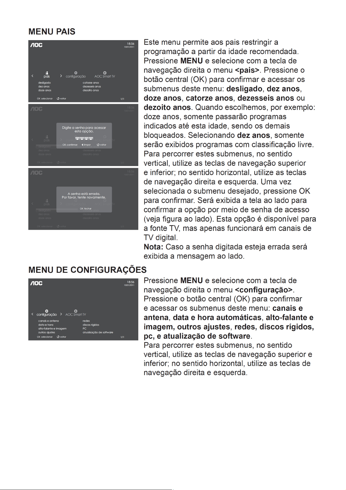
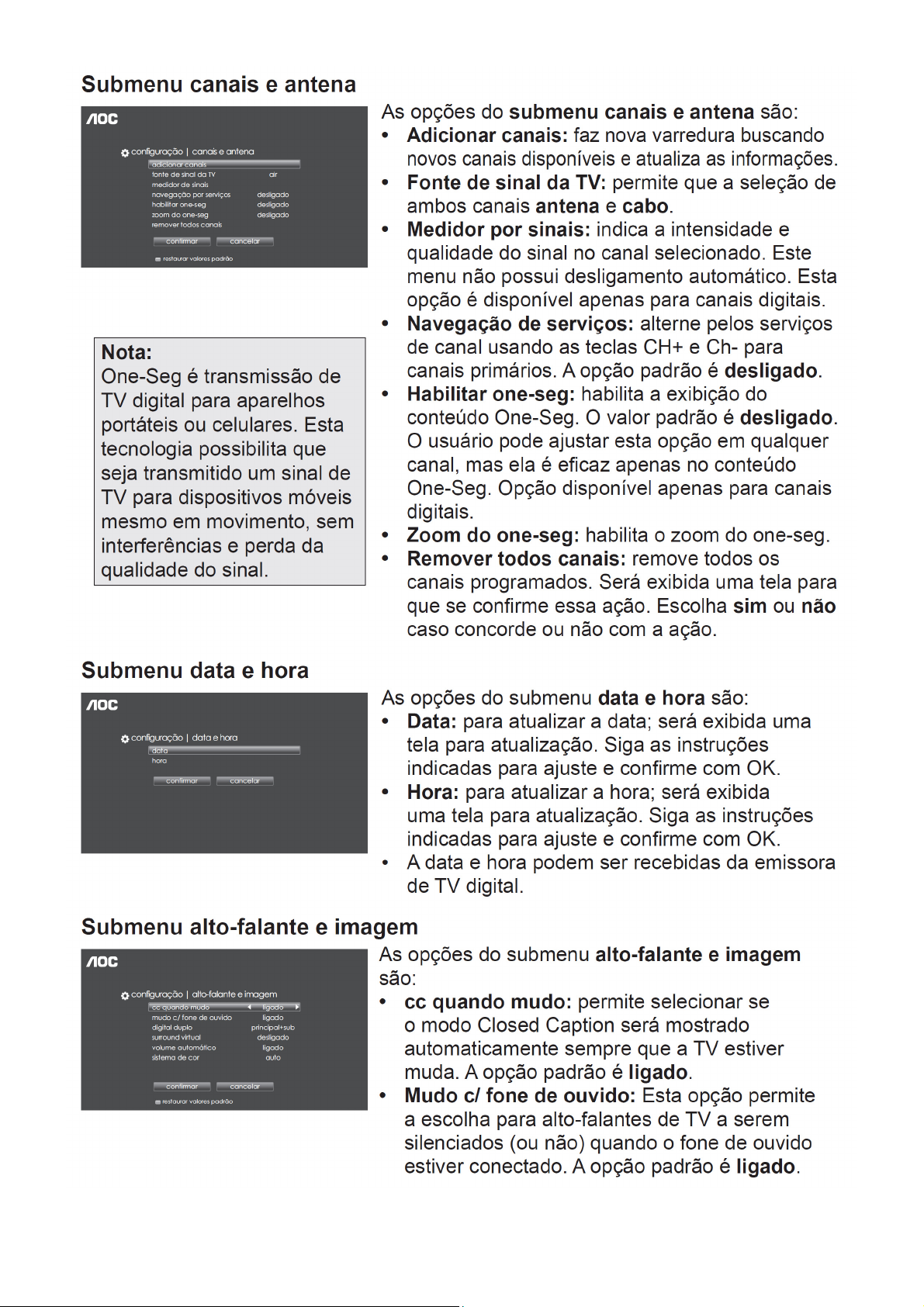
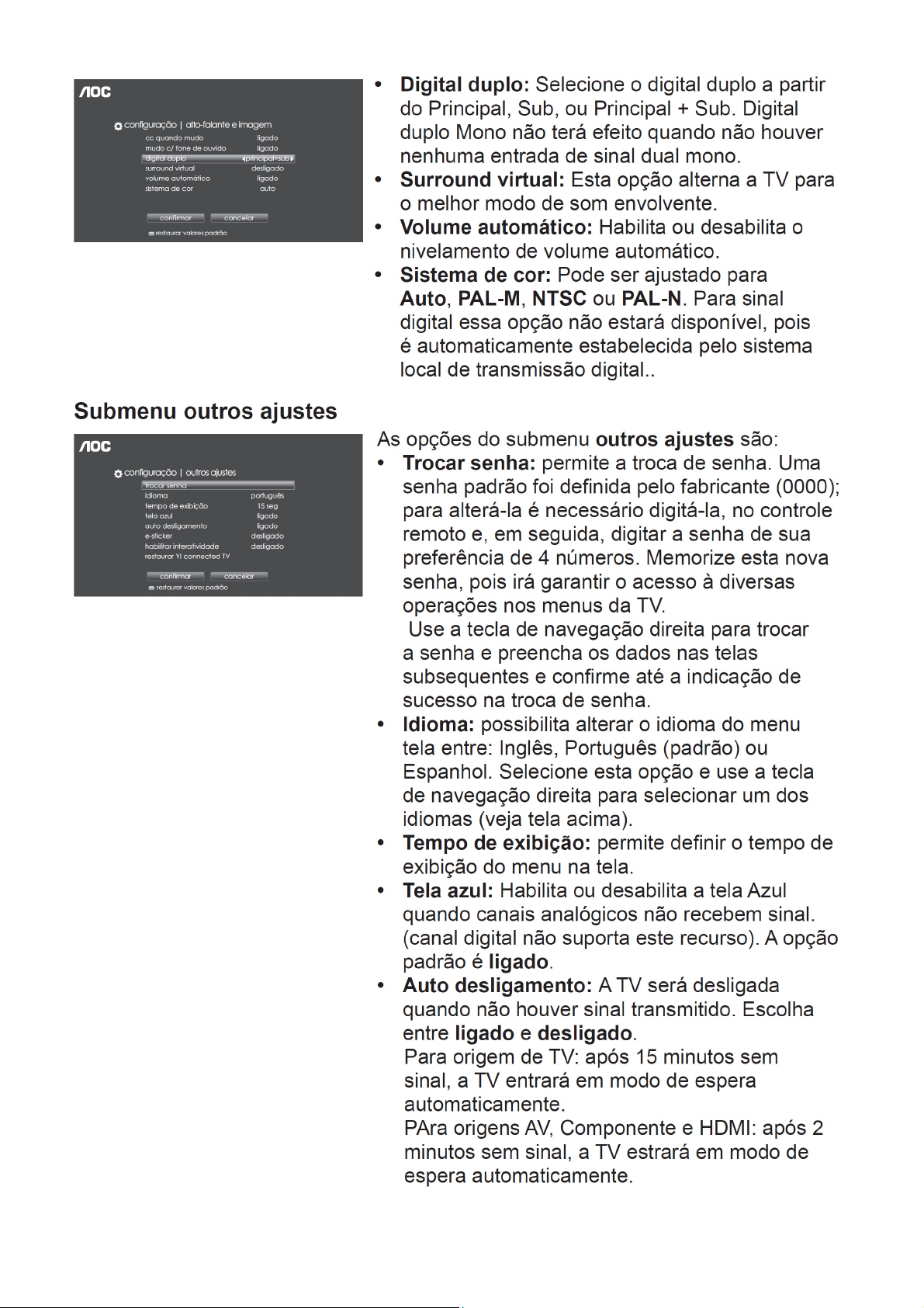
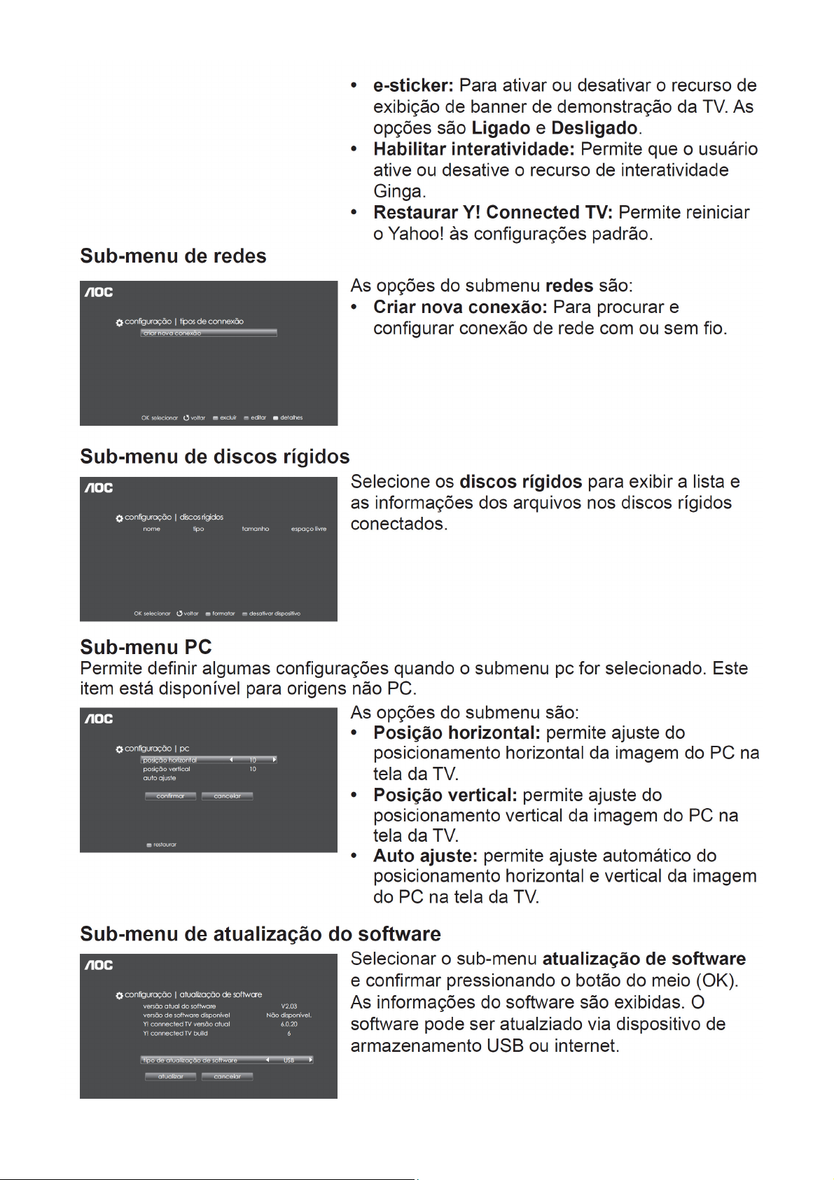
Page 1
32″&42″ LCD TV AOC LE32D5520-LE42D5520
Service
Service
Service
31~60 KHz(Analog)
31~64 KHz(Digital)
TABLE OF CONTENTS
Description Page Description Page
Table of Contents.......……....................................…........1
Important Safety Notice.......................................……......2
Revision List…………………………………………………3
1. General Specification..............................……...…........4
2. Operating Instructions………………...…….……….......5
2.1 The Use of Remote Control…….…..……….…….......5
2.2 To Use the Menus….....………………….…..…….......6
2.3 How to Connect……..……………….…….……….....15
2.4 Front Panel Control Knobs…….………….……….....17
3. Input/Output Specification…………....................…....19
4. Mechanical Instructions…………………….................21
5. Repair Flow Chart ……………………….…….…….....29
6. PCB Layout ………………..………………....….......36
6.1 Main Board…………..……………...…….…….......36
6.2 Power Board……...…………..….…….……….......38
SAFETY NOTICE
ANY PERSON ATTEMPTING TO SERVICE THIS CHASSIS MUST FAMILIARIZE HIMSELF WITH THE CHASSIS
6.3 Key Board……………………………………….......44
6.4 IR Board……………………………………….......44
6.5 Daughter Board……………………………….......44
7. Adjustment..............................................................45
7.1 ADC Adjustment....................................................45
7.2 FW Upgrade.………………………………...………46
8. Block Diagram.…….................................................47
9. Schematic Diagram…..…………....………………...49
9.1 Main Board…………………………………...….......49
9.2 Power Board…………..….….……...………….......68
9.3 Key Board……………………………………….......71
9.4 IR Board……………………………………….......72
9.5 Daughter Board……………………………….......73
10. Exploded View………………………………….…...74
11. BOM List……………….………………….………….78
Horizontal Frequency
AND BE AWARE OF THE NECESSARY SAFETY PRECAUTIONS TO BE USED WHEN SERVICING
ELECTRONIC EQUIPMENT CONTAINING HIGH VOLTAGES.
CAUTION: USE A SEPARATE ISOLATION TRANSFOMER FOR THIS UNIT WHEN SERVICING
1
Page 2

Important Safety Notice
Proper service and repair is important to the safe, reliable operation of all AOC Company Equipment. The service
procedures recommended by AOC and described in this service manual are effective methods of performing service
operations. Some of these service operations require the use of tools specially designed for the purpose. The
special tools should be used when and as recommended.
It is important to note that this manual contains various CAUTIONS and NOTICES which should be carefully read in
order to minimize the risk of personal injury to service personnel. The possibility exists that improper service
methods may damage the equipment. It is also important to understand that these CAUTIONS and NOTICES ARE
NOT EXHAUSTIVE. AOC could not possibly know, evaluate and advise the service trade of all conceivable ways in
which service might be done or of the possible hazardous consequences of each way. Consequently, AOC has not
undertaken any such broad evaluation. Accordingly, a servicer who uses a service procedure or tool which is not
recommended by AOC must first satisfy himself thoroughly that neither his safety nor the safe operation of the
equipment will be jeopardized by the service method selected.
Hereafter throughout this manual, AOC Company will be referred to as AOC.
WARNING
Use of substitute replacement parts, which do not have the same, specified safety characteristics might create
shock, fire, or other hazards.
Under no circumstances should the original design be modified or altered without written permission from AOC.
AOC assumes no liability, express or implied, arising out of any unauthorized modification of design.
Servicer assumes all liability.
FOR PRODUCTS CONTAINING LASER:
DANGER-Invisible laser radiations when open AVOID DIRECT EXPOSURE TO BEAM.
CAUTION-Use of controls or adjustments or performance of procedures other than those specified herein may
result in hazardous radiation exposure.
CAUTION -The use of optical instruments with this product will increase eye hazard.
TO ENSURE THE CONTINUED RELIABILITY OF THIS PRODUCT, USE ONLY ORIGINAL MANUFACTURER'S
REPLACEMENT PARTS, WHICH ARE LISTED WITH THEIR PART NUMBERS IN THE PARTS LIST SECTION OF
THIS SERVICE MANUAL.
Take care during handling the LCD module with backlight unit
-Must mount the module using mounting holes arranged in four corners.
-Do not press on the panel, edge of the frame strongly or electric shock as this will result in damage to the screen.
-Do not scratch or press on the panel with any sharp objects, such as pencil or pen as this may result in damage to
the panel.
-Protect the module from the ESD as it may damage the electronic circuit (C-MOS).
-Make certain that treatment person’s body is grounded through wristband.
-Do not leave the module in high temperature and in areas of high humidity for a long time.
-Avoid contact with water as it may a short circuit within the module.
-If the surface of panel becomes dirty, please wipe it off with a soft material. (Cleaning with a dirty or rough cloth may
damage the panel.)
2
Page 3

Revision List
Version Release Date Revision Instructions Customer Model TPV Model
A00 May.10,2012 Initial release LE32D5520 E32CATNSBYB13N
A01 Nov.7,2012 Add new model LE42D5520 E42CATNSBYB16N
3
Page 4

1. General Specification
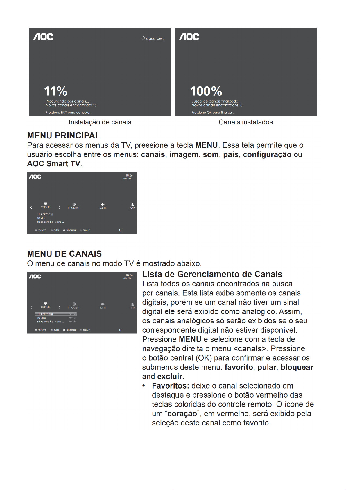
Notas:
• Este modelo está em conformidade com as especificações listadas abaixo.
• O design e as especificações estão sujeitas a alterações sem prévio aviso.
• Este modelo pode não ser compatível com as apresentações e/ou especificações que podem ser acrescidas no
futuro.
4
Page 5

2. Operating Instructions
2.1 The Use of Remote Control
5
Page 6

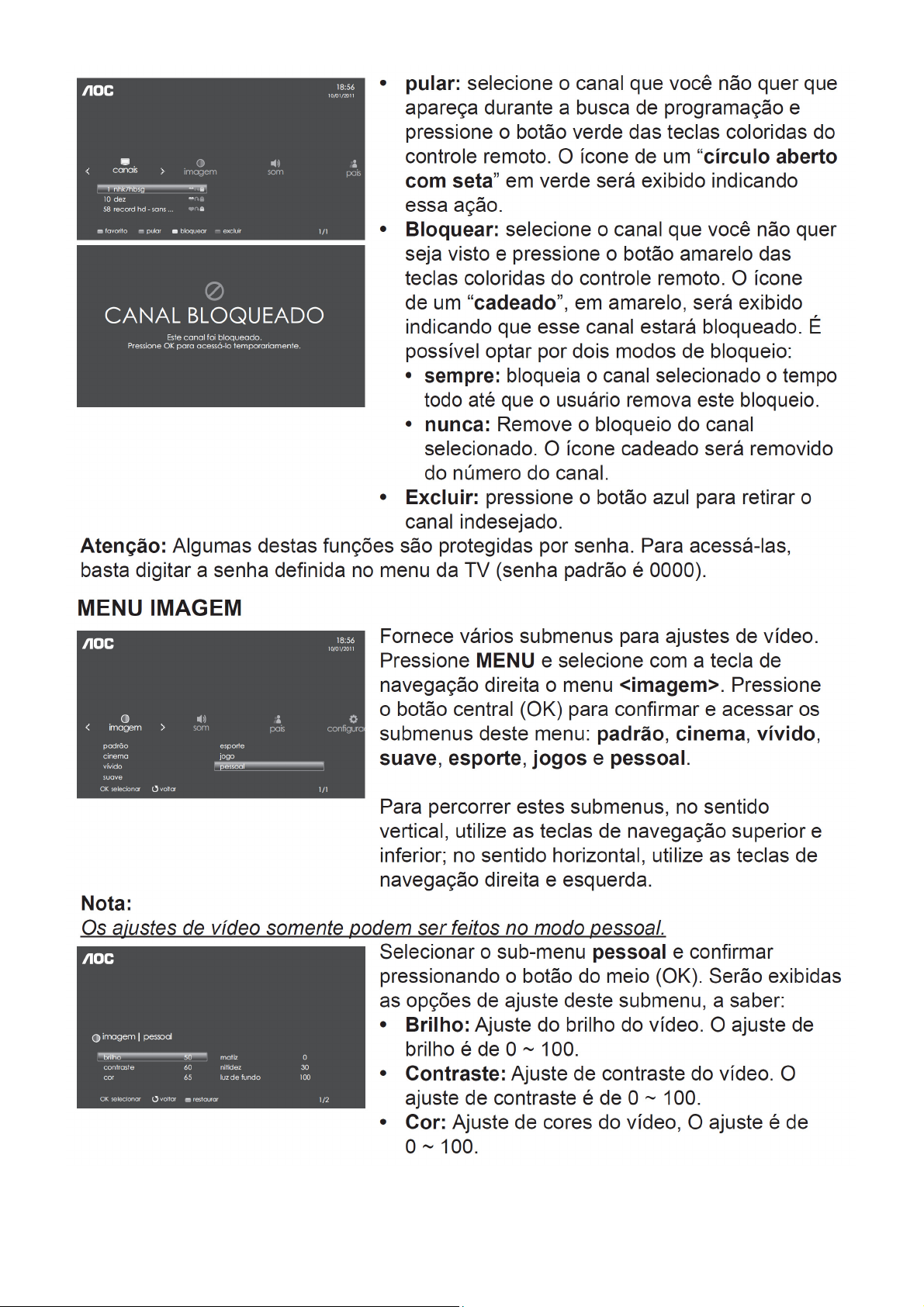
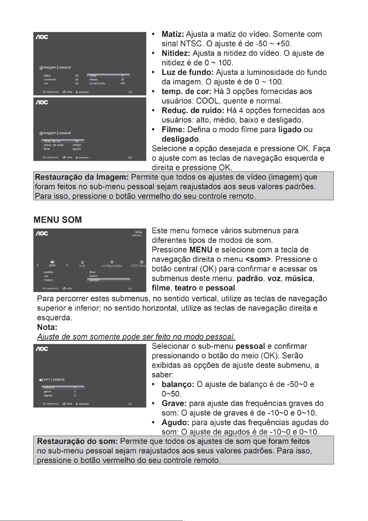
2.2 To Use the Menus
6
Page 7
7
Page 8
8 9
Page 9
Page 10
10 11 12 13 14
Page 11
Page 12
Page 13
Page 14

Page 15
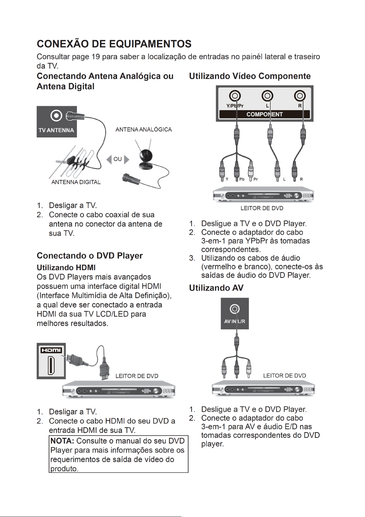
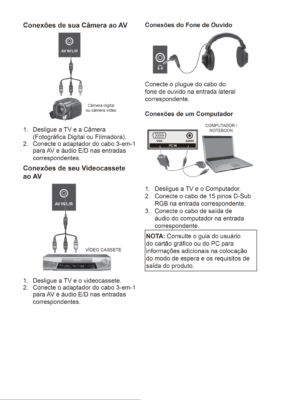
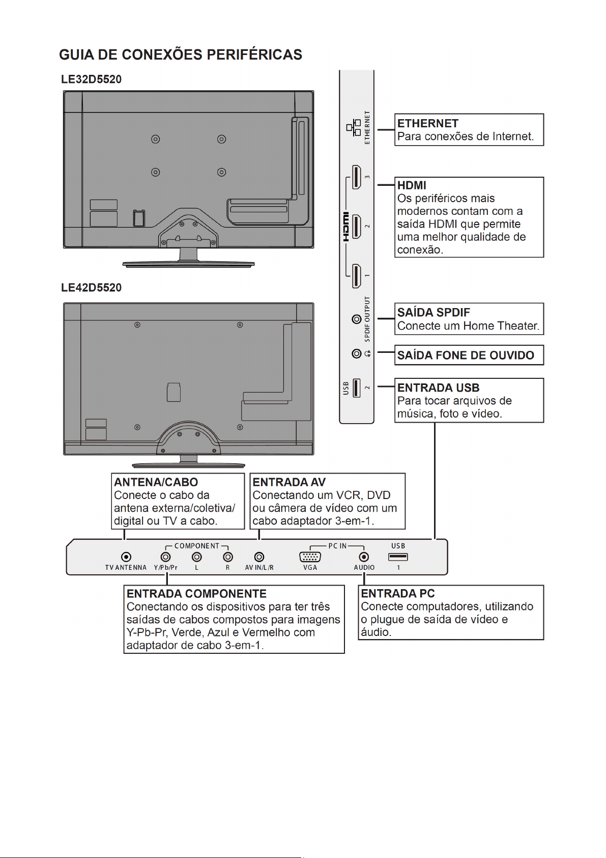
2.3 How to Connect
15
Page 16
16
Page 17
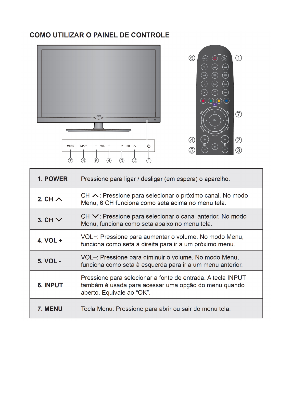
2.4 Front Panel Control Knobs
17
Page 18
18
Page 19
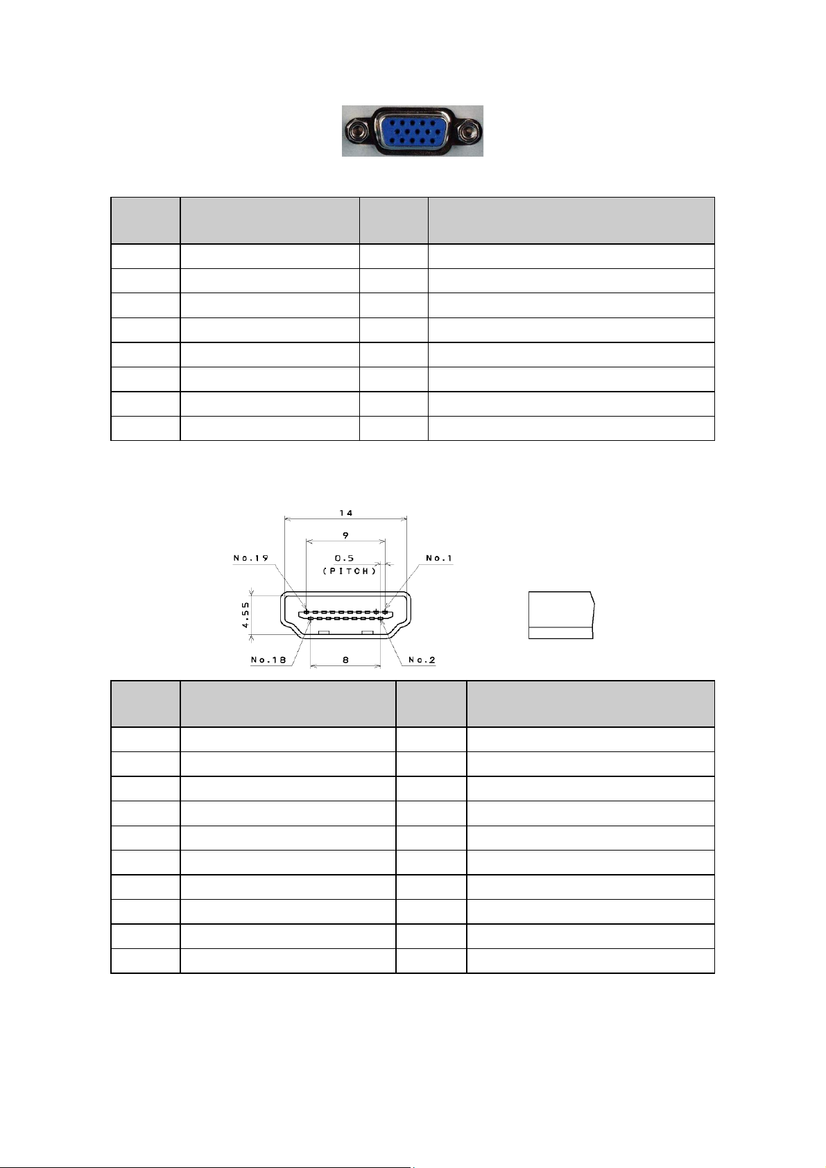
3. Input / Output Specification
3.1 RGB Signal Input
15 - Pin Color Display Signal Cable
Pin No. Description Pin No. Description
1 Red Video 9 No Pin!
2 Green Video 10 Sync Ground
3 Blue Video 11 RXD
4 TXD 12 Serial Data for DDC
5 Ground 13 H-Sync.
6 Red Ground 14 V-Sync.
7 Green Ground 15 Serial Clock for DDC
8 Blue Ground
3.2 HDMI Digital Connector Pin Assignments
Pin No. Description Pin No. Description
1 TMDS Data2+ 2 TMDS Data2 Shield
3 TMDS Data2- 4 TMDS Data1+
5 TMDS Data1 Shield 6 TMDS Data1-
7 TMDS Data0+ 8 TMDS Data0 Shield
9 TMDS Data0- 10 TMDS Clock+
11 TMDS Clock Shield 12 TMDS Clock13 CEC 14 NC
15 SCL 16 SDA
17 DDC/CEC Ground 18 +5V Power
19 Hot Plug Detect
19
Page 20
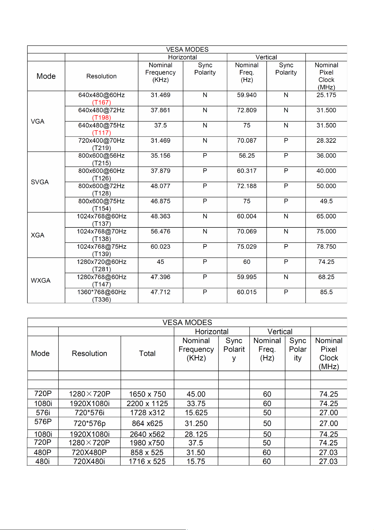
3.3 Compatible Mode Table
Analog RGB Input Signal Timing
HDMI Input Signal Timing
20
Page 21
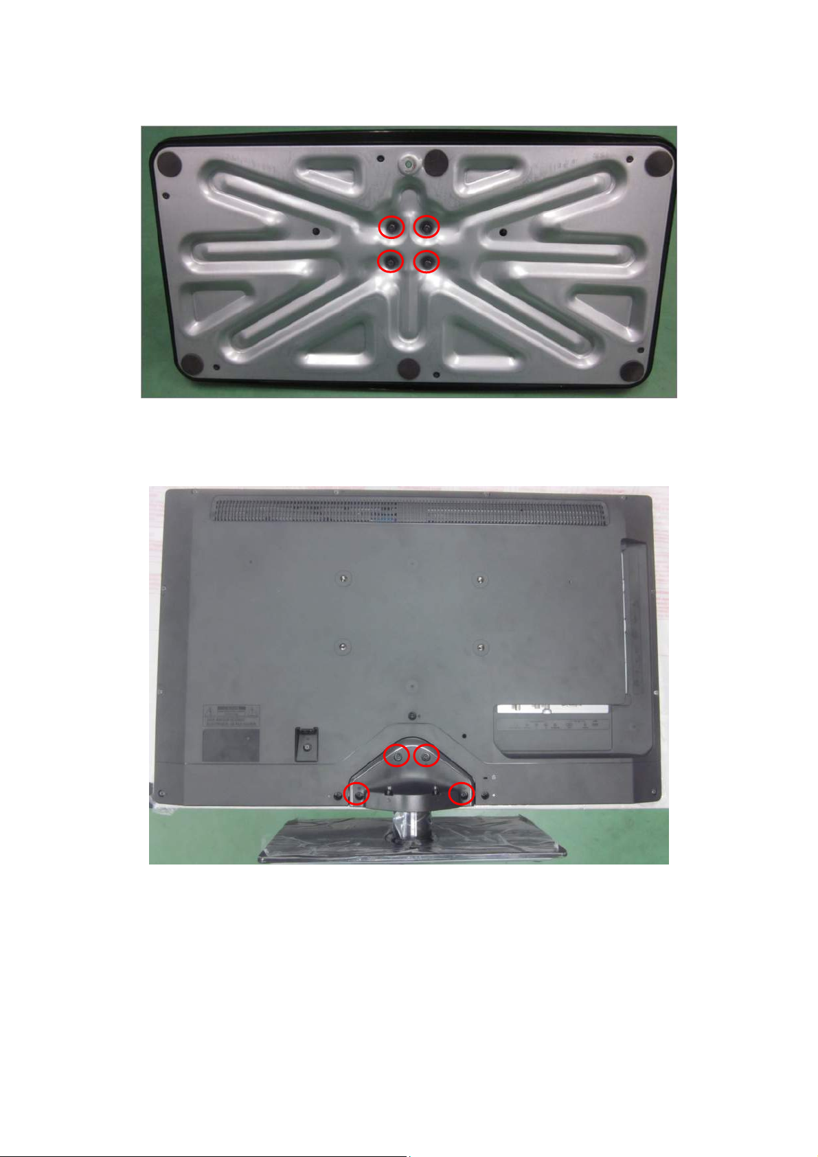
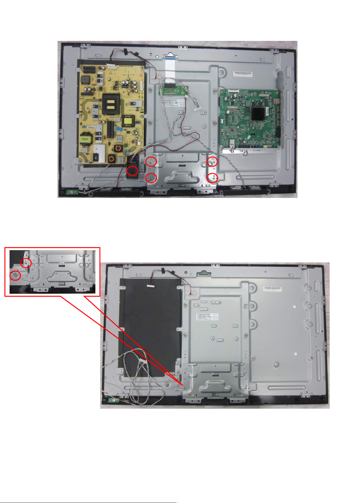
4. Mechanical Instructions
LE32D5520
1. Remove the screws to remove BASE.
2. Remove the screws to remove COVER HINGE.
21
Page 22
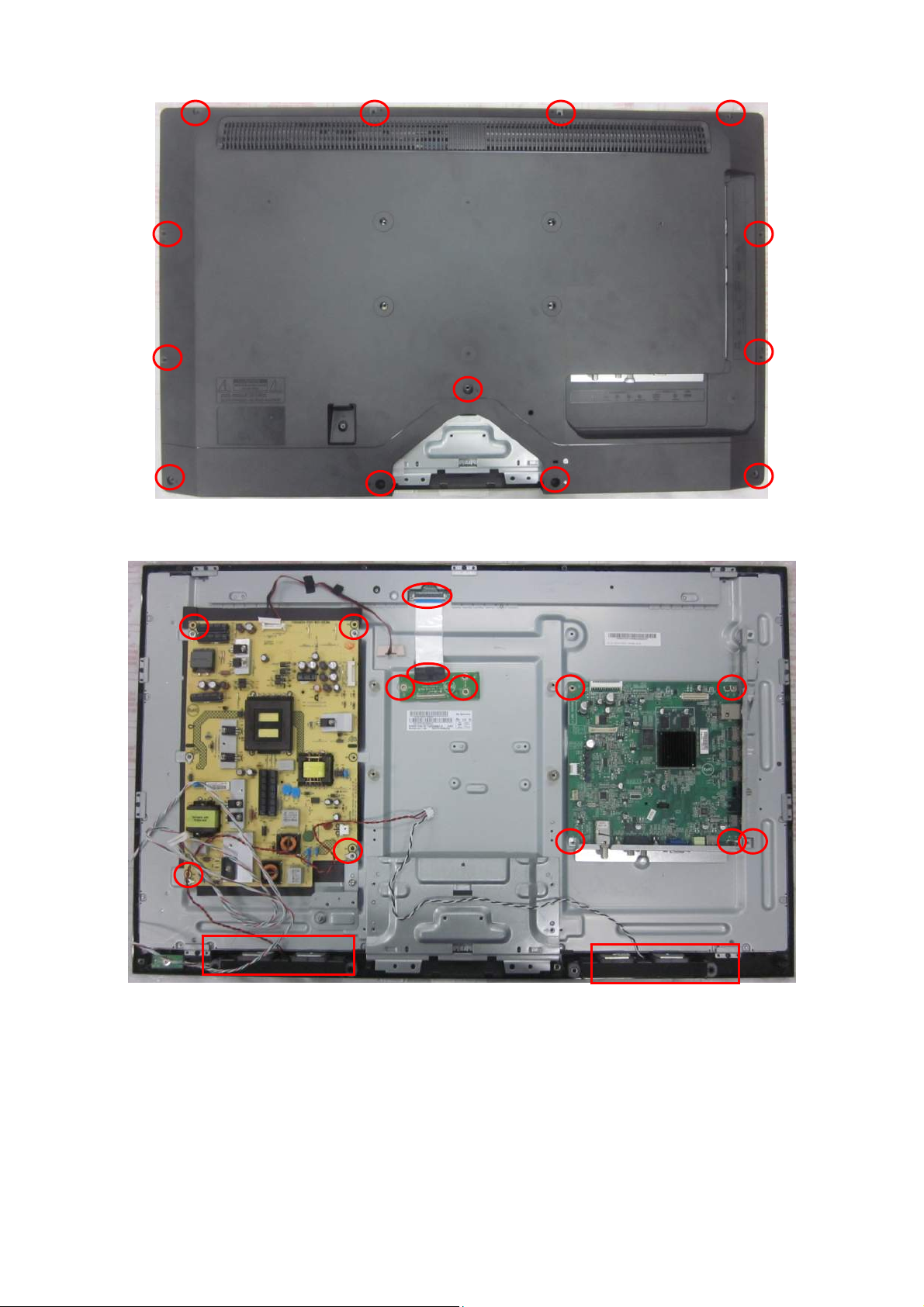
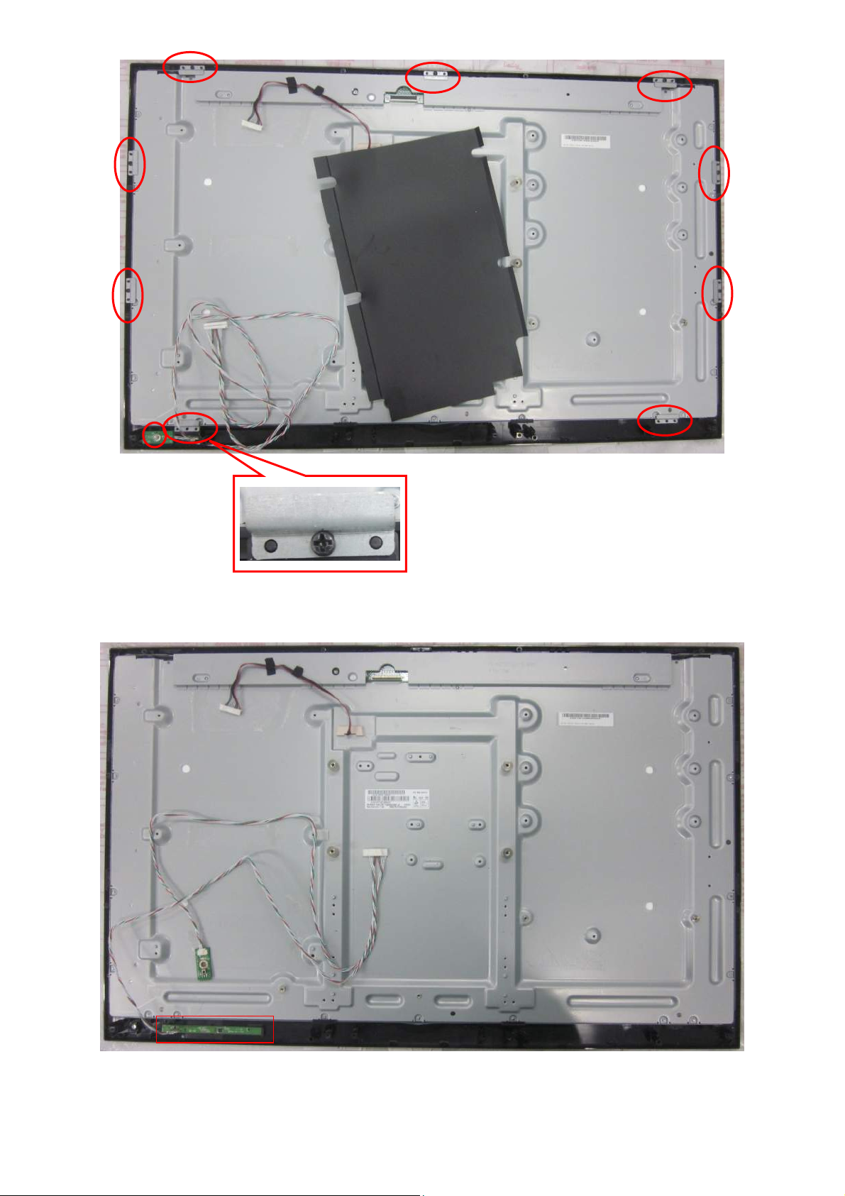
3. Remove the screws to remove REAR COVER.
4. Remove the screws to remove SPEAKERS, MAIN BOARD and POWER BOARD.
22
Page 23
5. Remove the screws to remove BKT, AC COVER and IR BOARD.
23
Page 24
6. The PANEL & The KEY BOARD.
24
Page 25

LE42D5520
1. Remove the screws to remove BASE.
2. Remove the screws to remove COVER HINGE.
25
Page 26

3. Remove the screws to remove REAR COVER.
4. Remove the screws to remove SPEAKERS, MAIN BOARD and POWER BOARD.
26
Page 27
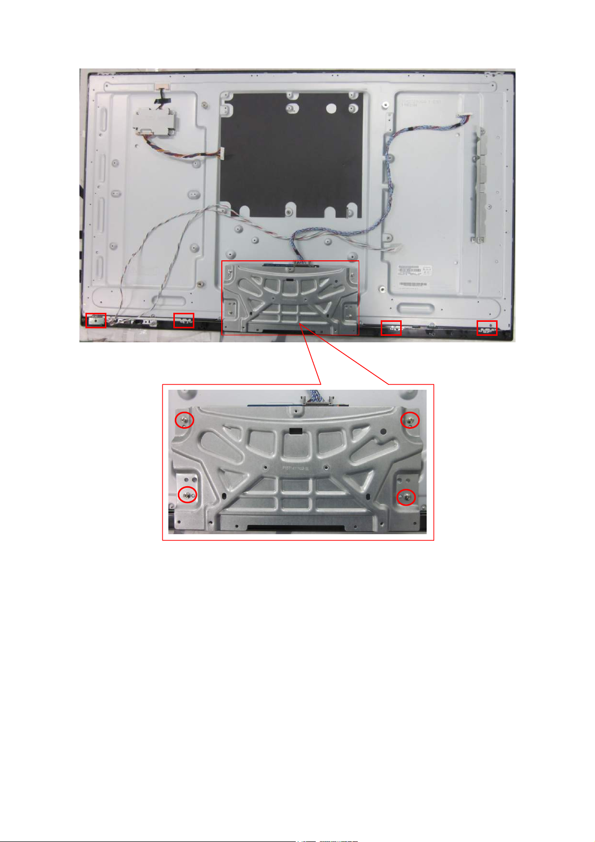
5. Remove the screws to remove BKT.
27
Page 28

6. The PANEL.
7. The BEZEL.
28
Page 29
p
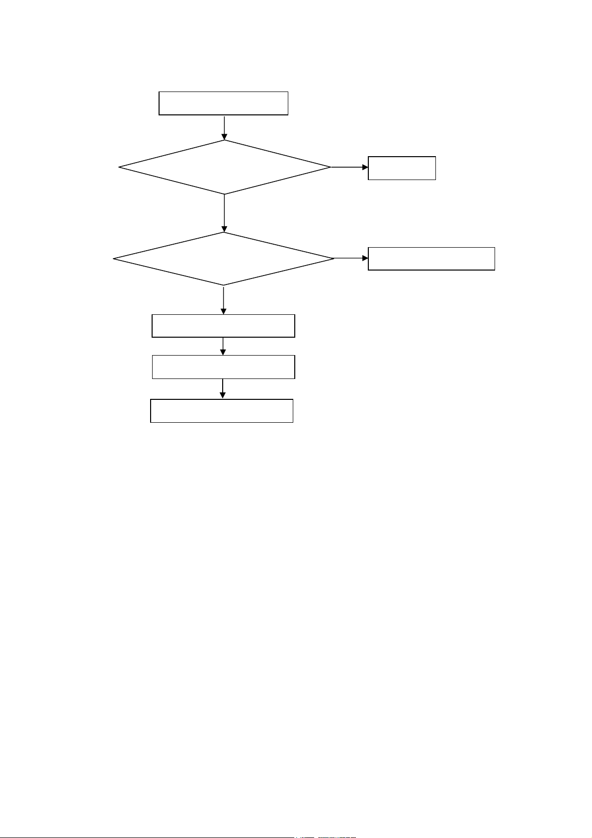
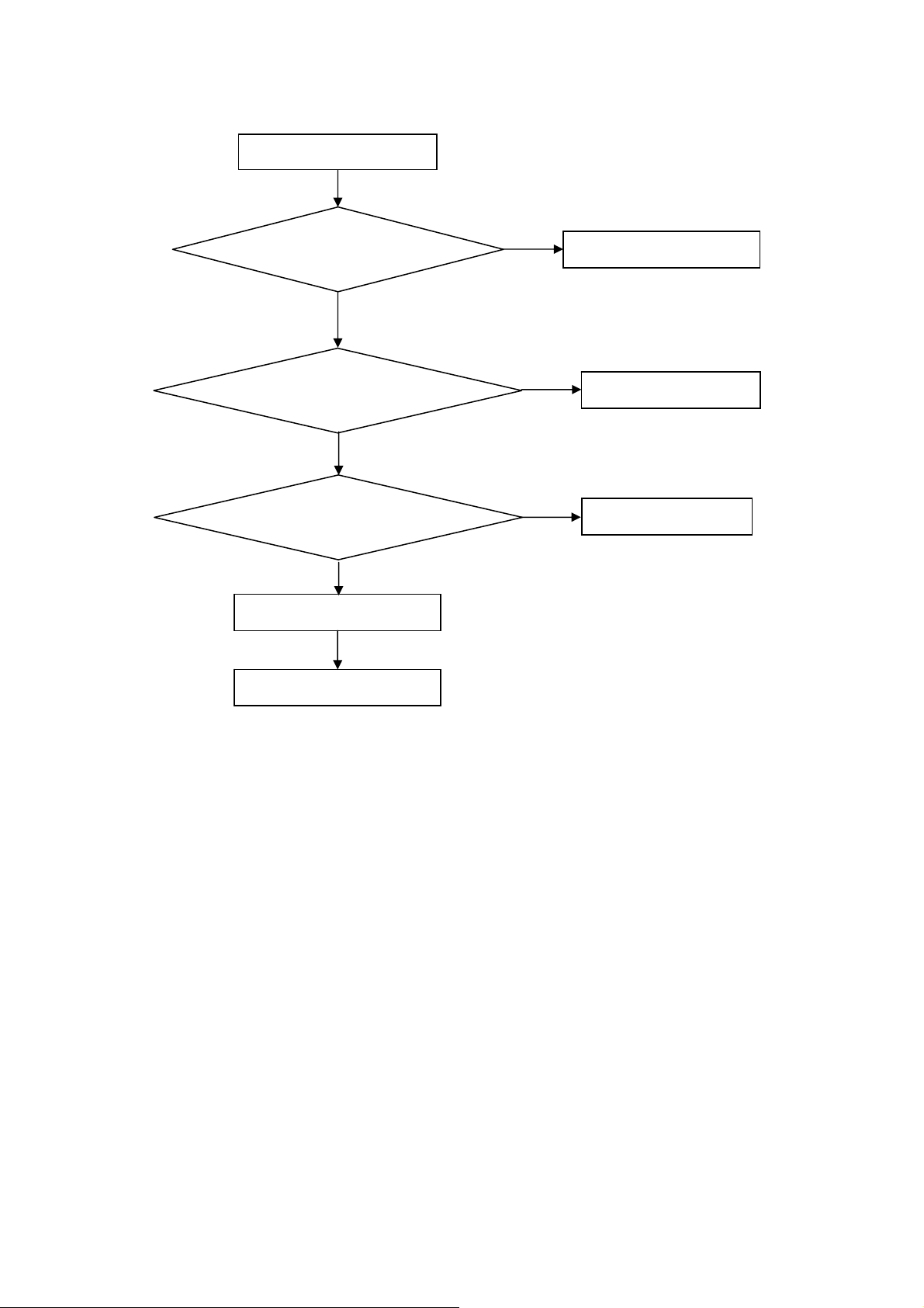
5. Repair Flow Chart
1. No power
No power (LED “Off”)
Check the AC input and
the
ower is “ON”?
Yes
Power board output=5V?
Yes
Check the IR board and LED
Replace the IR board
No
Replace the main board
No
Power “On”
No
Replace the power board
29
Page 30
2. Can’t start
Can’t start (LED red)
Power board output=24V?
Yes
Check the power key is under control?
No
Check the IR receiver is normal?
No
Replace the power board
Yes
Replace the key board
Yes
Replace the IR board
No
Replace the main board
No
Replace the Power board
30
Page 31

3. Abnormal display
Abnormal Display
Check the source
Yes
Enter factory mode to do
“EEPROM initial”&“Reset”
No
No
Reset the source
Check the main board
Yes
Check the LVDS cable
Yes
Check the panel
No
Replace the panel
No
Replace the main board
No
Replace the LVDS cable
31
Page 32

4. No display
No display (No LED)
Check TV is under control and power
on/off by remote control and power key?
Yes
Check the LVDS cable
Yes
Yes
Check the backlight is
“On”?
No
Reinsert or replace the
LVDS cable
No
No
Check the B/L
signal is available?
Yes
Replace the main board
No
Replace main board
Panel Vcc = 12V?
Yes
Replace the Panel
No
Replace the main board
Power board output=24V?
Yes
Replace the Panel
Replace the power board
No
32
Page 33

5. Sound problem
No sound or sound abnormal
Check the audio source connection
and the TV system are correct?
Yes
Check the TV is muted, adjust the
volume or enter the menu to reset?
No
No
Reinsert the audio cable or
change the TV system
Enter factory mode to do “Reset”
No
Check the cable between the
speakers and main board is OK?
Yes
Check the speaker resistance value is in spec
(Remark: The value is marked on the speaker)?
Yes
Replace the cable
Replace the main board
No
No
Replace the speaker
33
Page 34

6. Remote control malfunction
Remote Control malfunction
Check the remote control battery is
not properly placed or no power?
No
Use the other remote controls
No
Whether the IR board is
abnormal?
No
Replace the main board
Yes
Replace the battery
Yes
Replace the remote control
Yes
Replace the IR board
34
Page 35

7. OSD is unstable or can’t work normally
OSD is unstable or can’t work normally
Key board connected properly?
Yes
Buttons are OK?
Yes
Key board is OK?
Yes
Enter factory mode to do “Reset”
No
No
No
No
Reconnect the key board
Replace the button function
Replace the key board
Replace the main board
35
Page 36

6. PCB Layout
6.1 Main Board
715G4948M0G000005K
36
Page 37

37
Page 38

6.2 Power Board
715G4654P01W21003M(LE32D5520)
38
Page 39

39
Page 40

40
Page 41

715G5173P01W21002S(LE42D5520)
41
Page 42

42 43
Page 43

Page 44

6.3 Key Board
715G5290K0B000004I
6.4 IR Board
715G5291R0C000004I
6.5 DAUGHTER Board
715G5401T0A000004B
44
Page 45

7. Adjustment
7.1 ADC Adjustment
1. Factory Mode
Turn on the TV. Press menu key and then press number key 1+9 +9+9+back. It will achieve the factory mode.
2. ADC Adjustment (It’s no need to adjust ADC.)
3. White Balance Adjustment
(1) Enter into the factory mode :(same as the above-mentioned).
(2)Take an example of adjust Ypbpr source.
a. Select item “Source”: Ypbpr and item “Color Temp”: Normal, Adjust gain of RGB to meet spec in the below
setting of Tim\pat. (COMPONENT mode: TIM = 314; PAT = 141(80IRE))
b. Select item “Source”: Ypbpr and item “Color Temp”:Warm, Adjust gain of RGB to meet spec in the below setting
of Tim\pat. (COMPONENT mode: TIM = 314; PAT = 141(80IRE))
c. Select item “Source”: Ypbpr and item “Color Temp”: Cool, Adjust gain of RGB to meet spec in the below setting
of Tim\pat. (COMPONENT mode: TIM = 314; PAT = 141(80IRE))
(3) Take an example of adjust VGA Normal:
a. Select item “Source”: VGA and item “Color Temp”: Normal, Adjust gain of RGB to meet spec in the below
setting of Tim\pat. (VGA mode: TIM = 137; PAT = 141(80IRE)
b. Select item “Source”: VGA and item “Color Temp”: Warm, Adjust gain of RGB to meet spec in the below setting
of Tim\pat. (VGA mode: TIM = 137; PAT = 141(80IRE)
c. Select item “Source”: VGA and item “Color Temp”: Cool, Adjust gain of RGB to meet spec in the below setting of
Tim\pat. (VGA mode: TIM = 137; PAT = 141(80IRE)
(4)Take an example of adjust AV Normal:
a. Select item “Source”: AV and item “Color Temp”: Normal, Adjust gain of RGB to meet spec in the below
setting of Tim\pat. (AV mode: TIM = 303; PAT = 141(80IRE)
b. Select item “Source”: AV and item “Color Temp”: Warm, Adjust gain of RGB to meet spec in the below setting of
Tim\pat. (AV mode: TIM = 303; PAT = 141(80IRE)
c. Select item “Source”: AV and item “Color Temp”: Cool, Adjust gain of RGB to meet spec in the below
setting of Tim/pat. (AV mode: TIM = 303; PAT = 141(80IRE)
(5) Take an example of adjust HDMI Normal:
a. Select item “Source”: HDMI and item “Color Temp”: Normal, Adjust gain of RGB to meet spec in the below
setting of Tim\pat. (HDMI mode: TIM = 347; PAT = 141(80IRE)
b. Select item “Source”: HDMI and item “Color Temp”: Warm, Adjust gain of RGB to meet spec in the below setting
of Tim\pat. (HDMI mode: TIM = 347; PAT = 141(80IRE)
c. Select item “Source”: HDMI and item “Color Temp”: Cool, Adjust gain of RGB to meet spec in the below
setting of Tim/pat. (HDMI mode: TIM = 347; PAT = 141(80IRE)
4.The following color specifications for reference, to RD engineering specifications.
FOR LE32D5520
Source VGA/YPbPr/AV/HDMI VGA/YPbPr/AV/HDMI VGA/YPbPr/AV/HDMI
Temp Normal/(9300 K) Warm/(6500 K) Cool/(12000 K)
x (center) 0.285 0.020 0.313 0.020 0.272 0.020
y (center) 0.293 0.020 0.329 0.020 0.278 0.020
FOR LE42D5520
Source VGA/YPbPr/AV/HDMI VGA/YPbPr/AV/HDMI VGA/YPbPr/AV/HDMI
Temp Normal/(9300 K) Warm/(6500 K) Cool/(12000 K)
x (center) 0.285 0.020 0.313 0.020 0.270 0.020
y (center) 0.293 0.020 0.329 0.020 0.273 0.020
Note: all models of color temperature within specification, but also ensure the brightness conform to engineering
specification.
45
Page 46

7.2 FW Upgrade
7.2.1: Ready for F/W Upgrade
1. Change the software file name to “upgrade_loader.pkg”.
2. Prepare a USB disk (The file system of USB disk must be FAT16 or FAT 32).
3. Copy the file (upgrade_loader.pkg) from your computer to the USB disk root directory, and remove it from
computer’s USB port!
7.2.2: F/W Upgrade
1. Press “menu+1999” into factory menu, set USB update options to “ON”
2. AC on (Power plug)
Plug the USB disk on the USB port on the side I/O port of TV.
3. TV AC power off -> AC power on
4. TV will upgrade by itself after detect the USB disk condition and the content of the pkg file.
5. When firmware update ok, the TV will display “firmware update finished”.
6. Remove USB disk from TV.
7. Check if the software version is correct.
8. Please do factory reset in user menu.
9. Reset finish, AC OFF.
46
Page 47

8. Block Diagram
Nutune
FK1605
IF
TC90527FG
VGA RGB +Audio IN
YPb P r +A udi o IN
CVBS+Audio IN
TS S tream
HDMI 1
HDMI 2
HDMI 3
SXL SOC
L/R
TPA3110D2
Speaker
Amplifier
Headphone
SPDIF Out
SPEAKER
USB 1
USB 2
GL852G-MNG12
USB hub
128Mx16_DDR3
4M bit
Serial
Flash
47
LVDS
Interface
Ethernet
NAND Flash
128Mx16 bit
Page 48

5VSB
12V
1913mA
1296mA
G1117T63UF
1A
SOT223
MOS- A4449
7A
SOP8
574mA@85%
PWM-G5655P12U
2A
SOP8
330mA
MOS- A4449
7A
SOP8
Q704
U705
1880mA
5V
U1101
Q4150
33mA
3VSB
193mA
321mA@85%
638mA@85%
711mA
1170mA
MEMC_5V1
PANEL_VCC
SOC
Pro-SXL
G1117T63UF
1A
SOT223
PWM- AT1529
3.2A
SOP8
PWM- AT1529F11U
4A
SOP8
G1084-33TU3Uf
5A
TO252
U401 U4100
PANEL
22uA
U704
U710
U706
U704
Reset IC
G692L293TCUf
HP_VCC_25
PRO-SXL
193mA
3V3_SW
HP_VCC1V
1.9A
3.3V
205mA
370mA
G903T63UF
0.6A
SOT223
1600mA
USB
connector
U401
387mA
PRO-SXL
core power
G9661
3A
U701
SOP8
IF switch
TS5A3157
U709
CN103
20mA13mA
U401
VA_1.1
U1101
3.3V_TUNER
370mA
SPI FLASH
MX25L4006EM2I-12G 4M
R755
U406
HP_VCC_15
207mA
PRO-SXL
TUNER
NuTune FK1605
U401
TU102
180mA
24mA
NANYA
DDR3-2GB*2
U402, U403
PRO-SXL
G1117T63UF
1A
SOT223
U708
U401
+1.2V
Demodulator IC
138mA
TC90527FG
U101
371mA
160mA
5mA
+3.3VD
30mA
V_3.3_Flash
46mA
3.3V_PHY
130mA
V_3.3USB
3V3_P
PRO-SXL
Demodulator IC
TC90527FG
22uA
Reset IC - G692
NAND Flash
H27U2G8F2CTR-BC 2Gb
Ethernet IC
LAN8720A
USB hub
GL852G
U401
U101
U163
U405
U711
U1104
24V
800mA
AMP24V
Amplifier IC
TPA3110D2
U601
48
Page 49

9. Schematic Diagram
9.1 Main Board
715G4948M0G000005K
1 2FB705
1 2FB708
BL_ON/OF F_PRE
BRT_CTRL_PRE
12V_PRE
NC/120R/6000mA
1 2
24V_PRE
L0805
PS_ON_PRE
5VSB_PRE
AUX_POWER_ON #
5V
FB741
R755
0oHM
FB740
NC/120R/6000mA
1 2
L0805
C726
100N 50V
C0603
R723
0R05 1/10W
C734
10uF 10V
C713
100N 50V
C0603
C719
100N 50V
C0603
C735
1UF16V
C736
100N 50V
1 2FB709
1 2FB710
1 2FB712
1 2
1 2
120R/6000mA
L0805
C701
100N 50V
120R/6000mA
L0805
120R/6000mA
L0805
C714
+
C716
100N 50V
330UF 35V
C0603
10x9mm
120R/6000mA
L0805
C720
100N 50V
C0603
R715
120R/6000mA
L0805
FB714
120R/6000mA
L0805
FB715
120R/6000mA
L0805
C733
100N 50V
C0603
R727
10K 1/10W
R726
10ohm +/-1% 1/ 10W
100N 50V
Vout = 0.8x(1+ R725/R728)=1.11V
R725
3.3K
3K
33 OHM 1/16WR0402
C728
100N 16V
C729
1N 50V
C0402
C0402
U706
8
LX7VIN
5
EN
1
VCC
FB
2
REF
GND
PGND
Thermal Pad
3
6
9
9.1K3.6K
9.1K
9.1K
AT1527F11U
C737
10K 1/10W
0R05 1/10W
R701
PMBS3904
12V
24V
4
5V
R702
Q701
R710
1K 1/10W
C710
NC/10uF 6.3V
4.7K
+
C721
330UF 35V
10x9mm
2.2uH 30%
L701
100uF/16V
4.7K 1/10W
R714
CN701
C738
VoutR728
1.11 V
1.09 V
1.07 V
CONN
5VSB
5VSB
+
R738
0R05 1/10W
5V
R707
Q702
PMBS3904
4.7K
NC/4. 7K 1/10W
Q703
PMBS3904
BL_ON/OF F_PRE
1
BRT_CTRL_PRE
2
12V_PRE
3
12V_PRE
4
5
6
7
8
9
10
11
12
13
100N 50V
C740
C739
22uF 10V
NC 150pF 50V
3.3V
R703
10K 1/10W
R706
NC/ 4.7K
R711
NC/4. 7K 1/10W
1K 1/10W
R791
R716
R717
4.7K
24V_PRE
24V_PRE
PS_ON_PRE
5VSB_PRE
5VSB_PRE
5VSB_PRE
C744
9.1KOHM + -1% 1/10W
System power
SYS_PW
C784
C0805
NC 10U 16V
3.3V
R708
4.7K
R712
PS_ON
FB728
120R/6000mA
L0805
1 2
1 2
R725
3.3K
R728
R802
NC 10K 1/10W
CN704
1
2
3
4
5
6
7
8
9
10
11
12
13
NC CONN
FB719
120R/6000mA
L0805
BRT_CTRL
5VSB_PRE
5VSB_PRE
5VSB_PRE
PS_ON_PRE
24V_PRE
24V_PRE
12V_PRE
12V_PRE
BRT_CTRL_PRE
BL_ON/OFF _PRE
HP_VCC1V
BL_ON/OF F
Normal: High
Stand_By:
Low
SXL_PWRON
10K 1/10W
R722
5V
R756
0oHM
R757
0oHM
R760
0oHM
R759
0oHM
C727
100N 50V
絬隔瓜絪腹
Key Component
C781
C780
100N 50V
10U 16V
C0603
C0805
C783
C782
10U 16V
100N 50V
C0805
C0603
G1117T63Uf
C771
1UF16V
R742
C770
10ohm +/-1% 1/ 10W
10uF 10V
C772
100N 50V
C724
10uF 10V
G1117T63Uf
T P V ( Top Victory Electronics Co . , Ltd. )
04.0.Power Circ uit 1
Date
5VSB 5V
NC/200K 1/10W
R718
22K 1/10W 1%
1K 1/10W
R721
R720 100K 1/10W
Q705
PMBS3904
U702
G1084-33TU3Uf
TO263GOI
3
Vout = 0.8x(1+ (R741+R743)/R744)=1.52V
3
TO263
2
VIN3VOUT
GND
1
U704
VIN
10K 1/10W
R740
EC080-35
VOUT
GND
1
4
C773
100N 50V
2
TH
100R 1/10W 1%
8
5
EN
1
VCC
2
REF
+
C702
220UF 16V
R754
U710
も础
R753
100R 1/10W 1%
LX7VIN
FB
GND
PGND
Thermal Pad
AT1527F11U
3
6
9
95% Efficent at 3.3V 1A
U705
2
VIN
VOUT
GND
TH
82R 1/10W 1%
1
4
R752
300R 1/10W 1%
OEM MOD EL
TPV MOD EL
PCB NAME
Sheet
AO4449 -7A/-30V
Q704
1
R719
0.47uF 16V
C751
FB729
120R/6000mA
L0805
3.3V
1 2
C703
100N 50V
C0603
C722
100N 50V
C0603
VOUT = 1.25V x (1+(R753/R754 ) + IADJ x R753
IADJ = 80 A (TYP.)
2.2uH 30%
L702
C779
100uF/16V
4
R750
C725
100N 50V
R751
100R 1/10W 1%
423Wednesday , January 18, 2012
of
8
S
D
2
7
S
D
3
6
S
D
4
5
G
D
+
C731
100N 50V
C768
C769
HP_VCC_25
3VSB5VSB
R744
3K 1/10W 1%
Size
Rev
称爹
100UF 16V
FB734
120R/6000mA
L0805
1 2
R741
2.4KOHM +-1% 1/10W
R743
300R 1/10W 1%
Custom
F
称爹
<>
C732
NC/4.7uF K 25V
FB711
120R/6000mA
L0805
1 2
C723
10U 16V
C0805
+
C767
22uF 10V
NC 150pF 50V
FB713
1 2
120R/6000mA
L0805
C730
10uF 10V
VOUT = 1.25V x (1+(R752/(R750+R751) ) + IADJ x R752
IADJ = 80 A (TYP.)
HP_VCC_15
49
Page 50

1.1V
C748
1UF 10V
3.3V
3.3V
R730 10K
C746
10uF 10V
Vo=0.8(1+R732/R731)=1.116V
1
2
3
U701
E-Pad
POK
GND
VEN
ADJ
VIN
VPP4NC
G9661
VO
9
8
7
6
5
C747
10uF 10V
R732
360OHM 1/10W
R731
910 OHM +-1% 1/10W
FB726
1 2
C750
120R/ 3000mA
100UF 16V
+
EC63
VA_1.1
13 14
CN702
12
11
10
9
8
7
6
5
4
3
2
1
NC CONN
MEMC _SC L
MEMC _SD A
MEMC 5V_ SW
V105_SW
V105DLL_SW
RESET_FR C
MEMC 5V
NC/120R/3000mA
1 2
FB727
5VSB
3.3V_TUNER
FB732
220R/ 2000mA
5V_TUNER
1 2
MEMC _5V 1
FB733
220R/ 2000mA
1 2
C749
1UF
U709
G903T63UF
VIN3VOUT
GND14
3.3V_TUNE R
FB725 220R/2000mA
2
1 2
C766
4
10U 16V
For Nutune tuner
T P V ( Top Victory Electronics Co . , Ltd. )
F
絬隔瓜絪腹
Key Component
05.1.Power Circuit 2
Date
OEM MO D EL
TPV MO D EL
PCB NAME
Sheet
523Wednesda y , J anuary 18, 2012
of
Size
Rev
称爹
B
<>
称爹
50
Page 51

3VSB
4.7K 1/10W
R223
NC 0R05 1/10W
spec 100mA max
12
12
R222
Q210
BC857C
R233
1K 1/10W
ZD407 MLVG0402
12
ZD406 MLVG0402
ZD408 MLVG0402
TouchKey _VCC
0.1UF 16V
C218
Key _POR# 13, 17
L_R
L_B
120R
FB402
1 2
1K 1/10W
R403
NC BAS32 L
D401
D402
BAS32L
Q401
PMBS3906
R406
1K 1/10W
3VSB
23
Q402
PMBS3906
R408
4.7K
1
R402
4.7K
23
1
R405
4.7K
R404
4.7K
LED_R
LED_B
CN401
CONN
R248
NC 4.7K 1/10W
Key _SDA
R235 0R05 1/10W
1
2
3
4
5
6
7
8
9
10
11
12
13
14
TouchKey _VCC
Q403
NC 2N 7002
LightSensor_SCL
LightSen sor_SDA
Key _SDA
LightSensor_SCL
MLVG0402
R250
NC 4.7K 1/ 10W
LightSensor_SDA
R410
0R05 1/10W
ZD405
R411 0R05 OHM
R412 0R05 OHM
L_R
L_B
1 2
ZD403
MLVG0402
1 2
KEY_SD A_SW 13,17
3VSB
Lightsens or
SCL_Dem od
SDA_Demod
RLZ5.6B
When you want to Write touch key(IT7235),
you should set GPIO11 (KEY_SDA_SW) to high to turn on I2C SDA switch,
when you finished touch key i2C operation,
Set GPIO 11 to low to avoid abnormal data to touch key
100N 16V
ZD401
TouchKey_VC C
C405
1 2
C404
100N 16V
120R
FB404
1 2
1 2
FB403
120R
ZD402
RLZ5.6B
1 2
120R
FB401
1 2
ZD404
MLVG0402
1 2
3VSB
R401
20K 1/10W 1%
C401
100N 16V
R407
10K 1/10W
C402
NC/0.1UF 16V
R409
20K 1/10W 1%
C403
0.1UF 16V
IR_D
IR_D
KEY_PW_SU _MENU
KEY_VOL _CH
T P V ( Top Victory Electronics Co . , Ltd. )
絬隔瓜絪腹
F
Key Component
06. key and IR interf ace
Date
OEM MO DE L
TPV MO DE L
PCB NAME
Sheet
B
Size
Rev
称爹
称爹
of
623Tuesday , March 06, 2012
<>
51
Page 52

VA_1.1
3.3V
HP_VCC _25
R425
0R05 1/10W
C429
10uF 6.3V
C430
100N 16V
R423
0R05 1/10W
R424
0R05 1/10W
C431
10N 50V
R426
0R05 1/10W
R427
0R05 1/10W
SXL_VDD_1
SXL_VDD_2
C432
1N 50V
SXL_VDD_4
SXL_VDD_5
C422
C423
10uF 6.3V
10uF 6.3V
R421
R422
C439
10uF 6.3V
C443
10uF 6.3V
SXL_VDD_3
0R05 OHM
0R05 OHM
C421
100N 16V
SMT
C426
100N 16V
C435 100N 16V
C436 100N 16V
C440
100N 16V
C444
100N 16V
H21
L18
J21
L17
G23
G22
F21
K18
K17
J18
F22
E22
G21
D23
K21
N18
U401F
AVDD25_SP16
AVSS25_SP16
AVDD33_SP16
AVSS33_SP16
AVDD11_ SP2
AVDD11_ SP3
AVDD11_ SP4
AVSS11_SP2
AVSS11_SP3
AVSS11_SP4
INN16
INN 234
AVDD33_SP234
AVSS33_SP234
VDD33_VD AC
VSS33_VDAC
Power for_
ADC1-4,6
ASXL
Analog 3.3V for DAC
27x27
(1/8)
3.3V power_
for DRX AFE
1.1V power_
for DRX AFE
3.3V analog power_
for CODEC
3.3V analog power_
for CODEC
2.5V Analog power_
for KMNP LL
2.5V Analog power_
for LPL L
AVDDH_DRX
AVSSH_DRX
AVDDL_DRX
AVSSL_DRX
VREFAU
SGNDAU
AVDD
AVDD
AVSS
AVSS
AVSS
AVDDKMN PLL
AVSSKMNPLL
VDD25_LPLL
VSSA_LPLL
P21
P18
P24
P25
L24
L21
M24
M21
N21
N24
P22
AC24
AB21
K22
M17
C424
100N 16V
C427
100N 16V
C433
100N 16V
C437
100N 16V
C441
100N 16V
C445
100N 16V
SXL_VDD_11
SXL_VDD_12
VREFAU
C434
10uF 6.3V
SXL_VDD_13
C438
10uF 6.3V
SXL_VDD_14
SXL_VDD_15
C425
10uF 6.3V
C428
10uF 6.3V
C442
10uF 6.3V
C446
10uF 6.3V
R428
0R05 1/10W
R429
0R05 1/10W
FB426
120R/600mA
R430
0R05 1/10W
R431
0R05 1/10W
VA_1.1 HP_VCC _253.3V
12
HP_VCC1V3.3V HP_VCC_25
R432
0R05 1/10W
FB431
1 2
120R/600mA
R433
0R05 1/10W
R434
0R05 1/10W
R435
0R05 1/10W
C447
10uF 6.3V
C452
10uF 6.3V
C456
10uF 6.3V
C460
10uF 6.3V
C462
10uF 6.3V
C448
1UF 10V
SXL_VDD_7
C453
100N 16V
SXL_VDD_8
C457
100N 16V
SXL_VDD_9
C461
100N 16V
SXL_VDD_10
C463
100N 16V
C449
100N 16V
AC2
AC3
D15
D16
D14
AB20
M5
M6
E15
E14
F14
V18
U401G
PLL_VDD
PLL_VSS
AVDD_MCK2
AVSS_MCK2
VDD33A
VDD33A
VSS33A
VSS33A
VDD10A
VSS10A
VDD33
VSSAC
2.5V Analog power
for DDRPLL
2.5V Analog power_
for DDR MCLK2 P LL
3.3V HDMI power
1.0V HDMI power
3.3V power for_
USB Comm on Block
ASXL
27x27
(2/8)
2.5V Analog Power_
52
2.5V power _
for LVDS
for Video AFE
2.5V power_
for LVDS1 PLL
LVDS_VDD
LVDS_VDD
LVDS_GND
LVDS_GND
2.5V power_
for USB
AVDD25_REF_BG
AVSS25_REF_BG
HP_VCC _25
C455
10uF 6.3V
C459
10uF 6.3V
FB433
1 2
120R/600mA
R436
0R05 1/10W
R437
0R05 1/10W
FB439
120R/600mA
OEM MODEL
TPV MODEL
PCB NAME
Sheet
Heats ink
1
GND
Shielding, only show on PCB, not draw on schematic.
12
of
723Wednesday , January 18, 2012
E6
VDDP
J10
GNDP
D6
F6
J9
J11
AC21
VDD25
V17
VSSA
J22
M18
T P V ( Top Victory Electronics Co . , Lt d. )
F
絬隔瓜絪腹
Key Component
Date
SXL_VDD_16SXL_VDD_6
C450
100N 16V
SXL_VDD_17
C454
100N 16V
SXL_VDD_18
C458
100N 16V
SXL_VDD_19
C464
100N 16V
07:SXL_1/2_Power_I
C451
10uF 6.3V
C465
10uF 6.3V
HS1
H1
For U401
GND
2
Size
Rev
称爹
A3
<>
称爹
Page 53

U401H
D10
VDDCD7VDDCD8VDDCD9VDDC
3.3V
AA7
AA17
AA18
VDDF1D5VDDF2
AB18
VDDF3
VDDF3
VDD F: fo r
3.3V digital IO
D11
D17
D18
D19
E10
E11
E17
E18
E16
F10
F11
F16
F18
F15
AA16
F17
AA13
AA14
AA15
VDDC
VDDC
VDDC
VDDC
VDDCE7VDDCE8VDDCE9VDDC
VDDC
VDDC
VDDC
VDDC
VDDCF7VDDCF8VDDCF9VDDC
VDDC
VDDC
VDDC
VDDC
VDDC
VDDC
VDDC
VDDC
VDDC
3VSBHP_VCC1V
AC18
F20
AB4
AC4
T24
AA20
VDDF3
VDDF3
VDDF4
VDDF_STB
VDDF_STB
VDDFLASH
VDDFLASH
VDDF_ST B: for
3.3V ST B IO
J6
VDDMG4VDDMG5VDDMH4VDDMH5VDDMH6VDDMN5VDDMP5VDDMN6VDDMP6VDDMW4VDDMW5VDDMW6VDDMY4VDDMY5VDDMY6VDDM
VDDM: 1.5V, memory I/O powerVDDC: 1.0V, core power
HP_VCC_15
AA4
AA6
AA5
G6
VDDM
VDDM
VDDM
VDDMR6VDDMR5VDDM
ASXL
27x27
(3/8)
POWER/GROUND
C4001
10uF 6.3V
C4010
10uF 6.3V
C4025
10uF 6.3V
3.3V
HP_VCC_15
HP_VCC1V
10uF 6.3V
10uF 6.3V
C4002
C4011
10uF 6.3V
C4026
10uF 6.3V
100N 16V
C4003
C4012
10uF 6.3V
C4027
10uF 6.3V
C4013
100N 16V
C4004
10uF 6.3V
C4028
C4014
10uF 6.3V
100N 16V
C4005
100N 16V
C4029
100N 16V
C4006
C4015
100N 16V
100N 16V
C4023
100N 16V
C4030
100N 16V
C4007
100N 16V
C4016
100N 16V
C4031
100N 16V
C4017
100N 16V
C4032
C4008
10uF 6.3V
100N 16V
C4018
100N 16V
C4033
3VSB
100N 16V
C4019
100N 16V
C4034
10N 50V
C4020
C4009
10N 50V
10N 50V
C4021
10N 50V
C4022
10N 50V
C4024
10N 50V
C4038
10N 50V
C4039
10N 50V
C4040
10N 50V
C4041
10N 50V
C4042
10N 50V
C4043
10N 50V
C4044
10N 50V
C4045
10N 50V
10N 50V
VSSA1VSS
VSS
VSS
VSS
VSS
VSS
VSS
VSS
VSS
VSS
VSS
VSS
VSS
VSS
VSS
VSS
VSS
VSS
VSS
VSS
VSS
VSS
VSS
VSSM9VSS
VSS
VSS
VSS
VSS
VSS
VSS
VSSN9VSS
VSS
VSS
VSS
VSS
VSS
VSS
VSSP9VSS
VSS
VSS
VSS
VSS
VSS
VSS
VSS
VSSR9VSS
VSS
VSS
VSS
VSS
VSS
VSS
VSS
VSS
VSS
VSS
VSS
VSS
VSS
VSS
VSS
VSSU9VSS
VSS
VSS
VSS
VSS
VSS
VSS
VSS
VSS
VSSV9VSS
VSS
VSS
VSS
J12
J13
J14
J15
J16
J17
L10
L11
L12
L13
L14
L15
A26
K10
K11
K12
K13
AF1
AF26
K14
L16
K15
K16
M10
M11
M12
M13
M14
M15
VSS
P10
P11
P12
P13
P14
P15
P16
N10
N11
N12
N13
N14
N16
N17
N15
M16
P17
R10
R11
R12
R13
VSS
T10
T11
T12
T14
T15
T16
T17
T13
R14
R15
R16
R17
R18
U10
U11
U12
U13
U14
U15
VSS
VSS
VSS
VSST9VSSL9VSS
K9
V10
V11
V12
V13
V14
V15
U16
U17
V16
U18
C4035
10N 50V
C4036
C4037
Boot from SPI (System Config NAND+SPI)
FRA11
F_WE
F_OE
FRA8
FRA14
FRA13
FRA15
FRA10
FRA6
FRA7
FRA12
FRA0
FRA5
R4001 4.7K
R4004 4.7K
R4007 4.7K
R4010 4.7K
R4013 4.7K
R4016 4.7K
R4019 4.7K
R4024 4.7K
R4029 4.7K
R4034 4.7K
R4039 4.7K
R4042 4.7K
R4045 4.7K
R4002 0R05 OHM
R4005 0R05 OHM
R4008 0R05 OHM
R4011 NC 0R05 OHM
R4014 NC 0R05 OHM
R4017 0R05 OHM
R4020 0R05 OHM
R4025 0R05 OHM
R4030 0R05 OHM
R4035 0R05 OHM
R4040 NC 0R05 OHM
R4043 0R05 OHM
R4046 0R05 OHM
3.3V
R4003 NC 4.7K 1/16W
R4006 NC 4.7K 1/16W
R4009 NC 4.7K 1/16W
R4012 4.7K
R4015 4.7K
R4018 NC 4.7K 1/16W
R4021 NC 4.7K 1/16W
R4026 NC 4.7K 1/16W
R4031 NC 4.7K 1/16W
R4036 NC 4.7K 1/16W
R4041 4.7K
R4044 NC 4.7K 1/16W
R4047 NC 4.7K 1/16W
No Configure Pin
PIN
MIPS Boot ROM width selection
FRA11
1 0 : 8bit 1 : 16bit(* )
2
3
4
5 Int ernal 8051 b us Mas ter/ Slave s elec tion
6
7
8
9
10
11
12
Internal E2PROM or EFUSS burning mode selection
F_WE
(Option 1 only used in Chip production)
EJTA G Mo de Se lect ion
F_OE
Secle t inte rnal 8051 b us o r Slave I2C for de bug
FRA8
FRA14 0 : Slave 8051 1 : Mas ter 8051 (* )
OneNand Flash sync mode clock enable
FRA13
Boot from SPI or Parallel Flash
FRA15
NAND boot enableFRA10
NAND TYPE
FRA_[7:6]
FRA12
CPU Little Endian Mode enable 0 : little endian 1 : big endian(*)
FRA0
Control Core MIPS Clock Switch
FRA5
Con trol CPU_ CLK Clock Switc h
Lexru Bus Master SelectMAST SEL
StandBy Mode Enable
STB_EN
Description & Setting(* as default setting)
0 : normal function(*)
1 : burn code for eeprom
0 : non-daisy chain mode(*) 1 : daisy chain mode
0 : Disa ble Slav e I2C/Ena ble 8051
1 : Enab le Slave I2C/Disa ble 8051(* )
0 : ASYNC mode 1 : SYNC mod e(*)
0 : SPI En ab led 1 : P arralle l FLAS H Enab led (*)
0 : Disable boot from Nand(*)
1 : Enable boot from Nand
00 : address mapping mode 1(*)
01 : address mapping mode 2
10 : address mapping mode 3
11 : address mapping mode 4
0 : Normal(*) 1 : Int ernal Switc h Inve rted
0 : Normal(*) 1 : Int ernal Switc h Inve rted
0 : Inte rnal 8051(* ) 1 : External 8051(A TE mod e)
0 : dis ab le 1 : en ab le(*)
SX_TESTMOD
SX_TESTCON
MASTSEL
STB_EN
Work Mode
Normal Mode
EJTAG Mode
Scan Mode
Simulation Mode(ATE)
R4022 0R05 OHM
R4121
R4037
NC 0R05 OHM
TESTMOD TESTCON
0
0
1
0R05 1/10W
0
1
0
11
3VSB
R4023 NC 4. 7K 1/16W
R43414.7K
R4033 NC 4. 7K 1/16WR4032 0R05 OHM
R4038
4.7K
T P V ( Top Victory Electronics Co . , Ltd. )
絬隔瓜絪腹
F
08.SXL_3_Power_II/ Conf ig
Key Component
Date
OEM MOD EL
TPV MOD EL
PCB NAME
Sheet
of
823Wednesday , January 18, 2012
A2
Size
Rev
称爹
称爹
<>
53
Page 54

SPDIF OUT
CN112
PHONEJAC K
YPBPR Video
CN116
B
A
RCA JACK
R159
NC/ 10K 1/10W
R169
0R05 OHM
R0402
R166
0R05 OHM
R0402
R164
0R05 OHM
R0402
C159
NC
C156
NC
C153
NC
R160
NC/ 10K 1/10W
Y
Y
3
PB
5
4
PR
2
1
3
4
1
2
D0603
D153 VPORT0603100KV05
PR
PR_GND
1 2
D0603
Y_GND
PB
PB_GND
1 2
D154 VPORT0603100KV05
VPORT0603100KV05
D158
1 2
D0603
D152
VPORT0603100KV05
VPORT0603100KV05
C180
NC
D0603
D151
1 2
R171
75R
D0603
R168
75R
R163
75R
1 2
R157
0R05 1/10W
R158
0R05 1/10W
C181
NC
R170
0R05 OHM
R0402
R167
0R05 OHM
R0402
R165
0R05 OHM
R0402
HD_RIN
HD_LIN
Y1_IN
PB1_IN
PR1_IN
Near to IC
CN121
PHONEJAC K
SPDIF_OU T
SPDIF_Mut e
CVBS & R/L
CVBS2
3
AV2L
5
4
AV2R
2
CVBS2_GND
1
R/A
H=10.5mm
A:Yello,
B:White,
C:RED
SPDIF_OU T
SPDIF_Mut e
CVBS2_GND
CVBS2
CVBS2_GND
AV2L
AV2R
C623
100N 16V
R602
NC 0R 05 1/10W
D155
VPORT0603100KV05
D157
1 2
VPORT0603100KV05
D0603
R622
100R 1/10W 1%
1 2
D0603
D156
1 2
VPORT0603100KV05
D0603
R623
100R 1/10W 1%
R156
NC
33P 50V
R155
NC
C624
1
2
3
D604
1 2
VPORT0603100KV05
D0603
R162
75R
R151 0R05 1/ 10W
R152 0R05 1/ 10W
NC/ 10K 1/10W
CN605
CONN
R153
R/A 8.5mm
R161
0R05 1/10 W
C166
NC
R154
NC/ 10K 1/10W
CVBS1_IN
AV1_LIN
AV1_RIN
54
T P V ( Top Victory Electronics Co . , Ltd. )
絬隔瓜絪腹
F
09. AV In/ Audio Out
Key Component
Date
OEM MOD EL
TPV MODEL
PCB NAME
Sheet
of
923Wednesday , January 18, 2012
Custom
Size
Rev
称爹
称爹
<>
Page 55

NC M24C02-WMN6TP
U501
1
A0
VCC
2
A1
WP
3
A2
SCL
VSS4SDA
I2C Address: 1010 000x
HDMI0_DDC_SDA
HDMI0_DDC_SCL
HDMI_HEAC+
HDMI_CEC
8
7
6
5
R509
NC
R511 4.7K
R516 4.7K
R507
4.7K
5VSB
HDMI INPUT 0
20
22
23
21
CN501
HDMI
SHLD0
SHLD2
SHLD3
SHLD1
TMDSD2+
DSHLD0
TMDSD 2-
TMDSD1+
DSHLD1
TMDSD 1-
TMDSD0+
DSHLD2
TMDSD 0-
TMDSC+
CSHLD0
TMDSC-
DDC_GND
HDMI0_HPD
HDMI0_5VIN
HDMI0_RX2+
1
2
HDMI0_RX2-
3
HDMI0_RX1+
4
5
HDMI0_RX1-
6
HDMI0_RX0+
7
8
HDMI0_RX0-
9
HDMI0_RXC+
10
11
HDMI0_RXC-
12
HDMI0_CEC
13
CEC
HDMI_HEAC
14
NC
HDMI0_SCL
15
SCL
HDMI0_SDA
16
SDA
17
HDMI0_5VIN
18
VCC5
HDMI0_HPD
19
HPD
pin 7: WC# ,Low enable to write, and internal pull
low.
HDMI0_SDA
HDMI0_SCL
HDMI_HEAC
HDMI0_CEC
HDMI0_RXC-
HDMI0_RXC+
HDMI0_RX0-
HDMI0_RX0+
HDMI0_RX1-
HDMI0_RX1+
HDMI0_RX2-
HDMI0_RX2+
R512 0R05 OHM
R513 0R05 OHM
C501 100N 16V
D503
VPORT0603100KV05
1 2
D0603
R515 0R05 OHM
5VSB
D501
HDMI0_5VIN
132
FB501
1 2
120R/600mA
HDMI0_HPD
C502
220N16V
HDMI0_CEC HDMI0_CEC
BAT54C
HDMI0_5VI N
R510
1K 1/16W 5%
Q501
PMBS3904
U513 NC/RClamp0524P.TCT
R518 10K
1
IN1
2
IN2
4
IN3
IN45OUT4
R514
3.3K
OUT1
OUT2
OUT3
GND
GND
3
8
3VSB
R506 4.7K
HDMI0_5VI N
R517
100R
RX0_HOTPLUG
10
HDMI0_SCLHDMI0_SCL
9
HDMI0_SDAHDMI0_SDA
7
HDMI0_5VINHDMI0_5VIN
6
HDMI0_DDC_SCL
HDMI0_DDC_SDA
HDMI0_RXCHDMI0_RXC+
HDMI0_RX0HDMI0_RX0+
HDMI0_RX1HDMI0_RX1+
HDMI0_RX2HDMI0_RX2+
312
Q505
R508 4.7K
BSN20
312
Q506
BSN20
1
2
4
U502 NC/RClamp0524P.TCT
1
2
4
U503 NC/RClamp0524P.TCT
IN1
IN2
IN3
IN45OUT4
GND
GND
3
8
IN1
IN2
IN3
IN45OUT4
GND
GND
3
8
10
OUT1
9
OUT2
7
OUT3
6
10
OUT1
9
OUT2
7
OUT3
6
DDC0_SCL
DDC0_SDA
HDMI0_RXCHDMI0_RXC+
HDMI0_RX0HDMI0_RX0+
HDMI0_RX1HDMI0_RX1+
HDMI0_RX2HDMI0_RX2+
HDMI INPUT 1
CN502
20
22
23
21
HDMI
HDMI INPUT 2
CN503
20
22
23
21
HDMI
SHLD0
SHLD2
SHLD3
SHLD1
SHLD0
SHLD2
SHLD3
SHLD1
TMDSD2+
DSHLD0
TMDSD 2-
TMDSD1+
DSHLD1
TMDSD 1-
TMDSD0+
DSHLD2
TMDSD 0-
TMDSC+
CSHLD0
TMDSC-
DDC_GND
TMDSD2+
DSHLD0
TMDSD 2-
TMDSD1+
DSHLD1
TMDSD 1-
TMDSD0+
DSHLD2
TMDSD 0-
TMDSC+
CSHLD0
TMDSC-
DDC_GND
5VSB
NC/ M24C0 2-WMN 6TP
HDMI1_HPD
HDMI1_5VIN
HDMI1_RX2+
1
2
HDMI1_RX2-
3
HDMI1_RX1+
4
5
HDMI1_RX1-
6
HDMI1_RX0+
7
8
HDMI1_RX0-
9
HDMI1_RXC+
10
11
HDMI1_RXC-
12
HDMI1_CEC
13
CEC
14
NC
HDMI1_SCL
15
SCL
HDMI1_SDA
16
SDA
17
HDMI1_5VIN
18
VCC5
HDMI1_HPD
19
HPD
HDMI2_RX2+
1
2
HDMI2_RX2-
3
HDMI2_RX1+
4
5
HDMI2_RX1-
6
HDMI2_RX0+
7
8
HDMI2_RX0-
9
HDMI2_RXC+
10
11
HDMI2_RXC-
12
HDMI2_CEC
13
CEC
14
NC
HDMI2_SCL
15
SCL
HDMI2_SDA
16
SDA
17
HDMI2_5VIN
18
VCC5
HDMI2_HPD
19
HPD
HDMI1_RXC-
HDMI1_RXC+
HDMI1_RX0-
HDMI1_RX0+
HDMI1_RX1-
HDMI1_RX1+
HDMI1_RX2-
HDMI1_RX2+
HDMI1_SDA
HDMI1_SCL
HDMI1_CEC
HDMI2_RXC-
HDMI2_RXC+
HDMI2_RX0-
HDMI2_RX0+
HDMI2_RX1-
HDMI2_RX1+
HDMI2_RX2-
HDMI2_RX2+
R523 0R 05 OHM
R525 0R 05 OHM
R502 0R 05 OHM
HDMI2_SDA
HDMI2_SCL
HDMI2_CEC
HDMI2_HPD
HDMI2_5VIN
U504
1
A0
VCC
2
A1
WP
3
A2
SCL
VSS4SDA
I2C Address: 1010 000x
HDMI1_DDC_SDA
HDMI1_DDC_SCL
I2C Address: 1010 0 00x
R556 0R05 OHM
R558 0R05 OHM
R560 0R05 OHM
8
7
6
5
NC/ M24C0 2-WMN 6TP
U507
1
A0
VCC
2
A1
WP
3
A2
SCL
VSS4SDA
HDMI2_DDC_SDA
HDMI2_DDC_SCL
HDMI_CEC
R519
4.7K
R521
NC
R524 4. 7K
R503
8
7
6
5
R554
NC
5VSB
4.7K
R552
4.7K
R557 4.7K
R561
FB502
1 2
120R/600mA
C503
220N16V
5VSB
4.7K
HDMI2_CEC
HDMI2_SCL
HDMI2_SDA
HDMI2_5VIN
132
HDMI1_CEC
HDMI1_SCL
5VSB
FB551
1 2
120R/600mA
HDMI2_HPD
C551
220N16V
U515 NC/RClamp0524P.TCT
D502
HDMI1_5VIN
BAT54C
HDMI1_5VIN
R522
1K 1/16W 5%
HDMI1_HPD
PMBS3904
U514 NC/RClamp052 4P.TCT
132
HDMI2_5VIN
PMBS3904
1
2
4
Q502
1
IN1
2
IN2
4
IN3
IN45OUT4
GND
8
D551
BAT54C
R555
1K 1/16W 5%
Q551
IN1
IN2
IN3
IN45OUT4
GND
GND
3
8
OUT1
OUT2
OUT3
GND
3
R504 10K
OUT1
OUT2
OUT3
HDMI2_5VIN
R562 10K
10
9
7
6
10
9
7
6
3.3K
HDMI1_CEC
HDMI1_SCL
HDMI1_SDAHDMI1_SDA
HDMI1_5VINHDMI1_5VI N
R559
3.3K
HDMI2_CEC
HDMI2_SCL
HDMI2_SDA
HDMI2_5VIN
R501
R505
100R
R563 100R
HDMI1_5VIN
HDMI2_5VIN
RX2_HOTPLUG
RX1_HOTPLUG
HDMI1_DDC_SCL
HDMI1_DDC_SDA
HDMI1_RXCHDMI1_RXC+
HDMI1_RX0HDMI1_RX0+
HDMI1_RX1HDMI1_RX1+
HDMI1_RX2HDMI1_RX2+
HDMI2_DDC_SCL
HDMI2_DDC_SDA
HDMI2_RXC-
HDMI2_RXC+
HDMI2_RX0HDMI2_RX0+
HDMI2_RX1HDMI2_RX1+
HDMI2_RX2HDMI2_RX2+
3VSB
R526 4.7K
312
Q507
R520 4.7K
BSN20
312
Q508
BSN20
1
2
4
U505 NC/RClamp0524P.TCT
U506 NC/RClamp0524P.TCT
312
Q552
BSN20
312
Q553
BSN20
1
2
4
U509 NC/RClamp0524P.TCT
U510 NC/RClamp0524P.TCT
IN1
IN2
IN3
IN45OUT4
GND
8
1
IN1
2
IN2
4
IN3
IN45OUT4
GND
8
3VSB
IN1
IN2
IN3
IN45OUT4
GND
8
1
IN1
2
IN2
4
IN3
IN45OUT4
GND
8
OUT1
OUT2
OUT3
GND
3
OUT1
OUT2
OUT3
GND
3
R551 4.7K
R553 4.7K
OUT1
OUT2
OUT3
GND
3
OUT1
OUT2
OUT3
GND
3
10
9
7
6
10
9
7
6
DDC1_SCL
DDC1_SDA
HDMI1_RXCHDMI1_RXC+
HDMI1_RX0-HDMI_CEC
HDMI1_RX0+
10
HDMI1_RX1-
9
HDMI1_RX1+
7
HDMI1_RX2-
6
HDMI1_RX2+
DDC2_SCL
DDC2_SDA
HDMI2_RXCHDMI2_RXC+
HDMI2_RX0HDMI2_RX0+
10
HDMI2_RX1-
9
HDMI2_RX1+
7
HDMI2_RX2-
6
HDMI2_RX2+
55
T P V ( Top Victory Electronics Co . , Ltd. )
絬隔瓜絪腹
F
10.HDMI_INPUT_I (Port 0/ 1)
Key Component
Date
OEM MODEL
TPV MOD EL
PCB NAME
Sheet
10 23Monday , April 09, 20 12
of
Size
A2
Rev
称爹
称爹
<>
Page 56

CN101
1716
D-SUB 15P
RX
VGA_SDA
VGA_HIN
VGA_VIN
VGA_SCL
U111
VGA_HIN VG A_SDA
1
I/O1
2
GND
VGA_VIN
I/O23I/O3
AOZ8105CI
11
12
13
14
15
VDD
I/O4
6
5
4
VGA_VCC
6
1
7
2
8
3
9
4
10
5
VPORT0603100KV05
RED
GRN
BLU
VGA_5V
VGA_SCL
D0603
D101
1 2
BLU
U112
AOZ8105CI
GRN
RX
R/G/B : 75 Ohm Trace
1
3
2
I/O1
I/O2
GND
I/O34VDD5I/O4
6
RED
VGA_VCC
RED
GRN
BLU
R107
R109
R111
R101 0R 05 OHM R0402
75R
R102 0R 05 OHM R0402
75R
R104 0R 05 OHM R0402
75R
C103
NC
C106
NC
C109
NC
R103
100R
R105
100R
R106
100R
R108
100R
R110
100R
100N 16V
C102
C0402
100N 16V
C104
C0402
100N 16V
C107
C0402
HP_RXD
HP_TXD
PC_G_IN
PC_R_IN
PC_B_IN
CN102
CONN
R132
100R 1/10W 1%
R133
100R 1/10W 1%
VGA_AUL_O
3
D0603
2
1
2.2K
2.2K
D0603
VGA_AUR_O
1 2
D104 VPORT0603100KV05
D105 VPORT0603100KV05
R115
R117
R119 0R05 1/10W
R124 0R05 1/10W
100K 1/10W
1 2
R128
C112
22P 50V
C114
22P 50V
100K 1/10W
C121
470PF
R129
R114
1K 1/10W
R116
1K 1/10W
C111
NC 22P 50V
C122
470PF
C115
NC 22P 50V
R120 0R05 1/10W
R125 0R05 1/10W
PC_LIN
PC_RIN
PC_HS_IN
PC_VS_IN
56
Near to IC
T P V ( Top Victory Electronics Co . , Ltd. )
絬隔瓜絪腹
F
11.VGA INPUT
Key Component
Date
5VSB
VGA_SCL
VGA_SDA
0R05 OHM
R130
R0402
U115
1
E0
VCC
2
E1
3
E2
SCL
VSS4SDA
M24C02-RMN6TP
2
D103
BAV70
VGA_VCC
3
C116
220N16V
8
7
WC
6
R126
5
C123
NC/33P
C0402
OEM MODEL
TPV MODEL
PCB NAME
Sheet
R127
33 OHM 1/16W
33 OHM 1/16W
R0402
C124
NC/33P
C0402
of
11 23Wednesday , January 18, 2012
R0402
R121
4.7K
R122
4.7K
5VSB
R131
NC
R0402
R123
4.7K
VGA_SDA
VGA_5V
1
VGA_SCL
Size
Rev
称爹
Custom
称爹
<>
Page 57

Power & GND
RP1051
4
5
3
6
2
7
1
8
RP1052
TS1_D6
4
5
6
7
8
5
6
7
8
120R/3000mA
FB731
3
2
1
4
3
2
1
33 OHM +-5% 1/16W
1.2V
C709
10uF 6.3V
C0603
TS1_D5
TS1_D3
RP1053
For demodulator
C712
100N 16V
C1052
10uF 10V
R1077
0R05 OHM
R1076
0R05 OHM
DM_AGND
TS1_ SY NC
TS1_ CLK
TS1_ DEN
U708
3
VIN
VOUT
GND
1
10ohm +/-1% 1/10W
TS1_D[0..7]
2
TH
4
470R 1/10W 1%
R737
TS1_ D7
TS1_ D2
TS1_ D1
TS1_ D0
G1117T63Uf
C0402
Linear equation: Vout=1.25v*(1+Rdow n/Rup)
R736
C1053
100N 16V
120R/3000mA
C715
10uF 6.3V
+
C1054
47uF 16V
R1078
0R05 OHM
0R05 OHM
R1075
0R05 OHM
FB730
1 2
C758
100N 50V
120R/3000m A
R1059
+1.2V
FB1052
3.3V+3.3VD
12
R1054
1.2K
DM_AGND
1 2
C1051
18pF 50V
R1051
1M 1/10W 5%
X1051
XT_O
XT_I
Crystal is 16MHZ
C1055
18pF 50V
+1.2V
+3.3VD
R1055
4.7K
TSC L
TSD A
FB1051
120R/3000m A
12
FB1053
120R/3000m A
12
C1063
100N 16V
FB1054
120R/3000m A
FB1055
120R/3000m A
FB1056
120R/3000m A
Reset _demo#
DM_AGND
12
12
12
C1072
100N 16V
MR has internal pull-up with 20K
U163
4
3
G692L293TCUf 2.91V
R1056
4.7K
100N 16V
C1065
100N 16V
100N 16V
VCC
MR
D_IF_AGC
C1061
C1067
GND
RESET
TNSC L
TNSD A
SLADRS1
C1064
100N 16V
DM_AGND
D_IFP
D_IFN
D_RF_AGC
1
2
C1057
100N 16V
C1059
NC 100N 16V
C1062
1UF
C1066
1UF
TNSC L
TNSD A
XT_O
XT_I
+3.3V D
R1052
NC/ 10K+-5%1/16W
SLADRS0
R1057
10K
R1060
1K 1/10W
R1061
DM_AGND DM_AGND
NC/1K 1/10W
C1058
NC 100N 16V
DM_AGND DM_AGND
22
23
24
21
XI
XO
XCKO
37
C1070
100N 16V
AINP Q
39
DM_AGND
TNSDA
AINN Q40AINN I38AINP I
C1071
100N 16V
25
PLLVDD
26
PLLVSS
27
VDDC
28
CKI
29
SLADRS1
30
TSMD
31
VSS
32
VDDC
33
ADCVDD
34
ADCVSS
35
VREFL
36
VREFH
R1072
10K 1/10W
C1073
10N 50V
+3.3V D+3.3VD
C1056
100N 16V
AGCCNTR
R1063
20K OHM 1/16W 1%
20
19
TNSCL
AGCCNTR
SYRSTN42VPGM
41
R1069
100R
R1053
NC/ 10K+-5%1/16W
SLADRS1
R1058
10K
AGCCNTI
SBYTE_OR R
R1064
20K OHM 1/16W 1%
17
16
18
SBYTE
SLADRS0
AGCCNT1
STSFLG143SCL
STSFLG044SDA
45
R1070
100R
TP2 TP1
15
RSEORF
46
R1071
100R
R1073
+3.3VD
14
47
4.7K
SLADRS0
13
VDDS
VSS
48
C1060
100N 16V
VSS
VDDS
C1069
R1065
NC 0R05 OHM
SRCK
PBVAL
SRDT
SLOCK
RLOCK
RERR
SLPEN
GPIO2
GPIO1
GPIO0
VSS
VDDC
100N 16V
+3.3V D
U101
TC90527FG
12
11
10
9
8
7
6
5
4
3
2
1
C1068
100N 16V
+3.3V D
R1074
4.7K
SRCK_OR R
PBVAL_ORR
SRDT_ORR
12
FB1057
120R/3000m A
33 OHM +-5% 1/16W
33 OHM +-5% 1/16W
RERR_ORR TS1_D4
RP1051 & RP1052 close to IC
+1.2V
3.3V
1 2
SDA_Demod
SCL_Demod
57
T P V ( Top Victory Electronics Co . , Ltd. )
絬隔瓜絪腹
F
12.Dem odulator (TC90527FG)
Key Component
Date
OEM MODEL
TPV MODEL
PCB NAME
Sheet
12 23Wednesday , January 18, 2012
of
Size
Custom
Rev
称爹
称爹
<>
Page 58

0R05 OHM
0R05 OHM
R1008
R1010
LG TDST-H070F
TUNER_GND
TUNER_GND
TUNER_GND
TUNER_GND
R1012
0R05 OHM
R1014
0R05 OHM
T_IF AGC
R1028
0R05 OHM
TU2_DIF +
TU2_AIF
C1140
NC/ 100N 50V
15
14
13
12
R1027
0R05 OHM
TH4
TH3
TH2
TH1
11
TU101
TDST-H070F
C1007
NC/ 100N 50V
N.C1N.C2SDA3SCL4+B1(3.3V)5N.C6N.C7N.C8IF AGC9DIF(N)10DIF(P)
Tuner_SDA
Tuner_SCL
C1009
NC/470uF 16V
TUNER_GND
C1020
1N 50V
C1025
+
1UF 10V
NC/300 OHM
FB1001
1 2
C1010
1N 50V
5V_TUNER
C1016
470P 50V
3.3V_TUNER
C1011
100UF 16V
+
C1013
100N 16V
C1002
10uF 6.3V
IF_CTL
T_I FAG C
R1007
NC/ 10K+-5%1/ 16W
5V_TUNER
FB1003
1 2
120R/3000mA
C1001
10N 50V
AIF & DIF switch
U1001
TS5A3157DCKR
6
5
4
1
NO
IN
2
GND
V+
NC3COM
IF_CTL
D_IF_AGC
R1024
6.8K
3.3V
0R05 OHM
C1012
22N 25V
IF_CTRL
R1015
A_IF_AGC
TU2_ AIF
TU2_ DI F+
C1028
10PF 50V
C1029
10PF 50V
Close to Tuner
L1002
0.56uH
L1001
0.56uH
C1005
100N 50V
C1008
100N 50V
Close to demod
Tuner_SDA
C1023
47pF 50V
Tuner_SCL
C1021
NC/10PF 50V
C1022
NC/10PF 50V
Tuner_SDA
Tuner_SCL
R1026
C1024
47pF 50V
D_IFN
D_IFP
C1003
100N 16V
C1004
100N 16V
0R05 OHM
C1026
NC/ 4P7 50V
C1027
NC/ 4P7 50V
Close to U401 (SXL)
R1025
0R05 OHM
A_IFN
A_IFP
TSD A
TSC L
T P V ( Top Victory Electronics Co . , Ltd. )
絬隔瓜絪腹
F
Key Component
14.Tuner_FK1605
Date
OEM MOD EL
TPV MO DEL
PCB NAME
Sheet
of
14 23Wednesday , January 18, 2012
Size
Rev
称爹
Custom
称爹
<>
58
Page 59

HDMI0_5VIN
HDMI1_5VIN
HDMI2_5VIN
R4236 10K
R4237 10K
R4238 10K
NC 27K 1/16W 5%
CVBS1_IN
PC_G_IN
PC_B_IN
PC_R_I N
Y1_IN
PB1_IN
PR1_IN
R4201
10N 50V
C4212
C4207 100N 25V
C4202 100N 25V
C4203 100N 25V
C4204 100N 25V
Layout Close to U401
HDMI0_RX0HDMI0_RX0+
HDMI0_RX1HDMI0_RX1+
HDMI0_RX2HDMI0_RX2+
HDMI0_RXCHDMI0_RXC+
HDMI1_RX0HDMI1_RX0+
HDMI1_RX1HDMI1_RX1+
HDMI1_RX2HDMI1_RX2+
HDMI1_RXCHDMI1_RXC+
HDMI2_RX0HDMI2_RX0+
HDMI2_RX1HDMI2_RX1+
HDMI2_RX2HDMI2_RX2+
HDMI2_RXCHDMI2_RXC+
DDC0_SDA
DDC0_SCL
DDC1_SDA
DDC1_SCL
DDC2_SDA
DDC2_SCL
10N 50V
C4213
HDMI_HEAC+
R4203
NC 27K 1/16W 5%
R4202
NC 27K 1/ 16W 5%
10N 50V
C4214
0R05 OHM
R4209
0R05 OHM
R4212
10K
R4214
R4240NC
R4230 0R05 OHM
R4231 0R05 OHM
R4232 0R05 OHM
R4233 0R05 OHM
R4234 0R05 OHM
R4235 0R05 OHM
ARCD_O
RREF
U401A
U401C
C19
C18
A18
B18
B17
A17
B19
A19
A16
B16
B15
A15
C15
C14
C17
C16
B13
A13
C13
C12
A12
B12
A14
B14
B21
A21
C21
C20
A20
B20
A22
B22
A23
C24
C22
C23
E21
D21
A24
B25
B24
B23
D22
A25
D20
E19
F19
E20
J26
G25
G26
H22
H23
D26
F26
E26
D25
F25
E25
C26
F24
E24
D24
F23
E23
G24
J23
H25
H24
H26
VDAC_OU T
CVBS
CVBS2
CVBS3
CVBS4
Y_G1
PB_B1
PR_R1
Y_G2
PB_B2
PR_R2
Y_G3
PB_B3
PR_R3
Y_G4
PB_B4
PR_R4
CHROMA
FS1
FB1
FS2
FB2
RX0D0N
RX0D0P
RX0D1N
RX0D1P
RX0D2N
RX0D2P
RX0CN
RX0CP
RX1D0N
RX1D0P
RX1D1N
RX1D1P
RX1D2N
RX1D2P
RX1CN
RX1CP
RX2D0N
RX2D0P
RX2D1N
RX2D1P
RX2D2N
RX2D2P
RX2CN
RX2CP
RX3D0N
RX3D0P
RX3D1N
RX3D1P
RX3D2N
RX3D2P
RX3CN
RX3CP
DSDA0
DSCL0
DSDA1
DSCL1
DSDA2
DSCL2
DSDA3
DSCL3
PWR5V0
PWR5V1
PWR5V2
PWR5V3
HEAC
FSOURCE
FSOURCE
REXT
Analog_
Video_In
HDMI
IN
Audio_Out
ASXL
27x27
(4/8)
I2C
ASXL
27x27
(5/8)
Ethernet
Digital_
Analog
Audio
Out
Analog
Video
Out
Analog_
Audio_In
LVDS
OUT
USB
Port
PANEL
EJTAG
UART
_Port
SCK
SD1
SD2
SPDIF_O
I2SCLK
MAIN _O L
MAIN _OR
SUBO
SPK_AOR1
SPK_AOL1
AOR2
AOL2
CVBS_OUT1
CVBS_OUT2
AR1
AR2
AR3
AR4
AR5
TA1N
TA1P
TB1N
TB1P
TC1 N
TC1 P
TCLK1N
TCLK1P
TD1 N
TD1 P
TE1N
TE1P
TA2N
TA2P
TB2N
TB2P
TC2 N
TC2 P
TCLK2N
TCLK2P
TD2 N
TD2 P
TE2N
TE2P
USBPPON
TXRTUNE
EN_RXD0
EN_RXD1
EN_TXD0
EN_TXD1
EN_MDC
EN_TXEN
EN_MDIO
EN_CRS_DV
EN_REF CLK
EN_RX_ER
H_BK_LITE
PWM0
PWM1
BOOST
BKLGON
TCO N_O N
TCK
TMS
TDO
TRST N
RXD
AE23
AD23
WS
AF23
AE24
AD22
AF24
P23
N25
N26
K23
K24
K25
K26
J24
J25
N22
N23
AL1
M25
M26
AL2
M22
M23
AL3
L25
L26
AL4
L22
L23
AL5
B4
A4
C4
C5
A5
B5
B6
A6
C6
C7
A7
B7
B8
A8
C8
C9
A9
B9
B10
A10
C10
C11
A11
B11
AF20
DP
AE20
DN
AA19
AD20
AF17
AD18
AC19
AD19
AE19
AB19
AE18
AE17
AF19
AF18
B3
A3
A2
B2
B1
C1
AD25
AD26
AE25
AE26
TDI
AD24
D3
D2
TXD
R4218 0R05 OHM
C469 10uF 16V
C470 10uF 16V
R4249
14.3K 1%
R4250
14.3K 1%
R4221
R4222
R4223
R4224
R4225
R4226
R4227
R4228
R4219
R4220
R4229 43. 2 OHM 1%
PWM0
R4239 0R05 OHM
PWM1
R4204 0R05 OHM
R4205 NC 0R05 OHM
R4206 3 3 OHM 1/16W
R4207 3 3 OHM 1/16W
R4208 3 3 OHM 1/16W
R4210 3 3 OHM 1/16W
R4211 3 3 OHM 1/16W
R4213 0R05 OHM
R4215 0R05 OHM
14.3K 1%
14.3K 1%
14.3K 1%
14.3K 1%
14.3K 1%
14.3K 1%
14.3K 1%
14.3K 1%
14.3K 1%
14.3K 1%
TX0AN
TX0AP
TX1AN
TX1AP
TX2AN
TX2AP
TXCKA N
TXCKA P
TX3AN
TX3AP
TX4AN
TX4AP
TX0BN
TX0BP
TX1BN
TX1BP
TX2BN
TX2BP
TXCKB N
TXCKB P
TX3BN
TX3BP
TX4BN
TX4BP
USB_DP
USB_DN
USB_PPON
EN_RXD0
EN_RXD1
EN_TXD0
EN_TXD1
EN_MDC
EN_TXEN
EN_MDIO
EN_CRS_DV
EN_REF CLK
EN_RX_ER
R4217 0R05 1/10W
BL_ON/OF F
PANEL_ON
JTAG_TCK
JTAG_TMS
JTAG_TDO
JTAG_TDI
JTAG_RSTN
HP_RXD
HP_TXD
SPDIF_OUT
HP_LOUT
HP_ROUT
AOUT_R 19
AOUT_L 19
C4200 4.7U F 10V
C4201 4.7U F 10V
C4209 4.7U F 10V
C4208 4.7U F 10V
C4206 4.7U F 10V
C4205 4.7U F 10V
R4245 NC 0R05 1/10W
BRT_CTRL
Only MAIN_OL/R intergated
headphone Amp
PC_RI N
PC_LIN
AV1_RIN
AV1_LIN
HD_RIN
HD_LIN
Layout Close to U401
PANEL_PWM_IN
59
T P V ( Top Victory Electronics Co . , Ltd. )
絬隔瓜絪腹
F
15.SXL_4/5_AV_InOut_PanelUsbLan
Key Component
Date
OEM MOD EL
TPV MO DEL
PCB NAME
Sheet
of
15 23Wednesday , Janu ary 18, 2012
Size
Custom
Rev
称爹
称爹
<>
Page 60

FRA13
FRA14
FRA15
MEMC _SC L
MEMC _SD A
3.3V
FRA0
FRA5
FRA6
FRA7
FRA8
FRA10
FRA11
FRA12
NAND _CLE
NAND_ALE
FRA13
FRA14
FRA15
F_OE
F_WE
F_CE
F_RDY
R4278 4.7K
R4279 4.7K
FRA13
FRA14
FRA15
U401B
AE3
FRD0/PODD0
AD4
FRD1/PODD1
AF4
FRD2/PODD2
AC5
FRD3/PODD3
AE5
FRD4/PODD4
AB6
FRD5/PODD5
AD6
FRD6/PODD6
AF6
FRD7/PODD7
AD3
FRD8/PODA0
AE4
FRD9/PODA1
AB5
FRD 10/POD A2
AD5
FRD 11/POD A3
AF5
FRD 12/POD A10
AC6
FRD 13/POD A11
AE6
FRD 14/POD A12
AC7
FRD 15/POD A13
AD8
FRA0/ FAD 0
AB11
FRA1/PODWE
AA11
FRA2/PODIORD
AF10
FRA3/PODIOWR
AE10
FRA4/PODREG
AE8
FRA5/ FAD 1
AF8
FRA6/ FAD 2
AA9
FRA7/ FAD 3
AB9
FRA8/ FAD 4
AD10
FRA9/PODOE
AC9
FRA10/FAD5
AD9
FRA11/FAD6
AE9
FRA12/FAD7
AF9
FRA13/ CLE/ FAD 8
AA10
FRA14/ ALE/F AD9
AB10
FRA15/FAD10/PODA14
AB8
FOE#
AC8
FWE#
AB7
BOOTCS
AD7
FCE2#
AF7
FINT1
AA8
FINT2
AE7
FCLK
AF3
FAVD/POD_A6
AC10
FRDY
ASXL
FLASH
/POD
27x27
(6/8)
POD
GPIO_
PORT
POD_A7
POD_A8
POD_A9
POD_IREQ
POD_RST
POD_VS1
POD_WAIT
POD_DIR
POD_CE1
POD_CE2
POD_CD1
POD_CD2
POD_VCC_EN
POD_VPP_EN
HPD
GPIO0
GPIO1
GPIO2
GPIO3
GPIO4
GPIO5
GPIO6
GPIO7
GPIO8
GPIO9
GPIO10
GPIO11
GPIO12
GPIO13
POD_A4/GPIO14
POD_A5/GPIO15
SCLM1
SDAM1
I2C
SCLM2
SDAM2
SCLM3
SDAM3
MASTSEL
SDIO_CLK
AE1
AD2
AD1
AC11
AA12
AF11
AD11
AB13
AB12
AC12
AE11
AF12
AD12
AE12
AF25
D13
E13
F13
D12
E12
F12
C2
C3
D1
AD21
AF21
AE21
AF22
AE22
AE2
AF2
C25
B26
F5
F4
D4
E4
E5
AC20
R4251 0R05 OHM
R4252 0R05 OHM
R4275 0R05 OHM
R4253 0R05 OHM
R4254 0R05 OHM
R4264 0R05 OHM
R4265 0R05 OHM
R4255 0R05 OHM
R4256 0R05 OHM
R4257 0R05 OHM
R4258 0R05 OHM
R4259 0R05 OHM
R4266 0R05 OHM
R4272 0R05 OHM
R4273 0R05 OHM
R4274 0R05 OHM
R4260 33 OHM 1/16W
R4261 33 OHM 1/16W
R4262 33 OHM 1/16W
R4263 33 OHM 1/16W
3.3V
R426710K 1/10W
R426810K 1/10W
R426910K 1/10W
R428010K 1/10W
R427110K
MEMC 5V_ SW
V105_SW
V105DLL_SW
MEMC5V1_Enable#
IF_CTRL
RESET_FRC
R4283
4.7K
I2S_MUTEB#
HPH_DETECT
I2S_MUTEB#
RESET_FRC
DRC_EN
Reset_demo#
GP4
AMP_SD
IF_CTRL
USB_OC
MEMC 5V_ SW
V105_SW
V105DLL_SW
KEY_SD A_SW 6
MEMC5V1_Enable#
SCL_Dem od
SDA_Dem od
MEMC _SC L
MEMC _SD A
MASTSEL
R4281
4.7K
R4282
4.7K
AMP_SD
T P V ( Top Victory Electronics Co . , Ltd. )
F
絬隔瓜絪腹
Key Component
Date
16.SXL_6_Flash_CI_GPIO
OEM MOD EL
TPV MODEL
PCB NAME
Sheet
of
16 23Wednesday , January 18, 2012
Size
Rev
称爹
60
Custom
<>
称爹
Page 61

V_3.3_Flas h
C4311
100N 16V
AC13
AD13
AE13
AF13
AB14
AC14
AD14
AE14
AF14
AC15
AB15
R26
P26
V23
V24
V25
V26
Y25
Y26
W26
W25
W24
W23
W22
AA21
Y21
U23
U24
AA23
AA24
V21
V22
U26
U25
U22
U21
T26
T25
Y24
Y22
Y23
FRA12
FRA11
FRA10
FRA8
FRA7
FRA6
FRA5
FRA0
U401D
TS1_D0
TS1_D1
TS1_D2
TS1_D3
TS1_D4
TS1_D5
TS1_D6
TS1_D7
TS1_CLK
TS1_SYNC
TS1_DEN
INN
INP
STB_GP0
STB_GP1
STB_GP2
STB_GP3
STB_GP4
STB_GP5
STB_GP6
STB_GP7
STB_GP8
STB_GP9
STB_GP10
STB_TXD
STB_RXD
STB_SDA
STB_SCL
LED
IR
KYBRD
LGSEN
CEC
PWRON
AVLINK1
AVLINK2
PCVS
PCHS
STB_RSTO
HP_DETECT
MUTE
FRA12
FRA11
FRA10
FRA8
TS In TS Out
IF_In
ASXL
27x27
(7/8)
STB_MCU
STB_ IO
FRA7
FRA6
FRA5
FRA0
61
AD15
TS2_D0
AE15
TS2_D1
AF15
TS2_D2
AB16
TS2_D3
AC16
TS2_D4
Parall el_Parallel_
DRX
Reset
SPI_IO
Config
Xtal
3.3V Analog
ST B P owe r
3.3V power_
for DRX P LL
AVDD33_STB
VDD33_XTAL
T P V ( Top Victory Electronics Co . , Ltd. )
絬隔瓜絪腹
F
Key Component
Date
AD16
TS2_D5
TS2_D6
TS2_D7
TS2_ CLK
TS2_SYNC
TS2_D EN
PD_IO
PDQ_IO
TAGC O_I F
TAGCO_RF
DGPIO1
DGPIO2
RSTN
SF_SI
SF_SO
SF_WPN
SF_HOLD N
SF_CES
SF_SCK
TESTC ON
TESTMOD
STB_EN
XTL I 24 M
XTLO24M
AVSS_STB
VSSA_XTAL
SF_CS
SF_SO
SF_WP#
SF_SI
SF_SCK
SF_HOLD #
17.SXL_7_TS_STB_MCU_SPI_F lash
TS2_D 6
AE16
TS2_D 7
AF16
AB17
AD17
AC17
C4312 100N 16V
R22
C4313 100N 16V
R23
R25
R24
1K 1/16W 5%
R4246 NC 0R 05 OHM
AC26
R4247 NC 0R 05 OHM
AC25
AA25
AB25
AB24
AB23
AB22
AB26
AA26
AC22
AC23
AA22
T22
R4315
1M 1/16W
T21
0R05 OHM
R4318
W21
C4304
100N 16V
T18
R21
C4305
100N 16V
T23
R4330 33 OHM 1/16W
R4331 33 OHM 1/16W
R4333 33 OHM 1/16W
R4334 33 OHM 1/16W
R4336 33 OHM 1/16W
R4306 0R05 OHM
R4307 0R05 OHM
R4301 0R05 OHM
R4304 0R05 OHM
R4305 0R05 OHM
R4338
C4306
10uF 6.3V
R4323
4.7K
SF_SI
SF_SO
SF_WP#
SF_HOLD#
SF_CS
SF_SCK
24MHz
R4324
4.7K
OEM MOD EL
TPV MOD EL
A_IF_AGC
C4301
10N 50V
C4302 20pF
X4301
C4303 20pF
FB4303
1 2
120R
FB4304
1 2
120R
R4325
4.7K
PCB NAME
Sheet
R4326
4.7K
17 23Wednesday , January 18, 2012
SXL_RESET#
SX_TESTCON
SX_TESTMOD
STB_EN
3VSB
of
4M bit Serial Flash
U406
1
CS#
VCC
2
SO/SIO1
HOLD#
3
WP#
SCLK
GND4SI/SI O0
MX25L4006EM21
C4309
220N16V
3VSB
8
7
6
5
FB4302
120R/600mA
1 2
Size
A3
Rev
称爹
称爹
<>
HDMI_CEC
27K 1/10W
C4307
F_RDY
F_OE
F_CE
NAND _CLE
NAND _ALE
F_WE
R565
C4308
100N 16V
R4316 NC / 100R
10uF 6.3V
12
R4332
0R05 OHM
D712
SS0520
R4327
4.7K
R4328
4.7K
Q4301
2N7002
3VSB
R4329
4.7K
V_3.3_Flash
R4335
NC
R4311
47K
Lightsens or
V_3.3_Flash
STB_JTAG_TDI
STB_JTAG_TMS
STB_JTAG_TCK
RX1_HOTPLUG
DDC1_SCL
DDC1_SDA
DDC2_SCL
DDC2_SDA
AUX_POWER_ON #
STB_MCU_TXD
STB_MCU_RXD
DDC0_S DA
DDC0_S CL
STB_JTAG_TDO
IR_D
RX2_HOTPLUG
SXL_PWRON
RX0_HOTPLUG
PS_ON
1 2
F_RDY
F_OE
C4310
100N 16V
NAND _CLE
NAND _ALE
F_WE
TS1_D[0.. 7]
A_IFN
A_IFP
Key_POR#6
SPDIF _Mute
3VSB
PHY RST#
PC_VS_IN
PC_HS_I N
TP3
FB4301
120R/600mA
10
11
13
14
15
16
17
18
19
20
21
22
23
TS1_CLK
TS1_SYNC
TS1_DEN
R4317 100R
3.3V
U405
1
NC
2
NC
3
NC
4
NC
5
I/O7
NC
6
I/O6
NC
7
R/B1
I/O5
8
I/O4
RE
9
CE1
NC
NC
VDD12VDD
VSS
VSS
NC
NC
CLE
ALE
I/O3
I/O2
WE
I/O1
WP
I/O0
NC
NC
NC
NC
NC24NC
K9F4G08U0D -SIB0
TS1_D 0
TS1_D 1
TS1_D 2
TS1_D 3
TS1_D 4
TS1_D 5
TS1_D 6
TS1_D 7
STB_GP0
STB_GP1
R4314100R
R4340 0R05 OHM
R4321 0R05 OHM
R4322 0R05 OHM
48
47
46
45
44
43
42
41
40
39
38
37
36
35
34
33
32
31
30
29
28
27
26
25
STB_GP2
R4312 0R05 OHM
R4308 0R05 OHM
R4309 0R05 OHM
R4310 0R05 OHM
R4313 0R05 OHM
R4337 NC/4. 7K 1/16W
R4319 NC 0R05 OH M
R4320 0R05 OHM
NC
NC
NC
NC
NC
NC
NC
NC
NC
NC
NC
NC
NC
Page 62

MD0
MD1
MD2
MD3
MD4
MD5
MD6
MD7
MD8
MD9
MD1 0
MD1 1
MD1 2
MD1 3
MD1 4
MD1 5
MD1 6
MD1 7
MD1 8
MD1 9
MD2 0
MD2 1
MD2 2
MD2 3
MD2 4
MD2 5
MD2 6
MD2 7
MD2 8
MD2 9
MD3 0
MD3 1
DQM0
DQM1
DQM2
DQM3
DQS0
DQS#0
DQS1
DQS#1
DQS2
DQS#2
DQS3
DQS#3
U401E
E3
MMDQ 0
E2
MMDQ 1
E1
MMDQ 2
F3
MMDQ 3
G2
MMDQ 4
G3
MMDQ 5
H3
MMDQ 6
H2
MMDQ 7
H1
MMDQ 8
J5
MMDQ 9
J4
MMDQ 10
J3
MMDQ 11
K4
MMDQ 12
K3
MMDQ 13
K2
MMDQ 14
K1
MMDQ 15
U2
MMDQ 16
U3
MMDQ 17
U4
MMDQ 18
U5
MMDQ 19
V4
MMDQ 20
V5
MMDQ 21
W1
MMDQ 22
W2
MMDQ 23
W3
MMDQ 24
Y1
MMDQ 25
Y2
MMDQ 26
Y3
MMDQ 27
AB1
MMDQ 28
AB2
MMDQ 29
AB3
MMDQ 30
AC1
MMDQ 31
G1
MMDM0
K5
MMDM1
V3
MMDM2
AA3
MMDM3
F1
MMDQ S0P
F2
MMDQ S0N
J2
MMDQ S1P
J1
MMDQ S1N
V1
MMDQ S2P
V2
MMDQ S2N
AA1
MMDQ S3P
AA2
MMDQ S3N
ASXL
27x27
(8/8)
DDR3 INTERFACE
MMA0
MMA1
MMA2
MMA3
MMA4
MMA5
MMA6
MMA7
MMA8
MMA9
MMA10
MMA11
MMA12
MMA13
MMA14
MMBA0
MMBA1
MMBA2
MMCAS#
MMRAS#
MMWE #
MMCK E
MMOD T
MMCK P
MMCK N
MMRE SETN
MZQ
MMVREF0
MMVREF1
MMDIG_TEST0
MMDIG_TEST1
MMANA_TEST
MA0
M2
MA1
R4
MA2
M4
MA3
M3
MA4
T1
MA5
L1
MA6
T3
MA7
L3
MA8
T4
MA9
L2
MA10
R1
MA11
T2
MA12
R2
MA13
L4
MA14
U1
BA0
M1
BA1
R3
BA2
N4
CAS#
P2
RAS#
P3
WE#
N2
CKE
P4
ODT
N3
MCL K0
N1
MCLK0#
P1
MMRS T#
L5
T5
R4355 240 OHM +-1% 1/16W
MVRE F0
K6
MVRE F1
V6
L6
T6
U6
HP_VCC_15 HP_VCC_15
R4351
C4388
100N 16V
C4390
100N 16V
HP_VCC_15
C4395
C4394
+
HP_VCC_15 H P_VCC_15
HP_VCC_15
+
47uF 16V
C4355
100N 16V
C4367
47uF 16V
10uF 6.3V
C4356
100N 16V
C4368
10uF 6.3V
20K OHM 1/16W 1%
20K OHM 1/16W 1%
R4353
C4396
10uF 10V
DDR3-1 De-cap
C4357
100N 16V
C4369
10uF 6.3V
DDR3-2 De-cap
Place each D-cap close
to each MVREF ball
C4391
100N 16V
DDR3-1 De-cap
C4397
C4398
100N 16V
100N 16V
C4358
C4359
10N 50V
10N 50V
C4371
C4370
100N 16V
100N 16V
MVRE F0
C4399
100N 16V
C4360
10N 50V
C4372
100N 16V
C4400
100N 16V
C4361
100N 16V
C4373
100N 16V
C4389
100N 16V
C4392
100N 16V
C4401
100N 16V
DDR3-2 De-cap
C4362
100N 16V
C4374
10N 50V
R4352
20K OHM 1/16W 1%
20K OHM 1/16W 1%
R4354
C4351
C4352
10N 50V
10N 50V
C4363
100N 16V
C4375
10N 50V
C4393
100N 16V
C4364
10N 50V
C4376
10N 50V
C4353
10N 50V
MVREF 1
C4365
10N 50V
C4377
10N 50V
C4354
10N 50V
C4366
10N 50V
C4378
10N 50V
C4384
100N 16V
C4385
100N 16V
MCLK 0
MCLK0#
DQS0
DQS1
DQS#1
DQM0
DQM1
DDR_MVREF21
RAS#
CAS#
WE#
ODT
CKE
MMRST#
R4362
240 OHM +-1% 1/16W
HP_VCC_15
U402
J7
CK
K7
CK#
F3
LDQS
G3
LDQS#
C7
UDQS
B7
UDQS#
E7
LDM
D3
UDM
H1
VREF_DQ
M8
VREF_CA
J3
RAS#
K3
CAS#
L3
WE#
L2
CS#
K1
ODT
K9
CKE
T2
RESET#
L8
ZQ
J1
NC_J1
J9
NC_J9
L1
NC_L1
L9
NC_L9
H9
N1
VDDQA1VDDQC1VDDQF1VDDQD2VDDQH2VDDQA8VDDQC9VDDQE9VDDQ
VSSQD1VSSQG1VSSQE2VSSQD8VSSQE8VSSQB9VSSQF9VSSQG9VSSE1VSSP1VSST1VSSJ2VSS
VSSQ
B1
VDD
NT5CB128M16BP-CG
VSS
M1
VDDR1VDDB2VDDK2VDD
G7
K8
B3
G8
R9
VDD
VDDD9VDDN9VDD
VSS
VSSJ8VSSA9VSSM9VSSP9VSS
DQL0
DQL1
DQL2
DQL3
DQL4
DQL5
DQL6
DQL7
DQU0
DQU1
DQU2
DQU3
DQU4
DQU5
DQU6
DQU7
A10_AP
T9
HP_VCC_15
H9
G7
K8
U403
MD3
E3
MD7
F7
MD0
F2
MD4
F8
MD1
H3
MD6
H8
MD2
G2
MD5
H7
MD1 3
D7
MD8
C3
C8
MD9
C2
MD1 1
A7
MD1 0
A2
MD1 5
B8
MD1 2
A3
MA0
N3
A0
A1
A2
A3
A4
A5
A6
A7
A8
A9
A11
A12
NC
NC
NC
BA0
BA1
BA2
MA1
P7
MA2
P3
MA3
N2
MA4
P8
MA5
P2
MA6
R8
MA7
R2
MA8
T8
R3
L7
R7
N7
T3
T7
M7
M2
N8
M3
MA9
MA10
MA11
MA12
MA13
MA14
BA0
BA1
BA2
C4386
100N 16V
C4387
100N 16V
MCLK 0
MCLK0#
DQS3
DQS#3
DQS2
DQS#2
DQM3
DQM2MD1 4
DDR_MVREF22
DDR_MVREF22
RAS#
CAS#
WE#
ODT
CKE
MMRST#
R4363
240 OHM +-1% 1/16W
J7
K7
F3
G3
C7
B7
E7
D3
H1
M8
J3
K3
L3
L2
K1
K9
T2
L8
J1
J9
L1
L9
CK
CK#
LDQS
LDQS#
UDQS
UDQS#
LDM
UDM
VREF_DQ
VREF_CA
RAS#
CAS#
WE#
CS#
ODT
CKE
RESET#
ZQ
NC_J1
NC_J9
NC_L1
NC_L9
VDDQA1VDDQC1VDDQF1VDDQD2VDDQH2VDDQA8VDDQC9VDDQE9VDDQ
VSSQD1VSSQG1VSSQE2VSSQD8VSSQE8VSSQB9VSSQF9VSSQG9VSSE1VSSP1VSST1VSSJ2VSS
VSSQ
B1
N1
NT5CB128M16BP-CG
M1
T P V ( Top Victory Electronics Co . , Ltd. )
絬隔瓜絪腹
F
Key Component
Date
VDDR1VDDB2VDDK2VDD
VDD
VSS
B3
18.SXL_8_DDR3
VDD
VSS
G8
R9
VDDD9VDDN9VDD
A10_AP
VSSJ8VSSA9VSSM9VSSP9VSS
DQL0
DQL1
DQL2
DQL3
DQL4
DQL5
DQL6
DQL7
DQU0
DQU1
DQU2
DQU3
DQU4
DQU5
DQU6
DQU7
T9
MD2 7
E3
MD2 9
F7
MD2 6
F2
MD2 8
F8
MD2 4
H3
MD3 1
H8
MD2 5
G2
MD3 0
H7
MD2 1
D7
MD1 6
C3
MD2 0
C8
MD1 9DDR_MVREF21
C2
MD2 2
A7
MD1 8
A2
MD2 3
B8
MD1 7
A3
MA0
N3
A0
A1
A2
A3
A4
A5
A6
A7
A8
A9
A11
A12
NC
NC
NC
BA0
BA1
BA2
MA1
P7
MA2
P3
MA3
N2
MA4
P8
MA5
P2
MA6
R8
MA7
R2
MA8
T8
MA9
R3
MA10
L7
MA11
R7
MA12
N7
MA13
T3
MA14
T7
M7
BA0
M2
BA1
N8
BA2
M3
OEM MOD EL
TPV MOD EL
PCB NAME
Sheet
HP_VCC_15 HP_VCC_15
R4356
1K 1/16W 1%
R4358
1K 1/16W 1%
MCL K0
MCLK0#
of
100N 16V
C4381
100N 16V
R4360
75R
R4361
75R
DDR_MVREF21DQS#0
18 23Wednesday , January 18, 2012
C4379
DDR_MVREF22
C4383
10N 50V
R4357
1K 1/16W 1%
R4359
1K 1/16W 1%
Size
Rev
称爹
100N 16V
C4382
100N 16V
Custom
称爹
<>
C4380
62
Page 63

12V
NC/ 390 OHM 1/10W
NC/ 220 OHM 1/10W
NC/ 220 OHM 1/10W
R4163
NC/360R 1/10W 5%
R4164
R4166
R4165
NC/100N 50V
DRC_EN
U765
NC/AZ809ANSTR-E1
RESET
3
Vcc
GND
C4153
R4158
NC/0R 05 1/10W
2
1
3.3V
PANEL_ON
4.7K
PANEL POWER
1:ON ;
0:OFF
R4152
NC/4.7K 1/10W
BRT_CTRL
R4153
NC
12V
5VSB
NC/R B501V-40
D4151
R4160
PANEL_VCC
R4157
NC 0R05 1/ 10W
12
1 2
FB4151
1 2
R4162
4.7K
TX0AP
TX1AP
TX2AP
TXCKAP
TX3AP
TX4AP
TX0BP
TX1BP
TX2BP
TXCKBP
TX3BP
TX4BP
R4167
NC 330R 1/ 8W 5%
FB4150
BEAD
NC BEAD 120R
4.7K
R4159
150K 1/10W 5%
Q4151
PMBS3904
2
4
6
8
10
12
14
16
18
20
22
24
26
28
30
32
34
36
38
40
42
R4161
43
44
100K 1/10W
C4150
0.22uF 50V
CN408
1
3
5
7
9
11
13
15
17
19
21
23
25
27
29
31
33
35
37
39
41
CONN
R4150
1
S
2
S
3
S
4
G
Q4150
AO4449 -7A/-30V
TX0AN
TX1AN
TX2AN
TXCKAN
TX3AN
TX4AN
TX0BN
TX1BN
TX2BN
TXCKBN
TX3BN
TX4BN
R4156
NC/0R 05 1/10W
8
D
7
D
6
D
5
D
C4151
100N 50V
SELLVDS
R4168
NC 330R 1/ 8W 5%
PANEL_VCCVCC5_PANEL_I N
3.3V
PANEL_VCC
R4151
NC/4.7K 1/10W
+
C4152
100UF 16V
R4154
NC 4.7K 1/ 10W
SELLVDS
R4155
NC 4. 7K 1/10W
3.3V
PANEL_PWM_IN
63
T P V ( Top Victory Electronics Co . , Ltd. )
絬隔瓜絪腹
F
19.LVDS Interface
Key Component
Date
OEM MODEL
TPV MODEL
PCB NA ME
Sheet
19 23Wednesday , January 18, 2012
of
Size
Rev
称爹
Custom
称爹
<>
Page 64

FB651
120R/6000mA
L0805
AMP24V24V
AMP24V
12
+
C657
330UF 35V
0R05 1/10W
R660
0R05 1/10W
R661
0R05 1/10W
R684
3.3V
D613
10K 1/10W
AMP24V
R665
NC 10K 1/10W
D653
NC BAS32L
R673 10R 1/16W 5%
R674 10R 1/ 16W 5%
NC
R663
R664
NC 10K 1/10W
1
Q653
2 3
NC PMBS3906
C658
+
NC 100UF 16V
EC63
R675 NC 10K
AMP_STBY
AMP_SD16
AOUT_L
AOUT_L15
AOUT_R
AOUT_R15
R676 NC 10K
R662
100K 1/10W
Q652
PMBS3904
FOR AC "PO PO"
10/31/08
C661 1uF 25V
C660
33P 50V(NC)
C664 1uF 25V
C663
33P 50V(NC)
3.3V
R667
NC 10K 1/10W
R669
0R05 1/10W
R66810K 1/10W
R670
NC 0R05 1/ 10W
R679
6K8 1/10W 1%
C665
1uF
1uF 25V
AMP24V
R678
1uF 25V
R690
0R05 1/10W
U601
1
SDZ
2
FAULTZ
3
LINP
4
C659
LINN
5
GAIN0
6
GAIN1
R671
10 OHM 1/4W
7
AVCC
C662
1uF
8
AGND
C690
1uF
3.3K
9
GVDD
10
PLIMIT
11
C666
RINN
12
RINP
13
NC
14
PBTL
TPA3110D2
Headphone out
3.3V
Therm al Pad
PVCCL
PVCCL
BSPL
OUTPL
PGND
OUTNL
BSNL
BSNR
OUTNR
PGND
OUTPR
BSPR
PVCC
PVCC
29
1uF
28
C667
27
C668
1uF
26
220NF 25V
C669
25
24
23
22
220NF 25V
C673
21
220NF 25V
C675
20
19
18
17
220NF 25V
C679
16
1uF 25V
15
1uF 25V
C681
C682
1 2
120R/6000mA
R680
10R 1/16W 5%
R681
10R 1/16W 5%
R682
10R 1/16W 5%
R683
10R 1/16W 5%
1 2
AMP24V
FB652
L0805
C671
330pF 50V
C674
330pF 50V
C677
330pF 50V
C680
330pF 50V
FB653
120R/6000mA
L0805
AMP24V
max 3A
L651
22uH
LOUT+
C670
330nF
L652
22uH
LOUT-
C672
330nF
CN601
L653
22uH
ROUT-
C676
330nF
L654
22uH
ROUT+
C678
330nF
56
1
2
3
4
CONN
R655
HP_ROUT15
HP_LOUT15
HP_ROUT_AC
HP_LOUT_AC
1 2
D651
1 2
D652
VPORT0603100KV05
D0603
D0603
C652
100UF 6.3V
C653
100UF 6.3V
R653
100K1/16W
VPORT0603100KV05
HP_ROUT_AC
HP_LOUT_AC
R658
100K1/16W
CN602
5
4
3
2
6
7
1
CONN
22K
1K 1/16W 5%
C656
10U 16V
R656
R687 NC 0R05 OHM
R659
10K
R686 0R05 OH M
Q651
R654
PMBS3904
22K
HPH_DETECT 16
T P V ( Top Victory Elect ronics Co . , Ltd. )
絬隔瓜絪腹
F
20.Audio- TPA3110D2
Key Component
Date
OEM MOD EL
TPV MOD EL
PCB NAME
Sheet
20 23Thursday , January 19, 2012
of
C
Size
Rev
称爹
称爹
<>
64
Page 65

C1114 100N 16V
C1115
100N 16V
R1122
680R 1/10W 1%
C1116 100N 16V
C1117 1U F16V
33P 50V
M5VSW
USB_DN
USB_DP
USB2_DN
USB2_DP
33P 50V
C1118
C1119
USB_DN15
USB_DP15
R1106
10K 1/10W
Q1101
NC/ PMBS3904
12V
12V
1 2
V_3.3USB
X1101
12MHz 20P
USB_DN
USB_DP
120R/3000mA
FB1103
5V
NC/1K 1/10W
R1107
U1104
1
AVDD
2
GND
3
DM0
4
DP0
5
DM1
6
DP1
7
AVDD
8
GND
9
DM2
10
DP2
11
RREF
12
AVDD
NC 1M
Full-Speed
12
C1107
4.7UF
47uF/16V
R1134
NC 10K 1/ 10W
R1123
C1108
3V3_P
R1121NC/ 0R05 1/16W
R1120NC/ 0R05 1/10W
R1114 10K
45
44
48
47
V33
GND13X114X215AVDD16DM317DP318AVDD19GND20DM421DP4
42
V5
SEL27
AMBER146GREEN1
PWREN1#43PWREN2#
GL852G-MNG12
C1120 100N 16V
C1121 100N 16V
V_3.3USB
40
41
OVCUR2#
OVCUR1#
2 port
suspend
706uA
Power Consumption
M5VSW
C1109
NC 22uF 10V
+
MEMC5V1_Enable#
R142->H:self-powered R142->L:Bus-powered
R157=100K to VCC: Gang: input 1, output 0@normal, 1@ suspend
R157=100K to GND: Individual: input 1, output 1@normal,0 @suspend
R1119 N C 100OHM1/16W
R1116 10K
15K 1/10W
36
35
34
33
32
31
30
R1113 10K
29
R1112 N C 100OHM1/16W
28
R1133 N C 100OHM1/16W
27
26
25
3
5
FB
8
SS
4
GND
USB_OVCUR2#
R1118NC 100OHM1/16W
R182
R1115 10K
USB_RESET#
USB4_DP
USB4_DN
USB_RESET#
R1124
47K
D1101
SJPW-T4VL
1 2
C1105
1UF16V
PWREN2
3V3_P
L1102
10uH
3V3_P
3V3_P
3V3_P
220UF 16V
C1111
+
PWREN4
USB_OVCUR4#
R197
10K 1/10W
C1113
1UF16V
C1110
100N 16V
R1109
27K 1/10W 1%
39
PGANG
22
100K 1/10W
38
37
DVDD
PSELF
AMBER2
GREEN2
AMBER3
GREEN3
PWREN 3#
OVCUR3#
PWREN 4#
OVCUR4#
GREEN423AMBER4
24
7
1
6
10K 1/10W
R142
R1117
DVDD
TEST
RESET#
SEL48
1 port
706uA
83 mA85 mA
U1101
IN2LX
EN
NC
COMP
G5655P12U
C1106
180P 50V
R1111
0R05 1/10W
vout= 0.92*(1+(R1108+R1110)/R1109))=5.17V
C1112
10uF 10V
24K
USB_PPON15
MEMC_5V1
USB_PPON15
R1108
120K 1/10W 1%
R1110
4.7K
Active High
USB_OC16
Active High
R1130
1K 1/10W
USB_OC16
3.3V
1 2
R1125
1K 1/10W
R1104
4.7K
1K 1/10W
85 mA
FB1102
120R/600mA
C145
10uF
R1127
100N 16V
C1128
NC 0R 051/8W
TH1101
NC PTCR
t
1 2
U1103
5
OUT
IN
GND
4
OC
EN
G5250M1T1U
R1131
NC 0R 051/8W
TH1102
NC PTCR
t
1 2
U1102
5
4
G5250M1T1U
1
OUT
IN
2
GND
3
OC
EN
120R/3000m A
FB1104
1 2
C1129
10uF
T P V ( Top Victory Electronics Co . , Ltd. )
絬隔瓜絪腹
F
21.USB
Key Component
Date
1
2
3
10K 1/10W
USB_POW
10K 1/10W
R1102
100N 16V
C1130
100N 16V
C1122
USB_POW
R1128
100N 16V
C1125
C1126
100UF 16V
100N 16V
C1123
100UF 16V
+
C1131
+
1UF16V
100N 16V
USB_POW
R1103
4.7K
1K 1/10W
R1101
C1104
10U 16V
PWREN 4
USB_OVCUR4#
R1126
USB_POW
C1135
10U 16V
PWREN 2
USB_OVCUR2#
V_3.3USB
100N 16V
C11127
SEL48 SEL27 Clock source
----------------------------------- 0 1 48MHz OSC-in
1 0 27MHz OSC-in
1 1 12MHz Xtal / OSC In
Note: 0: use 15K pull down
1: connect to DVDD
pin 36 R182 :Amber2 Power switch type
------------------------------0 default setting: power switch Low active
1 ,15K pull to DVDD: power switch High active
1UF16V
C1102
C1132
C1124
C1133
100N 16V
NC 1K 1/10W
R1129
NC 1K 1/ 10W
R1132
3V3_P
C1134
100N 16V
OEM MOD EL
TPV MODEL
PCB NAME
Sheet
USB4_5V
1234
cost down 0.01
FB1101
1
2
3
4
6 5
1234
1
2
3
4
6 5
USB_POW
Size
Rev
称爹
USB4_DN
USB4_DP
ZD1101
NC/P ESD0603-240
D0603
USB2_DN
USB2_DP
ZD1103
NC/ PESD0603-240
D0603
Port # Amber3 Amber4
----------------------------- 4 0 0
3 0 1
2 1 0
1 1 1
Note: 0: default setting
1: use 15K pull high to DVDD
21 23Wednesday , January 18, 2012
of
1 2
1 2
MEMC _5V 1
ZD1102
NC/ PESD0603-240
D0603
1 2
USB2_5V
ZD1104
NC/ PESD0603-240
D0603
1 2
1 2
120R/3000mA
L0603
CN103
USB CONN
CN104
USB CONN
Custom
称爹
<>
65
Page 66

10uF 6.3V
EN_TXD0
EN_TXD1
EN_RXD0
EN_RXD1
EN_TXEN
EN_MDC
EN_MDIO
PHY RST#
EN_RX_ER
EN_CR S_DV
EN_REF CLK
C7001
100N 16V
C7002
R7008 100R
R7009 100R
R7011 100R
3.3V_PHY
FB7002
12
120R/600mA
R7007
1.5K 1/ 16W
U711 LAN8720A-CP-TR
17
18
8
7
16
13
12
15
10
11
5
4
TXD0
TXD1
RXD0/MODE0
RXD1/MODE1
TXEN
MDC
MDI O
nRST
RXER/PHYAD0
CRS_DV/MODE2
XTAL 1 / C LK I N
XTAL 2
9
19
VDDIO
VDD1A
25
1
VDD2A
VSS
C7009
100N 16V
6
VDDCR
nINT/REF CLKO
LED2/nINTSEL
LED1/R EGOFF
TXP
TXN
RXP
RXN
RBIAS
R7012
12.1K 1%
C7005
1UF 10V
21
20
23
22
14
2
3
24
R7001
10K
C7006
100N 16V
LAN_TX+
LAN_TX-
LAN_RX+
LAN_RX-
R7010
0R05 OHM
LED2/nINTSEL
LED1/REGOFF
LED1 = LINK/ACT
LED2 = SPEED
Pull-up Resistors should close to PHY chip ( <400 mil )
C7007
C7008
100N 16V
10uF 6.3V
GP4
R7002
49.9R 1%
C7013
10PF 50V
R7003
49.9R 1%
C7014
10PF 50V
R7004
49.9R 1%
C7015
10PF 50V
R7005
49.9R 1%
C7016
10PF 50V
Common mode caps should close t o transformer ( <400 mil )
REGOFF & INTSEL Configurati on Resis tors
C7017
22N 25V
R7018
0R05 1/10W
FB7001
PIN_2
PIN_3
PIN_4
PIN_5
PIN_16
3.3V_PHY
3.3V
1 2
120R/3000mA
L0603
ET_LED1---> LINK/Activity --> Green
ET_LED2---> Speed --> Yellow
LED1_ANODE
LED1_CATHODE
LED2_ANODE
LED2_CATHODE
PIN_16
PIN_5
PIN_4
PIN_3
PIN_2
PIN_16
R7020
0R05 1/10W
R7021
0R05 1/10W
17
G+ P15
G- P14
Y+ P13
Y- P12
NC P11
NC P10
NC P9
NC P8
NC P7
RCT P6
RD- P5
RD+ P4
TD- P 3
TD+ P 2
TCT P1
CN703
TH2
RJ45 CON N+LED 15P
TH1
16
15
14
13
12
11
10
9
8
7
6
5
4
3
2
1
3.3V_PHY
LED1/R EGOFF
R7017
0R05 1/10W
R7019
0R05 1/10W
LED2_ANODE
LED1_ANODE
LED2_CATHODE
LED1_CATHODE
66
R7013
300R
R7014
300R
LED2/nIN TSEL
T P V ( Top Victory Electronics Co . , Ltd. )
絬隔瓜絪腹
F
2.:Block Diagram
Key Component
Date
OEM MODEL
TPV MOD EL
PCB NAME
Sheet
22 23Wednesday , January 18, 2012
of
Size
Rev
称爹
Custom
称爹
<>
Page 67

EJTAG(Core MIPS)
CN405
1
3
5
7
9
NC CONN
NC 1K 1/16W
JTAG FOR STB MODE
CONN
9
7
5
3
1
CN406
UART_VDD
UART_TX
UART_RX
R4123 NC 0R05 OHM
R4124 NC 0R 05 OHM
UART Port for STB MCU
3VSB
C4101
100N 16V
4
VCC
3
MR
U4100
MR has internal pull-up with 20K
SW4100
TACT SW FWRD H1.5MM
R4106
4.7K
3VSB
R4107
4.7K
STB_MCU_TXD
STB_MCU_RXD
CN412
CONN
UART_VDD
1
2
3
4
UART_VDD
UART_TX
UART_RX
R4125
0R05 1/10W
R4126 0R05 OH M
R4127 0R05 OHM
3.3V R4122 NC 0R05 OHM
R4105
R4108
4.7K
4.7K
HP_TXD
HP_RXD
3.3V
R4100
R4101
R4102
R4103
4.7K
4.7K
4.7K
2
4
6
8
10
R4109
NC 1K 1/16W
R4110
NC 1K 1/16W
R4111
4.7K
R4112
NC 1K 1/16W
R4104
NC 4. 7K
R4113
1K 1/16W 5%
JTAG_TDI
JTAG_RSTN
JTAG_TMS
JTAG_TDO
JTAG_TCK
UART Port for MIPS
3VSB
R4114
NC/ 4.7K 1/16W
R4115
100R
NC/ 10K 1/10W
R4117
NC/ 1K 1/16W
STB_JTAG_TCK
STB_JTAG_TDO
STB_JTAG_TMS
STB_JTAG_TDI
SXL_RESET#
10
8
6
4
2
R4116
NC/ 1K 1/16W
R4119
R4118
10K 1/10W
C4100
10N 50V
1
GND
2
RESET
G692L293TCUf 2.91V
JTAG STB Mode
R4130, R4131, R4132, R4133
NC R4121 △ NC
△
4.7K
R4114
R4116, R4117
△
1K
△
KEY_VOL_CH
KEY_PW _SU_MENU
LED_R
LED_B
STB_JTAG_TDI
STB_JTAG_TMS
STB_JTAG_TDI
STB_JTAG_TMS
R4130
0R05 1/10W
R4131
0R05 1/10W
R4132
0R05 1/10W
R4133
0R05 1/10W
STB_JTAG_TDI
STB_JTAG_TMS
STB_JTAG_TDO
STB_JTAG_TCK
67
STB_JTAG_TDO
STB_JTAG_TCK
STB_JTAG_TDO
STB_JTAG_TCK
T P V ( Top Victory Electronics Co . , Ltd. )
F
絬隔瓜絪腹
23.Debug Int erface
Key Component
Date
OEM MO DEL
TPV MO DEL
PCB NAME
Sheet
of
23 23Wednesday , January 18, 2012
Size
Rev
称爹
A3
<>
称爹
Page 68

9.2 Power Board
715G4654P01W21003M (LE32D5520)
L9902
124
!
3
8MH
BOX
C9911
!
470NF 305V
!!
R9902
330K 1/4W
L9901
3
8MH
680NF 305V
CN901
CONN
C9910
1
L
124
220pF +-10%
2
N
!
!!
C9902
!
!
R9903
330K 1/4W
C9907
470PF 250V
!!
t
1 2
R9901
330K 1/4W
470PF 250V
NR901
NTCR
!
F901
FUSE
!
C9906
!
C9901
220pF +-10%
BD901
2
TS10B06G-06-X0
FB902
BEAD
+
-
1 2
1
4
!
3
R9805
43K +-5% 1/8W
B+
C9145
100N 50V
C9146
100N 50V
R9146
2K43 1/8W 1%
C9148
4.7uF 25V
1
2
3
R9806
10K 1/8W
C9824
33N 50V
470NF 500V
IC9801
INV
COMP
RAMP
CS4ZCD
13K OHM 1%
C9147
10UF 50V
C9820
LD7591GS
R9145
0R05 1/4W
C9149
100N 50V
VCC
OUT
GND
VCC1
C9825
330N 50V
+
R9147
8
7
6
5
R9804
1M 1% 1/4W
!
C9903
470PF 250V
1 2
2K OHM
R9142
43
FB903
BEAD
!
1
5
R9807
20K 1/4W
C9826
56PF 50V
C9827
100P 50V
0.47UF 50 V
R9158
3.9K 1/4W
!
12
FB901
1 2
BEAD
1N5408-11
4
L9801
300UH
6
C9151
1U 25V
C9150
IC9106
PC123X8YFZOF
IC9107
AS431AZTR-E1
!
C9904
470PF 250V
D9802
R9810
19K1 +-1% 1/8W
R9143
1M 1% 1/4W
1M 1% 1/4W
VBoot
B1+
D9801
FMN-1106S
+
+
C9802
C9801
47UF 450V
47UF 450V
!
VCC1
R9808
30 OHM
R9809
R9816
1 MOHM +-1% 1/4W
D9114
UF4007
IC9101
1
Vsen
2
Vcc
3
FB
4
GND
5
Css
6
OC
7
RC
8
Reg
RV9COM
SSC9512S-TL
C9153
1U 25V
R9149
1K 1/8W 1%
C9154
620pF 50V
+24V
C9158
NC
R9160
10K 1/4W
!
C9905
470PF 250V
C9828
100N 50V
C9829
470P 50V
10R 1/8W 5%
VGH
VGL
GDZJ15B
1 2
10R 1/8W 5 %
R9151
NC
NC
VS
VB
NC
NC
ZD9104
R9101
240R 1/8W 5%
FB904
BEAD
+
C9830
10UF 50V
R9144
C9152
10pF3KV
R9148
NC
R9159
3.3K 1/4W
C9159
0.33uF 50V
D9803
NC
12
R9813
10K 1/4W
R9811
470 OHM 1/4W
R9815
1 MOHM +-1% 1/4W
18
17
16
15
14
13
12
11
10
1 2
+12V
R9161
24K 1/8W 1%
R9163
2K2 1/8W 1%
1
D9113
SS0520
47OHM +-5% 1/8W
10K 1/8W
47OHM +-5% 1/8W
10K 1/8W
C9155
1N 50V
+24V
2
Q9801
STP20NM60FP
3
R9801
0.1 OHM +-5% 2WS
R9814
1 MOHM +-1% 1/4W
12
R9152
R9153
D9112
SS0520
12
R9154
R9155
C9156
100PF1KV
LED Vcc
R9180
56K 1/8W +/-1%
R929
0.1 ohm
C9803
470PF1KV
B1+
!
Q9101
2SK4100LS-T 7A/650V
!
Q9102
2SK4100LS-T 7A/650V
R9181
120KOHM +-1% 1/8W
B+
C9333
0.47UF 50 V
R9317
1.5M 1% 1/4W
VBoot
C9157
27NF
R9325
100K 1/4W
R9326
100K 1/4W
2 OHM 1%
R9320
620K 1/8W
R9318
1.5M 1% 1/4W
POWER X'FMR
1
2
3
4
!
T9301
POWER X'FMR
1
R9327
100K 1/4W
C9331
2200PF
R9328
100K 1/4W
C9332
2200PF
D9305
R9323
PS1010R
4.7 MOHM +-5% 1/4W
IC9301
!
A6069H
1
8
S/OCP
D/ST
2
7
BR
D/ST
3
GND
5
FB/OLP4VCC
C9334
1N 50V
VCC
Q905
2SD1624T-TD-E
R964
10K 1/8W
43
D9304
PS1010R
!
100N 50V
!
5V
R965
220 OHM 1/4W
12
IC908
Q906
PMBS3904
C9335
D9101
SR815-01
1 2
1 2
D9102
SR815-01
D9103
1 2
SR510-22
D9104
1 2
SR510-22
D9105
1 2
D9106
SR510-22
1 2
SR510-22
PC123X8YFZ OF
R9301
R9302
2 OHM 1%
R9319
1.5M OHM 1% 1/4W
!
T9101
6
8
10
12
11
9
7
5
VCC1
+
C971
10UF 50V
ZD905
GDZJ15B
1 2
D9306
1N4148
2
3
4
5
VCC
R9324
4R7 1/4W 5%
D9307
PS1010R
+
C9337
47UF 50V
+
C9336
10UF 50V
ZD9303
GDZJ15B
1 2
BOX
R967
10K 1/8W
R966
10K 1/8W
C972
100N 50V
6
7
9
10
+
C9175
390UF 63V
+
C9163
470uF 35V
+
C9167
270UF 25V
R9330
47 OHM 1/4W
R9331
47 OHM 1/4W
C9338
D9308
0.001uF/1KV
3
FMWN-2308
2
1
R9334
220 OHM 1/4W
!
12
43
IC9303
PC123X8YFZOF
IC9304
AS431AZTR-E1
PS_ON
+
C9168
270UF 25V
R9335
3K3 1/8W 5%
C9343
1K 1/8W
0.22uF 50V
L9107
5uH
L9105
5uH
5uH
L9106
絬隔瓜絪腹
Key Component
L9304
5uH
+
+
C9339
C9340
470uF 10V
470uF 10V
R9337
8K2 1/8W 1%
R9336
R9338
7K5 1/8W +/ -1%
+
C9176
68UF 63V
+
C9164
150UF 35V
+
C9169
270UF 25V
T P V ( Top Victory Electronics Co . , Ltd. )
1.0
02.Power circ uit
Date
Q9103
PMBS3904
R9156
6.2K 1/4W
R9157
1.5K 1/4W
+
C9177
68UF 63V
+24V
GDZJ30B
1 2
C9165
100N 50V
C9170
100N 50V
+
ZD9101
D9109
1N4148
C9341
470UF 16V
C9144
100N 50V
+12V
R9182
15K OHM
OEM MODEL
TPV MODEL
PCB NAME
Sheet
GDZJ15B
1 2
ZD9102
D9110
1N4148
R9139
100 OHM 1%
R9140
1K 1/8W 1%
22Wednesday, Decem ber 21, 2011
C9342
100N 50V
of
5V
LED Vcc
+24V
+12V
ON/OFF
DIM
CN902
13
12
11
+12V
10
9
8
7
PS_ON
+24V
6
5
4
3
2
5V
1
CONN
Size
Rev
称爹
A2
称爹
<>
68
Page 69

ON/OFF
LED-2
V-CON
R8501
3.3K OHM
R8505
100OHM 1/8W
IC8501
AZ432ANTR-G1
R8509
20R 1%
+12V
V-CON
R8531
Q8511
5.1K 1/8W
DTA144WKA
Q8512
DTA144WKA
Q8513
DTC144WKA
Q8514
DTA144WKA
LED Vcc
Q8515
DTC144WKA
R8551
51K OHM
1
3
R8546
9.1K OHM
2
4
C8516
10nF50V
L8501
120UH
VCC-15V
10UF 50V
30K +-5% 1/8W
R8550
15K 1/8W 5%
C8507
DIM
R8532
10K OHM
Q8516
DTC144WKA
R8585
ON/OFF
+
IC8512
1
INV
2
COMP
3
MOT
CS4ZCD
FAN7529MX
C8513
220NF 50V
4.7uF 25V
VCC
OUT
GND
C8501
Q8521
DTA144WKA
8
7
6
5
C8514
470P 50V
+12V
Q8524
DTC144WKA
27 OHM
R8549
1K 1/4W
C8515
47P 50V
ZD8502
BZT52-B5V1
1 2
10K 1/8W
R8535
20K OHM
R8538
20K OHM
C8508
100N 50V
R8547
20.5KOHM +-1% 1/8W
R8533
R8517
20R 1%
R8548
10K 1/8W
R8510
22R 1%
R8534
1.2K 1/8W
1N4148
Q8525
P6015AT
R8552
0.1 OHM +-5% 2WS
R8554
Q8501
PO320AL
AZ432ANTR-G1
D8509
1
1OUT
2
1IN-
3
1IN+
GND42IN+
IC8511
LM258D
D8512
1
3
MBRF10150CT
IC8502
VCC
2OUT
2IN-
100OHM 1/8W
20R 1%
8
7
6
5
2
+
Comp
R8502
3.3K OHM
R8506
R8511
20R 1%
Comp
C8509
220UF 100V
R8553
3K9 1/8W 1%
C8521
NC
R8518
R8537
20K OHM
ZD8503
BZT52-B5V1
1 2
R8539
56K 1/8W
C8503
100N 50V
+
22R 1%
C8510
220UF 100V
Q8502
PO320AL
IC8503
AZ432ANTR-G1
R8512
1
R8536
20K OHM
R8540
56K 1/8W
L8502
5uH
3
+
+24V
100OHM 1/8W
20R 1%
D8501
BAV99
2
C8502
10UF 50V
C8519
100N 50V
R8503
3.3K OHM
R8507
R8513
20R 1%
1
Q8518
PMBS3904
R8588
10K 1/8W
+
C8534
12UF 160V
AS78L15RTR-G1
R8519
3
IC8513
IN3OUT
2
LED-3V-CON LED -1
22R 1%
D8502
BAV99
2
R8581
100K
GND
Q8503
PO320AL
AZ432ANTR-G1
R8514
LED-3LED-2LED-1 LED-4
D8503
3
BAV99
1
2
VCC-15V
OVP-SENSE
Q8517
DTA144WKA
R8582
100K
VCC-15V
1
V-CONV-CON
R8504
3.3K OHM
R8508
100OHM 1/8W
IC8504
R8515
20R 1%
1
R8591
100K +-1% 1/4W
R8592
7K5 1/8W +/-1 %
R8583
100K
C8520
100N 50V
3
R8584
100K
20R 1%
LED-S
R8520
D8504
BAV99
2
C8504
100N 50V
LED-S
LED-4
22R 1%
Q8504
PO320AL
R8516
ZD8504
BZT52-B6V2
C8533
1N 50V
R8541
1K 1/8W
Q8522
PMBS3904
1K 1/8W
12
Q8520
PMBS3906
R8593
10K 1/8W
C8511
0.1uF 50V
R8542
ZD8501
BZT52-B6V2
1 2
Q8519
DTA144WKA
R8544
10K 1/8W
PMBS3904
Q8523
C8531
1N 50V
R8586
10K 1/8W
C8512
100PF 50V
LED-1
LED-2
LED-3
LED-4
OVP-SENSE
LED-S
LED-S
R8543
20K OHM
R8545
20K OHM
CN8501
12
11
10
9
8
7
6
5
4
3
2
1
CONN
C8532
1N 50V
Titl e
<Title>
Size D ocument Num ber Rev
<Doc> <Rev Code>
A2
Date: Sheet
of
11Monday, May 09, 2011
69
Page 70

715G5173P01W21002S (LE42D5520)
SG9905
GS41-201MA
BOX
R9904
NC
SG9903
GS41-201MA
!
!
12
NR9902
NTCR
D145T60P7_5-1_2-R
!
t
12
NR9901
NTCR
!
t
F9901
FUSE
!
HEAT SINK(BD9901)
1
2
3
4
HEAT
SINK(D8120,Q8101)
!
3
12MH
!
1
NC
2
D1
3
D1
NC4NC
C9901
NC
C9906
220PF 250V
124
12MH
1MOHM +-5% 1/4W
470NF 305V
C9909
470PF 250V
D145T60P7_5-1_2-R
!
VARISTOR 560V
1 2
HEAT SINK
HS9901
HS9101
341
HEAT SINK
!
L9903
124
C9911
330NF 305V
!
IC9901
NC
8
NC
7
D2
6
D2
5
!
L9901
3
R9901
C9910
RV9901
CN901
SOCKET
HEAT SINK(Q9801,D9801)
HEAT SINK
1
2
3
4
2
RV9902
TVR14561KFAOZF
R-
!
C9907
220PF 250V
GS41-201MA
!
C9912
470PF 250V
HS9801
SG9904
GS41-201MA
R9905
NC
!
!!
SG9902
!
!
HEAT
SINK(Q9101,Q9102)
341
HEAT SINK
-
4
CN904
CONN
R9805
200KOHM 1/8W +/-5%
B1+
HS9804
2
2
BD9901
3
TS10B06G-06-X0
1
4
L
N
C9145
100N 50V
100N 50V
R9146
2.43K +-1% 1/4W
+
R-
C9146
C9148
4.7UF 10V
1
!
56K 1/8W
22N 50V
R9806
C9824
1
2
3
R9141
HS9807
SHIELD
C9820
1UF 450V
C9902
220PF 250V
IC9801
FB
VCC
COMP
OUT
RT
GND
VREF4CS
R2A20113ASP
0.1R
R9145
16K9 1/8W 1%
VCC1
R9147
470 OHM 1/8W
C9149
100N 50V
C9913
680PF 250V
1
2
3
C9825
220N 50V
+
!
8
7
6
5
R9804
R9142
1.5M 1% 1/4W
C9147
22UF 50V
43
ZD9105
GDZJ30B
ZD075
!
L9801
FMNS-1106S
1
4
5
6
240UH
C9831
NC
R9807
75 OHM 1/4W
12
C9826
ZD9106
2N2 50V
NC
BZT52-B3V6
R9810
C9827
16K 1% 1/8W
1000PF 50V
R9150
1.5M 1% 1/4W
R9144
1.5M 1% 1/4W
VBoot
C9150
0.47UF 50V
R9158
7.5K OHM 1%
!
12
IC9106
PC123X8YFZOF
1 2
IC9107
AS431AZTR-E1
!
D9802
IN5408G-10
D9801
C9151
1UF
R9148
NC
1 2
R9820
20R 1%
10R 1/8W 5%
+
C9830
10UF 50V
R9817
100K +-1% 1/4W
C9152
10PF
C9154
560P 50V
24V
R9159
20K 1/4W
C9159
330NF 50V
FB9801
BEAD
VCC1
R9808
UF4007
D9114
IC9101
1
Vsen
2
Vcc
3
FB
4
GND
5
Css
6
OC
7
RC
8
Reg
RV9COM
C9153
1uF
470 OHM 1/8W
R9149
C9158
NC
10K OHM
C9172
47UF 450V
2.2nF 630V
C9828
100N 50V
C9829
100N 50V
R9816
680K OHM +-1% 1/4W
R9151
10 OHM
18
NC
17
NC
16
VGH
15
VS
14
VB
13
NC
12
NC
11
VGL
10
SSC9512S-TL
ZD9104
BZT52-B13
R9101
150 OHM 1%
R9160
!
C9915
220PF 250V
C9801
+
47UF 450V
D9803
RB160M
12
R9809
200R +-1% 1/8W
R9813
10K OHM +-5% 1/8W
680K OHM +-1% 1/4W
47OHM +-5% 1/8W
1 2
12V
R9161
24K 1/8W 1%
R9163
2K 1/8W 1%
C9802
+
47UF 450V
R9815
D9113
RB160M
12
R9152
D9112
RB160M
R9154
47OHM +-5% 1/8W
10K 1/8W 1%
C9155
1N 50V
24V
R9180
27Kohm 1/4W +/-1%
C9804
Q9801
STF24NM60N
!
R9801
0.05R
12
R9155
C9156
100PF1KV
C9805
+
NC
R9814
1MOHM +-5% 1/4W
R9102
10 OHM
R9153
10K 1/8W 1%
R9103
10 OHM
+
!
R-
B1+
!
!
HEAT SINK (D9308)
1
2
3
4
1
2
3
4
12
Q9101
STF8NM50N
Q9102
STF8NM50N
HS9301
HS9103
HEAT SINK
B1+
R9329
0.47R
C9803
470PF1KV
FB9803
BEAD
C9904
470PF 250V
C9333
0.47UF 50V
R9317
1.5M 1% 1/4W
!
HEAT
SINK(D9115,D9116)
VBoot
VCC1
R9325
100K
R9326
100K
R9320
560K 1/8W 1%
R9318
1.5M 1% 1/4W
C9157
22NF 800V
+
C9302
22UF 50V
6
7
1
2
!
10K OHM
1 2
R9327
100K
R9328
100K
D9305
FR107
4.7M OHM +-5% 1/4W
R9301
1R0
R9319
1.5M 1% 1/4W
T9101
POWER X'FMR
VCC
Q9303
2SD1624T-TD-E
R9306
ZD9301
MTZJ18 B
R9330
!
R9323
8
10
11
14
15
13
12
9
!
C9331
1NF
1
S/OCP
2
BR
3
GND
FB/OLP4VCC
C9334
1N 50V
A6069H
D9304
FR107
IC9301
!
D/ST
D/ST
C9335
100N 50V
8
7
5
3
1
VCC
D9306
1N4148
BOX
3
1
D9116
MBRF1560CT
2
+
C9336
22UF 50V
D9915
FCHS30A08
2
560UF 35V
1
2
3
5
4
R9332
2R2 +-5% 1/4 W
D9307
FR107
+
C9337
47UF 50V
C9160
T9301
POWER X'FMR
ZD9303
MTZJ1 5B
1 2
+
C9161
560UF 35V
ZD9103
GDZJ6. 2B
47 OHM 1/4W
R9331
47 OHM 1/4W
6
7
9
10
!
12
43
1 2
+24V
L9104
3UH
L9103
3UH
+
R9174
5.1K 1/4W
3
D9308
FMW-2156
2
1
IC9303
PC123X8YFZOF
IC9304
AS431AZTR-E1
24V
C9343
220N 50V
L9105
NC
C9165
100N 50V
C9338
1NF
+
C9340
470UF 10V
R9334
220R 1/6W 5%
R9335
3K3 1/8W 5%
8K2 1/8W 1%
1K 1/8W 1%
R9336
+
R9337
C9164
560UF 35V
+
C9344
330UF 25V
R9339
NC
R9338
7K5 1/8W +/-1%
L9304
NC
R9171
5.1K 1/4W
C9341
330UF 25V
R9340
NC
C9342
100N 50V
Q9103
RK7002BM
DV5
24V
12V
ZD9102
ZD9101
GDZJ30B
MTZJ15B
ZD075
1 2
1 2
D9109
D9110
1N4148
1N4148
R9139
100 OHM 1%
R9140
C9144
1K 1/8W 1%
100N 50V
24V-LED
+
Q9301
NC
R9341
NC
R9172
R9173
5.1K 1/4W
5.1K 1/4W
5.2V
change to 150uF
L9106
+
C9163
330UF 25V
5.2V
Q9302
RK7002BM
C9301
100N 50V
3UH
+
C9169
330UF 25V
R9175
R9176
1.5K 1/4W
R9303
PS-On
20K 1/8W 1%
R9304
100K 1/8W 1%
T P V ( Top Victory Electronics Co . , Ltd. )
絬隔瓜絪腹
C
Key Component
Date
P_OK
0R05 1/4W
On/Off
24V to VLED (DC/DC ) 715G5173-P0B-000-0020
Friday , June 01, 2012
R9177
1.5K 1/4W
1.5K 1/4W
24V
DIM
On/Of f
5.2V
R9342
NC
R9343
NC
R9345
OEM MODEL
TPV MODE L
PCB NAME
Sheet
+
C9168
330UF 25V
DV5
Q9305
MMBT3906 PNP
R9308
R9311
R9305
220R 1%
R9178
12
IC9302
PC123X8YFZOF
5K1 +-5% 1/8W
!
43
10K 1/8W 1%
0 OHM 1/8W
5.2V
R9307
10K 1% 1/4W
R9309
C9345
NC
R9310
NC
NC
Q9304
NC
C9170
100N 50V
CN903
12
11
10
9
8
7
6
5
4
3
2
1
CON
EN
of
23
12V
On/Off
DIM
CN902
13
12
12V
24V
PS-On
5.2V
P_OK
11
10
9
8
7
6
5
4
3
2
1
CONN
A2
Size
Rev
称爹
<>
称爹
70
Page 71

9.3 Key Board
715G5290K0B000004I
VBIAS
C101
100nF 25V
AC_shield is a large
cooper which encircles the
Cin button and it's path.
U102
CIN_01
1
CIN1
CIN_02
2
CIN2
CIN_03
3
CIN3
CIN_04
4
CIN4
CIN_07
5
CIN7
CIN_09
6
CIN9
IT7235BFN
AC_SHIELD
1
Touch Pad Shieldelectrode
OTP
GPIO_13
23
25
24
THD1
E-PAD
CIN117VSHILD8VBIAS9AVSS10AVCC11GPIO11
CIN_11
AC_SHI ELD
GPIO_02
22
NC
VBIAS
DVSS
GPIO_03
20
GPIO321GPIO2
AVSS
3.3V
C103
100nF 25V
C104
100P 50V
DVSS
GPIO_04
19
GPIO4
GPIO7
INT#
SDA
SCLK
GPIO9
DVCC
12
GPIO_11
R112
100OHM1/16W
MAINBOARD PULL HIGH 20K TO 3.3V
GPIO_12
GPIO_11
GPIO_10
GPIO_13
GPIO_07
GPIO_08
GPIO_09
100R 1/16W 1%
CH-
CH+
VOL
-
VOL
+
0.016
0.63
0.9
0.016
0.3
0.63
0.9
GPIO_13
GPIO_02
GPIO_03
GPIO_04
POWER
INPUT
MEN
R115
U
100R 1/16W 1%
GPIO_07
GPIO_09
GPIO_11
R124
NC 2K7 1/16W 5%
R121
R120
R122
2K 1%
4K7 1/16W 1%
R119
R118
4K7 1/16W 1%
7.5K
R116
NC 2K7 1/16W 5%
R117
7.5K
POWER
INPUT
MENU
CH-
3.3V
C102
100nF 25V
CH+
V-
V+
GPIO_07
18
17
SM_SDA
16
SM_SCL
15
GPIO_09
14
13
3.3V
Key1
Key2
R110 0R01 1/16W
SM_SCL
SM_SDA
C105
100nF 25V
3.3V
3.3V
GPIO2,3,4,7,9,11, 13 output data format
is like mechanical switch output form,
i.e., No touch: Open, Touch: GND.
R111 0R01 1/16W
Key1
R123
0R01MAX 1/16W +-1%(NC)
R125
0R01 1/16W
OTP
Key2
CN101
89
1
2
3
4
5
6
7
CONN
Cap Pads
VOL
+
CB104
1
TOUCH PAD 6X12-OVAL
CIN_02
CH-
CB106
1
TOUCH PAD 6X12-OVAL
CIN_03 CIN_07CIN_04CIN_01
CH+
CB105
1
TOUCH PAD 6X12-OVAL
POWER
CB107
1
TOUCH PAD 6X12-OVAL
71
MEN
U
CB101
1
TOUCH PAD 6X12-OVAL
T P V ( Top Victory Electronics Co . , Ltd. )
絬隔瓜絪腹
B
Key Component
Date
2.0.Touch key
INPUT
CB102
1
TOUCH PAD 6X12-OVAL
CIN_11CIN_09
VOL
-
CB103
1
TOUCH PAD 6X12-OVAL
OEM MOD EL
TPV MODEL
PCB NAME
Sheet
715G4682-K0B
22Monday, August 22, 2011
of
Custom
Size
Rev
称爹
<>
称爹
Page 72

9.4 IR Board
715G5291R0C000004I
CN01
5
4
3
2
1
CONN
33G8032 5F HR
LED_B
LED_R
IRRV
GND PINGND PIN
LED01
LED
BLUE
VCC
BLUE
RED
4
23
1
RED
81T 14 24 EL
U01
1
VOUT
R001 15K 1/10W
C01
100N 50V
1
C02
NC/4.7uF/16V
2
GND
3
VCC
KSM-2003TN2MS1
T P V ( Top Victory Electronics Co . , Ltd. )
絬隔瓜絪腹
0.2
Key Component
Date
02-IR&LED
OEM MOD EL
TPV MODEL
PCB NAME
Sheet
715G4045R0A000004S
22Wednes day , Nov ember 25, 2009
of
Size
Rev
称爹
72
Custom
称爹
<>
Page 73

9.5 Daughter Board
715G5401T0A000004B
3134
CN4008
CONN
32
1
2
3
4
5
6
7
8
9
10
11
12
13
14
15
16
17
18
19
20
21
22
23
24
25
26
27
28
29
30
33
Panel VCC
GND
LVDS_SEL
CH1_0CH1_0+
CH1_1CH1_1+
CH1_2CH1_2+
CH1_CLKCH1_CLK+
CH1_3CH1_3+
Panel VCC
GND
LVDS_SEL
CH1_0CH1_0+
CH1_1CH1_1+
CH1_2CH1_2+
CH1_CLKCH1_CLK+
CH1_3CH1_3+
30
29
28
27
26
25
24
23
22
21
20
19
18
17
16
15
14
13
12
11
10
9
8
7
6
5
4
3
2
1
CN4002
CONN
31 32
T320XVN1.0
T P V ( Top Victory Elec tronic s C o . , Ltd. )
絬隔瓜絪腹
A
Key Component
Date
01
OEM MOD E L Size
TPV MODEL
PCB NAME
Sheet
of
11Thursday , Oc tober 06, 2011
73
Rev
称爹
A
称爹
<>
Page 74

10. Exploded View
LE32D5520
74
Page 75

LE32D5520
Item Description
1 BEZEL
2 PANEL
3 MAIN BOARD
4 REAR COVER
5 BASE_TV32WSL-A1
6 STAND COVER
7 TOUCH KEY BOARD HOLDER
8 COVER HINGE
9 COVER HINGE_W/O_BASE
10 AC COVER 26 0M1G 940 8 47 CR3 SCREW(AC BKT-PANEL) 1
11 LENS IR 27 0M1G 940 8 47 CR3 SCREW(AC COVER-AC BKT) 1
12 LENS LED 28 0M1F 940 10125 SCREW(STAND BKT-STAND) 1
13 CASTINGS 29 0M1G1730 6120 SCREW(HINGE BKT) 4
14 HINGE ASS'Y 30 0M1G1730 6120 SCREW(AC BKT) 1
15 BKT_AC_COVER 31 0M1G 940 8 47 CR3 SCREW(REAR COVER-HINGE BKT) 1
16 BKT_HINGE 32 AM1G1740 12225 CR3 SCREW(HINGE COVER-HINGE BKT) 2
17 BKT_BASE 33 AM1G1740 12225 CR3 SCREW(STAND BKT-HINGE) 4
18 BKT_IO BTM 34 AM1G1740 12225 CR3 SCREW(BASE-STAND NECK) 4
19 BKT_IO ŸSIDE 35 0Q1G 130 6120 SCREW(BASE BKT-BASE) 6
20 PANEL HOLDER BKT 36 0Q1G 940 14 47 CR3 SCREW(REAR COVER) 12
21 INSULATING SHEET 37 0Q1G 940 14 47 CR3 SCREW(HINGE COVER) 2
22 FOOT PAD 38 0Q1G1030 6120 SCREW(IR BOARD-BEZEL) 1
24 KEY BOARD 39 0Q1G 330 8 47 CR3 SCREW(PANEL HOLDER BKT-BEZEL) 9
25 POWER BOARD 40 0M1G1730 6120 SCREW(PANEL) 2
43 SPEAKER 41 AM1G1740 12225 CR3 SCREW(BASE) 4
Item Part No. Description Qty
75
Page 76

LE42D5520
76
Page 77

LE42D5520
Item Description
1 BEZEL
2 KEY BOARD HOLDER
3 KEY BOARD HOLDER BKT
4 REAR_COVER
5 BASE
6 COVER_STAND
7 COVER_VESA
8 LENS_IR
9 LENS_POWER
10 BKT_STAND
11 BKT_STAND_LCM 25 0M1G1030 6 47 CR3 SCREW(REAR COVER/PANEL) 10
12 BKT_IO_SIDE 26 0Q1G1030 10 47 CR3 SCREW(REAR COVER/BEZEL) 6
13 BKT_HOLDER 27 0Q1G1030 10 47 CR3 SCREW(REAR COVER/POWER BOARD) 1
15 BKT_POWER_TOP 28 0M1G1030 6 47 CR3 SCREW(REAR COVER/BKT STAND) 1
16 BKT_BASE 29 0M1G1730 8120 SCREW(SIDE BKT/PANEL) 2
18 BKT_IO_BTM 31 0M1G1730 8120 SCREW(MAIN BOARD/PANEL) 4
19 INSULATING SHEET 32 0M1G1730 8120 SCREW(POWER BOARD/PANEL) 6
20 FOOT PAD 33 0M1G1730 8120 SCREW(BKT STAND/PANEL) 4
21 KEY BOARD PCB 34 0M1G1740 12225 CR3 SCREW(COVER STAND/BKT STAND) 4
22 POWER BOARD PCB 35 0M1G1740 14225 CR3 SCREW(BKT STAND LCM/COVER STAND) 2
23 IR BOARD PCB 36 0Q1G 940 18 47 CR3 SCREW(COVER STAND) 1
24 SPEAKER 38 0Q1G 130 6120 SCREW(BASE BKT/BASE) 6
41 MAIN BOARD-CBPFCTASX1C 39 001G6021 1 SCREW(SPEAKER/BEZEL) 3
42 SIMPLENESS HINGE 40 0Q1G1030 6120 H1 SCREW(IR BOARD/BEZEL) 1
Item Part No. Description Qty
77
Page 78

11. BOM List
Note: The parts information listed below are for reference only, and are subject to change without notice.
Please go to http://cs.tpv.com.cn/hello1.asp
E32CATNSBYB13N
Location Part No. Description Remark
705TQCBCP26 705 ASS'Y FOR BRAZIL PACKING
089G 17356G583 RCA CABLE 200MM
089G 17356GX01 RCA CABLE 100mm
ECN701 095G801313R686 HARNESS 13P(H2506)-13P(A2008H) 350MM
0M1G 940 8 47 CR3 SCREW 4x8
0M1G1730 6120 SCREW 3x6
0M1G1730 6120 SCREW 3x6
0Q1G 130 6120 SCREW (T3X6)
0Q1G 330 8 47 CR3 SCREW 3x8
0Q1G 940 14 47 CR3 SCREW
0Q1G1030 6120 SCREW 3x6
378G012008BYLC SPEAKER 16 OHM 12W 140X26mm 350mm YES
378G012008BYRC SPEAKER 16 OHM 12W 140X26mm 450mm YES
389G224A15N0HL AC POWER CORD 1500mm 2nd Source
395G176H30NM10 FFC CABLE 30P 100mm 1.0MM
ECN401 395G801414XM27 HARNESS 14P-5P+7P 700+700mm
ECN408 395G801842XM04 HARNESS 30P-42P 380mm
705TXB87007 AC SOCKET ASS'Y
087G 50149A S AC SOCKET V/T 2P ST-02BM-AWBS0-0000
ECN901 095G8021 2XY02 HARNESS 2P 120mm
096G 29 6 H.S. TUBE
750TBU320X1013N000 LCD T320XVN01.000 XM AUO 2nd Source
A15T1548101CKD00AJ BKT_HINGE SGCC 1.2 mm 32 AOC
A15T1549102CKD00AJ BKT_BASE SGCC 1.0 mm 32 AOC
A33T1159 GM 1G0100 AC COVER
A34T2457ADT 1L0100 BASE_TV32WSL-a1
AM1G1740 12225 CR3 SCREW
P15T0870201CKD00AJ BKT_IO SECC 1.0 mm 32 AOC
P15T1112101CKD00AJ BKT_AC_INLET Ÿo SGCC 0.8 mm 32 AOC
P33T030000101C0100 LENS led
P33T03010ED01C0100 LENS IR
P33T0379ADT01L0100 KNOB ABS
P34T07390GM01K0200 Rear Cover
P34T07400GM01L0100 COVER HINGE
P34T07420GM01K0100 COVER HINGE_W/O_BASE
P34T0949ADTZ1L0108 BEZEL
P52G1801073 INSULATING SHEET
Q12G6300 25 3 FOOT PAD
Q36T 600 18113 NON-WOVEN FABRIC
Q36T 600 18114 NON-WOVEN FABRIC
Q40G 581689 4B SN LABEL(58x35mm)
Q40T0001001 1A SN LABEL
Q41G32MV61550A MANUAL
Q41G7800615B92 WARRANTY CARD
Q41G78SV61537A QSG
Q45G2010M0201A P.E. BAG (INSTR. BOOK)
Q45G9901 TV008 P.E. BAGx680x540x0.02+0.3 0.02
Q45G9901 TV010 P.E. BAG 1000 680 0.02+0.3 0.02
for the latest information.
78
Page 79

M05001 Q50G 500523 JY CABLE TIE
M05001 Q50G 500523 TS CABLE TIE 2nd Source
Q52G130118600000YY TAPE
Q52G15011505230WYY TAPE_INSULATING
Q52G160119100A00YY TAPE
SP37T0114021B HINGE ASS'Y
015F0114030 BRACKET
015F0114040 BRACKET
004F081510T 03 WASHERS
004F081510M 02 WASHERS
004F0815052 02 WASHERS
028F0817080 SHAFTS
002F0806200 NUT
P20F0009 1 Castings
0M1F1740 12225 CR3 SCREW
0M1F 940 10125 SCREW
A34F2458ADT 1L0100 Stand cover
X15T8276101CKD00Z1 BKT_IO Ÿo SGCC 0.6 mm 32 aoc
X15T8277101CKD00LH BKT_IO Ÿo SGCC 0.6 mm 32 aoc
X40G032061528A LE32D5520/20 RATING LABEL
X44GJA54101 CUSHION-TL
X44GJA54201 CUSHION- TR
X44GJA54301 CUSHION- BL
X44GJA54401 CUSHION- BR
X44GJA54624 1A DIE CUT CARTON
X52G1201 TV X1 TAPE
052G 1185 MIDDLE TAPE (Y1200141)
705TQCCK004 BASE SCREW ASS'Y FOR CKD
AM1G1740 12225 CR3 SCREW
Q45G 76 28NV2 R PE BAG FOR BASE SCREW sz02742
X40G0001624 2A Label for screw pe bag
705TQCBCA26 705 ASS'Y FOR BRAZIL PABA
756TXCCB0TS0120002 MAIN BOARD-CBPFCTASX1C
U115 056G1133 34 1 EEPROM M24C02-RMN6TP 2Kb SO-8
U406 056G2233X01 FLASH MX25L4006EM2I-12G 4M SOP8L 200 mil
SMTF-U406 100TATAK023S3X MCU ASSY-056G2233X01
SMTF-U405 100TATAK024S3X MCU ASSY-356G2233072
SMTF-U115 100TATAKV02S1D MCU ASSY-056G1133 34 1
U405 356G2233072 FLASH K9F4G08U0D-SIB0 4Gb TSOP48
CN412 033G3802 4B Y L CONNECTOR 4P 2.0
CN401 033G380214B Y CONNECTOR
CN406 033G8027 10 F CONNECTOR
CN121 088G 302506 C PHONE JACK 4P BLACK CN112 088G 302X01 CL PHONE JACK 5P GREEN 1*5 R/A 15
CN101 088G 35315FHDS D-SUB CONN R/A 15P BLUE H=10
CN605 088G 78G113ACL RCA JACK R/A 3P BLACK H=10.5
CN116 088G 78G121ACL RCA JACK R/A 4P W/R 1*2 H=10.5
CN102 088G302G3G2ACL PHONE JACK R/A 3P GREEN H=10mm
CN602 088G302G7B1ACL PHONE JACK R/A 7P BLACK H=10.5
CN703 088G342GFB1ATE RJ45 CONN + LED R/A 15P BLACK H=10.5
CN104 088G352F6B2ACL USB CONN R/A 6P BLACK 8.4mm
CN103 088G352F6B2ACL USB CONN R/A 6P BLACK 8.4mm
TU101 094GNTSC MN14G TUNER ATSC TDST-H070F
CN601 311GW250B04DBX WAFER 2.5mm 4P
79
Page 80

CN701 311GW250B13BBX WAFER 2.5mm 13P R/A 35mm 7mm
709T49480QM00C COMSUMPTIVE ASS'Y
055G 23520 IPA
055G 23524 WELDING FLUX WITHOUT PB
Q55G 100620500 TIN STICK(Sn-0.5Ag)
X90T8018 2 HEAT SINK FOR U401
U702 056G 563121 LDO G1084-33TU3UF 5A 3.3V TO-263T
U704 056G 563126 LDO G1117T63Uf 1A adj SOT-223
U708 056G 563126 LDO G1117T63Uf 1A adj SOT-223
U705 056G 563126 LDO G1117T63Uf 1A adj SOT-223
U709 056G 563149 IC G903T63UF 0.6A/3.3V SOT-223
U1101 056G 563172 DC/DC G5655P12U 2A SOP-8
U706 056G 563398 DC/DC AT1527F11U 3A
U710 056G 563398 DC/DC AT1527F11U 3A
U701 056G 563X01 LDO G9661-25ADJF11U 2A 300mv drop SOP-8
U101 056G 575 35 DEMODULATOR TC90527FG LQFP-48
U402 056G 615127 DRAM NT5CB128M16BP-CG 2Gb BGA-96
U403 056G 615127 DRAM NT5CB128M16BP-CG 2Gb BGA-96
U601 056G 616 54 IC TPA3110D2 15W TSSOP-28
U1001 056G 623904 IC TS5A3157DCKR SC70
U163 056G 643 27 IC G692L293TCUf 2.91V SOT-143
U4100 056G 643 27 IC G692L293TCUf 2.91V SOT-143
U1104 056G 659 35 USB GL852G-MNG12 LQFP48
U111 056G 662505 ESD PROTECT AOZ8105CI SOT-23-6
U112 056G 662505 ESD PROTECT AOZ8105CI SOT-23-6
U1102 056G 665528 Others IC G5250M1T1U 1A SOT23-5
U1103 056G 665528 Others IC G5250M1T1U 1A SOT23-5
U711 056G 777501 C LAN LAN8720A-CP-TR (Cu) QFN-24
U115 056G1133 34 1 EEPROM M24C02-RMN6TP 2Kb SO-8
U406 056G2233X01 FLASH MX25L4006EM2I-12G 4M SOP8L 200 mil
Q4151 057G 417 4 PMBS3904/PHILIPS-SMT(04)
Q501 057G 417 4 PMBS3904/PHILIPS-SMT(04)
Q502 057G 417 4 PMBS3904/PHILIPS-SMT(04)
Q551 057G 417 4 PMBS3904/PHILIPS-SMT(04)
Q652 057G 417 4 PMBS3904/PHILIPS-SMT(04)
Q701 057G 417 4 PMBS3904/PHILIPS-SMT(04)
Q702 057G 417 4 PMBS3904/PHILIPS-SMT(04)
Q703 057G 417 4 PMBS3904/PHILIPS-SMT(04)
Q705 057G 417 4 PMBS3904/PHILIPS-SMT(04)
Q651 057G 417 4 PMBS3904/PHILIPS-SMT(04)
Q402 057G 417 6 PMBS3906/PHILIPS-SMT(06)
Q401 057G 417 6 PMBS3906/PHILIPS-SMT(06)
Q210 057G 420519 T BC857C
Q507 057G 600 54 BSN20
Q508 057G 600 54 BSN20
Q552 057G 600 54 BSN20
Q553 057G 600 54 BSN20
Q506 057G 600 54 BSN20
Q505 057G 600 54 BSN20
Q4150 057G 763 79 FET AO4449 -7A/-30V SOIC-8
Q704 057G 763 79 FET AO4449 -7A/-30V SOIC-8
Q4301 057G 763904 TRA FET 2N7002 SOT-23 PHILIPS
RP1053 061G 1253308JF RST CHIP AR 8P4R 33 OHM +-5% 1/16W
RP1052 061G 1253308JF RST CHIP AR 8P4R 33 OHM +-5% 1/16W
80
Page 81

RP1051 061G 1253308JF RST CHIP AR 8P4R 33 OHM +-5% 1/16W
R4020 061G0402000 JF RST CHIPR MAX0R05 1/16W FENGHUA
R4256 061G0402000 JY RST CHIPR MAX 0R05 OHM 1/16W YAGEO
R4257 061G0402000 JY RST CHIPR MAX 0R05 OHM 1/16W YAGEO
R4258 061G0402000 JY RST CHIPR MAX 0R05 OHM 1/16W YAGEO
R4259 061G0402000 JY RST CHIPR MAX 0R05 OHM 1/16W YAGEO
R4264 061G0402000 JY RST CHIPR MAX 0R05 OHM 1/16W YAGEO
R4265 061G0402000 JY RST CHIPR MAX 0R05 OHM 1/16W YAGEO
R4266 061G0402000 JY RST CHIPR MAX 0R05 OHM 1/16W YAGEO
R4272 061G0402000 JY RST CHIPR MAX 0R05 OHM 1/16W YAGEO
R4273 061G0402000 JY RST CHIPR MAX 0R05 OHM 1/16W YAGEO
R4274 061G0402000 JY RST CHIPR MAX 0R05 OHM 1/16W YAGEO
R4275 061G0402000 JY RST CHIPR MAX 0R05 OHM 1/16W YAGEO
R4301 061G0402000 JY RST CHIPR MAX 0R05 OHM 1/16W YAGEO
R4255 061G0402000 JY RST CHIPR MAX 0R05 OHM 1/16W YAGEO
R4252 061G0402000 JY RST CHIPR MAX 0R05 OHM 1/16W YAGEO
R4251 061G0402000 JY RST CHIPR MAX 0R05 OHM 1/16W YAGEO
R4239 061G0402000 JY RST CHIPR MAX 0R05 OHM 1/16W YAGEO
R4235 061G0402000 JY RST CHIPR MAX 0R05 OHM 1/16W YAGEO
R4234 061G0402000 JY RST CHIPR MAX 0R05 OHM 1/16W YAGEO
R4233 061G0402000 JY RST CHIPR MAX 0R05 OHM 1/16W YAGEO
R4232 061G0402000 JY RST CHIPR MAX 0R05 OHM 1/16W YAGEO
R4231 061G0402000 JY RST CHIPR MAX 0R05 OHM 1/16W YAGEO
R4230 061G0402000 JY RST CHIPR MAX 0R05 OHM 1/16W YAGEO
R422 061G0402000 JY RST CHIPR MAX 0R05 OHM 1/16W YAGEO
R4253 061G0402000 JY RST CHIPR MAX 0R05 OHM 1/16W YAGEO
R4254 061G0402000 JY RST CHIPR MAX 0R05 OHM 1/16W YAGEO
R4304 061G0402000 JY RST CHIPR MAX 0R05 OHM 1/16W YAGEO
R4340 061G0402000 JY RST CHIPR MAX 0R05 OHM 1/16W YAGEO
R502 061G0402000 JY RST CHIPR MAX 0R05 OHM 1/16W YAGEO
R512 061G0402000 JY RST CHIPR MAX 0R05 OHM 1/16W YAGEO
R513 061G0402000 JY RST CHIPR MAX 0R05 OHM 1/16W YAGEO
R515 061G0402000 JY RST CHIPR MAX 0R05 OHM 1/16W YAGEO
R523 061G0402000 JY RST CHIPR MAX 0R05 OHM 1/16W YAGEO
R525 061G0402000 JY RST CHIPR MAX 0R05 OHM 1/16W YAGEO
R556 061G0402000 JY RST CHIPR MAX 0R05 OHM 1/16W YAGEO
R558 061G0402000 JY RST CHIPR MAX 0R05 OHM 1/16W YAGEO
R560 061G0402000 JY RST CHIPR MAX 0R05 OHM 1/16W YAGEO
R686 061G0402000 JY RST CHIPR MAX 0R05 OHM 1/16W YAGEO
R7010 061G0402000 JY RST CHIPR MAX 0R05 OHM 1/16W YAGEO
R4332 061G0402000 JY RST CHIPR MAX 0R05 OHM 1/16W YAGEO
R4305 061G0402000 JY RST CHIPR MAX 0R05 OHM 1/16W YAGEO
R4306 061G0402000 JY RST CHIPR MAX 0R05 OHM 1/16W YAGEO
R4307 061G0402000 JY RST CHIPR MAX 0R05 OHM 1/16W YAGEO
R4308 061G0402000 JY RST CHIPR MAX 0R05 OHM 1/16W YAGEO
R4309 061G0402000 JY RST CHIPR MAX 0R05 OHM 1/16W YAGEO
R4310 061G0402000 JY RST CHIPR MAX 0R05 OHM 1/16W YAGEO
R4312 061G0402000 JY RST CHIPR MAX 0R05 OHM 1/16W YAGEO
R4313 061G0402000 JY RST CHIPR MAX 0R05 OHM 1/16W YAGEO
R4318 061G0402000 JY RST CHIPR MAX 0R05 OHM 1/16W YAGEO
R4320 061G0402000 JY RST CHIPR MAX 0R05 OHM 1/16W YAGEO
R4321 061G0402000 JY RST CHIPR MAX 0R05 OHM 1/16W YAGEO
R4322 061G0402000 JY RST CHIPR MAX 0R05 OHM 1/16W YAGEO
R4002 061G0402000 JY RST CHIPR MAX 0R05 OHM 1/16W YAGEO
81
Page 82

R170 061G0402000 JY RST CHIPR MAX 0R05 OHM 1/16W YAGEO
R169 061G0402000 JY RST CHIPR MAX 0R05 OHM 1/16W YAGEO
R167 061G0402000 JY RST CHIPR MAX 0R05 OHM 1/16W YAGEO
R166 061G0402000 JY RST CHIPR MAX 0R05 OHM 1/16W YAGEO
R165 061G0402000 JY RST CHIPR MAX 0R05 OHM 1/16W YAGEO
R164 061G0402000 JY RST CHIPR MAX 0R05 OHM 1/16W YAGEO
R130 061G0402000 JY RST CHIPR MAX 0R05 OHM 1/16W YAGEO
R104 061G0402000 JY RST CHIPR MAX 0R05 OHM 1/16W YAGEO
R1028 061G0402000 JY RST CHIPR MAX 0R05 OHM 1/16W YAGEO
R1027 061G0402000 JY RST CHIPR MAX 0R05 OHM 1/16W YAGEO
R1026 061G0402000 JY RST CHIPR MAX 0R05 OHM 1/16W YAGEO
R1025 061G0402000 JY RST CHIPR MAX 0R05 OHM 1/16W YAGEO
R102 061G0402000 JY RST CHIPR MAX 0R05 OHM 1/16W YAGEO
R1015 061G0402000 JY RST CHIPR MAX 0R05 OHM 1/16W YAGEO
R1014 061G0402000 JY RST CHIPR MAX 0R05 OHM 1/16W YAGEO
R1012 061G0402000 JY RST CHIPR MAX 0R05 OHM 1/16W YAGEO
R1010 061G0402000 JY RST CHIPR MAX 0R05 OHM 1/16W YAGEO
R101 061G0402000 JY RST CHIPR MAX 0R05 OHM 1/16W YAGEO
R1008 061G0402000 JY RST CHIPR MAX 0R05 OHM 1/16W YAGEO
R4005 061G0402000 JY RST CHIPR MAX 0R05 OHM 1/16W YAGEO
R4218 061G0402000 JY RST CHIPR MAX 0R05 OHM 1/16W YAGEO
R4215 061G0402000 JY RST CHIPR MAX 0R05 OHM 1/16W YAGEO
R4213 061G0402000 JY RST CHIPR MAX 0R05 OHM 1/16W YAGEO
R4212 061G0402000 JY RST CHIPR MAX 0R05 OHM 1/16W YAGEO
R421 061G0402000 JY RST CHIPR MAX 0R05 OHM 1/16W YAGEO
R4209 061G0402000 JY RST CHIPR MAX 0R05 OHM 1/16W YAGEO
R4204 061G0402000 JY RST CHIPR MAX 0R05 OHM 1/16W YAGEO
R4127 061G0402000 JY RST CHIPR MAX 0R05 OHM 1/16W YAGEO
R4126 061G0402000 JY RST CHIPR MAX 0R05 OHM 1/16W YAGEO
R412 061G0402000 JY RST CHIPR MAX 0R05 OHM 1/16W YAGEO
R4008 061G0402000 JY RST CHIPR MAX 0R05 OHM 1/16W YAGEO
R4017 061G0402000 JY RST CHIPR MAX 0R05 OHM 1/16W YAGEO
R4022 061G0402000 JY RST CHIPR MAX 0R05 OHM 1/16W YAGEO
R4025 061G0402000 JY RST CHIPR MAX 0R05 OHM 1/16W YAGEO
R4030 061G0402000 JY RST CHIPR MAX 0R05 OHM 1/16W YAGEO
R4032 061G0402000 JY RST CHIPR MAX 0R05 OHM 1/16W YAGEO
R4035 061G0402000 JY RST CHIPR MAX 0R05 OHM 1/16W YAGEO
R4043 061G0402000 JY RST CHIPR MAX 0R05 OHM 1/16W YAGEO
R4046 061G0402000 JY RST CHIPR MAX 0R05 OHM 1/16W YAGEO
R411 061G0402000 JY RST CHIPR MAX 0R05 OHM 1/16W YAGEO
R681 061G0402100 JT RST CHIP 10R 1/16W 5% TZAI YUAN
R682 061G0402100 JT RST CHIP 10R 1/16W 5% TZAI YUAN
R683 061G0402100 JT RST CHIP 10R 1/16W 5% TZAI YUAN
R673 061G0402100 JT RST CHIP 10R 1/16W 5% TZAI YUAN
R674 061G0402100 JT RST CHIP 10R 1/16W 5% TZAI YUAN
R680 061G0402100 JT RST CHIP 10R 1/16W 5% TZAI YUAN
R4359 061G04021001FY RST CHIP 1K 1/16W 1%
R4358 061G04021001FY RST CHIP 1K 1/16W 1%
R4357 061G04021001FY RST CHIP 1K 1/16W 1%
R4356 061G04021001FY RST CHIP 1K 1/16W 1%
R108 061G0402101 JI bEST ONLY RST 0402 100R 5% 1/16W TA-I
R1071 061G0402101 JI bEST ONLY RST 0402 100R 5% 1/16W TA-I
R1070 061G0402101 JI bEST ONLY RST 0402 100R 5% 1/16W TA-I
R7011 061G0402101 JI bEST ONLY RST 0402 100R 5% 1/16W TA-I
82
Page 83

R7009 061G0402101 JI bEST ONLY RST 0402 100R 5% 1/16W TA-I
R7008 061G0402101 JI bEST ONLY RST 0402 100R 5% 1/16W TA-I
R563 061G0402101 JI bEST ONLY RST 0402 100R 5% 1/16W TA-I
R517 061G0402101 JI bEST ONLY RST 0402 100R 5% 1/16W TA-I
R505 061G0402101 JI bEST ONLY RST 0402 100R 5% 1/16W TA-I
R4317 061G0402101 JI bEST ONLY RST 0402 100R 5% 1/16W TA-I
R4314 061G0402101 JI bEST ONLY RST 0402 100R 5% 1/16W TA-I
R4115 061G0402101 JI bEST ONLY RST 0402 100R 5% 1/16W TA-I
R110 061G0402101 JI bEST ONLY RST 0402 100R 5% 1/16W TA-I
R1069 061G0402101 JI bEST ONLY RST 0402 100R 5% 1/16W TA-I
R106 061G0402101 JI bEST ONLY RST 0402 100R 5% 1/16W TA-I
R105 061G0402101 JI bEST ONLY RST 0402 100R 5% 1/16W TA-I
R103 061G0402101 JI bEST ONLY RST 0402 100R 5% 1/16W TA-I
R4113 061G0402102 JT RST CHIP 1K 1/16W 5% TZAI YUAN
R4338 061G0402102 JT RST CHIP 1K 1/16W 5% TZAI YUAN
R656 061G0402102 JT RST CHIP 1K 1/16W 5% TZAI YUAN
R555 061G0402102 JT RST CHIP 1K 1/16W 5% TZAI YUAN
R522 061G0402102 JT RST CHIP 1K 1/16W 5% TZAI YUAN
R510 061G0402102 JT RST CHIP 1K 1/16W 5% TZAI YUAN
R4214 061G0402103 JY RST CHIPR 10KOHM +-5% 1/16W YAGEO
R1116 061G0402103 JY RST CHIPR 10KOHM +-5% 1/16W YAGEO
R1115 061G0402103 JY RST CHIPR 10KOHM +-5% 1/16W YAGEO
R4236 061G0402103 JY RST CHIPR 10KOHM +-5% 1/16W YAGEO
R4237 061G0402103 JY RST CHIPR 10KOHM +-5% 1/16W YAGEO
R4238 061G0402103 JY RST CHIPR 10KOHM +-5% 1/16W YAGEO
R4271 061G0402103 JY RST CHIPR 10KOHM +-5% 1/16W YAGEO
R504 061G0402103 JY RST CHIPR 10KOHM +-5% 1/16W YAGEO
R518 061G0402103 JY RST CHIPR 10KOHM +-5% 1/16W YAGEO
R562 061G0402103 JY RST CHIPR 10KOHM +-5% 1/16W YAGEO
R659 061G0402103 JY RST CHIPR 10KOHM +-5% 1/16W YAGEO
R7001 061G0402103 JY RST CHIPR 10KOHM +-5% 1/16W YAGEO
R730 061G0402103 JY RST CHIPR 10KOHM +-5% 1/16W YAGEO
R1114 061G0402103 JY RST CHIPR 10KOHM +-5% 1/16W YAGEO
R1113 061G0402103 JY RST CHIPR 10KOHM +-5% 1/16W YAGEO
R1058 061G0402103 JY RST CHIPR 10KOHM +-5% 1/16W YAGEO
R1057 061G0402103 JY RST CHIPR 10KOHM +-5% 1/16W YAGEO
R658 061G0402104 JY RST CHIPR 100KOHM +-5% 1/16W YAGEO
R653 061G0402104 JY RST CHIPR 100KOHM +-5% 1/16W YAGEO
R4315 061G0402105 JY RST CHIPR 1000KOHM 1/16W YAGEO
R7012 061G04021212FT RST 0402 12.1K 1% 1/16W TZAI YUAN
R4220 061G04021432FT RST 0402 14.3K 1% 1/16W TZAI YUAN
R4221 061G04021432FT RST 0402 14.3K 1% 1/16W TZAI YUAN
R4222 061G04021432FT RST 0402 14.3K 1% 1/16W TZAI YUAN
R4223 061G04021432FT RST 0402 14.3K 1% 1/16W TZAI YUAN
R4224 061G04021432FT RST 0402 14.3K 1% 1/16W TZAI YUAN
R4225 061G04021432FT RST 0402 14.3K 1% 1/16W TZAI YUAN
R4226 061G04021432FT RST 0402 14.3K 1% 1/16W TZAI YUAN
R4227 061G04021432FT RST 0402 14.3K 1% 1/16W TZAI YUAN
R4228 061G04021432FT RST 0402 14.3K 1% 1/16W TZAI YUAN
R4249 061G04021432FT RST 0402 14.3K 1% 1/16W TZAI YUAN
R4250 061G04021432FT RST 0402 14.3K 1% 1/16W TZAI YUAN
R4219 061G04021432FT RST 0402 14.3K 1% 1/16W TZAI YUAN
R7007 061G0402152 JY RST CHIPR 1.5KOHM +-5% 1/16W YAGEO
R4354 061G04022002FT RST 0402 20K 1% 1/16W
83
Page 84

R4353 061G04022002FT RST 0402 20K 1% 1/16W
R4352 061G04022002FT RST 0402 20K 1% 1/16W
R4351 061G04022002FT RST 0402 20K 1% 1/16W
R1064 061G04022002FT RST 0402 20K 1% 1/16W
R1063 061G04022002FT RST 0402 20K 1% 1/16W
R117 061G0402222 JI TEST ONLY RST 0402 2.2K 5% 1/16W TA-I
R115 061G0402222 JI TEST ONLY RST 0402 2.2K 5% 1/16W TA-I
R655 061G0402223 JI TEST ONLY RST 0402 22K 5% 1/16W TA-I
R654 061G0402223 JI TEST ONLY RST 0402 22K 5% 1/16W TA-I
R4363 061G04022400FT RST CHIPR 240 OHM +-1% 1/16W TZAI YUAN
R4362 061G04022400FT RST CHIPR 240 OHM +-1% 1/16W TZAI YUAN
R4355 061G04022400FT RST CHIPR 240 OHM +-1% 1/16W TZAI YUAN
R4208 061G0402330 JY RST CHIPR 33 OHM £«-5£¥ 1/16W YAGEO
R4210 061G0402330 JY RST CHIPR 33 OHM £«-5£¥ 1/16W YAGEO
R4211 061G0402330 JY RST CHIPR 33 OHM £«-5£¥ 1/16W YAGEO
R4260 061G0402330 JY RST CHIPR 33 OHM £«-5£¥ 1/16W YAGEO
R4261 061G0402330 JY RST CHIPR 33 OHM £«-5£¥ 1/16W YAGEO
R4262 061G0402330 JY RST CHIPR 33 OHM £«-5£¥ 1/16W YAGEO
R4263 061G0402330 JY RST CHIPR 33 OHM £«-5£¥ 1/16W YAGEO
R4330 061G0402330 JY RST CHIPR 33 OHM £«-5£¥ 1/16W YAGEO
R4331 061G0402330 JY RST CHIPR 33 OHM £«-5£¥ 1/16W YAGEO
R4333 061G0402330 JY RST CHIPR 33 OHM £«-5£¥ 1/16W YAGEO
R715 061G0402330 JY RST CHIPR 33 OHM £«-5£¥ 1/16W YAGEO
R4336 061G0402330 JY RST CHIPR 33 OHM £«-5£¥ 1/16W YAGEO
R4334 061G0402330 JY RST CHIPR 33 OHM £«-5£¥ 1/16W YAGEO
R4207 061G0402330 JY RST CHIPR 33 OHM £«-5£¥ 1/16W YAGEO
R4206 061G0402330 JY RST CHIPR 33 OHM £«-5£¥ 1/16W YAGEO
R127 061G0402330 JY RST CHIPR 33 OHM £«-5£¥ 1/16W YAGEO
R126 061G0402330 JY RST CHIPR 33 OHM £«-5£¥ 1/16W YAGEO
R559 061G0402332 JI RST 0402 3.3K 5% 1/16W
R514 061G0402332 JI RST 0402 3.3K 5% 1/16W
R501 061G0402332 JI RST 0402 3.3K 5% 1/16W
R4106 061G0402472 JI TEST ONLY RST CHIP 4.7K 5% 1/16W TA-I
R4105 061G0402472 JI TEST ONLY RST CHIP 4.7K 5% 1/16W TA-I
R4103 061G0402472 JI TEST ONLY RST CHIP 4.7K 5% 1/16W TA-I
R4102 061G0402472 JI TEST ONLY RST CHIP 4.7K 5% 1/16W TA-I
R4101 061G0402472 JI TEST ONLY RST CHIP 4.7K 5% 1/16W TA-I
R4100 061G0402472 JI TEST ONLY RST CHIP 4.7K 5% 1/16W TA-I
R4045 061G0402472 JI TEST ONLY RST CHIP 4.7K 5% 1/16W TA-I
R4042 061G0402472 JI TEST ONLY RST CHIP 4.7K 5% 1/16W TA-I
R4041 061G0402472 JI TEST ONLY RST CHIP 4.7K 5% 1/16W TA-I
R4039 061G0402472 JI TEST ONLY RST CHIP 4.7K 5% 1/16W TA-I
R4038 061G0402472 JI TEST ONLY RST CHIP 4.7K 5% 1/16W TA-I
R4034 061G0402472 JI TEST ONLY RST CHIP 4.7K 5% 1/16W TA-I
R4029 061G0402472 JI TEST ONLY RST CHIP 4.7K 5% 1/16W TA-I
R4341 061G0402472 JI TEST ONLY RST CHIP 4.7K 5% 1/16W TA-I
R4329 061G0402472 JI TEST ONLY RST CHIP 4.7K 5% 1/16W TA-I
R4328 061G0402472 JI TEST ONLY RST CHIP 4.7K 5% 1/16W TA-I
R4327 061G0402472 JI TEST ONLY RST CHIP 4.7K 5% 1/16W TA-I
R4326 061G0402472 JI TEST ONLY RST CHIP 4.7K 5% 1/16W TA-I
R4325 061G0402472 JI TEST ONLY RST CHIP 4.7K 5% 1/16W TA-I
R4324 061G0402472 JI TEST ONLY RST CHIP 4.7K 5% 1/16W TA-I
R507 061G0402472 JI TEST ONLY RST CHIP 4.7K 5% 1/16W TA-I
R519 061G0402472 JI TEST ONLY RST CHIP 4.7K 5% 1/16W TA-I
84
Page 85

R552 061G0402472 JI TEST ONLY RST CHIP 4.7K 5% 1/16W TA-I
R4323 061G0402472 JI TEST ONLY RST CHIP 4.7K 5% 1/16W TA-I
R4108 061G0402472 JI TEST ONLY RST CHIP 4.7K 5% 1/16W TA-I
R4107 061G0402472 JI TEST ONLY RST CHIP 4.7K 5% 1/16W TA-I
R4024 061G0402472 JI TEST ONLY RST CHIP 4.7K 5% 1/16W TA-I
R1055 061G0402472 JI TEST ONLY RST CHIP 4.7K 5% 1/16W TA-I
R1056 061G0402472 JI TEST ONLY RST CHIP 4.7K 5% 1/16W TA-I
R1073 061G0402472 JI TEST ONLY RST CHIP 4.7K 5% 1/16W TA-I
R1074 061G0402472 JI TEST ONLY RST CHIP 4.7K 5% 1/16W TA-I
R121 061G0402472 JI TEST ONLY RST CHIP 4.7K 5% 1/16W TA-I
R122 061G0402472 JI TEST ONLY RST CHIP 4.7K 5% 1/16W TA-I
R123 061G0402472 JI TEST ONLY RST CHIP 4.7K 5% 1/16W TA-I
R4001 061G0402472 JI TEST ONLY RST CHIP 4.7K 5% 1/16W TA-I
R4019 061G0402472 JI TEST ONLY RST CHIP 4.7K 5% 1/16W TA-I
R4016 061G0402472 JI TEST ONLY RST CHIP 4.7K 5% 1/16W TA-I
R4015 061G0402472 JI TEST ONLY RST CHIP 4.7K 5% 1/16W TA-I
R4013 061G0402472 JI TEST ONLY RST CHIP 4.7K 5% 1/16W TA-I
R4012 061G0402472 JI TEST ONLY RST CHIP 4.7K 5% 1/16W TA-I
R4010 061G0402472 JI TEST ONLY RST CHIP 4.7K 5% 1/16W TA-I
R4007 061G0402472 JI TEST ONLY RST CHIP 4.7K 5% 1/16W TA-I
R4004 061G0402472 JI TEST ONLY RST CHIP 4.7K 5% 1/16W TA-I
R4311 061G0402473 JY RST CHIPR 47KOHM +-5% 1/16W YAGEO
R7005 061G04024999FI RST 0402 49.9R 1% 1/16W TA-I
R7004 061G04024999FI RST 0402 49.9R 1% 1/16W TA-I
R7003 061G04024999FI RST 0402 49.9R 1% 1/16W TA-I
R7002 061G04024999FI RST 0402 49.9R 1% 1/16W TA-I
R1024 061G0402682 JI RST CHIP 6.8K 5% 1/16W TA-I
R4361 061G0402750 JI TEST ONLY RST 0402 75R 5% 1/16W TA-I
R4360 061G0402750 JI TEST ONLY RST 0402 75R 5% 1/16W TA-I
R171 061G0402750 JI TEST ONLY RST 0402 75R 5% 1/16W TA-I
R168 061G0402750 JI TEST ONLY RST 0402 75R 5% 1/16W TA-I
R163 061G0402750 JI TEST ONLY RST 0402 75R 5% 1/16W TA-I
R162 061G0402750 JI TEST ONLY RST 0402 75R 5% 1/16W TA-I
R111 061G0402750 JI TEST ONLY RST 0402 75R 5% 1/16W TA-I
R109 061G0402750 JI TEST ONLY RST 0402 75R 5% 1/16W TA-I
R107 061G0402750 JI TEST ONLY RST 0402 75R 5% 1/16W TA-I
R7021 061G0603000 JF RST CHIPR MAX 0R05 1/10W FENGHUA
R435 061G0603000 JT RST CHIP MAX 0R05 1/10W TZAI YUAN
R434 061G0603000 JT RST CHIP MAX 0R05 1/10W TZAI YUAN
R433 061G0603000 JT RST CHIP MAX 0R05 1/10W TZAI YUAN
R432 061G0603000 JT RST CHIP MAX 0R05 1/10W TZAI YUAN
R431 061G0603000 JT RST CHIP MAX 0R05 1/10W TZAI YUAN
R430 061G0603000 JT RST CHIP MAX 0R05 1/10W TZAI YUAN
R429 061G0603000 JT RST CHIP MAX 0R05 1/10W TZAI YUAN
R428 061G0603000 JT RST CHIP MAX 0R05 1/10W TZAI YUAN
R427 061G0603000 JT RST CHIP MAX 0R05 1/10W TZAI YUAN
R426 061G0603000 JT RST CHIP MAX 0R05 1/10W TZAI YUAN
R425 061G0603000 JT RST CHIP MAX 0R05 1/10W TZAI YUAN
R424 061G0603000 JT RST CHIP MAX 0R05 1/10W TZAI YUAN
R423 061G0603000 JT RST CHIP MAX 0R05 1/10W TZAI YUAN
R436 061G0603000 JT RST CHIP MAX 0R05 1/10W TZAI YUAN
R669 061G0603000 JT RST CHIP MAX 0R05 1/10W TZAI YUAN
R738 061G0603000 JT RST CHIP MAX 0R05 1/10W TZAI YUAN
R723 061G0603000 JT RST CHIP MAX 0R05 1/10W TZAI YUAN
85
Page 86

R7020 061G0603000 JT RST CHIP MAX 0R05 1/10W TZAI YUAN
R7019 061G0603000 JT RST CHIP MAX 0R05 1/10W TZAI YUAN
R684 061G0603000 JT RST CHIP MAX 0R05 1/10W TZAI YUAN
R690 061G0603000 JT RST CHIP MAX 0R05 1/10W TZAI YUAN
R701 061G0603000 JT RST CHIP MAX 0R05 1/10W TZAI YUAN
R7017 061G0603000 JT RST CHIP MAX 0R05 1/10W TZAI YUAN
R7018 061G0603000 JT RST CHIP MAX 0R05 1/10W TZAI YUAN
R661 061G0603000 JT RST CHIP MAX 0R05 1/10W TZAI YUAN
R660 061G0603000 JT RST CHIP MAX 0R05 1/10W TZAI YUAN
R437 061G0603000 JT RST CHIP MAX 0R05 1/10W TZAI YUAN
R1111 061G0603000 JT RST CHIP MAX 0R05 1/10W TZAI YUAN
R119 061G0603000 JT RST CHIP MAX 0R05 1/10W TZAI YUAN
R120 061G0603000 JT RST CHIP MAX 0R05 1/10W TZAI YUAN
R124 061G0603000 JT RST CHIP MAX 0R05 1/10W TZAI YUAN
R125 061G0603000 JT RST CHIP MAX 0R05 1/10W TZAI YUAN
R151 061G0603000 JT RST CHIP MAX 0R05 1/10W TZAI YUAN
R152 061G0603000 JT RST CHIP MAX 0R05 1/10W TZAI YUAN
R161 061G0603000 JT RST CHIP MAX 0R05 1/10W TZAI YUAN
R235 061G0603000 JT RST CHIP MAX 0R05 1/10W TZAI YUAN
R4217 061G0603000 JT RST CHIP MAX 0R05 1/10W TZAI YUAN
R4133 061G0603000 JT RST CHIP MAX 0R05 1/10W TZAI YUAN
R4132 061G0603000 JT RST CHIP MAX 0R05 1/10W TZAI YUAN
R4131 061G0603000 JT RST CHIP MAX 0R05 1/10W TZAI YUAN
R4130 061G0603000 JT RST CHIP MAX 0R05 1/10W TZAI YUAN
R4125 061G0603000 JT RST CHIP MAX 0R05 1/10W TZAI YUAN
R4121 061G0603000 JT RST CHIP MAX 0R05 1/10W TZAI YUAN
R410 061G0603000 JT RST CHIP MAX 0R05 1/10W TZAI YUAN
R1078 061G0603000 JY RST CHIPR MAX0R05 1/10W YAGEO
R1077 061G0603000 JY RST CHIPR MAX0R05 1/10W YAGEO
R1076 061G0603000 JY RST CHIPR MAX0R05 1/10W YAGEO
R1075 061G0603000 JY RST CHIPR MAX0R05 1/10W YAGEO
R1059 061G0603000 JY RST CHIPR MAX0R05 1/10W YAGEO
R754 061G06031000FY RST CHIP 100R 1% 1/10W
R753 061G06031000FY RST CHIP 100R 1% 1/10W
R751 061G06031000FY RST CHIP 100R 1% 1/10W
R623 061G06031000FY RST CHIP 100R 1% 1/10W
R622 061G06031000FY RST CHIP 100R 1% 1/10W
R133 061G06031000FY RST CHIP 100R 1% 1/10W
R132 061G06031000FY RST CHIP 100R 1% 1/10W
R742 061G06031009FT RST CHIP R 10ohm +/-1% 1/10W
R737 061G06031009FT RST CHIP R 10ohm +/-1% 1/10W
R726 061G06031009FT RST CHIP R 10ohm +/-1% 1/10W
R710 061G0603102 JY RST CHIPR 1KOHM +-5£¥ 1/10W YAGEO
R233 061G0603102 JY RST CHIPR 1KOHM +-5£¥ 1/10W YAGEO
R721 061G0603102 JY RST CHIPR 1KOHM +-5£¥ 1/10W YAGEO
R712 061G0603102 JY RST CHIPR 1KOHM +-5£¥ 1/10W YAGEO
R406 061G0603102 JY RST CHIPR 1KOHM +-5£¥ 1/10W YAGEO
R403 061G0603102 JY RST CHIPR 1KOHM +-5£¥ 1/10W YAGEO
R116 061G0603102 JY RST CHIPR 1KOHM +-5£¥ 1/10W YAGEO
R114 061G0603102 JY RST CHIPR 1KOHM +-5£¥ 1/10W YAGEO
R1130 061G0603102 JY RST CHIPR 1KOHM +-5£¥ 1/10W YAGEO
R1126 061G0603102 JY RST CHIPR 1KOHM +-5£¥ 1/10W YAGEO
R1125 061G0603102 JY RST CHIPR 1KOHM +-5£¥ 1/10W YAGEO
R1101 061G0603102 JY RST CHIPR 1KOHM +-5£¥ 1/10W YAGEO
86
Page 87

R1060 061G0603102 JY RST CHIPR 1KOHM +-5£¥ 1/10W YAGEO
R197 061G0603103 JY RST CHIPR 10KOHM £«-5£¥ 1/10W YAGEO
R407 061G0603103 JY RST CHIPR 10KOHM £«-5£¥ 1/10W YAGEO
R4118 061G0603103 JY RST CHIPR 10KOHM £«-5£¥ 1/10W YAGEO
R4267 061G0603103 JY RST CHIPR 10KOHM £«-5£¥ 1/10W YAGEO
R668 061G0603103 JY RST CHIPR 10KOHM £«-5£¥ 1/10W YAGEO
R740 061G0603103 JY RST CHIPR 10KOHM £«-5£¥ 1/10W YAGEO
R727 061G0603103 JY RST CHIPR 10KOHM £«-5£¥ 1/10W YAGEO
R722 061G0603103 JY RST CHIPR 10KOHM £«-5£¥ 1/10W YAGEO
R703 061G0603103 JY RST CHIPR 10KOHM £«-5£¥ 1/10W YAGEO
R4268 061G0603103 JY RST CHIPR 10KOHM £«-5£¥ 1/10W YAGEO
R4269 061G0603103 JY RST CHIPR 10KOHM £«-5£¥ 1/10W YAGEO
R4280 061G0603103 JY RST CHIPR 10KOHM £«-5£¥ 1/10W YAGEO
R663 061G0603103 JY RST CHIPR 10KOHM £«-5£¥ 1/10W YAGEO
R702 061G0603103 JY RST CHIPR 10KOHM £«-5£¥ 1/10W YAGEO
R142 061G0603103 JY RST CHIPR 10KOHM £«-5£¥ 1/10W YAGEO
R1128 061G0603103 JY RST CHIPR 10KOHM £«-5£¥ 1/10W YAGEO
R1106 061G0603103 JY RST CHIPR 10KOHM £«-5£¥ 1/10W YAGEO
R1102 061G0603103 JY RST CHIPR 10KOHM £«-5£¥ 1/10W YAGEO
R1072 061G0603103 JY RST CHIPR 10KOHM £«-5£¥ 1/10W YAGEO
R720 061G0603104 JY RST CHIPR 100KOHM 1/10W YAGEO
R1117 061G0603104 JY RST CHIPR 100KOHM 1/10W YAGEO
R128 061G0603104 JY RST CHIPR 100KOHM 1/10W YAGEO
R129 061G0603104 JY RST CHIPR 100KOHM 1/10W YAGEO
R4150 061G0603104 JY RST CHIPR 100KOHM 1/10W YAGEO
R662 061G0603104 JY RST CHIPR 100KOHM 1/10W YAGEO
R1051 061G0603105 JT RST CHIP 1M 1/10W 5% TZAI YUAN
R1054 061G06031201FI RST 0603 1.2K 1% 1/10W
R1108 061G06031203FY RST CHIP 120K 1/10W 1%
R182 061G0603153 JY RST CHIPR 15KOHM 1/10W YAGEO
R4161 061G0603154 JT RST CHIP 150K 1/10W 5% TZAI YUAN
R401 061G06032002FY RST CHIP 20K 1/10W 1%
R409 061G06032002FY RST CHIP 20K 1/10W 1%
R153 061G0603204 JF RST CHIPR 200KOHM 5% 1/10W FENGHUA
R154 061G0603204 JF RST CHIPR 200KOHM 5% 1/10W FENGHUA
R718 061G06032202FY RST CHIP 22K 1/10W 1%
R741 061G06032401FY RST CHIPR 2.4KOHM +-1% 1/10W YAGEO
R1109 061G06032702FY RST CHIP 27K 1/10W 1%
R565 061G0603273 JF RST CHIPR 27KOHM 5% 1/10W FENGHUA
R752 061G06033000FT RST CHIP 300R 1/10W 1%
R743 061G06033000FT RST CHIP 300R 1/10W 1%
R744 061G06033001FT RST CHIP 3K 1/10W 1%
R7014 061G0603301 JI RST 0603 300R 5% 1/10W TA-I
R7013 061G0603301 JI RST 0603 300R 5% 1/10W TA-I
R725 061G06033301FI RST 0603 3.3K 1% 1/10W
R678 061G06033301FI RST 0603 3.3K 1% 1/10W
R732 061G06033600FY RST CHIPR 360OHM 1/10W YAGEO
R4229 061G06034329FF RST 0603 43.2 OHM 1% 1/10W
R736 061G06034700FY RST CHIP 470R 1/10W 1%
R1110 061G06034701DT RST 0603 4.7K 0.5% 1/10W
R223 061G0603472 JF RST CHIPR 4.7KOHM +-5% 1/10W FENGHUA
R4281 061G0603472 JI RST 0603 4.7K 5% 1/10W TA-I
R4282 061G0603472 JI RST 0603 4.7K 5% 1/10W TA-I
R4283 061G0603472 JI RST 0603 4.7K 5% 1/10W TA-I
87
Page 88

R503 061G0603472 JI RST 0603 4.7K 5% 1/10W TA-I
R506 061G0603472 JI RST 0603 4.7K 5% 1/10W TA-I
R508 061G0603472 JI RST 0603 4.7K 5% 1/10W TA-I
R511 061G0603472 JI RST 0603 4.7K 5% 1/10W TA-I
R516 061G0603472 JI RST 0603 4.7K 5% 1/10W TA-I
R520 061G0603472 JI RST 0603 4.7K 5% 1/10W TA-I
R524 061G0603472 JI RST 0603 4.7K 5% 1/10W TA-I
R557 061G0603472 JI RST 0603 4.7K 5% 1/10W TA-I
R708 061G0603472 JI RST 0603 4.7K 5% 1/10W TA-I
R561 061G0603472 JI RST 0603 4.7K 5% 1/10W TA-I
R707 061G0603472 JI RST 0603 4.7K 5% 1/10W TA-I
R791 061G0603472 JI RST 0603 4.7K 5% 1/10W TA-I
R717 061G0603472 JI RST 0603 4.7K 5% 1/10W TA-I
R714 061G0603472 JI RST 0603 4.7K 5% 1/10W TA-I
R526 061G0603472 JI RST 0603 4.7K 5% 1/10W TA-I
R551 061G0603472 JI RST 0603 4.7K 5% 1/10W TA-I
R553 061G0603472 JI RST 0603 4.7K 5% 1/10W TA-I
R4279 061G0603472 JI RST 0603 4.7K 5% 1/10W TA-I
R1103 061G0603472 JI RST 0603 4.7K 5% 1/10W TA-I
R1104 061G0603472 JI RST 0603 4.7K 5% 1/10W TA-I
R402 061G0603472 JI RST 0603 4.7K 5% 1/10W TA-I
R404 061G0603472 JI RST 0603 4.7K 5% 1/10W TA-I
R405 061G0603472 JI RST 0603 4.7K 5% 1/10W TA-I
R408 061G0603472 JI RST 0603 4.7K 5% 1/10W TA-I
R4159 061G0603472 JI RST 0603 4.7K 5% 1/10W TA-I
R4160 061G0603472 JI RST 0603 4.7K 5% 1/10W TA-I
R4162 061G0603472 JI RST 0603 4.7K 5% 1/10W TA-I
R4278 061G0603472 JI RST 0603 4.7K 5% 1/10W TA-I
R1124 061G0603473 JI TEST ONLY RST 0603 47K 5% 1/16W TA-I
R1122 061G06036800FT RST CHIP 680R 1/10W 1%
R679 061G06036801FY RST CHIP 6K8 1/10W 1%
R750 061G06038209FY RST CHIP 82R 1/10W 1%
R731 061G06039100FF RST CHIPR 910 OHM +-1% 1/10W FENGHUA
R728 061G06039101FY RST CHIPR 9.1KOHM +-1% 1/10W YAGEO
R760 061G08050004JT RST CHIPR 0805 0 OHM 4A
R759 061G08050004JT RST CHIPR 0805 0 OHM 4A
R757 061G08050004JT RST CHIPR 0805 0 OHM 4A
R756 061G08050004JT RST CHIPR 0805 0 OHM 4A
R755 061G08050004JT RST CHIPR 0805 0 OHM 4A
R671 061G1206100 JT RST CHIPR 10 OHM +-5% 1/4W TZAI YUAN
C729 065G040210232K Y CAP CHIP 0402 1N 50V X7R +/-10%
C432 065G040210232K Y CAP CHIP 0402 1N 50V X7R +/-10%
C1020 065G040210232K Y CAP CHIP 0402 1N 50V X7R +/-10%
C1010 065G040210232K Y CAP CHIP 0402 1N 50V X7R +/-10%
C4358 065G040210332K Y CAP CHIP 0402 10N 50V X7R +/-10%
C4354 065G040210332K Y CAP CHIP 0402 10N 50V X7R +/-10%
C4353 065G040210332K Y CAP CHIP 0402 10N 50V X7R +/-10%
C4352 065G040210332K Y CAP CHIP 0402 10N 50V X7R +/-10%
C4351 065G040210332K Y CAP CHIP 0402 10N 50V X7R +/-10%
C431 065G040210332K Y CAP CHIP 0402 10N 50V X7R +/-10%
C4301 065G040210332K Y CAP CHIP 0402 10N 50V X7R +/-10%
C4214 065G040210332K Y CAP CHIP 0402 10N 50V X7R +/-10%
C4213 065G040210332K Y CAP CHIP 0402 10N 50V X7R +/-10%
C4212 065G040210332K Y CAP CHIP 0402 10N 50V X7R +/-10%
88
Page 89

C4100 065G040210332K Y CAP CHIP 0402 10N 50V X7R +/-10%
C4045 065G040210332K Y CAP CHIP 0402 10N 50V X7R +/-10%
C4044 065G040210332K Y CAP CHIP 0402 10N 50V X7R +/-10%
R156 065G040210332K Y CAP CHIP 0402 10N 50V X7R +/-10%
R155 065G040210332K Y CAP CHIP 0402 10N 50V X7R +/-10%
C4383 065G040210332K Y CAP CHIP 0402 10N 50V X7R +/-10%
C4378 065G040210332K Y CAP CHIP 0402 10N 50V X7R +/-10%
C4377 065G040210332K Y CAP CHIP 0402 10N 50V X7R +/-10%
C4376 065G040210332K Y CAP CHIP 0402 10N 50V X7R +/-10%
C4365 065G040210332K Y CAP CHIP 0402 10N 50V X7R +/-10%
C4366 065G040210332K Y CAP CHIP 0402 10N 50V X7R +/-10%
C4374 065G040210332K Y CAP CHIP 0402 10N 50V X7R +/-10%
C4375 065G040210332K Y CAP CHIP 0402 10N 50V X7R +/-10%
C4364 065G040210332K Y CAP CHIP 0402 10N 50V X7R +/-10%
C4360 065G040210332K Y CAP CHIP 0402 10N 50V X7R +/-10%
C4359 065G040210332K Y CAP CHIP 0402 10N 50V X7R +/-10%
C1001 065G040210332K Y CAP CHIP 0402 10N 50V X7R +/-10%
C1073 065G040210332K Y CAP CHIP 0402 10N 50V X7R +/-10%
C4009 065G040210332K Y CAP CHIP 0402 10N 50V X7R +/-10%
C4020 065G040210332K Y CAP CHIP 0402 10N 50V X7R +/-10%
C4021 065G040210332K Y CAP CHIP 0402 10N 50V X7R +/-10%
C4022 065G040210332K Y CAP CHIP 0402 10N 50V X7R +/-10%
C4024 065G040210332K Y CAP CHIP 0402 10N 50V X7R +/-10%
C4035 065G040210332K Y CAP CHIP 0402 10N 50V X7R +/-10%
C4043 065G040210332K Y CAP CHIP 0402 10N 50V X7R +/-10%
C4042 065G040210332K Y CAP CHIP 0402 10N 50V X7R +/-10%
C4041 065G040210332K Y CAP CHIP 0402 10N 50V X7R +/-10%
C4040 065G040210332K Y CAP CHIP 0402 10N 50V X7R +/-10%
C4039 065G040210332K Y CAP CHIP 0402 10N 50V X7R +/-10%
C4038 065G040210332K Y CAP CHIP 0402 10N 50V X7R +/-10%
C4037 065G040210332K Y CAP CHIP 0402 10N 50V X7R +/-10%
C4036 065G040210332K Y CAP CHIP 0402 10N 50V X7R +/-10%
C4372 065G040210412K 3 CAP CHIP 0402 100N 16V X7R +/-10%
C4371 065G040210412K 3 CAP CHIP 0402 100N 16V X7R +/-10%
C4370 065G040210412K 3 CAP CHIP 0402 100N 16V X7R +/-10%
C437 065G040210412K 3 CAP CHIP 0402 100N 16V X7R +/-10%
C4363 065G040210412K 3 CAP CHIP 0402 100N 16V X7R +/-10%
C4362 065G040210412K 3 CAP CHIP 0402 100N 16V X7R +/-10%
C4361 065G040210412K 3 CAP CHIP 0402 100N 16V X7R +/-10%
C436 065G040210412K 3 CAP CHIP 0402 100N 16V X7R +/-10%
C4373 065G040210412K 3 CAP CHIP 0402 100N 16V X7R +/-10%
C4379 065G040210412K 3 CAP CHIP 0402 100N 16V X7R +/-10%
C4380 065G040210412K 3 CAP CHIP 0402 100N 16V X7R +/-10%
C4381 065G040210412K 3 CAP CHIP 0402 100N 16V X7R +/-10%
C4382 065G040210412K 3 CAP CHIP 0402 100N 16V X7R +/-10%
C4384 065G040210412K 3 CAP CHIP 0402 100N 16V X7R +/-10%
C4385 065G040210412K 3 CAP CHIP 0402 100N 16V X7R +/-10%
C4386 065G040210412K 3 CAP CHIP 0402 100N 16V X7R +/-10%
C4357 065G040210412K 3 CAP CHIP 0402 100N 16V X7R +/-10%
C421 065G040210412K 3 CAP CHIP 0402 100N 16V X7R +/-10%
C424 065G040210412K 3 CAP CHIP 0402 100N 16V X7R +/-10%
C426 065G040210412K 3 CAP CHIP 0402 100N 16V X7R +/-10%
C427 065G040210412K 3 CAP CHIP 0402 100N 16V X7R +/-10%
C430 065G040210412K 3 CAP CHIP 0402 100N 16V X7R +/-10%
89
Page 90

C4304 065G040210412K 3 CAP CHIP 0402 100N 16V X7R +/-10%
C4305 065G040210412K 3 CAP CHIP 0402 100N 16V X7R +/-10%
C4308 065G040210412K 3 CAP CHIP 0402 100N 16V X7R +/-10%
C4310 065G040210412K 3 CAP CHIP 0402 100N 16V X7R +/-10%
C4311 065G040210412K 3 CAP CHIP 0402 100N 16V X7R +/-10%
C4312 065G040210412K 3 CAP CHIP 0402 100N 16V X7R +/-10%
C4313 065G040210412K 3 CAP CHIP 0402 100N 16V X7R +/-10%
C433 065G040210412K 3 CAP CHIP 0402 100N 16V X7R +/-10%
C435 065G040210412K 3 CAP CHIP 0402 100N 16V X7R +/-10%
C4355 065G040210412K 3 CAP CHIP 0402 100N 16V X7R +/-10%
C4356 065G040210412K 3 CAP CHIP 0402 100N 16V X7R +/-10%
C450 065G040210412K 3 CAP CHIP 0402 100N 16V X7R +/-10%
C453 065G040210412K 3 CAP CHIP 0402 100N 16V X7R +/-10%
C454 065G040210412K 3 CAP CHIP 0402 100N 16V X7R +/-10%
C457 065G040210412K 3 CAP CHIP 0402 100N 16V X7R +/-10%
C458 065G040210412K 3 CAP CHIP 0402 100N 16V X7R +/-10%
C461 065G040210412K 3 CAP CHIP 0402 100N 16V X7R +/-10%
C463 065G040210412K 3 CAP CHIP 0402 100N 16V X7R +/-10%
C464 065G040210412K 3 CAP CHIP 0402 100N 16V X7R +/-10%
C501 065G040210412K 3 CAP CHIP 0402 100N 16V X7R +/-10%
C623 065G040210412K 3 CAP CHIP 0402 100N 16V X7R +/-10%
C7002 065G040210412K 3 CAP CHIP 0402 100N 16V X7R +/-10%
C7006 065G040210412K 3 CAP CHIP 0402 100N 16V X7R +/-10%
C7007 065G040210412K 3 CAP CHIP 0402 100N 16V X7R +/-10%
C7009 065G040210412K 3 CAP CHIP 0402 100N 16V X7R +/-10%
C712 065G040210412K 3 CAP CHIP 0402 100N 16V X7R +/-10%
C728 065G040210412K 3 CAP CHIP 0402 100N 16V X7R +/-10%
C449 065G040210412K 3 CAP CHIP 0402 100N 16V X7R +/-10%
C4387 065G040210412K 3 CAP CHIP 0402 100N 16V X7R +/-10%
C4388 065G040210412K 3 CAP CHIP 0402 100N 16V X7R +/-10%
C4389 065G040210412K 3 CAP CHIP 0402 100N 16V X7R +/-10%
C4390 065G040210412K 3 CAP CHIP 0402 100N 16V X7R +/-10%
C4391 065G040210412K 3 CAP CHIP 0402 100N 16V X7R +/-10%
C4392 065G040210412K 3 CAP CHIP 0402 100N 16V X7R +/-10%
C4393 065G040210412K 3 CAP CHIP 0402 100N 16V X7R +/-10%
C4397 065G040210412K 3 CAP CHIP 0402 100N 16V X7R +/-10%
C4398 065G040210412K 3 CAP CHIP 0402 100N 16V X7R +/-10%
C4399 065G040210412K 3 CAP CHIP 0402 100N 16V X7R +/-10%
C440 065G040210412K 3 CAP CHIP 0402 100N 16V X7R +/-10%
C4400 065G040210412K 3 CAP CHIP 0402 100N 16V X7R +/-10%
C4401 065G040210412K 3 CAP CHIP 0402 100N 16V X7R +/-10%
C441 065G040210412K 3 CAP CHIP 0402 100N 16V X7R +/-10%
C444 065G040210412K 3 CAP CHIP 0402 100N 16V X7R +/-10%
C445 065G040210412K 3 CAP CHIP 0402 100N 16V X7R +/-10%
C1068 065G040210412K 3 CAP CHIP 0402 100N 16V X7R +/-10%
C1069 065G040210412K 3 CAP CHIP 0402 100N 16V X7R +/-10%
C107 065G040210412K 3 CAP CHIP 0402 100N 16V X7R +/-10%
C1070 065G040210412K 3 CAP CHIP 0402 100N 16V X7R +/-10%
C1071 065G040210412K 3 CAP CHIP 0402 100N 16V X7R +/-10%
C1072 065G040210412K 3 CAP CHIP 0402 100N 16V X7R +/-10%
C1110 065G040210412K 3 CAP CHIP 0402 100N 16V X7R +/-10%
C11127 065G040210412K 3 CAP CHIP 0402 100N 16V X7R +/-10%
C1114 065G040210412K 3 CAP CHIP 0402 100N 16V X7R +/-10%
C1115 065G040210412K 3 CAP CHIP 0402 100N 16V X7R +/-10%
90
Page 91

C1116 065G040210412K 3 CAP CHIP 0402 100N 16V X7R +/-10%
C1120 065G040210412K 3 CAP CHIP 0402 100N 16V X7R +/-10%
C1121 065G040210412K 3 CAP CHIP 0402 100N 16V X7R +/-10%
C1122 065G040210412K 3 CAP CHIP 0402 100N 16V X7R +/-10%
C1003 065G040210412K 3 CAP CHIP 0402 100N 16V X7R +/-10%
C1004 065G040210412K 3 CAP CHIP 0402 100N 16V X7R +/-10%
C1013 065G040210412K 3 CAP CHIP 0402 100N 16V X7R +/-10%
C102 065G040210412K 3 CAP CHIP 0402 100N 16V X7R +/-10%
C104 065G040210412K 3 CAP CHIP 0402 100N 16V X7R +/-10%
C1053 065G040210412K 3 CAP CHIP 0402 100N 16V X7R +/-10%
C1056 065G040210412K 3 CAP CHIP 0402 100N 16V X7R +/-10%
C1057 065G040210412K 3 CAP CHIP 0402 100N 16V X7R +/-10%
C1060 065G040210412K 3 CAP CHIP 0402 100N 16V X7R +/-10%
C1061 065G040210412K 3 CAP CHIP 0402 100N 16V X7R +/-10%
C1063 065G040210412K 3 CAP CHIP 0402 100N 16V X7R +/-10%
C1064 065G040210412K 3 CAP CHIP 0402 100N 16V X7R +/-10%
C1065 065G040210412K 3 CAP CHIP 0402 100N 16V X7R +/-10%
C1067 065G040210412K 3 CAP CHIP 0402 100N 16V X7R +/-10%
C4016 065G040210412K 3 CAP CHIP 0402 100N 16V X7R +/-10%
C4017 065G040210412K 3 CAP CHIP 0402 100N 16V X7R +/-10%
C4018 065G040210412K 3 CAP CHIP 0402 100N 16V X7R +/-10%
C4019 065G040210412K 3 CAP CHIP 0402 100N 16V X7R +/-10%
C4023 065G040210412K 3 CAP CHIP 0402 100N 16V X7R +/-10%
C4029 065G040210412K 3 CAP CHIP 0402 100N 16V X7R +/-10%
C4030 065G040210412K 3 CAP CHIP 0402 100N 16V X7R +/-10%
C4031 065G040210412K 3 CAP CHIP 0402 100N 16V X7R +/-10%
C4032 065G040210412K 3 CAP CHIP 0402 100N 16V X7R +/-10%
C4033 065G040210412K 3 CAP CHIP 0402 100N 16V X7R +/-10%
C4034 065G040210412K 3 CAP CHIP 0402 100N 16V X7R +/-10%
C404 065G040210412K 3 CAP CHIP 0402 100N 16V X7R +/-10%
C405 065G040210412K 3 CAP CHIP 0402 100N 16V X7R +/-10%
C4101 065G040210412K 3 CAP CHIP 0402 100N 16V X7R +/-10%
C1125 065G040210412K 3 CAP CHIP 0402 100N 16V X7R +/-10%
C1128 065G040210412K 3 CAP CHIP 0402 100N 16V X7R +/-10%
C1130 065G040210412K 3 CAP CHIP 0402 100N 16V X7R +/-10%
C1131 065G040210412K 3 CAP CHIP 0402 100N 16V X7R +/-10%
C1132 065G040210412K 3 CAP CHIP 0402 100N 16V X7R +/-10%
C1133 065G040210412K 3 CAP CHIP 0402 100N 16V X7R +/-10%
C1134 065G040210412K 3 CAP CHIP 0402 100N 16V X7R +/-10%
C4015 065G040210412K 3 CAP CHIP 0402 100N 16V X7R +/-10%
C401 065G040210412K 3 CAP CHIP 0402 100N 16V X7R +/-10%
C4007 065G040210412K 3 CAP CHIP 0402 100N 16V X7R +/-10%
C4006 065G040210412K 3 CAP CHIP 0402 100N 16V X7R +/-10%
C4005 065G040210412K 3 CAP CHIP 0402 100N 16V X7R +/-10%
C4004 065G040210412K 3 CAP CHIP 0402 100N 16V X7R +/-10%
C4003 065G040210412K 3 CAP CHIP 0402 100N 16V X7R +/-10%
C218 065G040210412K M CAP 0402 0.1UF 10% 16V X7R
C403 065G040210412K M CAP 0402 0.1UF 10% 16V X7R
C4207 065G040210425K 3 CAP CHIP 0402 100N 25V X5R +/-10%
C4202 065G040210425K 3 CAP CHIP 0402 100N 25V X5R +/-10%
C4203 065G040210425K 3 CAP CHIP 0402 100N 25V X5R +/-10%
C4204 065G040210425K 3 CAP CHIP 0402 100N 25V X5R +/-10%
C7005 065G0402105A5K 3 CAP CHIP 0402 1UF K 10V X5R
C748 065G0402105A5K 3 CAP CHIP 0402 1UF K 10V X5R
91
Page 92

C1025 065G0402105A5K 3 CAP CHIP 0402 1UF K 10V X5R
C448 065G0402105A5K 3 CAP CHIP 0402 1UF K 10V X5R
C1051 065G040218031J T CAP CHIP 0402 18PF 50V J NPO
C1055 065G040218031J T CAP CHIP 0402 18PF 50V J NPO
C4303 065G040220031J Y CAP 0402 20PF 5% 50V NP0
C4302 065G040220031J Y CAP 0402 20PF 5% 50V NP0
C112 065G040222031J 3 CAP CHIP 0402 22P 50V NPO +/-5%
C114 065G040222031J 3 CAP CHIP 0402 22P 50V NPO +/-5%
C1012 065G040222322K Y CAP 0402 22NF 10% 25V X7R
C7017 065G040222322K Y CAP 0402 22NF 10% 25V X7R
C503 065G040222415K T CAP CHIP 0402 220nF K 16V X5R
C551 065G040222415K T CAP CHIP 0402 220nF K 16V X5R
C116 065G040222415K T CAP CHIP 0402 220nF K 16V X5R
C4309 065G040222415K T CAP CHIP 0402 220nF K 16V X5R
C502 065G040222415K T CAP CHIP 0402 220nF K 16V X5R
C680 065G040233131J T CAP CHIP 0402 330PF 50V J NPO
C671 065G040233131J T CAP CHIP 0402 330PF 50V J NPO
C674 065G040233131J T CAP CHIP 0402 330PF 50V J NPO
C677 065G040233131J T CAP CHIP 0402 330PF 50V J NPO
C1023 065G040247031J Y CAP 0402 47PF 5% 50V NP0
C1024 065G040247031J Y CAP 0402 47PF 5% 50V NP0
C121 065G040247131J M NDS-Assign CAP CHIP 0402 470PF J 50V NPO
C122 065G040247131J M NDS-Assign CAP CHIP 0402 470PF J 50V NPO
C7013 065G060310031J 3 CAP 0603 10PF 5% 50V NP0
C7014 065G060310031J 3 CAP 0603 10PF 5% 50V NP0
C7015 065G060310031J 3 CAP 0603 10PF 5% 50V NP0
C7016 065G060310031J 3 CAP 0603 10PF 5% 50V NP0
C4151 065G060310432K Y CAP 0603 100NF 10% 50V X7R
C701 065G060310432K Y CAP 0603 100NF 10% 50V X7R
C703 065G060310432K Y CAP 0603 100NF 10% 50V X7R
C713 065G060310432K Y CAP 0603 100NF 10% 50V X7R
C714 065G060310432K Y CAP 0603 100NF 10% 50V X7R
C719 065G060310432K Y CAP 0603 100NF 10% 50V X7R
C720 065G060310432K Y CAP 0603 100NF 10% 50V X7R
C722 065G060310432K Y CAP 0603 100NF 10% 50V X7R
C725 065G060310432K Y CAP 0603 100NF 10% 50V X7R
C726 065G060310432K Y CAP 0603 100NF 10% 50V X7R
C727 065G060310432K Y CAP 0603 100NF 10% 50V X7R
C1008 065G060310432K Y CAP 0603 100NF 10% 50V X7R
C1005 065G060310432K Y CAP 0603 100NF 10% 50V X7R
C733 065G060310432K Y CAP 0603 100NF 10% 50V X7R
C736 065G060310432K Y CAP 0603 100NF 10% 50V X7R
C737 065G060310432K Y CAP 0603 100NF 10% 50V X7R
C740 065G060310432K Y CAP 0603 100NF 10% 50V X7R
C758 065G060310432K Y CAP 0603 100NF 10% 50V X7R
C768 065G060310432K Y CAP 0603 100NF 10% 50V X7R
C772 065G060310432K Y CAP 0603 100NF 10% 50V X7R
C782 065G060310432K Y CAP 0603 100NF 10% 50V X7R
C780 065G060310432K Y CAP 0603 100NF 10% 50V X7R
C773 065G060310432K Y CAP 0603 100NF 10% 50V X7R
C771 065G060310512K T CAP 0603 1UF 10% 16V X7R
C735 065G060310512K T CAP 0603 1UF 10% 16V X7R
C1124 065G060310512K T CAP 0603 1UF 10% 16V X7R
C1117 065G060310512K T CAP 0603 1UF 10% 16V X7R
92
Page 93

C1113 065G060310512K T CAP 0603 1UF 10% 16V X7R
C1105 065G060310512K T CAP 0603 1UF 10% 16V X7R
C1102 065G060310512K T CAP 0603 1UF 10% 16V X7R
C666 065G060310522K T CAP CHIP 0603 1uF K 25V X7R
C664 065G060310522K T CAP CHIP 0603 1uF K 25V X7R
C661 065G060310522K T CAP CHIP 0603 1uF K 25V X7R
C659 065G060310522K T CAP CHIP 0603 1uF K 25V X7R
C4028 065G060310605M 3 MLCC 0603 10uF 6.3V X5R +-20% TDK
C422 065G060310605M 3 MLCC 0603 10uF 6.3V X5R +-20% TDK
C423 065G060310605M 3 MLCC 0603 10uF 6.3V X5R +-20% TDK
C425 065G060310605M 3 MLCC 0603 10uF 6.3V X5R +-20% TDK
C428 065G060310605M 3 MLCC 0603 10uF 6.3V X5R +-20% TDK
C429 065G060310605M 3 MLCC 0603 10uF 6.3V X5R +-20% TDK
C4306 065G060310605M 3 MLCC 0603 10uF 6.3V X5R +-20% TDK
C4307 065G060310605M 3 MLCC 0603 10uF 6.3V X5R +-20% TDK
C434 065G060310605M 3 MLCC 0603 10uF 6.3V X5R +-20% TDK
C4368 065G060310605M 3 MLCC 0603 10uF 6.3V X5R +-20% TDK
C4369 065G060310605M 3 MLCC 0603 10uF 6.3V X5R +-20% TDK
C455 065G060310605M 3 MLCC 0603 10uF 6.3V X5R +-20% TDK
C452 065G060310605M 3 MLCC 0603 10uF 6.3V X5R +-20% TDK
C451 065G060310605M 3 MLCC 0603 10uF 6.3V X5R +-20% TDK
C447 065G060310605M 3 MLCC 0603 10uF 6.3V X5R +-20% TDK
C438 065G060310605M 3 MLCC 0603 10uF 6.3V X5R +-20% TDK
C439 065G060310605M 3 MLCC 0603 10uF 6.3V X5R +-20% TDK
C4395 065G060310605M 3 MLCC 0603 10uF 6.3V X5R +-20% TDK
C442 065G060310605M 3 MLCC 0603 10uF 6.3V X5R +-20% TDK
C443 065G060310605M 3 MLCC 0603 10uF 6.3V X5R +-20% TDK
C446 065G060310605M 3 MLCC 0603 10uF 6.3V X5R +-20% TDK
C4027 065G060310605M 3 MLCC 0603 10uF 6.3V X5R +-20% TDK
C715 065G060310605M 3 MLCC 0603 10uF 6.3V X5R +-20% TDK
C709 065G060310605M 3 MLCC 0603 10uF 6.3V X5R +-20% TDK
C7008 065G060310605M 3 MLCC 0603 10uF 6.3V X5R +-20% TDK
C7001 065G060310605M 3 MLCC 0603 10uF 6.3V X5R +-20% TDK
C465 065G060310605M 3 MLCC 0603 10uF 6.3V X5R +-20% TDK
C462 065G060310605M 3 MLCC 0603 10uF 6.3V X5R +-20% TDK
C460 065G060310605M 3 MLCC 0603 10uF 6.3V X5R +-20% TDK
C459 065G060310605M 3 MLCC 0603 10uF 6.3V X5R +-20% TDK
C456 065G060310605M 3 MLCC 0603 10uF 6.3V X5R +-20% TDK
C1002 065G060310605M 3 MLCC 0603 10uF 6.3V X5R +-20% TDK
C4001 065G060310605M 3 MLCC 0603 10uF 6.3V X5R +-20% TDK
C4002 065G060310605M 3 MLCC 0603 10uF 6.3V X5R +-20% TDK
C4008 065G060310605M 3 MLCC 0603 10uF 6.3V X5R +-20% TDK
C4010 065G060310605M 3 MLCC 0603 10uF 6.3V X5R +-20% TDK
C4011 065G060310605M 3 MLCC 0603 10uF 6.3V X5R +-20% TDK
C4012 065G060310605M 3 MLCC 0603 10uF 6.3V X5R +-20% TDK
C4013 065G060310605M 3 MLCC 0603 10uF 6.3V X5R +-20% TDK
C4014 065G060310605M 3 MLCC 0603 10uF 6.3V X5R +-20% TDK
C4025 065G060310605M 3 MLCC 0603 10uF 6.3V X5R +-20% TDK
C4026 065G060310605M 3 MLCC 0603 10uF 6.3V X5R +-20% TDK
C1106 065G060318131J Y CAP CHIP 0603 180P 50V NP0 +/-5%
C679 065G060322422K T CAP CHIP0603 220NF K 25V X7R
C675 065G060322422K T CAP CHIP0603 220NF K 25V X7R
C673 065G060322422K T CAP CHIP0603 220NF K 25V X7R
C669 065G060322422K T CAP CHIP0603 220NF K 25V X7R
93
Page 94

C624 065G060333031J Y CAP CHIP 0603 33P 50V NP0 +/-5%
C1119 065G060333031J Y CAP CHIP 0603 33P 50V NP0 +/-5%
C1118 065G060333031J Y CAP CHIP 0603 33P 50V NP0 +/-5%
C1016 065G060347131J Y CAP CHIP 0603 470P 50V NP0 +/-5%
C751 065G060347412K T CAP CHIP 0603 0.47UF K 16V X7R
C4209 065G0603475A5K 3 CAP 0603 4.7UF K 10V X5R
C4208 065G0603475A5K 3 CAP 0603 4.7UF K 10V X5R
C4206 065G0603475A5K 3 CAP 0603 4.7UF K 10V X5R
C4205 065G0603475A5K 3 CAP 0603 4.7UF K 10V X5R
C4201 065G0603475A5K 3 CAP 0603 4.7UF K 10V X5R
C4200 065G0603475A5K 3 CAP 0603 4.7UF K 10V X5R
C1029 065G080510031J Y CAP CHIP 0805 10PF J 50V NPO
C1028 065G080510031J Y CAP CHIP 0805 10PF J 50V NPO
C749 065G080510522K M CAP 0805 1UF 10% 25V X7R
C1066 065G080510522K M CAP 0805 1UF 10% 25V X7R
C1062 065G080510522K M CAP 0805 1UF 10% 25V X7R
C662 065G080510532K T CAP 0805 1UF 10% 50V X7R
C690 065G080510532K T CAP 0805 1UF 10% 50V X7R
C668 065G080510532K T CAP 0805 1UF 10% 50V X7R
C667 065G080510532K T CAP 0805 1UF 10% 50V X7R
C665 065G080510532K T CAP 0805 1UF 10% 50V X7R
C145 065G080510602K T CAP 0805 10UF 10% 6.3V X7R
C1129 065G080510602K T CAP 0805 10UF 10% 6.3V X7R
C656 065G080510615K 3 CAP CHIP 0805 10U 16V X5R +/-10%
C783 065G080510615K 3 CAP CHIP 0805 10U 16V X5R +/-10%
C781 065G080510615K 3 CAP CHIP 0805 10U 16V X5R +/-10%
C766 065G080510615K 3 CAP CHIP 0805 10U 16V X5R +/-10%
C723 065G080510615K 3 CAP CHIP 0805 10U 16V X5R +/-10%
C1135 065G080510615K 3 CAP CHIP 0805 10U 16V X5R +/-10%
C1104 065G080510615K 3 CAP CHIP 0805 10U 16V X5R +/-10%
C470 065G080510615K T CHIP 10uF 16V X5R 0805
C469 065G080510615K T CHIP 10uF 16V X5R 0805
C770 065G0805106A5K 3 CHIP 10uF 10V X5R 10%
C747 065G0805106A5K 3 CHIP 10uF 10V X5R 10%
C746 065G0805106A5K 3 CHIP 10uF 10V X5R 10%
C734 065G0805106A5K 3 CHIP 10uF 10V X5R 10%
C730 065G0805106A5K 3 CHIP 10uF 10V X5R 10%
C724 065G0805106A5K 3 CHIP 10uF 10V X5R 10%
C4396 065G0805106A5K 3 CHIP 10uF 10V X5R 10%
C1112 065G0805106A5K 3 CHIP 10uF 10V X5R 10%
C1052 065G0805106A5K 3 CHIP 10uF 10V X5R 10%
C4150 065G080522432K A CAP 0805 220NF 10% 50V X7R
C678 065G080533432K F CAP 0805 330NF 10% 50V X7R
C676 065G080533432K F CAP 0805 330NF 10% 50V X7R
C672 065G080533432K F CAP 0805 330NF 10% 50V X7R
C670 065G080533432K F CAP 0805 330NF 10% 50V X7R
C1107 065G080547525K M CAP 0805 4.7UF 10% 25V X5R
C653 065G120610705M M NDS-Assign CAP 1206 100UF 20% 6.3V X5R
C652 065G120610705M M NDS-Assign CAP 1206 100UF 20% 6.3V X5R
C767 065G1206226A5K T CAP CHIP1206 22uF K 10V X5R
C739 065G1206226A5K T CAP CHIP1206 22uF K 10V X5R
C1111 067G 3112213LT EC SMD 220UF 20% 16V 6.3*7.7
C702 067G 3112213LT EC SMD 220UF 20% 16V 6.3*7.7
C1054 067G 3114703CT EC SMD 47uF 16V HV 6.3x5.5
94
Page 95

C4367 067G 3114703CT EC SMD 47uF 16V HV 6.3x5.5
C4394 067G 3114703CT EC SMD 47uF 16V HV 6.3x5.5
C750 067G311C1013LT EC SMD 100UF 20% 16V 6.3*7.7 3000 hr 2
C1011 067G311C1013LT EC SMD 100UF 20% 16V 6.3*7.7 3000 hr 2
C1123 067G311C1013LT EC SMD 100UF 20% 16V 6.3*7.7 3000 hr 2
C1126 067G311C1013LT EC SMD 100UF 20% 16V 6.3*7.7 3000 hr 2
C4152 067G311C1013LT EC SMD 100UF 20% 16V 6.3*7.7 3000 hr 2
C731 067G311C1013LT EC SMD 100UF 20% 16V 6.3*7.7 3000 hr 2
C779 067G311F1013ST EC SMD 100UF 20% 16V EEEFK1C101P 6.3*5.8
C738 067G311F1013ST EC SMD 100UF 20% 16V EEEFK1C101P 6.3*5.8
C721 067G311F3316RT EC 330UF 20% 35V 10*10.5
C716 067G311F3316RT EC 330UF 20% 35V 10*10.5
C657 067G311F3316RT EC 330UF 20% 35V 10*10.5
C1108 067G311F4703ST
FB4150 071G 56121 M CHIP BEAD 0805 120ohm +-25% 3A
FB733 071G 56A221 TA IND FXD 0805 EMI 100MHZ 220R R
FB732 071G 56A221 TA IND FXD 0805 EMI 100MHZ 220R R
FB725 071G 56A221 TA IND FXD 0805 EMI 100MHZ 220R R
FB705 071G 56K121 TA CHIP BEAD 120R/6000mA HCB2012KF-121T60
FB708 071G 56K121 TA CHIP BEAD 120R/6000mA HCB2012KF-121T60
FB709 071G 56K121 TA CHIP BEAD 120R/6000mA HCB2012KF-121T60
FB728 071G 56K121 TA CHIP BEAD 120R/6000mA HCB2012KF-121T60
FB719 071G 56K121 TA CHIP BEAD 120R/6000mA HCB2012KF-121T60
FB715 071G 56K121 TA CHIP BEAD 120R/6000mA HCB2012KF-121T60
FB734 071G 56K121 TA CHIP BEAD 120R/6000mA HCB2012KF-121T60
FB729 071G 56K121 TA CHIP BEAD 120R/6000mA HCB2012KF-121T60
FB710 071G 56K121 TA CHIP BEAD 120R/6000mA HCB2012KF-121T60
FB711 071G 56K121 TA CHIP BEAD 120R/6000mA HCB2012KF-121T60
FB712 071G 56K121 TA CHIP BEAD 120R/6000mA HCB2012KF-121T60
FB713 071G 56K121 TA CHIP BEAD 120R/6000mA HCB2012KF-121T60
FB714 071G 56K121 TA CHIP BEAD 120R/6000mA HCB2012KF-121T60
FB653 071G 56K121 TA CHIP BEAD 120R/6000mA HCB2012KF-121T60
FB652 071G 56K121 TA CHIP BEAD 120R/6000mA HCB2012KF-121T60
FB651 071G 56K121 TA CHIP BEAD 120R/6000mA HCB2012KF-121T60
FB1053 071G 59A121 TA CHIP BEAD 120R/3000mA HCB1608KF-121T30
FB1054 071G 59A121 TA CHIP BEAD 120R/3000mA HCB1608KF-121T30
FB1055 071G 59A121 TA CHIP BEAD 120R/3000mA HCB1608KF-121T30
FB1056 071G 59A121 TA CHIP BEAD 120R/3000mA HCB1608KF-121T30
FB1057 071G 59A121 TA CHIP BEAD 120R/3000mA HCB1608KF-121T30
FB1101 071G 59A121 TA CHIP BEAD 120R/3000mA HCB1608KF-121T30
FB1103 071G 59A121 TA CHIP BEAD 120R/3000mA HCB1608KF-121T30
FB1104 071G 59A121 TA CHIP BEAD 120R/3000mA HCB1608KF-121T30
FB7001 071G 59A121 TA CHIP BEAD 120R/3000mA HCB1608KF-121T30
FB726 071G 59A121 TA CHIP BEAD 120R/3000mA HCB1608KF-121T30
FB730 071G 59A121 TA CHIP BEAD 120R/3000mA HCB1608KF-121T30
FB731 071G 59A121 TA CHIP BEAD 120R/3000mA HCB1608KF-121T30
FB1052 071G 59A121 TA CHIP BEAD 120R/3000mA HCB1608KF-121T30
FB1051 071G 59A121 TA CHIP BEAD 120R/3000mA HCB1608KF-121T30
FB1003 071G 59A121 TA CHIP BEAD 120R/3000mA HCB1608KF-121T30
FB439 071G 59D121 TA CHIP BEAD 120R/600mA FCM1608KF-121T06
FB433 071G 59D121 TA CHIP BEAD 120R/600mA FCM1608KF-121T06
FB431 071G 59D121 TA CHIP BEAD 120R/600mA FCM1608KF-121T06
FB4302 071G 59D121 TA CHIP BEAD 120R/600mA FCM1608KF-121T06
FB4301 071G 59D121 TA CHIP BEAD 120R/600mA FCM1608KF-121T06
CAP S105℃ 47UF M 16V
95
Page 96

FB426 071G 59D121 TA CHIP BEAD 120R/600mA FCM1608KF-121T06
FB1102 071G 59D121 TA CHIP BEAD 120R/600mA FCM1608KF-121T06
FB501 071G 59D121 TA CHIP BEAD 120R/600mA FCM1608KF-121T06
FB502 071G 59D121 TA CHIP BEAD 120R/600mA FCM1608KF-121T06
FB551 071G 59D121 TA CHIP BEAD 120R/600mA FCM1608KF-121T06
FB7002 071G 59D121 TA CHIP BEAD 120R/600mA FCM1608KF-121T06
FB401 071G 59L121 M CHIP BEAD 0603 120R 0.3A
FB402 071G 59L121 M CHIP BEAD 0603 120R 0.3A
FB403 071G 59L121 M CHIP BEAD 0603 120R 0.3A
FB404 071G 59L121 M CHIP BEAD 0603 120R 0.3A
FB4303 071G 59L121 M CHIP BEAD 0603 120R 0.3A
FB4304 071G 59L121 M CHIP BEAD 0603 120R 0.3A
L1002 073G 6356810M CHIP INDUCTOR 0603 0.56uH +-10% 35mA
L1001 073G 6356810M CHIP INDUCTOR 0603 0.56uH +-10% 35mA
L702 073G253S 61 T SMD CHOKE 2.2UH 30% 0.0217R
L701 073G253S 61 T SMD CHOKE 2.2UH 30% 0.0217R
L1102 073G253S 87 T SMD CHOKE 10uH 20% 3.9A 0.0327R
L654 073G253S 89 M SMD CHOKE 22uH 20% 0.0723R 2.6A
L653 073G253S 89 M SMD CHOKE 22uH 20% 0.0723R 2.6A
L652 073G253S 89 M SMD CHOKE 22uH 20% 0.0723R 2.6A
L651 073G253S 89 M SMD CHOKE 22uH 20% 0.0723R 2.6A
SW4100 077G 607 2 FD CHIP TACT SW BY FORWARD SFKQGMA2125T-PL
CN503 088G 34019K AV HDMI HEADER R/A 19P BLACK H=8.4
CN502 088G 34019K AV HDMI HEADER R/A 19P BLACK H=8.4
CN501 088G 34019K AV HDMI HEADER R/A 19P BLACK H=8.4
D551 093G 60505 SCHOTTKY BAT54C 0.2A 30V SOT-23
D502 093G 60505 SCHOTTKY BAT54C 0.2A 30V SOT-23
D501 093G 60505 SCHOTTKY BAT54C 0.2A 30V SOT-23
D151 093G 64 37 N VPORT0603100KV05
D152 093G 64 37 N VPORT0603100KV05
D158 093G 64 37 N VPORT0603100KV05
D157 093G 64 37 N VPORT0603100KV05
D156 093G 64 37 N VPORT0603100KV05
D155 093G 64 37 N VPORT0603100KV05
D154 093G 64 37 N VPORT0603100KV05
D652 093G 64 37 N VPORT0603100KV05
D651 093G 64 37 N VPORT0603100KV05
D604 093G 64 37 N VPORT0603100KV05
D503 093G 64 37 N VPORT0603100KV05
D153 093G 64 37 N VPORT0603100KV05
D105 093G 64 37 N VPORT0603100KV05
D104 093G 64 37 N VPORT0603100KV05
D101 093G 64 37 N VPORT0603100KV05
D103 093G 64 42 PP BAV70 SOT-23
X1101 093G 22S918 C CRYSTAL 12MHz 20P SMD-49
X1051 093G 22SX01 YC CRYSTAL YC 49USMD 16.000MHz 20PPM 18PF
X4301 093G 22SX02 YC CRYSTAL YC 49U/SMD 24MHz 20PPM 18PF
ZD402 093G 39GA01 T RLZ5.6B
ZD401 093G 39GA01 T RLZ5.6B
D1101 093G 60S 42 T DIODE SJPW-T4V 5A/40V SMA
D712 093G 60S934 T DIODE SS0520 SOD-123
D402 093G 64S3PH BAS32L
ZD408 093G 64S500 SU ESD MLVG04025R0QV05BP INPAQ
ZD407 093G 64S500 SU ESD MLVG04025R0QV05BP INPAQ
96
Page 97

ZD406 093G 64S500 SU ESD MLVG04025R0QV05BP INPAQ
ZD405 093G 64S500 SU ESD MLVG04025R0QV05BP INPAQ
ZD404 093G 64S500 SU ESD MLVG04025R0QV05BP INPAQ
ZD403 093G 64S500 SU ESD MLVG04025R0QV05BP INPAQ
CN408 311GW125F42ACH WAFER 1.25mm 42P V/T 30.85 5.4
U401 356G0562A71 SCALER TSXL68-B2A11-SE BGA
U405 356G2233072 FLASH K9F4G08U0D-SIB0 4Gb TSOP48
709T49480QS00C COMSUMPTIVE ASS'Y
040G 45762420A LABEL 25x6mm
055G 23520 IPA
055G 100610 TIN CREAM W/O PB
Q52G160119100A00YY TAPE
Q52G1701 2 XW MESH PRINTTING_PAPER PAPER
E715 715G4948M0G000005K MAIN BOARD PCB
E715 715G4948M0G000005X MAIN BOARD PCB 2nd Source
R157 061G0603000 JF RST CHIPR MAX 0R05 1/10W FENGHUA
R158 061G0603000 JF RST CHIPR MAX 0R05 1/10W FENGHUA
R158 061G0603000 JT RST CHIP MAX 0R05 1/10W TZAI YUAN
R157 061G0603000 JT RST CHIP MAX 0R05 1/10W TZAI YUAN
C682 365G0603105D5K000T CAP 0603 1UF 10% 35V X5R
C681 365G0603105D5K000T CAP 0603 1UF 10% 35V X5R
KEPFCXB1C KEY BOARD
CN101 033G8032 7F S HR CONNECTOR 7P 1.25
U102 056G 669X32 TOUCH KEY IT7235BFN-3105/AX(R) QFN24
R110 061G0402000 JF RST CHIPR MAX0R05 1/16W FENGHUA
R111 061G0402000 JF RST CHIPR MAX0R05 1/16W FENGHUA
R125 061G0402000 JF RST CHIPR MAX0R05 1/16W FENGHUA
R119 061G04021000FT RST CHIP 100R 1/16W 1%
R115 061G04021000FT RST CHIP 100R 1/16W 1%
R112 061G0402101 JF RST CHIPR 100 OHM +-5% 1/16W FENGHUA
R122 061G04022001FF RST CHIPR 2KOHM +-1% 1/16W FENGHUA
R120 061G04024701FT RST 0402 4.7K 1% 1/16W
R118 061G04024701FT RST 0402 4.7K 1% 1/16W
R121 061G0402752 JF RST CHIP 7K5 1/16W 5% FENGHUA
R117 061G0402752 JF RST CHIP 7K5 1/16W 5% FENGHUA
C104 065G040210131J Y CAP CHIP 0402 100P 50V NP0 +/-5%
C101 065G040210425K M CAP 0402 100NF 10% 25V X5R
C102 065G040210425K M CAP 0402 100NF 10% 25V X5R
C103 065G040210425K M CAP 0402 100NF 10% 25V X5R
C105 065G040210425K M CAP 0402 100NF 10% 25V X5R
709T52900QS00C COMSUMPTIVE ASS'Y
715G5290K0B000004I KEY BOARD PCB
PTPFCXA1C MEMC BOARD
CN4008 033G810130A HC LVDS CONN 1.0mm 30P R/A 187053-30091
CN4002 311GF100B30ADJ FFC CONN 1.0mm 30P
709T54010QS00C COMSUMPTIVE ASS'Y
040G 45762420A LABEL 25x6mm
E715 715G5401T0A000004B DAUGHTER BOARD PCB
IRPFCXB2C IR BOARD
CN01 033G8032 5F HR CONNECTOR
R001 061G0603153 JY RST CHIPR 15KOHM 1/10W YAGEO
C01 065G060310432K Y CAP 0603 100NF 10% 50V X7R
LED01 081G 14 24 EL CHIP LED BLUE/DARK RED
U01 356GS927072 IR RECEIVER IRM-H638M3/TR2 38 KHz
97
Page 98

709T52910QS00C COMSUMPTIVE ASS'Y
E715 715G5291R0C000004I IR BOARD PCB
PLTVCL544UXD7C POWER BOARD
Z40G0002ALL01A SFIS Label 35mm*9mm
009G6005 1 GND TERMINAL
CN8501 033G3802 12 H X WAFER 12P 2.0mm H W2011-12RVA-S01
CN902 033G380213B YH WAFER 2.0mm 13P
CN902 033G380213B YH L WAFER 2.0MM 13P
IC908 056G 139 10 IC TLP781F photocoupler DIP-4
IC9106 056G 139 10 IC TLP781F photocoupler DIP-4
IC9303 056G 139 10 IC TLP781F photocoupler DIP-4
IC9303 056G 139 3B PC123Y82FZOF SHARP
IC9106 056G 139 3B PC123Y82FZOF SHARP
IC908 056G 139 3B PC123Y82FZOF SHARP
IC9301 056G 379121 IC STR- A6069H DIP-8
NR901 061G 58509MEW NTCR 5R 5A SCK13055MMY506
C9911 063G107K474AUZ E CAP X2 470NF 10% 305V
C9910 063G107K474AUZ E CAP X2 470NF 10% 305V
C9820 063G210K684HZU E CAP MPP 680NF 10% 500V BULK ( B )
C9157 063G211J2735ZU E CAP MPP 27NF 5% 1KV BULK ( B )
C9331 065G 1K2229ZS CAP CER 2200PF 10% 1KV R
C9332 065G 1K2229ZS CAP CER 2200PF 10% 1KV R
C9152 065G 3J1006ET 10PF 5% SL 3KV
C9901 065G306K1012B3 Y1 CAP 100pF +-10% 250VAC
C9901 065G306K1012BS CAP Y1 100PF 10% 250V Y5P
C9904 065G306K1012BS CAP Y1 100PF 10% 250V Y5P
C9903 065G306K3312BS CAP Y1 330PF 10% 250V Y5P
C9906 065G306K3312BS CAP Y1 330PF 10% 250V Y5P
C9907 065G306K3312BS CAP Y1 330PF 10% 250V Y5P
C9905 065G306K4712BS CAP Y1 470PF 10% 250V Y5P
C9341 067G 3154713KE EC 470UF 20% 16V 8*9
C9801 067G 42Z47015K EC 47UF 20% 450V LF 10*50
C9802 067G 42Z47015K EC 47UF 20% 450V LF 10*50
C9802 067G 42Z47015L EC 47UF 20% 450V 10*50
C9801 067G 42Z47015L EC 47UF 20% 450V 10*50
C9340 067G204V2713KE CAP CS 270UF 20% 16V 8*8
C9147 067G215C1007KE EC 10UF 20% 50V 8*9
C9336 067G215C1007KE EC 10UF 20% 50V 8*9
C971 067G215C1007KE EC 10UF 20% 50V 8*9
C9830 067G215C1007KE EC 10UF 20% 50V 8*9
C9147 067G215C1007LE EC 10UF 20% 50V 8*9 2000 hr
C9336 067G215C1007LE EC 10UF 20% 50V 8*9 2000 hr
C971 067G215C1007LE EC 10UF 20% 50V 8*9 2000 hr
C9830 067G215C1007LE EC 10UF 20% 50V 8*9 2000 hr
C9337 067G215C4707KE EC 47UF 20% 50V 8*9
C9337 067G215C4707LE EC 47UF 20% 50V 8*9 2000 hr
C9163 067G215Z471 6K EC 470UF 20% 35V 10*20 5000 hr
C8509 067G305Z221 9K EC 220UF 20% 100V 10*35
C8510 067G305Z221 9K EC 220UF 20% 100V 10*35
C8502 067G315M1007HE EC 10UF 20% 50V 8*7 3000 hr
C8507 067G315M1007HE EC 10UF 20% 50V 8*7 3000 hr
C8502 067G315M1007KE EC 10UF 20% 50V 8*7 3000 hr
C8507 067G315M1007KE EC 10UF 20% 50V 8*7 3000 hr
C9175 067G515Z391 8K EC 390UF 20% 63V 10*35
98
Page 99

L9902 073G 174231 H LINE FILTER 12MH MIN LCL-11816 HA
L9901 073G 174231 H LINE FILTER 12MH MIN LCL-11816 HA
L9801 073G 174248YS1 PFC CHOKE 300UH 8% YS04120091
L8501 073G 174250 N1 BOOST CHOKE 120UH 10% YUVA-1777
L8501 073G 174250CP1 BOOST CHOKE 120UH 10% L020367-6
L8502 073G 253203 H1 CHOKE COIL 5UH 15% L5R0A HA, HF
L9105 073G 253203 H1 CHOKE COIL 5UH 15% L5R0A HA, HF
L9106 073G 253203 H1 CHOKE COIL 5UH 15% L5R0A HA, HF
L9107 073G 253203 H1 CHOKE COIL 5UH 15% L5R0A HA, HF
L9304 073G 253203 H1 CHOKE COIL 5UH 15% L5R0A HA, HF
L9304 073G 253203 X1 CHOKE COIL 5UH 15% 3LCDR0810-5R0L,HF
L9107 073G 253203 X1 CHOKE COIL 5UH 15% 3LCDR0810-5R0L,HF
L9106 073G 253203 X1 CHOKE COIL 5UH 15% 3LCDR0810-5R0L,HF
L9105 073G 253203 X1 CHOKE COIL 5UH 15% 3LCDR0810-5R0L,HF
L8502 073G 253203 X1 CHOKE COIL 5UH 15% 3LCDR0810-5R0L,HF
T9101 080GL32P 71 N X'FMR 600UH 10% 90UH YUVA-1673 OI-51
T9101 080GL32P 71 CP X'FMR 600UH 10% 90UH T010255-6 OI-51
T9301 080GL52P 27 N X'FMR 1MH 8% 36UH YUVA-1575 EFD35
T9301 080GL52P 27 YS X'FMR 1MH 8% 36UH YS04160309 EFD35
D9802 093G 52 70 1 1N5408-E(Short pin) 3A/1000V DO-201AD
D9802 093G 52910 RECTIFIER 1N5408-11 3A 1000V DO-201AD
D9106 093G 60924 DIODE SR510-22 DO-201AD
D9105 093G 60924 DIODE SR510-22 DO-201AD
D9104 093G 60924 DIODE SR510-22 DO-201AD
D9103 093G 60924 DIODE SR510-22 DO-201AD
D9101 093G 60939 DIODE SR815-01 8A/150V DO-201AD
D9102 093G 60939 DIODE SR815-01 8A/150V DO-201AD
CN901 311GW792B02ABX WAFER 7.92mm 2P W7913-02RVA-S02
705TXB57910 Q8525/D8512 ASS'Y
005G 42 1 WASHER
012G 372 1 SILICONE RUBBER
Q8525 057G 600962 MOSFET P6015AT 26A 150V TO-220
D8512 093G 60903 RECT MBRF10150CT C0 10A 150V ITO-220AB
0M1G1730 8120 SCREW 3x8
HS7 Q90T0237 1 HEAT SINK
705TXB57911 Q9101/Q9102 ASS'Y
Q9101 057G 667 52 FET 2SK4100LS-T 7A/650V TO-220FI(LS)
Q9102 057G 667 52 FET 2SK4100LS-T 7A/650V TO-220FI(LS)
Q9101 057G 667914 MOSFET TK10A50D TO220
Q9102 057G 667914 MOSFET TK10A50D TO220
0M1G1730 8120 SCREW 3x8
HS2 Q90T0237 2 HEAT SINK
705TXB57912 Q9801/D9801 ASS'Y
Q9801 057G 667 24 STP20NM60FP TO-220FP ST
D9801 093G 52 56 DIODE FMN-1106S 10A/600V TO-220
D9801 093G 64907 SWITCHING UD1006FR-H 10A 600V TO-220F
0M1G1730 8120 SCREW 3x8
HS1 Q90T0237 2 HEAT SINK
705TXB93904 D9308 ASS'Y
D9308 093G 60323 DIODE FCHS30A08 30A/80V TO-220AB
D9308 093G 60324 SCHOTTKY FMWN-2308 30A 80V TO-220
0M1G1730 8120 SCREW 3x8
HS6 Q90T0236 1 HEAT SINK
705TXB93905 BD901 ASS'Y
99
Page 100

BD901 093G 50460937 BRIDGE TS10B06G-06-X0 10A 800V KBJ
BD901 093G 50460940 BRIDGE KBJ1008G-FU 10A 800V KBJ
0M1G1730 8120 SCREW 3x8
HS3 Q90T0222 7 HEAT SINK
709T46540XM00C COMSUMPTIVE ASS'Y
055G 23520 IPA
Q49G 51100 cleaner
Q55G 100620500 TIN STICK(Sn-0.5Ag)
IC8511 056G 192 31 IC OP Amplifier LM258DT SOP-8
IC8512 056G 368 12 IC FAN7529MX SOP-8
IC9801 056G 379172 IC LD7591GS SOP-8
IC9101 056G 379176 IC SSC9512S-TL SOP-18
IC8504 056G 563242 IC DC/DC AZ432ANTR-G1 SOT-23
IC8503 056G 563242 IC DC/DC AZ432ANTR-G1 SOT-23
IC8502 056G 563242 IC DC/DC AZ432ANTR-G1 SOT-23
IC8501 056G 563242 IC DC/DC AZ432ANTR-G1 SOT-23
IC8513 056G 563337 DC/DC AS78L15RTR-G1 100mA 15V SOT-89
Q8518 057G 417 4 PMBS3904/PHILIPS-SMT(04)
Q8522 057G 417 4 PMBS3904/PHILIPS-SMT(04)
Q8523 057G 417 4 PMBS3904/PHILIPS-SMT(04)
Q906 057G 417 4 PMBS3904/PHILIPS-SMT(04)
Q9103 057G 417 4 PMBS3904/PHILIPS-SMT(04)
Q8520 057G 417 6 PMBS3906/PHILIPS-SMT(06)
Q8520 057G 417517 Tra LMBT3906LT1G -200mA/-40V SOT-23 LRC
Q8518 057G 417518 TRA LMBT3904LT1G 200mA/40V SOT-23 LRC
Q8522 057G 417518 TRA LMBT3904LT1G 200mA/40V SOT-23 LRC
Q8523 057G 417518 TRA LMBT3904LT1G 200mA/40V SOT-23 LRC
Q906 057G 417518 TRA LMBT3904LT1G 200mA/40V SOT-23 LRC
Q9103 057G 417518 TRA LMBT3904LT1G 200mA/40V SOT-23 LRC
Q905 057G 419912 T TRANSISTOR 2SD1624T-TD-E PCP
Q8521 057G 760 4 DTA144WKA BY ROHM SMT
Q8519 057G 760 4 DTA144WKA BY ROHM SMT
Q8517 057G 760 4 DTA144WKA BY ROHM SMT
Q8514 057G 760 4 DTA144WKA BY ROHM SMT
Q8512 057G 760 4 DTA144WKA BY ROHM SMT
Q8511 057G 760 4 DTA144WKA BY ROHM SMT
Q8524 057G 760 5 DTC144WKA BY ROHM SMT
Q8516 057G 760 5 DTC144WKA BY ROHM SMT
Q8515 057G 760 5 DTC144WKA BY ROHM SMT
Q8513 057G 760 5 DTC144WKA BY ROHM SMT
Q8501 057G 763992 MOSFET P0320AL 1A 200V SOT-223
Q8502 057G 763992 MOSFET P0320AL 1A 200V SOT-223
Q8503 057G 763992 MOSFET P0320AL 1A 200V SOT-223
Q8504 057G 763992 MOSFET P0320AL 1A 200V SOT-223
R9809 061G0805100 JF RST CHIPR 10 OHM +-5% 1/8W FENGHUA
R9151 061G0805100 JF RST CHIPR 10 OHM +-5% 1/8W FENGHUA
R9151 061G0805100 JI RST 0805 10R 5% 1/8W TA-I
R9809 061G0805100 JI RST 0805 10R 5% 1/8W TA-I
R9151 061G0805100 JT RST CHIP 10R 1/8W 5% TZAI YUAN
R9809 061G0805100 JT RST CHIP 10R 1/8W 5% TZAI YUAN
R9139 061G08051000FF RST CHIPR 100 OHM +-1% 1/8W FENGHUA
R9139 061G08051000FI RST 100 OHM +-1% 1/8W TA-I
R9139 061G08051000FT RST CHIPR 100 OHM +-1% 1/8W
R9149 061G08051001FF RST CHIPR 1KOHM +-1% 1/8W FENGHUA
100
 Loading...