

Page 1

32″& 39″LED TV AOC LE32D1440/20-LE39D1440/20
Service
Service
Service
TABLE OF CONTENTS
Description Page Description Page
Table of Contents.......……....................................…........1
Important Safety Notice.......................................……......2
Revision List…………………………………………………3
1. General Specification..............................……...…........4
2. Operating Instructions………………...…….……….......6
2.1 The Use of Remote Control…….…..……….…….......6
2.2 To Use the Menus….....………………….…..…….......7
2.3 How to Connect……..……………….…….……….....17
2.4 Front Panel Control Knobs…….………….………....19
3. Input/ Output Specification………....................…....21
4. Mechanical Instructions…………………….................23
5. Repair Flow Chart ……………………….…….…….....26
6. PCB Layout ………………..………………....….......32
6.1 Main Board……...…………..….…….……….......32
SAFETY NOTICE
ANY PERSON ATTEMPTING TO SERVICE THIS CHASSIS MUST FAMILIARIZE HIMSELF WITH THE CHASSIS
6.2 Power Board……...…………..….…….……….......34
6.3 IR Board…...…………………………………….......38
6.4 KEY Board…...………………………................….38
7. Adjustment..............................................................39
7.1 WB Adjustment……………………..……...………39
7.2 FW Upgrade.………………………………...………40
8. Block Diagram…..…………....………………...41
9. Schematic Diagram…..…………....………………...43
9.1 Main Board…………..….….……...………….......43
9.2 Power Board…………..….….……...………….......57
9.3 IR Board…...…………….……….…………….........62
9.4 KEY Board…...………………………………….…. .63
10. Exploded View………………………………….…...64
11. BOM List……………….…..…………….………….66
AND BE AWARE OF THE NECESSARY SAFETY PRECAUTIONS TO BE USED WHEN SERVICING
ELECTRONIC EQUIPMENT CONTAINING HIGH VOLTAGES.
CAUTION: USE A SEPARATE ISOLATION TRANSFOMER FOR THIS UNIT WHEN SERVICING
Copyright © 2013 by TPV Corporation. All rights reserved. Specifications are subject to change without notice.
No part of this publication may be reproduced in any form or means, without the prior written permission of TPV Corporation.
Otherwise we will reserve the right to investigate the legal responsibility.
1
Page 2

Important Safety Notice
Proper service and repair is important to the safe, reliable operation of all AOC Company Equipment. The service
procedures recommended by AOC and described in this service manual are effective methods of performing service
operations. Some of these service operations require the use of tools specially designed for the purpose. The
special tools should be used when and as recommended.
It is important to note that this manual contains various CAUTIONS and NOTICES which should be carefully read in
order to minimize the risk of personal injury to service personnel. The possibility exists that improper service
methods may damage the equipment. It is also important to understand that these CAUTIONS and NOTICES ARE
NOT EXHAUSTIVE. AOC could not possibly know, evaluate and advise the service trade of all conceivable ways in
which service might be done or of the possible hazardous consequences of each way. Consequently, AOC has not
undertaken any such broad evaluation. Accordingly, a servicer who uses a service procedure or tool which is not
recommended by AOC must first satisfy himself thoroughly that neither his safety nor the safe operation of the
equipment will be jeopardized by the service method selected.
Hereafter throughout this manual, AOC Company will be referred to as AOC.
WARNING
Use of substitute replacement parts, which do not have the same, specified safety characteristics might create
shock, fire, or other hazards.
Under no circumstances should the original design be modified or altered without written permission from AOC.
AOC assumes no liability, express or implied, arising out of any unauthorized modification of design.
Servicer assumes all liability.
FOR PRODUCTS CONTAINING LASER:
DANGER-Invisible laser radiations when open AVOID DIRECT EXPOSURE TO BEAM.
CAUTION-Use of controls or adjustments or performance of procedures other than those specified herein may
result in hazardous radiation exposure.
CAUTION -The use of optical instruments with this product will increase eye hazard.
TO ENSURE THE CONTINUED RELIABILITY OF THIS PRODUCT, USE ONLY ORIGINAL MANUFACTURER'S
REPLACEMENT PARTS, WHICH ARE LISTED WITH THEIR PART NUMBERS IN THE PARTS LIST SECTION OF
THIS SERVICE MANUAL.
Take care during handling the LCD module with backlight unit
-Must mount the module using mounting holes arranged in four corners.
-Do not press on the panel, edge of the frame strongly or electric shock as this will result in damage to the screen.
-Do not scratch or press on the panel with any sharp objects, such as pencil or pen as this may result in damage to
the panel.
-Protect the module from the ESD as it may damage the electronic circuit (C-MOS).
-Make certain that treatment person’s body is grounded through wristband.
-Do not leave the module in high temperature and in areas of high humidity for a long time.
-Avoid contact with water as it may a short circuit within the module.
-If the surface of panel becomes dirty, please wipe it off with a soft material. (Cleaning with a dirty or rough cloth may
damage the panel.)
2
Page 3

Revision List
Version Release Date Revision Instructions Customer Model TPV Model
LE32D1440/20 E32D9KNSCHB16NX
A00 Sep. 25, 2013 Initial release
LE39D1440/20 E39D2KNSCHB16NX
3
Page 4
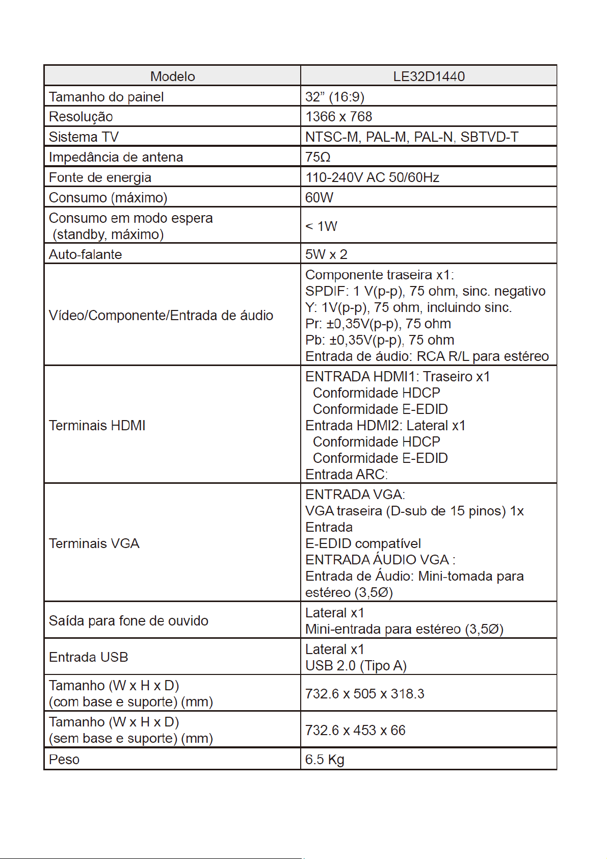
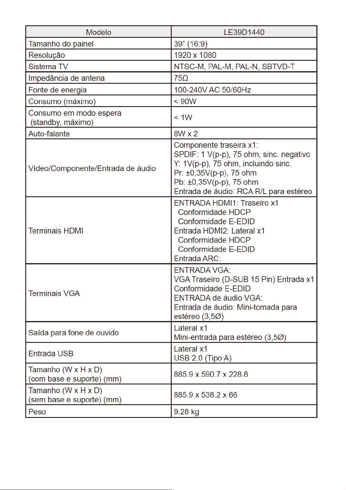
1. General Specification
4
Page 5
5
Page 6
2. Operating Instructions
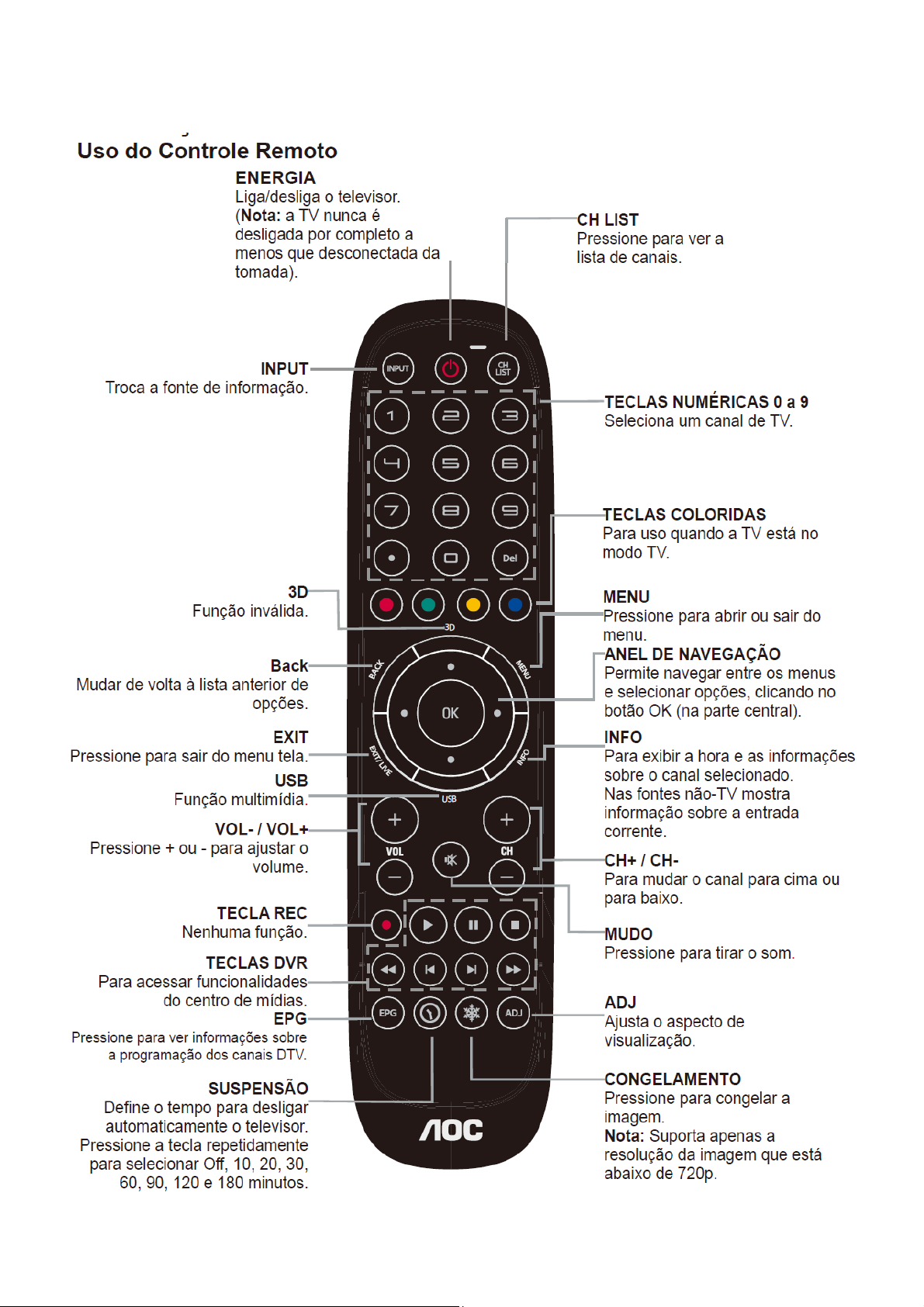
2.1 The Use of Remote Control
6
Page 7
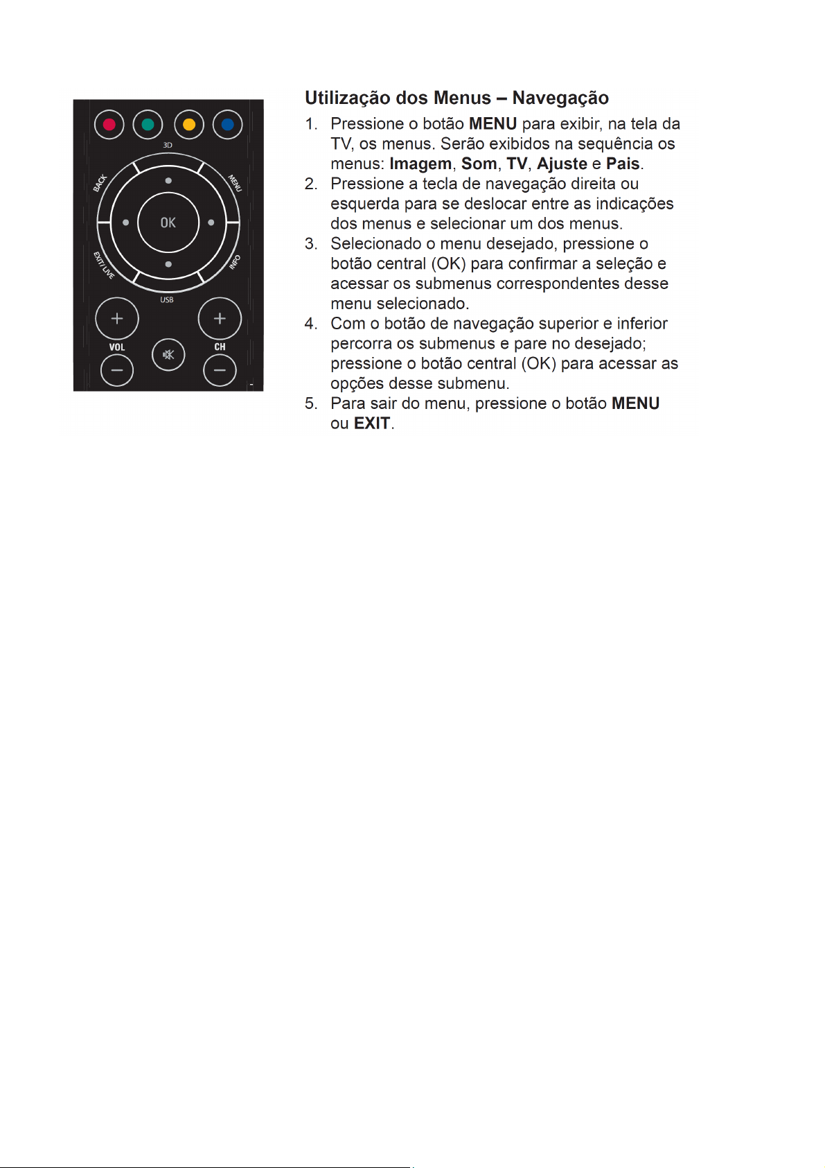
2.2 To Use the Menus
7
Page 8

8
Page 9
9
Page 10

10 11 12 13 14 15 16
Page 11
Page 12

Page 13

Page 14
Page 15
Page 16
Page 17

2.3 How to Connect
17
Page 18
18
Page 19

2.4 Front Panel Control Knobs
19
Page 20
20
Page 21

3. Input / Output Specification
D-Sub, HDMI Digital Connector Pin Assignments
D-Sub HDMI1 HDMI2
PIN No. Signal PIN No. Signal PIN No. Signal
1 Red 1 TMDS Data2+ 1 TMDS Data2+
2 Green 2 TMDS Data2 shield 2 TMDS Data2 shield
3 Blue 3 TDMS Data2- 3 TDMS Data24
5 GND 5 TMDS Data1 shield 5 TMDS Data1 shield
6 Red GND 6 TMDS Data1- 6 TMDS Data17 Green GND 7 TMDS Data0+ 7 TMDS Data0+
8 Blue GND 8 TMDS Data0 shield 8 TMDS Data0 shield
9 +5V (supply from PC) 9 TMDS Data0- 9 TMDS Data010 Sync GND 10 TMDS Clock+ 10 TMDS Clock+
11
12 Bi-directional data (SDA) 12 TMDS Clock- 12 TMDS Clock13 H-sync 13 CEC 13 CEC
14 V-sync (vclk) 14 ARC 14 NC
15 Data clock (SCL) 15 SCL 15 SCL
16 SDA 16 SDA
17 DDC_Ground 17 DDC_Ground
18 +5V Power 18 +5V Power
19 Hot Plug Detect 19 Hot Plug Detect
20 SHLD_GND1
21 SHLD_GND2
D/TXDC
D/RXDC
4 TMDS Data1+ 4 TMDS Data1+
11 TMDS Clock Shield 11 TMDS Clock Shield
HDMI Timing
WXGA Panel FHD Panel Horizontal Vertical
Resolution
640x480@60Hz ● ● 31.469 - 59.94 - 25.175
720x400@70Hz ● ● 31.469 - 70.087 + 28.322
800x600@60Hz ● ● 37.879 + 60.317 + 40
1024x768@60Hz ● ● 48.363 - 60.004 - 65
1280x720@60Hz ● ● 45 + 60 + 74.25
1280x768@60Hz ● ●
1280x1024@60Hz ● ● 63.981 + 60.02 + 108
1360x768@60Hz ● 47.71 + 59.799 + 85.5
1440x900@60Hz
1680x1050@60Hz
HDMI-
DVI
HDMI-
DVI
●
●
Nominal Sync Nominal Sync
Frequency
(KHz)
47.396
/47.776
55.935
/55.469
64.674
/65.29
Polarity Freq. (Hz) Polarity
+
/-
-
/+
+
/-
59.995
/59.87
59.887
/59.901
59.883
/59.954
Nominal Pixel
-
/+
+
/-
-
/+
Clock(MHz)
68.25
/79.5
106.5
/88.75
119
/146.25
1920x1080@60Hz ● 66.587 + 59.934 - 138.5
720x480i
59.94/60Hz
● ● 15.75 60 27.03
21
Page 22
720x480P
59.94/60Hz
720P 59.94/60Hz ● ● 45 60 74.25
1080i 59.94/ 60Hz ● ● 33.75 60 74.25
1080P 24Hz ● ● 67.5 24 59.4
1080P 60Hz ● ● 67.5 + 60 + 148.5
● ● 31.54 60 27.03
PC timing table(For RGB input)
WXGA Panel Full HD Panel Horizontal Vertical
Resolution
VGA VGA
640x480@60Hz ● ● 31.469 - 59.94 - 25.175
640x480@72Hz
640x480@75Hz
720x400@70Hz ● ● 31.469 - 70.087 + 28.322
800x600@56Hz
800x600@60Hz ● ● 37.879 + 60.317 + 40
800x600@72Hz
800x600@75Hz
1024x768@60Hz ● ● 48.363 - 60.004 - 65
1024x768@70Hz
1024x768@75Hz
1280x720@60Hz ● ● 45 + 60 + 74.25
1280x768@60Hz ● ●
● ● 37.861 - 72.809 - 31.5
● ● 37.5 - 75 - 31.5
● ● 35.156 + 56.25 + 36
● ● 48.077 + 72.188 + 50
● ● 46.875 + 75 + 49.5
● ● 56.476 - 70.069 - 75
● ● 60.023 + 75.029 + 78.75
Nominal Sync Nominal Sync
Frequency
(KHz)
47.396
/47.776
Polarity Freq.(Hz) Polarity
+
/-
59.995
/59.87
Nominal Pixel
-
/+
Clock(MHz)
68.25
/79.5
1280x1024@60Hz ● ● 63.981 + 60.02 + 108
1360x768@60Hz ● 47.71 + 59.799 + 85.5
1440x900@60Hz ●
1680x1050@60Hz ●
1920x1080@60Hz ● 66.587 + 59.934 - 138.5
55.935
/55.469
64.674
/65.29
-
/+
+
/-
59.887
/59.901
59.883
/59.954
+
/-
-
/+
106.5
/88.75
119
/146.25
22
Page 23

4. Mechanical Instructions
1. Remove the screws to remove BASE.
2. Remove the screws to remove REAR COVER.
23
Page 24

3. Disconnect the PINS marked in yellow .Remove the screws marked in red to remove MAIN BOARD,POWER
BOARD,KEY BOARD,SPEAKER,BKT_IO_SIDE.
4. Remove the screws to remove BKT_ STAND, COVER_HINGE,DECO.
24
Page 25
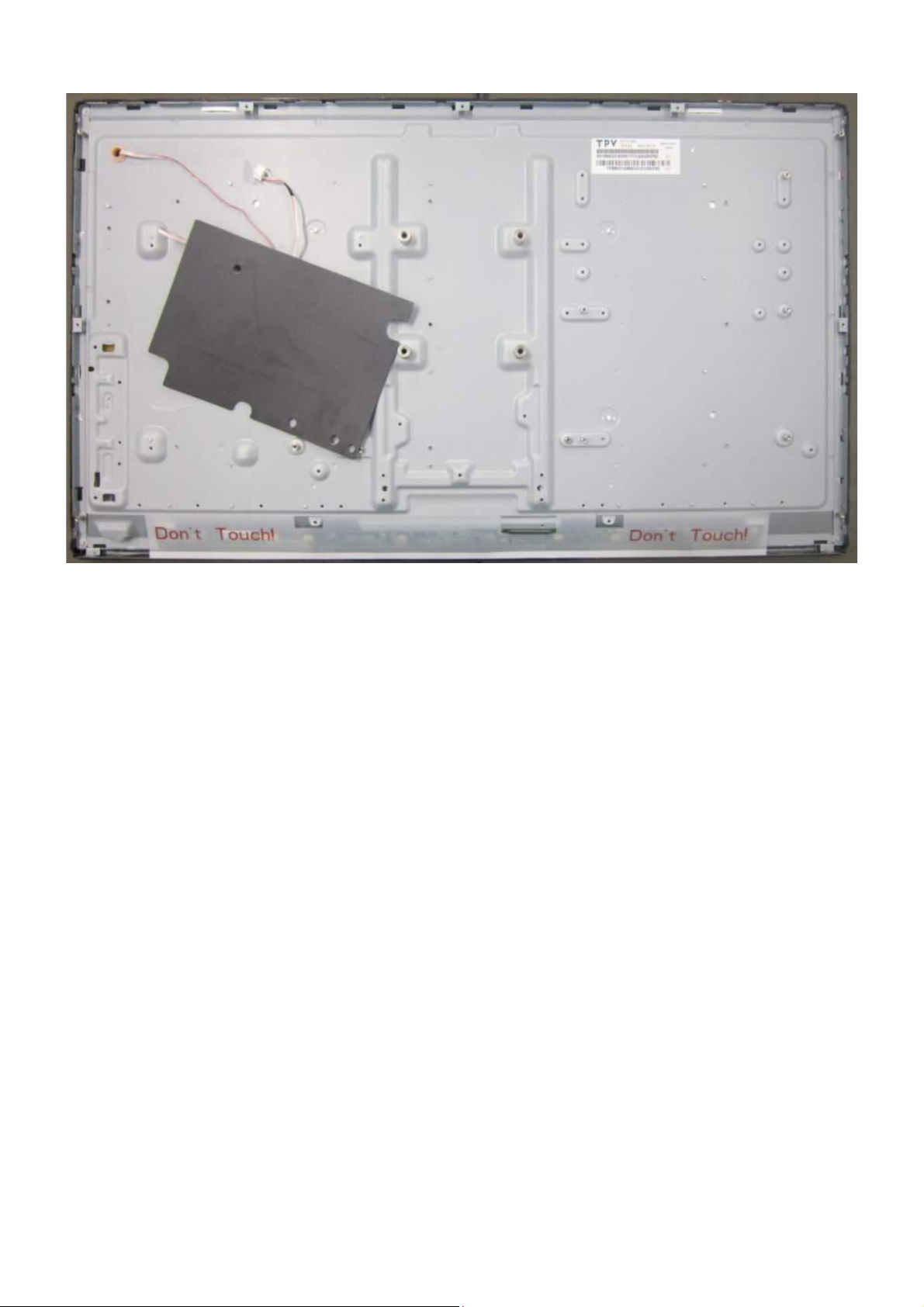
5. Remove the Mylar from PANEL.
25
Page 26
p
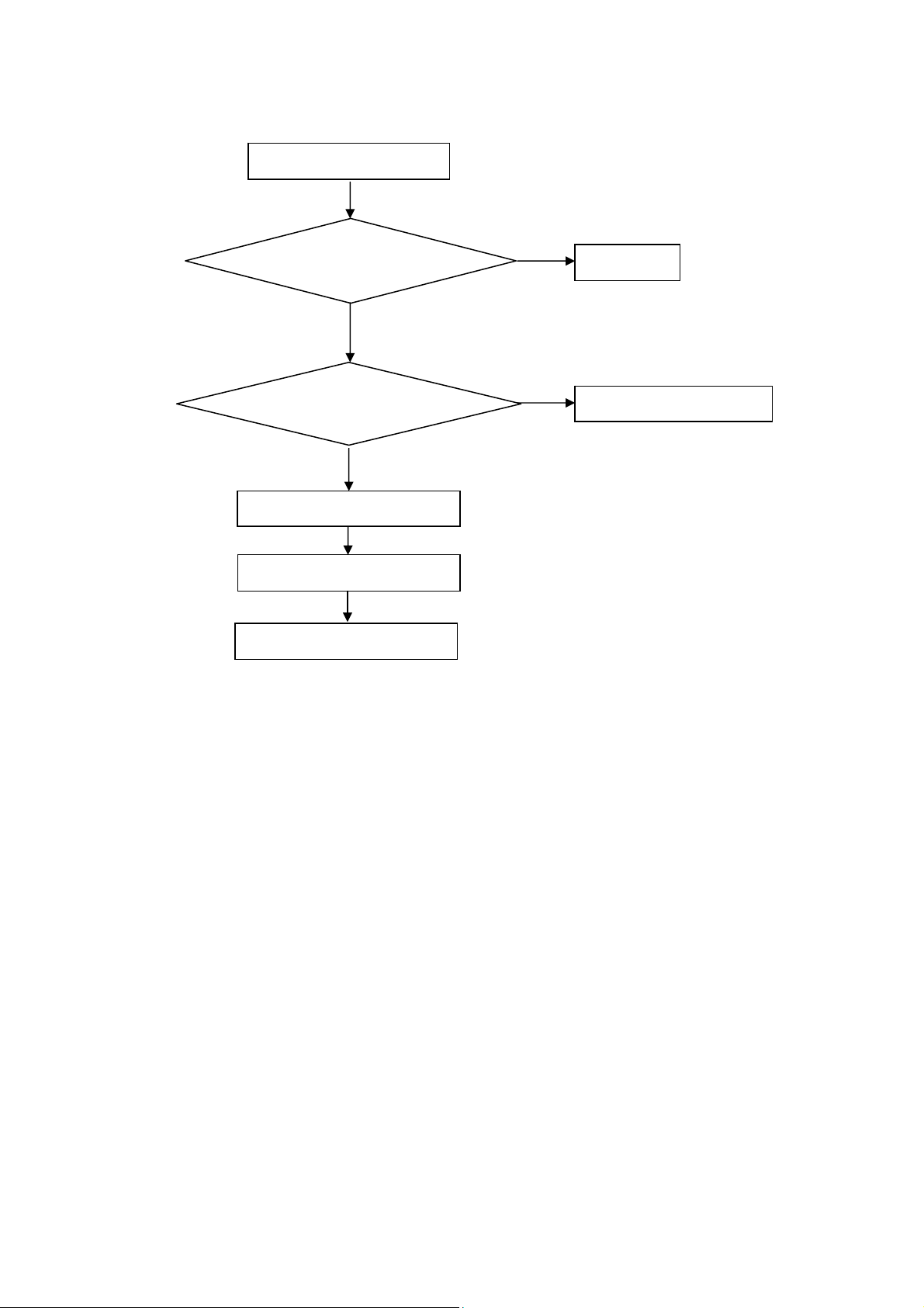
5. Repair Flow Chart
1. No power
No power (LED “Off”)
Check the AC input and
the
ower is “ON”?
Yes
Power board output=5V?
Yes
Check the IR board and LED
Replace the IR board
No
Replace the main board
No
Power “On”
No
Replace the power board
26
Page 27

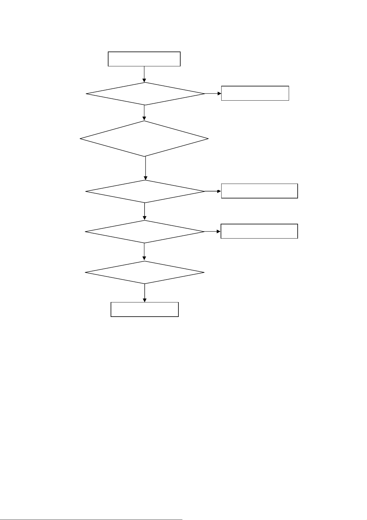
2. Can’t start
Can’t start (LED red)
Power board output=12/24V?
Yes
Check the power key is under control?
No
Check the IR receiver is normal?
No
Replace the power board
Yes
Replace the main board
Yes
Replace the IR board
No
Replace the main board
No
Replace the Power board
27
Page 28
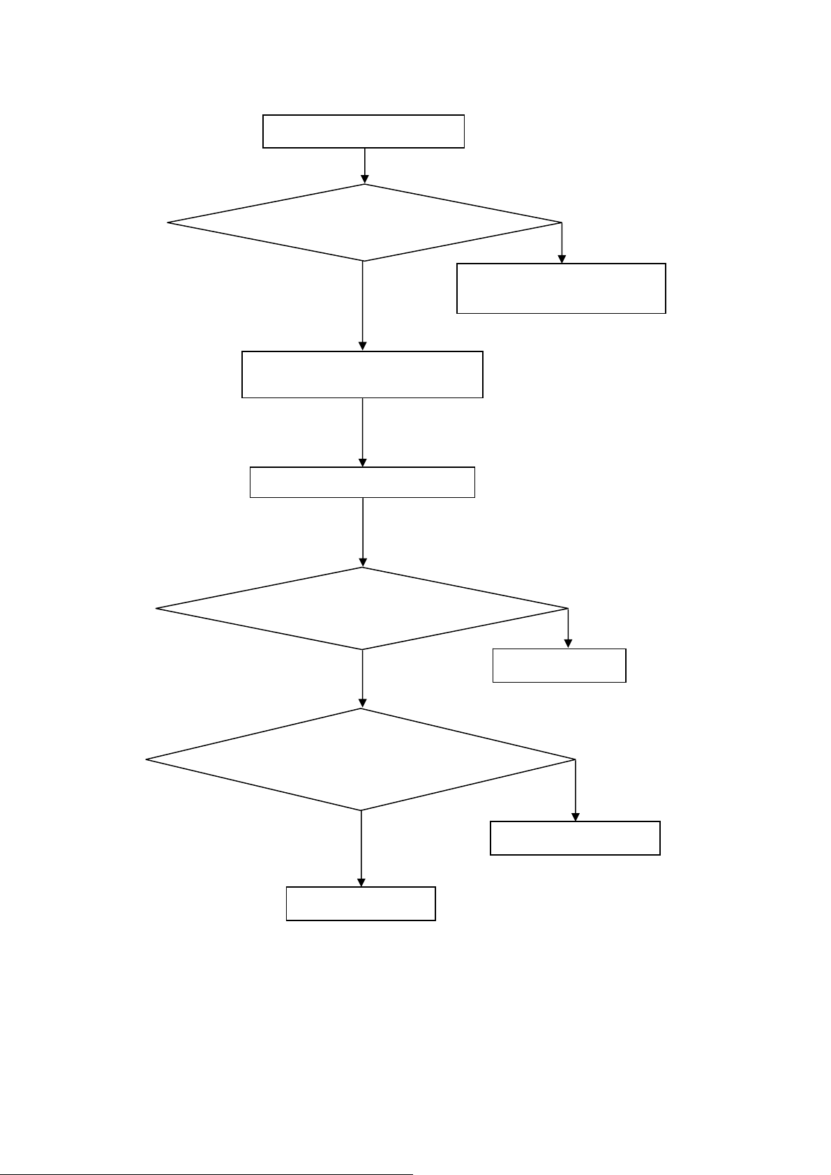
3. Abnormal display
Abnormal Display
Check the source
Yes
Enter factory mode to do
“EEPROM initial”&“Reset”
No
No
Reset the source
Check the main board
Yes
Check the LVDS cable
Yes
Check the panel
No
Replace the panel
No
Replace the main board
No
Replace the LVDS cable
28
Page 29

4. No display
No display (No LED)
Check TV is under control and power
on/off by remote control and power key?
Yes
Check the LVDS cable
Yes
Yes
Check the backlight is
“On”?
No
Reinsert or replace the
LVDS cable
No
No
Check the B/L
signal is available?
Yes
Replace the main board
No
Replace main board
Panel Vcc = 12V?
Yes
Replace the Panel
No
Replace the main board
Power board output=12/24V?
Yes
Replace the Panel
Replace the power board
No
29
Page 30
5. Sound problem
No sound or sound abnormal
Check the audio source connection
and the TV system are correct?
Yes
Check the TV is muted, adjust the
volume or enter the menu to reset?
No
No
Reinsert the audio cable or
change the TV system
Enter factory mode to do “Reset”
No
Check the cable between the
speakers and main board is OK?
Yes
Check the speaker resistance value is in spec
(Remark: The value is marked on the speaker)?
Yes
Replace the cable
Replace the main board
No
No
Replace the speaker
30
Page 31

6. Remote control malfunction
Remote Control malfunction
Check the remote control battery is
not properly placed or no power?
No
Use the other remote controls
No
Whether the IR board is
abnormal?
No
Replace the main board
Yes
Replace the battery
Yes
Replace the remote control
Yes
Replace the IR board
31
Page 32

6. PCB Layout
6.1 Main Board
715G5801M0E000004K
32
Page 33

33
Page 34

6.2 Power Board
715G5827P03000002H
34
Page 35

35
Page 36

715G6050P02W20002M
36
Page 37

37
Page 38

6.3 IR Board
715G6077R01000004S
6.4 Key Board
715G6076K01000004S
38
Page 39

7. Adjustment
7.1 White Balance Adjustment
In Component signal mode, Signal generator will select Tim 314, Pattern 141(80% White);
1.
2. Press "Menu +1+9+9+9+ Back" into the factory mode.
3. Move the cursor to Current Source and choose component; Move the cursor to Color temp and choose color
temp(Cool, Normal, Warm), Move the cursor to the Gain and adjust RGB parameters to make the color
temperature value within the cool color temperature specifications(Specifications in the following table) (NOTE:
What we need is the Gain after the Color temp )
Take LE32D1440 for example:
色温规格:
调整规格
产品规格
色温
(x,y)
Item Level x y x y x y
80IRE 0.003 0.003 0.003 0.003 0.003 0.003
80IRE 0.030 0.030 0.030 0.030 0.030 0.030
Cool
(0.271,0.274)
Normal
(0.285,0.293)
Warm
(0.313.329)
39
Page 40

7.2 Firmware Instruction
Step 1: Ready for F/W Upgrade
1.1 Change the software file name to “
1.2 Prepare a USB memory. Copy the file “
remove it from computer’s USB port!
Step 2: F/W Upgrade
2.1 Insert USB flash disk into TV’S USB .Do as the Figure2.1.
2.2 AC on the TV, the indicator light will shine after about tens of seconds, and the software will update automatically.
install.img”.
install.img” from your computer to the USB memory root directory, and
TV will auto restart after update the software.
2.3 After restart, press “menu+1999+back” keys in remote control into the factory menu. Check the version of MCU,
and restart, software update is completed.
40
Page 41

8. Block Diagram
Single te r m inal s ilicon
tuner
(LG TDST-H020F)
DIF+/-
ATV/ISDBT
DEMOD
NAND FLASH
1Gb
HD& FHD LCD PANEL
LVDS (50/60 Hz)
RTD2958I
VGA IN
Line IN
CVBS
R/L IN
YPb Pr
HDMI1
HDMI2
USB 2.0
(MM&service port)
RGB
CV BS
YPbPr
RCKEY UART
L/R
SPDIF
Line Out
Headphone
AUDIO AMP
TI 3113
3W/5W/10W SPK
41
Page 42

Audio_PWR
FB4048
PWR_12V
PWR_5V
FB4047
2908 mA
FB101
328mA
D5V_STB
2580 mA
FB7008
370mA
Power_EN
ALWAYS ON
BUCK (3A)
AP3407K
U701
BUCK (3A)
AT1529F11U
U703
FB107
MOS SW
Q7004
AO4421
D_5V
2580mA
VCC33_STB
423mA
1380mA
FB7007
MOS SW
143mA 143mA
Q7007
Power_EN
AO4421
CORE_1.1V
DVDD3V3
D_5V
280mA
LDO
G9661
U702
1.5V
ADC, VDC, APLL
A1V0
280mA
A1V1 (Core Power)
1100mA
FB4016
280mA
DDR Power
Pac' :1A
Mac :2A
DDR3 :1.5V
DDR_POWER
DM3V3
FB114
IO_3V3, UART,
Always ON
Keypad, LVDS_3V3,
LSADC_3V3, HDMI_3V3
ADC_3V3, BB_3V3,
IFDADC_3V3,
USB_3V3
U401
RTD2958I
Main chip
NAND FLASH -GINGA
HY27UF081G2A-TPCB
U403
SPI FLASH - NON GINGA
Audio_PWR
26'' Audio_PWR=24V
22'' Audio_PWR=16V
Audio_PWR
BUCK (36V/3A)
MP1584EN-C319
U715
1400mA for 21.5 CMO Pane l
600mA for 18.5 CMO Panel
300mA for 26 BOE Panel
+12V
Backup_PWR
26'' Bcak_PWR=12V
22'' Bcak_PWR=5V
FB2904
FB2905
600mA
AUDIO_VDD
D3V3
FB7011
NC/FB4043
LVDS_PWR_EN
NC/FB4042
FB4041
NC/FB4043
Audio Amp
TPA3110D2
U601
D_5V
D_5V
330mA
800mA
800mA
AO4412
Q4006
LDO
G903T63
U704
LVDSVDDMOS SW
LVDS Connect
CN408 (40P)
+5V real comsumption 2.15A (185 CMO panel) from HDMI black pattern
+5V real comsumption 2.95A (215 CMO panel)from HDMI black pattern
330mA
TH1001
TH1001 USB Connect
800mA
800mA
T3V3
USB5V
USB5V
TUNER
TU701
Tuner
USB
USB Connect
CN103
USB
CN103
42
Page 43

9. Schematic Diagram
9.1 Main Board
715G5801M0E000004K
Part
Reference
from 701
1415
CN701
CONN
DGND
Core Power(D1V1)
C7017
100N 16V
C0402
DGND
C7020
100N 16V
C0402
DGND
FB7012
D5V_STB
120R/6000mA
1 2
L0805
DC POWER INPUT form PSU
FB7002
120R/6000mA
TP363
L0805
TP365
1 2
1
2
3
4
5
6
7
8
9
10
11
12
13
C7053
10UF 10V
TP366
BL_ON1_PWR
BL_PWM_PWR
PWR_12V
TP371
DGND
TP372
PWR_ON
TP373
FB7004
PWR_5V
120R/6000mA
L0805
1 2
R7016
10R
R0402
U703
9
E-PAD
1
8
VCC
VIN
2
7
REF
LX
3
6
GND
PGND
5
FB4EN
DGND
AT1529F11U
56A379-92
DGND
Vou t = 0.8x(1+R1/ R2)
=1.114
R1=22K, R2=56K
range
為
1.05V(min) /
1.1V (typ) /
1.15V(max)
Vout = 0.6(1+Rup/Rdn)=3.33V
TP386
C7054
100N 16V
DGND
Vddr=0.8*(1+R1/R2)=3.36V
TP374
R7017
10K
R0402
4
5
10UF 25V
U701
AP3417C
C7002
C1210
FB7003
120R/6000mA
L0805
1 2
2.2uH 30%
L6005
FB
+12V
TP364
C7003
0.1uF 50V
DGND
DGND
C7009
2.2UF 50V
C1206
D5V_STB
C7013
10UF 10V
DGND DGND
C7018
10UF 10V
C7021
NC
C0402
LX3VIN
2
GND
1
EN
R7072
10K
R0402
2.2UF 50V
DGND
C7014
100N 16V
C0402
TP380
DGND
2.2uH 30%
L6006
DGND
C1206
DGND
R1
R7019
22K 1%
R0402
R2
R7023
56K 1%
R0402
C7010
TP376
FB7005
120R/6000mA
L0805
1 2
C7019
100N 16V
C0402
R1
R2
DGND
PWR_ON
Audio_PWR
+
DGND
R7073
4.7K 1%
R7074
1.02K 1%
C7011
0.1uF 50V
DGND
C7015
220UF 16V
EC63
SMD
6.3 X7.7
C7055
10UF 10V
D5V_STB
R7002
R7004
1K
NC
R0402
R0603
R7005
Q7002
1K
PMBS3904
R0402
SOT23BEC
BL_PWM:
Normal:Max:+3V3, Min:0V
Stand_By :0V
BL_ON1:
Normal: High
Stand_By :
Low
R7003
10K 1/10W
R0603
TP367
PSU_ON
DDR_POWER
Mac: 1.8V Pac': 2.5V
U702
10K 1/10W
D3V3
DGND
R733
R7013
10K 1/10W
C7058
2.2uF
1
2
3
POK
VEN
VIN
VPP4NC
G9661
9
8
7
6
5
R1
R2
DDR Power 1.5V
DGND
R7006
3.01K 1%
C716
10UF 10V
R7007
3.3K 1%
DGND
DGND
DGND
C7006
100N 16V
C0402
+
C7008
100UF 16V
EC63
SMD
6.3
X7.7
0.5A
E-Pad
GND
ADJ
VO
3/15_Mars
R7095
0.05R
Vout=1.5V
TP370
DDR_POWER
C7004
100NF 25V
D5V_STB
DGND
Vddr=0.8*((R1+R2)/R2)=1.529V
D5V_STB
04. POWER
R7009
10K 1/10W
R0603
NC/10K
NC/10K
R7026
R7014
D3V3_STB
DGND
DGND
R7001
10K
10K 1/10W
R7024
10K
1uF 10V
10K 1/10W
NC/1uF 10V
C7050
R7008
R0603
C7049
DGND
DGND
VCC33_ST B & DVDD3V3 switch
D3V3_STB
R7018
R0603
10K 1/10W 5%
DGND
DGND
OEM MOD EL
TPV MOD EL
PCB NAME
Sheet
9/11(Mars)
D5V
FB7007
1 2
120R/3000mA
L0603
+
C7052
220UF 16V
EC63
10/18(Mars)
D3V3_STB
R7082
NC/4.7K
R0402
A1V1
TP387
R7033
NC/0R05 1/16W
R0402
R7038
4.7K
R0402
4.7K
R0402
Q7001
PMBS3904
SOT23BEC
R7029
D3V3_STB
DGND
BL_EN
R7083
4.7K
R0402
USB 5V
4.7K
R0402
R7021
D3V3_STB
FB7011
120R/3000mA
L0603
Q7008
MMBT390 6
R7027
4.7K
R0402
R7041
NC
R0402
1
D5V_STB
DGND
TP362
USB_5V
R7025
100R
R0402
C7029
NC
C0805
DGND
D3V3_STB
R7042
2K OHM
R0402
3
Q7011
PMBS3904
SOT23BEC
2
Vddr=0.8*(1+R1/R2)=3.3V
DGND
BL_PWM
C7038
100N 16V
C0402
DGND
R7037
NC/12K 1/ 16W
120517_Mars
R7035
To PWR module
BL_ON1
D5V
1 2
D3V3_STB
DGND
TP391
R7045
4.7K
R0402
DGND
C7023
100N 16V
C0402
TP529
DGND
C7056
10UF 10V
D3V3_STB
C7057
100N 16V
TP384
C7024
10UF 10V
DGND
C7059
1UF 10V
D1V1
C7025
10UF 10V
DGND
DGND
BL_DIM(PWM for Bright_Adj):
Max: 0 V
Min : +3V3
From
RTD2958i
BL_ADJ
BRIGHT ADJ UST
BackLight_SW:
BackLight on: Low
Back Ligh t off:
High
INVER TER ON/OFF
From
RTD2958i
POWER_EN
To PWR module
BL_PWM_PWR
0.05R
R0402
BL_ON1_PWR
R7043 1K
C7037
10UF 10V
DGND
111021 EIT AC drop issue
T P V ( Top Victory Electronics Co . , Ltd. )
G5801-M0A-000-0040-1
絬 隔 瓜 絪 腹
Key Component
Date
PAGE LINK
BL_ADJ
BL_ADJ12
BL_EN
BL_EN12
POWER_EN
POWER_EN12
PSU_ON
PSU_ON12
D5V_ST B & D_5V switch
D5V
TP377
C7012
100N 16V
Tuner 3.3V
U704
G903T63UF
VIN3VOUT
GND14
4
Q7004
AO3401A
0.1uF 50V
0.1uF 50V
2
C0603
C7026
C0402
DGND
C7016
D3V3
TP381
1 2
120R/3000mA
L0603
C7022
100N 16V
C0402
R7022
100K 1/10W
R0603
TP390TP389
1 2
120R/3000mA
R7011
47K +-5% 1/10W
R0603
Q7005
PMBS3904
SOT23BEC
Q7007
AO3401A
R7020
R0603
Q7009
PMBS3904
SOT23BEC
D5V
FB7009
220R/2000mA
1 2
C7035
1uF 10V
DGND DGND DGND
TBD
TBD A
TBD
of
519Thursday, May 23, 2013
R7012
100K 1/10W
R0603
FB7006
FB7013
L0603
Size
Rev
称爹
DGND
T3V3
D5V_STB
DM3V3
C7036
22UF 16V
称爹
<
R1
R2
D3V3_STB
C
>
43
Page 44

From Main Chip
VGA_DDC_SCL11,12
VGA_DDC_SDA11,12
VGA_DDC_SCL
VGA_DDC_SDA
Make on board
UART0
UART_RX112
UART_TX111,12
Part
Reference
from 4001
UART_RX1
UART_TX1
VGA_DDC_SCL
VGA_DDC_SDA
UART_RX1
UART_TX1
TP33
TP35
R4077 100R
R4078 100R
R4073 NC/100R
R4074 NC/100R
TP3 8
TP4 0
TP39 2
UART_RX1_OUT
UART_TX1_OUT
Height is 13mm.
Make on board
UART1
CN410
3
2
1
CONN
AGND
CN410 is for code download,debugging,factory aligument and compair
mode, CN411 is for BUH models.
T P V ( Top Victory Electronics Co . , Ltd. )
絬 隔 瓜 絪 腹
Key Component
Date
G5801-M0A-000-0040-1
05-1.UART
44
OEM MOD EL
TPV MODEL
PCB NAME
Sheet
TBD
TBD A
TBD
619Thursday , May 23, 2013
of
Size
Rev
称爹
<
A
称爹
>
Page 45

From Main Chip
N_WP#/SPI_WP#12
12
EE_WP
N_ALE/SPI_SDO12
N_CLE/SPI_SCLK12
N_WE#/SPI_DI12
SPI_CS#12
N_CE1#12
N_CE0#12
N_WE#/SPI_DI12
N_RE#12
N_RDY12
N_DATA012
N_DATA112
N_DATA212
N_DATA312
N_DATA412
N_DATA512
N_DATA612
N_DATA712
R4065
4.7K
N_CE0#
From Scaler
I2C_SCL5,7,12
I2C_SDA5,7,12
N_WP#/ SPI_WP#
EE_WP
N_ALE/S PI_SDO
N_CLE/ SPI_SCLK
N_WE#/ SPI_DI
SPI_CS#
N_CE1#
N_CE0#
N_WE#/ SPI_DI
N_RE#
N_RDY
N_DATA0
N_DATA1
N_DATA2
N_DATA3
N_DATA4
N_DATA5
N_DATA6
N_DATA7
R4066
4.7K
N_CE1#
I2C_SCL
I2C_SDA
DM3V3
N_RDY
R4067
4.7K
DM3V3
R4058
4.7K
SPI_CS#
N_WE#/ SPI_DI
WP#
R4063
NC/ 4K7 1/16W 5%
DGND
For Rtice Check
N_WP#/ SPI_WP#
HDCP KEY
TP423
EE_WP
TP396
TP397
22R
NAND FLASH
TP405
R4064
NC/ 4K7 1/16W 5%
DM3V3
4.7K
R4068
1
PMBS3904
4.7K
3
Q4001
2
DGND
4.7K
R7079
R4070
10K
N_WP#/SPI_WP#
R7080 0.05R
R7081
NC/ 0.05R
SPI FLASH
DM3V3
(Reserved)
TP398
1
/CS
2
SPI_DI 0
R4060
22R
DM3V3
R7077
TP425
R0402
R4069
4.7K
R7078
TP42 4
I2C_SCL
I2C_SDA
DO(IO1)
3
/WP(IO2)
GND4DI(IO0)
DGND
N_RE#
N_CE0#
N_CLE/SPI_SCLK
N_ALE/SPI_SDO
N_WE#/SPI_DI
WP#
D5V_STB
U407
8
NC
VCC
7
NC
WC
6
NC
SCL
5
VSS
SDA
M24C16
change U4009 24C02(056G1133913) to
24C04(056G1133911) for HDCP key
U406
VCC
/HOLD(IO3)
CLK
NC/ W25Q64BVSSIG
TP408
TP410
16
17
18
19
TP422
1
2
3
4
8
7
6
5
8
RE
9
CE
CLE
ALE
WE
WP
C4091
0.22UF 10V
C0402
DGND
C4089
0.22UF 10V
C0402
DGND
SPI_HOLD
SPI_SCLK0
SPI_DO0
VDD12VDD
VSS
13
DGND
TP395
R4059
4.7K
TP399
TP401
TP403
U405
H27U1G8F 2BTR-BC
37
<Package>
I/O0
I/O1
I/O2
I/O3
I/O4
I/O5
I/O6
I/O7
R/B
VSS
36
R4061 22R
R4062 22R
29
N_DATA0
30
N_DATA1
31
N_DATA2
32
N_DATA3
41
N_DATA4
42
N_DATA5
43
N_DATA6
44
N_DATA7
7
R0402
N_RDY
TP402
DM3V3DM3V3
TP406
TP411
TP416
TP404
R0402
C4090
1uF 25V
DGND
TP407
TP412
TP417
Part
Reference
from 4001
N_CLE/SPI_SCLK
N_ALE/ SPI_SDO
TP409
TP414
TP420
45
T P V ( Top Victory Electronics Co . , Ltd. )
絬 隔 瓜 絪 腹
Key Component
G5801-M0A-000-0040-1
05-2 SPI & N AND FLASH
Date
OEM MO DE L
TPV MO DE L
PCB NAME
Sheet
TBD
TBD A
TBD
of
719Thursday , May 23, 2013
Size
Rev
称爹
B
称爹
>
<
Page 46

To LVDS
TEDP5
TEDN5
TECLKP5
TECLKN5
TECP5
TECN5
TEBP5
TEBN5
TEAP5
TEAN5
TODP5
TODN5
TOCLKP5
TOCLKN5
TOCP5
TOCN5
TOBP5
TOBN5
TOAP5
TOAN5
PANEL_EN5
To HDMI 0
HDMI0_CLK-9
HDMI0_CLK+9
HDMI0_D0-9
HDMI0_D0+9
HDMI0_D1-9
HDMI0_D1+9
HDMI0_D2-9
HDMI0_D2+9
HDMI_CEC9
HDMI0_DDC_SDA9
HDMI0_DDC_SCL9
HOTPLUG09
SPDIF_OUT_ARC9
To HDMI 1
HDMI1_CLK-9
HDMI1_CLK+9
HDMI1_D0-9
HDMI1_D0+9
HDMI1_D1-9
HDMI1_D1+9
HDMI1_D2-9
HDMI1_D2+9
HDMI1_DDC_SDA9
HDMI1_DDC_SCL9
HOTPLUG19
To Tuner
TUN_I F-8
TUN_I F+8
TUN_I2C_SDA8
TUN_I2C_SCL8
ATV_IF_AGC8
To Keypad IR
IR_SSB3
LEDG7
LSADC17
LSADC07
LEDR7
LightSensor7
To Power
BL_EN15
BL_ADJ15
POWER_EN15
PSU_ON15
HP_OUT_JD6
To AMP
AMP_MUTE6
To USB
USB1_DP2
USB1_DM2
LSADC32
FB4013
D3V3_STB IFADC_3V3
120R/3000mA
12
C4053
10UF 6.3V X5R +-20%
FB4015
IFPGA_3V3
D3V3_STB
120R/3000mA
12
C4056
10UF 6.3V X5R +-20%
D3V3_STB TMDS_ 3V3
FB4020
12
120R/3000m A
TEDP
TEDN
TECLKP
TECLKN
TECP
TECN
TEBP
TEBN
TEAP
TEAN
TODP
TODN
TOCLKP
TOCLKN
TOCP
TOCN
TOBP
TOBN
TOAP
TOAN
PANEL_EN
HDMI0_CLKHDMI0_CLK+
HDMI0_D0HDMI0_D0+
HDMI0_D1HDMI0_D1+
HDMI0_D2HDMI0_D2+
HDMI_CEC
HDMI0_DDC_SDA
HDMI0_DDC_SCL
HOTPLUG0
SPDIF_OU T_ARC
HDMI1_CLKHDMI1_CLK+
HDMI1_D0HDMI1_D0+
HDMI1_D1HDMI1_D1+
HDMI1_D2HDMI1_D2+
HDMI1_DDC_SDA
HDMI1_DDC_SCL
HOTPLUG1
TUN_I FTUN_I F+
TUN_I2C_SDA
TUN_I2C_SCL
ATV_IF_AGC
IR_SSB
LEDG
LSADC1
LSADC0
LEDR
LightSensor
BL_EN
BL_ADJ
POWER_EN
PSU_ON
HP_OUT_JD
AMP_MUTE
USB1_DP
USB1_DM
LSADC3
FB4012
120R/3000mA
AGND
AGND
AGND
C4072
100NF 16V
AGND
ST_GPIO0
V10LDO
V33LSADC
LSADC_REF
LSADC0
LSADC1
LSADC2
LSADC3
V10CORE
G10CORE
RX0_RP
RX0_RN
RX0_GP
RX0_GN
RX0_BP
RX0_BN
RX0_CKP
RX0_CKN
V10TMDS
G10TMDS
RX1_RP
RX1_RN
RX1_GP
RX1_GN
RX1_BP
RX1_BN
RX1_CKP
RX1_CKN
G33TMDS
V33TMDS
GPIO_67
I2S_OUT_MCLK
V10CORE
I2S_OUT_SCLK
LVDSB_AN
LVDSB_AP
LVDSB_BN
LVDSB_BP
LVDSB_CN
LVDSB_CP
LVDSB_DN
LVDSB_DP
LVDSB_EN
LVDSB_EP
LVDSB_FN
LVDSB_FP
TMDS_1V0
C4066
100NF 16V
D3V3_STB
AGND
CEC
REXT
V33IO
R4031
10K
C4013
100NF 16V
162
161
160
159
158
157
156
155
154
153
152
151
150
149
148
147
146
145
144
143
142
141
140
139
138
137
136
135
134
133
132
131
130
129
128
127
126
125
124
123
122
121
120
119
118
117
116
115
114
113
112
111
110
109
D5V_STB
2
RESET#
HDMI0_DDC_SDA
AMP_MUTE
HDMI_CEC
STB_1V0
LSADC_REF
LSADC0
LSADC1
LightSensor
LSADC3
HDMI_REXT
HDMI0_D2+
HDMI0_D2HDMI0_D1+
HDMI0_D1HDMI0_D0+
HDMI0_D0HDMI0_CLK+
HDMI0_CLK-
HDMI1_D2+
HDMI1_D2HDMI1_D1+
HDMI1_D1HDMI1_D0+
HDMI1_D0HDMI1_CLK+
HDMI1_CLK-
TEAN
TEAP
TEBN
TEBP
TECN
TECP
TECLKN
TECLKP
TEDN
TEDP
3
U706
VDD
GND1RESET(RESET)
G691L400T73F
AGND
STB_1V0
D3V3_STB
CORE_1V0
R4034 6.2K
TMDS_1V0
TMDS_3V3
D3V3_STB
SPDIF_OUT_ARC
CORE_1V0
EE_WP
Power On Latch
FB7016
D3V3_STB
VDADC_3V3 A1V1
120R/3000mA
12
C4007
AGND
100NF 16V
100NF 16V
L109
VDAC_3V3
0.1UH
C4009
10UF 6.3V X5R +-20%
C4014
100NF 16V
AGND
DGND
AGND
AGND
AGND
C4015
100NF 16V
C4001
100NF 16V
AGND
DGND
11/8 Mars
D3V3_STB
R4033
10K
TP28
TP29
TP30
HIF_Selection_n (Pin 59)
0 : HIF Enable
1 : HIF Disable
EJTAG (Pin 61, pull-hi)
0 : enable
1 : disable
ROM boot (Pin 63, pull-lo)
0 : boot from ROM
1 : don't boot from ROM
BOOT_MODE_bit1 (pin 64, pull-lo)
0 : SPI-Flash boot
1 : NAND-Flash boot
test mode (Pin 161, pull-hi)
0 : enable
1 : disable
PLL enable mode (Pin 162, pull-hi)
0 : disable
1 : enable
NAND access type (Pin77)
0 :Sequence mode
1 :random mode
NAND ECC type (Pin75)
0 : 6 bit
1 :12 bit
C4008
C4016
100NF 16V
ETN_LED1
ETN_LED0
TUN_I2C_SCL
N_CLE/SPI_SCLK
SPI_CS#
N_ALE/SPI_SDO
AMP_MUTE
HDMI0_DDC_SDA
N_DATA1
N_DATA0
TP426
C4017
100NF 16V
FB4008
120R/3000mA
C4010
1UF16V
AGND
For ESD_Mars130301
10UF 6.3V X5R +-20%
C4019
C4018
100NF 16V
100NF 16V
D3V3_STB
DGND
D3V3_STB
DGND
D3V3_STB
DGND
D3V3_STB
DGND
D3V3_STB
DGND
D3V3_STB
DGND
D3V3_STB
DGND
D3V3_STB
DGND
R4038
4.7K
R4039
NC/4.7K
R4040
4.7K
R4041
NC/4.7K
R4042
NC/4.7K
R4043
4.7K
R4046
4.7K
R4049
NC/4.7K
12
R4050
4.7K
R4051
NC/4.7K
R4052
NC/4.7K
R4001
NC/4.7K
R4053
NC/4.7K
R4054
4.7K
R4055
NC/4.7K
R4056
4.7K
AGND
C4011
100NF 16V
C4020
YPPADC_1V0
AGNDAGND
STB_1V0
1 2
DGND
C4012
100NF 16V
FB7017
120R/3000mA
L0603
TP428
Default
1
1
0
1
1
1
0
0
TP427
Diode Vf
should
0.3V
TP429
HDMI_CEC
絬 隔 瓜 絪 腹
Key Component
D3V3_STB
D102
BAS316RRG
R4032
27K 1/16W
T P V ( Top Victory Electronics Co . , Ltd. )
G5801-M0A-000-0040-1
05. RTD2958I 216-A
Date
HS401
1
2
HEAT SINK
Add for Heat Sink Outline 2008/12/06
OEM MODEL
TBD
TPV MODEL
TBD A
TBD
PCB NAME
819Thursday, May 23, 2013
of
Sheet
1
2
AGND
E
Size
Rev
<
称爹
>
称爹
To YPbPr in
PB0+
PB0+10
YPbPr0-
YPbPr0-10
Y0+
Y0+10
PR0+
PR0+10
YPBPR1_IN_L
YPBPR1_IN_L10
YPBPR1_IN_R
YPBPR1_IN_R10
SPDIF_OU T
SPDIF_OUT9,10
To AV in
(OPTION)
To Ethernet
Ether_TxP
Ether_TxP1
Ether_TxN
Ether_TxN1
Ether_RxP
Ether_RxP1
Ether_RxN
Ether_RxN1
ETN_LED11
ETN_LED01
HP_OUT_L6
HP_OUT_R6
SPKOUT_R6
SPKOUT_L6
12
PLL_GND
D3V3_STB
FB4014
TP436
120R/3000mA
C4054
100NF 16V
TP438
A1V1 PLL_1V0
FB4016
120R/3000m A
C4057
100NF 16V
D3V3_STB
FB4021
TP443
120R/3000m A
D3V3_STB
C4083
100NF 16V
close to Main chip
FB4022
120R/3000mA
C4086
100NF 16V
BB2_GND
close to main chip
ETN_LED1
ETN_LED0
To Flash ROM
EE_WP
12
EE_WP
SPI_CS#
SPI_CS#13
N_WP#/SPI_WP#
N_WP#/SPI_WP#13
N_ALE/SPI_SDO
N_ALE/SPI_SDO13
N_CLE/SPI_SCLK
N_CLE/SPI_SCLK13
N_WE#/SPI_DI
N_WE#/SPI_DI13
N_CE1#
N_CE1#13
N_CE0#
N_CE0#13
N_RE#
N_RE#13
N_RDY
N_RDY13
N_DATA0
N_DATA013
N_DATA1
N_DATA113
N_DATA2
N_DATA213
N_DATA3
N_DATA313
N_DATA4
N_DATA413
N_DATA5
N_DATA513
N_DATA6
N_DATA613
N_DATA7
N_DATA713
I2C_SDA
I2C_SDA5,7,13
I2C_SCL
I2C_SCL5, 7,13
3D_CTL
3D_CTL5
HP_OUT_L
HP_OUT_R
SPKOUT_R
SPKOUT_L
PLL_3V3
TP437
12
PLL_GND
C4055
100NF 16V
PLL_GND
TP439 TP440
12
C4058
100NF 16V
PLL_GND
USB_3V3
TP444
12
C4074
C4073
100NF 16V
10UF 6.3V X5R +-20%
AGND
BB1_3V3
L110
TP449 TP450
0.33uH
C4084
100NF 16V
BB1_GNDBB1_GND
BB2_3V3
TP448
12
C4087
100NF 16V
BB2_GND
To VGA input
VGA_DDC_SCL11,14
VGA_DDC_SDA11,14
VGA_HS11
VGA_VS11
VGA_B+11
VGA_B-11
VGA_G+11
VGA_R+11
VGA_IN_L11
VGA_IN_R11
UART_RX114
UART_TX111,14
Change 3.2X2.5
crystal_Mars 0207
C4050
15pF 50V
R4047
C4051
1M 1%
15pF 50V
D3V3_STB
ETN_3V3
FB4017
12
120R/3000mA
A1V1 DDRPLL_1V0
FB4023
12
120R/3000m A
DDRPLL_GND
PLL_GND
AGND
1
3
C4059
100NF 16V
C4085
100NF 16V
AGND
HP_OUT_R
HP_OUT_L
AGND
AGND
X401
PLL_GND
VGA_DDC_SCL
VGA_DDC_SDA
VGA_HS
VGA_VS
VGA_B+
VGA_BVGA_G+
VGA_R+
VGA_IN_L
VGA_IN_R
27MHz
24
ETN_1V0
ETN_1V0
R4045 0.05R
A1V1
UART_RX1
UART_TX1
FB4010
120R/3000mA
FB4011
120R/3000mA
TP531
11/8 Mars
XOUT
R4057
0.05R
Part
Reference
from 4001
U401
C4033 1UF16V
C4034 100NF 16V
AGND
BB1_3V3
YPBPR1_IN_L
C4037 2.2UF 10V
YPBPR1_IN_R
C4038 2.2UF 10V
VGA_IN_L
C4041 2.2UF 10V
VGA_IN_R
C4042 2.2UF 10V
SPKOUT_R
C4043 2.2UF 10V
SPKOUT_L
CORE_1V0
PLL_GND
IFPGA_3V3
IFADC_3V3
USB_3V3
CORE_1V0
D3V3_STB
C4088
100NF 16V
PLL_3V3
PLL_1V0
USB_1V0
ETN_3V3
TP32
TP451
R7059
0.05R
R7060
0.05R
R7062
0.05R
XOUT
XIN
ATV_IF_AGC
BB2_GND
R7061
0.05R
C4044 2.2UF 10V
TUN_I FTUN_I F+
USB1_DM
USB1_DP
USB_GND
Ether_TxP
Ether_TxN
Ether_RxP
Ether_RxN
0.05R
R4035
12
BB2_3V3
12
AGND
AGND
AGND
AGND
TP530
HP_OUT_JD
XIN
USB_1V0
AGND
AGND
R7090
0.05R
TP13
AGND
DGND
BB1_GND
214
213
215
217
216
EPAD
G33BB1
1
2
3
4
5
6
7
8
9
10
11
12
13
14
15
16
17
18
19
20
21
22
23
24
25
26
27
28
29
30
31
32
33
34
35
36
37
38
39
40
41
42
43
44
45
46
47
48
49
50
51
52
53
54
AVOUT2
G33VDAC
VCM_BB
V33BB1
AIN_4L
AIN_4R
AIN_3L
AIN_3R
AIN_2L
AIN_2R
AIN_1L
AIN_1R
SPKOUT_R
SPKOUT_L
AVOUT_R(FixVol)
AVOUT_L(FixVol)
G33BB2
V33BB2
HPOUT_R
HPOUT_L
V10CORE
V33PLL
XOUT
XIN
V10PLL
G33PLL
G33IFADC
IF_N
IF_P
V33IFPGA
V33IFADC
V33USB
U1DM
U1DP
G10USB
V10USB
U0DM
U0DP
G10USB0
V10ETN
ETNTXP
ETNTXN
GND0_ETN
ETNRXP
ETNRXN
V33ETN
GND1_ETN
V10ETN
GPIO9
GPIO10
RFAGC
IFAGC
GPIO13
V10CORE
V33IO
GPIO17
GPIO1855GPIO1956GPIO2057TUNER_I2C1_SDA58TUNER_I2C1_SCL59SPDIFI60SPI_SCK/ N_CLE61SPI_DI/N_WR62SPI_CS_N63SPI_DO/N_ALE64GPIO2465ETN_LED0/UART_RX(5V)66ETN_LED1/UART_TX(5V)67V33DDRPLL68G10DDRPLL69V10DDRPLL70VDDR_POWER71DDRZQ72VREF_DDR73VDDR_POWER74N_DATA075V10CORE76N_DATA177N_DATA278N_DATA379N_DATA480VDDR_POWER81N_DATA582V33IO83N_DATA684N_DATA785N_RD86N_CE187N_CE088N_RDY89VREF_DDR90VDDR_POWER91V10CORE92VDDR_POWER93VDDR_POWER94VDDR_POWER95LVDSA_FP96LVDSA_FN97LVDSA_EP98LVDSA_EN99LVDSA_DP
RTD2958IG
SPDIF_OU T
PANEL_EN
BL_ADJ
DDR_POWER
C4049
R4044
1K 1%
100NF 16V
DDR_VERF1
R4048
C4052
1K 1%
100NF 16V
DGND
3/15_Mars
D1V1
R7094
0.05R
10UF 6.3V X5R +-20%
NC/10UF 6.3V X5R +-20%
NC/10UF 6.3V X5R +-20%
DDR_POWER
C4077
C4076
C4075
22UF 6.3V
1UF 10V
10UF 6.3V X5R +-20%
DGND
TP446
TP15
TP16
TP17
TP14
VDADC_3V3
CORE_1V0
VDAC_3V3
211
212
208
206
210
209
207
205
VIN_9P
AVOUT1
VIN_10P
VIN_12P
VIN_A1N
V33VDAC
V10CORE
V33VDADC
SCART_FSW
N_WE#/SPI_DI
N_WP#/SPI_WP#
TUN_I2C_SCL
TUN_I2C_SDA
SPI_CS#
N_ALE/SPI _SDO
N_CLE/SPI_SCLK
UART_RX1
BOM For Pac': RD1 NM
w/o DDR
BOM For Mac : RD1 1K
CORE_1V0
C4060
C4061
C4062
C4080
C4078
C4079
2.2UF 6.3V
2.2UF 6. 3V
1UF 10V
TP447
DGNDAGND
204
VIN_A0N
UART_TX1
100NF 16V
C4024 47N16V
203
D3V3_STB
AGND
DGND
TP445
AGND
201
202
VIN_11P
V10VDADC
DDRPLL_GND
12
C4081
AGND
TP18
YPPADC_1V0
CLOAD_DW
200
199
G33ADC
V10YPPADC
R4036
DDRPLL_1V0
DDR_POWER
DGND
FB4001
120R/3000mA
C4063
100NF 16V
C4082
2.2UF 6.3V
TP19
AGND
198
CLOAD
DDR_VERF1
240R 1% 1/16W
TP442
Pin199 CLOAD:
BOM For Mac : CS5 10uF
BOM For Pac': CS5 0R
TP20
TP21
C4021
10UF 6.3V X5R +-20%
PR0+
VGA_B+
VGA_B-
VGA_G+
Y0+
PB0+
YPbPr0-
VGA_R+
VGA_HS
C4032 47N16V
C4031 47N16V
C4030 47N16V
C4029 47N16V
C4028 47N16V
C4027 47N16V
C4026 47N16V
C4025 47N16V
186
196
192
197
195
194
193
191
190
189
187
188
VIN_8P
VIN_7P
VIN_6P
VIN_5P
VIN_4P
VIN_3P
VIN_2P
VIN_1P
VIN_0P
VIN_BN
VIN_Y1N
VIN_Y0N
N_DATA5
N_DATA6
N_DATA7
N_DATA0
N_DATA1
N_DATA3
N_DATA2
N_DATA4
D3V3_STB
CORE_1V0
DDR_POWER
DDR_POWER
RD3 0R
RD3 1K
C4067
C4065
C4064
100NF 16V
100NF 16V
100NF 16V
C7063 10UF 6.3V X5R +-20%
AGND
CORE_1V0
VDADC_3V3
TP23
TP432TP431
TP433
D3V3_STB
VGA_VS
185
182
184
181
183
V33APLL
G33APLL
V10CORE
VSYNCVIN
HSYNCVIN
DDR_VERF1
N_CE0#
N_CE1#
N_RE#
N_RDY
R4037 NC/0.05R
DGND
C4068
100NF 16V
PSU_ON
I2C_SCL
VGA_DDC_SC L
VGA_DDC_SD A
RESET#
HDMI0_DDC_SCL
HOTPLUG1HOTPLUG1
LEDR
LEDG
HOTPLUG0
I2C_SDA
BL_EN
HDMI1_DDC_SDA
POWER_EN
IR_SSB
HDMI1_DDC_SCL
3D_CTL
177
176
180
179
178
V33IO
ST_GPIO23
ST_GPIO22
ST_GPIO21
HDMI1_DDC_SCL
CORE_1V0
DDR_POWER
ETN_1V0
C4069
100NF 16V
DDR_POWER
174
175
SPDIF_IN
HDMI1_DDC_SDA
C4070
100NF 16V
173
172
ST_GPIO12
ST_GPIO11
TODN
TODP
AGND
170
171
169
IRRX(5V)
BL_EN(5V)
ST_GPIO10
LVDSA_DN
100
101
102
TOCP
TOCLKP
TOCLKN
FB7015
1 2
120R/3000mA
C4071
L0603
100NF 16V
163
166
165
168
167
164
RESET
ST_GPIO6
ST_GPIO5
HDMI0_DDC_SDA
HOTPLUG1(5V)
VGA_DDC_SC L
VGA_DDC_SDA
HDMI0_DDC_SCL
ETN_LED1/GPIO_69
ETN_LED0/GPIO_68
I2S_OUT_WCLK
I2S_OU T_DA TA0
LVDSA_CP
LVDSA_CN
LVDSA_BP
LVDSA_BN
LVDSA_AP
LVDSA_AN
V33LVDS
103
104
105
106
107
108
TOAN
TOAP
TOBN
TOCN
TOBP
D3V3_STB
46
Page 47

TO RTD2958
VGA_B+12
VGA_B-12
VGA_G+12
VGA_R+12
VGA_HS12
VGA_VS12
UART_RX112, 14
UART_TX112,14
VGA_DDC_SCL12,14
VGA_DDC_SDA12,14
VGA_IN_L12
VGA_IN_R12
VGA_DDC_SCL
VGA_VS
VGA_HS
VGA_DDC_SDA
VGA_RX0
TP453
DGND
VGA_RX0
DGND
R0402
TP45 6
TP46 0
D5V_STB
D5V_STB
R163
0.05R
TP46 2
D3V3_STB
R157
4.7K
Q102
NC/AO3404
R158
0.05R R0402
D3V3_STB
R101
4.7K
Q101
NC/ AO3404
VGA_CON5V
TP455
TP458
1 3
DGND
ZD114
BZX84-C5V6
TP51 3
UART_TX1VGA_TX0
TP51 5
UART_RX1
DGND
VPORT0603100KV05
ZD112
1 2
R169 100R
VGA_BIN
VGA_GIN
VGA_RIN
VGA_TX0
VGA_BIN
1 2
ZD111
VPORT0603100KV05
VGA_GIN
1 2
ZD113
VPORT0603100KV05
VGA_RIN
ZD130
1 2
VPORT0603100KV05
R162
75R
SHORT TEST POIN T
DGND
R167
75R
DGND
R177
75R
DGND
SH101
SH105
SHORT TEST POINT
SH106
SHORT TEST POINT
R161
100R
C143
5PF 50V
R164
100R
R165
100R
C144
5PF 50V
R171
100R
R174
100R
C145
5PF 50V
R178
Close to Main Chip
100R
TP514
VGA_B+
TP516
VGA_B-
TP517
VGA_G+
VGA_B-
TP519
VGA_R+
VGA_B-
Part
VGA_B+
VGA_BVGA_G+
VGA_R+
VGA_HS
VGA_VS
UART_RX1
UART_TX1
VGA_DDC _SCL
VGA_DDC _SDA
VGA_IN_L
VGA_IN_R
C146
22pF 50V
IR_IN
DET_IR_CON
IR_OUT
DGND DGNDDGNDDGND
IR_IN3
DET_IR_CON3
IR_OUT3
Reference
from 101
R166 100R
R168 100R
R170 100R
R172 100R
R173 100R
C147
10PF 50V
VGA_CON5V
4.7K
VGA_DDC_SCL
VGA_DDC_SDA
R159
C141
NC
R175
2.2K
D101
BAT54C
1
TP512
VGA_5V
DGND
R176
2.2K
D5V_STB
2
Reserved for
3
AC-off EDID Only
R160
4.7K
C142
NC
ZD116 VP ORT0603100KV05
ZD115 VP ORT0603100KV05
1 2
1 2
TP452
1 2
DGND
TP454
ZD117 VP ORT0603100KV05
TP457
DGND
1819
5
15
VGA_SCL
VS
HS
TP45 9
VGA_SDA
TP461
ZD118 VP ORT0603100KV05
ZD119 VP ORT0603100KV05
12
1 2
10
4
14
9
3
13
8
2
12
7
1
11
6
CN101
D-SUB 15P
17 16
DGND
Shared with hotel mode
CN102
4
3
2
1
PHONE JACK
TP466
VPORT0603 100KV05
TP465
ZD124
1 2
TP463
ZD120
1 2
VPORT06031 00KV05
IR_OUT
C149
470pF 50V
VPORT06031 00KV05
TP46 4
ZD121
1 2
C150
470pF 50V
R179
NC/0.05R
R180
NC/0.05R
ZD122
1 2
VPORT06031 00KV05
IR_IN
DET_IR_CON
Near CONN
ZD123
1 2
VPORT06031 00KV05
TP52 1
R181
6K8 1/16W 5%
TP52 2
R182
6K8 1/16W 5%
R7075
10K 1/16W 5%
47
VGA_IN_L
VGA_IN_R
R7076
10K 1/16W 5%
T P V ( Top Victory Electron ics Co . , Ltd. )
G5801-M0A-000-0040-1
絬 隔 瓜 絪 腹
Key Component
06. VGA
Date
OEM MODEL
TBD
TPV MOD EL
TBD A
PCB NAME
TBD
Sheet
of
919Thursday , May 23, 2013
Size
Rev
称爹
称爹
<
Custom
>
Page 48

Part
YPbPr
Y0+12
PB0+12
PR0+12
YPbPr0-12
YPBPR1_I N_L12
YPBPR1_I N_R12
SPDIF
SPDIF _OUT9, 12
Y0+
PB0+
PR0+
YPbPr0-
YPBPR1_I N_L
YPBPR1_I N_R
SPDIF _OUT
Reference
from 101
YPbPr L/R INPUT
CN111
TP467
YPBPR1_L1
YPBPR1_R 1
SPDIF
TP472
TP470
DGND
8
D
7
10
EF
9
12
11
RCA JACK
TP468
TP469
2
ABC
1
4
3
6
5
DGND
TP471
TP473
TP523
Y1
ZD105
VPORT0603100KV05
Y1
PB1
PR1
VPORT0603100KV05
VPORT0603100KV05
PB1
ZD106
PR1
ZD107
YPBPR1_L1
YPBPR1_R 1
1 2
1 2
1 2
ZD108
VPORT0603100KV05
1 2
ZD109
VPORT0603100KV05
1 2
DGND
DGND
DGND
R138
75R
R143
75R
R148
75R
DGND
SH102
SHORT TEST POINT
SH103
SHORT TEST POINT
SH104
SHORT TEST POINT
C138
470pF 50V
C139
470pF 50V
TP527
R151
6K8 1/16W 5%
R153
6K8 1/16W 5%
R136
0.05R
C135
5PF 50V
R139
0.05R
R141
0.05R
C136
5PF 50V
R144
0.05R
R146
0.05R
C137
5PF 50V
R149
0.05R
Close to Main Chip
10K 1/16W 5%
TP52 8
10K 1/16W 5%
YPBPR1_I N_L
R152
YPBPR1_I N_R
R154
R137
100R
R140
100R
R142
100R
R145
100R
R147
100R
R150
100R
Y0+
TP524
YPbPr0-
TP525
PB0+
YPbPr0-
TP526
PR0+
YPbPr0-
48
DGND
SPDIF
ZD110
VPORT0603100KV05
T P V ( Top Victory Electronics Co . , Ltd. )
G5801-M0A-000-0040-1
絬 隔 瓜 絪 腹
Key Component
07 YPBPR
Date
1 2
DGND
R7086
100R 1/ 10W 1%
DGND
OEM MODEL
TPV MODEL
PCB NAME
Sheet
TP533
R7085
100R 1/10W 1%
TBD
TBD A
TBD
10 19Thursday, May 23, 2013
of
C7060
100NF 16V
SPDIF_OU T
Size
Rev
称爹
称爹
<
Custom
>
Page 49

HDMI 0
HDMI0_D2+12
HDMI0_D2-12
HDMI0_D1+12
HDMI0_D1-12
HDMI0_D0+12
HDMI0_D0-12
HDMI0_CLK+12
HDMI0_CLK-12
HDMI_CEC12
HDMI0_DDC_SDA12
HOTPLUG012
HDMI0_D2+
HDMI0_D2HDMI0_D1+
HDMI0_D1HDMI0_D0+
HDMI0_D0HDMI0_CLK+
HDMI0_CLKHDMI_CEC
HDMI0_DD C_SCL
HDMI0_DD C_SDA
HOTPLUG0
Part
Reference
from 501
SPDIF_OU T10,12HDMI0_DDC_SCL12
SPDIF_OUT
HDMI 1
HDMI1_DD C_SCL12
HDMI1_DD C_SDA12
HOTPLUG112
SPDIF_OU T_ARC12
TO RTD268x
HDMI1_D2+12
HDMI1_D2-12
HDMI1_D1+12
HDMI1_D1-12
HDMI1_D0+12
HDMI1_D0-12
HDMI1_CLK+12
HDMI1_CLK-12
HDMI1_D2+
HDMI1_D2HDMI1_D1+
HDMI1_D1HDMI1_D0+
HDMI1_D0HDMI1_CLK+
HDMI1_CLK-
HDMI1_DDC_SCL
HDMI1_DDC_SDA
HOTPLUG1
SPDIF_OUT_ARC
R5010
4.7K
HDMI0_DDC_SCL
HDMI0_DDC_SDA
C5002
NC
HDMI0_CON 5V
HOTPLUG0
D5V_STB
SPDIF_OUT_ARC
AC off EDID
solution
without
EEPROM
DGND
R5003
1
TP532
R5020
100R 1/16W 1%
DGND
1K 1/16W
3
Q4009
PMBS3904
2
DGND
HDMI0_DDC_SCL#
HDMI0_DDC_SDA#
C5005
100N 16V
C0402
R7064
47K 1/16W 5%
R5006
22K 1%
R0402
R5011
4.7K
R5014
R5016
0.05R
0.05R
C5003
NC
DGND
TP474 TP475
R5019
180R 1/16W 1%
R0402
HDMI0_CON _PIN14
HDMI0_DD C_SCL#
HDMI0_DD C_SDA#
R7057
100K 1/16W
DGND
D5V_STB
HDMI0_D2+
HDMI0_D2HDMI0_D1+
HDMI0_D1HDMI0_D0+
HDMI0_D0HDMI0_CLK+
HDMI0_CLK-
HDMI_CEC
ZD502
ZD501
ZD503
MLVG0402
MLVG0402
MLVG0402
DGND
R5018
1.02K 1%
HDMI0_CON _PIN14
R5021
3.9K 1%
DGND
1 2
1 2
ZD603
MLVG0402
1 2
DGND
CN506
1
TMDSD 2+
2
DSHLD0
3
TMDSD 2-
4
TMDSD 1+
5
DSHLD1
6
TMDSD 1-
7
TMDSD 0+
8
DSHLD2
9
TMDSD 0-
10
TMDSC +
11
CSHLD0
12
TMDSC -
13
CEC
14
NC
15
SCL
16
SDA
17
DDC_GND
18
VCC5
19
HPD
1 2
HDMI
HDM I0
Horizontal shoulder
7.9mm
HDMI0_D2+
HDMI0_D2-
HDMI0_D1+
HDMI0_D1-
HDMI0_D0+
HDMI0_D0-
HDMI0_CLK+
HDMI0_CLK-
SHLD0
SHLD2
SHLD3
SHLD1
U502
1
CH1
2
CH2
3
VN
4
CH3
CH45NC
NC/AOZ 8804DI
U501
1
CH1
2
CH2
3
VN
4
CH3
CH45NC
NC/AOZ 8804DI
20
22
23
21
DGND
10
HDMI0_D2+
NC
9
HDMI0_D2-
NC
8
VN
7
HDMI0_D1+
NC
6
HDMI0_D1-
DGND
10
HDMI0_D0+
NC
9
HDMI0_D0-
NC
8
VN
7
HDMI0_CLK+
NC
6
HDMI0_CLK-
DGND
HDMI1_CON5V
HOTPLUG1
R5012
4.7K
HDMI1_DDC_SCL
HDMI1_DDC_SDA
C5004
NC
R7063
47K 1/16W 5%
D5V_STB
R5013
4.7K
C5001
NC
DGND
AC off EDID
solution
without
EEPROM
R5007
10K
R5015
R5017
0.05R
0.05R
1
DGND
3
2
R5005
1K 1/16W
Q501
PMBS3904
DGND
HDMI1_DDC_SCL#
HDMI1_DDC_SDA#
HDMI1_D2+
HDMI1_D2HDMI1_D1+
HDMI1_D1HDMI1_D0+
HDMI1_D0HDMI1_CLK+
HDMI1_CLK-
HDMI_CEC
HDMI1_DDC_SCL#
HDMI1_DDC_SDA#
ZD504
ZD505
ZD506
MLVG0402
MLVG0402
MLVG0402
DGND
R7058
100K 1/16W
DGND
1 2
1 2
1 2
CN501
1
D2+
2
D2 Shield
3
D2-
4
D1+
5
D1 Shield
6
D1-
7
D0+
8
D0 Shield
9
D0-
10
CK+
11
CK Shield
12
CK-
13
CE Remote
14
NC
15
DDC CLK
16
DDC DATA
17
GND
18
+5V
19
HP DET
20
SHELL1
21
SHELL2
HDM I1
HDMI
Vertical shoulder 7.9mm
HDMI1_D2+
HDMI1_D2-
HDMI1_D1+
HDMI1_D1-
HDMI1_D0+
HDMI1_D0-
HDMI1_CLK+
HDMI1_CLK-
SHELL3
SHELL4
SHELL5
SHELL6
SHELL7
U503
1
CH1
2
CH2
3
VN
4
CH3
CH45NC
NC/AOZ 8804DI
U504
1
CH1
2
CH2
3
VN
4
CH3
CH45NC
NC/AOZ 8804DI
22
23
24
25
26
DGND
10
HDMI1_D2+
NC
9
HDMI1_D2-
NC
8
VN
7
HDMI1_D1+
NC
6
HDMI1_D1-
DGND
10
HDMI1_D0+
NC
9
HDMI1_D0-
NC
8
VN
7
HDMI1_CLK+
NC
6
HDMI1_CLK-
DGND
49
T P V ( Top Victory Electronics Co . , Ltd. )
G5801-M0A-000-0040-1
絬 隔 瓜 絪 腹
Key Component
08 HDMIX2
Date
OEM MOD EL
TBD
TPV MOD EL
TBD A
TBD
PCB NAME
11 19Thursday, May 23, 2013
Sheet
of
C
Size
Rev
<
称爹
>
称爹
Page 50

RTD2958 <->
TUN_IF-
TUN_IF+
TUN_I2C_SDA
TUN_I2C_SCL
TP47 7
TP47 8
TUN_IF- 12
TUN_IF+ 12
TUN_I2C_SDA 12
TUN_I2C_SCL 12
Part
Reference
from 101
D3V3
R125
NC/1K
Close to Tuner
GND_TU
R129 0.05R
0.05R
R131
R130
0.05R
R132 0.05R
ATV_IF_AGC
Tuner TCL
ST07CN-6-E
TU1 01
12
TH1
13
TH2
14
TH3
15
TH4
DGND
R0402
R0402
R0402
R0402
ANT
N.C
SDA
SCL
3.3V
N.C
N.C
N.C
IF_AGC
IF_P
IF_N
ATV_IF_AGC 12
1
2
3
Tuner _SD A
4
Tuner _SC L
5
6
7
8
9
10
AIF-
11
AIF+
ST07CN-6-E
C125
33PF 50V
C121
NC
C0402
IF_AGC
GND_TU
Tuner _SD A
Tuner _SC L
33PF 50V
C126
C117
470P 50V
C0603
R134
0.05R
R135
R0402
0.05R R0402
T3V 3
DGND
D3V3
C118
1N 50V
C0402
R133
C119
1uF 10V
4.7K
TUN_I2C_SDA
TUN_I2C_SCL
C120
ATV_IF_AGC
IF_AGC from main chip To tuner
+
100UF 1 6V
R126
10K
Mars_10/21
AIF+
AIF-
C114
10NF 50V
C127
1uF 10V
C131
1uF 10V
R127
0.05R
R128
C115
NC/10UF
AGNDAGND
1K
C116
100NF
GND_T U
Close to Main Chipset
C129
20PF
L104
0.47uH
L108
0.47uH
C130
20PF
TUN_IF+
NC/ 200R 1/ 16W
R7071
TUN_IF-
IF_AGC
DGND
50
T P V ( Top Victory Electronics Co . , Ltd. )
絬 隔 瓜 絪 腹
Key Component
G5801-M0A-000-0040-1
09 TUNER
Date
OEM MO DE L
TPV MO DEL
PCB NAME
Sheet
TBD
TBD A
TBD
of
12 19Thursday , May 23, 2013
Size
Rev
称爹
B
称爹
>
<
Page 51

To 2958
IR_RC3
LEDG12
LEDR12
LSADC112
LSADC012
LightSensor12
LED-R
4/10 12'' Mars
5/15 12'' Mars
LED-G
4/10 12'' Mars
I2C_SDA
IR_RC
LEDG
LEDR
LSADC1
LSADC0
LightSensor
D3V3_STB
200OHM1/16W
D3V3_STB
LightSensor
LSADC1
I2C_SCL
R4084
0.05R
R4100
200OHM1/16W
DGND
R4095
0.05R
Q4024
MMBT3906
LED_R_LOGOLED_R
R4083
LED_G_LOGOLED_G
R4093
100R
R4081
NC/ 510K 1%
R4102
NC/0R05 OHM
R4087
NC/ 510K 1%
DGND
R4096
NC/0R05 OHM
R4101
100R
R4099
100R
I2C_SDA5,12,13
I2C_SCL5,12,13
4.7K
Q4020
MMBT3906
DGND
C4103
0.1uF 50V
I2C_SDA
I2C_SCL
R4079
R4091
4.7K
DGND
C4107
NC/ 100P 50V
LEDR
LEDG
LightSensor_AD C
ZD404
VPORT0603100KV05
1 2
C4102
0.1uF 50V
DGND
C4106
100nF 50V
DGND
DGND
ZD403
VPORT0603100KV05
1 2
DGNDDGND
ADC1LSADC0
ZD402
VPORT0603100KV05
1 2
DGND
ADC2
ZD401
VPORT0603100KV05
1 2
IR_RCIR_RC
Part
Reference
from 4001
Light LOGO
CN402
45
1
CONN
TP481
DGND
LOGO_G
2
LOGO_R
3
2K12 IR/Key/Lightsensor
C4105
10N 50V
1112
CN401
1
2
3
4
5
6
7
8
9
10
TP490
CONN
DGND
1.25 pitch R/A type
TP479
TP480
DGND
DGND
C4109
100N 16V
R4092 100 OHM 1/10W
DGND
DGND
LightSensor_AD C
LED_G#:
Enable: Low
Disable(Stand_By): High
LED_R#:
Enable(Stand_By): Low
Disable: High
LED_G:
For flash function when
press remote control
51
Light LOGO
LOGO_R
C4108
100N 16V
LOGO_G
DGNDDGND
R4086
R4097
1K
1K
TP482
TP483
LED_R
TP484
LED_G
TP487
TP488
TP489
絬 隔 瓜 絪 腹
Key Component
D5V_STB
Q4022
AO3401A
R4094
200OHM1/16W
D5V_STB
DGND
C4110
100N 16V
DGND
R4088
200OHM1/16W
Q4021
AO3401A
Power
Key on
board
0204
C4101
100N 16V
IR_RC
TP485
TP486
ADC1
ADC2
T P V ( Top Victory Electronics Co . , Ltd. )
G5801-M0A-000-0040-1
10 KEYPAD
Date
C4104
100N 16V
DGND
C4100
100N 16V
PMBS3904
SOT23BEC
1 2
FB4025
120R/3000m A
DGND
D5V_STB
R4080
4.7K
R4082
Q4023
PMBS3904
SOT23BEC
1 2
OEM MODEL
TPV MOD EL
PCB NAME
4K7 1/16W 5%
DGND
D5V_STB
R4085
4.7K
Q4025
4K7 1/16W 5%
DGND
D3V3_STB
R7089
NC/2.7K 1%
ADC1
SW100
3 4
1 2
NC/SW
DGND
D3V3_STB
D5V_STB
FB4024
120R/3000mA
TBD
TBD A
TBD
13 19Monday, September 09, 2013
Sheet
LED_R_LOGO
R4098
LED_G_LOGO
ADC2
Power
4/11 12'' Mars
of
R4090
4.7K
DGND
R4089
4.7K
DGND
D3V3_STB
R7087
NC/2.7K 1%
R7088
NC/0R05 OHM
Size
Rev
称爹
A3
<
称爹
>
Page 52

AMP_M UTE
NORMAL: Low
MUTE : Hi gh
FW
ARM
AMP_MUTE
Audio_PWR
R0603
Part
Reference
from 601
D3V3_STB
R6003
4.7K
R6004
R0402
D6003
BAS316
SOD-323
R6021
NC
R0402
Q6001
GND_SOUND
SMD
6.3 X 7.7
MMBT3906
R0402
TP495
R6018
0.05R
R0402
TP492 TP493 TP494
0.05R
D5V_STB
R0603
100 OHM 1/10W
R6011
R6010 NC
TP496
R6016
4.7K
R0402
10K
+
GND_SOUND
R6005
R0402
C6011
100UF 25V
EC63
1
R6008
150R 1/16W
R0402
D6001
BAS316
SOD-323
TP497
3.3V: have output
TP491
0V: mute
Shutdown
3
Q6002
PMBS3904
2
GND_SOUND
SOT23BEC
R6009
150R 1/16W
R0402
D6002
NC/BAS316
SOD-323
HP_OUT_JD
H
Gain 0
L
H
Gain 1
L
Power
Limit
R6012
SPKOUT_L
100R
R0402
DGND
R6006
0.05R
R0402
Close to RTD2684D
R6026
DGND
0.05R R0402
R6025
SPKOUT_R
100R
R0402
Close to RTD2684D
R6028 0R05OHM1/8W R0805
R6029 0R05OHM1/8W R0805
GND_SOUND
DGND
20dB
26dB
3W
5W
<=21.5
Item
R629 NC
R633
R635
R634
R651 43K 1%
R652
Audio_PWR
NC
0R
47K 1%
24K 1%
C6008
100P 50V
C0402
>21.5
100K
NC0R
NC
0R
27K 1%
1 2
GND_SOUND
C6022
100P 50V
C0402
6dB 畉2
FB6002
220R
11W/16ohm speaker_Mars120502
D3V3_STB
C6002
100N 16V
C0402
R6002
100K
R0402
GND_SOUND
Shutdown
R6001
NC
R0402
Close to
3113D2
GND_SOUND
C6006
1UF16V
C0603
C6009
D3V3_STB
R6014
AUDIO_VDD
R6023
100K 1%
1UF16V
C0603
11W/16ohm speaker_Mars120502
R6013
4.7K
R6015
NC/0R05 1/16W
R0402
GND_SOUND
NC/4.7K1/16W
R6017
0.05R
R0402
1206
GND_SOUND
R6019
10 OHM 1/4W
C6015
R1206
GND_SOUND
C6020
1uF 50V
C1206
1uF 50V
C1206
C6018
1uF 50V
C1206
R6024
47K
R0402
C6021
1UF16V
C0603
C6023
1UF16V
C0603
GND_SOUND
change from TPA3113 to TPA3110 Mars0423
Close to
3113D2
C6003
1N 50V
C0402
10R
R6007
R0402
R0402
R0402
C6029
0.1uF 50V
C6004
0.1uF 50V
GND_SOUND
R6020
R0402
R6022
R6027
C6017
AUDIO_VDD
+
6.3X7.7 mm
SMD
AUDIO_VDD
current ripple_Mars 0225
C6005
C7061
+
+
100uF 35V
100uF 35V
C6007
330PF 50V
GND_SOUND
C6013
330PF 50V
GND_SOUND
330PF 50V
GND_SOUND
C6025
330PF 50V
GND_SOUND
C6027
100uF 35V
+
C7062
100uF 35V
current ripple_Mars 0225
Close to end of terminal
L6001
47UH
C6010
330nF
GND_SOUND
L6002
47UH
C6014
330nF
GND_SOUND
L6003
47UH
GND_SOUND
L6004
47UH
GND_SOUND
L
C
Load
1uF
8R
33uH
330nF
47uH
16R
1uF
6R
22uH
Speaker
OUT
LOUT+
LOUT-
ROUT+
ROUT-
LOUT+LOUT+
LOUT-
TP43
TP42
TP
TP-1. 0
TP-1.0
TP44
TP45
TP
TP
TP-1.0
TP-1. 0
ROUT-
ROUT+
26'' NC
32'' Mounted
TP
-------><-------
HS601
1
2
NC/HEAT SINK
-------><-------
-------><-------
-------><-------
GND_SOUND
C6019
330nF
C6026
330nF
U601
1
SDZ
2
FAULTZ
3
LINP
4
LINN
5
GAIN0
6
GAIN1
7
AVCC
8
AGND
9
GVDD
7V
10
PLIMIT
11
RINN
12
RINP
13
NC
14
PBTL
TPA3110D2
Thermal Pad
OUTNR
OUTPR
PVCCL
PVCCL
OUTPL
OUTNL
29
28
GND_SOUND
27
C6001
26
BSPL
PGND
BSNL
BSNR
PGND
BSPR
PVCC
PVCC
10R
C0805
220N 50V
25
24
23
GND_SOUND
C6012
22
C0805
220N 50V
10R
C6016
21
C0805
220N 50V
20
19
GND_SOUND
18
C6024
17
C0805
10R
220N 50V
16
15
C6028
1N 50V
C0402
GND_SOUND
4
3
2
1
GND_SOUND
GND_SOUND
CN601
5 6
CONN
Audi o Out
HP_OUT_R12
HP_OUT_L12
SPKOUT_R12
SPKOUT_L12
HP_OUT_JD12
Audio Mute Control
AMP_MUTE12
HP_OUT_R
HP_OUT_L
SPKOUT_R
SPKOUT_L
HP_OUT_JD
AMP_MUTE
52
HP OUT
CN602
PHONE JA CK 5P
D3V3
DGND
R6030
10K 1/10W
TP499
TP500
3
4
HP_OUT_JD
2
HP_OUTR
HP_OUTL
5
1
DGND
MLVG0402
MLVG0402
絬 隔 瓜 絪 腹
Key Component
TP501
TP502
R6031
1K 1/10W
ZD602
ZD601
T P V ( Top Victory Electronics Co . , Ltd. )
Date
1 2
1 2
DGND
G5801-M0A-000-0040-1
10 AUDIO AMP_TPA311xD2
R6032
1K 1/10W
C6030
22UF 16V
C6031
100nF 50V
C6032
DGND
22UF 16V
C6033
100nF 50V
DGND
OEM MODE L
TBD
TPV MODEL
TBD A
TBD
PCB NAME
14 19Thursday, May 23, 2013
Sheet
of
HP_OUT_R
HP_OUT_L
Custom
Size
Rev
称爹
>
<
称爹
Page 53

Part
Reference
from 4001
DVDD3V3
TEDP12
TEDN12
TECLK P12
TECLK N12
TECP12
TECN12
TEBP12
TEBN12
TEAP12
TEAN12
TODP12
TODN12
TOCLKP12
TOCLKN12
TOCP12
TOCN12
TOBP12
TOBN12
TOAP12
TOAN12
PANEL_EN12
I2C_SDA7,12,13
I2C_SCL7,12, 13
3D_CTL12
TEDP
TEDN
TECL KP
TECL KN
TECP
TECN
TEBP
TEBN
TEAP
TEAN
TODP
TODN
TOCL KP
TOCL KN
TOCP
TOCN
TOBP
TOBN
TOAP E3NTEDN
TOAN
PANEL_EN
OSDA1
OSCL1
3D_CTL
TOBN O1 N
TOAP O0 P
TOAN O0 N
TOCL KP
R4018 22R R 0402
TOCL KN
R4019 22R R 0402
TOCP O2 P
TOCN O2N
TODP O3 P
TEBP E1P
TECL KP
R4020 22R R 0402
TECL KN
R4021 22R R 0402
No EMI's requirement
O1PTOBP
OCKP
OCKN
O3NTODN
E1NTEBN
E0PTEAP
E0NTEAN
ECKP
ECKN
E2PTEC P
E2NTECN
E3PTED P
OSDA1
Q7012
OSCL1
Q7013
NC/AO3404
NC/AO3404
NC/0R 05 1/16W
TP267
NC/0R 05 1/16W
R7054
R7056
TP255
DVDD3V3
TP257
TP259
TP261
TP263
TP265
+PANEL_VCC
TP253
TP254
LVDS_SDA
E4N
E3N
ECKN
E2N
E2N
E1N
E0N
O4N
O3N
OCKN
O2N
O1N
O0N
LVDS_f ormat
TP258
TP260
TP262
TP264
TP256
3D_CTL
42
40
38
36
34
32
30
28
26
24
22
20
18
16
14
12
10
8
6
4
2
41
FOR WXGA PANEL FOR FULL HD PANEL
FOR 26" ~ 40" PANEL_12Vcc
39
37
35
33
31
29
27
25
23
21
19
17
15
13
11
9
7
5
3
1
CN408
CONN
TP271
LVDS_SCL
E4P
E3P
TP274
ECKP
TP278
E2P
E1P
TP288
E0P
O4P
O3P
OCKP
O2P
O1P
O0P
TP268
TP266
TP272
DVDD3V3
TP276
TP280
TP503
TP505
TP507
TP504
TP506
R7053
NC/0R 05 1/16W
TP269
R7055
NC/0R 05 1/16W
TP270
+PANEL_VCC
Panel Power filter
PANEL_PWR
FB4004
1 2
120R/6000m A
120509_Mars
Near
CN1002
C0402
DGND
C4005
100N 16V
+
220UF 16V
6.3 X 7.7
SMD
C4004
EC63
R4022
1.5K 1/4W
DGNDDGND
+PANEL_VCCTP5 08
120517_MARS
Panel Power 3.3V
D3V3_STB
PANEL_PWR
FB4006
1 2
120R/6000m A
FB4007
1 2
NC/120R/6000mA
120509_Mars
+12V
D5V_STB
R7084
R0402
4.7K
PANEL_EN
D3V3_STB
4.7K
R0402
R4029
DGND
R4025
4.7K
R0402
R4027
4.7K
R0402
Q4008
PMBS3904
SOT23BEC
R7093
NC/0.05R
SOT23BEC
Q4007
PMBS3904
DGND
R4026
47K +-5% 1/10W
R0603
C4006
2.2UF
C0603
R4028 100K 1/10W
R0603
R4030
R0603
10K 1/10W
Q4006
AO3401A
53
U707
2
RESET(RESET)
1
GND
G691L400T73F
T P V ( Top Victory Electronics Co . , Ltd. )
G5801-M0A-000-0040-1
絬 隔 瓜 絪 腹
Key Component
12. LVDS OUT
Date
VDD
R7091
4.32KOHM +-1% 1/10W
3
R7092
3.3K +-1% 1/10W
DGND
OEM MODEL
TPV MODEL
PCB NAME
TBD
TBD A
TBD
Sheet
of
15 19Thursday, May 23, 2013
C
Size
Rev
<
称爹
>
称爹
Page 54

Part
Reference
from 4001
IR_RC
R4007
NC/ 22K 1/16W 5%
D3V3_STB
R4003
10K
R4005 1K
Q4003
PMBS3904
R4002
10K
Q4002
PMBS3904
IR_OUT
R4006
33K 1/16W 5%
DET_IR_CON
NC/ 22K 1/16W 5%
R4009
R4008
22K 1/16W 5%
D3V3_STB
R4004
10K
Q4004
PMBS3904
IR_D ET_SW
IR_RC7
IR_SSB12
IR_OUT11
IR_IN11
DET_IR_CON11
IR_RC
IR_SSB
IR_OUT
IR_IN
DET_IR_CON
R4010
NC/ 10K 1/16W 5%
IR_IN
IR_RC
D3V3_STB
3V3_SW
U409
2 4
R4016
D3V3_STB
Q4005
AO3404
R4012
NC/ 0R05OHM1/16W
53
1
74LVC1G17GV
NC/ 0R05OHM1/16W
R4011
NC/ 10K 1/16W 5%
IR_BUFFER
HTV model
IR SWITCH
R4013 0.05R
R4014 0.05R
IR_INIR_OUTDET_IR_CON
L
H
YES
YES
U408
NC/ TS5A3157DCKR E4
1
NO
IN
2
GND
V+
NC3COM
6
5
4
R4015 NC/0.05R
H:NO-COM
L:NC-COM
3V3_SW
C4002
100N16V
IR_DET_SW
FB4002
1 2
120R/600m A
C4003
10UF
IR_SSB
D3V3_STB
R4017
0R05 OHM
Non-HTV model
IR_SSBIR_RC
T P V ( Top Victory Electronics Co . , Ltd. )
絬 隔 瓜 絪 腹
Key Component
G5801-M0A-000-0040-1
14. IR Link
Date
OEM MODEL
TPV MO DE L
PCB NAME
Sheet
TBD
TBD A
TBD
of
17 19Thursday , May 23, 2013
Size
Rev
称爹
B
<
称爹
>
54
Page 55

From Main Chip
Part
Reference
from 101
USB1_DM12
USB1_DP12
LSADC312
USB1_DM
USB1_DP
LSADC3
LSADC3
R119
0.05R
USB_5V
t
TH10 2 PTCR
R120
30K 1/16W
R121
47K
12
TP9
USB1_DP
USB1_DM
C110
100UF 16V
R117
0.05R
R118
0.05R
+
C111
100NF 16V
C113
10PF 50V
TP8
10PF 50V
TP511
TP7
C112
12
ZD104
VPORT0603100 KV05
4
3
2
1
12
ZD103
VPORT0603100KV05
65
1234
CN104
USB CONN
55
T P V ( Top Victory Electronics Co . , Ltd. )
絬 隔 瓜 絪 腹
Key Component
G5801-M0A-000-0040-1
15. USB 2. 0
Date
OEM MO DE L
TPV MODEL
PCB NAME
Sheet
TBD
TBD A
TBD
of
18 19Thursday , May 23, 2013
Size
Rev
称爹
B
称爹
>
<
Page 56

main chip <-->
Part
Reference
Ether_TxP12
Ether_TxN12
Ether_RxP12
Ether_RxN12
ETN_LED112
ETN_LED012
Ether_TxP
Ether_TxN
Ether_RxP
Ether_RxN
ETN_LED1
ETN_LED0
RJ-45
100NF 16V
C102
from 101
C103
10NF 50V
R102
0.05R
R103
0.05R
L102
90R/400mA
Ether_TxP
Ether_TxN
Ether_RxP
Ether_RxN
ETN_LED1
ETN_LED0
1
2
1
2
L103
90R/400mA
ETN_LED0 = LINK/ACTIVITY Green
ETN_LED1 = LINK SPEED Yellow
Reg ON, LED Active High
C104
100NF 16V
4
3
4
3
TXVP
TXVN
RXVP
RXVN
R108
0.05R
T P V ( Top Victory Electronics Co . , Ltd. )
絬 隔 瓜 絪 腹
Key Component
Date
C105
10NF 50V
R104 0.05R
R105 0.05R
R106 510R 1/10W
R107 510R 1/10W
G5801-M0A-000-0040-1
16. Ethernet
56
10
11
12
1
2
3
4
5
6
7
8
9
13
P1
P2
P3
P4
P5
P6
P7 NC
P8
P9
P10
P11
P12
14
OEM MOD E L
TPV MODEL
PCB NAME
CN160
TH1
NC/RJ45 CONN+LED
TH2
TBD
TBD A
TBD
Sheet
19 19Thursday , May 23, 2013
<
A
称爹
>
Size
Rev
of
称爹
Page 57

狠
筭皏
1
2
9.2 Power Board
715G5827P03000002H (For 32")
ECN_121026
390K +-5% 1/4W
390K +-5% 1/4W
note: BD9101(+/-
癸莱祏竲
393G0050460A04
盢 暗 捌 磷
BD9101
3
TS6B06G-05-X0
!
4
-
2
NR9902
t
1
+
NTCR
!
Jumper wire(J9905)bypass.
2
CN901
N
1
NC
L
ECN_121217
L9902
3
!
124
18MH
ECN_121217
C9903
220PF 250V
C9904
220PF 250V
!!
L9901
3
!
124
18MH
ECN_121217
!
C9906
220PF 250V
R9140
R9133
R9141
FB9907
BEAD
ECN_121217
ECN_121228
!
!
390K +-5% 1/4W
R9134
390K +-5% 1/4W
C9901
220NF 305V
RV9901
620V
ECN_121023
CN9901
SOCKET
R9139
390K +-5% 1/4W
R9132
390K +-5% 1/4W
!
F9901
!
NC
12
12
!
FB9908
BEAD
1 2
12
NR9901
NC
t
F9902
T4AL 250V
FUSE 4AL/250V
ECN_121228
)
!!
C9102
+
56UF 450V
12.5*40 12.5*40
ECN_121126
筭皏
ZD9105
BZT52-B39
1 2
ZD9104
BZT52-B39
1 2
!
C9907
220PF 250V
C9101
+
56UF 450V
!!
note:Q9101
Vac:90~264/Q9101
Vac:108~132/Q9101
Vac:198(176)~264/Q9101
IC9101
SSC2S110
1
GND
2
FB/OLP
3
NC
ST4NC
ECN_121217
!
C9107 full range
+
12.5*40
8
VCC
7
OCP
6
DRIVE
5
!
C9107
56UF 450V
C9905
470pF 250V
匡ノ
匡ノ
D9104
RB160M
!
100N 50V
惠璶
C9103
1.5NF
C9125
2.2NF
ECN_121121
FR107G-A0
K13A65U or 24NM65N
24NM65N or K13A65U
匡ノ
TK6A65D
R9109
10R 1/8W 5%
12
D9106
1N4148
C9127
+
22uF50V
5*11
470OHM +-5% 1/8W
C9106
470P 50V
FB9903
BEAD
R9113
R9111
10K 1/8W
5*11
R9110
22 OHM 1/8W
C9104
1 2
ECN_121217
C9909
220PF 250V
.ECN_121018
R9104
68K 1/4W
R9105
68K 1/4W
D9103
Q9101
24NM65N
!
C9105
+
22uF50V
R9106
68K 1/4W
R9107
68K 1/4W
!
R9112
0.3R
ECN_121217
C9124
4N7 50V
D9105
FR107
L9301
R9360
ECN_121023
L9102
3.5uH
22K 1/8W 1%_N C
C9114
100N 50V
15uH
ECN_121023
C9354
1N 50V
C9356
C9357
1UF
+
ECN_121217
ECN_121106
R9357
100KOHM +-5% 1/8W
0 OHM 1/4W
R9354
C9355
100N 50V
R9356
33K OHM
C9359 N C
470UF 25V
0 OHM 1/4W
R9355
Jumper wire(J9101/J9102)bypass.
+12VA
R9129
10K 1/8W 1%_N C
C9119
100N 50V_NC
R9127
Q9103
2N7002K_NC
100K 1/8W 1%_NC
R9128
Q9102
1
S
2
S
3
S
4
G
R9123
20K 1/8W_N C
C9121
100N 50V_NC
NC
ECN_121217
ON/OFF
DIM
+12VO
ECN_121129
PS-On
C9118
ECN_121217
12
D9107
1UF
SR204
C9133
1NF_NC
C9358
1UF
+12VEN
D
D
D
D
ECN_121106
+5.2V
ECN_121022
!
T9101
3
POWER X'FMR
10
4
7
5
11
1
6
2
R9118 560 OHM 1/4W
R9130560 OHM 1/4W
R9119 560 OHM 1/4W
C9109
1NF 500V
HS9102
1
23
3
1
1
2
3
4
IC9102
EL817M(X)
R9131560 OHM 1/4W
R9135560 OHM 1/4W
D9108
FMEN-220A
2
R9120 560 OHM 1/4W
3
1
(Q9101)
HS9101
HEAT SINK
R9108
4.7 OHM
4N7 50V_NC
C9126
(D9108&D9102)
HEAT SINK
4
!
+12VEN
D9102
FMEN-220A
2
1
2
3
4
ZD9106
BZT52-B15
C9350
470UF 25V
1NF 500V
+12V
12
+
C9108
1 2
FB9906
BEAD
C9351
2.2UF 25V
ECN_121023
C9128
470UF 25V
+
R9121
1.5K
R9122
3.3K +-5%1/8W
C9117
0.47UF 50V
1K OHM +-5% 1/8W
IC9103
AS431AZTR-E1
+
R9124
C9353
100N 50V
R9353
22 OHM 1/8W
ECN_121023
+12V
470UF 25V
C9122
470UF 25V
+
1
2
3
C9113
IC9351
NR111D
BS
VIN
SW
GND4FB
+
10*12
ECN_121129
8
SS
7
EN
6
ISET
5
C9116
470UF 25V
+
+12VA
R9125
9.31K OHM 1%
R9126
2K4 +/-1% 1/8W
D9351
SK84C
1 2
0 OHM 1/8W
C9129
470UF 25V
PS-On
11K 1/8W 1%
8
7
6
5
C9115
2.5A
100R 1/8W 5%
R9358
10N 50V
ECN_121129
R9359
2K 1/8W 1%
1UF
ECN_121015
13
12
11
10
9
8
7
6
5
4
3
2
1
+5.2V
R9361
C9360
+
CN9101
CONN
+12VO
C9123
470UF 25V
10*12
ECN_121015
T P V ( Top Victory Electronics Co . , Ltd. )
絬 隔 瓜 絪 腹
715G5827-P0F-000-0020
Key Component
01.POWER
Date
OEM MOD EL
Sky worth 37'' (195.5x142x 13.5 mm)
TPV MOD EL
PLTVCN121XAO1
PCB NAME
Sheet
12Monday, April 01, 2013
of
Size
Rev
称爹
A3
57
Page 58

+12VO
VLED+
1 2
C8107
100N 50V
C8117
1uF_NC
R8121
100K 1% 1/8W_N C
FB
ECN_121013
R8127
1K OHM +-5% 1/8W
R8122
47K +-5% 1/8W
C8118
1NF 50V_N C
C8108
100N 50V
ZD8101
BZT52-B4V7_NC
ECN_121015
C8112
+
470UF 25V
10*12
surge/ESD solution.
IC8501
1
DIMOUT
2
GM
3
FB
OVP/DI M4CS
PF
PSU Type: R8122(200K)
LPB Type: R8122(47K)
ZD8102
BZT52-B22_NC
1 2
P0E э
C8104
2.2uF 25V
VCC
OUT
GND
;
7903BS
硈钡翴
,1/8 pin癸秸_121106
L8102
33uH
8
1
VCC1
R8138
0 OHM +-5% 1/ 8W
8
7
6
5
C8110
1NF 50V
R8128
100 OHM 1/4W
R8141
NC
R8109
NC
D8102
NC
ECN_121109
R8108
330R 1/8W 5%
R8129
10K OHM +-5% 1/8W
ECN_121106
R8123
1R 1%
R8105
10K 1/8W
R8104
47 OHM
0.2oHM 1% 1/4W
R8124
1.2R 5%
ECN_121217
C8115
NC
D8101
SR506
Q8104
AOD2916
ECN_121121
C8106
1N 50V
ECN_121217
C8105
+
330UF 50V
12.5*12
ECN_121109
R8137
0 OHM +-5% 1/8W_NC
FB
R8136
0 OHM +-5% 1/8W
PSU Type: R8137(0R)/R8136(1K)/C8116(100NF/50V)
LPB Type: R8137(NC)/R8136(0R)/C8116(NC)
0.2oHM 1% 1/4W
0.2oHM 1% 1/4W
R8110
R8111
0.2oHM 1% 1/4W
R8112
R8113
LED1
Q8101
1
2
3
4
S
S
S
G
AO4486
8
D
7
D
6
D
5
D
ECN_121121
ON/OF F
R8125
R8126
1R 1%
1 R 1%
ECN_121018
C8113
+
330UF 50V
12.5*12
C8116
100N 50V_NC
+12VO
C8119
2.2uF 25V
R8133
33K OHM
R8134
100K 1/8W 1%
51K 1% 1/8W
R8116
51K 1% 1/8W
R8135
6.2K OHM +-1% 1/8W
R8117
C8121
1uF
ECN_121217
D8103
1N4148W
MMBT3906 PNP
R8131
15K 1% 1/8W
C8122
100N 50V
Q8106
R8132
8K2 +-5% 1/8W
Q8107
PMBS3904
C8123
1uF
VLED+
OVP:43V
VCC1
R8118
5K1 +-5% 1/8W
Q8103
C8114
10N 50V
2N7002
R8119
10K OHM +-5% 1/8W
Q8105
PMBT3904
100NF/50V change to 10NF/50V
LED1
VCC1
C8120
2.2uF 25V_N C
VLED+
DIM
ON/OFF
VLED+
DIM
ECN_121126
R8120
33K 1/6W 5%
C8111
100pF 50V
PSU Type: NC all
LPB Type: Add all
R8139 0R05 1/4W_N C
R8140 0R05 1/4W
ECN_121013
ECN_121126
R8130
330K 1/8W 5%
6
5
4
3
2
1
CN8102
CONN_NC
12
11
10
9
8
7
6
5
4
3
2
1
CN8101
CONN
7 8
58
T P V ( Top Victory Electronics Co . , Ltd. )
絬 隔 瓜 絪 腹
Key Component
715G5827-P0E-000-0020
02.LED D RIVER
Date
OEM MODEL
TPV MODEL
PCB N AME
Sheet
Sky worth 37'' (195.5x142x 13.5 m m)
PLTVCN121XAO1
22Thursday , March 07, 2013
of
Size
Rev
称爹
B
Page 59

715G6050P02W20002M (For 39")
!
CN9901
NC/CONN
C9903
47PF 250V
C9904
12
CN9903
CONN-NC
VXB VXA
1
2
C9905
470NF 275V
!
VXA VXB
2
3
!
12mH
L9901
1
4
!
IC9901
C9906
470NF 275V
NC
!
1
8
NC
R9908
NC
!
C9910
470pF 250V
R9907
NC
4
3
D12D1
NC
NC5D26D27NC
!
R9904
560K
R9906
R9903
560K
560K
R9902
560K
R9901
C9901
560K
NC
R9905
560K
SG9901
DSPL-501N-A21F-NC
L9902
12mH
4
3
1
2
!
SG9902
DSPL-501N-A21F-NC
TS6B06G-05-X0
3
BD9901
!
1
+
Vsin
4
-
2
061G 58259MYW 8A
┪
!
F9901
T5.0AH/250V
FUSE
361G0058259MYW006A
NR9901
1 2
NTCR
FB9901BEAD
t
1 2
!
1
2
12
CN9902
SOCKET
!
NR9902
1 2
NTCR-NC
t
!
RV9901
680V
!
47PF 250V
FB9902 BEAD
T P V ( Top Victory Electronics Co . , Ltd. )
絬 隔 瓜 絪 腹
Key Component
Date
GXXXX-P0A-000-0020-1-20120605
01.AC input
59
OEM MODEL
TPV MODEL
PCB NAME
Sheet
э
715GXXXX-P0A-000-0020
of
15Friday , May 03, 2013
穝糤传 竚
эLay
Size
Rev
称爹
IE
A
Page 60

Vsin
R9147
100K 1/8W 1%
FOR D9106
HS9103
HS9104
1
2
3
4
HEAT SINK-NC
HEAT SINK
FOR D9105 Q9107
HS9102
1
2
3
4
HEAT SINK
C9113
NC
+
C9103
68uF 450V
+
C9104
68uF 450V
+
C9144
10N 50V
2.2NF-N C
C9106
68uF 450V
+
1
2
3
C9148
220P 50V
C9150
C9114
68uF 450V
IC9101
PF6200
PT
FB
CS
GND4OUT
1 2
1 2
8
HV
6
VCC
5
100N 50V
FB9103
1 2
BEAD
R9101
47K +-1% 1/4W
2.2NF-N C
R9102
47K +-1% 1/4W
R9103
47K +-1% 1/4W
ZD9101
BZT52-B36
ZD9102
BZT52-B36
D9102
1N4148W
R9106 47OHM +-5% 1/8W
C9139
C9149
R9104
10R 1/8W 5%
R9118
0R05 1/4W
R9109
1K 1/4W
R9107
10K 1/4W
C9105
2.2NF
R9108
27 OHM 1/4W
R9135
27 OHM 1/4W
D9101
SARS01-V1
Q9101
TK8A65D
+
R9111
0.2OHM 2W
R9105
82KOHM +-5% 2WS
R9110
27 OHM 1/4W
R9142
27 OHM 1/4W
C9119
47PF
D9103
FR107G-A0
C9107
47UF 50V
5
4
3
2
1
HQ9101
HEAT SINK
R9112
3.3 OHM 1/4W
POWER X'FMR
T9101
!
1
2
3
4
C9911
1NF 250V
C9912
1NF 250V-NC
COLDHOT
!
+12V12V +24VS
joeэΘ470ohm
R9124
470R 1/8W 1%
1 2
C9140
470UF 25V
12
IC9103
AS431AZTR-E1
joeэΘ1.5k ohm
R9125
1K5 1/8W 5%
R9126
1K 1/8W 1%
+
C9121
0.1uF 50V
!
43
PS2561DL1-1
IC9102
ZD9106
BZT52-B13
12V
FB9101
1 2
127R
1
2
3
4
R9128
200K 1/8W 1%
R9127
9K1 1/8W 1%
C9118
220N 50V
C9117
100N 50V
R9121
22OHM +-5% 1/8W
R9339
5.23K 1% 1/8W
R9129
3K65 +-1% 1/8W
100K
IC9104
1
BS
2
VIN
3
SW
GND4FB
NR111D
R9132
EN
ISET
Q9301
2N7002K
8
SS
7
6
5
NC/3K OH M 1%
R9133
R9341
100K 1/8W 1%
R9340
10K OHM +-5% 1/8W
R9122
100K 1/8W 1%
DV5
C9124
100N 50V
R9154
0 OHM +-5% 1/8W
5.2V_On
C9129
1N 50V
OVP
C9145
1uF
R9145
100 OHM 1/4W
R9146
100 OHM 1/4W
8
3
2
10
7
D9106
FME-220B
1
11
9
12
R9148
100 OHM 1/4W
R9139
100 OHM 1/4W
R9140
100 OHM 1/4W
3
1
100 OHM 1/4W
100 OHM 1/4W
D9105
FMXA-2203SE
2
!
+24VS
R9150
24K 1/8W 1%
C9134
1N 50V
2K43 1/8W 1%
L9101
15uH
C9132
2N2 50V
SK84C
D9104
1 2
R9158
20R 1%
R9149
100 OHM 1/4W
R9113
R9114
+
C9108
R9151
R9161
20R 1%
C9141
2N2 50V
C9142
2N2 50V
12V
C9143
2N2 50V
+
C9135
470UF 25V
C9126
1NF 500V
C9127
1NF 500V
+
+
+
C9110
C9109
330UF 35V
R9162
2K 1/8W 5%
20K 1/4W
R9152
C9102
330UF 35V
330UF 35V-NC
330UF 35V-NC
Q9404
PBSS5350X
1K OHM
R9156
AS431AN-E1
IC9106
+
C9116
C9115
220UF 35V
1uF
100N 50V
穝糤传 竚
+
C9146
C9136
470UF 25V
1K OHM
R9157
R9159
NC
R9138
11K 1/8W 1%
R9123
2K 1/8W 1%
эLay
FB9102
1 2
BEAD
+
C9120
470UF 25V-NC
R9160
NC
+5.2V
L9103
3UH
+
C9137
470UF 25V
C9138
100N 50V
+24VS
C9147
+12V
1uF
+24VS1
FB9104
127R
1 2
AOTF4185
R9141
100K
R9130
R9131
GND
GND
SS
FLAG4EN
PF8200S
IC9151
8
VCC
7
GATE
6
ADJ
5
C9131
1uF
10K OHM +-5% 1/8W
100 OHM 1/4W
R9178
1 2
ZD9103
BZT52-B36
5.2V_On
D9113
200KOHM 1/8W +/- 5%
1N4148W
1
2
3
C9128
R9137
47N 50V
1 2
NC/620K
IEэ
L9104
3UH
+
C9122
L9102
Q9107
3UH-NC
+
C9111
330UF 35V-NC
R9134
10R 1/8W 5%
R9119
C9133
1uF 50V
C9125
1UF 16V
FB8101
BEAD
T P V ( Top Victory Electronics Co . , Ltd. )
絬 隔 瓜 絪 腹
Key Component
Date
NC/20K 1% 1/ 8W
R9153
330K 1/4W
D9107
R9120
1N4148W
270K 1/8W 5%
Q9305
PMBT3906
R9308
10K 1/8W 1%
R9307
10K OHM
Q9402
NC/2N7002K
NC
C9401
GXXXX-P0A-000-0020-1-20120605
03. Main POWER
Friday , May 03, 2013
R9115
330UF 35V
10K OHM
C9123
100N 50V
R9143
91KOHM +-1% 1/8W
PS_ON
+5.2V
R9403
NC
R9404
NC
DV5
12V
24VA
C9112
100N 50V
R9136
NC
C9130
NC
R9144
4K7 1/8W 1%
R9406
0 OHM +-5% 1/8W
Q9403
2N7002K
OEM MOD EL
TPV MOD EL
PCB NAME
Sheet
+24LED
R9117
R9116
10K OHM
PS_ON
R9407
10K OHM
R9408
C9403
330K 1/8W 5%
100N 50V
71 5G G XXXX- P0 A - 00 0 - 00 2 0
of
35
10K OHM
ON/OFF
DIM
+12V
ON/OF F
+12V
PS_ON
+24LED
CN9102
CONN-NC
12
11
10
9
8
7
6
5
4
3
DIM
24VA
+5.2V
2
1
13
12
11
10
9
8
7
6
5
4
3
2
1
Size
Rev
称爹
CN9101
CONN
180*240*25mm
A
称爹
>
<
60
Page 61

+24VS1
330UF 35V
VLED+
+
C8101
R8121
100K 1% 1/8W_N C
C8117
1uF_NC
R8127
100R 1/8W 5%
C8102
330UF 35V
C8123
1uF
VLED+
C8114
10N 50V
Q8103
2N7002
OVP: 43.6V
VCC1
R8118
10K OHM +-5% 1/8W
R8119
10K OHM +-5% 1/8W
Q8105
PMBT3904
DIM
R8120
10K OHM +-5% 1/8W
C8111
100pF 50V
R8130
220K +-5% 1/8W
+
L8102
3UH
C8113
330UF 50V
51K 1% 1/8W
R8116
C8124
+
47UF 50V
51K 1% 1/8W
R8135
R8117
6.2K OHM +-1% 1/8W
C8121
1uF
12
D8101
SR506
C8103
100PF-NC
FB8100
BEAD-NC
HQ8102
HEAT SINK-NC
C8106
1NF
1
2
3
4
C8125
+
220UF 100V-N C
8
VCC1
0 OHM +-5% 1/8W
C8112
100N 50V
R8138
1
L8101
33uH
R8161
10R 1/8W 5%
22OHM +-5% 1/8W
D8102
1N4148W
R8158
Q8102
AOTF4126
R8102
47K +-5% 1/8W
+
C8104
2.2uF 25V
IC8501
1
DIMOUT
2
GM
3
FB
OVP/DIM4CS
PF7903BS
VCC
OUT
GND
8
7
6
5
ZD8101
BZT52-B4V7_N C
1 2
R8122
47K +-5% 1/8W
C8118
1NF 50V_N C
C8108
100N 50V
ZD8102
BZT52-B22_NC
1 2
R8108
330R 1/8W 5%
C8110
1NF 50V
R8128
100 OHM 1/4W
Light bar current(1.045/1.1/1.155A)
Voltage 32V/34V/37V
R8129
10K OHM +-5% 1/8W
R8123
1R 1%
砞﹚
R8124
1R 1%
1.12A
R8125
1R 1%
R8175
0.05R
R8126
1R 1%
1
2
3
4
R8136
1.5R
Q8101
S
S
S
G
AO4486
CN8101
D8103
1N4148W
LED1
+12V
8
D
7
D
6
D
5
D
ON/OFF
C8119
2.2uF 25V
R8133
33K OHM
R8134
100K 1/8W 1%
T P V ( Top Victory Electronics Co . , Ltd. )
絬 隔 瓜 絪 腹
Key Component
GXXXX- P 0A - 000-0020-1-20120605
04.LED D riv er
Date
PMBT3906
R8131
15K 1% 1/8W
C8122
100N 50V
Q8106
R8132
10K OHM +-5% 1/8W
Q8107
PMBS3904
C8120
2.2uF 25V_N C
OEM MOD EL
TPV MO DE L
PCB NAME
Sheet
VCC1
715GGXXXX-P0A-000-0020
of
45Friday , May 03, 2013
LED1
VLED+
Size
Rev
称爹
1
2
3
4
5
6
7
8
9
10
11
12
Custom
CONN
61
Page 62

9.3 IR Board
715G6077R01000004S
+24VS1
C8101
330UF 35V
VLED+
C8117
1uF_NC
R8121
100K 1% 1/8W_N C
100R 1/8W 5%
+
R8127
C8102
330UF 35V
+
1
2
3
C8104
2.2uF 25V
IC8501
DIMOUT
VCC
GM
OUT
FB
GND
OVP/DIM4CS
PF7903BS
VCC1
100N 50V
8
7
6
5
8
C8112
0 OHM +-5% 1/8W
R8138
1
L8101
33uH
R8161
10R 1/8W 5%
22OHM +-5% 1/8W
D8102
1N4148W
R8158
Q8102
AOTF4126
12
R8102
47K +-5% 1/8W
D8101
SR506
C8103
100PF-NC
FB8100
BEAD-NC
HQ8102
HEAT SINK-NC
C8106
1NF
1
2
3
4
C8125
+
220UF 100V-N C
+
L8102
3UH
C8113
330UF 50V
51K 1% 1/8W
R8116
C8124
+
47UF 50V
51K 1% 1/8W
R8135
R8117
6.2K OHM +-1% 1/8W
C8121
1uF
C8123
1uF
VLED+
C8114
10N 50V
Q8103
2N7002
OVP: 43.6V
VCC1
R8118
10K OHM +-5% 1/8W
R8119
10K OHM +-5% 1/8W
Q8105
PMBT3904
DIM
R8120
10K OHM +-5% 1/8W
C8111
100pF 50V
R8130
220K +-5% 1/8W
ZD8101
BZT52-B4V7_N C
1 2
R8122
47K +-5% 1/8W
C8118
1NF 50V_N C
C8108
100N 50V
ZD8102
BZT52-B22_NC
1 2
R8108
330R 1/8W 5%
C8110
1NF 50V
R8128
100 OHM 1/4W
Light bar current(1.045/1.1/1.155A)
Voltage 32V/34V/37V
R8129
10K OHM +-5% 1/8W
R8123
1R 1%
砞﹚
R8124
1R 1%
1.12A
R8175
0.05R
R8125
1R 1%
R8126
1R 1%
1
2
3
4
R8136
1.5R
Q8101
S
S
S
G
AO4486
CN8101
D8103
1N4148W
LED1
+12V
8
D
7
D
6
D
5
D
ON/OFF
C8119
2.2uF 25V
R8133
33K OHM
R8134
100K 1/8W 1%
T P V ( Top Victory Electronics C o . , Ltd. )
絬 隔 瓜 絪 腹
Key Component
GXXXX- P 0A - 000-0020-1-20120605
04.LED D riv er
Date
PMBT3906
R8131
15K 1% 1/8W
C8122
100N 50V
Q8106
R8132
10K OHM +-5% 1/8W
Q8107
PMBS3904
C8120
2.2uF 25V_N C
OEM MOD EL
TPV MO DE L
PCB NAME
Sheet
VCC1
715GGXXXX-P0A-000-0020
of
45Friday , May 03, 2013
LED1
VLED+
Size
Rev
称爹
1
2
3
4
5
6
7
8
9
10
11
12
Custom
CONN
62
Page 63

9.4 KEY Board
715G6076K01000004S
CN01
65
33G8032 4F HR
CONN
1
2
3
4
3V3_STB
PWR-SW
FUNC_KEY
PWR-SW
3V3_STB
R07
3.3K 1%
3V3_STB
R06
3.3K 1%
R01
22K 1%
R02
8.2K 1%
R03
4.3K 1%
R04
2.2K OHM 1%
R05
1K 1%
VOL+
VOL-
CH+
CH-
SOURCEFUNC_KEY
SW01
TACT SW FWRD H1.5MM
SW02 TACT SW FWRD H1.5MM
SW03
TACT SW FWRD H1.5MM
SW04
TACT SW FWRD H1.5MM
SW05
TACT SW FWRD H1.5MM
SW06
TACT SW FWRD H1.5MM
SW07
TACT SW FWRD H1.5MM
VOL+
VOL-
CH+
CH-
Source Select
MENU
Power ON/OFF
2.77~2.97
2.25~2.45V
1.74~1.95
1.22~1.42
0.67V~0.87V
0V
0V
63
Page 64

10. Exploded View
64
Page 65

LE32D1440/20
Item Part No Description Qty
1 PLTVDL121XXNK POWER BOARD 1
2 378G0110567YBE 8 OHM 11W 132x34 100 NO 1
3 Q52G18010TV13600JY INSULATING SHEET 1
4 IRPFDAAKC IR BOARD 1
5 P34T1535ADT01L01BA DECO_BEZEL 1
6 P34T14670GM04K0101 REAR_COVER 1
7 Q12G716003000100HK RUBBER PAD 1
8 KEPFDAA7C KEY BOARD 1
9 P33T0486ADTW1L0100 COVER_KEY 1
10 P34T1239ADT02L0100 BASE 1
11 X20T8038001CKDGMQC DIE-CASTING 1
12 X15T8907101CKD00AJ BKT_STAND 1
13 Q12G6300 25 3 FOOT PAD 6
14 756TXDCB0KS0140003 MCU ASSY 1
15 X15T8908101CKDGMLH BKT_PCB_MAINBD_R 1
16 750TBV315X21H8N000 LCD PANEL TPT315B5-WX221 SC1H XM TPV XM 1
17 X40G2013039X0300YI SIDE LABEL 1
LE39D1440/20
Item Part No Description Qty
1 PLTVDU314XAB1 POWER BOARD 1
2 378G0110567YBB 16 OHM 11W 132X34MM 100 UNIT 1
3 Q52G18010TV10100JY INSULATING SHEET 1
4 IRPFDAAKC IR BOARD 1
5 P34T1547ADT01L02BB DECO_BEZEL 1
6 P34T14770GM03K0201 REAR_COVER 1
7 Q12G716003000100BK RUBBER PAD 1
8 KEPFDAA7C KEY BOARD 1
9 P33T0486ADTW1L0100 COVER_KEY 1
10 P34T1242ADT02L0100 BASE 1
11 X20T8028001CKDGMXL DIE-CASTING 1
12 X15T8850101CKD00YF BKT_STAND 1
13 Q12G6300 25 3 FOOT PAD 6
14 756TXDCB0KS0120003 MAIN BOARD 1
15 X15T8908101CKDGMLH BKT_PCB_MAINBD_R 1
16 750TBV390J12K8N000 LCD TPT390J1-HJ1L02 SC1K XM TPV 1
17 X40G2013039X0300YI SIDE LABEL 1
65
Page 66

11. BOM List
Note: The following information of initial version BOM are only for reference of repair, not place the order as the
basis and are subject to change without notice. Please base on RSPL or Service BOM (http://cs.tpv.com.cn),
thank you!
LE32D1440/20 E32D9KNSCHB16NX
Location Part No. Description Remark
705TXDBCPD8 705 ASS’Y FOR BRAZIL PACKING
036T 600 18111 NONWOVEN FABRTC
036T 600 18119 GP NONWOVEN FABRTC
045G 77500 BARCODE RIBBON
045G 77501 BAR CODE RIBBON X300X75
092GB1JX1A3EGC BATTERY 1.5V LR03 AAA£¨LR03£© ALKALI
0M1G1030 6 47 CR3 SCREW
0M1G1030 8 47 CR3 SCREW
0M1G1730 6120 SCREW 3X6
0M1G1730 8120 SCREW
0Q1G 330 8 47 CR3 SCREW 3X8
0Q1G 940 10 47 CR3 SCREW 4X10
SP01 378G0110567YBE 8 OHM 11W 132X34 100 NO
E38901 389G224A12N0IS AC POWER CORD 1200 FOR BRAZIL 2nd Source
ECN601 395G801304DM88 HARNESS 4P-2P+2P 400/160MM
ECN701 395G801313FM87 HARNESS 13P-13P(2008) 230
ECN408 395G801830RM29 LVDS CABLE 30P TO 40P 500MM
ECN401 395G802210XM17 HARNESS 10P TO 5P+4P 900MM+500MM
398GRABD7NEACR REMOTE AOC RC2414704/01 ENGLISH 2nd Source
705TXDCK009 BASE SCREW ASS'Y
0M1G 940 8225 CR3 SCREW 4.0X8.0
Q45G 76 28NV2 R PE BAG FOR BASE SCREW SZ02742
X40G0001624 2A LABEL FOR SCREW PE BAG
705TXDCK012 STAND SCREW ASS'Y
0M1G1740 14225 CR3 SCREW
Q45T 76 28NV2 R PE BAG FOR BASE SCREW SZ02742
X40G0001624 2A LABEL FOR SCREW PE BAG
709G00XP000006 COMSUMPTIVE ASSY
052G 1185 MIDDLE TAPE (Y1200141)
Q45G 77 5 PE PACKING
052G 1185 MIDDLE TAPE (Y1200141)
052G 1185 MIDDLE TAPE (Y1200141)
Q45G66010TV01000X1 PROTECT BAG
E750 750TBV315X21H8N000 LCD PANEL TPT315B5-WX221 SC1H XM TPV XM 2nd Source
E750 LCB315WX221ADKE10X PANEL TPT315B5-WX221 SC1H XM TPV 2nd Source
P33T0486ADTW1L0100 COVER_KEY
P34T1239ADT02L0100 BASE
P34T14670GM04K0101 REAR_COVER
P34T1535ADT01L01BA DECO_BEZEL
PLTVDL121XXNK POWER BOARD
IC9102 056G 139 9 IC EL817M(X) PHOTOCOUPLER DIP-4
NR9902 061G 58159LAW 5A NTCR 1.5R 15% 2.4W SCK101R55LMY502
C9901 063G107K224 EM CAP X2 220NF 10% 305V BULK ( B )
L9902 073G 174241 X LINE FILTER 18MH MIN EF20 3LFEF2022-303M
L9901 073G 174241 X LINE FILTER 18MH MIN EF20 3LFEF2022-303M
L9102 073G 253 91 V CHOKE COIL 3.5UH+-10%
CN9901 087G 50147D HC AC SOKET R/A 2P 12DEGREE H=12.8
D8101 093G 60334 SCHOTTKY SR506-44 5A 60V DO-201AD
FOR
CN9901
0Q1G 340 8140 SCREW Q1-SELF TAPING SCREW :Q X8.0
66
Page 67

CN8101 311GW200A06ABX WAFER 2.0MM 6P
CN9101 311GW250B13BBX WAFER 2.5MM 13P R/A 35MM 7MM
IC9351 356GD563008116 DC/DC NR111D 4A ADJ DIP-8
RV9901 361G0046621KZW VARISTOR 620V 10%
C9101 367G215X560PKZ000S EC 56UF 20% 450V 12.5*40
C9102 367G215X560PKZ000S EC 56UF 20% 450V 12.5*40
C9107 367G215X560PKZ000S EC 56UF 20% 450V 12.5*40
FB9907 371G0055021H02 BEAD 6.5*12.5 700R 25% BF-I60100R-815
FB9908 371G0055021H02 BEAD 6.5*12.5 700R 25% BF-I60100R-815
L8102 373G0253258X00 BOOST CHOKE 33UH 10% 3.5A 3LCEF16-330K
L9301 373G0253259H00 CHOKE COIL 15UH 20% 2.5A L150B HA
T9101 380GL32P121N00 X'FMR 350UH 10% 8UH MAX PQ38 YUVA-2083-
BD9101 393G0050460A04 BRIDGE TS6K80-02 6A 800V KBJ
705TXD57035 Q9101 ASSY
0M1G1730 8120 SCREW
Q9101 357G0667650003 MOSFET STF24NM65N 19A 650V TO-220FP
HS9101 Q90G0219 2 HEAT SINK
705TXD93040 D9102 , D9108 ASSY
D9102 093G 60329 DIODE FMEN-220A 20A/100V TO-220
D9108 093G 60329 DIODE FMEN-220A 20A/100V TO-220
0M1G1730 8120 SCREW
HS9102 Q90T0236 3 HEAT SINK
Q8107 057G 417 4 PMBS3904/PHILIPS-SMT(04)
Q8105 057G 417 18 T PMBT3904 SOT-23
Q8106 057G 417907 T TRA PMBT3906 PNP -200MA/-40V SOT-23
Q8103 057G 759 2A HF TANSISTOR 2N7002H SOT-23
Q8101 057G 763125 MOSFET AO4486 4.2A 100V SO-8
R9360 061G0805000 JI RST 0805 MAX0.05R 5% 1/8W TA-I
R8138 061G0805000 JT RST 0805 0.05R MAX 1/8W
R8136 061G0805000 JT RST 0805 0.05R MAX 1/8W
R8138 061G0805000 JY RST CHIPR MAX 0R05 OHM 1/8W YAGEO
R9360 061G0805000 JY RST CHIPR MAX 0R05 OHM 1/8W YAGEO
R8136 061G0805000 JY RST CHIPR MAX 0R05 OHM 1/8W YAGEO
R9109 061G0805100 JI RST 0805 10R 5% 1/8W TA-I
R9109 061G0805100 JT RST CHIP 10R 1/8W 5% TZAI YUAN
R8134 061G08051003FT RST CHIP 100K 1/8W 1%
R8134 061G08051003FY RST CHIP 100K 1/8W 1%
R9361 061G0805101 JI RST 0805 100R 5% 1/8W
R9361 061G0805101 JT RST CHIP 100R 1/8W 5% TZAI YUAN
R8127 061G0805102 JT RST CHIPR 1K OHM +- 5% 1/8W TZAI YUAN
R9124 061G0805102 JT RST CHIPR 1K OHM +- 5% 1/8W TZAI YUAN
R9124 061G0805102 JY RST CHIPR 1K OHM 5% 1/8W YAGEO
R8127 061G0805102 JY RST CHIPR 1K OHM 5% 1/8W YAGEO
R9111 061G0805103 JF RST CHIPR 10K OHM +-5% 1/8W FENGHUA
R8105 061G0805103 JF RST CHIPR 10K OHM +-5% 1/8W FENGHUA
R8119 061G0805103 JT RST 0805 10K 5% 1/8W
R8129 061G0805103 JT RST 0805 10K 5% 1/8W
R8119 061G0805103 JY RST CHIPR 10KOHM +-5% 1/8W YAGEO
R8129 061G0805103 JY RST CHIPR 10KOHM +-5% 1/8W YAGEO
R9111 061G0805103 JY RST CHIPR 10KOHM +-5% 1/8W YAGEO
R8105 061G0805103 JY RST CHIPR 10KOHM +-5% 1/8W YAGEO
R9357 061G0805104 JI RST 0805 100K 5% 1/8W
R9357 061G0805104 JT RST CHIPR 100KOHM +- 5% 1/8W TZAI YUAN
R9358 061G08051102FT RST 0805 11K 1% 1/8W SMD0805011KF
R9358 061G08051102FY RST CHIP 11K 1/8W 1%
R8131 061G08051502FI ST 0805 15K 1% 1/8W
R8131 061G08051502FY RST CHIP 15K 1/8W 1%
67
Page 68

R9359 061G08052001FI RST CHIPR 2KOHM +-1% 1/8W TA-I
R9359 061G08052001FT RST CHIP 2K 1/8W 1%
R9110 061G0805220 JF RST CHIPR 22 OHM +-5% 1/8W FENGHUA
R9110 061G0805220 JI RST 0805 22R 5% 1/8W
R9353 061G0805220 JI RST 0805 22R 5% 1/8W
R9353 061G0805220 JT RST CHIPR 22OHM +-5% 1/8W TZAI YUAN
R9126 061G08052401FI RST 0805 2.4K 1% 1/8W
R9126 061G08052401FT RST CHIP R 2K4 +/-1% 1/8W
R8108 061G0805331 JI RST CHIPR 330 OHM +-5% 1/8W 0805
R8108 061G0805331 JT RST CHIP 330R 1/8W 5% TZAI YUAN
R9122 061G0805332 JF RST CHIPR 3.3KOHM +-5% 1/8W FENGHUA
R9122 061G0805332 JY RST CHIPR 3K3 +-5% 1/8W YAGEO
R8133 061G0805333 JI RST CHIPR 33KOHM +-5% 1/8W 0805
R9356 061G0805333 JI RST CHIPR 33KOHM +-5% 1/8W 0805
R9356 061G0805333 JT RST CHIP 33K 1/8W 5% TZAI YUAN
R8133 061G0805333 JY RST CHIPR 33K +-5% 1/8W YAGEO
R8130 061G0805334 JT RST CHIP 330K 1/8W 5% TZAI YUAN
R8130 061G0805334 JY RST CHIPR 330K +-5% 1/8W YAGEO
R8104 061G0805470 JI RST CHIPR 47 OHM +-5% 1/8W 0805
R8104 061G0805470 JT RST CHIPR 47OHM +-5% 1/8W TZAI YUAN
R9113 061G0805471 JT RST CHIPR 470OHM +-5% 1/8W TZAI YUAN
R9113 061G0805471 JY RST CHIPR 470OHM +-5% 1/8W YAGEO
R8122 061G0805473 JT RST CHIPR 47K +-5% 1/8W TZAI YUAN
R8122 061G0805473 JY RST CHIPR 47K +-5% 1/8W YAGEO
R8116 061G08055102FI RST 51K OHM 1% 1/8W TA-I
R8135 061G08055102FI RST 51K OHM 1% 1/8W TA-I
R8135 061G08055102FY RST CHIP 51K 1/8W 1%
R8116 061G08055102FY RST CHIP 51K 1/8W 1%
R8118 061G0805512 JT RST CHIPR 5K1 +-5% 1/8W TZAI YUAN
R8117 061G08056201FT RST CHIPR 6.2KOHM +-1% 1/8W TZAI YUAN
R8117 061G08056201FY RST CHIP 6.2K 1/8W 1% YAGEO
R8132 061G0805822 JT RST CHIPR 8K2 +-5% 1/8W TZAI YUAN
R9125 061G08059311FI RST CHIPR 9.31 KOHM +-1% 1/8W 0805
R9125 061G08059311FT RST CHIPR 9.31KOHM +-1% 1/8W TZAI YUAN
R9355 061G1206000 JI RST 1206 MAX0R05 5% 1/4W
R8140 061G1206000 JI RST 1206 MAX0R05 5% 1/4W
JR8101 061G1206000 JI RST 1206 MAX0R05 5% 1/4W
R9354 061G1206000 JI RST 1206 MAX0R05 5% 1/4W
R9354 061G1206000 JT RST CHIPR MAX0R05 1/4W TZAI YUAN
R9355 061G1206000 JT RST CHIPR MAX0R05 1/4W TZAI YUAN
R8140 061G1206000 JT RST CHIPR MAX0R05 1/4W TZAI YUAN
JR8101 061G1206000 JT RST CHIPR MAX0R05 1/4W TZAI YUAN
R8123 061G12061008FT RST CHIPR 1OHM +-1% 1/4W TZAI YUAN
R8125 061G12061008FT RST CHIPR 1OHM +-1% 1/4W TZAI YUAN
R8126 061G12061008FT RST CHIPR 1OHM +-1% 1/4W TZAI YUAN
R8125 061G12061008FY RST 1206 1R 1% 1/4W
R8123 061G12061008FY RST 1206 1R 1% 1/4W
R8126 061G12061008FY RST 1206 1R 1% 1/4W
R8128 061G1206101 JI RST 1206 100R 5% 1/4W
R8128 061G1206101 JT RST CHIPR 100 OHM +-5% 1/4W TZAI YUAN
R8124 061G1206129 JI RST CHIPR 1.2 OHM +-5% 1/4W 1206
R8124 061G1206129 JT RST CHIPR 1.2OHM +-5% 1/4W TZAI YUAN
R9121 061G1206152 JI RST 1206 1.5K 5% 1/4W
R9121 061G1206152 JY RST CHIPR 1K5 +-5% 1/4W YAGEO
R8110 061G12062007FF RST CHIPR 0.2 OHM +-1% 1/4W FENGHUA
R8112 061G12062007FF RST CHIPR 0.2 OHM +-1% 1/4W FENGHUA
R8113 061G12062007FF RST CHIPR 0.2 OHM +-1% 1/4W FENGHUA
68
Page 69

R8111 061G12062007FF RST CHIPR 0.2 OHM +-1% 1/4W FENGHUA
R8110 061G12062007FT RST 1206 0.2R 1% 1/4W SMD12060R2
R8111 061G12062007FT RST 1206 0.2R 1% 1/4W SMD12060R2
R8113 061G12062007FT RST 1206 0.2R 1% 1/4W SMD12060R2
R8112 061G12062007FT RST 1206 0.2R 1% 1/4W SMD12060R2
R9139 061G1206394 JT RST CHIPR 390K +-5% 1/4W TZAI YUAN
R9134 061G1206394 JT RST CHIPR 390K +-5% 1/4W TZAI YUAN
R9140 061G1206394 JT RST CHIPR 390K +-5% 1/4W TZAI YUAN
R9133 061G1206394 JT RST CHIPR 390K +-5% 1/4W TZAI YUAN
R9132 061G1206394 JT RST CHIPR 390K +-5% 1/4W TZAI YUAN
R9141 061G1206394 JT RST CHIPR 390K +-5% 1/4W TZAI YUAN
R9140 061G1206394 JY RST CHIPR 390 KOHM +-5% 1/4W YAGEO
R9139 061G1206394 JY RST CHIPR 390 KOHM +-5% 1/4W YAGEO
R9134 061G1206394 JY RST CHIPR 390 KOHM +-5% 1/4W YAGEO
R9133 061G1206394 JY RST CHIPR 390 KOHM +-5% 1/4W YAGEO
R9141 061G1206394 JY RST CHIPR 390 KOHM +-5% 1/4W YAGEO
R9132 061G1206394 JY RST CHIPR 390 KOHM +-5% 1/4W YAGEO
R9108 061G1206479 JI RST 4.7 OHM 5% 1/4W TA-I
R9108 061G1206479 JT RST 1206 4.7R 5% 1/4W
R9120 061G1206561 JF RST CHIPR 560 OHM +-5% 1/4W FENGHUA
R9119 061G1206561 JF RST CHIPR 560 OHM +-5% 1/4W FENGHUA
R9135 061G1206561 JF RST CHIPR 560 OHM +-5% 1/4W FENGHUA
R9130 061G1206561 JF RST CHIPR 560 OHM +-5% 1/4W FENGHUA
R9131 061G1206561 JF RST CHIPR 560 OHM +-5% 1/4W FENGHUA
R9118 061G1206561 JF RST CHIPR 560 OHM +-5% 1/4W FENGHUA
R9120 061G1206561 JT RST CHIPR 560 OHM +-5% 1/4W TZAI YUAN
R9119 061G1206561 JT RST CHIPR 560 OHM +-5% 1/4W TZAI YUAN
R9135 061G1206561 JT RST CHIPR 560 OHM +-5% 1/4W TZAI YUAN
R9130 061G1206561 JT RST CHIPR 560 OHM +-5% 1/4W TZAI YUAN
R9131 061G1206561 JT RST CHIPR 560 OHM +-5% 1/4W TZAI YUAN
R9118 061G1206561 JT RST CHIPR 560 OHM +-5% 1/4W TZAI YUAN
R9106 061G1206683 JI RST 1206 68K 5% 1/4W
R9105 061G1206683 JI RST 1206 68K 5% 1/4W
R9104 061G1206683 JI RST 1206 68K 5% 1/4W
R9107 061G1206683 JI RST 1206 68K 5% 1/4W
R9104 061G1206683 JT RST CHIPR 68 KOHM +-5% 1/4W TZAI YUAN
R9106 061G1206683 JT RST CHIPR 68 KOHM +-5% 1/4W TZAI YUAN
R9107 061G1206683 JT RST CHIPR 68 KOHM +-5% 1/4W TZAI YUAN
R9105 061G1206683 JT RST CHIPR 68 KOHM +-5% 1/4W TZAI YUAN
C8111 065G080510131J A CAP CHIP 0805 100PF J 50V NPO
C8111 065G080510131J Y CAP CHIP 0805 100P 50V NP0 +/-5%
C8110 065G080510231J A 0805 1000PF J 50V NPO
C8110 065G080510231J F CAP 0805 1NF 5% 50V NPO
C9354 065G080510232K A MLCC 0805 1NF 50V X7R +/-10% SAMSUNG
C8106 065G080510232K A MLCC 0805 1NF 50V X7R +/-10% SAMSUNG
C8106 065G080510232K Y CAP CHIP 0805 1N 50V X7R +/-10%
C9354 065G080510232K Y CAP CHIP 0805 1N 50V X7R +/-10%
C8114 065G080510332K A CAP CHIP 0805 10NF K 50V X7R
C9360 065G080510332K A CAP CHIP 0805 10NF K 50V X7R
C9360 065G080510332K Y CAP CHIP 0805 10N 50V X7R +/-10%
C8114 065G080510332K Y CAP CHIP 0805 10N 50V X7R +/-10%
C9355 065G080510432K A CAP CHIP 0805 0.1UF K 50V X7R
C8108 065G080510432K A CAP CHIP 0805 0.1UF K 50V X7R
C8107 065G080510432K A CAP CHIP 0805 0.1UF K 50V X7R
C9114 065G080510432K A CAP CHIP 0805 0.1UF K 50V X7R
C9104 065G080510432K A CAP CHIP 0805 0.1UF K 50V X7R
C9353 065G080510432K A CAP CHIP 0805 0.1UF K 50V X7R
69
Page 70

C8122 065G080510432K A CAP CHIP 0805 0.1UF K 50V X7R
C8122 065G080510432K Y CAP CHIP 0805 100N 50V X7R +/-10%
C9353 065G080510432K Y CAP CHIP 0805 100N 50V X7R +/-10%
C9104 065G080510432K Y CAP CHIP 0805 100N 50V X7R +/-10%
C8108 065G080510432K Y CAP CHIP 0805 100N 50V X7R +/-10%
C8107 065G080510432K Y CAP CHIP 0805 100N 50V X7R +/-10%
C9114 065G080510432K Y CAP CHIP 0805 100N 50V X7R +/-10%
C9355 065G080510432K Y CAP CHIP 0805 100N 50V X7R +/-10%
C9118 065G080510522K M CAP 0805 1UF 10% 25V X7R
C9358 065G080510522K M CAP 0805 1UF 10% 25V X7R
C9357 065G080510522K M CAP 0805 1UF 10% 25V X7R
C9115 065G080510522K M CAP 0805 1UF 10% 25V X7R
C9118 065G080510522K T CAP 0805 1UF 10% 25V X7R
C9115 065G080510522K T CAP 0805 1UF 10% 25V X7R
C9358 065G080510522K T CAP 0805 1UF 10% 25V X7R
C9357 065G080510522K T CAP 0805 1UF 10% 25V X7R
C8123 065G080510532K M CAP 0805 1UF 10% 50V X7R
C8121 065G080510532K M CAP 0805 1UF 10% 50V X7R
C8123 065G080510532K T CAP 0805 1UF 10% 50V X7R
C8121 065G080510532K T CAP 0805 1UF 10% 50V X7R
C8104 065G080522522K M CAP 0805 2.2UF 10% 25V X7R
C8119 065G080522522K M CAP 0805 2.2UF 10% 25V X7R
C9351 065G080522522K M CAP 0805 2.2UF 10% 25V X7R
C9351 065G080522522K T CAP 0805 2.2UF 10% 25V X7R
C8119 065G080522522K T CAP 0805 2.2UF 10% 25V X7R
C8104 065G080522522K T CAP 0805 2.2UF 10% 25V X7R
C9106 065G080547131J A CAP 0805 470PF 5% 50V NP0
C9106 065G080547131J Y CAP CHIP 0805 470P 50V NPO +/-5%
C9124 065G080547232K A CAP 0805 4.7NF 10% 50V X7R
C9124 065G080547232K Y CAP CHIP 0805 4N7 50V X7R +/-10%
C9117 065G080547432K A CAP CHIP 0805 0.47UF K 50V X7R
C9117 065G080547432K T CAP CHIP 0805 0.47UF K 50V X7R
C9109 065G120610272K A CAP 1206 1NF 10% 500V X7R SAMSUNG
C9108 065G120610272K A CAP 1206 1NF 10% 500V X7R SAMSUNG
C9108 065G120610272K Y CAP 1206 1NF 10% 500V X7R
C9109 065G120610272K Y CAP 1206 1NF 10% 500V X7R
D9104 093G 60S 15 T SCHOTTKY RB160M 60 TR 1A 60V SOD-123
IC9101 356G0379213 AC/DC SSC2S110 SOP-8
IC8501 356G0700008054 LED DRIVER PF7903BS SOP-8
Q8104 357G0600100010 MOSFET AOD2916 25A 100V TO252
D8103 393G006432S0HF SWITCHING 1N4148W 0.15A 75V SOD-123
ZD9104 393G039SA1300T ZENER BZT52-B39_R1_00001 39V 0.41W
ZD9105 393G039SA1300T ZENER BZT52-B39_R1_00001 39V 0.41W
ZD9106 393G039SA2900T ZENER BZT52-B15 15V 0.41 SOD-123
D9351 393G060SA0300T RECTIFIER SK84C 8A 40V DC-214AB/SMC
FOR
BD9101
CN9901 006G 31500 EYELET
T9101 006G 31500 EYELET
FOR C9107 006G 31502 EYELET
L9902 006G 31502 EYELET
FOR C9102 006G 31502 EYELET
FOR
RV9901
L9901 006G 31502 EYELET
FOR C9101 006G 31502 EYELET
006G 31 4 1.7MM RIVET
006G 31502 EYELET
040G 45762420A LABEL 25X6MM
70
Page 71

IC9103 056G 158 10 T DC/DC AS431AZTR-E1 150MA 40V TO-92
R8120 061G 60233352T TZ RST CFR 33K 1/6W 5%
R9112 061G152M30852T SY RST MOF 0.3R 5% 2W
C9103 065G 1K15293T CAP CER 1.5NF 10% 1KV R
C9125 065G 1K22293S CAP CER 2.2NF 10% 1KV R TAPING
C9904 065G306K22123R CAP Y1 220PF 10% 250V Y5P
C9906 065G306K22123R CAP Y1 220PF 10% 250V Y5P
C9903 065G306K22123R CAP Y1 220PF 10% 250V Y5P
C9907 065G306K22123R CAP Y1 220PF 10% 250V Y5P
C9909 065G306K22123R CAP Y1 220PF 10% 250V Y5P
C9905 065G306K47123R CAP Y1 470PF 10% 250V Y5P
C9905 065G306K4712SR CAP Y1 470PF 10% 250V Y5P
C9105 067G 3152207KB EC 22UF M 50V 5*11MM EG
C9127 067G 3152207KB EC 22UF M 50V 5*11MM EG
C9128 067G 5154714KT EC 470UF 20% 25V EV1E471MPN1012RSU
C9123 067G 5154714KT EC 470UF 20% 25V EV1E471MPN1012RSU
C9350 067G 5154714KT EC 470UF 20% 25V EV1E471MPN1012RSU
C9116 067G 5154714KT EC 470UF 20% 25V EV1E471MPN1012RSU
C8112 067G 5154714KT EC 470UF 20% 25V EV1E471MPN1012RSU
C9356 067G 5154714KT EC 470UF 20% 25V EV1E471MPN1012RSU
C9122 067G 5154714KT EC 470UF 20% 25V EV1E471MPN1012RSU
C9113 067G 5154714KT EC 470UF 20% 25V EV1E471MPN1012RSU
C9129 067G 5154714KT EC 470UF 20% 25V EV1E471MPN1012RSU
FB9906 071G 55 23 BEAD 3.5*7.5*0.8 100R 25% GBQM4.777.571
FB9903 071G 55 29 FERRITE BEAD
F9902 084G 56 4 C FUSE 4A 250V MST 4A 250V
D9105 093G 6026T52T CTIFIER DIODE FR107
D9103 093G 60953 SCHOTTKY FR107G-A0 1A 1000V DO-41
D9107 093G 60962 SCHOTTKY SR204 A0 2A 40V DO-15
D9106 093G 6451652T 1N4148
J8104 095G 90 23 JUMP WIRE - -
J9101 095G 90 23 JUMP WIRE - -
J8110 095G 90 23 JUMP WIRE - -
J8112 095G 90 23 JUMP WIRE - -
J8113 095G 90 23 JUMP WIRE - -
J9902 095G 90 23 JUMP WIRE - -
J8107 095G 90 23 JUMP WIRE - -
J8103 095G 90 23 JUMP WIRE - -
J9903 095G 90 23 JUMP WIRE - -
J9111 095G 90 23 JUMP WIRE - -
J8109 095G 90 23 JUMP WIRE - -
J9901 095G 90 23 JUMP WIRE - -
J8108 095G 90 23 JUMP WIRE - -
J9110 095G 90 23 JUMP WIRE - -
J9103 095G 90 23 JUMP WIRE - -
J8101 095G 90 23 JUMP WIRE - -
J9107 095G 90 23 JUMP WIRE - -
J9106 095G 90 23 JUMP WIRE - -
J9905 095G 90 23 JUMP WIRE - -
J9108 095G 90 23 JUMP WIRE - -
J8106 095G 90 23 JUMP WIRE - -
J8111 095G 90 23 JUMP WIRE - -
J9102 095G 90 23 JUMP WIRE - -
J9112 095G 90 23 JUMP WIRE - -
J8102 095G 90 23 JUMP WIRE - -
J8105 095G 90 23 JUMP WIRE - -
J9906 095G 90 23 JUMP WIRE - -
71
Page 72

C8113 367G415X3317KT EC 330UF 20% 50V 12.5*12
C8105 367G415X3317KT EC 330UF 20% 50V 12.5*12
E715 715G5827P03000002H POWER BOARD PCB
GND7 Q09G601500100100RJ GND TERMINAL
GND6 Q09G601500100100RJ GND TERMINAL
GND10 Q09G601500100100RJ GND TERMINAL
GND4 Q09G601500100100RJ GND TERMINAL
Z40G0002ALL01A OTHER LABEL
Q02G707105000100XL BOLT
Q11G701015000L00ZL PCB-SUPPORT
Q12G6300 25 3 FOOT PAD
M01201 Q12G716003000100BK RUBBER PAD
M01201 Q12G716003000100HK RUBBER PAD
Q36T 600 18118 NON-WOVEN FABRIC
Q36T 600 28 10 GP NONWOVEN FABRIC
Q36T 600 38 4 NONWOVEN FABRIC
Q40G 581689 4B SN LABEL(58X35MM)
Q40T0001001 1A SN LABEL
Q41G7800615B92 WARRANTY CARD
Q45G2010M0201A P.E. BAG (INSTR. BOOK)
Q45G88010TV05200X1 PE PACKING
Q45G88010TV05300WN PE PACKING
Q45G99010TV05100WN PROTECT BAG
Q50G 500 TV005 CABLE TIE
Q52G130118600000YY TAPE
Q52G1501150523AWYY TAPE_INSULATING
Q52G160119100A00YY TAPE
Q52G18010TV13600JY INSULATING SHEET
X15T8907101CKD00AJ BKT_STAND
X15T8908101CKDGMLH BKT_PCB_MAINBD_R
X20T8038001CKDGMQC DIE-CASTING
X35T8171001B1C01XD DECO_BEZEL
X40G032061561A RATING LABEL LE32D1440/20
X40G2013039X0300YI SIDE LABEL
X40G2013039X0400YI IO LABEL
X41G39MV61503B MANUAL LE32_39D1440
X41G78SV61524B QSG AOC BRZ LE32D1440/20 LE39D1440/20
X44GJB02101000 CUSHION-T
X44GJB02201000 CUSHION-B
X44GJB0262401A DIE CUT CARTON
705TXDBCAD8 705 ASS’Y FOR BRAZIL PCBA
756TXDCB0KS0140003 MAIN BOARD-CBPFDKCSX5C
U405 056G2233 50 FLASH H27U1G8F2BTR-BC 1GB TSOP1-48
SMTF-U405 100TARWK001S3X MCU ASSY-056G2233 50
040G 457624 1B SN LABEL
CN111 088G 78F232XQS RCA JACK V/T 12P 2*3 G/BL/R+W/R/B H=8.6
CN602 088G302C5B1ACL PHONE JACK R/A 5P BLACK H=6.2
CN104 088G352F6B3ACL USB A TYPE R/A 6P BLACK H=8.4
CN101 088G353FFF1XCL D-SUB CONN SCREWED V/T 15P BLUE H=8.6
CN410 311GW200G03BAX WAFER 2.0MM 3P W2011-03SVA-S14
CN102 388G302F4O3VQS PHONE JACK V/T 4P 1*1 ORANGE 15.5
TU101 394GATSCALL12L TUNER -- ST07CN-6-E
709T58010XM001C COMSUMPTIVE ASSY
055G 23524 WELDING FLUX WITHOUT PB
Q49G 51100 CLEANER
Q55G 100620500 TIN STICK(SN-0.5AG)
HS401 P90T0059202 HEAT SINK
72
Page 73

CN401 033G803210F HR CONNECTOR 10P 1.25
U704 056G 563149 IC G903T63UF 0.6A/3.3V SOT-223
U703 056G 563344 DC/DC AT1529F11U 3.2A SOP-8
U702 056G 563X01 LDO G9661-25ADJF11U 2A 300MV DROP SOP-8
U601 056G 616 54 IC TPA3110D2 15W TSSOP-28
U706 056G 643 13 G691L400T73UF SOT-23 GMT
U707 056G 643 13 G691L400T73UF SOT-23 GMT
U407 056G1133 56 M24C16-WMN6TP
U405 056G2233 50 FLASH H27U1G8F2BTR-BC 1GB TSOP1-48
U409 056G74LS 23 LOGIC 74LVC1G17GV SOT-753
Q4001 057G 417 4 PMBS3904/PHILIPS-SMT(04)
Q7011 057G 417 4 PMBS3904/PHILIPS-SMT(04)
Q7001 057G 417 4 PMBS3904/PHILIPS-SMT(04)
Q4009 057G 417 4 PMBS3904/PHILIPS-SMT(04)
Q4004 057G 417 4 PMBS3904/PHILIPS-SMT(04)
Q4025 057G 417 4 PMBS3904/PHILIPS-SMT(04)
Q4007 057G 417 4 PMBS3904/PHILIPS-SMT(04)
Q501 057G 417 4 PMBS3904/PHILIPS-SMT(04)
Q6002 057G 417 4 PMBS3904/PHILIPS-SMT(04)
Q7005 057G 417 4 PMBS3904/PHILIPS-SMT(04)
Q4002 057G 417 4 PMBS3904/PHILIPS-SMT(04)
Q4003 057G 417 4 PMBS3904/PHILIPS-SMT(04)
Q4008 057G 417 4 PMBS3904/PHILIPS-SMT(04)
Q7009 057G 417 4 PMBS3904/PHILIPS-SMT(04)
Q4023 057G 417 4 PMBS3904/PHILIPS-SMT(04)
Q7002 057G 417 4 PMBS3904/PHILIPS-SMT(04)
Q6001 057G 417512 MMBT3906
Q7008 057G 417512 MMBT3906
Q4024 057G 417512 MMBT3906
Q4020 057G 417512 MMBT3906
Q4005 057G 763 39 FET AO3404 SOT-23 AOS
Q4006 057G 763940 MOSFET AO3401A SOT-23
Q7004 057G 763940 MOSFET AO3401A SOT-23
Q4022 057G 763940 MOSFET AO3401A SOT-23
Q7007 057G 763940 MOSFET AO3401A SOT-23
Q4021 057G 763940 MOSFET AO3401A SOT-23
TH102 061G 56A100 WT PTCR SMD 0.21R MAX 0.8W
R4014 061G0402000 JI RST 0402 0.05R MAX 1/16W
R136 061G0402000 JI RST 0402 0.05R MAX 1/16W
R132 061G0402000 JI RST 0402 0.05R MAX 1/16W
R6017 061G0402000 JI RST 0402 0.05R MAX 1/16W
R4013 061G0402000 JI RST 0402 0.05R MAX 1/16W
R7080 061G0402000 JI RST 0402 0.05R MAX 1/16W
R4095 061G0402000 JI RST 0402 0.05R MAX 1/16W
R6004 061G0402000 JI RST 0402 0.05R MAX 1/16W
R6006 061G0402000 JI RST 0402 0.05R MAX 1/16W
R129 061G0402000 JI RST 0402 0.05R MAX 1/16W
R141 061G0402000 JI RST 0402 0.05R MAX 1/16W
R127 061G0402000 JI RST 0402 0.05R MAX 1/16W
R103 061G0402000 JI RST 0402 0.05R MAX 1/16W
R4045 061G0402000 JI RST 0402 0.05R MAX 1/16W
R104 061G0402000 JI RST 0402 0.05R MAX 1/16W
R144 061G0402000 JI RST 0402 0.05R MAX 1/16W
R146 061G0402000 JI RST 0402 0.05R MAX 1/16W
R102 061G0402000 JI RST 0402 0.05R MAX 1/16W
R4083 061G0402000 JI RST 0402 0.05R MAX 1/16W
R6018 061G0402000 JI RST 0402 0.05R MAX 1/16W
73
Page 74

R163 061G0402000 JI RST 0402 0.05R MAX 1/16W
R108 061G0402000 JI RST 0402 0.05R MAX 1/16W
R135 061G0402000 JI RST 0402 0.05R MAX 1/16W
R105 061G0402000 JI RST 0402 0.05R MAX 1/16W
R7035 061G0402000 JI RST 0402 0.05R MAX 1/16W
R6026 061G0402000 JI RST 0402 0.05R MAX 1/16W
R158 061G0402000 JI RST 0402 0.05R MAX 1/16W
R149 061G0402000 JI RST 0402 0.05R MAX 1/16W
R134 061G0402000 JI RST 0402 0.05R MAX 1/16W
R139 061G0402000 JI RST 0402 0.05R MAX 1/16W
R4017 061G0402000 JY RST CHIPR MAX 0R05 OHM 1/16W YAGEO
R6020 061G0402100 JI TEST ONLY RST 0402 10R 5% 1/16W TA-I
R6007 061G0402100 JI TEST ONLY RST 0402 10R 5% 1/16W TA-I
R7016 061G0402100 JI TEST ONLY RST 0402 10R 5% 1/16W TA-I
R6022 061G0402100 JI TEST ONLY RST 0402 10R 5% 1/16W TA-I
R6027 061G0402100 JI TEST ONLY RST 0402 10R 5% 1/16W TA-I
R5020 061G04021000FT RST CHIP 100R 1/16W 1%
R4044 061G04021001FI RST 0402 1K 1% 1/16W TA-I
R4048 061G04021001FI RST 0402 1K 1% 1/16W TA-I
R6023 061G04021003FI RST CHIP 100K 1/16W 1% TA-I
R4047 061G04021004FI RST 0402 1M 1% 1/16W TA-I
R172 061G0402101 JI BEST ONLY RST 0402 100R 5% 1/16W TA-I
R169 061G0402101 JI BEST ONLY RST 0402 100R 5% 1/16W TA-I
R4077 061G0402101 JI BEST ONLY RST 0402 100R 5% 1/16W TA-I
R173 061G0402101 JI BEST ONLY RST 0402 100R 5% 1/16W TA-I
R142 061G0402101 JI BEST ONLY RST 0402 100R 5% 1/16W TA-I
R4093 061G0402101 JI BEST ONLY RST 0402 100R 5% 1/16W TA-I
R161 061G0402101 JI BEST ONLY RST 0402 100R 5% 1/16W TA-I
R137 061G0402101 JI BEST ONLY RST 0402 100R 5% 1/16W TA-I
R171 061G0402101 JI BEST ONLY RST 0402 100R 5% 1/16W TA-I
R4078 061G0402101 JI BEST ONLY RST 0402 100R 5% 1/16W TA-I
R4101 061G0402101 JI BEST ONLY RST 0402 100R 5% 1/16W TA-I
R164 061G0402101 JI BEST ONLY RST 0402 100R 5% 1/16W TA-I
R6012 061G0402101 JI BEST ONLY RST 0402 100R 5% 1/16W TA-I
R178 061G0402101 JI BEST ONLY RST 0402 100R 5% 1/16W TA-I
R147 061G0402101 JI BEST ONLY RST 0402 100R 5% 1/16W TA-I
R4099 061G0402101 JI BEST ONLY RST 0402 100R 5% 1/16W TA-I
R150 061G0402101 JI BEST ONLY RST 0402 100R 5% 1/16W TA-I
R168 061G0402101 JI BEST ONLY RST 0402 100R 5% 1/16W TA-I
R165 061G0402101 JI BEST ONLY RST 0402 100R 5% 1/16W TA-I
R145 061G0402101 JI BEST ONLY RST 0402 100R 5% 1/16W TA-I
R7025 061G0402101 JI BEST ONLY RST 0402 100R 5% 1/16W TA-I
R174 061G0402101 JI BEST ONLY RST 0402 100R 5% 1/16W TA-I
R166 061G0402101 JI BEST ONLY RST 0402 100R 5% 1/16W TA-I
R6025 061G0402101 JI BEST ONLY RST 0402 100R 5% 1/16W TA-I
R170 061G0402101 JI BEST ONLY RST 0402 100R 5% 1/16W TA-I
R140 061G0402101 JI BEST ONLY RST 0402 100R 5% 1/16W TA-I
R5003 061G0402102 JF RST CHIPR 1KOHM +-5% 1/16W FENGHUA
R5005 061G0402102 JF RST CHIPR 1KOHM +-5% 1/16W FENGHUA
R4086 061G0402102 JI RST 0402 1K 5% 1/16W TA-I
R4097 061G0402102 JI RST 0402 1K 5% 1/16W TA-I
R7005 061G0402102 JI RST 0402 1K 5% 1/16W TA-I
R4005 061G0402102 JI RST 0402 1K 5% 1/16W TA-I
R7002 061G0402102 JI RST 0402 1K 5% 1/16W TA-I
R128 061G0402102 JI RST 0402 1K 5% 1/16W TA-I
R7043 061G0402102 JI RST 0402 1K 5% 1/16W TA-I
R7074 061G04021021FI RST 0402 1.02K 1% 1/16W TA-I
74
Page 75

R5018 061G04021021FT RST 0402 1.02K 1% 1/16W TZAI YUAN
R4003 061G0402103 JI TEST ONLY RST 0402 10K 5% 1/16W TA-I
R7017 061G0402103 JI TEST ONLY RST 0402 10K 5% 1/16W TA-I
R7001 061G0402103 JI TEST ONLY RST 0402 10K 5% 1/16W TA-I
R4004 061G0402103 JI TEST ONLY RST 0402 10K 5% 1/16W TA-I
R126 061G0402103 JI TEST ONLY RST 0402 10K 5% 1/16W TA-I
R4002 061G0402103 JI TEST ONLY RST 0402 10K 5% 1/16W TA-I
R5007 061G0402103 JI TEST ONLY RST 0402 10K 5% 1/16W TA-I
R7024 061G0402103 JI TEST ONLY RST 0402 10K 5% 1/16W TA-I
R4070 061G0402103 JI TEST ONLY RST 0402 10K 5% 1/16W TA-I
R4031 061G0402103 JI TEST ONLY RST 0402 10K 5% 1/16W TA-I
R7072 061G0402103 JI TEST ONLY RST 0402 10K 5% 1/16W TA-I
R6005 061G0402103 JI TEST ONLY RST 0402 10K 5% 1/16W TA-I
R4033 061G0402103 JI TEST ONLY RST 0402 10K 5% 1/16W TA-I
R7076 061G0402103 JT RST CHIP 10K 1/16W 5% TZAI YUAN
R154 061G0402103 JT RST CHIP 10K 1/16W 5% TZAI YUAN
R152 061G0402103 JT RST CHIP 10K 1/16W 5% TZAI YUAN
R7075 061G0402103 JT RST CHIP 10K 1/16W 5% TZAI YUAN
R7057 061G0402104 JF RST CHIPR 100KOHM +-5% 1/16W FENGHUA
R7058 061G0402104 JF RST CHIPR 100KOHM +-5% 1/16W FENGHUA
R6002 061G0402104 JI TEST ONLY RST 0402 100K 5% 1/16W TA-I
R6009 061G0402151 JI RST 0402 150R 5% 1/16W
R6008 061G0402151 JI RST 0402 150R 5% 1/16W
R5019 061G04021800FT RST CHIP 180R 1/16W 1% TZAI YUAN
R4088 061G0402201 JF RST CHIPR 200 OHM +-5% 1/16W FENGHUA
R4094 061G0402201 JF RST CHIPR 200 OHM +-5% 1/16W FENGHUA
R4084 061G0402201 JF RST CHIPR 200 OHM +-5% 1/16W FENGHUA
R4100 061G0402201 JF RST CHIPR 200 OHM +-5% 1/16W FENGHUA
R7042 061G0402202 JY RST CHIPR 2KOHM 1/16W YAGEO
R4060 061G0402220 JI RST 0402 22R 5% 1/16W TA-I
R4018 061G0402220 JI RST 0402 22R 5% 1/16W TA-I
R4019 061G0402220 JI RST 0402 22R 5% 1/16W TA-I
R4061 061G0402220 JI RST 0402 22R 5% 1/16W TA-I
R4020 061G0402220 JI RST 0402 22R 5% 1/16W TA-I
R4021 061G0402220 JI RST 0402 22R 5% 1/16W TA-I
R4062 061G0402220 JI RST 0402 22R 5% 1/16W TA-I
R4069 061G0402220 JI RST 0402 22R 5% 1/16W TA-I
R7019 061G04022202FI RST 0402 22K 1% 1/16W TA-I
R5006 061G04022202FI RST 0402 22K 1% 1/16W TA-I
R175 061G0402222 JI TEST ONLY RST 0402 2.2K 5% 1/16W TA-I
R176 061G0402222 JI TEST ONLY RST 0402 2.2K 5% 1/16W TA-I
R4008 061G0402223 JT RST CHIP 22K 1/16W 5% TZAI YUAN
R4036 061G04022400FI RST 0402 240R 1% 1/16W
R4032 061G0402273 JI RST 0402 27K 5% 1/16W
R7006 061G04023011FI RST 0402 3.01K 1% 1/16W TA-I
R120 061G0402303 JI RST 0402 30K 5% 1/16W
R7007 061G04023301FI RST 0402 3.3K 1% 1/16W TA-I
R4006 061G0402333 JT RST CHIP 33K 1/16W 5% TZAI YUAN
R5021 061G04023901FT ST 0402 3.9K 1% 1/16W TZAI YUAN
R7073 061G04024701FI RST 0402 4.7K 1/16W 1% TA-I
R4027 061G0402472 JI TEST ONLY RST CHIP 4.7K 5% 1/16W TA-I
R4029 061G0402472 JI TEST ONLY RST CHIP 4.7K 5% 1/16W TA-I
R4066 061G0402472 JI TEST ONLY RST CHIP 4.7K 5% 1/16W TA-I
R7021 061G0402472 JI TEST ONLY RST CHIP 4.7K 5% 1/16W TA-I
R4085 061G0402472 JI TEST ONLY RST CHIP 4.7K 5% 1/16W TA-I
R4025 061G0402472 JI TEST ONLY RST CHIP 4.7K 5% 1/16W TA-I
R4038 061G0402472 JI TEST ONLY RST CHIP 4.7K 5% 1/16W TA-I
75
Page 76

R4080 061G0402472 JI TEST ONLY RST CHIP 4.7K 5% 1/16W TA-I
R7045 061G0402472 JI TEST ONLY RST CHIP 4.7K 5% 1/16W TA-I
R5013 061G0402472 JI TEST ONLY RST CHIP 4.7K 5% 1/16W TA-I
R5012 061G0402472 JI TEST ONLY RST CHIP 4.7K 5% 1/16W TA-I
R157 061G0402472 JI TEST ONLY RST CHIP 4.7K 5% 1/16W TA-I
R7083 061G0402472 JI TEST ONLY RST CHIP 4.7K 5% 1/16W TA-I
R133 061G0402472 JI TEST ONLY RST CHIP 4.7K 5% 1/16W TA-I
R7078 061G0402472 JI TEST ONLY RST CHIP 4.7K 5% 1/16W TA-I
R7079 061G0402472 JI TEST ONLY RST CHIP 4.7K 5% 1/16W TA-I
R5010 061G0402472 JI TEST ONLY RST CHIP 4.7K 5% 1/16W TA-I
R4068 061G0402472 JI TEST ONLY RST CHIP 4.7K 5% 1/16W TA-I
R6003 061G0402472 JI TEST ONLY RST CHIP 4.7K 5% 1/16W TA-I
R7077 061G0402472 JI TEST ONLY RST CHIP 4.7K 5% 1/16W TA-I
R7027 061G0402472 JI TEST ONLY RST CHIP 4.7K 5% 1/16W TA-I
R4046 061G0402472 JI TEST ONLY RST CHIP 4.7K 5% 1/16W TA-I
R159 061G0402472 JI TEST ONLY RST CHIP 4.7K 5% 1/16W TA-I
R4079 061G0402472 JI TEST ONLY RST CHIP 4.7K 5% 1/16W TA-I
R4067 061G0402472 JI TEST ONLY RST CHIP 4.7K 5% 1/16W TA-I
R4090 061G0402472 JI TEST ONLY RST CHIP 4.7K 5% 1/16W TA-I
R160 061G0402472 JI TEST ONLY RST CHIP 4.7K 5% 1/16W TA-I
R7029 061G0402472 JI TEST ONLY RST CHIP 4.7K 5% 1/16W TA-I
R7038 061G0402472 JI TEST ONLY RST CHIP 4.7K 5% 1/16W TA-I
R4056 061G0402472 JI TEST ONLY RST CHIP 4.7K 5% 1/16W TA-I
R7084 061G0402472 JI TEST ONLY RST CHIP 4.7K 5% 1/16W TA-I
R4040 061G0402472 JI TEST ONLY RST CHIP 4.7K 5% 1/16W TA-I
R4058 061G0402472 JI TEST ONLY RST CHIP 4.7K 5% 1/16W TA-I
R4050 061G0402472 JI TEST ONLY RST CHIP 4.7K 5% 1/16W TA-I
R6013 061G0402472 JI TEST ONLY RST CHIP 4.7K 5% 1/16W TA-I
R4043 061G0402472 JI TEST ONLY RST CHIP 4.7K 5% 1/16W TA-I
R4091 061G0402472 JI TEST ONLY RST CHIP 4.7K 5% 1/16W TA-I
R4065 061G0402472 JI TEST ONLY RST CHIP 4.7K 5% 1/16W TA-I
R101 061G0402472 JI TEST ONLY RST CHIP 4.7K 5% 1/16W TA-I
R6016 061G0402472 JI TEST ONLY RST CHIP 4.7K 5% 1/16W TA-I
R5011 061G0402472 JI TEST ONLY RST CHIP 4.7K 5% 1/16W TA-I
R4054 061G0402472 JI TEST ONLY RST CHIP 4.7K 5% 1/16W TA-I
R4059 061G0402472 JI TEST ONLY RST CHIP 4.7K 5% 1/16W TA-I
R4089 061G0402472 JI TEST ONLY RST CHIP 4.7K 5% 1/16W TA-I
R4098 061G0402472 JT RST CHIP 4K7 1/16W 5% TZAI YUAN
R4082 061G0402472 JT RST CHIP 4K7 1/16W 5% TZAI YUAN
R121 061G0402473 JI TEST ONLY RST 0402 47K 5% 1/16W TA-I
R6024 061G0402473 JI TEST ONLY RST 0402 47K 5% 1/16W TA-I
R7063 061G0402473 JT RST CHIP 47K 1/16W 5% TZAI YUAN
R7064 061G0402473 JT RST CHIP 47K 1/16W 5% TZAI YUAN
R7023 061G04025602FI RST 0402 56K 1% 1/16W TA-I
R4034 061G0402622 JI RST 0402 6.2K 5% 1/16W
R153 061G0402682 JT RST CHIP 6K8 1/16W 5% TZAI YUAN
R151 061G0402682 JT RST CHIP 6K8 1/16W 5% TZAI YUAN
R182 061G0402682 JT RST CHIP 6K8 1/16W 5% TZAI YUAN
R181 061G0402682 JT RST CHIP 6K8 1/16W 5% TZAI YUAN
R177 061G0402750 JI TEST ONLY RST 0402 75R 5% 1/16W TA-I
R148 061G0402750 JI TEST ONLY RST 0402 75R 5% 1/16W TA-I
R143 061G0402750 JI TEST ONLY RST 0402 75R 5% 1/16W TA-I
R138 061G0402750 JI TEST ONLY RST 0402 75R 5% 1/16W TA-I
R167 061G0402750 JI TEST ONLY RST 0402 75R 5% 1/16W TA-I
R162 061G0402750 JI TEST ONLY RST 0402 75R 5% 1/16W TA-I
R7095 061G0603000 JI RST 0603 0.05R MAX 1/10W TA-I
R5017 061G0603000 JI RST 0603 0.05R MAX 1/10W TA-I
76
Page 77

R5016 061G0603000 JI RST 0603 0.05R MAX 1/10W TA-I
R5014 061G0603000 JI RST 0603 0.05R MAX 1/10W TA-I
R7094 061G0603000 JI RST 0603 0.05R MAX 1/10W TA-I
R4057 061G0603000 JI RST 0603 0.05R MAX 1/10W TA-I
R7090 061G0603000 JI RST 0603 0.05R MAX 1/10W TA-I
R7062 061G0603000 JI RST 0603 0.05R MAX 1/10W TA-I
R7061 061G0603000 JI RST 0603 0.05R MAX 1/10W TA-I
R119 061G0603000 JI RST 0603 0.05R MAX 1/10W TA-I
R4035 061G0603000 JI RST 0603 0.05R MAX 1/10W TA-I
R5015 061G0603000 JI RST 0603 0.05R MAX 1/10W TA-I
R117 061G0603000 JI RST 0603 0.05R MAX 1/10W TA-I
R7060 061G0603000 JI RST 0603 0.05R MAX 1/10W TA-I
R7059 061G0603000 JI RST 0603 0.05R MAX 1/10W TA-I
R118 061G0603000 JI RST 0603 0.05R MAX 1/10W TA-I
R7085 061G06031000FY RST CHIP 100R 1% 1/10W
R7086 061G06031000FY RST CHIP 100R 1% 1/10W
R6011 061G0603101 JF RST CHIPR 100 OHM +-5% 1/10W FENGHUA
R4092 061G0603101 JF RST CHIPR 100 OHM +-5% 1/10W FENGHUA
R6032 061G0603102 JF RST CHIPR 1K OHM +-5% 1/10W FENGHUA
R6031 061G0603102 JF RST CHIPR 1K OHM +-5% 1/10W FENGHUA
R7018 061G0603103 JF RST CHIPR 10K OHM +-5% 1/10W FENGHUA
R4030 061G0603103 JF RST CHIPR 10K OHM +-5% 1/10W FENGHUA
R7009 061G0603103 JF RST CHIPR 10K OHM +-5% 1/10W FENGHUA
R6030 061G0603103 JF RST CHIPR 10K OHM +-5% 1/10W FENGHUA
R7008 061G0603103 JF RST CHIPR 10K OHM +-5% 1/10W FENGHUA
R7003 061G0603103 JF RST CHIPR 10K OHM +-5% 1/10W FENGHUA
R7020 061G0603103 JT RST CHIP 10K 1/10W 5% TZAI YUAN
R733 061G0603103 JY RST CHIPR 10KOHM £«-5£¥ 1/10W YAGEO
R7013 061G0603103 JY RST CHIPR 10KOHM £«-5£¥ 1/10W YAGEO
R7012 061G0603104 JF RST CHIPR 100KOHM 5% 1/10W FENGHUA
R4028 061G0603104 JF RST CHIPR 100KOHM 5% 1/10W FENGHUA
R7022 061G0603104 JF RST CHIPR 100KOHM 5% 1/10W FENGHUA
R7092 061G06033301FF RST CHIPR 3.3KOHM +-1% 1/10W FENGHUA
R7091 061G06034321FF RST CHIPR 4.32KOHM +-1% 1/10W FENGHUA
R4026 061G0603473 JF RST CHIPR 47KOHM +-5% 1/10W FENGHUA
R7011 061G0603473 JF RST CHIPR 47KOHM +-5% 1/10W FENGHUA
R107 061G0603511 JI RST CHIP 510R 1/10W 5% TA-I
R106 061G0603511 JI RST CHIP 510R 1/10W 5% TA-I
R6028 061G0805000 JF RST CHIPR 0 OHM +-5% 1/8W FENGHUA
R6029 061G0805000 JF RST CHIPR 0 OHM +-5% 1/8W FENGHUA
R6019 061G1206100 JT RST CHIPR 10 OHM +-5% 1/4W TZAI YUAN
R4022 061G1206152 JF RST CHIPR 1.5KOHM +-5% 1/4W FENGHUA
C113 065G040210031J F CAP 0402 10PF 5% 50V NP0
C112 065G040210031J F CAP 0402 10PF 5% 50V NP0
C6022 065G040210131J Y CAP CHIP 0402 100P 50V NP0 +/-5%
C6008 065G040210131J Y CAP CHIP 0402 100P 50V NP0 +/-5%
C6003 065G040210232K Y CAP 0402 1NF 10% 50V X7R CC0402KRX7R9BB
C6028 065G040210232K Y CAP 0402 1NF 10% 50V X7R CC0402KRX7R9BB
C118 065G040210232K Y CAP 0402 1NF 10% 50V X7R CC0402KRX7R9BB
C103 065G040210332K F CAP 0402 10NF 10% 50V X7R
C114 065G040210332K F CAP 0402 10NF 10% 50V X7R
C105 065G040210332K F CAP 0402 10NF 10% 50V X7R
C4105 065G040210332K Y CAP CHIP 0402 10N 50V X7R +/-10%
C4002 065G040210412K A CAP CHIP 0402 100NF K 16V X7R
C4070 065G040210412K F CAP 0402 100NF 10% 16V X7R
C4054 065G040210412K F CAP 0402 100NF 10% 16V X7R
C4011 065G040210412K F CAP 0402 100NF 10% 16V X7R
77
Page 78

C4084 065G040210412K F CAP 0402 100NF 10% 16V X7R
C4057 065G040210412K F CAP 0402 100NF 10% 16V X7R
C4052 065G040210412K F CAP 0402 100NF 10% 16V X7R
C4068 065G040210412K F CAP 0402 100NF 10% 16V X7R
C4012 065G040210412K F CAP 0402 100NF 10% 16V X7R
C4007 065G040210412K F CAP 0402 100NF 10% 16V X7R
C4069 065G040210412K F CAP 0402 100NF 10% 16V X7R
C4059 065G040210412K F CAP 0402 100NF 10% 16V X7R
C4083 065G040210412K F CAP 0402 100NF 10% 16V X7R
C102 065G040210412K F CAP 0402 100NF 10% 16V X7R
C4087 065G040210412K F CAP 0402 100NF 10% 16V X7R
C4074 065G040210412K F CAP 0402 100NF 10% 16V X7R
C4066 065G040210412K F CAP 0402 100NF 10% 16V X7R
C4065 065G040210412K F CAP 0402 100NF 10% 16V X7R
C4017 065G040210412K F CAP 0402 100NF 10% 16V X7R
C4008 065G040210412K F CAP 0402 100NF 10% 16V X7R
C4071 065G040210412K F CAP 0402 100NF 10% 16V X7R
C4067 065G040210412K F CAP 0402 100NF 10% 16V X7R
C4072 065G040210412K F CAP 0402 100NF 10% 16V X7R
C4014 065G040210412K F CAP 0402 100NF 10% 16V X7R
C4081 065G040210412K F CAP 0402 100NF 10% 16V X7R
C4018 065G040210412K F CAP 0402 100NF 10% 16V X7R
C4086 065G040210412K F CAP 0402 100NF 10% 16V X7R
C4013 065G040210412K F CAP 0402 100NF 10% 16V X7R
C4001 065G040210412K F CAP 0402 100NF 10% 16V X7R
C7060 065G040210412K F CAP 0402 100NF 10% 16V X7R
C4015 065G040210412K F CAP 0402 100NF 10% 16V X7R
C4058 065G040210412K F CAP 0402 100NF 10% 16V X7R
C104 065G040210412K F CAP 0402 100NF 10% 16V X7R
C4088 065G040210412K F CAP 0402 100NF 10% 16V X7R
C4064 065G040210412K F CAP 0402 100NF 10% 16V X7R
C4049 065G040210412K F CAP 0402 100NF 10% 16V X7R
C4034 065G040210412K F CAP 0402 100NF 10% 16V X7R
C4063 065G040210412K F CAP 0402 100NF 10% 16V X7R
C4016 065G040210412K F CAP 0402 100NF 10% 16V X7R
C4019 065G040210412K F CAP 0402 100NF 10% 16V X7R
C111 065G040210412K F CAP 0402 100NF 10% 16V X7R
C4085 065G040210412K F CAP 0402 100NF 10% 16V X7R
C4055 065G040210412K F CAP 0402 100NF 10% 16V X7R
C4005 065G040210412K Y CAP 0402 100NF 10% 16V X7R
C6002 065G040210412K Y CAP 0402 100NF 10% 16V X7R
C7019 065G040210412K Y CAP 0402 100NF 10% 16V X7R
C7017 065G040210412K Y CAP 0402 100NF 10% 16V X7R
C7057 065G040210412K Y CAP 0402 100NF 10% 16V X7R
C4108 065G040210412K Y CAP 0402 100NF 10% 16V X7R
C4101 065G040210412K Y CAP 0402 100NF 10% 16V X7R
C7006 065G040210412K Y CAP 0402 100NF 10% 16V X7R
C7054 065G040210412K Y CAP 0402 100NF 10% 16V X7R
C7022 065G040210412K Y CAP 0402 100NF 10% 16V X7R
C4100 065G040210412K Y CAP 0402 100NF 10% 16V X7R
C5005 065G040210412K Y CAP 0402 100NF 10% 16V X7R
C7020 065G040210412K Y CAP 0402 100NF 10% 16V X7R
C7038 065G040210412K Y CAP 0402 100NF 10% 16V X7R
C7012 065G040210412K Y CAP 0402 100NF 10% 16V X7R
C7014 065G040210412K Y CAP 0402 100NF 10% 16V X7R
C4104 065G040210412K Y CAP 0402 100NF 10% 16V X7R
C7023 065G040210412K Y CAP 0402 100NF 10% 16V X7R
78
Page 79

C4109 065G040210412K Y CAP 0402 100NF 10% 16V X7R
C4110 065G040210412K Y CAP 0402 100NF 10% 16V X7R
C116 065G040210425K M CAP 0402 100NF 10% 25V X5R
C7004 065G040210425K T CAP 0402 100NF 10% 25V X5R
C4076 065G0402105A5K A CAP CHIP 0402 1UF K 10V X5R
C4080 065G0402105A5K A CAP CHIP 0402 1UF K 10V X5R
C7059 065G0402105A5K A CAP CHIP 0402 1UF K 10V X5R
C119 065G0402105A5K M CAP 0402 1UF 10% 10V X5R
C7050 065G0402105A5K M CAP 0402 1UF 10% 10V X5R
C131 065G0402105A5K M CAP 0402 1UF 10% 10V X5R
C7035 065G0402105A5K M CAP 0402 1UF 10% 10V X5R
C127 065G0402105A5K M CAP 0402 1UF 10% 10V X5R
C4051 065G040215031J T CAP CHIP 0402 15PF 50V J NPO
C4050 065G040215031J T CAP CHIP 0402 15PF 50V J NPO
C129 065G040220031J F CAP 0402 20PF 5% 50V NP0
C130 065G040220031J F CAP 0402 20PF 5% 50V NP0
C146 065G040222031J T CAP 0402 22PF 5% 50V NP0 UMK105 CG220JV
C4091 065G0402224A5K M CAP 0402 0.22UF 10V X5R
C4089 065G0402224A5K M CAP 0402 0.22UF 10V X5R
C125 065G040233031J F CAP 0402 33PF 5% 50V NP0
C126 065G040233031J F CAP 0402 33PF 5% 50V NP0
C6007 065G040233131J Y 0402 330PF J 50V NPO
C6013 065G040233131J Y 0402 330PF J 50V NPO
C6017 065G040233131J Y 0402 330PF J 50V NPO
C6025 065G040233131J Y 0402 330PF J 50V NPO
C150 065G040247131J A CAP CHIP 0402 470PF J 50V NPO
C138 065G040247131J A CAP CHIP 0402 470PF J 50V NPO
C139 065G040247131J A CAP CHIP 0402 470PF J 50V NPO
C149 065G040247131J A CAP CHIP 0402 470PF J 50V NPO
C4029 065G040247312K T CAP 0402 47NF 10% 16V X7R
C4024 065G040247312K T CAP 0402 47NF 10% 16V X7R
C4027 065G040247312K T CAP 0402 47NF 10% 16V X7R
C4026 065G040247312K T CAP 0402 47NF 10% 16V X7R
C4025 065G040247312K T CAP 0402 47NF 10% 16V X7R
C4031 065G040247312K T CAP 0402 47NF 10% 16V X7R
C4028 065G040247312K T CAP 0402 47NF 10% 16V X7R
C4032 065G040247312K T CAP 0402 47NF 10% 16V X7R
C4030 065G040247312K T CAP 0402 47NF 10% 16V X7R
C136 065G040250931C F CAP 0402 5PF 0.25PF 50V NP0
C144 065G040250931C F CAP 0402 5PF 0.25PF 50V NP0
C145 065G040250931C F CAP 0402 5PF 0.25PF 50V NP0
C137 065G040250931C F CAP 0402 5PF 0.25PF 50V NP0
C135 065G040250931C F CAP 0402 5PF 0.25PF 50V NP0
C143 065G040250931C F CAP 0402 5PF 0.25PF 50V NP0
C147 065G060310031J F CAP 0603 10PF 5% 50V NP0
C6033 065G060310432K A CAP 0603 100NF 10% 50V X7R
C6031 065G060310432K A CAP 0603 100NF 10% 50V X7R
C4106 065G060310432K A CAP 0603 100NF 10% 50V X7R
C4102 065G060310432K F CAP CHIP 0603 0.1UF K 50V X7R
C6004 065G060310432K F CAP CHIP 0603 0.1UF K 50V X7R
C7016 065G060310432K F CAP CHIP 0603 0.1UF K 50V X7R
C4103 065G060310432K F CAP CHIP 0603 0.1UF K 50V X7R
C6029 065G060310432K F CAP CHIP 0603 0.1UF K 50V X7R
C7026 065G060310432K F CAP CHIP 0603 0.1UF K 50V X7R
C7003 065G060310432K F CAP CHIP 0603 0.1UF K 50V X7R
C7011 065G060310432K F CAP CHIP 0603 0.1UF K 50V X7R
C6009 065G060310512K T CAP 0603 1UF 10% 16V X7R
79
Page 80

C6021 065G060310512K T CAP 0603 1UF 10% 16V X7R
C4033 065G060310512K T CAP 0603 1UF 10% 16V X7R
C6006 065G060310512K T CAP 0603 1UF 10% 16V X7R
C4010 065G060310512K T CAP 0603 1UF 10% 16V X7R
C6023 065G060310512K T CAP 0603 1UF 10% 16V X7R
C4090 065G060310522K M CAP MLCC 0603 1UF K 25V X7R
C4003 065G060310605M M CAP 0603 10UF 20% 6.3V X5R
C4021 065G060310605M T CAP 0603 10UF 20% 6.3V X5R
C4053 065G060310605M T CAP 0603 10UF 20% 6.3V X5R
C4009 065G060310605M T CAP 0603 10UF 20% 6.3V X5R
C7063 065G060310605M T CAP 0603 10UF 20% 6.3V X5R
C4056 065G060310605M T CAP 0603 10UF 20% 6.3V X5R
C4077 065G060310605M T CAP 0603 10UF 20% 6.3V X5R
C4060 065G060310605M T CAP 0603 10UF 20% 6.3V X5R
C4073 065G060310605M T CAP 0603 10UF 20% 6.3V X5R
C4020 065G060310605M T CAP 0603 10UF 20% 6.3V X5R
C4006 065G060322515K M CAP 0603 2.2UF 10% 16V X5R
C117 065G060347131J Y CAP CHIP 0603 470P 50V NP0 +/-5%
C7037 065G0805106A5K A CAP 0805 10UF 10% 10V X5R
C7056 065G0805106A5K A CAP 0805 10UF 10% 10V X5R
C7013 065G0805106A5K A CAP 0805 10UF 10% 10V X5R
C716 065G0805106A5K A CAP 0805 10UF 10% 10V X5R
C7024 065G0805106A5K A CAP 0805 10UF 10% 10V X5R
C7025 065G0805106A5K A CAP 0805 10UF 10% 10V X5R
C7018 065G0805106A5K A CAP 0805 10UF 10% 10V X5R
C7053 065G0805106A5K A CAP 0805 10UF 10% 10V X5R
C7055 065G0805106A5K A CAP 0805 10UF 10% 10V X5R
C6012 065G080522432K Y CAP CHIP 0805 220N 50V X7R +/-10%
C6016 065G080522432K Y CAP CHIP 0805 220N 50V X7R +/-10%
C6024 065G080522432K Y CAP CHIP 0805 220N 50V X7R +/-10%
C6001 065G080522432K Y CAP CHIP 0805 220N 50V X7R +/-10%
C7058 065G080522512K A CAP 0805 2.2UF 10% 16V X7R
C4075 065G080522605M T CAP 0805 22UF 20% 6.3V X5R JMK212 BJ226
C6019 065G080568131J F CAP 0805 680PF 5% 50V NPO
C6014 065G080568131J F CAP 0805 680PF 5% 50V NPO
C6010 065G080568131J F CAP 0805 680PF 5% 50V NPO
C6026 065G080568131J F CAP 0805 680PF 5% 50V NPO
C6015 065G120610532K M CAP CHIP 1206 1UF K 50V X7R
C6018 065G120610532K M CAP CHIP 1206 1UF K 50V X7R
C6020 065G120610532K M CAP CHIP 1206 1UF K 50V X7R
C7009 065G120622532K M CAP 1206 2.2UF 10% 50V X7R
C7010 065G120622532K M CAP 1206 2.2UF 10% 50V X7R
C6030 065G120622615K M AP CHIP 1206 22UF K 16V X5R
C6032 065G120622615K M AP CHIP 1206 22UF K 16V X5R
C7036 065G120622615K M AP CHIP 1206 22UF K 16V X5R
C7002 065G121010622K M CAP 1210 10UF 10% 25V X7R
C7015 067G 3112213CT EC SMD 220UF 16V HV 6.3*7.7
C4004 067G 3112213CT EC SMD 220UF 16V HV 6.3*7.7
C7052 067G 3112213CT EC SMD 220UF 16V HV 6.3*7.7
C7008 067G311C1013CT EC SMD 100UF 20% 16V RV 6.3*7.7
C110 067G311C1013CT EC SMD 100UF 20% 16V RV 6.3*7.7
C120 067G311C1013CT EC SMD 100UF 20% 16V RV 6.3*7.7
C6011 067G311R1014CT EC 100UF 20% 25V 6.3*7.7
HDCP-U407 070GHDCP500HDC HDCP CODE
FB7009 071G 56A221 TA IND FXD 0805 EMI 100MHZ 220R R
FB6002 071G 56D221 M CHIP BEAD 0805 220R 25% 3000MA
FB7004 071G 56K121 TA CHIP BEAD 120R/6000MA HCB2012KF-121T60
80
Page 81

FB4004 071G 56K121 TA CHIP BEAD 120R/6000MA HCB2012KF-121T60
FB7002 071G 56K121 TA CHIP BEAD 120R/6000MA HCB2012KF-121T60
FB7005 071G 56K121 TA CHIP BEAD 120R/6000MA HCB2012KF-121T60
FB7012 071G 56K121 TA CHIP BEAD 120R/6000MA HCB2012KF-121T60
FB4006 071G 56K121 TA CHIP BEAD 120R/6000MA HCB2012KF-121T60
FB7003 071G 56K121 TA CHIP BEAD 120R/6000MA HCB2012KF-121T60
FB4013 071G 59A121 TA CHIP BEAD 120R/3000MA HCB1608KF-121T30
FB7011 071G 59A121 TA CHIP BEAD 120R/3000MA HCB1608KF-121T30
FB4010 071G 59A121 TA CHIP BEAD 120R/3000MA HCB1608KF-121T30
FB4023 071G 59A121 TA CHIP BEAD 120R/3000MA HCB1608KF-121T30
FB7013 071G 59A121 TA CHIP BEAD 120R/3000MA HCB1608KF-121T30
FB4021 071G 59A121 TA CHIP BEAD 120R/3000MA HCB1608KF-121T30
FB7017 071G 59A121 TA CHIP BEAD 120R/3000MA HCB1608KF-121T30
FB7015 071G 59A121 TA CHIP BEAD 120R/3000MA HCB1608KF-121T30
FB4014 071G 59A121 TA CHIP BEAD 120R/3000MA HCB1608KF-121T30
FB4001 071G 59A121 TA CHIP BEAD 120R/3000MA HCB1608KF-121T30
FB4011 071G 59A121 TA CHIP BEAD 120R/3000MA HCB1608KF-121T30
FB4008 071G 59A121 TA CHIP BEAD 120R/3000MA HCB1608KF-121T30
FB4024 071G 59A121 TA CHIP BEAD 120R/3000MA HCB1608KF-121T30
FB4022 071G 59A121 TA CHIP BEAD 120R/3000MA HCB1608KF-121T30
FB7006 071G 59A121 TA CHIP BEAD 120R/3000MA HCB1608KF-121T30
FB4015 071G 59A121 TA CHIP BEAD 120R/3000MA HCB1608KF-121T30
FB4016 071G 59A121 TA CHIP BEAD 120R/3000MA HCB1608KF-121T30
FB4012 071G 59A121 TA CHIP BEAD 120R/3000MA HCB1608KF-121T30
FB7007 071G 59A121 TA CHIP BEAD 120R/3000MA HCB1608KF-121T30
FB4017 071G 59A121 TA CHIP BEAD 120R/3000MA HCB1608KF-121T30
FB4025 071G 59A121 TA CHIP BEAD 120R/3000MA HCB1608KF-121T30
FB7016 071G 59A121 TA CHIP BEAD 120R/3000MA HCB1608KF-121T30
FB4020 071G 59A121 TA CHIP BEAD 120R/3000MA HCB1608KF-121T30
FB4002 071G 59D121 TA CHIP BEAD 120R/600MA FCM1608KF-121T06
L109 073G 63108CJT CHIP INDUCTOR 0.1UH 5% 1R 300MA
L110 073G 6333810M CHIP INDUCTOR 0.33UH 10% 0.75R 100MA
L104 073G 63478 5T CHIP INDUCTOR 0603 100MA 0.47UH 5% 3.5R
L108 073G 63478 5T CHIP INDUCTOR 0603 100MA 0.47UH 5% 3.5R
L6005 073G253S 61 T SMD CHOKE 2.2UH 30% 0.0217R
L6006 073G253S 61 T SMD CHOKE 2.2UH 30% 0.0217R
L6004 073G253S 89 M SMD CHOKE 22UH 20% 0.0723R 2.6A
L6003 073G253S 89 M SMD CHOKE 22UH 20% 0.0723R 2.6A
L6001 073G253S 89 M SMD CHOKE 22UH 20% 0.0723R 2.6A
L6002 073G253S 89 M SMD CHOKE 22UH 20% 0.0723R 2.6A
L102 073G253S901 T SMD CHOKE - - 90R ACM2012-900-2P
L103 073G253S901 T SMD CHOKE - - 90R ACM2012-900-2P
CN506 088G 34019K AT HDMI HEADER R/A 19P BLACK H=8.4
CN501 088G 34021A VA HDMI V/T 21P 1*1 BLACK 10.5MM
D101 093G 60505 SCHOTTKY BAT54C 0.2A 30V SOT-23
ZD112 093G 64 37 N VPORT0603100KV05
ZD111 093G 64 37 N VPORT0603100KV05
ZD105 093G 64 37 N VPORT0603100KV05
ZD402 093G 64 37 N VPORT0603100KV05
ZD118 093G 64 37 N VPORT0603100KV05
ZD119 093G 64 37 N VPORT0603100KV05
ZD104 093G 64 37 N VPORT0603100KV05
ZD120 093G 64 37 N VPORT0603100KV05
ZD123 093G 64 37 N VPORT0603100KV05
ZD108 093G 64 37 N VPORT0603100KV05
ZD113 093G 64 37 N VPORT0603100KV05
ZD403 093G 64 37 N VPORT0603100KV05
81
Page 82

ZD115 093G 64 37 N VPORT0603100KV05
ZD107 093G 64 37 N VPORT0603100KV05
ZD404 093G 64 37 N VPORT0603100KV05
ZD401 093G 64 37 N VPORT0603100KV05
ZD121 093G 64 37 N VPORT0603100KV05
ZD124 093G 64 37 N VPORT0603100KV05
ZD130 093G 64 37 N VPORT0603100KV05
ZD109 093G 64 37 N VPORT0603100KV05
ZD103 093G 64 37 N VPORT0603100KV05
ZD106 093G 64 37 N VPORT0603100KV05
ZD117 093G 64 37 N VPORT0603100KV05
ZD122 093G 64 37 N VPORT0603100KV05
ZD110 093G 64 37 N VPORT0603100KV05
ZD116 093G 64 37 N VPORT0603100KV05
ZD114 093G 39S911 T ZENER BZX84-C5V6 5.6V 0.25W SOT-23
ZD506 093G 64S500 SU ESD MLVG04025R0QV05BP INPAQ
ZD601 093G 64S500 SU ESD MLVG04025R0QV05BP INPAQ
ZD504 093G 64S500 SU ESD MLVG04025R0QV05BP INPAQ
ZD501 093G 64S500 SU ESD MLVG04025R0QV05BP INPAQ
ZD502 093G 64S500 SU ESD MLVG04025R0QV05BP INPAQ
ZD603 093G 64S500 SU ESD MLVG04025R0QV05BP INPAQ
ZD503 093G 64S500 SU ESD MLVG04025R0QV05BP INPAQ
ZD505 093G 64S500 SU ESD MLVG04025R0QV05BP INPAQ
ZD602 093G 64S500 SU ESD MLVG04025R0QV05BP INPAQ
D6003 093G 64S900 T DIODE BAS316 SOD-323 PHILIPS
D6001 093G 64S900 T DIODE BAS316 SOD-323 PHILIPS
D102 093G 64S904 T SWITCHING BAS316RRG 4A 100V SOD323
CN402 311GW125D03AAX CONN 1.25MM 3P
CN408 311GW125F40ACH WAFER 1.25MM 40P V/T A12511WVA-SF-2*20PN
CN701 311GW200A13ADJ WAFER 2.0MM 13P T20038A-13-H011
CN601 311GW250B04ADX WAFER 2.5MM 4P R/A S2415-04RWA-K
U401 356G0568216015 SCALER RTD2958IG-GR LQFP-216
U701 356GD563005142 DC/DC AP3417CKTR-G1 1A 0.6V~0.9VIN SOT-2
C4079 365G040222505M000T CAP 0402 2.2UF 20% 6.3V X5R JMK105BJ225M
C4078 365G040222505M000T CAP 0402 2.2UF 20% 6.3V X5R JMK105BJ225M
C4082 365G040222505M000T CAP 0402 2.2UF 20% 6.3V X5R JMK105BJ225M
C4041 365G0603225A2K000A CAP 0603 2.2UF 10% 10V X7R
C4043 365G0603225A2K000A CAP 0603 2.2UF 10% 10V X7R
C4042 365G0603225A2K000A CAP 0603 2.2UF 10% 10V X7R
C4038 365G0603225A2K000A CAP 0603 2.2UF 10% 10V X7R
C4037 365G0603225A2K000A CAP 0603 2.2UF 10% 10V X7R
C4044 365G0603225A2K000A CAP 0603 2.2UF 10% 10V X7R
C7061 367G311X101GCT EC SMD 100UF/35V 20% 35V 6.3X7.7 2000 HR
C6005 367G311X101GCT EC SMD 100UF/35V 20% 35V 6.3X7.7 2000 HR
C7062 367G311X101GCT EC SMD 100UF/35V 20% 35V 6.3X7.7 2000 HR
C6027 367G311X101GCT EC SMD 100UF/35V 20% 35V 6.3X7.7 2000 HR
X401 393G022SA35TXC CRYSTAL --7M27000021 --10PPM --10PF
709T58010XS001C COMSUMPTIVE ASSY
052G 2191 A PAPER TAPE
055G 100610 TIN CREAM W/O PB
Q52G170100700B00XW MESH PRINTTING_PAPER
E715 715G5801M0E000004K MAIN BOARD PCB
Q45G7701009A0100HB LLDPE WRAP
KEPFDAA7C KEY BOARD
CN01 033G8032 4F HR CONNECTOR 4P 1.25
R05 061G04021001FI RST 0402 1K 1% 1/16W TA-I
R04 061G04022201FI RST CHIPR 2.2KOHM +-1% 1/16W TA-I
82
Page 83

R01 061G04022202FI RST 0402 22K 1% 1/16W TA-I
R06 061G04023301FI RST 0402 3.3K 1% 1/16W TA-I
R07 061G04023301FI RST 0402 3.3K 1% 1/16W TA-I
R03 061G04024301FT RST CHIP 4K3 1/16W 1%
R02 061G04028201FI RST 0402 8.2K 1% 1/16W TA-I
SW02 077G 607 2 FD
SW03 077G 607 2 FD
SW01 077G 607 2 FD
SW07 077G 607 2 FD
SW05 077G 607 2 FD
SW06 077G 607 2 FD
SW04 077G 607 2 FD
SW02 077G 607 2 HC TACT SW 4P 1.5MM 160G TS-4402-1.58B-01
SW03 077G 607 2 HC TACT SW 4P 1.5MM 160G TS-4402-1.58B-01
SW01 077G 607 2 HC TACT SW 4P 1.5MM 160G TS-4402-1.58B-01
SW07 077G 607 2 HC TACT SW 4P 1.5MM 160G TS-4402-1.58B-01
SW05 077G 607 2 HC TACT SW 4P 1.5MM 160G TS-4402-1.58B-01
SW06 077G 607 2 HC TACT SW 4P 1.5MM 160G TS-4402-1.58B-01
SW04 077G 607 2 HC TACT SW 4P 1.5MM 160G TS-4402-1.58B-01
709T60760XS001C COMSUMPTIVE ASSY
E715 715G6076K01000004S KEY BOARD PCB
IRPFDAAKC IR BOARD
R204 061G0603101 JT RST CHIP 100R 1/10W 5% TZAI YUAN
R201 061G0603153 JY RST CHIPR 15KOHM 1/10W YAGEO
R203 061G0603221 JF ST CHIPR 220 OHM +-5% 1/10W FENGHUA
R202 061G0603221 JF ST CHIPR 220 OHM +-5% 1/10W FENGHUA
C201 065G060322515K T CAP 0603 2.2UF 10% 16V X5R
LED201 081G 14 24 EL CHIP LED BLUE/DARK RED
CN201 311GW125D05ACX WAFER 1.25MM 5P V/T S1315-05SVB-S03-R
U201 356GS927057 IR RECEIVER IRM-H938M3/TR2 38 KHZ 6V
709T60770XS001C COMSUMPTIVE ASSY
E715 715G6077R01000004S IR BOARD PCB
CHIP TACT SW BY FORWARD
SFKQGMA2125T-PL
CHIP TACT SW BY FORWARD
SFKQGMA2125T-PL
CHIP TACT SW BY FORWARD
SFKQGMA2125T-PL
CHIP TACT SW BY FORWARD
SFKQGMA2125T-PL
CHIP TACT SW BY FORWARD
SFKQGMA2125T-PL
CHIP TACT SW BY FORWARD
SFKQGMA2125T-PL
CHIP TACT SW BY FORWARD
SFKQGMA2125T-PL
83
Page 84

LE39D1440/20 E39D2KNSCHB16NX
Location Part No. Description Remark
705TXDBCAD6 705 ASS’Y FOR BRAZIL PCBA
756TXDCB0KS0120003 MAIN BOARD-CBPFDKCSA5C
U405 056G2233 50 FLASH H27U1G8F2BTR-BC 1GB TSOP1-48
SMTF-U405 100TARVT011S3X MCU ASSY-056G2233 50
040G 457624 1B SN LABEL
CN111 088G 78F232XQS RCA JACK V/T 12P 2*3 G/BL/R+W/R/B H=8.6
CN602 088G302C5B1ACL PHONE JACK R/A 5P BLACK H=6.2
CN104 088G352F6B3ACL USB A TYPE R/A 6P BLACK H=8.4
CN101 088G353FFF1XCL D-SUB CONN SCREWED V/T 15P BLUE H=8.6
CN410 311GW200G03BAX WAFER 2.0MM 3P W2011-03SVA-S14
CN102 388G302F4O3VQS PHONE JACK V/T 4P 1*1 ORANGE 15.5
TU101 394GATSCALL12L TUNER -- ST07CN-6-E
709T58010XM001C COMSUMPTIVE ASSY
055G 23524 WELDING FLUX WITHOUT PB
Q49G 51100 CLEANER
Q55G 100620500 TIN STICK(SN-0.5AG)
HS401 P90T0059202 HEAT SINK
CN401 033G803210F HR CONNECTOR 10P 1.25
U704 056G 563149 IC G903T63UF 0.6A/3.3V SOT-223
U703 056G 563344 DC/DC AT1529F11U 3.2A SOP-8
U702 056G 563X01 LDO G9661-25ADJF11U 2A 300MV DROP SOP-8
U601 056G 616 54 IC TPA3110D2 15W TSSOP-28
U706 056G 643 13 G691L400T73UF SOT-23 GMT
U707 056G 643 13 G691L400T73UF SOT-23 GMT
U407 056G1133 56 M24C16-WMN6TP
U405 056G2233 50 FLASH H27U1G8F2BTR-BC 1GB TSOP1-48
U409 056G74LS 23 LOGIC 74LVC1G17GV SOT-753
Q7011 057G 417 4 PMBS3904/PHILIPS-SMT(04)
Q4007 057G 417 4 PMBS3904/PHILIPS-SMT(04)
Q4003 057G 417 4 PMBS3904/PHILIPS-SMT(04)
Q501 057G 417 4 PMBS3904/PHILIPS-SMT(04)
Q4009 057G 417 4 PMBS3904/PHILIPS-SMT(04)
Q7005 057G 417 4 PMBS3904/PHILIPS-SMT(04)
Q7009 057G 417 4 PMBS3904/PHILIPS-SMT(04)
Q4008 057G 417 4 PMBS3904/PHILIPS-SMT(04)
Q4002 057G 417 4 PMBS3904/PHILIPS-SMT(04)
Q4001 057G 417 4 PMBS3904/PHILIPS-SMT(04)
Q6002 057G 417 4 PMBS3904/PHILIPS-SMT(04)
Q4025 057G 417 4 PMBS3904/PHILIPS-SMT(04)
Q4004 057G 417 4 PMBS3904/PHILIPS-SMT(04)
Q4023 057G 417 4 PMBS3904/PHILIPS-SMT(04)
Q7002 057G 417 4 PMBS3904/PHILIPS-SMT(04)
Q7001 057G 417 4 PMBS3904/PHILIPS-SMT(04)
Q7008 057G 417512 MMBT3906
Q6001 057G 417512 MMBT3906
Q4020 057G 417512 MMBT3906
Q4024 057G 417512 MMBT3906
Q4005 057G 763 39 FET AO3404 SOT-23 AOS
Q7007 057G 763940 MOSFET AO3401A SOT-23
Q4022 057G 763940 MOSFET AO3401A SOT-23
Q4006 057G 763940 MOSFET AO3401A SOT-23
Q7004 057G 763940 MOSFET AO3401A SOT-23
Q4021 057G 763940 MOSFET AO3401A SOT-23
TH102 061G 56A100 WT PTCR SMD 0.21R MAX 0.8W
R146 061G0402000 JI RST 0402 0.05R MAX 1/16W
84
Page 85

R4014 061G0402000 JI RST 0402 0.05R MAX 1/16W
R127 061G0402000 JI RST 0402 0.05R MAX 1/16W
R6017 061G0402000 JI RST 0402 0.05R MAX 1/16W
R108 061G0402000 JI RST 0402 0.05R MAX 1/16W
R4013 061G0402000 JI RST 0402 0.05R MAX 1/16W
R7035 061G0402000 JI RST 0402 0.05R MAX 1/16W
R7080 061G0402000 JI RST 0402 0.05R MAX 1/16W
R158 061G0402000 JI RST 0402 0.05R MAX 1/16W
R129 061G0402000 JI RST 0402 0.05R MAX 1/16W
R135 061G0402000 JI RST 0402 0.05R MAX 1/16W
R136 061G0402000 JI RST 0402 0.05R MAX 1/16W
R139 061G0402000 JI RST 0402 0.05R MAX 1/16W
R134 061G0402000 JI RST 0402 0.05R MAX 1/16W
R132 061G0402000 JI RST 0402 0.05R MAX 1/16W
R6026 061G0402000 JI RST 0402 0.05R MAX 1/16W
R144 061G0402000 JI RST 0402 0.05R MAX 1/16W
R103 061G0402000 JI RST 0402 0.05R MAX 1/16W
R6018 061G0402000 JI RST 0402 0.05R MAX 1/16W
R4045 061G0402000 JI RST 0402 0.05R MAX 1/16W
R104 061G0402000 JI RST 0402 0.05R MAX 1/16W
R6004 061G0402000 JI RST 0402 0.05R MAX 1/16W
R141 061G0402000 JI RST 0402 0.05R MAX 1/16W
R4095 061G0402000 JI RST 0402 0.05R MAX 1/16W
R163 061G0402000 JI RST 0402 0.05R MAX 1/16W
R102 061G0402000 JI RST 0402 0.05R MAX 1/16W
R4083 061G0402000 JI RST 0402 0.05R MAX 1/16W
R6006 061G0402000 JI RST 0402 0.05R MAX 1/16W
R149 061G0402000 JI RST 0402 0.05R MAX 1/16W
R105 061G0402000 JI RST 0402 0.05R MAX 1/16W
R4017 061G0402000 JY RST CHIPR MAX 0R05 OHM 1/16W YAGEO
R6027 061G0402100 JI TEST ONLY RST 0402 10R 5% 1/16W TA-I
R6022 061G0402100 JI TEST ONLY RST 0402 10R 5% 1/16W TA-I
R7016 061G0402100 JI TEST ONLY RST 0402 10R 5% 1/16W TA-I
R6020 061G0402100 JI TEST ONLY RST 0402 10R 5% 1/16W TA-I
R6007 061G0402100 JI TEST ONLY RST 0402 10R 5% 1/16W TA-I
R5020 061G04021000FT RST CHIP 100R 1/16W 1%
R4048 061G04021001FI RST 0402 1K 1% 1/16W TA-I
R4044 061G04021001FI RST 0402 1K 1% 1/16W TA-I
R6023 061G04021003FI RST CHIP 100K 1/16W 1% TA-I
R4047 061G04021004FI RST 0402 1M 1% 1/16W TA-I
R150 061G0402101 JI BEST ONLY RST 0402 100R 5% 1/16W TA-I
R6012 061G0402101 JI BEST ONLY RST 0402 100R 5% 1/16W TA-I
R137 061G0402101 JI BEST ONLY RST 0402 100R 5% 1/16W TA-I
R161 061G0402101 JI BEST ONLY RST 0402 100R 5% 1/16W TA-I
R147 061G0402101 JI BEST ONLY RST 0402 100R 5% 1/16W TA-I
R164 061G0402101 JI BEST ONLY RST 0402 100R 5% 1/16W TA-I
R165 061G0402101 JI BEST ONLY RST 0402 100R 5% 1/16W TA-I
R171 061G0402101 JI BEST ONLY RST 0402 100R 5% 1/16W TA-I
R4093 061G0402101 JI BEST ONLY RST 0402 100R 5% 1/16W TA-I
R170 061G0402101 JI BEST ONLY RST 0402 100R 5% 1/16W TA-I
R178 061G0402101 JI BEST ONLY RST 0402 100R 5% 1/16W TA-I
R173 061G0402101 JI BEST ONLY RST 0402 100R 5% 1/16W TA-I
R168 061G0402101 JI BEST ONLY RST 0402 100R 5% 1/16W TA-I
R4078 061G0402101 JI BEST ONLY RST 0402 100R 5% 1/16W TA-I
R6025 061G0402101 JI BEST ONLY RST 0402 100R 5% 1/16W TA-I
R4101 061G0402101 JI BEST ONLY RST 0402 100R 5% 1/16W TA-I
R174 061G0402101 JI BEST ONLY RST 0402 100R 5% 1/16W TA-I
85
Page 86

R7025 061G0402101 JI BEST ONLY RST 0402 100R 5% 1/16W TA-I
R172 061G0402101 JI BEST ONLY RST 0402 100R 5% 1/16W TA-I
R142 061G0402101 JI BEST ONLY RST 0402 100R 5% 1/16W TA-I
R4099 061G0402101 JI BEST ONLY RST 0402 100R 5% 1/16W TA-I
R166 061G0402101 JI BEST ONLY RST 0402 100R 5% 1/16W TA-I
R4077 061G0402101 JI BEST ONLY RST 0402 100R 5% 1/16W TA-I
R145 061G0402101 JI BEST ONLY RST 0402 100R 5% 1/16W TA-I
R140 061G0402101 JI BEST ONLY RST 0402 100R 5% 1/16W TA-I
R169 061G0402101 JI BEST ONLY RST 0402 100R 5% 1/16W TA-I
R5005 061G0402102 JF RST CHIPR 1KOHM +-5% 1/16W FENGHUA
R5003 061G0402102 JF RST CHIPR 1KOHM +-5% 1/16W FENGHUA
R7002 061G0402102 JI RST 0402 1K 5% 1/16W TA-I
R4005 061G0402102 JI RST 0402 1K 5% 1/16W TA-I
R7043 061G0402102 JI RST 0402 1K 5% 1/16W TA-I
R7005 061G0402102 JI RST 0402 1K 5% 1/16W TA-I
R4086 061G0402102 JI RST 0402 1K 5% 1/16W TA-I
R4097 061G0402102 JI RST 0402 1K 5% 1/16W TA-I
R128 061G0402102 JI RST 0402 1K 5% 1/16W TA-I
R7074 061G04021021FI RST 0402 1.02K 1% 1/16W TA-I
R5018 061G04021021FT RST 0402 1.02K 1% 1/16W TZAI YUAN
R4004 061G0402103 JI TEST ONLY RST 0402 10K 5% 1/16W TA-I
R7024 061G0402103 JI TEST ONLY RST 0402 10K 5% 1/16W TA-I
R4002 061G0402103 JI TEST ONLY RST 0402 10K 5% 1/16W TA-I
R4070 061G0402103 JI TEST ONLY RST 0402 10K 5% 1/16W TA-I
R126 061G0402103 JI TEST ONLY RST 0402 10K 5% 1/16W TA-I
R4033 061G0402103 JI TEST ONLY RST 0402 10K 5% 1/16W TA-I
R4031 061G0402103 JI TEST ONLY RST 0402 10K 5% 1/16W TA-I
R7017 061G0402103 JI TEST ONLY RST 0402 10K 5% 1/16W TA-I
R7001 061G0402103 JI TEST ONLY RST 0402 10K 5% 1/16W TA-I
R4003 061G0402103 JI TEST ONLY RST 0402 10K 5% 1/16W TA-I
R5007 061G0402103 JI TEST ONLY RST 0402 10K 5% 1/16W TA-I
R7072 061G0402103 JI TEST ONLY RST 0402 10K 5% 1/16W TA-I
R6005 061G0402103 JI TEST ONLY RST 0402 10K 5% 1/16W TA-I
R7076 061G0402103 JT RST CHIP 10K 1/16W 5% TZAI YUAN
R152 061G0402103 JT RST CHIP 10K 1/16W 5% TZAI YUAN
R7075 061G0402103 JT RST CHIP 10K 1/16W 5% TZAI YUAN
R154 061G0402103 JT RST CHIP 10K 1/16W 5% TZAI YUAN
R7057 061G0402104 JF RST CHIPR 100KOHM +-5% 1/16W FENGHUA
R7058 061G0402104 JF RST CHIPR 100KOHM +-5% 1/16W FENGHUA
R6002 061G0402104 JI TEST ONLY RST 0402 100K 5% 1/16W TA-I
R6009 061G0402151 JI RST 0402 150R 5% 1/16W
R6008 061G0402151 JI RST 0402 150R 5% 1/16W
R5019 061G04021800FT RST CHIP 180R 1/16W 1% TZAI YUAN
R4088 061G0402201 JF RST CHIPR 200 OHM +-5% 1/16W FENGHUA
R4100 061G0402201 JF RST CHIPR 200 OHM +-5% 1/16W FENGHUA
R4094 061G0402201 JF RST CHIPR 200 OHM +-5% 1/16W FENGHUA
R4084 061G0402201 JF RST CHIPR 200 OHM +-5% 1/16W FENGHUA
R7042 061G0402202 JY RST CHIPR 2KOHM 1/16W YAGEO
R4062 061G0402220 JI RST 0402 22R 5% 1/16W TA-I
R4021 061G0402220 JI RST 0402 22R 5% 1/16W TA-I
R4018 061G0402220 JI RST 0402 22R 5% 1/16W TA-I
R4019 061G0402220 JI RST 0402 22R 5% 1/16W TA-I
R4069 061G0402220 JI RST 0402 22R 5% 1/16W TA-I
R4020 061G0402220 JI RST 0402 22R 5% 1/16W TA-I
R4061 061G0402220 JI RST 0402 22R 5% 1/16W TA-I
R4060 061G0402220 JI RST 0402 22R 5% 1/16W TA-I
R7019 061G04022202FI RST 0402 22K 1% 1/16W TA-I
86
Page 87

R5006 061G04022202FI RST 0402 22K 1% 1/16W TA-I
R176 061G0402222 JI TEST ONLY RST 0402 2.2K 5% 1/16W TA-I
R175 061G0402222 JI TEST ONLY RST 0402 2.2K 5% 1/16W TA-I
R4008 061G0402223 JT RST CHIP 22K 1/16W 5% TZAI YUAN
R4036 061G04022400FI RST 0402 240R 1% 1/16W
R4032 061G0402273 JI RST 0402 27K 5% 1/16W
R7006 061G04023011FI RST 0402 3.01K 1% 1/16W TA-I
R120 061G0402303 JI RST 0402 30K 5% 1/16W
R7007 061G04023301FI RST 0402 3.3K 1% 1/16W TA-I
R4006 061G0402333 JT RST CHIP 33K 1/16W 5% TZAI YUAN
R5021 061G04023901FT ST 0402 3.9K 1% 1/16W TZAI YUAN
R7073 061G04024701FI RST 0402 4.7K 1/16W 1% TA-I
R4085 061G0402472 JI TEST ONLY RST CHIP 4.7K 5% 1/16W TA-I
R4090 061G0402472 JI TEST ONLY RST CHIP 4.7K 5% 1/16W TA-I
R6013 061G0402472 JI TEST ONLY RST CHIP 4.7K 5% 1/16W TA-I
R160 061G0402472 JI TEST ONLY RST CHIP 4.7K 5% 1/16W TA-I
R7021 061G0402472 JI TEST ONLY RST CHIP 4.7K 5% 1/16W TA-I
R4066 061G0402472 JI TEST ONLY RST CHIP 4.7K 5% 1/16W TA-I
R157 061G0402472 JI TEST ONLY RST CHIP 4.7K 5% 1/16W TA-I
R7029 061G0402472 JI TEST ONLY RST CHIP 4.7K 5% 1/16W TA-I
R6016 061G0402472 JI TEST ONLY RST CHIP 4.7K 5% 1/16W TA-I
R5010 061G0402472 JI TEST ONLY RST CHIP 4.7K 5% 1/16W TA-I
R4067 061G0402472 JI TEST ONLY RST CHIP 4.7K 5% 1/16W TA-I
R4029 061G0402472 JI TEST ONLY RST CHIP 4.7K 5% 1/16W TA-I
R5013 061G0402472 JI TEST ONLY RST CHIP 4.7K 5% 1/16W TA-I
R133 061G0402472 JI TEST ONLY RST CHIP 4.7K 5% 1/16W TA-I
R4079 061G0402472 JI TEST ONLY RST CHIP 4.7K 5% 1/16W TA-I
R4056 061G0402472 JI TEST ONLY RST CHIP 4.7K 5% 1/16W TA-I
R4025 061G0402472 JI TEST ONLY RST CHIP 4.7K 5% 1/16W TA-I
R7084 061G0402472 JI TEST ONLY RST CHIP 4.7K 5% 1/16W TA-I
R7038 061G0402472 JI TEST ONLY RST CHIP 4.7K 5% 1/16W TA-I
R4080 061G0402472 JI TEST ONLY RST CHIP 4.7K 5% 1/16W TA-I
R4058 061G0402472 JI TEST ONLY RST CHIP 4.7K 5% 1/16W TA-I
R4065 061G0402472 JI TEST ONLY RST CHIP 4.7K 5% 1/16W TA-I
R4038 061G0402472 JI TEST ONLY RST CHIP 4.7K 5% 1/16W TA-I
R7083 061G0402472 JI TEST ONLY RST CHIP 4.7K 5% 1/16W TA-I
R7077 061G0402472 JI TEST ONLY RST CHIP 4.7K 5% 1/16W TA-I
R4068 061G0402472 JI TEST ONLY RST CHIP 4.7K 5% 1/16W TA-I
R6003 061G0402472 JI TEST ONLY RST CHIP 4.7K 5% 1/16W TA-I
R7078 061G0402472 JI TEST ONLY RST CHIP 4.7K 5% 1/16W TA-I
R7079 061G0402472 JI TEST ONLY RST CHIP 4.7K 5% 1/16W TA-I
R4046 061G0402472 JI TEST ONLY RST CHIP 4.7K 5% 1/16W TA-I
R4089 061G0402472 JI TEST ONLY RST CHIP 4.7K 5% 1/16W TA-I
R5012 061G0402472 JI TEST ONLY RST CHIP 4.7K 5% 1/16W TA-I
R4054 061G0402472 JI TEST ONLY RST CHIP 4.7K 5% 1/16W TA-I
R7045 061G0402472 JI TEST ONLY RST CHIP 4.7K 5% 1/16W TA-I
R101 061G0402472 JI TEST ONLY RST CHIP 4.7K 5% 1/16W TA-I
R4040 061G0402472 JI TEST ONLY RST CHIP 4.7K 5% 1/16W TA-I
R4059 061G0402472 JI TEST ONLY RST CHIP 4.7K 5% 1/16W TA-I
R4050 061G0402472 JI TEST ONLY RST CHIP 4.7K 5% 1/16W TA-I
R7027 061G0402472 JI TEST ONLY RST CHIP 4.7K 5% 1/16W TA-I
R159 061G0402472 JI TEST ONLY RST CHIP 4.7K 5% 1/16W TA-I
R4027 061G0402472 JI TEST ONLY RST CHIP 4.7K 5% 1/16W TA-I
R5011 061G0402472 JI TEST ONLY RST CHIP 4.7K 5% 1/16W TA-I
R4091 061G0402472 JI TEST ONLY RST CHIP 4.7K 5% 1/16W TA-I
R4043 061G0402472 JI TEST ONLY RST CHIP 4.7K 5% 1/16W TA-I
R4098 061G0402472 JT RST CHIP 4K7 1/16W 5% TZAI YUAN
87
Page 88

R4082 061G0402472 JT RST CHIP 4K7 1/16W 5% TZAI YUAN
R6024 061G0402473 JI TEST ONLY RST 0402 47K 5% 1/16W TA-I
R121 061G0402473 JI TEST ONLY RST 0402 47K 5% 1/16W TA-I
R7064 061G0402473 JT RST CHIP 47K 1/16W 5% TZAI YUAN
R7063 061G0402473 JT RST CHIP 47K 1/16W 5% TZAI YUAN
R7023 061G04025602FI RST 0402 56K 1% 1/16W TA-I
R4034 061G0402622 JI RST 0402 6.2K 5% 1/16W
R153 061G0402682 JT RST CHIP 6K8 1/16W 5% TZAI YUAN
R151 061G0402682 JT RST CHIP 6K8 1/16W 5% TZAI YUAN
R181 061G0402682 JT RST CHIP 6K8 1/16W 5% TZAI YUAN
R182 061G0402682 JT RST CHIP 6K8 1/16W 5% TZAI YUAN
R162 061G0402750 JI TEST ONLY RST 0402 75R 5% 1/16W TA-I
R148 061G0402750 JI TEST ONLY RST 0402 75R 5% 1/16W TA-I
R177 061G0402750 JI TEST ONLY RST 0402 75R 5% 1/16W TA-I
R138 061G0402750 JI TEST ONLY RST 0402 75R 5% 1/16W TA-I
R143 061G0402750 JI TEST ONLY RST 0402 75R 5% 1/16W TA-I
R167 061G0402750 JI TEST ONLY RST 0402 75R 5% 1/16W TA-I
R5017 061G0603000 JI RST 0603 0.05R MAX 1/10W TA-I
R7059 061G0603000 JI RST 0603 0.05R MAX 1/10W TA-I
R7061 061G0603000 JI RST 0603 0.05R MAX 1/10W TA-I
R7062 061G0603000 JI RST 0603 0.05R MAX 1/10W TA-I
R7095 061G0603000 JI RST 0603 0.05R MAX 1/10W TA-I
R7090 061G0603000 JI RST 0603 0.05R MAX 1/10W TA-I
R5015 061G0603000 JI RST 0603 0.05R MAX 1/10W TA-I
R7094 061G0603000 JI RST 0603 0.05R MAX 1/10W TA-I
R117 061G0603000 JI RST 0603 0.05R MAX 1/10W TA-I
R119 061G0603000 JI RST 0603 0.05R MAX 1/10W TA-I
R118 061G0603000 JI RST 0603 0.05R MAX 1/10W TA-I
R7060 061G0603000 JI RST 0603 0.05R MAX 1/10W TA-I
R5016 061G0603000 JI RST 0603 0.05R MAX 1/10W TA-I
R4057 061G0603000 JI RST 0603 0.05R MAX 1/10W TA-I
R5014 061G0603000 JI RST 0603 0.05R MAX 1/10W TA-I
R4035 061G0603000 JI RST 0603 0.05R MAX 1/10W TA-I
R7086 061G06031000FY RST CHIP 100R 1% 1/10W
R7085 061G06031000FY RST CHIP 100R 1% 1/10W
R4092 061G0603101 JF RST CHIPR 100 OHM +-5% 1/10W FENGHUA
R6011 061G0603101 JF RST CHIPR 100 OHM +-5% 1/10W FENGHUA
R6032 061G0603102 JF RST CHIPR 1K OHM +-5% 1/10W FENGHUA
R6031 061G0603102 JF RST CHIPR 1K OHM +-5% 1/10W FENGHUA
R7009 061G0603103 JF RST CHIPR 10K OHM +-5% 1/10W FENGHUA
R7018 061G0603103 JF RST CHIPR 10K OHM +-5% 1/10W FENGHUA
R6030 061G0603103 JF RST CHIPR 10K OHM +-5% 1/10W FENGHUA
R7003 061G0603103 JF RST CHIPR 10K OHM +-5% 1/10W FENGHUA
R4030 061G0603103 JF RST CHIPR 10K OHM +-5% 1/10W FENGHUA
R7008 061G0603103 JF RST CHIPR 10K OHM +-5% 1/10W FENGHUA
R7020 061G0603103 JT RST CHIP 10K 1/10W 5% TZAI YUAN
R7013 061G0603103 JY RST CHIPR 10KOHM £«-5£¥ 1/10W YAGEO
R733 061G0603103 JY RST CHIPR 10KOHM £«-5£¥ 1/10W YAGEO
R7022 061G0603104 JF RST CHIPR 100KOHM 5% 1/10W FENGHUA
R7012 061G0603104 JF RST CHIPR 100KOHM 5% 1/10W FENGHUA
R4028 061G0603104 JF RST CHIPR 100KOHM 5% 1/10W FENGHUA
R7092 061G06033301FF RST CHIPR 3.3KOHM +-1% 1/10W FENGHUA
R7091 061G06034321FF RST CHIPR 4.32KOHM +-1% 1/10W FENGHUA
R7011 061G0603473 JF RST CHIPR 47KOHM +-5% 1/10W FENGHUA
R4026 061G0603473 JF RST CHIPR 47KOHM +-5% 1/10W FENGHUA
R107 061G0603511 JI RST CHIP 510R 1/10W 5% TA-I
R106 061G0603511 JI RST CHIP 510R 1/10W 5% TA-I
88
Page 89

R6028 061G0805000 JF RST CHIPR 0 OHM +-5% 1/8W FENGHUA
R6029 061G0805000 JF RST CHIPR 0 OHM +-5% 1/8W FENGHUA
R6019 061G1206100 JT RST CHIPR 10 OHM +-5% 1/4W TZAI YUAN
R4022 061G1206152 JF RST CHIPR 1.5KOHM +-5% 1/4W FENGHUA
C113 065G040210031J F CAP 0402 10PF 5% 50V NP0
C112 065G040210031J F CAP 0402 10PF 5% 50V NP0
C6008 065G040210131J Y CAP CHIP 0402 100P 50V NP0 +/-5%
C6022 065G040210131J Y CAP CHIP 0402 100P 50V NP0 +/-5%
C6028 065G040210232K Y CAP 0402 1NF 10% 50V X7R CC0402KRX7R9BB
C6003 065G040210232K Y CAP 0402 1NF 10% 50V X7R CC0402KRX7R9BB
C118 065G040210232K Y CAP 0402 1NF 10% 50V X7R CC0402KRX7R9BB
C105 065G040210332K F CAP 0402 10NF 10% 50V X7R
C103 065G040210332K F CAP 0402 10NF 10% 50V X7R
C114 065G040210332K F CAP 0402 10NF 10% 50V X7R
C4105 065G040210332K Y CAP CHIP 0402 10N 50V X7R +/-10%
C4002 065G040210412K A CAP CHIP 0402 100NF K 16V X7R
C4012 065G040210412K F CAP 0402 100NF 10% 16V X7R
C4068 065G040210412K F CAP 0402 100NF 10% 16V X7R
C4066 065G040210412K F CAP 0402 100NF 10% 16V X7R
C4088 065G040210412K F CAP 0402 100NF 10% 16V X7R
C4064 065G040210412K F CAP 0402 100NF 10% 16V X7R
C4087 065G040210412K F CAP 0402 100NF 10% 16V X7R
C102 065G040210412K F CAP 0402 100NF 10% 16V X7R
C4058 065G040210412K F CAP 0402 100NF 10% 16V X7R
C4054 065G040210412K F CAP 0402 100NF 10% 16V X7R
C4084 065G040210412K F CAP 0402 100NF 10% 16V X7R
C7060 065G040210412K F CAP 0402 100NF 10% 16V X7R
C4008 065G040210412K F CAP 0402 100NF 10% 16V X7R
C4069 065G040210412K F CAP 0402 100NF 10% 16V X7R
C4017 065G040210412K F CAP 0402 100NF 10% 16V X7R
C111 065G040210412K F CAP 0402 100NF 10% 16V X7R
C4074 065G040210412K F CAP 0402 100NF 10% 16V X7R
C4065 065G040210412K F CAP 0402 100NF 10% 16V X7R
C4019 065G040210412K F CAP 0402 100NF 10% 16V X7R
C4085 065G040210412K F CAP 0402 100NF 10% 16V X7R
C104 065G040210412K F CAP 0402 100NF 10% 16V X7R
C4013 065G040210412K F CAP 0402 100NF 10% 16V X7R
C4011 065G040210412K F CAP 0402 100NF 10% 16V X7R
C4016 065G040210412K F CAP 0402 100NF 10% 16V X7R
C4055 065G040210412K F CAP 0402 100NF 10% 16V X7R
C4071 065G040210412K F CAP 0402 100NF 10% 16V X7R
C4067 065G040210412K F CAP 0402 100NF 10% 16V X7R
C4014 065G040210412K F CAP 0402 100NF 10% 16V X7R
C4034 065G040210412K F CAP 0402 100NF 10% 16V X7R
C4049 065G040210412K F CAP 0402 100NF 10% 16V X7R
C4015 065G040210412K F CAP 0402 100NF 10% 16V X7R
C4018 065G040210412K F CAP 0402 100NF 10% 16V X7R
C4052 065G040210412K F CAP 0402 100NF 10% 16V X7R
C4059 065G040210412K F CAP 0402 100NF 10% 16V X7R
C4081 065G040210412K F CAP 0402 100NF 10% 16V X7R
C4057 065G040210412K F CAP 0402 100NF 10% 16V X7R
C4086 065G040210412K F CAP 0402 100NF 10% 16V X7R
C4001 065G040210412K F CAP 0402 100NF 10% 16V X7R
C4063 065G040210412K F CAP 0402 100NF 10% 16V X7R
C4007 065G040210412K F CAP 0402 100NF 10% 16V X7R
C4072 065G040210412K F CAP 0402 100NF 10% 16V X7R
C4070 065G040210412K F CAP 0402 100NF 10% 16V X7R
89
Page 90

C4083 065G040210412K F CAP 0402 100NF 10% 16V X7R
C4108 065G040210412K Y CAP 0402 100NF 10% 16V X7R
C7054 065G040210412K Y CAP 0402 100NF 10% 16V X7R
C7017 065G040210412K Y CAP 0402 100NF 10% 16V X7R
C4100 065G040210412K Y CAP 0402 100NF 10% 16V X7R
C4110 065G040210412K Y CAP 0402 100NF 10% 16V X7R
C7023 065G040210412K Y CAP 0402 100NF 10% 16V X7R
C4005 065G040210412K Y CAP 0402 100NF 10% 16V X7R
C4101 065G040210412K Y CAP 0402 100NF 10% 16V X7R
C7038 065G040210412K Y CAP 0402 100NF 10% 16V X7R
C7006 065G040210412K Y CAP 0402 100NF 10% 16V X7R
C4104 065G040210412K Y CAP 0402 100NF 10% 16V X7R
C7012 065G040210412K Y CAP 0402 100NF 10% 16V X7R
C7014 065G040210412K Y CAP 0402 100NF 10% 16V X7R
C7020 065G040210412K Y CAP 0402 100NF 10% 16V X7R
C4109 065G040210412K Y CAP 0402 100NF 10% 16V X7R
C6002 065G040210412K Y CAP 0402 100NF 10% 16V X7R
C7019 065G040210412K Y CAP 0402 100NF 10% 16V X7R
C5005 065G040210412K Y CAP 0402 100NF 10% 16V X7R
C7057 065G040210412K Y CAP 0402 100NF 10% 16V X7R
C7022 065G040210412K Y CAP 0402 100NF 10% 16V X7R
C116 065G040210425K M CAP 0402 100NF 10% 25V X5R
C7004 065G040210425K T CAP 0402 100NF 10% 25V X5R
C7059 065G0402105A5K A CAP CHIP 0402 1UF K 10V X5R
C4080 065G0402105A5K A CAP CHIP 0402 1UF K 10V X5R
C4076 065G0402105A5K A CAP CHIP 0402 1UF K 10V X5R
C7035 065G0402105A5K M CAP 0402 1UF 10% 10V X5R
C127 065G0402105A5K M CAP 0402 1UF 10% 10V X5R
C131 065G0402105A5K M CAP 0402 1UF 10% 10V X5R
C7050 065G0402105A5K M CAP 0402 1UF 10% 10V X5R
C119 065G0402105A5K M CAP 0402 1UF 10% 10V X5R
C4051 065G040215031J T CAP CHIP 0402 15PF 50V J NPO
C4050 065G040215031J T CAP CHIP 0402 15PF 50V J NPO
C130 065G040220031J F CAP 0402 20PF 5% 50V NP0
C129 065G040220031J F CAP 0402 20PF 5% 50V NP0
C146 065G040222031J T CAP 0402 22PF 5% 50V NP0 UMK105 CG220JV
C4089 065G0402224A5K M CAP 0402 0.22UF 10V X5R
C4091 065G0402224A5K M CAP 0402 0.22UF 10V X5R
C126 065G040233031J F CAP 0402 33PF 5% 50V NP0
C125 065G040233031J F CAP 0402 33PF 5% 50V NP0
C6017 065G040233131J Y 0402 330PF J 50V NPO
C6025 065G040233131J Y 0402 330PF J 50V NPO
C6013 065G040233131J Y 0402 330PF J 50V NPO
C6007 065G040233131J Y 0402 330PF J 50V NPO
C138 065G040247131J A CAP CHIP 0402 470PF J 50V NPO
C139 065G040247131J A CAP CHIP 0402 470PF J 50V NPO
C150 065G040247131J A CAP CHIP 0402 470PF J 50V NPO
C149 065G040247131J A CAP CHIP 0402 470PF J 50V NPO
C4030 065G040247312K T CAP 0402 47NF 10% 16V X7R
C4026 065G040247312K T CAP 0402 47NF 10% 16V X7R
C4029 065G040247312K T CAP 0402 47NF 10% 16V X7R
C4024 065G040247312K T CAP 0402 47NF 10% 16V X7R
C4032 065G040247312K T CAP 0402 47NF 10% 16V X7R
C4028 065G040247312K T CAP 0402 47NF 10% 16V X7R
C4025 065G040247312K T CAP 0402 47NF 10% 16V X7R
C4027 065G040247312K T CAP 0402 47NF 10% 16V X7R
C4031 065G040247312K T CAP 0402 47NF 10% 16V X7R
90
Page 91

C144 065G040250931C F CAP 0402 5PF 0.25PF 50V NP0
C136 065G040250931C F CAP 0402 5PF 0.25PF 50V NP0
C145 065G040250931C F CAP 0402 5PF 0.25PF 50V NP0
C137 065G040250931C F CAP 0402 5PF 0.25PF 50V NP0
C135 065G040250931C F CAP 0402 5PF 0.25PF 50V NP0
C143 065G040250931C F CAP 0402 5PF 0.25PF 50V NP0
C147 065G060310031J F CAP 0603 10PF 5% 50V NP0
C6033 065G060310432K A CAP 0603 100NF 10% 50V X7R
C4106 065G060310432K A CAP 0603 100NF 10% 50V X7R
C6031 065G060310432K A CAP 0603 100NF 10% 50V X7R
C4103 065G060310432K F CAP CHIP 0603 0.1UF K 50V X7R
C6004 065G060310432K F CAP CHIP 0603 0.1UF K 50V X7R
C7026 065G060310432K F CAP CHIP 0603 0.1UF K 50V X7R
C7016 065G060310432K F CAP CHIP 0603 0.1UF K 50V X7R
C7011 065G060310432K F CAP CHIP 0603 0.1UF K 50V X7R
C7003 065G060310432K F CAP CHIP 0603 0.1UF K 50V X7R
C6029 065G060310432K F CAP CHIP 0603 0.1UF K 50V X7R
C4102 065G060310432K F CAP CHIP 0603 0.1UF K 50V X7R
C6006 065G060310512K T CAP 0603 1UF 10% 16V X7R
C6023 065G060310512K T CAP 0603 1UF 10% 16V X7R
C4010 065G060310512K T CAP 0603 1UF 10% 16V X7R
C6009 065G060310512K T CAP 0603 1UF 10% 16V X7R
C6021 065G060310512K T CAP 0603 1UF 10% 16V X7R
C4033 065G060310512K T CAP 0603 1UF 10% 16V X7R
C4090 065G060310522K M CAP MLCC 0603 1UF K 25V X7R
C4003 065G060310605M M CAP 0603 10UF 20% 6.3V X5R
C4077 065G060310605M T CAP 0603 10UF 20% 6.3V X5R
C4053 065G060310605M T CAP 0603 10UF 20% 6.3V X5R
C4073 065G060310605M T CAP 0603 10UF 20% 6.3V X5R
C4056 065G060310605M T CAP 0603 10UF 20% 6.3V X5R
C4009 065G060310605M T CAP 0603 10UF 20% 6.3V X5R
C7063 065G060310605M T CAP 0603 10UF 20% 6.3V X5R
C4021 065G060310605M T CAP 0603 10UF 20% 6.3V X5R
C4020 065G060310605M T CAP 0603 10UF 20% 6.3V X5R
C4060 065G060310605M T CAP 0603 10UF 20% 6.3V X5R
C4006 065G060322515K M CAP 0603 2.2UF 10% 16V X5R
C117 065G060347131J Y CAP CHIP 0603 470P 50V NP0 +/-5%
C7025 065G0805106A5K A CAP 0805 10UF 10% 10V X5R
C7053 065G0805106A5K A CAP 0805 10UF 10% 10V X5R
C7056 065G0805106A5K A CAP 0805 10UF 10% 10V X5R
C716 065G0805106A5K A CAP 0805 10UF 10% 10V X5R
C7013 065G0805106A5K A CAP 0805 10UF 10% 10V X5R
C7055 065G0805106A5K A CAP 0805 10UF 10% 10V X5R
C7018 065G0805106A5K A CAP 0805 10UF 10% 10V X5R
C7037 065G0805106A5K A CAP 0805 10UF 10% 10V X5R
C7024 065G0805106A5K A CAP 0805 10UF 10% 10V X5R
C6016 065G080522432K Y CAP CHIP 0805 220N 50V X7R +/-10%
C6012 065G080522432K Y CAP CHIP 0805 220N 50V X7R +/-10%
C6001 065G080522432K Y CAP CHIP 0805 220N 50V X7R +/-10%
C6024 065G080522432K Y CAP CHIP 0805 220N 50V X7R +/-10%
C7058 065G080522512K A CAP 0805 2.2UF 10% 16V X7R
C4075 065G080522605M T CAP 0805 22UF 20% 6.3V X5R JMK212 BJ226
C6014 065G080533432K F CAP 0805 330NF 10% 50V X7R
C6026 065G080533432K F CAP 0805 330NF 10% 50V X7R
C6010 065G080533432K F CAP 0805 330NF 10% 50V X7R
C6019 065G080533432K F CAP 0805 330NF 10% 50V X7R
C6020 065G120610532K M CAP CHIP 1206 1UF K 50V X7R
91
Page 92

C6018 065G120610532K M CAP CHIP 1206 1UF K 50V X7R
C6015 065G120610532K M CAP CHIP 1206 1UF K 50V X7R
C7010 065G120622532K M CAP 1206 2.2UF 10% 50V X7R
C7009 065G120622532K M CAP 1206 2.2UF 10% 50V X7R
C6030 065G120622615K M AP CHIP 1206 22UF K 16V X5R
C7036 065G120622615K M AP CHIP 1206 22UF K 16V X5R
C6032 065G120622615K M AP CHIP 1206 22UF K 16V X5R
C7002 065G121010622K M CAP 1210 10UF 10% 25V X7R
C7052 067G 3112213CT EC SMD 220UF 16V HV 6.3*7.7
C4004 067G 3112213CT EC SMD 220UF 16V HV 6.3*7.7
C7015 067G 3112213CT EC SMD 220UF 16V HV 6.3*7.7
C110 067G311C1013CT EC SMD 100UF 20% 16V RV 6.3*7.7
C120 067G311C1013CT EC SMD 100UF 20% 16V RV 6.3*7.7
C7008 067G311C1013CT EC SMD 100UF 20% 16V RV 6.3*7.7
C6011 067G311R1014CT EC 100UF 20% 25V 6.3*7.7
HDCP-U407 070GHDCP500HDC HDCP CODE
FB7009 071G 56A221 TA IND FXD 0805 EMI 100MHZ 220R R
FB6002 071G 56D221 M CHIP BEAD 0805 220R 25% 3000MA
FB7004 071G 56K121 TA CHIP BEAD 120R/6000MA HCB2012KF-121T60
FB7012 071G 56K121 TA CHIP BEAD 120R/6000MA HCB2012KF-121T60
FB4004 071G 56K121 TA CHIP BEAD 120R/6000MA HCB2012KF-121T60
FB4006 071G 56K121 TA CHIP BEAD 120R/6000MA HCB2012KF-121T60
FB7002 071G 56K121 TA CHIP BEAD 120R/6000MA HCB2012KF-121T60
FB7003 071G 56K121 TA CHIP BEAD 120R/6000MA HCB2012KF-121T60
FB7005 071G 56K121 TA CHIP BEAD 120R/6000MA HCB2012KF-121T60
FB7017 071G 59A121 TA CHIP BEAD 120R/3000MA HCB1608KF-121T30
FB4014 071G 59A121 TA CHIP BEAD 120R/3000MA HCB1608KF-121T30
FB4024 071G 59A121 TA CHIP BEAD 120R/3000MA HCB1608KF-121T30
FB4025 071G 59A121 TA CHIP BEAD 120R/3000MA HCB1608KF-121T30
FB4001 071G 59A121 TA CHIP BEAD 120R/3000MA HCB1608KF-121T30
FB4023 071G 59A121 TA CHIP BEAD 120R/3000MA HCB1608KF-121T30
FB7011 071G 59A121 TA CHIP BEAD 120R/3000MA HCB1608KF-121T30
FB4012 071G 59A121 TA CHIP BEAD 120R/3000MA HCB1608KF-121T30
FB4016 071G 59A121 TA CHIP BEAD 120R/3000MA HCB1608KF-121T30
FB4022 071G 59A121 TA CHIP BEAD 120R/3000MA HCB1608KF-121T30
FB4017 071G 59A121 TA CHIP BEAD 120R/3000MA HCB1608KF-121T30
FB7007 071G 59A121 TA CHIP BEAD 120R/3000MA HCB1608KF-121T30
FB4015 071G 59A121 TA CHIP BEAD 120R/3000MA HCB1608KF-121T30
FB7016 071G 59A121 TA CHIP BEAD 120R/3000MA HCB1608KF-121T30
FB4013 071G 59A121 TA CHIP BEAD 120R/3000MA HCB1608KF-121T30
FB4010 071G 59A121 TA CHIP BEAD 120R/3000MA HCB1608KF-121T30
FB7006 071G 59A121 TA CHIP BEAD 120R/3000MA HCB1608KF-121T30
FB7015 071G 59A121 TA CHIP BEAD 120R/3000MA HCB1608KF-121T30
FB4020 071G 59A121 TA CHIP BEAD 120R/3000MA HCB1608KF-121T30
FB4008 071G 59A121 TA CHIP BEAD 120R/3000MA HCB1608KF-121T30
FB4021 071G 59A121 TA CHIP BEAD 120R/3000MA HCB1608KF-121T30
FB7013 071G 59A121 TA CHIP BEAD 120R/3000MA HCB1608KF-121T30
FB4011 071G 59A121 TA CHIP BEAD 120R/3000MA HCB1608KF-121T30
FB4002 071G 59D121 TA CHIP BEAD 120R/600MA FCM1608KF-121T06
L109 073G 63108CJT CHIP INDUCTOR 0.1UH 5% 1R 300MA
L110 073G 6333810M CHIP INDUCTOR 0.33UH 10% 0.75R 100MA
L108 073G 63478 5T CHIP INDUCTOR 0603 100MA 0.47UH 5% 3.5R
L104 073G 63478 5T CHIP INDUCTOR 0603 100MA 0.47UH 5% 3.5R
L6006 073G253S 61 T SMD CHOKE 2.2UH 30% 0.0217R
L6005 073G253S 61 T SMD CHOKE 2.2UH 30% 0.0217R
L6002 073G253S 83 M SMD CHOKE 47UH 20% 0.13R 1.4A
L6003 073G253S 83 M SMD CHOKE 47UH 20% 0.13R 1.4A
92
Page 93

L6004 073G253S 83 M SMD CHOKE 47UH 20% 0.13R 1.4A
L6001 073G253S 83 M SMD CHOKE 47UH 20% 0.13R 1.4A
L103 073G253S901 T SMD CHOKE - - 90R ACM2012-900-2P
L102 073G253S901 T SMD CHOKE - - 90R ACM2012-900-2P
CN506 088G 34019K AT HDMI HEADER R/A 19P BLACK H=8.4
CN501 088G 34021A VA HDMI V/T 21P 1*1 BLACK 10.5MM
D101 093G 60505 SCHOTTKY BAT54C 0.2A 30V SOT-23
ZD108 093G 64 37 N VPORT0603100KV05
ZD113 093G 64 37 N VPORT0603100KV05
ZD104 093G 64 37 N VPORT0603100KV05
ZD130 093G 64 37 N VPORT0603100KV05
ZD120 093G 64 37 N VPORT0603100KV05
ZD402 093G 64 37 N VPORT0603100KV05
ZD105 093G 64 37 N VPORT0603100KV05
ZD112 093G 64 37 N VPORT0603100KV05
ZD115 093G 64 37 N VPORT0603100KV05
ZD403 093G 64 37 N VPORT0603100KV05
ZD119 093G 64 37 N VPORT0603100KV05
ZD121 093G 64 37 N VPORT0603100KV05
ZD118 093G 64 37 N VPORT0603100KV05
ZD107 093G 64 37 N VPORT0603100KV05
ZD116 093G 64 37 N VPORT0603100KV05
ZD106 093G 64 37 N VPORT0603100KV05
ZD123 093G 64 37 N VPORT0603100KV05
ZD111 093G 64 37 N VPORT0603100KV05
ZD103 093G 64 37 N VPORT0603100KV05
ZD117 093G 64 37 N VPORT0603100KV05
ZD110 093G 64 37 N VPORT0603100KV05
ZD109 093G 64 37 N VPORT0603100KV05
ZD122 093G 64 37 N VPORT0603100KV05
ZD401 093G 64 37 N VPORT0603100KV05
ZD404 093G 64 37 N VPORT0603100KV05
ZD124 093G 64 37 N VPORT0603100KV05
ZD114 093G 39S911 T ZENER BZX84-C5V6 5.6V 0.25W SOT-23
ZD505 093G 64S500 SU ESD MLVG04025R0QV05BP INPAQ
ZD602 093G 64S500 SU ESD MLVG04025R0QV05BP INPAQ
ZD503 093G 64S500 SU ESD MLVG04025R0QV05BP INPAQ
ZD501 093G 64S500 SU ESD MLVG04025R0QV05BP INPAQ
ZD502 093G 64S500 SU ESD MLVG04025R0QV05BP INPAQ
ZD504 093G 64S500 SU ESD MLVG04025R0QV05BP INPAQ
ZD601 093G 64S500 SU ESD MLVG04025R0QV05BP INPAQ
ZD506 093G 64S500 SU ESD MLVG04025R0QV05BP INPAQ
ZD603 093G 64S500 SU ESD MLVG04025R0QV05BP INPAQ
D6001 093G 64S900 T DIODE BAS316 SOD-323 PHILIPS
D6003 093G 64S900 T DIODE BAS316 SOD-323 PHILIPS
D102 093G 64S904 T SWITCHING BAS316RRG 4A 100V SOD323
CN402 311GW125D03AAX CONN 1.25MM 3P
CN408 311GW125F40ACH WAFER 1.25MM 40P V/T A12511WVA-SF-2*20PN
CN701 311GW200A13ADJ WAFER 2.0MM 13P T20038A-13-H011
CN601 311GW250B04ADX WAFER 2.5MM 4P R/A S2415-04RWA-K
U401 356G0568216015 SCALER RTD2958IG-GR LQFP-216
U701 356GD563005142 DC/DC AP3417CKTR-G1 1A 0.6V~0.9VIN SOT-2
C4078 365G040222505M000T CAP 0402 2.2UF 20% 6.3V X5R JMK105BJ225M
C4079 365G040222505M000T CAP 0402 2.2UF 20% 6.3V X5R JMK105BJ225M
C4082 365G040222505M000T CAP 0402 2.2UF 20% 6.3V X5R JMK105BJ225M
C4037 365G0603225A2K000A CAP 0603 2.2UF 10% 10V X7R
C4044 365G0603225A2K000A CAP 0603 2.2UF 10% 10V X7R
93
Page 94

C4042 365G0603225A2K000A CAP 0603 2.2UF 10% 10V X7R
C4038 365G0603225A2K000A CAP 0603 2.2UF 10% 10V X7R
C4043 365G0603225A2K000A CAP 0603 2.2UF 10% 10V X7R
C4041 365G0603225A2K000A CAP 0603 2.2UF 10% 10V X7R
C6005 367G311X101GCT EC SMD 100UF/35V 20% 35V 6.3X7.7 2000 HR
C6027 367G311X101GCT EC SMD 100UF/35V 20% 35V 6.3X7.7 2000 HR
C7062 367G311X101GCT EC SMD 100UF/35V 20% 35V 6.3X7.7 2000 HR
C7061 367G311X101GCT EC SMD 100UF/35V 20% 35V 6.3X7.7 2000 HR
X401 393G022SA35TXC CRYSTAL --7M27000021 --10PPM --10PF
709T58010XS001C COMSUMPTIVE ASSY
052G 2191 A PAPER TAPE
055G 100610 TIN CREAM W/O PB
Q52G170100700B00XW MESH PRINTTING_PAPER
E715 715G5801M0E000004K MAIN BOARD PCB
Q45G7701009A0100HB LLDPE WRAP
KEPFDAA7C KEY BOARD
CN01 033G8032 4F HR CONNECTOR 4P 1.25
R05 061G04021001FI RST 0402 1K 1% 1/16W TA-I
R04 061G04022201FI RST CHIPR 2.2KOHM +-1% 1/16W TA-I
R01 061G04022202FI RST 0402 22K 1% 1/16W TA-I
R07 061G04023301FI RST 0402 3.3K 1% 1/16W TA-I
R06 061G04023301FI RST 0402 3.3K 1% 1/16W TA-I
R03 061G04024301FT RST CHIP 4K3 1/16W 1%
R02 061G04028201FI RST 0402 8.2K 1% 1/16W TA-I
SW03 077G 607 2 FD CHIP TACT SW BY FORWARD SFKQGMA2125T-PL
SW02 077G 607 2 FD CHIP TACT SW BY FORWARD SFKQGMA2125T-PL
SW01 077G 607 2 FD CHIP TACT SW BY FORWARD SFKQGMA2125T-PL
SW07 077G 607 2 FD CHIP TACT SW BY FORWARD SFKQGMA2125T-PL
SW05 077G 607 2 FD CHIP TACT SW BY FORWARD SFKQGMA2125T-PL
SW06 077G 607 2 FD CHIP TACT SW BY FORWARD SFKQGMA2125T-PL
SW04 077G 607 2 FD CHIP TACT SW BY FORWARD SFKQGMA2125T-PL
SW02 077G 607 2 HC TACT SW 4P 1.5MM 160G TS-4402-1.58B-01
SW03 077G 607 2 HC TACT SW 4P 1.5MM 160G TS-4402-1.58B-01
SW01 077G 607 2 HC TACT SW 4P 1.5MM 160G TS-4402-1.58B-01
SW07 077G 607 2 HC TACT SW 4P 1.5MM 160G TS-4402-1.58B-01
SW05 077G 607 2 HC TACT SW 4P 1.5MM 160G TS-4402-1.58B-01
SW06 077G 607 2 HC TACT SW 4P 1.5MM 160G TS-4402-1.58B-01
SW04 077G 607 2 HC TACT SW 4P 1.5MM 160G TS-4402-1.58B-01
709T60760XS001C COMSUMPTIVE ASSY
E715 715G6076K01000004S KEY BOARD PCB
IRPFDAAKC IR BOARD
R204 061G0603101 JT RST CHIP 100R 1/10W 5% TZAI YUAN
R201 061G0603153 JY RST CHIPR 15KOHM 1/10W YAGEO
R203 061G0603221 JF ST CHIPR 220 OHM +-5% 1/10W FENGHUA
R202 061G0603221 JF ST CHIPR 220 OHM +-5% 1/10W FENGHUA
C201 065G060322515K T CAP 0603 2.2UF 10% 16V X5R
LED201 081G 14 24 EL CHIP LED BLUE/DARK RED
CN201 311GW125D05ACX WAFER 1.25MM 5P V/T S1315-05SVB-S03-R
U201 356GS927057 IR RECEIVER IRM-H938M3/TR2 38 KHZ 6V
709T60770XS001C COMSUMPTIVE ASSY
E715 715G6077R01000004S IR BOARD PCB
705TXDBCPD6 705 ASS’Y FOR BRAZIL PACKING
036T 600 18119 GP NONWOVEN FABRTC
045G 77500 BARCODE RIBBON
045G 77501 BAR CODE RIBBON X300X75
092GB1JX1A3EGC BATTERY 1.5V LR03 AAA£¨LR03£© ALKALI
ECN701 095G801313R686 HARNESS 13P(H2506)-13P(A2008H) 350MM
94
Page 95

0M1G 940 6125 SCREW M1-MACHINE SCREW X6.0
0M1G1030 6 47 CR3 SCREW
0M1G1030 6 47 CR3 SCREW
0M1G1030 6 47 CR3 SCREW
0M1G1730 6120 SCREW 3X6
0M1G1730 6120 SCREW 3X6
0M1G1730 6120 SCREW 3X6
0M1G1730 8120 SCREW
0Q1G 130 6120 XL SCREW 3X6
0Q1G 330 8 47 CR3 SCREW 3X8
0Q1G 940 10 47 CR3 SCREW 4X10
SP01 378G0110567YBB 16 OHM 11W 132X34MM 100 UNIT
E38901 389G224A12N0IS AC POWER CORD 1200 FOR BRAZIL 2nd Source
ECN601 395G801304WM81 HARNESS 4P-2P+2P 450/100
ECN408 395G801851LN65 LVDS CABLE 51P TO 40P 600MM 2nd Source
ECN408 395G801851XN65 LVDS CABLE 51PIN TO 40 PIN 600MM
ECN401 395G802210DM16 HARNESS 10P TO 4P+5P 1100MM+600MM 2nd Source
ECN401 395G802210XM16 HARNESS 10P-4P+5P 650/400
398GRABD7NEACR REMOTE AOC RC2414704/01 ENGLISH
705TXDCK007 BASE SCREW ASS'Y
0M1G 940 8225 CR3 SCREW 4.0X8.0
Q45G 76 28NV2 R PE BAG FOR BASE SCREW SZ02742
X40G0001624 2A LABEL FOR SCREW PE BAG
705TXDCK010 STAND SCREW ASS'Y
0M1G1740 12225 CR3 SCREW M1-MACHINE SCREW X12.0
Q45G 76 28NV2 R PE BAG FOR BASE SCREW SZ02742
X40G0001624 2A LABEL FOR SCREW PE BAG
709G00XP000002 COMSUMPTIVE ASSY
052G 1185 MIDDLE TAPE (Y1200141)
Q45G 77 5 PE PACKING
052G 1185 MIDDLE TAPE (Y1200141)
052G 1185 MIDDLE TAPE (Y1200141)
Q45G66010TV00500X1 PROTECT BAG
E750 750TBV390J12K8N000 LCD TPT390J1-HJ1L02 SC1K XM TPV 2nd Source
P33T0486ADTW1L0100 COVER_KEY
P34T1242ADT02L0100 BASE
P34T14770GM03K0201 REAR_COVER
P34T1547ADT01L02BB DECO_BEZEL
PLTVDU314XAB1 POWER BOARD
Z40G0002ALL01A OTHER LABEL
CN8101 033G380212B YH WAFER 12P 2.0 DIP
IC9102 056G 139 8 PHOTO-COUPLER PS2561DL1-1 CTR Q100~200%
R8175 061G3SWJ50759B SY RST WD 0.05R 5% 3W
C9905 063G107M47410M CAP X2 470NF 20% 275V R46KI3470HAP1M
C9906 063G107M47410M CAP X2 470NF 20% 275V R46KI3470HAP1M
FB9902 071G 55906 FERRITE CORE 510R C8B R6H 6X9.2(A)
FB9901 071G 55906 FERRITE CORE 510R C8B R6H 6X9.2(A)
L9902 073G 174270 H1 LINE FILTER 12MH MIN -- LCL-11821 HA
L9901 073G 174270 H1 LINE FILTER 12MH MIN -- LCL-11821 HA
CN9902 087G 50147D HC HF HF AC SOKET R/A 2P 12DEGREE H=12.8
D8101 093G 60334 SCHOTTKY SR506-44 5A 60V DO-201AD
FOR
CN9902
CN9101 311GW250B13BBX WAFER 2.5MM 13P R/A 35MM 7MM
IC9104 356GD563008116 DC/DC NR111D 4A ADJ DIP-8
Q8102 357G0600A01 MOSFET AOTF4126 19A 100V 42W TO-220F
RV9901 361G0046621KZE VARISTOR 620V 10%
0Q1G 340 8140 SCREW Q1-SELF TAPING SCREW :Q X8.0
95
Page 96

RV9901 361G0046621KZW VARISTOR 620V 10%
NR9901 361G0058259MYW006A NTCR 2.5R 20% 3.1W SCK132R56MTY504
C9104 367G215X470PKZ002S .C 47UF 20% 450V 12.5*36 2000 HR 420MA P
C9103 367G215X470PKZ002S .C 47UF 20% 450V 12.5*36 2000 HR 420MA P
C9106 367G215X470PKZ002S .C 47UF 20% 450V 12.5*36 2000 HR 420MA P
L9103 373G0253247X00 CHOKE COIL 3UH 15% DR8*8 5A
L8102 373G0253247X00 CHOKE COIL 3UH 15% DR8*8 5A
L9104 373G0253247X00 CHOKE COIL 3UH 15% DR8*8 5A
L8101 373G0253258H00 BOOST CHOKE 33UH 10% 3.5A GL-11601
L9101 373G0253259H00 CHOKE COIL 15UH 20% 2.5A L150B HA
T9101 380GL32P129H00 X'FMR 330UH 10% 5UH ER40 BCK-14037-HA
BD9901 393G0050460A04 BRIDGE TS6K80-02 6A 800V KBJ
705TAD93045 D9105/Q9107 ASS`Y
0M1G1730 8120 SCREW
Q9107 357G0600979 MOSFET P1604ETF 40A 40V 42W TO-220F
D9105 393G0060300012 RECTIFIER SFF2005G 20A 300V ITO-220AB
HS9102 Q90T0236 3 HEAT SINK
705TXD57052 Q9101 ASS"Y
0M1G1730 8120 SCREW
Q9101 357G0667650004 MOSFET TK8A65D(STA4,X,M) 8A 650V SC-67
HQ9101 Q90T0236 7 HEAT SINK
705TXD84017 F9901 ASS'Y
EF9901 084G 34 10 FUSE CLIP
EF9901 084G 34 14 USE -- -- --
F9901 084G 41 7 FUSE 5A 250V 0215005M LITTELFUSE
F9901 084G 41 7 C FUSE 5A 250V UDA005(PF)
705TXD93054 D9106 ASSY.
D9106 093G 60258 DIODE FME-220B TO-220 SANKEN
0M1G1730 8120 SCREW
HS9104 Q90G0219 4 HEAT SINK ÐͲÄ/PROFILE
IC9106 056G 158501 IC AS431AN-E1 SOT23
IC9901 056G 665142 OTHERS CAP004DG-TL SOP-8
Q8107 057G 417 4 PMBS3904/PHILIPS-SMT(04)
Q8105 057G 417 18 T PMBT3904 SOT-23
Q9305 057G 417907 T TRA PMBT3906 PNP -200MA/-40V SOT-23
Q8106 057G 417907 T TRA PMBT3906 PNP -200MA/-40V SOT-23
Q9404 057G 417913 T SMALLTRAN PBSS5350X -3A -50V SOT89
Q8103 057G 759 2A HF TANSISTOR 2N7002H SOT-23
Q8101 057G 763125 MOSFET AO4486 4.2A 100V SO-8
R9406 061G0805000 JF RST CHIPR 0 OHM +-5% 1/8W FENGHUA
R9154 061G0805000 JF RST CHIPR 0 OHM +-5% 1/8W FENGHUA
R8138 061G0805000 JF RST CHIPR 0 OHM +-5% 1/8W FENGHUA
R8138 061G0805000 JT RST 0805 0.05R MAX 1/8W
R9154 061G0805000 JT RST 0805 0.05R MAX 1/8W
R9406 061G0805000 JT RST 0805 0.05R MAX 1/8W
R9406 061G0805000 JY RST CHIPR MAX 0R05 OHM 1/8W YAGEO
R8138 061G0805000 JY RST CHIPR MAX 0R05 OHM 1/8W YAGEO
R9154 061G0805000 JY RST CHIPR MAX 0R05 OHM 1/8W YAGEO
R9104 061G0805100 JF RST CHIPR 10 OHM +-5% 1/8W FENGHUA
R8161 061G0805100 JF RST CHIPR 10 OHM +-5% 1/8W FENGHUA
R9134 061G0805100 JF RST CHIPR 10 OHM +-5% 1/8W FENGHUA
R9104 061G0805100 JT RST CHIP 10R 1/8W 5% TZAI YUAN
R8161 061G0805100 JT RST CHIP 10R 1/8W 5% TZAI YUAN
R9134 061G0805100 JT RST CHIP 10R 1/8W 5% TZAI YUAN
R9126 061G08051001FF RST CHIPR 1KOHM +-1% 1/8W FENGHUA
R9126 061G08051001FT RST CHIP 1K 1/8W 1%
R9126 061G08051001FY RST CHIP 1K 1/8W 1%
96
Page 97

R9308 061G08051002FF RST CHIPR 10KOHM +-1% 1/8W FENGHUA
R9308 061G08051002FT RST CHIP 10K 1/8W 1%
R9308 061G08051002FY RST CHIP 10K 1/8W 1%
R9341 061G08051003FF RST CHIPR 100KOHM +-1% 1/8W FENGHUA
R8134 061G08051003FF RST CHIPR 100KOHM +-1% 1/8W FENGHUA
R9122 061G08051003FF RST CHIPR 100KOHM +-1% 1/8W FENGHUA
R8134 061G08051003FT RST CHIP 100K 1/8W 1%
R9341 061G08051003FT RST CHIP 100K 1/8W 1%
R9122 061G08051003FT RST CHIP 100K 1/8W 1%
R8134 061G08051003FY RST CHIP 100K 1/8W 1%
R9122 061G08051003FY RST CHIP 100K 1/8W 1%
R9341 061G08051003FY RST CHIP 100K 1/8W 1%
R8127 061G0805102 JF RST CHIPR 1K OHM +-5% 1/8W FENGHUA
R8127 061G0805102 JT RST CHIPR 1K OHM +- 5% 1/8W TZAI YUAN
R8127 061G0805102 JY RST CHIPR 1K OHM 5% 1/8W YAGEO
R8129 061G0805103 JF RST CHIPR 10K OHM +-5% 1/8W FENGHUA
R8120 061G0805103 JF RST CHIPR 10K OHM +-5% 1/8W FENGHUA
R9178 061G0805103 JF RST CHIPR 10K OHM +-5% 1/8W FENGHUA
R8119 061G0805103 JF RST CHIPR 10K OHM +-5% 1/8W FENGHUA
R9340 061G0805103 JF RST CHIPR 10K OHM +-5% 1/8W FENGHUA
R8118 061G0805103 JF RST CHIPR 10K OHM +-5% 1/8W FENGHUA
R8129 061G0805103 JT RST 0805 10K 5% 1/8W
R8120 061G0805103 JT RST 0805 10K 5% 1/8W
R9178 061G0805103 JT RST 0805 10K 5% 1/8W
R8119 061G0805103 JT RST 0805 10K 5% 1/8W
R8118 061G0805103 JT RST 0805 10K 5% 1/8W
R9340 061G0805103 JT RST 0805 10K 5% 1/8W
R8119 061G0805103 JY RST CHIPR 10KOHM +-5% 1/8W YAGEO
R8118 061G0805103 JY RST CHIPR 10KOHM +-5% 1/8W YAGEO
R9340 061G0805103 JY RST CHIPR 10KOHM +-5% 1/8W YAGEO
R9178 061G0805103 JY RST CHIPR 10KOHM +-5% 1/8W YAGEO
R8120 061G0805103 JY RST CHIPR 10KOHM +-5% 1/8W YAGEO
R8129 061G0805103 JY RST CHIPR 10KOHM +-5% 1/8W YAGEO
R9138 061G08051102FF RST CHIRP 11K OHM 1/8W 1% FENGHUA
R9138 061G08051102FT RST 0805 11K 1% 1/8W SMD0805011KF
R9138 061G08051102FY RST CHIP 11K 1/8W 1%
R8131 061G08051502FF RST CHIPR 15KOHM +-1% 1/8W FENGHUA
R8131 061G08051502FI ST 0805 15K 1% 1/8W
R8131 061G08051502FT RST CHIP 15K 1/8W 1%
R9121 061G0805151 JF RST CHIPR 150 OHM +-5% 1/8W FENGHUA
R9121 061G0805151 JT RST CHIPR 150OHM +-5% 1/8W TZAI YUAN
R9125 061G0805152 JF RST CHIPR 1.5KOHM +-5% 1/8W FENGHUA
R9125 061G0805152 JI RST 0805 1.5K 5% 1/8W
R9125 061G0805152 JT RST CHIP 1K5 1/8W 5% TZAI YUAN
R9125 061G0805152 JY RST CHIPR 1K5 +-5% 1/8W YAGEO
R9123 061G08052001FF RST CHIPR 2KOHM +-1% 1/8W FENGHUA
R9123 061G08052001FT RST CHIP 2K 1/8W 1%
R9123 061G08052001FY RST CHIP 2K 1/8W 1%
R9128 061G08052003FF RST CHIPR 200KOHM +-1% 1/8W FENGHUA
R9128 061G08052003FT RST CHIP 200K 1/8W 1%
R9128 061G08052003FY RST CHIP 200K 1/8W 1%
R9162 061G0805202 JF RST CHIPR 2KOHM +-5% 1/8W FENGHUA
R9162 061G0805202 JT RST CHIP 2K 1/8W 5% TZAI YUAN
R9162 061G0805202 JY RST CHIPR 2K 5% 0805 YAGEO
R9131 061G0805204 JF RST CHIPR 200KOHM +-5% 1/8W FENGHUA
R9131 061G0805204 JT RST CHIP R 200KOHM 1/8W +/-5% TZAI YUAN
R9131 061G0805204 JY RST 0805 200K 5% 1/8W RC0805JR-07200KL
97
Page 98

R8158 061G0805220 JF RST CHIPR 22 OHM +-5% 1/8W FENGHUA
R8158 061G0805220 JT RST CHIPR 22OHM +-5% 1/8W TZAI YUAN
R8158 061G0805220 JY RST CHIPR 22R +-5% 1/8W YAGEO
R9124 061G08052201FT CHIP 2K2 1/8W 1%
R8130 061G0805224 JF RST CHIPR 220KOHM +-5% 1/8W FENGHUA
R8130 061G0805224 JT RST CHIPR 220K +-5% 1/8W TZAI YUAN
R8130 061G0805224 JY RST CHIPR 220K +-5% 1/8W YAGEO
R9150 061G08052402FF RST CHIPR 24KOHM +-1% 1/8W FENGHUA
R9150 061G08052402FT RST CHIP 24K 1/8W 1%
R9150 061G08052402FY RST CHIP 24K 1/8W 1%
R9151 061G08052431FF RST CHIPR 2.43KOHM +-1% 1/8W FENGHUA
R9151 061G08052431FT RST CHIP 2K43 1/8W 1%
R9151 061G08052431FY RST CHIP 2K43 1/8W 1%
R9120 061G0805274 JF RST CHIPR 270KOHM +-5% 1/8W FENGHUA
R9120 061G0805274 JT RST CHIP 270K 1/8W 5% TZAI YUAN
R9120 061G0805274 JY RST CHIPR 270K OHM 5% 1/8W YAGEO
R8108 061G0805331 JF RST CHIPR 330 OHM +-5% 1/8W FENGHUA
R8108 061G0805331 JT RST CHIP 330R 1/8W 5% TZAI YUAN
R8108 061G0805331 JY RST CHIPR 330OHM +-5% 1/8W YAGEO
R8133 061G0805333 JF RST CHIPR 33KOHM +-5% 1/8W FENGHUA
R8133 061G0805333 JI RST CHIPR 33KOHM +-5% 1/8W 0805
R8133 061G0805333 JT RST CHIP 33K 1/8W 5% TZAI YUAN
R9408 061G0805334 JF RST CHIPR 330KOHM +-5% 1/8W FENGHUA
R9408 061G0805334 JT RST CHIP 330K 1/8W 5% TZAI YUAN
R9408 061G0805334 JY RST CHIPR 330K +-5% 1/8W YAGEO
R9129 061G08053651FF RST CHIPR 3.65KOHM +-1% 1/8W FENGHUA
R9129 061G08053651FT RST CHIPR 3K65 +-1% 1/8W TZAI YUAN
R9106 061G0805470 JF RST CHIPR 47OHM +-5% 1/8W FENGHUA
R9106 061G0805470 JT RST CHIPR 47OHM +-5% 1/8W TZAI YUAN
R9106 061G0805470 JY RST CHIPR 47R +-5% 1/8W YAGEO
R9144 061G08054701FF RST CHIPR 4.7KOHM +-1% 1/8W FENGHUA
R9144 061G08054701FT RST CHIP 4K7 1/8W 1%
R9144 061G08054701FY RST CHIP 4K7 1/8W 1%
R8122 061G0805473 JF RST CHIPR 47K OHM +-5% 1/8W FENGHUA
R8102 061G0805473 JF RST CHIPR 47K OHM +-5% 1/8W FENGHUA
R8102 061G0805473 JT RST CHIPR 47K +-5% 1/8W TZAI YUAN
R8122 061G0805473 JT RST CHIPR 47K +-5% 1/8W TZAI YUAN
R8102 061G0805473 JY RST CHIPR 47K +-5% 1/8W YAGEO
R8122 061G0805473 JY RST CHIPR 47K +-5% 1/8W YAGEO
R8135 061G08055102FF RST CHIPR 51KOHM +-1% 1/8W FENGHUA
R8116 061G08055102FF RST CHIPR 51KOHM +-1% 1/8W FENGHUA
R8135 061G08055102FI RST 51K OHM 1% 1/8W TA-I
R8116 061G08055102FI RST 51K OHM 1% 1/8W TA-I
R8116 061G08055102FT RST CHIP 51K 1/8W 1%
R8135 061G08055102FT RST CHIP 51K 1/8W 1%
R8132 061G0805513 JF RST CHIPR 51KOHM +-5% 1/8W FENGHUA
R8132 061G0805513 JI RST CHIPR 51K OHM +-5% 1/8W 0805
R8132 061G0805513 JT RST CHIPR 51K +-5% 1/8W TZAI YUAN
R9339 061G08055231FF RST CHIPR 5.23KOHM +-1% 1/8W FENGHUA
R8117 061G08056201FF RST CHIPR 6.2KOHM +-1% 1/8W FENGHUA
R8117 061G08056201FT RST CHIPR 6.2KOHM +-1% 1/8W TZAI YUAN
R8117 061G08056201FY RST CHIP 6.2K 1/8W 1% YAGEO
R9127 061G08059101FF RST CHIPR 9.1KOHM +-1% 1/8W FENGHUA
R9127 061G08059101FT RST CHIP 9K1 1/8W 1%
R9127 061G08059101FY RST CHIP 9K1 1/8W 1%
R9143 061G08059102FF RST CHIPR 91KOHM +-1% 1/8W FENGHUA
R9143 061G08059102FT RST CHIP R 91KOHM +-1% 1/8W
98
Page 99

R9143 061G08059102FY RST CHIP R 91KOHM +-1% 1/8W
RJ903 061G1206000 JF RST CHIPR MAX0R05 1/4W FENGHUA
RJ902 061G1206000 JF RST CHIPR MAX0R05 1/4W FENGHUA
RJ904 061G1206000 JF RST CHIPR MAX0R05 1/4W FENGHUA
RJ901 061G1206000 JF RST CHIPR MAX0R05 1/4W FENGHUA
RJ905 061G1206000 JF RST CHIPR MAX0R05 1/4W FENGHUA
R9118 061G1206000 JF RST CHIPR MAX0R05 1/4W FENGHUA
R9118 061G1206000 JT RST CHIPR MAX0R05 1/4W TZAI YUAN
RJ902 061G1206000 JT RST CHIPR MAX0R05 1/4W TZAI YUAN
RJ903 061G1206000 JT RST CHIPR MAX0R05 1/4W TZAI YUAN
RJ904 061G1206000 JT RST CHIPR MAX0R05 1/4W TZAI YUAN
RJ905 061G1206000 JT RST CHIPR MAX0R05 1/4W TZAI YUAN
RJ901 061G1206000 JT RST CHIPR MAX0R05 1/4W TZAI YUAN
RJ901 061G1206000 JY RST CHIPR MAX0R05 1/4W YAGEO
RJ904 061G1206000 JY RST CHIPR MAX0R05 1/4W YAGEO
R9118 061G1206000 JY RST CHIPR MAX0R05 1/4W YAGEO
RJ905 061G1206000 JY RST CHIPR MAX0R05 1/4W YAGEO
RJ903 061G1206000 JY RST CHIPR MAX0R05 1/4W YAGEO
RJ902 061G1206000 JY RST CHIPR MAX0R05 1/4W YAGEO
R9116 061G12061002FF RST CHIPR 10KOHM +-1% 1/4W FENGHUA
R9117 061G12061002FF RST CHIPR 10KOHM +-1% 1/4W FENGHUA
R9115 061G12061002FF RST CHIPR 10KOHM +-1% 1/4W FENGHUA
R9307 061G12061002FF RST CHIPR 10KOHM +-1% 1/4W FENGHUA
R9407 061G12061002FF RST CHIPR 10KOHM +-1% 1/4W FENGHUA
R9115 061G12061002FT RST CHIPR 10KOHM +-1% 1/4W 1206
R9407 061G12061002FT RST CHIPR 10KOHM +-1% 1/4W 1206
R9307 061G12061002FT RST CHIPR 10KOHM +-1% 1/4W 1206
R9117 061G12061002FT RST CHIPR 10KOHM +-1% 1/4W 1206
R9116 061G12061002FT RST CHIPR 10KOHM +-1% 1/4W 1206
R8125 061G12061008FF RST CHIPR 1OHM +-1% 1/4W FENGHUA
R8126 061G12061008FF RST CHIPR 1OHM +-1% 1/4W FENGHUA
R8125 061G12061008FT RST CHIPR 1OHM +-1% 1/4W TZAI YUAN
R8126 061G12061008FT RST CHIPR 1OHM +-1% 1/4W TZAI YUAN
R8125 061G12061008FY RST 1206 1R 1% 1/4W
R8126 061G12061008FY RST 1206 1R 1% 1/4W
R9149 061G1206101 JF RST CHIPR 100 OHM +-5% 1/4W FENGHUA
R9145 061G1206101 JF RST CHIPR 100 OHM +-5% 1/4W FENGHUA
R9114 061G1206101 JF RST CHIPR 100 OHM +-5% 1/4W FENGHUA
R9148 061G1206101 JF RST CHIPR 100 OHM +-5% 1/4W FENGHUA
R9140 061G1206101 JF RST CHIPR 100 OHM +-5% 1/4W FENGHUA
R9113 061G1206101 JF RST CHIPR 100 OHM +-5% 1/4W FENGHUA
R9146 061G1206101 JF RST CHIPR 100 OHM +-5% 1/4W FENGHUA
R9130 061G1206101 JF RST CHIPR 100 OHM +-5% 1/4W FENGHUA
R9139 061G1206101 JF RST CHIPR 100 OHM +-5% 1/4W FENGHUA
R8128 061G1206101 JF RST CHIPR 100 OHM +-5% 1/4W FENGHUA
R8128 061G1206101 JT RST CHIPR 100 OHM +-5% 1/4W TZAI YUAN
R9130 061G1206101 JT RST CHIPR 100 OHM +-5% 1/4W TZAI YUAN
R9139 061G1206101 JT RST CHIPR 100 OHM +-5% 1/4W TZAI YUAN
R9146 061G1206101 JT RST CHIPR 100 OHM +-5% 1/4W TZAI YUAN
R9148 061G1206101 JT RST CHIPR 100 OHM +-5% 1/4W TZAI YUAN
R9149 061G1206101 JT RST CHIPR 100 OHM +-5% 1/4W TZAI YUAN
R9113 061G1206101 JT RST CHIPR 100 OHM +-5% 1/4W TZAI YUAN
R9114 061G1206101 JT RST CHIPR 100 OHM +-5% 1/4W TZAI YUAN
R9140 061G1206101 JT RST CHIPR 100 OHM +-5% 1/4W TZAI YUAN
R9145 061G1206101 JT RST CHIPR 100 OHM +-5% 1/4W TZAI YUAN
R8128 061G1206101 JY RST CHIPR 100R +-5% 1/4W YAGEO
R9114 061G1206101 JY RST CHIPR 100R +-5% 1/4W YAGEO
99
Page 100

R9139 061G1206101 JY RST CHIPR 100R +-5% 1/4W YAGEO
R9130 061G1206101 JY RST CHIPR 100R +-5% 1/4W YAGEO
R9146 061G1206101 JY RST CHIPR 100R +-5% 1/4W YAGEO
R9113 061G1206101 JY RST CHIPR 100R +-5% 1/4W YAGEO
R9140 061G1206101 JY RST CHIPR 100R +-5% 1/4W YAGEO
R9148 061G1206101 JY RST CHIPR 100R +-5% 1/4W YAGEO
R9149 061G1206101 JY RST CHIPR 100R +-5% 1/4W YAGEO
R9145 061G1206101 JY RST CHIPR 100R +-5% 1/4W YAGEO
R9107 061G1206103 JF RST CHIPR 10KOHM +-5% 1/4W FENGHUA
R9107 061G1206103 JT RST CHIPR 10KOHM +-5% 1/4W TZAI YUAN
R9107 061G1206103 JY RST CHIPR 10K +-5% 1/4W YAGEO
R9132 061G1206104 JF RST CHIPR 100KOHM +-5% 1/4W FENGHUA
R9141 061G1206104 JF RST CHIPR 100KOHM +-5% 1/4W FENGHUA
R9141 061G1206104 JT RST CHIPR 100KOHM +-5% 1/4W TZAI YUAN
R9132 061G1206104 JT RST CHIPR 100KOHM +-5% 1/4W TZAI YUAN
R9141 061G1206104 JY RST CHIPR 100KOHM 5% 1/4W YAGEO
R9132 061G1206104 JY RST CHIPR 100KOHM 5% 1/4W YAGEO
R8136 061G12061508FT RST 1206 1.5R 1% 1/4W
R8123 061G12061508FT RST 1206 1.5R 1% 1/4W
R8124 061G12061508FT RST 1206 1.5R 1% 1/4W
R9158 061G12062009FF RST 1206 20R 1% 1/4W FENGHUA
R9161 061G12062009FF RST 1206 20R 1% 1/4W FENGHUA
R9161 061G12062009FT RST 1206 20R 1% 1/4W TZAI YUAN
R9158 061G12062009FT RST 1206 20R 1% 1/4W TZAI YUAN
R9152 061G1206203 JF RST CHIPR 20KOHM +-5% 1/4W FENGHUA
R9152 061G1206203 JT RST CHIPR 20KOHM +-5% 1/4W TZAI YUAN
R9135 061G1206270 JF RST CHIPR 27 OHM +-5% 1/4W FENGHUA
R9142 061G1206270 JF RST CHIPR 27 OHM +-5% 1/4W FENGHUA
R9108 061G1206270 JF RST CHIPR 27 OHM +-5% 1/4W FENGHUA
R9110 061G1206270 JF RST CHIPR 27 OHM +-5% 1/4W FENGHUA
R9110 061G1206270 JT RST CHIPR 27 OHM +-5% 1/4W TZAI YUAN
R9108 061G1206270 JT RST CHIPR 27 OHM +-5% 1/4W TZAI YUAN
R9135 061G1206270 JT RST CHIPR 27 OHM +-5% 1/4W TZAI YUAN
R9142 061G1206270 JT RST CHIPR 27 OHM +-5% 1/4W TZAI YUAN
R9153 061G1206334 JF RST CHIPR 330KOHM +-5% 1/4W FENGHUA
R9153 061G1206334 JT RST CHIPR 330 KOHM +-5% 1/4W TZAI YUAN
R9153 061G1206334 JY RST CHIPR 330K +-5% 1/4W YAGEO
R9112 061G1206339 JF RST CHIPR 3.3 OHM +-5% 1/4W FENGHUA
R9112 061G1206339 JT RST CHIPR 3.3 OHM +-5% 1/4W TZAI YUAN
R9109 061G12064700FF RST 1206 470R 1% 1/4W FENGHUA
R9102 061G1206682 JF RST CHIPR 6.8KOHM +-5% 1/4W FENGHUA
R9101 061G1206682 JF RST CHIPR 6.8KOHM +-5% 1/4W FENGHUA
R9103 061G1206682 JF RST CHIPR 6.8KOHM +-5% 1/4W FENGHUA
C8111 065G080510131J F CAP CHIP 0805 100PF J 50V NPO
C8111 065G080510131J M CAP CHIP 0805 100PF J 50V NPO
C8110 065G080510231J F CAP 0805 1NF 5% 50V NPO
C8110 065G080510231J M CAP 0805 1NF 5% 50V NP0
C9144 065G080510232K A MLCC 0805 1NF 50V X7R +/-10% SAMSUNG
C9129 065G080510232K A MLCC 0805 1NF 50V X7R +/-10% SAMSUNG
C9134 065G080510232K A MLCC 0805 1NF 50V X7R +/-10% SAMSUNG
C9134 065G080510232K F CAP 0805 1000PF 10% 50V X7R
C9129 065G080510232K F CAP 0805 1000PF 10% 50V X7R
C9134 065G080510232K Y CAP CHIP 0805 1N 50V X7R +/-10%
C9129 065G080510232K Y CAP CHIP 0805 1N 50V X7R +/-10%
C8114 065G080510332K A CAP CHIP 0805 10NF K 50V X7R
C8114 065G080510332K F CAP 0805 10NF K 50V X7R
C8114 065G080510332K Y CAP CHIP 0805 10N 50V X7R +/-10%
100
 Loading...