

Page 1

31.5″&39″LCD TV AOC LE32D0330-LE39D0330
Service
Service
Service
TABLE OF CONTENTS
Description Page Description Page
Table of Contents.......……....................................…........1
Important Safety Notice.......................................……......2
Revision List…………………………………………………3
1. General Specification..............................……...…........4
2. Operating Instructions………………...…….……….......5
2.1 The Use of Remote Control…….…..……….…….......5
2.2 To Use the Menus….....………………….…..…….......6
2.3 How to Connect……..……………….…….……….......7
2.4 Front Panel Control Knobs…….………….……..….....8
3. Input/ Output Specification………....................….....9
4. Mechanical Instructions…………………….................12
5. Repair Flow Chart ……………………….…….…….....15
6. PCB Layout ………………..………………....…........22
SAFETY NOTICE
ANY PERSON ATTEMPTING TO SERVICE THIS CHASSIS MUST FAMILIARIZE HIMSELF WITH THE CHASSIS
6.1 Main Board…………..……………...…….…….......22
6.2 Power Board……...…………..….…….……….......25
6.3 Key Board…...………………………………….......27
6.4 IR Board…...…………………………………….......27
7. Adjustment..............................................................28
8. Block Diagram.…….................................................29
9. Schematic Diagram…..…………....………………...30
9.1 Main Board…………………………………...….......30
9.2 Power Board…………..….….……...………….......46
9.3 Key Board……………….……….…………….........48
9.4 IR Board…...…………….……….…………….........49
10. Exploded View………………………………….…...50
11. BOM List……………….………………….………….52
AND BE AWARE OF THE NECESSARY SAFETY PRECAUTIONS TO BE USED WHEN SERVICING
ELECTRONIC EQUIPMENT CONTAINING HIGH VOLTAGES.
CAUTION: USE A SEPARATE ISOLATION TRANSFOMER FOR THIS UNIT WHEN SERVICING
1
Page 2

Important Safety Notice
Proper service and repair is important to the safe, reliable operation of all AOC Company Equipment. The service
procedures recommended by AOC and described in this service manual are effective methods of performing service
operations. Some of these service operations require the use of tools specially designed for the purpose. The
special tools should be used when and as recommended.
It is important to note that this manual contains various CAUTIONS and NOTICES which should be carefully read in
order to minimize the risk of personal injury to service personnel. The possibility exists that improper service
methods may damage the equipment. It is also important to understand that these CAUTIONS and NOTICES ARE
NOT EXHAUSTIVE. AOC could not possibly know, evaluate and advise the service trade of all conceivable ways in
which service might be done or of the possible hazardous consequences of each way. Consequently, AOC has not
undertaken any such broad evaluation. Accordingly, a servicer who uses a service procedure or tool which is not
recommended by AOC must first satisfy himself thoroughly that neither his safety nor the safe operation of the
equipment will be jeopardized by the service method selected.
Hereafter throughout this manual, AOC Company will be referred to as AOC.
WARNING
Use of substitute replacement parts, which do not have the same, specified safety characteristics might create
shock, fire, or other hazards.
Under no circumstances should the original design be modified or altered without written permission from AOC.
AOC assumes no liability, express or implied, arising out of any unauthorized modification of design.
Servicer assumes all liability.
FOR PRODUCTS CONTAINING LASER:
DANGER-Invisible laser radiations when open AVOID DIRECT EXPOSURE TO BEAM.
CAUTION-Use of controls or adjustments or performance of procedures other than those specified herein may
result in hazardous radiation exposure.
CAUTION -The use of optical instruments with this product will increase eye hazard.
TO ENSURE THE CONTINUED RELIABILITY OF THIS PRODUCT, USE ONLY ORIGINAL MANUFACTURER'S
REPLACEMENT PARTS, WHICH ARE LISTED WITH THEIR PART NUMBERS IN THE PARTS LIST SECTION OF
THIS SERVICE MANUAL.
Take care during handling the LCD module with backlight unit
-Must mount the module using mounting holes arranged in four corners.
-Do not press on the panel, edge of the frame strongly or electric shock as this will result in damage to the screen.
-Do not scratch or press on the panel with any sharp objects, such as pencil or pen as this may result in damage to
the panel.
-Protect the module from the ESD as it may damage the electronic circuit (C-MOS).
-Make certain that treatment person’s body is grounded through wristband.
-Do not leave the module in high temperature and in areas of high humidity for a long time.
-Avoid contact with water as it may a short circuit within the module.
-If the surface of panel becomes dirty, please wipe it off with a soft material. (Cleaning with a dirty or rough cloth may
damage the panel.)
2
Page 3

Revision List
Version Release Date Revision Instructions Customer Model TPV Model
LE32D0330 E32C12NSCQB13NX
A00 Oct.10,2012 Initial release
LE39D0330
E39C22NSCQB13NX
E39C22NSCQB23NX
3
Page 4

1. General Specification
Refer to User Manual.
4
Page 5

2. Operating Instructions
2.1 The Use of Remote Control
Refer to User Manual.
5
Page 6

2.2 To Use the Menus
Refer to User Manual.
6
Page 7

2.3 How to Connect
Refer to User Manual.
7
Page 8

2.4 Front Panel Control Knobs
Refer to User Manual.
8
Page 9
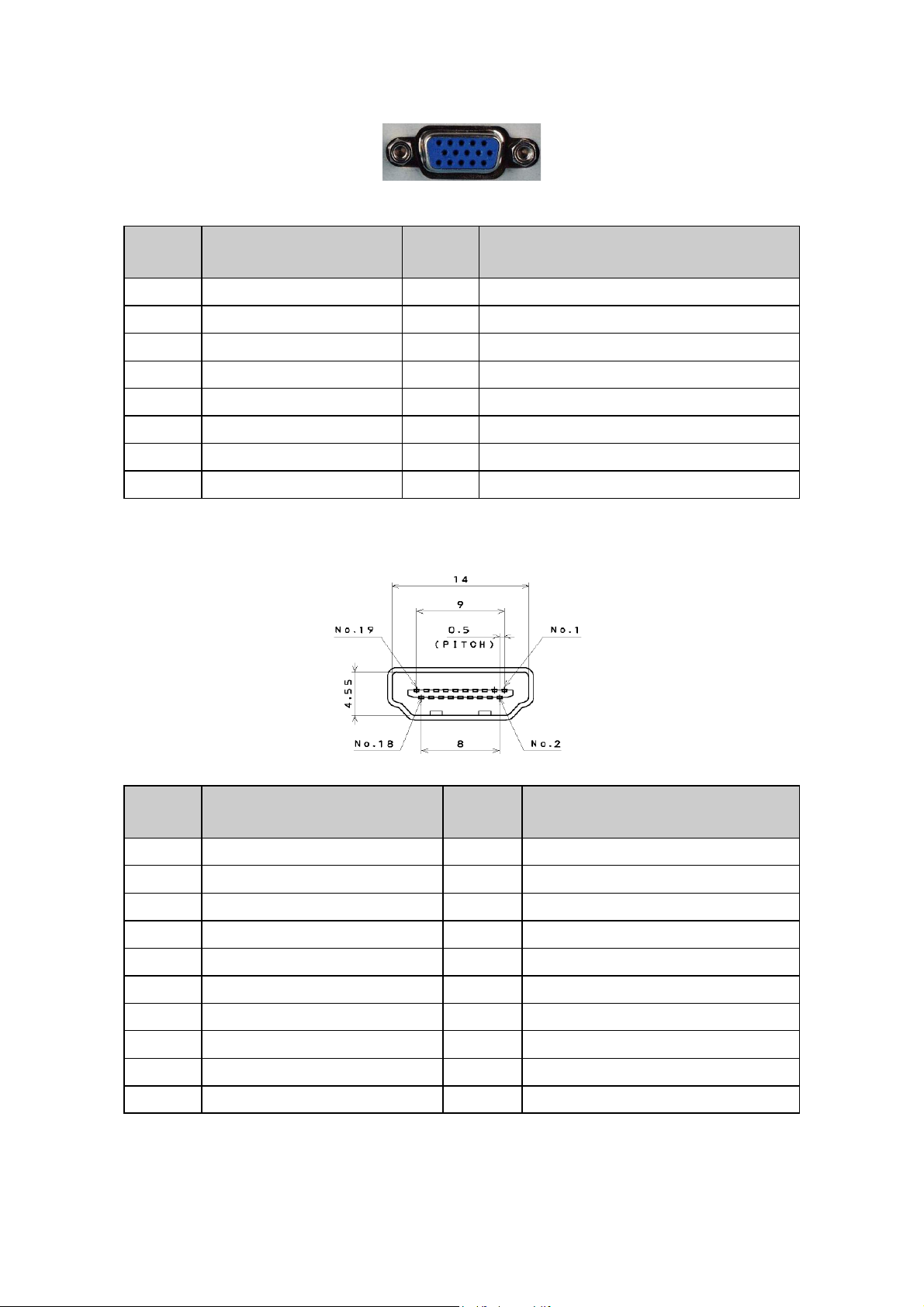
3. Input / Output Specification
RGB Signal Input
15 - Pin Color Display Signal Cable
Pin No. Description Pin No. Description
1 Red Video 9 +5V
2 Green Video 10 Sync Ground
3 Blue Video 11 Not Used
4 Not Used 12 Serial Data for DDC
5 Ground 13 H-Sync.
6 Red Ground 14 V-Sync.
7 Green Ground 15 Serial Clock for DDC
8 Blue Ground
HDMI Digital Connector Pin Assignments
Pin No. Description Pin No. Description
1 TMDS Data2+ 2 TMDS Data2 Shield
3 TMDS Data2- 4 TMDS Data1+
5 TMDS Data1 Shield 6 TMDS Data1-
7 TMDS Data0+ 8 TMDS Data0 Shield
9 TMDS Data0- 10 TMDS Clock+
11 TMDS Clock Shield 12 TMDS Clock13 CEC 14 NC
15 SCL 16 SDA
17 DDC/CEC Ground 18 +5V Power
19 Hot Plug Detect
9
Page 10
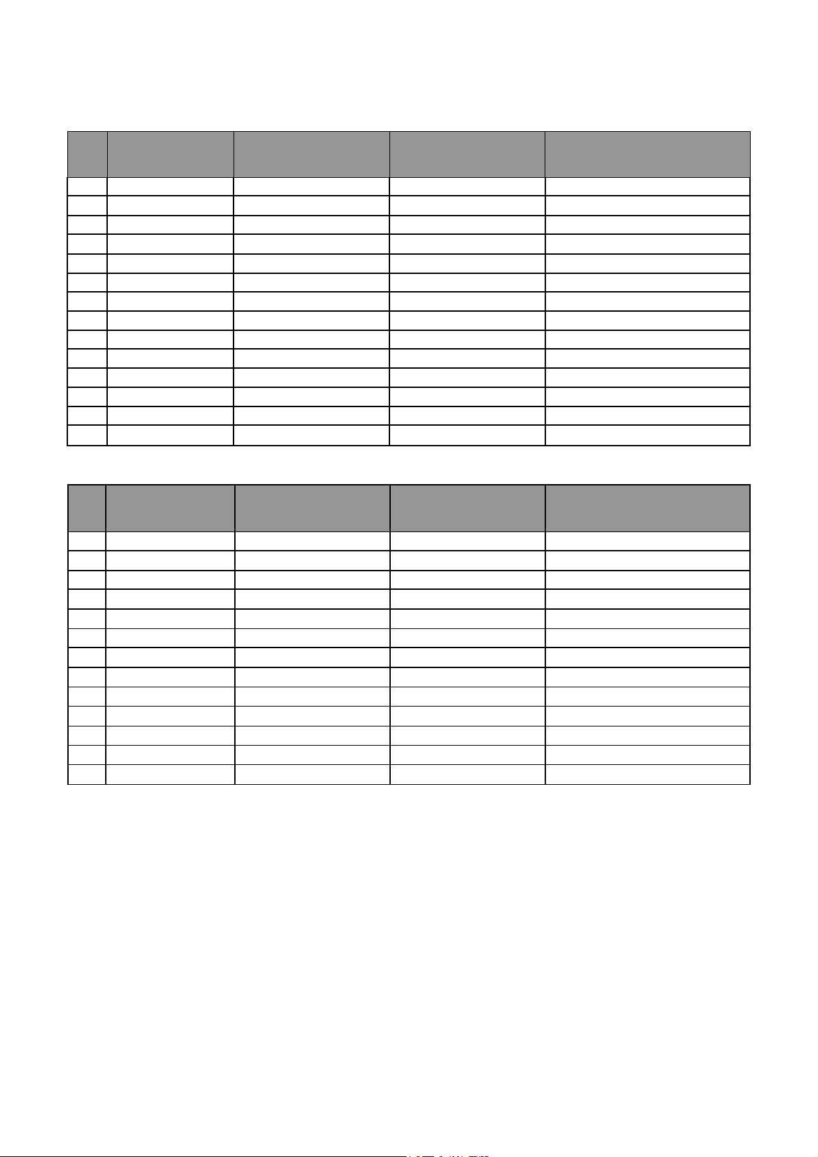
Compatible Mode Table
LE32D0330
HDMI Input Signal Timing
PC Timing
No Resolution H-freq.(kHz) V-freq. (Hz) Pixel clock (MHz)
1 640x480 31.469 59.940 25.175
2 640x480 37.861 72.809 31.500
3 640x480 37.500 75.000 31.500
4 720x400 31.469 70.087 28.322
5 800x600 35.156 56.250 36.000
6 800x600 37.879 60.317 40.000
7 800x600 48.077 72.188 50.000
8 800x600 46.875 75.000 49.500
9 1024x768 48.363 60.004 65.000
10 1024x768 56.476 70.069 75.000
11 1024x768 60.023 75.029 78.750
12 1280x768 47.776 59.870 79.500
13 1360x768 47.712 60.015 85.500
14 1280x1024 63.981 60.020 108.000
Video Timing
No Resolution H-freq(kHz) V-freq.(Hz) Pixel clock (MHz)
1 720*480 15.734 60 27
2 720*480 31.5 60 27.00/27.03
3 720*576 15.625 50 27
4 720*576 31.25 50 54
5 1280*720 37.5 50 74.25
6 1280*720 44.96 / 45 59.94 / 60 74.17/74.25
7 1920*1080 33.72 / 33.75 59.94 / 60 74.17/74.25
8 1920*1080 28.125 50 74.25
9 1920*1080 26.97/27 23.97/24 74.17/74.25
10 1920*1080 26.98 25 74.25
11 1920*1080 33.716/33.75 29.976/30.00 74.25
12 1920*1080 56.25 50 148.5
13 1920*1080 67.43/67.5 59.94/60 148.35/148.50
10
Page 11
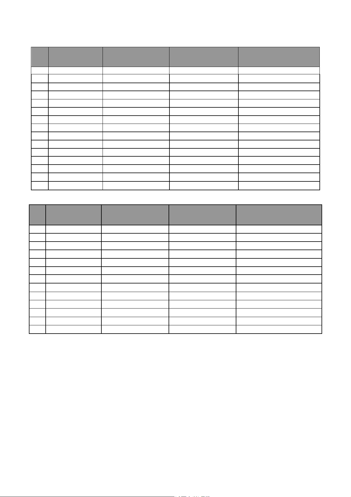
LE39D0330
HDMI Input Signal Timing
PC Timing
No Resolution H-freq.(kHz) V-freq. (Hz) Pixel clock (MHz)
1 640x480 31.469 59.940 25.175
2 640x480 37.861 72.809 31.500
3 640x480 37.500 75.000 31.500
4 720x400 31.469 70.087 28.322
5 800x600 35.156 56.250 36.000
6 800x600 37.879 60.317 40.000
7 800x600 48.077 72.188 50.000
8 800x600 46.875 75.000 49.500
9 1024x768 48.363 60.004 65.000
10 1024x768 56.476 70.069 75.000
11 1024x768 60.023 75.029 78.750
12 1280x768 47.776 59.870 79.500
13 1360x768 47.712 60.015 85.500
14 1280x1024 63.981 60.020 108.000
15 1280x1024 79.98 75.02 135.000
Video Timing
No Resolution H-freq(kHz) V-freq.(Hz) Pixel clock (MHz)
1 720*480 15.734 60 27
2 720*480 31.5 60 27.00/27.03
3 720*576 15.625 50 27
4 720*576 31.25 50 54
5 1280*720 37.5 50 74.25
6 1280*720 44.96 / 45 59.94 / 60 74.17/74.25
7 1920*1080 33.72 / 33.75 59.94 / 60 74.17/74.25
8 1920*1080 28.125 50 74.25
9 1920*1080 26.97/27 23.97/24 74.17/74.25
10 1920*1080 26.98 25 74.25
11 1920*1080 33.716/33.75 29.976/30.00 74.25
12 1920*1080 56.25 50 148.5
13 1920*1080 67.43/67.5 59.94/60 148.35/148.50
11
Page 12

4. Mechanical Instructions
Take LE32D0330 for example.
1. Remove the screws to remove BASE.
2. Remove the screws to remove REAR COVER.
12
Page 13
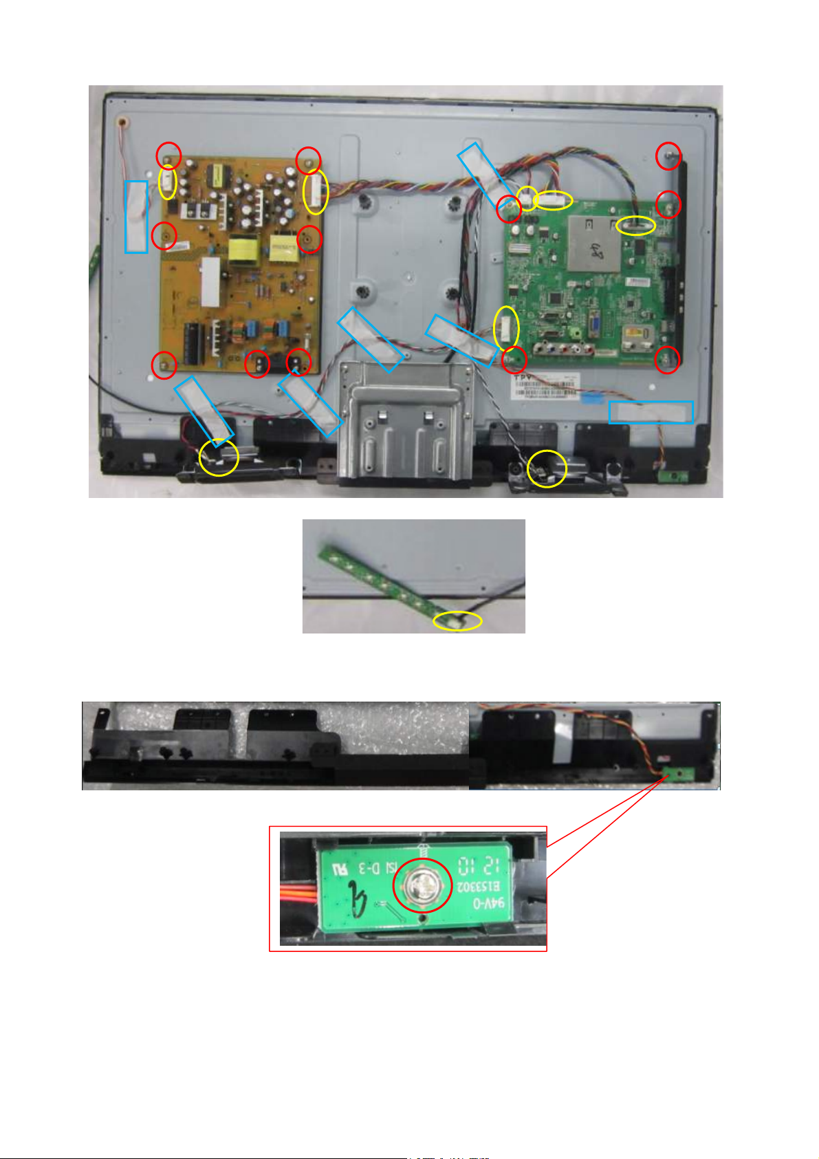
3. Remove the pins, taps and screws to remove SPEAKERS, MAIN BOARD, KEY BOARD and POWER BOARD.
4. Remove the IR board.
13
Page 14
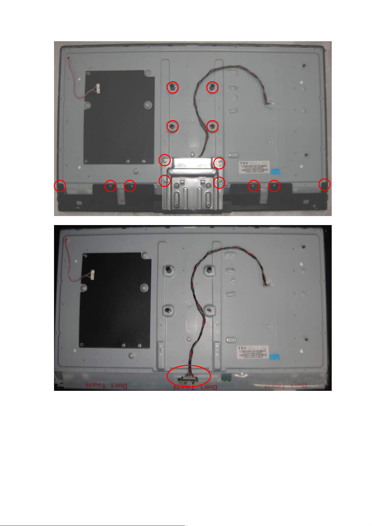
5. Remove the screws, and then remove the LVDS cable to remove the Panel.
14
Page 15
p
p
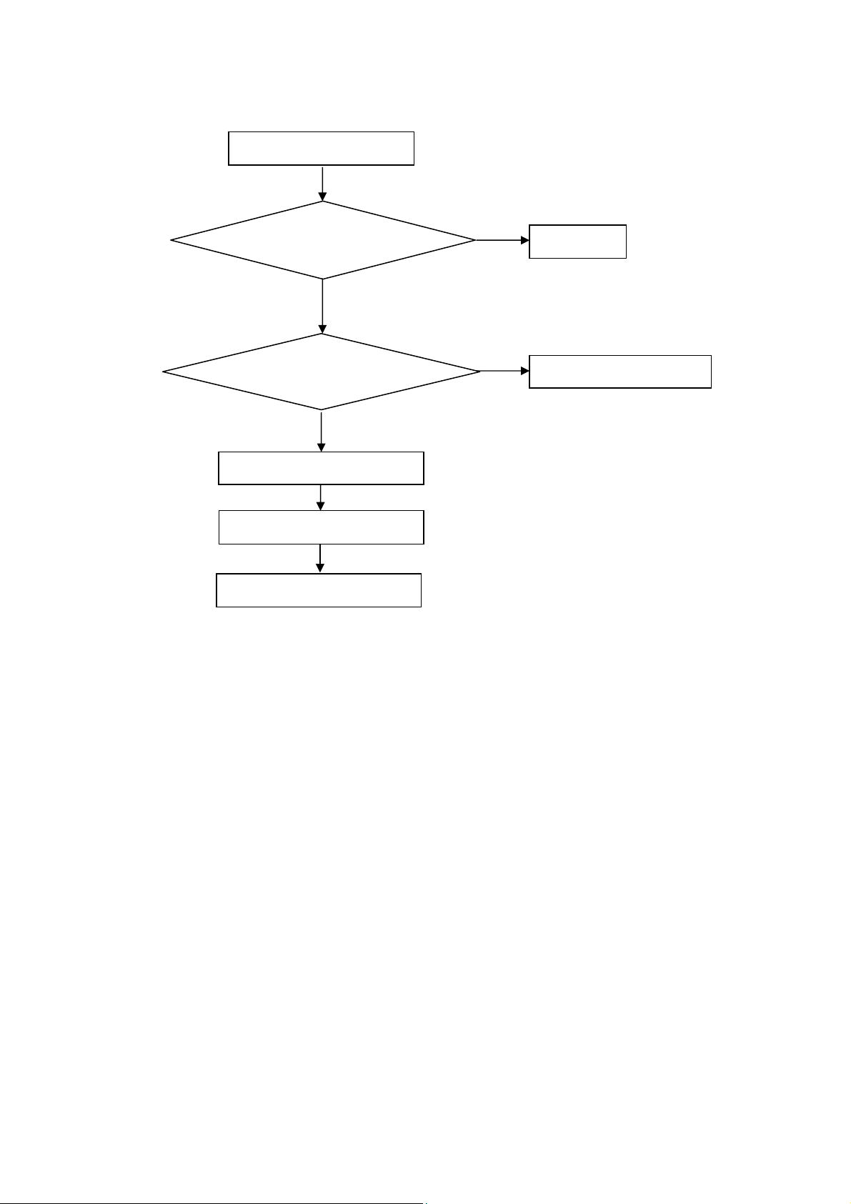
5. Repair Flow Chart
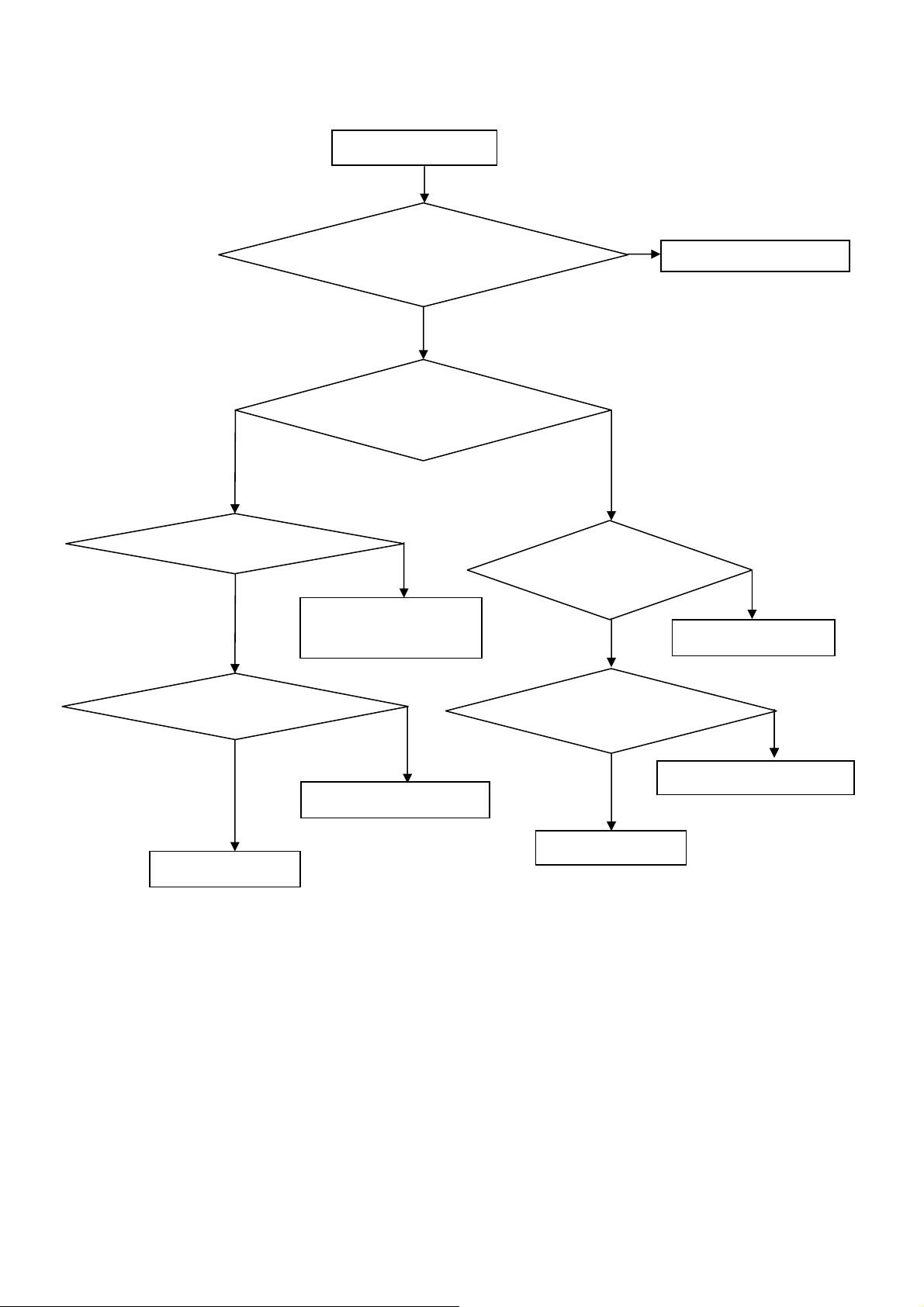
1. No power
No power (LED “Off”)
Check the AC input and
the
ower is “ON”?
Yes
Power board
out
ut=5.2V?
Yes
Check the IR board and LED
Replace the IR board
No
Replace the main board
No
Power “On”
No
Replace the power board
15
Page 16
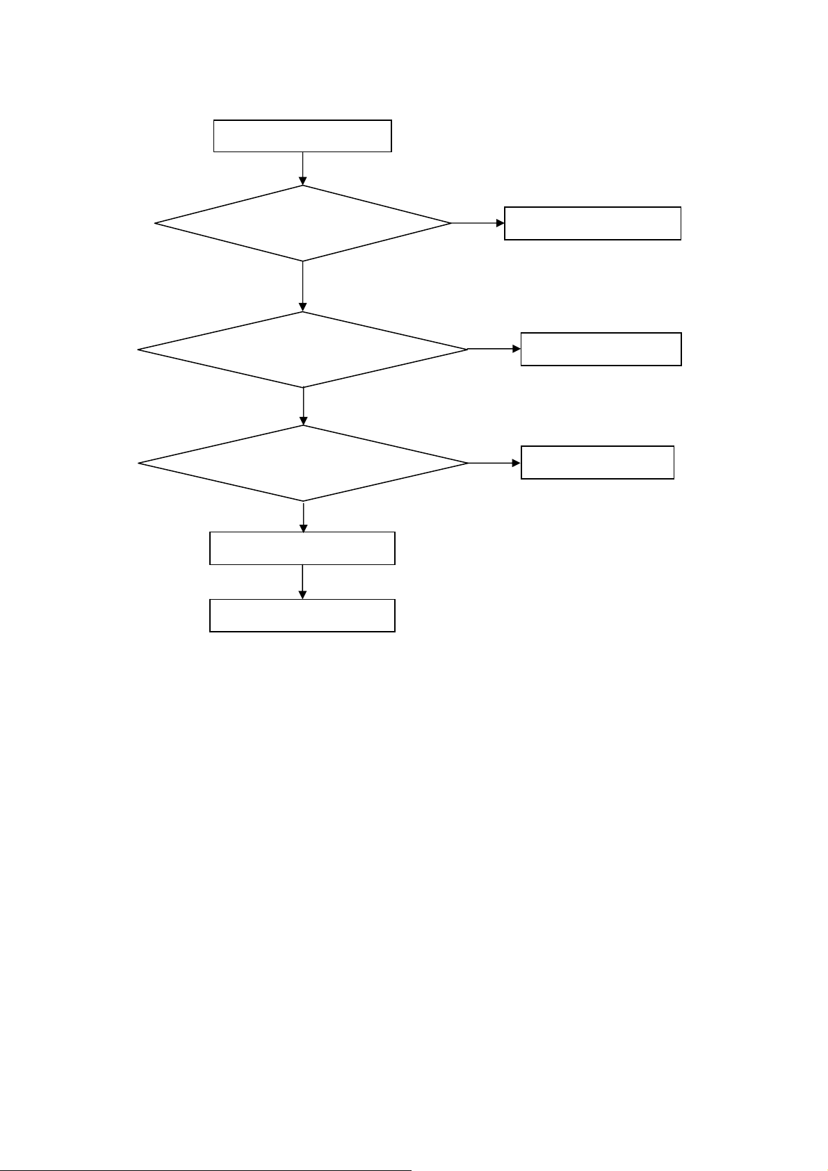
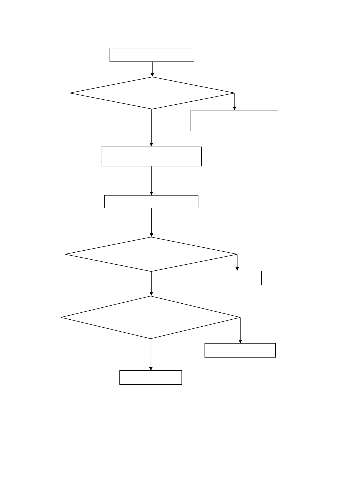
2. Can’t start
Can’t start (LED red)
Power board output=12/16V?
Yes
Check the power key is under control?
No
Check the IR receiver is normal?
No
Replace the power board
Yes
Replace the key board
Yes
Replace the IR board
No
Replace the main board
No
Replace the Power board
16
Page 17
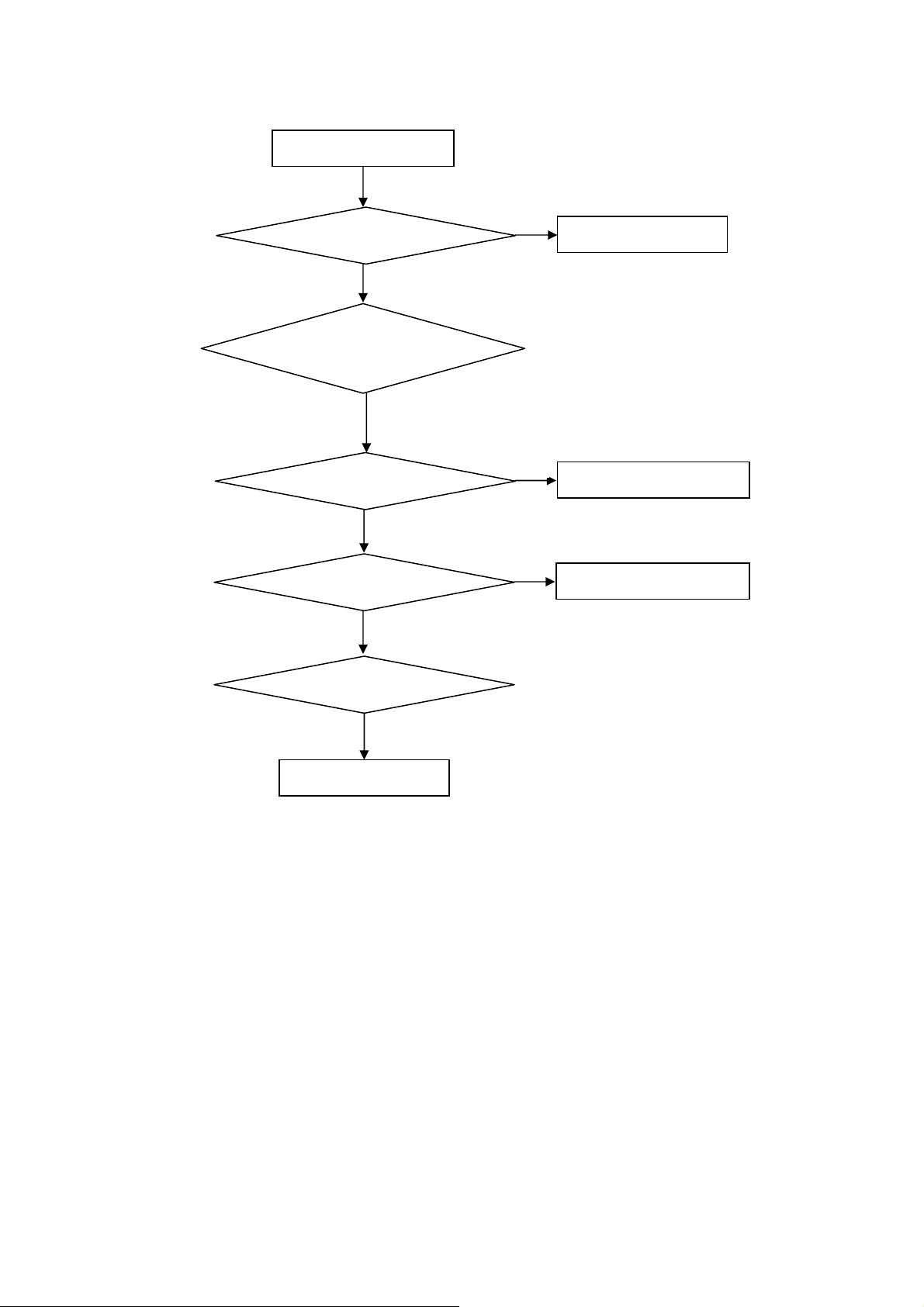
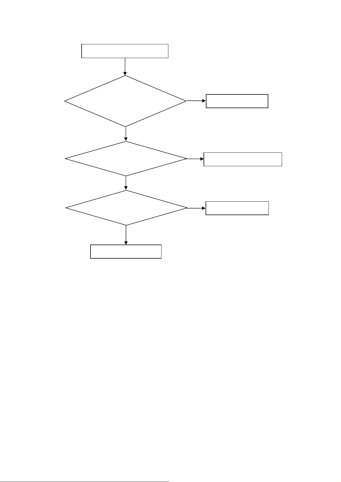
3. Abnormal display
Abnormal Display
Check the source
Yes
Enter factory mode to do
“EEPROM initial”&“Reset”
No
No
Reset the source
Check the main board
Yes
Check the LVDS cable
Yes
Check the panel
No
Replace the panel
No
Replace the main board
No
Replace the LVDS cable
17
Page 18
4. No display
No display (No LED)
Check TV is under control and power
on/off by remote control and power key?
Yes
Check the LVDS cable
Yes
Yes
Check the backlight is
“On”?
No
Reinsert or replace the
LVDS cable
No
No
Check the B/L
signal is available?
Yes
Replace the main board
No
Replace main board
Panel Vcc = 12V?
Yes
Replace the Panel
No
Replace the main board
Power board output=12/16V?
Yes
Replace the Panel
Replace the power board
No
18
Page 19
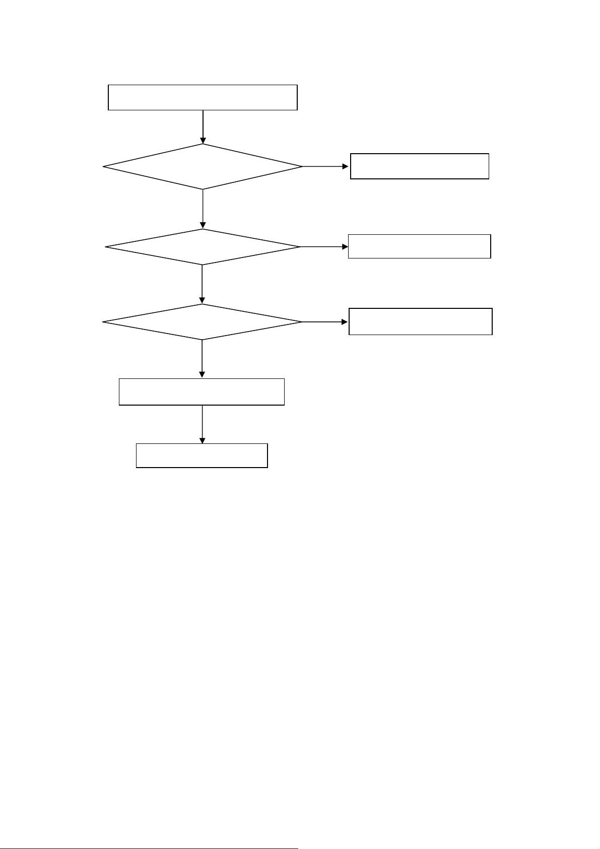
5. Sound problem
No sound or sound abnormal
Check the audio source connection
and the TV system are correct?
Yes
Check the TV is muted, adjust the
volume or enter the menu to reset?
No
No
Reinsert the audio cable or
change the TV system
Enter factory mode to do “Reset”
No
Check the cable between the
speakers and main board is OK?
Yes
Check the speaker resistance value is in spec
(Remark: The value is marked on the speaker)?
Yes
Replace the cable
Replace the main board
No
No
Replace the speaker
19
Page 20
6. Remote control malfunction
Remote Control malfunction
Check the remote control battery is
not properly placed or no power?
No
Use the other remote controls
No
Whether the IR board is
abnormal?
No
Replace the main board
Yes
Replace the battery
Yes
Replace the remote control
Yes
Replace the IR board
20
Page 21
7. OSD is unstable or can’t work normally
OSD is unstable or can’t work normally
Key board connected properly?
Yes
Buttons are OK?
Yes
Key board is OK?
Yes
Enter factory mode to do “Reset”
No
No
No
No
Reconnect the key board
Replace the button function
Replace the key board
Replace the main board
21
Page 22
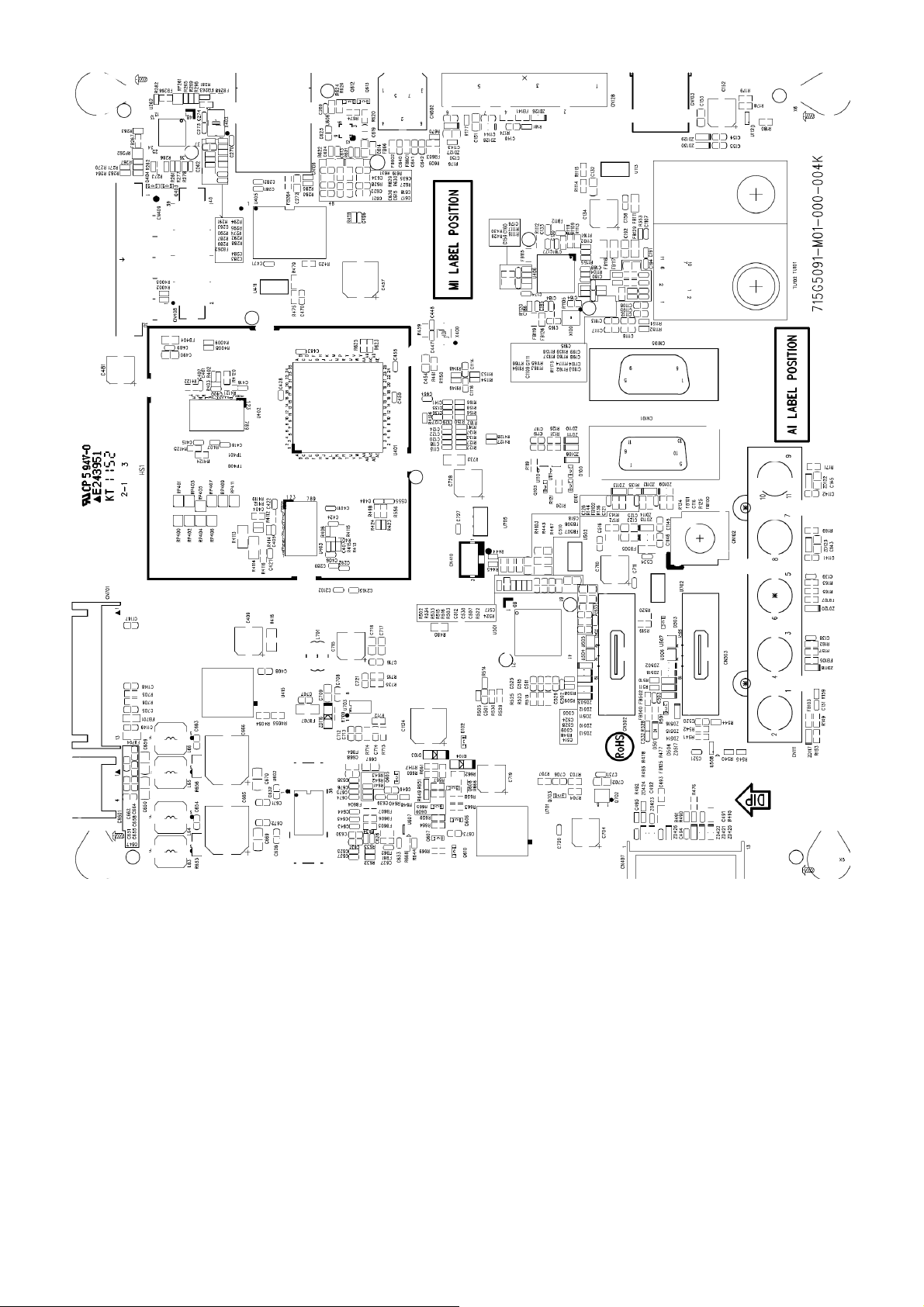
6. PCB Layout
6.1 Main Board
715G5091M01000004K
22
Page 23
23 24
Page 24
Page 25
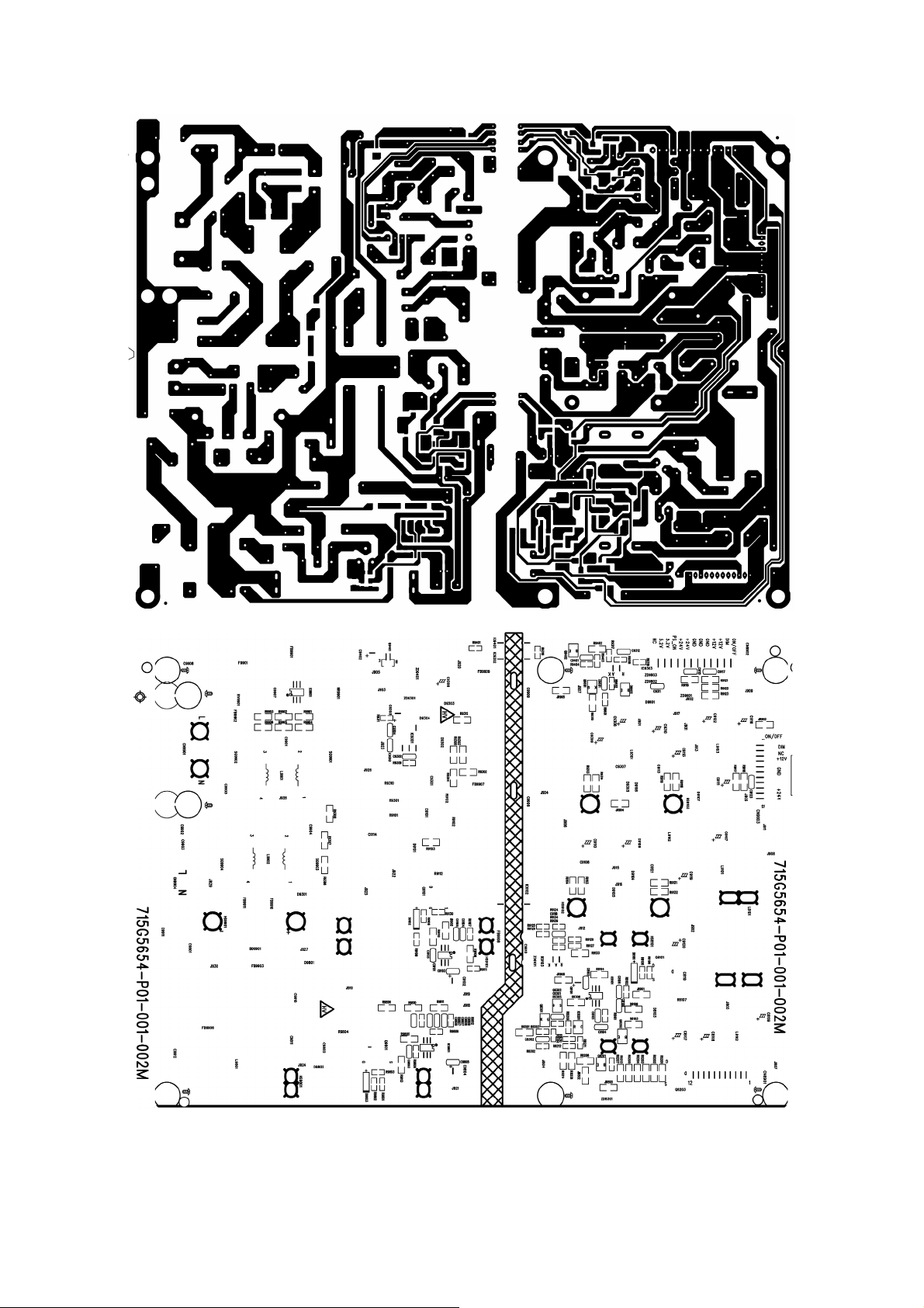
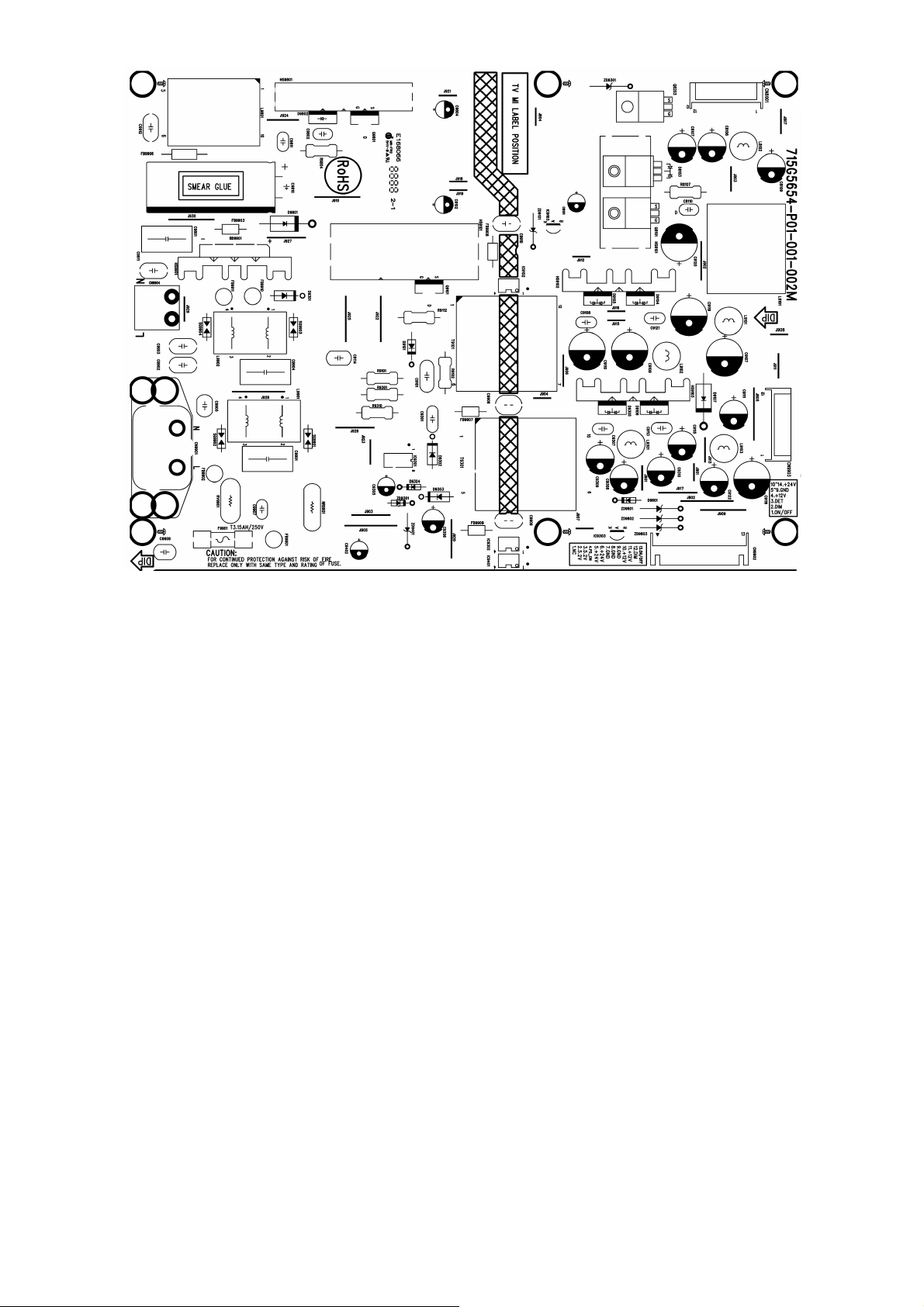
6.2 Power Board
715G5654P01001002M
25
Page 26
26
Page 27
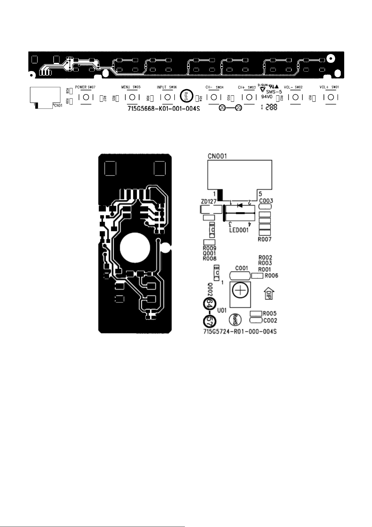
6.3 Key Board
715G5668K01001004S
6.4 IR Board
715G5724R01000004S
27
Page 28
7. Adjustment
(Take other model for example)
ADC Adjustment
1. Factory Mode
Turn on the TV. Press menu key and then press number key 1+9 +9+9+back. It will achieve the factory mode.
2. ADC Adjustment (It’s no need to adjust ADC.)
(1) Enter into the factory mode :(same as the above-mentioned)
(2) Select item “Source”: Ypbpr
a. Tim\pat. (COMPONENT mode: TIM = 314; PAT = 185,select item “auto color” and press ok key.
b. Tim\pat. (COMPONENT mode: TIM = 311; PAT = 185,select item “auto color” and press ok key.
(3) Select item “Source”: VGA
Tim\pat. (VGA mode: TIM = 137; PAT = 42,select item “auto color” and press ok key.
3. White Balance Adjustment
(1) Enter into the factory mode :(same as the above-mentioned).
(2) Just only adjust Ypbpr source.
a. Select item “Source”: Ypbpr and item “Color Temp”: Normal, Adjust gain of RGB to meet spec in the below
setting of Tim\pat. (COMPONENT mode: TIM = 314; PAT = 141(80IRE))
b. Select item “Source”: Ypbpr and item “Color Temp”:Warm, Adjust gain of RGB to meet spec in the below setting
of Tim\pat. (COMPONENT mode: TIM = 314; PAT = 141(80IRE))
c. Select item “Source”: Ypbpr and item “Color Temp”: Cool, Adjust gain of RGB to meet spec in the below setting
of Tim\pat. (COMPONENT mode: TIM = 314; PAT = 141(80IRE))
(3) check VGA TIM137,PAT141, AV TIM304 PAT141, HDMI TIM349 PAT141 , white balance whether or not meet
the specifications.
4.The following color specifications for reference, to RD engineering specifications.
Source VGA /YPbPr /AV/HDMI VGA /YPbPr /AV/HDMI VGA /YPbPr /AV/HDMI
Te mp
x (center)
y (center)
Note: 1、all models of color temperature within specification, but also ensure the brightness conform to
engineering specifications.
2、
RGB gain value cannot exceed 138,128,138.
Warm / 6500K) Normal / (9300K) Cool / (12350K)
0.313 0.02 0.285 0.02 0.270 0.02
0.329 0.02 0.293 0.02 0.273 0.02
28
Page 29
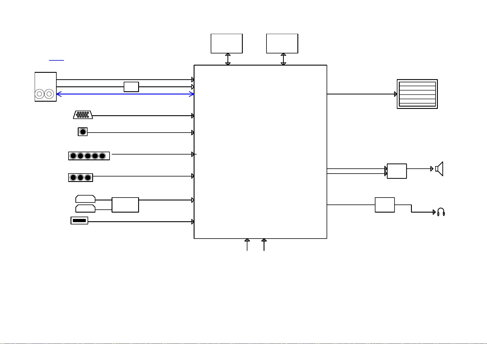
8. Block Diagram
I2C
U409
M24C32
NVM
H27U2G8F2CTR-BC
2Gb TSOP-48
U405
NA ND FLASH
SUT-RB211TV
TU101
CN101
D-SUB(PC IN)
CN102
PHONE JACK(PC R/L)
CN111
YPB PR +L ,R
CN128
composite
CN103
USB
IF
HDMI1
HDMI2
I2C
U501
HDMI SWITCH
MP3 & JPEG, &MPEG,SW UPD ATE
U406
DEMOD
USB 2.0
VGA
PC A UDIO
YPbPr
CV BS
MT5366
U401
CN408&CN409
LVDS (50/60 Hz)
AOU T_ L
AOU T_ R
AUD IO AMP
U606
HP amplifier
U602
amplifier
LCD PANEL T-CON
SPK R/L
HP R/L
SPK X 2
CN602
HEADPHONE
CN407
29
RCKEY
Page 30

9. Schematic Diagram
9.1 Main Board
715G5091M01000004K
H:7.7mm
CN701
MAIN POWER
1
2
3
4
5
6
7
8
9
10
11
12
13
CONN
+5VSB
C711
1UF 10V
+5V_SW
U701
G1084-33TU3Uf
VIN3VOUT
C720
1UF 10V
09/01 change temp
U702
VI3VO
GND
1
1.2 x (1+ 0/110) = 1.2V
U705
DVDD3V3
G912T63U
2
VI3VO
C727
1UF 10V
GND
1
GND14
4
2
2
TJ3940S-3.3
DVDD3V3
+
1 2
FB701
3V3SB
+
C719
100UF 16V
H:7.7mm
08/30 change
to 10*9
AVDD1V2
R732
0R05 4A 1/4W
C728
100UF 16V
120R/6000mA
C1149
1N 50V
C710
+
100UF 16 V
H:7mm
AVDD3V3
26",32",40"
BKL C ONTRO L
TYPE
PWM CONTROL
CMO26W/
SEC32F/SEC40F
DC-CONTROL
(3V3)
SEC32W AP12
DC-CONTROL
(5V)
INVERTER_ON_OF F
BRIGHT_ADJ
(+16V) for 22"
C1147
1N 50V
24V
+5VSB
C712
0.1uF 50V
C713
0.1uF 50V
C1148
1N 50V
C705
1uF 25V
+5VSB
1K 1/10W
OPWRSB
R119
N/C
N/C
4K7
FB704 120R/6000mA
1 2
R706
100K 1/10W
1uF 25V
3V3SB
R715
10K 1/10W
R123
R120
4K7
100R
5K6
1K
N/C
5K6
1K 1/10W
C707
R709
10OHM1/10W
1
2
3
R735
R705
1 2
FB707
80OHM 4A
U703
E-PAD
VCC
REF
GND
PGND
FB4EN
AT1529F11U
GMT
R624
N/C
N/C
15K
+12V
EMI solution 09/01/11"
+24V
STANDBY 13
HI = > POWER_ON
LO = > POW ER_OFF
9
8
VIN
7
LX
6
5
C127
REMARK
N/C
SEC32W AP12
22U
OLD Inverter lm p
260K
NEW Inverter
22U
lmp 28K
+5V Switch
C731
10N 50V
VCCK
R707
2.7K 1/10W
C706
NC/4U7 6V3
ZD116
C708
1uF 25V
RLZ6.8B
1 2
C714 180P 50V
R712
1K8 1/10W 1%
C721
1uF 25V
R714
R2
4.7K 1/1 0W
BRIGHT ADJUST
BL_DIMMING
INVERTER
ON/OFF
3V3
5V
C709
10uF 10V
L701
4.7uH
R713
100R 1/10W 5%
R1
4.7K 1/10W
+5VSB
5
R70322K 1/10W
C702
1uF25V
R704
51K 1/10W
Q703
BC847C
S
4
Vout = 0.8x(R1+R2)/R2
C716
C717
0.1uF 50V
10uF 10V
modify vcck feed back voltage
DVDD3V3 +5V_SW
R731
4.7K 1/1 0W
R720
NC/15K 1/ 10W
R725
R721 R722
N/C
2K
N/C4K7
T P V ( Top Victory Electronics Co . , Ltd. )
絬 隔 瓜 絪 腹
Key Component
Date
8
D6D7D
R723
D1D2D3G
NC/4K7 1/ 10W
Q705
MMBT3904
+5V_SW
Q702
AON4421
C704
+
220uF 16V
SMD H=7.7
C718
+
10uF 10V
DVDD3V3
R724
1K 1/10W
R728
100R 1/10W 5%
R733
NC/1K 1/ 10W
VCCK
C715
100UF 16V
H:10.5mm
Bright_Adj
Max:3.3V
Min: 0V
BRIGHT_ADJ
C726
NC/22 10V
Control Interface
Detection
INVERTER ON/OFF
3V3SB
INVERTER ON/OFF
H: OFF
L: ON
BL_ON/OF F
OEM MO DEL
TPV MODEL
PCB NAME
Sheet
R726
10K 1/10W
4.7K 1/1 0W
TBD B
CBPFB4FSAC
715G5091-M0G-000-0040
of
218Thursday, January 05, 2012
NC/4K7 1/ 10W
R730
+24V11
+5V_SW5,7,10,12, 13,14,15,16,17
+5VSB3,4, 6,9,17
+12V14,17
3V3SB6,7,9,13, 17
DVDD3V34,5,7,8, 9,10,11,12,13,14,15,16, 18
AVDD3V34,5,7,8, 9,10,11,12,13,14,15,16, 18
AVDD1V27,8,9,12, 14,15
VCCK9
OPWRSB9
BL_DIMMING13
BL_ON/OF F13
STANDBY13
DVDD3V3
+5V_SW
R721
Q704
MMBT3904
23
NC/MMBT3906 PNP
1
Q706
GND3,4,5,6, 7,8,9,10,11,12,13, 14,15,16,17,18
OPWRSB
BL_DIMMING
BL_ON/OFF
STANDBY
R722
2K 1/10W
INVER TER_ON_OFF
R734
NC/1K 1/ 10W
Size
A
Rev
称爹
称爹
<
+24V
+5V_SW
+5VSB
+12V
3V3SB
DVDD3V3
AVDD3V3
AVDD1V2
VCCK
24V24V
C725
10uF 10V
>
30
Page 31

VGA CONNECTOR
VGA11
VGASDA#
VSYN C#
VGASCL#
11
12
13
14
15
H:8.5mm
+5VSB2,4,6,9, 17
VGA Switch
VGA_PLUGPWR
1716
6
1
RED
7
G_G
2
GRN
8
3
BLUHSYNC#
9
4
10
5
CN101
D-SUB 15P
18 19
12
ZD108
TVM1G5 R5M1 00R
+5VSB
D100
1
BAV70
3
2
VGA_PLUGPWR
UART_SW
VGA11
1
2
10K 1/10W
R121
D101
BAV70
3
R120
1K 1/10W
VGA_PLUGPWR
BC847C
Q103
R119
10K 1/10W
VGASCL#
R107 10K 1/10W
VGASDA#
R111 10K 1/10W
C113
0.1uF 50V
U11 0
B1
S
GND
VCC
B0
A
NC7SB3 157P6X
U11 1
B1
S
GND
VCC
B0
A
NC7SB3 157P6X
1
2
3
1
2
3
VGASCL
U0RX
VGASDA
U0TX
6
5
4
0.1uF 50V
C114
6
5
4
L:B0 connected to A
H:B1 connected to A
I2C
Video Input
VGASCL12
VGASDA12
VSYN C12
HSYNC12
BP12
SOG12
GP12
VGACOM12
RP12
Other Control Interface
U0TX9, 17
U0RX9,17
UART_SW13
VGA_EEPROM_WP13
+5VSB
GND2,4,5,6, 7,8,9,10,11,12, 13,14,15,16,17,18
VGASCL
VGASDA
VSYN C
HSYNC
BP
SOG
GP
VGACOM
RP
U0TX
U0RX
UART_SW
VGA_EEPROM_WP
VGA SYNC SLICER
Wake Up TV From Power Saving Mode
VSYN C#
12
HSYNC#
ZD110
TVM1G5 R5M1 00R
12
ZD111
TVM1G5 R5M1 00R
R126
NC/2.2K 1/10W
R131
NC/2.2K 1/10W
C117
NC/5pF
C119
NC/5pF
VSYN C
HSYNC
Near VGA CONN.
BLU
GRN
G_G
RED
1 2
12
ZD109
TVM1G5 R5M1 00R
FB101 80 OHM
1 2
12
ZD112
TVM1G5 R5M1 00R
1 2
FB102
12
ZD113
TVM1G5 R5M1 00R
FB10080 OHM
R135
0R05 OHM
80 OHM
R125
75R 1/10W 1%
R134
75R 1/10W 1%
R144
75R 1/10W 1%
0R05 OHM
C116
15PF50V
C121
15PF50V
R136
C126
15PF50V
Near MT5366
R122
68 OHM +-5% 1/16W
ESD solution 11/09/2011
R127
22ohm 1/ 16W +/-1%
R133
68 OHM +-5% 1/16W
R137
100R 1/16W 5%
R141
68 OHM +-5% 1/16W
T P V ( Top Victory Electronics Co . , Ltd. )
絬 隔 瓜 絪 腹
Key Component
G5091-M0G-000-0040-2-111222
VGA
Date
C115
10N 50V
C118
1.5nF 50V
C120
10N 50V
C122
10N 50V
C124
10N 50V
BP
SOG
GP
VGACOM
RP
VGA EEPROM
100N 16V
U40 7
1
E0
2
E1
3
E2
VSS4SDA
M24C02-WDW6P
VGADDC WP
Q109
BC847C
OEM MO DEL
TPV MODEL
PCB NAME
TBD B
CBPFB4F SAC A
715G5091-M0G-000-0040
Sheet
of
318Thursday , January 05, 2012
VGA_PLUGPWR
C142
VCC
WC
SCL
R160 10K 1%
R161 10K 1%
R164 10K 1%
8
7
6
5
R170
2.2K 1/16W
R167 33R 1/16W 5%
R168 33R 1/16W 5%
VGADDC WP
H = > Enable
L = > Pr ote ct
VGA_EEPROM_WP
R118
4K7 1/16W 5%
Size
Rev
称爹
称爹
<
>
VGASCL
VGASDA
31
Page 32

CN111
A
B
C
D
E
RCA JACK
H:8.5mm
1N 50V
1
2
3
4
5
6
7
8
9
10
11
C1142
Y_IN_1
PB_IN_1
PR_IN _1
YPbPr1L_IN
TVM1G 5R5M1 00R
ZD122
C1141
1N 50V
1 2
FB10380 OHM
12
ZD117
TVM1G 5R5M1 00R
1 2
12
FB10580 OHM
ZD118
TVM1G 5R5M1 00R
ZD120
TVM1G 5R5M1 00R
1 2
1 2
FB10780 OHM
10uF 10V
10uF 10V
12
12
ZD123
TVM1G 5R5M1 00R
R149
18R 1/10W 5%
R153
56R 1/10W 1%
R157
18R 1/10W 5%
R162
56R 1/10W 1%
R163
56R 1/10W 1%
R165
18R 1/10W 5%
C143
C145
30K 1/10W 5%
YPbPr1 Audio Input
NEARLY CONN.
C131
15PF50V
R159
0R05 OHM
C138
15PF50V
C139
15PF50V
R169
30K 1/10W 5%
R171
improve ESD 11/09/2011
R182 22 OHM +-1% 1/16W
R150
68 OHM +-5% 1/16W
R156
68 OHM +-5% 1/16W
R158
68 OHM +-5% 1/16W
R166
68 OHM +-5% 1/16W
C127
1.5nF 50V
C129
10N 50V
C136
10N 50V
C135
10N 50V
C141
10N 50V
SOY0 12
Y0P 12
COM0 12
PB0P 12
PR0P 12
YPbPr_L_In1 12
YPbPr_R_In1 12
AVDD3 V32,7,12,14
AVDD3V3
GND2,3,5, 6,7,8,9, 10,11,12,13,14,15,16,17,18
32
T P V ( Top Victory Electronics Co . , Ltd. )
絬 隔 瓜 絪 腹
Key Component
G5091-M0G-000-0040-2-111222
YPBPR
Date
OEM MO DE L
TPV MO D EL
PCB N AME
Sheet
TBD B
CBPFB4FSAC A
715G5091-M0G-000-0040
418Wednes day , D ecem ber 28, 201 1
of
Size
Rev
称爹
<
称爹
>
Page 33

Side AV(CVBS)Video & Audio input
CN128
A
B
C
JACK
H:8.5mm
2
1
4
3
7
6
5
1N 50V
C1143
SIDE_C VBS_IN
SIDE_AudioLI N
SIDE_AudioR IN
C1144
1N 50V
FB141 80 OHM
1 2
12
75R 1/10W 1%
ZD126
TVM1G 5R5 M100R
12
ZD127
TVM1G 5R5 M100R
12
ZD128
TVM1G 5R5 M100R
R174
C150
10uF 10V
C151
10uF 10V
C148
47pF 50V
R176
30K 1/16W
R177
30K 1/16W
R173
100OHM1/16W
R181
0R05 1/16W
R175
100R 1/16W 5%
Near MT5366
C147 47N 16V
C149
47N 16V
AV2_L_In
AV2_R_In
CVBS1P
CVBS_COM
VGA Audio Input
CN102
PHONE J ACK
H:8.4mm
C1146
1N 50V
1
2
3
VGA_Audio_L_In
VGA_Audio_R_In
ZD114
TVM1G 5R5 M100R
C1145
1N 50V
12
12
Near CONN.
C123
10uF 10V
C125
10uF 10V
ZD115
TVM1G5R5M100R
R172
30K 1/10W 5%
R143
30K 1/10W 5%
VGA_L_In
VGA_R_In
Audio Input
GND2,3,4, 6,7,8,9,10, 11,12,13,14,15, 16,17,18
DVDD3V3
+5V_S W
DVDD3V32,4,7, 8,9,10,11,12, 13,14,15,16,18
+5V_S W2,7,10, 12,13,14,15,16, 17
Side AV Video & Audio
CVBS_COM
CVBS1P
AV2_L_In
AV2_R_In
USB_DP0
USB_DM0
USB_PWR_EN0
USB_OC_C OM
VGA_L_In
VGA_R_In
USB
CVBS_COM12
CVBS1P12
AV2_L_In12
AV2_R_In12
USB_DP014
USB_DM014
USB_PWR_EN013
USB_OC_C OM13
VGA_L_In12
VGA_R_In12
R180
4.7K 1/10W
+5V_SW
USB_PWR_EN0
HI = > POWER ON
LO = > POWER OFF
EQUAL LENGTH and DIFFERENTIAL
IMPEDANCE 90ohm
Near Connector
Power Distribution
Switch
U112
G5250K1T1U
4
IN
EN1OC
5
OUT
3
GND
2
USB_OC_COM
HI = > NORMAL
LO=> OC
DVDD3V3
R178
10K 1/10W
C152
100UF 16V
R179
100R 1/10W 1%
USB PORT 0
CN103
USB CONN
65
4
12
ZD129
TVM1G5R 5M100R
12
ZD130
3
2
1
TVM1G5R 5M100R
1234
T P V ( Top Victory Electronics Co . , Ltd. )
絬 隔 瓜 絪 腹
Key Component
G5091-M0G-000-0040-2-111222
SIDE AV/SPDIF/USB/SIDE HDMI
Date
OEM MO DE L
TPV MO DE L
PCB NAME
Sheet
TBD B
CBPFB4FSAC A
715G5091-M0G-000-0040
518Thursday , January 05, 2012
of
Size
Rev
称爹
称爹
>
<
USB_DP0
USB_DM0
C155 10PF 50V
C154 10PF 50V
+
C153
10uF 10V
33
Page 34

3V3SB
CEC_A1
CEC_A0
D501
BAS316
27K 1/10W 5%
R501
1 2
1 2
HD_CEC 7
FB50030R 0.7A
FB50230R 0.7A
OPWR1_5V7
OPWR0_5V7
3V3SB2,7, 9,13,17
+5VSB2,3,4,9, 17
GND2, 3,4,5,7,8,9, 10,11,12,13,14,15, 16,17,18
OPWR1_5V
OPWR0_5V
3V3SB
+5VSB
PORT 2
CN502 HDMI
22
SHELL3
23
SHELL4
24
SHELL5
25
SHELL6
26
SHELL7
100ohm diff ere ntial impe dance
for TMDS traces .
1
D2+
2
D2 Shield
3
D2-
4
D1+
5
D1 Shield
6
D1-
7
D0+
8
D0 Shield
9
D0-
10
CK+
11
CK Shield
12
CK-
DDC CLK
GND
+5V
HP DET
SHELL1
SHELL2
13
14
NC
15
16
17
18
19
20
21
CE Remote
DDC DATA
RR1X2+
RR1X2RR1X1+
RR1X1RR1X0+
RR1X0RR1XC+
RR1XCCEC_A1
DDC_SDA1
OPWR1_5V
HPD1
H:7.8mm
U504
1
RR1XC-
IN1
2
RR1XC+ RR1X1+
IN2
4
RR1X0-
IN3
5
RR1X0+
IN4
GND
8
10
RR1XC-
OUT1
9
RR1XC+
OUT2
7
RR1X0-
OUT3
6
RR1X0+
OUT4
GND
NC/ RClamp0524P.TCT
3
RR1X1-
RR1X2RR1X2+
1
2
4
5
+5VSB
OPWR1_5V
U505
IN1
IN2
IN3
IN4
GND
8
D503
1
2
BAV70
10
RR1X1-
OUT1
9
RR1X1+
OUT2
7
RR1X2-
OUT3
6
RR1X2+
OUT4
GND
NC/ RClamp0524P.TCT
3
3
100N 16V
C502
1 2
ZD510 TVM1G5R5M 100R
ZD511 TVM1G5R5M 100R
HPWR1
ZD512 TVM1G5R5M 100R
ZD513 TVM1G5R5M 100R
R508 47K 1/16W 5%
R509 47K 1/16W 5%
DDC_SCL1DDC_SCL1
DDC_SDA1
NC/TVM1G5R5M100R
PORT 1
CN503 HDMI
22
SHELL3
23
SHELL4
24
SHELL5
25
SHELL6
26
SHELL7
12
ZD502
ZD503
1 2
NC/TVM1G5R5M100R
100ohm differential impedance
for TMDS traces .
1
D2+
2
D2 Shield
3
D2-
4
D1+
5
D1 Shield
6
D1-
7
D0+
8
D0 Shield
9
D0-
10
CK+
11
CK Shield
12
CK-
DDC CLK
GND
+5V
HP DET
SHELL1
SHELL2
13
14
NC
15
16
17
18
19
20
21
CE Remote
DDC DATA
RR0X2+
RR0X2RR0X1+
RR0X1RR0X0+
RR0X0RR0XC+
RR0XCCEC_A0
HEC+
DDC_SCL0
DDC_SDA0
OPWR0_5V
HPD0
+5VSB
OPWR0_5V
1
2
D504
BAV70
3
100N 16V
C503
ZD514 TVM1G5R5M 100R
HDMI 2
HDMI 1
HPWR0
ZD516 TVM1G5R5M 100R
ZD515 TVM1G5R5M 100R
ZD517 TVM1G5R5M 100R
ZD518 TVM1G5R5M 100R
RR1X0-7
RR1X0+7
RR1X1-7
RR1X1+7
RR1X2-7
RR1X2+7
RR1XC-7
RR1XC+7
DDC_SCL17
DDC_SDA17
HPD17
RR0X0-7
RR0X0+7
RR0X1-7
RR0X1+7
RR0X2-7
RR0X2+7
RR0XC-7
RR0XC+7
DDC_SCL07
DDC_SDA07
HEC+7
HPD07
R510 47K 1/16W 5%
R511 47K 1/16W 5%
OPWR0_5VOPWR1_5V
RR1X0RR1X0+
RR1X1RR1X1+
RR1X2RR1X2+
RR1XCRR1XC+
DDC_SCL1
DDC_SDA1
HPD1
RR0X0RR0X0+
RR0X1RR0X1+
RR0X2RR0X2+
RR0XCRR0XC+
DDC_SCL0
DDC_SDA0
HEC+
HEC-
DDC_SCL0
DDC_SDA0
H:7.8mm
U506
1
RR0XC- RR0X1-
IN1
2
1 2
1 2
1 2
RR0XC+
RR0X0RR0X0+
IN2
4
IN3
5
IN4
GND
8
10
RR0XC-
OUT1
9
RR0XC+
OUT2
7
RR0X0-
OUT3
6
RR0X0+
OUT4
GND
NC/ RClamp0524P.TCT
3
RR0X1RR0X1+
RR0X2RR0X2+
U507
1
IN1
2
IN2
4
IN3
5
IN4
GND
8
10
OUT1
9
RR0X1+
OUT2
7
RR0X2-
OUT3
6
RR0X2+
OUT4
GND
NC/ RClamp0524P.TCT
3
1 2
1 2
1 2
1 2
1 2
34
T P V ( Top Victory Electronics Co . , Ltd. )
絬 隔 瓜 絪 腹
Key Component
G5091-M0G-000-0040-2-111222
HDMI CONNECTOR
Date
OEM MO DE L
TPV MODEL
PCB NAME
Sheet
TBD B
CBPFB4F SAC A
715G5091-M0G-000-0040
of
618Tuesday, December 27, 2011
Size
Rev
称爹
称爹
>
<
Page 35

AVCC 1V8
RR0XC-
RR0XC+
HPD0
19
20
18
16
15
U501
SiI9185AC TU
RPWR 1_5V
0.1uF 50V
0.1uF 50V
C507
C526
21
22
23
24
25
26
27
28
29
30
31
32
33
34
35
36
37
38
39
40
R0X0R0X0+
AVCC33
R0X1R0X1+
AGND
R0X2R0X2+
AVCC18
DSDA0
DSCL0
RPWR0
DVDD18
DGND
I2CSEL/INT
HPD1
AVCC18
R1XCR1XC+
AGND
RR0X0-
3V3SB_9185
AVCC1V8
DVDD1V8
3V3SB_9185
AVCC1V8
OPWR1_ 5V6
NC/100K 1/10W
3V3SB_9185 DVDD1V8
C504
10uF 10V
AVCC1V8
C523
10uF 10V
RR0X0+
RR0X1RR0X1+
RR0X2RR0X2+
DDC_SDA0
DDC_SCL0
RPWR0_5V
R513 4.7K 1/10W
HPD1
RR1XCRR1XC+
R519
0R05 OHM
R520
C514
NC/1uF 25V
C505
C524
C506
0.1uF 50V
C525
0.1uF 50V
10uF 10V
PCB LAYOUT: Place all decoupling capacitors (0. 1uf)as close to the pin
as p oss ible.
10uF 10V
17
HPD0
AGND
R0XC-
R0XC+
AVCC18
R1X0-41R1X0+42AVCC3343R1X1-44R1X1+45AGND46R1X2-47R1X2+48AVCC1849DSDA150DSCL151RPWR152CEC_D53CEC_A54AVCC3355HPD256AVCC1857R2XC-58R2XC+59AGND
RR1X0-
RR1X0+
RR1X1+
RR1X1-
3V3SB_9185 AVCC1V8
C509
C508
0.1uF 50V
0.1uF 50V
C527
0.1uF 50V
C528
0.1uF 50V
AVCC1V8
HDMISW_SDA#
HDMISW_SCL#
14
LSCL/PSEL1
RR1X2-
1K 1/16W 5 %
R512
HDMISW_RST#
M_RX1_CB
11
13
12
RESET#
ExtSW ING
LSDA/PSEL0
RR1X2+
DDC_SDA1
C510
10uF 10V
C529
0.1uF 50V
AVCC1V8
M_RX1_C
M_RX1_0B
M_RX1_0
8
9
10
7
TX0-
TXC-
TXC+
AGND
DDC_SCL1
RPWR 1_5V
R548
3V3SB_9185
3V3SB_9185
0.1uF 50V
0.1uF 50V
M_RX1_1B
M_RX1_1
5
4
6
TX1-
TX0+
AVCC18
TPWR/I2CADDR
10K 1/10W
C533
10N 50V
C511
C530
M_RX1_2B
2
3
TX1+
AGND
AVCC1V8
C512
0.1uF 50V
C531
0.1uF 50V
TPWR
M_RX1_2
NC/0R05 1/16W
1
TX2-
TX2+
AGND
TSC L
TSD A
HPDIN
TEST
DGND
DVDD18
RPWR2
DSCL2
DSDA2
AVCC18
R2X2+
R2X2AGND
R2X1+
R2X1-
AVCC33
R2X0+
R2X0-
60
EMI solution 09/01/11"
R502
80
79
78
77
76
75
74
73
72
71
70
69
68
67
66
65
64
63
62
61
OPWR0_5V6
3V3SB_9185
R533
NC/10K 1/16W 5%
R534
HDMI_SCL
HDMI_SDA
HPDIN
R503 0R05 1/16W
R525
NC/100K 1/10W
HDMISW_SCL#
HDMISW_SDA#
3V3SB_9185
R515
4.7K 1/10W
10K 1%
R523
0R05 OHM
R516
10K 1%
HDMI_HPD
DVDD1V8
AVCC1V8
3V3SB_9185
RPWR0_5V
C515
NC/ 1uF 25V
R529 0R05 OH M
R530 0R05 OH M
3V3SB_9185
HDMISW_RST#
C501
1uF 25V
3V3SB
1 2
C534
10N 50V
EMI solution 09/01/11"
OSCL1 9,11, 14
OSDA1 9,11,14
R514
10K 1%
R505
NC/0R05 1/16W
R545
NC/10K+ -5%1/16W
SPDI F_OUT
HI = > Disab le
LO = > Enab le
3V3SB_9185
FB505
220R/200 0mA
C516
1uF 16V
HDMI_SW_RST
ARC_OE
R540
10K 1%
U508
1
OE
VCC
2
A
GND3Y
SN74LVC1G125D BVR
DVDD3V3
5
4
180R 1/10W 1%
82R 1/10W 1%
R541
ARC
U502
G1117T63Uf
3
VIN
C517
NC/ 10U 10V
EMI solution 09/01/11"
T P V ( Top Victory Electronics Co . , Ltd. )
絬 隔 瓜 絪 腹
Key Component
Date
2
VOUT
GND
TH
1
4
R528
0R05 1/16W
C532
NC/22PF 50V
G5091-M0G-000-0040-2-111222
HDMI SWITCH
Tuesday , December 27, 2011
120R 1% 1/1 0W
56R 1/10W 1%
HD_CEC
HDMI_CEC
R522
R524
AVDD1V22,8,9, 12,14,15
AVDD3V32,4,5, 8,9,10,11, 12,13,14,15, 16,18
+5V_SW2, 5,10,12,13, 14,15,16,17
+5VSB2,3, 4,6,9,17
3V3SB2,6, 9,13,17
DVDD3V32, 4,5,8,9, 10,11,12,1 3,14,15,16, 18
OPWR1_5V6
OPWR0_5V6
U401G
GND2, 3,4,5,6, 8,9,10,11, 12,13,14,15, 16,17,18
HECC+
R542
10uF 10V
MT5366
HDMI_CEC
HDMI_HPD
HDMI_SCL
HDMI_SDA
AVDD33_H DMI
AVDD12_H DMI
AVSS33_HDMI
C521
100N 16V
C520
1uF 25V
FB506
1 2
220R/20 00mA
FB507
1 2
220R/20 00mA
C518
RX_0
RX_0B
RX_1
RX_1B
RX_2
RX_2B
RX_C
RX_CB
PWR5V
MT5366GSNG
OEM MODEL
TPV MOD EL
PCB N AME
Sheet
AVDD1V2
AVDD3V3
+5V_SW
+5VSB
3V3SB
DVDD3V3
OPWR1_ 5V
OPWR0_ 5V
HDMI 2
HDMI 1
HEC+
100K1/16W
R544
DDC_SDA16
DVDD1V8
AVCC1V8
AE3
M_R X1_0
AD3
M_R X1_0B
AE4
M_R X1_1
AD4
M_R X1_1B
AE5
M_R X1_2
AD5
M_R X1_2B
AE2
M_R X1_C
AD2
M_R X1_CB
AB6
HDMI_CEC
AC6
HDMI_HPD
AC5
HDMI_SCL
AB5
HDMI_SDA
AD6
TPW R
AE1
AVDD33_H DMI
AA6
AVDD12_H DMI
AC4
TBD B
CBPFB4F SAC A
715G5091-M0G-000-0040
of
7
18
DDC_SCL16
DDC_SDA06
DDC_SCL06
SPDIF _OUT12
HD_CEC6
HDMI_SW_RST13
Ana lo g Power
AVDD3V3
R556
0R05 OHM
AVDD1V2
R560
0R05 OHM
RR1X0-6
RR1X0+6
RR1X1-6
RR1X1+6
RR1X2-6
RR1X2+6
RR1XC-6
RR1XC+6
RR0X0-6
RR0X0+6
RR0X1-6
RR0X1+6
RR0X2-6
RR0X2+6
RR0XC-6
RR0XC+6
OSDA19,11, 14
HEC+6
HPD06
ARC_OE13
HPD16
HPD06
OSCL19,11,14
RR1X0RR1X0+
RR1X1RR1X1+
RR1X2RR1X2+
RR1XCRR1XC+
HPD1
RR0X0RR0X0+
RR0X1RR0X1+
RR0X2RR0X2+
RR0XCRR0XC+
HPD0
OSDA1
OSCL1
DDC _SDA1
DDC_SCL1
DDC _SDA0
DDC_SCL0
HEC+
HECSPDIF _OUT
HD_CEC
HDMI_SW_RST
ARC_OE
( 17 mA )
AVDD33_H DMI
( 61 mA )
AVDD12_H DMI
Size
Rev
称爹
称爹
<
C555
100N 16V
C556
100N 16V
>
35
Page 36

RDQ0
RDQ1
RDQ2
RDQ3
RDQ4
RDQ5
RDQ6
RDQ7
RDQ8
RDQ9
RDQ10
RDQ11
RDQ12
RDQ13
RDQ14
RDQ15
RDQ16
RDQ17
RDQ18
RDQ19
RDQ20
RDQ21
RDQ22
RDQ23
RDQ24
RDQ25
RDQ26
RDQ27
RDQ28
RDQ29
RDQ30
RDQ31
RDQS0
RDQS0#
RDQS1
RDQS1#
RDQS2
RDQS2#
RDQS3
RDQS3#
RDQM0
RDQM1
RDQM2
RDQM3
RCLK0
RCLK0#
RCLK1
RCLK1#
1_RST#
AVDD12_MEMPLL
MEMTP
MEMTN
DDRV
C425
10uF
MT5366
U401B
D13
RDQ6//RDQ0
D12
RDQ0//RDQ1
E13
RDQ1//RDQ2
D11
RDQ7//RDQ3
D14
RDQ4//RDQ4
E12
RDQ5//RDQ5
E14
RDQ3//RDQ6
E11
RDQ2//RDQ7
B10
RDQ13//RDQ8
B15
RDQ11//RDQ9
A10
RDQ10//RDQ10
A15
RDQ12//RDQ11
C11
RDQ15//RDQ12
C15
RDQ9//RDQ13
C10
RDQ8//RDQ14
C14
RDQ14//RDQ15
G5
RDQ22//RDQ16
J5
RDQ23//RDQ17
H5
RDQ17//RDQ18
J4
RDQ16//RDQ19
H4
RDQ20//RDQ20
K4
RDQ21//RDQ21
G4
RDQ19//RDQ22
K3
RDQ18//RDQ23
J1
RDQ26//RDQ24
D2
RDQ27//RDQ25
J2
RDQ29//RDQ26
C1
RDQ28//RDQ27
H3
RDQ31//RDQ28
D1
RDQ25//RDQ29
J3
RDQ24//RDQ30
E2
RDQ30//RDQ31
B13
RDQS0//RDQS0
A13
RDQS0_// RDQS0_
A12
RDQS1//RDQS1
B12
RDQS1_// RDQS1_
F2
RDQS2//RDQS2
F1
RDQS2_// RDQS2_
G1
RDQS3//RDQS3
G2
RDQS3_// RDQS3_
C12
RDQM0//RDQM0
C13
RDQM1//RDQM1
G3
RDQM2//RDQM2
E1
RDQM3//RDQM3
A9
RCLK0//RCLK0
B9
RCLK0_//RCLK0_
K1
RCLK1//RCLK1
K2
RCLK1_//RCLK1_
C6
RBA2//R RESET_
H9
AVDD12_MEMPLL
H10
AVSS12_MEMPLL
D8
MEMTP
C8
MEMTN
TP400
TP401
C426
100N 16V
100N 16V
U401B
100N 16V
C427
C4
RCAS_//R A0
F9
RA6//RA1
C5
RBA0//R A2
A7
RA5//RA3
F8
RA4//RA4
D5
RBA1//R A5
D7
RA13//RA6
A6
RA10//RA7
E6
NC//RA8
B7
RA3//RA9
E8
RA12//RA10
F7
RA11//RA11
D6
RA0//RA12
B6
RA1//RA13
B4
RCKE//RWE_
A3
RODT//RODT
B3
RRAS_// RCAS_
A4
RWE_//RCS_
A2
RCS_// RRAS_
D9
RA9//RCKE
E7
RA8//RBA0
E9
RA2//RBA1
C7
RA7//RBA2
E3
RVREF
C16
VCC2IO
B16
VCC2IO
A16
VCC2IO
F15
VCC2IO
E15
VCC2IO
D15
VCC2IO
H14
VCC2IO
H13
VCC2IO
C2
VCC2IO
D3
VCC2IO
K8
VCC2IO
J8
VCC2IO
H8
VCC2IO
B1
VCC2IO
F6
VCC2IO
E5
VCC2IO
D4
VCC2IO
C3
VCC2IO
B2
VCC2IO
A1
VCC2IO
E4
VCC2IO
F5
VCC2IO
G6
VCC2IO
F14
VCC2IO
L3
DVSS
L4
DVSS
L5
DVSS
L6
DVSS
K6
DVSS
C9
DVSS
F11
DVSS
F12
DVSS
E10
DVSS
J6
DVSS
F10
DVSS
H11
DVSS
K7
DVSS
H12
DVSS
Main Chip Bottom Sid e
100N 16V
C429
100N 16V
C428
MT5366 DE-CAP.
1_A0
1_A1
1_A2
1_A3
1_A4
1_A5
1_A6
1_A7
1_A8
1_A9
1_A10
1_A11
1_A12
1_A13
1_WE#
1_ODT
1_CAS#
1_CS#
1_RAS#
1_CKE
1_BA0
1_BA1
1_BA2
RVREF5
DDRV
RVREF_as closed to U402
DDRV
R402
1K 1/16W 1%
C401
R403
100N 16V
1K 1/16W 1%
RVREF_as closed to U402
DDRV
R410
1K 1/16W 1%
R411
C402
100N 16V
1K 1/16W 1%
DRAM POWER DDRV
DVDD3V3
C430
C431
100N 16V
240 OHM +-5% 1/16W
1_DDRV_C1
RVREF1
C400
1_DDRV_F1
100N 16V
1_DDRV_H9
RVREF2
C403
100N 16V
VIN3VOUT
C408
1uF 25V
U402
DDR3#1
E3
RDQ0
DQL0
F7
RDQ1
DQL1
F2
RDQ2
DQL2
F8
RDQ3
DQL3
H3
RDQ4
DQL4
H8
RDQ5
DQL5
G2
RDQ6
DQL6
H7
RDQ7
DQL7
D7
RDQ8
DQU0
C3
RDQ9
DQU1
C8
RDQ10
DQU2
C2
RDQ11
DQU3
A7
RDQ12
DQU4
A2
RDQ13
DQU5
B8
RDQ14
DQU6
A3
RDQ15
DQU7
C7
RDQS1
UDQS
B7
RDQS1#
UDQS#
F3
RDQS0
LDQS
G3
RDQS0#
LDQS#
D3
RDQM1
UDM
E7
RDQM0
LDM
T2
B_RST# CLK0#
RESET#
L8
ZQ1
RVREF1
U415
DDRV
ADJ/GN D
120R 1% 1/10W
1
ZQ
A1
VDDQ_0
A8
VDDQ_1
C1
VDDQ_2
C9
VDDQ_3
D2
VDDQ_4
E9
VDDQ_5
F1
VDDQ_6
H2
VDDQ_7
H9
VDDQ_8
B2
VDD_0
D9
VDD_1
G7
VDD_2
VDD_3K2VSS_3
K8
VDD_4
N1
VDD_5
N9
VDD_6
R9
VDD_8
R1
VDD_7
H1
VREFDQ
H5TQ1G63DFR-H9C
2
R4054
R405524R 1/ 10W 1%
R400
1_DDRV_N9
1_DDRV_R9
1_DDRV_R1
A10/AP
A11
A12/BC#
NC
NC_0
NC_1
NC_2
NC_3
NC_4
NC_6
BA0
BA1
BA2
CK
CK#
CS#
CAS#
ODT
RAS#
WE#
CKE
VSSQ_0
VSSQ_1
VSSQ_2
VSSQ_3
VSSQ_4
VSSQ_5
VSSQ_6
VSSQ_7
VSSQ_8
VSS_0
VSS_1
VSS_2
VSS_4
VSS_5
VSS_6
VSS_7
VSS_8
VSS_9
VSS_10
VSS_11
VREFCA
DDRV
R416
0R05 4A 1/4W
C409
+
220uF 16V
H:6.7mm
N3
A0
P7
A1
P3
A2
N2
A3
P8
A4
P2
A5
R8
A6
R2
A7
T8
A8
R3
A9
L7
R7
N7
T3
J1
J9
L1
L9
M7
T7
M2
N8
M3
J7
K7
L2
K3
K1
J3
L3
K9
B1
B9
D1
D8
E2
E8
F9
G1
G9
A9
B3
E1
G8
J2
J8
M1
M9
P1
P9
T1
T9
M8
C410
100N 16V
Damping for DDR#1 ADDR/CMD
B_A0
B_A1
B_A2
B_A3
B_A4
B_A5
B_A6
B_A7
B_A8
B_A9
B_A10
B_A11
B_A12
B_A13
B_BA0
B_BA1
B_BA2
CLK0
B_CS#
B_CAS#
B_ODT
B_RAS#
B_WE#
B_CKE
RP400 100 OHM 1/16W
1
A_BA0
A_A5
A_A7
A_RST#
A_A9
A_A13
A_A2
A_A3
A_A0
A_BA2
A_WE#
A_CS#
A_ODT
A_CAS#
A_RAS#
A_A11
A_A1
A_A4
A_A6
A_A8
A_CKE 1_A12
A_A10
A_A12
A_BA1
Damping and Termination for CLK
Near MT5366 NEAR DRAM NEAR DRAMNear MT5366
RCLK1
RCLK1#
8
2
7
3
6
4
5
RP402 100 OHM 1/16W
1
8
2
7
3
6
4
5
RP404 100 OHM 1/16W
1
8
2
7
3
6
4
5
0R05 1/16W
R4129
RP406 100 OHM 1/16W
1
8
2
7
3
6
4
5
RP408 100 OHM 1/16W
1
8
2
7
3
6
4
5
RP410 100 OHM 1/16W
1
8
2
7
3
6
4
5
CLK1 CLK0
R406
100R 1/16W 5%
RVREF_as closed to U403
DDRV
RVREF2
R412
1K 1/16W 1%
C404
R414
100N 16V
1K 1/16W 1%
For 2 layer Layout
DDRV
R4120
0R05 OHM
R4121
0R05 OHM
R4122
0R05 OHM
1_DDRV_H9
R4123
0R05
R4124
0R05 OHM
0R05 OHM
R4125
RVREF3
1_DDRV_F1
1_DDRV_R1
1_DDRV_N9
1_DDRV_C 1
Damping for DDR#2 ADDR/CMD
NEAR BRANCHNEAR BRANCH
RP401 100 OHM 1/16W
1_BA0
1_A5
1_A7
1_RST#
1_A9
1_A13
1_A2
1_A3
1_A0
1_BA2
1_WE#
1_ODT
1_CAS#
1_RAS#
1_A11
1_A1
1_A4
1_A6
1_A8
1_CKE
1_A10
1_A12
1_BA1
1_BA0
1_A5
1_A7
1_RST#
RP403100 O HM 1/16W
1_A3
1_A2
1_A13
1_A9
RP405 100 OHM 1/16W
1_A0
1_BA2
1_WE#
1_CS#
1_CS#
R4130
1_ODT
1_CAS#
1_RAS#
1_A11
RP409 100 OHM 1/16W
1_A8
1_A6
1_A4
1_A1
RP411 100 OHM 1/16W
1_BA1
1_A10
1_CKE
Damping and Termination for CLK
RCLK0
RCLK0#
RVREF_as closed to U403
DDRV
R413
1K 1/16W 1%
C405
100N 16V
1_DDRV_R9
C406
100N 16V
1K 1/16W 1%
1
8
2
7
3
6
4
5
1
8
2
7
3
6
4
5
1
8
2
7
3
6
4
5
0R05 1/16W
RP407 100 OHM 1/16W
1
8
2
7
3
6
4
5
1
8
2
7
3
6
4
5
1
8
2
7
3
6
4
5
R407
100R 1/16W 5%
CLK0#CLK1#
RVREF4
R415
C407
100N 16V
B_BA0
B_A5
B_A7
B_RST#
B_A3
B_A2
B_A13
B_A9
B_A0
B_BA2
B_WE#
B_CS#
B_ODT
B_CAS#
B_RAS#
B_A11
B_A8
B_A6
B_A4
B_A1
B_BA1
B_A12
B_A10
B_CKE
2_DDRV_A8
2_DDRV_C 1
2_DDRV_C 9
2_DDRV_F 1
2_DDRV_H 9
2_DDRV_N1
2_DDRV_R1
DDR3#2
RDQ16
RDQ17
RDQ18
RDQ19
RDQ20
RDQ21
RDQ22
RDQ23
RDQ24
RDQ25
RDQ26
RDQ27
RDQ28
RDQ29
RDQ30
RDQ31
RDQS3
RDQS3#
RDQS2
RDQS2#
RDQM3
RDQM2
A_RST#
ZQ2
R401
240 OHM +-5% 1/16W
RVREF3
DDRV
E3
F7
F2
F8
H3
H8
G2
H7
D7
C3
C8
C2
A7
A2
B8
A3
C7
B7
F3
G3
D3
E7
T2
L8
A1
A8
C1
C9
D2
E9
F1
H2
H9
B2
D9
G7
K8
N1
N9
R9
R1
H1
DDRV
0R05 OHM
0R05 OHM
2_DDRV_N1
2_DDRV_H9
2_DDRV_C9
U403U402
U403
DQL0
A0
DQL1
A1
DQL2
A2
DQL3
A3
DQL4
A4
DQL5
A5
DQL6
A6
DQL7
A7
DQU0
A8
DQU1
A9
DQU2
A10/AP
DQU3
A11
DQU4
A12/BC#
DQU5
NC
DQU6
NC_0
DQU7
NC_1
NC_2
UDQS
NC_3
UDQS#
NC_4
LDQS
NC_6
LDQS#
UDM
BA0
LDM
BA1
BA2
CK
CK#
RESET#
CS#
CAS#
ZQ
ODT
RAS#
WE#
CKE
VSSQ_0
VDDQ_0
VSSQ_1
VDDQ_1
VSSQ_2
VDDQ_2
VDDQ_3
VSSQ_3
VDDQ_4
VSSQ_4
VSSQ_5
VDDQ_5
VSSQ_6
VDDQ_6
VSSQ_7
VDDQ_7
VDDQ_8
VSSQ_8
VDD_0
VSS_0
VDD_1
VSS_1
VSS_2
VDD_2
VDD_3K2VSS_3
VSS_4
VDD_4
VDD_5
VSS_5
VSS_6
VDD_6
VSS_7
VDD_8
VSS_8
VDD_7
VSS_9
VSS_10
VSS_11
VREFDQ
VREFCA
H5TQ1G63DFR-H9C
For 2 layer Layout
R4119
R4112
0R05 OHM
R4113
R4114
0R05
0R05
R4115
R4116
0R05 OHM
2_DDRV_C 9
R4117
0R05
2_DDRV_A8
R4118
0R05
C4009
10uF 10V
N3
P7
P3
N2
P8
P2
R8
R2
T8
R3
L7
R7
N7
T3
J1
J9
L1
L9
M7
T7
M2
N8
M3
J7
K7
L2
K3
K1
J3
L3
K9
B1
B9
D1
D8
E2
E8
F9
G1
G9
A9
B3
E1
G8
J2
J8
M1
M9
P1
P9
T1
T9
M8
RVREF4
2_DDRV_F1
2_DDRV_C1
2_DDRV_N1
2_DDRV_H9
2_DDRV_R1
A_A0
A_A1
A_A2
A_A3
A_A4
A_A5
A_A6
A_A7
A_A8
A_A9
A_A10
A_A11
A_A12
A_A13
A_BA0
A_BA1
A_BA2
CLK1
CLK1#
A_CS#
A_CAS#
A_ODT
A_RAS#
A_WE#
A_CKE
DVDD3V3
DVDD3V32,4,5,7, 9,10,11, 12,13,14,15, 16,18
AVDD1V2
AVDD1V22, 7,9,12, 14,15
GND2,3,4,5, 6,7,9, 10,11,12,13, 14,15,16,1 7,18
RVREF_as closed to MT5363
DDRV
R417
RVREF5
1K 1/16W 1%
R419
C432
100N 16V
1K 1/16W 1%
C433
100N 16V
AVDD1V2
R418
0R05 1/16W
AV1V2_MEMPLL
AVDD12_MEMPLL
C434
100N 16V
DDRV
1_DDRV_N9 1_DDRV_C1 1_DDRV_H9
C411
10uF
C415
100N 16V
DRAM DE-CAP.
C4006
C413
10uF
100N 16V
C416
100N 16V
36
C414
100N 16V
DDR#1 Bottom Side
C417
100N 16V
C418
100N 16V
C449
100N 16V
DDRV
C4008
C4007
10uF
2_DDRV_N1 2_DDRV_A82_DDRV_C1 2_D DRV_H9
100N 16V
10uF
C421
100N 16V
T P V ( Top Victory Electronics Co . , Ltd. )
絬 隔 瓜 絪 腹
Key Component
Date
C419
C420
100N 16V
C422
C423
100N 16V
100N 16V
G5091-M0G-000-0040-2-111222
DDR3 DRAM
DDR#2 Bottom Side
2_DDRV_C9
C424
C4011
100N 16V
100N 16V
OEM MODEL
TPV MODEL
TBD C
CBPFB4FSAC A
PCB NAME
715G5091-M0G-000-0040
Sheet
of
818Tuesday, December 27, 2011
Size
Rev
称爹
称爹
>
<
Page 37

R426
TP495
10K 1/10W
TP496
AVDD33_XTAL_STB
AVDD33_R EG_STB
AVDD12_PLL
3V3SB
MTK
R4104
1.3K 1%
C437
4.7UF 10V
JTCK
JTDI
JTDO
JTMS
JTRST#
OSDA0
OSCL0
OSDA1
OSCL1
OSDA2
OSCL2
OXTAL_I
OXTAL_O
AVDD10_LD O
U401A
AE19
AD19
AC18
AE18
AB15
AA17
AA12
AB22
AA23
AB23
AC23
AB24
AA20
AC24
AB25
U401A
R4
JTCK
T1
JTDI
R3
JTDO
T3
JTMS
T2
JTRST_
J22
OSDA0
J23
OSCL0
U4
OSDA1
U3
OSCL1
T22
OSDA2
T23
OSCL2
XTA LI
XTA LO
AVDD33_XTAL_STB
AVSS33_XTAL_STB
AA7
AVDD33_VGA_STB
W8
AVSS33_VGA_STB
AVDD12_PLL
AVSS12_PLL
AVDD10_LD O
A25
DVSS
B25
DVSS
Y21
DVSS
Y22
DVSS
DVSS
DVSS
DVSS
DVSS
DVSS
DVSS
Y20
DVSS
W20
DVSS
Y19
DVSS
W19
DVSS
M9
DVSS
H6
DVSS
N9
DVSS
L12
DVSS
L13
DVSS
L14
DVSS
P9
DVSS
R10
DVSS
W21
DVSS
DVSS
DVSS
M11
DVSS
M12
DVSS
M13
DVSS
M14
DVSS
M15
DVSS
M16
DVSS
N11
DVSS
N12
DVSS
N13
DVSS
N14
DVSS
N15
DVSS
N16
DVSS
P11
DVSS
P12
DVSS
P13
DVSS
P14
DVSS
P15
DVSS
P16
DVSS
R11
DVSS
R12
DVSS
R13
DVSS
R14
DVSS
K12
DVSS
K13
DVSS
M10
DVSS
N10
DVSS
P10
DVSS
K14
DVSS
K17
DVSS
L17
DVSS
N17
DVSS
P17
DVSS
W17
DVSS
V19
DVSS
MT5366GSNG
U0TX
U0RX
U1RX
U1TX
POWE_
POOE_
POCE1_
POCE0_
PDD7
PDD6
PDD5
PDD4
PDD3
PDD2
PDD1
PDD0
PARB_
PACLE
PAALE
OPWRSB
ORESET_
OIRI
FSRC_WR
VCC3IO
VCC3IO
VCC3IO
VCC3IO
VCC3IO
VCC3IO
VCCK
VCCK
VCCK
VCCK
VCCK
VCCK
VCCK
VCCK
VCCK
VCCK
VCCK
VCCK
VCCK
VCCK
VCCK
VCCK
VCCK
VCCK
VCCK
VCCK
VCCK
VCCK
VCCK
VCCK
VCCK
VCCK
VCCK
VCCK
VCCK
VCCK
VCCK
VCCK
VCCK
VCCK
VCCK
AB8
AC7
U2
U1
J19
K21
K22
J21
K23
L23
L24
L25
K20
K19
L22
M23
J20
J24
J25
AB9
Y8
AC8
E23
T8
M18
H19
V8
U8
N18
M1
M2
M3
M4
M5
M6
N1
N2
N3
N4
N5
N6
K10
K11
K9
L9
R9
K15
K16
L10
T9
T10
T11
T12
T13
T14
T15
T16
L11
L15
R15
L16
R16
R17
T17
FSRC_WR
DVDD3V3
VCCK
3V3SB
R461
0R05 OHM
U0TX
U0RX
U1RX
U1TX
POWE#
POOE#
POCE1#
POCE0#
PDD7
PDD6
PDD5
PDD4
PDD3
PDD2
PDD1
PDD0
PARB#
PACLE
PAALE
OPWRSB
ORESET#
OIRI
JTRST#
JTDI
JTMS
JTCK
JTDO
VCCK
C439
4.7UF 10V
VCCK
C443
100N 16V
AVDD1 V2
R460
0R05 OHM
R431
4.7K 1/10W
R446
33R 1/10W 5%
R450
10K 1/10W
C440
10uF 6.3V
C444
100N 16V
( 42 mA )
100N 16V
AVDD33_XTAL_STB
C454
10uF 10V
R420 4.7K 1/16W
R421 NC/4.7K 1/10W
DVDD3V3
TP402
E-Fuse
DVDD3V3
R437
10K 1/10W
R438
10K 1/10W
100N 16V
C445
100N 16V
AVDD12_PLL
C450
DVDD3V3
C441
100N 16V
NAND Flash
U405
R422 4.7K 1/16W
PACLE
PAALE
POWE#
Flash_WP#
R439
10K 1/10W
C455
1
2
3
4
5
6
7
PARB#
8
POOE#
9
POCE1#
10
11
12
13
14
15
16
17
18
19
20
21
22
23
Default 2G bit NAND Flash used
JTAG Port
R441
10K 1/10W
R440
10K 1/10W
JTAG_DBGRQ
JTAG_DBGACK
R451
10K 1/10W
C442
100N 16V
C446
100N 16V
3V3SB
R462
0R05 OHM
NC1
NC2
NC3
NC4
NC5
NC6
RY/BY1
RE
CE1
NC7
NC8
VCC1
VSS1
NC9
NC10
CLE
ALE
WE
WP
NC11
NC12
NC13
NC14
NC1524NC16
CN406
R442
1K 1/10W
TVTR EF# 1
11
13
15
17
19
CN406
DVDD3V3
C451
4.7UF 10V
( 13 mA )( 10 mA )
AVDD33_REG_STB
C456
100N 16V
U405
NC29
NC28
NC27
NC26
I/O7
I/O6
I/O5
I/O4
NC25
NC24
NC23
VCC2
VSS2
NC22
NC21
NC20
I/O3
I/O2
I/O1
I/O0
NC19
NC18
NC17
1
3
5
7
9
100N 16V
48
47
46
45
44
43
42
41
40
39
38
37
36
35
34
33
32
31
30
29
28
27
26
25
21
22
OXTAL_I
C452
256MB
DVDD3V3
NC/CONN
PDD7
PDD6
PDD5
PDD4
DVDD3V3
C435
100N 16V
PDD3
PDD2
PDD1
PDD0
H27U2G8F 2CTR-BC
R480
NC/0oHM
2
4
6
8
10
12
14
16
18
20
FOR CODE DOW NLOA D AND DEBUG
24
1
R459
NC/ 100K 1/10W
C447
33P 50V
C453
100N 16V
DVDD3V3
R425
NC/4.7K 1/10W
POCE0# Flash_WP#
Serial Flash
1
POCE0#
2
PDD7
3
Flash_W P#
SYSTEM EEPROM
LO = > WRITE
HI = > WP
SYS_EEPROM_WP
OSCL0
OSDA0
UART Port 0
OXTAL_O
C448
33P 50V
R445
4.7K 1/16W
絬 隔 瓜 絪 腹
Key Component
R444
4.7K 1/16W
U0TX
U0RX
27MHz CRYSTAL
X40 0
27MHz
3
DVDD3V3
R427
4.7K 1/10W
U404
CS#
VCC
SO/SIO1
NC/SIO3
WP#/SIO2
SCLK
GND4SI/SIO0
NC/ MX25L6445EM2I-10G
R433
R432
4.7K 1/16W
4.7K 1/16W
R436
0R05 OHM
3V3SB
CN410
CN410
1
2
3
CONN
64Mb
8
7
6
5
R434
DVDD3V3
R4053NC /4.7K 1/10W
POOE#
PDD6
NC/ 100N 16V
DVDD3V3
4.7K 1/16W
U409
U409
8
VCC
7
WC
6
SCL
5
SDA
M24C32-WMN6TP
I2C ADDRESS "A0"
UART Port 1
R448
4.7K 1/16W
U1TX
U1RX
C436
R449
4.7K 1/16W
ZD124 and C438 near U401 should be
very close to U401
STRAPPING
T P V ( Top Victory Elec tronics Co . , Ltd. )
G5091-M0G-000-0040-2-111222
FLASH/XTAL/JTAG/UART
Date
E0
E1
E2
VSS
DVDD3V3
2nd I2C
DVDD3V3
OSDA1
OSCL1
3rd I2C
DVDD3V3
OSDA2
OSCL2
1
2
3
4
3V3SB
DVDD3V3
OEM MO DE L
TPV MOD EL
PCB NA ME
Sheet
DVDD3V3
R423
R424
4.7K 1/16W
4.7K 1/16W
DVDD3V3
R430
R429
4.7K 1/10W
4.7K 1/10W
+5VSB
NC/ 820R +-1%
R447
R443
NC/1K8 +-1%
R453 N C/10K 1/10W
R455 N C/10K 1/10W
R457 1 0K 1%
TBD B
CBPFB4FSAC A
715G5091-M0G-000-0040
918Monday, January 09, 2012
of
DVDD3V32,4,5,7, 8,10,11,12, 13,14,15,16, 18
+5VSB2,3, 4,6,17
3V3SB2,6,7, 13,17
VCCK2
AVDD1V22, 7,8,12,14, 15
Control Interface
OPWRSB2
OIRI13,17
SYS_EEPROM_WP13
OPCTRL513
OPCTRL413
AOSDATA112
U0RX3,17
3V3SB
RESET Circuit
820R 1/10W 1%
R4103
3
12
ZD124
TVM1G5R5M100R
OPCTRL5
OPCTRL4
R458 NC/10K 1%
AOSDATA1
OPWRSB
SYS_EEPROM_WP
OSDA1
OSDA17, 11,14
OSCL1
OSCL17,11, 14
OSDA2
OSDA215
OSCL2
OSCL215
OPCTRL5
OPCTRL4
AOSDATA1
U0TX
U0TX3,17
U0RX
U408
U408
1
GND
Vcc
2
RESET
AZ809ANSTR -E1
ORESET#
R452
100K 1/10W
R454 10K 1%
R456 10K 1/10W
Size
Rev
称爹
DVDD3V3
+5VSB
3V3SB
VCCK
AVDD1V2
GND2, 3,4,5,6, 7,8,10,11, 12,13,14,15, 16,17,18
OIRI
R408
100R 1/16W 5%
C438
15pF 50V
称爹
>
<
37
Page 38

DVDD3V32,4,5, 7,8,9,11,12, 13,14,15,16,18 DVDD3V3
AVDD3V32,4,5,7,8, 9,11,12,13,14, 15,16,18
+5V_SW2,5,7, 12,13,14,15,16, 17
GND2,3,4,5, 6,7,8,9,11, 12,13,14,15,16,17, 18
AR0O
AR0O12
AL0O
AL0O12
AVDD3V3
+5V_SW
HPOUT_RT
HPOUT_LT
DVDD3V3
R609
47K 1/10W 5%
1 2
FB602
1 2
1 2
HPDET#
C640
2.2N F
R670
NC/ 470K 1/16W 5%
FB60130R/600mA
30R/600mA
FB603
30R/600mA
C641
2.2NF
EMI 09/03
C642
0.1uF 50V
5
4
3
2
6
7
1
CN602
CONN
PreAmp output for Headphone/Line out
Q612
MMBT3906 PN P
R626
2 3
C615
1uF 16V
C620
1uF 16V
1
R624
10K 1/10W
C622
330pF 50V
C618
330pF 50V
R674
4K7 1/10W 5%
L:MUTE
H:UN-MUTE
AL0O
AR0O
R623
18K 1/10W
NC/ 330pF 50V
R625
18K 1/10W
NC/ 330pF 50V
V_MUTE
47K 1/10W 5%
A_MUTE
C617
C621
Q613
MMBT39 04
R627
43K 1/10W 1%
R628
43K 1/10W 1%
HP_PWR
R620
10K 1/10W
Near MT5366
change R623,R625 from 20K to 10 for 6dB Gain
C619 1uF 25V
3
4
PVss
5
SHDN
6
IN_L
U606
MAX9728AETC+
C634 47pF 50V
R629 20K 1/10W
C635 47pF 50V
R630 20K 1/10W
7
Audio Mute Control
HPDET#13
V_MUTE17
A_MUTE11,17
HP_PWR
2U2 16V
2
1
13
C1P
C1N
TH1
PGND
SGND
IN R
8
SVss
9
VDD
OUTL
OUTR
C623
1uF 25V
12
11
10
R619
0 OHM 1/8W
C613
330pF 50V
R631
0 OHM 1/8W
C624
330pF 50V
change R619,R631 from 150 to 0 for
output loss
HPDET#
V_MUTE
A_MUTE
FB66
1 2
120R/3000mA
C614
+5V_SW
HPOUT_LT
R621
47K 1/16W 5%
HPOUT_RT
R622
47K 1/16W 5%
T P V ( Top Victory Electronics Co . , Ltd. )
絬 隔 瓜 絪 腹
Key Component
G5091-M0G-000-0040-2-111222
REAMP / HEAD PHONE OU T
Date
38
OEM MODEL
TPV MODEL
PCB NAME
Sheet
TBD B
CBPFB4F SAC A
715G5091-M0G-000-0040
of
10 18Thursday , January 05, 2012
Size
Rev
称爹
称爹
>
<
Page 39

Audio Amp
AMP3V3
C627
100N 16V
AOSDATA0
SPK_MUTE
AMP_RESETN
PLL_Vdd
FB61
1 2
120R/3000mA
FB62
1 2
120R/3000mA
U607
1
B
VCC
2
A
GND3Y
74LVC1G08GW
R644 NC/47K 1/16W
R649
NC/ 10K 1/16W 5%
R651
1K 1/16W
C628
100N 16V
AMP3V3
5
4
AMP3V3
R634
C630
4N7 50V
SOUND_INT
C633
100N 16V
R648
10K
AMP_RESET#
Q605
MMBT3904
2K2 1/16W 5%
C631
680pF 50V
FB604
1 2
SPK_INT
OSDA1
OSCL1
C646
NC/2.2U10V
R633
I2S_MUTEB#
AMP3V3
FB605 120R/3000mA
AOMCLK
FB606 120R/3000mA
AOBCLK
AOLRCK
120R/3000mA
FB607 120R/3000mA
AMP_RESET#
R641 100R 1/16W 5%
R642 100R 1/16W 5%
R643 100R 1/16W 5%
SPK_INT_A
OSDA1_A
OSCL1_A
0R05 OHM
C637
100N 16V
PLL_FILTER
PLL_GND OSDA1
1 2
1 2
1 2
R640 0R05 OH M
AMP3V3
C638
100N 16V
NC/ 10PF 50V
C676
NC/1N 50V
EMI solution
07/14/11"
AMP3V3
SPK_INT_A
OSDA1_A
OSCL1_A
100N 16V
C643
C675
NC/ 1N 50V
R632
10K 1%
PLL_Vdd
C639
C625
1N 50V
C645
NC/10PF 50V
U602
19
EAPD/OU T4B
20
TWA RN /OU T4A
21
VDD_D IG
22
GND_DIG
23
PWRDN
24
VDD_PLL
25
FILTER_PLL
26
GND_PLL
27
XTI
28
BICKI
29
LRCKI
30
SDI
31
RESET
32
INT_LIN E
33
SDA
34
SCL
35
GND_DIG
36
VDD_D IG
37
Ther ma l Pa d
STA339BWTR
C644
NC/ 10PF 50V
A_MUTE
C674
1N 50V
CONFIG
GND_REG
VCC_REG
TEST_ MODE
GND_SUB
R669
10K 1/10W
OUT3A
OUT3B
VDD
OUT1A
GND1
VCC1
OUT1B
OUT2A
VCC2
GND2
OUT2B
VSS
SA
AMP3V3
18
17
16
15
14
13
12
11
10
9
8
7
6
5
4
3
2
1
R668
10K 1/10W
SPK_MUTE
Q610
PMBS3906
AMP24V
C626 100nF 50V
LOUT+
LOUTROUT+
ROUT-
C632 100nF 50V
Speaker out
LOUT+
L63
22UH
R653
22 OHM 1/4W
C654
330P 50V
L64 22UH
LOUTROUT+
L65
22UH
R656
22 OHM 1/4W
C663
330P 50V
ROUT-
L66
22UH
AMP3V3
FB64
1 2
120R/3000mA
C667
10uF
T P V ( Top Victory Electronics Co . , Ltd. )
絬 隔 瓜 絪 腹
Key Component
G5091-M0G-000-0040-2-111222
AUDIO AMP
Date
C668
0.1UF 50V
C648
0.1UF 50V
C652
0.1UF 50V
C656
0.1UF 50V
C660
0.1UF 50V
+24V
R652
6.2 OHM 1/4W
C649 0.1U F50V
C653 0.1U F50V
R654
6.2 OHM 1/4W
R655
6.2 OHM 1/4W
C657 0.1U F50V
C661 0.1U F50V
R657
6.2 OHM 1/4W
OEM MODEL
TPV MODEL
PCB NAME
Sheet
LOUT1+
LOUT1ROUT1+
ROUT1-
C671
0.1UF 50V
DVDD3V3
+12V
+24V
SPK_INT
AOBCLK
AOLRCK
AOMCLK
AOSDATA0
I2S_MUTEB#
AMP_RESETN
A_MUTE
OSCL1
GND2,3,4,5,6, 7,8,9,10,12, 13,14,15,16,17, 18
CN601
CONN
4
3
2
1
5 6
Size
Rev
称爹
C672
0.1UF 50V
DVDD3V32, 4,5,7,8,9,10, 12,13,14,15,16, 18
+12V2,14,17
+24V2
SPK_INT13
AOBCLK12
AOLRCK12
AOMCLK12
AOSDATA012
SP_Amp_MUTE13
AMP_RESETN13
A_MUTE10,17
OSCL17,9, 14
OSDA17,9,14
C647
C650 0.22uF 50V
1N 50V
C651
1N 50V
C655
1N 50V
C659 0.22uF 50V
C658
1N 50V
C662
1N 50V
C664
1N 50V
+
TBD B
CBPFB4F SAC A
715G5091-M0G-000-0040
11 18Tuesday , Dec ember 27, 2011
C665
330UF 35V
of
C669
1uF 50V
C670
1uF 50V
L
L+
LR+
R-
R
AMP24VDVDD3V3
+
C666
330UF 35V
H:10.5mmH:10.5mm
<
称爹
>
39
Page 40

VGA_R_In
VGA_L_In
AV2_R_In
AV2_L_In
YPbPr_R_In1
YPbPr_L_I n1
AVDD33_AAD C
VMID_AADC
C461
100N 16V
C462
1uF 10V
AE25
AB21
AD25
AE22
AC25
AD22
AD23
AB20
AE24
AC21
AE23
AC20
AD24
AC22
AA19
AA21
AA18
U401F
U401F
AIN0_R _AADC
AIN0_L_AAD C
AIN1_R _AADC
AIN1_L_AAD C
AIN2_R _AADC
AIN2_L_AAD C
AIN3_R _AADC
AIN3_L_AAD C
AIN4_R _AADC
AIN4_L_AAD C
AIN5_R _AADC
AIN5_L_AAD C
AIN6_R _AADC
AIN6_L_AAD C
AVDD33_AAD C
AVSS33_AADC
VMID_AADC
AR0_ADAC
AL0_ADAC
AR1_ADAC
AL1_ADAC
AR2_ADAC
AL2_ADAC
AR3_ADAC
AL3_ADAC
AVDD33_D AC
AVDD33_D AC1
AVSS33_DAC
AVSS33_DAC1
ALIN
ASPDIF
AOBCK
AOLRCK
AOMCLK
AOSDATA4
AOSDATA3
AOSDATA2
AOSDATA1
AOSDATA0
Y23
AA25
W23
AA24
V24
Y25
V25
Y24
V22
V23
AA22
W22
V21
V20
T21
U24
U25
R21
R20
T19
U23
T20
AR0O
AL0O
AVDD33_D AC
AVDD33_DAC1
AU_DI N
AOBCLK
AOLRCK
AOMCLK
AOSDATA1
AOSDATA0
TP409
R4126
0R05 4A 1/4W
SPDIF _OUT
ADAC_PW R
R463
47ohm 1/10W +/-1%
AVDD3V3
R467
0R05 OHM
Analo g Power
( 1 mA )
AVDD33_D AC
+
C457
470UF 16V
R465 0R05 OHM
C458
100N 16V
H:9mm
( 13 mA )
AVDD33_AAD C
C463
100N 16V
AVDD33_D AC1
C460
100N 16V
AVDD3V32,4, 5,7,8,9,10, 11,13,14,15, 16,18
+5V_SW2,5, 7,10,13,14,15, 16,17
ADAC _PWR
SPDIF_OU T7
AR0O10
AL0O10
VGA_R_I n5
VGA_L_In5
AV2_R_I n5
AV2_L_In5
YPbPr_R_In14
YPbPr_L_I n14
AOBCLK11
AOLRCK11
AOMCLK11
AOSDATA011
AVDD3V3
AVDD1V22,7,8, 9,14,15
AVDD1 V2
+5V_SW
ADAC _PWR
SPDIF_OU T
AR0O
AL0O
VGA_R_In
VGA_L_In
AV2_R_In
AV2_L_In
YPbPr_R_In1
YPbPr_L_I n1
AOBCLK
AOLRCK
AOMCLK
AOSDATA0
FAT_IN+
FAT_IN-
AVDD33_D EMOD
AVDD33_I FPGA
AVDD12_D EMOD
IF_AGCT
CVBS1P
CVBS_COM
AVDD33_C VBS
AD17
AE17
AC19
AB19
Y18
AB18
Y16
R19
P23
AD20
AE20
AD15
AC15
AE15
AB16
AC16
AC17
AB17
Y15
W14
W16
U401C
U401C
ADCINP_DEMOD
ADCINN_DEMOD
AVDD33_D EMOD
AVDD33_I FPGA
AVSS33_DEMOD
AVDD12_D EMOD
AVSS12_DEMOD
IF_AGC
RF_AGC
LOUTN
LOUTP
SC0
SC1
SY0
SY1
CVBS2P
CVBS1P
CVBS0P
CVBS_COM
AVDD33_C VBS
AVSS33_CVBS
MT5366GSNG
HSYNC
VSYN C
COM
SOG
VGA_SDA
VGA_SCL
COM1
PB1P
PR1P
Y1P
SOY1
COM0
PB0P
PR0P
Y0P
SOY0
AVDD12_R GB
AVSS12_RGB
FS_VDAC
VDAC_O UT1
VDAC_O UT2
AVDD33_VD AC
AVSS33_VDAC
W12
HSYNC
W11
VSYN C
AC10
AC9
AD9
AB10
AE9
AC11
AB12
AE11
AD12
AE12
AD11
AB11
AC13
AB14
AC14
AB13
AC12
AD14
Y14
AA15
W13
Y12
AA14
W15
MON ITOR _O UT
AVDD33_VD AC
RP
GP
BP
VGACOM
SOG
R4127 N C/0R 05 1/16W
R4128 NC/ 0R05 1/16W
COM0
PB0P
PR0P
Y0P
SOY0
AVDD12_R GB
VDAC_F S
VGASDA
VGASCL
R4020
75 OHM 1/16W
RP
GP
BP
Analo g Power
R468
0R05 OHM
AVDD3V3
R470
0R05 OHM
AVDD3V3
R472
TP42 3
0R05 OHM
R474
560R
C471
1UF 10V
C464
AVDD3V3AVDD1V2
R469
0R05 OHM
( 86 mA ) ( 9.5 mA )
AVDD12_R GB
100N 16V
( 65 mA )
AVDD33_C VBS
( 42 mA )
AVDD33_VD AC
C466
100N 16V
C468
100N 16V
R471
0R05 OHM
AVDD1V2
R473
0R05 OHM
AVD D3V 3
+5V_SW
U41 1
G1117-33T63Uf
VI3VO
GND14
4
2
AVDD33_D EMOD
C465
100N 16V
( 20 mA )
AVDD33_I FPGA
C467
100N 16V
( 37 mA )
AVDD12_D EMOD
C469
100N 16V
R479 N C/0R01
R475
0R05 OHM
T P V ( Top Victory Electronics Co . , Ltd. )
絬 隔 瓜 絪 腹
Key Component
Date
ADAC_P WR
C470
10uF 6.3V
G5091-M0G-000-0040-2-111222
A/V IN TERFACE
OEM MO D EL
TPV MO DE L
PCB NA ME
Sheet
AOSDATA19
HSYNC3
VSYN C3
RP3
GP3
BP3
VGACOM3
SOG3
VGA_EEPROM_W P3,13
VGASCL3
VGASDA3
CVBS1P5
CVBS_COM5
COM04
PB0P4
PR0P4
Y0P4
SOY04
FAT_IN-16
FAT_IN+16
IF_AGCT16
TBD B
CBPFB4FSAC A
715G5091-M0G-000-0040
of
12 18Tuesday , Dec ember 27, 2011
AOSDATA1
HSYNC
VSYN C
RP
GP
BP
VGACOM
SOG
VGA_EEPROM_WP
VGASCL
VGASDA
CVBS1P
CVBS_COM
COM0
PB0P
PR0P
Y0P
SOY0
FAT_INFAT_IN+
IF_AGCT
GND2,3,4, 5,6,7,8,9, 10,11,13,14, 15,16,17,18
Size
Rev
称爹
<
称爹
>
40
Page 41

UART_SW
ARC_OE
TP490
SYS_EEPR OM_WP
LVDS_PWR_EN
TP491
TP492
TP489
TP484
HPDET#
TP485
USB_PWR _EN0
HDMI_SW_RST
SP_Amp_MUTE
SPK_INT
TP494
LED_POW ER_GREEN
STANDBY
AMP_RESETN
VGA_EEPROM_WP
BL_ON/OFF
USB_OC_COM
KEY_MENU_L_R_SOURCE
ADIN4_ SRV
KEY_UP_DN_DCSW
SMD/0402
OIRI_IR board
SMD/0402
C491
100N 16V
SMD/0402
C492
10N 50V
SMD/0402
PHYRST#
OPCTRL1
MUTE_C TL
OPCTRL4
OPCTRL5
ADIN0_SRV
ADIN1_SRV
LED_G
C495
100N 16V
SMD/0402
R4106
10K 1%
R476
LED_POWER_GREEN
OIRI
KEY_UP_DN_DCSW
KEY_MENU_L_R_SOUR CE
R492
NC/10 K 1/16W 5%
SMD/0402
ADIN4_ SRV
ADIN0_SRVADIN1_SRV
R4107
R4105
10K 1%
10K 1%
3V3SB 3V3SB
2K2 1/10W 1%
TO IR/KEY BOARD
R477
2K2 1/10W 1%
SMD/0402
R493 100R 1/16W 5%
R478 100R 1/16W 5%
R491 22ohm 1/16W +/-1%
SMD/0402
R490 22ohm 1/16W +/-1%
SMD/0402
C494
100N 16V
SMD/0402
GPIO_7
GPIO_8
GPIO9
GPIO_12
Key1
Key2
TVM1G5 R5M1 00R
U401E
E25
GPIO0
G24
GPIO1
F23
GPIO2
H25
GPIO3
G23
GPIO4
E24
GPIO5
H20
GPIO6
G21
GPIO7
H21
GPIO8
E22
GPIO9
F22
GPIO10
F21
GPIO11
G20
GPIO12
H24
GPIO13
G25
GPIO14
G22
GPIO15
P6
GPIO16
R6
GPIO17
P5
GPIO18
P4
GPIO19
P3
GPIO20
P2
GPIO21
P1
GPIO22
R5
GPIO23
U5
GPIO24
U6
GPIO25
V6
GPIO26
U7
GPIO27
AD8
OPCTRL0
AE8
OPCTRL1
AA8
OPCTRL2
AE6
OPCTRL3
AB7
OPCTRL4
Y7
OPCTRL5
AA9
ADIN0_SR V
AA11
ADIN1_SR V
Y10
ADIN2_SR V
W9
ADIN3_SR V
W10
ADIN4_SR V
Y11
ADIN5_SR V
MT5366GSNG
12
ZD421
TVM1G5 R5M1 00R
DEMOD_TSCLK
DEMOD_TSVAL
DEMOD_TSSYNC
DEMOD_TSDATA0
PVR_TSSYN C
PVR_TSDATA0
PVR_TSDATA1
12
ZD422
TVM1G5R5M100R
CI_TSCLK
CI_TSVAL
CI_TSSYNC
CI_TSDATA0
PVR_TSCLK
PVR_TSVAL
SPI_CLK
SPI_DATA
SPI_CLE
CI_INT
DEMOD_RST
ETCOL
ETTXEN
ETTXD 3
ETTXD 2
ETTXD 1
ETTXD 0
ETTXCLK
ETRXDV
ETRXD3
ETRXD2
ETRXD1
ETRXD0
ETRXCLK
ETPHYCLK
ETMDIO
ETMDC
OPWM2
OPWM1
OPWM0
12
ZD423
TVM1G5R5M100R
R25
R24
R22
N19
P25
N20
P21
P24
P22
M21
M20
M19
N22
N21
M22
M25
M24
R23
AA3
W5
Y5
Y3
Y2
Y1
W2
Y4
W3
W4
V3
V4
W1
AA4
V5
W6
T6
T5
R7
4.7K 1/10W
12
ZD424
DEMOD_TSCLK
DEMOD_TSVAL
DEMOD_TSSYNC
DEMOD_TSDATA0
ETCOL
ETTXEN
ETTXD3
ETTXD2
ETTXD1
ETTXD0
ETTXCLK_REF_CLK
ETRXDV
ETRXD3
ETRXD2
ETRXD1
ETRXD0
ETRXCLK_C50M_O
PHY_R EFCLK_E
ETMDIO
ETMDC
DVDD3V3
R495
12
ZD425
TVM1G5R 5M100 R
TVM1G5 R5M1 00R
BL_DIMMING
220R/2000mA
KEY_EN
12
DVDD3V3
FB125
ZD426
R4111
NC/10K 1/16W
DEMOD_RST
12
+5V_SW
C493
100N 16V
SMD/0402
C496
NC/100N 16V
CN407
1
2
3
4
5
6
7
8
9
10
11
12
13
CONN
DEMOD_RST15,16
UART_SW3
SPK_INT11
AMP_RESETN11
SP_Amp_MUTE11
LVDS_PWR_EN14
MUTE _C TL17
HPDET#10
SYS_EEPR OM_WP9
ARC_OE7
VGA_EEPROM_WP3
STANDBY2
USB_PWR_EN05
USB_OC_COM5
OPCTRL117
OPCTRL49
OPCTRL59
DEMOD_TSCLK15
DEMOD_TSVAL15
DEMOD_TSSYNC15
DEMOD_TSDATA015
OIRI9,17
BL_DIMMING2
BL_ON/OFF2
HDMI_SW_RST7
MII Interface
ETCOL18
ETTXEN18
ETTXD318
ETTXD218
ETTXD118
ETTXD018
ETTXCLK_REF_CLK18
ETRXDV18
ETRXD318
ETRXD218
ETRXD118
ETRXD018
ETRXCLK_C50M_O18
PHY_REF CLK_E18
ETMDIO18
ETMDC18
PHYR ST#18
DVDD3V32, 4,5,7,8,9,10,11, 12,14,15,16,18
24V2
+5V_SW2,5,7,10,12,14,15,16,17
VCCK2,9
AVDD3V32,4,5,7,8,9, 10,11,12,14,15,16,18
LVDSVDD14
ADAC_PW R12
DEMOD_RST
UART_SW
SPK_INT
AMP_RESETN
SP_Amp_MUTE
LVDS_PWR_EN
MUTE_C TL
HPDET#
SYS_EEPR OM_WP
ARC_OE
VGA_EEPROM_WP
STANDBY
USB_PWR_EN0
USB_OC_COM
OPCTRL1
OPCTRL4
OPCTRL5
DEMOD_TSCLK
DEMOD_TSVAL
DEMOD_TSSYNC
DEMOD_TSDATA0
OIRI
BL_D IMMI NG
BL_ON/OFF
HDMI_SW _RST
3V3SB2,6,7, 9,17
GND2,3,4,5, 6,7,8,9,10,11,12, 14,15,16,17,18
DVDD3V3
3V3SB
24V
+5V_SW
VCCK
AVDD3V3
LVDSVDD
ADAC_PW R
ETCOL
ETTXEN
ETTXD 3
ETTXD 2
ETTXD 1
ETTXD 0
ETTXC LK_REF_CLK
ETRXDV
ETRXD3
ETRXD2
ETRXD1
ETRXD0
ETRXCLK_C50M_O
PHY_REF CLK_E
ETMDIO
ETMDC
PHYRST#
41
T P V ( Top Victory Electronics Co . , Ltd. )
G5091-M0G-000-0040-2-111222
絬 隔 瓜 絪 腹
Key Component
GPIO INTERFACE
Date
OEM MOD EL
TBD C
TPV MO DEL
CBPFB4FSAC A
PCB NAME
715G5091-M0G-000-0040
13 18Monday, January 09, 2012
Sheet
of
Size
Rev
称爹
称爹
>
<
Page 42

R497
5.1K 1/16W
Close t o 5366.
OSDA1
OSCL1
AVDD33_USB_2P
USB_VRT
Q403 NC /2N7002
Q404 NC /2N7002
USB_DP0
USB_DM0
DVDD3V3
NC/ 0R05 1/16W
NC/ 0R05 1/16W
DVDD3V3
R4008
R4009
U401D
AB1
AVDD33_U SB_2P
V7
AVSS33_USB_2P
AC3
USB_2P_VRT
AB2
USB_2P_DP0
AC1
USB_2P_DM0
AC2
USB_2P_DP1
AD1
USB_2P_DM1
Panel_12V
LVDS_SDA
E4N
E3N
E2N
E1N
O4N
O3N
OCKN
O2N
O1N
O0N
LVDS_f ormat
AVDD33_LVDSA
AVDD33_LVDSA
AVSS33_LVDSA
AVSS33_LVDSA
AVDD 12_VPLL
AVSS12_VPLL
TP_VP LL
AE0P
AE0N
AE1P
AE1N
AE2P
AE2N
AECKP
AECKN
AE3P
AE3N
AE4P
AE4N
AE5P
AE5N
AO0P
AO0N
AO1P
AO1N
AO2P
AO2N
AOCKP
AOCKN
AO3P
AO3N
AO4P
AO4N
AO5P
AO5N
MT5366GSNG
42
40
38
36
34
32
30
28
26
24
22
20
18
16
14
12
10
8
6
4
2
41
CN408
39
37
35
33
31
29
27
25
23
21
19
17
15
13
11
9
7
5
3
1
CONN
E18
E19
E16
E17
F19
G19
A24
D17
C17
C19
D19
D20
C20
C21
D21
D23
C23
C24
D24
D25
C25
A17
B17
A18
B18
A19
B19
A20
B20
A21
B21
A22
B22
A23
B23
AVDD33_LVD STX
AVDD12_VPLL
E0P
E0N
E1P
E1N
E2P
E2N
ECKP
ECKN
E3P
E3N
E4P
E4N
O0P
O0N
O1P
O1N
O2P
O2N
OCKP
OCKN
O3P
O3N
O4P
O4N
LVDS_SCL
E4P
E3P
ECKPECKN
E2P
E1P
E0PE0N
O4P
O3P
OCKP
O2P
O1P
O0P
C481
100uF16V
+
DVDD3V3
R4002
NC/ 0R05 1/16W
R4005
NC/ 0R05 1/16W
Panel_12V
100N 16V
C49010U 16V
Ana lo g Power
AVDD3V3
R498
0R05 OHM
FB404
1 2
120R/60 00mA
C489
( ?? mA )
AVDD33_U SB_2P
Panel_12V
LVDS_f ormat
O0N
O0P
O1N
O1P
O2N
O2P
OCKN
OCKP
O3N
O3P
FPC Connector
LVDSVDD
C484
100N 16V
30
29
28
27
26
25
24
23
22
21
20
19
18
17
16
15
14
13
12
11
10
GND2, 3,4,5,6, 7,8,9,10,11, 12,13,15,16, 17,18
D6D7D
8
D1D2D3G
AVDD3V3
AVDD1V2
+5V_SW
AVDD1V2
LVDSVDD
DVDD3V3
LVDSVDD
Q400
AON4421
+12V
+12V2, 17
AVDD3V32,4, 5,7,8,9, 10,11,12,13, 15,16,18
AVDD 3V3
R496
0R05 OHM
C482
100N 16V
AVDD 1V2
R499
0R05 OHM
C485
100N 16V
CN409
NC CONN
9
8
7
6
5
4
3
2
1
31 32
( 180 mA )
AVDD 33_LVDSTX
( 6.5 mA )
AVDD12_VPLL
+5V_SW
+12V
C483
100N 16V
C486
100N 16V
FB401 N C/120R/6 000mA
1 2
1 2
FB402 120R/6000mA
R4000
47K 1/10W 5%
HI = > LV DS P OW ER ON
LO = > LVDS POW ER OFF
R4006
R4004 20K 1/10W
R4007
NC
C488
0.1uF 50V
LVDS_PWR_EN
4.7K 1/10 W
AVDD1V22,7,8, 9,12,15
+5V_SW2,5,7, 10,12,13,15, 16,17
AVDD1V22,7,8, 9,12,15
LVDSVDD
DVDD3V32,4,5, 7,8,9,10, 11,12,13,15, 16,18
LVDS_PWR _EN13
USB_DP05
USB_DM05
C487
330N 25V
R4001
47K 1/10W 5%
OSDA17,9, 11
OSCL17, 9,11
LVDS_PWR_EN
USB_DP0
USB_DM0
OSDA1
OSCL1
5
S
4
LVDS POWER Control
Q402
BC847C
FOR 26" ~ 40" PANEL_12Vcc
FOR FULL HD PANELFOR WXGA PANEL
T P V ( Top Victory Electronics Co . , Ltd. )
絬 隔 瓜 絪 腹
Key Component
G5091-M0G-000-0040-2-111222
LVDS OUTPUT
Date
OEM MO DEL
TPV MO DE L
PCB NAME
TBD B
CBPFB4F SAC A
715G5091-M0G-000-0040
14 18Tuesday , January 17, 2012
Sheet
of
Size
Rev
称爹
<
称爹
>
42
Page 43

T_AVDD2V5_demod
T_DVDD1V2
FAT_IN+_C
FAT_IN-_C
C180
100N 16V
R1104
NC/ 0R05 1/16W
C188
100N 16V
TUNER_D ATA_Demod
TUNER_C LK_Demod
IF_AGC
C164
12P 50V
T_AVDD2V5_demod
C184
100N 16V
37
TAI NM
38
TAI NP
39
TAVSS
40
TAVDD
41
SLVADR1
42
XTALSEL
43
VSS3
44
CVDD4
45
TTUS DA
46
TTUS CL
47
GPIO1
48
TIF AGC
49
E-Pad
X100
41.0MHz
1
36
XVSS
GPIO0
1
24
35
XTALI
GPIO22TSSYNC
3
R1105
470R 1/10W 1%
T_AVDD1V2
100N 16V
33
34
XVDD
XTALO
TSVALID4TSCLK
3
C185
32
5
31
PVDD
6
C165
12P 50V
30
PVSS
OSCMOD E
C181
100N 16V
T_DVDD 3V3
T_DVDD1V2
100N 16V
DEMOD_RST
28
29
RST_X
CVDD3
T_DVDD1V2
C186
27
C177
100N 16V
R1114
R1115
AVDD2V5_dem od
C134
+
100UF 16V
AVDD2V5_demo d
DEMOD_RST13,16
DEMOD_TSCLK
DEMOD_TSVAL
DEMOD_TSSY NC
DEMOD_TSDATA0
TUNER_CLK_Demod16
TUNER_D ATA_Demod16
DVDD3V32,4,5, 7,8,9,10, 11,12,13,14,16, 18
AVDD1V 22, 7,8,9,12,14
+5V_SW2,5,7, 10,12,13,14,16, 17
AVDD2V5_tun er16
OSCL29
OSDA29
DEMOD_TSCLK 13
DEMOD_TSVAL 13
DEMOD_TSSY NC 13
DEMOD_TSDATA0 13
FAT_I N-_C16
FAT_I N+_C16
IF_AGC16
DVDD3V3
AVDD1V 2
+5V_SW
GND2,3,4, 5,6,7,8,9, 10,11,12,13, 14,16,17,18
AVDD2V5_t uner
DEMOD_RST
OSCL2
OSDA2
FAT_IN-_C
FAT_IN+_C
IF_AGC
TUNER_C LK_Demod
TUNER_D ATA_Demod
FB126
26
R1120
0R05 1/16W
25
U406
T_AVDD1V2
T_DV DD 1V2
T_DV DD 3V3
120R/3000m A
1 2
FB119
120R/3000m A
1 2
FB115
120R/3000m A
AVDD1V2
12
DVDD3V3
+5V_SW
FB111
1 2
220R/2000m A
C158
1uF 16V
U113
G1117T63Uf
3
C132
NC/ 10U 10V
2
VIN
VOUT
GND
TH
1
4
120R 1% 1/10W
120R 1% 1/10W
Vo= 1.25 x (1+120R/12 0R) = 2.5V
+5V_SW TO AVDD2V5_demod for DEMOD IC
CVSS3
OSCEN_X
SLVADR 0
TESTMODE
CVSS2
CVDD2
DVDD2
VSS2
TSD ATA7
TSD ATA6
TSD ATA5
TSD ATA4
TSD ATA3
TSDATA212CVSS111CVDD110TSDATA19TSDATA08DVDD17VSS1
CXD2828ER
SDA
SCL
24
23
22
21
20
19
18
17
16
15
14
13
C174
100N 16V
T_DVDD1V2
R1116
R1117
T_DVDD3V3
C176
100N 16V
R1112 22R 1/10W 5%
R1111
22R 1/10W 5%
0R05 1/16W
0R05 1/16W
C159
NC/ 10PF 50V
FB112
60 OHM
C130
NC/10P 50V
SMD/0402
OSDA2
OSCL2
C160
NC/ 10PF 50V
DEMOD_TSDATA0
12
DEMOD_TSCLK
C133
10PF 50V
T_AVDD2V5_demod
AVDD2V5_t uner
FB116 220R /2000mA
1 2
FB117 220R /2000mA
1 2
R1109 22R 1/10W 5%
R1113 22R 1/10W 5%
DEMOD_TSVAL
DEMOD_TSSY NC
43
T P V ( Top Victory Electronics Co . , Ltd. )
G5091-M0G-000-0040-2-111222
絬 隔 瓜 絪 腹
Key Component
SBTVD DEMOD.
Date
OEM MO DEL
TBD Cust om
TPV MO DEL
CBPFB4FSAC A
PCB NAME
715G5091-M0G-000-0040
Sheet
of
15 18Tuesday , December 27, 2011
Size
Rev
称爹
称爹
>
<
Page 44

15
17
TU101
CASE112CASE213CASE314CASE4
CASE516CASE6
1
AGC1
AGC2
A2.5V
RESET
SCL
SDA
I2C_SCL
I2C_SDA
A2.5V
RESET
TH18TH29TH310TH411TH5
IFOUT1P
2
IFOUT1N
3
TIF AGC
4
Analog_IFOUT2P
5
Analog_IFOUT2N
6
Analog_IFAGC
7
T_SCL
8
T_SDA
9
A2.5V
10
11
+5V_T1
C1107
10N 50V
1
Analog_IFOUT2P
IF_P
2
Analog_IFOUT2N
IF_N
3
Analog_IFAGC
AGC
4
T_SCL
5
T_SDA
6
A2.5V
7
DEMOD_RST
IFOUT1P
IFOUT1N
SUT-R B21 1TV
IFOUT2P
IFOUT2N
ANT_5V
TU102
NC/SUT-RA217
12
Close to TUNER
Close to TUNER
DEMOD_RST
R353
10K 1%
+5V_T1
C191
100N 16V
A2.5V
C194
100N 16V
Impeda nce Contrl 100ohm and
route these pa th with diffe rentia l
pattern on top layer.
FB129 220R/2000m A
1 2
C192
10uF 10V
C195
10uF 10V
+5V_SW
AVDD2V5_tuner
T_SCL
T_SDA
TIF AGC
10N 50V
SMD/0402
Analog_IFAGC
10N 50V
SMD/0402
Close to TUNER
C198
39pF 50V
SMD/0402
Close to TUNER
R1162
4.7K 1/16W
SMD/0402
C1103
Close to TUNER
R1174
4.7K 1/16W
SMD/0402
C1104
R1159 200R 1/10W 1%
R1160 200R 1/10W 1%
C199
39pF 50V
SMD/0402
Close to ISDB-T Demod
R1161
22K 1/16W
R1175
NC/0R01
Close to MT5366
R1173
22K 1/16W
R1157
3.3K 1/16W
SMD/0402
10K 1%
C1102
100N 16V
R1155
10K 1%
C1108
47N 16V
R1156
DVDD3V3
R1158
3.3K 1/16W
SMD/0402
TUNER_CLK_Demod
TUNER_DATA_Demod
IF_AGC
IF_AGCT
+5V_SW2,5,7, 10,12,13,14,15,17
DVDD3V32,4,5,7,8, 9,10,11,12,13, 14,15,18
AVDD2V5_tuner15
Tuner I/O Interface
FAT_I N-12
FAT_IN+12
FAT_I N-_C15
FAT_I N+_C15
DEMOD_RST13,15
IF_AGCT12
IF_AGC15
TUNER_CLK_Demod15
TUNER_DATA_Demod15
GND2,3, 4,5,6,7,8, 9,10,11,12,13,14, 15,17,18
FAT_INFAT_IN+
FAT_IN-_C
FAT_IN+_C
DEMOD_RST
IF_AGCT
IF_AGC
TUNER_CLK_Demod
TUNER_DATA_Demod
+5V_SW
DVDD3V3
AVDD2V5_tuner
IFOUT1P
R1151
NC/0R05 1/16W
C1112
NC/47pF 50V
Analog_IFOUT2P
Analog_IFOUT2N
C1118
NC/47pF 50V
IFOUT1N
R1152
NC/0R05 1/16W
Close to TUNER
C1113
1uF 25V
C1117
1uF 25V
FAT_I N2+
FAT_I N2-
R1153
0R05 1/16W
R1154
0R05 1/16W
Close to MT5366
IF BP F
C1114
47pF 50V
C1116
47pF 50V
R1148 100R 1/16W 5%
R1149 100R 1/16W 5%
FAT_IN+
R1150
150R 1/10W 5%
FAT_IN-
C1105
1uF 25V
IFOUT1P
IFOUT1N
C1106
1uF 25V
Close to TUNER
44
FAT_IN1+
FAT_IN1-
R1163
47 OHM 1/16W
R1165
47 OHM 1/16W
Close to ISDB-T Demod
C1109
82pF 50V
R1164
47 OHM 1/16W
R1166
47 OHM 1/16W
C1111
82pF 50V
T P V ( Top Victory Elec tronics Co . , Ltd. )
G5091-M0G-000-0040-2-111222
絬 隔 瓜 絪 腹
Key Component
TUNE R
Date
FAT_IN+_C
FAT_IN-_C
OEM MOD EL
TBD C
TPV MOD EL
CBPFB4F SAC A
PCB NAME
715G5091-M0G-000-0040
Sheet
of
16 18Tuesday, D ecember 27, 2011
Size
Rev
称爹
称爹
>
<
Page 45

CN105
11
10
NC/D-SUB 9P
H:8.5mm
NC/ TVM1G5R5M100R
Mute Circuit
1
6
2
7
3
8
4
9
5
NC/ 1K 1/16W
REMOTE_5V
+5VSB
R1136
SMD/0402
12
12
ZD132
ZD133
NC/TVM1G5R5M100R
NC/TVM1G5R5M100R
ZD131
NC/ TVM1G5R5M100R
1 2
R1137 NC/100R 1/16W 5%
SMD/0402
R1138NC/100R 1/16W 5%
SMD/0402
R1139NC/100R 1/16W 5%
SMD/0402
R1140 NC/100R 1/16W 5%
SMD/0402
12
ZD134
RS232
TXD_1 2
RXD_12
REMOTE_5V
C1119
NC/ 1uF 25V
NC/ 1uF 25V
C1121
R1141
NC/10K 1%
R1144NC/100R 1/16W 5%
C1123 N C/1uF 25V
C1122 N C/1uF 25V
+5VSB3V3SB
R1142
NC/ 10K 1/16W 5%
1
C1+
2
V+
3
C1-
4
C2+
5
C2-
6
V-
7
DOUT2
RIN28ROUT2
U116
16
VCC
15
GND
14
DOUT1
13
RIN1
12
ROUT1
11
DIN1
10
DIN2
9
NC/MAX3232ECPWR
Q108
NC/ 2N7002
NC/1uF 25V
TXD_1 2
RXD_12
U0RX
U0TX
R1145
NC/ 0R05 1/16W
FB140
NC/80 OHM
C1120
3V3SB
R1146
12
NC/4.7K 1/10W
OIRI
IR_LI NK
3V3SB
MUTE _CTL13
V_MUTE10
A_MUTE10, 11
U0TX3,9
U0RX3,9
OIRI9,13
OPCTRL113
3V3SB2, 6,7,9,13
+5VSB2,3,4, 6,9
+12V2,14
+5V_SW2,5,7,10,12,13, 14,15,16
MUTE _CTL
U0TX
U0RX
OIRI
IR_LINK
3V3SB
GND2, 3,4,5,6,7, 8,9,10,11,12, 13,14,15,16,18
+5VSB
+12V
+5V_S W
V_MUTE
A_MUTE
For AC OFF Pop Noise
For AC ON Pop Noise
DC ON Pop Nose
DC OFF Pop Noise
R661
NC/10K 1/ 10W
First Drop
R662
10K 1/10W
R666
2.2K 1/10W
R658
10K 1/10W
R663
1K 1/10W 1%
Q608
MMBT3904
+12V +5V_SW V_MUTE+5VSB V_MUTE
R660
NC/27K 1/10W
Power Detect
Q606
MMBT3904
HI = > UN-MUT E
LO = > M UTE
A_MUTE
Q607
MMBT39 04
C673
220N 25V
R664
1K 1/10W 1%
MMBT3904
Q609
R659
10K 1/10W
R665
1K 1/10W 1%
45
First Arrival
Last Drop
LO = > M UTE
HI = > UN-M UTE
MUTE _CTL
R667
4.7K 1/10W
T P V ( Top Victory Electronics Co . , Ltd. )
絬 隔 瓜 絪 腹
Key Component
G5091-M0G-000-0040-2-111222
RS-232
Date
+5VSB
+12V
+5V_SW
R11470R05 OHM
D103
NC/BAS32L
C1124
NC/ 100uF 25V
OEM MO DE L
TPV MO DE L
PCB NAME
Sheet
D102
1
3
2
BAV70
+
D104
NC/BAS32L
TBD B
CBPFB4FSAC A
715G5091-M0G-000-0040
17 18Tues day , Dec ember 27, 2011
of
V_MUTE
Size
Rev
称爹
V_MUTE
<
称爹
>
Page 46

9.2 Power Board
715G5654P01001002M
FOR BD9901
HS9901
HEAT SINK
ECN issue list_20120620
12
BEAD
FB9910
ECN issue list_20120601
124
SG9903
DSPL201M-A21F_NC
C9902
470PF 250V
SG9901
DSPL201M-A21F_NC
ECN issue list_20120601
C9901
470NF 305V
R9901
ECN issue list_20120601
ECN issue list_20120620
FB9908 Jumper _20120620
510K 1/4W
R9904
510K 1/4W_NC
t
NTCR
NR9901
1 2
FB9901
BEAD
1 2
ECN issue list_20120620
C9908
NC
F9901
FUSE
1 2
3 4
ECN issue list_20120620
FB9909
NC
1 2
FB9908
BEAD
12
C9912
470PF 250V
ECN issue list_20120620
1
2
3
CN9901
SOCKET
1 2
C9909
NC
C9910
220PF 250V
FB9906
BEAD
1
-
4
2
BEAD
FB9911
L9902
13MH
3
C9904
470NF 305V
C9903
470PF 250V
124
L9901
13MH
3
ECN issue list_20120718
R9902
R9903
510K 1/4W
510K 1/4W
ECN issue list_20120601
R9905
R9906
510K 1/4W_NC
510K 1/4W_NC
IC9901
NC
8
NC
NC
7
D1
D2
6
D1
D2
5
NC4NC
C9907
NC
RV9901
Varistor
C9905
NC
ECN issue list_20120620
FB9907 Jumper _20120620
FB9907
BEAD
B+
C9911
12
NC
ECN issue list_20120620
ECN issue list_20120621
2
BD9901
TS6B06G -01
+
1
3
CN9904
CONN
1 2
2
N
1
L
SG9904
DSPL201M-A21F_NC
SG9902
DSPL201M-A21F_NC
12
FB9902
BEAD
C9906
470pF 250V
12
FB9903
12
BEAD
C9801
PFC_ZCD
R9813
47K OHM_NC
R9806
4.7K OHM_NC
HV
C9114
1NF
VCC_ON
20K OHM
2K 1/8W 1%
ECN issue list_20120601
1UF 450V_NC
10 OHM 1/8W_NC
+
C9803
47PF 50V_NC
R9106
R9107
R9801
VCC_ON
C9804
10UF 50V_NC
R9101
0R1 5% 2W
D9801
1N5408G-04_NC
10
L9801
300UH_NC
1
2 6
D9803
SS0520_NC
12
33R 1/8W 5%_NC
R9802
10K 1% 1/8W_NC
IC9801
LD7591GS_NC
8
VCC
7
COMP
OUT
6
RAMP
GND
5
C9806
10K 1% 1/8W_NC
0.22uF 50V_NC
C9807
C9805
0.1uF 50V_NC
100N 50V_NC
ECN issue list_20120601
+
C9103
C9102
10UF 50V
C9104
0.1UF 50V
C9106
10nF 50V
PFC_ZCD
R9803
R9804
0.15R_NC
1
INV
2
3
CS4ZCD
R9808
ECN issue list_20120613
82KOHM +-5% 2WS
ECN issue list_20120620
ECN issue list_20120620
0.1UF 50V
IC9101
1
BNO
2
COMP
3
NC
CS4GND
LD7523GS
1N 50V
C9105
D9802
FMNS-1106S_NC
C9802
2200PF_NC
Q9801
STP10NK60ZFP_NC
R9805
470R 1%_NC
C9808
R9807
1NF_NC
FOR Q9801 D9802
HS9801
HEAT SINK
FOR D9105 D9104
R9102
C9101
2.2NF
8
OVP
7
VCC
6
OUT
5
R9110
470R 1%
R9809
680K OHM 1% 1/4W_NC
R9810
680K OHM 1% 1/4W_NC
R9811
680K OHM 1% 1/4W_NC
C9809
100PF 50V_NC
33K OHM_NC
1
2
3
4
HS9102
HEAT SINK
1
2
ECN issue list_20120620
R9103
0R05 1/4W
R9109
33 OHM 1/8W
R9111
10K 1% 1/8W
HV
C9810
+
150uF 450V
ECN issue list_20120717
R9812
13K OHM 1%_NC
D9301
PR1007
R9306
1M5 1/4W 1%
R9307
1M5 1/4W 1%
R9308
1M5 1/4W 1%
R9309
620K 1/8W 1%
R9301
0.1R
R9310
C9302
1R2 5% 2W
0.47UF 50V
ECN issue list_20120601
FOR D9106 D9305
PLTVCL621UAE1(CHH 32'' D-LED)T9101 change
to 380GL32P110CP0_ECN issue list_20120705
ECN issue list_20120601
6
4
HS9101
HEAT SINK
R9130
10K 1% 1/8W
1
2
3
4
2
R9112
0R33 5% 2W
ECN issue list_20120620
IC9102
PC123X8YFZOF
D9101
PR1007
FOR Q9101
R9108
22R 1/8W 1%
D9102
SS0520
12
ECN issue list_20120529
B+
R9302
R9303
100K 1%
100K 1%
R9304
R9305
100K 1%
100K 1%
C9301
1NF
R9311
4.7M 5% 1/8W
IC9301
A6069H
1
S/OCP
D/ST
2
BR
D/ST
3
GND
FB/OLP4VCC
ECN issue list_20120601
C9303
10nF50V
ECN issue list_20120515
HS9103
HEAT SINK
1
2
12
9
10
8
11
7
T9101
POWER X'FMR
ECN issue list_20120515
100 OHM 1/4W
Q9101
STP10NK70ZFP
43
100 OHM 1/4W
+12V
R9124
1K 1/8W 1%
12
R9125
22K 1% 1/8W
R9126
3K3 1/8W 1%
GDZJ16B
ZD9101
IC9103
1 2
AS431AZTR-E1
ECN issue list_20120620
D9302
PR1007
R9312
4R7 1/4W 5%
D9303
PR1007
8
7
5
+
C9304
GDZJ30B
ZD9301
0.1UF 50V
1 2
ECN issue list_20120718
R9132
220 OHM 1/4W
R9131
220 OHM 1/4W
3
D9104
FMX-23S
2
1
ECN issue list_20120515
R9113
100 OHM 1/4W
R9114
100 OHM 1/4W
D9105
3
FMXA-2202S
2
1
R9118
R9119
C9113
470PF
3
2
D9106
FMEN-220A
1
ECN issue list_20120620
+12V
+24 LED
24K OHM 1%
R9127
ECN issue list_20120620
C9118
0.47UF 50V
R9134
62K 1%_NC
T9301
1
POWER X'FMR
2
7
3
9
5
4
VCC
D9304
1N4148
+
C9305
10UF 50V
C9306
100uF/50V
C9121
100PF
+
C9107
330UF 50V
ECN issue list_20120718
+24VS
C9108
470PF
+
+
C9110
C9109
1000UF 35V
1000UF 35V
L9103
3.5uH
+
C9115
1000UF 25V
+36V
R9133
120K
56K OHM 1%
R9128
R9129
2.26K 1%
ECN issue list_20120529
R9314
100 OHM 1/4W
R9313
100 OHM 1/4W
3
D9305
FMEN-2308
2
1
ECN issue list_20120613
43
IC9302
PC123X8YFZOF
L9101
3.5uH
+
C9119
+
C9120
330UF 50V
330UF 50V
L9102
3.5uH
ECN issue list_20120718
+
C9111
C9123
330UF 35V
ECN issue list_20120515
+
C9116
C9117
0.1uF 50V
680UF 25V
R9121
1.5K OHM
VCC
VCC_ON
C9402
10UF 50V
5.2V
L9301
3.5uH
+
C9309
470UF 25V
+
C9307
470PF
C9308
330UF 16V
ECN issue list_20120502
5.2V
R9315
470R 1%
12
3.3K 1% 1/8W
R9316
+36V
+24 LED
D9107
SR506
5.6K
5.6K
R9116
R9117
0.1uF 50V
C9312
R9317
220NF 50V
3.3K 1% 1/8W
ECN issue list_20120601
IC9303
AS431AZTR-E1
ECN issue list_20120718
+
C9122
R9115
330UF 35V
ECN issue list_20120515
+12V
R9123
R9122
1.5K OHM
1.5K OHM
2SD1624T-TD-E
Q9401
+
R9401
10K 1% 1/8W
+5.2V
R9402
330R 1%
12
43
IC9401
PC123X8YFZOF
Q9402
PMBS3904
GDZJ16B
ZD9401
1 2
ECN issue list_20120601
T P V ( Top Victory Electronics C o . , Ltd. )
G5654-P0E-001-0020
絬 隔 瓜 絪 腹
Key Component
02.POWER 715G5654-P0E-001-0020
Wednesday, July 18, 2012
Date
OEM MOD EL
TPV MODEL
PCB NAME
Sheet
+
C9310
270UF 25V
ECN issue list_20120601
+5.2V
R9319
6.2K OHM +-1% 1/8W
3
R9318
1
5.6K OHM 1%
5.6K
C9112
0.1uF 50V
PS_ON
C9401
0.1UF 50V
of
23
+5.2V
C9311
0.1UF 50V
+12V
+5.2V
ZD9602
ZD9601
GDZJ20B
GDZJ6.2B
1 2
1 2
1
D9601
1N4148
ECN issue list_20120529
Q9601
BCR1002N3
2
C9601
1UF 50V
ECN issue list_20120502
ON/OFF
DIM
+12V
+24V aduio
PS_ON
+24V aduio
+5.2V
+12V
DIM
ON/OFF
ECN issue list_20120516
R9403
10K 1% 1/8W
R9404
10K 1% 1/8W
3
+24V aduio
1 2
2
R9601
1K OHM 1%
R9602
1K OHM 1%
+24 LED
Size
Rev
称爹
ZD9603
GDZJ30B
D9602
BAV70
CN9902
CONN
13
12
11
10
9
8
7
6
5
4
3
2
1
CN9903
CONN_NC
12
11
10
9
8
7
6
5
4
3
2
1
180*240*25mm
<
C
称爹
>
46
Page 47

R8206
+12V
DIM
5.1K OHM
LED-SOURC E
ZD8301
GDZJ 30B
1 2
R8301
82K OHM 1%
ECN issue list_20120529
R8302
0 OHM 1/8W
R8303
1K OHM 1%
LED-1
Q8201
DTA144WN3/ S
R8207
10K 1% 1/8W
DTC 144WN3/S
Q8202
ON/O FF
R8304
10K 1% 1/8W
3
2
1
Q8301
C8302
1uF
BCR1002N 3
ECN issue list_20120620
ECN issue list_20120529
Q8203
P0420ATF
R8201
20R 1%
R8202
20R 1%
ECN issue list_20120718
R8203
20R 1%
20R 1%
FOR D-LED32
EN
R8306
300K 1/4W
Q8302
2N7002
C8301
1nF 50V
300K OHM
R8305
R8204
FB
R8208
75K 1%
R8205
20R 1%
R8214
R8213
20R 1%
75K 1%
FB
EN
ECN issue list_20120601
1
FB
2
COMP
3
RFW
CS4DIM
R8101
30K OHM
NC
C8103
C8104
0.1UF 50V
C8105
ECN issue list_20120601
470PF 50V
R8211
100K 1% 1/8W
VCC
DRV
GND
IC8101
LD7400GS
+12V
8
7
6
5
R8210
100K 1% 1/8W
R8209
100K 1% 1/8W
C8101
10UF 50V
+
C8102
0.1UF 50V
C8106
1nF 50V
+12V
R8212
10K 1% 1/8W
ECN issue list_20120529
IC8201
AS431AN-E1
ECN issue list_20120529
FOR Q8101 D8103
HS8101
HEAT SINK
3
4
R8103
10K 1% 1/4W
R8102
300K OHM
R8104
33 OHM 1/4W
R8109
470R 1%
DIM
D8101
SS0520
R8105
33 OHM
1
2
12
L8101
33UH
R8106
10K 1% 1/8W
R8107
+36V
1
2
0R1 5% 2W
Q8101
AOTF454FL
D8103
3
FME-220B
2
1
+
C8107
47UF 100V
ECN issue list_20120529
C8110
470PF_NC
ECN issue list_20120502
LED-SOURCE
LED-SOURCE
+
L8102
5uH
C8108
47UF 100V
LED-1
LED-1
+
C8109
47UF 100V
LED-SOURC E
CN8901
CONN
12
11
10
9
8
7
6
5
4
3
2
1
47
T P V ( Top Victory Electronics Co . , Ltd. )
絬 隔 瓜 絪 腹
Key Component
G5654-P0E-001-0020
03. LED D RI VER 715G5654-P0E-0 01-0020
Wednesday , July 18, 2012
Date
OEM MODEL
TPV MO DE L
PCB NAME
Sheet
of
33
Size
180*240*25mm
Rev
称爹
C
称爹
>
<
Page 48

7
9.3 Key Board
715G5668K01001004S
CN01
65
CONN
33G8032 4F HR
VCC33_STB
NC/R08
2.7K 1%
VOL+
R01
7.5K
R02
VOL-
4.7K
R03
CH+ADC1
2K
ADC1
VCC33_STB
ADC2
1
2
3
4
VCC33_STB
NC/R09
2.7K 1%
R04
100R
R05
7.5K
SW01
TACT SW FWRD H1.5MM
SW02
TACT SW FWRD H1.5MM
SW03
TACT SW FWRD H1.5MM
SW04
CH-
TACT SW FWRD H1.5MM
SW05
Menu
TACT SW FWRD H1.5MM
VOL+
VOL-
CH+
CH-
MENU
SW06
Input
TACT SW FWRD H1.5MM
SW07
Power
TACT SW FWRD H1.5MM
7G 607 2 FD
Source Select
Power ON/OFF
ADC2
R06
4.7K
R07
100R
48
Page 49

9.4 IR Board
715G5724R01000004S
DV33SB
DV33SB
7 6
CN001
CONN
5
4
3
2
1
LED_B
LED_R
IR_in C003
100NF
12
ZD127
NC/TVM1G5R5M100R
DV33SB
2.2K
R003
R009
NC/2.2K
R001
NC/10K
R008
NC/10K
R005
10K
R007
NC/1K
1 2
Q001
NC/BC847C
Q002
BC847C
DV33SB
3 4
R006
100OHM
R002
1K
LED001
LED
BLUERED
C002
NC/100P 50V
49
C001
1UF16V
----><----|
--------><----|
U01
4
VCC
3
OUT
2
GND
1
GND
IRM-H638M3/TR2
Page 50

10. Exploded View
50
Page 51

Item Description
1 BEZEL
2
PANEL
3
DECO_BEZEL
4
IR BOARD
6
SPEAKER
7
COVER_STAND
8
BKT_STAND
9
INSULATING SHEET
10
11
12
13
14
15
16
17
18
19
20
POWER BOARD
BKT_IO
MAIN BOARD
BKT_HINGE
STAND
BASE
BKT_BASE
FOOT PAD
KEY
KEY BOARD
REAR_COVER
Item Part No. Description Qty
5 0M1G1030 8 47 CR3 SCREW(FOR PANEL) 6
51
Page 52

11. BOM List
Note: The parts information listed below are for reference only, and are subject to change without notice.
Please go to http://cs.tpv.com.cn/hello1.asp
LE32D0330
Location Part No. Description Remark
705TXCBCAD7 705 ASS’Y FOR BRAZIL PCBA
040G 457624 1B LABEL-CPU
052G 1185 MIDDLE TAPE (Y1200141)
756TXCCB02S2980003 MAIN BOARD-CBPFC4FSXBC
U409 056G113353A IC M24C32-WMN6T SO-8 ST
U407 056G1133913 EEPROM M24C02-WDW6P 2KB TSSOP8
U405 056G2233 43 FLASH H27U2G8F2CTR-BC 2GB TSOP-48
SMTF-U405 100TAKVK005S3X MCU ASSY-056G2233 43
SMTF-U409 100TAKVK008S3X MCU ASSY-056G113353A
SMTF-U407 100TAKVKV05S1D MCU ASSY-056G1133913
X5 009G6005 1 GND TERMINAL
X6 009G6005 1 GND TERMINAL
CN410 033G3802 3 WAFER 2.0MM 3P
CN407 033G380213B YH WAFER 2.0MM 13P
CN111 088G 78F151XCL RCA JACK V/T 11P G/BL/R/W/R 1*5 H=8.6
CN128 088G 78G132AYG RCA JACK R/A 7P Y/W/R 1*3 H=10.5
CN102 088G302F3G1VYG PHONE JACK V/T 3P GREEN H=8.4
CN602 088G302G7B1ACL PHONE JACK R/A 7P BLACK H=10.5
CN602 088G302G7B1AQS PHONE JACK R/A 7P BLACK H=10.5MM
CN103 088G352F6B2ACL USB CONN R/A 6P BLACK 8.4MM
CN101 088G353FFF1XCL D-SUB CONN SCREWED V/T 15P BLUE H=8.6
CN601 311GW250B04DBX WAFER 2.5MM 4P
CN701 311GW250B13BBX WAFER 2.5MM 13P R/A 35MM 7MM
TU101 394GNTSC0MN04Y TUNER BRAZIL SUT-RB211TV
709T50910XM00C COMSUMPTIVE ASSY
055G 23520 IPA
055G 23524 WELDING FLUX WITHOUT PB
Q55G 100620500 TIN STICK(SN-0.5AG)
P12G 65011 HEAT PAD
P85T0171101CKD SHIELD-IC
P90T0066201 HEAT SINK
U401 056G 562402 SCALER MT5366RVNG PBGA-479
U411 056G 563114 LDO G1117-33T63UF 1A 3.3V SOT-223
U701 056G 563121 LDO G1084-33TU3UF 5A 3.3V TO-263T
U502 056G 563126 LDO G1117T63UF 1A ADJ SOT-223
U113 056G 563126 LDO G1117T63UF 1A ADJ SOT-223
U705 056G 563146 LDO G912T63U 1A 1.2V SOT-223
U415 056G 563227 IC LDO G1084TU3UF 5A/ADJUST TO263T
U703 056G 563344 DC/DC AT1529F11U 3.2A SOP-8
U702 056G 563380 LDO TJ3940S-3.3 1A 3.3V SOT223
U406 056G 575 31 DEMODULATOR CXD2828ER-T4 VQFN-48
U112 056G 581 9 IC G5250K1T1U SOT23-5
U602 056G 593 39 IC STA339BWTR POWERSSO36
U403 056G 615145 DRAM H5TQ1G63DFR-H9C 1GB BGA-96
U402 056G 615145 DRAM H5TQ1G63DFR-H9C 1GB BGA-96
U606 056G 616916 IC MAX9728AETC+ TQFN-EP-12
U501 056G 634 21 IC SII9185ACTU TQFP-80
U408 056G 643 46 IC RESET AZ809ANSTR-E1 SOT-23 2.93V
for the latest information.
52
Page 53

U110 056G 7SB157 F IC NC7SB3157P6X MAA06A SC-70 FAIRCHIL
U111 056G 7SB157 F IC NC7SB3157P6X MAA06A SC-70 FAIRCHIL
U409 056G113353A IC M24C32-WMN6T SO-8 ST
U407 056G1133913 EEPROM M24C02-WDW6P 2KB TSSOP8
U405 056G2233 43 FLASH H27U2G8F2CTR-BC 2GB TSOP-48
U607 056G4LVCG08 PP IC 74LVC1G08GW TSSOP-5
U508 056G74LS 10 LOGIC SN74LVC1G125DBVR SOT-23
Q610 057G 417 6 PMBS3906/PHILIPS-SMT(06)
Q613 057G 417511 MMBT3904
Q605 057G 417511 MMBT3904
Q704 057G 417511 MMBT3904
Q607 057G 417511 MMBT3904
Q608 057G 417511 MMBT3904
Q705 057G 417511 MMBT3904
Q609 057G 417511 MMBT3904
Q606 057G 417511 MMBT3904
Q612 057G 417907 T TRA PMBT3906 PNP -200MA/-40V SOT-23
Q103 057G 419513 BC847C
Q402 057G 419513 BC847C
Q109 057G 419513 BC847C
Q703 057G 419513 BC847C
Q400 057G 763941 MOSFET AON4421 DFN
Q702 057G 763941 MOSFET AON4421 DFN
RP401 061G 1261018JF RST CHIP AR 8P4R 100 OHM +-5% 1/16W
RP402 061G 1261018JF RST CHIP AR 8P4R 100 OHM +-5% 1/16W
RP411 061G 1261018JF RST CHIP AR 8P4R 100 OHM +-5% 1/16W
RP406 061G 1261018JF RST CHIP AR 8P4R 100 OHM +-5% 1/16W
RP405 061G 1261018JF RST CHIP AR 8P4R 100 OHM +-5% 1/16W
RP409 061G 1261018JF RST CHIP AR 8P4R 100 OHM +-5% 1/16W
RP407 061G 1261018JF RST CHIP AR 8P4R 100 OHM +-5% 1/16W
RP408 061G 1261018JF RST CHIP AR 8P4R 100 OHM +-5% 1/16W
RP410 061G 1261018JF RST CHIP AR 8P4R 100 OHM +-5% 1/16W
RP403 061G 1261018JF RST CHIP AR 8P4R 100 OHM +-5% 1/16W
RP404 061G 1261018JF RST CHIP AR 8P4R 100 OHM +-5% 1/16W
RP400 061G 1261018JF RST CHIP AR 8P4R 100 OHM +-5% 1/16W
R436 061G0402000 JF RST CHIPR MAX0R05 1/16W FENGHUA
R633 061G0402000 JF RST CHIPR MAX0R05 1/16W FENGHUA
R640 061G0402000 JF RST CHIPR MAX0R05 1/16W FENGHUA
R159 061G0402000 JF RST CHIPR MAX0R05 1/16W FENGHUA
R1120 061G0402000 JT RST CHIPR MAX0R05 1/16W TZAI YUAN
R1117 061G0402000 JT RST CHIPR MAX0R05 1/16W TZAI YUAN
R1154 061G0402000 JT RST CHIPR MAX0R05 1/16W TZAI YUAN
R181 061G0402000 JT RST CHIPR MAX0R05 1/16W TZAI YUAN
R4130 061G0402000 JT RST CHIPR MAX0R05 1/16W TZAI YUAN
R418 061G0402000 JT RST CHIPR MAX0R05 1/16W TZAI YUAN
R1153 061G0402000 JT RST CHIPR MAX0R05 1/16W TZAI YUAN
R503 061G0402000 JT RST CHIPR MAX0R05 1/16W TZAI YUAN
R4129 061G0402000 JT RST CHIPR MAX0R05 1/16W TZAI YUAN
R1116 061G0402000 JT RST CHIPR MAX0R05 1/16W TZAI YUAN
R528 061G0402000 JT RST CHIPR MAX0R05 1/16W TZAI YUAN
R417 061G04021001FY RST CHIP 1K 1/16W 1%
R403 061G04021001FY RST CHIP 1K 1/16W 1%
R419 061G04021001FY RST CHIP 1K 1/16W 1%
R414 061G04021001FY RST CHIP 1K 1/16W 1%
53
Page 54

R413 061G04021001FY RST CHIP 1K 1/16W 1%
R410 061G04021001FY RST CHIP 1K 1/16W 1%
R411 061G04021001FY RST CHIP 1K 1/16W 1%
R412 061G04021001FY RST CHIP 1K 1/16W 1%
R415 061G04021001FY RST CHIP 1K 1/16W 1%
R402 061G04021001FY RST CHIP 1K 1/16W 1%
R1155 061G04021002FI TEST ONLY RST 0402 10K 1% 1/16W TA-I
R164 061G04021002FI TEST ONLY RST 0402 10K 1% 1/16W TA-I
R632 061G04021002FI TEST ONLY RST 0402 10K 1% 1/16W TA-I
R4107 061G04021002FI TEST ONLY RST 0402 10K 1% 1/16W TA-I
R160 061G04021002FI TEST ONLY RST 0402 10K 1% 1/16W TA-I
R540 061G04021002FI TEST ONLY RST 0402 10K 1% 1/16W TA-I
R514 061G04021002FI TEST ONLY RST 0402 10K 1% 1/16W TA-I
R515 061G04021002FI TEST ONLY RST 0402 10K 1% 1/16W TA-I
R457 061G04021002FI TEST ONLY RST 0402 10K 1% 1/16W TA-I
R353 061G04021002FI TEST ONLY RST 0402 10K 1% 1/16W TA-I
R161 061G04021002FI TEST ONLY RST 0402 10K 1% 1/16W TA-I
R4105 061G04021002FI TEST ONLY RST 0402 10K 1% 1/16W TA-I
R1156 061G04021002FI TEST ONLY RST 0402 10K 1% 1/16W TA-I
R4106 061G04021002FI TEST ONLY RST 0402 10K 1% 1/16W TA-I
R516 061G04021002FI TEST ONLY RST 0402 10K 1% 1/16W TA-I
R454 061G04021002FI TEST ONLY RST 0402 10K 1% 1/16W TA-I
R173 061G0402101 JF RST CHIPR 100 OHM +-5% 1/16W FENGHUA
R408 061G0402101 JT RST CHIP 100R 1/16W 5% TZAI YUAN
R493 061G0402101 JT RST CHIP 100R 1/16W 5% TZAI YUAN
R407 061G0402101 JT RST CHIP 100R 1/16W 5% TZAI YUAN
R643 061G0402101 JT RST CHIP 100R 1/16W 5% TZAI YUAN
R1148 061G0402101 JT RST CHIP 100R 1/16W 5% TZAI YUAN
R478 061G0402101 JT RST CHIP 100R 1/16W 5% TZAI YUAN
R641 061G0402101 JT RST CHIP 100R 1/16W 5% TZAI YUAN
R137 061G0402101 JT RST CHIP 100R 1/16W 5% TZAI YUAN
R406 061G0402101 JT RST CHIP 100R 1/16W 5% TZAI YUAN
R1149 061G0402101 JT RST CHIP 100R 1/16W 5% TZAI YUAN
R175 061G0402101 JT RST CHIP 100R 1/16W 5% TZAI YUAN
R642 061G0402101 JT RST CHIP 100R 1/16W 5% TZAI YUAN
R651 061G0402102 JF RST CHIPR 1KOHM +-5% 1/16W FENGHUA
R512 061G0402102 JT RST CHIP 1K 1/16W 5% TZAI YUAN
R648 061G0402103 JI TEST ONLY RST 0402 10K 5% 1/16W TA-I
R544 061G0402104 JY RST CHIPR 100KOHM +-5% 1/16W YAGEO
R4104 061G04021301FI RST 0402 1.3K 1% 1/16W TA-I
R127 061G04022209FY RST CHIPR 0402 22 OHM +-1% 1/16W
R491 061G04022209FY RST CHIPR 0402 22 OHM +-1% 1/16W
R490 061G04022209FY RST CHIPR 0402 22 OHM +-1% 1/16W
R182 061G04022209FY RST CHIPR 0402 22 OHM +-1% 1/16W
R170 061G0402222 JF RST CHIPR 2.2KOHM +-5% 1/16W FENGHUA
R634 061G0402222 JT RST CHIP 2K2 1/16W 5% TZAI YUAN
R1161 061G0402223 JF RST CHIPR 22KOHM 5% 1/16W FENGHUA
R1173 061G0402223 JF RST CHIPR 22KOHM 5% 1/16W FENGHUA
R400 061G0402241 JT RST CHIPR 240 OHM +-5% 1/16W TZAI YUAN
R401 061G0402241 JT RST CHIPR 240 OHM +-5% 1/16W TZAI YUAN
R177 061G0402303 JI RST 0402 30K 5% 1/16W
R176 061G0402303 JI RST 0402 30K 5% 1/16W
R167 061G0402330 JT RST CHIP 33R 1/16W 5% TZAI YUAN
R168 061G0402330 JT RST CHIP 33R 1/16W 5% TZAI YUAN
54
Page 55

R1158 061G0402332 JY RST CHIPR 3.3KOHM 5% 1/16W YAGEO
R1157 061G0402332 JY RST CHIPR 3.3KOHM 5% 1/16W YAGEO
R1166 061G0402470 JF RST CHIPR 47 OHM 5% 1/16W FENGHUA
R1165 061G0402470 JF RST CHIPR 47 OHM 5% 1/16W FENGHUA
R1163 061G0402470 JF RST CHIPR 47 OHM 5% 1/16W FENGHUA
R1164 061G0402470 JF RST CHIPR 47 OHM 5% 1/16W FENGHUA
R445 061G0402472 JF RST CHIPR 4.7KOHM +-5% 1/16W FENGHUA
R422 061G0402472 JF RST CHIPR 4.7KOHM +-5% 1/16W FENGHUA
R1174 061G0402472 JF RST CHIPR 4.7KOHM +-5% 1/16W FENGHUA
R448 061G0402472 JF RST CHIPR 4.7KOHM +-5% 1/16W FENGHUA
R433 061G0402472 JF RST CHIPR 4.7KOHM +-5% 1/16W FENGHUA
R434 061G0402472 JF RST CHIPR 4.7KOHM +-5% 1/16W FENGHUA
R449 061G0402472 JF RST CHIPR 4.7KOHM +-5% 1/16W FENGHUA
R444 061G0402472 JF RST CHIPR 4.7KOHM +-5% 1/16W FENGHUA
R1162 061G0402472 JF RST CHIPR 4.7KOHM +-5% 1/16W FENGHUA
R432 061G0402472 JF RST CHIPR 4.7KOHM +-5% 1/16W FENGHUA
R424 061G0402472 JF RST CHIPR 4.7KOHM +-5% 1/16W FENGHUA
R423 061G0402472 JF RST CHIPR 4.7KOHM +-5% 1/16W FENGHUA
R420 061G0402472 JF RST CHIPR 4.7KOHM +-5% 1/16W FENGHUA
R118 061G0402472 JT RST CHIP 4K7 1/16W 5% TZAI YUAN
R509 061G0402473 JT RST CHIP 47K 1/16W 5% TZAI YUAN
R621 061G0402473 JT RST CHIP 47K 1/16W 5% TZAI YUAN
R508 061G0402473 JT RST CHIP 47K 1/16W 5% TZAI YUAN
R510 061G0402473 JT RST CHIP 47K 1/16W 5% TZAI YUAN
R622 061G0402473 JT RST CHIP 47K 1/16W 5% TZAI YUAN
R511 061G0402473 JT RST CHIP 47K 1/16W 5% TZAI YUAN
R497 061G0402512 JI RST 0402 5.1K 5% 1/16W
R474 061G0402561 JI RST 0402 560R 5% 1/16W
R158 061G0402680 JF RST 0402 68R 5% 1/16W
R133 061G0402680 JF RST 0402 68R 5% 1/16W
R122 061G0402680 JF RST 0402 68R 5% 1/16W
R150 061G0402680 JF RST 0402 68R 5% 1/16W
R156 061G0402680 JF RST 0402 68R 5% 1/16W
R141 061G0402680 JF RST 0402 68R 5% 1/16W
R166 061G0402680 JF RST 0402 68R 5% 1/16W
R4020 061G0402750 JY RST CHIPR 75OHM +-5% 1/16W YAGEO
R471 061G0603000 JY RST CHIPR MAX0R05 1/10W YAGEO
R523 061G0603000 JY RST CHIPR MAX0R05 1/10W YAGEO
R530 061G0603000 JY RST CHIPR MAX0R05 1/10W YAGEO
R468 061G0603000 JY RST CHIPR MAX0R05 1/10W YAGEO
R135 061G0603000 JY RST CHIPR MAX0R05 1/10W YAGEO
R499 061G0603000 JY RST CHIPR MAX0R05 1/10W YAGEO
R4116 061G0603000 JY RST CHIPR MAX0R05 1/10W YAGEO
R465 061G0603000 JY RST CHIPR MAX0R05 1/10W YAGEO
R461 061G0603000 JY RST CHIPR MAX0R05 1/10W YAGEO
R4119 061G0603000 JY RST CHIPR MAX0R05 1/10W YAGEO
R136 061G0603000 JY RST CHIPR MAX0R05 1/10W YAGEO
R4121 061G0603000 JY RST CHIPR MAX0R05 1/10W YAGEO
R1147 061G0603000 JY RST CHIPR MAX0R05 1/10W YAGEO
R498 061G0603000 JY RST CHIPR MAX0R05 1/10W YAGEO
R469 061G0603000 JY RST CHIPR MAX0R05 1/10W YAGEO
R475 061G0603000 JY RST CHIPR MAX0R05 1/10W YAGEO
R467 061G0603000 JY RST CHIPR MAX0R05 1/10W YAGEO
R4115 061G0603000 JY RST CHIPR MAX0R05 1/10W YAGEO
55
Page 56

R4122 061G0603000 JY RST CHIPR MAX0R05 1/10W YAGEO
R519 061G0603000 JY RST CHIPR MAX0R05 1/10W YAGEO
R460 061G0603000 JY RST CHIPR MAX0R05 1/10W YAGEO
R4120 061G0603000 JY RST CHIPR MAX0R05 1/10W YAGEO
R473 061G0603000 JY RST CHIPR MAX0R05 1/10W YAGEO
R556 061G0603000 JY RST CHIPR MAX0R05 1/10W YAGEO
R4124 061G0603000 JY RST CHIPR MAX0R05 1/10W YAGEO
R470 061G0603000 JY RST CHIPR MAX0R05 1/10W YAGEO
R462 061G0603000 JY RST CHIPR MAX0R05 1/10W YAGEO
R4125 061G0603000 JY RST CHIPR MAX0R05 1/10W YAGEO
R496 061G0603000 JY RST CHIPR MAX0R05 1/10W YAGEO
R560 061G0603000 JY RST CHIPR MAX0R05 1/10W YAGEO
R529 061G0603000 JY RST CHIPR MAX0R05 1/10W YAGEO
R4112 061G0603000 JY RST CHIPR MAX0R05 1/10W YAGEO
R472 061G0603000 JY RST CHIPR MAX0R05 1/10W YAGEO
R709 061G0603100 JY RST CHIPR 10OHM 1/10W YAGEO
R179 061G06031000FT RST CHIP 100R 1/10W 1%
R665 061G06031001FT RST CHIP 1K 1/10W 1%
R663 061G06031001FT RST CHIP 1K 1/10W 1%
R664 061G06031001FT RST CHIP 1K 1/10W 1%
R713 061G0603101 JT RST CHIP 100R 1/10W 5% TZAI YUAN
R728 061G0603101 JT RST CHIP 100R 1/10W 5% TZAI YUAN
R705 061G0603102 JF RST CHIPR 1K OHM +-5% 1/10W FENGHUA
R442 061G0603102 JF RST CHIPR 1K OHM +-5% 1/10W FENGHUA
R715 061G0603102 JF RST CHIPR 1K OHM +-5% 1/10W FENGHUA
R120 061G0603102 JF RST CHIPR 1K OHM +-5% 1/10W FENGHUA
R724 061G0603102 JY RST CHIPR 1KOHM +-5£¥ 1/10W YAGEO
R548 061G0603103 JF RST CHIPR 10K OHM +-5% 1/10W FENGHUA
R111 061G0603103 JY RST CHIPR 10KOHM £«-5£¥ 1/10W YAGEO
R735 061G0603103 JY RST CHIPR 10KOHM £«-5£¥ 1/10W YAGEO
R726 061G0603103 JY RST CHIPR 10KOHM £«-5£¥ 1/10W YAGEO
R178 061G0603103 JY RST CHIPR 10KOHM £«-5£¥ 1/10W YAGEO
R624 061G0603103 JY RST CHIPR 10KOHM £«-5£¥ 1/10W YAGEO
R659 061G0603103 JY RST CHIPR 10KOHM £«-5£¥ 1/10W YAGEO
R668 061G0603103 JY RST CHIPR 10KOHM £«-5£¥ 1/10W YAGEO
R662 061G0603103 JY RST CHIPR 10KOHM £«-5£¥ 1/10W YAGEO
R669 061G0603103 JY RST CHIPR 10KOHM £«-5£¥ 1/10W YAGEO
R438 061G0603103 JY RST CHIPR 10KOHM £«-5£¥ 1/10W YAGEO
R119 061G0603103 JY RST CHIPR 10KOHM £«-5£¥ 1/10W YAGEO
R121 061G0603103 JY RST CHIPR 10KOHM £«-5£¥ 1/10W YAGEO
R439 061G0603103 JY RST CHIPR 10KOHM £«-5£¥ 1/10W YAGEO
R440 061G0603103 JY RST CHIPR 10KOHM £«-5£¥ 1/10W YAGEO
R441 061G0603103 JY RST CHIPR 10KOHM £«-5£¥ 1/10W YAGEO
R426 061G0603103 JY RST CHIPR 10KOHM £«-5£¥ 1/10W YAGEO
R451 061G0603103 JY RST CHIPR 10KOHM £«-5£¥ 1/10W YAGEO
R107 061G0603103 JY RST CHIPR 10KOHM £«-5£¥ 1/10W YAGEO
R658 061G0603103 JY RST CHIPR 10KOHM £«-5£¥ 1/10W YAGEO
R437 061G0603103 JY RST CHIPR 10KOHM £«-5£¥ 1/10W YAGEO
R620 061G0603103 JY RST CHIPR 10KOHM £«-5£¥ 1/10W YAGEO
R456 061G0603103 JY RST CHIPR 10KOHM £«-5£¥ 1/10W YAGEO
R450 061G0603103 JY RST CHIPR 10KOHM £«-5£¥ 1/10W YAGEO
R706 061G0603104 JF RST CHIPR 100KOHM 5% 1/10W FENGHUA
R452 061G0603104 JF RST CHIPR 100KOHM 5% 1/10W FENGHUA
R522 061G06031200FY RST 0603 120R 1% 1/10W
56
Page 57

R4054 061G06031200FY RST 0603 120R 1% 1/10W
R1114 061G06031200FY RST 0603 120R 1% 1/10W
R1115 061G06031200FY RST 0603 120R 1% 1/10W
R1150 061G0603151 JT RST CHIP 150R 1/10W 5% TZAI YUAN
R165 061G0603180 JT RST CHIP 18R 1/10W 5% TZAI YUAN
R157 061G0603180 JT RST CHIP 18R 1/10W 5% TZAI YUAN
R149 061G0603180 JT RST CHIP 18R 1/10W 5% TZAI YUAN
R541 061G06031800FY RST CHIP 180R 1/10W 1%
R712 061G06031801FT RST CHIP 1K8 1/10W 1%
R625 061G0603183 JF RST CHIPR 18KOHM 5% 1/10W FENGHUA
R623 061G0603183 JF RST CHIPR 18KOHM 5% 1/10W FENGHUA
R1159 061G06032000FT RST CHIP 200R 1/10W 1%
R1160 061G06032000FT RST CHIP 200R 1/10W 1%
R722 061G06032001FY RST CHIPR 2KOHM +-1% 1/10W YAGEO
R629 061G06032002FF RST CHIPR 20KOHM +-1% 1/10W FENGHUA
R4004 061G06032002FF RST CHIPR 20KOHM +-1% 1/10W FENGHUA
R630 061G06032002FF RST CHIPR 20KOHM +-1% 1/10W FENGHUA
R1111 061G0603220 JT RST CHIP 22R 1/10W 5% TZAI YUAN
R1113 061G0603220 JT RST CHIP 22R 1/10W 5% TZAI YUAN
R1109 061G0603220 JT RST CHIP 22R 1/10W 5% TZAI YUAN
R1112 061G0603220 JT RST CHIP 22R 1/10W 5% TZAI YUAN
R476 061G06032201FY RST CHIP 2K2 1/10W 1%
R477 061G06032201FY RST CHIP 2K2 1/10W 1%
R666 061G0603222 JF RST CHIPR 2.2K OHM +-5% 1/10W FENGHUA
R703 061G0603223 JF RST CHIPR 22KOHM 5% 1/10W FENGHUA
R4055 061G06032409FY RST CHIP 24R 1/10W 1%
R707 061G0603272 JF RST CHIPR 2.7KOHM 5% 1/10W FENGHUA
R501 061G0603273 JT RST CHIP 27K 1/10W 5% TZAI YUAN
R171 061G0603303 JT RST CHIP 30K 1/10W 5% TZAI YUAN
R143 061G0603303 JT RST CHIP 30K 1/10W 5% TZAI YUAN
R169 061G0603303 JT RST CHIP 30K 1/10W 5% TZAI YUAN
R172 061G0603303 JT RST CHIP 30K 1/10W 5% TZAI YUAN
R446 061G0603330 JT RST CHIP 33R 1/10W 5% TZAI YUAN
R628 061G06034302FY RST CHIP 43K 1/10W 1%
R627 061G06034302FY RST CHIP 43K 1/10W 1%
R1105 061G06034700FT RST CHIP 470R 1/10W 1%
R463 061G06034709FY RST CHIP R 47OHM 1/10W +/-1%
R429 061G0603472 JF RST CHIPR 4.7KOHM +-5% 1/10W FENGHUA
R4006 061G0603472 JF RST CHIPR 4.7KOHM +-5% 1/10W FENGHUA
R431 061G0603472 JF RST CHIPR 4.7KOHM +-5% 1/10W FENGHUA
R730 061G0603472 JF RST CHIPR 4.7KOHM +-5% 1/10W FENGHUA
R714 061G0603472 JF RST CHIPR 4.7KOHM +-5% 1/10W FENGHUA
R427 061G0603472 JF RST CHIPR 4.7KOHM +-5% 1/10W FENGHUA
R725 061G0603472 JF RST CHIPR 4.7KOHM +-5% 1/10W FENGHUA
R430 061G0603472 JF RST CHIPR 4.7KOHM +-5% 1/10W FENGHUA
R667 061G0603472 JF RST CHIPR 4.7KOHM +-5% 1/10W FENGHUA
R534 061G0603472 JF RST CHIPR 4.7KOHM +-5% 1/10W FENGHUA
R731 061G0603472 JF RST CHIPR 4.7KOHM +-5% 1/10W FENGHUA
R495 061G0603472 JF RST CHIPR 4.7KOHM +-5% 1/10W FENGHUA
R513 061G0603472 JF RST CHIPR 4.7KOHM +-5% 1/10W FENGHUA
R180 061G0603472 JF RST CHIPR 4.7KOHM +-5% 1/10W FENGHUA
R674 061G0603472 JT RST CHIP 4K7 1/10W 5% TZAI YUAN
R4000 061G0603473 JT RST CHIP 47K 1/10W 5% TZAI YUAN
R4001 061G0603473 JT RST CHIP 47K 1/10W 5% TZAI YUAN
57
Page 58

R626 061G0603473 JT RST CHIP 47K 1/10W 5% TZAI YUAN
R609 061G0603473 JT RST CHIP 47K 1/10W 5% TZAI YUAN
R704 061G0603513 JF RST CHIPR 51K OHM +-5% 1/10W FENGHUA
R524 061G06035609FT RST CHIP 56R 1/10W 1%
R163 061G06035609FT RST CHIP 56R 1/10W 1%
R153 061G06035609FT RST CHIP 56R 1/10W 1%
R162 061G06035609FT RST CHIP 56R 1/10W 1%
R174 061G06037509FY RST CHIP 75R 1/10W 1%
R125 061G06037509FY RST CHIP 75R 1/10W 1%
R134 061G06037509FY RST CHIP 75R 1/10W 1%
R144 061G06037509FY RST CHIP 75R 1/10W 1%
R4103 061G06038200FY RST CHIP 820R 1/10W 1%
R542 061G06038209FT RST CHIP 82R 1/10W 1% TZAI YUAN
R631 061G0805000 JI RST 0805 MAX0.05R 5% 1/8W TA-I
R619 061G0805000 JI RST 0805 MAX0.05R 5% 1/8W TA-I
R4126 061G12060004JF RST CHIPR MAX0R05 4A 1/4W FENGHUA
R416 061G12060004JF RST CHIPR MAX0R05 4A 1/4W FENGHUA
R732 061G12060004JF RST CHIPR MAX0R05 4A 1/4W FENGHUA
R4118 061G12060004JT RST CHIPR 1206 MAX0R05 4A 1/4W TZAI YUAN
R4114 061G12060004JT RST CHIPR 1206 MAX0R05 4A 1/4W TZAI YUAN
R4117 061G12060004JT RST CHIPR 1206 MAX0R05 4A 1/4W TZAI YUAN
R4123 061G12060004JT RST CHIPR 1206 MAX0R05 4A 1/4W TZAI YUAN
R4113 061G12060004JT RST CHIPR 1206 MAX0R05 4A 1/4W TZAI YUAN
R653 061G1206220 JF RST CHIPR 22 OHM +-5% 1/4W FENGHUA
R656 061G1206220 JF RST CHIPR 22 OHM +-5% 1/4W FENGHUA
R654 061G1206629 JT RST CHIPR 6.2 OHM +-5% 1/4W TZAI YUAN
R655 061G1206629 JT RST CHIPR 6.2 OHM +-5% 1/4W TZAI YUAN
R657 061G1206629 JT RST CHIPR 6.2 OHM +-5% 1/4W TZAI YUAN
R652 061G1206629 JT RST CHIPR 6.2 OHM +-5% 1/4W TZAI YUAN
C133 065G040210031J T CAP 0402 10PF 5% 50V NP0
C674 065G040210232K Y CAP CHIP 0402 1N 50V X7R +/-10%
C625 065G040210232K Y CAP CHIP 0402 1N 50V X7R +/-10%
C115 065G040210332K Y CAP CHIP 0402 10N 50V X7R +/-10%
C1104 065G040210332K Y CAP CHIP 0402 10N 50V X7R +/-10%
C731 065G040210332K Y CAP CHIP 0402 10N 50V X7R +/-10%
C135 065G040210332K Y CAP CHIP 0402 10N 50V X7R +/-10%
C1103 065G040210332K Y CAP CHIP 0402 10N 50V X7R +/-10%
C120 065G040210332K Y CAP CHIP 0402 10N 50V X7R +/-10%
C534 065G040210332K Y CAP CHIP 0402 10N 50V X7R +/-10%
C1107 065G040210332K Y CAP CHIP 0402 10N 50V X7R +/-10%
C122 065G040210332K Y CAP CHIP 0402 10N 50V X7R +/-10%
C533 065G040210332K Y CAP CHIP 0402 10N 50V X7R +/-10%
C124 065G040210332K Y CAP CHIP 0402 10N 50V X7R +/-10%
C492 065G040210332K Y CAP CHIP 0402 10N 50V X7R +/-10%
C129 065G040210332K Y CAP CHIP 0402 10N 50V X7R +/-10%
C136 065G040210332K Y CAP CHIP 0402 10N 50V X7R +/-10%
C141 065G040210332K Y CAP CHIP 0402 10N 50V X7R +/-10%
C491 065G040210412K 3 CAP CHIP 0402 100N 16V X7R +/-10%
C491 065G040210412K A CAP CHIP 0402 100NF K 16V X7R
C556 065G040210412K Y CAP 0402 100NF 10% 16V X7R
C418 065G040210412K Y CAP 0402 100NF 10% 16V X7R
C429 065G040210412K Y CAP 0402 100NF 10% 16V X7R
C400 065G040210412K Y CAP 0402 100NF 10% 16V X7R
C422 065G040210412K Y CAP 0402 100NF 10% 16V X7R
58
Page 59

C419 065G040210412K Y CAP 0402 100NF 10% 16V X7R
C402 065G040210412K Y CAP 0402 100NF 10% 16V X7R
C186 065G040210412K Y CAP 0402 100NF 10% 16V X7R
C464 065G040210412K Y CAP 0402 100NF 10% 16V X7R
C482 065G040210412K Y CAP 0402 100NF 10% 16V X7R
C446 065G040210412K Y CAP 0402 100NF 10% 16V X7R
C489 065G040210412K Y CAP 0402 100NF 10% 16V X7R
C628 065G040210412K Y CAP 0402 100NF 10% 16V X7R
C403 065G040210412K Y CAP 0402 100NF 10% 16V X7R
C458 065G040210412K Y CAP 0402 100NF 10% 16V X7R
C455 065G040210412K Y CAP 0402 100NF 10% 16V X7R
C430 065G040210412K Y CAP 0402 100NF 10% 16V X7R
C521 065G040210412K Y CAP 0402 100NF 10% 16V X7R
C401 065G040210412K Y CAP 0402 100NF 10% 16V X7R
C181 065G040210412K Y CAP 0402 100NF 10% 16V X7R
C633 065G040210412K Y CAP 0402 100NF 10% 16V X7R
C483 065G040210412K Y CAP 0402 100NF 10% 16V X7R
C469 065G040210412K Y CAP 0402 100NF 10% 16V X7R
C441 065G040210412K Y CAP 0402 100NF 10% 16V X7R
C465 065G040210412K Y CAP 0402 100NF 10% 16V X7R
C433 065G040210412K Y CAP 0402 100NF 10% 16V X7R
C407 065G040210412K Y CAP 0402 100NF 10% 16V X7R
C442 065G040210412K Y CAP 0402 100NF 10% 16V X7R
C493 065G040210412K Y CAP 0402 100NF 10% 16V X7R
C404 065G040210412K Y CAP 0402 100NF 10% 16V X7R
C184 065G040210412K Y CAP 0402 100NF 10% 16V X7R
C456 065G040210412K Y CAP 0402 100NF 10% 16V X7R
C413 065G040210412K Y CAP 0402 100NF 10% 16V X7R
C424 065G040210412K Y CAP 0402 100NF 10% 16V X7R
C191 065G040210412K Y CAP 0402 100NF 10% 16V X7R
C420 065G040210412K Y CAP 0402 100NF 10% 16V X7R
C555 065G040210412K Y CAP 0402 100NF 10% 16V X7R
C450 065G040210412K Y CAP 0402 100NF 10% 16V X7R
C421 065G040210412K Y CAP 0402 100NF 10% 16V X7R
C461 065G040210412K Y CAP 0402 100NF 10% 16V X7R
C434 065G040210412K Y CAP 0402 100NF 10% 16V X7R
C452 065G040210412K Y CAP 0402 100NF 10% 16V X7R
C426 065G040210412K Y CAP 0402 100NF 10% 16V X7R
C414 065G040210412K Y CAP 0402 100NF 10% 16V X7R
C466 065G040210412K Y CAP 0402 100NF 10% 16V X7R
C415 065G040210412K Y CAP 0402 100NF 10% 16V X7R
C188 065G040210412K Y CAP 0402 100NF 10% 16V X7R
C417 065G040210412K Y CAP 0402 100NF 10% 16V X7R
C405 065G040210412K Y CAP 0402 100NF 10% 16V X7R
C428 065G040210412K Y CAP 0402 100NF 10% 16V X7R
C406 065G040210412K Y CAP 0402 100NF 10% 16V X7R
C484 065G040210412K Y CAP 0402 100NF 10% 16V X7R
C453 065G040210412K Y CAP 0402 100NF 10% 16V X7R
C416 065G040210412K Y CAP 0402 100NF 10% 16V X7R
C627 065G040210412K Y CAP 0402 100NF 10% 16V X7R
C494 065G040210412K Y CAP 0402 100NF 10% 16V X7R
C432 065G040210412K Y CAP 0402 100NF 10% 16V X7R
C435 065G040210412K Y CAP 0402 100NF 10% 16V X7R
C177 065G040210412K Y CAP 0402 100NF 10% 16V X7R
59
Page 60

C503 065G040210412K Y CAP 0402 100NF 10% 16V X7R
C4011 065G040210412K Y CAP 0402 100NF 10% 16V X7R
C176 065G040210412K Y CAP 0402 100NF 10% 16V X7R
C449 065G040210412K Y CAP 0402 100NF 10% 16V X7R
C194 065G040210412K Y CAP 0402 100NF 10% 16V X7R
C468 065G040210412K Y CAP 0402 100NF 10% 16V X7R
C174 065G040210412K Y CAP 0402 100NF 10% 16V X7R
C638 065G040210412K Y CAP 0402 100NF 10% 16V X7R
C639 065G040210412K Y CAP 0402 100NF 10% 16V X7R
C485 065G040210412K Y CAP 0402 100NF 10% 16V X7R
C463 065G040210412K Y CAP 0402 100NF 10% 16V X7R
C185 065G040210412K Y CAP 0402 100NF 10% 16V X7R
C637 065G040210412K Y CAP 0402 100NF 10% 16V X7R
C467 065G040210412K Y CAP 0402 100NF 10% 16V X7R
C460 065G040210412K Y CAP 0402 100NF 10% 16V X7R
C427 065G040210412K Y CAP 0402 100NF 10% 16V X7R
C410 065G040210412K Y CAP 0402 100NF 10% 16V X7R
C443 065G040210412K Y CAP 0402 100NF 10% 16V X7R
C502 065G040210412K Y CAP 0402 100NF 10% 16V X7R
C444 065G040210412K Y CAP 0402 100NF 10% 16V X7R
C495 065G040210412K Y CAP 0402 100NF 10% 16V X7R
C180 065G040210412K Y CAP 0402 100NF 10% 16V X7R
C142 065G040210412K Y CAP 0402 100NF 10% 16V X7R
C423 065G040210412K Y CAP 0402 100NF 10% 16V X7R
C445 065G040210412K Y CAP 0402 100NF 10% 16V X7R
C486 065G040210412K Y CAP 0402 100NF 10% 16V X7R
C1102 065G040210412K Y CAP 0402 100NF 10% 16V X7R
C431 065G040210412K Y CAP 0402 100NF 10% 16V X7R
C720 065G0402105A5K 3 CAP CHIP 0402 1UF K 10V X5R
C711 065G0402105A5K 3 CAP CHIP 0402 1UF K 10V X5R
C727 065G0402105A5K 3 CAP CHIP 0402 1UF K 10V X5R
C471 065G0402105A5K 3 CAP CHIP 0402 1UF K 10V X5R
C727 065G0402105A5K A CAP CHIP 0402 1UF K 10V X5R
C711 065G0402105A5K A CAP CHIP 0402 1UF K 10V X5R
C720 065G0402105A5K A CAP CHIP 0402 1UF K 10V X5R
C471 065G0402105A5K A CAP CHIP 0402 1UF K 10V X5R
C462 065G0402105A5K M CAP 0402 1UF 10% 10V X5R
C438 065G040215031J A CAP 0402 15PF 5% 50V NP0
C126 065G040215031J Y CAP CHIP 0402 15PF J 50V NPO
C131 065G040215031J Y CAP CHIP 0402 15PF J 50V NPO
C139 065G040215031J Y CAP CHIP 0402 15PF J 50V NPO
C138 065G040215031J Y CAP CHIP 0402 15PF J 50V NPO
C116 065G040215031J Y CAP CHIP 0402 15PF J 50V NPO
C121 065G040215031J Y CAP CHIP 0402 15PF J 50V NPO
C118 065G040215232K T CAP CHIP 0402 1.5NF K 50V X7R
C127 065G040215232K Y CAP CHIP 0402 1.5NF 50V X7R
C448 065G040233031J Y CAP CHIP 0402 33P 50V NP0 +/-5%
C447 065G040233031J Y CAP CHIP 0402 33P 50V NP0 +/-5%
C613 065G040233131J T CAP CHIP 0402 330PF 50V J NPO
C624 065G040233131J T CAP CHIP 0402 330PF 50V J NPO
C198 065G040239031J Y CAP CHIP 0402 39PF 50V NPO +/-5%
C199 065G040239031J Y CAP CHIP 0402 39PF 50V NPO +/-5%
C147 065G040247312K 3 CHIP CAP 47NF16V X7R 10%
C1108 065G040247312K 3 CHIP CAP 47NF16V X7R 10%
60
Page 61

C149 065G040247312K 3 CHIP CAP 47NF16V X7R 10%
C147 065G040247312K Y CAP 0402 47NF 10% 16V X7R
C149 065G040247312K Y CAP 0402 47NF 10% 16V X7R
C1108 065G040247312K Y CAP 0402 47NF 10% 16V X7R
C1109 065G040282031J Y CAP CHIP 0402 82PF J 50V NPO
C1111 065G040282031J Y CAP CHIP 0402 82PF J 50V NPO
C154 065G060310031J Y CAP 0603 10P 50V NP0 +/-5%
C155 065G060310031J Y CAP 0603 10P 50V NP0 +/-5%
C658 065G060310232K Y CAP CHIP 0603 1N 50V X7R +/-10%
C1144 065G060310232K Y CAP CHIP 0603 1N 50V X7R +/-10%
C1146 065G060310232K Y CAP CHIP 0603 1N 50V X7R +/-10%
C662 065G060310232K Y CAP CHIP 0603 1N 50V X7R +/-10%
C647 065G060310232K Y CAP CHIP 0603 1N 50V X7R +/-10%
C1141 065G060310232K Y CAP CHIP 0603 1N 50V X7R +/-10%
C1147 065G060310232K Y CAP CHIP 0603 1N 50V X7R +/-10%
C1149 065G060310232K Y CAP CHIP 0603 1N 50V X7R +/-10%
C655 065G060310232K Y CAP CHIP 0603 1N 50V X7R +/-10%
C664 065G060310232K Y CAP CHIP 0603 1N 50V X7R +/-10%
C1145 065G060310232K Y CAP CHIP 0603 1N 50V X7R +/-10%
C1143 065G060310232K Y CAP CHIP 0603 1N 50V X7R +/-10%
C651 065G060310232K Y CAP CHIP 0603 1N 50V X7R +/-10%
C1142 065G060310232K Y CAP CHIP 0603 1N 50V X7R +/-10%
C1148 065G060310232K Y CAP CHIP 0603 1N 50V X7R +/-10%
C672 065G060310432K 3 CAP CHIP 0603 0.1UF K 50V X7R
C668 065G060310432K 3 CAP CHIP 0603 0.1UF K 50V X7R
C656 065G060310432K 3 CAP CHIP 0603 0.1UF K 50V X7R
C648 065G060310432K 3 CAP CHIP 0603 0.1UF K 50V X7R
C649 065G060310432K 3 CAP CHIP 0603 0.1UF K 50V X7R
C671 065G060310432K 3 CAP CHIP 0603 0.1UF K 50V X7R
C660 065G060310432K 3 CAP CHIP 0603 0.1UF K 50V X7R
C657 065G060310432K 3 CAP CHIP 0603 0.1UF K 50V X7R
C653 065G060310432K 3 CAP CHIP 0603 0.1UF K 50V X7R
C661 065G060310432K 3 CAP CHIP 0603 0.1UF K 50V X7R
C652 065G060310432K 3 CAP CHIP 0603 0.1UF K 50V X7R
C632 065G060310432K A CAP 0603 100NF 10% 50V X7R
C626 065G060310432K A CAP 0603 100NF 10% 50V X7R
C531 065G060310432K F CAP CHIP 0603 0.1UF K 50V X7R
C511 065G060310432K F CAP CHIP 0603 0.1UF K 50V X7R
C716 065G060310432K F CAP CHIP 0603 0.1UF K 50V X7R
C488 065G060310432K F CAP CHIP 0603 0.1UF K 50V X7R
C712 065G060310432K F CAP CHIP 0603 0.1UF K 50V X7R
C713 065G060310432K F CAP CHIP 0603 0.1UF K 50V X7R
C507 065G060310432K F CAP CHIP 0603 0.1UF K 50V X7R
C526 065G060310432K F CAP CHIP 0603 0.1UF K 50V X7R
C512 065G060310432K F CAP CHIP 0603 0.1UF K 50V X7R
C113 065G060310432K F CAP CHIP 0603 0.1UF K 50V X7R
C525 065G060310432K F CAP CHIP 0603 0.1UF K 50V X7R
C527 065G060310432K F CAP CHIP 0603 0.1UF K 50V X7R
C506 065G060310432K F CAP CHIP 0603 0.1UF K 50V X7R
C529 065G060310432K F CAP CHIP 0603 0.1UF K 50V X7R
C508 065G060310432K F CAP CHIP 0603 0.1UF K 50V X7R
C528 065G060310432K F CAP CHIP 0603 0.1UF K 50V X7R
C114 065G060310432K F CAP CHIP 0603 0.1UF K 50V X7R
C642 065G060310432K F CAP CHIP 0603 0.1UF K 50V X7R
61
Page 62

C530 065G060310432K F CAP CHIP 0603 0.1UF K 50V X7R
C509 065G060310432K F CAP CHIP 0603 0.1UF K 50V X7R
C671 065G060310432K Y CAP 0603 100NF 10% 50V X7R
C657 065G060310432K Y CAP 0603 100NF 10% 50V X7R
C652 065G060310432K Y CAP 0603 100NF 10% 50V X7R
C661 065G060310432K Y CAP 0603 100NF 10% 50V X7R
C668 065G060310432K Y CAP 0603 100NF 10% 50V X7R
C649 065G060310432K Y CAP 0603 100NF 10% 50V X7R
C653 065G060310432K Y CAP 0603 100NF 10% 50V X7R
C656 065G060310432K Y CAP 0603 100NF 10% 50V X7R
C648 065G060310432K Y CAP 0603 100NF 10% 50V X7R
C672 065G060310432K Y CAP 0603 100NF 10% 50V X7R
C660 065G060310432K Y CAP 0603 100NF 10% 50V X7R
C158 065G060310512K 3 CAP 0603 1UF 10% 16V X7R
C620 065G060310512K 3 CAP 0603 1UF 10% 16V X7R
C615 065G060310512K 3 CAP 0603 1UF 10% 16V X7R
C516 065G060310512K 3 CAP 0603 1UF 10% 16V X7R
C516 065G060310512K A CAP 0603 1UF 10% 16V X7R
C615 065G060310512K A CAP 0603 1UF 10% 16V X7R
C620 065G060310512K A CAP 0603 1UF 10% 16V X7R
C158 065G060310512K A CAP 0603 1UF 10% 16V X7R
C1113 065G060310522K A 0603 1UF 25V X7R
C707 065G060310522K A 0603 1UF 25V X7R
C721 065G060310522K A 0603 1UF 25V X7R
C408 065G060310522K A 0603 1UF 25V X7R
C520 065G060310522K A 0603 1UF 25V X7R
C705 065G060310522K A 0603 1UF 25V X7R
C623 065G060310522K A 0603 1UF 25V X7R
C1106 065G060310522K A 0603 1UF 25V X7R
C708 065G060310522K A 0603 1UF 25V X7R
C619 065G060310522K A 0603 1UF 25V X7R
C501 065G060310522K A 0603 1UF 25V X7R
C1105 065G060310522K A 0603 1UF 25V X7R
C1117 065G060310522K A 0603 1UF 25V X7R
C619 065G060310522K M CAP MLCC 0603 1UF K 25V X7R
C708 065G060310522K M CAP MLCC 0603 1UF K 25V X7R
C408 065G060310522K M CAP MLCC 0603 1UF K 25V X7R
C520 065G060310522K M CAP MLCC 0603 1UF K 25V X7R
C721 065G060310522K M CAP MLCC 0603 1UF K 25V X7R
C707 065G060310522K M CAP MLCC 0603 1UF K 25V X7R
C705 065G060310522K M CAP MLCC 0603 1UF K 25V X7R
C623 065G060310522K M CAP MLCC 0603 1UF K 25V X7R
C501 065G060310522K M CAP MLCC 0603 1UF K 25V X7R
C1105 065G060310522K M CAP MLCC 0603 1UF K 25V X7R
C1117 065G060310522K M CAP MLCC 0603 1UF K 25V X7R
C1113 065G060310522K M CAP MLCC 0603 1UF K 25V X7R
C1106 065G060310522K M CAP MLCC 0603 1UF K 25V X7R
C619 065G060310522K T CAP CHIP 0603 1UF K 25V X7R
C708 065G060310522K T CAP CHIP 0603 1UF K 25V X7R
C408 065G060310522K T CAP CHIP 0603 1UF K 25V X7R
C1117 065G060310522K T CAP CHIP 0603 1UF K 25V X7R
C501 065G060310522K T CAP CHIP 0603 1UF K 25V X7R
C623 065G060310522K T CAP CHIP 0603 1UF K 25V X7R
C705 065G060310522K T CAP CHIP 0603 1UF K 25V X7R
62
Page 63

C707 065G060310522K T CAP CHIP 0603 1UF K 25V X7R
C721 065G060310522K T CAP CHIP 0603 1UF K 25V X7R
C520 065G060310522K T CAP CHIP 0603 1UF K 25V X7R
C1105 065G060310522K T CAP CHIP 0603 1UF K 25V X7R
C1113 065G060310522K T CAP CHIP 0603 1UF K 25V X7R
C1106 065G060310522K T CAP CHIP 0603 1UF K 25V X7R
C470 065G060310605M 3 MLCC 0603 10UF 6.3V X5R +-20% TDK
C440 065G060310605M 3 MLCC 0603 10UF 6.3V X5R +-20% TDK
C440 065G060310605M A MLCC 0603 10UF 6.3V X5R +-20%
C470 065G060310605M A MLCC 0603 10UF 6.3V X5R +-20%
C164 065G060312031J Y CAP CHIP 0603 12P 50V NP0 +/-5%
C165 065G060312031J Y CAP CHIP 0603 12P 50V NP0 +/-5%
C714 065G060318131J Y CAP CHIP 0603 180P 50V NP0 +/-5%
C641 065G060322232K A CAP 0603 2.2NF K 50V X7R
C640 065G060322232K A CAP 0603 2.2NF K 50V X7R
C673 065G060322422K Y CAP 0603 220N 25V X7R 10%
C622 065G060333131J F CAP CHIP 0603 330PF J 50V NPO
C618 065G060333131J F CAP CHIP 0603 330PF J 50V NPO
C654 065G060333131J Y CAP CHIP 0603 330P 50V NP0 +/-5%
C663 065G060333131J Y CAP CHIP 0603 330P 50V NP0 +/-5%
C1116 065G060347031J F CAP CHIP 0603 47PF J 50V NPO
C634 065G060347031J F CAP CHIP 0603 47PF J 50V NPO
C1114 065G060347031J F CAP CHIP 0603 47PF J 50V NPO
C635 065G060347031J F CAP CHIP 0603 47PF J 50V NPO
C148 065G060347031J F CAP CHIP 0603 47PF J 50V NPO
C630 065G060347232K Y CAP CHIP 0603 4N7 50V X7R +/-10%
C437 065G0603475A5K T CAP CHIP 0603 4.7UF K 10V X5R
C451 065G0603475A5K T CAP CHIP 0603 4.7UF K 10V X5R
C631 065G060368131J Y CAP CHIP 0603 680PF J 50V NP0
C702 065G080510522K T CAP 0805 1UF 10% 25V X7R
C411 065G080510602K M CAP 0805 10UF 10% 6.3V X7R
C4008 065G080510602K M CAP 0805 10UF 10% 6.3V X7R
C667 065G080510602K M CAP 0805 10UF 10% 6.3V X7R
C4007 065G080510602K M CAP 0805 10UF 10% 6.3V X7R
C4006 065G080510602K M CAP 0805 10UF 10% 6.3V X7R
C425 065G080510602K M CAP 0805 10UF 10% 6.3V X7R
C490 065G080510615K 3 CAP CHIP 0805 10U 16V X5R +/-10%
C490 065G080510615K A CAP 0805 10UF 10% 16V X5R
C718 065G0805106A5K 3 CHIP 10UF 10V X5R 10%
C523 065G0805106A5K 3 CHIP 10UF 10V X5R 10%
C725 065G0805106A5K 3 CHIP 10UF 10V X5R 10%
C123 065G0805106A5K 3 CHIP 10UF 10V X5R 10%
C709 065G0805106A5K 3 CHIP 10UF 10V X5R 10%
C505 065G0805106A5K 3 CHIP 10UF 10V X5R 10%
C454 065G0805106A5K 3 CHIP 10UF 10V X5R 10%
C150 065G0805106A5K 3 CHIP 10UF 10V X5R 10%
C145 065G0805106A5K 3 CHIP 10UF 10V X5R 10%
C504 065G0805106A5K 3 CHIP 10UF 10V X5R 10%
C524 065G0805106A5K 3 CHIP 10UF 10V X5R 10%
C151 065G0805106A5K 3 CHIP 10UF 10V X5R 10%
C125 065G0805106A5K 3 CHIP 10UF 10V X5R 10%
C510 065G0805106A5K 3 CHIP 10UF 10V X5R 10%
C518 065G0805106A5K 3 CHIP 10UF 10V X5R 10%
C717 065G0805106A5K 3 CHIP 10UF 10V X5R 10%
63
Page 64

C153 065G0805106A5K 3 CHIP 10UF 10V X5R 10%
C4009 065G0805106A5K 3 CHIP 10UF 10V X5R 10%
C143 065G0805106A5K 3 CHIP 10UF 10V X5R 10%
C150 065G0805106A5K A CAP 0805 10UF 10% 10V X5R
C504 065G0805106A5K A CAP 0805 10UF 10% 10V X5R
C524 065G0805106A5K A CAP 0805 10UF 10% 10V X5R
C151 065G0805106A5K A CAP 0805 10UF 10% 10V X5R
C125 065G0805106A5K A CAP 0805 10UF 10% 10V X5R
C143 065G0805106A5K A CAP 0805 10UF 10% 10V X5R
C523 065G0805106A5K A CAP 0805 10UF 10% 10V X5R
C153 065G0805106A5K A CAP 0805 10UF 10% 10V X5R
C518 065G0805106A5K A CAP 0805 10UF 10% 10V X5R
C510 065G0805106A5K A CAP 0805 10UF 10% 10V X5R
C717 065G0805106A5K A CAP 0805 10UF 10% 10V X5R
C718 065G0805106A5K A CAP 0805 10UF 10% 10V X5R
C4009 065G0805106A5K A CAP 0805 10UF 10% 10V X5R
C454 065G0805106A5K A CAP 0805 10UF 10% 10V X5R
C725 065G0805106A5K A CAP 0805 10UF 10% 10V X5R
C123 065G0805106A5K A CAP 0805 10UF 10% 10V X5R
C709 065G0805106A5K A CAP 0805 10UF 10% 10V X5R
C145 065G0805106A5K A CAP 0805 10UF 10% 10V X5R
C505 065G0805106A5K A CAP 0805 10UF 10% 10V X5R
C192 065G0805106A5K T CHIP 10UF 10V X5R 0805
C195 065G0805106A5K T CHIP 10UF 10V X5R 0805
C614 065G080522512K 3 CAP CHIP 0805 2U2 16V X7R +/-10%
C614 065G080522512K A CAP 0805 2.2UF 10% 16V X7R
C487 065G080533422K Y CAP CHIP 0805 330N 25V X7R +/-10%
C439 065G0805475A2K 3 CAP 0805 4.7UF 10% 10V X7R
C439 065G0805475A2K A MLCC 0805 4U7 10V X7R +-10%
C669 065G120610532K 3 CAP 1206 1UF 10% 50V X7R
C670 065G120610532K 3 CAP 1206 1UF 10% 50V X7R
C669 065G120610532K A 1206 1UF K 50V X7R
C670 065G120610532K A 1206 1UF K 50V X7R
C650 065G120622432K Y CAP CHIP 1206 0.22UF K 50V X7R
C659 065G120622432K Y CAP CHIP 1206 0.22UF K 50V X7R
C710 067G311C1013CT EC SMD 100UF 20% 16V RV 6.3*7.7
C728 067G311C1013CT EC SMD 100UF 20% 16V RV 6.3*7.7
C152 067G311C1013CT EC SMD 100UF 20% 16V RV 6.3*7.7
C134 067G311C1013CT EC SMD 100UF 20% 16V RV 6.3*7.7
C719 067G311C1013CT EC SMD 100UF 20% 16V RV 6.3*7.7
C715 067G311C1013CT EC SMD 100UF 20% 16V RV 6.3*7.7
C481 067G311F1013NT CAP S105C 100UF M 16V
C704 067G311F2213LT X01 EC SMD 220UF 20% 16V 6.3*7.7
C409 067G311F2213LT X01 EC SMD 220UF 20% 16V 6.3*7.7
C665 067G311F3316RT EC 330UF 20% 35V 10*10.5
C666 067G311F3316RT EC 330UF 20% 35V 10*10.5
C457 067G311R4713CT EC SMD 470UF 20% 16V ZV 8*10.5
U409 070GHDCP500HDC HDCP CODE
FB125 071G 56A221 M CHIP BEAD 0805 220R/2000MA
FB507 071G 56A221 M CHIP BEAD 0805 220R/2000MA
FB129 071G 56A221 M CHIP BEAD 0805 220R/2000MA
FB506 071G 56A221 M CHIP BEAD 0805 220R/2000MA
FB117 071G 56A221 M CHIP BEAD 0805 220R/2000MA
FB111 071G 56A221 M CHIP BEAD 0805 220R/2000MA
64
Page 65

FB116 071G 56A221 M CHIP BEAD 0805 220R/2000MA
FB505 071G 56A221 M CHIP BEAD 0805 220R/2000MA
FB404 071G 56K121 M CHIP BEAD 120OHM 6A MGLB2012-120T-LF
FB402 071G 56K121 M CHIP BEAD 120OHM 6A MGLB2012-120T-LF
FB704 071G 56K121 M CHIP BEAD 120OHM 6A MGLB2012-120T-LF
FB701 071G 56K121 M CHIP BEAD 120OHM 6A MGLB2012-120T-LF
FB707 071G 57B800 M CHIP BEAD 1206 80R 25% 4A
FB605 071G 59A121 M CHIP BEAD 0603 120R 25% 1608E121T3R0-LF
FB604 071G 59A121 M CHIP BEAD 0603 120R 25% 1608E121T3R0-LF
FB126 071G 59A121 M CHIP BEAD 0603 120R 25% 1608E121T3R0-LF
FB64 071G 59A121 M CHIP BEAD 0603 120R 25% 1608E121T3R0-LF
FB119 071G 59A121 M CHIP BEAD 0603 120R 25% 1608E121T3R0-LF
FB115 071G 59A121 M CHIP BEAD 0603 120R 25% 1608E121T3R0-LF
FB607 071G 59A121 M CHIP BEAD 0603 120R 25% 1608E121T3R0-LF
FB66 071G 59A121 M CHIP BEAD 0603 120R 25% 1608E121T3R0-LF
FB606 071G 59A121 M CHIP BEAD 0603 120R 25% 1608E121T3R0-LF
FB62 071G 59A121 M CHIP BEAD 0603 120R 25% 1608E121T3R0-LF
FB61 071G 59A121 M CHIP BEAD 0603 120R 25% 1608E121T3R0-LF
FB603 071G 59C300 M CHIP BEAD 0603 30R 600MA
FB601 071G 59C300 M CHIP BEAD 0603 30R 600MA
FB602 071G 59C300 M CHIP BEAD 0603 30R 600MA
FB112 071G 59C600 M CHIP BEAD 60 OHM 0603 600MA
FB103 071G 59C800 M CHIP BEAD 80 OHM 0603 400MA
FB102 071G 59C800 M CHIP BEAD 80 OHM 0603 400MA
FB107 071G 59C800 M CHIP BEAD 80 OHM 0603 400MA
FB101 071G 59C800 M CHIP BEAD 80 OHM 0603 400MA
FB100 071G 59C800 M CHIP BEAD 80 OHM 0603 400MA
FB105 071G 59C800 M CHIP BEAD 80 OHM 0603 400MA
FB141 071G 59C800 M CHIP BEAD 80 OHM 0603 400MA
FB502 071G 59K300 M CHIP BEAD 0603 30R 700MA
FB500 071G 59K300 M CHIP BEAD 0603 30R 700MA
L701 073G253S 46 S SMD CHOKE 4.7UH
L65 073G253S112 X1 SMD CHOKE 22UH 20% 1.8A 3SMCH75-220M
L63 073G253S112 X1 SMD CHOKE 22UH 20% 1.8A 3SMCH75-220M
L64 073G253S112 X1 SMD CHOKE 22UH 20% 1.8A 3SMCH75-220M
L66 073G253S112 X1 SMD CHOKE 22UH 20% 1.8A 3SMCH75-220M
CN502 088G 34021A VA HDMI HEADER V/T 21P BLACK H=10.5 HF
CN503 088G 34021A VA HDMI HEADER V/T 21P BLACK H=10.5 HF
ZD511 093G 64 37 T ESD TVM1G5R5M100R
ZD421 093G 64 37 T ESD TVM1G5R5M100R
ZD111 093G 64 37 T ESD TVM1G5R5M100R
ZD423 093G 64 37 T ESD TVM1G5R5M100R
ZD517 093G 64 37 T ESD TVM1G5R5M100R
ZD123 093G 64 37 T ESD TVM1G5R5M100R
ZD129 093G 64 37 T ESD TVM1G5R5M100R
ZD514 093G 64 37 T ESD TVM1G5R5M100R
ZD108 093G 64 37 T ESD TVM1G5R5M100R
ZD426 093G 64 37 T ESD TVM1G5R5M100R
ZD127 093G 64 37 T ESD TVM1G5R5M100R
ZD424 093G 64 37 T ESD TVM1G5R5M100R
ZD110 093G 64 37 T ESD TVM1G5R5M100R
ZD516 093G 64 37 T ESD TVM1G5R5M100R
ZD130 093G 64 37 T ESD TVM1G5R5M100R
ZD115 093G 64 37 T ESD TVM1G5R5M100R
65
Page 66

ZD513 093G 64 37 T ESD TVM1G5R5M100R
ZD114 093G 64 37 T ESD TVM1G5R5M100R
ZD515 093G 64 37 T ESD TVM1G5R5M100R
ZD124 093G 64 37 T ESD TVM1G5R5M100R
ZD122 093G 64 37 T ESD TVM1G5R5M100R
ZD422 093G 64 37 T ESD TVM1G5R5M100R
ZD128 093G 64 37 T ESD TVM1G5R5M100R
ZD109 093G 64 37 T ESD TVM1G5R5M100R
ZD120 093G 64 37 T ESD TVM1G5R5M100R
ZD518 093G 64 37 T ESD TVM1G5R5M100R
ZD126 093G 64 37 T ESD TVM1G5R5M100R
ZD512 093G 64 37 T ESD TVM1G5R5M100R
ZD425 093G 64 37 T ESD TVM1G5R5M100R
ZD113 093G 64 37 T ESD TVM1G5R5M100R
ZD510 093G 64 37 T ESD TVM1G5R5M100R
ZD112 093G 64 37 T ESD TVM1G5R5M100R
ZD118 093G 64 37 T ESD TVM1G5R5M100R
ZD117 093G 64 37 T ESD TVM1G5R5M100R
D100 093G 64 42 PP BAV70 SOT-23
D101 093G 64 42 PP BAV70 SOT-23
D504 093G 64 42 PP BAV70 SOT-23
D102 093G 64 42 PP BAV70 SOT-23
D503 093G 64 42 PP BAV70 SOT-23
X100 093G 22S941 C CRYSTAL 7M41000001 41M 20PPM 12P
X400 093G 22SA15 J CRYSTAL NXH27.000AC20F-BK8-2 27M 30PPM
ZD116 093G 39S510 T ZENER RLZ6V8B 6.8V 500MW LL-34
D501 093G 64S900 T DIODE BAS316 SOD-323 PHILIPS
CN408 311GW125F40ACH WAFER 1.25MM 40P V/T
U401 356G056240200C SCALER MT5366RVNG PBGA-479
709T50910XS00C COMSUMPTIVE ASSY
052G 2191 A PAPER TAPE
052G6026 2 MESH PRINTTING_PAPER
055G 23520 IPA
055G 100610 TIN CREAM W/O PB
E715 715G5091M01000004K MAIN BOARD PCB
X12G8008 1 HEAT PAD
Z40G0002ALL01A SFIS LABEL 35MM*9MM
Q45G7701009A0100HB LLDPE WRAP
KEPFCXC9C KEY BOARD
CN01 033G8032 4F HR CONNECTOR 4P 1.25
R07 061G04021000FT RST CHIP 100R 1/16W 1%
R04 061G04021000FT RST CHIP 100R 1/16W 1%
R03 061G04022001FF RST CHIPR 2KOHM +-1% 1/16W FENGHUA
R06 061G04024701FF RST 0402 4.7K 1% 1/16W
R02 061G04024701FF RST 0402 4.7K 1% 1/16W
R01 061G0402752 JF RST CHIP 7K5 1/16W 5% FENGHUA
R05 061G0402752 JF RST CHIP 7K5 1/16W 5% FENGHUA
SW01 077G 607 2 HC TACT SW 4P 1.5MM 160G TS-4402-1.58B-01
SW03 077G 607 2 HC TACT SW 4P 1.5MM 160G TS-4402-1.58B-01
SW02 077G 607 2 HC TACT SW 4P 1.5MM 160G TS-4402-1.58B-01
SW07 077G 607 2 HC TACT SW 4P 1.5MM 160G TS-4402-1.58B-01
SW05 077G 607 2 HC TACT SW 4P 1.5MM 160G TS-4402-1.58B-01
SW04 077G 607 2 HC TACT SW 4P 1.5MM 160G TS-4402-1.58B-01
SW06 077G 607 2 HC TACT SW 4P 1.5MM 160G TS-4402-1.58B-01
66
Page 67

709T56680XS00C COMSUMPTIVE ASSY
E715 715G5668K01001004S KEY BOARD PCB
IRPFCXC8C IR BOARD
CN001 033G8032 5F X WAFER 5P 1.25MM S1315-05RVB-S03-K
Q002 057G 419513 BC847C
R006 061G0402101 JF RST CHIPR 100 OHM +-5% 1/16W FENGHUA
R002 061G0402102 JF RST CHIPR 1KOHM +-5% 1/16W FENGHUA
R005 061G0402103 JY RST CHIPR 10KOHM +-5% 1/16W YAGEO
R003 061G0402222 JI TEST ONLY RST 0402 2.2K 5% 1/16W TA-I
C003 065G040210425K M CAP 0402 100NF 10% 25V X5R
C001 065G060310512K T CAP 0603 1UF 10% 16V X7R
LED001 081G 14 12 GP CHIP LED GPTD1210YBC5-D
U01 356GS927057 IR RECEIVER IRM-H938M3/TR2 38 KHZ 6V
709T57240XS00C COMSUMPTIVE ASSY
E715. 715G5724R01000004S IR BOARD PCB
PLTVCL621UXE6C POWER BOARD
CN8901 033G380212B YH WAFER 12P 2.0 DIP
IC9401 056G 139 3B PC123Y82FZOF SHARP
IC9102 056G 139 3B PC123Y82FZOF SHARP
IC9302 056G 139 3B PC123Y82FZOF SHARP
Q8203 057G 600948 MOSFET P0420ATF 4A 200V TO-220F
RV9901 061G 46621 P VARISTOR 620V 10% 16*7
C9901 063G107K474 EM CAP X2 470NF 10% 305V
C9904 063G107K474 EM CAP X2 470NF 10% 305V
FB9902 071G 55 21 H1 BEAD 6.0*10 700R 25% BF-I60100R-706B
FB9911 071G 55 21 H1 BEAD 6.0*10 700R 25% BF-I60100R-706B
FB9910 071G 55 21 H1 BEAD 6.0*10 700R 25% BF-I60100R-706B
FB9901 071G 55 21 H1 BEAD 6.0*10 700R 25% BF-I60100R-706B
L9902 073G 174106 X LINE FILTER 13MH MIN 3LFT201110-133M
L9901 073G 174106 X LINE FILTER 13MH MIN 3LFT201110-133M
L9102 073G 253 91 V CHOKE COIL 3.5UH+-10%
L9301 073G 253 91 V CHOKE COIL 3.5UH+-10%
L9103 073G 253 91 V CHOKE COIL 3.5UH+-10%
L9101 073G 253 91 V CHOKE COIL 3.5UH+-10%
L8102 073G 253203 X CHOKE COIL 5UH 15% --
T9301 080GL52P 54 H X'FMR 1000UH 10% 40UH EQ30 BCK-13026-HA
CN9901 087G 50147D HC AC SOKET R/A 2P 12DEGREE H=12.8
D9107 093G 60334 SCHOTTKY SR506-44 5A 60V DO-201AD
CN9901 0Q1G 340 8140 SCREW Q1-SELF TAPING SCREW :Q X8.0
CN9902 311GW250B13BBX WAFER 2.5MM 13P R/A 35MM 7MM
C9810 367G315X151PKZ000S EC 150UF 20% 450V 18*45 3000 HR 1200MA -
L8101 373G0253249CP0 BOOST CHOKE 33UH 10% EQ25 0.5A L020692-6
T9101 380GL32P106N00 X'FMR 750UH 10% 18UH ER28 YUVA-2016-4
705TXC57330 Q9101 ASSY
Q9101 057G 667 21 MOSFET STP10NK70ZFP 8.6A 700V TO-220FP
0M1G1730 8120 SCREW 3X8
HS9101 Q90G0087 7 HEAT SINK ÆÄËÛ/OTHER
705TXC57331 Q8101 & D8103 ASSY
D8103 093G 60258 DIODE FME-220B TO-220 SANKEN
0M1G1730 8120 SCREW 3X8
Q8101 357G0600980 MOSFET AOTF454L 13A 150V 41W TO-220F
HS8101 Q90T0237 1 HEAT SINK
705TXC93969 BD9901 ASSY
HS9901 090G6064 1 HEAT SINK
67
Page 68

BD9901 093G 50460925 BRIDGE TS6B06G-01 6A 800V KBJ
0M1G1730 8120 SCREW 3X8
705TXC93970 D9104 & D9105 ASSY
HS9102 090G6064 1 HEAT SINK
D9105 093G 52 57 RECTIFIER FMXA-2202S 20A 200V TO-220F
D9104 093G 52909 RECTIFIER SFF1006G 10A 400V ITO-220AB
D9104 093G 220 24 DIODE FMX-23S SANKEN
0M1G1730 8120 SCREW 3X8
705TXC93971 D9106 & D9305 ASSY
HS9103 090G6064 1 HEAT SINK
D9106 093G 60329 DIODE FMEN-220A 20A/100V TO-220
D9305 093G 60987 SCHOTTKY FMEN-2308 30A 80V TO-22OF
0M1G1730 8120 SCREW 3X8
705TXCA4909 PREFORM ASS'Y
IC9301 056G 379121 IC STR- A6069H DIP-8
NR9901 061G 58309MEW NTCR 3R 20% 3.6W SCK15037MMY502
705TXC84040 F9901 ASSY
EF9901 084G 34 10 FUSE CLIP
EF9901 084G 34 14 FUSE -- -- --
F9901 084G 41 3 C FUSE 3.15A 250V, TIME LAG FUSE
709T56540XM00C COMSUMPTIVE ASSY
051G 200 1 OIL FOR DISAPPEAR
055G 23524 WELDING FLUX WITHOUT PB
Q49G 51100 CLEANER
Q55G 100620500 TIN STICK(SN-0.5AG)
IC8201 056G 158501 IC AS431AN-E1 SOT23
IC9101 056G 379175 IC LD7523GS SOP-8
IC8101 056G 700 40 LED DRIVER LD7400GS SOP-8
Q9402 057G 417 4 PMBS3904/PHILIPS-SMT(04)
Q9401 057G 419912 T TRANSISTOR 2SD1624T-TD-E PCP
Q8302 057G 759 2A HF TANSISTOR 2N7002H SOT-23
Q8201 057G 760 4A DTA144WN3/S SOT-23
Q8202 057G 760 5A DTC 144WN3/S SOT-23
Q9601 057G 769900 SMALLTRAN BCR1002N3 0.2A 50V SOT23
Q8301 057G 769900 SMALLTRAN BCR1002N3 0.2A 50V SOT23
R8302 061G0805000 JI RST 0805 MAX0.05R 5% 1/8W TA-I
R9602 061G08051001FI RST CHIPR 1KOHM +-1% 1/8W TA-I
R8303 061G08051001FI RST CHIPR 1KOHM +-1% 1/8W TA-I
R9601 061G08051001FI RST CHIPR 1KOHM +-1% 1/8W TA-I
R9124 061G08051001FT RST CHIP 1K 1/8W 1%
R8304 061G08051002FI RST 0805 10K 1% 1/8W
R9401 061G08051002FI RST 0805 10K 1% 1/8W
R9130 061G08051002FI RST 0805 10K 1% 1/8W
R8212 061G08051002FI RST 0805 10K 1% 1/8W
R9404 061G08051002FI RST 0805 10K 1% 1/8W
R8106 061G08051002FI RST 0805 10K 1% 1/8W
R8207 061G08051002FI RST 0805 10K 1% 1/8W
R9111 061G08051002FI RST 0805 10K 1% 1/8W
R9403 061G08051002FI RST 0805 10K 1% 1/8W
R8209 061G08051003FI RST 0805 100K 1% 1/8W
R8211 061G08051003FI RST 0805 100K 1% 1/8W
R8210 061G08051003FI RST 0805 100K 1% 1/8W
R9107 061G08052001FT RST CHIP 2K 1/8W 1%
R9125 061G08052202FI RST 0805 22K 1% 1/8W
68
Page 69

R9108 061G08052209FT RST 0805 22R 1% 1/8W
R9129 061G08052261FY RST 0805 2.26K 1% 1/8W RC0805FR-07 2K26L
R9127 061G08052402FI RST CHIPR 24 KOHM +-1% 1/8W
R8101 061G0805303 JI RST CHIPR 30 KOHM +-5% 1/8W
R8305 061G0805304 JI RST CHIPR 300K OHM +-5% 1/8W
R8102 061G0805304 JI RST CHIPR 300K OHM +-5% 1/8W
R9109 061G0805330 JF RST CHIPR 33 OHM +-5% 1/8W FENGHUA
R8105 061G0805330 JI RST CHIPR 33 OHM +-5% 1/8W 0805
R9316 061G08053301FI RST 0805 3.3K 1% 1/8W
R9317 061G08053301FI RST 0805 3.3K 1% 1/8W
R9126 061G08053301FT RST CHIP 3K3 1/8W 1%
R9311 061G0805475 JT RST CHIP 4.7M 5% 1/8W
R9318 061G08055601FI RST CHIPR 5.6 KOHM +-1% 1/8W 0805
R9128 061G08055602FI RST CHIPR 56 KOHM +-1% 1/8W 0805
R9319 061G08056201FT RST CHIPR 6.2KOHM +-1% 1/8W TZAI YUAN
R9309 061G08056203FT RST CHIP 620K 1/8W 1%
JR803 061G1206000 JI RST 1206 MAX0R05 5% 1/4W
JR903 061G1206000 JI RST 1206 MAX0R05 5% 1/4W
JR802 061G1206000 JI RST 1206 MAX0R05 5% 1/4W
JR901 061G1206000 JI RST 1206 MAX0R05 5% 1/4W
JR902 061G1206000 JI RST 1206 MAX0R05 5% 1/4W
JR906 061G1206000 JT RST CHIPR MAX0R05 1/4W TZAI YUAN
R9103 061G1206000 JT RST CHIPR MAX0R05 1/4W TZAI YUAN
JR905 061G1206000 JT RST CHIPR MAX0R05 1/4W TZAI YUAN
R8103 061G12061002FI RST 1206 10K 1% 1/4W
R9305 061G12061003FT RST CHIP 100K 1/4W 1%
R9303 061G12061003FT RST CHIP 100K 1/4W 1%
R9302 061G12061003FT RST CHIP 100K 1/4W 1%
R9304 061G12061003FT RST CHIP 100K 1/4W 1%
R9113 061G1206101 JT RST CHIPR 100 OHM +-5% 1/4W TZAI YUAN
R9119 061G1206101 JT RST CHIPR 100 OHM +-5% 1/4W TZAI YUAN
R9118 061G1206101 JT RST CHIPR 100 OHM +-5% 1/4W TZAI YUAN
R9114 061G1206101 JT RST CHIPR 100 OHM +-5% 1/4W TZAI YUAN
R9313 061G1206101 JT RST CHIPR 100 OHM +-5% 1/4W TZAI YUAN
R9314 061G1206101 JT RST CHIPR 100 OHM +-5% 1/4W TZAI YUAN
R9133 061G1206124 JT RST CHIP 120K 5% 1/4W
R9121 061G12061501FT RST 1206 1.5K 1% 1/4W
R9122 061G12061501FT RST 1206 1.5K 1% 1/4W
R9123 061G12061501FT RST 1206 1.5K 1% 1/4W
R9308 061G12061504FT RST CHIP 1M5 1/4W 1%
R9306 061G12061504FT RST CHIP 1M5 1/4W 1%
R9307 061G12061504FT RST CHIP 1M5 1/4W 1%
R8203 061G12062009FI RST 1206 20R 1% 1/4W TA-I
R8205 061G12062009FI RST 1206 20R 1% 1/4W TA-I
R8201 061G12062009FI RST 1206 20R 1% 1/4W TA-I
R8213 061G12062009FI RST 1206 20R 1% 1/4W TA-I
R8202 061G12062009FI RST 1206 20R 1% 1/4W TA-I
R8204 061G12062009FI RST 1206 20R 1% 1/4W TA-I
R9106 061G1206203 JI RST 20K OHM 5% 1/4W TA-I
R9132 061G1206221 JT RST CHIPR 220 OHM +-5% 1/4W TZAI YUAN
R9131 061G1206221 JT RST CHIPR 220 OHM +-5% 1/4W TZAI YUAN
R8306 061G1206304 JI RST 1206 300K 5% 1/4W
R8104 061G1206330 JI RST 1206 33R 5% 1/4W
R9402 061G12063300FT RST 1206 330R 1% 1/4W
69
Page 70

R9315 061G12064700FI RST 1206 470R 1% 1/4W TA-I
R9110 061G12064700FI RST 1206 470R 1% 1/4W TA-I
R8109 061G12064700FI RST 1206 470R 1% 1/4W TA-I
R9312 061G1206479 JT RST 1206 4.7R 5% 1/4W
R9902 061G12065103FT RST CHIPR 510 KOHM +-1% 1/4W TZAI YUAN
R8206 061G1206512 JI RST 5.1K OHM 5% 1/4W TA-I
R9903 061G1206514 JF RST CHIPR 510KOHM +-5% 1/4W FENGHUA
R9901 061G1206514 JF RST CHIPR 510KOHM +-5% 1/4W FENGHUA
R9115 061G1206562 JT RST 1206 5.6K 5% 1/4W TZAI YUAN
R9116 061G1206562 JT RST 1206 5.6K 5% 1/4W TZAI YUAN
R9117 061G1206562 JT RST 1206 5.6K 5% 1/4W TZAI YUAN
R8208 061G12067502FT RST CHIPR 75K 1/4W +/-1% TZAI YUAN
R8214 061G12067502FT RST CHIPR 75K 1/4W +/-1% TZAI YUAN
R8301 061G12068202FT RST CHIPR 82KOHM +-1% 1/4W TZAI YUAN
C8301 065G080510232K F CAP 0805 1000PF 10% 50V X7R
C8106 065G080510232K F CAP 0805 1000PF 10% 50V X7R
C9105 065G080510232K Y CAP CHIP 0805 1N 50V X7R +/-10%
C9303 065G080510332K A CAP CHIP 0805 10NF K 50V X7R
C9106 065G080510332K F CAP 0805 10NF K 50V X7R
C9117 065G080510432K F CAP CHIP 0805 0.1UF K 50V X7R
C9123 065G080510432K F CAP CHIP 0805 0.1UF K 50V X7R
C9112 065G080510432K F CAP CHIP 0805 0.1UF K 50V X7R
C9103 065G080510432K T 0.1UF K 50V X7R TAIYO YUDEN
C9304 065G080510432K T 0.1UF K 50V X7R TAIYO YUDEN
C9311 065G080510432K T 0.1UF K 50V X7R TAIYO YUDEN
C9401 065G080510432K T 0.1UF K 50V X7R TAIYO YUDEN
C9104 065G080510432K T 0.1UF K 50V X7R TAIYO YUDEN
C8102 065G080510432K T 0.1UF K 50V X7R TAIYO YUDEN
C8104 065G080510432K T 0.1UF K 50V X7R TAIYO YUDEN
C9601 065G080510532K A CAP 0805 1UF 10% 50V X7R
C8302 065G080510532K M CAP 0805 1UF 10% 50V X7R
C9312 065G080522432K T CAP 0805 220NF K 50V X7R
C8105 065G080547131J A CAP 0805 470PF 5% 50V NP0
C9302 065G080547432K T CAP CHIP 0805 0.47UF K 50V X7R
C9118 065G080547432K T CAP CHIP 0805 0.47UF K 50V X7R
D9602 093G 64 42SEM SWITCHING BAV70 215MA 75V SOT-23
D8101 393G060S93400T00HF HF SS0520_R1_00001 0.5A 20V SOD-123
D9102 393G060S93400T00HF HF SS0520_R1_00001 0.5A 20V SOD-123
709T56540XS00C COMSUMPTIVE ASSY
052G 2191 A PAPER TAPE
CN9901 006G 31500 EYELET
IC9103 056G 158 10 T DC/DC AS431AZTR-E1 150MA 40V TO-92
IC9303 056G 158 10 T DC/DC AS431AZTR-E1 150MA 40V TO-92
R9301 061G 30310852T SY RST FUSE 0.1R 5% 1W
R8107 061G152M10852T SY RST MOF 0R1 5% 2W
R9101 061G152M10852T SY RST MOF 0R1 5% 2W
R9310 061G152M12952T SY RST MOF 1R2 5% 2W
R9112 061G152M33852T SY RST MOF 0R33 5% 2W
R9102 061G152M82352T SY RST MOFR 82KOHM +-5% 2WS FUTABA
C9121 065G 1K1019ST CAP CER 100PF 10% 1KV R
C9114 065G 1K10293T CAP CER 1NF 10% 1KV R
C9301 065G 1K1029ST CAP CER 1NF 10% 1KV R
C9101 065G 1K22293S CAP CER 2.2NF 10% 1KV R TAPING
C9307 065G 1K4719ST CAP CER 470PF 10% 1KV R
70
Page 71

C9108 065G 1K4719ST CAP CER 470PF 10% 1KV R
C9113 065G 1K4719ST CAP CER 470PF 10% 1KV R
C9910 065G306K2212SR CAP Y1 220PF 10% 250V Y5P
C9906 065G306K47123R CAP Y1 470PF 10% 250V Y5P
C9902 065G306K4712SR CAP Y1 470PF 10% 250V Y5P
C9912 065G306K4712SR CAP Y1 470PF 10% 250V Y5P
C9903 065G306K4712SR CAP Y1 470PF 10% 250V Y5P
C9402 067G 3151007KB A EC 10UF 20% 50V 6.3*7 3000 HR
C9305 067G 3151007KB A EC 10UF 20% 50V 6.3*7 3000 HR
C9102 067G 3151007KB A EC 10UF 20% 50V 6.3*7 3000 HR
C8101 067G 3151007KB A EC 10UF 20% 50V 6.3*7 3000 HR
C9111 067G 5153316KT EC 330UF 20% 35V 10*12 5000 HR
C9122 067G 5153316KT EC 330UF 20% 35V 10*12 5000 HR
C8109 067G 5154709KT EC 47UF 20% 100V 10*12
C8108 067G 5154709KT EC 47UF 20% 100V 10*12
C8107 067G 5154709KT EC 47UF 20% 100V 10*12
C9308 067G204S3313KT CAP CS 330UF 20% 16V 10*7 2000 HR
C9306 067G215D1017KT EC CAP 100UF 50V 8*12MM
C9115 067G215H1024KT EC 1000UF 20% 25V 10*20
C9310 067G215P2714KT EC 270UF 20% 25V 10*9
C9309 067G215P4714KT EC 470UF 20% 25V 10*16
FB9903 071G 55 9 T BEAD 3.5*0.8*6.0MM 110R HF
FB9906 071G 55 9 T BEAD 3.5*0.8*6.0MM 110R HF
ZD9602 093G 3957752T GDZJ6.2B
ZD9301 093G 3995652T DIODE GDZJ30B DO-35
ZD9603 093G 3995652T DIODE GDZJ30B DO-35
ZD8301 093G 3995652T DIODE GDZJ30B DO-35
ZD9601 093G 3996052T DIODE GDZJ20B DO-35
D9304 093G 6451652T 1N4148
D9601 093G 6451652T 1N4148
ZD9401 093G 39G 8 ZENER GDZJ16B 16 0.5 DO-35
ZD9101 093G 39G 8 ZENER GDZJ16B 16 0.5 DO-35
D9101 093G110050152T DIODE PR1007 1A/1000V 500NS DO-41
D9302 093G110050152T DIODE PR1007 1A/1000V 500NS DO-41
D9303 093G110050152T DIODE PR1007 1A/1000V 500NS DO-41
D9301 093G110050152T DIODE PR1007 1A/1000V 500NS DO-41
J804 095G 90 23 JUMP WIRE - -
J907 095G 90 23 JUMP WIRE - -
J929 095G 90 23 JUMP WIRE - -
J906 095G 90 23 JUMP WIRE - -
J922 095G 90 23 JUMP WIRE - -
J913 095G 90 23 JUMP WIRE - -
J912 095G 90 23 JUMP WIRE - -
J927 095G 90 23 JUMP WIRE - -
J930 095G 90 23 JUMP WIRE - -
J923 095G 90 23 JUMP WIRE - -
J903 095G 90 23 JUMP WIRE - -
J928 095G 90 23 JUMP WIRE - -
J911 095G 90 23 JUMP WIRE - -
J919 095G 90 23 JUMP WIRE - -
J902 095G 90 23 JUMP WIRE - -
J802 095G 90 23 JUMP WIRE - -
J926 095G 90 23 JUMP WIRE - -
J805 095G 90 23 JUMP WIRE - -
71
Page 72

J803 095G 90 23 JUMP WIRE - -
J917 095G 90 23 JUMP WIRE - -
J910 095G 90 23 JUMP WIRE - -
J901 095G 90 23 JUMP WIRE - -
J918 095G 90 23 JUMP WIRE - -
J905 095G 90 23 JUMP WIRE - -
J920 095G 90 23 JUMP WIRE - -
FB9908 095G 90 23 JUMP WIRE - -
FB9907 095G 90 23 JUMP WIRE - -
J801 095G 90 23 JUMP WIRE - -
J925 095G 90 23 JUMP WIRE - -
J921 095G 90 23 JUMP WIRE - -
J807 095G 90 23 JUMP WIRE - -
J909 095G 90 23 JUMP WIRE - -
C9119 367G415X3317KT EC 330UF 20% 50V 12.5*12
C9107 367G415X3317KT EC 330UF 20% 50V 12.5*12
C9120 367G415X3317KT EC 330UF 20% 50V 12.5*12
C9116 367G415X6814KT EC 680UF 20% 25V 12.5*12
C9110 367G515C102GKT EC 1000UF 20% 35V 12.5*20 6000HRS
C9109 367G515C102GKT EC 1000UF 20% 35V 12.5*20 6000HRS
709T56540XA00C COMSUMPTIVE ASSY
E715 715G5654P01001002M POWER BOARD PCB 2nd source
E715 715G5654P01001002S POWER BOARD PCB
Z40G0002ALL01A SFIS LABEL 35MM*9MM
705TXCBCPD7 705 ASS’Y FOR BRAZIL PACKING
045G 77500 BARCODE RIBBON
045G 77501 BAR CODE RIBBON X300X75
050G 600 1 W WHITE STRAP (1G004991)
052G 1185 MIDDLE TAPE (Y1200141)
052G 1186 SMALL TAPE
052G 2191 A PAPER TAPE
ECN601 095G8013 4XX06 HARNESS 4P-B&R+B&W 680/380MM
ECN701 095G801313WX14 HARNESS 13P-13P 320MM
ECN701 095G801313XX14 HARNESS 13P-13P 320MM 2nd source
098GRABD3NEACR REMOTE AOC RC2444204/01
0M1G1030 8 47 CR3 SCREW
0M1G1030 8 47 CR3 SCREW
0M1G1030 8 47 CR3 SCREW
0M1G1730 8120 SCREW 3X8
0M1G1730 8120 SCREW 3X8
0M1G1730 8120 SCREW 3X8
0M1G1740 10225 CR3 SCREW M1-MACHINE SCREW X10.0
0M1G1740 10225 CR3 SCREW M1-MACHINE SCREW X10.0
0Q1G 930 8 47 CR3 SCREW
0Q1G 930 8 47 CR3 SCREW
0Q1G 940 8 47 CR3 SCREW 4X8
0Q1G 940 12 47 CR3 SCREW 4X12
0Q1G1030 6120 SCREW 3X6
SP01 378G0110567YAP 16 OHM 11W 132X34 0 NO
E08901 389G224A15N0IS AC POWER CORD 1500MM 2nd source
ECN407 395G801413MY32 HARNESS 13P-5P+4P 400/550MM
ECN408 395G801840LY15 LVDS CABLE 30P-40P 550MM
ECN408 395G801840MY15 LVDS CABLE 30P-40P 550MM 2nd source
705TXCCK012 SCREW ASS'Y
72
Page 73

0M1G1740 16225 CR3 SCREW M1-MACHINE SCREW X16.0
Q45G 76 28NV2 R PE BAG FOR BASE SCREW SZ02742
X40G0001624 2A LABEL FOR SCREW PE BAG
E750 750TBV315TAT38N000 LCD TPT315B5-TAT01 C1C XM TPV 2nd source
P33T0408ADT01L0100 KEY
P34T12010GMY2K01BA REAR_COVER
P34T1202ADT01L0100 DECO_BEZEL
P34T1203ADT01L0100 BASE
P34T1204ADT01L0100 STAND
P34T12050GM01K0100 COVER_STAND
Q02G7060001001 BOLT
M00201 Q02G706100200100HX BOLT
M00201 Q02G706100200100XL BOLT
Q11G701027000L PCB-SUPPORT
Q12G6300 25 3 FOOT PAD
Q16G0001 20 1 EVA WASHER
Q16G0001 20 8 EVA
Q36T 600 37 26 GP NON-WOVEN FABRIC
Q40G 581689 4B SN LABEL(58X35MM)
Q40T0001001 1A SN LABEL
Q41G7800615B92 WARRANTY CARD
Q45G 77 5 PE PACKING
Q45G 88607 56 CKD PE BAG
Q45G 88607 57 CKD PE BAG
Q45G 99606 24 ESD INSULATING PE BAG
Q45G 99606 25 ESD INSULATING PE BAG
Q45G2010M0201A P.E. BAG (INSTR. BOOK)
Q45G88010TV03500HW PROTECT BAG
Q45G99010TV03900WN PROTECT BAG
Q50G 500 TV005 CABLE TIE
Q52G1501150523 W INSULATING PLATE
Q52G18010TV08200ZA INSULATING SHEET
X15T8412101CKD00Z1 BKT_STAND
X15T8413101CKD00Z1 BKT_STAND
X15T8481101CKDGMBL BKT_IO
M03502 X35T8022001J1C01TS DECO_BEZEL
M03502 X35T8022001J1C01XD DECO_BEZEL
X40G032061543A RATING LABEL --LE32D0330/20
X40G2012032X52 SIDE LABEL
X40G2012032X53 IO LABEL
X41G32MV61526A MANUAL LE32D0330/20 LE39D0330/20 BR
X41G78SV61514A QSG LE32D0330/20 LE39D0330/20
M04401-01 X44GJA661010FS CUSHION-TL
M04401-02 X44GJA661010SY CUSHION-TL
M04402-01 X44GJA662010FS CUSHION-TR
M04402-02 X44GJA662010SY CUSHION-TR
M04403-01 X44GJA663010FS CUSHION-BL
M04403-02 X44GJA663010SY CUSHION-BL
M04404-01 X44GJA664010FS CUSHION-BR
M04404-02 X44GJA664010SY CUSHION-BR
X44GJA6662401A DIE CUT CARTON
052G 1185 MIDDLE TAPE (Y1200141)
73
Page 74

LE39D0330
Location Part No. Description Remark
705TXCBCPD8 705 ASS’Y FOR BRAZIL PACKING
045G 77500 BARCODE RIBBON
045G 77501 BAR CODE RIBBON X300X75
050G 600 1 W WHITE STRAP (1G004991)
052G 1185 MIDDLE TAPE (Y1200141)
052G 1186 SMALL TAPE
052G 2191 A PAPER TAPE
ECN601 095G8013 4XX06 HARNESS 4P-B&R+B&W 680/380MM
ECN701 095G801313RX14 HARNESS 13P-13P 320MM
ECN701 095G801313XX14 HARNESS 13P-13P 320MM 2nd source
098GRABD3NEACR REMOTE AOC RC2444204/01
0M1G 940 6125 SCREW M1-MACHINE SCREW X6.0
0M1G1030 8 47 CR3 SCREW
0M1G1030 8 47 CR3 SCREW
0M1G1730 8120 SCREW 3X8
0M1G1740 10225 CR3 SCREW M1-MACHINE SCREW X10.0
0Q1G 130 6120 XL SCREW 3X6
0Q1G 330 6 47 CR3 SCREW 3X6
0Q1G 330 8 47 CR3 SCREW 3X8
0Q1G 940 10 47 CR3 SCREW 4X10
0Q1G1030 6120 SCREW 3X6
SP01 378G0110567YAP 16 OHM 11W 132X34 0 NO
E08901 389G224A15N0IS AC POWER CORD 1500MM 2nd source
ECN407 395G801413MY33 HARNESS 13P-5P+4P 450/600
ECN408 395G801851LY97 LVDS CABLE 51P-40P 550MM
705TXCCK013 SCREW ASS'Y
0M1G1740 10225 CR3 SCREW M1-MACHINE SCREW X10.0
Q45G 76 28NV2 R PE BAG FOR BASE SCREW SZ02742
X40G0001624 2A LABEL FOR SCREW PE BAG
E750 750TBV390J1158N000 LCD TPT390J1-L01 C1E XM TPV 2nd source
P33T0408ADT01L0100 KEY
P34T1188ADT01L0100 DECO_BEZEL
P34T11890GMZ2K01BA REAR_COVER
P34T11900GM01K0100 COVER_STAND
P34T1191ADT01L0100 BASE
P34T1192ADT01L0100 STAND
Q02G7060001001 BOLT
Q02G706100200100XL BOLT
Q12G6300 25 3 FOOT PAD
Q36T 600 37 26 GP NON-WOVEN FABRIC
Q40G 581689 4B SN LABEL(58X35MM)
Q40T0001001 1A SN LABEL
Q41G7800615B92 WARRANTY CARD
Q45G 77 5 PE PACKING
Q45G2010M0201A P.E. BAG (INSTR. BOOK)
Q45G88010TV03500HW PROTECT BAG
Q45G99010TV04100WN PROTECT BAG
Q50G 500 TV005 CABLE TIE
Q52G1501 TV 7 W INSULATING SHEET
Q52G18010TV08200ZA INSULATING SHEET
X15T8417101CKD00Z1 BKT_STAND
X15T8418101CKD00Z1 BKT_HINGE
74
Page 75

X15T8419101CKD00AJ BKT_BASE
X15T8481101CKDGMBL BKT_IO
X35T8023001B1C01XD DECO_BEZEL
X40G039061502A RATING LABEL --LE39D0330/20
X40G2012032X5300ZA IO LABEL
X40G2012032X6600ZA IO LABEL
X41G32MV61526A MANUAL LE32D0330/20 LE39D0330/20 BR
X41G78SV61514A QSG LE32D0330/20 LE39D0330/20
M04401-01 X44GTA071010FS CUSHION-TL
M04401-02 X44GTA071010SY CUSHION-TL
M04402-01 X44GTA072010FS CUSHION-TR
M04402-02 X44GTA072010SY CUSHION-TR
M04403-01 X44GTA073010FS CUSHION-BL
M04403-02 X44GTA073010SY CUSHION-BL
M04404-01 X44GTA074010FS CUSHION-BR
M04404-02 X44GTA074010SY CUSHION-BR
X44GTA0762401A DIE CUT CARTON
052G 1185 MIDDLE TAPE (Y1200141)
705TXCBCAD8 705 ASS’Y FOR BRAZIL PCBA
040G 457624 1B LABEL-CPU
052G 1185 MIDDLE TAPE (Y1200141)
756TXCCB02S2970003 MAIN BOARD-CBPFC4FSXBC
U409 056G113353A IC M24C32-WMN6T SO-8 ST
U407 056G1133913 EEPROM M24C02-WDW6P 2KB TSSOP8
U405 056G2233 43 FLASH H27U2G8F2CTR-BC 2GB TSOP-48
SMTF-U405 100TAKVT005S3X MCU ASSY-056G2233 43
SMTF-U409 100TAKVT006S3X MCU ASSY-056G113353A
SMTF-U407 100TAKVTV03S1D MCU ASSY-056G1133913
X5 009G6005 1 GND TERMINAL
X6 009G6005 1 GND TERMINAL
CN410 033G3802 3 WAFER 2.0MM 3P
CN407 033G380213B YH WAFER 2.0MM 13P
CN111 088G 78F151XCL RCA JACK V/T 11P G/BL/R/W/R 1*5 H=8.6
CN128 088G 78G132AYG RCA JACK R/A 7P Y/W/R 1*3 H=10.5
CN102 088G302F3G1VYG PHONE JACK V/T 3P GREEN H=8.4
CN602 088G302G7B1ACL PHONE JACK R/A 7P BLACK H=10.5
CN602 088G302G7B1AQS PHONE JACK R/A 7P BLACK H=10.5MM
CN103 088G352F6B2ACL USB CONN R/A 6P BLACK 8.4MM
CN101 088G353FFF1XCL D-SUB CONN SCREWED V/T 15P BLUE H=8.6
CN601 311GW250B04DBX WAFER 2.5MM 4P
CN701 311GW250B13BBX WAFER 2.5MM 13P R/A 35MM 7MM
TU101 394GNTSC0MN04Y TUNER BRAZIL SUT-RB211TV
709T50910XM00C COMSUMPTIVE ASSY
055G 23520 IPA
055G 23524 WELDING FLUX WITHOUT PB
Q55G 100620500 TIN STICK(SN-0.5AG)
P12G 65011 HEAT PAD
P85T0171101CKD SHIELD-IC
P90T0066201 HEAT SINK
U401 056G 562402 SCALER MT5366RVNG PBGA-479
U411 056G 563114 LDO G1117-33T63UF 1A 3.3V SOT-223
U701 056G 563121 LDO G1084-33TU3UF 5A 3.3V TO-263T
U502 056G 563126 LDO G1117T63UF 1A ADJ SOT-223
U113 056G 563126 LDO G1117T63UF 1A ADJ SOT-223
75
Page 76

U705 056G 563146 LDO G912T63U 1A 1.2V SOT-223
U415 056G 563227 IC LDO G1084TU3UF 5A/ADJUST TO263T
U703 056G 563344 DC/DC AT1529F11U 3.2A SOP-8
U702 056G 563380 LDO TJ3940S-3.3 1A 3.3V SOT223
U406 056G 575 31 DEMODULATOR CXD2828ER-T4 VQFN-48
U112 056G 581 9 IC G5250K1T1U SOT23-5
U602 056G 593 39 IC STA339BWTR POWERSSO36
U403 056G 615145 DRAM H5TQ1G63DFR-H9C 1GB BGA-96
U402 056G 615145 DRAM H5TQ1G63DFR-H9C 1GB BGA-96
U606 056G 616916 IC MAX9728AETC+ TQFN-EP-12
U501 056G 634 21 IC SII9185ACTU TQFP-80
U408 056G 643 46 IC RESET AZ809ANSTR-E1 SOT-23 2.93V
U110 056G 7SB157 F IC NC7SB3157P6X MAA06A SC-70 FAIRCHIL
U111 056G 7SB157 F IC NC7SB3157P6X MAA06A SC-70 FAIRCHIL
U409 056G113353A IC M24C32-WMN6T SO-8 ST
U407 056G1133913 EEPROM M24C02-WDW6P 2KB TSSOP8
U405 056G2233 43 FLASH H27U2G8F2CTR-BC 2GB TSOP-48
U607 056G4LVCG08 PP IC 74LVC1G08GW TSSOP-5
U508 056G74LS 10 LOGIC SN74LVC1G125DBVR SOT-23
Q610 057G 417 6 PMBS3906/PHILIPS-SMT(06)
Q609 057G 417511 MMBT3904
Q705 057G 417511 MMBT3904
Q613 057G 417511 MMBT3904
Q605 057G 417511 MMBT3904
Q704 057G 417511 MMBT3904
Q607 057G 417511 MMBT3904
Q608 057G 417511 MMBT3904
Q606 057G 417511 MMBT3904
Q612 057G 417907 T TRA PMBT3906 PNP -200MA/-40V SOT-23
Q103 057G 419513 BC847C
Q402 057G 419513 BC847C
Q109 057G 419513 BC847C
Q703 057G 419513 BC847C
Q400 057G 763941 MOSFET AON4421 DFN
Q702 057G 763941 MOSFET AON4421 DFN
RP402 061G 1261018JF RST CHIP AR 8P4R 100 OHM +-5% 1/16W
RP401 061G 1261018JF RST CHIP AR 8P4R 100 OHM +-5% 1/16W
RP406 061G 1261018JF RST CHIP AR 8P4R 100 OHM +-5% 1/16W
RP405 061G 1261018JF RST CHIP AR 8P4R 100 OHM +-5% 1/16W
RP409 061G 1261018JF RST CHIP AR 8P4R 100 OHM +-5% 1/16W
RP407 061G 1261018JF RST CHIP AR 8P4R 100 OHM +-5% 1/16W
RP411 061G 1261018JF RST CHIP AR 8P4R 100 OHM +-5% 1/16W
RP408 061G 1261018JF RST CHIP AR 8P4R 100 OHM +-5% 1/16W
RP410 061G 1261018JF RST CHIP AR 8P4R 100 OHM +-5% 1/16W
RP403 061G 1261018JF RST CHIP AR 8P4R 100 OHM +-5% 1/16W
RP404 061G 1261018JF RST CHIP AR 8P4R 100 OHM +-5% 1/16W
RP400 061G 1261018JF RST CHIP AR 8P4R 100 OHM +-5% 1/16W
R436 061G0402000 JF RST CHIPR MAX0R05 1/16W FENGHUA
R633 061G0402000 JF RST CHIPR MAX0R05 1/16W FENGHUA
R640 061G0402000 JF RST CHIPR MAX0R05 1/16W FENGHUA
R159 061G0402000 JF RST CHIPR MAX0R05 1/16W FENGHUA
R1120 061G0402000 JT RST CHIPR MAX0R05 1/16W TZAI YUAN
R1117 061G0402000 JT RST CHIPR MAX0R05 1/16W TZAI YUAN
R1154 061G0402000 JT RST CHIPR MAX0R05 1/16W TZAI YUAN
76
Page 77

R181 061G0402000 JT RST CHIPR MAX0R05 1/16W TZAI YUAN
R4130 061G0402000 JT RST CHIPR MAX0R05 1/16W TZAI YUAN
R418 061G0402000 JT RST CHIPR MAX0R05 1/16W TZAI YUAN
R1153 061G0402000 JT RST CHIPR MAX0R05 1/16W TZAI YUAN
R503 061G0402000 JT RST CHIPR MAX0R05 1/16W TZAI YUAN
R4129 061G0402000 JT RST CHIPR MAX0R05 1/16W TZAI YUAN
R1116 061G0402000 JT RST CHIPR MAX0R05 1/16W TZAI YUAN
R528 061G0402000 JT RST CHIPR MAX0R05 1/16W TZAI YUAN
R403 061G04021001FY RST CHIP 1K 1/16W 1%
R419 061G04021001FY RST CHIP 1K 1/16W 1%
R414 061G04021001FY RST CHIP 1K 1/16W 1%
R411 061G04021001FY RST CHIP 1K 1/16W 1%
R413 061G04021001FY RST CHIP 1K 1/16W 1%
R410 061G04021001FY RST CHIP 1K 1/16W 1%
R417 061G04021001FY RST CHIP 1K 1/16W 1%
R412 061G04021001FY RST CHIP 1K 1/16W 1%
R415 061G04021001FY RST CHIP 1K 1/16W 1%
R402 061G04021001FY RST CHIP 1K 1/16W 1%
R1155 061G04021002FI TEST ONLY RST 0402 10K 1% 1/16W TA-I
R164 061G04021002FI TEST ONLY RST 0402 10K 1% 1/16W TA-I
R632 061G04021002FI TEST ONLY RST 0402 10K 1% 1/16W TA-I
R4107 061G04021002FI TEST ONLY RST 0402 10K 1% 1/16W TA-I
R160 061G04021002FI TEST ONLY RST 0402 10K 1% 1/16W TA-I
R540 061G04021002FI TEST ONLY RST 0402 10K 1% 1/16W TA-I
R514 061G04021002FI TEST ONLY RST 0402 10K 1% 1/16W TA-I
R515 061G04021002FI TEST ONLY RST 0402 10K 1% 1/16W TA-I
R457 061G04021002FI TEST ONLY RST 0402 10K 1% 1/16W TA-I
R353 061G04021002FI TEST ONLY RST 0402 10K 1% 1/16W TA-I
R161 061G04021002FI TEST ONLY RST 0402 10K 1% 1/16W TA-I
R4105 061G04021002FI TEST ONLY RST 0402 10K 1% 1/16W TA-I
R1156 061G04021002FI TEST ONLY RST 0402 10K 1% 1/16W TA-I
R4106 061G04021002FI TEST ONLY RST 0402 10K 1% 1/16W TA-I
R516 061G04021002FI TEST ONLY RST 0402 10K 1% 1/16W TA-I
R454 061G04021002FI TEST ONLY RST 0402 10K 1% 1/16W TA-I
R173 061G0402101 JF RST CHIPR 100 OHM +-5% 1/16W FENGHUA
R1148 061G0402101 JT RST CHIP 100R 1/16W 5% TZAI YUAN
R643 061G0402101 JT RST CHIP 100R 1/16W 5% TZAI YUAN
R407 061G0402101 JT RST CHIP 100R 1/16W 5% TZAI YUAN
R493 061G0402101 JT RST CHIP 100R 1/16W 5% TZAI YUAN
R408 061G0402101 JT RST CHIP 100R 1/16W 5% TZAI YUAN
R641 061G0402101 JT RST CHIP 100R 1/16W 5% TZAI YUAN
R137 061G0402101 JT RST CHIP 100R 1/16W 5% TZAI YUAN
R478 061G0402101 JT RST CHIP 100R 1/16W 5% TZAI YUAN
R406 061G0402101 JT RST CHIP 100R 1/16W 5% TZAI YUAN
R1149 061G0402101 JT RST CHIP 100R 1/16W 5% TZAI YUAN
R175 061G0402101 JT RST CHIP 100R 1/16W 5% TZAI YUAN
R642 061G0402101 JT RST CHIP 100R 1/16W 5% TZAI YUAN
R651 061G0402102 JF RST CHIPR 1KOHM +-5% 1/16W FENGHUA
R512 061G0402102 JT RST CHIP 1K 1/16W 5% TZAI YUAN
R648 061G0402103 JI TEST ONLY RST 0402 10K 5% 1/16W TA-I
R544 061G0402104 JY RST CHIPR 100KOHM +-5% 1/16W YAGEO
R4104 061G04021301FI RST 0402 1.3K 1% 1/16W TA-I
R182 061G04022209FY RST CHIPR 0402 22 OHM +-1% 1/16W
R127 061G04022209FY RST CHIPR 0402 22 OHM +-1% 1/16W
77
Page 78

R491 061G04022209FY RST CHIPR 0402 22 OHM +-1% 1/16W
R490 061G04022209FY RST CHIPR 0402 22 OHM +-1% 1/16W
R170 061G0402222 JF RST CHIPR 2.2KOHM +-5% 1/16W FENGHUA
R634 061G0402222 JT RST CHIP 2K2 1/16W 5% TZAI YUAN
R1161 061G0402223 JF RST CHIPR 22KOHM 5% 1/16W FENGHUA
R1173 061G0402223 JF RST CHIPR 22KOHM 5% 1/16W FENGHUA
R400 061G0402241 JT RST CHIPR 240 OHM +-5% 1/16W TZAI YUAN
R401 061G0402241 JT RST CHIPR 240 OHM +-5% 1/16W TZAI YUAN
R176 061G0402303 JI RST 0402 30K 5% 1/16W
R177 061G0402303 JI RST 0402 30K 5% 1/16W
R168 061G0402330 JT RST CHIP 33R 1/16W 5% TZAI YUAN
R167 061G0402330 JT RST CHIP 33R 1/16W 5% TZAI YUAN
R1158 061G0402332 JY RST CHIPR 3.3KOHM 5% 1/16W YAGEO
R1157 061G0402332 JY RST CHIPR 3.3KOHM 5% 1/16W YAGEO
R1166 061G0402470 JF RST CHIPR 47 OHM 5% 1/16W FENGHUA
R1165 061G0402470 JF RST CHIPR 47 OHM 5% 1/16W FENGHUA
R1163 061G0402470 JF RST CHIPR 47 OHM 5% 1/16W FENGHUA
R1164 061G0402470 JF RST CHIPR 47 OHM 5% 1/16W FENGHUA
R422 061G0402472 JF RST CHIPR 4.7KOHM +-5% 1/16W FENGHUA
R445 061G0402472 JF RST CHIPR 4.7KOHM +-5% 1/16W FENGHUA
R434 061G0402472 JF RST CHIPR 4.7KOHM +-5% 1/16W FENGHUA
R433 061G0402472 JF RST CHIPR 4.7KOHM +-5% 1/16W FENGHUA
R448 061G0402472 JF RST CHIPR 4.7KOHM +-5% 1/16W FENGHUA
R1174 061G0402472 JF RST CHIPR 4.7KOHM +-5% 1/16W FENGHUA
R449 061G0402472 JF RST CHIPR 4.7KOHM +-5% 1/16W FENGHUA
R444 061G0402472 JF RST CHIPR 4.7KOHM +-5% 1/16W FENGHUA
R1162 061G0402472 JF RST CHIPR 4.7KOHM +-5% 1/16W FENGHUA
R432 061G0402472 JF RST CHIPR 4.7KOHM +-5% 1/16W FENGHUA
R424 061G0402472 JF RST CHIPR 4.7KOHM +-5% 1/16W FENGHUA
R423 061G0402472 JF RST CHIPR 4.7KOHM +-5% 1/16W FENGHUA
R420 061G0402472 JF RST CHIPR 4.7KOHM +-5% 1/16W FENGHUA
R118 061G0402472 JT RST CHIP 4K7 1/16W 5% TZAI YUAN
R511 061G0402473 JT RST CHIP 47K 1/16W 5% TZAI YUAN
R622 061G0402473 JT RST CHIP 47K 1/16W 5% TZAI YUAN
R510 061G0402473 JT RST CHIP 47K 1/16W 5% TZAI YUAN
R508 061G0402473 JT RST CHIP 47K 1/16W 5% TZAI YUAN
R621 061G0402473 JT RST CHIP 47K 1/16W 5% TZAI YUAN
R509 061G0402473 JT RST CHIP 47K 1/16W 5% TZAI YUAN
R497 061G0402512 JI RST 0402 5.1K 5% 1/16W
R474 061G0402561 JI RST 0402 560R 5% 1/16W
R158 061G0402680 JF RST 0402 68R 5% 1/16W
R133 061G0402680 JF RST 0402 68R 5% 1/16W
R122 061G0402680 JF RST 0402 68R 5% 1/16W
R150 061G0402680 JF RST 0402 68R 5% 1/16W
R156 061G0402680 JF RST 0402 68R 5% 1/16W
R141 061G0402680 JF RST 0402 68R 5% 1/16W
R166 061G0402680 JF RST 0402 68R 5% 1/16W
R4020 061G0402750 JY RST CHIPR 75OHM +-5% 1/16W YAGEO
R523 061G0603000 JY RST CHIPR MAX0R05 1/10W YAGEO
R530 061G0603000 JY RST CHIPR MAX0R05 1/10W YAGEO
R468 061G0603000 JY RST CHIPR MAX0R05 1/10W YAGEO
R135 061G0603000 JY RST CHIPR MAX0R05 1/10W YAGEO
R499 061G0603000 JY RST CHIPR MAX0R05 1/10W YAGEO
R4116 061G0603000 JY RST CHIPR MAX0R05 1/10W YAGEO
78
Page 79

R465 061G0603000 JY RST CHIPR MAX0R05 1/10W YAGEO
R461 061G0603000 JY RST CHIPR MAX0R05 1/10W YAGEO
R4119 061G0603000 JY RST CHIPR MAX0R05 1/10W YAGEO
R136 061G0603000 JY RST CHIPR MAX0R05 1/10W YAGEO
R4121 061G0603000 JY RST CHIPR MAX0R05 1/10W YAGEO
R1147 061G0603000 JY RST CHIPR MAX0R05 1/10W YAGEO
R519 061G0603000 JY RST CHIPR MAX0R05 1/10W YAGEO
R498 061G0603000 JY RST CHIPR MAX0R05 1/10W YAGEO
R469 061G0603000 JY RST CHIPR MAX0R05 1/10W YAGEO
R475 061G0603000 JY RST CHIPR MAX0R05 1/10W YAGEO
R467 061G0603000 JY RST CHIPR MAX0R05 1/10W YAGEO
R4115 061G0603000 JY RST CHIPR MAX0R05 1/10W YAGEO
R4122 061G0603000 JY RST CHIPR MAX0R05 1/10W YAGEO
R471 061G0603000 JY RST CHIPR MAX0R05 1/10W YAGEO
R460 061G0603000 JY RST CHIPR MAX0R05 1/10W YAGEO
R4120 061G0603000 JY RST CHIPR MAX0R05 1/10W YAGEO
R473 061G0603000 JY RST CHIPR MAX0R05 1/10W YAGEO
R556 061G0603000 JY RST CHIPR MAX0R05 1/10W YAGEO
R4124 061G0603000 JY RST CHIPR MAX0R05 1/10W YAGEO
R470 061G0603000 JY RST CHIPR MAX0R05 1/10W YAGEO
R462 061G0603000 JY RST CHIPR MAX0R05 1/10W YAGEO
R4125 061G0603000 JY RST CHIPR MAX0R05 1/10W YAGEO
R496 061G0603000 JY RST CHIPR MAX0R05 1/10W YAGEO
R560 061G0603000 JY RST CHIPR MAX0R05 1/10W YAGEO
R529 061G0603000 JY RST CHIPR MAX0R05 1/10W YAGEO
R4112 061G0603000 JY RST CHIPR MAX0R05 1/10W YAGEO
R472 061G0603000 JY RST CHIPR MAX0R05 1/10W YAGEO
R709 061G0603100 JY RST CHIPR 10OHM 1/10W YAGEO
R179 061G06031000FT RST CHIP 100R 1/10W 1%
R663 061G06031001FT RST CHIP 1K 1/10W 1%
R664 061G06031001FT RST CHIP 1K 1/10W 1%
R665 061G06031001FT RST CHIP 1K 1/10W 1%
R713 061G0603101 JT RST CHIP 100R 1/10W 5% TZAI YUAN
R728 061G0603101 JT RST CHIP 100R 1/10W 5% TZAI YUAN
R705 061G0603102 JF RST CHIPR 1K OHM +-5% 1/10W FENGHUA
R442 061G0603102 JF RST CHIPR 1K OHM +-5% 1/10W FENGHUA
R715 061G0603102 JF RST CHIPR 1K OHM +-5% 1/10W FENGHUA
R120 061G0603102 JF RST CHIPR 1K OHM +-5% 1/10W FENGHUA
R724 061G0603102 JY RST CHIPR 1KOHM +-5£¥ 1/10W YAGEO
R548 061G0603103 JF RST CHIPR 10K OHM +-5% 1/10W FENGHUA
R735 061G0603103 JY RST CHIPR 10KOHM £«-5£¥ 1/10W YAGEO
R726 061G0603103 JY RST CHIPR 10KOHM £«-5£¥ 1/10W YAGEO
R178 061G0603103 JY RST CHIPR 10KOHM £«-5£¥ 1/10W YAGEO
R624 061G0603103 JY RST CHIPR 10KOHM £«-5£¥ 1/10W YAGEO
R659 061G0603103 JY RST CHIPR 10KOHM £«-5£¥ 1/10W YAGEO
R668 061G0603103 JY RST CHIPR 10KOHM £«-5£¥ 1/10W YAGEO
R438 061G0603103 JY RST CHIPR 10KOHM £«-5£¥ 1/10W YAGEO
R119 061G0603103 JY RST CHIPR 10KOHM £«-5£¥ 1/10W YAGEO
R426 061G0603103 JY RST CHIPR 10KOHM £«-5£¥ 1/10W YAGEO
R669 061G0603103 JY RST CHIPR 10KOHM £«-5£¥ 1/10W YAGEO
R121 061G0603103 JY RST CHIPR 10KOHM £«-5£¥ 1/10W YAGEO
R439 061G0603103 JY RST CHIPR 10KOHM £«-5£¥ 1/10W YAGEO
R440 061G0603103 JY RST CHIPR 10KOHM £«-5£¥ 1/10W YAGEO
R662 061G0603103 JY RST CHIPR 10KOHM £«-5£¥ 1/10W YAGEO
79
Page 80

R111 061G0603103 JY RST CHIPR 10KOHM £«-5£¥ 1/10W YAGEO
R451 061G0603103 JY RST CHIPR 10KOHM £«-5£¥ 1/10W YAGEO
R107 061G0603103 JY RST CHIPR 10KOHM £«-5£¥ 1/10W YAGEO
R658 061G0603103 JY RST CHIPR 10KOHM £«-5£¥ 1/10W YAGEO
R437 061G0603103 JY RST CHIPR 10KOHM £«-5£¥ 1/10W YAGEO
R620 061G0603103 JY RST CHIPR 10KOHM £«-5£¥ 1/10W YAGEO
R456 061G0603103 JY RST CHIPR 10KOHM £«-5£¥ 1/10W YAGEO
R450 061G0603103 JY RST CHIPR 10KOHM £«-5£¥ 1/10W YAGEO
R441 061G0603103 JY RST CHIPR 10KOHM £«-5£¥ 1/10W YAGEO
R452 061G0603104 JF RST CHIPR 100KOHM 5% 1/10W FENGHUA
R706 061G0603104 JF RST CHIPR 100KOHM 5% 1/10W FENGHUA
R522 061G06031200FY RST 0603 120R 1% 1/10W
R4054 061G06031200FY RST 0603 120R 1% 1/10W
R1114 061G06031200FY RST 0603 120R 1% 1/10W
R1115 061G06031200FY RST 0603 120R 1% 1/10W
R1150 061G0603151 JT RST CHIP 150R 1/10W 5% TZAI YUAN
R165 061G0603180 JT RST CHIP 18R 1/10W 5% TZAI YUAN
R157 061G0603180 JT RST CHIP 18R 1/10W 5% TZAI YUAN
R149 061G0603180 JT RST CHIP 18R 1/10W 5% TZAI YUAN
R541 061G06031800FY RST CHIP 180R 1/10W 1%
R712 061G06031801FT RST CHIP 1K8 1/10W 1%
R625 061G0603183 JF RST CHIPR 18KOHM 5% 1/10W FENGHUA
R623 061G0603183 JF RST CHIPR 18KOHM 5% 1/10W FENGHUA
R1159 061G06032000FT RST CHIP 200R 1/10W 1%
R1160 061G06032000FT RST CHIP 200R 1/10W 1%
R722 061G06032001FY RST CHIPR 2KOHM +-1% 1/10W YAGEO
R630 061G06032002FF RST CHIPR 20KOHM +-1% 1/10W FENGHUA
R629 061G06032002FF RST CHIPR 20KOHM +-1% 1/10W FENGHUA
R4004 061G06032002FF RST CHIPR 20KOHM +-1% 1/10W FENGHUA
R1112 061G0603220 JT RST CHIP 22R 1/10W 5% TZAI YUAN
R1111 061G0603220 JT RST CHIP 22R 1/10W 5% TZAI YUAN
R1113 061G0603220 JT RST CHIP 22R 1/10W 5% TZAI YUAN
R1109 061G0603220 JT RST CHIP 22R 1/10W 5% TZAI YUAN
R476 061G06032201FY RST CHIP 2K2 1/10W 1%
R477 061G06032201FY RST CHIP 2K2 1/10W 1%
R666 061G0603222 JF RST CHIPR 2.2K OHM +-5% 1/10W FENGHUA
R703 061G0603223 JF RST CHIPR 22KOHM 5% 1/10W FENGHUA
R4055 061G06032409FY RST CHIP 24R 1/10W 1%
R707 061G0603272 JF RST CHIPR 2.7KOHM 5% 1/10W FENGHUA
R501 061G0603273 JT RST CHIP 27K 1/10W 5% TZAI YUAN
R171 061G0603303 JT RST CHIP 30K 1/10W 5% TZAI YUAN
R143 061G0603303 JT RST CHIP 30K 1/10W 5% TZAI YUAN
R169 061G0603303 JT RST CHIP 30K 1/10W 5% TZAI YUAN
R172 061G0603303 JT RST CHIP 30K 1/10W 5% TZAI YUAN
R446 061G0603330 JT RST CHIP 33R 1/10W 5% TZAI YUAN
R628 061G06034302FY RST CHIP 43K 1/10W 1%
R627 061G06034302FY RST CHIP 43K 1/10W 1%
R1105 061G06034700FT RST CHIP 470R 1/10W 1%
R463 061G06034709FY RST CHIP R 47OHM 1/10W +/-1%
R429 061G0603472 JF RST CHIPR 4.7KOHM +-5% 1/10W FENGHUA
R4006 061G0603472 JF RST CHIPR 4.7KOHM +-5% 1/10W FENGHUA
R431 061G0603472 JF RST CHIPR 4.7KOHM +-5% 1/10W FENGHUA
R534 061G0603472 JF RST CHIPR 4.7KOHM +-5% 1/10W FENGHUA
R667 061G0603472 JF RST CHIPR 4.7KOHM +-5% 1/10W FENGHUA
80
Page 81

R730 061G0603472 JF RST CHIPR 4.7KOHM +-5% 1/10W FENGHUA
R430 061G0603472 JF RST CHIPR 4.7KOHM +-5% 1/10W FENGHUA
R714 061G0603472 JF RST CHIPR 4.7KOHM +-5% 1/10W FENGHUA
R427 061G0603472 JF RST CHIPR 4.7KOHM +-5% 1/10W FENGHUA
R725 061G0603472 JF RST CHIPR 4.7KOHM +-5% 1/10W FENGHUA
R731 061G0603472 JF RST CHIPR 4.7KOHM +-5% 1/10W FENGHUA
R495 061G0603472 JF RST CHIPR 4.7KOHM +-5% 1/10W FENGHUA
R513 061G0603472 JF RST CHIPR 4.7KOHM +-5% 1/10W FENGHUA
R180 061G0603472 JF RST CHIPR 4.7KOHM +-5% 1/10W FENGHUA
R674 061G0603472 JT RST CHIP 4K7 1/10W 5% TZAI YUAN
R626 061G0603473 JT RST CHIP 47K 1/10W 5% TZAI YUAN
R609 061G0603473 JT RST CHIP 47K 1/10W 5% TZAI YUAN
R4000 061G0603473 JT RST CHIP 47K 1/10W 5% TZAI YUAN
R4001 061G0603473 JT RST CHIP 47K 1/10W 5% TZAI YUAN
R704 061G0603513 JF RST CHIPR 51K OHM +-5% 1/10W FENGHUA
R163 061G06035609FT RST CHIP 56R 1/10W 1%
R524 061G06035609FT RST CHIP 56R 1/10W 1%
R153 061G06035609FT RST CHIP 56R 1/10W 1%
R162 061G06035609FT RST CHIP 56R 1/10W 1%
R174 061G06037509FY RST CHIP 75R 1/10W 1%
R125 061G06037509FY RST CHIP 75R 1/10W 1%
R134 061G06037509FY RST CHIP 75R 1/10W 1%
R144 061G06037509FY RST CHIP 75R 1/10W 1%
R4103 061G06038200FY RST CHIP 820R 1/10W 1%
R542 061G06038209FT RST CHIP 82R 1/10W 1% TZAI YUAN
R631 061G0805000 JI RST 0805 MAX0.05R 5% 1/8W TA-I
R619 061G0805000 JI RST 0805 MAX0.05R 5% 1/8W TA-I
R4126 061G12060004JF RST CHIPR MAX0R05 4A 1/4W FENGHUA
R732 061G12060004JF RST CHIPR MAX0R05 4A 1/4W FENGHUA
R416 061G12060004JF RST CHIPR MAX0R05 4A 1/4W FENGHUA
R4118 061G12060004JT RST CHIPR 1206 MAX0R05 4A 1/4W TZAI YUAN
R4114 061G12060004JT RST CHIPR 1206 MAX0R05 4A 1/4W TZAI YUAN
R4117 061G12060004JT RST CHIPR 1206 MAX0R05 4A 1/4W TZAI YUAN
R4123 061G12060004JT RST CHIPR 1206 MAX0R05 4A 1/4W TZAI YUAN
R4113 061G12060004JT RST CHIPR 1206 MAX0R05 4A 1/4W TZAI YUAN
R653 061G1206220 JF RST CHIPR 22 OHM +-5% 1/4W FENGHUA
R656 061G1206220 JF RST CHIPR 22 OHM +-5% 1/4W FENGHUA
R654 061G1206629 JT RST CHIPR 6.2 OHM +-5% 1/4W TZAI YUAN
R655 061G1206629 JT RST CHIPR 6.2 OHM +-5% 1/4W TZAI YUAN
R657 061G1206629 JT RST CHIPR 6.2 OHM +-5% 1/4W TZAI YUAN
R652 061G1206629 JT RST CHIPR 6.2 OHM +-5% 1/4W TZAI YUAN
C133 065G040210031J T CAP 0402 10PF 5% 50V NP0
C674 065G040210232K Y CAP CHIP 0402 1N 50V X7R +/-10%
C625 065G040210232K Y CAP CHIP 0402 1N 50V X7R +/-10%
C1104 065G040210332K Y CAP CHIP 0402 10N 50V X7R +/-10%
C731 065G040210332K Y CAP CHIP 0402 10N 50V X7R +/-10%
C135 065G040210332K Y CAP CHIP 0402 10N 50V X7R +/-10%
C124 065G040210332K Y CAP CHIP 0402 10N 50V X7R +/-10%
C533 065G040210332K Y CAP CHIP 0402 10N 50V X7R +/-10%
C1103 065G040210332K Y CAP CHIP 0402 10N 50V X7R +/-10%
C120 065G040210332K Y CAP CHIP 0402 10N 50V X7R +/-10%
C534 065G040210332K Y CAP CHIP 0402 10N 50V X7R +/-10%
C1107 065G040210332K Y CAP CHIP 0402 10N 50V X7R +/-10%
C122 065G040210332K Y CAP CHIP 0402 10N 50V X7R +/-10%
81
Page 82

C115 065G040210332K Y CAP CHIP 0402 10N 50V X7R +/-10%
C492 065G040210332K Y CAP CHIP 0402 10N 50V X7R +/-10%
C129 065G040210332K Y CAP CHIP 0402 10N 50V X7R +/-10%
C136 065G040210332K Y CAP CHIP 0402 10N 50V X7R +/-10%
C141 065G040210332K Y CAP CHIP 0402 10N 50V X7R +/-10%
C491 065G040210412K 3 CAP CHIP 0402 100N 16V X7R +/-10%
C491 065G040210412K A CAP CHIP 0402 100NF K 16V X7R
C418 065G040210412K Y CAP 0402 100NF 10% 16V X7R
C429 065G040210412K Y CAP 0402 100NF 10% 16V X7R
C400 065G040210412K Y CAP 0402 100NF 10% 16V X7R
C422 065G040210412K Y CAP 0402 100NF 10% 16V X7R
C419 065G040210412K Y CAP 0402 100NF 10% 16V X7R
C402 065G040210412K Y CAP 0402 100NF 10% 16V X7R
C186 065G040210412K Y CAP 0402 100NF 10% 16V X7R
C464 065G040210412K Y CAP 0402 100NF 10% 16V X7R
C482 065G040210412K Y CAP 0402 100NF 10% 16V X7R
C446 065G040210412K Y CAP 0402 100NF 10% 16V X7R
C441 065G040210412K Y CAP 0402 100NF 10% 16V X7R
C556 065G040210412K Y CAP 0402 100NF 10% 16V X7R
C489 065G040210412K Y CAP 0402 100NF 10% 16V X7R
C628 065G040210412K Y CAP 0402 100NF 10% 16V X7R
C403 065G040210412K Y CAP 0402 100NF 10% 16V X7R
C458 065G040210412K Y CAP 0402 100NF 10% 16V X7R
C455 065G040210412K Y CAP 0402 100NF 10% 16V X7R
C430 065G040210412K Y CAP 0402 100NF 10% 16V X7R
C521 065G040210412K Y CAP 0402 100NF 10% 16V X7R
C401 065G040210412K Y CAP 0402 100NF 10% 16V X7R
C181 065G040210412K Y CAP 0402 100NF 10% 16V X7R
C633 065G040210412K Y CAP 0402 100NF 10% 16V X7R
C483 065G040210412K Y CAP 0402 100NF 10% 16V X7R
C465 065G040210412K Y CAP 0402 100NF 10% 16V X7R
C433 065G040210412K Y CAP 0402 100NF 10% 16V X7R
C407 065G040210412K Y CAP 0402 100NF 10% 16V X7R
C442 065G040210412K Y CAP 0402 100NF 10% 16V X7R
C493 065G040210412K Y CAP 0402 100NF 10% 16V X7R
C404 065G040210412K Y CAP 0402 100NF 10% 16V X7R
C184 065G040210412K Y CAP 0402 100NF 10% 16V X7R
C456 065G040210412K Y CAP 0402 100NF 10% 16V X7R
C413 065G040210412K Y CAP 0402 100NF 10% 16V X7R
C424 065G040210412K Y CAP 0402 100NF 10% 16V X7R
C191 065G040210412K Y CAP 0402 100NF 10% 16V X7R
C420 065G040210412K Y CAP 0402 100NF 10% 16V X7R
C555 065G040210412K Y CAP 0402 100NF 10% 16V X7R
C450 065G040210412K Y CAP 0402 100NF 10% 16V X7R
C421 065G040210412K Y CAP 0402 100NF 10% 16V X7R
C461 065G040210412K Y CAP 0402 100NF 10% 16V X7R
C434 065G040210412K Y CAP 0402 100NF 10% 16V X7R
C452 065G040210412K Y CAP 0402 100NF 10% 16V X7R
C426 065G040210412K Y CAP 0402 100NF 10% 16V X7R
C414 065G040210412K Y CAP 0402 100NF 10% 16V X7R
C466 065G040210412K Y CAP 0402 100NF 10% 16V X7R
C415 065G040210412K Y CAP 0402 100NF 10% 16V X7R
C188 065G040210412K Y CAP 0402 100NF 10% 16V X7R
C469 065G040210412K Y CAP 0402 100NF 10% 16V X7R
82
Page 83

C417 065G040210412K Y CAP 0402 100NF 10% 16V X7R
C405 065G040210412K Y CAP 0402 100NF 10% 16V X7R
C428 065G040210412K Y CAP 0402 100NF 10% 16V X7R
C406 065G040210412K Y CAP 0402 100NF 10% 16V X7R
C484 065G040210412K Y CAP 0402 100NF 10% 16V X7R
C453 065G040210412K Y CAP 0402 100NF 10% 16V X7R
C416 065G040210412K Y CAP 0402 100NF 10% 16V X7R
C627 065G040210412K Y CAP 0402 100NF 10% 16V X7R
C494 065G040210412K Y CAP 0402 100NF 10% 16V X7R
C432 065G040210412K Y CAP 0402 100NF 10% 16V X7R
C435 065G040210412K Y CAP 0402 100NF 10% 16V X7R
C177 065G040210412K Y CAP 0402 100NF 10% 16V X7R
C503 065G040210412K Y CAP 0402 100NF 10% 16V X7R
C4011 065G040210412K Y CAP 0402 100NF 10% 16V X7R
C176 065G040210412K Y CAP 0402 100NF 10% 16V X7R
C449 065G040210412K Y CAP 0402 100NF 10% 16V X7R
C194 065G040210412K Y CAP 0402 100NF 10% 16V X7R
C468 065G040210412K Y CAP 0402 100NF 10% 16V X7R
C174 065G040210412K Y CAP 0402 100NF 10% 16V X7R
C638 065G040210412K Y CAP 0402 100NF 10% 16V X7R
C639 065G040210412K Y CAP 0402 100NF 10% 16V X7R
C485 065G040210412K Y CAP 0402 100NF 10% 16V X7R
C463 065G040210412K Y CAP 0402 100NF 10% 16V X7R
C185 065G040210412K Y CAP 0402 100NF 10% 16V X7R
C637 065G040210412K Y CAP 0402 100NF 10% 16V X7R
C467 065G040210412K Y CAP 0402 100NF 10% 16V X7R
C460 065G040210412K Y CAP 0402 100NF 10% 16V X7R
C427 065G040210412K Y CAP 0402 100NF 10% 16V X7R
C410 065G040210412K Y CAP 0402 100NF 10% 16V X7R
C443 065G040210412K Y CAP 0402 100NF 10% 16V X7R
C502 065G040210412K Y CAP 0402 100NF 10% 16V X7R
C444 065G040210412K Y CAP 0402 100NF 10% 16V X7R
C495 065G040210412K Y CAP 0402 100NF 10% 16V X7R
C180 065G040210412K Y CAP 0402 100NF 10% 16V X7R
C142 065G040210412K Y CAP 0402 100NF 10% 16V X7R
C423 065G040210412K Y CAP 0402 100NF 10% 16V X7R
C445 065G040210412K Y CAP 0402 100NF 10% 16V X7R
C486 065G040210412K Y CAP 0402 100NF 10% 16V X7R
C1102 065G040210412K Y CAP 0402 100NF 10% 16V X7R
C431 065G040210412K Y CAP 0402 100NF 10% 16V X7R
C720 065G0402105A5K 3 CAP CHIP 0402 1UF K 10V X5R
C711 065G0402105A5K 3 CAP CHIP 0402 1UF K 10V X5R
C727 065G0402105A5K 3 CAP CHIP 0402 1UF K 10V X5R
C471 065G0402105A5K 3 CAP CHIP 0402 1UF K 10V X5R
C727 065G0402105A5K A CAP CHIP 0402 1UF K 10V X5R
C711 065G0402105A5K A CAP CHIP 0402 1UF K 10V X5R
C720 065G0402105A5K A CAP CHIP 0402 1UF K 10V X5R
C471 065G0402105A5K A CAP CHIP 0402 1UF K 10V X5R
C462 065G0402105A5K M CAP 0402 1UF 10% 10V X5R
C438 065G040215031J A CAP 0402 15PF 5% 50V NP0
C126 065G040215031J Y CAP CHIP 0402 15PF J 50V NPO
C131 065G040215031J Y CAP CHIP 0402 15PF J 50V NPO
C139 065G040215031J Y CAP CHIP 0402 15PF J 50V NPO
C138 065G040215031J Y CAP CHIP 0402 15PF J 50V NPO
83
Page 84

C116 065G040215031J Y CAP CHIP 0402 15PF J 50V NPO
C121 065G040215031J Y CAP CHIP 0402 15PF J 50V NPO
C118 065G040215232K T CAP CHIP 0402 1.5NF K 50V X7R
C127 065G040215232K Y CAP CHIP 0402 1.5NF 50V X7R
C448 065G040233031J Y CAP CHIP 0402 33P 50V NP0 +/-5%
C447 065G040233031J Y CAP CHIP 0402 33P 50V NP0 +/-5%
C613 065G040233131J T CAP CHIP 0402 330PF 50V J NPO
C624 065G040233131J T CAP CHIP 0402 330PF 50V J NPO
C198 065G040239031J Y CAP CHIP 0402 39PF 50V NPO +/-5%
C199 065G040239031J Y CAP CHIP 0402 39PF 50V NPO +/-5%
C147 065G040247312K 3 CHIP CAP 47NF16V X7R 10%
C1108 065G040247312K 3 CHIP CAP 47NF16V X7R 10%
C149 065G040247312K 3 CHIP CAP 47NF16V X7R 10%
C1108 065G040247312K Y CAP 0402 47NF 10% 16V X7R
C149 065G040247312K Y CAP 0402 47NF 10% 16V X7R
C147 065G040247312K Y CAP 0402 47NF 10% 16V X7R
C1109 065G040282031J Y CAP CHIP 0402 82PF J 50V NPO
C1111 065G040282031J Y CAP CHIP 0402 82PF J 50V NPO
C155 065G060310031J Y CAP 0603 10P 50V NP0 +/-5%
C154 065G060310031J Y CAP 0603 10P 50V NP0 +/-5%
C1146 065G060310232K Y CAP CHIP 0603 1N 50V X7R +/-10%
C662 065G060310232K Y CAP CHIP 0603 1N 50V X7R +/-10%
C658 065G060310232K Y CAP CHIP 0603 1N 50V X7R +/-10%
C647 065G060310232K Y CAP CHIP 0603 1N 50V X7R +/-10%
C1141 065G060310232K Y CAP CHIP 0603 1N 50V X7R +/-10%
C1147 065G060310232K Y CAP CHIP 0603 1N 50V X7R +/-10%
C1149 065G060310232K Y CAP CHIP 0603 1N 50V X7R +/-10%
C655 065G060310232K Y CAP CHIP 0603 1N 50V X7R +/-10%
C664 065G060310232K Y CAP CHIP 0603 1N 50V X7R +/-10%
C1145 065G060310232K Y CAP CHIP 0603 1N 50V X7R +/-10%
C1144 065G060310232K Y CAP CHIP 0603 1N 50V X7R +/-10%
C1143 065G060310232K Y CAP CHIP 0603 1N 50V X7R +/-10%
C651 065G060310232K Y CAP CHIP 0603 1N 50V X7R +/-10%
C1142 065G060310232K Y CAP CHIP 0603 1N 50V X7R +/-10%
C1148 065G060310232K Y CAP CHIP 0603 1N 50V X7R +/-10%
C660 065G060310432K 3 CAP CHIP 0603 0.1UF K 50V X7R
C672 065G060310432K 3 CAP CHIP 0603 0.1UF K 50V X7R
C668 065G060310432K 3 CAP CHIP 0603 0.1UF K 50V X7R
C656 065G060310432K 3 CAP CHIP 0603 0.1UF K 50V X7R
C648 065G060310432K 3 CAP CHIP 0603 0.1UF K 50V X7R
C649 065G060310432K 3 CAP CHIP 0603 0.1UF K 50V X7R
C671 065G060310432K 3 CAP CHIP 0603 0.1UF K 50V X7R
C657 065G060310432K 3 CAP CHIP 0603 0.1UF K 50V X7R
C653 065G060310432K 3 CAP CHIP 0603 0.1UF K 50V X7R
C661 065G060310432K 3 CAP CHIP 0603 0.1UF K 50V X7R
C652 065G060310432K 3 CAP CHIP 0603 0.1UF K 50V X7R
C632 065G060310432K A CAP 0603 100NF 10% 50V X7R
C626 065G060310432K A CAP 0603 100NF 10% 50V X7R
C531 065G060310432K F CAP CHIP 0603 0.1UF K 50V X7R
C511 065G060310432K F CAP CHIP 0603 0.1UF K 50V X7R
C716 065G060310432K F CAP CHIP 0603 0.1UF K 50V X7R
C488 065G060310432K F CAP CHIP 0603 0.1UF K 50V X7R
C712 065G060310432K F CAP CHIP 0603 0.1UF K 50V X7R
C713 065G060310432K F CAP CHIP 0603 0.1UF K 50V X7R
84
Page 85

C507 065G060310432K F CAP CHIP 0603 0.1UF K 50V X7R
C526 065G060310432K F CAP CHIP 0603 0.1UF K 50V X7R
C512 065G060310432K F CAP CHIP 0603 0.1UF K 50V X7R
C113 065G060310432K F CAP CHIP 0603 0.1UF K 50V X7R
C525 065G060310432K F CAP CHIP 0603 0.1UF K 50V X7R
C527 065G060310432K F CAP CHIP 0603 0.1UF K 50V X7R
C506 065G060310432K F CAP CHIP 0603 0.1UF K 50V X7R
C529 065G060310432K F CAP CHIP 0603 0.1UF K 50V X7R
C508 065G060310432K F CAP CHIP 0603 0.1UF K 50V X7R
C528 065G060310432K F CAP CHIP 0603 0.1UF K 50V X7R
C114 065G060310432K F CAP CHIP 0603 0.1UF K 50V X7R
C642 065G060310432K F CAP CHIP 0603 0.1UF K 50V X7R
C530 065G060310432K F CAP CHIP 0603 0.1UF K 50V X7R
C509 065G060310432K F CAP CHIP 0603 0.1UF K 50V X7R
C657 065G060310432K Y CAP 0603 100NF 10% 50V X7R
C652 065G060310432K Y CAP 0603 100NF 10% 50V X7R
C661 065G060310432K Y CAP 0603 100NF 10% 50V X7R
C668 065G060310432K Y CAP 0603 100NF 10% 50V X7R
C649 065G060310432K Y CAP 0603 100NF 10% 50V X7R
C653 065G060310432K Y CAP 0603 100NF 10% 50V X7R
C656 065G060310432K Y CAP 0603 100NF 10% 50V X7R
C648 065G060310432K Y CAP 0603 100NF 10% 50V X7R
C671 065G060310432K Y CAP 0603 100NF 10% 50V X7R
C672 065G060310432K Y CAP 0603 100NF 10% 50V X7R
C660 065G060310432K Y CAP 0603 100NF 10% 50V X7R
C158 065G060310512K 3 CAP 0603 1UF 10% 16V X7R
C620 065G060310512K 3 CAP 0603 1UF 10% 16V X7R
C615 065G060310512K 3 CAP 0603 1UF 10% 16V X7R
C516 065G060310512K 3 CAP 0603 1UF 10% 16V X7R
C516 065G060310512K A CAP 0603 1UF 10% 16V X7R
C615 065G060310512K A CAP 0603 1UF 10% 16V X7R
C620 065G060310512K A CAP 0603 1UF 10% 16V X7R
C158 065G060310512K A CAP 0603 1UF 10% 16V X7R
C520 065G060310522K A 0603 1UF 25V X7R
C408 065G060310522K A 0603 1UF 25V X7R
C705 065G060310522K A 0603 1UF 25V X7R
C623 065G060310522K A 0603 1UF 25V X7R
C708 065G060310522K A 0603 1UF 25V X7R
C619 065G060310522K A 0603 1UF 25V X7R
C1106 065G060310522K A 0603 1UF 25V X7R
C721 065G060310522K A 0603 1UF 25V X7R
C707 065G060310522K A 0603 1UF 25V X7R
C1113 065G060310522K A 0603 1UF 25V X7R
C501 065G060310522K A 0603 1UF 25V X7R
C1105 065G060310522K A 0603 1UF 25V X7R
C1117 065G060310522K A 0603 1UF 25V X7R
C708 065G060310522K M CAP MLCC 0603 1UF K 25V X7R
C408 065G060310522K M CAP MLCC 0603 1UF K 25V X7R
C520 065G060310522K M CAP MLCC 0603 1UF K 25V X7R
C721 065G060310522K M CAP MLCC 0603 1UF K 25V X7R
C707 065G060310522K M CAP MLCC 0603 1UF K 25V X7R
C705 065G060310522K M CAP MLCC 0603 1UF K 25V X7R
C623 065G060310522K M CAP MLCC 0603 1UF K 25V X7R
C501 065G060310522K M CAP MLCC 0603 1UF K 25V X7R
85
Page 86

C1105 065G060310522K M CAP MLCC 0603 1UF K 25V X7R
C619 065G060310522K M CAP MLCC 0603 1UF K 25V X7R
C1117 065G060310522K M CAP MLCC 0603 1UF K 25V X7R
C1113 065G060310522K M CAP MLCC 0603 1UF K 25V X7R
C1106 065G060310522K M CAP MLCC 0603 1UF K 25V X7R
C708 065G060310522K T CAP CHIP 0603 1UF K 25V X7R
C408 065G060310522K T CAP CHIP 0603 1UF K 25V X7R
C520 065G060310522K T CAP CHIP 0603 1UF K 25V X7R
C1117 065G060310522K T CAP CHIP 0603 1UF K 25V X7R
C501 065G060310522K T CAP CHIP 0603 1UF K 25V X7R
C623 065G060310522K T CAP CHIP 0603 1UF K 25V X7R
C705 065G060310522K T CAP CHIP 0603 1UF K 25V X7R
C707 065G060310522K T CAP CHIP 0603 1UF K 25V X7R
C721 065G060310522K T CAP CHIP 0603 1UF K 25V X7R
C619 065G060310522K T CAP CHIP 0603 1UF K 25V X7R
C1105 065G060310522K T CAP CHIP 0603 1UF K 25V X7R
C1113 065G060310522K T CAP CHIP 0603 1UF K 25V X7R
C1106 065G060310522K T CAP CHIP 0603 1UF K 25V X7R
C470 065G060310605M 3 MLCC 0603 10UF 6.3V X5R +-20% TDK
C440 065G060310605M 3 MLCC 0603 10UF 6.3V X5R +-20% TDK
C440 065G060310605M A MLCC 0603 10UF 6.3V X5R +-20%
C470 065G060310605M A MLCC 0603 10UF 6.3V X5R +-20%
C164 065G060312031J Y CAP CHIP 0603 12P 50V NP0 +/-5%
C165 065G060312031J Y CAP CHIP 0603 12P 50V NP0 +/-5%
C714 065G060318131J Y CAP CHIP 0603 180P 50V NP0 +/-5%
C640 065G060322232K A CAP 0603 2.2NF K 50V X7R
C641 065G060322232K A CAP 0603 2.2NF K 50V X7R
C673 065G060322422K Y CAP 0603 220N 25V X7R 10%
C618 065G060333131J F CAP CHIP 0603 330PF J 50V NPO
C622 065G060333131J F CAP CHIP 0603 330PF J 50V NPO
C654 065G060333131J Y CAP CHIP 0603 330P 50V NP0 +/-5%
C663 065G060333131J Y CAP CHIP 0603 330P 50V NP0 +/-5%
C634 065G060347031J F CAP CHIP 0603 47PF J 50V NPO
C1114 065G060347031J F CAP CHIP 0603 47PF J 50V NPO
C148 065G060347031J F CAP CHIP 0603 47PF J 50V NPO
C635 065G060347031J F CAP CHIP 0603 47PF J 50V NPO
C1116 065G060347031J F CAP CHIP 0603 47PF J 50V NPO
C630 065G060347232K Y CAP CHIP 0603 4N7 50V X7R +/-10%
C451 065G0603475A5K T CAP CHIP 0603 4.7UF K 10V X5R
C437 065G0603475A5K T CAP CHIP 0603 4.7UF K 10V X5R
C631 065G060368131J Y CAP CHIP 0603 680PF J 50V NP0
C702 065G080510522K T CAP 0805 1UF 10% 25V X7R
C411 065G080510602K M CAP 0805 10UF 10% 6.3V X7R
C4008 065G080510602K M CAP 0805 10UF 10% 6.3V X7R
C667 065G080510602K M CAP 0805 10UF 10% 6.3V X7R
C4007 065G080510602K M CAP 0805 10UF 10% 6.3V X7R
C4006 065G080510602K M CAP 0805 10UF 10% 6.3V X7R
C425 065G080510602K M CAP 0805 10UF 10% 6.3V X7R
C490 065G080510615K 3 CAP CHIP 0805 10U 16V X5R +/-10%
C490 065G080510615K A CAP 0805 10UF 10% 16V X5R
C523 065G0805106A5K 3 CHIP 10UF 10V X5R 10%
C725 065G0805106A5K 3 CHIP 10UF 10V X5R 10%
C123 065G0805106A5K 3 CHIP 10UF 10V X5R 10%
C709 065G0805106A5K 3 CHIP 10UF 10V X5R 10%
86
Page 87

C505 065G0805106A5K 3 CHIP 10UF 10V X5R 10%
C454 065G0805106A5K 3 CHIP 10UF 10V X5R 10%
C145 065G0805106A5K 3 CHIP 10UF 10V X5R 10%
C150 065G0805106A5K 3 CHIP 10UF 10V X5R 10%
C125 065G0805106A5K 3 CHIP 10UF 10V X5R 10%
C151 065G0805106A5K 3 CHIP 10UF 10V X5R 10%
C524 065G0805106A5K 3 CHIP 10UF 10V X5R 10%
C504 065G0805106A5K 3 CHIP 10UF 10V X5R 10%
C718 065G0805106A5K 3 CHIP 10UF 10V X5R 10%
C510 065G0805106A5K 3 CHIP 10UF 10V X5R 10%
C518 065G0805106A5K 3 CHIP 10UF 10V X5R 10%
C717 065G0805106A5K 3 CHIP 10UF 10V X5R 10%
C153 065G0805106A5K 3 CHIP 10UF 10V X5R 10%
C4009 065G0805106A5K 3 CHIP 10UF 10V X5R 10%
C143 065G0805106A5K 3 CHIP 10UF 10V X5R 10%
C504 065G0805106A5K A CAP 0805 10UF 10% 10V X5R
C524 065G0805106A5K A CAP 0805 10UF 10% 10V X5R
C151 065G0805106A5K A CAP 0805 10UF 10% 10V X5R
C125 065G0805106A5K A CAP 0805 10UF 10% 10V X5R
C143 065G0805106A5K A CAP 0805 10UF 10% 10V X5R
C523 065G0805106A5K A CAP 0805 10UF 10% 10V X5R
C153 065G0805106A5K A CAP 0805 10UF 10% 10V X5R
C518 065G0805106A5K A CAP 0805 10UF 10% 10V X5R
C510 065G0805106A5K A CAP 0805 10UF 10% 10V X5R
C717 065G0805106A5K A CAP 0805 10UF 10% 10V X5R
C718 065G0805106A5K A CAP 0805 10UF 10% 10V X5R
C4009 065G0805106A5K A CAP 0805 10UF 10% 10V X5R
C150 065G0805106A5K A CAP 0805 10UF 10% 10V X5R
C454 065G0805106A5K A CAP 0805 10UF 10% 10V X5R
C725 065G0805106A5K A CAP 0805 10UF 10% 10V X5R
C123 065G0805106A5K A CAP 0805 10UF 10% 10V X5R
C709 065G0805106A5K A CAP 0805 10UF 10% 10V X5R
C145 065G0805106A5K A CAP 0805 10UF 10% 10V X5R
C505 065G0805106A5K A CAP 0805 10UF 10% 10V X5R
C192 065G0805106A5K T CHIP 10UF 10V X5R 0805
C195 065G0805106A5K T CHIP 10UF 10V X5R 0805
C614 065G080522512K 3 CAP CHIP 0805 2U2 16V X7R +/-10%
C614 065G080522512K A CAP 0805 2.2UF 10% 16V X7R
C487 065G080533422K Y CAP CHIP 0805 330N 25V X7R +/-10%
C439 065G0805475A2K 3 CAP 0805 4.7UF 10% 10V X7R
C439 065G0805475A2K A MLCC 0805 4U7 10V X7R +-10%
C669 065G120610532K 3 CAP 1206 1UF 10% 50V X7R
C670 065G120610532K 3 CAP 1206 1UF 10% 50V X7R
C670 065G120610532K A 1206 1UF K 50V X7R
C669 065G120610532K A 1206 1UF K 50V X7R
C659 065G120622432K Y CAP CHIP 1206 0.22UF K 50V X7R
C650 065G120622432K Y CAP CHIP 1206 0.22UF K 50V X7R
C719 067G311C1013CT EC SMD 100UF 20% 16V RV 6.3*7.7
C710 067G311C1013CT EC SMD 100UF 20% 16V RV 6.3*7.7
C134 067G311C1013CT EC SMD 100UF 20% 16V RV 6.3*7.7
C152 067G311C1013CT EC SMD 100UF 20% 16V RV 6.3*7.7
C728 067G311C1013CT EC SMD 100UF 20% 16V RV 6.3*7.7
C715 067G311C1013CT EC SMD 100UF 20% 16V RV 6.3*7.7
C481 067G311F1013NT CAP S105C 100UF M 16V
87
Page 88

C704 067G311F2213LT X01 EC SMD 220UF 20% 16V 6.3*7.7
C409 067G311F2213LT X01 EC SMD 220UF 20% 16V 6.3*7.7
C665 067G311F3316RT EC 330UF 20% 35V 10*10.5
C666 067G311F3316RT EC 330UF 20% 35V 10*10.5
C457 067G311R4713CT EC SMD 470UF 20% 16V ZV 8*10.5
U409 070GHDCP500HDC HDCP CODE
FB507 071G 56A221 M CHIP BEAD 0805 220R/2000MA
FB129 071G 56A221 M CHIP BEAD 0805 220R/2000MA
FB506 071G 56A221 M CHIP BEAD 0805 220R/2000MA
FB117 071G 56A221 M CHIP BEAD 0805 220R/2000MA
FB116 071G 56A221 M CHIP BEAD 0805 220R/2000MA
FB505 071G 56A221 M CHIP BEAD 0805 220R/2000MA
FB111 071G 56A221 M CHIP BEAD 0805 220R/2000MA
FB125 071G 56A221 M CHIP BEAD 0805 220R/2000MA
FB402 071G 56K121 M CHIP BEAD 120OHM 6A MGLB2012-120T-LF
FB704 071G 56K121 M CHIP BEAD 120OHM 6A MGLB2012-120T-LF
FB701 071G 56K121 M CHIP BEAD 120OHM 6A MGLB2012-120T-LF
FB404 071G 56K121 M CHIP BEAD 120OHM 6A MGLB2012-120T-LF
FB707 071G 57B800 M CHIP BEAD 1206 80R 25% 4A
FB605 071G 59A121 M CHIP BEAD 0603 120R 25% 1608E121T3R0-LF
FB604 071G 59A121 M CHIP BEAD 0603 120R 25% 1608E121T3R0-LF
FB126 071G 59A121 M CHIP BEAD 0603 120R 25% 1608E121T3R0-LF
FB64 071G 59A121 M CHIP BEAD 0603 120R 25% 1608E121T3R0-LF
FB119 071G 59A121 M CHIP BEAD 0603 120R 25% 1608E121T3R0-LF
FB115 071G 59A121 M CHIP BEAD 0603 120R 25% 1608E121T3R0-LF
FB607 071G 59A121 M CHIP BEAD 0603 120R 25% 1608E121T3R0-LF
FB66 071G 59A121 M CHIP BEAD 0603 120R 25% 1608E121T3R0-LF
FB606 071G 59A121 M CHIP BEAD 0603 120R 25% 1608E121T3R0-LF
FB62 071G 59A121 M CHIP BEAD 0603 120R 25% 1608E121T3R0-LF
FB61 071G 59A121 M CHIP BEAD 0603 120R 25% 1608E121T3R0-LF
FB603 071G 59C300 M CHIP BEAD 0603 30R 600MA
FB601 071G 59C300 M CHIP BEAD 0603 30R 600MA
FB602 071G 59C300 M CHIP BEAD 0603 30R 600MA
FB112 071G 59C600 M CHIP BEAD 60 OHM 0603 600MA
FB103 071G 59C800 M CHIP BEAD 80 OHM 0603 400MA
FB102 071G 59C800 M CHIP BEAD 80 OHM 0603 400MA
FB107 071G 59C800 M CHIP BEAD 80 OHM 0603 400MA
FB101 071G 59C800 M CHIP BEAD 80 OHM 0603 400MA
FB141 071G 59C800 M CHIP BEAD 80 OHM 0603 400MA
FB105 071G 59C800 M CHIP BEAD 80 OHM 0603 400MA
FB100 071G 59C800 M CHIP BEAD 80 OHM 0603 400MA
FB502 071G 59K300 M CHIP BEAD 0603 30R 700MA
FB500 071G 59K300 M CHIP BEAD 0603 30R 700MA
L701 073G253S 46 S SMD CHOKE 4.7UH
L63 073G253S112 X1 SMD CHOKE 22UH 20% 1.8A 3SMCH75-220M
L64 073G253S112 X1 SMD CHOKE 22UH 20% 1.8A 3SMCH75-220M
L66 073G253S112 X1 SMD CHOKE 22UH 20% 1.8A 3SMCH75-220M
L65 073G253S112 X1 SMD CHOKE 22UH 20% 1.8A 3SMCH75-220M
CN502 088G 34021A VA HDMI HEADER V/T 21P BLACK H=10.5 HF
CN503 088G 34021A VA HDMI HEADER V/T 21P BLACK H=10.5 HF
ZD511 093G 64 37 T ESD TVM1G5R5M100R
ZD421 093G 64 37 T ESD TVM1G5R5M100R
ZD111 093G 64 37 T ESD TVM1G5R5M100R
ZD423 093G 64 37 T ESD TVM1G5R5M100R
88
Page 89

ZD517 093G 64 37 T ESD TVM1G5R5M100R
ZD123 093G 64 37 T ESD TVM1G5R5M100R
ZD129 093G 64 37 T ESD TVM1G5R5M100R
ZD514 093G 64 37 T ESD TVM1G5R5M100R
ZD108 093G 64 37 T ESD TVM1G5R5M100R
ZD426 093G 64 37 T ESD TVM1G5R5M100R
ZD127 093G 64 37 T ESD TVM1G5R5M100R
ZD424 093G 64 37 T ESD TVM1G5R5M100R
ZD110 093G 64 37 T ESD TVM1G5R5M100R
ZD516 093G 64 37 T ESD TVM1G5R5M100R
ZD130 093G 64 37 T ESD TVM1G5R5M100R
ZD115 093G 64 37 T ESD TVM1G5R5M100R
ZD513 093G 64 37 T ESD TVM1G5R5M100R
ZD114 093G 64 37 T ESD TVM1G5R5M100R
ZD515 093G 64 37 T ESD TVM1G5R5M100R
ZD124 093G 64 37 T ESD TVM1G5R5M100R
ZD422 093G 64 37 T ESD TVM1G5R5M100R
ZD128 093G 64 37 T ESD TVM1G5R5M100R
ZD109 093G 64 37 T ESD TVM1G5R5M100R
ZD120 093G 64 37 T ESD TVM1G5R5M100R
ZD518 093G 64 37 T ESD TVM1G5R5M100R
ZD126 093G 64 37 T ESD TVM1G5R5M100R
ZD512 093G 64 37 T ESD TVM1G5R5M100R
ZD122 093G 64 37 T ESD TVM1G5R5M100R
ZD425 093G 64 37 T ESD TVM1G5R5M100R
ZD113 093G 64 37 T ESD TVM1G5R5M100R
ZD510 093G 64 37 T ESD TVM1G5R5M100R
ZD112 093G 64 37 T ESD TVM1G5R5M100R
ZD118 093G 64 37 T ESD TVM1G5R5M100R
ZD117 093G 64 37 T ESD TVM1G5R5M100R
D101 093G 64 42 PP BAV70 SOT-23
D504 093G 64 42 PP BAV70 SOT-23
D102 093G 64 42 PP BAV70 SOT-23
D503 093G 64 42 PP BAV70 SOT-23
D100 093G 64 42 PP BAV70 SOT-23
X100 093G 22S941 C CRYSTAL 7M41000001 41M 20PPM 12P
X400 093G 22SA15 J CRYSTAL NXH27.000AC20F-BK8-2 27M 30PPM
ZD116 093G 39S510 T ZENER RLZ6V8B 6.8V 500MW LL-34
D501 093G 64S900 T DIODE BAS316 SOD-323 PHILIPS
CN408 311GW125F40ACH WAFER 1.25MM 40P V/T
U401 356G056240200C SCALER MT5366RVNG PBGA-479
709T50910XS00C COMSUMPTIVE ASSY
052G 2191 A PAPER TAPE
052G6026 2 MESH PRINTTING_PAPER
055G 23520 IPA
055G 100610 TIN CREAM W/O PB
E715 715G5091M01000004K MAIN BOARD PCB
X12G8008 1 HEAT PAD
Z40G0002ALL01A SFIS LABEL 35MM*9MM
Q45G7701009A0100HB LLDPE WRAP
KEPFCXC9C KEY BOARD
CN01 033G8032 4F HR CONNECTOR 4P 1.25
R07 061G04021000FT RST CHIP 100R 1/16W 1%
R04 061G04021000FT RST CHIP 100R 1/16W 1%
89
Page 90

R03 061G04022001FF RST CHIPR 2KOHM +-1% 1/16W FENGHUA
R02 061G04024701FF RST 0402 4.7K 1% 1/16W
R06 061G04024701FF RST 0402 4.7K 1% 1/16W
R01 061G0402752 JF RST CHIP 7K5 1/16W 5% FENGHUA
R05 061G0402752 JF RST CHIP 7K5 1/16W 5% FENGHUA
SW06 077G 607 2 HC TACT SW 4P 1.5MM 160G TS-4402-1.58B-01
SW04 077G 607 2 HC TACT SW 4P 1.5MM 160G TS-4402-1.58B-01
SW05 077G 607 2 HC TACT SW 4P 1.5MM 160G TS-4402-1.58B-01
SW07 077G 607 2 HC TACT SW 4P 1.5MM 160G TS-4402-1.58B-01
SW02 077G 607 2 HC TACT SW 4P 1.5MM 160G TS-4402-1.58B-01
SW03 077G 607 2 HC TACT SW 4P 1.5MM 160G TS-4402-1.58B-01
SW01 077G 607 2 HC TACT SW 4P 1.5MM 160G TS-4402-1.58B-01
709T56680XS00C COMSUMPTIVE ASSY
E715 715G5668K01001004S KEY BOARD PCB
IRPFCXC8C IR BOARD
CN001 033G8032 5F X WAFER 5P 1.25MM S1315-05RVB-S03-K
Q002 057G 419513 BC847C
R006 061G0402101 JF RST CHIPR 100 OHM +-5% 1/16W FENGHUA
R002 061G0402102 JF RST CHIPR 1KOHM +-5% 1/16W FENGHUA
R005 061G0402103 JY RST CHIPR 10KOHM +-5% 1/16W YAGEO
R003 061G0402222 JI TEST ONLY RST 0402 2.2K 5% 1/16W TA-I
C003 065G040210425K M CAP 0402 100NF 10% 25V X5R
C001 065G060310512K T CAP 0603 1UF 10% 16V X7R
LED001 081G 14 12 GP CHIP LED GPTD1210YBC5-D
U01 356GS927057 IR RECEIVER IRM-H938M3/TR2 38 KHZ 6V
709T57240XS00C COMSUMPTIVE ASSY
E715. 715G5724R01000004S IR BOARD PCB
PLTVCL801UXE7C POWER BOARD
CN8901 033G380212B YH WAFER 12P 2.0 DIP
IC9102 056G 139 3B PC123Y82FZOF SHARP
IC9401 056G 139 3B PC123Y82FZOF SHARP
IC9302 056G 139 3B PC123Y82FZOF SHARP
Q8203 057G 600948 MOSFET P0420ATF 4A 200V TO-220F
RV9901 061G 46621 P VARISTOR 620V 10% 16*7
C9901 063G107K474 EM CAP X2 470NF 10% 305V
C9904 063G107K474 EM CAP X2 470NF 10% 305V
FB9910 071G 55 21 H1 BEAD 6.0*10 700R 25% BF-I60100R-706B
FB9902 071G 55 21 H1 BEAD 6.0*10 700R 25% BF-I60100R-706B
FB9901 071G 55 21 H1 BEAD 6.0*10 700R 25% BF-I60100R-706B
FB9911 071G 55 21 H1 BEAD 6.0*10 700R 25% BF-I60100R-706B
L9901 073G 174106 X LINE FILTER 13MH MIN 3LFT201110-133M
L9902 073G 174106 X LINE FILTER 13MH MIN 3LFT201110-133M
L9801 073G 174124 L PFC CHOKE 300UH 10% PT-009584 1 33
L9301 073G 253 91 V CHOKE COIL 3.5UH+-10%
L9101 073G 253 91 V CHOKE COIL 3.5UH+-10%
L9102 073G 253 91 V CHOKE COIL 3.5UH+-10%
L9103 073G 253 91 V CHOKE COIL 3.5UH+-10%
L8102 073G 253203 X CHOKE COIL 5UH 15% --
T9301 080GL52P 54 H X'FMR 1000UH 10% 40UH EQ30 BCK-13026-HA
CN9901 087G 50147D HC AC SOKET R/A 2P 12DEGREE H=12.8
D9801 093G 52918 RECTIFIER 1N5408G-04 X0 3A 1000V DO201AD
D9107 093G 60334 SCHOTTKY SR506-44 5A 60V DO-201AD
CN9901 0Q1G 340 8140 SCREW Q1-SELF TAPING SCREW :Q X8.0
CN9902 311GW250B13BBX WAFER 2.5MM 13P R/A 35MM 7MM
90
Page 91

C9810 367G315X151PKZ000S EC 150UF 20% 450V 18*45 3000 HR 1200MA -
L8101 373G0253249CP0 BOOST CHOKE 33UH 10% EQ25 0.5A L020692-6
T9101 380GL32P106N00 X'FMR 750UH 10% 18UH ER28 YUVA-2016-4
705TXC57330 Q9101 ASSY
Q9101 057G 667 21 MOSFET STP10NK70ZFP 8.6A 700V TO-220FP
0M1G1730 8120 SCREW 3X8
HS9101 Q90G0087 7 HEAT SINK ÆÄËÛ/OTHER
705TXC57331 Q8101 & D8103 ASSY
D8103 093G 60258 DIODE FME-220B TO-220 SANKEN
0M1G1730 8120 SCREW 3X8
Q8101 357G0600980 MOSFET AOTF454L 13A 150V 41W TO-220F
HS8101 Q90T0237 1 HEAT SINK
705TXC57883 Q9801/D9802 ASS'Y
Q9801 057G 667 50 TRA STP10NK60ZFP 10A/600V TO-220FP
D9802 093G 52905 DIODE FMNS-1106S TO-220
0M1G1730 8120 SCREW 3X8
HS9801 Q90G6241 1 GP HEAT SINK
705TXC93969 BD9901 ASSY
HS9901 090G6064 1 HEAT SINK
BD9901 093G 50460925 BRIDGE TS6B06G-01 6A 800V KBJ
0M1G1730 8120 SCREW 3X8
705TXC93970 D9104 & D9105 ASSY
HS9102 090G6064 1 HEAT SINK
D9105 093G 52 57 RECTIFIER FMXA-2202S 20A 200V TO-220F
D9104 093G 52909 RECTIFIER SFF1006G 10A 400V ITO-220AB
D9104 093G 220 24 DIODE FMX-23S SANKEN
0M1G1730 8120 SCREW 3X8
705TXC93971 D9106 & D9305 ASSY
HS9103 090G6064 1 HEAT SINK
D9106 093G 60329 DIODE FMEN-220A 20A/100V TO-220
D9305 093G 60987 SCHOTTKY FMEN-2308 30A 80V TO-22OF
0M1G1730 8120 SCREW 3X8
705TXCA4908 PREFORM ASS'Y
IC9301 056G 379121 IC STR- A6069H DIP-8
NR9901 061G 58309MEW NTCR 3R 20% 3.6W SCK15037MMY502
C9801 363G210J105GHN CAP MPP 1UF 5% 450V 18*9.1*12.5 --
705TXC84040 F9901 ASSY
EF9901 084G 34 10 FUSE CLIP
EF9901 084G 34 14 FUSE -- -- --
F9901 084G 41 3 C FUSE 3.15A 250V, TIME LAG FUSE
709T56540XM00C COMSUMPTIVE ASSY
051G 200 1 OIL FOR DISAPPEAR
055G 23524 WELDING FLUX WITHOUT PB
Q49G 51100 CLEANER
Q55G 100620500 TIN STICK(SN-0.5AG)
IC8201 056G 158501 IC AS431AN-E1 SOT23
IC9801 056G 379172 IC LD7591GS SOP-8
IC9101 056G 379175 IC LD7523GS SOP-8
IC8101 056G 700 40 LED DRIVER LD7400GS SOP-8
Q9402 057G 417 4 PMBS3904/PHILIPS-SMT(04)
Q9401 057G 419912 T TRANSISTOR 2SD1624T-TD-E PCP
Q8302 057G 759 2A HF TANSISTOR 2N7002H SOT-23
Q8201 057G 760 4A DTA144WN3/S SOT-23
Q8202 057G 760 5A DTC 144WN3/S SOT-23
91
Page 92

Q9601 057G 769900 SMALLTRAN BCR1002N3 0.2A 50V SOT23
Q8301 057G 769900 SMALLTRAN BCR1002N3 0.2A 50V SOT23
R8302 061G0805000 JI RST 0805 MAX0.05R 5% 1/8W TA-I
R9801 061G0805100 JF RST CHIPR 10 OHM +-5% 1/8W FENGHUA
R9602 061G08051001FI RST CHIPR 1KOHM +-1% 1/8W TA-I
R9601 061G08051001FI RST CHIPR 1KOHM +-1% 1/8W TA-I
R8303 061G08051001FI RST CHIPR 1KOHM +-1% 1/8W TA-I
R9124 061G08051001FT RST CHIP 1K 1/8W 1%
R9403 061G08051002FI RST 0805 10K 1% 1/8W
R9803 061G08051002FI RST 0805 10K 1% 1/8W
R9401 061G08051002FI RST 0805 10K 1% 1/8W
R8304 061G08051002FI RST 0805 10K 1% 1/8W
R8106 061G08051002FI RST 0805 10K 1% 1/8W
R9130 061G08051002FI RST 0805 10K 1% 1/8W
R8207 061G08051002FI RST 0805 10K 1% 1/8W
R8212 061G08051002FI RST 0805 10K 1% 1/8W
R9808 061G08051002FI RST 0805 10K 1% 1/8W
R9111 061G08051002FI RST 0805 10K 1% 1/8W
R9404 061G08051002FI RST 0805 10K 1% 1/8W
R8209 061G08051003FI RST 0805 100K 1% 1/8W
R8210 061G08051003FI RST 0805 100K 1% 1/8W
R8211 061G08051003FI RST 0805 100K 1% 1/8W
R9812 061G08051302FI RST CHIPR 13KOHM +-1% 1/8W TA-I
R9107 061G08052001FT RST CHIP 2K 1/8W 1%
R9125 061G08052202FI RST 0805 22K 1% 1/8W
R9108 061G08052209FT RST 0805 22R 1% 1/8W
R9129 061G08052261FY RST 0805 2.26K 1% 1/8W RC0805FR-07 2K26L
R9127 061G08052402FI RST CHIPR 24 KOHM +-1% 1/8W
R8101 061G0805303 JI RST CHIPR 30 KOHM +-5% 1/8W
R8102 061G0805304 JI RST CHIPR 300K OHM +-5% 1/8W
R8305 061G0805304 JI RST CHIPR 300K OHM +-5% 1/8W
R9109 061G0805330 JF RST CHIPR 33 OHM +-5% 1/8W FENGHUA
R8105 061G0805330 JI RST CHIPR 33 OHM +-5% 1/8W 0805
R9802 061G0805330 JT RST CHIP 33R 1/8W 5% TZAI YUAN
R9317 061G08053301FI RST 0805 3.3K 1% 1/8W
R9316 061G08053301FI RST 0805 3.3K 1% 1/8W
R9126 061G08053301FT RST CHIP 3K3 1/8W 1%
R9806 061G0805332 JI RST CHIPR 3.3KOHM +-5% 1/8W 0805
R9807 061G0805333 JI RST CHIPR 33KOHM +-5% 1/8W 0805
R9311 061G0805475 JT RST CHIP 4.7M 5% 1/8W
R9318 061G08055601FI RST CHIPR 5.6 KOHM +-1% 1/8W 0805
R9128 061G08055602FI RST CHIPR 56 KOHM +-1% 1/8W 0805
R9319 061G08056201FT RST CHIPR 6.2KOHM +-1% 1/8W TZAI YUAN
R9309 061G08056203FT RST CHIP 620K 1/8W 1%
JR902 061G1206000 JI RST 1206 MAX0R05 5% 1/4W
JR901 061G1206000 JI RST 1206 MAX0R05 5% 1/4W
JR903 061G1206000 JI RST 1206 MAX0R05 5% 1/4W
JR803 061G1206000 JI RST 1206 MAX0R05 5% 1/4W
JR802 061G1206000 JI RST 1206 MAX0R05 5% 1/4W
JR906 061G1206000 JT RST CHIPR MAX0R05 1/4W TZAI YUAN
R9103 061G1206000 JT RST CHIPR MAX0R05 1/4W TZAI YUAN
JR905 061G1206000 JT RST CHIPR MAX0R05 1/4W TZAI YUAN
R8103 061G12061002FI RST 1206 10K 1% 1/4W
R9305 061G12061003FT RST CHIP 100K 1/4W 1%
92
Page 93

R9304 061G12061003FT RST CHIP 100K 1/4W 1%
R9302 061G12061003FT RST CHIP 100K 1/4W 1%
R9303 061G12061003FT RST CHIP 100K 1/4W 1%
R9314 061G1206101 JT RST CHIPR 100 OHM +-5% 1/4W TZAI YUAN
R9118 061G1206101 JT RST CHIPR 100 OHM +-5% 1/4W TZAI YUAN
R9114 061G1206101 JT RST CHIPR 100 OHM +-5% 1/4W TZAI YUAN
R9119 061G1206101 JT RST CHIPR 100 OHM +-5% 1/4W TZAI YUAN
R9113 061G1206101 JT RST CHIPR 100 OHM +-5% 1/4W TZAI YUAN
R9313 061G1206101 JT RST CHIPR 100 OHM +-5% 1/4W TZAI YUAN
R9133 061G1206124 JT RST CHIP 120K 5% 1/4W
R8301 061G1206124 JT RST CHIP 120K 5% 1/4W
R9123 061G12061501FT RST 1206 1.5K 1% 1/4W
R9122 061G12061501FT RST 1206 1.5K 1% 1/4W
R9121 061G12061501FT RST 1206 1.5K 1% 1/4W
R9306 061G12061504FT RST CHIP 1M5 1/4W 1%
R9307 061G12061504FT RST CHIP 1M5 1/4W 1%
R9308 061G12061504FT RST CHIP 1M5 1/4W 1%
R9106 061G1206203 JI RST 20K OHM 5% 1/4W TA-I
R9813 061G1206203 JI RST 20K OHM 5% 1/4W TA-I
R9132 061G1206221 JT RST CHIPR 220 OHM +-5% 1/4W TZAI YUAN
R9131 061G1206221 JT RST CHIPR 220 OHM +-5% 1/4W TZAI YUAN
R8306 061G1206304 JI RST 1206 300K 5% 1/4W
R8104 061G1206330 JI RST 1206 33R 5% 1/4W
R9402 061G12063300FT RST 1206 330R 1% 1/4W
R9805 061G12064700FI RST 1206 470R 1% 1/4W TA-I
R8109 061G12064700FI RST 1206 470R 1% 1/4W TA-I
R9110 061G12064700FI RST 1206 470R 1% 1/4W TA-I
R9315 061G12064700FI RST 1206 470R 1% 1/4W TA-I
R9312 061G1206479 JT RST 1206 4.7R 5% 1/4W
R9902 061G12065103FT RST CHIPR 510 KOHM +-1% 1/4W TZAI YUAN
R8206 061G1206512 JI RST 5.1K OHM 5% 1/4W TA-I
R9903 061G1206514 JF RST CHIPR 510KOHM +-5% 1/4W FENGHUA
R9901 061G1206514 JF RST CHIPR 510KOHM +-5% 1/4W FENGHUA
R9117 061G1206562 JT RST 1206 5.6K 5% 1/4W TZAI YUAN
R9116 061G1206562 JT RST 1206 5.6K 5% 1/4W TZAI YUAN
R9115 061G1206562 JT RST 1206 5.6K 5% 1/4W TZAI YUAN
R9809 061G12066803FF E RST 1206 680K 1% 1/4W
R9810 061G12066803FF E RST 1206 680K 1% 1/4W
R9811 061G12066803FF E RST 1206 680K 1% 1/4W
R8201 061G12066808FT RST 1206 6.8R 1% 1/4W
R8202 061G12066808FT RST 1206 6.8R 1% 1/4W
R8213 061G12066808FT RST 1206 6.8R 1% 1/4W
R8203 061G12066808FT RST 1206 6.8R 1% 1/4W
R8204 061G12066808FT RST 1206 6.8R 1% 1/4W
R8205 061G12066808FT RST 1206 6.8R 1% 1/4W
R8208 061G12067503FI RST 1206 750K 1% 1/4W
R8214 061G12068202FT RST CHIPR 82KOHM +-1% 1/4W TZAI YUAN
C9809 065G080510131J F CAP CHIP 0805 100PF J 50V NPO
C9808 065G080510231J F CAP 0805 1NF 5% 50V NPO
C8301 065G080510232K F CAP 0805 1000PF 10% 50V X7R
C8106 065G080510232K F CAP 0805 1000PF 10% 50V X7R
C9105 065G080510232K Y CAP CHIP 0805 1N 50V X7R +/-10%
C9303 065G080510332K A CAP CHIP 0805 10NF K 50V X7R
C9106 065G080510332K F CAP 0805 10NF K 50V X7R
93
Page 94

C9807 065G080510432K A CAP CHIP 0805 0.1UF K 50V X7R
C9117 065G080510432K F CAP CHIP 0805 0.1UF K 50V X7R
C9112 065G080510432K F CAP CHIP 0805 0.1UF K 50V X7R
C9123 065G080510432K F CAP CHIP 0805 0.1UF K 50V X7R
C9401 065G080510432K T 0.1UF K 50V X7R TAIYO YUDEN
C9104 065G080510432K T 0.1UF K 50V X7R TAIYO YUDEN
C9311 065G080510432K T 0.1UF K 50V X7R TAIYO YUDEN
C8104 065G080510432K T 0.1UF K 50V X7R TAIYO YUDEN
C9805 065G080510432K T 0.1UF K 50V X7R TAIYO YUDEN
C8102 065G080510432K T 0.1UF K 50V X7R TAIYO YUDEN
C9103 065G080510432K T 0.1UF K 50V X7R TAIYO YUDEN
C9304 065G080510432K T 0.1UF K 50V X7R TAIYO YUDEN
C9601 065G080510532K A CAP 0805 1UF 10% 50V X7R
C8302 065G080510532K M CAP 0805 1UF 10% 50V X7R
C9806 065G080522432K A CAP 0805 220NF 10% 50V X7R
C9312 065G080522432K T CAP 0805 220NF K 50V X7R
C9803 065G080547031J F CAP CHIP 0805 47PF J 50V NPO
C8105 065G080547131J A CAP 0805 470PF 5% 50V NP0
C9302 065G080547432K T CAP CHIP 0805 0.47UF K 50V X7R
C9118 065G080547432K T CAP CHIP 0805 0.47UF K 50V X7R
D9602 093G 64 42SEM SWITCHING BAV70 215MA 75V SOT-23
D8101 393G060S93400T00HF HF SS0520_R1_00001 0.5A 20V SOD-123
D9803 393G060S93400T00HF HF SS0520_R1_00001 0.5A 20V SOD-123
D9102 393G060S93400T00HF HF SS0520_R1_00001 0.5A 20V SOD-123
709T56540XS00C COMSUMPTIVE ASSY
052G 2191 A PAPER TAPE
CN9901 006G 31500 EYELET
IC9303 056G 158 10 T DC/DC AS431AZTR-E1 150MA 40V TO-92
IC9103 056G 158 10 T DC/DC AS431AZTR-E1 150MA 40V TO-92
R9301 061G 30310852T SY RST FUSE 0.1R 5% 1W
R8107 061G152M10852T SY RST MOF 0R1 5% 2W
R9101 061G152M10852T SY RST MOF 0R1 5% 2W
R9310 061G152M12952T SY RST MOF 1R2 5% 2W
R9804 061G152M15852T SY RST MOFR 0.15R 5% 2WS FUTABA
R9112 061G152M33852T SY RST MOF 0R33 5% 2W
R9102 061G152M82352T SY RST MOFR 82KOHM +-5% 2WS FUTABA
C9121 065G 1K1019ST CAP CER 100PF 10% 1KV R
C9114 065G 1K10293T CAP CER 1NF 10% 1KV R
C9301 065G 1K1029ST CAP CER 1NF 10% 1KV R
C9101 065G 1K22293S CAP CER 2.2NF 10% 1KV R TAPING
C9108 065G 1K4719ST CAP CER 470PF 10% 1KV R
C9307 065G 1K4719ST CAP CER 470PF 10% 1KV R
C9113 065G 1K4719ST CAP CER 470PF 10% 1KV R
C9910 065G306K2212SR CAP Y1 220PF 10% 250V Y5P
C9906 065G306K47123R CAP Y1 470PF 10% 250V Y5P
C9912 065G306K4712SR CAP Y1 470PF 10% 250V Y5P
C9902 065G306K4712SR CAP Y1 470PF 10% 250V Y5P
C9903 065G306K4712SR CAP Y1 470PF 10% 250V Y5P
C9402 067G 3151007KB A EC 10UF 20% 50V 6.3*7 3000 HR
C9305 067G 3151007KB A EC 10UF 20% 50V 6.3*7 3000 HR
C9102 067G 3151007KB A EC 10UF 20% 50V 6.3*7 3000 HR
C8101 067G 3151007KB A EC 10UF 20% 50V 6.3*7 3000 HR
C9804 067G 3151007KB A EC 10UF 20% 50V 6.3*7 3000 HR
C9111 067G 5153316KT EC 330UF 20% 35V 10*12 5000 HR
94
Page 95

C9122 067G 5153316KT EC 330UF 20% 35V 10*12 5000 HR
C8107 067G 5154709KT EC 47UF 20% 100V 10*12
C8108 067G 5154709KT EC 47UF 20% 100V 10*12
C8109 067G 5154709KT EC 47UF 20% 100V 10*12
C9308 067G204S3313KT CAP CS 330UF 20% 16V 10*7 2000 HR
C9306 067G215D1017KT EC CAP 100UF 50V 8*12MM
C9115 067G215H1024KT EC 1000UF 20% 25V 10*20
C9310 067G215P2714KT EC 270UF 20% 25V 10*9
C9309 067G215P4714KT EC 470UF 20% 25V 10*16
FB9903 071G 55 9 T BEAD 3.5*0.8*6.0MM 110R HF
FB9906 071G 55 9 T BEAD 3.5*0.8*6.0MM 110R HF
ZD9602 093G 3957752T GDZJ6.2B
ZD9603 093G 3995652T DIODE GDZJ30B DO-35
ZD8301 093G 3995652T DIODE GDZJ30B DO-35
ZD9301 093G 3995652T DIODE GDZJ30B DO-35
ZD9601 093G 3996052T DIODE GDZJ20B DO-35
D9601 093G 6451652T 1N4148
D9304 093G 6451652T 1N4148
ZD9101 093G 39G 8 ZENER GDZJ16B 16 0.5 DO-35
ZD9401 093G 39G 8 ZENER GDZJ16B 16 0.5 DO-35
D9302 093G110050152T DIODE PR1007 1A/1000V 500NS DO-41
D9301 093G110050152T DIODE PR1007 1A/1000V 500NS DO-41
D9101 093G110050152T DIODE PR1007 1A/1000V 500NS DO-41
D9303 093G110050152T DIODE PR1007 1A/1000V 500NS DO-41
J905 095G 90 23 JUMP WIRE - -
J924 095G 90 23 JUMP WIRE - -
J801 095G 90 23 JUMP WIRE - -
J901 095G 90 23 JUMP WIRE - -
FB9908 095G 90 23 JUMP WIRE - -
J903 095G 90 23 JUMP WIRE - -
J802 095G 90 23 JUMP WIRE - -
J920 095G 90 23 JUMP WIRE - -
J906 095G 90 23 JUMP WIRE - -
J925 095G 90 23 JUMP WIRE - -
J805 095G 90 23 JUMP WIRE - -
J803 095G 90 23 JUMP WIRE - -
J918 095G 90 23 JUMP WIRE - -
J804 095G 90 23 JUMP WIRE - -
J917 095G 90 23 JUMP WIRE - -
J930 095G 90 23 JUMP WIRE - -
J929 095G 90 23 JUMP WIRE - -
J926 095G 90 23 JUMP WIRE - -
J807 095G 90 23 JUMP WIRE - -
FB9907 095G 90 23 JUMP WIRE - -
J922 095G 90 23 JUMP WIRE - -
J913 095G 90 23 JUMP WIRE - -
J902 095G 90 23 JUMP WIRE - -
J910 095G 90 23 JUMP WIRE - -
J907 095G 90 23 JUMP WIRE - -
J912 095G 90 23 JUMP WIRE - -
J928 095G 90 23 JUMP WIRE - -
J923 095G 90 23 JUMP WIRE - -
J909 095G 90 23 JUMP WIRE - -
J911 095G 90 23 JUMP WIRE - -
95
Page 96

J921 095G 90 23 JUMP WIRE - -
J919 095G 90 23 JUMP WIRE - -
C9119 367G415X3317KT EC 330UF 20% 50V 12.5*12
C9107 367G415X3317KT EC 330UF 20% 50V 12.5*12
C9120 367G415X3317KT EC 330UF 20% 50V 12.5*12
C9116 367G415X6814KT EC 680UF 20% 25V 12.5*12
C9110 367G515C102GKT EC 1000UF 20% 35V 12.5*20 6000HRS
C9109 367G515C102GKT EC 1000UF 20% 35V 12.5*20 6000HRS
709T56540XA00C COMSUMPTIVE ASSY
E715 715G5654P01001002M POWER BOARD PCB 2nd source
E715 715G5654P01001002S POWER BOARD PCB
Z40G0002ALL01A SFIS LABEL 35MM*9MM
96
 Loading...