

Page 1

32″ LCD TV AOC LE32A3520/61
Service
Service
Service
15.326~67.5 KHz
TABLE OF CONTENTS
Description Page Description Page
Table of Contents.......……....................................…........1
Important Safety Notice.......................................……......2
Revision List…………………………………………………3
1. General Specification..............................……...…........4
2. Operating Instructions………………...…….……….......5
2.1 The Use of Remote Control…….…..……….…….......5
2.2 To Use the Menus….....………………….…..…….......6
2.3 How to Connect……..……………….…….……….....17
2.4 Front Panel Control Knobs…….………….……….....19
3. Input/Output Specification…………....................…....20
4. Mechanical Instructions…………………….................22
5. Repair Flow Chart ……………………….…….…….....26
6. PCB Layout ………………..………………....….......33
ANY PERSON ATTEMPTING TO SERVICE THIS CHASSIS MUST FAMILIARIZE HIMSELF WITH THE CHASSIS
SAFETY NOTICE
6.1 Main Board…………..……………...…….…….......33
6.2 Power Board……...…………..….…….……….......34
6.3 Key Board……………………………………….......35
6.4 IR Board……………………………………….......35
7. Adjustment..............................................................36
8. Block Diagram.…….................................................37
9. Schematic Diagram…..…………....………………...39
9.1 Main Board…………………………………...….......39
9.2 Power Board…………..….….……...………….......51
9.3 Key Board……………………………………….......56
9.4 IR Board……………………………………….......57
10. Exploded View………………………………….…...58
11. BOM List……………….………………….………….60
Horizontal Frequency
AND BE AWARE OF THE NECESSARY SAFETY PRECAUTIONS TO BE USED WHEN SERVICING
ELECTRONIC EQUIPMENT CONTAINING HIGH VOLTAGES.
CAUTION: USE A SEPARATE ISOLATION TRANSFOMER FOR THIS UNIT WHEN SERVICING
1
Page 2

Important Safety Notice
Proper service and repair is important to the safe, reliable operation of all AOC Company Equipment. The service
procedures recommended by AOC and described in this service manual are effective methods of performing service
operations. Some of these service operations require the use of tools specially designed for the purpose. The
special tools should be used when and as recommended.
It is important to note that this manual contains various CAUTIONS and NOTICES which should be carefully read in
order to minimize the risk of personal injury to service personnel. The possibility exists that improper service
methods may damage the equipment. It is also important to understand that these CAUTIONS and NOTICES ARE
NOT EXHAUSTIVE. AOC could not possibly know, evaluate and advise the service trade of all conceivable ways in
which service might be done or of the possible hazardous consequences of each way. Consequently, AOC has not
undertaken any such broad evaluation. Accordingly, a servicer who uses a service procedure or tool which is not
recommended by AOC must first satisfy himself thoroughly that neither his safety nor the safe operation of the
equipment will be jeopardized by the service method selected.
Hereafter throughout this manual, AOC Company will be referred to as AOC.
WARNING
Use of substitute replacement parts, which do not have the same, specified safety characteristics might create
shock, fire, or other hazards.
Under no circumstances should the original design be modified or altered without written permission from AOC.
AOC assumes no liability, express or implied, arising out of any unauthorized modification of design.
Servicer assumes all liability.
FOR PRODUCTS CONTAINING LASER:
DANGER-Invisible laser radiations when open AVOID DIRECT EXPOSURE TO BEAM.
CAUTION-Use of controls or adjustments or performance of procedures other than those specified herein may
result in hazardous radiation exposure.
CAUTION -The use of optical instruments with this product will increase eye hazard.
TO ENSURE THE CONTINUED RELIABILITY OF THIS PRODUCT, USE ONLY ORIGINAL MANUFACTURER'S
REPLACEMENT PARTS, WHICH ARE LISTED WITH THEIR PART NUMBERS IN THE PARTS LIST SECTION OF
THIS SERVICE MANUAL.
Take care during handling the LCD module with backlight unit
-Must mount the module using mounting holes arranged in four corners.
-Do not press on the panel, edge of the frame strongly or electric shock as this will result in damage to the screen.
-Do not scratch or press on the panel with any sharp objects, such as pencil or pen as this may result in damage to
the panel.
-Protect the module from the ESD as it may damage the electronic circuit (C-MOS).
-Make certain that treatment person’s body is grounded through wristband.
-Do not leave the module in high temperature and in areas of high humidity for a long time.
-Avoid contact with water as it may a short circuit within the module.
-If the surface of panel becomes dirty, please wipe it off with a soft material. (Cleaning with a dirty or rough cloth may
damage the panel.)
2
Page 3

Revision List
Version Release Date Revision Instructions Customer Model TPV Model
A00 May.28,2012 Initial release
LE32A3520/61 E32C1KNCASA1NNX
3
Page 4

1. General Specification
Note:
• Designs and specifications are subject to change without notice.
• This model may not be compatible with features and/or specifications that may be added in the future.
4
Page 5

2. Operating Instructions
2.1 The Use of Remote Control
Multichannel Television Sound (MTS)
The broadcasting standard, which allows stereo sounds to be transmitted with the TV picture.
5
Page 6

2.2 To USE the Menus
Power On And off
Press the power button at your TV set or remote controller to power it on.
Reminder
1. Your TV set continues consuming powers at a very low consumption rate. When you will not use it for extended
period of time, disconnect the power cable between the TV set and power socket.
2. When the remote control is not available and if you want to turn on your TV set from the standby mode, please
press the Power key, CH+/- key or the source key at its side.
3. When turning your TV set off with the power switch of your TV set, it enters the power saving mode and displays
red light.
Switching Input Source
You can select signal sources to your AOC TV set directly with your remote controller. You can also press the
Source key to display source menu and then select signal source.
1) Directly select the input signal sources by using
2) Select signal source with the Source key
Press the Source button to display source menu.
Press the
Input source contains:TV,AV1,AV2,YPbPr,VGA ,HDMI1,HDMI2,HDMI3,USB.
Press the OK.
button to select desired input source.
6
Page 7

How to select on screen Menu items
Press the MENU button to display main menu
Picture Setting
Press the
setup,
Channel setup and
Press the
the OK for entering into the sub menus.
Follow sub-menu operations and the detailed description refer to the table under each
settings description.
Press the MENU button return to previous menu.
icon for sound setup, icon for feature setup, icon for
and button to select the desired menu item and then press
button to select required menu icon for picture
icon for USB media setup.
7
Page 8

Main menu Sub Menu Functions Description
Standard
Cinema
Vivid
Mild
Sport
Game
Brightness Brightens or darkens the picture.
Contrast Increases or decreases picture contrast.
Color To add or reduce color.
Personal
Tint Video tint adjustment, Can only select with NTSC signal.
Sharpness To improve details. Not available in PC mode.
Backlight
For standard picture settings. Recommended for home
entertainment.
For viewing film-based content. Most suitable for viewing in a
theater like environment.
For Enhances picture contrast and sharpness.
Optimizes video for viewing more mild.
Optimizes video for watching sports event.
Optimizes video for playing game and entertainment content.
Control the brightness of the backlight from 0 to 100. Lower
the backlight value brightness is low and Higher the backlight
value higher the brightness.
Color Temp Select the color temperature.
Sound Setting
Main menu Sub Menu Functions Description
Standard For standard quality sound with treble and bass at medium level
Voice Suitable for spoken dialog.
Music Enhance treble and bass and optimizes sound for listening to music.
Theatre Optimizes sound for watching movie content.
Adjust the balance between left and right speakers to adapt to your
listening position.
Adjusts the level of specific bandwidth frequencies to get customized
sound quality.
Increase 300Hz bandwidth frequency bar increases Bass in sound
Increase in 15KHz bandwidth frequency increases Treble in sound.
Change middle frequency bandwidth (3KHz) to vary Voice content in
sound
Personal
Balance
300Hz
1KHz
3KHz
8KHz
15KHz
8
Page 9

Settings Menu
Main menu Sub Menu Functions Description
Channel Search
Other Adjustments
Sound and OSD
PC
System Reset
Channel Search
This setting is only available in TV mode.
Auto Search, Update Search,
Manual Search
Password Setting. TV Lock,
Blue Screen, Sleep Time,
Zoom, Noise Reduction, DCR,
DCC, HDMI/DVI Switch
Language, Menu
Transparency, Menu Timeout,
DSS Effect, AVL, Sound Mode.
Auto Adjust, H. Position, V.
Position, Phase and Clock
Please refer to“Channel Search” (p19,p20)for details.
Please refer to “Other Adjustments” (p21) for details.
Please refer to “Sound and OSD” (P22) for details.
Please refer to “PC setup” (p23) for details.
You can restore the factory default picture and sound
settings of your TV.
The channel settings and TV lock remains the same.
9
Page 10

Main menu Description
TV automatically searches for the channel in the available frequency band and stores
sequentially.
Auto Search
Update Search
Manual Search
Manual search description
1. Select Channel Search menu.
2. Select Manual Search and press OK key or ► arrow key to get Manual search sub-menu.
1. Select Channel Search menu.
2. Select Auto Search and press OK key or ► arrow key to tune channels automatically and
store.
3. During auto searching Press Menu key to stop search.
Updates your channel list by adding new/missed channels to the end of the list without
disturbing previously stored channels. Updated Search can be done when Auto Search is
interrupted before searching all channels. It takes same time as auto search.
Search for the channels manually and store it to the desired channel number. It can also be
used for editing of channels searched by auto search if required. Please refer to "Manual
Search description" in next page for details.
Menu Function Description
Channel NO. Press the ◄/► arrow button to select desired channel number.
To Enter a name for the selected channel.
Press ► arrow button and then press ▲/▼ arrow button to select a character.
Channel Name
Fine Tune
Color System
Sound System
AFC
Press ► arrow to move the cursor to next position.
Program Name can be a word of maximum 10 characters.
To confirm the name press Menu button.
Press numeric buttons on remote to manually enter the frequency if the desired channel
frequency is known.
If the desired channel frequency is unknown then simply press hold ► button for 3second to
enter into Manual search mode. If the desired channel is found press Menu button to store the
channel found to the specified channel number else press ► button till desired channel is
found.
Press the ◄/► button to select the required Color system.
Available color systems are [Auto], [PAL], [NTSC] and [SECAM].
India region: Auto or PAL must be selected as the color system.
Tips: Skip this step if your system setting is correct.
Press the ◄/► button to select the required Sound system
Available sound systems are [Auto], [M], [BG], [I] and [DK].
India region: Auto or BG must be selected as the sound system.
Tips: Skip this step if your system setting is correct.
Automatic Frequency Control: Reduces the tuning error of a TV tuner by automatically fine
tuning the TV tuner to desired channel. By default AFC is On.
10
Page 11

Channel Edit Menu
1. In these case the shortcut key like Red key, Green key, Yellow key, Blue key action as below.
2. Red key: To set the channel as user’s favorite channel.
3. Green key: To skip the channel and you will not find this channel by press Ch+/- key to change channel.
4. Yellow key: To lock the channel and user will get the channel only by entering the password.
5. Blue key: To delete the channel and user will get the channel only by re-searching the channel.
Other Adjustments
11
Page 12

Menu Functions
Password Setting
TV Lock
Blue Screen
Sleep Time
Zoom
Noise Reduction
DCR
DDC
Description
The initial password for AOC is 0000. You can change the password to any 4-digit number
of your choice.
A super password 3448 is pre-defined to enter into child lock setup function in case you
have forgotten the password.
The super password cannot be used as a normal password. It is used for setting up user
password only.
Note: All the passwords are cleared after a valid password is entered once in power on
mode.
You can restrict to access of the Channel Search menu, so that initial tuned channels are
not disturbed by the unauthorized users. Access to locked channels in channel edit menu
will be denied only when TV lock is On.
How to enable the TV lock?
1. Select the TV lock ON.
2. Turn off the TV.
3. Turn ON the TV, now TV lock is enabled.
To select the transition type required while changing from one channel to another
Select Off: Blank signal will appear while changing the channel.
Select On: Blue screen will appear while changing the channel.
Select Freeze: Picture get freeze while changing the channel
Set a time period after which the TV will be turned off and enter standby mode
automatically. Sleep timer can be set to off, 15, 30, 60, 90 & 120 minutes.
Tips: 1. The TV switches to standby after the specified time.
2. This can also be set by using the Sleep button on the remote control.
To resize the aspect ratio of the picture for optimum viewing
Available aspect ratio are : Wide, Normal, Zoom 1,Zoom 2;
For PC mode: Normal and Wide mode.
Picture size can also be accessed by Zoom button on remote control.
To filter out and reduces the image noise and improve picture quality. It is available only in
TV, AV and YPbPr mode Available options for Noise reduction are: off, Low, Medium,
High.
Dynamic contrast ratio: Setup the contrast of the TV set to vary in accordance with the
brightness and darkness of the TV set when it is set to on.
To strengthen the contrast of TV picture.
(Not support in PC source mode).
HDMI/DVI Switch Setting HDMI/DVI switch, available only in HDMI source
Color System
* Passwords Setting, TV Lock, Blue Screen functions are available only in TV mode.
* Noise Reduction, DCR, DCC will be enable only when the Picture mode is Personal.
* Press Red key on remote control to reset Blue screen, Sleep time, Zoom, Noise Reduction, DCR, DCC, HDMI/DVI
Switch, Color System functions to the default settings.
Sound and OSD
Select the required color system.
Available only in AV source.
12
Page 13

Menu Function Description
Language
Menu Transparency To set Menu Transparency (0%~100%).
Menu Timeout Set time duration for OSD display.
DSS Effect
AVL
Sound Mode
PC setting
Select required Language. English will be the default
OSD language.
It can create the perception that there are many more
sources of sound than are actually present,
Automatically reduces sudden volume changes, for
example , when switching between the channels,
Select sound mode: Mono or Stereo. It is default FM
mono for India region.
It can also be accessed by pressing MTS on the remote
control to directly toggle the modes. Only support in TV
source mode.
Menu Functions Description
Auto Adjust
H. Position Adjusts the horizontal position of the picture.
Press ► arrow button to adjust the screen automatically
to the optimal position of the picture.
V. Position Adjusts the vertical interfering lines.
Phase Eliminate the vertical interfering lines.
Clock
Eliminate the vertical interfering lines by adjusting clock
frequency.
13
Page 14

Note:
* If the PC is connected to the TV and no signal has been input from the PC for more than 30 seconds, the TV enters
the standby mode automatically.
* This setting is only available in VGA source
Media Functions (USB)
TV USB port can be used to view JPEG photos, play mp3 music and Video files, and read text present in USB
devices.
Entering to USB Media:
Press the
▲/▼/◄/► keys on remote and select USB source to get USB Media menu as shown above Select the Media type
(Photo/ Music/ Video/ Text) to be viewed and press OK key to enter into USB Media and When USB drive is
detected by the TV, USB drive is displayed as a folder on the screen as shown below. If more than one USB is
plugged to the TV two folders will be displayed. Select the required drive and press OK key to view subfolder or files
in the USB drive.
Note: * If USB storage device is plug-in to TV USB port, Media menu will pop up on TV screen irrespective of Input
Source.
* Files of selected Media type can only be viewed through USB. Media type can be any one among Photo /
Music / Video / Text.
Direct USB key on remote to get USB Media menu as shown above Or Press the Source key and
Viewing Photos
1. Thumbnail of the available images will be displayed on the screen. If no images are displayed then select the
folder containing the Photos.
2. To select a particular image and to display it in full screen press key and press OK key. Slide show starts
automatically when image is viewed in full screen.
3. Press
stop slideshow
key to play/pause slideshow. Press to view previous or next image. Press key to
14
Page 15

USB menu settings for Photo Slide show
Press OK key to get following Menu setup shown above.
1. [Transition Effect]: Select the slide transition as None, Top To Bottom, Bottom To Top, Left To Right, Right To Left,
Random.
2. [Rotate]: Rotate the select photo by 90° clock wise direction.
3. [Play Time]: Select the duration of time a photo is to be displayed.
4. [Information]: Display the information of the file.
Playing Music files
1. Thumbnail of the available music files will be displayed on the screen. If no files are displayed then select the
folder containing the music files.
2. To play particular music file select the required file and press OK key.
3. Press
Music play.
USB menu settings for Music play
key to play/pause music. Press to play previous or next track. Press key to stop
Press OK key to get following Menu setup shown above.
1. [Repeat Mode]: Select the repeat mode as None, Single, Random, All.
2. [Sound Mode]: Select sound mode like Pop, Rock, Classical, Dance, Music, Personal.
3. [DSS Effect]: Turn on or off TV DSS effect.
4. [Background Music]: Select it to on to turn off display and to get only sound from TV
5. [Information]: Display the information of the file.
Playing Video files
1. Thumbnail of the available video files will be displayed on the screen. If no files are displayed then select the
folder containing the video files.
2. To play particular video file select the required file and press OK key.
3. Press
stop video play.
USB menu settings for Video play
key to play/pause video. Press to play previous or next video. Press key to
Press OK key to get following Menu setup shown above.
1. [Repeat mode]: Select the repeat mode as None, Single, All, Random.
2. [Information]: Display the information of the file.
15
Page 16

Reading Text files
1. Thumbnail of the available text files will be displayed on the screen. If no files are displayed then select the folder
containing the text files.
2. To read particular text file select the required file and press OK key.
3. Press ◄/►/▲/▼ keys to browse the text. Press MENU key to stop text read.
USB menu settings for text read
Press OK key to get following Menu setup shown above.
1. [Next Page]: Select the duration of time a page is to be displayed.
2. [Display Mode]: Select the text display mode as 4:3 and 16:9.
3. [Font Size]: Select the text font size.
Formats supported to multimedia mode: Photo, Music, and Video.
Picture
Format Resolution Type Note
JPEG 16128×16128 Baseline JPEG
Audio
Format Sample Rate Date Rate Channel
MP3 8-48KHz 8-320Kbps Mono/Stereo
Format File Extension Codec Date Rate
Video
Remarks:
1. USB interface of digital multimedia player is not all-purpose. So when some USB devices could not be recognized,
the problem is usually not the performance failure but due to device driver.
2. Because USB devices and memory capability are different, the time needs for multimedia player to read
information are also different. So the information reading speed of the player temporarily getting slow are not the
performance failure.
3. The voltage supplied to USB interface is 5V, and the most electrical current is 500mA. When some interface
criteria of USB devices are different from standard USB protocol, digital multimedia player may be unable to
recognize USB devices correctly, which is normal status.
4. USB could be used as an interface to update software.
5. If some files source could not play because of the parameter decoding-limitation, the problem is not performance
failure.
6. The system only applies to memory medium with FAT32 and NTFS format.7. The system cannot support dynamic
Gif format.
Real media .RM/.RMVB RealVideo8/9 Max 1200Kbps
MPEG1/2 .DAT/.MPG MPEG-1/2 Video Max 3000Kbps
MPEG4 .AVI/.MP4 DIV×3/4/5/6XviD/H.264 Max 1500kbps
16
Page 17

2.3 How to Connect
Connecting TV
Cable System or VHF/UHF Antenna System
You can enjoy standard-definition and high-definition digital programming (if available in your area), along with
standard-definition analog programming.
It is strongly recommended that you connect the antenna/cable input using a 75-ohm coaxial cable to receive
optimum picture quality. A 300-ohm twin lead cable can be easily affected by radio frequency interference, resulting
in signal degradation.
Cable or VHF/UHF (or VHF only)
High Definition Interface
You can enjoy high-definition programming by subscribing to a high-definition cable service or a high-definition
satellite service. For the best possible picture, make sure you connect this equipment to your TV via the HDMI
or component video (with audio) input on the back of your TV.
HDMI Connection
If the equipment has a DVI jack and not an HDMI jack, connect the DVI jack to the HDMI IN (with DVI-to-HDMI cable
or adapter) jack and connect the audio jack to the PC AUDIO IN jacks.
Component Signal Connection
17
Page 18

Composite Signal Connection
PC Connection
Use the TV as a monitor for your PC shown below with the HD15 to HD15 connection. This TV can also be
connected to a PC with DVI or HDMI output.
• Connect the PC IN jack to the PC using the HD15- HD15 cable with ferrite core (analog RGB) and audio cable.
• If the PC is connected to the TV and no signal has been input from the PC for more than 30 seconds, the TV enters
the standby mode automatically.
Connecting USB drive
Connecting Earphone
18
Page 19

2.4 Front Panel Control Knobs
Controls & Connections
Controls
Item Description
1. VOL+/-
2. CH
3. MENU
4. INPUT
5. (Power)
Connections
Item Description
AV(Audio/Video)Input
Video Output
HDMI Input
PC VGA IN (RGB)&PC Audio IN
Component input
Connect audio (L/R)/video output from an external device to these jacks
For connecting the Composite Video signal of the TV to other display
devices as their source signal.
Connect a HDMI signal to HDMI port. The HDMI (High definition Multimedia
Input) connector provides Non-compressed and fully digital audio/video data
transmission between TV set and any HDMI audio/video devices, including
the set top box, DVD player, Blue-ray player, A/V receiver and computer.
You need an HDMI connection for viewing in 480i, 480p, 576i, 576p 720p,
1080i and 1080p modes.
It is used to Connect the video output port of a personal computer with a 15
pin D-sub (Analog RGB) VGA cable. It can be connected to other simulated
RGB devices. Connect separate audio cable between PC and TV to get
sound. Please refer to “Reference Table for computer input signal” for
signals that can be displayed.
Connect a component video (YPbPr) / audio (L/R) device to these jacks.
Component provides better picture quality than the composite video
connections.
Press to increase or decrease the sound volume level.
Press to select the next higher or lower program number.
Press to open or exit the OSD menu.
Press to select the input source.
Switches the product on/standby or off. The product is not powered
off completely unless it is physically unplugged.
TV Antenna input
USB
SPDIF (Coaxial Digital Audio Out)
* SPDIF
Sony/Philips Digital Interconnect Format. SPDIF is mostly used to transmit compressed multichannel audio from a
media player to an amplifier/receiver.
The RF input is for connecting to the cable or VHF/UHF antenna.
Connect USB storage device to enjoy Photos, Music and Videos.
Connect an external sound system with coaxial cable to the SPDIF out jack
on the back of your TV to the SPDIF IN jack and to the amplifier or receiver.
19
Page 20

3. Input / Output Specification
3.1 RGB Signal Input
15 - Pin Color Display Signal Cable
Pin No. Description Pin No. Description
1 Red Video 9 No Pin!
2 Green Video 10 Sync Ground
3 Blue Video 11 RXD
4 TXD 12 Serial Data for DDC
5 Ground 13 H-Sync.
6 Red Ground 14 V-Sync.
7 Green Ground 15 Serial Clock for DDC
8 Blue Ground
3.2 HDMI Digital Connector Pin Assignments
Pin No. Description Pin No. Description
1 TMDS Data2+ 2 TMDS Data2 Shield
3 TMDS Data2- 4 TMDS Data1+
5 TMDS Data1 Shield 6 TMDS Data1-
7 TMDS Data0+ 8 TMDS Data0 Shield
9 TMDS Data0- 10 TMDS Clock+
11 TMDS Clock Shield 12 TMDS Clock-
13 CEC 14 NC
15 SCL 16 SDA
17 DDC/CEC Ground 18 +5V Power
19 Hot Plug Detect
20
Page 21

3.3 compatible mode table
PC Input Signal Reference Chart
Connect a computer to your TV set and set up the computer output signal in accordance with table below.
Default computer mode
Standard Resolution Horizontal Frequency(KHz) Vertical Frequency(Hz)
VGA 720×400 31.327 69.617
SVGA 800×600 37.879 60.317
XGA 1024×768 48.363 60.004
WXGA 1360 × 768* 47.72 59.799
DVI/PC HDMI Input Signal Reference Chart
1. When DVI port is being used: connect the DVI port of video device to your TV set with a DVI-to-HDMI line and
set up the output signal of the video device in accordance with table below.
2. When HDMI port is being used: connect the HDMI ports of your computer and TV set with one HDMI wire and
set up the output signal of the video device in accordance with table below.
Default HDMI Mode
Standard Resolution Horizontal Frequency(KHz) Vertical Frequency(Hz)
VGA 640×480 37.879 60.317
VGA 720×400 31.327 69.617
SVGA 800×600 37.879 60.317
XGA 1024×768 48.363 60.004
SXGA 1280×1024 63.981 60.020
WXGA 1360 × 768* 47.72 59.799
*Recommended resolution
Video Input Signal Reference Chart
1. Connect the component signal or HDMI port of video device to your TV set and set up the output signal of the
video device in accordance with table below.
2. If your computer display card supports signals of video format then you can set up following output signal.
Default Component or HDMI Mode
Standard Resolution Horizontal Frequency(KHz) Vertical Frequency(Hz)
SD
SD
SD
SD
HD
720×480i
720×480p
720×576i
720×576p
1280×720p
15.734 60
31.5 60
15.625 50
31.25 50
37.5 50
HD
HD
HD
FHD
FHD
Video systems supported by the TV, video modes
PAL D/K B/G I; NTSC M
Standard Definition Interface
You can also enjoy traditional program by using a DVD player or VCR Player. Connect this equipment to your TV via
the Composite Input on the back of your TV.
1280×720p
1920×1080i
1920×1080i
1920×1080p
1920×1080p
45 60
28.125 50
33.75 60
56.25 50
67.5 60
21
Page 22

4. Mechanical Instructions
LE32A3520
1. Remove the screws to remove STAND.
2. Remove the screws to remove REAR COVER.
.
22
Page 23

3. Remove the screws to remove MAIN BOARD and POWER BOARD.
4.Remove the screws to remove BKT and AC COVER.
23
Page 24

24
Page 25

5.Remove the screws to remove SPEAKERS ,IR BOARD and KEY BOARD.
25
Page 26

p
p
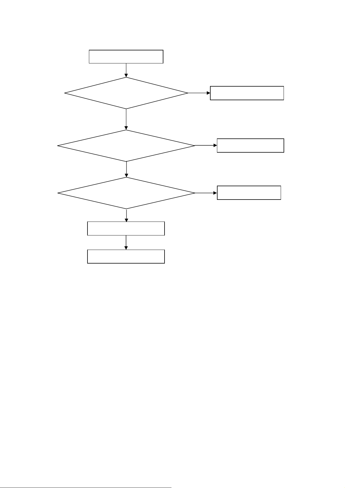
5. Repair Flow Chart
1. No power
No power (LED “Off”)
Check the AC input and
the
ower is “ON”?
Yes
Power board
out
ut=5.2?
Yes
Check the IR board and LED
Replace the IR board
No
Replace the main board
No
Power “On”
No
Replace the power board
26
Page 27
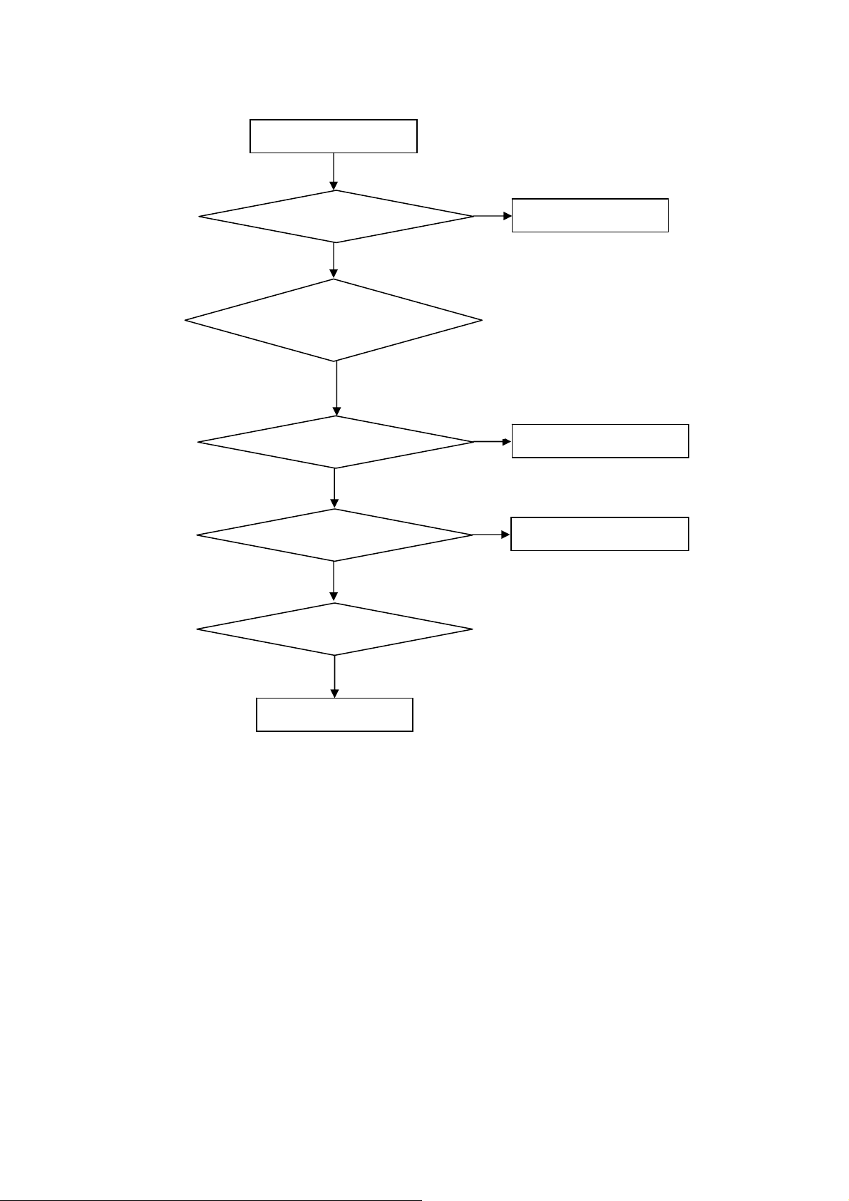
2. Can’t start
Can’t start (LED red)
Power board output=24V?
Yes
Check the power key is under control?
No
Check the IR receiver is normal?
No
Replace the power board
Yes
Replace the key board
Yes
Replace the IR board
No
Replace the main board
No
Replace the Power board
27
Page 28
3. Abnormal display
Abnormal Display
Check the source
Yes
Enter factory mode to do
“EEPROM initial”&“Reset”
No
No
Reset the source
Check the main board
Yes
Check the LVDS cable
Yes
Check the panel
No
Replace the panel
No
Replace the main board
No
Replace the LVDS cable
28
Page 29

4. No display
No display (No LED)
Check TV is under control and power
on/off by remote control and power key?
Yes
Check the LVDS cable
Yes
Yes
Check the backlight is
“On”?
No
Reinsert or replace the
LVDS cable
No
No
Check the B/L
signal is available?
Yes
Replace the main board
No
Replace main board
Panel Vcc = 12V?
Yes
Replace the Panel
No
Replace the main board
Power board output=24V?
Yes
Replace the Panel
Replace the power board
No
29
Page 30

5. Sound problem
No sound or sound abnormal
Check the audio source connection
and the TV system are correct?
Yes
Check the TV is muted, adjust the
volume or enter the menu to reset?
No
No
Reinsert the audio cable or
change the TV system
Enter factory mode to do “Reset”
No
Check the cable between the
speakers and main board is OK?
Yes
Check the speaker resistance value is in spec
(Remark: The value is marked on the speaker)?
Yes
Replace the cable
Replace the main board
No
No
Replace the speaker
30
Page 31

6. Remote control malfunction
Remote Control malfunction
Check the remote control battery is
not properly placed or no power?
No
Use the other remote controls
No
Whether the IR board is
abnormal?
No
Replace the main board
Yes
Replace the battery
Yes
Replace the remote control
Yes
Replace the IR board
31
Page 32

7. OSD is unstable or can’t work normally
OSD is unstable or can’t work normally
Key board connected properly?
Yes
Buttons are OK?
Yes
Key board is OK?
Yes
Enter factory mode to do “Reset”
No
No
No
No
Reconnect the key board
Replace the button function
Replace the key board
Replace the main board
32
Page 33

6. PCB Layout
6.1 Main Board
715G4629M01000004K
33
Page 34

6.2 Power Board
715G4697P02001003H
34
Page 35

6.3 Key Board
715G4846K01000004S
6.4 IR Board
715G4845R01000004S
35
Page 36

7. Adjustment
ADC Adjustment
1. Factory Mode
Turn on the TV. Press menu key and then press number key 1+9 +9+9+back. It will achieve the factory mode.
2. ADC Adjustment
⑴ Enter into the factory mode: (same as the above-mentioned)
⑵ Select item “Source”: Ypbpr
a. Tim\pat. (COMPONENT mode: TIM = 314; PAT = 185,select item “auto color” and press ok key.
b. Tim\pat. (COMPONENT mode: TIM = 311; PAT = 185,select item “auto color” and press ok key.
⑶ Select item “Source”: VGA
Tim\pat. (VGA mode: TIM = 137; PAT = 42,select item “auto color” and press ok key.
3. White Balance Adjustment
(1) Enter into the factory mode :(same as the above-mentioned).
(2) Just only adjust Ypbpr source.
a. Select item “Source”: Ypbpr and item “Color Temp”: Normal, Adjust gain of RGB to meet spec in the below
setting of Tim\pat. (COMPONENT mode: TIM = 314; PAT = 141(80IRE))
b. Select item “Source”: Ypbpr and item “Color Temp”:Warm, Adjust gain of RGB to meet spec in the below setting
of Tim\pat. (COMPONENT mode: TIM = 314; PAT = 141(80IRE))
c. Select item “Source”: Ypbpr and item “Color Temp”: Cool, Adjust gain of RGB to meet spec in the below setting
of Tim\pat. (COMPONENT mode: TIM = 314; PAT = 141(80IRE))
(3) check VGA TIM137,PAT141, AV TIM304 PAT141, HDMI TIM349 PAT141 , white balance whether or not meet
the specifications.
4.The following color specifications for reference, to RD engineering specifications.
Source
Temp Normal/(7500 K) Warm/(6500 K) Cool/(9300 K)
x (center) 0.285 0.0 30 0.313 0.0 30 0.270 0.0 30
VGA/YPbPr/AV/HDMI VGA/YPbPr/AV/HDMI VGA/YPbPr/AV/HDMI
y (center) 0.293 0.030 0.329 0.0 30 0.273 0.0 30
Note: 1.all models of color temperature within specification, but also ensure the brightness conform to engineering
specifications.
2. RGB gain value cannot exceed 138,128,138
36
Page 37

8. Block Diagram
37
Page 38

38
Page 39

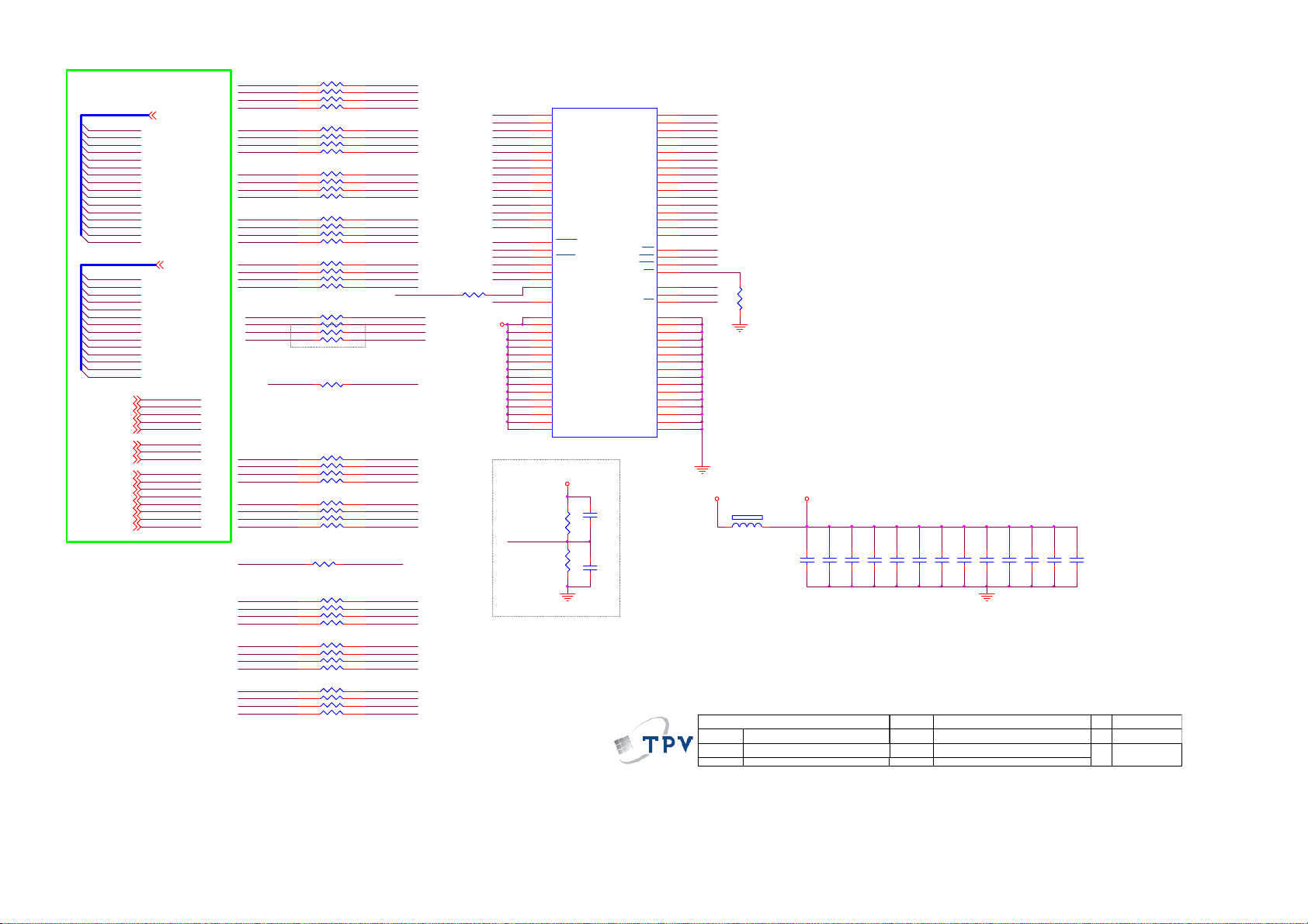
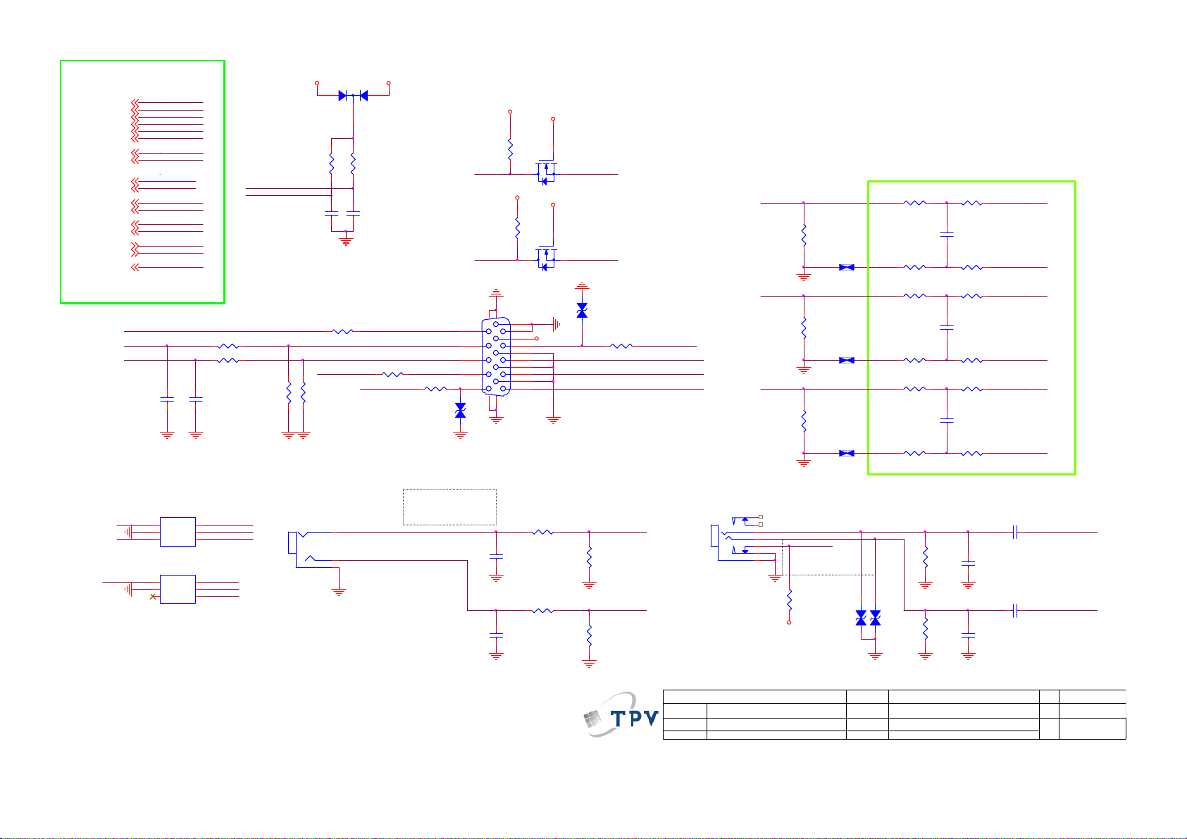
9. Schematic Diagram
9.1 Main Board
715G4629M01000004K
CN700
CONN
D7101
S1D-E3
10uF 10V
C753
100nF 50V
C759
100nF 50V
D_5V
C707
BL_ON1
1
BL_PWM
2
3
4
5
6
7
8
9
10
11
12
13
DGND
DGND
C716
100nF 50V
DGND
DGND
100nF 50V
DGND
+18V_AMP
PWR_ON
C704
C708
100nF 50V
1
VCC
2
REF
3
GND
FB4EN
C700
100nF 50V
U702
AT1529F11U
+
DGND
R732
10 OHM 1/10W
E-PAD
VIN
LX
PGND
Vout = 0.8x(1+R1/R2)=1.36V
R735
1
2
3
U704
E-PAD
VCC
REF
GND
PGND
FB4EN
AT1529F11U
10 OHM 1/10W
VIN
LX
DGND
DGND
C722
100nF 50V
DGND
Vout = 0.8x(1+R1/R2)=3.3V
D12V
D5V_STB
DGND
C705
470uF 10V
TO-252, 1A
U700
VIN3VOUT
ADJ
1
DGND
9
8
7
6
5
DGND
9
8
7
6
5
DGND
FB700
1 2
120R/6000mA
+
C701
330UF 35V
2
R707 100R 1/ 10W 1%
22R 1/10W 1%
R709
R719
24R 1/10W 1%
Vo=1.25x(1+Rdn/Rup)
+
C750
220uF16V
R722
10K 1/10W
L702
2.2uH 20mOH M 8A
C758
NC
+
C762
220uF/16V
R733
10K 1/10W
L703
2.2uH 20mOH M 8A
C764
NC
12V
C757
4.7UF 10V
DGND
C763
4.7UF 10V
NC/CONN
CN701
C709
10uF 10V
DGND
FB719
120R/6000mA
1 2
C748
100nF 50V
DGND
R726
C751
100nF 50V
R1
33K 1/10W 1%
R727
47K 1/10W 1%
R2
FB720
120R/6000mA
1 2
C760
100nF 50V
DGND
R728
C755
100nF 50V
R1
47K 1/10W 1%
R734
15K 1/10W 1%
R2
DGND
D1V8
13
12
11
10
9
8
7
6
5
4
3
2
1
PWR_ON
C711
100nF 50V
D_5V
DGND
C752
22uF 10V
D5V_STB
DGND
C756
22uF 10V
BL_ON1
BL_PWM
C749
100nF 50V
1 2
1 2
+
DGND
C761
100nF 50V
+
DGND
D12V
DGND
+18V_AMP
D5V_STB
FB715
120R/6000mA
FB714
120R/6000mA
C747
220uF/16V
1 2
C754
220uF/16V
BL_ON1
PWR_ON
CORE_1.2V
FB706
1 2
300OHM 4A
FB708
300OHM 4A
C703
100nF 50V
BL_PWM
DM3V3
D5V_STB
R700
10K 1/10W
DGND
C710
100nF 50V
A3V3D3V3
Q700
PMBS3904
D5V_STB
DGND
C715
NC 4.7U F 10V
R731
R701
1K 1/16W
R705
4.7K 1/10W
Q703
PMBS3904
R713
1K 1/10W
NC
D5V_STB
DGND
BL_EN
R721
NC
R708
1K 1/16W 5 %
R711
10K 1/10W
Q705
LMBT3904LT1G
+18V_AMP
USB_5V Power
12
FB702
120R/6000mA
C765
+
C766
100UF 50V
1uF 50V
PS
POWER_EN
DM3V3
R723
NC
R714
NC
R717
1K 1/16W
T P V ( Top Victory Electronics Co . , Ltd. )
絬隔瓜絪腹
A
Key Component
Date
R737
47K 1/16W 5%
BL_ADJ
C767
1uF 50V
POWER_EN
?
P01_POWER
D3V3
DGND
C768
180P 50V
C734
10uF 10V
C770 1uF 25V
AOZ1242AI
U705
8
VBIAS
7
VIN
6
EN
5
C769
1nF 50V
R738
10K 1/10W
R736 0R05 1/ 10W
R720
NC
C733
100nF 50V
LX
BST
GND
FB4COMP
DGND
D5V_STB
DGND
TO-252, 1A
U703
AZ1117H-A DJ-E1
VI3VO
1
C771 100N 50V
2
3
10K 1/10W
R715
NC
R718
4K7 1/10W 5%
Q707
NC
GND14
4
OEM MOD EL
TPV MOD EL
PCB NAME
Sheet
R121 5
R121 4
R710
2
R739
52.3K 1%
R740
10K 1%
114Saturday, June 25, 2011
D5V_STB
DGND
R729
NC
R730
0R05 1/10W
of
5V
52.3K
Vo = 0.8 * (1+ R739/R740)
10K
V1 = 0.8 * (1+ 52.3/10) =4.984V
V1 = 0.8 * (1+ 53.4/10) =5.072V
L704
15uH
R741
3K 1%
D701
SX34
1 2
C713
100nF 50V
R716
47K +-5% 1/10W
Q706
PMBS3904
C735
10uF 10V
DGND DGND
C772
10uF 25V
Q704
AO4449 -7A/-30V
1
S
2
S
3
S
4
G
R712
100K 1/10W
C736
100nF 50V
1 2
C773
10uF 25V
D_5V
8
D
7
D
6
D
5
D
DGND
FB705
1 2
1 2
Size
Rev
称爹
FB701
120R/6000mA
+
C714
NC
300OHM 4A
FB707
300OHM 4A
5V_USB
C712
100nF 50V
ST_D1V2
A1V2
A3
称爹
<>
39
Page 40

From DDR2
S_DQ_IN[0:15][8]
S_DA_IN[0:13][8]
S_LUDQS#_IN[8]
S_LUDQS_IN[8]
S_LLDQS#_IN[8]
S_LLDQS_IN[8]
S_DODT_IN[8]
S_WE#_IN[8]
S_CAS#_IN[8]
S_RAS#_IN[8]
S_CKE_IN[8]
S_CK_IN[8]
S_CK#_IN[8]
S_DBA0_IN[8]
S_DBA1_IN[8]
S_DM0_IN[8]
S_DM1_IN[8]
S_DBA2_IN[8]
To AVout & SPDIF
CVBS_OUT
SPDIF_OUT[9,12]
D1V8
Efuse_3. 3V
S_DQ_IN0
S_DQ_IN1
S_DQ_IN2
S_DQ_IN3
S_DQ_IN4
S_DQ_IN5
S_DQ_IN6
S_DQ_IN7
S_DQ_IN8
S_DQ_IN9
S_DQ_IN10
S_DQ_IN11
S_DQ_IN12
S_DQ_IN13
S_DQ_IN14
S_DQ_IN15
S_DA_IN0
S_DA_IN1
S_DA_IN2
S_DA_IN3
S_DA_IN4
S_DA_IN5
S_DA_IN6
S_DA_IN7
S_DA_IN8
S_DA_IN9
S_DA_IN10
S_DA_IN11
S_DA_IN12
S_DA_IN13
S_LUDQS#_IN
S_LUDQS_IN
S_LLDQS#_IN
S_LLDQS_IN
S_DODT_IN
S_WE#_IN
S_CAS#_IN
S_RAS#_IN
S_CKE_IN
S_CK_IN
S_CK#_IN
S_DBA0_IN
S_DBA1_IN
S_DM0_IN
S_DM1_IN
S_DBA2_IN
SPDIF_OUT
1 2
CVBS_OUT
(1.1A)
(760mA)
FB4016
300OHM 4A
22UF 6.3V
From HDMI
HDMI0_D2+
HDMI0_D2+
HDMI0_D2-
HDMI0_D2-
HDMI0_D1+
HDMI0_D1+
HDMI0_D1-
HDMI0_D1-
HDMI0_D0+
HDMI0_D0+
HDMI0_D0-
HDMI0_D0-
HDMI0_CLK+
HDMI0_CLK+
HDMI0_CLK-
HDMI0_CLK-
HDMI1_D2+
HDMI1_D2+
HDMI1_D2-
HDMI1_D2-
HDMI1_D1+
HDMI1_D1+
HDMI1_D1-
HDMI1_D1-
HDMI1_D0+
HDMI1_D0+
HDMI1_D0-
HDMI1_D0-
HDMI1_CLK+
HDMI1_CLK+
HDMI1_CLK-
HDMI1_CLK-
HDMI2_D2+
HDMI2_D2+
HDMI2_D2-
HDMI2_D2-
HDMI2_D1+
HDMI2_D1+
HDMI2_D1-
HDMI2_D1-
HDMI2_D0+
HDMI2_D0+
HDMI2_D0-
HDMI2_D0-
HDMI2_CLK+
HDMI2_CLK+
HDMI2_CLK-
HDMI2_CLK-
HOTPLUG2
HOTPLUG2
HOTPLUG1
HOTPLUG1
HOTPLUG0
HOTPLUG0
HDMI_CEC
HDMI_CEC
HDMI2_DDC_SCL
HDMI2_DDC_SCL[9]
HDMI2_DDC_SDA
HDMI2_DDC_SDA[9]
HDMI1_DDC_SCL
HDMI1_DDC_SCL[9]
HDMI1_DDC_SDA
HDMI1_DDC_SDA[9]
HDMI0_DDC_SCL
HDMI0_DDC_SCL[9]
HDMI0_DDC_SDA
HDMI0_DDC_SDA[9]
To Audio Amplifier
AOUT_L
AOUT_L
AOUT_R
AOUT_R
AMP_STBY
AMP_STBY
To POWER
POWER_EN
POWER_EN
PS
PS
BL_ADJ[9,12]
NAND FLASH
SPI_SCK-N_RE#
DM3V3
DGND
R4070
4K7 1/10W 5%
R4069
SPI_WP
GPIO追加Pull hi
C4061
100uF16V
C4074
DDR_1.8V
D3V3
10K 1/10W
BL_EN
PANEL_EN
LEDG
LEDR
PS
AMP_STBY
POWER_EN
N_RDY
N_CE0#
PW_KEY
LIGHT_G
LIGHT_R
N_ALE
USB_PWR_FLAG1
USB_PWR_FLAG0
SPDIF_OUT
TX0
RX0
4K7 1/10W 5%
4K7 1/10W 5%
CORE_1.2V
+
12
R4032
NC
PMBS3904
R4074
R4076
22R 1/16W 5%
Q4007
DGND
DGND
100N16V
100N16V
100N16V
100N16V
100N16V
100N16V
C4066
C4067
C4059
C4076
C4075
C4077
TOEN
N_RDY
N_CE0#
DM3V3
N_CLE
N_ALE
N_WE#
R4061
電阻
DM3V3
R4064 4K7 1/10W 5%
R4065 4K7 1/10W 5%
C4060
C4062
DGND
C4078
C4079
DGND
From TUNER
RF_AGC
From CVBS1
From YPBPR1
Y1+
PB1+
PR1+
VIN_Y0-
YPBPR1_IN_L
YPBPR1_IN_R
From KeyPad
LSADC0
LSADC1
PW_KEY
LIGHT_SENSOR
IRRX
LEDG
KEY_SDA
KEY_SCL
LIGHT_R
LIGHT_G
1
NC1
2
NC2
3
NC3
4
NC4
5
NC5
6
NC6
7
RY/BY1
8
RE
9
CE1
10
NC7
11
NC8
12
VCC1
13
VSS1
14
NC9
15
NC10
16
CLE
17
ALE
18
WE
19
WP
20
NC11
21
NC12
22
NC13
23
NC14
NC1524NC16
A3V3
D5V_STB
C4121
C4068
2.2UF 16V
C4080
C4081
TUN_IF+
TUN_IF-
I2C_SCL
I2C_SDA
AV1_CVBS+
VIN_A0AV2_CVBS+
VIN_A1-
AV1_IN_L
AV1_IN_R
AV2_IN_L
AV2_IN_R
LEDR
U4003
NC29
NC28
NC27
NC26
NC25
NC24
NC23
VCC2
VSS2
NC22
NC21
NC20
NC19
NC18
NC17
C4082
I/O7
I/O6
I/O5
I/O4
I/O3
I/O2
I/O1
I/O0
48
47
46
45
44
43
42
41
40
39
38
37
36
35
34
33
32
31
30
29
28
27
26
25
C4083
HY27UF 082G2B-TPCB
C4084
TUN_IF +
TUN_IF -
I2C_SCL
I2C_SDA
RF_AGC
AV1_CVBS+
VIN_A0AV2_CVBS+
VIN_A1-
AV1_IN_L
AV1_IN_R
AV2_IN_L
AV2_IN_R
Y1+
PB1+
PR1+
VIN_Y0-
YPBPR1_IN_L
YPBPR1_IN_R
LSADC0
LSADC1
PW_KEY
LIGHT_SENSOR
IRRX
LEDG
LEDR
KEY_SDA
KEY_SCL
LIGHT_R
LIGHT_G
N_DATA7
N_DATA6
N_DATA5
N_DATA4
DGND
N_DATA3
N_DATA2
N_DATA1
N_DATA0
R4023 4K7 1/10W 5%
R4025 4K7 1/10W 5%
R4062 4K7 1/10W 5%
R4063 4.7K 1/10W
R4068 4K7 1/10W 5%
R4066 4K7 1/10W 5%
R4075 4K7 1/10W 5%
R4077 4K7 1/10W 5%
R4079 4K7 1/10W 5%
R4072 4K7 1/10W 5%
R4080 4K7 1/10W 5%
R4081 4K7 1/10W 5%
100N16V
100N16V
100N16V
100N16V
100N16V
100N16V
100N16V
100N16V
100N16V
100N16V
DM3V3
1uF 25V
From LVDS
From VGA
C4042
DGND
TEDP
TEDN
TECLKP
TECLKN
TECP
TECN
TEBP
TEBN
TEAP
TEAN
TODP
TODN
TOCLKP
TOCLKN
TOCP
TOCN
TOBP
TOBN
TOAP
TOAN
BL_EN
PANEL_EN
VGA_R+
VGA_RVGA_G+
VGA_GVGA_B+
VGA_B-
VGA_VS
VGA_HS
VGA_IN_L
VGA_IN_R
HP_OUT_L
HP_OUT_R
HP_OUT_JD
TX0
RX0
VGA_DDC_SDA
VGA_DDC_SCL
TEDP
TEDN
TECLKP
TECLKN
TECP
TECN
TEBP
TEBN
TEAP
TEAN
TODP
TODN
TOCLKP
TOCLKN
TOCP
TOCN
TOBP
TOBN
TOAP
TOAN
BL_EN
PANEL_EN
VGA_R+
VGA_RVGA_G+
VGA_GVGA_B+
VGA_B-
VGA_VS
VGA_HS
VGA_IN_L
VGA_IN_R
HP_OUT_L
HP_OUT_R
HP_OUT_JD
TX0
RX0
VGA_DDC_SDA
VGA_DDC_SCL
(pin share fu nction)
(pin share fu nction)
1uF 25VC4003
C4004 100nF 50V
FB4002 300OHM 4A
FB4001 300OHM 4A
1uF 25VC 4022
2.2UF 16V C412 3
2.2UF 16V C404 1
2.2UF 16V C401 0
2.2UF 16V C402 1
2.2UF 16V C401 7
2.2UF 16V C402 0
2.2UF 16V C401 4
2.2UF 16V C401 1
2.2UF 16V C401 6
2.2UF 16V C401 5
IF_NTUN_I F-
C4051
1uF 25V
TUN_IF +
C4052
1uF 25V
C4046
PLL_GND
22pF 50V
X4000
27mHZ
C4047
1 2
22pF 50V
C4118
C4055
C4056
10uF 6.3V
100N16V
10uF 6.3V
DGND
IO_3.3V
300OHM 4A
C4087
C4085
C4086
(36mA)
C4088
100N16V
DGND DGND
100N16V
100N16V
100N16V
100N16V
ST_D1V2
D3V3
FB4007
300OHM
1 2
DGND
0.5A)
FB4017
1 2
C4119
100N16V
DGND
IF_P
C4089
R4017 0R05 1/10 W
R4018
NC
A1V2
1 2
A3V3
XOUT
XIN
FB4011
300OHM 4A
FB4018
1 2
AGND
300OHM 4A
FB4004
FB4003
300OHM
300OHM
PLL_GND
R4014
R4015
100 OHM 1/10W
100 OHM 1/10W
HDMI_1.2V
C4063
DGND
HDMI_3.3V
C4090
100N16V
DGND
47N 50V C4023
VDAC_3.3V
1 2
1 2
VADC_3.3V
CORE_1.2V
Efuse_3. 3V
CORE_1.2V
CORE_1.2V
DDR_1.8V
DDR_1.8V
DDR_1.8V
DDR_1.8V
DDR_1.8V
DDR_1.8V
C4064
100N16V
100N16V
47N 50V C4024
47N 50V C4025
47N 50V C4120
PLL_3.3V
I2C_SCL
I2C_SDA
HP_OUT_JD
USB_PWR_FLAG1
IO_3.3V
IO_3.3V
47N 50V C4026
VDACGND
VADCGND
47N 50V C4027
47N 50V C4028
47N 50V C4029
47N 50V C4030
47N 50V C4032
47N 50V C4033
47N 50V C4034
47N 50V C4035
47N 50V C4031
CORE_1.2V
PS
MEMC_GPI O
CVBS_OUT
IF_N
IF_P
XIN
XOUT
RF_AGC
LEDG
LEDR
R4019
5K1 1/16W 5%
LIGHT_G
LIGHT_R
S_DQ_IN14
S_DM1_IN
S_DQ_IN9
S_DQ_IN11
S_DQ_IN12
S_DQ_IN6
S_DM0_IN
S_DQ_IN1
S_DQ_IN4
S_DQ_IN3
S_LLDQS_IN
S_LLDQS#_IN
S_LUDQS_IN
S_LUDQS#_IN
S_DQ_IN15
S_DQ_IN8
S_DQ_IN10
S_DQ_IN13
S_DQ_IN7
S_DQ_IN0
S_DQ_IN2
S_DQ_IN5
A1V2
FB4012
1 2
300OHM 4A
A3V3 USB_3.3V
FB4019
1 2
300 OHM
BB_3.3V
AGND
12
AGND
To AMP
To AV_out
DGND
VGA_IN_R
VGA_IN_L
47N 50V C4036
47N 50V C4039
47N 50V C4040
47N 50V C4037
47N 50V C4038
U4000
257
256
254
255
EPAD
AIN_5L
AIN_4R
1
AIN_5R
2
LSADC3
3
LSADC5
4
VDAC3V3
5
AVOUT1
6
AVOUT2
7
VDACGND
8
ADC2XGND
9
IF1N
10
IF1P
11
ADC2X3V3
12
PLLGND
13
XIN
14
XOUT
15
PLL3V3
16
D1V2
17
RF_AGC
18
I2C0_SCL
19
I2C0_SDA
20
GPIO_M3
21
GPIO_M4
22
GPIO_M6
23
GPIO_M5
24
GPIO_M7
25
D3V3
26
GPIO_U5
27
GPIO_R4
28
GPIO_R3
29
EFUSE_D3V3
30
D3V3
31
NC
32
NC
33
NC
34
NC
35
D1V2
36
D1V2
37
DDR18VCC
38
DQ_14
39
DM1
40
DQ_9
41
DQ_11
42
DDR18VCC
43
DQ_12
44
DQ_6
45
DM0
46
DQ_1
47
DDR18VCC
48
DQ_4
49
DQ_3
50
DQS0
51
DQS0_N
52
DDR18VCC
53
DQS1
54
DQS1_N
55
DQ_15
56
DQ_8
57
DDR18VCC
58
DQ_10
59
DQ_13
60
DQ_7
61
DQ_0
62
DDR18VCC
63
DQ_2
64
DQ_5
DVRI65CK66CK#67RAS#68DDR18VCC69CAS#70ADDR071ADDR272DDR18VCC73ADDR474ADDR675ADDR876ADDR1177ADDR1378DDR18VCC79WE#80CKE81BA182BA083DDR12VCC84ADDR185ADDR1086ADDR587ADDR388DDR18VCC89ADDR990ADDR791ADDR1292BA293ODT94USB1V295HSDM_096HSDP_097USB3V398HSDM_199HSDP_1
RTD2684S
S_DVREF_A
S_CK_IN
S_CK#_IN
DDR_1.8V
Jack Detection Function (place
resistor Near Connector)
USB_1.2V
C4065
C4069
100N16V
100N16V
DGND
C4073
100N16V
1 2
AV2_IN_R
HP_OUT_R
AOUT_L
AOUT_R
YPBPR1_IN_R
YPBPR1_IN_L
AV1_IN_L
AV1_IN_R
HP_OUT_L
AV2_IN_L
VCM_BB
AVDD_BB0
BB1GND
BB1GND
249
248
241
240
239
250
251
252
246
244
242
253
247
245
243
AIN_4L
AIN_1L
AIO_1L
AIO_2L
AIN_3L
AIN_1R
AIO_1R
AIO_2R
AIN_3R
AOUT_L
AOUT_R
VCM_BB
BB0_3V3
HPOUT_L
HPOUT_R
S_DA_IN13
S_CKE_IN
S_RAS#_IN
S_CAS#_IN
S_DA_IN0
S_DBA1_IN
S_DA_IN2
S_DA_IN4
S_DA_IN6
S_DA_IN8
S_DA_IN11
S_WE#_IN
Y_1.2V
A1V2
FB4008
1 2
300OHM 4A
AGND
A1V2
VD_1.2V
FB4013
1 2
300OHM 4A
C4070
2.2UF 16V
AGND
A3V3
PLL_3.3V
FB4020
1 2
300OHM 4A
C4091
100N16V
PLL_GND
DGNDAGND
40
FB4000
300OHM 4A
C4000
1uF 25V
BB1GND
VD_3.3V
1 2
HOTPLUG1
HOTPLUG0
238
237
236
235
234
D1V2
VD3V3
VIN_14P
BB1GND
BB1_3V3
S_DBA0_IN
S_DA_IN1
S_DA_IN10
S_DA_IN5
C4122
1UF16V
AGND
1KOHM +-1% 1/16W
1KOHM +-1% 1/16W
C4058
100N16V
VD_1.2V
Y_1.2V
AV1_CVBS+
VIN_A0-
VIN_A1-
AV2_CVBS+
HOTPLUG2
AGND
AGND
226
225
232
229
227
230
233
231
228
VIN1N
VIN0N
VD1V2
VIN_9P
VIN_13P
VIN_10P
VIN_12P
VIN_11P
VD_GND33
S_DA_IN3
S_DA_IN9
S_DA_IN7
S_DA_IN12
S_DODT_IN
USB_DM0
S_DBA2_IN
USB_3.3V
USB_1.2V
DDR_1.8V
R4020
S_DVREF_A
R4021
DGND
Close to RT D268x IC
A3V3 VADC_3.3V
A3V3 VDAC_3.3V
224
ADC_GND33
USB_DP0
AGND
221
223
222
VIN_8P
VIN_7P
YPP1V2
100
USB_DP1
USB_DM1
1 2
1 2
C4092
4.7UF 10V
AVDD_BB0
close to RTD268x
Y1+
PR1+
220
219
218
VIN_6P
VIN_5P
VIN_4P
VIN_Y1N
USB1V2
D1V2
GPIO_R1
101
102
103
TOEN
C4053
100N16V
C4054
100N16V
FB4014
300OHM 4A
FB4021
300OHM 4A
VIN_Y0-
217
104
N_WE#
PB1+
VGA_R-
216
215
VIN_3P
VIN_Y0N
GPIO_K3
GPIO_K4
105
106
AMP_STBY
USB_PWR_FLAG0
VADCGND
AGND
VGA_G-
VGA_R+
214
213
VIN_2P
VIN_RN
GPIO_K5
GPIO_K6
107
108
KEY_SDA
100N16V
VDACGND
D5V_STB
3
R4001
C4001
100nF 50V
Y_3.3V
VGA_G+
VGA_B+
VGA_B-
212
211
210
209
VIN_1P
VIN_0P
VIN_BN
VIN_GN
D3V3
GPIO_K7
GPIO_S6
GPIO_S5
109
110
111
112
N_DATA3
N_DATA5
N_DATA4
KEY_SCL
A3V3
1 2
C4071
C4093
4.7UF 10V
DGND
R4000
10K 1/10W
DGND
APLL3.3V
AGND
VGA_VS
VGA_HS
205
206
208
207
VSYNC
HSYNC
YPP3V3
APLLGND
GPIO_S4
GPIO_M0
GPIO_M1
GPIO_M2
113
114
115
116
RX0
N_DATA2
N_DATA0
N_DATA1
FB4009
300OHM 4A
ST_D1V2
VGA_DDC_SCL
VGA_DDC_SDA
IO_3.3V
R4007
R4008
0R05 1/10W
0R05 1/10W
LSADC1
LSADC0
PANEL_EN
LSADC_REF
BL_EN
197
195
202
201
194
193
200
199
196
198
203
204
D3V3
XIRTC
XORTC
RTC3V3
APLL3V3
GPIO_B7
GPIO_B6
ST_D1V2
VDDC_SCL
VDDC_SDA
LVDS_B_FP
LVDS_B_FN
LVDS_B_EP
LVDS_B_EN
LVDS_B_DP
LVDS_B_DN
LVDS_B_CP
LVDS_B_CN
LVDS_B_BP
117
118
119
120
121
122
123
124
125
TOCLKP
TOCLKN
TODN
TODP
TOBN
TOBP
TOCN
TOCP
TX0
Y_3.3V
C4057
100N16V
AGND
A3V3
FB4015
1 2
300OHM 4A
FB4022
1 2
300OHM 4A
A3V3
FB4024
1 2
300OHM 4A
LSADC0
LSADC1
LSADC_REF
HDMI_2_CLKP
HDMI_2_CLKN
HDMI_1_CLKP
HDMI_1_CLKN
TMDS_R EXT
HDMI_0_CLKP
HDMI_0_CLKN
HDDC0_SDA
HDDC0_SCL
HDDC1_SDA
HDDC1_SCL
HDDC2_SDA
HDDC2_SCL
PMM_GPIO_C4
NAND RDY/BUSY
LVDS_A_AN
LVDS_A_AP
LVDS_A_BN
LVDS_A_BP
LVDS_A_CN
LVDS_A_CP
LVDS_A_DN
LVDS_A_DP
LVDS_A_EN
LVDS_A_EP
LVDS_A_FN
LVDS_A_FP
LVDS_B_BN
LVDS_B_AP
LVDS_B_AN
D3V3
126
127
128
TOAP
TOAN
VD_3.3V
AGND
BB_3.3VA3V3
APLL3.3V
C4094
100N16V
AGND
LSADC2
LSADC4
RSTI_N
HDMI1V2
HDMI_2_2P
HDMI_2_2N
HDMI_2_1P
HDMI_2_1N
HDMI_2_0P
HDMI_2_0N
HDMI_1_2P
HDMI_1_2N
HDMI_1_1P
HDMI_1_1N
HDMI_1_0P
HDMI_1_0N
HDMI3V3
HDMI_0_2P
HDMI_0_2N
HDMI_0_1P
HDMI_0_1N
HDMI_0_0P
HDMI_0_0N
HDMI1V2
ST_D1V2
NAND_D7
NAND_D6
SPI_SCLK
SPI_CSN
NAND_CS1
NAND_CS0
NAND_ALE
NAND_CLE
C4072
2.2UF 16V
PW_KEY
192
LIGHT_SENSOR
191
RESET#
190
HDMI_CEC
189
CEC
188
HDMI2_D2+
187
HDMI2_D2-
186
HDMI2_D1+
185
HDMI2_D1-
184
HDMI2_D0+
183
HDMI2_D0-
182
HDMI2_CLK+
181
HDMI2_CLK-
180
HDMI1_D2+
179
HDMI1_D2-
178
HDMI1_D1+
177
HDMI1_D1-
176
HDMI1_D0+
175
HDMI1_D0-
174
HDMI1_CLK+
173
HDMI1_CLK-
172
171
170
HDMI0_D2+
169
HDMI0_D2-
168
HDMI0_D1+
167
HDMI0_D1-
166
HDMI0_D0+
165
HDMI0_D0-
164
HDMI0_CLK+
163
HDMI0_CLK-
162
161
160
IRRX
159
IRRX
HDMI0_DDC_SDA
158
HDMI0_DDC_SCL
157
HDMI1_DDC_SDA
156
HDMI1_DDC_SCL
155
HDMI2_DDC_SDA
154
HDMI2_DDC_SCL
153
POWER_EN
152
N_DATA7
151
N_DATA6
150
SPI_SCK-N_RE#
149
SPI_WP
148
SPDIF_OUT
147
N_CE0#
146
N_RDY
145
N_ALE
144
N_CLE
143
142
D3V3
141
D1V2
TEAN
140
TEAP
139
TEBN
138
TEBP
137
TECN
136
TECP
135
TECLKN
134
TECLKP
133
TEDN
132
TEDP
131
UART0_RX
130
UART0_TX
129
IO_3.3V
HDMI_1.2V
HDMI_3.3V
HDMI_1.2V
ST_D1V2
Power-On-Latch (POL)
test mode (PIN147 pad_nand_cs1_n)
0 : enable
1 : disable
EJTAG (PIN146 pad_nand_cs0_n)
0 : enable
1 : disable
ROM boot (PIN149 pad_spi_sclk)
0 : boot from ROM
1 : don't boot from ROM
Flash type (PIN148 pa d_spi_cs_n)
0 : SPI-Flash boot
1 : NAND-Flash boot
test mode PLL (PIN144 pad_pcmcia_iowr_n)
0 : external
1 : internal
1 2
NC/10K 1/10W
D4000
NC/BAV99
123Q4000
R4003
NC/1K 1/10W
R4005
C4005
NC/10K 1/10W
NC/10UF 6.3V X5R +-20%
DGND DGND
R4016
DGND
2K7 1/16W 5%
CN4001 USB CONN
1
1234
2
3
4
6 5
DGND
USB1_5V
1
1234
USB_DM1
2
USB_DP1
3
4
USB CONN
6 5
CN4002
DGND
IO_3.3V
CORE_1.2V
R4024
N_CE0#
4K7 1/16W 5%
R4026
SPI_SCK-N_RE#
R4027
4K7 1/16W 5%
SPI_WP
R4039
NC
N_ALE
R4030
4K7 1/16W 5%
HS4000
1
2
Heat Sink
H1
G11G22G33G44G5
GLZ
5
AGND
隔离罩
T P V ( Top Victory Electronics Co . , Ltd. )
?
絬隔瓜絪腹
A
Key Component
P02_RTD268x_256C
Date
DGND
NC/2N3906S- RTK/PS
NC/100R 1/10W 5%
R4004
R4006
NC/10K 1/10W
USB0_5V
USB_DM0
USB_DP0
UART0_RX
UART0_TX
MEMC_GPI O
D12V
D3V3
D3V3
NC/4K7 1/16W 5%
DGND
D3V3
R4031
4K7 1/16W 5%
D3V3
DGND
1
2
AGND
IO_3.3V
R4002
C4002
10K 1/10W 5%
NC/47uF/ 16V
+
NC/2N3904S-RTK/PS
Q4001
C4008
C4006
NC
NC/100P 50V
DGNDDGND DGND
D3V3
HDMI2_DDC_SDA
HDMI2_DDC_SCL
DGND
R4010
R4009
100R 1/10W 5%
100R 1/10W 5%
USB
C4043
100N 16V
FB4006
220R/2000mA
+
C4048
C4049
100uF16V
100N 16V
DGND
CN4006
7
6
5
4
3
2
1
DGND
CONN
OEM MODEL Size
TPV MODEL
PCB NAME
Sheet
RESET#
C4007
NC/10UF 6.3V X5R +-20%
CN4007
4
3
2
1
CONN
220R/2000mA
+
C4044
100uF16V
DGND
USB_PWR_FLAG1
12
C4050
NC
of
214Wednesday, May 11, 2011
USB_PWR_FLAG0
FB4005
t
12
t
5V_USB
12
C4045
TH4001
NC
5V_USB
12
TH4000
A1
Rev
称爹
<>
称爹
Page 41
From RTD268x
S_DQ_IN 0
S_DQ_IN 1
S_DQ_IN 2
S_DQ_IN 3
S_DQ_IN 4
S_DQ_IN 5
S_DQ_IN 6
S_DQ_IN 7
S_DQ_IN 8
S_DQ_IN 9
S_DQ_IN 10
S_DQ_IN 11
S_DQ_IN 12
S_DQ_IN 13
S_DQ_IN 14
S_DQ_IN 15
S_DA_IN [0:13]
S_DA_IN 0
S_DA_IN 1
S_DA_IN 2
S_DA_IN 3
S_DA_IN 4
S_DA_IN 5
S_DA_IN 6
S_DA_IN 7
S_DA_IN 8
S_DA_IN 9
S_DA_IN 10
S_DA_IN 11
S_DA_IN 12
S_DA_IN 13
S_LUDQS#_IN[7]
S_LUDQS_I N[7]
S_LLDQS#_IN[7]
S_LLDQS_IN[7]
S_DODT_IN[7]
S_WE#_IN[7]
S_CAS#_IN[7]
S_RAS#_IN[7]
S_CKE_IN[7]
S_CK_IN[7]
S_CK#_IN[7]
S_DBA0_IN[7]
S_DBA1_IN[7]
S_DM0_IN[7]
S_DM1_IN[7]
S_DBA2_IN[7]
S_DQ_IN [0:15] [ 7]
S_DA_IN [0:13] [ 7]
S_LUDQS#_I N
S_LUDQS_I N
S_LLDQS#_IN
S_LLDQS_IN
S_DODT_IN
S_WE#_IN
S_CAS#_IN
S_RAS#_IN
S_CKE_IN
S_CK_IN
S_CK#_IN
S_DBA0_IN
S_DBA1_IN
S_DM0_IN
S_DM1_IN
S_DBA2_IN
S_DQ_IN 14
S_DM1_IN
S_DQ_IN 9
S_DQ_IN 11
S_DQ_IN 12
S_DQ_IN 6
S_DM0_IN
S_DQ_IN 1
S_DQ_IN 4
S_DQ_IN 3
S_LLDQS_IN
S_LLDQS#_IN
S_LUDQS_I N
S_LUDQS#_I N
S_DQ_IN 15
S_DQ_IN 8
S_DQ_IN 10
S_DQ_IN 13
S_DQ_IN 7
S_DQ_IN 0
S_DQ_IN2
S_DQ_IN5
S_CK_IN
S_CK#_IN
S_CK
S_RAS#_IN
S_CAS#_IN
S_DA_IN 0
S_DA_IN 2
S_DA_IN 4
S_DA_IN 6
S_DA_IN 8
S_DA_IN 11
S_DA_IN13
S_WE#_IN
S_CKE_IN
S_DBA1_IN
S_DBA0_IN
S_DA_IN 1
S_DA_IN 10
S_DA_IN 5
S_DA_IN 3
S_DA_IN 9
S_DA_IN 7
S_DA_IN 12
S_DBA2_IN
RP4000
8
7
6
5
RP4001
8
7
6
5
RP4002
8
7
6
5
RP4003
8
7
6
5
RP4004
8
7
6
5
R4035
R4037
R4036
R4038
close RTD268x
R4040
100R 1/16W 5%
close DDR
RP4005
8
7
6
5
RP4006
8
7
6
5
R4043
51R 1/16W 5%
RP4007
8
7
6
5
RP4008
8
7
6
5
RP4009
8
7
6
5
22oHM 1/16W
S_DQ14
1
S_DM1
2
S_DQ9
3
S_DQ11
4
22oHM 1/16W
S_DQ12
1
S_DQ6
2
S_DM0
3
S_DQ1
4
22oHM 1/16W
S_DQ4
1
S_DQ3
2
S_LLDQS
3
S_LLDQS#
4
22oHM 1/16W
S_LUDQS
1
S_LUDQS#
2
S_DQ15
3
S_DQ8
4
22oHM 1/16W
S_DQ10
1
S_DQ13
2
S_DQ7
3
S_DQ0
4
S_CK#
51R
1
2
3
4
51R
1
2
3
4
S_DA13
51R
1
2
3
4
51R
1
2
3
4
51R
1
2
3
4
S_DODT_IN
S_DQ2
S_DQ5
S_CK
S_CK#
22R 1/16W 5%
22R 1/16W 5%
22R 1/16W 5%
22R 1/16W 5%
S_RAS#
S_CAS#
S_DA0
S_DA2
S_DA4
S_DA6
S_DA8
S_DA11
S_WE#
S_CKE
S_DBA1
S_DBA0
S_DA1
S_DA10
S_DA5
S_DA3
S_DA9
S_DA7
S_DA12
S_DBA2
22R 1/16W 5%
R4033
1V8DDR
S_DQ0
S_DQ1
S_DQ2
S_DQ3
S_DQ4
S_DQ5
S_DQ6
S_DQ7
S_DQ8
S_DQ9
S_DQ10
S_DQ11
S_DQ12
S_DQ13
S_DQ14
S_DQ15
S_LUDQS#
S_LUDQS
S_LLDQS#
S_DM1
S_DM0
S_DVREF
1K 1/10W 1%
S_DVREF
1K 1/10W 1%
R4041
R4042
G8
DQ0
G2
DQ1
H7
DQ2
H3
DQ3
H1
DQ4
H9
DQ5
F1
DQ6
F9
DQ7
C8
DQ8
C2
DQ9
D7
DQ10
D3
DQ11
D1
DQ12
D9
DQ13
B1
DQ14
B9
DQ15
A8
UDQS
B7
UDQS
E8
LDQS
F7
LDQS
B3
UDM
F3
LDM
K9
ODT
J2
VREF
A1
VDD
E1
VDD
J9
VDD
M9
VDD
R1
VDD
A9
VDDQ
C1
VDDQ
C3
VDDQ
C7
VDDQ
C9
VDDQ
E9
VDDQ
G1
VDDQ
G3
VDDQ
G7
VDDQ
G9
VDDQ
J1
VDDL
U4002
W971GG6JB-18
1V8DDR
DGND
C4095
100N16V
C4096
100N 16V
M8
A0
M3
A1
M7
A2
N2
A3
N8
A4
N3
A5
N7
A6
P2
A7
P8
A8
P3
A9
M2
A10
P7
A11
R2
A12
R8
A13
L2
BA0
L3
BA1
L1
BA2
K3
WE
L7
CAS
K7
RAS
L8
CS
K2
CKE
J8
CK
K8
CK
A3
VSS
J3
VSS
N1
VSS
P9
VSS
E3
VSS
A7
VSSQ
B2
VSSQ
B8
VSSQ
D2
VSSQ
D8
VSSQ
E7
VSSQ
F2
VSSQ
F8
VSSQ
H2
VSSQ
H8
VSSQ
J7
VSSDL
Close to DDR
S_DA0
S_DA1
S_DA2
S_DA3
S_DA4
S_DA5
S_DA6
S_DA7
S_DA8
S_DA9
S_DA10
S_DA11
S_DA12
S_DA13
S_DBA0
S_DBA1
S_DBA2
S_WE#
S_CAS#
S_RAS#S_LLDQS
S_CKE
S_CK
S_CK#
DGND
D1V8
R4034
1K 1/16W
DGND
FB4027
1 2
300OHM 4A
1V8DDR
100N 16V
100N 16V
100N 16V
100N 16V
100N 16V
100N 16V
100N 16V
100N 16V
100N 16V
100N 16V
100N 16V
100N 16V
(210mA)
C4097
22UF 6.3V
T P V ( Top Victory Electronics Co . , Ltd. )
絬隔瓜絪腹
A
Key Component
Date
?
P03_DDR 2
C4098
C4099
C4100
C4101
C4102
OEM MODEL
TPV MODEL
PCB NAME
Sheet
C4103
314Wednesday , May 11, 2011
C4104
C4105
C4106
DGND
of
C4107
C4108
C4109
Size
Rev
称爹
B
称爹
<>
41
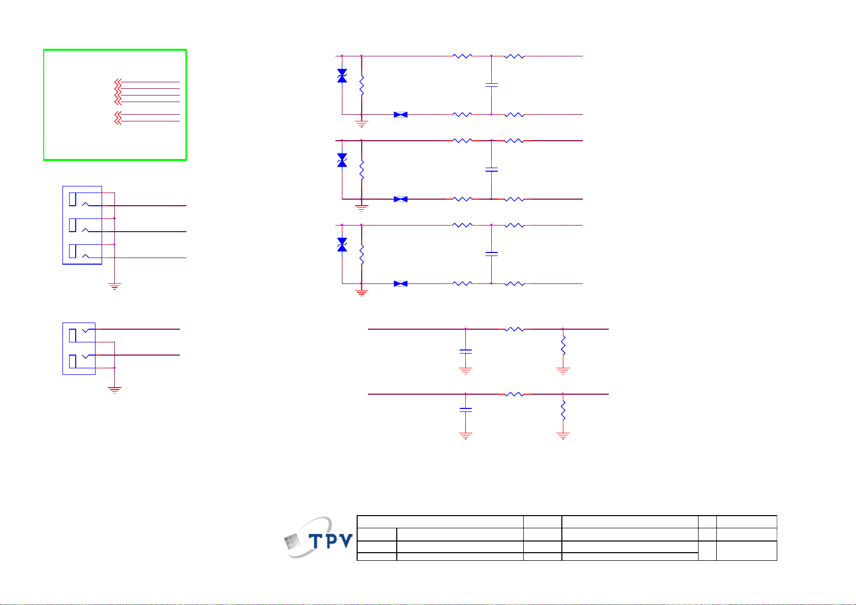
Page 42

TO RTD268x
AV1_CVBS+
VIN_A0-
AV1_IN _L
AV1_IN _R
AV2_CVBS+
VIN_A1-
AV2_IN _L
AV2_IN _R
AV1
AV2
CN102
CONN
CN101
A
AV1_CVBS+
VIN_A0-
AV1_IN _L
AV1_IN _R
AV2_CVBS+
VIN_A1-
AV2_IN _L
AV2_IN _R
A
B
C
2
1
4
3
6
5
AGND
ZD105
MLVG0402
1 2
AGND
R112
75 OHM +- 5% 1/16W
SH101
C105
470pF 50V
B
C
RCA JACK
0R05 1/ 10W
R133
12K 1/16W
R138
2
1
4
3
6
5
C106
NC
AGND
AV2_IN _L
R135
8.2K 1/10W
ZD101
MLVG0402
1 2
AGND
AV2_CVBS+
VIN_A1-
R101
0R05 1/ 10W
R102
75R
SH100
R103
C102
470pF 50V
AGND AGND
C103
470pF 50V
12KOHM +-5% 1/16W
R105
12KOHM +-5% 1/16W
C101
NC
AV1_IN_L
AV1_IN_R
AGNDAGND
R104
8.2K 1/10W
R106
8.2K 1/10W
AV1_CVBS+
VIN_A0-
AGND AGND
C104
470pF 50V
R137
12K 1/16W
AGNDAGND
T P V ( Top Victory Electronics Co . , Ltd. )
絬隔瓜絪腹
A
Key Component
Date
AV2_IN _R
R136
8.2K 1/10W
?
P04_AV
42
OEM MOD EL
TPV MOD EL
PCB NAME
Sheet
Size
Rev
of
414Wednes day , May 11, 2011
称爹
A4
称爹
<>
Page 43
TO RTD268x
Y1+
PB1+
PR1+
VIN_Y 0-
YPBPR 1_IN_L
YPBPR 1_IN_R
CN103
CONN
YPbPr1 Video in
ZD102
Y1+
PB1+
PR1+
VIN_Y0-
YPBPR 1_IN_L
YPBPR 1_IN_R
C
B
A
5
6
3
4
1
2
AGND
PR1
PB1
Y1
MLVG0402
ZD103
MLVG0402
ZD104
MLVG0402
PB1
PR1
Y1
Y1
R115
75R
1 2
SH102
AGND
R120
75R
1 2
SH103
AGND
R125
75R
1 2
SH104
AGND
R113
0R05 1/10W
C107
5PF 50V
R116
0R05 1/10W
R118
0R05 1/10W
C108
5PF 50V
R121
0R05 1/10W
R123
0R05 1/10W
C109
5PF 50V
R126
0R05 1/10W
R114
100R 1/10W 5%
R117
100R 1/10W 5%
R119
100R 1/10W 5%
R122
100R 1/10W 5%
R124
100R 1/10W 5%
R127
100R 1/10W 5%
Y1+
VIN_Y 0-
PB1+
VIN_Y 0-
PR1+
VIN_Y 0-
CN104
A
B
RCA+S
2
1
4
3
YPBPR 1_L
YPBPR 1_R
AGND
YPBPR 1_R
C111
470pF 50V
YPBPR 1_L
C110
470pF 50V
AGND AGND
T P V ( Top Victory Electronics Co . , Ltd. )
A
絬隔瓜絪腹
Key Component
Date
?
P05_YPBPR
R130
12KOHM + -5% 1/16W
R128
12KOHM + -5% 1/16W
OEM MODEL
TPV MODEL
PCB NAME
Sheet
YPBPR 1_IN_R
R131
8.2K 1/10W
AGNDAGND
YPBPR 1_IN_L
R129
8.2K 1/10W
514Wednes day , May 11, 2011
Size
Rev
of
称爹
43
A4
<>
称爹
Page 44
TO RTD268x
VGA_B+
VGA_BVGA_G+
VGA_GVGA_R+
VGA_R-
VGA_HS
VGA_VS
TX0
RX0
VGA_DDC_SCL
VGA_DDC_SDA
VGA_IN _L
VGA_IN _R
HP_OUT_L
HP_OUT_R
HP_OUT_JD
AGND
AGND
VGA_VS
VGA_HS
VGA_RIN
VGA_B+
VGA_BVGA_G+
VGA_GVGA_R+
VGA_R-
VGA_HS
VGA_VS
TX0
RX0
VGA_DDC _SCL
VGA_DDC _SDA
VGA_IN_L
VGA_IN_R
HP_OUT_L
HP_OUT_R
HP_OUT_JD
C120
22pF 50V
AGND AGND
U100
HS
1
I/O1
2
GND
VS
I/O23I/O3
MSEA53025V06B0
U101
1
I/O1
2
GND
I/O23I/O3
MSEA53025V06B0
C121
10P 50V
I/O4
VDD
I/O4
VDD
R160
100R 1/10W 5%
R161
100R 1/10W 5%
VGA_DDC _SDA
6
VGA_5V
5
VGA_DDC _SCL
4
VGA_BIN
6
VGA_5V
5
VGA_GIN
4
VGA_CON5V
4K7 1/16W 5%
VGA_DDC _SCL
VGA_DDC _SDA
R164
2.2K 1/16W
D100
BAT54C
1
R100
C100
NC
R108 100OHM1/16W
VGA_DDC _SDA VGA_SDA
R165
2.2K 1/16W
AGNDAGND
CN105
PHONE J ACK
VGA_5V
AGND
3
2
1
AGND
2
3
R151
4K7 1/16W 5%
C117
NC
VGA_SCLVGA_DDC _SCL
HS
R107
100OHM1/16W
VGA_RX0
D5V_STB
VS
R110
100OHM1/16W
ZD113
MLVG0402
1.65V: jack not plug in
0V: jack plug in
VGA_INR
VGA_INL
CN100
1 2
AGND
VGA_TX0
VGA_RX0
15
14
13
12
11
AGND
1819
17 16
AGND
AGND
AGND
D5V_STB
R205
4K7 1/16W 5%
D5V_STB
R211
4K7 1/16W 5%
10
5
9
4
8
3
7
2
6
1
D-SUB 15P
C124
470pF 50V
C127
470pF 50V
A3V3
Q301
2N7002
A3V3
Q302
2N7002
AGND
VGA_CON5V
AGND
R171
7K5 1/16W 5%
R174
7K5 1/16W 5%
AGND
ZD114
MLVG0402
1 2
R109
100OHM1/16W
R172
1K5 1/10W 5%
AGND
R175
1K5 1/10W 5%
AGND
TX0
RX0
Pin 12 (VGA_SDA) =Pin 4(VGA_TX)
Pin 15 (VGA_SCl) =Pin 11(VGA_RX)
VGA_TX0
VGA_BIN
VGA_GIN
VGA_RIN
PHONEJ ACK
VGA_IN _R
CN106
VGA_IN _L
5
4
HP_OUTR
3
HP_OUTL
2
6
7
1
AGND
DM3V3
R154
75R
SH108
AGND
R159
75R
SH109
AGND
R168
75R
SH110
AGND
HP_OUT_JD
1.65V: jack not plug in
0V: jack plug in
R4078
ZD112
10K 1/10W
ZD111
MLVG0402
MLVG0402
1 2
1 2
AGND
R152
0R05 1/10W
C118
5PF 50V
R155
0R05 1/10W
R157
0R05 1/10W
C119
5PF 50V
R162
0R05 1/10W
R166
0R05 1/10W
C122
5PF 50V
R169
0R05 1/10W
R173
1K 1/10W
R176
1K 1/10W
R153
100R 1/10W 5%
R156
100R 1/10W 5%
R158
100R 1/10W 5%
R163
100R 1/10W 5%
R167
100R 1/10W 5%
R170
100R 1/10W 5%
C125
100nF 50V
AGNDAGND
C128
100nF 50V
AGNDAGND
VGA_B+VGA_BIN
VGA_B-
VGA_G+VGA_GIN
VGA_G-
VGA_R+VGA_RIN
VGA_R-
C123
10uF 16V
C126
10uF 16V
HP_OUT_R
HP_OUT_L
44
T P V ( Top Victory Electronics Co . , Ltd. )
A
絬隔瓜絪腹
Key Component
Date
?
P07_VGA
OEM MODEL
TPV MODEL
PCB NAME
Sheet
of
714Wednesday , June 15, 2011
Size
Rev
称爹
B
<>
称爹
Page 45

HOTPLUG0
R509
10K 1/10W
TO RTD268x
HDMI0_D2+
HDMI0_D2HDMI0_D1+
HDMI0_D1HDMI0_D0+
HDMI0_D0HDMI0_CLK+
HDMI0_CLK-
HDMI0_DDC_SCL
HDMI0_DDC_SDA
HOTPLUG0
HDMI1_D2+
HDMI1_D2HDMI1_D1+
HDMI1_D1HDMI1_D0+
HDMI1_D0HDMI1_CLK+
HDMI1_CLK-
HDMI1_DDC_SCL
HDMI1_DDC_SDA
HOTPLUG1
HDMI_CEC
HDMI2_D2+
HDMI2_D2HDMI2_D1+
HDMI2_D1HDMI2_D0+
HDMI2_D0HDMI2_CLK+
HDMI2_CLK-
HDMI2_DDC_SCL
HDMI2_DDC_SDA
HOTPLUG2
D3V3
R500
NC/ 27K 1/16W 5%
HDMI0_5V
R501
47K 1/16W
10K 1/10W
Q502
PMBS3904
DGND
HDMI0_D2+
HDMI0_D2HDMI0_D1+
HDMI0_D1HDMI0_D0+
HDMI0_D0HDMI0_CLK+
HDMI0_CLK-
HDMI0_D DC_SCL
HDMI0_D DC_SDA
HOTPLUG0
HDMI1_D2+
HDMI1_D2HDMI1_D1+
HDMI1_D1HDMI1_D0+
HDMI1_D0HDMI1_CLK+
HDMI1_CLK-
HDMI1_D DC_SCL
HDMI1_D DC_SDA
HOTPLUG1
HDMI_CEC
HDMI2_D2+
HDMI2_D2HDMI2_D1+
HDMI2_D1HDMI2_D0+
HDMI2_D0HDMI2_CLK+
HDMI2_CLK-
HDMI2_D DC_SCL
HDMI2_D DC_SDA
HOTPLUG2
HDMI_CEC
HDMI0_DDC_SDA#
HDMI0_DDC_SCL#
ZD500
ZD505
ZD504
MLVG0402
MLVG0402
MLVG0402
R502
1K 1/10W
R506
Q500
PMBS3904
DGND
DGND
CN500
26
SHLD5
25
SHLD4
24
SHLD3
23
SHLD2
22
SHLD1
21
SHLD_GN D2
20
SHLD_GN D1
17
DDC_GND
11
CSHLD0
8
DSHLD2
5
DSHLD1
2
DSHLD0
14
HDMI0_5V
HDMI0_C LKHDMI0_C LK+
HDMI0_D 2HDMI0_D 2+
1 2
HDMI0_DDC_SCL
HDMI0_DDC_SDA
HDMI0_D 1HDMI0_D 1+
HDMI0_D 0HDMI0_D 0+
R517
4K7 1/16W 5%
C500
NC
1 2
1 2
DGND
18
19
13
16
15
12
10
HOTPLUG1
D5V_STB
R518
4K7 1/16W 5%
C505
NC
DGND
3
1
6
4
9
7
NC
VCC5
HPD
CEC
SDA
SCL
TMDSCTMDSC+
TMDSD2TMDSD2+
TMDSD1TMDSD1+
TMDSD0TMDSD0+
HDMI
R523
R524
0R05 1/10W
0R05 1/10W
R512
10K 1/10W
HDMI0_D DC_SCL#
HDMI0_D DC_SDA#
HDMI1_5V
R507
47K 1/16W
Q505
PMBS3904
DGND
R510
10K 1/10W
ZD502
ZD501
ZD503
MLVG0402
MLVG0402
MLVG0402
R505
1K 1/10W
Q503
PMBS3904
DGND
R513
4K7 1/16W 5%
HDMI1_DDC_SCL
HDMI1_DDC_SDA
HDMI_CEC
HDMI1_DDC_SDA#
HDMI1_DDC_SCL#
1 2
1 2
1 2
DGND
D5V_STB
C501
NC
HDMI1_CLKHDMI1_CLK+
HDMI1_D2HDMI1_D2+
HDMI1_D1HDMI1_D1+
HDMI1_D0HDMI1_D0+
R514
4K7 1/16W 5%
R520
R522
0R05 1/10W
0R05 1/10W
C502
NC
DGND
HDMI1_5V
HDMI1_DDC_SCL#
HDMI1_DDC_SDA#
Key Component
CN501
DGND
26
SHLD5
25
SHLD4
24
SHLD3
23
SHLD2
22
SHLD1
21
SHLD_GN D2
20
SHLD_GN D1
17
DDC_GND
11
CSHLD0
8
DSHLD2
14
18
19
13
16
15
12
10
5
2
3
1
6
4
9
7
DSHLD1
DSHLD0
NC
VCC5
HPD
CEC
SDA
SCL
TMDSCTMDSC+
TMDSD2TMDSD2+
TMDSD1TMDSD1+
TMDSD0TMDSD0+
HDMI
DGND
HDMI2_5V
R508
47K 1/16W
10K 1/10W
HDM I1HDM I0
HOTPLUG2
T P V ( Top Victory Electronics Co . , Ltd. )
Date
?
P08_HDMIx3
A
絬隔瓜絪腹
R515
10K 1/10W
Q506
PMBS3904
DGND
R526
4K7 1/16W 5%
HDMI2_D DC_SCL
HDMI2_D DC_SDA
OEM MODEL
TPV MODEL
PCB NAME
Sheet
R519
1K 1/10W
R511
C504
NC
of
814Wednesday , May 11, 2011
HDMI2_D2+
HDMI2_D2HDMI2_D1+
HDMI2_D1HDMI2_D0+
HDMI2_D0HDMI2_CLK+
HDMI2_CLKHDMI_CEC
HDMI2_DDC_SCL#
HDMI2_DDC_SDA#
HDMI2_5V
ZD507
ZD508
ZD506
MLVG0402
MLVG0402
MLVG0402
DGND
Q504
PMBS3904
DGND
D5V_STB
R516
4K7 1/16W 5%
C503
NC
DGND
R521
R525
0R05 1/10W
0R05 1/10W
1 2
1 2
1 2
CN502
1
TMDSD2+
2
DSHLD0
3
TMDSD2-
4
TMDSD1+
5
DSHLD1
6
TMDSD1-
7
TMDSD0+
8
DSHLD2
9
TMDSD0-
10
TMDSC+
11
CSHLD0
12
TMDSC-
13
CEC
14
NC
15
SCL
16
SDA
17
DDC_GND
18
VCC5
19
HPD
HDMI
HDM I2
HDMI2_DDC_SCL#
HDMI2_DDC_SDA#
Size
Rev
称爹
SHLD0
SHLD2
SHLD3
SHLD1
<>
称爹
20
22
23
21
DGND
A3
45
Page 46

RTD268x<-->
RF_AGC
TUN_IF+
TUN_IFI2C_SCL
I2C_SDA
AGND
15
RF AGC
F35CT-2-E
TU100
RF_AGC
SCL
SDA
B+(+5V)
+18V_AMP
RF_AGC
TUN_IF+
TUN_IFI2C_SCL
I2C_SDA
TH112TH213TH314TH4
11
IF-
IF+
N.C
N.C
N.C
N.C
N.C
10
9
8
7
6
5
4
3
2
1
10nF 50V
SCL_CAN
SDA_CAN
RF_Gain
C137
AGND
5VT
+
330UF 35V
Close to RTD268x
1uF 25V
R200
0R05 1/16W
C139
C147
1 2
AGND
12V
+
C129
100uF/25V
AGND
IF
FB100
220R/2000m A
C138
100nF 50V
R177
300R
R178 300R
C130
10nF 50V
+5VT
AGND
10nF 50V
+
C131
10uF16V
C134
R185
47 OHM 1/16W
IF_12V
AGND
R192
NC
R179
6.8kOH M +-5% 1/10W
R183
C132
1.2K 1/10W
10nF 50V
Q101
2SC4215-O
R189
1K 1/10W
20R 5% 1/16W
R190
A_IF
L101
0.82uH
AGND
R180
680OHM +-5% 1/10W
R186
0R05 1/10W
A_IF
L102
C136
10nF 50V
0.33uH 10%
Close to Tuner
D_5V
R197 1K 1/16W
510R 1/16W 5%
R199
L103
C142
10uH
100NF 25V
DGND DGND
C143
10uF 10V
RF_Gain
FB102
NC/ 120R/6000mA
NC/ 100UF 25V
D_5V
AGND
12V
1 2
C148
HDBF35A3DdA
U102
1
INPUT
2
INPUT
C140
10uF 10V
FB103
NC/ 120R/6000mA
1 2
+
TUN _GN D
R181
R182
4K7 1/16W 5%
4K7 1/16W 5%
I2C_SCL
I2C_SDA
OUTPUT
OUTPUT
GND
3
U103
G965-25ADJPI UF
2.2 OHM 1/10W
R198
38.3K 1%
U104 NC /BA17809FP-E2
IN1OUT
GND
C154
2
NC/ 330nF
TUN _GN D
D_5V
4
5
1K 1/10W
8
VEN1VIN2VO3ADJ
4
R201
3
+
C152
NC/ 100UF 25V
TUN_GNDTUN _GN D TUN_GND
R184
100R 1/10W 5%
C133
10pF 50V
R187
AGND
100R 1/10W 5%
C135
10pF 50V
AGND
L100
2.2uH
R195
5V for Tuner
AGND
GND5GND6GND7GND
R203
12K 1/10W 1%
AGND
IF_12V
C151 NC/ 0.1uF 50V
R193
0R05OHM1/8W
R194
0R05OHM1/8W
R196
1K 1/10W
AGNDAGNDAGND
+5VT
C141
10uF 10V
SCL_CAN
SDA_CAN
TUN _I F+
TUN_IF-
Vout=1.2*(38.3+12)/12=5.03V
AGND
46
T P V ( Top Victory Electronics Co . , Ltd. )
Date
?
P09_TUNER
絬隔瓜絪腹
A
Key Component
OEM MO DE L
TPV MOD EL
PCB NAME
Sheet
914Wednesday, May 11, 2011
of
Size
Rev
称爹
A3
称爹
<>
Page 47

CN4003
CONN
D3V3
D3V3
23
R139 4.7K
R141
R142
100R 1/16W 5%
100R 1/16W 5%
IRVCC
IRRX
ZD4000
RLZ5.6B
1 2
C4110
100N 16V
DGND
DGND
D3V3
C4111
100nF 50V
14
13
12
11
PW
10
ADC2
9
ADC1
8
DGND
7
6
5
DGND
4
3
LED_G
2
LED_R
1
R140 4.7K
LIGHT_SENSOR
KEY_SD A
KEY_SC L
RLZ5.6B
ZD4003
RLZ5.6B
ADC1
ZD4001
ADC2
1 2
DGND
1 2
DGND
C4112
100nF 50V
DGND
C4113
100nF 50V
DGND
D3V3
R4083
4.7K
R4071
100 OHM 1/10W
D3V3
R4082
4.7K
R4067
100 OHM 1/10W
LED_R
LSADC0
LED_G
LSADC1
LIGHT_R1
PMBS3906
R4073
200OHM1/16W
PMBS3906
Q4002
R4046
200OHM1/16W
D3V3
Q4003
PMBS3906
R4048
200OHM1/16W
D5V_STB
23
Q4009
1
D5V_STB
23
R4044
1
4K7 1/16W 5%
1
R4047
4K7 1/16W 5%
R4045
4K7 1/16W 5%
LEDR
LEDG
LIGHT_R
CN4004
CONN
3
2
1
DGND
LIGHT_R1
LIGHT_G1
PW
ZD4004
RLZ5.6B
IRRX
ZD4005
RLZ5.6B
23
Q4008
OEM MODEL
TPV MODE L
PCB NAME
Sheet
PMBS3906
R4049
200OHM1/16W
of
10 14Wednesday , May 11, 2011
R4050
100 OHM 1/10W
C4114
NC
1 2
DGND DGND
C4115
100pF 50V
1 2
DGND DGND
T P V ( Top Victory Electronics Co . , Ltd. )
A
絬隔瓜絪腹
Key Component
Date
?
P10_KEY PAD
PW_KEY
IRRX
LIGHT_G1
1
R4084
4K7 1/16W 5%
47
Size
Rev
称爹
LIGHT_G
A4
<>
称爹
Page 48

To RTD268x
FB600
1 2
120R/6000mA
AOUT_L
AOUT_R
AMP_STBY
AOUT_L
AOUT_R
AMP_STBY
+18V_A MP PVDD
AOUT_L
AOUT_R
AMP_STBY
R619 10OH M1/16W
R613 10OH M1/16W
R622
10K 1/10W
C6140
NC
C6138
NC
SH600
SH601
SH602
SH603
SH604
DGND
DM3V3
R621
100K 1/10W 5%
Q603
PMBS3904
GND
DM3V3
R618 NC
R627
0.05R
C626 1uF 25V
C627 1uF 25V
R617 10K
PVDD
R626 NC
1
2
3
C628
1uF 25V
R624
10 OHM 1/4W
C614
1UF 50V
R615
3.6K 1%
R623
3.32KOHM + -1% 1/10W
C613
1UF 50V
C633
1UF 50V
10
C631
11
1uF 25V
12
13
14
4
5
6
7
8
9
U600
SDZ
FAULTZ
LINP
LINN
GAIN0
GAIN1
AVCC
AGND
GVDD
PLIMIT
RINN
RINP
NC
PBTL
TPA3110D2
Therm al Pad
PVCCL
PVCCL
BSPL
OUTPL
PGND
OUTNL
BSNL
BSNR
OUTNR
PGND
OUTPR
BSPR
PVCC
PVCC
29
28
27
26
C624
220NF 25 V
25
24
23
22
C630
220NF 25 V
21
C615
220NF 25 V
20
19
18
17
C616
220NF 25 V
16
15
0.1uF 50V
R614
10OHM1/16W
R625
10OHM1/16W
R620
10OHM1/16W
R616
10OHM1/16W
C617
0.1uF 50V
C612
1nF 50V
C625
330pF 50V
C632
330pF 50V
C629
330pF 50V
C6158
330pF 50V
C622
1nF 50V
C623
1 2
L604
22uH
1 2
1 2
1 2
L605
22uH
L606
22uH
L607
22uH
100UF 35V
100UF 35V
C605
PVDD
C607
+
LOUT+
LOUT-
ROUT-
ROUT+
PVDD
C620
680NF 50V
C619
680NF 50V
C618
680NF 50V
C621
680NF 50V
+
1
2
3
4
CN610
CONN
48
T P V ( Top Victory Electronics Co . , Ltd. )
Date
?
P11_AUDI O AMP
絬隔瓜絪腹
A
Key Component
OEM MOD EL
TPV MODEL
PCB NAME
Sheet
of
11 14Wednes day , May 11, 2011
Size
Rev
称爹
A3
称爹
<>
Page 49

D_5V
From RTD268x
CVBS_OUT
SPDIF_OUT
CVBS_OUT
SPDIF_OUT
CVBS_OUT
C146
NC 82pF 50V
75K 1/16W
C145
10uF 16V
68KOHM 1/16W +/-5%
AGND
R206
SPDIF_OUT
R204
AGND
AGND
C153
10uF 16V
R209
330OHM 1/10W
Q102
PMBS3904
R210
220OHM 1/10W
R208
220OHM 1/10W
D_5V
R132
15KOHM 1/16W
R134
15KOHM 1/16W
DGND
FB101
1 2
AGND
R207
220R/2000mA
+
AGND
CN107
2
1
RCA JACK
C144
100N 16V
AGND
23
1
Q103
PMBS3906
R111 0R05 1/10W
C150
+
NC/330UF 35V
C149
220uF 16V
75R 1%
Mark on board
SPDIF_OUT
ZD110
MLVG0402
1 2
DGND
1
2
3
DGND
CN108
CONN
T P V ( Top Victory Electronics Co . , Ltd. )
絬隔瓜絪腹
A
Key Component
Date
?
P12_Video/Audio out put
OEM MOD EL
TPV MODEL
PCB NAME
Sheet
of
12 14Wednesday , May 11, 2011
Size
Rev
称爹
49
A
称爹
<>
Page 50

FromRTD268x
PANEL_EN
4.7K 1/16W
TED P
TED N
TEC LKP
TEC LKN
TEC P
TEC N
TEBP
TEBN
TEAP
TEAN
TOD P
TOD N
TOC LKP
TOC LKN
TOC P
TOC N
TOBP
TOBN
TOAP
TOAN
PANEL_EN
R4060
TED P
TED N
TEC LKP
TEC LKN
TEC P
TEC N
TEBP
TEBN
TEAP
TEAN
TOD P
TOD N
TOC LKP
TOC LKN
TOC P
TOC N
TOBP
TOBN
TOAP
TOAN
PANEL_EN
D5V_STB
D5V_STB
R4058
4.7K 1/16W
Q4006
PMBS3904
DGND
FB4028
300OHM 4A
1 2
12V
1 2
FB4029
NC/300 OHM
R4059
4.7K 1/16W
TEAN
TEAP
TEBN
TEBP
TEC N
TEC P
TEC LKN
TEC LKP
TED N
TED P
TOAN
TOAP
TOBN
TOBP
TOC N
TOC P
TOC LKN
TOC LKP
TOD N
TOD P
R4053
10K 1/10W
Q4005
PMBS3904
DGND
1
RP4010
2
3
4
22oHM 1/16W
1
2
3
4
RP4011 22oHM 1/16W
1
2
3
4
RP4012 22oHM 1/16W
1
2
3
4
RP4013 22oHM 1/16W
1
2
3
4
RP4014 22oHM 1/16W
1
2
3
4
RP4015 22oHM 1/16W
C4116
100nF 50V
R4057
47K + -5% 1/10W
8
7
6
5
8
7
6
5
8
7
6
5
8
7
6
5
8
7
6
5
8
7
6
5
1
S
2
S
3
S
4
G
R4054
100K 1/10W
AO4449 -7A/-30V
Q4004
8
D
7
D
6
D
5
D
TEA N_1
TEA P_1
TEB N_1
TEB P_1
TEC N_ 1
TEC P_1
TEC LKN _1
TEC LKP _1
TED N_ 1
TED P_1
TOA N_1
TOA P_1
TOB N_1
TOB P_1
TOCN_1
TOC P_1
TOC LKN _1
TOCLKP_1
TODN_1
TOD P_1
+
C4117
220uF16V
R4055
R4056
NC
NC
PANEL_VCC
DGND
TEA P_1
TEB P_1
TEC P_1
TEC LKP _1
TED P_1
TOAP _1
TOBP _1
TOC P_1
TOC LKP _1
TOD P_1
8-bit LVDS
PANEL_VCC
DGND
1
3
5
7
9
11
13
15
17
19
21
23
25
27
29
CONN
DGND DGND
CN4005
2
4
6
8
10
12
14
16
18
20
22
24
26
28
30
31 32
SELLVDS
TEAN _1
TEBN _1
TECN_1
TEC LKN _1
TEDN_1
TOAN _1
TOBN _1
TOC N_1
TOC LKN _1
TOD N_1
D5V_STB
R4051
NC
R4052
0R05 1/ 16W
DGND
T P V ( Top Victory Electronics Co . , Ltd. )
絬隔瓜絪腹
A
Key Component
Date
?
P13_LVDS
OEM MO D EL
TPV MOD EL
PCB NAME
Sheet
13 14Wednesday , June 15, 2011
of
Size
Rev
称爹
50
A4
称爹
<>
Page 51

9.2 Power Board
715G4697P02001003H
F9901
4A 250V
CN9901
1
L
2
N
RV9901
TVR14561KFAOZF
1 2
NR9901
NTCR
EMI Solution
EMI Solution
t
C9910
NC/220PF
390K 1/4W
C9911
NC/220PF
R9908
R9907
390K 1/4W
R9909
390K 1/4W
4
1
C9908
470NF 275V
EMI Solution
3
L9901
12MH
2
EMI Solution
12
1 2
C9909
680pF
FB9903
BEAD
FB9904
BEAD
C9912
680pF
C9901
470NF 275V
BO
BD9901
KBJ1008G-F
4
3
L9902
12MH
1
2
4
3
C9906
47UF 450V
B+
-
2
1
+
C9904
47UF 450V
+
+
C9905
47UF 450V
+
!
FB9901
1 2
BEAD
FB9103
1 2
BEAD
C9913
470pF/250V
SURGE 4.5KV
HS9901_PIN1,2
HS9101_PIN3,4
HS9901_GND
HS9101_GND
C9914
0.001uF/250V
T P V ( Top Victory Electronics Co . , Ltd. )
絬隔瓜絪腹
A
Key Component
Date
G4697-P0A-000-0030-1-101227
2.AC s ide 715G4697-P0C-000-0030
Wednes day , March 30, 2011
OEM MODEL
TPV MODEL
PCB NAME
Sheet
FB9902
1 2
BEAD
of
26
Size
Rev
称爹
51
A
称爹
<>
Page 52

FB9301
1 2
BEAD
ZD9301
4R7 1/ 4W 5%
D9303
PR1007
C9307
+
100UF 35V
D9305
12
RB160M-60TE25
+
C9312
100N 50V
R9308
C9310
10uF/50V
VCC
C9316
2.2nF 50V
T9301
1
2
3
5
4
POWER X'FMR
12
43
6
7
9
10
IC9302
PC123X8YFZOF
IC9303
AS431AN-E1
R9302
47 OHM 1/4W
R9305
47 OHM 1/4W
D9302
SR506
D9306
SR506
1K 1/8W
R9315
C9308
220N 50V
C9303
2N2 500V
+
C9315
1000UF 10V
R9310
220 OHM 1/4W
Protect
R9317
2K 1/8W 5%
R9319
2.2K 1/8W
3.5uH
L9301
C9304
+
NC/ 1000UF 10V
R9314
2K4 1/8W 1%
NC
R9321
+
470uF 16V
Q9301
D
S
C9305
NC
G
5.2VBO
C9306
100N 50V
R9322
NC
B+
1 2
1.5M 1/4W
R9313
1.5M 1/4W
R9316
1.5M 1/4W
BR_DC
0.1 ohm
R9301
BEAD
FB9302
10NF/1KV
R9309
C9313
D9301
PR1007
C9311
220N 50V
B1+
C9301
2N2 500V
2 OHM 1% 1/4W
R9311
R9312
2 OHM 1% 1/4W
R9320
560K 1/8W
2N2 500V
C9302
C9309
2.2nF 50V
B1+
EMI Solution
R9303
100K 1/4W
100K 1/4W
R9306
100K 1/4W
100K 1/4W
PR1007
IC9301
1
S/OCP
2
BR
3
GND
FB/OLP4VCC
A6069H
R9318
4.7M OHM +-5% 1/4W
R9304
R9307
D9304
D/ST
D/ST
8
7
5
C9314
680pF
12
NC/P6KE160A
PS_ON
T P V ( Top Victory Electronics Co . , Ltd. )
絬隔瓜絪腹
A
Key Component
Date
G4697-P0A-000-0030-1-101227
3.Standby 715G4697-P0C-000-0030
Wednesday , March 30, 2011
OEM MOD EL
TPV MODEL
PCB NAME
Sheet
of
36
Size
Rev
称爹
52
A
称爹
<>
Page 53

VCC1
R9122
20K 1/8W
R9123
2K 1/8W
B1+
C9114
100N 50V
FB9101
1 2
BEAD
C9119
1N 50V
C9111
NC/ 680pF
!
C9116
10NF
IC9103
1
BNO
2
COMP
3
NC
CS4GND
LD7523GS
220R 1/8W 5%
FB9102
1 2
BEAD
OVP
VCC
OUT
R9132
C9112
1500PF1KV
8
7
6
5
C9115
100N 50V
R9131
10K 1/8W
Protect
R9114
100K 1/4W
R9116
100K 1/4W
10 OHM 1/8W
R9129
R9128
22 OHM 1/8W
MMBT39 04
Q9102
VCC1
D9105
PR1007
RB160M-60TE25
D9106
C9106
100N 50V
R9115
100K 1/4W
R9117
100K 1/4W
12
R9130
10K 1/8W
1K 1/8W
R9113
R9112
10K 1/8W
!
T9101
8 9
6
5
3
POWER X'FMR
!
Q9101
2SK4101FS-V
R9118
0.3R
ZD9102
MTZJ T-72 30B
1 2
12
D9103
RB160M-60T E25
10
11
12
13
14
15
16
R9126
100 OHM 1/4W
12V24V2
ZD9101
MTZJ T-72 18B
1 2
12
D9104
RB160M-60T E25
D9102
1
FMEN-220A
2
3
C9118
1500PF1KV
R9125
100 OHM 1/4W
R9124 100 OH M 1/4W
C9117 150 0PF1KV
R9127
100 OHM 1/4W
FMEN-220A
C9113
10N 50V
PC123X8YFZ OF
L9102
3.5uH
R9102NC
R9105 8. 2K 1/4W
R9106
56K 1/8W +/ -1%
R9104
NC
24V
R9101
NC
R9103NC
R9121NCR9120
Size
Rev
称爹
C9104
+
C9107
680UF 2 5V
1
2
D9101
3
R9108
2KOHM +-1% 1/8W
IC9101
12
43
!
IC9102
KIA431A-AT/P
T P V ( Top Victory Electronics Co . , Ltd. )
G4697-P0A-000-0030-1-101227
A
絬隔瓜絪腹
Key Component
4.Scondar y power 715G4697-P0C-000-0030
Wednesday , March 30, 201 1
Date
+
C9110 470UF 35V
R9109
3K 1/8W +/ -1%
100N 50V
C9105
680UF 25V
+
+
C9109
C9108 470UF 35V
NC
R9110
5.1KOHM +-1% 1/8W
+
24V1
L9101
3.5uH
C9103 470UF 35V
R9107
20.5KOHM +-1% 1/8W
R9111
2K 1/8W
OEM MODEL
TPV MODEL
PCB NAME
Sheet
C9102
100N 50V
+
C9101 100N 50V
24V 12V
46
of
12V
24V
1.5K 1/4W
12V
B
53
Page 54

CN9201
VCC
VCC1
R9224
4.7K 1/ 8W
Q9204
2SD1624T-TD-E
+
100UF 35V
BZX55T18B
C9224
ZD9204
ON/OFF
DIM
24V2
12V
1 2
D9208
SJPW-T4VL
L9203
3.5uH
470UF 35V
C9225
PS_ON
+
5.2V
24V
1K 1/8W
R9225
24V
5.2V
!
43
1 2
12
IC9204
PC123X8YF ZOF
Q9205
MMBT3904
R9227
10K 1/8W
C9223
100N 50V
PS_ON
R9226
100KOHM +-5% 1/8W
DIM
ON/OFF
13
12
11
10
9
8
7
6
5
4
3
2
1
12
11
10
9
8
7
6
5
4
3
2
1
CONN
CN9202
NC
T P V ( Top Victory Electronics Co . , Ltd. )
絬隔瓜絪腹
A
Key Component
Date
G4697-P0A-000-0030-1-101227
5.Main power
Wednes day , March 30, 2011
OEM MOD EL
TPV MOD E L
PCB NAME
Sheet
715G4697-P0C-000-0030
56
of
Size
Rev
称爹
54
A
Page 55

G1
S1
G2
22 OHM 1/8W
R8106
R8105
51 OHM 1/8W
1
S2
2
G2
3
S1
G14D1
R8101
5.1 OHM 1/4W
Q8102
D2
D2
D1
AO4828L
S2
8
7
6
5
LED2
LED1
R8102
5.1 OHM 1/4W
G3
51 OHM 1/8W
R8107
22 OHM 1/8W
R8108
S3
1
2
3
S4
R8103
5.1 OHM 1/4W
Q8103
S2
D2
G2
D2
S1
D1
G14D1
AO4828L
LED3
LED4G4
8
7
6
5
R8104
5.1 OHM 1/4W
DIM ON /OFF
56K 1/8W
R8112
VLED
150KOHM +-1% 1/8W
R8144
R8140
56K 1/8W
MTZJ12B
ZD8105
R8145
36KOHM +-1% 1/8W
Q8104
2N7002
EN
VLED
LED4
LED3
LED2
LED1
VLED
CN8101
12
11
10
9
8
7
6
5
4
3
2
1
CONN
5.2V
10K 1/8W
R8141
1K 1/8W
R8142
12
C8115
100N 50V
Q8106
PMBT3904
12V
ZD8104
MTZJ13B
12V
R8113
10K 1/8W
R8114
1.5K 1/8W
D8104
R8109
100K 1/8W
12V
R8111
510OHM +-5% 1/8W
510OHM +-5% 1/8W
+
C8102
1 2
10UF 50V
R8115
10K 1/8W
2
3
BAW56
R8147
Surge 4.5KV
C8101
100N 50V
LED2 LED4LED1 LED3
1
2
D8103
BAW56
COMP
DIM
EN
G2
S2
G1
S1
VFB
3
VSET
1
1
2
3
4
5
6
7
IC8101
COMP
VFB
DIM
VSET
EN
SLP
VCC
GND
OUT1
OUT2
CS1
CS2
OUT3
OUT4
CS38CS4
PF7004
2
R8148
3K 1/8W 5%
16
15
14
13
12
11
10
9
LED3LED4LED2LED1
1
D8101
BAV70
Q8108
PMBS3906
ZD8102
GDZJ 4.7B
2
D8102
BAV70
3
SLP
R8110
1M OHM +-5% 1/8W
R8143
200K 1/8W
1
3
12V
1 2
VFB
VSET
SLP
G3
S3
G4
S4
24V1
150UF 35V
C8103
R8146
1K 1/4W
For Fan7529
ZD8103
MTZJ16B
1
2
L8101
3
C8110
47PF 50V
C8111
100N 50V
51K 1/8W
56UH
4
R8134
1.8K 1/4W
R8135
NC
R8121
0.15R
6
5
8
INV1COMP2RAMP3CS
R8138
OUT7VCC
GND
4
R8137
1K 1/8W
FAN7529
ZCD
IC8102
470PF
C8105
Q8107
NC
T P V ( Top Victory Electronics Co . , Ltd. )
絬隔瓜絪腹
A
Key Component
Date
+
R8124
1K 1/4W
1 2
D8105
1 2
SR510-22
R8120
22KOHM +-1% 1/8W
Q8101
AOD4126
R8136
R8132
10K 1/8W
R8128 N C
5.6K 1/8W
R8123
C8104
470PF
715G4697-P0C-000-0030
6.LED driv er 715G4697-P0A-000-0030
Wednesday , March 30, 2011
2R2 +-5% 1/8W
R8133
12
27 OHM 1/8W
D8106
RB160M-60TE25
C8109
1UF 50V
DIM
R8122
22KOHM +-1% 1/8W
9.1KOHM +-1% 1/8W
C8106
47PF 50V
1.96KOHM +-1% 1/8W
R8126
NC
R8127
NC
C8107
NC
OEM MODEL
TPV MO DE L
PCB NA ME
R8119
0.1uF 50V
R8116
Sheet
+
C8108
120UF 160V
C8113
R8125
NC
of
66
R8129
100K 1/4W
Q8105
2N7002
VLED
R8130
100K 1/4W
R8131
100K 1/4W
R8118
10K 1/8W
R8117
10K 1/8W
VLED
Size
Rev
称爹
C8112
NC
R8139
NC
COMP
B
55
Page 56

9.3 Key Board
715G4846K01000004S
CN001
CONN
SW001
VOL+
R001
3V3_STB
C003
FUNC_KEY
PWR-SW
NC
65
1
2
3
4
7K5 1/10W 1%
R002
2.7K 1%
SW
SW002
VOL-
SW
SW003
CH+
R003
1.8K 1%
SW
SW004
CH-
R004
1K 1%
SW
FUNC_KEY
PWR-SW
3V3_STB
SW005
MENU
SW
SW006
R009
NC
R010
NC
R005
750R
R007
Source Select
C001
0.1uF 16V
750R 1%
R008
SW
SW007
Power ON/OFF
C002
0.1uF 16V
T P V ( Top Victory Electronics Co . , Ltd. )
B
絬隔瓜絪腹
Key Component
Date
715G4846-K01-000-0040
Keyp ad
750R
OEM MO D EL
TPV MO DE L
PCB NAME
Sheet
715G4846-K01-000-0040
of
11Tuesday , May 10, 2011
SW
Size
Rev
称爹
56
Custom
Page 57

9.4 IR Board
715G4845R01000004S
LED001
CN01
CONN
Green
Red
VCC
12
5
4
3
2
1
LED_G
LED_R
IRRV
R015 15K OHM 1/10W
C010
0.1uF 16V X7R
T P V ( Top Victory Electronics Co . , Ltd. )
絬隔瓜絪腹
C
Key Component
Date
715G4845-R01-000-0040
IR&LED
C011
NC/4.7uF/16V
RLZ5.6B
ZD001
1
2
3
56T 627911
OEM MODEL
TPV MODEL
PCB NAME
Sheet
1
3
U001
VOUT
GND
VCC
KSM-603TM2M
715G4845-R01-000-0040
11Friday , May 06, 2011
of
2
LED
Size
Rev
称爹
A
57
Page 58
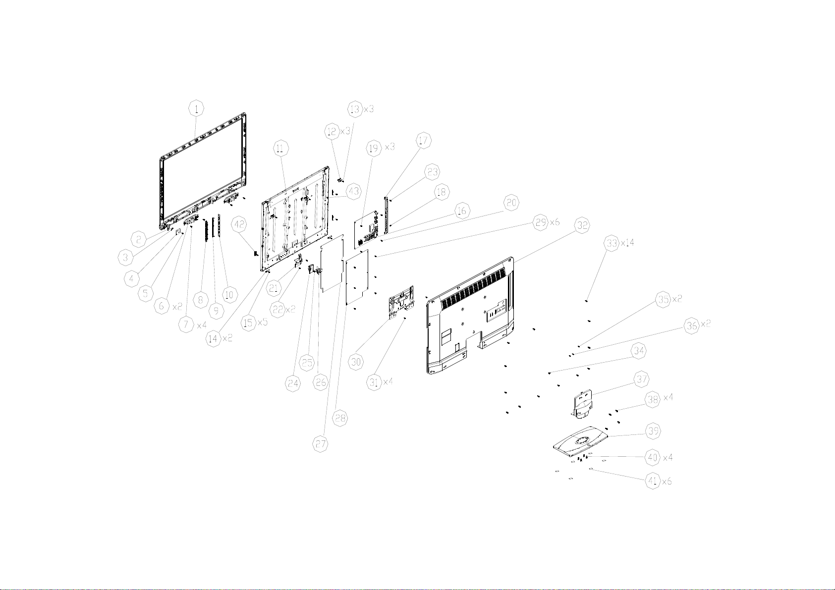
10. Exploded View
LE32A3520/61
58
Page 59

LE32A3520/61
Item Description
1 BEZEL
2 LENS IR
3 LENS LED
4 IR BOARD
6 SPEAKER
8 COVER KEY 5 0Q1G1030 8120 SCREW(IR BOARD-BEZEL) 1
9 KEY 7 001G6021 1 SCREW(SPEAKER-BEZEL) 4
10 KEY BOARD 13 0Q1G 330 8120 SCREW(BRACKET HOLDER_TOP-BEZEL) 3
11 PANEL 15 0Q1G 330 8120 SCREW(BKT_HOLDER -BEZEL) 5
12 BRACKET HOLDER_TOP_DYNEX 18 0Q1G 330 8 47 CR3 SCREW(BKT_OPS_CHASSIS-COMPONENT) 1
14 BKT_HOLDER Ÿ 19 0M1G1730 6120 SCREW(MAIN BOARD-PANEL) 3
16 MAIN BOARD 20 0M1G1730 6120 SCREW(BKT_OPS_CHASSIS-PANEL) 1
17 BKT_OPS_CHASSIS 22 0M1G1730 8120 SCREW(BRACKET PB_BTM-PANEL) 2
21 BRACKET PB_BTM 23 0M1G1730 6120 SCREW(BKT_OPS_CHASSIS-PANEL) 1
24 AC COVER 25 0M1G 940 6 47 CR3 SCREW(AC COVER-BRACKET PB_BTM) 1
26 POWER CORE 29 0M1G1730 6120 SCREW(POWER BOARD-PANEL) 6
27 MYLAR 31 0M1G1730 8120 SCREW(BRACKET STAND-PANEL) 4
28 POWER BOARD 33 0Q1G 940 10 47 CR3 SCREW(REAR COVER-BEZEL) 14
30 BRACKET STAND 34 0M1G 940 6 47 CR3 SCREW(REAR COVER-AC STAND) 1
32 REAR COVER 35 0Q1G 330 8 47 CR3 SCREW(REAR COVER-HDMI) 2
37 STAND 36 0M1G 330 8 47 CR3
39 BASE 38 0M1G1740 12225 CR3 SCREW(STAND-AC STAND) 4
41 FOOT PAD 40 0Q1G 940 18 47 CR3 SCREW(BASE-STAND) 4
42 BRACKET HOLDER_BTM_DYNEX 43 Q02G7022 3 SCREW(PANEL) 1
Item Part No. Description Qty
SCREW(REAR COVER-YPbPr)
2
59
Page 60

11. BOM List
Note: The parts information listed below are for reference only, and are subject to change without notice.
Please go to http://cs.tpv.com.cn/hello1.asp
E32C1KNCASA1NNX
Location Part NO. Description Remark
P33T0213ADT 1L0300 KEY
052G 1186 SMALL TAPE
052G 1211 B Conductive Tape 85mm *40mm *0.09mm
052G 2191 A PAPER TAPE
052G 2191 A PAPER TAPE
070GHDCP500HDC HDCP CODE
ECN8901 089G217A15NISU X1 AC POWER CORD 1500+215mm
ECN700 095G801313DX14 HARNESS 13P-13P 320mm
ECN4005 095G8018 3XY17 HARNESS 30P-30P 320mm
0M1G 330 8 47 CR3 SCREW 3x8
0M1G 940 6 47 CR3 SCREW 4x6
0M1G 940 6 47 CR3 SCREW 4x6
0M1G1730 6120 SCREW 3x6
0M1G1730 6120 SCREW 3x6
0M1G1730 8120 SCREW 3x8
0M1G1730 8120 SCREW 3x8
0M1G1740 12225 CR3 SCREW M1-MACHINE SCREW x12.0
0Q1G 330 8 47 CR3 SCREW 3x8
0Q1G 330 8120 SCREW
0Q1G 940 10 47 CR3 SCREW 4x10
756TXCCB0KD0650000 MAIN BOARD-CBPFCK4DX2
SMTF-U4003 100TARVK017CTX MCU ASS'Y-056G2233 50
A33T1159 GM 1G0100 AC COVER
040G 45762412B CBPC LABEL
CN4003 033G380214B YH L WAFER 2.0mm 14P R/A 29.98mm 7.8mm
U102 053T 44501 HD SAW FILTER HD-BF35 A3 DC
C765 067G 3151017RV EC 100UF 20% 50V 10*9
C129 067G215C101 4H EC 100 20% 25 6.3*7
C149 067G305M221 3C EC 220uF 16V SZ 8x7mm
C131 067G305S1003HV EC 10UF 20% 16V 4*7
C4044 067G305S1013HV EC 100UF 20% 16V 6.3*7
C4049 067G305S1013HV EC 100UF 20% 16V 6.3*7
C4061 067G305S1013HV EC 100UF 20% 16V 6.3*7
C139 067G305S3316CV EC 330UF 20% 35V 10*9
C701 067G305S3316CV EC 330UF 20% 35V 10*9
C705 067G305S471 2C EC 470UF 20% 10V KW 8*9
C605 067G315M1016HV EC 100UF 20% 35V 8*7
C607 067G315M1016HV EC 100UF 20% 35V 8*7
C605 067G315M1016KV EC 100UF 20% 35V 8*7
C607 067G315M1016KV EC 100UF 20% 35V 8*7
C750 067G315M2213HV EC 220UF 20% 16V 6.3*7
C747 067G315M2213HV EC 220UF 20% 16V 6.3*7
C754 067G315M2213HV EC 220UF 20% 16V 6.3*7
C762 067G315M2213HV EC 220UF 20% 16V 6.3*7
CN106 088G 30211K NO-SUGGEST PHONG JACK 7PIN
CN106 088G 302A11 YG PHONE JACK 3.5µ 7PIN BLACK CKX3.507B-01
CN107 088G 78F114VCL RCA JACK 2P YELLOW 1*1 V/T 13.5
CN107 088G 78F114VYG RCA JACK 2P YELLOW V/T 13.5
for the latest information.
60
Page 61

CN104 088G 78F121XYG RCA JACK V/T 4P W/R 1*2 H=8.6
CN102 088G 78F131XYG RCA JACK V/T 6P Y/W/R 1*3 H=8.6
CN103 088G 78F135XYG RCA JACK V/T 6P G/BL/R 1*3 H=8.6
CN108 088G 78G113ACL RCA JACK R/A 3P BLACK H=10.5
CN101 088G 78G131ACL RCA JACK 6P R/A Y/W/R H 1*3 H=10.5
CN101 088G 78G131AYG RCA JACK 6P R/A Y/W/R H 1*3 H=10.5
CN105 088G302F3G1VYG PHONE JACK V/T 3P GREEN H=8.4
CN4001 088G352F6B2ACL USB CONN R/A 6P BLACK 8.4mm
CN4002 088G352F6B2ACL USB CONN R/A 6P BLACK 8.4mm
CN100 088G353FFF1XCL D-SUB CONN SCREWED V/T 15P BLUE H=8.6
TU100 094G PAL D12L TUNER CHINA F35CT-2-E 1
CN610 311GW250B04BBX WAFER 2.5MM 4P
CN700 311GW250B13BBX WAFER 2.5mm 13P R/A 35mm 7mm
709T4629 XM001 COMSUPTIVE ASS'Y
055G 23524 WELDING FLUX WITHOUT PB
Q55G 100625 TIN STICK_LOW ARGENTUM
U703 056G 133 30AAC DC/DC AZ1117H-ADJ-E1 1A adj SOT-223
U4000 056G 562F32 SCALER RTD2684S-GR LQFP-256
U700 056G 563 93 IC G9084T43U TO-252
U700 056G 563 93 C LDO G9084PT43U 5A ADJ TO-252
U705 056G 563323 DC/DC AOZ1242AI 3A SO-8
U704 056G 563344 DC/DC AT1529F11U 3.2A SOP-8
U702 056G 563344 DC/DC AT1529F11U 3.2A SOP-8
U103 056G 563519 IC G965-25ADJPIUF 1.8A SOP-8
U4002 056G 615503 W971GG6JB-18 1066Mb DDR2-1066 1G WBGA84
U600 056G 616 54 IC TPA3110D2 15W TSSOP-28
U100 056G 662502 IC ESD AZC199-04S.R7G SOT23-6L
U101 056G 662502 IC ESD AZC199-04S.R7G SOT23-6L
U4003 056G2233 50 FLASH H27U1G8F2BTR-BC 1Gb TSOP1-48
Q703 057G 417 4 PMBS3904/PHILIPS-SMT(04)
Q700 057G 417 4 PMBS3904/PHILIPS-SMT(04)
Q4007 057G 417 4 PMBS3904/PHILIPS-SMT(04)
Q500 057G 417511 MMBT3904
Q502 057G 417511 MMBT3904
Q503 057G 417511 MMBT3904
Q4006 057G 417511 MMBT3904
Q4005 057G 417511 MMBT3904
Q102 057G 417511 MMBT3904
Q504 057G 417511 MMBT3904
Q505 057G 417511 MMBT3904
Q506 057G 417511 MMBT3904
Q603 057G 417511 MMBT3904
Q706 057G 417511 MMBT3904
Q4002 057G 417512 MMBT3906
Q4003 057G 417512 MMBT3906
Q103 057G 417512 HF TRA MMBT3906G -0.2A/-40V SOT-23
Q705 057G 417518 TRA LMBT3904LT1G 200mA/40V SOT-23 LRC
Q101 057G 761513 SMALLTRAN 2SC4215-O(TE85L,F) 0.02 40 SMD
Q4004 057G 763 79 FET AO4449 -7A/-30V SOIC-8
Q704 057G 763 79 FET AO4449 -7A/-30V SOIC-8
Q301 057G 763904 TRA FET 2N7002 SOT-23 PHILIPS
Q302 057G 763904 TRA FET 2N7002 SOT-23 PHILIPS
TH4001 061G 52902 PTC CHIP 8V 0R4 KMC4S075RY
TH4000 061G 52902 PTC CHIP 8V 0R4 KMC4S075RY
61
Page 62

RP4015 061G 1262208JF RST NET 22R 5% 1/16W 8P4R
RP4014 061G 1262208JF RST NET 22R 5% 1/16W 8P4R
RP4013 061G 1262208JF RST NET 22R 5% 1/16W 8P4R
RP4012 061G 1262208JF RST NET 22R 5% 1/16W 8P4R
RP4011 061G 1262208JF RST NET 22R 5% 1/16W 8P4R
RP4010 061G 1262208JF RST NET 22R 5% 1/16W 8P4R
RP4004 061G 1262208JF RST NET 22R 5% 1/16W 8P4R
RP4003 061G 1262208JF RST NET 22R 5% 1/16W 8P4R
RP4002 061G 1262208JF RST NET 22R 5% 1/16W 8P4R
RP4001 061G 1262208JF RST NET 22R 5% 1/16W 8P4R
RP4000 061G 1262208JF RST NET 22R 5% 1/16W 8P4R
RP4009 061G 1265108JY RST CHIP NET 51R 5% 1/16W 8P4R
RP4008 061G 1265108JY RST CHIP NET 51R 5% 1/16W 8P4R
RP4007 061G 1265108JY RST CHIP NET 51R 5% 1/16W 8P4R
RP4006 061G 1265108JY RST CHIP NET 51R 5% 1/16W 8P4R
RP4005 061G 1265108JY RST CHIP NET 51R 5% 1/16W 8P4R
R200 061G0402000 JT RST CHIPR MAX0R05 1/16W TZAI YUAN
R4052 061G0402000 JT RST CHIPR MAX0R05 1/16W TZAI YUAN
R613 061G0402100 JF RST CHIPR 10 OHM +-5% 1/16W FENGHUA
R614 061G0402100 JF RST CHIPR 10 OHM +-5% 1/16W FENGHUA
R616 061G0402100 JF RST CHIPR 10 OHM +-5% 1/16W FENGHUA
R619 061G0402100 JF RST CHIPR 10 OHM +-5% 1/16W FENGHUA
R620 061G0402100 JF RST CHIPR 10 OHM +-5% 1/16W FENGHUA
R625 061G0402100 JF RST CHIPR 10 OHM +-5% 1/16W FENGHUA
R4020 061G04021001FF RST CHIPR 1KOHM +-1% 1/16W FENGHUA
R4021 061G04021001FF RST CHIPR 1KOHM +-1% 1/16W FENGHUA
R740 061G04021002FI TEST ONLY RST 0402 10K 1% 1/16W TA-I
R107 061G0402101 JF RST CHIPR 100 OHM +-5% 1/16W FENGHUA
R108 061G0402101 JF RST CHIPR 100 OHM +-5% 1/16W FENGHUA
R109 061G0402101 JF RST CHIPR 100 OHM +-5% 1/16W FENGHUA
R110 061G0402101 JF RST CHIPR 100 OHM +-5% 1/16W FENGHUA
R4040 061G0402101 JT RST CHIP 100R 1/16W 5% TZAI YUAN
R717 061G0402102 JF RST CHIPR 1KOHM +-5% 1/16W FENGHUA
R701 061G0402102 JF RST CHIPR 1KOHM +-5% 1/16W FENGHUA
R4034 061G0402102 JF RST CHIPR 1KOHM +-5% 1/16W FENGHUA
R197 061G0402102 JF RST CHIPR 1KOHM +-5% 1/16W FENGHUA
R708 061G0402102 JT RST CHIP 1K 1/16W 5% TZAI YUAN
R205 061G0402103 JF RST CHIPR 10KOHM +-5% 1/16W FENGHUA
R211 061G0402103 JF RST CHIPR 10KOHM +-5% 1/16W FENGHUA
R211 061G0402103 JT RST CHIP 10K 1/16W 5% TZAI YUAN
R205 061G0402103 JT RST CHIP 10K 1/16W 5% TZAI YUAN
R133 061G0402123 JF RST CHIPR 12KOHM +-5% 1/16W FENGHUA
R137 061G0402123 JF RST CHIPR 12KOHM +-5% 1/16W FENGHUA
R103 061G0402123 JT RST CHIPR 12KOHM +-5% 1/16W TZAI YUAN
R105 061G0402123 JT RST CHIPR 12KOHM +-5% 1/16W TZAI YUAN
R128 061G0402123 JT RST CHIPR 12KOHM +-5% 1/16W TZAI YUAN
R130 061G0402123 JT RST CHIPR 12KOHM +-5% 1/16W TZAI YUAN
R134 061G0402153 JF RST CHIPR 15KOHM 1/16W FENGHUA
R132 061G0402153 JF RST CHIPR 15KOHM 1/16W FENGHUA
R190 061G0402200 JF RST CHIP 20R 5% 1/16W FENGHUA
R4046 061G0402201 JF RST CHIPR 200 OHM +-5% 1/16W FENGHUA
R4048 061G0402201 JF RST CHIPR 200 OHM +-5% 1/16W FENGHUA
R4061 061G0402220 JT RST CHIP 22R 1/16W 5% TZAI YUAN
R4038 061G0402220 JT RST CHIP 22R 1/16W 5% TZAI YUAN
62
Page 63

R4037 061G0402220 JT RST CHIP 22R 1/16W 5% TZAI YUAN
R4036 061G0402220 JT RST CHIP 22R 1/16W 5% TZAI YUAN
R4035 061G0402220 JT RST CHIP 22R 1/16W 5% TZAI YUAN
R4033 061G0402220 JT RST CHIP 22R 1/16W 5% TZAI YUAN
R164 061G0402222 JT RST CHIP 2K2 1/16W 5% TZAI YUAN
R165 061G0402222 JT RST CHIP 2K2 1/16W 5% TZAI YUAN
R4016 061G0402272 JF RST CHIP 2K7 1/16W 5% FENGHUA
R185 061G0402470 JF RST CHIPR 47 OHM 5% 1/16W FENGHUA
R4060 061G0402472 JF RST CHIPR 4.7KOHM +-5% 1/16W FENGHUA
R4059 061G0402472 JF RST CHIPR 4.7KOHM +-5% 1/16W FENGHUA
R4058 061G0402472 JF RST CHIPR 4.7KOHM +-5% 1/16W FENGHUA
R516 061G0402472 JT RST CHIP 4K7 1/16W 5% TZAI YUAN
R514 061G0402472 JT RST CHIP 4K7 1/16W 5% TZAI YUAN
R513 061G0402472 JT RST CHIP 4K7 1/16W 5% TZAI YUAN
R4047 061G0402472 JT RST CHIP 4K7 1/16W 5% TZAI YUAN
R4044 061G0402472 JT RST CHIP 4K7 1/16W 5% TZAI YUAN
R4031 061G0402472 JT RST CHIP 4K7 1/16W 5% TZAI YUAN
R4030 061G0402472 JT RST CHIP 4K7 1/16W 5% TZAI YUAN
R4027 061G0402472 JT RST CHIP 4K7 1/16W 5% TZAI YUAN
R4024 061G0402472 JT RST CHIP 4K7 1/16W 5% TZAI YUAN
R182 061G0402472 JT RST CHIP 4K7 1/16W 5% TZAI YUAN
R181 061G0402472 JT RST CHIP 4K7 1/16W 5% TZAI YUAN
R151 061G0402472 JT RST CHIP 4K7 1/16W 5% TZAI YUAN
R100 061G0402472 JT RST CHIP 4K7 1/16W 5% TZAI YUAN
R517 061G0402472 JT RST CHIP 4K7 1/16W 5% TZAI YUAN
R518 061G0402472 JT RST CHIP 4K7 1/16W 5% TZAI YUAN
R526 061G0402472 JT RST CHIP 4K7 1/16W 5% TZAI YUAN
R501 061G0402473 JF RST CHIPR 47KOHM +-5% 1/16W FENGHUA
R507 061G0402473 JF RST CHIPR 47KOHM +-5% 1/16W FENGHUA
R508 061G0402473 JF RST CHIPR 47KOHM +-5% 1/16W FENGHUA
R737 061G0402473 JT RST CHIP 47K 1/16W 5% TZAI YUAN
R4043 061G0402510 JF RST CHIP 51R 1/16W 5% FENGHUA
R199 061G0402511 JT RST CHIP 510R 1/16W 5% TZAI YUAN
R4019 061G0402512 JF RST CHIP 5K1 1/16W 5% FENGHUA
R739 061G04025232FT RST 0402 52.3K 1/16W 1% TZAI YUAN
R206 061G0402683 JT RST CHIP R 68Kohm 1/16W +/-5% TZAI YUAN
R168 061G0402750 JI TEST ONLY RST 0402 75R 5% 1/16W TA-I
R159 061G0402750 JI TEST ONLY RST 0402 75R 5% 1/16W TA-I
R154 061G0402750 JI TEST ONLY RST 0402 75R 5% 1/16W TA-I
R125 061G0402750 JI TEST ONLY RST 0402 75R 5% 1/16W TA-I
R120 061G0402750 JI TEST ONLY RST 0402 75R 5% 1/16W TA-I
R115 061G0402750 JI TEST ONLY RST 0402 75R 5% 1/16W TA-I
R102 061G0402750 JI TEST ONLY RST 0402 75R 5% 1/16W TA-I
R112 061G0402750 JT RST 0402 75R 5% 1/16W
R207 061G04027509FI TEST ONLY RST 0402 75R 1% 1/16W TA-I
R171 061G0402752 JF RST CHIP 7K5 1/16W 5% FENGHUA
R174 061G0402752 JF RST CHIP 7K5 1/16W 5% FENGHUA
R204 061G0402753 JF RST CHIPR 75KOHM 5% 1/16W FENGHUA
R4008 061G0603000 JF RST CHIPR MAX 0R05 1/10W FENGHUA
R4007 061G0603000 JF RST CHIPR MAX 0R05 1/10W FENGHUA
R730 061G0603000 JF RST CHIPR MAX 0R05 1/10W FENGHUA
R4017 061G0603000 JF RST CHIPR MAX 0R05 1/10W FENGHUA
R169 061G0603000 JF RST CHIPR MAX 0R05 1/10W FENGHUA
R166 061G0603000 JF RST CHIPR MAX 0R05 1/10W FENGHUA
63
Page 64

R162 061G0603000 JF RST CHIPR MAX 0R05 1/10W FENGHUA
R157 061G0603000 JF RST CHIPR MAX 0R05 1/10W FENGHUA
R155 061G0603000 JF RST CHIPR MAX 0R05 1/10W FENGHUA
R111 061G0603000 JF RST CHIPR MAX 0R05 1/10W FENGHUA
R113 061G0603000 JF RST CHIPR MAX 0R05 1/10W FENGHUA
R116 061G0603000 JF RST CHIPR MAX 0R05 1/10W FENGHUA
R118 061G0603000 JF RST CHIPR MAX 0R05 1/10W FENGHUA
R121 061G0603000 JF RST CHIPR MAX 0R05 1/10W FENGHUA
R123 061G0603000 JF RST CHIPR MAX 0R05 1/10W FENGHUA
R126 061G0603000 JF RST CHIPR MAX 0R05 1/10W FENGHUA
R152 061G0603000 JF RST CHIPR MAX 0R05 1/10W FENGHUA
R627 061G0603000 JI RST 0603 0.05R MAX 1/10W TA-I
R736 061G0603000 JT RST CHIP MAX 0R05 1/10W TZAI YUAN
R525 061G0603000 JT RST CHIP MAX 0R05 1/10W TZAI YUAN
R524 061G0603000 JT RST CHIP MAX 0R05 1/10W TZAI YUAN
R523 061G0603000 JT RST CHIP MAX 0R05 1/10W TZAI YUAN
R522 061G0603000 JT RST CHIP MAX 0R05 1/10W TZAI YUAN
R521 061G0603000 JT RST CHIP MAX 0R05 1/10W TZAI YUAN
R520 061G0603000 JT RST CHIP MAX 0R05 1/10W TZAI YUAN
R186 061G0603000 JT RST CHIP MAX 0R05 1/10W TZAI YUAN
R138 061G0603000 JT RST CHIP MAX 0R05 1/10W TZAI YUAN
R101 061G0603000 JT RST CHIP MAX 0R05 1/10W TZAI YUAN
R735 061G0603100 JF RST CHIPR 10 OHM 5% 1/10W FENGHUA
R732 061G0603100 JF RST CHIPR 10 OHM 5% 1/10W FENGHUA
R707 061G06031000FT RST CHIP 100R 1/10W 1%
R4041 061G06031001FT RST CHIP 1K 1/10W 1%
R4042 061G06031001FT RST CHIP 1K 1/10W 1%
R4071 061G0603101 JF RST CHIPR 100 OHM +-5% 1/10W FENGHUA
R4067 061G0603101 JF RST CHIPR 100 OHM +-5% 1/10W FENGHUA
R4050 061G0603101 JF RST CHIPR 100 OHM +-5% 1/10W FENGHUA
R4015 061G0603101 JF RST CHIPR 100 OHM +-5% 1/10W FENGHUA
R4014 061G0603101 JF RST CHIPR 100 OHM +-5% 1/10W FENGHUA
R114 061G0603101 JT RST CHIP 100R 1/10W 5% TZAI YUAN
R117 061G0603101 JT RST CHIP 100R 1/10W 5% TZAI YUAN
R119 061G0603101 JT RST CHIP 100R 1/10W 5% TZAI YUAN
R122 061G0603101 JT RST CHIP 100R 1/10W 5% TZAI YUAN
R124 061G0603101 JT RST CHIP 100R 1/10W 5% TZAI YUAN
R127 061G0603101 JT RST CHIP 100R 1/10W 5% TZAI YUAN
R153 061G0603101 JT RST CHIP 100R 1/10W 5% TZAI YUAN
R156 061G0603101 JT RST CHIP 100R 1/10W 5% TZAI YUAN
R158 061G0603101 JT RST CHIP 100R 1/10W 5% TZAI YUAN
R4010 061G0603101 JT RST CHIP 100R 1/10W 5% TZAI YUAN
R4009 061G0603101 JT RST CHIP 100R 1/10W 5% TZAI YUAN
R187 061G0603101 JT RST CHIP 100R 1/10W 5% TZAI YUAN
R184 061G0603101 JT RST CHIP 100R 1/10W 5% TZAI YUAN
R170 061G0603101 JT RST CHIP 100R 1/10W 5% TZAI YUAN
R167 061G0603101 JT RST CHIP 100R 1/10W 5% TZAI YUAN
R163 061G0603101 JT RST CHIP 100R 1/10W 5% TZAI YUAN
R161 061G0603101 JT RST CHIP 100R 1/10W 5% TZAI YUAN
R160 061G0603101 JT RST CHIP 100R 1/10W 5% TZAI YUAN
R196 061G0603102 JF RST CHIPR 1K OHM +-5% 1/10W FENGHUA
R195 061G0603102 JF RST CHIPR 1K OHM +-5% 1/10W FENGHUA
R713 061G0603102 JF RST CHIPR 1K OHM +-5% 1/10W FENGHUA
R189 061G0603102 JF RST CHIPR 1K OHM +-5% 1/10W FENGHUA
64
Page 65

R176 061G0603102 JF RST CHIPR 1K OHM +-5% 1/10W FENGHUA
R173 061G0603102 JF RST CHIPR 1K OHM +-5% 1/10W FENGHUA
R519 061G0603102 JY RST CHIPR 1KOHM +-5% 1/10W YAGEO
R505 061G0603102 JY RST CHIPR 1KOHM +-5% 1/10W YAGEO
R502 061G0603102 JY RST CHIPR 1KOHM +-5% 1/10W YAGEO
R710 061G0603103 JF RST CHIPR 10K OHM +-5% 1/10W FENGHUA
R711 061G0603103 JF RST CHIPR 10K OHM +-5% 1/10W FENGHUA
R722 061G0603103 JF RST CHIPR 10K OHM +-5% 1/10W FENGHUA
R733 061G0603103 JF RST CHIPR 10K OHM +-5% 1/10W FENGHUA
R738 061G0603103 JF RST CHIPR 10K OHM +-5% 1/10W FENGHUA
R4023 061G0603103 JF RST CHIPR 10K OHM +-5% 1/10W FENGHUA
R4025 061G0603103 JF RST CHIPR 10K OHM +-5% 1/10W FENGHUA
R4066 061G0603103 JF RST CHIPR 10K OHM +-5% 1/10W FENGHUA
R4068 061G0603103 JF RST CHIPR 10K OHM +-5% 1/10W FENGHUA
R4075 061G0603103 JF RST CHIPR 10K OHM +-5% 1/10W FENGHUA
R4080 061G0603103 JF RST CHIPR 10K OHM +-5% 1/10W FENGHUA
R4081 061G0603103 JF RST CHIPR 10K OHM +-5% 1/10W FENGHUA
R4000 061G0603103 JF RST CHIPR 10K OHM +-5% 1/10W FENGHUA
R4053 061G0603103 JF RST CHIPR 10K OHM +-5% 1/10W FENGHUA
R4069 061G0603103 JF RST CHIPR 10K OHM +-5% 1/10W FENGHUA
R4078 061G0603103 JF RST CHIPR 10K OHM +-5% 1/10W FENGHUA
R506 061G0603103 JF RST CHIPR 10K OHM +-5% 1/10W FENGHUA
R509 061G0603103 JF RST CHIPR 10K OHM +-5% 1/10W FENGHUA
R510 061G0603103 JF RST CHIPR 10K OHM +-5% 1/10W FENGHUA
R511 061G0603103 JF RST CHIPR 10K OHM +-5% 1/10W FENGHUA
R512 061G0603103 JF RST CHIPR 10K OHM +-5% 1/10W FENGHUA
R515 061G0603103 JF RST CHIPR 10K OHM +-5% 1/10W FENGHUA
R622 061G0603103 JF RST CHIPR 10K OHM +-5% 1/10W FENGHUA
R700 061G0603103 JF RST CHIPR 10K OHM +-5% 1/10W FENGHUA
R617 061G0603103 JI RST 0603 10K 5% 1/10W
R4002 061G0603103 JT RST CHIP 10K 1/10W 5% TZAI YUAN
R4054 061G0603104 JF RST CHIPR 100KOHM 5% 1/10W FENGHUA
R621 061G0603104 JT RST CHIP 100K 1/10W 5% TZAI YUAN
R203 061G06031202FT RST CHIP 12K 1/10W 1%
R183 061G0603122 JF RST CHIPR 1.2KOHM 5% 1/10W FENGHUA
R734 061G06031502FT RST CHIP 15K 1/10W 1%
R175 061G0603152 JT RST CHIP 1K5 1/10W 5% TZAI YUAN
R172 061G0603152 JT RST CHIP 1K5 1/10W 5% TZAI YUAN
R709 061G06032209FT RST CHIP 22R 1/10W 1%
R208 061G0603221 JT RST CHIPR 220OHM 1/10W TZAI YUAN
R210 061G0603221 JT RST CHIPR 220OHM 1/10W TZAI YUAN
R198 061G0603229 JF RST CHIPR 2.2 OHM 5% 1/10W FENGHUA
R719 061G06032409FT RST CHIP 24R 1/10W 1%
R741 061G06033001FI TEST ONLY RST 0603 3K 1% 1/10W TA-I
R177 061G0603301 JF RST 0603 300R 5% 1/10W FENGHUA
R178 061G0603301 JF RST 0603 300R 5% 1/10W FENGHUA
R726 061G06033302FT RST CHIP 33K 1/10W 1%
R209 061G0603331 JT RST 0603 330R 5% 1/10W
R623 061G06033321FF RST CHIPR 3.32KOHM +-1% 1/10W FENGHUA
R615 061G06033601FF RST CHIPR 3.6K OHM +-1% 1/10W FENGHUA
R615 061G06033601FI TEST ONLY RST 0603 3.6K 1% 1/10W TA-I
R727 061G06034702FT RST CHIP 47K 1/10W 1%
R728 061G06034702FT RST CHIP 47K 1/10W 1%
R4063 061G0603472 JF RST CHIPR 4.7KOHM +-5% 1/10W FENGHUA
65
Page 66

R705 061G0603472 JF RST CHIPR 4.7KOHM +-5% 1/10W FENGHUA
R4077 061G0603472 JF RST CHIPR 4.7KOHM +-5% 1/10W FENGHUA
R4082 061G0603472 JI RST 0603 4.7K 5% 1/10W TA-I
R4083 061G0603472 JI RST 0603 4.7K 5% 1/10W TA-I
R4062 061G0603472 JT RST CHIP 4K7 1/10W 5% TZAI YUAN
R4064 061G0603472 JT RST CHIP 4K7 1/10W 5% TZAI YUAN
R4070 061G0603472 JT RST CHIP 4K7 1/10W 5% TZAI YUAN
R4074 061G0603472 JT RST CHIP 4K7 1/10W 5% TZAI YUAN
R4076 061G0603472 JT RST CHIP 4K7 1/10W 5% TZAI YUAN
R4079 061G0603472 JT RST CHIP 4K7 1/10W 5% TZAI YUAN
R718 061G0603472 JT RST CHIP 4K7 1/10W 5% TZAI YUAN
R4065 061G0603472 JT RST CHIP 4K7 1/10W 5% TZAI YUAN
R4072 061G0603472 JT RST CHIP 4K7 1/10W 5% TZAI YUAN
R4057 061G0603473 JF RST CHIPR 47KOHM +-5% 1/10W FENGHUA
R716 061G0603473 JF RST CHIPR 47KOHM +-5% 1/10W FENGHUA
R180 061G0603681 JF RST CHIPR 680OHM +-5% 1/10W FENGHUA
R179 061G0603682 JF RST CHIPR 6.8kOHM +-5% 1/10W FENGHUA
R104 061G0603822 JF RST CHIPR 8.2KOHM 5% 1/10W FENGHUA
R106 061G0603822 JF RST CHIPR 8.2KOHM 5% 1/10W FENGHUA
R129 061G0603822 JF RST CHIPR 8.2KOHM 5% 1/10W FENGHUA
R131 061G0603822 JF RST CHIPR 8.2KOHM 5% 1/10W FENGHUA
R135 061G0603822 JF RST CHIPR 8.2KOHM 5% 1/10W FENGHUA
R136 061G0603822 JF RST CHIPR 8.2KOHM 5% 1/10W FENGHUA
R193 061G0805000 JF RST CHIPR 0 OHM +-5% 1/8W FENGHUA
R194 061G0805000 JF RST CHIPR 0 OHM +-5% 1/8W FENGHUA
R201 061G08053832FF RST CHIPR 38.3KOHM +-1% 1/8W FENGHUA
R624 061G1206100 JF RST CHIPR 10 OHM +-5% 1/4W FENGHUA
R4055 061G12067501FF RST CHIPR 7.5K OHM +-1% 1/4W FENGHUA
C121 065G040210031D 3 CAP 0402 10PF 0.5pF 50V NP0
C4115 065G040210131J T CAP CHIP 0402 100pF 50V NPO
C4071 065G040210412K A CAP CHIP 0402 100nF K 16V X7R
C4069 065G040210412K A CAP CHIP 0402 100nF K 16V X7R
C4068 065G040210412K A CAP CHIP 0402 100nF K 16V X7R
C4067 065G040210412K A CAP CHIP 0402 100nF K 16V X7R
C4066 065G040210412K A CAP CHIP 0402 100nF K 16V X7R
C4065 065G040210412K A CAP CHIP 0402 100nF K 16V X7R
C4064 065G040210412K A CAP CHIP 0402 100nF K 16V X7R
C4063 065G040210412K A CAP CHIP 0402 100nF K 16V X7R
C4062 065G040210412K A CAP CHIP 0402 100nF K 16V X7R
C4060 065G040210412K A CAP CHIP 0402 100nF K 16V X7R
C4059 065G040210412K A CAP CHIP 0402 100nF K 16V X7R
C4058 065G040210412K A CAP CHIP 0402 100nF K 16V X7R
C4057 065G040210412K A CAP CHIP 0402 100nF K 16V X7R
C4054 065G040210412K A CAP CHIP 0402 100nF K 16V X7R
C4053 065G040210412K A CAP CHIP 0402 100nF K 16V X7R
C4119 065G040210412K A CAP CHIP 0402 100nF K 16V X7R
C4118 065G040210412K A CAP CHIP 0402 100nF K 16V X7R
C4095 065G040210412K A CAP CHIP 0402 100nF K 16V X7R
C4094 065G040210412K A CAP CHIP 0402 100nF K 16V X7R
C4091 065G040210412K A CAP CHIP 0402 100nF K 16V X7R
C4090 065G040210412K A CAP CHIP 0402 100nF K 16V X7R
C4089 065G040210412K A CAP CHIP 0402 100nF K 16V X7R
C4088 065G040210412K A CAP CHIP 0402 100nF K 16V X7R
C4087 065G040210412K A CAP CHIP 0402 100nF K 16V X7R
66
Page 67

C4086 065G040210412K A CAP CHIP 0402 100nF K 16V X7R
C4085 065G040210412K A CAP CHIP 0402 100nF K 16V X7R
C4084 065G040210412K A CAP CHIP 0402 100nF K 16V X7R
C4083 065G040210412K A CAP CHIP 0402 100nF K 16V X7R
C4082 065G040210412K A CAP CHIP 0402 100nF K 16V X7R
C4081 065G040210412K A CAP CHIP 0402 100nF K 16V X7R
C4080 065G040210412K A CAP CHIP 0402 100nF K 16V X7R
C4079 065G040210412K A CAP CHIP 0402 100nF K 16V X7R
C4078 065G040210412K A CAP CHIP 0402 100nF K 16V X7R
C4077 065G040210412K A CAP CHIP 0402 100nF K 16V X7R
C4076 065G040210412K A CAP CHIP 0402 100nF K 16V X7R
C4075 065G040210412K A CAP CHIP 0402 100nF K 16V X7R
C4073 065G040210412K A CAP CHIP 0402 100nF K 16V X7R
C4110 065G040210412K Y CAP 0402 100NF 10% 16V X7R
C4109 065G040210412K Y CAP 0402 100NF 10% 16V X7R
C4108 065G040210412K Y CAP 0402 100NF 10% 16V X7R
C4107 065G040210412K Y CAP 0402 100NF 10% 16V X7R
C4106 065G040210412K Y CAP 0402 100NF 10% 16V X7R
C4105 065G040210412K Y CAP 0402 100NF 10% 16V X7R
C4104 065G040210412K Y CAP 0402 100NF 10% 16V X7R
C4103 065G040210412K Y CAP 0402 100NF 10% 16V X7R
C4102 065G040210412K Y CAP 0402 100NF 10% 16V X7R
C144 065G040210412K Y CAP 0402 100NF 10% 16V X7R
C4043 065G040210412K Y CAP 0402 100NF 10% 16V X7R
C4048 065G040210412K Y CAP 0402 100NF 10% 16V X7R
C4096 065G040210412K Y CAP 0402 100NF 10% 16V X7R
C4098 065G040210412K Y CAP 0402 100NF 10% 16V X7R
C4099 065G040210412K Y CAP 0402 100NF 10% 16V X7R
C4100 065G040210412K Y CAP 0402 100NF 10% 16V X7R
C4101 065G040210412K Y CAP 0402 100NF 10% 16V X7R
C142 065G040210425K T CAP 0402 100NF 10% 25V X5R
C768 065G040218131J 3 CAP CHIP 0402 180P 50V NP0 +/-5%
C120 065G040222031J T CAP CHIP 0402 22pF J 50V NPO
C4046 065G040222031J T CAP CHIP 0402 22pF J 50V NPO
C4047 065G040222031J T CAP CHIP 0402 22pF J 50V NPO
C632 065G040233131J T CAP CHIP 0402 330PF 50V J NPO
C6158 065G040233131J T CAP CHIP 0402 330PF 50V J NPO
C625 065G040233131J T CAP CHIP 0402 330PF 50V J NPO
C629 065G040233131J T CAP CHIP 0402 330PF 50V J NPO
C104 065G040247131J A CAP CHIP 0402 470PF J 50V NPO
C105 065G040247131J A CAP CHIP 0402 470PF J 50V NPO
C110 065G040247131J A CAP CHIP 0402 470PF J 50V NPO
C111 065G040247131J A CAP CHIP 0402 470PF J 50V NPO
C103 065G040247131J A CAP CHIP 0402 470PF J 50V NPO
C127 065G040247131J A CAP CHIP 0402 470PF J 50V NPO
C124 065G040247131J A CAP CHIP 0402 470PF J 50V NPO
C102 065G040247131J A CAP CHIP 0402 470PF J 50V NPO
C107 065G040250931C Y CAP 0402 5PF 0.25pF 50V NP0
C108 065G040250931C Y CAP 0402 5PF 0.25pF 50V NP0
C109 065G040250931C Y CAP 0402 5PF 0.25pF 50V NP0
C118 065G040250931C Y CAP 0402 5PF 0.25pF 50V NP0
C119 065G040250931C Y CAP 0402 5PF 0.25pF 50V NP0
C122 065G040250931C Y CAP 0402 5PF 0.25pF 50V NP0
C135 065G060310031D F CAP CHIP 0603 10PF D 50V NPO
67
Page 68

C133 065G060310031D F CAP CHIP 0603 10PF D 50V NPO
C623 065G060310232K A CAP CHIP 0603 1000pF K 50V X7R
C622 065G060310232K A CAP CHIP 0603 1000pF K 50V X7R
C769 065G060310232K F CAP CHIP 0603 1NF K 50V X7R
C764 065G060310232K Y CAP CHIP 0603 1N 50V X7R +/-10%
C758 065G060310232K Y CAP CHIP 0603 1N 50V X7R +/-10%
C137 065G060310332K F CAP CHIP 0603 10NF K 50V X7R
C136 065G060310332K F CAP CHIP 0603 10NF K 50V X7R
C134 065G060310332K F CAP CHIP 0603 10NF K 50V X7R
C132 065G060310332K F CAP CHIP 0603 10NF K 50V X7R
C130 065G060310332K F CAP CHIP 0603 10NF K 50V X7R
C722 065G060310432K A CAP 0603 100NF 10% 50V X7R
C716 065G060310432K A CAP 0603 100NF 10% 50V X7R
C713 065G060310432K A CAP 0603 100NF 10% 50V X7R
C712 065G060310432K A CAP 0603 100NF 10% 50V X7R
C711 065G060310432K A CAP 0603 100NF 10% 50V X7R
C710 065G060310432K A CAP 0603 100NF 10% 50V X7R
C708 065G060310432K A CAP 0603 100NF 10% 50V X7R
C704 065G060310432K A CAP 0603 100NF 10% 50V X7R
C703 065G060310432K A CAP 0603 100NF 10% 50V X7R
C733 065G060310432K A CAP 0603 100NF 10% 50V X7R
C4112 065G060310432K A CAP 0603 100NF 10% 50V X7R
C4111 065G060310432K A CAP 0603 100NF 10% 50V X7R
C4004 065G060310432K A CAP 0603 100NF 10% 50V X7R
C4001 065G060310432K A CAP 0603 100NF 10% 50V X7R
C125 065G060310432K A CAP 0603 100NF 10% 50V X7R
C128 065G060310432K A CAP 0603 100NF 10% 50V X7R
C138 065G060310432K A CAP 0603 100NF 10% 50V X7R
C4116 065G060310432K A CAP 0603 100NF 10% 50V X7R
C700 065G060310432K A CAP 0603 100NF 10% 50V X7R
C617 065G060310432K A CAP 0603 100NF 10% 50V X7R
C612 065G060310432K A CAP 0603 100NF 10% 50V X7R
C4113 065G060310432K A CAP 0603 100NF 10% 50V X7R
C761 065G060310432K A CAP 0603 100NF 10% 50V X7R
C760 065G060310432K A CAP 0603 100NF 10% 50V X7R
C759 065G060310432K A CAP 0603 100NF 10% 50V X7R
C755 065G060310432K A CAP 0603 100NF 10% 50V X7R
C753 065G060310432K A CAP 0603 100NF 10% 50V X7R
C751 065G060310432K A CAP 0603 100NF 10% 50V X7R
C749 065G060310432K A CAP 0603 100NF 10% 50V X7R
C748 065G060310432K A CAP 0603 100NF 10% 50V X7R
C736 065G060310432K A CAP 0603 100NF 10% 50V X7R
C771 065G060310432K Y CAP 0603 100NF 10% 50V X7R
C770 065G060310512K 3 CAP 0603 1UF 10% 16V X7R
C4122 065G060310512K T CAP 0603 1UF 10% 16V X7R
C631 065G060310522K M CAP MLCC 0603 1uF K 25V X7R
C628 065G060310522K M CAP MLCC 0603 1uF K 25V X7R
C627 065G060310522K M CAP MLCC 0603 1uF K 25V X7R
C626 065G060310522K M CAP MLCC 0603 1uF K 25V X7R
C4052 065G060310522K T CAP CHIP 0603 1uF K 25V X7R
C4051 065G060310522K T CAP CHIP 0603 1uF K 25V X7R
C4042 065G060310522K T CAP CHIP 0603 1uF K 25V X7R
C4022 065G060310522K T CAP CHIP 0603 1uF K 25V X7R
C4003 065G060310522K T CAP CHIP 0603 1uF K 25V X7R
68
Page 69

C4000 065G060310522K T CAP CHIP 0603 1uF K 25V X7R
C147 065G060310522K T CAP CHIP 0603 1uF K 25V X7R
C4056 065G060310605M M CAP 0603 10UF 20% 6.3V X5R
C4055 065G060310605M M CAP 0603 10UF 20% 6.3V X5R
C615 065G060322422K A MLCC 0603 220nF 25V X7R +/-10% SAMSUNG
C616 065G060322422K A MLCC 0603 220nF 25V X7R +/-10% SAMSUNG
C624 065G060322422K A MLCC 0603 220nF 25V X7R +/-10% SAMSUNG
C630 065G060322422K A MLCC 0603 220nF 25V X7R +/-10% SAMSUNG
C4017 065G060322515K T CAP 0603 2.2UF 10% 16V X5R
C4020 065G060322515K T CAP 0603 2.2UF 10% 16V X5R
C4021 065G060322515K T CAP 0603 2.2UF 10% 16V X5R
C4041 065G060322515K T CAP 0603 2.2UF 10% 16V X5R
C4070 065G060322515K T CAP 0603 2.2UF 10% 16V X5R
C4072 065G060322515K T CAP 0603 2.2UF 10% 16V X5R
C4121 065G060322515K T CAP 0603 2.2UF 10% 16V X5R
C4123 065G060322515K T CAP 0603 2.2UF 10% 16V X5R
C4016 065G060322515K T CAP 0603 2.2UF 10% 16V X5R
C4015 065G060322515K T CAP 0603 2.2UF 10% 16V X5R
C4014 065G060322515K T CAP 0603 2.2UF 10% 16V X5R
C4011 065G060322515K T CAP 0603 2.2UF 10% 16V X5R
C4010 065G060322515K T CAP 0603 2.2UF 10% 16V X5R
C4120 065G060347332K Y CAP CHIP 0603 47N 50V X7R +/-10%
C4040 065G060347332K Y CAP CHIP 0603 47N 50V X7R +/-10%
C4039 065G060347332K Y CAP CHIP 0603 47N 50V X7R +/-10%
C4038 065G060347332K Y CAP CHIP 0603 47N 50V X7R +/-10%
C4037 065G060347332K Y CAP CHIP 0603 47N 50V X7R +/-10%
C4036 065G060347332K Y CAP CHIP 0603 47N 50V X7R +/-10%
C4035 065G060347332K Y CAP CHIP 0603 47N 50V X7R +/-10%
C4034 065G060347332K Y CAP CHIP 0603 47N 50V X7R +/-10%
C4033 065G060347332K Y CAP CHIP 0603 47N 50V X7R +/-10%
C4032 065G060347332K Y CAP CHIP 0603 47N 50V X7R +/-10%
C4031 065G060347332K Y CAP CHIP 0603 47N 50V X7R +/-10%
C4030 065G060347332K Y CAP CHIP 0603 47N 50V X7R +/-10%
C4029 065G060347332K Y CAP CHIP 0603 47N 50V X7R +/-10%
C4028 065G060347332K Y CAP CHIP 0603 47N 50V X7R +/-10%
C4027 065G060347332K Y CAP CHIP 0603 47N 50V X7R +/-10%
C4026 065G060347332K Y CAP CHIP 0603 47N 50V X7R +/-10%
C4025 065G060347332K Y CAP CHIP 0603 47N 50V X7R +/-10%
C4024 065G060347332K Y CAP CHIP 0603 47N 50V X7R +/-10%
C4023 065G060347332K Y CAP CHIP 0603 47N 50V X7R +/-10%
C4092 065G0603475A5K T CAP CHIP 0603 4.7UF K 10V X5R
C4093 065G0603475A5K T CAP CHIP 0603 4.7UF K 10V X5R
C613 065G080510532K T CAP 0805 1UF 10% 50V X7R
C614 065G080510532K T CAP 0805 1UF 10% 50V X7R
C633 065G080510532K T CAP 0805 1UF 10% 50V X7R
C123 065G080510615K T CHIP 10uF 16V X5R 0805
C126 065G080510615K T CHIP 10uF 16V X5R 0805
C145 065G080510615K T CHIP 10uF 16V X5R 0805
C153 065G080510615K T CHIP 10uF 16V X5R 0805
C735 065G0805106A5K 3 CHIP 10uF 10V X5R 10%
C734 065G0805106A5K 3 CHIP 10uF 10V X5R 10%
C709 065G0805106A5K 3 CHIP 10uF 10V X5R 10%
C707 065G0805106A5K 3 CHIP 10uF 10V X5R 10%
C143 065G0805106A5K 3 CHIP 10uF 10V X5R 10%
69
Page 70

C141 065G0805106A5K 3 CHIP 10uF 10V X5R 10%
C140 065G0805106A5K 3 CHIP 10uF 10V X5R 10%
C4074 065G080522605M T CAP0805 22UF 20% 6.3V X5R
C4097 065G080522605M T CAP0805 22UF 20% 6.3V X5R
C757 065G0805475A2K 3 CAP 0805 4.7UF 10% 10V X7R
C763 065G0805475A2K 3 CAP 0805 4.7UF 10% 10V X7R
C766 065G120610532K 3 CAP 1206 1UF 10% 50V X7R
C767 065G120610532K 3 CAP 1206 1UF 10% 50V X7R
C772 065G120610625K T CAP CHIP 1206 10uF K 25V X5R
C773 065G120610625K T CAP CHIP 1206 10uF K 25V X5R
C752 065G1206226A5K T CAP CHIP1206 22uF K 10V X5R
C756 065G1206226A5K T CAP CHIP1206 22uF K 10V X5R
C618 065G120633432K Y CAP 1206 330NF 10% 50V X7R
C619 065G120633432K Y CAP 1206 330NF 10% 50V X7R
C620 065G120633432K Y CAP 1206 330NF 10% 50V X7R
C621 065G120633432K Y CAP 1206 330NF 10% 50V X7R
FB4006 071G 56A221 TA IND FXD 0805 EMI 100MHZ 220R R
FB4005 071G 56A221 TA IND FXD 0805 EMI 100MHZ 220R R
FB101 071G 56A221 TA IND FXD 0805 EMI 100MHZ 220R R
FB100 071G 56A221 TA IND FXD 0805 EMI 100MHZ 220R R
FB4000 071G 56G301 EA CHIP BEAD 0805 300R 25% 4000mA
FB4001 071G 56G301 EA CHIP BEAD 0805 300R 25% 4000mA
FB4002 071G 56G301 EA CHIP BEAD 0805 300R 25% 4000mA
FB4008 071G 56G301 EA CHIP BEAD 0805 300R 25% 4000mA
FB4009 071G 56G301 EA CHIP BEAD 0805 300R 25% 4000mA
FB4011 071G 56G301 EA CHIP BEAD 0805 300R 25% 4000mA
FB708 071G 56G301 EA CHIP BEAD 0805 300R 25% 4000mA
FB706 071G 56G301 EA CHIP BEAD 0805 300R 25% 4000mA
FB4028 071G 56G301 EA CHIP BEAD 0805 300R 25% 4000mA
FB4027 071G 56G301 EA CHIP BEAD 0805 300R 25% 4000mA
FB4024 071G 56G301 EA CHIP BEAD 0805 300R 25% 4000mA
FB4022 071G 56G301 EA CHIP BEAD 0805 300R 25% 4000mA
FB4021 071G 56G301 EA CHIP BEAD 0805 300R 25% 4000mA
FB4020 071G 56G301 EA CHIP BEAD 0805 300R 25% 4000mA
FB4019 071G 56G301 EA CHIP BEAD 0805 300R 25% 4000mA
FB4018 071G 56G301 EA CHIP BEAD 0805 300R 25% 4000mA
FB4017 071G 56G301 EA CHIP BEAD 0805 300R 25% 4000mA
FB4016 071G 56G301 EA CHIP BEAD 0805 300R 25% 4000mA
FB4015 071G 56G301 EA CHIP BEAD 0805 300R 25% 4000mA
FB4014 071G 56G301 EA CHIP BEAD 0805 300R 25% 4000mA
FB4013 071G 56G301 EA CHIP BEAD 0805 300R 25% 4000mA
FB4012 071G 56G301 EA CHIP BEAD 0805 300R 25% 4000mA
FB706 071G 56G301 MA CHIP BEAD 0805 300OHM 4A
FB4028 071G 56G301 MA CHIP BEAD 0805 300OHM 4A
FB4027 071G 56G301 MA CHIP BEAD 0805 300OHM 4A
FB4024 071G 56G301 MA CHIP BEAD 0805 300OHM 4A
FB4022 071G 56G301 MA CHIP BEAD 0805 300OHM 4A
FB4021 071G 56G301 MA CHIP BEAD 0805 300OHM 4A
FB4020 071G 56G301 MA CHIP BEAD 0805 300OHM 4A
FB4019 071G 56G301 MA CHIP BEAD 0805 300OHM 4A
FB4018 071G 56G301 MA CHIP BEAD 0805 300OHM 4A
FB4017 071G 56G301 MA CHIP BEAD 0805 300OHM 4A
FB707 071G 56G301 MA CHIP BEAD 0805 300OHM 4A
FB705 071G 56G301 MA CHIP BEAD 0805 300OHM 4A
70
Page 71

FB4016 071G 56G301 MA CHIP BEAD 0805 300OHM 4A
FB4015 071G 56G301 MA CHIP BEAD 0805 300OHM 4A
FB4014 071G 56G301 MA CHIP BEAD 0805 300OHM 4A
FB4013 071G 56G301 MA CHIP BEAD 0805 300OHM 4A
FB4012 071G 56G301 MA CHIP BEAD 0805 300OHM 4A
FB4011 071G 56G301 MA CHIP BEAD 0805 300OHM 4A
FB4009 071G 56G301 MA CHIP BEAD 0805 300OHM 4A
FB4008 071G 56G301 MA CHIP BEAD 0805 300OHM 4A
FB4002 071G 56G301 MA CHIP BEAD 0805 300OHM 4A
FB4001 071G 56G301 MA CHIP BEAD 0805 300OHM 4A
FB4000 071G 56G301 MA CHIP BEAD 0805 300OHM 4A
FB708 071G 56G301 MA CHIP BEAD 0805 300OHM 4A
FB600 071G 56K121 TA CHIP BEAD 120R/6000mA HCB2012KF-121T60
FB700 071G 56K121 TA CHIP BEAD 120R/6000mA HCB2012KF-121T60
FB701 071G 56K121 TA CHIP BEAD 120R/6000mA HCB2012KF-121T60
FB702 071G 56K121 TA CHIP BEAD 120R/6000mA HCB2012KF-121T60
FB714 071G 56K121 TA CHIP BEAD 120R/6000mA HCB2012KF-121T60
FB715 071G 56K121 TA CHIP BEAD 120R/6000mA HCB2012KF-121T60
FB719 071G 56K121 TA CHIP BEAD 120R/6000mA HCB2012KF-121T60
FB720 071G 56K121 TA CHIP BEAD 120R/6000mA HCB2012KF-121T60
FB4003 071G 59G301 TA CHIP BEAD 300OHM 200mA FCM1608KF-301T02
FB4004 071G 59G301 TA CHIP BEAD 300OHM 200mA FCM1608KF-301T02
FB4007 071G 59G301 TA CHIP BEAD 300OHM 200mA FCM1608KF-301T02
L100 073G 63229 TA CHIP INDUCROR 2.2uH 10% FCI1608F-2R2K
L102 073G 6333810T CHIP INDUCTOR 0.33uH 10%
L101 073G 63828 TA CHIP INDUCTOR 0603 0.82uH 10%
L103 073G 12610010M CHIP INDUCTOR 1206 10UH 10% 25mA 1.0R
L704 073G253S 31 H SMD CHOKE 15.0uH
L607 073G253S 36 H HF SMD CHOKE 22UH 20% SPI105LRR-220 3.5A,HF
L606 073G253S 36 H HF SMD CHOKE 22UH 20% SPI105LRR-220 3.5A,HF
L605 073G253S 36 H HF SMD CHOKE 22UH 20% SPI105LRR-220 3.5A,HF
L604 073G253S 36 H HF SMD CHOKE 22UH 20% SPI105LRR-220 3.5A,HF
L702 073G253S 71 DN SMD CHOKE 2.2UH 20% 8A LZ.412R2.A0P,HF
L703 073G253S 71 DN SMD CHOKE 2.2UH 20% 8A LZ.412R2.A0P,HF
CN500 088G 34021A VA HDMI HEADER V/T 21P BLACK H=10.5 HF
CN501 088G 34021A VA HDMI HEADER V/T 21P BLACK H=10.5 HF
CN502 088G340FJ04AAT HDMI 19P BLACK R/A H=11.2mm
D100 093G 60505 SCHOTTKY BAT54C 0.2A 30V SOT-23
X4000 093G 22S515 YC CRYSTAL 27MHZ 27MHZ 30ppm 20PF
ZD4005 093G 39S 24 T RLZ 5.6B LLDS
ZD4004 093G 39S 24 T RLZ 5.6B LLDS
ZD4003 093G 39S 24 T RLZ 5.6B LLDS
ZD4001 093G 39S 24 T RLZ 5.6B LLDS
ZD4000 093G 39S 24 T RLZ 5.6B LLDS
D701 093G 60S927 T DIODE SX34 DO-214AA
ZD114 093G 64S500 SU ESD MLVG04025R0QV05BP INPAQ
ZD113 093G 64S500 SU ESD MLVG04025R0QV05BP INPAQ
ZD112 093G 64S500 SU ESD MLVG04025R0QV05BP INPAQ
ZD111 093G 64S500 SU ESD MLVG04025R0QV05BP INPAQ
ZD110 093G 64S500 SU ESD MLVG04025R0QV05BP INPAQ
ZD105 093G 64S500 SU ESD MLVG04025R0QV05BP INPAQ
ZD104 093G 64S500 SU ESD MLVG04025R0QV05BP INPAQ
ZD103 093G 64S500 SU ESD MLVG04025R0QV05BP INPAQ
ZD102 093G 64S500 SU ESD MLVG04025R0QV05BP INPAQ
71
Page 72

ZD101 093G 64S500 SU ESD MLVG04025R0QV05BP INPAQ
ZD500 093G 64S500 SU ESD MLVG04025R0QV05BP INPAQ
ZD501 093G 64S500 SU ESD MLVG04025R0QV05BP INPAQ
ZD502 093G 64S500 SU ESD MLVG04025R0QV05BP INPAQ
ZD503 093G 64S500 SU ESD MLVG04025R0QV05BP INPAQ
ZD504 093G 64S500 SU ESD MLVG04025R0QV05BP INPAQ
ZD505 093G 64S500 SU ESD MLVG04025R0QV05BP INPAQ
ZD506 093G 64S500 SU ESD MLVG04025R0QV05BP INPAQ
ZD507 093G 64S500 SU ESD MLVG04025R0QV05BP INPAQ
ZD508 093G 64S500 SU ESD MLVG04025R0QV05BP INPAQ
D7101 093G1020 PH DIODE S1D-E3 DO-214AC
CN4005 311GW125F30ACH WAFER 1.25mm 30P V/T U700 356G0563418 LDO AZ1084CD-ADJTRG1 5A ADJ TO-252 12V
709T4629 XS001 COMSUPTIVE ASS'Y
055G 100610 TIN CREAM W/O PB
052G6026 2 MESH PRINTTING PAPER
052G 2191 A PAPER TAPE
E715 715G4629M01000004F MAIN BOARD PCB 2nd source
E715 715G4629M01000004K MAIN BOARD PCB
H1 X85T8006101 SHIELD
HS4000 X90G8014 1 HEAT SINK
P15T1107201 BRACKET PB_BTM_
P15T1214101 BRACKET HOLDER_BTM_DYNEX
P15T1215101 BRACKET HOLDER_TOP_DYNEX
P34T0676 GM 1L0100 STAND
PLTVCL544UXB8 POWER BOARD
040G 45762412B CBPC LABEL
009G6005 1 GP GND TERMINAL
CN8101 033G380212H WAFER 2.0mm 12P R/A 26mm 7.7mm
IC9101 056G 139 9 IC EL817M(X) photo coupler DIP-4
IC9204 056G 139 9 IC EL817M(X) photo coupler DIP-4
IC9302 056G 139 9 IC EL817M(X) photo coupler DIP-4
IC9101 056G 139 3B PC123Y82FZOF SHARP
IC9204 056G 139 3B PC123Y82FZOF SHARP
IC9302 056G 139 3B PC123Y82FZOF SHARP
IC9301 056G 379121 IC STR- A6069H DIP-8
RV9901 061G 46 20 W VARISTOR 560V 10% 14*5
NR9901 061G 58259MYW 8A NTCR 2.5R 20% 3.6W
C9901 063G107K474AUZ CAP X2 470NF 10% 305V
C9908 063G107K474AUZ CAP X2 470NF 10% 305V
C9910 065G306K2212BS CAP Y1 220PF 10% 250V Y5P
C9911 065G306K2212BS CAP Y1 220PF 10% 250V Y5P
C9913 065G306K4712BM Y1 CAP 470PF +-10% 250V AC KX
C9913 065G306K4712BS CAP Y1 470PF 10% 250V Y5P
C9912 065G306K6812BM CAP Y1 680PF 10% 250V Y5P
C9909 065G306K6812BM CAP Y1 680PF 10% 250V Y5P
C9314 065G306K6812BM CAP Y1 680PF 10% 250V Y5P
C9914 065G306M1022B3 Y1 CAP 1000PF M 250VAC TDK
C9914 065G306M1022BM Y1.CAP.001UF 250VAC MURATA
C9310 067G 3151007KE EC 10UF 20% 50V 5*11
C9110 067G 4154716KE EC 470UF 20% 35V 12.5*12
C9108 067G 4154716KE EC 470UF 20% 35V 12.5*12
C9103 067G 4154716KE EC 470UF 20% 35V 12.5*12
C9225 067G 4154716KE EC 470UF 20% 35V 12.5*12
72
Page 73

C9107 067G 4156814KE EC 680UF 20% 25V 12.5*12
C9104 067G 4156814KE EC 680UF 20% 25V 12.5*12
C9906 067G 42Z47015K EC 47UF 20% 450V LF 10*50
C9904 067G 42Z47015K EC 47UF 20% 450V LF 10*50
C9905 067G 42Z47015K EC 47UF 20% 450V LF 10*50
C9904 067G 42Z47015L EC 47UF 20% 450V 10*50
C9906 067G 42Z47015L EC 47UF 20% 450V 10*50
C9905 067G 42Z47015L EC 47UF 20% 450V 10*50
C9315 067G204V1022KE CAP CS 1000UF 20% 10V 10*12
C8102 067G215C1007KE EC 10UF 20% 50V 8*9
C8102 067G215C1007LE EC 10UF 20% 50V 8*9 2000 hr
C9224 067G215C1016KE EC 100UF 20% 35V 8*9
C9307 067G215C1016KE EC 100UF 20% 35V 8*9
C9305 067G215P4713KE EC 470UF 20% 16V 10*12
C8108 067G515Z221 9K EC 220UF 20% 100V 10*35 5000 hr
L9901 073G 174185 H LINE FILTER 12MH MIN LCL-12009 HA
L9902 073G 174185 H LINE FILTER 12MH MIN LCL-12009 HA
L8101 073G 174255 CP BOOST CHOKE 56UH 10% L020296-6
L8102 073G 253 91 H IND CHOKE 3.5uH+-10% DADONG
L9301 073G 253 91 H IND CHOKE 3.5uH+-10% DADONG
L9102 073G 253 91 H IND CHOKE 3.5uH+-10% DADONG
L9203 073G 253 91 H IND CHOKE 3.5uH+-10% DADONG
L9101 073G 253 91 H IND CHOKE 3.5uH+-10% DADONG
L9101 073G 253 91 V CHOKE COIL 3.5uH+-10%
L9203 073G 253 91 V CHOKE COIL 3.5uH+-10%
L9102 073G 253 91 V CHOKE COIL 3.5uH+-10%
L9301 073G 253 91 V CHOKE COIL 3.5uH+-10%
T9101 080GL32P 79 H1 X'FMR 550UH 10% 15UH BCK-14322-HA EFD43
T9301 080GL52P 38YS1 X'FMR 1MH 10% 74UH YS04160345 EFD2328
D9302 093G 60334 SCHOTTKY SR506-44 5A 60V DO-201AD
D9306 093G 60334 SCHOTTKY SR506-44 5A 60V DO-201AD
D8105 093G 60924 DIODE SR510-22 DO-201AD
CN9201 311GW250B13BBX WAFER 2.5mm 13P R/A 35mm 7mm
CN9901 311GW396B03BBX WAFER 3.96mm 3(2N)P R/A 11.88mm 9.5mm
705TXA57998 Q9101 ASS'Y
Q9101 057G 667911 MOSFET 2SK4013 TO-220F
0M1G1730 8120 SCREW 3x8
HS9101 Q90T0236 3 HEAT SINK
705TXA93159 BD9901 ASS'Y
BD9901 093G 50460941 BRIDGE KBJ1008G-F 10A 800V KBJ
0M1G 930 8120 SCREW 3x8
HS9901 Q90T0194 3 HEAT SINK
705TXA93996 D9101 and D9102 ASS'Y
D9101 093G 60329 DIODE FMEN-220A 20A/100V TO-220
D9102 093G 60329 DIODE FMEN-220A 20A/100V TO-220
0M1G1730 8120 SCREW 3x8
HS9202 Q90T0236 3 HEAT SINK
709T4697 XM001 COMSUMPTIVE ASS'Y
055G 23520 IPA
055G 23524 WELDING FLUX WITHOUT PB
Q49G 51100 cleaner
Q51G 6 4509 GLUE_RTV
Q55G 100625 TIN STICK_LOW ARGENTUM
IC9303 056G 158501 IC AS431AN-E1 SOT23
73
Page 74

IC8102 056G 368 12 IC FAN7529MX SOP-8
IC9103 056G 379175 IC LD7523GS SOP-8
IC8101 056G 700 17 TEST ONLY LED DRIVER PF7004S SOP-16
Q8108 057G 417 6 PMBS3906/PHILIPS-SMT(06)
Q8106 057G 417 18 T PMBT3904 SOT-23
Q9102 057G 417511 MMBT3904
Q9205 057G 417511 MMBT3904
Q8108 057G 417517 Tra LMBT3906LT1G -200mA/-40V SOT-23 LRC
Q9204 057G 419912 T TRANSISTOR 2SD1624T-TD-E PCP
Q8101 057G 600923 MOSFET AOD4126 TO-252
Q8104 057G 759 2A HF TANSISTOR 2N7002H SOT-23
Q9204 057G 761 5 SMALLTRAN 2SC4672Q 3A 60V SOT-89
Q8105 057G 763532 MOSFET RK7002BM 0.25A 60V SOT-23
Q8105 057G 763904 TRA FET 2N7002 SOT-23 PHILIPS
Q8102 057G 763992 MOSFET P0320AL 1A 200V SOT-223
Q8103 057G 763992 MOSFET P0320AL 1A 200V SOT-223
Q8110 057G 763992 MOSFET P0320AL 1A 200V SOT-223
Q8109 057G 763992 MOSFET P0320AL 1A 200V SOT-223
R9129 061G0805100 JF RST CHIPR 10 OHM +-5% 1/8W FENGHUA
R9129 061G0805100 JI RST 0805 10R 5% 1/8W TA-I
R9129 061G0805100 JT RST CHIP 10R 1/8W 5% TZAI YUAN
R9317 061G08051001FF RST CHIPR 1KOHM +-1% 1/8W FENGHUA
R9108 061G08051001FI RST CHIPR 1KOHM +-1% 1/8W TA-I
R9317 061G08051001FT RST CHIP 1K 1/8W 1%
R9113 061G0805102 JF RST CHIPR 1K OHM +-5% 1/8W FENGHUA
R9225 061G0805102 JF RST CHIPR 1K OHM +-5% 1/8W FENGHUA
R8142 061G0805102 JF RST CHIPR 1K OHM +-5% 1/8W FENGHUA
R9113 061G0805102 JI RST 0805 1K 5% 1/8W
R9225 061G0805102 JI RST 0805 1K 5% 1/8W
R8142 061G0805102 JI RST 0805 1K 5% 1/8W
R8137 061G0805102 JI RST 0805 1K 5% 1/8W
R9113 061G0805102 JT RST CHIPR 1K OHM +- 5% 1/8W TZAI YUAN
R9225 061G0805102 JT RST CHIPR 1K OHM +- 5% 1/8W TZAI YUAN
R8142 061G0805102 JT RST CHIPR 1K OHM +- 5% 1/8W TZAI YUAN
R8137 061G0805102 JT RST CHIPR 1K OHM +- 5% 1/8W TZAI YUAN
R8141 061G0805103 JF RST CHIPR 10K OHM +-5% 1/8W FENGHUA
R8113 061G0805103 JF RST CHIPR 10K OHM +-5% 1/8W FENGHUA
R8115 061G0805103 JF RST CHIPR 10K OHM +-5% 1/8W FENGHUA
R9131 061G0805103 JF RST CHIPR 10K OHM +-5% 1/8W FENGHUA
R8117 061G0805103 JF RST CHIPR 10K OHM +-5% 1/8W FENGHUA
R8132 061G0805103 JF RST CHIPR 10K OHM +-5% 1/8W FENGHUA
R9112 061G0805103 JF RST CHIPR 10K OHM +-5% 1/8W FENGHUA
R9227 061G0805103 JF RST CHIPR 10K OHM +-5% 1/8W FENGHUA
R8118 061G0805103 JF RST CHIPR 10K OHM +-5% 1/8W FENGHUA
R9130 061G0805103 JF RST CHIPR 10K OHM +-5% 1/8W FENGHUA
R8141 061G0805103 JI RST 0805 10K 5% 1/8W
R8113 061G0805103 JI RST 0805 10K 5% 1/8W
R8132 061G0805103 JI RST 0805 10K 5% 1/8W
R8115 061G0805103 JI RST 0805 10K 5% 1/8W
R9227 061G0805103 JI RST 0805 10K 5% 1/8W
R8117 061G0805103 JI RST 0805 10K 5% 1/8W
R9131 061G0805103 JI RST 0805 10K 5% 1/8W
R9112 061G0805103 JI RST 0805 10K 5% 1/8W
R9130 061G0805103 JI RST 0805 10K 5% 1/8W
74
Page 75

R8118 061G0805103 JI RST 0805 10K 5% 1/8W
R8118 061G0805103 JT RST 0805 10K 5% 1/8W
R9112 061G0805103 JT RST 0805 10K 5% 1/8W
R8141 061G0805103 JT RST 0805 10K 5% 1/8W
R8113 061G0805103 JT RST 0805 10K 5% 1/8W
R8117 061G0805103 JT RST 0805 10K 5% 1/8W
R8132 061G0805103 JT RST 0805 10K 5% 1/8W
R8115 061G0805103 JT RST 0805 10K 5% 1/8W
R9227 061G0805103 JT RST 0805 10K 5% 1/8W
R9131 061G0805103 JT RST 0805 10K 5% 1/8W
R9130 061G0805103 JT RST 0805 10K 5% 1/8W
R8109 061G0805104 JF RST CHIPR 100KOHM +-5% 1/8W FENGHUA
R9226 061G0805104 JF RST CHIPR 100KOHM +-5% 1/8W FENGHUA
R9226 061G0805104 JI RST 0805 100K 5% 1/8W
R8109 061G0805104 JI RST 0805 100K 5% 1/8W
R8109 061G0805104 JT RST CHIPR 100KOHM +- 5% 1/8W TZAI YUAN
R8110 061G0805105 JF RST CHIPR 1M OHM +- 5% 1/8W FENGHUA
R8110 061G0805105 JI RST 0805 1M 5% 1/8W
R8110 061G0805105 JT RST CHIP 1M 1/8W 5% TZAI YUAN
R8119 061G08051302FT RST CHIP 13K 1/8W 1%
R8114 061G0805152 JI RST 0805 1.5K 5% 1/8W
R8114 061G0805152 JT RST CHIP 1K5 1/8W 5% TZAI YUAN
R9110 061G08052002FI RST 0805 20K 1% 1/8W
R9110 061G08052002FT RST CHIP 20K 1/8W 1%
R8135 061G0805202 JF RST CHIPR 2KOHM +-5% 1/8W FENGHUA
R9111 061G0805202 JF RST CHIPR 2KOHM +-5% 1/8W FENGHUA
R9111 061G0805202 JI RST CHIPR 2K OHM +-5% 1/8W
R8135 061G0805202 JI RST CHIPR 2K OHM +-5% 1/8W
R9111 061G0805202 JT RST CHIP 2K 1/8W 5% TZAI YUAN
R8135 061G0805202 JT RST CHIP 2K 1/8W 5% TZAI YUAN
R9122 061G0805203 JF RST CHIPR 20KOHM +-5% 1/8W FENGHUA
R9122 061G0805203 JI RST CHIP 20KOHM 1/8W 5%
R9122 061G0805203 JT RST CHIPR 20K +-5% 1/8W TZAI YUAN
R8143 061G0805204 JF RST CHIPR 200KOHM +-5% 1/8W FENGHUA
R8143 061G0805204 JI RST CHIPR 200 KOHM +-5% 1/8W
R8143 061G0805204 JT RST CHIP R 200Kohm 1/8W +/-5% TZAI YUAN
R9107 061G08052052FF RST CHIPR 20.5KOHM +-1% 1/8W FENGHUA
R9107 061G08052052FI RST 0805 20.5K 1% 1/8W
R9107 061G08052052FT RST CHIP 20K5 1/8W 1%
R8106 061G0805220 JF RST CHIPR 22 OHM +-5% 1/8W FENGHUA
R8107 061G0805220 JF RST CHIPR 22 OHM +-5% 1/8W FENGHUA
R8105 061G0805220 JF RST CHIPR 22 OHM +-5% 1/8W FENGHUA
R8108 061G0805220 JF RST CHIPR 22 OHM +-5% 1/8W FENGHUA
R8107 061G0805220 JI RST 0805 22R 5% 1/8W
R8108 061G0805220 JI RST 0805 22R 5% 1/8W
R8105 061G0805220 JI RST 0805 22R 5% 1/8W
R8106 061G0805220 JI RST 0805 22R 5% 1/8W
R8105 061G0805220 JT RST CHIPR 22OHM +-5% 1/8W TZAI YUAN
R8106 061G0805220 JT RST CHIPR 22OHM +-5% 1/8W TZAI YUAN
R8108 061G0805220 JT RST CHIPR 22OHM +-5% 1/8W TZAI YUAN
R8107 061G0805220 JT RST CHIPR 22OHM +-5% 1/8W TZAI YUAN
R8120 061G08052202FF RST CHIPR 22KOHM +-1% 1/8W FENGHUA
R8122 061G08052202FF RST CHIPR 22KOHM +-1% 1/8W FENGHUA
R8122 061G08052202FI RST 0805 22K 1% 1/8W
75
Page 76

R8122 061G08052202FY RST CHIPR 22 KOHM +-1% 1/8W
R8120 061G08052202FY RST CHIPR 22 KOHM +-1% 1/8W
R9132 061G0805221 JI RST CHIPR 220 OHM +-5% 1/8W 0805
R9132 061G0805221 JT RST CHIP 220R 1/8W 5% TZAI YUAN
R9319 061G0805222 JF bST CHIPR 2.2KOHM +-5% 1/8W FENGHUA
R9319 061G0805222 JT RST CHIP 2K2 1/8W 5% TZAI YUAN
R8136 061G0805229 JF RST CHIPR 2R2 +-5% 1/8W FENGHUA
R8136 061G0805229 JI RST 2.2 OHM 5% 1/8W TA-I
R8136 061G0805229 JT RST CHIPR 2R2 +-5% 1/8W TZAI YUAN
R8116 061G08052401FF RST CHIPR 2.4KOHM +-1% 1/8W FENGHUA
R9314 061G08052401FI RST 0805 2.4K 1% 1/8W
R9314 061G08052401FT RST CHIP R 2K4 +/-1% 1/8W
R9314 061G08052401FY RST CHIP 2K4 1/8W 1%
R8133 061G0805270 JI RST CHIPR 27 OHM +-5% 1/8W
R8133 061G0805270 JT RST CHIP 27R 1/8W 5% TZAI YUAN
R9123 061G08053001FF RST CHIPR 3KOHM +-1% 1/8W
R9315 061G08053001FF RST CHIPR 3KOHM +-1% 1/8W
R9315 061G08053001FY RST CHIP R 3K 1/8W +/-1%
R9123 061G08053001FY RST CHIP R 3K 1/8W +/-1%
R8148 061G0805302 JF RST CHIPR 3KOHM +-5% 1/8W FENGHUA
R8148 061G0805302 JI RST CHIPR 3K OHM +-5% 1/8W
R8148 061G0805302 JT RST CHIP 3K 1/8W 5% TZAI YUAN
R8145 061G08053602FF RST CHIPR 36KOHM +-1% 1/8W FENGHUA
R8145 061G08053602FI RST CHIPR 36 KOHM +-1% 1/8W 0805
R8145 061G08053602FT RST CHIP 36K 1/8W 1%
R9109 061G08054301FT RST CHIPR 4.3 KOHM +-1% 1/8W 0805
R9109 061G08054301FY RST CHIPR 4K3 +-1% 1/8W YAGEO
R9128 061G0805470 JI RST CHIPR 47 OHM +-5% 1/8W 0805
R9128 061G0805470 JT RST CHIPR 47OHM +-5% 1/8W TZAI YUAN
R9224 061G0805472 JF RST CHIPR 4.7KOHM +-5% 1/8W FENGHUA
R9224 061G0805472 JI RST CHIPR 4.7 KOHM +-5% 1/8W 0805
R9224 061G0805472 JT RST CHIPR 4K7 +-5% 1/8W TZAI YUAN
R8147 061G0805511 JT RST CHIPR 510OHM +-5% 1/8W TZAI YUAN
R8111 061G0805511 JT RST CHIPR 510OHM +-5% 1/8W TZAI YUAN
R8147 061G0805511 JY RST CHIPR 510OHM +-5% 1/8W YAGEO
R8138 061G0805513 JI RST CHIPR 51K OHM +-5% 1/8W 0805
R8138 061G0805513 JT RST CHIPR 51K +-5% 1/8W TZAI YUAN
R9106 061G08055602FF RST CHIPR 56KOHM +-1% 1/8W FENGHUA
R9106 061G08055602FI RST CHIPR 56 KOHM +-1% 1/8W 0805
R9106 061G08055602FT RST CHIP R 56K 1/8W +/-1%
R9320 061G08055603FI RST CHIPR 560 KOHM +-1% 1/8W 0805
R9320 061G08055603FT RST CHIP 560K 1/8W 1%
R8123 061G0805562 JI RST CHIPR 5.6 KOHM +-5% 1/8W 0805
R8123 061G0805562 JT RST CHIPR 5K6 +-5% 1/8W TZAI YUAN
R8112 061G0805563 JF RST CHIPR 56kOHM +-5% 1/8W FENGHUA
R8140 061G0805563 JF RST CHIPR 56kOHM +-5% 1/8W FENGHUA
R8140 061G0805563 JI RST CHIPR 56K OHM +-5% 1/8W 0805
R8112 061G0805563 JI RST CHIPR 56K OHM +-5% 1/8W 0805
R8112 061G0805563 JT RST CHIPR 56K +-5% 1/8W TZAI YUAN
R8140 061G0805563 JT RST CHIPR 56K +-5% 1/8W TZAI YUAN
R8144 061G0805913 JT RST 0805 91K 5% 1/8W
JR902 061G1206000 JF RST CHIPR MAX0R05 1/4W FENGHUA
JR911 061G1206000 JF RST CHIPR MAX0R05 1/4W FENGHUA
JR906 061G1206000 JF RST CHIPR MAX0R05 1/4W FENGHUA
76
Page 77

JR900 061G1206000 JF RST CHIPR MAX0R05 1/4W FENGHUA
JR909 061G1206000 JF RST CHIPR MAX0R05 1/4W FENGHUA
JR903 061G1206000 JF RST CHIPR MAX0R05 1/4W FENGHUA
JR904 061G1206000 JF RST CHIPR MAX0R05 1/4W FENGHUA
JR907 061G1206000 JF RST CHIPR MAX0R05 1/4W FENGHUA
JR910 061G1206000 JF RST CHIPR MAX0R05 1/4W FENGHUA
JR901 061G1206000 JF RST CHIPR MAX0R05 1/4W FENGHUA
JR905 061G1206000 JF RST CHIPR MAX0R05 1/4W FENGHUA
JR900 061G1206000 JT RST CHIPR MAX0R05 1/4W TZAI YUAN
JR904 061G1206000 JT RST CHIPR MAX0R05 1/4W TZAI YUAN
JR902 061G1206000 JT RST CHIPR MAX0R05 1/4W TZAI YUAN
JR911 061G1206000 JT RST CHIPR MAX0R05 1/4W TZAI YUAN
JR903 061G1206000 JT RST CHIPR MAX0R05 1/4W TZAI YUAN
JR901 061G1206000 JT RST CHIPR MAX0R05 1/4W TZAI YUAN
JR905 061G1206000 JT RST CHIPR MAX0R05 1/4W TZAI YUAN
JR909 061G1206000 JT RST CHIPR MAX0R05 1/4W TZAI YUAN
JR907 061G1206000 JT RST CHIPR MAX0R05 1/4W TZAI YUAN
JR910 061G1206000 JT RST CHIPR MAX0R05 1/4W TZAI YUAN
JR906 061G1206000 JT RST CHIPR MAX0R05 1/4W TZAI YUAN
R9127 061G1206101 JF RST CHIPR 100 OHM +-5% 1/4W FENGHUA
R9125 061G1206101 JF RST CHIPR 100 OHM +-5% 1/4W FENGHUA
R9126 061G1206101 JF RST CHIPR 100 OHM +-5% 1/4W FENGHUA
R9124 061G1206101 JF RST CHIPR 100 OHM +-5% 1/4W FENGHUA
R9126 061G1206101 JI RST 1206 100R 5% 1/4W
R9124 061G1206101 JI RST 1206 100R 5% 1/4W
R9125 061G1206101 JI RST 1206 100R 5% 1/4W
R9127 061G1206101 JI RST 1206 100R 5% 1/4W
R9127 061G1206101 JT RST CHIPR 100 OHM +-5% 1/4W TZAI YUAN
R9125 061G1206101 JT RST CHIPR 100 OHM +-5% 1/4W TZAI YUAN
R9124 061G1206101 JT RST CHIPR 100 OHM +-5% 1/4W TZAI YUAN
R9126 061G1206101 JT RST CHIPR 100 OHM +-5% 1/4W TZAI YUAN
R8131 061G1206104 JF RST CHIPR 100KOHM +-5% 1/4W FENGHUA
R9304 061G1206104 JF RST CHIPR 100KOHM +-5% 1/4W FENGHUA
R9114 061G1206104 JF RST CHIPR 100KOHM +-5% 1/4W FENGHUA
R9307 061G1206104 JF RST CHIPR 100KOHM +-5% 1/4W FENGHUA
R8129 061G1206104 JF RST CHIPR 100KOHM +-5% 1/4W FENGHUA
R9303 061G1206104 JF RST CHIPR 100KOHM +-5% 1/4W FENGHUA
R9115 061G1206104 JF RST CHIPR 100KOHM +-5% 1/4W FENGHUA
R8130 061G1206104 JF RST CHIPR 100KOHM +-5% 1/4W FENGHUA
R9117 061G1206104 JF RST CHIPR 100KOHM +-5% 1/4W FENGHUA
R9306 061G1206104 JF RST CHIPR 100KOHM +-5% 1/4W FENGHUA
R9116 061G1206104 JF RST CHIPR 100KOHM +-5% 1/4W FENGHUA
R9303 061G1206104 JI RST 1206 100K 5% 1/4W
R9304 061G1206104 JI RST 1206 100K 5% 1/4W
R8131 061G1206104 JI RST 1206 100K 5% 1/4W
R9114 061G1206104 JI RST 1206 100K 5% 1/4W
R8129 061G1206104 JI RST 1206 100K 5% 1/4W
R9307 061G1206104 JI RST 1206 100K 5% 1/4W
R8130 061G1206104 JI RST 1206 100K 5% 1/4W
R9117 061G1206104 JI RST 1206 100K 5% 1/4W
R9306 061G1206104 JI RST 1206 100K 5% 1/4W
R9115 061G1206104 JI RST 1206 100K 5% 1/4W
R9116 061G1206104 JI RST 1206 100K 5% 1/4W
R9303 061G1206104 JT RST CHIPR 100KOHM +-5% 1/4W TZAI YUAN
77
Page 78

R9304 061G1206104 JT RST CHIPR 100KOHM +-5% 1/4W TZAI YUAN
R8131 061G1206104 JT RST CHIPR 100KOHM +-5% 1/4W TZAI YUAN
R9114 061G1206104 JT RST CHIPR 100KOHM +-5% 1/4W TZAI YUAN
R8129 061G1206104 JT RST CHIPR 100KOHM +-5% 1/4W TZAI YUAN
R9307 061G1206104 JT RST CHIPR 100KOHM +-5% 1/4W TZAI YUAN
R9306 061G1206104 JT RST CHIPR 100KOHM +-5% 1/4W TZAI YUAN
R8130 061G1206104 JT RST CHIPR 100KOHM +-5% 1/4W TZAI YUAN
R9117 061G1206104 JT RST CHIPR 100KOHM +-5% 1/4W TZAI YUAN
R9115 061G1206104 JT RST CHIPR 100KOHM +-5% 1/4W TZAI YUAN
R9116 061G1206104 JT RST CHIPR 100KOHM +-5% 1/4W TZAI YUAN
R8146 061G1206122 JI RST CHIPR 1.2 KOHM +-5% 1/4W
R8124 061G1206122 JI RST CHIPR 1.2 KOHM +-5% 1/4W
R9120 061G1206152 JF RST CHIPR 1.5KOHM +-5% 1/4W FENGHUA
R9120 061G1206152 JT RST CHIPR 1.5KOHM +-5% 1/4W TZAI YUAN
R9309 061G1206155 JF RST CHIPR 1.5MOHM +-5% 1/4W FENGHUA
R9316 061G1206155 JF RST CHIPR 1.5MOHM +-5% 1/4W FENGHUA
R9313 061G1206155 JF RST CHIPR 1.5MOHM +-5% 1/4W FENGHUA
R9313 061G1206155 JI RST 1206 1.5M 5% 1/4W
R9316 061G1206155 JI RST 1206 1.5M 5% 1/4W
R9309 061G1206155 JI RST 1206 1.5M 5% 1/4W
R9316 061G1206155 JT RST CHIPR 1.5MOHM +-5% 1/4W TZAI YUAN
R9313 061G1206155 JT RST CHIPR 1.5MOHM +-5% 1/4W TZAI YUAN
R9309 061G1206155 JT RST CHIPR 1.5MOHM +-5% 1/4W TZAI YUAN
R8134 061G1206182 JI RST CHIPR 1.8 KOHM +-5% 1/4W 1206
R8134 061G1206182 JT RST CHIPR 1.8KOHM +-5% 1/4W TZAI YUAN
R9311 061G12062008FI RST 1206 2R 1% 1/4W
R9312 061G12062008FI RST 1206 2R 1% 1/4W
R9909 061G1206394 JI RST 390K OHM 5% 1/4W TA-I
R9907 061G1206394 JI RST 390K OHM 5% 1/4W TA-I
R9908 061G1206394 JI RST 390K OHM 5% 1/4W TA-I
R9909 061G1206394 JT RST CHIPR 390K +-5% 1/4W TZAI YUAN
R9908 061G1206394 JT RST CHIPR 390K +-5% 1/4W TZAI YUAN
R9907 061G1206394 JT RST CHIPR 390K +-5% 1/4W TZAI YUAN
R9305 061G1206470 JF RST CHIPR 47 OHM +-5% 1/4W FENGHUA
R9302 061G1206470 JF RST CHIPR 47 OHM +-5% 1/4W FENGHUA
R9305 061G1206470 JI RST 47 OHM 5% 1/4W TA-I
R9302 061G1206470 JI RST 47 OHM 5% 1/4W TA-I
R9305 061G1206470 JT RST CHIPR 47 OHM +-5% 1/4W TZAI YUAN
R9302 061G1206470 JT RST CHIPR 47 OHM +-5% 1/4W TZAI YUAN
R9310 061G1206471 JF RST CHIPR 470 OHM +-5% 1/4W FENGHUA
R9310 061G1206471 JT RST CHIPR 470 OHM +-5% 1/4W TZAI YUAN
R9318 061G1206475 JF RST CHIPR 4.7 MOHM +-5% 1/4W FENGHUA
R9318 061G1206475 JI RST 1206 4.7M 5% 1/4W
R9318 061G1206475 JT RST CHIPR 4.7 MOHM +-5% 1/4W TZAI YUAN
R9308 061G1206479 JT RST 1206 4.7R 5% 1/4W
R9308 061G1206479 JY RST CHIPR 4R7 +-5% 1/4W YAGEO
R9105 061G1206822 JI RST 1206 8.2K 5% 1/4W
C9119 065G080510232K F CAP 0805 1000PF 10% 50V X7R
C9119 065G080510232K Y CAP CHIP 0805 1N 50V X7R +/-10%
C9113 065G080510332K A CAP CHIP 0805 10nF K 50V X7R
C9113 065G080510332K F CAP 0805 10NF K 50V X7R
C9113 065G080510332K Y CAP CHIP 0805 10N 50V X7R +/-10%
C9101 065G080510432K 3 CAP CHIP 0805 100N 50V X7R +/-10%
C9114 065G080510432K 3 CAP CHIP 0805 100N 50V X7R +/-10%
78
Page 79

C8113 065G080510432K 3 CAP CHIP 0805 100N 50V X7R +/-10%
C9306 065G080510432K 3 CAP CHIP 0805 100N 50V X7R +/-10%
C8101 065G080510432K 3 CAP CHIP 0805 100N 50V X7R +/-10%
C8111 065G080510432K 3 CAP CHIP 0805 100N 50V X7R +/-10%
C9115 065G080510432K 3 CAP CHIP 0805 100N 50V X7R +/-10%
C9106 065G080510432K 3 CAP CHIP 0805 100N 50V X7R +/-10%
C9102 065G080510432K 3 CAP CHIP 0805 100N 50V X7R +/-10%
C9223 065G080510432K 3 CAP CHIP 0805 100N 50V X7R +/-10%
C9312 065G080510432K 3 CAP CHIP 0805 100N 50V X7R +/-10%
C8115 065G080510432K 3 CAP CHIP 0805 100N 50V X7R +/-10%
C9101 065G080510432K A CAP CHIP 0805 0.1UF K 50V X7R
C9114 065G080510432K A CAP CHIP 0805 0.1UF K 50V X7R
C9306 065G080510432K A CAP CHIP 0805 0.1UF K 50V X7R
C8113 065G080510432K A CAP CHIP 0805 0.1UF K 50V X7R
C8115 065G080510432K A CAP CHIP 0805 0.1UF K 50V X7R
C9102 065G080510432K A CAP CHIP 0805 0.1UF K 50V X7R
C9106 065G080510432K A CAP CHIP 0805 0.1UF K 50V X7R
C8101 065G080510432K A CAP CHIP 0805 0.1UF K 50V X7R
C9223 065G080510432K A CAP CHIP 0805 0.1UF K 50V X7R
C9312 065G080510432K A CAP CHIP 0805 0.1UF K 50V X7R
C9115 065G080510432K A CAP CHIP 0805 0.1UF K 50V X7R
C8111 065G080510432K A CAP CHIP 0805 0.1UF K 50V X7R
C9308 065G080510432K F CAP CHIP 0805 0.1UF K 50V X7R
C9312 065G080510432K Y CAP CHIP 0805 100N 50V X7R +/-10%
C9306 065G080510432K Y CAP CHIP 0805 100N 50V X7R +/-10%
C8115 065G080510432K Y CAP CHIP 0805 100N 50V X7R +/-10%
C9102 065G080510432K Y CAP CHIP 0805 100N 50V X7R +/-10%
C8101 065G080510432K Y CAP CHIP 0805 100N 50V X7R +/-10%
C9106 065G080510432K Y CAP CHIP 0805 100N 50V X7R +/-10%
C9308 065G080510432K Y CAP CHIP 0805 100N 50V X7R +/-10%
C9223 065G080510432K Y CAP CHIP 0805 100N 50V X7R +/-10%
C9115 065G080510432K Y CAP CHIP 0805 100N 50V X7R +/-10%
C8111 065G080510432K Y CAP CHIP 0805 100N 50V X7R +/-10%
C8113 065G080510432K Y CAP CHIP 0805 100N 50V X7R +/-10%
C9101 065G080510432K Y CAP CHIP 0805 100N 50V X7R +/-10%
C9114 065G080510432K Y CAP CHIP 0805 100N 50V X7R +/-10%
C8109 065G080510532K M CAP 0805 1UF 10% 50V X7R
C8109 065G080510532K T CAP 0805 1UF 10% 50V X7R
C9105 065G080522332K F CAP 0805 22NF K 50V X7R
C9105 065G080522332K Y CAP CHIP 0805 22N 50V X7R +/-10%
C9311 065G080522432K 3 CAP CHIP 0805 220N 50V X7R +/-10%
C9311 065G080522432K F CAP 0805 220NF 10% 50V X7R
C9311 065G080522432K Y CAP CHIP 0805 220N 50V X7R +/-10%
C8110 065G080547031J F CAP CHIP 0805 47PF J 50V NPO
C8106 065G080547031J F CAP CHIP 0805 47PF J 50V NPO
C8110 065G080547031J Y CAP CHIP 0805 47P 50V NP0 +/-5%
C8106 065G080547031J Y CAP CHIP 0805 47P 50V NP0 +/-5%
C8105 065G080547131J M CAP 0805 470PF 5% 50V NP0
C8104 065G080547131J M CAP 0805 470PF 5% 50V NP0
C8104 065G080547131J Y CAP CHIP 0805 470P 50V NPO +/-5%
C8105 065G080547131J Y CAP CHIP 0805 470P 50V NPO +/-5%
C9316 065G080547232K F CAP 0805 4.7NF 10% 50V X7R
C9316 065G080547232K Y CAP CHIP 0805 4N7 50V X7R +/-10%
C9303 065G1206222B2K 3 CER 1206 2N2 500V X7R 10%
79
Page 80

C9303 065G1206222B2K M Panasonic Assign 1206 2.2NF 10% 630V X7R
C9303 065G1206222B2K T CAP CHIP 1206 2200PF K 630V X7R
D8103 093G 64 38 P BAW56
D8104 093G 64 38 P BAW56
D8101 093G 64 42 P BAV70 SOT23 BY PAN JIT
D8102 093G 64 42 P BAV70 SOT23 BY PAN JIT
D8101 093G 64 42 PP BAV70 SOT-23
D8102 093G 64 42 PP BAV70 SOT-23
D9103 093G 60S 15 T SCHOTTKY RB160M 60 TR 1A 60V SOD-123
D9305 093G 60S 15 T SCHOTTKY RB160M 60 TR 1A 60V SOD-123
D8106 093G 60S 15 T SCHOTTKY RB160M 60 TR 1A 60V SOD-123
D9106 093G 60S 15 T SCHOTTKY RB160M 60 TR 1A 60V SOD-123
D9104 093G 60S 15 T SCHOTTKY RB160M 60 TR 1A 60V SOD-123
D9208 093G 60S 42 T DIODE SJPW-T4V 5A/40V SMA
D8104 093G 64S 38SEM BAW56 SOT-23 SEMTECH
D8103 093G 64S 38SEM BAW56 SOT-23 SEMTECH
709T4697 XS001 COMSUMPTIVE ASS'Y
052G 2191 A PAPER TAPE
BD901 006G 31 4 1.7MM RIVET
CN9901 006G 31500 EYELET
IC9102 056G 158 10 T DC/DC AS431AZTR-E1 150MA 40V TO-92
IC9102 056G 158 12 Shunt Regulator KIA431A-AT/P TO-92
R8103 061G 20031652T TZ RST MF 3.16R 1% 1/4W MF1/4W3R16FT52
R8104 061G 20031652T TZ RST MF 3.16R 1% 1/4W MF1/4W3R16FT52
R8101 061G 20031652T TZ RST MF 3.16R 1% 1/4W MF1/4W3R16FT52
R8102 061G 20031652T TZ RST MF 3.16R 1% 1/4W MF1/4W3R16FT52
R9301 061G 30310852T GP FUSER 0.1OHM +-5% 1W
R9301 061G 30310852T HX RST FUSE 0.1R 5% 1W
R8121 061G152M15852T HX RST MOFR 0.15 OMH 2WS
R8121 061G152M15852T SY RST MOFR 0.15R 5% 2WS FUTABA
R9118 061G152M30852T SY RST MOF 0.3R 5% 2W
C9301 065G 1K102 2T6921 CAP CER 1000pF 1KV K Y5P
C9117 065G 1K152 2T6921 CAP CER 1500pF 1KV K Y5P
C9118 065G 1K152 2T6921 CAP CER 1500pF 1KV K Y5P
C9112 065G 1K152 2T6921 CAP CER 1500pF 1KV K Y5P
C9313 065G 1M1033WS CAP CER 10NF 20% 1KV Y5U
C9116 065G 1M1033WS CAP CER 10NF 20% 1KV Y5U
C8120 067G215P12010K T EC 12UF 20% 160V 10*9
C8103 067G215P1516KT EC 150UF 20% 35V 10*9
FB9302 071G 55 23 S FERRITE BEAD LB 3.5*0.8*7.5A
FB9903 071G 55 29 FERRITE BEAD
FB9301 071G 55 29 FERRITE BEAD
FB9902 071G 55 29 FERRITE BEAD
FB9904 071G 55 29 FERRITE BEAD
FB9901 071G 55 29 FERRITE BEAD
FB9103 071G 55 29 FERRITE BEAD
F9901 084G 56 4 B FUSE 4A 250V
ZD8103 093G 3916752T MTZJ T-72 16B
ZD9102 093G 3917152T TZJ T-72 30B
ZD9101 093G 3918252T ZENER MTZJ T-72 18B 16.82 0.5 DO-34
ZD8104 093G 3919152T MTZJ T-72 13B 500mW/13V DO-34
ZD8103 093G 3954752T DIODE MTZJ16B SEMTECH
ZD9204 093G 3958952T ZENER BZX55T18B 18V 500mW DO-35
ZD8102 093G 3997752T ZENER GDZJ4.7B 4.7V 0.5W DO-35
80
Page 81

ZD8105 093G 39G 2 DIODE MTZJ T-72 12B DO-34
ZD8105 093G 39G 4 DIODE MTZJ12B DO-34
ZD9102 093G 39G 9 DIODE MTZJ30B DO-34
ZD9101 093G 39G 11 ZENER MTZJ18B 18V 0.5W DO-34
D9301 093G110050152T DIODE PR1007 1A/1000V 500ns DO-41
D9303 093G110050152T DIODE PR1007 1A/1000V 500ns DO-41
D9304 093G110050152T DIODE PR1007 1A/1000V 500ns DO-41
D9105 093G110050152T DIODE PR1007 1A/1000V 500ns DO-41
J946 095G 90 23 JUMP WIRE - J955 095G 90 23 JUMP WIRE - J928 095G 90 23 JUMP WIRE - J924 095G 90 23 JUMP WIRE - J937 095G 90 23 JUMP WIRE - J915 095G 90 23 JUMP WIRE - J902 095G 90 23 JUMP WIRE - J960 095G 90 23 JUMP WIRE - J912 095G 90 23 JUMP WIRE - J903 095G 90 23 JUMP WIRE - J947 095G 90 23 JUMP WIRE - J939 095G 90 23 JUMP WIRE - J911 095G 90 23 JUMP WIRE - J958 095G 90 23 JUMP WIRE - J927 095G 90 23 JUMP WIRE - J948 095G 90 23 JUMP WIRE - J940 095G 90 23 JUMP WIRE - J926 095G 90 23 JUMP WIRE - J904 095G 90 23 JUMP WIRE - J959 095G 90 23 JUMP WIRE - J933 095G 90 23 JUMP WIRE - J943 095G 90 23 JUMP WIRE - J949 095G 90 23 JUMP WIRE - J910 095G 90 23 JUMP WIRE - J905 095G 90 23 JUMP WIRE - J929 095G 90 23 JUMP WIRE - J931 095G 90 23 JUMP WIRE - J932 095G 90 23 JUMP WIRE - J914 095G 90 23 JUMP WIRE - J952 095G 90 23 JUMP WIRE - J921 095G 90 23 JUMP WIRE - J957 095G 90 23 JUMP WIRE - J920 095G 90 23 JUMP WIRE - J930 095G 90 23 JUMP WIRE - J907 095G 90 23 JUMP WIRE - J906 095G 90 23 JUMP WIRE - J916 095G 90 23 JUMP WIRE - J938 095G 90 23 JUMP WIRE - J925 095G 90 23 JUMP WIRE - J956 095G 90 23 JUMP WIRE - J942 095G 90 23 JUMP WIRE - J954 095G 90 23 JUMP WIRE - J922 095G 90 23 JUMP WIRE - J936 095G 90 23 JUMP WIRE - J913 095G 90 23 JUMP WIRE - J917 095G 90 23 JUMP WIRE - -
81
Page 82

J935 095G 90 23 JUMP WIRE - J919 095G 90 23 JUMP WIRE - J953 095G 90 23 JUMP WIRE - J918 095G 90 23 JUMP WIRE - J945 095G 90 23 JUMP WIRE - J934 095G 90 23 JUMP WIRE - J944 095G 90 23 JUMP WIRE - J909 095G 90 23 JUMP WIRE - J923 095G 90 23 JUMP WIRE - J901 095G 90 23 JUMP WIRE - J941 095G 90 23 JUMP WIRE - -
709T4697 XA001 COMSUMPTIVE ASS'Y
E715 715G4697P02001003H POWER BOARD PCB
Q02G7022 3 SCREW-STOPPER
Q02G7022 3 SCREW-STOPPER
Q12G6300 25 1 FOOT PAD
Q40G0003615C90 OTHER LABEL
Q45G 77 5 PE PACKING (Y1900241)
Q45G 99626 36 PE BAG
Q50G 4 10 TIE (Y1900221)
Q50G 500 TV005 CABLE TIE
Q52G 1185 99 BIG CARTON TAPE FOR AOC 72MM
Q52G1501150523 W INSULATING PLATE
TPT315TAT01AC00LX1 Panel :TPT315B5-TAT01 C1A
X15T8340101 BKT_HOLDER Ÿo SGCC 0.6 mm 32 AOC
X40G000261575A POS STICKER LABEL
X41G78DV61508A WARRANTY CARD
X44GJA561010YD CUSHION-TL
X44GJA562010YD CUSHION-TR
X44GJA563010YD CUSHION-BL
X44GJA564010YD CUSHION-BR
X44GJA5661504A ARTWORK CARTON AOC LE32A3520 61
X45G9901 TVX03 EPE BAG
X52G1801 TVX090100 INSULATING SHEET
092GB1JX1A3EGC BATTERY 1.5V LR03
098GRABD6NEACD REMOTE AOC 90-364100T4425
0Q1G 940 18 47 CR3 screw
P34T0752 GM 1K0100 COVER_STAND
Q45G2010M0101A pe bag for manual
Q45T 76 28NV2 R PE BAG FOR BASE SCREW sz02742
X41G32MV61521A MANUAL LE32A3520/61 india
040G 58162435A PN LABEL FOR Manual PE Bag
Q40G 581689 4B SN LABEL(58x35mm)
Q40G0001954 1A S/N LABEL
X40G0001624 2A Label for screw pe bag
X40G032061536A RATING LABEL
0Q1G 330 8 47 CR3 SCREW 3x8
P15T1002201 GM BKT_OPS_CHASSIS SGCC
001G6021 1 screw
ECN4003 095G801414DX22 HARNESS 14P-5P+4P 600/700mm
0Q1G1030 8120 SCREW
SP01 378G0120520YAA 16 OHM 12W 125X32 N/A NO
ECN610 395G801304DY24 HARNESS 4P-B&R+B&W 500/260mm 2nd source
ECN610 395G801304XY24 HARNESS 4P-B&R+B&W 500/260mm
82
Page 83

IRPFCXC5 IR BOARD
CN01 033G3802 5B YH L WAFER 2.0mm 5P R/A 11.98mm 7.8mm
U001 056G 627911 IR 38KHZ KSM-603TM2M
LED001 081G 12GR1 GP LED Red/Green GP31032M/GP-1-ZR-HB
U001 356G0927911 IR RECEIVER KSM-603TM2M. 38K
709T4845 XM001 COMSUPTIVE ASS'Y
C010 065G060310412K M MLCC 0603 CAP 0.1uF 16V X7R
R015 061G0603153 JF RST 0603 15K 5% 1/10W
ZD001 093G 39S 24 T RLZ 5.6B LLDS
E715 715G4845R01000004S IR BOARD PCB
709T4845 XS001 COMSUPTIVE ASS'Y
KEPFBXCB KEY BOARD
709T4846 XM001 COMSUPTIVE ASS'Y
SW001 077G603S AI HJ TACT SWITCH AI 2PIN SEALED
SW002 077G603S AI HJ TACT SWITCH AI 2PIN SEALED
SW003 077G603S AI HJ TACT SWITCH AI 2PIN SEALED
SW004 077G603S AI HJ TACT SWITCH AI 2PIN SEALED
SW005 077G603S AI HJ TACT SWITCH AI 2PIN SEALED
SW006 077G603S AI HJ TACT SWITCH AI 2PIN SEALED
SW007 077G603S AI HJ TACT SWITCH AI 2PIN SEALED
709T4846 XA001 COMSUPTIVE ASS'Y
R004 061G06031001FI 1EST ONLY RST 0603 1K 1% 1/10W TA-I
R003 061G06031801FI RST 0603 1.8K 1% 1/10W
R002 061G06032701FI RST 0603 2.7K 1% 1/10W
R008 061G06037500FF RST CHIPR 750 OHM +-1% 1/10W FENGHUA
R005 061G06037500FF RST CHIPR 750 OHM +-1% 1/10W FENGHUA
R001 061G06037501FF RST CHIPR 7.5KOHM +-1% 1/10W FENGHUA
R007 061G08057500FT RST CHIPR 750R +-1% 1/8W TZAI YUAN
C001 065G060310412K M MLCC 0603 CAP 0.1uF 16V X7R
C002 065G060310412K M MLCC 0603 CAP 0.1uF 16V X7R
709T4846 XS001 COMSUPTIVE ASS'Y
CN001 033G8032 4F HR CONNECTOR 4P 1.25
E715 715G4846K01000004S KEY BOARD PCB
P15T1000201 BRACKET STAND_FOR_AUO
P33T0211 ED 1C0100 LENS IR
P33T0212 1 1C0100 LENS LED
P33T0214 GMY1L0200 COVER KEY
P34T0674ADTV1L02BA BEZEL
P34T0675 GM 3K02BA REAR COVER
P34T0677 GM 1L01BA BASE
Q12G6300 25 3 FOOT PAD
Q36G 600 52 1 NONWOVEN FABRIC
Q36T 600 18113 NON-WOVEN FABRIC
Q36T 600 18113 NON-WOVEN FABRIC
Q36T 600 18114 NON-WOVEN FABRIC
Q36T 600 38 3 NONWOVEN FABRIC
Q36T 600 38 3 NONWOVEN FABRIC
X40G2012032X23 LABEL IO
X40G2012032X24 LABEL SIDE
83
 Loading...