

Page 1
31.5″LCD TV AOC LE32A3330/61
Service
Service
Service
TABLE OF CONTENTS
Description Page Description Page
Table of Contents.......……....................................…........1
Important Safety Notice.......................................……......2
Revision List…………………………………………………3
1. General Specification..............................……...…........4
2. Operating Instructions………………...…….……….......5
2.1 The Use of Remote Control…….…..……….…….......5
2.2 To Use the Menus….....………………….…..…….......6
2.3 How to Connect……..……………….…….……….....16
2.4 Front Panel Control Knobs…….………….……….....18
3. Input/ Output Specification………....................…....19
4. Mechanical Instructions…………………….................21
5. Repair Flow Chart ……………………….…….…….....24
6. PCB Layout ………………..………………....….......31
SAFETY NOTICE
ANY PERSON ATTEMPTING TO SERVICE THIS CHASSIS MUST FAMILIARIZE HIMSELF WITH THE CHASSIS
6.1 Power Board……...…………..….…….……….......31
6.2 Key Board…...………………………………….......34
6.3 IR Board…...…………………………………….......34
7. Adjustment..............................................................35
8. Schematic Diagram…..…………....………………...36
8.1 Power Board…………..….….……...………….......36
8.2 Key Board……………….……….…………….........38
8.3 IR Board…...…………….……….…………….........39
9. Exploded View………………………………….…...40
10. BOM List……………….……………….………….42
AND BE AWARE OF THE NECESSARY SAFETY PRECAUTIONS TO BE USED WHEN SERVICING
ELECTRONIC EQUIPMENT CONTAINING HIGH VOLTAGES.
CAUTION: USE A SEPARATE ISOLATION TRANSFOMER FOR THIS UNIT WHEN SERVICING
Copyright © 2012 by TPV Corporation. All rights reserved. Specifications are subject to change without notice.
No part of this publication may be reproduced in any form or means, without the prior written permission of TPV Corporation.
Otherwise we will reserve the right to investigate the legal responsibility.
1
Page 2

Important Safety Notice
Proper service and repair is important to the safe, reliable operation of all AOC Company Equipment. The service
procedures recommended by AOC and described in this service manual are effective methods of performing service
operations. Some of these service operations require the use of tools specially designed for the purpose. The
special tools should be used when and as recommended.
It is important to note that this manual contains various CAUTIONS and NOTICES which should be carefully read in
order to minimize the risk of personal injury to service personnel. The possibility exists that improper service
methods may damage the equipment. It is also important to understand that these CAUTIONS and NOTICES ARE
NOT EXHAUSTIVE. AOC could not possibly know, evaluate and advise the service trade of all conceivable ways in
which service might be done or of the possible hazardous consequences of each way. Consequently, AOC has not
undertaken any such broad evaluation. Accordingly, a servicer who uses a service procedure or tool which is not
recommended by AOC must first satisfy himself thoroughly that neither his safety nor the safe operation of the
equipment will be jeopardized by the service method selected.
Hereafter throughout this manual, AOC Company will be referred to as AOC.
WARNING
Use of substitute replacement parts, which do not have the same, specified safety characteristics might create
shock, fire, or other hazards.
Under no circumstances should the original design be modified or altered without written permission from AOC.
AOC assumes no liability, express or implied, arising out of any unauthorized modification of design.
Servicer assumes all liability.
FOR PRODUCTS CONTAINING LASER:
DANGER-Invisible laser radiations when open AVOID DIRECT EXPOSURE TO BEAM.
CAUTION-Use of controls or adjustments or performance of procedures other than those specified herein may
result in hazardous radiation exposure.
CAUTION -The use of optical instruments with this product will increase eye hazard.
TO ENSURE THE CONTINUED RELIABILITY OF THIS PRODUCT, USE ONLY ORIGINAL MANUFACTURER'S
REPLACEMENT PARTS, WHICH ARE LISTED WITH THEIR PART NUMBERS IN THE PARTS LIST SECTION OF
THIS SERVICE MANUAL.
Take care during handling the LCD module with backlight unit
-Must mount the module using mounting holes arranged in four corners.
-Do not press on the panel, edge of the frame strongly or electric shock as this will result in damage to the screen.
-Do not scratch or press on the panel with any sharp objects, such as pencil or pen as this may result in damage to
the panel.
-Protect the module from the ESD as it may damage the electronic circuit (C-MOS).
-Make certain that treatment person’s body is grounded through wristband.
-Do not leave the module in high temperature and in areas of high humidity for a long time.
-Avoid contact with water as it may a short circuit within the module.
-If the surface of panel becomes dirty, please wipe it off with a soft material. (Cleaning with a dirty or rough cloth may
damage the panel.)
2
Page 3

Revision List
Version Release Date Revision Instructions Customer Model TPV Model
A00 Nov.9.2012 Initial release LE32A3330/61 E32C11NCCHA1NNX
3
Page 4
1. General Specification
Notes:
• Designs and specifications are subject to change without notice.
• This model may not be compatible with features and/or specifications that may be added in the future.
4
Page 5

2. Operating Instructions
2.1 The Use of Remote Control
5
Page 6
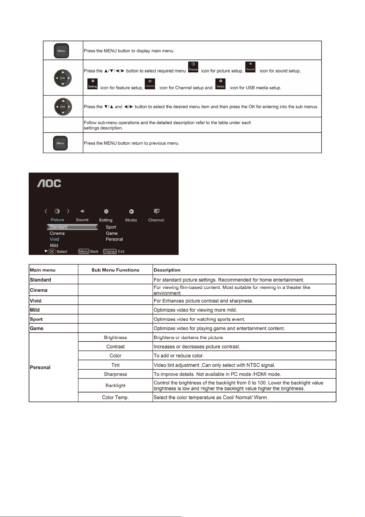
2.2 To Use the Menus
Picture Setting
6
Page 7

Sound Setting
Setting Menu
7
Page 8
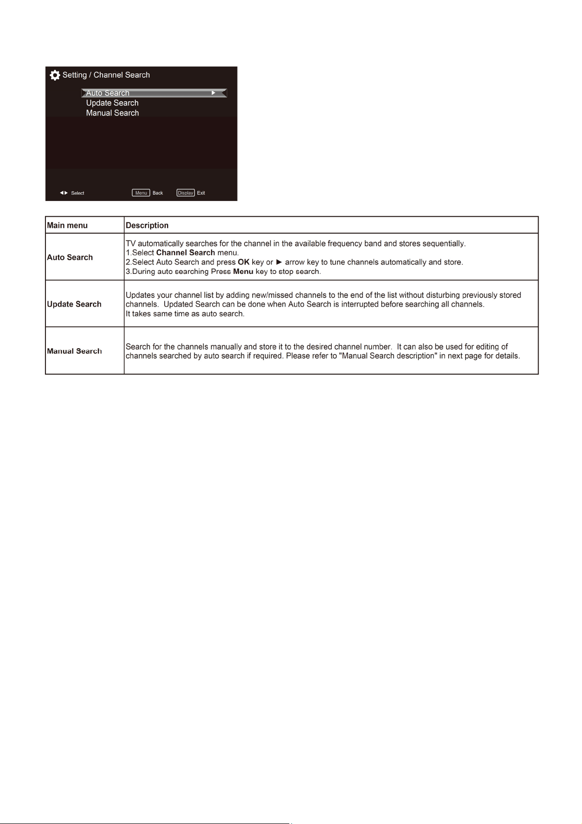
Channel Search
Note: This setting is only available in TV mode.
8
Page 9
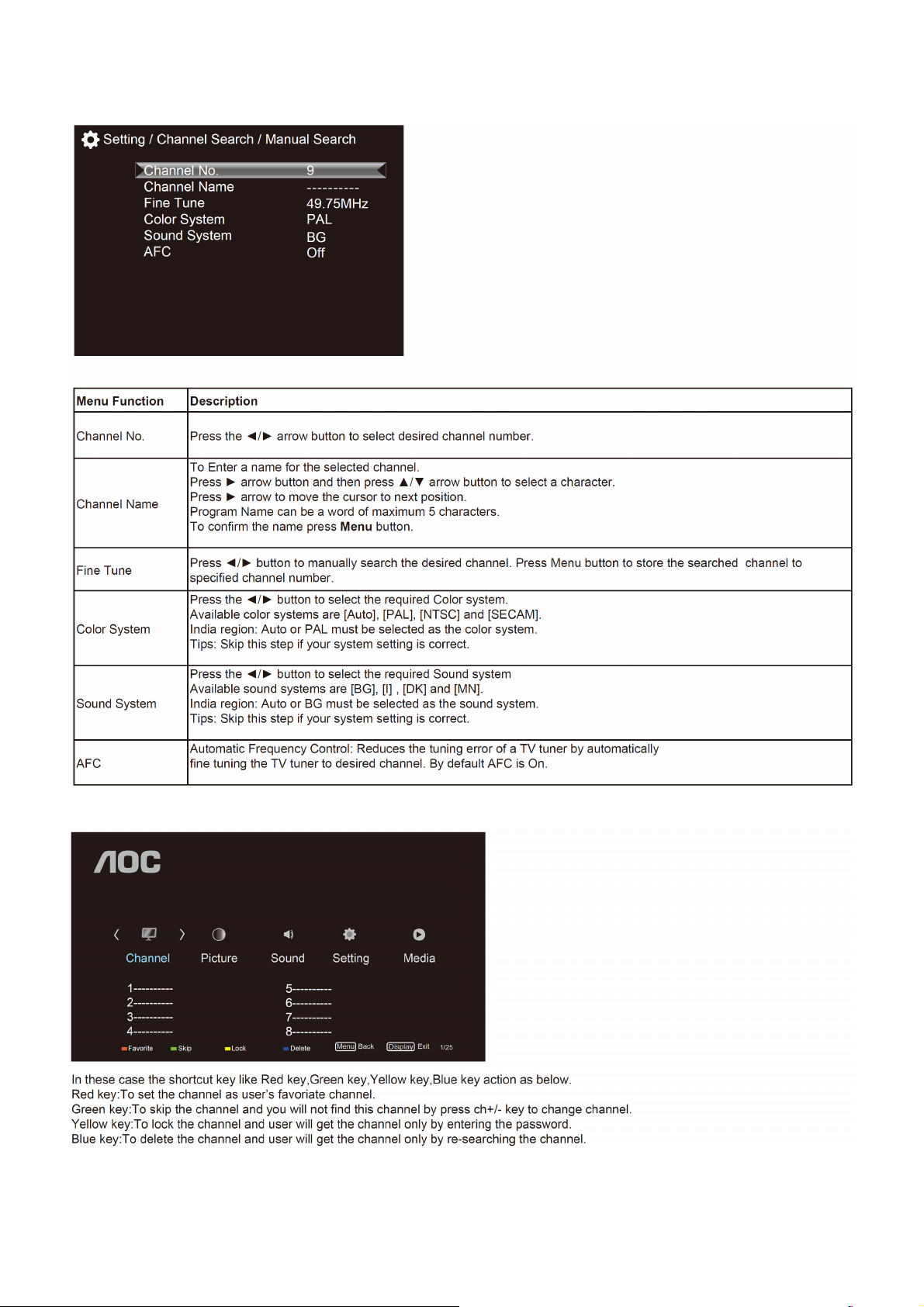
Manual search description
1. Select Channel Search menu.
2. Select Manual Search and press OK key or ► arrow key to get Manual search sub-menu
Channel Edit Menu
9
Page 10
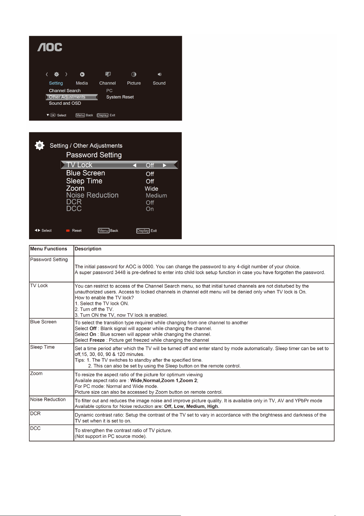
Other Adjustments
Notes:
• Passwords Setting, TV Lock, Blue Screen functions are available only in TV mode.
• Noise Reduction, DCR, DCC will be enable only when the Picture mode is Personal.
• Press Red key on remote control to reset Blue screen, Sleep time, Zoom, Noise Reduction, DCR,DCC, functions to
the default settings.
10
Page 11
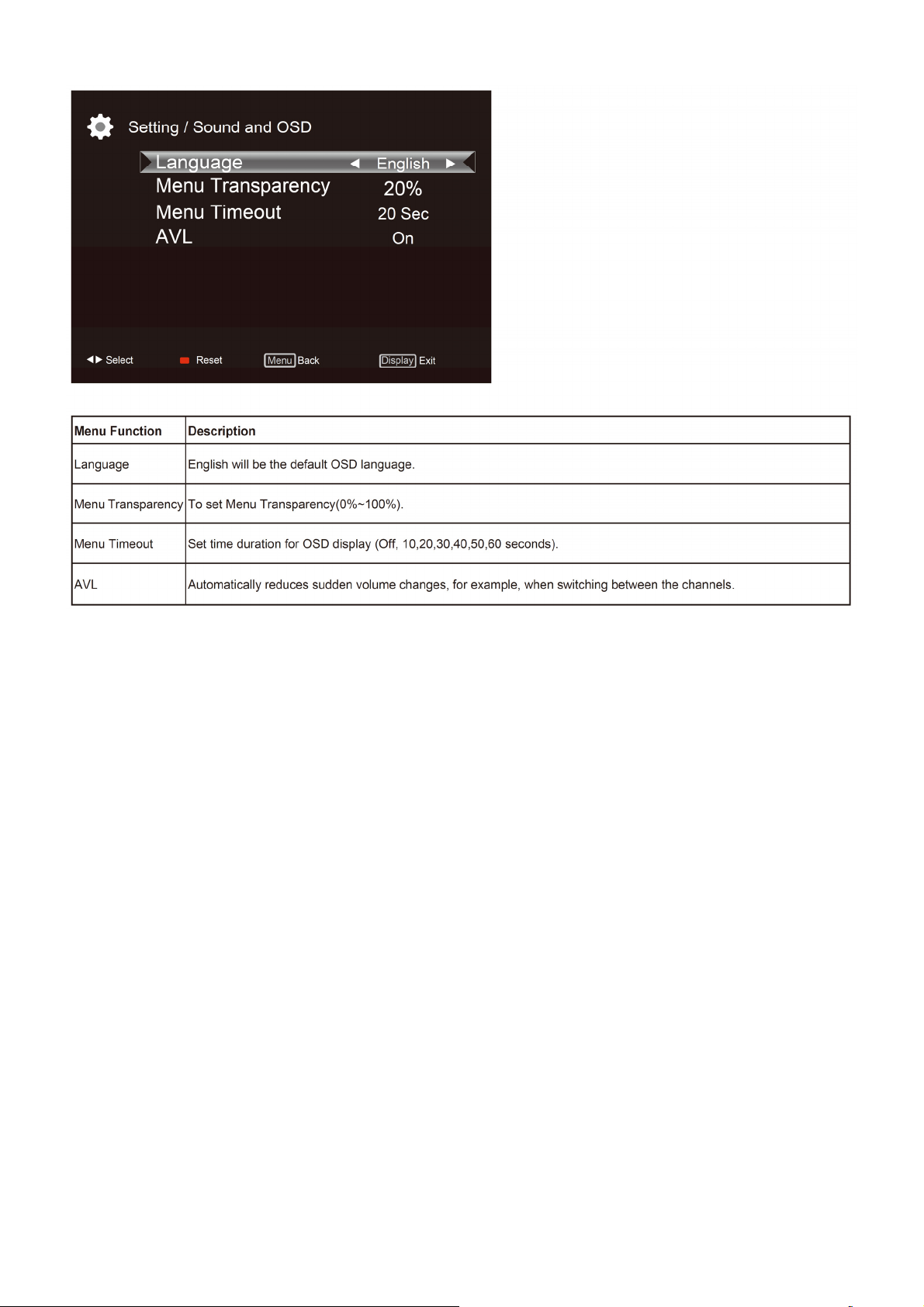
Sound and OSD
11
Page 12

PC setting
Notes:
• If the PC is connected to the TV and no signal has been input from the PC for more than 30 seconds, the TV enters
the standby mode automatically.
• This setting is only available in VGA source
12
Page 13
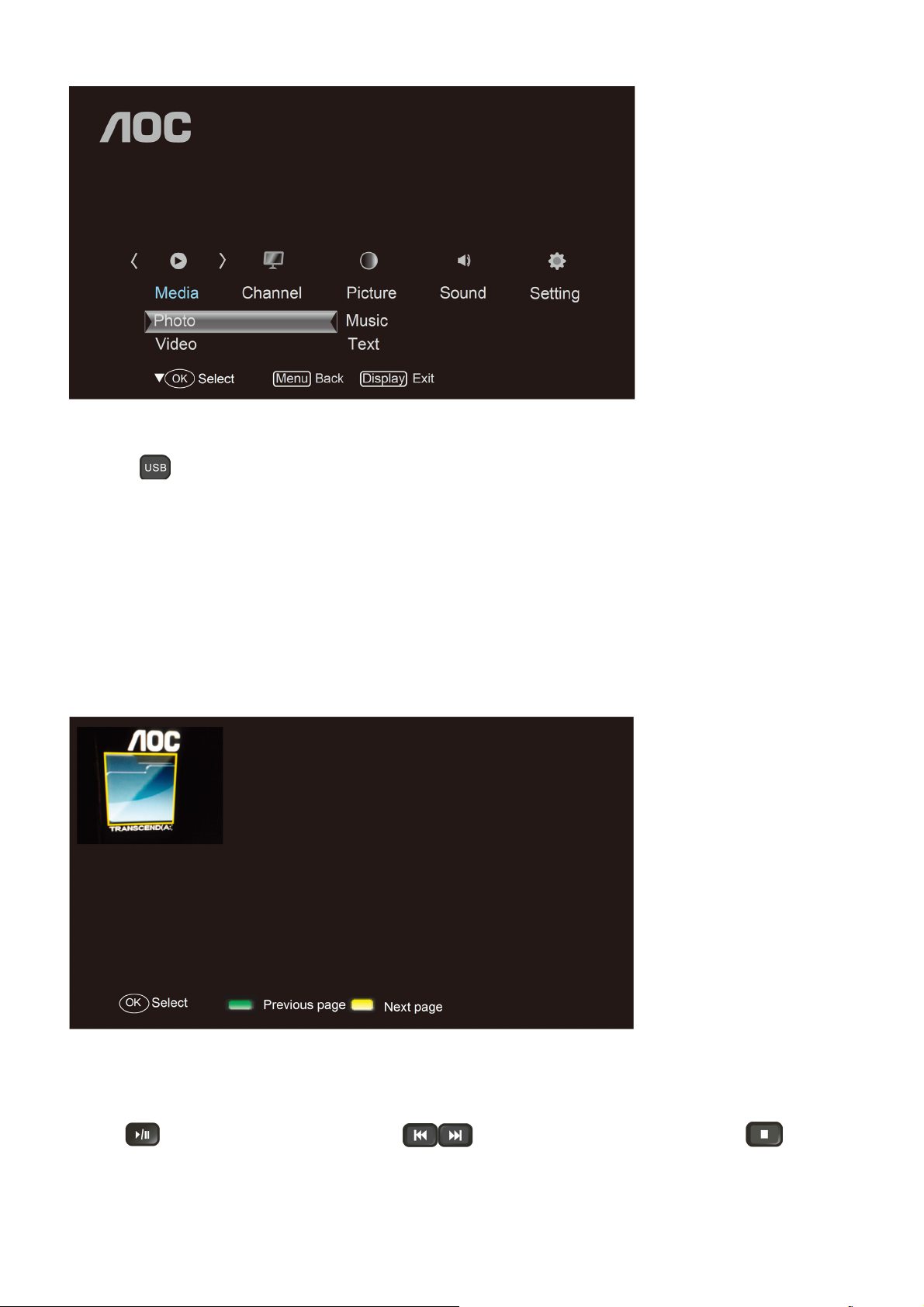
Media Functions(USB)
TV USB port can be used to view JPEG photos, play mp3 music and Video files, and read text present in USB
devices.
Entering to USB Media:
Press the
Or
Press the Source key and ▲/▼/◄/► keys on remote and select USB source to get USB Media menu as shown
above
Select the Media type (Photo/ Music/ Video/ Text) to be viewed and press OK key to enter into USB Media
and When USB drive is detected by the TV, USB drive is displayed as a folder on the screen as shown below. If
more then one USB is pluged to the TV two folders will be displayed. Select the required drive and press OK
key to view subfolder or files in the USB drive.
Notes:
• If USB storage device is plug-in to TV USB port, Media menu will pop up on TV screen irrespective of Input
Source .
• Files of selected Media type can only be viewed through USB. Media type can be any one amoung Photo / Music /
Video / Text.
Direct USB key on remote to get USB Media menu as shown above
Viewing Photos
1. Thumbnail of the available images will be displayed on the screen. If no images are displayed then select the
folder containing the Photos .
2. To select a particular image and to display it in fullscreen press key and press OK key.
Slide show starts automatically when image is viewed in full screen.
3. Press
slideshow
key to play/pause slideshow. Press to view previous or next image. Press key to stop
13
Page 14

USB menu settings for Photo Slide show
Press OK key to get following Menu setup shown above.
1. [Transition Effect] : Select the slide transition as None, Top To Bottom, Bottom To Top, Left To Right, Right To
Left, Random.
2. [Rotate] : Rotate the select photo by 90° clock wise direction.
3. [Play Time] : Select the duration of time a photo is to be displayed.
4. [Information] : Display the information of the file.
Playing Music files
1. Thumbnail of the available music files will be displayed on the screen. If no files are displayed then select the
folder containing the music files.
2. To play particular music file select the required file and press OK key.
3. Press
Music play.
USB menu settings for Music play
Press OK key to get following Menu setup shown above.
1. [Repeat Mode] : Select the repeat mode as None, Single,Random,All.
2. [Sound Mode] : Select sound mode like Pop,Rock,Class,Dance,Music,Personal.
3. [DSS Effect] : Turn on or off TV DSS effect.
4. [Background Music] : Select it to on to turn off display and to get only sound from TV
5. [Information] : Display the information of the file.
Playing Video files
1. Thumbnail of the available video files will be displayed on the screen. If no files are displayed then select the
folder containing the video files.
2. To play particular video file select the required file and press OK key.
key to play/pause music. Press to play previous or next track. Press key to stop
3. Press key
video play.
to play/pause video. Press to play previous or next video. Press key to stop
USB menu settings for Video play
Press OK key to get following Menu setup shown above.
1. [Repeat mode] : Select the repeat mode as None, Single,All,Random.
2. [Information] : Display the information of the file.
14
Page 15

Reading Text files
1. Thumbnail of the available text files will be displayed on the screen. If no files are displayed then select the folder
containing the text files.
2. To read particular text file select the required file and press OK key.
3. Press ◄/►/▲/▼ keys to browse the text. Press MENU key to stop text read.
USB menu settings for text read
Press OK key to get following Menu setup shown above.
1. [Next Page] : Select the duration of time a page is to be displayed.
2. [Display Mode] : Select the text display mode as 4:3 and 16:9.
Formats supported to multimedia mode: Photo, Music, and Video.
Remarks:
1. USB interface of digital multimedia player is not all-purpose. So when some USB devices could not be recognized,
the problem is usually not the performance failure but due to device driver.
2. Because USB devices and memory capability are different, the time needs for multimedia player to read
information are also different. So the information reading speed of the player temporarily getting slow are not the
performance failure.
3. The voltage supplied to USB interface is 5V, and the most electrical current is 500mA. When some interface
criteria of USB devices are different from standard USB protocol, digital multimedia player may be unable to
recognize USB devices correctly, which is normal status.
4. USB could be used as an interface to update software.
5. If some files source could not play because of the parameter decoding-limitation, the problem is not performance
failure.
6. The system can not support dynamic Gif format.
15
Page 16

2.3 How to Connect
You can enjoy standard-definition and high-definition digital programming (if available in your area), along with
standard-definition analog programming.
It is strongly recommended that you connect the antenna/cable input using a 75-ohm coaxial cable to receive
optimum picture quality. A 300- ohm twin lead cable can be easily affected by radio frequency interference, resulting
in signal degradation.
Cable or VHF/UHF(or VHF only)
High Definition Interface
You can enjoy high-definition programming by subscribing to a high-definition cable service or a high-definition
satellite service. For the best possible picture, make sure you connect this equipment to your TV via the HDMI or
component video (with audio) input on the back of your TV.
HDMI Connection
If the equipment has a DVI jack and not an HDMI jack, connect the DVI jack to the HDMI IN (with DVI-to-HDMI cable
or adapter) jack and connect the audio jack to the PC AUDIO IN jacks.
Component Signal Connection
Composite Signal Connection
16
Page 17

PC Connection
Use the TV as a monitor for your PC shown below with the HD15 to HD15 connection. This TV can also be
connected to a PC with DVI or HDMI output.
• Connect the PC IN jack to the PC using the HD15- HD15 cable with ferrite core (analog RGB) and audio cable.
• If the PC is connected to the TV and no signal has been input from the PC for more than 30 seconds, the TV enters
the standby mode automatically.
Connecting USB drive Connecting Earphone
Connecting VIDEO
17
Page 18

2.4 Front Panel Control Knobs
18
Page 19

3. Input / Output Specification
RGB Signal Input
15 - Pin Color Display Signal Cable
Pin No. Description Pin No. Description
1 Red Video 9 +5V
2 Green Video 10 Sync Ground
3 Blue Video 11 Not Used
4 Not Used 12 Serial Data for DDC
5 Ground 13 H-Sync.
6 Red Ground 14 V-Sync.
7 Green Ground 15 Serial Clock for DDC
8 Blue Ground
HDMI Digital Connector Pin Assignments
Pin No. Description Pin No. Description
1 TMDS Data2+ 2 TMDS Data2 Shield
3 TMDS Data2- 4 TMDS Data1+
5 TMDS Data1 Shield 6 TMDS Data1-
7 TMDS Data0+ 8 TMDS Data0 Shield
9 TMDS Data0- 10 TMDS Clock+
11 TMDS Clock Shield 12 TMDS Clock-
13 CEC 14 NC
15 SCL 16 SDA
17 DDC/CEC Ground 18 +5V Power
19 Hot Plug Detect
19
Page 20

Compatible Mode Table
LE32A3330/61
RGB Input Signal Timing
Vertical Horizontal Sync Polarity Presence
Dots × Lines
640 X 480 59.9 31.5 NEG NEG YES YES YES
800 X 600 60 37.9 POS POS YES YES YES
1024 X 768 60 48.3 NEG NEG YES YES YES
1280 x 1024 60 - - - - - -
1360 X 768 60 47.7 POS POS YES YES YES
Frequency Frequency Horizontal Vertical Horizontal Vertical FULL
(Hz) (KHz) (16:9)
Screen
Mode
20
Page 21

4. Mechanical Instructions
1. Remove the screws to remove BASE.
2. Remove the screws to remove REAR COVER.
21
Page 22

3. Remove the screws to remove SPEAKERS, MAIN BOARD and POWER BOARD.
4. Remove the IR board.
22
Page 23

5. Remove the screws to remove the Panel.
23
Page 24

p
p
5. Repair Flow Chart
1. No power
No power (LED “Off”)
Check the AC input and
the
ower is “ON”?
Yes
Power board
out
ut=5.2V?
Yes
Check the IR board and LED
Replace the IR board
No
Replace the main board
No
Power “On”
No
Replace the power board
24
Page 25

2. Can’t start
Can’t start (LED red)
Power board output=12/16V?
Yes
Check the power key is under control?
No
Check the IR receiver is normal?
No
Replace the power board
Yes
Replace the key board
Yes
Replace the IR board
No
Replace the main board
No
Replace the Power board
25
Page 26

3. Abnormal display
Abnormal Display
Check the source
Yes
Enter factory mode to do
“EEPROM initial”&“Reset”
No
No
Reset the source
Check the main board
Yes
Check the LVDS cable
Yes
Check the panel
No
Replace the panel
No
Replace the main board
No
Replace the LVDS cable
26
Page 27

4. No display
No display (No LED)
Check TV is under control and power
on/off by remote control and power key?
Yes
Check the LVDS cable
Yes
Yes
Check the backlight is
“On”?
No
Reinsert or replace the
LVDS cable
No
No
Check the B/L
signal is available?
Yes
Replace the main board
No
Replace main board
Panel Vcc = 12V?
Yes
Replace the Panel
No
Replace the main board
Power board output=12/16V?
Yes
Replace the Panel
Replace the power board
No
27
Page 28

5. Sound problem
No sound or sound abnormal
Check the audio source connection
and the TV system are correct?
Yes
Check the TV is muted, adjust the
volume or enter the menu to reset?
No
No
Reinsert the audio cable or
change the TV system
Enter factory mode to do “Reset”
No
Check the cable between the
speakers and main board is OK?
Yes
Check the speaker resistance value is in spec
(Remark: The value is marked on the speaker)?
Yes
Replace the cable
Replace the main board
No
No
Replace the speaker
28
Page 29

6. Remote control malfunction
Remote Control malfunction
Check the remote control battery is
not properly placed or no power?
No
Use the other remote controls
No
Whether the IR board is
abnormal?
No
Replace the main board
Yes
Replace the battery
Yes
Replace the remote control
Yes
Replace the IR board
29
Page 30

7. OSD is unstable or can’t work normally
OSD is unstable or can’t work normally
Key board connected properly?
Yes
Buttons are OK?
Yes
Key board is OK?
Yes
Enter factory mode to do “Reset”
No
No
No
No
Reconnect the key board
Replace the button function
Replace the key board
Replace the main board
30
Page 31

6. PCB Layout
6.1 Power Board
715G5508P01001002M
31
Page 32

32
Page 33

33
Page 34

6.2 Key Board
715G5298K01000004S
6.3 IR Board
715G5671R01000004X
x
34
Page 35

7. Adjustment
(Take other model for example)
ADC Adjustment
1. Factory Mode
Turn on the TV. Press RC key ‘menu’+’1’+’9’+’9’+’9’ or ‘menu’+’1’+’9’+’9’+’9’+’ok’.It will achieve the factory mode.
2. ADC Adjustment (It’s no need to adjust ADC.)
(1) Enter into the factory mode :(same as the above-mentioned)
(2) Select item “Source”: Ypbpr
a. Tim\pat. (COMPONENT mode: TIM = 314; PAT = 185,select item “auto color” and press ok key.
b. Tim\pat. (COMPONENT mode: TIM = 311; PAT = 185,select item “auto color” and press ok key.
(3) Select item “Source”: VGA
Tim\pat. (VGA mode: TIM = 137; PAT = 42,select item “auto color” and press ok key.
3. White Balance Adjustment
(1) Enter into the factory mode :(same as the above-mentioned).
(2) Just only adjust Ypbpr source.
a. Select item “Source”: Ypbpr and item “Color Temp”: Normal, Adjust gain of RGB to meet spec in the below
setting of Tim\pat. (COMPONENT mode: TIM = 314; PAT = 141(80IRE))
b. Select item “Source”: Ypbpr and item “Color Temp”:Warm, Adjust gain of RGB to meet spec in the below setting
of Tim\pat. (COMPONENT mode: TIM = 314; PAT = 141(80IRE))
c. Select item “Source”: Ypbpr and item “Color Temp”: Cool, Adjust gain of RGB to meet spec in the below setting
of Tim\pat. (COMPONENT mode: TIM = 314; PAT = 141(80IRE))
(3) check VGA TIM137,PAT141, AV TIM304 PAT141, HDMI TIM349 PAT141 , white balance whether or not meet
the specifications.
4.The following color specifications for reference, to RD engineering specifications.
Source VGA/YPbPr/AV/HDMI VGA/YPbPr/AV/HDMI VGA/YPbPr/AV/HDMI
Temp Normal/(8000 K ) Warm/(6500 K ) Cool/(9300 K )
x (center) 0.285 0.030 0.313 0.030 0.271 0.030
y (center) 0.293 0.030 0.321 0.030 0.274 0.030
Note: 1、all models of color temperature within specification, but also ensure the brightness conform to
engineering specifications.
2、
RGB gain value cannot exceed 138,128,138
35
Page 36

8. Schematic Diagram
8.1 Power Board
715G5508P01001002M
1 2
3
4
-
2
RV9901
TVR14561KFAOZF
FB9104
BEAD
L9902
124
3
30MH
C9904
1NF 250V
1NF 250V
B A
C9907
0.22uF 305V
L9901
3
30MH
SG901
124
DSPL-501N-A21F
C9901
0.22uF 305V
change type_1124
A
R9901
390K
IC9901
CAP004DG
1
8
NC
NC
2
7
D1
D2
3
6
D1
D2
5
NC4NC
C9906
R9903
47pF
390K
B
C9903
100PF 250V
CN901
1 2
SOCKET
1
2
CN904
NC/CONN
BD901
FB9102
1
1 2
+
BEAD
TS6B06G-05-X0
FB9105
BEAD
1 2
change type_1124
C9902
SG902
DSPL-501N-A21F
12
NR9901
NTCR2. 5R 6A
t
C9905
100PF 250V
1
2
1 2
3 4
FUSE
220PF 250V
C9316
1 2
470PF 250V
C9144
68UF 450V
R9108
100KOHM +-5% 1/8W
CN9902
L
N
CONN
F901
FB9101
BEAD
C9908
+
R9101
6.8K 1/4W
R9102
6.8K 1/4W
R9103
6.8K 1/4W
+
C9101
NC
C9108
470P 50V
C9145
68UF 450V
+
C9102
NC
IC9101
LD7750RGR
1
OTP
HV
2
COMP
3
CS
VCC
GND4OUT
100N 50V
R9109
470OHM +-5% 1/ 8W
1NF 250V
C9315
8
6
5
C9105
C9103
+
1 2
HS9101
HEAT SINK
+
NC
D9102
SS0520
12
10 OHM
R9106
47OHM +-5% 1/8W
R9110
10 OHM 1/4W
ZD9101
1 2
BEAD
FB9103
1
2
3
4
R9105
MTZJ27B
+
C9104
2.2NF
R9113
5.1 OHM 1/4W
HS9102
HEAT SINK
C9136
NC
D9101
PR1007
12
R9107
10K OHM +-5% 1/8W
1
2
3
4
C9126
2.2nF 630V
R9104
82KOHM +-5% 2WS
FB9106
BEAD
C9119
47pF
Q9101
TK13A65U
+
C9107
47UF 50V
R9111
0.24 oHM 2W
C9109
22N 50V
PS2561DL1-1
D9103
PR1007
IC9102
T9101
POWER X'FMR
8 9
5
1
2
R9112
3.3 OHM 1/4W
43
NC
1
2
3
NC
10
11
12
13
14
15
16
5.2V1
R9145
910 OHM +-1% 1/8W
12
C9133
100N 50V
IC9103
KIA431A-AT/P
R9114
47 OHM 1/4W
R9115
47 OHM 1/4W
R9116
47 OHM 1/4W
R9120
220 OHM 1/4W
R9121
220 OHM 1/4W
R9122
220 OHM 1/4W
D9107
3
FMXA-2202S
2
1
R9146
1.5KOHM +-1% 1/8W
OVP
R9147
2K OHM
3
1
5.2V
D9104
FMW-2156
2
+
C9140
330UF 50V
R9148
3K OHM 1%
R9151
2K43 1/8W 1%
C9110
2N2 50V
C9121
2N2 50V
+
C9111
330UF 16V
C9125
1000pF 630V
C9148
1000pF 630V
+
+24V1
C9142
330UF 50V
R9150
200K +-1% 1/4W
5.2V1
L9101
3.5uH
+
C9114
ZD9106
P6KE27A
+
C9143
330UF 50V
5.2V
1 2
12
100N 50V
ZD9104
BZT52-B9V1
D9109
RB160M
C9113
470uF 16V
C9127
C9120
330UF 35V
+12V
BZT52-B16
1 2
12
1uF
R9137
100K 1/8W 1%
ZD9105
D9105
R9153
470 OHM
C9112
100N 50V
R9159
10R
12
+24V1
+
C9141
330UF 50V
24V_A
C9128
1N 50V
RB160M
5.2V
C9117
100N 50V
IC8104
1
BOOT
2
VIN
GND
3
EN
COMP
4
R9119
SS
+24V1
C9122
2.2UF 10% 16V
100N 50V
TPS54231DR
C9123
15N 50V
R9140
5.6K 1/8W
C9129
NC
IC9105
AS431AN-E1
R9134
10M
R9156
47KOHM +-1% 1/8W
VSNS
R9133
510K +-5% 1/8W
+
330K 1/8W
C9118
0.1uF 50V
R9118
39K 1/8W 1%
Q9107
AOTF409 24A 60V
R9138
100K 1/8W 1%
ZD9103
Q9108
BZT52-B6V2
2N7002
1 2
R9139
Q9105
3.9K 1/8W
2N7002
+24V1
5.2V1
ZD9107
BZT52-B39
R9155
1 2
12
10K OHM +-5% 1/8W
D9108
RB160M
Q9110
PMBS3906
R9154
C9134
1K 1/8W
PH
8
7
6
5
L9103
3.5uH
Q9111
D9106
SM340A
C9131
470UF 35V
R9143
27K 1/8W 1%
R9144
3K 1/8W +/-1%
PS_ON
R9157
33K 1/8W 5%
PMBS3904
0.1uF 50V
47uH
L9102
1 2
100 OHM 1/4W
24V_A
+
D9110
SS0520
C9106
R9158
C9124
1nF 50V
R9126
33K OHM
C9132
100N 50V
C9130
1N 50V
5.2V1
12
C9146
680PF 630V
100 OHM 1/4W
R9168
NC
Q9113
NC
C9137
NC
OVP
R9129
10K OHM +-5% 1/8W
C9116
270UF 25V
R9160
C9138
100PF 50V
+
R9166
NC
R9167
NC
PS_ON
C9115
11K 1/8W 1%
100N 50V
R9117
750 OHM
soft start >20ms
C9135
NC
+
R9152
NC
PS_ON
24V_A
R9125
+12V
CN902
+24V
+24V
Q9112
NC
C9149
1NF 50V
R9169
330R 1/8W 5%
R9170
330R 1/8W 5%
24V_B
R9201
100 OHM 1%
C9150
R9202
1NF 50V
100 OHM 1%
+12V
PS_ON
C9147
5.2V
1uF
24V_B
ON/OFF
R9165
NC
DIM
R9161
0 OHM 1/4W
Q9114
NC
R9135
NC
+
R9136
C9139
NC
NC
CONN
12
11
10
9
8
7
6
5
4
3
2
1
CN903
CONN
13
12
11
10
9
8
7
6
5
4
3
2
1
36
T P V ( Top Victory Electronics Co . , Ltd. )
絬 隔 瓜 絪 腹
Key Component
01.POWER
Date
OEM MODE L
TPV MODE L
PCB NAME
Sheet
Custom
Size
Rev
of
12Saturday, August 11, 2012
称爹
Page 37

C8116
R8106
Q8109
2N3904
1
3
R8127
15.8R 1%
47pF
D8101
MBRD10150D
2
C8115
47pF
R8107
0.07R
LED4
Q8110
2N3904
C8106
1NF
R8128
15.8R 1%
+
Q8111
2N3904
R8132
15.8R 1%
C8102
100UF 63V
LED5
C8111
NC
Q8112
2N3904
C8113
+
100UF 63V
R8136
15.8R 1%
R8116
100K 1% 1/4W
R8117
4.3K 1% 1/8W
Q8114
2N3904
R8137
15.8R 1%
LED6
VLED+
Q8113
2N3904
R8138
15.8R 1%
LED1
LED2
LED3
LED4
LED5
LED6
Q8115
2N3904
R8139
15.8R 1%
D8103
2
3
1
BAV99
D8104
2
3
1
BAV99
D8105
2
3
1
BAV99
D8106
2
3
1
BAV99
D8107
2
3
1
BAV99
D8108
2
3
1
BAV99
R8118
1M 1/6W 5%
VLED+
LED5
LED3
LED1
LED2
LED4
LED6
VLED+
VFB
R8119
150K 1/8W 5%
C8119
NC
SLP
C8112
NC
CN801
12
11
10
9
8
7
6
5
4
3
2
1
CONN
VBJT
C8117
1NF 50V
C8118
1NF 50V
+24V
10N 50V
18K 1/8W 5%
C8114
10N 50V
C8108
R8111
+12V
R8110
100K 1% 1/4W
5.2V
51K 1% 1/8W
VSET
Q8102
2N3904
VADJ
R8101
R8113
18R 1%
VSET
C8109
100N 50V
C8104
100N 50V
C8105
100N 50V
DIM
VFB
+
ON/OF F
R8102
150K
Q8103
2N3904
R8121
15.8R 1%
C8101
330UF 35V
IC8501
1
EN
2
DIM
3
GM
4
VFB
5
VSET
6
OVP
RT7CS
PF7001S
Q8104
2N3904
R8122
15.8R 1%
SLP
VADJ
VBJT
VCC
VMOS
GND
SLP
14
13
12
11
10
9
8
C8110
1NF 50V
Q8105
2N3904
L8101
2
33UH
VBJT
VADJ
C8103
R8108
330R 1/8W 5%
R8123
15.8R 1%
1uF
LED2LED1 LED3
Q8106
2N3904
R8124
15.8R 1%
4
10 OHM 1/8W
D8102
RB160M
0 OHM 1/4W
R8103
R8104
12
Q8107
2N3904
R8125
15.8R 1%
R8105
2R2 +-5% 1/ 8W
+12V
Q8108
2N3904
R8126
15.8R 1%
Q8101
AOD4126
10K 1/4W
T P V ( Top Victory Electronics Co . , Ltd. )
絬 隔 瓜 絪 腹
Key Component
Date
02.LED DRIVER
OEM MODEL
TPV MO DEL
PCB NAME
Sheet
Size
Rev
22Saturday , August 11, 2012
of
称爹
B
37
Page 38

8.2 Key Board
715G5298K01000004S
SW01
CN01
65
CONN
33G8032 4F HR
R01
7K5 1/8W + /-1%
R02
2K7 1/8W 1%
R03
1K8 + /-1% 1/8W
1
2
FUNC_KEY
3
4
PWR-SW
FUNC_KEY
R06
750OHM +- 1% 1/8W
R04
1K 1/8W 1%
R05
750OHM +-1% 1/8W
TACT SW FWRD H1.5MM
SW02
TACT SW FWRD H1.5MM
SW03
TACT SW FWRD H1.5MM
SW04
TACT SW FWRD H1.5MM
SW05
TACT SW FWRD H1.5MM
SW06
TACT SW FWRD H1.5MM
VOL+
VOL-
CH+
CH-
MENU
Source Select
2.48V~2.72V
2.04V~2.22V
1.58V~1.79V
1.24~1.45V
0.85V~1.02V
0.47V~0.63V
PWR-SW
R07
750OHM +- 1% 1/8W
SW07
TACT SW FWRD H1.5MM
77G 607 2 FD
絬 隔 瓜 絪 腹
Key Component
38
Power ON/OFF
T P V ( Top Victory Electronics Co . , Ltd. )
02-Keypad
Date
OEM MODEL
TPV MO D EL
PCB NAME
Sheet
A
<
称爹
Custom
>
Size
Rev
22Friday , Septem ber 02, 2011
of
称爹
Page 39

8.3 IR Board
715G5671R01000004X
LED201
081G 14 24 EL
RED
033G8032 5F HR
CN201
67
1
2
3
4
5
CONN
LED_R
LED_B
IR
VCC
100R 1/10W 5%
R0603
R202 220 OHM 1/10W
R203 220 OHM 1/10W
R204
C201
2.2UF 16V
LED
R201
R0402
BLUE
VCC
1
23
U201
1
GND
2
GND
3
OUT
4
VCC
IRM-H 938M3/ TR2
10 mm
4
15K 1/16W
change flat type emitting
terminal_120405 by Mars
Top Vie w
SMD
LED
SMD IR
42.55mm
T P V ( Top Victory Electronics Co . , Ltd. )
絬 隔 瓜 絪 腹
Key Component
Date
02-IR&LED
39
OEM MODEL
TPV MODEL
PCB NAME
Sheet
<
A
称爹
A
>
Size
Rev
of
22Friday , June 22, 2012
称爹
Page 40

9. Exploded View
40
Page 41

Item Description
1 REAR_COVER
2 DECO_BEZEL
3 BASE
4 COVER_STAND
5 LENS_POWER
6 COVER_FUNCTION
7 KEY
8 LENS_IR
9 BKT_HINGE
10 DIE-CASTING
11 BKT_IO
12 ADAPTER BOARD
13 FOOT PAD
14 PCB-SUPPORT
19 MAIN BOARD
21 TAPE_INSULATING
22 IPTV BOARD 15 0M1G1030 6 47 CR3 SCREW(REAR COVER/BEZEL) 14
23 IO LABEL 17 0M1G1730 8120 SCREW 3x8(POWER BOARD) 9
24 BKT_IO 18 0M1G1740 8120 SCREW FOR STD/MF 42-D020715/42-D000649(HINGE/PANEL) 4
25 KEY BOARD 20 0M1G1740 12225 CR3 SCREW M1-MACHINE SCREW x12.0(STAND COVER/BASE) 4
Item Part No. Description Qty
41
Page 42

10. BOM List
Note: The parts information listed below are for reference only, and are subject to change without notice.
Please go to http://cs.tpv.com.cn/hello1.asp
LE32A3330/61 E32C11NCCHA1NNX
Location Part No. Description Remark
052G 1186 SMALL TAPE
052G 2191 A PAPER TAPE
ECN1 095G801313RY04 HARNESS 13P-13P 350mm
0M1G1030 6 47 CR3 SCREW
0M1G1030 6 47 CR3 SCREW
0M1G1730 8120 SCREW 3x8
0M1G1740 8120 SCREW FOR STD/MF 42-D020715/42-D000649()
0M1G1740 12225 CR3 SCREW M1-MACHINE SCREW x12.0
0Q1G 930 8 47 CR3 SCREW
ECN2 317GAADW024GPU LIGHT BAR GPBLE032BG-334-07
317GAAMB065CVT MAIN BOARD T.VST59S.72A
E37801 378G0110567YAQ 16 OHM 11W L132*W34*34.5H 0 NO
ECNA1 395G801404LY34 HARNESS 4P-B&R+B&W 700/500
ECN8 395G801410DY24 HARNESS 10P-5P+4P 400/550
ECN8 395G801410RY24 HARNESS 10P-5P+4P 400/550 2nd source
ECN21 395G801840LY17 LVDS CABLE 30P-40P 400 2nd source
ECN21 395G801840RY17 LVDS CABLE 30P-40P 400
IRPFCXAF IPTV BOARD
CN201 033G8032 5F B CONN 1.25mm 5P R/A 11.2mm 5.7mm 2nd source
CN201 033G8032 5F X WAFER 5P 1.25MM S1315-05RVB-S03-K
R201 061G0402153 JI RST 0402 15K 5% 1/16W
R204 061G0603101 JT RST CHIP 100R 1/10W 5% TZAI YUAN
C201 065G060322515K T CAP 0603 2.2UF 10% 16V X5R
U201 356GS927057 IR RECEIVER IRM-H938M3/TR2 38 KHZ 6V
E715 715G5671R01000004X IB BOARD PCB
KEPFCXA2 KEY BOARD
CN01 033G8032 4F X WAFER 4P 1.25MM
R04 061G08051001FT RST CHIP 1K 1/8W 1%
R03 061G08051801FY RST CHIP R 1K8 +/-1% 1/8W
R02 061G08052701FY RST CHIP 2K7 1/8W 1%
R07 061G08057500FF RST CHIPR 750 OHM +-1% 1/8W FENGHUA
R06 061G08057500FF RST CHIPR 750 OHM +-1% 1/8W FENGHUA
R05 061G08057500FF RST CHIPR 750 OHM +-1% 1/8W FENGHUA
R01 061G08057501FY RST CHIP R 7K5 1/8W +/-1%
SW07 077G 607 2 FD CHIP TACT SW BY FORWARD SFKQGMA2125T-PL
SW05 077G 607 2 FD CHIP TACT SW BY FORWARD SFKQGMA2125T-PL
SW06 077G 607 2 FD CHIP TACT SW BY FORWARD SFKQGMA2125T-PL
SW02 077G 607 2 FD CHIP TACT SW BY FORWARD SFKQGMA2125T-PL
SW03 077G 607 2 FD CHIP TACT SW BY FORWARD SFKQGMA2125T-PL
SW04 077G 607 2 FD CHIP TACT SW BY FORWARD SFKQGMA2125T-PL
SW01 077G 607 2 FD CHIP TACT SW BY FORWARD SFKQGMA2125T-PL
SW03 077G 607 2 HC TACT SW 4P 1.5mm 160g TS-4402-1.58B-01
SW04 077G 607 2 HC TACT SW 4P 1.5mm 160g TS-4402-1.58B-01
SW02 077G 607 2 HC TACT SW 4P 1.5mm 160g TS-4402-1.58B-01
SW05 077G 607 2 HC TACT SW 4P 1.5mm 160g TS-4402-1.58B-01
SW06 077G 607 2 HC TACT SW 4P 1.5mm 160g TS-4402-1.58B-01
SW07 077G 607 2 HC TACT SW 4P 1.5mm 160g TS-4402-1.58B-01
SW01 077G 607 2 HC TACT SW 4P 1.5mm 160g TS-4402-1.58B-01
for the latest information.
42
Page 43

CN01 311GW125D04ADJ WAFER 1.25mm 4P R/A 1.25T-11-4PWB
709T52980XS001 COMSUPTIVE ASS'Y
E715 715G5298K01000004S KEY BOARD PCB
E750 LCV315TU4AXA08011X PANEL TPT315B5-TU4A R00A XM TPV
P12G6311010 RUBBER PAD SILICONE
P15T1414C01000GMZ1 BKT_IO
P15T1442C01000GMZ1 BKT_IO
P15T1619101 BKT_HINGE SGCC 1.2 mm
P20G0029001 DIE-CASTING
P33T0359ADTV1L0100 COVER_FUNCTION
P33T0361ADT01L0100 KEY
P33T03900ED01C0100 LENS_IR
P33T0391XHZ01C0100 LENS_POWER
P34T10810GM05K0100 REAR_COVER
P34T1083AFL01L01BA BASE
P34T1133ADTZ1L01BA DECO_BEZEL
P34T11340GM01K0100 COVER_STAND
PLTVCL246AXGL ADAPTER BOARD NA
040G 45762412B OTHER LABEL
CN801 033G3802 12 H X WAFER 12P 2.0mm H W2011-12RVA-S01
IC9102 056G 139 8 Photo-Coupler PS2561DL1-1 CTR Q100~200%
RV9901 061G 46561 WB VARISTOR 560V 10% 14
R8107 061G3SWJ70759B SY RST WD 0.07R 5% 3W
C9901 063G 10722410V 0.22UF 275VAC ARCO
C9907 063G 10722410V 0.22UF 275VAC ARCO
C9144 067G 42Z68015K EC 68UF 20% 450V 12.5*50 2000 hr
C9145 067G 42Z68015K EC 68UF 20% 450V 12.5*50 2000 hr
FB9105 071G 55 21 FERRITE BEAD
FB9104 071G 55 21 FERRITE BEAD
FB9102 071G 55906 FERRITE CORE 510R C8B R6H 6x9.2(A)
L9902 073G 174241 X LINE FILTER 18MH MIN EF20 3LFEF2022-303M
L9901 073G 174241 X LINE FILTER 18MH MIN EF20 3LFEF2022-303M
L8101 073G 174259 CP BOOST CHOKE 33UH 10% 2.5A L020341-6
L9103 073G 253 91 H IND CHOKE 3.5uH+-10% DADONG
L9101 073G 253 91 H IND CHOKE 3.5uH+-10% DADONG
L9102 073G 253214 H CHOKE COIL 47UH 10% L470R HA
CN901 087G 50147D HC AC SOKET R/A 2P 12DEGREE H=12.8
BD901 093G 50460938 BRIDGE TS6B06G-05-X0 6A 800V KBJ
0Q1G 340 8140 SCREW Q1-SELF TAPING SCREW :Q x8.0
CN903 311GW250B13BBX WAFER 2.5mm 13P R/A 35mm 7mm
NR9901 361G0058509MYW005A NTCR 5R 20% 3.1W SCK13055MTY501
T9101 380GL32P102N00 X'FMR 320uH 10% 5uH YUVA-1986-3
705TXC57899 Q9101 ASS'Y
Q9101 057G 667956 MOSFET TK13A65U(STA4,X.M) 13A 650V SC-67
0M1G 930 8120 SCREW 3x8
HS9101 Q90G0219 2 HEAT SINK
705TXC84025 F901 ASS'Y
F901 084G 34 14 FUSE -- -- --
F901 084G 41 3 T3.15AH250V 02153.15 LITTLEFUSE
705TXC93986 D9104&D9107 ASS'Y
D9107 093G 52 57 RECTIFIER FMXA-2202S 20A 200V TO-220F
D9104 093G1506 2 SCHOTTKY FMW-2156 15A 60V TO-220
0M1G1730 8120 SCREW 3x8
Q9107 357G0600A02 MOSFET AOTF409 24A 60V 43W TO-220FL
43
Page 44

HS9102 Q90G0219 3 HEAT SINK
IC9105 056G 158501 IC AS431AN-E1 SOT23
IC8104 056G 368909 Others IC TPS54231DR SO-8
IC9101 056G 379190 AC/DC CONVERTER LD7750RGR SOP-7
IC9901 056G 665142 Others CAP004DG-TL SOP-8
IC8501 056G 700 34 LED DRIVER PF7001S SOP-14
Q8101 057G 600923 MOSFET AOD4126 TO-252
Q9105 057G 763904 TRA FET 2N7002 SOT-23 PHILIPS
Q9108 057G 763904 TRA FET 2N7002 SOT-23 PHILIPS
R9105 061G0805100 JF RST CHIPR 10 OHM +-5% 1/8W FENGHUA
R8104 061G0805100 JF RST CHIPR 10 OHM +-5% 1/8W FENGHUA
R9202 061G08051000FY RST CHIPR 100 OHM +-1% 1/8W YAGEO
R9201 061G08051000FY RST CHIPR 100 OHM +-1% 1/8W YAGEO
R9137 061G08051003FT RST CHIP 100K 1/8W 1%
R9138 061G08051003FT RST CHIP 100K 1/8W 1%
R9154 061G0805102 JI RST 0805 1K 5% 1/8W
R9107 061G0805103 JT RST 0805 10K 5% 1/8W
R9155 061G0805103 JT RST 0805 10K 5% 1/8W
R9129 061G0805103 JT RST 0805 10K 5% 1/8W
R9108 061G0805104 JT RST CHIPR 100KOHM +- 5% 1/8W TZAI YUAN
R9134 061G0805106 JT RST CHIPR 10M +-5% 1/8W TZAI YUAN
R9125 061G08051102FT RST 0805 11K 1% 1/8W SMD0805011KF
R9146 061G08051501FF RST CHIPR 1.5KOHM +-1% 1/8W FENGHUA
R8102 061G0805154 JF RST CHIPR 150KOHM +-5% 1/8W FENGHUA
R8102 061G0805154 JI RST 0805 150K 5% 1/8W
R8119 061G0805154 JT RST CHIP 150K 1/8W 5% TZAI YUAN
R8111 061G0805183 JT RST CHIP 18K 1/8W 5%
R8105 061G0805229 JF RST CHIPR 2R2 +-5% 1/8W FENGHUA
R9151 061G08052431FY RST CHIP 2K43 1/8W 1%
R9143 061G08052702FT RST CHIP 27K 1/8W 1%
R9148 061G08053001FI RST CHIPR 3KOHM +-1% 1/8W 0805
R9144 061G08053001FT RST CHIP R 3K 1/8W +/-1%
R9170 061G0805331 JT RST CHIP 330R 1/8W 5% TZAI YUAN
R8108 061G0805331 JT RST CHIP 330R 1/8W 5% TZAI YUAN
R9169 061G0805331 JT RST CHIP 330R 1/8W 5% TZAI YUAN
R9126 061G0805333 JI RST CHIPR 33KOHM +-5% 1/8W 0805
R9157 061G0805333 JT RST CHIP 33K 1/8W 5% TZAI YUAN
R9119 061G0805334 JF RST CHIPR 330KOHM +-5% 1/8W FENGHUA
R9119 061G0805334 JT RST CHIP 330K 1/8W 5% TZAI YUAN
R9118 061G08053902FF RST CHIPR 39KOHM +-1% 1/8W FENGHUA
R9118 061G08053902FT RST CHIP 39K 1/8W 1%
R9139 061G0805392 JF RST CHIPR 3.9KOHM +-5% 1/8W FENGHUA
R8117 061G08054301FY RST CHIPR 4K3 +-1% 1/8W YAGEO
R9106 061G0805470 JT RST CHIPR 47OHM +-5% 1/8W TZAI YUAN
R9156 061G08054702FF RST CHIPR 47KOHM +-1% 1/8W FENGHUA
R9109 061G0805471 JT RST CHIPR 470OHM +-5% 1/8W TZAI YUAN
R8101 061G08055102FI RST 51K OHM 1% 1/8W TA-I
R9133 061G0805514 JT RST CHIPR 510K +-5% 1/8W TZAI YUAN
R9140 061G0805562 JF RST CHIPR 5.6kOHM +-5% 1/8W FENGHUA
R9117 061G0805751 JF RST CHIPR 750 OHM +-5% 1/8W FENGHUA
R9145 061G0805911 JF RST CHIPR 910 OHM +-5% 1/8W FENGHUA
JR9103 061G1206000 JF RST CHIPR MAX0R05 1/4W FENGHUA
JR9105 061G1206000 JF RST CHIPR MAX0R05 1/4W FENGHUA
JR9104 061G1206000 JF RST CHIPR MAX0R05 1/4W FENGHUA
44
Page 45

JR9102 061G1206000 JF RST CHIPR MAX0R05 1/4W FENGHUA
R8103 061G1206000 JI RST 1206 MAX0R05 5% 1/4W
R9161 061G1206000 JI RST 1206 MAX0R05 5% 1/4W
R9110 061G1206100 JF RST CHIPR 10 OHM +-5% 1/4W FENGHUA
R8110 061G12061003FI RST 1206 100K 1% 1/4W
R8116 061G12061003FI RST 1206 100K 1% 1/4W
R9160 061G1206101 JI RST 1206 100R 5% 1/4W
R9158 061G1206101 JI RST 1206 100R 5% 1/4W
R8106 061G1206103 JT RST CHIPR 10KOHM +-5% 1/4W TZAI YUAN
R8113 061G12061809FT RST 1206 18R 1% 1/4W
R9150 061G12062003FF RST CHIPR 200KOHM +-1% 1/4W FENGHUA
R9150 061G12062003FT RST CHIPR 200KOHM +-1% 1/4W TZAI YUAN
R9147 061G1206202 JI RST 2K OHM 5% 1/4W TA-I
R9120 061G1206221 JT RST CHIPR 220 OHM +-5% 1/4W TZAI YUAN
R9122 061G1206221 JT RST CHIPR 220 OHM +-5% 1/4W TZAI YUAN
R9121 061G1206221 JT RST CHIPR 220 OHM +-5% 1/4W TZAI YUAN
R9112 061G1206339 JT RST CHIPR 3.3 OHM +-5% 1/4W TZAI YUAN
R9114 061G1206470 JT RST CHIPR 47 OHM +-5% 1/4W TZAI YUAN
R9116 061G1206470 JT RST CHIPR 47 OHM +-5% 1/4W TZAI YUAN
R9115 061G1206470 JT RST CHIPR 47 OHM +-5% 1/4W TZAI YUAN
R9153 061G1206471 JI RST 470 OHM 5% 1/4W TA-I
R9113 061G1206519 JT RST CHIPR 5.1 OHM +-5% 1/4W TZAI YUAN
R9102 061G1206682 JT RST CHIPR 6.8 KOHM +-5% 1/4W TZAI YUAN
R9101 061G1206682 JT RST CHIPR 6.8 KOHM +-5% 1/4W TZAI YUAN
R9103 061G1206682 JT RST CHIPR 6.8 KOHM +-5% 1/4W TZAI YUAN
C9138 065G080510131J F CAP CHIP 0805 100PF J 50V NPO
C8117 065G080510231J F CAP 0805 1NF 5% 50V NPO
C9149 065G080510231J F CAP 0805 1NF 5% 50V NPO
C8110 065G080510231J F CAP 0805 1NF 5% 50V NPO
C9150 065G080510231J F CAP 0805 1NF 5% 50V NPO
C8118 065G080510231J F CAP 0805 1NF 5% 50V NPO
C8117 065G080510231J M CAP 0805 1NF 5% 50V NP0
C9149 065G080510231J M CAP 0805 1NF 5% 50V NP0
C9150 065G080510231J M CAP 0805 1NF 5% 50V NP0
C8110 065G080510231J M CAP 0805 1NF 5% 50V NP0
C8118 065G080510231J M CAP 0805 1NF 5% 50V NP0
C9124 065G080510232K F CAP 0805 1000PF 10% 50V X7R
C9130 065G080510232K Y CAP CHIP 0805 1N 50V X7R +/-10%
C8108 065G080510332K Y CAP CHIP 0805 10N 50V X7R +/-10%
C8114 065G080510332K Y CAP CHIP 0805 10N 50V X7R +/-10%
C9106 065G080510432K F CAP CHIP 0805 0.1UF K 50V X7R
C9118 065G080510432K F CAP CHIP 0805 0.1UF K 50V X7R
C9112 065G080510432K Y CAP CHIP 0805 100N 50V X7R +/-10%
C9117 065G080510432K Y CAP CHIP 0805 100N 50V X7R +/-10%
C8105 065G080510432K Y CAP CHIP 0805 100N 50V X7R +/-10%
C9132 065G080510432K Y CAP CHIP 0805 100N 50V X7R +/-10%
C9134 065G080510432K Y CAP CHIP 0805 100N 50V X7R +/-10%
C8109 065G080510432K Y CAP CHIP 0805 100N 50V X7R +/-10%
C8104 065G080510432K Y CAP CHIP 0805 100N 50V X7R +/-10%
C9115 065G080510432K Y CAP CHIP 0805 100N 50V X7R +/-10%
C9133 065G080510432K Y CAP CHIP 0805 100N 50V X7R +/-10%
C9127 065G080510432K Y CAP CHIP 0805 100N 50V X7R +/-10%
C9105 065G080510432K Y CAP CHIP 0805 100N 50V X7R +/-10%
C8103 065G080510532K M CAP 0805 1UF 10% 50V X7R
45
Page 46

C9114 065G080510532K M CAP 0805 1UF 10% 50V X7R
C9147 065G080510532K M CAP 0805 1UF 10% 50V X7R
C9123 065G080515332K Y CAP CHIP 0805 15N 50V X7R +/-10%
C9110 065G080522232K Y CAP CHIP 0805 2N2 50V X7R +/-10%
C9121 065G080522232K Y CAP CHIP 0805 2N2 50V X7R +/-10%
C9109 065G080522332K Y CAP CHIP 0805 22N 50V X7R +/-10%
C9128 065G080522432K Y CAP CHIP 0805 220N 50V X7R +/-10%
C9122 065G080522512K M CAP 0805 2.2UF 10% 16V X7R
C9108 065G080547131J Y CAP CHIP 0805 470P 50V NPO +/-5%
C9146 065G1206102B2K Y CAP 1206 1NF 10% 630V X7R -
C9148 065G1206102B2K Y CAP 1206 1NF 10% 630V X7R -
C9125 065G1206102B2K Y CAP 1206 1NF 10% 630V X7R -
D8108 093G 64 33 SWITCHING BAV99 0.2A 85V SOT-23
D8103 093G 64 33 SWITCHING BAV99 0.2A 85V SOT-23
D8104 093G 64 33 SWITCHING BAV99 0.2A 85V SOT-23
D8106 093G 64 33 SWITCHING BAV99 0.2A 85V SOT-23
D8107 093G 64 33 SWITCHING BAV99 0.2A 85V SOT-23
D8105 093G 64 33 SWITCHING BAV99 0.2A 85V SOT-23
ZD9103 093G 39S952 T ZENER BZT52-B6V2 -R1-10001 6.2V 0.41W SO
ZD9104 093G 39S953 T ZENER BZT52-B9V1 9.1V 0.41W SOD-123
D8102 093G 60S 15 T SCHOTTKY RB160M 60 TR 1A 60V SOD-123
D9108 093G 60S 15 T SCHOTTKY RB160M 60 TR 1A 60V SOD-123
D9105 093G 60S 15 T SCHOTTKY RB160M 60 TR 1A 60V SOD-123
D9109 093G 60S 15 T SCHOTTKY RB160M 60 TR 1A 60V SOD-123
D9102 093G 60S934 T DIODE SS0520 SOD-123
D9110 093G 60S934 T DIODE SS0520 SOD-123
D9106 093G 60S935 T HF SCHOTTKY SK34A R2G 3A 40V DO-214AC
R8123 361G12061699FT RST CHIPR 1206 16R9 1% 1/4W
R8136 361G12061699FT RST CHIPR 1206 16R9 1% 1/4W
R8128 361G12061699FT RST CHIPR 1206 16R9 1% 1/4W
R8138 361G12061699FT RST CHIPR 1206 16R9 1% 1/4W
R8121 361G12061699FT RST CHIPR 1206 16R9 1% 1/4W
R8125 361G12061699FT RST CHIPR 1206 16R9 1% 1/4W
R8122 361G12061699FT RST CHIPR 1206 16R9 1% 1/4W
R8139 361G12061699FT RST CHIPR 1206 16R9 1% 1/4W
R8126 361G12061699FT RST CHIPR 1206 16R9 1% 1/4W
R8132 361G12061699FT RST CHIPR 1206 16R9 1% 1/4W
R8127 361G12061699FT RST CHIPR 1206 16R9 1% 1/4W
R8137 361G12061699FT RST CHIPR 1206 16R9 1% 1/4W
R8124 361G12061699FT RST CHIPR 1206 16R9 1% 1/4W
D8101 393G0060A11 HF SCHOTTKY MBRD10150D 10A 150V TO-252
D8101 393G0060A14 SCHOTTKY SM10150D1-C 10A 150V (D-Pack)
ZD9107 393G039SA1300T ZENER BZT52-B39_R1_00001 39V 0.41W
ZD9105 393G039SA1400T ZENER BZT52-B16_R1_00001 16V 0.41W
PLCL246AXGLAI ADAPTER BOARD FOR AI
T9101 006G 31 4 1.7MM RIVET
BD901 006G 31 4 1.7MM RIVET
CN9902 006G 31500 EYELET
CN901 006G 31500 EYELET
L9902 006G 31502 EYELET
C9145 006G 31502 EYELET
NR9901 006G 31502 EYELET
C9907 006G 31502 EYELET
C9144 006G 31502 EYELET
46
Page 47

C9901 006G 31502 EYELET
RV9901 006G 31502 EYELET
L9901 006G 31502 EYELET
IC9103 056G 158 12 Shunt Regulator KIA431A-AT/P TO-92
Q8111 057G 417513 T TRA 2N3904 TO-92
Q8105 057G 417513 T TRA 2N3904 TO-92
Q8112 057G 417513 T TRA 2N3904 TO-92
Q8113 057G 417513 T TRA 2N3904 TO-92
Q8115 057G 417513 T TRA 2N3904 TO-92
Q8103 057G 417513 T TRA 2N3904 TO-92
Q8109 057G 417513 T TRA 2N3904 TO-92
Q8114 057G 417513 T TRA 2N3904 TO-92
Q8106 057G 417513 T TRA 2N3904 TO-92
Q8102 057G 417513 T TRA 2N3904 TO-92
Q8104 057G 417513 T TRA 2N3904 TO-92
Q8107 057G 417513 T TRA 2N3904 TO-92
Q8110 057G 417513 T TRA 2N3904 TO-92
Q8108 057G 417513 T TRA 2N3904 TO-92
R8118 061G 60210552T TZ RST CFR 1M 1/6W 5%
R9111 061G152M24852T SY RST MOFR 0.24OHM +-5% 2WS SY
R9104 061G152M82352T SY RST MOFR 82KOHM +-5% 2WS FUTABA
R9159 061G208M10052T SY RST MOF 10R 5% 1W
R9903 061G212Y39452T SY RST MGF 390K 5% 1/2W RMU12J3903A520NL
R9901 061G212Y39452T SY RST MGF 390K 5% 1/2W RMU12J3903A520NL
C8106 065G 1K10223T CAP CER 1NF 10% 1KV Y5P
C9104 065G 1K22293S CAP CER 2.2NF 10% 1KV R TAPING
C8115 065G 1K470 2T6921 CAP CER 47pF K 1KV
C9119 065G 1K470 2T6921 CAP CER 47pF K 1KV
C8116 065G 1K470 2T6921 CAP CER 47pF K 1KV
C9906 065G 1K470 2T6921 CAP CER 47pF K 1KV
C9905 065G306K1012SR CAP Y1 100PF 10% 250V Y5P
C9903 065G306K1012SR CAP Y1 100PF 10% 250V Y5P
C9316 065G306K2212SR CAP Y1 220PF 10% 250V Y5P
C9908 065G306K47123R CAP Y1 470PF 10% 250V Y5P
C9908 065G306K4712SR CAP Y1 470PF 10% 250V Y5P
C9904 065G306M1023SR CAP Y1 1NF 20% 250V Y5U
C9902 065G306M1023SR CAP Y1 1NF 20% 250V Y5U
C9315 065G306M1023SR CAP Y1 1NF 20% 250V Y5U
C9107 067G 3154707KT EC 47UF 20% 50V ER1H470MPN1007RU
C8113 067G 5151018KT EC 100UF 20% 63V EV1J101MPN1012RSU
C8102 067G 5151018KT EC 100UF 20% 63V EV1J101MPN1012RSU
C9120 067G 5153316KT EC 330UF 20% 35V 10*12 5000 hr
C8101 067G 5153316KT EC 330UF 20% 35V 10*12 5000 hr
C9113 067G 5154713KT EC 470 20% 16V EV
C9111 067G204S3313KT CAP CS 330UF 20% 16V 10*7 2000 hr
C9116 067G215P2714KT EC 270UF 20% 25V 10*9
C9131 067G515S4716KT EC 470UF 20% 35V 12.5*12 EC EC1V471MPN
FB9106 071G 55 29 FERRITE BEAD
FB9103 071G 55 29 FERRITE BEAD
FB9101 071G 55 29 FERRITE BEAD
ZD9106 093G 3918652T TVS P6KE27A 27V 100A 600W DO15
ZD9101 093G 39G 6 ZENER MTZJ27B 27V 0.5W DO-35
D9103 093G110050152T DIODE PR1007 1A/1000V 500ns DO-41
D9101 093G110050152T DIODE PR1007 1A/1000V 500ns DO-41
47
Page 48

J9117 095G 90 23 JUMP WIRE - -
J9101 095G 90 23 JUMP WIRE - -
J9113 095G 90 23 JUMP WIRE - -
J9105 095G 90 23 JUMP WIRE - -
J9102 095G 90 23 JUMP WIRE - -
J9109 095G 90 23 JUMP WIRE - -
J8108 095G 90 23 JUMP WIRE - -
J9116 095G 90 23 JUMP WIRE - -
J8110 095G 90 23 JUMP WIRE - -
J9104 095G 90 23 JUMP WIRE - -
J8111 095G 90 23 JUMP WIRE - -
J8102 095G 90 23 JUMP WIRE - -
J9114 095G 90 23 JUMP WIRE - -
J8106 095G 90 23 JUMP WIRE - -
J9112 095G 90 23 JUMP WIRE - -
J8107 095G 90 23 JUMP WIRE - -
J9103 095G 90 23 JUMP WIRE - -
J9107 095G 90 23 JUMP WIRE - -
J9110 095G 90 23 JUMP WIRE - -
J8104 095G 90 23 JUMP WIRE - -
J8105 095G 90 23 JUMP WIRE - -
J9108 095G 90 23 JUMP WIRE - -
J9106 095G 90 23 JUMP WIRE - -
J9111 095G 90 23 JUMP WIRE - -
J8101 095G 90 23 JUMP WIRE - -
J9115 095G 90 23 JUMP WIRE - -
J8103 095G 90 23 JUMP WIRE - -
J8109 095G 90 23 JUMP WIRE - -
C9126 363G213K2224TA CAP DMPE 2.2nF 10% 630V RSBPC1220SH00K
C9140 367G415X3317KT EC 330UF 20% 50V 12.5*12
C9142 367G415X3317KT EC 330UF 20% 50V 12.5*12
C9143 367G415X3317KT EC 330UF 20% 50V 12.5*12
C9141 367G415X3317KT EC 330UF 20% 50V 12.5*12
E715 715G5508P01001002M POWER BOARD PCB
Q11G701017000L00ZL PCB-SUPPORT PA66 YES 94V-V0
Q12G6300 25 3 FOOT PAD
Q40G0003615D90 OTHER LABEL
Q45G99010TV03900WN PROTECT BAG
Q50G 4 10 TIE (Y1900221)
Q50G 500 TV005 CABLE TIE
Q52G 1185 99 BIG CARTON TAPE FOR AOC 72MM
Q52G1501150523 W INSULATING PLATE
Q52G18010TV056 TAPE_INSULATING
X40G0002615A06 POS STICKER LABEL
X40G2012032X8600ZA IO LABEL
X40G2012032X8700ZA LABEL SIDE
X41G78DV61508A WARRANTY CARD
X44GJA531020YX CUSHION-TL
X44GJA532020YX CUSHION-TR
X44GJA533020YX CUSHION-BL
X44GJA534020YX CUSHION-BR
X44GJA5361504A ARTWORK CARTON ASA LE32A3330/61
E089 089G202A15N JR AC POWER CORD 1500mm
E092 092GB1JX1A3EGC BATTERY 1.5V LR03 LR03alkali
48
Page 49

E098 098GRABD6NEACD REMOTE AOC 90-364100T4425 2nd source
0M1G1740 12225 CR3 SCREW M1-MACHINE SCREW x12.0
E098 398GRABDFNEACC REMOTE AOC RL76E ENGLISH
Q45G2010M0101A pe bag for manual
Q45T 76 28NV2 R PE BAG FOR BASE SCREW sz02742
X41G32MV61532B MANUAL LE32A3330/61 india
040G 58162435A MANUAL P/N LABEL
Q40G 581689 4B SN LABEL(58x35mm)
Q40G0001954 1A S/N LABEL
X40G0001624 2A Label for screw pe bag
X40G032061549A RATING LABEL --LE32A3330/61
49
 Loading...