

Page 1

31.5″ LCD TV AOC LE32A1710
Service
Service
Service
31~48 KHz
Description Page Description Page
Table of Contents.......……....................................…........1
Important Safety Notice.......................................……......2
Revision List…………………………………………………3
1. General Specification..............................……...…........4
2. Operating Instructions………………...…….……….......5
2.1 The Use of Remote Control…….…..……….…….......5
2.2 To Use the Menus….....………………….…..…….......6
2.3 How to Connect……..……………….…….……….....18
2.4 Front Panel Control Knobs…….………….……….....20
3. Input/Output Specification…………....................…....21
4. Mechanical Instructions…………………….................23
5. Repair Flow Chart ……………………….…….…….....26
6. PCB Layout ………………..…………………....….......33
ANY PERSON ATTEMPTING TO SERVICE THIS CHASSIS MUST FAMILIARIZE HIMSELF WITH THE CHASSIS
TABLE OF CONTENTS
6.1 Main Board…………..……………...…….…….......33
6.2 Power Board……...…………..….…….……….......35
6.3 Key Board…………….………….……..……….......38
6.4 IR Board………………………….……..……….......38
7. Adjustment..............................................................39
8. Block Diagram.…….................................................40
9. Schematic Diagram…..…………....………………...41
9.1 Main Board…………………………………...….......41
9.2 Power Board…………..….….……...………….......50
9.3 Key Board……………….……….…………….........55
9.4 IR Board……...………….……….…………….........56
10. Exploded View………………………………….…...57
11. BOM List……………….………………….………….59
SAFETY NOTICE
Horizontal Frequency
AND BE AWARE OF THE NECESSARY SAFETY PRECAUTIONS TO BE USED WHEN SERVICING
ELECTRONIC EQUIPMENT CONTAINING HIGH VOLTAGES.
CAUTION: USE A SEPARATE ISOLATION TRANSFOMER FOR THIS UNIT WHEN SERVICING
1
Page 2

Important Safety Notice
Proper service and repair is important to the safe, reliable operation of all AOC Company Equipment. The service
procedures recommended by AOC and described in this service manual are effective methods of performing service
operations. Some of these service operations require the use of tools specially designed for the purpose. The
special tools should be used when and as recommended.
It is important to note that this manual contains various CAUTIONS and NOTICES which should be carefully read in
order to minimize the risk of personal injury to service personnel. The possibility exists that improper service
methods may damage the equipment. It is also important to understand that these CAUTIONS and NOTICES ARE
NOT EXHAUSTIVE. AOC could not possibly know, evaluate and advise the service trade of all conceivable ways in
which service might be done or of the possible hazardous consequences of each way. Consequently, AOC has not
undertaken any such broad evaluation. Accordingly, a servicer who uses a service procedure or tool which is not
recommended by AOC must first satisfy himself thoroughly that neither his safety nor the safe operation of the
equipment will be jeopardized by the service method selected.
Hereafter throughout this manual, AOC Company will be referred to as AOC.
WARNING
Use of substitute replacement parts, which do not have the same, specified safety characteristics might create
shock, fire, or other hazards.
Under no circumstances should the original design be modified or altered without written permission from AOC.
AOC assumes no liability, express or implied, arising out of any unauthorized modification of design.
Servicer assumes all liability.
FOR PRODUCTS CONTAINING LASER:
DANGER-Invisible laser radiations when open AVOID DIRECT EXPOSURE TO BEAM.
CAUTION-Use of controls or adjustments or performance of procedures other than those specified herein may
result in hazardous radiation exposure.
CAUTION -The use of optical instruments with this product will increase eye hazard.
TO ENSURE THE CONTINUED RELIABILITY OF THIS PRODUCT, USE ONLY ORIGINAL MANUFACTURER'S
REPLACEMENT PARTS, WHICH ARE LISTED WITH THEIR PART NUMBERS IN THE PARTS LIST SECTION OF
THIS SERVICE MANUAL.
Take care during handling the LCD module with backlight unit
-Must mount the module using mounting holes arranged in four corners.
-Do not press on the panel, edge of the frame strongly or electric shock as this will result in damage to the screen.
-Do not scratch or press on the panel with any sharp objects, such as pencil or pen as this may result in damage to
the panel.
-Protect the module from the ESD as it may damage the electronic circuit (C-MOS).
-Make certain that treatment person’s body is grounded through wristband.
-Do not leave the module in high temperature and in areas of high humidity for a long time.
-Avoid contact with water as it may a short circuit within the module.
-If the surface of panel becomes dirty, please wipe it off with a soft material. (Cleaning with a dirty or rough cloth may
damage the panel.)
2
Page 3

Revision List
Version Release Date Revision Instructions TPV Model
A00 Jan.5,2011 Initial release E32B8KNCASA1NNX
3
Page 4
1. General Specification
Model LE32A1710
Panel size
Resolution
TV System
Speaker
Antenna impedance
Input Voltage
Power consumption
Standby power consumption
Video/Audio Terminals
Video/Audio Input
Rear Component :
Y: 1V(p-p), 75 ohm, including sync.
Component Input
AUDIO: 500mv (rms)
HDMI INPUT: Rear HDMI x 1
HDMI Terminals
E-EDID compliant
VGA Terminals
Size (W × H × D) (with base
and stand) (mm)
Size (W × H × D)
(without base and stand)
(mm)
Weight
Wall mount size
Wall-Mount accessory
Operating
conditions
Storage
conditions
Temperature
Humidity
Altitude
Temperature
Humidity
Altitude
Note:
• Designs and specifications are subject to change without notice.
• This model may not be compatible with features and/or specifications that may be added in the future.
800mm diagonal (31.5” viewable)
1366 x 768
PAL D/K, B/G, I NTSC M
7W x 2
75Ω
100-240V AC, 50/60Hz
80W
<1W
Rear AV in x 1 , Side Video out x 1
VIDEO: 1 V(p-p), 75 ohm, negative sync.
AUDIO: 500mv (rms)
Pr/Cr: ±0.35V(p-p), 75 ohm
Pb/Cb: ±0.35V(p-p), 75 ohm
HDCP compliant
VGA INPUT:
Rear VGA (D-SUB 15 Pin) Input x 1
E-EDID compliant
Audio Input: Mini-jack for stereo (3.5Ø )
770 x 542 x 180
770 x 496 x 50
7.57 Kg (with stand)
7.2 Kg (without stand and base)
200 x 100mm
Optional accessory and not included in standard package
0°C to +40°C
10%~85%
To 3,000m
-10°C to +50°C
5%~85%
To 5,000m
4
Page 5
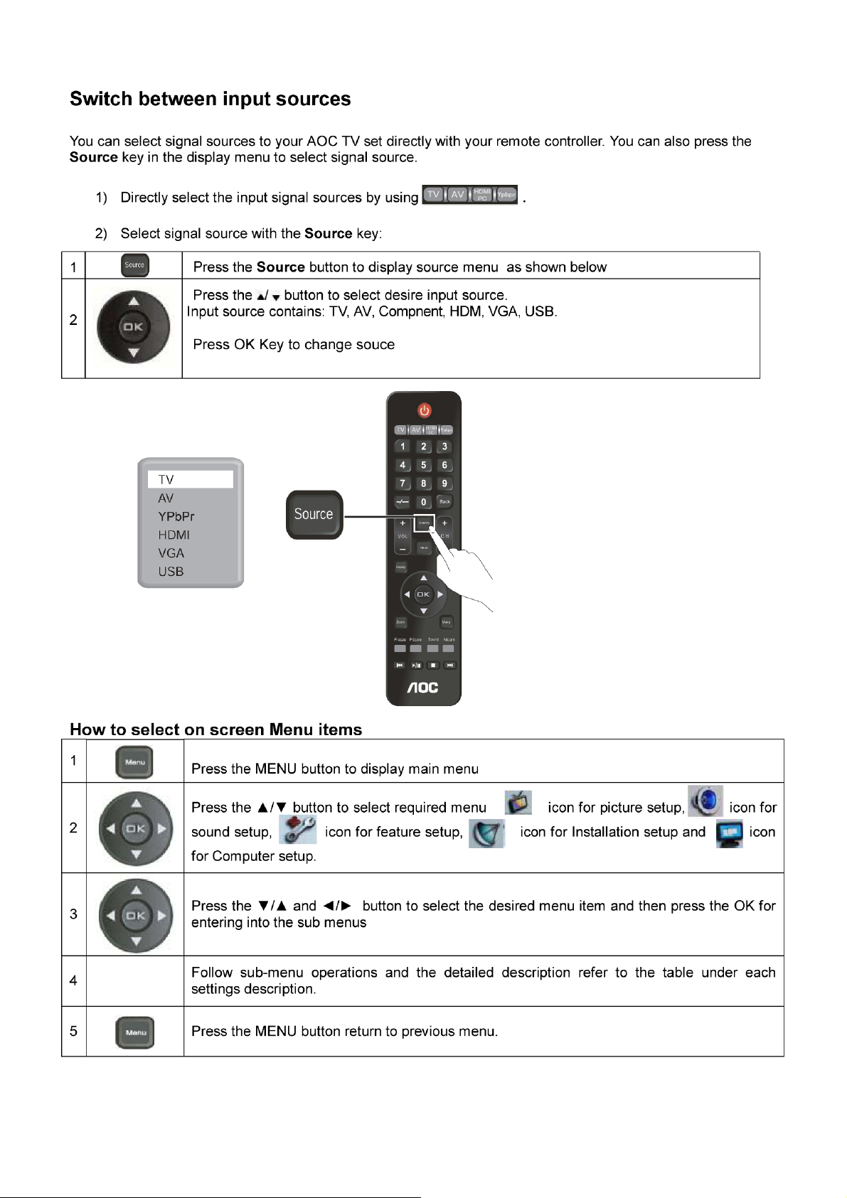
2. Operating Instructions
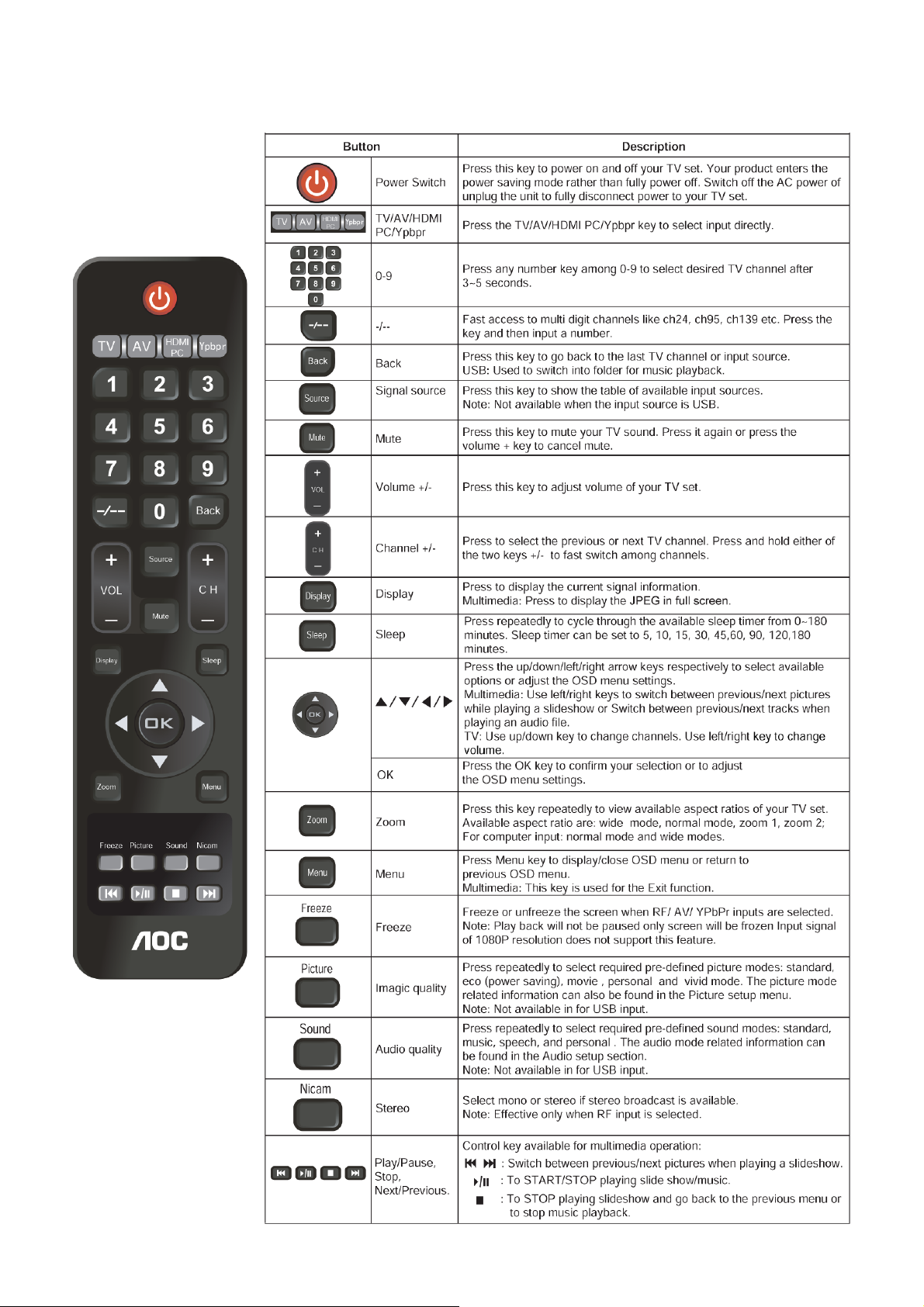
2.1 The Use of Remote Control
5
Page 6
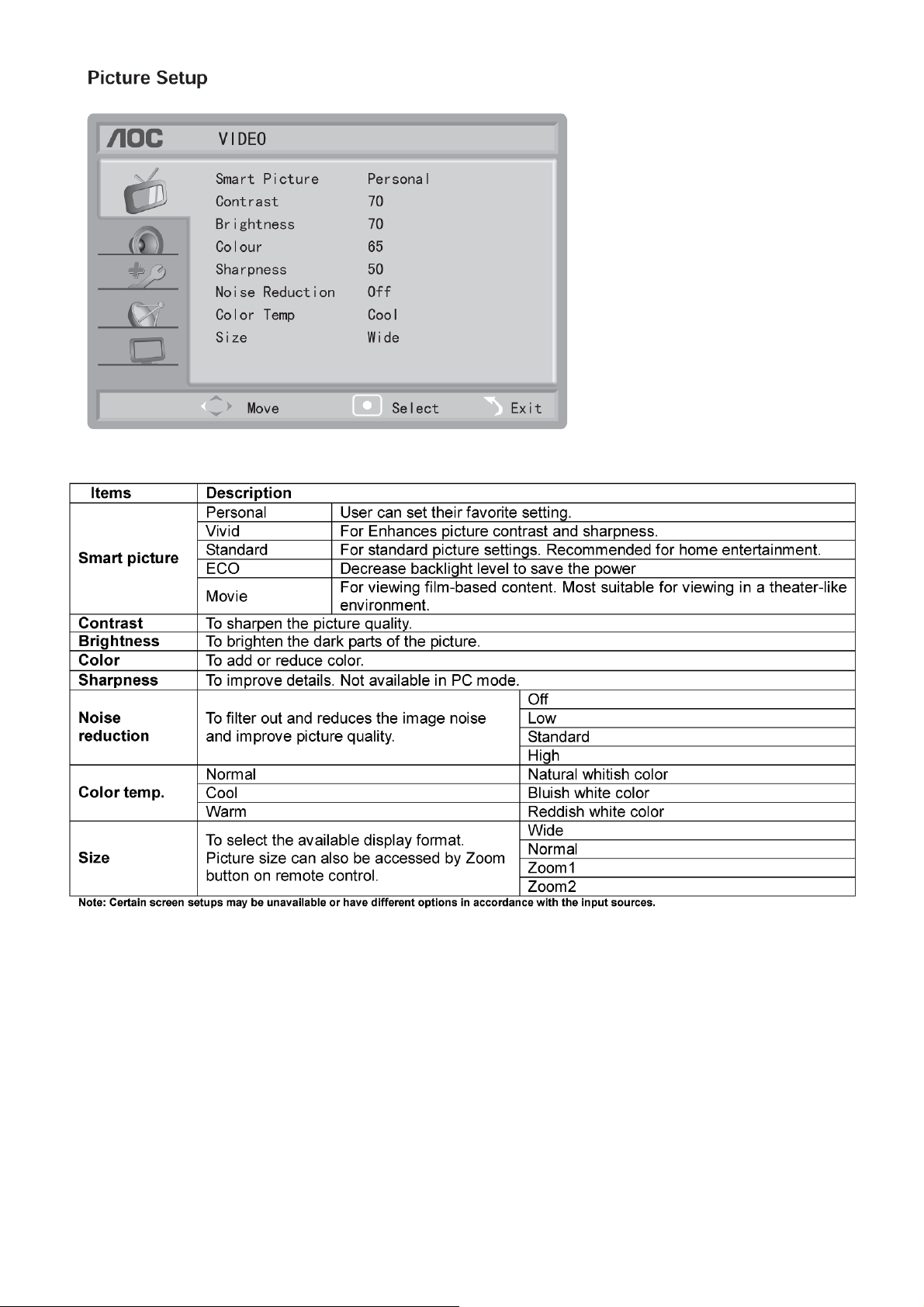
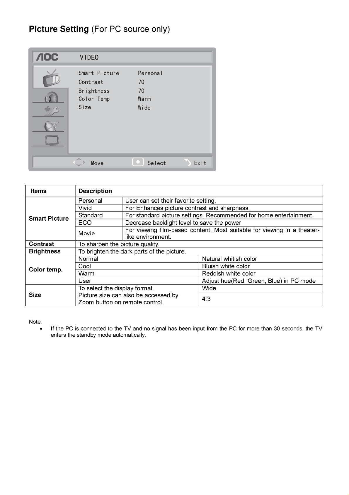
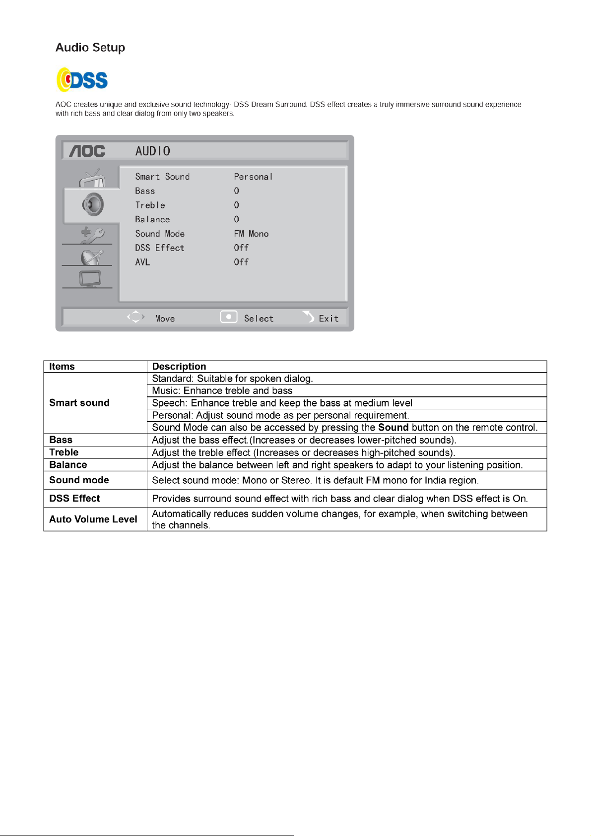
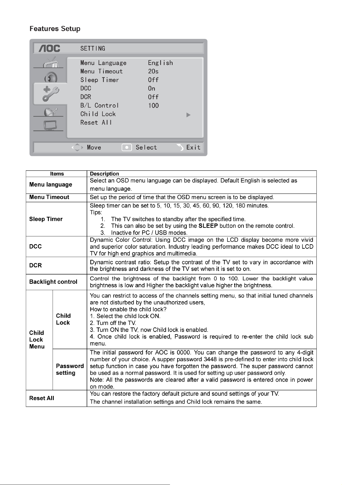
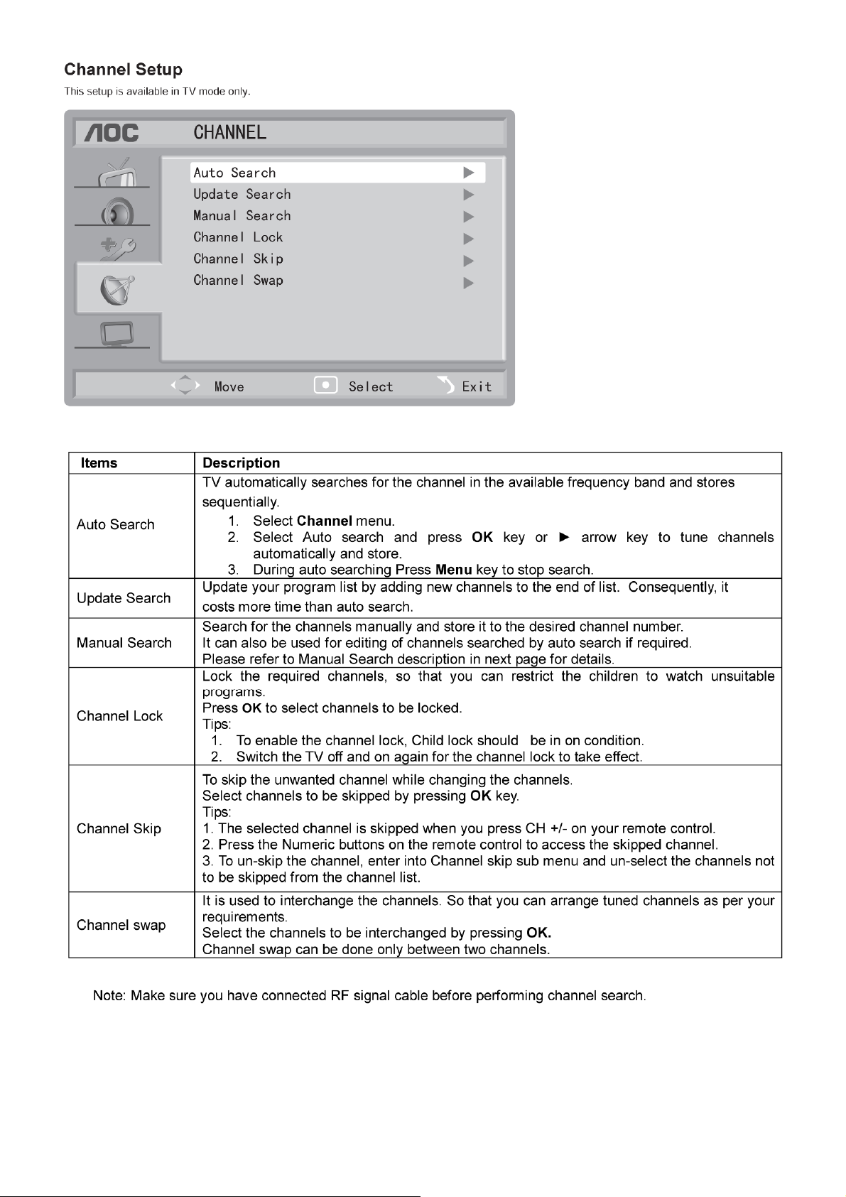
2.2 To Use the Menus
6
Page 7
7 8 9
Page 8
Page 9
Page 10
10 11 12 13 14 15 16 17
Page 11
Page 12
Page 13
Page 14
Page 15
Page 16
Page 17
Page 18
2.3 How to Connect
18
Page 19
19
Page 20
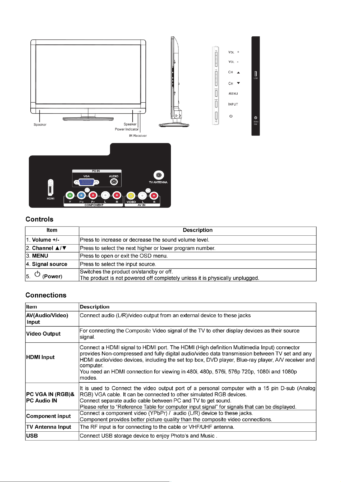
2.4 Front Panel Control Keys
20
Page 21
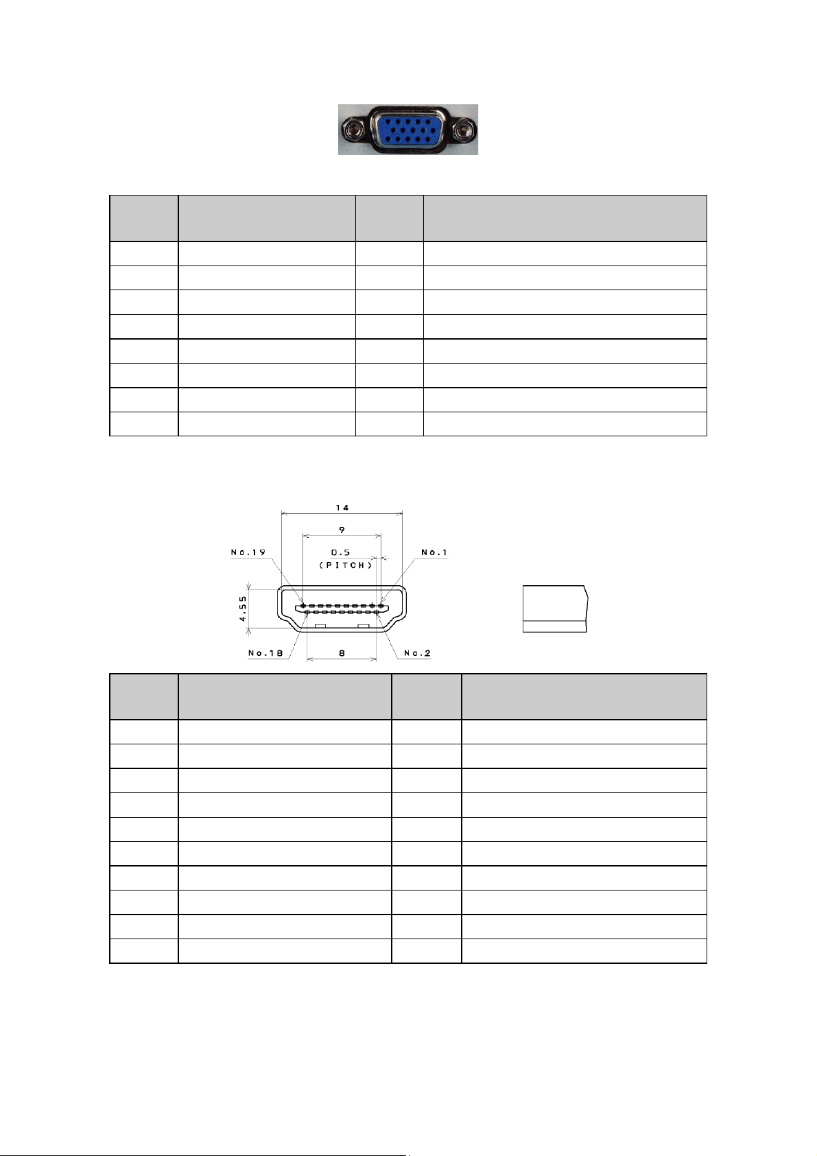
3. Input/Output Specification
3.1 RGB Signal Input
15 - Pin Color Display Signal Cable
Pin No. Description Pin No. Description
1 Red Video 9 5V
2 Green Video 10 Sync Ground
3 Blue Video 11 Not Used
4 Not Used 12 Serial Data for DDC
5 Ground 13 H-Sync.
6 Red Ground 14 V-Sync.
7 Green Ground 15 Serial Clock for DDC
8 Blue Ground
3.2 HDMI Digital Connector Pin Assignments
Pin No. Description Pin No. Description
1 TMDS Data2+ 2 TMDS Data2 Shield
3 TMDS Data2- 4 TMDS Data1+
5 TMDS Data1 Shield 6 TMDS Data1-
7 TMDS Data0+ 8 TMDS Data0 Shield
9 TMDS Data0- 10 TMDS Clock+
11 TMDS Clock Shield 12 TMDS Clock-
13 CEC 14 NC
15 SCL 16 SDA
17 DDC/CEC Ground 18 +5V Power
19 Hot Plug Detect
21
Page 22
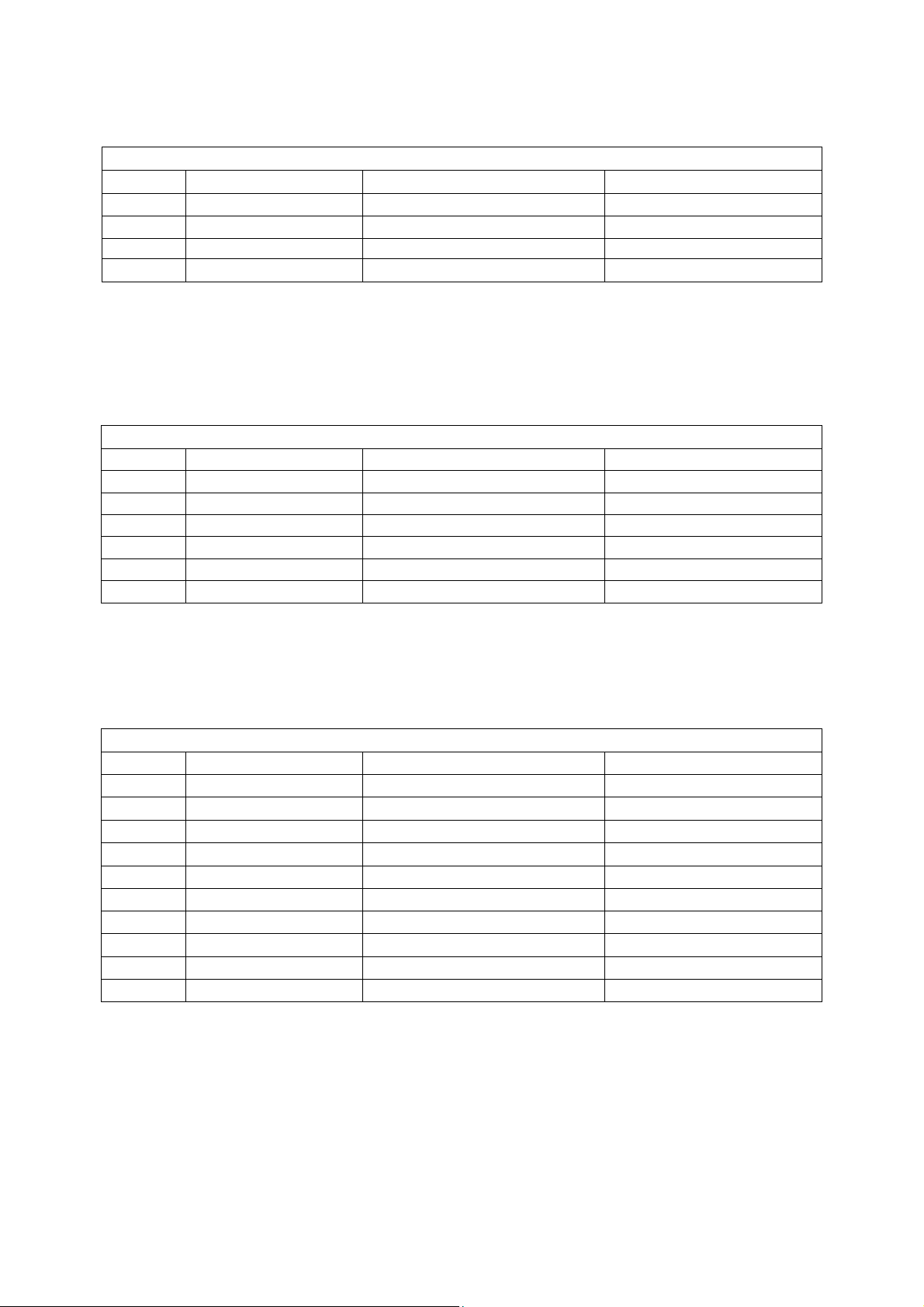
3.3 Compatible Mode Table
PC Input Signal Reference Chart
Connect a computer to your TV set and set up the computer output signal in accordance with table below.
Default computer mode
Standard Resolution Horizontal Frequency (KHz) Vertical Frequency(Hz)
VGA 720 x 400 31.327 69.617
SVGA 800 x 600 37.879 60.317
XGA 1024 x 768 48.363 60.004
WXGA 1360 x 768* 47.72 59.799
*Recommended resolution
DVI/ PC HDMI Input Signal Reference Chart
1. When DVI port is being used: connect the DVI port of video device to your TV set with a DVI-to-HDMI line and set
up the output signal of the video device in accordance with table below.
2. When HDMI port is being used: connect the HDMI ports of your computer and TV set with one HDMI wire and set
up the output signal of the video device in accordance with table below.
Default HDMI Mode
Standard Resolution Horizontal Frequency (KHz) Vertical Frequency(Hz)
VGA 640 x 480 37.879 60.317
VGA 720 x 400 31.327 69.617
SVGA 800 x 600 37.879 60.317
XGA 1024 x 768 48.363 60.004
SXGA 1280 x 1024 63.981 60.020
WXGA 1360 x 768* 47.72 59.799
*Recommended resolution
Video Input Signal Reference Chart
1. Connect the component signal or HDMI port of video device to your TV set and set up the output signal of the
video device in accordance with table below.
2. If your computer display card supports signals of video format then you can set up following output signal.
Default Component or HDMI Mode
Standard Resolution Horizontal Frequency (KHz) Vertical Frequency (Hz)
SD 720 x 480i 15.734 60
SD 720 x 480p 31.5 60
SD 720 x 576i 15.625 50
SD 720 x 576p 31.25 50
HD 1280 x 720p 37.5 50
HD 1280 x 720p 45 60
HD 1920 x 1080i 28.125 50
HD 1920 x 1080i 33.75 60
FHD 1920 x 1080p 56.25 50
FHD 1920 x 1080p 67.5 60
Video systems supported by the TV, video modes
PAL D/K B/G I; NTSC M
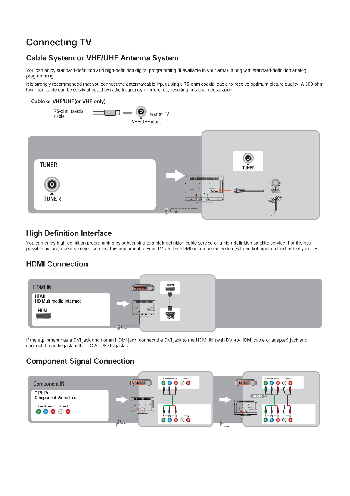
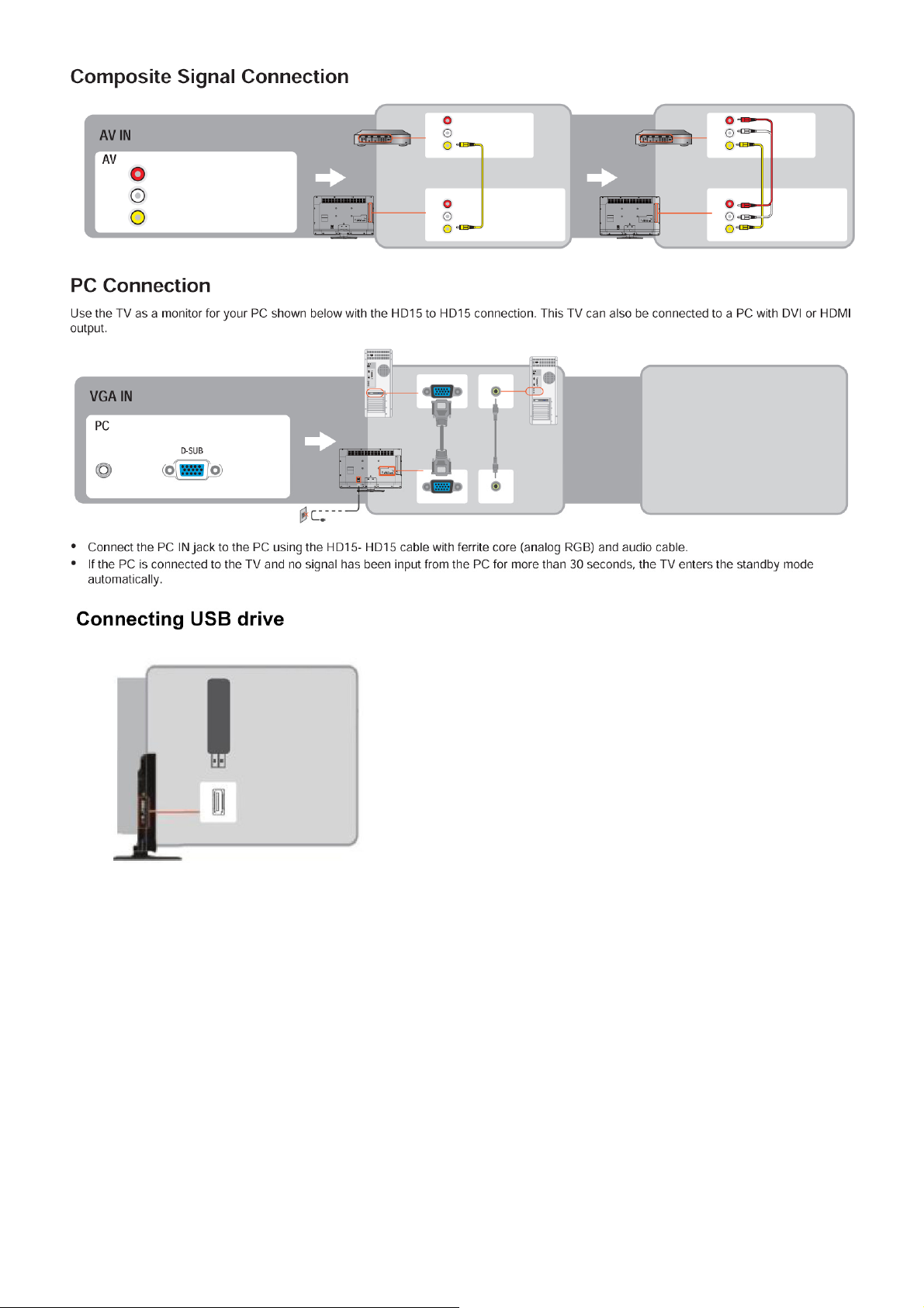
Standard Definition Interface
You can also enjoy traditional program by using a DVD player or VCR Player. Connect this equipment to your TV via
the Composite Input on the back of your TV.
22
Page 23
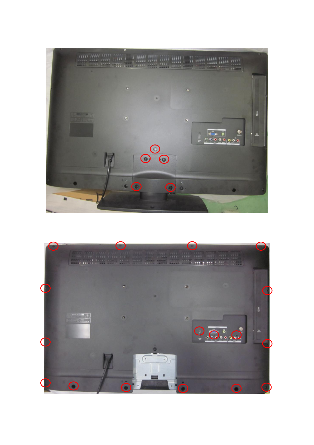
4. Mechanical Instructions
1. Remove the screws to remove STAND and BASE.
2. Remove the screws to remove REAR COVER.
23
Page 24
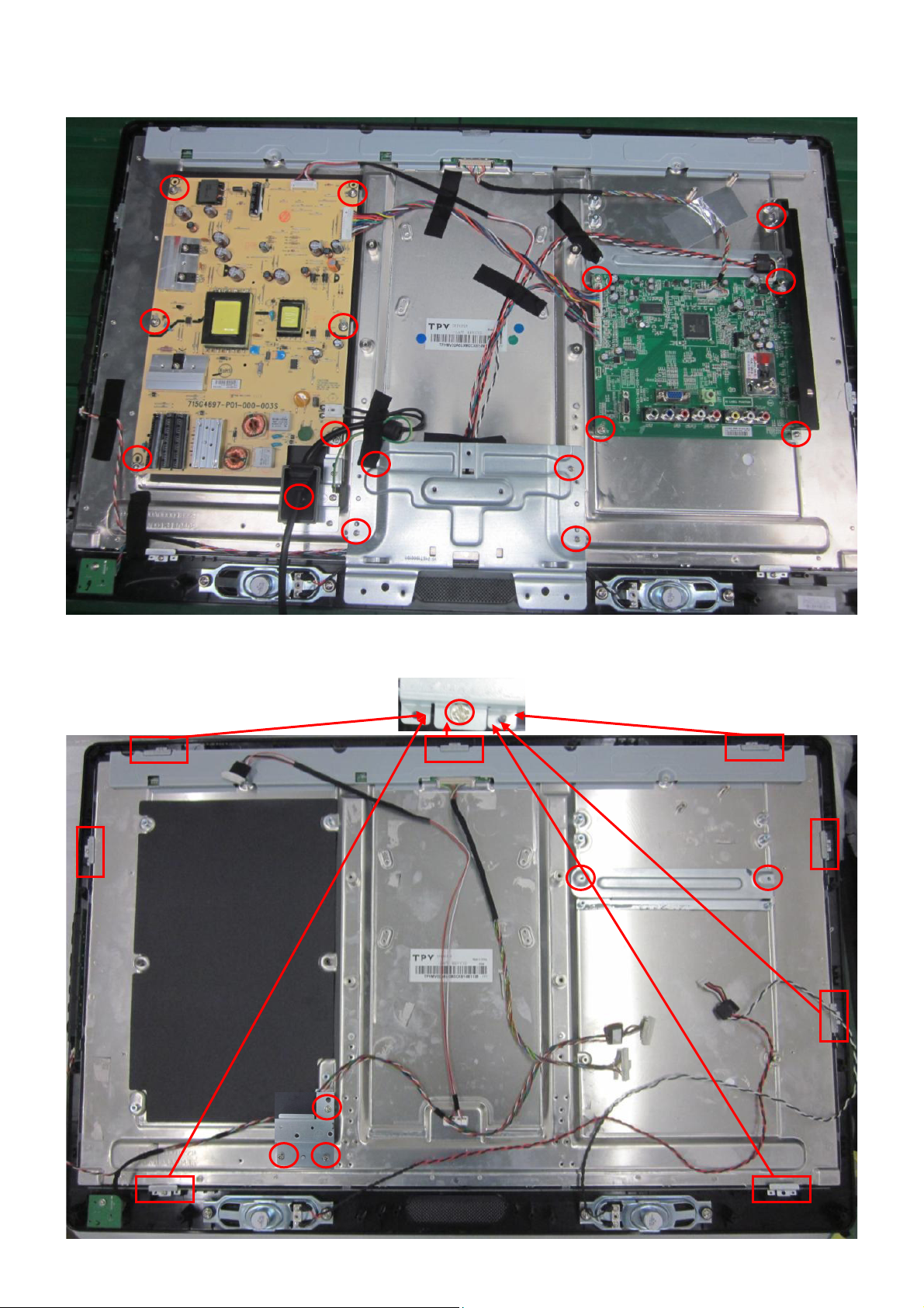
3. Remove the screws to remove AC COVER, BKT, MAIN BOARD and POWER BOARD.
4. Remove the screws to remove BKT and separate the BEZEL and PANEL.
24
Page 25
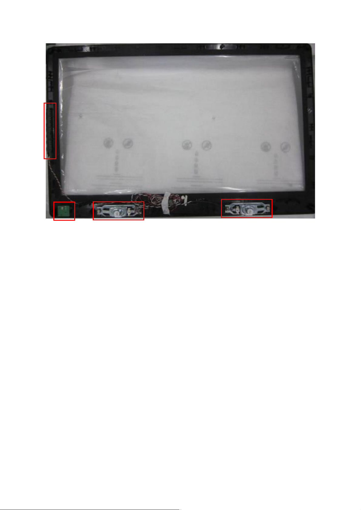
5. Remove the screws to remove KEY BOARD, IR BOARD and SPEAKERS.
25
Page 26

p
p
5. Repair Flow Chart
1. No power
No power (LED “Off”)
Check the AC input and
the
ower is “ON”?
Yes
Power board
out
ut=5.2V?
Yes
Check the IR board and LED
Replace the IR board
No
Replace the main board
No
Power “On”
No
Replace the power board
26
Page 27

2. Can’t start
Can’t start(LED red)
Power board output=24V?
Yes
Check the power key is under control?
No
Check the IR receiver is normal?
No
Replace the power board
Yes
Replace the key board
Yes
Replace the IR board
No
Replace the main board
No
Replace the Power board
27
Page 28

3. Abnormal display
Abnormal Display
Check the source
Yes
Enter factory mode to do
“EEPROM initial”&“Reset”
No
No
Reset the source
Check the main board
Yes
Check the LVDS cable
Yes
Check the panel
No
Replace the panel
No
Replace the main board
No
Replace the LVDS cable
28
Page 29

4. No display
No display (LED blue)
Check TV is under control and power
on/off by remote control and power key?
Yes
Check the LVDS cable
Yes
Yes
Check the backlight is
“On”?
No
Reinsert or replace the
LVDS cable
No
No
Check the B/L
signal is available?
Yes
Replace the main board
No
Replace main board
Panel Vcc = 12V?
Yes
Replace the Panel
No
Replace the main board
Power board output=24V?
Yes
Replace the Panel
Replace the power board
No
29
Page 30

5. Sound problem
No sound or sound abnormal
Check the audio source connection
and the TV system are correct?
Yes
Check the TV is muted, adjust the
volume or enter the menu to reset?
No
No
Reinsert the audio cable or
change the TV system
Enter factory mode to do “Reset”
No
Check the cable between the
speakers and main board is OK?
Yes
Check the speaker resistance value is in spec
(Remark: The value is marked on the speaker)?
Yes
Replace the cable
Replace the main board
No
No
Replace the speaker
30
Page 31

6. Remote control malfunction
Remote Control malfunction
Check the remote control battery is
not properly placed or no power?
No
Use the other remote controls
No
Whether the IR board is
abnormal?
No
Replace the main board
Yes
Replace the battery
Yes
Replace the remote control
Yes
Replace the IR board
31
Page 32

7. OSD is unstable or can’t work normally
OSD is unstable or can’t work normally
Key board connected properly?
Yes
Buttons are OK?
Yes
Key board is OK?
Yes
Enter factory mode to do “Reset”
No
No
No
No
Reconnect the key board
Replace the button function
Replace the key board
Replace the main board
32
Page 33

6. PCB Layout
6.1 Main Board
715G4763M01000004K
33
Page 34

34
Page 35

6.2 Power Board
715G4697P01000003S
35
Page 36

36 37
Page 37

Page 38

6.3 Key Board
715G4846K01000004S
6.4 IR Board
715G4845R01000004S
38
Page 39

7. Adjustment
ADC Adiustment
1. Factory Mode
In the TV mode adjust volume to zero, press menu key and then press number key 1 Æ 9 Æ 9 Æ 9. It will
achieve the factory mode.
2. ADC Adjustment
In the TV mode adjust volume to zero, press menu key and then press number key 1 Æ 9 Æ 9 Æ 9. It will
achieve the factory mode. Select the item of White Balance and press right key to enter it.
1. Change TV, press the item “Current Source” to Component mode and change signal to Component TIMING
311(576i/50Hz)Pattern 185(COLORBAR), press the item “Auto Color”;
2. Change TV, press the item “Current Source” to Component mode and change signal to Component TIMING
314(720P/60Hz)Pattern 185(COLORBAR), press the item “Auto Color”;
3. Change TV, press the item “Current Source” to PC mode and change signal to PC TIMING 137(1024X768)
Pattern 42 (5 MOSAIC), press the item “Auto Color”.
3. White Balance Adjustment
1. Enter into the factory mode:(same as the above-mentioned).
2. Take an example of adjust Ypbpr_source.
a. Select item”Source”: Ypbpr and item “Color Temp”: Normal, Adjust gain of RGB to meet spec in the below
setting of tim\pat. (COMPONENT mode: TIM = 314; PAT = 141(80IRE))
b. Select item”Source”: Ypbpr and item “Color Temp”:Warm, Adjust gain of RGB to meet spec in the below setting
of tim\pat. (COMPONENT mode: TIM = 314; PAT = 141(80IRE))
c. Select item”Source”: Ypbpr and item “Color Temp”: Cool, Adjust gain of RGB to meet spec in the below setting of
tim\pat. (COMPONENT mode: TIM = 314; PAT = 141(80IRE))
3. Take an example of adjust VGA_Normal:
a. Select item”Source”: Ypbpr and item “Color Temp”: Normal, Adjust gain of RGB to meet spec in the below
setting of tim\pat. (VGA mode: TIM = 137; PAT = 141(80IRE)
b. Select item”Source”: Ypbpr and item “Color Temp”: Warm, Adjust gain of RGB to meet spec in the below setting
of tim\pat. (VGA mode: TIM = 137; PAT = 141(80IRE)
c. Select item”Source”: Ypbpr and item “Color Temp”: Cool, Adjust gain of RGB to meet spec in the below
setting of tim\pat. (VGA mode: TIM = 137; PAT = 141(80IRE)
Source VGA/YPbPr VGA/YPbPr VGA/YPbPr
Temp Normal/(7500°K) Warm/(6500°K) Cool/(9300°K)
x (center) 0.285 ± 0.020 0.313 ± 0.020 0.272 ± 0.020
y (center) 0.293 ± 0.020 0.329 ± 0.020 0.278 ± 0.020
39
Page 40

8. Block Diagram
I2C for With DVB-T2
F35CT-2-E
TU101
D-SUB(PC IN)
H5DU2562GTR-FAC
X1
DDR1 U402
IF
I2C
HD-BF35 A3 DC
SAW FILTER
U10 6
IF1P
IF1N
VGA
MX25L3205DMI-12G
NOR FLA SH 3 2Mb U4 03
LCD PANEL T-CON
LVDS (50/60 Hz)
PHONE JACK(PC R/L)
YPBP R
RCA(AV1)
RCA(AV2)
USB(Multimedia)
HDMI1
HDMI2
MP3 & JPEG, SW UPDATE
USB 2.0
PC A UDIO
YPbPr
CVB S
CVB S
RTD2674
CVB S
monitor output
AOU T_ L
AOU T_ R
AV CVBS outpu t
AUD IO AMP
R2A15112FP
SPK X 2
SPK R/L
HEADPHONE
HP R/L
KEY RC
40
Page 41

9. Schematic Diagram
9.1 Main Board
715G4763M01000004K
+5VSB
R114
R119 0R05 1/10W
10K 1/10W
R121 0R05 1/10W
10K 1/10W
R112
AHS0
R103 1K 1/10W
AVS0
R104 1K 1/10W
C102
22pF 50V
DGND
CONN
CN102
R108
2.2K 1/10W
22pF 50V
3
2
1
MLVG0402
DGND
VGA_DDC_SDA
VGA_DDC_SD A#
VGA_DDC_SCL#
VGA_DDC_SCL
C103
12
ZD101
DGND
DGND
12
ZD103
MLVG0402
URAT_RX
VGA_DDC_SDA#
VGA_DDC_SCL#
R101
2.2K 1/10W
100K 1/10W
R115
DGND
DGND
R102
100 OHM +-5% 1/10W
U101
I/O23I/O3
2
GND
VDD
1
I/O1
I/O4
AZC199-04S
R110 27K 1/10W
R113 27K 1/10W
R116
100K 1/10W
VGA
+5VSB
U102
4
I/O23I/O3
2
GND
1
I/O1
AZC199-04S
VDD
I/O4
5
6
R105 100 OHM +-5% 1/10W
R109 75OHM +-5% 1/10W
R106 75OHM +-5% 1/10W
R107 75OHM +-5% 1/10W
C134 NC
C135 NC
C136 NC
RIN
R122 BEAD 60ohm 600mA
GIN
R126 BEAD 60ohm 600mA
BIN
R177 BEAD 60ohm 600mA
RIN+
GIN+
BIN+
URAT_TX
CN104
NC
VGA_IN_L6
VGA_IN_R6
VGA_DDC_SC L6
VGA_DDC_SD A6
USB
USB_PWR_CTRL6
USB_PWR_F LAG6
UART
URAT_RX6
URAT_TX6
+3V3
1
URAT_RX
2
URAT_TX
3
4
DGND
1
6
2
7
3
8
4
9
5
10
D-SUB 15P
DGND
DGND
DGND
TX
12
ZD102
MLVG0402
DGND
CN101
1716
RX
11
VGA_IN_R
VGA_IN_L
12
13
14
15
18 19
DGND
HS
VS
+5VSB
4
5
6
BIN+
BIN+6
GIN+
GIN+6
RIN+
RIN+6
AVS0
AVS06
AHS0
AHS06
VGA_IN_L
VGA_IN_R
VGA_DDC_SC L
VGA_DDC_SD A
USB_DM
USB_DM6
USB_DP
USB_DP6
USB_PWR_CTRL
USB_PWR_FLAG
URAT_RX
URAT_TX
VGA
USB
USB_PWR_CTRL
UART(V GA Pi n4 & Pin11 Share)
+5VSB
U104 BD8012FVJ
1U25V
C118
DGND
1
2
3
R123
R125
R1200R05 1/10W
1K 1/10W
USB_DM
USB_DP
USB_PWR_FLAG
10K 1/10W
R128
1K 1/10W
4 1
3 2
L101
NC/90OHM
R129
0R05 1/10W
R130
0R05 1/10W
GND
VIN
VIN
EN4OC
C106
4P7 50V
8
OUT
7
OUT
6
OUT
5
DGNDDGND
100nF 50V
C107
4P7 50V
1 2
C101
+
12
DGND DGND
FB101
300 OHM
C105
100UF16V
ZD104
MLVG0402
12
ZD105
MLVG0402
DGND
USB_Shield_GND
USB CONN
56
78
1234
1
2
3
4
USB_Shield_GND
CN103
DGND
USB_Shield_GND
T P V ( Top Victory Electronics Co . , Ltd. )
絬 隔 瓜 絪 腹
Key Component
01) VGA/USB/U ART
Date
OEM MOD EL
TPV MODEL
PCB NAME
Sheet
715G4763
of
210Thursday , April 21, 2011
A3
Size
A
Rev
称爹
>
<
称爹
41
Page 42

YPBPR INPUT
CN111
CONN
CN106
CONN
AV INPUT
CN121
CONN
YPbPr
YPBPR 0_IN_R6
SIDE AV IN
AV Output
6
YPBPR0_Y6
YPBPR0_PB6
YPBPR0_PR6
YPBPR0_I N_L6
AV IN
AV0_IN_L6
AV0_IN_R6
AV1_IN_L6
AV1_IN_R6
CVBS_OUT
2
A
1
4
B
3
6
C
5
ZD109 MLVG0402
ZD110 MLVG0402
ZD111 MLVG0402
DGND
2
A
1
4
B
3
ZD112 MLVG0402
DGND
ZD113 MLVG0402
2
A
1
4
B
3
6
C
12
ZD107
MLVG0402
12
5
YPBPR 0_L
YPBPR 0_R
ZD106
MLVG0402
12
DGND
12
ZD108
MLVG0402
12
12
12
DGND
R136
100K 1/10W
12
R132 27K 1/10W
R134 27K 1/10W
R137
100K 1/10W
R140 75OHM +-5% 1/10W
R141 75OHM +-5% 1/10W
R142 75OHM +-5% 1/10W
R135 5.1K 1/10W
R139 5.1K 1/10W
R143 100K 1/10W
R144 100K 1/10W
AV0_IN_L
AV0_IN_R
YPBPR 0_Y
YPBPR 0_PB
YPBPR 0_PR
YPBPR0_IN_L
YPBPR0_IN_R
CVBS0+
R133
75OHM +-5% 1/10W
CVBS0-
R138
0R05 1/10W
CN122
2
A
1
4
B
3
6
C
5
NC/RCA JACK
SIDE AV INPUT
12
ZD114
NC/ MLVG0402
DGNDDGNDDGND DGNDDGND
12
ZD115
NC/ MLVG0402
12
ZD116
NC/ MLVG0402
R145 NC /27K 1/10W
R148 NC /27K 1/10W
R149
R150
NC/ 100K 1/10W
NC/ 100K 1/10W
DGNDDGND
AV1_IN_L
CVBS1+
R146
NC/ 75OHM +-5% 1/10W
CVBS1-AV1_IN_R
R151
NC/ 0R05 1/10W
YPBPR0_Y
YPBPR0_PB
YPBPR0_PR
YPBPR0_IN_L
YPBPR0_IN_R
CVBS0+6
CVBS0-6
CVBS1+6
CVBS1-6
CVBS0+
CVBS0-
AV0_IN_L
AV0_IN_R
CVBS1+
CVBS1-
AV1_IN_L
AV1_IN_R
CVBS_OUT
DGND
VIDEO OUTPUT
DGND
CN123
3
2
1
CONN
DGND
ZD122
MLVG0402
12
DGND
DGNDDGNDDGNDDGNDDGND
FB103
121 OHM
1 2
C111
NC/ 220pF 50V
C109
100nF 50V
R159
75OHM +-5% 1/10W
C112
NC/ 100pF 50V
DGNDDGND
DGND
+5VSW
DGND
23
Q103
PMBS3906
1
R160
220 OHM 1/10W
R157
330OHM 1/10W
Q104
PMBS3904
R161
220 OHM 1/10W
DGND
R158
75K 1/10W 5%
R162
100K 1/10W
DGND
C108
10uF 25V
DGND
CVBS_OUT
C110
NC
42
T P V ( Top Victory Electronics Co . , Ltd. )
絬 隔 瓜 絪 腹
Key Component
02) YPbPr/ AV/CVBS OUT
Date
OEM MO DEL
TPV MOD EL
PCB NAME
Sheet
715G4763
310Thursday , April 21, 2011
of
Size
Rev
称爹
A3
A
<
称爹
>
Page 43

TUN_GND
RF_AGC#
C125
NC
15
B+(+5V)
RF AGC
TU1 01
TH112TH213TH314TH4
11
IF-
10
IF+
9
N.C
8
N.C
TUNER_SCL
7
SCL
TUNER_SDA
6
SDA
5
RF_AGC#
4
3
N.C
2
N.C
1
N.C
TUN_5V
R183
0R05OHM1/8W
NC
Tune r5V
F35CT
C126
TUN _GN D
TUNER_IFT
FB105
300 OHM
1 2
DGNDDGND
C121
10uF
DGND
TUN_GND
C127
10uF 16V
C143
NC/ 100UF 25V
Tuner5V
C122
100nF 50V
+5VSW
R182
1K 1/10W
R184 NC
23
1
Q106
PMBS3906
DGND
FB720 120R/6000mA
1 2
FB721 N C/120R/6000m A
1 2
U705
BA17809FP-E2
330nF
TUN_GND
TUN_GND
R185
0R05 1/10W
IN1OUT
C138
+
BYPASS IF preamp
+12V
+24V
3
GND
2
10UF 50V
C140
10N 50V
L104
1 2
10uH +-10%
C128
10uF 16V
DGND
R179
0R05 1/16W(NC)
IF_12V
C139
+
C144
R196
0.5 OHM 1/16W
R187
510 +-5% 1/10W
C129
100nF 50V
DGND
CLOSE TO RTD2674
0.1uF 50V
TUN_GNDTUN_GND
TUN_GND
R195
6.8kOHM + -5% 1/10W
C142
10N 50V
R197
1K 1/10W 5%
1K2 1/10W 5%
RF_AGC
IF_OUTTUNER_IFT
IF_12V
680OHM +- 5% 1/10W
R199
R198
Q107
2SC4215-O
R200
20 OHM 1/4W
TUN _GN D
L105
0.82uH
IF_OUT
R201
0R05OHM1/16W
5V For TUNER
+5VSW
C130
+
100UF16V
change from 330u to 100u
22P 50V
CS C132/C 133
IF1P
IF1N
DGND
TUNER_SCL
C123
TUN_GND TUN_GND
C119 1U25V
L102
2.2uH
C120 1U25V
TUNER_SDA I2C_M0_SDA
C124
22P 50V
R191
1K 1/10W
R192
1K 1/10W
DGND
U105
G965-25ADJPI UF
2.2 OHM 1/10W
R190
R174 10 OHM 1/10W
R181 10 OHM 1/10W
DGND
U106
4
5
OUTPUT
OUTPUT
3
INPUT
INPUT
GND
8
VEN1VIN2VO3ADJ
38.3KOHM +-1% 1/8W
DGND
1
2
DGND
GND5GND6GND7GND
4
R188
DGND
12K1/10W
R189
4.7K 1/10W
L103
0.33uH 10%
R117
NC/ 0.05R
R111
0.05R
DGND
+
C131
47UF 25V
R194
TUNER
I2C_M0_SDA6
I2C_M0_SCL6
C137
RF_AGC6
IF1P6
IF1N6
TUN_5V
FB107
300 OHM
1 2
R193
4.7K 1/10W
I2C_M0_SCL
IF_OUT
10N 50V
IF1P
IF1N
I2C_M0_SDA
I2C_M0_SCL
RF_AGC
TUN_GNDDGND
TUN_5V
43
T P V ( Top Victory Electronics Co . , Ltd. )
絬 隔 瓜 絪 腹
Key Component
Date
03) TUNER
OEM MODEL
TPV MOD EL
PCB NAME
Sheet
715G4763
410Monday, June 27, 2011
of
Size
Rev
称爹
A3
A
<
称爹
>
Page 44

C512
NC/100nF 50V
DGND
CN502
CN506
21
23
22
20
SHLD1
SHLD3
SHLD2
SHLD0
NC/HDMI
TMDSD 0+
TMDSD0-
TMDSD 1+
TMDSD1-
TMDSD 2+
TMDSD2-
TMDSC+
TMDSC-
SCL
SDA
CEC
HPD
VCC5
DSHLD0
DSHLD1
DSHLD2
CSHLD0
DDC_GND
SHLD_GND 1
SHLD_GND 2
SHLD1
SHLD2
SHLD3
SHLD4
SHLD5
HDMI
HPD
VCC5
DDC_GND
SDA
SCL
NC
CEC
TMDSC CSHLD0
TMDSC +
TMDSD0-
DSHLD2
TMDSD0+
TMDSD1-
DSHLD1
TMDSD1+
TMDSD2-
DSHLD0
TMDSD2+
MHDMI(HDMI Mux
DGND
12
ZD502
MLVG0402
DGND
12
ZD503
NC/ MLVG0402
DGND
R525
NC
HDMI1_C LK-HDMI1_C LK+
R513
100K 1/10W
R552
NC/100K 1/ 10W
R551
NC
R511
NC
Q504
PMBS3904
DGND
Q507
NC/PMBS3904
DGND
R512
1K 1/10W
R514
4.7K 1/10W
R550
NC/ 1K 1/10W
R553
NC/4. 7K 1/10W
HDMI1_5V
R556
10K 1/10W
HDMI1_HPD
HDMI2_5V
R557
NC/10K 1/10W
HDMI2_HPD
HDMI2_CLK+
DGND
HDMI2_C LK-
R518
NC
R507
NC
HDMI2_SDA#
GND
3
3
GND
GND
3
OUT1
OUT2
OUT3
OUT3
OUT2
OUT1
OUT1
OUT2
OUT3
10
9
7
6
6
7
9
10
10
9
7
6
HDMI2_SCL#
HDMI1_D0+
10
HDMI1_D0-
9
HDMI1_CLK+
7
HDMI1_CLK-
6
HDMI1_D2+
6
HDMI1_D2-
7
HDMI1_D1+
9
HDMI1_D1-
10
R529 NC
10
HDMI1_SCL#
9
7
6
HDMI2_SDA#
R536
NC/0R05 1/10W
HDMI2_C LKHDMI2_C LK+
HDMI2_D 0HDMI2_D 0+
HDMI2_D 1HDMI2_D 1+
HDMI2_D 2HDMI2_D 2+
DGND
HDMI1_SDA#
NC/10K 1/10W
R534
HDMI2_5V
HDMI_CEC #
10K 1/10W
3
R531
NC/10K 1/10W
D501
NC
R516
3
10K 1/10W
R517
HDMI_CEC #
HDMI1_5V
HDMI2_5V
1
2
D503
BAT54C
HDMI1_5V
1
2
+5VSB
HDMI1_HPD#
+5VSB
HDMI2_HPD #
HDMI_CEC# HDMI_CEC
1
IN1
2
IN2
4
IN3
IN45OUT4
7
9
4
6
1
3
10
12
15
16
HDMI1_CE
13
HDMI1_HPD#
19
18
14
NC
2
5
8
11
17
20
21
22
23
24
25
26
DGND
HDMI2_HPD#
19
18
17
16
15
14
13
12
11
10
NC
9
8
7
6
5
4
NC
3
2
1
DGND
DGND
3241L501
3241L503
DGND
C511
100nF 50V
U510
NC RC lamp0524P.TCT
1
2
4
U512 NC R Clamp0524P.TCT
4
3241L502
2
1
NC
1
2
3241L504
4
NC
U513 NC R Clamp0524P.TCT
GND
U507 NC R Clamp0524P.TCT
8
8
U506 NC R Clamp0524P.TCT
IN45OUT4
4
IN3
GND
2
IN2
1
IN1
U509
NC R Clamp0524P.TCT
1
IN1
2
IN2
4
IN3
IN45OUT4
GND
8
DGND
IN1
OUT1
IN2
OUT2
IN3
OUT3
IN45OUT4
GND
GND
3
8
DGND
DGND
3
8
IN45OUT4
IN3
OUT3
GND
GND
IN2
OUT2
IN1
OUT1
IN1
OUT1
IN2
OUT2
IN3
OUT3
IN45OUT4
GND
GND
3
8
DGND
MHDMI_D2+6
MHDMI_D2-6
MHDMI_D1+6
MHDMI_D1-6
MHDMI_D0+6
MHDMI_D0-6
MHDMI_CLK+6
MHDMI_CLK-6
MHDMI_SDA6
MHDMI_SCL6
MHD MI_H PD6
HDMI2
HDMI2_D2+6
HDMI2_D2-6
HDMI2_D1+6
HDMI2_D1-6
HDMI2_D0+6
HDMI2_D0-6
HDMI2_C LK+6
HDMI2_C LK-6
HDMI2_SDA6
HDMI2_SCL6
HDMI2_HPD6
HDMI_CEC6
MHDMI_HPD HDMI1_HPD
MHDMI_SDA HDMI1_SDA
MHDMI_SCL HDMI1_SCL
MHDMI_CLK- HDMI1_C LKMHDMI_CLK+ HDMI1_C LK+
MHDMI_D0- HDMI1_D0MHDMI_D0+ HDMI1_D0+
MHDMI_D1- HDMI1_D1MHDMI_D1+ HDMI1_D1+
MHDMI_D2- HDMI1_D2MHDMI_D2+ HDMI1_D2+
R522 22 OHM 1/10W
R523 22 OHM 1/10W
R524 NC/ 100 OHM 1/10W
R526 NC/ 100 OHM 1/10W
)
MHDMI_D2+
MHDMI_D2-
MHDMI_D1+
MHDMI_D1-
MHDMI_D0+
MHDMI_D0-
MHDMI_CLK+
MHD MI_C LK-
MHDMI_SDA
MHDMI_SCL
MHD MI_H PD
HDMI2_D2+
HDMI2_D2HDMI2_D1+
HDMI2_D1HDMI2_D0+
HDMI2_D0-
HDMI2_C LK+
HDMI2_C LK-
HDMI2_SDA
HDMI2_SCL
HDMI2_HPD
HDMI_CEC
HDMI1_SCLH DMI1_SCL#
HDMI1_SDAHDMI1_SDA#
HDMI2_SCLH DMI2_SCL#
HDMI2_SDA
44
T P V ( Top Victory Electronics Co . , Ltd. )
絬 隔 瓜 絪 腹
Key Component
Date
04) HDMI
OEM MODEL
TPV MODEL
PCB NAME
Sheet
715G4763
510Wednesday , April 27, 2011
of
Size
Rev
称爹
A3
A
<
称爹
>
Page 45

C4101
CVBS0+
CVBS0-
CVBS1+
CVBS1-
DGND
DGND
RIN+
DGND
GIN+
DGND
BIN+
DGND
YPBPR0_Y
DGND
YPBPR0_PB
DGND
YPBPR0_PR
DGND
VGA_IN_L
VGA_IN_R
R4101
49.9 OHM +-1% 1/10W
C4103
NC
R4105
NC/49.9 OH M +-1% 1/10W
C4108
NC
R4112
0R05 1/10W
C4125
5pF 50V
R4114
0R05 1/10W
R4118
0R05 1/10W
C4130
5pF 50V
R4120
0R05 1/10W
R4124
0R05 1/10W
C4133
5pF 50V
R4126
0R05 1/10W
R4128
0R05 1/10W
C4138
5pF 50V
R4132
0R05 1/10W
R4134
0R05 1/10W
C4141
5pF 50V
R4136
0R05 1/10W
R4138
0R05 1/10W
C4147
5pF 50V
R4143
0R05 1/10W
R4130
NC
DGND
47nF 50V
L402
CHIP I NDUCTOR 1. 0uH +-10%
C4104
270PF50V
L401NC/CH IP INDUC TOR 1.0uH +-10%
C4109
NC/270PF50V
C4111 47nF 50V
R4113
100 OHM 1/10W
R4115
100 OHM 1/10W
R4119
100 OHM 1/10W
R4121
100 OHM 1/10W
R4125
100 OHM 1/10W
R4127
100 OHM 1/10W
R4129
100 OHM 1/10W
R4133
100 OHM 1/10W
R4135
100 OHM 1/10W
R4137
100 OHM 1/10W
R4139
100 OHM 1/10W
R4144
100 OHM 1/10W
R4131
NC
47nF 50VC4117
C4106
47nF 50V
C4107
NC/47nF 50V
C4110
NC/47nF 50V
C4124
47nF 50V
C4126
47nF 50V
C4128
47nF 50V
C4131
47nF 50V
C4132
47nF 50V
C4134
47nF 50V
C4137
47nF 50V
C4139
47nF 50V
C4140
47nF 50V
C4144
47nF 50V
C4135
4.7UF 10V
C4136
4.7UF 10V
VIN11P
COM_A0-
VIN14P
COM_A2-
VIN13P
VIN10P
VGA_R+
VGA_R-
VGA_G+
VGA_G-
VGA_B+
VGA_B-
Y1+
COM_Y0-
PB1+
Pr1+
AIO_2L
AIO_2R
AV0_IN_L
AV0_IN_R
AV1_IN_L
AV1_IN_R
R4106
YPBPR0_I N_L
YPBPR0_I N_R
R4110
DGND
R4103
AIN_1L
C4102
4.7UF 10V
AIN_1R
C4105
4.7UF 10V
R4104
NC
NC
DGND
R4108
NC
NC
DGND
R4111
NC
NC
DGND
C4150
47nF 50V
C4151
47nF 50V
C4152
47nF 50V
C4155
47nF 50V
C4118
47nF 50V
C4115
47nF 50V
C4116
47nF 50V
C4112 NC/4U7 10V
C4113 NC/4U7 10V
C4122
4.7UF 10V
C4123
4.7UF 10V
Y2+
COM_Y1-
PB2+
PR2+
SV_C+
COM_A1-
SV_Y+
AIN_2L
AIN_2R
AIN_3L
AIN_3R
A3_3V
A3_3V
A1_2V
FB402
300 OHM
1 2
FB403 300 OHM
FB404 300 OHM
BB3_3V
TMDS1_2V
TMDS3_3V
TMDS1_2V
1 2
1 2
FB406
300 OHM
1 2
1 2
FB405
300 OHM
FB407
300 OHM
1 2
VIN11P
DGND
MHDMI_CLKMHDMI_CLK+
MHDMI_D0MHDMI_D0+
MHDMI_D1MHDMI_D1+
MHDMI_D2MHDMI_D2+
HDMI2_CLKHDMI2_CLK+
HDMI2_D0HDMI2_D0+
HDMI2_D1HDMI2_D1+
HDMI2_D2HDMI2_D2+
HDMI_REXT
YPP3_3V0
DGND
AHS0
AVS0
YPP3_3V1
YPP3_3V2
VGA_B+
VGA_BVGA_G+
VGA_GVGA_R+
VGA_RPB1+
COM_Y0Y1+
PR1+
PB2+
COM_Y1PR2+
Y2+
A1_2V0
A1_2V1
DGND
COM_A0SV_Y+
SV_C+
COM_A1VIN10P
VIN13P
COM_A2VIN14PVIN14P
AVDD_BB1
DGND
C4127
4.7UF 10V
C4129
4.7UF 10V
163
TMDS_1.2V
164
TMDS_3.3V
165
P1_RX3N/HDMI_C LKN_1
166
P1_RX3P/HDMI_CLKP_1
167
P1_RX2N/HDMI_0N _1
168
P1_RX2P/HDMI_0P_1
169
P1_RX1N/HDMI_1N _1
170
P1_RX1P/HDMI_1P_1
171
P1_RX0N/HDMI_2N _1
172
P1_RX0P/HDMI_2P_1
173
P0_RX3N/HDMI_C LKN_0
174
P0_RX3P/HDMI_CLKP_0
175
P0_RX2N/HDMI_0N _0
176
P0_RX2P/HDMI_0P_0
177
P0_RX1N/HDMI_1N _0
178
P0_RX1P/HDMI_1P_0
179
P0_RX0N/HDMI_2N _0
180
P0_RX0P/HDMI_2P_0
181
TMDS_R EXT
182
TMDS_1.2V
183
APLL_VDD_3.3V
184
APLL_GND
185
HSYNC
186
VSYNC
187
ADC_VDD _3.3V
188
VD_VDD_3. 3V
189
(VGA_B)VIN_0P
190
VIN_0N
191
(VGA_G)VIN_1P
192
VIN1_N
193
(VGA_R)VIN_2P
194
VIN_2N
195
(Pb)VIN_3P
196
VIN_Y 0N
197
(Y)VIN_4P
198
(Pr)VIN_5P
199
(FSC_B/Pb)VI N_6P
200
VIN_Y 1N
201
(FSC_G/Pr)VI N_7P
202
(FSC_R/Y )VIN_8P
203
ADC_VDD _1.2V
204
VD_VDD_1. 2V
205
VD_GND
206
(SV-C/FSC _CVBS)VIN_ 11P
207
VIN_A0N
208
(SV-Y)VIN _9P
209
(SV-C)VIN_1 2P
210
VIN_A1N
211
(CVBS/SV-Y )VIN_10P
212
(CVBS/SV-C)VI N_13P
213
VIN_A2N
214
(CVBS)VIN_14P
215
AVDD_BB1_3.3V
216
AGND_BB1
217
E-PAD
U401
RTD2674U
C4145
DGND
100nF 50V
AIN_4L
AIN_4R
D3_3V
STB1_2V
HDMI_SEL
HDMI2_SCL
HDMI2_SDA
VGA_DDC_SD A
VGA_DDC_SC L
HDMI_CEC
MHDMI_SCL
MHDMI_SDA
162
154
159
161
156
155
158
160
157
CEC
IO_3.3V
HDDC1_SCL
HDDC0_SCL
HDDC1_SDA
HDDC0_SDA
VGA_DDC_SCL
VGA_DDC_SD A
VCM_BB1AIO_2L5AIO_1R6AIO_1L
AVDD_BB0_3.3V2AIN_5L/LSAD C63AIN_3R10AIN_3L11AIN_2R12AIN_2L13AIN_1R14AIN_1L15AOUT_R16AOUT_L17HPOUT_R19HPOUT_L18SCART_FSW_020DAC_VDD_3.3V22AVOUT_123AVOUT_224DAC_GND25ADC2X_GND _3.3V26IF_N27IF_P28ADC2X_VDD29PLL_GND30XIN31XOUT32PLL_VDD_3.3V33CORE_1.2V
AIO_2R4AIN_4R8AIN_4L
7
9
AIN_4L
AIN_4R
L_SEN1
AIO_2R
AIO_2L
AVDD_BB0
C4142
1U25V
FB408
300 OHM
1 2
BB3_3V
POWER_ON_LV2
HDMI2_HPD
MHDMI_HPD
152
153
GPIO_C6
GPIO_C8
AIN_3L
AIN_3R
URAT_TX
RESET#
SPI_SCK
SPI_DI
SPI_DO
SPI_CS#
POWER_ON_LV1
IRRX
148
142
143
144
145
146
150
149
151
147
SPI_DI
SPI_DO
SPI_SCK
GPIO_C2
GPIO_C3
GPIO_C4
GPIO_C5
SPI_CS_N
RESET_IN
STBY_CORE_1. 2V
21
AIN_1R
AIN_1L
HPOUT_JD
MUTE_AVOU T
AOUT_L
AOUT_R
HPOUT_R
AIN_2L
AIN_2R
HPOUT_L
FB409
300 OHM
C4225100P 50V
DGND
D1_2V
D3_3V
STB1_2V
LEDY
URAT_RX
139
141
140
GPIO_C0
GPIO_C1
STBY_CORE_1. 2V
DDR_IO_2. 5V
POWER_KEY
LSADC_REF
DDR_DQS1
DDR_DQ11
DDR_DQ9
DDR_DQ10
DDR_DQ8
LEDG
LSADC1
128
135
136
137
138
130
131
134
129
132
133
DQ_9
DQ_8
DQS1
DQ_10
IO_3.3V
CORE_1.2V
LSADC_REF
DDR_IO_2. 5V
LSADC0/G PIO
LSADC1/G PIO
LSADC2/G PIO
LSADC4/G PIO
RTD2674U
LQFP-216
E-PAD
SCART_FSW_1
FB415300 OHM
CVBS_OUT
VDAC3_3V0
1 2
FB417300 OHM
1 2
A3_3V
DGND
VDAC3_3V1
XOUT
IF1P
IF1N
PLL3_3V
XIN
FB411
1000OHM
1 2
C41921U25V
1 2
1 2
FB412 300 OHM
DGND
A3_3V
A3_3V
USB_AVDD_3. 3V35HSDM36HSDP37USB_AVDD_1. 2V38I2C0_SCL39I2C0_SDA40IO_3.3V41GPIO_A0/RF _AGC42GPIO_A1/IF _AGC43CORE_1.2V44O_FP45O_FN46O_EP47O_EN48O_DP49O_DN50O_CP51O_CN52O_BP53O_BN
34
USB_3V3
USB_DM
D1_2V
1 2
FB413300 OH M
A3_3V
DDR_IO_2. 5V
DDR_DQ12
DDR_DQ15
DDR_DQ13
DDR_DQ14
DDR_VREF
123
124
125
126
127
121
122
DQ_15
DQ_14
DQ_13
DQ_12
DQ_11
DDR_VREF
DDR_IO_2. 5V
USB_1V2
USB_DP
RF_AGC
I2C_M0_SCL
I2C_M0_SDA
1 2
FB401 300 OHM
CS FB410,改接D3_3V
D3_3V
A1_2V
C4226 100P 50V
DGND
DDR_IO_2. 5V
DDR_ADD5
DDR_CK
DDR_ADD9
DDR_CKE
DDR_ADD8
DDR_ADD7
DDR_DM1
120
USB_PWR_CTRL
DDR_ADD6
DDR_ADD11
DDR_ADD12
DDR_CK#
118
119
114
115
117
116
109
110
111
112
113
CK
CK#
CKE
DM1
D1_2V
ADDR5
ADDR6
ADDR7
ADDR8
ADDR9
ADDR11
ADDR12
DDR_IO_2. 5V
DDR_IO_2. 5V
CORE_1.2V
DDR_IO_2. 5V
DDR_IO_2. 5V
CORE_1.2V
TCON/GPI O_B12
TCON/GPI O_B10
TCON/GPI O_B9
TCON/GPI O_B8
TCON/GPI O_B7
TCON/GPI O_B6
TCON/GPI O_B5
TCON/GPI O_B4
TCON/GPI O_B3
TCON/GPI O_B2
TCON/GPI O_B0
CORE_1.2V
54
123
4
123
4
876
5
876
5
RP415
TOBN
TOCN
TOCP
TOBP
TOCLKP
TODP
TODN
TOCLKN
60R 1/16W 5%
ADDR4
ADDR3
ADDR2
ADDR1
ADDR0
ADDR10
IO_3.3V
IO_3.3V
RP414
60R 1/16W 5%
RAS#
CAS#
DQ_0
DQ_1
DQ_2
DQ_3
DQ_4
DQ_5
DQ_6
DQ_7
DQS0
E_AN
E_AP
E_BN
E_BP
E_CN
E_CP
E_DN
E_DP
E_EN
E_EP
E_FN
E_FP
O_AN
O_AP
108
107
106
105
104
103
102
101
BA1
100
BA0
99
98
97
96
WE#
95
DM0
94
93
92
91
90
89
88
87
86
85
84
83
82
81
80
79
78
77
76
75
74
73
72
71
70
69
68
67
66
65
64
63
62
61
60
59
58
57
56
55
POWER_ON_LV2
L_SEN1
MUTE_AMP
URAT_RX
URAT_TX
PANEL_ON
BL_ON_OFF
AMP_STB
L_SEN1
POWER_ON_LV1
MUTE_AV OUT
LEDG
LEDY
DDR_ADD4
DDR_ADD3
DDR_ADD2
DDR_ADD1
DDR_ADD0
DDR_ADD10
DDR_BA1
DDR_BA0DDR_BA0
DDR_RAS#
DDR_CAS#
DDR_WE#
DDR_DM0
DDR_DQ0
DDR_DQ1
DDR_DQ2
DDR_DQ3
DDR_DQ4
DDR_DQ5
DDR_DQ6
DDR_DQ7
DDR_DQS0
BL_PWM
BL_ON_OFF
SPI_WP
AMP_STB
MUTE_ AMP
USB_PWR_F LAG
PANEL_ON
1
8
2
7
3
6
4
5
1
8
2
7
3
6
4
5
1
8
2
7
3
6
4
5
R4212 4.7K 1/10W
C4143 2.2UF K 25V
R4140 NC
R4150 4.7K 1/10W
R4151 10K OHM +-5% 1/10W
R4100 10K OHM +-5% 1/10W
R4216 4.7K 1/10W
R4215 4.7K 1/10W
R4192 4.7K 1/10W
R4145 NC
R4142 NC
R4146 NC
R4149 NC
R4191 NC
DDR_IO_2. 5V
D1_2V
DDR_IO_2. 5V
DDR_IO_2. 5V
D1_2V
D3_3V
D1_2V
D3_3V
TEAN
TEAP
TEBN
TEBP
TECN
TECP
TECLK N
TECLK P
TEDN
TEDP
TOAN
TOAP
100nF 50V
L_SEN
C4153
RP411
60R 1/16W 5%
RP412
60R 1/16W 5%
RP413
60R 1/16W 5%
DGND
DGND
+3V3
D3_3V
SPI FLASH
SPI_CS#7
SPI_SCK7
SPI_DI7
SPI_DO7
DDR
DDR_DQ[ 15:0]7
DDR_ADD [12:0]7
DDR_BA[1:0]7
DDR_DQS[1:0]7
DDR_DM[1:0]7
DDR_CKE7
DDR_RAS#7
DDR_CAS#7
DDR_WE#7
DDR_CK7
DDR_CK#7
Component Video
YPBPR0_Y3
YPBPR0_PB3
YPBPR0_PR3
RIN+2
GIN+2
BIN+2
AVS02
AHS02
VGA_DDC_SCL2
VGA_DDC_SDA2
HDMI
MHDMI _CL K-5
MHDMI _CL K+5
MHD MI_D 0-5
MHD MI_D 0+5
MHD MI_D 1-5
MHD MI_D 1+5
MHD MI_D 2-5
MHD MI_D 2+5
MHD MI_S DA5
MHD MI_S CL5
HDMI2_CLK-5
HDMI2_CLK+5
HDMI2_D0-5
HDMI2_D0+5
HDMI2_D1-5
HDMI2_D1+5
HDMI2_D2-5
HDMI2_D2+5
HDMI2_SDA5
HDMI2_SCL5
HDMI_CEC5
MHD MI_H PD5
HDMI2_HPD5
CVBS & SV IN
CVBS0+3
CVBS0-3
CVBS1+3
CVBS1-3
CVBS OUT
CVBS_OUT3
IF DEMOD
IF1P4
IF1N4
RF_AGC4
LSADC
LSADC18
L_SEN8
SPI_CS#
SPI_SCK
SPI_DI
SPI_DO
DDR_DQ[ 15:0]
DDR_AD D[12:0]
DDR_BA[1:0]
DDR_DQ S[1:0]
DDR_DM[1:0]
DDR_CKE
DDR_RAS#
DDR_CAS#
DDR_WE#
DDR_CK
DDR_CK#
YPBPR0_Y
YPBPR0_PB
YPBPR0_PR
RIN+
GIN+
BIN+
AVS0
AHS0
VGA_DDC_SCL
VGA_DDC_SDA
MHDMI _CL KMHDMI _CL K+
MHDMI _D0 MHDMI _D0 +
MHDMI _D1 MHDMI _D1 +
MHDMI _D2 MHDMI _D2 +
MHDMI _SD A
MHDMI _SC L
HDMI2_CLKHDMI2_CLK+
HDMI2_D0HDMI2_D0+
HDMI2_D1HDMI2_D1+
HDMI2_D2HDMI2_D2+
HDMI2_SDA
HDMI2_SCL
HDMI_CEC
MHDMI _HP D
HDMI2_HPD
CVBS0+
CVBS0-
CVBS1+
CVBS1-
CVBS_OUT
IF1P
IF1N
RF_AGC
LSADC1
L_SEN
I2C
I2C_M0_SDA4
I2C_M0_SCL4
IRRX
IRRX8
PANEL LVDS
TEAN8
TEAP8
TEBN8
TEBP8
TECN8
TECP8
TECLK N8
TECLK P8
TEDN8
TEDP8
TOAN8
TOAP8
TOBN8
TOBP8
TOCN8
TOCP8
TOCLK N8
TOCLK P8
TODN8
TODP8
BB AUDIO
AV0_IN_L3
AV0_IN_R3
AV1_IN_L3
AV1_IN_R3
YPBPR0_I N_L3
YPBPR0_IN_R3
VGA_IN_L2
VGA_IN_R2
CLASS D AMP
AOUT_L9
AOUT_R9
HEAD PHONE OUT
HPOUT_L9
HPOUT_R9
UART
URAT_RX2
URAT_TX2
USB
USB_DM2
USB_DP2
GPIO
LEDY8
POWER_ON_LV110
POWER_ON_LV210
POWER_KEY8
LEDG8
PANEL_ON8
BL_ON_OFF10
BL_PWM10
AMP_STB9
MUTE_ AMP9
HPOUT_JD9
USB_PWR_CTRL2
USB_PWR_FLAG2
SPI_WP7
I2C_M0_SDA
I2C_M0_SCL
IRRX
TEAN
TEAP
TEBN
TEBP
TECN
TECP
TECLK N
TECLK P
TEDN
TEDP
TOAN
TOAP
TOBN
TOBP
TOCN
TOCP
TOCLK N
TOCLK P
TODN
TODP
AV0_IN_L
AV0_IN_R
AV1_IN_L
AV1_IN_R
YPBPR0_I N_L
YPBPR0_I N_R
VGA_IN_L
VGA_IN_R
AOUT_L
AOUT_R
HPOUT_L
HPOUT_R
URAT_RX
URAT_TX
USB_DM
USB_DP
LEDY
PANEL_ON_LV1
PANEL_ON_LV2
POWER_KEY
LEDG
PANEL_ON
BL_ON_OFF
BL_PWM
AMP_STB
MUTE_ AMP
HPOUT_JD
USB_PWR_C TRL
USB_PWR_F LAG
SPI_WP
DGND
STB1_2V
DGND
DDR_IO_2. 5V
C4170
100nF 50V
C4177
100nF 50V
C4171
100nF 50V
C4178
1uF 25V
D1_2V
DGND
C4172
100nF 50V
C4179
1uF 25V
C4173
100nF 50V
C4180
100nF 50V
C4174
100nF 50V
C4181
1uF 25V
C4175
100nF 50V
C4182
100nF 50V
C4183
100nF 50V
C4196
4.7UF 10V
C4184
1uF 25V
FB422
300 OHM
1 2
TMDS1_2V
DGND
DDR2_5V
C4185
100nF 50V
FB414
300 OHM
1 2
C4186
100nF 50V
C4156
100nF 50V
C4161
DGND
USB_3V3
C4165
100nF 50V
DGND
D3_3V
A1_2V
10uF 16V
C4187
C4188
100nF 50V
DGND DGND DGND
100nF 50V
C4166
100nF 50V
DGND DGND
C4189
C4190
100nF 50V
100nF 50V
USB_1V2
BB3_3V
A1_2V0
A1_2V1
C4191
1U25V
DGND
C4157
100nF 50V
C4162
100nF 50V
C4167
100nF 50V
TMDS3_3V
YPP3_3V0
YPP3_3V1
YPP3_3V2
C4193
100nF 50V
DGND
C4158
100nF 50V
C4163
100nF 50V
C4168
100nF 50V
DDR_VREF
DGND
VDAC3_3V0
VDAC3_3V1
PLL3_3V
C4176
100nF 50V
DGND
HDMI_REXT
C4164
100nF 50V
C4169
100nF 50V
DGND
AVDD_BB0
AVDD_BB1
R4168
6.2K 1/10W
45
LSADC_REF
RESET Cir.
RESET#
R4169
15K +-1% 1/10W
DGND
DGND
DGND
U405
NC
XOU T
XIN
GND
RESET
R4170
D3_3V
3
Vcc
C4146
NC
DGND
R4167
10 OHM 1/10W
X401
NC
27MHz
1 2
C4194
22pF 50V
Power On Latch (PO L)
R4160
10K 1/10W
C4100
100nF 50V
C4195
22pF 50V
SPI_CLK(TEST
mode Enable)
SPI_DO(PLL Enable)
SPI_CS#(SPI_EJTAG_EN)
Pin 154 (Boot mode)
T P V ( Top Victory Electronic s Co . , Ltd. )
絬 隔 瓜 絪 腹
Key Component
Date
1 : Normal Mode (default)
0 : Test Mode
1 : Enable (default)
0 : Disable
1 : Disable (default)
0 : Enable
1 : Flash boot
0 : ROM boot (default)
05) RTD2674
OEM MOD EL
TPV MODEL
PCB NAME
Sheet
SPI_SCK
SPI_DO
SPI_CS#
HDMI_SEL
Close to RTD2674
715G4763
610Thursday, April 21, 2011
of
R4163 4.7K 1/10W
R4164 4.7K 1/10W
R4165 4.7K 1/10W
R4166 4.7K 1/10W
D3_3V
DGND
A2
Size
Rev
A
<
称爹
>
称爹
1
2
Page 46

R4172
22 OHM +-1% 1/10W
DDR_DQ4
DDR_DQ6
DDR_DQ7
DDR_DQ0
DDR_DQ1
DDR_DQ2
DDR_DQ3
DDR_RAS#
DDR_CAS#
DDR_WE#
DDR_DM0
DDR_ADD10
DDR_BA1
DDR_BA0
DDR_ADD3
DDR_ADD2 DDR_ADD2_
DDR_ADD1
DDR_ADD0
DDR_ADD7 DDR_ADD7_
DDR_ADD6
DDR_ADD5
DDR_ADD4
DDR_ADD12
DDR_ADD11
DDR_ADD9
DDR_ADD8
DDR_DM1
DDR_CK#
DDR_CK
DDR_CKE
DDR_DQ12
DDR_DQ13
DDR_DQ14
DDR_DQ15
DDR_DQ8
DDR_DQ9
DDR_DQ10
DDR_DQ11
DDR_DQS1
22 OHM +-5% 1/16W
1
RP402
2
3
4
22 OHM +-5% 1/16W
1
RP403
2
3
4
22 OHM +-5% 1/16W
1
RP404
2
3
4
22 OHM +-5% 1/16W
1
RP405
2
3
4
22 OHM +-5% 1/16W
1
RP406
2
3
4
22 OHM +-5% 1/16W
1
RP407
2
3
4
22 OHM +-5% 1/16W
1
RP408
2
3
4
22 OHM +-5% 1/16W
1
RP409
2
3
4
22 OHM +-5% 1/16W
1
RP401
2
3
4
22 OHM +-5% 1/16W
1
RP410
2
3
4
R4182
22 OHM +-1% 1/10W
8
7
6
5
8
7
6
5
8
7
6
5
8
7
6
5
8
7
6
5
8
7
6
5
8
7
6
5
8
7
6
5
8
7
6
5
8
7
6
5
DDR_DQS0_DD R_DQS0
DDR_DQ4_
DDR_DQ5_DDR_DQ5
DDR_DQ6_
DDR_DQ7_
DDR_DQ0_
DDR_DQ1_
DDR_DQ2_
DDR_DQ3_
DDR_RAS#_
DDR_CAS#_
DDR_WE#_
DDR_DM0_
DDR_ADD10_
DDR_BA1_
DDR_BA0_
DDR_ADD3_
DDR_ADD1_
DDR_ADD0_
DDR_ADD6_
DDR_ADD5_
DDR_ADD4_
DDR_ADD12_
DDR_ADD11_
DDR_ADD9_
DDR_ADD8_
DDR_DM1_
DDR_CK#_
DDR_CK_
DDR_CKE_
DDR_DQ12_
DDR_DQ13_
DDR_DQ14_
DDR_DQ15_
DDR_DQ8_
DDR_DQ9_
DDR_DQ10_
DDR_DQ11_
DDR_DQS1_
DDR2_5V
DGND
DDR_DQ0_
DDR_DQ1_
DDR_DQ2_
DDR_DQ3_
DDR_DQ4_
DDR_DQ5_
DDR_DQ6_
DDR_DQ7_
DDR_DQS0_
DDR_DM0_
DDR_WE#_
DDR_CAS#_
DDR_RAS#_
DDR_BA0_
DDR_BA1_
DDR_ADD10_
DDR_ADD0_
DDR_ADD1_
DDR_ADD2_
DDR_ADD3_
C4205
+
100UF16V
C4198
C4197
100nF 50V
U402
1
VDD
2
DQ0
3
VDDQ
4
DQ1
5
DQ2
6
VSSQ
7
DQ3
8
DQ4
9
VDDQ
10
DQ5
11
DQ6
12
VSSQ
13
DQ7
14
NC
15
VDDQ
16
LDQS
17
NC
18
VDD
19
NC
20
LDM
21
WE
22
CAS
23
RAS
24
CS
25
NC
26
BA0
27
BA1
28
AP/A10
29
A0
30
A1
31
A2
32
A3
33
VDD
IC H 5DU2562GTR-FAC TSOPII-66
100nF 50V
C4199
100nF 50V
VSS
DQ15
VSSQ
DQ14
DQ13
VDDQ
DQ12
DQ11
VSSQ
DQ10
DQ9
VDDQ
DQ8
VSSQ
UDQS
VREF
VSS
UDM
CLK
CLK
CKE
VSS
C4200
100nF 50V
C4201
100nF 50V
C4202
100nF 50V
C4203
100nF 50V
C4204
100nF 50V
C4210
10uF 16V
DDR
DDR_DQ[15:0]6
DDR_ADD[12:0]6
DDR_BA[1:0]6
DDR_DQS[1:0]6
DDR_DM[1:0]6
DDR_CKE6
DDR_RAS#6
DDR_CAS#6
DDR_WE#6
DDR_CK6
DDR_CK#6
SPI FLASH
SPI_CS#6
SPI_SCK6
SPI_DI6
SPI_DO6
SPI_WP6
DDR _DQ[15:0]
DDR_ADD[12:0]
DDR_BA[1:0]
DDR_DQS[1:0]
DDR_DM[1:0]
DDR_CKE
DDR_RAS#
DDR_CAS#
DDR_WE#
DDR_CK
DDR_CK#
SPI_CS#
SPI_SCK
SPI_DI
SPI_DO
SPI_WP
EEPROM
DDR2_5VDDR2_5V
66
DDR_DQ15_
65
64
DDR_DQ14_
63
DDR_DQ13_
62
61
DDR_DQ12_
60
DDR_DQ11_
59
58
DDR_DQ10_
57
DDR_DQ9_
56
55
DDR_DQ8_
54
53
NC
52
DDR_DQS1_
51
50
NC
49
48
DDR_DM1_
47
DDR_CK#_
46
DDR_CK_
45
DDR_CKE_
44
43
NC
A12
A11
A9
A8
A7
A6
A5
A4
DDR_ADD12_
42
DDR_ADD11_
41
DDR_ADD9_
40
DDR_ADD8_
39
DDR_ADD7_
38
DDR_ADD6_
37
DDR_ADD5_
36
DDR_ADD4_
35
34
DGNDDGND
R4179
120OHM 1/10W
DDR_VREF
C4207
100nF 50V
DGND
DDR2_5V
DGND
R4176
1K 1/10W
R4180
1K 1/10W
DGND
C4211
100nF 50V
C4208
100nF 50V
D3_3V
R4173 4. 7K 1/10W
C4206
1U25V
SPI_CS#
SPI_DI
R4177 22 OH M 1/10W
R4171 22 OH M 1/10W
DGND
SPI FLASH
T P V ( Top Victory Electronics Co . , Ltd. )
絬 隔 瓜 絪 腹
Key Component
06) DDR/SPI FLASH/EEPROM
Date
SPI_HOLD
/CS
SO
/CS
SO
SPI_WP
U403
1
HOLD
2
VCC
3
NC
4
NC
5
NC
6
NC
7
CS
SO/SIO18WP
MX25L3205DMI-12G
1
/CS
2
DO
3
/WP
4
GND
DGND
OEM MO DEL
TPV MO DEL
PCB NAME
Sheet
U404
SCLK
SI/SIO0
NC
NC
NC
NC
GND
NC
VCC
/HOLD
CLK
DI
715G4763
710Thursday, April 21, 2011
of
CL
R4174 22 OHM 1/10W
16
SI
R4175 22 OHM 1/10W
15
14
13
12
11
10
9
DGND
8
SPI_HOLD
7
6
5
SPI_WP
D3_3V
CL
SI
SPI_SCK
SPI_DO
R4178 4.7K 1/10 W
Size
Rev
称爹
<
D3_3V
A3
A
称爹
>
46
Page 47

CN401
1
2
3
4
5
6
7
8
9
10
11
12
13
CONN
IR & KEYPAD CONNECTOR:
Pin01: LED-G
Pin02: LED-Y
Pin03: IRRX1
Pin04/7: GND
Pin05: POWER
Pin06/08/11/13: NC
Pin09: KEY1
Pin10: POWERKEY
Pin12: L_SEN
IR & KEYPAD CONNECTOR
NC/ 0R05 1/16W
R4051
BL_ADJ
TOD P
TOC LKP
TOC P
TOBP
TOAP
TEDP
TECL KP
TECP
TEBP
TEAP
1
3
5
7
9
11
13
15
17
19
21
23
25
27
29
POWER
POWERKEY
L_SEN
NC
ZD404
1 2
DGND
CN405
CONN
LED-G
LED-Y
KEY1
NC
C4219
2
4
6
8
10
12
14
16
18
20
22
24
26
28
30
IR/KEY
POWER_KEY6
PANEL
LSADC16
TEAN6
TEAP6
TEBN6
TEBP6
TECN6
TECP6
TECL KN6
TECL KP6
TEDN6
TEDP6
TOAN6
TOAP6
TOBN6
TOBP6
TOC N6
TOC P6
TOC LKN6
TOC LKP6
TOD N6
TOD P6
PANEL_ON6
D3_3V
+5VSB
1 2
RLZ5.6B
ZD402
1 2
C4214
100pF 50V
1 2
FB419
NC
C4215
100pF 50V
C4213
100pF 50V
FB427 300 OHM
+12V
+5VSB
47K +-5% 1/10W
R4206 NC
R4208
4.7K 1/10W
C4224
100nF 50V
12
FB418
300 OHM
POWERKEY
KEY1
LED-Y
LED-G
POWER
DGND
PANEL_VCC
PANEL_VC CPANEL_VC C
TOD N
TOC LKN
TOC N
TOBN
TOAN
TED N
TEC LKN
TEC N
TEBN
TEAN
DGNDDGND
R4200
NC
R4201
NC
DGND
PANEL_ON
PANEL POWER:
1: OFF
0: ON
DGND
R4189
2.2K 1/10W
ZD401
C4216
RLZ5.6B
100pF 50V
R4204
DGND
D3_3V D3_3V
ZD403
RLZ5.6B
1 2
FB423
120R/6000m A
1 2
FB420
120R/6000m A
1 2
FB421 NC
1 2
FB424 NC
1 2
+5VSB
R4207
4.7K 1/10W
Q406
PMBS3904
C4217
100pF 50V
1 2
IRRX
R4190
4.7K 1/8W
R4116
0R05 1/10W
R41170R05 1/10W
C4218
100pF 50V
DGND
DGND
POWER_KE YIRRX1
R4202
10K 1/10W
Q405
PMBS3904
LSADC1
FB425 300 OHM
FB426 300 OHM
R4205
120K +-5% 1/10W
12
12
C4221
100nF 50V
R4193 1K 1/10W
R4188 1K 1/10W
R4203
100K 1/10W
D3_3V
23
Q401
PMBS3906
1
2
3
4
1
R4195 4.7K 1/ 10W
23
Q402
PMBS3906
Q404
S
D
S
D
S
D
G
D
AO4449 -7A/-30V
1
R4194 4.7K 1/ 10W
8
7
6
C4222
100UF16V
5
+
DGND
LEDY
LEDGIRRX1
PANEL_VCC
C4223
100nF 50V
LEDG
LEDG6
LSADC1
IRRX
IRRX6
POWER_KE Y
L_SEN
L_SEN6
LEDY
LEDY6
TEAN
TEAP
TEBN
TEBP
TECN
TECP
TECL KN
TECL KP
TEDN
TEDP
TOAN
TOAP
TOBN
TOBP
TOC N
TOC P
TOC LKN
TOC LKP
TOD N
TOD P
PANEL_ON
LVDS
47
T P V ( Top Victory Electronics Co . , Ltd. )
絬 隔 瓜 絪 腹
Key Component
Date
07) LVDS/I R/KEY
Thursday , April 21, 2011
OEM MO DEL
TPV MODEL
PCB NAME
Sheet
715G4763
of
8
Size
Rev
10
称爹
A3
A
称爹
>
<
Page 48

C601
100nF 50V
AMP_STB
+24V
1 2
SGND
R604 1K 1/ 10W
MUTE _AMP
ZD602
RLZ18B
R602
4.7K 1/10W
R611 10K 1/ 10W
+5VSB
R613
10K 1/10W
R614
10K 1/10W
MUTE 5V
R603
47K +-5% 1/10W
Q602
PMBS3904
10K 1/10W
1
R612
SGND
Q601
PMBS3906
2 3
+
C605
100nF 50V
SGNDSGND
PGND
MUTE 5V
SGND
C623
100UF16V
AOUT_L
DGND
AOUT_R
R610
47K +-5% 1/10W
Q603
PMBS3904
SGND
PGND
PGND
PGND
SGND
R606
16.2K1/10W
R607
R608
16.2K1/10W
SH601
SH602
SH603
DGND
C609 10uF 25V
33KOHM 1/10W
C610
SGND
C615 10uF 25V
C616
1uF 50V
SGND
SGND
R605 NC
SGND
13
14
15
16
17
18
19
20
21
22
23
24
R609 NC
R601
270K 1/10W
C603
100nF 50V
C608
1U25V
CBIAS
ROSC
AVCC
GND
NC
NC
NC
NC
NC
CLOCK
VREF
PROT
C618
1U25V
49
TGND
C602
+
330uF 35V
SGNDSGND
C604 100nF 50V
SGND
5
3
9
11
12
10
NC6NC7NC8NC
IN1
GAIN1
IN225GAIN226MUTEL27NC28NC29NC30NC31VD232VD233NC34OUT235OUT2
SGND
STBYL
SGND
C622
100nF 50V
VD14VD1
C620
+24V
SGND
SGND
2
NC
OUT11OUT1
DVDD
36
100nF 50V
48
NC
47
VS1
46
VS1
45
NC
44
HB1
43
NC
42
41
HB2
40
NC
39
VS2
38
VS2
37
NC
U602
R2A15112FP
SGND
SGND
C614 10uF 25V
SGND
SGND
L602
22uH
SGND
C611
100nF 50V
SGND
C617
100nF 50V
L601
22uH
SGND
CN602
NC/PH ONEJACK
HEADPHONE
C607
0.47uF 50V
C621
0.47uF 50V
DGND
5
4
3
2
6
7
1
+
+
DGND
C606
330uF 35V
C619
330uF 35V
C612
NC
SGND
+5VSB
R615
NC/47K +- 5% 1/10W
12
R619
10K 1/10W
ZD603
DGND
C613
NC
SGND
12
ZD601
NC/MLVG0402
SGND
R616
10K 1/10W
NC/ MLVG0402
C626
NC/1U25V
4
3
2
1
CN601
CONN
R617NC/1K 1/10W
C627NC/ 100nF 50V
C624
C628NC/ 100nF 50V
R618 NC/1K 1/ 10W
DGND
AMP
AOUT_L6
AOUT_R6
MUTE _AMP6
AMP_STB6
HEADPHONE
HPOUT_L6
HPOUT_R6
HPOUT_JD6
NC/ 10uF 16V
C625 NC/10uF 16V
AOUT_L
AOUT_R
MUTE _AMP
AMP_STB
HPOUT_L
HPOUT_R
HPOUT_JD
HPOUT_R
HPOUT_JD
HPOUT_L
48
T P V ( Top Victory Electronics Co . , Ltd. )
絬 隔 瓜 絪 腹
Key Component
08) AMP/HP
Date
OEM MODEL
TPV MOD EL
PCB NAME
Sheet
715G4763
910Thursday, April 21, 2011
of
Size
Rev
称爹
A3
A
<
称爹
>
Page 49

POWER/BL CONNECTOR:
Pin01: BACKLIGHT ON/OFF
Pin02: BACKLIGHT PWM
Pin03: +12V
Pin04: +12V
Pin05: GND
Pin06: GND
Pin07: GND
Pin08: +24V
Pin09: +24V
Pin10: POWER ON/OFF
Pin11: +5VSTB
Pin12: +5VSTB
C734
100nF 50V
DGND
C742
100nF 50V
DGND
10K 1/10W
100nF 50V
CN701
1
2
3
12V
4
5
6
DGND
7
8
9
10
11
12
CONN
R721
10 OHM 1/10W
U701
DGND
1
2
3
VCC
REF
GND
PGND
FB4EN
G5627F11U
8
VIN
7
LX
6
5
DGND
Vout = 0.8x(R1+R2)/R2
R702
C705
10K 1/10W
+5VSB
DGND
R722
NC
BL_ADJ
R717
L701
4.7uH
DGND
C706
NC
DGND
FB702
120R/6000mA
1 2
FB716
120R/6000mA
1 2
FB704
120R/6000mA
1 2
FB705
120R/6000mA
1 2
+5VSB
C723
100nF 50V
DGND
FB708
120R/6000mA
1 2
FB715
120R/6000mA
1 2
C735
+
220uF 16V
C741
1N 50V
R705 NC
R706 4.7K 1/10W
Q703
+5VSB
PMBS3904
R712
1K 1/10W
Q706
PMBS3904
DGND
DGND
Q701
PMBS3904
DGND
C737
4.7UF 10V
DGND
R723
51K 1/10W
R1
R724
16.2K1/10W
R2
DGND
R710
1K 1/10W
C712
100nF 50V
C717
100nF 50V
DGND
R718
NC
R719
4.7K 1/10W
C725
100nF 50V
DGND
FB712
120R/6000mA
1 2
C738
100nF 50V
C743
100nF 50V
+3V3
R729
NC/ 10K 1/10W
R713 NC
R714
4.7K 1/10W
C736
100nF 50V
BL_ON_OFF
C707
+
330UF 35V
+
C708
330UF 35V
POWER_ON_LV1
C701
+
220uF 16V
+5VSB
DGND
+3V3
C744
22uF 10V
DGND
BL_PWM
+12V
+24V
+5VSB
+
C745
220uF 16V
POWER_ON_LV2
47K +-5% 1/10W
R725
NC
R711
4.7K 1/10W
+3V3
1 2
C710
100nF 50V
DGND
C753
100nF 50V
DGND
FB717
120R/6000mA
1 2
100nF 50V
+5VSB
R707
R709
4.7K 1/10W
Q705
PMBS3904
DGND
FB718
120R/6000mA
C713
100nF 50V
DGND
R732
10 OHM 1/10W
U702
1
VCC
2
REF
3
GND
PGND
FB4EN
G5627F11U
DGND
Vout = 0.8x(R1+R2)/R2
C719
DGND
+
C721
100UF16V
R703
10K 1/10W
VIN3VOUT
C714
+
100UF 25V
8
VIN
7
LX
6
5
DGND
U704 G1084T43Uf
3
VIN
DGND
49
+5VSB
R708
47K +-5% 1/10W
Q704
PMBS3904
DGND
U703
GND/ADJ
1
R716
VOUT
ADJ
1
R720
100R 1/10W 1%
Q702
1
S
2
S
3
S
4
G
AO4449 -7A/-30V
R704
C703
100nF 50V
100K 1/10W
5V SWITCHER FOR STB CUT OFF
R728
0R05 1/10W
NC
L702
4.7uH
2
2
R715
NC
+
C750
220uF 16V
C758
1N 50V
C720
R701
100nF 50V
100R 1/10W 1%
C715
220uF 16V
C757
4.7UF 10V
DGND
DGND
1 2
C716
+
1 2
100nF 50V
FB719
120R/6000mA
1 2
C748
100nF 50V
100nF 50V
DGND
R726
C751
100nF 50V
R1
30K 1/10W 1%
R727
47KOHM +-1% 1/10W
R2
T P V ( Top Victory Electronics Co . , Ltd. )
絬 隔 瓜 絪 腹
Key Component
Date
D
D
D
D
FB711
0R
FB701
120R/6000mA
C749
22uF 10V
09) POWER
8
7
6
5
+5VSW
DGND
C752
+
C702
DGND
STB1_2V
A1_2V
1 2
C747
+
220uF 16V
DGND
DDR2_5V+5VSW
+5VSW
C704
100UF16V
100nF 50V
FB714
0R
1.3V
D1_2V
For layout smoothly, chang from
A3_3V to D3_3V on 20111101
OEM MOD EL Size
TPV MOD EL
PCB NAME
Sheet
715G4763
10 10Thursday, April 21, 2011
of
POWER
POWER_ON_LV16
POWER_ON_LV26
1073 POWER
FB707
120R/6000mA
1 2
FB710
120R/6000mA
1 2
D3_3V
CLOSE TO RTD2674
FB709
A3_3V
120R/6000mA
1 2
BL_ON_OFF6
BL_PWM6
BL_ADJ
C732
10uF 16V
FB713
120R/6000mA
1 2
C726
10uF 16V
DGND
D3_3V+3V3
DGND
TMDS3_3V
POWER_ON_LV1
POWER_ON_LV2
BL_ON_OFF
BL_PWM
BL_ADJ
A3_3V
BB3_3V
Rev
称爹
A3
A
<
称爹
>
Page 50

9.2 Power Board
715G4697P01000003S
1
2
TVR14561KFAOZF
1 2
NR9901
NTCR
1 2
1 2
!
F9901
4A 250V
CN9901
L
N
RV9901
FB9901
BEAD
FB9103
BEAD
EMI Solution
EMI Solution
t
!
!
C9910
NC/220PF
R9908
390K 1/4W
C9911
NC/220PF
!
HS9901_PIN 1,2
HS9101_PIN 3,4
!
R9907
390K 1/4W
!
R9909
390K 1/4W
!
HS9901_GND
HS9101_GND
4
!
1
C9908
470NF 275V
!
EMI Solution
3
L9901
12MH
2
EMI Solution
12
1 2
C9909
680pF
FB9903
BEAD
FB9904
BEAD
C9912
680pF
!
!
!
C9901
470NF 275V
BO
!
4
3
L9902
2
12MH
1
!
4
C9914
0.001uF/ 250V
!
BD9901
KBJ1008G-F
3
-
2
FB9902
1 2
BEAD
1
+
C9904
47UF 450V
+
+
C9905
47UF 450V
C9906
+
47UF 450V
B+
!
C9913
470pF/250V
T P V ( Top Victory Electronics Co . , Ltd. )
絬 隔 瓜 絪 腹
Key Component
Date
G4697-P0A-000-0030-1-101227
2.AC s ide 715G4697-P0C-000-0030
Wednesday , March 30, 2011
50
EMI Solution
OEM MOD EL
TPV MO D EL
PCB NAME
Sheet
26
of
Size
Rev
称爹
A
A
Page 51

FB9301
1 2
BEAD
ZD9301
NC/P6KE160A
D9305
12
RB160M-60TE25
C9312
100N 50V
R9308
4R7 1/4W 5%
D9303
PR1007
+
C9307
100UF 35V
+
VCC
C9310
10uF/50V
C9316
2.2nF 50V
!
T9301
1
2
3
5
4
POWER X'FMR
!
12
43
6
7
9
10
IC9302
PC123X8YFZOF
IC9303
AS431AN-E1
R9302
47 OHM 1/4W
R9305
47 OHM 1/4W
D9302
SR506
D9306
SR506
1K 1/8W
R9315
C9308
220N 50V
C9303
2N2 500V
+
C9315
1000UF 10V
R9310
220 OHM 1/4W
Protect
R9317
2K 1/8W 5%
R9319
2.2K 1/ 8W
3.5uH
L9301
+
C9304
NC/1000UF 10V
R9314
2K4 1/8W 1%
NC
R9321
+
C9305
470uF 16V
Q9301
D
NC
S
G
5.2VBO
C9306
100N 50V
R9322
NC
B+
1 2
1.5M 1/4W
R9313
1.5M 1/4W
R9316
1.5M 1/4W
BR_DC
0.1 ohm
R9301
BEAD
FB9302
10NF /1KV
R9309
C9313
D9301
PR1007
C9311
220N 50V
B1+
C9301
2N2 500V
2 OHM 1% 1/4W
R9311
R9312
2 OHM 1% 1/4W
R9320
560K 1/8W
2N2 500V
C9302
C9309
2.2nF 50V
B1+
EMI Solution
R9303
100K 1/4W
100K 1/4W
100K 1/4W
R9306
100K 1/4W
PR1007
!
IC9301
1
S/OCP
2
BR
3
GND
FB/OLP4VCC
A6069H
R9318
4.7M OHM +-5% 1/4W
R9304
R9307
D9304
D/ST
D/ST
C9314
680pF
!
12
8
7
5
T P V ( Top Victory Electronics Co . , Ltd. )
絬 隔 瓜 絪 腹
Key Component
Date
G4697-P0A-000-0030-1-101227
3.St andby 715G4697-P0C-000-0030
Wednesday , March 30, 2011
51
OEM MODEL
TPV MODEL
PCB NAME
Sheet
of
36
PS_ON
Size
Rev
称爹
A
A
Page 52

VCC1
R9122
20K 1/8W
R9123
2K 1/8W
B1+
C9114
100N 50V
FB9101
1 2
BEAD
C9119
1N 50V
C9111
NC/ 680pF
!
C9116
10NF
IC9103
1
BNO
2
COMP
3
NC
CS4GND
LD7523GS
220R 1/8W 5%
FB9102
1 2
BEAD
OVP
VCC
OUT
R9132
C9112
1500PF1KV
8
7
6
5
C9115
100N 50V
R9131
10K 1/8W
Protect
R9114
100K 1/4W
R9116
100K 1/4W
10 OHM 1/8W
R9129
R9128
22 OHM 1/8W
MMBT39 04
Q9102
VCC1
D9105
PR1007
RB160M-60TE25
D9106
C9106
100N 50V
R9115
100K 1/4W
R9117
100K 1/4W
12
R9130
10K 1/8W
1K 1/8W
R9113
R9112
10K 1/8W
!
T9101
8 9
6
5
3
POWER X'FMR
!
Q9101
2SK4101FS-V
R9118
0.3R
ZD9102
MTZJ T-72 30B
1 2
12
D9103
RB160M-60T E25
10
11
12
13
14
15
16
R9126
100 OHM 1/4W
12V24V2
ZD9101
MTZJ T-72 18B
1 2
12
D9104
RB160M-60T E25
D9102
1
FMEN-220A
2
3
C9118
1500PF1KV
R9125
100 OHM 1/4W
R9124 100 OH M 1/4W
C9117 150 0PF1KV
R9127
100 OHM 1/4W
FMEN-220A
C9113
10N 50V
PC123X8YFZ OF
L9102
3.5uH
+
C9107
680UF 2 5V
1
2
D9101
3
R9108
2KOHM +-1% 1/8W
IC9101
12
43
R9109
3K 1/8W +/ -1%
!
IC9102
KIA431A-AT/P
T P V ( Top Victory Electronics Co . , Ltd. )
絬 隔 瓜 絪 腹
Key Component
G4697-P0A-000-0030-1-101227
4.Scondar y power 715G4697-P0C-000-0030
Wednesday , March 30, 201 1
Date
+
C9110 470UF 35V
100N 50V
C9105
+
C9108 470UF 35V
R9110
5.1KOHM +-1% 1/8W
C9104
680UF 25V
+
C9109
NC
+
24V1
L9101
3.5uH
C9103 470UF 35V
R9107
20.5KOHM +-1% 1/8W
R9111
2K 1/8W
OEM MODEL
TPV MODEL
PCB NAME
Sheet
C9102
100N 50V
+
R9105 8.2K 1/4W
C9101 100N 50V
24V 12V
46
of
R9104
NC
R9102NC
R9106
56K 1/8W +/ -1%
12V
24V
R9101
NC
R9103NC
24V
R9121NCR9120
Size
Rev
称爹
1.5K 1/4W
12V
B
A
52
Page 53

CN 9201
VCC
VCC1
R9224
4.7K 1/ 8W
Q9204
2SD1624T-TD-E
+
100UF 35V
BZX55T18B
C9224
ZD9204
ON/OFF
DIM
24V2
12V
1 2
D9208
SJPW -T4VL
L9203
3.5uH
470UF 35V
C9225
PS_ON
+
5.2V
24V
1K 1/8W
R9225
24V
5.2V
!
43
1 2
12
IC9204
PC123X8YF ZOF
Q9205
MMBT3904
R9227
10K 1/8W
C9223
100N 50V
PS_ON
R9226
100KOHM +-5% 1/8W
DIM
ON/ OFF
13
12
11
10
9
8
7
6
5
4
3
2
1
12
11
10
9
8
7
6
5
4
3
2
1
CONN
CN 9202
NC
T P V ( Top Victory Electronics Co . , Ltd. )
絬 隔 瓜 絪 腹
Key Component
Date
G4697-P0A-000-0030-1-101227
5.Main power
Wednes day , March 30, 2011
OEM MOD E L
TPV MOD E L
PCB NAME
Sheet
53
715G4697-P0C-000-0030
56
of
Size
Rev
称爹
A
A
Page 54

G1
S1
G2
22 OHM 1/8W
R8106
R8105
51 OHM 1/8W
1
S2
2
G2
3
S1
G14D1
S2
R8101
5.1 OHM 1/4W
Q8102
D2
D2
D1
AO4828L
8
7
6
5
LED2
LED1
R8102
5.1 OHM 1/4W
G3
51 OHM 1/8W
R8107
22 OHM 1/8W
R8108
S3
1
S2
2
G2
3
S1
G14D1
S4
R8103
5.1 OHM 1/4W
Q8103
D2
D2
D1
AO4828L
LED3
LED4G4
8
7
6
5
R8104
5.1 OHM 1/4W
DIM ON/OFF
56K 1/8W
R8112
VLED
R8144
150KOHM +-1% 1/8W
R8140
56K 1/8W
MTZJ12B
ZD8105
R8145
36KOHM +-1% 1/8W
Q8104
2N7002
EN
VLED
LED4
LED3
LED2
LED1
VLED
12
11
10
9
8
7
6
5
4
3
2
1
CN8101
CONN
5.2V
10K 1/8W
R8141
1K 1/8W
R8142
12
C8115
100N 50V
Q8106
PMBT3904
12V
ZD8104
MTZJ13B
12V
R8113
10K 1/8W
R8114
1.5K 1/8W
D8104
R8109
100K 1/8W
12V
R8111
510OHM +-5% 1/8W
510OHM +-5% 1/8W
+
C8102
1 2
10UF 50V
R8115
10K 1/8W
2
3
BAW56
R8147
Surge 4.5KV
C8101
100N 50V
LED2 LED4LED1 LED3
1
2
D8103
BAW56
COMP
DIM
EN
G2
S2
G1
S1
VFB
3
VSET
1
1
2
3
4
5
6
7
IC8101
COMP
VFB
DIM
VSET
EN
SLP
VCC
GND
OUT1
OUT2
CS1
CS2
OUT3
OUT4
CS38CS4
PF7004
2
R8148
3K 1/8W 5%
16
15
14
13
12
11
10
9
LED3LED4LED2LED1
1
2
1
D8101
BAV70
3
12V
Q8108
PMBS3906
ZD8102
GDZJ 4.7B
1 2
VFB
VSET
SLP
G3
S3
G4
S4
SLP
3
D8102
BAV70
R8110
1M OHM +-5% 1/8W
R8143
200K 1/8W
24V1
150UF 35V
C8103
R8146
1K 1/4W
For Fan7529
ZD8103
MTZJ16B
1
2
L8101
3
C8111
100N 50V
4
C8110
47PF 50V
R8138
51K 1/8W
56UH
R8134
1.8K 1/4W
R8135
NC
R8121
0.15R
6
5
8
OUT7VCC
INV1COMP2RAMP3CS
GND
4
R8137
1K 1/8W
FAN7529
ZCD
IC8102
470PF
C8105
Q8107
NC
T P V ( Top Victory Electronics Co . , Ltd. )
絬 隔 瓜 絪 腹
Key Component
Date
+
R8124
1K 1/4W
1 2
D8105
1 2
SR510-22
R8120
22KOHM +-1% 1/8W
Q8101
AOD4126
R8136
R8132
10K 1/8W
R8128 N C
5.6K 1/8W
R8123
C8104
470PF
715G4697-P0C-000-0030
6.LED driv er 715G4697-P0A-000-0030
Wednesday , March 30, 2011
2R2 +-5% 1/8W
R8133
12
27 OHM 1/8W
D8106
RB160M-60TE25
C8109
1UF 50V
DIM
R8122
22KOHM +-1% 1/8W
9.1KOHM +-1% 1/8W
C8106
47PF 50V
1.96KOHM +-1% 1/8W
R8126
NC
R8127
NC
C8107
NC
OEM MODEL
TPV MODEL
PCB NA ME
R8119
0.1uF 50V
R8116
Sheet
+
C8108
120UF 160V
C8113
R8125
NC
of
66
R8129
100K 1/4W
Q8105
2N7002
VLED
R8130
100K 1/4W
R8131
100K 1/4W
R8118
10K 1/8W
R8117
10K 1/8W
VLED
Size
Rev
称爹
C8112
NC
R8139
NC
COMP
B
A
54
Page 55

9.3 Key Board
715G4846K01000004S
CN001
CONN
SW001
VOL+
R001
3V3_STB
C003
FUNC_KEY
PWR-SW
NC
65
1
2
3
4
7K5 1/10W 1%
R002
2.7K 1%
SW
SW002
VOL-
SW
SW003
CH+
R003
1.8K 1%
SW
SW004
CH-
R004
1K 1%
SW
FUNC_KEY
PWR-SW
3V3_STB
R009
NC
T P V ( Top Victory Electronics Co . , Ltd. )
絬 隔 瓜 絪 腹
Key Component
Date
R010
NC
R007
C001
0.1uF 16V
C002
0.1uF 16V
750R 1%
R008
750R
715G4846-K01-000-0040
Keyp ad
R005
750R
OEM MO D EL
TPV MO DE L
PCB N AME
Sheet
55
715G4846-K01-000-0040
of
11Tuesday , May 10, 2011
SW005
SW
SW006
SW
SW007
SW
MENU
Source Select
Power ON/OFF
Size
Rev
称爹
Custom
B
Page 56

9.4 IR Board
715G4845R01000004S
LED001
CN01
CONN
Green
Red
VCC
12
5
4
3
2
1
LED_G
LED_R
IRRV
R015 15K OHM 1/10W
C010
0.1uF 16V X7R
T P V ( Top Victory Electronics Co . , Ltd. )
絬 隔 瓜 絪 腹
Key Component
Date
715G4845-R01-000-0040
IR&LED
C011
NC/4. 7uF/16V
RLZ5.6B
ZD001
1
2
3
56T 627911
OEM MODEL
TPV MOD EL
PCB NAME
Sheet
1
3
U001
VOUT
GND
VCC
KSM-603TM2M
715G4845-R01-000-0040
11Friday , May 06, 2011
of
2
LED
Size
Rev
称爹
A
C
56
Page 57

10. Exploded View
57
Page 58

Item Description
1 BEZEL
2 BRACKET TOP_HOLDER
3 BRACKET HOLDER
4 BRACKET
5 BRACKET
6 BRACKET
7 REAR COVER
8 BRACKET STAND 18 0Q1G 330 8120 SCREW(BKT/PANEL) 8
9 AC COVER 19
10 FOOT PAD 20 0M1G1730 8120 SCREW(MAIN BOARD/POWER BOARD/BKT/PANEL) 20
11 BASE 21 0Q1G1030 8120 SCREW(IR BOARD/BEZEL) 1
12 STAND 22 0M1G1740 12 47 CR3 SCREW(STAND/BKT) 4
13 KEY 23 0Q1G 940 10 47 CR3 SCREW(REAR COVER/BEZEL) 14
14 COVER KEY 24 0M1G 940 6 47 CR3 SCREW(REAR COVER/BKT) 1
15 LENS IR 25 0M1G 330 8 47 CR3 SCREW(HDMI/REAR CVOVER) 1
16 LENS LED 26 0Q1G 330 8 47 CR3 SCREW(REAR COVER) 2
17 MYLAR 27 0Q1G 940 18 47 CR3 SCREW(BASE/BKT) 4
Item Part No. Description Qty
001G6021 1
SCREW(SPEAKER/BEZEL) 4
58
Page 59

11. BOM List
Note: The parts information listed below are for reference only, and are subject to change without notice.
Please go to http://cs.tpv.com.cn/hello1.asp
E32B8KNCASA1NNX
Location Part No. Description Remark
036T 600 18119 GP NONWOVEN FABRTC
052G 1185 1 BIG TAPE(Y1200141)
052G 1186 SMALL TAPE
052G 1211 B CONDUCTIVE TAPE 85MM *40MM *0.09MM
052G 2191 A PAPER TAPE
E08901 089G217A15NISU X1 AC POWER CORD 1500+215MM
ECN701 095G801313DX16 HARNESS 13P-12P 290MM 2nd source
ECN701 095G801313XX16 HARNESS 13P-12P 290MM
ECN405 095G8018 3DX08 HARNESS 30P-30P 380MM 2nd source
ECN405 095G8018 3XX08 HARNESS 30P-30P 380MM
0M1G 330 8 47 CR3 SCREW 3X8
0M1G 940 6 47 CR3 SCREW 4X6
0M1G 940 6 47 CR3 SCREW 4X6
0M1G1730 8120 SCREW 3X8
0M1G1730 8120 SCREW 3X8
0M1G1730 8120 SCREW 3X8
0M1G1730 8120 SCREW 3X8
0M1G1730 8120 SCREW 3X8
0M1G1730 8120 SCREW 3X8
0M1G1740 12 47 CR3 SCREW 12X4
0Q1G 330 8 47 CR3 SCREW 3X8
0Q1G 330 8120 SCREW
0Q1G 330 8120 SCREW
0Q1G 330 8120 SCREW
0Q1G 940 10 47 CR3 SCREW 4X10
E750 750TBV31557748N000 LCD TPT315L5-LA77 C1D XM TPV
756TXBCB KC009 01 MAIN BOARD-CBPFBK1DX2
U403 056T1133935 IC MX25L3205DMI-12G SOP-16
SMTF-U403 100TARVK010C1X MCU ASS'Y-056T1133935
A33T1159 GM 1G0100 AC COVER
040G 45762412B CBPC LABEL
CN701 033T327812D WAFER 12P PLUG
CN601 033T3802 4B Y CONNECTOR
CN401 033T380213B Y L CONNECTOR 13P 2.0
U106 053T 44501 HD SAW FILTER HD-BF35 A3 DC
C131 067G204S4704LV CAP CS 47UF 20% 25V 8*7 2000 HR
C130 067G215H101 4C EC 100UF 20% 25V SY 8*7
C714 067G215H101 4C EC 100UF 20% 25V SY 8*7
C715 067G215H221 3C EC 220UF 20% 16V 8*7
C619 067G215S3316KV EC 330UF M 35V 10*12MM
C606 067G215S3316KV EC 330UF M 35V 10*12MM
C602 067G215S3316KV EC 330UF M 35V 10*12MM
C750 067G305S2213HV EC 220UF 20% 16V 6.3*7
C745 067G305S2213HV EC 220UF 20% 16V 6.3*7
C735 067G305S2213HV EC 220UF 20% 16V 6.3*7
C701 067G305S2213HV EC 220UF 20% 16V 6.3*7
C708 067G305S3316CV EC 330UF 20% 35V 10*9
for the latest information.
59
Page 60

C707 067G305S3316CV EC 330UF 20% 35V 10*9
C747 067G315M2213HV EC 220UF 20% 16V 6.3*7
CN106 088G 78F121XCL RCA JACK V/T 4P W/R 1*2 H=8.6
CN106 088G 78F121XYG RCA JACK V/T 4P W/R 1*2 H=8.6
CN121 088G 78F131XCL RCA JACK V/T 6P Y/W/R 1*3 H=8.6
CN121 088G 78F131XYG RCA JACK V/T 6P Y/W/R 1*3 H=8.6
CN111 088G 78F135XCL RCA JACK V/T 6P G/BL/R 1*3 H=8.6
CN111 088G 78F135XYG RCA JACK V/T 6P G/BL/R 1*3 H=8.6
CN123 088G 78G114ACL RCA JACK R/A YELLOW H=10.5
CN102 088G302F3G1VCL PHONE JACK V/T 3P GREEN H=8.4
CN101 088G353FFF1XCH D-SUB CONN SCREWED V/T 15P BLUE H=8.6
CN101 088G353FFF1XCL D-SUB CONN SCREWED V/T 15P BLUE H=8.6
TU101 094G PAL D 9L TUNER CHINA F35CT-2-E
CN405 311GW200C30AAL WAFER 2.0MM 2*15P
709T4763 XM001 COMSUPTIVE ASS'Y
055G 23524 WELDING FLUX WITHOUT PB
Q55G 100625 TIN STICK_LOW ARGENTUM
C623 067G305S1013HB EC 100UF 16V 6.3*7MM
C4222 067G305S1013HB EC 100UF 16V 6.3*7MM
C4205 067G305S1013HB EC 100UF 16V 6.3*7MM
C105 067G305S1013HB EC 100UF 16V 6.3*7MM
C721 067G305S1013HB EC 100UF 16V 6.3*7MM
C702 067G305S1013HB EC 100UF 16V 6.3*7MM
U401 056G 562F09 SCALER RTD2674U-GR LQFP216
U704 056G 563143 IC G1084T43UF TO-252
U701 056G 563344 DC/DC AT1529F11U 3.2A SOP-8
U702 056G 563344 DC/DC AT1529F11U 3.2A SOP-8
U105 056G 563519 IC G965-25ADJPIUF 1.8A SOP-8
U402 056G 615921 G DRAM H5DU2562GTR-FAC 256M TSOPII-66
U602 056G 616518 IC R2A15112FP HTQFP48
U104 056G 659501 USB IC BD8012FVJ TSSOP-B8J
U101 056G 662502 IC ESD AZC199-04S.R7G SOT23-6L
U102 056G 662502 IC ESD AZC199-04S.R7G SOT23-6L
Q706 057G 417 4 PMBS3904/PHILIPS-SMT(04)
Q705 057G 417 4 PMBS3904/PHILIPS-SMT(04)
Q704 057G 417 4 PMBS3904/PHILIPS-SMT(04)
Q703 057G 417 4 PMBS3904/PHILIPS-SMT(04)
Q701 057G 417 4 PMBS3904/PHILIPS-SMT(04)
Q603 057G 417 4 PMBS3904/PHILIPS-SMT(04)
Q104 057G 417 4 PMBS3904/PHILIPS-SMT(04)
Q405 057G 417 4 PMBS3904/PHILIPS-SMT(04)
Q406 057G 417 4 PMBS3904/PHILIPS-SMT(04)
Q602 057G 417 4 PMBS3904/PHILIPS-SMT(04)
Q504 057G 417 4 PMBS3904/PHILIPS-SMT(04)
Q402 057G 417 6 PMBS3906/PHILIPS-SMT(06)
Q601 057G 417 6 PMBS3906/PHILIPS-SMT(06)
Q401 057G 417 6 PMBS3906/PHILIPS-SMT(06)
Q106 057G 417 6 PMBS3906/PHILIPS-SMT(06)
Q103 057G 417 6 PMBS3906/PHILIPS-SMT(06)
Q702 057G 763 79 FET AO4449 -7A/-30V SOIC-8
Q404 057G 763 79 FET AO4449 -7A/-30V SOIC-8
RP401 061G 1262208JI RST NET 22R 5% 1/16W
RP402 061G 1262208JI RST NET 22R 5% 1/16W
RP403 061G 1262208JI RST NET 22R 5% 1/16W
60
Page 61

RP404 061G 1262208JI RST NET 22R 5% 1/16W
RP405 061G 1262208JI RST NET 22R 5% 1/16W
RP406 061G 1262208JI RST NET 22R 5% 1/16W
RP407 061G 1262208JI RST NET 22R 5% 1/16W
RP408 061G 1262208JI RST NET 22R 5% 1/16W
RP409 061G 1262208JI RST NET 22R 5% 1/16W
RP410 061G 1262208JI RST NET 22R 5% 1/16W
R201 061G0402000 JI RST 0402 0.05R MAX 1/16W
R196 061G0402470 JF RST CHIPR 47 OHM 5% 1/16W FENGHUA
R728 061G0603000 JF RST CHIPR MAX 0R05 1/10W FENGHUA
R4143 061G0603000 JF RST CHIPR MAX 0R05 1/10W FENGHUA
R4138 061G0603000 JF RST CHIPR MAX 0R05 1/10W FENGHUA
R4136 061G0603000 JF RST CHIPR MAX 0R05 1/10W FENGHUA
R4134 061G0603000 JF RST CHIPR MAX 0R05 1/10W FENGHUA
R4132 061G0603000 JF RST CHIPR MAX 0R05 1/10W FENGHUA
R4128 061G0603000 JF RST CHIPR MAX 0R05 1/10W FENGHUA
R4126 061G0603000 JF RST CHIPR MAX 0R05 1/10W FENGHUA
R4124 061G0603000 JF RST CHIPR MAX 0R05 1/10W FENGHUA
R4120 061G0603000 JF RST CHIPR MAX 0R05 1/10W FENGHUA
R119 061G0603000 JF RST CHIPR MAX 0R05 1/10W FENGHUA
R120 061G0603000 JF RST CHIPR MAX 0R05 1/10W FENGHUA
R121 061G0603000 JF RST CHIPR MAX 0R05 1/10W FENGHUA
R138 061G0603000 JF RST CHIPR MAX 0R05 1/10W FENGHUA
R4112 061G0603000 JF RST CHIPR MAX 0R05 1/10W FENGHUA
R4114 061G0603000 JF RST CHIPR MAX 0R05 1/10W FENGHUA
R4116 061G0603000 JF RST CHIPR MAX 0R05 1/10W FENGHUA
R4117 061G0603000 JF RST CHIPR MAX 0R05 1/10W FENGHUA
R4118 061G0603000 JF RST CHIPR MAX 0R05 1/10W FENGHUA
R4120 061G0603000 JI RST 0603 0.05R MAX 1/10W TA-I
R4124 061G0603000 JI RST 0603 0.05R MAX 1/10W TA-I
R4126 061G0603000 JI RST 0603 0.05R MAX 1/10W TA-I
R4128 061G0603000 JI RST 0603 0.05R MAX 1/10W TA-I
R4132 061G0603000 JI RST 0603 0.05R MAX 1/10W TA-I
R4134 061G0603000 JI RST 0603 0.05R MAX 1/10W TA-I
R4136 061G0603000 JI RST 0603 0.05R MAX 1/10W TA-I
R4138 061G0603000 JI RST 0603 0.05R MAX 1/10W TA-I
R4143 061G0603000 JI RST 0603 0.05R MAX 1/10W TA-I
R4118 061G0603000 JI RST 0603 0.05R MAX 1/10W TA-I
R4117 061G0603000 JI RST 0603 0.05R MAX 1/10W TA-I
R4116 061G0603000 JI RST 0603 0.05R MAX 1/10W TA-I
R4114 061G0603000 JI RST 0603 0.05R MAX 1/10W TA-I
R4112 061G0603000 JI RST 0603 0.05R MAX 1/10W TA-I
R138 061G0603000 JI RST 0603 0.05R MAX 1/10W TA-I
R121 061G0603000 JI RST 0603 0.05R MAX 1/10W TA-I
R120 061G0603000 JI RST 0603 0.05R MAX 1/10W TA-I
R119 061G0603000 JI RST 0603 0.05R MAX 1/10W TA-I
R728 061G0603000 JI RST 0603 0.05R MAX 1/10W TA-I
R174 061G0603100 JF RST CHIPR 10 OHM 5% 1/10W FENGHUA
R181 061G0603100 JF RST CHIPR 10 OHM 5% 1/10W FENGHUA
R4167 061G0603100 JF RST CHIPR 10 OHM 5% 1/10W FENGHUA
R721 061G0603100 JF RST CHIPR 10 OHM 5% 1/10W FENGHUA
R732 061G0603100 JF RST CHIPR 10 OHM 5% 1/10W FENGHUA
R720 061G06031000FY RST CHIP 100R 1% 1/10W
R701 061G06031000FY RST CHIP 100R 1% 1/10W
61
Page 62

R4144 061G0603101 JF RST CHIPR 100 OHM +-5% 1/10W FENGHUA
R4139 061G0603101 JF RST CHIPR 100 OHM +-5% 1/10W FENGHUA
R4137 061G0603101 JF RST CHIPR 100 OHM +-5% 1/10W FENGHUA
R4135 061G0603101 JF RST CHIPR 100 OHM +-5% 1/10W FENGHUA
R4133 061G0603101 JF RST CHIPR 100 OHM +-5% 1/10W FENGHUA
R4129 061G0603101 JF RST CHIPR 100 OHM +-5% 1/10W FENGHUA
R4127 061G0603101 JF RST CHIPR 100 OHM +-5% 1/10W FENGHUA
R102 061G0603101 JF RST CHIPR 100 OHM +-5% 1/10W FENGHUA
R105 061G0603101 JF RST CHIPR 100 OHM +-5% 1/10W FENGHUA
R4113 061G0603101 JF RST CHIPR 100 OHM +-5% 1/10W FENGHUA
R4115 061G0603101 JF RST CHIPR 100 OHM +-5% 1/10W FENGHUA
R4119 061G0603101 JF RST CHIPR 100 OHM +-5% 1/10W FENGHUA
R4121 061G0603101 JF RST CHIPR 100 OHM +-5% 1/10W FENGHUA
R4125 061G0603101 JF RST CHIPR 100 OHM +-5% 1/10W FENGHUA
R4144 061G0603101 JI RST 0603 100R 5% 1/10W TA-I
R4139 061G0603101 JI RST 0603 100R 5% 1/10W TA-I
R4137 061G0603101 JI RST 0603 100R 5% 1/10W TA-I
R4135 061G0603101 JI RST 0603 100R 5% 1/10W TA-I
R4133 061G0603101 JI RST 0603 100R 5% 1/10W TA-I
R4129 061G0603101 JI RST 0603 100R 5% 1/10W TA-I
R4127 061G0603101 JI RST 0603 100R 5% 1/10W TA-I
R102 061G0603101 JI RST 0603 100R 5% 1/10W TA-I
R105 061G0603101 JI RST 0603 100R 5% 1/10W TA-I
R4113 061G0603101 JI RST 0603 100R 5% 1/10W TA-I
R4115 061G0603101 JI RST 0603 100R 5% 1/10W TA-I
R4119 061G0603101 JI RST 0603 100R 5% 1/10W TA-I
R4121 061G0603101 JI RST 0603 100R 5% 1/10W TA-I
R4125 061G0603101 JI RST 0603 100R 5% 1/10W TA-I
R712 061G0603102 JF RST CHIPR 1K OHM +-5% 1/10W FENGHUA
R710 061G0603102 JF RST CHIPR 1K OHM +-5% 1/10W FENGHUA
R604 061G0603102 JF RST CHIPR 1K OHM +-5% 1/10W FENGHUA
R512 061G0603102 JF RST CHIPR 1K OHM +-5% 1/10W FENGHUA
R4193 061G0603102 JF RST CHIPR 1K OHM +-5% 1/10W FENGHUA
R4188 061G0603102 JF RST CHIPR 1K OHM +-5% 1/10W FENGHUA
R4180 061G0603102 JF RST CHIPR 1K OHM +-5% 1/10W FENGHUA
R4176 061G0603102 JF RST CHIPR 1K OHM +-5% 1/10W FENGHUA
R103 061G0603102 JF RST CHIPR 1K OHM +-5% 1/10W FENGHUA
R104 061G0603102 JF RST CHIPR 1K OHM +-5% 1/10W FENGHUA
R125 061G0603102 JF RST CHIPR 1K OHM +-5% 1/10W FENGHUA
R128 061G0603102 JF RST CHIPR 1K OHM +-5% 1/10W FENGHUA
R182 061G0603102 JF RST CHIPR 1K OHM +-5% 1/10W FENGHUA
R191 061G0603102 JF RST CHIPR 1K OHM +-5% 1/10W FENGHUA
R192 061G0603102 JF RST CHIPR 1K OHM +-5% 1/10W FENGHUA
R712 061G0603102 JI TEST ONLY RST 0603 1K 5% 1/10W TA-I
R710 061G0603102 JI TEST ONLY RST 0603 1K 5% 1/10W TA-I
R604 061G0603102 JI TEST ONLY RST 0603 1K 5% 1/10W TA-I
R512 061G0603102 JI TEST ONLY RST 0603 1K 5% 1/10W TA-I
R4193 061G0603102 JI TEST ONLY RST 0603 1K 5% 1/10W TA-I
R4188 061G0603102 JI TEST ONLY RST 0603 1K 5% 1/10W TA-I
R4180 061G0603102 JI TEST ONLY RST 0603 1K 5% 1/10W TA-I
R4176 061G0603102 JI TEST ONLY RST 0603 1K 5% 1/10W TA-I
R192 061G0603102 JI TEST ONLY RST 0603 1K 5% 1/10W TA-I
R191 061G0603102 JI TEST ONLY RST 0603 1K 5% 1/10W TA-I
R182 061G0603102 JI TEST ONLY RST 0603 1K 5% 1/10W TA-I
62
Page 63

R128 061G0603102 JI TEST ONLY RST 0603 1K 5% 1/10W TA-I
R125 061G0603102 JI TEST ONLY RST 0603 1K 5% 1/10W TA-I
R104 061G0603102 JI TEST ONLY RST 0603 1K 5% 1/10W TA-I
R103 061G0603102 JI TEST ONLY RST 0603 1K 5% 1/10W TA-I
R197 061G0603102 JT RST CHIP 1K 1/10W 5% TZAI YUAN
R112 061G0603103 JF RST CHIPR 10K OHM +-5% 1/10W FENGHUA
R114 061G0603103 JF RST CHIPR 10K OHM +-5% 1/10W FENGHUA
R123 061G0603103 JF RST CHIPR 10K OHM +-5% 1/10W FENGHUA
R4100 061G0603103 JF RST CHIPR 10K OHM +-5% 1/10W FENGHUA
R4151 061G0603103 JF RST CHIPR 10K OHM +-5% 1/10W FENGHUA
R4160 061G0603103 JF RST CHIPR 10K OHM +-5% 1/10W FENGHUA
R4202 061G0603103 JF RST CHIPR 10K OHM +-5% 1/10W FENGHUA
R516 061G0603103 JF RST CHIPR 10K OHM +-5% 1/10W FENGHUA
R517 061G0603103 JF RST CHIPR 10K OHM +-5% 1/10W FENGHUA
R556 061G0603103 JF RST CHIPR 10K OHM +-5% 1/10W FENGHUA
R611 061G0603103 JF RST CHIPR 10K OHM +-5% 1/10W FENGHUA
R612 061G0603103 JF RST CHIPR 10K OHM +-5% 1/10W FENGHUA
R613 061G0603103 JF RST CHIPR 10K OHM +-5% 1/10W FENGHUA
R614 061G0603103 JF RST CHIPR 10K OHM +-5% 1/10W FENGHUA
R702 061G0603103 JF RST CHIPR 10K OHM +-5% 1/10W FENGHUA
R703 061G0603103 JF RST CHIPR 10K OHM +-5% 1/10W FENGHUA
R717 061G0603103 JF RST CHIPR 10K OHM +-5% 1/10W FENGHUA
R717 061G0603103 JI RST 0603 10K 5% 1/10W
R703 061G0603103 JI RST 0603 10K 5% 1/10W
R702 061G0603103 JI RST 0603 10K 5% 1/10W
R614 061G0603103 JI RST 0603 10K 5% 1/10W
R613 061G0603103 JI RST 0603 10K 5% 1/10W
R612 061G0603103 JI RST 0603 10K 5% 1/10W
R611 061G0603103 JI RST 0603 10K 5% 1/10W
R556 061G0603103 JI RST 0603 10K 5% 1/10W
R517 061G0603103 JI RST 0603 10K 5% 1/10W
R112 061G0603103 JI RST 0603 10K 5% 1/10W
R114 061G0603103 JI RST 0603 10K 5% 1/10W
R123 061G0603103 JI RST 0603 10K 5% 1/10W
R4100 061G0603103 JI RST 0603 10K 5% 1/10W
R4151 061G0603103 JI RST 0603 10K 5% 1/10W
R4160 061G0603103 JI RST 0603 10K 5% 1/10W
R4202 061G0603103 JI RST 0603 10K 5% 1/10W
R516 061G0603103 JI RST 0603 10K 5% 1/10W
R4203 061G0603104 JF RST CHIPR 100KOHM 5% 1/10W FENGHUA
R162 061G0603104 JF RST CHIPR 100KOHM 5% 1/10W FENGHUA
R144 061G0603104 JF RST CHIPR 100KOHM 5% 1/10W FENGHUA
R143 061G0603104 JF RST CHIPR 100KOHM 5% 1/10W FENGHUA
R137 061G0603104 JF RST CHIPR 100KOHM 5% 1/10W FENGHUA
R136 061G0603104 JF RST CHIPR 100KOHM 5% 1/10W FENGHUA
R116 061G0603104 JF RST CHIPR 100KOHM 5% 1/10W FENGHUA
R115 061G0603104 JF RST CHIPR 100KOHM 5% 1/10W FENGHUA
R513 061G0603104 JF RST CHIPR 100KOHM 5% 1/10W FENGHUA
R704 061G0603104 JF RST CHIPR 100KOHM 5% 1/10W FENGHUA
R704 061G0603104 JI TEST ONLY RST 0603 100K 5% 1/16W TA-I
R513 061G0603104 JI TEST ONLY RST 0603 100K 5% 1/16W TA-I
R4203 061G0603104 JI TEST ONLY RST 0603 100K 5% 1/16W TA-I
R162 061G0603104 JI TEST ONLY RST 0603 100K 5% 1/16W TA-I
R144 061G0603104 JI TEST ONLY RST 0603 100K 5% 1/16W TA-I
63
Page 64

R143 061G0603104 JI TEST ONLY RST 0603 100K 5% 1/16W TA-I
R137 061G0603104 JI TEST ONLY RST 0603 100K 5% 1/16W TA-I
R136 061G0603104 JI TEST ONLY RST 0603 100K 5% 1/16W TA-I
R116 061G0603104 JI TEST ONLY RST 0603 100K 5% 1/16W TA-I
R115 061G0603104 JI TEST ONLY RST 0603 100K 5% 1/16W TA-I
R189 061G06031202FY RST CHIP 12K 1/10W 1%
R4179 061G0603121 JT RST CHIPR 120OHM 1/10W TZAI YUAN
R198 061G0603122 JT RST CHIP 1K2 1/10W 5% TZAI YUAN
R4205 061G0603124 JF RST CHIPR 120KOHM 5% 1/10W FENGHUA
R4169 061G06031502FF RST CHIPR 15KOHM +-1% 1/10W FENGHUA
R606 061G06031622FF RST CHIPR 16.2KOHM +-1% 1/10W FENGHUA
R608 061G06031622FF RST CHIPR 16.2KOHM +-1% 1/10W FENGHUA
R724 061G06031622FF RST CHIPR 16.2KOHM +-1% 1/10W FENGHUA
R4171 061G0603220 JF ST CHIPR 22 OHM +-5% 1/10W FENGHUA
R4174 061G0603220 JF ST CHIPR 22 OHM +-5% 1/10W FENGHUA
R4175 061G0603220 JF ST CHIPR 22 OHM +-5% 1/10W FENGHUA
R4177 061G0603220 JF ST CHIPR 22 OHM +-5% 1/10W FENGHUA
R4189 061G0603222 JF RST CHIPR 2.2K OHM +-5% 1/10W FENGHUA
R108 061G0603222 JF RST CHIPR 2.2K OHM +-5% 1/10W FENGHUA
R101 061G0603222 JF RST CHIPR 2.2K OHM +-5% 1/10W FENGHUA
R101 061G0603222 JI RST 0603 2.2K 5% 1/10W
R108 061G0603222 JI RST 0603 2.2K 5% 1/10W
R4189 061G0603222 JI RST 0603 2.2K 5% 1/10W
R190 061G0603229 JF RST CHIPR 2.2 OHM 5% 1/10W FENGHUA
R110 061G0603273 JF RST CHIPR 27KOHM 5% 1/10W FENGHUA
R113 061G0603273 JF RST CHIPR 27KOHM 5% 1/10W FENGHUA
R132 061G0603273 JF RST CHIPR 27KOHM 5% 1/10W FENGHUA
R134 061G0603273 JF RST CHIPR 27KOHM 5% 1/10W FENGHUA
R110 061G0603273 JI RST 0603 27K 5% 1/10W
R113 061G0603273 JI RST 0603 27K 5% 1/10W
R132 061G0603273 JI RST 0603 27K 5% 1/10W
R134 061G0603273 JI RST 0603 27K 5% 1/10W
R601 061G0603274 JF RST CHIPR 270KOHM 5% 1/10W FENGHUA
R726 061G06033002FY RST CHIP 30K 1/10W 1%
R607 061G0603333 JF RST CHIPR 33KOHM 1/10W FENGHUA
R607 061G0603333 JI RST 0603 33K 5% 1/10W
R727 061G06034702FF RST CHIPR 47KOHM +-1% 1/10W FENGHUA
R4207 061G0603472 JF RST CHIPR 4.7KOHM +-5% 1/10W FENGHUA
R4208 061G0603472 JF RST CHIPR 4.7KOHM +-5% 1/10W FENGHUA
R4212 061G0603472 JF RST CHIPR 4.7KOHM +-5% 1/10W FENGHUA
R4215 061G0603472 JF RST CHIPR 4.7KOHM +-5% 1/10W FENGHUA
R4216 061G0603472 JF RST CHIPR 4.7KOHM +-5% 1/10W FENGHUA
R514 061G0603472 JF RST CHIPR 4.7KOHM +-5% 1/10W FENGHUA
R602 061G0603472 JF RST CHIPR 4.7KOHM +-5% 1/10W FENGHUA
R706 061G0603472 JF RST CHIPR 4.7KOHM +-5% 1/10W FENGHUA
R709 061G0603472 JF RST CHIPR 4.7KOHM +-5% 1/10W FENGHUA
R711 061G0603472 JF RST CHIPR 4.7KOHM +-5% 1/10W FENGHUA
R714 061G0603472 JF RST CHIPR 4.7KOHM +-5% 1/10W FENGHUA
R719 061G0603472 JF RST CHIPR 4.7KOHM +-5% 1/10W FENGHUA
R193 061G0603472 JF RST CHIPR 4.7KOHM +-5% 1/10W FENGHUA
R194 061G0603472 JF RST CHIPR 4.7KOHM +-5% 1/10W FENGHUA
R4150 061G0603472 JF RST CHIPR 4.7KOHM +-5% 1/10W FENGHUA
R4163 061G0603472 JF RST CHIPR 4.7KOHM +-5% 1/10W FENGHUA
R4164 061G0603472 JF RST CHIPR 4.7KOHM +-5% 1/10W FENGHUA
64
Page 65

R4165 061G0603472 JF RST CHIPR 4.7KOHM +-5% 1/10W FENGHUA
R4166 061G0603472 JF RST CHIPR 4.7KOHM +-5% 1/10W FENGHUA
R4173 061G0603472 JF RST CHIPR 4.7KOHM +-5% 1/10W FENGHUA
R4178 061G0603472 JF RST CHIPR 4.7KOHM +-5% 1/10W FENGHUA
R4192 061G0603472 JF RST CHIPR 4.7KOHM +-5% 1/10W FENGHUA
R4194 061G0603472 JF RST CHIPR 4.7KOHM +-5% 1/10W FENGHUA
R4195 061G0603472 JF RST CHIPR 4.7KOHM +-5% 1/10W FENGHUA
R4207 061G0603472 JI RST 0603 4.7K 5% 1/10W TA-I
R4208 061G0603472 JI RST 0603 4.7K 5% 1/10W TA-I
R4212 061G0603472 JI RST 0603 4.7K 5% 1/10W TA-I
R4215 061G0603472 JI RST 0603 4.7K 5% 1/10W TA-I
R4216 061G0603472 JI RST 0603 4.7K 5% 1/10W TA-I
R514 061G0603472 JI RST 0603 4.7K 5% 1/10W TA-I
R602 061G0603472 JI RST 0603 4.7K 5% 1/10W TA-I
R706 061G0603472 JI RST 0603 4.7K 5% 1/10W TA-I
R709 061G0603472 JI RST 0603 4.7K 5% 1/10W TA-I
R711 061G0603472 JI RST 0603 4.7K 5% 1/10W TA-I
R714 061G0603472 JI RST 0603 4.7K 5% 1/10W TA-I
R719 061G0603472 JI RST 0603 4.7K 5% 1/10W TA-I
R193 061G0603472 JI RST 0603 4.7K 5% 1/10W TA-I
R194 061G0603472 JI RST 0603 4.7K 5% 1/10W TA-I
R4150 061G0603472 JI RST 0603 4.7K 5% 1/10W TA-I
R4163 061G0603472 JI RST 0603 4.7K 5% 1/10W TA-I
R4164 061G0603472 JI RST 0603 4.7K 5% 1/10W TA-I
R4165 061G0603472 JI RST 0603 4.7K 5% 1/10W TA-I
R4166 061G0603472 JI RST 0603 4.7K 5% 1/10W TA-I
R4173 061G0603472 JI RST 0603 4.7K 5% 1/10W TA-I
R4178 061G0603472 JI RST 0603 4.7K 5% 1/10W TA-I
R4192 061G0603472 JI RST 0603 4.7K 5% 1/10W TA-I
R4194 061G0603472 JI RST 0603 4.7K 5% 1/10W TA-I
R4195 061G0603472 JI RST 0603 4.7K 5% 1/10W TA-I
R4204 061G0603473 JF RST CHIPR 47KOHM +-5% 1/10W FENGHUA
R603 061G0603473 JF RST CHIPR 47KOHM +-5% 1/10W FENGHUA
R610 061G0603473 JF RST CHIPR 47KOHM +-5% 1/10W FENGHUA
R707 061G0603473 JF RST CHIPR 47KOHM +-5% 1/10W FENGHUA
R708 061G0603473 JF RST CHIPR 47KOHM +-5% 1/10W FENGHUA
R4101 061G06034999FF RST CHIPR 49.9 OHM +-1% 1/10W FENGHUA
R4172 061G06034999FF RST CHIPR 49.9 OHM +-1% 1/10W FENGHUA
R4182 061G06034999FF RST CHIPR 49.9 OHM +-1% 1/10W FENGHUA
R187 061G0603511 JT RST CHIP 510R 1/10W 5% TZAI YUAN
R135 061G0603512 JI RST 0603 5.1K 5% 1/16W TA-I
R139 061G0603512 JI RST 0603 5.1K 5% 1/16W TA-I
R723 061G0603513 JF RST CHIPR 51K OHM +-5% 1/10W FENGHUA
R4168 061G0603622 JF RST CHIPR 6.2KOHM +-5% 1/10W FENGHUA
R199 061G0603681 JT RST CHIPR 680OHM +-5% 1/10W TZAI YUAN
R195 061G0603682 JF RST CHIPR 6.8KOHM +-5% 1/10W FENGHUA
R159 061G0603750 JF RST CHIPR 75OHM +- 5% 1/10W FENGHUA
R142 061G0603750 JF RST CHIPR 75OHM +- 5% 1/10W FENGHUA
R141 061G0603750 JF RST CHIPR 75OHM +- 5% 1/10W FENGHUA
R140 061G0603750 JF RST CHIPR 75OHM +- 5% 1/10W FENGHUA
R133 061G0603750 JF RST CHIPR 75OHM +- 5% 1/10W FENGHUA
R109 061G0603750 JF RST CHIPR 75OHM +- 5% 1/10W FENGHUA
R107 061G0603750 JF RST CHIPR 75OHM +- 5% 1/10W FENGHUA
R106 061G0603750 JF RST CHIPR 75OHM +- 5% 1/10W FENGHUA
65
Page 66

R159 061G0603750 JI RST 0603 75R 5% 1/16W TA-I
R142 061G0603750 JI RST 0603 75R 5% 1/16W TA-I
R141 061G0603750 JI RST 0603 75R 5% 1/16W TA-I
R140 061G0603750 JI RST 0603 75R 5% 1/16W TA-I
R133 061G0603750 JI RST 0603 75R 5% 1/16W TA-I
R109 061G0603750 JI RST 0603 75R 5% 1/16W TA-I
R107 061G0603750 JI RST 0603 75R 5% 1/16W TA-I
R106 061G0603750 JI RST 0603 75R 5% 1/16W TA-I
R188 061G08053832FF RST CHIPR 38.3KOHM +-1% 1/8W FENGHUA
R4190 061G0805472 JF RST CHIPR 4.7KOHM +-5% 1/8W FENGHUA
C741 065G060310232K Y CAP CHIP 0603 1N 50V X7R +/-10%
C758 065G060310232K Y CAP CHIP 0603 1N 50V X7R +/-10%
C137 065G060310332K Y CAP CHIP 0603 10N 50V X7R +/-10%
C140 065G060310332K Y CAP CHIP 0603 10N 50V X7R +/-10%
C142 065G060310332K Y CAP CHIP 0603 10N 50V X7R +/-10%
C4169 065G060310432K A CAP 0603 100NF 10% 50V X7R
C717 065G060310432K A CAP 0603 100NF 10% 50V X7R
C719 065G060310432K A CAP 0603 100NF 10% 50V X7R
C720 065G060310432K A CAP 0603 100NF 10% 50V X7R
C4168 065G060310432K A CAP 0603 100NF 10% 50V X7R
C620 065G060310432K A CAP 0603 100NF 10% 50V X7R
C617 065G060310432K A CAP 0603 100NF 10% 50V X7R
C611 065G060310432K A CAP 0603 100NF 10% 50V X7R
C605 065G060310432K A CAP 0603 100NF 10% 50V X7R
C748 065G060310432K A CAP 0603 100NF 10% 50V X7R
C743 065G060310432K A CAP 0603 100NF 10% 50V X7R
C742 065G060310432K A CAP 0603 100NF 10% 50V X7R
C738 065G060310432K A CAP 0603 100NF 10% 50V X7R
C736 065G060310432K A CAP 0603 100NF 10% 50V X7R
C734 065G060310432K A CAP 0603 100NF 10% 50V X7R
C725 065G060310432K A CAP 0603 100NF 10% 50V X7R
C723 065G060310432K A CAP 0603 100NF 10% 50V X7R
C4167 065G060310432K A CAP 0603 100NF 10% 50V X7R
C4164 065G060310432K A CAP 0603 100NF 10% 50V X7R
C4163 065G060310432K A CAP 0603 100NF 10% 50V X7R
C4162 065G060310432K A CAP 0603 100NF 10% 50V X7R
C4158 065G060310432K A CAP 0603 100NF 10% 50V X7R
C4157 065G060310432K A CAP 0603 100NF 10% 50V X7R
C4153 065G060310432K A CAP 0603 100NF 10% 50V X7R
C4145 065G060310432K A CAP 0603 100NF 10% 50V X7R
C4100 065G060310432K A CAP 0603 100NF 10% 50V X7R
C129 065G060310432K A CAP 0603 100NF 10% 50V X7R
C122 065G060310432K A CAP 0603 100NF 10% 50V X7R
C109 065G060310432K A CAP 0603 100NF 10% 50V X7R
C101 065G060310432K A CAP 0603 100NF 10% 50V X7R
C749 065G060310432K A CAP 0603 100NF 10% 50V X7R
C751 065G060310432K A CAP 0603 100NF 10% 50V X7R
C753 065G060310432K A CAP 0603 100NF 10% 50V X7R
C4165 065G060310432K A CAP 0603 100NF 10% 50V X7R
C4166 065G060310432K A CAP 0603 100NF 10% 50V X7R
C622 065G060310432K A CAP 0603 100NF 10% 50V X7R
C4189 065G060310432K A CAP 0603 100NF 10% 50V X7R
C4190 065G060310432K A CAP 0603 100NF 10% 50V X7R
C4193 065G060310432K A CAP 0603 100NF 10% 50V X7R
66
Page 67

C4197 065G060310432K A CAP 0603 100NF 10% 50V X7R
C4198 065G060310432K A CAP 0603 100NF 10% 50V X7R
C4199 065G060310432K A CAP 0603 100NF 10% 50V X7R
C4200 065G060310432K A CAP 0603 100NF 10% 50V X7R
C4201 065G060310432K A CAP 0603 100NF 10% 50V X7R
C4202 065G060310432K A CAP 0603 100NF 10% 50V X7R
C4203 065G060310432K A CAP 0603 100NF 10% 50V X7R
C4204 065G060310432K A CAP 0603 100NF 10% 50V X7R
C4207 065G060310432K A CAP 0603 100NF 10% 50V X7R
C4208 065G060310432K A CAP 0603 100NF 10% 50V X7R
C4211 065G060310432K A CAP 0603 100NF 10% 50V X7R
C4221 065G060310432K A CAP 0603 100NF 10% 50V X7R
C4223 065G060310432K A CAP 0603 100NF 10% 50V X7R
C4224 065G060310432K A CAP 0603 100NF 10% 50V X7R
C511 065G060310432K A CAP 0603 100NF 10% 50V X7R
C601 065G060310432K A CAP 0603 100NF 10% 50V X7R
C603 065G060310432K A CAP 0603 100NF 10% 50V X7R
C604 065G060310432K A CAP 0603 100NF 10% 50V X7R
C703 065G060310432K A CAP 0603 100NF 10% 50V X7R
C704 065G060310432K A CAP 0603 100NF 10% 50V X7R
C705 065G060310432K A CAP 0603 100NF 10% 50V X7R
C710 065G060310432K A CAP 0603 100NF 10% 50V X7R
C712 065G060310432K A CAP 0603 100NF 10% 50V X7R
C713 065G060310432K A CAP 0603 100NF 10% 50V X7R
C716 065G060310432K A CAP 0603 100NF 10% 50V X7R
C4170 065G060310432K A CAP 0603 100NF 10% 50V X7R
C4171 065G060310432K A CAP 0603 100NF 10% 50V X7R
C4172 065G060310432K A CAP 0603 100NF 10% 50V X7R
C4173 065G060310432K A CAP 0603 100NF 10% 50V X7R
C4174 065G060310432K A CAP 0603 100NF 10% 50V X7R
C4175 065G060310432K A CAP 0603 100NF 10% 50V X7R
C4176 065G060310432K A CAP 0603 100NF 10% 50V X7R
C4177 065G060310432K A CAP 0603 100NF 10% 50V X7R
C4180 065G060310432K A CAP 0603 100NF 10% 50V X7R
C4182 065G060310432K A CAP 0603 100NF 10% 50V X7R
C4183 065G060310432K A CAP 0603 100NF 10% 50V X7R
C4185 065G060310432K A CAP 0603 100NF 10% 50V X7R
C4186 065G060310432K A CAP 0603 100NF 10% 50V X7R
C4188 065G060310432K A CAP 0603 100NF 10% 50V X7R
C102 065G060322031J F CAP CHIP 0603 22PF J 50V NPO
C103 065G060322031J F CAP CHIP 0603 22PF J 50V NPO
C4194 065G060322031J F CAP CHIP 0603 22PF J 50V NPO
C4195 065G060322031J F CAP CHIP 0603 22PF J 50V NPO
C4104 065G060327131J F CAP CHIP 0603 270PF J 50V NPO
C4128 065G060347332K F CAP CHIP 0603 47NF K 50V X7R
C4131 065G060347332K F CAP CHIP 0603 47NF K 50V X7R
C4132 065G060347332K F CAP CHIP 0603 47NF K 50V X7R
C4134 065G060347332K F CAP CHIP 0603 47NF K 50V X7R
C4137 065G060347332K F CAP CHIP 0603 47NF K 50V X7R
C4139 065G060347332K F CAP CHIP 0603 47NF K 50V X7R
C4151 065G060347332K F CAP CHIP 0603 47NF K 50V X7R
C4144 065G060347332K F CAP CHIP 0603 47NF K 50V X7R
C4140 065G060347332K F CAP CHIP 0603 47NF K 50V X7R
C4126 065G060347332K F CAP CHIP 0603 47NF K 50V X7R
67
Page 68

C4124 065G060347332K F CAP CHIP 0603 47NF K 50V X7R
C4118 065G060347332K F CAP CHIP 0603 47NF K 50V X7R
C4117 065G060347332K F CAP CHIP 0603 47NF K 50V X7R
C4116 065G060347332K F CAP CHIP 0603 47NF K 50V X7R
C4115 065G060347332K F CAP CHIP 0603 47NF K 50V X7R
C4111 065G060347332K F CAP CHIP 0603 47NF K 50V X7R
C4106 065G060347332K F CAP CHIP 0603 47NF K 50V X7R
C4101 065G060347332K F CAP CHIP 0603 47NF K 50V X7R
C107 065G060347931C Y CAP 0603 4.7PF 0.25PF 50V NPO
C106 065G060347931C Y CAP 0603 4.7PF 0.25PF 50V NPO
C4125 065G060350931C Y CAP CHIP 0603 5P 50V NPO +/- 0.25PF
C4130 065G060350931C Y CAP CHIP 0603 5P 50V NPO +/- 0.25PF
C4133 065G060350931C Y CAP CHIP 0603 5P 50V NPO +/- 0.25PF
C4138 065G060350931C Y CAP CHIP 0603 5P 50V NPO +/- 0.25PF
C4141 065G060350931C Y CAP CHIP 0603 5P 50V NPO +/- 0.25PF
C4147 065G060350931C Y CAP CHIP 0603 5P 50V NPO +/- 0.25PF
C618 065G080510522K M CAP 0805 1UF 10% 25V X7R
C608 065G080510522K M CAP 0805 1UF 10% 25V X7R
C4206 065G080510522K M CAP 0805 1UF 10% 25V X7R
C4192 065G080510522K M CAP 0805 1UF 10% 25V X7R
C4191 065G080510522K M CAP 0805 1UF 10% 25V X7R
C4142 065G080510522K M CAP 0805 1UF 10% 25V X7R
C120 065G080510522K M CAP 0805 1UF 10% 25V X7R
C119 065G080510522K M CAP 0805 1UF 10% 25V X7R
C118 065G080510522K M CAP 0805 1UF 10% 25V X7R
C121 065G080510602K M CAP 0805 10UF 10% 6.3V X7R
C4143 065G080522522K T CAP 0805 2.2UF 10% 25V X7R
C607 065G080547432K A CAP CHIP 0805 0.47UF K 50V X7R
C621 065G080547432K A CAP CHIP 0805 0.47UF K 50V X7R
C616 065G120610532K T CAP CHIP 1206 1UF K 50V X7R
C732 065G120610612K T CAP 1206 10UF 10% 16V X7R
C726 065G120610612K T CAP 1206 10UF 10% 16V X7R
C4210 065G120610612K T CAP 1206 10UF 10% 16V X7R
C4187 065G120610612K T CAP 1206 10UF 10% 16V X7R
C128 065G120610612K T CAP 1206 10UF 10% 16V X7R
C615 065G120610625K T CAP CHIP 1206 10UF K 25V X5R
C614 065G120610625K T CAP CHIP 1206 10UF K 25V X5R
C610 065G120610625K T CAP CHIP 1206 10UF K 25V X5R
C609 065G120610625K T CAP CHIP 1206 10UF K 25V X5R
C744 065G1206226A5K T CAP CHIP1206 22UF K 10V X5R
C752 065G1206226A5K T CAP CHIP1206 22UF K 10V X5R
FB409 071G 56G301 MA CHIP BEAD 0805 300OHM 4A
FB408 071G 56G301 MA CHIP BEAD 0805 300OHM 4A
FB407 071G 56G301 MA CHIP BEAD 0805 300OHM 4A
FB404 071G 56G301 MA CHIP BEAD 0805 300OHM 4A
FB403 071G 56G301 MA CHIP BEAD 0805 300OHM 4A
FB402 071G 56G301 MA CHIP BEAD 0805 300OHM 4A
FB401 071G 56G301 MA CHIP BEAD 0805 300OHM 4A
FB107 071G 56G301 MA CHIP BEAD 0805 300OHM 4A
FB105 071G 56G301 MA CHIP BEAD 0805 300OHM 4A
FB101 071G 56G301 MA CHIP BEAD 0805 300OHM 4A
FB412 071G 56G301 MA CHIP BEAD 0805 300OHM 4A
FB427 071G 56G301 MA CHIP BEAD 0805 300OHM 4A
FB426 071G 56G301 MA CHIP BEAD 0805 300OHM 4A
68
Page 69

FB425 071G 56G301 MA CHIP BEAD 0805 300OHM 4A
FB422 071G 56G301 MA CHIP BEAD 0805 300OHM 4A
FB418 071G 56G301 MA CHIP BEAD 0805 300OHM 4A
FB417 071G 56G301 MA CHIP BEAD 0805 300OHM 4A
FB415 071G 56G301 MA CHIP BEAD 0805 300OHM 4A
FB414 071G 56G301 MA CHIP BEAD 0805 300OHM 4A
FB413 071G 56G301 MA CHIP BEAD 0805 300OHM 4A
FB710 071G 56K121 TA CHIP BEAD 120R/6000MA HCB2012KF-121T60
FB712 071G 56K121 TA CHIP BEAD 120R/6000MA HCB2012KF-121T60
FB713 071G 56K121 TA CHIP BEAD 120R/6000MA HCB2012KF-121T60
FB715 071G 56K121 TA CHIP BEAD 120R/6000MA HCB2012KF-121T60
FB716 071G 56K121 TA CHIP BEAD 120R/6000MA HCB2012KF-121T60
FB717 071G 56K121 TA CHIP BEAD 120R/6000MA HCB2012KF-121T60
FB718 071G 56K121 TA CHIP BEAD 120R/6000MA HCB2012KF-121T60
FB719 071G 56K121 TA CHIP BEAD 120R/6000MA HCB2012KF-121T60
FB709 071G 56K121 TA CHIP BEAD 120R/6000MA HCB2012KF-121T60
FB708 071G 56K121 TA CHIP BEAD 120R/6000MA HCB2012KF-121T60
FB707 071G 56K121 TA CHIP BEAD 120R/6000MA HCB2012KF-121T60
FB705 071G 56K121 TA CHIP BEAD 120R/6000MA HCB2012KF-121T60
FB704 071G 56K121 TA CHIP BEAD 120R/6000MA HCB2012KF-121T60
FB702 071G 56K121 TA CHIP BEAD 120R/6000MA HCB2012KF-121T60
FB701 071G 56K121 TA CHIP BEAD 120R/6000MA HCB2012KF-121T60
FB423 071G 56K121 TA CHIP BEAD 120R/6000MA HCB2012KF-121T60
FB420 071G 56K121 TA CHIP BEAD 120R/6000MA HCB2012KF-121T60
RP411 071G 57U600 M CHIP BEAD ARRAY 1206 60 OHM
RP412 071G 57U600 M CHIP BEAD ARRAY 1206 60 OHM
RP413 071G 57U600 M CHIP BEAD ARRAY 1206 60 OHM
RP414 071G 57U600 M CHIP BEAD ARRAY 1206 60 OHM
RP415 071G 57U600 M CHIP BEAD ARRAY 1206 60 OHM
FB103 071G 59B121 J CHIP BEAD 0603 120R 25% GB160808H121TT
R177 071G 59C600 TA CHIP BEAD 0603 60R 25% 600MA
R126 071G 59C600 TA CHIP BEAD 0603 60R 25% 600MA
R122 071G 59C600 TA CHIP BEAD 0603 60R 25% 600MA
L103 073G 6333810M CHIP INDUCTOR 0.33UH 10% 0.75R 100MA
L601 073G253S 36 H HF SMD CHOKE 22UH 20% SPI105LRR-220 3.5A,HF
L602 073G253S 36 H HF SMD CHOKE 22UH 20% SPI105LRR-220 3.5A,HF
L701 073G253S 46 H SMD CHOKE 4.7UH 20% 0.06R SPI65C-4R7,HF
L702 073G253S 46 H SMD CHOKE 4.7UH 20% 0.06R SPI65C-4R7,HF
L104 073T 6310010M CHIP INDUCTOR 10UH 10% 2.55R 15MA
CN502 088G 34021A VA HDMI HEADER V/T 21P BLACK H=10.5 HF
D503 093G 60505 SCHOTTKY BAT54C 0.2A 30V SOT-23
ZD401 093G 39S 24 T RLZ 5.6B LLDS
ZD402 093G 39S 24 T RLZ 5.6B LLDS
ZD403 093G 39S 24 T RLZ 5.6B LLDS
ZD602 093G 39S 44 T ZENER RLZ18B TE11 15.25V 0.5W LL-34
ZD502 093G 64S500 SU ESD MLVG04025R0QV05BP INPAQ
ZD122 093G 64S500 SU ESD MLVG04025R0QV05BP INPAQ
ZD113 093G 64S500 SU ESD MLVG04025R0QV05BP INPAQ
ZD112 093G 64S500 SU ESD MLVG04025R0QV05BP INPAQ
ZD111 093G 64S500 SU ESD MLVG04025R0QV05BP INPAQ
ZD110 093G 64S500 SU ESD MLVG04025R0QV05BP INPAQ
ZD109 093G 64S500 SU ESD MLVG04025R0QV05BP INPAQ
ZD108 093G 64S500 SU ESD MLVG04025R0QV05BP INPAQ
ZD107 093G 64S500 SU ESD MLVG04025R0QV05BP INPAQ
69
Page 70

ZD106 093G 64S500 SU ESD MLVG04025R0QV05BP INPAQ
ZD105 093G 64S500 SU ESD MLVG04025R0QV05BP INPAQ
ZD104 093G 64S500 SU ESD MLVG04025R0QV05BP INPAQ
ZD103 093G 64S500 SU ESD MLVG04025R0QV05BP INPAQ
ZD102 093G 64S500 SU ESD MLVG04025R0QV05BP INPAQ
ZD101 093G 64S500 SU ESD MLVG04025R0QV05BP INPAQ
U705 056G 133 23 R BA17809FP-E2
U703 056G 563153 HF LDO AP1117DG-13 1A ADJ TO252-3L
U704 056G 563531BHF LDO BL1084-ADCY 5A ADJ TO-252
U705 056G 563811NDS IC SMD BA178M09FP-E2
U403 056T1133935 IC MX25L3205DMI-12G SOP-16
Q107 057G 417530 T SMALLTRAN BTC4082S3 50MA 25V SOT-323
R111 061G0402000 JI RST 0402 0.05R MAX 1/16W
R130 061G0603000 JT RST CHIP MAX 0R05 1/10W TZAI YUAN
R129 061G0603000 JT RST CHIP MAX 0R05 1/10W TZAI YUAN
R619 061G0603103 JF RST CHIPR 10K OHM +-5% 1/10W FENGHUA
R616 061G0603103 JF RST CHIPR 10K OHM +-5% 1/10W FENGHUA
R522 061G0603220 JF ST CHIPR 22 OHM +-5% 1/10W FENGHUA
R523 061G0603220 JF ST CHIPR 22 OHM +-5% 1/10W FENGHUA
R523 061G0603220 JT RST CHIP 22R 1/10W 5% TZAI YUAN
R522 061G0603220 JT RST CHIP 22R 1/10W 5% TZAI YUAN
R161 061G0603221 JF ST CHIPR 220 OHM +-5% 1/10W FENGHUA
R160 061G0603221 JF ST CHIPR 220 OHM +-5% 1/10W FENGHUA
R157 061G0603331 JT RST 0603 330R 5% 1/10W
R158 061G0603753 JT RST CHIP 75K 1/10W 5% TZAI YUAN
FB405 061G0805000 JT RST 0805 0.05R MAX 1/8W
FB406 061G0805000 JT RST 0805 0.05R MAX 1/8W
FB406 061G0805000 JY RST CHIPR MAX 0R05 OHM 1/8W YAGEO
FB405 061G0805000 JY RST CHIPR MAX 0R05 OHM 1/8W YAGEO
FB714 061G0805000 JY RST CHIPR MAX 0R05 OHM 1/8W YAGEO
FB711 061G0805000 JY RST CHIPR MAX 0R05 OHM 1/8W YAGEO
R200 061G12062009FI RST 1206 20R 1% 1/4W TA-I
R200 061G12062009FT RST 1206 20R 1% 1/4W TZAI YUAN
C4213 065G060310131J M CAP CHIP 0603 100PF J 50V NPO
C4214 065G060310131J M CAP CHIP 0603 100PF J 50V NPO
C4215 065G060310131J M CAP CHIP 0603 100PF J 50V NPO
C4216 065G060310131J M CAP CHIP 0603 100PF J 50V NPO
C4217 065G060310131J M CAP CHIP 0603 100PF J 50V NPO
C4218 065G060310131J M CAP CHIP 0603 100PF J 50V NPO
C4225 065G060310131J Y CAP CHIP 0603 100P 50V NP0 +/-5%
C4226 065G060310131J Y CAP CHIP 0603 100P 50V NP0 +/-5%
C139 065G060310432K F CAP CHIP 0603 0.1UF K 50V X7R
C4156 065G060310512K 3 CAP 0603 1UF 10% 16V X7R
C4161 065G060310512K 3 CAP 0603 1UF 10% 16V X7R
C4178 065G060310522K T CAP CHIP 0603 1UF K 25V X7R
C4179 065G060310522K T CAP CHIP 0603 1UF K 25V X7R
C4181 065G060310522K T CAP CHIP 0603 1UF K 25V X7R
C4184 065G060310522K T CAP CHIP 0603 1UF K 25V X7R
C123 065G060322031J Y CAP CHIP 0603 22P 50V NP0 +/-5%
C124 065G060322031J Y CAP CHIP 0603 22P 50V NP0 +/-5%
C138 065G080533432K F CAP 0805 330NF 10% 50V X7R
C757 065G0805475A2K 3 CAP 0805 4.7UF 10% 10V X7R
C4127 065G0805475A2K 3 CAP 0805 4.7UF 10% 10V X7R
C737 065G0805475A2K 3 CAP 0805 4.7UF 10% 10V X7R
70
Page 71

C4196 065G0805475A2K 3 CAP 0805 4.7UF 10% 10V X7R
C4123 065G0805475A2K 3 CAP 0805 4.7UF 10% 10V X7R
C4122 065G0805475A2K 3 CAP 0805 4.7UF 10% 10V X7R
C4105 065G0805475A2K 3 CAP 0805 4.7UF 10% 10V X7R
C4135 065G0805475A2K 3 CAP 0805 4.7UF 10% 10V X7R
C4129 065G0805475A2K 3 CAP 0805 4.7UF 10% 10V X7R
C4136 065G0805475A2K 3 CAP 0805 4.7UF 10% 10V X7R
C4102 065G0805475A2K 3 CAP 0805 4.7UF 10% 10V X7R
C127 065G120610612K 3 CHIP 10UF 16V X7R 10%
C108 065G121010622K T CAP 1210 10UF 10% 25V X7R
U403 070GHDCP500HDC HDCP CODE
FB411 071G 56D102 MA CHIP BEAD 1000OHM 0805 1A
FB720 071G 56K121 TA CHIP BEAD 120R/6000MA HCB2012KF-121T60
L402 073G 6310910M CHIP INDUCTOR 1UH 10% 0.6R 25MA
L102 073G 6322910K NO-SUGGEST CHIP INDUCTOR 2.2UH 10%
L105 073G 63828 TA CHIP INDUCTOR 0603 0.82UH 10%
CN103 088G352F4B3ACL USB CONN 8P BLACK 2*4 R/A 14.2
X401 093G 22S515 YC CRYSTAL 27MHZ 27MHZ 30PPM 20PF
X401 093G 22S920 C CRYSTAL 27MHZ 27M 30PPM 20PF
709T4763 XS001 COMSUPTIVE ASS'Y
052G6026 2 MESH PRINTTING PAPER
055G 100610 TIN CREAM W/O PB
E715 715G4763M01000004F MAIN BOARD PCB 2nd source
E715 715G4763M01000004K MAIN BOARD PCB
LNTVAL634UXD7 POWER BOARD
040G 45762412B CBPC LABEL
009G6005 1 GP GROUND TERMINAL
CN8101 033G380212H WAFER 2.0MM 12P R/A 26MM 7.7MM
IC9302 056G 139 3B IC PC123Y82FZ0F
IC9204 056G 139 3B IC PC123Y82FZ0F
IC9101 056G 139 3B IC PC123Y82FZ0F
IC9301 056G 379121 IC STR- A6069H DIP-8
RV9901 061G 46 20 W VARISTOR 560V 10% 14*5
NR9901 061G 58259MYW 8A NTCR 2.5R 20% 3.6W
C9901 063G107K474AUZ CAP X2 470NF 10% 305V
C9908 063G107K474AUZ CAP X2 470NF 10% 305V
C9313 065G 1M1033ZS CAP CER 10NF 20% 1KV Y5U
C9116 065G 1M1033ZS CAP CER 10NF 20% 1KV Y5U
C9913 065G306K4712BM Y1 CAP 470PF +-10% 250V AC KX
C9909 065G306K6812BM CAP Y1 680PF 10% 250V Y5P
C9912 065G306K6812BM CAP Y1 680PF 10% 250V Y5P
C9314 065G306K6812BM CAP Y1 680PF 10% 250V Y5P
C9914 065G306M1022BM Y1.CAP.001UF 250VAC MURATA
C9310 067G 3151007KE EC 10UF 20% 50V 5*11
C9103 067G 4154716KE EC 470UF 20% 35V 12.5*12
C9108 067G 4154716KE EC 470UF 20% 35V 12.5*12
C9110 067G 4154716KE EC 470UF 20% 35V 12.5*12
C9225 067G 4154716KE EC 470UF 20% 35V 12.5*12
C9104 067G 4156814KE EC 680UF 20% 25V 12.5*12
C9107 067G 4156814KE EC 680UF 20% 25V 12.5*12
C9904 067G 42Z47015K EC 47UF 20% 450V LF 10*50
C9905 067G 42Z47015K EC 47UF 20% 450V LF 10*50
C9906 067G 42Z47015K EC 47UF 20% 450V LF 10*50
C9315 067G204V1022KE CAP CS 1000UF 20% 10V 10*12
71
Page 72

C8102 067G215C1007KE EC 10UF 20% 50V 8*9
C9307 067G215C1016KE EC 100UF 20% 35V 8*9
C9224 067G215C1016KE EC 100UF 20% 35V 8*9
C9305 067G215P4713KE EC 470UF 20% 16V 10*12
C8108 067G305Z221 9K EC 220UF 20% 100V 10*35
L9901 073G 174185 H LINE FILTER 12MH MIN LCL-12009 HA
L9902 073G 174185 H LINE FILTER 12MH MIN LCL-12009 HA
L8101 073G 174255 CP BOOST CHOKE 56UH 10% L020296-6
L9101 073G 253 91 H IND CHOKE 3.5UH+-10% DADONG
L9301 073G 253 91 H IND CHOKE 3.5UH+-10% DADONG
L9102 073G 253 91 H IND CHOKE 3.5UH+-10% DADONG
L9203 073G 253 91 H IND CHOKE 3.5UH+-10% DADONG
T9101 080GL32P 79 H X'FMR 550UH 10% 15UH BCK-14320-HA EFD43
T9301 080GL52P 38YS1 X'FMR 1MH 10% 74UH YS04160345 EFD2328
D8105 093G 60325 SCHOTTKY SB5150 5A 150V DO-201AD
D9306 093G 60334 DIODE SR506 5A/60V DO-201AD
D9302 093G 60334 DIODE SR506 5A/60V DO-201AD
CN9201 311GW250B13BBX WAFER 2.5MM 13P R/A 35MM 7MM
CN9901 311GW396B03BBX WAFER 3.96MM 3(2N)P R/A 11.88MM 9.5MM
705TXA57998 Q9101 ASS'Y
Q9101 057G 667911 MOSFET 2SK4013 TO-220F
0M1G1730 8120 SCREW 3X8
HS9101 Q90T0236 3 HEAT SINK
705TXA93159 BD9901 ASS'Y
BD9901 093G 50460941 BRIDGE KBJ1008G-F 10A 800V KBJ
0M1G 930 8120 SCREW 3X8
HS9901 Q90T0194 3 HEAT SINK
705TXA93996 D9101 AND D9102 ASS'Y
D9101 093G 60329 DIODE FMEN-220A 20A/100V TO-220
D9102 093G 60329 DIODE FMEN-220A 20A/100V TO-220
0M1G1730 8120 SCREW 3X8
HS9202 Q90T0236 3 HEAT SINK
709T4697 XM001 COMSUMPTIVE ASS'Y
055G 23520 IPA
055G 23524 WELDING FLUX WITHOUT PB
Q49G 51100 CLEANER
Q51G 6 4509 GLUE_RTV
Q55G 100625 TIN STICK_LOW ARGENTUM
IC9303 056G 158501 IC AS431AN-E1 SOT23
IC8102 056G 368 12 IC FAN7529MX SOP-8
IC9103 056G 379175 IC LD7523GS SOP-8
IC8101 056G 700 17 TEST ONLY LED DRIVER PF7004S SOP-16
Q8108 057G 417 6 PMBS3906/PHILIPS-SMT(06)
Q8106 057G 417 18 T PMBT3904 SOT-23
Q9205 057G 417511 MMBT3904
Q9102 057G 417511 MMBT3904
Q9204 057G 419912 T TRANSISTOR 2SD1624T-TD-E PCP
Q8101 057G 600923 MOSFET AOD4126 TO-252
Q8104 057G 759 2A HF TANSISTOR 2N7002H SOT-23
Q8102 057G 763 6 AO4828 SOIC-8 BY AOS
Q8103 057G 763 6 AO4828 SOIC-8 BY AOS
Q8105 057G 763904 TRA FET 2N7002 SOT-23 PHILIPS
R9129 061G0805100 JF RST CHIPR 10 OHM +-5% 1/8W FENGHUA
R9129 061G0805100 JI RST 0805 10R 5% 1/8W TA-I
72
Page 73

R9129 061G0805100 JT RST CHIP 10R 1/8W 5% TZAI YUAN
R9315 061G0805102 JF RST CHIPR 1K OHM +-5% 1/8W FENGHUA
R9225 061G0805102 JF RST CHIPR 1K OHM +-5% 1/8W FENGHUA
R9113 061G0805102 JF RST CHIPR 1K OHM +-5% 1/8W FENGHUA
R8142 061G0805102 JF RST CHIPR 1K OHM +-5% 1/8W FENGHUA
R8142 061G0805102 JI RST 0805 1K 5% 1/8W
R9113 061G0805102 JI RST 0805 1K 5% 1/8W
R9225 061G0805102 JI RST 0805 1K 5% 1/8W
R9225 061G0805102 JT RST CHIPR 1K OHM +- 5% 1/8W TZAI YUAN
R9113 061G0805102 JT RST CHIPR 1K OHM +- 5% 1/8W TZAI YUAN
R8142 061G0805102 JT RST CHIPR 1K OHM +- 5% 1/8W TZAI YUAN
R9227 061G0805103 JF RST CHIPR 10K OHM +-5% 1/8W FENGHUA
R9131 061G0805103 JF RST CHIPR 10K OHM +-5% 1/8W FENGHUA
R9130 061G0805103 JF RST CHIPR 10K OHM +-5% 1/8W FENGHUA
R9112 061G0805103 JF RST CHIPR 10K OHM +-5% 1/8W FENGHUA
R8141 061G0805103 JF RST CHIPR 10K OHM +-5% 1/8W FENGHUA
R8113 061G0805103 JF RST CHIPR 10K OHM +-5% 1/8W FENGHUA
R8115 061G0805103 JF RST CHIPR 10K OHM +-5% 1/8W FENGHUA
R8117 061G0805103 JF RST CHIPR 10K OHM +-5% 1/8W FENGHUA
R8132 061G0805103 JF RST CHIPR 10K OHM +-5% 1/8W FENGHUA
R8118 061G0805103 JF RST CHIPR 10K OHM +-5% 1/8W FENGHUA
R9112 061G0805103 JI RST 0805 10K 5% 1/8W
R8141 061G0805103 JI RST 0805 10K 5% 1/8W
R9130 061G0805103 JI RST 0805 10K 5% 1/8W
R9131 061G0805103 JI RST 0805 10K 5% 1/8W
R9227 061G0805103 JI RST 0805 10K 5% 1/8W
R8132 061G0805103 JI RST 0805 10K 5% 1/8W
R8118 061G0805103 JI RST 0805 10K 5% 1/8W
R8117 061G0805103 JI RST 0805 10K 5% 1/8W
R8115 061G0805103 JI RST 0805 10K 5% 1/8W
R8113 061G0805103 JI RST 0805 10K 5% 1/8W
R9227 061G0805103 JT RST 0805 10K 5% 1/8W
R9131 061G0805103 JT RST 0805 10K 5% 1/8W
R9130 061G0805103 JT RST 0805 10K 5% 1/8W
R9112 061G0805103 JT RST 0805 10K 5% 1/8W
R8141 061G0805103 JT RST 0805 10K 5% 1/8W
R8132 061G0805103 JT RST 0805 10K 5% 1/8W
R8118 061G0805103 JT RST 0805 10K 5% 1/8W
R8117 061G0805103 JT RST 0805 10K 5% 1/8W
R8115 061G0805103 JT RST 0805 10K 5% 1/8W
R8113 061G0805103 JT RST 0805 10K 5% 1/8W
R8109 061G0805104 JF RST CHIPR 100KOHM +-5% 1/8W FENGHUA
R8109 061G0805104 JI RST 0805 100K 5% 1/8W
R8109 061G0805104 JT RST CHIPR 100KOHM +- 5% 1/8W TZAI YUAN
R8110 061G0805105 JF RST CHIPR 1M OHM +- 5% 1/8W FENGHUA
R8110 061G0805105 JI RST 0805 1M 5% 1/8W
R8110 061G0805105 JT RST CHIP 1M 1/8W 5% TZAI YUAN
R9317 061G0805202 JF RST CHIPR 2KOHM +-5% 1/8W FENGHUA
R9123 061G0805202 JF RST CHIPR 2KOHM +-5% 1/8W FENGHUA
R9111 061G0805202 JF RST CHIPR 2KOHM +-5% 1/8W FENGHUA
R8135 061G0805202 JF RST CHIPR 2KOHM +-5% 1/8W FENGHUA
R8135 061G0805202 JI RST CHIPR 2K OHM +-5% 1/8W
R9111 061G0805202 JI RST CHIPR 2K OHM +-5% 1/8W
R9123 061G0805202 JI RST CHIPR 2K OHM +-5% 1/8W
73
Page 74

R9317 061G0805202 JI RST CHIPR 2K OHM +-5% 1/8W
R9317 061G0805202 JT RST CHIP 2K 1/8W 5% TZAI YUAN
R9123 061G0805202 JT RST CHIP 2K 1/8W 5% TZAI YUAN
R9111 061G0805202 JT RST CHIP 2K 1/8W 5% TZAI YUAN
R8135 061G0805202 JT RST CHIP 2K 1/8W 5% TZAI YUAN
R9122 061G0805203 JF RST CHIPR 20KOHM +-5% 1/8W FENGHUA
R9122 061G0805203 JI RST CHIP 20KOHM 1/8W 5%
R9122 061G0805203 JT RST CHIPR 20K +-5% 1/8W TZAI YUAN
R8143 061G0805204 JF RST CHIPR 200KOHM +-5% 1/8W FENGHUA
R8143 061G0805204 JI RST CHIPR 200 KOHM +-5% 1/8W
R8143 061G0805204 JT RST CHIP R 200KOHM 1/8W +/-5% TZAI YUAN
R9107 061G08052052FF RST CHIPR 20.5KOHM +-1% 1/8W FENGHUA
R9107 061G08052052FI RST 0805 20.5K 1% 1/8W
R9107 061G08052052FT RST CHIP 20K5 1/8W 1%
R9128 061G0805220 JF RST CHIPR 22 OHM +-5% 1/8W FENGHUA
R8108 061G0805220 JF RST CHIPR 22 OHM +-5% 1/8W FENGHUA
R8107 061G0805220 JF RST CHIPR 22 OHM +-5% 1/8W FENGHUA
R8106 061G0805220 JF RST CHIPR 22 OHM +-5% 1/8W FENGHUA
R8105 061G0805220 JF RST CHIPR 22 OHM +-5% 1/8W FENGHUA
R9128 061G0805220 JI RST 0805 22R 5% 1/8W
R8108 061G0805220 JI RST 0805 22R 5% 1/8W
R8107 061G0805220 JI RST 0805 22R 5% 1/8W
R8106 061G0805220 JI RST 0805 22R 5% 1/8W
R8105 061G0805220 JI RST 0805 22R 5% 1/8W
R8105 061G0805220 JT RST CHIPR 22OHM +-5% 1/8W TZAI YUAN
R8106 061G0805220 JT RST CHIPR 22OHM +-5% 1/8W TZAI YUAN
R8107 061G0805220 JT RST CHIPR 22OHM +-5% 1/8W TZAI YUAN
R8108 061G0805220 JT RST CHIPR 22OHM +-5% 1/8W TZAI YUAN
R9128 061G0805220 JT RST CHIPR 22OHM +-5% 1/8W TZAI YUAN
R8122 061G08052202FF RST CHIPR 22KOHM +-1% 1/8W FENGHUA
R8120 061G08052202FF RST CHIPR 22KOHM +-1% 1/8W FENGHUA
R8122 061G08052202FI RST 0805 22K 1% 1/8W
R8120 061G08052202FY RST CHIPR 22 KOHM +-1% 1/8W
R8122 061G08052202FY RST CHIPR 22 KOHM +-1% 1/8W
R9132 061G0805221 JI RST CHIPR 220 OHM +-5% 1/8W 0805
R9132 061G0805221 JT RST CHIP 220R 1/8W 5% TZAI YUAN
R9319 061G0805222 JF BST CHIPR 2.2KOHM +-5% 1/8W FENGHUA
R9319 061G0805222 JT RST CHIP 2K2 1/8W 5% TZAI YUAN
R8136 061G0805229 JF RST CHIPR 2R2 +-5% 1/8W FENGHUA
R8136 061G0805229 JI RST 2.2 OHM 5% 1/8W TA-I
R8136 061G0805229 JT RST CHIPR 2R2 +-5% 1/8W TZAI YUAN
R9314 061G08052401FI RST 0805 2.4K 1% 1/8W
R9314 061G08052401FT RST CHIP R 2K4 +/-1% 1/8W
R9314 061G08052401FY RST CHIP 2K4 1/8W 1%
R8148 061G0805302 JF RST CHIPR 3KOHM +-5% 1/8W FENGHUA
R8148 061G0805302 JI RST CHIPR 3K OHM +-5% 1/8W
R8148 061G0805302 JT RST CHIP 3K 1/8W 5% TZAI YUAN
R8145 061G08053602FF RST CHIPR 36KOHM +-1% 1/8W FENGHUA
R8145 061G08053602FI RST CHIPR 36 KOHM +-1% 1/8W 0805
R8145 061G08053602FT RST CHIP 36K 1/8W 1%
R9224 061G0805472 JF RST CHIPR 4.7KOHM +-5% 1/8W FENGHUA
R9224 061G0805472 JI RST CHIPR 4.7 KOHM +-5% 1/8W 0805
R9224 061G0805472 JT RST CHIPR 4K7 +-5% 1/8W TZAI YUAN
R9106 061G08055602FF RST CHIPR 56KOHM +-1% 1/8W FENGHUA
74
Page 75

R9106 061G08055602FI RST CHIPR 56 KOHM +-1% 1/8W 0805
R9106 061G08055602FT RST CHIP R 56K 1/8W +/-1%
R9320 061G08055603FI RST CHIPR 560 KOHM +-1% 1/8W 0805
R9320 061G08055603FT RST CHIP 560K 1/8W 1%
R8112 061G0805563 JF RST CHIPR 56KOHM +-5% 1/8W FENGHUA
R8140 061G0805563 JF RST CHIPR 56KOHM +-5% 1/8W FENGHUA
R8112 061G0805563 JI RST CHIPR 56K OHM +-5% 1/8W 0805
R8140 061G0805563 JI RST CHIPR 56K OHM +-5% 1/8W 0805
R8140 061G0805563 JT RST CHIPR 56K +-5% 1/8W TZAI YUAN
R8112 061G0805563 JT RST CHIPR 56K +-5% 1/8W TZAI YUAN
JR911 061G1206000 JF RST CHIPR MAX0R05 1/4W FENGHUA
JR910 061G1206000 JF RST CHIPR MAX0R05 1/4W FENGHUA
JR909 061G1206000 JF RST CHIPR MAX0R05 1/4W FENGHUA
JR907 061G1206000 JF RST CHIPR MAX0R05 1/4W FENGHUA
JR906 061G1206000 JF RST CHIPR MAX0R05 1/4W FENGHUA
JR905 061G1206000 JF RST CHIPR MAX0R05 1/4W FENGHUA
JR904 061G1206000 JF RST CHIPR MAX0R05 1/4W FENGHUA
JR903 061G1206000 JF RST CHIPR MAX0R05 1/4W FENGHUA
JR902 061G1206000 JF RST CHIPR MAX0R05 1/4W FENGHUA
JR901 061G1206000 JF RST CHIPR MAX0R05 1/4W FENGHUA
JR900 061G1206000 JF RST CHIPR MAX0R05 1/4W FENGHUA
JR911 061G1206000 JT RST CHIPR MAX0R05 1/4W TZAI YUAN
JR910 061G1206000 JT RST CHIPR MAX0R05 1/4W TZAI YUAN
JR909 061G1206000 JT RST CHIPR MAX0R05 1/4W TZAI YUAN
JR907 061G1206000 JT RST CHIPR MAX0R05 1/4W TZAI YUAN
JR906 061G1206000 JT RST CHIPR MAX0R05 1/4W TZAI YUAN
JR905 061G1206000 JT RST CHIPR MAX0R05 1/4W TZAI YUAN
JR904 061G1206000 JT RST CHIPR MAX0R05 1/4W TZAI YUAN
JR903 061G1206000 JT RST CHIPR MAX0R05 1/4W TZAI YUAN
JR902 061G1206000 JT RST CHIPR MAX0R05 1/4W TZAI YUAN
JR901 061G1206000 JT RST CHIPR MAX0R05 1/4W TZAI YUAN
JR900 061G1206000 JT RST CHIPR MAX0R05 1/4W TZAI YUAN
R9127 061G1206101 JF RST CHIPR 100 OHM +-5% 1/4W FENGHUA
R9126 061G1206101 JF RST CHIPR 100 OHM +-5% 1/4W FENGHUA
R9125 061G1206101 JF RST CHIPR 100 OHM +-5% 1/4W FENGHUA
R9124 061G1206101 JF RST CHIPR 100 OHM +-5% 1/4W FENGHUA
R9124 061G1206101 JI RST 1206 100R 5% 1/4W
R9125 061G1206101 JI RST 1206 100R 5% 1/4W
R9126 061G1206101 JI RST 1206 100R 5% 1/4W
R9127 061G1206101 JI RST 1206 100R 5% 1/4W
R9127 061G1206101 JT RST CHIPR 100 OHM +-5% 1/4W TZAI YUAN
R9126 061G1206101 JT RST CHIPR 100 OHM +-5% 1/4W TZAI YUAN
R9125 061G1206101 JT RST CHIPR 100 OHM +-5% 1/4W TZAI YUAN
R9124 061G1206101 JT RST CHIPR 100 OHM +-5% 1/4W TZAI YUAN
R9307 061G1206104 JF RST CHIPR 100KOHM +-5% 1/4W FENGHUA
R9306 061G1206104 JF RST CHIPR 100KOHM +-5% 1/4W FENGHUA
R9304 061G1206104 JF RST CHIPR 100KOHM +-5% 1/4W FENGHUA
R9303 061G1206104 JF RST CHIPR 100KOHM +-5% 1/4W FENGHUA
R9117 061G1206104 JF RST CHIPR 100KOHM +-5% 1/4W FENGHUA
R9116 061G1206104 JF RST CHIPR 100KOHM +-5% 1/4W FENGHUA
R9115 061G1206104 JF RST CHIPR 100KOHM +-5% 1/4W FENGHUA
R9114 061G1206104 JF RST CHIPR 100KOHM +-5% 1/4W FENGHUA
R8131 061G1206104 JF RST CHIPR 100KOHM +-5% 1/4W FENGHUA
R8130 061G1206104 JF RST CHIPR 100KOHM +-5% 1/4W FENGHUA
75
Page 76

R8129 061G1206104 JF RST CHIPR 100KOHM +-5% 1/4W FENGHUA
R8129 061G1206104 JI RST 1206 100K 5% 1/4W
R9307 061G1206104 JI RST 1206 100K 5% 1/4W
R9306 061G1206104 JI RST 1206 100K 5% 1/4W
R9304 061G1206104 JI RST 1206 100K 5% 1/4W
R9303 061G1206104 JI RST 1206 100K 5% 1/4W
R9117 061G1206104 JI RST 1206 100K 5% 1/4W
R9116 061G1206104 JI RST 1206 100K 5% 1/4W
R9115 061G1206104 JI RST 1206 100K 5% 1/4W
R9114 061G1206104 JI RST 1206 100K 5% 1/4W
R8131 061G1206104 JI RST 1206 100K 5% 1/4W
R8130 061G1206104 JI RST 1206 100K 5% 1/4W
R9307 061G1206104 JT RST CHIPR 100KOHM +-5% 1/4W TZAI YUAN
R9306 061G1206104 JT RST CHIPR 100KOHM +-5% 1/4W TZAI YUAN
R9304 061G1206104 JT RST CHIPR 100KOHM +-5% 1/4W TZAI YUAN
R9303 061G1206104 JT RST CHIPR 100KOHM +-5% 1/4W TZAI YUAN
R9117 061G1206104 JT RST CHIPR 100KOHM +-5% 1/4W TZAI YUAN
R9116 061G1206104 JT RST CHIPR 100KOHM +-5% 1/4W TZAI YUAN
R9115 061G1206104 JT RST CHIPR 100KOHM +-5% 1/4W TZAI YUAN
R9114 061G1206104 JT RST CHIPR 100KOHM +-5% 1/4W TZAI YUAN
R8131 061G1206104 JT RST CHIPR 100KOHM +-5% 1/4W TZAI YUAN
R8130 061G1206104 JT RST CHIPR 100KOHM +-5% 1/4W TZAI YUAN
R8129 061G1206104 JT RST CHIPR 100KOHM +-5% 1/4W TZAI YUAN
R9120 061G1206152 JF RST CHIPR 1.5KOHM +-5% 1/4W FENGHUA
R9120 061G1206152 JT RST CHIPR 1.5KOHM +-5% 1/4W TZAI YUAN
R9316 061G1206155 JF RST CHIPR 1.5MOHM +-5% 1/4W FENGHUA
R9313 061G1206155 JF RST CHIPR 1.5MOHM +-5% 1/4W FENGHUA
R9309 061G1206155 JF RST CHIPR 1.5MOHM +-5% 1/4W FENGHUA
R9309 061G1206155 JI RST 1206 1.5M 5% 1/4W
R9313 061G1206155 JI RST 1206 1.5M 5% 1/4W
R9316 061G1206155 JI RST 1206 1.5M 5% 1/4W
R9309 061G1206155 JT RST CHIPR 1.5MOHM +-5% 1/4W TZAI YUAN
R9313 061G1206155 JT RST CHIPR 1.5MOHM +-5% 1/4W TZAI YUAN
R9316 061G1206155 JT RST CHIPR 1.5MOHM +-5% 1/4W TZAI YUAN
R9310 061G1206221 JF RST CHIPR 220 OHM +-5% 1/4W FENGHUA
R9310 061G1206221 JT RST CHIPR 220 OHM +-5% 1/4W TZAI YUAN
R9907 061G1206394 JI RST 390K OHM 5% 1/4W TA-I
R9908 061G1206394 JI RST 390K OHM 5% 1/4W TA-I
R9909 061G1206394 JI RST 390K OHM 5% 1/4W TA-I
R9302 061G1206470 JF RST CHIPR 47 OHM +-5% 1/4W FENGHUA
R9305 061G1206470 JF RST CHIPR 47 OHM +-5% 1/4W FENGHUA
R9305 061G1206470 JI RST 47 OHM 5% 1/4W TA-I
R9302 061G1206470 JI RST 47 OHM 5% 1/4W TA-I
R9302 061G1206470 JT RST CHIPR 47 OHM +-5% 1/4W TZAI YUAN
R9305 061G1206470 JT RST CHIPR 47 OHM +-5% 1/4W TZAI YUAN
R9318 061G1206475 JF RST CHIPR 4.7 MOHM +-5% 1/4W FENGHUA
R9318 061G1206475 JI RST 1206 4.7M 5% 1/4W
R9318 061G1206475 JT RST CHIPR 4.7 MOHM +-5% 1/4W TZAI YUAN
R9308 061G1206479 JY RST CHIPR 4R7 +-5% 1/4W YAGEO
C9119 065G080510232K 3 CAP CHIP 0805 1N 50V X7R +/-10%
C9113 065G080510332K Y CAP CHIP 0805 10N 50V X7R +/-10%
C9312 065G080510432K 3 CAP CHIP 0805 100N 50V X7R +/-10%
C9306 065G080510432K 3 CAP CHIP 0805 100N 50V X7R +/-10%
C9223 065G080510432K 3 CAP CHIP 0805 100N 50V X7R +/-10%
76
Page 77

C9115 065G080510432K 3 CAP CHIP 0805 100N 50V X7R +/-10%
C9114 065G080510432K 3 CAP CHIP 0805 100N 50V X7R +/-10%
C9106 065G080510432K 3 CAP CHIP 0805 100N 50V X7R +/-10%
C9102 065G080510432K 3 CAP CHIP 0805 100N 50V X7R +/-10%
C9101 065G080510432K 3 CAP CHIP 0805 100N 50V X7R +/-10%
C8115 065G080510432K 3 CAP CHIP 0805 100N 50V X7R +/-10%
C8113 065G080510432K 3 CAP CHIP 0805 100N 50V X7R +/-10%
C8111 065G080510432K 3 CAP CHIP 0805 100N 50V X7R +/-10%
C8101 065G080510432K 3 CAP CHIP 0805 100N 50V X7R +/-10%
C9316 065G080522232K F CAP 0805 2.2NF 10% 50V X7R
C9309 065G080522232K F CAP 0805 2.2NF 10% 50V X7R
C9311 065G080522432K 3 CAP CHIP 0805 220N 50V X7R +/-10%
C9308 065G080522432K 3 CAP CHIP 0805 220N 50V X7R +/-10%
C8110 065G080547031J F CAP CHIP 0805 47PF J 50V NPO
C8106 065G080547031J F CAP CHIP 0805 47PF J 50V NPO
C9301 065G120622272K Y CER 1206 2N2 500V X7R 10%
C9302 065G120622272K Y CER 1206 2N2 500V X7R 10%
C9303 065G1206222B2K 3 CER 1206 2N2 500V X7R 10%
D8103 093G 64 38 P BAW56
D8104 093G 64 38 P BAW56
D8101 093G 64 42 P BAV70 SOT23 BY PAN JIT
D8102 093G 64 42 P BAV70 SOT23 BY PAN JIT
D8106 093G 60S 15 T SCHOTTKY RB160M 60 TR 1A 60V SOD-123
D9103 093G 60S 15 T SCHOTTKY RB160M 60 TR 1A 60V SOD-123
D9104 093G 60S 15 T SCHOTTKY RB160M 60 TR 1A 60V SOD-123
D9106 093G 60S 15 T SCHOTTKY RB160M 60 TR 1A 60V SOD-123
D9305 093G 60S 15 T SCHOTTKY RB160M 60 TR 1A 60V SOD-123
D9208 093G 60S 42 T DIODE SJPW-T4V 5A/40V SMA
R9301 061G 30310852T GP FUSER 0.1OHM +-5% 1W
R8121 061G152M15852T HX RST MOFR 0.15 OMH 2WS
R9118 061G152M30852T SY RST MOF 0.3R 5% 2W
C9112 065G 1K152 2T6921 CAP CER 1500PF 1KV K Y5P
C9117 065G 1K152 2T6921 CAP CER 1500PF 1KV K Y5P
C9118 065G 1K152 2T6921 CAP CER 1500PF 1KV K Y5P
C8103 067G215P1516KT EC 150UF 20% 35V 10*9
FB9302 071G 55 23 S FERRITE BEAD LB 3.5*0.8*7.5A
FB9901 071G 55 29 FERRITE BEAD
FB9301 071G 55 29 FERRITE BEAD
FB9103 071G 55 29 FERRITE BEAD
F9901 084G 56 4 B FUSE 4A 250V
ZD9102 093G 3917152T TZJ T-72 30B
ZD9101 093G 3918252T ZENER MTZJ T-72 18B 16.82 0.5 DO-34
ZD8104 093G 3919152T MTZJ T-72 13B 500MW/13V DO-34
ZD8103 093G 3954752T DIODE MTZJ16B SEMTECH
ZD9204 093G 3958952T ZENER BZX55T18B 18V 500MW DO-35
ZD8102 093G 3997752T ZENER GDZJ4.7B 4.7V 0.5W DO-35
D9304 093G110050152T DIODE PR1007 1A/1000V 500NS DO-41
D9303 093G110050152T DIODE PR1007 1A/1000V 500NS DO-41
D9301 093G110050152T DIODE PR1007 1A/1000V 500NS DO-41
D9105 093G110050152T DIODE PR1007 1A/1000V 500NS DO-41
J912 095G 90 23 JUMPER WIRE
J913 095G 90 23 JUMPER WIRE
J914 095G 90 23 JUMPER WIRE
J915 095G 90 23 JUMPER WIRE
77
Page 78

J916 095G 90 23 JUMPER WIRE
J917 095G 90 23 JUMPER WIRE
J918 095G 90 23 JUMPER WIRE
J919 095G 90 23 JUMPER WIRE
J920 095G 90 23 JUMPER WIRE
J921 095G 90 23 JUMPER WIRE
J911 095G 90 23 JUMPER WIRE
J910 095G 90 23 JUMPER WIRE
J909 095G 90 23 JUMPER WIRE
J907 095G 90 23 JUMPER WIRE
J906 095G 90 23 JUMPER WIRE
J905 095G 90 23 JUMPER WIRE
J904 095G 90 23 JUMPER WIRE
J903 095G 90 23 JUMPER WIRE
J902 095G 90 23 JUMPER WIRE
J901 095G 90 23 JUMPER WIRE
J900 095G 90 23 JUMPER WIRE
J922 095G 90 23 JUMPER WIRE
J941 095G 90 23 JUMPER WIRE
J942 095G 90 23 JUMPER WIRE
J943 095G 90 23 JUMPER WIRE
J944 095G 90 23 JUMPER WIRE
J945 095G 90 23 JUMPER WIRE
J946 095G 90 23 JUMPER WIRE
J947 095G 90 23 JUMPER WIRE
J948 095G 90 23 JUMPER WIRE
J949 095G 90 23 JUMPER WIRE
J952 095G 90 23 JUMPER WIRE
J953 095G 90 23 JUMPER WIRE
J954 095G 90 23 JUMPER WIRE
J955 095G 90 23 JUMPER WIRE
J956 095G 90 23 JUMPER WIRE
J957 095G 90 23 JUMPER WIRE
J959 095G 90 23 JUMPER WIRE
J960 095G 90 23 JUMPER WIRE
J940 095G 90 23 JUMPER WIRE
J923 095G 90 23 JUMPER WIRE
J924 095G 90 23 JUMPER WIRE
J925 095G 90 23 JUMPER WIRE
J926 095G 90 23 JUMPER WIRE
J927 095G 90 23 JUMPER WIRE
J928 095G 90 23 JUMPER WIRE
J929 095G 90 23 JUMPER WIRE
J930 095G 90 23 JUMPER WIRE
J931 095G 90 23 JUMPER WIRE
J932 095G 90 23 JUMPER WIRE
J933 095G 90 23 JUMPER WIRE
J934 095G 90 23 JUMPER WIRE
J935 095G 90 23 JUMPER WIRE
J936 095G 90 23 JUMPER WIRE
J937 095G 90 23 JUMPER WIRE
J938 095G 90 23 JUMPER WIRE
J939 095G 90 23 JUMPER WIRE
715G4697P01000003S POWER BOARD PCB
78
Page 79

IC9102 056G 158 12 SHUNT REGULATOR KIA431A-AT/P TO-92
R8101 061G 17251952T TZ RST CF 5.1R 5% 1/4W
R8102 061G 17251952T TZ RST CF 5.1R 5% 1/4W
R8103 061G 17251952T TZ RST CF 5.1R 5% 1/4W
R8104 061G 17251952T TZ RST CF 5.1R 5% 1/4W
CN9901 006G 31500 EYELET
ZD8105 093G 39G 4 DIODE MTZJ12B DO-34
FB9902 071G 55 29 FERRITE BEAD
FB9903 071G 55 29 FERRITE BEAD
FB9904 071G 55 29 FERRITE BEAD
J958 095G 90 23 JUMPER WIRE
IC9102 056G 158 10 T LDO IC AZ431AZ-AE1 TO-92 150MA 40V TO-92
R9301 061G 30310852T HX RST FUSE 0.1R 5% 1W
R8121 061G152M15852T SY RST MOFR 0.15R 5% 2WS FUTABA
ZD9102 093G 39G 9 DIODE MTZJ30B DO-34
ZD9101 093G 39G 11 ZENER MTZJ18B 18V 0.5W DO-34
ZD8103 093G 3916752T MTZJ T-72 16B
ZD8105 093G 39G 2 DIODE MTZJ T-72 12B DO-34
709T4697 XA001 COMSUMPTIVE ASS'Y
R9308 061G1206479 JT RST 1206 4.7R 5% 1/4W
C8104 065G080547131J Y CAP CHIP 0805 470P 50V NPO +/-5%
C8105 065G080547131J Y CAP CHIP 0805 470P 50V NPO +/-5%
R8134 061G1206182 JI RST CHIPR 1.8 KOHM +-5% 1/4W 1206
R8134 061G1206182 JT RST CHIPR 1.8KOHM +-5% 1/4W TZAI YUAN
R8138 061G0805513 JI RST CHIPR 51K OHM +-5% 1/8W 0805
R8138 061G0805513 JT RST CHIPR 51K +-5% 1/8W TZAI YUAN
C8109 065G080510532K T CAP 0805 1UF 10% 50V X7R
R8123 061G0805562 JI RST CHIPR 5.6 KOHM +-5% 1/8W 0805
R8123 061G0805562 JT RST CHIPR 5K6 +-5% 1/8W TZAI YUAN
R8137 061G0805102 JI RST 0805 1K 5% 1/8W
R8137 061G0805102 JT RST CHIPR 1K OHM +- 5% 1/8W TZAI YUAN
R8133 061G0805270 JI RST CHIPR 27 OHM +-5% 1/8W
R8133 061G0805270 JT RST CHIP 27R 1/8W 5% TZAI YUAN
R8119 061G08058201FI RST 0805 8.2K 1% 1/8W
R8119 061G08058201FT RST CHIP 8K2 1/8W 1%
R8114 061G0805152 JI RST 0805 1.5K 5% 1/8W
R8114 061G0805152 JT RST CHIP 1K5 1/8W 5% TZAI YUAN
R8144 061G0805913 JT RST 0805 91K 5% 1/8W
R8116 061G08051961FI RST CHIP 1K96 1/8W 1% TA-I
R8111 061G0805511 JT RST CHIPR 510OHM +-5% 1/8W TZAI YUAN
R9311 061G12062008FI RST 1206 2R 1% 1/4W
R8124 061G1206122 JI RST CHIPR 1.2 KOHM +-5% 1/4W
R8146 061G1206122 JI RST CHIPR 1.2 KOHM +-5% 1/4W
R9312 061G12062008FI RST 1206 2R 1% 1/4W
R8147 061G0805511 JT RST CHIPR 510OHM +-5% 1/8W TZAI YUAN
R8147 061G0805511 JY RST CHIPR 510OHM +-5% 1/8W YAGEO
R9105 061G1206822 JI RST 1206 8.2K 5% 1/4W
R9907 061G1206394 JT RST CHIPR 390K +-5% 1/4W TZAI YUAN
R9908 061G1206394 JT RST CHIPR 390K +-5% 1/4W TZAI YUAN
R9909 061G1206394 JT RST CHIPR 390K +-5% 1/4W TZAI YUAN
R9108 061G08053301FI RST 0805 3.3K 1% 1/8W
R9108 061G08053301FT RST CHIP 3K3 1/8W 1%
R9109 061G08054301FY RST CHIPR 4K3 +-1% 1/8W YAGEO
R9109 061G08054301FT RST CHIPR 4.3 KOHM +-1% 1/8W 0805
79
Page 80

C9105 065G080522332K Y CAP CHIP 0805 22N 50V X7R +/-10%
R9110 061G08052002FI RST 0805 20K 1% 1/8W
R9110 061G08052002FT RST CHIP 20K 1/8W 1%
R9226 061G0805104 JF RST CHIPR 100KOHM +-5% 1/8W FENGHUA
R9226 061G0805104 JI RST 0805 100K 5% 1/8W
709T4697 XS001 COMSUMPTIVE ASS'Y
052G 2191 A PAPER TAPE
P15T1039101 BRACKET HOLDER
P15T1040101 BRACKET TOP_HOLDER
P34T0752 GM 1K0100 COVER_STAND
Q36T 600 18113 NON-WOVEN FABRIC
Q40G0003615B90 LABEL WARRANTY STICKER LABEL
Q45G 77 5 PE PACKING (Y1900241)
Q50G 4 10 TIE (Y1900221)
Q50G 500523 CABLE TIE
Q52G1501150523 W INSULATING PLATE
E750 TPT315LA77WA810LX1 PANEL TPT315L5-LA77, C1D
X40G000261535A POP LABEL
X44GJA29101 CUSHION-TL EPS
X44GJA29201 CUSHION-TL EPS
X44GJA29301 CUSHION-BL EPS
X44GJA29401 CUSHION-BR EPS
X44GJA29615 2A ARTWORK CARTON
X45G9901 TVX01 EPE BAG
X45G9901 TVX03 EPE BAG
X52G1801 TVX09 MYLAR
E092 092GB1JX1A3EGC BATTERY 1.5V BATTERY LR03
098GRABD1NEACD REMOTE CONTROL AOC 90-364100T4418
0Q1G 940 18 47 CR3 SCREW
Q41G78DV615 6C WARRANTY CARD
Q45G2010M0101A PE BAG FOR MANUAL
X41G32MV61514B USER MANUAL
040G 58162435A PN LABEL FOR MANUAL PE BAG
Q26G 800504 3B BARCODE LABEL FOR 4
X40G 32061518A RATING LABEL
001G6021 1 SCREW
SP01 078G0120501 Y SPK 6 OHM 12W 125×32×37 N/A
ECN601 095G8014 4DX03 HARNESS 4P-B&R+B&W 910/610MM
ECN401 095G801413DX13 HARNESS 13P-5P+4P 630/750MM 2nd source
ECN401 095G801413XX13 HARNESS 13P-5P+4P 630/750MM
0Q1G1030 8120 SCREW
IRPFBXB9 IR BOARD
CN01 033G3802 5B YH L WAFER 2.0MM 5P R/A 11.98MM 7.8MM
U001 056G 627911 IR 38KHZ KSM-603TM2M
LED001 081G 12 10 EL RED/BLUE 209-3SURUBW/C470/A3/T2/F182-150
709T4845 XM001 COMSUPTIVE ASS'Y
C010 065G060310412K M MLCC 0603 CAP 0.1UF 16V X7R
R015 061G0603153 JF RST 0603 15K 5% 1/10W
ZD001 093G 39S 24 T RLZ 5.6B LLDS
E715 715G4845R01000004S IR BOARD PCB
709T4845 XS001 COMSUPTIVE ASS'Y
KEPFBXCB KEY BOARD
709T4846 XM001 COMSUPTIVE ASS'Y
SW001 077G603S AI HJ TACT SWITCH AI 2PIN SEALED
80
Page 81

SW002 077G603S AI HJ TACT SWITCH AI 2PIN SEALED
SW003 077G603S AI HJ TACT SWITCH AI 2PIN SEALED
SW004 077G603S AI HJ TACT SWITCH AI 2PIN SEALED
SW005 077G603S AI HJ TACT SWITCH AI 2PIN SEALED
SW006 077G603S AI HJ TACT SWITCH AI 2PIN SEALED
SW007 077G603S AI HJ TACT SWITCH AI 2PIN SEALED
709T4846 XA001 COMSUPTIVE ASS'Y
R004 061G06031001FI 1EST ONLY RST 0603 1K 1% 1/10W TA-I
R003 061G06031801FI RST 0603 1.8K 1% 1/10W
R002 061G06032701FI RST 0603 2.7K 1% 1/10W
R005 061G06037500FF RST CHIPR 750 OHM +-1% 1/10W FENGHUA
R008 061G06037500FF RST CHIPR 750 OHM +-1% 1/10W FENGHUA
R001 061G06037501FF RST CHIPR 7.5KOHM +-1% 1/10W FENGHUA
R007 061G08057500FT RST CHIPR 750R +-1% 1/8W TZAI YUAN
C001 065G060310412K M MLCC 0603 CAP 0.1UF 16V X7R
C002 065G060310412K M MLCC 0603 CAP 0.1UF 16V X7R
709T4846 XS001 COMSUPTIVE ASS'Y
CN001 033G8032 4F HR CONNECTOR 4P 1.25
E715 715G4846K01000004S KEY BOARD PCB
P15T1000101 BRACKET STAND
P15T1002101 GM BRACKET
P15T1041102 BRACKET
P15T1042102 BRACKET
P33T0211 ED 1C0100 LENS IR
P33T0212 1 1C0100 LENS LED
P33T0213ADT 1L0100 KEY
P33T0214 GMY1L0100 COVER KEY
P34T0674ADTZ1L01BA BEZEL
P34T0675 GM 1K01BA REAR COVER
P34T0676 GM 1L0100 STAND
P34T0677 GM 1L01BA BASE
Q12G6300 25 3 FOOT PAD
Q36G 600 52 1 NONWOVEN FABRIC
Q36T 600 18113 NON-WOVEN FABRIC
Q36T 600 18114 CLOTH_GRIDDING
Q36T 600 30 8 NONWOVEN FABRIC
Q36T 600 38 3 NONWOVEN FABRIC
Q36T 600 38 3 NONWOVEN FABRIC
Q52G1501150523 W INSULATING PLATE
X40G2011 32X16 LABEL IO
X40G2011 32X22 LABEL SIDE
81
 Loading...