

Page 1

19.5ƎLED TV AOC LE24D3140_30
Copyright © 2014 by TPV Corporation. All rights reserved. Specifications are subject to change without notice.
No part of this publication may be reproduced in any form or means, without the prior written permission of TPV Corporation.
Otherwise we will reserve the right to investigate the legal responsibility.
1
Service
Service
Service
TABLE OF CONTENTS
Description Page Description Page
SAFETY NOTICE
ANY PERSON ATTEMPTING TO SERVICE THIS CHASSIS MUST FAMILIARIZE HIMSELF WITH THE CHASSIS
AND BE AWARE OF THE NECESSARY SAFETY PRECAUTIONS TO BE USED WHEN SERVICING
ELECTRONIC EQUIPMENT CONTAINING HIGH VOLTAGES.
CAUTION: USE A SEPARATE ISOLATION TRANSFOMER FOR THIS UNIT WHEN SERVICING
6.1 Main Board……...…………..….…….……….......25
6.2 Power Board……...…………..….…….……….......27
6.3 IR Board…...…………………………………….......30
7. Adjustment..............................................................31
7.1 WB Adjustment……………………..……...………31
7.2 FW Upgrade.………………………………...………32
8. Block Diagram…..…………....………………...33
9. Schematic Diagram…..…………....………………...35
9.1 Main Board…………..….….……...………….......35
9.2 Power Board…………..….….……...………….......45
9.3 IR Board…...…………….……….…………….........47
10. Exploded View………………………………….…...48
11. BOM List……………….…..…………….………….50
Table of Contents.......……....................................…........1
Important Safety Notice.......................................……......2
Revision List…………………………………………………3
1. General Specification..............................……...…........4
2. Operating Instructions………………...…….……….......5
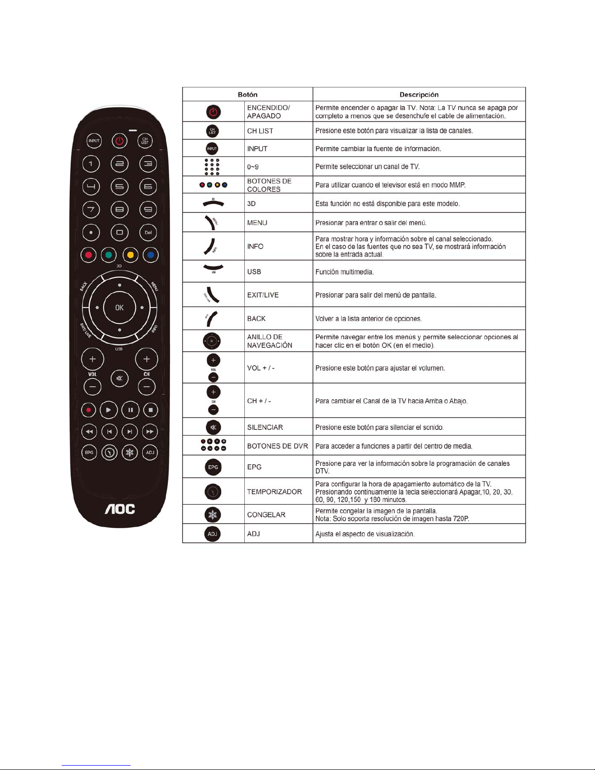
2.1 The Use of Remote Control…….…..……….…….......5
2.2 To Use the Menus….....………………….…..…….......6
2.3 How to Connect……..……………….…….……….....11
2.4 Front Panel Control Knobs…….………….………....13
3. Input/ Output Specification………....................…....14
4. Mechanical Instructions…………………….................16
5. Repair Flow Chart ……………………….…….…….....19
6. PCB Layout ………………..………………....….......25
Page 2

2
Important Safety Notice
Proper service and repair is important to the safe, reliable operation of all AOC Company Equipment. The service
procedures recommended by AOC and described in this service manual are effective methods of performing servi ce
operations. Some of these service operations require the use of tools specially designed for the purpose. Th e
special tools should be used when and as recommended.
It is important to note that this manual contains various CAUTIONS and NOTICES which should be carefully read in
order to minimize the risk of personal injury to service personnel. The possibility exists that improper service
methods may damage the equipment. It is also important to understand that these CAUTIONS and NOTICES ARE
NOT EXHAUSTIVE. AOC could not possibly know, evaluate and advise the service trade of all conceivable ways in
which service might be done or of the possible hazardous consequences of each way. Consequently, AOC has not
undertaken any such broad evaluation. Accordingly, a servicer who uses a service procedure or tool which is not
recommended by AOC must first satisfy himself thoroughly that neither his safety nor the safe operation of the
equipment will be jeopardized by the service method selected.
Hereafter throughout this manual, AOC Company will be referred to as AOC.
WARNING
Use of substitute replacement parts, which do not have the same, specified safety characteristics might create
shock, fire, or other hazards.
Under no circumstances should the original design be modified or altered without written permission from AOC.
AOC assumes no liability, express or implied, arising out of any unauthorized modification of design.
Servicer assumes all liability.
FOR PRODUCTS CONTAINING LASER:
DANGER-Invisible laser radiations when open AVOID DIRECT EXPOSURE TO BEAM.
CAUTION-Use of controls or adjustments or performance of procedures other than those specified herein may
result in hazardous radiation exposure.
CAUTION -The use of optical instruments with this product will increase eye hazard.
TO ENSURE THE CONTINUED RELIABILITY OF THIS PRODUCT, USE ONLY ORIGINAL MANUFACTURER'S
REPLACEMENT PARTS, WHICH ARE LISTED WITH THEIR PART NUMBERS IN THE PARTS LIST SECTION OF
THIS SERVICE MANUAL.
Take care during handling the LCD module with backlight unit
-Must mount the module using mounting holes arranged in four corners.
-Do not press on the panel, edge of the frame strongly or electric shock as this will result in damage to the screen.
-Do not scratch or press on the panel with any sharp objects, such as pencil or pen as this may result in damage to
the panel.
-Protect the module from the ESD as it may damage the electronic circuit (C-MOS).
-Make certain that treatment person’s body is grounded through wristband.
-Do not leave the module in high temperature and in areas of high humidity for a long time.
-Avoid contact with water as it may a short circuit within the module.
-If the surface of panel becomes dirty, please wipe it off with a soft material. (Cleaning with a dirty or rough cloth may
damage the panel.)
Page 3

3
Revision List
Version Release Date Revision Instructions Customer Model TPV Model
A00 May.15,2014 Initial release LE24D3140_30
E2CE21NSDDE6NNQ
E2CE21NSDDE8NNQ
E2CE21NSDDE7NNQ
Page 4

4
1. General Specification
Page 5
5
2. Operating Instructions
2.1 The Use of Remote Control
Page 6

6
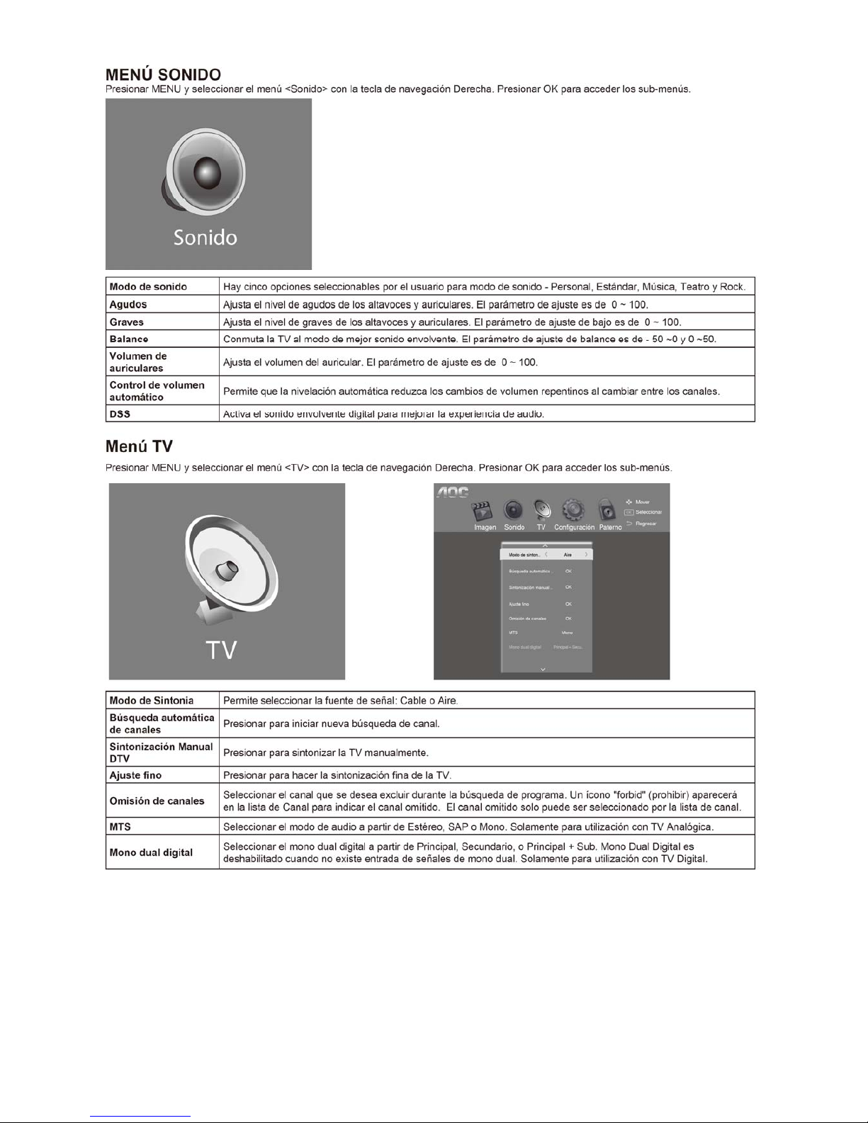
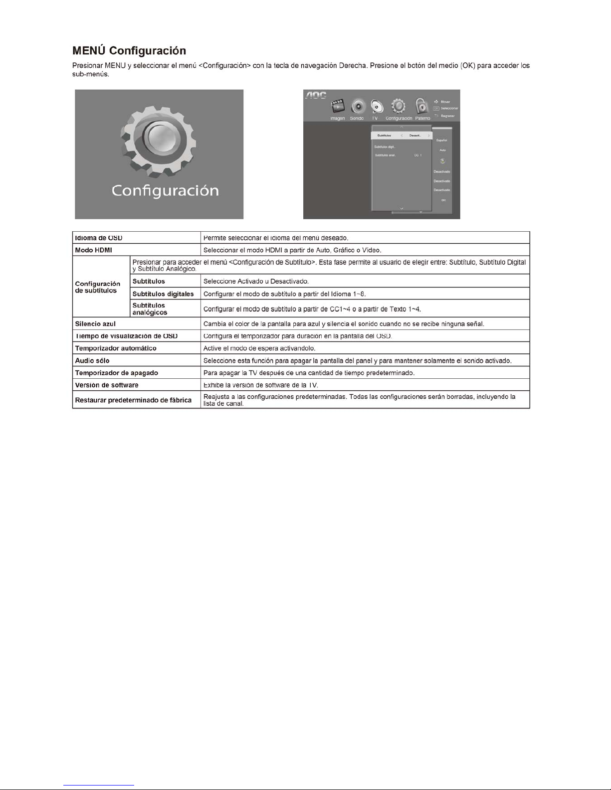
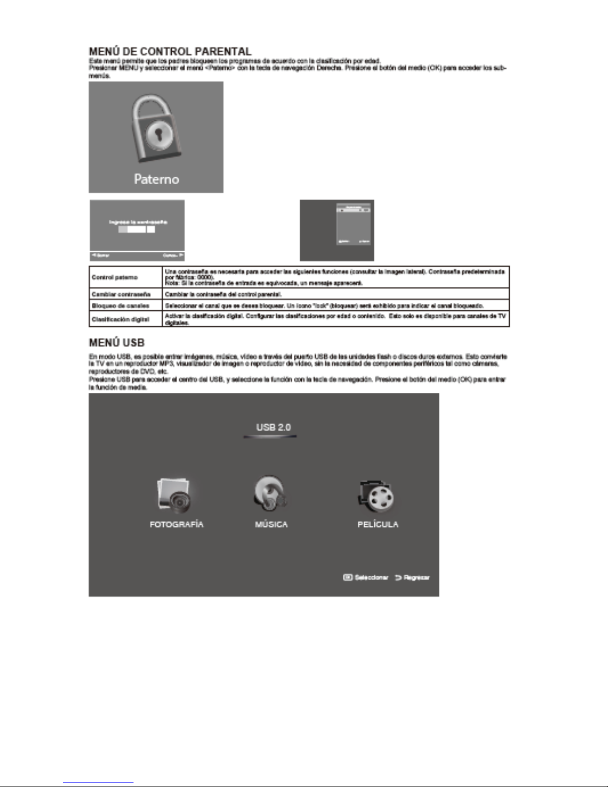
2.2 To Use the Menus
Page 7

7
Page 8
8
Page 9
9
Page 10
10
Page 11
11
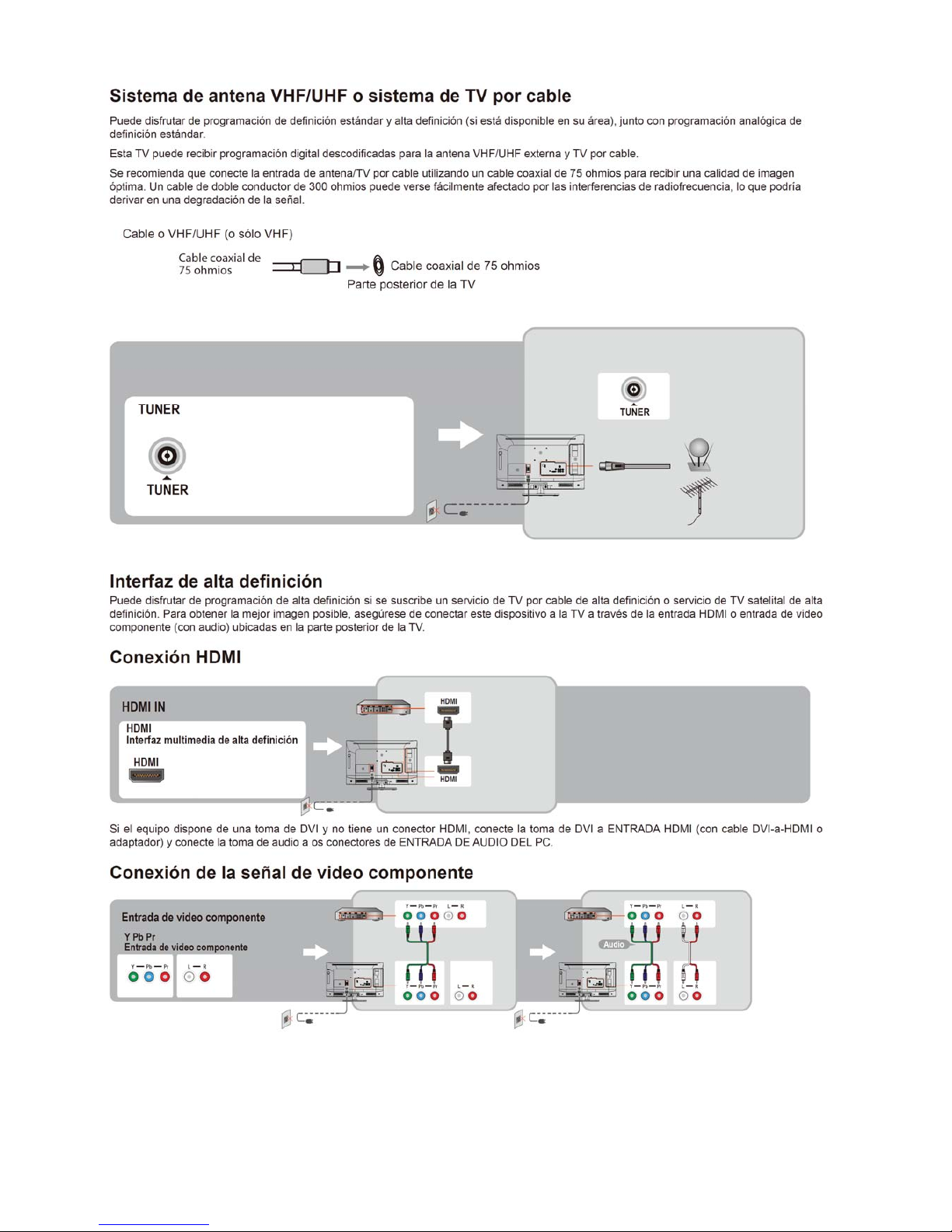
2.3 How to Connect
Page 12

12
Page 13
13
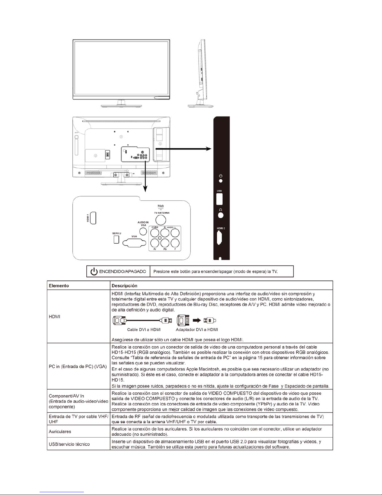
2.4 Front Panel Control Knobs
Page 14

14
3. Input / Output Specification
D-Sub and HDMI Pin assignment
DͲSub(CN101) HDMI1(CN501) HDMI2(CN506)
PINNo. Signal PIN
No.
Signal PIN
No.
Signal
1 Red 1 TMDS Data2+ 1 TMDS Data2+
2 Green 2 TMDS Data2 shield 2 TMDS Data2 shield
3 Blue 3 TDMS Data2- 3 TDMS Data24
D/TXDC
4 TMDS Data1+ 4 TMDS Data1+
5 GND 5 TMDS Data1 shield 5 TMDS Data1 shield
6 RedGND 6 TMDS Data1- 6 TMDS Data17 GreenGND 7 TMDS Data0+ 7 TMDS Data0+
8 BlueGND 8 TMDS Data0 shield 8 TMDS Data0 shield
9 +5V(supplyfromPC) 9 TMDS Data0- 9 TMDS Data010 SyncGND 10 TMDS Clock+ 10 TMDS Clock+
11
D/RXDC
11 TMDS Clock Shield 11 TMDS Clock Shield
12 BiͲdirectional data
(SDA)
12 TMDS Clock- 12 TMDS Clock-
13 HͲsync 13 CEC 13 CEC
14
V
Ͳsync(vclk) 14 ARC 14 NC
15 Dataclock(SCL) 15 SCL 15 SCL
16 SDA 16 SDA
17 DDC_Ground 17 DDC_Ground
18 +5V Power 18 +5V Power
19 Hot Plug Detect 19 Hot Plug Detect
20 SHLD_GND1
21 SHLD_GND2
Page 15

15
Page 16
16
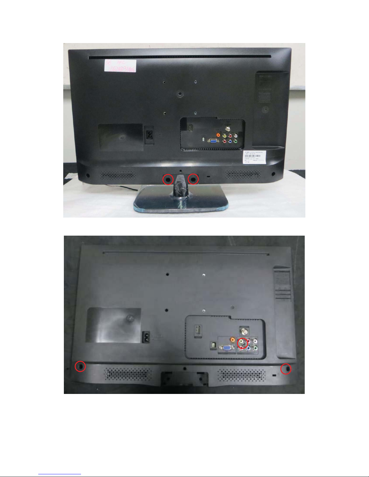
4. Mechanical Instructions
1. Remove the screws to remove STAND & BASE.
2. Remove the screws to remove REAR COVER.
Page 17
17
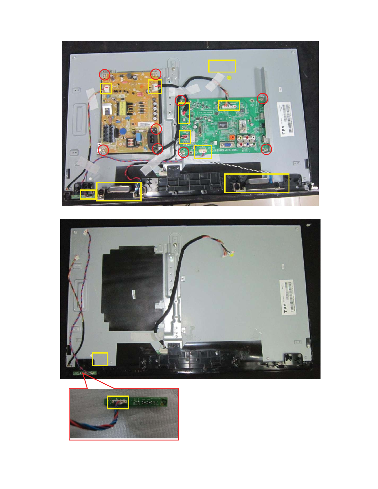
3. Disconnect the PINS marked in yellow .Remove the screws marked in red to remove MAIN BOARD, POWER
BOARD and SPEAKERS.
4. Remove the screws to remove DECO and disconnect the pin to remove the IR Board.
Page 18

18
5.
Remove the screws to remove BKT.
6. Panel.
Page 19
19
5. Repair Flow Chart
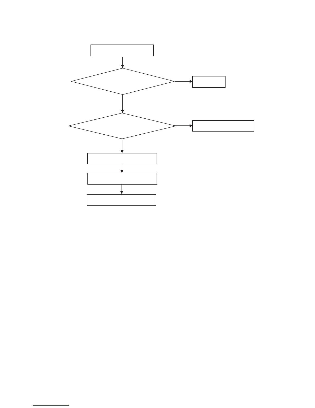
1. No power
No power (LED “Off”)
Check the AC input and
the
p
ower is “ON”?
Power “On”
Check the IR board and LED
Replace the IR board
Replace the main board
Power board
out
p
ut=5.2V?
Replace the power board
No
Yes
No
Yes
No
Page 20
20
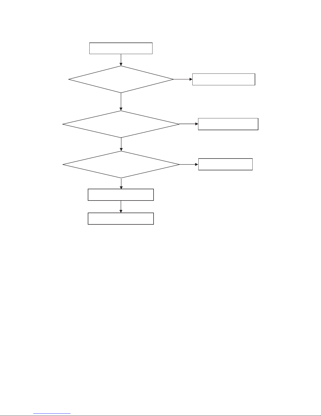
2. Can’t start
Can’t start (LED Blue)
Replace the main board
Replace the Power board
No
Yes
No
Yes
No
No
Power board output᧹12V?
Check the power key is under control?
Check the IR receiver is normal?
Replace the power board
Replace the main board
Yes
Replace the IR board
Page 21

21
3. Abnormal display
Abnormal Display
Reset the source
Check the source
Check the panel
Replace the main board
Replace the LVDS cable
Replace the panel
No
No
No
Yes
Yes
Yes
No
No
Check the main board
Enter factory mode to do
“EEPROM initial”&“Reset”
Check the LVDS cable
Page 22

22
4. No display
Check the B/L
signal is available?
Replace main board
Replace the power board
Panel Vcc = 12V?
Replace the Panel
No display (No LED)
Replace the main board
Check the backlight is
“On”?
Check the LVDS cable
Reinsert or replace the
LVDS cable
Replace the main board
Replace the Panel
No
Yes
Yes
No
Yes
No
No
Yes
Yes
No
Yes
No
Power board output᧹12V?
Check TV is under control and power
on/off by remote control and power key?
Page 23

23
5. Sound problem
No
Check the cable between the
speakers and main board is OK?
No sound or sound abnormal
Check the TV is muted, adjust the
volume or enter the menu to reset?
Reinsert the audio cable or
change the TV system
Replace the cable
Replace the speaker
Replace the main board
No
Yes
Check the speaker resistance value is in spec
(Remark: The value is marked on the speaker)?
Check the audio source connection
and the TV system are correct?
Yes
No
Yes
No
Enter factory mode to do “Reset”
No
Page 24

24
6. Remote control malfunction
Remote Control malfunction
Replace the battery
Replace the remote control
Whether the IR board is
abnormal?
Yes
No
Replace the IR board
Replace the main board
No
Yes
No
Yes
Use the other remote controls
Check the remote control battery is
not properly placed or no power?
Page 25

25
6. PCB Layout
6.1 Main Board (715G6418M0F000004K)
Page 26

26
Page 27

27
6.2 Power Board (715G6297P01000001E)
Page 28

28
Page 29

29
Page 30

30
6.3 IR Board (715G5772R01000004K)
Page 31

31
7. Adjustment
They only need adjust WB(Ypbpr’s Normal/Warm/Cool).
7.1 White Balance Adjustment
1. Enter into the factory mode:MENU+1+9+9+9+back
2. Take an example of adjust Ypbpr_Normal:
a. Select item “Source”: Ypbpr
and item “Color Temp”: Normal.
b. Adjust gain of RGB to meet spec in the below setting of tim\pat.
(COMPONENT mode: TIM = 314; PAT = 141(80IRE))
3. Check the colour temperature of other ĀSourceāˈ
If the colour temperature can’t meet specˈplease adjust it
4.The white color temperature should be app.
Normal/(9300qK) Warm/(6500qK) Cool/(12000qK)
x (center) 0.295 r 0.003 0.313 r 0.003 0.285 r 0.003
y (center) 0.305 r 0.003 0.329 r 0.003 0.293 r 0.003
Lv(center) >240cd >240cd >240cd
Page 32

32
7.2 Firmware Instruction
Step1˖Change the software file name to MERGE.bin, Copy F/W to USB flash disk root directory
Step2˖TV Power On
Step3˖Insert USB flash disk to TVˈthen AC off/on
Step4˖TV auto upgrade. the LED lamp will flicker. After USB F/W update OK, TV will power off/on.
Step5˖Power on, press “Menu+1999+recall”ˈthen TV will enter factory menu, Check SW version ,if OK, then do
reset .USB F/W update OK.
Page 33

33
8. Block Diagram
With ARC
YPbPr
CVBS
DTV DEMOD
MSB1400
Single terminal silic on tuner
(LG TDST-H030F)
Series TS
Analog IF+/-
RGB
Hea dphone AMP
LVDS
AUDIO AMP
APA2 17 6A
L/R
5W SPK
5W SPK
R
L
emote Control
KeyPad
AV Audi o
USB
L/R
ATV
DEMOD
UART
TI 31100
MST6931XP
Headphone
Page 34

34
P12V
AZ1117
AZ1117
MOS
1130mA
1930mA(2USB)
330mA
1A
MST6931 Core Power
MOS
LDO
LDO
Panel Power
Demod Power
1500mA
Demod Power
115mA
800mA (*1)
1600mA (*2)
APL3511CBI
3.3V_TUNER
MST6931 DDR Power
+1.2V_VDDC
5mA
3.3V
Headphone Power
1A
500mA
+5V_NORMAL
PANEL_VCC
+1V2
Without panel <= 3.5A
LDO 3.3V_STANDBY
G9141
150mA
DC-DC
170mA
USB Power
1. 18.5
Dž
~ 23.6
Dž
audio current = 3W*2 / 75% =
8W
12V current : 8W/12V = 0.67A
2. 29" ~ 32" audio current = 5W*2 / 75% = 13.4W
12V current : 13.4W/12V = 1.12A
3. 29
Dž
~55
Dž
audio current = 10W*2 / 80% = 25W
24V current : 25W/24V = 1.04A
+1.8V_DDR
AZ1117
MST6931 Power
Tuner Power
Audio Amp
TPA3113D2
1A
USB_5V
3A
MOS
VDD33
LDO
500mA
APW7323
G5759F11U
DC-DC
4A
+5V_Standby
Page 35

35
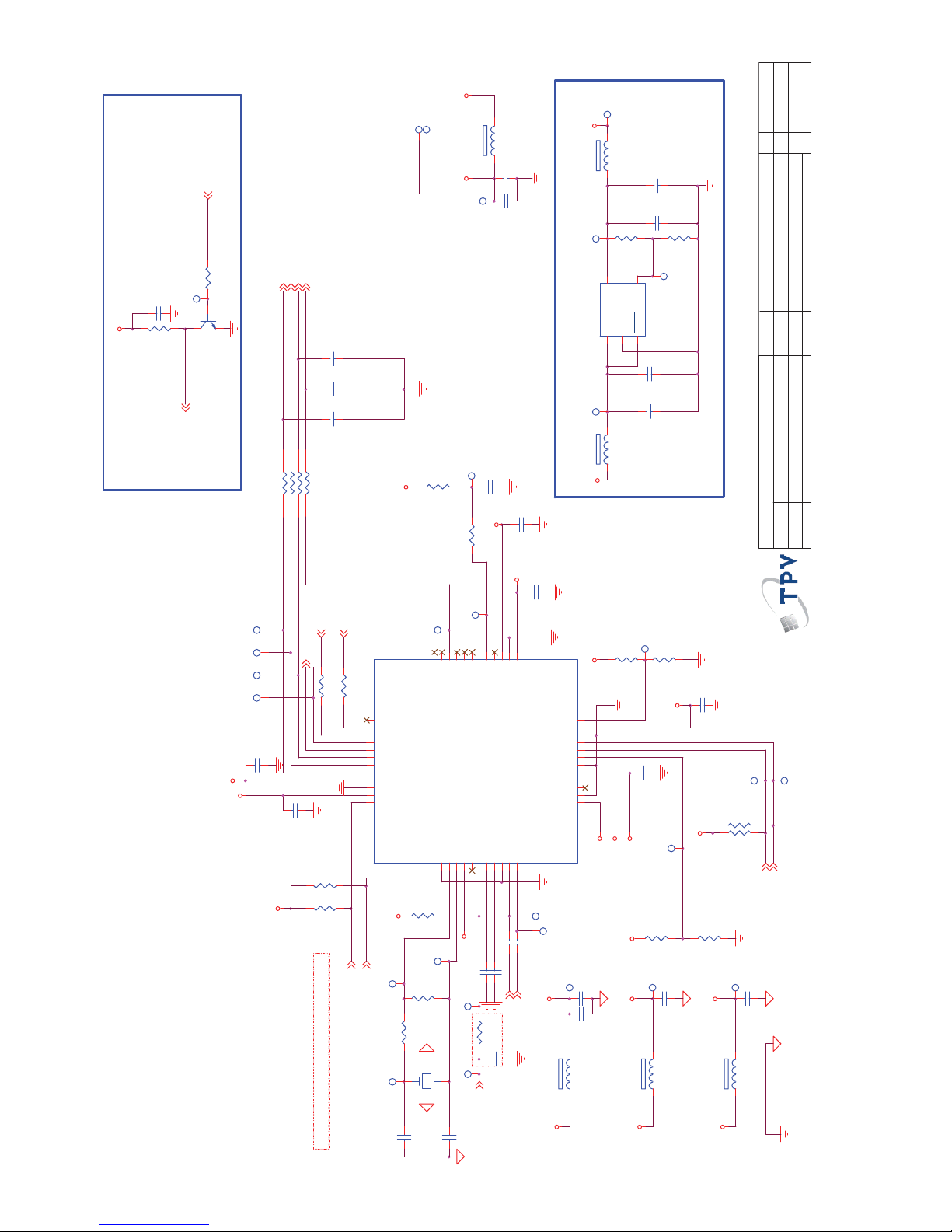
9. Schematic Diagram
9.1 Main Board (715G6418M0F000004K)
+
C722
100UF 16V
R1
R7091
100K 1/16W 5%
DDR Power
R2
Vout = 1.25x(R1+R2)/R2
1.845V
+1.8V_DDR
C7071
100NF 25V
+5V_Standby
R711
100K 1/16W 5%
Standby Power
C780
100N 16V
C719
22UF
L6007
15uH
Q708
AO3401A
R722
1K 1/16W 5%
Q709
MMBT3904
R729
4K7 1/16W 5%
+3.3V_Standby
+3.3V
C720
22UF
TP4116
C715
22PF 50V
TP4115
C
EB
TP4114
C709
NC 22UF
+
C738
100uF 25V
TP4112
TP4111
OEM MODEL
Size
Rev
Date
Sheet
of
TPV MODEL
PCB NAME
〠⡩
T P V ( Top Victory Electronics Co . , Ltd. )
Key Component
㎜䳄⬌㎚㞩
A
Custom
413Thursday, Dec em ber 26, 2013
715G6418-M0D-000-0040
〠⡩
<>
04. Power
C724
10UF 10V
C716
1uF 10V
AC_DET 11
R720
10K 1/16W 5%
AC_DET
+3.3V_Standby
R7093
18Kohm 1/16W +/-1%
C7074
100N 16V
FB7020
120R 6A
1 2
AC Detect
C7069
10UF 25V
H = > AC_ON
C7075
22UF 16V
R7094
3.3K 1%
C7073
NC 22PF 50V
L = > AC_OFF_DET
AC _ D E T
C7077
3.3nF 50V
U703
AZ1117H-ADJ-E1
VI
3
VO
2
GND
1
4
4
TP4
+12VSB_PRE
+5V_Standby
+12V_Amp
+12VSB_PRE
BL_EN
TP8
TP11
TP12
TP13
TP9
CN701
CONN
246810
12
13579
11
C723
22UF
TP705 TP706
TP707
Q710
NC/2N7002K
R772
NC/1K 1/16W 5%
R773
NC/4K7 1/16W 5%
TP10
TP14
TP15
TP16
TP18
FB710
NC 120R/ 6000m A
12
TP20
TP17
TP19
R715
11.5K +-1% 1/16W
High active
TP709
TP703
TP21
TP710
TP23
R717 20K 1/16W 5%
TP22
C710
10UF 10V
U701
APW7323
VCC1POK2GND3FB
4
EN
5
PGND
6
LX
7
VIN
8
E-Pad
9
+
C717
NC/330UF 6.3V
FB701
300R 4A
1 2
L701
2.2uH
+5V_Standby
+1.2V_VDDC
Vout = 0.8*(1+R1/R2)
R1
073G253S 68 H
Core Power = 1.26V
PWR_ON
R714
1K 1/16W 5%
R706
NC/10K
+
C713
100UF 16V
NC/4.7UF 10V
C706
R702
1K 1/16W 5%
R710 4K7 1/16W 5%
Q701
AO3401A
R704 1K 1/16W 5%
Q702
MMBT3904
R775
NC 10K 1%
R709 1K 1/16W 5%
TP704
U702
AZ1117D
VI
3
VO
2
GND
1
Q703
MMBT3904
R707
1K 1/16W 5%
C702
NC/10N 50V
Q706
MMBT3904
TP708
R703
10K 1/16W 5%
R723
4K7 1/16W 5%
R705
100R 1/16W 5%
+5V_Standby
+5V_Standby
+5V_Normal
+5V_Normal
+3.3V_Standby
+5V_Normal
+3.3V_Standby
BRI_ADJ-PWM0 5
PWR_ON5
VBL_CTRL 5
Q707
MMBT3904
C701
100N 16V
C714
100N 16V
R780 47K 1/16W 5%
TP24 TP25
TP26
TP27
TP28
GPIO
TP349
R727 4K7 1/ 16W 5%
+12V_Amp R781
10OHM1/16W
3.2A
BL_EN
+3.3V
BL_PWM
HI = > POWER_OFF
LO = > POWER_ON
Main power On/Off control
BL_PWM
+5V_Standby
PS_ON
TP7
C7070
100N 16V
+
C781
100UF 16V
Close CN701
(Standby)
R7092
12K1/10W
High active
AUD_PVDD
C737
100N 50V
FB702
120R 6A
1 2
P12V
R776
NC 4.7K 1/16W
FB603 300R 4A
1 2
+12VSB_PRE
U708
NC G691 L400T73F
GND
1
RESET(RESET)
2
VDD
3
+
C736
100uF 35V
EN
R777
NC/22K 1/ 16W 5%
C739
100N 50V
P12V
AC_DET
R774
NC 1K2 1/10W 5%
TP3
R771
NC 2K
L = > DC_OFF
C712
1uF 10V
PS_ON /STANDBY
H = > POWER_ON
PS_ON
System power control
+12VSB_PRE
+12V_Amp
C718
1uF 10V
Vout = 0.8x(1+R1/R2)
100mil
90mil
Close U707
12V TO 5VSB
R2
R1
+5V_Normal
Low active
R778
NC 100R 1/16W 5%
U707
G5759F11U
EN1BS2IN3LX
4
VCC
5
GND
6
FB
7
COMP
8
E-PAD
9
R728
10K 1/16W 5%
C705
100N 16V
R719
220R +-5% 1/16W
R7095
24K 1/16W 5%
C773
100N 16V
R770
NC/22K 1/16W 5%
C772
470nF 16V
EN
C774
470nF 16V
C775
NC/100N 16V
PS_ON
R721
100R 1/16W 5%
R701
2.2R 1%
Page 36

36
CN466 component select:
For Philips : 311GW200G03BAX (1 1m m)
For AOC :033G3802 3 (6mm)
C431
10UF 10V
AUVAG
AV-AUOUTL3
C405
1uF 10V
R407 51R 1/16W 5%
URAT Po r t
1
C413
10UF 10V
HDMI-ARC
HOTPLUGA
HDMIA_DDC_SCL
C444
10UF 10V
HDMIA-RX2N
HDMIA-RX1N
HDMIA-RX1P
HDMIA-RX0N
HDMIA-RX0P
HDMIA-RX2P
HDMIA-CLKP
HDMIA-CLKN
HDMIA_DDC_SDA
TAGC
A_IFN
LED-Red
A_IFP
XTAL O
AVDD33_DEMOD
TP94
TP95
KEY1-SAR1
OEM MO D E L
Size
Rev
Date
Sheet
of
TPV MOD E L
PCB NAME
〠⡩
T P V ( Top Victory Electronics Co . , Ltd. )
Key Component
㎜䳄⬌㎚㞩
A
Custom
513Thursday, December 26, 2013
715G6418-M0D-000-0040
〠⡩
<>
05. MST6831XP/SPI FLASH
VGA_BIN
VDD33
VGA-AUL1
HDMIA_DDC_SCL
PWR_ON
HDMIA_DDC_SDA
HDMIA-RX1N
HDMIA-CLKP
HDMIA-CLKN
VGA-AUR1
HDMIA-RX2N
HDMIA-RX1P
HDMIA-RX0P
HDMIA-RX2P
HDMIA-RX0N
+3.3V_Standby
VGA_HS
VGA_VS
CVBS_OUT0
SOY
Pr+
AV1-CVBS0P
AUDIO_EN
U402
W25Q64FVSSI G
CS#1SO/SIO12WP#3GND
4
SI/SIO0
5
SCLK
6
HOLD#
7
VCC
8
HDMI-ARC
C420
100N 16V
C422
100N 16V
C421
100N 16V
XTAL I
I/OInterface
COMP_AUL4
AV-AUOUTR3
SERIAL FLASH
COMP_AUR4
C402
2.2UF 10V
USB0_DP
USB0_DM
CHIP_CONFIG
UART-RX
USB1_DM
USB1_DP
Powerco ntrol
Backlightcont rol
ARC
C401
2.2UF 10V
PANEL_ON6
PANEL_ON
ZD408
MLVG04 02
12
ZD409
MLVG0402
12
RXE3-
SOG0
XTAL O
Power 3.3V
XTAL I
HOTPLUGA
HDMID-RX2P
HDMID-RX2N
HS401
NC/H EAT SIN K
1
2
VGA_RIN
C436
22PF 50V
R409
100K 1/16W
HDMIsignal
C433
1uF 10V
R408
51R 1/16W 5%
Sys tem-RST
R732
10K 1/16W 5%
H/W Reset
+5V_Standby
AMP-AUOUTL0
R413
100K 1/16W 5%
C417
100N 16V
R421
4K7 1/16W 5%
R416
100K 1/16W 5%
FB406
60 OHM
1 2
C412
100N 16V
R428
1M 1/16W
R412
68OHM 1/16W
TP351
R418
100K 1/16W 5%
C406
180PF 50V
R422
4K7 1/16W 5%
SPI-SDI
SPI_CS0N
C434
100N 16V
SPI-SCK
VBL-CTRLHDMID-SCL
SPI-SDO
GND-EFUSE
VGA-AUL1
VGA-AUR1
FB408
120R 3A
1 2
FB402
60 OHM
1 2
HDMID-RX1P
DDR Power
HDMID-RX1N
C432
100N 16V
C407
47nF 16V
AVDD_DDR
FB405
60 OHM
1 2
+1.8V_D DR
HDMID-SDA
HDMID-RX0P
CN466
CONN
123
C411
180PF 50V
C423
100N 16V
HDMID-RX0N
R436
4K7 1/16W 5%
HDMID-CLKP
SPI-SCK
RXE2+
RXE1+
RXE1-
RXE0-
R415
68OHM 1/16W
RXE3-
RXEC+
RXE3+
RXE2-
RXE0+
C414
180PF 50V
RXOC-
RXO2-
RXOC+
RXO0-
RXO1+
RXEC-
HDMID-CLKN
RXO1-
RXO0+
RXO3-
RXO2+
RXO3+
RXOC+ 6
RXO3- 6
RXO3+ 6
R435 must close U401
RXO1- 6
RXO2+ 6
RXO2- 6
RXOC- 6
Y+
R424
4K7 1/16W 5%
RXO0- 6
RXO1+ 6
RXO0+ 6
Pb+
C416
100N 16V
RXE3- 6
RXEC+ 6
RXEC- 6
FB40760 OHM
1 2
RXE2+ 6
RXE1- 6
RXE3+ 6
RXE1+ 6
RXE0- 6
RXE2- 6
TP39
RXE0+ 6
TP40
TP41
RXE0+
RXO2+
RXOC-
C410
47nF 16V
TP43
TP44
RXE0-
RXOC+
RXO3+
RXO3-
TP42
RXO0+
RXO1+
RXO2-
RXO1-
RXO0-
C430
20PF
C419
100N 16V
RXE2-
RXE1+
RXE1-
RXEC-
RXE2+
RXEC+
C424
100N 16V
C418
100N 16V
R410
68OHM 1/16W
R431
4K7 1/16W 5%
LVDSsignal
C425
20PF
C408
47nF 16V
TP45
AV1-CVBS0P
R435 51R 1/16W 5%
TP46
UART-RX
C409
180PF 50V
TP48
TP47
TP49
VDDC
TP50
VDD33
TP51
AVDD_MOD
AVDD_MOD
VDDC
HOTPLUGD
TP52
R427
0R05 OHM
R163 NC/10K
TP53
AVDD_MOD
AU33
AVDD_DDR
TP55
TP54
AU33
TP56
AVDD33_DEMOD
VDD33
+3.3V_Standby
TP57
+3.3V_Standby
TP58
+3.3V_St andby
TP59
FB403
120R 3A
1 2
VDD33
TP60
AVDD_DD R
VDDC
+3.3V_Standby
TP61
+3.3V_Standby
TP62
+5V_Standby
A_IFN
A_IFP
TP63
TP64
AVDD_MOD
TP65
+3.3V_Standby
TP66
TP67
HDMI_CEC8
HDMI-ARC8
USB0_DP7
TP68
USB0_DM7
TS_VAL ID
TP69
A_IFN10
A_IFP10
TAGC10
TP70
VBL_CTRL 4
AUDIO_EN 12
TP71
PWR_ON 4
TP72
I2C_SCL 6,10,11
BRI_ADJ -PWM0 4
TAGC
AMP_AUOUTR0 12
AV_AUOUTR3 13
AMP_AUOUTL0 12
TP73
AV_AUOUTL3 13
HDMID_D0-8
HDMID_D0+8
HDMID_D1-8
HDMID_D1+8
TP74
HDMID_D2-8
HDMID_D2+8
AMP-AUOUTR0
HDMID_CLK+8
TP75
HDMID_CLK-8
HDMID_DDC_SDA8
TP76
HDMID_DDC_SCL8
HOTPLUGD8
HDMIA_D0-8
HDMIA_D0+8
TP77
HDMIA_D1-8
HDMIA_D1+8
HDMIA_D2-8
HDMIA_D2+8
LED-Blue9
HDMIA_CLK+8
LED-Blue
HDMIA_CLK-8
HDMIA_DDC_SDA8
HDMIA_DDC_SCL8
TP78
HOTPLUGA8
TP79
TP80
TP81
TP83
TP82
TP84
TP85
TP86
U401
MST6931XP-Z1
LVA2M
69
SOGIN123BIN1P22GIN1M25GIN1P24CVBS129HSYNC1
28
LINEI N_R1
37
GIN0P
17
GND
55
LVA3P
63
TAGC
54
IM
53
AVDD_MOD
5
RIN1P
26
LVB2P
80
LVACKM
66
LVA1P
70
SAR2
112
SAR1
111
GIN0M
18
PWM2
93
TS1_D[0]92TS1_C LK
91
TS1_SY NC
90
TS1_V LD
89
LVA4P
61
LVA4M
62
LVA3M
64
LVACKP
65
SCZ
97
LVA0M
73
LVB4P
74
LVB4M
75
LVB3P
76
LVB3M
77
LVB1P
83
LVA0P
72
SDO
96
IRIN
113
CEC
114
RESET
115
HOTPLUGA
128
SOGIN0
16
LINEOUT_R0
47
XOUT
48
LINEOUT_R3
45
LINEOUT_L0
46
AVDD_DMPLL
50
XIN
49
AVDD_REF
51
RXCKN_A1RXCKP_A2RX0N_A3RX0P_A4RX1N_A6RX1P_A7DDCDA_DA8RX2N_A9RX2P_A10DDCDA_CK11ARC12AVDD_1213HSYNC014BIN0P15RIN0P19VSYNC 020AVDD_ADC 33
21
CVBS030VCOM31CVBSOUT132AVDD_AU3333LINEI N_L338AUVAG35LINEI N_L1
36
LINEIN_R 4
41
LINEIN_L5
42
IP
52
GPIO56
58
AVDD_PLL
59
VDDC
60
GPIO55
57
LVA2P
68
LVA1M
71
AVDD_MOD
67
LVBCKP
78
LVBCKM
79
LVB2M81LVB1M
84
LVB0P
85
LVB0M
86
AVDD_MOD
82
INT/GPIO65
88
PWM0
105
PWM1
106
DM_P0
98
GND
104
DP_P0
99
AVDD_MOD
100
VDDIO_DATA
109
SCK
94
GND
116
SDI
95
SAR0
110
DDCA_CK
107
DDCA_DA
108
E-Pad
129
VSYNC 1
27
AUREFM
34
LINEOUT_L3
44
LINEIN_R 5
43
VDDIO_CMD
56
VDDC
87
HOTPLUGD
117
RXCKN_D
118
RXCKP_D
119
RX0N_D
120
RX0P_D
121
RX1N_D
123
RX1P_D
124
DDCDD_DA
122
RX2N_D
126
RX2P_D
127
DDCDD_CK
125
LINEIN_R 3
39
LINEIN_L4
40
DP_P1
102
DM_P1
101
GPIO11
103
UART-RX
TP88
TP87
VGA_HS7
VGA_VS7
VGA_BIN7
VGA_GIN7
TP89
Pb+7
VGA_RIN7
TP90
Pr+7
TP91
Y+7
TP93
TP92
VGA-AUL19
AV1-CVBS0P7
PWR_ON
VGA-AUR19
UART-TX
COMP_AUR47
COMP_AUL47
I2C_SDA 6,10,11
VBL-CTRL
SOG07
TP96
SOY7
KEY1-SAR19
TP97
UART-TX7
IRIN9
UART-RX7
BRI_ADJ -PWM0
I2C_SDA
I2C_SCL
TP98
Sys tem-RST
TP99
TP100
+3.3V_Standby
TP101
BRI_ADJ -PWM0
TP102
TP103
TP104
TP105
TP106
HDMI-CEC
TS_D I 11
TS_SY NC 11
TS_VALID 11
TS_VAL ID
TS_CLK 11
TS_C LK
TS_D I
TS_SY NC
C480
NC 100N 16V
TS_CLK, TS_SYNC, TS_VALID
must GND shieldinh
COMP_AUR4
COMP_AUL4
C479
NC 100N 16V
IRIN
KEY1-SAR1
TS_SY NC
SOY
SPI-SCK trace must
GND shielding
C449 47nF 16 V
System XTAL
IRIN
X40 1
24MHz
1243
R401
100OHM
UART-TX
UART-TX
VGA_GIN
close to IC
R402
100OHM
TP107
HOTPLUGD
RXE3+
VGA_GIN
TP118
MST6931 chipset:
For Philips :
MST6931XP-SW
356G0568128047
For AOC :
MST6931XP-Z1
356G0568128050
R495
4K7 1/16W 5%
VGA_BIN
VGA_VS
VGA_HS
TP120
Power 1.2V
TP121
C429
100N 16V
C428
100N 16V
C427
100N 16V
FB401
120R 3A
1 2
+1.2V_VDDC
VDDC
TP122
TS_C LK
TP123
RXO4+
RXO4-
R494
4K7 1/16W 5%
RXE4-
RXE4+
TP124
TP125
TP126
HDMID-SCL
R440 NC/0.05R
RXE4+
RXE4-
RXE4- 6
RXE4+ 6
RXO4- 6
RXO4+
RXO4+ 6
RXO4-
HDMI-CEC
HDMID-RX1N
HDMID-RX2P
HDMID-RX1P
HDMID-RX2N
HDMID-CLKN
HDMID-RX0P
HDMID-CLKP
HDMID-RX0N
LED-Blue
ARC_Det 11
Status Register Protect Bits (SRP1, SRP0)
SRP1 SRP0 WP Status
0 0 X SW protection
0 1 0 HW protection
0 1 1 HW Unprotection
1 0 X Power Supply Lock-Down
1 1 X One Time Program
C426
10UF 10V
AUVRM
HDMID-SDA
I2C_SDA
VGA_RIN
C403
10UF 10V
I2C_SCL
LED-Red
Pr+
SOG0
R420 4K7 1/16W 5%Y+R419 4K7 1/16W 5%
Pb+
C415
10UF 10V
USB0_DP
USB0_DM
SPI-SDO
SPI_CS0N
SPI-SDI
PANEL_ON
TS_D I
C451
10UF 10V
Close to IC
with width
trace
LED-Red9
Page 37

37
TP144
TP143
TP145
TP146
TP151
TP152
TP150
TP149
TP148
TP155
TP154
TP153
TP147
TP156
TP158
TP159
TP157
D121 BAS316
OEM MODEL
Size
Rev
Date
Sheet
of
TPV MO D EL
PCB NAME
〠⡩
T P V ( Top Victory Electronics Co . , Ltd. )
Key Component
㎜䳄⬌㎚㞩
A
B
613Thursday , December 26, 2013
715G6418-M0D-000-0040
〠⡩
<>
06. LV DS
+
C438
100UF 16 V
RXO2-
RXOC+
RXO2+
RXO0+
PANEL_VCC
RXO0-
RXO1+
RXOC-
RXO3+
RXE0+
RXE2+
RXE3+
RXE0-
RXEC+
RXE1+
RXEC-
RXE2-
+3.3V
R445
NC 4.7K 1/ 16W
R446
NC 4. 7K 1/ 16W
+3.3V
R448
NC 4. 7K 1/ 16W
R447
NC 4. 7K 1/ 16W
RXE3-
PANEL_VCC
RXE1-
LVDS_format
RXO0+
RXO1+
RXO0-
RXO1-
RXOC+
RXO2+
RXO3-
RXO3+
RXO2-
RXOC-
RXO1-
RXO3-
CN404
NC CONN
123456789
101112131415161718192021222324252627282930
31 32
C437
100N 16V
Q401
AO4449 -7A/-30V
S1S2S3G
4
D8D7D6D
5
C453
100N 16V
R449
0R05 1/16W
R450
0R05 1/16W
C452
100N 16V
Master Panel Connector
For LCM290XX
R443
10K 1/16W 5%
R444
10K 1/16W 5%
30
1
CN403
CONN
135791113151719212325272931333537
39
41
246
8
101214161820222426283032343638
40
42
FFC
RXOC+
RXO2+
RXO3-
RXE3-
RXE1-
RXO3+
RXE2+
RXEC-
RXO0+
RXO1-
RXE0-
RXEC+
RXE2-
RXOC-5
RXO3-5
RXO1+
RXOC-
RXO0+5
RXOC+5
RXO0-
RXO2-
RXE3+
RXE2-5
RXO0-5
RXE1+
RXE0+
RXO1-5
RXE2+5
RXO2+5
RXE3-5
RXE3+5
RXO3+5
RXE1-5
RXO1+5
RXE0+5
RXE1+5
RXEC-5
RXEC+5
RXO2-5
RXE0-5
I2C_SCL I2C_SDA
Panel Power
I2C_SDA 5,10,11I2C_SCL5,10,11
Measure Result
R439 C439 Timing
4.7k 470nF 0.388ms
47k 470nF 0.78ms
47k 1uF 2ms
75k 2.2uF 3ms
100k 2.2uF 3.8ms
Q403
MMBT3904
R441
10K 1/16W 5%
R173 1K
P12V
PANEL_VCC
+5V_Standby
PANEL_ON5
LVDS_format
FB416 300R 4A
1 2
FB415 NC 300R 4A
1 2
R599
1K 1/10W 5%
TP129
TP127
C439
1UF16V
TP128
TP130
TP131
RXE4+5
RXE4+
RXE4-5
RXO4+
RXE4-
RXO4-5
RXO4+5
RXO4-
RXO4+
RXE4-
RXO4-
RXE4+
PANEL_VCC
R439 4K7 1/16W 5%
TP132
PANEL_ON
3D_enable
TP133
TP134
LVDS_SCL
+
C435
NC 100 U F 16 V
TP135
LVDS_SDA
TP136
TP137
TP138
TP139
3D_Enable11
TP140
TP141
TP142
Page 38

38
ZD104
NC/MLVG0402
12
ZD121
NC/MLVG0402
12
TP160
TP161
TP162
ZD106
NC/MLVG0402
12
TP163
TP164
TP165
TP166
TP167
TP168
TP169
TP170
TP171
C112
2.2uF 10V
TP172
ZD107
NC/MLVG0402
12
TP173 TP1 74 TP175 TP176
TP177
ZD112
NC/MLVG0402
12
TP178
TP179
TP180
TP181
TP182
VGA_R
TP183
VGA_G
TP185
VGA_B
TP184
VGA_SOG
ZD113
NC/MLVG0402
12
VGA_SDA
VGA_HSYN C
VGA_VSYNC
OEM MODEL
Size
Rev
Date
Sheet
of
TPV MOD EL
PCB NAME
〠⡩
T P V ( Top Victory Electronics Co . , Ltd. )
Key Component
㎜䳄⬌㎚㞩
A
A2
713Thursday, Dec ember 26, 2013
715G6418-M0D-000-0040
〠⡩
<>
07. Video/Audio Inter fac /USB2.0
VGA_SCL
ZD101
NC/MLVG0402
12
ZD114
NC/MLVG0402
12
ZD126
NC/MLVG0402
12
ZD125
NC/MLVG0402
12
R107
75R 1/16W 1%
VGA_RX
VGA_SDA
ZD115
NC/MLVG0402
12
R725
1K 1/16W 5%
Close MST6931(U401) side
R108
75R 1/16W 1%
Placement Near RCA.
R726
NC/1K
Y1
PR1
PB1
ZD111
NC/MLVG0402
12
R109
75R 1/16W 1%
ZD110
NC/MLVG0402
12
R140
75R 1/16W 1%
E
ABC
D
F
CN111
RCA JACK
1234567891011
12
YPBPR Video/Audio IN
R125
75R 1/16W 1%
R128
75R 1/16W 1%
R126 33R 1/16W 5%
R130
75R 1/16W 1%
R132 68OHM 1/16W
R150 NC/33R
R106
33R 1/16W 5%
VGA_TX
R149 NC/ 33R
VGA_RX
R136
10K 1/16W 5%
R118
10K 1/16W 5%
C121
1NF 50V
VGA_TX
C122
47nF 16V
C107
1NF 50V
1234
CN103
USB CONN
123
4
6 5
R113
33R 1/16W 5%
R119
10K 1/16W 5%
R127
USB IN
R724
100K 1/16W 5%
USB0_DP
USB0_DM
R111
33R 1/16W 5%
U704
APL3511CBI-TRG
VOUT
1
GND
2
OCB
3
EN4VIN
5
R133 33R 1/16W 5%
C125
100N 16V
R134 68OHM 1/16W
R137
10K 1/16W 5%
R116 12K 1/16W
CN101
D-SUB 15P
162738495
1112131415
10
1716
18 19
USB0_5V
C110
47nF 16V
R135 33R 1/16W 5%
C106
47nF 16V
SOY
YPBPR1_I N_L1
Pr+
YPBPR1_I N_R1
Y+
AV1-CVBS0P
Pb+
R102
33R 1/16W 5%
R129 33R 1/16W 5%
C102
47nF 16V
Output Current : Max 1A
330pF 50V
C114
R138 4.99R 1/16W
R117 12K 1/16W
C105
47nF 16V
USB Power
R104
33R 1/16W 5%
C120
47nF 16V
ZD119
NC/MLVG0402
12
330pF 50V
C113
C111
2.2uF 10V
R122 33R 1/16W 5%
C117
47nF 16V
R139 4.99R 1/16W
ZD120
NC/MLVG0402
12
VGA IN
USB0_5V
COMP_AUR4 5
COMP_AUL4 5
SOY 5
AV1-CVBS0P 5
Pr+ 5
Y+ 5
Pb+ 5
VGA_HS 5
COMP_AUR4
VGA_RIN 5
VGA_VS 5
VGA_GIN 5
SOG0 5
VGA_BIN 5
USB0_DM5
USB0_DP5
UART-RX 5
UART-TX 5
TP199
TP193
Close MST6931(U401) side
TP194 TP1 95
TP201
VGA_SCL
C725
1uF 10V
088G353GFF1ACL
COMP_AUL4
0402
C138
2.2nF 50V
C139
2.2nF 50V
VGA_HS
VGA_VSYNC
VGA_HSYN C
VGA_VS
Close MST6931(U401) side
Close MST6931(U401) side
+5V_No rmal
C126
10UF 10V
ZD102
NC/MLVG0402
12
ZD103
NC/MLVG0402
12
Page 39

39
R503
1K 1/16W 5%
HDMIA_CON5V
R505
1K 1/16W 5%
OEM MOD EL
Size
Rev
Date
Sheet
of
TPV MOD EL
PCB NAME
〠⡩
T P V ( Top Victory Electronics Co . , Ltd. )
Key Component
㎜䳄⬌㎚㞩
A
Custom
813Thursday , D ecember 26, 2 013
715G6418-M0D-000-0040
〠⡩
<>
08. H DMI
R506 4K7 1/16W 5%
R507 4K7 1/16W 5%
R508
4K7 1/16W 5%
R509
4K7 1/16W 5%
R511
4K7 1/16W 5%
R512
4K7 1/16W 5%
HDMI_CEC0
R533
NC/ 27K 1/ 16W 1%
D501
NC/BAS316
+3.3V_Standby
Close HDMI (CN501/CN506) side
R534 33R 1%
CN506
HDMI
TMDSD0+7TMDSD0-9TMDSD1+4TMDSD1-6TMDSD2+1TMDSD2-3SCL
15
DSHLD1
5
VCC5
18
CSHLD0
11
HPD19NC14DSHLD0
2
CEC13SDA
16
DDC_GND17DSHLD2
8
TMDSC+10TMDSC-
12
SHLD_GND120SHLD_GND221SHLD122SHLD223SHLD324SHLD425SHLD5
26
ZD502
NC/MLVG0402
12
ZD509
NC/MLVG0402
12
ZD503
NC/MLVG0402
12
ZD504
NC/MLVG0402
12
TP206
ZD506
NC/MLVG0402
12
HDMIA_CON5V11
HDMIA_CON5V
ZD505
NC/MLVG0402
12
TP209
TP210
ZD508
NC/MLVG0402
12
ZD507
NC/MLVG0402
12
TP217
ZD501
NC/MLVG0402
12
HDMID-ARC
HDMI-CEC
HDMID-ARCHDMI-ARC
R535 NC/ 0R 05 OH M
(R/A H:8.4mm)
HDMIA_CON5V
HDMID_CON5V
HDMID_CLK-
HDMIA_DDC_SCL#
HDMID_DDC_SDA#
R532 0R05 OHM
HDMIA-SCL
HDMID_D2+
R528 0R05 OHM
AC off EDID
solution
without
EEPROM
HDMID_CLK-5
HDMIA_DDC_SCL#
HDMID_CLK-
HDMIA_DDC_SCL5
HDMID_DDC_SDA#
HDMIA_D0+
R531 0R05 OHM
HDMID_CLK-
HDMIA-RX2N
R501 100R 1/16W 5%
HOTPLUGA5
HDMID_D1+5
HDMID-RX2P
HOTPLUGD
HDMID_D2-
HDMIA-SDA
R518 0R05 OHM
HDMID_CLK+HDMIA_D1-
HDMIA_DDC_SDA5
HDMID_D2-
HDMI-ARC
HDMID_D1+
R515 0R05 OHM
R520 0R05 OHM
HDMIA-RX1N
HDMID_D0-
HDMID_D1-5
HDMID_DDC_SCL
HDMIA_D0-5
HDMIA_CLK-5
R519 0R05 OHM
HDMID_DDC_SCL#
HDMIA_D1+ HDMID_D0-
HDMI1_D
HDMID_D2+5
HDMIA_D2-
HDMID-RX2N
HDMID_DDC_SDA5
HDMIA-CLKN
HDMIA_D1-
HDMIA-RX2P
HDMID-RX1P
HDMIA_D2+5
HDMIA_CLK+5
HDMIA_DDC_SCL
HDMI-CEC
(V/T H:8.5mm)
HDMID_CLK+5
HDMID_D1-
HDMI_A with ARC function
HDMID_D0-
HDMI-ARC
HDMIA_D2+
HDMID_D1-
Q502
MMBT3904
HDMIA_D2+
HDMID_D0+
R530 0R05 OHM
AC off EDID
solution
without
EEPROM
R513 100R 1/16W 5%
HDMID_CLK+
HOTPLUGD
HDMID_D0+
HDMIA-RX1P
HDMIA_D1-5
HDMIA_D2-5
HDMIA_DDC_SD A#
HOTPLUGA
HDMIA_D2-
HDMIA_D0+
HDMIA_D1+
HDMID-RX0N
CN501
HDMI
SHLD0
20
SHLD1
21
TMDSD2+1DSHLD02TMDSD2-3TMDSD1+4DSHLD15TMDSD1-6TMDSD0+7DSHLD28TMDSD0-9TMDSC+10CSHLD011TMDSC-12CEC13NC14SCL15SDA16DDC_GND17VCC518HPD
19
SHLD2
22
SHLD3
23
Q503
MMBT3904
HDMIA_CON5V
HDMID_DDC_SCL#
HDMIA_D1+5
HDMID_D0+5
HDMID-SDA
HDMIA_CLK+
HDMIA_CLK+
HDMIA_D0-
R504
47K 1/16W 5%
HDMIA_CLK-
R527 0R05 OHM
HDMID_D0-5
HDMIA_D0+5
HDMID_D0+
HDMID_D1+
U503 NC/ RClam p0524P.TCT
IN11IN2
2
GND
3
IN34IN4
5
OUT46OUT3
7
GND
8
OUT29OUT1
10
HDMID_D1-
U504 NC /RC lamp0524P.TCT
IN11IN2
2
GND
3
IN34IN4
5
OUT46OUT3
7
GND
8
OUT29OUT1
10
HDMI_CEC5
HOTPLUGA
U501 NC/ RClam p0524P.TCT
IN11IN2
2
GND
3
IN34IN4
5
OUT46OUT3
7
GND
8
OUT29OUT1
10
HDMID-CLKN
HOTPLUGD5
R521 0R05 OHM
U502 NC/RClamp0524P.TCT
IN11IN2
2
GND
3
IN34IN4
5
OUT46OUT3
7
GND
8
OUT29OUT1
10
From Main Chip
HDMI_CEC1
HDMIA_CLK-
HDMI_CEC1
HDMIA_D0-
HDMI_CEC0
R523 0R05 OHM
HDMID-RX0P
HDMIA_D0+
HDMID_DDC_SDA
HDMIA_D2+
HDMID-CLKP
R502
47K 1/16W 5%
HDMID_D2-5
HDMIA_D1-
HDMIA-RX0N
HDMID-SCL
HDMID_DDC_SCL5
HDMID_D2-
HDMID_D1+
R525 0R05 OHM
HDMIA_DDC_SDA
HDMIA_CLK+
HDMIA-CLKP
HDMID_CLK+
R522 0R05 OHM
R510 100R 1/16W 5%
HDMID_CON5V
R517 0R05 OHM
HDMIA-RX0P
Close U401
HDMIA_DDC_SDA#
R514 100R 1/16W 5%
HDMIA_D2-
HDMI-ARC5
HDMIA_D1+
R516 0R05 OHM
R529 0R05 OHM
R526 0R05 OHM
R524 0R05 OHM
HDMID_CON5V
HDMIA_CLK-
HDMID-RX1N
HDMID_D2+
HDMID_D2+
HDMIA_D0-
CEC Standard //MST6931 build in
Page 40

40
LED-Blue
Q1005
NC/2N7002K
IR bupass
enable
LED_B
IR_SW_IN:L
GND
YKJ-3396PCBA
1
5
LED_R
disable
IR_SW_IN:H disable
+3V3SB
IR
NC the cable
470pF 50V
C119
C1119
NC/10UF 10V
IRRX1
FB409
120R 3A
1 2
Q422
NC/3401
IR_OUT
FB1015
NC/60 OHM
1 2
IRIN
Q1004
NC/MMBT3904
IR_IN_2
OEM MOD EL
Size
Rev
Date
Sheet
of
TPV MOD E L
PCB NAME
〠⡩
T P V ( Top Victory Electronics Co . , Ltd. )
Key Component
㎜䳄⬌㎚㞩
A
A3
913Thursday , D ec em b er 26, 2013
715G6418-M0D-000-0040
〠⡩
<>
09. Keypad/IR
Q1006
NC/MMBT3904
VGA-AUR1
Shared with hotel mode
ZD401
NC/MLVG0402
12
+3.3V_Standby
+3.3V_Standby
IRIN
R483
NC 0R05 1/16W
R484
0R05 1/16W
R4014
1.2K 1/16W
R4015
NC/10K
Q420
NC BC 847C
KEY1-SAR1
LED-Red 5
R4011
NC 1.2K 1/16W
LED-Blue 5
VGA-AUL1
R459
6.8K 1/16W
VGA_L_IN
VGA_R_IN
Q421
2N7002K
VGA_L_IN
R120 12K 1/16W
IRIN 5
C116
2.2uF 10V
VGA_R_IN
C442
100N 16V
Keyboard and LED
R121 12K 1/16W
CN102
PHONE JAC K
124
3
IR_IN_2
ZD1022
NC/VPORT0603100KV05
1 2
IR_SW_IN
470pF 50V
C118
R124
10K 1/16W 5%
C115
2.2uF 10V
R123
10K 1/16W 5%
To scaler IR pin
+3.3V_Standby
To IR board connector
When Hotel TV NC
VGA-AUL1 5
VGA-AUR1 5
C1118
NC/ 100N 16V
LED-B
LED-R
R1136
NC 22K 1/ 16W
R1134
NC/ 33K 1/ 16W
R1144
NC 22K 1/ 16W
IRRX1
R1135
NC/10K
R4012
NC/10K
R1060
NC 0R05 OHM
IR_DET_SW
+3.3V_Standby
R1140
NC/ 100R 1 / 16W 5 %
SW1 SW
1 2
3 4
R1061
NC/0R05 OHM
KEY1-SAR1
LED-R
LED-B
IRIN
From Main Chip
LED-Red
CN401
CONN
123456789
10
11 12
R459/R460 Close to U401
Close to SW1
R153
100K 1/16W 5%
TP219
TP218
TP220
TP221
C443
1uF 10V
TP222
TP223
TP225
R154
100K 1/16W 5 %
TP226
TP227
TP234
TP235
TP236
TP237
TP238
TP239
TP240
IR_SW_IN
TP241
TP242
TP243
+3.3V_Standby
UART-RX
UART-TX
TP244
TP245
R1137
NC/10K
R1138
NC 10K 1/16W 5%
TP246
R4085
NC/0.05R
TP247
R1139
NC/1K
R1142 NC/0.05R
U407
NC TS5A3157DCKRE4
NO1GND2NC
3
COM
4
V+
5
IN
6
TP248
ZD402
NC/MLVG0402
12
IR_DET_SW
ZD403
NC/MLVG0402
12
3V3_SW
C441
1NF 50V
+3.3V_Standby
POWER
C445
1NF 50V
C440
1NF 50V
R460
100OHM
C446
1NF 50V
R464
100OHM
KEY_ADC1
+3.3V_Standby
ZD1024
NC/VPORT0603100KV05
1 2
IRIN5
KEY1-SAR15
UART-RX5,7
UART-TX5,7
ZD1023
NC/VPORT0603100KV05
1 2
PC AUDIO IN
IR_OUT
Q423
NC AO3401
Placement Near
connect.
C Placement
Near IC
Page 41

41
D_IFP 11
D_IFN 11
D_IF_AGC11
R101
100R 1/16W 5%
Close MST6931(U401) side
R899
0R05 OHM
C127
10UF 10V
C146
NC/4P7 50V
C147
NC/4P7 50V
C477
22PF 50V
C476
22PF 50V
OEM MO D E L
Size
Rev
Date
Sheet
of
TPV MODEL
PCB NAME
〠⡩
T P V ( Top Victory Electronics Co . , Ltd. )
Key Component
㎜䳄⬌㎚㞩
A
B
10 13Thursday, D ec em ber 26, 2013
715G6418-M0D-000-0040
〠⡩
<>
10. T u ner
Tuner_GN D
Tuner_GND
Tuner_GN D
Tuner_GNDTuner_GND
R161
10K 1/16W 5%
TAGC5
TAGC
Tuner_GND
R162 10K 1/16W 5%
Tuner_GND
I2C_SCL
I2C_SDA
C130
2.2uF 10V
I2C_SCL 5,6,11
I2C_SDA 5,6,11
IF_P
IF_N
C142
22PF 50V
C144
NC/10PF 50V
C145
NC/10PF 50V
300mA
Tuner Power 3.3V_TUNER
C128
100N 16V
1K_100MHz/400_400MHz
C101
100N 16V
U166
VIN
3
VOUT
2
GND
1
4
4
R731
0R05 1/16W
3.3V_TUNER
+5V_Normal
Close to Tuner
R733
0R05 1/16W
C140
NC 100N 16V
3.3V_TUNER
R156 0R05 1/16W
C454
1NF 50V
Demod-M_SCL
R155 0R05 1/16W
Demod-M_SDA
IF_AGC
R496 0R05 1/10W
Tuner
LG TDST-H030F
C135
100N 16V
TUNER_SC L
TUNER_SD A
C141
100N 16V
R142 NC 100 OHM 1/10W
IF_AGC from Demod
IF_AGC Control Circuit
To tuner
IF_AGC trace shielding by GND
R143 NC 100 OHM 1/10W
Close Tuner (TU101) side
Close U401 side
3.3V_TUNER
SH102 NC SH OR T TEST POINT
SH103 NC SH OR T TEST POINT
SH104 NC SH OR T TEST POINT
Demod-M_SDA 11
Demod-M_SCL 11
Close U101 side
R497 0R05 1/10W
R498 0R05 1/10W
+
C129
100UF 16V
R499 0R05 1/10W
C148
NC/10PF 50V
C131
100N 16V
IF_AGC
R145
NC/10K
R144
NC/10K
SH101 NC SH OR T TEST POINT
TP249
TP250
TP251
TP252
TP253
TP255
TP256
TP257
TP258
TP259
L702 10uH
TP260
A_IFP 5
A_IFN 5
L703 10uH
C132
100N 16V
TU101
TDST-H030F
Ant Power
1
N.C
2
SDA
3
SCL
4
+B1(3.3V)
5
N.C6N.C7N.C
8
IF AGC
9
DIF(P)
10
DIF(N)
11
TH112TH213TH314TH4
15
C143
22PF 50V
IF_P
IF_N
Tuner_GND
Page 42
42
Detect HDMI ARC
TS1_D0
TS1_VALID
TS1_SYNC
TS1_CLK
TP350
RESETn
C462
1uF 25V
DIFP
C466
1uF 25V
XT_O
1.2V
OEM MO D EL
Size
Rev
Date
Sheet
of
TPV MO D EL
PCB NAME
〠⡩
T P V ( Top Victory Electronics Co . , Ltd. )
Key Component
㎜䳄⬌㎚㞩
A
B
11 13Thursday , D ec em ber 26, 2013
715G6418-M0D-000-0040
〠⡩
<>
11. MSB1400 Demod
Linear equation: Vout=1.0V*(1+Rup/Rdown)
C458
18PF 50V
C459
NC/100N 16V
place close to U101
C381 100N 16V
C460
100N 16V
Q411
MMBT3904
R491
4K7 1/16W 5%
ARC_Det
C465
100N 16V
H/W Str ap
C468
100N 16V
R476 must close to U101
H/W Strap x2bits
I2C slave ad dress:
TS_ERR=0, I2C slave addr ess=0xD 2
TS_ERR=1, I2C slave addr ess=0xF 2
C735
100N 16V
+3.3V
3D_Enable 6
C733
100N 16V
R476
0R05 OHM
C469
100N 16V
C463
100N 16V
C464
100N 16V
C481
100N 16V
C461
100N 16V
+3.3V
C467
100N 16V
RP401
33 OHM +-5% 1/16W
123
4
876
5
Demod_3V3
FB411
120R 3A
12
FB412
120R 3A
12
R479
100OHM1/16W
C470 100N 16V
FB413
120R 3A
12
Demod_3V3
C471 100N 16V
R489
4K7 1/16W 5%
Demod_3V3
I2C_SDA5,6,10
I2C_SCL5,6,10
Demod_3V3
+3.3V
+3.3V
D_IF_AGC10
TS_C LK 5
TS_VALI D 5
D_IFP10
+3.3V
TS_SYNC 5
TS_D I 5
D_IFN10
R478
NC/10K
R475
1K 1/16W 5%
C482
100N 16V
R487
10K 1/16W 5%
R486
NC/10K
TS_C LK
I2C_SDA
Demod-M_SDA10
Demod-M_SCL10
HP_DET 13
HP_DET
R471
1M 1/10W
R474 1. 2K 1%
C457
18PF 50V
XT_I
HDMIA_CON5V 8
HDMIA_CON5V
U101
MSB1400
AVDD_SAR
16
SAR_RSSI
15
VSS
14
SSPI_CLK
33
VSS
46
I2CM_SCL
20
I2CM_SDA
21
VDD
25
VSS
18
VDD33
23
TS_ERR
24
VDD
17
RESETZ
29
TESTPIN
30
AMP_BOND_MODE
19
SSPI_CSZ
28
SSPI_DO
31
IF_AGC
7
VSS
26
VDD33
27
RFAGC
6
TS_CLK34TS_D [7]35TS_D [6]
36
TS_D[5]
37
TS_D[4]
38
TS_D[3]
39
TS_D[2]
40
TS_D[1]
41
TS_D[0]
42
TS_VLD
43
TS_SYNC
44
VDD33
45
VSS
22
VDD
47
I2CS_SDA
48
I2CS_SCL1VSS2XTAL_ OUT3XTAL_ I N4AVDD_MPLL
5
VSS
10
SSPI_DI
32
QP8QM9IP11IM
12
AVDD33_ADC
13
R490
10K 1/16W 5%
+3.3V_Standby
C456
1uF 10V
R477
1K 1/16W 5%
U705
G9141T11U
IN1GND2SHDN
3
SET
4
OUT
5
C478
NC 100N 16V
ARC_Det
R796
100R 1/16W 5%
R795
470R 1%
FB705 300R 4A
1 2
C732
1uF 10V
R481
NC/0R05 OHM
C473
10PF 50V
C474
10PF 50V
C475
10PF 50V
I2C_SCL
TS_SYNC
TS_VALID
TS_D I
C380 100N 16V
R482
NC/0R05 OHM
R485
NC 10K
TS_ERR
GND
GND
GND
GND
+3.3V
TP261
TP262
TP263
FB704
120R 3A
1 2
R472
NC/4.7K
AC_DET 4
AC_DET
TP264
R473
NC/4.7K
TP265
C734
22UF
+1V2
+3.3V
TP266
TP267
TP268
TP269
TP270
FB410
120R 3A
12
+3.3V
TP271
TP272
AVDD_MPLL
TP273
AMP_BOND_MODE
TP274
TP275
X40 2
24MHz
1
24
3
TP276
TP277 TP278
ARC_Det5
TP279
TP280
TP281
TP282
TP283
GND
TP284
+3.3V
AVDD33_ADC
GND
DIFM
TP285 TP286 TP287 TP288
+1V2
+1V2
AVDD_SAR
+1V2
AVDD33_ADC
AVDD_MPLL
QP
QM
+3.3V_Standby
QM
QP
GND
R488
4K7 1/16W 5%
+3.3V
AVDD_SAR
Page 43

43
TP315
R2909
150OHM 1/16W +/-5%
TP316
TP317
TP318
TP319
TP321
TP322
R699
0R05 1/4W
TP323
TP324
TP326
R627
NC/10K
TP325
AUD_PVDD
TP328
AUD_PVDD
TP329
TP330
TP331
+3.3V_Standby
+3.3V_Standby
AV_L_OUT#
AUD_PVDD
+
C615
100uF 25V
AMP_STB
OEM MODEL
Size
Rev
Date
Sheet
of
TPV MODEL
PCB NAME
〠⡩
T P V ( Top Victory Electronics Co . , Ltd. )
Key Component
㎜䳄⬌㎚㞩
A
A3
12 13Thursday, D ec ember 26, 2013
715G6418-M0D-000-0040
〠⡩
<>
12. AUDIO AMP
ADO_GND
ADO_GND
ADO_GND
ADO_GND
Q2901
MMBT3904
R2911
100 OHM 1/10W
D2902
BAS316
R2905
1K 1/16W 5%
ADO_GND
ADO_GND
ADO_GND
R2901
0R05 1/16W
R628
NC/100 OHM 1/10W
AUD_PVDD
ADO_GND
Q2902
MMBT3906
R2903
NC/10K+-5%1/16W
R2904
0R05 1/16W
+
C614
100uF 25V
R2917
4K7 1/16W 5%
C641
100PF 50V
C642
100PF 50V
+3.3V _Standby
ADO_GND
ADO_GND
ADO_GND
D2901
BAS316
ADO_GND
+
C2912
100UF 16V
ADO_GND
ADO_GND
ADO_GND
Gain set:
Power 3W 5W/10W
Item
ĝ
29 >29
-----------------------------
Gain 0 H R618 NC 10K
L R619 0ohm NC
Gain 1 H R617 NC NC
L R601 0ohm 0ohm
ADO_GND
AMP_MUTE
Low: Mute disablde
High: Mute enable
1.2A Max
R+
ADO_GND
Note:20130621
1. 24V DC for 3W ~ 10W audio power/16ohm
load
L: 47uH_373G253S173D00
C: 330nF_065G080533432K A
2. 12V DC for 8W ~ 10W audio power/ 6ohm
load
L: 10uH/3A_073G253S 81 Y
C: 1uF/50V_065G080510532K A
3. 12V DC for 2.5W ~ 5W audio power/8ohm
load
L: 22uH/1.9A_373G253S147Y00
C: 680NF 16V_065G080568412K F
ADO_GND
Power Limit R622 3.32K 1%
R624 6.8K 1%
ADO_GND
R612
100OHM
R625
100OHM
AV_R_OUT#
L+
C630
330pF 50V
R620
10 OHM 1/4W
C638
100N 50V
C639
1NF 50V
C620
0.22uF 50V
C626
330pF 50V
C631
1UF 50V
C628
0.22uF 50 V
HS601
HEAT SINK
1
2
R622
3.32K 0.5% 1/16W
R626
10OHM1/16W
R624
6.8K +-1% 1/16W
R621
10OHM1/16W
C621
680NF 16V
TP348
C636
0.22uF 50 V
C619
1NF 50V
R618
NC 1K 1/16W 5%
C622
1uF 25V
C627
1UF 50V
R611
100K 1/16W 5%
U601
AD52580
SDZ1FAULTZ2LINP3LINN4GAIN05GAIN16NC7AGND8GVDD9PLIMIT10RINN11RINP12NC13PBTL
14
PVCCL28PVCCL
27
NC
26
OUTPL
25
PGND
24
OUTNL
23
NC22NC
21
OUTNR
20
PGND
19
OUTPR
18
NC
17
PVCC16PVCC
15
Therm a l P ad
29
C625
0.22uF 50 V
R617
NC/10K
C618
100N 50V
C623
330pF 50V
C616
1uF 25V
R616
10OHM1/16W
R629
100OHM
C633
1uF 25V
C632
1UF 50V
C635
1uF 25V
R613
100OHM
R623
10OHM1/16W
C637
330pF 50V
AMP_AUOUTR05
AMP_AUOUTL05
AUDIO_EN5
R-
R601
0R05 OHM
AMP_STB
R619
0R05 OHM
R2921
NC/10K+-5%1/16W
L603
22uH
+5V_Standby
L601
22uH
AV_L_OUT#
L604
22uH
AV_R_OUT#
C624
680NF 16V
C629
680NF 16V
C634
680NF 16V
FB605
NC HCB3216KF-121T30
1 2
FB604
NC HCB3216KF-121T30
1 2
FB606
NC HCB3216KF-121T30
1 2
FB607
NC HC B3216KF-121T30
1 2
L-
L602
22uH
ADO_GND
ADO_GND
TP289
AMP_MUTE
TP290 TP291
TP292
TP293
TP294
TP295
TP296
TP298
TP299TP300
CN601
CONN
123
4
TP301TP302
TP303
TP304
TP305
TP306
TP307
TP308
C613
100N 50V
TP309
TP310
TP311 TP313
TP314
Page 44

44
AV_AUOUTL3
TP332
TP333
TP334 TP335
TP336
TP337
TP338 TP339
TP340
TP341
TP342
TP343 TP344 TP345
TP346
TP347
FB601
60 OHM
1 2
FB602
120R 3A
1 2
OE M MO DE L
Size
Rev
Date
Sheet
of
TPV MODEL
PCB NAME
〠⡩
T P V ( Top Victory Electronics Co . , Ltd. )
Key Component
㎜䳄⬌㎚㞩
A
A
13 13Thursday, Dec em ber 26, 2013
715G6418-M0D-000-0040
〠⡩
<>
13. Earphone pre amp
C610
2.2uF 10V
R736
10K 1/16W 5%
AV_AUOUTR3 5
AV_AUOUTL3
AV_AUOUTR3
AV_AUOUTL3 5
HP_OUT_R
HP_OUT_L
C643
100N 16V
APA2176A
U606
NC
13
PVDD
16
NC
4
CP+1PGND2CP-
3
CVSS
5
VSS
6
LOUT
7
VDD
8
ROUT
9
LIN
10
/RSD
11
RIN
12
GND
14
/LSD
15
C605
1.5nF 50V
C601
100N 16V
C611
10UF 10V
R605 0R05 OHM
C602
10UF 10V
R603
1K 1/16W 5%
R604 100OHM1/16W
R602 0R05 OHM
C609
1.5nF 50V
R606
1K 1/16W 5%
C603
NC/ 1. 5nF 50V
C608
NC/ 1. 5nF 50V
+5V_Normal
+3.3V_Standby
HP_DET 11
Headphone Amp
R607 15R 1/ 8W 5%
R608 15R 1/ 8W 5%
C604
1uF 10V
C606
1uF 10V
C607
1uF 10V
AV_AUOUTR3
ZD117
NC/MLVG0402
12
ZD116
NC/MLVG0402
12
TP203
+3.3V_Standby
HP_OUT_R
HP_OUT_L
100N 16V
C124
ZD118
NC/MLVG0402
12
R131
10K 1/16W 5%
CN602
PHONE J AC K 5P
1
235
4
100N 16V
C123
HP_DET
HP_DET
Headphone
Page 45

45
9.2 Power Board (715G6297P01000001E)
FB9910
NC
1 2
R9144
NC
!
R9125
9K1 1/8W 1 %
D9101
NC
1
2
3
FB9909
BEAD
12
C9908
100PF 250V
FB9904
BEAD
12
R9102
6.8K 1/4W
!
R9119
330 OHM 1/4W
+
C9109
330UF 25V
ZD9106
BZT52-B36
1 2
!
IC9102
EL817M(X)
12
43
FB9908
JUMPER
1 2
R9104
82K OHM 1%
R9120
330 OHM 1/4W
!
t
NR9902
NC
12
!
R9109
18R 1/8W
+
C9122
330UF 25V
R9103
6.8K 1/4W
R9101
6.8K 1/4W
HS9105
NC
123
4
!
T9101
POWER X'FMR
1
2
3
4
5
6
7910
R9111
10K OHM +-5% 1/8W
R9901
1MOHM +-5% 1/2W
HS9102
NC
123
4
!
ZD9104
BZT52-B15
1 2
R9114
100KOHM +-5% 1/8W
+12V
+
C9127
NC
R9124
1K OHM +-5% 1/8W
R9127
0R05 1/4W
CN9901
SOCKET
12
+
C9113
330UF 25V
OEM MOD EL
Size
Rev
Date
Sheet
of
TPV MO D EL
PCB NAME
〠⡩
T P V ( Top Victory Electronics Co . , Ltd. )
Key Component
㎜䳄⬌㎚㞩
A3
12Monday, Marc h 2 4, 20 14
01.POWER
!
R9105
82K OHM 1%
R9128
0R05 1/4W
CN9903ǂɧCN9904
㔒ӵ
CN9904
CONN
2468101214
13579
11
13
!
C9901
0.47uF 275V
R9129
0R05 1/4W
C9114
NC
!
R9136
NC
R9135
NC
R9137
NC
C9103
2.2NF 10% 1KV
R9134
NC
R9132
NC
R9133
NC
CN9903
NC
246
8
101214
135791113
R9106
82K OHM 1%
+12V
C9104
100N 50V
C9906
220PF 250V
+12V
ON/OFF
C9120
NC
DIM
R9142
0 OHM +-5% 1/8W
C9107
1NF 500V
Eyelet
C9115
NC
C9904
2.2NF 250V
R9110
75R 1/8W 5%
T3.15AH/250V
R9145
NC
-
+
BD9101
GBL408-C
2
1
3
4
R9107
82K OHM 1%
D9105
FR107
D9106
SB5100-E
1 2
IC9103
SOT23-3
SG9901
NC
HS9103
NC
123
4
R9121
1.5K 1/4W
!
R9126
0 OHM +-5% 1/8W
C9907
NC
Q9101
TK6A65D
L9901
30MH
1
2
4
3
+
C9110
330UF 25V
D9108
SB5100-E
1 2
R9122
3K3 1/8W 1%
C9124
10N 50V
D9109
SB5100-E
1 2
R9141
2K4 1/8W 1 %
D9103
FR107
CN9902
NC
1
2
L9102
3UH
D9110
SB5100-E
1 2
FB9906
BEAD
1 2
SG9902
NC
ZD9105
BZT52-B36
1 2
C9902
NC
C9125
NC
D9104
1N4148W
+
C9101
47UF 450V
C9106
220P 50V
R9143
0R05OHM1/8W
R9118
330 OHM 1/4W
t
NR9901
3R 15% 2.4W
12
+
C9116
330UF 25V
HS9101
HEAT SINK
123
4
IC9101
PF6200
PT1FB2CS3GND
4
OUT
5
VCC
6
HV
8
R9113
220 OHM 1/4W
!
FB9903
60R
1 2
C9903
NC
F9901
FUSE
!
!
RV9901
620V
FB9901
NC
12
RV9902
NC
3.7A
HV
C9126
100PF
C9117
470NF 50V
+
C9105
47UF 50V
R9108
4R7 1/4W 5 %
C9108
1NF 500V
+
C9102
47UF 450V
D9102
NC
1
2
3
R9112
0.39R
!
Page 46

46
R8106
10K OHM +-5% 1/8W
R8104
22OHM +-5% 1/8W
R8108
200OHM +-5% 1/8W
CN8102
NC
1
2
VLED+
LED1
FB9905
BEAD
1 2
R8105
2R2 +-5% 1/8W
LED4
LED3
LED2
LED1
ON/OFF
DIM
L8102
47uH
VFB
+
C8102
33UF 100V
VSET
+
C8101
330UF 25V
SLP 7.67V
Q8106
2N3904
R8107
0R1 5% 2W
C8109
100N 50V
D8103
BAV99
3
1
2
R8116
100K 1%
R8110
100K 1%
OEM MOD EL
Size
Rev
Date
Sheet
of
TPV MOD EL
PCB NAME
〠⡩
T P V ( Top Victory Electronics Co . , Ltd. )
Key Component
㎜䳄⬌㎚㞩
B
22Monday, Marc h 24, 2014
02.LED DR I VER
R8118
1M 1/6W 5%
R8119
150K 1/8W 5%
D8101
SR310-29
1 2
C8110
470P 50V
C8105
NC
D8104
BAV99
3
1
2
D8105
BAV99
3
1
2
D8106
BAV99
3
1
2
CN8104
NC
123456789
10
R8133
150R
CN8101
CONN
12345
6
7 8
VBJT
VADJ
R8121
10R5 1%
VFB
+12V
D8102
1N4148W
+12V
VADJ
VBJT
SLP
C8108
10N 50V
R8101
51K 1/8W 1%
R8122
10R5 1%
R8114
100R 1%
R8115 100R 1%
R8123
10R5 1%
R8124
10R5 1%
VLED+
R8125
10R5 1%
Q8103
2N3904
Q8102
2N3904
R8103
0 OHM +-5% 1/8W
C8106
NC
LED1
R8129
NC
R8131
NC
LED2
LED3
Q8101
MTD55N10Q8
S
1
S
2
S
3
G
4
D
8
D
7
D
6
D
5
LED4
FB9907
JUMPER
1 2
R8111
18K 1/8W 1%
R8130
NC
C8104
100N 50V
+12V
C8103
100N 50V
VSET
+12V
R8132
150R
IC8501
PF7001S
EN1DIM2GM3VFB4VSET5OVP6RT
7
CS
8
GND
9
VMOS
10
VCC
11
VBJT
12
VADJ
13
SLP
14
R8117
3K9 1/8W 1%
C8116NCC8107
NC
Q8104
2N3904
Q8105
2N3904
Q8107
2N3904
R8113 100R 1%
AO4482L 6A/100V 057G 763958
AO4486 4.2A/100V 057G 763125
SM1A13NSKC 7A/100V 057G 763537
SM1105NSKC 3.5A/100V 357G0763A09
LED2LED1 LED4LED3
SLP
R8102
180K +-1% 1/8W
C8112
NC
C8114
10N 50V
OVP 66.6V
C8111
NC
C8115
NC
+
C8113
NC
Page 47

47
9.3 IR Board (715G5772R01000004K)
NC
NC
Q301
BC847C
OEM MO D E L
Size
Rev
Date
Sheet
of
TPV MO D E L
PCB NAME
〠⡩
T P V ( Top Victory Electronics Co . , Ltd. )
Key Component
㎜䳄⬌㎚㞩
0
Custom
22Thursday, Sep t em ber 20, 2012
715G5251-R0C-000-0040
〠⡩
<>
02. LED & I R
From M/B
R302
1K 1/10W 5%
R301
2K2 1/10W 5%
LED301
LED
12
Red
The item of LED function start from "301~315"
The item of IR fu n ction start from "201~215"
The item of key fumction start from "001~015"
CN201
CONN
12345
6
78
LED_R
U201
TSOP75436WTT
GND1Vs2OUT3GND
4
C204
1UF16V
--------><----|
R202
100R 1/ 10W 5%
----><----|
C203
NC/1N 50V
R201
NC/ 2K7 1/ 16W 5%
3V3SB
3V3SB
D201
BAV99
3
1
2
D202
BAV99
3
1
2
3V3SB
3V3SB
RC6
C201
100N 16V
3V3SB
Close to U201
Close to U201
033G8032 6F S HR
Page 48

48
10. Exploded View
Page 49

49
Item Part No Description Qty
1 P34T14160GM07K0100 REAR_COVER L24W-Wph2-s2 --NA --NA 1
2 P34T2136ADT01L0100 DECO_BEZEL L24W-Wph 2-s2 --NA --NA 1
3 Q15T041130200000AJ BKT_MID 1
4 X15T905230100000LH BKT_IO 1
5 Q15T141110100000ZA BKT_POWER_BTM 2
6 P15T8299 1 AJ VESA 2
7 Q52G18010TV11600ZA INSULATING SHEET 1
8 X40G2013020X0700XY SIDE LABEL 1
9 Q50G 4 10 TIE (Y1900221) 1
10 CBPFDMNSA1Q CONVERSION BOARD 1
11 IRPFDAB1Q IR BOARD 1
12 PLTVDE464XXA2Q ADAPTER BOARD 715G6297P01000001E 1
13 P34T1027ADT01L0100 STAND TV20W9aa51 NA NA 1
14 P34T1028ADT01L0100 BASE TV20W9aa51 NA NA 1
15 Q12G6300 25 1 FOOT PAD 6
16 X35T8277001A1C01HK DECO_BEZEL 1
17 378G0060566HBE 8 OHM 6W 100 x 27 0 UNIT 2
Page 50

50
11. BOM List
Note: The following information of initial version BOM are only for reference of repair, not place the order as the
basis and are subject to change without notice. Please base on RSPL or Service BOM (http://cs.tpv.com.cn
),
thank you!
E2CE21NSDDE6NNQ
Location Part No. Description Remark
0M1G1030 6120 SCREW 3x6
0M1G1040 6120 SCREW
0M1G1730 10 47 CR3 SCREW
0Q1G 930 8 47 CR3 SCREW
0Q1G 940 18 47 CR3 screw
SP01 378G0060566HBE 8 OHM 6W 100 x 27 0 UNIT
E38901 389G228A15N0IS AC POWER CORD 1500mm
ECN601 395G801304WC56 HARNESS 4P-2P+2P 180+340mm
ECN601 395G801304XC56 HARNESS 4P-2P+2P 180+340mm
ECN8101 395G801406XY11 HARNESS 6P-6P 260
ECN701 395G801414XM90 HARNESS 14(2*7) -12(2*6) 120mm
ECN403 395G801830RC17 LVDS CABLE 30p-40p 400mm
398GRABD7NEACR REMOTE AOC RC2414704/01 ENGLISH
708GKA220CPQ01 AOC 40(1760)/20(800)
052G 1185 1 BIG TAPE(Y1200141)
Q45G 77511 PROTECT BAG
Q50G 4 10 TIE (Y1900221)
E750 750GBV236B13B1N000 LCD TPM236H3-BJ1L03.N SC1B FQ TPV 2nd Source
756TXECB01S002010Q MAIN BOARD-CBPFDMNSA1Q
SMTF-U402 100TAMVD006S1X MCU ASSY-356G2233073
U402 356G2233073 FLASH W25Q64FVSSIG 64MB SOIC-8
E750 LCM236BJ103A01AX0F Panel TPM236H3-BJ1L03.N SC1B FQ
P11G002310100000PJ WIRE-CLIP
Q15T041130200000AJ BKT_MID
Q40G0004615A33 OTHER LABEL LE24D3140 ECO Lable
Q44GKA221010KL
CUSHION-T N/A н࠶ฏ(ޘ⨳
Q44GKA222010KL
CUSHION-B N/A н࠶ฏ(ޘ⨳
Q44GKA2261501A00DL ARTWORK CARTON LE24D3140/30
Q45G88010TV08500WN PROTECT BAG
Q45G99010TV06700WN PROTECT BAG
Q52G130118600000YY TAPE
Q52G15010TV0070WXW TAPE_INSULATING
Q52G1501150523AWBK TAPE_INSULATING
Q52G160119100A00YY TAPE
Q52G18010TV11600ZA INSULATING SHEET
X15T905230100000LH BKT_IO
X40G2013020X0700XY SIDE LABEL
089G 17356C554 AUDIO CABLE 1800MM
0Q1G 940 16 47 CR3 SCREW 4x16
392GB1JA1A3E2C BATTERY 1.5V 2P LR03(KA)2S/G
Q41G24MV61535A MANUAL LE24D3140/30
Q41G78DV61515A SHEET-FLYER service center list
Q41G78SV61544A QSG LE24D3140/30
Q45G2010M0101A pe bag for manual
Q45G88010TV08900X1 PROTECT BAG
X41G78DV61503C WARRANTY CARD SA all region
040G 58162435A MANUAL P/N LABEL
Page 51

51
Q40G 581689 4B SN LABEL(58x35mm)
Q40G024061522B
RATING LABEL for LE24D3140/30 Ც࡙/
X40G0001624 2A Label for screw pe bag
Z40G0002ALL01A OTHER LABEL
Z40G0002ALL01A OTHER LABEL
CN601 033G3278 4D WAFER 2.5mm 4P V/T W2415-04SVA-A
SW1 077G602S 3A HJ TACT SW 4P 5.85 200g TSDBYC2202
CN602 088G302C5B1ACL PHONE JACK R/A 5P BLACK H=6.2
CN103 088G352F6B3ACL USB A TYPE R/A 6P BLACK H=8.4
CN101 088G353FFF1XCL HF HF D-SUB CONN SCREWED V/T 15P BLUE H=8.6
CN701 311GW200C12AAL WAFER 2.0mm 12P
CN466 311GW200G03BAX WAFER 2.0mm 3P W2011-03SVA-S14
CN111 388G078F233XYG RCA V/T 12P 2*3 G/B/R+W/R/Y 8.4mm
CN102 388G302F4O3VYG PHONE JACK V/T 4P 1*1 ORANGE 15.5mm
TU101 394GATSCALL12G TUNER LATAM TDST-H030F
709T64180XM001 COMSUMPTIVE ASSY
055G 23524 WELDING FLUX WITHOUT PB
Q49G 51100 cleaner
Q55G 100625 TIN STICK_LOW ARGENTUM
HS601 P90T0066101 HEAT SINK
CN401 033G803210F L CONN 1.25mm 10P R/A B1254W10HUM2
CN401 033G803210F X WAFER 10P 1.25MM S1315-10RVB-S03-K
U703 056G 133 30AAC DC/DC AZ1117H-ADJ-E1 1A adj SOT-223
U166 056G 563149 IC G903T63UF 0.6A/3.3V SOT-223
U705 056G 563156 IC G9141T11U SOT23-5
U702 056G 563515 LDO AZ1117D-3.3TR/E1 1A/3.3V TO-252
U701 056G 563X04 DC/DC APW7323KAI-TRG 3.2A 5V SOP-8P
U606 056G 616516 AUDIO APA2176AQBITRG 0.27W TQFN3X3-16
Q709 057G 417511 MMBT3904
Q703 057G 417511 MMBT3904
Q503 057G 417511 MMBT3904
Q502 057G 417511 MMBT3904
Q2901 057G 417511 MMBT3904
Q411 057G 417511 MMBT3904
Q702 057G 417511 MMBT3904
Q707 057G 417511 MMBT3904
Q706 057G 417511 MMBT3904
Q403 057G 417511 MMBT3904
Q2902 057G 417512 MMBT3906
Q401 057G 763 79 FET AO4449 -7A/-30V SOIC-8
Q708 057G 763940 MOSFET AO3401A SOT-23
Q701 057G 763940 MOSFET AO3401A SOT-23
RP401 061G 1253308JF RST CHIP AR 8P4R 33 OHM +-5% 1/16W
R515 061G0402000 JF RST CHIPR MAX0R05 1/16W FENGHUA
R529 061G0402000 JF RST CHIPR MAX0R05 1/16W FENGHUA
R601 061G0402000 JF RST CHIPR MAX0R05 1/16W FENGHUA
R518 061G0402000 JF RST CHIPR MAX0R05 1/16W FENGHUA
R525 061G0402000 JF RST CHIPR MAX0R05 1/16W FENGHUA
R524 061G0402000 JF RST CHIPR MAX0R05 1/16W FENGHUA
R519 061G0402000 JF RST CHIPR MAX0R05 1/16W FENGHUA
R531 061G0402000 JF RST CHIPR MAX0R05 1/16W FENGHUA
R528 061G0402000 JF RST CHIPR MAX0R05 1/16W FENGHUA
R527 061G0402000 JF RST CHIPR MAX0R05 1/16W FENGHUA
R522 061G0402000 JF RST CHIPR MAX0R05 1/16W FENGHUA
Page 52

52
R476 061G0402000 JF RST CHIPR MAX0R05 1/16W FENGHUA
R521 061G0402000 JF RST CHIPR MAX0R05 1/16W FENGHUA
R526 061G0402000 JF RST CHIPR MAX0R05 1/16W FENGHUA
R517 061G0402000 JF RST CHIPR MAX0R05 1/16W FENGHUA
R602 061G0402000 JF RST CHIPR MAX0R05 1/16W FENGHUA
R427 061G0402000 JF RST CHIPR MAX0R05 1/16W FENGHUA
R516 061G0402000 JF RST CHIPR MAX0R05 1/16W FENGHUA
R523 061G0402000 JF RST CHIPR MAX0R05 1/16W FENGHUA
R619 061G0402000 JF RST CHIPR MAX0R05 1/16W FENGHUA
R520 061G0402000 JF RST CHIPR MAX0R05 1/16W FENGHUA
R605 061G0402000 JF RST CHIPR MAX0R05 1/16W FENGHUA
R530 061G0402000 JF RST CHIPR MAX0R05 1/16W FENGHUA
R532 061G0402000 JF RST CHIPR MAX0R05 1/16W FENGHUA
R2901 061G0402000 JT RST 0402 0.05R MAX 1/16W -
R483 061G0402000 JT RST 0402 0.05R MAX 1/16W -
R2904 061G0402000 JT RST 0402 0.05R MAX 1/16W -
R484 061G0402000 JT RST 0402 0.05R MAX 1/16W R731 061G0402000 JT RST 0402 0.05R MAX 1/16W R733 061G0402000 JT RST 0402 0.05R MAX 1/16W R449 061G0402000 JT RST 0402 0.05R MAX 1/16W R155 061G0402000 JT RST 0402 0.05R MAX 1/16W R156 061G0402000 JT RST 0402 0.05R MAX 1/16W R450 061G0402000 JT RST 0402 0.05R MAX 1/16W R626 061G0402100 JF RST CHIPR 10 OHM +-5% 1/16W FENG HUA
R781 061G0402100 JF RST CHIPR 10 OHM +-5% 1/16W FENG HUA
R621 061G0402100 JF RST CHIPR 10 OHM +-5% 1/16W FENG HUA
R623 061G0402100 JF RST CHIPR 10 OHM +-5% 1/16W FENG HUA
R616 061G04021009FF RST CHIPR 10 OHM +-1% 1/16W FENGHUA
R479 061G0402101 JF RST CHIPR 100 OHM +-5% 1/16W FENGHUA
R604 061G0402101 JF RST CHIPR 100 OHM +-5% 1/16W FENGHUA
R510 061G0402101 JT RST CHIP 100R 1/16W 5% TZAI YUAN
R513 061G0402101 JT RST CHIP 100R 1/16W 5% TZAI YUAN
R101 061G0402101 JT RST CHIP 100R 1/16W 5% TZAI YUAN
R514 061G0402101 JT RST CHIP 100R 1/16W 5% TZAI YUAN
R501 061G0402101 JT RST CHIP 100R 1/16W 5% TZAI YUAN
R721 061G0402101 JT RST CHIP 100R 1/16W 5% TZAI YUAN
R796 061G0402101 JT RST CHIP 100R 1/16W 5% TZAI YUAN
R705 061G0402101 JT RST CHIP 100R 1/16W 5% TZAI YUAN
R464 061G0402101 JY RST CHIPR 100 OHM +-5% 1/16W YAGEO
R629 061G0402101 JY RST CHIPR 100 OHM +-5% 1/16W YAGEO
R612 061G0402101 JY RST CHIPR 100 OHM +-5% 1/16W YAGEO
R402 061G0402101 JY RST CHIPR 100 OHM +-5% 1/16W YAGEO
R460 061G0402101 JY RST CHIPR 100 OHM +-5% 1/16W YAGEO
R625 061G0402101 JY RST CHIPR 100 OHM +-5% 1/16W YAGEO
R613 061G0402101 JY RST CHIPR 100 OHM +-5% 1/16W YAGEO
R401 061G0402101 JY RST CHIPR 100 OHM +-5% 1/16W YAGEO
R606 061G0402102 JT RST CHIP 1K 1/16W 5% TZAI YUAN
R714 061G0402102 JT RST CHIP 1K 1/16W 5% TZAI YUAN
R505 061G0402102 JT RST CHIP 1K 1/16W 5% TZAI YUAN
R704 061G0402102 JT RST CHIP 1K 1/16W 5% TZAI YUAN
R709 061G0402102 JT RST CHIP 1K 1/16W 5% TZAI YUAN
R503 061G0402102 JT RST CHIP 1K 1/16W 5% TZAI YUAN
R722 061G0402102 JT RST CHIP 1K 1/16W 5% TZAI YUAN
R603 061G0402102 JT RST CHIP 1K 1/16W 5% TZAI YUAN
Page 53

53
R475 061G0402102 JT RST CHIP 1K 1/16W 5% TZAI YUAN
R707 061G0402102 JT RST CHIP 1K 1/16W 5% TZAI YUAN
R477 061G0402102 JT RST CHIP 1K 1/16W 5% TZAI YUAN
R725 061G0402102 JT RST CHIP 1K 1/16W 5% TZAI YUAN
R2905 061G0402102 JT RST CHIP 1K 1/16W 5% TZAI YUAN
R702 061G0402102 JT RST CHIP 1K 1/16W 5% TZAI YUAN
R173 061G0402102 JY RST CHIPR 1KOHM +-5% 1/16W YAGEO
R720 061G0402103 JT RST CHIP 10K 1/16W 5% TZAI YUAN
R703 061G0402103 JT RST CHIP 10K 1/16W 5% TZAI YUAN
R124 061G0402103 JT RST CHIP 10K 1/16W 5% TZAI YUAN
R441 061G0402103 JT RST CHIP 10K 1/16W 5% TZAI YUAN
R732 061G0402103 JT RST CHIP 10K 1/16W 5% TZAI YUAN
R443 061G0402103 JT RST CHIP 10K 1/16W 5% TZAI YUAN
R119 061G0402103 JT RST CHIP 10K 1/16W 5% TZAI YUAN
R487 061G0402103 JT RST CHIP 10K 1/16W 5% TZAI YUAN
R136 061G0402103 JT RST CHIP 10K 1/16W 5% TZAI YUAN
R123 061G0402103 JT RST CHIP 10K 1/16W 5% TZAI YUAN
R131 061G0402103 JT RST CHIP 10K 1/16W 5% TZAI YUAN
R444 061G0402103 JT RST CHIP 10K 1/16W 5% TZAI YUAN
R118 061G0402103 JT RST CHIP 10K 1/16W 5% TZAI YUAN
R728 061G0402103 JT RST CHIP 10K 1/16W 5% TZAI YUAN
R162 061G0402103 JT RST CHIP 10K 1/16W 5% TZAI YUAN
R161 061G0402103 JT RST CHIP 10K 1/16W 5% TZAI YUAN
R736 061G0402103 JT RST CHIP 10K 1/16W 5% TZAI YUAN
R137 061G0402103 JT RST CHIP 10K 1/16W 5% TZAI YUAN
R490 061G0402103 JT RST CHIP 10K 1/16W 5% TZAI YUAN
R409 061G0402104 JF RST CHIPR 100KOHM +-5% 1/16W FENGHUA
R153 061G0402104 JT RST CHIP 100K 1/16W 5% TZAI YUAN
R711 061G0402104 JT RST CHIP 100K 1/16W 5% TZAI YUAN
R154 061G0402104 JT RST CHIP 100K 1/16W 5% TZAI YUAN
R418 061G0402104 JT RST CHIP 100K 1/16W 5% TZAI YUAN
R724 061G0402104 JT RST CHIP 100K 1/16W 5% TZAI YUAN
R413 061G0402104 JT RST CHIP 100K 1/16W 5% TZAI YUAN
R7091 061G0402104 JT RST CHIP 100K 1/16W 5% TZAI YUAN
R416 061G0402104 JT RST CHIP 100K 1/16W 5% TZAI YUAN
R611 061G0402104 JT RST CHIP 100K 1/16W 5% TZAI YUAN
R428 061G0402105 JF RST CHIPR 1MOHM 5% 1/16W FENGHUA
R715 061G04021152FF RST CHIPR 11.5 KOHM +-1% 1/16W FENGHUA
R474 061G04021201FT RST 0402 1.2K 1% 1/16W
R116 061G0402123 JF RST CHIPR 12KOHM +-5% 1/16W FENG HUA
R121 061G0402123 JF RST CHIPR 12KOHM +-5% 1/16W FENG HUA
R117 061G0402123 JF RST CHIPR 12KOHM +-5% 1/16W FENG HUA
R120 061G0402123 JF RST CHIPR 12KOHM +-5% 1/16W FENG HUA
R2909 061G0402151 JT RST CHIP R 150ohm 1/16W +/-5% TZAI YUAN
R7093 061G04021802FT RST CHIP R 18Kohm 1/16W +/-1%
R717 061G0402203 JT RST CHIP 20K 1/16W 5% TZAI YUAN
R701 061G04022208FF RST 0402 2.2R 1% 1/16W FENGHUA
R719 061G0402221 JT RST CHIPR 220R +-5% 1/16W TZAI YUAN
R7095 061G0402243 JT RST CHIP 24K 1/16W 5% TZAI YUAN
R133 061G0402330 JT RST CHIP 33R 1/16W 5% TZAI YUAN
R104 061G0402330 JT RST CHIP 33R 1/16W 5% TZAI YUAN
R135 061G0402330 JT RST CHIP 33R 1/16W 5% TZAI YUAN
R126 061G0402330 JT RST CHIP 33R 1/16W 5% TZAI YUAN
R111 061G0402330 JT RST CHIP 33R 1/16W 5% TZAI YUAN
Page 54

54
R127 061G0402330 JT RST CHIP 33R 1/16W 5% TZAI YUAN
R129 061G0402330 JT RST CHIP 33R 1/16W 5% TZAI YUAN
R102 061G0402330 JT RST CHIP 33R 1/16W 5% TZAI YUAN
R113 061G0402330 JT RST CHIP 33R 1/16W 5% TZAI YUAN
R106 061G0402330 JT RST CHIP 33R 1/16W 5% TZAI YUAN
R122 061G0402330 JT RST CHIP 33R 1/16W 5% TZAI YUAN
R7094 061G04023301FF RST CHIP 3K3 1/16W 1% FENGHUA
R534 061G04023309FF RST CHIPR 0402 33R 1% 1/16W FENGHUA
R795 061G04024700FF RST CHIP 470R 1/16W 1% FENGHUA
R489 061G0402472 JT RST CHIP 4K7 1/16W 5% TZAI YUAN
R419 061G0402472 JT RST CHIP 4K7 1/16W 5% TZAI YUAN
R723 061G0402472 JT RST CHIP 4K7 1/16W 5% TZAI YUAN
R727 061G0402472 JT RST CHIP 4K7 1/16W 5% TZAI YUAN
R491 061G0402472 JT RST CHIP 4K7 1/16W 5% TZAI YUAN
R511 061G0402472 JT RST CHIP 4K7 1/16W 5% TZAI YUAN
R431 061G0402472 JT RST CHIP 4K7 1/16W 5% TZAI YUAN
R421 061G0402472 JT RST CHIP 4K7 1/16W 5% TZAI YUAN
R424 061G0402472 JT RST CHIP 4K7 1/16W 5% TZAI YUAN
R488 061G0402472 JT RST CHIP 4K7 1/16W 5% TZAI YUAN
R422 061G0402472 JT RST CHIP 4K7 1/16W 5% TZAI YUAN
R512 061G0402472 JT RST CHIP 4K7 1/16W 5% TZAI YUAN
R507 061G0402472 JT RST CHIP 4K7 1/16W 5% TZAI YUAN
R729 061G0402472 JT RST CHIP 4K7 1/16W 5% TZAI YUAN
R495 061G0402472 JT RST CHIP 4K7 1/16W 5% TZAI YUAN
R436 061G0402472 JT RST CHIP 4K7 1/16W 5% TZAI YUAN
R710 061G0402472 JT RST CHIP 4K7 1/16W 5% TZAI YUAN
R508 061G0402472 JT RST CHIP 4K7 1/16W 5% TZAI YUAN
R2917 061G0402472 JT RST CHIP 4K7 1/16W 5% TZAI YUAN
R494 061G0402472 JT RST CHIP 4K7 1/16W 5% TZAI YUAN
R420 061G0402472 JT RST CHIP 4K7 1/16W 5% TZAI YUAN
R509 061G0402472 JT RST CHIP 4K7 1/16W 5% TZAI YUAN
R506 061G0402472 JT RST CHIP 4K7 1/16W 5% TZAI YUAN
R439 061G0402473 JT RST CHIP 47K 1/16W 5% TZAI YUAN
R780 061G0402473 JT RST CHIP 47K 1/16W 5% TZAI YUAN
R504 061G0402473 JT RST CHIP 47K 1/16W 5% TZAI YUAN
R502 061G0402473 JT RST CHIP 47K 1/16W 5% TZAI YUAN
R139 061G04024998FT RST 0402 4.99R 1% 1/16W SMD04024R99F
R138 061G04024998FT RST 0402 4.99R 1% 1/16W SMD04024R99F
R435 061G0402510 JF RST CHIP 51R 1/16W 5% FENGHUA
R407 061G0402510 JF RST CHIP 51R 1/16W 5% FENGHUA
R408 061G0402510 JF RST CHIP 51R 1/16W 5% FENGHUA
R132 061G0402680 JY RST CHIPR 68 OHM +-5% 1/16W YAGEO
R134 061G0402680 JY RST CHIPR 68 OHM +-5% 1/16W YAGEO
R410 061G0402680 JY RST CHIPR 68 OHM +-5% 1/16W YAGEO
R415 061G0402680 JY RST CHIPR 68 OHM +-5% 1/16W YAGEO
R412 061G0402680 JY RST CHIPR 68 OHM +-5% 1/16W YAGEO
R624 061G04026801FF RST CHIPR 6.8K +-1% 1/16W FENGHUA
R459 061G0402682 JF RST CHIPR 6.8KOHM +-5% 1/16W FE NGHUA
R130 061G04027509FT RST CHIP 75R 1/16W 1%
R109 061G04027509FT RST CHIP 75R 1/16W 1%
R108 061G04027509FT RST CHIP 75R 1/16W 1%
R140 061G04027509FT RST CHIP 75R 1/16W 1%
R128 061G04027509FT RST CHIP 75R 1/16W 1%
R125 061G04027509FT RST CHIP 75R 1/16W 1%
Page 55

55
R107 061G04027509FT RST CHIP 75R 1/16W 1%
R497 061G0603000 JT RST CHIP MAX 0R05 1/10W TZAI YUAN
R498 061G0603000 JT RST CHIP MAX 0R05 1/10W TZAI YUAN
R496 061G0603000 JT RST CHIP MAX 0R05 1/10W TZAI YUAN
R499 061G0603000 JT RST CHIP MAX 0R05 1/10W TZAI YUAN
R899 061G0603000 JY RST CHIPR MAX0R05 1/10W YAGEO
R2911 061G0603101 JF RST CHIPR 100 OHM +-5% 1/10W FENGHUA
R471 061G0603105 JF RST CHIPR 1M OHM +-5% 1/10W FE NGHUA
R7092 061G06031202FY RST CHIP 12K 1/10W 1%
R608 061G0805150 JT RST CHIP 15R 1/8W 5% TZAI YUAN
R607 061G0805150 JT RST CHIP 15R 1/8W 5% TZAI YUAN
R699 061G1206000 JT RST CHIPR MAX0R05 1/4W TZAI YUAN
R620 061G1206100 JF RST CHIPR 10 OHM +-5% 1/4W FENGHUA
C475 065G040210031J F CAP 0402 10PF 5% 50V NP0
C473 065G040210031J F CAP 0402 10PF 5% 50V NP0
C474 065G040210031J F CAP 0402 10PF 5% 50V NP0
C641 065G040210131J F CAP 0402 100PF 5% 50V NP0
C642 065G040210131J F CAP 0402 100PF 5% 50V NP0
C445 065G040210232K A CAP 0402 1NF 10% 50V X7R
C440 065G040210232K A CAP 0402 1NF 10% 50V X7R
C121 065G040210232K A CAP 0402 1NF 10% 50V X7R
C107 065G040210232K A CAP 0402 1NF 10% 50V X7R
C454 065G040210232K A CAP 0402 1NF 10% 50V X7R
C441 065G040210232K A CAP 0402 1NF 10% 50V X7R
C446 065G040210232K A CAP 0402 1NF 10% 50V X7R
C639 065G040210232K A CAP 0402 1NF 10% 50V X7R
C619 065G040210232K A CAP 0402 1NF 10% 50V X7R
C437 065G040210412K Y CAP 0402 100NF 10% 16V X7R
C381 065G040210412K Y CAP 0402 100NF 10% 16V X7R
C461 065G040210412K Y CAP 0402 100NF 10% 16V X7R
C428 065G040210412K Y CAP 0402 100NF 10% 16V X7R
C416 065G040210412K Y CAP 0402 100NF 10% 16V X7R
C773 065G040210412K Y CAP 0402 100NF 10% 16V X7R
C780 065G040210412K Y CAP 0402 100NF 10% 16V X7R
C701 065G040210412K Y CAP 0402 100NF 10% 16V X7R
C468 065G040210412K Y CAP 0402 100NF 10% 16V X7R
C735 065G040210412K Y CAP 0402 100NF 10% 16V X7R
C418 065G040210412K Y CAP 0402 100NF 10% 16V X7R
C419 065G040210412K Y CAP 0402 100NF 10% 16V X7R
C465 065G040210412K Y CAP 0402 100NF 10% 16V X7R
C427 065G040210412K Y CAP 0402 100NF 10% 16V X7R
C7074 065G040210412K Y CAP 0402 100NF 10% 16V X7R
C412 065G040210412K Y CAP 0402 100NF 10% 16V X7R
C101 065G040210412K Y CAP 0402 100NF 10% 16V X7R
C714 065G040210412K Y CAP 0402 100NF 10% 16V X7R
C128 065G040210412K Y CAP 0402 100NF 10% 16V X7R
C482 065G040210412K Y CAP 0402 100NF 10% 16V X7R
C467 065G040210412K Y CAP 0402 100NF 10% 16V X7R
C453 065G040210412K Y CAP 0402 100NF 10% 16V X7R
C7070 065G040210412K Y CAP 0402 100NF 10% 16V X7R
C124 065G040210412K Y CAP 0402 100NF 10% 16V X7R
C380 065G040210412K Y CAP 0402 100NF 10% 16V X7R
C421 065G040210412K Y CAP 0402 100NF 10% 16V X7R
C422 065G040210412K Y CAP 0402 100NF 10% 16V X7R
Page 56

56
C464 065G040210412K Y CAP 0402 100NF 10% 16V X7R
C481 065G040210412K Y CAP 0402 100NF 10% 16V X7R
C423 065G040210412K Y CAP 0402 100NF 10% 16V X7R
C460 065G040210412K Y CAP 0402 100NF 10% 16V X7R
C424 065G040210412K Y CAP 0402 100NF 10% 16V X7R
C471 065G040210412K Y CAP 0402 100NF 10% 16V X7R
C432 065G040210412K Y CAP 0402 100NF 10% 16V X7R
C125 065G040210412K Y CAP 0402 100NF 10% 16V X7R
C705 065G040210412K Y CAP 0402 100NF 10% 16V X7R
C601 065G040210412K Y CAP 0402 100NF 10% 16V X7R
C434 065G040210412K Y CAP 0402 100NF 10% 16V X7R
C131 065G040210412K Y CAP 0402 100NF 10% 16V X7R
C135 065G040210412K Y CAP 0402 100NF 10% 16V X7R
C643 065G040210412K Y CAP 0402 100NF 10% 16V X7R
C420 065G040210412K Y CAP 0402 100NF 10% 16V X7R
C123 065G040210412K Y CAP 0402 100NF 10% 16V X7R
C417 065G040210412K Y CAP 0402 100NF 10% 16V X7R
C429 065G040210412K Y CAP 0402 100NF 10% 16V X7R
C442 065G040210412K Y CAP 0402 100NF 10% 16V X7R
C463 065G040210412K Y CAP 0402 100NF 10% 16V X7R
C452 065G040210412K Y CAP 0402 100NF 10% 16V X7R
C132 065G040210412K Y CAP 0402 100NF 10% 16V X7R
C470 065G040210412K Y CAP 0402 100NF 10% 16V X7R
C733 065G040210412K Y CAP 0402 100NF 10% 16V X7R
C469 065G040210412K Y CAP 0402 100NF 10% 16V X7R
C141 065G040210412K Y CAP 0402 100NF 10% 16V X7R
C7071 065G040210425K Y CAP 0402 100nF 10% 25V X5R
C716 065G0402105A5K M CAP 0402 1UF 10% 10V X5R
C725 065G0402105A5K T CAP 0402 1uF 10% 10V X5R LMK105 BJ105KV
C712 065G0402105A5K T CAP 0402 1uF 10% 10V X5R LMK105 BJ105KV
C718 065G0402105A5K T CAP 0402 1uF 10% 10V X5R LMK105 BJ105KV
C607 065G0402105A5K T CAP 0402 1uF 10% 10V X5R LMK105 BJ105KV
C443 065G0402105A5K T CAP 0402 1uF 10% 10V X5R LMK105 BJ105KV
C732 065G0402105A5K T CAP 0402 1uF 10% 10V X5R LMK105 BJ105KV
C604 065G0402105A5K T CAP 0402 1uF 10% 10V X5R LMK105 BJ105KV
C405 065G0402105A5K T CAP 0402 1uF 10% 10V X5R LMK105 BJ105KV
C456 065G0402105A5K T CAP 0402 1uF 10% 10V X5R LMK105 BJ105KV
C606 065G0402105A5K T CAP 0402 1uF 10% 10V X5R LMK105 BJ105KV
C433 065G0402105A5K T CAP 0402 1uF 10% 10V X5R LMK105 BJ105KV
C609 065G040215232K Y CAP CHIP 0402 1.5NF 50V X7R
C605 065G040215232K Y CAP CHIP 0402 1.5NF 50V X7R
C458 065G040218031J F AP 0402 18PF J 50V NPO
C457 065G040218031J F AP 0402 18PF J 50V NPO
C406 065G040218131J F CAP 0402 180PF 5% 50V NP0
C414 065G040218131J F CAP 0402 180PF 5% 50V NP0
C411 065G040218131J F CAP 0402 180PF 5% 50V NP0
C409 065G040218131J F CAP 0402 180PF 5% 50V NP0
C425 065G040220031J F CAP 0402 20PF 5% 50V NP0
C430 065G040220031J F CAP 0402 20PF 5% 50V NP0
C715 065G040222031J A CAP 0402 22PF J 50V NPO
C477 065G040222031J A CAP 0402 22PF J 50V NPO
C476 065G040222031J A CAP 0402 22PF J 50V NPO
C436 065G040222031J A CAP 0402 22PF J 50V NPO
C139 065G040222232K A CAP 0402 2.2NF 10% 50V X7R
Page 57

57
C138 065G040222232K A CAP 0402 2.2NF 10% 50V X7R
C113 065G040233131J T AP CHIP 0402 330PF 50V J NPO
C637 065G040233131J T AP CHIP 0402 330PF 50V J NPO
C626 065G040233131J T AP CHIP 0402 330PF 50V J NPO
C114 065G040233131J T AP CHIP 0402 330PF 50V J NPO
C630 065G040233131J T AP CHIP 0402 330PF 50V J NPO
C623 065G040233131J T AP CHIP 0402 330PF 50V J NPO
C7077 065G040233232K A CAP CHIP 0402 3.3NF K 50V X7R
C118 065G040247131J A CAP CHIP 0402 470PF J 50V NPO
C119 065G040247131J A CAP CHIP 0402 470PF J 50V NPO
C106 065G040247312K A CAP 0402 47NF 10% 16V X7R
C117 065G040247312K A CAP 0402 47NF 10% 16V X7R
C120 065G040247312K A CAP 0402 47NF 10% 16V X7R
C407 065G040247312K A CAP 0402 47NF 10% 16V X7R
C110 065G040247312K A CAP 0402 47NF 10% 16V X7R
C122 065G040247312K A CAP 0402 47NF 10% 16V X7R
C410 065G040247312K A CAP 0402 47NF 10% 16V X7R
C408 065G040247312K A CAP 0402 47NF 10% 16V X7R
C449 065G040247312K A CAP 0402 47NF 10% 16V X7R
C105 065G040247312K A CAP 0402 47NF 10% 16V X7R
C102 065G040247312K A CAP 0402 47NF 10% 16V X7R
C638 065G060310432K Y CAP 0603 100NF 10% 50V X7R
C737 065G060310432K Y CAP 0603 100NF 10% 50V X7R
C613 065G060310432K Y CAP 0603 100NF 10% 50V X7R
C739 065G060310432K Y CAP 0603 100NF 10% 50V X7R
C618 065G060310432K Y CAP 0603 100NF 10% 50V X7R
C439 065G060310512K T CAP 0603 1UF 10% 16V X7R EMK107B7105KA
C466 065G060310522K T CAP CHIP 0603 1uF K 25V X7R
C616 065G060310522K T CAP CHIP 0603 1uF K 25V X7R
C462 065G060310522K T CAP CHIP 0603 1uF K 25V X7R
C635 065G060310522K T CAP CHIP 0603 1uF K 25V X7R
C622 065G060310522K T CAP CHIP 0603 1uF K 25V X7R
C633 065G060310522K T CAP CHIP 0603 1uF K 25V X7R
C401 065G0603225A5K A CAP 0603 2.2UF K 10V X5R
C402 065G0603225A5K A CAP 0603 2.2UF K 10V X5R
C130 065G0603225A5K M CAP MLCC 0603 2.2uF K 10V X5R
C115 065G0603225A5K M CAP MLCC 0603 2.2uF K 10V X5R
C112 065G0603225A5K M CAP MLCC 0603 2.2uF K 10V X5R
C111 065G0603225A5K M CAP MLCC 0603 2.2uF K 10V X5R
C116 065G0603225A5K M CAP MLCC 0603 2.2uF K 10V X5R
C610 065G0603225A5K M CAP MLCC 0603 2.2uF K 10V X5R
C772 065G060347412K A CAP 0603 470NF 10% 16V X7R
C774 065G060347412K A CAP 0603 470NF 10% 16V X7R
C627 065G080510532K A CAP 0805 1UF 10% 50V X7R
C632 065G080510532K A CAP 0805 1UF 10% 50V X7R
C631 065G080510532K A CAP 0805 1UF 10% 50V X7R
C602 065G0805106A5K A CAP 0805 10UF 10% 10V X5R
C426 065G0805106A5K A CAP 0805 10UF 10% 10V X5R
C413 065G0805106A5K A CAP 0805 10UF 10% 10V X5R
C415 065G0805106A5K A CAP 0805 10UF 10% 10V X5R
C127 065G0805106A5K A CAP 0805 10UF 10% 10V X5R
C710 065G0805106A5K A CAP 0805 10UF 10% 10V X5R
C611 065G0805106A5K A CAP 0805 10UF 10% 10V X5R
C451 065G0805106A5K A CAP 0805 10UF 10% 10V X5R
Page 58

58
C403 065G0805106A5K A CAP 0805 10UF 10% 10V X5R
C431 065G0805106A5K A CAP 0805 10UF 10% 10V X5R
C724 065G0805106A5K A CAP 0805 10UF 10% 10V X5R
C444 065G0805106A5K A CAP 0805 10UF 10% 10V X5R
C126 065G0805106A5K A CAP 0805 10UF 10% 10V X5R
C636 065G080522432K A CAP 0805 220NF 10% 50V X7R
C625 065G080522432K A CAP 0805 220NF 10% 50V X7R
C620 065G080522432K A CAP 0805 220NF 10% 50V X7R
C628 065G080522432K A CAP 0805 220NF 10% 50V X7R
C723 065G080522605M M CAP 0805 22UF 20% 6.3V X5R
C719 065G080522605M M CAP 0805 22UF 20% 6.3V X5R
C720 065G080522605M M CAP 0805 22UF 20% 6.3V X5R
C734 065G080522605M M CAP 0805 22UF 20% 6.3V X5R
C634 065G080568412K Y MLCC 680NF 16V X7R +-10%
C621 065G080568412K Y MLCC 680NF 16V X7R +-10%
C624 065G080568412K Y MLCC 680NF 16V X7R +-10%
C629 065G080568412K Y MLCC 680NF 16V X7R +-10%
C7069 065G120610622K M CAP 1206 10UF 10% 25V X7R
C7075 065G120622615K M AP CHIP 1206 22UF K 16V X5R
C722 067G311R1013LT EC SMD 100UF 20% 16V 6.3*5.3
C781 067G311R1013LT EC SMD 100UF 20% 16V 6.3*5.3
C129 067G311R1013LT EC SMD 100UF 20% 16V 6.3*5.3
C713 067G311R1013LT EC SMD 100UF 20% 16V 6.3*5.3
C2912 067G311R1013LT EC SMD 100UF 20% 16V 6.3*5.3
C438 067G311R1013LT EC SMD 100UF 20% 16V 6.3*5.3
FB416 071G 56G301 MA CHIP BEAD 0805 300OHM 4A
FB705 071G 56G301 MA CHIP BEAD 0805 300OHM 4A
FB603 071G 56G301 MA CHIP BEAD 0805 300OHM 4A
FB701 071G 56G301 MA CHIP BEAD 0805 300OHM 4A
FB7020 071G 56K121 M CHIP BEAD 0805 120R 25% MGLB2012E121T-L
FB702 071G 56K121 M CHIP BEAD 0805 120R 25% MGLB2012E121T-L
FB410 071G 59A121 TA CHIP BEAD 120R/3000mA HCB1608KF-121T30
FB403 071G 59A121 TA CHIP BEAD 120R/3000mA HCB1608KF-121T30
FB412 071G 59A121 TA CHIP BEAD 120R/3000mA HCB1608KF-121T30
FB408 071G 59A121 TA CHIP BEAD 120R/3000mA HCB1608KF-121T30
FB704 071G 59A121 TA CHIP BEAD 120R/3000mA HCB1608KF-121T30
FB401 071G 59A121 TA CHIP BEAD 120R/3000mA HCB1608KF-121T30
FB602 071G 59A121 TA CHIP BEAD 120R/3000mA HCB1608KF-121T30
FB413 071G 59A121 TA CHIP BEAD 120R/3000mA HCB1608KF-121T30
FB411 071G 59A121 TA CHIP BEAD 120R/3000mA HCB1608KF-121T30
FB409 071G 59A121 TA CHIP BEAD 120R/3000mA HCB1608KF-121T30
FB407 071G 59C600 TA CHIP BEAD 0603 60R 25% 600mA
FB406 071G 59C600 TA CHIP BEAD 0603 60R 25% 600mA
FB402 071G 59C600 TA CHIP BEAD 0603 60R 25% 600mA
FB405 071G 59C600 TA CHIP BEAD 0603 60R 25% 600mA
FB601 071G 59C600 TA CHIP BEAD 0603 60R 25% 600mA
L702 073G 12610010M CHIP IND 10UH 10% 0.025A 1R MGFI3216D10
L703 073G 12610010M CHIP IND 10UH 10% 0.025A 1R MGFI3216D10
L701 073G253S 68 H SMD CHOKE 2.2UH 30% 2.04A 0.031R SPI530L
CN501 088G 34019K AV HDMI HEADER R/A 19P BLACK H=8.4
CN506 088G 34021A VD HDMI V/T 21P 1*1 BLACK 10.5mm
ZD408 093G 64S500 SU ESD MLVG04025R0QV05BP INPAQ
ZD409 093G 64S500 SU ESD MLVG04025R0QV05BP INPAQ
D121 093G 64S900 T DIODE BAS316 SOD-323 PHILIPS
Page 59

59
D2901 093G 64S900 T DIODE BAS316 SOD-323 PHILIPS
D2902 093G 64S900 T DIODE BAS316 SOD-323 PHILIPS
CN403 311GW125F40ACH WAFER 1.25mm 40P V/T A12511WVA-SF-2*20PN
U401 356G0568128050 SCALER MST6931XP-Z1 EPLQFP-128
U101 356G0575048047 DEMODULATOR MSB1400 LQFP 48 pin
U601 356G0616028600 AUDIO AD52580-QG28NAR (AF) 15W E-TSSOP
U704 356G0667023 Power Switch APL3511CBI-TRG SOT23-5
U402 356G2233073 FLASH W25Q64FVSSIG 64MB SOIC-8
U707 356GD563008139 DC/DC G5759F11U 4A 5V SOP-8(FD)
C143 365G040222031J000M CAP 0402 22PF 5% 50V NP0 GRM1555C1H220J
C142 365G040222031J000M CAP 0402 22PF 5% 50V NP0 GRM1555C1H220J
C615 367G311C101FLT EC SMD 100uF 20% 25V 8x6.5 2000 hr 0.5A
C738 367G311C101FLT EC SMD 100uF 20% 25V 8x6.5 2000 hr 0.5A
C614 367G311C101FLT EC SMD 100uF 20% 25V 8x6.5 2000 hr 0.5A
C615 367G311X1014ST EC SMD 100uF 20% 25V 8*6.2 2000 hr 500mA
C738 367G311X1014ST EC SMD 100uF 20% 25V 8*6.2 2000 hr 500mA
C614 367G311X1014ST EC SMD 100uF 20% 25V 8*6.2 2000 hr 500mA
C736 367G311X101GCT EC SMD 100uF/35V 20% 35V 6.3x7.7 2000 hr
L604 373G253S147Y00 SMD CHOKE 22uH 20% 1.5A 0.115R NR6045T22
L601 373G253S147Y00 SMD CHOKE 22uH 20% 1.5A 0.115R NR6045T22
L603 373G253S147Y00 SMD CHOKE 22uH 20% 1.5A 0.115R NR6045T22
L602 373G253S147Y00 SMD CHOKE 22uH 20% 1.5A 0.115R NR6045T22
L6007 373G253S247D00 MD CHOKE 15UH 20% 2.05A 68mȍ SWPG60
L6007 373G253S247T01 SMD CHOKE 15UH 20% 2.1A 76mȍ VLC6045
X402 393G022SA3400H CRYSTAL X3S024000DC1H-HU +-20 12pF
X401 393G022SA3400H CRYSTAL X3S024000DC1H-HU +-20 12pF
709T64180XS001 COMSUMPTIVE ASSY
055G 100610 Solder Paste
Q52G170100700B00XW MESH PRINTTING_PAPER
E715 715G6418M0F000004K MAIN BOARD PCB
IRPFDAB1Q IR BOARD
Q301 057G 419513 BC847C
Q301 057G 477900 T TRA SIG SM BC847C (KEC0) R
Q301 057G 761516 SMALLTRAN BC847C 0.1 50 SOT-23
R202 061G0603101 JT RST CHIP 100R 1/10W 5% TZAI YUAN
R202 061G0603101 JY RST CHIPR 100 OHM +-5% 1/10W YAGEO
R302 061G0603102 JT RST CHIP 1K 1/10W 5% TZAI YUAN
R302 061G0603102 JY RST CHIPR 1KOHM +-5£¥ 1/10W YAGEO
R301 061G0603471 JT RST CHIPR 470OHM +-5% 1/10W TZAI YUAN
R301 061G0603471 JY RST CHIPR 470 OHM 5% 1/10W YAGEO
C201 065G040210412K F CAP 0402 100NF 10% 16V X7R
C201 065G040210412K Y CAP 0402 100NF 10% 16V X7R
C204 065G060310512K A CAP 0603 1UF 10% 16V X7R
C204 065G060310512K T CAP 0603 1UF 10% 16V X7R EMK107B7105KA
LED301 081G0603 B GP LED GPTS06033BC1 GP
D202 093G 64 33 SWITCHING BAV99 0.2A 85V SOT-23
D201 093G 64 33 SWITCHING BAV99 0.2A 85V SOT-23
D201 093G 6433L DIODE LBAV99LT1G SOT-23 LRC
D202 093G 6433L DIODE LBAV99LT1G SOT-23 LRC
D201 093G 6433S switching diode BAV99
D202 093G 6433S switching diode BAV99
CN201 311GW125D06AAX CONN 1.25mm 6P S1315-06SVB-S03-R
U201 356GS927052 IR RECEIVER TSOP75436WTT 36 KHZ
Q301 357G0761A0200T SMALLTRAN BC847N3 C-rank 100mA SOT-23
Page 60

60
709T57720QS001 COMSUMPTIVE ASSY
E715 715G5772R01000004K IR BOARD PCB
E715 715G5772R01000004S IR BOARD PCB 2nd Source
PLTVDE464XXA2Q ADAPTER BOARD
Z40G0002ALL01A OTHER LABEL
C9901 063G107M47410M CAP X2 470NF 20% 275V R46KI3470HAP1M
FB9909 071G 55 21 FERRITE BEAD
FB9904 071G 55 21 FERRITE BEAD
FB9904 071G 55 21 H1 BEAD 6.0*10 700R 25% BF-I60100R-706B
FB9909 071G 55 21 H1 BEAD 6.0*10 700R 25% BF-I60100R-706B
L9901 073G 174192 H LINE FILTER 30MH MIN LCL-12012 HA
L9901 073G 174192 X LINE FILTER 30MH MIN ET20 0.8A
L8102 073G 253214 H CHOKE COIL 47UH 10% L470R HA
L8102 073G 253214 X CHOKE COIL 47UH 10% ,HF
F9901 084G 41 15 C FUSE 3.15A 250V UDA-A3.15(PF)
F9901 084G 41 15 L FUSE 3.15A 250V 0215 3.15MXEP
CN9901 087G 50147C DL AC SOCKET V/T 2P ACT1MD-02BL4B006 H=14
CN9901 087G 50147C HC AC socket V/T 2P DB-8-01 H=14mm
D9106 093G 60924 SCHOTTKY SR510-22 5A 100V DO-201AD
D9109 093G 60924 SCHOTTKY SR510-22 5A 100V DO-201AD
D9108 093G 60924 SCHOTTKY SR510-22 5A 100V DO-201AD
D9110 093G 60924 SCHOTTKY SR510-22 5A 100V DO-201AD
D9110 093G 60988 SCHOTTKY SB5100-E 5A 100V DO-201AD
D9108 093G 60988 SCHOTTKY SB5100-E 5A 100V DO-201AD
D9109 093G 60988 SCHOTTKY SB5100-E 5A 100V DO-201AD
D9106 093G 60988 SCHOTTKY SB5100-E 5A 100V DO-201AD
0Q1G 340 8140 SCREW Q1-SELF TAPING SCREW :Q x8.0
CN8101 311GW200A06ABX WAFER 2.0mm 6P
CN9904 311GW200C14BBX CONN 2.0mm 14P R/A W2010-14RVA-S04
IC9102 356G0139200600 Photo-Coupler LTV-817M-A5-G-CU DIP-4
RV9901 361G0046621KZE VARISTOR 620V 10%
NR9901 361G0058309LAW004A NTCR 3R 15% 2.4W SCK10034LJY501
C9901 363G107K474BEC CAP X2 470nF 10% 275V 18*9*13.5 B32922L
C9102 367G215X470PHZ002S EC 47UF 20% 450V 12.5*35 2000 hr 420mA H
C9101 367G215X470PHZ002S EC 47UF 20% 450V 12.5*35 2000 hr 420mA H
C9101 367G215X470PKZ002S .C 47UF 20% 450V 12.5*36 2000 hr 420mA P
C9102 367G215X470PKZ002S .C 47UF 20% 450V 12.5*36 2000 hr 420mA P
L9102 373G0253247H00 CHOKE COIL 3UH 15% DR8*8 5A
L9102 373G0253247X00 CHOKE COIL 3UH 15% DR8*8 5A
T9101 380GL32P152CP0 X'FMR 470uH 10% 7UH MAX. EQ30H T021775
BD9101 393G0050460A03 BRIDGE GBL408-C 4A 800V GBL 150A
BD9101 393G0050460A05 BRIDGE GBL08-07 X0 4A 800V GBL
D8101 393G0060A0400T SCHOTTKY SR310-29 X0 3A 100V DO-201AD
705TAD5711400Q Q9101 ASSY
0M1G 930 8120 SCREW 3x8 Q9101_1
Q9101 357G06119080HF MOSFET TK6A65D(STA4,X,M) 6A 650V SC-67
HS9101 Q90G0219002A0000HG HEAT SINK
709T62970QM001 COMSUMPTIVE ASSY
055G 23524 WELDING FLUX WITHOUT PB
Q49G 51100 cleaner
Q55G 100625 TIN STICK_LOW ARGENTUM
IC8501 056G 700 34 LED DRIVER PF7001S SOP-14
R9142 061G0805000 JF RST CHIPR 0 OHM +-5% 1/8W FENGHUA
R8103 061G0805000 JF RST CHIPR 0 OHM +-5% 1/8W FENGHUA
Page 61

61
R9143 061G0805000 JF RST CHIPR 0 OHM +-5% 1/8W FENGHUA
R9126 061G0805000 JT RST 0805 0.05R MAX 1/8W
R9142 061G0805000 JT RST 0805 0.05R MAX 1/8W
R8103 061G0805000 JT RST 0805 0.05R MAX 1/8W
R9124 061G0805102 JT RST CHIPR 1K OHM +- 5% 1/8W TZAI YUAN
R9111 061G0805103 JF RST CHIPR 10K OHM +-5% 1/8W FENGHUA
R8106 061G0805103 JF RST CHIPR 10K OHM +-5% 1/8W FENGHUA
R9111 061G0805103 JT RST 0805 10K 5% 1/8W
R8106 061G0805103 JT RST 0805 10K 5% 1/8W
R9114 061G0805104 JF RST CHIPR 100KOHM +-5% 1/8W FENGHUA
R9114 061G0805104 JT RST CHIPR 100KOHM +- 5% 1/8W TZAI YUAN
R8119 061G0805154 JF RST CHIPR 150KOHM +-5% 1/8W FENGHUA
R8119 061G0805154 JT RST CHIP 150K 1/8W 5% TZAI YUAN
R8111 061G08051802FF RST CHIPR 18KOHM +-1% 1/8W FENGHUA
R8111 061G08051802FT RST 0805 18K 1% 1/8W
R8102 061G08051803FF RST CHIPR 180KOHM +-1% 1/8W FENGHUA
R8102 061G08051803FT RST CHIPR 180K +-1% 1/8W TZAI YUAN
R8108 061G0805201 JT RST CHIPR 200OHM +-5% 1/8W TZAI YUAN
R8104 061G0805220 JF RST CHIPR 22 OHM +-5% 1/8W FENGHUA
R8104 061G0805220 JT RST CHIPR 22OHM +-5% 1/8W TZAI YUAN
R8105 061G0805229 JF RST CHIPR 2R2 +-5% 1/8W FENGHUA
R8105 061G0805229 JT RST CHIPR 2R2 +-5% 1/8W TZAI YUAN
R9141 061G08052401FY RST CHIP 2K4 1/8W 1%
R9122 061G08053301FF RST CHIPR 3.3KOHM +-1% 1/8W FENGHUA
R9122 061G08053301FT RST CHIP 3K3 1/8W 1%
R8117 061G08053901FF RST CHIPR 3.9KOHM +-1% 1/8W FENGHUA
R8117 061G08053901FT RST CHIP 3K9 1/8W 1%
R8101 061G08055102FF RST CHIPR 51KOHM +-1% 1/8W FENGHUA
R8101 061G08055102FT RST CHIP 51K 1/8W 1%
R9110 061G0805750 JF RST CHIPR 75 OHM +-5% 1/8W FENGHUA
R9110 061G0805750 JT RST CHIPR 75OHM +-5% 1/8W TZAI YUAN
R9125 061G08059101FY RST CHIP 9K1 1/8W 1%
JR902 061G1206000 JF RST CHIPR MAX0R05 1/4W FENGHUA
JR901 061G1206000 JF RST CHIPR MAX0R05 1/4W FENGHUA
JR903 061G1206000 JF RST CHIPR MAX0R05 1/4W FENGHUA
JR904 061G1206000 JF RST CHIPR MAX0R05 1/4W FENGHUA
R9129 061G1206000 JT RST CHIPR MAX0R05 1/4W TZAI YUAN
JR904 061G1206000 JT RST CHIPR MAX0R05 1/4W TZAI YUAN
R9128 061G1206000 JT RST CHIPR MAX0R05 1/4W TZAI YUAN
R9127 061G1206000 JT RST CHIPR MAX0R05 1/4W TZAI YUAN
JR903 061G1206000 JT RST CHIPR MAX0R05 1/4W TZAI YUAN
JR902 061G1206000 JT RST CHIPR MAX0R05 1/4W TZAI YUAN
JR901 061G1206000 JT RST CHIPR MAX0R05 1/4W TZAI YUAN
JR905 061G1206000 JT RST CHIPR MAX0R05 1/4W TZAI YUAN
R8115 061G12061000FT RST 1206 100R 1% 1/4W
R8114 061G12061000FT RST 1206 100R 1% 1/4W
R8113 061G12061000FT RST 1206 100R 1% 1/4W
R8110 061G12061003FF RST CHIPR 100KOHM +-1% 1/4W FENGHUA
R8116 061G12061003FF RST CHIPR 100KOHM +-1% 1/4W FENGHUA
R8110 061G12061003FT RST 1206 100K 1% 1/4W SMD1206100KF
R8116 061G12061003FT RST 1206 100K 1% 1/4W SMD1206100KF
R9121 061G1206152 JT RST CHIPR 1.5KOHM +-5% 1/4W TZAI YUAN
R9113 061G1206221 JF RST CHIPR 220 OHM +-5% 1/4W FENGHUA
R9113 061G1206221 JT ST CHIPR 220 OHM +-5% 1/4W TZAI YUAN
Page 62

62
R9120 061G1206331 JF RST CHIPR 330 OHM +-5% 1/4W FENGHUA
R9119 061G1206331 JF RST CHIPR 330 OHM +-5% 1/4W FENGHUA
R9118 061G1206331 JF RST CHIPR 330 OHM +-5% 1/4W FENGHUA
R9118 061G1206331 JT RST CHIPR 330 OHM +-5% 1/4W TZAI YUAN
R9119 061G1206331 JT RST CHIPR 330 OHM +-5% 1/4W TZAI YUAN
R9120 061G1206331 JT RST CHIPR 330 OHM +-5% 1/4W TZAI YUAN
R9108 061G1206479 JF RST CHIPR 4.7OHM +-5% 1/4W FENGHUA
R9108 061G1206479 JT RST 1206 4.7R 5% 1/4W
R9101 061G1206682 JF RST CHIPR 6.8KOHM +-5% 1/4W FENGHUA
R9103 061G1206682 JF RST CHIPR 6.8KOHM +-5% 1/4W FENGHUA
R9102 061G1206682 JF RST CHIPR 6.8KOHM +-5% 1/4W FENGHUA
R9103 061G1206682 JT RST CHIPR 6.8 KOHM +-5% 1/4W TZAI YUAN
R9101 061G1206682 JT RST CHIPR 6.8 KOHM +-5% 1/4W TZAI YUAN
R9102 061G1206682 JT RST CHIPR 6.8 KOHM +-5% 1/4W TZAI YUAN
R9104 061G12068202FF RST CHIPR 82KOHM +-1% 1/4W FENGHUA
R9106 061G12068202FF RST CHIPR 82KOHM +-1% 1/4W FENGHUA
R9107 061G12068202FF RST CHIPR 82KOHM +-1% 1/4W FENGHUA
R9105 061G12068202FF RST CHIPR 82KOHM +-1% 1/4W FENGHUA
R9107 061G12068202FT RST CHIPR 82KOHM +-1% 1/4W TZAI YUAN
R9104 061G12068202FT RST CHIPR 82KOHM +-1% 1/4W TZAI YUAN
R9106 061G12068202FT RST CHIPR 82KOHM +-1% 1/4W TZAI YUAN
R9105 061G12068202FT RST CHIPR 82KOHM +-1% 1/4W TZAI YUAN
C8108 065G080510332K F CAP 0805 10NF K 50V X7R
C9124 065G080510332K F CAP 0805 10NF K 50V X7R
C8114 065G080510332K F CAP 0805 10NF K 50V X7R
C9124 065G080510332K Y CAP CHIP 0805 10N 50V X7R +/-10%
C8108 065G080510332K Y CAP CHIP 0805 10N 50V X7R +/-10%
C8114 065G080510332K Y CAP CHIP 0805 10N 50V X7R +/-10%
C9104 065G080510432K T 0.1UF K 50V X7R TAIYO YUDEN
C8104 065G080510432K T 0.1UF K 50V X7R TAIYO YUDEN
C8103 065G080510432K T 0.1UF K 50V X7R TAIYO YUDEN
C8109 065G080510432K T 0.1UF K 50V X7R TAIYO YUDEN
C9104 065G080510432K Y CAP CHIP 0805 100N 50V X7R +/-10%
C8104 065G080510432K Y CAP CHIP 0805 100N 50V X7R +/-10%
C8109 065G080510432K Y CAP CHIP 0805 100N 50V X7R +/-10%
C8103 065G080510432K Y CAP CHIP 0805 100N 50V X7R +/-10%
C9106 065G080522131J F CAP CHIP 0805 220PF J 50V NPO
C9106 065G080522131J Y CAP CHIP 0805 220P 50V NP0 +/-5%
C8110 065G080547131J F CAP CHIP 0805 470PF J 50V NPO
C8110 065G080547131J Y CAP CHIP 0805 470P 50V NPO +/-5%
C9117 065G080547432K M CAP 0805 470NF 10% 50V X7R
C9107 065G120610272K F CAP 1206 1NF 10% 500V X7R
C9107 065G120610272K Y CAP 1206 1NF 10% 500V X7R
C9108 065G120610272K Y CAP 1206 1NF 10% 500V X7R
D8104 093G 6433S switching diode BAV99
D8103 093G 6433S switching diode BAV99
D8105 093G 6433S switching diode BAV99
D8106 093G 6433S switching diode BAV99
D9104 093G 64S511SEM 1N4148W
D8102 093G 64S511SEM 1N4148W
IC9103 356G01585020HF Shunt Regu TL431G-AE2-R SOT23-3
IC9101 356G0379007217 AC/DC PF6200 S SOP-7
Q8101 357G0763100680 MOSFET MTD55N10Q8 4.9A 100V SOP-8
R8121 361G08051059FT RST 0805 10R5 1% 1/8W SMD080510R5F
Page 63

63
R8125 361G08051059FT RST 0805 10R5 1% 1/8W SMD080510R5F
R8123 361G08051059FT RST 0805 10R5 1% 1/8W SMD080510R5F
R8124 361G08051059FT RST 0805 10R5 1% 1/8W SMD080510R5F
R8122 361G08051059FT RST 0805 10R5 1% 1/8W SMD080510R5F
R9109 361G08051809FT RST 0805 18 ohm 1% 1/8W SMD0805018RF
D8102 393G006432S0HF SWITCHING 1N4148W 0.15A 75V SOD-123
D9104 393G006432S0HF SWITCHING 1N4148W 0.15A 75V SOD-123
D8103 393G006433P0HF HF BAV99_R1_00001 0.5A 100V SOT-23
D8104 393G006433P0HF HF BAV99_R1_00001 0.5A 100V SOT-23
D8106 393G006433P0HF HF BAV99_R1_00001 0.5A 100V SOT-23
D8105 393G006433P0HF HF BAV99_R1_00001 0.5A 100V SOT-23
ZD9106 393G039SA2800T ZENER BZT52-B36 36V -- -ZD9105 393G039SA2800T ZENER BZT52-B36 36V -- -ZD9104 393G039SA2900T ZENER BZT52-B15 15V 0.41 SOD-123
709T62970QS001 COMSUMPTIVE ASSY
040G 45762420A LABEL 25x6mm
Q8104 057G 417513 T TRA 2N3904 TO-92
Q8106 057G 417513 T TRA 2N3904 TO-92
Q8102 057G 417513 T TRA 2N3904 TO-92
R9112 061G152M39852T SY RST MOF 0.39R 5% 2W
R9901 061G212Y10552T SY RST MGFR 1MOHM +-5% 1/2W FUTABA
C9126 065G 1K10193T CAP CER 100PF 10% 1KV R
CN9901 006G 31500 EYELET
R8118 061G 60210552T TZ RST CFR 1M 1/6W 5%
C9904 065G306M22233R CAP Y1 2.2NF 20% 250V Y5U
C8102 067G 4153309KT EC 33UF 20% 100V 8*12 ED
C9105 067G 5154707KB EC 47UF 20% 50V 6.3*11
FB9903 071G 55908 BEAD - 60R - C8B RH3.5X4.7X1.0+TAP
D9103 093G 6026T52T CTIFIER DIODE FR107
J922 095G 90 23 JUMP WIRE - -
FB9907 095G 90 23 JUMP WIRE - -
J921 095G 90 23 JUMP WIRE - J919 095G 90 23 JUMP WIRE - J901 095G 90 23 JUMP WIRE - J914 095G 90 23 JUMP WIRE - J920 095G 90 23 JUMP WIRE - -
C9103 065G 1K22293S CAP CER 2.2NF 10% 1KV R TAPING
J929 095G 90 23 JUMP WIRE - J902 095G 90 23 JUMP WIRE - J915 095G 90 23 JUMP WIRE - J904 095G 90 23 JUMP WIRE - J905 095G 90 23 JUMP WIRE - J911 095G 90 23 JUMP WIRE - J903 095G 90 23 JUMP WIRE - J918 095G 90 23 JUMP WIRE - J926 095G 90 23 JUMP WIRE - J916 095G 90 23 JUMP WIRE - -
C8101 067G 5153314HT A EC 330UF 20% 25V HSP331M1EG07VM6HTAP5
RV9901 006G 31502 EYELET
C9101 006G 31502 EYELET
J924 095G 90 23 JUMP WIRE - C9113 067G 5153314HT A EC 330UF 20% 25V HSP331M1EG07VM6HTAP5
C9110 067G 5153314HT A EC 330UF 20% 25V HSP331M1EG07VM6HTAP5
C9122 067G 5153314HT A EC 330UF 20% 25V HSP331M1EG07VM6HTAP5
Page 64

64
C9109 067G 5153314HT A EC 330UF 20% 25V HSP331M1EG07VM6HTAP5
C9116 067G 5153314HT A EC 330UF 20% 25V HSP331M1EG07VM6HTAP5
FB9905 071G 55 29 FERRITE BEAD
FB9906 071G 55 29 FERRITE BEAD
J912 095G 90 23 JUMP WIRE - -
J933 095G 90 23 JUMP WIRE - -
J917 095G 90 23 JUMP WIRE - -
J908 095G 90 23 JUMP WIRE - -
FB9908 095G 90 23 JUMP WIRE - -
J923 095G 90 23 JUMP WIRE - Q8107 057G 417513 T TRA 2N3904 TO-92
709T62970QA001 COMSUMPTIVE ASSY
D9105 093G 6026T52T CTIFIER DIODE FR107
C9901 006G 31502 EYELET
R8132 361G152M15152T00TZ RST MOF 150ohm 5% 2W MOF2WS150RJT52
R8133 361G152M15152T00TZ RST MOF 150ohm 5% 2W MOF2WS150RJT52
E715 715G6297P01000001E POWER BOARD PCB
Q8105 057G 417513 T TRA 2N3904 TO-92
C9908 065G306K10123R CAP Y1 100PF 10% 250V Y5P
Q8103 057G 417513 T TRA 2N3904 TO-92
R8107 361G152M10852T00TZ RST MOF 0.1R 5% 2W MOF2W0R1JT52
C9906 065G306K2212MR CAP Y1 220PF 10% 250V Y5P DE1B3KX221KREA
C9102 006G 31502 EYELET
L9901 006G 31502 EYELET
T9101 006G 31 4 1.7MM RIVET
J925 095G 90 23 JUMP WIRE - R8133 061G152M15152T SY RST MOFR 150 OHM +-5% 2WS FUTABA
R8132 061G152M15152T SY RST MOFR 150 OHM +-5% 2WS FUTABA
D9105 093G 60964 RECTIFIER PS1010R T/B 1A 1000V DO-41
E715 715G6297P01000001H POWER BOARD PCB 2nd Source
C9906 065G306K22123R CAP Y1 220PF 10% 250V Y5P
R8107 061G152M10852T SY RST MOF 0R1 5% 2W
D9103 093G 60964 RECTIFIER PS1010R T/B 1A 1000V DO-41
R9112 361G152M39852T00TZ RST MOF 0.39R 5% 2W MOF2WS0R39JT52
R9901 361G212Y10552T00TZ RST MGF 1M 5% 1/2W MG1/2W1MJT52E8
ECN401 395G802210RC11 HARNESS 10P---6P 340mm
ECN401 395G802210XC11 HARNESS 10P---6P 340mm
P15T8299 1 AJ VESA
P34T1027ADT01L0100 STAND TV20W9aa51 NA NA
P34T1028ADT01L0100 BASE TV20W9aa51 NA NA
P34T14160GM07K0100 REAR_COVER L24W-Wph2-s2 --NA --NA
P34T2136ADT01L0100 DECO_BEZEL TV236W-13ph11-14aoc7-11a3 -Q11G701017000L00ZL PCB-SUPPORT PA66 YES 94V-V0
Q11G701100200000PJ PCB-SUPPORT
Q12G6300 25 1 FOOT PAD
Q15T141110100000ZA BKT_POWER_BTM
Q52G18010TV06500JY INSULATING SHEET
M03501 X35T8277001A1C01DA DECO_BEZEL
M03501 X35T8277001A1C01HK DECO_BEZEL
 Loading...