

Page 1

21.5″ LCD TV AOC LE22H168
Service
Service
Service
31~68 KHz
TABLE OF CONTENTS
Description Page Description Page
Table of Contents.......……....................................…........1
Important Safety Notice.......................................……......2
Revision List…………………………………………………3
1. General Specification..............................……...…........4
2. Operating Instructions………………...…….……….......5
2.1 The Use of Remote Control…….…..……….…….......5
2.2 To Use the Menus….....………………….…..…….......7
2.3 How to Connect……..……………….…….……….....17
2.4 Front Panel Control Knobs…….………….……….....19
3. Input/Output Specification…………....................…....21
4. Mechanical Instructions…………………….................23
5. Repair Flow Chart ……………………….…….…….....27
6. PCB Layout ………………..…………………....….......34
6.1 Main Board……………..……………...…….…….......34
6.2 Power Board……...……………..….…….……….......36
SAFETY NOTICE
ANY PERSON ATTEMPTING TO SERVICE THIS CHASSIS MUST FAMILIARIZE HIMSELF WITH THE CHASSIS
6.3 LED Board……...………………..……..……….......39
6.4 Key Board…………….………….……..……….......39
6.5 IR Board………………………….……..……….......39
7. Adjustment..............................................................40
7.1 ADC Adjustment……………………..……...………40
7.2 FW Upgrade.………………………………...………41
8. Block Diagram.…….................................................45
9. Schematic Diagram…..…………....………………...46
9.1 Main Board…………………………………...….......46
9.2 Power Board…………..….….……...………….......58
9.3 LED Board…...………….……….…………….........60
9.4 Key Board……………….……….…………….........61
9.5 IR Board……...………….……….…………….........62
10. Exploded View………………………………….…...63
11. BOM List……………….………………….………….65
Horizontal Frequency
AND BE AWARE OF THE NECESSARY SAFETY PRECAUTIONS TO BE USED WHEN SERVICING
ELECTRONIC EQUIPMENT CONTAINING HIGH VOLTAGES.
CAUTION: USE A SEPARATE ISOLATION TRANSFOMER FOR THIS UNIT WHEN SERVICING
1
Page 2

Important Safety Notice
Proper service and repair is important to the safe, reliable operation of all AOC Company Equipment. The service
procedures recommended by AOC and described in this service manual are effective methods of performing service
operations. Some of these service operations require the use of tools specially designed for the purpose. The
special tools should be used when and as recommended.
It is important to note that this manual contains various CAUTIONS and NOTICES which should be carefully read in
order to minimize the risk of personal injury to service personnel. The possibility exists that improper service
methods may damage the equipment. It is also important to understand that these CAUTIONS and NOTICES ARE
NOT EXHAUSTIVE. AOC could not possibly know, evaluate and advise the service trade of all conceivable ways in
which service might be done or of the possible hazardous consequences of each way. Consequently, AOC has not
undertaken any such broad evaluation. Accordingly, a servicer who uses a service procedure or tool which is not
recommended by AOC must first satisfy himself thoroughly that neither his safety nor the safe operation of the
equipment will be jeopardized by the service method selected.
Hereafter throughout this manual, AOC Company will be referred to as AOC.
WARNING
Use of substitute replacement parts, which do not have the same, specified safety characteristics might create
shock, fire, or other hazards.
Under no circumstances should the original design be modified or altered without written permission from AOC.
AOC assumes no liability, express or implied, arising out of any unauthorized modification of design.
Servicer assumes all liability.
FOR PRODUCTS CONTAINING LASER:
DANGER-Invisible laser radiations when open AVOID DIRECT EXPOSURE TO BEAM.
CAUTION-Use of controls or adjustments or performance of procedures other than those specified herein may
result in hazardous radiation exposure.
CAUTION -The use of optical instruments with this product will increase eye hazard.
TO ENSURE THE CONTINUED RELIABILITY OF THIS PRODUCT, USE ONLY ORIGINAL MANUFACTURER'S
REPLACEMENT PARTS, WHICH ARE LISTED WITH THEIR PART NUMBERS IN THE PARTS LIST SECTION OF
THIS SERVICE MANUAL.
Take care during handling the LCD module with backlight unit
-Must mount the module using mounting holes arranged in four corners.
-Do not press on the panel, edge of the frame strongly or electric shock as this will result in damage to the screen.
-Do not scratch or press on the panel with any sharp objects, such as pencil or pen as this may result in damage to
the panel.
-Protect the module from the ESD as it may damage the electronic circuit (C-MOS).
-Make certain that treatment person’s body is grounded through wristband.
-Do not leave the module in high temperature and in areas of high humidity for a long time.
-Avoid contact with water as it may a short circuit within the module.
-If the surface of panel becomes dirty, please wipe it off with a soft material. (Cleaning with a dirty or rough cloth may
damage the panel.)
2
Page 3

Revision List
Version Release Date Revision Instructions TPV Model
A00 Jul.8,2011 Initial release E2ABAZNKAEM49NX
3
Page 4
1. General Specification
Model LE22H168
Panel size
Resolution
TV System
Channel coverage
Speaker
Antenna impedance
Power source
Standby power consumption
Video/Audio Terminals
Video/Audio Input
Component Input
HDMI Terminals
VGA Terminals
Headphone
SPDIF Output
Size (W x H x D)
(with base and stand) (mm)
Size (W x H x D)
(without base and stand) (mm)
Weight
Wall mount size
Wall-Mount accessory
Equipment:
Operation Temperature
Storage Temperature
Note:
_ Designs and specifications are subject to change without notice.
_ This model may not be compatible with features and/or specifications that may be added in the future.
546 mm diagonal (21.5” viewable)
1920 x 1080
NTSC standard
ATSC standard (8-VSB, Clear-QAM)
VHF: 2 through 13
UHF: 14 through 69
Cable TV:
Mild band (A - 8 through A - 1, A through I)
Super band (J through W)
Hyper band (AA through ZZ, AAA, BBB)
Ultra band (65 through 94, 100 through 125)
3 W x 2
75Ω
100-240V, 50/60Hz, 41W
<1W
Side AV x1: Video/Audio Input
VIDEO: 1 V(p-p), 75 ohm, negative sync.
AUDIO: 500mv (rms)
Rear Component x1:
Y: 1V(p-p), 75 ohm, including sync.
Pr/Cr: ±0.35V(p-p), 75 ohm
Pb/Cb: ±0.35V(p-p), 75 ohm
AUDIO: 500mv (rms)
HDMI INPUT: Rear HDMI x1; Side HDMI x1
HDCP compliant
E-EDID compliant
VGA INPUT:
Rear VGA (D-SUB 15 Pin) Input x1
E-EDID compliant
Audio Input: Mini-jack for stereo (3.5Ø)
Audio Output: Mini-jack for stereo (3.5Ø)
Optical Digital Audio Out jack.
525 x 351 x 101.8
525 x 341.13 x 35
4.31 Kg (with stand) / 3.31 Kg (w/o stand)
100 x 100 mm (Wall mount kit is not included)
Optional accessory and not included in standard package
35 ºC for moderate climates (Maximum ambient temperature)
-20 ºC~50 ºC
4
Page 5
2. Operating Instructions
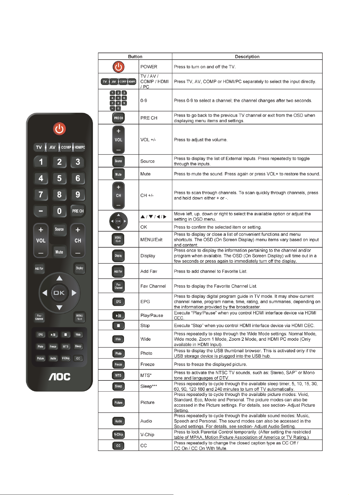
2.1 The Use of Remote Control
5
Page 6

* Multichannel Television Sound (MTS)
The broadcasting standard, which allows stereo sounds to be transmitted with the TV picture.
** Second audio program (SAP)
Another or additional audio channel provided for in the Multichannel Television Sound (MTS) broadcast standard. A
monaural sound track included within the recorded or video signal (usually containing a second language translation
for the displayed program).
*** Sleep
You can set a time period for which the TV will be turned off automatically.
6
Page 7
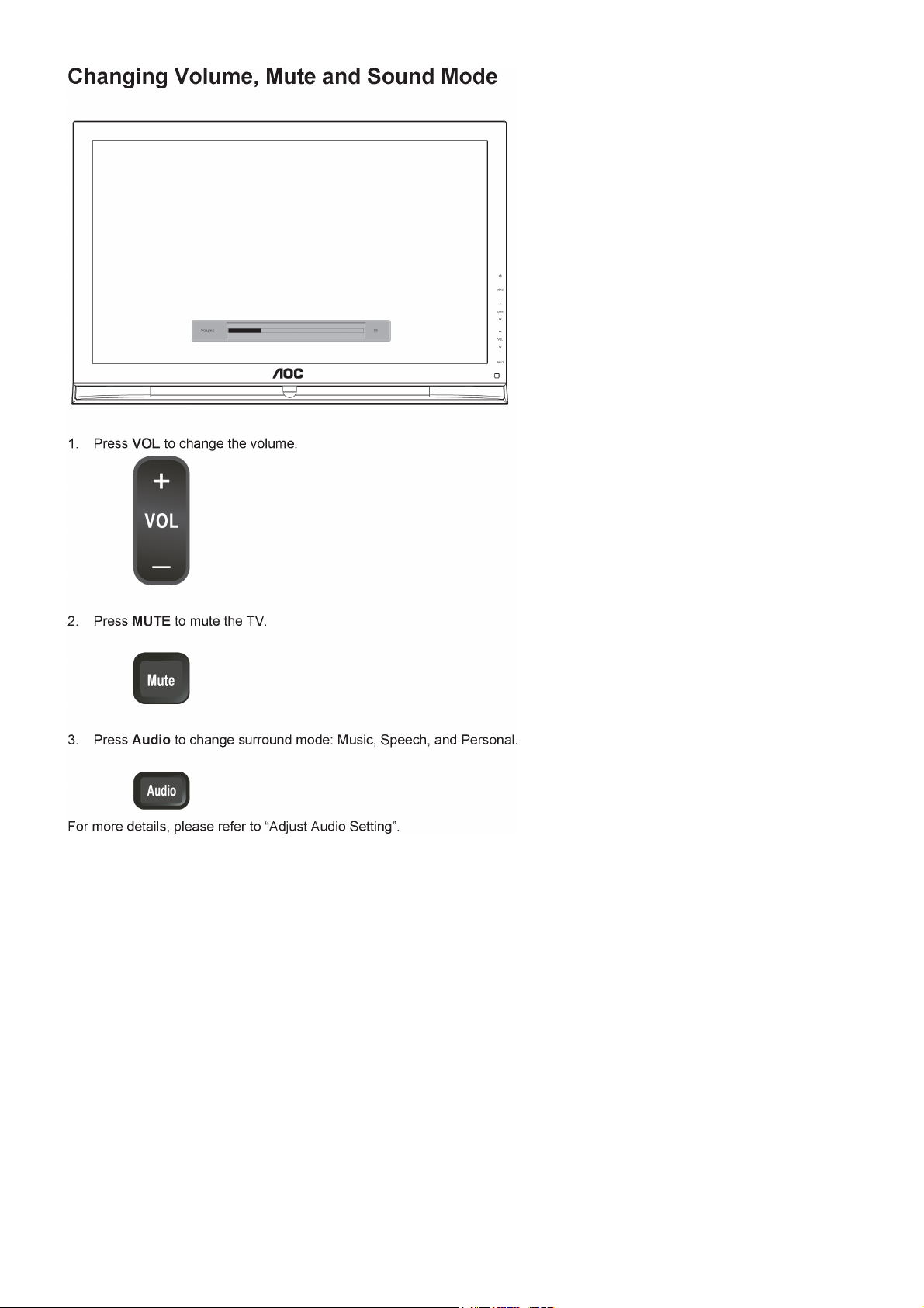
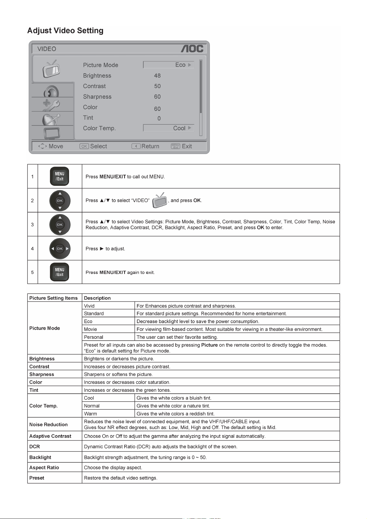
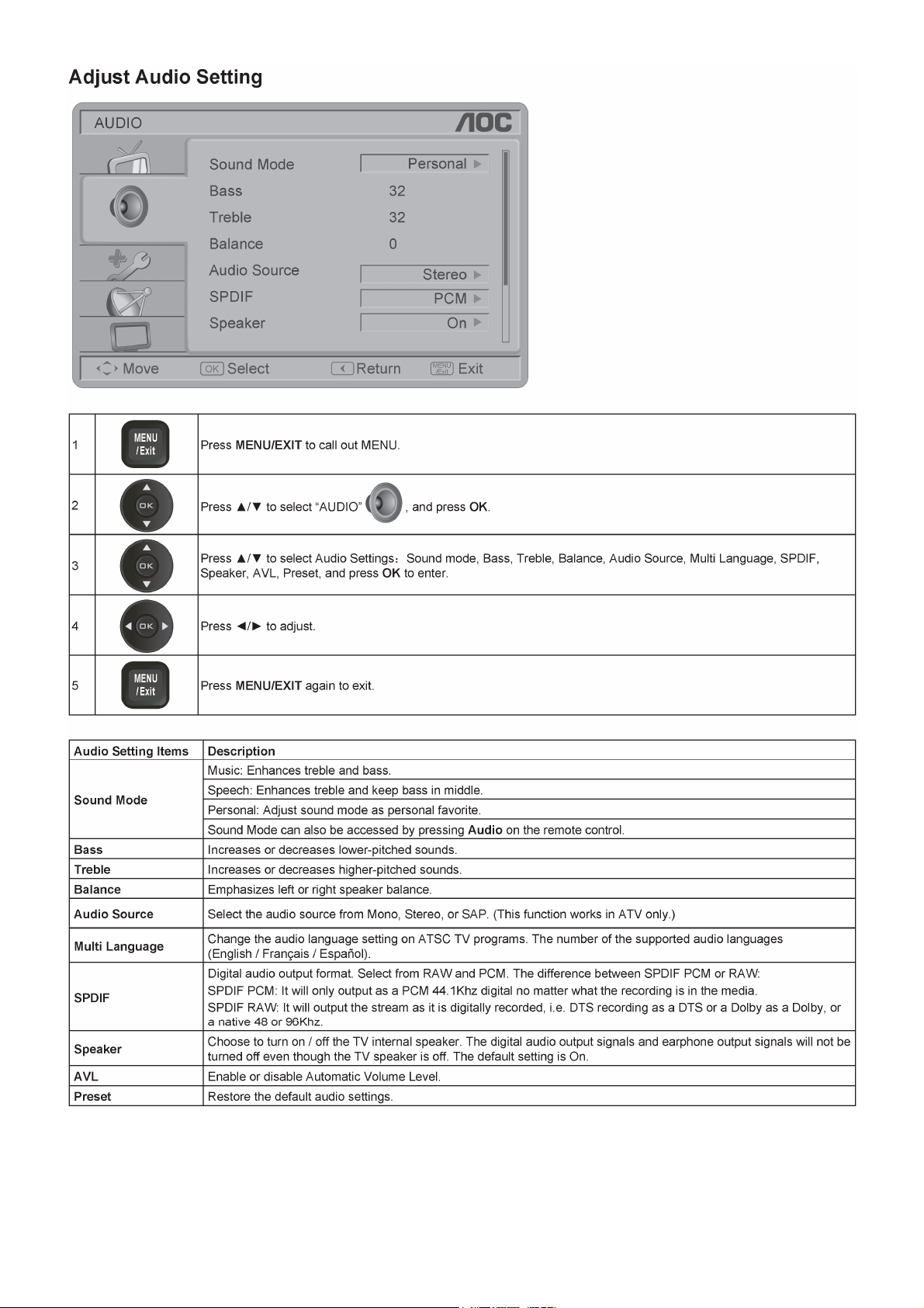
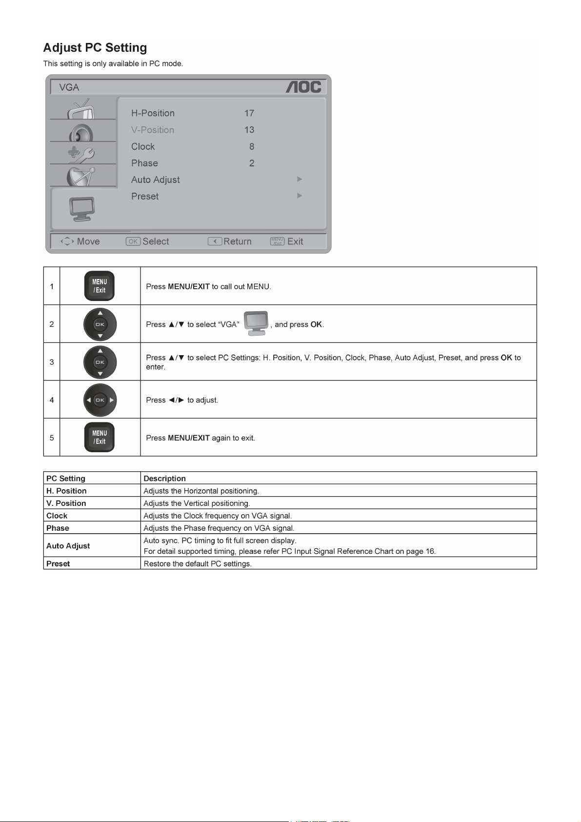
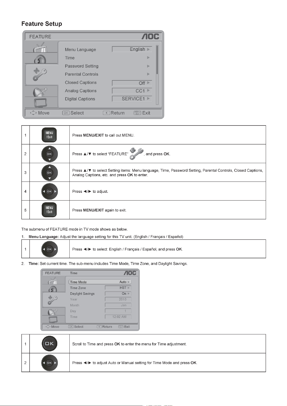
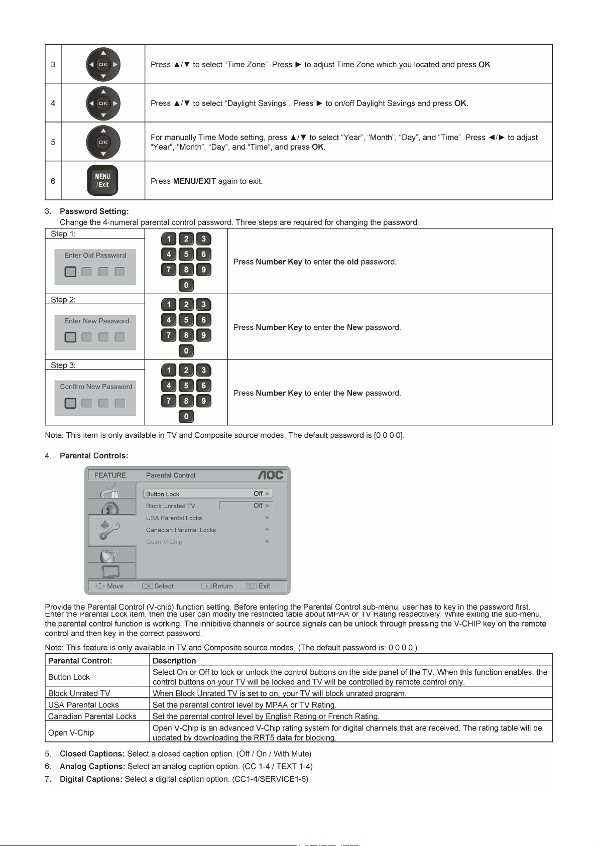
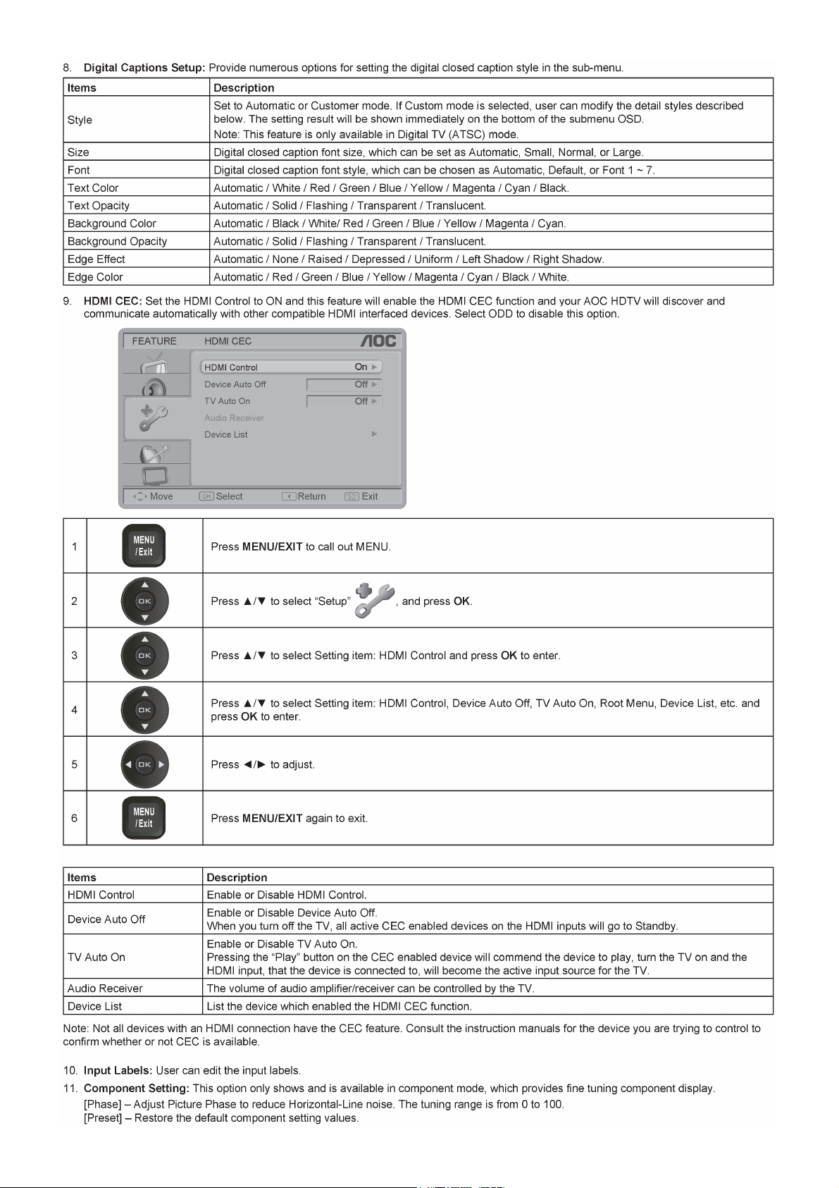
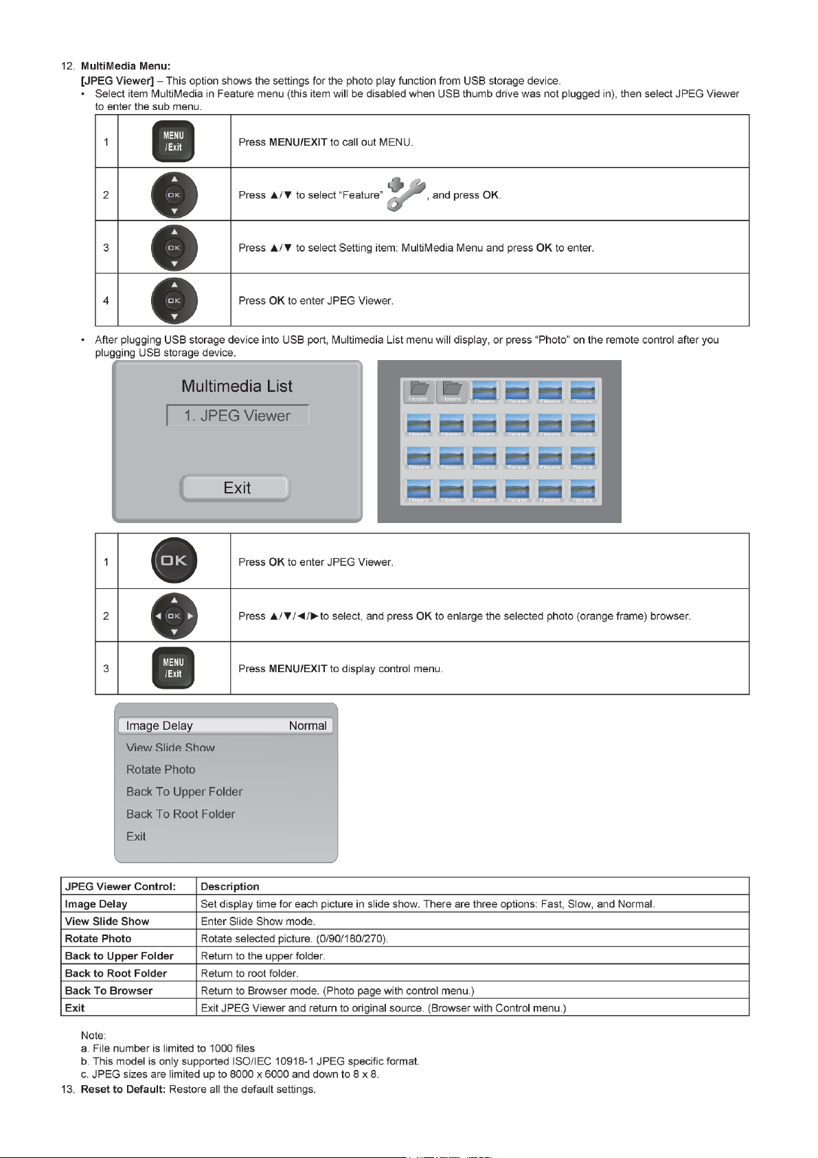
2.2 To Use the Menus
7
Page 8
8 9
Page 9
Page 10
10 11 12 13 14 15 16
Page 11
Page 12
Page 13
Page 14
Page 15
Page 16
Page 17
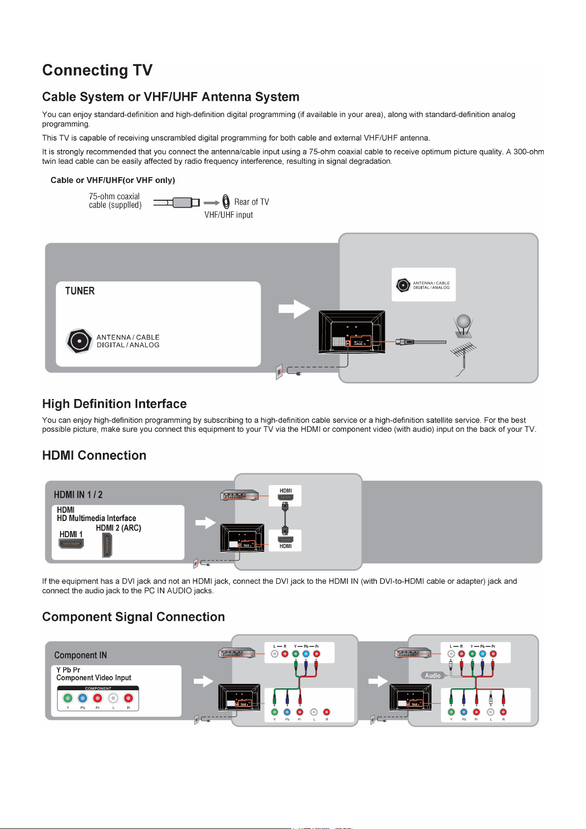
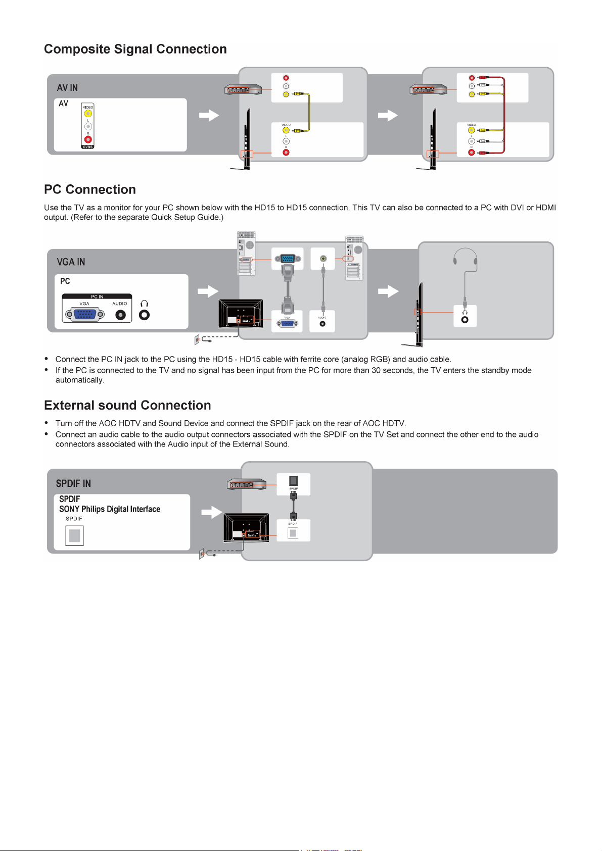
2.3 How to Connect
17
Page 18
18
Page 19
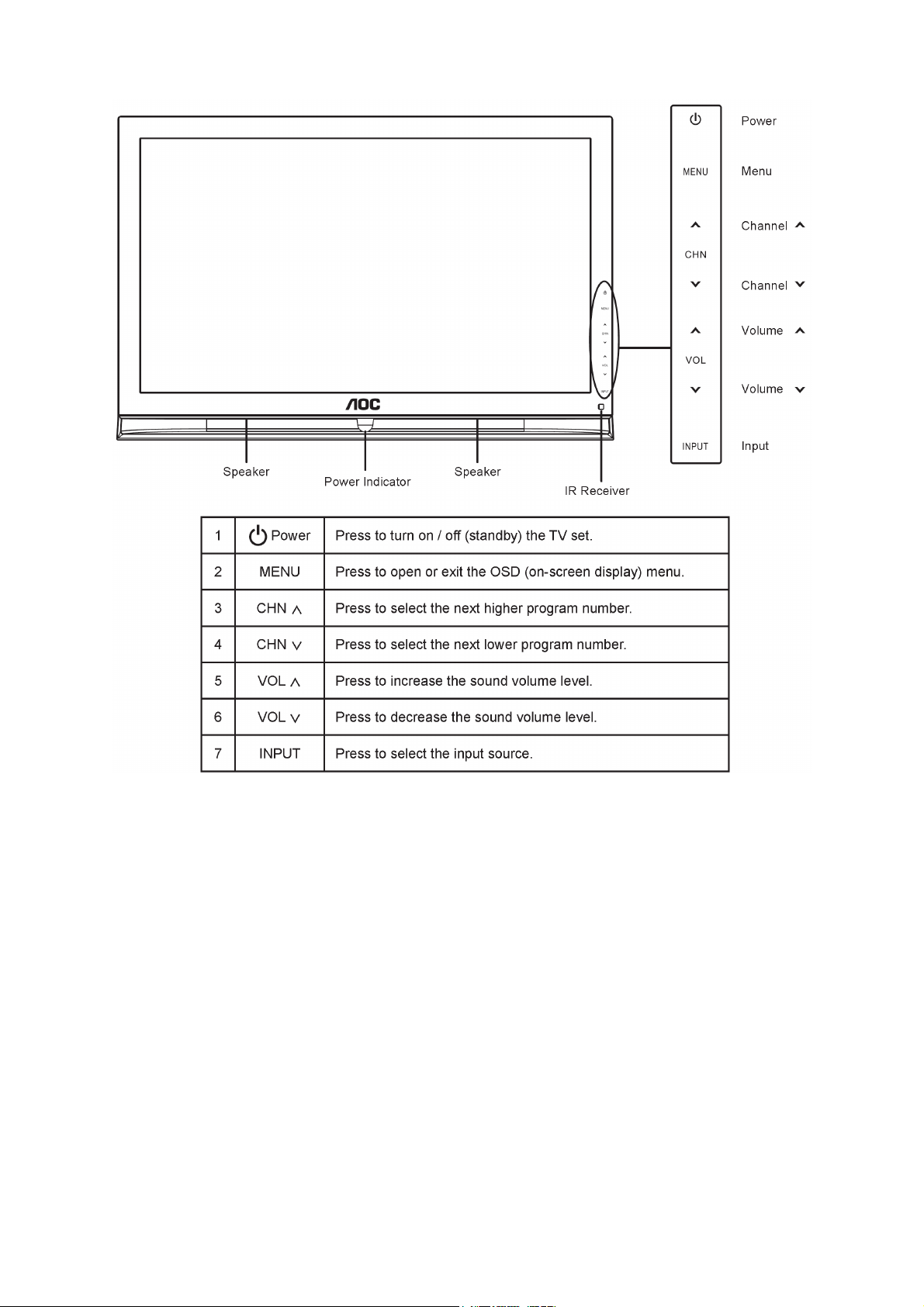
2.4 Front Panel Control Knobs
19
Page 20
20
Page 21
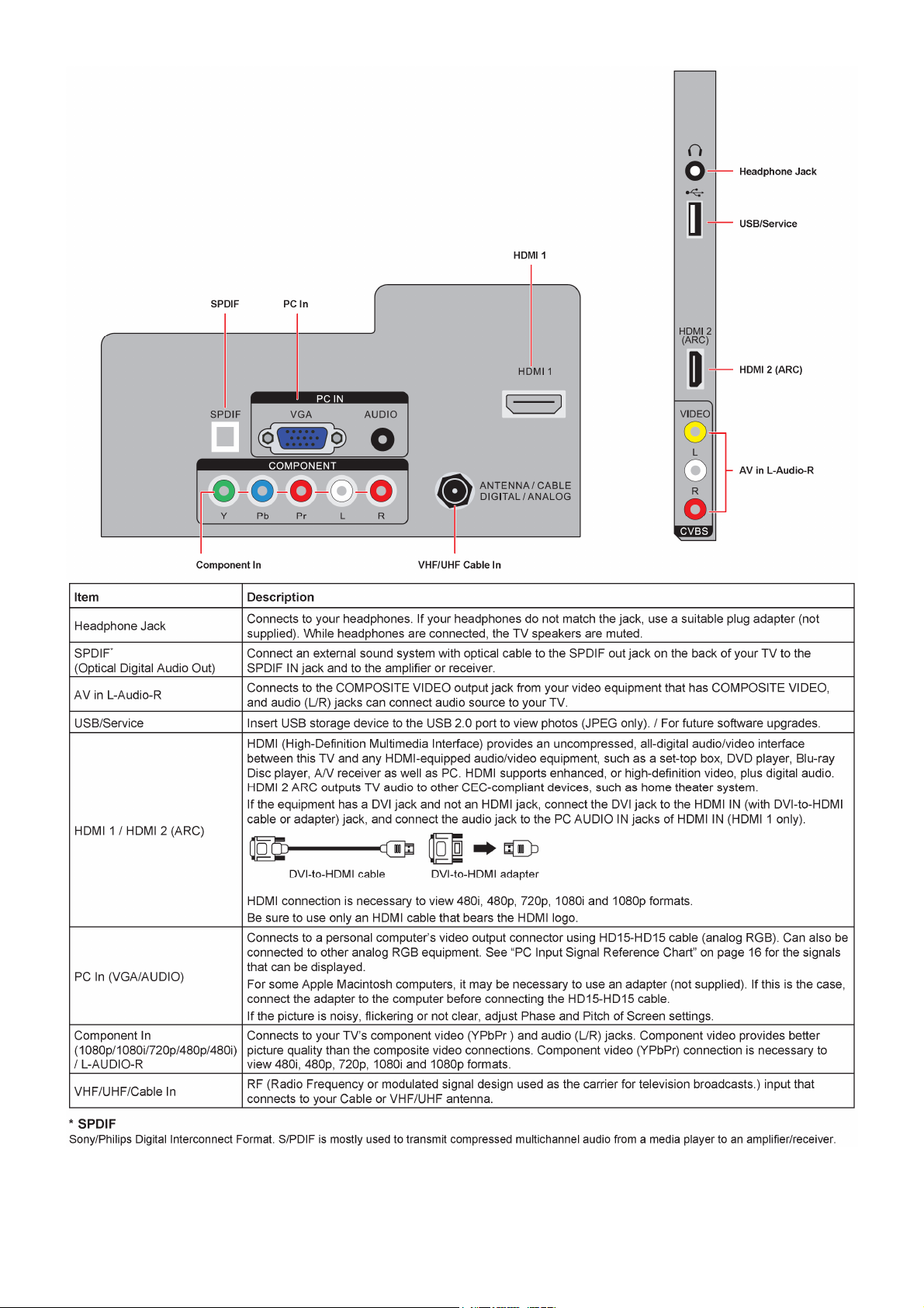
3. Input/Output Specification
3.1 RGB Signal Input
15 - Pin Color Display Signal Cable
Pin No. Description Pin No. Description
1 Red Video 9 No Pin
2 Green Video 10 Sync Ground
3 Blue Video 11 SDA(Remote Control)
4 SCL(Remote Control) 12 Serial Data for DDC
5 Ground 13 H-Sync.
6 Red Ground 14 V-Sync.
7 Green Ground 15 Serial Clock for DDC
8 Blue Ground
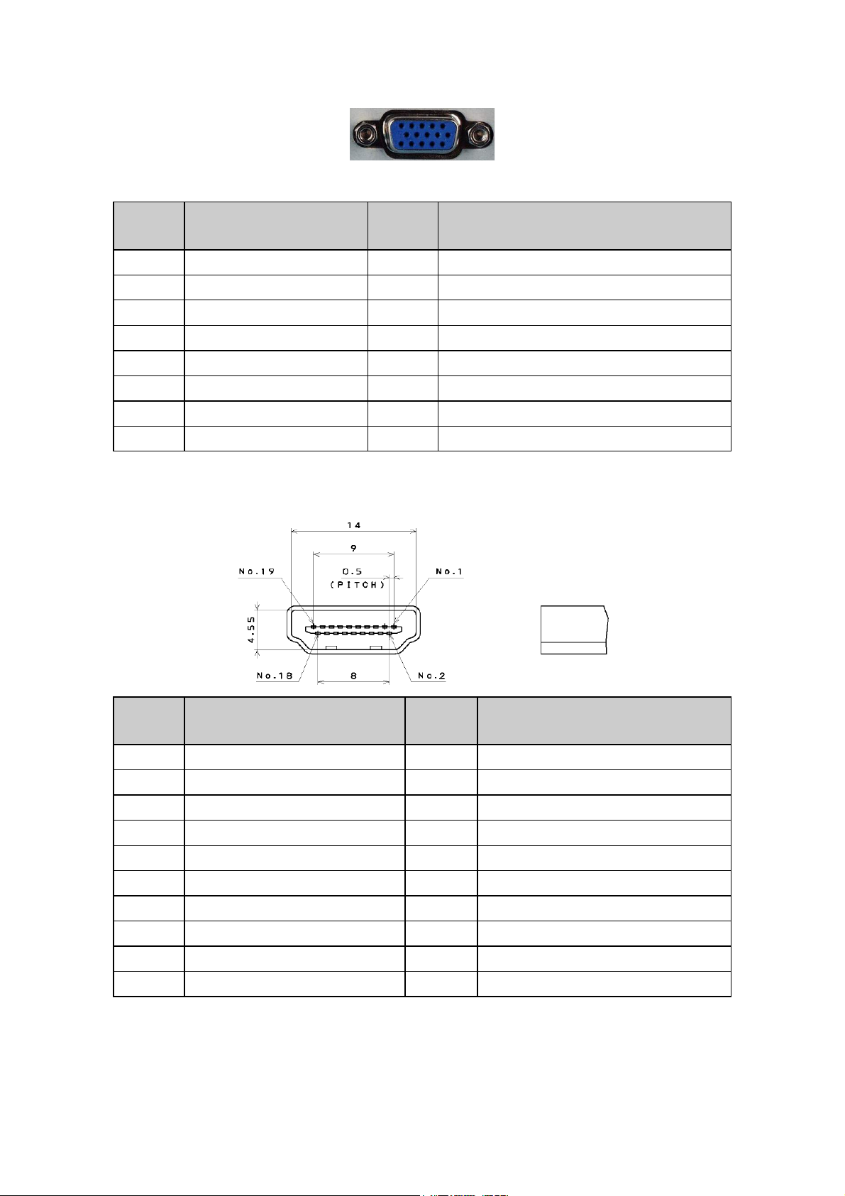
3.2 HDMI Digital Connector Pin Assignments
Pin No. Description Pin No. Description
1 TMDS Data2+ 2 TMDS Data2 Shield
3 TMDS Data2- 4 TMDS Data1+
5 TMDS Data1 Shield 6 TMDS Data1-
7 TMDS Data0+ 8 TMDS Data0 Shield
9 TMDS Data0- 10 TMDS Clock+
11 TMDS Clock Shield 12 TMDS Clock13 CEC 14 NC
15 SCL 16 SDA
17 DDC/CEC Ground 18 +5V Power
19 Hot Plug Detect
21
Page 22
3.3 Compatible Mode Table
Analog RGB Input Signal
Horizontal Vertical
Resolution
640x480@60Hz 31.469 - 59.940 - 25.175
720x400@70Hz 31.469 - 70.087 + 28.322
800x600@60Hz 37.879 + 60.317 + 40.000
1024x768@60Hz 48.363 - 60.004 - 65.000
1280x720@60Hz 44.772 - 59.855 + 74.500
1280x768@60Hz 47.396 - 59.995 + 68.250
1280x1024@60Hz 63.981 + 60.020 + 108.000
1440x900@60Hz 55.469 + 59.901 - 88.750
1680x1050@60Hz 65.290 - 59.954 + 146.250
1920x1080@60Hz 67.500 + 60.000 + 148.500
Nominal
Frequency(KHz)
Sync
Polarity
Nominal
Freq. (Hz)
Sync
Polarity
Nominal Pixel
Clock (MHz)
HDMI Input Signal
Horizontal Vertical
Nominal
Mode Resolution Total
VGA 640x480@60Hz 800x525 31.469 N 59.940 N 25.175
DOS 720x400@70Hz 900x449 31.469 N 70.087 P 28.322
SVGA 800x600@60Hz 1056x628 37.879 P 60.317 P 40.000
XGA 1024x768@60Hz 1344x806 48.363 N 60.004 N 65.000
WXGA 1280x768@60Hz 1312x800 47.396 P 59.995 N 68.250
CVT-0.92M 1280x720@60Hz 1664x748 44.772 N 59.855 P 74.500
SXGA 1280x1024@60Hz 1688x1066 63.981 P 60.020 P 108.000
WXGA+ 1440x900@60Hz 1600x926 55.469 P 59.901 N 88.750
WSXGA+ 1680x1050@60Hz 2240x1089 65.290 N 59.954 P 146.250
FHD 1920x1080@60Hz 2200x1125 67.500 P 60.000 P 148.500
480i 720x480i 15.75 60 13.513
480P 720x480P 31.50 60 27.027
720P 1280x720P 45.00 60 74.25
1080i 1920x1080i 33.75 60 74.25
1080P 1920x1080P 67.5 60 148.5
1080P 1920x1080P 27 24 74.25
Frequency
(KHz)
Sync
Polarity
Nominal
Freq.
(Hz)
Sync
Polarity
Nominal
Clock
(MHz)
Pixel
22
Page 23
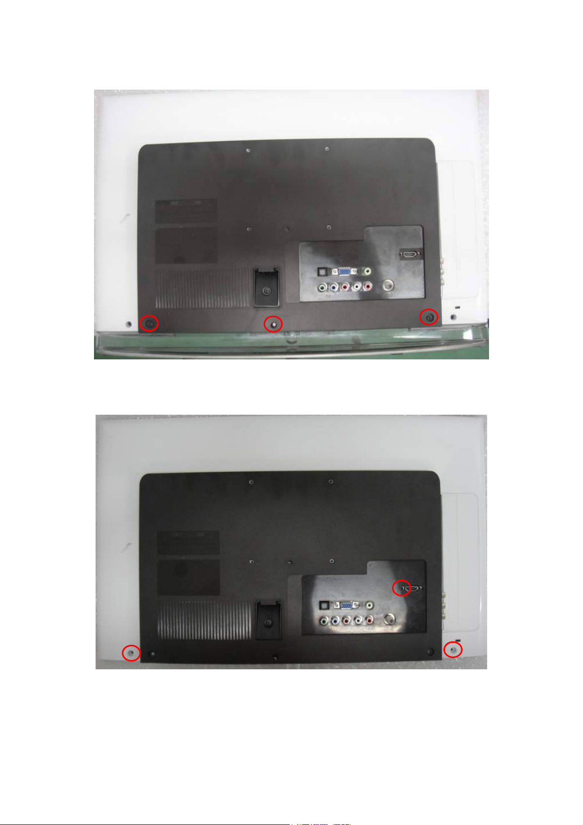
4. Mechanical Instructions
1. Remove the screws to remove STAND and BASE.
2. Remove the screws to remove REAR COVER.
23
Page 24
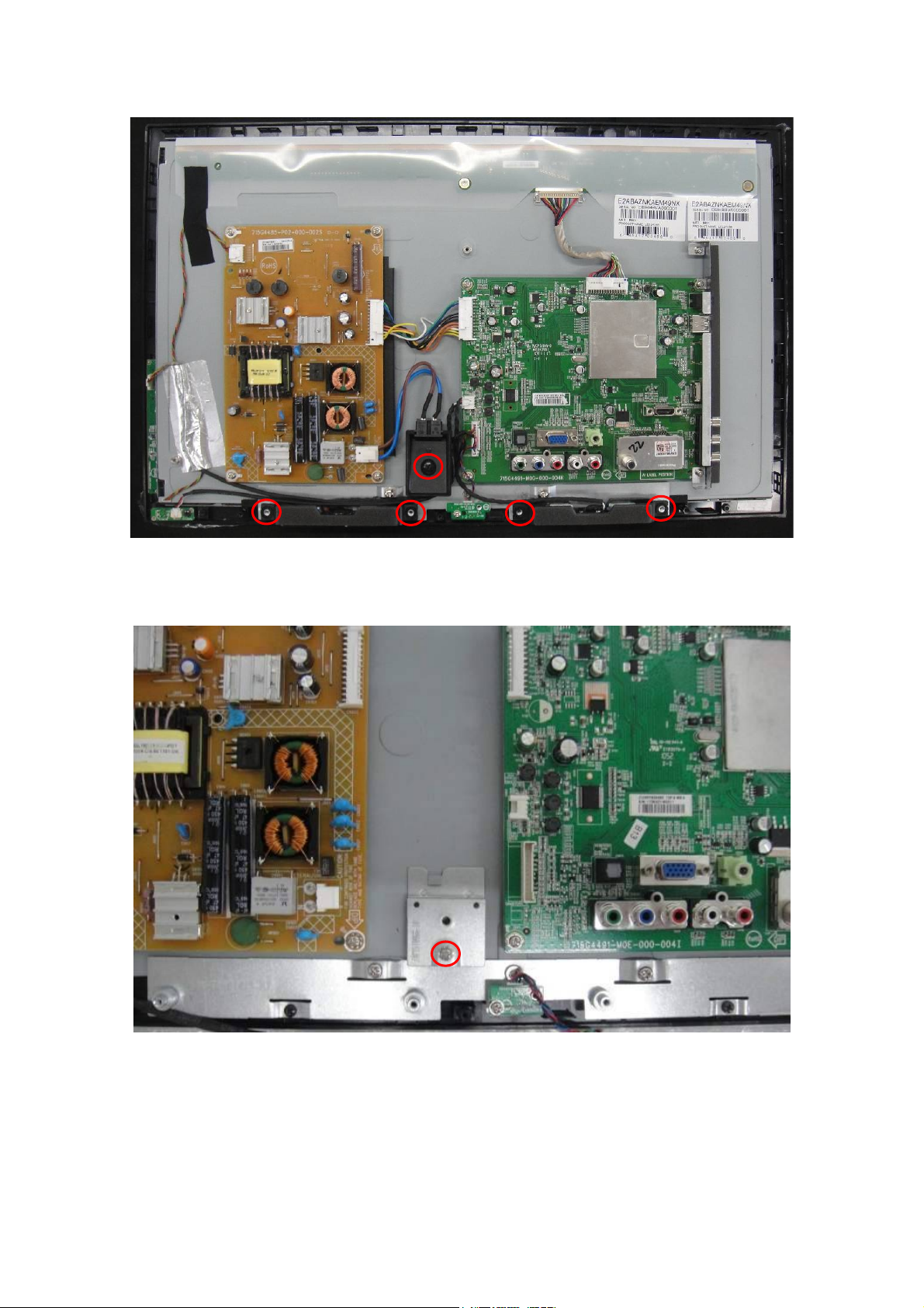
3. Remove the screws to remove AC COVER and SPEAKERS.
4. Remove the screws to remove BKT.
24
Page 25

5. Remove the screws to remove MAIN BOARD, POWER BOARD and LED BOARD.
6. Remove the screws to remove IR BOARD.
25
Page 26

7. Remove the screws to remove BKT and separate the PANEL and BEZEL.
8. The BEZEL.
26
Page 27

p
p
5. Repair Flow Chart
1. No power
No power (LED “Off”)
Check the AC input and
the
ower is “ON”?
Yes
Power board
out
ut=5.2V?
Yes
Check the IR board and LED
Replace the IR board
No
Replace the main board
No
Power “On”
No
Replace the power board
27
Page 28

2. Can’t start
Can’t start(LED orange)
Power board output=16V?
Yes
Check the power key is under control?
No
Check the IR receiver is normal?
No
Replace the power board
Yes
Replace the key board
Yes
Replace the IR board
No
Replace the main board
No
Replace the Power board
28
Page 29

3. Abnormal display
Abnormal Display
Check the source
Yes
Enter factory mode to do
“EEPROM initial”&“Reset”
No
No
Reset the source
Check the main board
Yes
Check the LVDS cable
Yes
Check the panel
No
Replace the panel
No
Replace the main board
No
Replace the LVDS cable
29
Page 30

4. No display
No display (LED blue)
Check TV is under control and power
on/off by remote control and power key?
Yes
Check the LVDS cable
Yes
Yes
Check the backlight is
“On”?
No
Reinsert or replace the
LVDS cable
No
No
Check the B/L
signal is available?
Yes
Replace the main board
No
Replace main board
Panel Vcc = 5V?
Yes
Replace the Panel
No
Replace the main board
Power board output=16V?
Yes
Replace the Panel
Replace the power board
No
30
Page 31

5. Sound problem
No sound or sound abnormal
Check the audio source connection
and the TV system are correct?
Yes
Check the TV is muted, adjust the
volume or enter the menu to reset?
No
No
Reinsert the audio cable or
change the TV system
Enter factory mode to do “Reset”
No
Check the cable between the
speakers and main board is OK?
Yes
Check the speaker resistance value is in spec
(Remark: The value is marked on the speaker)?
Yes
Replace the cable
Replace the main board
No
No
Replace the speaker
31
Page 32

6. Remote control malfunction
Remote Control malfunction
Check the remote control battery is
not properly placed or no power?
No
Use the other remote controls
No
Whether the IR board is
abnormal?
No
Replace the main board
Yes
Replace the battery
Yes
Replace the remote control
Yes
Replace the IR board
32
Page 33

7. OSD is unstable or can’t work normally
OSD is unstable or can’t work normally
Key board connected properly?
Yes
Buttons are OK?
Yes
Key board is OK?
Yes
Enter factory mode to do “Reset”
No
No
No
No
Reconnect the key board
Replace the button function
Replace the key board
Replace the main board
33
Page 34

6. PCB Layout
6.1 Main Board
715G4491M0G000004K
34
Page 35

35
Page 36

6.2 Power Board
715G4485P02000002S
36
Page 37

37 38
Page 38

Page 39

6.3 LED Board
715G4729T01000004M
6.4 Key Board
715G4660K01000004M
6.5 IR Board
715G4728R01000004M
39
Page 40

7. Adjustment
7.1 ADC Adiustment
It’s no need to adjust the white balance for this model, do ADC only.
Step1: Turn on the TV, press “Menu”, then press number key 1 Æ 9 Æ 9 Æ 9 and “ENTER”, it will achieve the factory
mode.
Step2: Change TV, press the “Current Source” to Component mode and change signal to 720P mode(TIMING 314),
Pattern 122(SMPTE BAR), press the “Auto Color”;
Step3: Change TV, press the “Current Source” to PC mode and change signal to PC TIMING 137(1024X768);
Pattern 147(16 Grays), press the “Auto Color”.
40
Page 41

7.2 FW Upgrade
Step 1: Ready for F/W Upgrade
1.1 Prepare a USB memory (The file system of USB memory must be FAT16 or FAT 32).
1.2 Copy the file (EPI_LE22H168_USA_ZR748-A2_PCB4491-D_V1.09_20110218_72DB.ecc) you’re your
computer to the folder named “usbupdate" then copy this folder to USB memory root path, and remove it from
computer’s USB port!
Note: 1)
2) The version of this F/W is V1.09.
3) Make sure there is only one F/W file in your USB memory.
Step 2: F/W Upgrade
2.1 AC ON TV(Power plug Figure 2.1/2.2)
Figure 2.1 Figure 2.2
2.2 Press the power key on the Remote Control or the right side of TV to turn on TV.
Figure 2.3 Figure 2.4
41
Page 42

2.3 Plug the USB memory on the USB port on the side I/O port of TV.(Figure 2.5)
Figure 2.5
2.4 When TV detect the USB memory and display below Upgrade info (Figure 2.6), press “Left” & “OK” button(on
the Navigation Keys on the Remote control, as follows Figure 2.7) to select “Yes” option to download
F/W(Figure 2.8)
.
Figure 2.6
Left
Down
OK
Figure 2.7
Figure 2.8
42
Page 43

2.5 TV will upgrade automatically.
Note: When Upgrade on the process, please don’t Power-Off! (Figure 2.9)
Figure 2.9
2.6 When upgrade 100% and prompt for Upgrade Success info, remove the USB Drive and AC off and on to reset
TV (Figure 2.10)
Figure 2.10
Step 3: Check the F/W version and reset to default.
3.1 Press “MENU/EXIT”+ “1”+ “9”+ “9”+ “9”+ “OK” key to enter the factory mode (Figure 3.1).
Do the following steps rapidly:
1. Press “MENU/EXIT”;
2. Press “1”+ “9”+ “9”+ “9”;
3. Press “OK”
Menu
Figure 3.1
43
Page 44

3.2 Check the F/W version on the fifth row of the factory mode info(eg. the “Ver” info is V1.09). If F/W version is
incorrect, please check the version of F/W in your USB memory, else let’s go to Step 3.3.
Figure 3.2
3.3 If F/W version is correct, press ‘down’ Key to choose ‘Reset to Def’ option (The option will be highlighted). Then
press ‘OK’ Key to active ‘Reset to Def’.
Figure 3.3 Figure 3.4
3.4 When “Reset to Def” show “Done”, then press ‘down’ Key to choose ‘exit’ option and press ‘OK’ Key to be off
factory mode.
Figure 3.5
DDC Upgrade
As the DDC data is included in the software, this model does not need a separate DDC Upgrade.
44
Page 45

8. Block Diagram
System Block Diagram
Tuner
ENV56U05D8F
VIDEO
YPbPr
VGA
I2C
HDMI CN501
Rear
HDMI CN506
Side
(ARC)
HDMI CN507
Side
AV AUDIO-R\L
YPbPr AUDIO-R\L
VGA AUDIO-R\L
VIF
CVBS
YPbPr
RGB
SN74LVC1G17
Hsync, Vsync
ZR39748BGCG
PORT 2
PORT 1
PORT 0
LINE_IN3
LINE_IN4
LINE_IN5
LVDS
LCD PANEL
DDRII * 1
W971GG6JB-18
FLASH ROM
MX25L3206EM2I-12G
GPIO
EJTAG
CAT24C64WI-GT3
S/PDIF Output
Side HDMI (ARC)
I2S
Audio Amplifier
STA339BWS13TR
R/L
Earphone Amplifier
MAX9728AETC+
P24V / 16V
P12V
+5VS B
SPEAKER
EarPhone Output
P24V
Main Board Power System
PANEL Inve rte r
NC / Q702 AO4449
U716
AS7812ADTR-G1
VCC5D
D24 V
12V
U715
AZ1117D
U704 AT1528P11U
U714 SC189ASKTRT
U701
G5250M1T 1U
U712
G1117-33T63Uf
U711 G1084-33T43UF
U717
G9084-50TU3U
VCC1_1
VCC1_8
USB5V
PLL3_3
VCC3_3
5VT
12V
5VSB
For ZR39748BGCGQ701 AO4449
For DDR II
For USB Po we r
For ZR39748BGCG PLL
For ZR39748BGCG
U709
G9141T11U
U718
G9141T11U
For Audio Amplifier
Fo r T UNER+5V
Q401 AO4449
3V3_ST B
U70 8
G9141T11U
For Audio Amplifier
VCC1_2
AFE_1V1
PANEL LVDS Po w er
For HDMI S/W 1.8V STB
1V1_STB
For ZR39748BGCG uM CU
For ZR39748BGCG
MSD Power
For ZR39748BGCG
45
Page 46

9. Schematic Diagram
9.1 Main Board
715G4491M0G000004K
U401A
ZR39748BGCG
S0 Memory I/F
S0_DQ15
AA15
AA9
AA16
AB9
AB11
AB14
AA10
AB16
AA13
AA8
AB12
AA7
AB7
AA12
AB8
AB13
AB10
AA11
V13
V17
U17
V16
500mA
S0_DQ15
S0_DQ14
S0_DQ13
S0_DQ12
S0_DQ11
S0_DQ10
S0_DQ9
S0_DQ8
S0_DQ7
S0_DQ6
S0_DQ5
S0_DQ4
S0_DQ3
S0_DQ2
S0_DQ1
S0_DQ0
S0_UDM
S0_LDM
S0_VREF
RDRIVER
RDRIVER50
RTERM
C432
10N 50V
0402040204020402 0402
S0_A12
S0_A11
S0_A10
S0_A9
S0_A8
S0_A7
S0_A6
S0_A5
S0_A4
S0_A3
S0_A2
S0_A1
S0_A0
S0_BA2
S0_BA1
S0_BA0
S0_UDQSN
S0_UDQS
S0_LDQSN
S0_LDQS
S0_RAS_N
S0_CAS_N
S0_WE_N
S0_CK_N
S0_CK_P
S0_CKE
S0_ODT
C421
100N16V
C422
100N16V
C418
100N16V
C429
100N16V
S0_DQ14
S0_DQ13
S0_DQ12
S0_DQ11
S0_DQ10
S0_DQ9
S0_DQ8
S0_DQ7
S0_DQ6
S0_DQ5
S0_DQ4
S0_DQ3
S0_DQ2
S0_DQ1
S0_DQ0
S0_UDM
S0_LDM
VCC1_8
C433
100N16V
DDRII 512M-800MHz 56G 615112 32M16DDRII W9751G6JB-25
DDRII 1G-1066MHz 56G 615503 64M16DDRII W971GG6JB-18
AB1
Y22
AB4
AA1
AA22
AB2
AB22
AA2
AA21
AB3
AB21
AA3
AA20
AA5
AA4
AB5
AB15
AA14
AB17
AA17
AA19
AB20
AB6
AA18
AB18
AA6
AB19
S0_A12
S0_A11
S0_A10
S0_A9
S0_A8
S0_A7
S0_A6
S0_A5
S0_A4
S0_A3
S0_A2
S0_A1
S0_A0
S0_BA2
S0_BA1
S0_BA0
S0_UDQSN
S0_UDQS
S0_LDQSN
S0_LDQS
S0_RASN
S0_CASN
S0_WEN
S0_CKN
S0_CK
S0_CKE
S0_ODT
C430
100N16V
0402 04020402
VCC1_8
C435
100N16V
500mA
C486
10N 50V
0402
S0_DQ[15. .0]
R409 150R 1%
Close to DDR
C462
10UF 6. 3V
S0_A[12.. 0]
C4129
NC/ 10U F 6. 3V
S0_BA0
S0_BA1
S0_BA2
S0_A12
S0_A11
S0_A10
S0_A9
S0_A8
S0_A7
S0_A6
S0_A5
S0_A4
S0_A3
S0_A2
S0_A1
S0_A0
S0_CKN
R408
100R 1%
S0_VREF
R410
100R 1%
S0_CK
S0_CKE
S0_WEN
S0_RASN
S0_CASN
S0_LDM
S0_UDM
S0_ODT
S0_LDQS
S0_LDQSN
S0_UDQS
S0_UDQSN
S0_CKS0_CKN
VCC1_8
500mA
C419
100N16V
0402
U402
L2
BA0
L3
BA1
L1
BA2
R2
A12
P7
A11
M2
A10/AP
P3
A9
P8
A8
P2
A7
N7
A6
N3
A5
N8
A4
N2
A3
M7
A2
M3
A1
M8
A0
K8
CK
J8
CK
K2
CKE
L8
CS
K3
WE
K7
RAS
L7
CAS
F3
LDM
B3
UDM
K9
ODT
F7
LDQS
E8
LDQS
B7
UDQS
A8
UDQS
J2
VREF
A2
NC#A2
E2
NC#E2
R3
NC#R3
R7
NC#R7
R8
NC#R8
W971GG6JB-18
DQ15
DQ14
DQ13
DQ12
DQ11
DQ10
DQ9
DQ8
DQ7
DQ6
DQ5
DQ4
DQ3
DQ2
DQ1
DQ0
VDDQ1
VDDQ2
VDDQ3
VDDQ4
VDDQ5
VDDQ6
VDDQ7
VDDQ8
VDDQ9
VDDQ10
VDD1
VDD2
VDD3
VDD4
VDD5
VDDL
VSSDL
VSSQ1
VSSQ2
VSSQ3
VSSQ4
VSSQ5
VSSQ6
VSSQ7
VSSQ8
VSSQ9
VSSQ10
VSS1
VSS2
VSS3
VSS4
VSS5
VCC1_8
S0_DQ15
S0_DQ14
S0_DQ13
S0_DQ12
S0_DQ11
S0_DQ10
S0_DQ9
S0_DQ8
S0_DQ7
S0_DQ6
S0_DQ5
S0_DQ4
S0_DQ3
S0_DQ2
S0_DQ1
S0_DQ0
B9
B1
D9
D1
D3
D7
C2
C8
F9
F1
H9
H1
H3
H7
G2
G8
A9
C1
C3
C7
C9
E9
G1
G3
G7
G9
A1
E1
J9
M9
R1
J1
J7
A7
B2
B8
D2
D8
E7
F2
F8
H2
H8
A3
E3
J3
N1
P9
T P V ( Top Victory Electronics C o . , Ltd. )
絬 隔 瓜 絪 腹
Key Component
Date
03- DDRII SDRAM I/F
46
OEM MODEL
TPV MO DEL
PCB NAME
Sheet
715G4491
315Wednesday , June 15, 2011
of
Size
Rev
称爹
G
<
称爹
Custom
>
Page 47

VCC3_3
VCC3_3
VCC3_3
VCC3_3VCC3_3
EJTAG Debug Only.
U401B
SIO I/F
TDO/EJTDO/SNDBUS[16]
EJTAG
TMS/EJTMS/SNDBUS[15]
TCK/EJTCK/SND BUS[21]
UART
I2C
TDI/EJTDI/SNDBUS[20]
UART1_TX/GPIO_S[2]
UART1_RX/GPIO_S[3]
I2C0_C
I2C0_D
I2C1_C /GPIO_S[4]
I2C1_D /GPIO_S[5]
D19
D18
C18
D20
F20
E20
F4
F3
A21
A22
EJTDI
EJTDO
EJTMS
EJTCK
R443 4.7K 1/10W
R442 4.7K 1/10W
R445 1.8K 1/10W
R444 2.2K 1/10W
R4176 33 OHM 1/16W
VCC3_3
I2C_SCL 9,11
I2C_SDA 9,11
I2C_1_SCL 6
I2C_1_SDA 6
R4211K 1/10W
VCC3_3
R439 4.7K 1/10W
CN406
NC/CONN
R440NC/4.7K 1/10W
R4221K 1/10W
R4231K 1/10W
TP1
2
4
6
8
10
12
14
1
3
5
7
9
11
13
VCC3_3
R402
4.7K 1/16W
C0402
SPI_HOLD
SPI_CLK
SPI_WR
C424
100N16V
C0402
R446
NC/4.7K 1/ 16W
8
VCC
7
HOLD#
6
SCLK
5
SI/SIO0
U405
MX25L3206EM2I-12G
CS#
SO/SIO1
WP#
GND
SPI FLASH
VCC3_3_EEPROMVCC3_3
R4155
NC/4.7K 1/16W
C0402C0402
1
2
3
4
SPI_CS_N
SPI_RD
R441
4.7K 1/16W
C0402
SPI_WEN 10
SPI
25M
USB2.0
ZR39748BGC G
SPI_DO/ GPIO_S[13]
SPI_DI/GPIO_S[7]
SPI_CLK/ GPIO_S[14]
SPI_SEL0/GPIO_S[15]
SIP_SEL1/ GPIO_S[11]
SPI_HOLD/GPIO_S[12]
CLKOUT_25M
CLKIN_25M
USB2_DN
USB2_DP
USB2_REXT
USB_ATEST
C22
B22
B21
C21
Y21
C20
A8
B8
W21
W22
T18
V19
R454 NC/47 OHM 1/16W
R460
150R 1/10W 1%
X401
25MHz
1 2
C498
18pF 50V
USB2_DN
USB2_DP
USB2_REXT
R403
6.04KOHM +-1% 1/10W
SPI_WR
SPI_RD
SPI_CLK
SPI_CS_N
SPI_HOLD
Crystal use CL = 12 pF
C498 , C497 = 18 pF
R460 = 150 Ohm.
C497
18pF 50V
2
1
L401
NC/90 ohm
073G253S 6 T
3
4
VPORT0603100KV05
R413
10K+ -5%1/16W
C0402
EEPROM_WP11
I2C_SCL
R436 33 OHM 1/16W
I2C_SDA
R435 33 OHM 1/16W
C414
220NF 25V
U404
CAT24C64WI-GT3
8
VCC
7
WP
C0402
6
SCL
C0402
5
SDA
GND
1
A0
2
A1
3
A2
4
EEPROM
500mA
USB5V
123 4
1
2
3
4
C417
100N16V
0402
1 2
1 2
ZD406
ZD407
VPORT0603100KV05
絬 隔 瓜 絪 腹
Key Component
CN103
USB CON N
088G352F6B1ACL
6 5
USB_EN10
T P V ( Top Victory Electronics Co . , Ltd. )
04- SIO I/F
Date
47
500mA 500mA
VCC5D USB5V
U701
G5250M1T1U
5
OUT
IN
GND
R412
4.7K 1/10W
OEM MO D EL
TPV MOD EL
PCB NAME
Sheet
+
C431
220uF 16V
4
EN
715G4491
415Monday, June 13, 2011
of
OC
VCC3_3
R411
10K+ -5%1/16W
1
2
3
C499
4.7uF 10V
C0402
R4174
100K 1/8W
Size
Rev
称爹
USB_OC_N 10
Custom
G
<
称爹
>
Page 48

CN501
HDMI
088G 34021A VT
TMDSD0+
TMDSD0-
TMDSD1+
TMDSD1-
TMDSD2+
TMDSD2-
TMDSC +
TMDSC-
SCL
SDA
CEC
HPD
VCC5
NC
DSHLD0
DSHLD1
DSHLD2
CSHLD0
DDC_GND
SHLD_GND 1
SHLD_GND 2
SHLD1
SHLD2
SHLD3
SHLD4
SHLD5
CN506
HDMI
088G340FJ01ATE
20
SHLD0
22
SHLD2
DDC_GND
23
SHLD3
21
SHLD1
CN50 7
NC/HDMI
088G340FJ01ATE
20
SHLD0
22
SHLD2
23
SHLD3
21
SHLD1
TMDSD 2+
DSHLD0
TMDSD2TMDSD 1+
DSHLD1
TMDSD1TMDSD 0+
DSHLD2
TMDSD0-
TMDSC +
CSHLD0
TMDSC -
VCC5
TMDSD2+
DSHLD0
TMDSD2-
TMDSD1+
DSHLD1
TMDSD1-
TMDSD0+
DSHLD2
TMDSD0-
TMDSC +
CSHLD0
TMDSC-
DDC_GND
7
9
4
6
1
3
10
12
15
16
13
19
18
14
2
5
8
11
17
20
21
22
23
24
25
26
CEC
NC
SCL
SDA
HPD
VCC5
CEC
NC
SCL
SDA
HPD
HDMI2_D0P
HDMI2_D0N
HDMI2_D1P
HDMI2_D1N
HDMI2_D2P
HDMI2_D2N
HDMI2_CLKP
HDMI2_CLKN
HDMI2_SCL
HDMI2_SDA
HDMI_CEC
HDMI2_HPD
1 2
FB501
120R
1
2
3
4
5
6
7
8
9
10
11
12
13
14
15
16
17
18
HDMI1_HPD
19
1
2
3
4
5
6
7
8
9
10
11
12
13
14
15
16
17
18
19
1 2
HDMI0_D2P
HDMI0_D2N
HDMI0_D1P
HDMI0_D1N
HDMI0_D0P
HDMI0_D0N
HDMI0_CLKP
HDMI0_CLKN
HDMI_CEC
HDMI0_SCL
HDMI0_SDA
HDMI0_HPD
12
HDMI2_5V
HDMI1_D2P
HDMI1_D2N
HDMI1_D1P
HDMI1_D1N
HDMI1_D0P
HDMI1_D0N
HDMI1_CLKP
HDMI1_CLKN
HDMI_CEC
HDMI_ARC
HDMI1_SCL
HDMI1_SDA
FB502
120R
12
ZD508MLVG0402
1 2
FB503
NC/120R
12
ZD515NC/M LVG0402
R503
4.7K 1/10W
12
ZD507MLVG0402
C515
100N16V
HDMI1_5V
HDMI2_5V
1
ZD509MLVG0402
R4138
4.7K 1/10W
R4164
4.7K 1/10W
C517
100N16V
HDMI0_5V
+5VSB
2
3
12
R4137
10K 1/10W 5%
R4163
NC/4.7K 1/10W
C518
NC/100N 16V
ZD519
BAT54C
R507
4.7K 1/10W
ZD511MLVG040212ZD513MLVG0402
HDMI1_5VSENSE 12
R4165
10K 1/10W 5%
HDMI2_SCL 12
HDMI2_SDA 12
HDMI2_5VSENSE 12
HDMI0_5VSENSE 12
R4166
NC/10K 1/10W 5%
HDMI1_5V
R506
4.7K 1/10W
12
ZD518MLVG0402
HDMI0_5V
R530
NC/4.7K 1/10W
U505
NC/AZ1045-04F.R7G
GND
8
GND
8
GND
8
GND
8
GND
8
GND
8
VCC3_3
C520
1UF 10V
C0402
GND
3
GND
3
GND
3
GND
3
GND
3
GND
3
10
NC
9
NC
7
NC
6
10
NC
9
NC
7
NC
6
10
NC
9
NC
7
NC
6
10
NC
9
NC
7
NC
6
10
NC
9
NC
7
NC
6
10
NC
9
NC
7
NC
6
53
2 4
HDMI2_D1N
HDMI2_D1P
HDMI2_D2N
HDMI2_D2P
HDMI2_CLKN
HDMI2_CLKP
HDMI2_D0N
HDMI2_D0P
HDMI1_D1N
HDMI1_D1P
HDMI1_D2N
HDMI1_D2P
HDMI1_CLKN
HDMI1_CLKP
HDMI1_D0N
HDMI1_D0P
HDMI0_D1N
HDMI0_D2N
HDMI0_D2P
HDMI0_CLKN
HDMI0_D0N
HDMI0_D0P
U508 ON : ARC_Ctrl = High.
1
U50 8
SN74LVC1G126DBVR
HDMI2_D 1N
1
IN1
HDMI2_D 1P
2
IN2
HDMI2_D 2N
4
IN3
HDMI2_D 2P
IN45NC
U503
NC/AZ1045-04F.R7G
HDMI2_C LKN
1
IN1
HDMI2_C LKP
2
IN2
HDMI2_D 0N
4
IN3
HDMI2_D 0P
IN45NC
U504
NC/AZ1045-04F.R7G
HDMI1_D 1N
1
IN1
HDMI1_D 1P
2
IN2
HDMI1_D 2N
4
IN3
HDMI1_D 2P
IN45NC
U502
+5VSB
1
2
ZD520
BAT54C
3
R502
4.7K 1/10W
HDMI1_SCL 12
HDMI1_SDA 12
12
ZD510MLVG040212ZD512MLVG0402
+5VSB
1
2
ZD521
NC/BAT54C
3
R531
NC/4.7K 1/10W
HDMI0_SCL 12
HDMI0_SDA 12
12
ZD516NC/M LVG040212ZD517NC/M LVG0402
NC/AZ1045-04F.R7G
HDMI1_C LKN
1
IN1
HDMI1_C LKP
2
IN2
HDMI1_D 0N
4
IN3
HDMI1_D 0P
IN45NC
U506
NC/AZ1045-04F.R7G
HDMI0_D 1N
1
IN1
HDMI0_D 1P HDMI0_D1P
2
IN2
HDMI0_D 2N
4
IN3
HDMI0_D 2P
IN45NC
U507
NC/AZ1045-04F.R7G
HDMI0_C LKN
1
IN1
HDMI0_C LKP HD MI0_CLKP
2
IN2
HDMI0_D 0N
4
IN3
HDMI0_D 0P
IN45NC
Coaxial9
R537
4.7K 1/16W
R0402
C522
0.1uF 50V
HDMI2_HPD
HDMI2_5V
HDMI2_HPD
HDMI1_HPD
HDMI1_5V
HDMI1_HPD
HDMI0_HPD
HDMI0_5V
HDMI0_HPD
ARC_Ctrl 10
R527
NC/1K 1/10W
R528
4.7K 1/10W
R512
1K 1/10W
R526
10K 1/10W 5%
R558
NC/1K 1/ 10W
R557
4.7K 1/10W
R549
1K 1/10W
R546
10K 1/10W 5%
R559
NC/1K 1/ 10W
R556
NC/4. 7K 1/10W
R548
NC/1K 1/10W
R547
NC/10K 1/10W 5%
HDMI ARC Cir cuit
R540
C521
180R 1/10W 1%
0.1uF 50V
R532
82R 1/10W 1%
U51 1
6
D1
5
G2
4
U50 9
6
D1
5
G2
4
U510
NC/2 N70 02 PS
6
D1
5
G2
4
R542
0.05R
2N7002PS
S1
G1
D23S2
2N7002PS
S1
G1
D23S2
S1
G1
D23S2
1
2
1
2
1
2
HDMI1_5V
HDMI2_HPD_S 12
HDMI2_HPD_S 12
HDMI1_HPD_S 12
HDMI1_HPD_S 12
HDMI0_HPD_S 12
HDMI0_H PD_S 12
R538
1K 1/10W
HDMI_ARC
R539
3K9 1/10W 1%
CN501 / HDMI1
U401E
ZR39748BGCG
HDMI2_D2P
HDMI2_D2N
HDMI2_D1P
HDMI2_D1N
HDMI2_D0P
HDMI2_D0N
HDMI2_CLKP
HDMI2_CLKN
CN506 / HDMI2
HDMI1_D 2P
HDMI1_D 2N
HDMI1_D 1P
HDMI1_D 1N
HDMI1_D 0P
HDMI1_D 0N
HDMI1_C LKP
HDMI1_C LKN
M2
HDMI2_D2P
M1
HDMI2_D2N
L2
HDMI2_D1P
L1
HDMI2_D1N
K2
HDMI2_D0P
K1
HDMI2_D0N
J2
HDMI2_CLKP
J1
HDMI2_CLKN
U401D
ZR39748BGCG
T2
T1
R2
R1
P2
P1
N2
N1
HDMI2 I/F
HDMI1 I/F
HDMI1_D2P
HDMI1_D2N
HDMI1_D1P
HDMI1_D1N
HDMI1_D0P
HDMI1_D0N
HDMI1_CLKP
HDMI1_CLKN
CN507 / HDMI 3
U401C
ZR39748BGCG
Y2
Y1
W2
W1
V2
V1
U2
U1
13
ZD504
BAT54
R517
27K 1/10W 1%
HDMI0 I/F
HDMI0_D2P
HDMI0_D2N
HDMI0_D1P
HDMI0_D1N
HDMI0_D0P
HDMI0_D0N
HDMI0_CLKP
HDMI0_CLKN
3V3_STB3V3_STB
Q501
2N7002K
R560
1K 1/10W
HDMI0_D2P
HDMI0_D2N
HDMI0_D1P
HDMI0_D1N
HDMI0_D0P
HDMI0_D0N
HDMI0_CLKP
HDMI0_CLKN
HDMI CEC Circuit
HDMI_CEC
HDMI_CEC_IN 12
48
T P V ( Top Victory Electronics Co . , Ltd. )
絬 隔 瓜 絪 腹
Key Component
05- HDMI I/F
Date
OEM MODEL
TPV MODE L
PCB NAME
Sheet
715G4491
of
515Monday, J une 13, 2011
GNDGND_EARTH
Custom
Size
Rev
G
称爹
>
<
称爹
Page 49

TU101
ENV56 U05 D8F
RF-AGC Monitor
BT Monitor
SCL
SDA
IF Monitor
IF AGC
IFD -out1
IFD -out2
TH115TH216TH317TH4
18
TU_ GND
TU_ GND
14
13
12
11
10
9
6
5
3
2
1
C123
100N16V
NC
NC
1
2
+B
3
5
6
9
10
11
12
13
14
0402
C177 2.2uF 10V
C152 NC /2N 2 50V
C178
10pF 50V
C149
10pF 50V
ENV56U03D8F
ET-29DHRV
5V: +B = 150mA(MAX)
I2C Bus Address
#C2H (Write Mode)
#C3H (Read Mode)
500mA
C151
2N2 50V
R106 100 OHM 1/10W
R107 100 OHM 1/10W
C150
10pF 50V
5VT
C144
1UF 16V
IF_AGC
C121
1N 50V
I2C_1_SC L
I2C_1_SD A
IF_AN
IF_AP
I2C_1_SCL 4
I2C_1_SDA 4
C131
1N 50V
C130
1N 50V
T P V ( Top Victory Electronics Co . , Ltd. )
絬 隔 瓜 絪 腹
Key Component
Date
L101
0.22uH 5% 0805
L103
L102
0.22uH 5% 0805
0U15
06- Tuner & Demodulator
Close to U401Close to TU101
C153
33P 50V
0402
IF_AGC
OEM MO D EL
TPV MO D EL
PCB NAME
Sheet
C137
15PF50V
C122
100N16V
0402
715G4491
615Monday, June 13, 2011
of
C136
15PF50V
04020402
R128
2K 1/16W
IF_AINN
IF_AINP
C175
B12
A12
A13
10N 50V
A4
U401F
ZR39748BGCG
Dmodulator I/F
AFE_I FN
AFE_I FP
AFE_SIF /AF E_PR2
IF_AGC
Size
Rev
称爹
<
G
称爹
Custom
>
49
Page 50

CN221
RCA JACK
088G 78G133ACL
2
A
1
4
B
3
6
C
5
CN111
CONN
088G 78F135XCL
2
A
1
4
B
3
6
C
5
ZD121
VPORT0603100KV05
ZD103
VPORT0603100KV05
Y
Pb
Pr
ZD104VPORT0603100KV05
1 2
AV2_R
AV2_L
CVBS
ZD105VPORT0603100KV05
1 2
1 2
1 2
ZD122
1 2
VPORT0603100KV05
R138
75R 1/10W 1%
R13775R 1/10W 1%
ZD106VPORT0603100KV05
1 2
R111 10K 1/10W 5%
R112 10K 1/10W 5%
1 2F B109 30 OHM
1 2F B111 30 OHM
1 2F B110 30 OHM
1 2F B112 30 OHM
R13975R 1/10W 1%
R14075R 1/10W 1%
R120
13K
C128
R117
100P 50V
13K
R156 47 OHM 1/16W
R158 47 OHM 1/16W
R160 47 OHM 1/16W
R155 47 OHM 1/16W
C127
100P 50V
C176
NC/22pF
C158
22P 50V
C156
22P 50V
CVBS_Audio_R 8
CVBS_Audio_L 8
AV_CVBS
YPbPr_Y
YPbPr_Pb
YPbPr_Pr
C157
22P 50V
AV_CVBS
YPbPr_Pr
YPbPr_Y
YPbPr_Pb
VGA_R
VGA_G
VGA_B
Place parts very
close to U401
C110 47N16V
C111 47N16V
C104 47N16V
C105 47N16V
C101 1N 50V
C108 47N16V
C107 47N16V
C103 47N16V
C113 10N 50V
AFE_1V1
AFE_1V1
C119
100N16V
0402
RGB_HSYNC
VGA_HSYNC
3V3_STB
5
2 4
3
A15
A16
AFE_CVBS
B13
A14
AFE_Pr
C13
AFE_Y
C14
AFE_Pb
C15
SOY_I N0
B11
R
B14
G
B15
B
B16
SOG_IN0
C11
J3
C112
100N16V
D12
C12
C145
200PF
D10
C102
3.9NF
R190
220OHM 1/10W
R132
100R 1/10W 1%
U107
SN74LVC1G17DBVR
U401G
ZR39748BGCG
Video IN I/F
AFE_SVID EO_Y/AF E_Y2
AFE_SVIDEO_C/AF E_PB2
AFE_CVBS1
AFE_CVBS2
AFE_PR
AFE_Y
AFE_PB
AFE_SOY
AFE_VGA_R
AFE_VGA_G
AFE_VGA_B
AFE_SOG
AFE_HSYNC_IN/SNDBUS[12]
AFE_RSET
AFE_FI LTOUT
AFE_FI LTOUT2
VGA_HSYNC
C154
NC/22pF 50V
VGA_HSYNC_DET 12
3V3_STB
C117
5
100N16V
0402
RGB_VSYNC
+5VSB
ZD123 BAT54
1 3
R195
R196
4.7K 1/10W
4.7K 1/10W
VGA_SDA12
RGB_HSYNC
RGB_VSYNC
VGA_SCL12
UART0_TX12
UART0_RX12
R101 100R 1/10 W 5%
R122 1K 1/10W
R123 1K 1/10W
R103 100R 1/10 W 5%
C160 NC/47pF
C159 N C/330pF
ZD115 VPORT0603100KV05
12
R126 470OH M1/10W
R127 470OH M1/10W
ZD108 VPORT0603100KV05
12
12
R125 2.2K 1/10W
R124 2.2K 1/10W
ZD101 VPORT 0603100KV0512ZD102 VPORT 0603100KV05
12
ZD119 VPORT 0603100KV0512ZD120 VPORT 0603100KV05
1716
1
11
6
2
12
7
3
13
8
4
14
9
5
15
10
18 19
CN101
D-SUB 15P
088G353FFF1X CL
1 2F B114 30 OHM
1 2F B113 30 OHM
1 2F B115 30 OHM
12
12
ZD116 VPORT0603100KV05
R14275R 1/10W 1%
ZD117 VPORT0603100KV0512ZD118 VPORT0603100KV05
C133NC/18pF 50V
C134NC/18pF 50V
R14575R 1/10W 1%
R14175R 1/10W 1%
C135NC/18pF 50V
T P V ( Top Victory Electronics Co . , Ltd. )
絬 隔 瓜 絪 腹
Key Component
Date
R163 0R05 OH M
R161 0R05 OH M
R162 0R05 OH M
07- Analog Video Input
2 4
3
VGA_R
VGA_G
VGA_B
OEM MOD EL
TPV MOD EL
PCB NAME
Sheet
R189
220OHM 1/10W
R131
100R 1/10W 1%
U105
SN74LVC1G17DBVR
715G4491
of
715Monday, J une 13, 2011
C155
NC/22pF 50V
VGA_VSYNC_DET 12
VGA_VSYNC 12
Size
Rev
<
称爹
Custom
G
称爹
>
50
Page 51

CN116
CONN
088G 78F121XCL
2
A
1
4
B
3
CN102
CONN
088G302F3G1VCL
1
2
3
12
ZD606
VPORT0603100KV05
12
VPORT0603100KV05
12
12
ZD605
R114 10K 1/10W 5%
R110 10K 1/10W 5%
ZD604
VPORT0603100KV05
FB107 300OHM
1 2
1 2
FB108 300OHM
ZD607
VPORT0603100KV05
R113 10K 1/10W 5%
R109 10K 1/10W 5%
R115
13K
R116
13K
R119
13K
C129
100P 50V
R118
13K
C126
100P 50V
C125100P 50V
YPbPr_Audio_L
YPbPr_Audio_R
C124100P 50V
PC_Audio_L
PC_Audio_R
CVBS_Audio_L7
CVBS_Audio_R7
VCC3_3
YPbPr_Audio_L
YPbPr_Audio_R
PC_Audio_L
PC_Audio_R
R129
2R2 1/16W 5%
Place parts very
close to U401
C138 1U F 10V
C142 1U F 10V
C141 1U F 10V
C139 1U F 10V
C143 1U F 10V
C140 1U F 10V
+
C114
100N16V
0402
C148
220UF 16V
SMT
C147 220pF 50V
C146 220pF 50V
C132 10UF 6. 3V
C174
100N16V
U401H
ZR39748BGCG
C16
LINE_I N1_L
A20
LINE_I N1_R
C17
LINE_I N2_L
B20
LINE_I N2_R
B17
LINE_I N3_L
A19
LINE_I N3_R
A17
LINE_I N4_L
B19
LINE_I N4_R
B18
LINE_I N5_L
A18
LINE_I N5_R
D16
AC_RCAP_N
D17
AC_RCAP_P
F15
AC_LCAP_N
F14
AC_LCAP_P
G18
AC_VR EFN
G17
AC_VR EFP
F16
AC_AVDD
F18
AC_VC M
F17
AC_R ES
R146
9.53K 1%
Audio IN I/F
T P V ( Top Victory Electronics Co . , Ltd. )
絬 隔 瓜 絪 腹
Key Component
Date
08-Audio Input
51
OEM MO D EL
TPV MO D EL
PCB NAME
Sheet
715G4491
815Monday, June 13, 2011
of
Size
Rev
称爹
Custom
G
<
称爹
>
Page 52

LOUT+
LOUTROUT+
ROUT-
L603 47u H
R622
22 OHM 1/4W
C642
330pF 50V
L604 47u H
L602 47u H
R621
22 OHM 1/4W
C643
330pF 50V
L601 47u H
C610
0.1uF 50V
C617
0.1uF 50V
C609
0.1uF 50V
C613
0.1uF 50V
C620
0.1uF 50V
R635
10 OHM 1/4W
C618
0.1uF 50V
R638
10 OHM 1/4W
C616
0.1uF 50V
R637
10 OHM 1/4W
C612
0.1uF 50V
R636
10 OHM 1/4W
C623
0.22uF 50V
C622
0.22uF 50V
C601
1N 50V
C602
1N 50V
C605
1N 50V
C606
1N 50V
FB613
FB612
C604
1N 50V
12
12
FB610
C603
1N 50V
12
120 OHM
120 OHM
12
120 OHM
FB611
120 OHM
C670
NC/1N 50V
C669
C667
NC/1N 50V
NC/1N 50V
For EMI Use.
C668
NC/1N 50V
L+
L-
R+
R-
CN601
CONN
033G3802 4B YH
4
3
2
1
D24V
VCC3_3
FB609
1 2
33 OHM
C619
0.1uF 50V
1 2
R655
2.2R
R654
0R05 1/10W
FB607
600R/200mA
1A
C654
0.1uF 50V
C608
0.1uF 50V
A3V3
C655
0.1uF 50V
C650
NC
AUD_AMP_Reset11
I2C_SDA4, 11
I2C_SCL4,11
A24V
C656
1U 25V
R623
2.2K 1/10W
C607
4.7nF 50V
A3V3
I2S0_D0
1 2
FB601
120R
C657
1U 25V
C648
680pF 50V
I2S0_PCLK
I2S0_SCLK
I2S0_WS
A3V3
+
C660
330UF 35V
R648
4.7K 1/10W
PLL_VddPLL_VddA3V3
1 2
FB616 300OHM
1 2
FB615 300OHM
1 2
FB618 300OHM
1 2
FB621 300OHM
R608 100R 1/10W 1%
1 2
FB614 300OHM
1 2
FB619 300OHM
FB617
300OHM
1 2
C640
0.1uF 50V
A3V3
PLL_FILTER
PLL_GND
120R
FB602
1 2
1 2
C641
0.1uF 50V
C611
0.1uF 50V
FB620
U608
STA339BWS13TR
300OHM
19
EAPD/OUT4B
20
TWARN /OU T4A
21
VDD_DIG
22
GND_DIG
23
PWRDN
24
VDD_PLL
25
FILTER_PLL
26
GND_PLL
27
XTI
28
BICKI
29
LRCKI
30
SDI
31
RESET
32
INT_LINE
33
SDA
34
SCL
35
GND_DIG
36
VDD_DIG
37
Thermal Pad
OUT3A
OUT3B
CONFIG
GND_REG
OUT1A
GND1
VCC1
OUT1B
OUT2A
VCC2
GND2
OUT2B
VCC_REG
TEST_MODE
GND_SUB
1A
A24V
18
17
16
C615 0.1uF 50V
15
VDD
14
13
12
11
10
9
8
7
6
C614 0.1uF 50V
5
4
VSS
3
2
SA
1
MUTE: PD_MUTE = High.
PD_MUTE
C636
1UF 16V
C634
EarPhone_R
1UF 16V
GPI O1 =B CLK
U401I
ZR39748BGCG
Audio OUT I/F
DDX_LO_L/SNDBUS[4]/ACLK
DDX_LO_R/SNDBUS[3]/ADATAIO[1]
DDX_LP/SNDBUS[1]/BCLK
DDX_LN/SNDBUS[5]/ADATAIO[0]
DDX_RP/SNDBUS[0]/LRCLK
DDX_RN/SNDBUS[2]/ADATAIO[2]
IEC958O/GPIO_S[10]/SNDBUS[14]
DDX_VDDIO
R607
100K 1/10W
VCC5D
R606
100K 1/10W
C635
Q602
MMBT3904
GPIO111
ACLK11
ADATAIO
LRCLK
VCC3_3
0.1uF 50V
C647
100pF 50V
R617
1M 1/10W
R619
43K
R618
43K
DDXOUT_L
DDXOUT_R
A9
C10
A10
B9
A11
B10
IEC958_O
C19
R620
100 OHM 1/10W
F8
+
C621
C639
1UF 10V
220UF 16V
0402
SMT
U60 6
MAX9728AETC+
4
PVss
5
SHDN
6
IN_L
L605 150UH
C664 100pF 50V
L606 150UH
C663 100pF 50V
C672
47pF 50V
C658
1UF 16V
2
3
1
13
C1P
C1N
TH1
PGND
12
VDD
11
OUTL
10
OUTR
SVss
SGND
IN R
9
7
8
C637
C653
1UF 16V
NC/10uF 6.3V
Close to U401
R659 150R 1/16W
C673 47N16V
R658 150R 1/16W
C674 47N16V
R626 220R +-5% 1/16W
R646 220R +-5% 1/16W
C671
47pF 50V
R647 220R +-5% 1/16W
R625 220R +-5% 1/16W
R604 100R 1%
C659
1UF 16V
C62882pF 50V
change value
C666 22NF25V
C665 22NF25V
FB608
1 2
300 OHM
EarP_REarPhone_L
R63982K 1/10W 5%
EarP_L
C62982pF 50V
EarPhone_L
EarPhone_R
I2S0_SCLK
I2S0_PCLK
I2S0_D0
I2S0_WS
Coaxial
5V_HP
EARPHONE_DET10
R64082K 1/10W 5%
Coaxial 5
To HDMI ARC
1 2FB604 300OHM
1 2FB603 300OHM
VCC5D
C627
100N16V
VCC3_3
R613
10K 1/10W 5%
R63147K 1/10W 5%
R63247K 1/10W 5%
1
GND
2
VCC
3
VIN
CN60 3
CONNNECTOR
088G 359 10 JT
R605
100 OHM 1/10W
C631 100P 50V
C630 100P 50V
CN602
PHONEJACK
088G 30211K
1
7
EAR_DET
6
EAR_L
2
3
EAR_R
4
5
ZD602MLVG0402
ZD601MLVG0402
ZD603MLVG0402
1 2
1 2
1 2
T P V ( Top Victory Electronics Co . , Lt d. )
絬 隔 瓜 絪 腹
Key Component
09- Audio & Ear Phone Amplife r
Date
+5VSB
A24V
D603
1 2
RB160M-60TE25
VCC5D
A24V
R641
R642
R634
NC
NC
680R 1/10W 1 %
R616
1K 1/10W
AUD_SHDN11
POP NOISE
+
C646
47UF 35V
Vout
Vin
C626
0.1uF 50V
VCC3_3
R644
NC/10K OH M 1/10W
R643 NC/10K OHM 1/10W
R609
10K 1/10W 5%
R610
10K 1/10W 5%
OEM MODEL
TPV MODEL
PCB NAME
Sheet
Vin>Vref : Vout=0.7V
MUTE: PD_MUTE = High.
R612
10K 1/10W 5%
D601
R633
LL4148
51K 1/10W
R624
U601
30K 1/10W 5%
AS431AN-E1
Vref=2.5V
+5VSB
R611
10K 1/10W 5%
C649
NC
Q601
MMBT3904
C638
0.1uF 50V
MUTE: AUD_SHDN = Low.
MUTE: PD_MUTE = High.
715G4491
of
915Monday, J une 13, 2011
PD_MUTE
D602
LL4148
PD_MUTE
Custom
Size
Rev
G
<
称爹
>
称爹
52
Page 53

U4 0 1 J
ZR39748BGCG
LVDS & TCON I/F
LVDS_D0O_N
LVDS_D0O_P
LVDS_D1O_N
LVDS_D1O_P
LVDS_D2O_N
LVDS_D2O_P
LVDS_D3O_N
LVDS_D3O_P
LVDS_CO_N
LVDS_CO_P
LVDS
TCON
CPV2/SND BUS[18]/TAPSEL_CAS
LVDS_D4O_N
LVDS_D4O_P
LVDS_D5O_N
LVDS_D5O_P
LVDS_D0E_N
LVDS_D0E_P
LVDS_D1E_N
LVDS_D1E_P
LVDS_CE_N
LVDS_CE_P
LVDS_D2E_N
LVDS_D2E_P
LVDS_D3E_N
LVDS_D3E_P
LVDS_D4E_N
LVDS_D4E_P
LVDS_D5E_N
LVDS_D5E_P
LVDS_REXT
LVDS_ATEST
PWM/GPIO_S[ 16]
STH1/SNDBUS[20]
RVS/SNDBUS[17]
TP/SNDBUS[ 19]/TAPSEL
STV1/GPIO_S[9]
CPV1/SNDBUS[22]
OE1/GPIO_S[ 8]
STH2/SNDBUS[21]
STV2/SNDBUS[24]
OE2/SNDBUS[23]/TRST
GPO/SND BUS[13]
L22
L21
M22
M21
N22
N21
P22
P21
K22
K21
R22
R21
P20
N20
E22
E21
F22
F21
D22
D21
G22
G21
H22
H21
J22
J21
J20
H20
N18
L15
Y20
U21
W19
V22
T21
V20
T22
U22
U20
W20
V21
T20
LVDS_REXT
PWM1
L402
NC/90OHM
32
41
L403
NC/90OHM
32
41
R461 825 + -1% 1/10W
R425 33R 1/10W 5%
C493
2.2nF 50V
R4168 33R 1/16W 5%
R4151 33R 1/16W 5%
R4169 33R 1/16W 5%
R4148 33R 1/16W 5%
LVDS_D0O_N
LVDS_D0O_P
LVDS_D1O_N
LVDS_D1O_P
LVDS_D2O_N
LVDS_D2O_P
LVDS_D3O_N
LVDS_D3O_P
LVDS_CKO_N
LVDS_CKO_P
LVDS_D0E_N
LVDS_D0E_P
LVDS_D1E_N
LVDS_D1E_P
LVDS_CKE_N
LVDS_CKE_P
LVDS_D2E_N
LVDS_D2E_P
LVDS_D3E_N
LVDS_D3E_P
R474
NC/2K 1/ 10W
R473
NC/2K 1/ 10W
C401
NC/ 10N 50V
EARPHONE_DET 9
USB_EN 4
SPI_W EN 4
USB_OC_N 4
ARC_Ctrl 5
VCC3_3
LVDS_CKE_P
LVDS_D0E_P
LVDS_D1E_P
LVDS_D2E_P
LVDS_D3E_P
LVDS_CKO_P
LVDS_D0O_P
LVDS_D1O_P
LVDS_D2O_P
LVDS_D3O_P
BL_BR_CTRL 12,14
PANEL_POWER
SELLVDS
FB406
300 OHM
1 2
PANEL_PW
29
27
25
23
21
19
17
15
13
11
9
7
5
3
1
CN40 8
CONN
311GW200C30ABL
Q401 ON : PANEL_ON = High.
PANEL_ON11
30
28
26
24
22
20
18
16
14
12
10
8
6
4
2
R457
4.7K 1/10W
C427
0.1uF 50V
LVDS_CKE_N
LVDS_D0E_N
LVDS_D1E_N
LVDS_D2E_N
LVDS_D3E_N
LVDS_CKO_N
LVDS_D0O_N
LVDS_D1O_N
LVDS_D2O_N
LVDS_D3O_N
R414
10K 1/10W 5%
C476
R424
10uF 16V
NC/1K 1/4W
Panel_power_reset
P12V
C4132
NC/ 100N 25V
R405
0R05 1/4W
R456
47K 1/10W 5%
R406
100K 1/10W
Q402
MMBT3904
R4195
NC/750R
3
R4197
NC/390R
U411
NC/AZ8 09 ANSTR-E1
1.5A
P12V+5VS B
RESET
Vcc
GND
R463
NC/0R05 1/4W
C413
100N 25V
R404
0R05 1/10W
R4196
2
1
NC/2K 1/ 10W
1.5A
PANEL_POWER
Q401
AO4449 -7A/-30V
1
2
3
4
8
S
D
7
S
D
6
S
D
5
G
D
Panel_power_reset
C428
0.1uF 50V
53
T P V ( Top Victory Electronics Co . , Ltd. )
絬 隔 瓜 絪 腹
Key Component
Date
10- LVDS I/F
OEM MO DE L
TPV MO DE L
PCB NAME
Sheet
715G4491
10 15Monday, June 13, 2011
of
Size
Rev
称爹
G
<
称爹
Custom
>
Page 54

3V3_STB_key
FB433 300OHM
CN401
NC/CONN
1
2
3
4
5
6
7
8
9
10
11
12
co-l ayout
033G380212B YH
&033G380212B Y
C425
100N16V
CN402
CONN
3V3_STB_key
1
2
3
4
5
6
7
8
9
10
11
12
1 2
KEY_I N_connect
KEY_PW R_connect
I2C0_SC L_KEY_connec t
I2C0_SD A_KEY_connec t
LIGHT_SENS OR_connect
KEY_I R_connect
1 2
1 2
1 2
ZD409 NC/M LVG0402
ZD402 NC/M LVG0402
KEY_I N_connect
KEY_PW R_connect
I2C0_SC L_KEY_connec t
I2C0_SD A_KEY_connec t
LED_B_co nnect
LED_R_c onnect
LIGHT_SENSOR_connect
KEY_I R_connect
LED_B_conn ect
LED_R_c onnect
1 2
ZD408 NC/M LVG0402
ZD410 NC/M LVG0402
3V3_STB
C4119NC/68P 50V
3V3_STB
R4158 470K 1%
FB421 300OHM
R4157
100K 1/10W
C4118NC/68P 50V
C41141N 50V
C4115100N16V
1 2
TKEY _I NT
1 2
FB429 300OHM
1 2FB432 300OH M
1 2
FB428 300OHM
1 2FB431 300OHM
1 2
FB430 300OHM
1 2FB426 NC/120R
1 2
FB420 120R
C4133
1UF 16V
Bootstrap Configuration:
Please note: this section can not be removed
KEY_I N 12
I2C0_SC L_KEY
I2C0_SD A_KEY
LED_B
LED_R
KEY_I R
BOOT_0
KEY_PW R 12
LIGHT_SENS OR 12
KEY_ IR 12
VCC3_3
R4156
NC/4.7K 1/16W
R0402
R458
4.7K 1/16W
R0402 R 0402
GPIO1
R459
4.7K 1/16W
R4188
NC
I2C0_SC L_KEY
NC/74CBTLV1G125GW
VCC3_3
R4190
NC
I2C0_SD A_KEY
NC/74CBTLV1G125GW
I2C0_SC L_KEY
5
4
5
4
R4191
R4192
U40 6
Vcc
B
U40 7
Vcc
B
GND
GND
33R
33R
R415
10K 1/10W 5%
R4127 NC/100
R4132NC/390K
C41101N 50V
C412310nF 50V
1 2
1 2
ZD405 NC/M LVG0402
1 2
1 2
ZD401 NC/M LVG0402
ZD404 NC/M LVG0402
ZD403 NC/M LVG0402
C41121N 50V
C41131N 50V
R4126 NC/0R 05
OE
A
OE
A
1
2
3
TKEY _C TRL
1
2
3
I2C_SCL
I2C_SDAI2C0_SDA_KEY
VCC3_3VCC3_3
R4189
NC/2.2K 1/10W
I2C_SCL 4,9
I2C_SDA 4,9
GPIO_P0(Boot_0)=0 boot from SPI
GPIO_P0(Boot_0)=1 boot from UART
U401K
3V3_STB
R429
R430
1K 1/10W
LED_B
LED_112
LED_212
R464 NC/10K 1/10W
R431 3.3K 1/10W
220OHM 1/10W
Q404
MMBT3906
R481
NC/470 OHM 1/10W
Q411
NC /MMB T3906
LED_B
LED_R
ZR39748BGCG
GPIO I/F
GPIO_P0/BO OT_0/LRC LK/SNDBU S[0]
GPIO_P1/BOOT_1/ BCLK/SNDBU S[1]
GPIO_P4/ ACLK/SNDBU S[4]
GPIO_P5/ADATAIO[ 0]/SNDBUS[ 5]
GPIO_P6/SNDBU S[6]
GPIO_P7/SNDBU S[7]
GPIO_P8/SNDBU S[8]
GPIO_P9/SNDBU S[9]
GPIO_P10/ SNDBUS[10]
GPIO_P11/ SNDBUS[11] /PWM2
GPIO_P12/ SNDBUS[12]
GPIO_P14/ SNDBUS[14]
GPIO_P16/SNDBUS16
BOOT_0
F2
GPIO1
L3
F1
G4
G3
G2
G1
H4
H3
H2
R4171
H1
J4
N3
4.7K 1/16W
TKEY_IN T
TKEY _C TRL
GPIO1 9
ACLK 9
AUD_SHDN 9
AUD_AMP_Reset 9
PANEL_ON 10
EEPROM_WP 4
BL_ON_OFF 14
54
T P V ( Top Victory Electronics Co . , Ltd. )
絬 隔 瓜 絪 腹
Key Component
Date
11- GPIO I/F & KEY
OEM MODEL
TPV MOD EL
PCB NAME
Sheet
715G4491
11 15Monday, June 13, 2011
of
Size
Rev
称爹
B
G
<
称爹
>
Page 55

U4 0 1 L
KEY_I N11
LIGHT_SENSOR11
R4170
1K
VGA_HSYNC_DET7
KEY_P WR11
VGA_VSY NC7
LED_211
LED_111
PWR_O N14
VGA_VSYNC_DET7
KEY_I R11
BL_BR_CTRL10, 14
3V3_STB
UART0_TX7
UART0_RX7
VGA_SCL7
VGA_SDA7
HDMI0_SCL5
HDMI0_SDA5
HDMI0_5VSENSE5
HDMI0_HPD_S5
HDMI1_SCL5
HDMI1_SDA5
HDMI1_5VSENSE5
HDMI1_HPD_S5
HDMI2_SCL5
HDMI2_SDA5
HDMI2_HPD_S5
HDMI2_5VSENSE5
HDMI_CEC_IN5
R4193 NC/33R 1/10W 5%
R4194 100OHM
R4173 4.7K 1/16W
R4172 4.7K 1/16W
ZR39748BGCG
C8
ADC8_IN0
D8
ADC8_IN1
C9
ADC8_IN2
D9
ADC8_IN3
D13
ADC8_IN6
B4
T0/GPIO_TV_P21
B6
T1/GPIO_TV_P24
C6
INT0_N/ GPIO_TV_P13
D6
INT1_N/ GPIO_TV_P23
B2
INT2/AFE_VSYNC_IN/GPIO_TV_P29
B5
WDT_EN_N /GPIO_TV_P27/T2
A5
BOOT_OPT/LED/GPIO_TV_P26
D5
POWER_CTL1/GPIO_TV_P15
C5
POWER_CTL2/GPIO_TV_P12
A2
IRR
D7
TVCPU_PWM0
A6
UART0TX/TVCPU_UART_TXD
C7
UART0RX/TVCPU_UART_RXD
B3
VGA_SCL/TV_DEBUG[ 7]
A3
VGA_SDA/TV_DEBUG[ 8]
E4
HDMI0_SCL
E3
HDMI0_SDA
D1
HDMI0_5VSE NSE
E2
HDMI0_HPD
D4
GPIO_TV_P0/H DMI1_SCL
D3
GPIO_TV_P1/H DMI1_SDA
C1
GPIO_TV_P3/HDMI1_5VSENSE
D2
GPIO_TV_P2/HDMI1_H PD
C4
GPIO_TV_P4/H DMI2_SCL
C3
GPIO_TV_P5/H DMI2_SDA
B1
GPIO_TV_P7/HDMI2_H PD
C2
GPIO_TV_P6/HDMI2_5VSENSE
A1
HDMI_CEC
MCU I/F
ADC8_RBI AS
RESET_N
IOVDD _STBY1
IOVDD _STBY2
COREVDD_STBY
CLK25M_VDD
CLKIN_RTC
CLKOUT_RTC
R417 10K 1/ 16W
FB407
1 2
600R/200m A
RESETN
100mA
3V3_STB
100mA
1V1_STB
F6
E1
G6
H6
G7
R4179 100R 1%
C4130 1 00N16V
C436
10N 50V
C0402
C438
100N16V
C0402
0402
0402
C484
1UF 10V
C0402
C496
2.2uF 10V
100mA
FB427
3V3_STB
C485
1UF 10V
C0402
C4128
22P 50V
1 2
600R/200m A
F7
C437
100N16V
C0402
A7
B7
RESETN
3V3_STB
R4102
33R 1/10W 5%
3
C426
100N16V
U410
AZ809ANSTR-E1
10K 1/10W 5%
R4182
1K 1/10W
R4185
10K 1/10W 5%
RESET CIRC UIT
US E TC O N D ET C IRC U IT R 4 10 2
CHANGE TO 1K OHM
R4187 33R 1/ 10W 5%
2
RESET
Vcc
GND
VCC3_3
R4184
1
R4183
100 OHM 1/10W
Q413
MMBT39 04
RESETN
R407
100K 1/10W
VCC3_3
Q412
AO3401
VCC3_3_EEPR OM
R4186
10K 1/10W 5%
TCO N POW ER DET C IRCUIT
VCC3_3
R4100
1K 1/10W
Q416
2N7002K
057G 763 62
R499
100 OHM 1/10W
061G0603101 JF
C4107
NC/1UF 16V
065G060310512K M
P12V +5VSB
D402
NC/RLZ5.6B
Q417
2N7002K
057G 763 62
C4106
NC/0.1uF 50V
065G060310432K F
1 2
D401
RLZ2.2B
093G 39G586
R4101
51K 1/10W
R4103
47K 1/10W 5%
061G0603474 JF
55
LED2 / WDT_EN_N LED1 / Boot OPT
0: Watchdog Timer Enabled
1: Watchdog Timer
Disabled
LED_2
T P V ( Top Victory Electronics Co . , Ltd. )
絬 隔 瓜 絪 腹
Key Component
Date
12- MCU I/F
R469
10K 1/16W
R419
NC/ 10K+-5%1/16W
3V3_STB
OEM MO DE L
TPV MODEL
PCB NAME
Sheet
0: MIPS BOOTSTRAP
1: EEPROM
BOOTSTRAP
LED_1
715G4491
of
12 15Monday, June 13, 2011
R420 10K 1/16W
GND_POWERGND
Size
Rev
称爹
B
G
称爹
>
<
Page 56

U4 0 1 M
ZR39748BGCG
L5
IOVDD1
L6
IOVDD2
K17
IOVDD5
K18
IOVDD6
R5
CORE_VDD1
T5
CORE_VDD2
T6
CORE_VDD3
R17
CORE_VDD4
R18
CORE_VDD5
J6
CORE_VDD6
H17
CORE_VDD7
F10
AFE_VPWR 10_PLL
F13
AFE_VPWR 10
D11
AFE_VPWR 33_PLL
F11
AFE_VPWR 33_REF
F12
AFE_VPWR 33
U16
DDRPLL_AVDD
R15
GNDDDRPLL
POWER
HDMI_VD D3P3_1
HDMI_VD D3P3_2
HDMI_VD D3P3_3
MVD D1
MVD D2
MVD D3
MVD D4
MVD D5
MVD D6
CVDD_MSD1
CVDD_MSD2
AUDPLL_VD DIO
VDDI O_SYSPLL
GNDSY SPLL
HDMI_REXT
HDMI_ATEST
HDMI_VDD1V
USB2_VDD A33T
LDI_VD D1
LDI_VD D2
LDI_C VDD
VCC1_8
V8
U9
V9
U13
U14
V14
U11
V11
F9
G8
H10
R401
390R 1/16W 1%
N5
N6
R8
U5
U3
R6
T17
L17
L18
N17
C478
NC/ 100N16V
C491
1UF 10V
C452
10N 50V
C0402
C411
100N16V
C0402 C0402
C459
1UF 10V
C0402
C492
1UF 10V
C0402
C490
1UF 10V
C0402
C488
1UF 10V
C0402
C0402
C464
NC/ 10UF 6.3V
C455
10N 50V
C0402C0402
C495
1UF 10V
C441
100N16V
C0402
C446
100N16V
C0402
FB413
600R/200m A
1 2
R516
1.8KOHM 5% 1/16W
FB417
600R/200m A
1 2
FB414
1 2
60 OHM
FB412
600R/200m A
1 2
FB415
600R/200m A
1 2
FB411
600R/200m A
1 2
MSD _Po wer
PLL3_3
PLL3_3
VCC3_3
VCC1_1
VCC3_3
VCC3_3
VCC1_1
VCC1_1
H11 and H12
1.5A
C465
10UF 6. 3V
U4 0 1 N
ZR39748BGCG
H9
AUDPLL_GN D
H11
AFE_PLL_GND
H12
AFE_GND
H13
GND5
H14
GND6
H15
AC_AGND REF
J8
GND8
J9
GND9
J10
GND10
J11
GND11
J12
GND12
J13
GND13
J14
GND14
J15
GND15
K8
GND16
K9
GND17
K10
GND18
K11
GND19
K12
GND20
K13
GND21
K14
GND22
K15
GND23
L8
GND24
L9
GND25
L10
GND26
L11
GND27
L12
GND28
L13
GND29
L14
GND30
M8
GND32
M9
GND33
M10
GND34
M11
GND35
M12
GND36
M13
GND37
M14
GND38
M15
GND39
N8
GND40
N9
GND41
N10
GND42
N11
GND43
N12
GND44
N13
GND45
N14
GND46
N15
GND47
C409
1UF 10V
GND
GND48
GND49
GND50
GND51
GND52
GND53
GND54
GND55
GND57
CVSS_MSD1
CVSS_MSD2
CVSS_MSD3
CVSS_MSD4
GND62
GND64
GND66
GND68
GND69
GND71
GND72
GND73
GND74
GND75
GND76
GND77
GND78
GND79
GND80
GND81
GND82
GND83
GND84
GND85
GND86
GND87
GND88
GND89
GND90
GND91
GND92
GND93
GND94
GND95
C451
1UF 10V
C0402C0402 C0402
C406
100N16V
P8
P9
P10
P11
P12
P13
P14
P15
R9
R10
R11
R12
R13
R14
K3
M3
P3
R3
T3
V3
W3
Y3
Y4
Y5
Y6
Y7
Y8
Y9
Y10
Y11
Y12
Y13
Y14
Y15
Y16
Y17
Y18
Y19
K20
L20
M20
R20
G20
VCC3_3
300mA
C463
10UF 6. 3V
VCC3_3
C404
100N16V
C0402
AFE_1V1
PLL3_3
R428
C448
10UF 6. 3V
C4102
C4131
10UF 6. 3V
10uF 6.3V
1K5 OHM 1/16W 1%
0402
VCC3_3
VCC1_1
C460
100N16V
C0402
C439
100N16V
C0402
C4124 100N16V
0402
VCC1_8
C466
10UF 6. 3V
C442
100N16V
C0402
C480
1UF 10V
C0402
C4127
1UF 10V
C0402
T P V ( Top Victory Electronics Co . , Ltd. )
絬 隔 瓜 絪 腹
Key Component
Date
13-Power & GND I/F
56
OEM MOD EL
TPV MODEL
PCB NAME
Sheet
715G4491
of
13 15Monday, June 13, 2011
Size
Rev
称爹
<
G
称爹
Custom
>
Page 57

CN701
CONN
311GB250A12ABW
1
2
3
4
5
6
7
8
9
10
11
12
PWR_ON12
R742 100 OH M 1/10W
1 2
FB722 300OHM
1 2
FB701 120R
C726
C730
0.1uF 50V
100N16V
C766
NC/100N 25V
1A
C709
0.1uF 50V
1 2
C723
100N16V
3V3_STB
R730
4.7K 1/10W
1.5A
FB720
33 OHM
R748
33K 1/10W 5%
R710
10K 1/10W 5%
C768
NC/1N 50V
P24V
C746
C745
1N 50V
+5VSB
1N 50V
R743
10K 1/10W 5%
R744
10K 1/10W 5%
Q706
MMBT390 4
R745
NC/10K 1/10W
P12V
C767
+
NC/100uF 25V
+
C753
220uF/16V
+5VSB
+5VSB
R746
1K 1/10W
Q705
MMBT3904
1 2
PS_ON
Use 15" 19" 22" 24"power board this part NC.
2.5A
ZD704
NC/BZT52-C5V6
093G 39S155
PS_ON
PS_ON
BL_ON_OFF 11
BL_BR_CTRL 10,12
PWR_ON12
R724
22K 1/10W
2.5A
+5VSB
R733
47K 1/10W 5%
R727
33K 1/10W 5%
Q704
MMBT3904
PWR_ON12
+5VSB
C705
0.47uF 16V
R702
0R05 1/10W
R732
NC/47K 1/10W 5%
R725
NC/22K 1/10W
U715
AZ1117D
2
VI3VO
C7124
1UF16V
Q701
AO4449 -7A/-30V
1
8
S
D
2
7
S
D
3
6
S
D
4
5
G
D
C
C716
B E
100N16V
500mA 500mA
P24V
R728
NC/33K 1/10W 5%
Q703
NC/ MMBT3 904
C7130
GND
0.1uF 50V
1
VCC5D
+
C754
220uF/16V
R741 0R05
1
S
2
S
C706
3
S
4
G
NC/4. 7uF 10V
R704
Q702
NC/AO4449 -7A/-30V
NC/0R05 1/10W
Use 26" power board this part NC.
R741 For 26" 24V
3V3_STB
+
C7133
100UF 16V
SMT
Standby Power
500mA
VCC5D
8
D
7
D
6
D
5
D
C7125
1UF16V
U711
G1084-33T43Uf
3
D24V
C717
NC/1uF 50V
100mA100mA
3V3_STB
C748
1UF 16V
500mA
VCC3_3 VC C5D
VOUT2VIN
GND
1
C7136
4.7uF 10V
VCC5D
C720
4.7uF 10V
+
C7134
220UF 16V
SMT
500mA
FB704
1 2
300 OHM
R783
10K 1/16W
D701 LL4148
C749
10uF 10V
U708
G9141T11U
1
IN
2
GND
SHDN3SET
C7151
1UF 10V
R715 10ohm +/ -1% 1/10W
C715
100N16V
5
OUT
4
300mA
C7132
C714
100N16V
R1
1UF 10V
R721
1.5K +-1% 1/10W
R7104
0R05 1/10W
U7 1 2
G1117-33T63Uf
VI3VO
1V1_STB
C762
4.7uF 10V
R711
R2
10K 1/10W 1%
GND14
U704
1
VCC
2
REF
3
GND
FB4EN
AT1528P11U
4
2
VCC3_3
VIN
PGND
LX
4.7uF 10V
300mA
C7131
10UF 6.3V
R712
20K
8
7
6
5
Vout=1X(1+R1/R2)
PLL3_3
Vout = 0.8x(R1+R2)/R2
GND14
5V_HP
2
C774
1UF16V
4
12V
U713
G9117-50T63U
VIN3VOUT
C773
1UF16V
Earphone Power
R7102
1K5 OHM 1/16W 1%
0402
R1
R7103
220R +-5% 1/16W
0402
R7101 15K 1/10W 1%
C743
10UF 6.3V
R720
R2
AFE_1V1
R2
C7152
10UF 6.3V
15K 1/10W 1%
C797
4.7uF 10V
VCC1_1
+
C756
220uF/16V
VCC3_3
C796
1UF 10V
0402
U7 1 8
G9141T11U
1
IN
2
GND
SHDN3SET
5
OUT
4
Vout = 1.0x(R1+R2)/R2
1.5A
C740 Close to Pin6 and Pin8
C740
10uF 10V
C743 Close to Inductor
L705
4.7uH
73G253S 72 T
R766
R761
C704
10R 1/10W 5%
NC/20K
C795
4.7nF 50V
R1
R737
6K2 1/10W 1%
R708
820R 1/10W 1%
C737
10N 50V
500mA 500mA
D24V
C7149
1uF 50V
1
U716
AS7812ADTR-G1
IN
GND
2
12V
3
OUT
C7150
1UF 16V
500mA
12V
Tuner Power
For 26" 12V
P12V
500mA
R747
NC/3.3 OHM 1/4W
+
SMT
C728
100UF 16V
C721
0.1uF 50V
U717
G9084-50TU3U
VIN3VOUT
ADJ/GN D
1
2
C739
10uF 10V
500mA
5VT
+
C755
220UF 16V
VCC3_3
120mA
FB715
1 2
300 OHM
C7116
1UF 10V
C0402
Vout=1X(1+R1/R2)
MSD Power
1.17V~1.23V
R784
C7102
100 OHM 1/10W
100N16V
When DDR 400MHz, R7105 use 100R 1%
When DDR 450MHz, R7105 use 560R 1%
U709
G9141T11U
1
IN
2
GND
SHDN3SET
C798
NC/10N 50V
57
5
OUT
4
120mA
MSD_ Power
R780
C7103
2.7K
100N16V
R1
R7105
620R 1/10W 1%
R786 15K 1/10W 1%
R2
C7141
0.1uF 50V
VCC3_3
R796 10K OHM
C7147
10uF 10V
U714
SC189ASKTRT
1
VIN
3
VOUT
EN
GND
C7145
1UF16V
2
R760
20K
073G253S 68 H
L709
5
LX
2.2uH
4
R799
2R2 +-5% 1/8W
C7148
4N7 50V
R1
R797
12K 1/10W
R795
330R +-1% 1/10W
400mA
VCC5D VCC1_8
FB721
1 2
120OHM
C7117
4.7uF 10V
C7142
4.7uF 10V
Vout = 1.0x(R1+R2)/R2
T P V ( Top Victory Electronics Co . , Ltd. )
絬 隔 瓜 絪 腹
Key Component
15- Power Supply
Date
OEM MOD EL
TPV MODEL
PCB NAME
Sheet
715G4491
14 15Monday, J une 13, 2011
of
700mA
+
C7146
10UF 6.3V
C7143
0.47uF 16V
R798 15K 1/10W 1%
R2
Size
Rev
<
称爹
C7144
100UF 25V
Custom
G
称爹
>
Page 58

9.2 Power Board
715G4485P02000002S
!
R923
620K 1/4W
t
NR901
NTCR
1 2
!
C9911
0.001uF/1KV
C9923
470PF 250V
620K 1/4W
!
!
C9920
680PF 250V
4
-
L9901
124
12MH
C9901
470NF 275V
! !
R924
BD901
3
UR4KB80-02
2
0.001uF/1KV
!!
C9922
470PF 250V
3
!
620K 1/4W
!
C9921
680PF 250V
R925
+
!
C9912
1
R908
6.8K 1/4W
R911
6.8K 1/4W
R913
6.8K 1/4W
!
F901
FUSE
084G 56 3 B
R919
100K 1/8W
C9924
1NF 250V
!
+
C905
47UF 450V
220P 50V
!
FB903
BEAD
1 2
!
C9925
470PF 250V
FB902
!
BEAD
1 2
!
!
FB901
BEAD
1 2
IC9101
LD7750RGR
1
OTP
2
COMP
3
CS
GND4OUT
C923
+
C904
47UF 450V
0.001uF/1KV
8
HV
6
VCC
5
C920
100N 50V
R921
220 OHM 1/4W
!
C907
10R 1/8W 5%
R914
22 OHM 1/8W
100K 1/4W
100K 1/4W
1N4148-B4006
D905
R965
C919
+
22UF 35V
680R 5% 3W
2SD1623S-TD-E
R906
R909
D903
PR1007
+
C928
22UF 35V
R928
Q902
100K 1/4W
100K 1/4W
R915
10K 1/8W
R907
R910
!
Q9101
2SK4101FS-V
!
D901
FR107
R9101
0.39 OHM 2W +-5%
ZD901
MTZJ T-72 18B
1 2
R929
510OHM +-5% 1/8W
!
T9101
POWER X'FMR
5
4
3
2
1
R912
2.2 OHM 1/4W
C924
10nF50V
+16V
10
9
8
7
6
!
IC903
056G 139 3A
PC123X2YFZOF
43
R902
220 OHM 1/4W
R903
220 OHM 1/4W
R904
220 OHM 1/4W
R905
220 OHM 1/4W
3
1
47 OHM 1/4W
R91 6
47 OHM 1/4W
12
HS902
HEAT SINK(Q9101)
1
2
HS903
HEAT SINK(D 9101)
1
2
3
1
D9101
SBT15006JST
2
C918
2N2 500V
R917
D9105
FME-220B
2
C903
1000pF630V
+
C9101
180uF 16V
HS901
HEAT SINK(D 9105)
1
2
C9105
47UF 25V
+
+
C9106
270UF 25V
+
C9102
470uF 16V
L902
3.4UH
R918
220 OHM 1/4W
R922
3.3K +-5%1/8W
3K9 1/8W 1%
C926
0.22uF 50V
R901
2K 1/8W 5%
KIA431A-AT/P
056G 158 12
IC904
R927
L901
3.4UH
C91 09
100N 50V
C9103
470uF 16V
R926
43K 1/8W 1%
R930
2K43 1/8W 1%
+
ON/OF F
+
C9104
100N 50V
C921
1N 50V
C9108
270UF 25V
+16V
+5.2V
+16V
DIM
+5.2V
CN902
13
12
11
10
9
8
7
6
5
4
3
2
1
CONN
R931
1
2
L
CN901
N
CONN
C929
100N 50V
1K 1/8W
T P V ( Top Victory Electronics Co . , Ltd. )
絬 隔 瓜 絪 腹
Key Component
01.POWER 715G4485
Date
OEM MODEL
TPV MODEL
PCB NAME
Sheet
of
12Monday , August 23, 2010
Size
Rev
称爹
A3
58
Page 59

+16V1
R8515
0R05 1/4W
ON/OF F
C8508
100N 50V
R8507
10K 1/8W
47UF 35V
+
C8513
270UF 25V
Q8501
+16V +16V1
C8503
100N 50V
C8514
+
C8515
100N 50V
L8501
L8502
R8502
0.3 OHM
C8501
1U 25V
Q8503
AOD4126
R8505
150K 1/8W
Q8502
2N3904S-R TK/PS
47UH
100UH
NC
R8501
0.3 OHM
R8504
150K 1/8W
R8522
100R 1/8W 5%
1
2
3
4
ZD8501
SK310B
R8512
2.7 OHM 1/4W
C8504
1000pF630V
C8509
1N 50V
S1
S2
S3
G
AO4407A
8
D1
7
D2
6
D3
5
D4
C8505
1UF 50V
C8507
1UF 50V
R8523
100K 1/8W
R8525
24K 1/8W 5%
VLED
+
C8506
120UF 100V
OVP1
R8527 160K 1/ 8W
ON/OFF
VLED
R8503
1M 1/8W 5%
OVP1
R8506
27K 1/8W 5%
1
PWM
2
ISEN1
3
ISEN2
4
ISEN3
5
ISEN4
6
GNDA
7
ISEN8
8
ISEN6
9
ISEN7
10
OVP
11
ISET
RT12ENA
R8528
10K OHM +-5% 1/8W
R8530
10R 1/8W 5%
24
STATUS
23
NC
22
SSTCMP
21
COMP
20
SEL
19
VIN
18
GNDP
17
VREF
16
LDR
15
ISEN5
14
ISW
13
IC8501
TA9690GN-A1-0-TR
C8502
100pF 50V
R8534
0R05 1/ 4W
100R 1/ 8W 5%
C8511
2U2 25V
R8524
C8510
0.47UF 50V
10K OHM +-5% 1/8W
R8529
NC
R8513 1R 1/ 8W 5%
R8514 1R 1/ 8W 5%
R8516 1R 1/ 8W 5%
R8517 1R 1/ 8W 5%
R8533 1R 1/ 8W 5%
R8518 1R 1/ 8W 5%
R8519 1R 1/ 8W 5%
R8520 1R 1/ 8W 5%
R8526
C8512
2.2U16V
R8531
100K 1/8W
LED3
LED4
VLED
LED2
LED1
LED2
LED3
LED4
LED1
VLED
R8521
10K OHM +-5% 1/8W
R8535
300K 1/8W 5%
DIM
R8508
NC
R8509
NC
R8510
NC
R8511
NC
6
5
4
3
2
1
1
2
CN8502
CONN
CN8501
CONN
25mA
27K
150K
27K
150K
R8532
10 OHM 1/4W
59
T P V ( Top Victory Electro nics C o . , Ltd. )
絬 隔 瓜 絪 腹
Key Component
02.LED DR IVER 715G4485
Date
OEM MODEL
TPV MODEL
PCB N AME
Sheet
Size
Rev
of
22Monday, August 23, 2010
称爹
B
Page 60

9.3 LED Board
715G4729T01000004M
CN301
CONN
VCC
4
LED_B
3
LED_R
2
1
6 5
C301
0.1uF
VCC
1
LED301
33G8032 4F HR
100R 1/16W 5%
T P V ( Top Victory Electronics Co . , Ltd. )
絬 隔 瓜 絪 腹
Key Component
Date
01-LED
R301
Blue
12-22/BHY 2C-C30/2C
2
3
R302
330R 1/16W 5%
Q301
MMBT3904
OEM MODEL
TPV MODEL
PCB NAME
Sheet
LED_R
11Wednesday , December 22, 2010
Q302
MMBT3 904
of
LED_B
Size
Rev
称爹
<
A
B
称爹
>
60
Page 61

9.4 Key Board
715G4660K01000004M
TKEY _I N
C004
4.7uF 10V
R010 10K 1/10W
PKEY_OU T
Button_7
Button_2
Button_1
C001 1N 50V
U001
1
P2[5]
2
P2[1]
3
P1[7]
4
P1[5]
16
P1[3]5P1[1] I2C_SCL6Vss7P1[0] I2C_SDA
VCC
P0[7]14P0[3]15P0[1]
13
Vdd
P0[4]
XR E S
P1[4]
P1[2]
8
C002
10uF 16V
12
11
10
9
CG7216AM
C003
100N16V
Button_6
Button_5
Button_4
Button_1
Button_2
Button_3
Button_4
Button_5
Button_6
Button_7
R001 560R 1/16W 5%
R002 560R 1/16W 5%
R003 560R 1/16W 5%
R004 560R 1/16W 5%
R005 560R 1/16W 5%
R006 560R 1/16W 5%
R007 560R 1/16W 5%
Buttons
T01
T02
T03
T04
T05
T06
T07
Menu
Input
POWER
CHN+
CHNVol+
Vol-
Button_3
I2C_SCL
I2C_SDA
T P V ( Top Victory Electronics Co . , Ltd. )
絬 隔 瓜 絪 腹
Key Component
Date
1.Key -pad-switch
61
CN001
78
1
2
3
4
5
6
CONN
OEM MOD EL
TPV MO D EL
PCB NAME
Sheet
715G4660-K0C
11Thursday , December 16, 2010
of
VCC
TKEY _I N
PKEY_OU T
I2C_SCL
I2C_SDA
Size
Rev
称爹
<
A
C
称爹
>
Page 62

9.5 IR Board
715G4728R01000004M
CN201
CONN
3
2
1
4 5
33G8032 3F HR
IRRV
VCC
R201 15K 1/10W
C201
0.1uF 50V
U201
1
VOUT
2
GND
3
VCC
KSM-603TM2M
56G 627911
T P V ( Top Victory Electronics Co . , Ltd. )
絬 隔 瓜 絪 腹
Key Component
Date
01-IR
OEM MOD E L
TPV MODEL
PCB NAME
Sheet
62
<
A
A
称爹
>
Size
Rev
of
11Monday, Oc tober 18, 2010
称爹
Page 63

10. Exploded View
63
Page 64

Item Description
1 BEZEL
2 KEY BOARD
3 LENS _IR
4 IR BOARD
6 PANEL
7 INSULATING SHEET
8 POWER BOARD
10 BRACKET _AC_INLET_TPV
11 AC COVER
12 MAIN BOARD
13 SIDE-BKT-168
14 BKT-SPEAKER 5 0Q1G 930 6 47 CR3 SCREW(IR BOARD/BEZEL) 1
15 SPEAKER 9 0M1G1730 8120 SCREW(MAIN BOARD/PANEL/POWER BOARD) 8
16 LENS _POWER 18 0M1G 940 8 47 CR3 SCREW(AC COVER/BKT) 1
17 LED BOARD 19 0Q1G 330 8 47 CR3 SCREW(BKT-SPEAKER/BEZEL) 2
21 PLATE-STAND 20 0M1G1740 6120 SCREW(BKT-SPEAKER/PANEL) 2
22 BASE 25 0Q1G 930 10 47 CR3 SCREW(REAR COVER/COVER _IO) 2
23 FOOT PAD 29 0M1G1730 6120 SCREW(LED BOARD/BEZEL) 1
24 FOOT PAD 30 0Q1G 930 10 47 CR3 SCREW(REAR COVER/BEZEL) 2
26 REAR COVER 31 0Q1G 930 20 47 CR3 SCREW(REAR COVER/COVER _IO) 3
27 VEAS-BKT 32 0M1G 330 8 47 CR3 SCREW(HDMI/COVER _IO) 1
28 COVER _IO 33 0M1G1830 6120 SCREW(BKT-SPEAKER/SPEAKER) 4
Item Part No. Description Qty
64
Page 65

11. BOM List
Note: The parts information listed below are for reference only, and are subject to change without notice.
Please go to http://cs.tpv.com.cn/hello1.asp
E2ABAZNKAEM49NX
Location Part No. Description
052G 1185 MIDDLE TAPE (Y1200141)
052G 2191 A PAPER TAPE
0M1G1830 6120 BASE/SLIVER SCREW
Q45G 77 5 PE PACKING (Y1900241)
Q45G 99606 25 ESD INSULATING PE BAG
Q50G 4 10 TIE (Y1900221)
Q52G 1185 99 BIG CARTON TAPE FOR AOC
052G 1185 MIDDLE TAPE (Y1200141)
040G 459690 5A CARTON LABEL
040G 58162435A PN LABEL FOR MANUAL PE BAG
Q40G000162428A MKD LABEL
096G 29 6 H.S. TUBE
705TQ949001 COMSUPTIVE ASS'Y-A4
052G 1185 MIDDLE TAPE (Y1200141)
052G 1186 SMALL TAPE
092GB1JX1A3EGC
098GR7BDBNEACD REMOTE CONTROL 90-364100T4401
0M1G 330 8 47 CR3 SCREW
0M1G1730 8120 SCREW 3X8
0Q1G 930 10 47 CR3 SCREW
0Q1G 930 20 47 CR3 SCREW
705TXB41003 MANUAL ASS'Y
Q45G2010M0101A PE BAG FOR MANUAL
X41G22MV673 1A LE22_24H168 MANUAL
X41G78DV673 2A LE22_24H168 SERVICE CENTER LIST
X41G78DV673 4A LE22_24H168 WARRANTY CARD FOR MKD
X41G78SV673 1A LE22_24H168 QSG
040G 58162435A PN LABEL FOR MANUAL PE BAG
705TXBMK005 MKD ASS'Y
050G 600 2 HANDLE1
050G 600 3 HANDLE2
SP01 078G050A 5 Y SPEAKER 16 OHM 5W 100X21 200/180
E08901 089G202A18N HL AC POWER CORD 1800MM
ECN701 095G801313DX13 HARNESS 12P-13P 80MM
ECN8502 095G8014 6D957 HARNESS 6P-6P 290MM FQE101879I
ECN408 095G8018 3DX10 HARNESS 30P-30P 100MM
0M1G 940 8 47 CR3 SCREW 4X8
0M1G1730 6120 SCREW 3X6
0M1G1730 8120 SCREW 3X8
0M1G1730 8120 SCREW 3X8
0M1G1740 6120 SCREW
0Q1G 330 8 47 CR3 SCREW 3X8
0Q1G 930 6 47 CR3 SCREW 3X6
0Q1G 930 20 47 CR3 SCREW
E750 750TBU215H1B4HN000 LCD M215HW01 VBPB WH AUO
A33T1159 GM 1A0100 AC COVER
IRPFBXA7 IR BOARD
for the latest information.
BATTERY LR03(KA)2S/G
65
Page 66

U201 056G 627911 IR 38KHZ KSM-603TM2M
709T4728 XM001 COMSUMPTIVE ASS'Y
Q49G 51100 CLEANER
CN201 033G8032 3F HR CONNECTOR 3P 1.25
R201 061G0603153 JF RST 0603 15K 5% 1/10W
C201 065G060310432K F CAP CHIP 0603 0.1UF K 50V X7R
E715 715G4728R01000004M IR BOARD PCB
709T4728 XS001 COMSUMPTIVE ASS'Y
LEPFBXA6 LED BOARD
709T4729 XM001 COMSUMPTIVE ASS'Y
CN301 033G8032 4F HR CONNECTOR 4P 1.25
Q301 057G 417511 MMBT3904
Q302 057G 417511 MMBT3904
R301 061G0402101 JT RST CHIP 100R 1/16W 5% TZAI YUAN
R302 061G0402331 JT RST CHIP 330R 1/16W 5% TZAI YUAN
C301 065G060310432K F CAP CHIP 0603 0.1UF K 50V X7R
LED301 081G 15 8 EL CHIP LED BLUE/YELLOW 12-22/BHY2C-C30/2C
E715 715G4729T01000004M LED BOARD PCB
709T4729 XS001 COMSUMPTIVE ASS'Y
P15T0956101 BRACKET _AC_INLET_TPV
PLTV1C441XXA1 POWER BOARD
040G 45762412B CBPC LABEL
009G6005 1 GROUND TERMINAL
CN8502 033G3802 6B YH CONN.6P 2.0 DIP
CN901 033G8029 3A H CONN 3.96MM 3(2N)P R/A 11.88MM 9.5MM
IC903 056G 139 3A PC123Y22FZOF SHARP
NR901 061G 58509MEW NTCR 5R 5A SCK13055MMY506
C9901 063G107K474AUZ CAP X2 470NF 10% 305V
C907 065G 1K10293T CAP CER 1NF 10% 1KV R
C9925 065G306K4712ZS CAP Y1 470PF 10% 250V Y5P
C9922 065G306M1022B3 Y1 CAP 1000PF M 250VAC TDK
C9923 065G306M1022B3 Y1 CAP 1000PF M 250VAC TDK
C9924 065G306M1022B3 Y1 CAP 1000PF M 250VAC TDK
C904 067G 42Z47015L EC 47UF 20% 450V 10*50
C905 067G 42Z47015L EC 47UF 20% 450V 10*50
C9105 067G204S4704LV CAP CS 47UF 20% 25V 8*7 2000 HR
C9101 067G204V471 2K CS CAP 470UF 10V 8*8 MM
C8514 067G215C4706KV EC 47UF 20% 35V EM 8*9
C928 067G215C4706LV EC 47UF 20% 35V RXY 8*9
C9103 067G215C4713KV LOW ESR EC 470UF 16V 8*9MM
C8506 067G415Z121 9K EC 120UF 20% 100V 8*35
FB904 071G 55906 FERRITE CORE 510R C8B R6H 6X9.2(A)
FB905 071G 55906 FERRITE CORE 510R C8B R6H 6X9.2(A)
L9902 073G 174231 H LINE FILTER 12MH MIN LCL-11816 HA
L9901 073G 174231 H LINE FILTER 12MH MIN LCL-11816 HA
L8501 073G 253214 DN CHOKE COIL 47UH 10% LZ.CC013.G01
L902 073G 253219 DN CHOKE COIL 3.4UH 10% 5A LZ.CJ006.B00
L901 073G 253219 DN CHOKE COIL 3.4UH 10% 5A LZ.CJ006.B00
T9101 080GL19P 33 N X'FMR 520UH 8% 20UH YUVA-1665 EFD38
BD901 093G 50460934 BRIDGE UR4KB80-02 X0 4A 800V D3K
CN902 311GW250B13BBX WAFER 2.5MM 13P R/A 35MM 7MM
705TXA57080 Q9101 ASS'Y
Q9101 057G 667 52 FET 2SK4100LS-T 7A/650V TO-220FI(LS)
Q9101 057G 667931 MOSFET AOTF8N65 8A 650V TO-220FP
66
Page 67

0M1G 930 8120 SCREW 3X8
Q90T0195 2 HEAT SINK
705TXA93113 D9105 ASS'Y
D9105 093G 60239 FME-210B T0-220
D9105 093G 60903 RECT MBRF10150CT C0 10A 150V ITO-220AB
0M1G 930 8120 SCREW 3X8
Q90T0195 2 HEAT SINK
705TXB93010 D9101 ASS'Y
D9101 093G 60931 DIODE MBRF1560CT ITO-220AB
D9101 093G1506 2 SCHOTTKY FMW-2156 15A 60V TO-220
0M1G 930 8120 SCREW 3X8
Q90T0195 2 HEAT SINK
IC8501 056G 379185 AC/DC CONVERTER TA9690GN-A1-0-TR SOP-24
IC9101 056G 379190 AC/DC CONVERTER LD7750RGR SOP-7
Q903 057G 417 4 PMBS3904/PHILIPS-SMT(04)
Q8503 057G 600941 MOSFET AOD482 32A 100V TO-252
Q8501 057G 763135 MOSFET SM4319PSK -11A -30V SO8
Q8501 057G 763925 MOSFET AO4407A SO-8
Q8503 057G 763989 MOSFET PA110BD 15A 100V TO-252
Q8502 057G419S501 TRA MMBT2222A 1A/40V SOT-23
R965 061G0805100 JF RST CHIPR 10 OHM +-5% 1/8W FENGHUA
R965 061G0805100 JT RST CHIP 10R 1/8W 5% TZAI YUAN
R8503 061G08051004FT RST CHIP R 1 MOHM +-1% 1/8W
R8522 061G0805101 JF RST 0805 100R 5% 1/8W
R8524 061G0805101 JF RST 0805 100R 5% 1/8W
R8524 061G0805101 JT RST CHIP 100R 1/8W 5% TZAI YUAN
R8522 061G0805101 JT RST CHIP 100R 1/8W 5% TZAI YUAN
R8526 061G0805102 JF RST CHIPR 1K OHM +-5% 1/8W FENGHUA
R932 061G0805102 JF RST CHIPR 1K OHM +-5% 1/8W FENGHUA
R933 061G0805102 JF RST CHIPR 1K OHM +-5% 1/8W FENGHUA
R918 061G0805102 JT RST CHIPR 1K OHM +- 5% 1/8W TZAI YUAN
R901 061G0805102 JT RST CHIPR 1K OHM +- 5% 1/8W TZAI YUAN
R8526 061G0805102 JT RST CHIPR 1K OHM +- 5% 1/8W TZAI YUAN
R8521 061G0805103 JF RST CHIPR 10K OHM +-5% 1/8W FENGHUA
R8528 061G0805103 JF RST CHIPR 10K OHM +-5% 1/8W FENGHUA
R915 061G0805103 JF RST CHIPR 10K OHM +-5% 1/8W FENGHUA
R915 061G0805103 JI RST 0805 10K 5% 1/8W
R8521 061G0805103 JT RST 0805 10K 5% 1/8W
R8528 061G0805103 JT RST 0805 10K 5% 1/8W
R915 061G0805103 JT RST 0805 10K 5% 1/8W
R8523 061G0805104 JF RST CHIPR 100KOHM +-5% 1/8W FENGHUA
R8531 061G0805104 JF RST CHIPR 100KOHM +-5% 1/8W FENGHUA
R8523 061G0805104 JY RST CHIPR 100KOHM 1/8W YAGEO
R8531 061G0805104 JY RST CHIPR 100KOHM 1/8W YAGEO
R8533 061G0805109 JF RST CHIPR 1 OHM +- 5% 1/8W FENGHUA
R8520 061G0805109 JF RST CHIPR 1 OHM +- 5% 1/8W FENGHUA
R8519 061G0805109 JF RST CHIPR 1 OHM +- 5% 1/8W FENGHUA
R8518 061G0805109 JF RST CHIPR 1 OHM +- 5% 1/8W FENGHUA
R8517 061G0805109 JF RST CHIPR 1 OHM +- 5% 1/8W FENGHUA
R8516 061G0805109 JF RST CHIPR 1 OHM +- 5% 1/8W FENGHUA
R8514 061G0805109 JF RST CHIPR 1 OHM +- 5% 1/8W FENGHUA
R8513 061G0805109 JF RST CHIPR 1 OHM +- 5% 1/8W FENGHUA
R8533 061G0805109 JT RST CHIP 1R 1/8W 5% TZAI YUAN
R8520 061G0805109 JT RST CHIP 1R 1/8W 5% TZAI YUAN
67
Page 68

R8519 061G0805109 JT RST CHIP 1R 1/8W 5% TZAI YUAN
R8518 061G0805109 JT RST CHIP 1R 1/8W 5% TZAI YUAN
R8517 061G0805109 JT RST CHIP 1R 1/8W 5% TZAI YUAN
R8516 061G0805109 JT RST CHIP 1R 1/8W 5% TZAI YUAN
R8514 061G0805109 JT RST CHIP 1R 1/8W 5% TZAI YUAN
R8513 061G0805109 JT RST CHIP 1R 1/8W 5% TZAI YUAN
R8505 061G0805154 JF RST CHIPR 150KOHM +-5% 1/8W FENGHUA
R8504 061G0805154 JF RST CHIPR 150KOHM +-5% 1/8W FENGHUA
R8504 061G0805154 JT RST CHIP 150K 1/8W 5% TZAI YUAN
R8505 061G0805154 JT RST CHIP 150K 1/8W 5% TZAI YUAN
R8527 061G0805164 JF RST 0805 160K 5% 1/8W
R8530 061G0805220 JT RST CHIPR 22OHM +-5% 1/8W TZAI YUAN
R8525 061G0805243 JF RST CHIPR 24KOHM +-5% 1/8W FENGHUA
R8525 061G0805243 JT RST CHIP 24K 1/8W 5% TZAI YUAN
R930 061G08052431FF RST CHIPR 2.43KOHM +-1% 1/8W FENGHUA
R930 061G08052431FY RST CHIP 2K43 1/8W 1%
R8535 061G0805304 JF RST CHIPR 300KOHM +-5% 1/8W FENGHUA
R8535 061G0805304 JT RST CHIP 300K 1/8W 5% TZAI YUAN
R8506 061G08053302FT RST CHIP 33K 1/8W 1%
R922 061G0805332 JF RST CHIPR 3.3KOHM +-5% 1/8W FENGHUA
R922 061G0805332 JT RST CHIP 3K3 1/8W 5% TZAI YUAN
R927 061G08053901FF RST CHIPR 3.9KOHM +-1% 1/8W FENGHUA
R927 061G08053901FY RST CHIP 3K9 1/8W 1%
R926 061G08053902FT RST CHIP 39K 1/8W 1%
R914 061G0805470 JT RST CHIPR 47OHM +-5% 1/8W TZAI YUAN
R8515 061G1206000 JF RST CHIPR MAX0R05 1/4W FENGHUA
JR901 061G1206000 JI RST 1206 MAX0R05 5% 1/4W
JR902 061G1206000 JI RST 1206 MAX0R05 5% 1/4W
JR904 061G1206000 JI RST 1206 MAX0R05 5% 1/4W
R8515 061G1206000 JI RST 1206 MAX0R05 5% 1/4W
R8534 061G1206000 JI RST 1206 MAX0R05 5% 1/4W
R8534 061G1206000 JT RST CHIPR MAX0R05 1/4W TZAI YUAN
JR904 061G1206000 JT RST CHIPR MAX0R05 1/4W TZAI YUAN
JR902 061G1206000 JT RST CHIPR MAX0R05 1/4W TZAI YUAN
JR901 061G1206000 JT RST CHIPR MAX0R05 1/4W TZAI YUAN
R8532 061G1206100 JF RST CHIPR 10 OHM +-5% 1/4W FENGHUA
R8532 061G1206100 JT RST CHIPR 10 OHM +-5% 1/4W TZAI YUAN
R8507 061G1206103 JT RST CHIPR 10KOHM +-5% 1/4W TZAI YUAN
R906 061G1206104 JF RST CHIPR 100KOHM +-5% 1/4W FENGHUA
R907 061G1206104 JF RST CHIPR 100KOHM +-5% 1/4W FENGHUA
R909 061G1206104 JF RST CHIPR 100KOHM +-5% 1/4W FENGHUA
R910 061G1206104 JF RST CHIPR 100KOHM +-5% 1/4W FENGHUA
R906 061G1206104 JI RST 1206 100K 5% 1/4W
R907 061G1206104 JI RST 1206 100K 5% 1/4W
R909 061G1206104 JI RST 1206 100K 5% 1/4W
R910 061G1206104 JI RST 1206 100K 5% 1/4W
R919 061G1206104 JT RST CHIPR 100KOHM +-5% 1/4W TZAI YUAN
R912 061G1206129 JF RST CHIPR 1.2 OHM +-5% 1/4W 1206
R912 061G1206129 JI RST CHIPR 1.2 OHM +-5% 1/4W 1206
R902 061G1206221 JI RST 1206 220R 5% 1/4W
R903 061G1206221 JI RST 1206 220R 5% 1/4W
R904 061G1206221 JI RST 1206 220R 5% 1/4W
R905 061G1206221 JI RST 1206 220R 5% 1/4W
R902 061G1206221 JT RST CHIPR 220 OHM +-5% 1/4W TZAI YUAN
68
Page 69

R903 061G1206221 JT RST CHIPR 220 OHM +-5% 1/4W TZAI YUAN
R904 061G1206221 JT RST CHIPR 220 OHM +-5% 1/4W TZAI YUAN
R905 061G1206221 JT RST CHIPR 220 OHM +-5% 1/4W TZAI YUAN
R8502 061G1206308 JF RST CHIPR 0.3 OHM +-5% 1/4W FENGHUA
R8501 061G1206308 JF RST CHIPR 0.3 OHM +-5% 1/4W FENGHUA
R8502 061G1206308 JI RST CHIPR 0.3 OHM +-5% 1/4W 1206
R8501 061G1206308 JI RST CHIPR 0.3 OHM +-5% 1/4W 1206
R8536 061G1206390 JT RST 1206 39R 5% 1/4W
R8512 061G1206390 JT RST 1206 39R 5% 1/4W
R917 061G1206470 JF RST CHIPR 47 OHM +-5% 1/4W FENGHUA
R916 061G1206470 JF RST CHIPR 47 OHM +-5% 1/4W FENGHUA
R916 061G1206470 JT RST CHIPR 47 OHM +-5% 1/4W TZAI YUAN
R917 061G1206470 JT RST CHIPR 47 OHM +-5% 1/4W TZAI YUAN
R921 061G1206471 JT RST CHIPR 470 OHM +-5% 1/4W TZAI YUAN
R925 061G1206624 JF RST CHIPR 620KOHM +-5% 1/4W FENGHUA
R924 061G1206624 JF RST CHIPR 620KOHM +-5% 1/4W FENGHUA
R923 061G1206624 JF RST CHIPR 620KOHM +-5% 1/4W FENGHUA
R923 061G1206624 JI RST 1206 620K 5% 1/4W
R924 061G1206624 JI RST 1206 620K 5% 1/4W
R925 061G1206624 JI RST 1206 620K 5% 1/4W
R908 061G1206682 JI RST 6.8K OHM 5% 1/4W TA-I
R911 061G1206682 JI RST 6.8K OHM 5% 1/4W TA-I
R913 061G1206682 JI RST 6.8K OHM 5% 1/4W TA-I
R908 061G1206682 JT RST CHIPR 6.8 KOHM +-5% 1/4W TZAI YUAN
R911 061G1206682 JT RST CHIPR 6.8 KOHM +-5% 1/4W TZAI YUAN
R913 061G1206682 JT RST CHIPR 6.8 KOHM +-5% 1/4W TZAI YUAN
C8502 065G080510131J F CAP CHIP 0805 100PF J 50V NPO
C8509 065G080510232K Y CAP CHIP 0805 1N 50V X7R +/-10%
C921 065G080510232K Y CAP CHIP 0805 1N 50V X7R +/-10%
C8515 065G080510432K 3 CAP CHIP 0805 100N 50V X7R +/-10%
C930 065G080510432K F CAP CHIP 0805 0.1UF K 50V X7R
C9106 065G080510432K F CAP CHIP 0805 0.1UF K 50V X7R
C9102 065G080510432K F CAP CHIP 0805 0.1UF K 50V X7R
C9109 065G080510432K Y CAP CHIP 0805 100N 50V X7R +/-10%
C920 065G080510432K Y CAP CHIP 0805 100N 50V X7R +/-10%
C9104 065G080510432K Y CAP CHIP 0805 100N 50V X7R +/-10%
C8503 065G080510432K Y CAP CHIP 0805 100N 50V X7R +/-10%
C8518 065G080510432K Y CAP CHIP 0805 100N 50V X7R +/-10%
C8501 065G080510522K Y CAP CHIP 0805 1U 25V X7R +/-10%
C8505 065G080510532K T CAP 0805 1UF 10% 50V X7R
C8507 065G080510532K T CAP 0805 1UF 10% 50V X7R
C8504 065G080522232K Y CAP CHIP 0805 2N2 50V X7R +/-10%
C8516 065G080522232K Y CAP CHIP 0805 2N2 50V X7R +/-10%
C924 065G080522332K Y CAP CHIP 0805 22N 50V X7R +/-10%
C8512 065G080522512K M CAP 0805 2.2UF 10% 16V X7R
C8511 065G080522525K 3 CAP 0805 2.2UF 10% 25V X5R
C8517 065G080533422K Y CAP CHIP 0805 330N 25V X7R +/-10%
C923 065G080547131J M CAP 0805 470PF 5% 50V NP0
C922 065G080547232K F CAP 0805 4.7NF 10% 50V X7R
C918 065G080547232K F CAP 0805 4.7NF 10% 50V X7R
C8510 065G080547432K T CAP CHIP 0805 0.47UF K 50V X7R
C926 065G080547432K T CAP CHIP 0805 0.47UF K 50V X7R
C903 065G1206102B2K Y MLCC 1206 1000PF 630V X7R +-10% YAGEO
ZD8501 093G 60S509 T SCHOTTKY BR310 T/R 3A 100V SMB
69
Page 70

ZD8501 093G 60S907 T SCHOTTKY B3100B 3A 100V SMB
D905 093G 60S914 T DIODE RB751V-40 SOD-323
D905 093G 60S934 T DIODE SS0520 SOD-123
NR901 006G 31 4 1.7MM RIVET
CN901 006G 31500 GP EYELET
IC904 056G 158 12 SHUNT REGULATOR KIA431A-AT/P TO-92
R9101 061G152M39852T RST MOFR 0.39 OHM +-5% 2WS
C9108 067G215P2714KT EC 270UF 20% 25V 10*9
FB906 071G 55 9 T BEAD 3.5*0.8*6.0MM 110R HF
FB901 071G 55 29 FERRITE BEAD
FB903 071G 55 29 FERRITE BEAD
F901 084G 56 3 B FUSE 3.15A 250V
F901 084G 56 3 C FUSE 3.15A 250V MST 3.15A 250V
ZD902 093G 3916952T ZENER MTZJ T-72 24B 24V 0.5W DO-34
ZD903 093G 3952552T ZENER MTZJ T 6.2B
ZD902 093G 3995752T ZENER GDZJ24B 24V 0.5W DO-35
D901 093G 6026T52T CTIFIER DIODE FR107
D904 093G 6451652T 1N4148
D902 093G 6451652T 1N4148
D903 093G110050152T DIODE PR1007 1A/1000V 500NS DO-41
J919 095G 90 23 JUMPER WIRE
J920 095G 90 23 JUMPER WIRE
J922 095G 90 23 JUMPER WIRE
J912 095G 90 23 JUMPER WIRE
J913 095G 90 23 JUMPER WIRE
J914 095G 90 23 JUMPER WIRE
J915 095G 90 23 JUMPER WIRE
J910 095G 90 23 JUMPER WIRE
J911 095G 90 23 JUMPER WIRE
J909 095G 90 23 JUMPER WIRE
J918 095G 90 23 JUMPER WIRE
J917 095G 90 23 JUMPER WIRE
J916 095G 90 23 JUMPER WIRE
J908 095G 90 23 JUMPER WIRE
J907 095G 90 23 JUMPER WIRE
J906 095G 90 23 JUMPER WIRE
J905 095G 90 23 JUMPER WIRE
J904 095G 90 23 JUMPER WIRE
J903 095G 90 23 JUMPER WIRE
J902 095G 90 23 JUMPER WIRE
J901 095G 90 23 JUMPER WIRE
E715 715G4485P02000002S POWER BOARD PCB
Q36T 600 48 1 HIMERON
Q44GC155101 CUSHION-T EPS
Q44GC155201 CUSHION-B EPS
Q44GC155301EPE CUSHION EPE
Q45G 99626 36 BC PE BAG
Q45G9901 TV008 P.E. BAG 680 540 0.02+0.3 0.02
Q52G 1150523 TAPE_INSULATING
Q52G1001 TV001 AL FOIL
Q52G1801 TV008 INSULATING SHEET
X44GC155615 2B CARTON
040G 581689 4A BARCODE LABEL FOR 1
X40G 220615 1A RATING LABEL
70
Page 71

087G 50149A S AC SOCKET V/T 2P ST-02BM-AWBS0-0000
ECN901 095G8021 3D 55 HARNESS 3P 120MM FQE103179I
052G 2191 A PAPER TAPE
ECN402 095G801412DX09 HARNESS 12P-3P+4P+6P 300/60/380MM
0Q1G 930 10 47 CR3 SCREW
KEPFBXA3 KEY BOARD
709T4660 XM001 COMSUMPTIVE ASS'Y
CN001 033G8032 6F S HR CONNECTOR
U001 056G 669 42 TOU. CG7216AM C/S:7B74,IC±¾ÓWÜCË{É«
R001 061G0402561 JF RST CHIP 560R 1/16W 5% FENGHUA
R002 061G0402561 JF RST CHIP 560R 1/16W 5% FENGHUA
R003 061G0402561 JF RST CHIP 560R 1/16W 5% FENGHUA
R004 061G0402561 JF RST CHIP 560R 1/16W 5% FENGHUA
R005 061G0402561 JF RST CHIP 560R 1/16W 5% FENGHUA
R006 061G0402561 JF RST CHIP 560R 1/16W 5% FENGHUA
R007 061G0402561 JF RST CHIP 560R 1/16W 5% FENGHUA
R010 061G0603103 JF RST CHIPR 10K OHM +-5% 1/10W FENGHUA
C001 065G040210232K T CAP CHIP 0402 1000PF 50V X7R
C003 065G040210412K T CAP CHIP 0402 100NF 16V X7R
C004 065G0603475A5K M CAP CHIP 0603 4.7UF K 10V X5R
C002 065G080510615K T CHIP 10UF 16V X5R 0805
E715 715G4660K01000004M KEY BOARD PCB
709T4660 XS001 COMSUMPTIVE ASS'Y
P15T0957102 BKT-SPEAKER
P15T0958102 PLATE-STAND
P15T8299 2 VEAS-BKT
P33T0192AMB 1C0100 LENS _POWER
P33T0193 ED 1C0100 LENS _IR
P34T0612ADTB1T0130 BEZEL
P34T0614ALZ 1T0130 REAR COVER
P34T0615AMA 1A0100 COVER _IO
P34T0616 KG 1C0133 BASE
Q12G6082 1 FOOT PAD
Q12G7110 1 FOOT PAD
Q36T 600 18118 NON-WOVEN FABRIC
Q36T 600 18121 NONWOVEN FABRTC
Q36T 600 35 18 GP NONWOVEN FABRIC
Q36T 600 38 3 NONWOVEN FABRIC
Q36T 600 49 6 NON-WOVEN FABRIC
Q40G2011 22003 SIDE_IO_LABEL
Q40G2011 22101 BACK_IO_LABEL
Q52G1201 TV 3 TAPE_DOUBLE
Q52G1201 TV 6 TAPE_DOUBLE
X40G000261520A POP LABEL
705TXBMK006 SCREW ASS'Y
0Q1G 930 20 47 CR3 SCREW
Q45G 76 28NV2 R PE BAG FOR BASE SCREW SZ02742
X40G0001624 2A LABEL FOR SCREW PE BAG
705TXBSM003 MAIN BOARD ASS'Y
756TXBCB ZK102 02 MAIN BOARD-CBPFBZAKX2
U405 056G2233 34 FLASH MX25L3206EM2I-12G 32MB SOP-8
SMTF-U405 100TAZAC001K2X MCU ASS'Y-056G2233 34
CN601 033G3802 4B YH CONNECTOR 4PIN 2.0PITCH
CN402 033G380212B Y WAFER 2.0MM 12P V/T 25.95MM 5.1MM
71
Page 72

CN602 088G 30211K PHONE JACK 7PIN
CN603 088G 359 10 JT FIBER-OPTIC JACK V/T 3P BLACK H=8.5
CN116 088G 78F121XCL RCA JACK V/T 4P W/R 1*2 H=8.6
CN111 088G 78F135XCL RCA JACK V/T 6P G/BL/R 1*3 H=8.6
CN221 088G 78G133ACL RCA JACK R/A 6P R/W/Y 1*3 H=10.5
CN102 088G302F3G1VCL PHONE JACK V/T 3P GREEN H=8.4
CN103 088G352F6B1ACL USB CONN A TYPE R/A 6P BLACK H=8.4
CN101 088G353FFF1XCL D-SUB CONN SCREWED V/T 15P BLUE H=8.6
X401 093G 22941 J CRYSTAL NXS25.000AC12F-KAB7 25M 30 12P
TU101 094GNTAT MA11M TUNER USA ENV56U05D8F
CN408 311GW200C30ABL WAFER 2.0MM 2*15P
CN701 311GW250B12BBX WAFER 2.5MM 12P
709T4491 XM001 COMSUMPTIVE ASS'Y
055G 23524 WELDING FLUX WITHOUT PB
Q55G 100625 TIN STICK_LOW ARGENTUM
P85T0148102 SHIELD
U601 056G 158501 IC AS431AN-E1 SOT23
U401 056G 562398 SCALER ZR39748BGCG BGA-365
U711 056G 563 75 G1084-33T43UF TO-252
U712 056G 563114 IC G1117-33T63UF 1A/3.3V SOT-223
U717 056G 563155 LDO G9084-50TU3U 5.0A/5V TO-263T
U708 056G 563156 IC G9141T11U SOT23-5
U709 056G 563156 IC G9141T11U SOT23-5
U718 056G 563156 IC G9141T11U SOT23-5
U714 056G 563179 DC/DC CONVERTER IC SC189ASKTRT SOT23-5
U704 056G 563345 DC/DC AT1528P11U 2A SOP-8
U402 056G 615503 W971GG6JB-18 1066MB DDR2-1066 1G WBGA84
U608 056G 616 71 IC STA339BWS13TR POWERSSO36
U606 056G 616916 IC MAX9728AETC+ TQFN-EP-12
U410 056G 643 46 IC RESET AZ809ANSTR-E1 SOT-23 2.93V
U701 056G 665528 OTHERS IC G5250M1T1U 1A SOT23-5
U404 056G1133153 IC EEPROM CAT24C64WI-GT3 SOP8 64KB
U405 056G2233 34 FLASH MX25L3206EM2I-12G 32MB SOP-8
U508 056G4LVC126TI1 LOGIC SN74LVC1G126DBVR SOT23-5
U105 056G4LVCG17 TI IC SN74LVC1G17DBVR STO-23
U107 056G4LVCG17 TI IC SN74LVC1G17DBVR STO-23
Q402 057G 417511 MMBT3904
Q601 057G 417511 MMBT3904
Q602 057G 417511 MMBT3904
Q704 057G 417511 MMBT3904
Q705 057G 417511 MMBT3904
Q706 057G 417511 MMBT3904
Q404 057G 417512 MMBT3906
Q501 057G 763 62 FET 2N7002K 300MA/60V SOT-23
Q701 057G 763 79 FET AO4449 -7A/-30V SOIC-8
Q401 057G 763 79 FET AO4449 -7A/-30V SOIC-8
R163 061G0402000 JF RST CHIPR MAX0R05 1/16W FENGHUA
R162 061G0402000 JF RST CHIPR MAX0R05 1/16W FENGHUA
R161 061G0402000 JF RST CHIPR MAX0R05 1/16W FENGHUA
R604 061G04021000FI RST 0402 100R 1% 1/16W TA-I
R4179 061G04021000FI RST 0402 100R 1% 1/16W TA-I
R410 061G04021000FI RST 0402 100R 1% 1/16W TA-I
R408 061G04021000FI RST 0402 100R 1% 1/16W TA-I
R420 061G04021002FF RST CHIPR 10KOHM +-1% 1/16W FENGHUA
72
Page 73

R417 061G04021002FF RST CHIPR 10KOHM +-1% 1/16W FENGHUA
R469 061G04021002FF RST CHIPR 10KOHM +-1% 1/16W FENGHUA
R783 061G04021002FF RST CHIPR 10KOHM +-1% 1/16W FENGHUA
R413 061G0402103 JF RST CHIPR 10KOHM +-5% 1/16W FENGHUA
R411 061G0402103 JF RST CHIPR 10KOHM +-5% 1/16W FENGHUA
R409 061G04021500FI CHIP 150R 1/16W 1% TA-I
R7102 061G04021501FF RST CHIP 1K5 1/16W 1% FENGHUA
R428 061G04021501FF RST CHIP 1K5 1/16W 1% FENGHUA
R659 061G0402151 JI RST 0402 150R 5% 1/16W
R658 061G0402151 JI RST 0402 150R 5% 1/16W
R516 061G0402182 JF RST CHIPR 1.8KOHM 5% 1/16W FENGHUA
R128 061G0402202 JF RST CHIPR 2KOHM +-5% 1/16W FENGHUA
R7103 061G0402221 JT RST CHIPR 220R +-5% 1/16W TZAI YUAN
R647 061G0402221 JT RST CHIPR 220R +-5% 1/16W TZAI YUAN
R646 061G0402221 JT RST CHIPR 220R +-5% 1/16W TZAI YUAN
R626 061G0402221 JT RST CHIPR 220R +-5% 1/16W TZAI YUAN
R625 061G0402221 JT RST CHIPR 220R +-5% 1/16W TZAI YUAN
R129 061G0402229 JT RST CHIP 2R2 1/16W 5% TZAI YUAN
R436 061G0402330 JF RST CHIPR 33 OHM +-5% 1/16W FENGHUA
R435 061G0402330 JF RST CHIPR 33 OHM +-5% 1/16W FENGHUA
R4176 061G0402330 JF RST CHIPR 33 OHM +-5% 1/16W FENGHUA
R4169 061G0402330 JT RST CHIP 33R 1/16W 5% TZAI YUAN
R4168 061G0402330 JT RST CHIP 33R 1/16W 5% TZAI YUAN
R4151 061G0402330 JT RST CHIP 33R 1/16W 5% TZAI YUAN
R4148 061G0402330 JT RST CHIP 33R 1/16W 5% TZAI YUAN
R401 061G04023900FT RST CHIP 390R 1/16W 1%
R160 061G0402470 JF RST CHIPR 47 OHM 5% 1/16W FENGHUA
R158 061G0402470 JF RST CHIPR 47 OHM 5% 1/16W FENGHUA
R156 061G0402470 JF RST CHIPR 47 OHM 5% 1/16W FENGHUA
R155 061G0402470 JF RST CHIPR 47 OHM 5% 1/16W FENGHUA
R4171 061G0402472 JF RST CHIPR 4.7KOHM +-5% 1/16W FENGHUA
R402 061G0402472 JF RST CHIPR 4.7KOHM +-5% 1/16W FENGHUA
R537 061G0402472 JF RST CHIPR 4.7KOHM +-5% 1/16W FENGHUA
R4172 061G0402472 JF RST CHIPR 4.7KOHM +-5% 1/16W FENGHUA
R4173 061G0402472 JF RST CHIPR 4.7KOHM +-5% 1/16W FENGHUA
R441 061G0402472 JF RST CHIPR 4.7KOHM +-5% 1/16W FENGHUA
R458 061G0402472 JF RST CHIPR 4.7KOHM +-5% 1/16W FENGHUA
R459 061G0402472 JF RST CHIPR 4.7KOHM +-5% 1/16W FENGHUA
R146 061G04029531FT RST CHIP 9.53K 1/16W 1% TZAI YUAN
R404 061G0603000 JF RST CHIPR MAX 0R05 1/10W FENGHUA
R654 061G0603000 JF RST CHIPR MAX 0R05 1/10W FENGHUA
R7104 061G0603000 JF RST CHIPR MAX 0R05 1/10W FENGHUA
R702 061G0603000 JF RST CHIPR MAX 0R05 1/10W FENGHUA
R766 061G0603100 JT RST CHIP 10R 1/10W 5% TZAI YUAN
R131 061G06031000FT RST CHIP 100R 1/10W 1%
R132 061G06031000FT RST CHIP 100R 1/10W 1%
R608 061G06031000FT RST CHIP 100R 1/10W 1%
R711 061G06031002FT RST CHIP 10K 1/10W 1%
R715 061G06031009FT RST CHIP R 10OHM +/-1% 1/10W
R106 061G0603101 JF RST CHIPR 100 OHM +-5% 1/10W FENGHUA
R107 061G0603101 JF RST CHIPR 100 OHM +-5% 1/10W FENGHUA
R605 061G0603101 JF RST CHIPR 100 OHM +-5% 1/10W FENGHUA
R620 061G0603101 JF RST CHIPR 100 OHM +-5% 1/10W FENGHUA
R742 061G0603101 JF RST CHIPR 100 OHM +-5% 1/10W FENGHUA
73
Page 74

R784 061G0603101 JF RST CHIPR 100 OHM +-5% 1/10W FENGHUA
R103 061G0603101 JT RST CHIP 100R 1/10W 5% TZAI YUAN
R101 061G0603101 JT RST CHIP 100R 1/10W 5% TZAI YUAN
R746 061G0603102 JF RST CHIPR 1K OHM +-5% 1/10W FENGHUA
R616 061G0603102 JF RST CHIPR 1K OHM +-5% 1/10W FENGHUA
R560 061G0603102 JF RST CHIPR 1K OHM +-5% 1/10W FENGHUA
R549 061G0603102 JF RST CHIPR 1K OHM +-5% 1/10W FENGHUA
R538 061G0603102 JF RST CHIPR 1K OHM +-5% 1/10W FENGHUA
R512 061G0603102 JF RST CHIPR 1K OHM +-5% 1/10W FENGHUA
R430 061G0603102 JF RST CHIPR 1K OHM +-5% 1/10W FENGHUA
R123 061G0603102 JF RST CHIPR 1K OHM +-5% 1/10W FENGHUA
R122 061G0603102 JF RST CHIPR 1K OHM +-5% 1/10W FENGHUA
R114 061G0603103 JT RST CHIP 10K 1/10W 5% TZAI YUAN
R4137 061G0603103 JT RST CHIP 10K 1/10W 5% TZAI YUAN
R414 061G0603103 JT RST CHIP 10K 1/10W 5% TZAI YUAN
R415 061G0603103 JT RST CHIP 10K 1/10W 5% TZAI YUAN
R710 061G0603103 JT RST CHIP 10K 1/10W 5% TZAI YUAN
R613 061G0603103 JT RST CHIP 10K 1/10W 5% TZAI YUAN
R612 061G0603103 JT RST CHIP 10K 1/10W 5% TZAI YUAN
R611 061G0603103 JT RST CHIP 10K 1/10W 5% TZAI YUAN
R610 061G0603103 JT RST CHIP 10K 1/10W 5% TZAI YUAN
R609 061G0603103 JT RST CHIP 10K 1/10W 5% TZAI YUAN
R546 061G0603103 JT RST CHIP 10K 1/10W 5% TZAI YUAN
R526 061G0603103 JT RST CHIP 10K 1/10W 5% TZAI YUAN
R4165 061G0603103 JT RST CHIP 10K 1/10W 5% TZAI YUAN
R744 061G0603103 JT RST CHIP 10K 1/10W 5% TZAI YUAN
R743 061G0603103 JT RST CHIP 10K 1/10W 5% TZAI YUAN
R113 061G0603103 JT RST CHIP 10K 1/10W 5% TZAI YUAN
R112 061G0603103 JT RST CHIP 10K 1/10W 5% TZAI YUAN
R111 061G0603103 JT RST CHIP 10K 1/10W 5% TZAI YUAN
R110 061G0603103 JT RST CHIP 10K 1/10W 5% TZAI YUAN
R109 061G0603103 JT RST CHIP 10K 1/10W 5% TZAI YUAN
R406 061G0603104 JF RST CHIPR 100KOHM 5% 1/10W FENGHUA
R407 061G0603104 JF RST CHIPR 100KOHM 5% 1/10W FENGHUA
R606 061G0603104 JF RST CHIPR 100KOHM 5% 1/10W FENGHUA
R607 061G0603104 JF RST CHIPR 100KOHM 5% 1/10W FENGHUA
R617 061G0603105 JF RST CHIPR 1M OHM +-5% 1/10W FENGHUA
R797 061G0603123 JY RST CHIPR 12KOHM 1/10W YAGEO
R115 061G0603133 JI RST 0603 13K 5% 1/10W
R116 061G0603133 JI RST 0603 13K 5% 1/10W
R117 061G0603133 JI RST 0603 13K 5% 1/10W
R118 061G0603133 JI RST 0603 13K 5% 1/10W
R119 061G0603133 JI RST 0603 13K 5% 1/10W
R120 061G0603133 JI RST 0603 13K 5% 1/10W
R460 061G06031500FT RST CHIP 150R 1/10W 1%
R721 061G06031501FF RST CHIPR 1.5K OHM +-1% 1/10W FENGHUA
R798 061G06031502FT RST CHIP 15K 1/10W 1%
R720 061G06031502FT RST CHIP 15K 1/10W 1%
R7101 061G06031502FT RST CHIP 15K 1/10W 1%
R786 061G06031502FY RST CHIP 15K 1/10W 1%
R445 061G0603182 JF RST CHIPR 1.8K OHM +-5% 1/10W FENGHUA
R712 061G0603203 JI RST 0603 20K 5% 1/10W
R429 061G0603221 JT RST CHIPR 220OHM 1/10W TZAI YUAN
R190 061G0603221 JT RST CHIPR 220OHM 1/10W TZAI YUAN
74
Page 75

R189 061G0603221 JT RST CHIPR 220OHM 1/10W TZAI YUAN
R623 061G0603222 JF RST CHIPR 2.2K OHM +-5% 1/10W FENGHUA
R444 061G0603222 JF RST CHIPR 2.2K OHM +-5% 1/10W FENGHUA
R125 061G0603222 JF RST CHIPR 2.2K OHM +-5% 1/10W FENGHUA
R124 061G0603222 JF RST CHIPR 2.2K OHM +-5% 1/10W FENGHUA
R724 061G0603223 JF RST CHIPR 22KOHM 5% 1/10W FENGHUA
R655 061G0603229 JI RST 0603 2.2R 5% 1/10W TA-I
R780 061G06032701FI RST 0603 2.7K 1% 1/10W
R517 061G06032702FT RST CHIP 27K 1/10W 1%
R624 061G0603303 JT RST CHIP 30K 1/10W 5% TZAI YUAN
R425 061G0603330 JF RST CHIP 33R 1/10W 5% FENGHUA
R4102 061G0603330 JF RST CHIP 33R 1/10W 5% FENGHUA
R795 061G06033300FT RST CHIPR 330R +-1% 1/10W TZAI YUAN
R431 061G0603332 JF RST CHIPR 3.3KOHM 5% 1/10W FENGHUA
R748 061G0603333 JT RST CHIP 33K 1/10W 5% TZAI YUAN
R727 061G0603333 JT RST CHIP 33K 1/10W 5% TZAI YUAN
R539 061G06033901FT RST CHIP 3K9 1/10W 1%
R619 061G0603433 JF RST 0603 43K 5% 1/10W FENGHUA
R618 061G0603433 JF RST 0603 43K 5% 1/10W FENGHUA
R127 061G0603471 JF RST CHIPR 470OHM +-5% 1/10W FENGHUA
R126 061G0603471 JF RST CHIPR 470OHM +-5% 1/10W FENGHUA
R4164 061G0603472 JF RST CHIPR 4.7KOHM +-5% 1/10W FENGHUA
R4138 061G0603472 JF RST CHIPR 4.7KOHM +-5% 1/10W FENGHUA
R412 061G0603472 JF RST CHIPR 4.7KOHM +-5% 1/10W FENGHUA
R196 061G0603472 JF RST CHIPR 4.7KOHM +-5% 1/10W FENGHUA
R195 061G0603472 JF RST CHIPR 4.7KOHM +-5% 1/10W FENGHUA
R442 061G0603472 JF RST CHIPR 4.7KOHM +-5% 1/10W FENGHUA
R443 061G0603472 JF RST CHIPR 4.7KOHM +-5% 1/10W FENGHUA
R503 061G0603472 JF RST CHIPR 4.7KOHM +-5% 1/10W FENGHUA
R506 061G0603472 JF RST CHIPR 4.7KOHM +-5% 1/10W FENGHUA
R507 061G0603472 JF RST CHIPR 4.7KOHM +-5% 1/10W FENGHUA
R528 061G0603472 JF RST CHIPR 4.7KOHM +-5% 1/10W FENGHUA
R557 061G0603472 JF RST CHIPR 4.7KOHM +-5% 1/10W FENGHUA
R648 061G0603472 JF RST CHIPR 4.7KOHM +-5% 1/10W FENGHUA
R730 061G0603472 JF RST CHIPR 4.7KOHM +-5% 1/10W FENGHUA
R457 061G0603472 JF RST CHIPR 4.7KOHM +-5% 1/10W FENGHUA
R502 061G0603472 JF RST CHIPR 4.7KOHM +-5% 1/10W FENGHUA
R733 061G0603473 JT RST CHIP 47K 1/10W 5% TZAI YUAN
R632 061G0603473 JT RST CHIP 47K 1/10W 5% TZAI YUAN
R456 061G0603473 JT RST CHIP 47K 1/10W 5% TZAI YUAN
R631 061G0603473 JT RST CHIP 47K 1/10W 5% TZAI YUAN
R633 061G0603513 JF RST CHIPR 51K OHM +-5% 1/10W FENGHUA
R403 061G06036041FF RST CHIPR 6.04KOHM +-1% 1/10W FENGHUA
R7105 061G06036200FT RST CHIP 620R 1/10W 1%
R737 061G06036201FT RST CHIP 6K2 1/10W 1%
R634 061G06036800FT RST CHIP 680R 1/10W 1%
R137 061G06037509FT RST CHIP 75R 1/10W 1%
R138 061G06037509FT RST CHIP 75R 1/10W 1%
R139 061G06037509FT RST CHIP 75R 1/10W 1%
R140 061G06037509FT RST CHIP 75R 1/10W 1%
R141 061G06037509FT RST CHIP 75R 1/10W 1%
R142 061G06037509FT RST CHIP 75R 1/10W 1%
R145 061G06037509FT RST CHIP 75R 1/10W 1%
R640 061G0603823 JT RST CHIP 82K 1/10W 5% TZAI YUAN
75
Page 76

R639 061G0603823 JT RST CHIP 82K 1/10W 5% TZAI YUAN
R461 061G06038250FY RST CHIPR 825OHM +-1% 1/10W YAGEO
R4174 061G0805104 JY RST CHIPR 100KOHM 1/8W YAGEO
R405 061G1206000 JF RST CHIPR MAX0R05 1/4W FENGHUA
R741 061G12060004JT RST CHIPR 1206 MAX0R05 4A 1/4W TZAI YUAN
R638 061G1206100 JT RST CHIPR 10 OHM +-5% 1/4W TZAI YUAN
R637 061G1206100 JT RST CHIPR 10 OHM +-5% 1/4W TZAI YUAN
R636 061G1206100 JT RST CHIPR 10 OHM +-5% 1/4W TZAI YUAN
R635 061G1206100 JT RST CHIPR 10 OHM +-5% 1/4W TZAI YUAN
R622 061G1206220 JF RST CHIPR 22 OHM +-5% 1/4W FENGHUA
R621 061G1206220 JF RST CHIPR 22 OHM +-5% 1/4W FENGHUA
FB721 071G 56K121 M CHIP BEAD 120OHM 6A MGLB2012-120T-LF
FB414 071G 59C600 TA CHIP BEAD 60OHM 600MA FCM1608CF-600T06
FB107 071G 59G301 TA CHIP BEAD 300OHM 200MA FCM1608KF-301T02
FB108 071G 59G301 TA CHIP BEAD 300OHM 200MA FCM1608KF-301T02
FB603 071G 59G301 TA CHIP BEAD 300OHM 200MA FCM1608KF-301T02
FB604 071G 59G301 TA CHIP BEAD 300OHM 200MA FCM1608KF-301T02
FB421 071G 59G301 TA CHIP BEAD 300OHM 200MA FCM1608KF-301T02
FB109 071G 59K300 B CHIP BEAD 0603 30R 25% 700MA
FB110 071G 59K300 B CHIP BEAD 0603 30R 25% 700MA
FB111 071G 59K300 B CHIP BEAD 0603 30R 25% 700MA
FB112 071G 59K300 B CHIP BEAD 0603 30R 25% 700MA
FB113 071G 59K300 B CHIP BEAD 0603 30R 25% 700MA
FB114 071G 59K300 B CHIP BEAD 0603 30R 25% 700MA
FB115 071G 59K300 B CHIP BEAD 0603 30R 25% 700MA
FB701 071G 59L121 M CHIP BEAD 0603 120R 0.3A
FB602 071G 59L121 M CHIP BEAD 0603 120R 0.3A
FB601 071G 59L121 M CHIP BEAD 0603 120R 0.3A
FB502 071G 59L121 M CHIP BEAD 0603 120R 0.3A
FB501 071G 59L121 M CHIP BEAD 0603 120R 0.3A
FB420 071G 59L121 M CHIP BEAD 0603 120R 0.3A
ZD520 093G 60505 SCHOTTKY BAT54C 0.2A 30V SOT-23
ZD519 093G 60505 SCHOTTKY BAT54C 0.2A 30V SOT-23
D701 093G 6432P LL4148
D602 093G 6432P LL4148
D601 093G 6432P LL4148
D603 093G 60S 15 T SCHOTTKY RB160M 60 TR 1A 60V SOD-123
ZD504 093G 60S902 T DIODE BAT54 SOT-23 PHILIPS
ZD123 093G 60S902 T DIODE BAT54 SOT-23 PHILIPS
ZD508 093G 64S500 SU ESD MLVG04025R0QV05BP INPAQ
ZD507 093G 64S500 SU ESD MLVG04025R0QV05BP INPAQ
ZD512 093G 64S500 SU ESD MLVG04025R0QV05BP INPAQ
ZD513 093G 64S500 SU ESD MLVG04025R0QV05BP INPAQ
ZD509 093G 64S500 SU ESD MLVG04025R0QV05BP INPAQ
ZD511 093G 64S500 SU ESD MLVG04025R0QV05BP INPAQ
ZD510 093G 64S500 SU ESD MLVG04025R0QV05BP INPAQ
ZD603 093G 64S500 SU ESD MLVG04025R0QV05BP INPAQ
ZD602 093G 64S500 SU ESD MLVG04025R0QV05BP INPAQ
ZD601 093G 64S500 SU ESD MLVG04025R0QV05BP INPAQ
ZD518 093G 64S500 SU ESD MLVG04025R0QV05BP INPAQ
FB722 071G 59G301 TA CHIP BEAD 300OHM 200MA FCM1608KF-301T02
FB428 071G 59G301 TA CHIP BEAD 300OHM 200MA FCM1608KF-301T02
FB429 071G 59G301 TA CHIP BEAD 300OHM 200MA FCM1608KF-301T02
FB430 071G 59G301 TA CHIP BEAD 300OHM 200MA FCM1608KF-301T02
76
Page 77

FB431 071G 59G301 TA CHIP BEAD 300OHM 200MA FCM1608KF-301T02
FB432 071G 59G301 TA CHIP BEAD 300OHM 200MA FCM1608KF-301T02
FB433 071G 59G301 TA CHIP BEAD 300OHM 200MA FCM1608KF-301T02
FB614 071G 59G301 TA CHIP BEAD 300OHM 200MA FCM1608KF-301T02
FB615 071G 59G301 TA CHIP BEAD 300OHM 200MA FCM1608KF-301T02
FB616 071G 59G301 TA CHIP BEAD 300OHM 200MA FCM1608KF-301T02
FB617 071G 59G301 TA CHIP BEAD 300OHM 200MA FCM1608KF-301T02
FB618 071G 59G301 TA CHIP BEAD 300OHM 200MA FCM1608KF-301T02
FB619 071G 59G301 TA CHIP BEAD 300OHM 200MA FCM1608KF-301T02
FB620 071G 59G301 TA CHIP BEAD 300OHM 200MA FCM1608KF-301T02
FB621 071G 59G301 TA CHIP BEAD 300OHM 200MA FCM1608KF-301T02
FB610 071G3216121 3M CHIP BEAD 3216 120OHM 25%
U716 056G 563330 DC/DC AS7812ADTR-G1 1A 12V TO-252-2
U713 056G 563352 LDO G9117-50T63U 1A 5V SOT-223
U715 056G 563515 LDO AZ1117D-3.3TR/E1 1A/3.3V TO-252
Q412 057G 763535 MOSFET LP3401LT1G -4.2A -30V SOT-23
U509 057G 763996 MOSFET 2N7002KDW 0.115 60V SOT-363
U511 057G 763996 MOSFET 2N7002KDW 0.115 60V SOT-363
R4194 061G0402101 JY RST CHIPR 100 OHM +-5% 1/16W YAGEO
R4170 061G0402102 JI RST 0402 1K 5% 1/16W TA-I
R542 061G0603000 JI RST 0603 0.05R MAX 1/10W TA-I
R796 061G0603103 Y RST CHIPR 10KOHM +-5% 1/10W YAGEO
R4157 061G0603104 JY RST CHIPR 100KOHM 1/10W YAGEO
R540 061G06031800FY RST CHIP 180R 1/10W 1%
R760 061G0603203 JI RST 0603 20K 5% 1/10W
R708 061G06038200FT RST CHIP 820R 1/10W 1%
R532 061G06038209FT RST CHIP 82R 1/10W 1% TZAI YUAN
FB406 071G 56G301 EA CHIP BEAD 0805 300R 25% 4000MA
FB608 071G 56G301 EA CHIP BEAD 0805 300R 25% 4000MA
FB704 071G 56G301 EA CHIP BEAD 0805 300R 25% 4000MA
FB715 071G 56G301 EA CHIP BEAD 0805 300R 25% 4000MA
FB406 071G 56G301 MA CHIP BEAD 0805 300OHM 4A
FB715 071G 56G301 MA CHIP BEAD 0805 300OHM 4A
FB704 071G 56G301 MA CHIP BEAD 0805 300OHM 4A
FB608 071G 56G301 MA CHIP BEAD 0805 300OHM 4A
FB607 071G 59B601 MA CHIP BEAD
FB427 071G 59B601 MA CHIP BEAD
FB417 071G 59B601 MA CHIP BEAD
FB415 071G 59B601 MA CHIP BEAD
FB413 071G 59B601 MA CHIP BEAD
FB412 071G 59B601 MA CHIP BEAD
FB411 071G 59B601 MA CHIP BEAD
FB407 071G 59B601 MA CHIP BEAD
FB611 071G3216121 3M CHIP BEAD 3216 120OHM 25%
FB720 071G3216330 6M CHIP BEAD 1206 33 OHM 25% 6A
FB609 071G3216330 6M CHIP BEAD 1206 33 OHM 25% 6A
FB720 071G3216330 6Y CHIP BEAD 1206 33 OHM 25% 6A
FB609 071G3216330 6Y CHIP BEAD 1206 33 OHM 25% 6A
CN501 088G 34021A VA HDMI HEADER V/T 21P BLACK H=10.5 HF
CN506 088G340FJ01ATE HDMI HEADER R/A 19P BLACK H=8.4 HF
ZD119 093G 64 37 N VPORT0603100KV05
ZD118 093G 64 37 N VPORT0603100KV05
ZD117 093G 64 37 N VPORT0603100KV05
ZD116 093G 64 37 N VPORT0603100KV05
77
Page 78

ZD115 093G 64 37 N VPORT0603100KV05
ZD108 093G 64 37 N VPORT0603100KV05
ZD106 093G 64 37 N VPORT0603100KV05
ZD105 093G 64 37 N VPORT0603100KV05
ZD104 093G 64 37 N VPORT0603100KV05
ZD103 093G 64 37 N VPORT0603100KV05
ZD102 093G 64 37 N VPORT0603100KV05
ZD101 093G 64 37 N VPORT0603100KV05
ZD120 093G 64 37 N VPORT0603100KV05
ZD406 093G 64 37 N VPORT0603100KV05
ZD122 093G 64 37 N VPORT0603100KV05
ZD121 093G 64 37 N VPORT0603100KV05
ZD607 093G 64 37 N VPORT0603100KV05
ZD606 093G 64 37 N VPORT0603100KV05
ZD605 093G 64 37 N VPORT0603100KV05
ZD604 093G 64 37 N VPORT0603100KV05
ZD407 093G 64 37 N VPORT0603100KV05
E715 715G4491M0G000004K MAIN BOARD PCB
FB612 071G3216121 3M CHIP BEAD 3216 120OHM 25%
FB613 071G3216121 3M CHIP BEAD 3216 120OHM 25%
R4191 061G0402330 JI RST 0402 33R 5% 1/16W
R4192 061G0402330 JI RST 0402 33R 5% 1/16W
D401 093G 39G586 RLZ2.2B
Q416 057G 763 62 FET 2N7002K 300MA/60V SOT-23
Q417 057G 763 62 FET 2N7002K 300MA/60V SOT-23
Q413 057G 417511 MMBT3904
R4101 061G0603513 JF RST CHIPR 51K OHM +-5% 1/10W FENGHUA
R4103 061G0603473 JT RST CHIP 47K 1/10W 5% TZAI YUAN
R4100 061G0603102 JF RST CHIPR 1K OHM +-5% 1/10W FENGHUA
R4182 061G0603102 JF RST CHIPR 1K OHM +-5% 1/10W FENGHUA
R499 061G0603101 JF RST CHIPR 100 OHM +-5% 1/10W FENGHUA
R4183 061G0603101 JF RST CHIPR 100 OHM +-5% 1/10W FENGHUA
R4184 061G0603103 JT RST CHIP 10K 1/10W 5% TZAI YUAN
R4185 061G0603103 JT RST CHIP 10K 1/10W 5% TZAI YUAN
R4186 061G0603103 JT RST CHIP 10K 1/10W 5% TZAI YUAN
R4187 061G0603330 JF RST CHIP 33R 1/10W 5% FENGHUA
R799 061G0805229 JT RST CHIPR 2R2 +-5% 1/8W TZAI YUAN
R4158 061G06034703FI RST 0603 470K 1% 1/10W
R421 061G0603102 JF RST CHIPR 1K OHM +-5% 1/10W FENGHUA
R422 061G0603102 JF RST CHIPR 1K OHM +-5% 1/10W FENGHUA
R423 061G0603102 JF RST CHIPR 1K OHM +-5% 1/10W FENGHUA
R439 061G0603472 JF RST CHIPR 4.7KOHM +-5% 1/10W FENGHUA
709T4491 XS001 COMSUMPTIVE ASS'Y
055G 100610 TIN CREAM W/O PB
052G6026 2 MESH PRINTTING PAPER
052G 2191 A PAPER TAPE
P15T0953103CKD SIDE-BKT-168
Q40G2011 22004 BKT_IO_LABEL
Q52G 1150523 TAPE_INSULATING
Q85G 583195 SHIELD
78
 Loading...