

Page 1

21.5″ LCD TV AOC LE22A3520/61
Service
Service
Service
TABLE OF CONTENTS
Description Page Description Page
Table of Contents.......……....................................…........1
Important Safety Notice.......................................……......2
Revision List…………………………………………………3
1. General Specification..............................……...…........4
2. Operating Instructions………………...…….……….......5
2.1 The Use of Remote Control…….…..……….…….......5
2.2 To Use the Menus….....………………….…..…….......6
2.3 How to Connect……..……………….…….……….....18
2.4 Front Panel Control Knobs…….………….……….....20
3. Input/Output Specification…………....................…....23
4. Mechanical Instructions…………………….................24
5. Repair Flow Chart ……………………….…….…….....27
6. PCB Layout ………………..………………....….......34
SAFETY NOTICE
ANY PERSON ATTEMPTING TO SERVICE THIS CHASSIS MUST FAMILIARIZE HIMSELF WITH THE CHASSIS
6.1 Main Board…………..……………...…….…….......34
6.2 Power Board……...…………..….…….……….......37
6.3 Key Board…...………………………………….......39
6.4 IR Board…...…………………………………….......39
7. Adjustment..............................................................40
8. Block Diagram.…….................................................41
9. Schematic Diagram…..…………....………………...42
9.1 Main Board…………………………………...….......42
9.2 Power Board…………..….….……...………….......54
9.3 Key Board……………….……….…………….........56
9.4 IR Board…...…………….……….…………….........57
10. Exploded View………………………………….…...58
11. BOM List……………….………………….………….60
AND BE AWARE OF THE NECESSARY SAFETY PRECAUTIONS TO BE USED WHEN SERVICING
ELECTRONIC EQUIPMENT CONTAINING HIGH VOLTAGES.
CAUTION: USE A SEPARATE ISOLATION TRANSFOMER FOR THIS UNIT WHEN SERVICING
1
Page 2

Important Safety Notice
Proper service and repair is important to the safe, reliable operation of all AOC Company Equipment. The service
procedures recommended by AOC and described in this service manual are effective methods of performing service
operations. Some of these service operations require the use of tools specially designed for the purpose. The
special tools should be used when and as recommended.
It is important to note that this manual contains various CAUTIONS and NOTICES which should be carefully read in
order to minimize the risk of personal injury to service personnel. The possibility exists that improper service
methods may damage the equipment. It is also important to understand that these CAUTIONS and NOTICES ARE
NOT EXHAUSTIVE. AOC could not possibly know, evaluate and advise the service trade of all conceivable ways in
which service might be done or of the possible hazardous consequences of each way. Consequently, AOC has not
undertaken any such broad evaluation. Accordingly, a servicer who uses a service procedure or tool which is not
recommended by AOC must first satisfy himself thoroughly that neither his safety nor the safe operation of the
equipment will be jeopardized by the service method selected.
Hereafter throughout this manual, AOC Company will be referred to as AOC.
WARNING
Use of substitute replacement parts, which do not have the same, specified safety characteristics might create
shock, fire, or other hazards.
Under no circumstances should the original design be modified or altered without written permission from AOC.
AOC assumes no liability, express or implied, arising out of any unauthorized modification of design.
Servicer assumes all liability.
FOR PRODUCTS CONTAINING LASER:
DANGER-Invisible laser radiations when open AVOID DIRECT EXPOSURE TO BEAM.
CAUTION-Use of controls or adjustments or performance of procedures other than those specified herein may
result in hazardous radiation exposure.
CAUTION -The use of optical instruments with this product will increase eye hazard.
TO ENSURE THE CONTINUED RELIABILITY OF THIS PRODUCT, USE ONLY ORIGINAL MANUFACTURER'S
REPLACEMENT PARTS, WHICH ARE LISTED WITH THEIR PART NUMBERS IN THE PARTS LIST SECTION OF
THIS SERVICE MANUAL.
Take care during handling the LCD module with backlight unit
-Must mount the module using mounting holes arranged in four corners.
-Do not press on the panel, edge of the frame strongly or electric shock as this will result in damage to the screen.
-Do not scratch or press on the panel with any sharp objects, such as pencil or pen as this may result in damage to
the panel.
-Protect the module from the ESD as it may damage the electronic circuit (C-MOS).
-Make certain that treatment person’s body is grounded through wristband.
-Do not leave the module in high temperature and in areas of high humidity for a long time.
-Avoid contact with water as it may a short circuit within the module.
-If the surface of panel becomes dirty, please wipe it off with a soft material. (Cleaning with a dirty or rough cloth may
damage the panel.)
2
Page 3

Revision List
Version Release Date Revision Instructions Customer Model TPV Model
A00 Jun.13,2012 Initial release LE22A3520/61 E22B1KNCBQA1NN
3
Page 4
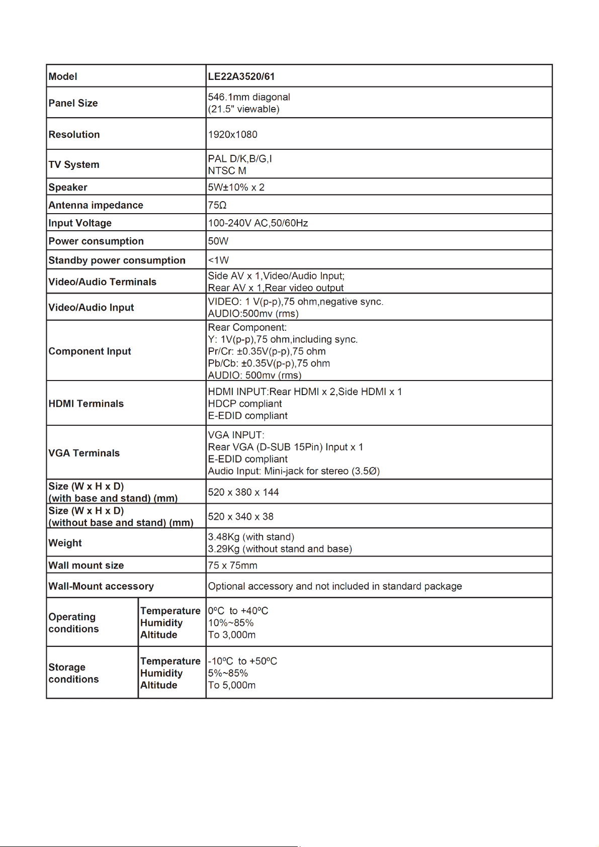
1. General Specification
Notas:
• Designs and specifications are subject to change without notice.
• This model may not be compatible with features and/or specifications that may be added in the future.
4
Page 5
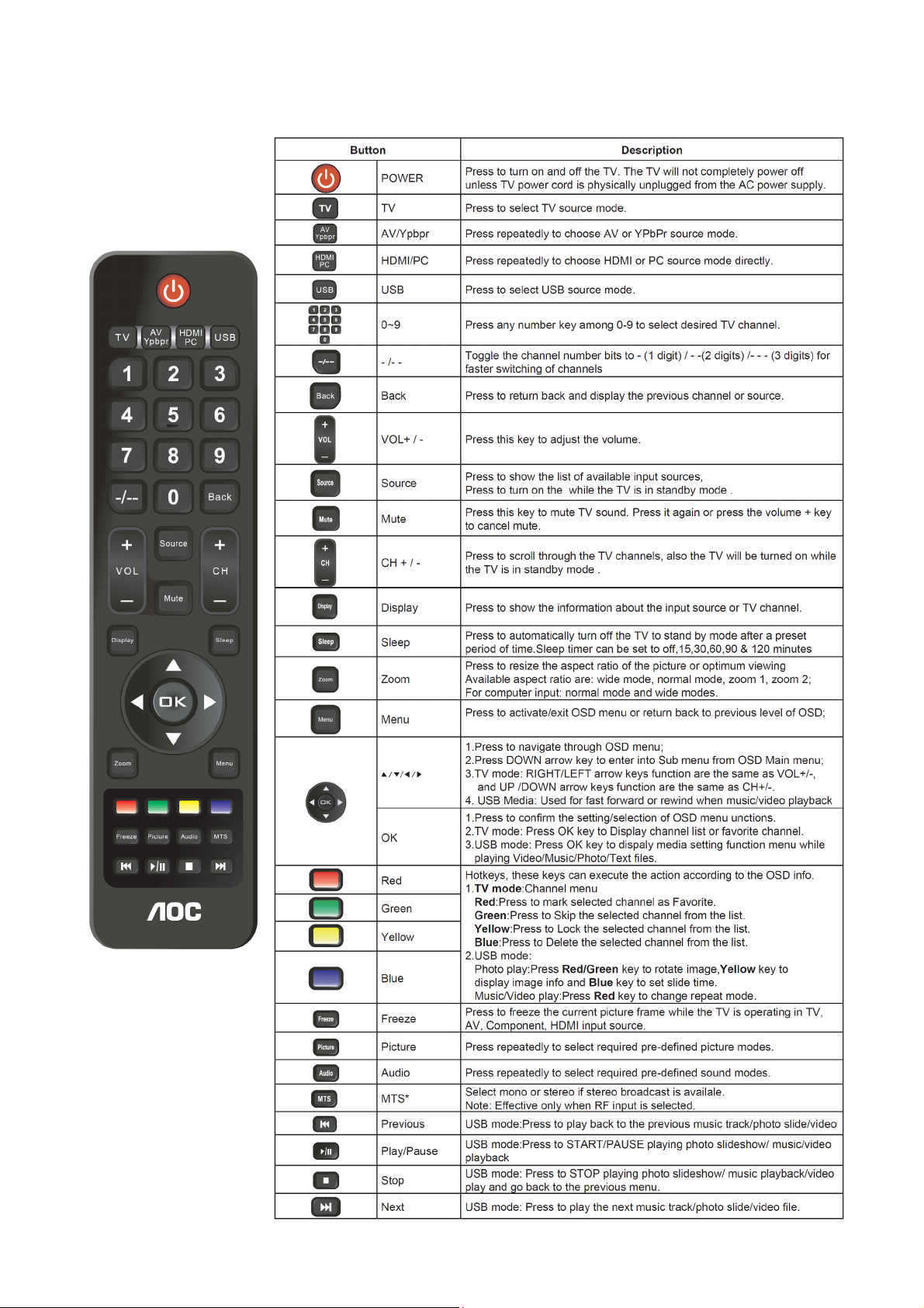
2. Operating Instructions
2.1 The Use of Remote Control
5
Page 6
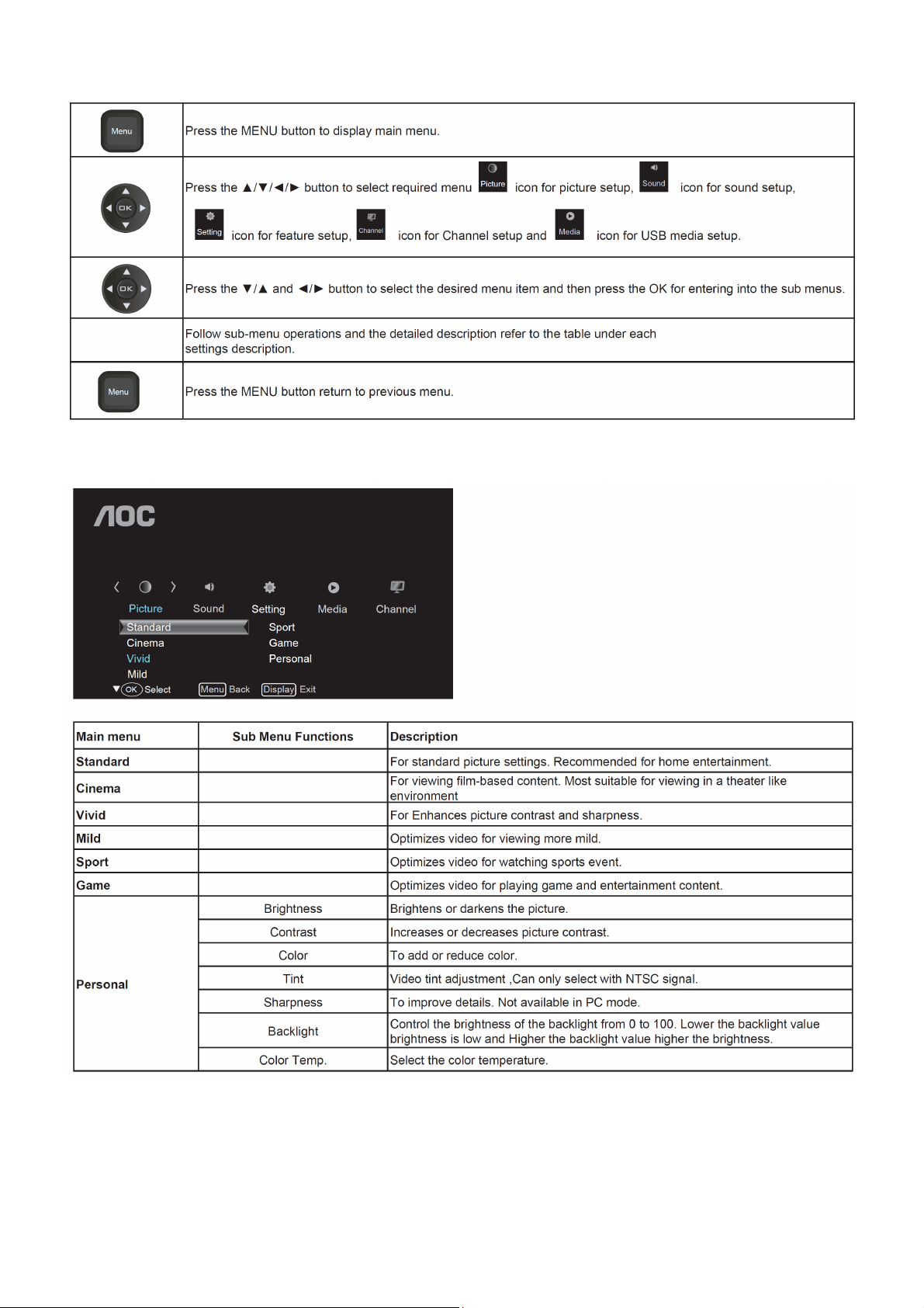
2.2 To Use the Menus
Picture Setting
6
Page 7
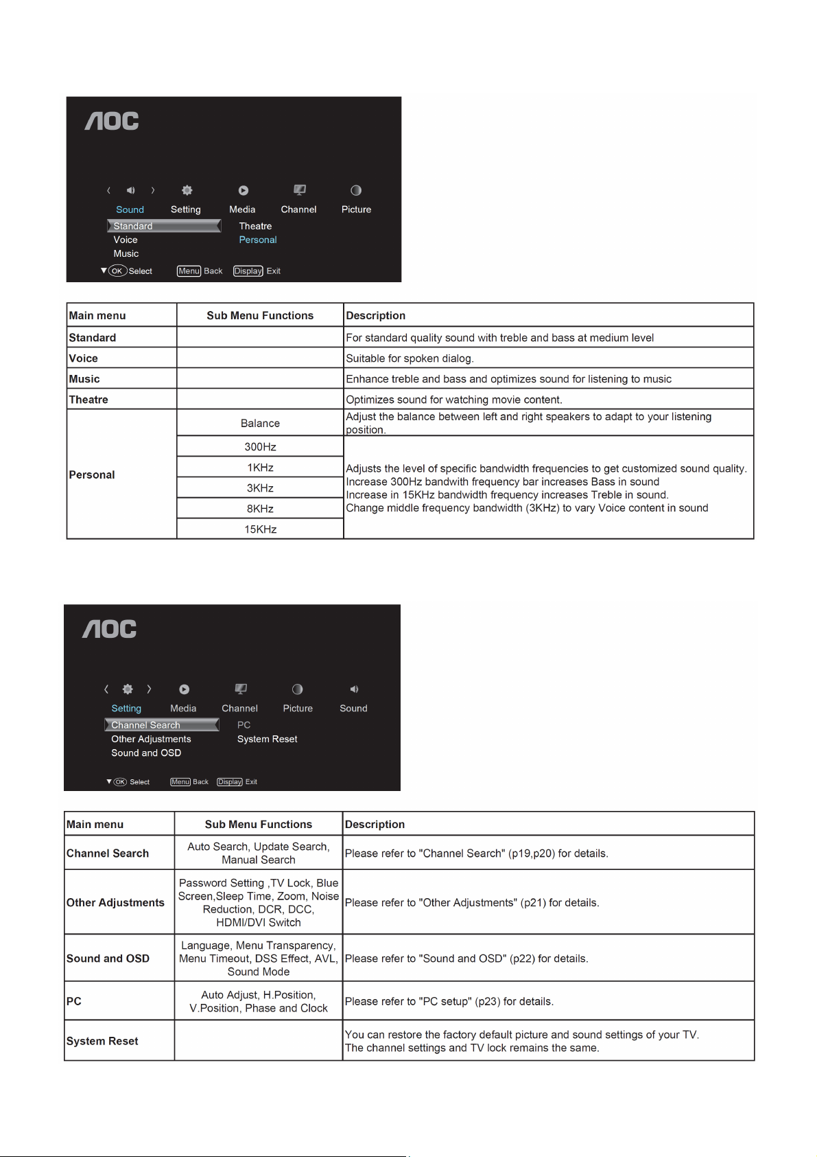
Sound Setting
Settings Menu
7
Page 8
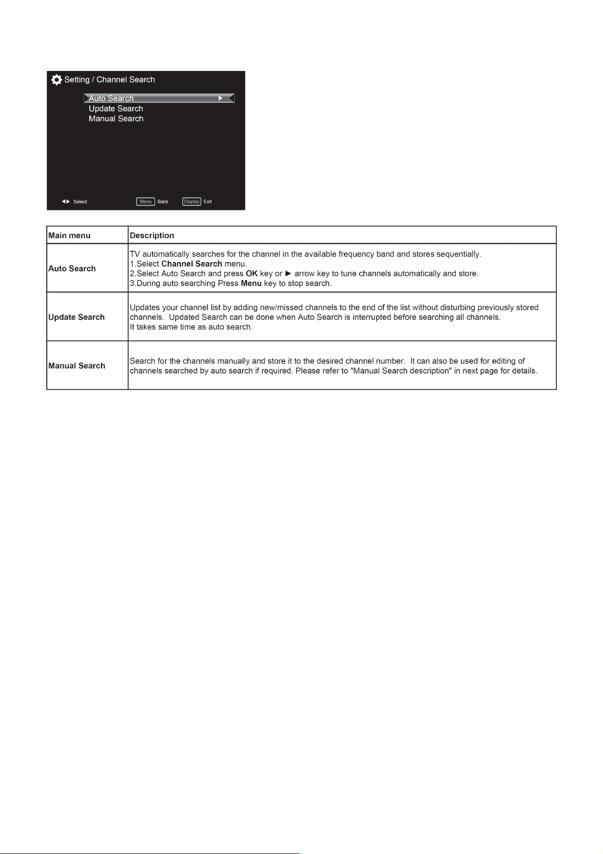
Channel Search
8
Page 9
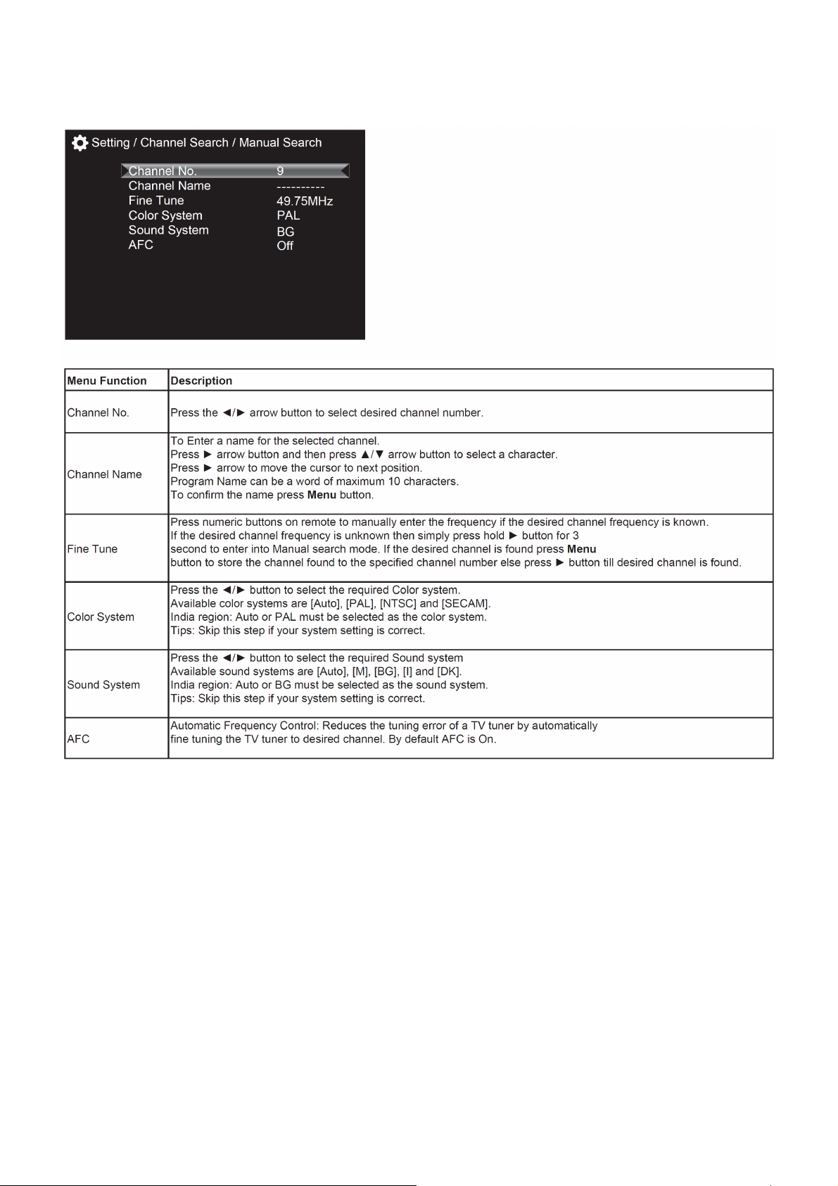
Manual search description
1. Select Channel Search menu.
2. Select Manual Search and press OK key or ► arrow key to get Manual search sub-menu
9
Page 10

Channel Edit Menu
In these case the shortcut key like Red key,Green key,Yellow key,Blue key action as below.
Red key:To set the channel as user’s favoriate channel.
Green key:To skip the channel and you will not find this channel by press ch+/- key to change channel.
Yellow key:To lock the channel and user will get the channel only by entering the password.
Blue key:To delete the channel and user will get the channel only by re-searching the channel.
10
Page 11
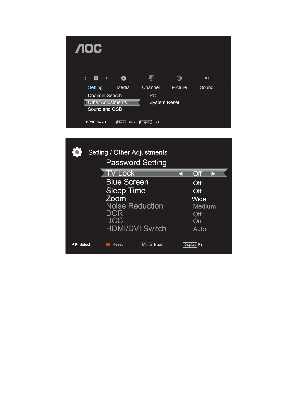
Other Adjustments
11
Page 12
* Passwors Setting, TV Lock, Blue Screen functions are available only in TV mode.
* Noise Reduction, DCR, DCC will be enable only when the Picture mode is Personal.
* Press Red key on remote control to reset Blue screen, Sleep time, Zoom, Noise Reduction, DCR,DCC,HDMI/DVI
Switch, Color System functions to the default settings.
12
Page 13
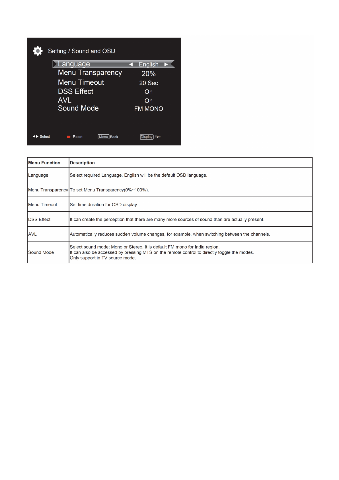
Sound and OSD
13
Page 14
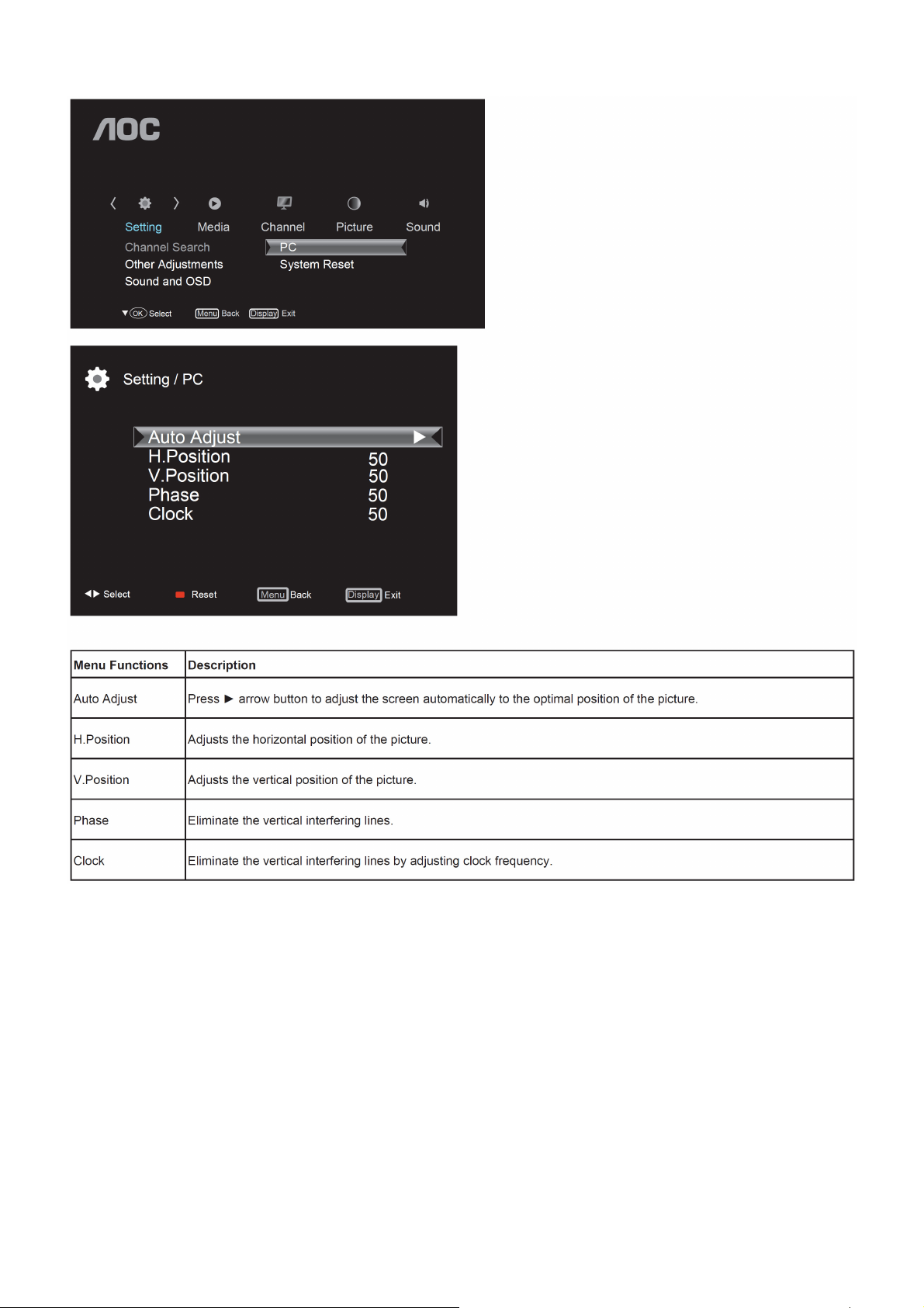
PC setting
Note:
* If the PC is connected to the TV and no signal has been input from the PC for more than 30 seconds, the TV enters
the standby mode automatically.
* This setting is only available in VGA source
14
Page 15
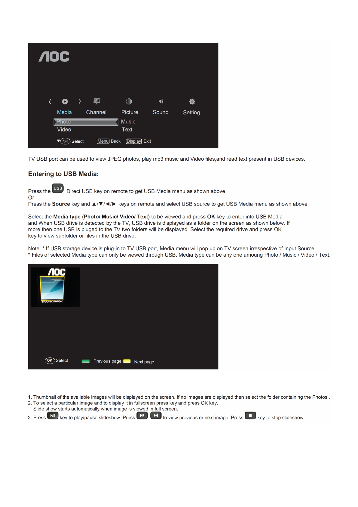
Media Functions(USB)
Viewing Photos
15
Page 16

USB menu settings for Photo Slide show
Press OK key to get following Menu setup shown above.
1. [Transition Effect] : Select the slide transition as None, Top To Bottom, Bottom To Top, Left To Right, Right To
Left, Random.
2. [Rotate] : Rotate the select photo by 90° clock wise direction.
3. [Play Time] : Select the duration of time a photo is to be displayed.
4. [Information] : Display the information of the file.
Playing Music files
Press OK key to get following Menu setup shown above.
1. [Repeat Mode] : Select the repeat mode as None, Single,Random,All.
2. [Sound Mode] : Select sound mode like Pop,Rock,Classical,Dance,Music,Personal.
3. [DSS Effect] : Turn on or off TV DSS effect.
4. [Background Music] : Select it to on to turn off dispaly and to get only sound from TV
5. [Information] : Display the information of the file.
Playing Video files
Press OK key to get following Menu setup shown above.
1. [Repeat mode] : Select the repeat mode as None, Single,All,Random.
2. [Information] : Display the information of the file.
16
Page 17
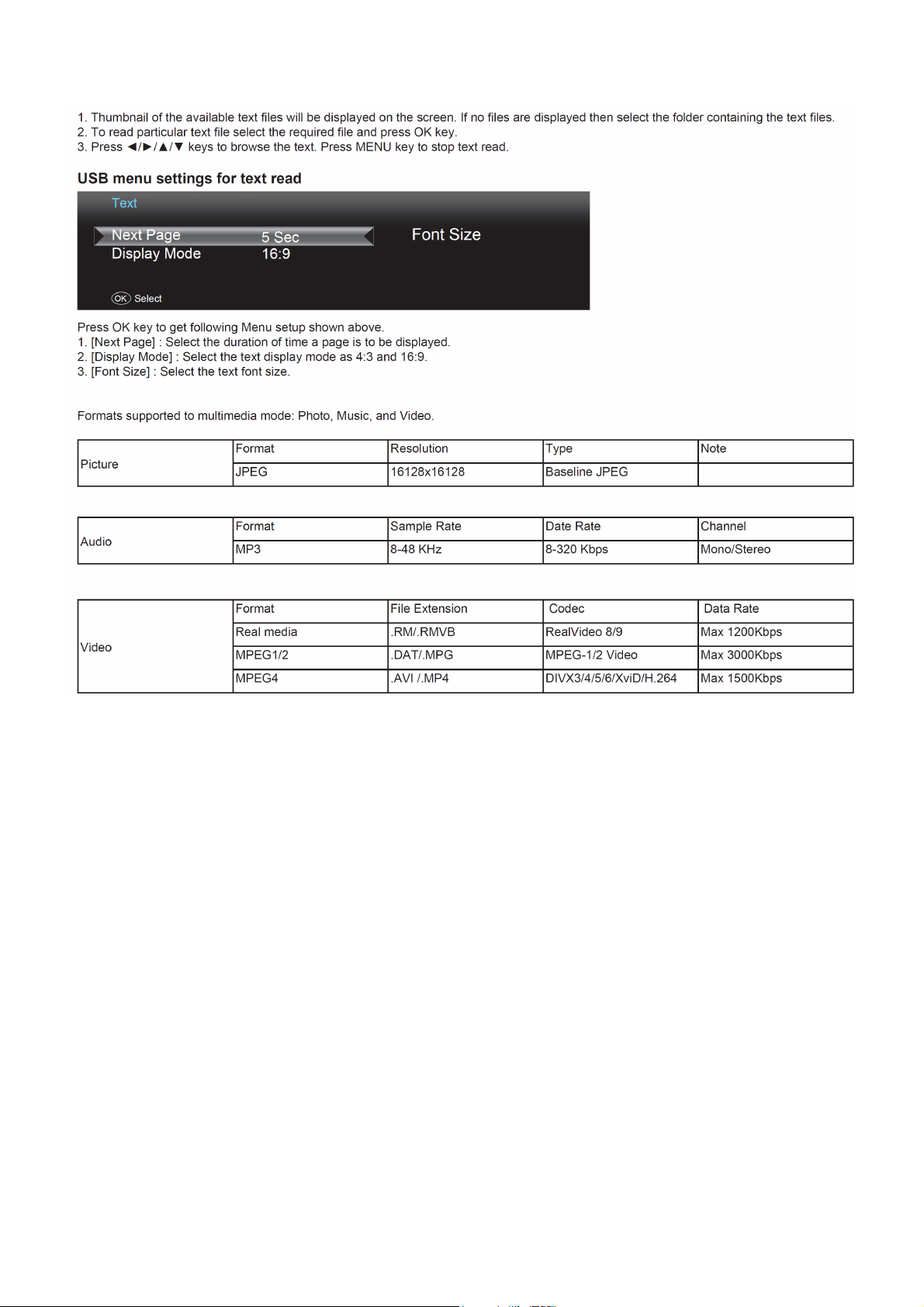
Reading Text files
Remarks:
1. USB interface of digital multimedia player is not all-purpose. So when some USB devices could not be recognized,
the problem is usually
not the performance failure but due to device driver.
2. Because USB devices and memory capability are different, the time needs for multimedia player to read
information are also different. So
the information reading speed of the player temporarily getting slow are not the performance failure.
3. The voltage supplied to USB interface is 5V, and the most electrical current is 500mA. When some interface
criteria of USB devices are
different from standard USB protocol, digital multimedia player may be unable to recognize USB devices correctly,
which is normal status.
4. USB could be used as an interface to update software.
5. If some files source could not play because of the parameter decoding-limitation, the problem is not performance
failure.
6. The system only applies to memory medium with FAT32 and NTFS format.
7. The system can not support dynamic Gif format.
17
Page 18
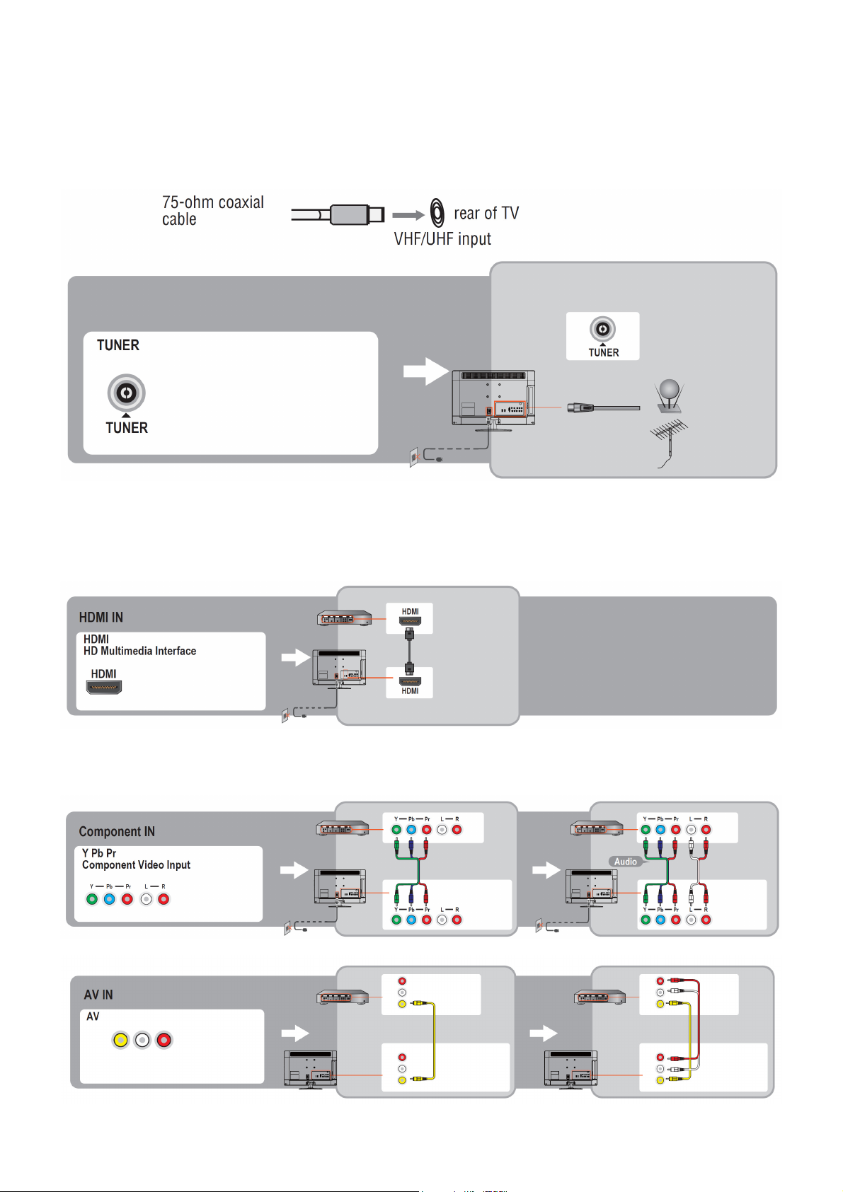
2.3 How to Connect
You can enjoy standard-definition and high-definition digital programming (if available in your area), along with
standard-definition analog programming.
It is strongly recommended that you connect the antenna/cable input using a 75-ohm coaxial cable to receive
optimum picture quality. A 300- ohm twin lead cable can be easily affected by radio frequency interference, resulting
in signal degradation.
Cable or VHF/UHF(or VHF only)
High Definition Interface
You can enjoy high-definition programming by subscribing to a high-definition cable service or a high-definition
satellite service. For the best possible picture, make sure you connect this equipment to your TV via the HDMI or
component video (with audio) input on the back of your TV.
HDMI Connection
If the equipment has a DVI jack and not an HDMI jack, connect the DVI jack to the HDMI IN (with DVI-to-HDMI cable
or adapter) jack and connect the audio jack to the PC AUDIO IN jacks.
Component Signal Connection
18
Page 19
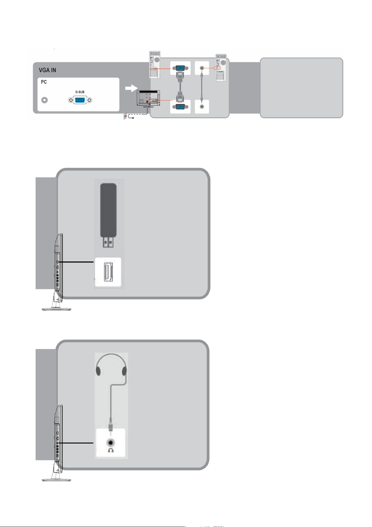
PC Connection
Use the TV as a monitor for your PC shown below with the HD15 to HD15 connection. This TV can also be
connected to a PC with DVI or HDMI output.
• Connect the PC IN jack to the PC using the HD15- HD15 cable with ferrite core (analog RGB) and audio cable.
• If the PC is connected to the TV and no signal has been input from the PC for more than 30 seconds, the TV enters
the standby mode automatically.
Connecting USB drive
Connecting Earphone
19
Page 20
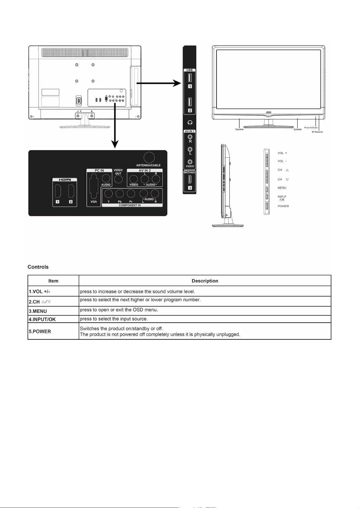
2.4 Front Panel Control Knobs
20
Page 21

r
r
Item
Description
AV(Audio/Video
) Input
Video Output
Connect audio (L/R)/video output from an external device to these jacks
For connecting the Composite Video signal of the TV to other display devices as their source
signal.
Connect a HDMI signal to HDMI port. The HDMI (High definition Multimedia Input) connecto
provides Non- compressed and fully digital audio/video data transmission between TV set and any
HDMI Input
HDMI audio/video devices, including the set top box, DVD player, Blue-ray player, A/V receive
and computer.
You need an HDMI connection for viewing in 480i, 480p, 576i, 576p 720p, 1080i and 1080p
modes.
PC VGA
IN(RGB)&PC
Audio IN
Component
input
Antenna/Cable
input
It is used to Connect the video output port of a personal computer with a 15 pin D-sub (Analog
RGB) VGA cable. It can be connected to other simulated RGB devices.
Connect separate audio cable between PC and TV to get sound.
Please refer to “Reference Table for computer input signal” for signals that can be displayed.
Connect a component video (YPbPr) / audio (L/R) device to these jacks. Component provides
better picture quality than the composite video connections.
The RF input is for connecting to the cable or VHF/UHF antenna.
USB Connect USB storage device to enjoy Photos, Music and Videos.
21
Page 22
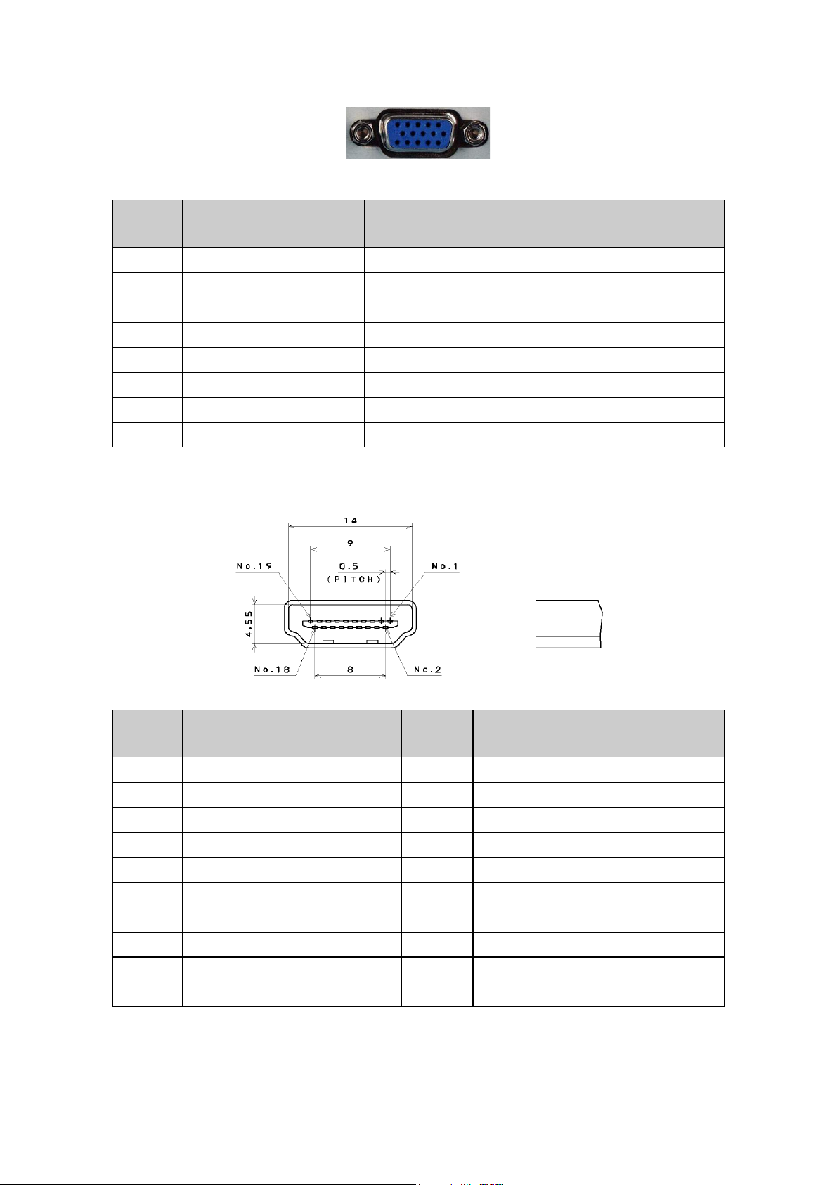
3. Input / Output Specification
3.1 RGB Signal Input
15 - Pin Color Display Signal Cable
Pin No. Description Pin No. Description
1 Red Video 9 +5V
2 Green Video 10 Sync Ground
3 Blue Video 11 Not Used
4 Not Used 12 Serial Data for DDC
5 Ground 13 H-Sync.
6 Red Ground 14 V-Sync.
7 Green Ground 15 Serial Clock for DDC
8 Blue Ground
3.2 HDMI Digital Connector Pin Assignments
Pin No. Description Pin No. Description
1 TMDS Data2+ 2 TMDS Data2 Shield
3 TMDS Data2- 4 TMDS Data1+
5 TMDS Data1 Shield 6 TMDS Data1-
7 TMDS Data0+ 8 TMDS Data0 Shield
9 TMDS Data0- 10 TMDS Clock+
11 TMDS Clock Shield 12 TMDS Clock13 CEC 14 NC
15 SCL 16 SDA
17 DDC/CEC Ground 18 +5V Power
19 Hot Plug Detect
22
Page 23
)
)
3.3 Compatible Mode Table
Analog RGB Input Signal Timing
VESA MODES
Horizontal Vertical
Nominal
Mode Resolution
VGA
SVGA
640x480@60Hz 31.469 N 59.940 N 25.175
800x600@56Hz 35.156 P 56.25 P 36.000
800x600@60Hz 37.879 P 60.317 P 40.000
Frequency
(KHz)
XGA 1024x768@60Hz 48.363 N 60.004 N 65.000
1280x1024@60Hz 63.981 P 60.02 P 108.000
1280x768 @ 60Hz 47.776 N 59.87 P 79.5
1360x768 @ 60Hz 47.712 P 6.015 p 85.8
HDMI Input Signal Timing
Default HDMI Mode
Standard Resolution Horizontal Frequency (kHz
VGA 640 ×480 37.879 60.317
VGA 720 × 400 31.327 69.617
SVGA 800 × 600 37.879 60.317
XGA 1024 × 1768 48.363 60.004
SXGA 1280 × 1024 63.981 60.020
WXGA 1360 × 768* 47.72 59.799
VESA 1280 × 1024 63.981 60.020
VESA 1680 × 1050 64.674
VESA 1920 × 1080 67.5 60.100
Sync
Polarity
Nominal
Freq.
(Hz)
Sync
Polarity
Nominal
Pixel
Clock
(MHz)
Vertical Frequency(Hz
59.884
23
Page 24
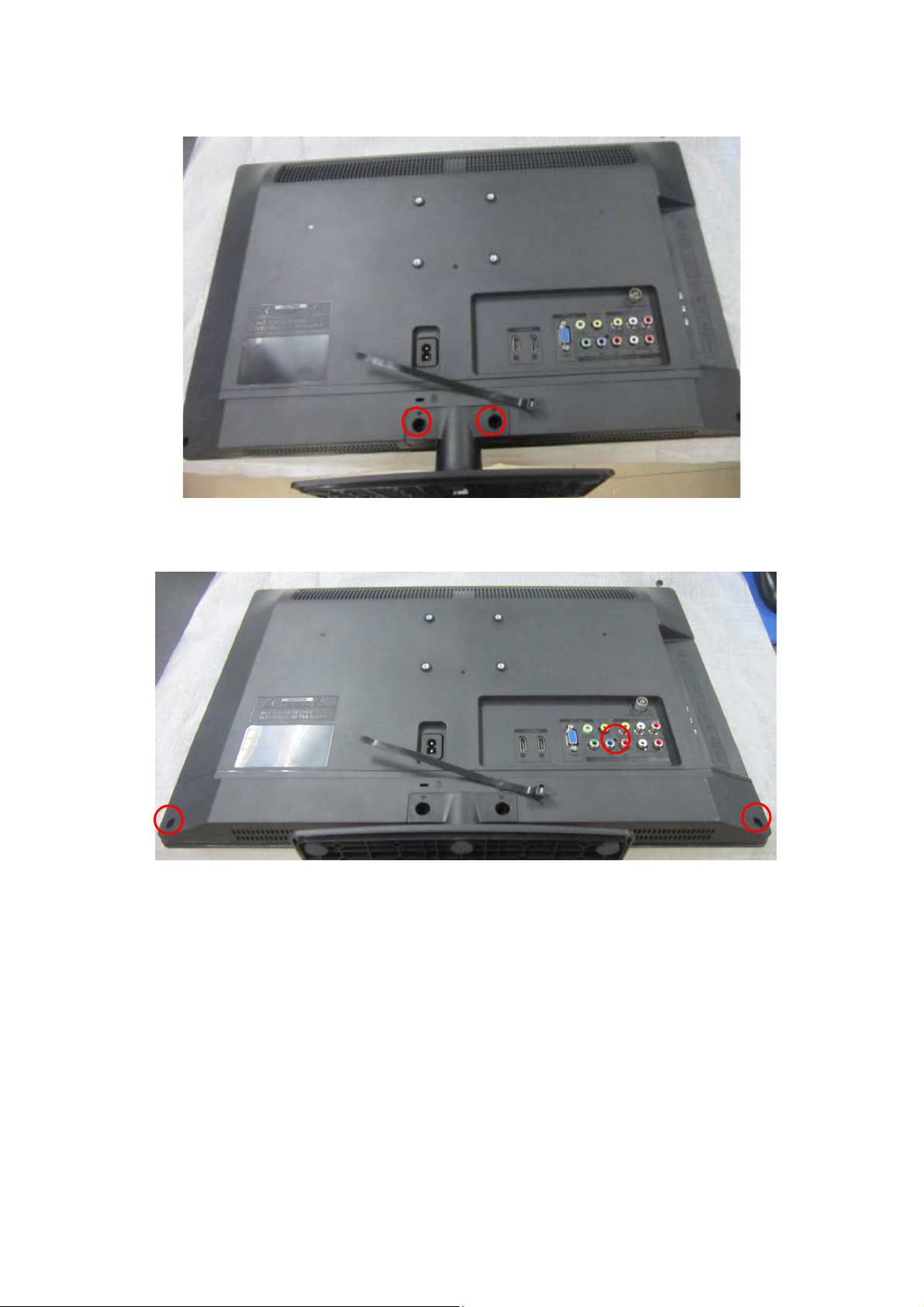
4. Mechanical Instructions
1. Remove the screws to remove BASE.
2. Remove the screws to remove REAR COVER.
24
Page 25

3. Remove the screws to remove SPEAKERS, MAIN BOARD and POWER BOARD.
4. Remove the screws to remove BKT.
25
Page 26

5. Remove the screw to remove IR BOARD.
26
Page 27

p
p
5. Repair Flow Chart
1. No power
No power (LED “Off”)
Check the AC input and
the
ower is “ON”?
Yes
Power board
out
ut=5.2V?
Yes
Check the IR board and LED
Replace the IR board
No
Replace the main board
No
Power “On”
No
Replace the power board
27
Page 28

2. Can’t start
Can’t start (LED red)
Power board output=12/16V?
Yes
Check the power key is under control?
No
Check the IR receiver is normal?
No
Replace the power board
Yes
Replace the key board
Yes
Replace the IR board
No
Replace the main board
No
Replace the Power board
28
Page 29

3. Abnormal display
Abnormal Display
Check the source
Yes
Enter factory mode to do
“EEPROM initial”&“Reset”
No
No
Reset the source
Check the main board
Yes
Check the LVDS cable
Yes
Check the panel
No
Replace the panel
No
Replace the main board
No
Replace the LVDS cable
29
Page 30

4. No display
No display (No LED)
Check TV is under control and power
on/off by remote control and power key?
Yes
Check the LVDS cable
Yes
Yes
Check the backlight is
“On”?
No
Reinsert or replace the
LVDS cable
No
No
Check the B/L
signal is available?
Yes
Replace the main board
No
Replace main board
Panel Vcc = 12V?
Yes
Replace the Panel
No
Replace the main board
Power board output=12/16V?
Yes
Replace the Panel
Replace the power board
No
30
Page 31

5. Sound problem
No sound or sound abnormal
Check the audio source connection
and the TV system are correct?
Yes
Check the TV is muted, adjust the
volume or enter the menu to reset?
No
No
Reinsert the audio cable or
change the TV system
Enter factory mode to do “Reset”
No
Check the cable between the
speakers and main board is OK?
Yes
Check the speaker resistance value is in spec
(Remark: The value is marked on the speaker)?
Yes
Replace the cable
Replace the main board
No
No
Replace the speaker
31
Page 32

6. Remote control malfunction
Remote Control malfunction
Check the remote control battery is
not properly placed or no power?
No
Use the other remote controls
No
Whether the IR board is
abnormal?
No
Replace the main board
Yes
Replace the battery
Yes
Replace the remote control
Yes
Replace the IR board
32
Page 33

7. OSD is unstable or can’t work normally
OSD is unstable or can’t work normally
Key board connected properly?
Yes
Buttons are OK?
Yes
Key board is OK?
Yes
Enter factory mode to do “Reset”
No
No
No
No
Reconnect the key board
Replace the button function
Replace the key board
Replace the main board
33
Page 34

6. PCB Layout
6.1 Main Board
715G4629M01000004K
34
Page 35

35
Page 36

36
Page 37

6.2 Power Board
715G5309P0A001002S
37
Page 38

38
Page 39

6.3 Key Board
715G5569K01000004S
6.4 IR Board
715G5061R01000004M
39
Page 40

7. Adjustment
(Take other model for example)
ADC Adjustment
1. Factory Mode
Turn on the TV. Press menu key and then press number key 1+9 +9+9+back. It will achieve the factory mode.
2. ADC Adjustment (It’s no need to adjust ADC.)
(1) Enter into the factory mode :(same as the above-mentioned)
(2) Select item “Source”: Ypbpr
a. Tim\pat. (COMPONENT mode: TIM = 314; PAT = 185,select item “auto color” and press ok key.
b. Tim\pat. (COMPONENT mode: TIM = 311; PAT = 185,select item “auto color” and press ok key.
(3) Select item “Source”: VGA
Tim\pat. (VGA mode: TIM = 137; PAT = 42,select item “auto color” and press ok key.
3. White Balance Adjustment
(1) Enter into the factory mode :(same as the above-mentioned).
(2) Just only adjust Ypbpr source.
a. Select item “Source”: Ypbpr and item “Color Temp”: Normal, Adjust gain of RGB to meet spec in the below
setting of Tim\pat. (COMPONENT mode: TIM = 314; PAT = 141(80IRE))
b. Select item “Source”: Ypbpr and item “Color Temp”:Warm, Adjust gain of RGB to meet spec in the below setting
of Tim\pat. (COMPONENT mode: TIM = 314; PAT = 141(80IRE))
c. Select item “Source”: Ypbpr and item “Color Temp”: Cool, Adjust gain of RGB to meet spec in the below setting
of Tim\pat. (COMPONENT mode: TIM = 314; PAT = 141(80IRE))
(3) check VGA TIM137,PAT141, AV TIM304 PAT141, HDMI TIM349 PAT141 , white balance whether or not meet
the specifications.
4.The following color specifications for reference, to RD engineering specifications.
Source VGA/YPbPr/AV/HDMI VGA/YPbPr/AV/HDMI VGA/YPbPr/AV/HDMI
Temp Normal/(7500K) Warm/(6500K) Cool/(9300K)
x (center) 0.285 0.030 0.313 0.030 0.270 0.030
y (center) 0.293 0.030 0.329 0.030 0.273 0.030
Note: 1、all models of color temperature within specification, but also ensure the brightness conform to
engineering specifications.
2、
RGB gain value cannot exceed 138,128,138
40
Page 41

8. Block Diagram
41
Page 42

9. Schematic Diagram
9.1 Main Board
715G4629M01000004K
CN700
CONN
D7101
S1D-E3
10uF 10V
C753
100nF 50V
C759
100nF 50V
D_5V
C707
BL_ON1
1
BL_PWM
2
3
4
5
6
7
8
9
10
11
12
13
DGND
DGND
C716
100nF 50V
DGND
DGND
100nF 50V
DGND
100nF 50V
+18V_AMP
PWR_ON
C704
C708
100nF 50V
1
VCC
2
REF
3
GND
FB4EN
C700
U702
E-PAD
PGND
AT1529F11U
+
DGND
R732
10 OHM 1/10W
VIN
LX
Vout = 0.8x(1+R1/R2)=1.36V
R735
1
VCC
2
REF
3
GND
FB4EN
U704
E-PAD
PGND
AT1529F11U
10 OHM 1/10W
VIN
LX
DGND
DGND
C722
100nF 50V
DGND
Vout = 0.8x(1+R1/R2)=3.3V
D12V
D5V_STB
DGND
C705
470uF 10V
TO-252, 1A
U700
VIN3VOUT
ADJ
1
DGND
9
8
7
6
5
DGND
9
8
7
6
5
DGND
FB700
1 2
120R/6000mA
+
C701
330UF 35V
2
R707 100R 1/ 10W 1%
22R 1/10W 1%
R709
R719
24R 1/10W 1%
Vo=1.25x(1+Rdn/Rup)
+
C750
220uF16V
R722
10K 1/10W
L702
2.2uH 20mOH M 8A
C758
NC
+
C762
220uF/16V
R733
10K 1/10W
L703
2.2uH 20mOH M 8A
C764
NC
12V
C757
4.7UF 10V
DGND
C763
4.7UF 10V
NC/CONN
CN701
C709
10uF 10V
DGND
120R/6000mA
1 2
C748
100nF 50V
DGND
R726
R1
33K 1/10W 1%
R727
47K 1/10W 1%
R2
120R/6000mA
1 2
C760
100nF 50V
DGND
R728
R1
47K 1/10W 1%
R734
15K 1/10W 1%
R2
DGND
D1V8
FB719
C751
100nF 50V
FB720
C755
100nF 50V
13
12
11
10
9
8
7
6
5
4
3
2
1
C711
100nF 50V
PWR_ON
D_5V
DGND
C752
22uF 10V
D5V_STB
DGND
C756
22uF 10V
BL_ON1
BL_PWM
C749
100nF 50V
1 2
1 2
+
DGND
C761
100nF 50V
+
DGND
D12V
DGND
+18V_AMP
D5V_STB
FB715
120R/6000mA
FB714
120R/6000mA
C747
220uF/16V
1 2
C754
220uF/16V
BL_ON1
PWR_ON
CORE_1.2V
FB706
1 2
300OHM 4A
FB708
300OHM 4A
C703
100nF 50V
BL_PWM
DM3V3
D5V_STB
R700
10K 1/10W
DGND
C710
100nF 50V
A3V3D3V3
Q700
PMBS3904
D5V_STB
DGND
C715
NC 4.7U F 10V
R731
R701
1K 1/16W
R705
4.7K 1/10W
Q703
PMBS3904
R713
1K 1/10W
NC
D5V_STB
DGND
BL_EN
R721
NC
R708
1K 1/16W 5 %
R711
10K 1/10W
Q705
LMBT3904LT1G
+18V_AMP
USB_5V Power
12
FB702
120R/6000mA
C765
+
C766
100UF 50V
1uF 50V
PS
POWER_EN
DM3V3
R723
NC
R714
NC
R717
1K 1/16W
T P V ( Top Victory Electronics Co . , Ltd. )
絬 隔 瓜 絪 腹
Key Component
Date
R737
47K 1/16W 5%
BL_ADJ
C767
1uF 50V
POWER_EN
?
P01_POWER
D3V3
DGND
C768
180P 50V
C734
10uF 10V
C770 1uF 25V
AOZ1242AI
U705
8
VBIAS
7
VIN
6
EN
5
C769
1nF 50V
R738
10K 1/10W
R736 0R05 1/ 10W
R720
NC
C733
100nF 50V
LX
BST
GND
FB4COMP
DGND
D5V_STB
DGND
TO-252, 1A
U703
AZ1117H-A DJ-E1
VI3VO
1
C771 100N 50V
2
3
10K 1/10W
R715
NC
R718
4K7 1/10W 5%
Q707
NC
GND14
4
OEM MOD EL
TPV MOD EL
PCB NAME
Sheet
R121 5
R121 4
R710
2
R739
52.3K 1%
R740
10K 1%
114Saturday, June 25, 2011
D5V_STB
DGND
R729
NC
R730
0R05 1/10W
of
5V
52.3K
Vo = 0.8 * (1+ R739/R740)
10K
V1 = 0.8 * (1+ 52.3/10) =4.984V
V1 = 0.8 * (1+ 53.4/10) =5.072V
L704
15uH
R741
3K 1%
D701
SX34
1 2
C713
100nF 50V
R716
47K +-5% 1/10W
Q706
PMBS3904
C735
10uF 10V
DGND DGND
C772
10uF 25V
Q704
AO4449 -7A/-30V
1
S
2
S
3
S
4
G
R712
100K 1/10W
C736
100nF 50V
1 2
C773
10uF 25V
D_5V
8
D
7
D
6
D
5
D
DGND
FB705
1 2
1 2
Size
Rev
称爹
FB701
120R/6000mA
+
C714
NC
300OHM 4A
FB707
300OHM 4A
100nF 50V
A3
A
称爹
<
5V_USB
C712
ST_D1V2
A1V2
>
42
Page 43

From DDR2
S_DQ_IN[0:15][8]
S_DQ_IN0
S_DQ_IN1
S_DQ_IN2
S_DQ_IN3
S_DQ_IN4
S_DQ_IN5
S_DQ_IN6
S_DQ_IN7
S_DQ_IN8
S_DQ_IN9
S_DQ_IN10
S_DQ_IN11
S_DQ_IN12
S_DQ_IN13
S_DQ_IN14
S_DQ_IN15
S_DA_IN[0:13][8]
S_DA_IN0
S_DA_IN1
S_DA_IN2
S_DA_IN3
S_DA_IN4
S_DA_IN5
S_DA_IN6
S_DA_IN7
S_DA_IN8
S_DA_IN9
S_DA_IN10
S_DA_IN11
S_DA_IN12
S_DA_IN13
S_LUDQS#_IN[8]
S_LUDQS_IN[8]
S_LLDQS#_IN[8]
S_LLDQS_IN[8]
S_DODT_IN[8]
S_WE#_IN[8]
S_CAS#_IN[8]
S_RAS#_IN[8]
S_CKE_IN[8]
S_CK_IN[8]
S_CK#_IN[8]
S_DBA0_IN[8]
S_DBA1_IN[8]
S_DM0_IN[8]
S_DM1_IN[8]
S_DBA2_IN[8]
To AVout & SPDIF
CVBS_OUT
SPDIF_OUT[9,12]
D1V8
Efuse_3. 3V
HDMI0_D2+
HDMI0_D2HDMI0_D1+
HDMI0_D1HDMI0_D0+
HDMI0_D0HDMI0_CLK+
HDMI0_CLK-
HDMI1_D2+
HDMI1_D2HDMI1_D1+
HDMI1_D1HDMI1_D0+
HDMI1_D0HDMI1_CLK+
HDMI1_CLK-
HDMI2_D2+
HDMI2_D2HDMI2_D1+
HDMI2_D1HDMI2_D0+
HDMI2_D0HDMI2_CLK+
HDMI2_CLK-
HOTPLUG2
HOTPLUG1
S_LUDQS#_IN
HOTPLUG0
S_LUDQS_IN
S_LLDQS#_IN
HDMI_CEC
S_LLDQS_IN
S_DODT_IN
HDMI2_DDC_SCL[9]
HDMI2_DDC_SDA[9]
S_WE#_IN
HDMI1_DDC_SCL[9]
S_CAS#_IN
HDMI1_DDC_SDA[9]
S_RAS#_IN
HDMI0_DDC_SCL[9]
S_CKE_IN
HDMI0_DDC_SDA[9]
S_CK_IN
S_CK#_IN
S_DBA0_IN
To Audio Amplifier
S_DBA1_IN
S_DM0_IN
S_DM1_IN
S_DBA2_IN
To POWER
CVBS_OUT
SPDIF_OUT
SPI_WP
GPIO追加Pull hi
USB_PWR_FLAG1
USB_PWR_FLAG0
CORE_1.2V
(1.1A)
C4061
100uF16V
FB4016
DDR_1.8V
1 2
300OHM 4A
(760mA)
C4074
22UF 6.3V
D3V3
R4032
NC
From HDMI
HDMI0_D2+
HDMI0_D2HDMI0_D1+
HDMI0_D1HDMI0_D0+
HDMI0_D0HDMI0_CLK+
HDMI0_CLK-
HDMI1_D2+
HDMI1_D2HDMI1_D1+
HDMI1_D1HDMI1_D0+
HDMI1_D0HDMI1_CLK+
HDMI1_CLK-
HDMI2_D2+
HDMI2_D2HDMI2_D1+
HDMI2_D1HDMI2_D0+
HDMI2_D0HDMI2_CLK+
HDMI2_CLK-
HOTPLUG2
HOTPLUG1
HOTPLUG0
HDMI_CEC
HDMI2_DDC_SCL
HDMI2_DDC_SDA
HDMI1_DDC_SCL
HDMI1_DDC_SDA
HDMI0_DDC_SCL
HDMI0_DDC_SDA
AOUT_L
AOUT_L
AOUT_R
AOUT_R
AMP_STBY
AMP_STBY
POWER_EN
POWER_EN
PS
PS
BL_ADJ[9,12]
NAND FLASH
SPI_SCK-N_RE#
DM3V3
DGND
R4070
4K7 1/10W 5%
R4069
R4061
22R 1/16W 5%
10K 1/10W
Q4007
PMBS3904
DGND
BL_EN
PANEL_EN
LEDG
LEDR
PS
AMP_STBY
POWER_EN
N_RDY
N_CE0#
PW_KEY
LIGHT_G
LIGHT_R
N_ALE
SPDIF_OUT
TX0
RX0
R4074
R4076
4K7 1/10W 5%
4K7 1/10W 5%
DGND
100N16V
100N16V
100N16V
100N16V
100N16V
100N16V
+
C4066
C4067
C4060
C4059
12
C4076
C4075
C4078
C4077
TOEN
N_RDY
N_CE0#
DM3V3
N_CLE
N_ALE
N_WE#
電阻
DM3V3
D5V_STB
R4064 4K7 1/10W 5%
R4065 4K7 1/10W 5%
C4062
DGND
C4079
DGND
From TUNER
TUN_IF+
TUN_IF-
I2C_SCL
I2C_SDA
RF_AGC
From CVBS1
AV1_CVBS+
VIN_A0AV2_CVBS+
VIN_A1-
AV1_IN_L
AV1_IN_R
AV2_IN_L
AV2_IN_R
From YPBPR1
Y1+
PB1+
PR1+
VIN_Y0-
YPBPR1_IN_L
YPBPR1_IN_R
From KeyPad
LSADC0
LSADC1
PW_KEY
LIGHT_SENSOR
IRRX
LEDG
LEDR
KEY_SDA
KEY_SCL
LIGHT_R
LIGHT_G
U4003
1
NC1
NC29
2
NC2
NC28
3
NC3
NC27
4
NC4
NC26
5
NC5
I/O7
6
I/O6
NC6
7
RY/BY1
I/O5
8
RE
I/O4
9
NC25
CE1
10
NC24
NC7
11
NC8
NC23
12
VCC1
VCC2
13
VSS2
VSS1
14
NC9
NC22
15
NC10
NC21
16
CLE
NC20
17
ALE
I/O3
18
WE
I/O2
19
WP
I/O1
20
NC11
I/O0
21
NC19
NC12
22
NC18
NC13
23
NC17
NC14
NC1524NC16
A3V3
C4121
C4068
2.2UF 16V
C4080
C4082
C4081
48
47
46
45
44
43
42
41
40
39
38
37
36
35
34
33
32
31
30
29
28
27
26
25
HY27UF082G2B-TPCB
R4023 4K7 1/10W 5%
R4025 4K7 1/10W 5%
R4062 4K7 1/10W 5%
R4063 4.7K 1/10W
R4068 4K7 1/10W 5%
R4066 4K7 1/10W 5%
R4075 4K7 1/10W 5%
R4077 4K7 1/10W 5%
R4079 4K7 1/10W 5%
R4072 4K7 1/10W 5%
R4080 4K7 1/10W 5%
R4081 4K7 1/10W 5%
C4084
C4083
TUN_IF +
TUN_IF -
I2C_SCL
I2C_SDA
RF_AGC
Y1+
PB1+
PR1+
VIN_Y0-
YPBPR1_IN_L
YPBPR1_IN_R
LSADC0
LSADC1
PW_KEY
LIGHT_SENSOR
IRRX
LEDG
LEDR
KEY_SDA
KEY_SCL
LIGHT_R
LIGHT_G
N_DATA7
N_DATA6
N_DATA5
N_DATA4
DGND
N_DATA3
N_DATA2
N_DATA1
N_DATA0
100N16V
100N16V
100N16V
100N16V
100N16V
100N16V
100N16V
100N16V
100N16V
100N16V
AV1_CVBS+
VIN_A0AV2_CVBS+
VIN_A1-
AV1_IN_L
AV1_IN_R
AV2_IN_L
AV2_IN_R
DM3V3
1uF 25V
From LVDS
From VGA
C4042
DGND
TEDP
TEDN
TECLKP
TECLKN
TECP
TECN
TEBP
TEBN
TEAP
TEAN
TODP
TODN
TOCLKP
TOCLKN
TOCP
TOCN
TOBP
TOBN
TOAP
TOAN
BL_EN
PANEL_EN
VGA_R+
VGA_RVGA_G+
VGA_GVGA_B+
VGA_B-
VGA_VS
VGA_HS
VGA_IN_L
VGA_IN_R
HP_OUT_L
HP_OUT_R
HP_OUT_JD
TX0
RX0
VGA_DDC_SDA
VGA_DDC_SCL
TEDP
TEDN
TECLKP
TECLKN
TECP
TECN
TEBP
TEBN
TEAP
TEAN
TODP
TODN
TOCLKP
TOCLKN
TOCP
TOCN
TOBP
TOBN
TOAP
TOAN
BL_EN
PANEL_EN
VGA_R+
VGA_RVGA_G+
VGA_GVGA_B+
VGA_B-
VGA_VS
VGA_HS
VGA_IN_L
VGA_IN_R
HP_OUT_L
HP_OUT_R
HP_OUT_JD
TX0
RX0
VGA_DDC_SDA
VGA_DDC_SCL
(pin share function)
(pin share function)
1uF 25VC4003
C4004 100nF 50V
FB4002 300OHM 4A
FB4001 300OHM 4A
1uF 25VC 4022
2.2UF 16V C412 3
2.2UF 16V C404 1
2.2UF 16V C401 0
2.2UF 16V C402 1
2.2UF 16V C401 7
2.2UF 16V C402 0
2.2UF 16V C401 4
2.2UF 16V C401 1
2.2UF 16V C401 6
2.2UF 16V C401 5
IF_NTUN_I F -
C4051
1uF 25V
TUN_I F +
C4052
1uF 25V
C4046
PLL_GND
22pF 50V
X400 0
27mHZ
C4047
1 2
22pF 50V
C4118
C4055
C4056
10uF 6.3V
100N16V
10uF 6.3V
DGND
IO_3.3V
300OHM 4A
C4087
C4085
C4086
(36mA)
C4088
100N16V
DGND DGND
100N16V
100N16V
100N16V
100N16V
ST_D1V2
D3V3
FB4007
300OHM
1 2
DGND
0.5A)
FB4017
1 2
C4119
100N16V
DGND
IF_P
C4089
R4017 0R05 1/10W
R4018
NC
A1V2
1 2
A3V3
XOUT
XIN
FB4011
300OHM 4A
FB4018
1 2
AGND
300OHM 4A
FB4004
FB4003
300OHM
300OHM
PLL_GND
R4014
R4015
100 OHM 1/10W
100 OHM 1/10W
HDMI_1.2V
C4063
DGND
HDMI_3.3V
C4090
100N16V
DGND
47N 50V C4023
VDAC_3.3V
1 2
1 2
VADC_3.3V
CORE_1.2V
Efuse_3. 3V
CORE_1.2V
CORE_1.2V
DDR_1.8V
DDR_1.8V
DDR_1.8V
DDR_1.8V
DDR_1.8V
DDR_1.8V
C4064
100N16V
100N16V
47N 50V C4026
47N 50V C4030
47N 50V C4024
47N 50V C4025
47N 50V C4120
VDACGND
VADCGND
PLL_3.3V
I2C_SCL
I2C_SDA
HP_OUT_JD
USB_PWR_FLAG1
IO_3.3V
IO_3.3V
A1V2
A3V3 USB_3.3V
47N 50V C4028
47N 50V C4029
R4019
5K1 1/16W 5%
47N 50V C4027
47N 50V C4032
47N 50V C4033
47N 50V C4031
CORE_1.2V
PS
MEMC_GPI O
CVBS_OUT
IF_N
IF_P
XIN
XOUT
RF_AGC
S_DQ_IN14
S_DM1_IN
S_DQ_IN9
S_DQ_IN11
S_DQ_IN12
S_DQ_IN6
S_DM0_IN
S_DQ_IN1
S_DQ_IN4
S_DQ_IN3
S_LLDQS_IN
S_LLDQS#_IN
S_LUDQS_IN
S_LUDQS#_IN
S_DQ_IN15
S_DQ_IN8
S_DQ_IN10
S_DQ_IN13
S_DQ_IN7
S_DQ_IN0
S_DQ_IN2
S_DQ_IN5
FB4012
1 2
FB4019
1 2
47N 50V C4036
47N 50V C4034
47N 50V C4035
LEDG
LEDR
LIGHT_G
LIGHT_R
300OHM 4A
300 OHM
BB_3.3V
AGND
12
AGND
To AMP
To AV_out
DGND
VGA_IN_R
VGA_IN_L
47N 50V C4039
47N 50V C4040
47N 50V C4037
47N 50V C4038
U4000
256
254
255
257
EPAD
AIN_5L
AIN_4R
1
AIN_5R
2
LSADC3
3
LSADC5
4
VDAC3V3
5
AVOUT1
6
AVOUT2
7
VDACGND
8
ADC2XGND
9
IF1N
10
IF1P
11
ADC2X3V3
12
PLLGND
13
XIN
14
XOUT
15
PLL3V3
16
D1V2
17
RF_AGC
18
I2C0_SCL
19
I2C0_SDA
20
GPIO_M3
21
GPIO_M4
22
GPIO_M6
23
GPIO_M5
24
GPIO_M7
25
D3V3
26
GPIO_U5
27
GPIO_R4
28
GPIO_R3
29
EFUSE_D3V3
30
D3V3
31
NC
32
NC
33
NC
34
NC
35
D1V2
36
D1V2
37
DDR18VCC
38
DQ_14
39
DM1
40
DQ_9
41
DQ_11
42
DDR18VCC
43
DQ_12
44
DQ_6
45
DM0
46
DQ_1
47
DDR18VCC
48
DQ_4
49
DQ_3
50
DQS0
51
DQS0_N
52
DDR18VCC
53
DQS1
54
DQS1_N
55
DQ_15
56
DQ_8
57
DDR18VCC
58
DQ_10
59
DQ_13
60
DQ_7
61
DQ_0
62
DDR18VCC
63
DQ_2
64
DQ_5
DVRI65CK66CK#67RAS#68DDR18VCC69CAS#70ADDR071ADDR272DDR18VCC73ADDR474ADDR675ADDR876ADDR1177ADDR1378DDR18VCC79WE#80CKE81BA182BA083DDR12VCC84ADDR185ADDR1086ADDR587ADDR388DDR18VCC89ADDR990ADDR791ADDR1292BA293ODT94USB1V295HSDM_096HSDP_097USB3V398HSDM_199HSDP_1
RTD2684S
S_DVREF_A
S_CK_IN
S_CK#_IN
DDR_1.8V
Jack Detection Function (place
resistor Near Connector)
USB_1.2V
C4065
C4069
100N16V
100N16V
DGND
C4073
100N16V
1 2
AV2_IN_R
HP_OUT_R
AOUT_L
AOUT_R
YPBPR1_IN_R
YPBPR1_IN_L
AV1_IN_L
AV1_IN_R
HP_OUT_L
AV2_IN_L
VCM_BB
AVDD_BB0
BB1GND
BB1GND
252
246
244
242
251
248
250
249
241
240
253
AIN_4L
S_RAS#_IN
239
247
245
243
AIN_1L
AIO_1L
AIO_2L
AIN_3L
AIN_1R
AIO_1R
AIO_2R
AIN_3R
AOUT_L
AOUT_R
VCM_BB
BB0_3V3
HPOUT_L
HPOUT_R
S_DA_IN13
S_CKE_IN
S_CAS#_IN
S_DA_IN0
S_DBA1_IN
S_DA_IN2
S_DA_IN4
S_DA_IN6
S_DA_IN8
S_DA_IN11
S_WE#_IN
Y_1.2V
A1V2
FB4008
1 2
300OHM 4A
AGND
A1V2
VD_1.2V
FB4013
1 2
300OHM 4A
C4070
2.2UF 16V
AGND
A3V3
PLL_3.3V
FB4020
1 2
300OHM 4A
C4091
100N16V
PLL_GND
DGNDAGND
43
FB4000
300OHM 4A
C4000
1uF 25V
BB1GND
VD_3.3V
1 2
HOTPLUG1
HOTPLUG0
235
234
237
238
236
D1V2
VD3V3
VIN_14P
BB1GND
BB1_3V3
S_DBA0_IN
S_DA_IN1
S_DA_IN10
S_DA_IN5
C4122
1UF16V
AGND
1KOHM +-1% 1/16W
1KOHM +-1% 1/16W
C4058
100N16V
VD_1.2V
AV1_CVBS+
VIN_A0-
VIN_A1-
AV2_CVBS+
HOTPLUG2
AGND
AGND
226
233
231
228
230
232
229
225
227
VIN1N
VIN0N
VD1V2
VIN_9P
VIN_13P
VIN_10P
VIN_12P
VIN_11P
VD_GND33
S_DA_IN3
S_DA_IN9
S_DA_IN7
S_DA_IN12
S_DODT_IN
USB_DM0
S_DBA2_IN
USB_3.3V
USB_1.2V
DDR_1.8V
R4020
S_DVREF_A
R4021
DGND
Close to RT D268x IC
AVDD_BB0
close to RTD268x
Y_1.2V
AGND
Y1+
PR1+
PB1+
VIN_Y0-
VGA_R-
VGA_R+
221
217
215
223
222
220
219
218
216
214
224
VIN_8P
VIN_7P
VIN_6P
VIN_5P
VIN_4P
VIN_3P
YPP1V2
VIN_RN
VIN_Y1N
VIN_Y0N
ADC_GND33
USB1V2
D1V2
GPIO_R1
GPIO_K3
GPIO_K4
GPIO_K5
100
101
102
103
104
105
106
107
TOEN
N_WE#
USB_DP1
USB_DM1
USB_DP0
AMP_STBY
USB_PWR_FLAG0
KEY_SDA
C4053
100N16V
C4054
100N16V
A3V3 VADC_3.3V
FB4014
1 2
300OHM 4A
VADCGND
A3V3 VDAC_3.3V
FB4021
1 2
300OHM 4A
C4092
4.7UF 10V
VDACGND
AGND
VGA_G-
213
VIN_2P
GPIO_K6
108
100N16V
D5V_STB
C4001
100nF 50V
Y_3.3V
VGA_G+
VGA_B+
VGA_B-
212
210
211
209
VIN_1P
VIN_0P
VIN_BN
VIN_GN
D3V3
GPIO_K7
GPIO_S6
GPIO_S5
109
110
111
112
N_DATA3
N_DATA5
N_DATA4
KEY_SCL
A3V3
1 2
C4071
C4093
4.7UF 10V
DGND
R4000
10K 1/10W
DGND
APLL3.3V
AGND
VGA_VS
VGA_HS
208
206
205
207
VSYNC
HSYNC
YPP3V3
APLLGND
GPIO_S4
GPIO_M0
GPIO_M1
GPIO_M2
113
114
115
116
RX0
N_DATA2
N_DATA0
N_DATA1
FB4009
300OHM 4A
ST_D1V2
VGA_DDC_SCL
VGA_DDC_SDA
IO_3.3V
R4007
R4008
0R05 1/10W
0R05 1/10W
LSADC1
LSADC0
PANEL_EN
LSADC_REF
BL_EN
201
200
199
198
202
194
193
195
196
197
204
203
D3V3
XIRTC
XORTC
RTC3V3
APLL3V3
GPIO_B7
GPIO_B6
ST_D1V2
VDDC_SCL
VDDC_SDA
LVDS_B_FP
LVDS_B_FN
LVDS_B_EP
LVDS_B_EN
LVDS_B_DP
LVDS_B_DN
LVDS_B_CP
LVDS_B_CN
LVDS_B_BP
LVDS_B_BN
117
118
119
120
121
122
123
124
125
TOCLKP
TOCLKN
TODN
TODP
TOAP
TOBN
TOBP
TOCN
TOCP
TX0
Y_3.3V
C4057
100N16V
AGND
A3V3
FB4015
1 2
300OHM 4A
FB4022
1 2
300OHM 4A
A3V3
FB4024
1 2
300OHM 4A
LSADC0
LSADC1
LSADC_REF
HDMI_2_2P
HDMI_2_2N
HDMI_2_1P
HDMI_2_1N
HDMI_2_0P
HDMI_2_0N
HDMI_2_CLKP
HDMI_2_CLKN
HDMI_1_2P
HDMI_1_2N
HDMI_1_1P
HDMI_1_1N
HDMI_1_0P
HDMI_1_0N
HDMI_1_CLKP
HDMI_1_CLKN
TMDS_REXT
HDMI_0_2P
HDMI_0_2N
HDMI_0_1P
HDMI_0_1N
HDMI_0_0P
HDMI_0_0N
HDMI_0_CLKP
HDMI_0_CLKN
HDDC0_SDA
HDDC0_SCL
HDDC1_SDA
HDDC1_SCL
HDDC2_SDA
HDDC2_SCL
PMM_GPIO _C4
NAND_CS1
NAND_CS0
NAND RDY/BUSY
NAND_ALE
NAND_CLE
LVDS_A_AN
LVDS_A_AP
LVDS_A_BN
LVDS_A_BP
LVDS_A_CN
LVDS_A_CP
LVDS_A_DN
LVDS_A_DP
LVDS_A_EN
LVDS_A_EP
LVDS_A_FN
LVDS_A_FP
LVDS_B_AP
LVDS_B_AN
D3V3
126
127
128
TOAN
VD_3.3V
AGND
BB_3.3VA3V3
APLL3.3V
C4094
100N16V
AGND
LSADC2
LSADC4
RSTI_N
HDMI1V2
HDMI3V3
HDMI1V2
ST_D1V2
NAND_D7
NAND_D6
SPI_SCLK
SPI_CSN
C4072
2.2UF 16V
PW_KEY
192
LIGHT_SENSOR
191
RESET#
190
HDMI_CEC
189
CEC
188
HDMI2_D2+
187
HDMI2_D2-
186
HDMI2_D1+
185
HDMI2_D1-
184
HDMI2_D0+
183
HDMI2_D0-
182
HDMI2_CLK+
181
HDMI2_CLK-
180
HDMI1_D2+
179
HDMI1_D2-
178
HDMI1_D1+
177
HDMI1_D1-
176
HDMI1_D0+
175
HDMI1_D0-
174
HDMI1_CLK+
173
HDMI1_CLK-
172
171
170
HDMI0_D2+
169
HDMI0_D2-
168
HDMI0_D1+
167
HDMI0_D1-
166
HDMI0_D0+
165
HDMI0_D0-
164
HDMI0_CLK+
163
HDMI0_CLK-
162
161
160
IRRX
159
IRRX
HDMI0_DDC_SDA
158
HDMI0_DDC_SCL
157
HDMI1_DDC_SDA
156
HDMI1_DDC_SCL
155
HDMI2_DDC_SDA
154
HDMI2_DDC_SCL
153
POWER_EN
152
N_DATA7
151
N_DATA6
150
SPI_SCK-N_RE#
149
SPI_WP
148
SPDIF_OUT
147
N_CE0#
146
N_RDY
145
N_ALE
144
N_CLE
143
142
D3V3
141
D1V2
TEAN
140
TEAP
139
TEBN
138
TEBP
137
TECN
136
TECP
135
TECLKN
134
TECLKP
133
TEDN
132
TEDP
131
UART0_RX
130
UART0_TX
129
IO_3.3V
HDMI_1.2V
HDMI_3.3V
HDMI_1.2V
ST_D1V2
Power-On-Latch (POL)
test mode (PIN147 pad_nand_cs1_n)
0 : enable
1 : disable
EJTAG (PIN146 pad_nand_cs0_n)
0 : enable
1 : disable
ROM boot (PIN149 pad_spi_sclk)
0 : boot from ROM
1 : don't boot from ROM
Flash type (PIN148 pad_spi_cs_n)
0 : SPI-Flash boot
1 : NAND-Flash boot
test mode PLL (PIN144 pad_pcmcia_iowr_n)
0 : external
1 : internal
NC/10K 1/10W
C4005
NC/10UF 6.3V X5R +-20%
DGND DGND
R4016
2K7 1/16W 5%
IO_3.3V
CORE_1.2V
N_ALE
HS4000
Heat Sink
GLZ
1 2
D4000
NC/BAV99
123Q4000
R4003
NC/1K 1/10W
R4005
NC/10K 1/10W
DGND
CN4001 USB CONN
1
1234
2
3
4
6 5
DGND
USB1_5V
1
1234
USB_DM1
2
USB_DP1
3
4
USB CONN
6 5
CN4002
DGND
R4024
N_CE0#
4K7 1/16W 5%
R4026
SPI_SCK-N_RE#
R4027
4K7 1/16W 5%
SPI_WP
R4039
NC
R4030
4K7 1/16W 5%
1
2
H1
G11G22G33G44G5
5
AGND
隔离罩
T P V ( Top Victory Electronics Co . , Ltd. )
?
絬 隔 瓜 絪 腹
Key Component
P02_RTD268x_256C
Date
3
R4001
DGND
NC/2N3906S-RTK/PS
NC/100R 1/10W 5%
R4004
R4006
NC/10K 1/10W
USB0_5V
USB_DM0
USB_DP0
UART0_RX
UART0_TX
MEMC_GPI O
D12V
D3V3
D3V3
NC/4K7 1/16W 5%
DGND
D3V3
R4031
4K7 1/16W 5%
D3V3
DGND
1
2
AGND
IO_3.3V
R4002
C4002
10K 1/10W 5%
NC/47uF/16V
+
NC/2N3904S-RTK/PS
Q4001
C4008
C4006
NC
NC/100P 50V
DGNDDGND DGND
D3V3
HDMI2_DDC_SDA
HDMI2_DDC_SCL
DGND
R4010
R4009
100R 1/10W 5%
100R 1/10W 5%
USB
C4043
100N 16V
FB4006
220R/2000mA
+
C4048
C4049
100uF16V
100N 16V
DGND
CN4006
7
6
5
4
3
2
1
DGND
CONN
OEM MODEL Size
TPV MODEL
PCB NAME
Sheet
RESET#
C4007
NC/10UF 6.3V X5R +-20%
CN4007
4
3
2
1
CONN
220R/2000mA
+
C4044
100uF16V
DGND
USB_PWR_FLAG1
12
C4050
NC
of
214Wednesday , May 11, 2 011
USB_PWR_FLAG0
FB4005
t
12
t
5V_USB
12
C4045
TH4001
NC
5V_USB
12
TH4000
A1
A
Rev
称爹
>
<
称爹
Page 44

From RTD268x
S_DQ_IN[0:15] [7]
S_LUDQS#_I N
S_LUDQS_I N
S_LLDQS#_IN
S_LLDQS_IN
S_DODT_IN
S_WE#_IN
S_CAS#_IN
S_RAS#_IN
S_CKE_IN
S_CK_IN
S_CK#_IN
S_DBA0_IN
S_DBA1_IN
S_DM0_IN
S_DM1_IN
S_DBA2_IN
S_DA_IN [0:13]
S_LUDQS#_IN[7]
S_LUDQS_I N[7]
S_LLDQS#_IN[7]
S_LLDQS_IN[7]
S_DODT_IN[7]
S_WE#_IN[7]
S_CAS#_IN[7]
S_RAS#_IN[7]
S_CKE_IN[7]
S_CK_IN[7]
S_CK#_IN[7]
S_DBA0_IN[7]
S_DBA1_IN[7]
S_DM0_IN[7]
S_DM1_IN[7]
S_DBA2_IN[7]
S_DQ_IN 0
S_DQ_IN 1
S_DQ_IN 2
S_DQ_IN 3
S_DQ_IN 4
S_DQ_IN 5
S_DQ_IN 6
S_DQ_IN 7
S_DQ_IN 8
S_DQ_IN 9
S_DQ_IN 10
S_DQ_IN 11
S_DQ_IN 12
S_DQ_IN 13
S_DQ_IN 14
S_DQ_IN 15
S_DA_IN 0
S_DA_IN 1
S_DA_IN 2
S_DA_IN 3
S_DA_IN 4
S_DA_IN 5
S_DA_IN 6
S_DA_IN 7
S_DA_IN 8
S_DA_IN 9
S_DA_IN 10
S_DA_IN 11
S_DA_IN 12
S_DA_IN 13
S_DA_IN [0:13] [ 7]
S_DQ_IN 14
S_DM1_IN
S_DQ_IN 9
S_DQ_IN 11
S_DQ_IN 12
S_DQ_IN 6
S_DM0_IN
S_DQ_IN 1
S_DQ_IN 4
S_DQ_IN 3
S_LLDQS_IN
S_LLDQS#_IN
S_LUDQS_IN
S_LUDQS#_IN
S_DQ_IN 15
S_DQ_IN 8
S_DQ_IN 10
S_DQ_IN 13
S_DQ_IN 7
S_DQ_IN 0
S_DQ_IN2
S_DQ_IN5
S_CK_IN
S_CK#_IN
S_CK
S_RAS#_IN
S_CAS#_IN
S_DA_IN 0
S_DA_IN 2
S_DA_IN 4
S_DA_IN 6
S_DA_IN 8
S_DA_IN 11
S_DA_IN13
S_WE#_IN
S_CKE_IN
S_DBA1_IN
S_DBA0_IN
S_DA_IN 1
S_DA_IN 10
S_DA_IN 5
S_DA_IN 3
S_DA_IN 9
S_DA_IN 7
S_DA_IN 12
S_DBA2_IN
RP4000
8
7
6
5
RP4001
8
7
6
5
RP4002
8
7
6
5
RP4003
8
7
6
5
RP4004
8
7
6
5
R4035
R4037
R4036
R4038
close RTD268x
R4040
100R 1/16W 5%
close DDR
RP4005
8
7
6
5
RP4006
8
7
6
5
R4043
51R 1/16W 5%
RP4007
8
7
6
5
RP4008
8
7
6
5
RP4009
8
7
6
5
22oHM 1/16W
S_DQ14
1
S_DM1
2
S_DQ9
3
S_DQ11
4
22oHM 1/16W
S_DQ12
1
S_DQ6
2
S_DM0
3
S_DQ1
4
22oHM 1/16W
S_DQ4
1
S_DQ3
2
S_LLDQS
3
S_LLDQS#
4
22oHM 1/16W
S_LUDQS
1
S_LUDQS#
2
S_DQ15
3
S_DQ8
4
22oHM 1/16W
S_DQ10
1
S_DQ13
2
S_DQ7
3
S_DQ0
4
S_CK#
51R
1
2
3
4
51R
1
2
3
4
S_DA13
51R
1
2
3
4
51R
1
2
3
4
51R
1
2
3
4
S_DODT_IN
S_DQ2
S_DQ5
S_CK
S_CK#
22R 1/16W 5%
22R 1/16W 5%
22R 1/16W 5%
22R 1/16W 5%
S_RAS#
S_CAS#
S_DA0
S_DA2
S_DA4
S_DA6
S_DA8
S_DA11
S_WE#
S_CKE
S_DBA1
S_DBA0
S_DA1
S_DA10
S_DA5
S_DA3
S_DA9
S_DA7
S_DA12
S_DBA2
22R 1/16W 5%
R4033
1V8DDR
S_DQ0
S_DQ1
S_DQ2
S_DQ3
S_DQ4
S_DQ5
S_DQ6
S_DQ7
S_DQ8
S_DQ9
S_DQ10
S_DQ11
S_DQ12
S_DQ13
S_DQ14
S_DQ15
S_LUDQS#
S_LUDQS
S_LLDQS#
S_DM1
S_DM0
S_DVREF
1K 1/10W 1%
S_DVREF
1K 1/10W 1%
R4041
R4042
U4002
G8
DQ0
G2
DQ1
H7
DQ2
H3
DQ3
H1
DQ4
H9
DQ5
F1
DQ6
F9
DQ7
C8
DQ8
C2
DQ9
D7
DQ10
D3
DQ11
D1
DQ12
D9
DQ13
B1
DQ14
B9
DQ15
A8
UDQS
B7
UDQS
E8
LDQS
F7
LDQS
B3
UDM
F3
LDM
K9
ODT
J2
VREF
A1
VDD
E1
VDD
J9
VDD
M9
VDD
R1
VDD
A9
VDDQ
C1
VDDQ
C3
VDDQ
C7
VDDQ
C9
VDDQ
E9
VDDQ
G1
VDDQ
G3
VDDQ
G7
VDDQ
G9
VDDQ
J1
VDDL
W971GG6JB-18
1V8DDR
DGND
C4095
100N16V
C4096
100N 16V
M8
A0
M3
A1
M7
A2
N2
A3
N8
A4
N3
A5
N7
A6
P2
A7
P8
A8
P3
A9
M2
A10
P7
A11
R2
A12
R8
A13
L2
BA0
L3
BA1
L1
BA2
K3
WE
L7
CAS
K7
RAS
L8
CS
K2
CKE
J8
CK
K8
CK
A3
VSS
J3
VSS
N1
VSS
P9
VSS
E3
VSS
A7
VSSQ
B2
VSSQ
B8
VSSQ
D2
VSSQ
D8
VSSQ
E7
VSSQ
F2
VSSQ
F8
VSSQ
H2
VSSQ
H8
VSSQ
J7
VSSDL
Close to DDR
S_DA0
S_DA1
S_DA2
S_DA3
S_DA4
S_DA5
S_DA6
S_DA7
S_DA8
S_DA9
S_DA10
S_DA11
S_DA12
S_DA13
S_DBA0
S_DBA1
S_DBA2
S_WE#
S_CAS#
S_RAS#S_LLDQS
S_CKE
S_CK
S_CK#
DGND
D1V8
R4034
1K 1/16W
DGND
FB4027
1 2
300OHM 4A
1V8DDR
(210mA)
C4097
22UF 6. 3V
T P V ( Top Victory Electronics Co . , Ltd. )
絬 隔 瓜 絪 腹
Key Component
Date
?
P03_DDR2
C4098
C4099
C4100
C4101
C4102
OEM MODEL
TPV MODEL
PCB NAME
Sheet
C4103
314Wednesday , May 11, 2011
100N 16V
100N 16V
100N 16V
100N 16V
100N 16V
100N 16V
100N 16V
100N 16V
100N 16V
100N 16V
100N 16V
100N 16V
C4104
C4105
C4106
DGND
of
C4107
C4108
C4109
Size
Rev
称爹
B
A
称爹
>
<
44
Page 45

TO RTD268x
AV1
AV1_CVBS+
VIN_A0-
AV1_IN _L
AV1_IN _R
AV2
AV2_CVBS+
VIN_A1-
AV2_IN _L
AV2_IN _R
CN102
A
B
C
CONN
AV1_CVBS+
VIN_A0-
AV1_IN _L
AV1_IN _R
AV2_CVBS+
VIN_A1-
AV2_IN _L
AV2_IN _R
2
1
4
3
6
5
AGND
ZD105
MLVG0402
1 2
AGND
R112
75 OHM +- 5% 1/16W
SH101
C105
470pF 50V
CN101
A
B
C
RCA JACK
R138
0R05 1/ 10W
R133
12K 1/16W
2
1
4
3
6
5
C106
NC
AGND
AV2_IN_L
R135
8.2K 1/10W
ZD101
MLVG0402
1 2
AGND
AV2_CVBS+
VIN_A1-
R101
0R05 1/ 10W
R102
75R
SH100
R103
C102
470pF 50V
AGND AGND
C103
470pF 50V
12KOHM +-5% 1/16W
R105
12KOHM +-5% 1/16W
C101
NC
AGNDAGND
AV1_IN_L
R104
8.2K 1/10W
AV1_IN_R
R106
8.2K 1/10W
AV1_CVBS+
VIN_A0-
AGND AGND
C104
470pF 50V
R137
12K 1/16W
AGNDAGND
T P V ( Top Victory Electronics Co . , Ltd. )
絬 隔 瓜 絪 腹
Key Component
Date
AV2_IN_R
R136
8.2K 1/10W
?
P04_AV
45
OEM MOD EL
TPV MOD EL
PCB NAME
Sheet
Size
Rev
of
414Wednes day , May 11, 2011
称爹
A4
A
<
称爹
>
Page 46

TO RTD268x
Y1+
PB1+
PR1+
VIN_Y 0-
YPBPR 1_IN_L
YPBPR 1_IN_R
CN103
C
B
A
CONN
5
6
3
4
1
2
AGND
Y1+
PB1+
PR1+
VIN_Y0-
YPBPR 1_IN_L
YPBPR 1_IN_R
PR1
PB1
Y1
YPbPr1 Video in
ZD102
MLVG0402
ZD103
MLVG0402
ZD104
MLVG0402
PB1
PR1
Y1
Y1
R115
75R
1 2
SH102
AGND
R120
75R
1 2
SH103
AGND
R125
75R
1 2
SH104
AGND
R113
0R05 1/10W
C107
5PF 50V
R116
0R05 1/10W
R118
0R05 1/10W
C108
5PF 50V
R121
0R05 1/10W
R123
0R05 1/10W
C109
5PF 50V
R126
0R05 1/10W
R114
100R 1/10W 5%
R117
100R 1/10W 5%
R119
100R 1/10W 5%
R122
100R 1/10W 5%
R124
100R 1/10W 5%
R127
100R 1/10W 5%
Y1+
VIN_Y 0-
PB1+
VIN_Y 0-
PR1+
VIN_Y 0-
CN104
A
B
RCA+S
2
1
4
3
YPBPR 1_L
YPBPR 1_R
AGND
YPBPR 1_R
C111
470pF 50V
YPBPR 1_L
C110
470pF 50V
AGND AGND
T P V ( Top Victory Electronics Co . , Ltd. )
絬 隔 瓜 絪 腹
Key Component
Date
?
P05_YPBPR
46
R130
12KOHM + -5% 1/16W
R128
12KOHM + -5% 1/16W
OEM MODEL
TPV MOD EL
PCB NAME
Sheet
YPBPR1_IN _R
R131
8.2K 1/10W
AGNDAGND
YPBPR 1_IN_L
R129
8.2K 1/10W
514Wednesday , May 11, 2011
<
A
称爹
A4
>
Size
Rev
of
称爹
Page 47

TO RTD268x
VGA_B+
VGA_BVGA_G+
VGA_GVGA_R+
VGA_R-
VGA_HS
VGA_VS
TX0
RX0
VGA_DDC_SCL
VGA_DDC_SDA
VGA_IN _L
VGA_IN _R
HP_OUT_L
HP_OUT_R
HP_OUT_JD
AGND
AGND
VGA_VS
VGA_HS
VGA_RIN
VGA_B+
VGA_BVGA_G+
VGA_GVGA_R+
VGA_R-
VGA_HS
VGA_VS
TX0
RX0
VGA_DDC _SCL
VGA_DDC _SDA
VGA_IN_L
VGA_IN_R
HP_OUT_L
HP_OUT_R
HP_OUT_JD
C120
22pF 50V
AGND AGND
U100
HS
1
I/O1
2
GND
VS
I/O23I/O3
MSEA53025V06B0
U101
1
I/O1
2
GND
I/O23I/O3
MSEA53025V06B0
C121
10P 50V
I/O4
VDD
I/O4
VDD
R160
100R 1/10W 5%
R161
100R 1/10W 5%
VGA_DDC _SDA
6
VGA_5V
5
VGA_DDC _SCL
4
VGA_BIN
6
VGA_5V
5
VGA_GIN
4
VGA_CON5V
4K7 1/16W 5%
VGA_DDC _SCL
VGA_DDC _SDA
R164
2.2K 1/16W
D100
BAT54C
1
2
3
VGA_5V
R100
C100
NC
R108 100OHM1/16W
R165
2.2K 1/16W
AGNDAGND
CN105
PHONE J ACK
R151
4K7 1/16W 5%
C117
NC
AGND
VGA_SCLVGA_DDC _SCL
HS
VGA_DDC _SDA VGA_SD A
3
2
1
AGND
R107
100OHM1/16W
VGA_RX0
D5V_STB
VS
R110
100OHM1/16W
ZD113
MLVG0402
1.65V: jack not plug in
0V: jack plug in
VGA_INR
VGA_INL
CN100
1 2
AGND
VGA_TX0
VGA_RX0
15
14
13
12
11
AGND
1819
AGND
AGND
AGND
17 16
D5V_STB
C124
470pF 50V
C127
470pF 50V
R205
4K7 1/16W 5%
D5V_STB
R211
4K7 1/16W 5%
10
5
9
VGA_CON5V
4
8
3
7
2
6
1
D-SUB 15P
A3V3
Q301
2N7002
A3V3
Q302
2N7002
AGND
AGND
1 2
100OHM1/16W
AGND
R171
7K5 1/16W 5%
AGND
R174
7K5 1/16W 5%
AGND
TX0
RX0
ZD114
MLVG0402
Pin 12 (VGA_SDA) =Pin 4(VGA_TX)
Pin 15 (VGA_SCl) =Pin 11(VGA_RX)
R109
VGA_IN _R
R172
1K5 1/10W 5%
VGA_IN _L
R175
1K5 1/10W 5%
VGA_TX0
VGA_BIN
VGA_GIN
VGA_RIN
PHONEJ ACK
CN106
5
4
HP_OUTR
3
HP_OUTL
2
6
7
1
AGND
DM3V3
R154
75R
SH108
AGND
R159
75R
SH109
AGND
R168
75R
SH110
AGND
HP_OUT_JD
1.65V: jack not plug in
0V: jack plug in
R4078
ZD112
10K 1/10W
ZD111
MLVG0402
MLVG0402
R152
0R05 1/10W
C118
5PF 50V
R155
0R05 1/10W
R157
0R05 1/10W
C119
5PF 50V
R162
0R05 1/10W
R166
0R05 1/10W
C122
5PF 50V
R169
0R05 1/10W
R173
1K 1/10W
R176
1 2
1 2
AGND
1K 1/10W
R153
100R 1/10W 5%
R156
100R 1/10W 5%
R158
100R 1/10W 5%
R163
100R 1/10W 5%
R167
100R 1/10W 5%
R170
100R 1/10W 5%
C125
100nF 50V
AGNDAGND
C128
100nF 50V
AGNDAGND
VGA_B+VGA_BIN
VGA_B-
VGA_G+VGA_GIN
VGA_G-
VGA_R+VGA_RIN
VGA_R-
C123
10uF 16V
C126
10uF 16V
HP_OUT_R
HP_OUT_L
47
T P V ( Top Victory Electronics Co . , Ltd. )
絬 隔 瓜 絪 腹
Key Component
Date
?
P07_VGA
OEM MODEL
TPV MODEL
PCB NAME
Sheet
Size
Rev
of
714Wednesday , June 15, 2011
称爹
B
A
称爹
>
<
Page 48

DGND
HOTPLUG0
TO RTD268x
HDMI0_D2+
HDMI0_D2HDMI0_D1+
HDMI0_D1HDMI0_D0+
HDMI0_D0HDMI0_CLK+
HDMI0_CLK-
HDMI0_DDC_SCL
HDMI0_DDC_SDA
HOTPLUG0
HDMI1_D2+
HDMI1_D2HDMI1_D1+
HDMI1_D1HDMI1_D0+
HDMI1_D0HDMI1_CLK+
HDMI1_CLK-
HDMI1_DDC_SCL
HDMI1_DDC_SDA
HOTPLUG1
HDMI_CEC
HDMI2_D2+
HDMI2_D2HDMI2_D1+
HDMI2_D1HDMI2_D0+
HDMI2_D0HDMI2_CLK+
HDMI2_CLK-
HDMI2_DDC_SCL
HDMI2_DDC_SDA
HOTPLUG2
R509
10K 1/10W
D3V3
R500
NC/ 27K 1/16W 5%
HDMI_CEC
HDMI0_DDC_SDA#
HDMI0_DDC_SCL#
HDMI0_5V
R501
47K 1/16W
R506
10K 1/10W
Q502
PMBS3904
DGND
HDMI0_D2+
HDMI0_D2HDMI0_D1+
HDMI0_D1HDMI0_D0+
HDMI0_D0HDMI0_CLK+
HDMI0_CLK-
HDMI0_DD C_SCL
HDMI0_DD C_SDA
HOTPLUG0
HDMI1_D2+
HDMI1_D2HDMI1_D1+
HDMI1_D1HDMI1_D0+
HDMI1_D0HDMI1_CLK+
HDMI1_CLK-
HDMI1_DDC_SCL
HDMI1_DDC_SDA
HOTPLUG1
HDMI_CEC
HDMI2_D2+
HDMI2_D2HDMI2_D1+
HDMI2_D1HDMI2_D0+
HDMI2_D0HDMI2_CLK+
HDMI2_CLK-
HDMI2_DDC_SCL
HDMI2_DDC_SDA
HOTPLUG2
ZD500
ZD505
ZD504
MLVG0402
MLVG0402
MLVG0402
1 2
R502
1K 1/10W
Q500
PMBS3904
DGND
1 2
DGND
1 2
HDMI0_DDC_SCL
HDMI0_DDC_SDA
HDMI0_5V
HDMI0_CLKHDMI0_CLK+
HDMI0_D2HDMI0_D2+
HDMI0_D1HDMI0_D1+
HDMI0_D0HDMI0_D0+
R517
4K7 1/16W 5%
C500
NC
26
25
24
23
22
21
20
17
11
14
18
19
13
16
15
12
10
HOTPLUG1
D5V_STB
R518
4K7 1/16W 5%
C505
NC
DGND
CN500
SHLD5
SHLD4
SHLD3
SHLD2
SHLD1
SHLD_GND 2
SHLD_GND 1
DDC_GND
CSHLD0
8
DSHLD2
5
DSHLD1
2
DSHLD0
NC
VCC5
HPD
CEC
SDA
SCL
TMDSCTMDSC+
3
TMDSD2-
1
TMDSD2+
6
TMDSD1-
4
TMDSD1+
9
TMDSD0-
7
TMDSD0+
HDMI
R523
R524
0R05 1/10W
0R05 1/10W
R512
10K 1/10W
HDMI0_DDC _SCL#
HDMI0_DDC _SDA#
HDMI1_5V
R507
47K 1/16W
Q505
PMBS3904
DGND
R510
10K 1/10W
ZD502
ZD501
ZD503
MLVG0402
MLVG0402
MLVG0402
R505
1K 1/10W
Q503
PMBS3904
DGND
R513
4K7 1/16W 5%
HDMI1_D DC_SCL
HDMI1_DDC_SDA
HDMI_CEC
HDMI1_DDC _SDA#
HDMI1_DDC _SCL#
1 2
1 2
1 2
DGND
D5V_STB
C501
NC
48
HDMI1_CLKHDMI1_CLK+
HDMI1_D2HDMI1_D2+
HDMI1_D1HDMI1_D1+
HDMI1_D0HDMI1_D0+
R514
4K7 1/16W 5%
R520
R522
0R05 1/10W
0R05 1/10W
C502
NC
DGND
HDMI1_5V
HDMI1_DDC_SCL#
HDMI1_DDC_SDA#
絬 隔 瓜 絪 腹
Key Component
CN501
DGND
26
SHLD5
25
SHLD4
24
SHLD3
23
SHLD2
22
SHLD1
21
SHLD_GN D2
20
SHLD_GN D1
17
DDC_GND
11
CSHLD0
8
DSHLD2
5
DSHLD1
2
DSHLD0
14
NC
18
VCC5
19
HPD
13
CEC
16
SDA
15
SCL
12
TMDS C-
10
TMDS C+
3
TMDS D2-
1
TMDS D2+
6
TMDS D1-
4
TMDS D1+
9
TMDS D0-
7
TMDS D0+
HDMI
HDM I1HDM I0
HOTPLUG2
T P V ( Top Victory Electronics Co . , Ltd. )
?
P08_HDMIx 3
Date
R515
10K 1/10W
DGND
HDMI2_5V
R508
47K 1/16W
10K 1/10W
Q506
PMBS3904
DGND
R526
4K7 1/16W 5%
HDMI2_D DC_SCL
HDMI2_DDC_SDA
OEM MO DE L
TPV MODEL
PCB NAME
Sheet
R519
1K 1/10W
R511
C504
NC
of
814Wednesday , May 11, 2011
HDMI2_D2+
HDMI2_D2HDMI2_D1+
HDMI2_D1HDMI2_D0+
HDMI2_D0HDMI2_CLK+
HDMI2_CLKHDMI_CEC
HDMI2_D DC_SCL#
HDMI2_D DC_SDA#
HDMI2_5V
ZD507
ZD508
ZD506
MLVG0402
MLVG0402
MLVG0402
DGND
Q504
PMBS3904
DGND
D5V_STB
R516
4K7 1/16W 5%
C503
NC
DGND
1 2
1 2
1 2
R521
R525
0R05 1/10W
0R05 1/10W
CN502
1
TMDS D2+
2
DSHLD0
3
TMDS D2-
4
TMDS D1+
5
DSHLD1
6
TMDS D1-
7
TMDS D0+
8
DSHLD2
9
TMDS D0-
10
TMDS C+
11
CSHLD0
12
TMDS C-
13
CEC
14
NC
15
SCL
16
SDA
17
DDC_GND
18
VCC5
19
HPD
HDMI
HDM I2
HDMI2_DDC_SCL#
HDMI2_DDC_SDA#
Size
Rev
称爹
SHLD0
SHLD2
SHLD3
SHLD1
A
称爹
<
20
22
23
21
DGND
A3
>
Page 49

RTD268x<-->
RF_AGC
TUN_IF+
TUN_IFI2C_SCL
I2C_SDA
AGND
15
B+(+5V)
RF AGC
F35CT-2-E
TU100
RF_AGC
SDA
N.C
N.C
SCL
N.C
N.C
N.C
+18V_AMP
RF_AGC
TUN_IF+
TUN_IFI2C_SCL
I2C_SDA
TH112TH213TH314TH4
11
IF-
IF+
10
9
8
SCL_CAN
7
SDA_CAN
6
5
RF_Gain
4
3
2
1
10nF 50V
5VT
C137
AGND
+
330UF 35V
Close to RTD268x
1uF 25V
R200
0R05 1/16W
C139
12V
C147
FB100
1 2
220R/2000m A
AGND
+
C129
100uF/25V
AGND
IF
C138
100nF 50V
R177
300R
R178 300R
C130
10nF 50V
+5VT
AGND
10nF 50V
+
C131
10uF16V
C134
R185
47 OHM 1/16W
IF_12V
AGND
R192
NC
R179
6.8kOH M +-5% 1/10W
R183
C132
1.2K 1/10W
10nF 50V
Q101
2SC4215-O
R189
1K 1/10W
20R 5% 1/16W
R190
A_IF
L101
0.82uH
AGND
R180
680OHM +-5% 1/10W
R186
0R05 1/10W
A_IF
L102
C136
10nF 50V
0.33uH 10%
Close to Tuner
D_5V
R197 1K 1/16W
510R 1/16W 5%
R199
L103
C142
10uH
100NF 25V
DGND DGND
C143
10uF 10V
RF_Gain
FB102
NC/ 120R/6000mA
NC/ 100UF 25V
1
2
D_5V
AGND
12V
1 2
C148
HDBF35A3DdA
U102
INPUT
INPUT
C140
10uF 10V
FB103
NC/ 120R/6000mA
1 2
+
TUN _GN D
R181
R182
4K7 1/16W 5%
4K7 1/16W 5%
I2C_SCL
I2C_SDA
OUTPUT
OUTPUT
GND
3
U103
G965-25ADJPI UF
2.2 OHM 1/10W
R198
38.3K 1%
U104 N C/BA17809FP-E2
IN1OUT
GND
C154
2
NC/ 330nF
TUN _GN D
D_5V
R184
100R 1/10W 5%
R187
100R 1/10W 5%
4
5
R195
1K 1/10W
8
VEN1VIN2VO3ADJ
4
R201
R203
12K 1/10W 1%
3
+
C152
NC/ 100UF 25V
TUN_GNDTUN _GN D TUN_GND
C133
10pF 50V
AGND
C135
10pF 50V
AGND
L100
2.2uH
5V for Tuner
AGND
+5VT
GND5GND6GND7GND
AGND
IF_12V
C151 NC/0. 1uF 50V
SCL_CAN
SDA_CAN
R193
0R05OHM1/8W
R194
0R05OHM1/8W
R196
1K 1/10W
AGNDAGNDAGND
C141
10uF 10V
TUN _I F+
TUN_IF-
Vout=1.2*(38.3+12)/12=5.03V
AGND
49
T P V ( Top Victory Electronics Co . , Ltd. )
Date
?
P09_TUNER
絬 隔 瓜 絪 腹
Key Component
OEM MO DE L
TPV MOD EL
PCB NAME
Sheet
A3
Size
A
Rev
<
称爹
914Wednesday , May 11, 2011
of
称爹
>
Page 50

D3V3
D3V3
CN4003
CONN
23
R139 4.7K
R141
R142
100R 1/16W 5%
100R 1/16W 5%
IRVCC
IRRX
ZD4000
RLZ5.6B
1 2
C4110
100N 16V
DGND
DGND
D3V3
C4111
100nF 50V
14
13
12
11
PW
10
ADC2
9
ADC1
8
DGND
7
6
5
DGND
4
3
LED_G
2
LED_R
1
R140 4.7K
LIGHT_SENSOR
KEY_SD A
KEY_SC L
ADC1
ZD4001
RLZ5.6B
ADC2
ZD4003
RLZ5.6B
1 2
DGND
1 2
DGND
C4112
100nF 50V
DGND
C4113
100nF 50V
DGND
D3V3
R4083
4.7K
R4071
100 OHM 1/10W
D3V3
R4082
4.7K
R4067
100 OHM 1/10W
LED_R
LSADC0
LED_G
LSADC1
LIGHT_R1
PMBS3906
R4073
200OHM1/16W
PMBS3906
Q4002
R4046
200OHM1/16W
D3V3
Q4003
PMBS3906
R4048
200OHM1/16W
D5V_STB
23
Q4009
1
D5V_STB
23
R4044
1
4K7 1/16W 5%
1
R4047
4K7 1/16W 5%
R4045
4K7 1/16W 5%
LEDR
LEDG
LIGHT_R
CN4004
CONN
3
2
1
DGND
LIGHT_R1
LIGHT_G1
PW
ZD4004
RLZ5.6B
IRRX
ZD4005
RLZ5.6B
R4050
100 OHM 1/10W
1 2
DGND DGND
1 2
DGND DGND
T P V ( Top Victory Electronics Co . , Ltd. )
絬 隔 瓜 絪 腹
Key Component
Date
C4114
NC
C4115
100pF 50V
?
P10_KEY PAD
50
PW_KEY
IRRX
LIGHT_G1
OEM MOD EL
TPV MODE L
PCB NAME
Sheet
Q4008
PMBS3906
R4049
200OHM1/16W
of
10 14Wednesday , May 11, 2011
23
1
R4084
4K7 1/16W 5%
Size
Rev
称爹
LIGHT_G
A4
A
称爹
>
<
Page 51

To RTD268x
R622
C6140
NC
C6138
NC
SH600
SH601
SH602
SH603
SH604
DGND
DM3V3
R621
100K 1/10W 5%
Q603
PMBS3904
GND
DM3V3
R618 NC
R627
0.05R
C626 1uF 25V
C627 1uF 25V
R617 10K
PVDD
R626 NC
1
2
3
C628
1uF 25V
4
5
C613
1UF 50V
C633
1UF 50V
10
C631
11
1uF 25V
12
13
14
6
7
8
9
R624
10 OHM 1/4W
C614
1UF 50V
R615
3.6K 1%
R623
3.32KOHM + -1% 1/10W
U600
SDZ
FAULTZ
LINP
LINN
GAIN0
GAIN1
AVCC
AGND
GVDD
PLIMIT
RINN
RINP
NC
PBTL
TPA3110D2
Therm al Pad
PVCCL
PVCCL
BSPL
OUTPL
PGND
OUTNL
BSNL
BSNR
OUTNR
PGND
OUTPR
BSPR
PVCC
PVCC
29
28
27
26
C624
220NF 25 V
25
24
23
22
C630
220NF 25 V
21
C615
220NF 25 V
20
19
18
17
C616
220NF 25 V
16
15
0.1uF 50V
R614
10OHM1/16W
R625
10OHM1/16W
R620
10OHM1/16W
R616
10OHM1/16W
C617
0.1uF 50V
C612
1nF 50V
C625
330pF 50V
C632
330pF 50V
C629
330pF 50V
C6158
330pF 50V
C622
1nF 50V
C623
1 2
L604
22uH
1 2
1 2
1 2
L605
22uH
L606
22uH
100UF 35V
L607
22uH
PVDD
C605
100UF 35V
LOUT+
LOUT-
ROUT-
ROUT+
PVDD
C607
+
C620
680NF 50V
C619
680NF 50V
C618
680NF 50V
C621
680NF 50V
+
1
2
3
4
CN610
CONN
FB600
1 2
120R/6000mA
AOUT_L
AOUT_R
AMP_STBY
AOUT_L
AOUT_R
AMP_STBY
+18V_A MP PVDD
AOUT_L
AOUT_R
AMP_STBY
10K 1/10W
R619 10OH M1/16W
R613 10OH M1/16W
51
T P V ( Top Victory Electronics Co . , Ltd. )
Date
?
P11_AUDI O AMP
絬 隔 瓜 絪 腹
Key Component
OEM MOD EL
TPV MODEL
PCB NAME
Sheet
Size
Rev
of
11 14Wednes day , May 11, 2011
称爹
A3
A
称爹
>
<
Page 52

D_5V
From RTD268x
CVBS_OUT
SPDIF_OUT
CVBS_OUT
SPDIF_OUT
CVBS_OUT
C146
NC 82pF 50V
75K 1/16W
C145
10uF 16V
68KOHM 1/16W +/-5%
AGND
R206
SPDIF_OUT
R204
AGND
AGND
C153
10uF 16V
R209
330OHM 1/10W
Q102
PMBS3904
R210
220OHM 1/10W
R208
220OHM 1/10W
D_5V
R132
15KOHM 1/16W
R134
15KOHM 1/16W
DGND
FB101
1 2
AGND
R207
220R/2000mA
+
AGND
CN107
2
1
RCA JACK
C144
100N 16V
AGND
23
1
Q103
PMBS3906
R111 0R05 1/10W
C150
+
NC/330UF 35V
C149
220uF 16V
75R 1%
Mark on board
SPDIF_OUT
ZD110
MLVG0402
1 2
DGND
1
2
3
DGND
CN108
CONN
T P V ( Top Victory Electronics Co . , Ltd. )
絬 隔 瓜 絪 腹
Key Component
Date
?
P12_Video/Audio out put
52
OEM MOD EL
TPV MODEL
PCB NAME
Sheet
<
A
A
称爹
>
Size
Rev
of
12 14Wednesday , May 11, 2011
称爹
Page 53

FromRTD268x
TED P
TED N
TEC LKP
TEC LKN
TEC P
TEC N
TEBP
TEBN
TEAP
TEAN
TOD P
TOD N
TOC LKP
TOC LKN
TOC P
TOC N
TOBP
TOBN
TOAP
TOAN
PANEL_EN
PANEL_EN
4.7K 1/16W
R4060
TED P
TED N
TEC LKP
TEC LKN
TEC P
TEC N
TEBP
TEBN
TEAP
TEAN
TOD P
TOD N
TOC LKP
TOC LKN
TOC P
TOC N
TOBP
TOBN
TOAP
TOAN
PANEL_EN
D5V_STB
D5V_STB
R4058
4.7K 1/16W
Q4006
PMBS3904
DGND
FB4028
1 2
12V
1 2
R4059
4.7K 1/16W
TEAN
TEAP
TEBN
TEBP
TEC N
TEC P
TEC LKN
TEC LKP
TED N
TED P
TOAN
TOAP
TOBN
TOBP
TOC N
TOC P
TOC LKN
TOC LKP
TOD N
TOD P
300OHM 4A
FB4029
NC/300 OHM
10K 1/10W
1
RP4010
2
3
4
22oHM 1/16W
1
2
3
RP4011 22oHM 1/16W
R4053
Q4005
PMBS3904
DGND
4
1
2
3
4
RP4012 22oHM 1/16W
1
2
3
4
RP4013 22oHM 1/16W
1
2
3
4
RP4014 22oHM 1/16W
1
2
3
4
RP4015 22oHM 1/16W
C4116
100nF 50V
R4057
47K + -5% 1/10W
8
7
6
5
8
7
6
5
8
7
6
5
8
7
6
5
8
7
6
5
8
7
6
5
1
S
2
S
3
S
4
G
R4054
100K 1/10W
AO4449 -7A/-30V
Q4004
D
D
D
D
TEA N_1
TEA P_1
TEB N_1
TEB P_1
TEC N_ 1
TEC P_1
TEC LKN _1
TECLKP_1
TED N_ 1
TED P_1
TOA N_1
TOA P_1
TOB N_1
TOB P_1
TOCN_1
TOC P_1
TOC LKN _1
TOCLKP_1
TODN_1
TOD P_1
8
7
6
5
+
C4117
220uF16V
R4055
R4056
NC
NC
PANEL_VCC
DGND
TEAP_1
TEBP_1
TEC P_1
TEC LKP _1
TED P_1
TOAP _1
TOBP _1
TOC P_1
TOCLKP_1
TOD P_1
8-bit LVDS
PANEL_VCC
DGND
1
3
5
7
9
11
13
15
17
19
21
23
25
27
29
CONN
DGND DGND
CN4005
2
4
6
8
10
12
14
16
18
20
22
24
26
28
30
31 32
SELLVDS
TEAN_1
TEBN_1
TECN_1
TEC LKN _1
TEDN_1
TOAN _1
TOBN _1
TOC N_1
TOC LKN _1
TOD N_1
D5V_STB
R4051
NC
R4052
0R05 1/ 16W
DGND
T P V ( Top Victory Electronics Co . , Ltd. )
絬 隔 瓜 絪 腹
Key Component
Date
?
P13_LVDS
53
OEM MO D EL
TPV MOD EL
PCB NAME
Sheet
Size
Rev
13 14Wednesday , June 15, 2011
of
称爹
A4
A
<
称爹
>
Page 54
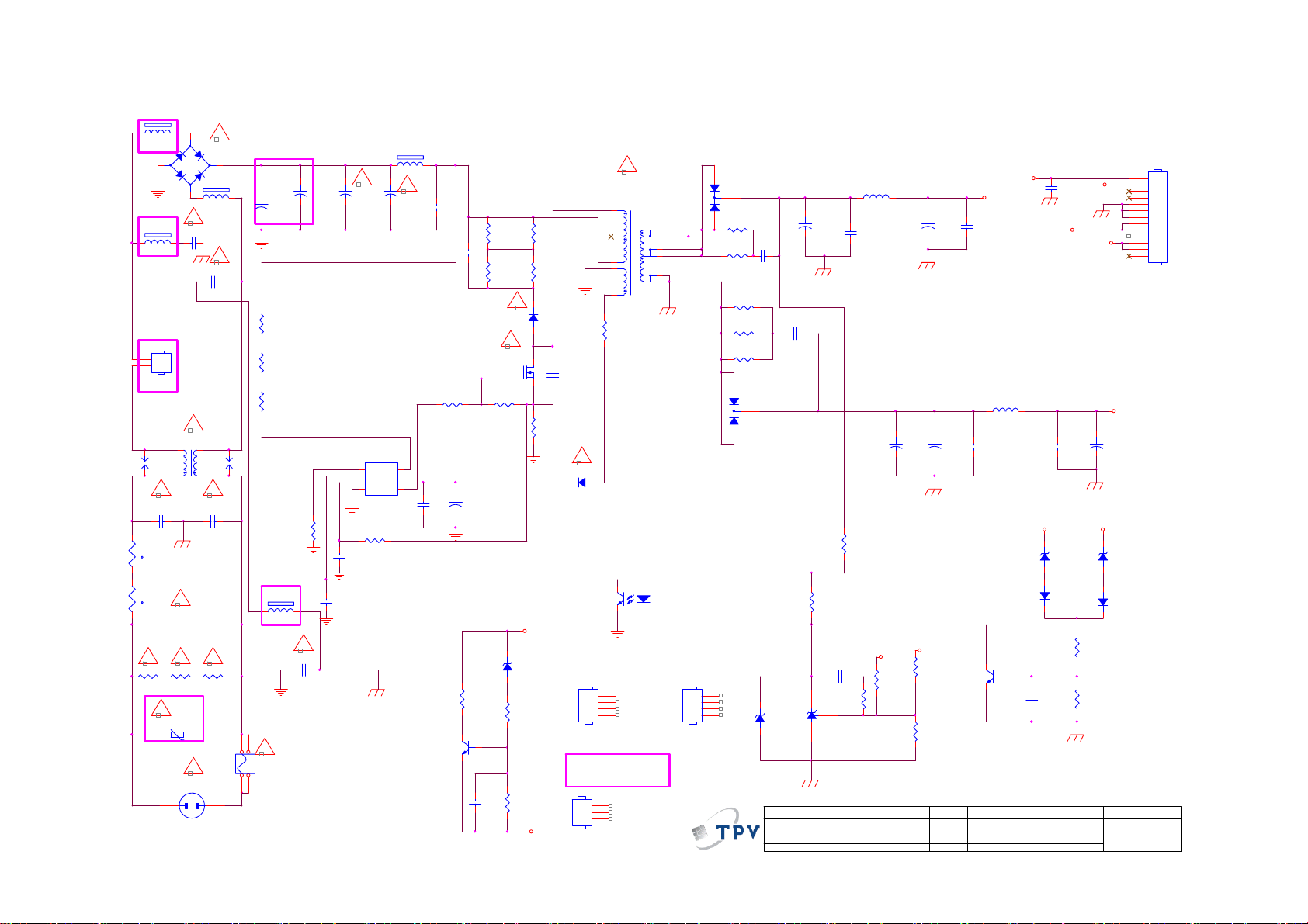
9.2 Power Board
715G5309P0A001002S
1 2
1 2
BBY(jumper)
DSPL-501N-A21F
12
t
12
t
R9132
620K
FB9908
BEAD
-
4
FB9907
BEAD
C9902
470PF 250V
2
N
1
L
CN901
CONN
L9901
30MH
SG9901
124
C9906
100PF 250V
NR9902
NTCR
!
NR9901
NTCR
C9901
470NF 305V
! !!
R9133
620K
!
RV9901
TVR14561KFAOZF
1 2
BBY(凹础Α)
2
!
BD9101
GBL408-C
+
1 2
3
FB9902
BEAD
!
!
C9904
470PF 250V
!
3
!!
C9907
100PF 250V
R9134
620K
BBY(510V)
!
CN9901
SOCKET
1
SG9902
DSPL-501N-A21F
BBY(NC)
C9101A
+
47UF 450V
13*40
R9101
6.8K 1/4W
R9102
6.8K 1/4W
R9103
6.8K 1/4W
BBY(200V)
100KOHM +-5% 1/8W
FB9901
BEAD
1 2
!
F9901
T3.15AH 250V
1 2
3 4
R9114
C9905
1NF 250V
+
!
C9102A
47UF 450V
13*40
C9124
22N 50V
!
C9101
+
NC
13*45
1
2
3
220 OHM 1/4W
C9106
470P 50V
IC9101
LD7750RGR
OTP
HV
COMP
CS
VCC
GND4OUT
R9113
FB9906
BEAD
1 2
!
+
C9102
NC
13*45
8
6
5
2SD1623S-TD-E
C9125
2.2nF 630V
C9103
2.2nF 630V
R9110
47OHM +-5% 1/8W
C9104
100N 50V
R9130
470R
Q9102
+
C9105
47UF 50V
10*7
R9104
100K 1/4W
R9105
100K 1/4W
R9111
10K 1/8W
C9119
100N 50V
!
D9103
FR107
!
Q9101
AOTF8N65
ZD9101
GDJ13B
1 2
R9129
470 OHM
R9131
1K 1/8W
R9106
100K 1/4W
R9107
100K 1/4W
R9112
0.43 OHM +-5% 2WS
+12_16V
+5.2V
C9126
100PF
!
D9105
FR107
(D9101&D9102)
HS1
HEAT SINK
BBY(NC)
HS4
(C9101A&C9102A)
SHIELD
6
5
4
2
1
R9108
4.7 OHM
1
2
3
4
1
2
3
!
T9101
POWER X'FMR
12
43
54
12
11
8
7
10
9
IC9102
056G 139 3A
PC123X2YFZOF
(Q9101)
HS3
HEAT SINK
D9101
3
MBRF1560CT
2
1
R9115
47 OHM 1/4W
R9116
47 OHM 1/4W
100 OHM 1/4W
100 OHM 1/4W
100 OHM 1/4W
1
2
3
4
+
C9109
330UF 16V
C9107
10*12
1NF 500V
R9118
R9119
R9120
3
1
C9108
1NF 500V
2
D9102
MBRF20150CT
R9122
3.3K +-5%1/8W
1K OHM +-5% 1/8W
ZD9104
BZT52-C5V6
1 2
絬 隔 瓜 絪 腹
Key Component
AS431AZTR-E1
IC9103
T P V ( Top Victory Electronics Co . , Ltd. )
01.POWER
Date
C9117
470NF 50V
R9124
L9101
3.5uH
C9110
100N 50V
470UF 25V
R9121
1K 1/8W
C9122
+5.2V
+
10*12 10*12
+12_16V
R9123
3K3 1/8W 1%
C9111
+
470UF 25V
10*12
C9113
+
470UF 25V
R9125
68K 1/8W 1%
R9126
2K43 1/8W 1%
OEM MOD EL
TPV MODEL
PCB NAME
Sheet
ON/OFF
+5.2V
C9112
100N 50V
L9102
3.5uH
C9114
100N 50V
Q9103
PMBS3904
715G5309-P0D-000-0020
12Thursday, March 29, 2012
of
+12_16V
1 2
D9107
1N4148
C9118
100N 50V
C9120
1NF
C9115
100N 50V
ZD9102
GDZJ 22B
+12_16V
DIM
+5.2V
+12_16V
C9123
+
470UF 25V
10*12
+5.2 V
1 2
1N4148
R9127
3.3K +-5%1/8W
R9128
1K 1/8W
Size
Rev
称爹
ZD9103
GDZJ5. 6B
D9106
CN9101
13
12
11
10
9
8
7
6
5
4
3
2
1
CONN
A3
Page 55

18K 1/8W 5%
VBJT
+12_16V
+12_16V
51K 1/4W
51K 1/4W
C8108
10N 50V
R8110
R8114
R8111
C8105
100N 50V
R8101
51K 1% 1/8W
VSET
R8112
0R05 1/6W 5%
C8101
+
470UF 25V
C8109
100N 50V
C8104
100N 50V
C8114
10N 50V
DIM
VSET
ON/OF F
VFB
200K 1/8W 1%
+5.2 V
Q8102
2N3904
1
2
3
4
5
6
R8102
R8113
18R 1%
IC8501
PF7001S
EN
SLP
DIM
VADJ
GM
VBJT
VFB
VCC
VSET
VMOS
OVP
GND
RT7CS
VADJ
R8121
13R 1%
SLP
VADJ
14
13
12
11
10
9
8
R8108
200OHM +-5% 1/8W
C8110
1NF
Q8103
2N3904
VBJT
R8122
L8102
47UH
R8129
NC
Q8104
2N3904
13R 1%
Q8101
AO4482L
R8104
33 OHM
12
D8102
RB160M-60TE25
C8103
R8103
1uF
10 OHM 1/4W
LED2LED1 LED4LED3
R8130
NC
Q8105
2N3904
R8123
13R 1%
5
4
+12_16V
R8131
NC
Q8106
2N3904
R8124
13R 1%
FB9904
BEAD
1 2
D8D7D6D
S1S2S3G
R8105
15R 1/ 8W 5%
Q8107
2N3904
R8125
13R 1%
1 2
C8115
100PF
C8107
1NF 500V
R8106
10K 1/8W
D8101
SR510-22
R8107
0.1R
FB9905
1 2
JUMPER
C8106
1NF
LED1
LED2
LED3
LED4
C8102
+
47UF 100V
10*1210*12
C8111
NC
3
D8104
3
BAV99
D8105
3
BAV99
D8106
3
BAV99
R8117
3.6K 1% 1/8W
D8103
BAV99
C8113
+
47UF 100V
10*12
2
1
2
1
2
1
2
1
R8115
51K 1/4W
VFB
VLED+
R8116
51K
R8120
0R05 1/6W 5%
R8118
1M 1/6W 5%
R8119
150K 1/8W 5%
LED4
LED3
LED2
LED1
SLP
C8112
NC
VLED+
CN8501 For LG
Panel(LC215EUE)
CN8101& CN8102
For FFC TRF
Board
LED1
CN8103
2
1
4
3
6
5
NC
CN8102
2
1
NC
6
5
4
3
2
1
7 8
CN8501 For
AUO&TPV
CN8101
CONN
55
T P V ( Top Victory Electronics Co . , Ltd. )
絬 隔 瓜 絪 腹
Key Component
Date
02.LED D RIVER
OEM MOD EL
TPV MODEL
PCB NAME
Sheet
715G5309-P0D-000-0020
22Monday, May 14, 2012
of
Size
Rev
称爹
B
Page 56

9.3 Key Board
715G5569K01000004S
SW01
CN01
65
CONN
33G8032 4F HR
R01
7K5 1/8W + /-1%
R02
2K7 +- 1% 1/8W
R03
1K8 +/- 1% 1/8W
1
PWR-SW
2
FUNC_KEY
3
4
FUNC_KEY
PWR-SW
R07
750OHM +- 1% 1/8W
R08
750OHM +- 1% 1/8W
R04
1K 1/8W 1%
R05
750OHM +- 1% 1/8W
C01
NC
C02
NC
C03
NC
C04
NC
C05
NC
C06
NC
C07
NC
TACT SW FWRD H1.5MM
SW02
TACT SW FWRD H1.5MM
SW03
TACT SW FWRD H1.5MM
SW04
TACT SW FWRD H1.5MM
SW05
TACT SW FWRD H1.5MM
SW06
TACT SW FWRD H1.5MM
SW07
TACT SW FWRD H1.5MM
77G 607 2 FD
VOL+
VOL-
CH+
CH-
MENU
Source Select
Power ON/OFF
2.48V~2.72V
2.04V~2.22V
1.58V~1.79V
1.24~1.45V
0.85V~1.02V
0.47V~0.63V
T P V ( Top Victory Electronics Co . , Ltd. )
絬 隔 瓜 絪 腹
Key Component
Date
02-Keypad
56
OEM MO DE L
TPV MO D EL
PCB NAME
Sheet
715GXXXX
22Thursday , J une 07, 2012
of
Size
Rev
称爹
<
Custom
A
称爹
>
Page 57

9.4 IR Board
715G5061R01000004M
33G8032 4F HR
CN01
67
1
2
3
4
5
CONN
LED
IR
VCC
R002
NC 220 OHM 1/10W
R001 15K 1/10W
C001
0.1uF 50V
Red
LED1
1 2
NC 264-10SUR C/ S530-A3
U001
1
VOUT
2
GND
3
VCC
IRM-3640CF45
16 mm
Top View
Dip LED
37mm
IR
T P V ( Top Victory Electronics Co . , Ltd. )
絬 隔 瓜 絪 腹
Key Component
Date
715G5061-R0A-000-0040
02-IR&LED
57
OEM MOD E L
TPV MODEL
PCB NAME
Sheet
715G5061-R0A-000-0040
22Monday , Oc tober 17, 2011
of
Size
Rev
称爹
<
A
称爹
A
>
Page 58

10. Exploded View
58
Page 59

Item Description
1 BEZEL
2 PANEL
3 BKT_CONNECTOR SGCC
4 POWER BOARD
5 MAIN BOARD
6 BKT_IO 15 0Q1G1030 6120 HX SCREW (FOR IR BOARD) 1
7 BKT_MID 16 0M1G1730 8120 RA SCREW(FOR POWER BOARD) 3
8 BASE 17 0M1G1730 8120 RA SCREW(FOR MAIN BOARD) 4
9 STAND 18 0Q1G 930 8 47 HX SCREW (FOR BKT_MID) 2
10 REAR_COVER 19 0Q1G 930 8 47 HX SCREW (FOR REAR COVER) 2
11 IR_LENS 20 0Q1G 940 18 47 RA SCREW (FOR STAND) 2
12 LED_LENS 21 0Q1G 340 8140 SCREW (FOR REAR COVER) 2
13 IR BOARD 22 0Q1G 940 16 47 HX SCREW (FOR REAR COVER) 1
14 SPEAKER 23 0Q1G 940 16 47 HX SCREW (FOR BASE) 1
15 SCREW 3x8 25 0Q1G 330 8 47 XL SCREW (FOR BACK IO) 1
24 INSULATING SHEET 26 0M1G1730 10120 XL SCREW (FOR POWER BOARD) 2
Item Part No. Description Qty
59
Page 60

11. BOM List
Note: The parts information listed below are for reference only, and are subject to change without notice.
Please go to http://cs.tpv.com.cn/hello1.asp
E22B1KNCBQA1NN
Location Part No. Description Remark
Q45G99010TV03700X1 PROTECT BAG
X15T8324201000GMBL BKT_IO
X34T0039 GM 1L03BA X34T0039 GM 1L03BA
085T 583113 GASKET
085T 583123 1 GP GASKET_ELECTRIC
089G217A18N IS AC POWER CORD 1800MM
ECN700 095G801313X909 HARNESS 13P-13P 300mm LCDXXTF0325
ECN906 095G8014 6DY01 HARNESS 6P-6P(CI1406S) 250mm
098GRABD6NEACD REMOTE AOC 90-364100T4425
M00101 0M1G1730 8120 RA SCREW 3x8
M00103 0M1G1730 10120 XL SCREW 3x10
M00104 0Q1G 330 8 47 XL SCREW 3x8
M00105 0Q1G 930 8 47 HX SCREW 3x8
M00107 0Q1G 940 16 47 HX SCREW Q1-SELF TAPING SCREW:Q x16
0Q1G 940 18 47 RA SCREW Q1-SELF TAPING SCREW :Q x18
SP01 378G060A577YAC 16 OHM 6W 68*27 220/220 NO
ECN4005 395G801830RY32 LVDS CABLE 30P-30P 100mm
705TQ949001 COMSUPTIVE ASS'Y-A4
708GCA120CPQ01 AOC 40(1680 AP)
050G 600 2 HANDLE1
050G 600 3 HANDLE2
Q52G 1185 98 MIDDLE CARTON TAPE FOR AOC 72MM
E750 750GBV215DAT16N000 LCD TPM215HW01-DAT01 C1A WH TPV
756TXBCB0KC025000Q MAIN BOARD-CBPFCK1DX7Q
SMTF-U4003 100TARVI005C2X MCU ASSY-056G2233 50
P11G002310100000PJ WIRE-CLIP
Q11T500500200000ZL WIRE-CLIP
Q36G 600 35 3 ZA NON-WOVEN FABRIC Cloth 0.3 0.3
Q40G0003615B90 LABEL Warranty Sticker Label
Q50G 500523 TS CABLE TIE
Q52G130118600000YY TAPE
Q52G1501 TV 7 W INSULATING SHEET
Q52G15011505230WXW TAPE_INSULATING
Q52G160119100A00YY TAPE
Q52G18010TV0500AHB INSULATING SHEET
Q85T 583131 2 GP GASKET_ELECTRIC
X15T818520200000BL BKT_CONNECTOR SGCC
X15T819210100000BL BKT_VESA SGCC
X15T832310100000BL BKT_MID
X34T0037AFLX4L0130 BEZEL
X40G000261577A FEATURE-POP LABEL --LE22A3520/61
X41G78DV61508A WARRANTY CARD
X44GCA08101 CUSHION-T EPS
X44GCA08201 CUSHION-B EPS
for the latest information.
60
Page 61

X44GCA1261501A ARTWORK CARTON --AOC LE22A3520
092GB1JX1A3EGC BATTERY 1.5V LR03 AAA£¨LR03£© alkali
Q45G2010M0101A pe bag for manual
X41G22MV61506A MANUAL
040G 58162435A PN LABEL FOR Manual PE Bag
Q40G 581689 4B SN LABEL(58x35mm)
Q40G0001954 1A S/N LABEL
X40G0001624 2A Label for screw pe bag
X40G022061512A RATING LABEL --LE22A3520/61
E750 750GBV215DAT11N000 LCD TPM215HW01-DAT01 C1A FQ TPV 2nd source
X34T00380GM04K0130 REAR_COVER
CBPFCK1DX7Q CONVERSION BOARD
Z40G0002ALL01A SFIS Label 35mm*9mm
CN4003 033G380214B YH L WAFER 2.0mm 14P R/A 29.98mm 7.8mm
U102 053T 44501 HD SAW FILTER HD-BF35 A3 DC
C765 067G 3151017RV EC 100UF 20% 50V 10*9
C149 067G305M221 3C EC 220uF 16V SZ 8x7mm
C4049 067G305S1013HV EC 100UF 20% 16V 6.3*7
C4044 067G305S1013HV EC 100UF 20% 16V 6.3*7
C4061 067G305S1013HV EC 100UF 20% 16V 6.3*7
C139 067G305S3316CV EC 330UF 20% 35V 10*9
C705 067G305S471 2C EC 470UF 20% 10V KW 8*9
C605 067G315M1016KV EC 100UF 20% 35V 8*7
C607 067G315M1016KV EC 100UF 20% 35V 8*7
C747 067G315M2213HV EC 220UF 20% 16V 6.3*7
C762 067G315M2213HV EC 220UF 20% 16V 6.3*7
C754 067G315M2213HV EC 220UF 20% 16V 6.3*7
C750 067G315M2213HV EC 220UF 20% 16V 6.3*7
CN106 088G 30211K NO-SUGGEST PHONG JACK 7PIN
CN106 088G 302A11 YG PHONE JACK 3.5¦µ 7PIN BLACK CKX3.507B-01
CN107 088G 78F114VCL RCA JACK 2P YELLOW 1*1 V/T 13.5
CN104 088G 78F121XYG RCA JACK V/T 4P W/R 1*2 H=8.6
CN102 088G 78F131XYG RCA JACK V/T 6P Y/W/R 1*3 H=8.6
CN103 088G 78F135XYG RCA JACK V/T 6P G/BL/R 1*3 H=8.6
CN101 088G 78G131ACL RCA JACK 6P R/A Y/W/R H 1*3 H=10.5
CN101 088G 78G131AYG RCA JACK 6P R/A Y/W/R H 1*3 H=10.5
CN105 088G302F3G1VYG PHONE JACK V/T 3P GREEN H=8.4
CN4002 088G352F6B2ACL USB CONN R/A 6P BLACK 8.4mm
CN4001 088G352F6B2ACL USB CONN R/A 6P BLACK 8.4mm
CN100 088G353FFF1XCL D-SUB CONN SCREWED V/T 15P BLUE H=8.6
TU100 094G PAL D12L TUNER CHINA F35CT-2-E 1
CN610 311GW250B04BBX WAFER 2.5MM 4P
CN700 311GW250B13BBX WAFER 2.5mm 13P R/A 35mm 7mm
709T4629 XM001 COMSUPTIVE ASS'Y
055G 23524 WELDING FLUX WITHOUT PB
Q55G 100625 TIN STICK_LOW ARGENTUM
U703 056G 133 30AAC DC/DC AZ1117H-ADJ-E1 1A adj SOT-223
P90T0051401 SY HEAT SINK
FOR
HS4000
61
Page 62

U4000 056G 562F32 SCALER RTD2684S-GR LQFP-256
U700 056G 563 93 IC G9084T43U TO-252
U700 056G 563 93 C LDO G9084PT43U 5A ADJ TO-252
U705 056G 563323 DC/DC AOZ1242AI 3A SO-8
U702 056G 563344 DC/DC AT1529F11U 3.2A SOP-8
U704 056G 563344 DC/DC AT1529F11U 3.2A SOP-8
U103 056G 563519 IC G965-25ADJPIUF 1.8A SOP-8
U4002 056G 615137 DRAM H5PS1G63EFR-G7C 1Gb FBGA-84
U4002 056G 615503 W971GG6JB-18 1066Mb DDR2-1066 1G WBGA84
U600 056G 616 54 IC TPA3110D2 15W TSSOP-28
U101 056G 662502 IC ESD AZC199-04S.R7G SOT23-6L
U100 056G 662502 IC ESD AZC199-04S.R7G SOT23-6L
U4003 056G2233 50 FLASH H27U1G8F2BTR-BC 1Gb TSOP1-48
Q700 057G 417 4 PMBS3904/PHILIPS-SMT(04)
Q102 057G 417 4 PMBS3904/PHILIPS-SMT(04)
Q4007 057G 417 4 PMBS3904/PHILIPS-SMT(04)
Q703 057G 417 4 PMBS3904/PHILIPS-SMT(04)
Q103 057G 417 6 PMBS3906/PHILIPS-SMT(06)
Q4005 057G 417511 MMBT3904
Q506 057G 417511 MMBT3904
Q505 057G 417511 MMBT3904
Q503 057G 417511 MMBT3904
Q504 057G 417511 MMBT3904
Q502 057G 417511 MMBT3904
Q500 057G 417511 MMBT3904
Q4006 057G 417511 MMBT3904
Q603 057G 417511 MMBT3904
Q706 057G 417511 MMBT3904
Q4003 057G 417512 MMBT3906
Q4002 057G 417512 MMBT3906
Q705 057G 417518 TRA LMBT3904LT1G 200mA/40V SOT-23 LRC
Q704 057G 763 79 FET AO4449 -7A/-30V SOIC-8
Q4004 057G 763 79 FET AO4449 -7A/-30V SOIC-8
Q301 057G 763904 TRA FET 2N7002 SOT-23 PHILIPS
Q302 057G 763904 TRA FET 2N7002 SOT-23 PHILIPS
TH4001 061G 52902 PTC CHIP 8V 0R4 KMC4S075RY
TH4000 061G 52902 PTC CHIP 8V 0R4 KMC4S075RY
RP4011 061G 1262208JF RST NET 22R 5% 1/16W 8P4R
RP4002 061G 1262208JF RST NET 22R 5% 1/16W 8P4R
RP4012 061G 1262208JF RST NET 22R 5% 1/16W 8P4R
RP4010 061G 1262208JF RST NET 22R 5% 1/16W 8P4R
RP4000 061G 1262208JF RST NET 22R 5% 1/16W 8P4R
RP4004 061G 1262208JF RST NET 22R 5% 1/16W 8P4R
RP4015 061G 1262208JF RST NET 22R 5% 1/16W 8P4R
RP4001 061G 1262208JF RST NET 22R 5% 1/16W 8P4R
RP4003 061G 1262208JF RST NET 22R 5% 1/16W 8P4R
RP4013 061G 1262208JF RST NET 22R 5% 1/16W 8P4R
RP4014 061G 1262208JF RST NET 22R 5% 1/16W 8P4R
RP4005 061G 1265108JY RST CHIP NET 51R 5% 1/16W 8P4R
62
Page 63

RP4006 061G 1265108JY RST CHIP NET 51R 5% 1/16W 8P4R
RP4009 061G 1265108JY RST CHIP NET 51R 5% 1/16W 8P4R
RP4008 061G 1265108JY RST CHIP NET 51R 5% 1/16W 8P4R
RP4007 061G 1265108JY RST CHIP NET 51R 5% 1/16W 8P4R
R4052 061G0402000 JT RST CHIPR MAX0R05 1/16W TZAI YUAN
R200 061G0402000 JT RST CHIPR MAX0R05 1/16W TZAI YUAN
R620 061G0402100 JF RST CHIPR 10 OHM +-5% 1/16W FENGHUA
R619 061G0402100 JF RST CHIPR 10 OHM +-5% 1/16W FENGHUA
R614 061G0402100 JF RST CHIPR 10 OHM +-5% 1/16W FENGHUA
R613 061G0402100 JF RST CHIPR 10 OHM +-5% 1/16W FENGHUA
R192 061G0402100 JF RST CHIPR 10 OHM +-5% 1/16W FENGHUA
R616 061G0402100 JF RST CHIPR 10 OHM +-5% 1/16W FENGHUA
R625 061G0402100 JF RST CHIPR 10 OHM +-5% 1/16W FENGHUA
R4021 061G04021001FF RST CHIPR 1KOHM +-1% 1/16W FENGHUA
R4020 061G04021001FF RST CHIPR 1KOHM +-1% 1/16W FENGHUA
R740 061G04021002FI TEST ONLY RST 0402 10K 1% 1/16W TA-I
R108 061G0402101 JF RST CHIPR 100 OHM +-5% 1/16W FENGHUA
R107 061G0402101 JF RST CHIPR 100 OHM +-5% 1/16W FENGHUA
R109 061G0402101 JF RST CHIPR 100 OHM +-5% 1/16W FENGHUA
R110 061G0402101 JF RST CHIPR 100 OHM +-5% 1/16W FENGHUA
R4040 061G0402101 JT RST CHIP 100R 1/16W 5% TZAI YUAN
R701 061G0402102 JF RST CHIPR 1KOHM +-5% 1/16W FENGHUA
R4034 061G0402102 JF RST CHIPR 1KOHM +-5% 1/16W FENGHUA
R197 061G0402102 JF RST CHIPR 1KOHM +-5% 1/16W FENGHUA
R717 061G0402102 JF RST CHIPR 1KOHM +-5% 1/16W FENGHUA
R708 061G0402102 JT RST CHIP 1K 1/16W 5% TZAI YUAN
R211 061G0402103 JF RST CHIPR 10KOHM +-5% 1/16W FENGHUA
R205 061G0402103 JF RST CHIPR 10KOHM +-5% 1/16W FENGHUA
R205 061G0402103 JT RST CHIP 10K 1/16W 5% TZAI YUAN
R211 061G0402103 JT RST CHIP 10K 1/16W 5% TZAI YUAN
R133 061G0402123 JF RST CHIPR 12KOHM +-5% 1/16W FENGHUA
R137 061G0402123 JF RST CHIPR 12KOHM +-5% 1/16W FENGHUA
R103 061G0402123 JT RST CHIPR 12KOHM +-5% 1/16W TZAI YUAN
R130 061G0402123 JT RST CHIPR 12KOHM +-5% 1/16W TZAI YUAN
R128 061G0402123 JT RST CHIPR 12KOHM +-5% 1/16W TZAI YUAN
R105 061G0402123 JT RST CHIPR 12KOHM +-5% 1/16W TZAI YUAN
R4048 061G0402201 JF RST CHIPR 200 OHM +-5% 1/16W FENGHUA
R4046 061G0402201 JF RST CHIPR 200 OHM +-5% 1/16W FENGHUA
R4061 061G0402220 JT RST CHIP 22R 1/16W 5% TZAI YUAN
R4037 061G0402220 JT RST CHIP 22R 1/16W 5% TZAI YUAN
R4033 061G0402220 JT RST CHIP 22R 1/16W 5% TZAI YUAN
R4035 061G0402220 JT RST CHIP 22R 1/16W 5% TZAI YUAN
R4036 061G0402220 JT RST CHIP 22R 1/16W 5% TZAI YUAN
R4038 061G0402220 JT RST CHIP 22R 1/16W 5% TZAI YUAN
R164 061G0402222 JT RST CHIP 2K2 1/16W 5% TZAI YUAN
R165 061G0402222 JT RST CHIP 2K2 1/16W 5% TZAI YUAN
R4016 061G0402272 JF RST CHIP 2K7 1/16W 5% FENGHUA
R4058 061G0402472 JF RST CHIPR 4.7KOHM +-5% 1/16W FENGHUA
R4059 061G0402472 JF RST CHIPR 4.7KOHM +-5% 1/16W FENGHUA
63
Page 64

R4060 061G0402472 JF RST CHIPR 4.7KOHM +-5% 1/16W FENGHUA
R181 061G0402472 JT RST CHIP 4K7 1/16W 5% TZAI YUAN
R518 061G0402472 JT RST CHIP 4K7 1/16W 5% TZAI YUAN
R514 061G0402472 JT RST CHIP 4K7 1/16W 5% TZAI YUAN
R4024 061G0402472 JT RST CHIP 4K7 1/16W 5% TZAI YUAN
R4027 061G0402472 JT RST CHIP 4K7 1/16W 5% TZAI YUAN
R4031 061G0402472 JT RST CHIP 4K7 1/16W 5% TZAI YUAN
R100 061G0402472 JT RST CHIP 4K7 1/16W 5% TZAI YUAN
R4044 061G0402472 JT RST CHIP 4K7 1/16W 5% TZAI YUAN
R517 061G0402472 JT RST CHIP 4K7 1/16W 5% TZAI YUAN
R526 061G0402472 JT RST CHIP 4K7 1/16W 5% TZAI YUAN
R516 061G0402472 JT RST CHIP 4K7 1/16W 5% TZAI YUAN
R4030 061G0402472 JT RST CHIP 4K7 1/16W 5% TZAI YUAN
R151 061G0402472 JT RST CHIP 4K7 1/16W 5% TZAI YUAN
R513 061G0402472 JT RST CHIP 4K7 1/16W 5% TZAI YUAN
R182 061G0402472 JT RST CHIP 4K7 1/16W 5% TZAI YUAN
R4047 061G0402472 JT RST CHIP 4K7 1/16W 5% TZAI YUAN
R507 061G0402473 JF RST CHIPR 47KOHM +-5% 1/16W FENGHUA
R508 061G0402473 JF RST CHIPR 47KOHM +-5% 1/16W FENGHUA
R501 061G0402473 JF RST CHIPR 47KOHM +-5% 1/16W FENGHUA
R737 061G0402473 JT RST CHIP 47K 1/16W 5% TZAI YUAN
R4043 061G0402510 JF RST CHIP 51R 1/16W 5% FENGHUA
R199 061G0402511 JT RST CHIP 510R 1/16W 5% TZAI YUAN
R4019 061G0402512 JF RST CHIP 5K1 1/16W 5% FENGHUA
R739 061G04025232FT RST 0402 52.3K 1/16W 1% TZAI YUAN
R206 061G0402683 JT RST CHIP R 68Kohm 1/16W +/-5% TZAI YUAN
R159 061G0402750 JI TEST ONLY RST 0402 75R 5% 1/16W TA-I
R125 061G0402750 JI TEST ONLY RST 0402 75R 5% 1/16W TA-I
R168 061G0402750 JI TEST ONLY RST 0402 75R 5% 1/16W TA-I
R154 061G0402750 JI TEST ONLY RST 0402 75R 5% 1/16W TA-I
R120 061G0402750 JI TEST ONLY RST 0402 75R 5% 1/16W TA-I
R115 061G0402750 JI TEST ONLY RST 0402 75R 5% 1/16W TA-I
R102 061G0402750 JI TEST ONLY RST 0402 75R 5% 1/16W TA-I
R112 061G0402750 JT RST 0402 75R 5% 1/16W
R207 061G04027509FI TEST ONLY RST 0402 75R 1% 1/16W TA-I
R174 061G0402752 JF RST CHIP 7K5 1/16W 5% FENGHUA
R171 061G0402752 JF RST CHIP 7K5 1/16W 5% FENGHUA
R204 061G0402753 JF RST CHIPR 75KOHM 5% 1/16W FENGHUA
R116 061G0603000 JF RST CHIPR MAX 0R05 1/10W FENGHUA
R126 061G0603000 JF RST CHIPR MAX 0R05 1/10W FENGHUA
R166 061G0603000 JF RST CHIPR MAX 0R05 1/10W FENGHUA
R152 061G0603000 JF RST CHIPR MAX 0R05 1/10W FENGHUA
R111 061G0603000 JF RST CHIPR MAX 0R05 1/10W FENGHUA
R169 061G0603000 JF RST CHIPR MAX 0R05 1/10W FENGHUA
R113 061G0603000 JF RST CHIPR MAX 0R05 1/10W FENGHUA
R118 061G0603000 JF RST CHIPR MAX 0R05 1/10W FENGHUA
R155 061G0603000 JF RST CHIPR MAX 0R05 1/10W FENGHUA
R4008 061G0603000 JF RST CHIPR MAX 0R05 1/10W FENGHUA
R730 061G0603000 JF RST CHIPR MAX 0R05 1/10W FENGHUA
64
Page 65

R121 061G0603000 JF RST CHIPR MAX 0R05 1/10W FENGHUA
R4017 061G0603000 JF RST CHIPR MAX 0R05 1/10W FENGHUA
R162 061G0603000 JF RST CHIPR MAX 0R05 1/10W FENGHUA
R157 061G0603000 JF RST CHIPR MAX 0R05 1/10W FENGHUA
R123 061G0603000 JF RST CHIPR MAX 0R05 1/10W FENGHUA
R4007 061G0603000 JF RST CHIPR MAX 0R05 1/10W FENGHUA
R627 061G0603000 JI RST 0603 0.05R MAX 1/10W TA-I
R520 061G0603000 JT RST CHIP MAX 0R05 1/10W TZAI YUAN
R525 061G0603000 JT RST CHIP MAX 0R05 1/10W TZAI YUAN
R524 061G0603000 JT RST CHIP MAX 0R05 1/10W TZAI YUAN
R101 061G0603000 JT RST CHIP MAX 0R05 1/10W TZAI YUAN
R521 061G0603000 JT RST CHIP MAX 0R05 1/10W TZAI YUAN
R523 061G0603000 JT RST CHIP MAX 0R05 1/10W TZAI YUAN
R138 061G0603000 JT RST CHIP MAX 0R05 1/10W TZAI YUAN
R736 061G0603000 JT RST CHIP MAX 0R05 1/10W TZAI YUAN
R522 061G0603000 JT RST CHIP MAX 0R05 1/10W TZAI YUAN
R732 061G0603100 JF RST CHIPR 10 OHM 5% 1/10W FENGHUA
R735 061G0603100 JF RST CHIPR 10 OHM 5% 1/10W FENGHUA
R707 061G06031000FT RST CHIP 100R 1/10W 1%
R4042 061G06031001FT RST CHIP 1K 1/10W 1%
R4041 061G06031001FT RST CHIP 1K 1/10W 1%
R4067 061G0603101 JF RST CHIPR 100 OHM +-5% 1/10W FENGHUA
R4071 061G0603101 JF RST CHIPR 100 OHM +-5% 1/10W FENGHUA
R4015 061G0603101 JF RST CHIPR 100 OHM +-5% 1/10W FENGHUA
R4050 061G0603101 JF RST CHIPR 100 OHM +-5% 1/10W FENGHUA
R4014 061G0603101 JF RST CHIPR 100 OHM +-5% 1/10W FENGHUA
R4010 061G0603101 JT RST CHIP 100R 1/10W 5% TZAI YUAN
R184 061G0603101 JT RST CHIP 100R 1/10W 5% TZAI YUAN
R167 061G0603101 JT RST CHIP 100R 1/10W 5% TZAI YUAN
R114 061G0603101 JT RST CHIP 100R 1/10W 5% TZAI YUAN
R117 061G0603101 JT RST CHIP 100R 1/10W 5% TZAI YUAN
R122 061G0603101 JT RST CHIP 100R 1/10W 5% TZAI YUAN
R160 061G0603101 JT RST CHIP 100R 1/10W 5% TZAI YUAN
R156 061G0603101 JT RST CHIP 100R 1/10W 5% TZAI YUAN
R153 061G0603101 JT RST CHIP 100R 1/10W 5% TZAI YUAN
R127 061G0603101 JT RST CHIP 100R 1/10W 5% TZAI YUAN
R158 061G0603101 JT RST CHIP 100R 1/10W 5% TZAI YUAN
R119 061G0603101 JT RST CHIP 100R 1/10W 5% TZAI YUAN
R161 061G0603101 JT RST CHIP 100R 1/10W 5% TZAI YUAN
R4009 061G0603101 JT RST CHIP 100R 1/10W 5% TZAI YUAN
R124 061G0603101 JT RST CHIP 100R 1/10W 5% TZAI YUAN
R187 061G0603101 JT RST CHIP 100R 1/10W 5% TZAI YUAN
R170 061G0603101 JT RST CHIP 100R 1/10W 5% TZAI YUAN
R163 061G0603101 JT RST CHIP 100R 1/10W 5% TZAI YUAN
R4072 061G0603102 JF RST CHIPR 1K OHM +-5% 1/10W FENGHUA
R176 061G0603102 JF RST CHIPR 1K OHM +-5% 1/10W FENGHUA
R173 061G0603102 JF RST CHIPR 1K OHM +-5% 1/10W FENGHUA
R713 061G0603102 JF RST CHIPR 1K OHM +-5% 1/10W FENGHUA
R505 061G0603102 JY RST CHIPR 1KOHM +-5£¥ 1/10W YAGEO
65
Page 66

R519 061G0603102 JY RST CHIPR 1KOHM +-5£¥ 1/10W YAGEO
R502 061G0603102 JY RST CHIPR 1KOHM +-5£¥ 1/10W YAGEO
R711 061G0603103 JF RST CHIPR 10K OHM +-5% 1/10W FENGHUA
R4066 061G0603103 JF RST CHIPR 10K OHM +-5% 1/10W FENGHUA
R509 061G0603103 JF RST CHIPR 10K OHM +-5% 1/10W FENGHUA
R4075 061G0603103 JF RST CHIPR 10K OHM +-5% 1/10W FENGHUA
R4080 061G0603103 JF RST CHIPR 10K OHM +-5% 1/10W FENGHUA
R511 061G0603103 JF RST CHIPR 10K OHM +-5% 1/10W FENGHUA
R4000 061G0603103 JF RST CHIPR 10K OHM +-5% 1/10W FENGHUA
R738 061G0603103 JF RST CHIPR 10K OHM +-5% 1/10W FENGHUA
R622 061G0603103 JF RST CHIPR 10K OHM +-5% 1/10W FENGHUA
R506 061G0603103 JF RST CHIPR 10K OHM +-5% 1/10W FENGHUA
R4053 061G0603103 JF RST CHIPR 10K OHM +-5% 1/10W FENGHUA
R722 061G0603103 JF RST CHIPR 10K OHM +-5% 1/10W FENGHUA
R4069 061G0603103 JF RST CHIPR 10K OHM +-5% 1/10W FENGHUA
R4081 061G0603103 JF RST CHIPR 10K OHM +-5% 1/10W FENGHUA
R4068 061G0603103 JF RST CHIPR 10K OHM +-5% 1/10W FENGHUA
R512 061G0603103 JF RST CHIPR 10K OHM +-5% 1/10W FENGHUA
R515 061G0603103 JF RST CHIPR 10K OHM +-5% 1/10W FENGHUA
R4023 061G0603103 JF RST CHIPR 10K OHM +-5% 1/10W FENGHUA
R710 061G0603103 JF RST CHIPR 10K OHM +-5% 1/10W FENGHUA
R4025 061G0603103 JF RST CHIPR 10K OHM +-5% 1/10W FENGHUA
R733 061G0603103 JF RST CHIPR 10K OHM +-5% 1/10W FENGHUA
R700 061G0603103 JF RST CHIPR 10K OHM +-5% 1/10W FENGHUA
R510 061G0603103 JF RST CHIPR 10K OHM +-5% 1/10W FENGHUA
R4078 061G0603103 JF RST CHIPR 10K OHM +-5% 1/10W FENGHUA
R617 061G0603103 JI RST 0603 10K 5% 1/10W
R4002 061G0603103 JT RST CHIP 10K 1/10W 5% TZAI YUAN
R621 061G0603104 JT RST CHIP 100K 1/10W 5% TZAI YUAN
R203 061G06031202FT RST CHIP 12K 1/10W 1%
R734 061G06031502FT RST CHIP 15K 1/10W 1%
R175 061G0603152 JT RST CHIP 1K5 1/10W 5% TZAI YUAN
R172 061G0603152 JT RST CHIP 1K5 1/10W 5% TZAI YUAN
R709 061G06032209FT RST CHIP 22R 1/10W 1%
R210 061G0603221 JT RST CHIPR 220OHM 1/10W TZAI YUAN
R208 061G0603221 JT RST CHIPR 220OHM 1/10W TZAI YUAN
R198 061G0603229 JF RST CHIPR 2.2 OHM 5% 1/10W FENGHUA
R719 061G06032409FT RST CHIP 24R 1/10W 1%
R741 061G06033001FI TEST ONLY RST 0603 3K 1% 1/10W TA-I
R726 061G06033302FT RST CHIP 33K 1/10W 1%
R209 061G0603331 JT RST 0603 330R 5% 1/10W
R623 061G06033321FF RST CHIPR 3.32KOHM +-1% 1/10W FENGHUA
R615 061G06033601FF RST CHIPR 3.6K OHM +-1% 1/10W FENGHUA
R615 061G06033601FI TEST ONLY RST 0603 3.6K 1% 1/10W TA-I
R727 061G06034702FT RST CHIP 47K 1/10W 1%
R728 061G06034702FT RST CHIP 47K 1/10W 1%
R4077 061G0603472 JF RST CHIPR 4.7KOHM +-5% 1/10W FENGHUA
R705 061G0603472 JF RST CHIPR 4.7KOHM +-5% 1/10W FENGHUA
R4063 061G0603472 JF RST CHIPR 4.7KOHM +-5% 1/10W FENGHUA
66
Page 67

R4082 061G0603472 JI RST 0603 4.7K 5% 1/10W TA-I
R4083 061G0603472 JI RST 0603 4.7K 5% 1/10W TA-I
R4062 061G0603472 JT RST CHIP 4K7 1/10W 5% TZAI YUAN
R4076 061G0603472 JT RST CHIP 4K7 1/10W 5% TZAI YUAN
R718 061G0603472 JT RST CHIP 4K7 1/10W 5% TZAI YUAN
R4064 061G0603472 JT RST CHIP 4K7 1/10W 5% TZAI YUAN
R4065 061G0603472 JT RST CHIP 4K7 1/10W 5% TZAI YUAN
R4079 061G0603472 JT RST CHIP 4K7 1/10W 5% TZAI YUAN
R4074 061G0603472 JT RST CHIP 4K7 1/10W 5% TZAI YUAN
R4070 061G0603472 JT RST CHIP 4K7 1/10W 5% TZAI YUAN
R4057 061G0603473 JF RST CHIPR 47KOHM +-5% 1/10W FENGHUA
R716 061G0603473 JF RST CHIPR 47KOHM +-5% 1/10W FENGHUA
R131 061G0603822 JF RST CHIPR 8.2KOHM 5% 1/10W FENGHUA
R106 061G0603822 JF RST CHIPR 8.2KOHM 5% 1/10W FENGHUA
R104 061G0603822 JF RST CHIPR 8.2KOHM 5% 1/10W FENGHUA
R129 061G0603822 JF RST CHIPR 8.2KOHM 5% 1/10W FENGHUA
R136 061G0603822 JF RST CHIPR 8.2KOHM 5% 1/10W FENGHUA
R135 061G0603822 JF RST CHIPR 8.2KOHM 5% 1/10W FENGHUA
R193 061G0805000 JF RST CHIPR 0 OHM +-5% 1/8W FENGHUA
R194 061G0805000 JF RST CHIPR 0 OHM +-5% 1/8W FENGHUA
R201 061G08053832FF RST CHIPR 38.3KOHM +-1% 1/8W FENGHUA
R624 061G1206100 JF RST CHIPR 10 OHM +-5% 1/4W FENGHUA
C121 065G040210031D 3 CAP 0402 10PF 0.5pF 50V NP0
C121 065G040210031D A CAP CHIP 0402 10PF D 50V NPO
C4115 065G040210131J F CAP 0402 100PF 5% 50V NP0
C4115 065G040210131J T CAP CHIP 0402 100pF 50V NPO
C4119 065G040210412K A CAP CHIP 0402 100nF K 16V X7R
C4057 065G040210412K A CAP CHIP 0402 100nF K 16V X7R
C4080 065G040210412K A CAP CHIP 0402 100nF K 16V X7R
C4058 065G040210412K A CAP CHIP 0402 100nF K 16V X7R
C4085 065G040210412K A CAP CHIP 0402 100nF K 16V X7R
C4067 065G040210412K A CAP CHIP 0402 100nF K 16V X7R
C4090 065G040210412K A CAP CHIP 0402 100nF K 16V X7R
C4077 065G040210412K A CAP CHIP 0402 100nF K 16V X7R
C4082 065G040210412K A CAP CHIP 0402 100nF K 16V X7R
C4060 065G040210412K A CAP CHIP 0402 100nF K 16V X7R
C4059 065G040210412K A CAP CHIP 0402 100nF K 16V X7R
C4089 065G040210412K A CAP CHIP 0402 100nF K 16V X7R
C4088 065G040210412K A CAP CHIP 0402 100nF K 16V X7R
C4084 065G040210412K A CAP CHIP 0402 100nF K 16V X7R
C4065 065G040210412K A CAP CHIP 0402 100nF K 16V X7R
C4076 065G040210412K A CAP CHIP 0402 100nF K 16V X7R
C4064 065G040210412K A CAP CHIP 0402 100nF K 16V X7R
C4071 065G040210412K A CAP CHIP 0402 100nF K 16V X7R
C4069 065G040210412K A CAP CHIP 0402 100nF K 16V X7R
C4066 065G040210412K A CAP CHIP 0402 100nF K 16V X7R
C4091 065G040210412K A CAP CHIP 0402 100nF K 16V X7R
C4086 065G040210412K A CAP CHIP 0402 100nF K 16V X7R
C4053 065G040210412K A CAP CHIP 0402 100nF K 16V X7R
67
Page 68

C4087 065G040210412K A CAP CHIP 0402 100nF K 16V X7R
C4068 065G040210412K A CAP CHIP 0402 100nF K 16V X7R
C4118 065G040210412K A CAP CHIP 0402 100nF K 16V X7R
C4079 065G040210412K A CAP CHIP 0402 100nF K 16V X7R
C4095 065G040210412K A CAP CHIP 0402 100nF K 16V X7R
C4063 065G040210412K A CAP CHIP 0402 100nF K 16V X7R
C4083 065G040210412K A CAP CHIP 0402 100nF K 16V X7R
C4054 065G040210412K A CAP CHIP 0402 100nF K 16V X7R
C4073 065G040210412K A CAP CHIP 0402 100nF K 16V X7R
C4094 065G040210412K A CAP CHIP 0402 100nF K 16V X7R
C4078 065G040210412K A CAP CHIP 0402 100nF K 16V X7R
C4075 065G040210412K A CAP CHIP 0402 100nF K 16V X7R
C4081 065G040210412K A CAP CHIP 0402 100nF K 16V X7R
C4062 065G040210412K A CAP CHIP 0402 100nF K 16V X7R
C4100 065G040210412K Y CAP 0402 100NF 10% 16V X7R
C4101 065G040210412K Y CAP 0402 100NF 10% 16V X7R
C4048 065G040210412K Y CAP 0402 100NF 10% 16V X7R
C4043 065G040210412K Y CAP 0402 100NF 10% 16V X7R
C4107 065G040210412K Y CAP 0402 100NF 10% 16V X7R
C4110 065G040210412K Y CAP 0402 100NF 10% 16V X7R
C144 065G040210412K Y CAP 0402 100NF 10% 16V X7R
C4099 065G040210412K Y CAP 0402 100NF 10% 16V X7R
C4108 065G040210412K Y CAP 0402 100NF 10% 16V X7R
C4105 065G040210412K Y CAP 0402 100NF 10% 16V X7R
C4103 065G040210412K Y CAP 0402 100NF 10% 16V X7R
C4096 065G040210412K Y CAP 0402 100NF 10% 16V X7R
C4102 065G040210412K Y CAP 0402 100NF 10% 16V X7R
C4098 065G040210412K Y CAP 0402 100NF 10% 16V X7R
C4104 065G040210412K Y CAP 0402 100NF 10% 16V X7R
C4109 065G040210412K Y CAP 0402 100NF 10% 16V X7R
C4106 065G040210412K Y CAP 0402 100NF 10% 16V X7R
C142 065G040210425K F CHIP 0402 0.1UF 25V X5R
C142 065G040210425K T CAP 0402 100NF 10% 25V X5R
C768 065G040218131J 3 CAP CHIP 0402 180P 50V NP0 +/-5%
C768 065G040218131J F CAP 0402 180PF 5% 50V NP0
C120 065G040222031J T CAP CHIP 0402 22pF J 50V NPO
C4047 065G040222031J T CAP CHIP 0402 22pF J 50V NPO
C4046 065G040222031J T CAP CHIP 0402 22pF J 50V NPO
C4046 065G040222031J Y CAP CHIP 0402 22P 50V NP0 +/-5%
C120 065G040222031J Y CAP CHIP 0402 22P 50V NP0 +/-5%
C4047 065G040222031J Y CAP CHIP 0402 22P 50V NP0 +/-5%
C632 065G040233131J A MLCC 0402 330pF 50V NP0 +-5%
C6158 065G040233131J A MLCC 0402 330pF 50V NP0 +-5%
C629 065G040233131J A MLCC 0402 330pF 50V NP0 +-5%
C625 065G040233131J A MLCC 0402 330pF 50V NP0 +-5%
C629 065G040233131J T CAP CHIP 0402 330PF 50V J NPO
C625 065G040233131J T CAP CHIP 0402 330PF 50V J NPO
C6158 065G040233131J T CAP CHIP 0402 330PF 50V J NPO
C632 065G040233131J T CAP CHIP 0402 330PF 50V J NPO
68
Page 69

C127 065G040247131J A CAP CHIP 0402 470PF J 50V NPO
C110 065G040247131J A CAP CHIP 0402 470PF J 50V NPO
C105 065G040247131J A CAP CHIP 0402 470PF J 50V NPO
C104 065G040247131J A CAP CHIP 0402 470PF J 50V NPO
C103 065G040247131J A CAP CHIP 0402 470PF J 50V NPO
C111 065G040247131J A CAP CHIP 0402 470PF J 50V NPO
C124 065G040247131J A CAP CHIP 0402 470PF J 50V NPO
C102 065G040247131J A CAP CHIP 0402 470PF J 50V NPO
C107 065G040250931C Y CAP 0402 5PF 0.25pF 50V NP0
C119 065G040250931C Y CAP 0402 5PF 0.25pF 50V NP0
C108 065G040250931C Y CAP 0402 5PF 0.25pF 50V NP0
C109 065G040250931C Y CAP 0402 5PF 0.25pF 50V NP0
C118 065G040250931C Y CAP 0402 5PF 0.25pF 50V NP0
C122 065G040250931C Y CAP 0402 5PF 0.25pF 50V NP0
C135 065G060310031D F CAP CHIP 0603 10PF D 50V NPO
C133 065G060310031D F CAP CHIP 0603 10PF D 50V NPO
C622 065G060310232K A CAP CHIP 0603 1000pF K 50V X7R
C623 065G060310232K A CAP CHIP 0603 1000pF K 50V X7R
C769 065G060310232K F CAP CHIP 0603 1NF K 50V X7R
C758 065G060310232K Y CAP CHIP 0603 1N 50V X7R +/-10%
C764 065G060310232K Y CAP CHIP 0603 1N 50V X7R +/-10%
C137 065G060310332K F CAP CHIP 0603 10NF K 50V X7R
C136 065G060310332K F CAP CHIP 0603 10NF K 50V X7R
C759 065G060310432K A CAP 0603 100NF 10% 50V X7R
C4116 065G060310432K A CAP 0603 100NF 10% 50V X7R
C4001 065G060310432K A CAP 0603 100NF 10% 50V X7R
C749 065G060310432K A CAP 0603 100NF 10% 50V X7R
C712 065G060310432K A CAP 0603 100NF 10% 50V X7R
C4111 065G060310432K A CAP 0603 100NF 10% 50V X7R
C722 065G060310432K A CAP 0603 100NF 10% 50V X7R
C704 065G060310432K A CAP 0603 100NF 10% 50V X7R
C753 065G060310432K A CAP 0603 100NF 10% 50V X7R
C755 065G060310432K A CAP 0603 100NF 10% 50V X7R
C4051 065G060310432K A CAP 0603 100NF 10% 50V X7R
C4004 065G060310432K A CAP 0603 100NF 10% 50V X7R
C733 065G060310432K A CAP 0603 100NF 10% 50V X7R
C4113 065G060310432K A CAP 0603 100NF 10% 50V X7R
C716 065G060310432K A CAP 0603 100NF 10% 50V X7R
C751 065G060310432K A CAP 0603 100NF 10% 50V X7R
C4112 065G060310432K A CAP 0603 100NF 10% 50V X7R
C612 065G060310432K A CAP 0603 100NF 10% 50V X7R
C761 065G060310432K A CAP 0603 100NF 10% 50V X7R
C617 065G060310432K A CAP 0603 100NF 10% 50V X7R
C711 065G060310432K A CAP 0603 100NF 10% 50V X7R
C710 065G060310432K A CAP 0603 100NF 10% 50V X7R
C736 065G060310432K A CAP 0603 100NF 10% 50V X7R
C748 065G060310432K A CAP 0603 100NF 10% 50V X7R
C4052 065G060310432K A CAP 0603 100NF 10% 50V X7R
C708 065G060310432K A CAP 0603 100NF 10% 50V X7R
69
Page 70

C760 065G060310432K A CAP 0603 100NF 10% 50V X7R
C125 065G060310432K A CAP 0603 100NF 10% 50V X7R
C138 065G060310432K A CAP 0603 100NF 10% 50V X7R
C703 065G060310432K A CAP 0603 100NF 10% 50V X7R
C128 065G060310432K A CAP 0603 100NF 10% 50V X7R
C713 065G060310432K F CAP CHIP 0603 0.1UF K 50V X7R
C713 065G060310432K M CAP 0603 100NF 10% 50V X7R
C771 065G060310432K Y CAP 0603 100NF 10% 50V X7R
C770 065G060310512K 3 CAP 0603 1UF 10% 16V X7R
C4122 065G060310512K T CAP 0603 1UF 10% 16V X7R
C628 065G060310522K A 0603 1UF 25V X7R
C627 065G060310522K A 0603 1UF 25V X7R
C626 065G060310522K A 0603 1UF 25V X7R
C631 065G060310522K A 0603 1UF 25V X7R
C631 065G060310522K M CAP MLCC 0603 1uF K 25V X7R
C627 065G060310522K M CAP MLCC 0603 1uF K 25V X7R
C628 065G060310522K M CAP MLCC 0603 1uF K 25V X7R
C626 065G060310522K M CAP MLCC 0603 1uF K 25V X7R
C4000 065G060310522K T CAP CHIP 0603 1uF K 25V X7R
C4022 065G060310522K T CAP CHIP 0603 1uF K 25V X7R
C4003 065G060310522K T CAP CHIP 0603 1uF K 25V X7R
C4042 065G060310522K T CAP CHIP 0603 1uF K 25V X7R
C4056 065G060310605M M CAP 0603 10UF 20% 6.3V X5R
C4055 065G060310605M M CAP 0603 10UF 20% 6.3V X5R
C615 065G060322422K A MLCC 0603 220nF 25V X7R +/-10% SAMSUNG
C624 065G060322422K A MLCC 0603 220nF 25V X7R +/-10% SAMSUNG
C616 065G060322422K A MLCC 0603 220nF 25V X7R +/-10% SAMSUNG
C630 065G060322422K A MLCC 0603 220nF 25V X7R +/-10% SAMSUNG
C4010 065G060322515K T CAP 0603 2.2UF 10% 16V X5R
C4020 065G060322515K T CAP 0603 2.2UF 10% 16V X5R
C4014 065G060322515K T CAP 0603 2.2UF 10% 16V X5R
C4016 065G060322515K T CAP 0603 2.2UF 10% 16V X5R
C4041 065G060322515K T CAP 0603 2.2UF 10% 16V X5R
C4070 065G060322515K T CAP 0603 2.2UF 10% 16V X5R
C4121 065G060322515K T CAP 0603 2.2UF 10% 16V X5R
C4021 065G060322515K T CAP 0603 2.2UF 10% 16V X5R
C4015 065G060322515K T CAP 0603 2.2UF 10% 16V X5R
C4123 065G060322515K T CAP 0603 2.2UF 10% 16V X5R
C4072 065G060322515K T CAP 0603 2.2UF 10% 16V X5R
C4017 065G060322515K T CAP 0603 2.2UF 10% 16V X5R
C4011 065G060322515K T CAP 0603 2.2UF 10% 16V X5R
C4040 065G060347332K Y CAP CHIP 0603 47N 50V X7R +/-10%
C4030 065G060347332K Y CAP CHIP 0603 47N 50V X7R +/-10%
C4032 065G060347332K Y CAP CHIP 0603 47N 50V X7R +/-10%
C4029 065G060347332K Y CAP CHIP 0603 47N 50V X7R +/-10%
C4028 065G060347332K Y CAP CHIP 0603 47N 50V X7R +/-10%
C4026 065G060347332K Y CAP CHIP 0603 47N 50V X7R +/-10%
C4033 065G060347332K Y CAP CHIP 0603 47N 50V X7R +/-10%
C4038 065G060347332K Y CAP CHIP 0603 47N 50V X7R +/-10%
70
Page 71

C4039 065G060347332K Y CAP CHIP 0603 47N 50V X7R +/-10%
C4034 065G060347332K Y CAP CHIP 0603 47N 50V X7R +/-10%
C4027 065G060347332K Y CAP CHIP 0603 47N 50V X7R +/-10%
C4035 065G060347332K Y CAP CHIP 0603 47N 50V X7R +/-10%
C4120 065G060347332K Y CAP CHIP 0603 47N 50V X7R +/-10%
C4025 065G060347332K Y CAP CHIP 0603 47N 50V X7R +/-10%
C4023 065G060347332K Y CAP CHIP 0603 47N 50V X7R +/-10%
C4024 065G060347332K Y CAP CHIP 0603 47N 50V X7R +/-10%
C4036 065G060347332K Y CAP CHIP 0603 47N 50V X7R +/-10%
C4031 065G060347332K Y CAP CHIP 0603 47N 50V X7R +/-10%
C4037 065G060347332K Y CAP CHIP 0603 47N 50V X7R +/-10%
C4093 065G0603475A5K T CAP CHIP 0603 4.7UF K 10V X5R
C4092 065G0603475A5K T CAP CHIP 0603 4.7UF K 10V X5R
C614 065G080510532K T CAP 0805 1UF 10% 50V X7R
C613 065G080510532K T CAP 0805 1UF 10% 50V X7R
C633 065G080510532K T CAP 0805 1UF 10% 50V X7R
C145 065G080510615K M CAP CHIP 0805 10UF K 16V X5R
C123 065G080510615K T CHIP 10uF 16V X5R 0805
C126 065G080510615K T CHIP 10uF 16V X5R 0805
C709 065G0805106A5K 3 CHIP 10uF 10V X5R 10%
C707 065G0805106A5K 3 CHIP 10uF 10V X5R 10%
C734 065G0805106A5K 3 CHIP 10uF 10V X5R 10%
C735 065G0805106A5K 3 CHIP 10uF 10V X5R 10%
C140 065G0805106A5K 3 CHIP 10uF 10V X5R 10%
C143 065G0805106A5K 3 CHIP 10uF 10V X5R 10%
C141 065G0805106A5K 3 CHIP 10uF 10V X5R 10%
C4074 065G080522605M T CAP0805 22UF 20% 6.3V X5R
C4097 065G080522605M T CAP0805 22UF 20% 6.3V X5R
C763 065G0805475A2K 3 CAP 0805 4.7UF 10% 10V X7R
C757 065G0805475A2K 3 CAP 0805 4.7UF 10% 10V X7R
C766 065G120610532K 3 CAP 1206 1UF 10% 50V X7R
C767 065G120610532K 3 CAP 1206 1UF 10% 50V X7R
C772 065G120610625K T CAP CHIP 1206 10uF K 25V X5R
C773 065G120610625K T CAP CHIP 1206 10uF K 25V X5R
C756 065G1206226A5K T CAP CHIP1206 22uF K 10V X5R
C752 065G1206226A5K T CAP CHIP1206 22uF K 10V X5R
C619 065G120633432K Y CAP 1206 330NF 10% 50V X7R
C620 065G120633432K Y CAP 1206 330NF 10% 50V X7R
C621 065G120633432K Y CAP 1206 330NF 10% 50V X7R
C618 065G120633432K Y CAP 1206 330NF 10% 50V X7R
FB101 071G 56A221 TA IND FXD 0805 EMI 100MHZ 220R R
FB4006 071G 56A221 TA IND FXD 0805 EMI 100MHZ 220R R
FB100 071G 56A221 TA IND FXD 0805 EMI 100MHZ 220R R
FB4005 071G 56A221 TA IND FXD 0805 EMI 100MHZ 220R R
FB706 071G 56G301 EA CHIP BEAD 0805 300R 25% 4000mA
FB4013 071G 56G301 EA CHIP BEAD 0805 300R 25% 4000mA
FB4021 071G 56G301 EA CHIP BEAD 0805 300R 25% 4000mA
FB4009 071G 56G301 EA CHIP BEAD 0805 300R 25% 4000mA
FB4011 071G 56G301 EA CHIP BEAD 0805 300R 25% 4000mA
71
Page 72

FB4019 071G 56G301 EA CHIP BEAD 0805 300R 25% 4000mA
FB4015 071G 56G301 EA CHIP BEAD 0805 300R 25% 4000mA
FB4020 071G 56G301 EA CHIP BEAD 0805 300R 25% 4000mA
FB4029 071G 56G301 EA CHIP BEAD 0805 300R 25% 4000mA
FB4001 071G 56G301 EA CHIP BEAD 0805 300R 25% 4000mA
FB708 071G 56G301 EA CHIP BEAD 0805 300R 25% 4000mA
FB4018 071G 56G301 EA CHIP BEAD 0805 300R 25% 4000mA
FB4027 071G 56G301 EA CHIP BEAD 0805 300R 25% 4000mA
FB4012 071G 56G301 EA CHIP BEAD 0805 300R 25% 4000mA
FB4024 071G 56G301 EA CHIP BEAD 0805 300R 25% 4000mA
FB4002 071G 56G301 EA CHIP BEAD 0805 300R 25% 4000mA
FB4022 071G 56G301 EA CHIP BEAD 0805 300R 25% 4000mA
FB4000 071G 56G301 EA CHIP BEAD 0805 300R 25% 4000mA
FB4014 071G 56G301 EA CHIP BEAD 0805 300R 25% 4000mA
FB4017 071G 56G301 EA CHIP BEAD 0805 300R 25% 4000mA
FB4016 071G 56G301 EA CHIP BEAD 0805 300R 25% 4000mA
FB4008 071G 56G301 EA CHIP BEAD 0805 300R 25% 4000mA
FB4008 071G 56G301 MA CHIP BEAD 0805 300OHM 4A
FB4016 071G 56G301 MA CHIP BEAD 0805 300OHM 4A
FB4017 071G 56G301 MA CHIP BEAD 0805 300OHM 4A
FB705 071G 56G301 MA CHIP BEAD 0805 300OHM 4A
FB4015 071G 56G301 MA CHIP BEAD 0805 300OHM 4A
FB4011 071G 56G301 MA CHIP BEAD 0805 300OHM 4A
FB4019 071G 56G301 MA CHIP BEAD 0805 300OHM 4A
FB4029 071G 56G301 MA CHIP BEAD 0805 300OHM 4A
FB4001 071G 56G301 MA CHIP BEAD 0805 300OHM 4A
FB4014 071G 56G301 MA CHIP BEAD 0805 300OHM 4A
FB4009 071G 56G301 MA CHIP BEAD 0805 300OHM 4A
FB4021 071G 56G301 MA CHIP BEAD 0805 300OHM 4A
FB4013 071G 56G301 MA CHIP BEAD 0805 300OHM 4A
FB706 071G 56G301 MA CHIP BEAD 0805 300OHM 4A
FB4022 071G 56G301 MA CHIP BEAD 0805 300OHM 4A
FB4002 071G 56G301 MA CHIP BEAD 0805 300OHM 4A
FB4000 071G 56G301 MA CHIP BEAD 0805 300OHM 4A
FB4024 071G 56G301 MA CHIP BEAD 0805 300OHM 4A
FB4012 071G 56G301 MA CHIP BEAD 0805 300OHM 4A
FB4020 071G 56G301 MA CHIP BEAD 0805 300OHM 4A
FB4027 071G 56G301 MA CHIP BEAD 0805 300OHM 4A
FB708 071G 56G301 MA CHIP BEAD 0805 300OHM 4A
FB4018 071G 56G301 MA CHIP BEAD 0805 300OHM 4A
FB707 071G 56G301 MA CHIP BEAD 0805 300OHM 4A
FB701 071G 56K121 TA CHIP BEAD 120R/6000mA HCB2012KF-121T60
FB719 071G 56K121 TA CHIP BEAD 120R/6000mA HCB2012KF-121T60
FB720 071G 56K121 TA CHIP BEAD 120R/6000mA HCB2012KF-121T60
FB600 071G 56K121 TA CHIP BEAD 120R/6000mA HCB2012KF-121T60
FB702 071G 56K121 TA CHIP BEAD 120R/6000mA HCB2012KF-121T60
FB714 071G 56K121 TA CHIP BEAD 120R/6000mA HCB2012KF-121T60
FB715 071G 56K121 TA CHIP BEAD 120R/6000mA HCB2012KF-121T60
FB4004 071G 59G301 TA CHIP BEAD 300OHM 200mA FCM1608KF-301T02
72
Page 73

FB4003 071G 59G301 TA CHIP BEAD 300OHM 200mA FCM1608KF-301T02
FB4007 071G 59G301 TA CHIP BEAD 300OHM 200mA FCM1608KF-301T02
L100 073G 63229 TA CHIP INDUCROR 2.2uH 10% FCI1608F-2R2K
L102 073G 6333810T CHIP INDUCTOR 0.33uH 10%
L103 073G 12610010M CHIP INDUCTOR 1206 10UH 10% 25mA 1.0R
L704 073G253S 31 H SMD CHOKE 15.0uH
L606 073G253S 36 H HF SMD CHOKE 22UH 20% SPI105LRR-220 3.5A,HF
L607 073G253S 36 H HF SMD CHOKE 22UH 20% SPI105LRR-220 3.5A,HF
L605 073G253S 36 H HF SMD CHOKE 22UH 20% SPI105LRR-220 3.5A,HF
L604 073G253S 36 H HF SMD CHOKE 22UH 20% SPI105LRR-220 3.5A,HF
L702 073G253S 71 DN SMD CHOKE 2.2UH 20% 8A LZ.412R2.A0P,HF
L703 073G253S 71 DN SMD CHOKE 2.2UH 20% 8A LZ.412R2.A0P,HF
CN500 088G 34021A VA HDMI HEADER V/T 21P BLACK H=10.5 HF
CN501 088G 34021A VA HDMI HEADER V/T 21P BLACK H=10.5 HF
CN502 088G340FJ04AAT HDMI 19P BLACK R/A H=11.2mm
D100 093G 60505 SCHOTTKY BAT54C 0.2A 30V SOT-23
X4000 093G 22S515 YC CRYSTAL 27MHZ 27MHZ 30ppm 20PF
ZD4005 093G 39S 24 T RLZ 5.6B LLDS
ZD4004 093G 39S 24 T RLZ 5.6B LLDS
ZD4000 093G 39S 24 T RLZ 5.6B LLDS
ZD4003 093G 39S 24 T RLZ 5.6B LLDS
ZD4001 093G 39S 24 T RLZ 5.6B LLDS
D701 093G 60S927 T DIODE SX34 DO-214AA
ZD503 093G 64S500 SU ESD MLVG04025R0QV05BP INPAQ
ZD505 093G 64S500 SU ESD MLVG04025R0QV05BP INPAQ
ZD506 093G 64S500 SU ESD MLVG04025R0QV05BP INPAQ
ZD507 093G 64S500 SU ESD MLVG04025R0QV05BP INPAQ
ZD500 093G 64S500 SU ESD MLVG04025R0QV05BP INPAQ
ZD502 093G 64S500 SU ESD MLVG04025R0QV05BP INPAQ
ZD113 093G 64S500 SU ESD MLVG04025R0QV05BP INPAQ
ZD103 093G 64S500 SU ESD MLVG04025R0QV05BP INPAQ
ZD102 093G 64S500 SU ESD MLVG04025R0QV05BP INPAQ
ZD111 093G 64S500 SU ESD MLVG04025R0QV05BP INPAQ
ZD504 093G 64S500 SU ESD MLVG04025R0QV05BP INPAQ
ZD105 093G 64S500 SU ESD MLVG04025R0QV05BP INPAQ
ZD114 093G 64S500 SU ESD MLVG04025R0QV05BP INPAQ
ZD101 093G 64S500 SU ESD MLVG04025R0QV05BP INPAQ
ZD501 093G 64S500 SU ESD MLVG04025R0QV05BP INPAQ
ZD112 093G 64S500 SU ESD MLVG04025R0QV05BP INPAQ
ZD508 093G 64S500 SU ESD MLVG04025R0QV05BP INPAQ
ZD104 093G 64S500 SU ESD MLVG04025R0QV05BP INPAQ
D7101 093G1020 PH DIODE S1D-E3 DO-214AC
CN4005 311GW125F30ACH WAFER 1.25mm 30P V/T -
709T4629 XS001 COMSUPTIVE ASS'Y
055G 100610 TIN CREAM W/O PB
052G6026 2 MESH PRINTTING PAPER
052G 2191 A PAPER TAPE
E715 715G4629M01000004F MAIN PCB FR4 DS 193X186X1.6MM 2nd source
E715 715G4629M01000004K MAIN PCB FR4 DS 193X186X1.6MM
73
Page 74

H1 X85T8006101 SHIELD
Q36G 600 18111 ZA NON-WOVEN FABRIC Cloth 0.25 0.3
PLTVCE514XXG1Q ADAPTER BOARD
040G 45762412B CBPC LABEL
009G6005 1 GP GND TERMINAL
IC9102 056G 139 3A PC123Y22FZOF SHARP
RV9901 061G 46561 WB VARISTOR 560V 10% 14
NR9901 061G 58159LAW 5A NTCR 1.5R 15% 2.4W SCK101R55LMY502
NR9902 061G 58159LAW 5A NTCR 1.5R 15% 2.4W SCK101R55LMY502
R9130 061G153M47159B SY RST MOF 470R 5% 3W
C9901 063G107M474AUM CAP X2 470NF 20% 305V
FB9908 071G 55906 FERRITE CORE 510R C8B R6H 6x9.2(A)
FB9902 071G 55906 FERRITE CORE 510R C8B R6H 6x9.2(A)
L9901 073G 174192 X LINE FILTER 30MH MIN ET20 0.8A
L9101 073G 253 91 V CHOKE COIL 3.5uH+-10%
L9102 073G 253 91 V CHOKE COIL 3.5uH+-10%
L8102 073G 253214 X CHOKE COIL 47UH 10% ,HF
T9101 080GL32P 92 YS X'FMR 800UH 10% 20UH EFD30 YS04160400
CN9901 087G 50147C DL AC SOCKET V/T 2P ACT1MD-02BL4B006 H=14
BD9101 093G 50460 50 BRIDGE GBL08 4A/800V GBL
D8101 093G 60924 DIODE SR510-22 DO-201AD
0Q1G 340 8140 SCREW Q1-SELF TAPING SCREW :Q x8.0
CN8101 311GW200A06ABX WAFER 2.0mm 6P
CN9101 311GW250B13BBX WAFER 2.5mm 13P R/A 35mm 7mm
C9101 367G215X470PKZ002S EC 47UF 20% 450V 12.5*36
C9102 367G215X470PKZ002S EC 47UF 20% 450V 12.5*36
BD9101 393G0050460A03 BRIDGE GBL408-C 4A 800V GBL 150A
705TXC5799500Q Q9101 ASS'Y
Q9101 057G 667931 MOSFET AOTF8N65 8A 650V TO-220FP
Q9101_1 0M1G1730 10120 SCREW 3x10
Q9101 357G0667A11 MOSFET STF6N65K3 5.4A 650V 30W TO-220FP
HS3 Q90G0219 4 HEAT SINK ÐͲÄ/Profile
705TXC8402300Q F9901 ASS'Y
F9901_1 084G 34 14 FUSE CLIP 5*20mm
F9901 084G 41 3 C FUSE 3.15A 250V, Time Lag Fuse
705TXC9399500Q D9101/D9102 ASS'Y
D9101 093G 60931 DIODE MBRF1560CT ITO-220AB
D9102 093G 60946 SCHOTTKY MBRF20150CT C0 20 150 ITO-220AB
D9101_1 0M1G1730 10120 SCREW 3x10
HS1 Q90G0219 5 HEAT SINK ÐͲÄ/Profile
IC9101 056G 379190 AC/DC CONVERTER LD7750RGR SOP-7
IC8501 056G 700 34 LED DRIVER PF7001S SOP-14
Q9103 057G 417 4 PMBS3904/PHILIPS-SMT(04)
Q9102 057G 419913 T TRANSISTOR 2SD1623S-TD-E PCP
Q8101 057G 763958 MOSFET AO4482L 6A 100V SO8
R9131 061G0805102 JF RST CHIPR 1K OHM +-5% 1/8W FENGHUA
R9128 061G0805102 JF RST CHIPR 1K OHM +-5% 1/8W FENGHUA
R9121 061G0805102 JI RST 0805 1K 5% 1/8W
R9124 061G0805102 JT RST CHIPR 1K OHM +- 5% 1/8W TZAI YUAN
74
Page 75

R9111 061G0805103 JF RST CHIPR 10K OHM +-5% 1/8W FENGHUA
R8106 061G0805103 JF RST CHIPR 10K OHM +-5% 1/8W FENGHUA
R9114 061G0805104 JT RST CHIPR 100KOHM +- 5% 1/8W TZAI YUAN
R8121 061G08051309FI RST 0805 13R 1% 1/8W
R8122 061G08051309FI RST 0805 13R 1% 1/8W
R8123 061G08051309FI RST 0805 13R 1% 1/8W
R8124 061G08051309FI RST 0805 13R 1% 1/8W
R8125 061G08051309FI RST 0805 13R 1% 1/8W
R8105 061G0805150 JT RST CHIP 15R 1/8W 5% TZAI YUAN
R8119 061G0805154 JT RST CHIP 150K 1/8W 5% TZAI YUAN
R8111 061G0805183 JT RST CHIP 18K 1/8W 5%
R8102 061G08052003FT RST CHIP 200K 1/8W 1%
R8108 061G0805201 JT RST CHIPR 200OHM +-5% 1/8W TZAI YUAN
R9126 061G08052431FY RST CHIP 2K43 1/8W 1%
R8104 061G0805330 JI RST CHIPR 33 OHM +-5% 1/8W 0805
R9123 061G08053301FY RST CHIP 3K3 1/8W 1%
R9127 061G0805332 JF RST CHIPR 3.3KOHM +-5% 1/8W FENGHUA
R9122 061G0805332 JF RST CHIPR 3.3KOHM +-5% 1/8W FENGHUA
R8117 061G08054301FI RST 0805 4.3K 1% 1/8W
R9110 061G0805470 JF RST CHIPR 47OHM +-5% 1/8W FENGHUA
R9129 061G0805471 JY RST CHIPR 470OHM +-5% 1/8W YAGEO
R8101 061G08055102FI RST 51K OHM 1% 1/8W TA-I
R9125 061G08056802FT RST CHIP R 68K 1/8W 1%
JR901 061G1206000 JF RST CHIPR MAX0R05 1/4W FENGHUA
JR902 061G1206000 JF RST CHIPR MAX0R05 1/4W FENGHUA
JR903 061G1206000 JF RST CHIPR MAX0R05 1/4W FENGHUA
R8103 061G1206100 JI RST 1206 10R 5% 1/4W
R9120 061G1206101 JF RST CHIPR 100 OHM +-5% 1/4W FENGHUA
R9118 061G1206101 JF RST CHIPR 100 OHM +-5% 1/4W FENGHUA
R9119 061G1206101 JF RST CHIPR 100 OHM +-5% 1/4W FENGHUA
R9106 061G1206104 JF RST CHIPR 100KOHM +-5% 1/4W FENGHUA
R9105 061G1206104 JF RST CHIPR 100KOHM +-5% 1/4W FENGHUA
R9104 061G1206104 JF RST CHIPR 100KOHM +-5% 1/4W FENGHUA
R9107 061G1206104 JF RST CHIPR 100KOHM +-5% 1/4W FENGHUA
R8113 061G12061809FT RST 1206 18R 1% 1/4W
R9113 061G1206221 JT RST CHIPR 220 OHM +-5% 1/4W TZAI YUAN
R9115 061G1206470 JT RST CHIPR 47 OHM +-5% 1/4W TZAI YUAN
R9116 061G1206470 JT RST CHIPR 47 OHM +-5% 1/4W TZAI YUAN
R9108 061G1206479 JI RST 4.7 OHM 5% 1/4W TA-I
R8114 061G1206513 JT RST CHIPR 51 KOHM +-5% 1/4W TZAI YUAN
R8110 061G1206513 JT RST CHIPR 51 KOHM +-5% 1/4W TZAI YUAN
R8115 061G1206513 JT RST CHIPR 51 KOHM +-5% 1/4W TZAI YUAN
R9132 061G1206624 JY RST CHIPR 620 KOHM +-5% 1/4W YAGEO
R9133 061G1206624 JY RST CHIPR 620 KOHM +-5% 1/4W YAGEO
R9134 061G1206624 JY RST CHIPR 620 KOHM +-5% 1/4W YAGEO
R9101 061G1206682 JT RST CHIPR 6.8 KOHM +-5% 1/4W TZAI YUAN
R9102 061G1206682 JT RST CHIPR 6.8 KOHM +-5% 1/4W TZAI YUAN
R9103 061G1206682 JT RST CHIPR 6.8 KOHM +-5% 1/4W TZAI YUAN
C9120 065G080510231J F CAP 0805 1NF 5% 50V NPO
75
Page 76

C8110 065G080510231J F CAP 0805 1NF 5% 50V NPO
C8114 065G080510332K Y CAP CHIP 0805 10N 50V X7R +/-10%
C8108 065G080510332K Y CAP CHIP 0805 10N 50V X7R +/-10%
C9104 065G080510432K 3 CAP CHIP 0805 100N 50V X7R +/-10%
C9110 065G080510432K 3 CAP CHIP 0805 100N 50V X7R +/-10%
C9112 065G080510432K 3 CAP CHIP 0805 100N 50V X7R +/-10%
C8105 065G080510432K 3 CAP CHIP 0805 100N 50V X7R +/-10%
C9114 065G080510432K 3 CAP CHIP 0805 100N 50V X7R +/-10%
C9115 065G080510432K 3 CAP CHIP 0805 100N 50V X7R +/-10%
C8109 065G080510432K 3 CAP CHIP 0805 100N 50V X7R +/-10%
C9119 065G080510432K 3 CAP CHIP 0805 100N 50V X7R +/-10%
C9118 065G080510432K 3 CAP CHIP 0805 100N 50V X7R +/-10%
C8104 065G080510432K 3 CAP CHIP 0805 100N 50V X7R +/-10%
C8103 065G080510532K M CAP 0805 1UF 10% 50V X7R
C9124 065G080522332K Y CAP CHIP 0805 22N 50V X7R +/-10%
C9106 065G080547131J Y CAP CHIP 0805 470P 50V NPO +/-5%
C9117 065G080547432K 3 CAP 0805 470NF 10% 50V X7R
C8107 065G120610272K Y CAP 1206 1NF 10% 500V X7R
C9108 065G120610272K Y CAP 1206 1NF 10% 500V X7R
C9107 065G120610272K Y CAP 1206 1NF 10% 500V X7R
D8103 093G 64 33 SWITCHING BAV99 0.2A 85V SOT-23
D8104 093G 64 33 SWITCHING BAV99 0.2A 85V SOT-23
D8105 093G 64 33 SWITCHING BAV99 0.2A 85V SOT-23
D8106 093G 64 33 SWITCHING BAV99 0.2A 85V SOT-23
D8102 093G 60S 15 T SCHOTTKY RB160M 60 TR 1A 60V SOD-123
J910 095G 90 23 JUMP WIRE - -
R8120 061G 60200052T TZ RST MAX 0R05 1/6W
J912 095G 90 23 JUMP WIRE - -
C8115 065G 1K1019ST CAP CER 100PF 10% 1KV R
SG9902 362G0010501MIT SPARK GAP 500V -20/+30%
J926 095G 90 23 JUMP WIRE - -
J913 095G 90 23 JUMP WIRE - -
C8106 065G 1K1029ST CAP CER 1NF 10% 1KV R
SG9901 362G0010501MIT SPARK GAP 500V -20/+30%
J917 095G 90 23 JUMP WIRE - -
J927 095G 90 23 JUMP WIRE - -
Q8102 057G 417513 T TRA 2N3904 TO-92
C9907 065G306K1012SR CAP Y1 100PF 10% 250V Y5P
C9123 067G 5154714HT EC 470UF 20% 25V 10*12
J928 095G 90 23 JUMP WIRE - -
C9902 065G306K4712SR CAP Y1 470PF 10% 250V Y5P
D9107 093G 6451652T 1N4148
C9113 067G 5154714HT EC 470UF 20% 25V 10*12
CN901 006G 31500 EYELET
J916 095G 90 23 JUMP WIRE - -
C9109 067G 2043313LT CAP CS 330UF 20% 16V
J904 095G 90 23 JUMP WIRE - -
L9901 006G 31502 EYELET
J929 095G 90 23 JUMP WIRE - -
76
Page 77

J915 095G 90 23 JUMP WIRE - -
D9106 093G 6451652T 1N4148
IC9103 056G 158 10 T DC/DC AS431AZTR-E1 150MA 40V TO-92
FB9907 071G 55 26 H BEAD 3.5*6.0*0.8 127R 25% BF-I35060R-796
J925 095G 90 23 JUMP WIRE - -
J914 095G 90 23 JUMP WIRE - -
R8107 061G 1SJ10852T SY RST WD 0.1R 5% 1W
E715 715G5309P0A001002S PWR PCB FR2 CTI>600 SS 125x181x1.6mm
J919 095G 90 23 JUMP WIRE - -
C8101 067G 5154714HT EC 470UF 20% 25V 10*12
C9906 065G306K1012SR CAP Y1 100PF 10% 250V Y5P
C9126 065G 1K1019ST CAP CER 100PF 10% 1KV R
C9125 363G213K2224TA CAP DMPE 2.2nF 10% 630V RSBPC1220SH00K
Q8104 057G 417513 T TRA 2N3904 TO-92
J930 095G 90 23 JUMP WIRE - -
C9111 067G 5154714KT EC 470UF 20% 25V EV1E471MPN1012RSU
FB9906 071G 55 26 H BEAD 3.5*6.0*0.8 127R 25% BF-I35060R-796
R8118 061G 60210552T TZ RST CFR 1M 1/6W 5%
Q8105 057G 417513 T TRA 2N3904 TO-92
J909 095G 90 23 JUMP WIRE - -
J920 095G 90 23 JUMP WIRE - -
J907 095G 90 23 JUMP WIRE - -
ZD9101 093G 3958352T ZENER GDZJ13B BY PANJIT
J918 095G 90 23 JUMP WIRE - -
R9112 061G152M43852T SY RST MOFR 0.43 OHM +-5% 2WS FUTABA
J908 095G 90 23 JUMP WIRE - -
ZD9103 093G 3959652T GDZJ5.6B
J903 095G 90 23 JUMP WIRE - -
ZD9102 093G 3958752T ZENER GDZJ22B 22V 0.5W DO-35
J924 095G 90 23 JUMP WIRE - -
FB9904 071G 55 29 FERRITE BEAD
J921 095G 90 23 JUMP WIRE - -
D9103 093G 6026T52T CTIFIER DIODE FR107
J923 095G 90 23 JUMP WIRE - -
Q8106 057G 417513 T TRA 2N3904 TO-92
C9105 067G 3154707KT EC 47UF 20% 50V ER1H470MPN1007RU
J922 095G 90 23 JUMP WIRE - -
C9122 067G 5154714HT EC 470UF 20% 25V 10*12
D9105 093G 6026T52T CTIFIER DIODE FR107
CN9901 006G 31500 EYELET
FB9901 071G 55 26 H BEAD 3.5*6.0*0.8 127R 25% BF-I35060R-796
C8113 067G 5154709HT EC 47UF 20% 100V 10*12
R8116 061G 20051352T TZ RST MF 51K 1% 1/4W
C9905 065G306M1023SR CAP Y1 1NF 20% 250V Y5U
R8112 061G 60200052T TZ RST MAX 0R05 1/6W
C9904 065G306K4712SR CAP Y1 470PF 10% 250V Y5P
Q8107 057G 417513 T TRA 2N3904 TO-92
FB9905 095G 90 23 JUMP WIRE - -
Q8103 057G 417513 T TRA 2N3904 TO-92
77
Page 78

C9103 363G213K2224TA CAP DMPE 2.2nF 10% 630V RSBPC1220SH00K
C8102 067G 5154709HT EC 47UF 20% 100V 10*12
HS4 X85T8026101 SHIELD_IC
M00109 0Q1G1030 6120 HX SCREW 3x8
ECN4003 395G801414WY44 HARNESS 14P-5P+4P 370/450mm
IRPFBXB7Q IR BOARD
LED1 081G 2 4 EL LED Red 264-10SURC/S530-A3
U001 356G0927911 IR RECEIVER KSM-603TM2M. 38K
LED1 381G00020040GP LED Red GPR2703C/P310A
709T5061 XM001 COMSUMPTIVE ASS'Y
055G 23520 IPA
CN01 033G8032 5F HR CONNECTOR
R001 061G0603153 JF RST 0603 15K 5% 1/10W
R002 061G06032200FI RST 0603 220R 1% 1/10W
C001 065G060310432K F CAP CHIP 0603 0.1UF K 50V X7R
709T5061 XS001 COMSUMPTIVE ASS'Y
E715 715G5061R01000004M IR PCB FR4 DS 37X16X1.6MM
KEPFCXA1Q KEY BOARD
CN01 033G8032 4F HR CONNECTOR 4P 1.25
R04 061G08051001FT RST CHIP 1K 1/8W 1%
R03 061G08051801FY RST CHIP R 1K8 +/-1% 1/8W
R02 061G08052701FY RST CHIP 2K7 1/8W 1%
R08 061G08057500FF RST CHIPR 750 OHM +-1% 1/8W FENGHUA
R07 061G08057500FF RST CHIPR 750 OHM +-1% 1/8W FENGHUA
R05 061G08057500FF RST CHIPR 750 OHM +-1% 1/8W FENGHUA
R01 061G08057501FF RST CHIPR 7.5KOHM +-1% 1/8W FENGHUA
SW02 077G 607 2 FD CHIP TACT SW BY FORWARD SFKQGMA2125T-PL
SW04 077G 607 2 FD CHIP TACT SW BY FORWARD SFKQGMA2125T-PL
SW06 077G 607 2 FD CHIP TACT SW BY FORWARD SFKQGMA2125T-PL
SW03 077G 607 2 FD CHIP TACT SW BY FORWARD SFKQGMA2125T-PL
SW01 077G 607 2 FD CHIP TACT SW BY FORWARD SFKQGMA2125T-PL
SW07 077G 607 2 FD CHIP TACT SW BY FORWARD SFKQGMA2125T-PL
SW05 077G 607 2 FD CHIP TACT SW BY FORWARD SFKQGMA2125T-PL
E715 715G5569K01000004B KEY PCB FR4 DS 145X10X1.6MM 2nd source
E715 715G5569K01000004S KEY PCB FR4 DS 145X10X1.6MM
Q12G6082 3 TS FOOT PAD
X33T0021 GM 1G0100 COVER_CLOCK_REAR
X33T0022 ED 1C0100 IR_LENS
X33T0023 1 1C0100 LED_LENS
X33T0028AFLZ1L0100 COVER_FUNCTION
X33T0034AFL01L0100 KEY
X34T0035 GM 1L0100 STAND
78
 Loading...