

Page 1

22″/24″LED TV AOC LE22A1331/61-LE24A1332/61
Service
Service
Service
TABLE OF CONTENTS
Description Page Description Page
Table of Contents.......……....................................…........1
Important Safety Notice.......................................……......2
Revision List…………………………………………………3
1. General Specification..............................……...…........4
2. Operating Instructions………………...…….……….......5
2.1 The Use of Remote Control…….…..……….…….......5
2.2 To Use the Menus….....………………….…..…….......6
2.3 How to Connect……..……………….…….……….....18
2.4 Front Panel Control Knobs…….………….……….....20
3. Input/ Output Specification………....................…....21
4. Mechanical Instructions…………………….................23
5. Repair Flow Chart ……………………….…….…….....26
ANY PERSON ATTEMPTING TO SERVICE THIS CHASSIS MUST FAMILIARIZE HIMSELF WITH THE CHASSIS
SAFETY NOTICE
6. PCB Layout ………………..………………....….......32
6.1 Main Board……...…………..….…….……….......32
6.2 Power Board……...…………..….…….……….......34
6.3 IR Board…...…………………………………….......39
7. Adjustment..............................................................40
8. Block Diagram…..…………....………………...41
9. Schematic Diagram…..…………....………………...42
9.1 Main Board…………..….….……...………….......44
9.2 Power Board…………..….….……...………….......51
9.3 IR Board…...…………….……….…………….........55
10. Exploded View………………………………….…...56
11. BOM List……………….……………….………….60
AND BE AWARE OF THE NECESSARY SAFETY PRECAUTIONS TO BE USED WHEN SERVICING
ELECTRONIC EQUIPMENT CONTAINING HIGH VOLTAGES.
CAUTION: USE A SEPARATE ISOLATION TRANSFOMER FOR THIS UNIT WHEN SERVICING
Copyright © 2013 by TPV Corporation. All rights reserved. Specifications are subject to change without notice.
No part of this publication may be reproduced in any form or means, without the prior written permission of TPV Corporation.
Otherwise we will reserve the right to investigate the legal responsibility.
1
Page 2

Important Safety Notice
Proper service and repair is important to the safe, reliable operation of all AOC Company Equipment. The service
procedures recommended by AOC and described in this service manual are effective methods of performing service
operations. Some of these service operations require the use of tools specially designed for the purpose. The
special tools should be used when and as recommended.
It is important to note that this manual contains various CAUTIONS and NOTICES which should be carefully read in
order to minimize the risk of personal injury to service personnel. The possibility exists that improper service
methods may damage the equipment. It is also important to understand that these CAUTIONS and NOTICES ARE
NOT EXHAUSTIVE. AOC could not possibly know, evaluate and advise the service trade of all conceivable ways in
which service might be done or of the possible hazardous consequences of each way. Consequently, AOC has not
undertaken any such broad evaluation. Accordingly, a servicer who uses a service procedure or tool which is not
recommended by AOC must first satisfy himself thoroughly that neither his safety nor the safe operation of the
equipment will be jeopardized by the service method selected.
Hereafter throughout this manual, AOC Company will be referred to as AOC.
WARNING
Use of substitute replacement parts, which do not have the same, specified safety characteristics might create
shock, fire, or other hazards.
Under no circumstances should the original design be modified or altered without written permission from AOC.
AOC assumes no liability, express or implied, arising out of any unauthorized modification of design.
Servicer assumes all liability.
FOR PRODUCTS CONTAINING LASER:
DANGER-Invisible laser radiations when open AVOID DIRECT EXPOSURE TO BEAM.
CAUTION-Use of controls or adjustments or performance of procedures other than those specified herein may
result in hazardous radiation exposure.
CAUTION -The use of optical instruments with this product will increase eye hazard.
TO ENSURE THE CONTINUED RELIABILITY OF THIS PRODUCT, USE ONLY ORIGINAL MANUFACTURER'S
REPLACEMENT PARTS, WHICH ARE LISTED WITH THEIR PART NUMBERS IN THE PARTS LIST SECTION OF
THIS SERVICE MANUAL.
Take care during handling the LCD module with backlight unit
-Must mount the module using mounting holes arranged in four corners.
-Do not press on the panel, edge of the frame strongly or electric shock as this will result in damage to the screen.
-Do not scratch or press on the panel with any sharp objects, such as pencil or pen as this may result in damage to
the panel.
-Protect the module from the ESD as it may damage the electronic circuit (C-MOS).
-Make certain that treatment person’s body is grounded through wristband.
-Do not leave the module in high temperature and in areas of high humidity for a long time.
-Avoid contact with water as it may a short circuit within the module.
-If the surface of panel becomes dirty, please wipe it off with a soft material. (Cleaning with a dirty or rough cloth may
damage the panel.)
2
Page 3

Revision List
Version Release Date Revision Instructions Customer Model TPV Model
A00 Mar.26.2013 Initial release LE22A1331/61
A01 May.16.2013 Add new model LE24A1332/61 E2CC91NCARA1NN
E2AC11NCAPA1NNX
E2AD21NCAPA1NNX
3
Page 4

1. General Specification
Notes:
• Designs and specifications are subject to change without notice.
• This model may not be compatible with features and/or specifications that may be added in the future.
4
Page 5
2. Operating Instructions
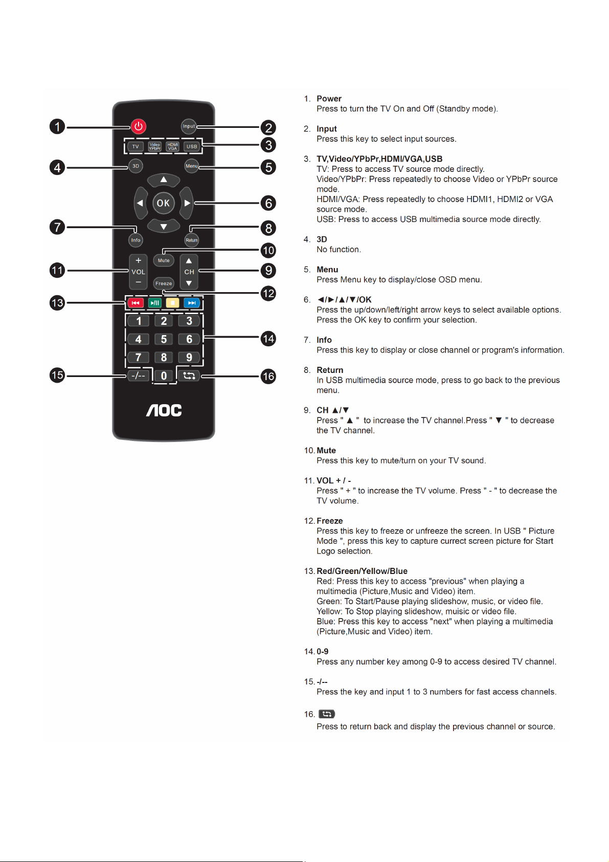
2.1 The Use of Remote Control
5
Page 6

2.2 To Use the Menus
You can select signal sources to your AOC TV set directly with your remote controller. You can also press the Input
key in the display menu to
select signal source.
1) Directly select the input signal sources by using
2) Select signal source with the Input key:
How to select on screen Menu items
Note:Some options may be unavailable or hidden according to the different input source and configuration.
6
Page 7
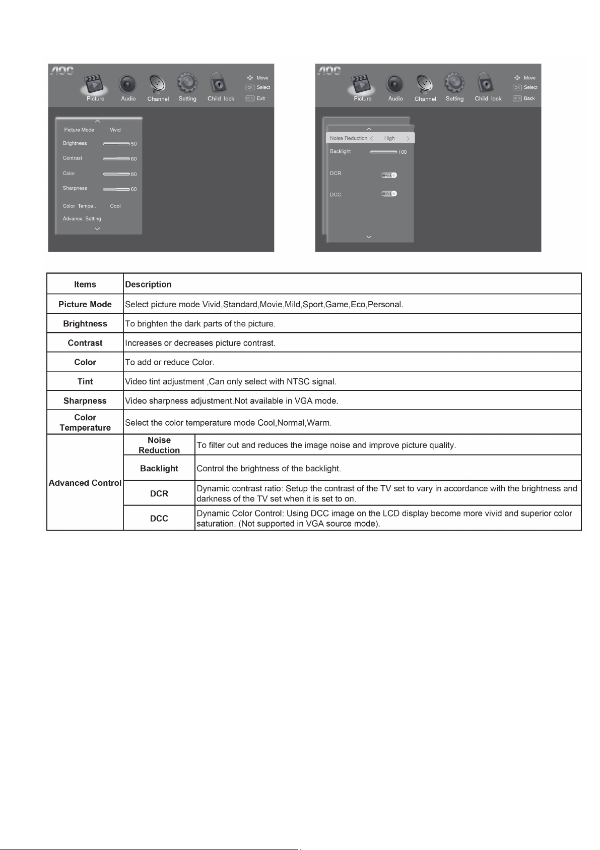
Picture Setting
Note:Certain screen setups may be unavailable or have different options in accordance with the input
sources.
7
Page 8
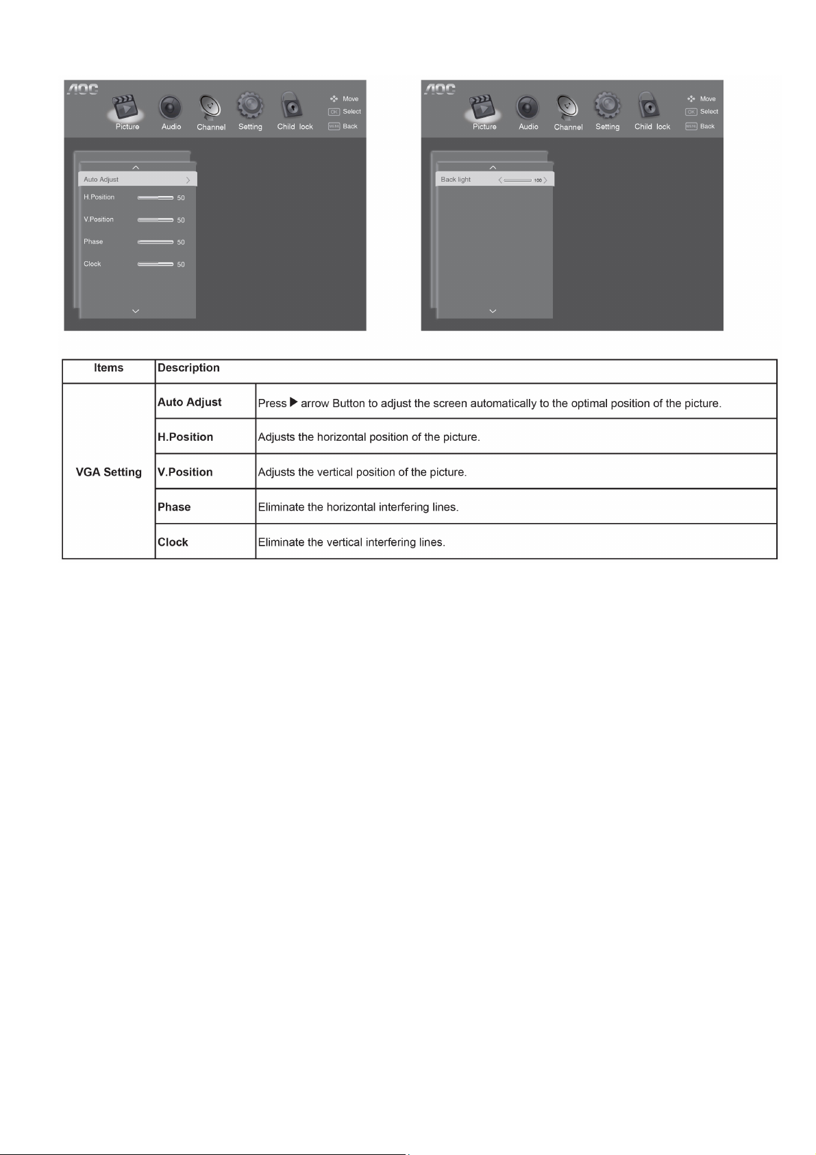
Picture Setting(For PC source only)
Note:
• If the PC is connected to the TV and no signal has been input from the PC for more than 30 seconds,the TV enters
the standby mode automatically.
8
Page 9

Audio Setup
9
Page 10

Channel Setup
Note: This setting is only available in TV mode.
Note:Make sure you have connected RF signal cable before performing channel search.
10
Page 11

Channel Edit description
1. Select Channel Search menu.
2. Select Manual Search and press OK key or ► arrow key to get Manual search sub-menu
3. Select a manual tuning parameter by using arrow.
11
Page 12
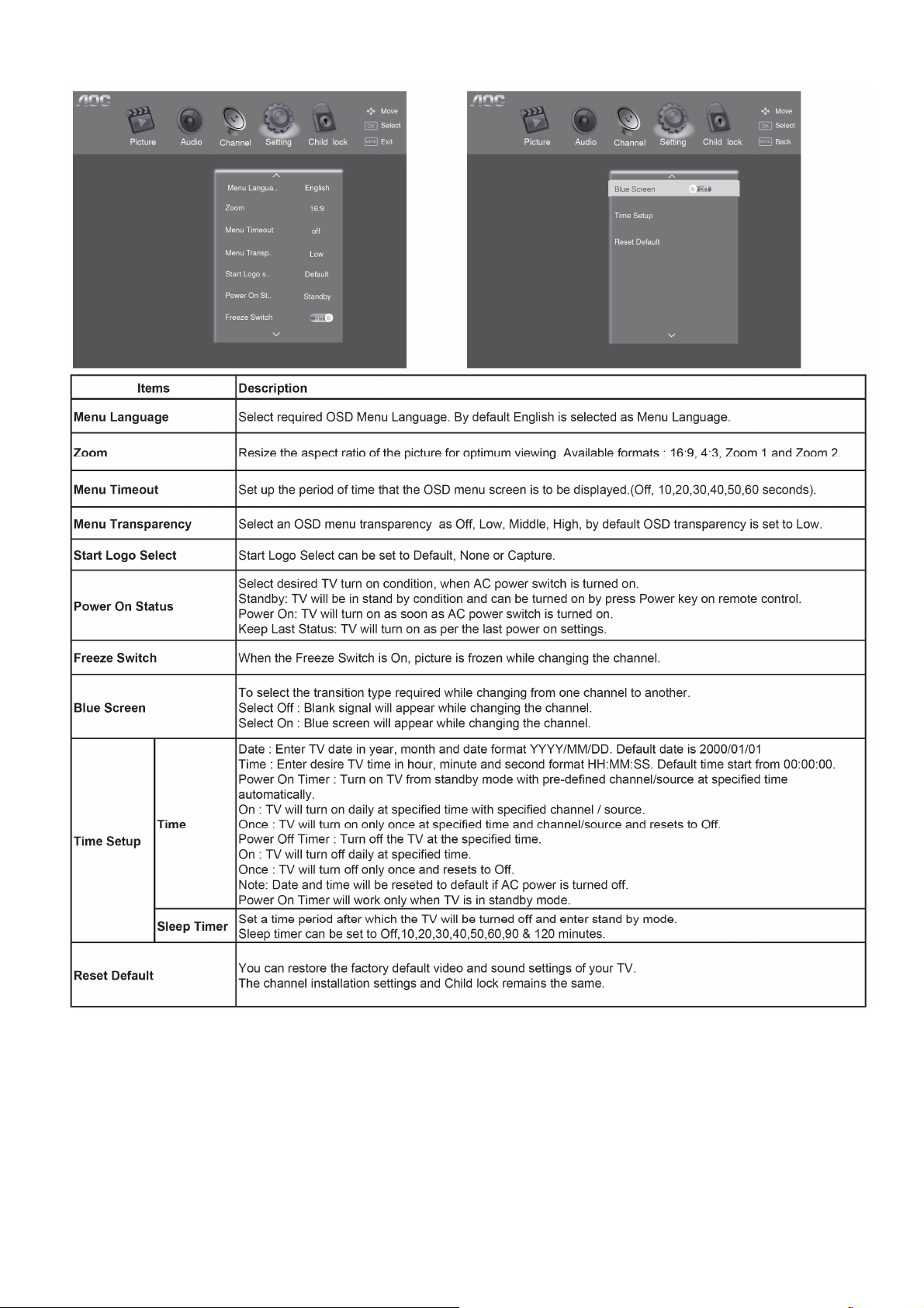
Features Setup
Note:Certain screen setups may be unavailable or have different options in accordance with the input sources.
12
Page 13
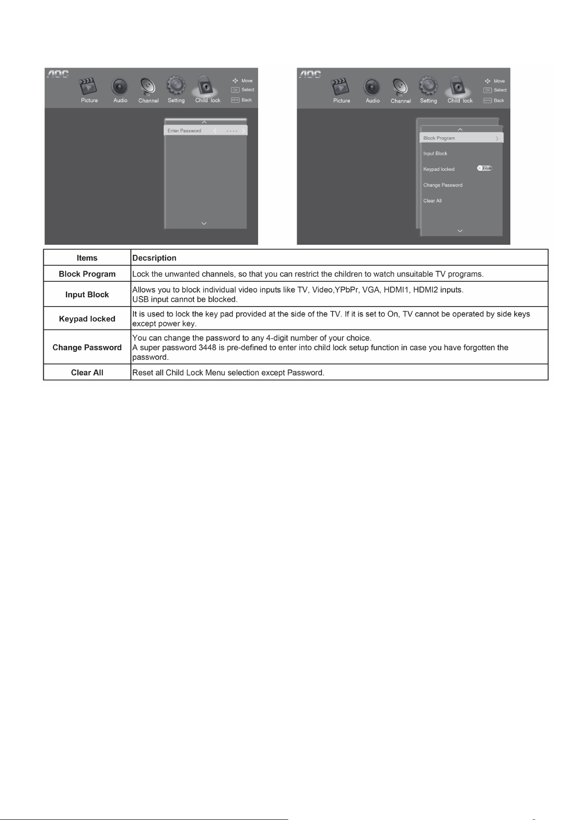
Child Lock Setup
Child lock menu can be accessed by entering 4 digit password through remote control. Initial password is 0000.
13
Page 14
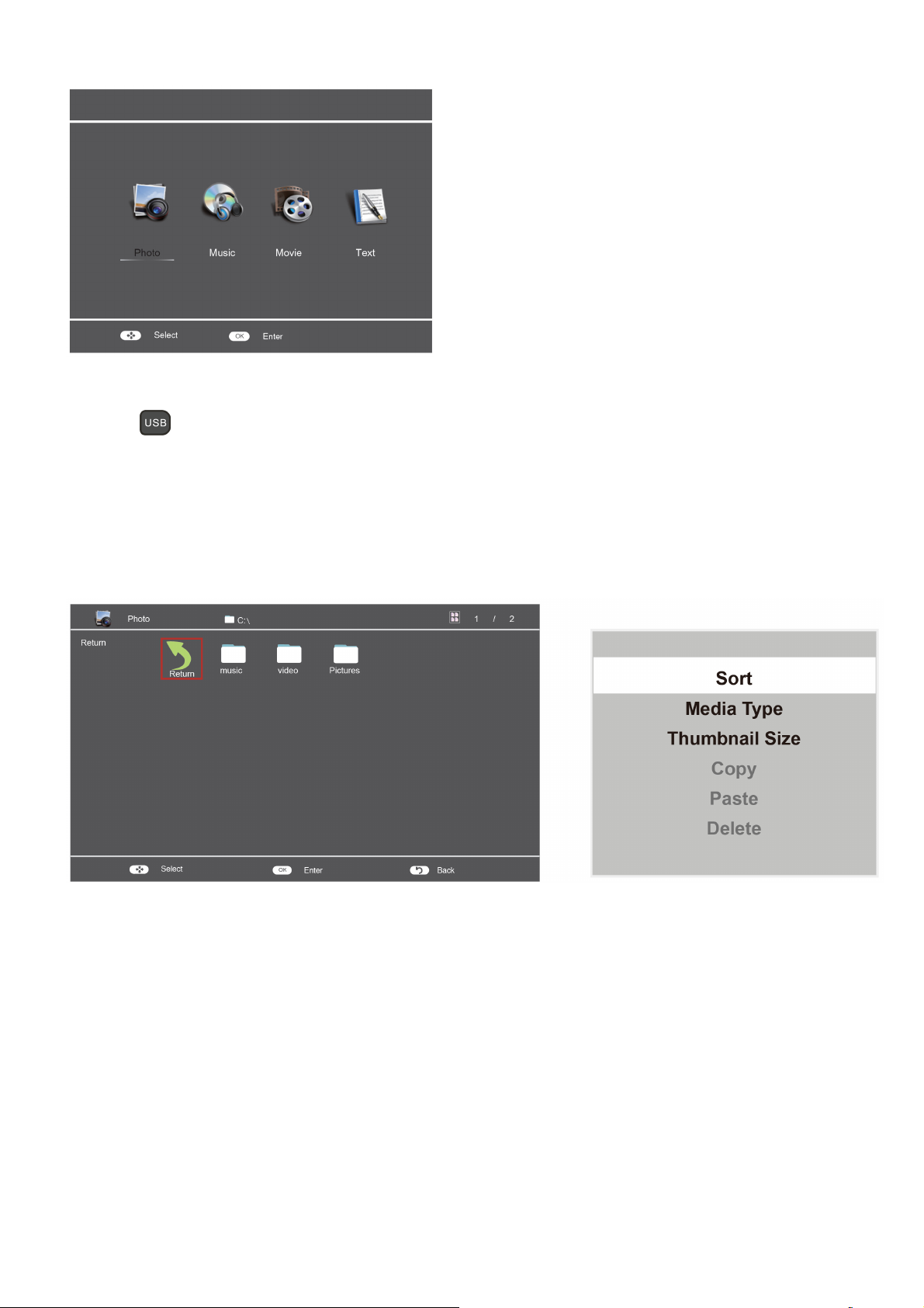
USB Media Center
TV USB port can be used to view JPEG photos, play mp3 music and Video files, and read text present in USB
devices.
Entering to USB Media:
Press the
Or Press the Source key and ▲/▼ keys on remote and select USB source to get USB Media menu as shown above
Select the Media type (Photo/ Music/ Video/ Text) to be viewed and press OK key to enter into USB Media
and When USB drive is detected by the TV, USB drive is displayed as a folder on the screen as shown below.
Press OK key to view subfolder or files in the USB drive.
Notes:
• Files of selected Media type can only be viewed through USB. Media type can be any one amoung Photo / Music /
Video / Text.
Direct USB key on remote to get USB Media menu as shown above
After entering the multimedia file selection interface, press the Menu button allows you to execute the following
control functions:
1. [Sort]: Sort the multimedia files according to Date or Name.
2. [Media Type]: Select the multimedia file type to playback.
3. [Thumbnail Size]: Select the size of the multimedia file thumbnail.
4. [Copy]: Select the multimedia files to copy.
5. [Paste]: Paste the copied multimedia file.
6. [Delete]: Delete the selected multimedia file.
14
Page 15
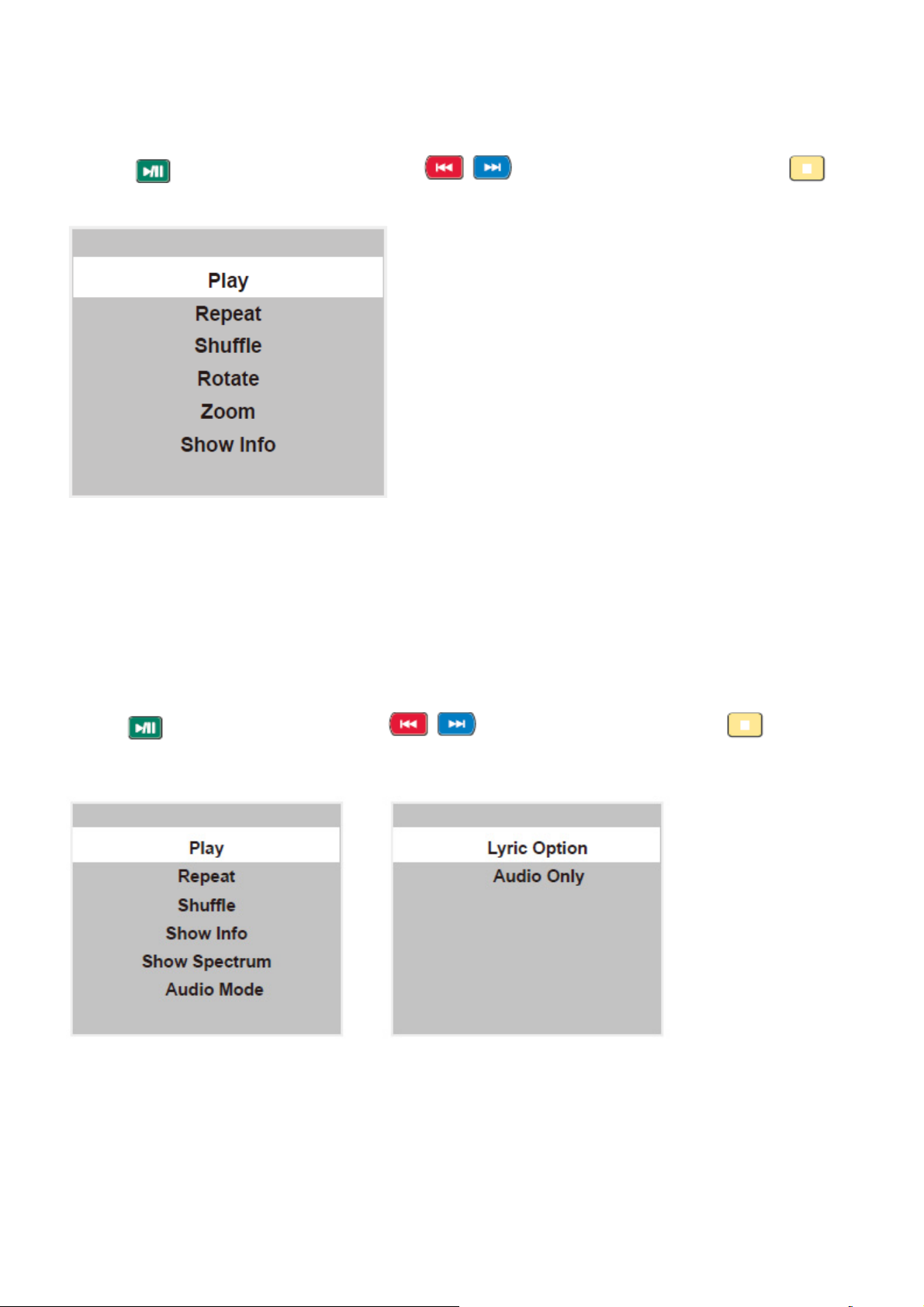
Viewing Photos
1. Thumbnail of the available images will be displayed on the screen. If no images are displayed then select the
folder containing the Photos .
2. To select a particular image and to display it in fullscreen press key and press OK key.
Slide show starts automatically when image is viewed in full screen.
3. Press
key to play/pause slideshow. Press to view previous or next image. Press key
to stop slideshow
USB menu settings for Photo Slide show
Press Menu key to get following Menu setup shown above.
1.[Play/Pause]:Play/Pause photo play.
2.[Repeat] : Select the repeat mode as None,Repeat One,Repeat All.
3.[Shuffle]:Select Shuffle mode as Shuffle Off,Shuffle On.
4.[Rotate] : Rotate the select photo by 90° clock wise direction.
5.[Zoom]:Allows you to zoom in on the screen when the playback is paused.
6.[Show Info] : Display the information of the file.
Playing Music files
1. Thumbnail of the available music files will be displayed on the screen. If no files are displayed then select the
folder containing the music files.
2. To play particular music file select the required file and press OK key.
3. Press
key to play/pause music. Press to play previous or next track. Press key to stop
Music play.
USB menu settings for Music play
Press Menu key to get following Menu setup shown above.
1.[Play/Pause]:Play/Pause music play.
2.[Repeat] : Select the repeat mode as None,Repeat One,Repeat All.
3.[Shuffle]:Select Shuffle mode as Shuffle Off,Shuffle On.
4.[Show Info] : Display the information of the file.
5.[Show Spectrum/Hide Spectrum]:select show or hide Spectrum.
6.[Audio Mode]: Select the sound mode as Standard,Personal, Music,Speech,Theater.
7.[Lyric Option]: Select on or off to turn on or off lyric display.
8.[Audio Only] : Select it to turn off dispaly and to get only sound from TV
.
15
Page 16
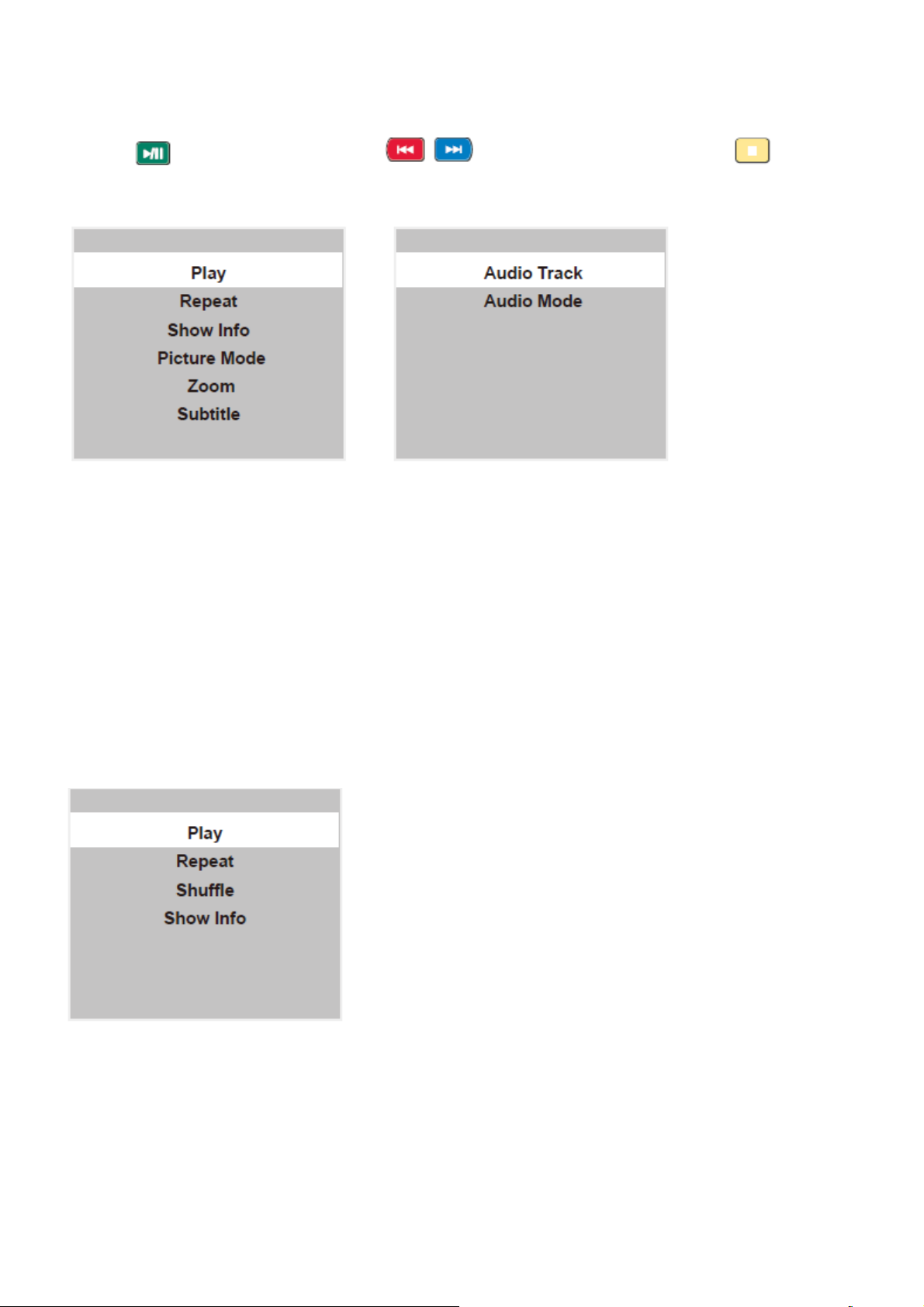
Playing Movie files
1. Thumbnail of the available video files will be displayed on the screen. If no files are displayed then select the
folder containing the video files.
2. To play particular video file select the required file and press OK key.
3. Press
video play.
key to play/pause video. Press to play previous or next video. Press key to stop
USB menu settings for Movie play
Press Menu key to get following Menu setup shown above.
1.[Play/Pause]:Play/Pause movie play.
2.[Repeat] : Select the repeat mode as None,Repeat One,Repeat All.
3.[Show Info] : Display the information of the file.
4.[Picture Mode]: Select the picture mode as Vivid,Standard,Movie,Personal,Eco,Sport,Game,Mild.
5.[Zoom]:Select the screen mode as 4:3,Zoom 1,Zoom 2,16:9.
6.[Subtitle]:Select the subtitle mode of the movie.
7.[AudioTrack]:Select the track mode of the audio.
8.[Audio Mode]:Select audio mode Standard,Personal,Music,Speech,Theater.
Reading Text files
1. Thumbnail of the available text files will be displayed on the screen. If no files are displayed then select the folder
containing the text files.
2. To read particular text file select the required file and press OK key.
3. Press ◄/►/▲/▼ keys to browse the text. Press MENU key to stop text read.
USB menu settings for text read
Press Menu key to get following Menu setup shown above.
1.[Play/Pause]:Play/Pause text read.
2.[Repeat]:Select the repeat mode as None,Repeat One,Repeat All.
3.[Shuffle]:Select the shuffle mode as Shuffle Off,Shuffle On.
4.[Show Info]: Display the information of the file.
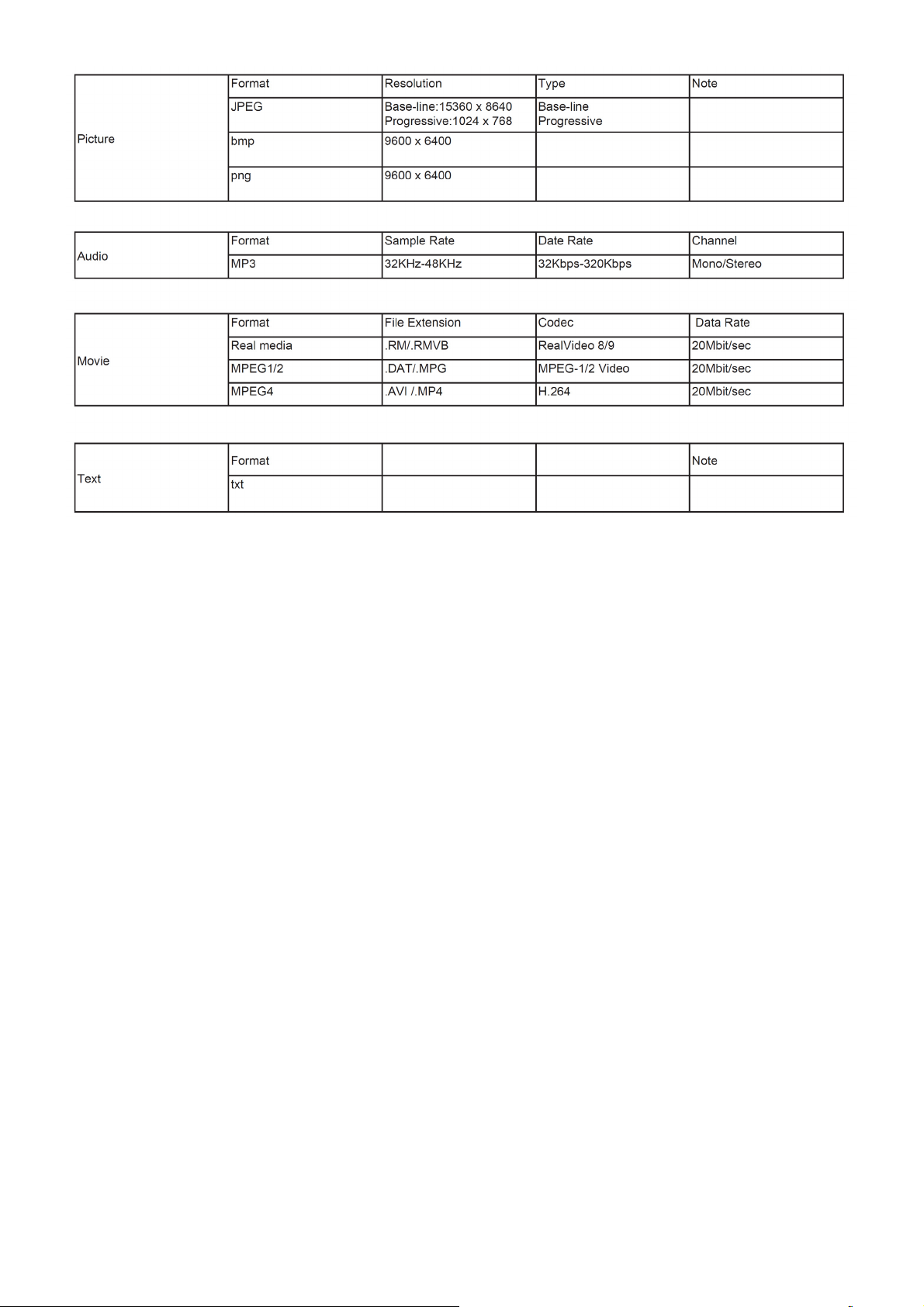
Formats supported to multimedia mode: Photo, Music, Movie and Text.
16
Page 17
Remarks:
1. USB interface of digital multimedia player is not all-purpose. So when some USB devices could not be recognized,
the problem is usually
not the performance failure but due to device driver.
2. Because USB devices and memory capability are different, the time needs for multimedia player to read
information are also different. So
the information reading speed of the player temporarily getting slow are not the performance failure.
3. The voltage supplied to USB interface is 5V, and the most electrical current is 500mA. When some interface
criteria of USB devices are
different from standard USB protocol, digital multimedia player may be unable to recognize USB devices correctly,
which is normal status.
4. USB could be used as an interface to update software.
5. If some files source could not play because of the parameter decoding-limitation, the problem is not performance
failure.
6. The system only applies to memory medium with FAT32 and NTFS format.
7.Does not support connecting of removable devices to the USB hub.
8. Does not support displaying of subtitles of video files with subtitles.
9. Does not support thumbnail display of png and Bmp format images.
10. The USB device does not support copying and pasting for NTFS system.
17
Page 18
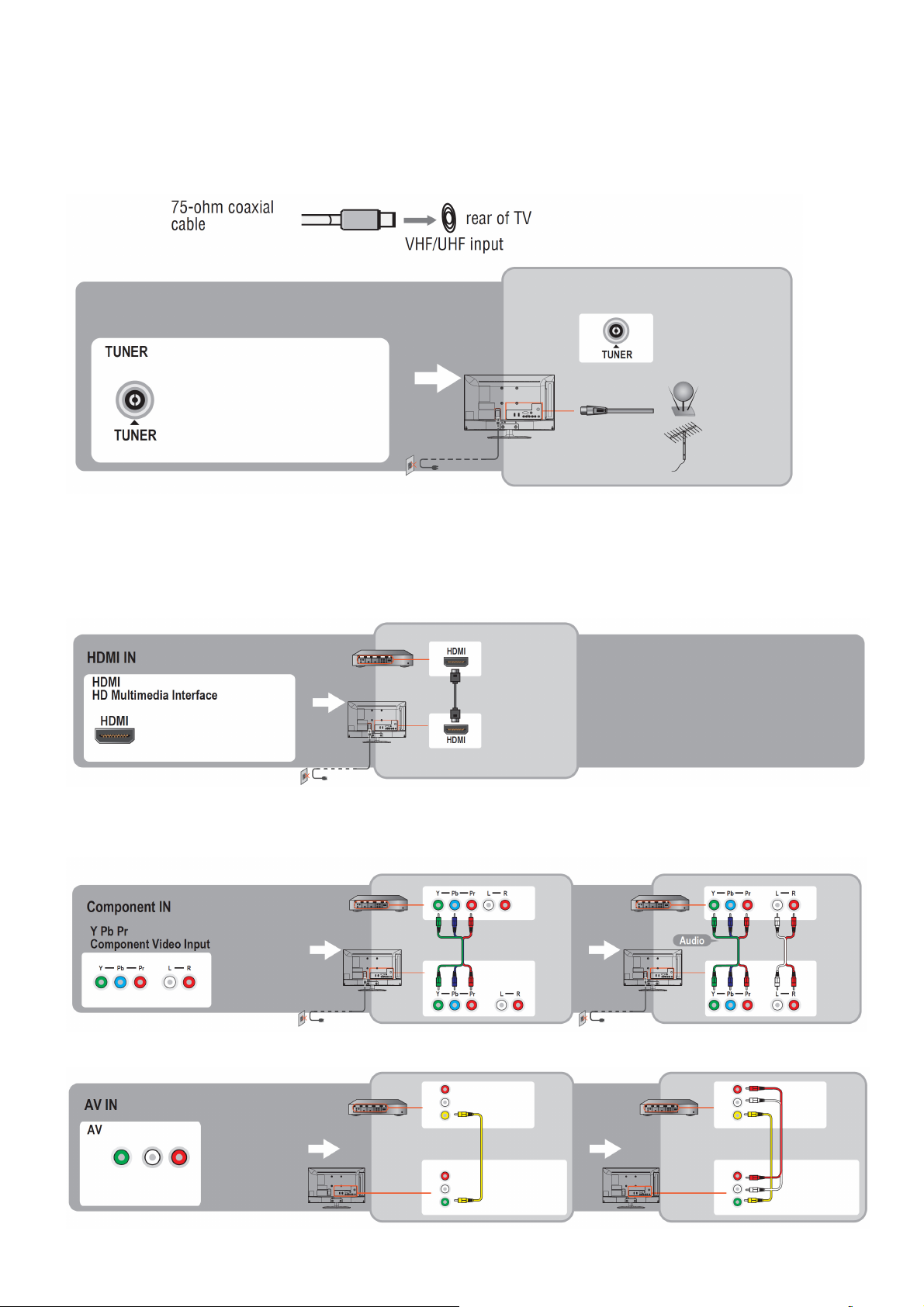
2.3 How to Connect
You can enjoy standard-definition and high-definition digital programming (if available in your area), along with
standard-definition analog programming.
It is strongly recommended that you connect the antenna/cable input using a 75-ohm coaxial cable to receive
optimum picture quality. A 300- ohm twin lead cable can be easily affected by radio frequency interference, resulting
in signal degradation.
Cable or VHF/UHF(or VHF only)
High Definition Interface
You can enjoy high-definition programming by subscribing to a high-definition cable service or a high-definition
satellite service. For the best possible picture, make sure you connect this equipment to your TV via the HDMI or
component video (with audio) input on the back of your TV.
HDMI Connection
If the equipment has a DVI jack and not an HDMI jack, connect the DVI jack to the HDMI IN (with DVI-to-HDMI cable
or adapter) jack and connect the audio jack to the PC AUDIO IN jacks.
Component Signal Connection
Composite Signal Connection
18
Page 19
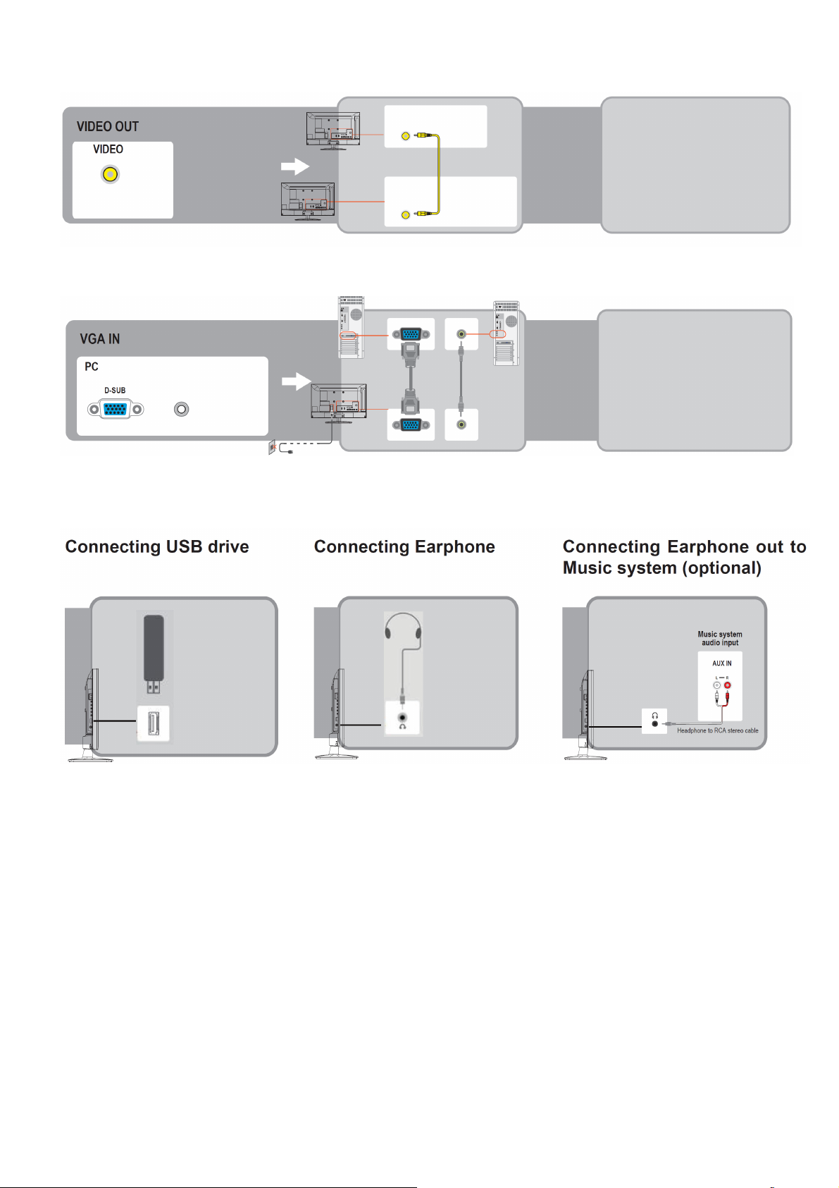
Video Out Signal Connection
PC Connection
Use the TV as a monitor for your PC shown below with the HD15 to HD15 connection. This TV can also be
connected to a PC with DVI or HDMI output.
• Connect the PC IN jack to the PC using the HD15- HD15 cable with ferrite core (analog RGB) and audio cable.
• If the PC is connected to the TV and no signal has been input from the PC for more than 30 seconds, the TV enters
the standby mode automatically.
19
Page 20

2.4 Front Panel Control Knobs
20
Page 21
3. Input / Output Specification
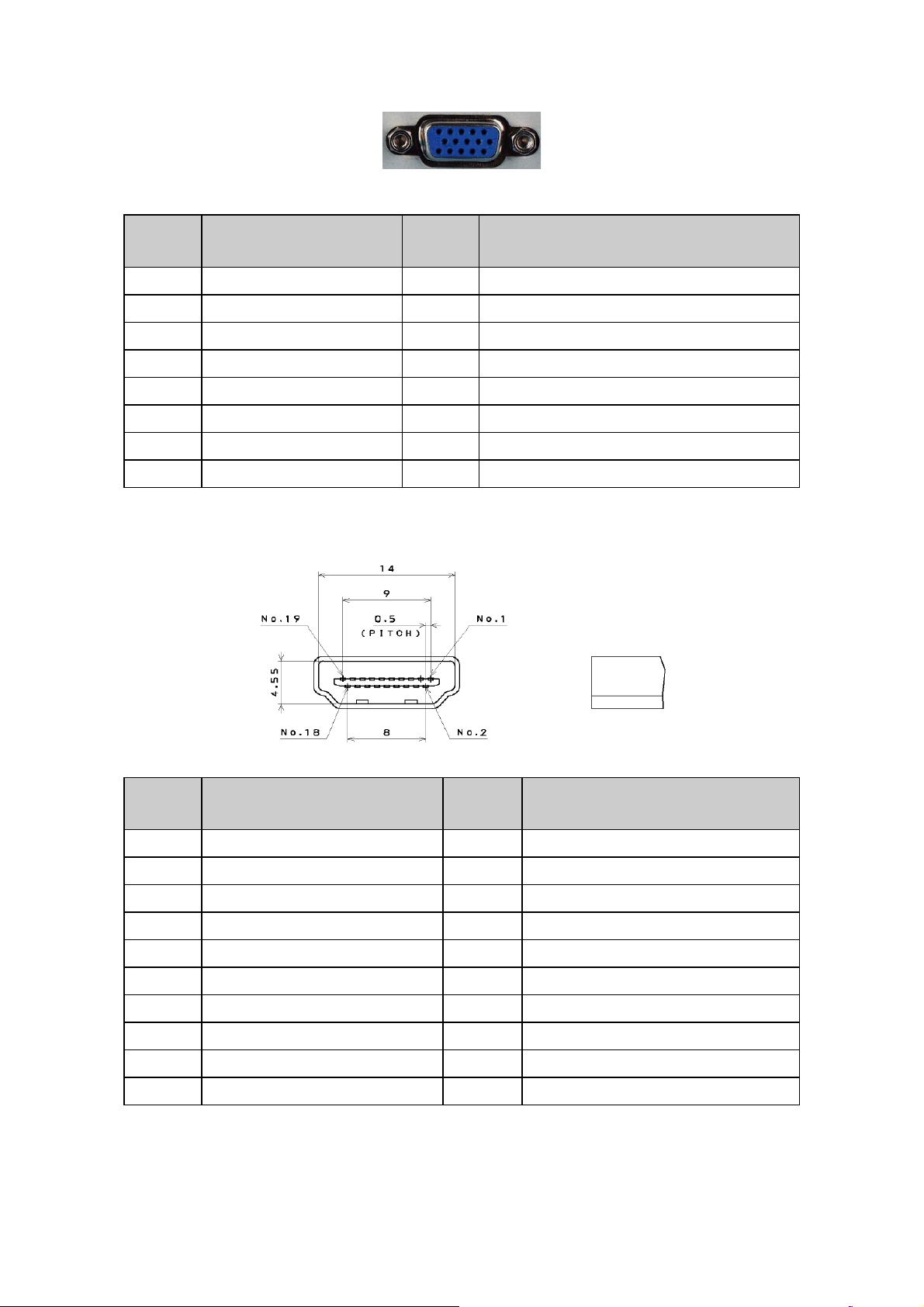
RGB Signal Input
15 - Pin Color Display Signal Cable
Pin No. Description Pin No. Description
1 Red Video 9 No Pin!
2 Green Video 10 Sync Ground
3 Blue Video 11 RDA
4 SCL 12 Serial Data for DDC
5 Ground 13 H-Sync.
6 Red Ground 14 V-Sync.
7 Green Ground 15 Serial Clock for DDC
8 Blue Ground
HDMI Digital Connector Pin Assignments
Pin No. Description Pin No. Description
1 TMDS Data2+ 2 TMDS Data2 Shield
3 TMDS Data2- 4 TMDS Data1+
5 TMDS Data1 Shield 6 TMDS Data1-
7 TMDS Data0+ 8 TMDS Data0 Shield
9 TMDS Data0- 10 TMDS Clock+
11 TMDS Clock Shield 12 TMDS Clock13 CEC 14 Reserved(N.C. on device)
15 SCL 16 SDA
17 DDC/CEC Ground 18 +5V Power
19 Hot Plug Detect
21
Page 22

Compatible Mode Table
22
Page 23
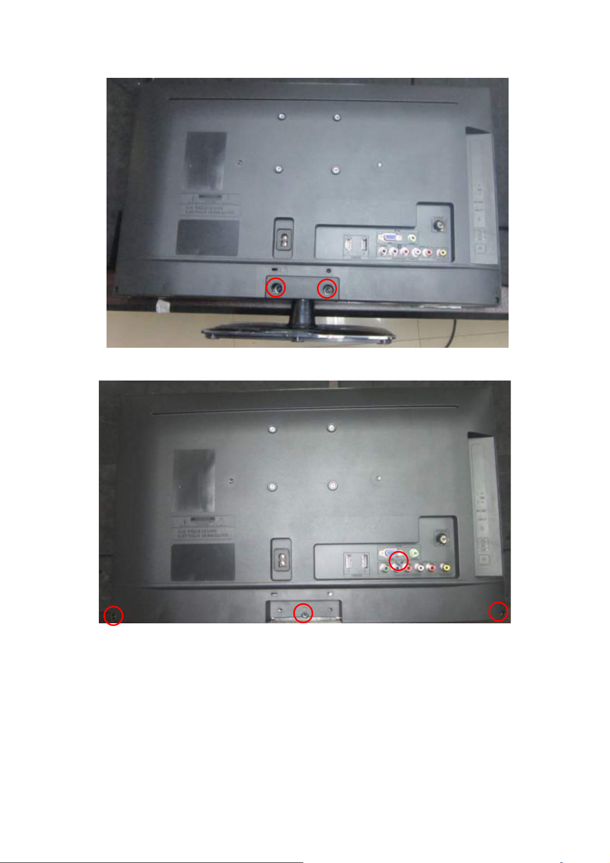
4. Mechanical Instructions
1. Remove the screws to remove BASE.
2. Remove the screws to remove REAR COVER.
23
Page 24
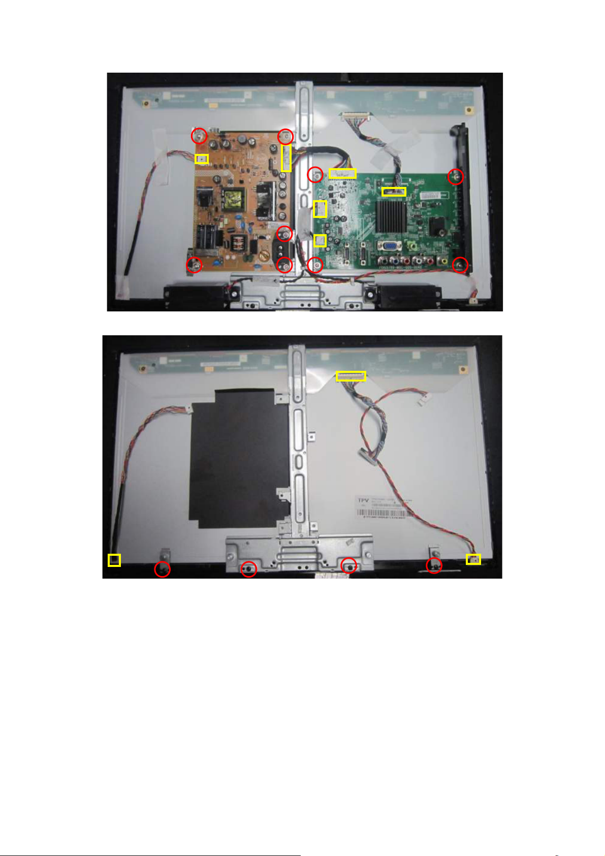
3. Disconnect the PINS marked in yellow .Remove the screws marked in red to remove MAIN BOARD,POWER
BOARD,IR BOARD.
4. Disconnect the PINS marked in yellow .Remove the screws to remove BKT_ STAND, BKT_HOLDER.
24
Page 25
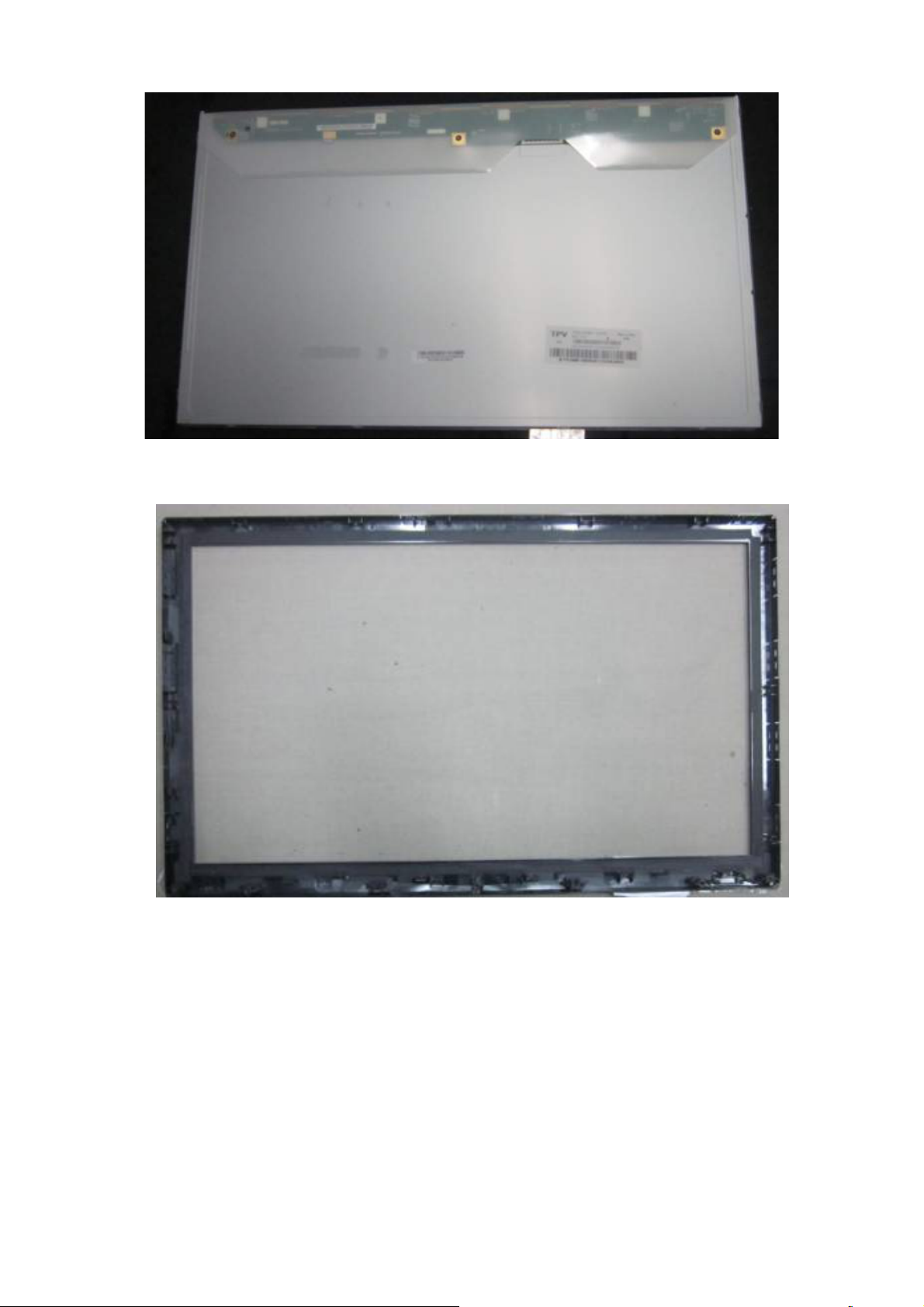
5. Sperate PANEL and BEZEL.
6. BEZEL.
25
Page 26
p
p
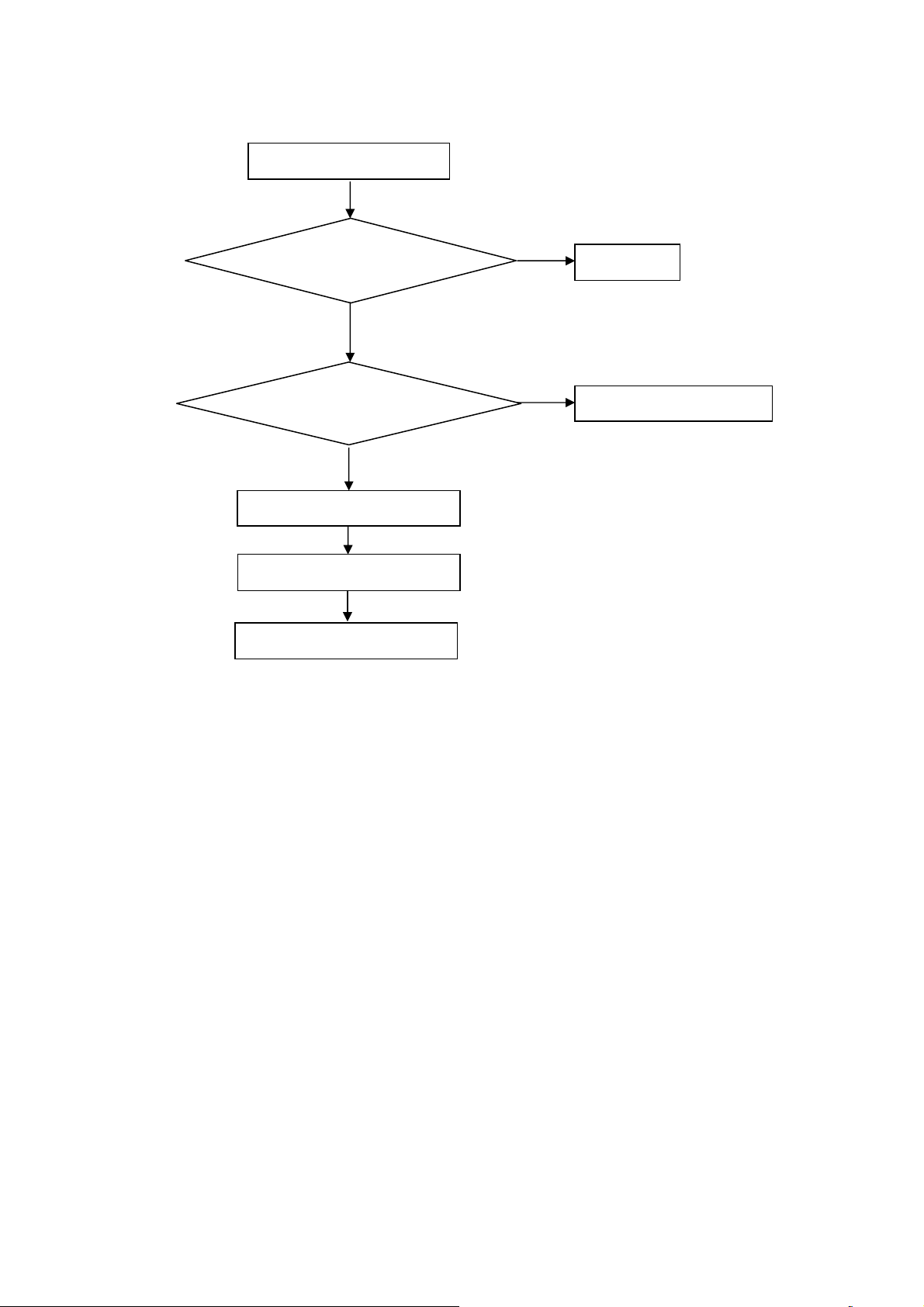
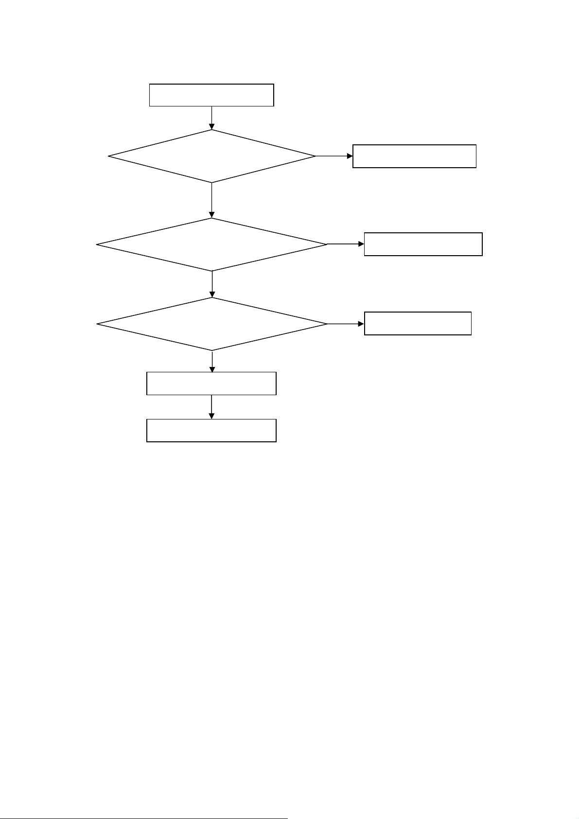
5. Repair Flow Chart
1. No power
No power (LED “Off”)
Check the AC input and
the
ower is “ON”?
Yes
Power board
out
ut=5.2V?
Yes
Check the IR board and LED
Replace the IR board
No
Replace the main board
No
Power “On”
No
Replace the power board
26
Page 27
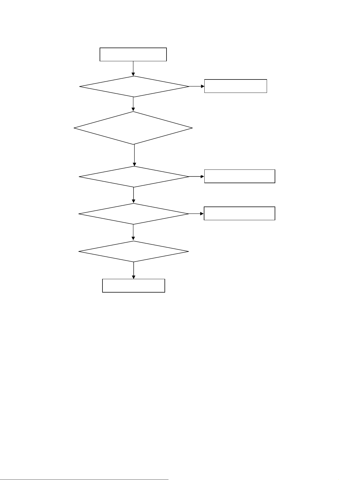
2. Can’t start
Can’t start (LED red)
Power board output=12/16V?
Yes
Check the power key is under control?
No
Check the IR receiver is normal?
No
Replace the power board
Yes
Replace the main board
Yes
Replace the IR board
No
Replace the main board
No
Replace the Power board
27
Page 28
3. Abnormal display
Abnormal Display
Check the source
Yes
Enter factory mode to do
“EEPROM initial”&“Reset”
No
No
Reset the source
Check the main board
Yes
Check the LVDS cable
Yes
Check the panel
No
Replace the panel
No
Replace the main board
No
Replace the LVDS cable
28
Page 29

4. No display
No display (No LED)
Check TV is under control and power
on/off by remote control and power key?
Yes
Check the LVDS cable
Yes
Yes
Check the backlight is
“On”?
No
Reinsert or replace the
LVDS cable
No
No
Check the B/L
signal is available?
Yes
Replace the main board
No
Replace main board
Panel Vcc = 12V?
Yes
Replace the Panel
No
Replace the main board
Power board output=12/16V?
Yes
Replace the Panel
Replace the power board
No
29
Page 30

5. Sound problem
No sound or sound abnormal
Check the audio source connection
and the TV system are correct?
Yes
Check the TV is muted, adjust the
volume or enter the menu to reset?
No
No
Reinsert the audio cable or
change the TV system
Enter factory mode to do “Reset”
No
Check the cable between the
speakers and main board is OK?
Yes
Check the speaker resistance value is in spec
(Remark: The value is marked on the speaker)?
Yes
Replace the cable
Replace the main board
No
No
Replace the speaker
30
Page 31

6. Remote control malfunction
Remote Control malfunction
Check the remote control battery is
not properly placed or no power?
No
Use the other remote controls
No
Whether the IR board is
abnormal?
No
Replace the main board
Yes
Replace the battery
Yes
Replace the remote control
Yes
Replace the IR board
31
Page 32

6. PCB Layout
6.1 Main Board
715G5789M01000004K
32
Page 33

33
Page 34

6.2 Power Board
715G5309P01001002S
34
Page 35

35
Page 36

715G5804P01W20001M
36
Page 37

37
Page 38

38
Page 39

6.3 IR Board
715G5889R01000004S
39
Page 40

7. Adjustment
White balance adjustment: press "menu +1+9+9+9+ look back" into the factory mode Current Source is
"component", and then choose Color temp color mode (Cool, Normal, Warm), select OK and then choose the
Gain bar to adjust the R/G/B value, the temperature adjustment to the required specification range. In the case
of LE26H100C:
Note: R G B GAIN were less than 138128138, after component adjustment, other source R G B GAIN and
component, if not the same, need to switch to the other source value is adjusted to the same.
White balance value checking: Current Source is selected as the "video" /T304,"HDMI /T349," "computer"
/T137 three model specifications, color temperature is within the specifications, the OK white balance
adjustment.
Figure 1 Figure 2
Adjustment specifications are written in the white balance program, test to product specification shall prevail:
Colour temperature
(x,y)
Cool
(0.280,0.285)
Normal
(0.295,0.305)
Warm
(0.313,0.329)
Item Level x y x y x y
Adjustment
specifications
specifications of
the products
80IRE 0.003 0.003 0.003 0.003 0.003 0.003
80IRE 0.020 0.020 0.020 0.020 0.020 0.020
40
Page 41

8. Block Diagram
TPA3110D
LVDS Panel
USB DM/DP
USB
SPI
Flash
Key&IR
HDMI1
MST6931
VGA
CVBS-OUT
YPbPr
Audio L
Audio R
Video-out
41
IF+/-
PC-Audio
DT21WN-2-E
AP2176
ATV
Earphone
HDMI2
Page 42
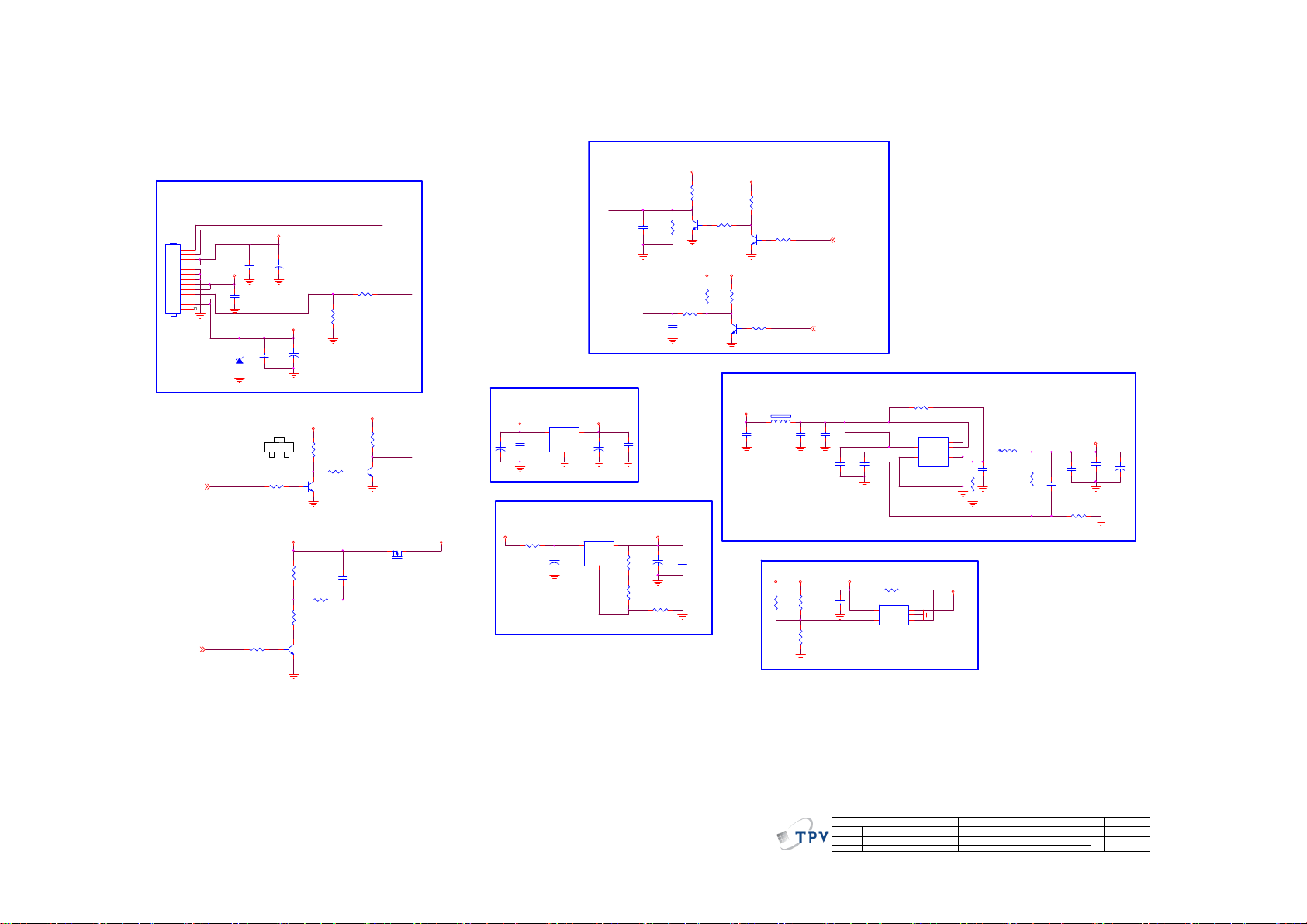
9. Schematic Diagram
9.1 Main Board
715G5789M01000004K
From
Power
Board
CN701
12V
P12V
1
2
3
4
5
6
7
8
9
10
11
12
13
CONN
13P R/A 2.5mm
311GW250B13BBX
PW_CTL2
PW_CTL2
24V
P24V
PW_CTL
PW_CTL
P24V
C705
0.1uF 50V
1 2
R723 4.7K
C703
100NF 16V
5V
ZD701
NC/BZT52-C5V6
R716 4.7K
+
C707
100NF 16V
B
C704
10UF 25V
SMT
+5V_Standby
C
E
P12V
+
C708
100UF 16V
SMT
+5V_Standby
R720
100K
R722
10K
Q706
MMBT390 4
+5V_No rmal
R713
10K
R714 10K
Q705
MMBT3904
R729
47K
R705 100R
R708
NC/10K
C724
100NF 16V
BL_EN
BL_PWM
+5V_No rmal
R712
1K
Q704
MMBT390 4
PS_ON
PS_ON
Q701
LP3401LT1G
+5V_Normal
Standby Power
+5V_Standby
U702
AZ1117D
C712
+
C711
1UF16V
100UF 16V
DDR Power
+5V_No rmal
R718 2.2R
+
+3.3V_Standby
2
VI3VO
+
C713
GND
100UF 16V
1
SMT
U703
AZ1084D-ADJTRE1
3
VOUT2VIN
C721
GND
100UF 16V
1
SMT
Vout = 1.25x(R1+R2)/R2
1.845V
BL_EN
C702
NC/10N 50V
R1
BL_PWM
NC/4. 7UF 10V
C714
100NF 16V
+1.8V_DDR
R719
2.4K 1%
R701
0.05R
R721 1K 1%
Backlight Control
+5V_No rmal
R702
1K
R704
Q702
R703
NC/10K
C706
+
C722
100UF 16V
SMT
R2
1K
R709
NC/10K
C723
NC/10uF
MMBT3904
+5V_Normal
R706
Q703
MMBT3904
1K
+3.3V_Standby
+5V_Normal
6-12
R728
10K
Q707
R727 4.7K
MMBT390 4
R707
1K
R710 4.7K
+1.2V Core Power
+5V_Standby
FB701
1 2
300R 4A
C709
4.7uF 10V
USB Power
P24V
R730
R725
NC/15KOHM 1/16W
27K 1/16W 5%
R726
10K+- 5%1/16W
Hi: Off
Low: On
VBL_CTRL
C701
100NF 16V
P12V
1UF 16V
VBL_CTRL 2
BRI_AD J-PWM0 2, 3
C710
10UF 10V
C715
100N 16V
0402
+5V_No rmal
C725
C716
100N 16V
0402
Vout = 0.8x(R1+R2)/R2
R724
NC/100K
U704
5
VOUT
VIN
GND
4
OCB3EN
APL3511CBI-TRG
R711 1K
1
VCC
2
POK
3
GND
FB4EN
1
2
U701
9
E-Pad
8
VIN
7
LX
6
PGND
5
APW7323AKAI-TRG
USB_5V
430 1%
R731
073G253S 68 H
L701
2.2uH
C718
1UF16V
1.26V
7.5K 1%
+1.2V_VDDC
220UF 16V
C726
+
C719
C717
22UF 10V
22UF 10V
R715
C720
10N 50V
0402
R717
SMT
12.4K 1%
R2
R1
42
T P V ( Top Victory Electronics Co . , Ltd. )
絬 隔 瓜 絪 腹
Key Component
01-Power
Date
OEM MOD EL
TPV MODE L
PCB NAME
Sheet
Custom
Size
A
Rev
<
称爹
>
19Friday , Nov ember 16, 2012
of
称爹
Page 43

H/W R es et
HDMI_CEC5
HDMI-ARC5
VGA_HS4
VGA_VS4
VGA_BIN4
VGA_GIN4
SOG04
VGA_RIN4
Y+4
SOY4
Pb+4
Pr+4
AV1-CVBS0P4
CVBS_OUT04
VGA-AUR14
VGA-AUL14
COMP_AUR44
COMP_AUL44
USB0_DP4
USB0_DM4
LEDR9
LEDG9
VIFP7
VIFM7
TAGC7
HP_DET4, 6
IRIN9
UART-RX4,9
UART-TX4,9
KEY0-SAR 09
KEY1-SAR 19
CN402
NC/CONN
HDMI_HP1
HDMI1-SCL
HDMI1-SDA
HDMI1-CLKP
HDMI1-CLKN
HDMI1-RX0P
HDMI1-RX0N
HDMI1-RX1P
HDMI1-RX1N
HDMI1-RX2P
HDMI1-RX2N
HDMI_HP0
HDMI0-SCL
HDMI0-SDA
HDMI0-CLKP
HDMI0-CLKN
HDMI0-RX0P
HDMI0-RX0N
HDMI0-RX1P
HDMI0-RX1N
HDMI0-RX2P
HDMI0-RX2N
HDMI-CEC
HDMI-ARC
VGA_HS
VGA_VS
VGA_BIN
VGA_GIN
SOG0
VGA_RIN
Y+
SOY
Pb+
Pr+
AV1-CVBS0P
CVBS_OUT0
VGA-AUR1
VGA-AUL1
COMP_AUR4
COMP_AUL4
USB0_DP
USB0_DM
LEDR
LEDG
VIFP
VIFM
TAGC
HP_DET
IRIN
UART-RX
UART-TX
KEY0-SAR0
KEY1-SAR1
Debug & ISP port
1
2
UART-RX
3
UART-TX
4
Sys tem-RST
C405
1uF 10V
+5V_Standby
R405
1K 1/16W
C404
1NF 50V
R407
51R 1/16W 5%
R421
R422
4.7K
4.7K
HDMI_ARC
HOTPLUG15
HDMI1_DDC_SCL5
HDMI1_DDC_SDA5
HDMI1_CLK+5
HDMI1_CLK-5
HDMI1_D0+5
HDMI1_D0-5
HDMI1_D1+5
HDMI1_D1-5
HDMI1_D2+5
HDMI1_D2-5
HOTPLUG05
HDMI0_DDC_SCL5
HDMI0_DDC_SDA5
HDMI0_CLK+5
HDMI0_CLK-5
HDMI0_D0+5
HDMI0_D0-5
HDMI0_D1+5
HDMI0_D1-5
HDMI0_D2+5
HDMI0_D2-5
+5V_Standby
3
1M 1/16W
D401
BAV99
1
2
C402
2.2UF 16V
R404
Q402
4.7K 1/16W
MMBT3906
R406
22K 1/16W
VDD33
VDDC
R410
68OHM 1/16W
AVDD_ADC
R412
68OHM 1/16W
C449
47nF 16V
R415
68OHM 1/16W
Close to IC
with width trace
100N 16V
FB402
60 OHM
1 2
CHIP_CONFIG
{IPAD_PWM1, PAD_PWM0}
B51_NO_EJ
VBL-CTRL
R419
4.7K
R0402
System XTAL
XTALO
R427
0R05 OHM
1M 1/16W
XTAL I
AU33
C412
R403
C403
2.2UF 16V
BRI_ADJ -PWM0
R428
47nF 16V
4'h00
R420
4.7K
R0402
X401
24MHz
12
C407
47nF 16V
C408
47nF 16V
AV1-CVBS0P
C410
C413
10UF
HDMI1-CLKN
HDMI1-CLKP
HDMI1-RX0N
HDMI1-RX0P
HDMI1-RX1N
HDMI1-RX1P
HDMI1-SDA
HDMI1-RX2N
HDMI1-RX2P
HDMI1-SCL
HDMI_ARC
VGA_HS
VGA_BIN
SOG0
VGA_GIN
VGA_RIN
VGA_VS
Pb+
SOY
Y+
Pr+
CVBS_OUT0
AUVRM
AUVAG
VGA-AUL1
C425
27PF 50V
C430
27PF 50V
1
RXCKN_A
2
RXCKP_A
3
RX0N_A
4
RX0P_A
5
AVDD_33
6
RX1N_A
7
RX1P_A
8
DDCDA_DA
9
RX2N_A
10
RX2P_A
11
DDCDA_CK
12
ARC
13
AVDD1P2_DVI_A
14
HSYNC0
15
BIN0P
16
SOGIN0
17
GIN0P
18
GIN0M
19
RIN0P
20
VSYNC 0
21
AVDD3P3_ADC
22
BIN1P
23
SOGIN1
24
GIN1P
25
GIN1M
26
RIN1P
27
VSYNC 1
28
HSYNC1
29
CVBS1
30
CVBS0
31
VCOM
32
CVBSOUT
33
AU33
34
AUREF
35
AUVAG
36
AUL1
37
AUR1
38
AUL3
U401
HDMI0-RX0P
HDMI0-RX1P
HDMI0-RX2P
HDMI_HP1
HDMI0-SDA
HDMI0-SCL
HDMI0-RX2N
HDMI0-RX0N
HDMI0-CLKP
HDMI0-RX1N
HDMI0-CLKN
118
121
124
127
128
120
123
126
122
125
129
119
E-Pad
RX0P_D
RX1P_D
RX2P_D
RX0N_D
RX1N_D
RX2N_D
RXCKP_D
HOTPLUGA
DDCDD_DA
DDCDD_CK
MST6931XP
AUOUTL146AUOUTR147AUOUTL044AUOUTR045XIN49XOUT48AVDD_DMPLL
AUL440AUR4
AUR543AUL5
AUR3
41
42
39
VGA-AUR1
COMP_AUR4
COMP_AUL4
AMP-AUOUTL0
AMP-AUOUTR0
XTALO
XTALI
AV-AUOUTL3
AV-AUOUTR3
+3.3V_Standby
R423
R424
4.7K
4.7K
AUDIO-EN
PWR-ON/OFF
VBL-C TRL VB L_CTR L
BRI_ADJ-PWM0
PW_CTL
GND-EFUSE
HDMI_HP0
116
117
RXCKN_D
HOTPLUGD
50
VDD33_DMPLL
R0402
R0402
PANEL-ON/ OFF
IRIN
HDMI-CEC
System -RST
112
115
113
114
IRIN
CEC
HWRESET
GND_EFUSE
SAR2/GPIO73
GND
RFAGC
VIFM53VIFP
AVDD3P3_DADC51GPIO5658VDDP59VDDC60GPIO55
55
54
52
TAGC
VIFM
VIFP
AVDD33_DEMOD
AUDIO_EN
ON_PANELPANEL-ON/OFF
TUNER _SC L
TUNER _SD A
3D_enable
C419
C418
100N 16V
100N 16V
+3.3V_Standby
1 2
Power 1.2V
+1.2V_VDDC
1 2
FB401120R/3000mA
FB406
RXO0RXO0+
RXO1RXO1+
RXO2RXO2+
RXOCRXOC+
RXO3RXO3+
RXE0RXE0+
RXE1RXE1+
RXE2RXE2+
RXECRXEC+
RXE3RXE3+
C420
100N 16V
60 OHM
C426
10UF
C406
180PF 50V
C409
180PF 50V
C411
180PF 50V
C414
180PF 50V
+3.3V_Standby
FB404
1 2
C423
100N 16V
C427
100N 16V
RXO0- 3
RXO0+ 3
RXO1- 3
RXO1+ 3
RXO2- 3
RXO2+ 3
RXOC- 3
RXOC+ 3
RXO3- 3
RXO3+ 3
RXE0- 3
RXE0+ 3
RXE1- 3
RXE1+ 3
RXE2- 3
RXE2+ 3
RXEC- 3
RXEC+ 3
RXE3- 3
RXE3+ 3
3D_enable 3
R409
R413
AV_AUOUTR3
R416
AV_AUOUTL3
R418
60 OHM
C428
100N 16V
100K 1/16W
100K 1/16W
100K 1/16W
100K 1/16W
C421
100N 16V
+3.3V_Standby
AVDD_AD C
1 2
FB40760 OHM
VDDC
C429
100N 16V
AMP_AUOUTR0 8
AMP_AUOUTL0 8
AV_AUOUTR3 6
AV_AUOUTL3 6
AU33AVDD33_DEMOD
C424
100N 16V
AVDD_DDR
KEY1-SAR1
KEY0-SAR0
BRI_ADJ -PWM0
UART-RX
UART-TX
VBL-CTR L
PWR-ON /OFF
104
105
106
107
108
111
110
103
109
GPIO64
TESTPIN
DDCA_CK
DDCA_DA
AVDD_D DR
SAR1/GPIO74
SAR0/GPIO75
AVDD_DDR
57
56
TUNER_SDA
TUNER_SCL
VDD33
VDDC
AVDD_DDR
PWM0/GP IO26
PWM1/GP IO25
USB1_DP
USB1_DM
AVDD_MOD
USB0_DP
USB0_DM
PWM2/GPIO24
INT/GPIO65
AVDD_MOD
LVBCKM
LVBCKP
AVDD_MOD
LVACKM
LVACKP
LVA3P
LVA4P61LVA4M62LVA3M
MST6931XP
63
64
RXE3-
RXE3+
AUDIO_EN 8
PW_CTL 1
ON_PANEL 3
VBL_CTRL 1
BRI_ADJ-PWM0 1,3
TUNER _SC L 7
TUNER _SD A 7
GPIO0
GPIO1
GPIO2
GPIO3
VDDC
LVB0M
LVB0P
LVB1M
LVB1P
LVB2M
LVB2P
LVB3M
LVB3P
LVB4M
LVB4P
LVA0M
LVA0P
LVA1M
LVA1P
LVA2M
LVA2P
102
101
100
99
98
97
SCZ
96
SDO
95
SDI
94
SCK
93
92
91
90
89
88
87
86
85
84
83
82
81
80
79
78
77
76
75
74
73
72
71
70
69
68
67
66
65
USB0_DP
USB0_DM
SPI_CS0N
SPI-SDO
SPI-SDI
SPI-SCK
SPI_WP0N
R401
100OHM1/16W
LEDG
LEDR
AUDIO-EN
RXO0RXO0+
RXO1RXO1+
RXO2RXO2+
RXOCRXOC+
RXO3RXO3+
RXE0RXE0+
RXE1RXE1+
RXE2RXE2+
RXECRXEC+
VDD33
HP_DET
3D_enable
VDDC
VDD33
VDD33
Power 3.3V
+3.3V_Standby
DDR Power
+1.8V_ DDR
FB408
0R05 1/10W
FB403
1 2
60 OHM
10UF
+3.3V_Standby
FB405
1 2
C431
10UF
NC/100N 16V
C415
VDD33
60 OHM
C432
AMP-AUOUTR0
AMP-AUOUTL0
AV-AUOUTR3
AV-AUOUTL3
C416
100N 16V
VDD33_DMPLL
C422
100N 16V
AVDD_D DR
C433
4.7UF 6. 3V
C417
100N 16V
SPI_CS0N
SPI-SDO
SPI_WP0N
+3.3V_Standby
WP active low
SERIAL FLASH
R431
4.7K
1
2
FLASH_WP0N
R434 1K
C435
100N 16V
3
R436
DGND
10K
close to IC
U402
CS#
SO/SIO1
HOLD#
WP#
GND4SI/SIO0
W25Q32BVSSIG
+3.3V_Standby
C434
R435 51R
C436
22PF 50V
DGND
100N 16V
SPI-SCK
SPI-SDI
8
VCC
7
6
SCLK
5
HS401
Heat Sink
DGND
AGND
DGND
1
1
2
2
DGND
T P V ( Top Victory Electronics Co . , Ltd. )
絬 隔 瓜 絪 腹
Key Component
02.MST6831XP/SPI FLASH
Date
OEM MODE L
TPV MOD EL
PCB NAME
Sheet
Custom
Size
Rev
A
<
称爹
>
29Friday , Nov ember 16, 2012
of
称爹
43
Page 44

NC/ 360R 1/ 10W 5%
ON_PANEL
S0
H
L
P12V
R444
NC/ 220 OHM 1/10W
R477 NC/4.7K
CHANNEL
B1
B0
ON_PANEL2
+5V_Standby
R447
NC/ 360R 1/ 10W 5%
R452
NC/ 220 OHM 1/10W
+5V_Standby
Panel IIC NC
Panel IIC
R451
NC/ 390 OHM 1/10W
R453
DGND
R476
NC/10K
Q408
NC/ MMBT3904
R442 4.7K
R443
10K
DGND
U403
NC/ AZ809ANSTR-E1
RESET
3
Vcc
GND
C439
NC/ 100N 50V
S0
TUN _I2 C_SC L
TUN _I2 C_SD A
P12V
+5V_Standby
2
1
+5V_Standby
100K
D402
NC/ RB501V-40
12
NC/ 100NF 16V
C448
U404
6
B1
S
5
GND
VCC
4
B0
A
NC/ NC7SB3157P6X
C510
NC/100N 16V
U405
6
B1
S
5
GND
VCC
4
B0
A
NC/ NC7SB3157P6X
R437 NC/0oH M
R438
0oHM
R439
Q403
MMBT390 4
DGND
C451
NC/ 100pF 50V
1
2
Panel_SCL
3
C452
NC/ 100pF 50V
1
2
Panel_SDA
3
R473
47K
R441
10K
Panel Power
C401
220N 25V
AO4449 -7A/-30V
Q401
1
S
D
2
S
D
3
S
D
4
G
D
RXOC+ RXOC1+
0R05 OHM
0R05 OHM
PANEL_VCC
8
7
6
5
R446
NC/0R05 OHM
SELLVDS
BLPWM
Panel_SCL
RXO0+
RXO1+
RXO2+
R454
RXO3+
RXE0+
RXE1+
RXE2+
R448
RXE3+
C437
100NF 16V
DGND
PANEL_VCC
RXEC1+RXEC+
DGND
C438
+
100UF 16V
LVDS(8-bit)
DGND
41
2
4
6
8
10
12
14
16
18
20
22
24
26
28
30
32
34
36
38
40
42
+3.3V_Standby
R445
NC/4.7K
+3.3V_Standby
R471
NC/ 4.7K
3D_EN
Panel_SDA
RXO0RXO1RXO2-
RXO3-
RXE0RXE1RXE2RXECRXE3-
SELLVDS
R450
NC/4.7K
DGND
R472
NC/0.05R
R440
NC/1K 1/4W
CN403
1
3
5
7
9
11
13
15
17
19
21
23
25
27
29
31
33
35
37
39
CONN
DGND
T P V ( Top Victory Electronics Co . , Ltd. )
絬 隔 瓜 絪 腹
Key Component
Date
3D_EN
RXOC1- RXOC-
R455
0R05 OHM
RXEC1-
R449
0R05 OHM
DGND
03. LVDS
3D_enable 2
OEM MOD EL
TPV MODEL
PCB NAME
Sheet
TUN _I 2C _SC L
TUN _I 2C _SD A
CN405
NC/CONN
30
29
28
27
26
25
24
23
22
21
20
19
18
17
16
15
14
13
12
11
10
9
8
7
6
5
4
3
2
1
DGND
RXO0RXO0+
RXO1RXO1+
RXO2RXO2+
RXOCRXOC+
RXO3RXO3+
RXE0RXE0+
RXE1RXE1+
RXE2RXE2+
RXECRXEC+
RXE3RXE3+
BLPWM
31 32
Size
Rev
称爹
DGND
DGND
B
A
<
称爹
>
RXO0-2
RXO0+2
RXO1-2
RXO1+2
RXO2-2
RXO2+2
RXOC-2
RXOC+2
RXO3-2
RXO3+2
RXE0-2
RXE0+2
RXE1-2
RXE1+2
RXE2-2
RXE2+2
RXEC-2
RXEC+2
RXE3-2
RXE3+2
BRI_AD J-PWM01,2
TUN ER _SC L2,7
TUN ER _SD A2, 7
RXO0RXO0+
RXO1RXO1+
RXO2RXO2+
RXOC1RXOC1+
RXO3RXO3+
RXE0RXE0+
RXE1RXE1+
RXE2RXE2+
RXEC1RXEC1+
RXE3RXE3+
PANEL_VCC
39Friday , Nov ember 16, 2012
of
44
Page 45

VGA_SDA
VGA_HSYNC
VGA_VSYN C
VGA_SCL
CONN
CN102
YPBPR Video/Audio IN
Close IC side
Y+
C102
47nF 16V
Pb+
C105
47nF 16V
Pr+
C106
47nF 16V
C107
1N50V
AV1-CVBS0P
C110
47nF 16V
COMP_AUL4
C111
2.2uF 10V
COMP_AUR4
C112
2.2uF 10V
Close IC side
Close to MST IC
R122 33R
R125
75R
0603
R126 33R
R127 33R
R128
75R
0603
R129 33R
R130
75R
0603
R133 33R
R135 33R
0402
SOY
0402
0402
0402
0402
Y+ 2
Pb+ 2
Pr+ 2
SOY 2
AV1-CVBS0P 2
COMP_AUL4 2
COMP_AUR4 2
VGA_R
VGA_G
VGA_SOG
VGA_B
UART-TX 2,9
UART-RX 2,9
C117
47nF 16V
C120
47nF 16V
C121
1N50V
C122
47nF 16V
VGA_RIN 2
VGA_GIN 2
SOG0 2
VGA_BIN 2
CN103
MLVG0402
RCA JACK
CN104
3
2
1
CONN
AGND
HeadPhone
CN101
CONN
Mark on board
HP OUT
R119
12K 1/16W
R102
33 OHM 1/16W
R104
33 OHM 1/16W
R106
33 OHM 1/16W
R111
33 OHM 1/16W
R113
33 OHM 1/16W
12
12
12
ZD102
ZD103
AGND
MLVG0402
MLVG0402
2
A
1
4
B
3
6
C
5
CONN
AGND
2
A
1
4
CN107
B
12
3
AGND
ZD106
MLVG0402
12
ZD107 MLVG0402
AGND
ZD104
MLVG0402
YPBPR1_I N_L1
YPBPR1_IN_R 1
330pF 50V
Y1
PB1
PR1
C113
R108
R107
R109
75 OHM
75 OHM
75 OHM
AGNDAGND
AGND
Placement Near RCA.
R116
10K 1/16W 5%
R117
10K 1/16W 5%
R118
C114
330pF 50V
12K 1/16W
AGND
AGND
AGND AGND
VGA IN
12
VGA_HSYNC
VGA_VSYN C
12
ZD112 MLVG0402
R136
10K
12
ZD113 MLVG0402
R132 68R
R134 68R
R137
10K
11
12
13
14
15
12
12
ZD101 MLVG0402
ZD114 MLVG0402
088G353GFF1ACL
Close to MST IC
VGA_HS
VGA_VS
1716
6
1
7
2
8
3
9
4
10
5
CN105
CONN
VGA_HS 2
VGA_VS 2
ZD110 MLVG0402
12
ZD111 MLVG0402
12
ZD115 MLVG0402
VGA_SDA
VGA_SCL
2
1
ZD105
AGND
AGND
12
ZD108MLVG0402
1
7
6
2
3
4
5
CVBS Out
12
C108
22pF 50V
AGND
AGND
12
C118
470pF 50V
ZD109
MLVG0402
Placement Near
connect.
AGND
AGND
2Vp-p
R110
CVBS_OUT1
75 OHM
Rf
Gain=1+ (Rf/Rg )
PC AUDIO IN
R120
10K 1/16W 5%
R121
10K 1/16W 5%
C119
470pF 50V
AGND
AGND
HP_D
12
12
ZD116
ZD118
ZD117
MLVG0402
MLVG0402
MLVG0402
AGNDAGND
AGND
1 2
C103
C104
100N 16V
R105
47K
C109
10UF 10V
R114
33K 1/16W 5%
VGA-AUR1
C115
2.2uF 10V
VGA-AUL1
C116
2.2uF 10V
C Placement
Near IC
+3.3V_Standby
C124
NC/100N 16V
1uF 10V
VGA-AUR1 2
VGA-AUL1 2
R131
10K 1/16W 5%
HP_OUT_L
HP_OUT_R
R103
220R 1/16W
Q102
MMBT3906
Q101
MMBT3904
R112
75 OHM
R115
Rg
75 OHM
R123
R124
12K 1/16W
12K 1/16W
AGND
AGND
12
C123
NC/100N 16V
AGNDAGN D
FB102
300R
CVBS_OUT0 2
HP_DET 2, 6
HP_OUT_L 6
HP_OUT_R 6
+5V_No rmal
USB IN
USB_5V
+
DGND
C126
100UF 16V
USB0_DM2
USB0_DP2
C125
100N 16V
ZD20/ZD21 new component for 0.5 Cp
R138 4.99ohm 1/16W +/- 1%
USB0_DM
R139 4.99ohm 1/16W +/- 1%
USB0_DP
NC/MLVG0402
NC/MLVG0402
ZD119
12
0.5pF
DGNDDGND
1
2
3
4
12
ZD120
DGND
DGNDAGND
USB_Shield_GND
1234
6 5
USB_Shield_GND
USB_Shield_GNDDGND
CN106
USB CONN
45
T P V ( Top Victory Electronics Co . , Ltd. )
絬 隔 瓜 絪 腹
Key Component
04. Vide o/Audio Interf ac/USB
Date
OEM MOD EL
TPV MODEL
PCB NAME
Sheet
A2
Size
Rev
A
<
称爹
>
49F riday, Novem ber 16, 2012
of
称爹
Page 46

AC off EDID
solution
without
EEPROM
HOTPLUG0
HDMI0_D2+
HDMI0_D2-
HDMI0_D1+
HDMI0_D1-
HDMI0_D0+
HDMI0_D0-
HDMI0_CLK+
HDMI0_CLK-
DGND
HDMI0_DDC_SCL#
HDMI0_DDC_SDA#
DGND
R506
IN1
IN2
IN3
IN4
IN1
IN2
IN3
IN4
R503
1K 1/10W
D502
MMBT3904
DGND
OUT1
OUT2
OUT3
OUT4
GND
GND
3
8
DGND
OUT1
OUT2
OUT3
OUT4
GND
GND
3
8
DGND
R502
47K
10K 1/16W 5%
U502 NC/ RClamp0524P. TCT
1
2
4
5
U504 NC/ RClamp0524P. TCT
1
2
4
5
HDMI0_D 2+
HDMI0_D 2HDMI0_D 1+
HDMI0_D 1HDMI0_D 0+
HDMI0_D 0HDMI0_C LK+
HDMI0_C LK-
10
9
7
6
10
9
7
6
R515 0R 05 OHM
R516 0R 05 OHM
R517 0R 05 OHM
R518 0R 05 OHM
R519 0R 05 OHM
R520 0R 05 OHM
R521 0R 05 OHM
R522 0R 05 OHM
HDMI0_CON5V
12
MLVG0402
ZD502
DGND
HDMI0_D 2+
HDMI0_D 2-
HDMI0_D 1+
HDMI0_D 1-
HDMI0_D 0+
HDMI0_D 0-
HDMI0_C LK+
HDMI0_C LK-
HDMI_CEC1
HDMI-ARC
DGND
HDMI0_DDC_SCL
HDMI0_DDC_SDA
CN501
1
D2+
2
D2 Shield
3
D2-
4
D1+
5
D1 Shield
6
D1-
7
D0+
8
D0 Shield
9
D0-
10
CK+
11
CK Shield
12
CK-
13
CE Remote
14
NC
15
DDC CLK
16
DDC DATA
17
GND
18
+5V
19
HP DET
20
SHELL1
21
SHELL2
HDMI
HDMI0_C ON5V
R508
47K
22
SHELL3
23
SHELL4
24
SHELL5
25
SHELL6
26
SHELL7
Make on board
HDM I0
R509
47K
100R
HDMI0_DDC_SCL#
R510
HDMI0_DDC_SDA#
100R
R501
DGND
12
DGND
12
DGND
MLVG0402
MLVG0402
ZD504
ZD503
AC off EDID
solution
without
EEPROM
HOTPLUG1
HDMI1_D2+
HDMI1_D2-
HDMI1_D1+
HDMI1_D1-
HDMI1_D0+
HDMI1_D0-
HDMI1_CLK+
HDMI1_CLK-
DGND
HDMI1_DDC_SCL#
HDMI1_DDC_SDA#
R504
47K
R507
10K 1/16W 5%
(180 degree connector)
U501 NC /RClamp0524P. TCT
1
IN1
2
IN2
4
IN3
5
IN4
U503 NC /RClamp0524P. TCT
1
IN1
2
IN2
4
IN3
5
IN4
HDMI1_D 2+
HDMI1_D 2-
HDMI1_D 1+
HDMI1_D 1-
HDMI1_D 0+
HDMI1_D 0HDMI1_C LK+
HDMI1_C LK-
DGND
R505
1K 1/10W
D503
MMBT3904
DGND DGND
GND
8
DGND
GND
8
DGND
HDMI1_CON5V
12
HDMI1_D 2+
10
OUT1
OUT2
OUT3
OUT4
GND
3
OUT1
OUT2
OUT3
OUT4
GND
3
9
7
6
10
9
7
6
HDMI1_D 2-
HDMI1_D 1+
HDMI1_D 1-
HDMI1_D 0+
HDMI1_D 0-
HDMI1_C LK+
HDMI1_C LK-
R523 0R05 OH M
R524 0R05 OH M
R525 0R05 OH M
R526 0R05 OH M
R527 0R05 OH M
R528 0R05 OH M
R529 0R05 OH M
R530 0R05 OH M
HDMI_CEC1
MLVG0402
ZD501
DGND
CN502
1
D2+
2
D2 Shield
3
D2-
4
D1+
5
D1 Shield
6
D1-
7
D0+
8
D0 Shield
9
D0-
10
CK+
11
CK Shield
12
CK-
13
CE Remote
14
NC
15
DDC CLK
16
DDC DATA
17
GND
18
+5V
19
HP DET
20
SHELL1
21
SHELL2
HDMI
HDMI1_D DC_SCL
HDMI1_D DC_SDA
22
SHELL3
23
SHELL4
24
SHELL5
25
SHELL6
26
SHELL7
Make on board
HDM I1
HDMI1_C ON5V
R511
R512
47K
47K
R513
100R
R514
100R
DGND
HDMI_CEC1
HDMI1_D DC_SCL#
HDMI1_DD C_SDA#
12
12
MLVG0402
MLVG0402
DGNDDGND
From Main Chip
HDMI0_D 2+2
HDMI0_D 2-2
HDMI0_D 1+2
HDMI0_D 1-2
HDMI0_D 0+2
HDMI0_D 0-2
HDMI0_C LK+2
HDMI0_C LK-2
HDMI0_D DC_SCL2
HDMI0_D DC_SDA2
HOTPLUG02
HDMI_CEC2
HDMI1_D 2+2
HDMI1_D 2-2
HDMI1_D 1+2
HDMI1_D 1-2
HDMI1_D 0+2
HDMI1_D 0-2
HDMI1_C LK+2
HDMI1_C LK-2
HDMI1_D DC_SCL2
HDMI1_D DC_SDA2
HOTPLUG12
HDMI-ARC2
12
MLVG0402
ZD505
DGND
ZD507
ZD506
HDMI0-RX2P
HDMI0-RX2N
HDMI0-RX1P
HDMI0-RX1N
HDMI0-RX0P
HDMI0-RX0N
HDMI0-CLKP
HDMI0-CLKN
HDMI0-SCL
HDMI0-SDA
HDMI_HP0
HDMI-CEC
HDMI1-RX2P
HDMI1-RX2N
HDMI1-RX1P
HDMI1-RX1N
HDMI1-RX0P
HDMI1-RX0N
HDMI1-CLKP
HDMI1-CLKN
HDMI1-SCL
HDMI1-SDA
HDMI_HP1
HDMI-ARC
R531
200R 1/16W
HDMI-CEC
T P V ( Top Victory Electronics Co . , Ltd. )
絬 隔 瓜 絪 腹
Key Component
Date
05 . Input _HDMI
OEM MODEL
TPV MODEL
PCB NAME
Sheet
Size
Rev
59Friday , Nov ember 16, 2012
of
称爹
A
<
称爹
Custom
>
46
Page 47

AV_AUOUTR32
AV_AUOUTL32
AV_AUOUTR3
AV_AUOUTL3
HP_OUT_R
HP_OUT_L
HP_OUT_R 4
HP_OUT_L 4
C610
2.2UF 16V
C604
1UF16V
U602
16
1
CP+
2
PGND
3
CP-
4
NC
+3.3V_Standby
1 2
1 2
15
GND14/LSD
PVDD
APA2176A
CVSS5VSS6LOUT7VDD
FB602
300R
13
NC
RIN
/RSD
LIN
ROUT
8
C611
10UF 10V
C601
100NF 16V
12
11
10
9
R607 100 OHM 1/10W
R608 100 OHM 1/10W
C602
10UF 10V
1UF16V
HP_SD
C607
1UF16V
Headphone Amp
FB601
300R
+5V_N ormal
C603
NC/ 1.5nF 50VC606
R602
0R05 OHM
R604 100O HM1/16W
R605 0R05 OHM
C608
NC/ 1.5nF 50V
HP_OUT_R
HP_OUT_L
C605
1.5nF 50V
C609
1.5nF 50V
R603
200OHM1/16W
R606
200OHM1/16W
AV_AUOUTR3
HP_DET 2,4
AV_AUOU TL3
T P V ( Top Victory Electronics Co . , Ltd. )
絬 隔 瓜 絪 腹
Key Component
Date
06. Earphone pre amp
47
OEM MO D EL
TPV MODEL
PCB NAME
Sheet
Size
Rev
of
69Friday , Nov ember 16, 2012
称爹
A4
A
称爹
>
<
Page 48

TUNER
TU1 01
Silicon Tuner
1K_100MHz/400_400MHz
FB101
1 2
1000OHM
C101
100N 16V
3.3V_TUNER
C130
2.2U F 16V
DGND
Main Chip <-->
VIFP2
VIFM2
TUN ER _SCL2
TUN ER _SDA2
TP_SYNC[55]
TP_CLK[48]
TUN _I F+
TUN _I F-
TUN_I2C_SCL
TUN_I2C_SDA
DGND
300mA
C128
100N 16V
FB103
NC/ 300 OHM
1
ANT-DC
2
VCC
SCL_C AN
3
SCL
SDA_C AN
4
SDA
5
GND
6
CLK_OUT
IF_N
IF_P
IF_AGC
TH110TH211TH312TH4
13
AGND
7
8
9
IF_AGC
AIF+
AIF-
C133
1N 50V
12
AGND
AGND DGND
Tune r3. 3V
C131
1uF 10V
AGND
C132
1N 50V
300mA
+5V_N orm al
3.3V_TUN ER
C127
10uF 10V
Tuner Power
3.3V_TUNER
U101
VIN3VOUT
2
GND14
4
DGND
C129
100UF 16V
+
DGNDDGND
Close to Main chip
TP_VALID[51]
TP_DI[54]
R141 4.7K
R142 4.7K
IF_CTL[47]
TUNER_SCL
TUNER_SDA
TUNER_SCL 2
TUN ER _SDA 2
BPF_IN
AIF+
AIF-
L102
1UH
L101
1UH
C135
56pF 50V
L need Q>15
close Tuner
L103
2.2uH
L104
C136
33PF 50V
2.2uH
R140
510R
C134
100N 16V
C137
100N 16V
TUN _I F+
I2C for Tuner
3.3V_TUNER
TUN _I F-
IF_AGC Control Circuit
Close to Main chip
TAGC2
IF_AGC from IC
TAGC
3.3V_TUNER
R144
10K
R146
0R05 OHM
C140
22NF 25V
Close to Tuner
R101
100R
AGNDAGND
C141
100NF 16V
IF_AGC
To tuner
IF_AGC trace shielding by GND
48
T P V ( Top Victory Electronics C o . , Lt d. )
絬 隔 瓜 絪 腹
Key Component
Date
07 . Tuner
close to main chip
TUN ER _SCL
Form main chip
TUN ER _SDA
Form main chip
OEM MO D EL
TPV MO DE L
PCB NAME
Sheet
R143
100OHM
R145
100OHM
79Friday , Nov ember 16, 2012
of
AGND
AGND
SCL_CAN
C138
NC/ 100pF 50V
SDA_CAN
C139
NC/ 100pF 50V
Size
Rev
称爹
B
A
<
称爹
>
Page 49

R629
Q602
MMBT39 06
C450
100UF 16 V
AV_L_OUT#
AV_R_OUT#
R615 NC/100K 1/16W
R614
NC/100K 1/16W
10K
NC/1NF 50V
AV_L_OUT#
AMP_MUTE
Low: Mute disablde
High: Mute enable
POP
AV_R_OUT#
C617
AMP_MUTE
R612
10K
R613
100OHM
100OHM
+5V_Nor mal
R625
POP
R617 NC/10K
R601 0.05R
+5V_Nor mal
R618 10K
R619 NC/0.05R
R611
10K
Q601
MMBT39 04
27K 1/16W 1%
C613 100N 50V
C616 220NF 25V
PVDD
R620
NC/10 OH M 1/4W
C627
NC/1UF 50V
R622
100K 1%
R624
C635 220NF 25V
AMP_STB
C622
220NF 25V
C631
1UF 50V
C632
1UF 50V
C633
220NF 25V
10
11
12
13
14
1
2
3
4
5
6
7
8
9
U601
SDZ
FLAGZ
LINP
LINN
GAIN0
GAIN1
NC
AGND
AVDD
PLIM
RINN
RINP
NC
PBTL
AD52580
1.2A Max
Thermal Pad
PVCCL
PVCCL
LOUTP
PGND
LOUTN
ROUTN
PGND
ROUTP
PVCCR
PVCCR
29
28
100N 50V
C620
C625
C628
C636
C638
100N 50V
C618
R616
10OHM1/16W
10OHM1/16W
10OHM1/16W
10OHM1/16W
27
26
NC
NC/0.22uF 50V
25
24
23
22
NC
NC/0.22uF 50V
21
NC
NC/0.22uF 50V
20
19
18
17
NC
NC/0.22uF 50V
16
15
R621
R623
R626
C619
1NF 50V
C639
1NF 50V
PVDD
100UF 35V
+
L602
47UH
C623
330pF 50V
L603
47UH
C626
330pF 50V
L601
47UH
C630
330pF 50V
L604
47UH
C637
330pF 50V
C614
PVDD
100UF 35V
C640
+
100UF 35V
+
C615
C621
330nF
C624
330nF
C629
330nF
C634
330nF
L+
L-
R-
R+
CONN
4
CN601
3
2
1
5 6
AMP_AUOUTL02
AMP_AUOUTR02
AUDI O_EN2
AMP_MUTE
+5V_Standby
P24V PVDD
AC OFF POPO
R627
10K
R628
10K
FB603
1 2
120R/6000mA
R609
10OHM1/16W
R610
10OHM1/16W
C612
NC/1NF 50V
+
T P V ( Top Victory Electronics Co . , Ltd. )
絬 隔 瓜 絪 腹
Key Component
08 . AUDIO AMP
Date
49
OEM MODEL
TPV MODEL
PCB NAME
Sheet
B
Size
Rev
A
称爹
>
<
of
89Friday , Novem ber 16, 2012
称爹
Page 50

DGND
1112
DGND
IRIN
UART-RX
UART-TX
CN401
1
2
3
4
5
6
7
8
9
10
CONN
+3.3V_Standby
Q406
NC/ 2N7002
LED-R
LED-G
POWER
KEY_ADC1
POWER_KEY
R469 NC/ 100R 1/ 16W 5%
R470 NC/ 100R 1/ 16W 5%
POWER_KEY
KEY_ADC1
LED-G
LED-R
IRRX1
POWER
C443
1UF16V
DGND
R467 NC
R468
NC/ 2N3906S-RTK/PS
ZD404
NC/MLVG0402
R465
NC/10K 1/ 16W 5%
+3.3V_Standby
FB409
120R/6000m A
1 2
C445
1N 50V
ZD403
MLVG0402
DGND
+5V_Standby
1
AGND
12
12
12
C446
1N 50V
R466
NC/ 10K 1/16W 5%
Q407
23
NC/ 100R 1/ 16W 5%
ZD405
NC/MLVG0402
NC/ 100nF 50V
DGND
C440
1N 50V
C447
+3.3V_Standby
C441
1N 50V
MLVG0402
t
12
ZD406
NC/ MLVG0402
R456
4K7 1/16W 1%
12
ZD402
R464
100OHM
+5V_Standby
12
TH4 01
NC/0R4
12
ZD407
NC/MLVG0402
+3.3V_Standby
C442
100NF 16V
ZD401
MLVG0402
R457
4K7 1/16W 1%
12
C444
100NF 16V
DGNDDGND
IRIN
1
2
3
4
5
R458
100OHM
R460
100OHM
CN404
NC/CONN
KEY0-SAR0IRRX1
KEY1-SAR1
+3.3V_Standby
R461
10OHM1/16W
R462
10OHM1/16W
KEY_ADC1
POWER_KEY
From Main Chip
KEY0-SAR02
KEY1-SAR12
IRIN2
LEDG2
LEDR2
R459
Q404
MMBT3906
UART-TX2, 4
UART-RX2,4
Q405
MMBT3906
4.7K
R478
NC/0R05 OHM
R463
4.7K
R479
NC/0R05 OHM
R402
14.7KOHM 1/10W
R408
7.15K 1%
R411
4.3K
R414
2.49K 1%
R417
750 OHM +- 1% 1/10W
KEY0-SAR0
KEY1-SAR1
IRIN
LEDG
LEDR
LEDG
R474
3.3K
LEDR
R475
NC/10K
3 4SW4007
1 2
3 4SW4006
1 2
3 4SW4005
1 2
3 4SW4004
1 2
3 4SW4001
1 2
SW
077G602S 3A HJ
CONN
+3.3V_Standby
+3.3V_Standby
SW
SW
SW
SW
45
DGND
CN406
1
2
3
DGND
DGND
DGND
DGND
DGND
LED-R
LED-G
DGND
VOL+
VOL-
CH+
CH-
Power
DGND
DGNDDGNDDGND
DGND
T P V ( Top Victory Electronics Co . , Ltd. )
絬 隔 瓜 絪 腹
Key Component
Date
09. Keypad/IR
OEM MO D EL
TPV MO D EL
PCB NAME
Sheet
<
A4
A
称爹
>
Size
Rev
99Friday , N ov ember 16, 2012
of
称爹
50
Page 51

9.2 Power Board
715G5309P01001002S
1 2
1 2
BBY(jumper)
DSPL-501N-A21F
12
t
12
t
R9132
620K
FB9908
BEAD
-
4
FB9907
C9902
BEAD
470PF 250V
2
N
1
L
CN901
CONN
L9901
30MH
SG9901
124
C9906
100PF 250V
NR9902
NTCR
!
NR9901
NTCR
C9901
470NF 305V
! !!
R9133
620K
!
RV9901
TVR14561KFAOZF
1 2
BBY(凹础Α)
2
BD9101
GBL408-C
+
1 2
3
FB9902
BEAD
!
C9904
470PF 250V
!
3
!!
C9907
100PF 250V
R9134
620K
BBY(510V)
!
CN9901
SOCKET
!
1
!
SG9902
DSPL-501N-A21F
BBY(NC)
C9101A
+
47UF 450V
13*40
R9101
6.8K 1/4W
R9102
6.8K 1/4W
R9103
6.8K 1/4W
BBY(200V)
100KOHM +-5% 1/8W
FB9901
BEAD
1 2
!
F9901
T3.15AH 250V
1 2
3 4
R9114
+
13*40
!
C9905
1NF 250V
C9102A
47UF 450V
C9124
10N 50V
!
C9101
+
NC
13*45
LD7750RGR
1
2
3
R9113
220 OHM 1/4W
C9106
470P 50V
IC9101
OTP
COMP
CS
VCC
GND4OUT
FB9906
BEAD
1 2
!
+
C9102
NC
13*45
8
HV
6
5
2SD1623S-TD-E
C9125
2.2nF 630V
C9103
2.2nF 630V
R9110
47OHM +-5% 1/8W
C9104
100N 50V
R9130
470R
Q9102
+
C9105
47UF 50V
10*7
R9104
100K 1/4W
R9105
100K 1/4W
R9111
10K 1/8W
C9119
100N 50V
!
D9103
FR107
!
Q9101
AOTF8N65
ZD9101
GDJ13B
1 2
R9129
470 OHM
R9131
1K 1/8W
R9106
100K 1/4W
R9107
100K 1/4W
R9112
0.43 OHM +-5% 2WS
+12_16V
+5.2V
C9126
100PF
!
D9105
FR107
HS1
HEAT SINK
BBY(NC)
HS4
SHIELD
!
T9101
POWER X'FMR
6
5
4
2
1
R9108
4.7 OHM
12
43
IC9102
056G 139 3A
PC123X2YFZOF
(D9101&D9102)
1
2
3
4
(C9101A&C9102A)
1
2
3
CN9101
+
+5.2V
1 2
+12_16V
C9123
470UF 25V
10*12
ZD9103
GDZJ5. 6B
D9106
1N4148
Size
Rev
称爹
13
12
11
10
9
8
7
6
5
4
3
2
1
CONN
A3
D9101
3
MBRF1560CT
2
12
11
8
7
10
9
1
R9115
47 OHM 1/4W
R9116
47 OHM 1/4W
100 OHM 1/4W
100 OHM 1/4W
100 OHM 1/4W
R9118
R9119
R9120
3
2
D9102
1
MBRF20150CT
C9107
1NF 500V
C9108
1NF 500V
+
C9109
330UF 16V
10*12
L9101
3.5uH
C9110
100N 50V
C9122
470UF 25V
C9111
+
470UF 25V
10*12
C9113
+
+
470UF 25V
+5.2V
C9112
100N 50V
C9114
100N 50V
L9102
3.5uH
ON/OF F
C9120
1NF
+12_16V
C9115
100N 50V
DIM
+5.2V
10*12 10*12
+12_16V
R9121
(Q9101)
HS3
HEAT SINK
1K 1/8W
R9122
7.5K +-5%1/8W
+12_16V
+5.2V
C9117
470NF 50V
1
2
3
4
ZD9104
BZT52-C5V6
1 2
T P V ( Top Victory Electronics Co . , Ltd. )
絬 隔 瓜 絪 腹
Key Component
Date
R9124
1K OHM +-5% 1/8W
AS431AZTR-E1
IC9103
01.POWER
R9123
3K3 1/8W 1%
R9125
68K 1/8W 1%
R9126
2K43 1/8W 1%
OEM MOD EL
TPV MOD EL
PCB NAME
Sheet
12Thursday, January 24, 2013
Q9103
PMBS3904
of
1 2
D9107
1N4148
C9118
100N 50V
ZD9102
GDZJ22B
R9127
3.3K +-5%1/8W
R9128
1K 1/8W
51
Page 52

+12_16V
C8108
10N 50V
+12_16V
R8110
51K 1/4W
R8114
51K 1/4W
R8111
18K 1/8W 5%
VBJT
C8105
100N 50V
R8101
51K 1% 1/8W
VSET
R8112
0R05 1/6W 5%
C8101
+
470UF 2 5V
C8109
100N 50V
C8104
100N 50V
C8114
10N 50V
DIM
VSET
ON/OF F
VFB
200K 1/8W 1%
+5.2V
Q8102
2N3904
1
2
3
4
5
6
R8102
R8113
18R 1%
IC8501
PF7001S
EN
SLP
DIM
VADJ
GM
VBJT
VFB
VCC
VSET
VMOS
OVP
GND
RT7CS
VADJ
R8121
13R 1%
SLP
14
VADJ
13
12
11
10
9
8
R8108
200OHM +-5% 1/8W
C8110
1NF
Q8103
2N3904
L8102
47UH
VBJT
Q8104
2N3904
R8122
13R 1%
R8129
NA
Q8101
AO4482L
R8104
33 OHM
12
D8102
RB160M-60TE25
C8103
R8103
1uF
10 OHM 1/4W
LED2LED1 LED4LED3
R8130
NA
Q8105
2N3904
R8123
13R 1%
5
4
+12_16V
R8131
NA
Q8106
2N3904
R8124
13R 1%
FB9904
BEAD
1 2
D8D7D6D
S1S2S3G
R8105
15R 1/8W 5%
Q8107
2N3904
R8125
13R 1%
1 2
C8115
100PF
C8107
1NF 50 0V
R8106
10K 1/8W
D8101
SR510-22
R8107
0.1R
FB9905
1 2
JUMPER
C8106
1NF
LED1
LED2
LED3
LED4
C8102
+
47UF 100V
10*1210*12
C8111
NC
3
3
3
3
D8103
BAV99
D8104
BAV99
D8105
BAV99
D8106
BAV99
C8113
+
47UF 100V
10*12
R8115
51K 1/4W
R8117
4.3K 1% 1/8W
2
1
2
1
2
1
2
1
VFB
VLED+
R8116
51K
R8120
0R05 1/ 6W 5%
R8118
1M 1/6W 5%
R8119
150K 1/8W 5%
LED4
LED3
LED2
LED1
SLP
C8112
NC
VLED+
CN8501 For LG
Panel(LC215EUE)
CN8101& CN8102
For FFC TRF
Board
LED1
CN8103
2
1
4
3
6
5
NC
CN8102
2
1
NC
6
5
4
3
2
1
7 8
CN8501 For
AUO&TPV
CN8101
33G8032-6F-HR
52
T P V ( Top Victory Electronics Co . , Ltd. )
絬 隔 瓜 絪 腹
Key Component
02.LED DRIVER
Date
OEM MO DE L
TPV MO DEL
PCB NAME
Sheet
Size
Rev
22Thursday , January 24, 2013
of
称爹
B
Page 53

715G5804P01W20001M
4
RV9901
!
560V
RV9902
!
12
DSPL-501N-A21F-NC
12
12
12
FB9901
NA
C9902
470pF 250V
CN9902
2
N
1
L
CONN-NC
SG9901
C9906
220PF 250V
!
窯
R9136
R9137
NC
R9132NCR9133
FB9904
NA
NR9901
NTCR-NC
t
NR9902
5R
t
SOCKET
560V-NC
124
!
C9901
0.47uF 305V
063G107M474AUM
NC
NC
1MOHM +-5% 1/2W
CN9901
-
!
L9901
30MH
R9901
!
!
3
2
C9903
470pF 250V
3
C9907
220PF 250V
!
R9135
NC
R9134
NC
12
+
BD9101
GBL08-07
1
FB9902
NA
!
12
SG9902
DSPL-501N-A21F -NC
100KOHM +-5% 1/8W
12
FB9909
BEAD
T3.15AH/250V
F9901
FUSE
!
+
C9127
100UF 450V-N C
+
R9114
T3.15AH/250V
C9101
47uF 450V
+
FB9908
JUMPER
1 2
C9102
47UF 450V-N C
1
2
3
C9106
220P 50V
C9124
10N 50V
065G 1K222 2T6921穦Τ
PITHC5.0(125 PITCH琌7.5mm
065G 1K22293S)
R9101
6.8K 1/4W
R9102
6.8K 1/4W
R9103
6.8K 1/4W
ZD9105
BZT52-B36
1 2
HV
IC9101
8
HV
VCC
PF6200
R9113
220 OHM 1/4W
1 2
6
5
PT
FB
CS
GND4OUT
!
C9904
1 2
220PF 250V
FB9906
1 2
JUMP WIRE
D9104
1N4148W
75ohm 1/8W +/-1%
R9110
ZD9106
BZT52-B36
C9104
100N 50V
FB9903
JUMPER
C9908
100PF 250V
钵
C9103
2.2NF
R9109
18R 1%
100K->82K
R9104
82K OHM 1%
R9105
82K OHM 1%
R9111
10K OHM +-5% 1/8W
C9105
+
47UF 50V
R9106
82K OHM 1%
R9107
82K OHM 1%
D9103
FR107
Q9101
STF8NM50N
R9112
0.43 OHM +-5% 2WS
ON/OF F
C9120
100N 50V-NC
C9126
NA
R9108
4R7 1/4W 5%
D9105
HS9101
HEAT SINK
1
2
3
4
PS2561DL1-1
R9144
0 OHM +-5% 1/8W-NC
12V 380GL19P049N(H)00
16V 380GL19P048N(H)00
6
5
4
2
1
FR107
!
43
IC9102
R9142
0 OHM +-5% 1/8W
DIM
C9125
100N 50V-NC
+16V
T9101
POWER X'FMR
!
HS9102
HEAT SINK-NC
12
R9143
0 OHM +-5% 1/8W
+5.2V
D9109
SR506
D9108
SR506
D9101
3
FMW-2156-NC
1
R9115
22 OHM 1/4W
R9116
22 OHM 1/4W
R9117
22 OHM 1/4W
9
10
7
8
11
12
HS9103
HEAT SINK-NC
1
2
3
4
CN9903
CN9904
CN9904
13
12
11
10
9
8
7
6
5
4
3
2
1
CONN
HS9104
HEAT SINK-NC
1
2
3
4
2
R9118
22 OHM 1/4W
R9119
22 OHM 1/4W
R9120
22 OHM 1/4W
D9102
MBRF10150CT-NC
1
3
D9111
SR510-22
1 2
D9112
SR510-22-NC
1 2
D9113
SR510-22
1 2
1
2
3
4
ミ
绢仅
CN9903
1
2
3
4
5
6
7
8
9
10
11
12
13
CONN-NC
C9121
330UF 25V
+
C9107
C9123
2N2 50V
2N2 50V
R9138
22 OHM 1/4W
R9139
22 OHM 1/4W
R9140
22 OHM 1/4W
2
ZD9104
BZT52-B6V8
1 2
T P V ( Top Victory Electronics Co . , Ltd. )
絬 隔 瓜 絪 腹
Key Component
02.POWER
Date
C9109
330UF 25V
+
C9108
1NF 500V
R9122
3K3 1/8W 1%
C9117
220N 50V
IC9103
AS431AN-E1
L9101
3UH
C9110
100N 50V
R9121
470OHM +-5% 1/8W
R9123
15K 1/8W 1%
R9145
3K3 1/8W 1% -NC
R9124
10K OHM +-5% 1/8W
C9122
330UF 25V
+
2.8A
C9111
330UF 25V
+
C9113
330UF 25V
+
R9125
180K +-1% 1/8W
R9126
9.31K +-1% 1/8W
R9141
510 OHM +-1% 1/8W
OEM MODEL
TPV MODEL
PCB NAME
Sheet
+5.2V
C9112
100N 50V
L9102
3UH
C9114
100N 50V
Q9103
MMBT3904-NC
R9125/R9126+R9141
12V out
130K/9.31K+430
16V out
180K/9.31K+510
12Thursday , March 21, 2013
of
Q9102
2N3904
C9115
100N 50V
R9130
470R
C9119
100N 50V
C9116
330UF 25V
+
+16V
1 2
C9118
100N 50V-NC
2.5A
ZD9102
GDZJ22B-NC
D9107
1N4148-NC
1 2
ZD9101
GDZJ 18B
093G 39A0852T-->18B
093G 39G 7----->15B
R9129
470 OHM 1/4W
R9131
1K OHM + -5% 1/8W
+16V
+5.2V
ZD9103
GDZJ5. 6B-NC
1 2
D9106
1N4148-NC
R9127
100R 1/8W 5%-NC
R9128
1K OHM +-5% 1/8W-NC
Size
Rev
称爹
+16V
A3
53
Page 54

+16V
C8108
10N 50V
R8111
13K 1/8W 1%
16V/13K
12V/18K
VBJT
+16V
51K 1/8W 1%
VSET
R8110
100K 1%
C8105
100N 50V
R8101
C8104
100N 50V
VADJ
C8109
100N 50V
10N 50V
DIM
VSET
C8114
ON/OF F
VFB
+5.2V
Q8102
2N3904
+
C8101
330UF 2 5V
IC8501
1
EN
2
DIM
3
GM
4
VFB
5
VSET
6
OVP
RT7CS
R8102
PF7001S
180K +-1% 1/8W
R8113
18R 1%
VADJ
VBJT
VCC
VMOS
GND
SLP
SLP
VADJ
14
13
12
11
10
9
8
R8108
200OHM +-5% 1/8W
C8110
470P 50V
Q8103
2N3904
R8121
13R 1%
VBJT
Q8104
2N3904
R8122
13R 1%
R8129
NC
L8102
47uH
R8104
75ohm 1/ 8W +/-1%
D8102
1N4148W
R8103
C8103
0 OHM +-5% 1/8W
100N 50V
LED2LED1 LED4LED3
R8130
NC
Q8105
2N3904
R8123
13R 1%
C8116
220P 50V-NC
C8107
220P 50V-NC
C8115
220P 50V-NC
R8105
2R2 +-5% 1/8W
+16V
R8131
NC
Q8106
2N3904
R8124
13R 1%
5
4
R8106
10K OHM +-5% 1/8W
R8107
0R1 5% 2W
Q8107
2N3904
R8125
13R 1%
SR310-29
D8101
1 2
Q8101
AO4486
D8D7D6D
AO4482L 6A/100V 05 7G 763958
S1S2S3G
AO4486 4.2A/100V 05 7G 763125
SM1A13NSKC 7A/100V 05 7G 763537
SM1105NSKC 3.5A/100V 35 7G0763A09
1 2
LED1
LED2
LED3
LED4
FB9905
071G 55 29-->JUMPER 095 G 90 23
BEAD
47UF 100V-NC
+
C8106
1NF-N C
D8103
3
BAV99
D8104
3
BAV99
D8105
3
BAV99
D8106
3
BAV99
C8102
2
1
2
1
2
1
2
1
VFB
+
C8113
47UF 10 0V
C8111
NC
FB9907
JUMPER
1 2
R8117
3K9 1/8W 1%
R8118
1M 1/6W 5%
R8119
150K 1/8W 5%
LED4
LED1
R8116
100K 1%
OVP 68V
LED3
LED2
VLED+
NC
SLP
C8112
VLED+
311AF050-H10-ABB
CN8101& CN8102
For FFC TRF
Board
LED1
CN8102
2
1
NC
6
5
4
3
2
1
7 8
CN8101 For
AUO&TPV
CN8104 LNT
CN8101
CONN
10
9
8
7
6
5
4
3
2
1
CN8104
CONN-NC
T P V ( Top Victory Electronics Co . , Ltd. )
絬 隔 瓜 絪 腹
Key Component
03.LED DRIVER
Date
OEM MODEL
TPV MODEL
PCB NAME
Sheet
Size
Rev
of
22Thursday , March 21, 2013
称爹
B
54
Page 55

9.3 IR Board
715G5889R01000004S
R204 220 OHM + -5% 1/16W
R205 NC 220 OHM +-5% 1/16W
CN201
67
CONN
033G8032 5F S B
LED201
2
3
LED_R
LED_B
1
2
3
4
5
IR
R202 NC 0R05 OHM
R203 0R05 OHM
VCC
R201 15K 1/16W 5%
R206 NC
R207 NC
C201
2.2uF 10V
12-22/BHR6C-C31/2C
Red
1
Blue
VCC
U201
1
GND
2
VCC
3
Vout
4
GND
V838M3/TR1
T P V ( Top Victory Electronics Co . , Ltd. )
絬 隔 瓜 絪 腹
Key Component
Date
02-IR&LED
55
OEM MODEL
TPV MODEL
PCB NAME
Sheet
22
of
Size
Rev
称爹
<
A
称爹
A
>
Page 56

10. Exploded View
LE22A1331/61
56
Page 57

Item Part No Description Qty
1 X33T0046AKZ01C0100 LENS_IR 1
2 IRPFCXE3 IR BOARD 1
3 X34T0087ADTZ1L0100 BEZEL 1
4 750GBV215DAT16N000 PANEL 1
5 0M1G1030 6120 SCREW(POWER BOARD/PANEL) 3
6 X15T8603201000GMBL BKT_IO_SIDE 1
7 X33T0021 GM 1G0100 COVER_CLOCK_REAR 3
8 X15T819210100000BL BKT_VESA 4
9 X34T00860GM02K0100 REAR_COVER 1
10 0Q1G 930 12 47 CR3 SCREW(REAR COVER/BEZEL) 2
11 0M1G1740 16 47 CR3 SCREW(NECK /REAR COVER/BKT_STAND) 2
12 X34T0089ADT01L0100 NECK 1
13 X34T0088ADT02L0100 BASE 1
14 0Q1G 930 10 47 CR3 SCREW(REAR COVER/BKT_STAND) 1
15 0Q1G 940 18 47 CR3 SCREW(BASE/NECK) 1
16 378G060A577YAD SPEAKER 2
17 0Q1G 930 10 47 CR3 SCREW(BKT_CONNECTOR/BEZEL) 2
18 PLTVCE514XXG4 POWER BOARD 1
19 0M1G1030 8120 SCREW(AC SWITCH/POWER BOARD/PANEL) 2
20 CBPFC3QCX1 MAIN BOARD 1
21 0M1G1030 6120 SCREW(MAIN BOARD/PANEL) 4
22 X15T861320100000BL BKT_POWER_TOP 1
23 X15T818520200000BL BKT_CONNECTOR 1
24 0Q1G 930 10 47 CR3 SCREW(BKT_SPEAKER/BEZEL) 2
25 X15T860120100000BL BKT_SPEAKER 2
26 X15T860420200000BL BKT_BTM 1
27 0Q1G 930 10 47 CR3 SCREW(BKT_STAND/BEZEL) 2
57
Page 58
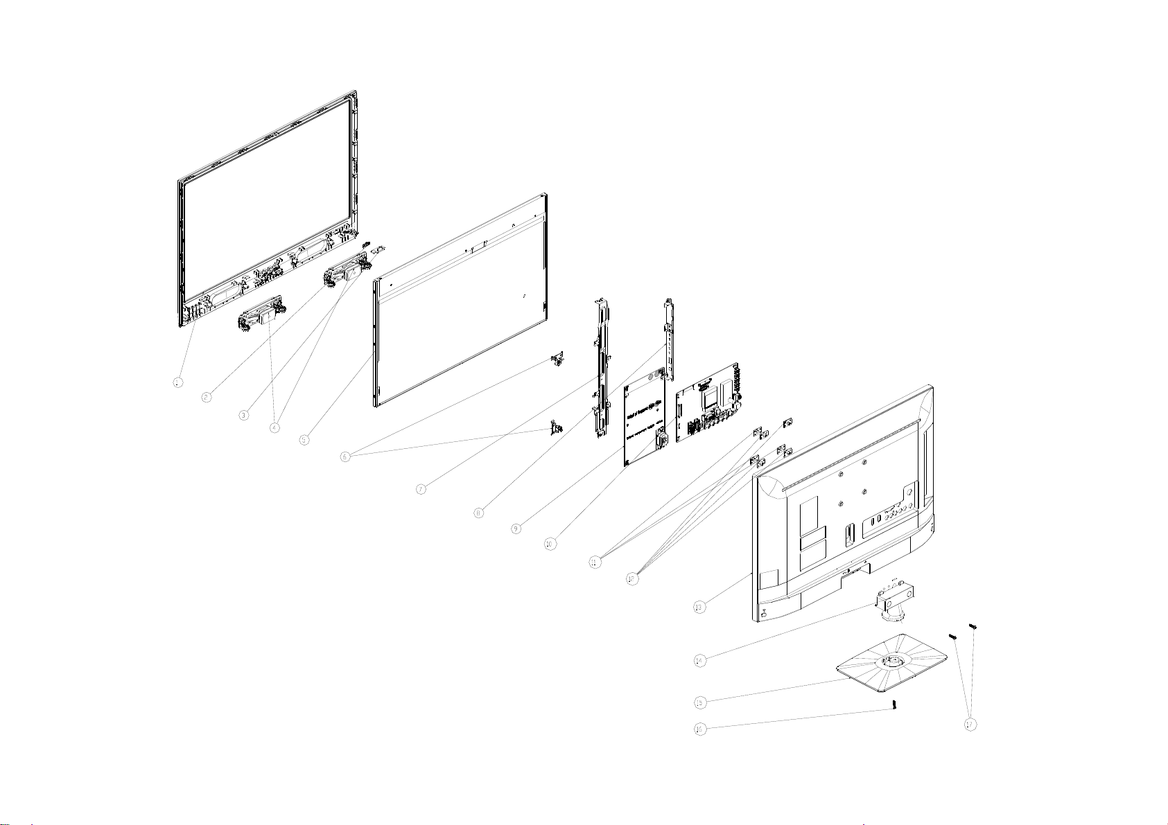
LE24A1332/61
58
Page 59

Item Part No. Description
1 X34T0091ADTY2L0101 BEZEL
2 X33T0046AKZ01C0100 LENS_IR
3 IRPFCXE3Q IR BOARD
4 378G0110567YAV SPEAKER
5 750GBV236W3122N000 PANEL
6 X15T823510200000YF BKT_POWER_L SGCC
7 X15T860210100000YF BKT_HOLDER
8 X15T8603101000GMBL BKT_IO
9 380GLP30016SP0 POWER BOARD
10 756TXCCB01C018003Q MAIN BOARD-CBPFC3QCX6Q
11 X33T0021 GM 1G0100 COVER_CLOCK_REAR
12 X15T819210100000BL BKT_VESA SGCC
13 X34T00920GM02K0230 REAR_COVER
14 X34T0089ADT01L0100 STAND
15 X34T0088ADT02L0133 BASE
16 0Q1G 940 18 47 RA SCREW(REAR_COVER/ STAND)
17 0Q1G 940 16 47 RA SCREW(STAND/ BASE)
Qty
1
1
1
2
1
2
1
1
1
1
3
4
1
1
1
1
2
59
Page 60

11. BOM List
Note: The following information of initial version BOM are only for reference of repair, not place the order as the
basis and are subject to change without notice. Please base on RSPL or Service BOM (http://cs.tpv.com.cn) , thank
you!
LE22A1331/61 E2AC11NCAPA1NNX
Location Part No DESCRIPTION Remark
0Q1G 940 18 47 CR3 SCREW
E750 750GBV215DAT16N000 LCD TPM215HW01-DAT01 C1A WH TPV
756TXCCB01C0030002 MAIN BOARD-CBPFC3QCX1
U402 356G223300200A FLASH W25Q32FVSSIG 32M SOP-8
SMTF-U402 100TAMVC001C2X MCU ASSY-356G223300200A
Q45G99010TV04900X1 PROTECT BAG
X15T818520200000BL BKT_CONNECTOR SGCC
X15T860420200000BL BKT_BTM
X44GCA141010FJ CUSHION-T
E750 LTE215DAT01A40CF PANEL TPM215HW01-DAT01 C1A CTOC 2nd-source
X15T861320100000BL BKT_POWER_TOP
X44GCA142010FJ CUSHION-B
E750 750GBV215DAT12N000 LCD TPM215HW01-DAT01 C1A FQ(CTOC ) FQ TP 2nd-source
X41G22MV61509A MANUAL LE19A1331/61 LE22A1331/61 INDIA
X15T8603201000GMBL BKT_IO
040G 45762412B OTHER LABEL
C640 067G315M1016KV EC 100UF 20% 35V 8*7
C615 067G315M1016KV EC 100UF 20% 35V 8*7
C614 067G315M1016KV EC 100UF 20% 35V 8*7
SW4007 077G602S 3A HJ TACT SW 4P 5.85 200G TSDBYC2202
SW4006 077G602S 3A HJ TACT SW 4P 5.85 200G TSDBYC2202
SW4001 077G602S 3A HJ TACT SW 4P 5.85 200G TSDBYC2202
SW4004 077G602S 3A HJ TACT SW 4P 5.85 200G TSDBYC2202
SW4005 077G602S 3A HJ TACT SW 4P 5.85 200G TSDBYC2202
CN103 088G 78F114VCL RCA JACK 2P YELLOW 1*1 V/T 13.5
CN107 088G 78F121XCL RCA JACK V/T 4P W/R 1*2 H=8.6
CN102 088G 78F135XCL RCA JACK V/T 6P G/BL/R 1*3 H=8.6
CN104 088G302F3G1VCL PHONE JACK V/T 3P GREEN H=8.4
CN101 088G302G7B1ACL PHONE JACK R/A 7P BLACK H=10.5
CN106 088G352F6B3ACL USB A TYPE R/A 6P BLACK H=8.4
CN105 088G353FFF3XCL D-SUB CONN V/T 15P BLUE H=8.4MM
CN105 088G353FFF3XDL D-SUB SCREWED V/T 15P BLUE H=8.4
TU101 094G PALALL 7L TUNER CHINA DT21CN-2-E
CN601 311GW200A04ABX WAFER 2.0MM 4P
CN701 311GW250B13BBX WAFER 2.5MM 13P R/A 35MM 7MM
709T57890XM001 COMSUMPTIVE ASSY
Z40G0002ALL01A SFIS LABEL 35MM*9MM
055G 23520 IPA
055G 23524 WELDING FLUX WITHOUT PB
Q49G 51100 CLEANER
Q55G 100625 TIN STICK_LOW ARGENTUM
U703 056G 563143 C LDO G1084PT43U 5A ADJ TO-252
U101 056G 563149 IC G903T63UF 0.6A/3.3V SOT-223
U702 056G 563515 LDO AZ1117D-3.3TR/E1 1A/3.3V TO-252
U602 056G 616516 AUDIO APA2176AQBITRG 0.27W TQFN3X3-16
Q705 057G 417511 MMBT3904
D502 057G 417511 MMBT3904
60
Page 61

D503 057G 417511 MMBT3904
Q704 057G 417511 MMBT3904
Q403 057G 417511 MMBT3904
Q601 057G 417511 MMBT3904
Q702 057G 417511 MMBT3904
Q703 057G 417511 MMBT3904
Q101 057G 417511 MMBT3904
Q707 057G 417511 MMBT3904
Q706 057G 417511 MMBT3904
Q402 057G 417512 MMBT3906
Q602 057G 417512 MMBT3906
Q404 057G 417512 MMBT3906
Q102 057G 417512 MMBT3906
Q405 057G 417512 MMBT3906
Q401 057G 763 79 FET AO4449 -7A/-30V SOIC-8
Q701 057G 763940 MOSFET AO3401A SOT-23
R528 061G0402000 JF RST CHIPR MAX0R05 1/16W FENGHUA
R527 061G0402000 JF RST CHIPR MAX0R05 1/16W FENGHUA
R529 061G0402000 JF RST CHIPR MAX0R05 1/16W FENGHUA
R525 061G0402000 JF RST CHIPR MAX0R05 1/16W FENGHUA
R526 061G0402000 JF RST CHIPR MAX0R05 1/16W FENGHUA
R523 061G0402000 JF RST CHIPR MAX0R05 1/16W FENGHUA
R524 061G0402000 JF RST CHIPR MAX0R05 1/16W FENGHUA
R448 061G0402000 JF RST CHIPR MAX0R05 1/16W FENGHUA
R449 061G0402000 JF RST CHIPR MAX0R05 1/16W FENGHUA
R520 061G0402000 JF RST CHIPR MAX0R05 1/16W FENGHUA
R522 061G0402000 JF RST CHIPR MAX0R05 1/16W FENGHUA
R521 061G0402000 JF RST CHIPR MAX0R05 1/16W FENGHUA
R454 061G0402000 JF RST CHIPR MAX0R05 1/16W FENGHUA
R605 061G0402000 JF RST CHIPR MAX0R05 1/16W FENGHUA
R602 061G0402000 JF RST CHIPR MAX0R05 1/16W FENGHUA
R455 061G0402000 JF RST CHIPR MAX0R05 1/16W FENGHUA
R515 061G0402000 JF RST CHIPR MAX0R05 1/16W FENGHUA
R519 061G0402000 JF RST CHIPR MAX0R05 1/16W FENGHUA
R516 061G0402000 JF RST CHIPR MAX0R05 1/16W FENGHUA
R518 061G0402000 JF RST CHIPR MAX0R05 1/16W FENGHUA
R517 061G0402000 JF RST CHIPR MAX0R05 1/16W FENGHUA
R146 061G0402000 JF RST CHIPR MAX0R05 1/16W FENGHUA
R530 061G0402000 JF RST CHIPR MAX0R05 1/16W FENGHUA
R701 061G0402000 JI RST 0402 0.05R MAX 1/16W
R601 061G0402000 JI RST 0402 0.05R MAX 1/16W
R427 061G0402000 JY RST CHIPR MAX 0R05 OHM 1/16W YAGEO
R610 061G0402100 JF RST CHIPR 10 OHM +-5% 1/16W FENGHUA
R621 061G0402100 JF RST CHIPR 10 OHM +-5% 1/16W FENGHUA
R626 061G0402100 JF RST CHIPR 10 OHM +-5% 1/16W FENGHUA
R623 061G0402100 JF RST CHIPR 10 OHM +-5% 1/16W FENGHUA
R609 061G0402100 JF RST CHIPR 10 OHM +-5% 1/16W FENGHUA
R616 061G0402100 JF RST CHIPR 10 OHM +-5% 1/16W FENGHUA
R462 061G0402100 JF RST CHIPR 10 OHM +-5% 1/16W FENGHUA
R461 061G0402100 JF RST CHIPR 10 OHM +-5% 1/16W FENGHUA
R721 061G04021001FI RST 0402 1K 1% 1/16W TA-I
R622 061G04021003FT RST 0402 100K 1% 1/16W TZAI YUAN
R604 061G0402101 JF RST CHIPR 100 OHM +-5% 1/16W FENGHUA
R401 061G0402101 JF RST CHIPR 100 OHM +-5% 1/16W FENGHUA
61
Page 62

R705 061G0402101 JI BEST ONLY RST 0402 100R 5% 1/16W TA-I
R510 061G0402101 JI BEST ONLY RST 0402 100R 5% 1/16W TA-I
R101 061G0402101 JI BEST ONLY RST 0402 100R 5% 1/16W TA-I
R501 061G0402101 JI BEST ONLY RST 0402 100R 5% 1/16W TA-I
R513 061G0402101 JI BEST ONLY RST 0402 100R 5% 1/16W TA-I
R514 061G0402101 JI BEST ONLY RST 0402 100R 5% 1/16W TA-I
R458 061G0402101 JY RST CHIPR 100 OHM +-5% 1/16W YAGEO
R143 061G0402101 JY RST CHIPR 100 OHM +-5% 1/16W YAGEO
R145 061G0402101 JY RST CHIPR 100 OHM +-5% 1/16W YAGEO
R460 061G0402101 JY RST CHIPR 100 OHM +-5% 1/16W YAGEO
R464 061G0402101 JY RST CHIPR 100 OHM +-5% 1/16W YAGEO
R625 061G0402101 JY RST CHIPR 100 OHM +-5% 1/16W YAGEO
R613 061G0402101 JY RST CHIPR 100 OHM +-5% 1/16W YAGEO
R405 061G0402102 JF RST CHIPR 1KOHM +-5% 1/16W FENGHUA
R434 061G0402102 JI RST 0402 1K 5% 1/16W TA-I
R702 061G0402102 JI RST 0402 1K 5% 1/16W TA-I
R711 061G0402102 JI RST 0402 1K 5% 1/16W TA-I
R712 061G0402102 JI RST 0402 1K 5% 1/16W TA-I
R709 061G0402102 JY RST CHIPR 1KOHM +-5% 1/16W YAGEO
R707 061G0402102 JY RST CHIPR 1KOHM +-5% 1/16W YAGEO
R704 061G0402102 JY RST CHIPR 1KOHM +-5% 1/16W YAGEO
R726 061G0402103 JF RST CHIPR 10KOHM +-5% 1/16W FENGHUA
R618 061G0402103 JI TEST ONLY RST 0402 10K 5% 1/16W TA-I
R443 061G0402103 JI TEST ONLY RST 0402 10K 5% 1/16W TA-I
R441 061G0402103 JI TEST ONLY RST 0402 10K 5% 1/16W TA-I
R136 061G0402103 JI TEST ONLY RST 0402 10K 5% 1/16W TA-I
R137 061G0402103 JI TEST ONLY RST 0402 10K 5% 1/16W TA-I
R627 061G0402103 JI TEST ONLY RST 0402 10K 5% 1/16W TA-I
R722 061G0402103 JI TEST ONLY RST 0402 10K 5% 1/16W TA-I
R629 061G0402103 JI TEST ONLY RST 0402 10K 5% 1/16W TA-I
R628 061G0402103 JI TEST ONLY RST 0402 10K 5% 1/16W TA-I
R714 061G0402103 JI TEST ONLY RST 0402 10K 5% 1/16W TA-I
R611 061G0402103 JI TEST ONLY RST 0402 10K 5% 1/16W TA-I
R612 061G0402103 JI TEST ONLY RST 0402 10K 5% 1/16W TA-I
R713 061G0402103 JI TEST ONLY RST 0402 10K 5% 1/16W TA-I
R121 061G0402103 JT RST CHIP 10K 1/16W 5% TZAI YUAN
R120 061G0402103 JT RST CHIP 10K 1/16W 5% TZAI YUAN
R507 061G0402103 JT RST CHIP 10K 1/16W 5% TZAI YUAN
R506 061G0402103 JT RST CHIP 10K 1/16W 5% TZAI YUAN
R116 061G0402103 JT RST CHIP 10K 1/16W 5% TZAI YUAN
R117 061G0402103 JT RST CHIP 10K 1/16W 5% TZAI YUAN
R436 061G0402103 JY RST CHIPR 10KOHM +-5% 1/16W YAGEO
R728 061G0402103 JY RST CHIPR 10KOHM +-5% 1/16W YAGEO
R144 061G0402103 JY RST CHIPR 10KOHM +-5% 1/16W YAGEO
R409 061G0402104 JF RST CHIPR 100KOHM +-5% 1/16W FENGHUA
R418 061G0402104 JF RST CHIPR 100KOHM +-5% 1/16W FENGHUA
R416 061G0402104 JF RST CHIPR 100KOHM +-5% 1/16W FENGHUA
R413 061G0402104 JF RST CHIPR 100KOHM +-5% 1/16W FENGHUA
R720 061G0402104 JI TEST ONLY RST 0402 100K 5% 1/16W TA-I
R439 061G0402104 JI TEST ONLY RST 0402 100K 5% 1/16W TA-I
R428 061G0402105 JF RST CHIPR 1MOHM 5% 1/16W FENGHUA
R403 061G0402105 JF RST CHIPR 1MOHM 5% 1/16W FENGHUA
R119 061G0402123 JF RST CHIPR 12KOHM +-5% 1/16W FENGHUA
R118 061G0402123 JF RST CHIPR 12KOHM +-5% 1/16W FENGHUA
62
Page 63

R124 061G0402123 JF RST CHIPR 12KOHM +-5% 1/16W FENGHUA
R123 061G0402123 JF RST CHIPR 12KOHM +-5% 1/16W FENGHUA
R717 061G04021242FT RST 0402 12.4K 1% 1/16W TZAI YUAN
R603 061G0402201 JF RST CHIPR 200 OHM +-5% 1/16W FENGHUA
R606 061G0402201 JF RST CHIPR 200 OHM +-5% 1/16W FENGHUA
R531 061G0402201 JI RST 0402 200R 5% 1/16W
R103 061G0402221 JI RST 0402 220R 5% 1/16W
R131 061G0402222 JF RST CHIPR 2.2KOHM +-5% 1/16W FENGHUA
R131 061G0402222 JY RST CHIPR 2.2KOHM +-5% 1/16W YAGEO
R406 061G0402223 JF RST CHIPR 22KOHM 5% 1/16W FENGHUA
R719 061G04022401FI TEST ONLY RST 0402 2.4K 1% 1/16W TA-I
R624 061G04022702FF RST CHIP 27K 1/16W 1% FENGHUA
R730 061G0402273 JF RST CHIP 27K 1/16W 5% FENGHUA
R106 061G0402330 JF RST CHIPR 33 OHM +-5% 1/16W FENGHUA
R102 061G0402330 JF RST CHIPR 33 OHM +-5% 1/16W FENGHUA
R104 061G0402330 JF RST CHIPR 33 OHM +-5% 1/16W FENGHUA
R111 061G0402330 JF RST CHIPR 33 OHM +-5% 1/16W FENGHUA
R113 061G0402330 JF RST CHIPR 33 OHM +-5% 1/16W FENGHUA
R122 061G0402330 JI RST 0402 33R 5% 1/16W
R127 061G0402330 JI RST 0402 33R 5% 1/16W
R126 061G0402330 JI RST 0402 33R 5% 1/16W
R135 061G0402330 JI RST 0402 33R 5% 1/16W
R133 061G0402330 JI RST 0402 33R 5% 1/16W
R129 061G0402330 JI RST 0402 33R 5% 1/16W
R474 061G0402332 JI RST 0402 3.3K 5% 1/16W
R114 061G0402333 JF ST CHIP 33K 1/16W 5% FENGHUA
R457 061G04024701FF RST 0402 4.7K 1% 1/16W
R456 061G04024701FF RST 0402 4.7K 1% 1/16W
R404 061G0402472 JF RST CHIPR 4.7KOHM +-5% 1/16W FENGHUA
R423 061G0402472 JI TEST ONLY RST CHIP 4.7K 5% 1/16W TA-I
R431 061G0402472 JI TEST ONLY RST CHIP 4.7K 5% 1/16W TA-I
R421 061G0402472 JI TEST ONLY RST CHIP 4.7K 5% 1/16W TA-I
R422 061G0402472 JI TEST ONLY RST CHIP 4.7K 5% 1/16W TA-I
R420 061G0402472 JI TEST ONLY RST CHIP 4.7K 5% 1/16W TA-I
R459 061G0402472 JI TEST ONLY RST CHIP 4.7K 5% 1/16W TA-I
R442 061G0402472 JI TEST ONLY RST CHIP 4.7K 5% 1/16W TA-I
R424 061G0402472 JI TEST ONLY RST CHIP 4.7K 5% 1/16W TA-I
R141 061G0402472 JI TEST ONLY RST CHIP 4.7K 5% 1/16W TA-I
R142 061G0402472 JI TEST ONLY RST CHIP 4.7K 5% 1/16W TA-I
R463 061G0402472 JI TEST ONLY RST CHIP 4.7K 5% 1/16W TA-I
R419 061G0402472 JI TEST ONLY RST CHIP 4.7K 5% 1/16W TA-I
R727 061G0402472 JI TEST ONLY RST CHIP 4.7K 5% 1/16W TA-I
R723 061G0402472 JI TEST ONLY RST CHIP 4.7K 5% 1/16W TA-I
R716 061G0402472 JI TEST ONLY RST CHIP 4.7K 5% 1/16W TA-I
R710 061G0402472 JI TEST ONLY RST CHIP 4.7K 5% 1/16W TA-I
R729 061G0402473 JI TEST ONLY RST 0402 47K 5% 1/16W TA-I
R473 061G0402473 JI TEST ONLY RST 0402 47K 5% 1/16W TA-I
R511 061G0402473 JI TEST ONLY RST 0402 47K 5% 1/16W TA-I
R504 061G0402473 JI TEST ONLY RST 0402 47K 5% 1/16W TA-I
R512 061G0402473 JI TEST ONLY RST 0402 47K 5% 1/16W TA-I
R508 061G0402473 JI TEST ONLY RST 0402 47K 5% 1/16W TA-I
R502 061G0402473 JI TEST ONLY RST 0402 47K 5% 1/16W TA-I
R509 061G0402473 JI TEST ONLY RST 0402 47K 5% 1/16W TA-I
R105 061G0402473 JY RST CHIPR 47KOHM +-5% 1/16W YAGEO
63
Page 64

R139 061G04024998FT RST 0402 4.99R 1% 1/16W SMD04024R99F
R138 061G04024998FT RST 0402 4.99R 1% 1/16W SMD04024R99F
R435 061G0402510 JF RST CHIP 51R 1/16W 5% FENGHUA
R407 061G0402510 JF RST CHIP 51R 1/16W 5% FENGHUA
R140 061G0402511 JI RST 0402 510R 5% 1/16W
R132 061G0402680 JI RST 0402 68R 5% 1/16W
R134 061G0402680 JI RST 0402 68R 5% 1/16W
R412 061G0402680 JY RST CHIPR 68 OHM +-5% 1/16W YAGEO
R410 061G0402680 JY RST CHIPR 68 OHM +-5% 1/16W YAGEO
R415 061G0402680 JY RST CHIPR 68 OHM +-5% 1/16W YAGEO
R715 061G04027501FI TEST ONLY RST 0402 7.5K 1% 1/16W TA-I
FB408 061G0603000 JF RST CHIPR MAX 0R05 1/10W FENGHUA
R607 061G0603101 JF RST CHIPR 100 OHM +-5% 1/10W FENGHUA
R608 061G0603101 JF RST CHIPR 100 OHM +-5% 1/10W FENGHUA
R505 061G0603102 JY RST CHIPR 1KOHM +-5£¥ 1/10W YAGEO
R503 061G0603102 JY RST CHIPR 1KOHM +-5£¥ 1/10W YAGEO
R402 061G06031472FY RST CHIPR 14.7KOHM 1/10W YAGEO
R414 061G06031501FF RST CHIPR 1.5K OHM +-1% 1/10W FENGHUA
R411 061G06034301FI RST 0603 4.3K 1% 1/10W
R408 061G06037151FI RST 0603 7.15K 1% 1/10W TA-I
R107 061G0603750 JY RST CHIPR 75 OHM +-5% 1/10W YAGEO
R108 061G0603750 JY RST CHIPR 75 OHM +-5% 1/10W YAGEO
R109 061G0603750 JY RST CHIPR 75 OHM +-5% 1/10W YAGEO
R115 061G0603750 JY RST CHIPR 75 OHM +-5% 1/10W YAGEO
R112 061G0603750 JY RST CHIPR 75 OHM +-5% 1/10W YAGEO
R110 061G0603750 JY RST CHIPR 75 OHM +-5% 1/10W YAGEO
R417 061G06037500FF RST CHIPR 750 OHM +-1% 1/10W FENGHUA
R125 061G06037509FI RST 0603 75R 1% 1/10W
R130 061G06037509FI RST 0603 75R 1% 1/10W
R128 061G06037509FI RST 0603 75R 1% 1/10W
R438 061G08050004JT RST CHIPR 0805 0 OHM 4A
R440 061G1206102 JT RST CHIPR 1KOHM +-5% 1/4W TZAI YUAN
R718 061G1206229 JY RST 1206 2.2R 5% 1/4W
C639 065G040210232K A CAP 0402 1NF 10% 50V X7R
C404 065G040210232K A CAP 0402 1NF 10% 50V X7R
C619 065G040210232K A CAP 0402 1NF 10% 50V X7R
C107 065G040210232K T CAP CHIP 0402 1000PF 50V X7R
C121 065G040210232K T CAP CHIP 0402 1000PF 50V X7R
C445 065G040210232K Y CAP CHIP 0402 1N 50V X7R +/-10%
C446 065G040210232K Y CAP CHIP 0402 1N 50V X7R +/-10%
C440 065G040210232K Y CAP CHIP 0402 1N 50V X7R +/-10%
C441 065G040210232K Y CAP CHIP 0402 1N 50V X7R +/-10%
C133 065G040210232K Y CAP CHIP 0402 1N 50V X7R +/-10%
C132 065G040210232K Y CAP CHIP 0402 1N 50V X7R +/-10%
C720 065G040210332K Y CAP CHIP 0402 10N 50V X7R +/-10%
C141 065G040210412K F CAP 0402 100NF 10% 16V X7R
C601 065G040210412K F CAP 0402 100NF 10% 16V X7R
C701 065G040210412K F CAP 0402 100NF 10% 16V X7R
C703 065G040210412K F CAP 0402 100NF 10% 16V X7R
C707 065G040210412K F CAP 0402 100NF 10% 16V X7R
C437 065G040210412K F CAP 0402 100NF 10% 16V X7R
C444 065G040210412K F CAP 0402 100NF 10% 16V X7R
C442 065G040210412K F CAP 0402 100NF 10% 16V X7R
C724 065G040210412K F CAP 0402 100NF 10% 16V X7R
64
Page 65

C714 065G040210412K F CAP 0402 100NF 10% 16V X7R
C137 065G040210412K Y CAP 0402 100NF 10% 16V X7R
C134 065G040210412K Y CAP 0402 100NF 10% 16V X7R
C716 065G040210412K Y CAP 0402 100NF 10% 16V X7R
C428 065G040210412K Y CAP 0402 100NF 10% 16V X7R
C427 065G040210412K Y CAP 0402 100NF 10% 16V X7R
C420 065G040210412K Y CAP 0402 100NF 10% 16V X7R
C429 065G040210412K Y CAP 0402 100NF 10% 16V X7R
C422 065G040210412K Y CAP 0402 100NF 10% 16V X7R
C421 065G040210412K Y CAP 0402 100NF 10% 16V X7R
C424 065G040210412K Y CAP 0402 100NF 10% 16V X7R
C423 065G040210412K Y CAP 0402 100NF 10% 16V X7R
C434 065G040210412K Y CAP 0402 100NF 10% 16V X7R
C128 065G040210412K Y CAP 0402 100NF 10% 16V X7R
C435 065G040210412K Y CAP 0402 100NF 10% 16V X7R
C412 065G040210412K Y CAP 0402 100NF 10% 16V X7R
C418 065G040210412K Y CAP 0402 100NF 10% 16V X7R
C125 065G040210412K Y CAP 0402 100NF 10% 16V X7R
C419 065G040210412K Y CAP 0402 100NF 10% 16V X7R
C417 065G040210412K Y CAP 0402 100NF 10% 16V X7R
C416 065G040210412K Y CAP 0402 100NF 10% 16V X7R
C101 065G040210412K Y CAP 0402 100NF 10% 16V X7R
C103 065G040210412K Y CAP 0402 100NF 10% 16V X7R
C715 065G040210412K Y CAP 0402 100NF 10% 16V X7R
C104 065G0402105A5K T CAP 0402 1UF 10% 10V X5R
C405 065G0402105A5K T CAP 0402 1UF 10% 10V X5R
C131 065G0402105A5K T CAP 0402 1UF 10% 10V X5R
C605 065G040215232K Y CAP CHIP 0402 1.5NF 50V X7R
C609 065G040215232K Y CAP CHIP 0402 1.5NF 50V X7R
C411 065G040218131J F CAP 0402 180PF 5% 50V NP0
C414 065G040218131J F CAP 0402 180PF 5% 50V NP0
C406 065G040218131J F CAP 0402 180PF 5% 50V NP0
C409 065G040218131J F CAP 0402 180PF 5% 50V NP0
C436 065G040222031J A CAP 0402 22PF J 50V NPO
C108 065G040222031J T CAP CHIP 0402 22PF J 50V NPO
C140 065G040222322K F CAP 0402 22NF 10% 25V X7R
C425 065G040227031J F CAP 0402 27PF 5% 50V NP0
C430 065G040227031J F CAP 0402 27PF 5% 50V NP0
C136 065G040233031J F CAP 0402 33PF 5% 50V NP0
C623 065G040233131J T CAP CHIP 0402 330PF 50V J NPO
C626 065G040233131J T CAP CHIP 0402 330PF 50V J NPO
C630 065G040233131J T CAP CHIP 0402 330PF 50V J NPO
C637 065G040233131J T CAP CHIP 0402 330PF 50V J NPO
C118 065G040247131J A CAP CHIP 0402 470PF J 50V NPO
C113 065G040247131J A CAP CHIP 0402 470PF J 50V NPO
C114 065G040247131J A CAP CHIP 0402 470PF J 50V NPO
C119 065G040247131J A CAP CHIP 0402 470PF J 50V NPO
C449 065G040247312K A CAP 0402 47NF 10% 16V X7R
C122 065G040247312K A CAP 0402 47NF 10% 16V X7R
C410 065G040247312K A CAP 0402 47NF 10% 16V X7R
C105 065G040247312K A CAP 0402 47NF 10% 16V X7R
C120 065G040247312K A CAP 0402 47NF 10% 16V X7R
C102 065G040247312K A CAP 0402 47NF 10% 16V X7R
C106 065G040247312K A CAP 0402 47NF 10% 16V X7R
65
Page 66

C408 065G040247312K A CAP 0402 47NF 10% 16V X7R
C407 065G040247312K A CAP 0402 47NF 10% 16V X7R
C110 065G040247312K A CAP 0402 47NF 10% 16V X7R
C117 065G040247312K A CAP 0402 47NF 10% 16V X7R
C433 065G040247505M M CAP 0402 4.7UF 20% 6.3V X5R
C135 065G040256031J A CAP 0402 56PF 5% 50V NP0
C638 065G060310432K Y CAP 0603 100NF 10% 50V X7R
C613 065G060310432K Y CAP 0603 100NF 10% 50V X7R
C618 065G060310432K Y CAP 0603 100NF 10% 50V X7R
C725 065G060310512K M CAP 0603 1UF 10% 16V X7R
C604 065G060310512K T CAP 0603 1UF 10% 16V X7R
C712 065G060310512K T CAP 0603 1UF 10% 16V X7R
C443 065G060310512K T CAP 0603 1UF 10% 16V X7R
C607 065G060310512K T CAP 0603 1UF 10% 16V X7R
C606 065G060310512K T CAP 0603 1UF 10% 16V X7R
C718 065G060310512K T CAP 0603 1UF 10% 16V X7R
C415 065G060310605M M CAP 0603 10UF 20% 6.3V X5R
C413 065G060310605M M CAP 0603 10UF 20% 6.3V X5R
C426 065G060310605M M CAP 0603 10UF 20% 6.3V X5R
C431 065G060310605M M CAP 0603 10UF 20% 6.3V X5R
C616 065G060322422K T CAP CHIP0603 220NF K 25V X7R
C633 065G060322422K T CAP CHIP0603 220NF K 25V X7R
C622 065G060322422K T CAP CHIP0603 220NF K 25V X7R
C635 065G060322422K T CAP CHIP0603 220NF K 25V X7R
C401 065G060322422K Y CAP 0603 220N 25V X7R 10%
C610 065G060322515K A 0603 2.2UF K 16V X5R
C403 065G060322515K A 0603 2.2UF K 16V X5R
C402 065G060322515K A 0603 2.2UF K 16V X5R
C130 065G060322515K A 0603 2.2UF K 16V X5R
C115 065G0603225A5K M CAP MLCC 0603 2.2UF K 10V X5R
C116 065G0603225A5K M CAP MLCC 0603 2.2UF K 10V X5R
C111 065G0603225A5K M CAP MLCC 0603 2.2UF K 10V X5R
C112 065G0603225A5K M CAP MLCC 0603 2.2UF K 10V X5R
C709 065G0603475A5K M CAP CHIP 0603 4.7UF K 10V X5R
C705 065G080510432K F CAP CHIP 0805 0.1UF K 50V X7R
C631 065G080510532K A CAP 0805 1UF 10% 50V X7R
C632 065G080510532K A CAP 0805 1UF 10% 50V X7R
C611 065G0805106A5K A CAP 0805 10UF 10% 10V X5R
C602 065G0805106A5K A CAP 0805 10UF 10% 10V X5R
C109 065G0805106A5K A CAP 0805 10UF 10% 10V X5R
C710 065G0805106A5K A CAP 0805 10UF 10% 10V X5R
C127 065G0805106A5K T CHIP 10UF 10V X5R 0805
C629 065G080533432K A CAP 0805 330NF 10% 50V X7R
C624 065G080533432K A CAP 0805 330NF 10% 50V X7R
C621 065G080533432K A CAP 0805 330NF 10% 50V X7R
C634 065G080533432K A CAP 0805 330NF 10% 50V X7R
C717 065G1206226A5K A 1206 22UF K 10V X5R
C719 065G1206226A5K A 1206 22UF K 10V X5R
C704 067G311R1004CT EC SMD 10UF 20% 25V ZV 4*5.5
C708 067G311R1013LT EC SMD 100UF 20% 16V 6.3*5.3
C713 067G311R1013LT EC SMD 100UF 20% 16V 6.3*5.3
C126 067G311R1013LT EC SMD 100UF 20% 16V 6.3*5.3
C722 067G311R1013LT EC SMD 100UF 20% 16V 6.3*5.3
C129 067G311R1013LT EC SMD 100UF 20% 16V 6.3*5.3
66
Page 67

C721 067G311R1013LT EC SMD 100UF 20% 16V 6.3*5.3
C711 067G311R1013LT EC SMD 100UF 20% 16V 6.3*5.3
C450 067G311R1013LT EC SMD 100UF 20% 16V 6.3*5.3
FB101 071G 56D102 MA CHIP BEAD 1000OHM 0805 1A
FB701 071G 56G301 MA CHIP BEAD 0805 300OHM 4A
FB603 071G 56K121 TA CHIP BEAD 120R/6000MA HCB2012KF-121T60
FB409 071G 56K121 TA CHIP BEAD 120R/6000MA HCB2012KF-121T60
FB401 071G 59A121 TA CHIP BEAD 120R/3000MA HCB1608KF-121T30
FB406 071G 59C600 TA CHIP BEAD 0603 60R 25% 600MA
FB405 071G 59C600 TA CHIP BEAD 0603 60R 25% 600MA
FB404 071G 59C600 TA CHIP BEAD 0603 60R 25% 600MA
FB407 071G 59C600 TA CHIP BEAD 0603 60R 25% 600MA
FB403 071G 59C600 TA CHIP BEAD 0603 60R 25% 600MA
FB402 071G 59C600 TA CHIP BEAD 0603 60R 25% 600MA
FB102 071G 59G301 M CHIP BEAD 0603 300R 25% 200MA
FB602 071G 59G301 M CHIP BEAD 0603 300R 25% 200MA
FB601 071G 59G301 M CHIP BEAD 0603 300R 25% 200MA
L101 073G 6310910M CHIP INDUCTOR 1UH 10% 0.6R 25MA
L102 073G 6310910M CHIP INDUCTOR 1UH 10% 0.6R 25MA
L103 073G 63229 TA CHIP INDUCROR 2.2UH 10% FCI1608F-2R2K
L104 073G 63229 TA CHIP INDUCROR 2.2UH 10% FCI1608F-2R2K
L701 073G253S 68 H SMD CHOKE 2.2UH 30% 2.04A 0.031R SPI530L
L602 073G253S 83 H SMD CHOKE 47UH 20% 1.4A,HF
L603 073G253S 83 H SMD CHOKE 47UH 20% 1.4A,HF
L604 073G253S 83 H SMD CHOKE 47UH 20% 1.4A,HF
L601 073G253S 83 H SMD CHOKE 47UH 20% 1.4A,HF
CN502 088G 34021A VA HDMI HEADER V/T 21P BLACK H=10.5 HF
CN501 088G 34021A VA HDMI HEADER V/T 21P BLACK H=10.5 HF
CN501 088G 34021A VD HDMI CONN V/T 21P BLACK H=10.5
CN502 088G 34021A VD HDMI CONN V/T 21P BLACK H=10.5
X401 093G 22SX02 YC CRYSTAL YC 49U/SMD 24MHZ 20PPM 18PF
ZD116 093G 64S500 SU ESD MLVG04025R0QV05BP INPAQ
ZD117 093G 64S500 SU ESD MLVG04025R0QV05BP INPAQ
ZD118 093G 64S500 SU ESD MLVG04025R0QV05BP INPAQ
ZD115 093G 64S500 SU ESD MLVG04025R0QV05BP INPAQ
ZD112 093G 64S500 SU ESD MLVG04025R0QV05BP INPAQ
ZD113 093G 64S500 SU ESD MLVG04025R0QV05BP INPAQ
ZD110 093G 64S500 SU ESD MLVG04025R0QV05BP INPAQ
ZD111 093G 64S500 SU ESD MLVG04025R0QV05BP INPAQ
ZD114 093G 64S500 SU ESD MLVG04025R0QV05BP INPAQ
ZD108 093G 64S500 SU ESD MLVG04025R0QV05BP INPAQ
ZD107 093G 64S500 SU ESD MLVG04025R0QV05BP INPAQ
ZD507 093G 64S500 SU ESD MLVG04025R0QV05BP INPAQ
ZD506 093G 64S500 SU ESD MLVG04025R0QV05BP INPAQ
ZD505 093G 64S500 SU ESD MLVG04025R0QV05BP INPAQ
ZD403 093G 64S500 SU ESD MLVG04025R0QV05BP INPAQ
ZD402 093G 64S500 SU ESD MLVG04025R0QV05BP INPAQ
ZD401 093G 64S500 SU ESD MLVG04025R0QV05BP INPAQ
ZD106 093G 64S500 SU ESD MLVG04025R0QV05BP INPAQ
ZD109 093G 64S500 SU ESD MLVG04025R0QV05BP INPAQ
ZD104 093G 64S500 SU ESD MLVG04025R0QV05BP INPAQ
ZD105 093G 64S500 SU ESD MLVG04025R0QV05BP INPAQ
ZD102 093G 64S500 SU ESD MLVG04025R0QV05BP INPAQ
ZD103 093G 64S500 SU ESD MLVG04025R0QV05BP INPAQ
67
Page 68

ZD101 093G 64S500 SU ESD MLVG04025R0QV05BP INPAQ
ZD502 093G 64S500 SU ESD MLVG04025R0QV05BP INPAQ
ZD501 093G 64S500 SU ESD MLVG04025R0QV05BP INPAQ
ZD504 093G 64S500 SU ESD MLVG04025R0QV05BP INPAQ
ZD503 093G 64S500 SU ESD MLVG04025R0QV05BP INPAQ
CN403 311GW125F40ACH WAFER 1.25MM 40P V/T A12511WVA-SF-2*20PN
CN401 311GW200A10ADJ WAFER 2.0MM 10P
U401 356G0568128019 SCALER MST6931XP-Z1-VB EPLQFP-128
U601 356G0616028147 AUDIO AD52580-QG28NAT 15W E-TSSOP 28L -
U704 356G0667023 POWER SWITCH APL3511CBI-TRG SOT23-5 15
U402 356G223300200A FLASH W25Q32FVSSIG 32M SOP-8
U701 356GD563008014 DC/DC APW7323AKAI-TRG 3.2A 5V SOP-8P
D401 393G006433P0HF HF BAV99_R1_00001 0.5A 100V SOT-23
709T57890XS001 COMSUMPTIVE ASSY
055G 100610 TIN CREAM W/O PB
Q52G6026 7 MESH PRINTTING PAPER
E715 715G5789M01000004K MAIN BOARD PCB
X12G8001 1 BGP HEAT PAD
HS401 X90G8014 1 HEAT SINK
Q40G 581689 4B SN LABEL(58X35MM)
E098 398GRABDGNEACC REMOTE AOC RL81D-1 ENGLISH
X40G0002615A07 OTHER LABEL --POP LABEL
M03602 Q36G060006204700JY NON-WOVEN FABRIC
0Q1G 930 10 47 CR3 SCREW M3X10
052G 1186 SMALL TAPE
X15T860120100000BL BKT_SPEAKER
X33T0046AKZ01C0100 LENS_IR
M05201 Q52G18010TV0500AHB INSULATING SHEET
X15T819210100000BL BKT_VESA SGCC
ECN701 395G801313DY36 HARNESS 13P-13P 100MM
SP01 378G060A577YAD 16 OHM 6W 68*27 180/180 NO
X33T0021 GM 1G0100 COVER_CLOCK_REAR
0M1G1030 8120 SCREW
0Q1G 930 12 47 CR3 SCREW 01-SPECIAL SCREW X12
Q40G0001954 1A S/N LABEL
X34T0087ADTZ1L0100 BEZEL
040G 58162435A MANUAL P/N LABEL
ECN403 395G801840XY33 LVDS CABLE 30P-40P 140MM
M01101 Q11G701017000L00ZL PCB-SUPPORT PA66 YES 94V-V0
092GB1JX1A3EGC BATTERY 1.5V LR03 AAA£¨LR03£© ALKALI
Q40G0003615D90 OTHER LABEL
Q45G88010TV05200WN PE PACKING
Q45G88010TV05800X1 PROTECT BAG
X40G0001624 2A LABEL FOR SCREW PE BAG
Q45G2010M0101A PE BAG FOR MANUAL
708GCA140CPX01 AOC 40 (2100 ASA)
Q45G 77 5 PE PACKING
Q50G 4 10 TIE (Y1900221)
Q52G 1185 99 BIG CARTON TAPE FOR AOC 72MM
X34T00860GM02K0100 REAR_COVER
X44GCA1461501A ARTWORK CARTON ASA LE22A133161
Q11T5024 1 GP WIRE-CLIP
Q52G1501 TV 7 W INSULATING SHEET
0M1G1030 6120 SCREW 3X6
68
Page 69

0M1G1030 6120 SCREW 3X6
0M1G1740 16 47 CR3 SCREW
Q52G1501150523 W INSULATING PLATE
X34T0088ADT02L0100 BASE
0Q1G 930 10 47 CR3 SCREW M3X10
ECN8101 095G8014 6RY01 HARNESS 6P-6P(CI1406S) 250MM
X41G78DV61508A WARRANTY CARD
Q50G 500 TV005 CABLE TIE
X40G024061512A RATING LABEL --LE22A1331/61
0Q1G 930 10 47 CR3 SCREW M3X10
ECN401 395G801410RY28 HARNESS 10P-5P 400MM
PLTVCE514XXG4 POWER BOARD
040G 45762412B OTHER LABEL
009G6005 1 GP GND TERMINAL
IC9102 056G 139 8 PHOTO-COUPLER PS2561DL1-1 CTR Q100~200%
IC9102 056G 139 3A PC123Y22FZOF SHARP
NR9902 061G 58159LAW 5A NTCR 1.5R 15% 2.4W SCK101R55LMY502
NR9901 061G 58159LAW 5A NTCR 1.5R 15% 2.4W SCK101R55LMY502
R9130 061G153M47159B SY RST MOF 470R 5% 3W
C9901 063G107M474AUM CAP X2 470NF 20% 305V
FB9902 071G 55906 FERRITE CORE 510R C8B R6H 6X9.2(A)
FB9908 071G 55906 FERRITE CORE 510R C8B R6H 6X9.2(A)
L9901 073G 174192 H LINE FILTER 30MH MIN LCL-12012 HA
L9901 073G 174192 X LINE FILTER 30MH MIN ET20 0.8A
L9102 073G 253 91 H IND CHOKE 3.5UH+-10% DADONG
L9101 073G 253 91 H IND CHOKE 3.5UH+-10% DADONG
L9101 073G 253 91 V CHOKE COIL 3.5UH+-10%
L9102 073G 253 91 V CHOKE COIL 3.5UH+-10%
L8102 073G 253214 H CHOKE COIL 47UH 10% L470R HA
L8102 073G 253214 X CHOKE COIL 47UH 10% ,HF
T9101 080GL32P 92 YS X'FMR 800UH 10% 20UH EFD30 YS04160400
CN9901 087G 50147C DL AC SOCKET V/T 2P ACT1MD-02BL4B006 H=14
D8101 093G 60520 DIODE SR5100-MK23 5A/100V DO-27 SECOS
D8101 093G 60924 DIODE SR510-22 DO-201AD
0Q1G 340 8140 SCREW Q1-SELF TAPING SCREW :Q X8.0
CN8101 311GW200A06ABX WAFER 2.0MM 6P
CN9101 311GW250B13BBX WAFER 2.5MM 13P R/A 35MM 7MM
RV9901 361G0046621KZW VARISTOR 620V 10%
C9102 367G215X470PKZ002S EC 47UF 20% 450V 12.5*36 2000 HR 420MA P
C9101 367G215X470PKZ002S EC 47UF 20% 450V 12.5*36 2000 HR 420MA P
BD9101 393G0050460A03 BRIDGE GBL408-C 4A 800V GBL 150A
BD9101 393G0050460A05 BRIDGE GBL08-07 X0 4A 800V GBL
705TXC57995
Q9101 057G 667931 MOSFET AOTF8N65 8A 650V TO-220FP
0M1G1730 8120 SCREW 3X8
Q9101 357G0667A11 MOSFET STF6N65K3 5.4A 650V 30W TO-220FP
HS3 Q90G0219 4 HEAT SINK ÐͲÄ/PROFILE
705TXC84023
084G 34 14 FUSE -- -- --
F9901 084G 41 3 C FUSE 3.15A 250V, TIME LAG FUSE
705TXC93995
D9102 093G 60258 DIODE FME-220B TO-220 SANKEN
D9101 093G 60931 DIODE MBRF1560CT ITO-220AB
D9102 093G 60946 SCHOTTKY MBRF20150CT C0 20 150 ITO-220AB
705 组件
705 组件
705 组件
69
Page 70

D9101 093G1506 2 SCHOTTKY FMW-2156 15A 60V TO-220
0M1G1730 8120 SCREW 3X8
HS1 Q90G0219 5 HEAT SINK ÐͲÄ/PROFILE
IC9101 056G 379190 AC/DC CONVERTER LD7750RGR SOP-7
IC8501 056G 700 34 LED DRIVER PF7001S SOP-14
Q9103 057G 417 4 PMBS3904/PHILIPS-SMT(04)
Q9103 057G 417525 SMALLTRAN MMBT3904 200MA 40V SOT-23
Q9102 057G 419913 T TRANSISTOR 2SD1623S-TD-E PCP
Q8101 057G 763958 MOSFET AO4482L 6A 100V SO8
R9128 061G0805102 JF RST CHIPR 1K OHM +-5% 1/8W FENGHUA
R9131 061G0805102 JF RST CHIPR 1K OHM +-5% 1/8W FENGHUA
R9121 061G0805102 JI RST 0805 1K 5% 1/8W
R9124 061G0805102 JT RST CHIPR 1K OHM +- 5% 1/8W TZAI YUAN
R8106 061G0805103 JF RST CHIPR 10K OHM +-5% 1/8W FENGHUA
R9111 061G0805103 JF RST CHIPR 10K OHM +-5% 1/8W FENGHUA
R9114 061G0805104 JT RST CHIPR 100KOHM +- 5% 1/8W TZAI YUAN
R8122 061G08051309FI RST 0805 13R 1% 1/8W
R8121 061G08051309FI RST 0805 13R 1% 1/8W
R8124 061G08051309FI RST 0805 13R 1% 1/8W
R8123 061G08051309FI RST 0805 13R 1% 1/8W
R8125 061G08051309FI RST 0805 13R 1% 1/8W
R8105 061G0805150 JT RST CHIP 15R 1/8W 5% TZAI YUAN
R8119 061G0805154 JT RST CHIP 150K 1/8W 5% TZAI YUAN
R8111 061G0805183 JT RST CHIP 18K 1/8W 5%
R8102 061G08052003FT RST CHIP 200K 1/8W 1%
R8108 061G0805201 JT RST CHIPR 200OHM +-5% 1/8W TZAI YUAN
R9126 061G08052431FY RST CHIP 2K43 1/8W 1%
R8104 061G0805330 JI RST CHIPR 33 OHM +-5% 1/8W 0805
R9123 061G08053301FY RST CHIP 3K3 1/8W 1%
R9127 061G0805332 JF RST CHIPR 3.3KOHM +-5% 1/8W FENGHUA
R8117 061G08054301FI RST 0805 4.3K 1% 1/8W
R9110 061G0805470 JF RST CHIPR 47OHM +-5% 1/8W FENGHUA
R9129 061G0805471 JY RST CHIPR 470OHM +-5% 1/8W YAGEO
R8101 061G08055102FI RST 51K OHM 1% 1/8W TA-I
R9125 061G08056802FT RST CHIP R 68K 1/8W 1%
R9122 061G0805752 JF RST CHIPR 7.5KOHM +-5% 1/8W 0805
JR902 061G1206000 JF RST CHIPR MAX0R05 1/4W FENGHUA
JR903 061G1206000 JF RST CHIPR MAX0R05 1/4W FENGHUA
JR901 061G1206000 JF RST CHIPR MAX0R05 1/4W FENGHUA
R8103 061G1206100 JI RST 1206 10R 5% 1/4W
R9120 061G1206101 JF RST CHIPR 100 OHM +-5% 1/4W FENGHUA
R9119 061G1206101 JF RST CHIPR 100 OHM +-5% 1/4W FENGHUA
R9118 061G1206101 JF RST CHIPR 100 OHM +-5% 1/4W FENGHUA
R9107 061G1206104 JF RST CHIPR 100KOHM +-5% 1/4W FENGHUA
R9105 061G1206104 JF RST CHIPR 100KOHM +-5% 1/4W FENGHUA
R9106 061G1206104 JF RST CHIPR 100KOHM +-5% 1/4W FENGHUA
R9104 061G1206104 JF RST CHIPR 100KOHM +-5% 1/4W FENGHUA
R8113 061G12061809FT RST 1206 18R 1% 1/4W
R9113 061G1206221 JT RST CHIPR 220 OHM +-5% 1/4W TZAI YUAN
R9115 061G1206470 JT RST CHIPR 47 OHM +-5% 1/4W TZAI YUAN
R9116 061G1206470 JT RST CHIPR 47 OHM +-5% 1/4W TZAI YUAN
R9108 061G1206479 JI RST 4.7 OHM 5% 1/4W TA-I
R8114 061G1206513 JT RST CHIPR 51 KOHM +-5% 1/4W TZAI YUAN
R8115 061G1206513 JT RST CHIPR 51 KOHM +-5% 1/4W TZAI YUAN
70
Page 71

R8110 061G1206513 JT RST CHIPR 51 KOHM +-5% 1/4W TZAI YUAN
R9133 061G1206624 JY RST CHIPR 620 KOHM +-5% 1/4W YAGEO
R9132 061G1206624 JY RST CHIPR 620 KOHM +-5% 1/4W YAGEO
R9134 061G1206624 JY RST CHIPR 620 KOHM +-5% 1/4W YAGEO
R9103 061G1206682 JT RST CHIPR 6.8 KOHM +-5% 1/4W TZAI YUAN
R9101 061G1206682 JT RST CHIPR 6.8 KOHM +-5% 1/4W TZAI YUAN
R9102 061G1206682 JT RST CHIPR 6.8 KOHM +-5% 1/4W TZAI YUAN
C9120 065G080510231J F CAP 0805 1NF 5% 50V NPO
C8110 065G080510231J F CAP 0805 1NF 5% 50V NPO
C9124 065G080510332K F CAP 0805 10NF K 50V X7R
C8108 065G080510332K Y CAP CHIP 0805 10N 50V X7R +/-10%
C8114 065G080510332K Y CAP CHIP 0805 10N 50V X7R +/-10%
C8109 065G080510432K Y CAP CHIP 0805 100N 50V X7R +/-10%
C8104 065G080510432K Y CAP CHIP 0805 100N 50V X7R +/-10%
C9114 065G080510432K Y CAP CHIP 0805 100N 50V X7R +/-10%
C9115 065G080510432K Y CAP CHIP 0805 100N 50V X7R +/-10%
C9112 065G080510432K Y CAP CHIP 0805 100N 50V X7R +/-10%
C9119 065G080510432K Y CAP CHIP 0805 100N 50V X7R +/-10%
C9118 065G080510432K Y CAP CHIP 0805 100N 50V X7R +/-10%
C9104 065G080510432K Y CAP CHIP 0805 100N 50V X7R +/-10%
C8105 065G080510432K Y CAP CHIP 0805 100N 50V X7R +/-10%
C9110 065G080510432K Y CAP CHIP 0805 100N 50V X7R +/-10%
C8103 065G080510532K M CAP 0805 1UF 10% 50V X7R
C9106 065G080547131J Y CAP CHIP 0805 470P 50V NPO +/-5%
C9117 065G080547432K F 0805 0.47UF K 50V X7R
C9108 065G120610272K Y CAP 1206 1NF 10% 500V X7R
C9107 065G120610272K Y CAP 1206 1NF 10% 500V X7R
C8107 065G120610272K Y CAP 1206 1NF 10% 500V X7R
D8103 093G 64 33 SWITCHING BAV99 0.2A 85V SOT-23
D8106 093G 64 33 SWITCHING BAV99 0.2A 85V SOT-23
D8105 093G 64 33 SWITCHING BAV99 0.2A 85V SOT-23
D8104 093G 64 33 SWITCHING BAV99 0.2A 85V SOT-23
D8102 093G 60S 15 T SCHOTTKY RB160M 60 TR 1A 60V SOD-123
D8102 093G 60S500 T SCHOTTKY SS1060FL-R1-10001 SOD123FL
Q9102 357G0761A0100T SMALLTRAN BTC4672M3 5A 50V 0.6W SOT-89
C9906 065G306K10123R CAP Y1 100PF 10% 250V Y5P
C9907 065G306K10123R CAP Y1 100PF 10% 250V Y5P
C9906 065G306K1012SR CAP Y1 100PF 10% 250V Y5P
C9907 065G306K1012SR CAP Y1 100PF 10% 250V Y5P
C9905 065G306M10233R CAP Y1 1NF 20% 250V Y5U
C9905 065G306M1023SR CAP Y1 1NF 20% 250V Y5U
CN901 006G 31500 EYELET
CN9901 006G 31500 EYELET
L9901 006G 31502 EYELET
IC9103 056G 158 10 T DC/DC AS431AZTR-E1 150MA 40V TO-92
IC9103 056G 158 12 SHUNT REGULATOR KIA431A-AT/P TO-92
Q8104 057G 417513 T TRA 2N3904 TO-92
Q8106 057G 417513 T TRA 2N3904 TO-92
Q8105 057G 417513 T TRA 2N3904 TO-92
Q8102 057G 417513 T TRA 2N3904 TO-92
Q8107 057G 417513 T TRA 2N3904 TO-92
Q8103 057G 417513 T TRA 2N3904 TO-92
R8107 061G 1SJ10852T SY RST WD 0.1R 5% 1W
R8116 061G 20051352T TZ RST MF 51K 1% 1/4W
71
Page 72

R8120 061G 60200052T TZ RST MAX 0R05 1/6W
R8112 061G 60200052T TZ RST MAX 0R05 1/6W
R8118 061G 60210552T TZ RST CFR 1M 1/6W 5%
R9112 061G152M43852T SY RST MOFR 0.43 OHM +-5% 2WS FUTABA
C9126 065G 1K1019ST CAP CER 100PF 10% 1KV R
C8115 065G 1K1019ST CAP CER 100PF 10% 1KV R
C8106 065G 1K1029ST CAP CER 1NF 10% 1KV R
C9904 065G306K47123R CAP Y1 470PF 10% 250V Y5P
C9902 065G306K47123R CAP Y1 470PF 10% 250V Y5P
C9904 065G306K4712SR CAP Y1 470PF 10% 250V Y5P
C9902 065G306K4712SR CAP Y1 470PF 10% 250V Y5P
C9109 067G 2043313LT CAP CS 330UF 20% 16V
C9105 067G 3154707KT EC 47UF 20% 50V ER1H470MPN1007RU
C8113 067G 5154709HT EC 47UF 20% 100V 10*12
C8102 067G 5154709HT EC 47UF 20% 100V 10*12
C8101 067G 5154714HT EC 470UF 20% 25V 10*12
C9113 067G 5154714HT EC 470UF 20% 25V 10*12
C9123 067G 5154714HT EC 470UF 20% 25V 10*12
C9122 067G 5154714HT EC 470UF 20% 25V 10*12
C9111 067G 5154714KT EC 470UF 20% 25V EV1E471MPN1012RSU
FB9906 071G 55 26 H BEAD 3.5*6.0*0.8 127R 25% BF-I35060R-796
FB9901 071G 55 26 H BEAD 3.5*6.0*0.8 127R 25% BF-I35060R-796
FB9907 071G 55 26 H BEAD 3.5*6.0*0.8 127R 25% BF-I35060R-796
FB9907 071G 55 26 S BEAD 3.5*6 127R 25% LB3.5*0.8*6-2
FB9906 071G 55 26 S BEAD 3.5*6 127R 25% LB3.5*0.8*6-2
FB9901 071G 55 26 S BEAD 3.5*6 127R 25% LB3.5*0.8*6-2
FB9904 071G 55 29 FERRITE BEAD
ZD9101 093G 3958352T ZENER GDZJ13B BY PANJIT
ZD9102 093G 3958752T ZENER GDZJ22B 22V 0.5W DO-35
ZD9103 093G 3959652T GDZJ5.6B
ZD9102 093G 39A6852T ZENER MTZJ22B 21.51V 0.5W DO-35
D9103 093G 6026T52T CTIFIER DIODE FR107
D9105 093G 6026T52T CTIFIER DIODE FR107
D9107 093G 6451652T 1N4148
D9106 093G 6451652T 1N4148
D9107 093G 6452452T SWITCHING 1N4148-B4006 0.2A 100V DO-35
D9106 093G 6452452T SWITCHING 1N4148-B4006 0.2A 100V DO-35
ZD9103 093G 39G 3 ZENER MTZJ5V6B 5.6V 0.5W DO-35
D9105 093G110050152T DIODE PR1007 1A/1000V 500NS DO-41
D9103 093G110050152T DIODE PR1007 1A/1000V 500NS DO-41
J903 095G 90 23 JUMP WIRE - -
J908 095G 90 23 JUMP WIRE - -
J917 095G 90 23 JUMP WIRE - -
J904 095G 90 23 JUMP WIRE - -
J928 095G 90 23 JUMP WIRE - -
J912 095G 90 23 JUMP WIRE - -
J927 095G 90 23 JUMP WIRE - -
J930 095G 90 23 JUMP WIRE - -
J914 095G 90 23 JUMP WIRE - -
J907 095G 90 23 JUMP WIRE - -
J910 095G 90 23 JUMP WIRE - -
J919 095G 90 23 JUMP WIRE - -
J925 095G 90 23 JUMP WIRE - -
J913 095G 90 23 JUMP WIRE - -
72
Page 73

J918 095G 90 23 JUMP WIRE - -
J922 095G 90 23 JUMP WIRE - -
J926 095G 90 23 JUMP WIRE - -
J923 095G 90 23 JUMP WIRE - -
J915 095G 90 23 JUMP WIRE - -
J924 095G 90 23 JUMP WIRE - -
J909 095G 90 23 JUMP WIRE - -
J921 095G 90 23 JUMP WIRE - -
J920 095G 90 23 JUMP WIRE - -
FB9905 095G 90 23 JUMP WIRE - -
J929 095G 90 23 JUMP WIRE - -
J916 095G 90 23 JUMP WIRE - -
SG9902 362G0010501MIT SPARK GAP 500V -20/+30%
SG9901 362G0010501MIT SPARK GAP 500V -20/+30%
C9103 363G213K2224TA CAP DMPE 2.2NF 10% 630V RSBPC1220SH00K
C9125 363G213K2224TA CAP DMPE 2.2NF 10% 630V RSBPC1220SH00K
E715 715G5309P01001002S POWER BOARD PCB
HS4 X85T8026101 SHIELD_IC
052G 2191 A PAPER TAPE
Q12G6082 3 FOOT PAD
IRPFCXE3 IR BOARD
R203 061G0402000 JF RST CHIPR MAX0R05 1/16W FENGHUA
R201 061G0402153 JT RST CHIP 15K 1/16W 5% TZAI YUAN
R204 061G0402221 JF RST CHIPR 220 OHM £«-5£¥ 1/16W FENGHUA
C201 065G0603225A5K M CAP MLCC 0603 2.2UF K 10V X5R
LED201 081G 15 3 GP CHIP LED BLUE/RED GPTD12048BRC1-AR
CN201 311GW125D05ACX WAFER 1.25MM 5P V/T S1315-05SVB-S03-R
U201 356GS927038006 SMD IR RECEIVER TSOP75438TR 38
E715 715G5889R01000004S IR BOARD PCB
X34T0089ADT01L0100 STAND
M03601 Q36G060006204600JY NON-WOVEN FABRIC
E08901 089G204A15N JR AC POWER CORD 1500 FOR EUROPE
M05201 Q52G18010TV0500AZA INSULATING SHEET
M03602 Q36G060006204700TS NON-WOVEN FABRIC
M01101 Q11G701017000L00XL PCB-SUPPORT
M03601 Q36G060006204600TS NON-WOVEN FABRIC
ECN403 395G801840DY33 LVDS CABLE 30P-40P 140 2nd-source
LE22A1331/61 E2AD21NCAPA1NNX
Location Part No DESCRIPTION Remark
0Q1G 930 12 47 CR3 SCREW 01-SPECIAL SCREW X12
708GCA140CPX01 AOC 40 (2100 ASA)
Q45G 77 5 PE PACKING
Q50G 4 10 TIE (Y1900221)
Q52G 1185 99 BIG CARTON TAPE FOR AOC 72MM
Q50G 500 TV005 CABLE TIE
0Q1G 930 10 47 CR3 SCREW M3X10
Q40G0003615D90 OTHER LABEL
X15T860130100000BL BKT_SPEAKER
X34T0088ADT02L0100 BASE
E098 398GRABDGNEACC REMOTE AOC RL81D-1 ENGLISH
X33T0046AKZ01C0100 LENS_IR
E750 750GBV215GE2A1N000 LCD TPM215HW01-HGEL02 C1A FQ TPV
73
Page 74

X40G024061512A RATING LABEL --LE22A1331/61
M01101 Q11G701017000L00ZL PCB-SUPPORT PA66 YES 94V-V0
Q45G88010TV05800X1 PROTECT BAG
0Q1G 940 18 47 CR3 SCREW
X34T0087ADTZ4L0100 BEZEL
756TXCCB01C0030002 MAIN BOARD-CBPFC3QCX1
U402 356G223300200A FLASH W25Q32FVSSIG 32M SOP-8
SMTF-U402 100TAMVC001C2X MCU ASSY-356G223300200A
0Q1G 930 10 47 CR3 SCREW M3X10
X40G0002615A07 OTHER LABEL --POP LABEL
X44GCA1461501A ARTWORK CARTON ASA LE22A133161
Q40G 581689 4B SN LABEL(58X35MM)
Q40G0001954 1A S/N LABEL
0M1G1740 16 47 CR3 SCREW
0Q1G 930 10 47 CR3 SCREW M3X10
092GB1JX1A3EGC BATTERY 1.5V LR03 AAA£¨LR03£© ALKALI
040G 58162435A MANUAL P/N LABEL
Q52G18010TV0500AJY INSULATING SHEET
Q45G99010TV04900X1 PROTECT BAG
X15T860430200000BL BKT_BTM
ECN8101 095G8014 6RY01 HARNESS 6P-6P(CI1406S) 250MM
ECN401 395G801410RY28 HARNESS 10P-5P 400MM
Q12G6082 3 FOOT PAD
040G 45762412B OTHER LABEL
C640 067G315M1016KV EC 100UF 20% 35V 8*7
C614 067G315M1016KV EC 100UF 20% 35V 8*7
C615 067G315M1016KV EC 100UF 20% 35V 8*7
SW4005 077G602S 3A HJ TACT SW 4P 5.85 200G TSDBYC2202
SW4004 077G602S 3A HJ TACT SW 4P 5.85 200G TSDBYC2202
SW4001 077G602S 3A HJ TACT SW 4P 5.85 200G TSDBYC2202
SW4007 077G602S 3A HJ TACT SW 4P 5.85 200G TSDBYC2202
SW4006 077G602S 3A HJ TACT SW 4P 5.85 200G TSDBYC2202
CN103 088G 78F114VCL RCA JACK 2P YELLOW 1*1 V/T 13.5
CN107 088G 78F121XCL RCA JACK V/T 4P W/R 1*2 H=8.6
CN102 088G 78F135XCL RCA JACK V/T 6P G/BL/R 1*3 H=8.6
CN104 088G302F3G1VCL PHONE JACK V/T 3P GREEN H=8.4
CN101 088G302G7B1ACL PHONE JACK R/A 7P BLACK H=10.5
CN106 088G352F6B3ACL USB A TYPE R/A 6P BLACK H=8.4
CN105 088G353FFF3XCL D-SUB CONN V/T 15P BLUE H=8.4MM
CN105 088G353FFF3XDL D-SUB SCREWED V/T 15P BLUE H=8.4
TU101 094G PALALL 7L TUNER CHINA DT21CN-2-E
CN601 311GW200A04ABX WAFER 2.0MM 4P
CN701 311GW250B13BBX WAFER 2.5MM 13P R/A 35MM 7MM
709T57890XM001 COMSUMPTIVE ASSY
Z40G0002ALL01A SFIS LABEL 35MM*9MM
055G 23520 IPA
055G 23524 WELDING FLUX WITHOUT PB
Q49G 51100 CLEANER
Q55G 100625 TIN STICK_LOW ARGENTUM
U703 056G 563143 C LDO G1084PT43U 5A ADJ TO-252
U101 056G 563149 IC G903T63UF 0.6A/3.3V SOT-223
U702 056G 563515 LDO AZ1117D-3.3TR/E1 1A/3.3V TO-252
U602 056G 616516 AUDIO APA2176AQBITRG 0.27W TQFN3X3-16
Q703 057G 417511 MMBT3904
74
Page 75

Q702 057G 417511 MMBT3904
Q704 057G 417511 MMBT3904
D503 057G 417511 MMBT3904
D502 057G 417511 MMBT3904
Q601 057G 417511 MMBT3904
Q403 057G 417511 MMBT3904
Q705 057G 417511 MMBT3904
Q101 057G 417511 MMBT3904
Q706 057G 417511 MMBT3904
Q707 057G 417511 MMBT3904
Q405 057G 417512 MMBT3906
Q102 057G 417512 MMBT3906
Q404 057G 417512 MMBT3906
Q402 057G 417512 MMBT3906
Q602 057G 417512 MMBT3906
Q401 057G 763 79 FET AO4449 -7A/-30V SOIC-8
Q701 057G 763940 MOSFET AO3401A SOT-23
R602 061G0402000 JF RST CHIPR MAX0R05 1/16W FENGHUA
R530 061G0402000 JF RST CHIPR MAX0R05 1/16W FENGHUA
R146 061G0402000 JF RST CHIPR MAX0R05 1/16W FENGHUA
R517 061G0402000 JF RST CHIPR MAX0R05 1/16W FENGHUA
R518 061G0402000 JF RST CHIPR MAX0R05 1/16W FENGHUA
R516 061G0402000 JF RST CHIPR MAX0R05 1/16W FENGHUA
R519 061G0402000 JF RST CHIPR MAX0R05 1/16W FENGHUA
R515 061G0402000 JF RST CHIPR MAX0R05 1/16W FENGHUA
R455 061G0402000 JF RST CHIPR MAX0R05 1/16W FENGHUA
R527 061G0402000 JF RST CHIPR MAX0R05 1/16W FENGHUA
R528 061G0402000 JF RST CHIPR MAX0R05 1/16W FENGHUA
R529 061G0402000 JF RST CHIPR MAX0R05 1/16W FENGHUA
R525 061G0402000 JF RST CHIPR MAX0R05 1/16W FENGHUA
R526 061G0402000 JF RST CHIPR MAX0R05 1/16W FENGHUA
R523 061G0402000 JF RST CHIPR MAX0R05 1/16W FENGHUA
R524 061G0402000 JF RST CHIPR MAX0R05 1/16W FENGHUA
R448 061G0402000 JF RST CHIPR MAX0R05 1/16W FENGHUA
R449 061G0402000 JF RST CHIPR MAX0R05 1/16W FENGHUA
R520 061G0402000 JF RST CHIPR MAX0R05 1/16W FENGHUA
R522 061G0402000 JF RST CHIPR MAX0R05 1/16W FENGHUA
R521 061G0402000 JF RST CHIPR MAX0R05 1/16W FENGHUA
R454 061G0402000 JF RST CHIPR MAX0R05 1/16W FENGHUA
R605 061G0402000 JF RST CHIPR MAX0R05 1/16W FENGHUA
R601 061G0402000 JI RST 0402 0.05R MAX 1/16W
R701 061G0402000 JI RST 0402 0.05R MAX 1/16W
R427 061G0402000 JY RST CHIPR MAX 0R05 OHM 1/16W YAGEO
R461 061G0402100 JF RST CHIPR 10 OHM +-5% 1/16W FENGHUA
R462 061G0402100 JF RST CHIPR 10 OHM +-5% 1/16W FENGHUA
R616 061G0402100 JF RST CHIPR 10 OHM +-5% 1/16W FENGHUA
R609 061G0402100 JF RST CHIPR 10 OHM +-5% 1/16W FENGHUA
R623 061G0402100 JF RST CHIPR 10 OHM +-5% 1/16W FENGHUA
R626 061G0402100 JF RST CHIPR 10 OHM +-5% 1/16W FENGHUA
R621 061G0402100 JF RST CHIPR 10 OHM +-5% 1/16W FENGHUA
R610 061G0402100 JF RST CHIPR 10 OHM +-5% 1/16W FENGHUA
R721 061G04021001FI RST 0402 1K 1% 1/16W TA-I
R622 061G04021003FT RST 0402 100K 1% 1/16W TZAI YUAN
R604 061G0402101 JF RST CHIPR 100 OHM +-5% 1/16W FENGHUA
75
Page 76

R401 061G0402101 JF RST CHIPR 100 OHM +-5% 1/16W FENGHUA
R514 061G0402101 JI BEST ONLY RST 0402 100R 5% 1/16W TA-I
R513 061G0402101 JI BEST ONLY RST 0402 100R 5% 1/16W TA-I
R501 061G0402101 JI BEST ONLY RST 0402 100R 5% 1/16W TA-I
R101 061G0402101 JI BEST ONLY RST 0402 100R 5% 1/16W TA-I
R510 061G0402101 JI BEST ONLY RST 0402 100R 5% 1/16W TA-I
R705 061G0402101 JI BEST ONLY RST 0402 100R 5% 1/16W TA-I
R458 061G0402101 JY RST CHIPR 100 OHM +-5% 1/16W YAGEO
R143 061G0402101 JY RST CHIPR 100 OHM +-5% 1/16W YAGEO
R145 061G0402101 JY RST CHIPR 100 OHM +-5% 1/16W YAGEO
R460 061G0402101 JY RST CHIPR 100 OHM +-5% 1/16W YAGEO
R464 061G0402101 JY RST CHIPR 100 OHM +-5% 1/16W YAGEO
R625 061G0402101 JY RST CHIPR 100 OHM +-5% 1/16W YAGEO
R613 061G0402101 JY RST CHIPR 100 OHM +-5% 1/16W YAGEO
R405 061G0402102 JF RST CHIPR 1KOHM +-5% 1/16W FENGHUA
R712 061G0402102 JI RST 0402 1K 5% 1/16W TA-I
R711 061G0402102 JI RST 0402 1K 5% 1/16W TA-I
R702 061G0402102 JI RST 0402 1K 5% 1/16W TA-I
R434 061G0402102 JI RST 0402 1K 5% 1/16W TA-I
R709 061G0402102 JY RST CHIPR 1KOHM +-5% 1/16W YAGEO
R707 061G0402102 JY RST CHIPR 1KOHM +-5% 1/16W YAGEO
R704 061G0402102 JY RST CHIPR 1KOHM +-5% 1/16W YAGEO
R726 061G0402103 JF RST CHIPR 10KOHM +-5% 1/16W FENGHUA
R618 061G0402103 JI TEST ONLY RST 0402 10K 5% 1/16W TA-I
R443 061G0402103 JI TEST ONLY RST 0402 10K 5% 1/16W TA-I
R441 061G0402103 JI TEST ONLY RST 0402 10K 5% 1/16W TA-I
R136 061G0402103 JI TEST ONLY RST 0402 10K 5% 1/16W TA-I
R137 061G0402103 JI TEST ONLY RST 0402 10K 5% 1/16W TA-I
R627 061G0402103 JI TEST ONLY RST 0402 10K 5% 1/16W TA-I
R722 061G0402103 JI TEST ONLY RST 0402 10K 5% 1/16W TA-I
R713 061G0402103 JI TEST ONLY RST 0402 10K 5% 1/16W TA-I
R612 061G0402103 JI TEST ONLY RST 0402 10K 5% 1/16W TA-I
R611 061G0402103 JI TEST ONLY RST 0402 10K 5% 1/16W TA-I
R714 061G0402103 JI TEST ONLY RST 0402 10K 5% 1/16W TA-I
R628 061G0402103 JI TEST ONLY RST 0402 10K 5% 1/16W TA-I
R629 061G0402103 JI TEST ONLY RST 0402 10K 5% 1/16W TA-I
R121 061G0402103 JT RST CHIP 10K 1/16W 5% TZAI YUAN
R120 061G0402103 JT RST CHIP 10K 1/16W 5% TZAI YUAN
R507 061G0402103 JT RST CHIP 10K 1/16W 5% TZAI YUAN
R506 061G0402103 JT RST CHIP 10K 1/16W 5% TZAI YUAN
R116 061G0402103 JT RST CHIP 10K 1/16W 5% TZAI YUAN
R117 061G0402103 JT RST CHIP 10K 1/16W 5% TZAI YUAN
R144 061G0402103 JY RST CHIPR 10KOHM +-5% 1/16W YAGEO
R728 061G0402103 JY RST CHIPR 10KOHM +-5% 1/16W YAGEO
R436 061G0402103 JY RST CHIPR 10KOHM +-5% 1/16W YAGEO
R413 061G0402104 JF RST CHIPR 100KOHM +-5% 1/16W FENGHUA
R416 061G0402104 JF RST CHIPR 100KOHM +-5% 1/16W FENGHUA
R418 061G0402104 JF RST CHIPR 100KOHM +-5% 1/16W FENGHUA
R409 061G0402104 JF RST CHIPR 100KOHM +-5% 1/16W FENGHUA
R720 061G0402104 JI TEST ONLY RST 0402 100K 5% 1/16W TA-I
R439 061G0402104 JI TEST ONLY RST 0402 100K 5% 1/16W TA-I
R428 061G0402105 JF RST CHIPR 1MOHM 5% 1/16W FENGHUA
R403 061G0402105 JF RST CHIPR 1MOHM 5% 1/16W FENGHUA
R119 061G0402123 JF RST CHIPR 12KOHM +-5% 1/16W FENGHUA
76
Page 77

R118 061G0402123 JF RST CHIPR 12KOHM +-5% 1/16W FENGHUA
R124 061G0402123 JF RST CHIPR 12KOHM +-5% 1/16W FENGHUA
R123 061G0402123 JF RST CHIPR 12KOHM +-5% 1/16W FENGHUA
R717 061G04021242FT RST 0402 12.4K 1% 1/16W TZAI YUAN
R603 061G0402201 JF RST CHIPR 200 OHM +-5% 1/16W FENGHUA
R606 061G0402201 JF RST CHIPR 200 OHM +-5% 1/16W FENGHUA
R531 061G0402201 JI RST 0402 200R 5% 1/16W
R103 061G0402221 JI RST 0402 220R 5% 1/16W
R131 061G0402222 JF RST CHIPR 2.2KOHM +-5% 1/16W FENGHUA
R131 061G0402222 JY RST CHIPR 2.2KOHM +-5% 1/16W YAGEO
R406 061G0402223 JF RST CHIPR 22KOHM 5% 1/16W FENGHUA
R719 061G04022401FI TEST ONLY RST 0402 2.4K 1% 1/16W TA-I
R624 061G04022702FF RST CHIP 27K 1/16W 1% FENGHUA
R730 061G0402273 JF RST CHIP 27K 1/16W 5% FENGHUA
R113 061G0402330 JF RST CHIPR 33 OHM +-5% 1/16W FENGHUA
R111 061G0402330 JF RST CHIPR 33 OHM +-5% 1/16W FENGHUA
R104 061G0402330 JF RST CHIPR 33 OHM +-5% 1/16W FENGHUA
R102 061G0402330 JF RST CHIPR 33 OHM +-5% 1/16W FENGHUA
R106 061G0402330 JF RST CHIPR 33 OHM +-5% 1/16W FENGHUA
R129 061G0402330 JI RST 0402 33R 5% 1/16W
R133 061G0402330 JI RST 0402 33R 5% 1/16W
R135 061G0402330 JI RST 0402 33R 5% 1/16W
R126 061G0402330 JI RST 0402 33R 5% 1/16W
R127 061G0402330 JI RST 0402 33R 5% 1/16W
R122 061G0402330 JI RST 0402 33R 5% 1/16W
R474 061G0402332 JI RST 0402 3.3K 5% 1/16W
R114 061G0402333 JF ST CHIP 33K 1/16W 5% FENGHUA
R456 061G04024701FF RST 0402 4.7K 1% 1/16W
R457 061G04024701FF RST 0402 4.7K 1% 1/16W
R404 061G0402472 JF RST CHIPR 4.7KOHM +-5% 1/16W FENGHUA
R423 061G0402472 JI TEST ONLY RST CHIP 4.7K 5% 1/16W TA-I
R431 061G0402472 JI TEST ONLY RST CHIP 4.7K 5% 1/16W TA-I
R421 061G0402472 JI TEST ONLY RST CHIP 4.7K 5% 1/16W TA-I
R422 061G0402472 JI TEST ONLY RST CHIP 4.7K 5% 1/16W TA-I
R420 061G0402472 JI TEST ONLY RST CHIP 4.7K 5% 1/16W TA-I
R459 061G0402472 JI TEST ONLY RST CHIP 4.7K 5% 1/16W TA-I
R442 061G0402472 JI TEST ONLY RST CHIP 4.7K 5% 1/16W TA-I
R424 061G0402472 JI TEST ONLY RST CHIP 4.7K 5% 1/16W TA-I
R710 061G0402472 JI TEST ONLY RST CHIP 4.7K 5% 1/16W TA-I
R716 061G0402472 JI TEST ONLY RST CHIP 4.7K 5% 1/16W TA-I
R723 061G0402472 JI TEST ONLY RST CHIP 4.7K 5% 1/16W TA-I
R727 061G0402472 JI TEST ONLY RST CHIP 4.7K 5% 1/16W TA-I
R419 061G0402472 JI TEST ONLY RST CHIP 4.7K 5% 1/16W TA-I
R463 061G0402472 JI TEST ONLY RST CHIP 4.7K 5% 1/16W TA-I
R142 061G0402472 JI TEST ONLY RST CHIP 4.7K 5% 1/16W TA-I
R141 061G0402472 JI TEST ONLY RST CHIP 4.7K 5% 1/16W TA-I
R509 061G0402473 JI TEST ONLY RST 0402 47K 5% 1/16W TA-I
R502 061G0402473 JI TEST ONLY RST 0402 47K 5% 1/16W TA-I
R508 061G0402473 JI TEST ONLY RST 0402 47K 5% 1/16W TA-I
R512 061G0402473 JI TEST ONLY RST 0402 47K 5% 1/16W TA-I
R504 061G0402473 JI TEST ONLY RST 0402 47K 5% 1/16W TA-I
R511 061G0402473 JI TEST ONLY RST 0402 47K 5% 1/16W TA-I
R473 061G0402473 JI TEST ONLY RST 0402 47K 5% 1/16W TA-I
R729 061G0402473 JI TEST ONLY RST 0402 47K 5% 1/16W TA-I
77
Page 78

R105 061G0402473 JY RST CHIPR 47KOHM +-5% 1/16W YAGEO
R139 061G04024998FT RST 0402 4.99R 1% 1/16W SMD04024R99F
R138 061G04024998FT RST 0402 4.99R 1% 1/16W SMD04024R99F
R435 061G0402510 JF RST CHIP 51R 1/16W 5% FENGHUA
R407 061G0402510 JF RST CHIP 51R 1/16W 5% FENGHUA
R140 061G0402511 JI RST 0402 510R 5% 1/16W
R134 061G0402680 JI RST 0402 68R 5% 1/16W
R132 061G0402680 JI RST 0402 68R 5% 1/16W
R412 061G0402680 JY RST CHIPR 68 OHM +-5% 1/16W YAGEO
R410 061G0402680 JY RST CHIPR 68 OHM +-5% 1/16W YAGEO
R415 061G0402680 JY RST CHIPR 68 OHM +-5% 1/16W YAGEO
R715 061G04027501FI TEST ONLY RST 0402 7.5K 1% 1/16W TA-I
FB408 061G0603000 JF RST CHIPR MAX 0R05 1/10W FENGHUA
R608 061G0603101 JF RST CHIPR 100 OHM +-5% 1/10W FENGHUA
R607 061G0603101 JF RST CHIPR 100 OHM +-5% 1/10W FENGHUA
R505 061G0603102 JY RST CHIPR 1KOHM +-5£¥ 1/10W YAGEO
R503 061G0603102 JY RST CHIPR 1KOHM +-5£¥ 1/10W YAGEO
R402 061G06031472FY RST CHIPR 14.7KOHM 1/10W YAGEO
R414 061G06031501FF RST CHIPR 1.5K OHM +-1% 1/10W FENGHUA
R411 061G06034301FI RST 0603 4.3K 1% 1/10W
R408 061G06037151FI RST 0603 7.15K 1% 1/10W TA-I
R110 061G0603750 JY RST CHIPR 75 OHM +-5% 1/10W YAGEO
R112 061G0603750 JY RST CHIPR 75 OHM +-5% 1/10W YAGEO
R115 061G0603750 JY RST CHIPR 75 OHM +-5% 1/10W YAGEO
R109 061G0603750 JY RST CHIPR 75 OHM +-5% 1/10W YAGEO
R108 061G0603750 JY RST CHIPR 75 OHM +-5% 1/10W YAGEO
R107 061G0603750 JY RST CHIPR 75 OHM +-5% 1/10W YAGEO
R417 061G06037500FF RST CHIPR 750 OHM +-1% 1/10W FENGHUA
R125 061G06037509FI RST 0603 75R 1% 1/10W
R130 061G06037509FI RST 0603 75R 1% 1/10W
R128 061G06037509FI RST 0603 75R 1% 1/10W
R438 061G08050004JT RST CHIPR 0805 0 OHM 4A
R440 061G1206102 JT RST CHIPR 1KOHM +-5% 1/4W TZAI YUAN
R718 061G1206229 JY RST 1206 2.2R 5% 1/4W
C639 065G040210232K A CAP 0402 1NF 10% 50V X7R
C404 065G040210232K A CAP 0402 1NF 10% 50V X7R
C619 065G040210232K A CAP 0402 1NF 10% 50V X7R
C121 065G040210232K T CAP CHIP 0402 1000PF 50V X7R
C107 065G040210232K T CAP CHIP 0402 1000PF 50V X7R
C445 065G040210232K Y CAP CHIP 0402 1N 50V X7R +/-10%
C446 065G040210232K Y CAP CHIP 0402 1N 50V X7R +/-10%
C440 065G040210232K Y CAP CHIP 0402 1N 50V X7R +/-10%
C441 065G040210232K Y CAP CHIP 0402 1N 50V X7R +/-10%
C133 065G040210232K Y CAP CHIP 0402 1N 50V X7R +/-10%
C132 065G040210232K Y CAP CHIP 0402 1N 50V X7R +/-10%
C720 065G040210332K Y CAP CHIP 0402 10N 50V X7R +/-10%
C141 065G040210412K F CAP 0402 100NF 10% 16V X7R
C601 065G040210412K F CAP 0402 100NF 10% 16V X7R
C701 065G040210412K F CAP 0402 100NF 10% 16V X7R
C703 065G040210412K F CAP 0402 100NF 10% 16V X7R
C707 065G040210412K F CAP 0402 100NF 10% 16V X7R
C437 065G040210412K F CAP 0402 100NF 10% 16V X7R
C444 065G040210412K F CAP 0402 100NF 10% 16V X7R
C442 065G040210412K F CAP 0402 100NF 10% 16V X7R
78
Page 79

C724 065G040210412K F CAP 0402 100NF 10% 16V X7R
C714 065G040210412K F CAP 0402 100NF 10% 16V X7R
C412 065G040210412K Y CAP 0402 100NF 10% 16V X7R
C418 065G040210412K Y CAP 0402 100NF 10% 16V X7R
C125 065G040210412K Y CAP 0402 100NF 10% 16V X7R
C419 065G040210412K Y CAP 0402 100NF 10% 16V X7R
C417 065G040210412K Y CAP 0402 100NF 10% 16V X7R
C416 065G040210412K Y CAP 0402 100NF 10% 16V X7R
C101 065G040210412K Y CAP 0402 100NF 10% 16V X7R
C103 065G040210412K Y CAP 0402 100NF 10% 16V X7R
C715 065G040210412K Y CAP 0402 100NF 10% 16V X7R
C716 065G040210412K Y CAP 0402 100NF 10% 16V X7R
C134 065G040210412K Y CAP 0402 100NF 10% 16V X7R
C137 065G040210412K Y CAP 0402 100NF 10% 16V X7R
C428 065G040210412K Y CAP 0402 100NF 10% 16V X7R
C427 065G040210412K Y CAP 0402 100NF 10% 16V X7R
C420 065G040210412K Y CAP 0402 100NF 10% 16V X7R
C429 065G040210412K Y CAP 0402 100NF 10% 16V X7R
C422 065G040210412K Y CAP 0402 100NF 10% 16V X7R
C421 065G040210412K Y CAP 0402 100NF 10% 16V X7R
C424 065G040210412K Y CAP 0402 100NF 10% 16V X7R
C423 065G040210412K Y CAP 0402 100NF 10% 16V X7R
C434 065G040210412K Y CAP 0402 100NF 10% 16V X7R
C128 065G040210412K Y CAP 0402 100NF 10% 16V X7R
C435 065G040210412K Y CAP 0402 100NF 10% 16V X7R
C104 065G0402105A5K T CAP 0402 1UF 10% 10V X5R
C405 065G0402105A5K T CAP 0402 1UF 10% 10V X5R
C131 065G0402105A5K T CAP 0402 1UF 10% 10V X5R
C605 065G040215232K Y CAP CHIP 0402 1.5NF 50V X7R
C609 065G040215232K Y CAP CHIP 0402 1.5NF 50V X7R
C409 065G040218131J F CAP 0402 180PF 5% 50V NP0
C406 065G040218131J F CAP 0402 180PF 5% 50V NP0
C414 065G040218131J F CAP 0402 180PF 5% 50V NP0
C411 065G040218131J F CAP 0402 180PF 5% 50V NP0
C436 065G040222031J A CAP 0402 22PF J 50V NPO
C108 065G040222031J T CAP CHIP 0402 22PF J 50V NPO
C140 065G040222322K F CAP 0402 22NF 10% 25V X7R
C430 065G040227031J F CAP 0402 27PF 5% 50V NP0
C425 065G040227031J F CAP 0402 27PF 5% 50V NP0
C136 065G040233031J F CAP 0402 33PF 5% 50V NP0
C623 065G040233131J T CAP CHIP 0402 330PF 50V J NPO
C626 065G040233131J T CAP CHIP 0402 330PF 50V J NPO
C630 065G040233131J T CAP CHIP 0402 330PF 50V J NPO
C637 065G040233131J T CAP CHIP 0402 330PF 50V J NPO
C119 065G040247131J A CAP CHIP 0402 470PF J 50V NPO
C114 065G040247131J A CAP CHIP 0402 470PF J 50V NPO
C113 065G040247131J A CAP CHIP 0402 470PF J 50V NPO
C118 065G040247131J A CAP CHIP 0402 470PF J 50V NPO
C105 065G040247312K A CAP 0402 47NF 10% 16V X7R
C120 065G040247312K A CAP 0402 47NF 10% 16V X7R
C102 065G040247312K A CAP 0402 47NF 10% 16V X7R
C106 065G040247312K A CAP 0402 47NF 10% 16V X7R
C408 065G040247312K A CAP 0402 47NF 10% 16V X7R
C407 065G040247312K A CAP 0402 47NF 10% 16V X7R
79
Page 80

C110 065G040247312K A CAP 0402 47NF 10% 16V X7R
C117 065G040247312K A CAP 0402 47NF 10% 16V X7R
C410 065G040247312K A CAP 0402 47NF 10% 16V X7R
C122 065G040247312K A CAP 0402 47NF 10% 16V X7R
C449 065G040247312K A CAP 0402 47NF 10% 16V X7R
C433 065G040247505M M CAP 0402 4.7UF 20% 6.3V X5R
C135 065G040256031J A CAP 0402 56PF 5% 50V NP0
C618 065G060310432K Y CAP 0603 100NF 10% 50V X7R
C638 065G060310432K Y CAP 0603 100NF 10% 50V X7R
C613 065G060310432K Y CAP 0603 100NF 10% 50V X7R
C725 065G060310512K M CAP 0603 1UF 10% 16V X7R
C718 065G060310512K T CAP 0603 1UF 10% 16V X7R
C606 065G060310512K T CAP 0603 1UF 10% 16V X7R
C607 065G060310512K T CAP 0603 1UF 10% 16V X7R
C443 065G060310512K T CAP 0603 1UF 10% 16V X7R
C712 065G060310512K T CAP 0603 1UF 10% 16V X7R
C604 065G060310512K T CAP 0603 1UF 10% 16V X7R
C413 065G060310605M M CAP 0603 10UF 20% 6.3V X5R
C415 065G060310605M M CAP 0603 10UF 20% 6.3V X5R
C426 065G060310605M M CAP 0603 10UF 20% 6.3V X5R
C431 065G060310605M M CAP 0603 10UF 20% 6.3V X5R
C616 065G060322422K T CAP CHIP0603 220NF K 25V X7R
C633 065G060322422K T CAP CHIP0603 220NF K 25V X7R
C622 065G060322422K T CAP CHIP0603 220NF K 25V X7R
C635 065G060322422K T CAP CHIP0603 220NF K 25V X7R
C401 065G060322422K Y CAP 0603 220N 25V X7R 10%
C130 065G060322515K A 0603 2.2UF K 16V X5R
C402 065G060322515K A 0603 2.2UF K 16V X5R
C403 065G060322515K A 0603 2.2UF K 16V X5R
C610 065G060322515K A 0603 2.2UF K 16V X5R
C112 065G0603225A5K M CAP MLCC 0603 2.2UF K 10V X5R
C111 065G0603225A5K M CAP MLCC 0603 2.2UF K 10V X5R
C116 065G0603225A5K M CAP MLCC 0603 2.2UF K 10V X5R
C115 065G0603225A5K M CAP MLCC 0603 2.2UF K 10V X5R
C709 065G0603475A5K M CAP CHIP 0603 4.7UF K 10V X5R
C705 065G080510432K F CAP CHIP 0805 0.1UF K 50V X7R
C631 065G080510532K A CAP 0805 1UF 10% 50V X7R
C632 065G080510532K A CAP 0805 1UF 10% 50V X7R
C611 065G0805106A5K A CAP 0805 10UF 10% 10V X5R
C602 065G0805106A5K A CAP 0805 10UF 10% 10V X5R
C109 065G0805106A5K A CAP 0805 10UF 10% 10V X5R
C710 065G0805106A5K A CAP 0805 10UF 10% 10V X5R
C127 065G0805106A5K T CHIP 10UF 10V X5R 0805
C629 065G080533432K A CAP 0805 330NF 10% 50V X7R
C624 065G080533432K A CAP 0805 330NF 10% 50V X7R
C621 065G080533432K A CAP 0805 330NF 10% 50V X7R
C634 065G080533432K A CAP 0805 330NF 10% 50V X7R
C719 065G1206226A5K A 1206 22UF K 10V X5R
C717 065G1206226A5K A 1206 22UF K 10V X5R
C704 067G311R1004CT EC SMD 10UF 20% 25V ZV 4*5.5
C708 067G311R1013LT EC SMD 100UF 20% 16V 6.3*5.3
C713 067G311R1013LT EC SMD 100UF 20% 16V 6.3*5.3
C126 067G311R1013LT EC SMD 100UF 20% 16V 6.3*5.3
C722 067G311R1013LT EC SMD 100UF 20% 16V 6.3*5.3
80
Page 81

C129 067G311R1013LT EC SMD 100UF 20% 16V 6.3*5.3
C721 067G311R1013LT EC SMD 100UF 20% 16V 6.3*5.3
C711 067G311R1013LT EC SMD 100UF 20% 16V 6.3*5.3
C450 067G311R1013LT EC SMD 100UF 20% 16V 6.3*5.3
FB101 071G 56D102 MA CHIP BEAD 1000OHM 0805 1A
FB701 071G 56G301 MA CHIP BEAD 0805 300OHM 4A
FB409 071G 56K121 TA CHIP BEAD 120R/6000MA HCB2012KF-121T60
FB603 071G 56K121 TA CHIP BEAD 120R/6000MA HCB2012KF-121T60
FB401 071G 59A121 TA CHIP BEAD 120R/3000MA HCB1608KF-121T30
FB402 071G 59C600 TA CHIP BEAD 0603 60R 25% 600MA
FB403 071G 59C600 TA CHIP BEAD 0603 60R 25% 600MA
FB407 071G 59C600 TA CHIP BEAD 0603 60R 25% 600MA
FB404 071G 59C600 TA CHIP BEAD 0603 60R 25% 600MA
FB405 071G 59C600 TA CHIP BEAD 0603 60R 25% 600MA
FB406 071G 59C600 TA CHIP BEAD 0603 60R 25% 600MA
FB102 071G 59G301 M CHIP BEAD 0603 300R 25% 200MA
FB602 071G 59G301 M CHIP BEAD 0603 300R 25% 200MA
FB601 071G 59G301 M CHIP BEAD 0603 300R 25% 200MA
L102 073G 6310910M CHIP INDUCTOR 1UH 10% 0.6R 25MA
L101 073G 6310910M CHIP INDUCTOR 1UH 10% 0.6R 25MA
L103 073G 63229 TA CHIP INDUCROR 2.2UH 10% FCI1608F-2R2K
L104 073G 63229 TA CHIP INDUCROR 2.2UH 10% FCI1608F-2R2K
L701 073G253S 68 H SMD CHOKE 2.2UH 30% 2.04A 0.031R SPI530L
L601 073G253S 83 H SMD CHOKE 47UH 20% 1.4A,HF
L604 073G253S 83 H SMD CHOKE 47UH 20% 1.4A,HF
L603 073G253S 83 H SMD CHOKE 47UH 20% 1.4A,HF
L602 073G253S 83 H SMD CHOKE 47UH 20% 1.4A,HF
CN502 088G 34021A VA HDMI HEADER V/T 21P BLACK H=10.5 HF
CN501 088G 34021A VA HDMI HEADER V/T 21P BLACK H=10.5 HF
CN502 088G 34021A VD HDMI CONN V/T 21P BLACK H=10.5
CN501 088G 34021A VD HDMI CONN V/T 21P BLACK H=10.5
X401 093G 22SX02 YC CRYSTAL YC 49U/SMD 24MHZ 20PPM 18PF
ZD114 093G 64S500 SU ESD MLVG04025R0QV05BP INPAQ
ZD108 093G 64S500 SU ESD MLVG04025R0QV05BP INPAQ
ZD107 093G 64S500 SU ESD MLVG04025R0QV05BP INPAQ
ZD403 093G 64S500 SU ESD MLVG04025R0QV05BP INPAQ
ZD505 093G 64S500 SU ESD MLVG04025R0QV05BP INPAQ
ZD103 093G 64S500 SU ESD MLVG04025R0QV05BP INPAQ
ZD102 093G 64S500 SU ESD MLVG04025R0QV05BP INPAQ
ZD105 093G 64S500 SU ESD MLVG04025R0QV05BP INPAQ
ZD104 093G 64S500 SU ESD MLVG04025R0QV05BP INPAQ
ZD109 093G 64S500 SU ESD MLVG04025R0QV05BP INPAQ
ZD106 093G 64S500 SU ESD MLVG04025R0QV05BP INPAQ
ZD401 093G 64S500 SU ESD MLVG04025R0QV05BP INPAQ
ZD101 093G 64S500 SU ESD MLVG04025R0QV05BP INPAQ
ZD502 093G 64S500 SU ESD MLVG04025R0QV05BP INPAQ
ZD501 093G 64S500 SU ESD MLVG04025R0QV05BP INPAQ
ZD504 093G 64S500 SU ESD MLVG04025R0QV05BP INPAQ
ZD503 093G 64S500 SU ESD MLVG04025R0QV05BP INPAQ
ZD116 093G 64S500 SU ESD MLVG04025R0QV05BP INPAQ
ZD117 093G 64S500 SU ESD MLVG04025R0QV05BP INPAQ
ZD118 093G 64S500 SU ESD MLVG04025R0QV05BP INPAQ
ZD115 093G 64S500 SU ESD MLVG04025R0QV05BP INPAQ
ZD112 093G 64S500 SU ESD MLVG04025R0QV05BP INPAQ
81
Page 82

ZD113 093G 64S500 SU ESD MLVG04025R0QV05BP INPAQ
ZD110 093G 64S500 SU ESD MLVG04025R0QV05BP INPAQ
ZD111 093G 64S500 SU ESD MLVG04025R0QV05BP INPAQ
ZD402 093G 64S500 SU ESD MLVG04025R0QV05BP INPAQ
ZD507 093G 64S500 SU ESD MLVG04025R0QV05BP INPAQ
ZD506 093G 64S500 SU ESD MLVG04025R0QV05BP INPAQ
CN403 311GW125F40ACH WAFER 1.25MM 40P V/T A12511WVA-SF-2*20PN
CN401 311GW200A10ADJ WAFER 2.0MM 10P
U401 356G0568128019 SCALER MST6931XP-Z1-VB EPLQFP-128
U601 356G0616028147 AUDIO AD52580-QG28NAT 15W E-TSSOP 28L -
U704 356G0667023 POWER SWITCH APL3511CBI-TRG SOT23-5 15
U402 356G223300200A FLASH W25Q32FVSSIG 32M SOP-8
U701 356GD563008014 DC/DC APW7323AKAI-TRG 3.2A 5V SOP-8P
D401 393G006433P0HF HF BAV99_R1_00001 0.5A 100V SOT-23
709T57890XS001 COMSUMPTIVE ASSY
055G 100610 TIN CREAM W/O PB
Q52G6026 7 MESH PRINTTING PAPER
E715 715G5789M01000004K MAIN BOARD PCB
X12G8001 1 BGP HEAT PAD
HS401 X90G8014 1 HEAT SINK
IRPFCXE3 IR BOARD
R203 061G0402000 JF RST CHIPR MAX0R05 1/16W FENGHUA
R201 061G0402153 JT RST CHIP 15K 1/16W 5% TZAI YUAN
R204 061G0402221 JF RST CHIPR 220 OHM £«-5£¥ 1/16W FENGHUA
C201 065G0603225A5K M CAP MLCC 0603 2.2UF K 10V X5R
LED201 081G 15 3 GP CHIP LED BLUE/RED GPTD12048BRC1-AR
CN201 311GW125D05ACX WAFER 1.25MM 5P V/T S1315-05SVB-S03-R
U201 356GS927038006 SMD IR RECEIVER TSOP75438TR 38
E715 715G5889R01000004S IR BOARD PCB
Q52G1501 TV 7 W INSULATING SHEET
Q45G2010M0101A PE BAG FOR MANUAL
X44GCA141010FJ CUSHION-T
0M1G1030 6120 SCREW 3X6
X40G0001624 2A LABEL FOR SCREW PE BAG
X15T823510200000YF BKT_POWER_L SGCC
E08901 089G217A18N IS AC POWER CORD 1800MM
X34T00860GM04K0300 REAR_COVER
PLTVDE631UXC1 POWER BOARD
040G 45762412B OTHER LABEL
IC9102 056G 139 8 PHOTO-COUPLER PS2561DL1-1 CTR Q100~200%
NR9902 061G 58005 W NTCR 5R 20% 3A THINKING
C9901 063G107M47410M CAP X2 470NF 20% 275V R46KI3470HAP1M
FB9909 071G 55 21 H1 BEAD 6.0*10 700R 25% BF-I60100R-706B
L9901 073G 174192 L LINE FILTER 30MH MIN LF-013589-2
L8102 073G 253214 H CHOKE COIL 47UH 10% L470R HA
F9901 084G 41 15 L FUSE 3.15A 250V 0215 3.15MXEP
CN9901 087G 50147C HC AC SOCKET V/T 2P DB-8-01 H=14MM
D9108 093G 60334 SCHOTTKY SR506-44 5A 60V DO-201AD
D9109 093G 60334 SCHOTTKY SR506-44 5A 60V DO-201AD
D9111 093G 60335 HF SCHOTTKY SR515-04 X0G 5A 150V DO-201AD
D9113 093G 60335 HF SCHOTTKY SR515-04 X0G 5A 150V DO-201AD
CN9901 0Q1G 340 8140 SCREW Q1-SELF TAPING SCREW :Q X8.0
CN8101 311GW200A06ABX WAFER 2.0MM 6P
CN9904 311GW250B13BBX WAFER 2.5MM 13P R/A 35MM 7MM
82
Page 83

RV9901 361G0046621KZW VARISTOR 620V 10%
C9101 367G215X470PKZ002S EC 47UF 20% 450V 12.5*36 2000 HR 420MA P
C9102 367G215X470PKZ002S EC 47UF 20% 450V 12.5*36 2000 HR 420MA P
L9102 373G0253247H00 CHOKE COIL 3UH 15% DR8*8 5A
L9101 373G0253247H00 CHOKE COIL 3UH 15% DR8*8 5A
T9101 380GL19P048H00 X'FMR 800UH 8% 20UH EFD30 BCK-13029-HA
T9101 380GL19P048N00 X'FMR 800UH 8% 20UH EFD30 YUVA-2069
BD9101 393G0050460A05 BRIDGE GBL08-07 X0 4A 800V GBL
D8101 393G0060A0400T SCHOTTKY SR310-29 X0 3A 100V DO-201AD
705TXC57044 Q9101 ASS'Y
Q9101_1 0M1G 930 8120 SCREW 3X8
Q9101 357G0667650002 MOSFET TK5A65D 5A 650V TO220F
HS9101 Q90G0219 4 HEAT SINK ÐͲÄ/PROFILE
IC9103 056G 158501 IC AS431AN-E1 SOT23
IC8501 056G 700 34 LED DRIVER PF7001S SOP-14
Q8101 057G 763125 MOSFET AO4486 4.2A 100V SO-8
R9142 061G0805000 JT RST 0805 0.05R MAX 1/8W
R9143 061G0805000 JT RST 0805 0.05R MAX 1/8W
R8103 061G0805000 JT RST 0805 0.05R MAX 1/8W
R9131 061G0805102 JT RST CHIPR 1K OHM +- 5% 1/8W TZAI YUAN
R8106 061G0805103 JT RST 0805 10K 5% 1/8W
R9111 061G0805103 JT RST 0805 10K 5% 1/8W
R9124 061G0805103 JT RST 0805 10K 5% 1/8W
R9114 061G0805104 JT RST CHIPR 100KOHM +- 5% 1/8W TZAI YUAN
R8111 061G08051302FT RST CHIP 13K 1/8W 1%
R8124 061G08051309FT RST 0805 13R 1% 1/8W
R8125 061G08051309FT RST 0805 13R 1% 1/8W
R8121 061G08051309FT RST 0805 13R 1% 1/8W
R8123 061G08051309FT RST 0805 13R 1% 1/8W
R8122 061G08051309FT RST 0805 13R 1% 1/8W
R9123 061G08051502FT RST CHIP 15K 1/8W 1%
R8119 061G0805154 JT RST CHIP 150K 1/8W 5% TZAI YUAN
R8102 061G08051803FT RST CHIPR 180K +-1% 1/8W TZAI YUAN
R9125 061G08051803FT RST CHIPR 180K +-1% 1/8W TZAI YUAN
R8108 061G0805201 JT RST CHIPR 200OHM +-5% 1/8W TZAI YUAN
R8105 061G0805229 JT RST CHIPR 2R2 +-5% 1/8W TZAI YUAN
R9122 061G08053301FT RST CHIP 3K3 1/8W 1%
R8117 061G08053901FT RST CHIP 3K9 1/8W 1%
R9121 061G0805471 JT RST CHIPR 470OHM +-5% 1/8W TZAI YUAN
R9141 061G08055100FT RST CHIP R 510 OHM +-1% 1/8W
R8101 061G08055102FT RST CHIP 51K 1/8W 1%
R8104 061G08057509FT RST CHIP R 75OHM 1/8W +/-1%
R9110 061G08057509FT RST CHIP R 75OHM 1/8W +/-1%
R9126 061G08059311FT RST CHIPR 9.31KOHM +-1% 1/8W TZAI YUAN
JR902 061G1206000 JF RST CHIPR MAX0R05 1/4W FENGHUA
JR904 061G1206000 JF RST CHIPR MAX0R05 1/4W FENGHUA
JR903 061G1206000 JF RST CHIPR MAX0R05 1/4W FENGHUA
JR901 061G1206000 JF RST CHIPR MAX0R05 1/4W FENGHUA
R8116 061G12061003FT RST CHIP 100K 1/4W 1%
R8110 061G12061003FT RST CHIP 100K 1/4W 1%
R8113 061G12061809FT RST 1206 18R 1% 1/4W
R9140 061G1206220 JT RST CHIPR 22 OHM +-5% 1/4W TZAI YUAN
R9118 061G1206220 JT RST CHIPR 22 OHM +-5% 1/4W TZAI YUAN
R9119 061G1206220 JT RST CHIPR 22 OHM +-5% 1/4W TZAI YUAN
83
Page 84

R9117 061G1206220 JT RST CHIPR 22 OHM +-5% 1/4W TZAI YUAN
R9116 061G1206220 JT RST CHIPR 22 OHM +-5% 1/4W TZAI YUAN
R9138 061G1206220 JT RST CHIPR 22 OHM +-5% 1/4W TZAI YUAN
R9120 061G1206220 JT RST CHIPR 22 OHM +-5% 1/4W TZAI YUAN
R9115 061G1206220 JT RST CHIPR 22 OHM +-5% 1/4W TZAI YUAN
R9139 061G1206220 JT RST CHIPR 22 OHM +-5% 1/4W TZAI YUAN
R9113 061G1206221 JT RST CHIPR 220 OHM +-5% 1/4W TZAI YUAN
R9129 061G1206471 JT RST CHIPR 470 OHM +-5% 1/4W TZAI YUAN
R9108 061G1206479 JT RST 1206 4.7R 5% 1/4W
R9103 061G1206682 JT RST CHIPR 6.8 KOHM +-5% 1/4W TZAI YUAN
R9101 061G1206682 JT RST CHIPR 6.8 KOHM +-5% 1/4W TZAI YUAN
R9102 061G1206682 JT RST CHIPR 6.8 KOHM +-5% 1/4W TZAI YUAN
R9105 061G12068202FT RST CHIPR 82KOHM +-1% 1/4W TZAI YUAN
R9106 061G12068202FT RST CHIPR 82KOHM +-1% 1/4W TZAI YUAN
R9107 061G12068202FT RST CHIPR 82KOHM +-1% 1/4W TZAI YUAN
R9104 061G12068202FT RST CHIPR 82KOHM +-1% 1/4W TZAI YUAN
C8108 065G080510332K Y CAP CHIP 0805 10N 50V X7R +/-10%
C8114 065G080510332K Y CAP CHIP 0805 10N 50V X7R +/-10%
C9124 065G080510332K Y CAP CHIP 0805 10N 50V X7R +/-10%
C9115 065G080510432K Y CAP CHIP 0805 100N 50V X7R +/-10%
C9104 065G080510432K Y CAP CHIP 0805 100N 50V X7R +/-10%
C8104 065G080510432K Y CAP CHIP 0805 100N 50V X7R +/-10%
C9114 065G080510432K Y CAP CHIP 0805 100N 50V X7R +/-10%
C8103 065G080510432K Y CAP CHIP 0805 100N 50V X7R +/-10%
C8105 065G080510432K Y CAP CHIP 0805 100N 50V X7R +/-10%
C8109 065G080510432K Y CAP CHIP 0805 100N 50V X7R +/-10%
C9112 065G080510432K Y CAP CHIP 0805 100N 50V X7R +/-10%
C9110 065G080510432K Y CAP CHIP 0805 100N 50V X7R +/-10%
C9119 065G080510432K Y CAP CHIP 0805 100N 50V X7R +/-10%
C9106 065G080522131J Y CAP CHIP 0805 220P 50V NP0 +/-5%
C9123 065G080522232K Y CAP CHIP 0805 2N2 50V X7R +/-10%
C9107 065G080522232K Y CAP CHIP 0805 2N2 50V X7R +/-10%
C9117 065G080522432K Y CAP CHIP 0805 220N 50V X7R +/-10%
C8110 065G080547131J Y CAP CHIP 0805 470P 50V NPO +/-5%
C9108 065G120610272K Y CAP 1206 1NF 10% 500V X7R
D8105 093G 6433S SWITCHING DIODE BAV99
D8104 093G 6433S SWITCHING DIODE BAV99
D8103 093G 6433S SWITCHING DIODE BAV99
D8106 093G 6433S SWITCHING DIODE BAV99
IC9101 356G0379007217 AC/DC PF6200 S SOP-7
R9109 361G08051809FT RST 0805 18 OHM 1% 1/8W SMD0805018RF
D8102 393G006432S0HF SWITCHING 1N4148W 0.15A 75V SOD-123
D9104 393G006432S0HF SWITCHING 1N4148W 0.15A 75V SOD-123
ZD9104 393G039SA2400T ZENER BZT52-B6V8 6.8V 0.41W SOD-123
ZD9106 393G039SA2800T ZENER BZT52-B36 36V -- --
ZD9105 393G039SA2800T ZENER BZT52-B36 36V -- --
CN9901 006G 31500 EYELET
L9901 006G 31502 EYELET
RV9901 006G 31502 EYELET
C9102 006G 31502 EYELET
C9101 006G 31502 EYELET
T9101 006G 31502 EYELET
FOR C9901 006G 31502 EYELET
Q8107 057G 417513 T TRA 2N3904 TO-92
84
Page 85

Q9102 057G 417513 T TRA 2N3904 TO-92
Q8102 057G 417513 T TRA 2N3904 TO-92
Q8106 057G 417513 T TRA 2N3904 TO-92
Q8104 057G 417513 T TRA 2N3904 TO-92
Q8105 057G 417513 T TRA 2N3904 TO-92
Q8103 057G 417513 T TRA 2N3904 TO-92
R8118 061G 60210552T TZ RST CFR 1M 1/6W 5%
R8107 061G152M10852T SY RST MOF 0R1 5% 2W
R9112 061G152M43852T SY RST MOFR 0.43 OHM +-5% 2WS FUTABA
R9130 061G152M47152T SY RST MOF 470R 5% 2W FUTABA
R9901 061G212Y10552T SY RST MGFR 1MOHM +-5% 1/2W FUTABA
C9103 065G 1K22293S CAP CER 2.2NF 10% 1KV R TAPING
C9908 065G306K10123R CAP Y1 100PF 10% 250V Y5P
C9906 065G306K22123R CAP Y1 220PF 10% 250V Y5P
C9904 065G306K22123R CAP Y1 220PF 10% 250V Y5P
C9907 065G306K22123R CAP Y1 220PF 10% 250V Y5P
C9902 065G306K47123R CAP Y1 470PF 10% 250V Y5P
C9903 065G306K47123R CAP Y1 470PF 10% 250V Y5P
C9113 067G 5153314HT A EC 330UF 20% 25V HSP331M1EG07VM6HTAP5
C8101 067G 5153314HT A EC 330UF 20% 25V HSP331M1EG07VM6HTAP5
C9116 067G 5153314HT A EC 330UF 20% 25V HSP331M1EG07VM6HTAP5
C9111 067G 5153314HT A EC 330UF 20% 25V HSP331M1EG07VM6HTAP5
C9122 067G 5153314HT A EC 330UF 20% 25V HSP331M1EG07VM6HTAP5
C9121 067G 5153314HT A EC 330UF 20% 25V HSP331M1EG07VM6HTAP5
C9109 067G 5153314HT A EC 330UF 20% 25V HSP331M1EG07VM6HTAP5
C9105 067G 5154707KB EC 47UF 20% 50V 6.3*11
C8113 067G 5154709KT EC 47UF 20% 100V 10*12
ZD9101 093G 39A0852T GDZJ18B
D9105 093G 6026T52T CTIFIER DIODE FR107
D9103 093G 6026T52T CTIFIER DIODE FR107
J920 095G 90 23 JUMP WIRE - -
J917 095G 90 23 JUMP WIRE - -
J924 095G 90 23 JUMP WIRE - -
J923 095G 90 23 JUMP WIRE - -
J912 095G 90 23 JUMP WIRE - -
FB9907 095G 90 23 JUMP WIRE - -
J909 095G 90 23 JUMP WIRE - -
J905 095G 90 23 JUMP WIRE - -
J915 095G 90 23 JUMP WIRE - -
J911 095G 90 23 JUMP WIRE - -
J907 095G 90 23 JUMP WIRE - -
J925 095G 90 23 JUMP WIRE - -
J918 095G 90 23 JUMP WIRE - -
J914 095G 90 23 JUMP WIRE - -
J930 095G 90 23 JUMP WIRE - -
J929 095G 90 23 JUMP WIRE - -
FB9906 095G 90 23 JUMP WIRE - -
FB9905 095G 90 23 JUMP WIRE - -
J904 095G 90 23 JUMP WIRE - -
J903 095G 90 23 JUMP WIRE - -
J906 095G 90 23 JUMP WIRE - -
J916 095G 90 23 JUMP WIRE - -
J919 095G 90 23 JUMP WIRE - -
FB9903 095G 90 23 JUMP WIRE - -
85
Page 86

J902 095G 90 23 JUMP WIRE - -
J922 095G 90 23 JUMP WIRE - -
J908 095G 90 23 JUMP WIRE - -
J921 095G 90 23 JUMP WIRE - -
J926 095G 90 23 JUMP WIRE - -
FB9908 095G 90 23 JUMP WIRE - -
E715 715G5804P01W20001M POWER BOARD PCB
X15T8603501000GMBL BKT_IO
M03601 Q36G060006204600JY NON-WOVEN FABRIC
SP01 378G060A577YAD 16 OHM 6W 68*27 180/180 NO
X15T861310100000BL BKT_POWER_TOP
X41G78DV61508A WARRANTY CARD
052G 2191 A PAPER TAPE
X34T0089ADT01L0100 STAND
X15T819210100000BL BKT_VESA SGCC
Q11T5024 1 GP WIRE-CLIP
052G 1186 SMALL TAPE
ECN701 395G801313DY36 HARNESS 13P-13P 100MM
X41G22MV61509A MANUAL LE19A1331/61 LE22A1331/61 INDIA
X44GCA142010FJ CUSHION-B
ECN403 395G801840XY33 LVDS CABLE 30P-40P 140MM
0M1G1030 8120 SCREW
Q52G1501150523 W INSULATING PLATE
X33T0021 GM 1G0100 COVER_CLOCK_REAR
Q45G88010TV05200WN PE PACKING
0M1G1030 6120 SCREW 3X6
M03602 Q36G060006204700JY NON-WOVEN FABRIC
M03601 Q36G060006204600TS NON-WOVEN FABRIC
M03602 Q36G060006204700TS NON-WOVEN FABRIC
ECN403 395G801840DY33 LVDS CABLE 30P-40P 140 2nd-source
M01101 Q11G701017000L00XL PCB-SUPPORT
E750 LMM215HGE02A00C PANEL TPM215HW01-HGEL02 C1A FQ TPV 2nd-source
86
Page 87

LE24A1332/61 E2CC91NCARA1NN
Location Part No. Description Remark
M00104 0Q1G 940 16 47 H1 SCREW 4X16
E750 750GBV236W3122N000 LCD TPM236H3-WU3100 4940 FQ(CTOC) TPV
756TXCCB01C018003Q MAIN BOARD-CBPFC3QCX6Q
SMTF-U402 100TAMVD002C3X MCU ASSY-356G223300200A
U402 356G223300200A FLASH W25Q32FVSSIG 32M SOP-8
X34T0091ADTY2L0101 BEZEL
X34T00920GM02K0230 REAR_COVER
X40G000162413A CARTON LABEL
M00101 001G6021 1 H1 SCREW 4X10
M00101 001G6021 1 XL SCREW M1-MACHINE SCREW X10
E08901 089G217A18N IS AC POWER CORD 1800MM
ECN8101 095G8014 6RY01 HARNESS 6P-6P(CI1406S) 250MM
0M1G1030 6120 SCREW 3X6
M00102 0M1G1030 8120 RA SCREW
M00102 0M1G1030 8120 XL SCREW
M00103 0Q1G 330 8 47 RA SCREW 3X8
M00103 0Q1G 330 8 47 XL SCREW 3X8
0Q1G 940 10 47 CR3 SCREW 4X10
SP01 378G0110567YAV 8 OHM 11W L 132 * W 34 *H 36.5 MM 0 NO
380GLP30016SP0 POWER BOARD 54W FSP057-2FS01
ECN701 395G801313DY36 HARNESS 13P-13P 100MM
ECN601 395G801404LY49 HARNESS 4P-B&R+B&W 160/320
ECN403 395G801840DY35 LVDS CABLE 30P-40P 260 2nd Source
ECN403 395G801840XY35 LVDS CABLE 30P-40P 260
E098 398GRABDGNEACC REMOTE AOC RL81D-1 ENGLISH
708GK0990CPQ01 AOC 40 (1520 ASA)
Q45G 77 5 PE PACKING
Q50G 4 10 TIE (Y1900221)
Q50G060000200A HANDLE_TOP
Q50G060000300A HANDLE_BOTTOM
Q52G 1185 98 MIDDLE CARTON TAPE FOR AOC 72MM
M01101 Q11G701017000L00XL PCB-SUPPORT
M01101 Q11G701017000L00ZL PCB-SUPPORT PA66 YES 94V-V0
Q40G0003615D90 OTHER LABEL
Q44GK09961501A00HX ARTWORK CARTON LE24A1332/61
M04503 Q45G88010TV05200WN PE PACKING
M04503 Q45G88010TV05200X1 PE PACKING
M04502 Q45G99010TV04900WN PROTECT BAG
M04502 Q45G99010TV04900ZW PROTECT BAG
Q50G 500 TV005 CABLE TIE
Q52G130118600000YY TAPE
Q52G15010TV0070WXW TAPE_INSULATING
Q52G1501150523AWYY TAPE_INSULATING
Q52G160119100A00YY TAPE
M05202 Q52G18010TV0500AJY INSULATING SHEET
M05202 Q52G18010TV0500AZA INSULATING SHEET
X15T823510200000YF BKT_POWER_L SGCC
X15T8603101000GMBL BKT_IO
X40G0002615A10 OTHER LABEL --POP LABEL
X44GKA161010JX CUSHION-T
X44GKA162010JX CUSHION-B
092GB1JX1A3EGC BATTERY 1.5V LR03 AAA£¨LR03£© ALKALI
0Q1G 940 18 47 RA SCREW Q1-SELF TAPING SCREW :Q X18
Q45G2010M0101A PE BAG FOR MANUAL
Q45G88010TV05800X1 PROTECT BAG
87
Page 88

X41G22MV61509A MANUAL LE19A1331/61 LE22A1331/61 INDIA
X41G78DV61508A WARRANTY CARD
040G 58162435A MANUAL P/N LABEL
Q40G 581689 4B SN LABEL(58X35MM)
Q40G0001954 1A S/N LABEL
X40G024061515A RATING LABEL --LE24A1332/61
M00104 0Q1G 940 16 47 RA SCREW Q1-SELF TAPING SCREW :Q X16
E750 750GBV236W3111N000 LCD TPM236H3-WU3100 4830 FQ TPV 2nd Source
Z40G0002ALL01A SFIS LABEL 35MM*9MM
C614 067G315M1016KE EC 100UF 20% 35V 8*7 3000 HR
C615 067G315M1016KE EC 100UF 20% 35V 8*7 3000 HR
C640 067G315M1016KE EC 100UF 20% 35V 8*7 3000 HR
C640 067G315M1016KV EC 100UF 20% 35V 8*7
C615 067G315M1016KV EC 100UF 20% 35V 8*7
C614 067G315M1016KV EC 100UF 20% 35V 8*7
SW4005 077G602S 3A HJ TACT SW 4P 5.85 200G TSDBYC2202
SW4004 077G602S 3A HJ TACT SW 4P 5.85 200G TSDBYC2202
SW4001 077G602S 3A HJ TACT SW 4P 5.85 200G TSDBYC2202
SW4006 077G602S 3A HJ TACT SW 4P 5.85 200G TSDBYC2202
SW4007 077G602S 3A HJ TACT SW 4P 5.85 200G TSDBYC2202
CN103 088G 78F114VCL RCA JACK 2P YELLOW 1*1 V/T 13.5
CN107 088G 78F121XCL RCA JACK V/T 4P W/R 1*2 H=8.6
CN102 088G 78F135XCL RCA JACK V/T 6P G/BL/R 1*3 H=8.6
CN104 088G302F3G1VCL PHONE JACK V/T 3P GREEN H=8.4
CN101 088G302G7B1ACL PHONE JACK R/A 7P BLACK H=10.5
CN106 088G352F6B3ACL USB A TYPE R/A 6P BLACK H=8.4
CN105 088G353FFF3XCL D-SUB CONN V/T 15P BLUE H=8.4MM
TU101 094G PALALL 7L TUNER CHINA DT21CN-2-E
CN601 311GW200A04ABX WAFER 2.0MM 4P
CN701 311GW250B13BBX WAFER 2.5MM 13P R/A 35MM 7MM
709T57890XM001 COMSUMPTIVE ASSY
Z40G0002ALL01A SFIS LABEL 35MM*9MM
055G 23520 IPA
055G 23524 WELDING FLUX WITHOUT PB
Q49G 51100 CLEANER
Q55G 100625 TIN STICK_LOW ARGENTUM
U703 056G 563143 C LDO G1084PT43U 5A ADJ TO-252
U101 056G 563149 IC G903T63UF 0.6A/3.3V SOT-223
U702 056G 563515 LDO AZ1117D-3.3TR/E1 1A/3.3V TO-252
U602 056G 616516 AUDIO APA2176AQBITRG 0.27W TQFN3X3-16
Q702 057G 417511 MMBT3904
Q707 057G 417511 MMBT3904
Q703 057G 417511 MMBT3904
Q705 057G 417511 MMBT3904
Q704 057G 417511 MMBT3904
Q101 057G 417511 MMBT3904
Q706 057G 417511 MMBT3904
Q403 057G 417511 MMBT3904
Q601 057G 417511 MMBT3904
D503 057G 417511 MMBT3904
D502 057G 417511 MMBT3904
Q402 057G 417512 MMBT3906
Q405 057G 417512 MMBT3906
Q102 057G 417512 MMBT3906
Q404 057G 417512 MMBT3906
Q602 057G 417512 MMBT3906
Q401 057G 763 79 FET AO4449 -7A/-30V SOIC-8
88
Page 89

Q701 057G 763940 MOSFET AO3401A SOT-23
R516 061G0402000 JF RST CHIPR MAX0R05 1/16W FENGHUA
R515 061G0402000 JF RST CHIPR MAX0R05 1/16W FENGHUA
R526 061G0402000 JF RST CHIPR MAX0R05 1/16W FENGHUA
R518 061G0402000 JF RST CHIPR MAX0R05 1/16W FENGHUA
R146 061G0402000 JF RST CHIPR MAX0R05 1/16W FENGHUA
R519 061G0402000 JF RST CHIPR MAX0R05 1/16W FENGHUA
R521 061G0402000 JF RST CHIPR MAX0R05 1/16W FENGHUA
R522 061G0402000 JF RST CHIPR MAX0R05 1/16W FENGHUA
R525 061G0402000 JF RST CHIPR MAX0R05 1/16W FENGHUA
R454 061G0402000 JF RST CHIPR MAX0R05 1/16W FENGHUA
R524 061G0402000 JF RST CHIPR MAX0R05 1/16W FENGHUA
R602 061G0402000 JF RST CHIPR MAX0R05 1/16W FENGHUA
R530 061G0402000 JF RST CHIPR MAX0R05 1/16W FENGHUA
R527 061G0402000 JF RST CHIPR MAX0R05 1/16W FENGHUA
R517 061G0402000 JF RST CHIPR MAX0R05 1/16W FENGHUA
R448 061G0402000 JF RST CHIPR MAX0R05 1/16W FENGHUA
R449 061G0402000 JF RST CHIPR MAX0R05 1/16W FENGHUA
R455 061G0402000 JF RST CHIPR MAX0R05 1/16W FENGHUA
R520 061G0402000 JF RST CHIPR MAX0R05 1/16W FENGHUA
R605 061G0402000 JF RST CHIPR MAX0R05 1/16W FENGHUA
R523 061G0402000 JF RST CHIPR MAX0R05 1/16W FENGHUA
R529 061G0402000 JF RST CHIPR MAX0R05 1/16W FENGHUA
R528 061G0402000 JF RST CHIPR MAX0R05 1/16W FENGHUA
R701 061G0402000 JI RST 0402 0.05R MAX 1/16W
R601 061G0402000 JI RST 0402 0.05R MAX 1/16W
R427 061G0402000 JY RST CHIPR MAX 0R05 OHM 1/16W YAGEO
R616 061G0402100 JF RST CHIPR 10 OHM +-5% 1/16W FENGHUA
R610 061G0402100 JF RST CHIPR 10 OHM +-5% 1/16W FENGHUA
R626 061G0402100 JF RST CHIPR 10 OHM +-5% 1/16W FENGHUA
R621 061G0402100 JF RST CHIPR 10 OHM +-5% 1/16W FENGHUA
R461 061G0402100 JF RST CHIPR 10 OHM +-5% 1/16W FENGHUA
R623 061G0402100 JF RST CHIPR 10 OHM +-5% 1/16W FENGHUA
R462 061G0402100 JF RST CHIPR 10 OHM +-5% 1/16W FENGHUA
R609 061G0402100 JF RST CHIPR 10 OHM +-5% 1/16W FENGHUA
R721 061G04021001FI RST 0402 1K 1% 1/16W TA-I
R622 061G04021003FT RST 0402 100K 1% 1/16W TZAI YUAN
R604 061G0402101 JF RST CHIPR 100 OHM +-5% 1/16W FENGHUA
R401 061G0402101 JF RST CHIPR 100 OHM +-5% 1/16W FENGHUA
R501 061G0402101 JI BEST ONLY RST 0402 100R 5% 1/16W TA-I
R705 061G0402101 JI BEST ONLY RST 0402 100R 5% 1/16W TA-I
R510 061G0402101 JI BEST ONLY RST 0402 100R 5% 1/16W TA-I
R514 061G0402101 JI BEST ONLY RST 0402 100R 5% 1/16W TA-I
R101 061G0402101 JI BEST ONLY RST 0402 100R 5% 1/16W TA-I
R513 061G0402101 JI BEST ONLY RST 0402 100R 5% 1/16W TA-I
R625 061G0402101 JY RST CHIPR 100 OHM +-5% 1/16W YAGEO
R613 061G0402101 JY RST CHIPR 100 OHM +-5% 1/16W YAGEO
R145 061G0402101 JY RST CHIPR 100 OHM +-5% 1/16W YAGEO
R460 061G0402101 JY RST CHIPR 100 OHM +-5% 1/16W YAGEO
R458 061G0402101 JY RST CHIPR 100 OHM +-5% 1/16W YAGEO
R464 061G0402101 JY RST CHIPR 100 OHM +-5% 1/16W YAGEO
R143 061G0402101 JY RST CHIPR 100 OHM +-5% 1/16W YAGEO
R405 061G0402102 JF RST CHIPR 1KOHM +-5% 1/16W FENGHUA
R712 061G0402102 JI RST 0402 1K 5% 1/16W TA-I
R702 061G0402102 JI RST 0402 1K 5% 1/16W TA-I
R434 061G0402102 JI RST 0402 1K 5% 1/16W TA-I
R711 061G0402102 JI RST 0402 1K 5% 1/16W TA-I
89
Page 90

R704 061G0402102 JY RST CHIPR 1KOHM +-5% 1/16W YAGEO
R709 061G0402102 JY RST CHIPR 1KOHM +-5% 1/16W YAGEO
R707 061G0402102 JY RST CHIPR 1KOHM +-5% 1/16W YAGEO
R726 061G0402103 JF RST CHIPR 10KOHM +-5% 1/16W FENGHUA
R441 061G0402103 JI TEST ONLY RST 0402 10K 5% 1/16W TA-I
R722 061G0402103 JI TEST ONLY RST 0402 10K 5% 1/16W TA-I
R137 061G0402103 JI TEST ONLY RST 0402 10K 5% 1/16W TA-I
R443 061G0402103 JI TEST ONLY RST 0402 10K 5% 1/16W TA-I
R611 061G0402103 JI TEST ONLY RST 0402 10K 5% 1/16W TA-I
R136 061G0402103 JI TEST ONLY RST 0402 10K 5% 1/16W TA-I
R714 061G0402103 JI TEST ONLY RST 0402 10K 5% 1/16W TA-I
R713 061G0402103 JI TEST ONLY RST 0402 10K 5% 1/16W TA-I
R627 061G0402103 JI TEST ONLY RST 0402 10K 5% 1/16W TA-I
R612 061G0402103 JI TEST ONLY RST 0402 10K 5% 1/16W TA-I
R629 061G0402103 JI TEST ONLY RST 0402 10K 5% 1/16W TA-I
R618 061G0402103 JI TEST ONLY RST 0402 10K 5% 1/16W TA-I
R628 061G0402103 JI TEST ONLY RST 0402 10K 5% 1/16W TA-I
R117 061G0402103 JT RST CHIP 10K 1/16W 5% TZAI YUAN
R507 061G0402103 JT RST CHIP 10K 1/16W 5% TZAI YUAN
R121 061G0402103 JT RST CHIP 10K 1/16W 5% TZAI YUAN
R120 061G0402103 JT RST CHIP 10K 1/16W 5% TZAI YUAN
R116 061G0402103 JT RST CHIP 10K 1/16W 5% TZAI YUAN
R506 061G0402103 JT RST CHIP 10K 1/16W 5% TZAI YUAN
R728 061G0402103 JY RST CHIPR 10KOHM +-5% 1/16W YAGEO
R144 061G0402103 JY RST CHIPR 10KOHM +-5% 1/16W YAGEO
R436 061G0402103 JY RST CHIPR 10KOHM +-5% 1/16W YAGEO
R418 061G0402104 JF RST CHIPR 100KOHM +-5% 1/16W FENGHUA
R413 061G0402104 JF RST CHIPR 100KOHM +-5% 1/16W FENGHUA
R409 061G0402104 JF RST CHIPR 100KOHM +-5% 1/16W FENGHUA
R416 061G0402104 JF RST CHIPR 100KOHM +-5% 1/16W FENGHUA
R439 061G0402104 JI TEST ONLY RST 0402 100K 5% 1/16W TA-I
R720 061G0402104 JI TEST ONLY RST 0402 100K 5% 1/16W TA-I
R428 061G0402105 JF RST CHIPR 1MOHM 5% 1/16W FENGHUA
R403 061G0402105 JF RST CHIPR 1MOHM 5% 1/16W FENGHUA
R123 061G0402123 JF RST CHIPR 12KOHM +-5% 1/16W FENGHUA
R124 061G0402123 JF RST CHIPR 12KOHM +-5% 1/16W FENGHUA
R119 061G0402123 JF RST CHIPR 12KOHM +-5% 1/16W FENGHUA
R118 061G0402123 JF RST CHIPR 12KOHM +-5% 1/16W FENGHUA
R717 061G04021242FT RST 0402 12.4K 1% 1/16W TZAI YUAN
R603 061G0402201 JF RST CHIPR 200 OHM +-5% 1/16W FENGHUA
R606 061G0402201 JF RST CHIPR 200 OHM +-5% 1/16W FENGHUA
R531 061G0402201 JI RST 0402 200R 5% 1/16W
R103 061G0402221 JI RST 0402 220R 5% 1/16W
R131 061G0402222 JF RST CHIPR 2.2KOHM +-5% 1/16W FENGHUA
R406 061G0402223 JF RST CHIPR 22KOHM 5% 1/16W FENGHUA
R719 061G04022401FI TEST ONLY RST 0402 2.4K 1% 1/16W TA-I
R624 061G04022702FF RST CHIP 27K 1/16W 1% FENGHUA
R730 061G0402273 JF RST CHIP 27K 1/16W 5% FENGHUA
R106 061G0402330 JF RST CHIPR 33 OHM +-5% 1/16W FENGHUA
R111 061G0402330 JF RST CHIPR 33 OHM +-5% 1/16W FENGHUA
R102 061G0402330 JF RST CHIPR 33 OHM +-5% 1/16W FENGHUA
R113 061G0402330 JF RST CHIPR 33 OHM +-5% 1/16W FENGHUA
R104 061G0402330 JF RST CHIPR 33 OHM +-5% 1/16W FENGHUA
R127 061G0402330 JI RST 0402 33R 5% 1/16W
R135 061G0402330 JI RST 0402 33R 5% 1/16W
R133 061G0402330 JI RST 0402 33R 5% 1/16W
R122 061G0402330 JI RST 0402 33R 5% 1/16W
90
Page 91

R126 061G0402330 JI RST 0402 33R 5% 1/16W
R129 061G0402330 JI RST 0402 33R 5% 1/16W
R474 061G0402332 JI RST 0402 3.3K 5% 1/16W
R114 061G0402333 JF ST CHIP 33K 1/16W 5% FENGHUA
R457 061G04024701FF RST 0402 4.7K 1% 1/16W
R456 061G04024701FF RST 0402 4.7K 1% 1/16W
R404 061G0402472 JF RST CHIPR 4.7KOHM +-5% 1/16W FENGHUA
R727 061G0402472 JI TEST ONLY RST CHIP 4.7K 5% 1/16W TA-I
R422 061G0402472 JI TEST ONLY RST CHIP 4.7K 5% 1/16W TA-I
R419 061G0402472 JI TEST ONLY RST CHIP 4.7K 5% 1/16W TA-I
R716 061G0402472 JI TEST ONLY RST CHIP 4.7K 5% 1/16W TA-I
R442 061G0402472 JI TEST ONLY RST CHIP 4.7K 5% 1/16W TA-I
R463 061G0402472 JI TEST ONLY RST CHIP 4.7K 5% 1/16W TA-I
R421 061G0402472 JI TEST ONLY RST CHIP 4.7K 5% 1/16W TA-I
R141 061G0402472 JI TEST ONLY RST CHIP 4.7K 5% 1/16W TA-I
R431 061G0402472 JI TEST ONLY RST CHIP 4.7K 5% 1/16W TA-I
R723 061G0402472 JI TEST ONLY RST CHIP 4.7K 5% 1/16W TA-I
R420 061G0402472 JI TEST ONLY RST CHIP 4.7K 5% 1/16W TA-I
R424 061G0402472 JI TEST ONLY RST CHIP 4.7K 5% 1/16W TA-I
R423 061G0402472 JI TEST ONLY RST CHIP 4.7K 5% 1/16W TA-I
R459 061G0402472 JI TEST ONLY RST CHIP 4.7K 5% 1/16W TA-I
R710 061G0402472 JI TEST ONLY RST CHIP 4.7K 5% 1/16W TA-I
R142 061G0402472 JI TEST ONLY RST CHIP 4.7K 5% 1/16W TA-I
R509 061G0402473 JI TEST ONLY RST 0402 47K 5% 1/16W TA-I
R504 061G0402473 JI TEST ONLY RST 0402 47K 5% 1/16W TA-I
R502 061G0402473 JI TEST ONLY RST 0402 47K 5% 1/16W TA-I
R508 061G0402473 JI TEST ONLY RST 0402 47K 5% 1/16W TA-I
R473 061G0402473 JI TEST ONLY RST 0402 47K 5% 1/16W TA-I
R512 061G0402473 JI TEST ONLY RST 0402 47K 5% 1/16W TA-I
R511 061G0402473 JI TEST ONLY RST 0402 47K 5% 1/16W TA-I
R729 061G0402473 JI TEST ONLY RST 0402 47K 5% 1/16W TA-I
R105 061G0402473 JY RST CHIPR 47KOHM +-5% 1/16W YAGEO
R138 061G04024998FT RST 0402 4.99R 1% 1/16W SMD04024R99F
R139 061G04024998FT RST 0402 4.99R 1% 1/16W SMD04024R99F
R407 061G0402510 JF RST CHIP 51R 1/16W 5% FENGHUA
R435 061G0402510 JF RST CHIP 51R 1/16W 5% FENGHUA
R140 061G0402511 JI RST 0402 510R 5% 1/16W
R134 061G0402680 JI RST 0402 68R 5% 1/16W
R132 061G0402680 JI RST 0402 68R 5% 1/16W
R412 061G0402680 JY RST CHIPR 68 OHM +-5% 1/16W YAGEO
R410 061G0402680 JY RST CHIPR 68 OHM +-5% 1/16W YAGEO
R415 061G0402680 JY RST CHIPR 68 OHM +-5% 1/16W YAGEO
R715 061G04027501FI TEST ONLY RST 0402 7.5K 1% 1/16W TA-I
FB408 061G0603000 JF RST CHIPR MAX 0R05 1/10W FENGHUA
R608 061G0603101 JF RST CHIPR 100 OHM +-5% 1/10W FENGHUA
R607 061G0603101 JF RST CHIPR 100 OHM +-5% 1/10W FENGHUA
R505 061G0603102 JY RST CHIPR 1KOHM +-5£¥ 1/10W YAGEO
R503 061G0603102 JY RST CHIPR 1KOHM +-5£¥ 1/10W YAGEO
R402 061G06031472FY RST CHIPR 14.7KOHM 1/10W YAGEO
R414 061G06031501FF RST CHIPR 1.5K OHM +-1% 1/10W FENGHUA
R411 061G06034301FI RST 0603 4.3K 1% 1/10W
R408 061G06037151FI RST 0603 7.15K 1% 1/10W TA-I
R107 061G0603750 JY RST CHIPR 75 OHM +-5% 1/10W YAGEO
R110 061G0603750 JY RST CHIPR 75 OHM +-5% 1/10W YAGEO
R108 061G0603750 JY RST CHIPR 75 OHM +-5% 1/10W YAGEO
R109 061G0603750 JY RST CHIPR 75 OHM +-5% 1/10W YAGEO
R115 061G0603750 JY RST CHIPR 75 OHM +-5% 1/10W YAGEO
91
Page 92

R112 061G0603750 JY RST CHIPR 75 OHM +-5% 1/10W YAGEO
R417 061G06037500FF RST CHIPR 750 OHM +-1% 1/10W FENGHUA
R128 061G06037509FI RST 0603 75R 1% 1/10W
R130 061G06037509FI RST 0603 75R 1% 1/10W
R125 061G06037509FI RST 0603 75R 1% 1/10W
R438 061G08050004JT RST CHIPR 0805 0 OHM 4A
R440 061G1206102 JT RST CHIPR 1KOHM +-5% 1/4W TZAI YUAN
R718 061G1206229 JY RST 1206 2.2R 5% 1/4W
C404 065G040210232K A CAP 0402 1NF 10% 50V X7R
C619 065G040210232K A CAP 0402 1NF 10% 50V X7R
C639 065G040210232K A CAP 0402 1NF 10% 50V X7R
C639 065G040210232K E NO-SUGGEST 0402 1000PF K 50V X7R
C121 065G040210232K E NO-SUGGEST 0402 1000PF K 50V X7R
C441 065G040210232K E NO-SUGGEST 0402 1000PF K 50V X7R
C133 065G040210232K E NO-SUGGEST 0402 1000PF K 50V X7R
C446 065G040210232K E NO-SUGGEST 0402 1000PF K 50V X7R
C404 065G040210232K E NO-SUGGEST 0402 1000PF K 50V X7R
C132 065G040210232K E NO-SUGGEST 0402 1000PF K 50V X7R
C107 065G040210232K E NO-SUGGEST 0402 1000PF K 50V X7R
C619 065G040210232K E NO-SUGGEST 0402 1000PF K 50V X7R
C440 065G040210232K E NO-SUGGEST 0402 1000PF K 50V X7R
C445 065G040210232K E NO-SUGGEST 0402 1000PF K 50V X7R
C107 065G040210232K T CAP 0402 1NF 10% 50V X7R UMK105 B7102KV
C121 065G040210232K T CAP 0402 1NF 10% 50V X7R UMK105 B7102KV
C446 065G040210232K Y CAP 0402 1NF 10% 50V X7R CC0402KRX7R9BB
C133 065G040210232K Y CAP 0402 1NF 10% 50V X7R CC0402KRX7R9BB
C441 065G040210232K Y CAP 0402 1NF 10% 50V X7R CC0402KRX7R9BB
C132 065G040210232K Y CAP 0402 1NF 10% 50V X7R CC0402KRX7R9BB
C440 065G040210232K Y CAP 0402 1NF 10% 50V X7R CC0402KRX7R9BB
C445 065G040210232K Y CAP 0402 1NF 10% 50V X7R CC0402KRX7R9BB
C720 065G040210332K E AP 0402 10NF 10% 50V X7R
C720 065G040210332K Y CAP CHIP 0402 10N 50V X7R +/-10%
C437 065G040210412K F CAP 0402 100NF 10% 16V X7R
C141 065G040210412K F CAP 0402 100NF 10% 16V X7R
C707 065G040210412K F CAP 0402 100NF 10% 16V X7R
C724 065G040210412K F CAP 0402 100NF 10% 16V X7R
C442 065G040210412K F CAP 0402 100NF 10% 16V X7R
C714 065G040210412K F CAP 0402 100NF 10% 16V X7R
C701 065G040210412K F CAP 0402 100NF 10% 16V X7R
C444 065G040210412K F CAP 0402 100NF 10% 16V X7R
C703 065G040210412K F CAP 0402 100NF 10% 16V X7R
C601 065G040210412K F CAP 0402 100NF 10% 16V X7R
C416 065G040210412K Y CAP 0402 100NF 10% 16V X7R
C715 065G040210412K Y CAP 0402 100NF 10% 16V X7R
C137 065G040210412K Y CAP 0402 100NF 10% 16V X7R
C434 065G040210412K Y CAP 0402 100NF 10% 16V X7R
C422 065G040210412K Y CAP 0402 100NF 10% 16V X7R
C101 065G040210412K Y CAP 0402 100NF 10% 16V X7R
C128 065G040210412K Y CAP 0402 100NF 10% 16V X7R
C412 065G040210412K Y CAP 0402 100NF 10% 16V X7R
C134 065G040210412K Y CAP 0402 100NF 10% 16V X7R
C423 065G040210412K Y CAP 0402 100NF 10% 16V X7R
C424 065G040210412K Y CAP 0402 100NF 10% 16V X7R
C418 065G040210412K Y CAP 0402 100NF 10% 16V X7R
C419 065G040210412K Y CAP 0402 100NF 10% 16V X7R
C716 065G040210412K Y CAP 0402 100NF 10% 16V X7R
C125 065G040210412K Y CAP 0402 100NF 10% 16V X7R
92
Page 93

C420 065G040210412K Y CAP 0402 100NF 10% 16V X7R
C427 065G040210412K Y CAP 0402 100NF 10% 16V X7R
C428 065G040210412K Y CAP 0402 100NF 10% 16V X7R
C103 065G040210412K Y CAP 0402 100NF 10% 16V X7R
C421 065G040210412K Y CAP 0402 100NF 10% 16V X7R
C435 065G040210412K Y CAP 0402 100NF 10% 16V X7R
C429 065G040210412K Y CAP 0402 100NF 10% 16V X7R
C417 065G040210412K Y CAP 0402 100NF 10% 16V X7R
C131 065G0402105A5K T CAP 0402 1UF 10% 10V X5R LMK105 BJ105KV
C104 065G0402105A5K T CAP 0402 1UF 10% 10V X5R LMK105 BJ105KV
C405 065G0402105A5K T CAP 0402 1UF 10% 10V X5R LMK105 BJ105KV
C609 065G040215232K E CAP 0402 1.5NF 10% 50V X7R
C605 065G040215232K E CAP 0402 1.5NF 10% 50V X7R
C605 065G040215232K Y CAP CHIP 0402 1.5NF 50V X7R
C609 065G040215232K Y CAP CHIP 0402 1.5NF 50V X7R
C414 065G040218131J F CAP 0402 180PF 5% 50V NP0
C409 065G040218131J F CAP 0402 180PF 5% 50V NP0
C406 065G040218131J F CAP 0402 180PF 5% 50V NP0
C411 065G040218131J F CAP 0402 180PF 5% 50V NP0
C436 065G040222031J A CAP 0402 22PF J 50V NPO
C108 065G040222031J T CAP 0402 22PF 5% 50V NP0 UMK105 CG220JV
C140 065G040222322K F CAP 0402 22NF 10% 25V X7R
C425 065G040227031J E CAP 0402 27PF 5% 50V NP0
C430 065G040227031J E CAP 0402 27PF 5% 50V NP0
C425 065G040227031J F CAP 0402 27PF 5% 50V NP0
C430 065G040227031J F CAP 0402 27PF 5% 50V NP0
C136 065G040233031J E CAP 0402 33PF 5% 50V NP0
C136 065G040233031J F CAP 0402 33PF 5% 50V NP0
C626 065G040233131J T CAP CHIP 0402 330PF 50V J NPO
C637 065G040233131J T CAP CHIP 0402 330PF 50V J NPO
C630 065G040233131J T CAP CHIP 0402 330PF 50V J NPO
C623 065G040233131J T CAP CHIP 0402 330PF 50V J NPO
C119 065G040247131J A CAP CHIP 0402 470PF J 50V NPO
C118 065G040247131J A CAP CHIP 0402 470PF J 50V NPO
C113 065G040247131J A CAP CHIP 0402 470PF J 50V NPO
C114 065G040247131J A CAP CHIP 0402 470PF J 50V NPO
C114 065G040247131J E CAP 0402 470PF 5% 50V NP0
C118 065G040247131J E CAP 0402 470PF 5% 50V NP0
C113 065G040247131J E CAP 0402 470PF 5% 50V NP0
C119 065G040247131J E CAP 0402 470PF 5% 50V NP0
C449 065G040247312K A CAP 0402 47NF 10% 16V X7R
C105 065G040247312K A CAP 0402 47NF 10% 16V X7R
C410 065G040247312K A CAP 0402 47NF 10% 16V X7R
C407 065G040247312K A CAP 0402 47NF 10% 16V X7R
C408 065G040247312K A CAP 0402 47NF 10% 16V X7R
C106 065G040247312K A CAP 0402 47NF 10% 16V X7R
C110 065G040247312K A CAP 0402 47NF 10% 16V X7R
C117 065G040247312K A CAP 0402 47NF 10% 16V X7R
C120 065G040247312K A CAP 0402 47NF 10% 16V X7R
C102 065G040247312K A CAP 0402 47NF 10% 16V X7R
C122 065G040247312K A CAP 0402 47NF 10% 16V X7R
C433 065G040247505M M CAP 0402 4.7UF 20% 6.3V X5R
C135 065G040256031J A CAP 0402 56PF 5% 50V NP0
C613 065G060310432K E CAP 0603 100NF 10% 50V X7R
C618 065G060310432K E CAP 0603 100NF 10% 50V X7R
C638 065G060310432K E CAP 0603 100NF 10% 50V X7R
C618 065G060310432K Y CAP 0603 100NF 10% 50V X7R
93
Page 94

C613 065G060310432K Y CAP 0603 100NF 10% 50V X7R
C638 065G060310432K Y CAP 0603 100NF 10% 50V X7R
C725 065G060310512K M CAP 0603 1UF 10% 16V X7R
C712 065G060310512K T CAP 0603 1UF 10% 16V X7R
C606 065G060310512K T CAP 0603 1UF 10% 16V X7R
C443 065G060310512K T CAP 0603 1UF 10% 16V X7R
C604 065G060310512K T CAP 0603 1UF 10% 16V X7R
C607 065G060310512K T CAP 0603 1UF 10% 16V X7R
C718 065G060310512K T CAP 0603 1UF 10% 16V X7R
C431 065G060310605M M CAP 0603 10UF 20% 6.3V X5R
C426 065G060310605M M CAP 0603 10UF 20% 6.3V X5R
C413 065G060310605M M CAP 0603 10UF 20% 6.3V X5R
C415 065G060310605M M CAP 0603 10UF 20% 6.3V X5R
C633 065G060322422K T CAP CHIP0603 220NF K 25V X7R
C635 065G060322422K T CAP CHIP0603 220NF K 25V X7R
C622 065G060322422K T CAP CHIP0603 220NF K 25V X7R
C616 065G060322422K T CAP CHIP0603 220NF K 25V X7R
C401 065G060322422K Y CAP 0603 220N 25V X7R 10%
C610 065G060322515K A 0603 2.2UF K 16V X5R
C130 065G060322515K A 0603 2.2UF K 16V X5R
C403 065G060322515K A 0603 2.2UF K 16V X5R
C402 065G060322515K A 0603 2.2UF K 16V X5R
C116 065G0603225A5K M CAP MLCC 0603 2.2UF K 10V X5R
C111 065G0603225A5K M CAP MLCC 0603 2.2UF K 10V X5R
C115 065G0603225A5K M CAP MLCC 0603 2.2UF K 10V X5R
C112 065G0603225A5K M CAP MLCC 0603 2.2UF K 10V X5R
C709 065G0603475A5K M CAP CHIP 0603 4.7UF K 10V X5R
C705 065G080510432K F CAP CHIP 0805 0.1UF K 50V X7R
C632 065G080510532K A CAP 0805 1UF 10% 50V X7R
C631 065G080510532K A CAP 0805 1UF 10% 50V X7R
C710 065G0805106A5K A CAP 0805 10UF 10% 10V X5R
C602 065G0805106A5K A CAP 0805 10UF 10% 10V X5R
C611 065G0805106A5K A CAP 0805 10UF 10% 10V X5R
C109 065G0805106A5K A CAP 0805 10UF 10% 10V X5R
C127 065G0805106A5K T CAP 0805 10UF 10% 10V X5R LMK212 BJ106K
C621 065G080547432K A CAP CHIP 0805 0.47UF K 50V X7R
C634 065G080547432K A CAP CHIP 0805 0.47UF K 50V X7R
C624 065G080547432K A CAP CHIP 0805 0.47UF K 50V X7R
C629 065G080547432K A CAP CHIP 0805 0.47UF K 50V X7R
C717 065G1206226A5K A 1206 22UF K 10V X5R
C719 065G1206226A5K A 1206 22UF K 10V X5R
C704 067G311R1004CT EC SMD 10UF 20% 25V ZV 4*5.5
C450 067G311R1013LT EC SMD 100UF 20% 16V 6.3*5.3
C126 067G311R1013LT EC SMD 100UF 20% 16V 6.3*5.3
C708 067G311R1013LT EC SMD 100UF 20% 16V 6.3*5.3
C722 067G311R1013LT EC SMD 100UF 20% 16V 6.3*5.3
C713 067G311R1013LT EC SMD 100UF 20% 16V 6.3*5.3
C721 067G311R1013LT EC SMD 100UF 20% 16V 6.3*5.3
C129 067G311R1013LT EC SMD 100UF 20% 16V 6.3*5.3
C711 067G311R1013LT EC SMD 100UF 20% 16V 6.3*5.3
FB101 071G 56D102 MA CHIP BEAD 1000OHM 0805 1A
FB701 071G 56G301 MA CHIP BEAD 0805 300OHM 4A
FB409 071G 56K121 TA CHIP BEAD 120R/6000MA HCB2012KF-121T60
FB603 071G 56K121 TA CHIP BEAD 120R/6000MA HCB2012KF-121T60
FB401 071G 59A121 TA CHIP BEAD 120R/3000MA HCB1608KF-121T30
FB402 071G 59C600 TA CHIP BEAD 0603 60R 25% 600MA
FB406 071G 59C600 TA CHIP BEAD 0603 60R 25% 600MA
94
Page 95

FB407 071G 59C600 TA CHIP BEAD 0603 60R 25% 600MA
FB404 071G 59C600 TA CHIP BEAD 0603 60R 25% 600MA
FB405 071G 59C600 TA CHIP BEAD 0603 60R 25% 600MA
FB403 071G 59C600 TA CHIP BEAD 0603 60R 25% 600MA
FB102 071G 59G301 M CHIP BEAD 0603 300R 25% 200MA
FB601 071G 59G301 M CHIP BEAD 0603 300R 25% 200MA
FB602 071G 59G301 M CHIP BEAD 0603 300R 25% 200MA
L101 073G 6310910M CHIP INDUCTOR 1UH 10% 0.6R 25MA
L102 073G 6310910M CHIP INDUCTOR 1UH 10% 0.6R 25MA
L104 073G 63229 TA CHIP INDUCROR 2.2UH 10% FCI1608F-2R2K
L103 073G 63229 TA CHIP INDUCROR 2.2UH 10% FCI1608F-2R2K
L701 073G253S 68 H SMD CHOKE 2.2UH 30% 2.04A 0.031R SPI530L
CN502 088G 34021A VA HDMI HEADER V/T 21P BLACK H=10.5 HF
CN501 088G 34021A VA HDMI HEADER V/T 21P BLACK H=10.5 HF
CN502 088G 34021A VD HDMI CONN V/T 21P BLACK H=10.5
CN501 088G 34021A VD HDMI CONN V/T 21P BLACK H=10.5
X401 093G 22SX02 YC CRYSTAL YC 49U/SMD 24MHZ 20PPM 18PF
ZD402 093G 64S500 SU ESD MLVG04025R0QV05BP INPAQ
ZD111 093G 64S500 SU ESD MLVG04025R0QV05BP INPAQ
ZD114 093G 64S500 SU ESD MLVG04025R0QV05BP INPAQ
ZD109 093G 64S500 SU ESD MLVG04025R0QV05BP INPAQ
ZD105 093G 64S500 SU ESD MLVG04025R0QV05BP INPAQ
ZD505 093G 64S500 SU ESD MLVG04025R0QV05BP INPAQ
ZD118 093G 64S500 SU ESD MLVG04025R0QV05BP INPAQ
ZD112 093G 64S500 SU ESD MLVG04025R0QV05BP INPAQ
ZD102 093G 64S500 SU ESD MLVG04025R0QV05BP INPAQ
ZD506 093G 64S500 SU ESD MLVG04025R0QV05BP INPAQ
ZD504 093G 64S500 SU ESD MLVG04025R0QV05BP INPAQ
ZD501 093G 64S500 SU ESD MLVG04025R0QV05BP INPAQ
ZD507 093G 64S500 SU ESD MLVG04025R0QV05BP INPAQ
ZD107 093G 64S500 SU ESD MLVG04025R0QV05BP INPAQ
ZD502 093G 64S500 SU ESD MLVG04025R0QV05BP INPAQ
ZD116 093G 64S500 SU ESD MLVG04025R0QV05BP INPAQ
ZD108 093G 64S500 SU ESD MLVG04025R0QV05BP INPAQ
ZD110 093G 64S500 SU ESD MLVG04025R0QV05BP INPAQ
ZD113 093G 64S500 SU ESD MLVG04025R0QV05BP INPAQ
ZD101 093G 64S500 SU ESD MLVG04025R0QV05BP INPAQ
ZD403 093G 64S500 SU ESD MLVG04025R0QV05BP INPAQ
ZD117 093G 64S500 SU ESD MLVG04025R0QV05BP INPAQ
ZD104 093G 64S500 SU ESD MLVG04025R0QV05BP INPAQ
ZD103 093G 64S500 SU ESD MLVG04025R0QV05BP INPAQ
ZD115 093G 64S500 SU ESD MLVG04025R0QV05BP INPAQ
ZD106 093G 64S500 SU ESD MLVG04025R0QV05BP INPAQ
ZD401 093G 64S500 SU ESD MLVG04025R0QV05BP INPAQ
ZD503 093G 64S500 SU ESD MLVG04025R0QV05BP INPAQ
CN403 311GW125F40ACH WAFER 1.25MM 40P V/T A12511WVA-SF-2*20PN
CN401 311GW200A10ADJ WAFER 2.0MM 10P
U401 356G0568128019 SCALER MST6931XP-Z1-VB EPLQFP-128
U601 356G0616028147 AUDIO AD52580-QG28NAT 15W E-TSSOP 28L -
U704 356G0667023 POWER SWITCH APL3511CBI-TRG SOT23-5 15
U402 356G223300200A FLASH W25Q32FVSSIG 32M SOP-8
U701 356GD563008014 DC/DC APW7323AKAI-TRG 3.2A 5V SOP-8P
L604 373G253S089H01 SMD CHOKE 22UH 20% 2.2A 73.3MΩ SPI75
L602 373G253S089H01 SMD CHOKE 22UH 20% 2.2A 73.3MΩ SPI75
L603 373G253S089H01 SMD CHOKE 22UH 20% 2.2A 73.3MΩ SPI75
L601 373G253S089H01 SMD CHOKE 22UH 20% 2.2A 73.3MΩ SPI75
D401 393G006433P0HF HF BAV99_R1_00001 0.5A 100V SOT-23
95
Page 96

709T57890XS001 COMSUMPTIVE ASSY
055G 100610 TIN CREAM W/O PB
Q52G6026 7 MESH PRINTTING PAPER
E715 715G5789M01000004K MAIN BOARD PCB
X12G8001 1 BGP HEAT PAD
HS401 X90G8014 1 HEAT SINK
E750 750GBV236W3121N000 LCD TPM236H3-WU3100 4940 FQ TPV
E750 LMB236WU110A01C PANEL TPM236H3-WU3100 4940 FQ TPV 2nd Source
E750 LMB236WU110A00C PANEL TPM236H3-WU3100 4830 FQ TPV 2nd Source
E750 LCB236WU110A011X0F PANEL TPM236H3-WU3100 4830 CTOC 2nd Source
E750 750GBV236W3112N000 LCD TPM236H3-WU3100 4830 FQ (CTOC) TPV 2nd Source
ECN401 395G801410FY59 HARNESS 10P-5P 350MM
IRPFCXE3Q IR BOARD
R203 061G0402000 JF RST CHIPR MAX0R05 1/16W FENGHUA
R201 061G0402153 JT RST CHIP 15K 1/16W 5% TZAI YUAN
R204 061G0402221 JF RST CHIPR 220 OHM £«-5£¥ 1/16W FENGHUA
C201 065G0603225A5K M CAP MLCC 0603 2.2UF K 10V X5R
LED201 081G 15 3 GP CHIP LED BLUE/RED GPTD12048BRC1-AR
CN201 311GW125D05ACX WAFER 1.25MM 5P V/T S1315-05SVB-S03-R
U201 356GS927038006 SMD IR RECEIVER TSOP75438TR 38
E715 715G5889R01000004S IR PCB FR4 DS 35.0*15.0*1.6
Q11T502400100000ZL WIRE-CLIP
Q12G6082 3 FOOT PAD
Q36G060006204600JY NON-WOVEN FABRIC
Q36G060006204700JY NON-WOVEN FABRIC
X15T819210100000BL BKT_VESA SGCC
X15T860210100000YF BKT_HOLDER
X33T0021 GM 1G0100 COVER_CLOCK_REAR
X33T0046AKZ01C0100 LENS_IR
X34T0088ADT02L0133 BASE
X34T0089ADT01L0100 STAND
96
 Loading...