

Page 1

18.5″&21.5″&23.6″LCD TV AOC LE19W037&LE22(24)H037
Service
Service
Service
31~60 KHz
Description Page Description Page
Table of Contents.......……....................................….......1
Important Safety Notice.......................................…….....2
Revision List………………………………………………....3
1. General Specification..............................……...….......5
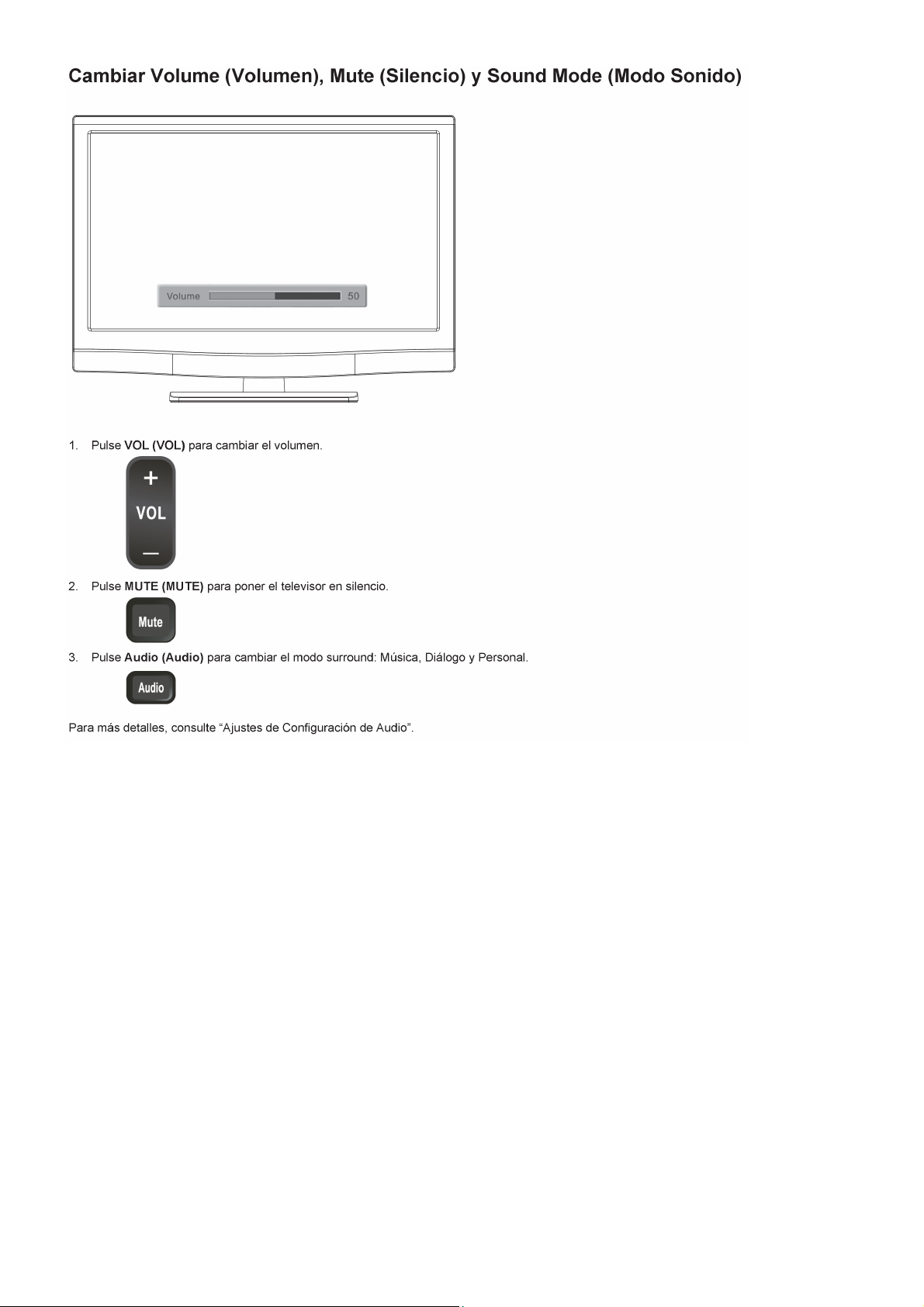
2. Operating Instructions………………...…….……….......6
2.1 The Use of Remote Control…….…..……….…….......6
2.2 To Use the Menus….....………………….…..…….......7
2.3 How to Connect……..……………….…….……….....17
2.4 Front Panel Control Knobs…….………….……….....19
3. Input/Output Specification…………....................…....20
4. Mechanical Instructions…………………….................22
5. Repair Flow Chart ……………………….…….…….....25
6. PCB Layout ………………..…………………....….......32
6.1 Main Board…………..………………...…….…….......32
ANY PERSON ATTEMPTING TO SERVICE THIS CHASSIS MUST FAMILIARIZE HIMSELF WITH THE CHASSIS
Horizontal Frequency
TABLE OF CONTENTS
6.2 Power Board………………..…….…….………......34
6.3 LED Board……...…………..…….…….………......44
6.4 Key Board………………………..……..……….......45
6.5 IR Board………………………….……..……….......45
7. Adjustment……..………………………….................46
8. Block Diagram.……...............................................47
9. Schematic Diagram…..…………....………………...49
9.1 Main Board…………………………………...…......49
9.2 Power Board…………..….….……...………….......58
9.3 LED Board………….……..….……...………….......66
9.4 Key Board……………….……….…………….........68
9.5 IR Board……...………….……….…………….........69
10. Exploded View……………………………….…....70
11. BOM List……..……….………………….…………..74
SAFETY NOTICE
AND BE AWARE OF THE NECESSARY SAFETY PRECAUTIONS TO BE USED WHEN SERVICING
ELECTRONIC EQUIPMENT CONTAINING HIGH VOLTAGES.
CAUTION: USE A SEPARATE ISOLATION TRANSFOMER FOR THIS UNIT WHEN SERVICING
1
Page 2

Important Safety Notice
Proper service and repair is important to the safe, reliable operation of all AOC Company Equipment. The service
procedures recommended by AOC and described in this service manual are effective methods of performing service
operations. Some of these service operations require the use of tools specially designed for the purpose. The
special tools should be used when and as recommended.
It is important to note that this manual contains various CAUTIONS and NOTICES which should be carefully read in
order to minimize the risk of personal injury to service personnel. The possibility exists that improper service
methods may damage the equipment. It is also important to understand that these CAUTIONS and NOTICES ARE
NOT EXHAUSTIVE. AOC could not possibly know, evaluate and advise the service trade of all conceivable ways in
which service might be done or of the possible hazardous consequences of each way. Consequently, AOC has not
undertaken any such broad evaluation. Accordingly, a servicer who uses a service procedure or tool which is not
recommended by AOC must first satisfy himself thoroughly that neither his safety nor the safe operation of the
equipment will be jeopardized by the service method selected.
Hereafter throughout this manual, AOC Company will be referred to as AOC.
WARNING
Use of substitute replacement parts, which do not have the same, specified safety characteristics might create
shock, fire, or other hazards.
Under no circumstances should the original design be modified or altered without written permission from AOC.
AOC assumes no liability, express or implied, arising out of any unauthorized modification of design.
Servicer assumes all liability.
FOR PRODUCTS CONTAINING LASER:
DANGER-Invisible laser radiations when open AVOID DIRECT EXPOSURE TO BEAM.
CAUTION-Use of controls or adjustments or performance of procedures other than those specified herein may
result in hazardous radiation exposure.
CAUTION -The use of optical instruments with this product will increase eye hazard.
TO ENSURE THE CONTINUED RELIABILITY OF THIS PRODUCT, USE ONLY ORIGINAL MANUFACTURER'S
REPLACEMENT PARTS, WHICH ARE LISTED WITH THEIR PART NUMBERS IN THE PARTS LIST SECTION OF
THIS SERVICE MANUAL.
Take care during handling the LCD module with backlight unit
-Must mount the module using mounting holes arranged in four corners.
-Do not press on the panel, edge of the frame strongly or electric shock as this will result in damage to the screen.
-Do not scratch or press on the panel with any sharp objects, such as pencil or pen as this may result in damage to
the panel.
-Protect the module from the ESD as it may damage the electronic circuit (C-MOS).
-Make certain that treatment person’s body is grounded through wristband.
-Do not leave the module in high temperature and in areas of high humidity for a long time.
-Avoid contact with water as it may a short circuit within the module.
-If the surface of panel becomes dirty, please wipe it off with a soft material. (Cleaning with a dirty or rough cloth may
damage the panel.)
2
Page 3
Version Release Date Revision Instructions
A00 Jun.7,2010 Initial Release
Add new Model LE19W037 E19AAANSWEB16N
A01 Aug.12,2010
Add new power board LE22H037 E22AGANSWEB16N
Add new Models LE19W037
Revision List
Customer
Model
LE19W037
LE22H037
LE24H037
TPV Model
E19A2ANSWEE7NN
E19A2ANSWEE6NN
E22A2ANSWEE6NN
E22A2ANSWEE7NN
E2CA6ANSWEE7NN
E2CA6ANSWEE6NN
E19A7ANSWEE6NN
E19A7ANSWEE7NN
Add new power board
A02 Dec.07,2010
A03 Jan.18,2011 Add new Models LE24H037
A04 May.13,2011
A05 Aug.31,2011
715G4147P01H21002S&
715G3798T02000004S
Update are as below:
Layout
Schematic Diagram
BOM List
Add new LED board
715G4614T01000004S
Update are as below:
PCB Layout
Schematic Diagram
BOM List
Add new power&LED board
715G4147P01H21002S&
715G3798T02000004S&
715G4614T01000004S
Update are as below:
Repair Flow Chart
PCB Layout
Schematic Diagram
BOM List
Add new inverter board
715G3798T02000004S
Update are as below:
BOM List
LE22H037
LE19W037
LE22H037
LE24H037 E2CA6ANSWEE9NN
LE19W037
E22A7ANSWEE6NN
E22A7ANSWEE7NN
E2CA6ANSWEACNN
E2CA6ANSWEAENN
E19A2ANSWEAENN
E19A2ANSWEACNN
E19A2ANSWEE9NN
E22A2ANSWEAENN
E22A2ANSWEACNN
E22A2ANSWEE9NN
E19A7ANSWEE65N
Add new Model E19A2ANSWEAE5N
3
Page 4
E19B2ANSWEE8NN
Add new Models LE19W037
A05 Aug.31,2011
A06 Oct.8,2011 Add new Model LE19W037 E19B2ANKWEM55N
A07 Dec.5,2011 Add new Model LE24H037 E2CA6ANSWEE8NN
Add new Models LE22H037
Add new power board
715G4313P02000003
Update are as below:
Repair Flow Chart
PCB Layout
Schematic Diagram
BOM List
LE24H037
E19B2ANSWEE7NN
E19B2ANSWEE9NN
E22B2ANSWEE8NN
E22B2ANSWEE7NN
E22B2ANSWEE9NN
E2CB6ANSWEE7NN
E2CB6ANSWEE8NN
E2CB6ANSWEE9NN
4
Page 5

1. General Specification
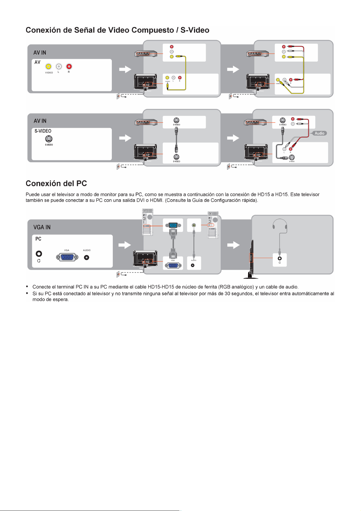
* Entrada de S-Video
Puede conectar la TV a una fuente de video de alta resolución (grabadora de videocasete Super VHS, reproductor
de discos láser y sistema de entretenimiento hogareño con DVD) para obtener una máxima satisfacción de
visualización.
Nota:
_ Los diseños y las especificaciones están sujetos a cambios sin aviso previo.
_ Este modelo podría ser no compatible con las funciones y/o especificaciones que se agreguen en el futuro.
5
Page 6
2. Operating Instructions
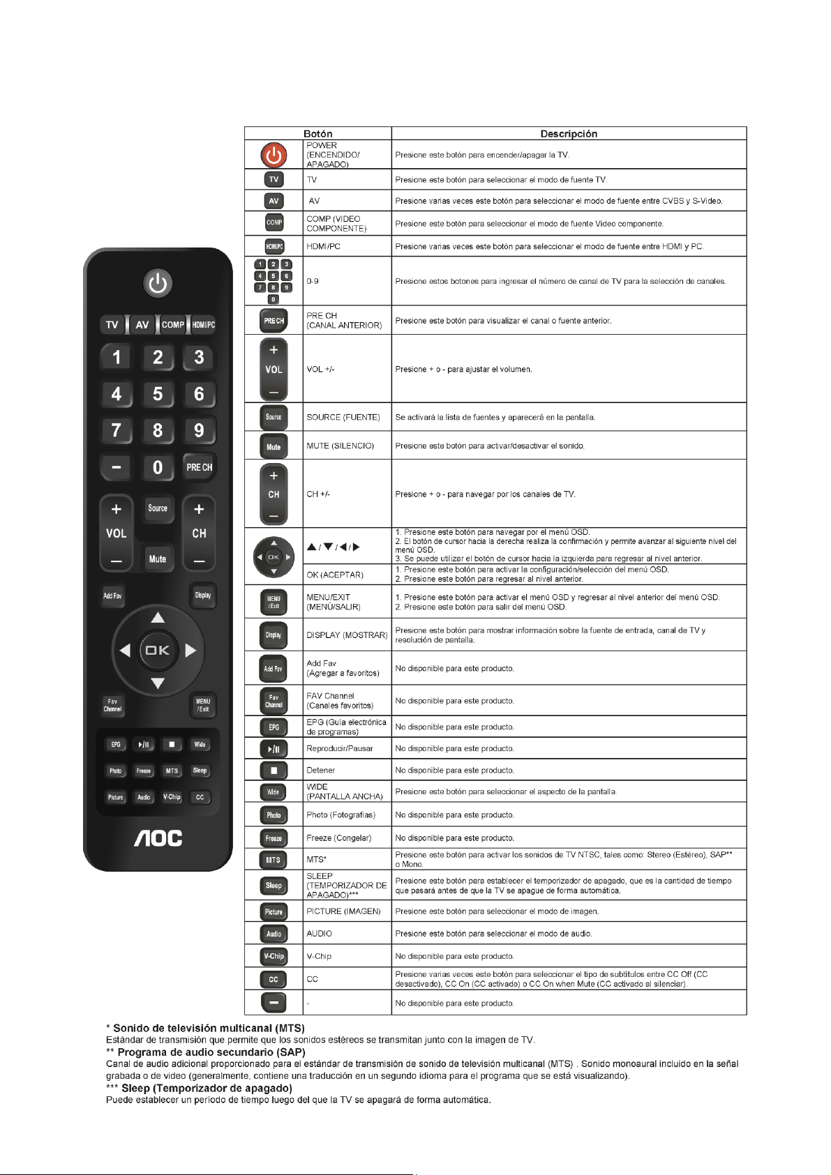
2.1 The Use of Remote Control
6
Page 7
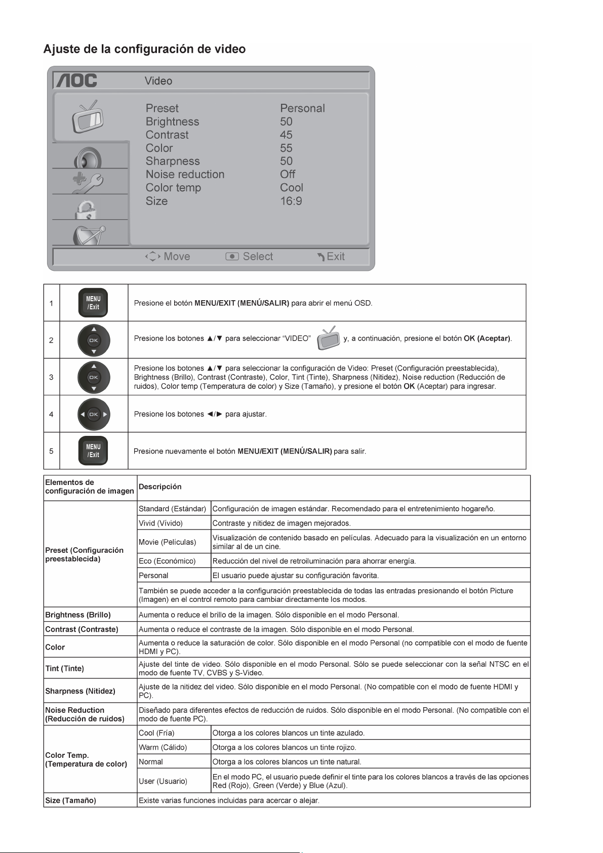
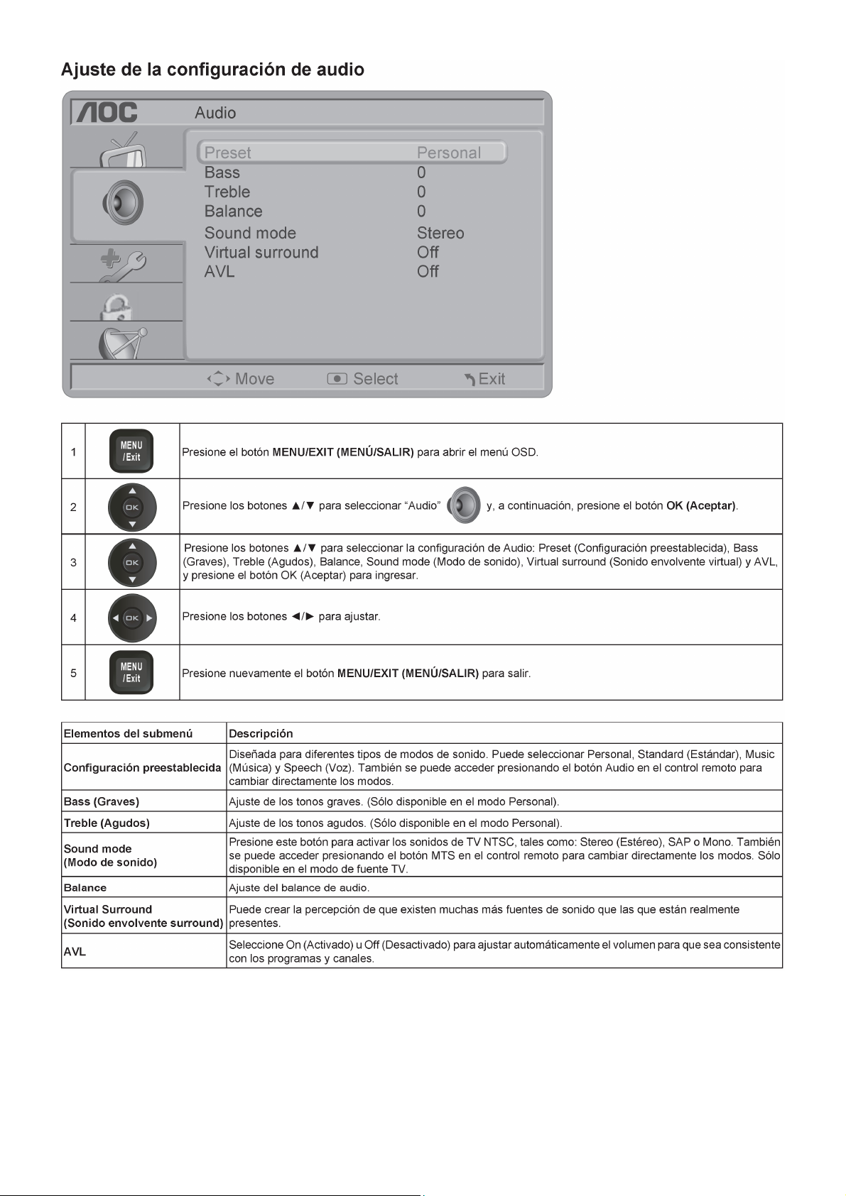
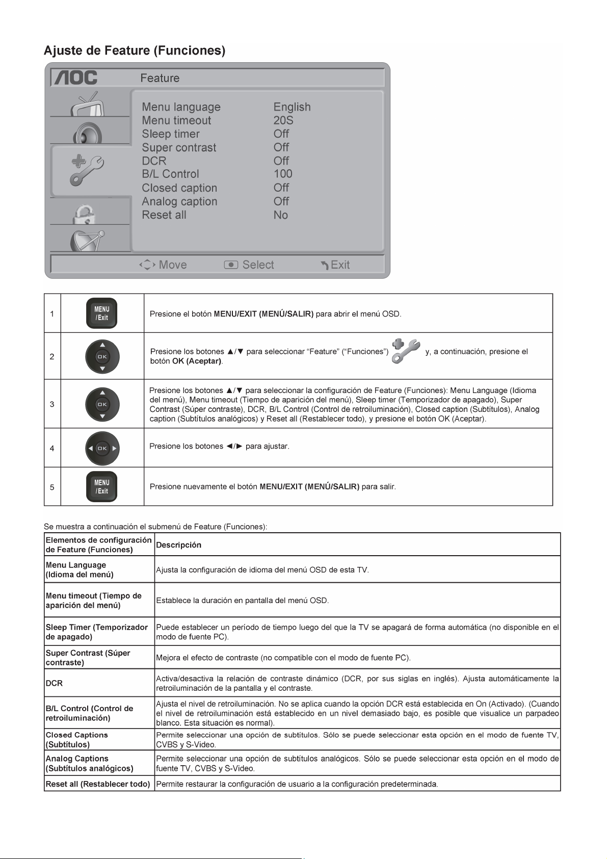
2.2 To Use the Menus
7
Page 8

8 9
Page 9
Page 10
10 11 12 13 14 15 16
Page 11
Page 12

Page 13
Page 14
Page 15

Page 16

Page 17
2.3 How to Connect
17
Page 18
18
Page 19
2.4 Front Panel Control Knobs
19
Page 20
3. Input/Output Specification
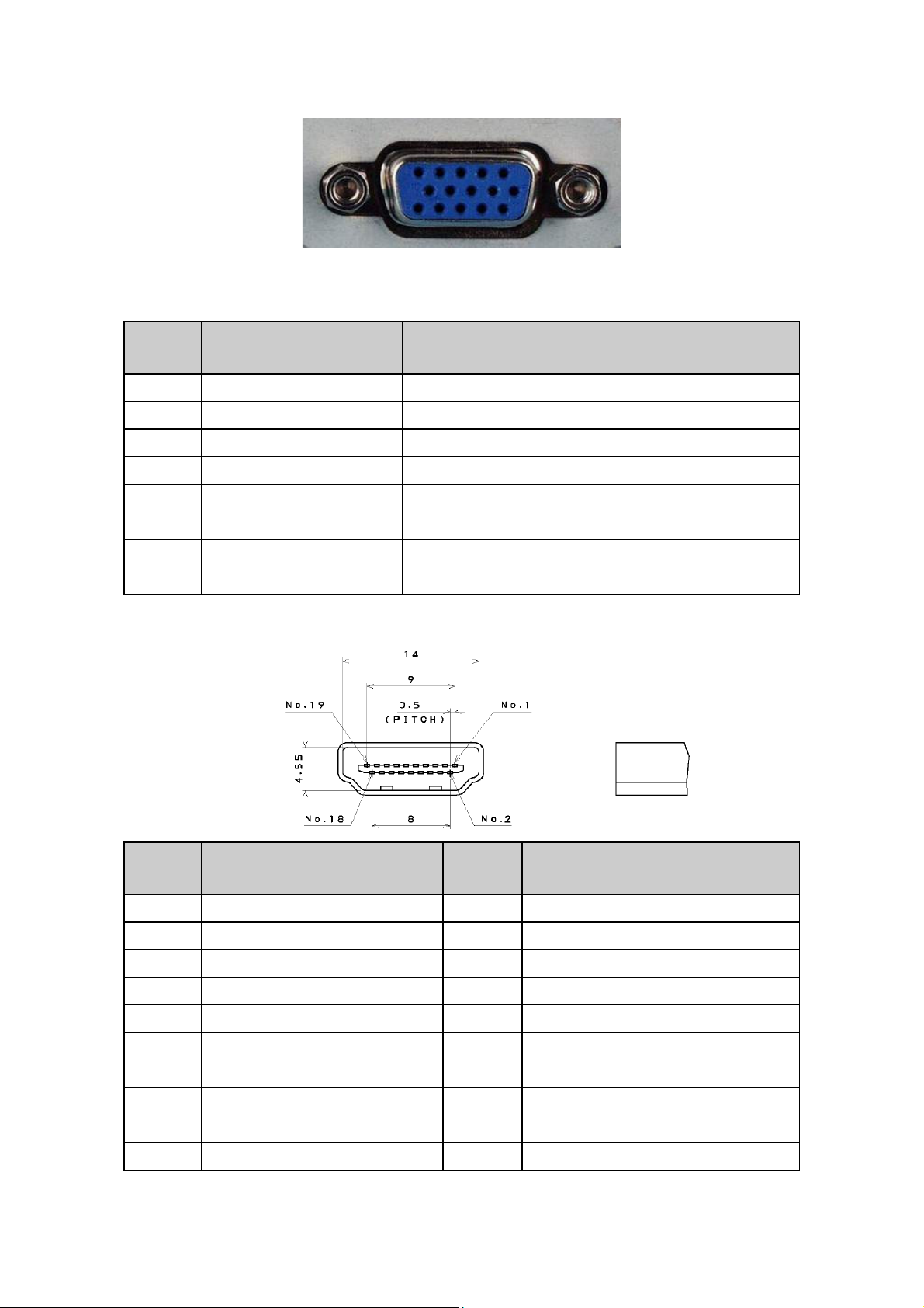
3.1 RGB Signal Input
15 - Pin Color Display Signal Cable
Pin No. Description Pin No. Description
1 Red Video 9 No Pin
2 Green Video 10 Sync Ground
3 Blue Video 11 RXD
4 TXD 12 Serial Data for DDC
5 Ground 13 H-Sync.
6 Red Video Ground 14 V-Sync.
7 Green Video Ground 15 Serial Clock for DDC
8 Blue Video Ground
3.2 HDMI Digital Connector Pin Assignments
Pin No. Description Pin No. Description
1 TMDS Data2+ 2 TMDS Data2 Shield
3 TMDS Data2- 4 TMDS Data1+
5 TMDS Data1 Shield 6 TMDS Data1-
7 TMDS Data0+ 8 TMDS Data0 Shield
9 TMDS Data0- 10 TMDS Clock+
11 TMDS Clock Shield 12 TMDS Clock-
13 CEC 14 Reserved (N.C. on device)
15 SCL 16 SDA
17 DDC/CEC Ground 18 +5V Power
19 Hot Plug Detect
20
Page 21

3.3 Compatible Mode Table
Modo de PC preestablecido (LE19W037)
Estándar Resolución Horizontal (kHz) Vertical (Hz)
VESA 640 x 480 31.469 59.94
VESA 800 x 600 35.156 56.250
VESA 800 x 600 37.879 60.317
VESA 1024 x 768 48.363 60.004
VESA 1280 x 720 60.000 45.000
VESA 1360 x 768 47.72 59.799
Modo de PC preestablecido (LE22H037/LE24H037)
Estándar Resolución Horizontal (KHz) Vertical (Hz)
VESA 640 x 480 31.469 59.94
VESA 800 x 600 35.156 56.250
VESA 800 x 600 37.879 60.317
VESA 1024 x 768 48.363 60.004
VESA 1280 x 720 60.000 45.000
VESA 1360 x 768 47.72 59.799
WXGA+ 1400 x 900 59.887 55.935
WSXGA 1680 x 1050 59.884 64.674
FHD 1920 x 1080 60 67.5
Modo de video preestablecido (LE19W037)
Estándar Resolución Horizontal (KHz) Vertical (Hz)
SD 480i 15.734 60
SD 480P 31.5 60
HD 720P 45 60
HD 1080i 33.75 60
Modo de video preestablecido (LE22H037/LE24H037)
Estándar Resolución Horizontal (KHz) Vertical (Hz)
SD 480i 15.734 60
SD 480P 31.5 60
HD 720P 45 60
HD 1080i 33.75 60
FHD 1080p 67.5 60
21
Page 22

4. Mechanical Instructions
1. Remove the screws to remove the stand, base and rear cover.
2. Remove the screws to remove AC cover.
22
Page 23
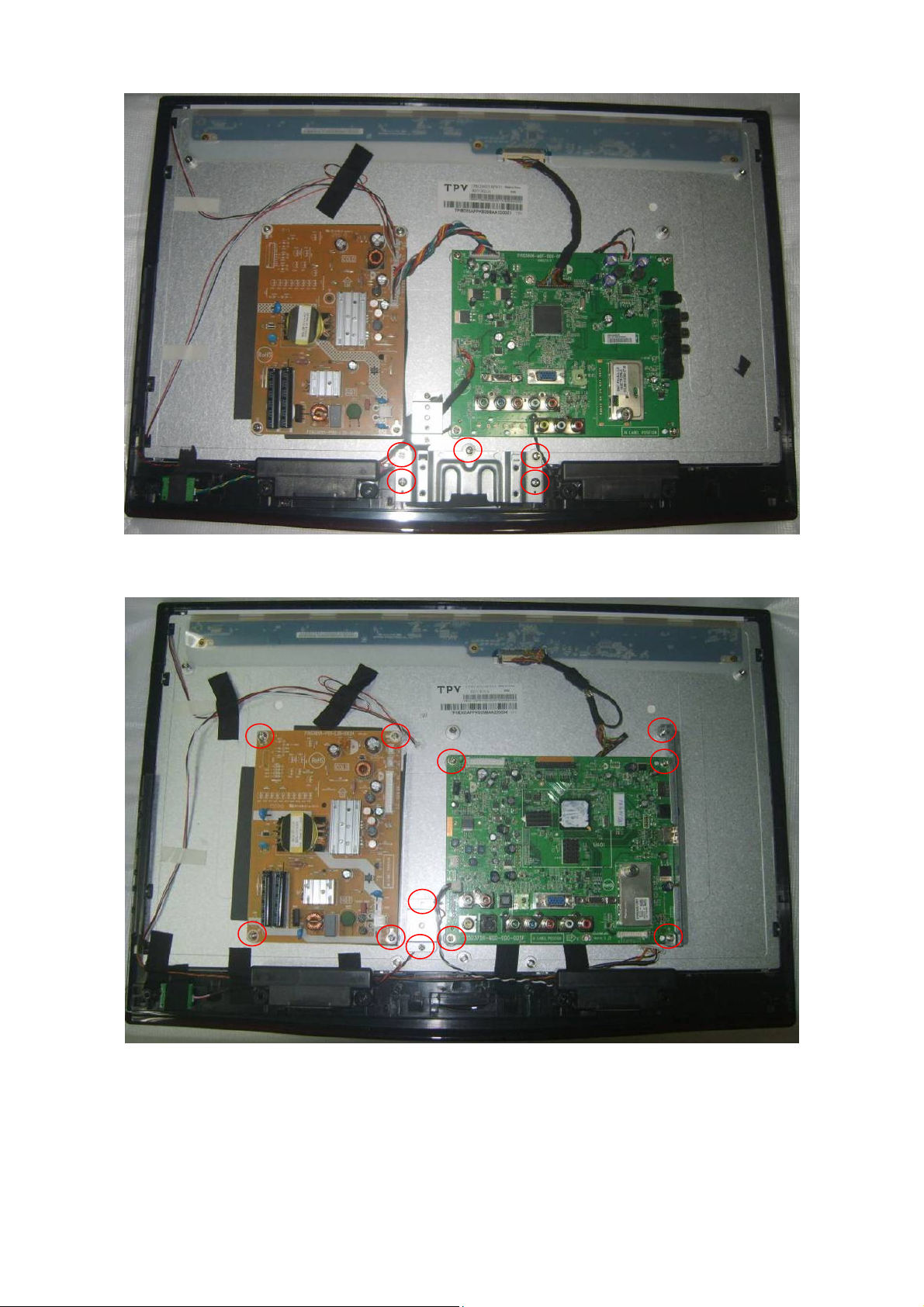
3. Remove the screws to remove hinge BKT.
4. Remove the screws to remove AC BKT, main board and power board.
23
Page 24
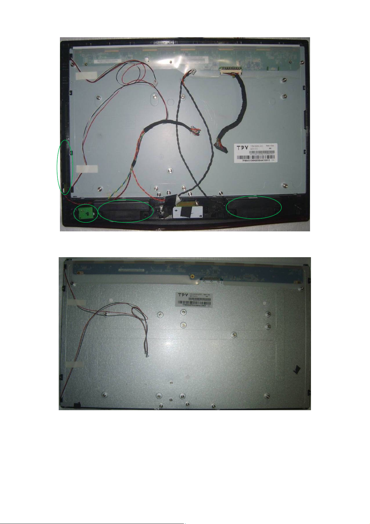
5. Remove the screws to remove key board, IR board and speakers.
6. The panel.
24
Page 25

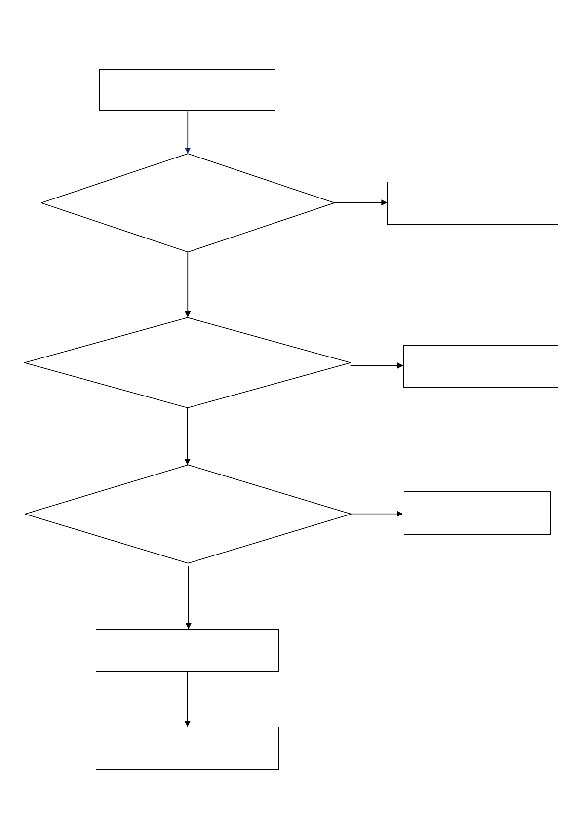
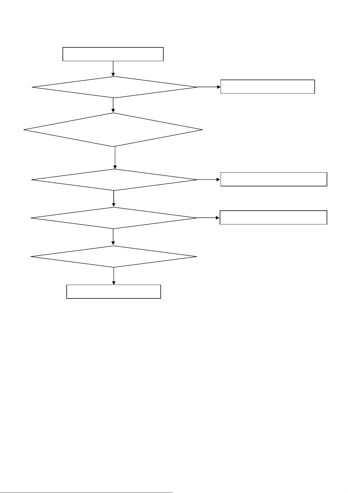
5. Repair Flow Chart
1. Sin Energía
Sin Energía (LED “Apagado”)
Revise la entrada AC. ¿La
energía está en “encendida”?
Si
Salida Power board =5.2V?
Si
Revise IR board y LED
No
Reemplace IR board
No
No
Enciéndalo
No
Reemplace power board
Reemplace main board
25
Page 26
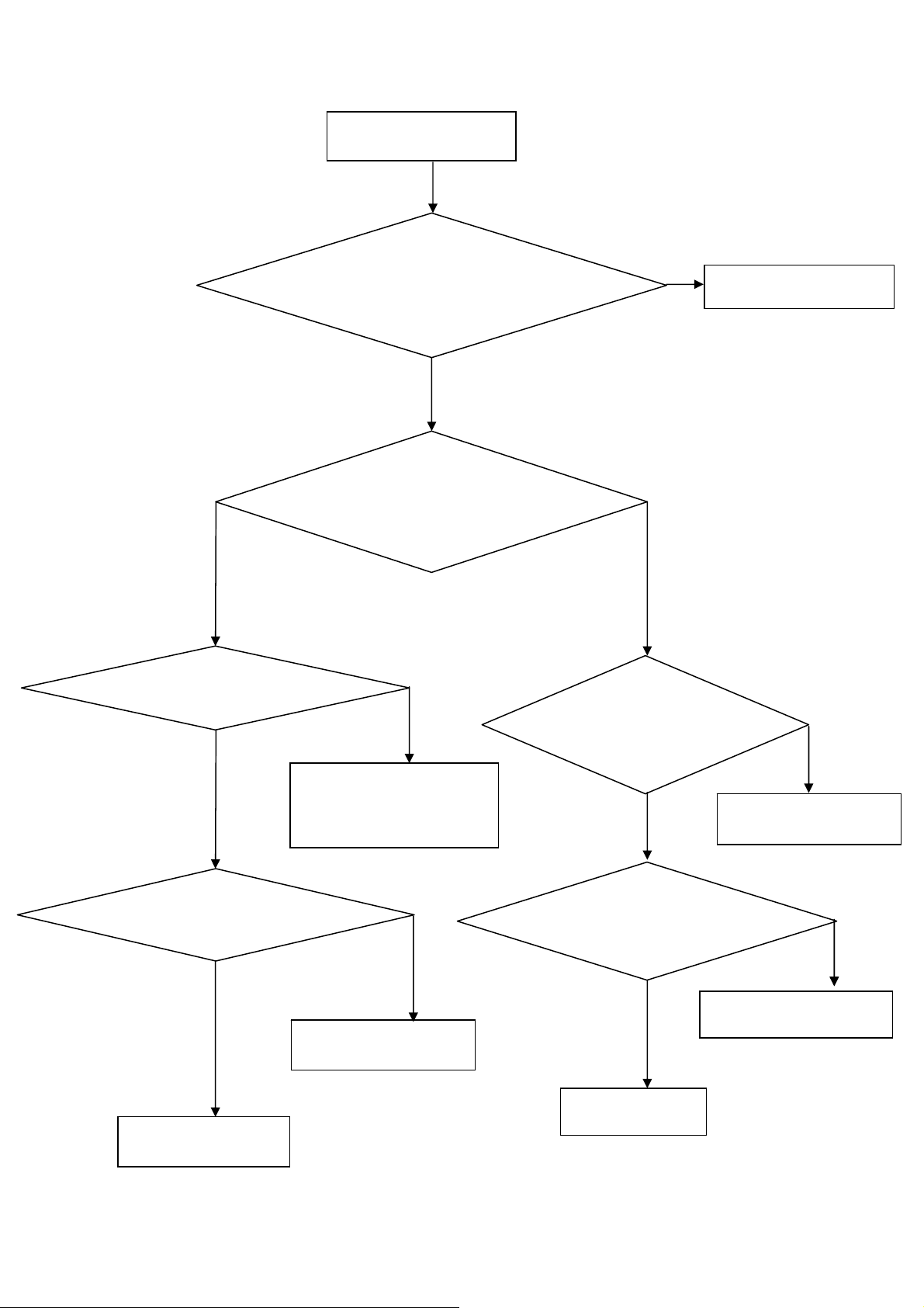
2. No Enciende
(Chequee tecla power del control remoto, si
equipo no responde significa que es anormal).
No inicia (LED naranjo)
Salida Power board=16V/12V?
Si
Revise si el botón de power funciona
No
Revise si el receptor IR es normal
No
No
Reemplace power board
Si
Reemplace key board
Si
Reemplace IR board
Reemplace main board
No
Reemplace la Power board
26
Page 27
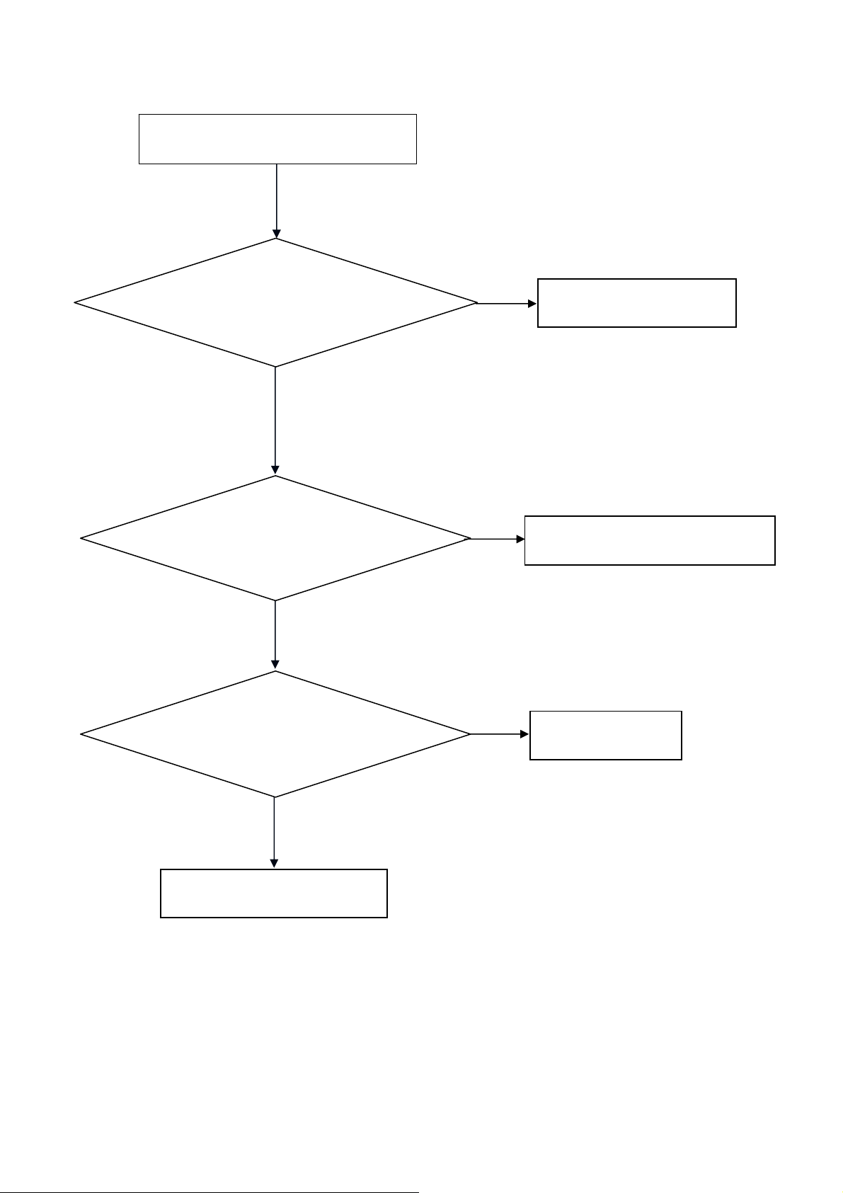
3. Imagen Anormal
Entre al menú modo de fábrica para hacer
Imagen Anormal
Revise la fuente
Si
“EEPROM initial”&“Reset”
No
No
Reinicie la fuente
Revise main board
Si
Revise el cable LVDS
Si
Revise el panel
No
Reemplace panel
No
Reemplace main board
No
Reemplace LVDS cable
27
Page 28
4. Sin Imagen
Revise si el TV funciona, si enciende/apaga
vía control remoto y botón de power.
Si
Revise cable LVDS
Si
Panel Vcc = 5V?
Sin imagen (LED verde)
Si
Revise si la luz del panel está
encendida= “On”
No
Vuelva a insertar o
Reemplace el cable LVDS
No
No
Reemplace main board
No
Revise señal L/P si
está disponible
No
Si
Salida de Power board=16V/12 V?
Reemplace main board
No
Si
Reemplace the Panel
Reemplace main board
28
Si
Reemplace Panel
Reemplace power board
Page 29

5. Problema de Sonido
Revise la conexión de la fuente de audio y si norma de
Sin sonido o sonido anormal
TV es correcto (NTSC-PAL N/M/ISTB)
Si
Revise si TV está mudo (muted), ajuste el volume o
entre al modo menú para reinicio?
No
Entre al modo menú de fábrica para reinicar
No
Revise el cable entre los parlantes y main
board si están OK
Si
No
Vuelva a insertar el cable de audio o cambie
la norma del TV
No
Reemplace cable
Revise los valores de Resistencia en el parlante que se encuentran en
las especificaciones (Nota: El valor está marcado en el parlante)
Si
Reemplace parlante
29
Reemplace main board
No
Page 30
6. Control Remoto - mal funcionamiento
Control remoto - mal funcionamiento
Revise la batería del control remoto si está
bien colocada o no tiene energía
No
Use otros controles remotos, ¿funciona?
Si
Reemplace batería
Si
Reemplace el control remoto
No
¿Es anormal la IR board?
No
Reemplace main board
Si
Reemplace IR board
30
Page 31

7. OSD es inestable o no trabaja de forma normal
OSD es inestable o no trabaja normalmente
La botonera está conectada correctamente?
Si
Los botones están OK?
Si
Botonera está OK?
Si
Entre al modo menú de fábrica para reinicar
No
No
No
No
Reconecte el key board
Reemplace la función del botón
Reemplace la botonera
Reemplace el main board
31
Page 32

6. PCB Layout
6.1 Main Board
715G3806M01000004L
32
Page 33

33
Page 34

6.2 Power Board
LE19W037 715G3762P01W30002S
34
Page 35

35 36
Page 36

Page 37

LE22H037/LE24H037 715G3895P01L30002H
37
Page 38

38 39
Page 39

Page 40

LE22H037/LE24H037 715G4313P02000003S
40
Page 41

41 42
Page 42

Page 43

LE22H037/LE24H037 715G4147P01H21002S
43
Page 44

LE22H037/LE24H037 715G3798T02000004S
6.3 LED Board
715G4087T01000004W
44
Page 45

715G4614T01000004S
6.4 Key Board
715G4053K01000004F
6.5 IR Board
715G4086R01000004S
45
Page 46

7. Adjustment
It’s no need to adjust the white balance for this model.
1. Enter into the factory mode:
Turn on the TV, press MENU key with remote control, then press number key 1 Æ 9 Æ 9 Æ 9. It will achieve the
factory mode.
2. Click on "Autowhite 100%" in the PC and Component modes:
PC mode: TIM = 107; PAT = 42
Component mode: TIM = 311; PAT = 185
Take other model’s factory menu for example:
46
Page 47

8. Block Diagram
CN301
HDMI
CN104
YPbPr
BACK BACKSIDE
CN107
AV&S-VIDEO
CN102
BACK
VGA
CN101
AV1
CN105
SCART
EU/CH Option
TU201
Tuner
OR
BACK BACK
TU202
Tuner
RF/IF Tuner Option
Hotel Pin
ADC KEY
IR
RX0,RX1,RX2,RXCLK
RS232
IF
HDMI EDID(U301)
Y,Pb,Pr
CVBS
Y/C
R,B,G,H,V
SC_R,SC_G,SC_B
FB_BLANK,STATUS
U201
SAWFILTER
SCL,SDA
RS232
IR_DAT
CVBS
CVBS
U404
EEPROM
24C32
SDA,SCL
RS232
Himax M2D U405
HDMI_RXA0,A1,A2,CLK
AINA2,AINB2,AINC2,SOG2
AINA5
AINB4,AINC4
AINA1,AINB1,AINC1
HSYNC,VSYNC
Himax M2D
AINA3
AINC3,AINB3,AIND1
AIN0_FAD,AIN1_FAD
AIND4
ADCINN,ADCINP
P0,P1
HDMI/ADC
Himax M2D
MCU
Himax M2D U405
Himax M2D U405
CVBS_O
Himax M2D
TTL/LVDS/RSDS
U402
SPI EEROM
AV Line Out
SCART CVBS Out
(Option)
(CN106)
LVDS BUS
Backlight
On/Off,Brightness
CN404
CN407
CN408
LVDS I/O
BACK
LVDS BUS
PANEL
CN103
PC Audio
AV&S-Video
Audio(CN107)
SIDE
AV1&SCART Option
Audio
(CN104&CN105)
BACK BACK
Tuner
YPbPr
Audio
AV Audio Line Out
SCART Audio
(Option)
BACK
(CN106&CN105)
MONO_AUD
COM1_AUL/R
U601
Switch 4052
SCR_AUOUT_L/R
SIF
MUX_AUL/R
RAIN0,LAIN0
RAIN2,LAIN2
RAIN1,LAIN1
Himax M2D
Audio
Himax M2D U405
47
U603
AMP TDA7297
U604
APA2176A
CN603
Connector
CN601
Earphone
BACK
Page 48

5VSB
POWER_ON
5VSB
5VSB
5VSB
1084-33
U701
AO4449
Q706
VCC5
VCC3
1077mA
VCC5
VCC5
VCC5
VCC5
400mA
1084_33
U707
AP1117D33
U705
AP1117D18
U703
AP1117D18
U709
VCC5
VCC5
VCC3
MX25L4005AM2C
U402
1084_1.8
U708
281mA
V33_ADC
39mA
V33_AUD
117mA
VCC18
16mA
VCC18_PLL
AP2176
U604
EARPHONE AMP
USB boad power
5V,5V TO 3.3v
5v to 1.8V
822mA
VCC18_CORE
V33ADC / VCCADC / VDDA33
HX6201
U405
V33AUD
HX6201
U405
V18_33HDMI
HX6201
U405
V18AUD / PVDD_LV
HX6201
U405
AVDD18 / VCCLV
HX6202A
U405
VCC5
PI5V33
U107
VIDEO SWITCH
VCC3AD
VCC3IO / V33LV
HX6201
U405
VCC3AD
VCC3IO / V33LV
AVDD18 / VCCLV
V33HDMI / VCCADC / VDDA33
V33AUD
V18_33HDMI
V18AUD / PVDD_LV
PANEL_ON
POWER_ON
+12V_SB
POWER_ON
PANEL_ON
5VSB
5VSB
500mA--1.0A
V12_ADP
V12_ADP
V12_ADP
Q406
AO3407
Q701
AO4449
Q406
TDA7297
U603
MPS2171
U711
M24C02
U301
PANEL_VCCAO4449
VCC12 BA17808
PANEL_VCC
USB 2.0 HOST
U706
A1117D5.0
U202
PANEL
PANEL
M24C02U101
5mA
VCC8
160mA
+5VT
74HC4052
U601
AUDIO SWITCH
TUNER
TU100
48
M24C32
U404
Page 49

9. Schematic Diagram
9.1 Main Board
715G3806M01000004L
GND
C728
100nF 50V
C730
100nF 50V
0R05 1/10W
R719
C723
NC 4. 7UF 10V
H2
NC
BL_ON1
V_IPWM
PWR_ON
5VSB
5VSB
GND
5VSB
GND
H3
NC
V12_ADP
24V
5VSB
R728
10K 1/10W
GND
R733
10K 1/10W
R717
NC 10K 1/10W
Q707
NC PMBS3904
CN701
CONN
H1
NC
1
2
3
4
5
6
7
8
9
10
11
12
BL_ON1
PWR_ON
V_IPWM
C714
100nF 50V
24V
C726
100nF 50V
Q710
PMBS3904
Q711
PMBS3904
R718
NC 1K1/16W
V1
NC
GND
R731
1K1/16W
R734
1K1/16W
0R05 1/10W
R720
H5
NC
V12_ADP
5VSB
GND
BL_ADJ
11
+
C715
470uF/ 16V
+
C727
470uF/16V
BL_ON 12
PW_ON 12
H6
NC
VS1
NC
VS2
NC
VS3
NC
VS4
NC
VS5
NC
VS6
NC
VS7
NC
VS8
NC
C718
220uF16V
+
C701
10uF/50V
VCC5
1 2
10uF/50V
VCC18
100nF 50V
GND
FB706
300 OHM
+
GND
+
C702
U703
AZ1117D-1. 8-E1
C721
GND
POWER_ON12
C738
100nF 50V
5VSB
C720
100nF 50V
GND
V33_ADC
ADJ/ GND1OUTPUT2INPUT
3
C717
100nF 50V
U707
G1084-33TU3U f
VIN3VOUT
GND
1
U701
G1084-33TU3Uf
VIN3VOUT
GND
1
12
FB709
300 OHM
+
C716
220uF16V
R729
4.7K 1/10W
2
2
+
C740
220uF/16V
VCC3
10K 1/10W
5VSB
R725
4.7K 1/10W
4.7K 1/10W
Q709
PMBS3904
V33_ADC
GND
+
C741
220uF/16V
GND
R716
R727
2008-11-18
FB701
1 2
300 OHM
C739
100nF 50V
G1084-18TU3Uf
C724
100nF 50V
5VSB
C719
100nF 50V
R726
47K +- 5% 1/10W
Q708
PMBS3904
2008-9-10
GNDGND
+
U708
VIN3VOUT
1
V33_AUD
C734
220uF16V
GND
GND
2
+
Q706
AO4449 -7A/-30V
1
S
D
2
S
D
3
S
D
4
G
D
R721
100K 1/10W
VCC3
C735
100nF 50V
GND
VCC18_CORE
C742
220uF/16V
VCC5
8
7
6
5
+
C722
100uF/16V
GND
C748
1nF 50V
C743
100nF 50V
GND
C733
100nF 50V
C749
1000PF50V
1000PF50V
GND
1
GND
1
1
1
GND
1
1
1
1
GND GND
1
1
GND
T P V ( Top Victory Electronics Co . , Ltd. )
絬 隔 瓜 絪 腹
Key Component
03.Power
Date
OEM MODEL
TPV MODEL
PCB NAME
Sheet
715G3806-M0D-000-0040
of
412Tuesday, March 02, 2010
Size
Rev
称爹
A4
D
<
称爹
>
1
1
49
Page 50

RXACLKN_M2
CN301
HDMI
1
D2+
D2-
D1+
D1-
D0+
D0-
CK+
CK-
NC
GND
+5V
2
3
4
5
6
7
8
9
10
11
12
13
14
15
16
17
18
19
D2 Shield
D1 Shield
D0 Shield
CK Shield
TH 1
TH 2
TH 3
TH 4
TH 5
CE Remote
DDC CLK
DDC DATA
HP DET
20
21
22
23
24
RXA2P_M2
RXA2N_M2
RXA1P_M2
RXA1N_M2
RXA0P_M2
RXA0N_M2
RXACLKP_M2
RXACLKN_M2
HDMIA_CEC
DDCA_SCL
DDCA_SDA
HDMIA_5VIN
HDMIA_HPD
5VSB
HDMIA_5VIN
R303
1K1/16W
RXACLKP_M2
RXA0N_M2
RXA0P_M2
D301
BAT54C
R309
47K1/16W
RXA1N_M2
RXA1P_M2
RXA2N_M2
RXA2P_M2
R310
HDMIA_CEC
DDCA_SCL
DDCA_SDA
HDMIA_5VIN
HDMIA_5VIN
47K1/16W
1
IN1
2
IN2
4
IN3
5
U303
1
2
4
5
U304
1
2
4
5
IN4
IN1
IN2
IN3
IN4
IN1
IN2
IN3
IN4
U302
R316 47K 1/16W
Q302
PMBS3904
GND
GND
3
8
GND
GND
3
8
GND
GND
3
8
47K 1/16W
R304
10K 1/10W
OUT1
OUT2
OUT3
OUT4
NC
OUT1
OUT2
OUT3
OUT4
OUT1
OUT2
OUT3
OUT4
10
9
7
6
NC
10
9
7
6
NC
HDMIA_CEC
10
DDCA_SCL
9
DDCA_SDA
7
HDMIA_5VIN
6
HPDA 9
RXACLKN_M2 9
RXACLKP_M2 9
RXA0N_M2 9
RXA0P_M2 9
RXA1N_M2 9
RXA1P_M2 9
RXA2N_M2 9
RXA2P_M2 9
HDMIA_5VIN
R305
10K 1/10W
5VSB
R302
10K 1/10W
Q303
PMBS3904
5VSB
R306
NC
HA5V_DET
VCC3
R308
NC
HA5V_DET 11
R307
NC
DDCA_SCL
DDCA_SDA
R312
R313
T P V ( Top Victory Electronics Co . , Ltd. )
絬 隔 瓜 絪 腹
Key Component
Date
0R05 1/10W
0R05 1/10W
04.HD MI
50
DDCHA_SCL 9 HA_CEC 9
DDCHA_SDA 9
OEM MODEL
TPV MODEL
PCB NAME
Sheet
HDMIA_CEC
715G3806-M0D-000-0040
512Thursday , January 28, 2010
of
NC
Q301
Size
Rev
称爹
A4
D
<
称爹
>
Page 51

TGN D
C323
56pF 50V
C324
56pF 50V
TGN D
R320
100 OHM 1/10W
NC1NC
2
3
SDA
SCL
SCL_A_Tuner
15
TH112TH213TH314TH4
VCC7SCL5SDA4AS
AGC8NC9AUD IO OU T
IF_SOUND
6
10
SIF
SIF
7
R317
100 OHM 1/10W
TGN D
CVBS
11
TV_CVBS
+5VT
C308
100uF
TU100
M40CTP-6N-E
+
TGN D
+5VT
100nF 50V
C309
VCC5
C219
+
330uF 10V
5V for Tuner
G965-25ADJPIUF
U159
2.2 OHM 1/10W
R739
8
VEN1VIN2VO3ADJ
38.3KOHM +-1% 1/8W
GND5GND6GND7GND
4
R172
12K1/10W
R173
FB151
1 2
220R/2000mA
C218
+
47PF/16V
+5VT
20
19
18
17
TGN D
TH 4
TH 3
TH 2
TH 1
16
TV_CVBS
SDA_A_Tuner
12
12
SIF
TGN D TGN D
SDA
SCL
TU101
NC
+5VT
TV_CVBS
GND
NC1NC2GND3+B(5V)4RF AGC5GND6SDA7SCL8MOPLL AS9NC10NC11NC12SIF13NC14AUDIO15VIDEO
TGN D
C207
TGN D
T P V ( Top Victory Electronics Co . , Lt d. )
絬 隔 瓜 絪 腹
Key Component
Date
05.TUNER
R206
2.2uH
220pF 50V
R212
NC
R207
18OHM1/16W
C208
220pF 50V
OE M MOD E L
TPV MO D EL
PCB NAME
Sheet
R208
100 OHM 1/10W
R210
56R 1/16W 5%
715G3806-M0D-000-0040
612Thursday , J anuary 28, 2010
of
T_C VBS
C206
0.1uF 50V
GND
T_CVBS 9
Put Near
to IC
Size
Rev
称爹
<
A4
D
称爹
>
51
Page 52

R151
100OHM1/16W
RX
VGASDA_IN
VGA_HIN
VGA_VIN
VGA_HIN
CN103
PHONEJ ACK
PHONEJ ACK
VGASCL_IN
U101
I/O23I/O3
2
GND
1
I/O1
AOZ8105CI
3
2
1
UART_RX
11
12
13
14
15
CONN
VDD
I/O4
VGA_AUR_O
VGA_AUL_O
4
5
6
CN108
1716
RED
1
RED_GND
6
GRN
2
GRN_GND
7
BLU
3
BLU_GND
8
4
9
5
10
VGA PIN DEFIINITION
1 R_OUT
5VSB
2 G_OUT
3 B_OUT
4 NC
5 GND
68K 1/10W
68K 1/10W
R122
R121
56K 1/10W
56K 1/10W
100OHM1/16W
ZD114
1 2
MLVG0402
MLVG0402
C113 4U7 10V
R116
C114 4U7 10V
R115
R148
6 R_GND
7 G_GND
8 B_GND
9 +5V(DDC)
10 GND
UART_TX
11 NC
12 DDC SDA
13 TTL H-S
14 TTL V-S
15 DDC SCL
VGA_AUR
VGA_AUL
RED
2
1
I/O1
GND
6
BLU
5VSB
RX
3
I/O2
I/O34VDD5I/O4
GRN
AOZ8105CI
U103
R/G/ B : 75 Oh m Trace
GRN
R161
GRN_GN D
75 OHM 1/10W
RED
RED_GND
BLU
BLU_GND
75 OHM 1/10W
5VSB
60 OHM
60 OHM
R149
60 OHM
60 OHM
R150
75 OHM 1/10W
R171
R170
VGASDA_IN
VGASCL_IN
C147
22P 50V
C117
22P 50V
C142
22P 50V
10K+-5%1/16W
10K+-5%1/16W
R160
60 OHM
60 OHM
R163
R154
C146
NC 180pF 50V
C141
NC 180pF 50V
C143
NC180pF 50V
R203 0R05 1/ 16W
R169 0R05 1/ 16W
0R05 1/16W
0R05 1/16W
R156
100OHM1/16W
R164
100OHM1/16W
R157
100OHM1/16W
R155
100OHM1/16W
VGA_DDCSD A
VGA_DDCSC L
Near to IC
C155 1N 50V
C152
47N 16V
C154
47nF 16V
C153
47nF 16V
VGA_VIN
VGA_HIN
SOGAIN
GAIN
RAIN
BAIN
2.2K 1/10W
R144
2.2K 1/10W
R127
120 OHM
FB103
C148
22P 50V
C150
22P 50V
33 OHM 1/16W
R126
33 OHM 1/16W
R125
VSYNC
HSYNC
CN109
E
D
C
B
A
JACK
Y
COM_AUR
11
10
9
COM_AUL
8
7
6
5
4
3
2
1
PR
PB
Y
MLVG0402
MLVG0402
PB
MLVG0402
MLVG0402
PR
MLVG0402
MLVG0402
ZD107
1 2
ZD108
1 2
ZD109
1 2
R656
75 OHM 1/10W
R657
75OHM1/16W
R655
75OHM1/16W
0R05 1/10W
C171
0R05 1/10W
NC
0R05 1/10W
0R05 1/10W
C172
NC
0R05 1/10W
0R05 1/10W
C173
NC
R168
R167
R166
C175
NC
C174
NC
C170
NC
R246
0R05 1/16W
0R05 1/16W
R222
0R05 1/16W
0R05 1/16W
R224
0R05 1/16W
0R05 1/16W
R245
0R05 1/16W
0R05 1/16W
C184
47nF 16V
C183 1N 50V
C186
47nF 16V
C185
47nF 16V
Y1
SOY1
GND
PB1
GND
PR1
GND
Near to IC
COM_AUL
COM_AUR
R211
27K 1/10W
R205
27K 1/10W
R215
R209
100K 1/10W 5%
100K 1/10W 5%
C179
4U7 10V
C182
4U7 10V
COM1_AUL
COM1_AUR
T P V ( Top Victory Electronics Co . , Ltd. )
絬 隔 瓜 絪 腹
Key Component
06.VGA/Y PbPr Connector
Date
OEM MODEL
TPV MODEL
PCB NA ME
Sheet
715G3806-M0D-000-0040
of
712Thursday , January 28, 2010
Size
Rev
称爹
A3
D
<
称爹
>
52
Page 53

CVBS1_IN
ZD101
S-video
CVBS & R/L
CN107B
JACK
2
1
4
3
6
5
SC_GND
CN107A
JACK
12
7 8
CY
9 10
GG
13
CVBS1_IN
CVBS_GND
R252
27K 1/10W
R256
27K 1/10W
R259
R253
100K 1/10W 5%
100K 1/10W 5%
SY_INSC_IN
SY_GND
11
C192
4U7 10V
C193
4U7 10V
SV/AV_AU L
SV/AV_AU R
VCC5
CVBS_GND
SY_IN
ZD102
SY_GND
SC_IN
ZD103
SC_GND
MLVG0402
MLVG0402
MLVG0402
L101
2.2uH
1 2
L102
2.2uH
1 2
L103
2.2uH
1 2
C189
220P 50V
C190
220P 50V
C187
220P 50V
CVBS2_IN
CVBS_GND
L105
L106
2.2uH
2.2uH
ZD104
NC M LVG0402
1 2
C217
220P 50V
C216
220P 50V
18OHM1/16W
L111
NC 2. 2uH
R254
18OHM1/16W
R257
18OHM1/16W
R250
Near to IC
L104
C214
NC 220P 50V
NC 2. 2uH
R247
100OHM1/16W
R248
56R 1/16W 5%
R255
100OHM1/16W
R249
56R 1/16W 5%
R251
100OHM1/16W
R258
56R 1/16W 5%
R267
NC 18OHM1/16W
C197
NC 220P 50V
C194
100N 16V
C188
100N 16V
C191
100N 16V
R260
NC 100OHM1/16W
R261
NC 56R 1/16W 5%
CVBS
GND
SV_Y
GND
SV_C
GND
C202
NC100N 16V
SCR_Y
GND
AV-OUT
CN110
A
B
C
JACK
2
1
4
3
6
5
GND
C195
100N 16V
FB107
1 2
121 OHM
220pF 50V
C196
100P 50V
C211
CVBS signal output
GND
23
R263
75OHM1/16W
C198
470pF 50V
Q110
1
PMBS3906
R273
270OHM 1/10W
R278
150 OHM 1/10W
FB105
600 OHM
FB106
600 OHM
C209
R280
200 OHM 1/10W
Q111
PMBS3904
GND
4U7 10V
470pF 50V
100K 1/10W 5%
100K 1/10W 5%
R277
100K 1/10W 5%
C210
10uF 16V
R262
100K 1/10W 5%
GND
C205
4U7 10V
C200
R271
CVBS_O
GND
R274
PMBS3904
GND
C782
NC
GND
Q112
CVBS_O
R279
680R 1/16W 5%
R264
680R 1/16W 5%
Q109
PMBS3904
R269
47K 1/16W
GND
4.7K 1/10W
R268
47K 1/16W
C204
4U7 10V
C203
4U7 10V
4.7K 1/10W
R275
R276
53
SCR_A UOUT_L
SCR_A UOUT_R
OFF_MUTE
CN101
NC JACK
T P V ( Top Victory Electronics Co . , Ltd. )
絬 隔 瓜 絪 腹
Key Component
Date
07.SCART SV/AV
CVBS2_IN
2
A
CVBS_GND
1
4
B
3
6
C
5
R265
NC 27K 1/ 10W
R270
NC 27K 1/ 10W
R272
R266
NC 100K 1/ 10W 5%
NC 100K 1/ 10W 5%
OEM MO DEL
TPV MO DEL
PCB NAME
Sheet
C199
NC 4U 7 10V
C201
NC 4U 7 10V
715G3806-M0D-000-0040
of
812Thursday , January 28, 2010
SCR_AU_L
SCR_AU_R
Size
Rev
称爹
A3
D
<
称爹
>
Page 54

V33_ADC
VCC18
FB306 300 OHM
VCC18
VCC3
V33_ADC
10uF 16V
1 2
C305
10uF 16V
1 2
FB303
1 2
300 OHM
C316
10uF 16V
FB307
1 2
300 OHM
1 2
C325
FB302
300 OHM
FB301 300 OHM
HDMI 3.3V POWER
V33HDMI
C306
100nF 50V
C307
100nF 50V
GNDGND
V18_33HDMI
C312
100nF 50V
GND
GNDGND
C330
100P 50V
AVDD18
C317
100nF 50V
V33ADC_PLL
C328
100nF 50V
C313
100nF 50V
C318
100nF 50V
C329
100nF 50V
GND
ADC 3.3V POWER
V33ADCV33ADC
C326
100nF 50V
C314
100nF 50V
V33ADC
V33ADC1
V33ADC1
AVDD18
V18_33HDMI
V33HDMI
12
1
5
176
U405A
RXACLKN_M25
RXACLKP_M25
RXA0N_M25
RXA0P_M25
RXA1N_M25
RXA1P_M25
RXA2N_M25
RXA2P_M25
HPDA5
HA_CEC5
DDCHA_SDA5
DDCHA_SCL5
VGA_DDCSDA7
VGA_DDCSCL7
V33HDMI REXT
R315
NC
NC
R318 390 OHM 1/10W
R301
R319
0R05 1/16W
0R05 1/16W
0R05 1/16W
0R05 1/16W
GND
3
HDMI_RXACKN
4
HDMI_RXACKP
6
HDMI_RXA0N
7
HDMI_RXA0P
8
HDMI_RXA1N
9
HDMI_RXA1P
10
HDMI_RXA2N
11
HDMI_RXA2P
170
GPIO_52/H PD
171
GPIO_53/C EC
172
GPIO_54/HDMIDDC_SDA
173
GPIO_55/HDMIDDC_SCL
13
EXT_R
168
GPIO_47/DSUBDDC_SDA/UART_TX1
169
GPIO_48/DSUBDDC_SCL/UART_RX1
2
VSSD(0V)
17
VSSDP_AD(0V)
42
VSSA_AD(0V)
174
VSSD_AL(0V)
HX6201
175
DVCC (1.8V)
AVDD33_RX
VDD18(1. 8V)
VDDA_AL(1.8V)
VDDD_AL(1.8V)
HDMI/ADC
V33ADC_PLL
36
22
19
45
14
VDDA_AD(3.3V)41VDDA_AD(3.3V)
VDDP_AD(3.3V)
VDDD_AD(3.3V)
BVDDA_AD(3.3V)
VDDDP_AD(3.3V)
AIN0_F AD
AIN1_F AD
AIN2_F AD
FILT
HSYNC
VSYN C
AINA1
AINB1
SOG1
AINC1
AINA2
SOG2
AINB2
AINC2
AINA3
SOG3
AINB3
AINC3
AIND1
AINA5
AINB4
AINC4
AIND4
AOUT1
AOUT2
VMIDS
VREF
18
15
16
23
24
25
26
C315 100nF 50V
27
C319 100nF 50V
28
C333 100nF 50V
29
30
31
32
33
34
35
37
38
39
40
43
44
48
47
46
20
21
C321
100nF 50V
C335 100nF 50V
VMID
ADC_VR EF
GND GND
FILT
C301
10N 50V
R314
1K62 1/1 0W 1%
C336 100nF 50V
C334 100nF 50V
C320 100nF 50V
C322
10uF 16V
V33ADC_PLL
V33ADC_PLL
C311
100nF 50V
HSYNC 7
VSYN C 7
BAIN 7
GAIN 7
SOGAIN 7
RAIN 7
GND
SCR_Y 8
SOY1 7
Y1 7
PB1 7
PR1 7
T_CVBS 8
GND
SV_C 8
SV_Y 8
CVBS 8
CVBS_O 8
GND
1 2
FB305
300 OHM
V33ADC1
C327
C331
100nF 50V
100nF 50V
GNDGND
C332
100nF 50V
GND
T P V ( Top Victory Electronics Co . , Ltd. )
絬 隔 瓜 絪 腹
Key Component
Date
08.M2D HD MI/Analog I/ O
54
OEM MO D EL
TPV MODEL
PCB N AME
Sheet
715G3806-M0D-000-0040
912Thursday , January 28, 2010
of
Size
Rev
称爹
<
D
称爹
A4
>
Page 55

NC
12
RIN
11
10
LIN
9
GND
C643
1U25V
1U25V
C644 10U 16V
C646
C651 10U 16V
C654
R618
7.5K +-1% 1/10W
SH600
SH601
SH602
10U 16V
SGND
1U25V
GND
SGND
10U 16V
AMP5VO
C652
1U25V
SGND
270K 1/10W 5%
VCC5
C648
100nF 50V
C650 1uF 25V
C655
1uF 25V
C659
100nF 50V
SGND
R2A15112FP
V24_ADP
SGND
R619
0R05 1/10W
U603
13
CBIAS
14
ROSC
15
AVCC
16
GND
17
NC
18
NC
19
NC
20
NC
21
NC
22
CLOCK
23
VREF
24
PROT
GND
0.1uF 50V
NC
C649
10uF 16V
0R05 1/16W
CN601
5
4
3
2
6
7
1
PHONEJACK
SPGND
To SPK_L
C636
C635
+
470uF/25V
SGND
SGND
9
12
49
11
10
IN1
TGND
GAIN1
STBYL
IN225GAIN226MUTEL27NC28NC29NC30NC31VD232VD233NC34OUT235OUT2
R617
SGND
R799
C667
0.1uF 50V
SGND
GND
C662
C615
NC
1.5nF 50V
R612
R642
0R05 1/16W
R643
C664
NC
5
NC6NC7NC8NC
3
VD14VD1
GND
SGND
2
NC
SGND
1K 1/16W 5%
R611
1K 1/16W 5%
C616
1.5nF 50V
C638
0.1uF 50V
OUT11OUT1
NC
VS1
VS1
NC
HB1
NC
DVDD
HB2
NC
VS2
VS2
NC
36
C657
0.1uF 50V
SW_AMP_RIN
SW_AMP_LIN
10K 1/10W
GND
48
47
46
45
44
43
42
41
40
39
38
37
C665
0.1uF 50V
R633
V24_ADP
T P V ( Top Victory Electronics C o . , Ltd. )
絬 隔 瓜 絪 腹
Key Component
09.M2D Audio
Date
22uH +-25%
C641
0.1uF 50V
SGND
C653
SGND
22uH +-25%
PW_GND
L600
L601
10U 16V
GND
Q604
PMBS3904
C642
0.47uF 50V
SGND
C668
0.47uF 50V
VCC5
R630
47K 1/16W
C656
100nF 50V
GND
MUTE_H PH ONE 1 2
GND
+
C640
470uF/25V
C666
470uF/25V
+
OEM MOD EL
TPV MOD EL
PCB NAME
Sheet
SGND
SGND
715G3806-M0D-000-0040
of
10 12Thursday, January 28, 2010
CN602
4
3
2
1
CONN
A2
Size
Rev
D
称爹
>
<
称爹
SIF6
VCC3
V33_AUD
0R05 1/16W
VGA_AUR7
VGA_AUL7
SCR_AU_R8
SCR_AU_L8
SV/AV_AUR8
SV/AV_AUL8
COM1_AUR7
COM1_AUL7
FB606
1 2
GND
R602
VREF_ADC
VCM_ADC
AGSCRT
VBG
VRN
VRP
300 OHM
FB602
1 2
C604
10uF 16V
R604
NC
GND
C625
C627
100nF 50V
100nF 50V
GND
300 OHM
SIF1SIF1+
C629
100nF 50V
C602
0.1uF 50V
GND
C631
100nF 50V
GND
VCC3AD
C663
100nF 50V
GND
SIF1+
SIF1-
C603
0.1uF 50V
U405B
77
78
49
50
52
53
54
55
56
57
59
60
61
62
63
64
HX6201
V33AUD
C605
100nF 50V
ADCINN
ADCINP
RAIN0
LAIN0
RAIN1
LAIN1
RAIN2
LAIN2
RAIN3
LAIN3
VREF_AD C
VCM
AGSCRT
VBG
VRN
VRP
C661
100nF 50V
VCC3AD
65
79
AVDD_DAC(3.3V)
AVDD(3.3V)(ForPI FADC)
AUDIO
VRN
VRP
C606
100nF 50V
V33AUD
58
VDDA(3.3V)
C621
100nF 50V
SIF_VREFP
SIF_VREFN
GPIO_03/PIF_AGC
GPIO_04/PIF _AMP
GPIO_02/SPDI FI
GPIO_40/SPDIF O
VREF(ForPIF ADC)
SIF_VREFN
SIF_VR EFP
C622
10uF 16V
C623
100nF 50V
GND
C617
100nF 50V
C634
100nF 50V
DAC_LSR
DAC_LSL
SCART1R
SCART1L
SCART2R
SCART2L
SIF_VCMG
VSSA(0V)
GND
C620
100nF 50V
84
85
86
167
70
71
68
69
66
67
73
74
75
76
51
SW_AMP_RIN
SW_AMP_LIN
GND
V12_ADP
24V
AMP_MUT8
VREFI_PIF
SIF_VCMG
SIF_VREFN
SIF_VREFP
STYAMP_MUT8
5VSB
R603
10K 1/10W
SCR_AUOUT_R 8
SCR_AUOUT_L 8
C611
100nF 50V
FB422
NC
1 2
FB423
300 OHM
1 2
R610
C637
0.1uF 25V
SGND
10K 1/10W
ZD600
RLZ11B
1 2
4.7K 1/10W
1K 1/10W
SW_AMP_RIN
R622
5VSB
10K 1/10W
10K 1/10W
C613
100nF 50V
GND
R613
R621
12KOHM 1/10W
R638
R637
EAR_DET
MUTE5V
SW_AMP_LIN
1
SGND
EAR_DET
R616
20K 1/16W
Q601
PMBS3904
SGND
PGND
R639
10K 1/10W
Q413
2 3
PMBS3906
+
C672
100uF/16V
GND
C647
1uF 25V
STBY
12KOHM 1/10W
SGND
C607
1nF 50V
R623
C645
1uF 25V
C660
NC
C639
0.1uF 50V
SGND
MUTE5V
47K 1/16W
SGND
PGND
PGND
1
CP+
2
PGND
3
CP-
4
NC
VCC5
GND
C601
1nF 50V
R620
Q603
PMBS3904
U604
16
PVDD
CVSS5VSS6LOUT7VDD
R634
5.1K 1/10W
33K 1/10W
47K 1/16W
15
APA2176A
PGND
R615
13
GND14/LSD
/RSD
ROUT
8
C658
100nF 50V
R614
7.5K +-1% 1/10W
PGND
PGND
55
Page 56

VCC3
CSN
SDO
U402
1
CS#
VCC
2
SO
HOLD#
WP
3
W#
SCK
4
GND
MX25L4005AM2C-12G
GND
MCU SDO to EEPROM SDI
MCU SDI to EEPROM SDO
SDO
CSN
SCK
SDI
WP
PD0
PD1
8
7
6
5
SI
R429
R430
System PLL 1.8V POWER
VCC18_CORE
1 2
C418
10uF 16V
FB415
300 OHM
GNDGND
V18AUD
C419
100nF 50V
C403
100nF 50V
GND
SCK
SDI
VCC3
R417
R416
R418
100 OHM 1/10W
R432
0R05 1/16W
0R05 1/16W
RST_N
TSTMD
IRDAT
C420
100P 50V
R402
4.7K 1/16W
GND
10K 1/10W
10K 1/10W
10K 1/10W
R420
R419
10K 1/10W
10K 1/10W
GND
C423
10UF 6.3V X5R +-20%
U405D
155
GPIO_33/SPI _SDI
156
GPIO_34/SP I_CSN
157
GPIO_35/SPI _SCK
158
GPIO_36/SPI _SDO
152
GPIO_30/SPI _WP
160
SARIN 0
161
SARIN 1
162
SARIN 2
163
SARIN 3
90
RST_N
89
TSTMD
159
GPIO_39/IR_RX
HX6201
C421
33P 50V
TSTMD
R436
1K 1/10W
V18AUD
83
82
AVSS_PL(0V)
AVDD_PL(1.8V)
GPIO_27/PW M_B/DBLC
PAD_OSCI81PAD_OSCO
80
R441
XTAL_O
1M 1/10W
X40 1
12
24.576mH Z
GND GND
GND
GPIO_00/U ART_TX0
GPIO_01/UART_RX0
GPIO_31/MSDA
GPIO_32/MSCL
GPIO_29/PW M_D
XTAL_IN
C422
33P 50V
LEDY12
LEDG12
87
88
153
154
150
151
10K 1/10W
IRDAT
PMBS3906
LEDY
R404 10K 1/1 0W
LEDG
R406 10K 1/1 0W
R442 10K 1/10W
R440 10K 1/10W
POWER KEY
PD0
ADC KEY
PD1
5VSB
10K 1/10W
10K 1/10W
4.7K OH M 1/10W
4.7K OH M 1/10W
R425
R422
R426
R421
R423
R424
10K 1/10W
10K 1/10W
UART_TX
R427 100 OHM 1/1 0W
R428 100 OHM 1/1 0W
R465
UART_RX
5VSB
3
1 2
D403
BAV99
R460
1K 1/10W
C425
10UF 6. 3V X5R +-20%
10K 1/10W
VCC3
Q402
23
1
1
VCC3
1 2 FB407
1 2 FB408
UART_TX 7
UART_RX 7
BL_ADJ 4
HA5V_DET 5
123Q414
PMBS3906
R466
10K 1/10W
VCC3
23
Q403
PMBS3906
R405
560R 1/10W 5%
R407
560R 1/10W 5%
150OHM
150OHM
SDA_A
SCL_A
C410
47uF/16V
+
R438
100 OHM 1/10W
R454
5VSB
LED_Y
LED_G
R409
C415
100P 50V
VCC3
VCC3
1 2 FB402
1 2 FB403
1 2 FB405
1 2 FB406
2009-4-8
GND
R408
10.2KOH M +-1% 1/10W
10.2KOH M +-1% 1/10W
U404
1
E0
2
E1
3
E2
4
VSS
GND
R456
5.1K 1/10W
PMBS3904
Q404
C427
NC
M24C32-WMN6TP
150OHM
150OHM
150OHM
150OHM
C405
C404
100P 50V
100P 50V
ZD116
RLZ5.6B
1 2
C402
0.22uF
8
VCC
7
WC
6
SCL
5
SDA
RST_N
C424
10UF 6.3V X5R +-20%
ZD115
RLZ5.6B
1 2
ZD117
RLZ5.6B
1 2
GND
5VSB
R403
4.7K OHM 1/16W
MCU _WP
IRVCC
IR_D
C407
C408
100P 50V
100pF 50V
C406
100P 50V
MCU _W P 12
SCL_A
SDA_A
L_Y
L_G
C409
100pF 50V
GND
PW
ADC
IRVCC
IR_D
L_G
L_Y
ADC
PW
GND
CONN
CN402
8
7
6
5
4
3
2
1
56
T P V ( Top Victory Electronics Co . , Ltd. )
絬 隔 瓜 絪 腹
Key Component
10. M2D MCU
Date
OEM MOD EL
TPV MO DEL
PCB NAME
Sheet
715G3806-M0D-000-0040
11 12Saturday , February 27, 2010
of
Size
Rev
称爹
A3
D
<
称爹
>
Page 57

V33LV
VCC3I O
VCCLV
VCC18_C ORE
VCC3
10uF 16V
C460
10uF 16V
U405C
102
AVDD3V_LV(3. 3V)
125
AVDD3V_LV(3. 3V)
164
VCC3IO(3.3V)
143
VCCLV(3. 3V)
114
PVDD_LV(1. 8V)
72
VCCK(1.8V)
100
VCCK(1.8V)
127
VCCK(1.8V)
166
VCCK(1.8V)
HX6201
C451
GND
1 2
GND
1 2
FB417
300 OHM
FB419
300 OHM
GNDLV
PN swap for layout
TX0BP
TX1BN
TX3BP
TX2BP
TXCKBP
TX0BN
TX1BP
TX2BN
TX3BN
TXCKBN
112
104
128
105
FRSR 0P/LVB3P/EB7
FRSR 0N/LVB3N/EB6
BRSR0N /GPO_07
BRSR0P/ GPO_06
129
106
130
V33LV
113
108
110
109
107
111
FRSC LKP/LVB1P
FRSC LKN/LVB1N
FRSR 2P/LVB2P/EB3
FRSG0P/ LVB0P/EG7
FRSR 2N/LVB2N/EB2
FRSR 1P/LVBCKP/EB5
FRSR 1N/LVBCKN/ EB4
TTL/RSDS/LVDS
BRSCLKN
BRSCLKP
BRSG0P/GPO_12
BRSR1N /GPO_09
BRSR1P/ GPO_08
BRSR2N /GPO_11
BRSR2P/ GPO_10
136
135
138
137
131
134
133
1 2
C453
C452
1uF 25V
1uF 25V
100nF 50V
C461
C462
1U25V
100nF 50V
1U25V
FRSG0N /LVB0N/EG6
BRSG0N/ GPO_13
C454
C463
1U25V
1U25V
TX3AP
TX3AN
TXCKAN
115
117
116
FRSG1P/ LVA3P/EG5
FRSG1N /LVA3N/EG4
FRSG2P/ LVACKP/EG3
BRSG1N/ GPO_15
BRSG1P/GPO_14
BRSG2P/GPO_16
140
139
141
300 OHM
C455
100nF 50V
C464
100nF 50V
TXCKAP
118
142
FB416
TX2AN
119
FRSB0P/ LVA2P/ER7
FRSG2N /LVACKN/EG2
BRSB0P/GPO_37
BRSG2N/ GPO_17
144
TX1AN
TX2AP
121
120
FRSB0N /LVA2N/ER6
BRSB0N/ GPO_38
145
146
C465
1U25V
1U25V
TX1AP
122
FRSB1P/ LVA1P/ER5
BRSB1P/GPO_43
147
TX0AN
FRSB1N /LVA1N/ER4
BRSB1N/ GPO_44
123
148
100nF 50V
C466
100nF 50V
TX0AP
124
GPIO_18/GVON
GPIO_19/GVOF F
GPIO_20/OEV/ TTL_DE
GPIO_21/C PV/TTL_HS
GPIO_22/STV1/TTL_VS
GPIO_23/POL
FRSB2P/ LVA0P/ER3
BRSB2P/GPO_45
149
C456
GPIO_24/F TP
GPIO_25/FSTH1/TTL_CLK
FRSB2N /LVA0N/ER2
GPIO_26/BSTH1
AVSS3V_LV(0V)
AVSS3V_LV(0V)
BRSB2N/ GPO_46
MCU_WP#
VCC3I O
C458
C457
1uF 25V
100nF 50V
VCCLV
C467
C468
1U25V
100nF 50V
1U25V
GNDK(0V)
GNDK(0V)
C459
1uF 25V
C469
100nF 50V
91
92
93
94
95
96
97
98
99
132
PI
103
126
101
165
GND
POWER_ON
LEDY 11
LEDG 11
PW_ON
5VSB
PANEL_ON
PI
R489 13K +-5% 1/10W
4
4
C432
NC
C433
100nF 50V
VCC3
C477
10uF 16V
GND
R510 10K 1/10W
R523 10K 1/10W
R522 10K 1/10W
R519 10K 1/10W
R526 10K 1/10W
R512 10K 1/10W
R509 10K 1/10W
R511 10K 1/10W
C431
100nF 50V
+
C478
100nF 50V
GND
SCL_A_Tuner 6
SDA_A_Tuner 6
AMP_MUT 10
STYAMP_MUT 10
OFF_MUTE 8
MUTE _HP HON E 10
BL_ON 4
GND
TX0AP1
2
TX1AP1
4
TX2AP1
6
TXCKAP1
8
TX3AP1
10
TX0BP1
12
TX1BP1
14
TX2BP1
16
TXCKBP1
18
TX3BP1
20
22
24
26
28
30
VCC5_I N
GND
CN404
CONN
TX0AN 1
1
TX1AN 1
3
TX2AN 1
5
TXCKAN1
7
TX3AN 1
9
TX0BN 1
11
TX1BN 1
13
TX2BN 1
15
TXCKBN1
17
TX3BN 1
19
21
23
25
27
29
R556
NC
SELLVDS
R559
NC
PANEL POWER
1>OFF ;
0>ON
PANEL_ON
4.7K 1/16W
絬 隔 瓜 絪 腹
Key Component
TX3BN 1TX3BN
TX3BP1TX3BP
TXCKBN1TXCKBN
TXCKBP1TXCKBP
TX2BN 1TX2BN
TX2BP1TX2BP
TX1BN 1TX1BN
TX1BP1TX1BP
TX0BN 1TX0BN
TX0BP1TX0BP
TX3AN 1TX3AN
TX3AP1TX3AP
TXCKAN1TXCKAN
TXCKAP1TXCKAP
TX2AN 1TX2AN
TX2AP1TX2AP
TX1AN 1TX1AN
TX1AP1TX1AP
TX0AN 1TX0AN
TX0AP1TX0AP
MCU_WP#
V12_ADP
5VSB
R569
T P V ( Top Victory Electronics Co . , Ltd. )
11.M2D LVDS
Date
R410
4.7K OHM 1/16W
FB420
NC
1 2
1 2
FB421
300 OHM
5VSB
R566
4.7K 1/16W
R568
4.7K 1/16W
Q408
PMBS3904
GND
GND
GND
Q410
PMBS3904
10K 1/10W
MCU _WP 11
VCC5_PAN EL_IN
100nF 50V
R565
R567
47K +- 5% 1/10W
Q407
PMBS3904
OEM MO DE L
TPV MODEL
PCB NAME
Sheet
C470
715G3806-M0D-000-0040
12 12Thursday , January 28, 2010
1
2
3
4
R570
NC
of
AO4449 -7A/-30V
Q406
S
D
S
D
S
D
G
D
VCC5_I N
8
7
6
5
C471
NC
R571
R572
NC
680 OHM +-5% 1/ 4W
GND
Size
Rev
称爹
A3
D
称爹
>
<
57
Page 58

9.2 Power Board
LE19W037 715G3762P01W30002S
C949
0.001uF/1KV
2
BD901
!
C902
R919
620K 1/4W
!
1 2
0.001uF/1KV
!
t
NR901
NTCR
C921
680pF
CN903
CONN
-
4
C948
L903
142
15mH
R920
620K 1/4W
!
C915
2
3
3
!
1
L
N
+
!
R921
620K 1/4W
C922
680pF
!
1
KBP208GL
!
!
F901
FUSE
84G 56 1 C
+
C916
47N 50V
33UF 450V
+
!
C903
33UF 450V
C920
1N 50V
1
2
3
IC901
CT
COMP
CS
GND4OUT
LD7576JGS
R906
3.3K 1/4W
0.001uF/2KV
R910
3.3K 1/4W
R913
1N4148-B4006
3.3K 1/4W
8
HV
7
NC
6
VCC
5
R923
470OHM +-5% 1/8W
C908
D911
R914
22 OHM 1/8W
C918
100N 50V
100K 1/4W
100K 1/4W
+
47UF 35V
R903
100K 1/4W
R908
100K 1/4W
D909
PR1007
!
R915
10KOHM +-5% 1/8W
C917
R904
R909
Q901
STP10NK70ZFP
D912
AU02
R922
0.68 OHM +-5% 2WS
C923
47N 50V
!
T901
POWER X'FMR
9
10
8
7
6
R912
2.2 OHM 1/4W
C919
0.001uF/250V
!
1
2
3
4
5
56G 139 9
PC123X2YFZOF
IC902
43
!
Q903
PMBT3904
220 OHM 1/4W
220 OHM 1/4W
12
1K 1/8W
R901
R902
SR515
SR515
D908
SR506
D910
SR506
2N2 500V
47 OHM 1/4W
R916
47 OHM 1/4W
R917
R928
C901
2N2 500V
D901
D915
C914
510OHM +-5% 1/8W
R927
C925
100N 25V
Coil
L901
+
C905
C909
100N 50V
68UF 25V
Coil
L902
C911
+
470uF 10V
R918
300R 1/8W 5%
R924
1K 1/8W
R926
3K9 1/8W 1%
12
ZD903
MTZJ T-72 22B
12
ZD902
MTZJ T-72 22B
42.9V
T P V ( Top Victory Electronics Co . , Ltd. )
絬 隔 瓜 絪 腹
Key Component
Date
01.POWER
C924
0.22uF 50V
R929
2K 1/8W 5%
AS431AZTR-E1
56G 158 10 T
IC903
C907
+
270UF 25V
C912
470uF 16V
R925
43K 1/8W 1%
R931
2K43 1/8W 1%
OEM MODEL
TPV MOD EL
PCB NAME
Sheet
+
ON/OFF
715G3762-P0E
12Friday , January 29, 2010
of
C913
100N 50V
C946
1nF50V
42.9V
+16V
+5.2V
C944
1nF50V
DIM
DIM
+16V
+5.2 V
1nF50V
LED1
LED2
LED3
LED4
LED5
LED6
C945
42.9V
Size
Rev
称爹
CN902
1
2
3
4
5
6
7
8
9
10
11
12
13
CONN
CN904
10
9
8
7
6
5
4
3
2
1
CONN
CN906
1
2
3
CONN
CN905
1
2
3
CONN
A3
A
ODM MODEL
58
Page 59

C936
470NF 25V
1 2
Sense the lowe st output voltage
of RT8326 and the n con trol RT8452
boost Vout.
1
LED1
C939
100N 50V
SS
D917
BAW56
3
2
LED2
LED3
D916
3
BAW56
2
1
LED4
LED5
1
GATE
ISW
ISP
ISN
VC
R932
10K 1/4W
12
C935
3N3 25V
3
1
GBIAS
2
GATE
3
NC
4
ISW
5
NC
6
ISP
7
ISN
VC8ACTL
2
LED6
IC904
RT8482GS
GND
VCC
OVP
EN
NC
SS
DCTL
10KOHM +-5% 1/8W
+2.5V
R943
24K +-5% 1/8W
R0805
R944
20K +-5% 1/8W
R0805
D918
BAW56
D913
1 2
B360B
D8D7D6D
S1S2S3G
R951
0.08R
R952
+16V
Q920
AO4438
1 2
+5.2V
IC905
KIA431A-AT/P
C933
0.1uF/ 100V
Q917
2N3904
R953
75R 1/8W 1%
Q911
2N3904
+2.5V
+
C932
120UF 63V
J903
1 2
BEAD
DIM
ISP
C937
470NF 25V
1 2
ISN
OVP
10KOHM +-5% 1/8W
R955
10OHM +-5% 1/8W
42.9V
R936
100OHM +-5% 1/8W
R933
62K 1/8W 1%
R934
1K8 1/8W 1%
+5.2V
R956
Q909
2N3904
R974
10ohm +/-1% 1/8W
LED1 LED 2 LED6LED5LED4LED3
Q910
2N3904
C950
470PF 1KV
R905
1K 1/8W
Q923
2N3904
1K 1/8W 1%
Q922
2N3904
L904
100UH
5
4
C934
100N 50V
+
C941
270UF 25V
16
VCC
15
OVP
14
13
12
SS
11
10
9
R937
R947
NC
R0805
DIM
ACTL
C943
1U 25V
R940
1K 1/8W
C940
100N 50V
R945
330R 1/8W 5%
Q921
SST2222A
R946
1.6K 1%
R0805
R966
NC
ISP
ISN
C938
3N3 25V
ON/OF F
R948
39K 1/8W 1%
ACTL
R949
12K 1/8W 1%
ON/OFF
R967
0 OHM 1/8W
GATE
ISW
10KOHM +-5% 1/8W
R964
1K 1/8W
4R7 1/4W
D902 NC
C904
1N 50V
R960
R950
LED1 LED2 LED4 LED6LED3 LED5
D907
D903
1N4148-B4006
1N4148-B4006
ON/OFF
Q918
R954
10KOHM +-5% 1/8W
2N3904
R942
10KOHM +-5% 1/8W
Q908
2N3904
R968
10ohm +/-1% 1/8W
Q912
2N3904
R969
10ohm +/-1% 1/8W
Q913
2N3904
R970
10ohm +/-1% 1/8W
D904
1N4148-B4006
ZD901
MTZJ T-72 15B
1 2
R957
100KOHM +-5% 1/8W
R958
100KOHM +-5% 1/8W
1N4148-B4006
D905
C942
100N 50V
Q914
2N3904
R971
10ohm +/-1% 1/8W
D906
D914
1N4148-B4006
1N4148-B4006
Q915
2N3904
R972
10ohm +/-1% 1/8W
R973
10ohm +/-1% 1/8W
Q916
2N3904
R978
10ohm +/-1% 1/ 8W
T P V ( Top Victory Electronics Co . , Ltd. )
絬 隔 瓜 絪 腹
Key Component
02.LED D RIVER
Date
OEM MODEL
TPV MODEL
PCB NAME
Sheet
715G3762-P0E
22Friday , January 29, 2010
of
Size
Rev
称爹
Custom
A
ODM MO DEL
59
Page 60

LE22H037/LE24H037 715G3895P01L30002H
2
BD901
12
!
C925
620K 1/4W
4
!
680pF
620K 1/4W
!
R919
NR901
NTCR
t
C921
NC
!
FB903
1 2
BEAD
!
CN903
CONN
!
-
L903
142
19mH
C915
R920
!
3
3
!
!
R921
620K 1/4W
C922
1 2
1
2
L
N
!
+
!
!
NC
FB902
BEAD
1
KBP208GL
C927
680pF
!
!
!
F901
FUSE
84G 56 3W
!
+
47N 50V
C902
39uF 450V
C916
!
C903
+
39uF 450V
IC901
1
CT
2
COMP
3
CS
GND4OUT
LD7576
C920
1nF50V
C919
0.001uF/250V
!
R906
3.3K 1/4W
0.001uF/2KV
R910
3.3K 1/4W
R913
3.3K 1/4W
8
HV
7
NC
6
VCC
5
R923
470OHM +-5% 1/8W
C908
1N4148-B4006
D911
R914
22 OHM 1/8W
100N 50V
100K 1/4W
100K 1/4W
C918
R903
R908
+
C917
47UF 35V
100K 1/4W
100K 1/4W
D909
PR1007
R915
10K 1/8W
R904
R909
Q901
STP10NK70ZFP
!
D912
AU02
R922
0.47 OHM +-5% 2WS
C923
22N 25V
T901
POWER X''FMR
10
9
8
7
6
!
R912
2.2 OHM 1/4W
1
2
3
4
5
56G 139 3A
PC123X2YFZOF
IC902
43
!
60
R930
150 OHM 1/4W
R901
150 OHM 1/4W
R902
150 OHM 1/4W
47 OHM 1/4W
R916
47 OHM 1/4W
12
C901
2N2 500V
D901
3
FME-220B
2
1
D908
3
SBT15006JST
2
1
C914
2N2 500V
R917
T P V ( Top Victory Electronics Co . , Ltd. )
絬 隔 瓜 絪 腹
Key Component
Date
+
01.POWER
+
68UF 25V
C911
470uF 10V
C926
+
C905
68UF 25V
Coil
L902
R918
220R 1/8W 5%
R924
3.3K 1/8W
C924
0.22uF 50V
2K 1/8W 5%
KIA431A-AT/P
56G 158 12
IC903
Coil
L901
C909
100N 50V
R926
3K9 1/8W 1%
R929
OEM MO DE L
TPV MODEL
PCB NAME
Sheet
C907
+
270UF 25V
C912
470uF 16V
R925
43K 1/8W 1%
R931
2K43 1/8W 1%
715G3895
12Wednesday , March 17, 2010
of
+16V
+5.2V
+
C913
100N 50V
CN902
42.9V
ON/OF F
DIM
DIM
+16V
+5.2V
LED1
LED2
LED3
LED4
LED5
LED6
42.9V
C946
1N5 50V
C947
1N5 50V
Size
Rev
称爹
C945
1N5 50V
1
2
3
4
5
6
7
8
9
10
11
12
13
CONN
CN904
10
9
8
7
6
5
4
3
2
1
CONN
CN906
1
2
3
CONN
CN905
1
2
3
CONN
A3
A
ODM MODEL
Page 61

C936
470NF 25V
1 2
C939
100N 50V
D8D7D6D
AO4438
S1S2S3G
Q920
+16V
D913
1 2
B360B
R951
0.08R
C933
0.1UF
+
C932
120UF 63V
+
C944
120UF 63V
1 2
ISP
C937
470NF 25V
ISN
OVP
42.9V
R936
100OHM +-5% 1/8W
R933
62KOHM +-1% 1/8W
R934
1K8 +/-1% 1/8W
R979
20K 1/4W
R980
20K 1/4W
C934
1U25V
IC904
RT8482GS
1
GBIAS
GATE
2
SS
GATE
3
NC
ISW
4
ISW
5
NC
ISP
6
ISP
ISN
7
ISN
VC
VC8ACTL
R932
1K 1/8W
12
C935
3N3 25V
GND
VCC
OVP
EN
NC
SS
DCTL
10KOHM +-5% 1/8W
+2.5V
16
VCC
15
OVP
14
13
12
SS
11
ACTL
10
9
R937
R940
1K 1/8W
C940
100N 50V
ISP
ISN
GATE
ISW
ON/OF F
+
C941
270UF 25V
4.7 OHM +-5% 1/4W
R950
C904
1N 50V
+
C906
47UF 35V
R905
1K 1/4W
L904
100UH
FB901
1 2
BEAD
5
4
LED1 LED2 LED4 LED6
R981
20K 1/4W
D907
ON/OF F
Q918
2N3904
LED3 LED5
D903
1N4148-B4006
1N4148-B4006
R954
10KOHM +-5% 1/8W
R942
10KOHM +-5% 1/8W
D904
1N4148-B4006
ZD901
MTZJ T-72 15B
1 2
R957
100KOHM +-5% 1/8W
R958
100KOHM +-5% 1/8W
1N4148-B4006
D905
D906
1N4148-B4006
C942
100N 50V
D914
1N4148-B4006
Sense the lowest output voltage
of RT8326 a nd the n con trol RT 8452
boost Vout.
LED1
D917
BAW56
3
2
1
LED2
LED3
D916
3
BAW56
2
1
LED4
LED5
R943
24K +-5% 1/8W
R0805
R944
20K +-5% 1/8W
R0805
3
D918
BAW56
2
1
LED6
DIM
R947
NC
R0805
R945
330 OHM +-1% 1/8W
R0805
Q921
SST2222A
C938
NC
R946
1.6K 1%
R0805
R966
0 OHM 1/4W
R948
39K 1/8W 1%
R0805
ACTL
R949
12K 1/8W 1%
R0805
ON/OF F
R967
NC
R960
10KOHM +-5% 1/8W
R964
1K 1/8W
Q923
2N3904
1K 1/8W 1%
Q922
2N3904
R952
+5.2V
IC905
KIA431A-AT/P
Q917
2N3904
R953
75R 1/8W 1%
Q911
2N3904
+2.5V
DIM
10KOHM +-5% 1/8W
R955
10OHM +-5% 1/8W
R956
+5.2V
Q909
2N3904
Q910
2N3904
LED2LED1 LED6LED5LED4LED3
Q908
2N3904
R968
10ohm +/-1% 1/8W
Q912
2N3904
R969
10ohm +/-1% 1/8W
NC
Q913
2N3904
R970
10ohm +/-1% 1/8W
Q914
2N3904
R971
10ohm +/-1% 1/8W
Q915
2N3904
R972
10ohm +/-1% 1/8W
R973
10ohm +/-1% 1/8W
Q916
2N3904
NC
R974
R978
10ohm +/-1% 1/8W
10ohm +/-1% 1/8W
61
Page 62

LE22H037/LE24H037 715G4313P02000003S
!
2
BD901
KBP208GL
C944
C909
680pF
!
R920
620K 1/4W
t
NR901
NTCR
1 2
F902
FUSE
84G 56 3 B
!
!
C925
CN901
CONN
NC
10NF1KV
-
4
15mH
142
L903
R921
620K 1/4W
2
!
C919
0.47UF
1
N
3
3
!
L
+
!!
C910
680pF
R922
620K 1/4W
!
C926
NC
!!
1
C943
10NF1KV
!
F901
FUSE
84G 56 3 B
+
47uF 450V
C915
47NF 50V
C902
+
C903
47uF 450V
C920
1nF50V
!!
IC901
1
CT
2
COMP
3
CS
GND4OUT
LD7576AGR
R906
3.3K 1/4W
0.001uF/1KV
R909
3.3K 1/4W
R911
3.3K 1/4W
8
HV
7
NC
6
VCC
5
C917
100N 50V
R918
470OHM +-5% 1/8W
C922
470pF/250V
C905
NC
R938
R912
22 OHM 1/8W
22UF 35V
R904
100K 1/4W
R907
100K 1/4W
NC
D904
C942
+
+
680 OHM 3W
2SD1623S-TD-E
D902
PR1007
R913
10K 1/8W
C916
22UF 35V
C923
470pF/250V
R999
Q919
R905
100K 1/4W
R908
100K 1/4W
Q901
AOT8N65
R917
0R43 5% 2W
!!
5
4
3
2
1
R910
2.2 OHM 1/4W
!
D905
!
RECTIFIER DIODE FR107
C921
22N 25V
ZD902
MTZJ T-72 18B
1 2
R998
0 OHM +- 5% 1/8W
!
T901
POWER X''FMR
PC123X2YFZOF
11
12
9
10
8
!
IC902
56G 139 3A
43
+16V
R965
100 OHM 1/4W
R901
100 OHM 1/4W
R902
100 OHM 1/4W
R903
100 OHM 1/4W
3
1
R914
100 OHM 1/4W
100 OHM 1/4W
100 OHM 1/4W
12
3
1
D903
MBRF20150CT
2
C914
2N2 500V
R915
R964
C901
1N 500V
D901
MBRF20200C T
2
+
C930
+
470UF 35V
C911
470uF 10V
C906
+
+
470UF 35V
Coil
L902
R916
220R 1/8W 5%
R919
3K3 +-5% 1/8W
3K9 1/8W 1%
C924
0.22uF 50V
R925
2K 1/8W 5%
KIA431A-AT/P
56G 158 12
IC903
C907
470UF 35V
R924
Coil
L901
C908
100N 50V
C912
470uF 16V
R923
43K 1/8W 1%
R926
2K43 1/8W 1%
+16V
C904
+
470UF 35V
+5.2V
+
C913
100N 50V
ON/OF F
LED2
LED4
60V
LED6 LED5
LED8 LED7
LED10
LED12
60V
LED16
LED14
+5.2V
+16V
C918
1N 50V
DIM
1
2
3
4
5
6
7
8
9
10
11
12
13
2
4
6
8
10
CN904
NC
2
4
6
8
10
CN903
NC
CN902
CONN
1
3
5
7
9
1
3
5
7
9
LED1
LED3
LED9
LED11
LED13
LED15
60V
60V
C945
100N 50V
R9100
1K 1/8W
62
T P V ( Top Victory Electronics Co . , Ltd. )
絬 隔 瓜 絪 腹
Key Component
01.POWER
Date
OEM MODEL
TPV MOD EL
PCB NAME
Sheet
715G4313P0B0000030
12Monday, May 31, 2010
of
Size
Rev
称爹
A3
A00
<
称爹
>
Page 63

1 2
C933
470NF 25V
C934
100N 50V
C927
C937
100N 50V
100N 50V
ON/OFF
ISP
ISN
IC904
RT8482GS
1
16
GBIAS
GND
GATE
2
GATE
3
NC
ISW
SS
4
ISW
5
NC
ISP
6
ISP
ISN
7
ISN
VC
VC8ACTL
R931
150K 1/8W 5%
12
C938
4N7 50V
10KOHM +-5% 1/8W
DCTL
VCC
15
VCC
OVP
14
OVP
13
EN
12
NC
SS
11
SS
10
ACTL
9
R932
6.2K 1/8W
R935
+
C929
100UH
47UF 35V
C928
330UF 35V
5
Q902
D8D7D6D
AO4438
R936
1K 1/8W
S1S2S3G
4
R939
0.05R
R933
GATE
4R7 +-5% 1/8W
ISW
C939
1N 50V
1 2
FB901
BEAD
D906
1 2
B3100B
100V 0.1UF Z Y5V
C932
82UF 100V
C931
+
+
C935
82UF 100V
1 2
+16V
L904
+
60V
R987
13K 1/6W
ISP
C936
NC
1 2
ISN
OVP
R930
150 OHM 1/8W
R934
36K 1/8W 1%
R937
1K 1/8W 1%
R927
NC
R929
R928
NC
NC
CN906
NC
CN905
CONN
1
2
3
4
5
6
LED14
LED12
60V
60V
LED6
LED2
1
2
3
4
60V
LED2
LED14
D907
D908
D909
D910NCD911
NC
1N4148
NC
LED1
LED2
LED3
LED4
D915NCD916NCD917NCD918NCD920
LED10 LED11LED9 LED12LED 13
LED1 LED 2 LED4 LED6LED3 LED 5
D923
D924
D925NCD926NCD927NCD928NCD929NCD930NCD931NCD932NCD933NCD934
NC
1N4148
2N3904
NC
LED5
LED6
D919NCD921NCD922
1N4148
ON/OFF
Q918
10KOHM +-5% 1/8W
D912NCD913NCD914
LED7 LED8
LED15LED14 LE D16
R981
R984
10KOHM +-5% 1/8W
NC
NC
LED8LED7
1 2
+2.5V
10K OHM +-5% 1/8W
R986
3K9 1/8W 5%
ZD901
MTZJ T-72 15B
R971
100KOHM +-5% 1/8W
R985
100KOHM +-5% 1/8W
R942
2K4 +/-1% 1/8W
R948
R950
10K OHM +-5% 1/8W
D935NCD936
NC
C941
100N 50V
R943
330 OHM +-1% 1/8W
R951
C940
1.2K 1%
NC
Q914
SST2222A
LED14 LED15 LED16LED13LED9 LED11 LED12LED10
D937NCD938
1N4148
NC
R945
12K 1/8W 1%
ACTL
R952
12K 1/8W 1%
IC905
KIA431A-AT/P
Q915
2N3904
R962
Q903
2N3904
R949
75R 1/8W 1%
+5.2V
+5.2V
LED14
R9106
0R01 1/10W
Q910
NC
R9113
0R01 1/10W
Q925
2N3904
R977
LED7 LED8
R9107
0R01 1/10W
Q911
2N3904
R959 R960
LED15
R9114
0R01 1/10W
Q926
2N3904
R978
LED16
Q912
NC
Q927
2N3904
LED2LED1
R9101
R9102
+2.5V
R961
NC
R963
DIM
NC
NC
Q917
NC
R980
NC
Q905
2N3904
Q916
R953 R 954 R955
NC
LED9
LED10
R9108
NC
Q920
2N3904
R972
NC
Q906
2N3904
R9109
NC
Q921NCQ922
R973
LED4 LED5 LED 6LED3
R9103
R9104
R9105
0R01 1/10W
0R01 1/10W
Q908
2N3904
R956 R958R957
R9111
0R01 1/10W
Q923
NC
R975
0R01 1/10W
Q909
2N3904
10ohm +/-1% 1/8W
R9112
0R01 1/10W
Q924
2N3904
R976
10ohm +/-1% 1/8W
Q907
2N3904
LED12 LED13
LED11
R9110
0R01 1/10W
2N3904
R974 R979
R940
1K 1/8W 1%
R941
10KOHM +-5% 1/8W
ON/OFF
R944
NC
R946
10K 1/4W
DIM
R947
10K OHM +-5% 1/8W
Q913
2N3904
Q904
2N3904
10ohm +/-1% 1/8W
63
T P V ( Top Victory Electronics Co . , Ltd. )
絬 隔 瓜 絪 腹
Key Component
02.LED DRIVER
Date
OEM MOD EL
TPV MODEL
PCB NAME
Sheet
715G4313P0A0000030
of
22Friday , May 28, 2010
C
Size
Rev
A00
称爹
>
<
称爹
Page 64

LE22H037/LE24H037 715G4147P01H21002S
!
F901
FUSE
84G 56 3 B
1 2
+
47uF 450V
C915
47NF 50V
C902
FB903
BEAD
!
!
+
C903
47UF 450V
1
2
3
4 5
C920
1nF50V
470pF/250V
R906
3.3K 1/4W
R909
3.3K 1/4W
R911
3.3K 1/4W
IC901
CT
HV
COMP
NC
CS
VCC
GNDOU T
LD7576AGR
R918
470OHM +-5% 1/8W
!
C922
0.001uF/1KV
8
7
6
C917
100N 50V
1 2
FB901
BEAD
C905
NC
D904
R912
22 OHM 1/8W
C944
10nF/1KV
FB902
BEAD
470pF/250V
!
R920
620K 1/4W
t
1 2
NR901
NTCR
!
C909
C925
1 2
!
!
!
NC
BD901
KBP208GL
-
4
C930
0.1UF
!
142
!
R921
620K 1/4W
2
3
!
470pF/250V
3
L903
30mH
!
C919
0.47UF
!
C926
!
+
1
10nF/1KV
C910
!
R922
620K 1/4W
NC
C943
100K 1/4W
100K 1/4W
+
C942
22UF 35V
R904
R90 7
+
C916
22UF 35V
100K 1/4W
100K 1/4W
D902
PR1007
R913
10K 1/8W
!
C923
470pF/250V
R905
R908
!
Q901
AOT8N65
D905
!
RECTIFIER DIODE FR107
R917
0.47 OHM +-5% 2WS
C921
22N 25V
T901
5
POWER X''FMR
4
3
2
1
R910
2.2 OHM 1/4W
!
11
12
9
10
8
IC902
56G 139 3A
PC123X2YFZOF
43
!
R901
100 OHM 1/4W
R902
100 OHM 1/4W
R903
100 OHM 1/4W
R988
100 OHM 1/4W
D901
MBRF20200CT
3
1
47 OHM 1/4W
R914
47 OHM 1/4W
12
D903
FMW-2156
2
2N2 500V
R915
C914
3
1
2
1000UF 35V
C901
1N 500V
C945
+
C906
NC
+
+
C911
330uF 16V
Coil
L901
+
C907
NC
Coil
L902
R916
220R 1/8W 5%
R919
3K3 +-5% 1/8W
3K9 1/8W 1%
C924
0.22uF 50V
R925
2K 1/8W 5%
AS431AZTR
56G 158 10 T
IC903
C908
100N 50V
R924
+
C912
470uF 16V
R923
43K 1/8W 1%
R926
2K43 1/8W 1%
C904
330UF 35V
+
ON/OF F
R927
NC
C913
100N 50V
LED2
LED4
42.9V
LED6
LED8
LED10
LED12
42.9V
LED14
LED16
+12V
+5.2V
R928
NC
+5.2V
C918
1N 50V
DIM
R929
NC
R990
680R 3W
Q932
2SD1623S-TD-E
2
4
6
8
10
CN902
NC
2
4
6
8
10
CN903
HARN ESS
1
2
3
4
5
6
7
8
9
10
11
12
13
CN901
CONN
1
3
5
7
9
1
3
5
7
9
ZD902
MTZJ T-72 18B
R991
510R 1/8W
C947
0.1uF
+12V
R989
1K 1/8W
LED1
LED3
42.9V
LED5
LED7
LED9
LED11
42.9V
LED13
LED15
CN904
CONN
1
2
L
N
T P V ( Top Victory Electronics Co . , Ltd. )
絬 隔 瓜 絪 腹
Key Component
Date
G4147-P01-X-X-3-100720
02.POW ER
OEM MOD EL Size
TPV MODEL
PCB NAME
12Monday, Augus t 16, 2004
Sheet
of
Rev
HISEN SE MOSEL
称爹
A3
1.0
64
Page 65

C927
100N 50V
+
+
C929
NC
C928
330UF 35V
5
Q902
AO4442
GATE
ISW
R933
22 OHM +-5% 1/8W
R936
1K 1/8W
C939
1N 50V
4
1 2
C933
470NF 25V
C934
100N 50V
IC904
RT8482GS
1
16
GBIAS
GND
GATE
2
GATE
VCC
3
NC
OVP
ISW
SS
4
5
6
ISP
ISN
7
VC
8 9
R931
1K 1/8W
12
C938
3N3 25V
ISW
EN
NC
NC
ISP
SS
ISN
DCTL
VC ACTL
56KOHM +-5% 1/8W
VCC
15
OVP
14
13
12
SS
11
10
ACTL
R932
6.2K 1/8W
ON/OFF
C937
100N 50V
R935
ISP
ISN
L904
D
G
100UH
1 2
876
DDD
SSS
123
+12V
FB904
BEAD
100V 0.1UF Z Y5V
R939
0.05R
D906
B360B
1 2
C931
120UF 63V
C935
42.9V
R987
1 2
ISP
C936
470NF 25V
ISN
OVP
0 OHM 1/8W
R930
100OHM +-1% 1/8W
R934
37.4K 1/8W 1%
R937
1K 1/8W 1%
C932
120UF 63V
+
+
1 2
D907
D908
NC
NC
LED2 LED8
LED3
LED1
D915
D916
1N4148
1N4148
LED11
LED10
LED9
LED3
LED1
LED2
D924
D923
NC
NC
NC
1N4148
D925
NC
D911
D909
D910
NC
NC
LED5
LED4
D919
D917
D918
1N4148
1N4148
LED12
LED13
LED4
LED5
D927
D926
NC
NC
ON/OFF
Q931
2N3904
D912
NC
LED6
D920
1N4148
LED14
LED7
LED6
D928
NC
10KOHM +-5% 1/8W
R984
10KOHM +-5% 1/8W
LED7
LED15
D929
NC
R981
NC
1N4148
D913
D921
LED8
D914
NC
R986
3.9K 1/8W
D922
1N4148
LED16
LED9
D930
NC
ZD901
MTZJ T-72 15B
1 2
R971
100KOHM +-5% 1/8W
R985
100KOHM +-5% 1/8W
+2.5V
10K +-5% 1/8W
D931
1N4148
R942
2.4K +-1% 1/8W
R948
R950
10K OHM 1/8W
LED12 LED16
LED11
LED10
D932
D933
1N4148
1N4148
C941
100N 50V
LED13
D934
1N4148
R943
330 OHM +-1% 1/8W
R951
1.2K 1%
Q914
SST2222A
LED14
D936
D935
1N4148
1N4148
C940
NC
Compensation circuit
LED15
D937
D938
1N4148
1N4148
R945
12K 1/8W 1%
ACTL
R952
12K 1/8W 1%
Q915
2N3904
+5.2V
Q903
2N3904
+2.5V
R949
43R 1/8W 1%
10KOHM +-5% 1/8W
R963
1KOHM +-5% 1/8W
10KOHM +-5% 1/8W
R961
Q917
2N3904
R980
+5.2V
R962
DIM
LED2
LED10
Q906
NC
Q921
2N3904
LED3
Q907
NC
R955
R954
NC
NC
LED11
Q922
2N3904
R974
R973
LED1 LED7
Q905
NC
R953
Q916
NC
2N3904
LED9
Q920
2N3904
R972
LED4
LED12
Q908
NC
R956
NC
Q923
2N3904
R975
LED5
Q909
NC
R957
NC
10ohm +/-1% 1/8W
LED13
Q924
2N3904
R976
10ohm +/-1% 1/8W
LED6
LED14
Q910
NC
Q925
2N3904
LED8
Q912
Q911
NC
NC
R958
NC
LED15
R977
R959
NC
Q926
2N3904
R978
LED16
R960
NC
Q927
2N3904
R979
R940
1K 1/8W 1%
R941
10KOHM +-5% 1/8W
ON/OFF
R944
0R051/8W
R946
NC
DIM
R947
10K 1/8W
Q913
2N3904
Q904
2N3904
IC905
KIA431A-AT/P
10ohm +/-1% 1/8W
65
T P V ( Top Victory Electronics Co . , Ltd. )
絬 隔 瓜 絪 腹
G4147-P01-X-X-3-100720
Key Component
02..LED DRIVER
Date
OEM MOD EL Size
TPV MODEL
PCB NAME
of
22Monday, Augu st 16, 2004
Sheet
Rev
HISENSE MODEL
称爹
C
1.0
Page 66

9.3 LED Board
715G4087T01000004W
CN301
CONN
2
1
33G8032 2F HR
LED_W
81G 15W 1 EL
L301
LED
21
T P V ( Top Victory Electronics Co . , Ltd. )
絬 隔 瓜 絪 腹
Key Component
Date
01-LED
OEM MODEL
TPV MODEL
PCB NAME
Sheet
66
715G4087
11Wednes day , Decem ber 09, 2009
of
Size
Rev
称爹
<
A
A
称爹
>
Page 67

715G4614T01000004S
CN301
CONN
L301
LED
2
1
LED_W
81G 15W 1 EL
33G8034 2C
T P V ( Top Victory Electronics Co . , Ltd. )
絬 隔 瓜 絪 腹
Key Component
Date
G4614-T01-000-004s
02-LED
21
OEM MODEL
TPV MODEL
PCB N AME
Sheet
715G4614
of
11Friday , Nov ember 26, 2010
Size
Rev
称爹
A
B
67
Page 68

9.4 Key Board
715G4053K01000004F
SW01
CN01
65
1
2
3
4
CONN
33G8032 4F
GND PI NGND PIN
3V3_STB
1
C01
NC/ 0.1uF/16V
PWR-S W
FUN C_KEY
C02
NC/ 4.7uF/16V
FUNC_KEY
3V3_STB
R06
NC/3.9K OHM 1/10W
C03
NC
R07
100 OHM + -1% 1/8W
TACT SW FWRD H1.5MM
R01
20K 1/8W 1%
TACT SW FWRD H1.5MM
R02
8.2K + -1% 1/8W
TACT SW FWRD H1.5MM
R03
4.32KO HM +-1% 1/8W
TACT SW FWRD H1.5MM
R04
2.74K 1/8W 1%
TACT SW FWRD H1.5MM
R05
1K8 + /-1% 1/8W
TACT SW FWRD H1.5MM
SW02
SW03
SW04
SW05
SW06
VOL+
VOL-
CH+
CH-
MENU
Source Select
~2.59V
~2.12V
~1.72V
~1.29V
~0.91V
~0.53V
SW07
TACT SW FWRD H1.5MM
77G 607 2 FD
Power ON/OFF
OEM MODEL
TPV MO D EL
PCB NAME
Sheet
715T3822-B
of
11Tuesday , May 25, 2010
Size
Rev
称爹
<
B
称爹
Custom
>
PWR-SW
R08
100 OHM + -1% 1/8W
C04
NC
T P V ( Top Victory Electronics Co . , Ltd. )
絬 隔 瓜 絪 腹
Key Component
Date
01-Keypad
68
Page 69

9.5 IR Board
715G4086R01000004S
CN201
CONN
3
2
1
4 5
33G8032 3F HR
IRRV
VCC
R201 15K 1/10W
C201
0.1uF 16V
T P V ( Top Victory Electronics Co . , Ltd. )
絬 隔 瓜 絪 腹
Key Component
Date
01-IR
1
2
3
U201
VOUT
GND
VCC
OEM MODEL
TPV MODEL
PCB N AME
Sheet
715G4086
of
11Wednes day , Decem ber 09, 2009
Size
Rev
称爹
<
A
A
称爹
>
69
Page 70

10. Exploded View
70
Page 71

LE19W037
Item Description
1 BEZEL
2 DECO_BEZEL
3 LED BOARD
4 SPK
5 DECO BACK LIGHT
6 IR BOARD
7 KEY COVER
8 KEY
9 KEY BOARD
10 PANEL
11 POWER BOARD
12 MAIN BOARD
13 SIDE IO BKT-CHINA_HIMAX 15 0M1G1730 8120 SCREW(POWER BOARD) 4
14 MYLAR 16 0M1G1730 8120 SCREW(MAIN BOARD) 5
17 HINGE BKT 18 0M1G1740 6120 SCREW(HINGE BKT) 3
19 BKT-VESA 21 0M1G1730 8120 SCREW(AC BKT) 2
20 AC BKT 22 0Q1G 930 8 47 CR3 SCREW(BACK IO/REAR COVER) 1
23 AC COVER 24 0M1G 940 8 47 CR3 SCREW(AC COVER) 1
27 REAR COVER 25 0M1G 930 8 47 CR3 SCREW(REAR COVER/PANEL) 2
30 HINGE 26 0Q1G 940 10 47 CR3 SCREW(REAR COVER/BEZEL) 2
31 STAND 28 0M1G 930 8 47 CR3 SCREW(HDMI/REAR COVER) 1
33 BASE 29 AM1G1740 12225 CR3 SCREW(HINGE/REAR COVER) 4
34 FOOT PAD 32 AM1G1740 10225 CR3 SCREW(STAND ASS'Y) 3
Item Part No. Description Qty
71
Page 72

LE22H037
Item Description
1 BEZEL
2 DECO_BEZEL
3 LED BOARD
4 SPK
5 DECO BACK LIGHT
6 IR BOARD
7 KEY COVER
8 KEY
9 KEY BOARD
10 PANEL
11 POWER BOARD
12 MAIN BOARD
13 SIDE IO BKT-CHINA_HIMAX 15 0D1G1730 8120 SCREW(POWER BOARD) 4
14 MYLAR 16 0D1G1730 8120 SCREW(MAIN BOARD) 5
17 HINGE BKT 18 0M1G1740 6120 SCREW(HINGE BKT) 3
19 BKT-VESA 21 0M1G 930 6120 SCREW(AC BKT) 2
20 AC BKT 22 0Q1G 930 8 47 CR3 SCREW(BACK IO/REAR COVER) 1
23 AC COVER 24 0M1G 940 8 47 CR3 SCREW(AC COVER) 1
27 REAR COVER 25 0M1G 940 8 47 CR3 SCREW(REAR COVER/PANEL) 2
30 HINGE 26 0Q1G 940 10 47 CR3 SCREW(REAR COVER/BEZEL) 2
31 STAND 28 0M1G 930 6 47 CR3 SCREW(HDMI/REAR COVER) 1
33 BASE 29 AM1G1740 12225 CR3 SCREW(HINGE/REAR COVER) 4
34 FOOT PAD 32 AM1G1740 10225 CR3 SCREW(STAND ASS'Y) 3
Item Part No. Description Qty
72
Page 73

LE24H037
Item Description
1 BEZEL
2 DECO_BEZEL
3 LED BOARD
4 SPK
5 DECO BACK LIGHT
6 IR BOARD
7 KEY COVER
8 KEY
9 KEY BOARD
10 PANEL
11 POWER BOARD
12 MAIN BOARD
13 SIDE IO BKT-CHINA_HIMAX 15 0M1G1730 8120 SCREW(POWER BOARD) 4
14 MYLAR 16 0M1G1730 8120 SCREW(MAIN BOARD) 5
17 HINGE BKT 18 0M1G1740 6120 SCREW(HINGE BKT) 3
19 BKT-VESA 21 0M1G1730 6120 SCREW(AC BKT) 2
20 AC BKT 22 0Q1G 930 6 47 CR3 SCREW(BACK IO/REAR COVER) 1
23 AC COVER 24 0M1G 940 8 47 CR3 SCREW(AC COVER) 1
27 REAR COVER 25 0M1G 930 6 47 CR3 SCREW(REAR COVER/PANEL) 2
30 HINGE 26 0Q1G 940 8 47 CR3 SCREW(REAR COVER/BEZEL) 2
31 STAND 28 0M1G 930 6 47 CR3 SCREW(HDMI/REAR COVER) 1
33 BASE 29 0M1G1740 12225 CR3 SCREW(HINGE/REAR COVER) 4
34 FOOT PAD 32 0M1G1740 12225 CR3 SCREW(STAND ASS'Y) 3
Item Part No. Description Qty
73
Page 74

11. BOM List
Note: The parts information listed below are for reference only, and are subject to change without notice.
Please go to http://cs.tpv.com.cn/hello1.asp
LE19W037 E19A2ANSWEE7NN
Location Part No. Description Remark
050G 600 2 HANDLE1
050G 600 3 HANDLE2
052G 1185 MIDDLE TAPE (Y1200141)
052G 1185 1 BIG TAPE(Y1200141)
052G 1186 SMALL TAPE
052G 2191 A PAPER TAPE
SP01 078G0035501 K SPK 8 OHM 3.5W 100X27 350 290MM KUAIDA 2nd source
SP01 078G0035501 Y SPK 8 OHM 3.5W 100X27 350 290MM SUNLINK
ECN108 089G 728CAA DB D-SUB CABLE
ECN108 089G 728LAA DB D-SUB CABLE 2nd source
ECN903 089G408A18NHL4 A1 AC POWER CORD 1800MM+100MM ITALY
ECN701 095G801313X634 HARNESS 13P(2506)-12P(2008) 100MM
ECN404 095G8018 3LJ46 LVDS CABLE 30P-30P(2004) 120MM
098GR7BDBNEACD REMOTE CONTROL 90-364100T4401
0M1G 930 8 47 CR3 SCREW
0M1G 940 8 47 CR3 SCREW
0M1G1140 6120 SCREW
0M1G1730 6120 SCREW,42-D020523
0M1G1730 8120 SCREW
0M1G1740 6120 SCREW
0Q1G 930 8 47 CR3 SCREW
0Q1G 940 8 47 CR3 SCREW
0Q1G 940 10 47 CR3 SCREW
0Q1G1830 6120 SCREW
705TQ949001 COMSUPTIVE ASS'Y-A4
756TQACB AS007 02 MAIN BOARD-CBPFAA3SQ4
U402 056G1133923 IC MX25L4005AM2C-12G SOP-8
SMTF-U402 100TAHV9001S31 MCU ASS'Y-056G1133923
A15T1181201 SIDE IO BKT-CHINA_HIMAX
A33T0907ADT 1L0100 AC COVER
M037 A37T0162011 HINGE ASSY
ADTV94203QDI POWER BOARD
040G 45762412B CBPC LABEL
009G6005 1 GROUND TERMINAL
CN902 033G327813D CONNECTOR
CN905 033G3802 3B Y L CONN 2.0 3P
CN906 033G3802 3B Y L CONN 2.0 3P
CN906 033G3802 3B Y W CONN 2.0 3P
CN905 033G3802 3B Y W CONN 2.0 3P
CN903 033G8029 3A H B2P3S-VH
IC902 056G 139 9 IC EL817M(X) PHOTOCOUPLER DIP-4
IC902 056G 139 10 IC TLP781F PHOTOCOUPLER DIP-4
NR901 061G 58509MEW NTCR 5R 5A SCK13055MMY506
C915 063G107M47410M CAP X2 0.47UF 20% 275VAC
C919 065G306M1022BM Y1.CAP.001UF 250VAC MURATA
C921 065G306M6812B3 Y1 CAP 680PF +-20% 250VAC CD SERIES
C922 065G306M6812B3 Y1 CAP 680PF +-20% 250VAC CD SERIES
for the latest information.
74
Page 75

C932 067G 4151218LV EC 120UF 20% 63V RZY 12.5*12
C902 067G 42Z33015K EC 33UF 20% 450V LF 10*40
C903 067G 42Z33015K EC 33UF 20% 450V LF 10*40
C911 067G204V471 2K CS CAP 470UF 10V 8*8 MM
C905 067G204V680 4K CAP CS 68UF 20% 25V 8*11
C917 067G215C4706KV EC 47UF 20% 35V EM 8*9
C912 067G215C4713KV LOW ESR EC 470UF 16V 8*9MM
L903 073G 174157 H LINE FILTER 15MH MIN LCL-11401 HA
L902 073G 253 91 L CHOKE BY LI TA
L901 073G 253 91 L CHOKE BY LI TA
L904 073G 253209 L CHOKE COIL 100UH 10% CC-012898
T901 080GL19P 6 S XFMR 1MH 15% BCK-P23-18309
BD901 093G 50460511 BRIDGE KBP208GL 4A/800V
BD901 093G 50460922 BRIDGE DIODE UR4KB80 D3K
D908 093G 60309 DIODE SB560 5A/60V DO-201AD
D910 093G 60309 DIODE SB560 5A/60V DO-201AD
D915 093G 60325 DIODE SB5150 5A/150V DO-201AD
D901 093G 60325 DIODE SB5150 5A/150V DO-201AD
D908 093G 60334 DIODE SR506 5A/60V DO-201AD
D910 093G 60334 DIODE SR506 5A/60V DO-201AD
D901 093G 60335 DIODE SR515 5A/150V DO-201AD
D915 093G 60335 DIODE SR515 5A/150V DO-201AD
705TQ957077 Q901 ASS'Y
Q901 057G 667 21 STP10NK70ZFP
IC901 056G 379174 IC LD7576JGR SOP-7
IC904 056G 700 2 IC RT8482GS SOP-16
Q920 057G 763945 MOSFET AO4438 SO-8
Q920 057G 763950 MOSFET FDS5690 SO-8
R936 061G0805101 JF RST CHIPR 100 OHM +-5% 1/8W FENGHUA
R936 061G0805101 JY RST CHIPR 100OHM +- 5% 1/8W YEGAO
R905 061G0805102 JF RST CHIPR 1K OHM +-5% 1/8W FENGHUA
R940 061G0805102 JF RST CHIPR 1K OHM +-5% 1/8W FENGHUA
R940 061G0805102 JY RST CHIPR 1K OHM 5% 1/8W YAGEO
R905 061G0805102 JY RST CHIPR 1K OHM 5% 1/8W YAGEO
R915 061G0805103 JF RST CHIPR 10K OHM +-5% 1/8W FENGHUA
R937 061G0805103 JF RST CHIPR 10K OHM +-5% 1/8W FENGHUA
R915 061G0805103 JY RST CHIPR 10KOHM +-5% 1/8W YAGEO
R937 061G0805103 JY RST CHIPR 10KOHM +-5% 1/8W YAGEO
R949 061G08051202FT RST CHIP 12K 1/8W 1%
R949 061G08051202FY RST CHIP 12K 1/8W 1%
R934 061G08051801FF RST CHIPR 1.8KOHM +-1% 1/8W FENGHUA
R934 061G08051801FT RST CHIP R 1K8 +/-1% 1/8W
R929 061G0805202 JF RST CHIPR 2KOHM +-5% 1/8W FENGHUA
R929 061G0805202 JT RST CHIP 2K 1/8W 5% TZAI YUAN
R914 061G0805220 JF RST CHIPR 22 OHM +-5% 1/8W FENGHUA
R914 061G0805220 JY RST CHIPR 22R +-5% 1/8W YAGEO
R931 061G08052431FT RST CHIP 2K43 1/8W 1%
R931 061G08052431FY RST CHIPR 2.43KOHM +-1% 1/8W YAGEO
R918 061G0805301 JF RST CHIPR 300OHM +-5% 1/8W FENGHUA
R918 061G0805301 JT RST CHIP 300R 1/8W 5% TZAI YUAN
R945 061G0805331 JF RST CHIPR 330 OHM +-5% 1/8W FENGHUA
R945 061G0805331 JT RST CHIP 330R 1/8W 5% TZAI YUAN
R924 061G0805332 JF RST CHIPR 3.3KOHM +-5% 1/8W FENGHUA
R924 061G0805332 JY RST CHIPR 3K3 +-5% 1/8W YAGEO
75
Page 76

R926 061G08053901FT RST CHIP 3K9 1/8W 1%
R926 061G08053901FY RST CHIPR 3.9KOHM +-1% 1/8W YAGEO
R948 061G08053902FT RST CHIP 39K 1/8W 1%
R948 061G08053902FY RST CHIPR 39KOHM +-1% 1/8W YAGEO
R925 061G08054302FT RST CHIP 43K 1/8W 1%
R925 061G08054302FY RST CHIPR 43KOHM +-1% 1/8W YAGEO
R923 061G0805471 JF RST CHIPR 470 OHM +-5% 1/8W FENGHUA
R923 061G0805471 JT RST CHIPR 470OHM +-5% 1/8W TZAI YUAN
R933 061G08056202FF RST CHIPR 62KOHM +-1% 1/8W FENGHUA
R933 061G08056202FT RST CHIP 62K 1/8W 1%
JR901 061G1206000 JF RST CHIPR MAX0R05 1/4W FENGHUA
JR902 061G1206000 JF RST CHIPR MAX0R05 1/4W FENGHUA
JR903 061G1206000 JF RST CHIPR MAX0R05 1/4W FENGHUA
JR905 061G1206000 JF RST CHIPR MAX0R05 1/4W FENGHUA
JR904 061G1206000 JF RST CHIPR MAX0R05 1/4W FENGHUA
JR901 061G1206000 JY RST CHIPR MAX0R05 1/4W YAGEO
JR902 061G1206000 JY RST CHIPR MAX0R05 1/4W YAGEO
JR903 061G1206000 JY RST CHIPR MAX0R05 1/4W YAGEO
JR905 061G1206000 JY RST CHIPR MAX0R05 1/4W YAGEO
JR904 061G1206000 JY RST CHIPR MAX0R05 1/4W YAGEO
R932 061G1206103 JT RST CHIPR 10KOHM +-5% 1/4W TZAI YUAN
R932 061G1206103 JY RST CHIPR 10K +-5% 1/4W YAGEO
R903 061G1206104 JF RST CHIPR 100KOHM +-5% 1/4W FENGHUA
R904 061G1206104 JF RST CHIPR 100KOHM +-5% 1/4W FENGHUA
R908 061G1206104 JF RST CHIPR 100KOHM +-5% 1/4W FENGHUA
R909 061G1206104 JF RST CHIPR 100KOHM +-5% 1/4W FENGHUA
R909 061G1206104 JY RST CHIPR 100KOHM 5% 1/4W YAGEO
R908 061G1206104 JY RST CHIPR 100KOHM 5% 1/4W YAGEO
R904 061G1206104 JY RST CHIPR 100KOHM 5% 1/4W YAGEO
R903 061G1206104 JY RST CHIPR 100KOHM 5% 1/4W YAGEO
R902 061G1206221 JF RST CHIPR 220 OHM +-5% 1/4W FENGHUA
R901 061G1206221 JF RST CHIPR 220 OHM +-5% 1/4W FENGHUA
R902 061G1206221 JT RST CHIPR 220 OHM +-5% 1/4W TZAI YUAN
R901 061G1206221 JT RST CHIPR 220 OHM +-5% 1/4W TZAI YUAN
R912 061G1206229 JF RST CHIPR 2.2 OHM +-5% 1/4W FENGHUA
R912 061G1206229 JY RST CHIPR 2.2R 5% 1/4W YAGEO
R913 061G1206332 JT RST CHIPR 3.3 KOHM 1/4W TZAI YUAN
R910 061G1206332 JT RST CHIPR 3.3 KOHM 1/4W TZAI YUAN
R906 061G1206332 JT RST CHIPR 3.3 KOHM 1/4W TZAI YUAN
R913 061G1206332 JY RST CHIPR 3K3 +-5% 1/4W YAGEO
R910 061G1206332 JY RST CHIPR 3K3 +-5% 1/4W YAGEO
R906 061G1206332 JY RST CHIPR 3K3 +-5% 1/4W YAGEO
R917 061G1206470 JT RST CHIPR 47 OHM +-5% 1/4W TZAI YUAN
R916 061G1206470 JT RST CHIPR 47 OHM +-5% 1/4W TZAI YUAN
R916 061G1206470 JY RST CHIPR 47R +-5% 1/4W YAGEO
R917 061G1206470 JY RST CHIPR 47R +-5% 1/4W YAGEO
R950 061G1206479 JF RST CHIPR 4.7OHM +-5% 1/4W FENGHUA
R950 061G1206479 JY RST CHIPR 4R7 +-5% 1/4W YAGEO
R919 061G1206624 JF RST CHIPR 620KOHM +-5% 1/4W FENGHUA
R920 061G1206624 JF RST CHIPR 620KOHM +-5% 1/4W FENGHUA
R921 061G1206624 JF RST CHIPR 620KOHM +-5% 1/4W FENGHUA
R919 061G1206624 JY RST CHIPR 620 KOHM 1/4W YAGEO
R920 061G1206624 JY RST CHIPR 620 KOHM 1/4W YAGEO
R921 061G1206624 JY RST CHIPR 620 KOHM 1/4W YAGEO
76
Page 77

C904 065G080510232K F CAP CHIP 0805 1NF K 50V X7R
C920 065G080510232K F CAP CHIP 0805 1NF K 50V X7R
C944 065G080510232K F CAP CHIP 0805 1NF K 50V X7R
C945 065G080510232K F CAP CHIP 0805 1NF K 50V X7R
C940 065G080510432K Y CAP CHIP 0805 100N 50V X7R +/-10%
C939 065G080510432K Y CAP CHIP 0805 100N 50V X7R +/-10%
C934 065G080510432K Y CAP CHIP 0805 100N 50V X7R +/-10%
C918 065G080510432K Y CAP CHIP 0805 100N 50V X7R +/-10%
C913 065G080510432K Y CAP CHIP 0805 100N 50V X7R +/-10%
C909 065G080510432K Y CAP CHIP 0805 100N 50V X7R +/-10%
C943 065G080510522K Y CAP CHIP 0805 1UF K 25V X7R
C924 065G080522432K F CAP CHIP 0805 0.22UF K 50V X7R
C935 065G080533232K Y CAP CHIP 0805 3300PF K 50V X7R
C938 065G080533232K Y CAP CHIP 0805 3300PF K 50V X7R
C916 065G080547332K Y CAP CHIP 0805 47N 50V X7R +/-10%
C923 065G080547332K Y CAP CHIP 0805 47N 50V X7R +/-10%
C936 065G080547422K Y CAP CHIP 0805 0.47UF K 25V X7R
C937 065G080547422K Y CAP CHIP 0805 0.47UF K 25V X7R
C901 065G120622272K Y CAP CHIP 1206 2200PF K 500V X7R
C914 065G120622272K Y CAP CHIP 1206 2200PF K 500V X7R
D913 093G 60S 31 T DIODE B360B 3A/60V SMB
D913 093G 60S924 T DIODE SB360B DO-214AA
CN903 006G 31500 EYELET
IC903 056G 158 10 T IC AS431AZTR-E1 TO-92
IC903 056G 158 12 KIA431A-AT/P TO-92
R951 061G 1SJ80752T SY RST WD 0.08R 5% 1WS FUTABA
R922 061G152M68852T SY RST MOFR 0.68 OHM +-5% 2WS FUTABA
C949 065G 1K102 2T6213 CAP CER 1000PF K 1KV Y5P
C948 065G 1K102 2T6213 CAP CER 1000PF K 1KV Y5P
C950 065G 1K471 2T6921 CAP CER 470PF 1KV K Y5P
C908 065G 2K102 2T6921 CAP CER 1000PF 2KV K Y5P
C933 065G 550104 7T6921 CAP CER 100V 0.1UF Z Y5V
C907 067G215P2714KT EC 270UF 20% 25V EH 10*9
C941 067G215P2714KT EC 270UF 20% 25V EH 10*9
J903 071G 55 9 T FERRITE BEAD
F901 084G 56 1 B FUSE 2A 250V
D912 093G 5250S52T DIODE AU02Z-V1 SANKEN
D911 093G 6452452T DIODE 1N4148-B4006 DO-35 SEMTECH
D909 093G110050152T DIODE PR1007 1A/1000V 500NS DO-41
J916 095G 90 23 JUMPER WIRE
J914 095G 90 23 JUMPER WIRE
J913 095G 90 23 JUMPER WIRE
J911 095G 90 23 JUMPER WIRE
J910 095G 90 23 JUMPER WIRE
J909 095G 90 23 JUMPER WIRE
J905 095G 90 23 JUMPER WIRE
J904 095G 90 23 JUMPER WIRE
E715 715G3762P01W30002H POWER BOARD PCB 2nd source
E715 715G3762P01W30002S POWER BOARD PCB
AM1G1740 12225 CR3 SCREW
CN602 033G3802 4B Y W WAFER
CN402 033G3802 8B Y W CONNECTOR
CN701 033G380212B Y L CONNECTOR 12P 2.0PITCH
040G 45762412B CBPC LABEL
77
Page 78

C636 067G215C4714HV EC 470UF 25V 10*13
C640 067G215C4714HV EC 470UF 25V 10*13
C666 067G215C4714HV EC 470UF 25V 10*13
L601 073G 253158 H CHOKE COIL 22UH+/-25%
L600 073G 253158 H CHOKE COIL 22UH+/-25%
CN109 088G 78 13 77 YG RCA JACK 1*5 G/B/R/W/R WITH SW 10.5MM
CN109 088G 78 1377C RCA JACK 1*5 G/B/R/W/R WITH SW 10.5MM
CN110 088G 78 1378C RCA JACK 1*3 Y/W/R V/T 10.5MM
CN107 088G 7813A 40 YG S JACK+RCA JACK 1*3 Y/W/R V/T
CN107 088G 7813A40C S JACK+RCA JACK 1*3 Y/W/R V/T
CN103 088G 302 69 YG PHONE JACK 3P GREEN 10.5MM V/T
CN601 088G 30211K PHONE JACK 5PIN
CN103 088G 30269C PHONE JACK 3.5MM 3P GREEN V/T 10.5MM
CN601 088G 302A11 YG PHONE JACK 3.5¦µ 7PIN BLACK CKX3.507B-01
CN108 088G353A15FCSL D-SUB 15PIN FEMALE VERTICAL SCREWED
X401 093G 22 58 YC 24.576MHZ/20PF HC-49/US
X401 093G 2270B H XAT024576FK1H-3OHX AT-49 24.576MHZ
TU100 094GNTSC MN 3L TUNER NTSC M40CTP-6N-E
CN404 311GW200C30AAL WAFER 2.0MM 2*15P
C702 067G 305100 7T
C701 067G 305100 7T
C722 067G 3051014CT EC 100UF 25V KM 6.3X11MM
C672 067G 3051014CT EC 100UF 25V KM 6.3X11MM
C742 067G 305221 3T 220UF/16V
C741 067G 305221 3T 220UF/16V
C740 067G 305221 3T 220UF/16V
C410 067G 305470 3T 47UF +-20% 16V
C715 067G 305471 3T
C727 067G 305471 3T
C734 067G215H2213CT EC 220UF 16V SY 8X7MM
C718 067G215H2213CT EC 220UF 16V SY 8X7MM
C716 067G215H2213CT EC 220UF 16V SY 8X7MM
C308 067G305M1013PT 105C RADIAL E-CAPACTOR 100UF 16V
C219 067G305M3312CT EC 330UF 10V SJ 8X7MM
C218 067G305M4703KT
U405 056G 562F08 IC HX6201-E09MLAG 1920*1080 LQFP-176
U703 056G 563 31 IC AZ1117D-1.8-E1
U701 056G 563121 IC G1084-33TU3UF TO-263T
U707 056G 563121 IC G1084-33TU3UF TO-263T
U708 056G 563123 IC G1084-18TU3UF TO-263T
U708 056G 563253 LDO AZ1084S2-1.8TRG1 5A 1.8V TO263-2
U701 056G 563254 LDO AZ1084S2-3.3TRG1 5A 3.3V TO263-2
U707 056G 563254 LDO AZ1084S2-3.3TRG1 5A 3.3V TO263-2
U159 056G 563519 IC G965-25ADJPIUF 1.8A SOP-8
U603 056G 616518 IC R2A15112FP HTQFP48
U101 056G 662502 C ESD AZC199-04S SOT23-6L
U103 056G 662502 C ESD AZC199-04S SOT23-6L
U101 056G 662505 IC ESD AOZ8105CI SOT-23-6 AOS
U103 056G 662505 IC ESD AOZ8105CI SOT-23-6 AOS
U404 056G113353A IC M24C32-WMN6T SO-8 ST
U402 056G1133923 IC MX25L4005AM2C-12G SOP-8
U604 056T 616516 IC APA2176AQBITRL TQFN3X3-16
Q109 057G 417 4 PMBS3904/PHILIPS-SMT(04)
Q111 057G 417 4 PMBS3904/PHILIPS-SMT(04)
105℃ 10UF +-20% 50V
105℃ 10UF +-20% 50V
105℃ 470UF +-20% 16V
105℃ 470UF +-20% 16V
CAP 105℃ 47UF M 16V
78
Page 79

Q112 057G 417 4 PMBS3904/PHILIPS-SMT(04)
Q302 057G 417 4 PMBS3904/PHILIPS-SMT(04)
Q410 057G 417 4 PMBS3904/PHILIPS-SMT(04)
Q711 057G 417 4 PMBS3904/PHILIPS-SMT(04)
Q710 057G 417 4 PMBS3904/PHILIPS-SMT(04)
Q709 057G 417 4 PMBS3904/PHILIPS-SMT(04)
Q708 057G 417 4 PMBS3904/PHILIPS-SMT(04)
Q604 057G 417 4 PMBS3904/PHILIPS-SMT(04)
Q303 057G 417 4 PMBS3904/PHILIPS-SMT(04)
Q404 057G 417 4 PMBS3904/PHILIPS-SMT(04)
Q407 057G 417 4 PMBS3904/PHILIPS-SMT(04)
Q603 057G 417 4 PMBS3904/PHILIPS-SMT(04)
Q601 057G 417 4 PMBS3904/PHILIPS-SMT(04)
Q408 057G 417 4 PMBS3904/PHILIPS-SMT(04)
Q413 057G 417 6 PMBS3906/PHILIPS-SMT(06)
Q414 057G 417 6 PMBS3906/PHILIPS-SMT(06)
Q403 057G 417 6 PMBS3906/PHILIPS-SMT(06)
Q402 057G 417 6 PMBS3906/PHILIPS-SMT(06)
Q110 057G 417 6 PMBS3906/PHILIPS-SMT(06)
Q414 057G 417517 TRA LMBT3906LT1G -200MA/-40V SOT-23 LRC
Q413 057G 417517 TRA LMBT3906LT1G -200MA/-40V SOT-23 LRC
Q403 057G 417517 TRA LMBT3906LT1G -200MA/-40V SOT-23 LRC
Q402 057G 417517 TRA LMBT3906LT1G -200MA/-40V SOT-23 LRC
Q110 057G 417517 TRA LMBT3906LT1G -200MA/-40V SOT-23 LRC
Q707 057G 417518 TRA LMBT3904LT1G 200MA/40V SOT-23 LRC
Q601 057G 417518 TRA LMBT3904LT1G 200MA/40V SOT-23 LRC
Q603 057G 417518 TRA LMBT3904LT1G 200MA/40V SOT-23 LRC
Q604 057G 417518 TRA LMBT3904LT1G 200MA/40V SOT-23 LRC
Q708 057G 417518 TRA LMBT3904LT1G 200MA/40V SOT-23 LRC
Q109 057G 417518 TRA LMBT3904LT1G 200MA/40V SOT-23 LRC
Q111 057G 417518 TRA LMBT3904LT1G 200MA/40V SOT-23 LRC
Q112 057G 417518 TRA LMBT3904LT1G 200MA/40V SOT-23 LRC
Q302 057G 417518 TRA LMBT3904LT1G 200MA/40V SOT-23 LRC
Q303 057G 417518 TRA LMBT3904LT1G 200MA/40V SOT-23 LRC
Q404 057G 417518 TRA LMBT3904LT1G 200MA/40V SOT-23 LRC
Q407 057G 417518 TRA LMBT3904LT1G 200MA/40V SOT-23 LRC
Q408 057G 417518 TRA LMBT3904LT1G 200MA/40V SOT-23 LRC
Q410 057G 417518 TRA LMBT3904LT1G 200MA/40V SOT-23 LRC
Q711 057G 417518 TRA LMBT3904LT1G 200MA/40V SOT-23 LRC
Q710 057G 417518 TRA LMBT3904LT1G 200MA/40V SOT-23 LRC
Q709 057G 417518 TRA LMBT3904LT1G 200MA/40V SOT-23 LRC
Q706 057G 763 79 FET AO4449 -7A/-30V SOIC-8
Q406 057G 763 79 FET AO4449 -7A/-30V SOIC-8
R643 061G0402000 JT RST CHIPR MAX0R05 1/16W TZAI YUAN
R642 061G0402000 JT RST CHIPR MAX0R05 1/16W TZAI YUAN
R602 061G0402000 JT RST CHIPR MAX0R05 1/16W TZAI YUAN
R430 061G0402000 JT RST CHIPR MAX0R05 1/16W TZAI YUAN
R429 061G0402000 JT RST CHIPR MAX0R05 1/16W TZAI YUAN
R319 061G0402000 JT RST CHIPR MAX0R05 1/16W TZAI YUAN
R301 061G0402000 JT RST CHIPR MAX0R05 1/16W TZAI YUAN
R246 061G0402000 JT RST CHIPR MAX0R05 1/16W TZAI YUAN
R245 061G0402000 JT RST CHIPR MAX0R05 1/16W TZAI YUAN
R224 061G0402000 JT RST CHIPR MAX0R05 1/16W TZAI YUAN
R222 061G0402000 JT RST CHIPR MAX0R05 1/16W TZAI YUAN
79
Page 80

R203 061G0402000 JT RST CHIPR MAX0R05 1/16W TZAI YUAN
R169 061G0402000 JT RST CHIPR MAX0R05 1/16W TZAI YUAN
R255 061G0402101 JF RST CHIPR 100 OHM +-5% 1/16W FENGHUA
R251 061G0402101 JF RST CHIPR 100 OHM +-5% 1/16W FENGHUA
R247 061G0402101 JF RST CHIPR 100 OHM +-5% 1/16W FENGHUA
R164 061G0402101 JF RST CHIPR 100 OHM +-5% 1/16W FENGHUA
R157 061G0402101 JF RST CHIPR 100 OHM +-5% 1/16W FENGHUA
R156 061G0402101 JF RST CHIPR 100 OHM +-5% 1/16W FENGHUA
R155 061G0402101 JF RST CHIPR 100 OHM +-5% 1/16W FENGHUA
R151 061G0402101 JF RST CHIPR 100 OHM +-5% 1/16W FENGHUA
R148 061G0402101 JF RST CHIPR 100 OHM +-5% 1/16W FENGHUA
R720 061G0402102 JF RST CHIPR 1KOHM +-5% 1/16W FENGHUA
R611 061G0402102 JT RST CHIP 1K 1/16W 5% TZAI YUAN
R612 061G0402102 JT RST CHIP 1K 1/16W 5% TZAI YUAN
R734 061G0402102 JY RST CHIPR 1KOHM +-5% 1/16W YAGEO
R731 061G0402102 JY RST CHIPR 1KOHM +-5% 1/16W YAGEO
R303 061G0402102 JY RST CHIPR 1KOHM +-5% 1/16W YAGEO
R170 061G0402103 JF RST CHIPR 10KOHM +-5% 1/16W FENGHUA
R171 061G0402103 JF RST CHIPR 10KOHM +-5% 1/16W FENGHUA
R616 061G0402123 JF RST CHIPR 12KOHM +-5% 1/16W FENGHUA
R207 061G0402180 JF RST CHIPR 18 OHM +-5% 1/16W FENGHUA
R250 061G0402180 JF RST CHIPR 18 OHM +-5% 1/16W FENGHUA
R254 061G0402180 JF RST CHIPR 18 OHM +-5% 1/16W FENGHUA
R257 061G0402180 JF RST CHIPR 18 OHM +-5% 1/16W FENGHUA
R125 061G0402330 JF RST CHIPR 33 OHM +-5% 1/16W FENGHUA
R126 061G0402330 JF RST CHIPR 33 OHM +-5% 1/16W FENGHUA
R403 061G0402472 JF RST CHIPR 4.7KOHM +-5% 1/16W FENGHUA
R569 061G0402472 JF RST CHIPR 4.7KOHM +-5% 1/16W FENGHUA
R568 061G0402472 JF RST CHIPR 4.7KOHM +-5% 1/16W FENGHUA
R566 061G0402472 JF RST CHIPR 4.7KOHM +-5% 1/16W FENGHUA
R402 061G0402472 JF RST CHIPR 4.7KOHM +-5% 1/16W FENGHUA
R410 061G0402472 JT RST CHIP 4K7 1/16W 5% TZAI YUAN
R630 061G0402473 JF RST CHIPR 47KOHM +-5% 1/16W FENGHUA
R620 061G0402473 JF RST CHIPR 47KOHM +-5% 1/16W FENGHUA
R269 061G0402473 JF RST CHIPR 47KOHM +-5% 1/16W FENGHUA
R268 061G0402473 JF RST CHIPR 47KOHM +-5% 1/16W FENGHUA
R309 061G0402473 JY RST CHIPR 47KOHM +-5% 1/16W YAGEO
R310 061G0402473 JY RST CHIPR 47KOHM +-5% 1/16W YAGEO
R258 061G0402560 JF RST CHIP 56R 1/16W 5% FENGHUA
R249 061G0402560 JF RST CHIP 56R 1/16W 5% FENGHUA
R248 061G0402560 JF RST CHIP 56R 1/16W 5% FENGHUA
R210 061G0402560 JF RST CHIP 56R 1/16W 5% FENGHUA
R210 061G04025609FT RST CHIP 56R 1/16W 1%
R248 061G04025609FT RST CHIP 56R 1/16W 1%
R249 061G04025609FT RST CHIP 56R 1/16W 1%
R258 061G04025609FT RST CHIP 56R 1/16W 1%
R264 061G0402681 JF RST CHIP 680R 1/16W 5% FENGHUA
R279 061G0402681 JF RST CHIP 680R 1/16W 5% FENGHUA
R657 061G0402750 JY RST CHIPR 75OHM +-5% 1/16W YAGEO
R655 061G0402750 JY RST CHIPR 75OHM +-5% 1/16W YAGEO
R263 061G0402750 JY RST CHIPR 75OHM +-5% 1/16W YAGEO
R166 061G0603000 JF RST CHIPR MAX 0R05 1/10W FENGHUA
R167 061G0603000 JF RST CHIPR MAX 0R05 1/10W FENGHUA
R168 061G0603000 JF RST CHIPR MAX 0R05 1/10W FENGHUA
80
Page 81

R312 061G0603000 JF RST CHIPR MAX 0R05 1/10W FENGHUA
R313 061G0603000 JF RST CHIPR MAX 0R05 1/10W FENGHUA
R619 061G0603000 JF RST CHIPR MAX 0R05 1/10W FENGHUA
R428 061G0603101 JF RST CHIPR 100 OHM +-5% 1/10W FENGHUA
R427 061G0603101 JF RST CHIPR 100 OHM +-5% 1/10W FENGHUA
R438 061G0603101 JF RST CHIPR 100 OHM +-5% 1/10W FENGHUA
R432 061G0603101 JF RST CHIPR 100 OHM +-5% 1/10W FENGHUA
R320 061G0603101 JF RST CHIPR 100 OHM +-5% 1/10W FENGHUA
R317 061G0603101 JF RST CHIPR 100 OHM +-5% 1/10W FENGHUA
R208 061G0603101 JF RST CHIPR 100 OHM +-5% 1/10W FENGHUA
R436 061G0603102 JF RST CHIPR 1K OHM +-5% 1/10W FENGHUA
R460 061G0603102 JF RST CHIPR 1K OHM +-5% 1/10W FENGHUA
R719 061G0603102 JF RST CHIPR 1K OHM +-5% 1/10W FENGHUA
R613 061G0603102 JY RST CHIPR 1KOHM +-5% 1/10W YAGEO
R409 061G06031022FY RST CHIPR 10.2KOHM +-1% 1/10W YAGEO
R408 061G06031022FY RST CHIPR 10.2KOHM +-1% 1/10W YAGEO
R302 061G0603103 JF RST CHIPR 10K OHM +-5% 1/10W FENGHUA
R304 061G0603103 JF RST CHIPR 10K OHM +-5% 1/10W FENGHUA
R305 061G0603103 JF RST CHIPR 10K OHM +-5% 1/10W FENGHUA
R404 061G0603103 JF RST CHIPR 10K OHM +-5% 1/10W FENGHUA
R406 061G0603103 JF RST CHIPR 10K OHM +-5% 1/10W FENGHUA
R416 061G0603103 JF RST CHIPR 10K OHM +-5% 1/10W FENGHUA
R512 061G0603103 JF RST CHIPR 10K OHM +-5% 1/10W FENGHUA
R519 061G0603103 JF RST CHIPR 10K OHM +-5% 1/10W FENGHUA
R522 061G0603103 JF RST CHIPR 10K OHM +-5% 1/10W FENGHUA
R523 061G0603103 JF RST CHIPR 10K OHM +-5% 1/10W FENGHUA
R526 061G0603103 JF RST CHIPR 10K OHM +-5% 1/10W FENGHUA
R565 061G0603103 JF RST CHIPR 10K OHM +-5% 1/10W FENGHUA
R603 061G0603103 JF RST CHIPR 10K OHM +-5% 1/10W FENGHUA
R622 061G0603103 JF RST CHIPR 10K OHM +-5% 1/10W FENGHUA
R633 061G0603103 JF RST CHIPR 10K OHM +-5% 1/10W FENGHUA
R637 061G0603103 JF RST CHIPR 10K OHM +-5% 1/10W FENGHUA
R638 061G0603103 JF RST CHIPR 10K OHM +-5% 1/10W FENGHUA
R639 061G0603103 JF RST CHIPR 10K OHM +-5% 1/10W FENGHUA
R716 061G0603103 JF RST CHIPR 10K OHM +-5% 1/10W FENGHUA
R728 061G0603103 JF RST CHIPR 10K OHM +-5% 1/10W FENGHUA
R733 061G0603103 JF RST CHIPR 10K OHM +-5% 1/10W FENGHUA
R717 061G0603103 JF RST CHIPR 10K OHM +-5% 1/10W FENGHUA
R417 061G0603103 JF RST CHIPR 10K OHM +-5% 1/10W FENGHUA
R418 061G0603103 JF RST CHIPR 10K OHM +-5% 1/10W FENGHUA
R419 061G0603103 JF RST CHIPR 10K OHM +-5% 1/10W FENGHUA
R420 061G0603103 JF RST CHIPR 10K OHM +-5% 1/10W FENGHUA
R421 061G0603103 JF RST CHIPR 10K OHM +-5% 1/10W FENGHUA
R422 061G0603103 JF RST CHIPR 10K OHM +-5% 1/10W FENGHUA
R425 061G0603103 JF RST CHIPR 10K OHM +-5% 1/10W FENGHUA
R426 061G0603103 JF RST CHIPR 10K OHM +-5% 1/10W FENGHUA
R511 061G0603103 JF RST CHIPR 10K OHM +-5% 1/10W FENGHUA
R510 061G0603103 JF RST CHIPR 10K OHM +-5% 1/10W FENGHUA
R509 061G0603103 JF RST CHIPR 10K OHM +-5% 1/10W FENGHUA
R466 061G0603103 JF RST CHIPR 10K OHM +-5% 1/10W FENGHUA
R465 061G0603103 JF RST CHIPR 10K OHM +-5% 1/10W FENGHUA
R454 061G0603103 JF RST CHIPR 10K OHM +-5% 1/10W FENGHUA
R442 061G0603103 JF RST CHIPR 10K OHM +-5% 1/10W FENGHUA
R440 061G0603103 JF RST CHIPR 10K OHM +-5% 1/10W FENGHUA
81
Page 82

R277 061G0603104 JT RST CHIP 100K 1/10W 5% TZAI YUAN
R274 061G0603104 JT RST CHIP 100K 1/10W 5% TZAI YUAN
R271 061G0603104 JT RST CHIP 100K 1/10W 5% TZAI YUAN
R262 061G0603104 JT RST CHIP 100K 1/10W 5% TZAI YUAN
R259 061G0603104 JT RST CHIP 100K 1/10W 5% TZAI YUAN
R253 061G0603104 JT RST CHIP 100K 1/10W 5% TZAI YUAN
R215 061G0603104 JT RST CHIP 100K 1/10W 5% TZAI YUAN
R209 061G0603104 JT RST CHIP 100K 1/10W 5% TZAI YUAN
R721 061G0603104 JY RST CHIPR 100KOHM 1/10W YAGEO
R441 061G0603105 JF RST CHIPR 1M OHM +-5% 1/10W FENGHUA
R173 061G06031202FY RST CHIPR 12KOHM +-1% 1/10W YAGEO
R623 061G0603123 JT RST CHIPR 12KOHM 1/10W TZAI YUAN
R621 061G0603123 JT RST CHIPR 12KOHM 1/10W TZAI YUAN
R489 061G0603133 JT RST CHIPR 13K +-5% 1/10W TZAI YUAN
R278 061G0603151 JF RST CHIPR 150 OHM +-5% 1/10W FENGHUA
R405 061G0603151 JF RST CHIPR 150 OHM +-5% 1/10W FENGHUA
R405 061G0603151 JT RST CHIP 150R 1/10W 5% TZAI YUAN
R314 061G06031621FY RST CHIPR 1.62KOHM +-1% 1/10W YAGEO
R280 061G0603201 JY RST CHIPR 200 OHM +-5% 1/10W YAGEO
R127 061G0603222 JF RST CHIPR 2.2K OHM +-5% 1/10W FENGHUA
R144 061G0603222 JF RST CHIPR 2.2K OHM +-5% 1/10W FENGHUA
R739 061G0603229 JF RST CHIPR 2.2 OHM 5% 1/10W FENGHUA
R273 061G0603271 JF RST CHIPR 270OHM 1/10W FENGHUA
R252 061G0603273 JF RST CHIPR 27KOHM 5% 1/10W FENGHUA
R256 061G0603273 JF RST CHIPR 27KOHM 5% 1/10W FENGHUA
R205 061G0603273 JF RST CHIPR 27KOHM 5% 1/10W FENGHUA
R211 061G0603273 JF RST CHIPR 27KOHM 5% 1/10W FENGHUA
R799 061G0603274 RST CHIPR 270 KOHM +-5% 1/10W
R615 061G0603333 JY RST CHIPR 33KOHM 1/10W YAGEO
R318 061G0603391 JF RST CHIPR 390 OHM +-5% 1/10W FENGHUA
R275 061G0603472 JF RST CHIPR 4.7KOHM +-5% 1/10W FENGHUA
R276 061G0603472 JF RST CHIPR 4.7KOHM +-5% 1/10W FENGHUA
R610 061G0603472 JF RST CHIPR 4.7KOHM +-5% 1/10W FENGHUA
R423 061G0603472 JT RST CHIP 4K7 1/10W 5% TZAI YUAN
R424 061G0603472 JT RST CHIP 4K7 1/10W 5% TZAI YUAN
R725 061G0603472 JY RST CHIPR 4.7KOHM +-5% 1/10W YAGEO
R727 061G0603472 JY RST CHIPR 4.7KOHM +-5% 1/10W YAGEO
R729 061G0603472 JY RST CHIPR 4.7KOHM +-5% 1/10W YAGEO
R726 061G0603473 JF RST CHIPR 47KOHM +-5% 1/10W FENGHUA
R567 061G0603473 JF RST CHIPR 47KOHM +-5% 1/10W FENGHUA
R634 061G0603512 JY RST CHIPR 5.1KOHM +-5% 1/10W YAGEO
R456 061G0603512 JY RST CHIPR 5.1KOHM +-5% 1/10W YAGEO
R407 061G0603561 JY RST CHIP 560R 1/10W 5% YAGEO
R122 061G0603563 JF RST CHIPR 56KOHM 5% 1/10W FENGHUA
R121 061G0603563 JF RST CHIPR 56KOHM 5% 1/10W FENGHUA
R116 061G0603683 JF RST CHIPR 68KOHM +-5% 1/10W FENGHUA
R115 061G0603683 JF RST CHIPR 68KOHM +-5% 1/10W FENGHUA
R656 061G0603750 JY RST CHIPR 75 OHM +-5% 1/10W YAGEO
R161 061G0603750 JY RST CHIPR 75 OHM +-5% 1/10W YAGEO
R150 061G0603750 JY RST CHIPR 75 OHM +-5% 1/10W YAGEO
R149 061G0603750 JY RST CHIPR 75 OHM +-5% 1/10W YAGEO
R618 061G06037501FF RST CHIPR 7.5KOHM +-1% 1/10W FENGHUA
R614 061G06037501FF RST CHIPR 7.5KOHM +-1% 1/10W FENGHUA
R172 061G08053832FF RST CHIPR 38.3KOHM +-1% 1/8W FENGHUA
82
Page 83

R572 061G1206681 JT RST CHIPR 680 OHM 1/4W TZAI YUAN
C407 065G040210131J A CAP 0402 100PF J 50V NPO
C409 065G040210131J A CAP 0402 100PF J 50V NPO
C420 065G040210131J Y CAP CHIP 0402 100P 50V NPO +/-5%
C415 065G040210131J Y CAP CHIP 0402 100P 50V NPO +/-5%
C408 065G040210131J Y CAP CHIP 0402 100P 50V NPO +/-5%
C406 065G040210131J Y CAP CHIP 0402 100P 50V NPO +/-5%
C405 065G040210131J Y CAP CHIP 0402 100P 50V NPO +/-5%
C404 065G040210131J Y CAP CHIP 0402 100P 50V NPO +/-5%
C330 065G040210131J Y CAP CHIP 0402 100P 50V NPO +/-5%
C196 065G040210131J Y CAP CHIP 0402 100P 50V NPO +/-5%
C183 065G040210232K Y CAP CHIP 0402 1N 50V X7R +/-10%
C155 065G040210232K Y CAP CHIP 0402 1N 50V X7R +/-10%
C301 065G040210332K Y CAP CHIP 0402 10N 50V X7R +/-10%
C195 065G040210412K Y CAP CHIP 0402 100N 16V X7R +/-10%
C637 065G040210425K F CHIP 0402 0.1UF 25V X5R
C616 065G040215232K Y CAP CHIP 0402 1.5NF 50V X7R
C615 065G040215232K Y CAP CHIP 0402 1.5NF 50V X7R
C148 065G040222031J Y CAP CHIP 0402 22P 50V NPO +/-5%
C150 065G040222031J Y CAP CHIP 0402 22P 50V NPO +/-5%
C207 065G040222132K Y CAP CHIP 0402 220PF 50V X7R +/-10%
C208 065G040222132K Y CAP CHIP 0402 220PF 50V X7R +/-10%
C211 065G040222132K Y CAP CHIP 0402 220PF 50V X7R +/-10%
C421 065G040233031J Y CAP CHIP 0402 33P 50V NPO +/-5%
C422 065G040233031J Y CAP CHIP 0402 33P 50V NPO +/-5%
C198 065G040247131J A CAP CHIP 0402 470PF J 50V NPO
C209 065G040247131J A CAP CHIP 0402 470PF J 50V NPO
C186 065G040247312K Y CAP CHIP 0402 47NF 16V X7R
C185 065G040247312K Y CAP CHIP 0402 47NF 16V X7R
C184 065G040247312K Y CAP CHIP 0402 47NF 16V X7R
C154 065G040247312K Y CAP CHIP 0402 47NF 16V X7R
C153 065G040247312K Y CAP CHIP 0402 47NF 16V X7R
C323 065G040256031J Y CAP CHIP 0402 56PF 50V NPO +/-5%
C324 065G040256031J Y CAP CHIP 0402 56PF 50V NPO +/-5%
C748 065G060310232K A CAP CHIP 0603 1000PF K 50V X7R
C607 065G060310232K F CAP CHIP 0603 1NF K 50V X7R
C601 065G060310232K F CAP CHIP 0603 1NF K 50V X7R
C749 065G060310232K Y CAP CHIP 0603 1N 50V X7R +/-10%
C188 065G060310412K Y CAP CHIP 0603 100N 16V X7R +/-10%
C191 065G060310412K Y CAP CHIP 0603 100N 16V X7R +/-10%
C194 065G060310412K Y CAP CHIP 0603 100N 16V X7R +/-10%
C318 065G060310432K A CAP CHIP 0603 100NF K 50V X7R
C319 065G060310432K A CAP CHIP 0603 100NF K 50V X7R
C320 065G060310432K A CAP CHIP 0603 100NF K 50V X7R
C321 065G060310432K A CAP CHIP 0603 100NF K 50V X7R
C326 065G060310432K A CAP CHIP 0603 100NF K 50V X7R
C327 065G060310432K A CAP CHIP 0603 100NF K 50V X7R
C328 065G060310432K A CAP CHIP 0603 100NF K 50V X7R
C329 065G060310432K A CAP CHIP 0603 100NF K 50V X7R
C728 065G060310432K A CAP CHIP 0603 100NF K 50V X7R
C730 065G060310432K A CAP CHIP 0603 100NF K 50V X7R
C733 065G060310432K A CAP CHIP 0603 100NF K 50V X7R
C735 065G060310432K A CAP CHIP 0603 100NF K 50V X7R
C738 065G060310432K A CAP CHIP 0603 100NF K 50V X7R
83
Page 84

C739 065G060310432K A CAP CHIP 0603 100NF K 50V X7R
C743 065G060310432K A CAP CHIP 0603 100NF K 50V X7R
C334 065G060310432K A CAP CHIP 0603 100NF K 50V X7R
C336 065G060310432K A CAP CHIP 0603 100NF K 50V X7R
C467 065G060310432K A CAP CHIP 0603 100NF K 50V X7R
C466 065G060310432K A CAP CHIP 0603 100NF K 50V X7R
C464 065G060310432K A CAP CHIP 0603 100NF K 50V X7R
C462 065G060310432K A CAP CHIP 0603 100NF K 50V X7R
C726 065G060310432K A CAP CHIP 0603 100NF K 50V X7R
C634 065G060310432K A CAP CHIP 0603 100NF K 50V X7R
C648 065G060310432K A CAP CHIP 0603 100NF K 50V X7R
C656 065G060310432K A CAP CHIP 0603 100NF K 50V X7R
C658 065G060310432K A CAP CHIP 0603 100NF K 50V X7R
C659 065G060310432K A CAP CHIP 0603 100NF K 50V X7R
C661 065G060310432K A CAP CHIP 0603 100NF K 50V X7R
C663 065G060310432K A CAP CHIP 0603 100NF K 50V X7R
C714 065G060310432K A CAP CHIP 0603 100NF K 50V X7R
C717 065G060310432K A CAP CHIP 0603 100NF K 50V X7R
C719 065G060310432K A CAP CHIP 0603 100NF K 50V X7R
C720 065G060310432K A CAP CHIP 0603 100NF K 50V X7R
C721 065G060310432K A CAP CHIP 0603 100NF K 50V X7R
C724 065G060310432K A CAP CHIP 0603 100NF K 50V X7R
C613 065G060310432K A CAP CHIP 0603 100NF K 50V X7R
C611 065G060310432K A CAP CHIP 0603 100NF K 50V X7R
C606 065G060310432K A CAP CHIP 0603 100NF K 50V X7R
C605 065G060310432K A CAP CHIP 0603 100NF K 50V X7R
C478 065G060310432K A CAP CHIP 0603 100NF K 50V X7R
C470 065G060310432K A CAP CHIP 0603 100NF K 50V X7R
C469 065G060310432K A CAP CHIP 0603 100NF K 50V X7R
C627 065G060310432K A CAP CHIP 0603 100NF K 50V X7R
C625 065G060310432K A CAP CHIP 0603 100NF K 50V X7R
C623 065G060310432K A CAP CHIP 0603 100NF K 50V X7R
C621 065G060310432K A CAP CHIP 0603 100NF K 50V X7R
C631 065G060310432K A CAP CHIP 0603 100NF K 50V X7R
C629 065G060310432K A CAP CHIP 0603 100NF K 50V X7R
C617 065G060310432K A CAP CHIP 0603 100NF K 50V X7R
C458 065G060310432K A CAP CHIP 0603 100NF K 50V X7R
C456 065G060310432K A CAP CHIP 0603 100NF K 50V X7R
C455 065G060310432K A CAP CHIP 0603 100NF K 50V X7R
C454 065G060310432K A CAP CHIP 0603 100NF K 50V X7R
C433 065G060310432K A CAP CHIP 0603 100NF K 50V X7R
C431 065G060310432K A CAP CHIP 0603 100NF K 50V X7R
C419 065G060310432K A CAP CHIP 0603 100NF K 50V X7R
C403 065G060310432K A CAP CHIP 0603 100NF K 50V X7R
C335 065G060310432K A CAP CHIP 0603 100NF K 50V X7R
C333 065G060310432K A CAP CHIP 0603 100NF K 50V X7R
C332 065G060310432K A CAP CHIP 0603 100NF K 50V X7R
C331 065G060310432K A CAP CHIP 0603 100NF K 50V X7R
C620 065G060310432K A CAP CHIP 0603 100NF K 50V X7R
C317 065G060310432K A CAP CHIP 0603 100NF K 50V X7R
C306 065G060310432K A CAP CHIP 0603 100NF K 50V X7R
C307 065G060310432K A CAP CHIP 0603 100NF K 50V X7R
C309 065G060310432K A CAP CHIP 0603 100NF K 50V X7R
C311 065G060310432K A CAP CHIP 0603 100NF K 50V X7R
84
Page 85

C312 065G060310432K A CAP CHIP 0603 100NF K 50V X7R
C313 065G060310432K A CAP CHIP 0603 100NF K 50V X7R
C314 065G060310432K A CAP CHIP 0603 100NF K 50V X7R
C315 065G060310432K A CAP CHIP 0603 100NF K 50V X7R
C667 065G060310432K F CAP CHIP 0603 0.1UF K 50V X7R
C665 065G060310432K F CAP CHIP 0603 0.1UF K 50V X7R
C657 065G060310432K F CAP CHIP 0603 0.1UF K 50V X7R
C641 065G060310432K F CAP CHIP 0603 0.1UF K 50V X7R
C639 065G060310432K F CAP CHIP 0603 0.1UF K 50V X7R
C638 065G060310432K F CAP CHIP 0603 0.1UF K 50V X7R
C635 065G060310432K F CAP CHIP 0603 0.1UF K 50V X7R
C603 065G060310432K M CAP CHIP 0603 0.1UF K 50V X7R
C602 065G060310432K M CAP CHIP 0603 0.1UF K 50V X7R
C206 065G060310432K M CAP CHIP 0603 0.1UF K 50V X7R
C452 065G060310522K T CAP CHIP 0603 1UF K 25V X7R
C453 065G060310522K T CAP CHIP 0603 1UF K 25V X7R
C457 065G060310522K T CAP CHIP 0603 1UF K 25V X7R
C459 065G060310522K T CAP CHIP 0603 1UF K 25V X7R
C645 065G060310522K T CAP CHIP 0603 1UF K 25V X7R
C647 065G060310522K T CAP CHIP 0603 1UF K 25V X7R
C655 065G060310522K T CAP CHIP 0603 1UF K 25V X7R
C650 065G060310522K T CAP CHIP 0603 1UF K 25V X7R
C425 065G060310605M T MLCC 0603 10UF 6.3V X5R +-20%
C424 065G060310605M T MLCC 0603 10UF 6.3V X5R +-20%
C423 065G060310605M T MLCC 0603 10UF 6.3V X5R +-20%
C117 065G060322031J Y CAP CHIP 0603 22P 50V NPO +/-5%
C142 065G060322031J Y CAP CHIP 0603 22P 50V NPO +/-5%
C147 065G060322031J Y CAP CHIP 0603 22P 50V NPO +/-5%
C187 065G060322131J Y CAP CHIP 0603 220P 50V NPO +/-5%
C189 065G060322131J Y CAP CHIP 0603 220P 50V NPO +/-5%
C190 065G060322131J Y CAP CHIP 0603 220P 50V NPO +/-5%
C216 065G060322131J Y CAP CHIP 0603 220P 50V NPO +/-5%
C217 065G060322131J Y CAP CHIP 0603 220P 50V NPO +/-5%
C402 065G060322422K T CAP CHIP0603 220NF K 25V X7R
C152 065G060347312K Y CAP CHIP 0603 47N 16V X7R +/-10%
C461 065G080510522K T CAP CHIP 0805 1UF K 25V X7R
C463 065G080510522K T CAP CHIP 0805 1UF K 25V X7R
C465 065G080510522K T CAP CHIP 0805 1UF K 25V X7R
C468 065G080510522K T CAP CHIP 0805 1UF K 25V X7R
C643 065G080510522K T CAP CHIP 0805 1UF K 25V X7R
C652 065G080510522K T CAP CHIP 0805 1UF K 25V X7R
C654 065G080510522K T CAP CHIP 0805 1UF K 25V X7R
C305 065G080510615K T CHIP 10UF 16V X5R 0805
C316 065G080510615K T CHIP 10UF 16V X5R 0805
C322 065G080510615K T CHIP 10UF 16V X5R 0805
C325 065G080510615K T CHIP 10UF 16V X5R 0805
C418 065G080510615K T CHIP 10UF 16V X5R 0805
C451 065G080510615K T CHIP 10UF 16V X5R 0805
C460 065G080510615K T CHIP 10UF 16V X5R 0805
C477 065G080510615K T CHIP 10UF 16V X5R 0805
C604 065G080510615K T CHIP 10UF 16V X5R 0805
C622 065G080510615K T CHIP 10UF 16V X5R 0805
C649 065G080510615K T CHIP 10UF 16V X5R 0805
C644 065G080510617Z 3 CAP CHIP 0805 10U 16V Y5V -20~+80%
85
Page 86

C646 065G080510617Z 3 CAP CHIP 0805 10U 16V Y5V -20~+80%
C651 065G080510617Z 3 CAP CHIP 0805 10U 16V Y5V -20~+80%
C653 065G080510617Z 3 CAP CHIP 0805 10U 16V Y5V -20~+80%
C642 065G080547432K T CAP CHIP 0805 0.47UF K 50V X7R
C668 065G080547432K T CAP CHIP 0805 0.47UF K 50V X7R
C113 065G0805475A2K Y CAP CHIP 0805 4.7UF K 10V X7R
C114 065G0805475A2K Y CAP CHIP 0805 4.7UF K 10V X7R
C179 065G0805475A2K Y CAP CHIP 0805 4.7UF K 10V X7R
C182 065G0805475A2K Y CAP CHIP 0805 4.7UF K 10V X7R
C192 065G0805475A2K Y CAP CHIP 0805 4.7UF K 10V X7R
C193 065G0805475A2K Y CAP CHIP 0805 4.7UF K 10V X7R
C200 065G0805475A2K Y CAP CHIP 0805 4.7UF K 10V X7R
C203 065G0805475A2K Y CAP CHIP 0805 4.7UF K 10V X7R
C204 065G0805475A2K Y CAP CHIP 0805 4.7UF K 10V X7R
C205 065G0805475A2K Y CAP CHIP 0805 4.7UF K 10V X7R
C210 065G120610612K T CAP CHIP 1206 10UF K 16V X7R
U402 070GHDCP500HDC HDCP CODE
FB151 071G 56A221 TA IND FXD 0805 EMI 100MHZ 220R R
FB408 071G 56G151 B BEAD 0805 150 OHM
FB407 071G 56G151 B BEAD 0805 150 OHM
FB406 071G 56G151 B BEAD 0805 150 OHM
FB405 071G 56G151 B BEAD 0805 150 OHM
FB403 071G 56G151 B BEAD 0805 150 OHM
FB402 071G 56G151 B BEAD 0805 150 OHM
FB301 071G 56G301 EA BEAD 300 OHM
FB302 071G 56G301 EA BEAD 300 OHM
FB303 071G 56G301 EA BEAD 300 OHM
FB305 071G 56G301 EA BEAD 300 OHM
FB306 071G 56G301 EA BEAD 300 OHM
FB307 071G 56G301 EA BEAD 300 OHM
FB415 071G 56G301 EA BEAD 300 OHM
FB416 071G 56G301 EA BEAD 300 OHM
FB417 071G 56G301 EA BEAD 300 OHM
FB419 071G 56G301 EA BEAD 300 OHM
FB421 071G 56G301 EA BEAD 300 OHM
FB602 071G 56G301 EA BEAD 300 OHM
FB606 071G 56G301 EA BEAD 300 OHM
FB706 071G 56G301 EA BEAD 300 OHM
FB709 071G 56G301 EA BEAD 300 OHM
FB423 071G 56G301 EA BEAD 300 OHM
FB701 071G 57G301 EA CHIP BEAD
FB107 071G 59B121 J CHIP BEAD 121 OHM
FB105 071G 59B601 MA CHIP BEAD
FB106 071G 59B601 MA CHIP BEAD
FB103 071G 59C121 B FCM1608C-121T03 SMD
R154 071G 59C600 CHIP BEAD 60 OHM 0603 FCM1608CF-600T06
R160 071G 59C600 CHIP BEAD 60 OHM 0603 FCM1608CF-600T06
R163 071G 59C600 CHIP BEAD 60 OHM 0603 FCM1608CF-600T06
L101 073T 6322910M CHIP IND 0603 2.2UH+-10% MICROGATE
L102 073T 6322910M CHIP IND 0603 2.2UH+-10% MICROGATE
L103 073T 6322910M CHIP IND 0603 2.2UH+-10% MICROGATE
L105 073T 6322910M CHIP IND 0603 2.2UH+-10% MICROGATE
L106 073T 6322910M CHIP IND 0603 2.2UH+-10% MICROGATE
R206 073T 6322910M CHIP IND 0603 2.2UH+-10% MICROGATE
86
Page 87

CN301 088G 34019H VA HDMI HEADER 19P V/T H:13.0MM 2nd source
CN301 088G 34019H VT HDMI HEADER 19P V/T H:13.0MM
D301 093G 60518SEM DIODE BAT54C-HAF 300MA/30V SOT-23
D403 093G 64 33 DIO SIG SM BAV99 (PHSE)R
ZD600 093G 39S 8 T RLZ11B LLDS
ZD115 093G 39S 24 T RLZ 5.6B LLDS
ZD116 093G 39S 24 T RLZ 5.6B LLDS
ZD117 093G 39S 24 T RLZ 5.6B LLDS
ZD101 093G 64S500 SU ESD MLVG04025R0QV05BP INPAQ
ZD102 093G 64S500 SU ESD MLVG04025R0QV05BP INPAQ
ZD103 093G 64S500 SU ESD MLVG04025R0QV05BP INPAQ
ZD107 093G 64S500 SU ESD MLVG04025R0QV05BP INPAQ
ZD108 093G 64S500 SU ESD MLVG04025R0QV05BP INPAQ
ZD109 093G 64S500 SU ESD MLVG04025R0QV05BP INPAQ
ZD114 093G 64S500 SU ESD MLVG04025R0QV05BP INPAQ
E715 715G3806M01000004L MAIN BOARD PCB
E750 LCM185B1L01A53L PANEL TPM185B1-L01 C1I FQ TPV
Q15T0762102 AC BKT
Q15T0975101 HINGE BKT
Q34T7123ADT 2A0100 REAR COVER 19"
Q34T7150AHY 1C0100 DECO_BEZEL
Q40G 19261552A RATING LABEL
Q40G000267351A SA SERVICE LABEL
Q40G000367317A POP LABEL FOR LE19W037
Q40G2010215003 SIDE LABEL
Q44G9191101 19" 2K10 AOC LED
Q44G9191201 19" 2K10 AOC LED
Q44G9191615 2B 19" LCD TV AOC CARTON
Q45G 77511 PE PACKING(BLACK)
Q45G 99626 35 PE BAG
Q45T 99609100 EPE COVER
Q50G 4 10 TIE (Y1900221)
Q50T 500523 CABLE TIE
Q52G 1150523 TAPE_INSULATING
Q52G6025 15273 MYLAR
Q52G6025 15274 MYLAR
ECN404 S95G80183J46 LVDS ASS'Y
033F303SM24Q30 PK2407P30Q
033F204H 30 A2004H-2*15P
033F303TTD1 TD00-T 2407PS-00
033F204T 24 A2004-T
M037 SA37T0162011 HINGE ASS'Y
015F016201L BRACKET
015F016201R BRACKET
015F0162020 BRACKET
028F0618070 SHAFTS
002F0604100 00 NUTS
004F061210T 01 METAL WASHERS12.0*4.72*1.0T
004F061212T 00 WASHER
004F061210M 00 METAL WASHERS12.0*6.03*4.70H
004F0612121 00 WASHER
004F0611051 00 WASHER
ECN103 089G 17356C553 AUDIO CABLE 1800MM
ECN103 089G 17356G553 AUDIO CABLE 1800MM
87
Page 88

092TB1JX1A3NGC BATTERY LR03 AAA CH760A2S/G
Q41G24MV615 2A LE19W037/LE22H037/LE24H037 MANUAL
Q41G78DV615 1A WARRANTY CARD
Q41G78SV61519A LE19W037/LE22H037/LE24H037 QSG
Q41T780061532D SA CENTER LIST
Q45G2010M0101A PE BAG FOR MANUAL
040G 58162435A P/N LABEL FOR MANUAL PE BAG
Q26G 800504 3B BARCODE LABEL FOR 4
036T 600 18111 NONWOVEN FABRTC
ECN402 095G8014 8LH45 HARNESS 8P-4P+2P+3P 350/290/290
ECN402 095G8014 8XH45 HARNESS 8P-4P+2P+3P 350/290/290 2nd source
A33T0908ADT 1L0100 KEY
A33T0909ADTB1L0100 KEY COVER
AM1G1740 10225 CR3 SCREW
IRPFAQC9 IR BOARD
U201 056G 627 14 1M IC KSM-2003TN2M-S 37.9KHZ
CN201 033G8032 3F HR CONNECTOR 3P 1.25
R201 061G0603153 JY RST CHIPR MAX 15KOHM 1/10W YAGEO
C201 065G060310432K A CAP CHIP 0603 100NF K 50V X7R
E715 715G4086R01000004L IR BOARD PCB 2nd source
E715 715G4086R01000004S IR BOARD PCB
KEPFAYA1 KEY BOARD
CN01 033G8032 4F X WAFER 4P 1.25MM
CN01 033G8032 4F HR CONNECTOR
R08 061G08051000FF RST CHIPR 100 OHM +-1% 1/8W FENGHUA
R07 061G08051000FF RST CHIPR 100 OHM +-1% 1/8W FENGHUA
R05 061G08051801FT RST CHIP R 1K8 +/-1% 1/8W
R01 061G08052002FT RST CHIP 20K 1/8W 1%
R04 061G08052741FT RST CHIP 2.74K OHM 1/8W 1% TZAI YUAN
R03 061G08054321FF RST CHIPR 4.32KOHM +-1% 1/8W FENGHUA
R02 061G08058201FF RST CHIPR 8.2KOHM +-1% 1/8W FENGHUA
SW07 077G 607 2 FD CHIP TACT SW BY FORWARD SFKQGMA2125T-PL
SW06 077G 607 2 FD CHIP TACT SW BY FORWARD SFKQGMA2125T-PL
SW03 077G 607 2 FD CHIP TACT SW BY FORWARD SFKQGMA2125T-PL
SW02 077G 607 2 FD CHIP TACT SW BY FORWARD SFKQGMA2125T-PL
SW01 077G 607 2 FD CHIP TACT SW BY FORWARD SFKQGMA2125T-PL
SW04 077G 607 2 FD CHIP TACT SW BY FORWARD SFKQGMA2125T-PL
SW05 077G 607 2 FD CHIP TACT SW BY FORWARD SFKQGMA2125T-PL
E715 715G4053K01000004F KEY BOARD PCB
E715 715G4053K01000004S KEY BOARD PCB 2nd source
LEPFAQA1 LED BOARD
CN301 033G8032 2F HR CONNECTOR 2P 1.25
L301 081G 15W 1 EL CHIP LED WHITE
E715 715G4087T01000004W LED BOARD PCB
E715 715G4087T01000004S LED BOARD PCB 2nd source
P15G8299 1 BKT-VESA
Q12G6082 3 FOOT PAD
Q34T7147AFL 1L0100 STAND
Q34T7148AFL 1L0133 BASE_AOC1_215
Q34T7149AFLB1L0130 BEZEL TV19
Q35T0074BBV 1L0100 DECO_BEZEL_TV 18.5"
Q35T0077 1A1C0100 DECO BACK LIGHT
Q36T 600 35 3 GP NONWOVEN FABRIC
Q40G2010215101 I/O LABEL
88
Page 89

Q52T6025 15252 INSULATING SHEET
89
Page 90

LE22H037 E22A2ANSWEE6NN
Location Part No. Description Remark
001G6021 1 SCREW
050G 600 2 HANDLE1
050G 600 3 HANDLE2
052G 1185 MIDDLE TAPE (Y1200141)
052G 1185 1 BIG TAPE(Y1200141)
052G 1186 SMALL TAPE
052G 2191 A PAPER TAPE
SP01 078G0035501 K SPK 8 OHM 3.5W 100X27 350 290MM KUAIDA 2nd source
SP01 078G0035501 Y SPK 8 OHM 3.5W 100X27 350 290MM SUNLINK
ECN108 089G 728CAA DB D-SUB CABLE
ECN108 089G 728LAA DB D-SUB CABLE 2nd source
ECN903 089G402A18NHL4 A1 AC POWER CORD --1800
095G801313X634 HARNESS 13P(2506)-12P(2008) 100MM
095G8018 3DH97 LVDS CABLE 30P-30P 160MM
098GR7BDBNEACD REMOTE CONTROL 90-364100T4401
0D1G1730 8120 SCREW
0D1G1730 8120 SCREW
0M1G 930 6 47 CR3 SCREW
0M1G 930 6120 SCREW
0M1G 940 8 47 CR3 SCREW
0M1G 940 8 47 CR3 SCREW
0M1G1140 6120 SCREW
0M1G1740 6120 SCREW
0Q1G 930 8 47 CR3 SCREW
0Q1G 940 10 47 CR3 SCREW
705TQ949001 COMSUPTIVE ASS'Y-A4
756TQACB AS008 02 MAIN BOARD-CBPFAA3SQ4
U402 056G1133923 IC MX25L4005AM2C-12G SOP-8
SMTF-U402 100TAHVC002S31 MCU ASS'Y-056G1133923
A15T1181201 SIDE IO BKT-CHINA_HIMAX
A15T1185101 AC BKT
A33T0907ADT 1L0100 AC COVER
M037 A37T0162021 HINGE
ADTVA4307QDH POWER BOARD
009G6005 1 GROUND TERMINAL
CN902 033G327813D CONNECTOR
CN905 033G3802 3B Y L CONN 2.0 3P
CN906 033G3802 3B Y L CONN 2.0 3P
CN906 033G3802 3B Y W CONN 2.0 3P
CN905 033G3802 3B Y W CONN 2.0 3P
CN903 033G8029 3A H B2P3S-VH
040G 45762412B CBPC LABEL
IC902 056G 139 9 IC EL817M(X) PHOTOCOUPLER DIP-4
IC902 056G 139 10 IC TLP781F PHOTOCOUPLER DIP-4
NR901 061G 58509MEW NTCR 5R 5A SCK13055MMY506
C915 063G107M47410M CAP X2 0.47UF 20% 275VAC
C919 065G306K4712B3 Y1 CAP 470PF +-10% 250VAC CD SERIES
C925 065G306M6812B3 Y1 CAP 680PF +-20% 250VAC CD SERIES
C927 065G306M6812B3 Y1 CAP 680PF +-20% 250VAC CD SERIES
C944 067G 4151218KV EC 120UF 20% 63V EP 12.5*12
C932 067G 4151218KV EC 120UF 20% 63V EP 12.5*12
90
Page 91

C902 067G 42Z39015K EC 39UF M 450V 18*36MM
C903 067G 42Z39015K EC 39UF M 450V 18*36MM
C911 067G204V471 2K CS CAP 470UF 10V 8*8 MM
C905 067G204V680 4K CAP CS 68UF 20% 25V 8*11
C926 067G204V680 4K CAP CS 68UF 20% 25V 8*11
C917 067G215C4706KV EC 47UF 20% 35V EM 8*9
C912 067G215C4713KV LOW ESR EC 470UF 16V 8*9MM
FB902 071G 55 21 FERRITE BEAD
FB903 071G 55 21 FERRITE BEAD
L903 073G 174157 H1 LINE FILTER 19MH MIN LCL-11618 HA
L901 073G 253 91 L CHOKE BY LI TA
L902 073G 253 91 L CHOKE BY LI TA
L904 073G 253208 L CHOKE COIL 100UH 5% CC-012850-1
T901 080GL32P 12 S X'FMR 700UH 15% BCK-P33-26609
BD901 093G 50460511 BRIDGE KBP208GL 4A/800V
BD901 093G 50460922 BRIDGE DIODE UR4KB80 D3K
705TQ957072 Q901 ASS'Y
Q901 057G 667 51 FET 2SK4101LS 7A/650V TO-220FI(LS)
Q901 057G 667931 TEST ONLY
0M1G1730 8120 SCREW
HS901 Q90T0195 1 HEAT SINK
705TQ993101 D901/D908 ASS"Y
D901 093G 60239 FME-210B T0-220
D908 093G 60298 DIODE SBT15006JST 15A/60V TO-220ML(LS)
D901 093G 60903 DIODE MBRF10150CT TSC
D908 093G1506 2 FMW-2156
0M1G1730 8120 SCREW
Q90T0194 1 HEAT SINK
IC901 056G 379529 IC LD7576AGR SOP-7
IC904 056G 700 2 IC RT8482GS SOP-16
Q920 057G 763945 MOSFET AO4438 SO-8
Q920 057G 763950 MOSFET FDS5690 SO-8
R936 061G0805101 JT RST CHIP 100R 1/8W 5% TZAI YUAN
R936 061G0805101 JY RST CHIPR 100OHM +- 5% 1/8W YEGAO
R940 061G0805102 JF RST CHIPR 1K OHM +-5% 1/8W FENGHUA
R940 061G0805102 JT RST CHIPR 1K OHM +- 5% 1/8W TZAI YUAN
R915 061G0805103 JF RST CHIPR 10K OHM +-5% 1/8W FENGHUA
R937 061G0805103 JF RST CHIPR 10K OHM +-5% 1/8W FENGHUA
R932 061G0805103 JF RST CHIPR 10K OHM +-5% 1/8W FENGHUA
R932 061G0805103 JT RST CHIPR 10K OHM +- 5% 1/8W TZAI YUAN
R915 061G0805103 JY RST CHIPR 10KOHM +-5% 1/8W YAGEO
R937 061G0805103 JY RST CHIPR 10KOHM +-5% 1/8W YAGEO
R949 061G08051202FT RST CHIP 12K 1/8W 1%
R949 061G08051202FY RST CHIP 12K 1/8W 1%
R934 061G08051801FF RST CHIPR 1.8KOHM +-1% 1/8W FENGHUA
R934 061G08051801FT RST CHIP R 1K8 +/-1% 1/8W
R929 061G0805202 JF RST CHIPR 2KOHM +-5% 1/8W FENGHUA
R929 061G0805202 JT RST CHIP 2K 1/8W 5% TZAI YUAN
R929 061G0805202 JW RST CHIPR 2K +-5% 1/8W WALSIN
R914 061G0805220 JF RST CHIPR 22 OHM +-5% 1/8W FENGHUA
R914 061G0805220 JT RST CHIPR 22OHM +-5% 1/8W TZAI YUAN
R931 061G08052431FF RST CHIPR 2.43KOHM +-1% 1/8W FENGHUA
R931 061G08052431FY RST CHIPR 2.43KOHM +-1% 1/8W YAGEO
R918 061G0805301 JF RST CHIPR 300OHM +-5% 1/8W FENGHUA
91
Page 92

R918 061G0805301 JT RST CHIP 300R 1/8W 5% TZAI YUAN
R918 061G0805301 JW RST CHIPR 300OHM +-5% 1/8W WALSIN
R945 061G08053300FF RST CHIPR 330 OHM +-1% 1/8W FENGHUA
R945 061G08053300FY RST CHIPR 330 OHM +-1% 1/8W YAGEO
R924 061G0805332 JF RST CHIPR 3.3KOHM +-5% 1/8W FENGHUA
R924 061G0805332 JY RST CHIPR 3K3 +-5% 1/8W YAGEO
R926 061G08053901FT RST CHIP 3K9 1/8W 1%
R926 061G08053901FY RST CHIPR 3.9KOHM +-1% 1/8W YAGEO
R948 061G08053902FF RST CHIPR 39KOHM +-1% 1/8W FENGHUA
R948 061G08053902FY RST CHIPR 39KOHM +-1% 1/8W YAGEO
R925 061G08054302FT RST CHIP 43K 1/8W 1%
R925 061G08054302FY RST CHIPR 43KOHM +-1% 1/8W YAGEO
R923 061G0805471 JF RST CHIPR 470 OHM +-5% 1/8W FENGHUA
R923 061G0805471 JT RST CHIPR 470OHM +-5% 1/8W TZAI YUAN
R933 061G08056202FF RST CHIPR 62KOHM +-1% 1/8W FENGHUA
R933 061G08056202FT RST CHIP 62K 1/8W 1%
JR901 061G1206000 JF RST CHIPR MAX0R05 1/4W FENGHUA
JR903 061G1206000 JF RST CHIPR MAX0R05 1/4W FENGHUA
JR906 061G1206000 JF RST CHIPR MAX0R05 1/4W FENGHUA
JR910 061G1206000 JF RST CHIPR MAX0R05 1/4W FENGHUA
JR911 061G1206000 JF RST CHIPR MAX0R05 1/4W FENGHUA
JR901 061G1206000 JY RST CHIPR MAX0R05 1/4W YAGEO
JR903 061G1206000 JY RST CHIPR MAX0R05 1/4W YAGEO
JR906 061G1206000 JY RST CHIPR MAX0R05 1/4W YAGEO
JR910 061G1206000 JY RST CHIPR MAX0R05 1/4W YAGEO
JR911 061G1206000 JY RST CHIPR MAX0R05 1/4W YAGEO
R905 061G1206102 JF RST CHIPR 1KOHM +-5% 1/4W FENGHUA
R905 061G1206102 JT RST CHIPR 1KOHM +-5% 1/4W TZAI YUAN
R903 061G1206104 JF RST CHIPR 100KOHM +-5% 1/4W FENGHUA
R904 061G1206104 JF RST CHIPR 100KOHM +-5% 1/4W FENGHUA
R908 061G1206104 JF RST CHIPR 100KOHM +-5% 1/4W FENGHUA
R909 061G1206104 JF RST CHIPR 100KOHM +-5% 1/4W FENGHUA
R903 061G1206104 JY RST CHIPR 100KOHM 5% 1/4W YAGEO
R904 061G1206104 JY RST CHIPR 100KOHM 5% 1/4W YAGEO
R908 061G1206104 JY RST CHIPR 100KOHM 5% 1/4W YAGEO
R909 061G1206104 JY RST CHIPR 100KOHM 5% 1/4W YAGEO
R930 061G1206151 JF RST CHIPR 150 OHM +-5% 1/4W FENGHUA
R901 061G1206151 JF RST CHIPR 150 OHM +-5% 1/4W FENGHUA
R902 061G1206151 JF RST CHIPR 150 OHM +-5% 1/4W FENGHUA
R930 061G1206151 JT RST CHIPR 150 OHM +-5% 1/4W TZAI YUAN
R901 061G1206151 JT RST CHIPR 150 OHM +-5% 1/4W TZAI YUAN
R902 061G1206151 JT RST CHIPR 150 OHM +-5% 1/4W TZAI YUAN
R979 061G1206203 JF RST CHIPR 20KOHM +-5% 1/4W FENGHUA
R980 061G1206203 JF RST CHIPR 20KOHM +-5% 1/4W FENGHUA
R981 061G1206203 JF RST CHIPR 20KOHM +-5% 1/4W FENGHUA
R979 061G1206203 JT RST CHIPR 20KOHM +-5% 1/4W TZAI YUAN
R979 061G1206203 JW RST CHIPR 20KOHM +-5% 1/4W WALSIN
R980 061G1206203 JW RST CHIPR 20KOHM +-5% 1/4W WALSIN
R981 061G1206203 JW RST CHIPR 20KOHM +-5% 1/4W WALSIN
R912 061G1206229 JF RST CHIPR 2.2 OHM +-5% 1/4W FENGHUA
R912 061G1206229 JY RST CHIPR 2.2R 5% 1/4W YAGEO
R906 061G1206332 JF RST CHIPR 3.3KOHM +-5% 1/4W FENGHUA
R910 061G1206332 JF RST CHIPR 3.3KOHM +-5% 1/4W FENGHUA
R913 061G1206332 JF RST CHIPR 3.3KOHM +-5% 1/4W FENGHUA
92
Page 93

R913 061G1206332 JT RST CHIPR 3.3 KOHM 1/4W TZAI YUAN
R910 061G1206332 JT RST CHIPR 3.3 KOHM 1/4W TZAI YUAN
R906 061G1206332 JT RST CHIPR 3.3 KOHM 1/4W TZAI YUAN
R913 061G1206332 JW RST CHIPR 3.3 KOHM +-5% 1/4W WALSIN
R910 061G1206332 JW RST CHIPR 3.3 KOHM +-5% 1/4W WALSIN
R906 061G1206332 JW RST CHIPR 3.3 KOHM +-5% 1/4W WALSIN
R917 061G1206470 JF RST CHIPR 47 OHM +-5% 1/4W FENGHUA
R916 061G1206470 JF RST CHIPR 47 OHM +-5% 1/4W FENGHUA
R916 061G1206470 JT RST CHIPR 47 OHM +-5% 1/4W TZAI YUAN
R917 061G1206470 JT RST CHIPR 47 OHM +-5% 1/4W TZAI YUAN
R950 061G1206479 JF RST CHIPR 4.7OHM +-5% 1/4W FENGHUA
R950 061G1206479 JT RST CHIP 4R7 1/4W 5% 215Y1013LT
R919 061G1206624 JT RST CHIPR 620 KOHM +-5% 1/4W TZAI YUAN
R920 061G1206624 JT RST CHIPR 620 KOHM +-5% 1/4W TZAI YUAN
R921 061G1206624 JT RST CHIPR 620 KOHM +-5% 1/4W TZAI YUAN
R919 061G1206624 JY RST CHIPR 620 KOHM 1/4W YAGEO
R920 061G1206624 JY RST CHIPR 620 KOHM 1/4W YAGEO
R921 061G1206624 JY RST CHIPR 620 KOHM 1/4W YAGEO
C920 065G080510232K 3 CAP CHIP 0805 1N 50V X7R +/-10%
C904 065G080510232K Y CAP CHIP 0805 1N 50V X7R +/-10%
C940 065G080510432K Y CAP CHIP 0805 100N 50V X7R +/-10%
C939 065G080510432K Y CAP CHIP 0805 100N 50V X7R +/-10%
C934 065G080510432K Y CAP CHIP 0805 100N 50V X7R +/-10%
C918 065G080510432K Y CAP CHIP 0805 100N 50V X7R +/-10%
C913 065G080510432K Y CAP CHIP 0805 100N 50V X7R +/-10%
C909 065G080510432K Y CAP CHIP 0805 100N 50V X7R +/-10%
C945 065G080515232K Y CAP CHIP 0805 1N5 50V X7R +/-10%
C946 065G080515232K Y CAP CHIP 0805 1N5 50V X7R +/-10%
C947 065G080515232K Y CAP CHIP 0805 1N5 50V X7R +/-10%
C924 065G080522432K F CAP CHIP 0805 0.22UF K 50V X7R
C935 065G080533232K Y CAP CHIP 0805 3300PF K 50V X7R
C938 065G080533232K Y CAP CHIP 0805 3300PF K 50V X7R
C916 065G080547332K Y CAP CHIP 0805 47N 50V X7R +/-10%
C923 065G080547332K Y CAP CHIP 0805 47N 50V X7R +/-10%
C936 065G080547422K Y CAP CHIP 0805 0.47UF K 25V X7R
C937 065G080547422K Y CAP CHIP 0805 0.47UF K 25V X7R
C901 065G120622272K Y CAP CHIP 1206 2200PF K 500V X7R
C914 065G120622272K Y CAP CHIP 1206 2200PF K 500V X7R
D913 093G 60S 31 T DIODE B360B 3A/60V SMB
D913 093G 60S924 T DIODE SB360B DO-214AA
CN903 006G 31500 EYELET
IC903 056G 158 10 T IC AS431AZTR-E1 TO-92
IC903 056G 158 12 KIA431A-AT/P TO-92
R951 061G 1SJ80752T SY RST WD 0.08R 5% 1WS FUTABA
R922 061G152M47852T SY RST MOFR 0.47 OHM +-5% 2WS FUTABA
C908 065G 2K102 2T6921 CAP CER 1000PF 2KV K Y5P
C933 065G 550104 7T6921 CAP CER 100V 0.1UF Z Y5V
C941 067G215P2714KT EC 270UF 20% 25V EH 10*9
C907 067G215P2714KT EC 270UF 20% 25V EH 10*9
FB901 071G 55 29 FERRITE BEAD
F901 084G 56 3 B FUSE 3.15A 250V
F901 084G 56 3W FUSE
D912 093G 5250S52T DIODE AU02Z-V1 SANKEN
D911 093G 6452452T DIODE 1N4148-B4006 DO-35 SEMTECH
93
Page 94

D909 093G110050152T DIODE PR1007 1A/1000V 500NS DO-41
J908 095G 90 23 JUMPER WIRE
J910 095G 90 23 JUMPER WIRE
J917 095G 90 23 JUMPER WIRE
J915 095G 90 23 JUMPER WIRE
J923 095G 90 23 JUMPER WIRE
J922 095G 90 23 JUMPER WIRE
J920 095G 90 23 JUMPER WIRE
J919 095G 90 23 JUMPER WIRE
J918 095G 90 23 JUMPER WIRE
J921 095G 90 23 JUMPER WIRE
J914 095G 90 23 JUMPER WIRE
J901 095G 90 23 JUMPER WIRE
J928 095G 90 23 JUMPER WIRE
J927 095G 90 23 JUMPER WIRE
J926 095G 90 23 JUMPER WIRE
J925 095G 90 23 JUMPER WIRE
J924 095G 90 23 JUMPER WIRE
J904 095G 90 23 JUMPER WIRE
J903 095G 90 23 JUMPER WIRE
E715 715G3895P01L30002H POWER BOARD PCB
E715 715G3895P01L30002S POWER BOARD PCB 2nd source
AM1G1740 12225 CR3 SCREW
CN602 033G3802 4B Y W WAFER
CN402 033G3802 8B Y W CONNECTOR
CN701 033G380212B Y L CONNECTOR 12P 2.0PITCH
040G 45762412B CBPC LABEL
C636 067G215C4714HV EC 470UF 25V 10*13
C640 067G215C4714HV EC 470UF 25V 10*13
C666 067G215C4714HV EC 470UF 25V 10*13
L601 073G 253158 H CHOKE COIL 22UH+/-25%
L600 073G 253158 H CHOKE COIL 22UH+/-25%
CN109 088G 78 13 77 YG RCA JACK 1*5 G/B/R/W/R WITH SW 10.5MM
CN109 088G 78 1377C RCA JACK 1*5 G/B/R/W/R WITH SW 10.5MM
CN110 088G 78 1378C RCA JACK 1*3 Y/W/R V/T 10.5MM
CN107 088G 7813A 40 YG S JACK+RCA JACK 1*3 Y/W/R V/T
CN107 088G 7813A40C S JACK+RCA JACK 1*3 Y/W/R V/T
CN103 088G 302 69 YG PHONE JACK 3P GREEN 10.5MM V/T
CN601 088G 30211K PHONE JACK 5PIN
CN103 088G 30269C PHONE JACK 3.5MM 3P GREEN V/T 10.5MM
CN601 088G 302A11 YG PHONE JACK 3.5¦µ 7PIN BLACK CKX3.507B-01
CN108 088G353A15FCSL D-SUB 15PIN FEMALE VERTICAL SCREWED
X401 093G 22 58 YC 24.576MHZ/20PF HC-49/US
X401 093G 2270B H XAT024576FK1H-3OHX AT-49 24.576MHZ
TU100 094GNTSC MN 3L TUNER NTSC M40CTP-6N-E
CN404 311GW200C30AAL WAFER 2.0MM 2*15P
C702 067G 305100 7T
C701 067G 305100 7T
C722 067G 3051014CT EC 100UF 25V KM 6.3X11MM
C672 067G 3051014CT EC 100UF 25V KM 6.3X11MM
C742 067G 305221 3T 220UF/16V
C741 067G 305221 3T 220UF/16V
C740 067G 305221 3T 220UF/16V
C410 067G 305470 3T 47UF +-20% 16V
105 摄氏度 10UF +-20% 50V
105 摄氏度 10UF +-20% 50V
94
Page 95

C715 067G 305471 3T
C727 067G 305471 3T
C734 067G215H2213CT EC 220UF 16V SY 8X7MM
C718 067G215H2213CT EC 220UF 16V SY 8X7MM
C716 067G215H2213CT EC 220UF 16V SY 8X7MM
C308 067G305M1013PT 105C RADIAL E-CAPACTOR 100UF 16V
C219 067G305M3312CT EC 330UF 10V SJ 8X7MM
C218 067G305M4703KT
U405 056G 562F08 IC HX6201-E09MLAG 1920*1080 LQFP-176
U703 056G 563 31 IC AZ1117D-1.8-E1
U701 056G 563121 IC G1084-33TU3UF TO-263T
U707 056G 563121 IC G1084-33TU3UF TO-263T
U708 056G 563123 IC G1084-18TU3UF TO-263T
U708 056G 563253 LDO AZ1084S2-1.8TRG1 5A 1.8V TO263-2
U701 056G 563254 LDO AZ1084S2-3.3TRG1 5A 3.3V TO263-2
U707 056G 563254 LDO AZ1084S2-3.3TRG1 5A 3.3V TO263-2
U159 056G 563519 IC G965-25ADJPIUF 1.8A SOP-8
U603 056G 616518 IC R2A15112FP HTQFP48
U101 056G 662502 C ESD AZC199-04S SOT23-6L
U103 056G 662502 C ESD AZC199-04S SOT23-6L
U101 056G 662505 IC ESD AOZ8105CI SOT-23-6 AOS
U103 056G 662505 IC ESD AOZ8105CI SOT-23-6 AOS
U404 056G113353A IC M24C32-WMN6T SO-8 ST
U402 056G1133923 IC MX25L4005AM2C-12G SOP-8
U604 056T 616516 IC APA2176AQBITRL TQFN3X3-16
Q109 057G 417 4 PMBS3904/PHILIPS-SMT(04)
Q111 057G 417 4 PMBS3904/PHILIPS-SMT(04)
Q112 057G 417 4 PMBS3904/PHILIPS-SMT(04)
Q302 057G 417 4 PMBS3904/PHILIPS-SMT(04)
Q410 057G 417 4 PMBS3904/PHILIPS-SMT(04)
Q711 057G 417 4 PMBS3904/PHILIPS-SMT(04)
Q710 057G 417 4 PMBS3904/PHILIPS-SMT(04)
Q709 057G 417 4 PMBS3904/PHILIPS-SMT(04)
Q708 057G 417 4 PMBS3904/PHILIPS-SMT(04)
Q604 057G 417 4 PMBS3904/PHILIPS-SMT(04)
Q303 057G 417 4 PMBS3904/PHILIPS-SMT(04)
Q404 057G 417 4 PMBS3904/PHILIPS-SMT(04)
Q407 057G 417 4 PMBS3904/PHILIPS-SMT(04)
Q603 057G 417 4 PMBS3904/PHILIPS-SMT(04)
Q601 057G 417 4 PMBS3904/PHILIPS-SMT(04)
Q408 057G 417 4 PMBS3904/PHILIPS-SMT(04)
Q413 057G 417 6 PMBS3906/PHILIPS-SMT(06)
Q414 057G 417 6 PMBS3906/PHILIPS-SMT(06)
Q403 057G 417 6 PMBS3906/PHILIPS-SMT(06)
Q402 057G 417 6 PMBS3906/PHILIPS-SMT(06)
Q110 057G 417 6 PMBS3906/PHILIPS-SMT(06)
Q414 057G 417517 TRA LMBT3906LT1G -200MA/-40V SOT-23 LRC
Q413 057G 417517 TRA LMBT3906LT1G -200MA/-40V SOT-23 LRC
Q403 057G 417517 TRA LMBT3906LT1G -200MA/-40V SOT-23 LRC
Q402 057G 417517 TRA LMBT3906LT1G -200MA/-40V SOT-23 LRC
Q110 057G 417517 TRA LMBT3906LT1G -200MA/-40V SOT-23 LRC
Q707 057G 417518 TRA LMBT3904LT1G 200MA/40V SOT-23 LRC
Q601 057G 417518 TRA LMBT3904LT1G 200MA/40V SOT-23 LRC
Q603 057G 417518 TRA LMBT3904LT1G 200MA/40V SOT-23 LRC
105 摄氏度 470UF +-20% 16V
105 摄氏度 470UF +-20% 16V
CAP 105℃ 47UF M 16V
95
Page 96

Q604 057G 417518 TRA LMBT3904LT1G 200MA/40V SOT-23 LRC
Q708 057G 417518 TRA LMBT3904LT1G 200MA/40V SOT-23 LRC
Q109 057G 417518 TRA LMBT3904LT1G 200MA/40V SOT-23 LRC
Q111 057G 417518 TRA LMBT3904LT1G 200MA/40V SOT-23 LRC
Q112 057G 417518 TRA LMBT3904LT1G 200MA/40V SOT-23 LRC
Q302 057G 417518 TRA LMBT3904LT1G 200MA/40V SOT-23 LRC
Q303 057G 417518 TRA LMBT3904LT1G 200MA/40V SOT-23 LRC
Q404 057G 417518 TRA LMBT3904LT1G 200MA/40V SOT-23 LRC
Q407 057G 417518 TRA LMBT3904LT1G 200MA/40V SOT-23 LRC
Q408 057G 417518 TRA LMBT3904LT1G 200MA/40V SOT-23 LRC
Q410 057G 417518 TRA LMBT3904LT1G 200MA/40V SOT-23 LRC
Q711 057G 417518 TRA LMBT3904LT1G 200MA/40V SOT-23 LRC
Q710 057G 417518 TRA LMBT3904LT1G 200MA/40V SOT-23 LRC
Q709 057G 417518 TRA LMBT3904LT1G 200MA/40V SOT-23 LRC
Q706 057G 763 79 FET AO4449 -7A/-30V SOIC-8
Q406 057G 763 79 FET AO4449 -7A/-30V SOIC-8
R643 061G0402000 JT RST CHIPR MAX0R05 1/16W TZAI YUAN
R642 061G0402000 JT RST CHIPR MAX0R05 1/16W TZAI YUAN
R602 061G0402000 JT RST CHIPR MAX0R05 1/16W TZAI YUAN
R430 061G0402000 JT RST CHIPR MAX0R05 1/16W TZAI YUAN
R429 061G0402000 JT RST CHIPR MAX0R05 1/16W TZAI YUAN
R319 061G0402000 JT RST CHIPR MAX0R05 1/16W TZAI YUAN
R301 061G0402000 JT RST CHIPR MAX0R05 1/16W TZAI YUAN
R246 061G0402000 JT RST CHIPR MAX0R05 1/16W TZAI YUAN
R245 061G0402000 JT RST CHIPR MAX0R05 1/16W TZAI YUAN
R224 061G0402000 JT RST CHIPR MAX0R05 1/16W TZAI YUAN
R222 061G0402000 JT RST CHIPR MAX0R05 1/16W TZAI YUAN
R203 061G0402000 JT RST CHIPR MAX0R05 1/16W TZAI YUAN
R169 061G0402000 JT RST CHIPR MAX0R05 1/16W TZAI YUAN
R255 061G0402101 JF RST CHIPR 100 OHM +-5% 1/16W FENGHUA
R251 061G0402101 JF RST CHIPR 100 OHM +-5% 1/16W FENGHUA
R247 061G0402101 JF RST CHIPR 100 OHM +-5% 1/16W FENGHUA
R164 061G0402101 JF RST CHIPR 100 OHM +-5% 1/16W FENGHUA
R157 061G0402101 JF RST CHIPR 100 OHM +-5% 1/16W FENGHUA
R156 061G0402101 JF RST CHIPR 100 OHM +-5% 1/16W FENGHUA
R155 061G0402101 JF RST CHIPR 100 OHM +-5% 1/16W FENGHUA
R151 061G0402101 JF RST CHIPR 100 OHM +-5% 1/16W FENGHUA
R148 061G0402101 JF RST CHIPR 100 OHM +-5% 1/16W FENGHUA
R720 061G0402102 JF RST CHIPR 1KOHM +-5% 1/16W FENGHUA
R611 061G0402102 JT RST CHIP 1K 1/16W 5% TZAI YUAN
R612 061G0402102 JT RST CHIP 1K 1/16W 5% TZAI YUAN
R734 061G0402102 JY RST CHIPR 1KOHM +-5% 1/16W YAGEO
R731 061G0402102 JY RST CHIPR 1KOHM +-5% 1/16W YAGEO
R303 061G0402102 JY RST CHIPR 1KOHM +-5% 1/16W YAGEO
R170 061G0402103 JF RST CHIPR 10KOHM +-5% 1/16W FENGHUA
R171 061G0402103 JF RST CHIPR 10KOHM +-5% 1/16W FENGHUA
R616 061G0402123 JF RST CHIPR 12KOHM +-5% 1/16W FENGHUA
R207 061G0402180 JF RST CHIPR 18 OHM +-5% 1/16W FENGHUA
R250 061G0402180 JF RST CHIPR 18 OHM +-5% 1/16W FENGHUA
R254 061G0402180 JF RST CHIPR 18 OHM +-5% 1/16W FENGHUA
R257 061G0402180 JF RST CHIPR 18 OHM +-5% 1/16W FENGHUA
R125 061G0402330 JF RST CHIPR 33 OHM +-5% 1/16W FENGHUA
R126 061G0402330 JF RST CHIPR 33 OHM +-5% 1/16W FENGHUA
R403 061G0402472 JF RST CHIPR 4.7KOHM +-5% 1/16W FENGHUA
96
Page 97

R569 061G0402472 JF RST CHIPR 4.7KOHM +-5% 1/16W FENGHUA
R568 061G0402472 JF RST CHIPR 4.7KOHM +-5% 1/16W FENGHUA
R566 061G0402472 JF RST CHIPR 4.7KOHM +-5% 1/16W FENGHUA
R402 061G0402472 JF RST CHIPR 4.7KOHM +-5% 1/16W FENGHUA
R410 061G0402472 JT RST CHIP 4K7 1/16W 5% TZAI YUAN
R630 061G0402473 JF RST CHIPR 47KOHM +-5% 1/16W FENGHUA
R620 061G0402473 JF RST CHIPR 47KOHM +-5% 1/16W FENGHUA
R269 061G0402473 JF RST CHIPR 47KOHM +-5% 1/16W FENGHUA
R268 061G0402473 JF RST CHIPR 47KOHM +-5% 1/16W FENGHUA
R309 061G0402473 JY RST CHIPR 47KOHM +-5% 1/16W YAGEO
R310 061G0402473 JY RST CHIPR 47KOHM +-5% 1/16W YAGEO
R258 061G0402560 JF RST CHIP 56R 1/16W 5% FENGHUA
R249 061G0402560 JF RST CHIP 56R 1/16W 5% FENGHUA
R248 061G0402560 JF RST CHIP 56R 1/16W 5% FENGHUA
R210 061G0402560 JF RST CHIP 56R 1/16W 5% FENGHUA
R210 061G04025609FT RST CHIP 56R 1/16W 1%
R248 061G04025609FT RST CHIP 56R 1/16W 1%
R249 061G04025609FT RST CHIP 56R 1/16W 1%
R258 061G04025609FT RST CHIP 56R 1/16W 1%
R264 061G0402681 JF RST CHIP 680R 1/16W 5% FENGHUA
R279 061G0402681 JF RST CHIP 680R 1/16W 5% FENGHUA
R657 061G0402750 JY RST CHIPR 75OHM +-5% 1/16W YAGEO
R655 061G0402750 JY RST CHIPR 75OHM +-5% 1/16W YAGEO
R263 061G0402750 JY RST CHIPR 75OHM +-5% 1/16W YAGEO
R166 061G0603000 JF RST CHIPR MAX 0R05 1/10W FENGHUA
R167 061G0603000 JF RST CHIPR MAX 0R05 1/10W FENGHUA
R168 061G0603000 JF RST CHIPR MAX 0R05 1/10W FENGHUA
R312 061G0603000 JF RST CHIPR MAX 0R05 1/10W FENGHUA
R313 061G0603000 JF RST CHIPR MAX 0R05 1/10W FENGHUA
R619 061G0603000 JF RST CHIPR MAX 0R05 1/10W FENGHUA
R428 061G0603101 JF RST CHIPR 100 OHM +-5% 1/10W FENGHUA
R427 061G0603101 JF RST CHIPR 100 OHM +-5% 1/10W FENGHUA
R438 061G0603101 JF RST CHIPR 100 OHM +-5% 1/10W FENGHUA
R432 061G0603101 JF RST CHIPR 100 OHM +-5% 1/10W FENGHUA
R320 061G0603101 JF RST CHIPR 100 OHM +-5% 1/10W FENGHUA
R317 061G0603101 JF RST CHIPR 100 OHM +-5% 1/10W FENGHUA
R208 061G0603101 JF RST CHIPR 100 OHM +-5% 1/10W FENGHUA
R436 061G0603102 JF RST CHIPR 1K OHM +-5% 1/10W FENGHUA
R460 061G0603102 JF RST CHIPR 1K OHM +-5% 1/10W FENGHUA
R719 061G0603102 JF RST CHIPR 1K OHM +-5% 1/10W FENGHUA
R613 061G0603102 JY RST CHIPR 1KOHM +-5% 1/10W YAGEO
R409 061G06031022FY RST CHIPR 10.2KOHM +-1% 1/10W YAGEO
R408 061G06031022FY RST CHIPR 10.2KOHM +-1% 1/10W YAGEO
R302 061G0603103 JF RST CHIPR 10K OHM +-5% 1/10W FENGHUA
R304 061G0603103 JF RST CHIPR 10K OHM +-5% 1/10W FENGHUA
R305 061G0603103 JF RST CHIPR 10K OHM +-5% 1/10W FENGHUA
R404 061G0603103 JF RST CHIPR 10K OHM +-5% 1/10W FENGHUA
R406 061G0603103 JF RST CHIPR 10K OHM +-5% 1/10W FENGHUA
R416 061G0603103 JF RST CHIPR 10K OHM +-5% 1/10W FENGHUA
R512 061G0603103 JF RST CHIPR 10K OHM +-5% 1/10W FENGHUA
R519 061G0603103 JF RST CHIPR 10K OHM +-5% 1/10W FENGHUA
R522 061G0603103 JF RST CHIPR 10K OHM +-5% 1/10W FENGHUA
R523 061G0603103 JF RST CHIPR 10K OHM +-5% 1/10W FENGHUA
R526 061G0603103 JF RST CHIPR 10K OHM +-5% 1/10W FENGHUA
97
Page 98

R565 061G0603103 JF RST CHIPR 10K OHM +-5% 1/10W FENGHUA
R603 061G0603103 JF RST CHIPR 10K OHM +-5% 1/10W FENGHUA
R622 061G0603103 JF RST CHIPR 10K OHM +-5% 1/10W FENGHUA
R633 061G0603103 JF RST CHIPR 10K OHM +-5% 1/10W FENGHUA
R637 061G0603103 JF RST CHIPR 10K OHM +-5% 1/10W FENGHUA
R638 061G0603103 JF RST CHIPR 10K OHM +-5% 1/10W FENGHUA
R639 061G0603103 JF RST CHIPR 10K OHM +-5% 1/10W FENGHUA
R716 061G0603103 JF RST CHIPR 10K OHM +-5% 1/10W FENGHUA
R728 061G0603103 JF RST CHIPR 10K OHM +-5% 1/10W FENGHUA
R733 061G0603103 JF RST CHIPR 10K OHM +-5% 1/10W FENGHUA
R717 061G0603103 JF RST CHIPR 10K OHM +-5% 1/10W FENGHUA
R417 061G0603103 JF RST CHIPR 10K OHM +-5% 1/10W FENGHUA
R418 061G0603103 JF RST CHIPR 10K OHM +-5% 1/10W FENGHUA
R419 061G0603103 JF RST CHIPR 10K OHM +-5% 1/10W FENGHUA
R420 061G0603103 JF RST CHIPR 10K OHM +-5% 1/10W FENGHUA
R421 061G0603103 JF RST CHIPR 10K OHM +-5% 1/10W FENGHUA
R422 061G0603103 JF RST CHIPR 10K OHM +-5% 1/10W FENGHUA
R425 061G0603103 JF RST CHIPR 10K OHM +-5% 1/10W FENGHUA
R426 061G0603103 JF RST CHIPR 10K OHM +-5% 1/10W FENGHUA
R511 061G0603103 JF RST CHIPR 10K OHM +-5% 1/10W FENGHUA
R510 061G0603103 JF RST CHIPR 10K OHM +-5% 1/10W FENGHUA
R509 061G0603103 JF RST CHIPR 10K OHM +-5% 1/10W FENGHUA
R466 061G0603103 JF RST CHIPR 10K OHM +-5% 1/10W FENGHUA
R465 061G0603103 JF RST CHIPR 10K OHM +-5% 1/10W FENGHUA
R454 061G0603103 JF RST CHIPR 10K OHM +-5% 1/10W FENGHUA
R442 061G0603103 JF RST CHIPR 10K OHM +-5% 1/10W FENGHUA
R440 061G0603103 JF RST CHIPR 10K OHM +-5% 1/10W FENGHUA
R277 061G0603104 JT RST CHIP 100K 1/10W 5% TZAI YUAN
R274 061G0603104 JT RST CHIP 100K 1/10W 5% TZAI YUAN
R271 061G0603104 JT RST CHIP 100K 1/10W 5% TZAI YUAN
R262 061G0603104 JT RST CHIP 100K 1/10W 5% TZAI YUAN
R259 061G0603104 JT RST CHIP 100K 1/10W 5% TZAI YUAN
R253 061G0603104 JT RST CHIP 100K 1/10W 5% TZAI YUAN
R215 061G0603104 JT RST CHIP 100K 1/10W 5% TZAI YUAN
R209 061G0603104 JT RST CHIP 100K 1/10W 5% TZAI YUAN
R721 061G0603104 JY RST CHIPR 100KOHM 1/10W YAGEO
R441 061G0603105 JF RST CHIPR 1M OHM +-5% 1/10W FENGHUA
R173 061G06031202FY RST CHIPR 12KOHM +-1% 1/10W YAGEO
R623 061G0603123 JT RST CHIPR 12KOHM 1/10W TZAI YUAN
R621 061G0603123 JT RST CHIPR 12KOHM 1/10W TZAI YUAN
R489 061G0603133 JT RST CHIPR 13K +-5% 1/10W TZAI YUAN
R278 061G0603151 JF RST CHIPR 150 OHM +-5% 1/10W FENGHUA
R405 061G0603151 JF RST CHIPR 150 OHM +-5% 1/10W FENGHUA
R405 061G0603151 JT RST CHIP 150R 1/10W 5% TZAI YUAN
R314 061G06031621FY RST CHIPR 1.62KOHM +-1% 1/10W YAGEO
R280 061G0603201 JY RST CHIPR 200 OHM +-5% 1/10W YAGEO
R127 061G0603222 JF RST CHIPR 2.2K OHM +-5% 1/10W FENGHUA
R144 061G0603222 JF RST CHIPR 2.2K OHM +-5% 1/10W FENGHUA
R739 061G0603229 JF RST CHIPR 2.2 OHM 5% 1/10W FENGHUA
R273 061G0603271 JF RST CHIPR 270OHM 1/10W FENGHUA
R252 061G0603273 JF RST CHIPR 27KOHM 5% 1/10W FENGHUA
R256 061G0603273 JF RST CHIPR 27KOHM 5% 1/10W FENGHUA
R205 061G0603273 JF RST CHIPR 27KOHM 5% 1/10W FENGHUA
R211 061G0603273 JF RST CHIPR 27KOHM 5% 1/10W FENGHUA
98
Page 99

R799 061G0603274 RST CHIPR 270 KOHM +-5% 1/10W
R615 061G0603333 JY RST CHIPR 33KOHM 1/10W YAGEO
R318 061G0603391 JF RST CHIPR 390 OHM +-5% 1/10W FENGHUA
R275 061G0603472 JF RST CHIPR 4.7KOHM +-5% 1/10W FENGHUA
R276 061G0603472 JF RST CHIPR 4.7KOHM +-5% 1/10W FENGHUA
R610 061G0603472 JF RST CHIPR 4.7KOHM +-5% 1/10W FENGHUA
R423 061G0603472 JT RST CHIP 4K7 1/10W 5% TZAI YUAN
R424 061G0603472 JT RST CHIP 4K7 1/10W 5% TZAI YUAN
R725 061G0603472 JY RST CHIPR 4.7KOHM +-5% 1/10W YAGEO
R727 061G0603472 JY RST CHIPR 4.7KOHM +-5% 1/10W YAGEO
R729 061G0603472 JY RST CHIPR 4.7KOHM +-5% 1/10W YAGEO
R726 061G0603473 JF RST CHIPR 47KOHM +-5% 1/10W FENGHUA
R567 061G0603473 JF RST CHIPR 47KOHM +-5% 1/10W FENGHUA
R634 061G0603512 JY RST CHIPR 5.1KOHM +-5% 1/10W YAGEO
R456 061G0603512 JY RST CHIPR 5.1KOHM +-5% 1/10W YAGEO
R407 061G0603561 JY RST CHIP 560R 1/10W 5% YAGEO
R122 061G0603563 JF RST CHIPR 56KOHM 5% 1/10W FENGHUA
R121 061G0603563 JF RST CHIPR 56KOHM 5% 1/10W FENGHUA
R116 061G0603683 JF RST CHIPR 68KOHM +-5% 1/10W FENGHUA
R115 061G0603683 JF RST CHIPR 68KOHM +-5% 1/10W FENGHUA
R656 061G0603750 JY RST CHIPR 75 OHM +-5% 1/10W YAGEO
R161 061G0603750 JY RST CHIPR 75 OHM +-5% 1/10W YAGEO
R150 061G0603750 JY RST CHIPR 75 OHM +-5% 1/10W YAGEO
R149 061G0603750 JY RST CHIPR 75 OHM +-5% 1/10W YAGEO
R618 061G06037501FF RST CHIPR 7.5KOHM +-1% 1/10W FENGHUA
R614 061G06037501FF RST CHIPR 7.5KOHM +-1% 1/10W FENGHUA
R172 061G08053832FF RST CHIPR 38.3KOHM +-1% 1/8W FENGHUA
R572 061G1206681 JT RST CHIPR 680 OHM 1/4W TZAI YUAN
C407 065G040210131J A CAP 0402 100PF J 50V NPO
C409 065G040210131J A CAP 0402 100PF J 50V NPO
C420 065G040210131J Y CAP CHIP 0402 100P 50V NPO +/-5%
C415 065G040210131J Y CAP CHIP 0402 100P 50V NPO +/-5%
C408 065G040210131J Y CAP CHIP 0402 100P 50V NPO +/-5%
C406 065G040210131J Y CAP CHIP 0402 100P 50V NPO +/-5%
C405 065G040210131J Y CAP CHIP 0402 100P 50V NPO +/-5%
C404 065G040210131J Y CAP CHIP 0402 100P 50V NPO +/-5%
C330 065G040210131J Y CAP CHIP 0402 100P 50V NPO +/-5%
C196 065G040210131J Y CAP CHIP 0402 100P 50V NPO +/-5%
C183 065G040210232K Y CAP CHIP 0402 1N 50V X7R +/-10%
C155 065G040210232K Y CAP CHIP 0402 1N 50V X7R +/-10%
C301 065G040210332K Y CAP CHIP 0402 10N 50V X7R +/-10%
C195 065G040210412K Y CAP CHIP 0402 100N 16V X7R +/-10%
C637 065G040210425K F CHIP 0402 0.1UF 25V X5R
C616 065G040215232K Y CAP CHIP 0402 1.5NF 50V X7R
C615 065G040215232K Y CAP CHIP 0402 1.5NF 50V X7R
C148 065G040222031J Y CAP CHIP 0402 22P 50V NPO +/-5%
C150 065G040222031J Y CAP CHIP 0402 22P 50V NPO +/-5%
C207 065G040222132K Y CAP CHIP 0402 220PF 50V X7R +/-10%
C208 065G040222132K Y CAP CHIP 0402 220PF 50V X7R +/-10%
C211 065G040222132K Y CAP CHIP 0402 220PF 50V X7R +/-10%
C421 065G040233031J Y CAP CHIP 0402 33P 50V NPO +/-5%
C422 065G040233031J Y CAP CHIP 0402 33P 50V NPO +/-5%
C198 065G040247131J A CAP CHIP 0402 470PF J 50V NPO
C209 065G040247131J A CAP CHIP 0402 470PF J 50V NPO
99
Page 100

英华家电维修资料专用
QQ:505966338
C186 065G040247312K Y CAP CHIP 0402 47NF 16V X7R
C185 065G040247312K Y CAP CHIP 0402 47NF 16V X7R
C184 065G040247312K Y CAP CHIP 0402 47NF 16V X7R
C154 065G040247312K Y CAP CHIP 0402 47NF 16V X7R
C153 065G040247312K Y CAP CHIP 0402 47NF 16V X7R
C323 065G040256031J Y CAP CHIP 0402 56PF 50V NPO +/-5%
C324 065G040256031J Y CAP CHIP 0402 56PF 50V NPO +/-5%
C748 065G060310232K A CAP CHIP 0603 1000PF K 50V X7R
C607 065G060310232K F CAP CHIP 0603 1NF K 50V X7R
C601 065G060310232K F CAP CHIP 0603 1NF K 50V X7R
C749 065G060310232K Y CAP CHIP 0603 1N 50V X7R +/-10%
C188 065G060310412K Y CAP CHIP 0603 100N 16V X7R +/-10%
C191 065G060310412K Y CAP CHIP 0603 100N 16V X7R +/-10%
C194 065G060310412K Y CAP CHIP 0603 100N 16V X7R +/-10%
C318 065G060310432K A CAP CHIP 0603 100NF K 50V X7R
C319 065G060310432K A CAP CHIP 0603 100NF K 50V X7R
C320 065G060310432K A CAP CHIP 0603 100NF K 50V X7R
C321 065G060310432K A CAP CHIP 0603 100NF K 50V X7R
C326 065G060310432K A CAP CHIP 0603 100NF K 50V X7R
C327 065G060310432K A CAP CHIP 0603 100NF K 50V X7R
C328 065G060310432K A CAP CHIP 0603 100NF K 50V X7R
C329 065G060310432K A CAP CHIP 0603 100NF K 50V X7R
C728 065G060310432K A CAP CHIP 0603 100NF K 50V X7R
C730 065G060310432K A CAP CHIP 0603 100NF K 50V X7R
C733 065G060310432K A CAP CHIP 0603 100NF K 50V X7R
C735 065G060310432K A CAP CHIP 0603 100NF K 50V X7R
C738 065G060310432K A CAP CHIP 0603 100NF K 50V X7R
C739 065G060310432K A CAP CHIP 0603 100NF K 50V X7R
C743 065G060310432K A CAP CHIP 0603 100NF K 50V X7R
C334 065G060310432K A CAP CHIP 0603 100NF K 50V X7R
C336 065G060310432K A CAP CHIP 0603 100NF K 50V X7R
C467 065G060310432K A CAP CHIP 0603 100NF K 50V X7R
C466 065G060310432K A CAP CHIP 0603 100NF K 50V X7R
C464 065G060310432K A CAP CHIP 0603 100NF K 50V X7R
C462 065G060310432K A CAP CHIP 0603 100NF K 50V X7R
C726 065G060310432K A CAP CHIP 0603 100NF K 50V X7R
C634 065G060310432K A CAP CHIP 0603 100NF K 50V X7R
C648 065G060310432K A CAP CHIP 0603 100NF K 50V X7R
C656 065G060310432K A CAP CHIP 0603 100NF K 50V X7R
C658 065G060310432K A CAP CHIP 0603 100NF K 50V X7R
C659 065G060310432K A CAP CHIP 0603 100NF K 50V X7R
C661 065G060310432K A CAP CHIP 0603 100NF K 50V X7R
C663 065G060310432K A CAP CHIP 0603 100NF K 50V X7R
C714 065G060310432K A CAP CHIP 0603 100NF K 50V X7R
C717 065G060310432K A CAP CHIP 0603 100NF K 50V X7R
C719 065G060310432K A CAP CHIP 0603 100NF K 50V X7R
C720 065G060310432K A CAP CHIP 0603 100NF K 50V X7R
C721 065G060310432K A CAP CHIP 0603 100NF K 50V X7R
C724 065G060310432K A CAP CHIP 0603 100NF K 50V X7R
C613 065G060310432K A CAP CHIP 0603 100NF K 50V X7R
C611 065G060310432K A CAP CHIP 0603 100NF K 50V X7R
C606 065G060310432K A CAP CHIP 0603 100NF K 50V X7R
C605 065G060310432K A CAP CHIP 0603 100NF K 50V X7R
C478 065G060310432K A CAP CHIP 0603 100NF K 50V X7R
100
 Loading...