

Page 1

18.5″& 21.5″& 23.6″ LCD TV AOC LE19A1321/30&LE19A1321/40&LE22A1321/30&LE24A1321/30
Service
Service
Service
31~68 KHz
TABLE OF CONTENTS
Description Page Description Page
Table of Contents.......……....................................…........1
Important Safety Notice.......................................……......2
Revision List…………………………………………………3
1. General Specification..............................……...…........4
2. Operating Instructions………………...…….……….......5
2.1 The Use of Remote Control…….…..……….…….......5
2.2 To Use the Menus….....………………….…..…….......6
2.3 How to Connect……..……………….…….……….....16
2.4 Front Panel Control Knobs…….………….……….....18
3. Input/Output Specification…………....................…....19
4. Mechanical Instructions…………………….................21
5. Repair Flow Chart ……………………….…….…….....30
6. PCB Layout ………………..…………………....….......37
SAFETY NOTICE
ANY PERSON ATTEMPTING TO SERVICE THIS CHASSIS MUST FAMILIARIZE HIMSELF WITH THE CHASSIS
6.1 Main Board…………..……………...…….…….......37
6.2 Power Board……...…………..….…….……….......40
6.3 IR Board………………………….……..……….......42
7. Adjustment..............................................................43
7.1 ADC Adjustment……………………..……...………43
7.2 FW Upgrade.………………………………...………44
8. Block Diagram.…….................................................46
9. Schematic Diagram…..…………....………………...47
9.1 Main Board…………………………………...….......47
9.2 Power Board…………..….….……...………….......57
9.3 IR Board……………….……….…………….........59
10. Exploded View………………………………….…...60
11. BOM List……………….………………….………….66
Horizontal Frequency
AND BE AWARE OF THE NECESSARY SAFETY PRECAUTIONS TO BE USED WHEN SERVICING
ELECTRONIC EQUIPMENT CONTAINING HIGH VOLTAGES.
CAUTION: USE A SEPARATE ISOLATION TRANSFOMER FOR THIS UNIT WHEN SERVICING
1
Page 2

Important Safety Notice
Proper service and repair is important to the safe, reliable operation of all AOC Company Equipment. The service
procedures recommended by AOC and described in this service manual are effective methods of performing service
operations. Some of these service operations require the use of tools specially designed for the purpose. The
special tools should be used when and as recommended.
It is important to note that this manual contains various CAUTIONS and NOTICES which should be carefully read in
order to minimize the risk of personal injury to service personnel. The possibility exists that improper service
methods may damage the equipment. It is also important to understand that these CAUTIONS and NOTICES ARE
NOT EXHAUSTIVE. AOC could not possibly know, evaluate and advise the service trade of all conceivable ways in
which service might be done or of the possible hazardous consequences of each way. Consequently, AOC has not
undertaken any such broad evaluation. Accordingly, a servicer who uses a service procedure or tool which is not
recommended by AOC must first satisfy himself thoroughly that neither his safety nor the safe operation of the
equipment will be jeopardized by the service method selected.
Hereafter throughout this manual, AOC Company will be referred to as AOC.
WARNING
Use of substitute replacement parts, which do not have the same, specified safety characteristics might create
shock, fire, or other hazards.
Under no circumstances should the original design be modified or altered without written permission from AOC.
AOC assumes no liability, express or implied, arising out of any unauthorized modification of design.
Servicer assumes all liability.
FOR PRODUCTS CONTAINING LASER:
DANGER-Invisible laser radiations when open AVOID DIRECT EXPOSURE TO BEAM.
CAUTION-Use of controls or adjustments or performance of procedures other than those specified herein may
result in hazardous radiation exposure.
CAUTION -The use of optical instruments with this product will increase eye hazard.
TO ENSURE THE CONTINUED RELIABILITY OF THIS PRODUCT, USE ONLY ORIGINAL MANUFACTURER'S
REPLACEMENT PARTS, WHICH ARE LISTED WITH THEIR PART NUMBERS IN THE PARTS LIST SECTION OF
THIS SERVICE MANUAL.
Take care during handling the LCD module with backlight unit
-Must mount the module using mounting holes arranged in four corners.
-Do not press on the panel, edge of the frame strongly or electric shock as this will result in damage to the screen.
-Do not scratch or press on the panel with any sharp objects, such as pencil or pen as this may result in damage to
the panel.
-Protect the module from the ESD as it may damage the electronic circuit (C-MOS).
-Make certain that treatment person’s body is grounded through wristband.
-Do not leave the module in high temperature and in areas of high humidity for a long time.
-Avoid contact with water as it may a short circuit within the module.
-If the surface of panel becomes dirty, please wipe it off with a soft material. (Cleaning with a dirty or rough cloth may
damage the panel.)
2
Page 3

Revision List
Version Release Date Revision Instructions Customer Model TPV Model
LE19A1321/30 E19BAKNSBQE9NN
LE19A1321/40 E19BAKNKBQM45N
A00 Jul.6,2012 Initial release
LE22A1321/30 E22BAKNSBQE9NN
LE24A1321/30
E24B2KNSBQE9NN
3
Page 4
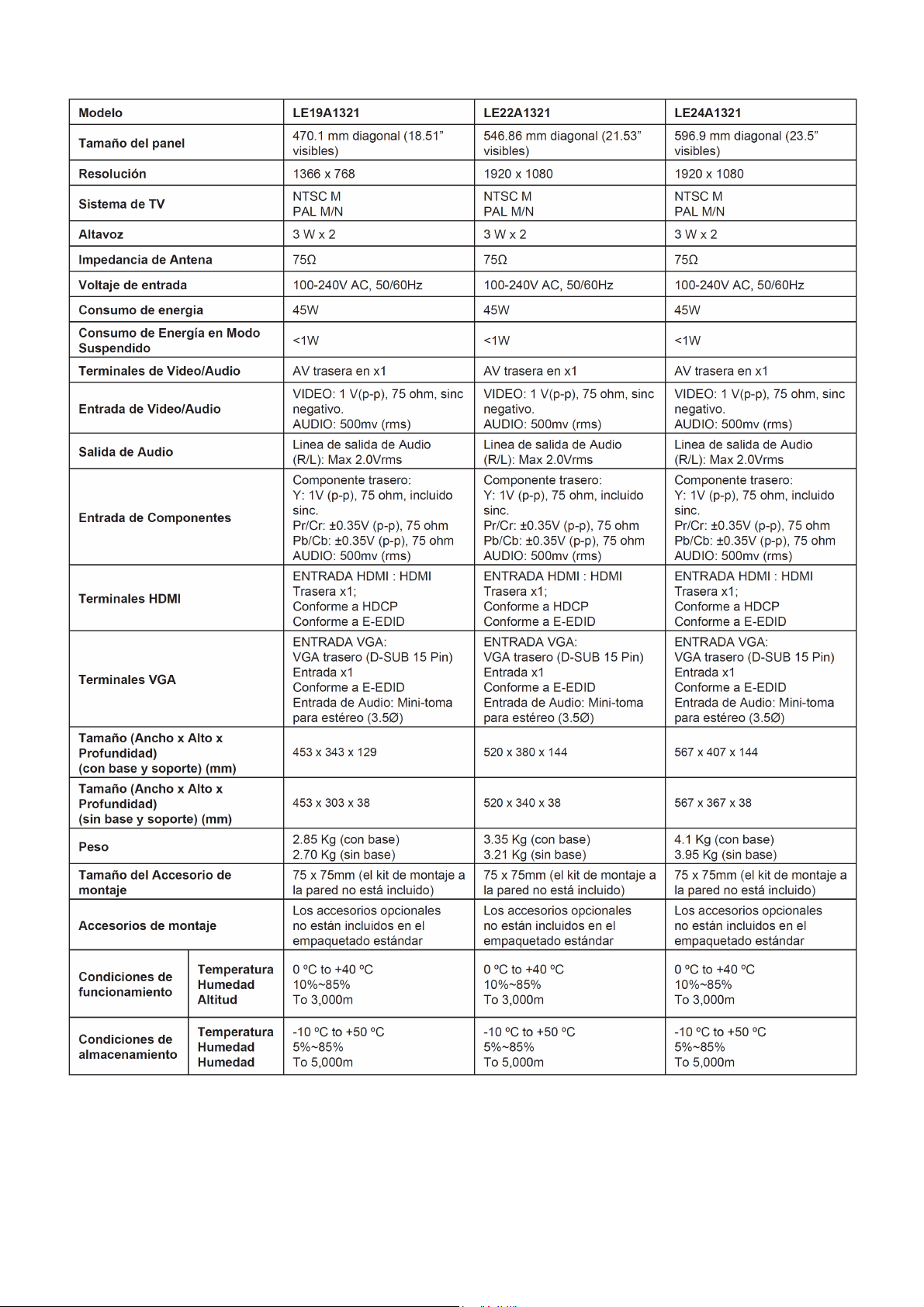
1. General Specification
Nota:
• Los diseños y las especificaciones están sujetos a cambios sin aviso previo.
• Este modelo podría no ser compatible con funciones y/o especificaciones que se introduzcan en el futuro.
4
Page 5
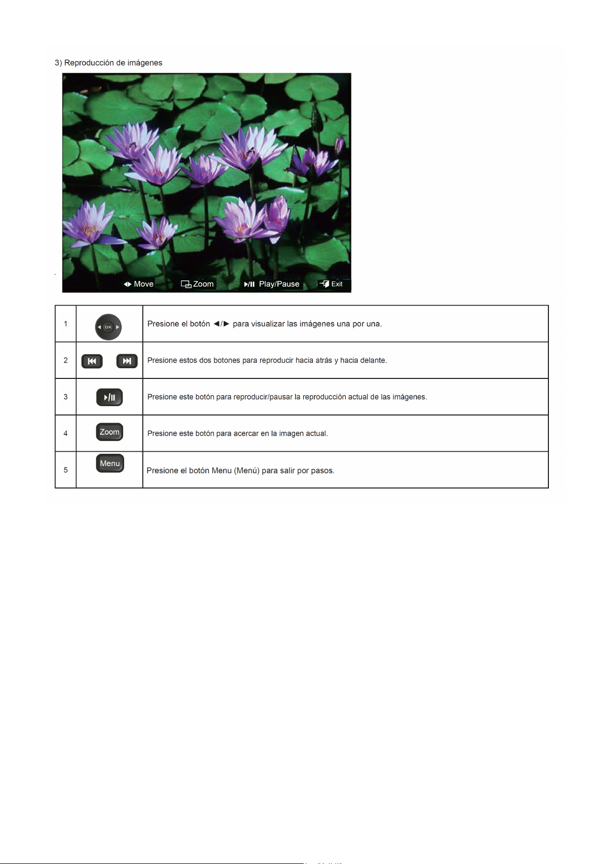
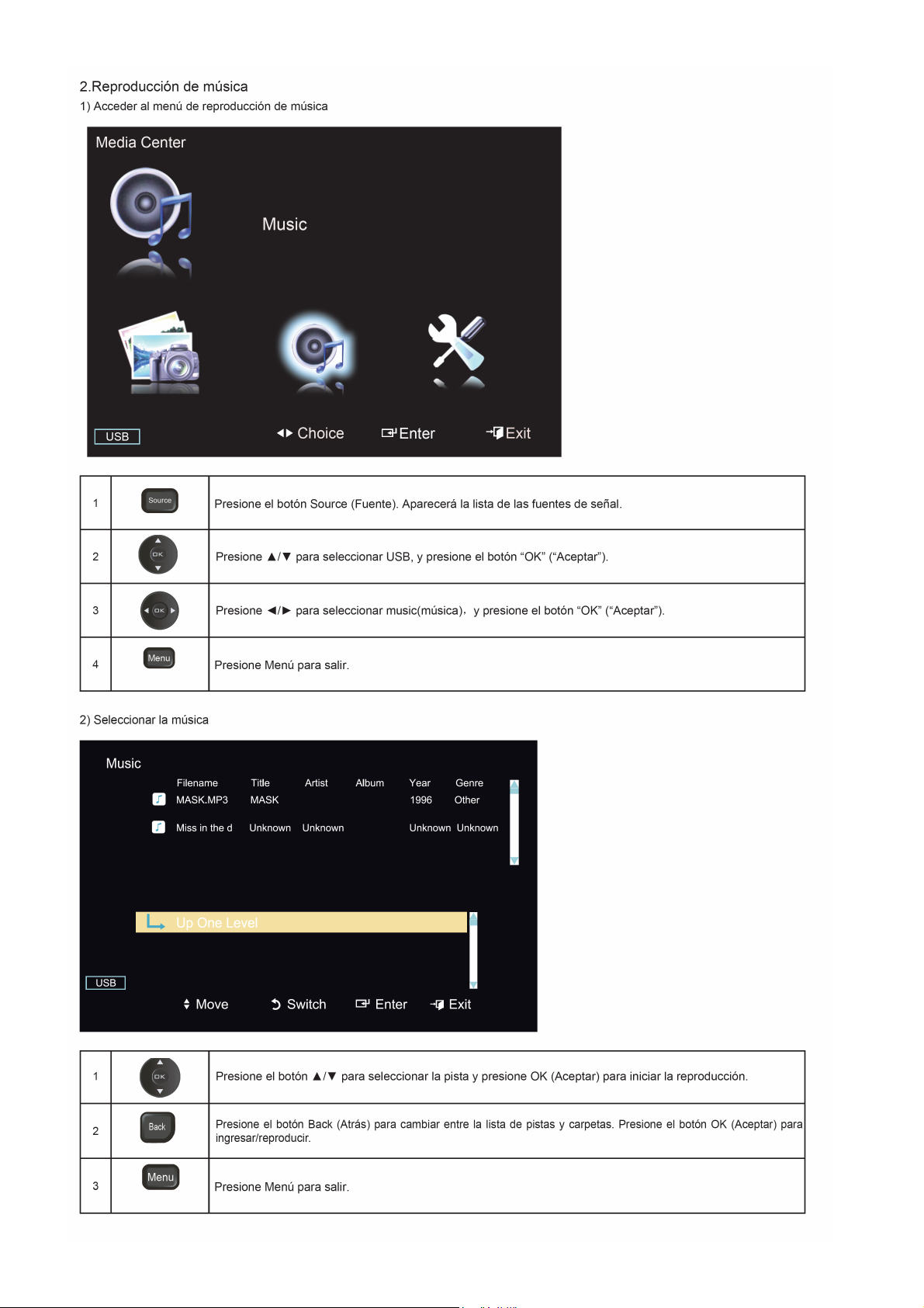
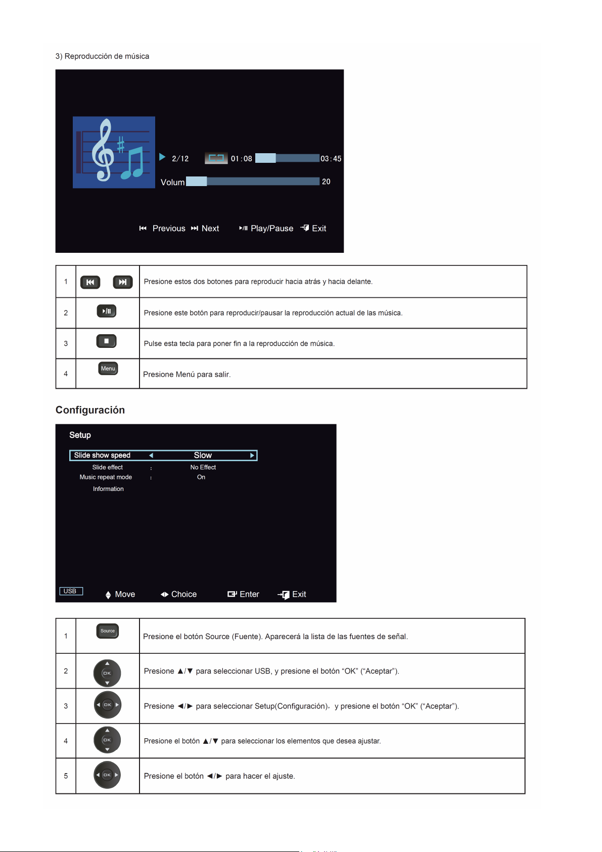
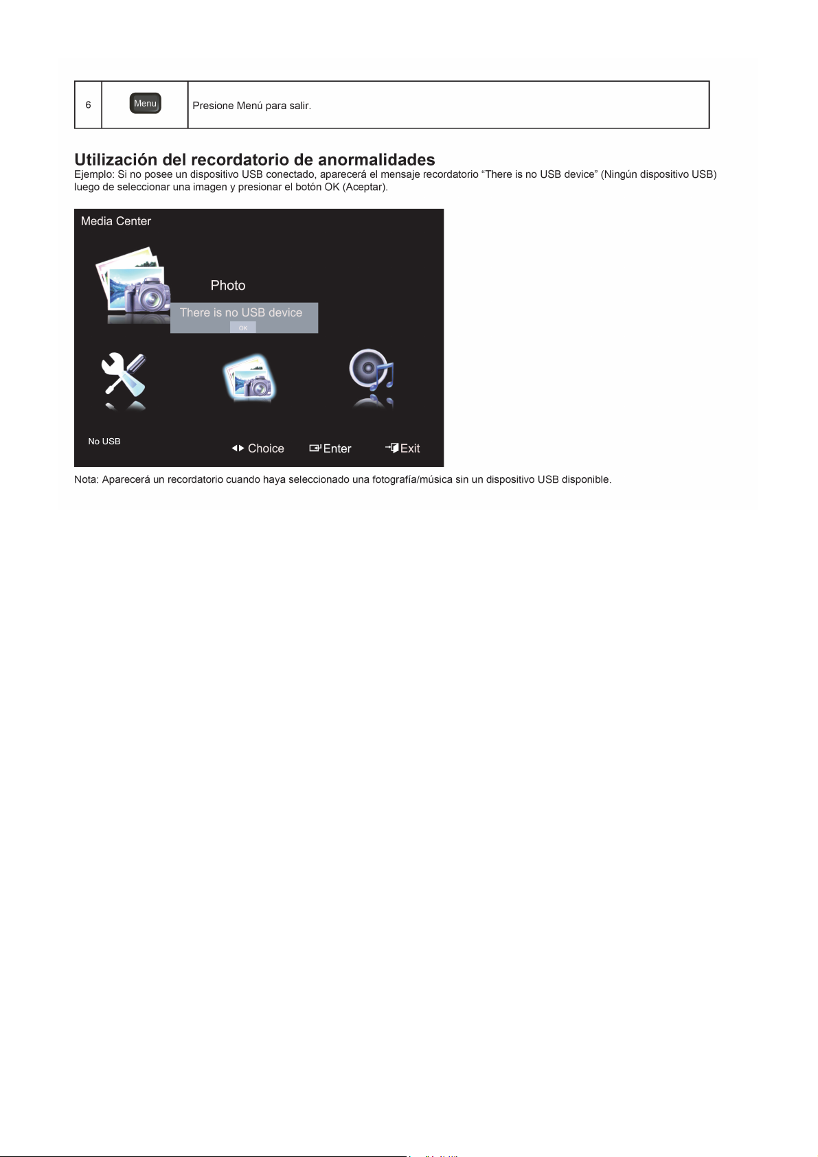
2. Operating Instructions
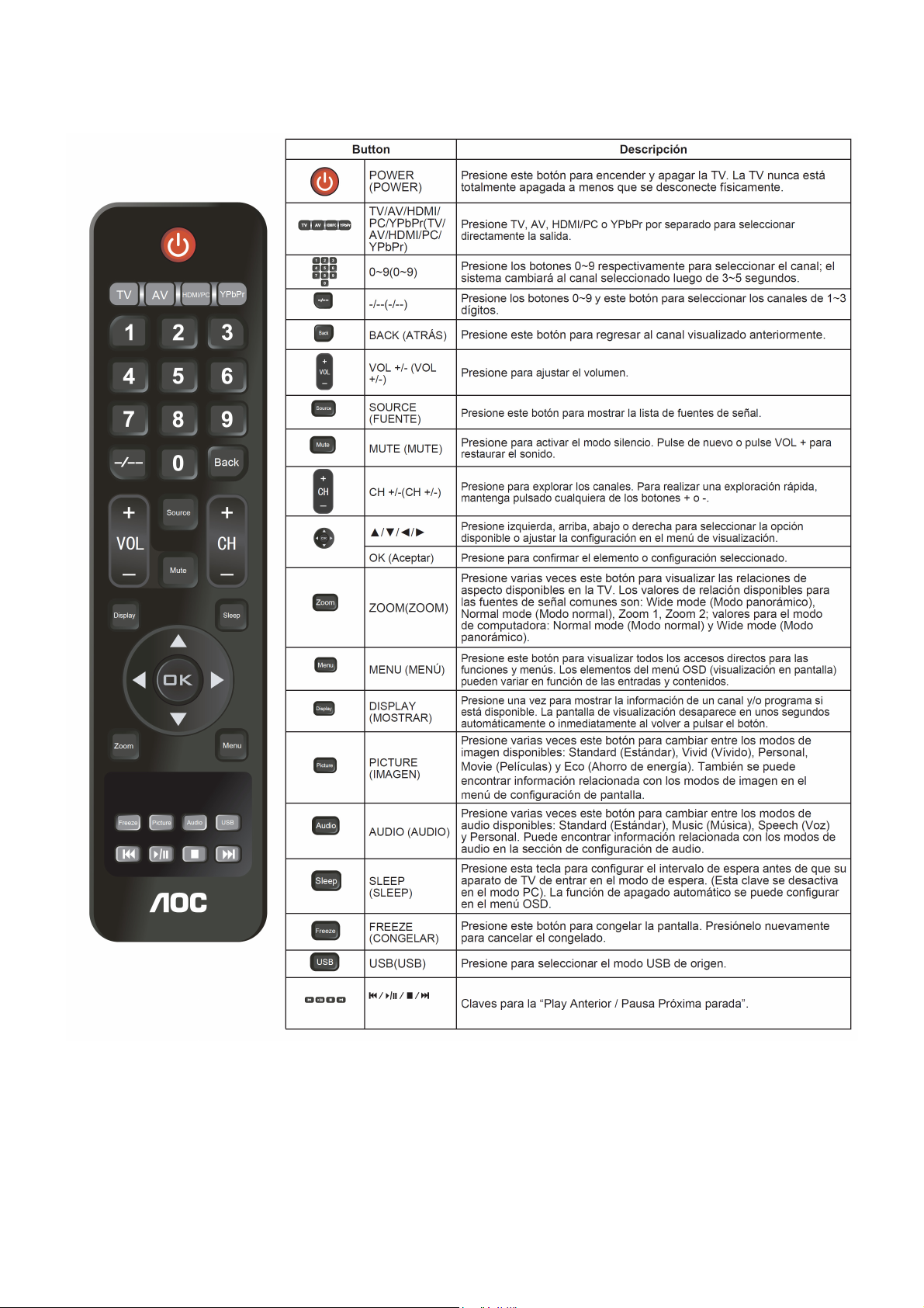
2.1 The Use of Remote Control
* Sonido Multicanal de Televisión (en inglés, Multichannel Television Sound (MTS)
La emisión estándar permite que los sonidos estéreo se transmitan con la imagen de TV.
** Segundo Programa de Audio (en ingles, Second Audio Program (SAP)
Un canal de audio adicional proporcionado por la emisión estándar de MTS. Una pista de sonido monofónico
incluida en la grabación o señal de video (normalmente contiene la traducción a un segundo idioma del programa
visualizado).
5
Page 6
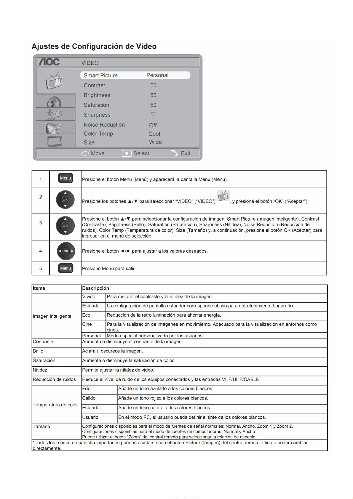
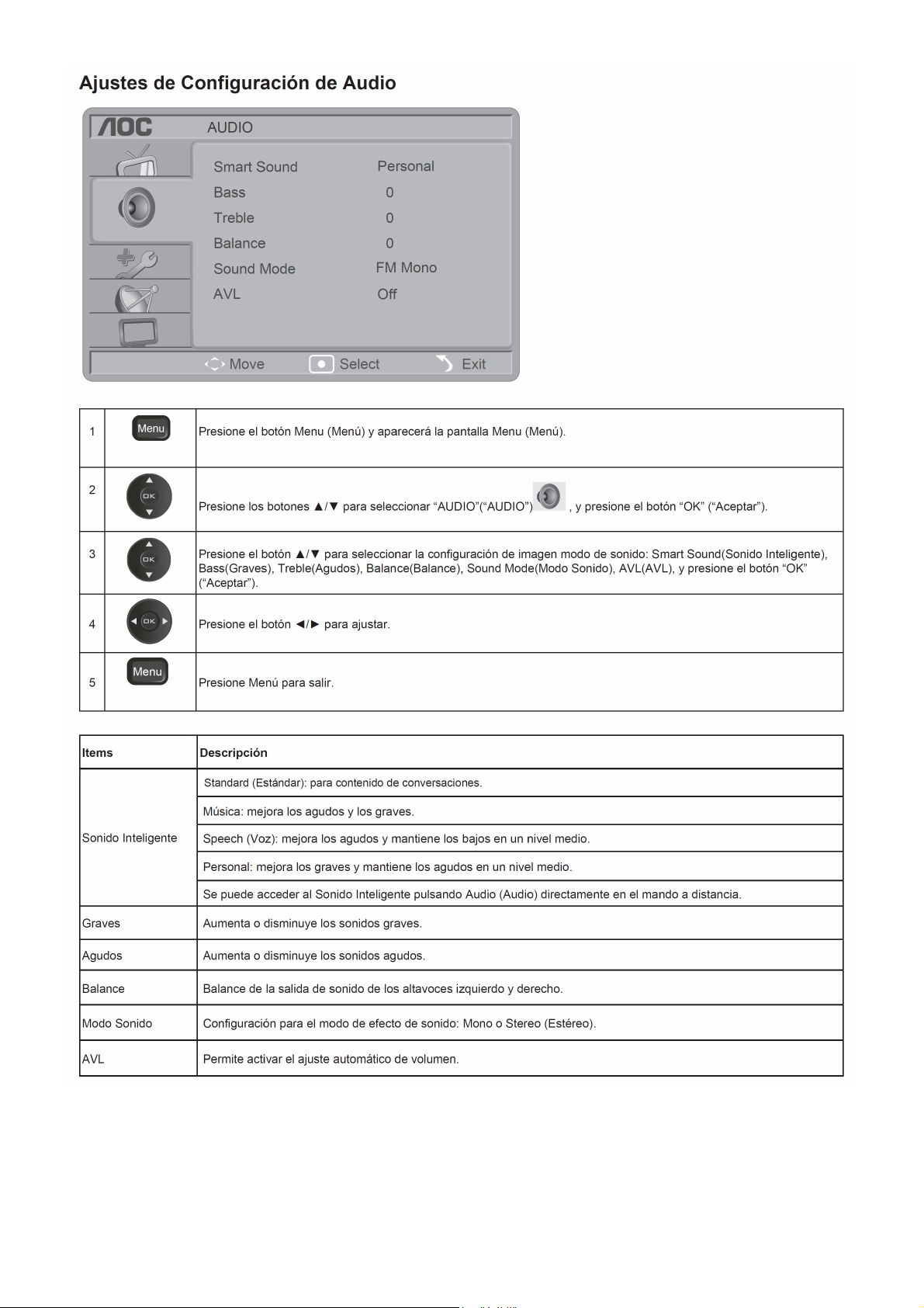
2.2 To Use the Menus
6
Page 7
7 8 9
Page 8
Page 9
Page 10
10 11 12 13 14 15
Page 11
Page 12
Page 13
Page 14
Page 15
Page 16
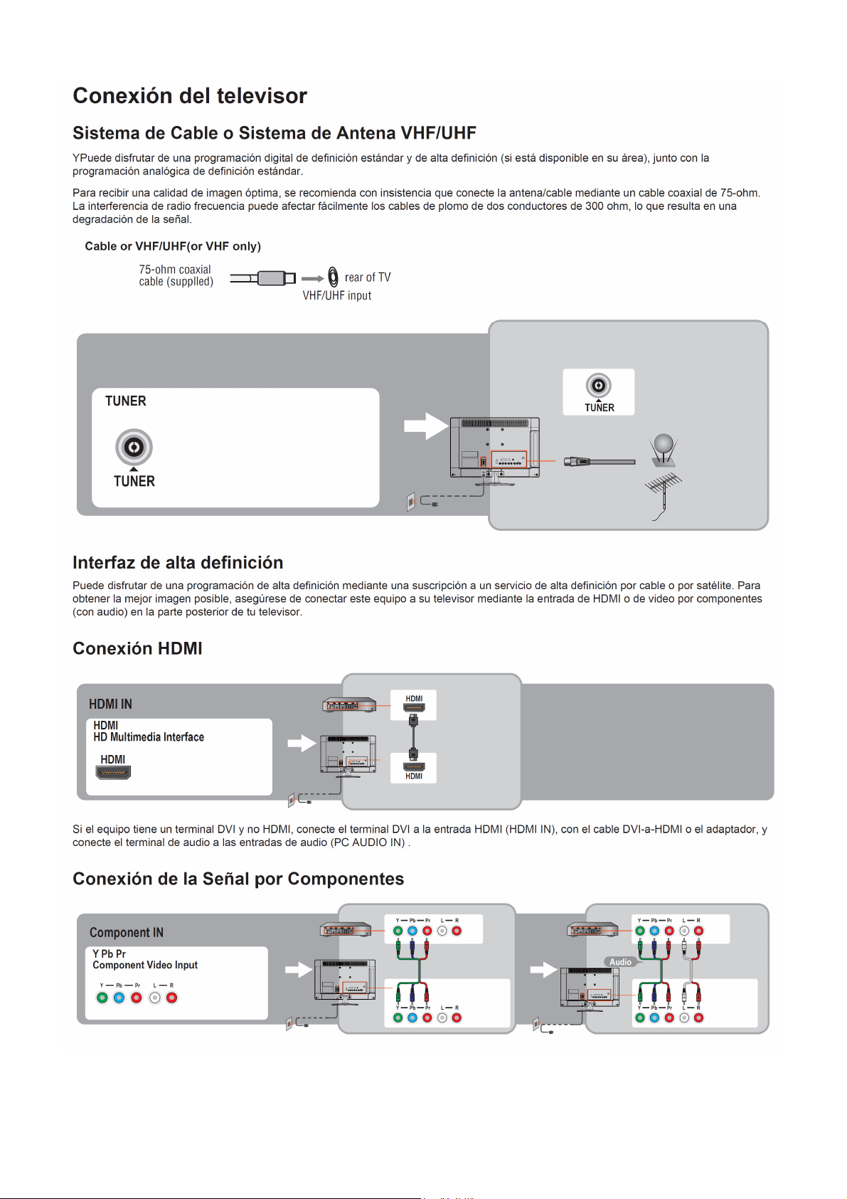
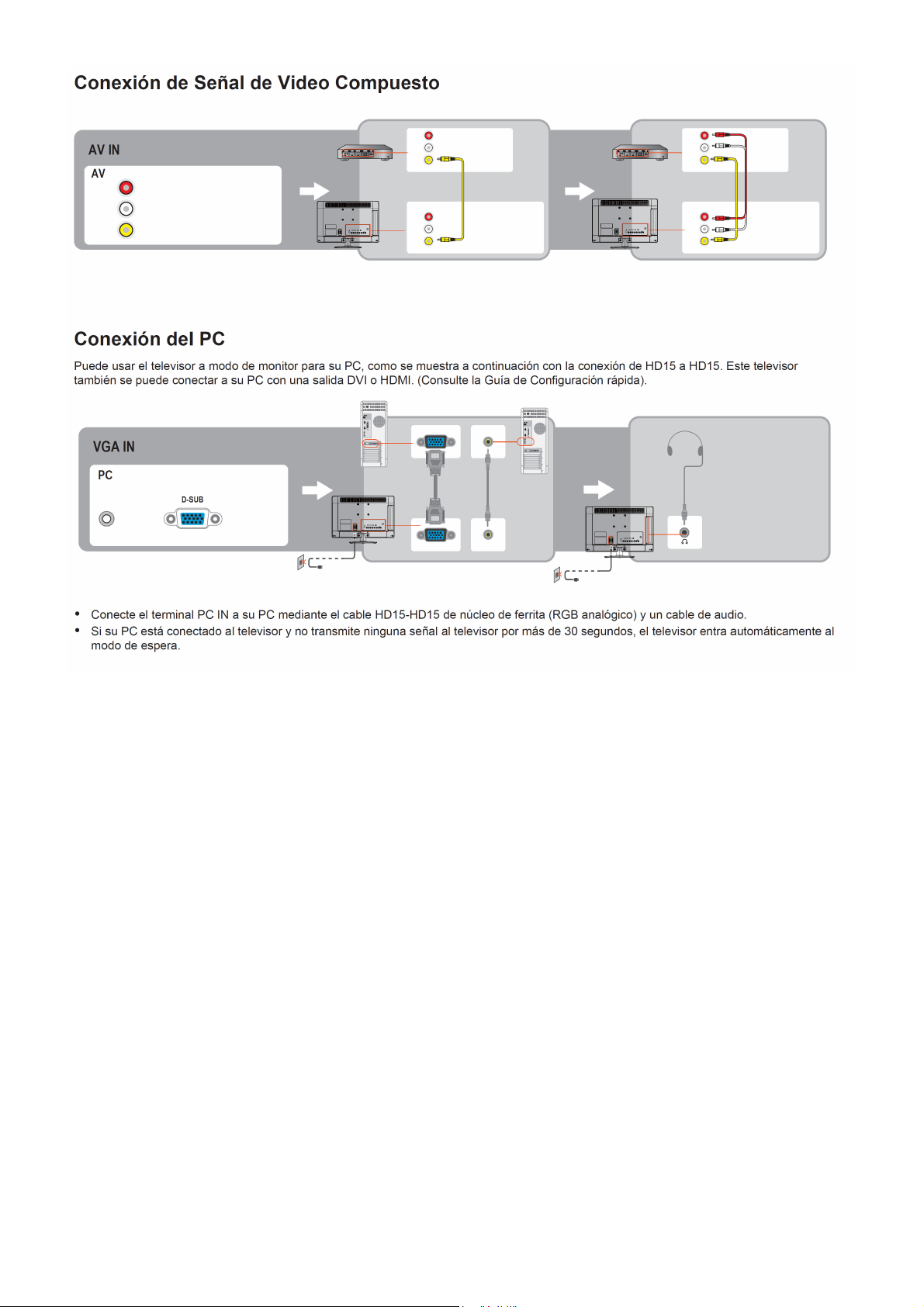
2.3 How to Connect
16
Page 17
17
Page 18
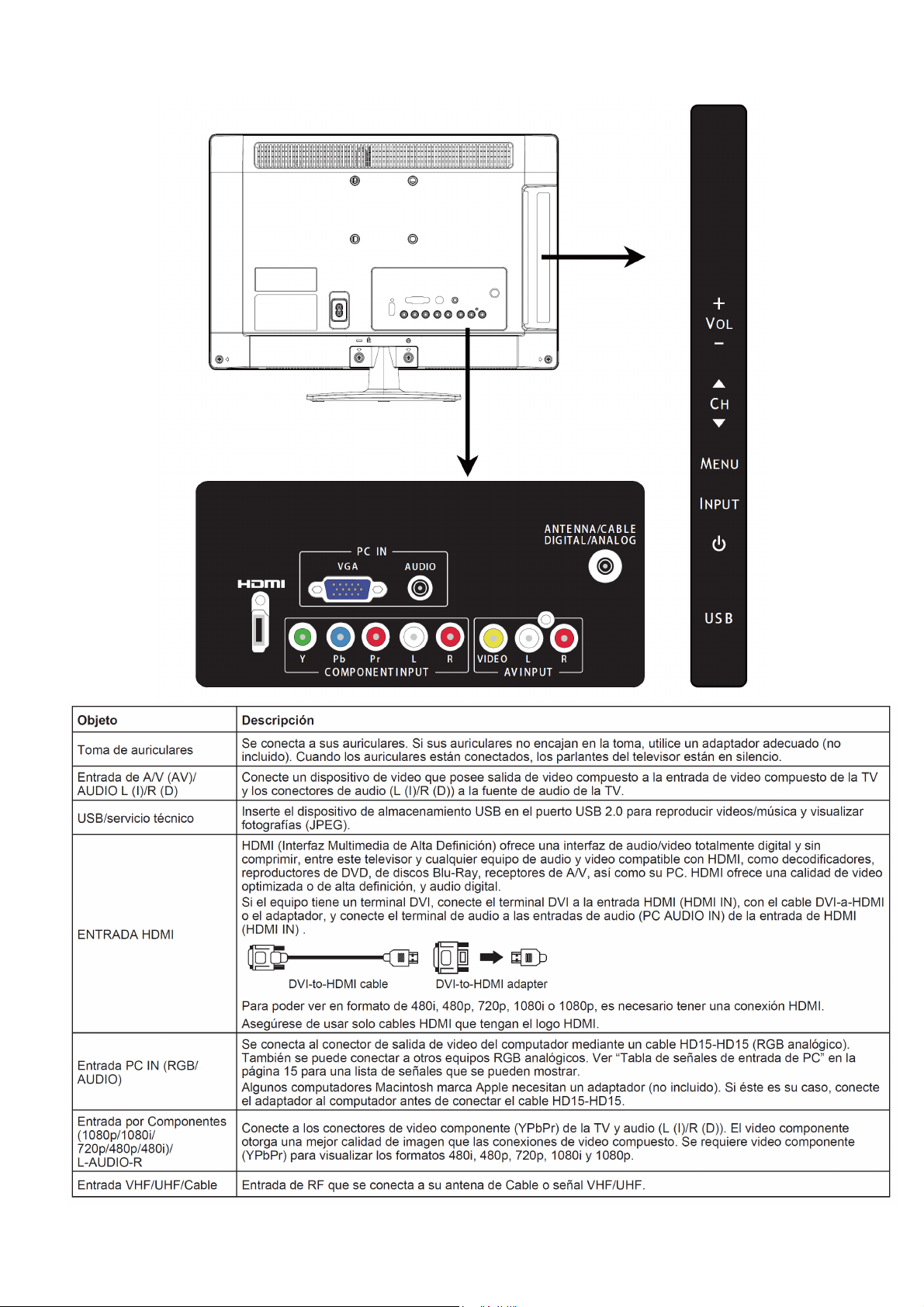
2.4 Front Panel Control Knobs
18
Page 19
3. Input/Output Specification
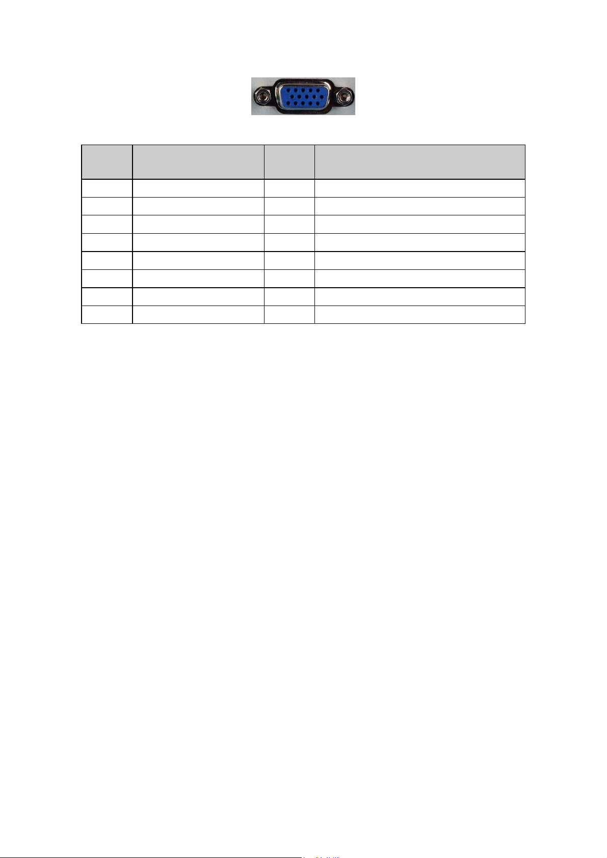
3.1 RGB Signal Input
15 - Pin Color Display Signal Cable
Pin No. Description Pin No. Description
1 Red Video 9 5V
2 Green Video 10 Sync Ground
3 Blue Video 11 Not Used
4 Not Used 12 Serial Data for DDC
5 Ground 13 H-Sync.
6 Red Ground 14 V-Sync.
7 Green Ground 15 Serial Clock for DDC
8 Blue Ground
19
Page 20
3.2 Compatible Mode Table
20
Page 21
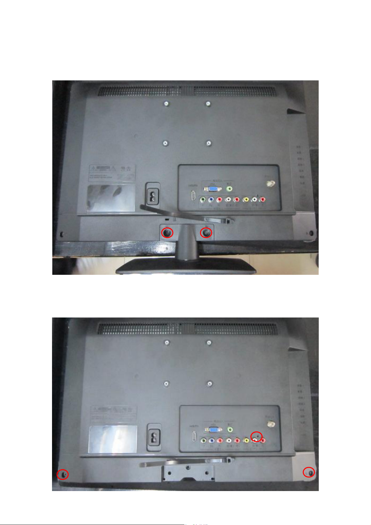
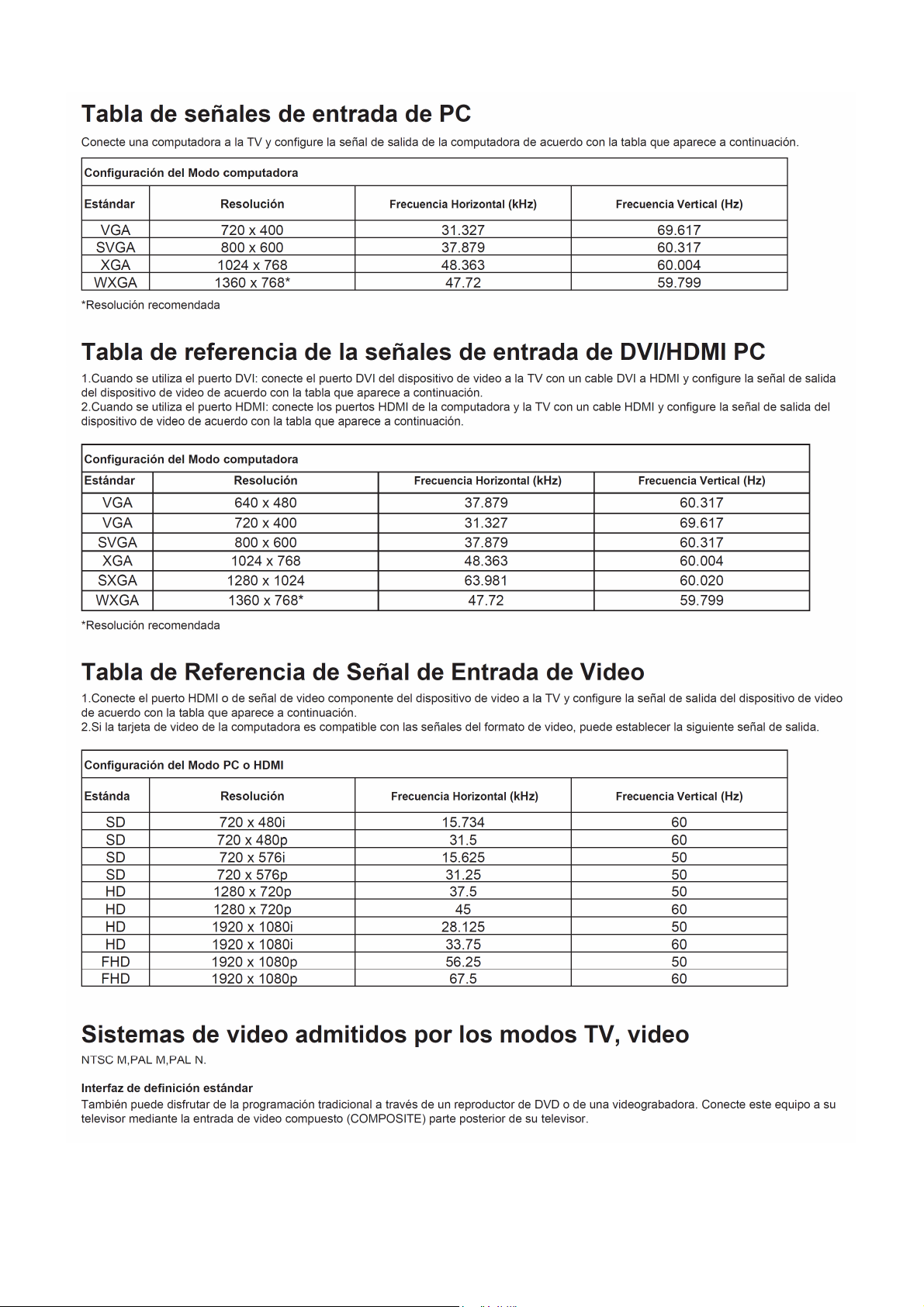
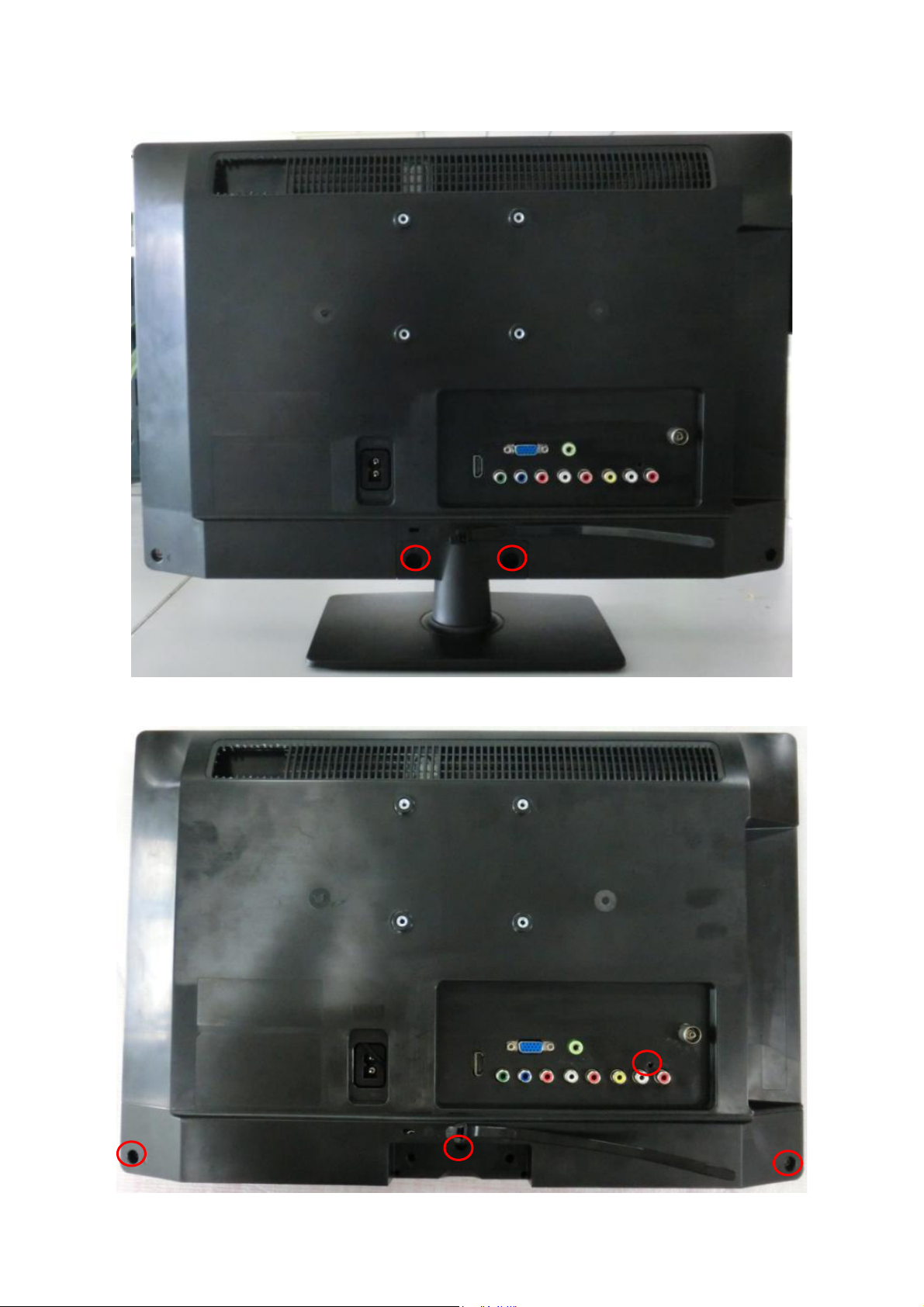
4. Mechanical Instructions
LE19A1321/30 & LE19A1321/40
1. Remove the screws to remove STAND and BASE.
2. Remove the screws to remove REAR COVER.
21
Page 22
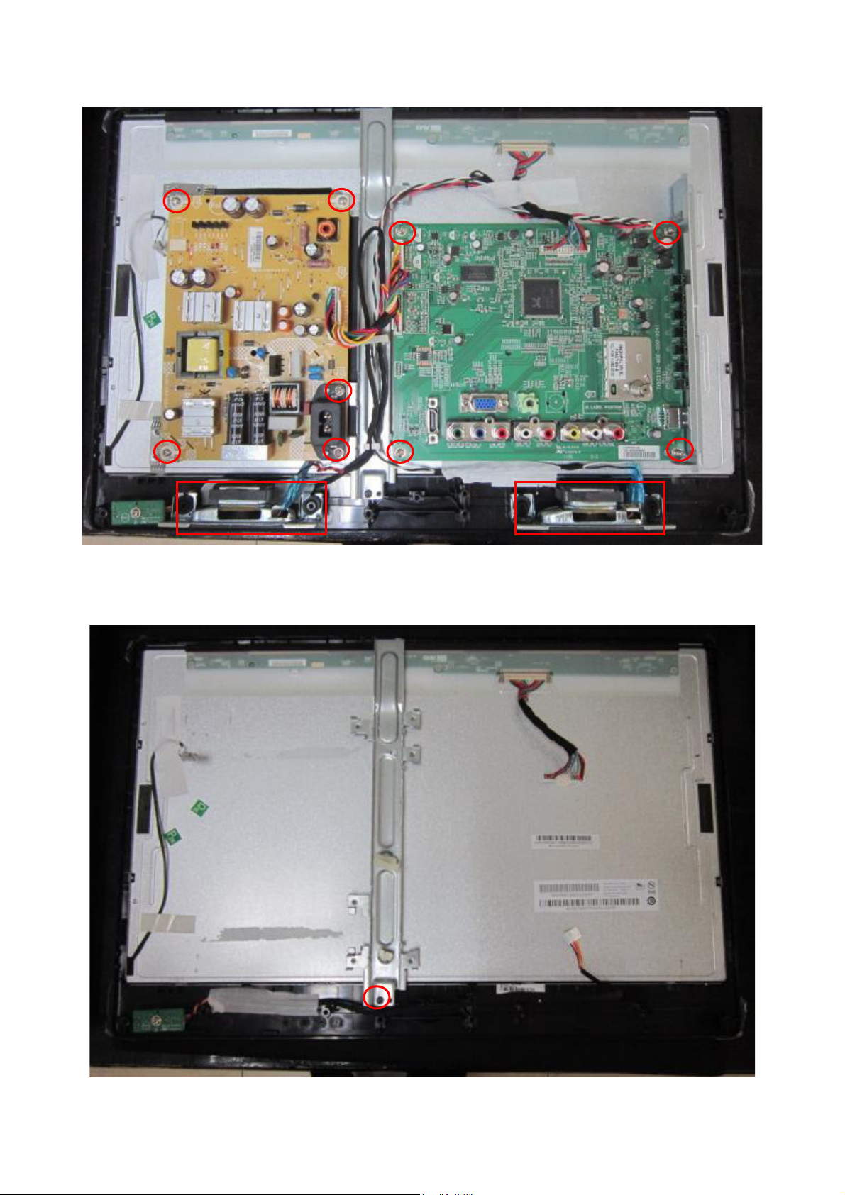
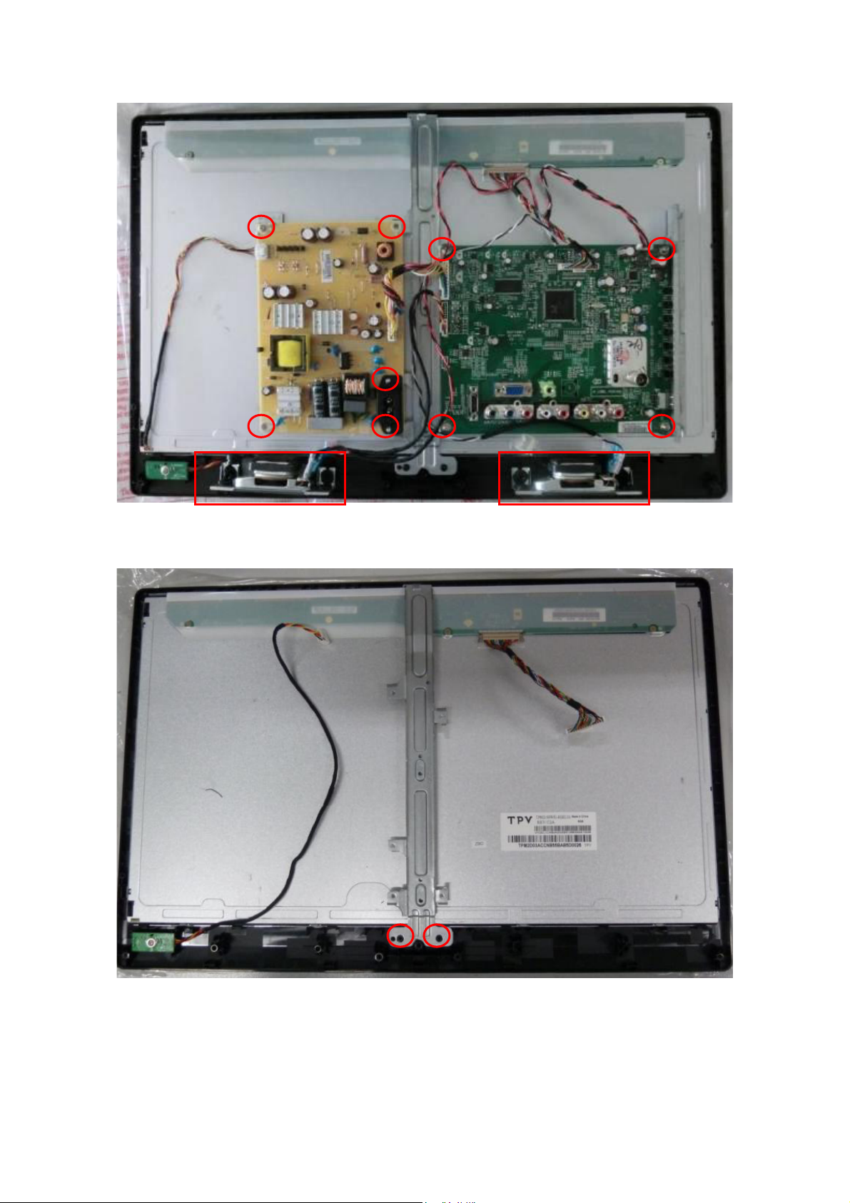
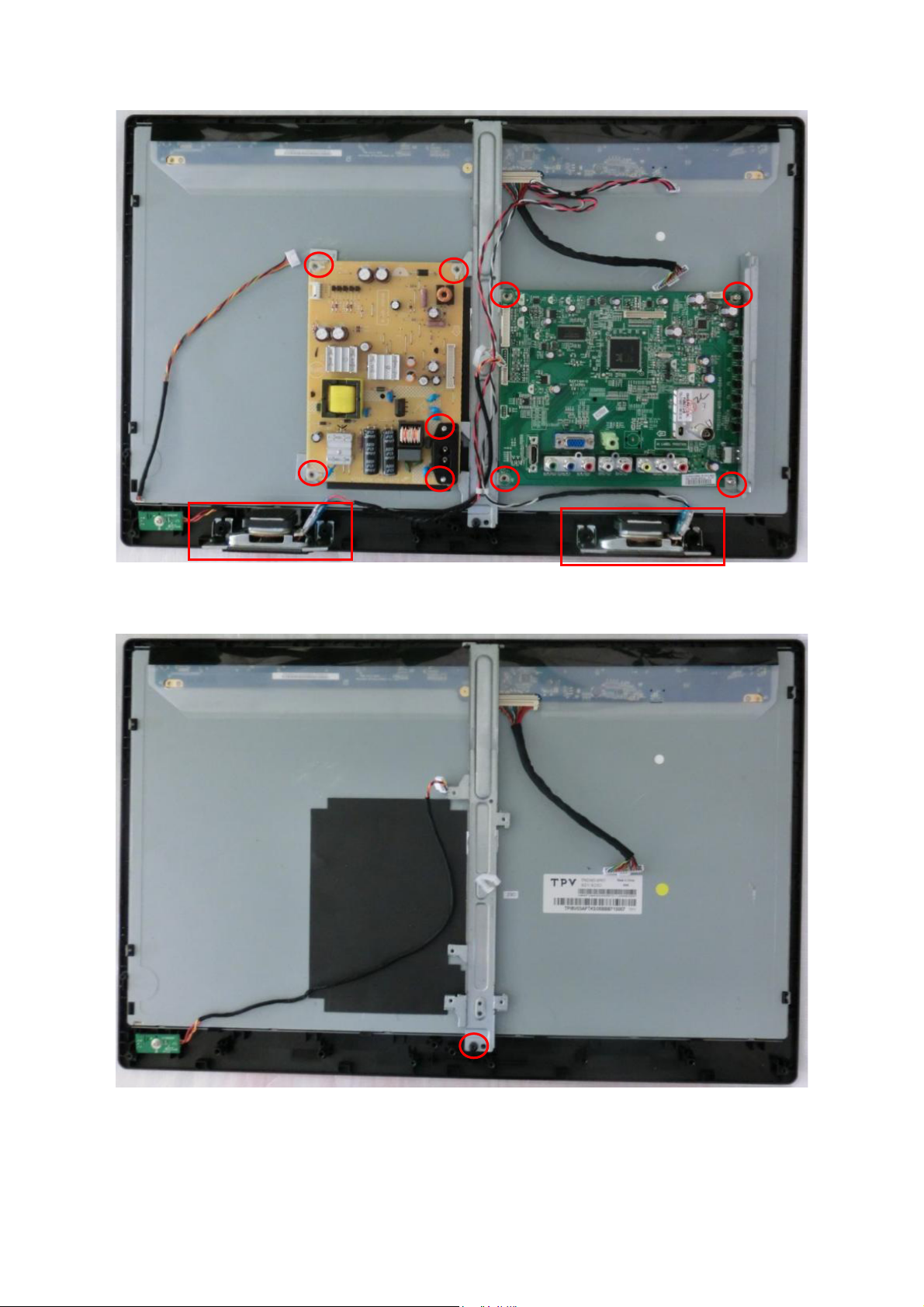
3. Remove the screws to remove MAIN BOARD , POWER BOARD and SPEAKERS.
4. Remove the screw to remove BKT and separate the BEZEL and PANEL.
22
Page 23
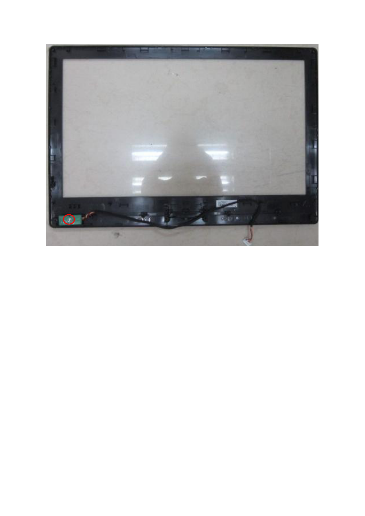
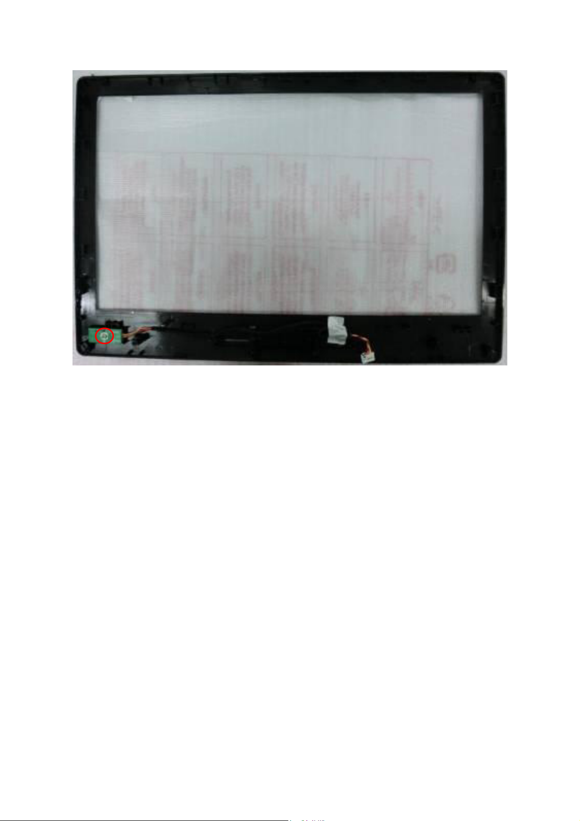
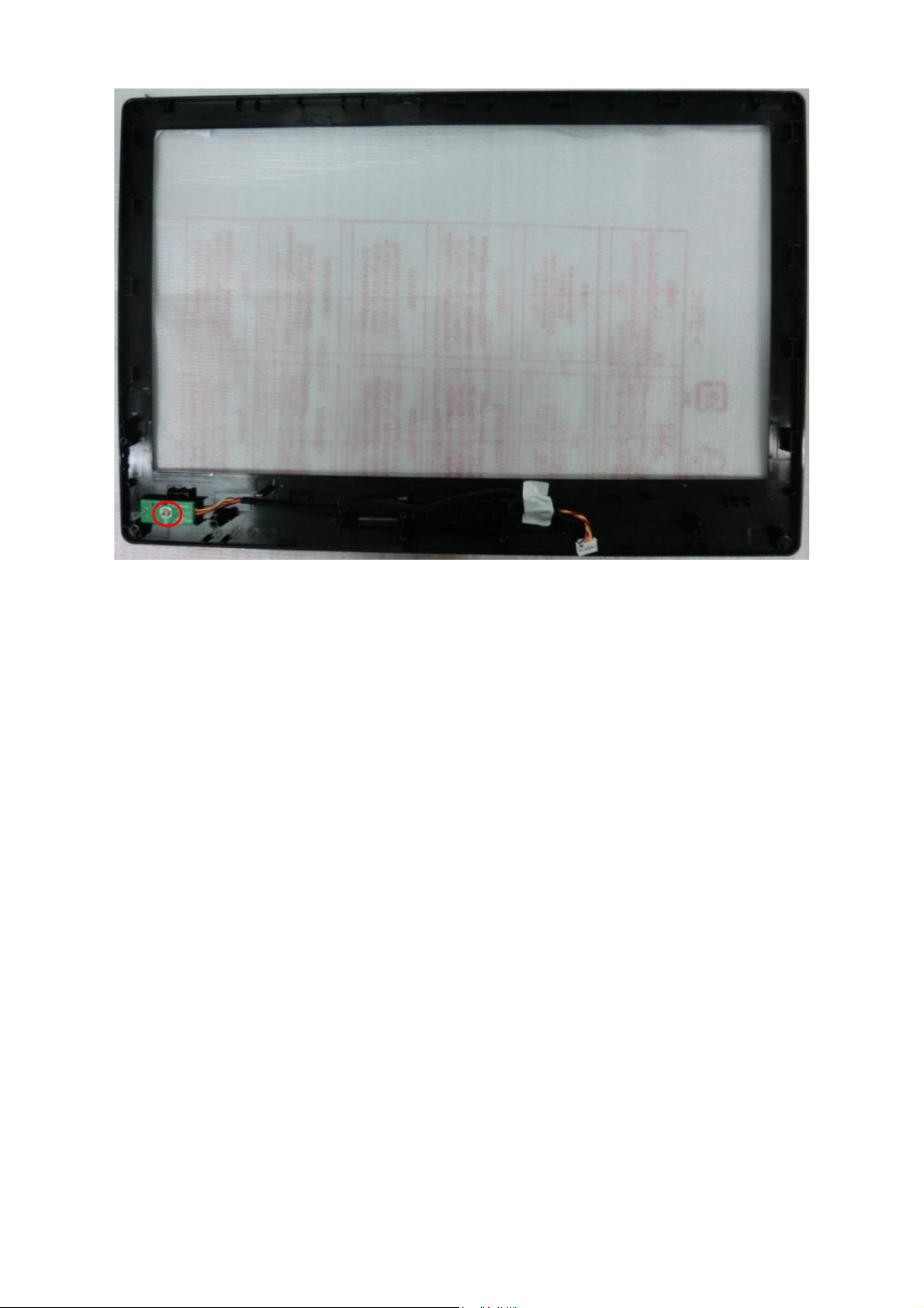
5. Remove the screw to remove IR BOARD.
23
Page 24
LE22A1321/30
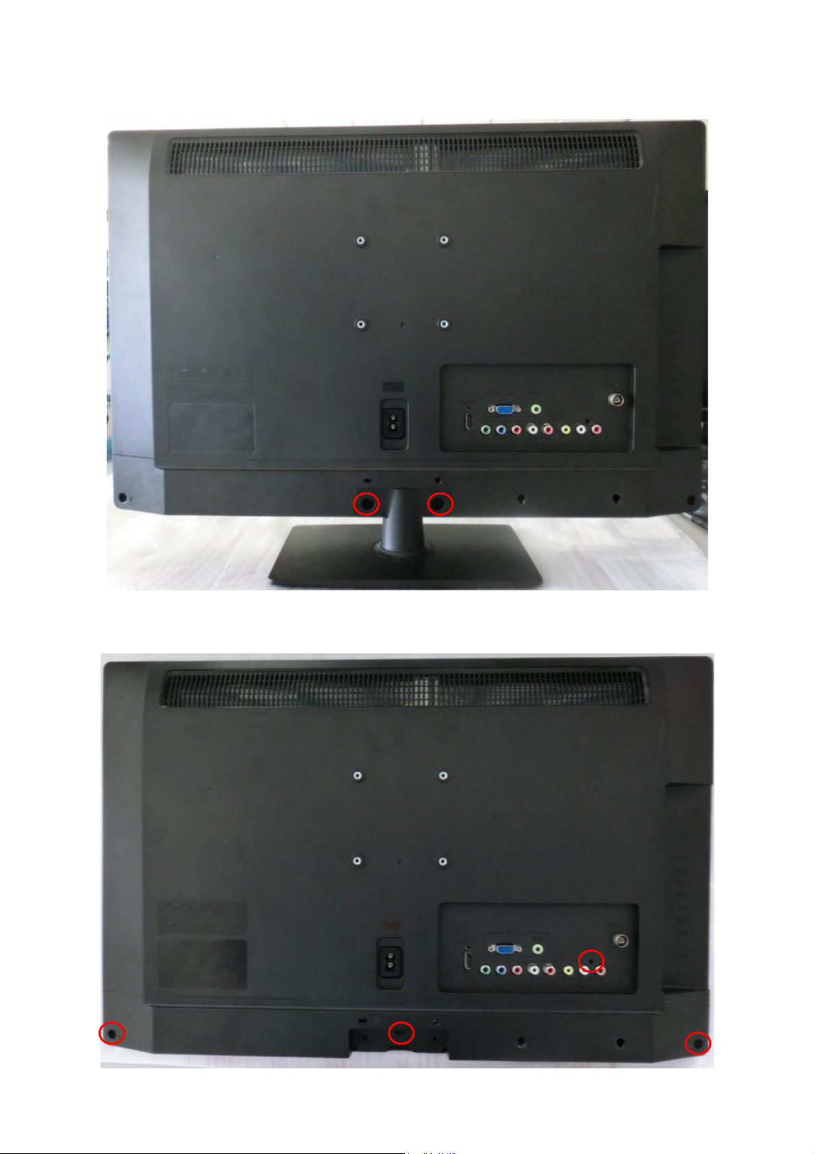
1. Remove the screws to remove STAND and BASE.
2. Remove the screws to remove REAR COVER.
24
Page 25
3. Remove the screws to remove MAIN BOARD , POWER BOARD and SPEAKERS.
4. Remove the screws to remove BKT and separate the BEZEL and PANEL.
25
Page 26
5. Remove the screw to remove IR BOARD.
26
Page 27
LE24A1321/30
1. Remove the screws to remove STAND and BASE.
2. Remove the screws to remove REAR COVER.
27
Page 28
3. Remove the screws to remove MAIN BOARD , POWER BOARD and SPEAKERS.
4. Remove the screw to remove BKT and separate the BEZEL and PANEL.
28
Page 29
5. Remove the screw to remove IR BOARD.
29
Page 30
5. Repair Flow Chart
1. Sin Energía
Sin Energía (LED “Apagado”)
Revise la entrada AC. ¿La
energía está en “encendida”?
Si
Salida Power board =5.2V?
Si
Revise IR board y LED
No
Reemplace IR board
No
No
Enciéndalo
No
Reemplace power board
Reemplace main board
30
Page 31

2. No Enciende
(Chequee tecla power del control remoto, si
equipo no responde significa que es anormal).
No inicia (LED naranjo)
Salida Power board=16V?
Si
Revise si el botón de power funciona
No
Revise si el receptor IR es normal
No
No
Reemplace power board
Si
Reemplace key board
Si
Reemplace IR board
Reemplace main board
No
Reemplace la Power board
31
Page 32
3. Imagen Anormal
Entre al menú modo de fábrica para hacer
Imagen Anormal
Revise la fuente
Si
“EEPROM initial”&“Reset”
No
No
Reinicie la fuente
Revise main board
Si
Revise el cable LVDS
Si
Revise el panel
No
Reemplace panel
No
Reemplace main board
No
Reemplace LVDS cable
32
Page 33

4. Sin Imagen
Revise si el TV funciona, si enciende/apaga
vía control remoto y botón de power.
Si
Revise cable LVDS
Si
Panel Vcc = 5V?
Sin imagen (LED verde)
Si
Revise si la luz del panel está
encendida= “On”
No
Vuelva a insertar o
Reemplace el cable LVDS
No
No
Reemplace main board
No
Revise señal L/P si
está disponible
Si
Salida de Power board=16V?
Reemplace main board
No
No
Si
Reemplace the Panel
Reemplace main board
33
Si
Reemplace Panel
Reemplace power board
Page 34

5. Problema de Sonido
Revise la conexión de la fuente de audio y si norma de
Sin sonido o sonido anormal
TV es correcto (NTSC-PAL N/M/ISTB)
Si
Revise si TV está mudo (muted), ajuste el volume o
entre al modo menú para reinicio?
No
Entre al modo menú de fábrica para reinicar
No
Revise el cable entre los parlantes y main
board si están OK
Si
No
Vuelva a insertar el cable de audio o cambie
la norma del TV
No
Reemplace cable
Revise los valores de Resistencia en el parlante que se encuentran en
las especificaciones (Nota: El valor está marcado en el parlante)
Si
Reemplace parlante
34
Reemplace main board
No
Page 35

6. Control Remoto - mal funcionamiento
Control remoto - mal funcionamiento
Revise la batería del control remoto si está
bien colocada o no tiene energía
No
Use otros controles remotos, ¿funciona?
Si
Reemplace batería
Si
Reemplace el control remoto
No
¿Es anormal la IR board?
No
Reemplace main board
Si
Reemplace IR board
35
Page 36

7. OSD es inestable o no trabaja de forma normal
OSD es inestable o no trabaja normalmente
La botonera está conectada correctamente?
Si
Los botones están OK?
Si
Botonera está OK?
Si
No
No
No
Reconecte el key board
Reemplace la función del botón
Reemplace la botonera
Entre al modo menú de fábrica para reinicar
No
Reemplace el main board
36
Page 37

6. PCB Layout
6.1 Main Board
715G5152M0D000004K
37
Page 38
38 39
Page 39

Page 40
6.2 Power Board
715G5147P01000001H
40
Page 41

41
Page 42

6.3 IR Board
715G5061R02002004M
42
Page 43
7. Adjustment
7.1 ADC Adjustment
1. Factory Mode
In the TV mode adjust volume to zero, press menu key and then press number key 1 9 9 9. It will
achieve the factory mode.
2. ADC Adjustment
In the TV mode adjust volume to zero, press menu key and then press number key 1 9 9 9. It will
achieve the factory mode. Select the item of White Balance and press right key to enter it.
1. Change TV, press the item “Current Source” to Component mode and change signal to Component TIMING
311(576i/50Hz)Pattern 185(COLORBAR), press the item “Auto Color”;
2. Change TV, press the item “Current Source” to Component mode and change signal to Component TIMING
314(720P/60Hz)Pattern 185(COLORBAR), press the item “Auto Color”;
3. Change TV, press the item “Current Source” to PC mode and change signal to PC TIMING 137(1024X768)
Pattern 42 (5 MOSAIC), press the item “Auto Color”.
3. White Balance Adjustment
1. Enter into the factory mode:(same as the above-mentioned).
2. Take an example of adjust Ypbpr_source.
a. Select item”Source”: Ypbpr and item “Color Temp”: Normal, Adjust gain of RGB to meet spec in the below setting
of tim\pat. (COMPONENT mode: TIM = 314; PAT = 141(80IRE))
b. Select item”Source”: Ypbpr and item “Color Temp”:Warm, Adjust gain of RGB to meet spec in the below setting
of tim\pat. (COMPONENT mode: TIM = 314; PAT = 141(80IRE))
c. Select item”Source”: Ypbpr and item “Color Temp”: Cool, Adjust gain of RGB to meet spec in the below setting of
tim\pat. (COMPONENT mode: TIM = 314; PAT = 141(80IRE))
3. Take an example of adjust VGA_Normal:
a. Select item”Source”: Ypbpr and item “Color Temp”: Normal, Adjust gain of RGB to meet spec in the below setting
of tim\pat. (VGA mode: TIM = 137; PAT = 141(80IRE)
b. Select item”Source”: Ypbpr and item “Color Temp”: Warm, Adjust gain of RGB to meet spec in the below setting
of tim\pat. (VGA mode: TIM = 137; PAT = 141(80IRE)
c. Select item”Source”: Ypbpr and item “Color Temp”: Cool, Adjust gain of RGB to meet spec in the below
setting of tim\pat. (VGA mode: TIM = 137; PAT = 141(80IRE)
LE19A1321/30 & LE19A1321/40:
Source VGA/YPbPr VGA/YPbPr VGA/YPbPr
Temp Normal/(7500K) Warm/(6500K) Cool/(9300K)
x (center) 0.295 0.020 0.313 0.020 0.285 0.020
y (center) 0.305 0.020 0.329 0.020 0.293 0.020
LE22A1321/30 & LE24A1321/30:
Source VGA/YPbPr VGA/YPbPr VGA/YPbPr
Temp Normal/(7500K) Warm/(6500K) Cool/(9300K)
x (center) 0.295 0.020 0.313 0.020 0.272 0.020
y (center) 0.305 0.020 0.329 0.020 0.277 0.020
43
Page 44
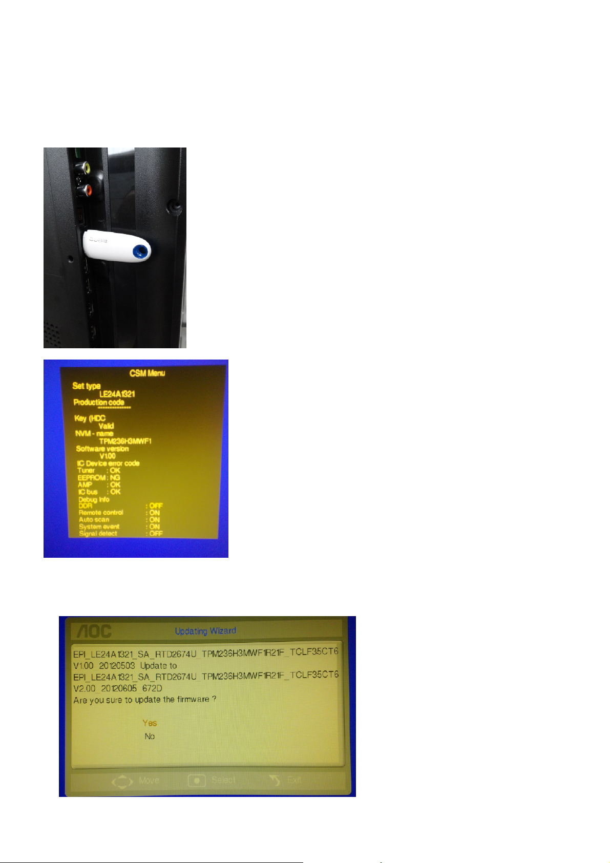
7.2 FW Upgrade
Step 1: Ready for F/W Upgrade
1.1 Prepare a U-disk.
1.2 Copy the software from your computer to the U-disk root directory.
Step 2: F/W Upgrade
2.1 Plug the U-disk to the USB port of TV.
2.2 AC ON TV.
2.3 Press the power key on the Remote Control or the right side of TV to turn on TV.
2.4 Press “menu +456987+recall” by RC to open the CSM menu.
2.5 The TV will detect the file and pop up below upgrade message. Select “Yes” to continue by RC. TV starts
upgrading. During the update process, please do not unplug the U-disk and turn off the TV set.
Notes: When Upgrade on the process, please don’t Power-Off!
44
Page 45
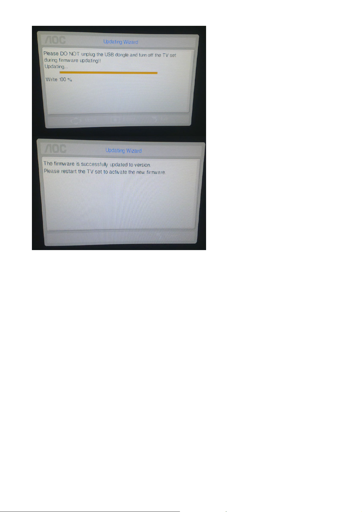
2.6 When upgrade Success, remove the U-disk and AC off.
DDC upgrade
As the DDC data were included in the software, this model do not need a separate DDC Upgrade.
45
Page 46

8. Block Diagram
46
Page 47

9. Schematic Diagram
9.1 Main Board
715G5152M0D000004K
+5VSB
R114
10K 1/10W
R119 0R05 1/10W
R121 0R05 1/10W
10K 1/10W
R112
AHS0
R103 1K 1/10W
AVS0
R104 1K 1/10W
C102
22PF 50V
DGND
CONN
CN102
R108
2.2K 1/10W
3
2
1
MLVG0402
DGND
VGA_DDC_SD A
VGA_DDC_SD A#
VGA_DDC_SC L#
VGA_DDC_SC L
12
ZD101
DGND
C103
22PF 50V
DGND
12
ZD103
MLVG0402
URAT_RX
VGA_DDC_SD A#
VGA_DDC_SC L#
R101
2.2K 1/10W
100K 1/10W
R115
DGND
DGND
R102
100 OHM +-5% 1/10W
U101
I/O23I/O3
2
GND
VDD
1
I/O1
I/O4
AZC399-04S
R110 27K 1/10W
R113 27K 1/10W
R116
100K 1/10W
4
5
6
HS
VS
+5VSB
VGA_IN_R
VGA_IN_L
VGA
+5VSB
U102
4
I/O23I/O3
2
GND
1
I/O1
AZC399-04S
VDD
I/O4
5
6
R105 100 OHM +-5% 1/10W
R109 75OHM +-5% 1/10W
R106 75OHM +-5% 1/10W
R107 75OHM +-5% 1/10W
C134 NC
C135 NC
C136 NC
RIN
R122 BEAD 60ohm 600mA
GIN
R126 BEAD 60ohm 600mA
BIN
R177 BEAD 60ohm 600mA
RIN+
GIN+
BIN+
URAT_TX
CN104
NC
VGA_IN_L6
VGA_IN_R6
VGA_DDC_SC L6
VGA_DDC_SD A6
USB
USB_PWR_F LAG6
UART
URAT_RX6
URAT_TX6
+3V3
1
URAT_RX
2
URAT_TX
3
4
DGND
1716
1
6
2
7
3
8
4
9
5
10
D-SUB 15P
DGND
DGND
DGND
TX
12
ZD102
MLVG0402
DGND
CN101
RX
11
12
13
14
15
18 19
DGND
BIN+
BIN+6
GIN+
GIN+6
RIN+
RIN+6
AVS0
AVS06
AHS0
AHS06
VGA_IN_L
VGA_IN_R
VGA_DDC_SC L
VGA_DDC_SD A
USB_DM
USB_DM6
USB_DP
USB_DP6
USB_PWR_F LAG
URAT_RX
URAT_TX
VGA
USB
+5VSW
USB_DM
USB_DP
t
TH1401
USB_PWR_FLAG
12
C118
NC/22uF 10V
4 1
3 2
L101
NC/90OHM
DGND
R129
0R05 1/10W
R130
0R05 1/10W
R4218
47K +-5% 1/10W
R4217
30K 1/10W 5%
FB101
0R05OHM1/8W
C106
4P7 50V
DGND DGND
C107
4P7 50V
DGND
DGND
12
C105
+
100UF 25V
ZD104
MLVG0402
DGND
12
ZD105
MLVG0402
C101
100N 16V
DGND
USB_Shield_GND
USB CONN
56
1234
1
2
3
4
USB_Shield_GND
47
UART(VGA Pin4 & Pin11 Share)
CN103
78
DGND
USB_Shiel d_GND
T P V ( Top Victory Electronics Co . , Ltd. )
絬隔瓜絪腹
A
Key Component
01) VGA/USB/U ART
Date
OEM MODEL
TPV MODEL
PCB NAME
Sheet
715G3934M0A0000040
210Friday , August 19, 2011
of
A3
Size
Rev
称爹
<>
称爹
Page 48

YPBPR INPUT
CN111
CONN
CN106
CONN
AV INPUT
CN121
CONN
YPbPr
6
YPBPR0_Y6
YPBPR0_PB6
YPBPR0_PR6
YPBPR0_I N_L6
YPBPR 0_IN_R6
AV IN
AV0_IN_L6
AV0_IN_R6
AV Output
CVBS_OUT
2
A
1
4
B
3
6
C
5
ZD109 MLVG0402
ZD110 MLVG0402
ZD111 MLVG0402
DGND
2
A
1
4
B
3
ZD112 NC/ MLVG0402
DGND
ZD113 NC/ MLVG0402
2
A
1
4
B
3
6
C
12
ZD107
MLVG0402
12
5
12
DGND
YPBPR 0_L
YPBPR 0_R
12
ZD106
ZD108
NC/ MLVG0402
NC/ MLVG0402
12
12
12
DGND
R136
100K 1/10W
12
R132 27K 1/10W
R134 27K 1/10W
R137
100K 1/10W
R140 75OHM +-5% 1/10W
R141 75OHM +-5% 1/10W
R142 75OHM +-5% 1/10W
R135 5.1K 1/10W
R139 5.1K 1/10W
R143 100K 1/ 10W
R144 100K 1/ 10W
AV0_IN_L
AV0_IN_R
YPBPR 0_Y
YPBPR 0_PB
YPBPR 0_PR
YPBPR0_IN_L
YPBPR0_IN_R
CVBS0+
R133
75OHM +-5% 1/10W
CVBS0-
R138
0R05 1/10W
YPBPR0_Y
YPBPR0_PB
YPBPR0_PR
YPBPR0_IN_L
YPBPR0_IN_R
CVBS0+6
CVBS0-6
CVBS0+
CVBS0-
AV0_IN_L
AV0_IN_R
CVBS_OUT
DGND
VIDEO OUTPUT
NC/RCA JACK
CN123
2
1
DGND
ZD122
NC/MLVG0402
DGND
DGNDDGNDDGNDDGNDDGND DGND
NC/ 100nF 50V
FB103
NC/121 OHM
1 2
12
+5VSW
C109
DGND
R159
NC/ 75OHM +-5% 1/10W
NC/220 OHM 1/10W
R157
NC/330OHM 1/10W
Q103
NC/MMBT3906
R160
NC/220 OHM 1/10W
R161
DGND
R158
NC/75K 1/10W 5%
Q104
NC/MMBT3904
R162
NC/ 100K 1/10W
DGND
C108
NC/ 10uF 25V
CVBS_OUT
48
T P V ( Top Victory Electronics Co . , Ltd. )
A
絬隔瓜絪腹
Key Component
02) YPbPr/ AV/CVBS OUT
Date
OEM MO DEL
TPV MOD EL
PCB NAME
Sheet
715G3934M0A0000040
310Thursday , June 09, 2011
of
Size
Rev
称爹
A3
<>
称爹
Page 49

TUN _GN D
15
SDA
B+(+5V)
RF AGC
RF_AGC#
N.C
N.C
SCL
N.C
N.C
N.C
IFIF+
TU1 01
TH112TH213TH314TH4
TUN _GN D
11
10
9
8
TUN ER _SC L
7
TUN ER _SD A
6
Tune r5V
5
RF_AGC#
4
3
2
F35CT-2-E
1
TUN _5V
TUN ER _I FT
1 2
FB105
300OHM 4A
C121
10uF
DGND
NC/120R /6000mA
TUN_GND
C127
10U 16V
FB720
NC/100UF 25V
Tuner 5V
C122
100N 16V
+5VSW
R182
1K 1/10W
R184 NC
DGND
+12V
1 2
C143
Q106
MMBT3906
+24V
FB721
NC/120R /6000mA
Pre_IF_12V
1 2
+
TUN _GN D
U705 N C/BA17809F P-E2
IN1OUT
GND
C138
2
NC/330nF
TUN _GN D
C140
NC/10NF 50V
L104
1 2
10uH +-10%
C128
10U 16V
DGND
BYPASS IF preamp
R179
0.05R
Pre_IF_1 2V
3
+
C144
NC/100UF 25V
NC/47 OHM 1/16W
DGND
CLOSE TO RTD2674
R4219
NC/ 0R05 1/10W
R4220
NC/ 0R05 1/10W
C139 NC /100N 16V
TUN _GN DTUN _GN DTUN _GN D
R196
TUN _GN D
R187
510R 1/10W 5%
C129
100N 16V
IF_12V
NC/10NF 50V
IF_OUTTUNER_IFT
IF_12V
NC/680OHM +- 5% 1/10W
R195
NC/6.8kOHM + -5% 1/10W
C142
R197
NC/1K 1/10W 5%
RF_AGC
R199
R198
NC/1K2 1/10W 5%
TUN_GND
L105
NC/0.82uH
Q107
NC/ 2SC4215-O
R200
NC/20R 1%
IF_OUT
R201
NC/0R05OHM1/16W
CS C132/C133
5V For TUNER
TUN ER _SC L
C123
22PF 50V
TUN _GN D TU N_ GND
IF1N
C120 1U 25V
IF1P
C119 1U 25V
8
U105
G965-25ADJPIUF
+5VSB
+5VSW
2.2 OHM 1/10W
+
C130
100UF 25V
DGND
TUN ER_ SDA I2C_M0_SDA
R174 10 OHM 1/10W
R181 10 OHM 1/10W
C124
22PF 50V
DGND
R192
1K 1/10W
HDBF 35A3DdA
4
1K 1/10W
DGND
R191
5
OUTPUT
OUTPUT
L102
2.2uH
U106
R190
3
INPUT
INPUT
GND
VEN1VIN2VO3ADJ
38.3KOHM +-1% 1/8W
DGND
1
2
4
R188
12K1/10W
R189
DGND
DGND
GND5GND6GND7GND
DGND
4.7K 1/10 W
L103
0.33uH 10%
R117
NC/0.05R
R111
0.05R
+
C131
47UF 25V
R194
TUNER
I2C_M0_SDA6
I2C_M0_SCL6
IF1P6
IF1N6
RF_AGC6
FB107
1 2
300OHM 4A
R193
4.7K 1/10 W
I2C_M0_SCL
IF_OUT
IF1P
IF1N
I2C_M0_SDA
I2C_M0_SCL
RF_AGC
TUN _5V
C137
10NF 50V
TUN _GN DDGND
+5VSW
49
T P V ( Top Victory Electronics Co . , Ltd. )
絬隔瓜絪腹
A
Key Component
Date
03) TUNER
OEM MOD EL
TPV MODEL
PCB NAME
Sheet
715G3934M0A0000040
410Friday , July 15, 2011
of
Size
Rev
称爹
A3
称爹
<>
Page 50

DGND
12
DGND
R525
NC
ZD502
MLVG0402
HDMI1_CLK-HDMI1_CLK+
R513
100K 1/10W
R551
NC
R511
NC
DGND
R512
1K 1/10W
R514
4.7K 1/10 W
Q504
MMBT3904
HDMI1_5V
R556
10K 1/10W
HDMI1_HPD
CN502
TMDS D0+
TMDS D0-
TMDS D1+
TMDS D1-
TMDS D2+
TMDS D2-
TMDSC +
TMDSC -
SCL
SDA
CEC
HPD
VCC5
DSHLD0
DSHLD1
DSHLD2
CSHLD0
DDC_GND
SHLD_GND1
SHLD_GND2
SHLD1
SHLD2
SHLD3
SHLD4
SHLD5
HDMI
1
IN1
2
IN2
4
IN3
IN45OUT4
7
9
4
6
1
3
10
12
15
16
HDMI1_CE
13
HDMI1_HPD#
19
18
14
NC
2
5
8
11
17
20
21
22
23
24
25
26
DGND
DGND
DGND
C511
100N 16V
GND
U507 NC RClamp0524P.TCT
8
8
U506 NC RClamp0524P.TCT
IN45OUT4
4
IN3
GND
2
IN2
1
IN1
U509
NC RC lamp0524P.TCT
1
IN1
2
IN2
4
IN3
IN45OUT4
GND
8
DGND
HDMI1_D0+
10
OUT1
HDMI1_D0-
9
OUT2
HDMI1_CLK+
7
OUT3
HDMI1_CLK-
6
GND
3
3
OUT3
GND
OUT2
OUT1
OUT1
OUT2
OUT3
GND
3
HDMI1_D2+
6
HDMI1_D2-
7
HDMI1_D1+
9
HDMI1_D1-
10
10
R529 NC
HDMI1_SCL#
9
7
6
DGND
HDMI1_SDA#
10K 1/10W
R516
3
10K 1/10W
R517
HDMI_CEC#
HDMI1_5V
D503
BAT54C
HDMI1_5V
1
2
+5VSB
HDMI1_HPD#
HDMI_CEC# HDMI_CEC
MHDMI(HDMI Mux
MHD MI_D 2+6
MHD MI_D 2-6
MHD MI_D 1+6
MHD MI_D 1-6
MHD MI_D 0+6
MHD MI_D 0-6
MHDMI_CLK+6
MHDMI_CLK-6
MHD MI_S DA6
MHD MI_S CL6
MHD MI_H PD6
HDMI_CEC6
R522 22 OHM 1/10W
R523 22 OHM 1/10W
MHDMI_CLK+
MHDMI_HPD HDMI1_HPD
MHDMI_SDA HDMI1_SDA
MHDMI_SCL HDMI1_SCL
MHDMI_CLK- HDMI 1_CLKMHDMI_CLK+ HDMI1_CLK+
MHDMI_D0- HDMI1_D0MHDMI_D0+ HDMI1_D0+
MHDMI_D1- HDMI1_D1MHDMI_D1+ HDMI1_D1+
MHDMI_D2- HDMI1_D2MHDMI_D2+ HDMI1_D2+
)
MHDMI_D2+
MHDMI_D2-
MHDMI_D1+
MHDMI_D1-
MHDMI_D0+
MHDMI_D0-
MHDMI_CLK-
MHD MI_SD A
MHD MI_ SC L
MHDMI_HPD
HDMI_CEC
HDMI1_SCLHDMI1_SCL#
HDMI1_SDAHDMI1_SD A#
50
T P V ( Top Victory Electronics Co . , Ltd. )
絬隔瓜絪腹
A
Key Component
04) HDMI
Date
OEM MOD EL Size
TPV MODEL
715G3934M0A0000040
PCB NAME
Sheet
510Thursday, June 30, 2011
of
Rev
称爹
A3
称爹
<>
Page 51

L402
SH100
SH101
SH102
SH103
SH104
SH105
C4171
100N 16V
D1_2V
DGND
C4179
1UF 10V
C4172
100N 16V
CHIP I NDUCTOR 1. 0uH +-10%
C4104
NC/270PF50V
C4111
47N16V
C4117
47N16V
R4113
100 OHM 1/10W
C4125 5PF 50V
R4115
100 OHM 1/10W
R4119
100 OHM 1/10W
C4130
5PF 50V
R4121
100 OHM 1/10W
R4125
100 OHM 1/10W
C4133
5PF 50V
R4127
100 OHM 1/10W
R4129
100 OHM 1/10W
C4138
5PF 50V
R4133
100 OHM 1/10W
R4135
100 OHM 1/10W
C4141
5PF 50V
R4137
100 OHM 1/10W
R4139
100 OHM 1/10W
C4147
5PF 50V
R4144
100 OHM 1/10W
C4135
4.7UF 10V
C4136
4.7UF 10V
C4175
C4173
C4174
100N 16V
100N 16V
100N 16V
C4181
C4182
C4180
100N 16V
100N 16V
1UF 10V
AIO_2LVGA_IN_L
AIO_2R
C4196
4.7UF 10V
C4183
100N 16V
1UF 10V
C4101
47N16V
C4106
47N16V
C4124
47N16V
C4126
47N16V
C4128
47N16V
C4131
47N16V
C4132
47N16V
C4134
47N16V
C4137
47N16V
C4139
47N16V
C4140
47N16V
C4144
47N16V
C4184
VIN11P
COM_A0-
VIN13P
VIN10P
VGA_R+
VGA_R-
VGA_G+
VGA_G-
VGA_B+
VGA_B-
Y1+
COM_Y0-
PB1+
1 2
DDR2_5V
FB422
300OHM 4A
TMDS1_2V
DGND
C4185
100N 16V
AV0_IN_L
AV0_IN_R
YPBPR0_I N_L
YPBPR0_I N_R
1 2
C4186
100N 16V
AIN_1L
C4102
4.7UF 10V
AIN_1R
C4105
4.7UF 10V
AIN_3L
C4122
4.7UF 10V
AIN_3R
C4123
4.7UF 10V
C4150
47nF 50V
Y2+
C4151
47N16V
COM_Y 1-
C4152
47nF 50V
PB2+
C4155
47nF 50V
PR2+
C4118
47N16V
SV_C+
C4115
47N16V
COM_A1-
C4116
47N16V
SV_Y+
C4107
47N16V
VIN14P
C4110
47N16V
COM_A2-
DGND
DGND
USB_3V3
C4165
100N 16V
DGND
D3_3V
A1_2V
FB414
300OHM 4A
C4187
10U 16V
DGND DGND DGND
DGND DGND
C4188
C4189
100N 16V
100N 16V
A3_3V
A3_3V
A1_2V
C4190
100N 16V
A1_2V0
C4156
100N 16V
A1_2V1
C4161
100N 16V
USB_1V2
C4166
100N 16V
BB3_3V
BB3_3V
FB402
1 2
300R
1 2
1 2
1 2
1 2
C4191
1UF 10V
TMDS1_2V
TMDS3_3V
TMDS1_2V
FB403
FB404
FB406
FB405
1 2
DGND
300R
300R
300R
300R
FB407
300R
TMDS3_3V
MHDMI_CLKMHDMI_CLK+
MHDMI_D0MHDMI_D0+
MHDMI_D1MHDMI_D1+
MHDMI_D2MHDMI_D2+
HDMI_REXT
YPP3_3V0
AHS0
AVS0
YPP3_3V1
YPP3_3V2
VGA_B+
VGA_BVGA_G+
VGA_GVGA_R+
VGA_RPB1+
COM_Y0Y1+
PR1+
PB2+
COM_Y1PR2+
Y2+
A1_2V0
A1_2V1
VIN11P
COM_A0SV_Y+
SV_C+
COM_A1VIN10P
VIN13P
COM_A2VIN14PVIN14P
AVDD_BB1
YPP3_3V0
C4157
100N 16V
YPP3_3V1
C4162
100N 16V
YPP3_3V2
C4167
100N 16V
C4193
100N 16V
DGND
DGND
DGND
DGND
163
TMDS_1.2V
164
TMDS_3.3V
165
P1_RX3N/HDMI_C LKN_1
166
P1_RX3P/HDMI_CLKP_1
167
P1_RX2N/HDMI_0N _1
168
P1_RX2P/HDMI_0P_1
169
P1_RX1N/HDMI_1N _1
170
P1_RX1P/HDMI_1P_1
171
P1_RX0N/HDMI_2N _1
172
P1_RX0P/HDMI_2P_1
173
P0_RX3N/HDMI_C LKN_0
174
P0_RX3P/HDMI_CLKP_0
175
P0_RX2N/HDMI_0N _0
176
P0_RX2P/HDMI_0P_0
177
P0_RX1N/HDMI_1N _0
178
P0_RX1P/HDMI_1P_0
179
P0_RX0N/HDMI_2N _0
180
P0_RX0P/HDMI_2P_0
181
TMDS_R EXT
182
TMDS_1.2V
183
APLL_VDD_3.3V
184
APLL_GND
185
HSYNC
186
VSYNC
187
ADC_VDD _3.3V
188
VD_VDD_3. 3V
189
(VGA_B)VIN_0P
190
VIN_0N
191
(VGA_G)VIN_1P
192
VIN1_N
193
(VGA_R)VIN_2P
194
VIN_2N
195
(Pb)VIN_3P
196
VIN_Y 0N
197
(Y)VIN_4P
198
(Pr)VIN_5P
199
(FSC_B/Pb)VI N_6P
200
VIN_Y 1N
201
(FSC_G/Pr)VI N_7P
202
(FSC_R/Y )VIN_8P
203
ADC_VDD _1.2V
204
VD_VDD_1. 2V
205
VD_GND
206
(SV-C/FSC _CVBS)VIN_ 11P
207
VIN_A0N
208
(SV-Y)VIN _9P
209
(SV-C)VIN_1 2P
210
VIN_A1N
211
(CVBS/SV-Y )VIN_10P
212
(CVBS/SV-C)VI N_13P
213
VIN_A2N
214
(CVBS)VIN_14P
215
AVDD_BB1_3.3V
216
AGND_BB1
217
E-PAD
U401
RTD2674U
DGND
VDAC3_3V0
C4158
100N 16V
VDAC3_3V1
C4163
100N 16V
PLL3_3V
C4168
100N 16V
DDR_VREF
C4176
100N 16V
DGND
D3_3V
STB1_2V
HDMI_SEL
VGA_DDC_SD A
VGA_DDC_SC L
HDMI_CEC
162
MHDMI_HPD
SPI_DI
MHDMI_SCL
159
161
160
CEC
HDDC0_SCL
HDDC0_SDA
SPI_DO
MHDMI_SDA
157
152
153
154
150
156
155
151
158
SPI_DI
IO_3.3V
GPIO_C5
GPIO_C6
GPIO_C8
HDDC1_SCL
HDDC1_SDA
VGA_DDC_SCL
VGA_DDC_SD A
STBY_CORE_1. 2V
STB1_2V
POWER_KEY
POWER_ON_LV2
LEDG
URAT_RX
URAT_TX
RESET#
SPI_SCK
SPI_CS#
POWER_ON_LV1
IRRX
LEDR
LSADC1
136
137
138
139
148
141
142
143
144
145
146
149
140
147
SPI_DO
SPI_SCK
GPIO_C0
GPIO_C1
GPIO_C2
GPIO_C3
GPIO_C4
SPI_CS_N
RESET_IN
LSADC1/G PIO
LSADC2/G PIO
LSADC4/G PIO
STBY_CORE_1. 2V
RTD2674U
LQFP-216
E-PAD
VCM_BB1AIO_2L5AIO_1R6AIO_1L7AVDD_BB0_3.3V2AIN_5L/LSAD C63AIN_3R10AIN_3L11AIN_2R12AIN_2L13AIN_1R14AIN_1L15AOUT_R16AOUT_L17HPOUT_R19HPOUT_L18SCART_FSW_020DAC_VDD_3.3V22AVOUT_123AVOUT_224DAC_GND25ADC2X_GND _3.3V26IF_N27IF_P28ADC2X_VDD29PLL_GND30XIN31XOUT32PLL_VDD_3.3V33CORE_1.2V
AIO_2R4AIN_4R8AIN_4L
9
L_SEN1
AIO_2R
AIO_2L
AVDD_BB0
AIN_3L
C4142
1UF 10V
C4145
100N 16V
AIN_3R
FB408
300R
1 2
BB3_3V
CS C4159
AVDD_BB0
C4164
100N 16V
AVDD_BB1
C4169
100N 16V
DGND
HDMI_REXT
R4168
6.2K 1/10W
DGND
AIN_1R
AIN_1L
AOUT_R
LSADC_REF
AOUT_L
SCART_FSW_1
21
HPOUT_L
HPOUT_R
HPOUT_JD
MUTE_AVOU T
CVBS_OUT
VDAC3_3V0
FB409
300R
C4225100pF 50V
1 2
DGND
A3_3V
RESET Cir.
RESET#
R4169
15K +-1% 1/10W
DGND
FB415
300R
1 2
DGND
FB417
300R
1 2
DGND
DGND
IF1N
D1_2V
D3_3V
DDR_IO_2. 5V
LSADC_REF
DDR_DQS1
DDR_DQ11
DDR_DQ9
DDR_DQ10
DDR_DQ8
132
127
128
135
130
131
134
129
133
DQ_9
DQ_8
DQS1
DQ_11
DQ_10
IO_3.3V
CORE_1.2V
LSADC_REF
DDR_IO_2. 5V
LSADC0/G PIO
USB_AVDD_3. 3V35HSDM36HSDP37USB_AVDD_1. 2V38I2C0_SCL39I2C0_SDA40IO_3.3V41GPIO_A0/RF _AGC42GPIO_A1/IF _AGC43CORE_1.2V44O_FP45O_FN46O_EP47O_EN48O_DP49O_DN50O_CP51O_CN52O_BP53O_BN
34
DGND
USB_3V3
VDAC3_3V1
XOUT
IF1P
PLL3_3V
XIN
USB_DM
FB411
1000OHM
D1_2V
1 2
FB413
C41921UF 10V
300R
FB412
1 2
1 2
300R
A3_3V
A3_3V
A3_3V
U405
1
GND
Vcc
2
RESET
NC
C4146
NC
R4167
XOU T
10 OHM 1/10W
R4170
NC
XIN
C4194
22PF 50V
DDR_DQ12
DDR_DQ13
DDR_DQ14
124
125
126
DQ_13
DQ_12
USB_1V2
USB_DP
I2C_M0_SCL
FB401
300R
1 2
A1_2V
C4226 100pF 50V
DGND
3
DGND
X401
27MHz
1 2
DDR_DQ15
123
DQ_14
I2C_M0_SDA
D3_3V
22PF 50V
DDR_VREF
122
DQ_15
C4195
DDR_IO_2. 5V
121
DDR_VREF
DDR_IO_2. 5V
RF_AGC
D3_3V
R4160
10K 1/10W
DDR_DM1
DDR_CK#
120
119
DM1
D1_2V
C4100
100N 16V
DDR_IO_2. 5V
DDR_CK
DDR_CKE
DDR_ADD12
118
116
115
117
CK
CK#
CKE
ADDR12
DDR_IO_2. 5V
4
5
RP415
TODP
TODN
60R 1/16W 5%
DDR_ADD5
DDR_ADD9
DDR_ADD8
DDR_ADD7
DDR_ADD6
DDR_ADD11
114
109
110
111
112
113
ADDR5
ADDR6
ADDR7
ADDR8
ADDR9
ADDR11
4
123
5
876
TOCP
TOCLKP
TOCLKN
DDR_IO_2. 5V
CORE_1.2V
DDR_IO_2. 5V
DDR_IO_2. 5V
CORE_1.2V
TCON/GPI O_B12
TCON/GPI O_B10
TCON/GPI O_B9
TCON/GPI O_B8
TCON/GPI O_B7
TCON/GPI O_B6
TCON/GPI O_B5
TCON/GPI O_B4
TCON/GPI O_B3
TCON/GPI O_B2
TCON/GPI O_B0
CORE_1.2V
54
123
876
TOBN
TOCN
TOBP
ADDR4
ADDR3
ADDR2
ADDR1
ADDR0
ADDR10
IO_3.3V
IO_3.3V
RP414
60R 1/16W 5%
RAS#
CAS#
DQ_0
DQ_1
DQ_2
DQ_3
DQ_4
DQ_5
DQ_6
DQ_7
DQS0
E_AN
E_AP
E_BN
E_BP
E_CN
E_CP
E_DN
E_DP
E_EN
E_EP
E_FN
E_FP
O_AN
O_AP
108
107
106
105
104
103
102
101
BA1
100
BA0
99
98
97
96
WE#
95
DM0
94
93
92
91
90
89
88
87
86
85
84
83
82
81
80
79
78
77
76
75
74
73
72
71
70
69
68
67
66
65
64
63
62
61
60
59
58
57
56
55
POWER_ON_LV2
L_SEN1
MUTE_AMP
URAT_RX
URAT_TX
PANEL_ON
BL_ON_OFF
AMP_STB
L_SEN1
POWER_ON_LV1
MUTE_AV OUT
LEDR
LEDG
DDR_ADD4
DDR_ADD3
DDR_ADD2
DDR_ADD1
DDR_ADD0
DDR_ADD10
DDR_BA1
DDR_BA0DDR_BA0
DDR_RAS#
DDR_CAS#
DDR_WE#
DDR_DM0
DDR_DQ0
DDR_DQ1
DDR_DQ2
DDR_DQ3
DDR_DQ4
DDR_DQ5
DDR_DQ6
DDR_DQ7
DDR_DQS0
BL_PWM
BL_ON_OFF
SPI_WP
AMP_STB
MUTE_ AMP
USB_PWR_F LAG
PANEL_ON
1
2
3
4
1
2
3
4
1
2
3
4
R4212 4.7K 1/10W
R4140 NC
R4150 4.7K 1/10W
R4151 10K OH M +-5% 1/10W
R4100 10K OH M +-5% 1/10W
R4216 4.7K 1/10W
R4215 4.7K 1/10W
R4192 4.7K 1/10W
R4145 NC
R4142 NC
R4146 NC
R4149 NC
R4191 NC
Power On Latch (PO L)
SPI_CLK(TEST
mode Enable)
SPI_DO(PLL Enable)
SPI_CS#(SPI_EJTAG_EN)
Pin 154 (Boot mode)
1 : Normal Mode (default)
0 : Test Mode
1 : Enable (default)
0 : Disable
1 : Disable (default)
0 : Enable
1 : Flash boot
0 : ROM boot (default)
T P V ( Top Victory Electronic s Co . , Ltd. )
絬隔瓜絪腹
A
Key Component
Date
05) RTD2674
DDR_IO_2. 5V
D1_2V
DDR_IO_2. 5V
DDR_IO_2. 5V
D1_2V
D3_3V
D1_2V
8
7
6
5
8
7
6
5
8
7
6
5
D3_3V
TECLK N
TECLK P
C4143
NC/2.2UF
TEAN
TEAP
TEBN
TEBP
TECN
TECP
TEDN
TEDP
TOAN
TOAP
L_SEN
CVBS0+
CVBS0-
DGND
DGND
RIN+
DGND
GIN+
DGND
BIN+
DGND
YPBPR0_Y
DGND
YPBPR0_PB
DGND
YPBPR0_PR Pr1+
DGND
VGA_IN_R
DDR_IO_2. 5V
C4170
100N 16V
DGND
STB1_2V
C4178
C4177
100N 16V
1UF 10V
DGND
RP411
60R 1/16W 5%
RP412
60R 1/16W 5%
RP413
60R 1/16W 5%
DGND
DGND
+3V3
D3_3V
C4153
100N 16V
SPI FLASH
SPI_CS#7
SPI_SCK7
SPI_DI7
SPI_DO7
DDR
DDR_DQ[ 15:0]7
DDR_ADD [12:0]7
DDR_BA[1:0]7
DDR_DQS[1:0]7
DDR_DM[1:0]7
DDR_CKE7
DDR_RAS#7
DDR_CAS#7
DDR_WE#7
DDR_CK7
DDR_CK#7
Component Video
YPBPR0_Y3
YPBPR0_PB3
YPBPR0_PR3
RIN+2
GIN+2
BIN+2
AVS02
AHS02
VGA_DDC_SCL2
VGA_DDC_SDA2
HDMI
MHDMI _CL K-5
MHDMI _CL K+5
MHD MI_D 0-5
MHD MI_D 0+5
MHD MI_D 1-5
MHD MI_D 1+5
MHD MI_D 2-5
MHD MI_D 2+5
MHD MI_S DA5
MHD MI_S CL5
HDMI_CEC5
MHD MI_H PD5
CVBS & SV IN
CVBS0+3
CVBS0-3
CVBS OUT
CVBS_OUT3
IF DEMOD
IF1P4
IF1N4
RF_AGC4
LSADC
LSADC18
L_SEN8
SPI_SCK
SPI_DO
SPI_CS#
HDMI_SEL
Close to RTD2674
OEM MOD EL
TPV MODEL
715G3934M0A0000040
PCB NAME
610Tuesday, J une 21, 2011
Sheet
of
SPI_CS#
SPI_SCK
SPI_DI
SPI_DO
DDR_DQ[ 15:0]
DDR_AD D[12:0]
DDR_BA[1:0]
DDR_DQ S[1:0]
DDR_DM[1:0]
DDR_CKE
DDR_RAS#
DDR_CAS#
DDR_WE#
DDR_CK
DDR_CK#
YPBPR0_Y
YPBPR0_PB
YPBPR0_PR
RIN+
GIN+
BIN+
AVS0
AHS0
VGA_DDC_SCL
VGA_DDC_SDA
MHDMI _CL KMHDMI _CL K+
MHDMI _D0 MHDMI _D0 +
MHDMI _D1 MHDMI _D1 +
MHDMI _D2 MHDMI _D2 +
MHDMI _SD A
MHDMI _SC L
HDMI_CEC
MHDMI _HP D
CVBS0+
CVBS0-
CVBS_OUT
IF1P
IF1N
RF_AGC
LSADC1
L_SEN
I2C
I2C_M0_SDA4
I2C_M0_SCL4
IRRX
IRRX8
PANEL LVDS
TEAN8
TEAP8
TEBN8
TEBP8
TECN8
TECP8
TECLK N8
TECLK P8
TEDN8
TEDP8
TOAN8
TOAP8
TOBN8
TOBP8
TOCN8
TOCP8
TOCLK N8
TOCLK P8
TODN8
TODP8
BB AUDIO
AV0_IN_L3
AV0_IN_R3
YPBPR0_I N_L3
YPBPR0_IN_R3
VGA_IN_L2
VGA_IN_R2
CLASS D AMP
AOUT_L9
AOUT_R9
HEAD PHONE OUT
HPOUT_L9
HPOUT_R9
UART
URAT_RX2
URAT_TX2
USB
USB_DM2
USB_DP2
GPIO
LEDG8
POWER_ON_LV110
POWER_ON_LV210
POWER_KEY8
LEDR8
PANEL_ON8
BL_ON_OFF10
BL_PWM10
AMP_STB9
MUTE_ AMP9
HPOUT_JD9
USB_PWR_FLAG2
SPI_WP7
R4163 4.7K 1/ 10W
R4164 4.7K 1/ 10W
R4165 4.7K 1/ 10W
R4166 4.7K 1/ 10W
I2C_M0_SDA
I2C_M0_SCL
IRRX
TEAN
TEAP
TEBN
TEBP
TECN
TECP
TECLK N
TECLK P
TEDN
TEDP
TOAN
TOAP
TOBN
TOBP
TOCN
TOCP
TOCLK N
TOCLK P
TODN
TODP
AV0_IN_L
AV0_IN_R
YPBPR0_I N_L
YPBPR0_I N_R
VGA_IN_L
VGA_IN_R
AOUT_L
AOUT_R
HPOUT_L
HPOUT_R
URAT_RX
URAT_TX
USB_DM
USB_DP
LEDG
PANEL_ON_LV1
PANEL_ON_LV2
POWER_KEY
LEDR
PANEL_ON
AMP_STB
MUTE_ AMP
HPOUT_JD
USB_PWR_F LAG
D3_3V
Size
Rev
称爹
BL_ON_OFF
BL_PWM
SPI_WP
DGND
<>
A2
称爹
51
Page 52

R4172
22 OHM +-1% 1/10W
DDR_DQ4
DDR_DQ6
DDR_DQ7
DDR_DQ0
DDR_DQ1
DDR_DQ2
DDR_DQ3
DDR_RAS#
DDR_CAS#
DDR_WE#
DDR_DM0
DDR_ADD10
DDR_BA1
DDR_BA0
DDR_ADD3
DDR_ADD2 DDR_ADD2_
DDR_ADD1
DDR_ADD0
DDR_ADD7 DDR_ADD7_
DDR_ADD6
DDR_ADD5
DDR_ADD4
DDR_ADD12
DDR_ADD11
DDR_ADD9
DDR_ADD8
DDR_DM1
DDR_CK#
DDR_CK
DDR_CKE
DDR_DQ12
DDR_DQ13
DDR_DQ14
DDR_DQ15
DDR_DQ8
DDR_DQ9
DDR_DQ10
DDR_DQ11
DDR_DQS1
1
RP402
2
3
4
1
RP403
2
3
4
1
RP404
2
3
4
1
RP405
2
3
4
1
RP406
2
3
4
1
RP407
2
3
4
1
RP408
2
3
4
1
RP409
2
3
4
1
RP401
2
3
4
1
RP410
2
3
4
R4182
22 OHM +-1% 1/10W
22 OHM +-5% 1/16W
8
7
6
5
22 OHM +-5% 1/16W
8
7
6
5
22 OHM +-5% 1/16W
8
7
6
5
22 OHM +-5% 1/16W
8
7
6
5
22 OHM +-5% 1/16W
8
7
6
5
22 OHM +-5% 1/16W
8
7
6
5
22 OHM +-5% 1/16W
8
7
6
5
22 OHM +-5% 1/16W
8
7
6
5
22 OHM +-5% 1/16W
8
7
6
5
22 OHM +-5% 1/16W
8
7
6
5
DDR_DQS0_DDR_DQS0
DDR_DQ4_
DDR_DQ5_DDR_DQ5
DDR_DQ6_
DDR_DQ7_
DDR_DQ0_
DDR_DQ1_
DDR_DQ2_
DDR_DQ3_
DDR_RAS#_
DDR_CAS#_
DDR_WE#_
DDR_DM0_
DDR_ADD10_
DDR_BA1_
DDR_BA0_
DDR_ADD3_
DDR_ADD1_
DDR_ADD0_
DDR_ADD6_
DDR_ADD5_
DDR_ADD4_
DDR_ADD12_
DDR_ADD11_
DDR_ADD9_
DDR_ADD8_
DDR_DM1_
DDR_CK#_
DDR_CK_
DDR_CKE_
DDR_DQ12_
DDR_DQ13_
DDR_DQ14_
DDR_DQ15_
DDR_DQ8_
DDR_DQ9_
DDR_DQ10_
DDR_DQ11_
DDR_DQS1_
DDR2_5V
DGND
DDR_DQ0_
DDR_DQ1_
DDR_DQ2_
DDR_DQ3_
DDR_DQ4_
DDR_DQ5_
DDR_DQ6_
DDR_DQ7_
DDR_DQS0_
DDR_DM0_
DDR_WE#_
DDR_CAS#_
DDR_RAS#_
DDR_BA0_
DDR_BA1_
DDR_ADD10_
DDR_ADD0_
DDR_ADD1_
DDR_ADD2_
DDR_ADD3_
C4205
+
100UF16V
1
2
3
4
5
6
7
8
9
10
11
12
13
14
15
16
17
18
19
20
21
22
23
24
25
26
27
28
29
30
31
32
33
C4197
100N 16V
U402
VDD
DQ0
VDDQ
DQ1
DQ2
VSSQ
DQ3
DQ4
VDDQ
DQ5
DQ6
VSSQ
DQ7
NC
VDDQ
LDQS
NC
VDD
NC
LDM
WE
CAS
RAS
CS
NC
BA0
BA1
AP/A10
A0
A1
A2
A3
VDD
DRAM
C4198
100N 16V
VSS
DQ15
VSSQ
DQ14
DQ13
VDDQ
DQ12
DQ11
VSSQ
DQ10
DQ9
VDDQ
DQ8
VSSQ
UDQS
VREF
VSS
UDM
CLK
CLK
CKE
VSS
C4199
100N 16V
NC
NC
NC
A12
A11
A9
A8
A7
A6
A5
A4
C4200
100N 16V
C4201
100N 16V
C4202
100N 16V
C4203
100N 16V
C4204
100N 16V
C4210
10U 16V
DDR
DDR_DQ[15:0]6
DDR_ADD[12:0]6
DDR_BA[1:0]6
DDR_DQS[1:0]6
DDR_DM[1:0]6
DDR_CKE6
DDR_RAS#6
DDR_CAS#6
DDR_WE#6
DDR_CK6
DDR_CK#6
SPI FLASH
SPI_CS#6
SPI_SCK6
SPI_DI6
SPI_DO6
SPI_WP6
DDR_DQ[15:0]
DDR_ADD[12:0]
DDR_BA[1:0]
DDR_DQS[1:0]
DDR_DM[1:0]
DDR_CKE
DDR_RAS#
DDR_CAS#
DDR_WE#
DDR_CK
DDR_CK#
SPI_CS#
SPI_SCK
SPI_DI
SPI_DO
SPI_WP
EEPROM
DDR2_5VDDR2_5V
66
DDR_DQ15_
65
64
DDR_DQ14_
63
DDR_DQ13_
62
61
DDR_DQ12_
60
DDR_DQ11_
59
58
DDR_DQ10_
57
DDR_DQ9_
56
55
DDR_DQ8_
54
53
52
DDR_DQS1_
51
50
49
48
DDR_DM1_
47
DDR_CK#_
46
DDR_CK_
45
DDR_CKE_
44
43
DDR_ADD12_
42
DDR_ADD11_
41
DDR_ADD9_
40
DDR_ADD8_
39
DDR_ADD7_
38
DDR_ADD6_
37
DDR_ADD5_
36
DDR_ADD4_
35
34
DGNDDGND
R4179
120OHM 1/10W
DDR_VREF
DGND
DDR2_5V
C4207
100N 16V
DGND
R4176
1K 1/10W
R4180
1K 1/10W
DGND
C4211
100N 16V
C4208
100N 16V
D3_3V
R4173 4.7K 1/ 10W
C4206
1U25V
SPI_CS#
DGND
SPI_DI
SPI FLASH
SPI_HOLD
R4177 22 OH M 1/10W
R4171 22 OH M 1/10W
/CS
SO
/CS
SO
SPI_WP
U403
1
HOLD
2
VCC
3
NC
4
NC
5
NC
6
NC
7
CS
SO/SIO18WP
NC/MX25L3205DMI-12G
U404
1
/CS
2
DO
3
/WP
4
GND
DGND
SCLK
SI/SI O0
NC
NC
NC
NC
GND
W25Q32BVSSIG
VCC
/HOLD
CLK
DI
CL
R4174 22 OHM 1/10W
16
SI
R4175 22 OHM 1/10W
15
14
13
12
11
10
9
DGND
8
SPI_HOLD
7
6
5
SPI_WP
D3_3V
CL
SI
SPI_SCK
SPI_DO
R4178 4.7K 1/ 10W
D3_3V
52
EEPROM(NC)
T P V ( Top Victory Electronics Co . , Ltd. )
絬隔瓜絪腹
A
Key Component
06) DDR /SPI FLASH /EEPROM
Date
OEM MOD EL Size
TPV MODEL
715G3934M0A0000040
PCB NAME
Sheet
710Tuesday, June 21, 2011
of
Rev
称爹
A3
称爹
<>
Page 53

CN401
1
2
3
4
5
6
7
8
9
10
11
12
13
NC/CONN
IR & KEYPAD CONNECTOR:
Pin01: LED-G
Pin02: LED-Y
Pin03: IRRX1
Pin04/7: GND
Pin05: POWER
Pin06/08/11/13: NC
Pin09: KEY1
Pin10: POWERKEY
Pin12: L_SEN
IR & KEYPAD CONNECTOR
NC/ 0R05 1/16W
R4051
BL_ADJ
TOD P
TOC LKP
TOC P
TOBP
TOAP
TEDP
TECL KP
TECP
TEBP
TEAP
1
3
5
7
9
11
13
15
17
19
21
23
25
27
29
LED-R
LED-G
POWER
KEY1
POWERKEY
L_SEN
NC
ZD404
1 2
DGND
CN405
CONN
IR/KEY
POWER_KEY6
PANEL
PANEL_ON6
LSADC16
TEAN6
TEAP6
TEBN6
TEBP6
TECN6
TECP6
TECL KN6
TECL KP6
TEDN6
TEDP6
TOAN6
TOAP6
TOBN6
TOBP6
TOC N6
TOC P6
TOC LKN6
TOC LKP6
TOD N6
TOD P6
KEY16
POWERKEY6
D3_3V
+5VSB
FB419
FB418
NC
300OHM 4A
1 2
1 2
POWERKEY
KEY1
LED-G
LED-R
POWER
RLZ5.6B
C4214
NC
C4219
CN402
1
2
3
4
5
6
CONN
PANEL_VCC
DGND
R4200
NC
R4201
NC
PANEL_ON
PANEL_VC CPAN EL_VCC
2
4
6
8
10
TOD N
12
TOC LKN
14
TOC N
16
TOBN
18
TOAN
20
TED N
22
TEC LKN
24
TEC N
26
TEBN
28
TEAN
30
DGNDDGND
100pF 50V
ZD402
1 2
DGND
LED-R
LED-G
IRRX1
POWER
DGND
PANEL POWER:
1: OFF
0: ON
C4215
100pF 50V
R4206 NC
R4208
4.7K 1/10W
C4213
100pF 50V
12
FB427
300OHM 4A
+12V
+5VSB
47K +-5% 1/10W
DGND
R4189
2.2K 1/10W
ZD401
C4216
RLZ5.6B
100pF 50V
R4204
C4224
100N 16V
DGND
D3_3V D3_3V
ZD403
RLZ5.6B
1 2
FB423
NC/ 120R/6000mA
1 2
FB420
NC/ 120R/6000mA
1 2
FB421 120R/6 000mA
1 2
FB424 120R/6 000mA
1 2
+5VSB
R4207
4.7K 1/10W
Q406
MMBT39 04
C4217
100pF 50V
1 2
IRRX
R4190
4.7K 1/8W
R4116
0R05 1/10W
R41170R05 1/10W
C4218
100pF 50V
DGND
DGND
POWER_KE YIRRX1
R4202
10K 1/10W
Q405
MMBT39 04
LSADC1
R4205
120K +-5% 1/10W
12
FB425
12
300OHM 4A
FB426
300OHM 4A
C4221
100N 16V
R4193 1K 1/10W
R4188 1K 1/10W
R4203
NC/ 100K 1/10W
D3_3V
1
2
3
4
Q401
R4195 4.7K 1/ 10W
MMBT3906
Q404
S
D
S
D
S
D
G
D
AO4449 -7A/-30V
Q402
R4194 4.7K 1/ 10W
MMBT3906
8
7
6
C4222
100UF16V
5
+
DGND
LEDG
LEDRIRRX1
PANEL_VCC
C4223
100N 16V
LEDR
LEDR6
LSADC1
IRRX
IRRX6
POWER_KE Y
L_SEN
L_SEN6
LEDG
LEDG6
TEAN
TEAP
TEBN
TEBP
TECN
TECP
TECL KN
TECL KP
TEDN
TEDP
TOAN
TOAP
TOBN
TOBP
TOC N
TOC P
TOC LKN
TOC LKP
TOD N
TOD P
PANEL_ON
KEY1
POWERKE Y
LVDS
53
T P V ( Top Victory Electronics Co . , Ltd. )
絬隔瓜絪腹
A
Key Component
07) LVDS/I R/KEY
Thursday , June 30, 2011
Date
OEM MO DEL
TPV MODEL
PCB NAME
Sheet
715G3934M0A0000040
of
8
10
Size
Rev
称爹
A3
称爹
<>
Page 54

AMP_STB
+24V
1 2
C601
100N 16V
SGND
R604 1K 1/10W
SH604
SH605
DGND
MUTE_ AMP
ZD602
RLZ11B
R602
4.7K 1/10W
SGND
R611 10K 1/10W
+5VSB
R613
10K 1/10W
R614
10K 1/10W
MUTE 5V
10K 1/10W
R603
10K 1/10W
Q602
MMBT39 04
R612
SGND
SGNDSGND
PGND
Q601
MMBT39 06
C623
+
100UF16V
MUTE 5V
SGND
C605
100N 16V
AOUT_L
DGND
AOUT_R
R610
47K +-5% 1/10W
Q603
MMBT39 04
SGND
PGND
PGND
PGND
SGND
R606
16.2K1/10W
R608
16.2K1/10W
SH601
SH602
SH603
DGND
SGND
C609
10uF 25V
R607 33KOHM 1/10W
C610
10uF 25V
SGND
C615
10uF 25V
C616
1uF 25V
SGND
270K 1/10W
C603
100nF 50V
R605 NC
C608
1U25V
SGND
13
CBIAS
14
ROSC
15
AVCC
16
GND
17
NC
18
NC
19
NC
20
NC
21
NC
22
CLOCK
23
VREF
24
PROT
C618
1U25V
R609 NC
R601
C602
+
330uF 35V
SGNDSGND
SGND
11
12
49
9
10
IN1
TGND
GAIN1
STBYL
IN225GAIN226MUTEL27NC28NC29NC30NC31VD232VD233NC34OUT235OUT2
SGND
C622
100N 16V
SGND
+24V
5
NC6NC7NC8NC
VD14VD1
C604 100nF 50V
SGND
2
3
NC
OUT11OUT1
NC
VS1
VS1
NC
HB1
NC
DVDD
HB2
NC
VS2
VS2
NC
U602
36
R2A15112FP
SGND
C620 100nF 50V
SGND
48
47
46
45
44
43
42
41
40
39
38
37
SGND
SGND
SGND
L602
22uH
C611
100nF 50V
C614
10uF 25V
C617
100nF 50V
L601
22uH
C607
0.47uF 50V
SGND
SGND
C621
0.47uF 50V
SGND
CN602
NC/PHONE JACK
1
7
6
3
2
4
5
+
+
DGND
DGND
C606
330uF 35V
C619
330uF 35V
A3_3V
CN601
4
3
2
C612
C613
NC
NC
SGND
SGND
SGND
1
CONN
Change from 100uF(Dip) to 10uF(SMT) on 10/21
For layout smoothly, chang from
3V3 to +5VSB,and adjust the
value of R615,R619 on 20101104
R615
NC/27K 1/10W
R616
10K 1/10W
12
12
R619
10K 1/10W
ZD603
DGND
ZD601
NC/MLVG0402
NC/ MLVG0402
C626
NC/1U25V
R617NC/1K 1/10W
C627NC/100n F 50V
HEADPHONE
C624 NC/ 10uF 16V
C625 NC/ 10uF 16V
C628NC/100n F 50V
R618NC/1K 1/10W
DGND
AMP
AOUT_L6
AOUT_R6
MUTE _AMP6
AMP_STB6
HEADPHONE
HPOUT_L6
HPOUT_R6
HPOUT_JD6
AOUT_L
AOUT_R
MUTE _AMP
AMP_STB
HPOUT_L
HPOUT_R
HPOUT_JD
HPOUT_R
HPOUT_JD
HPOUT_L
54
T P V ( Top Victory Electronics Co . , Ltd. )
A
絬隔瓜絪腹
Key Component
08) AMP/HP
Date
OEM MO DEL
TPV MODEL
PCB NAME
Sheet
715G3934M0A0000040
of
910Thursday , June 16, 2011
Size
Rev
称爹
A3
<>
称爹
Page 55

POWER/BL CONNECTOR:
Pin01: BACKLIGHT ON/OFF
Pin02: BACKLIGHT PWM
Pin03: +12V
Pin04: +12V
Pin05: GND
Pin06: GND
Pin07: GND
Pin08: +24V
Pin09: +24V
Pin10: POWER ON/OFF
Pin11: +5VSTB
Pin12: +5VSTB
DGND
C742
100N 16V
DGND
CN701
1
2
3
4
5
6
7
8
9
10
11
12
CONN
R721
10 OHM 1/10W
C734
100N 16V
U701
E-PAD
1
VCC
VIN
2
REF
3
GND
PGND
FB4EN
DGND
AT1529F11U
Vout = 0.8x(R1+R2)/R2
LX
R702
10K 1/10W
12V
DGND
9
8
7
6
5
DGND
+5VSB
DGND
BL_ADJ
R717
10K 1/10W
C705
0.47UF 10V
C706
NC
1 2
1 2
1 2
1 2
+5VSB
DGND
1 2
1 2
R722
NC
L701
4.7uH
R705 NC
R706 4.7K 1/10W
Q703
MMBT3904
DGND
R712
1K 1/10W
DGND
FB702
NC/120R /6000mA
FB716
NC/120R /6000mA
FB704
120R/6000mA
FB705
120R/6000mA
C723
100N 16V
DGND
FB708
120R/6000mA
FB715
120R/6000mA
C735
+
NC/ 220uF 16V
C741
1NF 50V
+5VSB
DGND
DGND
Q701
MMBT3904
C737
4.7UF 10V
R723
51K 1/10W
DGND
R710
NC/1K 1/ 10W
Q706
NC/MMBT3904
C712
NC/ 100N 16V
C717
100nF 50V
DGND
R718
NC
R719
4.7K 1/10W
C725
100N 16V
DGND
120R/6000mA
1 2
C738
100N 16V
DGND
R1
R724
16.2K1/10W
R2
+3V3
R729
NC/ 10K 1/10W
R713
100 OHM 1/10W
R714
NC/ 4.7K 1/10W
+
+
POWER_ON_LV1
+
FB712
C743
100N 16V
BL_ON_OFF
BL_PWM
+12V
C707
NC/ 330UF 35V
+24V
C708
NC/ 330UF 35V
+5VSB
C701
220uF 16V
+5VSB
C736
100N 16V
DGND
+3V3
C744
22uF 10V
DGND
+
C745
220uF 16V
POWER_ON_LV2
47K +-5% 1/10W
R725
NC
R711
4.7K 1/10W
+3V3
1 2
DGND
C753
100N 16V
DGND
FB717
120R/6000mA
1 2
R707
FB718
120R/6000mA
C713
100N 16V
C710
100N 16V
DGND
C719
100N 16V
DGND
+5VSB
+5VSB
DGND
NC/ 100UF 25V
DGND
1
2
3
10K 1/10W
R709
4.7K 1/10W
Q705
MMBT3904
+
C714
R732
10 OHM 1/10W
U702
E-PAD
VCC
REF
GND
PGND
FB4EN
AT1529F11U
R703
DGND
U703
VIN3VOUT
9
8
VIN
7
LX
6
5
DGND
Vout = 0.8x(R1+R2)/R2
U704 G1084T43Uf
3
VOUT
VIN
+
C721
ADJ
100UF16V
1
R720
100R 1/10W 1%
DGND
55
C703
100N 16V
R708
120K 1/10W
Q704
MMBT3904
5V SWITCHER FOR STB CUT OFF
2
ADJ(GND)
R715
1
220 OHM 1/10W
R728
0R05 1/10W
R716
NC
L702
4.7uH
1NF 50V
2
R701
100R 1/10W 1%
+
C750
NC/ 220uF 16V
C758
R704
NC/ 100K 1/10W
C715
+
220uF 16V
C757
4.7UF 10V
DGND
R726
R1
30K 1/10W 1%
R727
47KOHM +-1% 1/10W
R2
DGND
C720
100N 16V
DGND
T P V ( Top Victory Electronics Co . , Ltd. )
絬隔瓜絪腹
A
Key Component
Date
Q702
1
S
2
S
3
S
4
G
AO4449 -7A/-30V
FB711
0R
1 2
FB701
120R/6000mA
C716
100N 16V
1 2
FB719
120R/6000mA
1 2
C748
100N 16V
09) POWER
8
D
7
D
6
D
5
D
C751
100N 16V
+
DGND
+5VSW
DGND
C752
22uF 10V
DDR2_5V+5VSW
C702
NC/1 00UF16V
STB1_2V
A1_2V
C749
100N 16V
FB714
0R
1 2
C747
+
220uF 16V
DGND
+5VSW
C704
100N 16V
实为1.3V
D1_2V
D3_3V
For layout smoothly, chang from
A3_3V to D3_3V on 20111101
A3_3V
OEM MOD EL Size
TPV MOD EL
715G3934M0A0000040
PCB NAME
Sheet
of
10 10Wednesday , September 14, 2011
POWER
POWER_ON_LV16
POWER_ON_LV26
BL_ON_OFF6
BL_PWM6
BL_ADJ
1073 POWER
FB707
120R/6000mA
1 2
FB710
120R/6000mA
1 2
C732
10U 16V
D3_3V+3V3
CS C724
C732修改
DGND
FB713
TMDS3_3V
120R/6000mA
1 2
CLOSE TO RTD2674
FB709
120R/6000mA
1 2
C726
10U 16V
DGND
POWER_ON_LV1
POWER_ON_LV2
BL_ON_OFF
BL_PWM
BL_ADJ
A3_3V
CS NC C733
BB3_3V
Rev
称爹
A3
称爹
<>
Page 56

KEY1
POWERKEY
KEY1
POWERKEY
DGND
C013
NC
D3_3V
DGND
DGND
R019
NC
C011
0.1uF 50V
C012
0.1uF 50V
R010
NC
R017
750R 1%
R018
750R
R011
7K5 1/10W 1%
R012
2.7K 1%
R013
1.8K 1%
R014
1K 1%
R015
750R
SW001
3 4
1 2
SW
SW002
3 4
1 2
SW
SW003
3 4
1 2
SW
SW004
3 4
1 2
SW
SW005
3 4
1 2
SW
SW006
3 4
1 2
SW
SW007
3 4
1 2
SW
DGND
DGND
DGND
DGND
DGND
DGND
DGND
077G602S 3A HJ
VOL+
VOL-
CH+
CH-
MENU
Source Select
Power ON/OFF
KEY111
POWERKEY11
56
Tit le
<Title>
Size Document Number Rev
<Doc> <Rev Code>
B
Date: Sheet
of
11Monday, May 16, 2011
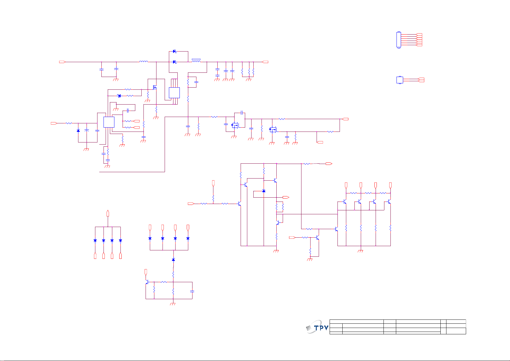
Page 57

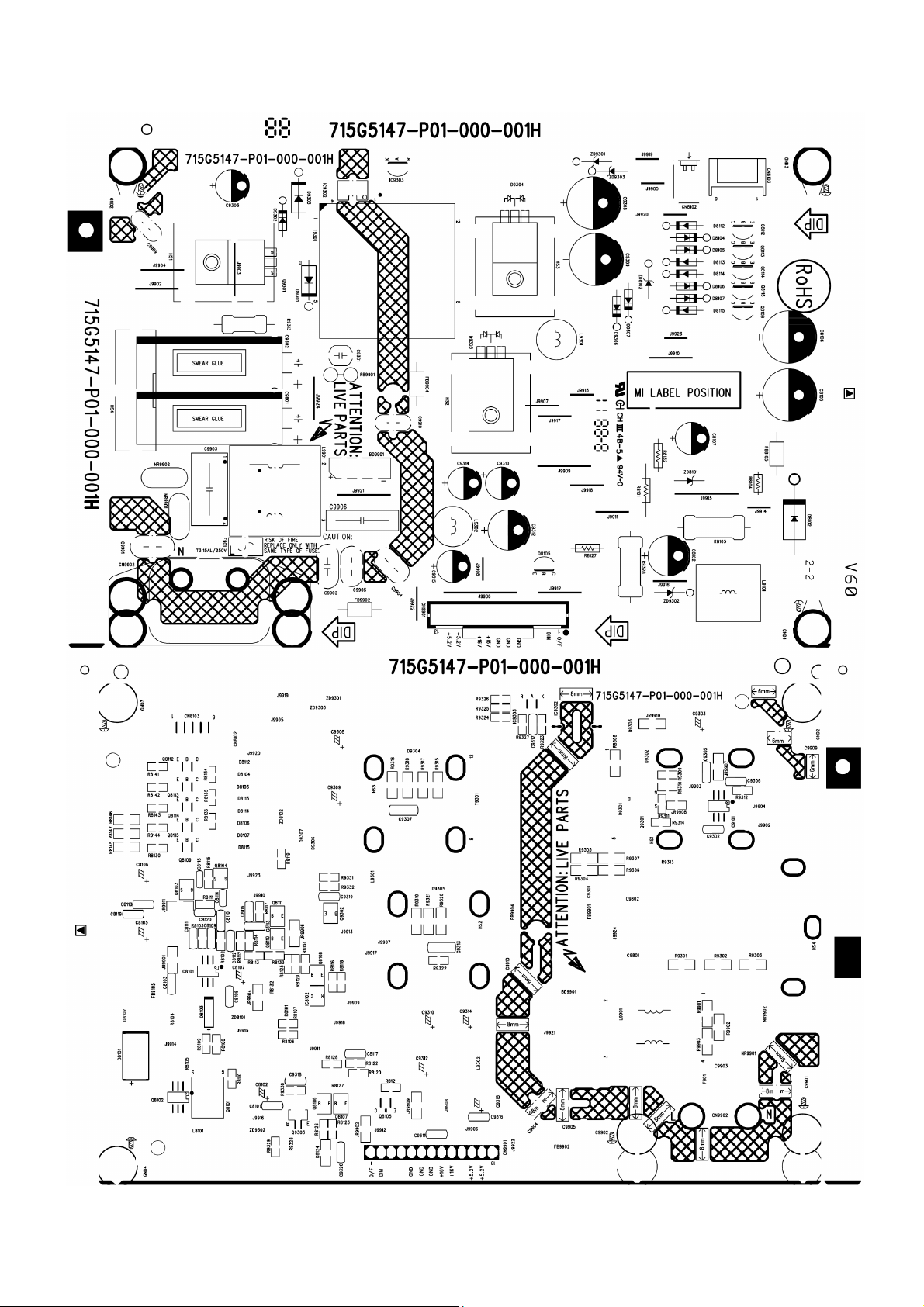
9.2 Power Board
715G5147P01000001H
BD9901
2
KBP208GL
+
C9904NCC9905
!
R9901
620K 1/4W
12
NR9902
NTCR
t
12
NR9901
NTCR
t
NC
CN9902
SOCKET
-
4
2
L9901
620K 1/4W
!
!
C9901
C9906
0.1UF
30MH
R9902
3
1.5NF 250V
431
!
C9903
330NF 275V
620K 1/4W
!
12
1
!!
R9903
C9902
220PF
!
100KOHM +-5% 1/8W
084G 56 3 B
F901
FUSE
R9315
100 OHM 1/4W
!
IC9302
43
100 OHM 1/4W
100 OHM 1/4W
100 OHM 1/4W
D9305
FMWN-2308
12
+5.2V
R9316
R9317
R9318
3
1
R9319
100 OHM 1/4W
100 OHM 1/4W
100 OHM 1/4W
!
T9301
!
D9303
FR107
!!
C9910
470pF/250V
POWER X'FMR
5 8
4
3
1
2
R9308
2R2 +-5% 1/4W
!
C9306
22N 50V
9
10
11
12
056G 139 3A
PC123X2YFZOF
1 2
FB9901
BEAD
!!
+
C9801
47UF 450V
R9312
12
FB9902
BEAD
+
C9802
47UF 450V
1
2
3
C9305
470P 50V
R9301
6.8K 1/4W
R9302
6.8K 1/4W
R9303
6.8K 1/4W
IC9101
LD7750RGR
OTP
HV
COMP
CS
VCC
GND4OUT
R9314
470OHM +-5% 1/8W
8
6
5
C9302
100N 50V
C9909
NC
C9301
1NF
R9309
NC
R9310
22 OHM 1/8W
+
100K
C9303
47uF
D9302
NC
R9304
R9307
100K
D9301
PR1007
R9311
10K 1/8W
FB9904
1 2
BEAD
R9305
100K
R9306
100K
Q9301
2SK4101LS-MG5/FS
R9313
0.43 OHM +-5% 2WS
!
R9328
470R
Q9303
2SD1623S-TD-E
C9318
100N 50V
ZD9302
MTZJ T-72 18B
1 2
R9329
470OHM +-5% 1/8W
R9330
1K OHM +- 5% 1/8W
+16V
Protect
Q9302
PMBT3904
C9319
100N 50V
ZD9301
MTZJT-725.6B
D9306
1N4148
R9331
3.3K +-5%1/8W
R9332
1KOHM +-1% 1/8W
1 2
2
2N2 500V
R9320
R9321
3
D9304
MBRF20150CT
1
C9313
+16V
1 2
2
ZD9303
GDZJ22B
D9307
1N4148
C9307
1N 630V
+
+
C9309
470UF 35V
+
+
C9314
470UF 10V
R9322
220R 1/8W 5%
R9323
3.3K OHM
C9310
470UF 10V
C9308
470UF 35V
Update_0610
AS431AZTR-E1
IC9303
HS4
SHIELD
T P V ( Top Victory Electronics Co . , Ltd. )
絬隔瓜絪腹
F
Key Component
02.POWER 715G5147-P0F-000-0010
Monday, December 26, 2011
Date
Coil
L9302
C9317
0.1uF 50V
Protect
R9324
3K3 1/8W 1%
1
2
3
Coil
L9301
C9311
100N 50V
R9325
68K 1/8W 1%
R9327
1K OHM +-5% 1/8W
R9326
2K43 1/8W 1%
C9315
470uF
OEM MOD EL
TPV MODEL
PCB NAME
Sheet
+
ON/OFF
+16V
C9312
+
330uF 35V
C9316
100N 50V
C9320
1N 50V
+16V
+5.2V
of
23
+5.2V
DIM
CN9901
1
2
3
4
5
6
7
8
9
10
11
12
13
CONN
A3
Size
Rev
称爹
<>
称爹
57
Page 58
D8101
NC
1 2
D8102
R8109
47 OHM
R8108
22OHM +-5% 1/8W
12
C8103
100N 50V
R8107
R8106
NC
R8103
200K 1/8W
DIM
ON/OFF
L8101
100UH
R8104
1K 1/6W 5%
C8111
470P 50V
R8110
10K 1/8W
+16V
R8101
51 OHM
+16V
Update_0722 for AI
ZD8101
C8107
+
22UF 35V
MTZJ T-72 22B
1 2
C8109
10N 50V
C8108
100N 50V
+
C8102
C8101
330uF 35V
NC
1 2
D8103
RB160M
5
6
8
22 OHM 1/8W
DIM
OUT7VCC
GND
FB1GM2RT3CS
IC8101
PF7900S
4
R8102
75K 1/8W
C8110
1uF
COMP
Q8101
AOD482
R8105
0.1R
SR810-05
1 2
5
4
1 2
FB8105
BEAD
C8118
1uF
C8119
C8105
1uF
82UF 100V
C8120
100NF 50V
R8111
432K
Q8102
D8D7D6D
NC
S1S2S3G
R8112
560K 1/8W 1%
R8114
220KOHM +-1% 1/8W
C8113
R8113
C8112
NC
51K 1% 1/8W
NC
ON/OF F
R8124
0R05 1/4W
R8123
DIM
NC
+
+
C8106
82UF 100V
R8127
10K 1/6W 5%
R8126
10K OHM +-5% 1/8W
R8145
C8114
NC
Q8103
2N7002
47K 1/4W
Q8106
PMBT3904
Q8107
PMBT3904
R8146
R8147
47K 1/4W
NC
C8115
NC
R8128
1K 1/8W 1%
60V
R8115
24K 1/8W 5%
IC8102
AS431AN-E1
R8129
33R 1%
Q8104
2N7002
R8116
100K 1/8W
C8116
NC
Q8108
PMBT3904
R8125
36R 1%
+2.5V
R8117
15K 1/8W 1%
J9918
1K OHM +-5% 1/8W
COMP
R8118
100K 1/8W
+5.2V
Q8112
2N3904
+16V
LED2LED1 LED4LED3
R8134
NC
4-Strings for one Light
R8135
NC
Q8114
Q8113
2N3904
2N3904
R8136
NC
Q8115
2N3904
CN8103
CONN
CN8102
NC
1
2
3
4
5
6
1
2
LED1
LED2
60V
60V
LED3
LED4
60V
LED3
D8104
1N4148
LED2LED1 LED4LED3
D8113
D8112
Q8105
2N3904
1N4148
ON/OF F
1N4148
Compensation circuit
R8121
10K OHM +-5% 1/8W
D8105
D8107
D8106
1N4148
1N4148
1N4148
LED1
LED2
LED3
LED4
D8115
D8114
1N4148
1N4148
ZD8102
GDZJ15B
1 2
R8119
100K 1/8W
R8120
10K OHM +-5% 1/8W
R8122
100KOHM +-5% 1/8W
C8117
100N 50V
Q8109
2N3904
R8130
10ohm +/-1% 1/8W
R8131
1K OHM +-5% 1/8W
R8132
10K 1/6W 5%
DIM
Q8110
PMBT3904
R8133
100KOHM +-1% 1/8W
R8141
R8142
R8143
10ohm +/-1% 1/8W
OEM MOD EL
TPV MOD EL
PCB NAME
Sheet
R8144
10ohm +/-1% 1/8W
33
Size
Rev
of
称爹
Q8111
PMBT3904
10ohm +/-1% 1/8W
10ohm +/-1% 1/8W
T P V ( Top Victory Electronics Co . , Ltd. )
絬隔瓜絪腹
F
Key Component
03.LED Driv er 715G5147-P0F-000-0010
Monday, D ecember 26, 2011
Date
C
称爹
<>
58
Page 59

9.3 IR Board
715G5061R02002004M
CN01
CONN
LED
R002 220R
081G 14 50 EL
Red
LED1
264-10SURC/S530-A3
1 2
Top View
65
1
2
3
4
IR
VCC
R001 15K OHM 1/10W
C001
100nF 50V
U001
1
OUT
2
GND
3
VCC
IRM-3636N3S27F45-P
56T 627911
16 mm
Dip LED
IR
37mm
T P V ( Top Victory Electronics Co . , Ltd. )
絬隔瓜絪腹
Key Component
Date
02-IR&LED
OEM MOD EL
TPV MOD EL
PCB NAME
Sheet
715G5061-R0A-000-0040
of
22Thursday , August 11, 2011
Size
Rev
称爹
A
A
<>
称爹
59
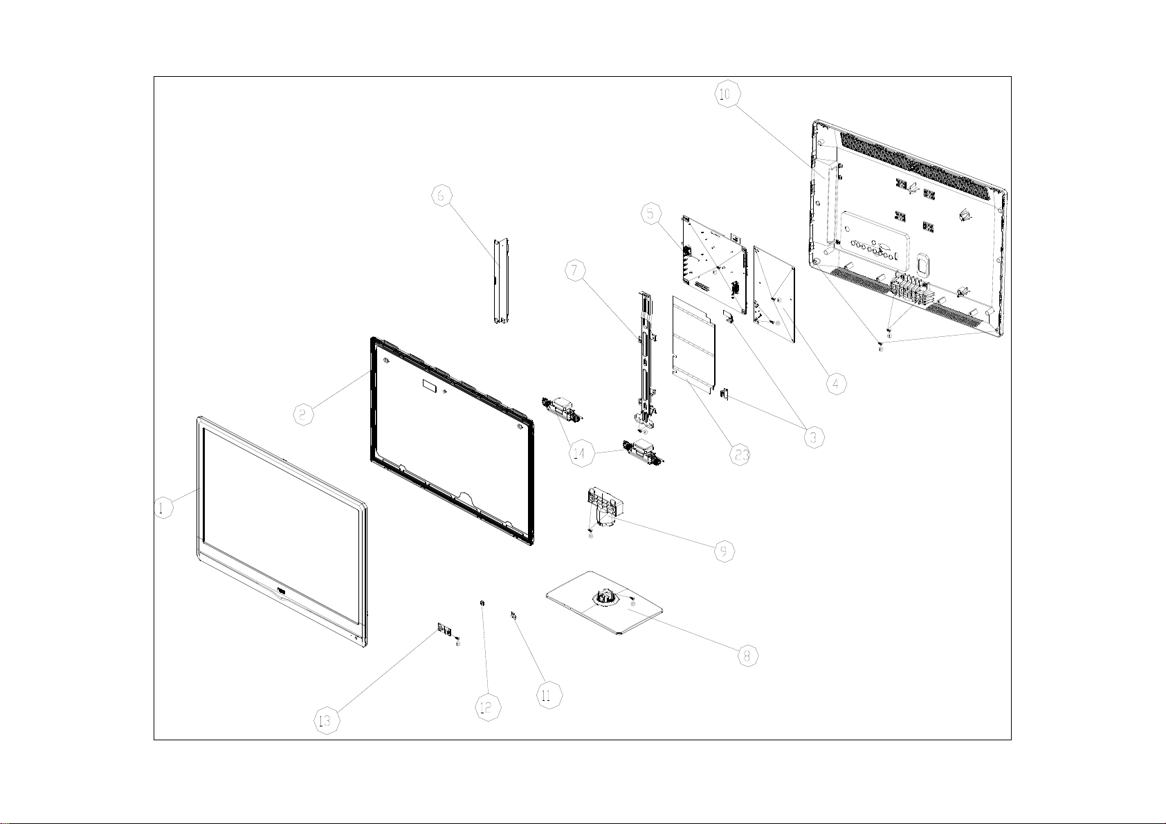
Page 60

10. Exploded View
LE19A1321/30 & LE19A1321/40
60
Page 61

LE19A1321/30 & LE19A1321/40
Item Description
1 BEZEL
2 IR_LENS
3 LED_LENS
4 IR BOARD
5 PANEL
6 MAIN BOARD
7 BKT_MID
8 POWER BOARD
9 BKT_CONNECTOR 17 0Q1G1030 6120 XL SCREW(IR BOARD/BEZEL) 1
10 BKT_IO 18 0M1G1730 8120 RA SCREW(MAIN BOARD/POWER BOARD/BEZEL) 7
11 REAR_COVER 19 0M1G 930 8 47 CR3 SCREW(POWER BOARD/BKT MID) 1
12 BKT_VESA 20 0Q1G 930 8 47 HX SCREW(REAR COVER/BEZEL) 2
13 COVER_VESA 21 0Q1G 940 18 47 RA SCREW(STAND/REAR COVER) 2
14 STAND 22 0Q1G 330 8 47 RA SCREW(REAR COVER I/O) 1
15 BASE 23 0Q1G 940 16 47 HX SCREW(BASE BKT/BASE) 1
16 FOOT PAD 24 0M1G1730 10120 H1 SCREW(POWER BOARD) 2
Item Part No. Description Qty
61
Page 62
LE22A1321/30
62
Page 63

LE22A1321/30
Item Description
1 BEZEL
2 PANEL
3 BKT_POWER
4 POWER BOARD
5 MAIN BOARD
6 BKT_SIDE 15 0Q1G1030 6120 H1 SCREW(IR BOARD/BEZEL) 1
7 BKT_HOLD 16 0M1G1730 8120 XL SCREW(POWER BOARD) 3
8 BASE 17 0M1G1730 8120 XL SCREW(MAIN BOARD) 4
9 STAND 18 0Q1G 930 8 47 XL SCREW(BKT HOLD) 2
10 REAR_COVER 19 0Q1G 930 8 47 HX SCREW(REAR-COVER/BEZEL) 2
11 IR_LENS 20 0Q1G 940 18 47 RA SCREW(STAND/BKT) 2
12 LED_LENS 21 0Q1G 940 16 47 HX SCREW(REAR COVER/BKT) 2
13 IR BOARD 22 0Q1G 940 12 47 HX SCREW(BASE/BKT) 1
14 SPEAKER 24 0Q1G 330 8 47 RA SCREW(REAR COVER/IO) 1
23 INSULATING SHEET 25 0M1G1730 10120 H1 SCREW(POWER BOARD) 2
Item Part No. Description Qty
63
Page 64

LE24A1321/30
64
Page 65

LE24A1321/30
Item Description
1 BEZEL_23.6AOC-SA
2 IR_LENS
3 LED_LENS
4 IR BOARD
5 SPEAKERS
6 PANEL
7 BKT_POWER_L SGCC
8 BKT_HOLDER SGCC 0.6 mm
9 BKT_IO SGCC 0.6 mm 18 0Q1G1030 6120 RA SCREW(IR BOARD/BEZEL) 1
10 INSULATING SHEET 19 0Q1G 940 10 47 XL SCREW(PANEL BKT) 1
11 POWER BOARD PCB 20 0M1G1730 8120 XL SCREW(MAIN BOADR/POWER BOARD) 7
12 MAIN BOARD PCB 21 0M1G1730 10120 RA SCREW (POWER BOARD) 2
13 COVER_CLOCK_REAR 22 0Q1G 940 10 47 H1 SCREW(REAR COVER/BEZEL) 2
14 BKT_VESA SGCC 23 0Q1G 940 16 47 HX SCREW(REAR COVER/BEZEL) 1
15 REAR_COVER 24 0Q1G 940 16 47 HX SCREW(STAND/REAR COVER) 2
16 STAND 25 0Q1G 330 8 47 XL SCREW(REAR COVER/IO) 1
17 BASE 26 0Q1G 940 16 47 HX SCREW(BASE/BKT) 1
Item Part No. Description Qty
65
Page 66

11. BOM List
Note: The parts information listed below are for reference only, and are subject to change without notice.
Please go to http://cs.tpv.com.cn/hello1.asp
E19BAKNSBQE9NN
Location Part No. Description Remark
040G 581 26646 LABEL
E098 398GRABD5NEACC REMOTE AOC RL76D-1 ENGLISH
P11G002310100000PJ WIRE-CLIP
Q40G 581689 4B SN LABEL(58X35MM)
Q41G78DV61508D WARRANTY CARD
Q45G99010TV03700X1 PROTECT BAG
M05001 Q50G 500523 TS CABLE TIE
Q52G15011505230WXW TAPE_INSULATING
X15T818210300000LH BKT_MID
SP01 078G0050561 Y SPEAKER 8 OHM 5W 100X27 0 NO
085T 583113 GASKET
089G 728CAA DB D-SUB CABLE 1800MM
E08901 089G204A15N IS AC POWER CORD 1500MM 2nd Source
E08901 089G204A15N JR AC POWER CORD 1500MM P19295VD
ECN701 095G801313D668 HARNESS -- -- 2nd Source
ECN701 095G801313X668 HARNESS 13P-12P 120MM
ECN601 095G8014 4RY03 HARNESS 4P-2P+2P 500/600MM
ECN601 095G8014 4WY03 HARNESS 4P-B&R+B&W 500/600MM 2nd Source
ECN405 095G8018 3DJ29 LVDS CABLE 30P-30P(2004) 120MM 2nd Source
ECN405 095G8018 3XJ29 LVDS CABLE 30P-30P(2004) 120MM
M00106 0M1G1730 8120 RA SCREW 3X8
M00108 0M1G1730 8120 RA SCREW 3X8
M00106 0M1G1730 8120 XL SCREW 3X8
M00108 0M1G1730 8120 XL SCREW 3X8
M00107 0M1G1730 10120 H1 SCREW M1-MACHINE SCREW X10
M00107 0M1G1730 10120 RA SCREW 3X10
M00101 0Q1G 330 8 47 H1 SCREW 3X8
M00101 0Q1G 330 8 47 RA SCREW 3X8
M00110 0Q1G 930 8 47 H1 SCREW 3X8
M00102 0Q1G 930 8 47 HX SCREW 3X8
M00110 0Q1G 930 8 47 RA SCREW 3X8
M00102 0Q1G 930 8 47 XL SCREW 3X8
0Q1G 940 18 47 RA SCREW Q1-SELF TAPING SCREW :Q X18
705TQ949001 COMSUPTIVE ASS'Y-A4
708G9A040CPQ02 AOC 40(2310 SA)
052G 1185 1 BIG TAPE(Y1200141)
Q45G 77511 PE PACKING(BLACK)
Q50G 4 10 TIE (Y1900221)
E750 750GBU185X1F1HN000 LCD M185XW01 VFT0 WH AUO 999-N/A 999
756TXBCB0KS011001Q MAIN BOARD-CBPFBK1SX4Q
U404 056G2233 2 FLASH W25Q32BVSSIG 32MB SOP-8
SMTF-U404 100TARA8001S1X MCU ASS'Y-056G2233 2
ADTV11636XYIQ POWER BOARD
Z40G0002ALL01A SFIS LABEL 35MM*9MM
GND2 009G6005 1 GND TERMINAL
GND3 009G6005 1 GND TERMINAL
GND4 009G6005 1 GND TERMINAL
for the latest information.
66
Page 67

CN9901 033G327813D CONNECTOR
CN8102 033G8021 2E XY CONNECTOR
IC9302 056G 139 3A PC123Y22FZOF SHARP
NR9901 061G 58159LAW 5A NTCR 1.5R 15% 2.4W SCK101R55LMY502
NR9902 061G 58159LAW 5A NTCR 1.5R 15% 2.4W SCK101R55LMY502
R8105 061G153M10859B SY RST MOF 0.1R 5% 3WS PITCH=20MM
R9328 061G153M27164T SY MOF 270 OHM 3W 5%
C9906 063G107K104 UU CAP X2 100NF 10% 305V
C9903 063G107K334 UM CAP X2 330NF 10% 275V BULK ( B )
C9308 067G 4154716KV EC 470UF 20% 35V EP 12.5*12
C9801 067G 43R47015K EC 47UF 20% 450V 13*35
C9802 067G 43R47015K EC 47UF 20% 450V 13*35
C9314 067G204S4712KT CAP CS 470UF 20% 10V 8*7
L9901 073G 174192 H LINE FILTER 30MH MIN LCL-12012 HA
L9302 073G 253 91 L CHOKE COIL 3.5UH 10% CC-015367HF,VOC,HF
L9301 073G 253 91 L CHOKE COIL 3.5UH 10% CC-015367HF,VOC,HF
L8101 073G 253209 L CHOKE COIL 100UH 10% CC-012898
T9301 080GL32P 27 L X'FMR 480UH 10% 10UH PT-013361-5 EFD30
T9301 080GL32P 27 N X'FMR 480UH 10% 10UH YUVA-1429 EFD30
CN9902 087G 50147C HC AC SOCKET V/T 2P DB-8-01 H=14MM
BD9901 093G 50460511 BRIDGE KBP208GL 4A 800V KBP
D8102 093G 60938 DIODE SR810-05 8A/100V DO-201AD
0Q1G 340 8140 SCREW Q1-SELF TAPING SCREW :Q X8.0
705TQB57983 Q9301 ASS'Y
Q9301 057G 611908 MOSFET TK6A65D (STA4,Q),£¨Q,M) SC-67
Q9301 057G 667 51 MOSFET 2SK4101LS-MG5/FS 7A 650V TO-220FI
0M1G1730 8120 SCREW 3X8
HS3 Q90G0195 1 HEAT SINK
705TQB93994 D9305 ASS'Y
D9305 093G 60324 SCHOTTKY FMWN-2308 30A 80V TO-220
0M1G1730 8120 SCREW 3X8
HS2 Q90G0195 1 HEAT SINK
705TQB93995 D9304 ASS'Y
D9304 093G 60946 SCHOTTKY MBRF20150CT C0 20 150 ITO-220AB
0M1G 930 8 47 CR3 SCREW 3X8
HS1 Q90G0195 1 HEAT SINK
IC8102 056G 158501 IC AS431AN-E1 SOT23
IC9101 056G 379190 AC/DC CONVERTER LD7750RGR SOP-7
IC8101 056G 700 23 TEST ONLY LED DRIVER PF7900S SOP-8
Q8106 057G 417 18 T PMBT3904 SOT-23
Q8107 057G 417 18 T PMBT3904 SOT-23
Q8108 057G 417 18 T PMBT3904 SOT-23
Q8110 057G 417 18 T PMBT3904 SOT-23
Q8111 057G 417 18 T PMBT3904 SOT-23
Q9302 057G 417 18 T PMBT3904 SOT-23
Q9303 057G 419913 T TRANSISTOR 2SD1623S-TD-E PCP
Q8101 057G 600941 MOSFET AOD482 32A 100V TO-252
Q8103 057G 763904 TRA FET 2N7002 SOT-23 PHILIPS
Q8104 057G 763904 TRA FET 2N7002 SOT-23 PHILIPS
R8134 061G0603000 JI RST 0603 0.05R MAX 1/10W TA-I
R8135 061G0603000 JI RST 0603 0.05R MAX 1/10W TA-I
R8136 061G0603000 JI RST 0603 0.05R MAX 1/10W TA-I
JR9908 061G0805000 JY RST CHIPR MAX 0R05 OHM 1/8W YAGEO
R8128 061G08051001FF RST CHIPR 1KOHM +-1% 1/8W FENGHUA
67
Page 68

R9332 061G08051001FF RST CHIPR 1KOHM +-1% 1/8W FENGHUA
R9332 061G08051001FY RST CHIP 1K 1/8W 1%
R8128 061G08051001FY RST CHIP 1K 1/8W 1%
R8133 061G08051003FF RST CHIPR 100KOHM +-1% 1/8W FENGHUA
R8144 061G08051009FT RST CHIP R 10OHM +/-1% 1/8W
R8143 061G08051009FT RST CHIP R 10OHM +/-1% 1/8W
R8142 061G08051009FT RST CHIP R 10OHM +/-1% 1/8W
R8141 061G08051009FT RST CHIP R 10OHM +/-1% 1/8W
R8130 061G08051009FT RST CHIP R 10OHM +/-1% 1/8W
R8130 061G08051009FY RST CHIP R 10OHM +/-1% 1/8W
R8141 061G08051009FY RST CHIP R 10OHM +/-1% 1/8W
R8142 061G08051009FY RST CHIP R 10OHM +/-1% 1/8W
R8143 061G08051009FY RST CHIP R 10OHM +/-1% 1/8W
R8144 061G08051009FY RST CHIP R 10OHM +/-1% 1/8W
R8131 061G0805102 JT RST CHIPR 1K OHM +- 5% 1/8W TZAI YUAN
R9327 061G0805102 JT RST CHIPR 1K OHM +- 5% 1/8W TZAI YUAN
R9330 061G0805102 JT RST CHIPR 1K OHM +- 5% 1/8W TZAI YUAN
R9327 061G0805102 JY RST CHIPR 1K OHM 5% 1/8W YAGEO
R8110 061G0805103 JF RST CHIPR 10K OHM +-5% 1/8W FENGHUA
R9311 061G0805103 JF RST CHIPR 10K OHM +-5% 1/8W FENGHUA
R9311 061G0805103 JT RST 0805 10K 5% 1/8W
R8126 061G0805103 JT RST 0805 10K 5% 1/8W
R8121 061G0805103 JT RST 0805 10K 5% 1/8W
R8120 061G0805103 JT RST 0805 10K 5% 1/8W
R8110 061G0805103 JT RST 0805 10K 5% 1/8W
R8121 061G0805103 JY RST CHIPR 10KOHM +-5% 1/8W YAGEO
R8126 061G0805103 JY RST CHIPR 10KOHM +-5% 1/8W YAGEO
R8116 061G0805104 JI RST 0805 100K 5% 1/8W
R8118 061G0805104 JI RST 0805 100K 5% 1/8W
R9312 061G0805104 JT RST CHIPR 100KOHM +- 5% 1/8W TZAI YUAN
R8122 061G0805104 JT RST CHIPR 100KOHM +- 5% 1/8W TZAI YUAN
R8119 061G0805104 JT RST CHIPR 100KOHM +- 5% 1/8W TZAI YUAN
R8118 061G0805104 JT RST CHIPR 100KOHM +- 5% 1/8W TZAI YUAN
R8116 061G0805104 JT RST CHIPR 100KOHM +- 5% 1/8W TZAI YUAN
R8119 061G0805104 JY RST CHIPR 100KOHM 1/8W YAGEO
R8122 061G0805104 JY RST CHIPR 100KOHM 1/8W YAGEO
R9312 061G0805104 JY RST CHIPR 100KOHM 1/8W YAGEO
R8117 061G08051502FY RST CHIP 15K 1/8W 1%
R8129 061G08051629FI RST 0805 16.2R 1% 1/8W
R8129 061G08051629FT RST 0805 16.2R 1% 1/8W
R8103 061G0805204 JF RST CHIPR 200KOHM +-5% 1/8W FENGHUA
R8103 061G0805204 JT RST CHIP R 200KOHM 1/8W +/-5% TZAI YUAN
R8107 061G0805220 JF RST CHIPR 22 OHM +-5% 1/8W FENGHUA
R9310 061G0805220 JF RST CHIPR 22 OHM +-5% 1/8W FENGHUA
R8107 061G0805220 JI RST 0805 22R 5% 1/8W
R9310 061G0805220 JI RST 0805 22R 5% 1/8W
R8108 061G0805220 JT RST CHIPR 22OHM +-5% 1/8W TZAI YUAN
R9322 061G0805221 JT RST CHIP 220R 1/8W 5% TZAI YUAN
R8115 061G0805243 JT RST CHIP 24K 1/8W 5% TZAI YUAN
R9326 061G08052431FF RST CHIPR 2.43KOHM +-1% 1/8W FENGHUA
R9326 061G08052431FY RST CHIP 2K43 1/8W 1%
R9324 061G08053301FT RST CHIP 3K3 1/8W 1%
R9331 061G0805332 JF RST CHIPR 3.3KOHM +-5% 1/8W FENGHUA
R9323 061G0805332 JI RST CHIPR 3.3KOHM +-5% 1/8W 0805
68
Page 69

R9331 061G0805332 JY RST CHIPR 3K3 +-5% 1/8W YAGEO
R9323 061G0805332 JY RST CHIPR 3K3 +-5% 1/8W YAGEO
R8109 061G0805470 JI RST CHIPR 47 OHM +-5% 1/8W 0805
R8114 061G08054703FF RST CHIPR 470KOHM +-1% 1/8W FENGHUA
R9314 061G0805471 JT RST CHIPR 470OHM +-5% 1/8W TZAI YUAN
R9329 061G0805471 JT RST CHIPR 470OHM +-5% 1/8W TZAI YUAN
R9314 061G0805471 JY RST CHIPR 470OHM +-5% 1/8W YAGEO
R8111 061G08055103FF RST CHIPR 510K OHM +- 1% 1/8W FENGHUA
R8111 061G08055103FT RST CHIP 510K OHM 1/8W 1% TZAI YUAN
R8112 061G08055603FT RST CHIP 560K 1/8W 1%
R9325 061G08056802FT RST CHIP R 68K 1/8W 1%
R8113 061G08057502FT RST CHIP R 75 KOHM +-1% 1/8W
R8102 061G0805753 JF RST CHIPR 75KOHM +-5% 1/8W FENGHUA
R8124 061G1206000 JF RST CHIPR MAX0R05 1/4W FENGHUA
JR9907 061G1206000 JF RST CHIPR MAX0R05 1/4W FENGHUA
JR9906 061G1206000 JF RST CHIPR MAX0R05 1/4W FENGHUA
JR9904 061G1206000 JF RST CHIPR MAX0R05 1/4W FENGHUA
JR9902 061G1206000 JF RST CHIPR MAX0R05 1/4W FENGHUA
JR9901 061G1206000 JF RST CHIPR MAX0R05 1/4W FENGHUA
JR9901 061G1206000 JY RST CHIPR MAX0R05 1/4W YAGEO
JR9902 061G1206000 JY RST CHIPR MAX0R05 1/4W YAGEO
JR9904 061G1206000 JY RST CHIPR MAX0R05 1/4W YAGEO
JR9906 061G1206000 JY RST CHIPR MAX0R05 1/4W YAGEO
JR9907 061G1206000 JY RST CHIPR MAX0R05 1/4W YAGEO
JR9909 061G1206000 JY RST CHIPR MAX0R05 1/4W YAGEO
JR9910 061G1206000 JY RST CHIPR MAX0R05 1/4W YAGEO
JR9911 061G1206000 JY RST CHIPR MAX0R05 1/4W YAGEO
R9315 061G1206101 JF RST CHIPR 100 OHM +-5% 1/4W FENGHUA
R9316 061G1206101 JF RST CHIPR 100 OHM +-5% 1/4W FENGHUA
R9317 061G1206101 JF RST CHIPR 100 OHM +-5% 1/4W FENGHUA
R9318 061G1206101 JF RST CHIPR 100 OHM +-5% 1/4W FENGHUA
R9319 061G1206101 JF RST CHIPR 100 OHM +-5% 1/4W FENGHUA
R9320 061G1206101 JF RST CHIPR 100 OHM +-5% 1/4W FENGHUA
R9321 061G1206101 JF RST CHIPR 100 OHM +-5% 1/4W FENGHUA
R9315 061G1206101 JT RST CHIPR 100 OHM +-5% 1/4W TZAI YUAN
R9316 061G1206101 JT RST CHIPR 100 OHM +-5% 1/4W TZAI YUAN
R9317 061G1206101 JT RST CHIPR 100 OHM +-5% 1/4W TZAI YUAN
R9318 061G1206101 JT RST CHIPR 100 OHM +-5% 1/4W TZAI YUAN
R9319 061G1206101 JT RST CHIPR 100 OHM +-5% 1/4W TZAI YUAN
R9320 061G1206101 JT RST CHIPR 100 OHM +-5% 1/4W TZAI YUAN
R9321 061G1206101 JT RST CHIPR 100 OHM +-5% 1/4W TZAI YUAN
R9304 061G1206104 JI RST 1206 100K 5% 1/4W
R9305 061G1206104 JI RST 1206 100K 5% 1/4W
R9306 061G1206104 JI RST 1206 100K 5% 1/4W
R9307 061G1206104 JI RST 1206 100K 5% 1/4W
R9307 061G1206104 JY RST CHIPR 100KOHM 5% 1/4W YAGEO
R9306 061G1206104 JY RST CHIPR 100KOHM 5% 1/4W YAGEO
R9305 061G1206104 JY RST CHIPR 100KOHM 5% 1/4W YAGEO
R9304 061G1206104 JY RST CHIPR 100KOHM 5% 1/4W YAGEO
R9308 061G1206229 JT RST CHIPR 2R2 +-5% 1/4W TZAI YUAN
R9308 061G1206229 JY RST 1206 2.2R 5% 1/4W
R8146 061G1206473 JI RST 47K OHM 5% 1/4W TA-I
R8145 061G1206473 JI RST 47K OHM 5% 1/4W TA-I
R8146 061G1206473 JT RST CHIPR 47 KOHM +-5% 1/4W TZAI YUAN
69
Page 70

R8145 061G1206473 JT RST CHIPR 47 KOHM +-5% 1/4W TZAI YUAN
R9903 061G1206624 JI RST 1206 620K 5% 1/4W
R9902 061G1206624 JI RST 1206 620K 5% 1/4W
R9901 061G1206624 JI RST 1206 620K 5% 1/4W
R9901 061G1206624 JT RST CHIPR 620 KOHM +-5% 1/4W TZAI YUAN
R9902 061G1206624 JT RST CHIPR 620 KOHM +-5% 1/4W TZAI YUAN
R9903 061G1206624 JT RST CHIPR 620 KOHM +-5% 1/4W TZAI YUAN
R9301 061G1206682 JI RST 6.8K OHM 5% 1/4W TA-I
R9302 061G1206682 JI RST 6.8K OHM 5% 1/4W TA-I
R9303 061G1206682 JI RST 6.8K OHM 5% 1/4W TA-I
R9301 061G1206682 JT RST CHIPR 6.8 KOHM +-5% 1/4W TZAI YUAN
R9302 061G1206682 JT RST CHIPR 6.8 KOHM +-5% 1/4W TZAI YUAN
R9303 061G1206682 JT RST CHIPR 6.8 KOHM +-5% 1/4W TZAI YUAN
C9320 065G080510232K M CAP 0805 1NF 10% 50V X7R
C9320 065G080510232K Y CAP CHIP 0805 1N 50V X7R +/-10%
C8117 065G080510432K 3 CAP CHIP 0805 100N 50V X7R +/-10%
C8108 065G080510432K 3 CAP CHIP 0805 100N 50V X7R +/-10%
C9302 065G080510432K 3 CAP CHIP 0805 100N 50V X7R +/-10%
C9311 065G080510432K 3 CAP CHIP 0805 100N 50V X7R +/-10%
C9316 065G080510432K 3 CAP CHIP 0805 100N 50V X7R +/-10%
C9319 065G080510432K 3 CAP CHIP 0805 100N 50V X7R +/-10%
C9317 065G080510432K F CAP CHIP 0805 0.1UF K 50V X7R
C8120 065G080510432K M CAP 0805 100NF 10% 50V X7R
C9317 065G080510432K T 0.1UF K 50V X7R TAIYO YUDEN
C8103 065G080510432K Y CAP CHIP 0805 100N 50V X7R +/-10%
C8108 065G080510432K Y CAP CHIP 0805 100N 50V X7R +/-10%
C8117 065G080510432K Y CAP CHIP 0805 100N 50V X7R +/-10%
C9318 065G080510432K Y CAP CHIP 0805 100N 50V X7R +/-10%
C9319 065G080510432K Y CAP CHIP 0805 100N 50V X7R +/-10%
C9302 065G080510432K Y CAP CHIP 0805 100N 50V X7R +/-10%
C9311 065G080510432K Y CAP CHIP 0805 100N 50V X7R +/-10%
C9316 065G080510432K Y CAP CHIP 0805 100N 50V X7R +/-10%
C8110 065G080510532K M CAP 0805 1UF 10% 50V X7R
C8118 065G080510532K M CAP 0805 1UF 10% 50V X7R
C8119 065G080510532K M CAP 0805 1UF 10% 50V X7R
C8119 065G080510532K T CAP 0805 1UF 10% 50V X7R
C8118 065G080510532K T CAP 0805 1UF 10% 50V X7R
C8109 065G080522232K F CAP 0805 2.2NF 10% 50V X7R
C8109 065G080522232K Y CAP CHIP 0805 2N2 50V X7R +/-10%
C9306 065G080522332K Y CAP CHIP 0805 22N 50V X7R +/-10%
C9305 065G080547131J F CAP CHIP 0805 470PF J 50V NPO
C8111 065G080547131J F CAP CHIP 0805 470PF J 50V NPO
C9305 065G080547131J Y CAP CHIP 0805 470P 50V NPO +/-5%
C8111 065G080547131J Y CAP CHIP 0805 470P 50V NPO +/-5%
C9307 065G1206102B2K 3 CAP 1206 1NF 10% 630V X7R
C9307 065G1206102B2K T CAP CHIP1206 1000PF K 630V X7R
C9313 065G120622272K F CAP 1206 2.2NF 10% 500V X7R
C9313 065G120622272K Y CER 1206 2N2 500V X7R 10%
D8103 093G 60S 15 T SCHOTTKY RB160M 60 TR 1A 60V SOD-123
CN9902 006G 31500 EYELET
IC9303 056G 158 10 T DC/DC AS431AZTR-E1 150MA 40V TO-92
Q8105 057G 417513 T TRA 2N3904 TO-92
Q8109 057G 417513 T TRA 2N3904 TO-92
Q8112 057G 417513 T TRA 2N3904 TO-92
70
Page 71

Q8113 057G 417513 T TRA 2N3904 TO-92
Q8114 057G 417513 T TRA 2N3904 TO-92
Q8115 057G 417513 T TRA 2N3904 TO-92
R8104 061G 60210252T TZ RST CFR 1K 1/6W 5%
R8127 061G 60210352T TZ RST CFR 10K 1/6W 5%
R8132 061G 60210352T TZ RST CFR 10K 1/6W 5%
R8101 061G 60251052T 51OHM +-5% 1/6W
R9313 061G152M43852T SY RST MOFR 0.43 OHM +-5% 2WS FUTABA
C9301 065G 1K10293T CAP CER 1NF 10% 1KV R
C9310 067G204S4712KT CAP CS 470UF 20% 10V 8*7
C8107 067G215C2206KT EC 22UF 20% 35V 8*9
C9303 067G215C4706KT EC 47UF 20% 35V 8*9 EM
C9315 067G215C4713KT EC 470 20% 16 8*9 EM
FB9904 071G 55 9 T BEAD 3.5*0.8*6.0MM 110R HF
FB9902 071G 55 9 T BEAD 3.5*0.8*6.0MM 110R HF
FB8105 071G 55 9 T BEAD 3.5*0.8*6.0MM 110R HF
F901 084G 56 3 B FUSE 3.15A 250V
ZD8102 093G 3916652T MTZJ15B (13.89-14.62)
ZD8101 093G 3916852T ZENER MTZJ T-72 22B 22V 0.5W DO-34
ZD9302 093G 3918252T ZENER MTZJ T-72 18B 16.82 0.5 DO-34
ZD9301 093G 3919652T ZENER MTZJT-725.6B 5.6V 0.5W DO-34
ZD9303 093G 3958752T ZENER GDZJ22B 22V 0.5W DO-35
D9303 093G 6026T52T CTIFIER DIODE FR107
D9307 093G 6451652T 1N4148
D9306 093G 6451652T 1N4148
D8114 093G 6451652T 1N4148
D8106 093G 6451652T 1N4148
D9301 093G110050152T DIODE PR1007 1A/1000V 500NS DO-41
J9911 095G 90 23 JUMP WIRE - J9910 095G 90 23 JUMP WIRE - J9909 095G 90 23 JUMP WIRE - J9908 095G 90 23 JUMP WIRE - J9907 095G 90 23 JUMP WIRE - J9906 095G 90 23 JUMP WIRE - J9905 095G 90 23 JUMP WIRE - J9904 095G 90 23 JUMP WIRE - J9903 095G 90 23 JUMP WIRE - J9902 095G 90 23 JUMP WIRE - J9917 095G 90 23 JUMP WIRE - J9919 095G 90 23 JUMP WIRE - J9914 095G 90 23 JUMP WIRE - J9915 095G 90 23 JUMP WIRE - J9916 095G 90 23 JUMP WIRE - J9912 095G 90 23 JUMP WIRE - J9913 095G 90 23 JUMP WIRE - J9920 095G 90 23 JUMP WIRE - J9921 095G 90 23 JUMP WIRE - J9922 095G 90 23 JUMP WIRE - J9923 095G 90 23 JUMP WIRE - J9924 095G 90 23 JUMP WIRE - -
E715 715G5147P01000001H POWER BOARD PCB
J9918 061G 20711052T SY RST MOF 11R 5% 1/2W RSS12J11R0A520NH
C9309 067G 4154716KT EC 470UF 20% 35V 12.5*12
C8106 067G 4158209KT EC 82UF 20% 100V 12.5*12 4000 HR
71
Page 72

C8105 067G 4158209KT EC 82UF 20% 100V 12.5*12 4000 HR
C9902 065G306K22123R CAP Y1 220PF 10% 250V Y5P
C9910 065G306K4712PR CAP Y1 470PF 10% 250V Y5P
C9910 065G306K47123R CAP Y1 470PF 10% 250V Y5P
C9902 065G306K2212SR CAP Y1 220PF 10% 250V Y5P
C9905 065G306M1523SR CAP Y1 1.5NF 20% 250V Y5U
FB9901 071G 55 26 H BEAD 3.5*6.0*0.8 127R 25% BF-I35060R-796
FB9901 071G 55 26 S BEAD 3.5*6MM 127R 25% LB3.5¡Á0.8¡Á6-2
C8102 067G215S3316LT EC 330UF 20% 35V 10*12.5
C9312 067G215S3316LT EC 330UF 20% 35V 10*12.5
C8102 067G215S3316KT EC 330UF 20% 35V 10*12
C9312 067G215S3316KT EC 330UF 20% 35V 10*12
HS4 Q85T0205101 SHIELD 13*30
Z40G0002ALL01A SFIS LABEL 35MM*9MM
CN701 033G327812D CONN 2.5MM 12P V/T 32.5MM 6.6MM
CN601 033G3802 4B Y WAFER 2.0MM 4P
CN402 033G3802 6B Y L WAFER
U106 053G 44500 H SAW FILTER IF 44MHZ D8618V
C131 067G204S4704KV CAP CS 47UF 20% 25V 8*7
C131 067G204S4704LV CAP CS 47UF 20% 25V 8*7 2000 HR
C105 067G215H101 4C EC 100UF 20% 25V SY 8*7
C130 067G215H101 4C EC 100UF 20% 25V SY 8*7
C715 067G215H221 3C EC 220UF 20% 16V 8*7
C619 067G215S3316KV EC 330UF M 35V 10*12MM
C606 067G215S3316KV EC 330UF M 35V 10*12MM
C602 067G215S3316KV EC 330UF M 35V 10*12MM
C747 067G315M2213HV EC 220UF 20% 16V 6.3*7
SW001 077G602S 3A HJ TACT SW 4P 5.85 200G TSDBYC2202
SW005 077G602S 3A HJ TACT SW 4P 5.85 200G TSDBYC2202
SW006 077G602S 3A HJ TACT SW 4P 5.85 200G TSDBYC2202
SW007 077G602S 3A HJ TACT SW 4P 5.85 200G TSDBYC2202
SW003 077G602S 3A HJ TACT SW 4P 5.85 200G TSDBYC2202
SW004 077G602S 3A HJ TACT SW 4P 5.85 200G TSDBYC2202
SW002 077G602S 3A HJ TACT SW 4P 5.85 200G TSDBYC2202
CN106 088G 78F121XCL RCA JACK V/T 4P W/R 1*2 H=8.6
CN121 088G 78F131XCL RCA JACK V/T 6P Y/W/R 1*3 H=8.6
CN111 088G 78F135XCL RCA JACK V/T 6P G/BL/R 1*3 H=8.6
CN102 088G302F3G1VCL PHONE JACK V/T 3P GREEN H=8.4
CN101 088G353FFF3XCL D-SUB CONN V/T 15P BLUE H=8.4MM
TU101 094GNPAL MN 5L TUNER LATIN AMERICA F35CT-6N-E
CN405 311GW200C30AAL WAFER 2.0MM 2*15P
709T51520XM001000Q COMSUPTIVE ASS'Y
055G 23520 IPA
055G 23524 WELDING FLUX WITHOUT PB
Q55G 100625 TIN STICK_LOW ARGENTUM
C4222 067G305S1013HB EC 100UF 20% 16V 6.3*7
C745 067G305S2213HB EC 220UF 20% 16V 6.3*7
C721 067G305S1013HB EC 100UF 20% 16V 6.3*7
C4205 067G305S1013HB EC 100UF 20% 16V 6.3*7
C623 067G305S1013HB EC 100UF 20% 16V 6.3*7
C701 067G305S2213HB EC 220UF 20% 16V 6.3*7
709T51520XA001000Q COMSUPTIVE ASS'Y
U401 056G 562F09 SCALER RTD2674U-GR LQFP216
U704 056G 563143 IC G1084T43UF TO-252
72
Page 73

U703 056G 563153 HF LDO AP1117DG-13 1A ADJ TO252-3L
U701 056G 563344 DC/DC AT1529F11U 3.2A SOP-8
U702 056G 563344 DC/DC AT1529F11U 3.2A SOP-8
U105 056G 563519 IC G965-25ADJPIUF 1.8A SOP-8
U402 056G 615130 DRAM W9425G6JH-4 256MB TSOPII-66
U602 056G 616518 IC R2A15112FP HTQFP48
U102 056G 662 48 ESD PROTECT AZC399-04S.R7G SOT23-6L
U101 056G 662 48 ESD PROTECT AZC399-04S.R7G SOT23-6L
U404 056G2233 2 FLASH W25Q32BVSSIG 32MB SOP-8 REL-HDCP
Q703 057G 417511 HF TRA MMBT3904G SOT-23
Q704 057G 417511 HF TRA MMBT3904G SOT-23
Q705 057G 417511 HF TRA MMBT3904G SOT-23
Q405 057G 417511 HF TRA MMBT3904G SOT-23
Q406 057G 417511 HF TRA MMBT3904G SOT-23
Q504 057G 417511 HF TRA MMBT3904G SOT-23
Q602 057G 417511 HF TRA MMBT3904G SOT-23
Q603 057G 417511 HF TRA MMBT3904G SOT-23
Q701 057G 417511 HF TRA MMBT3904G SOT-23
Q601 057G 417512 HF TRA MMBT3906G -0.2A/-40V SOT-23
Q402 057G 417512 HF TRA MMBT3906G -0.2A/-40V SOT-23
Q106 057G 417512 HF TRA MMBT3906G -0.2A/-40V SOT-23
Q702 057G 763 79 FET AO4449 -7A/-30V SOIC-8
Q404 057G 763 79 FET AO4449 -7A/-30V SOIC-8
RP404 061G 1262208JY RST CHIP AR 8P4R 22 OHM +-5% 1/16W
RP405 061G 1262208JY RST CHIP AR 8P4R 22 OHM +-5% 1/16W
RP403 061G 1262208JY RST CHIP AR 8P4R 22 OHM +-5% 1/16W
RP402 061G 1262208JY RST CHIP AR 8P4R 22 OHM +-5% 1/16W
RP401 061G 1262208JY RST CHIP AR 8P4R 22 OHM +-5% 1/16W
RP406 061G 1262208JY RST CHIP AR 8P4R 22 OHM +-5% 1/16W
RP407 061G 1262208JY RST CHIP AR 8P4R 22 OHM +-5% 1/16W
RP408 061G 1262208JY RST CHIP AR 8P4R 22 OHM +-5% 1/16W
RP409 061G 1262208JY RST CHIP AR 8P4R 22 OHM +-5% 1/16W
RP410 061G 1262208JY RST CHIP AR 8P4R 22 OHM +-5% 1/16W
TH1401 061G 56A100 WT PTCR SMD 0.21R MAX 0.8W
R179 061G0402000 JI RST 0402 0.05R MAX 1/16W
R111 061G0402000 JI RST 0402 0.05R MAX 1/16W
R119 061G0603000 JF RST CHIPR MAX 0R05 1/10W FENGHUA
R121 061G0603000 JF RST CHIPR MAX 0R05 1/10W FENGHUA
R138 061G0603000 JF RST CHIPR MAX 0R05 1/10W FENGHUA
R4116 061G0603000 JF RST CHIPR MAX 0R05 1/10W FENGHUA
R4117 061G0603000 JF RST CHIPR MAX 0R05 1/10W FENGHUA
R728 061G0603000 JF RST CHIPR MAX 0R05 1/10W FENGHUA
R130 061G0603000 JT RST CHIP MAX 0R05 1/10W TZAI YUAN
R129 061G0603000 JT RST CHIP MAX 0R05 1/10W TZAI YUAN
R174 061G0603100 JF RST CHIPR 10 OHM 5% 1/10W FENGHUA
R181 061G0603100 JF RST CHIPR 10 OHM 5% 1/10W FENGHUA
R4167 061G0603100 JF RST CHIPR 10 OHM 5% 1/10W FENGHUA
R721 061G0603100 JF RST CHIPR 10 OHM 5% 1/10W FENGHUA
R732 061G0603100 JF RST CHIPR 10 OHM 5% 1/10W FENGHUA
R720 061G06031000FY RST CHIP 100R 1% 1/10W
R701 061G06031000FY RST CHIP 100R 1% 1/10W
R014 061G06031001FI 1EST ONLY RST 0603 1K 1% 1/10W TA-I
R102 061G0603101 JF RST CHIPR 100 OHM +-5% 1/10W FENGHUA
R105 061G0603101 JF RST CHIPR 100 OHM +-5% 1/10W FENGHUA
73
Page 74

R4113 061G0603101 JF RST CHIPR 100 OHM +-5% 1/10W FENGHUA
R4115 061G0603101 JF RST CHIPR 100 OHM +-5% 1/10W FENGHUA
R4119 061G0603101 JF RST CHIPR 100 OHM +-5% 1/10W FENGHUA
R4121 061G0603101 JF RST CHIPR 100 OHM +-5% 1/10W FENGHUA
R4125 061G0603101 JF RST CHIPR 100 OHM +-5% 1/10W FENGHUA
R713 061G0603101 JF RST CHIPR 100 OHM +-5% 1/10W FENGHUA
R4144 061G0603101 JF RST CHIPR 100 OHM +-5% 1/10W FENGHUA
R4139 061G0603101 JF RST CHIPR 100 OHM +-5% 1/10W FENGHUA
R4137 061G0603101 JF RST CHIPR 100 OHM +-5% 1/10W FENGHUA
R4135 061G0603101 JF RST CHIPR 100 OHM +-5% 1/10W FENGHUA
R4133 061G0603101 JF RST CHIPR 100 OHM +-5% 1/10W FENGHUA
R4129 061G0603101 JF RST CHIPR 100 OHM +-5% 1/10W FENGHUA
R4127 061G0603101 JF RST CHIPR 100 OHM +-5% 1/10W FENGHUA
R712 061G0603102 JF RST CHIPR 1K OHM +-5% 1/10W FENGHUA
R604 061G0603102 JF RST CHIPR 1K OHM +-5% 1/10W FENGHUA
R512 061G0603102 JF RST CHIPR 1K OHM +-5% 1/10W FENGHUA
R4188 061G0603102 JF RST CHIPR 1K OHM +-5% 1/10W FENGHUA
R4180 061G0603102 JF RST CHIPR 1K OHM +-5% 1/10W FENGHUA
R4176 061G0603102 JF RST CHIPR 1K OHM +-5% 1/10W FENGHUA
R192 061G0603102 JF RST CHIPR 1K OHM +-5% 1/10W FENGHUA
R191 061G0603102 JF RST CHIPR 1K OHM +-5% 1/10W FENGHUA
R182 061G0603102 JF RST CHIPR 1K OHM +-5% 1/10W FENGHUA
R104 061G0603102 JF RST CHIPR 1K OHM +-5% 1/10W FENGHUA
R103 061G0603102 JF RST CHIPR 1K OHM +-5% 1/10W FENGHUA
R603 061G0603103 JF RST CHIPR 10K OHM +-5% 1/10W FENGHUA
R611 061G0603103 JF RST CHIPR 10K OHM +-5% 1/10W FENGHUA
R612 061G0603103 JF RST CHIPR 10K OHM +-5% 1/10W FENGHUA
R613 061G0603103 JF RST CHIPR 10K OHM +-5% 1/10W FENGHUA
R614 061G0603103 JF RST CHIPR 10K OHM +-5% 1/10W FENGHUA
R616 061G0603103 JF RST CHIPR 10K OHM +-5% 1/10W FENGHUA
R619 061G0603103 JF RST CHIPR 10K OHM +-5% 1/10W FENGHUA
R703 061G0603103 JF RST CHIPR 10K OHM +-5% 1/10W FENGHUA
R717 061G0603103 JF RST CHIPR 10K OHM +-5% 1/10W FENGHUA
R112 061G0603103 JF RST CHIPR 10K OHM +-5% 1/10W FENGHUA
R114 061G0603103 JF RST CHIPR 10K OHM +-5% 1/10W FENGHUA
R4100 061G0603103 JF RST CHIPR 10K OHM +-5% 1/10W FENGHUA
R4151 061G0603103 JF RST CHIPR 10K OHM +-5% 1/10W FENGHUA
R4160 061G0603103 JF RST CHIPR 10K OHM +-5% 1/10W FENGHUA
R4202 061G0603103 JF RST CHIPR 10K OHM +-5% 1/10W FENGHUA
R516 061G0603103 JF RST CHIPR 10K OHM +-5% 1/10W FENGHUA
R517 061G0603103 JF RST CHIPR 10K OHM +-5% 1/10W FENGHUA
R556 061G0603103 JF RST CHIPR 10K OHM +-5% 1/10W FENGHUA
R115 061G0603104 JF RST CHIPR 100KOHM 5% 1/10W FENGHUA
R116 061G0603104 JF RST CHIPR 100KOHM 5% 1/10W FENGHUA
R136 061G0603104 JF RST CHIPR 100KOHM 5% 1/10W FENGHUA
R137 061G0603104 JF RST CHIPR 100KOHM 5% 1/10W FENGHUA
R143 061G0603104 JF RST CHIPR 100KOHM 5% 1/10W FENGHUA
R144 061G0603104 JF RST CHIPR 100KOHM 5% 1/10W FENGHUA
R513 061G0603104 JF RST CHIPR 100KOHM 5% 1/10W FENGHUA
R189 061G06031202FY RST CHIP 12K 1/10W 1%
R4179 061G0603121 JT RST CHIPR 120OHM 1/10W TZAI YUAN
R4205 061G0603124 JF RST CHIPR 120KOHM 5% 1/10W FENGHUA
R708 061G0603124 JF RST CHIPR 120KOHM 5% 1/10W FENGHUA
R4169 061G06031502FF RST CHIPR 15KOHM +-1% 1/10W FENGHUA
74
Page 75

R606 061G06031622FF RST CHIPR 16.2KOHM +-1% 1/10W FENGHUA
R608 061G06031622FF RST CHIPR 16.2KOHM +-1% 1/10W FENGHUA
R724 061G06031622FF RST CHIPR 16.2KOHM +-1% 1/10W FENGHUA
R013 061G06031801FI RST 0603 1.8K 1% 1/10W
R523 061G0603220 JF ST CHIPR 22 OHM +-5% 1/10W FENGHUA
R522 061G0603220 JF ST CHIPR 22 OHM +-5% 1/10W FENGHUA
R4177 061G0603220 JF ST CHIPR 22 OHM +-5% 1/10W FENGHUA
R4175 061G0603220 JF ST CHIPR 22 OHM +-5% 1/10W FENGHUA
R4174 061G0603220 JF ST CHIPR 22 OHM +-5% 1/10W FENGHUA
R4171 061G0603220 JF ST CHIPR 22 OHM +-5% 1/10W FENGHUA
R715 061G0603221 JF ST CHIPR 220 OHM +-5% 1/10W FENGHUA
R4189 061G0603222 JF RST CHIPR 2.2K OHM +-5% 1/10W FENGHUA
R108 061G0603222 JF RST CHIPR 2.2K OHM +-5% 1/10W FENGHUA
R101 061G0603222 JF RST CHIPR 2.2K OHM +-5% 1/10W FENGHUA
R190 061G0603229 JF RST CHIPR 2.2 OHM 5% 1/10W FENGHUA
R012 061G06032701FI RST 0603 2.7K 1% 1/10W
R110 061G0603273 JF RST CHIPR 27KOHM 5% 1/10W FENGHUA
R113 061G0603273 JF RST CHIPR 27KOHM 5% 1/10W FENGHUA
R132 061G0603273 JF RST CHIPR 27KOHM 5% 1/10W FENGHUA
R134 061G0603273 JF RST CHIPR 27KOHM 5% 1/10W FENGHUA
R601 061G0603274 JF RST CHIPR 270KOHM 5% 1/10W FENGHUA
R726 061G06033002FY RST CHIP 30K 1/10W 1%
R4217 061G0603303 JT RST CHIP 30K 1/10W 5% TZAI YUAN
R607 061G0603333 JF RST CHIPR 33KOHM 1/10W FENGHUA
R727 061G06034702FF RST CHIPR 47KOHM +-1% 1/10W FENGHUA
R4178 061G0603472 JF RST CHIPR 4.7KOHM +-5% 1/10W FENGHUA
R4192 061G0603472 JF RST CHIPR 4.7KOHM +-5% 1/10W FENGHUA
R4194 061G0603472 JF RST CHIPR 4.7KOHM +-5% 1/10W FENGHUA
R4207 061G0603472 JF RST CHIPR 4.7KOHM +-5% 1/10W FENGHUA
R4208 061G0603472 JF RST CHIPR 4.7KOHM +-5% 1/10W FENGHUA
R4212 061G0603472 JF RST CHIPR 4.7KOHM +-5% 1/10W FENGHUA
R4215 061G0603472 JF RST CHIPR 4.7KOHM +-5% 1/10W FENGHUA
R4216 061G0603472 JF RST CHIPR 4.7KOHM +-5% 1/10W FENGHUA
R4173 061G0603472 JF RST CHIPR 4.7KOHM +-5% 1/10W FENGHUA
R4166 061G0603472 JF RST CHIPR 4.7KOHM +-5% 1/10W FENGHUA
R4165 061G0603472 JF RST CHIPR 4.7KOHM +-5% 1/10W FENGHUA
R4164 061G0603472 JF RST CHIPR 4.7KOHM +-5% 1/10W FENGHUA
R4163 061G0603472 JF RST CHIPR 4.7KOHM +-5% 1/10W FENGHUA
R4150 061G0603472 JF RST CHIPR 4.7KOHM +-5% 1/10W FENGHUA
R194 061G0603472 JF RST CHIPR 4.7KOHM +-5% 1/10W FENGHUA
R193 061G0603472 JF RST CHIPR 4.7KOHM +-5% 1/10W FENGHUA
R602 061G0603472 JF RST CHIPR 4.7KOHM +-5% 1/10W FENGHUA
R514 061G0603472 JF RST CHIPR 4.7KOHM +-5% 1/10W FENGHUA
R706 061G0603472 JF RST CHIPR 4.7KOHM +-5% 1/10W FENGHUA
R709 061G0603472 JF RST CHIPR 4.7KOHM +-5% 1/10W FENGHUA
R711 061G0603472 JF RST CHIPR 4.7KOHM +-5% 1/10W FENGHUA
R719 061G0603472 JF RST CHIPR 4.7KOHM +-5% 1/10W FENGHUA
R4204 061G0603473 JF RST CHIPR 47KOHM +-5% 1/10W FENGHUA
R4218 061G0603473 JF RST CHIPR 47KOHM +-5% 1/10W FENGHUA
R610 061G0603473 JF RST CHIPR 47KOHM +-5% 1/10W FENGHUA
R707 061G0603473 JF RST CHIPR 47KOHM +-5% 1/10W FENGHUA
R4182 061G06034999FF RST CHIPR 49.9 OHM +-1% 1/10W FENGHUA
R4172 061G06034999FF RST CHIPR 49.9 OHM +-1% 1/10W FENGHUA
R187 061G0603511 JT RST CHIP 510R 1/10W 5% TZAI YUAN
75
Page 76

R135 061G0603512 JY RST CHIPR 5.1KOHM +-5% 1/10W YAGEO
R139 061G0603512 JY RST CHIPR 5.1KOHM +-5% 1/10W YAGEO
R723 061G0603513 JF RST CHIPR 51K OHM +-5% 1/10W FENGHUA
R4168 061G0603622 JF RST CHIPR 6.2KOHM +-5% 1/10W FENGHUA
R141 061G0603750 JF RST CHIPR 75OHM +- 5% 1/10W FENGHUA
R142 061G0603750 JF RST CHIPR 75OHM +- 5% 1/10W FENGHUA
R140 061G0603750 JF RST CHIPR 75OHM +- 5% 1/10W FENGHUA
R133 061G0603750 JF RST CHIPR 75OHM +- 5% 1/10W FENGHUA
R109 061G0603750 JF RST CHIPR 75OHM +- 5% 1/10W FENGHUA
R107 061G0603750 JF RST CHIPR 75OHM +- 5% 1/10W FENGHUA
R106 061G0603750 JF RST CHIPR 75OHM +- 5% 1/10W FENGHUA
R015 061G06037500FF RST CHIPR 750 OHM +-1% 1/10W FENGHUA
R018 061G06037500FF RST CHIPR 750 OHM +-1% 1/10W FENGHUA
R011 061G06037501FF RST CHIPR 7.5KOHM +-1% 1/10W FENGHUA
R702 061G0603752 JF RST CHIPR 7.5KOHM 5% 1/10W FENGHUA
R702 061G0603752 JT RST CHIP 7K5 1/10W 5% TZAI YUAN
FB101 061G0805000 JF RST CHIPR 0 OHM +-5% 1/8W FENGHUA
FB711 061G0805000 JY RST CHIPR MAX 0R05 OHM 1/8W YAGEO
FB714 061G0805000 JY RST CHIPR MAX 0R05 OHM 1/8W YAGEO
R188 061G08053832FF RST CHIPR 38.3KOHM +-1% 1/8W FENGHUA
R4190 061G0805472 JF RST CHIPR 4.7KOHM +-5% 1/8W FENGHUA
R017 061G08057500FT RST CHIPR 750R +-1% 1/8W TZAI YUAN
C4214 065G040210131J A CAP CHIP 0402 100PF J 50V NPO
C4215 065G040210131J A CAP CHIP 0402 100PF J 50V NPO
C4216 065G040210131J A CAP CHIP 0402 100PF J 50V NPO
C4217 065G040210131J A CAP CHIP 0402 100PF J 50V NPO
C4218 065G040210131J A CAP CHIP 0402 100PF J 50V NPO
C4225 065G040210131J A CAP CHIP 0402 100PF J 50V NPO
C4226 065G040210131J A CAP CHIP 0402 100PF J 50V NPO
C741 065G040210232K A CAP 0402 1NF 10% 50V X7R
C758 065G040210232K A CAP 0402 1NF 10% 50V X7R
C137 065G040210332K A CAP 0402 10NF 10% 50V X7R
C4186 065G040210412K Y CAP 0402 100NF 10% 16V X7R
C4188 065G040210412K Y CAP 0402 100NF 10% 16V X7R
C4189 065G040210412K Y CAP 0402 100NF 10% 16V X7R
C4190 065G040210412K Y CAP 0402 100NF 10% 16V X7R
C4193 065G040210412K Y CAP 0402 100NF 10% 16V X7R
C4197 065G040210412K Y CAP 0402 100NF 10% 16V X7R
C4198 065G040210412K Y CAP 0402 100NF 10% 16V X7R
C4199 065G040210412K Y CAP 0402 100NF 10% 16V X7R
C4200 065G040210412K Y CAP 0402 100NF 10% 16V X7R
C4201 065G040210412K Y CAP 0402 100NF 10% 16V X7R
C4202 065G040210412K Y CAP 0402 100NF 10% 16V X7R
C4203 065G040210412K Y CAP 0402 100NF 10% 16V X7R
C4204 065G040210412K Y CAP 0402 100NF 10% 16V X7R
C4185 065G040210412K Y CAP 0402 100NF 10% 16V X7R
C4164 065G040210412K Y CAP 0402 100NF 10% 16V X7R
C4165 065G040210412K Y CAP 0402 100NF 10% 16V X7R
C4166 065G040210412K Y CAP 0402 100NF 10% 16V X7R
C4167 065G040210412K Y CAP 0402 100NF 10% 16V X7R
C4168 065G040210412K Y CAP 0402 100NF 10% 16V X7R
C4169 065G040210412K Y CAP 0402 100NF 10% 16V X7R
C4170 065G040210412K Y CAP 0402 100NF 10% 16V X7R
C4171 065G040210412K Y CAP 0402 100NF 10% 16V X7R
76
Page 77

C4172 065G040210412K Y CAP 0402 100NF 10% 16V X7R
C4173 065G040210412K Y CAP 0402 100NF 10% 16V X7R
C4174 065G040210412K Y CAP 0402 100NF 10% 16V X7R
C4175 065G040210412K Y CAP 0402 100NF 10% 16V X7R
C4176 065G040210412K Y CAP 0402 100NF 10% 16V X7R
C716 065G040210412K Y CAP 0402 100NF 10% 16V X7R
C719 065G040210412K Y CAP 0402 100NF 10% 16V X7R
C720 065G040210412K Y CAP 0402 100NF 10% 16V X7R
C723 065G040210412K Y CAP 0402 100NF 10% 16V X7R
C725 065G040210412K Y CAP 0402 100NF 10% 16V X7R
C734 065G040210412K Y CAP 0402 100NF 10% 16V X7R
C736 065G040210412K Y CAP 0402 100NF 10% 16V X7R
C738 065G040210412K Y CAP 0402 100NF 10% 16V X7R
C742 065G040210412K Y CAP 0402 100NF 10% 16V X7R
C743 065G040210412K Y CAP 0402 100NF 10% 16V X7R
C748 065G040210412K Y CAP 0402 100NF 10% 16V X7R
C749 065G040210412K Y CAP 0402 100NF 10% 16V X7R
C751 065G040210412K Y CAP 0402 100NF 10% 16V X7R
C753 065G040210412K Y CAP 0402 100NF 10% 16V X7R
C4207 065G040210412K Y CAP 0402 100NF 10% 16V X7R
C4208 065G040210412K Y CAP 0402 100NF 10% 16V X7R
C4211 065G040210412K Y CAP 0402 100NF 10% 16V X7R
C4221 065G040210412K Y CAP 0402 100NF 10% 16V X7R
C4223 065G040210412K Y CAP 0402 100NF 10% 16V X7R
C4224 065G040210412K Y CAP 0402 100NF 10% 16V X7R
C511 065G040210412K Y CAP 0402 100NF 10% 16V X7R
C601 065G040210412K Y CAP 0402 100NF 10% 16V X7R
C605 065G040210412K Y CAP 0402 100NF 10% 16V X7R
C622 065G040210412K Y CAP 0402 100NF 10% 16V X7R
C703 065G040210412K Y CAP 0402 100NF 10% 16V X7R
C704 065G040210412K Y CAP 0402 100NF 10% 16V X7R
C710 065G040210412K Y CAP 0402 100NF 10% 16V X7R
C713 065G040210412K Y CAP 0402 100NF 10% 16V X7R
C4163 065G040210412K Y CAP 0402 100NF 10% 16V X7R
C101 065G040210412K Y CAP 0402 100NF 10% 16V X7R
C122 065G040210412K Y CAP 0402 100NF 10% 16V X7R
C129 065G040210412K Y CAP 0402 100NF 10% 16V X7R
C4100 065G040210412K Y CAP 0402 100NF 10% 16V X7R
C4145 065G040210412K Y CAP 0402 100NF 10% 16V X7R
C4153 065G040210412K Y CAP 0402 100NF 10% 16V X7R
C4156 065G040210412K Y CAP 0402 100NF 10% 16V X7R
C4157 065G040210412K Y CAP 0402 100NF 10% 16V X7R
C4158 065G040210412K Y CAP 0402 100NF 10% 16V X7R
C4161 065G040210412K Y CAP 0402 100NF 10% 16V X7R
C4162 065G040210412K Y CAP 0402 100NF 10% 16V X7R
C4142 065G0402105A5K 3 CAP CHIP 0402 1UF K 10V X5R
C4178 065G0402105A5K 3 CAP CHIP 0402 1UF K 10V X5R
C4179 065G0402105A5K 3 CAP CHIP 0402 1UF K 10V X5R
C4181 065G0402105A5K 3 CAP CHIP 0402 1UF K 10V X5R
C4184 065G0402105A5K 3 CAP CHIP 0402 1UF K 10V X5R
C4191 065G0402105A5K 3 CAP CHIP 0402 1UF K 10V X5R
C4192 065G0402105A5K 3 CAP CHIP 0402 1UF K 10V X5R
C4177 065G0402105A5K 3 CAP CHIP 0402 1UF K 10V X5R
C4180 065G0402105A5K 3 CAP CHIP 0402 1UF K 10V X5R
77
Page 78

C4182 065G0402105A5K 3 CAP CHIP 0402 1UF K 10V X5R
C4183 065G0402105A5K 3 CAP CHIP 0402 1UF K 10V X5R
C4183 065G0402105A5K T CAP 0402 1UF 10% 10V X5R
C4182 065G0402105A5K T CAP 0402 1UF 10% 10V X5R
C4180 065G0402105A5K T CAP 0402 1UF 10% 10V X5R
C4177 065G0402105A5K T CAP 0402 1UF 10% 10V X5R
C4195 065G040222031J A CAP 0402 22PF J 50V NPO
C4194 065G040222031J A CAP 0402 22PF J 50V NPO
C124 065G040222031J A CAP 0402 22PF J 50V NPO
C123 065G040222031J A CAP 0402 22PF J 50V NPO
C103 065G040222031J A CAP 0402 22PF J 50V NPO
C102 065G040222031J A CAP 0402 22PF J 50V NPO
C4101 065G040247312K T CAP 0402 47NF 10% 16V X7R
C4106 065G040247312K T CAP 0402 47NF 10% 16V X7R
C4107 065G040247312K T CAP 0402 47NF 10% 16V X7R
C4110 065G040247312K T CAP 0402 47NF 10% 16V X7R
C4111 065G040247312K T CAP 0402 47NF 10% 16V X7R
C4115 065G040247312K T CAP 0402 47NF 10% 16V X7R
C4116 065G040247312K T CAP 0402 47NF 10% 16V X7R
C4151 065G040247312K T CAP 0402 47NF 10% 16V X7R
C4144 065G040247312K T CAP 0402 47NF 10% 16V X7R
C4140 065G040247312K T CAP 0402 47NF 10% 16V X7R
C4139 065G040247312K T CAP 0402 47NF 10% 16V X7R
C4137 065G040247312K T CAP 0402 47NF 10% 16V X7R
C4134 065G040247312K T CAP 0402 47NF 10% 16V X7R
C4132 065G040247312K T CAP 0402 47NF 10% 16V X7R
C4131 065G040247312K T CAP 0402 47NF 10% 16V X7R
C4128 065G040247312K T CAP 0402 47NF 10% 16V X7R
C4126 065G040247312K T CAP 0402 47NF 10% 16V X7R
C4124 065G040247312K T CAP 0402 47NF 10% 16V X7R
C4118 065G040247312K T CAP 0402 47NF 10% 16V X7R
C4117 065G040247312K T CAP 0402 47NF 10% 16V X7R
C705 065G0402474A5K T CAP CHIP 0402 0.47UF 10V K X5R
C705 065G0402474A5K Y CAP CHIP 0402 0.47UF K 10V X5R
C4147 065G040250931C 3 CAP CHIP 0402 5PF 50V NP0 +/-0.25PF
C4141 065G040250931C 3 CAP CHIP 0402 5PF 50V NP0 +/-0.25PF
C4138 065G040250931C 3 CAP CHIP 0402 5PF 50V NP0 +/-0.25PF
C4133 065G040250931C 3 CAP CHIP 0402 5PF 50V NP0 +/-0.25PF
C4130 065G040250931C 3 CAP CHIP 0402 5PF 50V NP0 +/-0.25PF
C4125 065G040250931C 3 CAP CHIP 0402 5PF 50V NP0 +/-0.25PF
C603 065G060310432K A CAP 0603 100NF 10% 50V X7R
C604 065G060310432K A CAP 0603 100NF 10% 50V X7R
C611 065G060310432K A CAP 0603 100NF 10% 50V X7R
C617 065G060310432K A CAP 0603 100NF 10% 50V X7R
C620 065G060310432K A CAP 0603 100NF 10% 50V X7R
C717 065G060310432K A CAP 0603 100NF 10% 50V X7R
C012 065G060310432K F CAP CHIP 0603 0.1UF K 50V X7R
C011 065G060310432K F CAP CHIP 0603 0.1UF K 50V X7R
C616 065G060310525K 3 NO-SUGGEST CAP 0603 1UF 10% 25V X5R
C107 065G060347931C Y CAP 0603 4.7PF 0.25PF 50V NPO
C106 065G060347931C Y CAP 0603 4.7PF 0.25PF 50V NPO
C119 065G080510522K M CAP 0805 1UF 10% 25V X7R
C120 065G080510522K M CAP 0805 1UF 10% 25V X7R
C4206 065G080510522K M CAP 0805 1UF 10% 25V X7R
78
Page 79

C608 065G080510522K M CAP 0805 1UF 10% 25V X7R
C618 065G080510522K M CAP 0805 1UF 10% 25V X7R
C121 065G080510602K M CAP 0805 10UF 10% 6.3V X7R
C121 065G080510602K T CAP 0805 10UF 10% 6.3V X7R
C607 065G080547432K A CAP CHIP 0805 0.47UF K 50V X7R
C621 065G080547432K A CAP CHIP 0805 0.47UF K 50V X7R
C757 065G0805475A2K 3 CAP 0805 4.7UF 10% 10V X7R
C737 065G0805475A2K 3 CAP 0805 4.7UF 10% 10V X7R
C4196 065G0805475A2K 3 CAP 0805 4.7UF 10% 10V X7R
C4136 065G0805475A2K 3 CAP 0805 4.7UF 10% 10V X7R
C4135 065G0805475A2K 3 CAP 0805 4.7UF 10% 10V X7R
C4123 065G0805475A2K 3 CAP 0805 4.7UF 10% 10V X7R
C4122 065G0805475A2K 3 CAP 0805 4.7UF 10% 10V X7R
C4105 065G0805475A2K 3 CAP 0805 4.7UF 10% 10V X7R
C4102 065G0805475A2K 3 CAP 0805 4.7UF 10% 10V X7R
C609 065G120610625K 3 CAP CHIP 1206 10UF K 25V X5R
C610 065G120610625K 3 CAP CHIP 1206 10UF K 25V X5R
C614 065G120610625K 3 CAP CHIP 1206 10UF K 25V X5R
C615 065G120610625K 3 CAP CHIP 1206 10UF K 25V X5R
FB427 071G 56G301 MA CHIP BEAD 0805 300OHM 4A
FB426 071G 56G301 MA CHIP BEAD 0805 300OHM 4A
FB422 071G 56G301 MA CHIP BEAD 0805 300OHM 4A
FB418 071G 56G301 MA CHIP BEAD 0805 300OHM 4A
FB414 071G 56G301 MA CHIP BEAD 0805 300OHM 4A
FB107 071G 56G301 MA CHIP BEAD 0805 300OHM 4A
FB105 071G 56G301 MA CHIP BEAD 0805 300OHM 4A
FB719 071G 56K121 TA CHIP BEAD 120R/6000MA HCB2012KF-121T60
FB718 071G 56K121 TA CHIP BEAD 120R/6000MA HCB2012KF-121T60
FB717 071G 56K121 TA CHIP BEAD 120R/6000MA HCB2012KF-121T60
FB715 071G 56K121 TA CHIP BEAD 120R/6000MA HCB2012KF-121T60
FB713 071G 56K121 TA CHIP BEAD 120R/6000MA HCB2012KF-121T60
FB712 071G 56K121 TA CHIP BEAD 120R/6000MA HCB2012KF-121T60
FB710 071G 56K121 TA CHIP BEAD 120R/6000MA HCB2012KF-121T60
FB709 071G 56K121 TA CHIP BEAD 120R/6000MA HCB2012KF-121T60
FB708 071G 56K121 TA CHIP BEAD 120R/6000MA HCB2012KF-121T60
FB707 071G 56K121 TA CHIP BEAD 120R/6000MA HCB2012KF-121T60
FB705 071G 56K121 TA CHIP BEAD 120R/6000MA HCB2012KF-121T60
FB704 071G 56K121 TA CHIP BEAD 120R/6000MA HCB2012KF-121T60
FB701 071G 56K121 TA CHIP BEAD 120R/6000MA HCB2012KF-121T60
FB424 071G 56K121 TA CHIP BEAD 120R/6000MA HCB2012KF-121T60
FB421 071G 56K121 TA CHIP BEAD 120R/6000MA HCB2012KF-121T60
RP411 071G 57U600 M CHIP BEAD ARRAY 1206 60 OHM
RP412 071G 57U600 M CHIP BEAD ARRAY 1206 60 OHM
RP413 071G 57U600 M CHIP BEAD ARRAY 1206 60 OHM
RP414 071G 57U600 M CHIP BEAD ARRAY 1206 60 OHM
RP415 071G 57U600 M CHIP BEAD ARRAY 1206 60 OHM
R122 071G 59C600 TA CHIP BEAD 0603 60R 25% 600MA
R126 071G 59C600 TA CHIP BEAD 0603 60R 25% 600MA
R177 071G 59C600 TA CHIP BEAD 0603 60R 25% 600MA
FB401 071G 59G301 M CHIP BEAD 0603 300R 25% 200MA
FB402 071G 59G301 M CHIP BEAD 0603 300R 25% 200MA
FB403 071G 59G301 M CHIP BEAD 0603 300R 25% 200MA
FB404 071G 59G301 M CHIP BEAD 0603 300R 25% 200MA
FB405 071G 59G301 M CHIP BEAD 0603 300R 25% 200MA
79
Page 80

FB406 071G 59G301 M CHIP BEAD 0603 300R 25% 200MA
FB407 071G 59G301 M CHIP BEAD 0603 300R 25% 200MA
FB408 071G 59G301 M CHIP BEAD 0603 300R 25% 200MA
FB409 071G 59G301 M CHIP BEAD 0603 300R 25% 200MA
FB412 071G 59G301 M CHIP BEAD 0603 300R 25% 200MA
FB413 071G 59G301 M CHIP BEAD 0603 300R 25% 200MA
FB415 071G 59G301 M CHIP BEAD 0603 300R 25% 200MA
FB417 071G 59G301 M CHIP BEAD 0603 300R 25% 200MA
FB411 071G 59S102 M CHIP BEAD 0603 1000OHM MICROGATE
L402 073G 6310910M CHIP INDUCTOR 1UH 10% 0.6R 25MA
L102 073G 6322910M CHIP INDUCTOR 2.2UH 10% 1.15R 15MA
L103 073G 6333810M CHIP INDUCTOR 0.33UH 10% 0.75R 100MA
L601 073G253S 36 H HF SMD CHOKE 22UH 20% SPI105LRR-220 3.5A,HF
L602 073G253S 36 H HF SMD CHOKE 22UH 20% SPI105LRR-220 3.5A,HF
L701 073G253S 46 H SMD CHOKE 4.7UH 20% 0.06R SPI65C-4R7,HF
L702 073G253S 46 H SMD CHOKE 4.7UH 20% 0.06R SPI65C-4R7,HF
L104 073T 6310010M CHIP INDUCTOR 10UH 10% 2.55R 15MA
CN502 088G 34021A VA HDMI HEADER V/T 21P BLACK H=10.5 HF
CN103 088G352F4B3ACL USB R/A 8P 2*4 BLACK R/A 14.2
D503 093G 60505 SCHOTTKY BAT54C 0.2A 30V SOT-23
X401 093G 22S517 YC CRYSTAL HC-49U/SMD 27M 30PPM 20PF
ZD602 093G 39S 8 T RLZ11B LLDS
ZD401 093G 39S 24 T RLZ 5.6B LLDS
ZD402 093G 39S 24 T RLZ 5.6B LLDS
ZD403 093G 39S 24 T RLZ 5.6B LLDS
ZD101 093G 64S500 SU ESD MLVG04025R0QV05BP INPAQ
ZD102 093G 64S500 SU ESD MLVG04025R0QV05BP INPAQ
ZD103 093G 64S500 SU ESD MLVG04025R0QV05BP INPAQ
ZD104 093G 64S500 SU ESD MLVG04025R0QV05BP INPAQ
ZD105 093G 64S500 SU ESD MLVG04025R0QV05BP INPAQ
ZD107 093G 64S500 SU ESD MLVG04025R0QV05BP INPAQ
ZD109 093G 64S500 SU ESD MLVG04025R0QV05BP INPAQ
ZD110 093G 64S500 SU ESD MLVG04025R0QV05BP INPAQ
ZD111 093G 64S500 SU ESD MLVG04025R0QV05BP INPAQ
ZD502 093G 64S500 SU ESD MLVG04025R0QV05BP INPAQ
709T51520XS001000Q COMSUPTIVE ASS'Y
055G 100610 TIN CREAM W/O PB
Q52G1701 7 XW MESH PRINTTING_PAPER
E715 715G5152M0D000004K MAIN BOARD PCB
C4210 065G080510615K A CAP 0805 10UF 10% 16V X5R
C726 065G080510615K A CAP 0805 10UF 10% 16V X5R
C4187 065G080510615K A CAP 0805 10UF 10% 16V X5R
C732 065G080510615K A CAP 0805 10UF 10% 16V X5R
C128 065G080510615K A CAP 0805 10UF 10% 16V X5R
C127 065G080510615K A CAP 0805 10UF 10% 16V X5R
C128 065G080510615K T CHIP 10UF 16V X5R 0805
C127 065G080510615K T CHIP 10UF 16V X5R 0805
C4210 065G080510615K T CHIP 10UF 16V X5R 0805
C726 065G080510615K T CHIP 10UF 16V X5R 0805
C4187 065G080510615K T CHIP 10UF 16V X5R 0805
C732 065G080510615K T CHIP 10UF 16V X5R 0805
C744 065G1206226A5K A 1206 22UF K 10V X5R
C752 065G1206226A5K A 1206 22UF K 10V X5R
U404 070GHDCP500HDC HDCP CODE REL-HDCP
80
Page 81

Q11T500500200000ZL WIRE-CLIP
Q40G000367356A OTHER LABEL LE19A1321_30 ECO
Q44G9A0461503A ARTWORK CARTON
Q52G130118600000YY TAPE
Q52G18010TV0500AHB INSULATING SHEET
Q85T 583131 2 GP GASKET_ELECTRIC
X15T818410200000BL BKT_IO SGCC 0.6 MM
X15T818520200000BL BKT_CONNECTOR SGCC
X15T819210100000BL BKT_VESA SGCC
X44G9A04101 CUSHION-T EPS
X44G9A04201 CUSHION-B EPS
089G 17356C553 AUDIO CABLE 1800MM
092GB1JX1A3EGC BATTERY 1.5V LR03 AAA£¨LR03£© ALKALI
M00104 0Q1G 940 16 47 H1 SCREW 4X16
M00104 0Q1G 940 16 47 HX SCREW Q1-SELF TAPING SCREW:Q X16
Q41G19MV61523A LE19A1321/LE22A1321/LE24A1321 MANUAL
Q41G780061532G SHEET-FLYER SA CENTER LIST
Q41G78SV61532A LE19A1321/LE22A1321/LE24A1321 QSG
Q45G8801 TV005 PE PACKINGX358X250X0.04
Q45G8801 TV012 HW PE PACKINGX120X80X0.04
040G 58162435A PN LABEL FOR MANUAL PE BAG
Q40G022061556B RATING LABEL
E098 098GRABD5NEACD REMOTE AOC 90-364100T4437
M05001 Q50G 500523 JY CABLE TIE
ECN402 095G8014 6RY06 HARNESS 6P-4P 290MM
ECN402 095G8014 6WY06 HARNESS 6P-4P 290MM 2nd Source
M00103 0Q1G1030 6120 H1 SCREW 3X8
M00103 0Q1G1030 6120 XL SCREW 3X6
IRPFBXBBQ IR BOARD
LED1 081G 2 4 EL LED RED 264-10SURC/S530-A3
LED1 081G 2 4 EL LED RED 264-10SURC/S530-A3
U001 356G0927911 IR RECEIVER KSM-603TM2M. 38K
LED1 381G00020040GP LED RED GPR2703C/P310A
709T5061 XM001000Q COMSUMPTIVE ASS'Y
055G 23520 IPA
CN01 033G8032 4F HR CONNECTOR 4P 1.25
R001 061G0603153 JY RST CHIPR 15KOHM 1/10W YAGEO
R002 061G0603221 JF ST CHIPR 220 OHM +-5% 1/10W FENGHUA
C001 065G060310432K F CAP CHIP 0603 0.1UF K 50V X7R
709T5061 XS001000Q COMSUMPTIVE ASS'Y
E715 715G5061R02002004M IR BOARD PCB
Q12G6082 3 TS FOOT PAD
Q36G 600 18111 ZA NON-WOVEN FABRIC CLOTH 0.25 0.3
Q36G 600 35 3 ZA NON-WOVEN FABRIC CLOTH 0.3 0.3
Q45G8801 TV006 WN PE PACKINGX340X290X0.04
Q52G160119100A00YY TAPE
X33T0021 GM 1G0100 COVER_CLOCK_REAR
X33T0022 ED 1C0100 IR_LENS
X33T0023 1 1C0100 LED_LENS
X34T0033AFLX2L01BA BEZEL_18.5AOC INDIA
X34T0034 GM 5K02BA REAR_COVER
X34T0035 GM 1L0100 STAND
X34T0036 GM 1L02BA BASE
81
Page 82

E19BAKNKBQM45N
Location Part No. Description Remark
040G 459690 5A CARTON LABEL
SP01 078G0050561 Y SPEAKER 8 OHM 5W 100X27 0 NO
085T 583113 GASKET
089G 17356C553 AUDIO CABLE 1800MM
089G 728CAA DB D-SUB CABLE 1800MM
E08901 089G202A18N HL AC POWER CORD 1800MM 2nd Source
E08901 089G202A18N IS AC POWER CORD 1800MM
092GB1JX1A3EGC BATTERY 1.5V LR03 AAA£¨LR03£© ALKALI
ECN601 095G8014 4RY03 HARNESS 4P-2P+2P 500/600MM
ECN601 095G8014 4WY03 HARNESS 4P-B&R+B&W 500/600MM 2nd Source
E098 098GRABD5NEACD REMOTE AOC 90-364100T4437
M00106 0M1G1730 8120 RA SCREW 3X8
M00106 0M1G1730 8120 XL SCREW 3X8
M00107 0M1G1730 10120 H1 SCREW M1-MACHINE SCREW X10
M00107 0M1G1730 10120 RA SCREW 3X10
M00110 0Q1G 930 8 47 H1 SCREW 3X8
M00102 0Q1G 930 8 47 HX SCREW 3X8
M00110 0Q1G 930 8 47 RA SCREW 3X8
M00102 0Q1G 930 8 47 XL SCREW 3X8
0Q1G 940 18 47 RA SCREW Q1-SELF TAPING SCREW :Q X18
E098 398GRABD5NEACC REMOTE AOC RL76D-1 ENGLISH
705TQCMK908001 SKD ASS'Y
ECN402 095G8014 6RY06 HARNESS 6P-4P 290MM
ECN402 095G8014 6WY06 HARNESS 6P-4P 290MM 2nd Source
ECN405 095G8018 3DJ29 LVDS CABLE 30P-30P(2004) 120MM 2nd Source
ECN405 095G8018 3XJ29 LVDS CABLE 30P-30P(2004) 120MM
M00101 0Q1G 330 8 47 H1 SCREW 3X8
M00101 0Q1G 330 8 47 RA SCREW 3X8
M00103 0Q1G1030 6120 H1 SCREW 3X8
M00103 0Q1G1030 6120 XL SCREW 3X6
E750 750GBU185X1F1HN000 LCD M185XW01 VFT0 WH AUO 999-N/A 999
Q11T500500200000ZL WIRE-CLIP
Q11T502400100000ZL WIRE-CLIP
Q12G6082 3 TS FOOT PAD
Q36G 600 18111 ZA NON-WOVEN FABRIC CLOTH 0.25 0.3
Q36G 600 35 3 ZA NON-WOVEN FABRIC CLOTH 0.3 0.3
Q40G 581689 4B SN LABEL(58X35MM)
Q40G0001654 2A S/N LABEL
Q44G9A0461505A ARTWORK CARTON
Q45G8801 TV006 WN PE PACKINGX340X290X0.04
Q45G99010TV03700X1 PROTECT BAG
Q50G 500523 TS CABLE TIE
Q52G18010TV0500AHB INSULATING SHEET
Q85T 583131 2 GP GASKET_ELECTRIC
X15T818210300000LH BKT_MID
X15T819210100000BL BKT_VESA SGCC
X33T0021 GM 1G0100 COVER_CLOCK_REAR
X33T0022 ED 1C0100 IR_LENS
X33T0023 1 1C0100 LED_LENS
X34T0033AFLX2L01BA BEZEL_18.5AOC INDIA
X34T0034 GM 5K02BA REAR_COVER
X34T0036 GM 1L02BA BASE
82
Page 83

X40G019061507A RATING LABEL
X44G9A04101 CUSHION-T EPS
X44G9A04201 CUSHION-B EPS
IRPFBXBBQ IR BOARD
LED1 081G 2 4 EL LED RED 264-10SURC/S530-A3
U001 356G0927911 IR RECEIVER KSM-603TM2M. 38K
LED1 381G00020040GP LED RED GPR2703C/P310A
709T5061 XM001000Q COMSUMPTIVE ASS'Y
055G 23520 IPA
CN01 033G8032 4F HR CONNECTOR 4P 1.25
R001 061G0603153 JY RST CHIPR 15KOHM 1/10W YAGEO
R002 061G0603221 JF ST CHIPR 220 OHM +-5% 1/10W FENGHUA
C001 065G060310432K F CAP CHIP 0603 0.1UF K 50V X7R
709T5061 XS001000Q COMSUMPTIVE ASS'Y
E715 715G5061R02002004M IR BOARD PCB
705TQCMK909001 PROCESS BOX
052G 1185 MIDDLE TAPE (Y1200141)
705TQ949001 COMSUPTIVE ASS'Y-A4
Q45G 77 5 PE PACKING
Q45G 99606 24 ESD INSULATING PE BAG
Q45G 99606 25 ESD INSULATING PE BAG
Q45T 88525T28 EPE BAG
Q50G 4 10 TIE (Y1900221)
Q50G 500517 CABLE TIE
Q52G15011505230WXW TAPE_INSULATING
Q52G160119100A00YY TAPE
052G 1185 MIDDLE TAPE (Y1200141)
Q52G 1185 99 BIG CARTON TAPE FOR AOC 72MM
Q52G130118600000YY TAPE
Q52G15010TV0070WXW TAPE_INSULATING
Q52G160119100A00YY TAPE
X34T0035 GM 1L0100 STAND
705TQC410DA SCREW ASSY
M00104 0Q1G 940 16 47 H1 SCREW 4X16
M00104 0Q1G 940 16 47 HX SCREW Q1-SELF TAPING SCREW:Q X16
Q45G8801 TV012 HW PE PACKINGX120X80X0.04
705TQC4187A DFU ASS'Y
Q41G19MV61525A MANUAL --LE19A1321/40/LE22A1321/LE24A1
Q41G78DV61514A WARRANTY CARD --WARRANTY CARD&CENTER L
Q41G78SV61532A LE19A1321/LE22A1321/LE24A1321 QSG
Q45G8801 TV005 PE PACKINGX358X250X0.04
040G 58162435A PN LABEL FOR MANUAL PE BAG
705TQCSC908002 MB ASS'Y
M00108 0M1G1730 8120 RA SCREW 3X8
M00108 0M1G1730 8120 XL SCREW 3X8
X15T818410200000BL BKT_IO SGCC 0.6 MM
756TXBCB0KS011001Q MAIN BORAD-CBPFBK1SX4Q
U404 056G2233 2 FLASH W25Q32BVSSIG 32MB SOP-8
SMTF-U404 100TARA8001S1X EPI_LE19A1320/30_SA_FLASH_V2.02_908F
Z40G0002ALL01A SFIS LABEL 35MM*9MM
CN701 033G327812D CONN 2.5MM 12P V/T 32.5MM 6.6MM
CN601 033G3802 4B Y WAFER 2.0MM 4P
CN402 033G3802 6B Y L WAFER
U106 053G 44500 H SAW FILTER IF 44MHZ D8618V
83
Page 84

C131 067G204S4704KV CAP CS 47UF 20% 25V 8*7
C131 067G204S4704LV CAP CS 47UF 20% 25V 8*7 2000 HR
C105 067G215H101 4C EC 100UF 20% 25V SY 8*7
C130 067G215H101 4C EC 100UF 20% 25V SY 8*7
C715 067G215H221 3C EC 220UF 20% 16V 8*7
C602 067G215S3316KV EC 330UF M 35V 10*12MM
C606 067G215S3316KV EC 330UF M 35V 10*12MM
C619 067G215S3316KV EC 330UF M 35V 10*12MM
C747 067G315M2213HV EC 220UF 20% 16V 6.3*7
SW007 077G602S 3A HJ TACT SW 4P 5.85 200G TSDBYC2202
SW006 077G602S 3A HJ TACT SW 4P 5.85 200G TSDBYC2202
SW005 077G602S 3A HJ TACT SW 4P 5.85 200G TSDBYC2202
SW004 077G602S 3A HJ TACT SW 4P 5.85 200G TSDBYC2202
SW003 077G602S 3A HJ TACT SW 4P 5.85 200G TSDBYC2202
SW002 077G602S 3A HJ TACT SW 4P 5.85 200G TSDBYC2202
SW001 077G602S 3A HJ TACT SW 4P 5.85 200G TSDBYC2202
CN106 088G 78F121XCL RCA JACK V/T 4P W/R 1*2 H=8.6
CN121 088G 78F131XCL RCA JACK V/T 6P Y/W/R 1*3 H=8.6
CN111 088G 78F135XCL RCA JACK V/T 6P G/BL/R 1*3 H=8.6
CN102 088G302F3G1VCL PHONE JACK V/T 3P GREEN H=8.4
CN101 088G353FFF3XCL D-SUB CONN V/T 15P BLUE H=8.4MM
TU101 094GNPAL MN 5L TUNER LATIN AMERICA F35CT-6N-E
CN405 311GW200C30AAL WAFER 2.0MM 2*15P
709T51520XM001000Q COMSUPTIVE ASS'Y
055G 23520 IPA
055G 23524 WELDING FLUX WITHOUT PB
Q55G 100625 TIN STICK_LOW ARGENTUM
C4222 067G305S1013HB EC 100UF 20% 16V 6.3*7
C745 067G305S2213HB EC 220UF 20% 16V 6.3*7
C4205 067G305S1013HB EC 100UF 20% 16V 6.3*7
C623 067G305S1013HB EC 100UF 20% 16V 6.3*7
C721 067G305S1013HB EC 100UF 20% 16V 6.3*7
C701 067G305S2213HB EC 220UF 20% 16V 6.3*7
709T51520XA001000Q COMSUPTIVE ASS'Y
U401 056G 562F09 SCALER RTD2674U-GR LQFP216
U703 056G 563153 HF LDO AP1117DG-13 1A ADJ TO252-3L
U702 056G 563344 DC/DC AT1529F11U 3.2A SOP-8
U701 056G 563344 DC/DC AT1529F11U 3.2A SOP-8
U105 056G 563519 IC G965-25ADJPIUF 1.8A SOP-8
U402 056G 615130 DRAM W9425G6JH-4 256MB TSOPII-66
U602 056G 616518 IC R2A15112FP HTQFP48
U102 056G 662 48 ESD PROTECT AZC399-04S.R7G SOT23-6L
U101 056G 662 48 ESD PROTECT AZC399-04S.R7G SOT23-6L
U404 056G2233 2 FLASH W25Q32BVSSIG 32MB SOP-8 REL-HDCP
Q603 057G 417511 HF TRA MMBT3904G SOT-23
Q701 057G 417511 HF TRA MMBT3904G SOT-23
Q703 057G 417511 HF TRA MMBT3904G SOT-23
Q704 057G 417511 HF TRA MMBT3904G SOT-23
Q705 057G 417511 HF TRA MMBT3904G SOT-23
Q602 057G 417511 HF TRA MMBT3904G SOT-23
Q504 057G 417511 HF TRA MMBT3904G SOT-23
Q406 057G 417511 HF TRA MMBT3904G SOT-23
Q405 057G 417511 HF TRA MMBT3904G SOT-23
Q601 057G 417512 HF TRA MMBT3906G -0.2A/-40V SOT-23
84
Page 85

Q402 057G 417512 HF TRA MMBT3906G -0.2A/-40V SOT-23
Q106 057G 417512 HF TRA MMBT3906G -0.2A/-40V SOT-23
Q404 057G 763 79 FET AO4449 -7A/-30V SOIC-8
Q702 057G 763 79 FET AO4449 -7A/-30V SOIC-8
RP410 061G 1262208JY RST CHIP AR 8P4R 22 OHM +-5% 1/16W
RP409 061G 1262208JY RST CHIP AR 8P4R 22 OHM +-5% 1/16W
RP408 061G 1262208JY RST CHIP AR 8P4R 22 OHM +-5% 1/16W
RP407 061G 1262208JY RST CHIP AR 8P4R 22 OHM +-5% 1/16W
RP406 061G 1262208JY RST CHIP AR 8P4R 22 OHM +-5% 1/16W
RP405 061G 1262208JY RST CHIP AR 8P4R 22 OHM +-5% 1/16W
RP404 061G 1262208JY RST CHIP AR 8P4R 22 OHM +-5% 1/16W
RP403 061G 1262208JY RST CHIP AR 8P4R 22 OHM +-5% 1/16W
RP402 061G 1262208JY RST CHIP AR 8P4R 22 OHM +-5% 1/16W
RP401 061G 1262208JY RST CHIP AR 8P4R 22 OHM +-5% 1/16W
TH1401 061G 56A100 WT PTCR SMD 0.21R MAX 0.8W
R179 061G0402000 JI RST 0402 0.05R MAX 1/16W
R111 061G0402000 JI RST 0402 0.05R MAX 1/16W
R119 061G0603000 JF RST CHIPR MAX 0R05 1/10W FENGHUA
R121 061G0603000 JF RST CHIPR MAX 0R05 1/10W FENGHUA
R138 061G0603000 JF RST CHIPR MAX 0R05 1/10W FENGHUA
R4116 061G0603000 JF RST CHIPR MAX 0R05 1/10W FENGHUA
R4117 061G0603000 JF RST CHIPR MAX 0R05 1/10W FENGHUA
R728 061G0603000 JF RST CHIPR MAX 0R05 1/10W FENGHUA
R130 061G0603000 JT RST CHIP MAX 0R05 1/10W TZAI YUAN
R129 061G0603000 JT RST CHIP MAX 0R05 1/10W TZAI YUAN
R174 061G0603100 JF RST CHIPR 10 OHM 5% 1/10W FENGHUA
R181 061G0603100 JF RST CHIPR 10 OHM 5% 1/10W FENGHUA
R4167 061G0603100 JF RST CHIPR 10 OHM 5% 1/10W FENGHUA
R721 061G0603100 JF RST CHIPR 10 OHM 5% 1/10W FENGHUA
R732 061G0603100 JF RST CHIPR 10 OHM 5% 1/10W FENGHUA
R720 061G06031000FY RST CHIP 100R 1% 1/10W
R701 061G06031000FY RST CHIP 100R 1% 1/10W
R014 061G06031001FI 1EST ONLY RST 0603 1K 1% 1/10W TA-I
R713 061G0603101 JF RST CHIPR 100 OHM +-5% 1/10W FENGHUA
R4144 061G0603101 JF RST CHIPR 100 OHM +-5% 1/10W FENGHUA
R4139 061G0603101 JF RST CHIPR 100 OHM +-5% 1/10W FENGHUA
R4137 061G0603101 JF RST CHIPR 100 OHM +-5% 1/10W FENGHUA
R4135 061G0603101 JF RST CHIPR 100 OHM +-5% 1/10W FENGHUA
R4133 061G0603101 JF RST CHIPR 100 OHM +-5% 1/10W FENGHUA
R4129 061G0603101 JF RST CHIPR 100 OHM +-5% 1/10W FENGHUA
R4127 061G0603101 JF RST CHIPR 100 OHM +-5% 1/10W FENGHUA
R102 061G0603101 JF RST CHIPR 100 OHM +-5% 1/10W FENGHUA
R105 061G0603101 JF RST CHIPR 100 OHM +-5% 1/10W FENGHUA
R4113 061G0603101 JF RST CHIPR 100 OHM +-5% 1/10W FENGHUA
R4115 061G0603101 JF RST CHIPR 100 OHM +-5% 1/10W FENGHUA
R4119 061G0603101 JF RST CHIPR 100 OHM +-5% 1/10W FENGHUA
R4121 061G0603101 JF RST CHIPR 100 OHM +-5% 1/10W FENGHUA
R4125 061G0603101 JF RST CHIPR 100 OHM +-5% 1/10W FENGHUA
R712 061G0603102 JF RST CHIPR 1K OHM +-5% 1/10W FENGHUA
R604 061G0603102 JF RST CHIPR 1K OHM +-5% 1/10W FENGHUA
R512 061G0603102 JF RST CHIPR 1K OHM +-5% 1/10W FENGHUA
R4188 061G0603102 JF RST CHIPR 1K OHM +-5% 1/10W FENGHUA
R4180 061G0603102 JF RST CHIPR 1K OHM +-5% 1/10W FENGHUA
R4176 061G0603102 JF RST CHIPR 1K OHM +-5% 1/10W FENGHUA
85
Page 86

R192 061G0603102 JF RST CHIPR 1K OHM +-5% 1/10W FENGHUA
R191 061G0603102 JF RST CHIPR 1K OHM +-5% 1/10W FENGHUA
R182 061G0603102 JF RST CHIPR 1K OHM +-5% 1/10W FENGHUA
R104 061G0603102 JF RST CHIPR 1K OHM +-5% 1/10W FENGHUA
R103 061G0603102 JF RST CHIPR 1K OHM +-5% 1/10W FENGHUA
R603 061G0603103 JF RST CHIPR 10K OHM +-5% 1/10W FENGHUA
R611 061G0603103 JF RST CHIPR 10K OHM +-5% 1/10W FENGHUA
R612 061G0603103 JF RST CHIPR 10K OHM +-5% 1/10W FENGHUA
R613 061G0603103 JF RST CHIPR 10K OHM +-5% 1/10W FENGHUA
R614 061G0603103 JF RST CHIPR 10K OHM +-5% 1/10W FENGHUA
R616 061G0603103 JF RST CHIPR 10K OHM +-5% 1/10W FENGHUA
R619 061G0603103 JF RST CHIPR 10K OHM +-5% 1/10W FENGHUA
R703 061G0603103 JF RST CHIPR 10K OHM +-5% 1/10W FENGHUA
R717 061G0603103 JF RST CHIPR 10K OHM +-5% 1/10W FENGHUA
R556 061G0603103 JF RST CHIPR 10K OHM +-5% 1/10W FENGHUA
R112 061G0603103 JF RST CHIPR 10K OHM +-5% 1/10W FENGHUA
R114 061G0603103 JF RST CHIPR 10K OHM +-5% 1/10W FENGHUA
R4100 061G0603103 JF RST CHIPR 10K OHM +-5% 1/10W FENGHUA
R4151 061G0603103 JF RST CHIPR 10K OHM +-5% 1/10W FENGHUA
R4160 061G0603103 JF RST CHIPR 10K OHM +-5% 1/10W FENGHUA
R4202 061G0603103 JF RST CHIPR 10K OHM +-5% 1/10W FENGHUA
R516 061G0603103 JF RST CHIPR 10K OHM +-5% 1/10W FENGHUA
R517 061G0603103 JF RST CHIPR 10K OHM +-5% 1/10W FENGHUA
R513 061G0603104 JF RST CHIPR 100KOHM 5% 1/10W FENGHUA
R144 061G0603104 JF RST CHIPR 100KOHM 5% 1/10W FENGHUA
R143 061G0603104 JF RST CHIPR 100KOHM 5% 1/10W FENGHUA
R137 061G0603104 JF RST CHIPR 100KOHM 5% 1/10W FENGHUA
R136 061G0603104 JF RST CHIPR 100KOHM 5% 1/10W FENGHUA
R116 061G0603104 JF RST CHIPR 100KOHM 5% 1/10W FENGHUA
R115 061G0603104 JF RST CHIPR 100KOHM 5% 1/10W FENGHUA
R189 061G06031202FY RST CHIP 12K 1/10W 1%
R4179 061G0603121 JT RST CHIPR 120OHM 1/10W TZAI YUAN
R708 061G0603124 JF RST CHIPR 120KOHM 5% 1/10W FENGHUA
R4205 061G0603124 JF RST CHIPR 120KOHM 5% 1/10W FENGHUA
R4169 061G06031502FF RST CHIPR 15KOHM +-1% 1/10W FENGHUA
R606 061G06031622FF RST CHIPR 16.2KOHM +-1% 1/10W FENGHUA
R608 061G06031622FF RST CHIPR 16.2KOHM +-1% 1/10W FENGHUA
R724 061G06031622FF RST CHIPR 16.2KOHM +-1% 1/10W FENGHUA
R013 061G06031801FI RST 0603 1.8K 1% 1/10W
R523 061G0603220 JF ST CHIPR 22 OHM +-5% 1/10W FENGHUA
R522 061G0603220 JF ST CHIPR 22 OHM +-5% 1/10W FENGHUA
R4177 061G0603220 JF ST CHIPR 22 OHM +-5% 1/10W FENGHUA
R4175 061G0603220 JF ST CHIPR 22 OHM +-5% 1/10W FENGHUA
R4174 061G0603220 JF ST CHIPR 22 OHM +-5% 1/10W FENGHUA
R4171 061G0603220 JF ST CHIPR 22 OHM +-5% 1/10W FENGHUA
R715 061G0603221 JF ST CHIPR 220 OHM +-5% 1/10W FENGHUA
R101 061G0603222 JF RST CHIPR 2.2K OHM +-5% 1/10W FENGHUA
R108 061G0603222 JF RST CHIPR 2.2K OHM +-5% 1/10W FENGHUA
R4189 061G0603222 JF RST CHIPR 2.2K OHM +-5% 1/10W FENGHUA
R190 061G0603229 JF RST CHIPR 2.2 OHM 5% 1/10W FENGHUA
R012 061G06032701FI RST 0603 2.7K 1% 1/10W
R134 061G0603273 JF RST CHIPR 27KOHM 5% 1/10W FENGHUA
R132 061G0603273 JF RST CHIPR 27KOHM 5% 1/10W FENGHUA
R113 061G0603273 JF RST CHIPR 27KOHM 5% 1/10W FENGHUA
86
Page 87

R110 061G0603273 JF RST CHIPR 27KOHM 5% 1/10W FENGHUA
R601 061G0603274 JF RST CHIPR 270KOHM 5% 1/10W FENGHUA
R726 061G06033002FY RST CHIP 30K 1/10W 1%
R4217 061G0603303 JT RST CHIP 30K 1/10W 5% TZAI YUAN
R607 061G0603333 JF RST CHIPR 33KOHM 1/10W FENGHUA
R727 061G06034702FF RST CHIPR 47KOHM +-1% 1/10W FENGHUA
R4207 061G0603472 JF RST CHIPR 4.7KOHM +-5% 1/10W FENGHUA
R4208 061G0603472 JF RST CHIPR 4.7KOHM +-5% 1/10W FENGHUA
R4212 061G0603472 JF RST CHIPR 4.7KOHM +-5% 1/10W FENGHUA
R4215 061G0603472 JF RST CHIPR 4.7KOHM +-5% 1/10W FENGHUA
R4216 061G0603472 JF RST CHIPR 4.7KOHM +-5% 1/10W FENGHUA
R514 061G0603472 JF RST CHIPR 4.7KOHM +-5% 1/10W FENGHUA
R602 061G0603472 JF RST CHIPR 4.7KOHM +-5% 1/10W FENGHUA
R706 061G0603472 JF RST CHIPR 4.7KOHM +-5% 1/10W FENGHUA
R709 061G0603472 JF RST CHIPR 4.7KOHM +-5% 1/10W FENGHUA
R711 061G0603472 JF RST CHIPR 4.7KOHM +-5% 1/10W FENGHUA
R719 061G0603472 JF RST CHIPR 4.7KOHM +-5% 1/10W FENGHUA
R4194 061G0603472 JF RST CHIPR 4.7KOHM +-5% 1/10W FENGHUA
R193 061G0603472 JF RST CHIPR 4.7KOHM +-5% 1/10W FENGHUA
R194 061G0603472 JF RST CHIPR 4.7KOHM +-5% 1/10W FENGHUA
R4150 061G0603472 JF RST CHIPR 4.7KOHM +-5% 1/10W FENGHUA
R4163 061G0603472 JF RST CHIPR 4.7KOHM +-5% 1/10W FENGHUA
R4164 061G0603472 JF RST CHIPR 4.7KOHM +-5% 1/10W FENGHUA
R4165 061G0603472 JF RST CHIPR 4.7KOHM +-5% 1/10W FENGHUA
R4166 061G0603472 JF RST CHIPR 4.7KOHM +-5% 1/10W FENGHUA
R4173 061G0603472 JF RST CHIPR 4.7KOHM +-5% 1/10W FENGHUA
R4178 061G0603472 JF RST CHIPR 4.7KOHM +-5% 1/10W FENGHUA
R4192 061G0603472 JF RST CHIPR 4.7KOHM +-5% 1/10W FENGHUA
R707 061G0603473 JF RST CHIPR 47KOHM +-5% 1/10W FENGHUA
R610 061G0603473 JF RST CHIPR 47KOHM +-5% 1/10W FENGHUA
R4218 061G0603473 JF RST CHIPR 47KOHM +-5% 1/10W FENGHUA
R4204 061G0603473 JF RST CHIPR 47KOHM +-5% 1/10W FENGHUA
R4172 061G06034999FF RST CHIPR 49.9 OHM +-1% 1/10W FENGHUA
R4182 061G06034999FF RST CHIPR 49.9 OHM +-1% 1/10W FENGHUA
R187 061G0603511 JT RST CHIP 510R 1/10W 5% TZAI YUAN
R139 061G0603512 JY RST CHIPR 5.1KOHM +-5% 1/10W YAGEO
R135 061G0603512 JY RST CHIPR 5.1KOHM +-5% 1/10W YAGEO
R723 061G0603513 JF RST CHIPR 51K OHM +-5% 1/10W FENGHUA
R4168 061G0603622 JF RST CHIPR 6.2KOHM +-5% 1/10W FENGHUA
R142 061G0603750 JF RST CHIPR 75OHM +- 5% 1/10W FENGHUA
R141 061G0603750 JF RST CHIPR 75OHM +- 5% 1/10W FENGHUA
R140 061G0603750 JF RST CHIPR 75OHM +- 5% 1/10W FENGHUA
R133 061G0603750 JF RST CHIPR 75OHM +- 5% 1/10W FENGHUA
R109 061G0603750 JF RST CHIPR 75OHM +- 5% 1/10W FENGHUA
R107 061G0603750 JF RST CHIPR 75OHM +- 5% 1/10W FENGHUA
R106 061G0603750 JF RST CHIPR 75OHM +- 5% 1/10W FENGHUA
R015 061G06037500FF RST CHIPR 750 OHM +-1% 1/10W FENGHUA
R018 061G06037500FF RST CHIPR 750 OHM +-1% 1/10W FENGHUA
R011 061G06037501FF RST CHIPR 7.5KOHM +-1% 1/10W FENGHUA
R702 061G0603752 JF RST CHIPR 7.5KOHM 5% 1/10W FENGHUA
R702 061G0603752 JT RST CHIP 7K5 1/10W 5% TZAI YUAN
FB101 061G0805000 JF RST CHIPR 0 OHM +-5% 1/8W FENGHUA
FB711 061G0805000 JY RST CHIPR MAX 0R05 OHM 1/8W YAGEO
FB714 061G0805000 JY RST CHIPR MAX 0R05 OHM 1/8W YAGEO
87
Page 88

R188 061G08053832FF RST CHIPR 38.3KOHM +-1% 1/8W FENGHUA
R4190 061G0805472 JF RST CHIPR 4.7KOHM +-5% 1/8W FENGHUA
R017 061G08057500FT RST CHIPR 750R +-1% 1/8W TZAI YUAN
C4226 065G040210131J A CAP CHIP 0402 100PF J 50V NPO
C4225 065G040210131J A CAP CHIP 0402 100PF J 50V NPO
C4218 065G040210131J A CAP CHIP 0402 100PF J 50V NPO
C4217 065G040210131J A CAP CHIP 0402 100PF J 50V NPO
C4216 065G040210131J A CAP CHIP 0402 100PF J 50V NPO
C4215 065G040210131J A CAP CHIP 0402 100PF J 50V NPO
C4214 065G040210131J A CAP CHIP 0402 100PF J 50V NPO
C741 065G040210232K A CAP 0402 1NF 10% 50V X7R
C758 065G040210232K A CAP 0402 1NF 10% 50V X7R
C137 065G040210332K A CAP 0402 10NF 10% 50V X7R
C703 065G040210412K Y CAP 0402 100NF 10% 16V X7R
C622 065G040210412K Y CAP 0402 100NF 10% 16V X7R
C605 065G040210412K Y CAP 0402 100NF 10% 16V X7R
C601 065G040210412K Y CAP 0402 100NF 10% 16V X7R
C511 065G040210412K Y CAP 0402 100NF 10% 16V X7R
C4224 065G040210412K Y CAP 0402 100NF 10% 16V X7R
C4223 065G040210412K Y CAP 0402 100NF 10% 16V X7R
C4221 065G040210412K Y CAP 0402 100NF 10% 16V X7R
C4211 065G040210412K Y CAP 0402 100NF 10% 16V X7R
C4208 065G040210412K Y CAP 0402 100NF 10% 16V X7R
C4207 065G040210412K Y CAP 0402 100NF 10% 16V X7R
C4204 065G040210412K Y CAP 0402 100NF 10% 16V X7R
C4203 065G040210412K Y CAP 0402 100NF 10% 16V X7R
C4202 065G040210412K Y CAP 0402 100NF 10% 16V X7R
C4201 065G040210412K Y CAP 0402 100NF 10% 16V X7R
C4200 065G040210412K Y CAP 0402 100NF 10% 16V X7R
C4199 065G040210412K Y CAP 0402 100NF 10% 16V X7R
C753 065G040210412K Y CAP 0402 100NF 10% 16V X7R
C751 065G040210412K Y CAP 0402 100NF 10% 16V X7R
C749 065G040210412K Y CAP 0402 100NF 10% 16V X7R
C748 065G040210412K Y CAP 0402 100NF 10% 16V X7R
C743 065G040210412K Y CAP 0402 100NF 10% 16V X7R
C742 065G040210412K Y CAP 0402 100NF 10% 16V X7R
C738 065G040210412K Y CAP 0402 100NF 10% 16V X7R
C736 065G040210412K Y CAP 0402 100NF 10% 16V X7R
C734 065G040210412K Y CAP 0402 100NF 10% 16V X7R
C725 065G040210412K Y CAP 0402 100NF 10% 16V X7R
C723 065G040210412K Y CAP 0402 100NF 10% 16V X7R
C720 065G040210412K Y CAP 0402 100NF 10% 16V X7R
C719 065G040210412K Y CAP 0402 100NF 10% 16V X7R
C716 065G040210412K Y CAP 0402 100NF 10% 16V X7R
C713 065G040210412K Y CAP 0402 100NF 10% 16V X7R
C710 065G040210412K Y CAP 0402 100NF 10% 16V X7R
C704 065G040210412K Y CAP 0402 100NF 10% 16V X7R
C4167 065G040210412K Y CAP 0402 100NF 10% 16V X7R
C4166 065G040210412K Y CAP 0402 100NF 10% 16V X7R
C4165 065G040210412K Y CAP 0402 100NF 10% 16V X7R
C4164 065G040210412K Y CAP 0402 100NF 10% 16V X7R
C4163 065G040210412K Y CAP 0402 100NF 10% 16V X7R
C4162 065G040210412K Y CAP 0402 100NF 10% 16V X7R
C4161 065G040210412K Y CAP 0402 100NF 10% 16V X7R
88
Page 89

C4158 065G040210412K Y CAP 0402 100NF 10% 16V X7R
C4157 065G040210412K Y CAP 0402 100NF 10% 16V X7R
C4156 065G040210412K Y CAP 0402 100NF 10% 16V X7R
C4153 065G040210412K Y CAP 0402 100NF 10% 16V X7R
C4145 065G040210412K Y CAP 0402 100NF 10% 16V X7R
C4100 065G040210412K Y CAP 0402 100NF 10% 16V X7R
C129 065G040210412K Y CAP 0402 100NF 10% 16V X7R
C122 065G040210412K Y CAP 0402 100NF 10% 16V X7R
C101 065G040210412K Y CAP 0402 100NF 10% 16V X7R
C4168 065G040210412K Y CAP 0402 100NF 10% 16V X7R
C4198 065G040210412K Y CAP 0402 100NF 10% 16V X7R
C4197 065G040210412K Y CAP 0402 100NF 10% 16V X7R
C4193 065G040210412K Y CAP 0402 100NF 10% 16V X7R
C4190 065G040210412K Y CAP 0402 100NF 10% 16V X7R
C4189 065G040210412K Y CAP 0402 100NF 10% 16V X7R
C4188 065G040210412K Y CAP 0402 100NF 10% 16V X7R
C4186 065G040210412K Y CAP 0402 100NF 10% 16V X7R
C4185 065G040210412K Y CAP 0402 100NF 10% 16V X7R
C4169 065G040210412K Y CAP 0402 100NF 10% 16V X7R
C4170 065G040210412K Y CAP 0402 100NF 10% 16V X7R
C4171 065G040210412K Y CAP 0402 100NF 10% 16V X7R
C4172 065G040210412K Y CAP 0402 100NF 10% 16V X7R
C4173 065G040210412K Y CAP 0402 100NF 10% 16V X7R
C4174 065G040210412K Y CAP 0402 100NF 10% 16V X7R
C4175 065G040210412K Y CAP 0402 100NF 10% 16V X7R
C4176 065G040210412K Y CAP 0402 100NF 10% 16V X7R
C4183 065G0402105A5K 3 CAP CHIP 0402 1UF K 10V X5R
C4182 065G0402105A5K 3 CAP CHIP 0402 1UF K 10V X5R
C4180 065G0402105A5K 3 CAP CHIP 0402 1UF K 10V X5R
C4177 065G0402105A5K 3 CAP CHIP 0402 1UF K 10V X5R
C4192 065G0402105A5K 3 CAP CHIP 0402 1UF K 10V X5R
C4191 065G0402105A5K 3 CAP CHIP 0402 1UF K 10V X5R
C4184 065G0402105A5K 3 CAP CHIP 0402 1UF K 10V X5R
C4181 065G0402105A5K 3 CAP CHIP 0402 1UF K 10V X5R
C4179 065G0402105A5K 3 CAP CHIP 0402 1UF K 10V X5R
C4178 065G0402105A5K 3 CAP CHIP 0402 1UF K 10V X5R
C4142 065G0402105A5K 3 CAP CHIP 0402 1UF K 10V X5R
C4183 065G0402105A5K T CAP 0402 1UF 10% 10V X5R
C4182 065G0402105A5K T CAP 0402 1UF 10% 10V X5R
C4180 065G0402105A5K T CAP 0402 1UF 10% 10V X5R
C4177 065G0402105A5K T CAP 0402 1UF 10% 10V X5R
C4195 065G040222031J A CAP 0402 22PF J 50V NPO
C4194 065G040222031J A CAP 0402 22PF J 50V NPO
C124 065G040222031J A CAP 0402 22PF J 50V NPO
C123 065G040222031J A CAP 0402 22PF J 50V NPO
C103 065G040222031J A CAP 0402 22PF J 50V NPO
C102 065G040222031J A CAP 0402 22PF J 50V NPO
C4126 065G040247312K T CAP 0402 47NF 10% 16V X7R
C4128 065G040247312K T CAP 0402 47NF 10% 16V X7R
C4131 065G040247312K T CAP 0402 47NF 10% 16V X7R
C4132 065G040247312K T CAP 0402 47NF 10% 16V X7R
C4134 065G040247312K T CAP 0402 47NF 10% 16V X7R
C4137 065G040247312K T CAP 0402 47NF 10% 16V X7R
C4139 065G040247312K T CAP 0402 47NF 10% 16V X7R
89
Page 90

C4140 065G040247312K T CAP 0402 47NF 10% 16V X7R
C4144 065G040247312K T CAP 0402 47NF 10% 16V X7R
C4151 065G040247312K T CAP 0402 47NF 10% 16V X7R
C4124 065G040247312K T CAP 0402 47NF 10% 16V X7R
C4101 065G040247312K T CAP 0402 47NF 10% 16V X7R
C4106 065G040247312K T CAP 0402 47NF 10% 16V X7R
C4107 065G040247312K T CAP 0402 47NF 10% 16V X7R
C4110 065G040247312K T CAP 0402 47NF 10% 16V X7R
C4111 065G040247312K T CAP 0402 47NF 10% 16V X7R
C4115 065G040247312K T CAP 0402 47NF 10% 16V X7R
C4116 065G040247312K T CAP 0402 47NF 10% 16V X7R
C4117 065G040247312K T CAP 0402 47NF 10% 16V X7R
C4118 065G040247312K T CAP 0402 47NF 10% 16V X7R
C705 065G0402474A5K T CAP CHIP 0402 0.47UF 10V K X5R
C705 065G0402474A5K Y CAP CHIP 0402 0.47UF K 10V X5R
C4147 065G040250931C 3 CAP CHIP 0402 5PF 50V NP0 +/-0.25PF
C4141 065G040250931C 3 CAP CHIP 0402 5PF 50V NP0 +/-0.25PF
C4138 065G040250931C 3 CAP CHIP 0402 5PF 50V NP0 +/-0.25PF
C4133 065G040250931C 3 CAP CHIP 0402 5PF 50V NP0 +/-0.25PF
C4130 065G040250931C 3 CAP CHIP 0402 5PF 50V NP0 +/-0.25PF
C4125 065G040250931C 3 CAP CHIP 0402 5PF 50V NP0 +/-0.25PF
C717 065G060310432K A CAP 0603 100NF 10% 50V X7R
C620 065G060310432K A CAP 0603 100NF 10% 50V X7R
C617 065G060310432K A CAP 0603 100NF 10% 50V X7R
C611 065G060310432K A CAP 0603 100NF 10% 50V X7R
C604 065G060310432K A CAP 0603 100NF 10% 50V X7R
C603 065G060310432K A CAP 0603 100NF 10% 50V X7R
C011 065G060310432K F CAP CHIP 0603 0.1UF K 50V X7R
C012 065G060310432K F CAP CHIP 0603 0.1UF K 50V X7R
C616 065G060310525K 3 NO-SUGGEST CAP 0603 1UF 10% 25V X5R
C106 065G060347931C Y CAP 0603 4.7PF 0.25PF 50V NPO
C107 065G060347931C Y CAP 0603 4.7PF 0.25PF 50V NPO
C618 065G080510522K M CAP 0805 1UF 10% 25V X7R
C608 065G080510522K M CAP 0805 1UF 10% 25V X7R
C4206 065G080510522K M CAP 0805 1UF 10% 25V X7R
C120 065G080510522K M CAP 0805 1UF 10% 25V X7R
C119 065G080510522K M CAP 0805 1UF 10% 25V X7R
C121 065G080510602K M CAP 0805 10UF 10% 6.3V X7R
C121 065G080510602K T CAP 0805 10UF 10% 6.3V X7R
C607 065G080547432K A CAP CHIP 0805 0.47UF K 50V X7R
C621 065G080547432K A CAP CHIP 0805 0.47UF K 50V X7R
C757 065G0805475A2K 3 CAP 0805 4.7UF 10% 10V X7R
C737 065G0805475A2K 3 CAP 0805 4.7UF 10% 10V X7R
C4196 065G0805475A2K 3 CAP 0805 4.7UF 10% 10V X7R
C4136 065G0805475A2K 3 CAP 0805 4.7UF 10% 10V X7R
C4135 065G0805475A2K 3 CAP 0805 4.7UF 10% 10V X7R
C4123 065G0805475A2K 3 CAP 0805 4.7UF 10% 10V X7R
C4122 065G0805475A2K 3 CAP 0805 4.7UF 10% 10V X7R
C4105 065G0805475A2K 3 CAP 0805 4.7UF 10% 10V X7R
C4102 065G0805475A2K 3 CAP 0805 4.7UF 10% 10V X7R
C615 065G120610625K 3 CAP CHIP 1206 10UF K 25V X5R
C614 065G120610625K 3 CAP CHIP 1206 10UF K 25V X5R
C610 065G120610625K 3 CAP CHIP 1206 10UF K 25V X5R
C609 065G120610625K 3 CAP CHIP 1206 10UF K 25V X5R
90
Page 91

FB427 071G 56G301 MA CHIP BEAD 0805 300OHM 4A
FB426 071G 56G301 MA CHIP BEAD 0805 300OHM 4A
FB422 071G 56G301 MA CHIP BEAD 0805 300OHM 4A
FB418 071G 56G301 MA CHIP BEAD 0805 300OHM 4A
FB414 071G 56G301 MA CHIP BEAD 0805 300OHM 4A
FB107 071G 56G301 MA CHIP BEAD 0805 300OHM 4A
FB105 071G 56G301 MA CHIP BEAD 0805 300OHM 4A
FB719 071G 56K121 TA CHIP BEAD 120R/6000MA HCB2012KF-121T60
FB718 071G 56K121 TA CHIP BEAD 120R/6000MA HCB2012KF-121T60
FB717 071G 56K121 TA CHIP BEAD 120R/6000MA HCB2012KF-121T60
FB715 071G 56K121 TA CHIP BEAD 120R/6000MA HCB2012KF-121T60
FB713 071G 56K121 TA CHIP BEAD 120R/6000MA HCB2012KF-121T60
FB712 071G 56K121 TA CHIP BEAD 120R/6000MA HCB2012KF-121T60
FB710 071G 56K121 TA CHIP BEAD 120R/6000MA HCB2012KF-121T60
FB709 071G 56K121 TA CHIP BEAD 120R/6000MA HCB2012KF-121T60
FB708 071G 56K121 TA CHIP BEAD 120R/6000MA HCB2012KF-121T60
FB707 071G 56K121 TA CHIP BEAD 120R/6000MA HCB2012KF-121T60
FB705 071G 56K121 TA CHIP BEAD 120R/6000MA HCB2012KF-121T60
FB704 071G 56K121 TA CHIP BEAD 120R/6000MA HCB2012KF-121T60
FB701 071G 56K121 TA CHIP BEAD 120R/6000MA HCB2012KF-121T60
FB424 071G 56K121 TA CHIP BEAD 120R/6000MA HCB2012KF-121T60
FB421 071G 56K121 TA CHIP BEAD 120R/6000MA HCB2012KF-121T60
RP415 071G 57U600 M CHIP BEAD ARRAY 1206 60 OHM
RP414 071G 57U600 M CHIP BEAD ARRAY 1206 60 OHM
RP413 071G 57U600 M CHIP BEAD ARRAY 1206 60 OHM
RP412 071G 57U600 M CHIP BEAD ARRAY 1206 60 OHM
RP411 071G 57U600 M CHIP BEAD ARRAY 1206 60 OHM
R177 071G 59C600 TA CHIP BEAD 0603 60R 25% 600MA
R126 071G 59C600 TA CHIP BEAD 0603 60R 25% 600MA
R122 071G 59C600 TA CHIP BEAD 0603 60R 25% 600MA
FB417 071G 59G301 M CHIP BEAD 0603 300R 25% 200MA
FB415 071G 59G301 M CHIP BEAD 0603 300R 25% 200MA
FB413 071G 59G301 M CHIP BEAD 0603 300R 25% 200MA
FB412 071G 59G301 M CHIP BEAD 0603 300R 25% 200MA
FB409 071G 59G301 M CHIP BEAD 0603 300R 25% 200MA
FB408 071G 59G301 M CHIP BEAD 0603 300R 25% 200MA
FB407 071G 59G301 M CHIP BEAD 0603 300R 25% 200MA
FB401 071G 59G301 M CHIP BEAD 0603 300R 25% 200MA
FB402 071G 59G301 M CHIP BEAD 0603 300R 25% 200MA
FB403 071G 59G301 M CHIP BEAD 0603 300R 25% 200MA
FB404 071G 59G301 M CHIP BEAD 0603 300R 25% 200MA
FB405 071G 59G301 M CHIP BEAD 0603 300R 25% 200MA
FB406 071G 59G301 M CHIP BEAD 0603 300R 25% 200MA
FB411 071G 59S102 M CHIP BEAD 0603 1000OHM MICROGATE
L402 073G 6310910M CHIP INDUCTOR 1UH 10% 0.6R 25MA
L102 073G 6322910M CHIP INDUCTOR 2.2UH 10% 1.15R 15MA
L103 073G 6333810M CHIP INDUCTOR 0.33UH 10% 0.75R 100MA
L602 073G253S 36 H HF SMD CHOKE 22UH 20% SPI105LRR-220 3.5A,HF
L601 073G253S 36 H HF SMD CHOKE 22UH 20% SPI105LRR-220 3.5A,HF
L702 073G253S 46 H SMD CHOKE 4.7UH 20% 0.06R SPI65C-4R7,HF
L701 073G253S 46 H SMD CHOKE 4.7UH 20% 0.06R SPI65C-4R7,HF
L104 073T 6310010M CHIP INDUCTOR 10UH 10% 2.55R 15MA
CN502 088G 34021A VA HDMI HEADER V/T 21P BLACK H=10.5 HF
CN103 088G352F4B3ACL USB R/A 8P 2*4 BLACK R/A 14.2
91
Page 92

D503 093G 60505 SCHOTTKY BAT54C 0.2A 30V SOT-23
X401 093G 22S517 YC CRYSTAL HC-49U/SMD 27M 30PPM 20PF
ZD602 093G 39S 8 T RLZ11B LLDS
ZD401 093G 39S 24 T RLZ 5.6B LLDS
ZD402 093G 39S 24 T RLZ 5.6B LLDS
ZD403 093G 39S 24 T RLZ 5.6B LLDS
ZD502 093G 64S500 SU ESD MLVG04025R0QV05BP INPAQ
ZD111 093G 64S500 SU ESD MLVG04025R0QV05BP INPAQ
ZD110 093G 64S500 SU ESD MLVG04025R0QV05BP INPAQ
ZD109 093G 64S500 SU ESD MLVG04025R0QV05BP INPAQ
ZD107 093G 64S500 SU ESD MLVG04025R0QV05BP INPAQ
ZD105 093G 64S500 SU ESD MLVG04025R0QV05BP INPAQ
ZD104 093G 64S500 SU ESD MLVG04025R0QV05BP INPAQ
ZD103 093G 64S500 SU ESD MLVG04025R0QV05BP INPAQ
ZD102 093G 64S500 SU ESD MLVG04025R0QV05BP INPAQ
ZD101 093G 64S500 SU ESD MLVG04025R0QV05BP INPAQ
709T51520XS001000Q COMSUPTIVE ASS'Y
055G 100610 TIN CREAM W/O PB
Q52G1701 7 XW MESH PRINTTING_PAPER
E715 715G5152M0D000004K MAIN BOARD PCB
U704 056G 563143 IC G1084T43UF TO-252
U704 056G 563143 C LDO G1084PT43U 5A ADJ TO-252
C4210 065G080510615K A CAP 0805 10UF 10% 16V X5R
C726 065G080510615K A CAP 0805 10UF 10% 16V X5R
C4187 065G080510615K A CAP 0805 10UF 10% 16V X5R
C732 065G080510615K A CAP 0805 10UF 10% 16V X5R
C128 065G080510615K A CAP 0805 10UF 10% 16V X5R
C127 065G080510615K A CAP 0805 10UF 10% 16V X5R
C128 065G080510615K T CHIP 10UF 16V X5R 0805
C127 065G080510615K T CHIP 10UF 16V X5R 0805
C4210 065G080510615K T CHIP 10UF 16V X5R 0805
C726 065G080510615K T CHIP 10UF 16V X5R 0805
C4187 065G080510615K T CHIP 10UF 16V X5R 0805
C732 065G080510615K T CHIP 10UF 16V X5R 0805
C744 065G1206226A5K A 1206 22UF K 10V X5R
C752 065G1206226A5K A 1206 22UF K 10V X5R
U404 070GHDCP500HDC HDCP CODE REL-HDCP
705TQCSC909001 PB ASS'Y
ECN701 095G801313D668 HARNESS -- -- 2nd Source
ECN701 095G801313X668 HARNESS 13P-12P 120MM
M00106 0M1G1730 8120 RA SCREW 3X8
M00106 0M1G1730 8120 XL SCREW 3X8
X15T818520200000BL BKT_CONNECTOR SGCC
ADTV11636XYIQ POWER BOARD
Z40G0002ALL01A SFIS LABEL 35MM*9MM
GND2 009G6005 1 GND TERMINAL
GND3 009G6005 1 GND TERMINAL
GND4 009G6005 1 GND TERMINAL
CN9901 033G327813D CONNECTOR
CN8102 033G8021 2E XY CONNECTOR
IC9302 056G 139 3A PC123Y22FZOF SHARP
NR9902 061G 58159LAW 5A NTCR 1.5R 15% 2.4W SCK101R55LMY502
NR9901 061G 58159LAW 5A NTCR 1.5R 15% 2.4W SCK101R55LMY502
R8105 061G153M10859B SY RST MOF 0.1R 5% 3WS PITCH=20MM
92
Page 93

R9328 061G153M27164T SY MOF 270 OHM 3W 5%
C9906 063G107K104 UU CAP X2 100NF 10% 305V
C9903 063G107K334 UM CAP X2 330NF 10% 275V BULK ( B )
C9308 067G 4154716KV EC 470UF 20% 35V EP 12.5*12
C9802 067G 43R47015K EC 47UF 20% 450V 13*35
C9801 067G 43R47015K EC 47UF 20% 450V 13*35
C9314 067G204S4712KT CAP CS 470UF 20% 10V 8*7
L9901 073G 174192 H LINE FILTER 30MH MIN LCL-12012 HA
L9301 073G 253 91 L CHOKE COIL 3.5UH 10% CC-015367HF,VOC,HF
L9302 073G 253 91 L CHOKE COIL 3.5UH 10% CC-015367HF,VOC,HF
L8101 073G 253209 L CHOKE COIL 100UH 10% CC-012898
T9301 080GL32P 27 L X'FMR 480UH 10% 10UH PT-013361-5 EFD30
T9301 080GL32P 27 N X'FMR 480UH 10% 10UH YUVA-1429 EFD30
CN9902 087G 50147C HC AC SOCKET V/T 2P DB-8-01 H=14MM
BD9901 093G 50460511 BRIDGE KBP208GL 4A 800V KBP
D8102 093G 60938 DIODE SR810-05 8A/100V DO-201AD
0Q1G 340 8140 SCREW Q1-SELF TAPING SCREW :Q X8.0
705TQB57983 Q9301 ASS'Y
Q9301 057G 611908 MOSFET TK6A65D (STA4,Q),£¨Q,M) SC-67
Q9301 057G 667 51 MOSFET 2SK4101LS-MG5/FS 7A 650V TO-220FI
0M1G1730 8120 SCREW 3X8
HS3 Q90G0195 1 HEAT SINK
705TQB93994 D9305 ASS'Y
D9305 093G 60324 SCHOTTKY FMWN-2308 30A 80V TO-220
0M1G1730 8120 SCREW 3X8
HS2 Q90G0195 1 HEAT SINK
705TQB93995 D9304 ASS'Y
D9304 093G 60946 SCHOTTKY MBRF20150CT C0 20 150 ITO-220AB
0M1G 930 8 47 CR3 SCREW 3X8
HS1 Q90G0195 1 HEAT SINK
IC8102 056G 158501 IC AS431AN-E1 SOT23
IC9101 056G 379190 AC/DC CONVERTER LD7750RGR SOP-7
IC8101 056G 700 23 TEST ONLY LED DRIVER PF7900S SOP-8
Q9302 057G 417 18 T PMBT3904 SOT-23
Q8111 057G 417 18 T PMBT3904 SOT-23
Q8110 057G 417 18 T PMBT3904 SOT-23
Q8108 057G 417 18 T PMBT3904 SOT-23
Q8107 057G 417 18 T PMBT3904 SOT-23
Q8106 057G 417 18 T PMBT3904 SOT-23
Q9303 057G 419913 T TRANSISTOR 2SD1623S-TD-E PCP
Q8101 057G 600941 MOSFET AOD482 32A 100V TO-252
Q8104 057G 763904 TRA FET 2N7002 SOT-23 PHILIPS
Q8103 057G 763904 TRA FET 2N7002 SOT-23 PHILIPS
R8134 061G0603000 JI RST 0603 0.05R MAX 1/10W TA-I
R8135 061G0603000 JI RST 0603 0.05R MAX 1/10W TA-I
R8136 061G0603000 JI RST 0603 0.05R MAX 1/10W TA-I
JR9908 061G0805000 JY RST CHIPR MAX 0R05 OHM 1/8W YAGEO
R8128 061G08051001FF RST CHIPR 1KOHM +-1% 1/8W FENGHUA
R9332 061G08051001FF RST CHIPR 1KOHM +-1% 1/8W FENGHUA
R9332 061G08051001FY RST CHIP 1K 1/8W 1%
R8128 061G08051001FY RST CHIP 1K 1/8W 1%
R8133 061G08051003FF RST CHIPR 100KOHM +-1% 1/8W FENGHUA
R8130 061G08051009FT RST CHIP R 10OHM +/-1% 1/8W
R8141 061G08051009FT RST CHIP R 10OHM +/-1% 1/8W
93
Page 94

R8142 061G08051009FT RST CHIP R 10OHM +/-1% 1/8W
R8143 061G08051009FT RST CHIP R 10OHM +/-1% 1/8W
R8144 061G08051009FT RST CHIP R 10OHM +/-1% 1/8W
R8144 061G08051009FY RST CHIP R 10OHM +/-1% 1/8W
R8143 061G08051009FY RST CHIP R 10OHM +/-1% 1/8W
R8142 061G08051009FY RST CHIP R 10OHM +/-1% 1/8W
R8141 061G08051009FY RST CHIP R 10OHM +/-1% 1/8W
R8130 061G08051009FY RST CHIP R 10OHM +/-1% 1/8W
R8131 061G0805102 JT RST CHIPR 1K OHM +- 5% 1/8W TZAI YUAN
R9327 061G0805102 JT RST CHIPR 1K OHM +- 5% 1/8W TZAI YUAN
R9330 061G0805102 JT RST CHIPR 1K OHM +- 5% 1/8W TZAI YUAN
R9327 061G0805102 JY RST CHIPR 1K OHM 5% 1/8W YAGEO
R8110 061G0805103 JF RST CHIPR 10K OHM +-5% 1/8W FENGHUA
R9311 061G0805103 JF RST CHIPR 10K OHM +-5% 1/8W FENGHUA
R9311 061G0805103 JT RST 0805 10K 5% 1/8W
R8126 061G0805103 JT RST 0805 10K 5% 1/8W
R8121 061G0805103 JT RST 0805 10K 5% 1/8W
R8120 061G0805103 JT RST 0805 10K 5% 1/8W
R8110 061G0805103 JT RST 0805 10K 5% 1/8W
R8121 061G0805103 JY RST CHIPR 10KOHM +-5% 1/8W YAGEO
R8126 061G0805103 JY RST CHIPR 10KOHM +-5% 1/8W YAGEO
R8116 061G0805104 JI RST 0805 100K 5% 1/8W
R8118 061G0805104 JI RST 0805 100K 5% 1/8W
R9312 061G0805104 JT RST CHIPR 100KOHM +- 5% 1/8W TZAI YUAN
R8122 061G0805104 JT RST CHIPR 100KOHM +- 5% 1/8W TZAI YUAN
R8119 061G0805104 JT RST CHIPR 100KOHM +- 5% 1/8W TZAI YUAN
R8118 061G0805104 JT RST CHIPR 100KOHM +- 5% 1/8W TZAI YUAN
R8116 061G0805104 JT RST CHIPR 100KOHM +- 5% 1/8W TZAI YUAN
R8119 061G0805104 JY RST CHIPR 100KOHM 1/8W YAGEO
R8122 061G0805104 JY RST CHIPR 100KOHM 1/8W YAGEO
R9312 061G0805104 JY RST CHIPR 100KOHM 1/8W YAGEO
R8117 061G08051502FY RST CHIP 15K 1/8W 1%
R8129 061G08051629FI RST 0805 16.2R 1% 1/8W
R8129 061G08051629FT RST 0805 16.2R 1% 1/8W
R8103 061G0805204 JF RST CHIPR 200KOHM +-5% 1/8W FENGHUA
R8103 061G0805204 JT RST CHIP R 200KOHM 1/8W +/-5% TZAI YUAN
R8107 061G0805220 JF RST CHIPR 22 OHM +-5% 1/8W FENGHUA
R9310 061G0805220 JF RST CHIPR 22 OHM +-5% 1/8W FENGHUA
R9310 061G0805220 JI RST 0805 22R 5% 1/8W
R8107 061G0805220 JI RST 0805 22R 5% 1/8W
R8108 061G0805220 JT RST CHIPR 22OHM +-5% 1/8W TZAI YUAN
R9322 061G0805221 JT RST CHIP 220R 1/8W 5% TZAI YUAN
R8115 061G0805243 JT RST CHIP 24K 1/8W 5% TZAI YUAN
R9326 061G08052431FF RST CHIPR 2.43KOHM +-1% 1/8W FENGHUA
R9326 061G08052431FY RST CHIP 2K43 1/8W 1%
R9324 061G08053301FT RST CHIP 3K3 1/8W 1%
R9331 061G0805332 JF RST CHIPR 3.3KOHM +-5% 1/8W FENGHUA
R9323 061G0805332 JI RST CHIPR 3.3KOHM +-5% 1/8W 0805
R9323 061G0805332 JY RST CHIPR 3K3 +-5% 1/8W YAGEO
R9331 061G0805332 JY RST CHIPR 3K3 +-5% 1/8W YAGEO
R8109 061G0805470 JI RST CHIPR 47 OHM +-5% 1/8W 0805
R8114 061G08054703FF RST CHIPR 470KOHM +-1% 1/8W FENGHUA
R9314 061G0805471 JT RST CHIPR 470OHM +-5% 1/8W TZAI YUAN
R9329 061G0805471 JT RST CHIPR 470OHM +-5% 1/8W TZAI YUAN
94
Page 95

R9314 061G0805471 JY RST CHIPR 470OHM +-5% 1/8W YAGEO
R8111 061G08055103FF RST CHIPR 510K OHM +- 1% 1/8W FENGHUA
R8111 061G08055103FT RST CHIP 510K OHM 1/8W 1% TZAI YUAN
R8112 061G08055603FT RST CHIP 560K 1/8W 1%
R9325 061G08056802FT RST CHIP R 68K 1/8W 1%
R8113 061G08057502FT RST CHIP R 75 KOHM +-1% 1/8W
R8102 061G0805753 JF RST CHIPR 75KOHM +-5% 1/8W FENGHUA
R8124 061G1206000 JF RST CHIPR MAX0R05 1/4W FENGHUA
JR9907 061G1206000 JF RST CHIPR MAX0R05 1/4W FENGHUA
JR9906 061G1206000 JF RST CHIPR MAX0R05 1/4W FENGHUA
JR9904 061G1206000 JF RST CHIPR MAX0R05 1/4W FENGHUA
JR9902 061G1206000 JF RST CHIPR MAX0R05 1/4W FENGHUA
JR9901 061G1206000 JF RST CHIPR MAX0R05 1/4W FENGHUA
JR9911 061G1206000 JY RST CHIPR MAX0R05 1/4W YAGEO
JR9910 061G1206000 JY RST CHIPR MAX0R05 1/4W YAGEO
JR9909 061G1206000 JY RST CHIPR MAX0R05 1/4W YAGEO
JR9907 061G1206000 JY RST CHIPR MAX0R05 1/4W YAGEO
JR9906 061G1206000 JY RST CHIPR MAX0R05 1/4W YAGEO
JR9904 061G1206000 JY RST CHIPR MAX0R05 1/4W YAGEO
JR9902 061G1206000 JY RST CHIPR MAX0R05 1/4W YAGEO
JR9901 061G1206000 JY RST CHIPR MAX0R05 1/4W YAGEO
R9321 061G1206101 JF RST CHIPR 100 OHM +-5% 1/4W FENGHUA
R9320 061G1206101 JF RST CHIPR 100 OHM +-5% 1/4W FENGHUA
R9319 061G1206101 JF RST CHIPR 100 OHM +-5% 1/4W FENGHUA
R9318 061G1206101 JF RST CHIPR 100 OHM +-5% 1/4W FENGHUA
R9317 061G1206101 JF RST CHIPR 100 OHM +-5% 1/4W FENGHUA
R9316 061G1206101 JF RST CHIPR 100 OHM +-5% 1/4W FENGHUA
R9315 061G1206101 JF RST CHIPR 100 OHM +-5% 1/4W FENGHUA
R9321 061G1206101 JT RST CHIPR 100 OHM +-5% 1/4W TZAI YUAN
R9320 061G1206101 JT RST CHIPR 100 OHM +-5% 1/4W TZAI YUAN
R9319 061G1206101 JT RST CHIPR 100 OHM +-5% 1/4W TZAI YUAN
R9318 061G1206101 JT RST CHIPR 100 OHM +-5% 1/4W TZAI YUAN
R9317 061G1206101 JT RST CHIPR 100 OHM +-5% 1/4W TZAI YUAN
R9316 061G1206101 JT RST CHIPR 100 OHM +-5% 1/4W TZAI YUAN
R9315 061G1206101 JT RST CHIPR 100 OHM +-5% 1/4W TZAI YUAN
R9304 061G1206104 JI RST 1206 100K 5% 1/4W
R9305 061G1206104 JI RST 1206 100K 5% 1/4W
R9306 061G1206104 JI RST 1206 100K 5% 1/4W
R9307 061G1206104 JI RST 1206 100K 5% 1/4W
R9307 061G1206104 JY RST CHIPR 100KOHM 5% 1/4W YAGEO
R9306 061G1206104 JY RST CHIPR 100KOHM 5% 1/4W YAGEO
R9305 061G1206104 JY RST CHIPR 100KOHM 5% 1/4W YAGEO
R9304 061G1206104 JY RST CHIPR 100KOHM 5% 1/4W YAGEO
R9308 061G1206229 JT RST CHIPR 2R2 +-5% 1/4W TZAI YUAN
R9308 061G1206229 JY RST 1206 2.2R 5% 1/4W
R8146 061G1206473 JI RST 47K OHM 5% 1/4W TA-I
R8145 061G1206473 JI RST 47K OHM 5% 1/4W TA-I
R8145 061G1206473 JT RST CHIPR 47 KOHM +-5% 1/4W TZAI YUAN
R8146 061G1206473 JT RST CHIPR 47 KOHM +-5% 1/4W TZAI YUAN
R9901 061G1206624 JI RST 1206 620K 5% 1/4W
R9902 061G1206624 JI RST 1206 620K 5% 1/4W
R9903 061G1206624 JI RST 1206 620K 5% 1/4W
R9903 061G1206624 JT RST CHIPR 620 KOHM +-5% 1/4W TZAI YUAN
R9902 061G1206624 JT RST CHIPR 620 KOHM +-5% 1/4W TZAI YUAN
95
Page 96

R9901 061G1206624 JT RST CHIPR 620 KOHM +-5% 1/4W TZAI YUAN
R9301 061G1206682 JI RST 6.8K OHM 5% 1/4W TA-I
R9302 061G1206682 JI RST 6.8K OHM 5% 1/4W TA-I
R9303 061G1206682 JI RST 6.8K OHM 5% 1/4W TA-I
R9303 061G1206682 JT RST CHIPR 6.8 KOHM +-5% 1/4W TZAI YUAN
R9302 061G1206682 JT RST CHIPR 6.8 KOHM +-5% 1/4W TZAI YUAN
R9301 061G1206682 JT RST CHIPR 6.8 KOHM +-5% 1/4W TZAI YUAN
C9320 065G080510232K M CAP 0805 1NF 10% 50V X7R
C9320 065G080510232K Y CAP CHIP 0805 1N 50V X7R +/-10%
C9319 065G080510432K 3 CAP CHIP 0805 100N 50V X7R +/-10%
C9316 065G080510432K 3 CAP CHIP 0805 100N 50V X7R +/-10%
C9311 065G080510432K 3 CAP CHIP 0805 100N 50V X7R +/-10%
C9302 065G080510432K 3 CAP CHIP 0805 100N 50V X7R +/-10%
C8117 065G080510432K 3 CAP CHIP 0805 100N 50V X7R +/-10%
C8108 065G080510432K 3 CAP CHIP 0805 100N 50V X7R +/-10%
C9317 065G080510432K F CAP CHIP 0805 0.1UF K 50V X7R
C8120 065G080510432K M CAP 0805 100NF 10% 50V X7R
C9317 065G080510432K T 0.1UF K 50V X7R TAIYO YUDEN
C9319 065G080510432K Y CAP CHIP 0805 100N 50V X7R +/-10%
C9318 065G080510432K Y CAP CHIP 0805 100N 50V X7R +/-10%
C9316 065G080510432K Y CAP CHIP 0805 100N 50V X7R +/-10%
C9311 065G080510432K Y CAP CHIP 0805 100N 50V X7R +/-10%
C9302 065G080510432K Y CAP CHIP 0805 100N 50V X7R +/-10%
C8117 065G080510432K Y CAP CHIP 0805 100N 50V X7R +/-10%
C8108 065G080510432K Y CAP CHIP 0805 100N 50V X7R +/-10%
C8103 065G080510432K Y CAP CHIP 0805 100N 50V X7R +/-10%
C8110 065G080510532K M CAP 0805 1UF 10% 50V X7R
C8118 065G080510532K M CAP 0805 1UF 10% 50V X7R
C8119 065G080510532K M CAP 0805 1UF 10% 50V X7R
C8118 065G080510532K T CAP 0805 1UF 10% 50V X7R
C8119 065G080510532K T CAP 0805 1UF 10% 50V X7R
C8109 065G080522232K F CAP 0805 2.2NF 10% 50V X7R
C8109 065G080522232K Y CAP CHIP 0805 2N2 50V X7R +/-10%
C9306 065G080522332K Y CAP CHIP 0805 22N 50V X7R +/-10%
C8111 065G080547131J F CAP CHIP 0805 470PF J 50V NPO
C9305 065G080547131J F CAP CHIP 0805 470PF J 50V NPO
C9305 065G080547131J Y CAP CHIP 0805 470P 50V NPO +/-5%
C8111 065G080547131J Y CAP CHIP 0805 470P 50V NPO +/-5%
C9307 065G1206102B2K 3 CAP 1206 1NF 10% 630V X7R
C9307 065G1206102B2K T CAP CHIP1206 1000PF K 630V X7R
C9313 065G120622272K F CAP 1206 2.2NF 10% 500V X7R
C9313 065G120622272K Y CER 1206 2N2 500V X7R 10%
D8103 093G 60S 15 T SCHOTTKY RB160M 60 TR 1A 60V SOD-123
CN9902 006G 31500 EYELET
IC9303 056G 158 10 T DC/DC AS431AZTR-E1 150MA 40V TO-92
Q8105 057G 417513 T TRA 2N3904 TO-92
Q8109 057G 417513 T TRA 2N3904 TO-92
Q8112 057G 417513 T TRA 2N3904 TO-92
Q8113 057G 417513 T TRA 2N3904 TO-92
Q8114 057G 417513 T TRA 2N3904 TO-92
Q8115 057G 417513 T TRA 2N3904 TO-92
R8104 061G 60210252T TZ RST CFR 1K 1/6W 5%
R8127 061G 60210352T TZ RST CFR 10K 1/6W 5%
R8132 061G 60210352T TZ RST CFR 10K 1/6W 5%
96
Page 97

R8101 061G 60251052T 51OHM +-5% 1/6W
R9313 061G152M43852T SY RST MOFR 0.43 OHM +-5% 2WS FUTABA
C9301 065G 1K10293T CAP CER 1NF 10% 1KV R
C9310 067G204S4712KT CAP CS 470UF 20% 10V 8*7
C8107 067G215C2206KT EC 22UF 20% 35V 8*9
C9303 067G215C4706KT EC 47UF 20% 35V 8*9 EM
C9315 067G215C4713KT EC 470 20% 16 8*9 EM
FB9904 071G 55 9 T BEAD 3.5*0.8*6.0MM 110R HF
FB9902 071G 55 9 T BEAD 3.5*0.8*6.0MM 110R HF
FB8105 071G 55 9 T BEAD 3.5*0.8*6.0MM 110R HF
F901 084G 56 3 B FUSE 3.15A 250V
ZD8102 093G 3916652T MTZJ15B (13.89-14.62)
ZD8101 093G 3916852T ZENER MTZJ T-72 22B 22V 0.5W DO-34
ZD9302 093G 3918252T ZENER MTZJ T-72 18B 16.82 0.5 DO-34
ZD9301 093G 3919652T ZENER MTZJT-725.6B 5.6V 0.5W DO-34
ZD9303 093G 3958752T ZENER GDZJ22B 22V 0.5W DO-35
D9303 093G 6026T52T CTIFIER DIODE FR107
D9307 093G 6451652T 1N4148
D9306 093G 6451652T 1N4148
D8114 093G 6451652T 1N4148
D8106 093G 6451652T 1N4148
D9301 093G110050152T DIODE PR1007 1A/1000V 500NS DO-41
J9913 095G 90 23 JUMP WIRE - J9914 095G 90 23 JUMP WIRE - J9915 095G 90 23 JUMP WIRE - J9916 095G 90 23 JUMP WIRE - J9917 095G 90 23 JUMP WIRE - J9919 095G 90 23 JUMP WIRE - J9920 095G 90 23 JUMP WIRE - J9921 095G 90 23 JUMP WIRE - J9922 095G 90 23 JUMP WIRE - J9923 095G 90 23 JUMP WIRE - J9924 095G 90 23 JUMP WIRE - J9912 095G 90 23 JUMP WIRE - J9902 095G 90 23 JUMP WIRE - J9903 095G 90 23 JUMP WIRE - J9904 095G 90 23 JUMP WIRE - J9905 095G 90 23 JUMP WIRE - J9906 095G 90 23 JUMP WIRE - J9907 095G 90 23 JUMP WIRE - J9908 095G 90 23 JUMP WIRE - J9909 095G 90 23 JUMP WIRE - J9910 095G 90 23 JUMP WIRE - J9911 095G 90 23 JUMP WIRE - -
E715 715G5147P01000001H POWER BOARD PCB
J9918 061G 20711052T SY RST MOF 11R 5% 1/2W RSS12J11R0A520NH
C9309 067G 4154716KT EC 470UF 20% 35V 12.5*12
C8106 067G 4158209KT EC 82UF 20% 100V 12.5*12 4000 HR
C8105 067G 4158209KT EC 82UF 20% 100V 12.5*12 4000 HR
C9902 065G306K22123R CAP Y1 220PF 10% 250V Y5P
C9910 065G306K4712PR CAP Y1 470PF 10% 250V Y5P
C9910 065G306K47123R CAP Y1 470PF 10% 250V Y5P
C9902 065G306K2212SR CAP Y1 220PF 10% 250V Y5P
C9905 065G306M1523SR CAP Y1 1.5NF 20% 250V Y5U
97
Page 98

FB9901 071G 55 26 H BEAD 3.5*6.0*0.8 127R 25% BF-I35060R-796
FB9901 071G 55 26 S BEAD 3.5*6MM 127R 25% LB3.5¡Á0.8¡Á6-2
C8102 067G215S3316LT EC 330UF 20% 35V 10*12.5
C9312 067G215S3316LT EC 330UF 20% 35V 10*12.5
C8102 067G215S3316KT EC 330UF 20% 35V 10*12
C9312 067G215S3316KT EC 330UF 20% 35V 10*12
HS4 Q85T0205101 SHIELD 13*30
E22BAKNSBQE9NN
Location Part No. Description Remark
040G 581 26646 LABEL
E098 398GRABD5NEACC REMOTE AOC RL76D-1 ENGLISH
P11G002310100000PJ WIRE-CLIP
Q40G 581689 4B SN LABEL(58X35MM)
Q41G78DV61508D WARRANTY CARD
Q45G99010TV03700X1 PROTECT BAG
X34T0039 GM 1L03BA X34T0039 GM 1L03BA
SP01 078G0050561 Y SPEAKER 8 OHM 5W 100X27 0 NO
085T 583113 GASKET
089G 17356C553 AUDIO CABLE 1800MM
089G 728CAA DB D-SUB CABLE 1800MM
E08901 089G204A15N IS AC POWER CORD 1500MM 2nd Source
E08901 089G204A15N JR AC POWER CORD 1500MM P19295VD
ECN701 095G801313D668 HARNESS -- -ECN701 095G801313X668 HARNESS 13P-12P 120MM 2nd Source
ECN601 095G8014 4RY02 HARNESS 4P-2P+2P 550/600MM 2nd Source
ECN601 095G8014 4WY02 HARNESS 4P-B&R+B&W 550/600MM
ECN906 095G8014 6DY01 HARNESS 6P-6P(CI1406S) 250MM
ECN906 095G8014 6RY01 HARNESS 6P-6P(CI1406S) 250MM 2nd Source
M00103 0M1G1730 8120 RA SCREW 3X8
M00102 0M1G1730 8120 RA SCREW 3X8
M00101 0M1G1730 8120 RA SCREW 3X8
M00101 0M1G1730 8120 XL SCREW 3X8
M00102 0M1G1730 8120 XL SCREW 3X8
M00103 0M1G1730 8120 XL SCREW 3X8
M00104 0M1G1730 10120 H1 SCREW M1-MACHINE SCREW X10
M00104 0M1G1730 10120 RA SCREW 3X10
M00106 0Q1G 330 8 47 H1 SCREW 3X8
M00106 0Q1G 330 8 47 RA SCREW 3X8
M00107 0Q1G 930 8 47 HX SCREW 3X8
M00107 0Q1G 930 8 47 XL SCREW 3X8
M00108 0Q1G 940 12 47 H1 SCREW 4X12
M00108 0Q1G 940 12 47 HX SCREW 4X12
0Q1G 940 18 47 RA SCREW Q1-SELF TAPING SCREW :Q X18
M00110 0Q1G1030 8120 RA SCREW 01-SPECIAL SCREW X6
M00110 0Q1G1030 8120 XL SCREW 01-SPECIAL SCREW X6
ECN405 395G801830DY24 HARNESS 30P-30P 140MM 2nd Source
ECN405 395G801830XY24 HARNESS 30P-30P 140MM
705TQ949001 COMSUPTIVE ASS'Y-A4
708GCA080CPQ04 AOC 40(1680 SA)
052G 1185 1 BIG TAPE(Y1200141)
Q45G 77511 PE PACKING(BLACK)
Q50G 4 10 TIE (Y1900221)
98
Page 99

750GBU215H311HN000 LCD M215HW03 V1T0 (C14) WH AUO
756TXBCB0KS017001Q MAIN BOARD-CBPFBK1SX4Q
U404 056G2233 2 FLASH W25Q32BVSSIG 32MB SOP-8
SMTF-U404 100TARAI001S1X EPI_LE22A1320/30_SA_FLASH_V2.02_572E
Q11T500500200000ZL WIRE-CLIP
Q40G000367358A OTHER LABEL ECO LABEL(LE22A1321/30)
Q44GCA0861503A ARTWORK CARTON AOC LE22A1321/30
Q45G8801 TV006 WN PE PACKINGX340X290X0.04
Q50G05005230JY CABLE TIE 3139 134 03971
Q52G130118600000YY TAPE
Q52G15010TV0070WXW TAPE_INSULATING
Q52G18010TV0500AHB INSULATING SHEET
Q85T 583131 2 GP GASKET_ELECTRIC
X15T818310200000LH BKT_MID SGCC 0.8 MM 21.5 LE22A1120
X15T818410200000BL BKT_IO SGCC 0.6 MM
X15T818520200000BL BKT_CONNECTOR SGCC
X44GCA08101 CUSHION-T EPS
X44GCA08201 CUSHION-B EPS
092GB1JX1A3EGC BATTERY 1.5V LR03 AAA£¨LR03£© ALKALI
M00111 0Q1G 940 16 47 H1 SCREW 4X16
M00111 0Q1G 940 16 47 HX SCREW Q1-SELF TAPING SCREW:Q X16
Q41G19MV61523A LE19A1321/LE22A1321/LE24A1321 MANUAL
Q41G780061532G SHEET-FLYER SA CENTER LIST
Q41G78SV61532A LE19A1321/LE22A1321/LE24A1321 QSG
Q45G8801 TV005 PE PACKINGX358X250X0.04
Q45G8801 TV012 HW PE PACKINGX120X80X0.04
040G 58162435A PN LABEL FOR MANUAL PE BAG
Q40G022061556B RATING LABEL
E098 098GRABD5NEACD REMOTE AOC 90-364100T4437
Z40G0002ALL01A SFIS LABEL 35MM*9MM
CN701 033G327812D CONN 2.5MM 12P V/T 32.5MM 6.6MM
CN601 033G3802 4B Y WAFER 2.0MM 4P
CN402 033G3802 6B Y L WAFER
U106 053G 44500 H SAW FILTER IF 44MHZ D8618V
C131 067G204S4704KV CAP CS 47UF 20% 25V 8*7
C131 067G204S4704LV CAP CS 47UF 20% 25V 8*7 2000 HR
C130 067G215H101 4C EC 100UF 20% 25V SY 8*7
C105 067G215H101 4C EC 100UF 20% 25V SY 8*7
C715 067G215H221 3C EC 220UF 20% 16V 8*7
C619 067G215S3316KV EC 330UF M 35V 10*12MM
C606 067G215S3316KV EC 330UF M 35V 10*12MM
C602 067G215S3316KV EC 330UF M 35V 10*12MM
C747 067G315M2213HV EC 220UF 20% 16V 6.3*7
SW006 077G602S 3A HJ TACT SW 4P 5.85 200G TSDBYC2202
SW005 077G602S 3A HJ TACT SW 4P 5.85 200G TSDBYC2202
SW004 077G602S 3A HJ TACT SW 4P 5.85 200G TSDBYC2202
SW003 077G602S 3A HJ TACT SW 4P 5.85 200G TSDBYC2202
SW002 077G602S 3A HJ TACT SW 4P 5.85 200G TSDBYC2202
SW001 077G602S 3A HJ TACT SW 4P 5.85 200G TSDBYC2202
SW007 077G602S 3A HJ TACT SW 4P 5.85 200G TSDBYC2202
CN106 088G 78F121XCL RCA JACK V/T 4P W/R 1*2 H=8.6
CN121 088G 78F131XCL RCA JACK V/T 6P Y/W/R 1*3 H=8.6
CN111 088G 78F135XCL RCA JACK V/T 6P G/BL/R 1*3 H=8.6
CN102 088G302F3G1VCL PHONE JACK V/T 3P GREEN H=8.4
99
Page 100

CN101 088G353FFF3XCL D-SUB CONN V/T 15P BLUE H=8.4MM
TU101 094GNPAL MN 5L TUNER LATIN AMERICA F35CT-6N-E
CN405 311GW200C30AAL WAFER 2.0MM 2*15P
709T51520XM001000Q COMSUPTIVE ASS'Y
055G 23520 IPA
055G 23524 WELDING FLUX WITHOUT PB
Q55G 100625 TIN STICK_LOW ARGENTUM
C4222 067G305S1013HB EC 100UF 20% 16V 6.3*7
C745 067G305S2213HB EC 220UF 20% 16V 6.3*7
C4205 067G305S1013HB EC 100UF 20% 16V 6.3*7
C623 067G305S1013HB EC 100UF 20% 16V 6.3*7
C721 067G305S1013HB EC 100UF 20% 16V 6.3*7
C701 067G305S2213HB EC 220UF 20% 16V 6.3*7
709T51520XA001000Q COMSUPTIVE ASS'Y
U401 056G 562F09 SCALER RTD2674U-GR LQFP216
U704 056G 563143 IC G1084T43UF TO-252
U703 056G 563153 HF LDO AP1117DG-13 1A ADJ TO252-3L
U702 056G 563344 DC/DC AT1529F11U 3.2A SOP-8
U701 056G 563344 DC/DC AT1529F11U 3.2A SOP-8
U105 056G 563519 IC G965-25ADJPIUF 1.8A SOP-8
U402 056G 615130 DRAM W9425G6JH-4 256MB TSOPII-66
U602 056G 616518 IC R2A15112FP HTQFP48
U101 056G 662 48 ESD PROTECT AZC399-04S.R7G SOT23-6L
U102 056G 662 48 ESD PROTECT AZC399-04S.R7G SOT23-6L
U404 056G2233 2 FLASH W25Q32BVSSIG 32MB SOP-8 REL-HDCP
Q405 057G 417511 HF TRA MMBT3904G SOT-23
Q406 057G 417511 HF TRA MMBT3904G SOT-23
Q504 057G 417511 HF TRA MMBT3904G SOT-23
Q602 057G 417511 HF TRA MMBT3904G SOT-23
Q603 057G 417511 HF TRA MMBT3904G SOT-23
Q701 057G 417511 HF TRA MMBT3904G SOT-23
Q703 057G 417511 HF TRA MMBT3904G SOT-23
Q704 057G 417511 HF TRA MMBT3904G SOT-23
Q705 057G 417511 HF TRA MMBT3904G SOT-23
Q106 057G 417512 HF TRA MMBT3906G -0.2A/-40V SOT-23
Q402 057G 417512 HF TRA MMBT3906G -0.2A/-40V SOT-23
Q601 057G 417512 HF TRA MMBT3906G -0.2A/-40V SOT-23
Q702 057G 763 79 FET AO4449 -7A/-30V SOIC-8
Q404 057G 763 79 FET AO4449 -7A/-30V SOIC-8
RP410 061G 1262208JY RST CHIP AR 8P4R 22 OHM +-5% 1/16W
RP409 061G 1262208JY RST CHIP AR 8P4R 22 OHM +-5% 1/16W
RP408 061G 1262208JY RST CHIP AR 8P4R 22 OHM +-5% 1/16W
RP407 061G 1262208JY RST CHIP AR 8P4R 22 OHM +-5% 1/16W
RP406 061G 1262208JY RST CHIP AR 8P4R 22 OHM +-5% 1/16W
RP405 061G 1262208JY RST CHIP AR 8P4R 22 OHM +-5% 1/16W
RP404 061G 1262208JY RST CHIP AR 8P4R 22 OHM +-5% 1/16W
RP403 061G 1262208JY RST CHIP AR 8P4R 22 OHM +-5% 1/16W
RP402 061G 1262208JY RST CHIP AR 8P4R 22 OHM +-5% 1/16W
RP401 061G 1262208JY RST CHIP AR 8P4R 22 OHM +-5% 1/16W
TH1401 061G 56A100 WT PTCR SMD 0.21R MAX 0.8W
R111 061G0402000 JI RST 0402 0.05R MAX 1/16W
R179 061G0402000 JI RST 0402 0.05R MAX 1/16W
R119 061G0603000 JF RST CHIPR MAX 0R05 1/10W FENGHUA
R121 061G0603000 JF RST CHIPR MAX 0R05 1/10W FENGHUA
100
 Loading...