

Page 1

31.5″&42″LCD TV AOC LC32(42)H063D
Service
Service
Service
31~68 KHz
TABLE OF CONTENTS
Description Page Description Page
Table of Contents.......……....................................…........1
Important Safety Notice.......................................……......2
Revision List…………………………………………………3
1. General Specification..............................……...…........4
2. Operating Instructions………………...…….……….......5
2.1 The Use of Remote Control…….…..……….…….......5
2.2 To Use the Menus….....………………….…..…….......7
2.3 How to Connect……..……………….…….……….....20
2.4 Front Panel Control Knobs…….………….……….....22
3. Input/Output Specification…………....................…....23
4. Mechanical Instructions…………………….................25
5. Repair Flow Chart ……………………….…….…….....30
6. PCB Layout ………………..…………………....….......36
SAFETY NOTICE
ANY PERSON ATTEMPTING TO SERVICE THIS CHASSIS MUST FAMILIARIZE HIMSELF WITH THE CHASSIS
6.1 Main Board…………..……………...…….…….......36
6.2 Power Board………………..…….…….……….......38
6.3 Key Board………………………..……..……….......44
6.4 IR Board………………………….……..……….......44
7. Adjustment……..………………………….................45
8. Block Diagram.…….................................................52
9. Schematic Diagram…..…………....………………...53
9.1 Main Board…………………………………...….......53
9.2 Power Board…………..….….……...………….......63
9.3 Key Board……………….……….…………….........68
9.4 IR Board……...………….……….…………….........69
10. Exploded View………………………………….…...70
11. BOM List……………….………………….………….74
Horizontal Frequency
AND BE AWARE OF THE NECESSARY SAFETY PRECAUTIONS TO BE USED WHEN SERVICING
ELECTRONIC EQUIPMENT CONTAINING HIGH VOLTAGES.
CAUTION: USE A SEPARATE ISOLATION TRANSFOMER FOR THIS UNIT WHEN SERVICING
1
Page 2

Important Safety Notice
Proper service and repair is important to the safe, reliable operation of all AOC Company Equipment. The service
procedures recommended by AOC and described in this service manual are effective methods of performing service
operations. Some of these service operations require the use of tools specially designed for the purpose. The
special tools should be used when and as recommended.
It is important to note that this manual contains various CAUTIONS and NOTICES which should be carefully read in
order to minimize the risk of personal injury to service personnel. The possibility exists that improper service
methods may damage the equipment. It is also important to understand that these CAUTIONS and NOTICES ARE
NOT EXHAUSTIVE. AOC could not possibly know, evaluate and advise the service trade of all conceivable ways in
which service might be done or of the possible hazardous consequences of each way. Consequently, AOC has not
undertaken any such broad evaluation. Accordingly, a servicer who uses a service procedure or tool which is not
recommended by AOC must first satisfy himself thoroughly that neither his safety nor the safe operation of the
equipment will be jeopardized by the service method selected.
Hereafter throughout this manual, AOC Company will be referred to as AOC.
WARNING
Use of substitute replacement parts, which do not have the same, specified safety characteristics might create
shock, fire, or other hazards.
Under no circumstances should the original design be modified or altered without written permission from AOC.
AOC assumes no liability, express or implied, arising out of any unauthorized modification of design.
Servicer assumes all liability.
FOR PRODUCTS CONTAINING LASER:
DANGER-Invisible laser radiations when open AVOID DIRECT EXPOSURE TO BEAM.
CAUTION-Use of controls or adjustments or performance of procedures other than those specified herein may
result in hazardous radiation exposure.
CAUTION -The use of optical instruments with this product will increase eye hazard.
TO ENSURE THE CONTINUED RELIABILITY OF THIS PRODUCT, USE ONLY ORIGINAL MANUFACTURER'S
REPLACEMENT PARTS, WHICH ARE LISTED WITH THEIR PART NUMBERS IN THE PARTS LIST SECTION OF
THIS SERVICE MANUAL.
Take care during handling the LCD module with backlight unit
-Must mount the module using mounting holes arranged in four corners.
-Do not press on the panel, edge of the frame strongly or electric shock as this will result in damage to the screen.
-Do not scratch or press on the panel with any sharp objects, such as pencil or pen as this may result in damage to
the panel.
-Protect the module from the ESD as it may damage the electronic circuit (C-MOS).
-Make certain that treatment person’s body is grounded through wristband.
-Do not leave the module in high temperature and in areas of high humidity for a long time.
-Avoid contact with water as it may a short circuit within the module.
-If the surface of panel becomes dirty, please wipe it off with a soft material. (Cleaning with a dirty or rough cloth may
damage the panel.)
2
Page 3

Revision List
Version Release Date Revision Instructions Customer Model TPV Model
E32AAZNKW3ACXNX
LC32H063D
E32AAZNKW3ACNNX
A00 Jun.21,2010 Initial Release
E42AAZNKW3ACXNX
LC42H063D
E42AAZNKW3ACNNX
3
Page 4
1. General Specification
Model LC32H063D/LC42H063D
Panel Size
Resolution
TV System
Channel Coverage
Speaker
Antenna Impedance
Power Source
Standby Power Consumption
Video/Audio Terminals
S-Video Input*
Video/Audio Input
Component Input
HDMI Terminals
VGA Terminals
Headphone
SPDIF Output
Size (W x H x D)
(With Base And Stand) (Mm)
Weight
Wall Mount Size
Wall-Mount Accessory
Equipment:
Operation Temperature
Storage Temperature
* S-Video Input
You can connect your TV set to a high-resolution video source (such as Super VHS videocassette recorder, Laser
Disc player, and DVD Home Theater Set) in order to provide maximum consumer viewing satisfaction.
Note:
Designs and specifications are subject to change without notice.
This model may not be compatible with features and/or specifications that may be added in the future.
LC32H063D: 800 mm diagonal (31.5” viewable)
LC42H063D: 1067 mm diagonal (42” viewable)
1920 x 1080
NTSC standard
ATSC standard (8-VSB, Clear-QAM)
VHF: 2 through 13
UHF: 14 through 69
Cable TV:
Mild band (A - 8 through A - 1, A through I)
Super band (J through W)
Hyper band (AA through ZZ, AAA, BBB)
Ultra band (65 through 94, 100 through 125)
LC32H063D: 10 W x 2
LC42H063D: 12 W x 2
75Ω
LC32H063D: 120V~60Hz, 150W
LC42H063D: 120V~60Hz, 220W
<1W
Rear AV x1: S-Video/Video/Audio Input/Audio output.
Y: 1 V(p-p), 75 ohm, negative sync.
C: 0.286 V(p-p) (burst signal), 75 ohm
VIDEO: 1 V(p-p), 75 ohm, negative sync.
AUDIO: 500mv (rms)
Rear Component x1:
Y: 1V(p-p), 75 ohm, including sync.
Pr/Cr: ±0.35V(p-p), 75 ohm
Pb/Cb: ±0.35V(p-p), 75 ohm
AUDIO: 500mv (rms)
HDMI INPUT: Side HDMI x4
HDCP compliant
E-EDID compliant
VGA INPUT:
Rear VGA (D-SUB 15 Pin) Input x1
E-EDID compliant
Audio Input: Mini-jack for stereo (3.5Ø )
Audio Output: Mini-jack for stereo (3.5Ø )
Optical Digital Audio Out jack.
LC32H063D: 778.51 x 552.20 x 250.5
LC42H063D: 1011.4 x 698.2x x 278.2
LC32H063D: 10.95Kg (with stand) / 9.35Kg (w/o stand and base)
LC42H063D: 18.8 Kg (with stand) / 16.5 Kg (w/o stand and base)
LC32H063D: 200 x 200 mm (Wall mount kit is not included)
LC42H063D: 400 x 200 mm (Wall mount kit is not included)
Optional accessory and not included in standard package
35 ºC for moderate climates (Maximum ambient temperature)
-20 ºC~50 ºC
4
Page 5
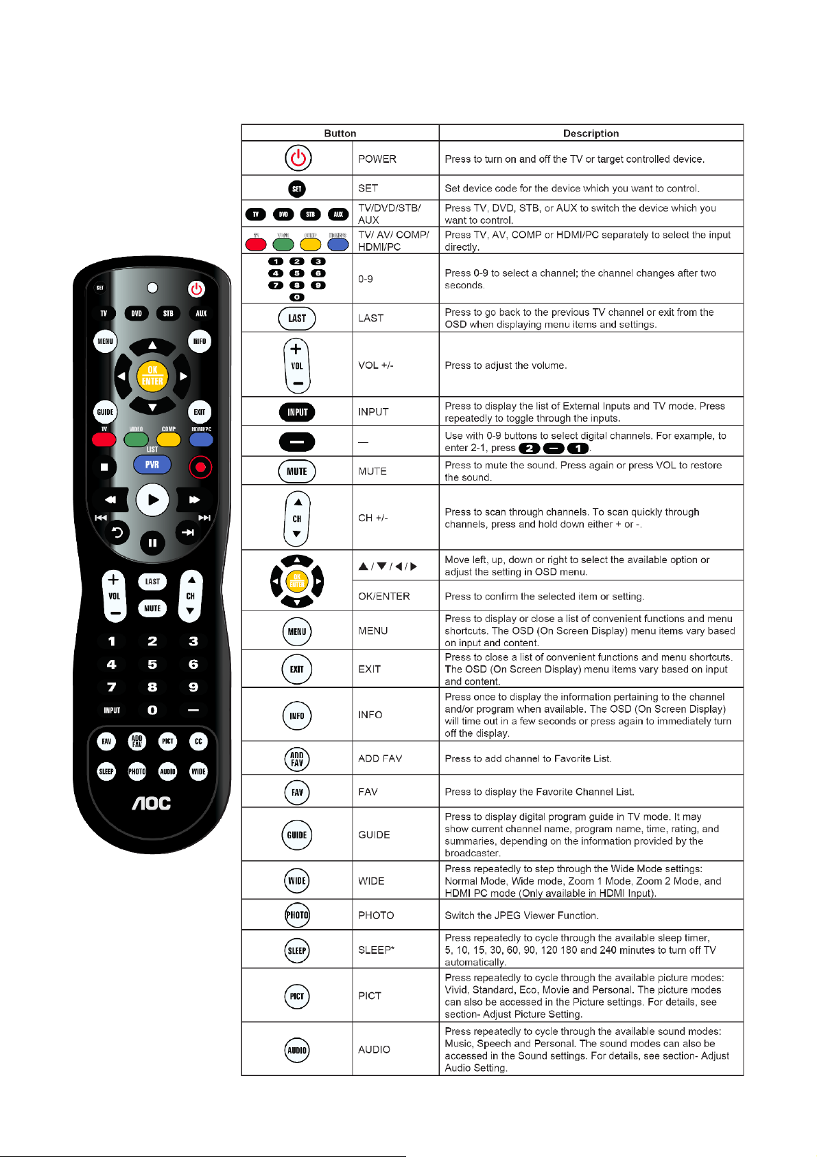
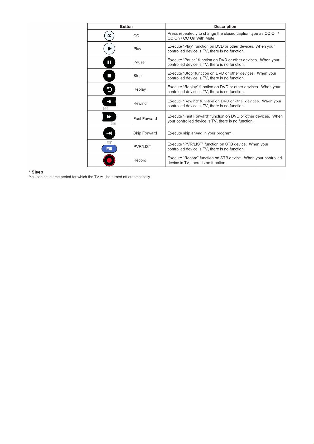
2. Operating Instructions
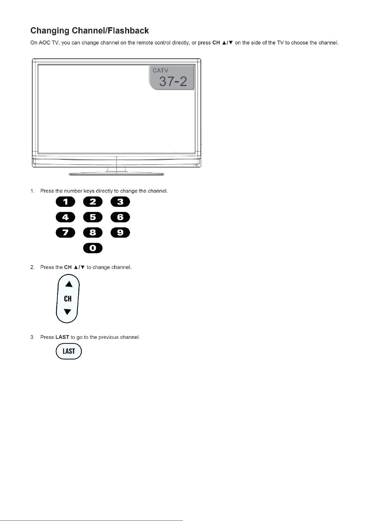
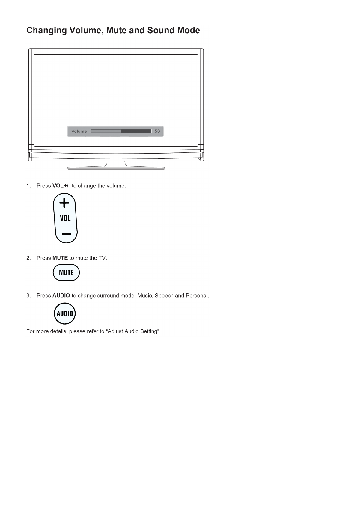
2.1 The Use of Remote Control
5
Page 6
6
Page 7
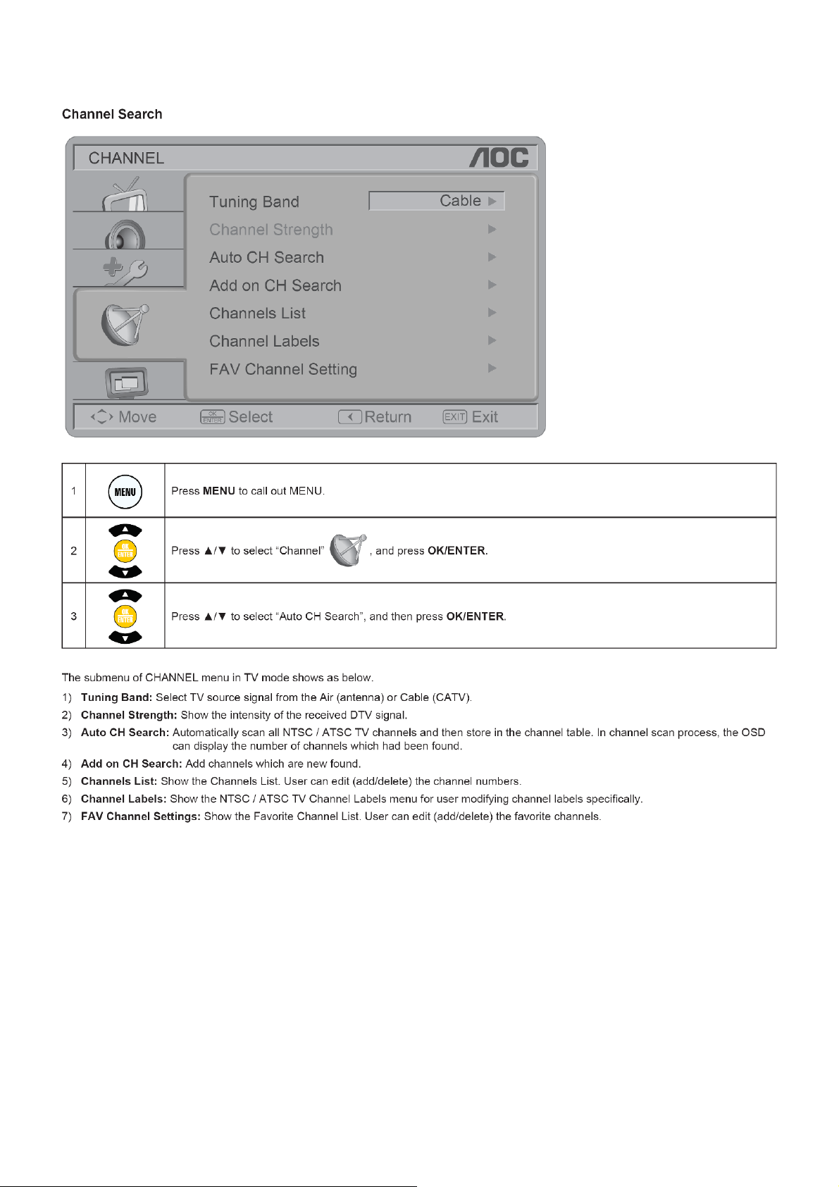
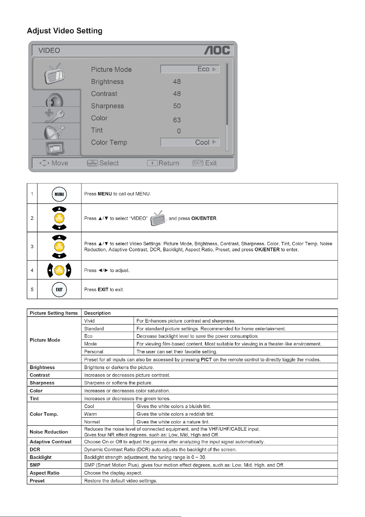
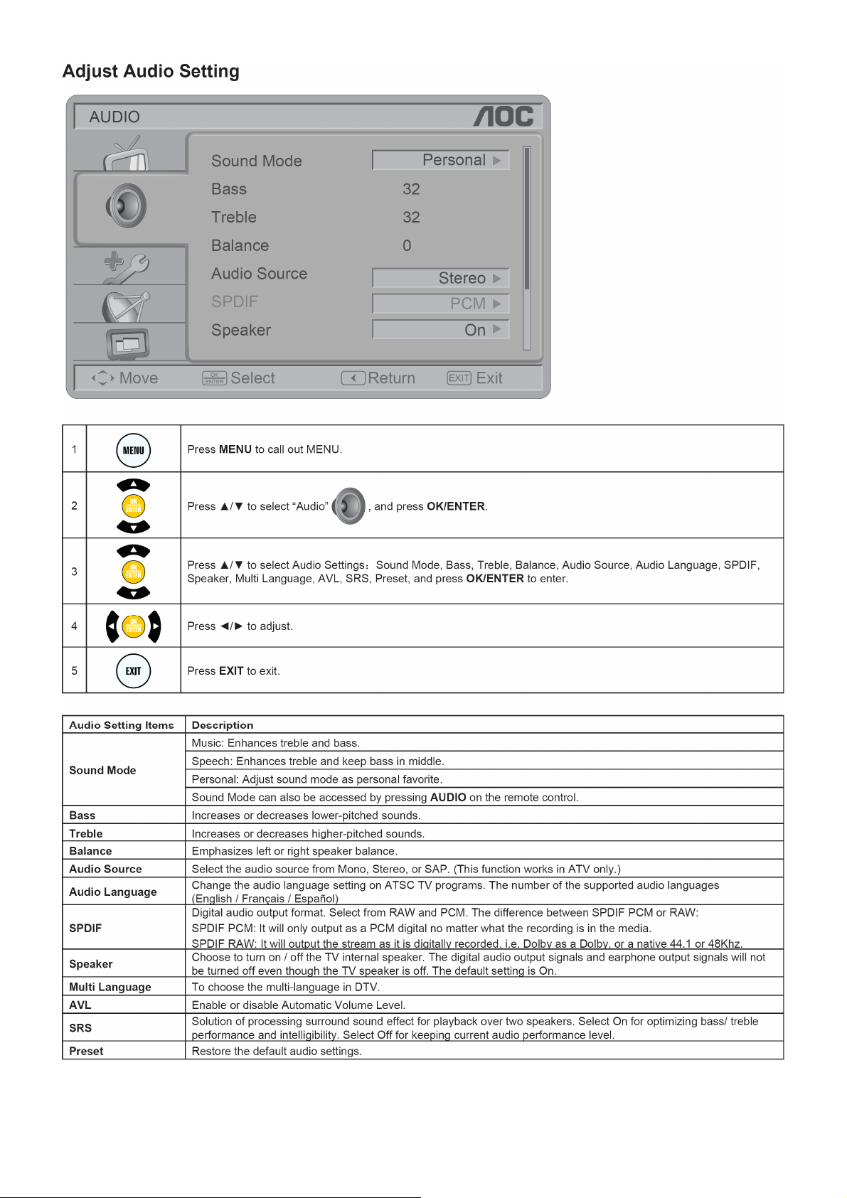
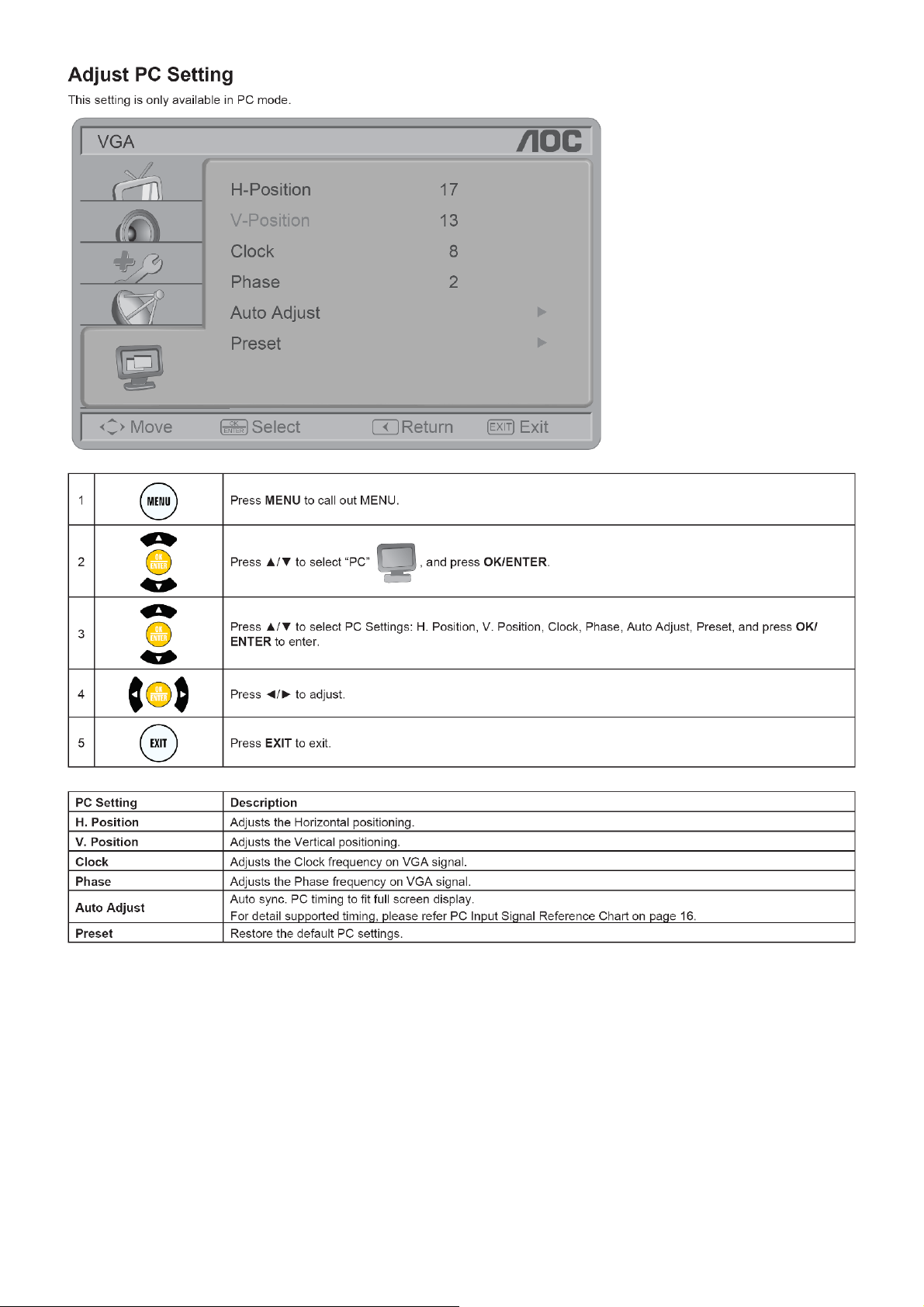
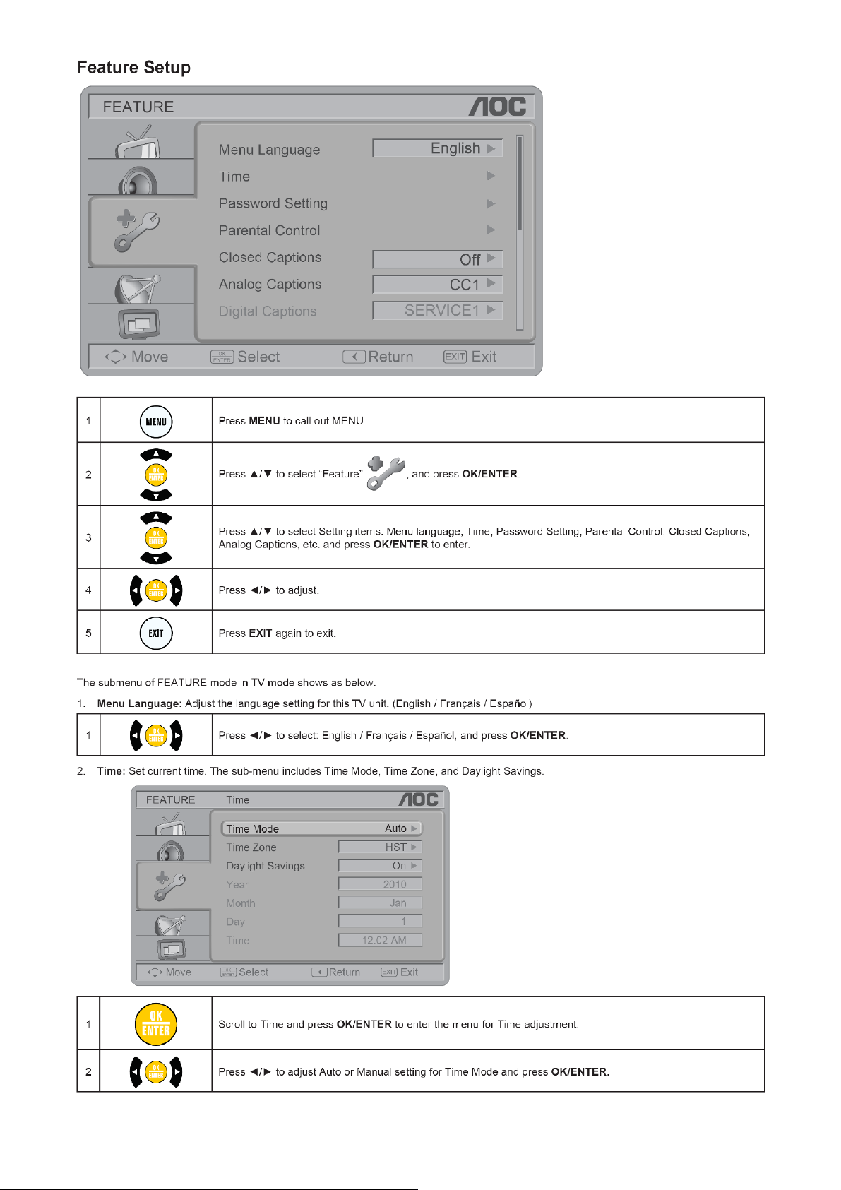
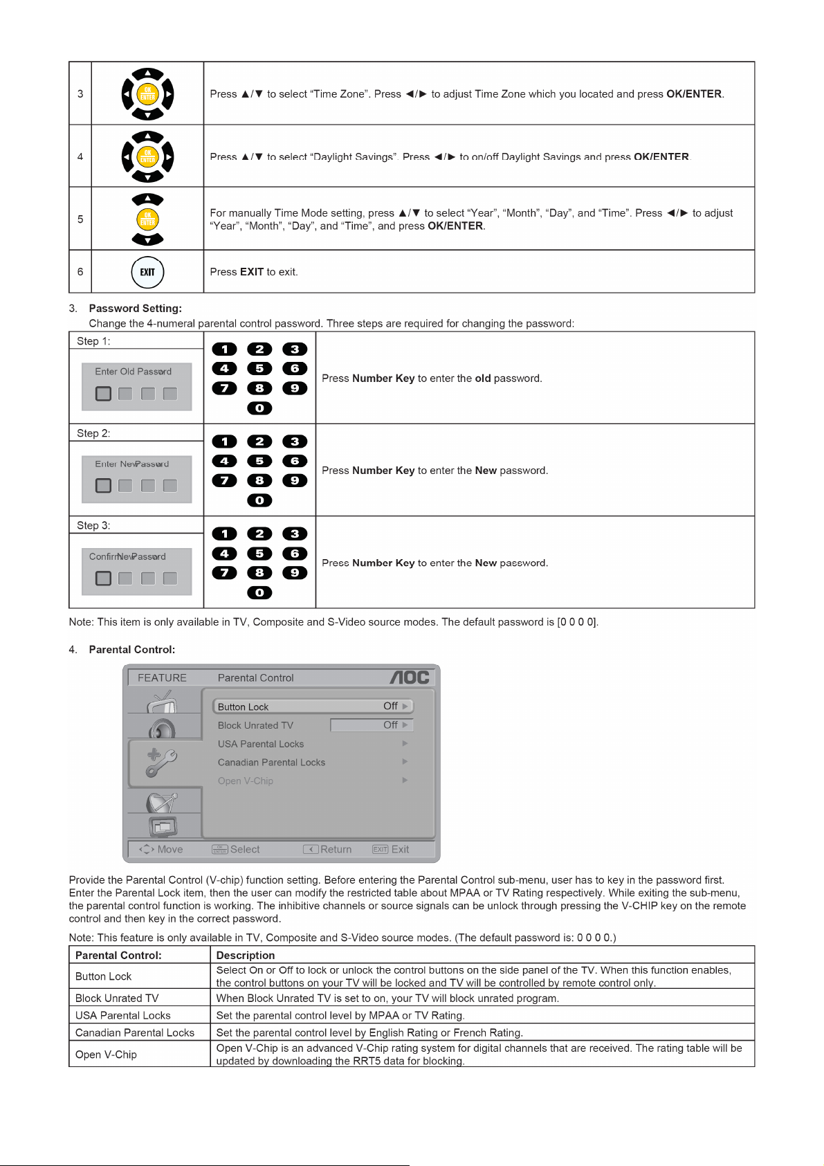
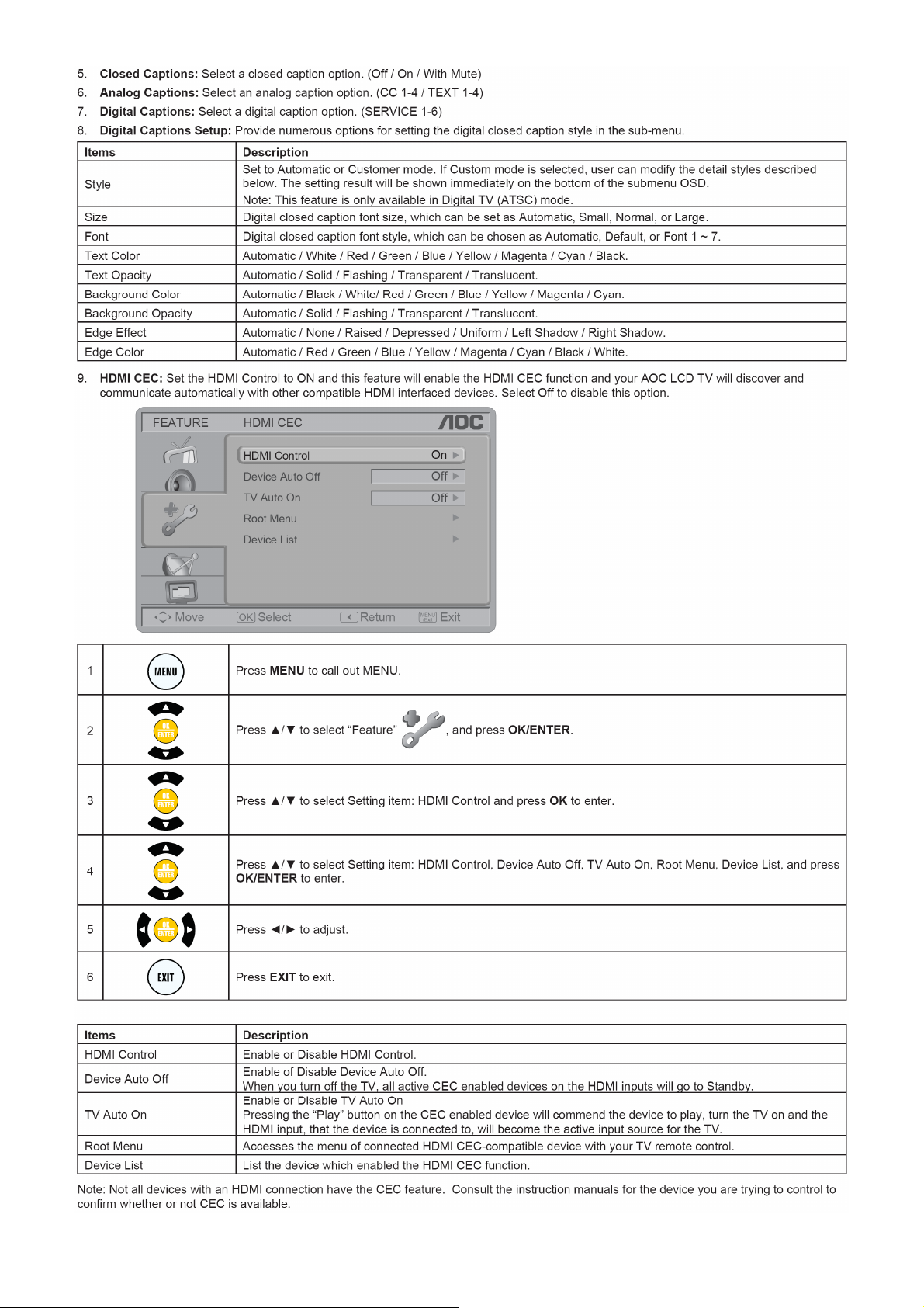
2.2 To Use the Menus
7
Page 8
8
Page 9
9
Page 10
10
Page 11
11
Page 12
12
Page 13
13
Page 14
14
Page 15
15
Page 16
16
Page 17
17
Page 18
18
Page 19
19
Page 20
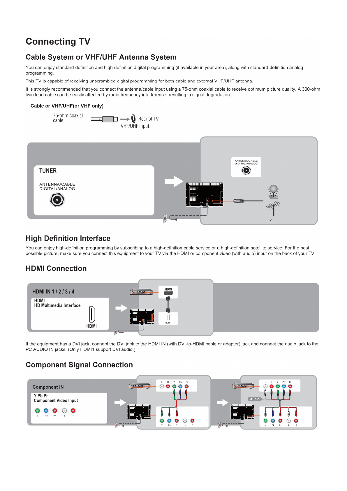
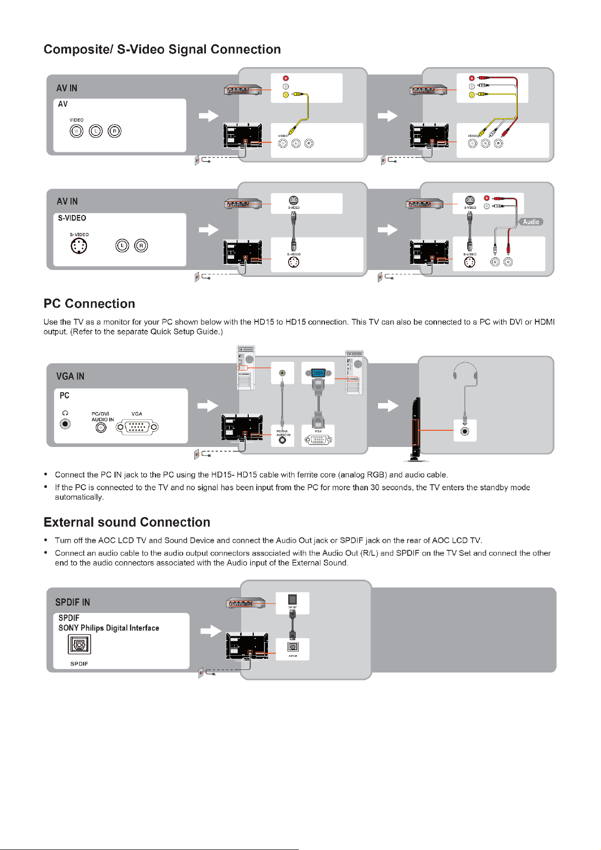
2.3 How to Connect
20
Page 21
21
Page 22
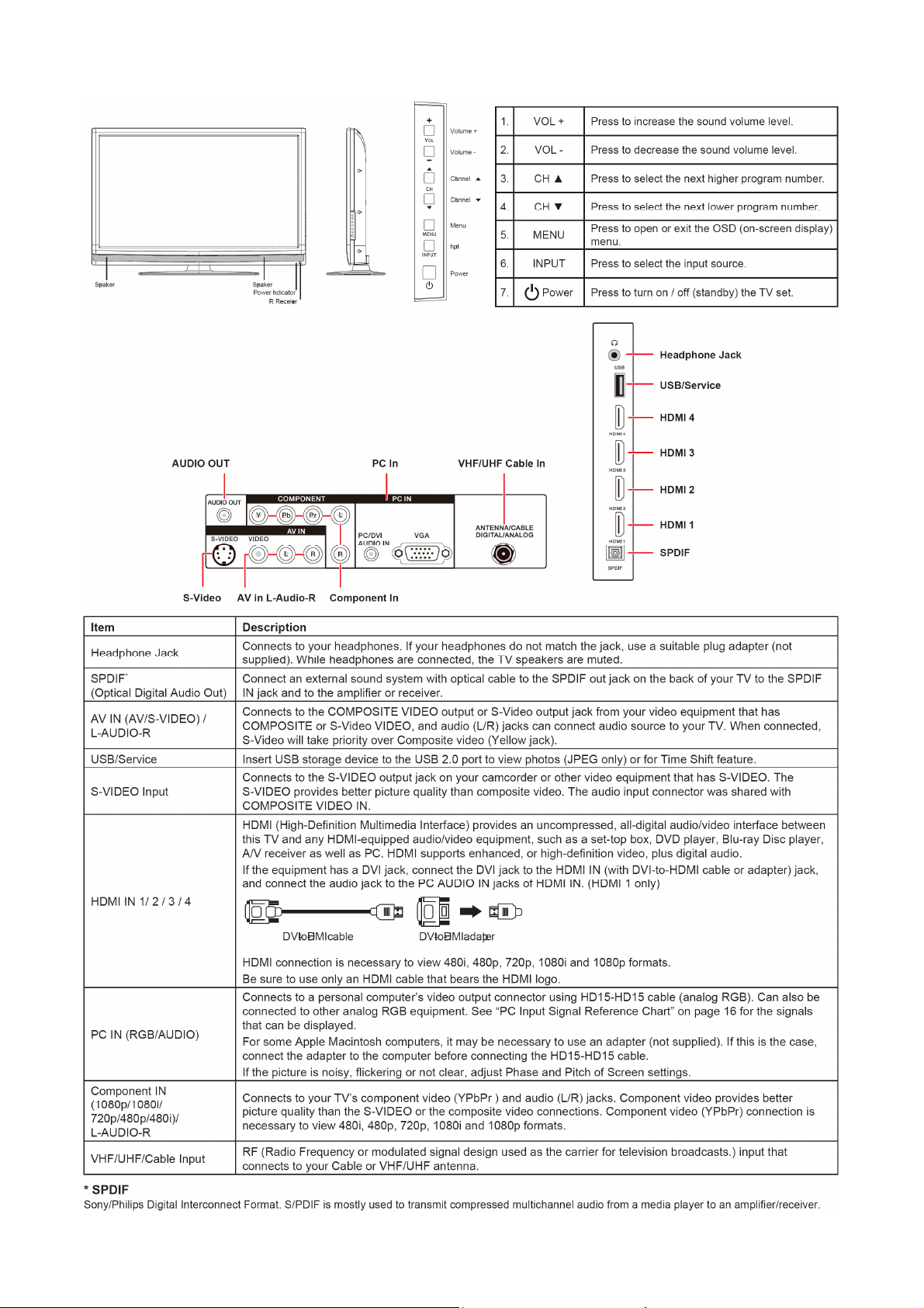
2.4 Front Panel Control Knobs
22
Page 23
3. Input/Output Specification
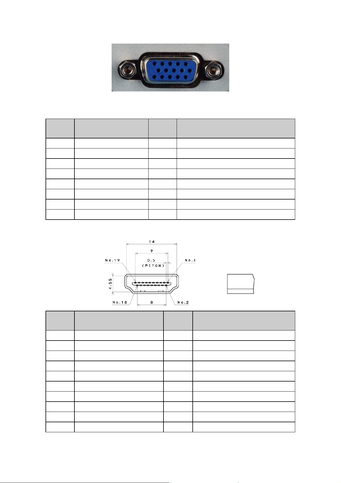
3.1 RGB Signal Input
15 - Pin Color Display Signal Cable
Pin No. Description Pin No. Description
1 Red Video 9 No Pin
2 Green Video 10 Sync Ground
3 Blue Video 11 SDA(Remote Control)
4 SCL(Remote Control) 12 Serial Data for DDC
5 Ground 13 H-Sync.
6 Red Video Ground 14 V-Sync.
7 Green Video Ground 15 Serial Clock for DDC
8 Blue Video Ground
3.2 HDMI Digital Connector Pin Assignments
Pin No. Description Pin No. Description
1 TMDS Data2+ 2 TMDS Data2 Shield
3 TMDS Data2- 4 TMDS Data1+
5 TMDS Data1 Shield 6 TMDS Data1-
7 TMDS Data0+ 8 TMDS Data0 Shield
9 TMDS Data0- 10 TMDS Clock+
11 TMDS Clock Shield 12 TMDS Clock-
13 CEC 14 NC
15 SCL 16 SDA
17 DDC/CEC Ground 18 +5V Power
19 Hot Plug Detect
23
Page 24
3.3 Compatible Mode Table
Presetting PC Mode
Standard Resolution Horizontal Frequency(kHz) Vertical Frequency(Hz)
VESA 640 x 480 31.469 59.94
VESA 800 x 600 37.879 60.317
VESA 1024 x 768 48.363 60.004
VESA 1280 x 720 44.772 59.855
VESA 1280 x 768 47.396 59.995
VESA 1280 x 1024 63.981 60.02
VESA 1440 x 900 55.469 59.901
VESA 1680 x 1050 65.29 59.954
VESA 1920 x 1080 67.5 60
Presetting Video Mode
Standard Resolution Horizontal Frequency(KHz) Vertical Frequency(Hz)
SD 480i 15.734 60
SD 480P 31.5 60
HD 720P 45 60
HD 1080i 33.75 60
FHD 1080p 67.5 60
24
Page 25

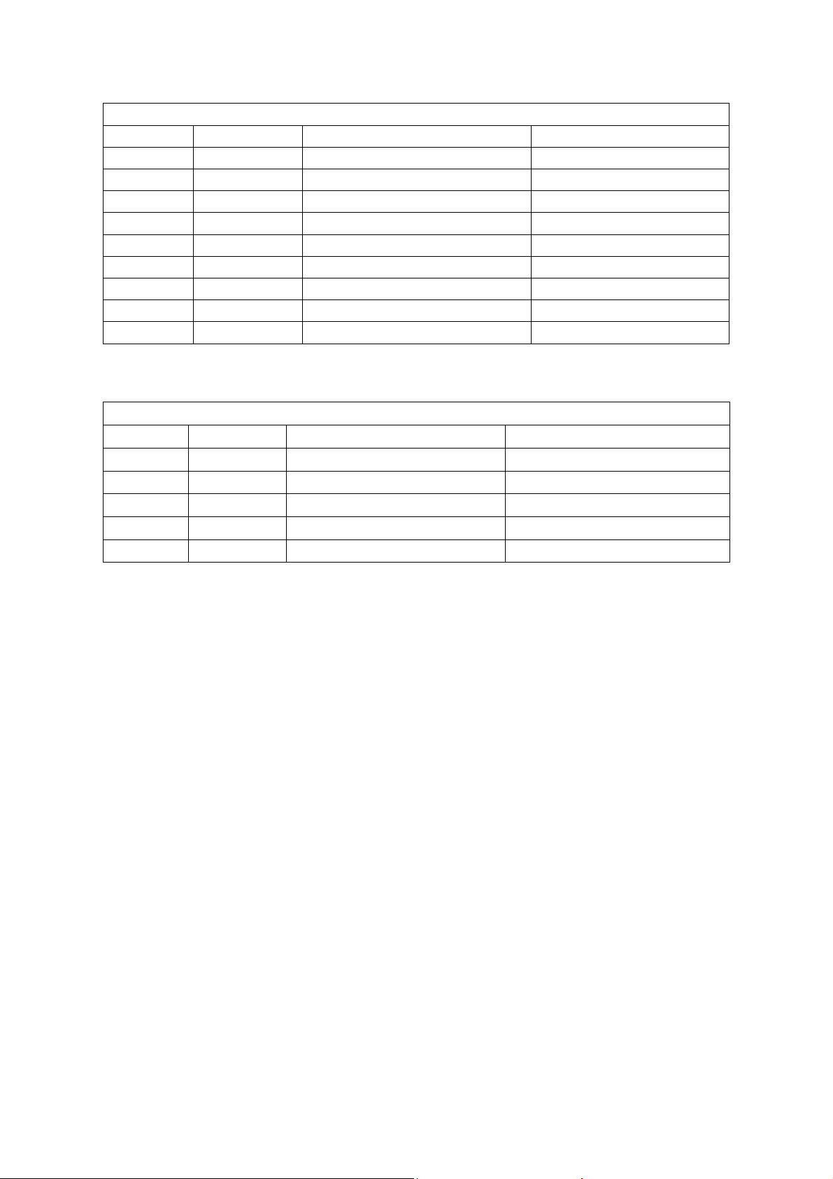
4. Mechanical Instructions
1. Remove the screws to remove the rear cover.
LC32H063D
LC42H063D
25
Page 26
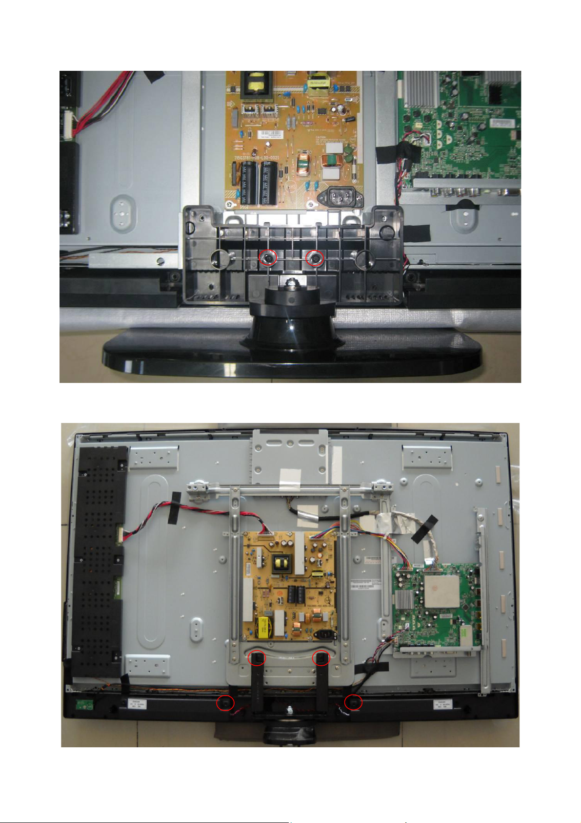
2. Remove the screws to remove stand base.
LC32H063D
LC42H063D
26
Page 27
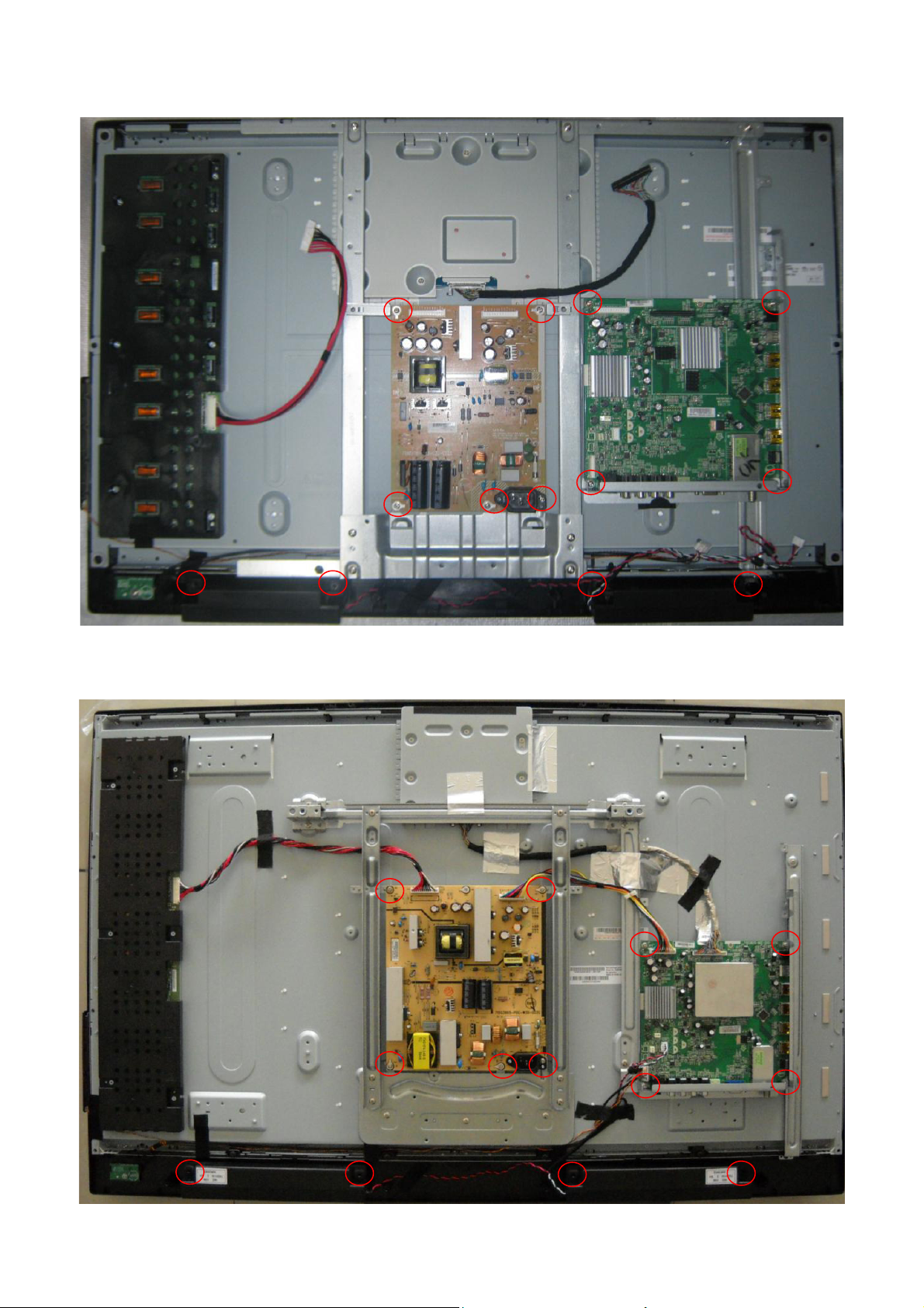
3. Remove the screws to remove main board, power board and speakers.
LC32H063D
LC42H063D
27
Page 28
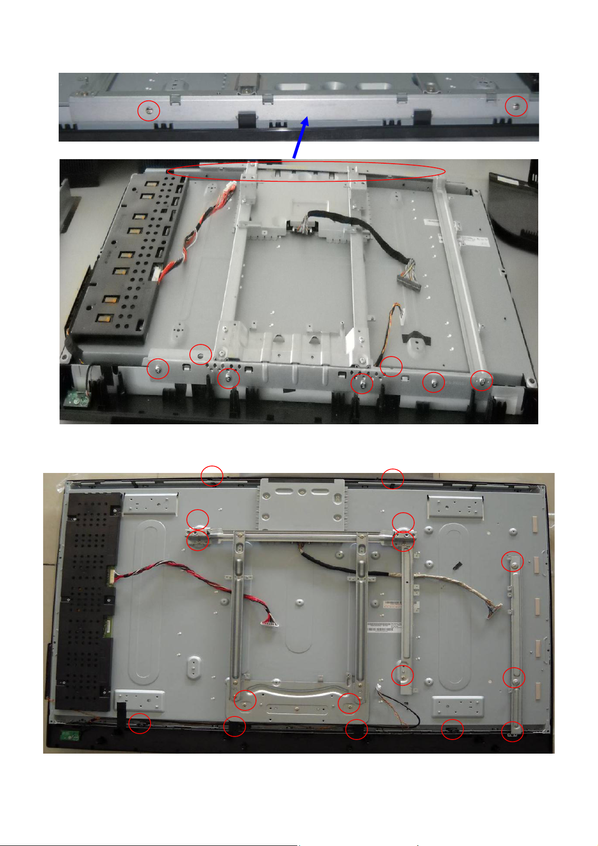
4. Remove the screws to remove bracket and separate panel and bezel.
LC32H063D
LC42H063D
28
Page 29
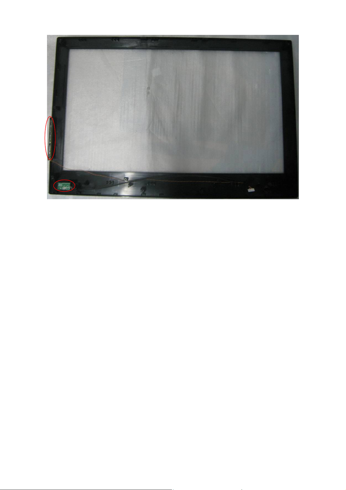
5. Remove the screws to remove key board and IR board.
29
Page 30
p
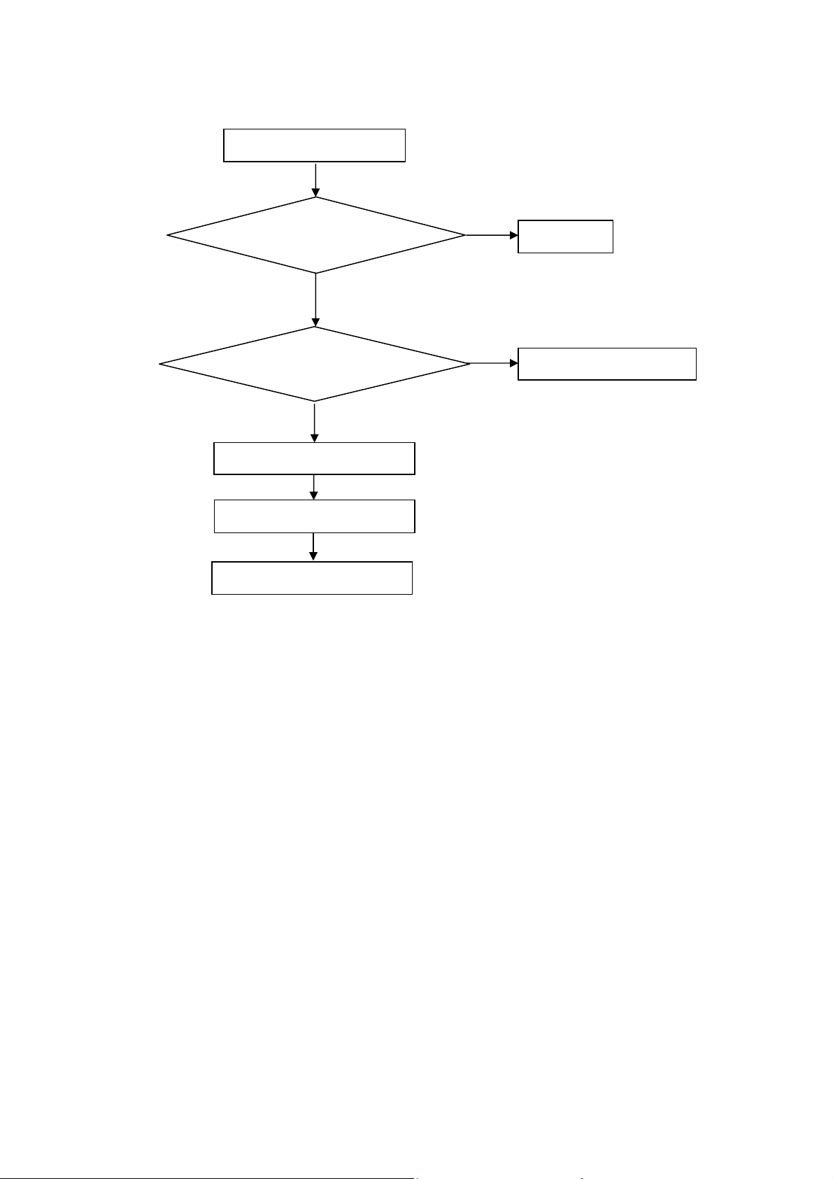
5. Repair Flow Chart
1. No power
No power (LED “Off”)
Check the AC input and
the
ower is “ON”?
Yes
Power board output=5V?
Yes
Check the IR board and LED
Replace the IR board
No
Replace the main board
No
Power “On”
No
Replace the power board
30
Page 31

2. Can’t start
Can’t start(LED red)
Power board output=24V?
Yes
Check the power key is under control?
No
Check the IR receiver is normal?
No
Replace the power board
Yes
Replace the key board
Yes
Replace the IR board
No
Replace the main board
No
Replace the Power board
31
Page 32

3. No display
No display (LED blue)
Check TV is under control and power
on/off by remote control and power key?
Yes
Check the LVDS cable
Yes
Yes
Check the backlight is
“On”?
No
Reinsert or replace the
LVDS cable
No
No
Check the B/L
signal is available?
Yes
Replace the main board
No
Replace main board
Panel Vcc = 12V?
Yes
Replace the Panel
No
Replace the main board
Power board output=24V?
Yes
Replace the Panel
Replace the power board
No
32
Page 33

4. Sound problem
No sound or sound abnormal
Check the audio source connection
and the TV system are correct?
Yes
Check the TV is muted, adjust the
volume or enter the menu to reset?
No
Check the cable between the
speakers and main board is ok?
No
Reinsert the audio cable or
change the TV system
No
Yes
Check the speaker resistance value is in spec
(Remark: The value is marked on the speaker)?
Yes
Replace the speaker
Replace the main board
Replace the cable
No
33
Page 34

5. Remote control malfunction
Remote Control malfunction
Check the remote control battery is
not properly placed or no power?
No
Use the other remote controls
No
Whether the IR board is
abnormal?
No
Replace the main board
Yes
Replace the battery
Yes
Replace the remote control
Yes
Replace the IR board
34
Page 35

6. OSD is unstable or can’t work normally
OSD is unstable or can’t work normally
Key board connected properly?
Yes
Buttons are ok?
Yes
Key board is ok?
Yes
Replace the main board
No
Reconnect the key board
No
Replace the button function
No
Replace the key board
35
Page 36
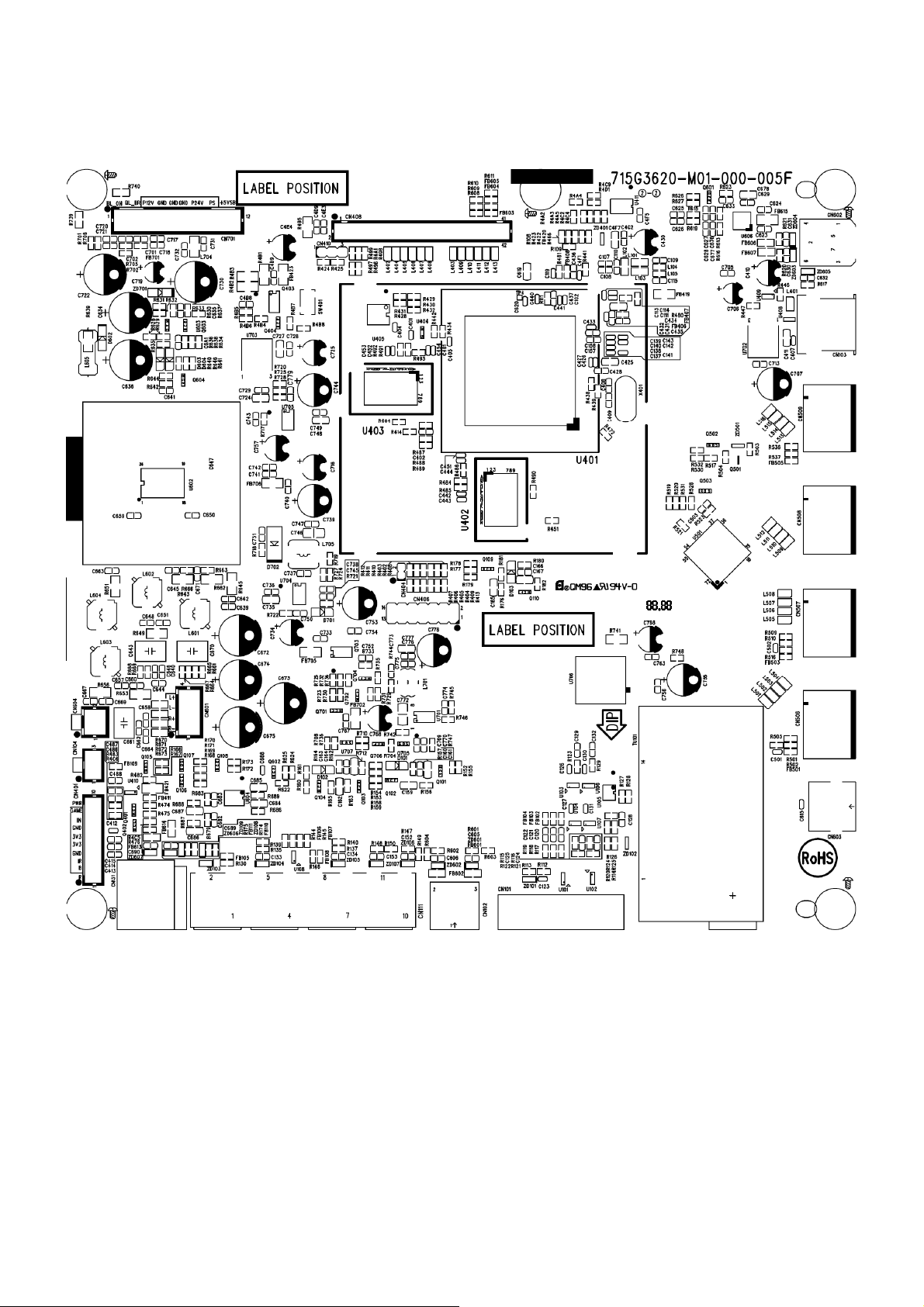
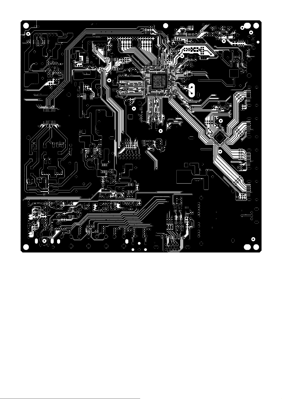
6. PCB Layout
6.1 Main Board
715G3620M01000005F
36
Page 37
37
Page 38
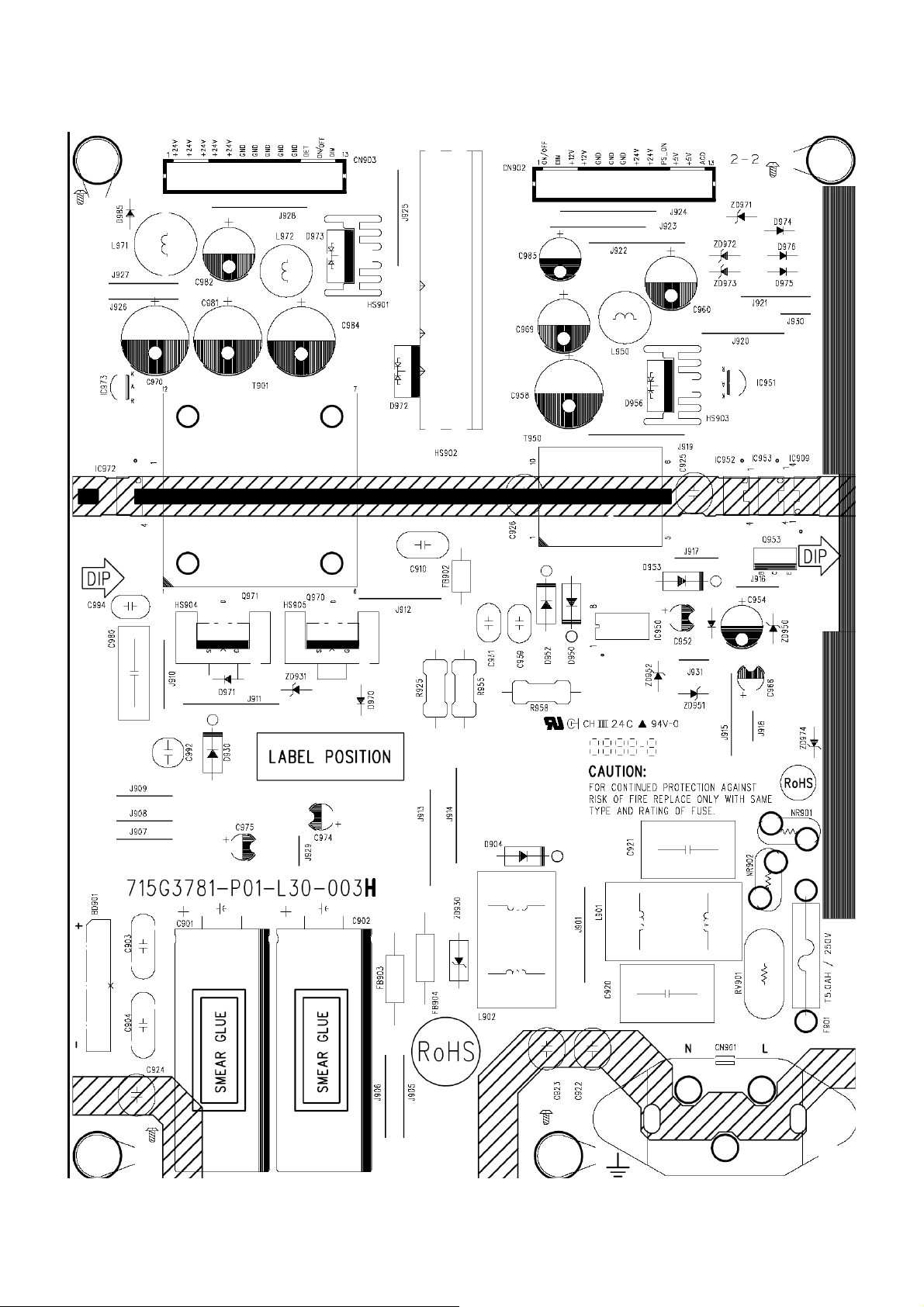
6.2 Power Board
LC32H063D 715G3781P01L30003H
38
Page 39

39 40
Page 40

Page 41

LC42H063D 715G3885P02W30003S
41
Page 42

42 43
Page 43

Page 44

6.3 Key Board
715G3814K01000003S
6.4 IR Board
715G3821R01000004M
44
Page 45

7. Adjustment
ADC Adjustment
1. Press menu key and then press number key 1 Æ 9 Æ 9 Æ 9. It will achieve the factory mode. Take the BBY factory
menu for example:
2. Change TV, press the item “Current Source” to Component mode and change signal to Timing314(Component
720p) and Pattern 122(SMPTE Bar), press the item “Auto Color”; Change TV, press the item “Current Source” to
PC mode and change signal to PC TIMING 137(1024X768@60Hz) Pattern 147 (16 Grays), press the item “Auto
Color”.
45
Page 46

F/W Upgrade with USB SOP
Step 1: Ready for F/W Upgrade
1.1 Prepare a USB memory (The file system of USB memory must be FAT16 or FAT 32).
1.2 Copy the file (EPI_LC32H063D_HW-1_SW-V2.03_USB_20100507.ecc or
EPI_LC42H063D_HW-1_SW-V2.03_USB_20100507.ecc) from your computer to the USB memory, and remove it
from computer’s USB port!
Note: 1) The F/W file name format must be “EPI_”+ model name + ”_HW-” + ver No. +”_SW-” + ver
No.+”_USB_”+Date
LC32H063D
LC42H063D
2) The version of this F/W is V2.03.
3) Make sure there is only one F/W file in your USB memory.
Step 2: F/W Upgrade
2.1 AC ON TV(Power plug Figure 2.1/2.2)
Figure 2.1 Figure 2.2
2.2 Press the power key on the Remote Control or the right side of TV to turn on TV.
46
Page 47

Figure 2.3 Figure 2.4
2.3 Plug the USB memory on the USB porton the side I/O port of TV.(Figure 2.5)
Figure 2.5
2.4 When TV detect the USB memory and display below Upgrade info (Figure 2.6), press “Left” & “OK” button(on the
Navigation Keys on the Remote control, as follows Figure 2.7 ) to select “Yes” option to download F/W(Figure 2.8)
LC32H063D
47
Page 48

LC42H063D
Figure 2.6
OK
Left
Down
Figure 2.7
LC32H063D
LC42H063D
Figure 2.8
2.5 TV will upgrade automatically.
Note: When Upgrade on the process, please don’t Power-Off! (Figure 2.9)
48
Page 49
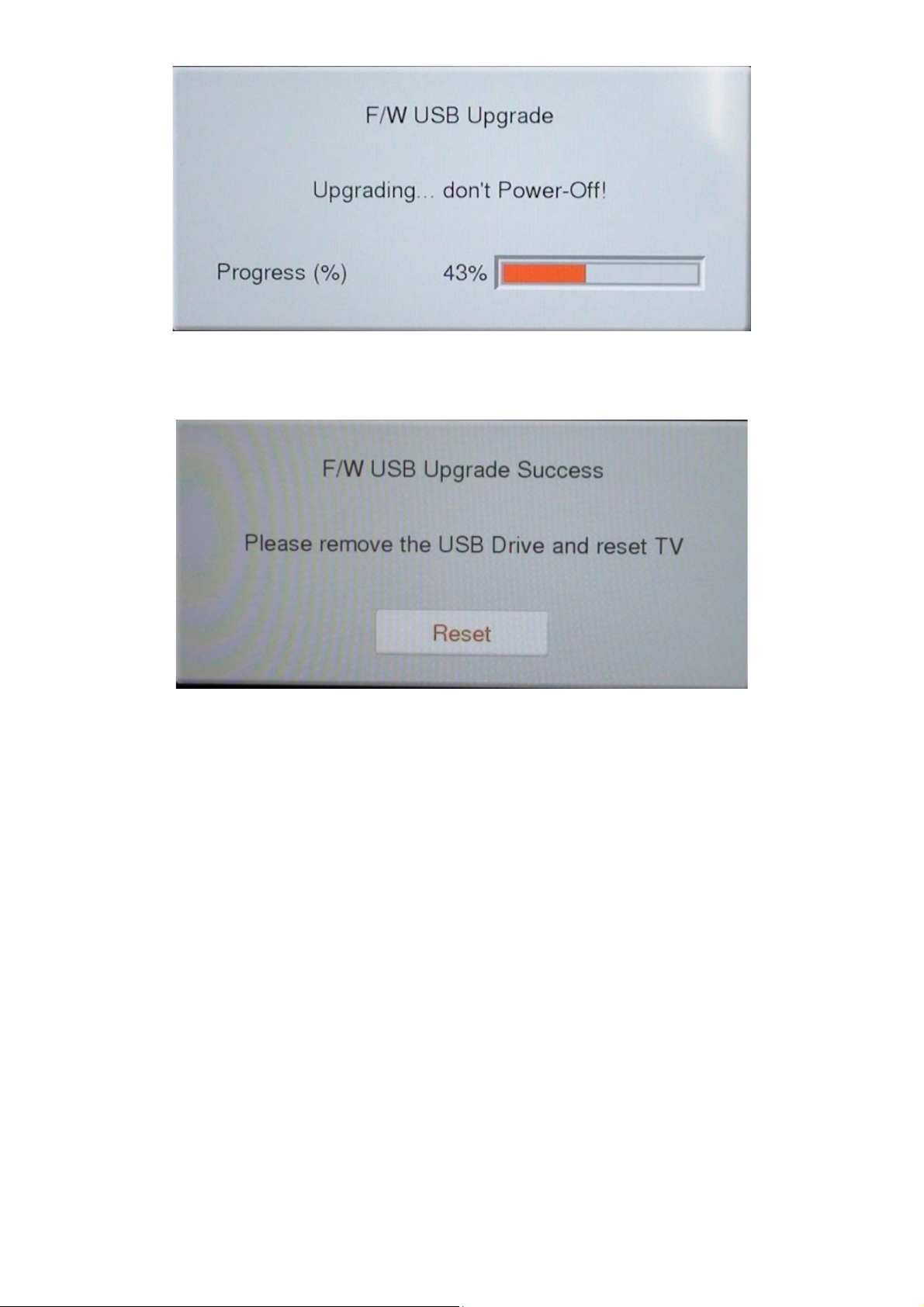
Figure 2.9
2.6 When upgrade 100% and prompt for Upgrade Success info ,remove the USB Drive and press “OK” key (on the
Navigation Keys on the Remote control )to reset TV (Figure 2.10)
Figure 2.10
Step 3: Check the F/W version and reset to default.
3.1 Press “MENU/EXIT”+”1”+”9” +”9” +”9” +”OK” key to enter the factory mode (Figure 3.1).
49
Page 50

Do the following steps rapidly:
1. Press “MENU/EXIT”;
2. Press”1”+”9” +”9” +”9”;
3. Press “OK”
Menu/
Exit
Figure 3.1
3.2 Check the F/W version on the fifth row of the factory mode info(eg, the “Ver” info is V2.03). If F/W version is
incorrect, please check the version of F/W in your USB memory, else let’s go to Step 3.3.
LC32H063D LC42H063D
Figure 3.2
50
Page 51
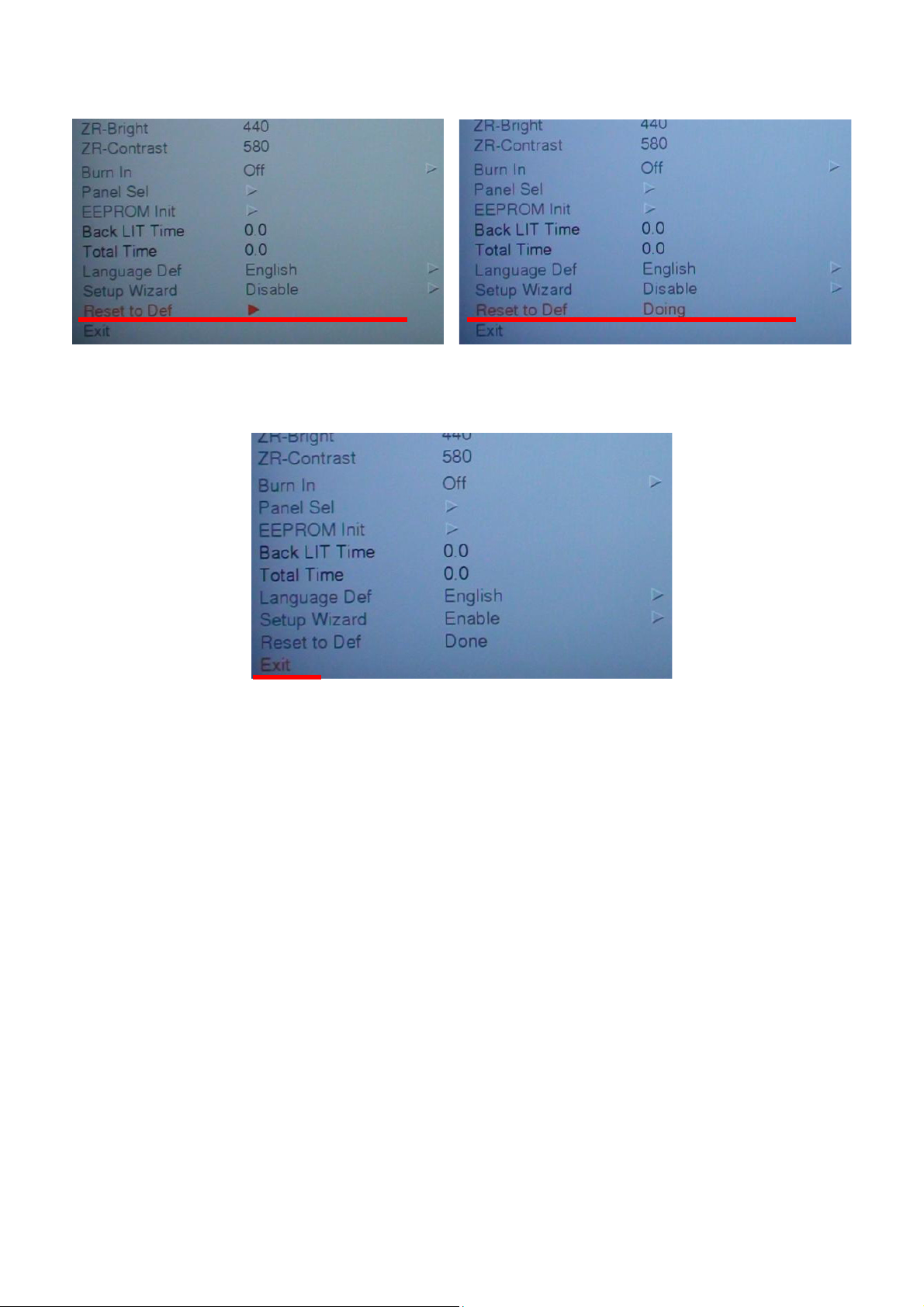
3.3 If F/W version is correct, press ‘down’ Key to choose ‘Reset to Def’ option (The option will be highlighted). Then
press ‘OK’ Key to active ‘Reset to Def’.
Figure 3.3 Figure 3.4
3.4 When “Reset to Def” show ”Done”, then press ‘down’ Key to choose ‘exit’ option and press ‘OK’ Key to be off
factory mode.
Figure 3.5
DDC upgrade
As the DDC data were included in the software, this model do not need a separate DDC Upgrade.
51
Page 52

8. Block Diagram
Tuner
ENV56U02D8F
VIDEO
VIDEO
YPbPr
VGA
I2C
M24C02
HDMI-1
HDMI-2
HDMI-3
HDMI-4
AV AUDIO-R\L
YPbPr AUDIO-R\L
VGA AUDIO-R\L
TMDS
TMDS
TMDS
TMDS
VIF
CVBS
S
YPbPr
RGB
SN74LVC1G17
SiI9287ACNU
System Block Diagram
Hsync, Vsync
ZR39787HGCF
TMDS
LVDS
LCD PANEL POWER
DDRII * 2
H5PS5162FFR-S6C
FLASH ROM
MX25L3205DM2I-12G
GPIO
EJTAG
M24C64-WMN6P
Audio Amplifier
STA339BW13TR
Earphone Amplifier
MAX9728AETC+
Line Out Driver
DRV602PW
SPEAKER
EarPhone Output
Line Out
S/PDIF Output
Audio Output
Power Board Input : +5VSB , P12V, P24V
P24V
BOARD
Max. 4A
P24V
Max. 1A
P12V
Max. 2.5A
+5VSB
VCC5D
Inverter & Audio Amplifier
P12V
Panel LVDS Power
U706 G9084-50TU3U
+5VSB
U701 G5692P11U
VCC5D
U703 G1084-33
U704 SC4525BSETRT
5VT
3V3_STB
D3V3
D1V8
Main Board Power System
P24V
P12V
+5V SB
PANEL Invert er
U602 STA339BW13TR
PANEL LVDS Powe r
U706 G9084-50TU3U
U105 M24C02-WDW6P
U701 G5692P11U U501 SiI9287ACNU
U702 G1084-18
Q703 AO4449
VCC5D
U409 G5250K1T1U
U606 MAX9728AETC+ For Audio Headphone Amplifier5V_HP
U604 DRV602PW
U703 G1084-33
U704 SC4525BSETRT
5VT
3V3_STB
1V8_STB
USB5 V
D3V 3
D1V 8
For Audio AmplifierA24V
TU101 ENV56U02D8F
For VGA EDID
U401 ZR39787HGCF
U401 ZR39787HGCF
For USB OCT
For Audio Line Out Driver
U401 ZR39787HGCF
U406 M24C64-WDW6TP
U405 MX25L3205DM2I- 12G
U401 ZR39787HGCF
U402, U403
H5PS5162FFR-S6C
U705 SC4215ASTRT
Max. 5A
Max. 2A
U702 G1084-18
Max. 1.5A
Max. 3A
U705 SC4215ASTRT
For TUNER+5V
For HDM I Sw itc h
For ZR39787HGCF uMCU
For ZR39787HGCF uMCU
For ZR39787HGCF uMCU
For uM CU EEPROM
For SPI Fla s h
For ZR39787HGCF
For DDR II
VCC1V1
1V8_STB
VCC1V1
Max. 5A
Max. 2A
For ZR39787HGCFU401 ZR39787HGCF
52
Page 53
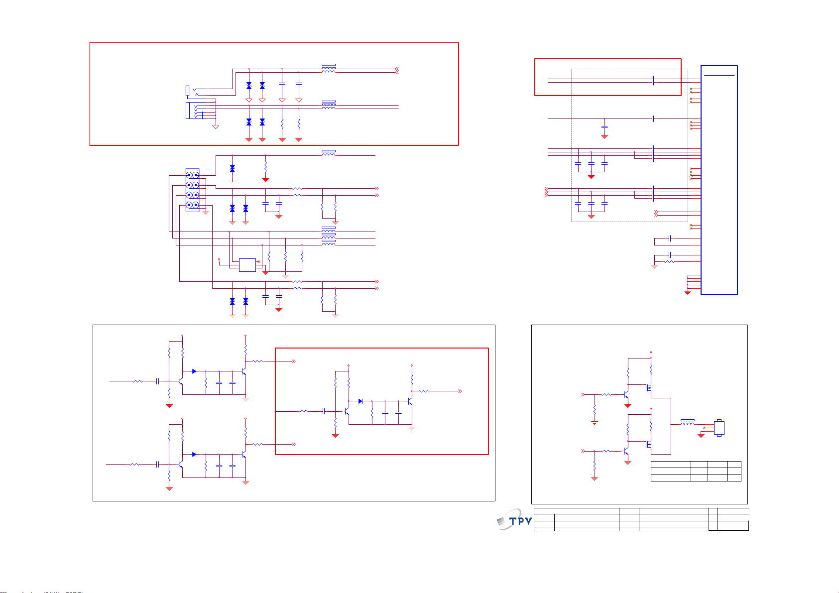
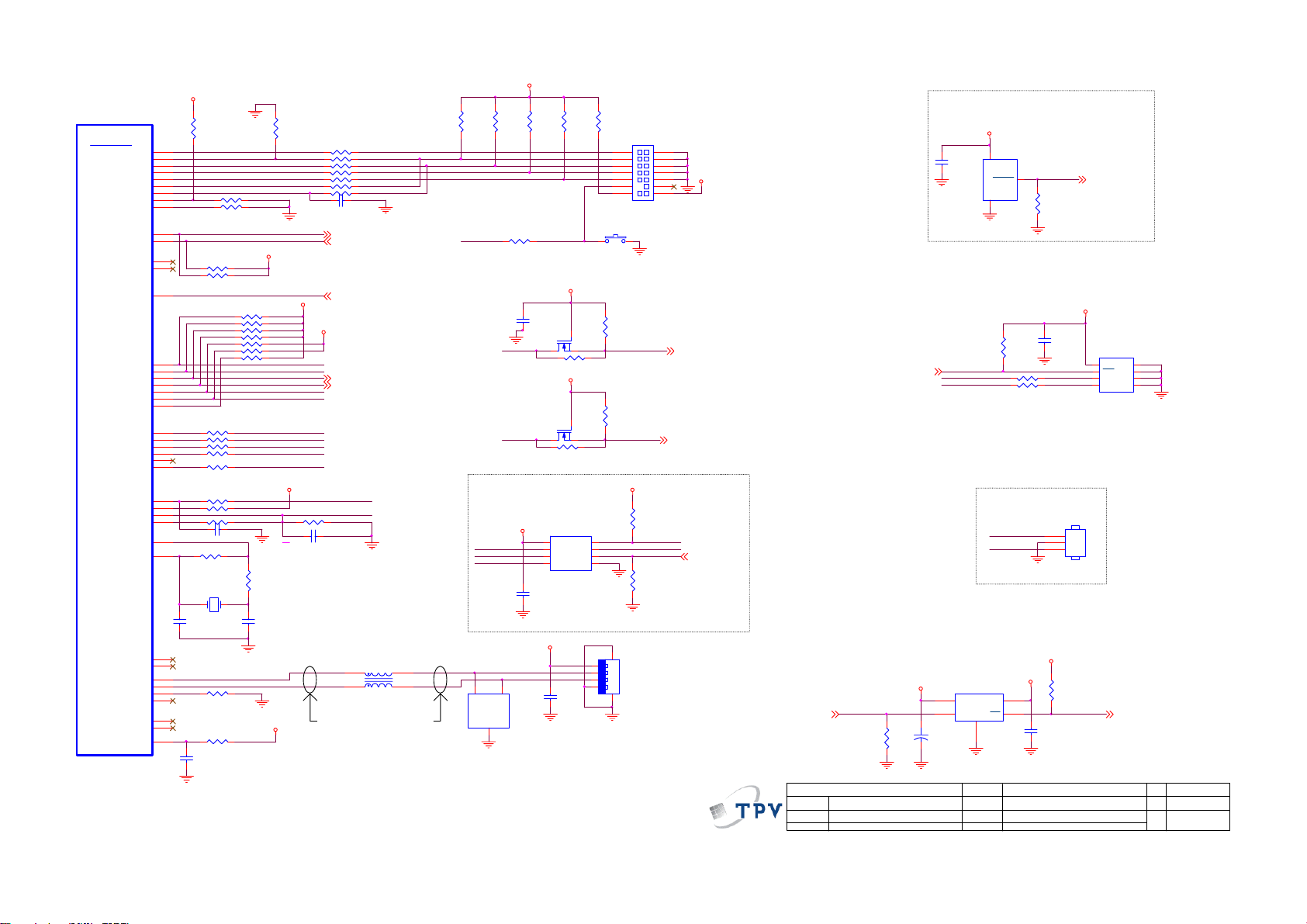
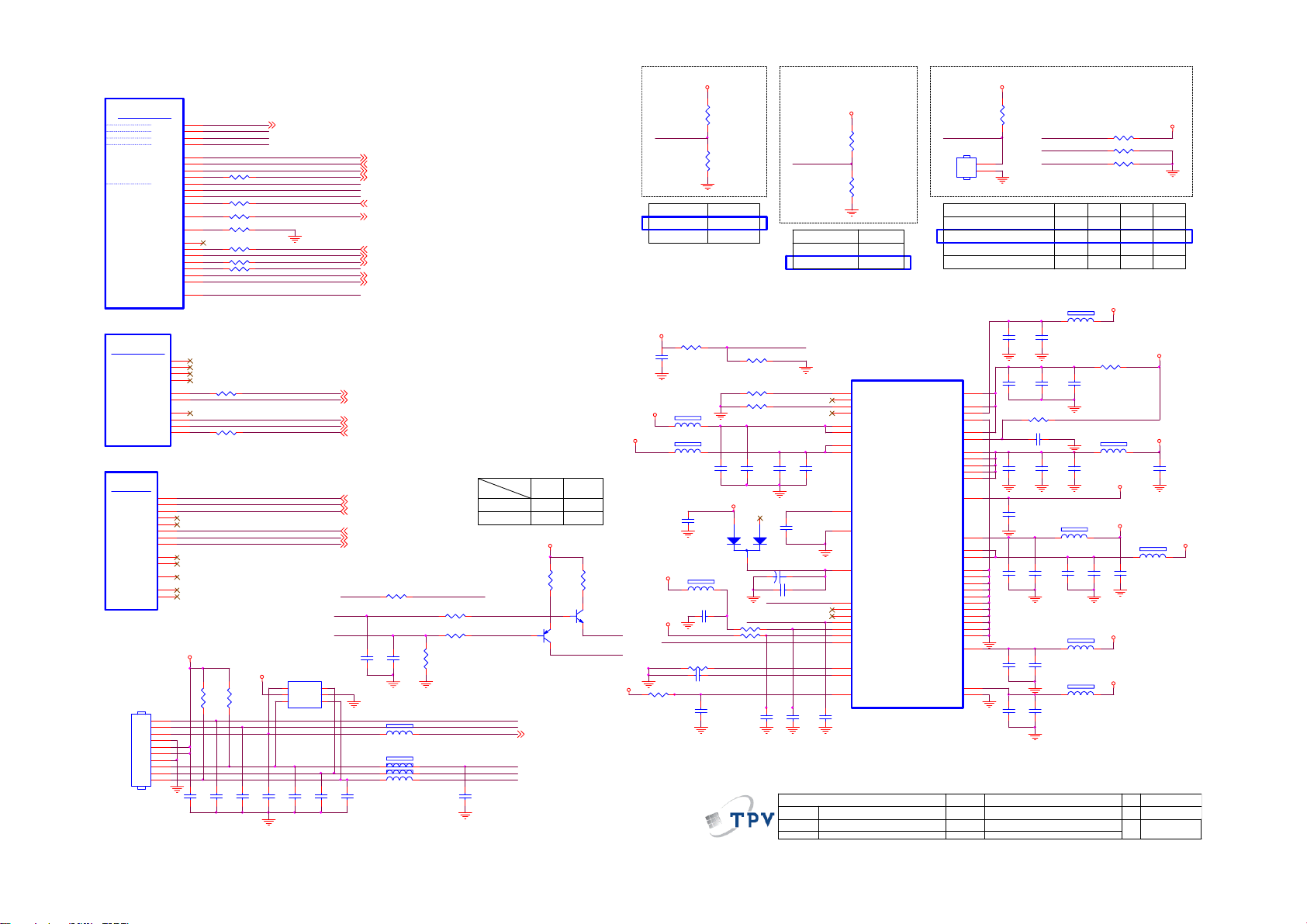
9. Schematic Diagram
9.1 Main Board
715G3620M01000005F
ENV56U02D8F
ET-29DHRV
1
2
3
5
6
9
10
11
12
13
14
5V: +B = 150mA(MAX)
I2C Bus Address
#C2H (Write Mode)
#C3H (Read Mode)
VGA Input
VGA5V
VGA_5V
C128
220N 16V
U10 5
1
8
E0
VCC
7
2
E1
WC
3
6
E2
SCL
5
VSS4SDA
NC/M24C02-WDW6P
1
+5VSB
3
VGA_SCL
VGA_SDA
RF-AGC Monitor
18
TU_G ND
2
ZD102
BAT54C
R124
1.5K 1/10W
TU101
TUNER
BT Monitor
IF Monitor
IF AGC
IFD -out1
IFD -out2
TH115TH216TH317TH4
TU_G ND
SCL
SDA
R125
1.5K 1/10W
1
NC
2
+B
3
5
NC
C106 2.2nF 50V
6
9
10
11
12
13
14
VGA_SDA5
VGA_SCL5
R126
NC/1K 1/10W
R127 NC/33 OHM 1/10W
R128
NC/1 0K 1/10W
C101
100N16V
0402
C116
22P 50V
C103
2.2nF 50V
C117
22P 50V
VGA_SDA
RGB_HSYNC
RGB_VSYN C
VGA_SCL
C104
4.7uF 10V
5VT
FB101
0R05 1/10W
R104 100 OHM 1/10W
R105 100 OHM 1/10W
IF_AGC
IF_AN
IF_AP
C118
100N16V
0402
R114 100 OHM 1/10W
R115 1K 1/10W
R116 1K 1/10W
R120 100 OHM 1/10W
C124
NC/47pF
NC/330p F
VGA_EDID_W P
D3V3
R102
R101
2.2K 1/10W
2.2K 1/10W
UART0_TX6
UART0_RX6
VGA_EDID_W P 7
I2C1_SCL
I2C1_SDA
UART0_TX
UART0_RX
R121
2.2K 1/10W
I2C1_SC L 6,9
I2C1_SD A 6,9
VCC5DC125
R122
2.2K 1/10W
RGB_HSYNC
Place parts very close to U401
R112 220 OHM 1/10W
R113 220 OHM 1/10W
ZD101
1 2
VPORT0603100KV05
U102
AZC19 9- 04S
4
I/O23I/O3
2
5
GND
VDD
1
6
I/O1
I/O4
D3V3
C126
53
100N16V
0402
2 4
U103
SN74LVC1G17DBVR
D3V3
C130
53
100N16V
0402
2 4
U106
SN74LVC1G17DBVR
C109 100P 50V
L104
0.082uH
73G 63827 5T
L105
0.082uH
C115 100P 50V
CN10 1
11
12
13
14
15
88G 35315F HJ
R123 33 OHM 1/10W
R129 33 OHM 1/10W
U401P
AF4
SIF_AIN N
AE4
SIF_AIN P
AF2
IF_AINN
AE2
IF_AINP
AD3
IF_RBI AS
AD2
IF_VIN BIAS
AD1
IF_VCM
AF1
IF_VREFN
AE1
IF_VREFP
AD8
DEMOD_CLKO
AC7
MPEG_FAIL
AC8
DMOD_RST_N
AC6
SA_DATA
AE7
PARAM0
AF8
RF_AGC
AF7
IF_AGC
AA5
IF_DVAL_GPI O
ZR39787HGCF
VGA_R
VGA_G
VGA_B
VGA_HSYNC_DET 7
VGA_VSYNC_DET 7
Demodulator
VGA_R 4
VGA_G 4
VGA_B 4
SIF_N
C102 10N 16V
C105 10N 16V
L101
47R 1/8W
L103
47R 1/8W
1716
1
6
2
7
3
8
4
9
5
10
DB15
VGA5V
VGA_HSYN C
C129
NC/22 pF
VGA_VSYNC
C132
NC/22 pF
1 2
VCC5D
C123
100N16V
0402
L102
0.15uH 5%
U10 1
AZC199-04S
4
5
VDD
6
I/O4
R117
75R 1/10W 1%
GND
VGA_HSYN C 4
VGA_VSYNC 4
C110
82pF 50V
I/O23I/O3
I/O1
C107 1000PF50V
C108 1000PF50V
2
1
R118
75R 1/10W 1%
DEMOD_RSTN7
R119
75R 1/10W 1%
IF_AGC
C120
NC/12pF 50V
C127
100N16V
0402
RGB_HSYNC
C131
100N16V
0402
RGB_VSYN C
D3V3
R108 33 OHM 1/10W
R109 4.7K 1/10W
R111 2K 1/10W
C119
100N16V
0402
C121
C122
NC/12pF 50V
NC/12 pF 50V
3V3_STB
53
2 4
3V3_STB
53
2 4
1 2FB102 30 OHM
1 2FB103 30 OHM
1 2FB104 30 OHM
U104
SN74LVC1G17DBVR
U107
SN74LVC1G17DBVR
0402
0402
R106 3.9K 1/10W
C111 100N 16V
C112 100N 16V
C113 100N16V
C114 100N16V
Place R111 & C119
close to U401
PARAM0
VGA_HSYNC_DET
VGA_VSYNC _DETRGB_VSYN C
0402
0402
0402
0402
SIF_P
IF_AINN
IF_AINP
53
T P V ( Top Victory Electronics Co . , Ltd. )
絬 隔 瓜 絪 腹
Key Component
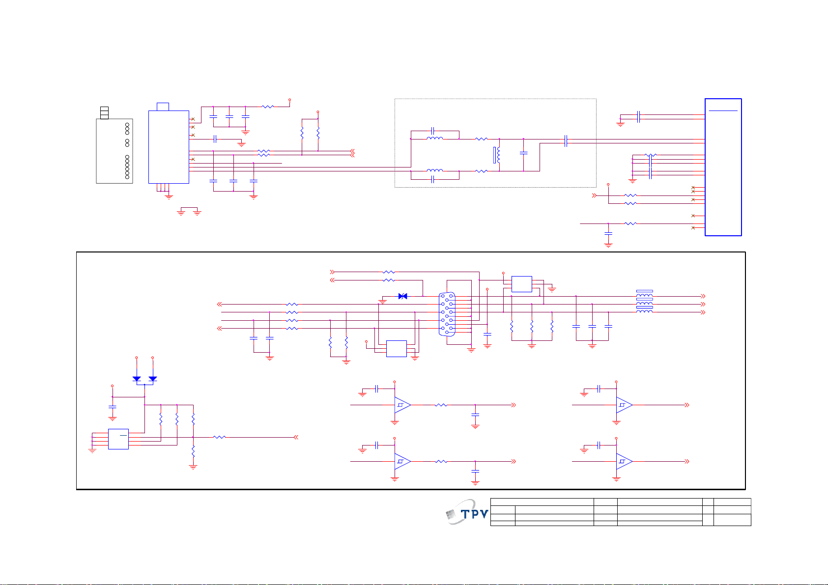
03- Tuner/VGA Inputs
Date
OEM MOD EL
TPV MODEL
PCB NAME
Sheet
715G3620
of
313Tuesday , March 16, 2010
Size
Rev
称爹
<
Custom
1.0
称爹
>
Page 54
REAR
S Input
Audio output
REAR
Component Input
Composite Input
Video signal
detect
Active Low
R156
AV_CVBS
YPbPr_Y
2K 1/10W
R163
2K 1/10W
10uF 16V
10uF 16V
CN131
PHONEJ ACK
88G 30258A YG
88G 30258A CL
CN111
JACK
88G 78 1376C
88G 78 13 76 YG
D3V3 D3V3
R153
R154
100K 1/10W
10K 1/10W
D101
C159
C162
LL4148
Q102
MMBT3904
R158
200KOHM 1/10W
D3V3
R160
R161
100K 1/10W
10K 1/10W
D102
LL4148
Q104
MMBT3904
R165
200KOHM 1/10W
ABCD
EFGH
23
1
56
4
89
7
1112
10
R157
200KOHM 1/10W
R164
200KOHM 1/10W
2
3
1
8
7
5
6
4
9
VCC5D
YPbPr_L
YPbPr_R
OUT_R
VPORT0603100KV05
OUT_L
S_Y
S_C
VPORT0603100KV05
CVBS
ZD103
VPORT0603100KV05
1 2
ZD104
VPORT0603100KV05
VPORT0603100KV05
1 2
Y
Pb
Pr
U108
AZC099-04S.R7G
4
5
VDD
6
I/O4
ZD106
VPORT0603100KV05
VPORT0603100KV05
1 2
C161
C160
10uF 16V
10N 50V
C164
C163
10uF 16V
10N 50V
ZD607
VPORT0603100KV05
1 2
ZD108
VPORT0603100KV05
1 2
ZD105
1 2
I/O23I/O3
GND
I/O1
ZD107
1 2
R152
10K 1/10W
R155
33 OHM 1/10W
Q101
MMBT3904
D3V3
R159
10K 1/10W
R162
33 OHM 1/10W
Q103
MMBT3904
ZD606
1 2
ZD109
1 2
2
1
R130
75R 1/10W 1%
C134
C133
100P 50V
100P 50V
R144
75R 1/10W 1%
C153
C152
100P 50V
100P 50V
AV_CVBS_DET
AV_S_Y
YPbPr_DET
C690
C689
100P 50V
100P 50V
R174
R175
75R 1/10W 1%
75R 1/10W 1%
R135 10K 1/10W
R137 10K 1/10W
R145
R146
75R 1/10W 1%
75R 1/10W 1%
R147 10K 1/10W
R148 10K 1/10W
AV_CVBS_DET 7
R176
2K 1/10W
YPbPr_DET 7
FB613 300 OH M
FB614 300 OH M
1 2FB110 30 OH M
1 2FB111 30 OH M
1 2FB105 30 OH M
R139
R140
10K 1/10W
10K 1/10W
1 2FB106 30 OH M
1 2FB107 30 OH M
1 2FB108 30 OH M
R149
R150
10K 1/10W
10K 1/10W
R177
100K 1/10W
C165
R178
10uF 16V
200KOHM 1/10W
D3V3
R179
10K 1/10W
Q109
MMBT3904
AV_CVBS
AV_Audio_L
AV_Audio_R
YPbPr_Y
YPbPr_Pb
YPbPr_Pr
YPbPr_Audio_L
YPbPr_Audio_R
D103
LL4148
LINE_OUT_R
LINE_OUT_L
AV_S_Y
AV_S_C
AV_Audio_L 10
AV_Audio_R 10
YPbPr_Audio_L 10
YPbPr_Audio_R 10
R180
C166
10N 50V
200KOHM 1/10W
LINE_OUT_L 10
LINE_OUT_R 10
D3V3
R181
10K 1/10W
R182
33 OHM 1/10W
Q110
MMBT3904
C167
10uF 16V
AV_S_DET
AV_S_DET 7
AV_S_Y
AV_S_C
AV_CVBS
YPbPr_Pr
YPbPr_Y
YPbPr_Pb
VGA_R
VGA_R3
VGA_G
VGA_G3
VGA_B
VGA_B3
Lighting Logo
LED
LIGHTING_LOGO_17
LIGHTING_LOGO_27
Place parts very close to U401
C136
NC/22pF
0402
C143
C142
C141
NC/22pF
NC/22pF
NC/22pF
04020402
0402
C154
C155
C156
NC/22pF
NC/22pF
NC/22pF
0402
0402
0402
VGA_HSYN C3
VGA_VSYN C3
R167
NC/10K 1/10W 5%
R168
Q106
R172
NC/MMBT3904
R171
NC/10K 1/10W 5%
Q108
NC/MMBT3904
NC/3K3 1/10W 5 %
R169
NC/10K 1/10W 5 %
NC/3K3 1/10W 5 %
R173
NC/10K 1/10W 5 %
C168 0.22UF 10V
C169 0.22UF 10V
C135 0.22UF 10V
C137 0.22UF 10V
C138 0.22UF 10V
C139 0.22UF 10V
C140 10N 16V
C148 0.22UF 10V
C149 0.22UF 10V
C150 0.22UF 10V
C151 10N 16V
VGA_HSY NC
VGA_VSYN C
C157 4.7uF 10V
C158 0.47uF 16V
R151 62K 1/10W
3V3_STB
R166
NC/0R05 1/10W 5%
Q105
NC/AO3401
3V3_STB
R170
NC/220R 1/10W 5%
Q107
NC/AO3401
LOGO LED
LIGHTING_LOGO_1
LIGHTING_LOGO_2
0402
0402
0402
0402
0402
0402
0402
0402
0402
FB109
1 2
NC/300 OHM
U401 F
Video In I/F
U3
SVIDEO0Y
V3
SVIDEO0C
U4
SVIDEO1Y
V4
SVIDEO1C
U5
SVIDEO2Y
V5
SVIDEO2C
AA3
CVBS0
AB3
CVBS1
AB4
CVBS2
AA4
CVBS3
U2
VIN_R1
U1
VIN_G1
V1
VIN_B1
V2
SOY_IN 0
W2
VIN_R2
W1
VIN_G2
Y1
VIN_B2
Y2
SOY_IN 1
T2
VGA_R0
T1
VGA_G0
T3
VGA_B0
T4
SOG_IN0
R5
AFE_HS_I N
T5
AFE_VS_IN
AB11
VGA_SCL_GPIO_P28
AE9
VGA_SDA_GPIO_P29
AA1
VREFP
AA2
VREFN
AB1
VCOM
L4
RSET
W3
REFNODE_GND_CVBS
K5
REFNODE_GND_G
L5
REFNODE_GND_R
M5
REFNODE_GND_B
N5
REFNODE_GND_Ch
ZR39787HGCF
CN10 4
NC/CONN
1
2
3
3P S/T 2.0mm
33G3802 3B Y
Normal
Light Off
01
0
1
0
0
54
T P V ( Top Victory Electronics C o . , Ltd. )
絬 隔 瓜 絪 腹
Key Component
04-AV/YPbPr Inputs
Date
OEM MOD EL
TPV MOD EL
PCB NAME
Sheet
715G3620
413Tuesday, March 16, 2010
C
Size
Rev
1.0
称爹
>
<
of
称爹
Page 55

CN506 HDMI
88G 34019E AT
Side HMDI1
CN507 HDMI
88G 34019E AT
Side HMDI2
CN508 HDMI
88G 34019E AT
Side HMDI3
TMDSD0+
TMDS D0-
TMDSD1+
TMDS D1-
TMDSD2+
TMDS D2-
TMDSC +
TMDSC -
VCC5
DSHLD0
DSHLD1
DSHLD2
CSHLD0
DDC_GND
SHLD0
SHLD1
SHLD2
SHLD3
TMDSD0+
TMDSD 0-
TMDSD1+
TMDSD 1-
TMDSD2+
TMDSD 2-
TMDSC+
TMDSC -
VCC5
DSHLD0
DSHLD1
DSHLD2
CSHLD0
DDC_GND
SHLD0
SHLD1
SHLD2
SHLD3
TMDSD0+
TMDS D0-
TMDSD1+
TMDS D1-
TMDSD2+
TMDS D2-
TMDSC +
TMDSC -
VCC5
DSHLD0
DSHLD1
DSHLD2
CSHLD0
DDC_GND
SHLD0
SHLD1
SHLD2
SHLD3
Run As 100 Ohm Differential Pairs
HDMI0_CLKN
1
L501 NC/90 ohm
HDMI0_D0P
7
HDMI0_D0N
9
HDMI0_D1P
4
HDMI0_D1N
6
HDMI0_D2P
1
HDMI0_D2N
3
HDMI0_CLKP
10
HDMI0_CLKN
12
DDC0_SCL
15
SCL
DDC0_SDA
16
SDA
HDMI_CEC
13
CEC
HDMI0_HPD
19
HPD
18
1 2
FB501
14
120OHM
NC
2
5
8
11
17
20
21
22
23
HDMI1_D0P
7
HDMI1_D0N
9
HDMI1_D1P
4
HDMI1_D1N
6
HDMI1_D2P
1
HDMI1_D2N
3
HDMI1_CLKP
10
HDMI1_CLKN
12
DDC1_SCL
15
SCL
DDC1_SDA
16
SDA
HDMI_CEC
13
CEC
HDMI1_HPD
19
HPD
18
1 2
FB503
14
120OHM
NC
2
5
8
11
17
20
21
22
23
C501
100N16V
0402
C502
100N16V
0402
HDMI0_5V
R501
10K 1/10W
HDMI1_5V
R509
10K 1/10W
R502
10K 1/10W
R505
3.3K 1/10W
R510
10K 1/10W
R516
3.3K 1/10W
HDMI0_CLKP
HDMI0_D0N
HDMI0_D0P
HDMI0_D1N
HDMI0_D1P
HDMI0_D2N
HDMI0_D2P
HDMI1_CLKN
HDMI1_CLKP
HDMI1_D0N
HDMI1_D0P
HDMI1_D1N
HDMI1_D1P
HDMI1_D2N
HDMI1_D2P
HDMI2_CLKN
HDMI2_CLKP
HDMI2_D0N
HDMI2_D0P
HDMI2_D1N
HDMI2_D1P
HDMI2_D2N
HDMI2_D2P
HDMI3_CLKN
HDMI3_CLKP
HDMI3_D0N
HDMI3_D0P
HDMI3_D1N
HDMI3_D1P
HDMI3_D2N
HDMI3_D2P
2
124
L502 NC/90 ohm
1
L503 NC/90 ohm
2
124
L504 NC/90 ohm
124
L505 NC/90 ohm
124
L506 NC/90 ohm
124
L507 NC/90 ohm
124
L508 NC/90 ohm
124
L509 NC/90 ohm
124
L510 NC/90 ohm
124
L511 NC/90 ohm
124
L512 NC/90 ohm
1
L513 NC/90 ohm
2
1
L514 NC/90 ohm
2
1
L515 NC/90 ohm
2
1
L516 NC/90 ohm
2
CN509 HDMI
HDMI2_D0P
7
HDMI2_D0N
9
HDMI2_D1P
4
HDMI2_D1N
6
HDMI2_D2P
1
HDMI2_D2N
3
HDMI2_CLKP
10
HDMI2_CLKN
12
DDC2_SCL
15
SCL
DDC2_SDA
16
SDA
HDMI_CEC
13
CEC
HDMI2_HPD
19
HPD
18
1 2
FB504
14
120OHM
NC
2
5
8
11
17
20
21
22
23
C507
100N16V
0402
HDMI2_5V
R534
10K 1/10W
R535
10K 1/10W
R538
3.3K 1/10W
88G 34019E AT
Side HMDI4
TMDSD0+
TMDSD 0-
TMDSD1+
TMDSD 1-
TMDSD2+
TMDSD 2-
TMDSC+
TMDSC-
VCC5
DSHLD0
DSHLD1
DSHLD2
CSHLD0
DDC_GND
SHLD0
SHLD1
SHLD2
SHLD3
7
9
4
6
1
3
10
12
15
SCL
16
SDA
13
CEC
19
HPD
18
14
NC
2
5
8
11
17
20
21
22
23
4
3
3
4
3
3
3
3
3
3
3
3
3
3
4
3
4
3
4
3
4
3
HDMI3_D0P
HDMI3_D0N
HDMI3_D1P
HDMI3_D1N
HDMI3_D2P
HDMI3_D2N
HDMI3_CLKP
HDMI3_CLKN
DDC3_SCL
DDC3_SDA
HDMI_CEC
HDMI3_HPD
1 2
FB505
120OHM
HDMI0_CLKN
HDMI0_CLKP
HDMI0_D0N
HDMI0_D0P
HDMI0_D1N
HDMI0_D1P
HDMI0_D2N
HDMI0_D2P
HDMI1_CLKN
HDMI1_CLKP
HDMI1_D0N
HDMI1_D0P
HDMI1_D1N
HDMI1_D1P
HDMI1_D2N
HDMI1_D2P
HDMI2_CLKN
HDMI2_CLKP
HDMI2_D0N
HDMI2_D0P
HDMI2_D1N
HDMI2_D1P
HDMI2_D2N
HDMI2_D2P
HDMI3_CLKN
HDMI3_CLKP
HDMI3_D0N
HDMI3_D0P
HDMI3_D1N
HDMI3_D1P
HDMI3_D2N
HDMI3_D2P
HDMI3_5V
C508
100N16V
0402
R536
10K 1/10W
R537
10K 1/10W
R539
3.3K 1/10W
HDMI0_5V
HDMI1_5V
3V3_STB
FB502
1 2
120OHM
HDMI3_CLKN
HDMI3_CLKP
HDMI3_D0N
HDMI3_D0P
HDMI3_D1N
HDMI3_D1P
HDMI3_D2N
HDMI3_D2P
DDC0_SDA
DDC0_SCL
HDMI0_HPD
R511 10R 1/10W 5%
DDC1_SDA
DDC1_SCL
HDMI1_HPD
R512 10R 1/10W 5%
R513
0R05 1/10W
R523
NC
HD3V3
C503
1UF16V
19
20
21
22
23
24
25
26
27
28
29
30
31
32
33
34
35
36
MIC OM
HD3V3
HDMI2_5V
HDMI3_5V
Q503
NC/AO3401
R3XCR3XC+
R3X0R3X0+
R3X1R3X1+
R3X2R3X2+
VCC33
RSVD
DSDA0
DSCL0
CBUS_HPD0
R0PWR5V
DSDA1
DSCL1
CBUS_HPD1
R1PWR5V
R533 NC
HDMI2_D2P
HDMI2_D1P
HDMI2_D2N
16
18
17
R2X2-
R2X2+
MICOM_VCC33
SBVCC
37
38
R524
NC
DDC2_SDA
R528
10R 1/10W 5%
R531
10R 1/10W 5%
C504
100N16V
0402
3V3_STB
HDMI2_CLKP
HDMI2_D0P
HDMI2_CLKN
HDMI2_D1N
HDMI2_D0N
11
14
10
13
15
9
12
RSVD
R2X0-
R2X1-
R2XC-
R2X0+
R2X1+
VCC33
R2XC+
U501
SiI9287BCNU
CBUS_HPD241R2PWR5V42DSDA239DSCL2
CBUS_HPD345R3PWR5V46DSDA343DSCL3
40
44
DDC2_SCL
HDMI3_H PD
DDC3_SCL
HDMI2_H PD
DDC3_SDA
HD3V3
C505
100N16V
0402
1
2
ZD501
BAT54C
3
R503
27K 1/10W
HDMI1_D2P
HDMI1_D0P
HDMI1_D1P
HDMI1_D2N
HDMI1_D1N
HDMI1_D0N
4
6
8
3
5
7
R1X0-
R1X1-
R1X2-
R1X0+
R1X1+
R1X2+
TPWR / CI 2C A
CEC_A
DSDA447DSCL4
CEC_D
INT
R4PWR5V
50
48
51
52
49
R525
0R05 1/10W
R527 0R05 1/10W
R529 0R05 1/10W
RESET_N 6
C506
1UF16V
Q501
2SK3018
HDMI1_CLKN
HDMI1_CLKP
R508 0R 05 1/10W
1
2
R1XC-
R1XC+
ePAD
R0X2+
R0X2-
R0X1+
R0X1-
R0X0+
R0X0-
R0XC+
R0XC-
VCC33
TXC-
TXC+
TX0-
TX0+
TX1-
TX1+
TX2-
TX2+
CSDA53CSCL
54
CSCL
CSDA
VGA_5V
3V3_STB
R504
NC
HDMITX_CECHDMI_CEC
73
HDMI0_D2P
72
HDMI0_D2N
71
HDMI0_D1P
70
HDMI0_D1N
69
HDMI0_D0P
68
HDMI0_D0N
67
HDMI0_CLKP
66
HDMI0_CLKN
65
64
HDMITX_CLKN
63
HDMITX_CLKP
62
HDMITX_D0N
61
HDMITX_D0P
60
HDMITX_D1N
59
HDMITX_D1P
58
HDMITX_D2N
57
HDMITX_D2P
56
HDMITX_5V
55
R514
4.7K 1/10W
R522 6K8 1/10W 5%
R519 33 OHM 1/10W
R520 33 OHM 1/10W
R521 33 OHM 1/10W
VGA_SCL
VGA_SDA
VGA_SCL 3
VGA_SDA 3
Run As 100 Ohm Differential Pairs
PANEL_CTRL 19
PANEL_CTRL 29
HD3V3
3V3_STB
R517
R518
MICO M
NC/10K 1/10W
10K 1/10W
R526 NC
Q502
2N7002K
HDMI_ISOLATE
R530
100 OHM 1/10W
R532
10K 1/10W
T P V ( Top Victory Electronics C o . , Ltd. )
絬 隔 瓜 絪 腹
Key Component
05-HDMI Inputs
Date
I2C_SCL
HDMI_INT
I2C_SDA
PANEL_CTRL1
HDMITX_5V
PANEL_CTRL2
I2C_SCL 6,11
HDMI_INT 7
I2C_SDA 6,11
OEM MO DEL
TPV MOD EL
PCB NAME
Sheet
HDMITX_D2P
HDMITX_D2N
HDMITX_D1P
HDMITX_D1N
HDMITX_D0P
HDMITX_D0N
HDMITX_CLKP
HDMITX_CLKN
R471 33 OHM 1/10W
R506 NC/ 0R05 1/10W
R507 10K 1/ 10W
HDMITX_CEC
R472 NC
HDMI_3V3
R515
390R 1/10W 1%
HDMI_ISOLATE
715G3620
513Tuesday, March 16, 2010
of
U40 1O
B4
HDMI1_D2P
A4
HDMI1_D2N
C4
HDMI1_D1P
C5
HDMI1_D1N
A5
HDMI1_D0P
B5
HDMI1_D0N
B6
HDMI1_CLKP
A6
HDMI1_CLKN
B7
HDMI1_SCL
A7
HDMI1_SDA
D6
HDMI1_HPD
C7
HDMI1_5VSENSE
ZR39787HGCF
U40 1G
B8
HDMI0_D2P
A8
HDMI0_D2N
C8
HDMI0_D1P
C9
HDMI0_D1N
A9
HDMI0_D0P
B9
HDMI0_D0N
B10
HDMI0_CLKP
A10
HDMI0_CLKN
D8
HDMI0_CEC
B11
HDMI0_SCL
A11
HDMI0_SDA
D9
HDMI0_HPD
D7
HDMI0_5VSENSE
D3
HDMI_ATEST
C3
HDMI_REXT
ZR39787HGCF
U40 1D
D1
HDMI2_D2P
D2
HDMI2_D2N
C1
HDMI2_D1P
C2
HDMI2_D1N
B1
HDMI2_D0P
B2
HDMI2_D0N
A1
HDMI2_CLKP
A2
HDMI2_CLKN
B3
HDMI2_SCL
A3
HDMI2_SDA
D4
HDMI2_HPD
E6
HDMI2_5VSENSE
ZR39787HGCF
HDMI1 I/F
HDMI0 I/ F
HDMI2 I/F
Size
Rev
称爹
GPIO_P12
GPIO_P14
GPIO_P16
GPIO_P15
GPIO_P17
GPIO_P18
GPIO_P20
<
Custom
1.0
称爹
>
55
Page 56
U401C
SIO I/F
JTAG/EJTAG
UART
I2C
I2C_MORPH__ENA
SPI
MOR_RESET_N_OU T
USB
ZR39787HGCF
TRST
TDI _T
TDO_ T
TMS
TCK
TDI _M
TDO_ M
TAPSEL
TAPSEL_CAS
UART0_TX
UART0_RX
UART1_TX
UART1_RX
IRR
I2C0_C
I2C0_D
I2C1_C
I2C1_D
TV_I2C2_C
TV_I2C2_D
SPI_DO
SPI_DI
SPI_CLK
SPI_SEL0
SPI_SEL1
SPI_HOLD
RESET_N
TRIN_R ESET_N
MOR_RESET_N
CLKOUT_25M
CLKIN_25M
USB_PADN
USB_PADP
USB2_DN
USB2_DP
USB2_REXT
USB2_ATEST
CLKIN_24M
CLKOUT_24M
CLKIN_SEL
D3V3
R401
4.7K 1/10W
E16
E14
E18
E15
E17
E19
B25
E13
D13
L22
M22
P22
N22
R22
AC16
AC17
AC18
AC19
AC20
AC21
AC22
AB24
AC25
AB25
AC24
AC26
AB26
W26
AD7
AB22
AB21
N2
N1
AB12
AC12
AF26
AE26
AD26
AD25
U26
U25
AF3
R415 NC /4.7K 1/10W
R416 4. 7K 1/10W
R418 4. 7K 1/10W
R419 4. 7K 1/10W
R428 47 O HM 1/10W
R429 47 O HM 1/10W
R430 47 O HM 1/10W
R431 47 O HM 1/10W
R432 47 O HM 1/10W
R434 100 OHM 1/10W
R435 10K 1/10W
R436 100 OHM 1/10W
C405 100N16V
R438
1M 1/10W
X401 25MHz
C408
27P 50V
USB2_DN
USB2_DP
R440 6. 04KOHM +-1% 1/10W
R441 4. 7K 1/10W
C4F1
1N50V
0402
R402
0402
R439
270R 1/10W 5%
C409
30pF 50V
4.7K 1/10W
UART0_TX
UART0_RX
D3V3
KEY_IR
I2C0_SCL
I2C0_SDA
I2C1_SCL
I2C1_SDA
I2C2_SCL
I2C2_SDA
SPI_WR
SPI_RD
SPI_CLK
SPI_CS_N
SPI_HOLD
3V3_STB
R437 10K 1/10W
C406 100N16V
Crystal X401
35ppm 20
50ppm 0~70
D3V3
D3V3
TRS TN
EJTDI
EJTDO
EJTMS
EJTCK
TDI _M
TDO _M
R420 2. 2K 1/10W
R421 2. 2K 1/10W
R422 N C/4.7K 1/10W
R423 N C/4.7K 1/10W
R424 4. 7K 1/10W
R425 4. 7K 1/10W
R426 4. 7K 1/10W
R408 33 O HM 1/10W
R409 NC /33 OHM 1/10W
R410 NC /33 OHM 1/10W
R411 33 O HM 1/10W
R412 33 O HM 1/10W
R413 33 O HM 1/10W
R414 33 O HM 1/10W
C402 1000PF50V
UART0_TX 3
UART0_RX 3
KEY_I R 7
3V3_STB
I2C1_SCL 3,9
I2C1_SDA 3,9
RESET_N
MOR_ RSTN
0402
L401
2
1
90 ohm
Run As 90 Ohm +/-15%
Differential Pairs
D3V3
EJTAG I/F
R403
1K 1/10W
RESET_N
R404
4.7K 1/10W
47 OHM 1/10W
I2C0_SCL
I2C0_SDA
SPI_HOLD
SPI_CLK
SPI_WR
R405
1K 1/10W
R417
EJTA G_R STN
C4G3
4.7uF 16V
R4D2
NC
R4D4
NC
D3V3
U40 5
8
7
6
5
MX25L3205DM2I-12G
C404
100N16V
0402
R407
R406
4.7K 1/10W
1K 1/10W
HEADER 2X7P S/T 2.5mm
SW401
SW
D3V3
R4D3
2.2K OHM
Q408
FET 2N7002K 300mA/60V SOT-23
D3V3
R4D5
2.2K OHM
Q409
FET 2N7002K 300mA/60V SOT-23
1
CS#
VCC
2
SO
HOLD#
3
W#
SCK
4
GND
SI
CN40 6
E-JTAG2X7
I2C_SCL
I2C_SDA
D3V3
R427
4.7K 1/10W
SPI_CS_N
SPI_RD
SPI_WEN
R433
4.7K 1/10W
12
34
56
78
910
1112
1314
I2C_SCL 5,11
I2C_SDA 5,11
D3V3
EEPROM_WP7
SPI_WEN 7
U405 should be programmed before soldering on PCB
USB5V
1234
1
CN10 3
C407
100N16V
2
3
4
6 5
CONN
88G 352 21CL
USB Port
USB_EN
R446
100K 1/10W
T P V ( Top Victory Electronics Co . , Ltd. )
絬 隔 瓜 絪 腹
Key Component
07-SIO I/F
Date
3
4
2
I/O
3
1
U40 8
I/O
GND
AZC19 9- 02 S
System MCU RESET
3V3_STB
C401
100N16V
0402
EEPROM_WP
I2C0_SCL
I2C0_SDA
C410
+
100uF 25V
U40 9
G5250K1T1U
4
IN
EN1OC
2
OEM MOD EL
TPV MOD EL
PCB NAME
Sheet
VCC5D
U404
APX809-29SAG-7
3
VCC
RESET
GND
1
RESET_N
2
R442
100K 1/10W
R443
C403
220N 16V
10K 1/10W
R444 33 O HM 1/10W
R445 33 O HM 1/10W
For uMCU Debug
I2C2_SCL
I2C2_SDA
5
OUT
3
GND
715G3620
613Tuesday, March 16, 2010
USB5V
C411
4.7uF 16V
of
1
2
3
3P S/T 2.5mm
VCC5D
R447
10K 1/10W
D3V3
CN41 0
NC/CONN
USB_OC_N
RESET_N 5
U40 6
VCC
WC
SCL
1
E0
2
E1
3
E2
VSS4SDA
USB_OC_N 7USB_EN7
8
7
6
5
M24C64-W MN6P
Size
Rev
称爹
<
Custom
1.0
称爹
>
56
Page 57
U401K
GPIO
BOOT_STRAP0
BOOT_STRAP1
BOOT_STRAP2
BOOT_STRAP3
8051_BOOT
ZR39787HGCF
U401S
AFE I/F_GPO
AFE_CLK
AFE_XCLK
AFE_ATCLK0
AFE_ATCLK1
AFE_TCLK_IN
AFE_TCLK_OUT
AFE_XCLK_TEST
AFE_TEST0
AFE_TEST1
AFE_TEST2
ZR39787HGCF
U401M
TVM M I/ F
VID0
VID1
VID2
VID3
VID4
VID5
VID6
VID7
Vsy nc_in
Hsync_in
VCLKx2
TEST_ G11
TEST_ G12
ZR39787HGCF
CN40 1
CONN
10P S/T 2.0mm
33G380210B Y
GPIO_P0
GPIO_P1
GPIO_P2
GPIO_P3
GPIO_P4
GPIO_P5
GPIO_P6
GPIO_P7
GPIO_P8
GPIO_P9
GPIO_P10
GPIO_P11
GPIO_P13
GPIO_P19
GPIO_P21
GPIO_P22
GPIO_P23
GPIO_P24
GPIO_P25
GPIO_P26
GPIO_P27
Res_AA6
E1
E2
E3
E4
E5
F1
F2
F3
F4
F5
G3
G4
H3
1
2
3
4
5
6
7
8
9
10
C10
C11
C12
D10
D11
D12
E12
E11
AB20
AB19
AB18
AB17
C6
D5
U24
U23
R23
AB13
AB14
AB16
AC14
AA6
K4
AE3
M6
N6
U6
R466 33 OHM 1/10W
V6
AB7
AB10
AB9
AB8
R448 33 OHM 1/10W
3V3_STB
R482
10K 1/10W
C412
100N16V
0402
BOOT_STRAP0
BOOT_STRAP1
BOOT_STRAP2
BOOT_STRAP3
R449 33 OHM 1/10W
R450 33 OHM 1/10W
R451 33 OHM 1/10W
R452 4.7K 1/ 10W
R453 33 OHM 1/10W
R454 100 OHM 1/10W
R455 100 OHM 1/10W
R483
3K9 1/10W 1%
C413
1000PF50V
3V3_STB
C414
1000PF50V
DEMOD_RSTN 3
LIGHTIN G_LOGO_1
LIGHTIN G_LOGO_2
U410
AZC0 99- 04 S.R7 G
4
5
6
C415
1000PF50V
BL_ON_OFF
EARPHON E_DET
PANEL_ON
SPI_WEN
TVM_BOOT
TEST_MODE
LED_1
VGA_VSYN C_DET
EEPROM_WP
VGA_HSYNC_DET
AUD_SHDN
PWR_ON
KEY_PW R
PANEL_CTRL3
PANEL_CTRL4
LED_2
USB_EN
SW_AMP_RSTN
VGA_EDID _WP
AUD_AMP_MUTE
USB_OC_N
AV_CVBS_DET
AV_S_DET
YPbPr_DET
HDMI_INT
I/O23I/O3
2
GND
VDD
1
I/O1
I/O4
C486
1000PF50V
BL_ON_OFF 9, 12
EARPHONE_DET 11
PANEL_ON 9
SPI_WEN 6
VGA_VSYNC_DET 3
EEPROM_WP 6
VGA_HSYNC_DET 3
AUD_SHDN 11
PWR_ON 12
PANEL_CTRL3 9
PANEL_CTRL4 9
USB_EN 6
SW_AMP_RSTN 11
VGA_EDID _WP 3
AUD_AMP_MUTE 11
USB_OC_N 6
AV_CVBS_DET 4
AV_S_DET 4
YPbPr_DET 4
HDMI_INT 5
LIGHTIN G_LOGO_1 4
LIGHTIN G_LOGO_2 4
LED_1 LED_B
R474 1.5K O HM 1/10W
LED_1
LED_2
C4F2
1N50V
0402
1 2
FB411 120OHM
1 2FB419 300 OHM
1 2FB420 NC/300 OH M
1 2FB421 300 OHM
C488
C487
1000PF50V
NC/10 00PF50V
R475 NC/10K 1/10W
R476 3.3K 1/ 10W
R477
C4F3
10K 1/10W
1N50V
0402
IO
LED_1
LED_2
LED_R
LED_B
KEY_I R
KEY_I N
LIGHT_SENSOR
KEY_PW R
C4F4
1N50V
0402
LED
Red
0
0
3V3_STB
R4C5
220 OHM 1/10W
Q402
MMBT3906
KEY_I R 6
Blue
1
1
R4C6
NC/470 OHM 1/10W
Q401
NC/ MMBT3904
LED_B
LED_R
3V3_STB
TEST_MODE
State
Debug Mode
Normal Mode
5VT-DET
D3V3
3V3_STB
D1V8
VCC1V1
R481 9.1KO HM
D3V3
R456
4.7K 1/10W
R457
NC/4.7K 1/10W
TEST MPDE
R464 2K 1/10W
C4F6
100nF 16V X7R
FB403
1 2
120OHM
FB404
1 2
120OHM
C4F7
4.7uF K 16V
ZD401
BAT54C
FB422
1 2
120OHM
C4A2
10N 16V
0402
LIGHT_SENSOR
R480 51K 1/1 0W
C438 100N 16V
C441
22P 50V
TVMicro Bootstrap
Configuration
0
TUNER FWR
R465 1K 1/10W
R467 845 OHM + -1% 1/10W
R468 845 OHM + -1% 1/10W
C421
1UF16V
3V3_STB
1
R478 1K 1/10 W
R479 1K 1/10 W
C423
C422
1UF16V
100N16V
0402
2
C428
4.7uF 10V
3
VDD33-BOD
C430 100uF 25V
+
C4G2 1uF K 16V
KEY_I N
TUN ER FW R
ADC 0.4V~2.9V
0402
C4F8
1UF16V
T P V ( Top Victory Electronics Co . , Ltd. )
絬 隔 瓜 絪 腹
Key Component
Date
TVM_BOO T
Boot Option
I2C EEPROM
SPI
C424
100N16V
0402
AB5
AC5
AD6
AD5
AD4
AE5
AE6
AB6
AC3
AC4
AF6
C4G1
C4F9
100nF 16V
1UF16V
08-GPIO Block
3V3_STB
R458
NC/10K 1/10W
R459
10K 1/10W
TVM_BOOT
U401Q
G2
LVDSVCRX_REXT
L6
LVDSVCRX_ATST
G1
LVDSVCTX_REXT
K6
LVD SVC TX_ATST
H6
LVDSVCRX_VDD33_0
J6
LVDSVCRX_VDD33_1
G5
LVDSVCTX_VDD33_0
G6
LVDSVCTX_VDD33_1
P4
PGA_LDO0
Y3
AFE_AVSS
VDD33_BOD
ADC8_INA
ADC8_INB
ADC8_INC
ADC8_IND
ADC8_INE
ADC8_INF
ADC8_ING
ADC8_R BIAS
ADC8_VREF
RC_OSC _REXT
ZR39787HGCF
1
0
BOOT_STRAP2
CN404
NC/CONN
16-Bit NAND-Small Page
8-Bit NAND-Large Page
8-Bit NAND-Small Page
AVDD3_SY NC1
AVDD3_H PLL
AVDD18_H PLL
AVSS_HPLL
AVDD3_SYNC
AVDD3_AFE
AVDD18_R
AVDD18_G
AVDD18_B
AVDD18_SVI DEO
AVDD18_C VBS
DVDD18
DM_PLL_VDD
IF_VD D3P3_0
IF_VD D3P3_1
AFE_AVSS0
AFE_AVSS1
AFE_AVSS2
AFE_AVSS3
AFE_AVSS4
AFE_AVSS5
AFE_AVSS6
AFE_AVSS7
AFE_AVSS8
AFE_AVSS9
AFE_AVSS10
VDDADC8
ACOD3_AVD D
ACOD3_AVSS
OEM MODEL
TPV MODEL
PCB NAME
Sheet
3V3_STB
1
2
Boot Option
SPI
R3
M4
L3
M3
N3
N4
P2
P1
R1
R2
P3
R4
AB2
AC1
AC2
W4
W5
W6
Y4
Y5
Y6
L7
M7
N7
P7
U7
AF5
C436
4.7UF 10V
AE10
AE11
715G3620
713Tuesday , March 16, 2010
Bootstrap Configuration
R460
4.7K 1/10W
of
BOOT_STRAP3
BOOT_STRAP1
BOOT_STRAP0
BOOT3
1
1
1
FB401
1 2
C417
1N50V
0402
C419
100N16V
0402
C426
100N16V
0402
1 2
C432
100N16V
0402
C437
100N16V
0402
C440
100N16V
0402
120OHM
FB406
120OHM
FB408
1 2
120OHM
FB409
1 2
120OHM
C416
10N 16V
0402
C418
1UF16V
R470 0R05 1/10W
C4E5 10uF 16V
C425
10uF 16V
C429
100N16V
0402
C431
1UF16V
C439
1UF16V
R461 4.7K 1/ 10W
R462 4.7K 1/ 10W
R463 4.7K 1/ 10W
BOOT2
BOOT1
01
1
1
1
1V8_STB
R469 4R7 1/10W 5%
C420
10uF 16V
FB405
1 2
80 OHM
C427
1N50V
1V8_STB
0402
D3V3
C434
4.7uF 16V
3V3_STB
3V3_STB
C435
1UF16V
Size
Rev
称爹
C433
10N 16V
0402
1
01
0
1
1 2
3V3_STB
1V8_STB
FB407
120OHM
3V3_STB
BOOT0
1
0
1
1
C475
10uF 16V
Custom
1.0
称爹
<
3V3_STB
>
57
Page 58

S0_VREF
S1_VREF
R486
0R05 1/10W
R493
0R05 1/10W
D1V8
C444
100N16V
0402
C451
100N16V
0402
R487
60.4 OHM +-1% 1/ 10W
D1V8
C454
100N16V
0402
C461
100N16V
0402
S0_DQ15
B15
S0_DQ14
A21
S0_DQ13
A14
S0_DQ12
B22
S0_DQ11
B20
S0_DQ10
B17
S0_DQ9
B21
S0_DQ8
A15
S0_DQ7
B14
S0_DQ6
A22
S0_DQ5
B13
S0_DQ4
A23
S0_DQ3
B19
S0_DQ2
A18
S0_DQ1
B23
S0_DQ0
A13
S0_UDM
A20
S0_LDM
A19
A24
B26
A26
A25
R488
R489
60.4 OHM +-1% 1/10W
150R 1/10W 1%
S1_DQ15
F25
S1_DQ14
M26
S1_DQ13
E26
S1_DQ12
N25
S1_DQ11
L25
S1_DQ10
H25
S1_DQ9
M25
S1_DQ8
F26
S1_DQ7
E25
S1_DQ6
N26
S1_DQ5
D25
S1_DQ4
P26
S1_DQ3
K25
S1_DQ2
J26
S1_DQ1
P25
S1_DQ0
D26
S1_UDM
L26
S1_LDM
K26
R26
U401A
S0 Memory I/F
S0_DQ15
S0_DQ14
S0_DQ13
S0_DQ12
S0_DQ11
S0_DQ10
S0_DQ9
S0_DQ8
S0_DQ7
S0_DQ6
S0_DQ5
S0_DQ4
S0_DQ3
S0_DQ2
S0_DQ1
S0_DQ0
S0_UDM
S0_LDM
S0_UDQS_N
S0_VREF
RDRIVER
RDRIVER50
RTERM
ZR39787HGCF
U401B
S1 Memory I/F
S1_DQ15
S1_DQ14
S1_DQ13
S1_DQ12
S1_DQ11
S1_DQ10
S1_DQ9
S1_DQ8
S1_DQ7
S1_DQ6
S1_DQ5
S1_DQ4
S1_DQ3
S1_DQ2
S1_DQ1
S1_DQ0
S1_UDM
S1_LDM
S1_UDQS_N
S1_VREF
ZR39787HGCF
S0_A13
S0_A12
S0_A11
S0_A10
S0_A9
S0_A8
S0_A7
S0_A6
S0_A5
S0_A4
S0_A3
S0_A2
S0_A1
S0_A0
S0_BA2
S0_BA1
S0_BA0
S0_UDQS_P
S0_LDQS_N
S0_LDQS_P
S0_RAS_N
S0_CAS_N
S0_WE_N
S0_CK_N
S0_CK_P
S0_CKE
S0_ODT
S1_A13
S1_A12
S1_A11
S1_A10
S1_A9
S1_A8
S1_A7
S1_A6
S1_A5
S1_A4
S1_A3
S1_A2
S1_A1
S1_A0
S1_BA2
S1_BA1
S1_BA0
S1_UDQS_P
S1_LDQS_N
S1_LDQS_P
S1_RAS_N
S1_CAS_N
S1_WE_N
S1_CK_N
S1_CK_P
S1_CKE
S1_ODT
S0_DQ[0:15]
S0_A[0:12]
S0_A13
C14
S0_A12
C24
C18
S0_A10
D22
S0_A9
D18
S0_A8
D14
S0_A7
D23
S0_A6
D17
S0_A5
C19
S0_A4
C15
S0_A3
C23
S0_A2
C17
S0_A1
D19
S0_A0
D15
S0_BA2
C22
S0_BA1
C20
S0_BA0
D21
S0_UDQSN
A16
S0_UDQS
B16
S0_LDQSN
B18
S0_LDQS
A17
S0_RASN
D16
S0_CASN
C16
S0_WEN
D20
S0_CKN
B12
S0_CK
A12
S0_CKE
C21
S0_ODT
C13
R490
100R 1/10W 1%
S1_DQ[0:15]
S0_A[0:12]
S1_A13
E24
S1_A12
R24
S1_A11
J24
S1_A10
N23
S1_A9
J23
S1_A8
E23
S1_A7
P23
S1_A6
H23
S1_A5
K24
S1_A4
F24
S1_A3
P24
S1_A2
H24
S1_A1
K23
S1_A0
F23
S1_BA2
N24
S1_BA1
L24
S1_BA0
M23
S1_UDQSN
G26
S1_UDQS
G25
S1_LDQSN
J25
S1_LDQS
H26
S1_RASN
G23
S1_CASN
G24
S1_WEN
L23
S1_CKN
C25
S1_CK S1_ODT
C26
S1_CKE
M24
S1_ODT
D24
R494
S1_CK
100R 1/10W 1%
D1V8
U402
C1
J1
J9
R1
VDDA1VDDE1VDD
S0_A0
M8
S0_A1S0_A11
M3
S0_A2
M7
S0_A3
N2
S0_A4
N8
S0_A5
N3
S0_A6
N7
S0_A7
P2
S0_A8
P8
S0_A9
P3
S0_A10
M2
S0_A11
P7
S0_A12
R2
S0_BA0
L2
S0_BA1
L3
S0_BA2
L1
S0_CK
J8
S0_CKN
K8
L8
S0_CKE
K2
S0_RASN
K7
S0_CASN
L7
S0_WEN
K3
S0_ODT
K9
S0_UDM
B3
S0_LDM
F3
R3
R7
S0_CKNS0_CK
S1_A0
M8
S1_A1
M3
S1_A2
M7
S1_A3
N2
S1_A4 S1_DQ1
N8
S1_A5
N3
S1_A6 S1_DQ3
N7
S1_A7
P2
S1_A8
P8
S1_A9
P3
S1_A10
M2
P7
S1_A12
R2
S1_BA0
L2
S1_BA1
L3
S1_BA2
L1
S1_CK
J8
S1_CKN
K8
L8
S1_CKE
K2
S1_RASN
K7
S1_CASN
L7
S1_WEN
K3
K9
S1_UDM
B3
S1_LDM
F3
R3
R7
S1_CKN
VDDM9VDD
A0
A1
A2
A3
A4
A5
A6
A7
A8
A9
A10
A11
A12
BA0
BA1
NC
CK
CK#
CS
CKE
RAS
CAS
WE
ODT
UDM
LDM
NC
NC
A0
A1
A2
A3
A4
A5
A6
A7
A8
A9
A10
A11
A12
BA0
BA1
NC
CK
CK#
CS
CKE
RAS
CAS
WE
ODT
UDM
LDM
NC
NC
VDDL
VSS
VSSE3VSSJ3VSSN1VSSP9VSSDLJ7VSSQB2VSSQB8VSSQD2VSSQD8VSSQE7VSSQF2VSSQF8VSSQH2VSSQ
A3
A3
A7
D1V8
J1
J9
R1
VDDA1VDDE1VDD
VDDM9VDD
VDDL
VSS
VSSE3VSSJ3VSSN1VSSP9VSSDLJ7VSSQB2VSSQB8VSSQD2VSSQD8VSSQE7VSSQF2VSSQF8VSSQH2VSSQ
A7
VDDQ
VDDQA9VDDQC3VDDQC7VDDQC9VDDQE9VDDQG1VDDQG3VDDQG7VDDQ
VSSQ
C1
VDDQ
VDDQA9VDDQC3VDDQC7VDDQC9VDDQE9VDDQG1VDDQG3VDDQG7VDDQ
VSSQ
H5PS5162FF R-S6C
G9
VREF
DQ0
DQ1
DQ2
DQ3
DQ4
DQ5
DQ6
DQ7
DQ8
DQ9
DQ10
DQ11
DQ12
DQ13
DQ14
DQ15
UDQS
UDQS
LDQS
LDQS
NC
NC
NC
H8
U403
H5PS5162FF R-S6C
G9
VREF
DQ0
DQ1
DQ2
DQ3
DQ4
DQ5
DQ6
DQ7
DQ8
DQ9
DQ10
DQ11
DQ12
DQ13
DQ14
DQ15
UDQS
UDQS
LDQS
LDQS
NC
NC
NC
H8
S0_VREF
J2
S0_DQ0
G8
S0_DQ1
G2
S0_DQ2
H7
S0_DQ3
H3
S0_DQ4
H1
S0_DQ5
H9
S0_DQ6
F1
S0_DQ7
F9
S0_DQ8
C8
S0_DQ9
C2
S0_DQ10
D7
S0_DQ11
D3
S0_DQ12
D1
S0_DQ13
D9
S0_DQ14
B1
S0_DQ15
B9
S0_UDQS
B7
S0_UDQSN
A8
S0_LDQS
F7
S0_LDQSN
E8
A2
E2
S0_A13
R8
S1_VREF
J2
S1_DQ0
G8
G2
S1_DQ2
H7
H3
S1_DQ4
H1
S1_DQ5
H9
S1_DQ6
F1
S1_DQ7
F9
S1_DQ8S1_A11
C8
S1_DQ9
C2
S1_DQ10
D7
S1_DQ11
D3
S1_DQ12
D1
S1_DQ13
D9
S1_DQ14
B1
S1_DQ15
B9
S1_UDQS
B7
S1_UDQSN
A8
S1_LDQS
F7
S1_LDQSN
E8
A2
E2
S1_A13
R8
S0_VREF
S1_VREF
D1V8
C442
100N16V
C443
100N16V
D1V8
C452
100N16V
C453
100N16V
0402
0402
0402
0402
R484
100R 1/10W 1%
R485
100R 1/10W 1%
C445
100N16V
0402
R491
100R 1/10W 1%
R492
100R 1/10W 1%
C455
100N16V
0402
C446
100N16V
0402
C456
100N16V
0402
C4E6
100N16V
0402
512Mb (32Mx16) DDRII
56G 615919
H5PS5162FFR-S6C
D1V8
C447
100N16V
0402
C457
100N16V
C4E7
100N16V
D1V8
D1V8
C448
10N 16V
0402
C458
10N 16V
040204 02
C4E8
100N16V
040204 02
C449
10N 16V
0402
C459
10N 16V
0402
C4E9
100N16V
0402
C450
1UF16V
U22
V24
W24
W25
W23
W22
Y26
Y25
Y24
Y23
Y22
V23
V22
U401L
No Connect P ins
K22
NC68
ZR39787HGCF
C460
1UF16V
C4E1
10uF 16V
U40 1H
Guest B us
GPO/GADR1_CLE
STV2/GCS_N0
CPV2/GDAT6
TP/GD AT5
RVS/GD AT7
OE2/GADR0_ALE
STH1/GDAT4
STH2/GDAT3
CPV/GD AT2
OE1/GDAT1
STV1/GDAT0
GOE_N
GWE_N
ZR39787HGCF
C4E2
10uF 16V
58
T P V ( Top Victory Elect ronics Co . , Ltd. )
絬 隔 瓜 絪 腹
Key Component
09 -DDRII SDRAM I/F
Date
OEM MODEL
TPV MODEL
PCB NAME
Sheet
715G3620
813Tuesday , March 16, 2010
of
Custom
Size
Rev
1.0
称爹
>
<
称爹
Page 59

U401J
LVDS I/F
LVDS_CE_P
LVDS_CE_N
LVDS_CO_P
LVDS_CO_N
LVDS_D0E_P
LVDS_D0E_N
LVDS_D1E_P
LVDS_D1E_N
LVDS_D2E_P
LVDS_D2E_N
LVDS_D3E_P
LVDS_D3E_N
LVDS_D4E_P
LVDS_D4E_N
LVDS_D5E_P
LVDS_D5E_N
LVDS_D0O_P
LVDS_D0O_N
LVDS_D1O_P
LVDS_D1O_N
LVDS_D2O_P
LVDS_D2O_N
LVDS_D3O_P
LVDS_D3O_N
LVDS_D4O_P
LVDS_D4O_N
LVDS_D5O_P
LVDS_D5O_N
LVDS_TXATST
LVDS_REXT
PWM1
PWM2
ZR39787HGCF
PANEL_ON7
AF24
L402 90R/400mA
AE24
AE19
L403 90R/400mA
AF19
L404 NC/90 ohm
AD23
AD24
AE23
L405 NC/90 ohm
AF23
AF22
L406 NC/90 ohm
AE22
AD21
L407 NC/90 ohm
AD22
L408 NC/90 ohm
AE21
AF21
AF20
AE20
AF18
L409 NC/90 ohm
AE18
AD17
L410 NC/90 ohm
AD18
AE17
L411 NC/90 ohm
AF17
L412 NC/90 ohm
AF16
AE16
AD15
L413 NC/90 ohm
AD16
AE15
AF15
AD19
AD20
R4A8 820R 1/10W 1%
AB23
R4A9 1K 1/10W
AC23
1
Place parts
very close
to U401
PANEL_ON
73T253S901 T
2
1
2
1
2
1
2
1
2
1
2
1
2
1
2
1
2
1
2
1
2
1
2
1
TP3
3
4
3
4
3
4
3
4
3
4
3
4
3
4
3
4
3
4
3
4
3
4
3
4
C489
0.1UF
R4B7
10K 1/10W
R4B8
47K 1/10W
LVDS_CKE_P
LVDS_CKE_N
LVDS_CKO_P
LVDS_CKO_N
LVDS_D0E_P
LVDS_D0E_N
LVDS_D1E_P
LVDS_D1E_N
LVDS_D2E_P
LVDS_D2E_N
LVDS_D3E_P
LVDS_D3E_N
LVDS_D4E_P
LVDS_D4E_N
LVDS_D0O_P
LVDS_D0O_N
LVDS_D1O_P
LVDS_D1O_N
LVDS_D2O_P
LVDS_D2O_N
LVDS_D3O_P
LVDS_D3O_N
LVDS_D4O_P
LVDS_D4O_N
BL_BR_CTRL
BL_BR_CTRL 12
IO
PANEL_CTRL3
R4B2
NC/0R05 1/4W
R4B4
10K HM 1/10W
R4B6
200K 1/10W
Q404
MMBT3904
PANEL_CTRL47
Panel I2C
P12V+5VSB
PANEL_POWER
D3V3
PANEL_CTRL25
BL_ON_OFF7,12
P_I2C1_SDA P_I2C1_SC L
I2C1_SC L3,6
I2C1_SD A3,6
R496 NC/10K 1/10W
R498 NC/33 OHM 1/10W
R4A1 NC/0R05 1/10W
LVDS_CKE_N
LVDS_D0E_N
LVDS_D1E_N
LVDS_D2E_N
LVDS_D3E_N
LVDS_D4E_N LVDS_D4E_P
LVDS_CKO_N
LVDS_D0O_N
LVDS_D1O_N
D3V3
LVDS_D2O_N
LVDS_D4O_N LVDS_D4O_P
R4A2 NC/10K 1/10W
R4A4 NC/33 OHM 1/10W
R4C9 0R05 1/10W
3V3_STB
Q406
NC
R4C7
33 OHM 1/10W
3V3_STB
Q407
NC
R4C8
33 OHM 1/10W
Off
ON
U411 PI5V330SQE C491
4
7
9
12
1 2
CN408
1
3
5
7
9
11
13
15
17
19
21
23
25
27
29
31
33
35
37
39
41
21PX2 S/T 2.0mm
33G8027 42
3V3_STB
C4F5
1UF16V
16
S1A
S2A
VCC
DA
S1B
S2B
DB
S1C
S2C
DC
S1D
S2D
DD
IN
/EN
GND
8
FB423
300 OHM
CONN
2
3
5
6
11
10
14
13
1
15
2
4
6
8
10
12
14
16
18
20
22
24
26
28
30
32
34
36
38
40
42
P_I2C1_SC L
P_I2C1_SD A
R4C4
100 OHM 1/10W
C4D9
0.1uF 50V
R497 NC/10K 1/10W
R499 NC/0R05 1/10W
LVDS_CKE_P
LVDS_D0E_P
LVDS_D1E_P
LVDS_D2E_P
LVDS_D3E_P
LVDS_CKO_P
LVDS_D0O_P
LVDS_D1O_P
LVDS_D2O_P
LVDS_D3O_PLVDS_D3O_N
C4E3
1000PF50V
R4A3 NC/10K 1/ 10W
R4A5 NC/33 OHM 1/10W
R4D1 0R05 1/10W
PANEL_CTRL3 7
R4C2
4.7K 1/10W
01
R4B3
0R05 1/4W
C4B8
33NF
R4B5
2K HM 1/10W
Q403
1
S
2
S
3
S
4
G
AO4449 -7A/-30V
PANEL_POW ER
8
D
7
D
6
D
5
D
C4B9
0.1uF 50V
For MEMC Board Power
P12V PAN EL_POWER
R4B1
NC/0R05 1/4W
R495
+
C4E4
EC 100uF 25V K M 6.3x11mm
2.2KOH M
D3V3
PANEL_CTRL1 5
D3V3
VCC1V1
D3V3
PANEL_CTRL3 7
FB414
1 2
120OHM
FB418
1 2
120OHM
HDMI_3V3
U401R
VCC1V1
F11
CORE_VDD0
F12
CORE_VDD1
F13
CORE_VDD2
F14
CORE_VDD3
F15
CORE_VDD4
G12
CORE_VDD5
G13
CORE_VDD6
G14
CORE_VDD7
G15
CORE_VDD8
G16
CORE_VDD9
L20
CORE_VDD10
L21
CORE_VDD11
M20
CORE_VDD12
M21
CORE_VDD13
N20
CORE_VDD14
N21
CORE_VDD15
P20
CORE_VDD16
P21
CORE_VDD17
R20
CORE_VDD18
R21
CORE_VDD19
T20
CORE_VDD20
T21
CORE_VDD21
T22
CORE_VDD22
T23
CORE_VDD23
T24
CORE_VDD24
U20
CORE_VDD25
U21
CORE_VDD26
V20
CORE_VDD27
V21
CORE_VDD28
W20
CORE_VDD29
W21
CORE_VDD30
V7
CORE_VDD31
W7
CORE_VDD32
Y7
CORE_VDD33
Y8
CORE_VDD34
Y9
CORE_VDD35
Y10
CORE_VDD36
Y11
CORE_VDD37
Y12
CORE_VDD38
Y13
CORE_VDD39
Y14
CORE_VDD40
Y15
CORE_VDD41
AA8
CORE_VDD42
AA9
CORE_VDD43
AA10
CORE_VDD44
AA11
CORE_VDD45
AA12
CORE_VDD46
AA13
CORE_VDD47
AA14
CORE_VDD48
AA15
CORE_VDD49
T25
CORE_VDD50
T26
CORE_VDD51
AA7
CORE_VDD52
E9
HDMI_VDD1V_0
E10
HDMI_VDD1V_1
F9
HDMI_VDD1V_2
F10
C495
1N50V
0402
C4A4
100N16V
0402
HDMI_VDD1V_3
E7
HDMI_VDD3P3_0
E8
HDMI_VDD3P3_1
F7
HDMI_VDD3P3_2
F8
HDMI_VDD3P3_3
C494
10N 16V
0402
C4A3
1UF16V
ZR39787HGCF
3V3_STB 1V8_STB
C4C1
C4C2
100N16V
1N50V
0402
0402
Power
CORE_VDD18_STBY0
STBY
POWER
CORE_VDD18_STBY1
CORE_VDD18_STBY2
CORE_VDD18_STBY3
CORE_VDD18_STBY4
CORE_VDD18_STBY5
C4C3
1UF16V
D3V3
G7
IO_VDD 0
G8
IO_VDD 1
G9
IO_VDD 2
G10
IO_VDD 3
G11
IO_VDD 4
H7
IO_VDD 5
H8
IO_VDD 6
J7
IO_VDD 7
Y16
IO_VDD 8
Y17
IO_VDD 9
Y18
IO_VDD10
Y19
IO_VDD11
Y20
IO_VDD12
Y21
IO_VDD13
AA16
IO_VDD14
AA17
IO_VDD15
AA18
IO_VDD16
AA19
IO_VDD17
AA20
IO_VDD18
AA21
IO_VDD19
AA22
IO_VDD20
AA23
IO_VDD21
AA24
IO_VDD22
AA25
IO_VDD23
AA26
IO_VDD24
M_VD D0
M_VD D1
M_VD D2
M_VD D3
M_VD D4
M_VD D5
M_VD D6
M_VD D7
M_VD D8
M_VD D9
M_VDD 10
M_VDD 11
M_VDD 12
M_VDD 13
M_VDD 14
M_VDD 15
M_VDD 16
M_VDD 17
M_VDD 18
M_VDD 19
M_VDD 20
M_VDD 21
M_VDD 22
M_VDD 23
PLL_VDD33
LDI_VD D33_0
LDI_VD D33_1
USB_VDD1
USB_VDD33
USB2_VDD33
IOVDD _STBY0
IOVDD _STBY1
IOVDD _STBY2
IOVDD _STBY3
IOVDD _STBY4
C4C4
100N16V
0402
絬 隔 瓜 絪 腹
Key Component
D1V8
E20
E21
E22
F16
F17
F18
F19
F20
F21
F22
G17
G18
G19
G20
G21
G22
H20
H21
H22
J20
J21
J22
K20
K21
V26
AC15
AB15
AC11
AC13
AF25
H4
J4
3V3_STB
H5
J5
K7
P5
P6
R6
1V8_STB
T6
T7
R7
C4A5
100N16V
0402
C4C6
C4C5
1UF16V
1N50V
0402
T P V ( Top Victory Electronics Co . , Ltd. )
10-LVDS I/F
Date
D3V3
C467
C462
C463
0402
0402
D1V8
1 2
100N16V
0402
1 2
C493
100N16V
0402
C497
1UF16V
C4A7
100N16V
C4C8
100N16V
0402
100N16V
0402
C470
100N16V
0402
C477
100N16V
04020402
C484
10uF 16V
FB412
120OHM
FB413
120OHM
FB415
1 2
120OHM
C498
0.47uF 16V
0402
C4A8
100N16V
0402
C4C9
100N16V
0402
C464
100N16V
C471
100N16V
C478
100N16V
100N16V
0402 0402
C469
100N16V
0402
C476
100N16V
0402
C483
1UF16V
C490
1UF16V
C492
1UF16V
C496
0.47uF 16V
0402
C4A6
100N16V
0402
C4C7
100N16V
0402 0402
C466
C465
100N16V
04020402
0402
Sheet
0402
0402
C473
1UF16V
C480
100N16V
C4A1
1UF16V
C4B1
100N16V
VCC1V1
C4D2
100N16V
0402
1 2
C4B2
100N16V
C4D3
100N16V
0402
715G3620
913Tuesday, March 16, 2010
100N16V
C474
10uF 16V
C481
1N50V
FB417
120OHM
of
100N16V
0402
D3V3
C472
1N50V
0402
D1V8
C479
100N16V
0402
D3V3
D3V3
VCC1V1
FB416
1 2
NC/120OHM
C499
0.47uF 16V
0402
VCC1V1
C4A9
100N16V
0402 04020402 04020402
C4D1
100N16V
0402
OEM MOD EL
TPV MODEL
PCB NAME
0402
0402
C468
1N50V
C482
1N50V
C4B3
100N16V
C4D4
1N50V
D3V3
C4B4
100N16V
C4D5
1UF16V
U401N
N18
N17
N16
N15
N14
N13
N12
N11
N10
N9
M18
M17
M16
M15
M14
M13
M12
M11
M10
M9
L18
L17
L16
L15
L14
L13
L12
L11
L10
L9
K18
K17
K16
K15
K14
K13
K12
K11
K10
K9
J18
J17
J16
J15
J14
J13
J12
J11
J10
AE25
V25
ZR39787HGCF
C4B5
100N16V
0402
C4D6
1UF16V
Ground
GND48
GND47
GND46
GND45
GND44
GND43
GND42
GND41
GND40
GND39
GND38
GND37
GND36
GND35
GND34
GND33
GND32
GND31
GND30
GND29
GND28
GND27
GND26
GND25
GND24
GND23
GND22
GND21
GND20
GND19
GND18
GND17
GND16
GND15
GND14
GND13
GND12
GND11
GND10
GND9
GND8
GND7
GND6
GND5
GND4
GND3
GND2
GND1
GND0
USB2_GND
PLL_VSS
C4B6
1N50V
0402
C4D7
1UF16V
GND49
GND50
GND51
GND52
GND53
GND54
GND55
GND56
GND57
GND58
GND59
GND60
GND61
GND62
GND63
GND64
GND65
GND66
GND67
GND68
GND69
GND70
GND71
GND72
GND73
GND74
GND75
GND76
GND77
GND78
GND79
GND80
GND81
GND82
GND83
GND84
GND85
GND86
GND87
GND88
GND89
GND90
GND91
GND92
GND93
GND94
GND95
GND96
GND97
GND98
GND99
GND100
S1_GND
C4B7
1N50V
C4D8
10uF 16V
Size
Rev
称爹
P9
P10
P11
P12
P13
P14
P15
P16
P17
P18
R9
R10
R11
R12
R13
R14
R15
R16
R17
R18
T9
T10
T11
T12
T13
T14
T15
T16
T17
T18
U9
U10
U11
U12
U13
U14
U15
U16
U17
U18
V9
V10
V11
V12
V13
V14
V15
V16
V17
V18
B24
F6
R25
Custom
1.0
称爹
>
<
59
Page 60

VGA
Audio
Input
U401I
Audio OUT
ACLK0
BCLK0
LRCLK0
ADATAOUT_0
ADATAOUT_1
ADATAOUT_2
LINE_OUT1_L
LINE_OU T1_R
LINE_OUT2_L
LINE_OU T2_R
IEC958_OU T
VCM
VREF_AADC
VREF_ADAC
AGNDREF
ZR39787HGCF
CN10 2
PHONEJ ACK
88G 30265C
1 2
FB603 120OHM
AD10
AD9
AD12
AC10
AD14
AE14
AF12
AF11
AF10
AF9
AD11
AE8
AE12
AE13
AF13
1 2
FB604 120OHM
1 2
FB605 120OHM
1
TP4
HP_LIN
HP_RIN
AUDIO_OU T_L
AUDIO_OU T_R
IEC958O
C617
10uF 16V
LINE_OU T_L4
3
2
1
C618
100N16V
0402
1 2
FB602 300 OHM
HP_LIN 11
HP_RIN 11
C619
10uF 16V
LINE_OUT_L
AUDIO_OU T_L
1 2
FB601 300 OHM
1 2
R608 22 OHM 1/10W
R609 22 OHM 1/10W
R610 22 OHM 1/10W
R611 22 OHM 1/10W
R612 100 OHM 1/10W
C621
C620
100N16V
0402
10uF 16V
C622
100N16V
0402
ZD602
ZD601
VPORT0603100KV05
1 2
VPORT0603100KV05
C615
100N16V
0402
Coaxial
C616
560pF 50V
PD_MUTE11
C605
100P 50V
I2SO_PCLK
I2SO_SCLK
I2SO_LRCLK
I2SO_D0
VCC5D
D3V3
R679
51K 1/10W
R687
43K 1/10W
C686
2.2uF 16V
R601 10K 1/10W
R602 10K 1/10W
C606
100P 50V
I2SO_PCLK 11
I2SO_SCLK 11
I2SO_LRCLK 11
I2SO_D0 11
CN603
1
Vin
Shield
2
Vcc
3
GND
Shield
CONNNECTOR
88G 359 6 JT
R618 NC
R674 NC
C682
CAP CH IP 0603 47PF
R686
NC
PD_MUTE
4
5
3V3_AUD
R624
100K 1/10W
R603
10K 1/10W
SPDIF
Output
FB612
1 2
300 OHM
C679
1UF16V
C680
1UF16V
U60 4
8
CN
CP
PVDD9PVSS
10
11
12
13
14
PGND
NC
OUTL
-INL
+IN L
DRV6 02P W
R625
1M 1/10W
SGND
OUTR
+INR
D3V3
EN
-INR
PC_Audio_L
PC_Audio_R
R604
10K 1/10W
D3V3
7
6
5
4
3
2
1
R622
47K 1/10W
Q602
MMBT3904
C681
1UF16V
C688
100N16V
0402
Audio
Lineout
C683
CAP CH IP 0603 47PF
R689
NC
R683
51K 1/10W
R688
43K 1/10W
C687
2.2uF 16V
LINE_OU T_R
C685 2.2uF 16VC684 2.2uF 16V
T P V ( Top Victory Electronics Co . , Ltd. )
絬 隔 瓜 絪 腹
Key Component
Date
AUDI O_OUT_R
11- Audio Inputs/Line out
AV_Audio_L4
AV_Audio_R4
YPbPr_Audio_L4
YPbPr_Audio_R4
LINE_OU T_R 4
AV_Audio_L
AV_Audio_R
YPbPr_Audio _L
YPbPr_Audio _R
PC_Audio_L
PC_Audio_R
OEM MODEL
TPV MOD EL
PCB NAME
Sheet
715G3620
of
10 13Tuesday , March 16, 2010
C601 2.2uF 16V
C602 2.2uF 16V
C691 NC
C692 NC
C607 2.2uF 16V
C608 2.2uF 16V
C611 2.2uF 16V
C612 2.2uF 16V
R605 10K 1/10W
R606 10K 1/10W
R607 NC/10K 1/10W
U401E
M1
M2
L1
L2
K1
K2
J1
J2
H1
H2
K3
J3
AC9
AD13
AF14
ZR39787HGCF
Size
Rev
称爹
Audio IN
LINE_I N1_L
LINE_I N1_R
LINE_I N2_L
LINE_I N2_R
LINE_I N3_L
LINE_I N3_R
LINE_I N4_L
LINE_I N4_R
LINE_I N5_L
LINE_I N5_R
LINE_I N6_L
LINE_I N6_R
ADATAIN_ 0
ADATAIN_ 1
ADATAIN_ 2
Custom
1.0
称爹
<
>
60
Page 61

VCC5D
P12V
R630
NC
+5VSB
R631
NC
R637
1K 1/10W
A24V
R632
NC
VCC5D
R633
680R 1/10W
C635
0.1uF 50V
AUD_AMP_MUTE7
A3V3
C652
3V3_STB
L606
33 OHM
AUD_SHD N7
100N16V
0402
A24V
12
D602
RB160M-60TE25
R628
10K 1/10W
R629
51K 1/10W
U603
AS4 31 AN-E1
AUD_SHD N
AUD_AMP_MUTE
FB609
1 2
600 OHM
FB610
1 2
600 OHM
A3V3
A_ONSEL
A_GAIN
PLL_Vdd
+
C634
220uF/35V
R635
20K 1/10W 5%
C653
100N16V
0402
A3V3
R657NCR658
NC
R659
R660
NC
NC
D603 LL4148
R636 NC
R638
10K 1/10W
C654
C655
NC
4N7 50V
I2SO_PCLK10
I2SO_SCLK10
I2SO_LRCLK10
I2SO_D010
SW_AMP_RSTN7
I2C_SDA5,6
I2C_SCL5,6
For STA335ML
Oversampling
selector
0:256 Fs
1:384 Fs
GAIN selector
0:0 dBFs
1:24 dBFs
PD_MUTE
D3V3
R634
10K 1/10W
Q603
MMBT3904
A3V3
C647 100N16V
R647 2.2K 1/10W
I2SO_PCLK
I2SO_SCLK
I2SO_LRCLK
I2SO_D0
SW_AMP_RSTN
I2C_SDA
I2C_SCL
FB611
A3V3
1 2
30 OHM
C666 100N16V
HP_LIN10
HP_RIN10
D604 LL4148
C6A1
NC
R642 NC
R644 10K 1/10W
FB608
1 2
30 OHM
0402
C656
680pF 50V
C668
0402
330P 50V
PD_MUTE
R626
100K 1/10W
HP_LIN
HP_RIN
R640
NC
R646
NC
R648 0R05 1/10W
C649 330P 50V
PLL_FILTER
PLL_GND
R650 100 OHM 1/10W
R652 100 OHM 1/10W
R654 100 OHM 1/10W
R655 0R05 1/10W
R627
1M 1/10W
C625
R615
20K 1/10W
1UF16V
C626
R619
20K 1/10W
1UF16V
PD_MUTE
D3V3
R641
10K 1/10W
Q604
NC
A_ONSEL
A_GAIN
C665
100N16V
0402
2.8 +- 0.1m m
R623
100K 1/10W
Q601
MMBT3904
PD_MUTE 10
C641
NC
PLL_Vdd
19
20
21
22
23
24
25
26
27
28
29
30
31
32
33
34
35
36
37
O=2- 2
mm
C633
1UF16V
C627
NC/1000pF
C628
NC/1000pF
C637
0.1uF 50V
U602
EAPD/OUT4B
TWAR N/ OUT4 A
VDD_DIG
GND_DIG
PWRDN
VDD_PLL
FILTER_PLL
GND_PLL
XTI
BICKI
LRCKI
SDI
RESET
INT_LINE
SDA
SCL
GND_DIG
VDD_DIG
Therm al Pad
HEAT SINK
P90T0051-101
C638
0.1uF 50V
OUT3A
OUT3B
CONFIG
VDD
GND_REG
OUT1A
GND1
VCC1
OUT1B
OUT2A
VCC2
GND2
OUT2B
VCC_REG
TEST_MODE
GND_SUB
STA339BWTR
2.8 +- 0.1m m
4
5
6
A24V
VSS
SA
3
C1N
PVss
SHDN
IN_L
SGND
7
R639
NC/0. 5 OHM 2W
L605
33 OHM
C6A2
1U50V
A24V
18
17
16
15
14
13
12
11
10
9
8
7
6
5
4
3
2
1
3 +- 0.1mm
C624
1UF16V
MAX9728AETC+
2
1
C1P
TH1
PGND
VDD
U606
OUTL
OUTR
SVss
IN R
9
8
C629
1UF16V
P24V
C6A3
+
C636
1U50V
220uF/35V
C650 0.1uF 50V
C659 0.1uF 50V
40 +- 0. 15mm
13
12
11
10
C678
NC/10uF 6.3V
LOUT+
LOUTROUT+
ROUT-
5V_HP
C676
100P 50V
R662
NC/22R 1/4W 5%
C671
NC/330pF
C645
330P 50V
R651
22 OHM 1/4W
C663
330P 50V
FB615
1 2
300 OHM
C623
1UF16V
R613
33K 1/10W
R643
22 OHM 1/4W
L602
47uH
L603
47uH
L604
47uH
EarP_L
EarP_R
C677
100P 50V
R666
VCC5D
R616
33K 1/10W
R663
0R05 1/10W
NC/0R05 1/10W
FB606 300 OHM
FB607 300 OHM
L601
47uH
C648 0.1uF 50V
C657 0.1uF 50V
C667 0.1uF 50V
C639
0.1uF 50V
C642
0.1uF 50V
C651
0.1uF 50V
C660
0.1uF 50V
C669
0.1uF 50V
R620
47K 1/10W
C670
NC/0.47uF
R645
6.2 OHM +-5% 1/4W
C643
0.22uF/100V
R649
6.2 OHM +-5% 1/4W
R653
6.2 OHM +-5% 1/4W
R656
6.2 OHM +-5% 1/4W
R621
47K 1/10W
R664
0R05 1/10W
R667
NC/0R05 1/10W
C661
0.22uF/100V
C630
100P 50V
D3V3
R614
10K 1/10W
EARPHONE_DET
R617 100 OHM 1/10W
C631
ZD603
100P 50V
VPORT0603100KV05
1 2
A24V
R661
NC/3.4KOHM +- 1% 1/10W
R665
NC/3.4KOH M +-1% 1/10W
A24V
R668
NC/3.4KOHM + -1% 1/10W
R669
NC/3.4KOHM + -1% 1/10W
C658
1000PF50V
C662
1000PF50V
C664
1000PF50V
A24V
+
C672
NC/330uF 35V
+
C674
NC/330uF 35V
EARPHON E_DET 7
ZD605
ZD604
VPORT0603100KV05
VPORT0603100KV05
1 2
1 2
C640
1000PF50V
C644
1000PF50V
C646
1000PF50V
R670 0R051/8W
R671 NC/0R051/8W
R672 0R051/8W
WSPK+
WSPK-
R673 0R051/8W
WSPK+
WSPK-
A24V
+
C673
NC/330uF 35V
LSPK- RSPK-
+
C675
NC/330uF 35V
CN602
1
7
EAR_DET
6
EAR_L
2
3
EAR_R
4
5
C632
PHONEJ ACK
NC/1000pF
88G 30211K
EarPhone
Output
LSPK-
CN60 1
CONN
4
3
2
1
33T3278 4D
4P S/T 2.5mm
RSPK-
CN60 4
NC/CONN
2
1
33G3278 2D
2P S/T 2.5mm
Woofer
L+
L-
L
R+
R-
R
3.6 +- 0 .1mm
38.5 +- 0.15m m
61
T P V ( Top Victory Electronics Co . , Lt d. )
絬 隔 瓜 絪 腹
Key Component
12-Audio Amplif ier/Earphone Out
Date
OEM MODEL
TPV MO DEL
PCB NAME
Sheet
715G3620
11 13Tuesday, March 16, 2010
of
Custom
Size
Rev
1.0
<
称爹
称爹
>
Page 62

L705
R719
220 OHM 1/10W
R1
R724
12K 1/10W 1%
R748 0R05 1/10W
Standby
+5VSB
5V_STB
FB702 33 OHM
C767
0.1uF 50V
3V3_STB
C705
+
C706
0.1uF 50V
22uF 50V
C746
22uF 10V
R727 15K 1/10W 1%
R2
5VT_DET
C768
+
100uF 25V
C769
0.1uF 50V
C747
10N 50V
R742
10R 1/10W 5%
C770
0.1uF 50V
C739
+
220uF16V
U701
G5692P11U
1
2
3
U702
AZ1084D-1.8TRE1
ADJ(GND)1VOUT(TAB)2VIN
3
D1V8
+
C716
100uF 25V
R743
C772
22uF 10V
8
VCC
REF
GND
FB4EN
10K 1/10W
VIN
7
LX
6
PGND
5
D1V8
FB706
0R05 1/4W
C740
0.1uF 50V
T P V ( Top Victory Electronics Co . , Ltd. )
絬 隔 瓜 絪 腹
Key Component
Date
C771
NC
C713
0.1uF 50V
14-Power
1V8_STB
+
C741
0.1uF 50V
L701 4.7uH
R744
15 OHM 1/10W
C773
330P 50V
C707
220uF16V
R1
R2
R717 2K 1/10W
C757
C742
+
100uF/25V
1UF16V
R745
C774
1000PF50V
47KOHM +- 1% 1/10W
R746
Vout = 0.8x(R1+R2)/R2
0R05 1/10W
R747
15K 1/10W 1%
U705
SC4215HSETRT
1
NC
2
EN
3
VIN
4
NC
C743
1UF16V
Vout = 0.5x(R1+R2)/R2
OEM MOD EL
TPV MO DEL
PCB NAME
Sheet
C775
330P 50V
9
715G3620
12 13Tuesday , March 16, 2010
3V3_STB
+
C777
C776
0.1uF 50V
8
GND
7
FB
6
VO
5
NC
TH1
of
10uF 16V
C779
100nF-10uF
R720
C779
NC
390R 1/10W 1%
R1
R725
12K 1/10W 1%
C778
220uF16V
C749
C748
0.1uF 50V
10uF 16V
R728 10K +-1% 1/10W
R2
P24V11
P12V9, 11
+5VSB3,9,11
VCC5D3,4,6,10,11
5VT3
3V3_STB3,4,5,6,7,9, 11
D3V33,4,6,7,9,11
D1V87,8,9
VCC1V17,9
Size
Rev
称爹
VCC1V1
+
C744
220uF/25V
C
1.0
<
称爹
>
From
Power
Board
CN701
CONN
1
2
3
4
5
6
7
8
9
10
11
12
33G327812D
12P S/T 2.5mm
PWR_ON7
PWR_ON
R739 220 ohm 1/8W
R740 220 ohm 1/8W
C731
0.1uF 50V
R735
22K 1/10W
C720
0.1uF 50V
L704
33 OHM
PWR_ON
C701
47KOHM
C717
0.1uF 50V
3V3_STB
R729
3.3K 1/10W
+5VSB
C702
10N 50V
C718
1000PF50V
C721
1000PF50V
C732
1000PF50V
R731
33K 1/10W
R732
47K 1/10W
R734
33K 1/10W
Q704
MMBT390 4
R701 10 0 OHM 1/10W
R702 10 0 OHM 1/10W
FB701 120OHM
R705
R706
10K 1/10W
NC/10K 1/10W
P12V
C719
+
22uF 50V
P24V
+
C722
470uF/35V
+
C730
470uF/16V
+5VSB
R726
10K 1/10W
R730
10K 1/10W
Q702
MMBT390 4
C752
0.47uF 16V
R733
0R05 1/10W
1 2
+5VSB
ZD701
BZT52-C5V6
1 2
C
12V
24V
5V
+5VSB
Q703
1
S
2
S
3
S
4
G
AO4449 -7A/-30V
EB
R723
1K 1/10W
Q701
MMBT390 4
8
D
7
D
6
D
5
D
PS_ON
C754
0.1uF 50V
PS_ON
BL_ON_OFF 7,9
BL_BR_CTRL 9
VCC5D
+
C753
220uF16V
VCC5D
C733
10N 50V
FB705
0 OHM
R721
10K 1/10W
P12V
Input
OVP-JP
+5VSB
R708
NC/2K7 1/10W 1 %
R736
NC/2K 1/10W 1%
VCC5D
C724
10uF 16V
C736
C735
10N 50V
4.7uF 16V
C738 100P 50V
C745
2.2nF 50V
For Tuner
R741 3.3 OHM 1/4W
R710
NC/1K 1/10W
C729
10N 50V
C734
+
100uF 25V
+
Q706
NC/MMBT3906
3
C750
22NF50V
C766
100uF 25V
R712
NC/1K 1/10W
U707
NC/AS4 31AN- E1
U703
G1084-33T43Uf
1
8
7
6
5
C763
0.1uF 50V
5V_STB
Q705
NC/AO3401
R704
NC/1K 1/10W
VOUT2VIN
GND
D701 LL4148
U704
SC4525BSETRT
BST
FB
COMP
SS/EN
C728
C727
0.1uF 50V
10uF 16V
1
SW
2
IN
3
ROSC
4
GND
TH1
R722
9
68K 1/10W
Vout = 1.0x(R1+R2)/R2
U70 6
G9084-50TU3U
VIN3VOUT
ADJ/GN D
1
2
D3V3
+
C725
100uF 25V
C737
330N 16V
D702
SM340A
1 2
C756
0.1uF 50V
73G253S 72 T
4.7uH 35.8mOHM 5.6A
R718
2.2 OHM 1/10W
C751
220pF 50V
5VT
+
C755
220uF16V
62
Page 63

9.2 Power Board
LC32H063D 715G3781P01L30003H
C922
330pF/ 250V
!
!
R903
330K 1/4W
!
!
R902
330K 1/4W
L901
3
2
330pF/ 250V
!
C921
0.47uF
!
330K 1/4W
4
1
C920 0.47uF
C923
!
R901
13mH
4
3
L902
13mH
2
-
4
BD901
KBJ608G
!
3
N.C.
1
!
2
!
ZD930
P6KE200A
1 2
C904
10NF1KV
BO
1 2
+
FB903
BEAD
C903
10NF1KV
1
ノ
ノ
FB904
1 2
BEAD
C901
+
470uF 220V
C902
+
470uF 220V
B+
!
!
F901
5A 250V
!
t
NR902
NTCR
NC
1 2
t
NR901
NTCR
1 2
1 2
!
CN901
SOCKET
!
!
3
HS904RV901
1
HS905
1
HS902
1
2
T P V ( Top Victory Electronics Co . , Ltd. )
絬 隔 瓜 絪 腹
Key Component
Date
01.AC SI DE & double v olt age
C924
680pF
!
OEM MO D EL
TPV MODEL
PCB N AME
Sheet
HS901
Heat-s ink( D 973 )
1
2
HS4
Heat-s ink( D 956 )
1
2
of
14Monday , N ov em ber 30, 2009
Size
Rev
称爹
Custom
1.0
<
称爹
>
63
Page 64

+12V +5V+24V
VCC_1
B+
1 2
D985
1N4148
ZD973
MTZJ T-72 15B
D975
1N4148
ZD 971
MTZJ T-72 30B
1 2
D974
1N4148
+24V
R986
100KOHM +-1% 1/4W
ZD972
MTZ J T-7 2
1 2
D976
1N4148
220 OHM 1/8W
1K 1/8W 1%
V_rise
R972
R973
C964
0.1U F50V
PROTECT
Q952
2N3904S-R TK/PS
NC
R997
R994
NC
R995
NC
R996
NC
ZD974
NC
R999
NC
R981
NC
+5V
R979
NC
R980
NC
NC
R998
12
R978
NC
Q907
NC
!
12
43
IC909
NC
Q908
NC
R982
NC
R983
NC
ACD
C900
47nF 50V
Q954
PMBS3906
T P V ( Top Victory Electronics Co . , Ltd. )
絬 隔 瓜 絪 腹
Key Component
Date
02.ACD & PROTECT
64
OEM MODEL
TPV MO D EL
PCB NAME
Sheet
Size
Rev
24Monday , N ov em ber 30, 2009
of
称爹
Custom
1.0
<
称爹
>
Page 65
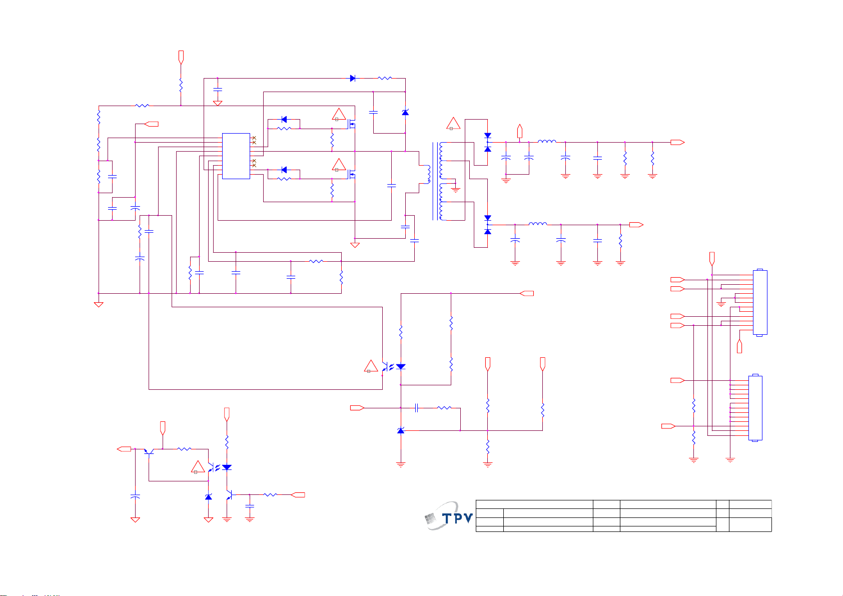
B+
R927
1M5 1/4W 1%
R928
1M5 1/4W 1%
R929
30K 1/8W 1
100N 50V
2K43 1/8W 1%
VCC_1
R926
1M5 1/4W 1%
C972
1nF 50V
C973
R930
C975
4.7uF 50V
C974
+
10uF 50V
+
C966
+
10uF/50V
VCC_1
C976
100N 50V
Vin
Q953
KTD1691/P
R925
0.1 ohm
R931
NC
R971
1K 1/8W
!
ZD950
MTZJ T-72 15B
C977
470N 25V
43
1 2
IC970
1
Vsen
2
Vcc
3
FB
4
GND
5
Css
6
OC
7
RC
8
Reg
RV9COM
SSC9512S
+5V
12
C993
1U 25V
18
NC
17
NC
16
VGH
15
VS
14
VB
13
NC
12
NC
11
VGL
10
C978
1N 50V
R969
1K 1/8W
IC953
PC123X8YFZ OF
Q951
2N3904S-RTK/PS
C963
1U25V
D970
1N4148
R937
47OHM +-5% 1/8W
D971
1N4148
R936
47OHM +-5% 1/8W
C979
680P 50V
R970
10KOHM +-5% 1/8W
R992
1K 1/8W
PS_ON
D930
UF4007
!
R938
10KOHM +-5% 1/8W
!
R935
10KOHM +-5% 1/8W
R924
220 OHM 1/8W
V_rise
R934
10R 1/8W 5%
C991
1U 25V
Q970
2SK4100LS-T 7A/650V
Q971
2SK4100LS-T 7A/650V
C980
0.027uF 5% 1 000V
43
!
IC973
AS431AZTR-E1
ZD931
MTZJ T-72 15B
1 2
3
1
C992
10pF/3KV
R942
4.7KOHM +-1% 1/8W
12
IC972
PC123X8YFZ OF
C988
220N 50V
T901
POWER X''FMR
C994
100PF1KV
R943
5.1KOHM +-1% 1/8W
D972
FMWN-2308
!
8
12
10
9
11
7
R944
1.2KOHM +-1% 1/8W
R941
2KOHM +-1% 1/8W
24V1
1
2
+
3
C981
1000uF 35V
D973
SBT15006JST
1
2
3
R945
20.5KOHM +-1% 1/8W
R946
1.96KOHM +-1% 1/8W
T P V ( Top Victory Electronics Co . , Ltd. )
絬 隔 瓜 絪 腹
Key Component
Date
03.MAINPOW ER
+
C984
1000uF 25V
3.0uH +-10%
+
C970
1000uF 35V
L972
3.5uH
24V1
+12V+24V
L971
+
R949
51KOHM +-1% 1/8W
+
C982
470uF 35V
C985
220uF 25V
R939
C983
5.1K 1/4W
100N 50V
12V/1.5A
R991
C986
24.K 1/4W
100N 50V
OEM MOD EL
TPV MODEL
PCB N AME
Sheet
34Monday, November 30, 2009
FOR INVERTER
24V/4A
R940
5.1K 1/4W
+12V
DIM
+12V
PS_ON
+5V
+24V
3K 1/8W
DET
3K 1/8W
of
R989
DET
R988
+24V
ON/OF F
DIM
INV ON/OFF
Size
Rev
称爹
ACD
CN902
1
2
3
4
5
6
7
8
9
10
11
12
13
CONN
CN903
1
2
3
4
5
6
7
8
9
10
11
12
13
CONN
Custom
1.0
<
称爹
>
65
Page 66

B+
R955
0.47 OHM +-5% 1W
BO
D904
1N4007-E3/73
R950
2Mohm 1/4W +/ -1%
2M OHM 1% 1/4W
R951
R952
3.3MOHM +-1% 1/4W
470KOHM +-1% 1/ 8W
R953
R958
1.2OH M2W
C950
220N 50V
FB902
BEAD
1 2
C910
1500PF 1KV
0.1NF 2KV
0.1NF 2KV
4.7M OHM +-5% 1/4W
1
S/OCP
2
BR
3
GND
FB/OLP4VCC
C955
1N 50V
1 2
C951
C959
R987
!
IC950
D/ST
D/ST
A6069H
ZD951
MTZJ T-72 30B
FB
ZD952
MTZJ T-72 15B
!
2200pF630V
3
2
1
NC
C925
1000PF/250VAC
C956
C957
2200pF630V
C958
+
R968
2K49 1/8W 1%
L950
3.5uH
C969
330uF 16V
470uF 16V
+
5V/2.5A
+5V
C960
C990
0.1UF 50V
+
C926
330pF/ 250V
!
T950
POWER X'FMR
1
R956
100K 1/4W
R975
100K 1/4W
8
7
5
C953
100N 50V
1 2
VCC
D954
1N4148
+
C952
10uF/ 50V
R974
100K 1/4W
R976
100K 1/4W
D952
RGP10M
D950
RGP10M
PROTECT
Vin
C954
100uF 50V
+
D953
PR1007
2
3
4
5
!
R957
4R7 1/4W 5%
43
!
6
7
9
10
12
IC952
PC123X8YFZ OF
C962
220N 50V
IC951
AS431AZTR-E1
SBT15006JST
R959
47 OHM 1/4W
R961
47 OHM 1/4W
D956
R963
470 OHM +-1% 1/8W
R964
2KOHM +-1% 1/8W
R965
3K 1/8W 5%
R966
33K 1/8W 1%
T P V ( Top Victory Electronics Co . , Ltd. )
絬 隔 瓜 絪 腹
Key Component
Date
04.STANDBY
66
R967
2K49 1/8W 1%
OEM MO DE L
TPV MO D EL
PCB NAME
Sheet
Size
Rev
of
44Monday, Nov ember 30, 2009
称爹
Custom
1.0
称爹
<
>
Page 67

LC42H063D 715G3885P02W30003S
1
-
4
3
!
L903
20.0MH
4
3
!
L902
2.0MH
73L 174 52 LG
4
!
3
L901
20.0MH
73L 174 49 LG
4
!
C903
0.047UF 27 5V
RV901
NC
G
HS2
HS5
680pF 250V
BO
3
2
1
!
C906
!
12
R903
330K 1/4W
t
F901
FUSE
LN
033G8105 3A X *2
HEAT SINK (IC 901)
HEAT SINK (D903, D906,D907)
CN902
CONN
N
L
220R 1/4W
!
NR901
NTCR
!
HS3
1
2
HS6
1
2
R941
R943
5K1 1/8W
C931
1uF/520V
0.1R 3W
0.1R 3W
B+
R932
R934
!
!
C936
47uF 25V
R940
20K 1/8W
C942
C940
4N7
10N
R904
0.1 ohm
VCC1
C908
10uF
HS4
HEAT SINK (Q901 )
1
2
HEAT SINK (BD 901,D901)
FB903
BEAD
1 2
C902
470pF/250V
1 2
FB904
BEAD
VCC1
R905
2M 1% 1/4W
+
0.1uF
GBJ1008
93G 50460 35
!
C901
680pF 250V
!
R901
330K 1/4W
!
BD901
+
2
2
1
!
C904
0.047UF 275V
2
1
2
1
!
R902
330K 1/4W
!
!
CN901
SOCKET
HEAT SINK (D911)
1
2
HEAT SINK (Q902,Q903)
1
2
126
5
+
1
GND
2
ICOMP
3
ISENSE
VINS4VCOMP
ICE2PCS02G
56G 379104
C941
1N
C909
HS1
1
2
L906
600uH 10%
73G 174148 S
VSENSE
IC906
R906
2M 1% 1/4W
1N5408-E
C937
100N
GATE
VCC
R908
2K 1/4W
D909
8
7
6
5
R907
2M 1% 1/4W
R909
30K 1% 1/8W
C914
470N
51R 1/8W
R942
51K 1/8W
C938
470N
C907
1N 50V
C916
1N
FB905
BEAD
1 2
1 2
FB901
BEAD
FB902
1 2
C932
NC
!
Q901
STW20NM60
57G 667 25
ZD902
MTZJ T- 72 15B
C919
22pF/3KV
R921
1K 1% 1/8W
!
C964
470pF/250V
Q904
KTD1691/P
57G 761 7
1 2
C918
1uF 25V
47R 1/8W
22pF/3KV
BEAD
R935
1M 1% 1/4W
R939
1M 1% 1/4W
R944
1M 1% 1/4W
R945
22K 1% 1/8W
D902
IN4148
R910
47R 1/8W
12
D904
IN4148
R916
C920
R922
150R 1/8W
C905
10NF1KV
ZD901
MTZJ T-72 1 5B
R976
0R05 1/8W
R931
1K2 /8W 1%
43
!
IC905
EL817M
56G 139 9
STP10NK60ZFP
57G 667 50
R975
0R05 1/8W
!
Q902
STP10NK60ZFP
57G 667 50
10K 1/8W
100PF/2KV
R925
24K 1% 1/8W
C928
4.7uF
+
67G 42Z82015K
067G 42Z10115K *2
BO
R946
1K 1/8W
!
Q903
R911
10K 1/8W
R917
C924
D901
FMXA-1106S
D910
R933
R936
33R 1/8W
C939
1uF 25V
!
!
IN4148
1
2
3
4
5
6
7
8
1uF 25V
C944
470pF/250V
C929
470pF/250V
Vsen
Vcc
FB
GND
Css
OC
RC
Reg
RV9COM
IC904
SSC9502S
56G 379112
C917
D905
EG01A
1
R938
10K 1/8W
NC
NC
VGH
VS
VB
NC
NC
VGL
2
3
C943
1N
VCC1
18
17
16
15
14
13
12
11
10
R919
7.5R 1/4W
C926
1N
!
C933
82uF 450V
Vcc
220R 1/8W
12
Q905
2N3904S-RTK/PS
+
+
R958
1M5 1/4W 1%
1M5 1/4W 1%
1M5 1/4W 1%
620K 1/8W 1%
R947
3
4
6
7
C915
0.033uF 1KV
C927
100N
1 2
FB906
BEAD
!
C934
82uF 450V
67G 42Z82015K
067G 42Z10115K *2
R961
R964
R967
C960
220N
5V
!
T902
POWER X'FMR
80TL42T 14 YS
R923
0R05 1/8W
!
IC902
EL817M
56G 139 9
KIA431A-AT/P
56G 158 12
1.2R 2W
R949
2K 1/8W
12
9
8
14
11
10
13
43
IC903
R963
4.7M 1/4W
R968
R950
4.7R 1W
C945
100N
3
1
D906
SBT15006JST
93G 60298
R924
4.7K 1% 1/8W
12
1
2
3
R948
2K7 1/8W
2
C948
NC
IC901
S/OCP
BR
GND
FB/OLP4VCC
A6069H
56T 379121
R926
3K 1% 1/8W
C930
100N 50V
100K 1/4W
100K 1/4W
D/ST
D/ST
PS_ON
3
1
3
1
V40100C
93G 60315
+
C921
1000uF25V
5.1K 1% 1/8W
R952
100K 1/4W
R954
100K 1/4W
D913
3.3R 1/4W
D914
PR1007
93G110050152T
D916
IN4148
+
C958
10uF
+
C911
1000UF 35V
+
C922
470UF 25V
C946
0.1NF 2KV
C947
0.1NF 2KV
R955
ZD906
MTZJ1 2B
1 2
R927
20K5 1/8W 1%
R930
2K 1% 1/8W
2
3
4
5
+
C956
100uF
!
L904
3.0uH +-10%
470UF 35V
Vcc
56G 139 9
C912
C923
100N
T901
POWER X'FMR
80GL52T 5 L2
C954
NC
43
IC907
EL817M
+
6
7
9
10
R962
220R 1/8W
12
R970
2K 1/8W
IC908
KIA431A-AT/P
56G 158 12
R912
5.1K 1/4W
R928
56K 1% 1/8W
D911
3
SBT15006JST
93G 60298
2
1
R956
47R 1/4W
C949
R957
2N2 500V
47R 1/4W
R965
2.4K 1% 1/8W
R966
1K 1/8W
C961
220N
R971
2.2K 1% 1/8W
R914
R913
5.1K 1/4W
5.1K 1/4W
12V
L907
3.5uH
+
+
C950
C951
330uF 16V
1000uF 16V
ZD903
MTZJ T- 72 30B
1 2
D917
IN4148
R969
Q906
100R 1/8W
PMBS3904
C963
100N
24V
10
11
12
10
11
12
CN905
CONN
13
1
2
3
4
5
6
7
8
9
C913
R915
1uF
5.1K 1/4W
12V
PS_ON
5V
R972
1K 1/8W
1
2
3
4
5
6
7
8
9
CN904
CONN
24V
C952
0.1uF
12V
ZD904
MTZJ T- 72 16B
1 2
D918
IN4148
1
2
3
4
5
6
7
8
9
10
11
12
13
CN903
CONN
5V
R951
R953
SARS01-V1
8
7
5
C955
0.1uF
C959
4N7
D903
2
V40100C
93G 60315
2
+
C910
D907
1000UF 35V
L905
3.5uH
R929
1
!
67
T P V ( Top Victory Electronics Co . , Ltd. )
絬 隔 瓜 絪 腹
Key Component
01.Adapter
Date
OEM MODEL
TPV MODEL
PCB NAME
Sheet
715G3885-1
of
11Tuesday , March 09, 2010
Size
C
Rev
B
称爹
称爹
>
<
Page 68
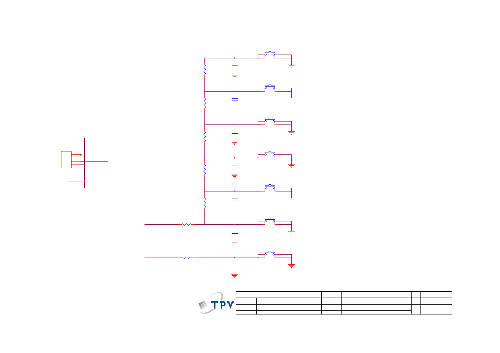
9.3 Key Board
715G3814K01000003S
SW01
CN01
65
1
2
3
4
CONN
33G8032 4F HR
PWR-SW
FUNC_KEY
FUNC_KEY
PWR-SW
R07
750OHM +- 1% 1/8W
R08
750OHM +- 1% 1/8W
R01
7K5 1/8W +/-1%
R02
2K7 +- 1% 1/8W
R03
1K8 +/ -1% 1/8W
R04
1K 1/8W 1%
R05
750OHM +- 1% 1/8W
C01
NC
C02
NC
C03
NC
C04
NC
C05
NC
C06
NC
C07
NC
TACT SW FWRD H1.5MM
SW02
TACT SW FWRD H1.5MM
SW03
TACT SW FWRD H1.5MM
SW04
TACT SW FWRD H1.5MM
SW05
TACT SW FWRD H1.5MM
SW06
TACT SW FWRD H1.5MM
SW07
TACT SW FWRD H1.5MM
77G 607 2 FD
VOL+
VOL-
CH+
CH-
MENU
Source Select
Power ON/OFF
2.48V~2.72V
2.04V~2.22V
1.58V~1.79V
1.24~1.45V
0.85V~1.02V
0.47V~0.63V
T P V ( Top Victory Electronics Co . , Ltd. )
絬 隔 瓜 絪 腹
Key Component
Date
01-Keypad
68
OEM MO DE L
TPV MO DE L
PCB NAME
Sheet
715GXXXX
11Monday, January 18, 2010
of
Size
Rev
称爹
Custom
A
<
称爹
>
Page 69
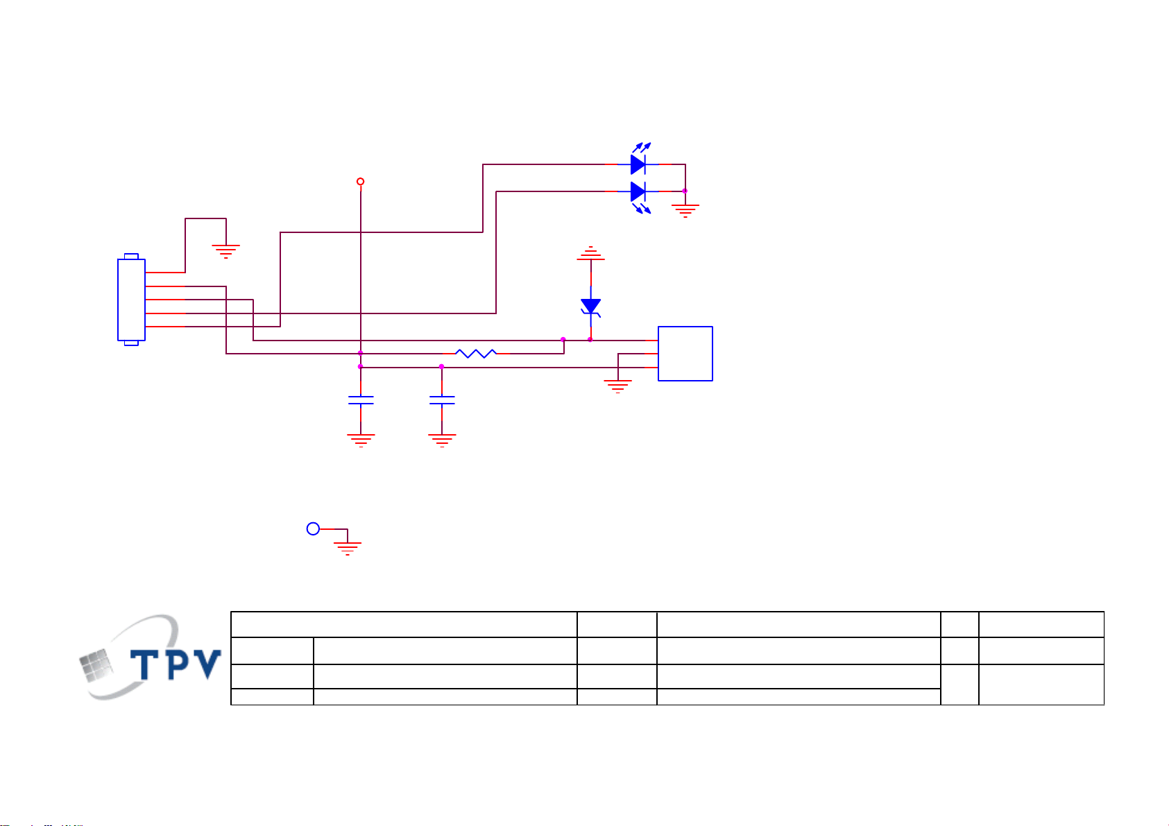
9.4 IR Board
715G3821R01000004M
LED01
LED
BLUE
CN01
5
4
3
2
1
CONN
33G8032 5F HR
LED_B
IRRV
GND PINGND PIN
VCC
BLUE
RED
4
23
1
RED
81T 14 24 EL
12
RLZ5.6B
LED_R
R001 15K 1/10W
C01
100N 50V
1
C02
NC/4.7uF /16V
ZD01
U01
1
VOUT
2
GND
3
VCC
IC KSM-2003TN2M-S 37.9KHZ
T P V ( Top Victory Electronics Co . , Ltd. )
絬 隔 瓜 絪 腹
Key Component
Date
T3821-D-X-X-1-091207
IR&LED
OEM MODEL
TPV MODEL
PCB NAME
Sheet
69
715G3821R01000004M
of
11Tuesday , December 08, 2009
Size
Rev
称爹
Custom
0.2
Page 70

10. Exploded View
LC32H063D
70
Page 71

LC42H063D
71
Page 72

LC32H063D
Item Description
1 BEZEL
2 DECO_BEZEL
3 SPEAKER
4 IR BOARD
5 LENS_POWER
6 POWER LENS
7 KEY COVER
8 KEY BUTTON
9 KEY BOARD
10 BKT-PANEL-SUPPORT-L
12 BKT-PANEL-SUPPORT-L
13 BKT-BASE-SUPPORT
13 BKT-PANEL-SUPPORT-L
15 MYLAR
16 PANEL
17 BKT-PANEL-SUPPORT-R 11 0D1G1730 8120 SCREW(POWER BD/BKT) 4
18 BKT-VESA-BTM 14 0M1G1730 10120 SCREW(AC/BKT) 1
19 BKT-SCLAR-BD-SIDE 20 0M1G1730 10120 SCREW(BKT/PANEL) 6
22 BKT-IO-SIDE 21 0D1G1730 8120 SCREW(MAIN BD/BKT) 6
24 IO_BKT_BTM 23 0M1G 930 6 47 CR3 SCREW(MAIN BD/BKT) 4
25 REAR COVER 26 0Q1G 940 16 47 CR3 SCREW(REAR COVER/BEZEL) 10
28 HINGE 27 0M1G 940 10 47 CR3 SCREW(REAR COVER/BKT) 6
29 STAND 30 0M1G1740 14 47 CR3 SCREW(HINGE/STAND) 4
31 BASE 33 0Q1G 130 6 47 CR3 SCREW(BASE/BASE BKT) 6
32 BASE BKT 34 0Q1G 940 16 47 CR3 SCREW(BASE/BASE BKT) 4
Item Part No. Description Qty
72
Page 73
LC42H063D
Item Description
BEZEL
1
IE LENS
2
LED LENS
3
KEY COVER
4
5
6
9
10
11
12
13
14
15
16
17
18
19
20
41
42
43
44
45
46
47
KEY BUTTON
REAR COVER
BASE
BKT-PANEL-TOP
BKT FIX PANEL
BKT-PB
BKT-STAND
BKT-MB_L
BKT-MB_R-AUO
BKT-IO-SIDE
IO_BKT_BTM
BKT-VESA-BTM
HINGE-A'SSY
BKT-BASE
MAIN BOARD
KEY BOARD
IR BOARD
SPEAKER
PANEL
POWER BOARD
DECO_BEZEL
Item Part No. Description Qty
21
22
23
24
25
26
27
28
29
30
31
32
33
34
35
36
37
38
39
40
0M1G 940 6120 SCREW(PANEL/BKT)
0M1G 940 6120 SCREW(PANEL/BKT)
0M1G 940 6120 SCREW(PANEL/BKT)
0M1G1740 8120 SCREW(PANEL/HINGE-A'SSY)
0M1G1740 14120 SCREW(PANEL/HINGE-A'SSY)
0M1G 930 6 47 CR3 SCREW(PANEL/BKT)
0M1G1730 8120 SCREW(AC/BKT)
0M1G1730 8120 SCREW(MAIN BD/BKT)
0M1G 930 6 47 CR3 SCREW(MAIN BD/BKT)
0Q1G 930 8 47 CR3 SCREW(MAIN BD/BKT)
0Q1G 930 8 47 CR3 SCREW(PANEL/BKT)
0Q1G 940 16 47 CR3 SCREW(PANEL/BEZEL)
0Q1G1030 6120 SCREW(IR BD)
0Q1G 940 16 47 CR3 SCREW(REAR COVER/BEZEL)
0M1G 940 8 47 CR3 SCREW(REAR COVER)
0M1G 940 8 47 CR3 SCREW(REAR COVER)
0Q1G 130 8 47 CR3 SCREW(BASE/BKT)
Q01G6145 1 SCREW(BASE/BKT)
0Q1G 930 8 47 CR3 SCREW(BKT/BEZEL)
0Q1G 940 30 47 CR3 SCREW(REAR COVER/BEZEL)
5
3
6
2
2
2
5
4
4
1
1
4
1
10
2
2
6
4
2
4
73
Page 74

11. BOM List
Note: The parts information listed below are for reference only, and are subject to change without notice.
Please go to http://cs.tpv.com.cn/hello1.asp
LC32H063D
Location Part No. Description Remark
001G6021 1 SCREW
052G 1185 1 BIG TAPE(Y1200141)
052G 1186 SMALL TAPE
052G 1211 A CONDUCTIVE TAPE 55MM *45MM *0.08MM
052G 1211 B CONDUCTIVE TAPE 85MM *40MM *0.09MM
052G 2191 A PAPER TAPE
078G0120 10 Y SPEAKER 16 OHM 12W 125X32MM
085T 583103 GASKET
E08901 089G402A15N CX AC POWER CORD 1500MM AMERICA REG.
E08901 089G402A15N HL AC POWER CORD 1500M AMERICA REG. 2nd source
ECN601 095G8013 4D904 HARNESS 4P-FAST 550MM
ECN701 095G801413D929 HARNESS 13P-12P 160MM FQE91229I
ECN903 095G801414D940 HARNESS 14P-13P 290MM FQE91230I
ECN408 095G801851D922 HARNESS 51P-42P 290MM
098GRABD1NEACU REMOTE CONTROL AOC 67100BA1-017-R
0D1G1730 8120 SCREW
0M1G 930 6 47 CR3 SCREW
0M1G 940 6120 SCREW (M4X6)
0M1G 940 10 47 CR3 SCREW
0M1G1730 10120 SCREW 42A9930016
0M1G1740 14 47 CR3 SCREW
0Q1G 930 8 47 CR3 SCREW
0Q1G 940 12 47 CR3 SCREW
0Q1G 940 16 47 CR3 SCREW
705TQ949001 COMSUPTIVE ASS'Y-A4
750TVU315W4611N000 PANEL T315HW04 V600 TW AUO
756TQACB ZK085 01 MAIN BOARD-CBPFAZ9KQE
U405 056G1133939 IC MX25L3205DM2I-12G SOP-8
SMTF-U405 100TAZAK004K21 MCU ASS'Y-056G1133939
ADTV92412QDN POWER BOARD
Q02G7038 1 NUT
Q11G5061 1 PCB SUPPORT
Q15T0690102 IO_BKT_BTM
Q15T0691101 BKT-IO-SIDE
Q36T 600 31 1 NONWOVEN FABRIC
Q36T 600 31 4 NONWOVEN FABRIC
Q36T 600 37 18 GP NONWOVEN FABRIC
Q36T 600 49 10 HIMERON
Q40G2010 46002 IO SIDE LABEL
Q44GJ069101EPE EPE
Q44GJ069201EPE EPE
Q45G 77 5 PE PACKING (Y1900241)
Q45G 99626 36 PE BAG
Q45T 99609 61 EPE COVER FOR MONITOR
Q50G 4 10 TIE (Y1900221)
Q50G 500523 CABLE TIE
for the latest information.
E32AAZNKW3ACXNX
74
Page 75

Q52G 1150523 TAPE_INSULATING
Q52T 1211833 AL
X40G0002615 7A POP LABEL
X44GJ061615 6B 32 TV EPI CARTON
X52G8000 5 MYLAR
092GB1JX1A2EGC BATTERY FOR LR6 (KA)2S/G
0Q1G 940 16 47 CR3 SCREW
Q41T780067358A WARRANTY CARD
Q45G 76 28NV2 R PE BAG FOR BASE SCREW SZ02742
Q45G2010M0101A PE BAG FOR MANUAL
X41G32MV615 7B EPI MANUAL
X41G78SV615 3A EPI QSG
040G 58162435A P/N LABEL FOR MANUAL PE BAG
040G 581689 4A BARCODE LABEL FOR 1
Q40G0001881 4A S/N LABEL
X40G 320615 4A RATING LABEL
085G 583501504 GASKET_ELECTRIC
ECN401 095G801410D934 HARNESS HARNESS 10P - 5P+3P 650MM
0M1G 940 6120 SCREW (M4X6)
0M1G1740 14 47 CR3 SCREW
0Q1G 130 6 47 CR3 SCREW
0Q1G1830 6120 SCREW
A15T0282201 BKT-VESA-BTM
A33T0788ADTB1L0100 KEY COVER
A33T0789AFL 1L0100 KEY BUTTON
A34T1580 GM 1A0130 REAR COVER_32
A34T1581ADT 1A0100 STAND HINGE
A34T1582AFL 1L0100 STAND-A1_32
IRPFAQC6 IR BOARD
KEPFAAA1 KEY BOARD
Q12G6300 25 1 RUBBER FOOT
Q15T0693101 BKT-BASE-SUPPORT
Q15T0694101 BKT-PANEL-SUPPORT-L
Q15T0695101 BKT-PANEL-SUPPORT-R
Q15T0696201 BKT-PANEL-SUPPORT-L
Q15T0697201 BKT-PANEL-SUPPORT-L
Q15T0698101 BKT-SCLAR-BD-SIDE
Q15T0704101 BASE BKT
Q33T0379 ED 1C0100 LENS_POWER_A2
Q33T0380 1 1C0100 POWER LENS
Q34T7081AFLB2L0130 BEZEL_TV32W-10A-EPI
Q34T7082AFL 1L0100 BASE
Q35T0071BBV 1L0100 DECO_BEZEL_TV 32"
Q36T 600 35 2 GP NONWOVEN FABRIC
Q37T0203011ADT0001 2K10-32 HINGE
Q40G2010 32106 I/O LABLE
Q44T3231 21 27 EVA WASHER
Q44T3231 21 28 EVA WASHER
CBPFAZ9KQE
040G 45762412B CBPC LABEL
CN408 033G804342C HR WAFER 2*21P 2.0MM
CN601 033T3278 4D CONNECTOR
CN701 033T327812D WAFER 12P PLUG
CN401 033T380210B Y CONNECTOR
75
Page 76

C730 067G215D2216KV EC 220UF M 35V 10*12MM
C636 067G215D2216KV EC 220UF M 35V 10*12MM
C634 067G215D2216KV EC 220UF M 35V 10*12MM
C722 067G215V471 6N
CN111 088G 78 13 76 YG RCA JACK 2*4 G/B/R/W+Y/W/R/R
CN111 088G 78 1376C RCA JACK 2*4 G/B/R/W+Y/W/R/R
CN102 088G 302 65 YG PHONE JACK 3P GREEN
CN602 088G 30211K PHONE JACK 5PIN
CN131 088G 30258A CL PHONE JACK+ S 3P
CN131 088G 30258A YG PHONE JACK+ S 3P
CN102 088G 30265C PHONE JACK 3P GREEN
CN602 088G 302A11 YG PHONE JACK 3.5¦µ 7PIN BLACK CKX3.507B-01
CN103 088G 352 21CL USB CONN TYPE A
CN103 088G 352 2L YG USB CONNECTOR USB4-03 AU=1U''
CN101 088G 35315FHSD D-SUB 15PIN FEMALE VERTICAL SCREWED
CN101 088G 35315FXSH D-SUB 15PIN FEMALE VERTICAL SCREWED 2nd source
CN603 088G 359 6 JT FIBER-OPTIC 3PIN JST1226
090G6250 1 GP HEAT SINK FOR U402
090G6250 1 GP HEAT SINK FOR U403
X401 093G 2262B J XTL NXS25.000AC20F-KAB5-3 HC-49/US
TU101 094GNTAT MA 9M TUNER NTSC+ATSC ENV56U02D8F
CN408 311GW200C42AAL WAFER 2*21P 2.0MM
A85T1017201 2K10-32-BKT-SHIELD-TOP
A85T1018101 2K10-37-BKT-SHIELD-MAIN
C643 064G179J2241AT MKT CAP. 0.22UF 100V RSB
C661 064G179J2241AT MKT CAP. 0.22UF 100V RSB
C744 067G 2152214NT KY25VB220M-TP5 8*11.5
C768 067G 3051014CT EC 100UF 25V KM 6.3X11MM
C766 067G 3051014CT EC 100UF 25V KM 6.3X11MM
C725 067G 3051014CT EC 100UF 25V KM 6.3X11MM
C716 067G 3051014CT EC 100UF 25V KM 6.3X11MM
C430 067G 3051014CT EC 100UF 25V KM 6.3X11MM
C410 067G 3051014CT EC 100UF 25V KM 6.3X11MM
C778 067G215H2213CT EC 220UF 16V SY 8X7MM
C755 067G215H2213CT EC 220UF 16V SY 8X7MM
C753 067G215H2213CT EC 220UF 16V SY 8X7MM
C739 067G215H2213CT EC 220UF 16V SY 8X7MM
C707 067G215H2213CT EC 220UF 16V SY 8X7MM
C734 067G215P1014CT EC 100UF/25V GF 6.3*11MM
C757 067G215Y1014KT EC CAP.105C
C706 067G215Y2207LT LOW ESR EC 22UF 50V M 5*11MM
C719 067G215Y2207LT LOW ESR EC 22UF 50V M 5*11MM
C4E4 067G215Y2207LT LOW ESR EC 22UF 50V M 5*11MM
U603 056G 158501 IC AS431AN-E1 SOT23
U701 056G 379150 IC G5692P11U SOP-8
U401 056G 562286 IC ZR39787HGCF BGA-632
U703 056G 563 75 G1084-33T43UF TO-252
U706 056G 563155 IC G9084-50TU3U 5.0A/5V TO-263T
U702 056G 563517 IC AZ1084D-1.8TRE1 5A/1.8V TO-252
U705 056G 563964 IC SC4215HSTRT SO-8
U409 056G 581 9 IC G5250K1T1U SOT23-5
U602 056G 593 39 IC STA339BWTR POWERSSO36
U402 056G 615919 IC H5PS5162FFR-S6C FBGA84
U403 056G 615919 IC H5PS5162FFR-S6C FBGA84
CAP 105℃ 470UF M 35V
76
Page 77

U604 056G 616 55 IC DRV602PWR 870MW TSSOP-14
U606 056G 616916 IC MAX9728AETC+ TQFN-EP-12
U501 056G 623 36 IC SWITCH SII9287BCNU QFN-72
U411 056G 634 2 1 IC PI5V330SQEX QSOP-16 PERICOM
U404 056G 643 41 IC APX809-29SAG-7 SOT23
U108 056G 662 13 IC AZC099-04S SOT23-6L
U410 056G 662 13 IC AZC099-04S SOT23-6L
U408 056G 662 22 IC AZC199-02S.R7G SOT23-3L
U101 056G 662502 C ESD AZC199-04S SOT23-6L
U102 056G 662502 C ESD AZC199-04S SOT23-6L
U108 056G 662504 IC ESD AOZ8902CIL 24KV 5A SOT23-6 AOS
U410 056G 662504 IC ESD AOZ8902CIL 24KV 5A SOT23-6 AOS
U406 056G1133 83 1 IC M24C64-WMN6P 64K SO-8 ST
U405 056G1133939 IC MX25L3205DM2I-12G SOP-8
U104 056G4LVCG17 TI IC SN74LVC1G17DBVR STO-23
U106 056G4LVCG17 TI IC SN74LVC1G17DBVR STO-23
U107 056G4LVCG17 TI IC SN74LVC1G17DBVR STO-23
U103 056G4LVCG17 TI IC SN74LVC1G17DBVR STO-23
U704 056T 379117 IC SC4525BSETRT SOIC-8 EDP
Q701 057G 417511 MMBT3904
Q702 057G 417511 MMBT3904
Q704 057G 417511 MMBT3904
Q603 057G 417511 MMBT3904
Q602 057G 417511 MMBT3904
Q601 057G 417511 MMBT3904
Q404 057G 417511 MMBT3904
Q110 057G 417511 MMBT3904
Q109 057G 417511 MMBT3904
Q104 057G 417511 MMBT3904
Q103 057G 417511 MMBT3904
Q102 057G 417511 MMBT3904
Q101 057G 417511 MMBT3904
Q402 057G 417512 MMBT3906
Q110 057G 417518 TRA LMBT3904LT1G 200MA/40V SOT-23 LRC
Q404 057G 417518 TRA LMBT3904LT1G 200MA/40V SOT-23 LRC
Q601 057G 417518 TRA LMBT3904LT1G 200MA/40V SOT-23 LRC
Q602 057G 417518 TRA LMBT3904LT1G 200MA/40V SOT-23 LRC
Q603 057G 417518 TRA LMBT3904LT1G 200MA/40V SOT-23 LRC
Q704 057G 417518 TRA LMBT3904LT1G 200MA/40V SOT-23 LRC
Q702 057G 417518 TRA LMBT3904LT1G 200MA/40V SOT-23 LRC
Q701 057G 417518 TRA LMBT3904LT1G 200MA/40V SOT-23 LRC
Q109 057G 417518 TRA LMBT3904LT1G 200MA/40V SOT-23 LRC
Q104 057G 417518 TRA LMBT3904LT1G 200MA/40V SOT-23 LRC
Q103 057G 417518 TRA LMBT3904LT1G 200MA/40V SOT-23 LRC
Q102 057G 417518 TRA LMBT3904LT1G 200MA/40V SOT-23 LRC
Q101 057G 417518 TRA LMBT3904LT1G 200MA/40V SOT-23 LRC
Q409 057G 763 62 FET 2N7002K 300MA/60V SOT-23
Q502 057G 763 62 FET 2N7002K 300MA/60V SOT-23
Q408 057G 763 62 FET 2N7002K 300MA/60V SOT-23
Q703 057G 763 79 FET AO4449 -7A/-30V SOIC-8
Q403 057G 763 79 FET AO4449 -7A/-30V SOIC-8
Q501 057G 763 90 FET 2SK3018 UMT3
Q403 057G 763512 P06P03LVG BY NIKO-SEM
Q703 057G 763512 P06P03LVG BY NIKO-SEM
77
Page 78

R479 061G0402102 JF RST CHIPR 1KOHM +-5% 1/16W FENGHUA
R478 061G0402102 JF RST CHIPR 1KOHM +-5% 1/16W FENGHUA
R465 061G0402102 JF RST CHIPR 1KOHM +-5% 1/16W FENGHUA
R733 061G0603000 JT RST CHIP MAX 0R05 1/10W TZAI YUAN
R746 061G0603000 JT RST CHIP MAX 0R05 1/10W TZAI YUAN
R748 061G0603000 JT RST CHIP MAX 0R05 1/10W TZAI YUAN
R664 061G0603000 JT RST CHIP MAX 0R05 1/10W TZAI YUAN
R663 061G0603000 JT RST CHIP MAX 0R05 1/10W TZAI YUAN
R655 061G0603000 JT RST CHIP MAX 0R05 1/10W TZAI YUAN
R648 061G0603000 JT RST CHIP MAX 0R05 1/10W TZAI YUAN
R529 061G0603000 JT RST CHIP MAX 0R05 1/10W TZAI YUAN
R527 061G0603000 JT RST CHIP MAX 0R05 1/10W TZAI YUAN
R525 061G0603000 JT RST CHIP MAX 0R05 1/10W TZAI YUAN
R513 061G0603000 JT RST CHIP MAX 0R05 1/10W TZAI YUAN
FB101 061G0603000 JT RST CHIP MAX 0R05 1/10W TZAI YUAN
R470 061G0603000 JT RST CHIP MAX 0R05 1/10W TZAI YUAN
R486 061G0603000 JT RST CHIP MAX 0R05 1/10W TZAI YUAN
R493 061G0603000 JT RST CHIP MAX 0R05 1/10W TZAI YUAN
R4C9 061G0603000 JT RST CHIP MAX 0R05 1/10W TZAI YUAN
R4D1 061G0603000 JT RST CHIP MAX 0R05 1/10W TZAI YUAN
R508 061G0603000 JT RST CHIP MAX 0R05 1/10W TZAI YUAN
R525 061G0603000 JY RST CHIPR MAX0R05 1/10W YAGEO
R527 061G0603000 JY RST CHIPR MAX0R05 1/10W YAGEO
R529 061G0603000 JY RST CHIPR MAX0R05 1/10W YAGEO
R648 061G0603000 JY RST CHIPR MAX0R05 1/10W YAGEO
R655 061G0603000 JY RST CHIPR MAX0R05 1/10W YAGEO
R663 061G0603000 JY RST CHIPR MAX0R05 1/10W YAGEO
R664 061G0603000 JY RST CHIPR MAX0R05 1/10W YAGEO
R733 061G0603000 JY RST CHIPR MAX0R05 1/10W YAGEO
R746 061G0603000 JY RST CHIPR MAX0R05 1/10W YAGEO
R748 061G0603000 JY RST CHIPR MAX0R05 1/10W YAGEO
R513 061G0603000 JY RST CHIPR MAX0R05 1/10W YAGEO
FB101 061G0603000 JY RST CHIPR MAX0R05 1/10W YAGEO
R470 061G0603000 JY RST CHIPR MAX0R05 1/10W YAGEO
R486 061G0603000 JY RST CHIPR MAX0R05 1/10W YAGEO
R493 061G0603000 JY RST CHIPR MAX0R05 1/10W YAGEO
R4C9 061G0603000 JY RST CHIPR MAX0R05 1/10W YAGEO
R4D1 061G0603000 JY RST CHIPR MAX0R05 1/10W YAGEO
R508 061G0603000 JY RST CHIPR MAX0R05 1/10W YAGEO
R742 061G0603100 JT RST CHIP 10R 1/10W 5% TZAI YUAN
R531 061G0603100 JT RST CHIP 10R 1/10W 5% TZAI YUAN
R511 061G0603100 JT RST CHIP 10R 1/10W 5% TZAI YUAN
R512 061G0603100 JT RST CHIP 10R 1/10W 5% TZAI YUAN
R528 061G0603100 JT RST CHIP 10R 1/10W 5% TZAI YUAN
R512 061G0603100 JY RST CHIPR 10OHM 1/10W YAGEO
R528 061G0603100 JY RST CHIPR 10OHM 1/10W YAGEO
R531 061G0603100 JY RST CHIPR 10OHM 1/10W YAGEO
R742 061G0603100 JY RST CHIPR 10OHM 1/10W YAGEO
R511 061G0603100 JY RST CHIPR 10OHM 1/10W YAGEO
R484 061G06031000FF RST CHIPR 100 OHM +-1% 1/10W FENGHUA
R485 061G06031000FF RST CHIPR 100 OHM +-1% 1/10W FENGHUA
R490 061G06031000FF RST CHIPR 100 OHM +-1% 1/10W FENGHUA
R491 061G06031000FF RST CHIPR 100 OHM +-1% 1/10W FENGHUA
R492 061G06031000FF RST CHIPR 100 OHM +-1% 1/10W FENGHUA
78
Page 79

R494 061G06031000FF RST CHIPR 100 OHM +-1% 1/10W FENGHUA
R494 061G06031000FT RST CHIP 100R 1/10W 1%
R492 061G06031000FT RST CHIP 100R 1/10W 1%
R491 061G06031000FT RST CHIP 100R 1/10W 1%
R490 061G06031000FT RST CHIP 100R 1/10W 1%
R485 061G06031000FT RST CHIP 100R 1/10W 1%
R484 061G06031000FT RST CHIP 100R 1/10W 1%
R728 061G06031002FF RST CHIPR 10KOHM +-1% 1/10W FENGHUA
R728 061G06031002FT RST CHIP 10K 1/10W 1%
R455 061G0603101 JT RST CHIP 100R 1/10W 5% TZAI YUAN
R4C4 061G0603101 JT RST CHIP 100R 1/10W 5% TZAI YUAN
R530 061G0603101 JT RST CHIP 100R 1/10W 5% TZAI YUAN
R612 061G0603101 JT RST CHIP 100R 1/10W 5% TZAI YUAN
R617 061G0603101 JT RST CHIP 100R 1/10W 5% TZAI YUAN
R650 061G0603101 JT RST CHIP 100R 1/10W 5% TZAI YUAN
R652 061G0603101 JT RST CHIP 100R 1/10W 5% TZAI YUAN
R702 061G0603101 JT RST CHIP 100R 1/10W 5% TZAI YUAN
R701 061G0603101 JT RST CHIP 100R 1/10W 5% TZAI YUAN
R654 061G0603101 JT RST CHIP 100R 1/10W 5% TZAI YUAN
R104 061G0603101 JT RST CHIP 100R 1/10W 5% TZAI YUAN
R105 061G0603101 JT RST CHIP 100R 1/10W 5% TZAI YUAN
R114 061G0603101 JT RST CHIP 100R 1/10W 5% TZAI YUAN
R120 061G0603101 JT RST CHIP 100R 1/10W 5% TZAI YUAN
R434 061G0603101 JT RST CHIP 100R 1/10W 5% TZAI YUAN
R436 061G0603101 JT RST CHIP 100R 1/10W 5% TZAI YUAN
R454 061G0603101 JT RST CHIP 100R 1/10W 5% TZAI YUAN
R455 061G0603101 JY RST CHIPR 100 OHM +-5% 1/10W YAGEO
R4C4 061G0603101 JY RST CHIPR 100 OHM +-5% 1/10W YAGEO
R530 061G0603101 JY RST CHIPR 100 OHM +-5% 1/10W YAGEO
R612 061G0603101 JY RST CHIPR 100 OHM +-5% 1/10W YAGEO
R617 061G0603101 JY RST CHIPR 100 OHM +-5% 1/10W YAGEO
R650 061G0603101 JY RST CHIPR 100 OHM +-5% 1/10W YAGEO
R652 061G0603101 JY RST CHIPR 100 OHM +-5% 1/10W YAGEO
R654 061G0603101 JY RST CHIPR 100 OHM +-5% 1/10W YAGEO
R701 061G0603101 JY RST CHIPR 100 OHM +-5% 1/10W YAGEO
R702 061G0603101 JY RST CHIPR 100 OHM +-5% 1/10W YAGEO
R454 061G0603101 JY RST CHIPR 100 OHM +-5% 1/10W YAGEO
R436 061G0603101 JY RST CHIPR 100 OHM +-5% 1/10W YAGEO
R434 061G0603101 JY RST CHIPR 100 OHM +-5% 1/10W YAGEO
R120 061G0603101 JY RST CHIPR 100 OHM +-5% 1/10W YAGEO
R114 061G0603101 JY RST CHIPR 100 OHM +-5% 1/10W YAGEO
R105 061G0603101 JY RST CHIPR 100 OHM +-5% 1/10W YAGEO
R104 061G0603101 JY RST CHIPR 100 OHM +-5% 1/10W YAGEO
R406 061G0603102 JT RST CHIP 1K 1/10W 5% TZAI YUAN
R405 061G0603102 JT RST CHIP 1K 1/10W 5% TZAI YUAN
R403 061G0603102 JT RST CHIP 1K 1/10W 5% TZAI YUAN
R116 061G0603102 JT RST CHIP 1K 1/10W 5% TZAI YUAN
R115 061G0603102 JT RST CHIP 1K 1/10W 5% TZAI YUAN
R723 061G0603102 JT RST CHIP 1K 1/10W 5% TZAI YUAN
R4A9 061G0603102 JT RST CHIP 1K 1/10W 5% TZAI YUAN
R637 061G0603102 JT RST CHIP 1K 1/10W 5% TZAI YUAN
R406 061G0603102 JY RST CHIPR 1KOHM +-5% 1/10W YAGEO
R405 061G0603102 JY RST CHIPR 1KOHM +-5% 1/10W YAGEO
R4A9 061G0603102 JY RST CHIPR 1KOHM +-5% 1/10W YAGEO
79
Page 80

R637 061G0603102 JY RST CHIPR 1KOHM +-5% 1/10W YAGEO
R723 061G0603102 JY RST CHIPR 1KOHM +-5% 1/10W YAGEO
R403 061G0603102 JY RST CHIPR 1KOHM +-5% 1/10W YAGEO
R116 061G0603102 JY RST CHIPR 1KOHM +-5% 1/10W YAGEO
R115 061G0603102 JY RST CHIPR 1KOHM +-5% 1/10W YAGEO
R603 061G0603103 JT RST CHIP 10K 1/10W 5% TZAI YUAN
R602 061G0603103 JT RST CHIP 10K 1/10W 5% TZAI YUAN
R601 061G0603103 JT RST CHIP 10K 1/10W 5% TZAI YUAN
R537 061G0603103 JT RST CHIP 10K 1/10W 5% TZAI YUAN
R536 061G0603103 JT RST CHIP 10K 1/10W 5% TZAI YUAN
R535 061G0603103 JT RST CHIP 10K 1/10W 5% TZAI YUAN
R534 061G0603103 JT RST CHIP 10K 1/10W 5% TZAI YUAN
R532 061G0603103 JT RST CHIP 10K 1/10W 5% TZAI YUAN
R518 061G0603103 JT RST CHIP 10K 1/10W 5% TZAI YUAN
R510 061G0603103 JT RST CHIP 10K 1/10W 5% TZAI YUAN
R509 061G0603103 JT RST CHIP 10K 1/10W 5% TZAI YUAN
R507 061G0603103 JT RST CHIP 10K 1/10W 5% TZAI YUAN
R502 061G0603103 JT RST CHIP 10K 1/10W 5% TZAI YUAN
R604 061G0603103 JT RST CHIP 10K 1/10W 5% TZAI YUAN
R743 061G0603103 JT RST CHIP 10K 1/10W 5% TZAI YUAN
R730 061G0603103 JT RST CHIP 10K 1/10W 5% TZAI YUAN
R726 061G0603103 JT RST CHIP 10K 1/10W 5% TZAI YUAN
R721 061G0603103 JT RST CHIP 10K 1/10W 5% TZAI YUAN
R705 061G0603103 JT RST CHIP 10K 1/10W 5% TZAI YUAN
R644 061G0603103 JT RST CHIP 10K 1/10W 5% TZAI YUAN
R641 061G0603103 JT RST CHIP 10K 1/10W 5% TZAI YUAN
R638 061G0603103 JT RST CHIP 10K 1/10W 5% TZAI YUAN
R634 061G0603103 JT RST CHIP 10K 1/10W 5% TZAI YUAN
R628 061G0603103 JT RST CHIP 10K 1/10W 5% TZAI YUAN
R614 061G0603103 JT RST CHIP 10K 1/10W 5% TZAI YUAN
R606 061G0603103 JT RST CHIP 10K 1/10W 5% TZAI YUAN
R605 061G0603103 JT RST CHIP 10K 1/10W 5% TZAI YUAN
R161 061G0603103 JT RST CHIP 10K 1/10W 5% TZAI YUAN
R159 061G0603103 JT RST CHIP 10K 1/10W 5% TZAI YUAN
R154 061G0603103 JT RST CHIP 10K 1/10W 5% TZAI YUAN
R152 061G0603103 JT RST CHIP 10K 1/10W 5% TZAI YUAN
R150 061G0603103 JT RST CHIP 10K 1/10W 5% TZAI YUAN
R149 061G0603103 JT RST CHIP 10K 1/10W 5% TZAI YUAN
R148 061G0603103 JT RST CHIP 10K 1/10W 5% TZAI YUAN
R147 061G0603103 JT RST CHIP 10K 1/10W 5% TZAI YUAN
R140 061G0603103 JT RST CHIP 10K 1/10W 5% TZAI YUAN
R139 061G0603103 JT RST CHIP 10K 1/10W 5% TZAI YUAN
R137 061G0603103 JT RST CHIP 10K 1/10W 5% TZAI YUAN
R135 061G0603103 JT RST CHIP 10K 1/10W 5% TZAI YUAN
R501 061G0603103 JT RST CHIP 10K 1/10W 5% TZAI YUAN
R4B7 061G0603103 JT RST CHIP 10K 1/10W 5% TZAI YUAN
R4B4 061G0603103 JT RST CHIP 10K 1/10W 5% TZAI YUAN
R482 061G0603103 JT RST CHIP 10K 1/10W 5% TZAI YUAN
R477 061G0603103 JT RST CHIP 10K 1/10W 5% TZAI YUAN
R459 061G0603103 JT RST CHIP 10K 1/10W 5% TZAI YUAN
R179 061G0603103 JT RST CHIP 10K 1/10W 5% TZAI YUAN
R181 061G0603103 JT RST CHIP 10K 1/10W 5% TZAI YUAN
R435 061G0603103 JT RST CHIP 10K 1/10W 5% TZAI YUAN
R437 061G0603103 JT RST CHIP 10K 1/10W 5% TZAI YUAN
80
Page 81

R443 061G0603103 JT RST CHIP 10K 1/10W 5% TZAI YUAN
R447 061G0603103 JT RST CHIP 10K 1/10W 5% TZAI YUAN
R604 061G0603103 JY RST CHIPR 10KOHM +-5% 1/10W YAGEO
R603 061G0603103 JY RST CHIPR 10KOHM +-5% 1/10W YAGEO
R602 061G0603103 JY RST CHIPR 10KOHM +-5% 1/10W YAGEO
R601 061G0603103 JY RST CHIPR 10KOHM +-5% 1/10W YAGEO
R537 061G0603103 JY RST CHIPR 10KOHM +-5% 1/10W YAGEO
R536 061G0603103 JY RST CHIPR 10KOHM +-5% 1/10W YAGEO
R535 061G0603103 JY RST CHIPR 10KOHM +-5% 1/10W YAGEO
R534 061G0603103 JY RST CHIPR 10KOHM +-5% 1/10W YAGEO
R532 061G0603103 JY RST CHIPR 10KOHM +-5% 1/10W YAGEO
R518 061G0603103 JY RST CHIPR 10KOHM +-5% 1/10W YAGEO
R510 061G0603103 JY RST CHIPR 10KOHM +-5% 1/10W YAGEO
R509 061G0603103 JY RST CHIPR 10KOHM +-5% 1/10W YAGEO
R507 061G0603103 JY RST CHIPR 10KOHM +-5% 1/10W YAGEO
R605 061G0603103 JY RST CHIPR 10KOHM +-5% 1/10W YAGEO
R730 061G0603103 JY RST CHIPR 10KOHM +-5% 1/10W YAGEO
R743 061G0603103 JY RST CHIPR 10KOHM +-5% 1/10W YAGEO
R4B4 061G0603103 JY RST CHIPR 10KOHM +-5% 1/10W YAGEO
R726 061G0603103 JY RST CHIPR 10KOHM +-5% 1/10W YAGEO
R721 061G0603103 JY RST CHIPR 10KOHM +-5% 1/10W YAGEO
R705 061G0603103 JY RST CHIPR 10KOHM +-5% 1/10W YAGEO
R644 061G0603103 JY RST CHIPR 10KOHM +-5% 1/10W YAGEO
R641 061G0603103 JY RST CHIPR 10KOHM +-5% 1/10W YAGEO
R638 061G0603103 JY RST CHIPR 10KOHM +-5% 1/10W YAGEO
R634 061G0603103 JY RST CHIPR 10KOHM +-5% 1/10W YAGEO
R628 061G0603103 JY RST CHIPR 10KOHM +-5% 1/10W YAGEO
R614 061G0603103 JY RST CHIPR 10KOHM +-5% 1/10W YAGEO
R606 061G0603103 JY RST CHIPR 10KOHM +-5% 1/10W YAGEO
R161 061G0603103 JY RST CHIPR 10KOHM +-5% 1/10W YAGEO
R159 061G0603103 JY RST CHIPR 10KOHM +-5% 1/10W YAGEO
R154 061G0603103 JY RST CHIPR 10KOHM +-5% 1/10W YAGEO
R152 061G0603103 JY RST CHIPR 10KOHM +-5% 1/10W YAGEO
R150 061G0603103 JY RST CHIPR 10KOHM +-5% 1/10W YAGEO
R149 061G0603103 JY RST CHIPR 10KOHM +-5% 1/10W YAGEO
R148 061G0603103 JY RST CHIPR 10KOHM +-5% 1/10W YAGEO
R147 061G0603103 JY RST CHIPR 10KOHM +-5% 1/10W YAGEO
R140 061G0603103 JY RST CHIPR 10KOHM +-5% 1/10W YAGEO
R139 061G0603103 JY RST CHIPR 10KOHM +-5% 1/10W YAGEO
R137 061G0603103 JY RST CHIPR 10KOHM +-5% 1/10W YAGEO
R135 061G0603103 JY RST CHIPR 10KOHM +-5% 1/10W YAGEO
R502 061G0603103 JY RST CHIPR 10KOHM +-5% 1/10W YAGEO
R501 061G0603103 JY RST CHIPR 10KOHM +-5% 1/10W YAGEO
R4B7 061G0603103 JY RST CHIPR 10KOHM +-5% 1/10W YAGEO
R482 061G0603103 JY RST CHIPR 10KOHM +-5% 1/10W YAGEO
R477 061G0603103 JY RST CHIPR 10KOHM +-5% 1/10W YAGEO
R459 061G0603103 JY RST CHIPR 10KOHM +-5% 1/10W YAGEO
R447 061G0603103 JY RST CHIPR 10KOHM +-5% 1/10W YAGEO
R443 061G0603103 JY RST CHIPR 10KOHM +-5% 1/10W YAGEO
R437 061G0603103 JY RST CHIPR 10KOHM +-5% 1/10W YAGEO
R435 061G0603103 JY RST CHIPR 10KOHM +-5% 1/10W YAGEO
R181 061G0603103 JY RST CHIPR 10KOHM +-5% 1/10W YAGEO
R179 061G0603103 JY RST CHIPR 10KOHM +-5% 1/10W YAGEO
R442 061G0603104 JF RST CHIPR 100KOHM 5% 1/10W FENGHUA
81
Page 82

R446 061G0603104 JT RST CHIP 100K 1/10W 5% TZAI YUAN
R177 061G0603104 JT RST CHIP 100K 1/10W 5% TZAI YUAN
R160 061G0603104 JT RST CHIP 100K 1/10W 5% TZAI YUAN
R153 061G0603104 JT RST CHIP 100K 1/10W 5% TZAI YUAN
R623 061G0603104 JT RST CHIP 100K 1/10W 5% TZAI YUAN
R624 061G0603104 JT RST CHIP 100K 1/10W 5% TZAI YUAN
R626 061G0603104 JT RST CHIP 100K 1/10W 5% TZAI YUAN
R160 061G0603104 JY RST CHIPR 100KOHM 1/10W YAGEO
R177 061G0603104 JY RST CHIPR 100KOHM 1/10W YAGEO
R623 061G0603104 JY RST CHIPR 100KOHM 1/10W YAGEO
R153 061G0603104 JY RST CHIPR 100KOHM 1/10W YAGEO
R624 061G0603104 JY RST CHIPR 100KOHM 1/10W YAGEO
R626 061G0603104 JY RST CHIPR 100KOHM 1/10W YAGEO
R446 061G0603104 JY RST CHIPR 100KOHM 1/10W YAGEO
R438 061G0603105 JF RST CHIPR 1M OHM +-5% 1/10W FENGHUA
R625 061G0603105 JF RST CHIPR 1M OHM +-5% 1/10W FENGHUA
R627 061G0603105 JF RST CHIPR 1M OHM +-5% 1/10W FENGHUA
R438 061G0603105 JT RST CHIP 1M 1/10W 5% TZAI YUAN
R625 061G0603105 JT RST CHIP 1M 1/10W 5% TZAI YUAN
R627 061G0603105 JT RST CHIP 1M 1/10W 5% TZAI YUAN
R724 061G06031202FF RST CHIPR 12KOHM +-1% 1/10W FENGHUA
R725 061G06031202FF RST CHIPR 12KOHM +-1% 1/10W FENGHUA
R725 061G06031202FT RST CHIP 12K 1/10W 1%
R724 061G06031202FT RST CHIP 12K 1/10W 1%
R744 061G0603150 JT RST CHIP R 15OHM 1/10W +/-5% TZAI YUAN
R744 061G0603150 JY RST CHIPR 15 1/10W YAGEO
R489 061G06031500FF RST CHIPR 150 OHM +-1% 1/10W FENGHUA
R489 061G06031500FY BRST CHIPR 150 OHM +-1% 1/10W YAGEO
R747 061G06031502FF RST CHIPR 15KOHM +-1% 1/10W FENGHUA
R727 061G06031502FF RST CHIPR 15KOHM +-1% 1/10W FENGHUA
R727 061G06031502FY RST CHIPR 15KOHM +-1% 1/10W YAGEO
R747 061G06031502FY RST CHIPR 15KOHM +-1% 1/10W YAGEO
R124 061G0603152 JF RST CHIPR 1.5KOHM +-5% 1/10W FENGHUA
R125 061G0603152 JF RST CHIPR 1.5KOHM +-5% 1/10W FENGHUA
R474 061G0603152 JF RST CHIPR 1.5KOHM +-5% 1/10W FENGHUA
R474 061G0603152 JT RST CHIP 1K5 1/10W 5% TZAI YUAN
R125 061G0603152 JT RST CHIP 1K5 1/10W 5% TZAI YUAN
R124 061G0603152 JT RST CHIP 1K5 1/10W 5% TZAI YUAN
R4B5 061G0603202 JF RST CHIPR 2K OHM +-5% 1/10W FENGHUA
R464 061G0603202 JF RST CHIPR 2K OHM +-5% 1/10W FENGHUA
R717 061G0603202 JF RST CHIPR 2K OHM +-5% 1/10W FENGHUA
R176 061G0603202 JF RST CHIPR 2K OHM +-5% 1/10W FENGHUA
R163 061G0603202 JF RST CHIPR 2K OHM +-5% 1/10W FENGHUA
R156 061G0603202 JF RST CHIPR 2K OHM +-5% 1/10W FENGHUA
R111 061G0603202 JF RST CHIPR 2K OHM +-5% 1/10W FENGHUA
R464 061G0603202 JT RST CHIPR 2KOHM 1/10W TZAI YUAN
R4B5 061G0603202 JT RST CHIPR 2KOHM 1/10W TZAI YUAN
R717 061G0603202 JT RST CHIPR 2KOHM 1/10W TZAI YUAN
R176 061G0603202 JT RST CHIPR 2KOHM 1/10W TZAI YUAN
R163 061G0603202 JT RST CHIPR 2KOHM 1/10W TZAI YUAN
R156 061G0603202 JT RST CHIPR 2KOHM 1/10W TZAI YUAN
R111 061G0603202 JT RST CHIPR 2KOHM 1/10W TZAI YUAN
R635 061G0603203 JT RST CHIP 20K 1/10W 5% TZAI YUAN
R619 061G0603203 JT RST CHIP 20K 1/10W 5% TZAI YUAN
82
Page 83

R615 061G0603203 JT RST CHIP 20K 1/10W 5% TZAI YUAN
R635 061G0603203 JY RST CHIP 20K 1/10W 5% YAGEO
R615 061G0603203 JY RST CHIP 20K 1/10W 5% YAGEO
R619 061G0603203 JY RST CHIP 20K 1/10W 5% YAGEO
R178 061G0603204 JT RST CHIP 200K 1/10W 5% TZAI YUAN
R180 061G0603204 JT RST CHIP 200K 1/10W 5% TZAI YUAN
R4B6 061G0603204 JT RST CHIP 200K 1/10W 5% TZAI YUAN
R165 061G0603204 JT RST CHIP 200K 1/10W 5% TZAI YUAN
R164 061G0603204 JT RST CHIP 200K 1/10W 5% TZAI YUAN
R158 061G0603204 JT RST CHIP 200K 1/10W 5% TZAI YUAN
R157 061G0603204 JT RST CHIP 200K 1/10W 5% TZAI YUAN
R4B6 061G0603204 JY RST CHIPR 200KOHM 1/10W YAGEO
R180 061G0603204 JY RST CHIPR 200KOHM 1/10W YAGEO
R178 061G0603204 JY RST CHIPR 200KOHM 1/10W YAGEO
R165 061G0603204 JY RST CHIPR 200KOHM 1/10W YAGEO
R164 061G0603204 JY RST CHIPR 200KOHM 1/10W YAGEO
R158 061G0603204 JY RST CHIPR 200KOHM 1/10W YAGEO
R157 061G0603204 JY RST CHIPR 200KOHM 1/10W YAGEO
R609 061G0603220 JT RST CHIP 22R 1/10W 5% TZAI YUAN
R610 061G0603220 JT RST CHIP 22R 1/10W 5% TZAI YUAN
R611 061G0603220 JT RST CHIP 22R 1/10W 5% TZAI YUAN
R608 061G0603220 JT RST CHIP 22R 1/10W 5% TZAI YUAN
R608 061G0603220 JY RST CHIPR 22 OHM +-5% 1/10W YAGEO
R609 061G0603220 JY RST CHIPR 22 OHM +-5% 1/10W YAGEO
R610 061G0603220 JY RST CHIPR 22 OHM +-5% 1/10W YAGEO
R611 061G0603220 JY RST CHIPR 22 OHM +-5% 1/10W YAGEO
R719 061G0603221 JF ST CHIPR 220 OHM +-5% 1/10W FENGHUA
R4C5 061G0603221 JF ST CHIPR 220 OHM +-5% 1/10W FENGHUA
R113 061G0603221 JF ST CHIPR 220 OHM +-5% 1/10W FENGHUA
R112 061G0603221 JF ST CHIPR 220 OHM +-5% 1/10W FENGHUA
R112 061G0603221 JY RST CHIP 220 OHM 1/10W 5%
R113 061G0603221 JY RST CHIP 220 OHM 1/10W 5%
R4C5 061G0603221 JY RST CHIP 220 OHM 1/10W 5%
R719 061G0603221 JY RST CHIP 220 OHM 1/10W 5%
R4D5 061G0603222 JF RST CHIPR 2.2K OHM +-5% 1/10W FENGHUA
R4D3 061G0603222 JF RST CHIPR 2.2K OHM +-5% 1/10W FENGHUA
R102 061G0603222 JF RST CHIPR 2.2K OHM +-5% 1/10W FENGHUA
R101 061G0603222 JF RST CHIPR 2.2K OHM +-5% 1/10W FENGHUA
R647 061G0603222 JF RST CHIPR 2.2K OHM +-5% 1/10W FENGHUA
R421 061G0603222 JF RST CHIPR 2.2K OHM +-5% 1/10W FENGHUA
R420 061G0603222 JF RST CHIPR 2.2K OHM +-5% 1/10W FENGHUA
R122 061G0603222 JF RST CHIPR 2.2K OHM +-5% 1/10W FENGHUA
R121 061G0603222 JF RST CHIPR 2.2K OHM +-5% 1/10W FENGHUA
R4D3 061G0603222 JY RST CHIPR 2.2KOHM 1/10W YAGEO
R421 061G0603222 JY RST CHIPR 2.2KOHM 1/10W YAGEO
R420 061G0603222 JY RST CHIPR 2.2KOHM 1/10W YAGEO
R122 061G0603222 JY RST CHIPR 2.2KOHM 1/10W YAGEO
R121 061G0603222 JY RST CHIPR 2.2KOHM 1/10W YAGEO
R102 061G0603222 JY RST CHIPR 2.2KOHM 1/10W YAGEO
R101 061G0603222 JY RST CHIPR 2.2KOHM 1/10W YAGEO
R4D5 061G0603222 JY RST CHIPR 2.2KOHM 1/10W YAGEO
R647 061G0603222 JY RST CHIPR 2.2KOHM 1/10W YAGEO
R735 061G0603223 JF RST CHIPR 22KOHM 5% 1/10W FENGHUA
R718 061G0603229 JF RST CHIPR 2.2 OHM 5% 1/10W FENGHUA
83
Page 84

R439 061G0603271 JF RST CHIPR 270OHM 1/10W FENGHUA
R439 061G0603271 JT RST CHIP 270R 1/10W 5% TZAI YUAN
R503 061G0603273 JF RST CHIPR 27KOHM 5% 1/10W FENGHUA
R503 061G0603273 JY RST CHIP 27K 1/10W 5% YAGEO
R448 061G0603330 JT RST CHIP 33R 1/10W 5% TZAI YUAN
R445 061G0603330 JT RST CHIP 33R 1/10W 5% TZAI YUAN
R444 061G0603330 JT RST CHIP 33R 1/10W 5% TZAI YUAN
R449 061G0603330 JT RST CHIP 33R 1/10W 5% TZAI YUAN
R450 061G0603330 JT RST CHIP 33R 1/10W 5% TZAI YUAN
R451 061G0603330 JT RST CHIP 33R 1/10W 5% TZAI YUAN
R453 061G0603330 JT RST CHIP 33R 1/10W 5% TZAI YUAN
R466 061G0603330 JT RST CHIP 33R 1/10W 5% TZAI YUAN
R471 061G0603330 JT RST CHIP 33R 1/10W 5% TZAI YUAN
R4C7 061G0603330 JT RST CHIP 33R 1/10W 5% TZAI YUAN
R4C8 061G0603330 JT RST CHIP 33R 1/10W 5% TZAI YUAN
R519 061G0603330 JT RST CHIP 33R 1/10W 5% TZAI YUAN
R520 061G0603330 JT RST CHIP 33R 1/10W 5% TZAI YUAN
R521 061G0603330 JT RST CHIP 33R 1/10W 5% TZAI YUAN
R108 061G0603330 JT RST CHIP 33R 1/10W 5% TZAI YUAN
R123 061G0603330 JT RST CHIP 33R 1/10W 5% TZAI YUAN
R129 061G0603330 JT RST CHIP 33R 1/10W 5% TZAI YUAN
R155 061G0603330 JT RST CHIP 33R 1/10W 5% TZAI YUAN
R162 061G0603330 JT RST CHIP 33R 1/10W 5% TZAI YUAN
R182 061G0603330 JT RST CHIP 33R 1/10W 5% TZAI YUAN
R408 061G0603330 JT RST CHIP 33R 1/10W 5% TZAI YUAN
R411 061G0603330 JT RST CHIP 33R 1/10W 5% TZAI YUAN
R412 061G0603330 JT RST CHIP 33R 1/10W 5% TZAI YUAN
R413 061G0603330 JT RST CHIP 33R 1/10W 5% TZAI YUAN
R414 061G0603330 JT RST CHIP 33R 1/10W 5% TZAI YUAN
R453 061G0603330 JY RST CHIPR 33 OHM 1/10W YAGEO
R451 061G0603330 JY RST CHIPR 33 OHM 1/10W YAGEO
R450 061G0603330 JY RST CHIPR 33 OHM 1/10W YAGEO
R449 061G0603330 JY RST CHIPR 33 OHM 1/10W YAGEO
R448 061G0603330 JY RST CHIPR 33 OHM 1/10W YAGEO
R445 061G0603330 JY RST CHIPR 33 OHM 1/10W YAGEO
R444 061G0603330 JY RST CHIPR 33 OHM 1/10W YAGEO
R466 061G0603330 JY RST CHIPR 33 OHM 1/10W YAGEO
R471 061G0603330 JY RST CHIPR 33 OHM 1/10W YAGEO
R4C7 061G0603330 JY RST CHIPR 33 OHM 1/10W YAGEO
R4C8 061G0603330 JY RST CHIPR 33 OHM 1/10W YAGEO
R519 061G0603330 JY RST CHIPR 33 OHM 1/10W YAGEO
R520 061G0603330 JY RST CHIPR 33 OHM 1/10W YAGEO
R521 061G0603330 JY RST CHIPR 33 OHM 1/10W YAGEO
R108 061G0603330 JY RST CHIPR 33 OHM 1/10W YAGEO
R123 061G0603330 JY RST CHIPR 33 OHM 1/10W YAGEO
R129 061G0603330 JY RST CHIPR 33 OHM 1/10W YAGEO
R155 061G0603330 JY RST CHIPR 33 OHM 1/10W YAGEO
R162 061G0603330 JY RST CHIPR 33 OHM 1/10W YAGEO
R182 061G0603330 JY RST CHIPR 33 OHM 1/10W YAGEO
R408 061G0603330 JY RST CHIPR 33 OHM 1/10W YAGEO
R411 061G0603330 JY RST CHIPR 33 OHM 1/10W YAGEO
R412 061G0603330 JY RST CHIPR 33 OHM 1/10W YAGEO
R413 061G0603330 JY RST CHIPR 33 OHM 1/10W YAGEO
R414 061G0603330 JY RST CHIPR 33 OHM 1/10W YAGEO
84
Page 85

R729 061G0603332 JF RST CHIPR 3.3KOHM 5% 1/10W FENGHUA
R539 061G0603332 JF RST CHIPR 3.3KOHM 5% 1/10W FENGHUA
R538 061G0603332 JF RST CHIPR 3.3KOHM 5% 1/10W FENGHUA
R516 061G0603332 JF RST CHIPR 3.3KOHM 5% 1/10W FENGHUA
R505 061G0603332 JF RST CHIPR 3.3KOHM 5% 1/10W FENGHUA
R476 061G0603332 JF RST CHIPR 3.3KOHM 5% 1/10W FENGHUA
R729 061G0603332 JT RST CHIPR 3.3KOHM 1/10W TZAI YUAN
R539 061G0603332 JT RST CHIPR 3.3KOHM 1/10W TZAI YUAN
R538 061G0603332 JT RST CHIPR 3.3KOHM 1/10W TZAI YUAN
R516 061G0603332 JT RST CHIPR 3.3KOHM 1/10W TZAI YUAN
R505 061G0603332 JT RST CHIPR 3.3KOHM 1/10W TZAI YUAN
R476 061G0603332 JT RST CHIPR 3.3KOHM 1/10W TZAI YUAN
R613 061G0603333 JT RST CHIP 33K 1/10W 5% TZAI YUAN
R616 061G0603333 JT RST CHIP 33K 1/10W 5% TZAI YUAN
R731 061G0603333 JT RST CHIP 33K 1/10W 5% TZAI YUAN
R734 061G0603333 JT RST CHIP 33K 1/10W 5% TZAI YUAN
R734 061G0603333 JY RST CHIPR 33KOHM 1/10W YAGEO
R613 061G0603333 JY RST CHIPR 33KOHM 1/10W YAGEO
R616 061G0603333 JY RST CHIPR 33KOHM 1/10W YAGEO
R731 061G0603333 JY RST CHIPR 33KOHM 1/10W YAGEO
R515 061G06033900FF RST CHIPR 390 OHM +-1% 1/10W FENGHUA
R720 061G06033900FF RST CHIPR 390 OHM +-1% 1/10W FENGHUA
R720 061G06033900FY RST CHIPR 390 OHM +-1% 1/10W YAGEO
R515 061G06033900FY RST CHIPR 390 OHM +-1% 1/10W YAGEO
R483 061G06033901FF RST CHIPR 3.9KOHM +-1% 1/10W FENGHUA
R483 061G06033901FT RST CHIP 3K9 1/10W 1%
R106 061G0603392 JY RST CHIPR 3.9KOHM 5% 1/10W YAGEO
R687 061G0603433 JF RST 0603 43K 5% 1/10W FENGHUA
R688 061G0603433 JF RST 0603 43K 5% 1/10W FENGHUA
R687 061G0603433 JT RST 0603 43K 5% 1/10W TZAI YUAN
R688 061G0603433 JT RST 0603 43K 5% 1/10W TZAI YUAN
R430 061G0603470 JF RST CHIPR 47OHM +-5% 1/10W FENGHUA
R431 061G0603470 JF RST CHIPR 47OHM +-5% 1/10W FENGHUA
R432 061G0603470 JF RST CHIPR 47OHM +-5% 1/10W FENGHUA
R429 061G0603470 JF RST CHIPR 47OHM +-5% 1/10W FENGHUA
R428 061G0603470 JF RST CHIPR 47OHM +-5% 1/10W FENGHUA
R417 061G0603470 JF RST CHIPR 47OHM +-5% 1/10W FENGHUA
R432 061G0603470 JY RST CHIPR 47 OHM 1/10W YAGEO
R417 061G0603470 JY RST CHIPR 47 OHM 1/10W YAGEO
R428 061G0603470 JY RST CHIPR 47 OHM 1/10W YAGEO
R429 061G0603470 JY RST CHIPR 47 OHM 1/10W YAGEO
R430 061G0603470 JY RST CHIPR 47 OHM 1/10W YAGEO
R431 061G0603470 JY RST CHIPR 47 OHM 1/10W YAGEO
C701 061G06034702FF RST CHIPR 47KOHM +-1% 1/10W FENGHUA
R745 061G06034702FF RST CHIPR 47KOHM +-1% 1/10W FENGHUA
R745 061G06034702FT RST CHIP 47K 1/10W 1%
C701 061G06034702FT RST CHIP 47K 1/10W 1%
R426 061G0603472 JT RST CHIP 4K7 1/10W 5% TZAI YUAN
R427 061G0603472 JT RST CHIP 4K7 1/10W 5% TZAI YUAN
R433 061G0603472 JT RST CHIP 4K7 1/10W 5% TZAI YUAN
R441 061G0603472 JT RST CHIP 4K7 1/10W 5% TZAI YUAN
R452 061G0603472 JT RST CHIP 4K7 1/10W 5% TZAI YUAN
R456 061G0603472 JT RST CHIP 4K7 1/10W 5% TZAI YUAN
R460 061G0603472 JT RST CHIP 4K7 1/10W 5% TZAI YUAN
85
Page 86

R461 061G0603472 JT RST CHIP 4K7 1/10W 5% TZAI YUAN
R462 061G0603472 JT RST CHIP 4K7 1/10W 5% TZAI YUAN
R463 061G0603472 JT RST CHIP 4K7 1/10W 5% TZAI YUAN
R4C2 061G0603472 JT RST CHIP 4K7 1/10W 5% TZAI YUAN
R514 061G0603472 JT RST CHIP 4K7 1/10W 5% TZAI YUAN
R425 061G0603472 JT RST CHIP 4K7 1/10W 5% TZAI YUAN
R109 061G0603472 JT RST CHIP 4K7 1/10W 5% TZAI YUAN
R401 061G0603472 JT RST CHIP 4K7 1/10W 5% TZAI YUAN
R402 061G0603472 JT RST CHIP 4K7 1/10W 5% TZAI YUAN
R404 061G0603472 JT RST CHIP 4K7 1/10W 5% TZAI YUAN
R407 061G0603472 JT RST CHIP 4K7 1/10W 5% TZAI YUAN
R416 061G0603472 JT RST CHIP 4K7 1/10W 5% TZAI YUAN
R418 061G0603472 JT RST CHIP 4K7 1/10W 5% TZAI YUAN
R419 061G0603472 JT RST CHIP 4K7 1/10W 5% TZAI YUAN
R424 061G0603472 JT RST CHIP 4K7 1/10W 5% TZAI YUAN
R426 061G0603472 JY RST CHIPR 4.7KOHM +-5% 1/10W YAGEO
R427 061G0603472 JY RST CHIPR 4.7KOHM +-5% 1/10W YAGEO
R433 061G0603472 JY RST CHIPR 4.7KOHM +-5% 1/10W YAGEO
R441 061G0603472 JY RST CHIPR 4.7KOHM +-5% 1/10W YAGEO
R452 061G0603472 JY RST CHIPR 4.7KOHM +-5% 1/10W YAGEO
R456 061G0603472 JY RST CHIPR 4.7KOHM +-5% 1/10W YAGEO
R460 061G0603472 JY RST CHIPR 4.7KOHM +-5% 1/10W YAGEO
R461 061G0603472 JY RST CHIPR 4.7KOHM +-5% 1/10W YAGEO
R462 061G0603472 JY RST CHIPR 4.7KOHM +-5% 1/10W YAGEO
R463 061G0603472 JY RST CHIPR 4.7KOHM +-5% 1/10W YAGEO
R4C2 061G0603472 JY RST CHIPR 4.7KOHM +-5% 1/10W YAGEO
R514 061G0603472 JY RST CHIPR 4.7KOHM +-5% 1/10W YAGEO
R425 061G0603472 JY RST CHIPR 4.7KOHM +-5% 1/10W YAGEO
R109 061G0603472 JY RST CHIPR 4.7KOHM +-5% 1/10W YAGEO
R401 061G0603472 JY RST CHIPR 4.7KOHM +-5% 1/10W YAGEO
R402 061G0603472 JY RST CHIPR 4.7KOHM +-5% 1/10W YAGEO
R404 061G0603472 JY RST CHIPR 4.7KOHM +-5% 1/10W YAGEO
R407 061G0603472 JY RST CHIPR 4.7KOHM +-5% 1/10W YAGEO
R416 061G0603472 JY RST CHIPR 4.7KOHM +-5% 1/10W YAGEO
R418 061G0603472 JY RST CHIPR 4.7KOHM +-5% 1/10W YAGEO
R419 061G0603472 JY RST CHIPR 4.7KOHM +-5% 1/10W YAGEO
R424 061G0603472 JY RST CHIPR 4.7KOHM +-5% 1/10W YAGEO
R732 061G0603473 JT RST CHIP 47K 1/10W 5% TZAI YUAN
R622 061G0603473 JT RST CHIP 47K 1/10W 5% TZAI YUAN
R621 061G0603473 JT RST CHIP 47K 1/10W 5% TZAI YUAN
R620 061G0603473 JT RST CHIP 47K 1/10W 5% TZAI YUAN
R4B8 061G0603473 JT RST CHIP 47K 1/10W 5% TZAI YUAN
R732 061G0603473 JY RST CHIPR 47KOHM 1/10W YAGEO
R622 061G0603473 JY RST CHIPR 47KOHM 1/10W YAGEO
R4B8 061G0603473 JY RST CHIPR 47KOHM 1/10W YAGEO
R620 061G0603473 JY RST CHIPR 47KOHM 1/10W YAGEO
R621 061G0603473 JY RST CHIPR 47KOHM 1/10W YAGEO
R469 061G0603479 JF RST CHIPR 4.7OHM +-5% 1/10W FENGHUA
R469 061G0603479 JT RST CHIP 4R7 1/10W 5% TZAI YUAN
R683 061G0603513 JF RST CHIPR 51K OHM +-5% 1/10W FENGHUA
R679 061G0603513 JF RST CHIPR 51K OHM +-5% 1/10W FENGHUA
R629 061G0603513 JF RST CHIPR 51K OHM +-5% 1/10W FENGHUA
R480 061G0603513 JF RST CHIPR 51K OHM +-5% 1/10W FENGHUA
R480 061G0603513 JT RST CHIP 51K 1/10W 5% TZAI YUAN
86
Page 87

R629 061G0603513 JT RST CHIP 51K 1/10W 5% TZAI YUAN
R679 061G0603513 JT RST CHIP 51K 1/10W 5% TZAI YUAN
R683 061G0603513 JT RST CHIP 51K 1/10W 5% TZAI YUAN
R440 061G06036041FF RST CHIPR 6.04KOHM +-1% 1/10W FENGHUA
R440 061G06036041FY RST CHIPR 6.04KOHM +-1% 1/10W YAGEO
R488 061G06036049FF RST CHIPR 60.4 OHM +-1% 1/10W FENGHUA
R487 061G06036049FF RST CHIPR 60.4 OHM +-1% 1/10W FENGHUA
R487 061G06036049FY RST CHIPR 60.4 OHM +-1% 1/10W YAGEO
R488 061G06036049FY RST CHIPR 60.4 OHM +-1% 1/10W YAGEO
R151 061G0603623 JF ST CHIPR 62KOHM 5% 1/10W FENGHUA
R633 061G0603681 J NDS RST 0603 680R 5% 1/10W
R633 061G0603681 T RST CHIP 680R 1/10W 5%
R522 061G0603682 JT RST CHIP 6K8 1/10W 5% TZAI YUAN
R522 061G0603682 JY RST CHIP 6K8 1/10W 5% YAGEO
R722 061G0603683 JF RST CHIPR 68KOHM +-5% 1/10W FENGHUA
R722 061G0603683 JT RST CHIP 68K 1/10W 5% TZAI YUAN
R175 061G06037509FF RST CHIPR 75 OHM +-1% 1/10W FENGHUA
R174 061G06037509FF RST CHIPR 75 OHM +-1% 1/10W FENGHUA
R146 061G06037509FF RST CHIPR 75 OHM +-1% 1/10W FENGHUA
R145 061G06037509FF RST CHIPR 75 OHM +-1% 1/10W FENGHUA
R144 061G06037509FF RST CHIPR 75 OHM +-1% 1/10W FENGHUA
R130 061G06037509FF RST CHIPR 75 OHM +-1% 1/10W FENGHUA
R119 061G06037509FF RST CHIPR 75 OHM +-1% 1/10W FENGHUA
R118 061G06037509FF RST CHIPR 75 OHM +-1% 1/10W FENGHUA
R117 061G06037509FF RST CHIPR 75 OHM +-1% 1/10W FENGHUA
R146 061G06037509FY RST CHIPR 75 OHM +-1% 1/10W YAGEO
R174 061G06037509FY RST CHIPR 75 OHM +-1% 1/10W YAGEO
R175 061G06037509FY RST CHIPR 75 OHM +-1% 1/10W YAGEO
R145 061G06037509FY RST CHIPR 75 OHM +-1% 1/10W YAGEO
R144 061G06037509FY RST CHIPR 75 OHM +-1% 1/10W YAGEO
R130 061G06037509FY RST CHIPR 75 OHM +-1% 1/10W YAGEO
R119 061G06037509FY RST CHIPR 75 OHM +-1% 1/10W YAGEO
R118 061G06037509FY RST CHIPR 75 OHM +-1% 1/10W YAGEO
R117 061G06037509FY RST CHIPR 75 OHM +-1% 1/10W YAGEO
R4A8 061G06038200FF RST CHIPR 820 OHM +-1% 1/10W FENGHUA
R4A8 061G06038200FY RST CHIPR 820 OHM +-1% 1/10W YAGEO
R468 061G06038450FF RST CHIPR 845 OHM +- 1% 1/10W FENGHUA
R467 061G06038450FF RST CHIPR 845 OHM +- 1% 1/10W FENGHUA
R467 061G06038450FY RST CHIPR 845OHM +-1% 1/10W YAGEO
R468 061G06038450FY RST CHIPR 845OHM +-1% 1/10W YAGEO
R481 061G06039101FF RST CHIPR 9.1KOHM +-1% 1/10W FENGHUA
R481 061G06039101FT RST CHIP 9K1 1/10W 1%
R670 061G0805000 JF RST CHIPR 0 OHM +-5% 1/8W FENGHUA
R672 061G0805000 JF RST CHIPR 0 OHM +-5% 1/8W FENGHUA
R673 061G0805000 JF RST CHIPR 0 OHM +-5% 1/8W FENGHUA
R670 061G0805000 JY RST CHIPR MAX 0R05 OHM 1/8W YAGEO
R672 061G0805000 JY RST CHIPR MAX 0R05 OHM 1/8W YAGEO
R673 061G0805000 JY RST CHIPR MAX 0R05 OHM 1/8W YAGEO
R739 061G0805221 JF RST CHIPR 220 OHM +-5% 1/8W FENGHUA
R740 061G0805221 JF RST CHIPR 220 OHM +-5% 1/8W FENGHUA
R739 061G0805221 JY RST CHIPR 220R +-5% 1/8W YAGEO
R740 061G0805221 JY RST CHIPR 220R +-5% 1/8W YAGEO
L101 061G0805470 J NDS RST 0805 47R 5% 1/8W
L103 061G0805470 J NDS RST 0805 47R 5% 1/8W
87
Page 88

R4B3 061G1206000 JT RST CHIPR MAX0R05 1/4W TZAI YUAN
FB706 061G1206000 JT RST CHIPR MAX0R05 1/4W TZAI YUAN
FB705 061G1206000 JT RST CHIPR MAX0R05 1/4W TZAI YUAN
FB705 061G1206000 JY RST CHIPR MAX0R05 1/4W YAGEO
FB706 061G1206000 JY RST CHIPR MAX0R05 1/4W YAGEO
R4B3 061G1206000 JY RST CHIPR MAX0R05 1/4W YAGEO
R651 061G1206220 JF RST CHIPR 22 OHM +-5% 1/4W FENGHUA
R643 061G1206220 JF RST CHIPR 22 OHM +-5% 1/4W FENGHUA
R643 061G1206220 JT RST CHIPR 22 OHM +-5% 1/4W TZAI YUAN
R651 061G1206220 JT RST CHIPR 22 OHM +-5% 1/4W TZAI YUAN
R495 061G1206222 JY RST CHIPR 2.2KOHM +-5% 1/4W YAGEO
R741 061G1206339 JF RST CHIPR 3.3 OHM +-5% 1/4W FENGHUA
R741 061G1206339 JT RST CHIPR 3.3 OHM +-5% 1/4W TZAI YUAN
R656 061G1206629 JT RST CHIPR 6.2 OHM 1/4W TZAI YUAN
R653 061G1206629 JT RST CHIPR 6.2 OHM 1/4W TZAI YUAN
R649 061G1206629 JT RST CHIPR 6.2 OHM 1/4W TZAI YUAN
R645 061G1206629 JT RST CHIPR 6.2 OHM 1/4W TZAI YUAN
R656 061G1206629 JY RST CHIPR 6.2 OHM +-5% 1/4W YAGEO
R653 061G1206629 JY RST CHIPR 6.2 OHM +-5% 1/4W YAGEO
R649 061G1206629 JY RST CHIPR 6.2 OHM +-5% 1/4W YAGEO
R645 061G1206629 JY RST CHIPR 6.2 OHM +-5% 1/4W YAGEO
C4B6 065G040210232K T CAP CHIP 0402 1000PF 50V X7R
C4B7 065G040210232K T CAP CHIP 0402 1000PF 50V X7R
C4C2 065G040210232K T CAP CHIP 0402 1000PF 50V X7R
C4C5 065G040210232K T CAP CHIP 0402 1000PF 50V X7R
C4D4 065G040210232K T CAP CHIP 0402 1000PF 50V X7R
C4F1 065G040210232K T CAP CHIP 0402 1000PF 50V X7R
C4F4 065G040210232K T CAP CHIP 0402 1000PF 50V X7R
C4F3 065G040210232K T CAP CHIP 0402 1000PF 50V X7R
C4F2 065G040210232K T CAP CHIP 0402 1000PF 50V X7R
C495 065G040210232K T CAP CHIP 0402 1000PF 50V X7R
C482 065G040210232K T CAP CHIP 0402 1000PF 50V X7R
C481 065G040210232K T CAP CHIP 0402 1000PF 50V X7R
C472 065G040210232K T CAP CHIP 0402 1000PF 50V X7R
C468 065G040210232K T CAP CHIP 0402 1000PF 50V X7R
C427 065G040210232K T CAP CHIP 0402 1000PF 50V X7R
C417 065G040210232K T CAP CHIP 0402 1000PF 50V X7R
C4A2 065G040210312K Y CAP CHIP 0402 10N 16V X7R +/-10%
C494 065G040210312K Y CAP CHIP 0402 10N 16V X7R +/-10%
C459 065G040210312K Y CAP CHIP 0402 10N 16V X7R +/-10%
C458 065G040210312K Y CAP CHIP 0402 10N 16V X7R +/-10%
C449 065G040210312K Y CAP CHIP 0402 10N 16V X7R +/-10%
C448 065G040210312K Y CAP CHIP 0402 10N 16V X7R +/-10%
C433 065G040210312K Y CAP CHIP 0402 10N 16V X7R +/-10%
C416 065G040210312K Y CAP CHIP 0402 10N 16V X7R +/-10%
C151 065G040210312K Y CAP CHIP 0402 10N 16V X7R +/-10%
C140 065G040210312K Y CAP CHIP 0402 10N 16V X7R +/-10%
C105 065G040210312K Y CAP CHIP 0402 10N 16V X7R +/-10%
C102 065G040210312K Y CAP CHIP 0402 10N 16V X7R +/-10%
C4A8 065G040210412K T CAP CHIP 0402 0.1UF 16V X7R
C4A9 065G040210412K T CAP CHIP 0402 0.1UF 16V X7R
C4B1 065G040210412K T CAP CHIP 0402 0.1UF 16V X7R
C4B2 065G040210412K T CAP CHIP 0402 0.1UF 16V X7R
C4B3 065G040210412K T CAP CHIP 0402 0.1UF 16V X7R
88
Page 89

C4B4 065G040210412K T CAP CHIP 0402 0.1UF 16V X7R
C4B5 065G040210412K T CAP CHIP 0402 0.1UF 16V X7R
C4C1 065G040210412K T CAP CHIP 0402 0.1UF 16V X7R
C4C4 065G040210412K T CAP CHIP 0402 0.1UF 16V X7R
C4C7 065G040210412K T CAP CHIP 0402 0.1UF 16V X7R
C4C8 065G040210412K T CAP CHIP 0402 0.1UF 16V X7R
C4C9 065G040210412K T CAP CHIP 0402 0.1UF 16V X7R
C4A7 065G040210412K T CAP CHIP 0402 0.1UF 16V X7R
C470 065G040210412K T CAP CHIP 0402 0.1UF 16V X7R
C471 065G040210412K T CAP CHIP 0402 0.1UF 16V X7R
C476 065G040210412K T CAP CHIP 0402 0.1UF 16V X7R
C477 065G040210412K T CAP CHIP 0402 0.1UF 16V X7R
C478 065G040210412K T CAP CHIP 0402 0.1UF 16V X7R
C479 065G040210412K T CAP CHIP 0402 0.1UF 16V X7R
C480 065G040210412K T CAP CHIP 0402 0.1UF 16V X7R
C491 065G040210412K T CAP CHIP 0402 0.1UF 16V X7R
C493 065G040210412K T CAP CHIP 0402 0.1UF 16V X7R
C4A4 065G040210412K T CAP CHIP 0402 0.1UF 16V X7R
C4A5 065G040210412K T CAP CHIP 0402 0.1UF 16V X7R
C4A6 065G040210412K T CAP CHIP 0402 0.1UF 16V X7R
C615 065G040210412K T CAP CHIP 0402 0.1UF 16V X7R
C618 065G040210412K T CAP CHIP 0402 0.1UF 16V X7R
C620 065G040210412K T CAP CHIP 0402 0.1UF 16V X7R
C622 065G040210412K T CAP CHIP 0402 0.1UF 16V X7R
C647 065G040210412K T CAP CHIP 0402 0.1UF 16V X7R
C652 065G040210412K T CAP CHIP 0402 0.1UF 16V X7R
C653 065G040210412K T CAP CHIP 0402 0.1UF 16V X7R
C665 065G040210412K T CAP CHIP 0402 0.1UF 16V X7R
C666 065G040210412K T CAP CHIP 0402 0.1UF 16V X7R
C688 065G040210412K T CAP CHIP 0402 0.1UF 16V X7R
C4F6 065G040210412K T CAP CHIP 0402 0.1UF 16V X7R
C4G1 065G040210412K T CAP CHIP 0402 0.1UF 16V X7R
C508 065G040210412K T CAP CHIP 0402 0.1UF 16V X7R
C4D1 065G040210412K T CAP CHIP 0402 0.1UF 16V X7R
C4D2 065G040210412K T CAP CHIP 0402 0.1UF 16V X7R
C4D3 065G040210412K T CAP CHIP 0402 0.1UF 16V X7R
C4E6 065G040210412K T CAP CHIP 0402 0.1UF 16V X7R
C4E7 065G040210412K T CAP CHIP 0402 0.1UF 16V X7R
C4E8 065G040210412K T CAP CHIP 0402 0.1UF 16V X7R
C4E9 065G040210412K T CAP CHIP 0402 0.1UF 16V X7R
C501 065G040210412K T CAP CHIP 0402 0.1UF 16V X7R
C502 065G040210412K T CAP CHIP 0402 0.1UF 16V X7R
C504 065G040210412K T CAP CHIP 0402 0.1UF 16V X7R
C505 065G040210412K T CAP CHIP 0402 0.1UF 16V X7R
C507 065G040210412K T CAP CHIP 0402 0.1UF 16V X7R
C469 065G040210412K T CAP CHIP 0402 0.1UF 16V X7R
C429 065G040210412K T CAP CHIP 0402 0.1UF 16V X7R
C426 065G040210412K T CAP CHIP 0402 0.1UF 16V X7R
C424 065G040210412K T CAP CHIP 0402 0.1UF 16V X7R
C422 065G040210412K T CAP CHIP 0402 0.1UF 16V X7R
C419 065G040210412K T CAP CHIP 0402 0.1UF 16V X7R
C412 065G040210412K T CAP CHIP 0402 0.1UF 16V X7R
C407 065G040210412K T CAP CHIP 0402 0.1UF 16V X7R
C406 065G040210412K T CAP CHIP 0402 0.1UF 16V X7R
89
Page 90

C405 065G040210412K T CAP CHIP 0402 0.1UF 16V X7R
C404 065G040210412K T CAP CHIP 0402 0.1UF 16V X7R
C401 065G040210412K T CAP CHIP 0402 0.1UF 16V X7R
C131 065G040210412K T CAP CHIP 0402 0.1UF 16V X7R
C130 065G040210412K T CAP CHIP 0402 0.1UF 16V X7R
C127 065G040210412K T CAP CHIP 0402 0.1UF 16V X7R
C126 065G040210412K T CAP CHIP 0402 0.1UF 16V X7R
C123 065G040210412K T CAP CHIP 0402 0.1UF 16V X7R
C119 065G040210412K T CAP CHIP 0402 0.1UF 16V X7R
C118 065G040210412K T CAP CHIP 0402 0.1UF 16V X7R
C114 065G040210412K T CAP CHIP 0402 0.1UF 16V X7R
C113 065G040210412K T CAP CHIP 0402 0.1UF 16V X7R
C112 065G040210412K T CAP CHIP 0402 0.1UF 16V X7R
C111 065G040210412K T CAP CHIP 0402 0.1UF 16V X7R
C101 065G040210412K T CAP CHIP 0402 0.1UF 16V X7R
C432 065G040210412K T CAP CHIP 0402 0.1UF 16V X7R
C467 065G040210412K T CAP CHIP 0402 0.1UF 16V X7R
C466 065G040210412K T CAP CHIP 0402 0.1UF 16V X7R
C465 065G040210412K T CAP CHIP 0402 0.1UF 16V X7R
C464 065G040210412K T CAP CHIP 0402 0.1UF 16V X7R
C463 065G040210412K T CAP CHIP 0402 0.1UF 16V X7R
C462 065G040210412K T CAP CHIP 0402 0.1UF 16V X7R
C461 065G040210412K T CAP CHIP 0402 0.1UF 16V X7R
C457 065G040210412K T CAP CHIP 0402 0.1UF 16V X7R
C456 065G040210412K T CAP CHIP 0402 0.1UF 16V X7R
C455 065G040210412K T CAP CHIP 0402 0.1UF 16V X7R
C454 065G040210412K T CAP CHIP 0402 0.1UF 16V X7R
C453 065G040210412K T CAP CHIP 0402 0.1UF 16V X7R
C437 065G040210412K T CAP CHIP 0402 0.1UF 16V X7R
C438 065G040210412K T CAP CHIP 0402 0.1UF 16V X7R
C440 065G040210412K T CAP CHIP 0402 0.1UF 16V X7R
C442 065G040210412K T CAP CHIP 0402 0.1UF 16V X7R
C443 065G040210412K T CAP CHIP 0402 0.1UF 16V X7R
C444 065G040210412K T CAP CHIP 0402 0.1UF 16V X7R
C445 065G040210412K T CAP CHIP 0402 0.1UF 16V X7R
C446 065G040210412K T CAP CHIP 0402 0.1UF 16V X7R
C447 065G040210412K T CAP CHIP 0402 0.1UF 16V X7R
C451 065G040210412K T CAP CHIP 0402 0.1UF 16V X7R
C452 065G040210412K T CAP CHIP 0402 0.1UF 16V X7R
C169 065G0402224A5K T CAP CHIP 0402 0.22UF 10V X5R
C168 065G0402224A5K T CAP CHIP 0402 0.22UF 10V X5R
C150 065G0402224A5K T CAP CHIP 0402 0.22UF 10V X5R
C149 065G0402224A5K T CAP CHIP 0402 0.22UF 10V X5R
C148 065G0402224A5K T CAP CHIP 0402 0.22UF 10V X5R
C139 065G0402224A5K T CAP CHIP 0402 0.22UF 10V X5R
C138 065G0402224A5K T CAP CHIP 0402 0.22UF 10V X5R
C137 065G0402224A5K T CAP CHIP 0402 0.22UF 10V X5R
C135 065G0402224A5K T CAP CHIP 0402 0.22UF 10V X5R
C605 065G060310131J Y CAP CHIP 0603 100P 50V NPO +/-5%
C606 065G060310131J Y CAP CHIP 0603 100P 50V NPO +/-5%
C630 065G060310131J Y CAP CHIP 0603 100P 50V NPO +/-5%
C631 065G060310131J Y CAP CHIP 0603 100P 50V NPO +/-5%
C676 065G060310131J Y CAP CHIP 0603 100P 50V NPO +/-5%
C677 065G060310131J Y CAP CHIP 0603 100P 50V NPO +/-5%
90
Page 91

C689 065G060310131J Y CAP CHIP 0603 100P 50V NPO +/-5%
C690 065G060310131J Y CAP CHIP 0603 100P 50V NPO +/-5%
C738 065G060310131J Y CAP CHIP 0603 100P 50V NPO +/-5%
C153 065G060310131J Y CAP CHIP 0603 100P 50V NPO +/-5%
C152 065G060310131J Y CAP CHIP 0603 100P 50V NPO +/-5%
C134 065G060310131J Y CAP CHIP 0603 100P 50V NPO +/-5%
C133 065G060310131J Y CAP CHIP 0603 100P 50V NPO +/-5%
C115 065G060310131J Y CAP CHIP 0603 100P 50V NPO +/-5%
C109 065G060310131J Y CAP CHIP 0603 100P 50V NPO +/-5%
C4E3 065G060310232K Y CAP CHIP 0603 1N 50V X7R +/-10%
C640 065G060310232K Y CAP CHIP 0603 1N 50V X7R +/-10%
C644 065G060310232K Y CAP CHIP 0603 1N 50V X7R +/-10%
C646 065G060310232K Y CAP CHIP 0603 1N 50V X7R +/-10%
C658 065G060310232K Y CAP CHIP 0603 1N 50V X7R +/-10%
C662 065G060310232K Y CAP CHIP 0603 1N 50V X7R +/-10%
C664 065G060310232K Y CAP CHIP 0603 1N 50V X7R +/-10%
C718 065G060310232K Y CAP CHIP 0603 1N 50V X7R +/-10%
C721 065G060310232K Y CAP CHIP 0603 1N 50V X7R +/-10%
C732 065G060310232K Y CAP CHIP 0603 1N 50V X7R +/-10%
C774 065G060310232K Y CAP CHIP 0603 1N 50V X7R +/-10%
C107 065G060310232K Y CAP CHIP 0603 1N 50V X7R +/-10%
C108 065G060310232K Y CAP CHIP 0603 1N 50V X7R +/-10%
C402 065G060310232K Y CAP CHIP 0603 1N 50V X7R +/-10%
C413 065G060310232K Y CAP CHIP 0603 1N 50V X7R +/-10%
C488 065G060310232K Y CAP CHIP 0603 1N 50V X7R +/-10%
C486 065G060310232K Y CAP CHIP 0603 1N 50V X7R +/-10%
C414 065G060310232K Y CAP CHIP 0603 1N 50V X7R +/-10%
C415 065G060310232K Y CAP CHIP 0603 1N 50V X7R +/-10%
C729 065G060310332K Y CAP CHIP 0603 10N 50V X7R +/-10%
C702 065G060310332K Y CAP CHIP 0603 10N 50V X7R +/-10%
C733 065G060310332K Y CAP CHIP 0603 10N 50V X7R +/-10%
C736 065G060310332K Y CAP CHIP 0603 10N 50V X7R +/-10%
C747 065G060310332K Y CAP CHIP 0603 10N 50V X7R +/-10%
C166 065G060310332K Y CAP CHIP 0603 10N 50V X7R +/-10%
C163 065G060310332K Y CAP CHIP 0603 10N 50V X7R +/-10%
C160 065G060310332K Y CAP CHIP 0603 10N 50V X7R +/-10%
C713 065G060310432K F CAP CHIP 0603 0.1UF K 50V X7R
C705 065G060310432K F CAP CHIP 0603 0.1UF K 50V X7R
C669 065G060310432K F CAP CHIP 0603 0.1UF K 50V X7R
C717 065G060310432K F CAP CHIP 0603 0.1UF K 50V X7R
C720 065G060310432K F CAP CHIP 0603 0.1UF K 50V X7R
C728 065G060310432K F CAP CHIP 0603 0.1UF K 50V X7R
C731 065G060310432K F CAP CHIP 0603 0.1UF K 50V X7R
C740 065G060310432K F CAP CHIP 0603 0.1UF K 50V X7R
C741 065G060310432K F CAP CHIP 0603 0.1UF K 50V X7R
C749 065G060310432K F CAP CHIP 0603 0.1UF K 50V X7R
C754 065G060310432K F CAP CHIP 0603 0.1UF K 50V X7R
C756 065G060310432K F CAP CHIP 0603 0.1UF K 50V X7R
C763 065G060310432K F CAP CHIP 0603 0.1UF K 50V X7R
C767 065G060310432K F CAP CHIP 0603 0.1UF K 50V X7R
C776 065G060310432K F CAP CHIP 0603 0.1UF K 50V X7R
C770 065G060310432K F CAP CHIP 0603 0.1UF K 50V X7R
C769 065G060310432K F CAP CHIP 0603 0.1UF K 50V X7R
C4B9 065G060310432K F CAP CHIP 0603 0.1UF K 50V X7R
91
Page 92

C4D9 065G060310432K F CAP CHIP 0603 0.1UF K 50V X7R
C635 065G060310432K F CAP CHIP 0603 0.1UF K 50V X7R
C637 065G060310432K F CAP CHIP 0603 0.1UF K 50V X7R
C638 065G060310432K F CAP CHIP 0603 0.1UF K 50V X7R
C639 065G060310432K F CAP CHIP 0603 0.1UF K 50V X7R
C642 065G060310432K F CAP CHIP 0603 0.1UF K 50V X7R
C648 065G060310432K F CAP CHIP 0603 0.1UF K 50V X7R
C650 065G060310432K F CAP CHIP 0603 0.1UF K 50V X7R
C651 065G060310432K F CAP CHIP 0603 0.1UF K 50V X7R
C657 065G060310432K F CAP CHIP 0603 0.1UF K 50V X7R
C659 065G060310432K F CAP CHIP 0603 0.1UF K 50V X7R
C660 065G060310432K F CAP CHIP 0603 0.1UF K 50V X7R
C667 065G060310432K F CAP CHIP 0603 0.1UF K 50V X7R
C489 065G060310432K Y CAP CHIP 0603 0.1UF K 50V X7R
C623 065G060310512K Y CAP CHIP 0603 1UF K 16V X7R
C506 065G060310512K Y CAP CHIP 0603 1UF K 16V X7R
C503 065G060310512K Y CAP CHIP 0603 1UF K 16V X7R
C4G2 065G060310512K Y CAP CHIP 0603 1UF K 16V X7R
C4F9 065G060310512K Y CAP CHIP 0603 1UF K 16V X7R
C4F8 065G060310512K Y CAP CHIP 0603 1UF K 16V X7R
C4F5 065G060310512K Y CAP CHIP 0603 1UF K 16V X7R
C4D7 065G060310512K Y CAP CHIP 0603 1UF K 16V X7R
C4D6 065G060310512K Y CAP CHIP 0603 1UF K 16V X7R
C4D5 065G060310512K Y CAP CHIP 0603 1UF K 16V X7R
C624 065G060310512K Y CAP CHIP 0603 1UF K 16V X7R
C625 065G060310512K Y CAP CHIP 0603 1UF K 16V X7R
C626 065G060310512K Y CAP CHIP 0603 1UF K 16V X7R
C629 065G060310512K Y CAP CHIP 0603 1UF K 16V X7R
C633 065G060310512K Y CAP CHIP 0603 1UF K 16V X7R
C679 065G060310512K Y CAP CHIP 0603 1UF K 16V X7R
C680 065G060310512K Y CAP CHIP 0603 1UF K 16V X7R
C681 065G060310512K Y CAP CHIP 0603 1UF K 16V X7R
C742 065G060310512K Y CAP CHIP 0603 1UF K 16V X7R
C743 065G060310512K Y CAP CHIP 0603 1UF K 16V X7R
C418 065G060310512K Y CAP CHIP 0603 1UF K 16V X7R
C421 065G060310512K Y CAP CHIP 0603 1UF K 16V X7R
C423 065G060310512K Y CAP CHIP 0603 1UF K 16V X7R
C431 065G060310512K Y CAP CHIP 0603 1UF K 16V X7R
C435 065G060310512K Y CAP CHIP 0603 1UF K 16V X7R
C439 065G060310512K Y CAP CHIP 0603 1UF K 16V X7R
C450 065G060310512K Y CAP CHIP 0603 1UF K 16V X7R
C460 065G060310512K Y CAP CHIP 0603 1UF K 16V X7R
C473 065G060310512K Y CAP CHIP 0603 1UF K 16V X7R
C4C6 065G060310512K Y CAP CHIP 0603 1UF K 16V X7R
C4C3 065G060310512K Y CAP CHIP 0603 1UF K 16V X7R
C4A3 065G060310512K Y CAP CHIP 0603 1UF K 16V X7R
C4A1 065G060310512K Y CAP CHIP 0603 1UF K 16V X7R
C497 065G060310512K Y CAP CHIP 0603 1UF K 16V X7R
C492 065G060310512K Y CAP CHIP 0603 1UF K 16V X7R
C490 065G060310512K Y CAP CHIP 0603 1UF K 16V X7R
C483 065G060310512K Y CAP CHIP 0603 1UF K 16V X7R
C117 065G060322031J Y CAP CHIP 0603 22P 50V NPO +/-5%
C116 065G060322031J Y CAP CHIP 0603 22P 50V NPO +/-5%
C441 065G060322031J Y CAP CHIP 0603 22P 50V NPO +/-5%
92
Page 93

C751 065G060322131J F CAP CHIP 0603 220PF J 50V NPO
C103 065G060322232K 3 CAP CHIP 0603 2200PF K 50V X7R
C106 065G060322232K 3 CAP CHIP 0603 2200PF K 50V X7R
C745 065G060322232K 3 CAP CHIP 0603 2200PF K 50V X7R
C750 065G060322332K 3 CAP CHIP 0603 22NF K 50V X7R
C403 065G060322412K Y CAP CHIP 0603 220N 16V X7R 10%
C128 065G060322412K Y CAP CHIP 0603 220N 16V X7R 10%
C408 065G060327031J Y CAP CHIP 0603 27P 50V NPO +/-5%
C409 065G060330031J Y CAP CHIP 0603 30PF J 50V NPO
C645 065G060333131J Y CAP CHIP 0603 330P 50V NPO +/-5%
C649 065G060333131J Y CAP CHIP 0603 330P 50V NPO +/-5%
C663 065G060333131J Y CAP CHIP 0603 330P 50V NPO +/-5%
C668 065G060333131J Y CAP CHIP 0603 330P 50V NPO +/-5%
C773 065G060333131J Y CAP CHIP 0603 330P 50V NPO +/-5%
C775 065G060333131J Y CAP CHIP 0603 330P 50V NPO +/-5%
C4B8 065G060333332K F CAP CHIP 0603 33NF K 50V X7R
C737 065G060333417Z Y CAP CHIP 0603 330N 16V Y5V -20%+80%
C682 065G060347031J F CAP CHIP 0603 47PF J 50V NPO
C683 065G060347031J F CAP CHIP 0603 47PF J 50V NPO
C655 065G060347232K Y CAP CHIP 0603 4N7 50V X7R +/-10%
C496 065G060347412K 3 CAP CHIP 0603 0.47UF K 16V X7R
C498 065G060347412K 3 CAP CHIP 0603 0.47UF K 16V X7R
C499 065G060347412K 3 CAP CHIP 0603 0.47UF K 16V X7R
C752 065G060347412K 3 CAP CHIP 0603 0.47UF K 16V X7R
C158 065G060347412K 3 CAP CHIP 0603 0.47UF K 16V X7R
C104 065G0603475A5K M CAP CHIP 0603 4.7UF K 10V X5R
C157 065G0603475A5K M CAP CHIP 0603 4.7UF K 10V X5R
C428 065G0603475A5K M CAP CHIP 0603 4.7UF K 10V X5R
C436 065G0603475A5K M CAP CHIP 0603 4.7UF K 10V X5R
C616 065G060356131J A CAP CHIP 0603 560PF J 50V NPO
C656 065G060368131J Y CAP CHIP 0603 680PF J 50V NPO
C110 065G060382031J A CAP CHIP 0603 82PF J 50V NPO
C6A2 065G080510537Z T CAP CHIP 0805 1UF Z 50V Y5V
C6A3 065G080510537Z T CAP CHIP 0805 1UF Z 50V Y5V
C4D8 065G080510615K T CHIP 10UF 16V X5R 0805
C4E1 065G080510615K T CHIP 10UF 16V X5R 0805
C4E2 065G080510615K T CHIP 10UF 16V X5R 0805
C617 065G080510615K T CHIP 10UF 16V X5R 0805
C619 065G080510615K T CHIP 10UF 16V X5R 0805
C621 065G080510615K T CHIP 10UF 16V X5R 0805
C724 065G080510615K T CHIP 10UF 16V X5R 0805
C727 065G080510615K T CHIP 10UF 16V X5R 0805
C748 065G080510615K T CHIP 10UF 16V X5R 0805
C4E5 065G080510615K T CHIP 10UF 16V X5R 0805
C475 065G080510615K T CHIP 10UF 16V X5R 0805
C777 065G080510615K T CHIP 10UF 16V X5R 0805
C484 065G080510615K T CHIP 10UF 16V X5R 0805
C159 065G080510615K T CHIP 10UF 16V X5R 0805
C161 065G080510615K T CHIP 10UF 16V X5R 0805
C162 065G080510615K T CHIP 10UF 16V X5R 0805
C164 065G080510615K T CHIP 10UF 16V X5R 0805
C165 065G080510615K T CHIP 10UF 16V X5R 0805
C167 065G080510615K T CHIP 10UF 16V X5R 0805
C420 065G080510615K T CHIP 10UF 16V X5R 0805
93
Page 94

C425 065G080510615K T CHIP 10UF 16V X5R 0805
C474 065G080510615K T CHIP 10UF 16V X5R 0805
C685 065G080522512K Y CAP CHIP 0805 2.2UF K 16V X7R
C684 065G080522512K Y CAP CHIP 0805 2.2UF K 16V X7R
C612 065G080522512K Y CAP CHIP 0805 2.2UF K 16V X7R
C611 065G080522512K Y CAP CHIP 0805 2.2UF K 16V X7R
C608 065G080522512K Y CAP CHIP 0805 2.2UF K 16V X7R
C607 065G080522512K Y CAP CHIP 0805 2.2UF K 16V X7R
C602 065G080522512K Y CAP CHIP 0805 2.2UF K 16V X7R
C601 065G080522512K Y CAP CHIP 0805 2.2UF K 16V X7R
C686 065G080522512K Y CAP CHIP 0805 2.2UF K 16V X7R
C687 065G080522512K Y CAP CHIP 0805 2.2UF K 16V X7R
C434 065G080547517Z T CAP CHIP 0805 4.7UF K 16V Y5V
C735 065G080547517Z T CAP CHIP 0805 4.7UF K 16V Y5V
C4F7 065G080547517Z T CAP CHIP 0805 4.7UF K 16V Y5V
C4G3 065G080547517Z T CAP CHIP 0805 4.7UF K 16V Y5V
C411 065G080547517Z T CAP CHIP 0805 4.7UF K 16V Y5V
C746 065G1206226A5K T CAP CHIP1206 22UF K 10V X5R
C772 065G1206226A5K T CAP CHIP1206 22UF K 10V X5R
FB607 071G 56G301 EA BEAD 300 OHM
FB613 071G 56G301 EA BEAD 300 OHM
FB614 071G 56G301 EA BEAD 300 OHM
FB606 071G 56G301 EA BEAD 300 OHM
FB602 071G 56G301 EA BEAD 300 OHM
FB601 071G 56G301 EA BEAD 300 OHM
FB610 071G 56Z601 CHIP BEAD 600 OHM 0805
FB609 071G 56Z601 CHIP BEAD 600 OHM 0805
FB419 071G 57G301 EA CHIP BEAD
FB421 071G 57G301 EA CHIP BEAD
FB423 071G 57G301 EA CHIP BEAD
FB612 071G 57G301 EA CHIP BEAD
FB615 071G 57G301 EA CHIP BEAD
FB423 071G 57G301 MB BEAD 1206 300OHM 4A
FB612 071G 57G301 MB BEAD 1206 300OHM 4A
FB615 071G 57G301 MB BEAD 1206 300OHM 4A
FB421 071G 57G301 MB BEAD 1206 300OHM 4A
FB419 071G 57G301 MB BEAD 1206 300OHM 4A
FB110 071G 59C300 CHIP BEAD
FB111 071G 59C300 CHIP BEAD
FB611 071G 59K300 B CHIP BEAD FCB1608KF-300T07 BULLWILL
FB608 071G 59K300 B CHIP BEAD FCB1608KF-300T07 BULLWILL
FB108 071G 59K300 B CHIP BEAD FCB1608KF-300T07 BULLWILL
FB107 071G 59K300 B CHIP BEAD FCB1608KF-300T07 BULLWILL
FB106 071G 59K300 B CHIP BEAD FCB1608KF-300T07 BULLWILL
FB105 071G 59K300 B CHIP BEAD FCB1608KF-300T07 BULLWILL
FB104 071G 59K300 B CHIP BEAD FCB1608KF-300T07 BULLWILL
FB103 071G 59K300 B CHIP BEAD FCB1608KF-300T07 BULLWILL
FB102 071G 59K300 B CHIP BEAD FCB1608KF-300T07 BULLWILL
FB405 071G 59K800 CHIP BEAD 80 OHM FCM1608K-800
FB405 071G 59K800 M CHIP BEAD 0603 80OHM 0.7A
FB415 071G 59L121 M CHIP BEAD 0603 120R 0.3A
FB417 071G 59L121 M CHIP BEAD 0603 120R 0.3A
FB418 071G 59L121 M CHIP BEAD 0603 120R 0.3A
FB422 071G 59L121 M CHIP BEAD 0603 120R 0.3A
94
Page 95

FB501 071G 59L121 M CHIP BEAD 0603 120R 0.3A
FB502 071G 59L121 M CHIP BEAD 0603 120R 0.3A
FB503 071G 59L121 M CHIP BEAD 0603 120R 0.3A
FB504 071G 59L121 M CHIP BEAD 0603 120R 0.3A
FB505 071G 59L121 M CHIP BEAD 0603 120R 0.3A
FB603 071G 59L121 M CHIP BEAD 0603 120R 0.3A
FB701 071G 59L121 M CHIP BEAD 0603 120R 0.3A
FB605 071G 59L121 M CHIP BEAD 0603 120R 0.3A
FB604 071G 59L121 M CHIP BEAD 0603 120R 0.3A
FB414 071G 59L121 M CHIP BEAD 0603 120R 0.3A
FB401 071G 59L121 M CHIP BEAD 0603 120R 0.3A
FB403 071G 59L121 M CHIP BEAD 0603 120R 0.3A
FB404 071G 59L121 M CHIP BEAD 0603 120R 0.3A
FB406 071G 59L121 M CHIP BEAD 0603 120R 0.3A
FB407 071G 59L121 M CHIP BEAD 0603 120R 0.3A
FB408 071G 59L121 M CHIP BEAD 0603 120R 0.3A
FB409 071G 59L121 M CHIP BEAD 0603 120R 0.3A
FB411 071G 59L121 M CHIP BEAD 0603 120R 0.3A
FB412 071G 59L121 M CHIP BEAD 0603 120R 0.3A
FB413 071G 59L121 M CHIP BEAD 0603 120R 0.3A
FB415 071G 59L121 Y CHIP BEAD 0603 120OHM+-25% 0.3A
FB417 071G 59L121 Y CHIP BEAD 0603 120OHM+-25% 0.3A
FB418 071G 59L121 Y CHIP BEAD 0603 120OHM+-25% 0.3A
FB422 071G 59L121 Y CHIP BEAD 0603 120OHM+-25% 0.3A
FB501 071G 59L121 Y CHIP BEAD 0603 120OHM+-25% 0.3A
FB502 071G 59L121 Y CHIP BEAD 0603 120OHM+-25% 0.3A
FB503 071G 59L121 Y CHIP BEAD 0603 120OHM+-25% 0.3A
FB504 071G 59L121 Y CHIP BEAD 0603 120OHM+-25% 0.3A
FB505 071G 59L121 Y CHIP BEAD 0603 120OHM+-25% 0.3A
FB603 071G 59L121 Y CHIP BEAD 0603 120OHM+-25% 0.3A
FB604 071G 59L121 Y CHIP BEAD 0603 120OHM+-25% 0.3A
FB605 071G 59L121 Y CHIP BEAD 0603 120OHM+-25% 0.3A
FB701 071G 59L121 Y CHIP BEAD 0603 120OHM+-25% 0.3A
FB414 071G 59L121 Y CHIP BEAD 0603 120OHM+-25% 0.3A
FB401 071G 59L121 Y CHIP BEAD 0603 120OHM+-25% 0.3A
FB403 071G 59L121 Y CHIP BEAD 0603 120OHM+-25% 0.3A
FB404 071G 59L121 Y CHIP BEAD 0603 120OHM+-25% 0.3A
FB406 071G 59L121 Y CHIP BEAD 0603 120OHM+-25% 0.3A
FB407 071G 59L121 Y CHIP BEAD 0603 120OHM+-25% 0.3A
FB408 071G 59L121 Y CHIP BEAD 0603 120OHM+-25% 0.3A
FB409 071G 59L121 Y CHIP BEAD 0603 120OHM+-25% 0.3A
FB411 071G 59L121 Y CHIP BEAD 0603 120OHM+-25% 0.3A
FB412 071G 59L121 Y CHIP BEAD 0603 120OHM+-25% 0.3A
FB413 071G 59L121 Y CHIP BEAD 0603 120OHM+-25% 0.3A
FB702 071G3216330 6M CHIP BEAD MGLB3216-033T
L605 071G3216330 6Y CHIP BEAD 1206 33 OHM 6A
L606 071G3216330 6Y CHIP BEAD 1206 33 OHM 6A
L704 071G3216330 6Y CHIP BEAD 1206 33 OHM 6A
FB702 071G3216330 6Y CHIP BEAD 1206 33 OHM 6A
L104 073G 63827 5T CHIP INDUCTOR 0.082UH 5% MLG1608B82NJT
L105 073G 63827 5T CHIP INDUCTOR 0.082UH 5% MLG1608B82NJT
L102 073G 85158 5B CHIP INDUCTOR 0.15UH 5% 250MA 0805
L401 073G253S 6 M COMMON FILTER CHOKE 90 OHM
L701 073G253S 46 S SMD CHOKE 4.7UH
95
Page 96

L705 073G253S 72 T SMD CHOKE 4.7UH 5.6A
L604 073G253S 83 DN SMD CHOKE 47UH 1.4A LZ.2B470.A2P HF
L603 073G253S 83 DN SMD CHOKE 47UH 1.4A LZ.2B470.A2P HF
L602 073G253S 83 DN SMD CHOKE 47UH 1.4A LZ.2B470.A2P HF
L601 073G253S 83 DN SMD CHOKE 47UH 1.4A LZ.2B470.A2P HF
L402 073G253S901 T SMD CHOKE 90R/400MA ACM2012-900-2P
L403 073G253S901 T SMD CHOKE 90R/400MA ACM2012-900-2P
CN506 088G 34019E AT DMI HEADER 19P H:11.38MM
CN507 088G 34019E AT DMI HEADER 19P H:11.38MM
CN508 088G 34019E AT DMI HEADER 19P H:11.38MM
CN509 088G 34019E AT DMI HEADER 19P H:11.38MM
CN507 088G 34019E AV HDMI HEADER 19P 16130053
CN508 088G 34019E AV HDMI HEADER 19P 16130053
CN509 088G 34019E AV HDMI HEADER 19P 16130053
CN506 088G 34019E AV HDMI HEADER 19P 16130053
CN506 088G 34019E VD HDMI HEADER 19P HDM24A-19BM4YN10
CN507 088G 34019E VD HDMI HEADER 19P HDM24A-19BM4YN10
CN508 088G 34019E VD HDMI HEADER 19P HDM24A-19BM4YN10
CN509 088G 34019E VD HDMI HEADER 19P HDM24A-19BM4YN10
ZD501 093G 60505 DIO SIG SM BAT54C(PHSE)R
ZD401 093G 60505 DIO SIG SM BAT54C(PHSE)R
ZD102 093G 60505 DIO SIG SM BAT54C(PHSE)R
ZD501 093G 60518SEM DIODE BAT54C-HAF 300MA/30V SOT-23
ZD401 093G 60518SEM DIODE BAT54C-HAF 300MA/30V SOT-23
ZD102 093G 60518SEM DIODE BAT54C-HAF 300MA/30V SOT-23
ZD607 093G 64 37 N VPORT0603100KV05
ZD606 093G 64 37 N VPORT0603100KV05
ZD605 093G 64 37 N VPORT0603100KV05
ZD604 093G 64 37 N VPORT0603100KV05
ZD603 093G 64 37 N VPORT0603100KV05
ZD602 093G 64 37 N VPORT0603100KV05
ZD601 093G 64 37 N VPORT0603100KV05
ZD109 093G 64 37 N VPORT0603100KV05
ZD108 093G 64 37 N VPORT0603100KV05
ZD107 093G 64 37 N VPORT0603100KV05
ZD106 093G 64 37 N VPORT0603100KV05
ZD105 093G 64 37 N VPORT0603100KV05
ZD104 093G 64 37 N VPORT0603100KV05
ZD103 093G 64 37 N VPORT0603100KV05
ZD101 093G 64 37 N VPORT0603100KV05
D701 093G 6432P LL4148
D604 093G 6432P LL4148
D603 093G 6432P LL4148
D103 093G 6432P LL4148
D102 093G 6432P LL4148
D101 093G 6432P LL4148
ZD701 093G 39S155 BZT52-C5V6
D602 093G 60S 15 T DIODE RB160M-60TE25 SOD-123 ROHM
D701 093G 64S522SEM LL4148
D604 093G 64S522SEM LL4148
D603 093G 64S522SEM LL4148
D103 093G 64S522SEM LL4148
D102 093G 64S522SEM LL4148
D101 093G 64S522SEM LL4148
96
Page 97

D702 093G3004 3 SM340A
E715 715G3620M01000005F MAIN BOARD PCB
E715 715G3620M01000005K MAIN BOARD PCB 2nd source
P90T0051101 HEAT SINK 40X38.5X10 FOR U401
P90T0051101 HEAT SINK 40X38.5X10 FOR U602
Q85G 583598 FOAM_ELECTRIC
ADTV92412QDN
040G 45762412B CBPC LABEL
009G6005 1 GP GROUND TERMINAL
CN902 033G327813D CONNECTOR
CN903 033G327813D CONNECTOR
IC952 056G 139 10 IC TLP781F PHOTOCOUPLER DIP-4
IC953 056G 139 10 IC TLP781F PHOTOCOUPLER DIP-4
IC972 056G 139 10 IC TLP781F PHOTOCOUPLER DIP-4
IC972 056G 139 3B IC PC123Y82FZ0F
IC953 056G 139 3B IC PC123Y82FZ0F
IC952 056G 139 3B IC PC123Y82FZ0F
IC950 056T 379121 IC STR- A6069H DIP-8
Q953 057G 761 7 KTD1691P
Q953 057G 761909 T TRANSISTOR KSD1691YSTU TO-126
C920 063G107K474 US 0.47UF +-10%
C921 063G107K474 US 0.47UF +-10%
C980 063G211J273 5C 10 0.027UF 5% 1000V P=15MM
C903 065G 1K103 2E6921 CAP CER 10NF K 1KV Y5U
C904 065G 1K103 2E6921 CAP CER 10NF K 1KV Y5U
C992 065G 3J1006ET GP 10PF 5% SL 3KV TDK
C926 065G306K3312BM Y1/CAP 330PF 250VAC MURATA
C923 065G306K3312BM Y1/CAP 330PF 250VAC MURATA
C922 065G306K3312BM Y1/CAP 330PF 250VAC MURATA
C924 065G306K6812BM Y1 CAP 680PF 10% 250VAC KX
C925 065G306M1022BP 1000PF Y1.CAP
C969 067G204V331 3K CS CAP 330UF 16V 10*12 MM
C960 067G215A4713KV EC 470UF 16V M 10*12MM
C984 067G215P1024KV LOW ESR EC 1000UF M 25V 12.5*20MM
C970 067G215P1026KV LOW ESR EC 1000UF M 35V 12.5*25MM
C981 067G215P1026KV LOW ESR EC 1000UF M 35V 12.5*25MM
C982 067G215P4716KV LOW ESR EC 470UF M 35V 10*20MM
C901 067G305L47122H EC 470UF 20% 220V HTL 18*45
C902 067G305L47122H EC 470UF 20% 220V HTL 18*45
L901 073G 174106 DN LINE FILTER 13MH LK.TF032.A20
L902 073G 174106 DN LINE FILTER 13MH LK.TF032.A20
L971 073G 253150 L CHOCK
L972 073T 253 91 H CHOKE COIL
L950 073T 253 91 H CHOKE COIL
T901 080GL32P 5 H X'FMR 450UH 10% BCK-13401-HA
T950 080GL52T 5 N2 X'FMR 1.0MH 10%
F901 084G 41 11 B FUSE 5A 250V LEAD TYPE
F901 084G 41 11 L FUSE 5A 250V
CN901 087G 501 48 S AC SOCKET 3PIN + 3 HOLE
CN901 087G 501 48 DL AC SOCKET 3PIN + 3 HOLE
BD901 093G 50460 34 BRIDGE KBJ608G 6A/800V KBJ
BD901 093G 50460925 BRIDGE DIODE TS6B06G-01 KBJ
0Q1G 340 8106 CR3 SCREW
705TQ761021 NR901 ASS'Y
97
Page 98

NR901 061T 58030 WL RST NTCR 3 OHM +-20% 5A THINKING
Q09G 203 8 PIN
705TQ957033 Q970 ASS'Y
Q970 057G 667 52 FET 2SK4100LS-T 7A/650V TO-220FI(LS)
Q970 057G 667914 MOSFET TK10A50D TO220
0M1G1730 8120 SCREW
HS904 P90T0012 1 HEATSINK(10*18*20)
705TQ957034 Q971 ASS'Y
Q971 057G 667 52 FET 2SK4100LS-T 7A/650V TO-220FI(LS)
Q971 057G 667914 MOSFET TK10A50D TO220
0M1G1730 8120 SCREW
HS905 P90T0012 1 HEATSINK(10*18*20)
705TQ961010 NR902 ASS'Y
NR902 061T 58030 WL RST NTCR 3 OHM +-20% 5A THINKING
Q09T 203 8 PIN FOR NR901
705TQ993043 D972 ASS'Y
D972 093G 60323 DIODE FCHS30A08 30A/80V TO-220AB
D972 093G 60324 DIODE FMWN-2308 30A/80V TO-220
0M1G1730 8120 SCREW
HS902 Q90T0125 2 HEAT SINK
705TQ993059 D956 ASS'Y
D956 093G 60298 DIODE SBT15006JST 15A/60V TO-220ML(LS)
D956 093G1506 2 FMW-2156
0M1G1730 8120 SCREW
HS4 Q90G6084 3 HEAT SINK
705TQ993060 D973 ASS'Y
D973 093G 60298 DIODE SBT15006JST 15A/60V TO-220ML(LS)
D973 093G1506 2 FMW-2156
0M1G1730 8120 SCREW
HS901 Q90G6084 3 HEAT SINK
IC970 056G 379176 IC SSC9512S-TL SOP-18
Q954 057G 417 6 PMBS3906/PHILIPS-SMT(06)
Q951 057T 417 12 T TRA 2N3904S-RTK/PS SOT-23 KEC
Q952 057T 417 12 T TRA 2N3904S-RTK/PS SOT-23 KEC
R934 061G0805100 JT RST CHIP 10R 1/8W 5% TZAI YUAN
R934 061G0805100 JT RST CHIP 10R 1/8W 5% TZAI YUAN
R973 061G08051001FF RST CHIPR 1KOHM +-1% 1/8W FENGHUA
R973 061G08051001FY RST CHIPR 1KOHM +-1% 1/8W YAGEO
R992 061G0805102 JF RST CHIPR 1K OHM +-5% 1/8W FENGHUA
R971 061G0805102 JF RST CHIPR 1K OHM +-5% 1/8W FENGHUA
R969 061G0805102 JF RST CHIPR 1K OHM +-5% 1/8W FENGHUA
R969 061G0805102 JY RST CHIPR 1K OHM 5% 1/8W YAGEO
R971 061G0805102 JY RST CHIPR 1K OHM 5% 1/8W YAGEO
R992 061G0805102 JY RST CHIPR 1K OHM 5% 1/8W YAGEO
R935 061G0805103 JF RST CHIPR 10K OHM +-5% 1/8W FENGHUA
R938 061G0805103 JF RST CHIPR 10K OHM +-5% 1/8W FENGHUA
R970 061G0805103 JF RST CHIPR 10K OHM +-5% 1/8W FENGHUA
R970 061G0805103 JY RST CHIPR 10KOHM +-5% 1/8W YAGEO
R938 061G0805103 JY RST CHIPR 10KOHM +-5% 1/8W YAGEO
R935 061G0805103 JY RST CHIPR 10KOHM +-5% 1/8W YAGEO
R944 061G08051201FF RST CHIPR 1.2KOHM +-1% 1/8W FENGHUA
R944 061G08051201FT RST CHIP R 1K2 1/8W +/-1%
R946 061G08051961FF RST CHIPR 1.96KOHM +-1% 1/8W FENGHUA
R946 061G08051961FY RST CHIPR 1.96KOHM +-1% 1/8W YAGEO
98
Page 99

R964 061G08052001FF RST CHIPR 2KOHM +-1% 1/8W FENGHUA
R941 061G08052001FF RST CHIPR 2KOHM +-1% 1/8W FENGHUA
R941 061G08052001FT RST CHIP 2K 1/8W 1%
R964 061G08052001FY RST CHIPR 2KOHM +-1% 1/8W YAGEO
R945 061G08052052FF RST CHIPR 20.5KOHM +-1% 1/8W FENGHUA
R945 061G08052052FY RST CHIPR 20.5KOHM +-1% 1/8W YAGEO
R924 061G0805221 JF RST CHIPR 220 OHM +-5% 1/8W FENGHUA
R972 061G0805221 JF RST CHIPR 220 OHM +-5% 1/8W FENGHUA
R972 061G0805221 JT RST CHIP 220R 1/8W 5% TZAI YUAN
R924 061G0805221 JY RST CHIPR 220R +-5% 1/8W YAGEO
R930 061G08052431FF RST CHIPR 2.43KOHM +-1% 1/8W FENGHUA
R930 061G08052431FY RST CHIPR 2.43KOHM +-1% 1/8W YAGEO
R968 061G08052491FF RST CHIPR 2.49KOHM +-1% 1/8W FENGHUA
R967 061G08052491FF RST CHIPR 2.49KOHM +-1% 1/8W FENGHUA
R967 061G08052491FY RST CHIPR 2.49KOHM +-1% 1/8W YAGEO
R968 061G08052491FY RST CHIPR 2.49KOHM +-1% 1/8W YAGEO
R929 061G08053002FF RST CHIPR 30KOHM +-1% 1/8W FENGHUA
R929 061G08053002FY RST CHIPR 30KOHM +-1% 1/8W YAGEO
R965 061G0805302 JF RST CHIPR 3KOHM +-5% 1/8W FENGHUA
R988 061G0805302 JF RST CHIPR 3KOHM +-5% 1/8W FENGHUA
R989 061G0805302 JF RST CHIPR 3KOHM +-5% 1/8W FENGHUA
R989 061G0805302 JT RST CHIP 3K 1/8W 5% TZAI YUAN
R988 061G0805302 JT RST CHIP 3K 1/8W 5% TZAI YUAN
R965 061G0805302 JT RST CHIP 3K 1/8W 5% TZAI YUAN
R966 061G08053302FF RST CHIPR 33KOHM +-1% 1/8W FENGHUA
R966 061G08053302FY RST CHIPR 33KOHM +-1% 1/8W YAGEO
R936 061G0805470 JT RST CHIPR 47OHM +-5% 1/8W TZAI YUAN
R937 061G0805470 JT RST CHIPR 47OHM +-5% 1/8W TZAI YUAN
R936 061G0805470 JY RST CHIPR 47R +-5% 1/8W YAGEO
R937 061G0805470 JY RST CHIPR 47R +-5% 1/8W YAGEO
R959 061G0805470 JY RST CHIPR 47R +-5% 1/8W YAGEO
R961 061G0805470 JY RST CHIPR 47R +-5% 1/8W YAGEO
R963 061G08054700FF RST CHIPR 470 OHM +-1% 1/8W FENGHUA
R963 061G08054700FY RST CHIPR 470 OHM +-1% 1/8W YAGEO
R942 061G08054701FF RST CHIPR 4.7KOHM +-1% 1/8W FENGHUA
R942 061G08054701FY RST CHIPR 4.7KOHM +-1% 1/8W YAGEO
R953 061G08054703FF RST CHIPR 470KOHM +-1% 1/8W FENGHUA
R943 061G08055101FF RST CHIPR 5.1KOHM +-1% 1/8W FENGHUA
R943 061G08055101FT RST CHIP 5K1 1/8W 1%
R949 061G08055102FF RST CHIPR 51KOHM +-1% 1/8W FENGHUA
R949 061G08055102FT RST CHIP 51K 1/8W 1%
JR909 061G1206000 4 RST CHIP MAX 0R05 1/4W
JR908 061G1206000 4 RST CHIP MAX 0R05 1/4W
JR907 061G1206000 4 RST CHIP MAX 0R05 1/4W
JR906 061G1206000 4 RST CHIP MAX 0R05 1/4W
JR905 061G1206000 4 RST CHIP MAX 0R05 1/4W
JR904 061G1206000 4 RST CHIP MAX 0R05 1/4W
JR903 061G1206000 4 RST CHIP MAX 0R05 1/4W
JR902 061G1206000 4 RST CHIP MAX 0R05 1/4W
JR901 061G1206000 4 RST CHIP MAX 0R05 1/4W
R986 061G12061003FF RST CHIPR 100KOHM +-1% 1/4W FENGHUA
R986 061G12061003FY RST CHIPR 100KOHM +-1% 1/4W YAGEO
R976 061G1206104 JF RST CHIPR 100KOHM +-5% 1/4W FENGHUA
R975 061G1206104 JF RST CHIPR 100KOHM +-5% 1/4W FENGHUA
99
Page 100

R974 061G1206104 JF RST CHIPR 100KOHM +-5% 1/4W FENGHUA
R956 061G1206104 JF RST CHIPR 100KOHM +-5% 1/4W FENGHUA
R956 061G1206104 JY RST CHIPR 100KOHM 5% 1/4W YAGEO
R974 061G1206104 JY RST CHIPR 100KOHM 5% 1/4W YAGEO
R975 061G1206104 JY RST CHIPR 100KOHM 5% 1/4W YAGEO
R976 061G1206104 JY RST CHIPR 100KOHM 5% 1/4W YAGEO
R926 061G12061504FF RST CHIPR 1.5MOHM 1% 1/4W FENGHUA
R927 061G12061504FF RST CHIPR 1.5MOHM 1% 1/4W FENGHUA
R928 061G12061504FF RST CHIPR 1.5MOHM 1% 1/4W FENGHUA
R928 061G12061504FY RST CHIP 1M5 1/4W 1%
R927 061G12061504FY RST CHIP 1M5 1/4W 1%
R926 061G12061504FY RST CHIP 1M5 1/4W 1%
R950 061G12062004FF RST CHIPR 2MOHM 1% 1/4W FENGHUA
R951 061G12062004FF RST CHIPR 2MOHM 1% 1/4W FENGHUA
R950 061G12062004FY RST CHIP R 2MOHM 1/4W +/-1%
R951 061G12062004FY RST CHIP R 2MOHM 1/4W +/-1%
R991 061G1206242 JT RST CHIPR 2.4KOHM +-5% 1/4W TZAI YUAN
R991 061G1206242 JW RST CHIPR 2.4KOHM +-5% 1/4W WALSIN
R952 061G12063304FF RST CHIPR 3.3MOHM +-1% 1/4W FENGHUA
R903 061G1206334 JF RST CHIPR 330KOHM +-5% 1/4W FENGHUA
R902 061G1206334 JF RST CHIPR 330KOHM +-5% 1/4W FENGHUA
R901 061G1206334 JF RST CHIPR 330KOHM +-5% 1/4W FENGHUA
R901 061G1206334 JT RST CHIPR 330 KOHM 1/4W TZAI YUAN
R902 061G1206334 JT RST CHIPR 330 KOHM 1/4W TZAI YUAN
R903 061G1206334 JT RST CHIPR 330 KOHM 1/4W TZAI YUAN
R959 061G1206470 JT RST CHIPR 47 OHM +-5% 1/4W TZAI YUAN
R961 061G1206470 JT RST CHIPR 47 OHM +-5% 1/4W TZAI YUAN
R987 061G1206475 JF RST CHIPR 4.7 MOHM +-5% 1/4W FENGHUA
R987 061G1206475 JT RST CHIPR 4.7 MOHM +-5% 1/4W TZAI YUAN
R957 061G1206479 JF RST CHIPR 4.7OHM +-5% 1/4W FENGHUA
R957 061G1206479 JT RST CHIP 4R7 1/4W 5% 215Y1013LT
R939 061G1206512 JT RST CHIPR 5.1 KOHM 1/4W TZAI YUAN
R940 061G1206512 JT RST CHIPR 5.1 KOHM 1/4W TZAI YUAN
R939 061G1206512 JY RST CHIPR 5.1 KOHM 1/4W YAGEO
R940 061G1206512 JY RST CHIPR 5.1 KOHM 1/4W YAGEO
C955 065G080510231J Y CAP CHIP 0805 1N 50V NPO +/-5%
C978 065G080510231J Y CAP CHIP 0805 1N 50V NPO +/-5%
C972 065G080510232K F CAP CHIP 0805 1NF K 50V X7R
C990 065G080510432K Y CAP CHIP 0805 100N 50V X7R +/-10%
C964 065G080510432K Y CAP CHIP 0805 100N 50V X7R +/-10%
C986 065G080510432K Y CAP CHIP 0805 100N 50V X7R +/-10%
C983 065G080510432K Y CAP CHIP 0805 100N 50V X7R +/-10%
C976 065G080510432K Y CAP CHIP 0805 100N 50V X7R +/-10%
C991 065G080510522K 3 CAP CHIP 0805 1U 25V X7R +/-10%
C993 065G080510522K 3 CAP CHIP 0805 1U 25V X7R +/-10%
C963 065G080510522K T CAP CHIP 0805 1UF K 25V X7R
C950 065G080522432K Y CAP CHIP 0805 0.22UF K 50V X7R
C962 065G080522432K Y CAP CHIP 0805 0.22UF K 50V X7R
C988 065G080522432K Y CAP CHIP 0805 0.22UF K 50V X7R
C900 065G080547332K A CAP CHIP 0805 47NF K 50V X7R
C977 065G080547422K Y CAP CHIP 0805 0.47UF K 25V X7R
C979 065G080568131J Y CAP CHIP 0805 680PF J 50V NPO
C953 065G120610432K Y CER 1206 100N 50V X7R +/-10%
C973 065G120610432K Y CER 1206 100N 50V X7R +/-10%
100
 Loading...