

Page 1
26″&31.5″&42″LCD TV AOC D26(32)W931/LC32W053/LC42H053
Service
Service
Service
31~60 KHz
TABLE OF CONTENTS
Description Page Description Page
Table of Contents.......……....................................…........1
Important Safety Notice.......................................……......2
Revision List…………………………………………………3
1. General Specification..............................……...…........4
2. Operating Instructions………………...…….……….......5
3. Input/Output Specification…………......................…....6
4. Mechanical Instructions……………..……….................9
5. Repair Flow Chart ……………………….…….…….....18
6. PCB Layout ………………..…………………....….......25
6.1 Main Board……………..……………...…….…….......25
6.2 Power Board……...…………..…….…….……….......27
6.3 Key Board…………………………..……..……….......41
SAFETY NOTICE
ANY PERSON ATTEMPTING TO SERVICE THIS CHASSIS MUST FAMILIARIZE HIMSELF WITH THE CHASSIS
6.4 IR Board………………………….……..……….......41
6.5 LVDS to FFC Board………….….……..……….......43
7. Adjustment……..………………………….................44
8. Block Diagram.…….................................................46
9. Schematic Diagram…..…………....………………...48
9.1 Main Board…………………………………...….......48
9.2 Power Board…………..….….……...………….......65
9.3 Key Board……………….……….…………….........73
9.4 IR Board……...………….……….…………….........75
9.5 LVDS to FFC Board………….….……..……….......78
10. Exploded View………………………………….…...79
11. BOM List……………….………………….………….87
Horizontal Frequency
AND BE AWARE OF THE NECESSARY SAFETY PRECAUTIONS TO BE USED WHEN SERVICING
ELECTRONIC EQUIPMENT CONTAINING HIGH VOLTAGES.
CAUTION: USE A SEPARATE ISOLATION TRANSFOMER FOR THIS UNIT WHEN SERVICING
1
Page 2

Important Safety Notice
Proper service and repair is important to the safe, reliable operation of all AOC Company Equipment. The service
procedures recommended by AOC and described in this service manual are effective methods of performing service
operations. Some of these service operations require the use of tools specially designed for the purpose. The
special tools should be used when and as recommended.
It is important to note that this manual contains various CAUTIONS and NOTICES which should be carefully read in
order to minimize the risk of personal injury to service personnel. The possibility exists that improper service
methods may damage the equipment. It is also important to understand that these CAUTIONS and NOTICES ARE
NOT EXHAUSTIVE. AOC could not possibly know, evaluate and advise the service trade of all conceivable ways in
which service might be done or of the possible hazardous consequences of each way. Consequently, AOC has not
undertaken any such broad evaluation. Accordingly, a servicer who uses a service procedure or tool which is not
recommended by AOC must first satisfy himself thoroughly that neither his safety nor the safe operation of the
equipment will be jeopardized by the service method selected.
Hereafter throughout this manual, AOC Company will be referred to as AOC.
WARNING
Use of substitute replacement parts, which do not have the same, specified safety characteristics might create
shock, fire, or other hazards.
Under no circumstances should the original design be modified or altered without written permission from AOC.
AOC assumes no liability, express or implied, arising out of any unauthorized modification of design.
Servicer assumes all liability.
FOR PRODUCTS CONTAINING LASER:
DANGER-Invisible laser radiations when open AVOID DIRECT EXPOSURE TO BEAM.
CAUTION-Use of controls or adjustments or performance of procedures other than those specified herein may
result in hazardous radiation exposure.
CAUTION -The use of optical instruments with this product will increase eye hazard.
TO ENSURE THE CONTINUED RELIABILITY OF THIS PRODUCT, USE ONLY ORIGINAL MANUFACTURER'S
REPLACEMENT PARTS, WHICH ARE LISTED WITH THEIR PART NUMBERS IN THE PARTS LIST SECTION OF
THIS SERVICE MANUAL.
Take care during handling the LCD module with backlight unit
-Must mount the module using mounting holes arranged in four corners.
-Do not press on the panel, edge of the frame strongly or electric shock as this will result in damage to the screen.
-Do not scratch or press on the panel with any sharp objects, such as pencil or pen as this may result in damage to
the panel.
-Protect the module from the ESD as it may damage the electronic circuit (C-MOS).
-Make certain that treatment person’s body is grounded through wristband.
-Do not leave the module in high temperature and in areas of high humidity for a long time.
-Avoid contact with water as it may a short circuit within the module.
-If the surface of panel becomes dirty, please wipe it off with a soft material. (Cleaning with a dirty or rough cloth may
damage the panel.)
2
Page 3

Revision List
Version Release Date Revision Instructions Customer Model TPV Model
D26W931 E269STNS4WB36N
D32W931 E329MTNS4WB36N
A00 Jul.26,2010 Initial Release
LC32W053 E32AATNSW3B26N
LC42H053 E42AATNSW3B26N
3
Page 4

1. General Specification
Please refer to user manual.
4
Page 5

2. Operating Instructions
Please refer to user manual.
5
Page 6
3. Input/Output Specification
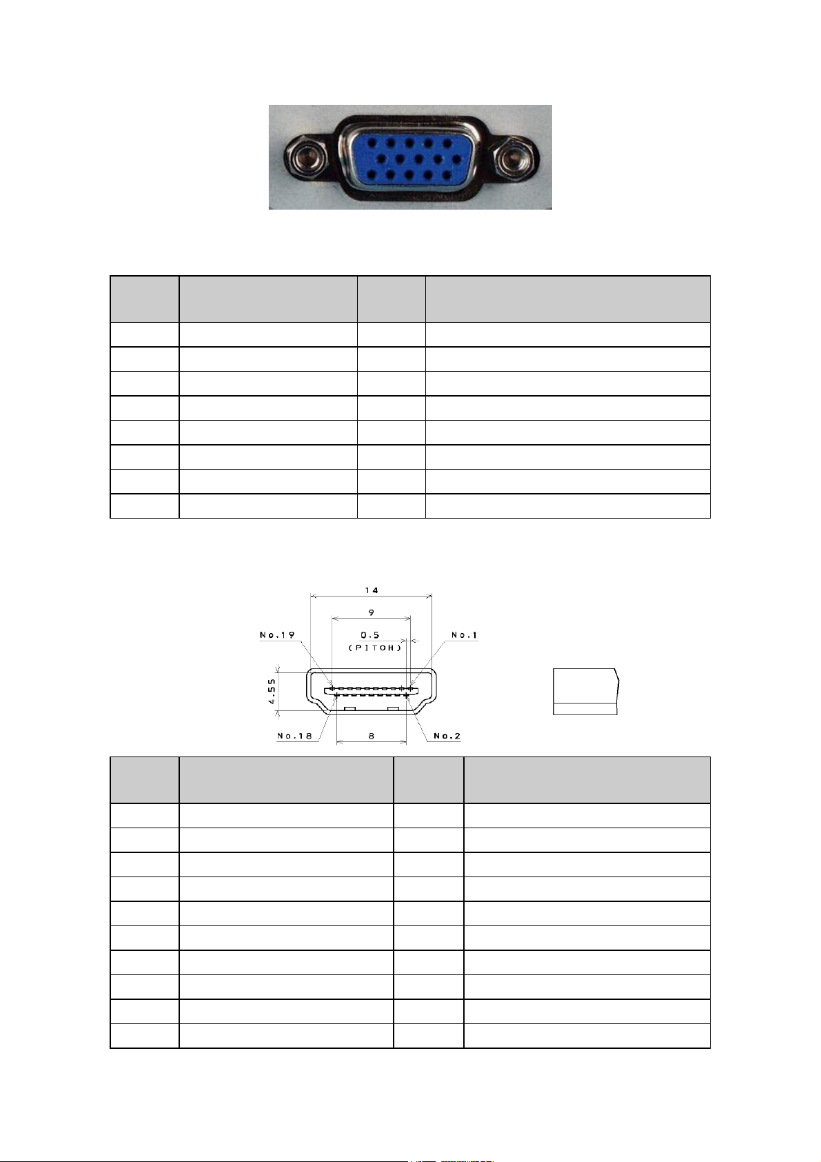
3.1 RGB Signal Input
15 - Pin Color Display Signal Cable
Pin No. Description Pin No. Description
1 Red Video 9 No Pin
2 Green Video 10 Sync Ground
3 Blue Video 11 SDA(Remote Control)
4 SCL(Remote Control) 12 Serial Data for DDC
5 Ground 13 H-Sync.
6 Red Video Ground 14 V-Sync.
7 Green Video Ground 15 Serial Clock for DDC
8 Blue Video Ground
3.2 HDMI Digital Connector Pin Assignments
Pin No. Description Pin No. Description
1 TMDS Data2+ 2 TMDS Data2 Shield
3 TMDS Data2- 4 TMDS Data1+
5 TMDS Data1 Shield 6 TMDS Data1-
7 TMDS Data0+ 8 TMDS Data0 Shield
9 TMDS Data0- 10 TMDS Clock+
11 TMDS Clock Shield 12 TMDS Clock-
13 CEC 14 NC
15 SCL 16 SDA
17 DDC/CEC Ground 18 +5V Power
19 Hot Plug Detect
6
Page 7
3.3 Compatible Mode Table
Analog RGB Input Signal Timing
D26W931/D32W931/LC42H053
Horizontal Vertical Sync Polarity Presence Screen Mode
Dots × Lines
720×400 31.47 70.00
640×480 31.47 59.94
640×480 37.50 75.00
640×480 37.86 72.81
800×600 37.88 60.32
800×600 46.88 75.00
800×600 48.08 72.19
832×624 49.73 74.55
1024×768 48.40 60.00
1024×768 60.02 75.03
1024×768 56.48 70.07
1360×768 47.70 60.00
Frequency Frequency
(kHz) (Hz)
Horizontal Vertical Horizontal Vertical
NEG POS YES YES YES YES
NEG NEG YES YES YES YES
NEG NEG YES YES YES YES
NEG NEG YES YES YES YES
POS POS YES YES YES YES
POS POS YES YES YES YES
POS POS YES YES YES YES
NEG NEG YES YES YES YES
NEG NEG YES YES YES YES
POS POS YES YES YES YES
NEG NEG YES YES YES YES
POS POS YES YES YES YES
Normal
(4:3)
LC32W053
VESA MODES
Horizontal Vertical
Nominal
Mode Resolution Total
640x480@60Hz 800 x 525 31.469 N 59.940 N 25.175
VGA
SVGA
XGA
WXGA 1360x768@60Hz 1792X795 47.712 P 60.015 P 85.5
640x480@72Hz 832 x 520 37.861 N 72.809 N 31.500
640x480@75Hz 840 x 500 37.5 N 75 N 31.500
720x400@70Hz 900 x 449 31.469 N 70.087 P 28.322
800x600@56Hz 1024 x 625 35.156 P 56.25 P 36.000
800x600@60Hz 1056 x 628 37.879 P 60.317 P 40.000
800x600@72Hz 1040 x 666 48.097 P 72.188 P 40.000
800x600@75Hz 1056 x 625 46.875 P 75 P 49.5
1024x768@60Hz 1344x806 48.363 N 60.004 N 65.000
1024x768@70Hz 1328x806 56.476 N 70.069 N 75.000
1024x768@75Hz 1312x800 60.023 P 75.029 P 78.750
Frequency
(KHz)
Sync
Polarity
Nominal
Freq.
(Hz)
Sync
Polarity
Nominal
Clock
(MHz)
Full
(16:9)
Pixel
7
Page 8

HDMI Input Signal Timing
D26W931/D32W931
VESA MODES
Horizontal Vertical
Nominal
Mode Resolution Total
720P 1280×720P 45.00 60 74.25
1080i 1920X1080i 33.75 60 74.25
480P 720X480P 31.54 60 27.00
480i 720X480i 15.75 60 13.51
Frequency
(KHz)
Sync
Polarity
Nominal
Freq.
(Hz)
Sync
Polarity
Nominal
Pixel
Clock
(MHz)
LC32W053/LC42H053
Nominal
Mode Resolution Total
1080P 1920X1080 67.5 60 148.50
720P 1280×720 1650 x 750 45.00 60 74.25
1080i 1920X1080 2200 x 1125 33.75 60 74.25
480P 720X480 858 x 525 31.50 60 27.03
480i 720X480 1716 x 525 15.75 60 13.51
Horizontal
Frequency
(KHz)
Nominal Vertical
Frequency
(Hz)
Nominal
Pixel
Clock
(MHz)
8
Page 9
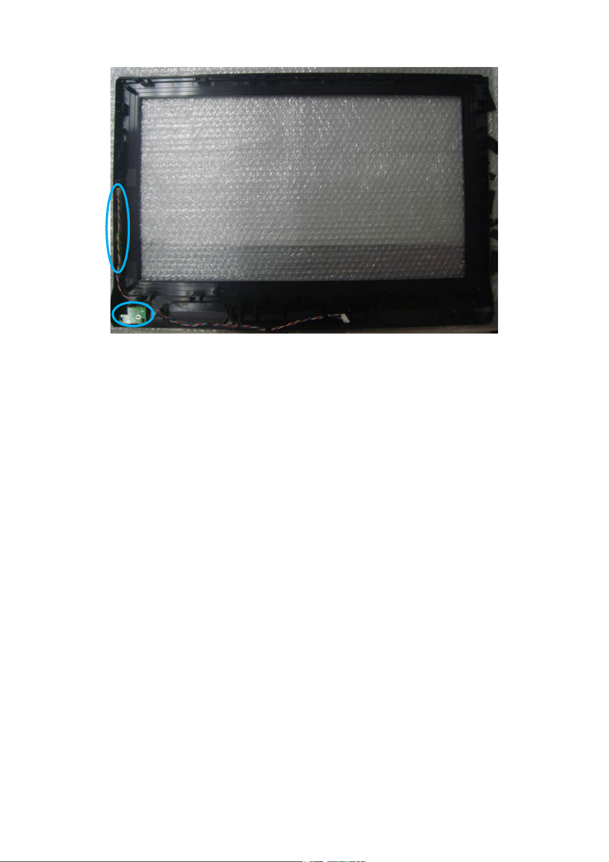
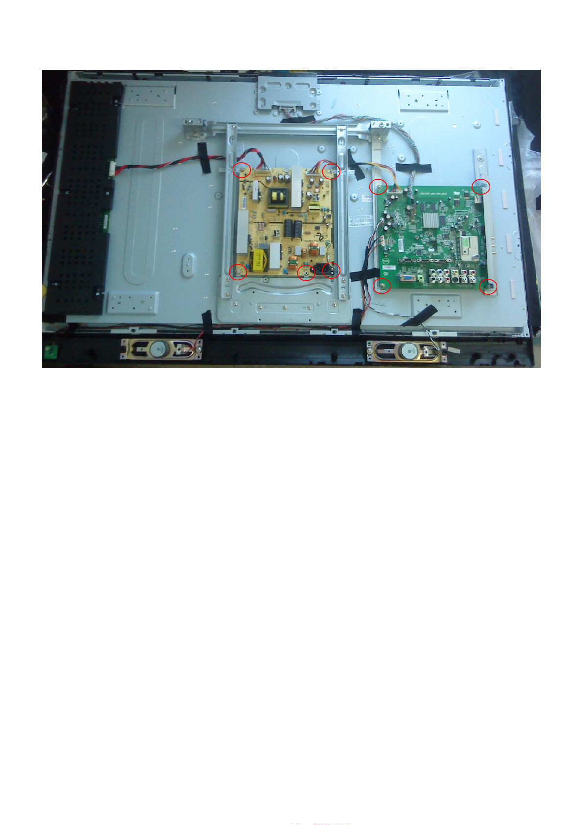
4. Mechanical Instructions
D26W931
1. Remove the screws to remove the rear cover ass’y and stand ass’y.
2. Remove the screws to remove main board, power board, bracket and speakers and separate panel and bezel.
9
Page 10
3. Remove the screws to remove IR board and key board.
10
Page 11

D32W931
1. Remove the screws to remove the rear cover ass’y and base ass’y.
2. Remove the screws to remove main board, power board and bracket.
11
Page 12
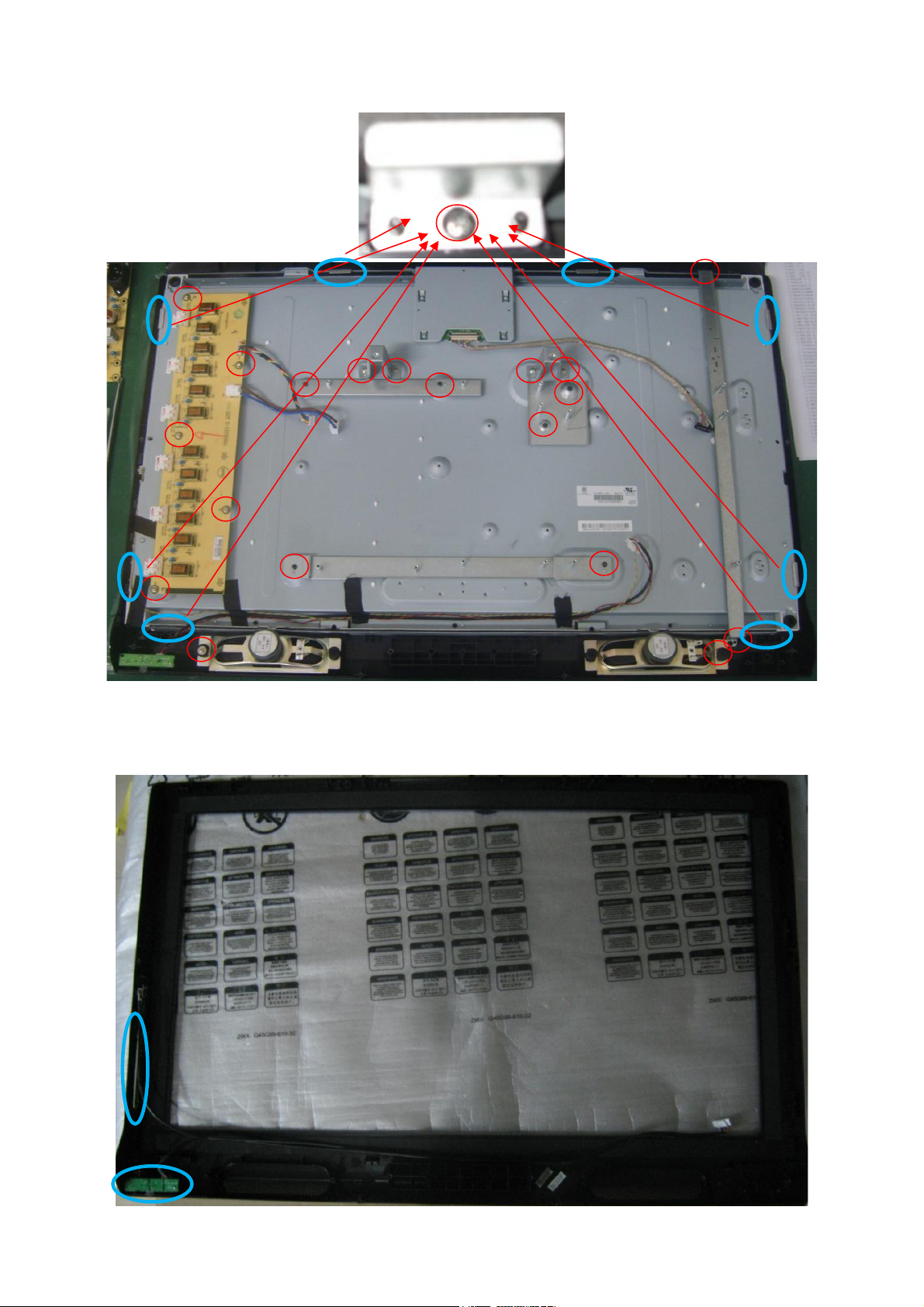
3. Remove the screws to remove inverter board, speakers and bracket and separate panel and bezel.
4. Remove the screws to remove key board and IR board.
12
Page 13

LC32W053
1. Remove the screws to remove the rear cover.
2. Remove the screws to remove the stand base, main board, power board, inverter board and LVDS to FFC board.
13
Page 14
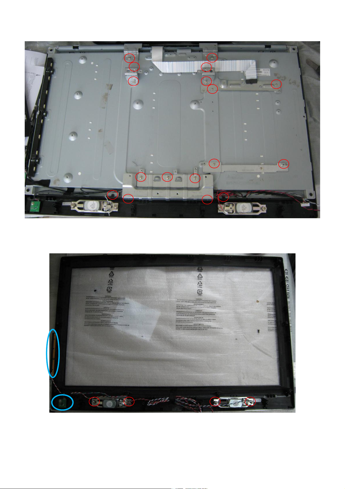
3. Remove the screws to remove the bracket and separate panel and bezel.
4. Remove the screws to remove IR board, key board and speakers.
14
Page 15
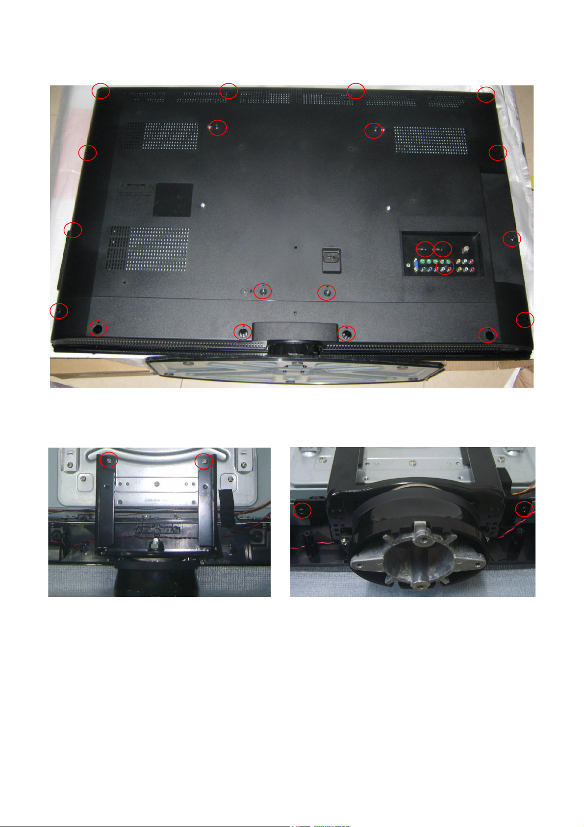
LC42H053
1. Remove the screws to remove the rear cover.
2. Remove the screws to remove the stand base.
15
Page 16
3. Remove the screws to remove main board and power board.
16
Page 17

4. Remove the screws to remove the bracket and speakers and separate the panel and bezel.
5. Remove the screws to remove key board and IR board.
17
Page 18
p
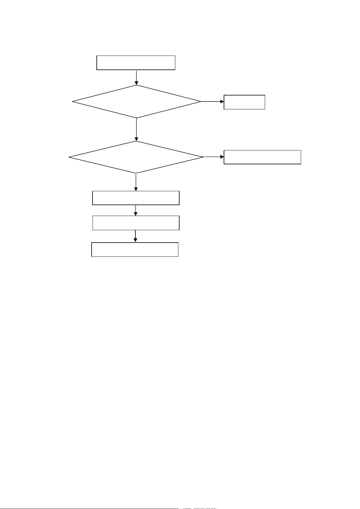
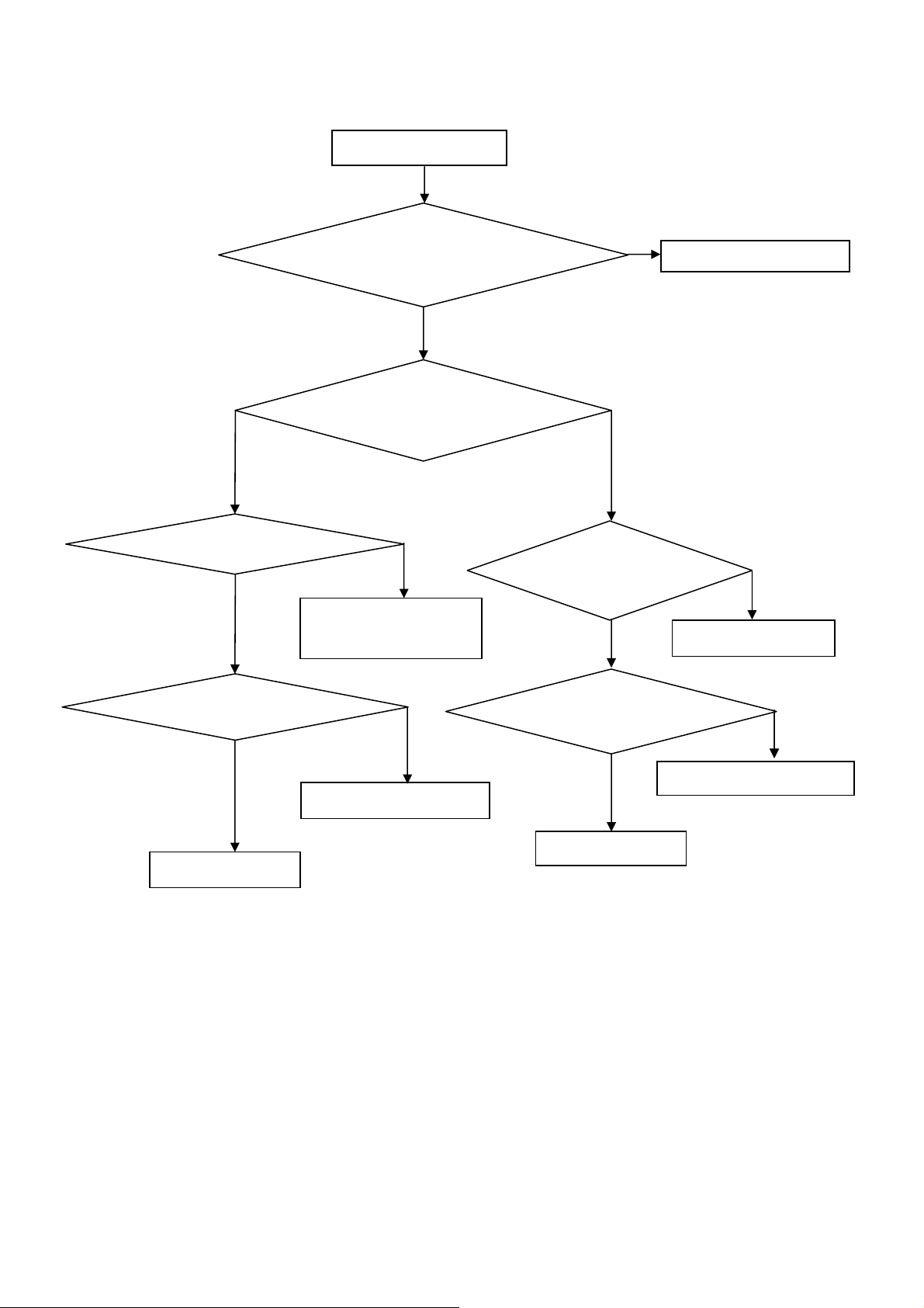
5. Repair Flow Chart
1. No power
No power (LED “Off”)
Check the AC input and
the
ower is “ON”?
Yes
Power board output=5V?
Yes
Check the IR board and LED
Replace the IR board
No
Replace the main board
No
Power “On”
No
Replace the power board
18
Page 19
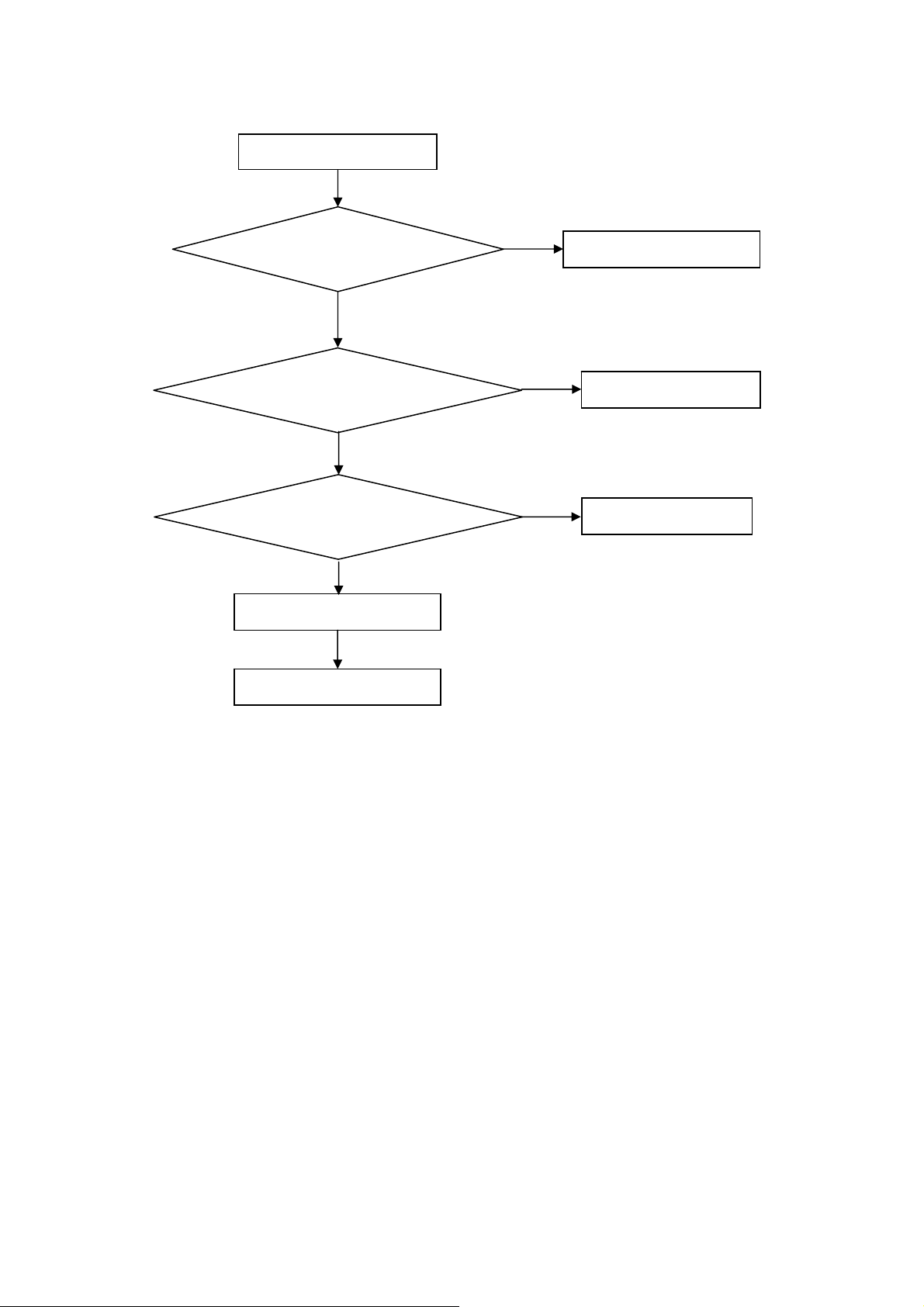
2. Can’t start
Can’t start(LED red)
Power board output=24V?
Yes
Check the power key is under control?
No
Check the IR receiver is normal?
No
Replace the power board
Yes
Replace the key board
Yes
Replace the IR board
No
Replace the main board
No
Replace the Power board
19
Page 20
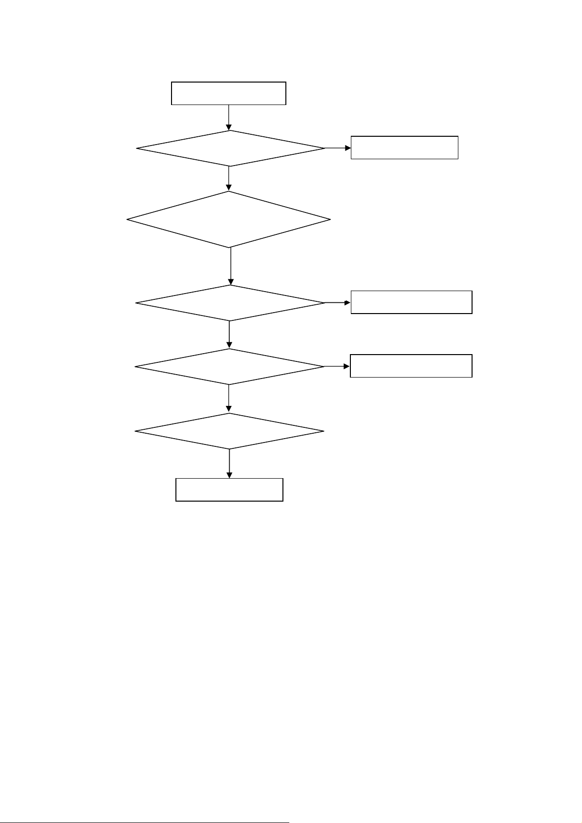
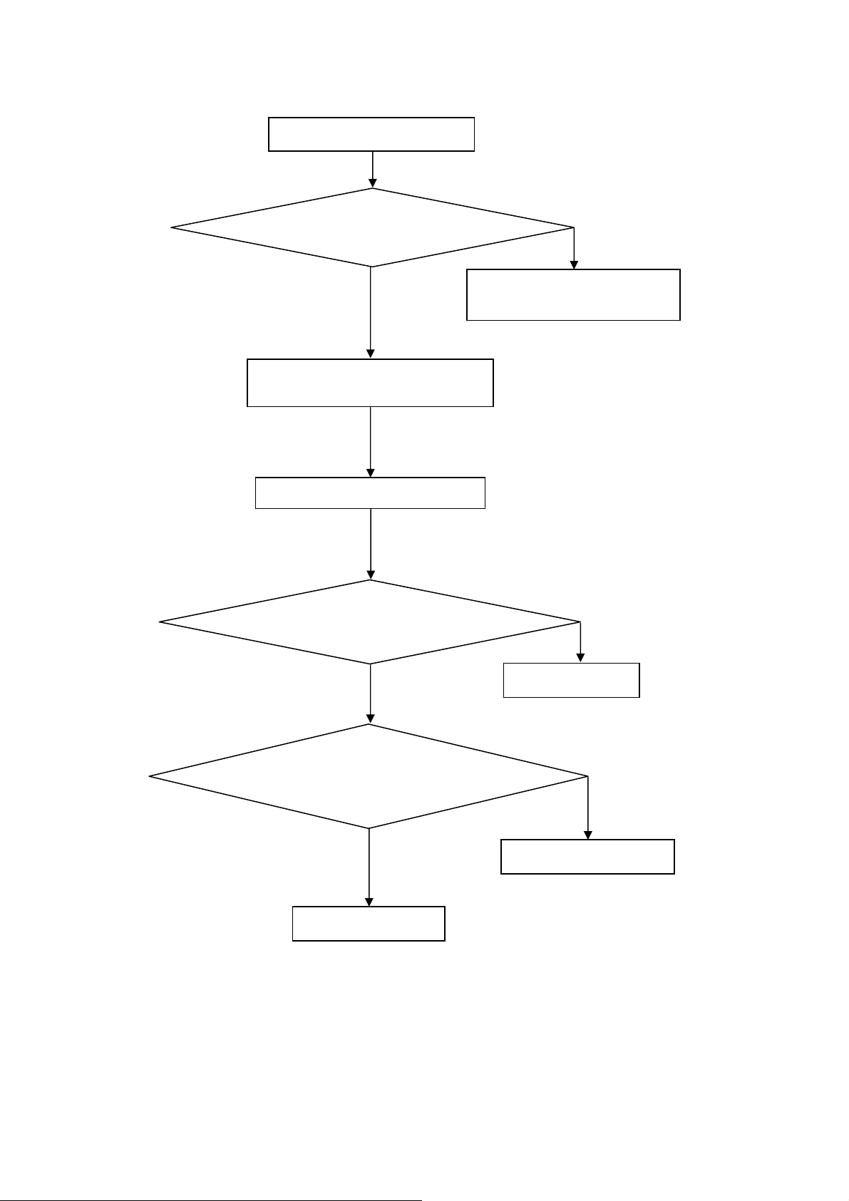
3. Abnormal Display
Abnormal Display
Check the source
Yes
Enter factory mode to do
“EEPROM initial”&“Reset”
No
No
Reset the source
Check the main board
Yes
Check the LVDS cable
Yes
Check the panel
No
Replace the panel
No
Replace the main board
No
Replace the LVDS cable
20
Page 21
4. No display
No display (LED blue)
Check TV is under control and power
on/off by remote control and power key?
Yes
Check the LVDS cable
Yes
Yes
Check the backlight is
“On”?
No
Reinsert or replace the
LVDS cable
No
No
Check the B/L
signal is available?
Yes
Replace the main board
No
Replace main board
Panel Vcc = 5V?
Yes
Replace the Panel
No
Replace the main board
Power board output=24V?
Yes
Replace the Panel
Replace the power board
No
21
Page 22
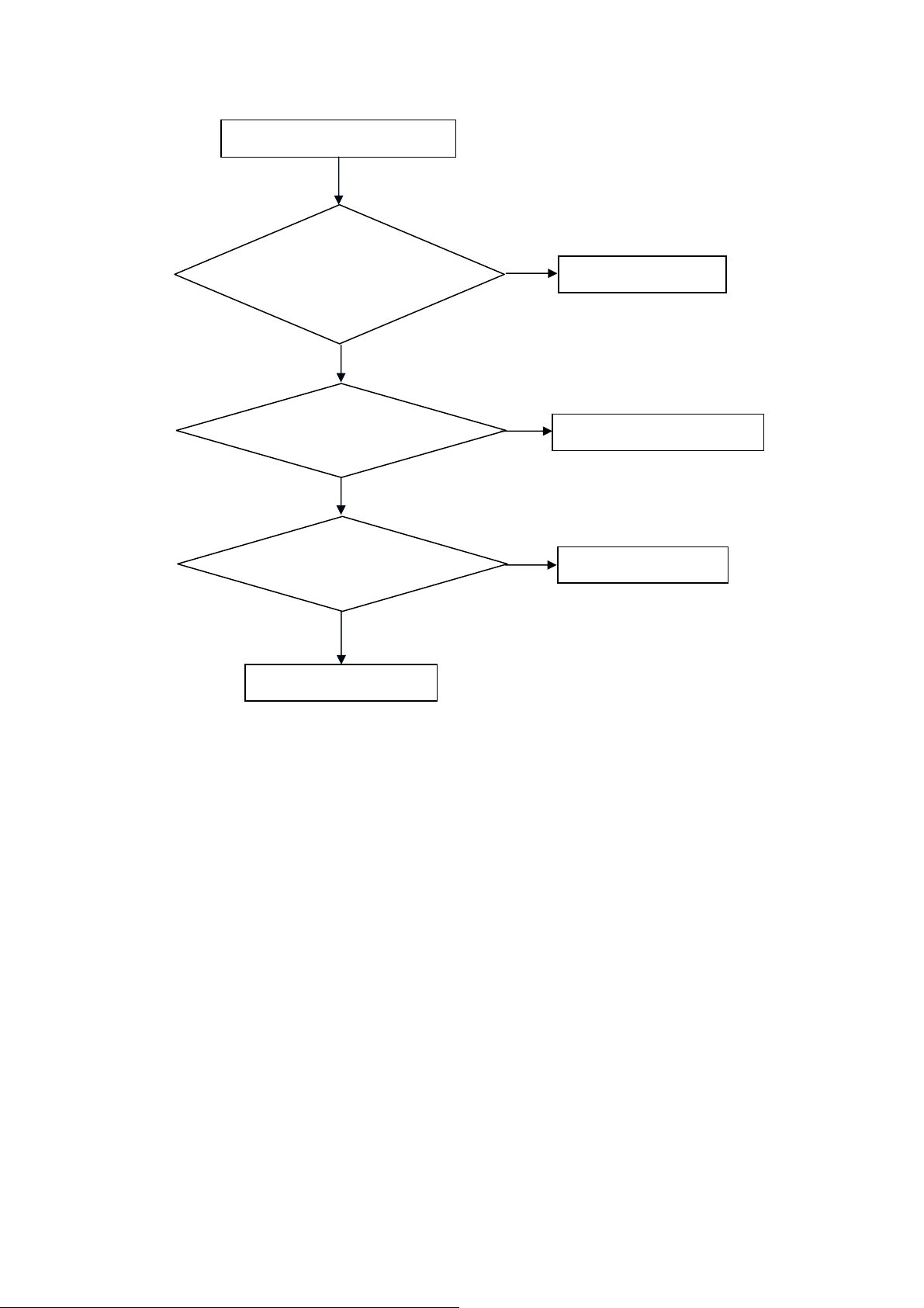
5. Sound problem
No sound or sound abnormal
Check the audio source connection
and the TV system are correct?
Yes
Check the TV is muted, adjust the
volume or enter the menu to reset?
No
No
Reinsert the audio cable or
change the TV system
Enter factory mode to do “Reset”
No
Check the cable between the
speakers and main board is OK?
Yes
Check the speaker resistance value is in spec
(Remark: The value is marked on the speaker)?
Yes
Replace the cable
Replace the main board
No
No
Replace the speaker
22
Page 23
6. Remote control malfunction
Remote Control malfunction
Check the remote control battery is
not properly placed or no power?
No
Use the other remote controls
No
Whether the IR board is
abnormal?
No
Replace the main board
Yes
Replace the battery
Yes
Replace the remote control
Yes
Replace the IR board
23
Page 24
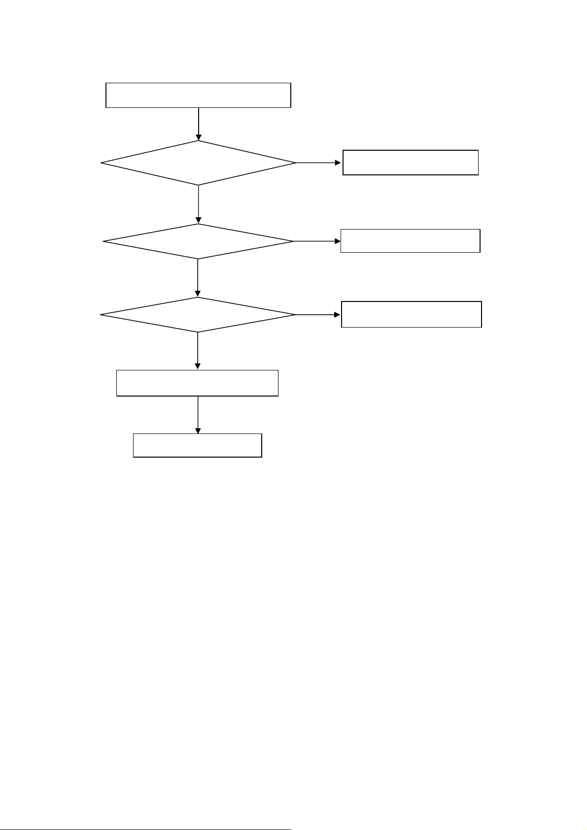
7. OSD is unstable or can’t work normally
OSD is unstable or can’t work normally
Key board connected properly?
Yes
Buttons are OK?
Yes
Key board is OK?
Yes
Enter factory mode to do “Reset”
No
No
No
No
Reconnect the key board
Replace the button function
Replace the key board
Replace the main board
24
Page 25
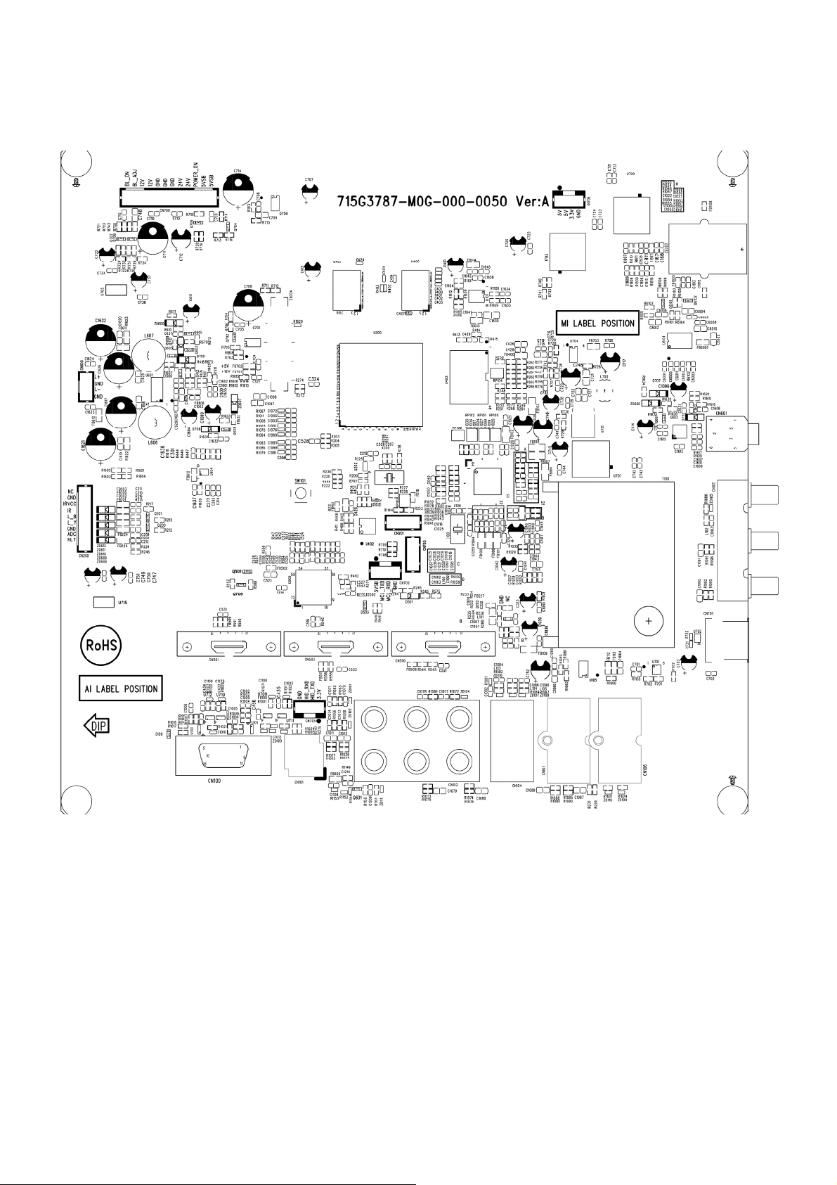
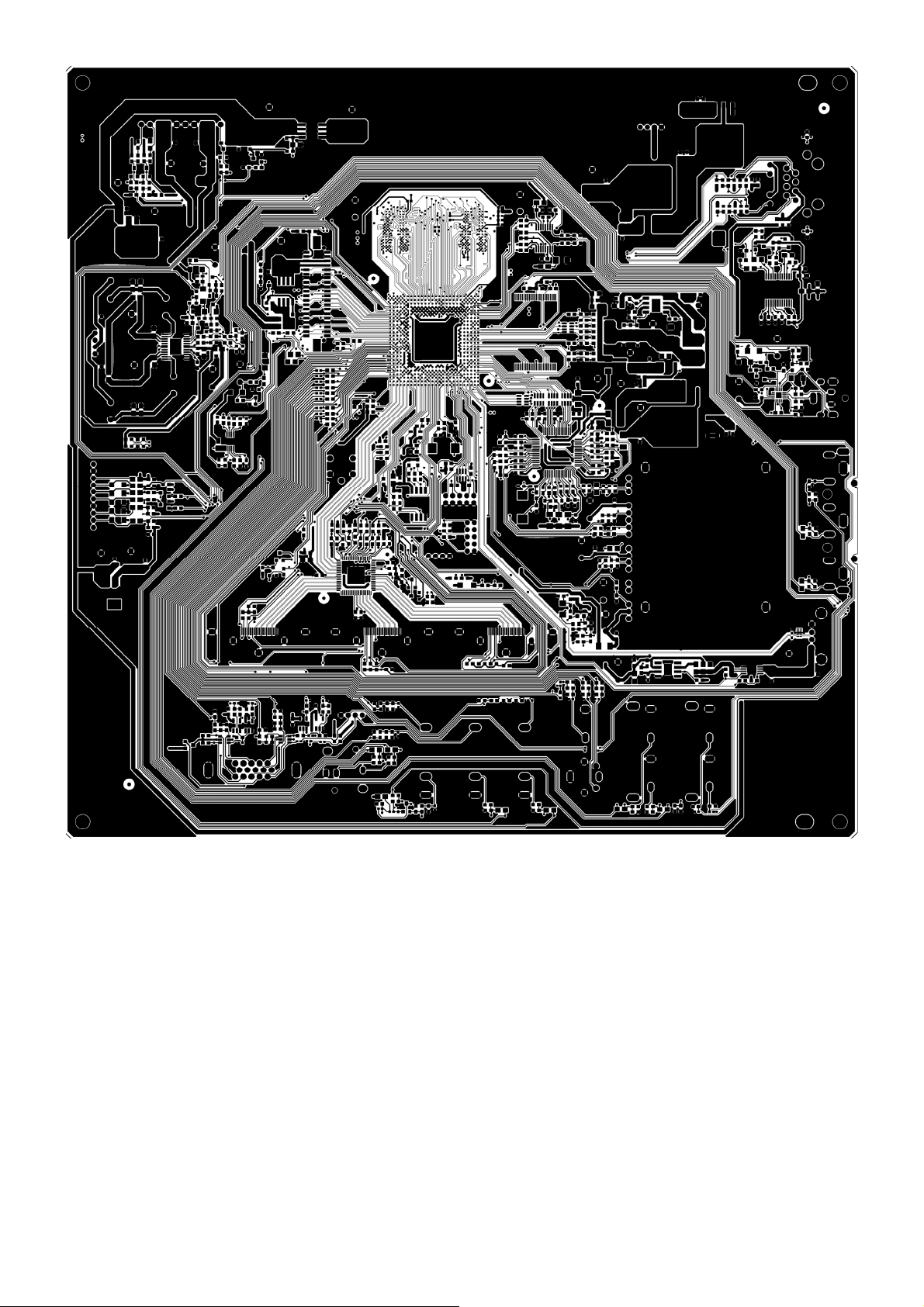
6. PCB Layout
6.1 Main Board
715G3787M0G000005K
25
Page 26
26
Page 27

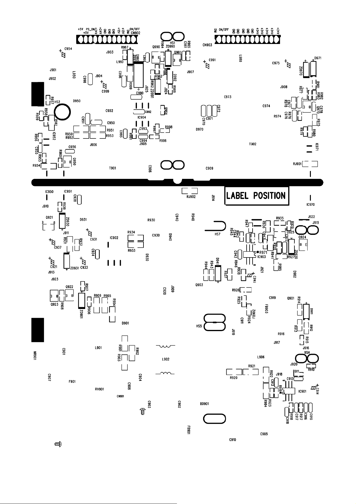
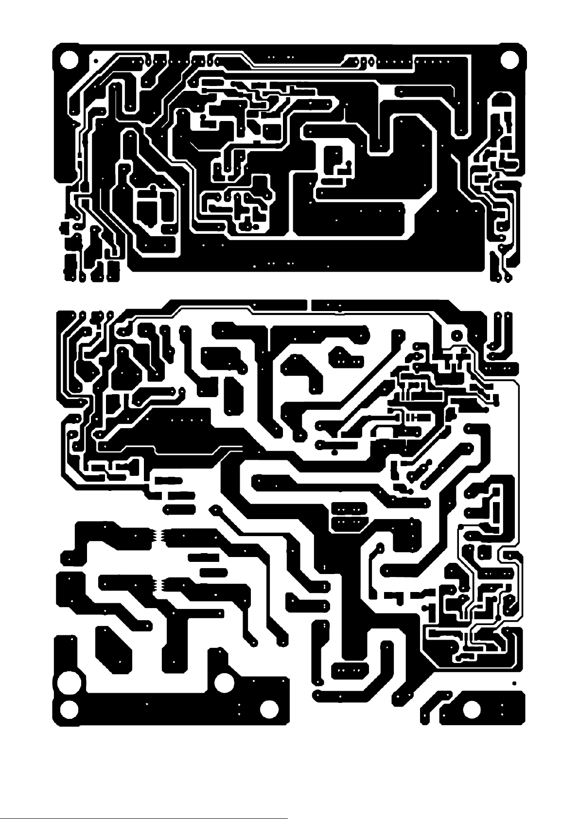
6.2 Power Board
D26W931 715G2907 1 3
27
Page 28
28 29
Page 29
Page 30
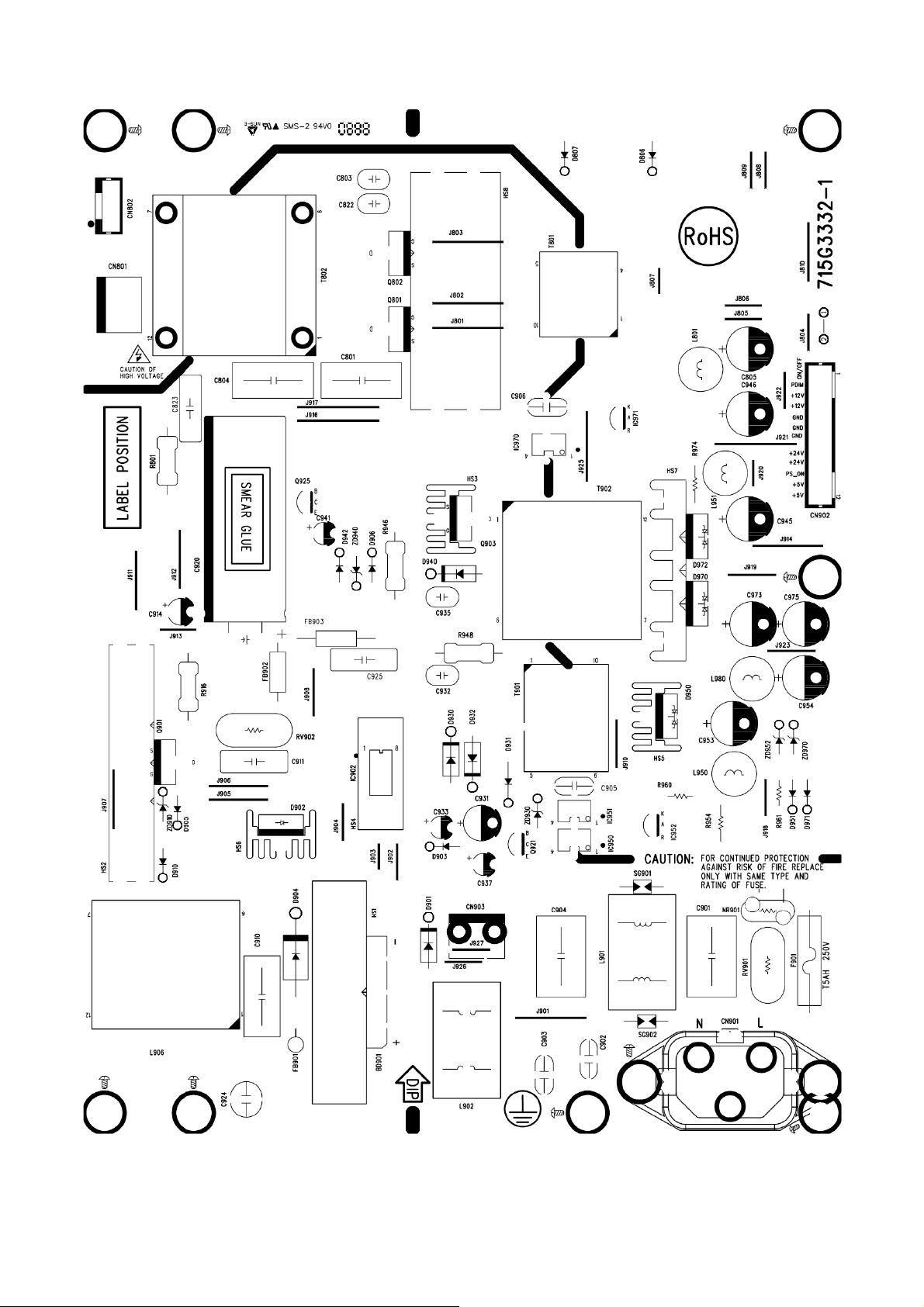
D32W931 715G3332 1
30
Page 31

31 32
Page 32

Page 33

D32W931 715G3690P01000003M
33
Page 34

LC32W053 715G3811P01W30003S
34
Page 35

35 36
Page 36

Page 37

LC32W053 715G4132P01000003H
37
Page 38

LC42H053 715G3885P02W30003S
38
Page 39

39 40
Page 40

Page 41

6.3 Key Board
D26W931/D32W931 715G4151K01000001S
LC32W053/LC42H053 715G3814K01003004S
6.4 IR Board
D26W931 715G3304 1
41
Page 42

D32W931 715G3394 2
LC32W053/LC42H053 715G3821R01000004M
42
Page 43

6.5 LVDS to FFC Board
LC32W053 715G4417T01000004S
43
Page 44

7. Adjustment
White Balance Adjustment
Approximately 60 minutes should be allowed for warm up before proceeding white balance adjustment.
Before started adjust white balance, please set the Ca210 Channel to 05 Channel and set it’s mode to xyLv mode.
Color Temp. Cold Normal Warm
x 272 285 313
AV/HDMI/VGA/Component
Mode
Note: The tolerance of the Cold/Normal/Warm color coordinates should be less than ± 20
How to setting the Ca210 channel, you can reference to Ca210 user guide or simple use the “Memory CH” up or
down to set the channel to 05 channel, and use the “Mode” key to set the mode to xyLv.
Following is the procedure to do white-balance adjust
1. Press menu key and then press number key 1 Æ 9 Æ 9 Æ 9Æ Enter, it will achieve the factory mode. Take
other model’s factory menu for example:
y 278 293 329
Y More than 350cd/cm2(at full white)
In the White Balance you can adjust 3 items.
SCALER GAIN R, G, B Æ R, G, B Gain adjust.
Adjust AV Source:
1. Set the pattern generator to timing 307 or PAL-M timing. And Select the item of Current Source and select
composite Source
2. Switch the Ca210 to xyLv-mode (with press “MODE” button)
3. Switch the Ca210 channel to Channel 05 (with up or down “MEMORY CH” button)
4. The LCD-indicator on Ca210 will show x =285, y =293, Lv can adjust to More than 350cd/cm
44
2
(at full white).
Page 45

5. Enter the item “Color Temp” to select Normal to adjust.
6. Use the item R Gain,G Gain or B Gain to adjust white balance: use 80 IRE (Pattern 141) signal, and adjust the
white balance, until the Ca210 show x =285, y =293.
Adjust HDMI Source:
1. Set the pattern generator to timing 347 or HDMI-720P@60Hz timing. And Select the item of Current Source and
select HDMI Source
2. Switch the Ca210 to xyLv-mode (with press “MODE” button)
3. Switch the Ca210 channel to Channel 05 (with up or down “MEMORY CH” button)
2
4. The LCD-indicator on Ca210 will show x =285, y =293, Lv can adjust to More than 350cd/cm
5. Enter the item “Color Temp” to select Normal to adjust.
6. Use the item R Gain,G Gain or B Gain to adjust white balance: use 80 IRE (Pattern 141) signal, and adjust the
white balance, until the Ca210 show x =285, y =293.
Adjust VGA Source:
1. Set the pattern generator to timing 137 or 1024*768@60Hz timing. And Select the item of Current Source and
select VGA Source
(at full white).
2. Switch the Ca210 to xyLv-mode (with press “MODE” button)
3. Switch the Ca210 channel to Channel 05 (with up or down “MEMORY CH” button)
2
4. The LCD-indicator on Ca210 will show x =285, y =293, Lv can adjust to More than 350cd/cm
(at full white).
5. Enter the item “Color Temp” to select Normal to adjust.
6. Use the item R Gain,G Gain or B Gain to adjust white balance: use 80 IRE (Pattern 141) signal, and adjust the
white balance, until the Ca210 show x =285, y =293.
Adjust Component Source:
1. Set the pattern generator to timing 314 or HDTV-720p@60Hz timing. And Select the item of Current Source and
select Component Source
2. Switch the Ca210 to xyLv-mode (with press “MODE” button)
3. Switch the Ca210 channel to Channel 05 (with up or down “MEMORY CH” button)
2
4. The LCD-indicator on Ca210 will show x =285, y =293, Lv can adjust to More than 350cd/cm
(at full white).
5. Enter the item “Color Temp” to select Normal to adjust.
6. Use the item R Gain,G Gain or B Gain to adjust white balance: use 80 IRE (Pattern 141) signal, and adjust the
white balance, until the Ca210 show x =285, y =293.
7. Enter the item “Color Temp” to select Cool to adjust.
8. Use the item R Gain,G Gain or B Gain to adjust white balance: use 80 IRE (Pattern 141) signal, and adjust the
white balance, until the Ca210 show x =272, y =278.
9. Enter the item “Color Temp” to select Warm to adjust.
10. Use the item R Gain,G Gain or B Gain to adjust white balance: use 80 IRE (Pattern 141) signal, and adjust the
white balance, until the Ca210 show x =313, y =329.
45
Page 46

8. Block Diagram
VP-35HRV
Panasonic
D Tuner
HDMI 1
HDMI 2
HDMI 3
HDMI 4
IF
TC90517FP
YPb P r +A ud io IN
AV CVBS+Audio IN
Side A V +S video+Audi o IN
SII9187ACNU
VGA RGB +Audio IN
TS S tre am
HDMI
HIDTV_PRO_SX27
L/R
AD52582
Audio Speaker Amp
APA2176
Headphone Amp
Audio out
APA2175QBI
SPDIF out
SPEAKER
BD8012FVJ
U701 power
USB
64Mx16_DDR2
64Mx16_DDR2
W25B40VSNI
SPI Flash
46
Panel
NAND Flash
512Mx8
Page 47

5VSB
5VSB 3VSB
AIC1117-33PY
POWER_ON
AO4449
MOS
HiDTV
5V
5V
5V
5V
AIC1084-33PM
AZ1117D-2.5
G5627F11U
BD8012FVJ
SPI Flash
W25B40VSNI
HP_VCC_25
HP_VCC1V
VCCH1
3.3V
3.3V
3.3V
HiDTV
HiDTV
SII9187ACNU
HDMI SWITCH
HiDTV
AIC1084-18PM
AZ1117D-ADJ
HP_VCC_18
1.2V_TUNER
NAND Flash
128Mx8
HiDTV DDR2
TC90517FP
TC90517FP
12V
24V
12V
PANEL_ON
24V
AO4449
MOS
AD82581B
Audio Speaker Amp
5V
5V
PANEL VDD
APA2176
Headphone Amp
SC4215ASTRT
47
USB
5V_Tuner
VP-35HRV
Tuner
Page 48

9. Schematic Diagram
9.1 Main Board
715G3787M0G000005K
TS1_D[0..7]
TS1_CLK
TS1_ SY NC
TS1_DEN
TS1_ CLK
TS1_D0
TS1_SYNC
TS1_ DEN
T1_S IF
C207
20P 50V
5V
TS1_ D0
HDMI_RX0HDMI_RX0+
HDMI_RX1HDMI_RX1+
HDMI_RX2HDMI_RX2+
HDMI_RXCHDMI_RXC+
HDMITX_5V
1M 1/10W
R207
24MHz
X20 0
4
5
3
6
2
7
1
8
RP101
8P4R 33 OHM +-5% 1/16W
NC 8P4R 33 OHM +-5% 1/16W
RP106
5
6
7
8
CVBS1_IN
PC_R_I N
PC_G_IN
PC_B_IN
PC_HS_I N
PC_VS_IN
Y1_IN
PB1_IN
PR1_IN
CVBS2_IN
SV_Y_I N
TV_C VBS
SV_C_IN
C206
100N 50V
R208
33 OHM 1/10W
12
C208
20P 50V
TS1_D0
TS1_D1
TS1_D2
TS1_D3
TS1_D4
TS1_D5
TS1_D6
TS1_D7
4
3
2
1
R204 4.7K 1/10W
R205 4.7K 1/10W
C205
100N 50V
AD6
AC6
AC7
AD7
AD3
AD4
AC4
AC5
AD5
AD1
AC3
AD2
ANT SIF
AE5
AF5
AF6
AE6
AB6
AF7
AE7
AF2
AF3
AE3
AF4
AE4
AB5
AE1
D2
D1
E2
E1
F2
F1
C2
C1
B1
B3
A1
B2
B5
A3
A2
B9
B8
D10
D4
C4
B7
A10
D8
A7
B10
D9
C8
C10
C9
D7
C6
D5
D6
C5
A4
B4
A6
B6
T1
R1
E3
E4
TS1D 0
TS1D 1
TS1D 2
TS1D 3
TS1D 4
TS1D 5
TS1D 6
TS1D 7
TS1CLK
TS1S YN C
TS1D EN
TS2D 0
TS2D 1
TS2D 2
TS2D 3
TS2D 4
TS2D 5
TS2D 6
TS2D 7
TS2CLK
TS2S YN C
TS2D EN
TSS_CLK
TSS_DI
TSS_SYNC
TSS_DEN
RX0RX0+
RX1RX1+
RX2RX2+
RXCRXC+
ANTS TO
PWR5V
DSDA
DSCL
CVBS1
CVBS_OUT1
CVBS_OUT2
PCR
PCG
PCB
PCHS
PCVS
YG1
PBB1
PRR1
YG2
PBB2
PRR2
YG3
PBB3
PRR3
C
FS1
FB1
FS2
FB2
FS3
FS4
SIFN
SIFP
XTLI 2 4 M
XTLO24M
INTN
RSTO
RESET_Demo_#
U200A
HiDTV-Pro_SXB
(1/5)
TS_IN
HDMI_IN
ANALOG_IN
LVDS_OUT
I2S PORT
I2C PORT
UART PORT
USB PORT
ADC
MISC
T P V ( Top Victory Electronics Co . , Ltd. )
絬 隔 瓜 絪 腹
Key Component
Date
HIDTV
04:HiD PRO SX-1
USBPPON
RREF EXT
I2SCLKIN
PC
AV
YPBPR
Side
SCART2
TESTCON
TESTMOD
MASTSEL
TA1M
TA1P
TB1M
TB1P
TC1M
TC1P
TD1M
TD1P
TE1M
TE1P
TCL K1M
TCL K1P
TA2M
TA2P
TB2M
TB2P
TC2M
TC2P
TD2M
TD2P
TE2M
TE2P
TCL K2M
TCL K2P
USBOC
TXD2
RXD2
SCKIN
WSI2S
SDI2S
I2SCLK
SPDIF
MUTE
SCLM1
SDAM1
SCLM2
SDAM2
SPKOR
SPKOL
HPHOR
HPHOL
AOR1
AOL1
AOR2
AOL2
A15
B15
C16
C15
B16
A16
C18
C17
B18
A18
A17
B17
A19
B19
C20
C19
B20
A20
C22
C21
B22
A22
A21
B21
AC1
DP
AB1
DN
AB3
AB2
AC2
AF20
TXD
AF21
RXD
Y1
AA1
AA3
AA4
AB4
AC21
SCK
AD21
WS
AF22
SD1
AE22
SD2
AD22
SD3
AF23
AA2
AE21
D21
Y3
Y2
C24
A23
B11
AR1
A11
AL1
D11
AR2
C11
AL2
C12
AR3
D12
AL3
A12
AR4
B12
AL4
B13
AR5
A13
AL5
B14
A14
D17
D16
D14
C14
D15
E14
M3
M2
B24
HID_TXD
HID_RXD
3.3V
HP_TESTCON
HP_TESTMOD
HP_MASTSEL
OEM MODEL
TPV MODEL
PCB NAME
R201 6.04K +-1% 1/10W
R275 10K 1/10W
R247 10K 1/10W
C203 1uF 25V
C204 1uF 25V
C321 1uF 25V
C324 1uF 25V
715G3787-M01-000-0050
Sheet
418Wednesday , May 05, 2010
3VSB
R200
4.7K 1/10W
R202
NC 0R 05 1/10W
of
HID_TXD
HID_RXD
TX0AN
TX0AP
TX1AN
TX1AP
TX2AN
TX2AP
TX3AN
TX3AP
TX4AN
TX4AP
TXCKAN
TXCKAP
TX0BN
TX0BP
TX1BN
TX1BP
TX2BN
TX2BP
TX3BN
TX3BP
TX4BN
TX4BP
TXCKBN
TXCKBP
USB_DP
USB_DN
USB_PPON
USB_OC
HID_TXD
HID_RXD
I2S_CK
I2S_WS
I2S_SD
I2S_CLK
HP_SPDIF
OFF_MUTE
SCL_MST1
SDA_MST1
HDMI_SCL
HDMI_SDA
PC_RIN
PC_LIN
AV_RIN
AV_LIN
HD_RIN
HD_LI N
AV2_RIN
AV2_LIN
TV_AR
TV_AL
AX_HP_OUTR
AX_HP_OUTL
AX_OUTR
AX_OUTL
Size
Rev
称爹
3.3V
CN705
1
2
3
4
NC
Custom
01
称爹
>
<
48
Page 49

SF_SI
SF_SO
SF_WP#
SF_HOL D#
SF_CS
SF_SCK
3.3V
MIPS_JTAG_TRSTN
33 OHM 1/10W
R1144
R244
GND
RESET
U202
G692L293TCUf 2.91V
10K 1/10W
VCC
10
8
6
4
2
BL_ADJ
PANEL_ON
PHONE_DET
3VSB
R245
10K 1/10W
3VSB
4
3
MR
NC
CN201
9
7
5
3
1
MCU_JTAG_TDO
IR_D
KYBR D
PW_KEY
HDMI_CEC
STB_HS_DET
STB_VS_DET
AUX_POWER_ON#
BL_ON#
MCU_JTAG_TDI
MCU_JTAG_TMS
MCU_JTAG_TCK
POWER_ON
CN702
1
2
3
4
NC
LED_B
LED_Y
SW101
2
45
1 3
NC
R210
NC 0R05 1/ 10W
FRA[19. .22]
4.7K 1/10W
AMP_SD
AMP_MUTE
HP_MUTE
HDMITX_INT
HDMI_I 2C_SW
FRD[0..7]
R220
3.3V
FRA13
FRA14
FRA18
FRA23
FOE#
FWE#
GCS0
GCS2
NC 4.7K 1/ 10W
R222
R226
4.7K 1/10W
FRA13
FRA14
FRA18
FRA19
FRA20
FRA21
FRA22
FRA23
R236
4.7K 1/10W
FRD0
FRD1
FRD2
FRD3
FRD4
FRD5
FRD6
FRD7
U200B HIDTV
AC9
FRD0/PODD0
AF10
FRD1/PODD1
AD10
FRD2/PODD2
AB10
FRD3/PODD3
AE11
FRD4/PODD4
AC11
FRD5/PODD5
AF12
FRD6/PODD6
AD12
FRD7/PODD7
AB9
FRD8/ PODA0
AC10
FRD9/ PODA1
AE10
FRD10/ PODA2
AF11
FRD11/ PODA3
AD11
FRD12/ PODA10
AB11
FRD13/ PODA11
AE12
FRD14/ PODA12
AB12
FRD15/ PODA13
AF9
FRA0
AF18
FRA1/POD WE
AB17
FRA2/POD IORD
AC17
FRA3/POD IOWR
AD17
FRA4/POD REG
AE17
FRA5
AF17
FRA6
AB16
FRA7
AD15
FRA8
AE15
FRA9/POD OE
AF15
FRA10
AB14
FRA11
AC14
FRA12
AD14
AE14
AF14
AF13
AC16
AD16
AC15
AB15
AE16
AB13
AC13
AD13
AD9
AF16
AE9
AE2
AF1
AC12
AE23
AD23
AB7
AF8
AE8
AD8
AC8
AB8
AE18
AF19
AB18
AD18
AB20
F3
G1
G2
G3
G4
H1
H2
H3
H4
J4
J3
J2
J1
FRA13
FRA14
FRA15
FRA16
FRA17
FRA18
FRA19
FRA20
FRA21
FRA22
FRA23
FRA24
FOE#
FWE#
GCS0
GCS1
GCS2
BOOTCS
GPIO0
GPIO1
GPIO2
GPIO3
GPIO4
GPIO5
GPIO6
GPIO7
GPIO8
GPIO9
GPIO10
GPIO11
GPIO12
GPIO13
GPIO14
POD_A4
POD_A5
POD_A6
POD_A7
POD_A8
POD_A9
POD_I REQ
POD_RS T
POD_VS1
POD_WA IT
POD_OVERLOAD
HiDTV-Pro_SXB
(2/5)
FLASH INTERFACE
GPIO PORT
SF_SI
SF_SO
SF_WPN
SF_HOL DN
SF_CES
SF_SCK
TMS
TCK
TRSTN
LED
KYBRD
LGSEN
CEC
PWRON
AVLINK1
AVLINK2
STB_RSTO
RXIP
RXIN
TXOP
TXON
RSET_BG
H_BK_LITE
PWM0
PWM1
BOOST
BKLGON
TCON_ON
HP_DETECT
FSOURCE
HPD
STB_GP0
STB_GP1
STB_GP2
STB_GP3
STB_TXD
STB_RXD
STB_EN
SPI_EN
STB_SDA
STB_SCL
RSTN
ET_LED1
ET_LED2
PLL_TEST
POD_CE2
POD_CE1
POD_CD2
POD_CD1
POD_VCC_EN
POD_VCC_ENB
POD_VPP_EN
POD_VPP_ENB
TDI
TD0
IR
NC
L3
L2
L1
K5
L4
L5
MIPS_JTAG_TDI
W4
MIPS_JTAG_TDO
W3
MIPS_JTAG_TMS
W2
MIPS_JTAG_TCK
W1
MIPS_JTAG_TRSTN
Y4
K1
K2
N1
P1
K4
P5
N3
N2
K3
U2
U1
V1
V2
T3
D24
B23
12K4 1/10W 1%
C23
D23
E23
D22
E22
C3
D3
P2
P3
P4
R3
N5
N4
HP_STB_EN
M4
M5
T4
U4
M1
HP_RESET#
V3
V4
T2
AE13
AD19
AE19
AE20
AC18
AC19
AC20
AB19
AD20
IR_D
KYBRD
R218
HP_SPI_EN
MCU _TXD
MCU_RXD
876
123
LAN_RXIN+
LAN_RXIN LAN_TXIN+
LAN_TXIN-
R223
4.7K 1/10W
5
RP103
4.7 K 1/16W
4
3VSB
R224
4.7K 1/10W
ET_LED1
ET_LED2
3VSB
4.7K 1/10W
NC 4.7K 1/ 10W
LED_B
C212
10N 50V
R253
4.7K 1/10W
MIPS_JTAG_TCK
MIPS_JTAG_TDO
MIPS_JTAG_TMS
MIPS_JTAG_TRSTN
MIPS_JTAG_TDI
R211
3VSB
3VSB
R227
3VSB
NC 4. 7K 1/10W
R221
3VSB
R214
NC 4.7K 1/ 10W
R219
4.7K 1/10W
R228
NC 4.7K 1/ 10W
10K 1/10W
R225
1
2
T P V ( Top Victory Elec tronics C o . , Ltd. )
絬 隔 瓜 絪 腹
Key Component
Date
05:HiDPR O SX-2
49
OEM MODEL
TPV MODEL
PCB NAME
Sheet
715G3787-M01-000-0050
of
518Wednesday , May 05, 2010
Size
Rev
称爹
01
称爹
<
Custom
>
Page 50

HP_MD[0..31]
HP_WDQS[0..3]
HP_RDQS[0..3]
HP_MD0
HP_MD1
HP_MD2
HP_MD3
HP_MD4
HP_MD5
HP_MD6
HP_MD7
HP_MD8
HP_MD9
HP_MD10
HP_MD11
HP_MD12
HP_MD13
HP_MD14
HP_MD15
HP_MD16
HP_MD17
HP_MD18
HP_MD19
HP_MD20
HP_MD21
HP_MD22
HP_MD23
HP_MD24
HP_MD25
HP_MD26
HP_MD27
HP_MD28
HP_MD29
HP_MD30
HP_MD31
HP_WDQS0
HP_RDQS0
HP_WDQS1
HP_RDQS1
HP_WDQS2
HP_RDQS2
HP_WDQS3
HP_RDQS3
U200C HIDTV
AF25
MD0
AF26
MD1
AE25
MD2
AE26
MD3
AC24
MD4
AB24
MD5
AB25
MD6
AB26
MD7
AA25
MD8
AA26
MD9
HiDTV-Pro_SXB
Y25
MD1 0
Y26
MD1 1
W24
MD1 2
V24
MD1 3
V25
MD1 4
V26
MD1 5
K24
J24
J25
J26
G26
G25
G24
F25
E24
E25
E26
D26
B25
B26
A25
A26
AD26
AD25
W25
W26
H25
H24
C26
C25
MD1 6
MD1 7
MD1 8
MD1 9
MD2 0
MD2 1
MD2 2
MD2 3
MD2 4
MD2 5
MD2 6
MD2 7
MD2 8
MD2 9
MD3 0
MD3 1
WDQS0_DQS0
RDQS0_DQS0#
WDQS1_DQS1
RDQS1_DQS1#
WDQS2_DQS2
RDQS2_DQS2#
WDQS3_DQS3
RDQS3_DQS3#
DDR2 INTERFACE
(3/5)
MAA0
MAA1
MAA2
MAA3
MAA4
MAA5
MAA6
MAA7
MAA8
MAA9
MAA1 0
MAA1 1
MAA1 2
BA0
BA1
BA2
DQM0
DQM1
DQM2
DQM3
MC LK0
MCLK0#
MVR EF 2
MVR EF 1
CAS
RAS
WE
CS0
CKE
ODT
MZ Q
MR ES
L26
P24
K26
L24
N24
P25
N26
M25
N25
M24
K25
L25
U23
U26
T26
R24
AC25
Y24
H26
D25
R26
P26
A24
AD24
U25
U24
R25
T24
T25
M26
AF24
F26
HP_MA0
HP_MA1
HP_MA2
HP_MA3
HP_MA4
HP_MA5
HP_MA6
HP_MA7
HP_MA8
HP_MA9
HP_MA10
HP_MA11
HP_MA12
HP_BA0
HP_BA1
HP_BA2
HP_DQM0
HP_DQM1
HP_DQM2
HP_DQM3
R239
402ohm 1/ 10W +/ -1%
HP_MVREF2
HP_MVREF1
HP_MVREF2
C214
100N 50V
Near to IC
HP_MVREF1
C317
100N 50V
Near to IC
1K1/10W
1K1/10W
R237
R238
R255
1K1/10W
1K1/10W
HP_VCC_18
R254
HP_MA[0. .12]
HP_BA[ 0.. 2]
HP_DQM[0..3]
HP_MCLK0
HP_MCLK0#
C213
100N 50V
C216
100N 50V
HP_VCC_18
HP_CAS#
HP_RAS#
HP_WE#
HP_CS0#
HP_CKE
HP_ODT
C319
100N 50V
C318
100N 50V
T P V ( Top Victory Electronics Co . , Ltd. )
絬 隔 瓜 絪 腹
Key Component
Date
06:H iDPR O SX-3
50
OEM MODEL
TPV MO DEL
PCB N AME
Sheet
715G3787-M01-000-0050
618Wednes day , May 05, 2010
of
Size
Rev
称爹
Custom
01
称爹
<
>
Page 51

this GND should be
connect to Cleanly GND
HP_VCC _25
120 OHM
1 2
120 OHM
1 2
120 OHM
1 2
120 OHM
1 2
120 OHM
1 2
120OHM
VDDI _25
1 2
120 OHM
3.3V
1 2
3.3V
1 2
3VSB
1 2
FB208
120 OHM
0R05 1/10W
FB210
FB211
FB214
FB216
FB217
FB219
FB220
0R05 1/10W
9/1 at shanghai
3.3V POWER FOR ADC OUTPUT BUFFER
120 OHM
FB221
3.3V
1 2
GND connection for
Balls, should be at
far end outside
De-caps.
See Trident reference
board for details.
120OHM
FB205
10uF 6.3V
10uF 6.3V
R273
2.2U25V
R274
2.2U25V
10uF 6.3V
C239
10uF 6.3V
C249
10uF 6.3V
C253
10uF 6.3V
C259
10uF 6.3V
C263
10uF 6.3V
C270
10uF 6.3V
3.3V FOR TMDS RECEIVER
C272
100N 50V
C224
C221
C222
C233
C237
AGND_LAN
AGND_LAN
AVDD33_OU TBUF
C271
100N 50V
C273
10uF 16V
C219
100N 50V
C226
100N 50V
C223
100N 50V
C234
100N 50V
C238
100N 50V
C240
100N 50V
C250
100N 50V
C254
100N 50V
C260
100N 50V
C264
100N 50V
AVSSOUTBUF
AVCC33RX
U200D HIDTV
H5
AVDD33_SP
J6
R4
R2
C13
F13
D13
F14
E12
J13
E13
J14
E15
F15
T5
U5
U3
V6
AC22
AB21
E6
F7
K6
AGND_LAN
3.3V Analog Power for ADC AFE
AVDD33_SP
AVDD33
3.3V Analog Power for STANDBY
AVSS33
VCM_ADC
VCM for ADC
VSS25_AUDIO_AD C
VCM_DAC
VCM for DAC
VSS25_AUDIO_D AC
VCC25A
2.5V Analog Power for Audio CODEC
VSS25A
2.5V Power for Switch Circuits in ADC and DAC.
VCC25D
VSS25D
VCC25HP
2.5V Power for Head Phone
VSS25HP
VCC25A_BG
2.5V Analog Power for Ethernet BG
GNDA
VCC25A_TX
2.5V Analog Power for Ethernet TX
GNDA_TX
AVDD_MCK2
2.5V Analog Power for MCLK2 PLL
AVSS_MCK2
AVDD33OUTBUF
AVSSOUTBUF
AVCC33RX
3.3V Analog Power for OUTBUF
3.3V Analog power for T MDS receiver
HiDTV-Pro_SXB
2.5V LDO out for PLL & Analog core
3.3V for LDO & USB Analog Core
1.8V power shielding for MVREF1
1.8V power shielding for MVREF2
2.5V Analog power for LVDS PLL
(4/5)
2.5V Analog powr for LVDS
2.5V Analog powr for ANAPLL/APLL
2.5V Analog power for PLL
2.5V Power for ADCs
2.5V Analog power for T MDS receiver
PAVDDLLPLL
PAVSSLLPLL
AVDD25_ADC 1
AVDD25_ADC 2
AVDD25_ADC 3
AVDD25_ADC 4
2.5V for TMDS PLL
2.5V for Audio PLL
VDDREG
AGNDREG
VDDA33
VDDR1
VDDR2
VSSR1
VSSR2
VDDP
GNDP
LVDS_VDD
LVDS_VDD
LVDS_GND
LVDS_GND
AVDDPLL
AVSSPLL
AVSSADC1
INN1
AVSSADC2
INN2
AVSSADC3
INN3
AVSSADC4
INN4
AVCC
AVCC
AGND
AGND
PVCC
DGND
REGVCC
AA5
W6
AA6
AC23
G22
AE24
F22
E16
F16
D20
E20
F20
F21
E11
F12
R5
U6
E7
F8
A5
E9
F10
A8
E10
F11
A9
E8
F9
C7
F4
G5
G6
H6
F5
F6
E5
100N 50V
C220
HP_VDD P_USB
C227
100N 50V
C231
100N 50V
HP_LVDS_VD DP
C235
100N 50V
HP_LVDS_VD D
C241
100N 50V
PAVDDLLPLL
PAVSSLLPLL
AVDDPLL
AVSSPLL
AVDD25_ADC1
INN1
AVDD25_ADC2
INN2
AVDD25_ADC3
INN3
AVDD25_ADC4
INN4
AVCC
PVCC
REGVCC
C242
100N 50V
C225
10uF 6.3V
C228
10uF 6.3V
C232
100N 50V
C236
10uF 6.3V
C244
C243
100N 50V
C255 100N 50V
C258 100N 50V
C261 100N 50V
C262 100N 50V
T P V ( Top Victory Electronics Co . , Ltd. )
絬 隔 瓜 絪 腹
Key Component
07:HiDPRO SX-4
Date
100N 50V
AVSSADC1
INN 1_GND
AVSSADC2
INN 2_GND
AVSSADC3
INN 3_GND
AVSSADC4
INN 4_GND
C245
10uF 6.3V
AVDD25_AD C1
120 OHM
FB206
1 2
HP_VCC_18
HP_VCC _25
120OHM
FB209
1 2
120OHM
FB212
1 2
10uF 6.3V
3.3V
C246
OEM MOD EL
TPV MODEL
PCB NAME
Sheet
ANALOG PLL 2.5V POWER
PAVDDLLPLL
PAVSSLLPLL
C217
100N 50V
PLL 2.5V POWER
AVDDPLL
AVSSPLL
C229
100N 50V
HDMI Analog 2.5V POWER
AVCC
C247
100N 50V
2.5V FOR HDMI PLL
PVCC
C251
100N 50V
HDMI AUDIO PLL 2.5V
REGVCC
C256
100N 50V
C266
C265
100N 50V
100N 50V
715G3787-M01-000-0050
718Wednesday , May 05, 2010
of
C267
100N 50V
C218
10uF 6.3V
C230
10uF 6.3V
C248
10uF 6.3V
C252
10uF 6.3V
C257
10uF 6.3V
C268
22uF 10V
120 OHM
FB204
120 OHM
FB207
1 2
120 OHM
FB213
1 2
120 OHM
FB215
1 2
FB218
1 2
120OHM
Size
Rev
称爹
HP_VCC_25
12
HP_VCC _25
2.2uH
R240
C269
22uF 10V
<
Custom
01
称爹
>
51
Page 52

HP_VCC _18
AA23
AB22
AA22
P21
N21
M21
L21
T21
VDDM
VDDM
VDDM
VDDM
VDDM
VDDM
VDDM
VDDM
VDDM
VDDL: 1.0V, DLL and DDR Delay Line
VSS
VSS
VSS
VSS
VSS
VSSN9VSS
VSS
VSS
VSS
VSS
N10
N11
N12
N13
N14
C286
10N 16V
N15
10N 16V
C308
100NF 25V
M15
M16
C285
10N 16V
M17
M18
C307
100NF 25V
VSS
N16
C287
VSS
VSS
N17
VDDL
R21
VDDL
VSSP9VSS
P10
100NF 25V
VSS
VSS
P11
P12
C288
10N 16V
C309
3.3V
3.3K 1/10W
N18
VSSL
VSS
VSS
VSS
VSS
P13
P14
P15
P16
P17
10N 16V
100NF 25V
C289
C310
VSS
V18
VSS
V17
VSS
V16
VSS
V15
VSS
V14
VSS
V13
VSS
V12
VSS
V11
VSS
V10
VSS
V9
VSS
U18
VSS
U17
VSS
U16
VSS
U15
VSS
U14
VSS
U13
VSS
U12
VSS
U11
VSS
U10
VSS
U9
VSS
T18
VSS
T17
VSS
T16
VSS
T15
VSS
T14
VSS
T13
VSS
T12
VSS
T11
VSS
T10
VSS
T9
VSS
R18
VSS
R17
VSS
R16
VSS
R15
VSS
R14
VSS
R13
VSS
R12
VSS
R11
VSS
R10
VSS
R9
VSS
VSS
HIDTV
P18
C320
C290
10uF 16V
10N 16V
C311
100NF 25V
NC 3. 3K 1/10W
C312
100NF 25V
R269
R265
0R05 1/10W
R270
R266
NC 0R 05 1/10W
3.3V
R256
NC
R260
0R05 1/10W
No
USB_PPON
1
2
FRA19/GCS0
3
FWE
FOE 0 : non-dais y chain mode(*) 1 : daisy chain modeEJT AG_ SEL
4
FRA20
5
FRA21
6
7
FRA22
8
FRA23
0R05 1/10W
NC 0R 05 1/10W
PIN
NC
NC
R264
R271
R249
NC
R272
0R05 1/10W
R268
R267
0R05 1/10W
3.3K 1/10W
NC 3. 3K 1/10W
R257
R258
R259
NC 3. 3K 1/10W
4.7 KOHM +-5% 1/16W
R263
0R05 1/10W
R261
R262
0R05 1/10W
Configure Pin
Description & Setting(* as default setting)
ROMSIZ E 0 : 8bit(*) 1 : 16bit
00 : auto (from process detector)
01 : ss corn er(* )
VCO_PC_ HW[ 1:0]
EEPRO M_ BURN
CONM_SN
SYNC_MODE
PARR_EN
I2C_8051_ SEL
10 : tt corner
11 : ff corner
0 : normal function 1 : burn code for eeprom(*)
0 : Slave 8051 1 : Mas ter 8051 (*)
0 : ASYNC mode(*) 1 : SYNC mode
0 : SPI Enab led 1 : Parrallel FLASH Enabled (*)
0 : Disable Slave I2C/ Enable 8051
1 : Enab le Slav e I2C/Disa ble 8051(*)
RP104
4
3
2
1
R241 4.7K 1/10W
R248 4.7K 1/10W
R250 4.7K 1/10W
R251 4.7K 1/10W
R252 4.7K 1/10W
FRA19
5
FRA20
6
FRA21
7
FRA22
8
USB_PPON
FRA23
FWE#
GCS0
FOE#
FRA[ 19..22]
10uF 6.3V
C296
10uF 6.3V
HP_VCC _25
HP_VCC1V
C274
HP_VCC _18
HP_VCC1V
D18
D19
E17
E18
E19
F17
F18
F19
AA10
AA11
AA12
AA13
AA14
AA15
AA16
AA9
AA17
H21
V21
W21
U21
3VSB
E21
AA7
AA8
AA18
AA19
AA20
10uF 6.3V
C297
100NF 25V
120 OHM
FB222
1 2
M6
N6
R6
J21
K21
W5
Y5
Y6
C275
U200E
L6
P6
T6
J5
V5
VDDI _25
VDDC
VDDC
VDDC
VDDC
VDDC
VDDC
VDDC
VDDC
VDDC
VDDC
VDDC
VDDC
VDDC: 1.0V, core power
VDDC
VDDC
VDDC
VDDC
VDDC
VDDC
VDDC
VDDC
VDDC
VDDC
VDDC
VDDC
VDDC
VDDC
VDDC
VDDC
VDDC
VDDF
VDDF
VDDF
VDDF: 3.3V I/O power
VDDF
VDDF
VDDF
VDDF
VDDF
VDDF
VDDF
VDDF
C276
10uF 6.3V
C298
100NF 25V
VDDI_25
G23
G21
VDDM
H22
VDDM
F24
AA24
AB23
F23
VDDI25
VDDI25
VDDI25
VDDI25
VDDI25: 2.5V digital power for memory
VSSJ9VSS
VSS
VSS
VSS
VSS
J10
J11
J12
C279
100NF 25V
VSS
J15
J16
J17
100NF 25V
C302
100NF 25V
J18
C280
VSS
AC26
100NF 25V
C299
10uF 6.3V
C278
10uF 6.3V
VDDI _25
C300
H23
J22
J23
K22
K23
L22
L23
M22
M23
N22
N23
P22
P23
R22
R23
T22
T23
U22
V22
V23
W22
Y21
Y22
W23
VDDM
VDDM
VDDM
VDDM
VDDM
VDDM
VDDM
VDDM
VDDM
VDDM
VDDM
VDDM
VDDM
VDDM
VDDM
VDDM
VDDM
VDDM
VDDM
VDDM
VDDM
VDDM
VDDM
VDDM
VDDM: 1.8V, memory I/O power
HiDTV-Pro_SXB
(5/5)
POWER/GROUND
VSS
VSSK9VSS
VSS
VSS
VSS
VSS
VSS
VSS
VSS
VSS
VSSL9VSS
VSS
VSS
VSS
VSS
VSS
VSS
VSS
VSS
VSSM9VSS
VSS
L10
L11
L12
L13
L14
L15
L16
L17
10N 16V
C305
100NF 25V
C283
L18
M10
10N 16V
C306
10uF 6.3V
M11
M12
C284
3VSB
K10
K11
100NF 25V
K12
K13
K14
C281
100NF 25V
C303
HP_VCC1V
K15
K16
K17
K18
100NF 25V
C282
100NF 25V
C304
1 2
120 OHM
FB223
Y23
VDDM
VSS
M13
AA21
VDDM
VSS
M14
VDDL
C291
10uF 6.3V
C293
100N 50V
C294
100N 50V
C315
10uF 6.3V
C316
100N 50V
52
T P V ( Top Victory Electronics Co . , Ltd. )
絬 隔 瓜 絪 腹
Key Component
08:HiD PRO SX-5
Date
OEM MODEL
TPV MOD EL
PCB NAME
Sheet
715G3787-M01-000-0050
818Wednesday , May 05, 2010
of
Size
Rev
称爹
<
Custom
01
称爹
>
Page 53

HP_WDQS[0..3]
HP_RDQS[0..3]
HP_DQM[0..3]
HP_BA[0..2]
HP_VDDM
HP_MD[0. .31]
HP_VDDM
HP_MCLK0
HP_MCLK0#
HP_RAS#
HP_CAS#
HP_WE#
HP_CS0#
HP_ODT
HP_CKE
HP_MCLK0
HP_MCLK0#
HP_WDQS1
HP_RDQS1
HP_WDQS0
HP_RDQS0
HP_DQM1
HP_DQM0
DDR_MVREF
HP_RAS#
HP_CAS#
HP_WE#
HP_CS0#
HP_ODT
HP_CKE
U400
VDDQG9VDDQG7VDDQG3VDDQG1VDDQE9VDDQC9VDDQC7VDDQC3VDDQC1VDDQ
J8
CK
K8
CK#
F7
LDQS
E8
LDQS#
B7
UDQS
A8
UDQS#
F3
LDM
B3
UDM
J2
VREF
K7
RAS#
L7
CAS#
K3
WE#
L8
CS#
K9
ODT
K2
CKE
A2
NC_A2
E2
NC_E2
L1
BA2
R3
NC_R3
R7
NC_R7
R8
NC_R8
VSSQH2VSSQF8VSSQF2VSSQE7VSSQD8VSSQD2VSSQB8VSSQB2VSSQA7VSSN1VSSJ3VSSE3VSS
VSSQ
H8
A9
M9
P9
VDDJ9VDDR1VDDE1VDD
VDD
VSS
A1
A3
J1
VDDL
DQ0
DQ1
DQ2
DQ3
DQ4
DQ5
DQ6
DQ7
DQ8
DQ9
DQ10
DQ11
DQ12
DQ13
DQ14
DQ15
A0
A1
A2
A3
A4
A5
A6
A7
A8
A9
A10
A11
A12
BA0
BA1
VSSDL
J7
NT5TU64M16DG-BE
HP_MA[0..12]
U401
HP_MD14
G8
HP_MD9
G2
HP_MD15
H7
HP_MD11
H3
HP_MD8
H1
HP_MD13
H9
HP_MD10
F1
HP_MD12
F9
HP_MD5
C8
HP_MD1
C2
HP_MD6
D7
HP_MD2
D3
HP_MD3
D1
HP_MD7
D9
HP_MD0
B1
HP_MD4
B9
HP_MA0
M8
HP_MA1
M3
HP_MA2
M7
HP_MA3
N2
HP_MA4
N8
HP_MA5
N3
HP_MA6
N7
HP_MA7
P2
HP_MA8
P8
HP_MA9
P3
HP_MA10
M2
HP_MA11
P7
HP_MA12
R2
HP_BA0
L2
HP_BA1
L3
HP_MCLK0
HP_MCLK0#
HP_WDQS2
HP_RDQS2
HP_WDQS3
HP_RDQS3
HP_DQM2
HP_DQM3
DDR_MVREF
HP_RAS#
HP_CAS#
HP_WE#
HP_CS0#
HP_ODT
HP_CKE
HP_BA2HP_BA2
HP_VDDM
K8
F7
E8
B7
A8
F3
B3
J2
K7
L7
K3
L8
K9
K2
A2
E2
L1
R3
R7
R8
J8
VDDQG9VDDQG7VDDQG3VDDQG1VDDQE9VDDQC9VDDQC7VDDQC3VDDQC1VDDQ
CK
CK#
LDQS
LDQS#
UDQS
UDQS#
LDM
UDM
VREF
RAS#
CAS#
WE#
CS#
ODT
CKE
NC_A2
NC_E2
BA2
NC_R3
NC_R7
NC_R8
VSSQH2VSSQF8VSSQF2VSSQE7VSSQD8VSSQD2VSSQB8VSSQB2VSSQA7VSSN1VSSJ3VSSE3VSS
VSSQ
H8
A9
M9
P9
VDDJ9VDDR1VDDE1VDD
VDD
VSS
A1
A3
J1
VDDL
DQ0
DQ1
DQ2
DQ3
DQ4
DQ5
DQ6
DQ7
DQ8
DQ9
DQ10
DQ11
DQ12
DQ13
DQ14
DQ15
A0
A1
A2
A3
A4
A5
A6
A7
A8
A9
A10
A11
A12
BA0
BA1
VSSDL
J7
NT5TU64M16DG-BE
G8
G2
H7
H3
H1
H9
F1
F9
C8
C2
D7
D3
D1
D9
B1
B9
M8
M3
M7
N2
N8
N3
N7
P2
P8
P3
M2
P7
R2
L2
L3
HP_MD22
HP_MD19
HP_MD20
HP_MD18
HP_MD16
HP_MD23
HP_MD17
HP_MD21
HP_MD28
HP_MD26
HP_MD29
HP_MD24
HP_MD25
HP_MD31
HP_MD27
HP_MD30
HP_MA0
HP_MA1
HP_MA2
HP_MA3
HP_MA4
HP_MA5
HP_MA6
HP_MA7
HP_MA8
HP_MA9
HP_MA10
HP_MA11
HP_MA12
HP_BA0
HP_BA1
C415
47uF/16V
HP_VDDM
+
HP_VDDM
47uF/16V
C416
10uF 16V
C400
+
C431
10uF 16V
C405
10uF 16V
C417
100NF 25V
C406
10uF 16V
C418
100NF 25V
C407
100NF 25V
C419
100NF 25V
C408
100NF 25V
C420
100NF 25V
C409
100NF 25V
C421
10N 50V
C410
100NF 25V
C422
10N 50V
C411
10N 50V
10N 50V
C423
10N 50V
C412
10N 50V
C424
10N 50V
C413
C414
10N 50V
53
1K 1/16W 1%
DDR_MVREF
1K 1/16W 1%
R400
R401
T P V ( Top Victory Electronics Co . , Ltd. )
絬 隔 瓜 絪 腹
Key Component
Date
C402
100NF 25V
09:GDDR2
C401
100NF 25V
C403
100NF 25V
C430
100NF 25V
HP_MCLK0#
OEM MODEL
TPV MO DEL
PCB NAME
Sheet
75R 1/16W 1%
R403
C404
10N 50V
715G3787-M01-000-0050
of
918Wednesday , May 05, 2010
R402
75R 1/16W 1%
HP_MCLK0
<
Custom
01
称爹
>
Size
Rev
称爹
Page 54

3VSB
12
R565
NC 27K 1/1 0W
HD3V3
9
64
VCC33
VCC3327VCC33
SII9187ACNU
D501
NC RB 160M-60TE25
R575
NC 0R05 1/10W
C525
1UF16V
37
MICOM_VCC33
CSDA
R564
NC
38
SBVCC
TPWR/CI2CA
NC 2N70 02
3VSB
R4PWR5V
DSCL4
DSDA4
CEC_D
CEC_A
SBMODE
Q501
TX2-
TX2+
TX1-
TX1+
TX0TX0+
TXCTXC+
CSCL
CSDA
RSVD
ePAD
C524
100N 50V
INT
49
48
47
57
56
59
58
61
60
63
62
51
50
54
53
NC 18P 50V
55
52
10
28
73
VGA_VCC
1.8K 1/10W
C1052
NC PMBS3904
R242
HDMI_CEC
R553
10R 1/10W
C522
1UF16V
R548 0R05 1/10W
R549 0R05 1/10W
HD3V3
R243
1.8K 1/10W
CSDA
C1094
NC 18P 50V
NC 4.7 K 1/10W
R559
R543 0R05 1/10W
R546 0R05 1/10W
R547 4.7K 1/10W
C526 NC
3VSB
R552
NC 4.7K 1/ 10W
Q709
VGA_SCL
VGA_SDA
HDMI_RX2HDMI_RX2+
HDMI_RX1HDMI_RX1+
HDMI_RX0HDMI_RX0+
HDMI_RXCHDMI_RXC+
100 OHM 1/10W
R557
R558
100 OHM 1/10W
HDMITX_5V
R580
NC 1K 1/10W
HDMI_SDA 7
HD3V3
R541
4.7K 1/10W
R542
NC
HDMI_SCL 7
HDMI_SDA 7
HDMITX_INT
HDMI_I 2C_SW
8
SHLD_GND 2
SHLD_GND 1
DDC_GND
TMDSD 2+
TMDSD 1+
TMDSD 0+
HDMI
SHLD_GND 2
SHLD_GND 1
DDC_GND
TMDSD 2+
TMDSD 1+
TMDSD 0+
HDMI
SHLD5
SHLD4
SHLD3
SHLD2
SHLD1
CSHLD0
DSHLD2
DSHLD1
DSHLD0
VCC5
TMDSC -
TMDSC +
TMDSD 2-
TMDSD 1-
TMDSD 0-
SHLD5
SHLD4
SHLD3
SHLD2
SHLD1
CSHLD0
DSHLD2
DSHLD1
DSHLD0
VCC5
TMDSC -
TMDSC +
TMDSD 2-
TMDSD 1-
TMDSD 0-
CN500
26
25
24
23
22
21
20
120 OHM
17
FB508
11
8
1 2
5
2
14
NC
18
HDMI_HPD3
19
HPD
CEC
SDA
SCL
NC
HPD
CEC
SDA
SCL
CN501
13
16
15
12
10
3
1
6
4
9
7
26
25
24
23
22
21
20
17
11
8
5
2
14
18
19
13
16
15
12
10
3
1
6
4
9
7
CEC
DDC3_SDA
DDC3_SCL
HDMI3_C LKN
HDMI3_CLKP
HDMI3_D 2N
HDMI3_D 2P
HDMI3_D 1N
HDMI3_D 1P
HDMI3_D 0N
HDMI3_D 0P
120 OHM
FB509
1 2
HDMI_HPD0
CEC
DDC0_SDA
DDC0_SCL
HDMI0_C LKN
HDMI0_C LKP
HDMI0_D 2N
HDMI0_D 2P
HDMI0_D 1N
HDMI0_D 1P
HDMI0_D 0N
HDMI0_D 0P
100N 50V
C521
100N 50V
47K 1/10W
C531
47K 1/10W
R545
R551
HDMI3_5V
R544
47K 1/10W
HDMI0_5V
HDMI2_5V
R550
47K 1/10W
HDMI0_5V
HDMI3_5V
SHLD_GND2
SHLD_GND1
DDC_GND
TMDSD 2-
TMDSD 2+
TMDSD 1-
TMDSD 1+
TMDSD 0-
TMDSD 0+
HDMI
D502
1
2
BAV70
D503
1
2
BAV70
SHLD5
SHLD4
SHLD3
SHLD2
SHLD1
CSHLD0
DSHLD2
DSHLD1
DSHLD0
VCC5
TMDSC -
TMDSC +
HPD
CEC
SDA
SCL
NC
CN503
26
25
24
23
22
21
20
17
11
8
5
2
14
18
19
13
16
15
12
10
3
1
6
4
9
7
3
3
HDMI_5V_DET
1 2
HDMI_HPD2
CEC
DDC2_S DA
DDC2_S CL
HDMI2_CLKN
HDMI2_C LKP
HDMI2_D2N
HDMI2_D2P
HDMI2_D1N
HDMI2_D1P
HDMI2_D0N
HDMI2_D0P
120 OHM
FB511
100N 50V
C533
4.7K 1/10W
C528
100N 50V
R203
R556
47K 1/10W
HDMI2_5V
HDMITX_5V
R573
10R 1/10W
R555
47K 1/10W
R4H6
3.3K 1/10W
HDMI3_5V
HDMI0_5V
3.3K 1/10W
R4H2
R571
10R 1/10W
R574
10R 1/10W
HDMI SWITCH
3.3V
120 OHM
FB502
1 2
C523
10uF 16V
DDC0_SDA
DDC0_SCL
HDMI0_CLKN
HDMI0_CLKP
HDMI0_D0N
HDMI0_D0P
HDMI0_D1N
HDMI0_D1P
HDMI0_D2N
HDMI0_D2P
HDMI_HPD0
R4H4
3.3K 1/10W
DDC2_SDA
DDC2_SCL
HDMI2_CLKN
HDMI2_C LKP
HDMI2_D0N
HDMI2_D0P
HDMI2_D1N
HDMI2_D1P
HDMI2_D2N
HDMI2_D2P
HDMI_HPD2
DDC3_SDA
DDC3_SCL
HDMI3_CLKN
HDMI3_C LKP
HDMI3_D0N
HDMI3_D0P
HDMI3_D1N
HDMI3_D1P
HDMI3_D2N
HDMI3_D2P
HDMI_HPD3
R4H1
3.3K 1/10W
C529
1UF16V
C530
1UF16V
100N 50V
C527
1UF16V
C514
29
30
65
66
67
68
69
70
71
72
31
32
33
34
1
2
3
4
5
6
7
8
35
36
39
40
11
12
13
14
15
16
17
18
41
42
43
44
19
20
21
22
23
24
25
26
45
46
100N 50V
U505
C516
DSDA0
DSCL0
R0XCR0XC+
R0X0R0X0+
R0X1R0X1+
R0X2R0X2+
CBUS_HPD0
R0PWR5V
DSDA1
DSCL1
R1XCR1XC+
R1X0R1X0+
R1X1R1X1+
R1X2R1X2+
CBUS_HPD1
R1PWR5V
DSDA2
DSCL2
R2XCR2XC+
R2X0R2X0+
R2X1R2X1+
R2X2R2X2+
CBUS_HPD2
R2PWR5V
DSDA3
DSCL3
R3XCR3XC+
R3X0R3X0+
R3X1R3X1+
R3X2R3X2+
CBUS_HPD3
R3PWR5V
C515
100N 50V
CECCEC
54
T P V ( Top Victory Electronics Co . , Ltd. )
絬 隔 瓜 絪 腹
Key Component
Date
OEM MODEL
TPV MOD EL
PCB NAME
Sheet
715G3787-M01-000-0050
of
10 18Wednesday , May 05, 2010
Custom
Size
Rev
01
称爹
>10:HDMI SWITCH
<
称爹
Page 55

NC 180pF 50V
NC 180pF 50V
0R05 1/10W
R1010
C1007
NC 180pF 50V
C1100
NC 22P 50V
0R05 1/10W
C1000
0R05 1/10W
C1004
R1002
R1007
RX
VGA_SDA
VGA_HIN
VGA_VIN
VGA_SCL
VGA_5V
5VSB
1 2
BLU
1
2
120 OHM
FB100
11
12
13
14
15
CN100
DB15-V04-0022
U100
1
I/O1
I/O4
2
GND
VDD
I/O23I/O3
AZC199-04S
D100
BAV70
R1024
2.2K 1/10W
6
5
4
VGA_VCC
3
R1017
10K 1/10W
2
1
3
I/O1
I/O2
GND
I/O34VDD5I/O4
6
VGA_VCC
75 OHM 1/10W
U709
3 5
SN74LVC1G17DBVR
R/G/B : 75 Ohm Trac e
GRN
R1004
75 OHM 1/10W
GRN_GND
RED
R1009
75 OHM 1/10W
RED_GND
BLU
R1012
BLU_GND
1K 1/10W
R1071
1716
RED_GND
6
RED
1
GRN_GN D
7
GRN
2
BLU_GND
8
BLU
3
VGA_5V
9
4
10
5
ZD100
MLVG0402
1 2
VGA_SDA
VGA_SCL
R1016
10K 1/10W
VGA_HSYN_I N
C1012
22P 50V
C436
100N 50V
U101
AZC199-04S
RX
VGA_HIN
2 4
3.3V
100OHM1/16W
100OHM1/16W
C1002
NC 180pF 50V
C1005
NC 180pF 50V
C1008
NC180pF 50V
R1001
R1005
100OHM1/16W
R1011
R1003
100OHM1/16W
100OHM1/16W
R1008
Near to IC
PC_HS_IN
C1006
100N 50V
100N 50V
C1001
100N 50V
C1003
HID_RXD
HID_TXD
PC_G_IN
PC_R_IN
PC_B_IN
VGA_SCL
VGA_SDA
PHONEJ ACK
CN101
VGA_AUR_O
3
VGA_AUL_O
2
1
180K 1/10W
R1023
R1025
180K 1/10W
R1026
100K 1/10W
VGA_VIN
R1021
2.2K 1/10W
4.7uF K 25V
C1011
C1013
4.7uF K 2 5V
R1027
100K 1/10W
C1010
22P 50V
PC_RI N
PC_LIN
100N 50V
C433
100N 50V
VGA_VIN
3.3V
U710
2 4
3 5
SN74LVC1G17DBVR
C434
1K 1/10W
R1020
3VSB
SN74LVC1G17DBVR
U712
2 4
3 5
R1103
NC 1K 1/10W
絬 隔 瓜 絪 腹
Key Component
1K 1/10W
R1100
T P V ( Top Victory Electronics Co . , Ltd. )
11:ANALOG _VGA
Date
55
C1075
NC 22P 50V
STB_VS_DET
C1109
NC 22P 50V
100N 50V
VGA_HSY N_IN
OEM MODEL
TPV MOD EL
PCB NAME
Sheet
PC_VS_IN
3VSB
C435
U711
2 4
3 5
SN74LVC1G17DBVR
R1102
NC 1K 1/ 10W
715G3787-M01-000-0050
11 18Wednesday , May 05, 2010
of
1K 1/10W
R1101
C1093
NC 22P 50V
Size
Rev
称爹
STB_HS_DET
Custom
01
<
称爹
>
Page 56

3VSB
120 OHM
FB401
1 2
100N 50V
C425
3V_SF
4.7K 1/10W
R405
4.7K 1/10W
R406
4.7K 1/10W
3.3V
VCC_F LASH
R413
120 OHM
FB400
1 2
SPI_IO1
SPI_IO2
NAND_WP#
U402
1
CS#
VCC
2
SO
HOLD#
3
W#
4
SCK
GND
SI
MX25L4005AM2C-12G
FRA18
FOE#
GCS2
VCC_F LASH
FRA13
FRA14
FWE#
FRA13
FRA14
8
SPI_IO3
7
SPI_SCK
6
SPI_IO0
5
4.7K 1/10W
0R05 1/ 10W
R415
VCC_F LASH
4.7K 1/10W
R412 33 OHM 1/10W
R411 33 OHM 1/10W
VCC_FLASH
R414
R404
U403
1
NC
2
NC
3
NC
4
NC
5
NC
6
NC
7
RB
8
R
9
E
10
NC
11
NC
12
VDD
13
VSS
14
NC
15
NC
16
CL
17
AL
18
W
19
WP
20
NC
21
NC
22
NC
23
NC
NC24NC
NAND 512W3A2CN 6E
NC
NC
NC
NC
I/O7
I/O6
I/O5
I/O4
NC
NC
NC
VDD
VSS
NC
NC
NC
I/O3
I/O2
I/O1
I/O0
NC
NC
NC
48
47
46
45
44
43
42
41
40
39
38
37
36
35
34
33
32
31
30
29
28
27
26
25
R407
4.7K 1/10W
33 OHM 1/10W
VCC_F LASH
R410
33 OHM 1/10W
R409
FRD7
FRD6
FRD5
FRD4
FRD3
FRD2
FRD1
FRD0
R408 33 OHM 1/10W
SF_HOLD #
SF_SCK
SF_SI
SF_WP#
SF_SO
SF_CS
FRD[0..7]
C426
10uF 16V
C427
100N 50V
C428
100N 50V
C429
100N 50V
T P V ( Top Victory Electronics Co . , Ltd. )
絬 隔 瓜 絪 腹
Key Component
Date
12:HP_SX_ROM/FLASH
56
OE M MOD EL
TPV MODEL
PCB NAME
Sheet
715G3787-M01-000-0050
of
12 18Wednesday , May 05, 2010
Size
Rev
称爹
Custom
01
称爹
<
>
Page 57

3-RF AGC Monitor
25
5V_TUNER
+
300 OHM
FB110
1 2
TH122TH223TH324TH4
C752
47uF/25V
BT Monitor
9-SIF out
10-VB
11-Video out
12-NC
13-SCL
14-SDA
15-AFT
16-IF AGC
17-+B
18-NC
19-IFD out 1
20-IFD out 2
21-IF Monitor
TUNE R_SI F
C1066
10uF 16V
1-NC
4-NC
5-NC
7-NC
8-NC
2-BB
T100
TUNE R
1
2
3
4
5
6
7
8
9
10
11
12
13
14
15
16
17
18
IF_OUT2
19
IF_OUT1
20
21
100N 50V
C1065
C1041
100N 50V
A5V-A
RF-AGC
SIF
A5V-B
TV_VI DE O
IF-AGC
A5V-C
82K 1%
R1061
10K1/10W
R1062
C1043
18P 50V
A5V-C
C1045
100N 50V
SIF
R1052
NC
R1093
C1042
+
10uF/25V
C1040
100N 50V
IF_OUT1
IF_OUT2
100N 50V
C1053
5
6
7
8
6.8KOHM +-1% 1/10W
C1044
18P 50V
+
47 OHM 1/10W
TV_VI DE O
NC
VO
FB
GND
SC4215HSETRT
VO=0.5*(R1061+R1062)/R1062=0.5*(1+R1061/R1062)=5.05V
5V_TUNER
C1038
100N 50V
C1047
100N 50V
R1029 100 OHM 1/10W
R1030 100 OHM 1/10W
300 OHM
FB111
1 2
C1046
10uF/25V
0R05 1/10W
R1056
R1059
0R05 1/10W
R1051
9
NC
TH1
VIN
EN
NC
U105
5V_TUNER
4
3
2
1
1K 1/10W
R1033
C1048
100N 50V
R1041
4.7K 1/10W
5V_TUNER
3.3V
10uF/25V
C1039
+3.3VO
L100
NC
5V
300 OHM
1 2
+
C1057
47P 50V
NC
120 OHM
R1060
10K 1/10W
FB103
1 2
1K 1/10W
R1028
R1042
4.7K 1/10W
FB113
FB112
C1021
220uF/16V
300 OHM
FB109
R1148
1.2K 1/10W
C1054
18P 50V
C1061
12
12
5V_TUNER
NC
5VSB
+
TNSC L
TNSD A
R1049 1M 1/10W
20P 16MHZ
X10 0
1 2
1UF16V
C1062
C1063
1UF16V
C1064
10uF 16V
+3.3VO
C1029
100N 50V
C1049
100N 50V
10uF/16V
HP_VCC_25
10K 1/10W
AGCCNTI
AGCCNTR
C1055
18P 50V
C323
R1034
SLADRS1
SLADRS0
+
C1050
100N 50V
100N 50V
C1814
10uF 16V
300 OHM
1 2
1 2
1 2
1 2
R1035
10K 1/10W
C322
FB101
300 OHM
FB104
300 OHM
FB106
300 OHM
FB108
R1077
10K 1/10W
10K 1/10W
R1031
R1032 NC
R1036
NC
R1037 10K 1/10W
R1038 10K 1/10W
R1039 20K 1/10W
R1040 20K 1/10W
R1043 10K 1/10W
C10561.5nF 50V
C1058100N 50V
C1059100N 50V
C1060100N 50V
C1068100N 50V
C1095100N 50V
R234
22K 1/10W
R232
0R05 1/10W
R233
22K 1/10W
R235 NC 0R05 1/10W
C1014
1uF 25V
C1022
1uF 25V
C1030
1uF 25V
C1035
1uF 25V
+3.3VO
R1078
10K 1/10W
1
TSMDO
2
XSEL1
3
XSEL0
5
SLADRS1
6
SLADRS0
7
AGC1
8
S_INFO
9
AGCCNTI
10
AGCCNTR
11
CKI
12
TNSC L
14
TNSD A
18
XO
19
XI
21
FIL
24
AD_VREFP
25
AV_VREFN
26
AD_VREF
27
ADQ_AIN
28
ADQ_AIP
29
ADI_AIN
30
ADI_AIP
TC90517FG
FB227
1 2
120R/600mA
2SC2412KR
Q202
0R05 1/10W
R230
75OHM +-5% 1/10W
C1015
100N 50V
C1023
100N 50V
C1031
100N 50V
C1036
100N 50V
C1037
1nF 50V
U106-1
R1094
T P V ( Top Victory Electronics Co . , Ltd. )
絬 隔 瓜 絪 腹
Key Component
Date
SRCK
SRDT
SBYTE
PBVAL
RSEORF
RLOCK
RERR
FLOCK
STSFLG0
SYRSTN
TSMD1
DTMB
DTCLK
STSFLG1
5V_TUNER
32
31
43
22
23
20
17
SDA
SCL
SRCK_ORR
61
SRDT_ORR
60
SBYTE_ORR
59
PBVAL_ORR
58
0R05 1/10W
R1099
55
RLOCK_ORR
54
RERR_ORR
53
SLOCK_ORR
52
STSFLG0_ORR
51
46
45
42
41
40
39
STSFLG1_ORR
38
U106-2
AD_DVDD
AD_DVSS
DR2VDD
AD_AVDD
AD_AVSS
PLLVDD
PLLVSS
TC90517FG
13:Demodulat or/TUNER
+3.3VO
4.7K 1/10W
VDDS
VDDS
VDDS
VDDS
VDDC
VDDC
VDDC
VDDC
DR1VDD
DR1VDD
VSS
VSS
VSS
VSS
VSS
VSS
VSS
VSS
VSS
R1046
R1055
10K 1/10W
R1058
10K 1/10W
L101
0R05 1/10W
13
35
49
64
16
36
56
63
48
34
4
15
33
37
44
47
50
57
62
R1053
4.7K 1/10W
100 OHM 1/10W
C1067
NC 220pF 5 0V
C1016
100N 50V
C1024
100N 50V
C1032
100N 50V
STSFLG1_ORR
SLADRS0
SLADRS1
R1047
4.7K 1/10W
+3.3VO
R280
OEM MOD EL
TPV MODEL
PCB NAME
Sheet
5
6
7
8
RP100
8P4R 33 OHM +-5% 1/16W
8P4R 33 OHM +-5% 1/16W
R1057
10K 1/10W
100N 50V
C1017
100N 50V
C1025
100N 50V
C1033
100N 50V
715G3787-M01-000-0050
of
13 18Monday, J une 28, 2010
8
7
6
5
RP102
C1051
C1018
100N 50V
C1026
100N 50V
4
3
2
1
1
2
3
4
100 OHM 1/10W
R1048
R1050
100 OHM 1/10W
0 OHM 1/10W
R1054
TS1_D 0
TS1_D 1
TS1_D 2
TS1_D 3
TS1_D 4
TV_CVBS
C1019
100N 50V
C1027
100N 50V
C1034
1uF 25V
TS1_D 5
TS1_D 6
TS1_D 7
1uF 25V
C1020
SDA_MST1
SCL_MST1
RESET_Demo_#
FB102
300 OHM
0 OHM
FB105
C1028
1uF 25V
FB107
0 OHM
TS1_C LK
TS1_S YN C
TS1_D EN
TS1_D[0.. 7]
T1_SI F
+3.3VO
12
+1.2V
12
12
Custom
Size
Rev
01
称爹
>
<
称爹
57
Page 58

120OHM
5V
FB612
12
Audio Limiter
C1637
NC 10N 50V
AMP_LIN
AMP_RIN
1uF 25V
PHONE_DET 7
C1613
100 OHM 1/10W
AMP_LIN
AX_HP_OUTL
100 OHM 1/10W
100N 50V
GND
R1620
C295 22nF 50V
C314 220N 25V
R1613
R1614
100 OHM 1/10W
AMP_MUTE
10uF/50V
C1614
C1615
GND
C1610
1uF 25V
BAS32L
D711
5V
R1619
5.1K 1/10W
C1609
NC
GND
U604
1
V+
GND
2
OUTa
3
INa
4
INT
VREF5SENSE
OUTb
NJM2761RB2
INb
SW
C2771U F16V
VCC33_AMP
C1629
10uF 16V
NC 10N 50V
C1630
C1635
NC 10N 50V
VCC33_AMP
10K 1/10W
5V
+
1
CP+
2
PGND
3
CP-
4
NC
R1608
16
15
PVDD
APA2176A
CVSS5VSS6LOUT7VDD
1
MUTE_ PH ONE
13
GND14/LSD
/RSD
ROUT
8
23
NC
RIN
LIN
100N 50V
R1617
20K 1/10W
10
9
8
7
6
R1607
47K 1/10W
PMBS3906
Q603
U602
APA2176
12
11
10
9
C1607
100 OHM 1/10W
R1618
C3011UF16V
R444 100 OHM 1/10W
R446
5.1K 1/10W
R447
3K6 OHM 5% 1/10W
AMP_SD#
100N 50V
C1627
C1628
1UF16V
C1601 1uF 25VR1605
20K 1/10W
C1602 1uF 25V
R1606
20K 1/10W
C1606
100N 50V
47K 1/10W
C1631
100N 50V
C1611 1uF 25V
C1612 1uF 25V
C1608
100N 50V
AX_HP_OUTR
25
10
R1628
Q607
AMP_RIN
9
6
4
3
5
7
8
U601
SD
AVDD
VCAP
AVSS
AVSS
GND
LIN
RIN
MUTE
PMBS3904
470OHM1/10W
24V
R670
NC 3.3K 1/10W
123Q602
C1636
NC 10N 50V
1U50V
22
PVDDL
21
PVDDL
24
LOUT
23
LOUT
2
PVSSL
1
PVSSL
R1602
20
N.C.
10K 1/10W
19
GAIN0
18
GAIN1
ROUT
ROUT
PVSSR
PVSSR
PVDDR
PVDDR
R1629
20K 1/10W
20K 1/10W
R1601
NC 0R05 1/ 10W
17
N.C.
14
13
12
11
16
15
C1625
1U50V
BAS32L
R1630
+
C1096
10uF/25V
3.3K 1/10W
ZD606
NC RLZ3.3B
1 2
R1625
NC W
R1615
R1611
1K 1/10W
R1626
NC W
R1616
R1610
1K 1/10W
T P V ( Top Victory Electronics Co . , Ltd. )
絬 隔 瓜 絪 腹
Key Component
14:AD52582
Date
123Q605
NC PMBS3906
R671
NC 100 OHM 1/10W
NC PMBS3906
NC 10K 1/10W
C1617
+
220uF/35V
VCC33_AMP
R1603
NC 10K 1/10W
R1604
0R05 1/10W
5V
D707
0R05 1/10W
R1634
AMP_RIN
AMP_LIN
5
4
3
2
6
7
1
NC 1K 1/10W
+
R673
120OHM
FB610
22uH +-25%
C1626
+
220uF/35V
PHONEJ ACK
CN601
R672
C615
NC 10uF/ 50V
12
22uH +-25%
L606
C1619
0.47uF 50V
L607
C1620
0.47uF 50V
HP_MUTE
AX_OUTR
AX_OUTL
R674
NC 10K 1/10W
24VC1618
FB611
120OHM
100N 50V
12
C1604
47uF/16V
OEM MODEL
TPV MODEL
PCB NAME
Sheet
RLZ18B
ZD600
12
C637
AMP_SD
R1622
4.7K 1/8W
470uF 35V
C1622
+
R1623
4.7K 1/8W
24V
3.3V
+
715G3787-M01-000-0050
14 18Monday, J une 28, 2010
of
470uF 35V
C1621
+
BAS32L
R610
4.7K 1/10W
R417
4.7KOHM
C1624
1nF 50V
GND
D710
L+
C1623
1nF 50V
R+
120OHM
FB606
1 2
C1603
100N 50V
AGND
AMP_5V
4
3
2
1
R416
10K 1/10W
AMP_SD#
Q402
PMBS3904
CONN
CN600
VCC33_AMP
NC BAS32L
D709
Size
Rev
称爹
5VSB
Custom
01
称爹
>
<
58
Page 59

USB_OC
USB_DN
USB_DP
PANEL POWER
1:ON ;
0:OFF
USB_PPON
5VSB
4.7K 1/10W
NC R Clam p0524P.TCT
1
IN1
2
IN2
4
IN3
5
IN4
12V
PANEL_ON8
4.7K 1/10W
R1155
GND
8
U702
3
GND
OUT1
OUT2
OUT3
OUT4
R704
R702
1K 1/10W
10
9
7
6
GND
NC
1 2FB701300 OHM
1 2FB702NC 300 OHM
4.7K 1/10W
4.7K 1/10W
R731
R706
5VSB
R703
1UF 16V
C701
R732
NC
VCC5_PAN EL_IN
R705
180K 1/10W
Q702
PMBS3904
BD8012FVJ
U701
1
GND
OUT
2
VIN
OUT
3
VIN
OUT
EN4OC
1
2
3
4
NC 100K 1/ 10W
R1818
C704
1uF 25V
8
7
6
10K 1/10W
5
R701
1234
CONN
CN701
6 5
1
S
2
S
3
S
4
G
Q701
AO4449 -7A/-30V
D
D
D
D
5V
8
7
6
5
VCCH1
+
C702
100N 50V
C703
100uF/16V
TX0AP
TX1AP
TX2AP
TXCKAP
TX3AP
TX4AP
TX0BP
TX1BP
TX2BP
TXCKBP
TX4BP
R1820 NC
VCC5_IN
C705
100N 50V
Panel Power
VCC5_IN
T P V ( Top Victory Electronics Co . , Ltd. )
絬 隔 瓜 絪 腹
Key Component
Date
R707
NC 1K 1/ 10W
TX0AP
TX1AP
TX2AP
TXCKA P
TX3AP
TX0BP
TX1BP
TX2BP
TXCKB P
TX3BP TX3BN
C706
220uF/35V
15:Peripheral1
CN704
TX0AN
TX1AN
TX2AN
TXCKA N
TX3AN
TX0BN
TX1BN
TX2BN
TXCKB N
SELLVDS
GND
3VSB
R708
1K 1/10W
R709
1K 1/10W
715G3787-M01-000-0050
15 18Wednesday , May 05, 2010
of
R712
NC
TX0AN
TX1AN
TX2AN
TXCKA N
TX3AN
TX4AN
TX0BN
TX1BN
TX2BN
TXCKB N
TX3BNTX3BP
3.3V
TX4BN
R711
820 OHM
MCU_JTAG_TCK
MCU_JTAG_TDO
MCU_JTAG_TMS
MCU_JTAG_TDI
Size
Rev
称爹
01
称爹
<
Custom
>
CONN
40
38
36
34
32
30
28
26
24
22
20
18
16
14
12
10
8
6
4
2
10
8
6
4
2
R710
1K 1/10W
OEM MO D EL
TPV MO D EL
PCB NAME
Sheet
39
37
35
33
31
29
27
25
23
21
19
17
15
13
11
9
7
5
3
1
+
NC
CN703
9
7
5
3
1
59
Page 60

C722
10N 50V
AZ1084S-3.3TREI
U700
3
VIN
AIC1117-33PY
C734
100N 50V
3
VIN
C739
100N 50V
10K 1/10W
R713
3
G1084T43Uf
5V
C721
100N 50V
5VSB
+
C735
47uF/16V
3.3V
+
C738
47uF/16V
Linear equation: Vout=1.25v*( 1+Rdown/Rup)
SYS_PW
Normal: High
Stand_By: Low
POWER_ON
2
VOUT
4
VOUT
ADJ
1
10N 50V
U705
4
VIN
1
U706
VOUT
ADJ
1
R730
10R 1/10W 5%
GND
C723
4
VOUT
VSS
470OHM1/10W
R729
2
1K 1/10W
3.3V
C724
100N 50V
3VSB
2
22K 1/10W
R716
+
C736
100N 50V
+1.2V
+
C740
100uF 16V
5VSB 5V
R714
AZ1084S2-ADJ G1
U703
3
INPUT
OUTPUT
ADJ/GN D
1
R741
47 OHM +-1% 1/10W
Vout=1.25v*( 1+Rdown/Rup)=1.25*(1+4.7k/10k)=1.837V
C737
47uF/16V
C741
100N 50V
NC 200K 1/ 10W
R715 100K 1/10W
Q704
PMBS3904
C742
100N 50V
R1819
AGND
5V
10N 50V
0.47uF 16V
C708
100 OHM 1% 1/10W
2
R733
U707
VIN3VOUT
C743
AO4449 -7A/-30V
Q700
1
S
2
S
3
S
4
G
C709
NC 4. 7uF K 25V
HP_VDDM
GND
1
D
D
D
D
R740
NC
8
7
6
5
C725
100N 50V
CN706
NC
2
C744
100N 50V
+
HP_VCC_18
1
2
3
4
HP_VCC_25
+
C745
47uF/16V
C707
100uF/16V
+
C726
47uF/16V
5V
3.3V
C716
100N 50V
CN700
CONN
100N 50V
C700
100N 50V
1
2
3
4
5
6
7
8
9
10
11
12
C728
R721
4.7K 1/10W
1K 1/10W
BL_ON/OF F
C715
100N 50V
C713
100N 50V
5VSB
POWER_ON/ OFF
+
C714
220uF/35V
10R 1/10W 5%
R725
U70 4
G5627F11U
1
VCC
VIN
2
REF
LX
3
GND
PGND
FB4EN
R728
9.1KOHM + -1% 1/10W
R723
Q707
PMBS3904
24V
+
R726
10K 1/10W
8
7
6
5
Vout = 0.8x(1+ R727/R728)=1.066V
T P V ( Top Victory Electronics Co . , Ltd. )
絬 隔 瓜 絪 腹
Key Component
Date
5V
NC 4. 7K 1/10W
100N 50V
C712
47uF 35V
C717
220uF/10V
+
4.7uH
L700
R738
C730
1nF 50V
16:Power
R724
1K 1/10W
C710
4.7uF K 25V
C718
3K +- % 1/10W
3.3V
R727
R722
4.7K 1/10W
12V
C711
+
220uF/35V
4.7K 1/10W
100N 50V
C719
R742 NC
10K 1/10W
R718
Q706
PMBS3904
C732
100N 50V
NC 4.7K 1/10W
R735
C748
10uF 16V
5VSB
1
2 3
300 OHM
FB703
1 2
C733
4.7uF K 25V
OEM MODEL
TPV MODEL
PCB NA ME
5V
R743
Q708
PMBS3904
NC 4. 7K 1/10W
R719
R720
4.7K 1/10W
22uF 10V
Sheet
R734
4.7K 1/10W
NC 4. 7K 1/10W
R739
R737
1K 1/10W
C720
100N 50V
+
C731
C746
220uF/10V
Low ESR EC
715G3787-M01-000-0050
16 18Wednesday , May 12, 2010
of
3.3V
5V
R736
4.7K 1/10W
C727
4.7uF K 25V
BL_ON#
AUX_POWER_ON#
HP_VCC 1V
BL_ADJ
C729
1UF16V
Size
Rev
称爹
01
称爹
<
Custom
>
60
Page 61

GND
100N 50V
C1085
C1088
100N 50V
R1081
C1084
220pF 50V
C1087 4U7 10V
C1089 4U7 10V
GND
GND
100N 50V
Y1_IN
PB1_IN
PR1_IN
CVBS1_IN
AV_LIN
AV_RIN
C1082
GND
Size
Rev
称爹
HP_SPDIF
AV2_LIN
AV2_RIN
SV_Y_IN
SV_C_IN
CVBS2_IN
Custom
01
<
称爹
>
5V
OFF_MUTE
BAS32L
D708
R1633
10K 1/10W
ZD607
NC RLZ3.3B
JACK
3 2
ABC
D
1
6 5
EF
4
9 8
7
CN102
COM_AUR
COM_AUL
C1099
10uF/25V
1 2
82K 1/10W
R1074
R1073
82K 1/10W
MLVG0402
+
PMBS3904
R1632
1K 1/10W
I2S_CLK
5V
ZD111
I2S_WS
I2S_CK
I2S_SD
MLVG0402
MLVG0402
MLVG0402
FB609
300 OHM
1 2
GND
AVDD
Y
Y_GND
PR
PR_GND
100K 1/10W
SPDIF_OU T
75 OHM 1/10W
R1631
47K 1/10W
Q608
100N 50V
ZD101
1 2
PB
ZD102
1 2
ZD104
1 2
R1075
R1076
100K 1/10W
22 OHM 1/16W
12
C1108
100N 50V
GND
Q601
100N 50V
PMBS3904
C1209
R1150
180 OHM
R1151
LINE_MUTE
LINE_MUTE
C1632
C1640
1uF 16V
R1104 100 OH M 1/10W
R1105 100 OH M 1/10W
R1106 100 OH M 1/10W
R1107 100 OH M 1/10W
R1609
10K 1/10W
R1065
75 OHM 1/10W
R1068
75 OHM 1/10W
R1072
75 OHM 1/10W
R1153
GND
R1612
NC 0R05 1/10W
R1154
1K 1/16W
U107
C1638
1UF16V
C1073
NC
4U7 10V
C1080
C1079
4U7 10V
R1152
1K 1/16W
11
2
3
5
8
10
9
7
12
0R05 1/10W
R1063
C1070
NC
0R05 1/10W
R1066
0R05 1/10W
R1069
C1077
NC
MUTE#
CPVOUTN
CPCB
WM8524GEDT/R
CPCA
LRCLK
MCLK
BCLK
DACDAT
AIFMODE
C1071
NC
C1074
NC
C1078
NC
HD_RIN
HD_LIN
C1210
100N 50V
AVDD
LINEVDD
VMID
AGND
LINEGND
LINEVOUTL
LINEOUTR
R1064
0R05OHM1/16W
R1067
0R05OHM1/16W
R1070
0R05OHM1/16W
Near to IC
1.2K 1/10W
R1149
3.3V
AVDD
15
6
14
C1641
2.2uF 10V
13
4
1
R1108 100 OH M 1/10W
16
R1109 100 OH M 1/10W
C1633
15nF 50V
12
FB614
120OHM
C1642
1UF16V
C1634
15nF 50V
C1069
47N 50V
C1072
47N 50V
C1076
47N 50V
120OHM
FB613
C1639
10uF 16V
ZD110
MLVG0402
1 2
GND
GND
GND
3.3V
12
1 2
ZD109
MLVG0402
NC
R1621
R1624NC
2
1
4
3
R206 0R05 1/ 10W
R231 0R05 1/ 10W
DGNDAGND
CVBS & R/L
JACK
CN105
A
CN106
JACK
B
9
8
MLVG0402
CVBS1_GNDPB_GND
7
6
5
4
3
2
1
S-video
5
6
7
CN107
JACK
2.2uH
CVBS1
ZD105
4
L102
R1080
75 OHM 1/10W
1 2
R1091
82K 1/10W
R1092
82K 1/10W
R1095
100K 1/10W
SY1_IN
SY1_GND
SC1_IN
2
8
AV2 in
13
SC1_GND
CN104
JACK
AV2L
2
A
1
AV2R
4
B
3
T P V ( Top Victory Electronics Co . , Ltd. )
絬 隔 瓜 絪 腹
Key Component
17:ANALOG_VID EO
Date
100OHM1/16W
R1079
C1083 220pF 50V
MLVG0402
ZD107
MLVG0402
ZD108
1 2
CVBS2
R1096
100K 1/10W
R1084
75 OHM 1/10W
1 2
R1087
75 OHM 1/10W
CVBS2_GND
R1085 82K 1/10W
R1088 82K 1/10W
100N 50V
C1081
2.2uH
L104
2.2uH
L105
MLVG0402
ZD106
100K 1/10W
OEM MOD EL
TPV MODEL
PCB NAME
Sheet
C1091
4U7 10V
C1092
4U7 10V
C1090
220pF 50V
1 2
R1089
715G3787-M01-000-0050
17 18Wednesday , May 05, 2010
of
100OHM1/16W
C1086
220pF 50V
100OHM1/16W
R1086
2.2uH
L103
R1082
75 OHM 1/10W
R1090
100K 1/10W
R1083
Near to IC
100OHM1/16W
61
Page 62

+1. 2VSB
5VSB
C751
47uF/ 16V
1K 1/10W
3VSB
R209
10K1/10W
C209
100N 50V
Q200
PMBS3906
R216
C211
100N 50V
PMBS3906
RLZ5.6B
ZD 608
CN200
1
2
3
4
5
6
7
8
9
10
CONN
+1. 2VSB
GND
1
47uF/ 16V
2
+
C750
R246
1K 1/10W
VI3VO
+
U715
C749
100N 50V
GND
C747
100N 50V
ADC
L_Y
L_B
IR
IRVCC
ZD 612
RLZ5.6B
1 2
1 2
1 2
1 2
ZD 611
RLZ5.6B
120OHM
FB225
1 2
1 2
FB224
120OHM
ZD609
RLZ5.6B
1 2
120OHM
FB201
1 2
ZD610
RLZ5.6B
1 2
FB202
120 OHM
120 OHM
FB200
1 2
1 2
FB203
120OHM
1K 1/10W
R213
23
Q201
3VSB
R229
10K1/10W
3VSB
1
23
R217
10K 1/10W
C210
100N 50V
C215
100N 50V
4.7K 1/10W
R212
1
R215
4.7K 1/10W
LED_Y
LED_B
IR_D
PW_KEY
KYBRD
LED_Y
LED_B
IR_D
T P V ( Top Victory Electronics Co . , Ltd. )
絬 隔 瓜 絪 腹
Key Component
Date
18:KEY AND IR INTERFACE
62
OE M MOD EL
TPV MODEL
PCB NAME
Sheet
715G3787-M01-000-0050
of
18 18Wednesday , May 05, 2010
Size
Rev
称爹
<
A
01
称爹
>
Page 63

ETH_VCC_25
C1805NC
C1806NC
C1807NC
C1808NC
13
R1816
NC
1
2
3
4
5
6
7
8
9
10
11
12
R1
TH1
R2
R3
R4
R5
R6
R7
R8
L1
L2
L3
L4
TH2
14
GND_ETH
CN707
NC
HP_VCC_25
LAN_RXIN+
LAN_RXIN-
LAN_TXIN+
LAN_TXIN-
NC
FB1805
1 2
C1812
NC
ETH_VCC_25
C1813
NC
R1808NC
R1809NC
R1810NC
C1810
NC
ET_LED2
ET_LED1
NC
C1811
ET_LED1---> LINK--> yellow
ET_LED2---> Speed--> green
R1811NC
C166 NC
C167 NC
3.3V
NC
R1817
NC
FB1808
1 2
1 2
FB1809
NC
GND_ETH
T P V ( Top Victory Electronics Co . , Ltd. )
絬 隔 瓜 絪 腹
Key Component
Date
18:KEY AND IR INTERFACE
63
OEM MO D EL
TPV MO DE L
PCB NAME
Sheet
715G3787-M01-000-0050
19 19Thursday , June 10, 2010
of
Size
Rev
称爹
Custom
01
<
称爹
>
Page 64

C6012
NC 2. 2U16V
NC 0R 05 1/10W
R6109
NC 4.7uF K 25V
C1097
TV_ AL
C6001
NC 1uF 16V
C6005
NC 1uF 16V
C6011
NC 100N 50V
C6007
NC 1uF 16V
5V_AN16903
R6102
I2C Mode
NC 4.7K 1/ 10W
C6003
NC 100N 50V
U6101
1
MAI NR EF
2
SUBR EF
3
CUER EF
4
COMP
5
I2C/PARA
6
MOMO DE
7
MOD E
8
FOMO
9
MU TE
10
SIF /BB
11
NC
12
SUBD ET
NC AN16903A
LOUT
ROUT
NC
SCL/STID
GND
SDA/BI LID
NC
SIFR EF
INPUT
NC
VCC
PE
TV_ AR
NC 2. 2U16V
24
23
22
21
20
19
18
17
16
15
14
13
C6006
NC 4.7uF K 25V
C6004
5V_AN16903
C6010
NC 2. 2U16V
R6106
NC0R 05 1/10W
R6108
NC
R6101 NC 0R05 1/10W
R6104 NC 0R05 1/10W
C6009
NC 1N 50V
NC 100N 50V
FB6001
NC 120 OHM
C6008
NC
NC 4. 7K 1/ 10W
12
NC 10uF 16V
R6103
C6002
5V_AN16903
R6105
NC 4. 7K 1/10W
C753 NC 10U 16V
5V
Near to TUNER
C1098
NC 4. 7uF K 25V
3.3VR6107
Q6101 NC 2N 7002
Q6102 NC 2N7002
SCL_MST1
SDA_MST1
TUNER_SIF
T P V ( Top Victory Electronics Co . , Ltd. )
絬 隔 瓜 絪 腹
Key Component
Date
18:KEY AN D I R I NTERF ACE
64
OEM MODEL
TPV MOD EL
PCB NAME
Sheet
715G3787-M01-000-0050
19 19Wednes day , May 05, 2010
of
Size
Rev
称爹
Custom
01
<
称爹
>
Page 65

9.2 Power Board
D26W931 715G2907 1 3
FB901
3
330K OHM 1/4W
C904 0.047UF
C903
1000UF250V
330K OHM 1/4W
R903
C907
330pF/250V
L902
124
13mH
R902
L901
124
13mH
RV901
NC
CN901
SOCKET
1 2
BEAD
C913
0.1uF
BD901
BU1006A-E3/45
1
+
-
4
3
3
C901
0.047UF
3
2
C902
1000UF250V
R901
330K OHM 1/4W
C908
330pF/250V
12
C910
1uF/450V
220K OHM 1/10W
VCC
+
C914
47uF/50V
R917
56K OHM 1/10W
D901
1N4007-E3/73
680K OHM +-1% 1/4W
100K OHM 1/8W
NR901
NTCR
F901
FUSE
1679
R910
R904
B+_350V
R928
2
10
L906
300uH
73T 174124 L
R911
8.2K OHM 1% 1/10W
6
5
8
OUT7VCC
GND
INV1COMP2MOT3CS
4
R918 10K OHM 1/10W
C916
NC
C917
0.047uF
R905
680K OHM +-1% 1/4W
R924
680K 1/8W
R925
680K 1/8W
R926
680K 1/8W
R985
680K 1/8W
ZD920
R927
270K OHM 1/8W
RLZ5.6B
C922
1uF
FB904
1 2
BEAD
R912
10 OHM 1/8W
R913 22 OHM 1/8W
C912
82pF
IC901
FAN7529MX
ZCD
R909
680K OHM +-1% 1/4W
Q925
KTB1124B
12
10K OHM 1/10W
D902
FMXA-1106S
D911
LL4148
R915
470 OHM 1/10W
C918
0.22uF
C921
10uF/50V
R929
10K OHM 1/10W
Q924
DTC144WKA
C943
C905
1000UF250V
R914
10K OHM 1/8W
C915
NC
R906
120K OHM 1/10W
+
R936
(NC)0 OHM 1/8W
R935
1K OHM 1/8W
4.7K OHM 1/8W
R941
10K OHM 1/4W
ZD901
RLZ 2.4BTE-11
VCC
R938
R942
10K OHM 1/10W
FB903
1 2
NC
C919
(NC)1000pF
12
FB902
(NC)BEAD
Q901
2SK4085LS
R916
0.15 OHM 2W
61T152M15852T
R919
470pF
12
4.7K OHM 1/8W
IC903
1
LUVP
2
Latch/Plimit
3
CS/FB
GND4OUT
FAN7602BMX
C911
(nc)10nF
R923
14.7K OHM 1/10W
R907
100K OHM 1/10W
R937
VSTR
NC
VCC
C944
220pF
67G215S10115R
+
R920
0 OHM 1/4W
VCC
R921
680K OHM +-1% 1/4W
R922
680K OHM +-1% 1/4W
R984
680KOHM1/4W
R908
100K OHM 1/8W
Q922
PMBS3904
B+_360V
C942
0.1uF
8
7
6
5
100R 1/8W 5%
R945
1K OHM 1% 1/10W
R947
6.2K OHM 1/10W
C920
100uF/450V
+
D941
LL4148
R943
B+_350V
C940
2200PF2KV
C941
10uF/50V
C938
1uF/25V
Q923
PMBS3904
R944
10K OHM 1/8W
+
C937
10uF/50V
R949
0 OHM 1/4W
KTD1624C
ZD930
RLZ15B
R940
100K OHM 2W
61T152M10452T
SARS01-V1
Q903
STP10NK70ZFP
R946
0.27 OHM 2W
061G152M27852T
B+_350V
C930
2200PF2KV
R934
R939
10K OHM 1/10W
8
7
6
5
T902
POWER X'FMR
80TL26T 6 L
43
C909
1000UF250V
IC902
TNY277PN-TL
EN/UV
S
BP/M
S
S
12
13
14
8
9
10
R974
1K OHM 1/2W
12
IC970
EL817MC
10K OHM 1/10W
IC971
AZ431AZ-AE1
22 OHM 1/4W
+
D4S
R976
C931
100uF/50V
16.8K OHM 1/ 8W
1
2
R975
3.9KOHM +-5% 1/ 8W
R970
NC
D970
3
DIODE FMXA-2202S 20A/200V TO-220F
93T 52 57
2
1
C973
1000UF 35V
C976
0.33UF 50V
65T0805334 32
Q921
1 2
7
6
5
D940
R948
0 OHM 1/4W
D930
SARS01-V1
R933
22 OHM 1/4W
R932
C934
0.1uF
C970 N C
A24V
12
R930
100KOHM +-5% 1WS
R931
47 OHM 1/4W
ZD931
RLZ18B
1 2
+
C933
10uF/50V
C971
NC
+
C974
1000UF 35V
R977
NC
C977
NC
D931
AU02Z
ZD932
+
T901
POWER X'FMR
1
NC
80TL26T 7 L
9
R950
47 OHM 1/4W
47 OHM 1/4W
AZ431AZ-AE1
C990
0.47UF/25V
R952
3
D950
SBT15006JST
2
1
R956
0 OHM 1/10W
ZD990
NC
NC
R951
47 OHM 1/4W
R953
47 OHM 1/4W
+
C952
CS CAP 330uF 16V 10*12 mm
67T 2043313KT
R955
1K OHM 1/10W
R959
NC
+24V
+
C991
470UF M 35V
ZD991
RLZ10B(NC)
1 2
R962
NC
NC
1uF/25V
NC
1 2
NC
NC
R963
NC
NC
C950
1000pF
C951
1000pF
R957
10K OHM 1% 1/10W
R958
10K OHM 1% 1/10W
Q990
(NC)47K OH M 1/10W
L950
L
R969
NC
C992
0.01uF
IC904
1
BS
2
IN
3
SW
COMP
GND4FB
SI-8105QL
R964
(NC)47K OHM 1/10W
NC
2.2uF/25(NC)V
(NC)47K OH M 1/8W
NC
R967
NC
R961
10K OHM 1/4W
61T1206103
C956
0.1uF
ZD970
RLZ27B
Q970
PMBS3904
D990
B360B
R968
NC
12
D971
LL4148
10K OHM 1/10W
1 2
C995
0.22uF
+5V
PS_ON
R983
C978
0.1uF
L990
20uH
R999
47 OHM 1/4W
C996
470pF/50V
Panel DIM
R981
56 OHM +-1% 1/10W
R982
62K OHM 1% 1/10W
Panel ON/OFF
+12V
+24V
PS_ON
+5V
+24V
R996
110K OHM 1% 1/10W
R997
8.2K OHM 1% 1/10W
R998
4.99K OHM 1/10W 0.5%
CN902
1
2
3
4
5
6
7
8
9
10
11
12
CONN
CN903
1
2
3
4
5
6
7
8
9
10
11
12
13
CONN
+12V
+
C998
C999
1uF
470uF/25V
+
C954
470uF/16V
R960
1K OHM 1/10W
12
43
IC951
EL817MC
Q950
PMBS3904
+24V
A24V
8
SS
7
EN
6
5
C993
0.001uF
C994
NC
D992
R991
(NC)LL4148
1K OHM 1/10W
NC
Q991
(NC)PMBS3904
R965
C961
NC
NC
R966
D991
(NC)LL4148
(NC)93T 6432V
C906
1000UF250V
C972
NC
L980
L
10
2
6
7
3
4
5
R954
47 OHM 1/4W
12
43
IC950
EL817MC
C955
0.1uF
IC952
+
C975
470uF/35V
R978
13K OHM 1% 1/8W
R979
R980
1.5K OHM 1% 1/10W
NC
65
T P V ( Top Victory Electronics Co . , Ltd. )
絬 隔 瓜 絪 腹
Key Component
01.POWER
Date
OEM MOD EL
TPV MOD EL
PCB NAME
Sheet
715T2907 1 3
11Friday, J anuary 09, 2009
of
D
Size
A
Rev
<
称爹
称爹
>
Page 66

D32W931 715G3332 1
FB901
1 2
BEAD
C910
1uF/450V
R910
300K OHM 1/4W
VCC
+
C913
0.1uF
C914
47uF/50V
1
330K OHM 1/4W
12
!
t
!
C902
680pF
2
2
1
R901
SG901
NC
F901
FUSE
CN903
N
L
NC
L902
3
13mH
0.47uF/275V
C904
R902
330K OHM 1/4W
L901
3
13mH
C901
0.47uF/275V
NR901
NTCR
RV901
NC
1 2
BD901
+
D10XB60
3
-
4
124
C903
680pF
R903
330K OHM 1/4W
!
!
124
!
SOCKET
3
CN901
D901
1N4007-E3/73
R904
1.5 MOHM +-5% 1/4W
R927
NC
R928
100K OHM 1/8W
SG902
NC
R917
56K OHM 1/8W
125
67
L906
310uH
8
R911
20K OHM 1/4W
123
C916
NC
R905
1.5 MOHM +-5% 1/4W
B+_390V
R924
1M OHM 1% 1/4W
R925
1M OHM 1% 1/4W
R926
1M OHM 1% 1/4W
2K OHM 1/8W
C922
1uF
D904
IN5408
1R 1/8W 5%
R932
C912
100pF
678
OUT
VCC
GND
INV
COMP
MOT
CS ZCD
4 5
R918
10K OHM 1/8W
C917
0.047uF
1.5 MOHM +-5% 1/4W
R964
C923
0.1uF
3.6K OHM 1/ 8W
IC901
FAN7529MX
R909
2 1
R985
FMN-1106S
D905
1N4148
10 OHM 1/8W
R913
10K OHM 1/8W
C918
0.47uF/ 25V
C921
0.1uF
Q925
KTA1273
3
R929
10K OHM 1/4W
Q924
DTC144WKA
!
D902
R914
R915
470 OHM 1/8W
C915
470pF,50V
R936
NC
R935
1K OHM 1/4W
C943
0.047uF
C911
10nF
2
1
STP20NM60FP
3
ZD910
NC
1 2
D910
NC
0.12 OHM 2W
C919
220pF,50V
R906
510KOHM +-5% 1/8W
VCC
R938
4.7K OHM 1/8W
R941
10K OHM 1/4W
1
2
FB
3
4 5
R942
51KOHM +-5% 1/4W
RV902
NC
Q901
R916
R919
NC
4.7K OHM 1/8W
R937
IC903
BNO
COMP
(-)LATCH
CS GND
LD7523PS
1 2
R920
680K OHM +-1% 1/4W
R921
680K OHM +-1% 1/4W
R922
680K OHM +-1% 1/4W
R923
13K OHM 1% 1/8W
10K OHM 1/8W
R947
8
OVP
7
VCC
6
OUT
C944
220pF
FB902
BEAD
VCC
B+
C942
0.1uF
R933
1R 1/8W 5%
R945
1KOHM +-5% 1/4W
+
C940
NC
SARS01-V1
+
10uF/50V
R943
22 OHM 1/8W
FB903
1 2
BEAD
C920
120uF M 450V
R996
100K OHM 1/4W
C935
1000PF2KV
D940
100K OHM 1/4W
C941
D906
1N4148
R944
10K OHM 1/8W
+
C937
10uF/50V
MTZJ T-72 16B
100K OHM 1/4W
100K OHM 1/4W
R998
D942
NC
ZD940
12
NC
KTD1691P
ZD930
Q903
STP10NK70ZFP
R946
0.36 OHM +-5%
Q921
C907
0.1uF
R997
R999
B+_390V
2
1 2
C925
10nF
31
C939
0.01uF
2.2 OHM 1/4W
R908
T902
5
6
3
2
1
POWER X'FMR
B+
R948
0.1 ohm
R939
10K OHM 1/4W
4.7M OHM 1/4W
IC902
4 5
FB/OLP VCC
3
GND
2
BR
1
S/OCP
A6069H
R907
2.2 OHM 1/4W
12
11
10
9
8
7
R974
1K OHM 1/4W
FB
12
43
EL817MC
10K OHM 1/4W
IC971
AZ431AZ-AE1
R962
IC970
D/ST
D/ST
10uF/50V
R976
B+
7
8
C933
+
0.001uF/250V
R973
100 OHM 1/4W
R970
100 OHM 1/4W
D970
3
SBR20010JST
2
1
100 OHM 1/4W
100 OHM 1/4W
R975
3.9KOHM +-5% 1/8W
0.33uF
C924
3
1
R977
R951
C932
1000PF2KV
100K OHM 1/4W
C930
NC
R992
100K OHM 1/4W
D930
SARS01-V1
D932
JUMPER
D903
1N4148
C908
0.1uF
D972
SBR20010JST
2
R991
C906
470pF/250V
C957
0.001uF
100K OHM 1/4W
100K OHM 1/4W
C934
0.1uF
C970
0.001uF
+
C973
470uF 35V
C952
0.001uF
1.8K OHM 1/4W
R993
R994
D931
AU02Z
R986
C972
0.001uF
+
R931
C945
470uF 35V
2.2 OHM 1/4W
C931
+
100uF/50V
L980
L
L951
L
R965
1.8K OHM 1/4W
1
2
3
4
5
C905
470pF/250V
T901
POWER X'FMR
43
C909
0.01uF
+
C975
470uF 35V
+
C946
470uF/25V
R967
1.8K OHM 1/4W
R980
NC
6
7
9
10
R954
100 OHM 1/4W
12
IC950
EL817MC
IC952
1.8K OHM 1/4W
R971
1.8K OHM 1/4W
R978
24K OHM 1% 1/8W
R979
2KOHM +-1% 1/8W
R950
47 OHM 1/4W
R952
47 OHM 1/4W
3
D950
SBT15006JST
2
1
A5V
R955
1K OHM 1/8W
C955
R956
0.22uF/50V
1K OHM 1/8W
AZ431AZ-AE1
R959
100K OHM 1% 1/8W
R972
1.8K OHM 1/4W
R988
R987
27KOHM +-1% 1/4W
6.8K OHM 1/4W
T P V ( Top Victory Electronics Co . , Ltd. )
絬 隔 瓜 絪 腹
Key Component
POWER
Wednesday , May 27, 2009
Date
+
C948
0.1uF
R966
C953
330uF 16V
C950
0.001uF
C951
L950
0.001uF
L
R957
8.2KOHM +-1% 1/8W
R958
8.2KOHM +-1% 1/8W
+24V
C949
0.1uF
+12V
R968
6.8K OHM 1/ 4W
C947
R960
1K OHM
12
IC951
EL817MC
Q950
PMBS3904
ZD970
MTZJ T-72 30B
ZD952
MTZJ T-72 15B
Q970
PMBS3904
R989
C956
0.1uF
D971
12
1N4148
D951
12
1N4148
R984
6.8K OHM 1/4W
of
0.1uF
10K OHM
R963
10K OHM 1/8W
R983
1K OHM 1/8W +-5%
C978
0.1uF
715G3332-I
+
C954
470uF 16V
43
+24V
+12V
A5V
1K 1/8W 5%
R969
6.8K OHM 1/ 4W
OEM MOD EL Size
TPV MODE L
PCB NAME
Sheet
+5V
PS_ON
R961
ON/OFF
PDIM
+12V
+24V
+5V
R981
100 OHM 1/8W
R982
1K OHM 1/8W +-5%
PS_ON
CN902
1
2
3
4
5
6
7
8
9
10
11
12
CONN
Custom
A
Rev
BBY MODEL
称爹
66
Page 67

DR1
D802
SCS0520P
C802
2.2uF 25V X7R
SCS0520P
1 2
DR2
D804
B+_390V
T801
50:50: 50
1
4
1 2
10
9
7
6
5
R801 0.1 ohm
D801
D803
12
SCS0520P
R802
100 OHM 1/8W
SCS0520P
12
R803
100 OHM 1/8W
C823
10nF
R832
10K OHM 1/4W +-5%
Q802
FQPF12N60C
R833
10K OHM 1/4W +-5%
Q801
FQPF12N60C
C803
1000pF
C822
1000pF
C801
1uF/450V
C804
1uF/450V
T802
P:S=50:45
5
6
3
2
1
12
11
10
9
8
7
TB
CN801
2
TA
CONN
N
L
TB
1
TA
PDIM
240K OHM 1/8W
150K OHM 1/8W
IS1
IS2
R807
R812
ON/OF F
D806
1N4148
D807
1N4148
R808
1M OHM 1/8W
C817
47N 50V
C818
47N 50V
62K OHM 1/8W
C808
1N 50V
100K OHM 1/8W
R828
68K OHM 1/8W
R830
68K OHM 1/8W
R805
VREF
VS
+12V
R806
3.3MOHM1/8W
C807
330PF/ 50V
R813
NC
R820
Q804
PMBS3904
R829
1M 1/8W
Q805
PMBS3904
R831
1M 1/8W
C810
4N7 50V
1K OHM 1/8W +-5%
ISEN
Q803
RK7002
L801
L
R817
R819
1M OHM 1/8W
CN802
5
VS
4
IS1
CONN
Rev
715G3332-1
称爹
3
2
1
IS1
IS2
IS2
B
A
BBY MODEL
C805
DR1
R816
51 OHM 1/8W
C815
0.0015uF/25V
+
470uF/25V
R809
NC
C806
0.1uF /50V
IC801
1
DRV1
DRV2
2
GND
ZCS
VREF
RT1
ENA
CT
ADIM
LCT
TIME R
PDIM
SSTCMP
VSEN ISEN
OZ9976GN
VIN
ISEN
3
4
5
6
7
8 9
16
15
14
13
12
11
10
C816
1500pF
絬 隔 瓜 絪 腹
Key Component
DR2
ENA
R811
1.5M OHM 1/8W
C809
C812
0.022uF/25V
R818
1.2K OHM 1/8W +-1%
R821
9.1K OHM 1/8W
T P V ( Top Victory Electronics Co . , Ltd. )
INVERTER
Date
1U 25V
Wednes day , J uly 15, 2009
VREF
51K OHM 1/8W +-5%
3
D805
BAV70
C819
NC(C1206)
R814
R804
10K OHM 1/8W
R810
100K OHM 1/8W
C811
R815
1U 25V
51K
1
2
R823
R822
NC
240 OHM 1/8W
OEM MO DE L Size
TPV MO DEL
PCB NAME
Sheet
C820
680PF/ 50V
of
C813
4N7 50V
R825
NC
C814
2.2uF 25V X7R
R824
510 OHM 1/8W
R826
240 OHM 1/8W
R827
C821
510 OHM 1/8W
680PF/50V
67
Page 68

D32W931 715G3690P01000003M
CN8801
CN 8802
CONN
1
2
3
TB
CONN
P1
P2
6
5
4
3
2
1
VS
IS1
IS2
P3
R8801
100 OHM +- 5% 1/8W
R8802
100 OHM +- 5% 1/8W
R8806
100 OHM +- 5% 1/8W
R8811
R8812
R8814
D8801
1N4148
D8802
1N4148
D8804
1N4148
R8804
10KOHM + -5% 1/8W
C8801
1N 50V
R8807
1K OHM 1/8W
D8806
MTZJ T-72 5.1B
R8808
100KOHM + -5% 1/8W
R8805
100K OHM 1/8W
C8822
VS
CN8804
CONN
CN 8803
CONN
2
1
5K1 +- 5% 1/8W
POWER X'FMR
1
2
3
C8802
5pF/6KV
39KOHM +-1% 1/8W
VS
TA
4
T8801A
6
330PF 50V
R8816
R8817
R8823
1K OHM +-5% 1/8W
C8818
D8821
1N4148
TA
T8801
POWER X'FMR
4
21
6
IS2
C8819
IS2
330PF 50V
R8803
39KOHM +-1% 1/8W
R8813
5K1 + -5% 1/8W
T8802A
POWER X'FMR
21
IS1
T8802
POWER X'FMR
1 2
1 2
IS1
C8803
5pF/ 6KV
D8820
1N4148
1K OHM 1/8W +-5%
4
6
4
6
R8818
T8803A
POWER X'FMR
4
6
CN8805
CONN
3
1
2
D8809
D-BAV99-7-F
21
4
6
POWER X'FMR
2
1
C8804
5pF/6KV
3
2
D8815
D-BAV99-7-F
T8804A
POWER X'FMR
21
4
6
P1 P2
4
T880 4
1 2
1 2
6
P1
C8816
6N8 50V
POWER X'FMR
CN 8806
CONN
C8805
5pF/ 6KV
2
C8817
6N8 50V
R8819
1K OHM 1/8W +-5%
D-BAV99-7-F
D8813
T8803
1
POWER X'FMR
T8805A
4
6
2
1
3
1
510 OHM +- 5% 1/8W
2
510 OHM +- 5% 1/8W
21
4
1 2
6
P2
T88 05
POWER X'FMR
C8812
5pF/ 6KV
3
C8824
6N8 50V
1
D8819 D-BAV99-7-F
R8820
1K OHM 1/8W +-5%
510 OHM +- 5% 1/8W
T8806A
POWER X'FMR
21
4
6
4
1 2
6
T8806
POWER X'FMR
C8813
5pF/ 6KV
C8825
6N8 50V
2
CN8807
CONN
3
1
D8811
D-BAV99-7-F
T8807A
POWER X'FMR
4
6
2
1
C8808
5pF/ 6KV
3
2
D8817
D-BAV99-7-F
21
4
6
T88 07
POWER X'FMR
C8820
6N8 50V
1
T8808A
POWER X'FMR
21
P3
1 2
1 2
T8808
POWER X'FMR
P3
C8809
5pF/ 6KV
C8821
6N8 50V
220pF K 50V X7R
4
6
TB
4
6
68
Page 69

LC32W053 715G3811P01W30003S
CN903
680pF
! !
330K 1/4W
12
!
t
!
2
2
1
NC
R901
F901
5A 250V
N
L
3
330K 1/4W
3
C901
NR901
NTCR
1 2
!
1
+
-
4
L902
13mH
!
C904C 902
R902
!
L901
13mH
3
FB901
1 2
BEAD
C913
0.1uF 50V
BD901
KBJ608G
!
!
124
C903
680pF
R903
330K 1/4W
!
124
!
RV901
NC
CN901
SOCKET
!
3
VCC
1M5 1/4W 1%
+
C910
1uF/520V
NC
C914
47uF/50V
R910
D901
1N4007-E3/73
R904
!
126
8
R911
20K 1/4W
56P 50V
R917
15K +-5% 1/8W
1M5 1/4W 1%
B+_390V
R9101
NC
R9102
NC
R9103
NC
R9104
NC
5
L906
253uH
7
C912
8
INV1COMP2MOT3CS
C916
NC
R905
ZD9101
NC
10R 1/8W 5%
R932
5
6
OUT7VCC
GND
4
R918
10KOHM +-5% 1/8W
C917
47N 50V
1M5 1/4W 1%
1M 1/4W 1%
12
D904
IN5408-E
R912
NC
ZCD
IC901
FAN6961SZ
R909
R924
1MOHM +-1% 1/4W
R925
R926
1M 1/4W 1%
R985
13K 1/8W 1%
R9105
NC
D902
FMNS-1106S
D907
NC
D905
1N4148
10 OHM +-5% 1/6W
R913
R914
10KOHM +-5% 1/8W
R915
470 OHM 1/4W
C915
220P 50V
C918
0.47uF 50V
C921
0.1uF 50V
B+_390V
C943
47N 50V
R9106
NC
R906
560K 1/8W 1%
R941
NC
FB
NC
R9107
R9108
NC
R9109
NC
Q9101
NC
C919
NC
R942
NC
!
Q901
2SK4086LS
R916
0R12 5% 2W
1
BNO
2
COMP
3
(-)LATCH
CS4GND
VCC
IC9101
1
2 3
NC
Q9102
NC
R919
NC
10KOHM +-5% 1/8W
IC903
OVP
VCC
OUT
LD7523GS
+5V
R801
R947
8
7
6
5
C944
220P 50V
4
R9110
NC
NC
!
+
R920
680K OHM +-1% 1/4W
VCC
R921
680K OHM +-1% 1/4W
R922
680K OHM +-1% 1/4W
R923
13K 1/8W 1%
B+
VCC
C942
100N 50V
R933
1R 1/4W 5%
R945
1K 1/4W
ACD
FB902
1 2
BEAD
C920
100uF M 450V
C935
0.1NF2KV
PR1007
+
10uF/50V
R943
10OHM +-5% 1/8W
100K 1/4W
D940
C941
D906
1N4148
R948
0.1 ohm
C925
10NF1KV
+
C937
10uF/50V
MTZJ T-72 16B
R996
100K 1/4W
100K 1/4W
R998
100K 1/4W
R944
10KOHM +-5% 1/8W
C905
470pF/250V
!
ZD930
1 2
C907
100N 50V
R997
R999
!
Q903
2SK4101LS
R946
0R36 5% 2W
C924
0.001uF/250V
B+_390V
B+
Q921
KTD1691/P
C939
10N 50V
!
5
4
3
B+
R939
10K 1/4W
3
2
1
R908
2.2 OHM 1/4W
T902
POWER X'FMR
!
FB
IC970
EL817M(X)
FB903
1 2
BEAD
R962
4.7M OHM +-5% 1/4W
IC902
FB/OLP4VCC
GND
BR
D/ST
S/OCP
D/ST
A6069H
R907
2.2 OHM 1/4W
9
8
10
11
R974
1K 1/4W
1234
!
10K 1/4W
IC971
AS431AZTR-E1
470pF/250V
R976
C906
0.1NF2KV
10uF/50V
!
C932
5
7
8
C933
100 OHM 1/4W
3
1
100 OHM 1/4W
R975
3K9 +-5% 1/8W
D930
PR1007
+
C908
100N 50V
R973
100 OHM 1/4W
R970
D973
YG865C10RSC
2
D972
3
YG865C10RSC
2
1
R977
100 OHM 1/4W
R951
C976
330N 50V
R991
100K 1/4W
R992
100K 1/4W
D903
1N4148
C957
1N 500V
+
C973
470uF 35V
100K 1/4W
100K 1/4W
C934
100N 50V
C970
1N 500V
C952
1N 500V
1.8K 1/4W
R993
R994
D931
AU02Z
R986
C972
1N 500V
+
R931
2.2 OHM 1/4W
+
100uF 50V
C945
470uF 35V
C931
L980
L
L951
L
R965
1.8K 1/4W
1
2
3
4
5
T901
POWER X'FMR
!
IC950
EL817M(X)
C909
1N 50V
+
C975
470uF 35V
+
C946
470uF 25V
R967
1.8K 1/4W
R980
NC
!
6
7
9
10
1.8K 1/4W
R971
47 OHM 1/4W
R954
100 OHM 1/4W
1234
C955
220N 50V
1K 1/4W
IC952
AS431AZTR-E1
R988
1.8K 1/4W
R978
24KOHM +-1% 1/8W
R979
2KOHM +-1% 1/8W
R950
47 OHM 1/4W
D950
SBT15006JST
R955
1K 1/8W
R987
27K 1/8W 1%
R959
NC
R972
1.8K 1/4W
6.8K 1/4W
C950
1N 500V
C951
1N 500V
+
C953
330uF 16V
R957
8K2 1/8W 1%
A5V
R958
7K5 1/8W +/-1%
C949
100N 50V
C948
100N 50V
R966
L950
L
+
C954
470uF 16V
R960
1K 1/4W
IC951
EL817M(X)
1234
!
Q950
PMBS3904
ZD970
+24V
+24V
+12V
6.8K 1/4W
T P V ( Top Victory Electronics Co . , Ltd. )
絬 隔 瓜 絪 腹
Key Component
Date
MTZJ T-72 30B
ZD952
+12V
MTZJ T-72 15B
A5V
Q970
PMBS3904
R968
R969
6.8K 1/4W
01.POWER
12
12
6.8K 1/4W
C956
100N 50V
D971
1N4148
D951
1N4148
1K 1/8W
R984
C947
100N 50V
R983
C978
100N 50V
+5V
R961
10KOHM +-5% 1/8W
R963
10KOHM +-5% 1/8W
100OHM +-5% 1/8W
R982
1K 1/8W
OEM MODEL
TPV MOD EL
PCB NAME
Sheet
R981
715G3811P01W300030
12Wednesday , March 24, 2010
of
PS_ON
CN902
1
2
ON/OFF
3
PDIM
4
+12V
5
6
7
8
+24V
9
PS_ON
10
11
12
+5V
13
ACD
CONN
Custom
Size
Rev
1.0
<
称爹
>
称爹
R952
3
2
1
R956
69
Page 70

B+_390V
R801
PDIM
R830
10K 1/8W 5%
R831
NC
R801 0.1 ohm
ON/OFF
R845 NC
R846
NC
DR1
D801
SCS0520P
62K 1/4W
C812
NC
C805
2.2uF 25V X7R
1 2
DR2
R832
D802
SCS0520P
1 2
+12V
C813
330P 50V
R834
2.7K OHM 1/8W
!
T802
1 9
POWER X'FMR
R833
1M 1/4W
C814
NC
D803
12
54
7
10
SCS0520P
R802
100R 1/8W 5%
D804
SCS0520P
12
R803
100OHM +-5% 1/8W
R816
10KOHM +-5% 1/8W
AOTF12N50
R817
10KOHM +-5% 1/8W
Q802
!
Q801
AOTF12N50
C803
1000PF1KV
C804
1000PF1KV
C801
1uF/450V
C802
1uF/450V
!
R835
NC
C810
100uF 50V
DR1
R814
51OHM +-5% 1/8W
+
C811
100N 50V
IC801
1
DRV1
2
GND
3
ZCS
4
RT1
5
CT
6
LCT
7
PDIM
SSTCMP
VSEN8ISEN
OZ9976GN-C -0-TR
DRV2
VREF
ENA
ADIM
TIME R
16
15
VIN
14
13
12
11
10
9
ISEN
12N 50V
C815
DR2
6
6
POWER X''FMR
ENA
T803
NC
T801
!
R840
1M5 1/8W 5%
C816
1U 25V
VREF
11
71
7
111
R841
51K +-5% 1/8W
1
2
10K 1/4W
R839
100K 1/4W
C817
1U 25V
51K +-5% 1/8W
CN801
CONN
R838
R842
C818
4N7 50V
C819
2.2uF 25V X7R
CN803
CONN
5
VS
4
IS1
3
2
IS2
1
C824
NC
3
D807
BAV70
2
1
R810
C822
R811
NC
240 OHM +-1% 1/8W
OEM MODEL
TPV MO DE L
PCB NAME
Sheet
680P 50V
715GG3811P01W300030
22Wednesday , March 24, 2010
of
R836
ISEN
Q804
PMBS3904
Q805
PMBS3904
1K 1/4W
1M 1/8W
Q803
RK7002FD 5T116
R837
C821
1N5 50V
C820
1500PF 50V
VS
VREF
R820
100K 1/8W
D805
IS1
1N4148
D806
IS2
1N4148
C830
47N 50V
C831
47N 50V
R821
68K +-5% 1/8W
R824
68K +-5% 1/8W
R823
1M 1/8W
R826
1M 1/8W
R843
1.2K 1/4W
R844
9.1KOHM +-1% 1/8W
T P V ( Top Victory Electronics Co . , Ltd. )
絬 隔 瓜 絪 腹
Key Component
02.IN VERTER
Date
R812
NC
R825
510 OHM +-1% 1/4W
R827
510 OHM +-1% 1/4W
C823
680P 50V
R813
240 OHM +-1% 1/8W
IS1
IS2
Size
Rev
称爹
B
1.0
<
称爹
>
70
Page 71

LC32W053 715G4132P01000003H
ɷ 2.5MM , 6PIN
CN8802
1
TB
2
3
CONN
CN8803
CONN
1
2
3
TA
CN8801
CONN
R8807
R8808
1K 1/8W
D8806
MTZJ T-72 5.1B
VS
R8805
100K OHM 1/8W
C8822
220pF; 50V
P1
P2
6
5
4
3
2
1
P3
VS
IS1
IS2
R8801
100 OHM +-5% 1/8W
R8802
100 OHM +-5% 1/8W
R8806
100 OHM +-5% 1/8W
R8812
510 OHM +-5% 1/8W
R8811
510 OHM +-5% 1/8W
R8814
510 OHM +-5% 1/8W
D8801
1N4148
D8802
1N4148
D8804
1N4148
R8804
10KOHM +-5% 1/8W
C8801
1N 50V
100KOHM +-5% 1/8W
GPIN1
GPIN2
1
1
C8802
5pF/6KV
22KOHM +-1% 1/8W
R8817
2K2 +-1% 1/8W
VS
T8801
POWER X'FMR
C8818
330pF 50V
R8816
D8821
1N4148
R8823
1K OHM 1/8W +-5%
!
4
621
IS2TAIS1
IS2
C8819
330pF 50V
R8803
22KOHM +-1% 1/8W
R8813
2K2 +-1% 1/8W
!
T8802
POWER X'FMR
2
4
1
6
C8803
5pF/6KV
D8820
1N4148
R8818
1K OHM 1/8W +-5%
3
2
D8809
D-BAV99-7-F
POWER X'FMR
GPIN3
GPIN4
1
1
1
C8804
5pF/6KV
3
2
D8815
D-BAV99-7-F
T8803
4
6
!
1
5N6 50V
!
T8804
POWER X'FMR
21
21
P1
C8805
5pF/6KV
C8816
C8817
5N6 50V
R8819
1K OHM 1/8W +-5%
C8808
5pF/6KV
3
1
D8817
D-BAV99-7-F
Sheet
Sheet
T8807
POWER X'FMR
!
21
4
6
P3
C8809
5pF/6KV
C8821
C8820
5N6 50V
5N6 50V
of
of
of
!
T8808
POWER X'FMR
4
21
6
TB
POWER X'FMR
T8805
!
1
1
1
2
4
621
P2
C8812
5pF/6KV
3
1
D8819 D-BAV99-7-F
1K OHM 1/8W +-5%
0 .INVERTER
.INVERTER
.INVERTER
01
4
6
GPIN5
GPIN6
3
2
D8813
D-BAV99-7-F
T P V ( Top Victory Electronics Co . , Ltd. )
T P V ( Top Victory Electronics Co . , Ltd. )
C
C
C
Key Component
Key Component
Key Component
Date
Date
!
T8806
POWER X'FMR
4
2
6
1
GPIN7
1
1
GPIN8
C8813
5pF/6KV
3
C8824
5N6 50V
C8825
5N6 50V
R8820
0102 ,62 hcraM ,yadirF 11
0102 ,62 hcraM ,yadirF1
0102 ,62 hcraM ,yadirF1
2
D8811
D-BAV99-7-F
1
2
OEM MODEL
OEM MODEL
TPV MODEL
TPV MODEL
PCB NAME
PCB NAME
Size
Size
Rev
Rev
SKYWORTH MODEL
SKYWORTH MODEL
Custom
Custom
Custom
71
Page 72

LC42H053 715G3885P02W30003S
3
!
L903
20.0MH
4
3
!
L902
2.0MH
73L 174 52 LG
4
680pF 250V
!
3
L901
20.0MH
73L 174 49 LG
4
!
C903
0.047UF 275V
330K 1/4W
RV901
NC
G
LN
HS2
HS5
BO
CN902
CONN
3
2
N
1
L
220R 1/4W
!
C906
!
12
!
R903
NR901
NTCR
t
!
F901
FUSE
033G8105 3A X *2
HEAT SINK (IC901)
1
2
HEAT SINK (D903,D 906,D907)
1
2
R941
HS3
HS6
R943
5K1 1/8W
C931
1uF/520V
R932
0.1R 3W
R934
0.1R 3W
B+
!
!
C936
47uF 25V
R940
20K 1/8W
C942
C940
4N7
10N
R904
0.1 ohm
VCC1
C908
10uF
HS4
HEAT SINK (Q901)
1
2
HEAT SINK (BD901,D 901)
FB903
BEAD
1 2
C902
470pF/250V
1 2
FB904
BEAD
2M 1% 1/4W
+
GBJ1008
93G 50460 35
!
C901
680pF 250V
!
R901
330K 1/4W
2
!
1
BD901
+
-
4
2
1
!
C904
0.047UF 275V
2
1
2
1
!
R902
330K 1/4W
!
!
CN901
SOCKET
HEAT SINK (D911)
1
2
HEAT SINK (Q902,Q903)
1
2
VCC1
1
2
3
R905
C909
0.1uF
1
2
5
+
C941
1N
HS1
126
L906
600uH 10%
73G 174148 S
GND
GATE
ICOMP
ISENSE
VSENSE
VINS4VCOMP
IC906
ICE2PCS02G
56G 379104
R906
2M 1% 1/4W
1N5408-E
C937
100N
VCC
R908
2K 1/4W
D909
8
7
6
5
R907
2M 1% 1/4W
R909
30K 1% 1/8W
C914
470N
51R 1/8W
R942
51K 1/8W
C938
470N
C907
1N 50V
C916
1N
FB905
BEAD
1 2
1 2
FB901
BEAD
FB902
1 2
C932
NC
!
Q901
STW20NM60
57G 667 25
ZD902
MTZJ T-72 15B
C919
22pF/3KV
R921
1K 1% 1/8W
!
C964
470pF/250V
Q904
KTD1691/P
57G 761 7
1 2
C918
1uF 25V
R916
47R 1/8W
22pF/3KV
BEAD
R935
1M 1% 1/4W
R939
1M 1% 1/4W
R944
1M 1% 1/4W
R945
22K 1% 1/8W
D902
IN4148
R910
47R 1/8W
12
ZD901
MTZJ T-72 15B
D904
IN4148
C920
R922
150R 1/8W
C905
10NF1KV
0R05 1/8W
STP10NK60ZFP
R976
0R05 1/8W
R931
1K2 /8W 1%
43
!
IC905
EL817M
56G 139 9
STP10NK60ZFP
57G 667 50
R975
!
Q902
57G 667 50
10K 1/8W
100PF/2KV
R925
24K 1% 1/8W
C928
4.7uF
+
C933
82uF 450V
67G 42Z82015K
067G 42Z10115K *2
BO
R946
1K 1/8W
!
Q903
R911
10K 1/8W
R917
C924
D901
FMXA-1106S
D910
R933
R936
33R 1/8W
C939
1uF 25V
!
!
IN4148
1
2
3
4
5
6
7
8
C917
1uF 25V
C944
470pF/250V
C929
470pF/250V
Vsen
Vcc
FB
GND
Css
OC
RC
Reg
RV9COM
IC904
SSC9502S
56G 379112
D905
EG01A
1
R938
10K 1/8W
NC
NC
VGH
VS
VB
NC
NC
VGL
2
3
C943
1N
VCC1
18
17
16
15
14
13
12
11
10
R919
7.5R 1/4W
C926
1N
!
Vcc
R947
220R 1/8W
12
Q905
2N3904S-RTK/PS
+
+
!
C934
82uF 450V
67G 42Z82015K
R958
1M5 1/4W 1%
1M5 1/4W 1%
1M5 1/4W 1%
620K 1/8W 1%
3
4
6
7
C915
0.033uF 1KV
C927
100N
1 2
FB906
BEAD
067G 42Z10115K *2
R961
R964
R967
C960
220N
1.2R 2W
5V
R949
2K 1/8W
!
T902
POWER X'FMR
80TL42T 14 YS
12
9
8
14
11
10
13
R923
0R05 1/8W
43
!
IC902
EL817M
56G 139 9
IC903
KIA431A-AT/P
56G 158 12
R963
4.7M 1/4W
R968
R950
4.7R 1W
C945
100N
3
1
D906
SBT15006JST
93G 60298
R924
4.7K 1% 1/8W
12
1
2
3
R948
2K7 1/8W
2
C948
NC
IC901
S/OCP
BR
GND
FB/OLP4VCC
A6069H
56T 379121
+
1000uF25V
R926
3K 1% 1/8W
C930
100N 50V
R951
100K 1/4W
R953
100K 1/4W
D/ST
D/ST
PS_ON
3
2
1
3
2
1
D907
V40100C
93G 60315
3.5uH
C921
R929
5.1K 1% 1/8W
8
7
5
L905
C955
0.1uF
D903
V40100C
93G 60315
SARS01-V1
C959
4N7
+
C910
1000UF 35V
R952
100K 1/4W
R954
100K 1/4W
D913
3.3R 1/4W
D914
PR1007
93G110050152T
D916
IN4148
+
C958
10uF
+
C911
1000UF 35V
+
C922
470UF 25V
C946
0.1NF 2KV
C947
0.1NF 2KV
R955
ZD906
MTZJ12B
1 2
R927
20K5 1/8W 1%
R930
2K 1% 1/8W
1
2
3
4
5
+
C956
100uF
!
L904
3.0uH +-10%
C912
470UF 35V
Vcc
IC907
EL817M
56G 139 9
C923
100N
!
6
7
9
10
T901
POWER X'FMR
80GL52T 5 L2
C954
NC
43
+
R912
R962
220R 1/8W
12
R970
2K 1/8W
IC908
KIA431A-AT/P
56G 158 12
5.1K 1/4W
R928
56K 1% 1/8W
D911
3
SBT15006JST
93G 60298
2
1
R956
47R 1/4W
C949
R957
2N2 500V
47R 1/4W
R965
2.4K 1% 1/8W
R966
1K 1/8W
C961
220N
R971
2.2K 1% 1/8W
R914
R913
5.1K 1/4W
5.1K 1/4W
12V
L907
3.5uH
+
+
C950
C951
330uF 16V
1000uF 16V
ZD903
MTZJ T-72 30B
1 2
D917
IN4148
R969
100R 1/8W
Q906
PMBS3904
C963
100N
24V
10
11
12
10
11
12
CN905
CONN
13
CN904
CONN
1
2
3
4
5
6
7
8
9
C913
R915
1uF
5.1K 1/4W
12V
PS_ON
5V
R972
1K 1/8W
1
2
3
4
5
6
7
8
9
24V
C952
0.1uF
12V
ZD904
MTZJ T-72 16B
1 2
D918
IN4148
1
2
3
4
5
6
7
8
9
10
11
12
13
CN903
CONN
5V
72
T P V ( Top Victory Electronics C o . , Ltd. )
絬 隔 瓜 絪 腹
Key Component
01.Adapter
Date
OEM MO DEL
TPV MODEL
PCB NAME
Sheet
715G3885-1
of
11Tuesday, March 09, 2010
Size
C
Rev
B
称爹
称爹
>
<
Page 73

9.3 Key Board
D26W931/D32W931 715G4151K01000001S
SW01
NONE KEY
~1.2V
CN01
1
2
3
4
CONN
033G3802 4H
PWR-SW
FUNC_KEY
PWR-SW
R08
100R 1/10W 1%
20K 1/10W
6.8KOHM +- 1% 1/10W
FUN C_KEY
100R 1/10W 1%
6.8KOHM +- 1% 1/10W
3K3 1/10W 1%
R01
R02
R03
3K3 1/10W 1%
R09
R05
20K 1/10W
R06
R07
C01
NC
SW02
C02
NC
SW03
C03
NC
SW04
C04
NC
SW05
C05
NC
SW06
C06
NC
SW07
C07
NC
VOL+
VOL-
CH+
CH-
MENU
Source Select
Power ON/OFF
~0.9015V
~0.6059V
~0.3045V
~0.0118V
~0.9015V
~0.6059V
~0.0118V
077G 603 AI HJ
T P V ( Top Victory Electronics Co . , Ltd. )
絬 隔 瓜 絪 腹
Key Component
Date
01-Keypad
73
OEM MO DEL
TPV MO DEL
PCB NAME
Sheet
715G4151
11Tuesday , January 26, 2010
of
Size
Rev
称爹
<
称爹
Custom
B
>
Page 74

LC32W053/LC42H053 715G3814K01003004S
SW01
NONE KEY
~1.2V
CN01
65
1
2
3
4
CONN
033G8032 4F HR
PWR-SW
FUNC_KEY
20K 1/10W
6.8KOHM + -1% 1/10W
FUNC_KEY
100R 1/10W 1%
6.8KOHM + -1% 1/10W
R01
R02
R03
3K3 1/10W 1%
R09
R05
20K 1/10W
R06
C01
TACT SW FWRD H1.5MM
NC
SW02
C02
TACT SW FWRD H1.5MM
NC
SW03
C03
TACT SW FWRD H1.5MM
NC
SW04
C04
TACT SW FWRD H1.5MM
NC
SW05
C05
TACT SW FWRD H1.5MM
NC
SW06
C06
TACT SW FWRD H1.5MM
NC
VOL+
VOL-
CH+
CH-
MENU
Source Select
~0.9015V
~0.6059V
~0.3045V
~0.0118V
~0.9015V
~0.6059V
PWR-SW
R08
100R 1/10W 1%
3K3 1/10W 1%
R07
SW07
C07
TACT SW FWRD H1.5MM
NC
077G 607 2 FD
T P V ( Top Victory Electronics Co . , Ltd. )
絬 隔 瓜 絪 腹
Key Component
Date
01-Keypad
74
Power ON/OFF
OEM MO DE L
TPV MODEL
PCB NAME
Sheet
~0.0118V
715G3814
of
11Tuesday , May 11, 2010
Size
Rev
称爹
B
称爹
<
Custom
>
Page 75

9.4 IR Board
D26W931 715G3304 1
LED01 LED
CN01
5
4
3
2
1
CONN
033G3802 5B YH L
LED_1
LED_2
IRRV
Blue
Red
VCC
R01 15K O HM 1/10W
C01
0.1uF 50V
絬 隔 瓜 絪 腹
Key Component
C02
NC/4.7uF/16V
T P V ( Top Victory Electronics Co . , Ltd. )
01-IR&LED
Date
4
081G 14 24 EL
U01
1
VOUT
2
GND
3
VCC
KSM-603TM2M
056G 627911
OE M MOD E L
TPV MODEL
23
1
RED
PCB NAME
Sheet
715T3304 1
of
11Monday, Nov ember 09, 2009
Size
Rev
称爹
<
A
C
称爹
>
75
Page 76

D32W931 715G3394 2
CN01
CONN
6
5
4
3
2
1
7 8
LIGHT_SENSOR
IRVCC
IR_DAT
D3V3
D3V3
12
U01
JSA-3111B
R001 22K 1/10W 5%
C01
3.3uF/ 10V
R003 4.7K 1/8W 5%
C02
0.1uF/ 16V
C03
NC/4.7uF/16V
R002
22K 1/10W 5%
U02
1
VOUT
2
GND
3
VCC
KSM-603TM2M
056G 627911
033G8032 6F X
GND _PIN
GND PIN
D01 LED
LED_B
LED_Y
RED
GREEN
1
絬 隔 瓜 絪 腹
Key Component
3
1
2
081G 12 10 EL
T P V ( Top Victory Electronics Co . , Ltd. )
01-IR&LED
Date
OE M MOD E L
TPV MODEL
PCB NAME
Sheet
715G3394
of
11Friday , January 15, 2010
Size
Rev
称爹
Custom
B
称爹
<
>
76
Page 77

LC32W053/LC42H053 715G3821R01000004M
LED01
LED
BLUE
CN01
5
4
3
2
1
CONN
33G8032 5F HR
LED_B
IRRV
GND PINGND PIN
VCC
BLUE
RED
4
23
1
RED
81T 14 24 EL
12
RLZ5.6B
LED_R
R001 15K 1/10W
C01
100N 50V
1
C02
NC/4.7uF/16V
ZD01
U01
1
VOUT
2
GND
3
VCC
IC KSM-2003TN2M-S 37.9KHZ
T P V ( Top Victory Electronics Co . , Ltd. )
絬 隔 瓜 絪 腹
Key Component
Date
T3821-D-X-X-1-091207
IR&LED
OEM MOD EL
TPV MODEL
PCB NAME
Sheet
77
715G3821R01000004M
of
11Tuesday , Dec ember 08, 2009
Size
Rev
称爹
Custom
0.2
Page 78

9.5 LVDS to FFC Board
LC32W053 715G4417T01000004S
RX0RX0+
RX1RX1+
RX2RX2+
RXCLKRXCLK+
RX3RX3+
LVDS_SEL
CN 4002
37
CN 4001
VDD
RX0RX0+
RX1RX1+
RX2RX2+
RXCLKRXCLK+
RX3RX3+
CONN
2
4
6
8
10
12
14
16
18
20
22
24
26
28
30
32
34
36
1
3
5
7
9
11
13
15
17
19
21
23
25
27
29
31
33
35
CONN
38
LVDS_SEL
3132
1
2
3
4
5
6
7
8
9
10
11
12
13
14
15
16
17
18
19
20
21
22
23
24
25
26
27
28
29
30
78
Page 79

10. Exploded View
D26W931
79
Page 80

D32W931
80
Page 81

LC32W053
81
Page 82

LC42H053
82
Page 83

D26W931
Item Description
1 DECO
2 BEZEL
3 SPK
4 KEY BOARD
5 KEY_FUNCTION
6 IR BOARD
7 PANEL
8 BKT-BTM-TRIDENT
9 BKT-TOP-TRIDENT
10 BKT-VESA-TRIDENT 21 0M1G 930 6 47 CR3 SCREW(REAR IO) 2
11 SIDE LABLE 22 0M1G 940 16 47 CR3 SCREW(BASE SWIVEL/BASE BKT) 2
12 SIDE-IO-TRIDENT 24 0M1G1140 6120 SCREW(VESA/BOTTOM BKT/TOP BKT) 10
13 MAIN BOARD 25 0M1G1730 8120 SCREW(POWER BOARD/MAIN BOARD) 8
14 POWER BOARD 26 0M1G1730 10120 SCREW(POWER BOARD) 1
15 REAR COVER 27 0Q1G 130 8120 SCREW(BASE BKT/BASE COVER) 6
16 COVER-REAR-IO 28 0Q1G 930 8 47 CR3 SCREW(SIDE IO/REAR IO) 3
17 STAND ASS`Y 29 0Q1G 940 12 47 CR3 SCREW(BEZEL/REAR COVER/BEZEL/PANEL) 12
18 BASE 23 0Q1G 940 16 47 CR3 SCREW(PACKAGE/BASE SWIVEL/BKT/BEZEL) 8
19 BKT_BASE_PLATE 30 0Q1G1030 8120 SCREW(IR BOARD) 1
20 RUBBER 31 0Q1G1840 8120 SCREW(SPEAKER) 2
Item Part No. Description Qty
83
Page 84

D32W931
Item Description
1 DECO
2 BEZEL
3 KEY_FUNCTION
4 LENS_IR
5 REAR COVER
6 BASE
7 COVER_REAR_IO
8 BRACKET_VESA
9 BRACKET_SIDE_AV_BRZ
10 BRACKET_POWER
11 BRACKET_TOP 21 0M1G 340 4120 SCREW(PANEL/BKT) 8
12 BRACKET_LEFT_TOP 22 0M1G 930 6120 SCREW(PANEL/BKT) 1
13 BRACKET_VESA 23 0M1G 930 8 47 CR3 SCREW(PANEL/BKT) 5
14 BRACKET_PCB_SUPPORT 24 0M1G 940 16 47 CR3 SCREW(COMSUPTIVE ASS'Y) 2
15 BRACKET_BASE 25 0M1G1730 8120 SCREW(MAIN BOARD/POWER BOARD/INVERTER BOARD/BKT) 14
16 BRACKET_HOLD_TOP 26 0M1G1730 10120 SCREW(MAIN BOARD/BKT) 1
17 BKT-TOP 27 0Q1G 930 10 47 CR3 SCREW(BKT/PANEL/BEZEL/REAR COVER) 25
18 BKT_BASE_PLATE 28 0Q1G 940 16 47 CR3 SCREW(COMSUPTIVE ASS'Y/REAR COVER) 2
19 COMSUPTIVE ASS'Y 29 Q01G6080 1 SCREW(SPEAKER/BEZEL) 2
20 RUBBER 30 0Q1G 130 8120 SCREW(BASE/BKT) 6
Item Part No. Description Qty
84
Page 85

LC32W053
Item Description
1 BEZEL
2 LENS_POWER
3 POWER LENS
4 IR BOARD
5 KEY COVER
6 KEY BUTTON
7 SPK
8 PANEL
9 PANEL_SUPPORT_BKT_TOP
10 PANEL_SUPPORT_BKT_TOP
11 VESA_BKT
12 POWER BOARD 24 0Q1G 130 6 47 CR3 SCREW(BASE BKT/BASE) 6
13 MAIN BOARD 25 0Q1G 940 14 47 CR3 SCREW(BASE BKT/STAND HINGE) 4
14 PCB_BKT_BTM 26 0M1G 130 6120 SCREW(PANEL/BKT) 4
15 BASE_SUPPORT_BKT 27 0M1G 940 10 47 CR3 SCREW(STAND HINGE/BKT) 2
16 STRING 28 0M1G 940 10 47 CR3 SCREW(REAR COVER) 6
17 PCB SUPPORT 29 0Q1G 940 16 47 CR3 SCREW(REAR COVER/BEZEL) 10
18 REAR COVER 30 0M1G 940 6120 SCREW(BKT/PANEL) 9
19 STAND HINGE 31 0M1G 940 6120 SCREW(BKT/PANEL) 2
20 SIDE_BKT 32 0Q1G 930 8 47 CR3 SCREW(REAR COVER) 2
21 BASE 33 0M1G1730 6120 SCREW(MAIN BOARD/POWER BOARD/BKT/PANEL) 14
22 BASE BKT 34 0M1G1730 8120 SCREW(POWER BOARD/PANEL) 1
23 RUBBER FOOT 35 0M1G 930 8 47 CR3 SCREW(REAR COVER) 2
39 BKT-VESA-BTM 36 001G6021 1 SCREW(SPEAKER/BEZEL) 4
40 PCB_BKT_TOP 37 0Q1G 940 14 47 CR3 SCREW(PANEL/BEZEL) 2
41 DECO_BEZEL 38 0Q1G1030 6120 SCREW(IR BOARD/BEZEL) 1
Item Part No. Description Qty
85
Page 86

LC42H053
Item Description
1 REAR COVER
2 BEZEL
3 BASE
4 KEY COVER
5 KEY BUTTON
6 IE LENS
7 LED LENS
8 HINGE-A'SSY
9 PANEL
10 BKT-VESA-BTM
11 BRACKET
12 BKT-PB 17 Q01G6145 1 SCREW(BKT-BASE/BASE) 4
13 BKT-STAND 18 001G6021 1 SCREW(SPEAKER/BEZEL) 4
14 BKT-MB-L 19 0M1G 930 6 47 CR3 SCREW(MAIN BOARD/BKT/PANEL/REAR COVER) 4
15 BKT-MB-R 20 0M1G 940 6120 SCREW(BKT/PANEL) 14
16 BKT-BASE 21 0M1G 940 8 47 CR3 SCREW(REAR COVER) 4
31 RUBBER FOOT 22 0M1G1730 8120 SCREW(MAIN BOARD/BKT/POWER BOARD) 9
32 BKT-FIX-PANEL 23 0M1G1740 8120 SCREW(BKT/HINGE-A'SSY) 2
34 PCB_BKT_TOP 24 0M1G1740 14120 SCREW(HINGE-A'SSY) 2
35 CABLE TIE 25 0Q1G 130 8 47 CR3 SCREW(BKT-BASE/BASE) 6
36 BKT-FIX 26 0Q1G 930 8 47 CR3 SCREW(BKT/PANEL) 4
37 BKT-FIX-S 27 0Q1G 940 16 47 CR3 SCREW(BKT-FIX-S/PANEL/REAR COVER/BEZEL) 14
38 DECO_BEZEL 28 0Q1G 940 30 47 CR3 SCREW(REAR COVER/BEZEL) 4
39 RUBBER 29 0Q1G1030 6120 SCREW(IR BOARD/BEZEL) 1
Item Part No. Description Qty
86
Page 87

11. BOM List
Note: The parts information listed below are for reference only, and are subject to change without notice.
Please go to http://cs.tpv.com.cn/hello1.asp
D26W931 E269STNS4WB36N
Location Part No. Description Remark
002F7015 1 NUT
004F081510T 00 WASHER
004F122515M 00 WASHER
004F1808104 00 WASHER
004F1808104 01 WASHER
004F180820M 00 WASHER
028F0840110 SHAFT
040G 581689 4A BARCODE LABEL FOR 1
045G 77500 BARCODE RIBBON
045G 77501 BARCODE RIBBON
052G 1186 SMALL TAPE
052G 2191 A PAPER TAPE
SP01 078G120A501 V SPK 8 OHM 12W 138X45 VECO 2nd source
SP01 078G120A501 Y SPK 8 OHM 12W 138X45 SUNLINK
085T 583103 GASKET
089G 725CAA DB D-SUB CABLE
E08901 089G424A15N CX AC POWER CORD 1500MM BRAZIL REG.
E08901 089G424A15N IS AC POWER CORD 1.5M FOR BRAZIL REG. 2nd source
ECN700 095G801312D664 HARNESS 12P-12P 120MM
ECN600 095G8014 4L614 HARNESS 4P-B&R+B&W 500/380MM
ECN600 095G8014 4W614 HARNESS 4P-B&R+B&W 500/380MM 2nd source
ECN903 095G801414DH82 HARNESS 14P(PH)-13P(A2008H) 230MM
ECN903 095G801414XH82 HARNESS 14P(PH)-13P(A2008H) 230MM 2nd source
ECN704 095G8018 3DJ35 LVDS CABLE 30P-40P 320MM 2nd source
ECN704 095G8018 3XJ35 LVDS CABLE 30P-40P 320MM
0M1G 930 6 47 CR3 SCREW
0M1G 940 16 47 CR3 SCREW
0M1G1140 6120 SCREW
0M1G1730 8120 SCREW
0M1G1730 10120 SCREW 42A9930016
0Q1G 930 8 47 CR3 SCREW
0Q1G 940 12 47 CR3 SCREW
0Q1G 940 16 47 CR3 SCREW
0Q1G 940 16 47 CR3 SCREW
0Q1G1840 8120 SCREW
705TQ949001 COMSUPTIVE ASS'Y-A4
705TQA34E20 REAR COVER ASS`Y
P34T0291ADT 1A0100 REAR COVER TV26W-9C1-9C1
Q15T0257101CKD 26BKT-VESA-BTM
Q34T7112ADT 1A0100 COVER-REAR-IO
705TQA34E21 STAND ASS`Y
0Q1G 130 8120 SCREW 42A9930011
P15T0439202CKD BKT_BASE_PLATE
P34T0305ADT 1L0100 BASE
Q12G6300 25 3 RUBBER
705TQA34E35 BEZEL ASS`Y
0Q1G1030 8120 SCREW
for the latest information.
87
Page 88

IRPFAQE9C IR BOARD
CN01 033G3802 5B YH L CONNECTOR 5P 2.0
U01 056G 627911 IR 38KHZ KSM-603TM2M
U01 056T 627 33 1 IR 37.9KHZ KSM-603TM2E
709T3304 QM002 COMSUPTIVE ASS'Y
R01 061G0603153 RST CHIPR 15KOHM +-5% 1/10W
C01 065G060310432K F CAP CHIP 0603 0.1UF K 50V X7R
LED01 081G 14 24 EL CHIP LED BLUE/DARK RED
709T3304 QS002 COMSUPTIVE ASS'Y
052G6026 2 MESH PRINTTING PAPER
E715 715G3304 1 IR BOARD PCB
P33T0131AFT 1C0100 IR LENS
P33T0132ADT 1L0100 KEY_FUNCTION
P34T0289ADT 2L0100 BEZEL TV26W-9C1
P34T0290ADTA1L0100 DECO-26
Q52G 31 7 3M DOUBLE FABE TYPE
E750 750TVS260AP512N000 PANEL LTA260AP05 002 SZ SEC 2nd source
756TQ9CB TS208 00 MAIN BOARD-CBPFAT9SQ1C
U402 056G1133923 IC MX25L4005AM2C-12G SOP-8
U403 056T1133111 IC NAND512W3A2DN6E TSOP-48
SMTF-U402 100TATMK001S11 MCU ASS'Y-056G1133923
SMTF-U403 100TATSF002S11 MCU ASS'Y-056T1133111
Q11G5054 1 CABLE CLAMP
Q11T5002 1 GP CABLE CLAMP
Q11T5043 3 SUPPORT CLIP
Q15T0804101CKD SIDE-IO-TRIDENT
Q15T0831101CKD BKT-VESA-TRIDENT
Q15T0832101CKD BKT-BTM-TRIDENT
Q15T0833101CKD BKT-TOP-TRIDENT
Q40G 26061539A RATING LABEL
Q40G2010 26006 SIDE LABLE
Q44GE033102 EPS FOR 2K9 AOC 26"TV
Q44GE033202 EPS FOR 2K9 AOC 26"TV
Q44GE033302 EPS FOR 2K9 AOC 26"TV
Q44GE03361514A 26 TV AOC CARTON
Q45G 77 5 PE PACKING (Y1900241)
Q45G 99609 78 BC PE BAG
Q45G 99626 36 BC PE BAG
Q50G 4 10 TIE (Y1900221)
Q50T 500523 CABLE TIE
Q51G6001 3 DESICCANT
Q52G 1150523 TAPE_INSULATING
Q52G 1150523 TAPE_INSULATING
Q52G 1185 92 HCL TAPE
Q52G6025 15256 INSULATING SHEET
089G 17356C553 AUDIO CABLE 1800MM
0Q1G 940 16 47 CR3 SCREW
Q41T7800615A92 WARRANTY CARD
Q45G 76 28NV2 R PE BAG FOR BASE SCREW SZ02742
Q45G2010M0101A PE BAG FOR MANUAL
040G 45762412B CBPC LABEL
CN700 033G327812D WAFER 12P PLUG
CN600 033G3802 4B Y W WAFER
CN200 033G380210B Y W WAFER
88
Page 89

C1622 067G 305471 6C EC 470UF 35V KM 10X16MM
C1621 067G 305471 6C EC 470UF 35V KM 10X16MM
C714 067G215Y221 6N EC 220UF 35V KY35VB220M-L 10*12.5MM
C711 067G215Y221 6N EC 220UF 35V KY35VB220M-L 10*12.5MM
C706 067G215Y221 6N EC 220UF 35V KY35VB220M-L 10*12.5MM
C1626 067G215Y221 6N EC 220UF 35V KY35VB220M-L 10*12.5MM
C1617 067G215Y221 6N EC 220UF 35V KY35VB220M-L 10*12.5MM
L607 073G 253158 H CHOKE COIL 22UH+/-25%
L606 073G 253158 H CHOKE COIL 22UH+/-25%
CN601 088G 30211K PHONE JACK 5PIN
CN701 088G 352 2 YG USB CONNECTOR USB4-01
CN701 088G 352 21CL USB CONN TYPE A
CN100 088G353A15FVCS D-SUB 15PIN FEMALE VERTICAL SCREWED
CN107 088T 78 1357C RCA JACK 1*1 W+R V/A
CN106 088T 78 1357C RCA JACK 1*1 W+R V/A
CN102 088T 78 1369C RCA JACK 2*3 G/B/R+B/W/R
CN104 088T 78 13932 C RCA JACK + S JACK Y/B
CN105 088T 7813C19C RCA JACK 1*3 R/W/Y
CN101 088T 30252C PHONE JACK 3.5MM 3P V/A GREEN
T100 094G PALISBM1M TUNER PAL+ISDB ENG36F13KF
709T3787 QM002 COMSUPTIVE ASS'Y
055G 23524 WELDING FLUX WITHOUT PB
Q55G 100620500 TIN STICK(SN-0.5AG)
C323 067G 305100 3T 10UF 16V
C1614 067G 305100 7T
C1099 067G 3051007PT
C1096 067G 3051007PT
C1046 067G 3051007PT
C1042 067G 3051007PT
C1039 067G 3051007PT
C740 067G 3051013CT EC 100UF 16V KM 6.3X11MM
C707 067G 3051014CT EC 100UF 25V KM 6.3X11MM
C703 067G 3051014CT EC 100UF 25V KM 6.3X11MM
C1021 067G 305221 3T 220UF/16V
C751 067G 305470 3T 47UF +-20% 16V
C750 067G 305470 3T 47UF +-20% 16V
C745 067G 305470 3T 47UF +-20% 16V
C738 067G 305470 3T 47UF +-20% 16V
C737 067G 305470 3T 47UF +-20% 16V
C735 067G 305470 3T 47UF +-20% 16V
C726 067G 305470 3T 47UF +-20% 16V
C415 067G 305470 3T 47UF +-20% 16V
C400 067G 305470 3T 47UF +-20% 16V
C1604 067G 305470 3T 47UF +-20% 16V
C712 067G 3054706CT EC CAP 47UF M 35V
C746 067G215Y2212KT LOW ESR EC 220UF 10V 6.3*11MM
C717 067G215Y2212KT LOW ESR EC 220UF 10V 6.3*11MM
C752 067G215Y4704KT EC CAP.105C
CN704 033T8033 40 X CON. V 2*20P M 1.25 SM S1312-40SVA-1R
U704 056G 379 92 IC G5627F11U SOP-8(FD)
U200 056G 562F03 IC HIDTV PRO-SX 27*27 BGA
U700 056G 563 30 IC AZ1084S-3.3TREI 5A/3.3V TO-263-3
U707 056G 563122 IC G1084-25TU3UF TO-263T
U706 056G 563143 IC G1084T43UF TO-252
105℃ 10UF +-20% 50V
CAP 105℃ 10UF M 50V
CAP 105℃ 10UF M 50V
CAP 105℃ 10UF M 50V
CAP 105℃ 10UF M 50V
CAP 105℃ 10UF M 50V
89
Page 90
U703 056G 563246 LDO AZ1084S2-ADJG1 TO-263-2 5A/ADJ
U705 056G 563514 IC AZ1117H-3.3TRG1 1A/3.3V SOT223
U105 056G 563964 IC SC4215HSTRT SO-8
U106 056G 575515 IC TC90517FG LQFP-64
U400 056G 615505 IC NT5TU64M16DG-BE(7-7-7) 1066 1G BGA-84
U401 056G 615505 IC NT5TU64M16DG-BE(7-7-7) 1066 1G BGA-84
U601 056G 616519 IC AD52582-QE24NAT E-TSSOP-24L 18W
U107 056G 616520 IC DAC WM8524GEDT/R TSSOP-16 WOLFSON
U505 056G 634 25 IC SII9187ACNU QFN-72
U202 056G 643 27 IC G692L293TCUF 2.91V SOT-143
U701 056G 659501 IC BD8012FVJ TSSOP-B8J
U100 056G 662502 C ESD AZC199-04S SOT23-6L
U101 056G 662502 C ESD AZC199-04S SOT23-6L
U402 056G1133923 IC MX25L4005AM2C-12G SOP-8
U709 056G4LVCG17 TI IC SN74LVC1G17DBVR STO-23
U710 056G4LVCG17 TI IC SN74LVC1G17DBVR STO-23
U711 056G4LVCG17 TI IC SN74LVC1G17DBVR STO-23
U712 056G4LVCG17 TI IC SN74LVC1G17DBVR STO-23
U715 056T 563146 IC G912T63U 1A/1.2V SOT-223
U604 056T 593 17 NTM2761RB2
U602 056T 616516 IC APA2176AQBITRL TQFN3X3-16
U403 056T1133111 IC NAND512W3A2DN6E TSOP-48
Q402 057G 417 4 PMBS3904/PHILIPS-SMT(04)
Q601 057G 417 4 PMBS3904/PHILIPS-SMT(04)
Q607 057G 417 4 PMBS3904/PHILIPS-SMT(04)
Q708 057G 417 4 PMBS3904/PHILIPS-SMT(04)
Q707 057G 417 4 PMBS3904/PHILIPS-SMT(04)
Q706 057G 417 4 PMBS3904/PHILIPS-SMT(04)
Q704 057G 417 4 PMBS3904/PHILIPS-SMT(04)
Q702 057G 417 4 PMBS3904/PHILIPS-SMT(04)
Q608 057G 417 4 PMBS3904/PHILIPS-SMT(04)
Q603 057G 417 6 PMBS3906/PHILIPS-SMT(06)
Q201 057G 417 6 PMBS3906/PHILIPS-SMT(06)
Q200 057G 417 6 PMBS3906/PHILIPS-SMT(06)
Q701 057G 763 79 FET AO4449 -7A/-30V SOIC-8
Q700 057G 763 79 FET AO4449 -7A/-30V SOIC-8
Q202 057G 765 1 2SC2412K
RP102 061G 125330 8Y RST CHIP AR 8P4R 33 OHM +-5% 1/16W
RP101 061G 125330 8Y RST CHIP AR 8P4R 33 OHM +-5% 1/16W
RP100 061G 125330 8Y RST CHIP AR 8P4R 33 OHM +-5% 1/16W
RP104 061G 1254728JF RST CHIP AR 8P4R 4.7 KOHM +-5% 1/16W
RP103 061G 1254728JF RST CHIP AR 8P4R 4.7 KOHM +-5% 1/16W
R1070 061G0402000 JY RST CHIPR 0 OHM +-5% 1/16W YAGEO
R1067 061G0402000 JY RST CHIPR 0 OHM +-5% 1/16W YAGEO
R1064 061G0402000 JY RST CHIPR 0 OHM +-5% 1/16W YAGEO
R401 061G04021001FY RST CHIPR 1KOHM 1% 1/16W YAGEO
R400 061G04021001FY RST CHIPR 1KOHM 1% 1/16W YAGEO
R1011 061G0402101 JF RST CHIPR 100 OHM +-5% 1/16W FENGHUA
R1079 061G0402101 JF RST CHIPR 100 OHM +-5% 1/16W FENGHUA
R1081 061G0402101 JF RST CHIPR 100 OHM +-5% 1/16W FENGHUA
R1005 061G0402101 JF RST CHIPR 100 OHM +-5% 1/16W FENGHUA
R1001 061G0402101 JF RST CHIPR 100 OHM +-5% 1/16W FENGHUA
R1003 061G0402101 JF RST CHIPR 100 OHM +-5% 1/16W FENGHUA
R1008 061G0402101 JF RST CHIPR 100 OHM +-5% 1/16W FENGHUA
90
Page 91

R1086 061G0402101 JF RST CHIPR 100 OHM +-5% 1/16W FENGHUA
R1083 061G0402101 JF RST CHIPR 100 OHM +-5% 1/16W FENGHUA
R1152 061G0402102 JF RST CHIPR 1KOHM +-5% 1/16W FENGHUA
R1154 061G0402102 JF RST CHIPR 1KOHM +-5% 1/16W FENGHUA
R1153 061G0402220 JF RST CHIPR 22 OHM +-5% 1/16W FENGHUA
R403 061G04027509FT RST CHIP 75R 1/16W 1%
R402 061G04027509FT RST CHIP 75R 1/16W 1%
R260 061G0603000 JF RST CHIPR MAX 0R05 1/10W FENGHUA
R262 061G0603000 JF RST CHIPR MAX 0R05 1/10W FENGHUA
R263 061G0603000 JF RST CHIPR MAX 0R05 1/10W FENGHUA
R265 061G0603000 JF RST CHIPR MAX 0R05 1/10W FENGHUA
R267 061G0603000 JF RST CHIPR MAX 0R05 1/10W FENGHUA
R268 061G0603000 JF RST CHIPR MAX 0R05 1/10W FENGHUA
R272 061G0603000 JF RST CHIPR MAX 0R05 1/10W FENGHUA
R273 061G0603000 JF RST CHIPR MAX 0R05 1/10W FENGHUA
R274 061G0603000 JF RST CHIPR MAX 0R05 1/10W FENGHUA
R548 061G0603000 JF RST CHIPR MAX 0R05 1/10W FENGHUA
R549 061G0603000 JF RST CHIPR MAX 0R05 1/10W FENGHUA
R415 061G0603000 JF RST CHIPR MAX 0R05 1/10W FENGHUA
R543 061G0603000 JF RST CHIPR MAX 0R05 1/10W FENGHUA
R546 061G0603000 JF RST CHIPR MAX 0R05 1/10W FENGHUA
R1094 061G0603000 JF RST CHIPR MAX 0R05 1/10W FENGHUA
L101 061G0603000 JF RST CHIPR MAX 0R05 1/10W FENGHUA
R231 061G0603000 JF RST CHIPR MAX 0R05 1/10W FENGHUA
R206 061G0603000 JF RST CHIPR MAX 0R05 1/10W FENGHUA
R1604 061G0603000 JF RST CHIPR MAX 0R05 1/10W FENGHUA
R1054 061G0603000 JF RST CHIPR MAX 0R05 1/10W FENGHUA
R232 061G0603000 JF RST CHIPR MAX 0R05 1/10W FENGHUA
R1002 061G0603000 JF RST CHIPR MAX 0R05 1/10W FENGHUA
R1007 061G0603000 JF RST CHIPR MAX 0R05 1/10W FENGHUA
R1010 061G0603000 JF RST CHIPR MAX 0R05 1/10W FENGHUA
R1056 061G0603000 JF RST CHIPR MAX 0R05 1/10W FENGHUA
R1059 061G0603000 JF RST CHIPR MAX 0R05 1/10W FENGHUA
R1063 061G0603000 JF RST CHIPR MAX 0R05 1/10W FENGHUA
R1066 061G0603000 JF RST CHIPR MAX 0R05 1/10W FENGHUA
R1069 061G0603000 JF RST CHIPR MAX 0R05 1/10W FENGHUA
R1099 061G0603000 JF RST CHIPR MAX 0R05 1/10W FENGHUA
R1634 061G0603100 JF RST CHIPR 10 OHM 5% 1/10W FENGHUA
R571 061G0603100 JT RST CHIP 10R 1/10W 5% TZAI YUAN
R573 061G0603100 JT RST CHIP 10R 1/10W 5% TZAI YUAN
R574 061G0603100 JT RST CHIP 10R 1/10W 5% TZAI YUAN
R725 061G0603100 JT RST CHIP 10R 1/10W 5% TZAI YUAN
R730 061G0603100 JT RST CHIP 10R 1/10W 5% TZAI YUAN
R553 061G0603100 JT RST CHIP 10R 1/10W 5% TZAI YUAN
R733 061G06031000FF RST CHIPR 100 OHM +-1% 1/10W FENGHUA
R255 061G06031001FY RST CHIPR 1KOHM +-1% 1/10W YAGEO
R254 061G06031001FY RST CHIPR 1KOHM +-1% 1/10W YAGEO
R238 061G06031001FY RST CHIPR 1KOHM +-1% 1/10W YAGEO
R237 061G06031001FY RST CHIPR 1KOHM +-1% 1/10W YAGEO
R1062 061G06031002FY RST CHIPR 10KOHM +-1% 1/10W YAGEO
R229 061G06031002FY RST CHIPR 10KOHM +-1% 1/10W YAGEO
R209 061G06031002FY RST CHIPR 10KOHM +-1% 1/10W YAGEO
R1614 061G0603101 JF RST CHIPR 100 OHM +-5% 1/10W FENGHUA
R557 061G0603101 JF RST CHIPR 100 OHM +-5% 1/10W FENGHUA
91
Page 92

R558 061G0603101 JF RST CHIPR 100 OHM +-5% 1/10W FENGHUA
R1104 061G0603101 JF RST CHIPR 100 OHM +-5% 1/10W FENGHUA
R280 061G0603101 JF RST CHIPR 100 OHM +-5% 1/10W FENGHUA
R444 061G0603101 JF RST CHIPR 100 OHM +-5% 1/10W FENGHUA
R1620 061G0603101 JF RST CHIPR 100 OHM +-5% 1/10W FENGHUA
R1618 061G0603101 JF RST CHIPR 100 OHM +-5% 1/10W FENGHUA
R1109 061G0603101 JF RST CHIPR 100 OHM +-5% 1/10W FENGHUA
R1105 061G0603101 JF RST CHIPR 100 OHM +-5% 1/10W FENGHUA
R1106 061G0603101 JF RST CHIPR 100 OHM +-5% 1/10W FENGHUA
R1107 061G0603101 JF RST CHIPR 100 OHM +-5% 1/10W FENGHUA
R1108 061G0603101 JF RST CHIPR 100 OHM +-5% 1/10W FENGHUA
R1613 061G0603101 JF RST CHIPR 100 OHM +-5% 1/10W FENGHUA
R1050 061G0603101 JF RST CHIPR 100 OHM +-5% 1/10W FENGHUA
R1048 061G0603101 JF RST CHIPR 100 OHM +-5% 1/10W FENGHUA
R1030 061G0603101 JF RST CHIPR 100 OHM +-5% 1/10W FENGHUA
R1029 061G0603101 JF RST CHIPR 100 OHM +-5% 1/10W FENGHUA
R1632 061G0603102 JY RST CHIPR 1KOHM +-5% 1/10W YAGEO
R213 061G0603102 JY RST CHIPR 1KOHM +-5% 1/10W YAGEO
R216 061G0603102 JY RST CHIPR 1KOHM +-5% 1/10W YAGEO
R702 061G0603102 JY RST CHIPR 1KOHM +-5% 1/10W YAGEO
R708 061G0603102 JY RST CHIPR 1KOHM +-5% 1/10W YAGEO
R709 061G0603102 JY RST CHIPR 1KOHM +-5% 1/10W YAGEO
R710 061G0603102 JY RST CHIPR 1KOHM +-5% 1/10W YAGEO
R716 061G0603102 JY RST CHIPR 1KOHM +-5% 1/10W YAGEO
R723 061G0603102 JY RST CHIPR 1KOHM +-5% 1/10W YAGEO
R724 061G0603102 JY RST CHIPR 1KOHM +-5% 1/10W YAGEO
R737 061G0603102 JY RST CHIPR 1KOHM +-5% 1/10W YAGEO
R1100 061G0603102 JY RST CHIPR 1KOHM +-5% 1/10W YAGEO
R1101 061G0603102 JY RST CHIPR 1KOHM +-5% 1/10W YAGEO
R246 061G0603102 JY RST CHIPR 1KOHM +-5% 1/10W YAGEO
R1616 061G0603102 JY RST CHIPR 1KOHM +-5% 1/10W YAGEO
R1615 061G0603102 JY RST CHIPR 1KOHM +-5% 1/10W YAGEO
R1071 061G0603102 JY RST CHIPR 1KOHM +-5% 1/10W YAGEO
R1033 061G0603102 JY RST CHIPR 1KOHM +-5% 1/10W YAGEO
R1028 061G0603102 JY RST CHIPR 1KOHM +-5% 1/10W YAGEO
R1020 061G0603102 JY RST CHIPR 1KOHM +-5% 1/10W YAGEO
R416 061G0603103 JF RST CHIPR 10K OHM +-5% 1/10W FENGHUA
R225 061G0603103 JF RST CHIPR 10K OHM +-5% 1/10W FENGHUA
R217 061G0603103 JF RST CHIPR 10K OHM +-5% 1/10W FENGHUA
R1633 061G0603103 JF RST CHIPR 10K OHM +-5% 1/10W FENGHUA
R1608 061G0603103 JF RST CHIPR 10K OHM +-5% 1/10W FENGHUA
R1078 061G0603103 JF RST CHIPR 10K OHM +-5% 1/10W FENGHUA
R1077 061G0603103 JF RST CHIPR 10K OHM +-5% 1/10W FENGHUA
R1060 061G0603103 JF RST CHIPR 10K OHM +-5% 1/10W FENGHUA
R1058 061G0603103 JF RST CHIPR 10K OHM +-5% 1/10W FENGHUA
R701 061G0603103 JF RST CHIPR 10K OHM +-5% 1/10W FENGHUA
R713 061G0603103 JF RST CHIPR 10K OHM +-5% 1/10W FENGHUA
R726 061G0603103 JF RST CHIPR 10K OHM +-5% 1/10W FENGHUA
R1602 061G0603103 JF RST CHIPR 10K OHM +-5% 1/10W FENGHUA
R1609 061G0603103 JF RST CHIPR 10K OHM +-5% 1/10W FENGHUA
R244 061G0603103 JF RST CHIPR 10K OHM +-5% 1/10W FENGHUA
R245 061G0603103 JF RST CHIPR 10K OHM +-5% 1/10W FENGHUA
R247 061G0603103 JF RST CHIPR 10K OHM +-5% 1/10W FENGHUA
R275 061G0603103 JF RST CHIPR 10K OHM +-5% 1/10W FENGHUA
92
Page 93

R1057 061G0603103 JF RST CHIPR 10K OHM +-5% 1/10W FENGHUA
R1016 061G0603103 JF RST CHIPR 10K OHM +-5% 1/10W FENGHUA
R1017 061G0603103 JF RST CHIPR 10K OHM +-5% 1/10W FENGHUA
R1031 061G0603103 JF RST CHIPR 10K OHM +-5% 1/10W FENGHUA
R1034 061G0603103 JF RST CHIPR 10K OHM +-5% 1/10W FENGHUA
R1035 061G0603103 JF RST CHIPR 10K OHM +-5% 1/10W FENGHUA
R1037 061G0603103 JF RST CHIPR 10K OHM +-5% 1/10W FENGHUA
R1038 061G0603103 JF RST CHIPR 10K OHM +-5% 1/10W FENGHUA
R1043 061G0603103 JF RST CHIPR 10K OHM +-5% 1/10W FENGHUA
R1055 061G0603103 JF RST CHIPR 10K OHM +-5% 1/10W FENGHUA
R735 061G0603103 JY RST CHIPR 10KOHM +-5% 1/10W YAGEO
R1026 061G0603104 JF RST CHIPR 100KOHM 5% 1/10W FENGHUA
R1027 061G0603104 JF RST CHIPR 100KOHM 5% 1/10W FENGHUA
R1075 061G0603104 JF RST CHIPR 100KOHM 5% 1/10W FENGHUA
R1076 061G0603104 JF RST CHIPR 100KOHM 5% 1/10W FENGHUA
R1089 061G0603104 JF RST CHIPR 100KOHM 5% 1/10W FENGHUA
R1090 061G0603104 JF RST CHIPR 100KOHM 5% 1/10W FENGHUA
R1095 061G0603104 JF RST CHIPR 100KOHM 5% 1/10W FENGHUA
R1096 061G0603104 JF RST CHIPR 100KOHM 5% 1/10W FENGHUA
R715 061G0603104 JF RST CHIPR 100KOHM 5% 1/10W FENGHUA
R207 061G0603105 JF RST CHIPR 1M OHM +-5% 1/10W FENGHUA
R1049 061G0603105 JF RST CHIPR 1M OHM +-5% 1/10W FENGHUA
R1149 061G0603122 JF RST CHIPR 1.2KOHM 5% 1/10W FENGHUA
R1148 061G0603122 JF RST CHIPR 1.2KOHM 5% 1/10W FENGHUA
R218 061G06031242FY RST CHIP 12K4 1/10W 1%
R1150 061G0603181 JF RST CHIPR 180 OHM +-5% 1/10W FENGHUA
R243 061G0603182 JF RST CHIPR 1.8K OHM +-5% 1/10W FENGHUA
R242 061G0603182 JF RST CHIPR 1.8K OHM +-5% 1/10W FENGHUA
R705 061G0603184 JF RST CHIPR 180KOHM 5% 1/10W FENGHUA
R1025 061G0603184 JF RST CHIPR 180KOHM 5% 1/10W FENGHUA
R1023 061G0603184 JF RST CHIPR 180KOHM 5% 1/10W FENGHUA
R1611 061G0603203 JF RST CHIPR 20K OHM +-5% 1/10W FENGHUA
R1610 061G0603203 JF RST CHIPR 20K OHM +-5% 1/10W FENGHUA
R1606 061G0603203 JF RST CHIPR 20K OHM +-5% 1/10W FENGHUA
R1605 061G0603203 JF RST CHIPR 20K OHM +-5% 1/10W FENGHUA
R1617 061G0603203 JF RST CHIPR 20K OHM +-5% 1/10W FENGHUA
R1040 061G0603203 JF RST CHIPR 20K OHM +-5% 1/10W FENGHUA
R1039 061G0603203 JF RST CHIPR 20K OHM +-5% 1/10W FENGHUA
R1024 061G0603222 JF RST CHIPR 2.2K OHM +-5% 1/10W FENGHUA
R1021 061G0603222 JF RST CHIPR 2.2K OHM +-5% 1/10W FENGHUA
R234 061G0603223 JF RST CHIPR 22KOHM 5% 1/10W FENGHUA
R233 061G0603223 JF RST CHIPR 22KOHM 5% 1/10W FENGHUA
R714 061G0603223 JY RST CHIPR 22K OHM 1/10W YAGEO
R727 061G06033001FF RST CHIPR 3KOHM +-1% 1/10W FENGHUA
R208 061G0603330 JY RST CHIPR 33 OHM 1/10W YAGEO
R408 061G0603330 JY RST CHIPR 33 OHM 1/10W YAGEO
R409 061G0603330 JY RST CHIPR 33 OHM 1/10W YAGEO
R410 061G0603330 JY RST CHIPR 33 OHM 1/10W YAGEO
R411 061G0603330 JY RST CHIPR 33 OHM 1/10W YAGEO
R412 061G0603330 JY RST CHIPR 33 OHM 1/10W YAGEO
R1144 061G0603330 JY RST CHIPR 33 OHM 1/10W YAGEO
R4H1 061G0603332 JF RST CHIPR 3.3KOHM 5% 1/10W FENGHUA
R270 061G0603332 JF RST CHIPR 3.3KOHM 5% 1/10W FENGHUA
R257 061G0603332 JF RST CHIPR 3.3KOHM 5% 1/10W FENGHUA
93
Page 94

R4H4 061G0603332 JF RST CHIPR 3.3KOHM 5% 1/10W FENGHUA
R4H6 061G0603332 JF RST CHIPR 3.3KOHM 5% 1/10W FENGHUA
R1630 061G0603332 JF RST CHIPR 3.3KOHM 5% 1/10W FENGHUA
R4H2 061G0603332 JF RST CHIPR 3.3KOHM 5% 1/10W FENGHUA
R447 061G0603362 JF RST CHIPR 3.6K OHM +-5% 1/10W FENGHUA
R447 061G0603362 JT RST CHIP 3K6 1/10W 5% TZAI YUAN
R239 061G06034020FT RST CHIP R 402OHM 1/10W +/-1%
R1051 061G0603470 JY RST CHIPR 47 OHM 1/10W YAGEO
R741 061G06034709FF RST CHIPR 47 OHM +-1% 1/10W FENGHUA
R1629 061G0603471 JF RST CHIPR 470OHM +-5% 1/10W FENGHUA
R729 061G0603471 JF RST CHIPR 470OHM +-5% 1/10W FENGHUA
R417 061G0603472 JF RST CHIPR 4.7KOHM +-5% 1/10W FENGHUA
R417 061G0603472 JT RST CHIP 4K7 1/10W 5% TZAI YUAN
R610 061G0603472 JY RST CHIPR 4.7KOHM +-5% 1/10W YAGEO
R547 061G0603472 JY RST CHIPR 4.7KOHM +-5% 1/10W YAGEO
R541 061G0603472 JY RST CHIPR 4.7KOHM +-5% 1/10W YAGEO
R414 061G0603472 JY RST CHIPR 4.7KOHM +-5% 1/10W YAGEO
R413 061G0603472 JY RST CHIPR 4.7KOHM +-5% 1/10W YAGEO
R407 061G0603472 JY RST CHIPR 4.7KOHM +-5% 1/10W YAGEO
R406 061G0603472 JY RST CHIPR 4.7KOHM +-5% 1/10W YAGEO
R405 061G0603472 JY RST CHIPR 4.7KOHM +-5% 1/10W YAGEO
R404 061G0603472 JY RST CHIPR 4.7KOHM +-5% 1/10W YAGEO
R253 061G0603472 JY RST CHIPR 4.7KOHM +-5% 1/10W YAGEO
R252 061G0603472 JY RST CHIPR 4.7KOHM +-5% 1/10W YAGEO
R251 061G0603472 JY RST CHIPR 4.7KOHM +-5% 1/10W YAGEO
R250 061G0603472 JY RST CHIPR 4.7KOHM +-5% 1/10W YAGEO
R721 061G0603472 JY RST CHIPR 4.7KOHM +-5% 1/10W YAGEO
R722 061G0603472 JY RST CHIPR 4.7KOHM +-5% 1/10W YAGEO
R734 061G0603472 JY RST CHIPR 4.7KOHM +-5% 1/10W YAGEO
R736 061G0603472 JY RST CHIPR 4.7KOHM +-5% 1/10W YAGEO
R203 061G0603472 JY RST CHIPR 4.7KOHM +-5% 1/10W YAGEO
R204 061G0603472 JY RST CHIPR 4.7KOHM +-5% 1/10W YAGEO
R205 061G0603472 JY RST CHIPR 4.7KOHM +-5% 1/10W YAGEO
R236 061G0603472 JY RST CHIPR 4.7KOHM +-5% 1/10W YAGEO
R704 061G0603472 JY RST CHIPR 4.7KOHM +-5% 1/10W YAGEO
R720 061G0603472 JY RST CHIPR 4.7KOHM +-5% 1/10W YAGEO
R718 061G0603472 JY RST CHIPR 4.7KOHM +-5% 1/10W YAGEO
R706 061G0603472 JY RST CHIPR 4.7KOHM +-5% 1/10W YAGEO
R703 061G0603472 JY RST CHIPR 4.7KOHM +-5% 1/10W YAGEO
R1041 061G0603472 JY RST CHIPR 4.7KOHM +-5% 1/10W YAGEO
R1042 061G0603472 JY RST CHIPR 4.7KOHM +-5% 1/10W YAGEO
R1046 061G0603472 JY RST CHIPR 4.7KOHM +-5% 1/10W YAGEO
R1047 061G0603472 JY RST CHIPR 4.7KOHM +-5% 1/10W YAGEO
R1053 061G0603472 JY RST CHIPR 4.7KOHM +-5% 1/10W YAGEO
R1155 061G0603472 JY RST CHIPR 4.7KOHM +-5% 1/10W YAGEO
R200 061G0603472 JY RST CHIPR 4.7KOHM +-5% 1/10W YAGEO
R211 061G0603472 JY RST CHIPR 4.7KOHM +-5% 1/10W YAGEO
R212 061G0603472 JY RST CHIPR 4.7KOHM +-5% 1/10W YAGEO
R248 061G0603472 JY RST CHIPR 4.7KOHM +-5% 1/10W YAGEO
R241 061G0603472 JY RST CHIPR 4.7KOHM +-5% 1/10W YAGEO
R226 061G0603472 JY RST CHIPR 4.7KOHM +-5% 1/10W YAGEO
R224 061G0603472 JY RST CHIPR 4.7KOHM +-5% 1/10W YAGEO
R223 061G0603472 JY RST CHIPR 4.7KOHM +-5% 1/10W YAGEO
R220 061G0603472 JY RST CHIPR 4.7KOHM +-5% 1/10W YAGEO
94
Page 95

R219 061G0603472 JY RST CHIPR 4.7KOHM +-5% 1/10W YAGEO
R215 061G0603472 JY RST CHIPR 4.7KOHM +-5% 1/10W YAGEO
R1631 061G0603473 JY RST CHIPR 47KOHM 1/10W YAGEO
R544 061G0603473 JY RST CHIPR 47KOHM 1/10W YAGEO
R545 061G0603473 JY RST CHIPR 47KOHM 1/10W YAGEO
R550 061G0603473 JY RST CHIPR 47KOHM 1/10W YAGEO
R551 061G0603473 JY RST CHIPR 47KOHM 1/10W YAGEO
R555 061G0603473 JY RST CHIPR 47KOHM 1/10W YAGEO
R556 061G0603473 JY RST CHIPR 47KOHM 1/10W YAGEO
R1607 061G0603473 JY RST CHIPR 47KOHM 1/10W YAGEO
R1628 061G0603473 JY RST CHIPR 47KOHM 1/10W YAGEO
R446 061G0603512 JF RST CHIPR 5.1K OHM +-5% 1/10W FENGHUA
R1619 061G0603512 JY RST CHIPR 5.1KOHM +-5% 1/10W YAGEO
R201 061G06036041FF RST CHIPR 6.04KOHM +-1% 1/10W FENGHUA
R1093 061G06036801FF RST CHIPR 6.8KOHM +-1% 1/10W FENGHUA
R230 061G0603750 JF RST CHIPR 75OHM +- 5% 1/10W FENGHUA
R1009 061G0603750 JY RST CHIPR 75 OHM +-5% 1/10W YAGEO
R1012 061G0603750 JY RST CHIPR 75 OHM +-5% 1/10W YAGEO
R1065 061G0603750 JY RST CHIPR 75 OHM +-5% 1/10W YAGEO
R1068 061G0603750 JY RST CHIPR 75 OHM +-5% 1/10W YAGEO
R1072 061G0603750 JY RST CHIPR 75 OHM +-5% 1/10W YAGEO
R1080 061G0603750 JY RST CHIPR 75 OHM +-5% 1/10W YAGEO
R1082 061G0603750 JY RST CHIPR 75 OHM +-5% 1/10W YAGEO
R1084 061G0603750 JY RST CHIPR 75 OHM +-5% 1/10W YAGEO
R1087 061G0603750 JY RST CHIPR 75 OHM +-5% 1/10W YAGEO
R1151 061G0603750 JY RST CHIPR 75 OHM +-5% 1/10W YAGEO
R1004 061G0603750 JY RST CHIPR 75 OHM +-5% 1/10W YAGEO
R1061 061G06038202FI TEST ONLY RST 0603 82K 1% 1/10W TA-I
R711 061G0603821 JF RST CHIPR 820 OHM +- 5% 1/10W FENGHUA
R1092 061G0603823 JF RST CHIPR 82KOHM 5% 1/10W FENGHUA
R1091 061G0603823 JF RST CHIPR 82KOHM 5% 1/10W FENGHUA
R1088 061G0603823 JF RST CHIPR 82KOHM 5% 1/10W FENGHUA
R1085 061G0603823 JF RST CHIPR 82KOHM 5% 1/10W FENGHUA
R1074 061G0603823 JF RST CHIPR 82KOHM 5% 1/10W FENGHUA
R1073 061G0603823 JF RST CHIPR 82KOHM 5% 1/10W FENGHUA
R728 061G06039101FF RST CHIPR 9.1KOHM +-1% 1/10W FENGHUA
R1623 061G0805472 JY RST CHIPR 4.7K OHM 5% 1/8W YAGEO
R1622 061G0805472 JY RST CHIPR 4.7K OHM 5% 1/8W YAGEO
FB107 061G1206000 JF RST CHIPR MAX0R05 1/4W FENGHUA
FB105 061G1206000 JF RST CHIPR MAX0R05 1/4W FENGHUA
FB107 061G1206000 JT RST CHIPR MAX0R05 1/4W TZAI YUAN
FB105 061G1206000 JT RST CHIPR MAX0R05 1/4W TZAI YUAN
C290 065G040210312K Y CAP CHIP 0402 10N 16V X7R +/-10%
C289 065G040210312K Y CAP CHIP 0402 10N 16V X7R +/-10%
C288 065G040210312K Y CAP CHIP 0402 10N 16V X7R +/-10%
C287 065G040210312K Y CAP CHIP 0402 10N 16V X7R +/-10%
C286 065G040210312K Y CAP CHIP 0402 10N 16V X7R +/-10%
C285 065G040210312K Y CAP CHIP 0402 10N 16V X7R +/-10%
C284 065G040210312K Y CAP CHIP 0402 10N 16V X7R +/-10%
C283 065G040210312K Y CAP CHIP 0402 10N 16V X7R +/-10%
C413 065G040210332K Y CAP CHIP 0402 10N 50V X7R +/-10%
C412 065G040210332K Y CAP CHIP 0402 10N 50V X7R +/-10%
C421 065G040210332K Y CAP CHIP 0402 10N 50V X7R +/-10%
C414 065G040210332K Y CAP CHIP 0402 10N 50V X7R +/-10%
95
Page 96

C424 065G040210332K Y CAP CHIP 0402 10N 50V X7R +/-10%
C423 065G040210332K Y CAP CHIP 0402 10N 50V X7R +/-10%
C422 065G040210332K Y CAP CHIP 0402 10N 50V X7R +/-10%
C404 065G040210332K Y CAP CHIP 0402 10N 50V X7R +/-10%
C411 065G040210332K Y CAP CHIP 0402 10N 50V X7R +/-10%
C305 065G040210425K T CAP CHIP 0402 0.1UF 25V X5R
C307 065G040210425K T CAP CHIP 0402 0.1UF 25V X5R
C308 065G040210425K T CAP CHIP 0402 0.1UF 25V X5R
C309 065G040210425K T CAP CHIP 0402 0.1UF 25V X5R
C310 065G040210425K T CAP CHIP 0402 0.1UF 25V X5R
C311 065G040210425K T CAP CHIP 0402 0.1UF 25V X5R
C312 065G040210425K T CAP CHIP 0402 0.1UF 25V X5R
C401 065G040210425K T CAP CHIP 0402 0.1UF 25V X5R
C402 065G040210425K T CAP CHIP 0402 0.1UF 25V X5R
C403 065G040210425K T CAP CHIP 0402 0.1UF 25V X5R
C407 065G040210425K T CAP CHIP 0402 0.1UF 25V X5R
C408 065G040210425K T CAP CHIP 0402 0.1UF 25V X5R
C409 065G040210425K T CAP CHIP 0402 0.1UF 25V X5R
C410 065G040210425K T CAP CHIP 0402 0.1UF 25V X5R
C417 065G040210425K T CAP CHIP 0402 0.1UF 25V X5R
C418 065G040210425K T CAP CHIP 0402 0.1UF 25V X5R
C419 065G040210425K T CAP CHIP 0402 0.1UF 25V X5R
C420 065G040210425K T CAP CHIP 0402 0.1UF 25V X5R
C430 065G040210425K T CAP CHIP 0402 0.1UF 25V X5R
C278 065G040210425K T CAP CHIP 0402 0.1UF 25V X5R
C279 065G040210425K T CAP CHIP 0402 0.1UF 25V X5R
C280 065G040210425K T CAP CHIP 0402 0.1UF 25V X5R
C281 065G040210425K T CAP CHIP 0402 0.1UF 25V X5R
C282 065G040210425K T CAP CHIP 0402 0.1UF 25V X5R
C297 065G040210425K T CAP CHIP 0402 0.1UF 25V X5R
C298 065G040210425K T CAP CHIP 0402 0.1UF 25V X5R
C302 065G040210425K T CAP CHIP 0402 0.1UF 25V X5R
C303 065G040210425K T CAP CHIP 0402 0.1UF 25V X5R
C304 065G040210425K T CAP CHIP 0402 0.1UF 25V X5R
C1010 065G040222031J Y CAP CHIP 0402 22P 50V NPO +/-5%
C1012 065G040222031J Y CAP CHIP 0402 22P 50V NPO +/-5%
C1037 065G060310232K A CAP CHIP 0603 1000PF K 50V X7R
C1623 065G060310232K A CAP CHIP 0603 1000PF K 50V X7R
C730 065G060310232K A CAP CHIP 0603 1000PF K 50V X7R
C1624 065G060310232K A CAP CHIP 0603 1000PF K 50V X7R
C212 065G060310332K Y CAP CHIP 0603 10N 50V X7R +/-10%
C722 065G060310332K Y CAP CHIP 0603 10N 50V X7R +/-10%
C723 065G060310332K Y CAP CHIP 0603 10N 50V X7R +/-10%
C743 065G060310332K Y CAP CHIP 0603 10N 50V X7R +/-10%
C317 065G060310432K Y CAP CHIP 0603 0.1UF K 50V X7R
C318 065G060310432K Y CAP CHIP 0603 0.1UF K 50V X7R
C319 065G060310432K Y CAP CHIP 0603 0.1UF K 50V X7R
C425 065G060310432K Y CAP CHIP 0603 0.1UF K 50V X7R
C427 065G060310432K Y CAP CHIP 0603 0.1UF K 50V X7R
C428 065G060310432K Y CAP CHIP 0603 0.1UF K 50V X7R
C429 065G060310432K Y CAP CHIP 0603 0.1UF K 50V X7R
C433 065G060310432K Y CAP CHIP 0603 0.1UF K 50V X7R
C436 065G060310432K Y CAP CHIP 0603 0.1UF K 50V X7R
C514 065G060310432K Y CAP CHIP 0603 0.1UF K 50V X7R
96
Page 97

C515 065G060310432K Y CAP CHIP 0603 0.1UF K 50V X7R
C516 065G060310432K Y CAP CHIP 0603 0.1UF K 50V X7R
C521 065G060310432K Y CAP CHIP 0603 0.1UF K 50V X7R
C524 065G060310432K Y CAP CHIP 0603 0.1UF K 50V X7R
C531 065G060310432K Y CAP CHIP 0603 0.1UF K 50V X7R
C533 065G060310432K Y CAP CHIP 0603 0.1UF K 50V X7R
C637 065G060310432K Y CAP CHIP 0603 0.1UF K 50V X7R
C700 065G060310432K Y CAP CHIP 0603 0.1UF K 50V X7R
C316 065G060310432K Y CAP CHIP 0603 0.1UF K 50V X7R
C247 065G060310432K Y CAP CHIP 0603 0.1UF K 50V X7R
C250 065G060310432K Y CAP CHIP 0603 0.1UF K 50V X7R
C251 065G060310432K Y CAP CHIP 0603 0.1UF K 50V X7R
C254 065G060310432K Y CAP CHIP 0603 0.1UF K 50V X7R
C255 065G060310432K Y CAP CHIP 0603 0.1UF K 50V X7R
C256 065G060310432K Y CAP CHIP 0603 0.1UF K 50V X7R
C258 065G060310432K Y CAP CHIP 0603 0.1UF K 50V X7R
C260 065G060310432K Y CAP CHIP 0603 0.1UF K 50V X7R
C261 065G060310432K Y CAP CHIP 0603 0.1UF K 50V X7R
C262 065G060310432K Y CAP CHIP 0603 0.1UF K 50V X7R
C264 065G060310432K Y CAP CHIP 0603 0.1UF K 50V X7R
C265 065G060310432K Y CAP CHIP 0603 0.1UF K 50V X7R
C266 065G060310432K Y CAP CHIP 0603 0.1UF K 50V X7R
C267 065G060310432K Y CAP CHIP 0603 0.1UF K 50V X7R
C271 065G060310432K Y CAP CHIP 0603 0.1UF K 50V X7R
C272 065G060310432K Y CAP CHIP 0603 0.1UF K 50V X7R
C293 065G060310432K Y CAP CHIP 0603 0.1UF K 50V X7R
C294 065G060310432K Y CAP CHIP 0603 0.1UF K 50V X7R
C528 065G060310432K Y CAP CHIP 0603 0.1UF K 50V X7R
C209 065G060310432K Y CAP CHIP 0603 0.1UF K 50V X7R
C215 065G060310432K Y CAP CHIP 0603 0.1UF K 50V X7R
C322 065G060310432K Y CAP CHIP 0603 0.1UF K 50V X7R
C434 065G060310432K Y CAP CHIP 0603 0.1UF K 50V X7R
C435 065G060310432K Y CAP CHIP 0603 0.1UF K 50V X7R
C747 065G060310432K Y CAP CHIP 0603 0.1UF K 50V X7R
C749 065G060310432K Y CAP CHIP 0603 0.1UF K 50V X7R
C1015 065G060310432K Y CAP CHIP 0603 0.1UF K 50V X7R
C1076 065G060310432K Y CAP CHIP 0603 0.1UF K 50V X7R
C1072 065G060310432K Y CAP CHIP 0603 0.1UF K 50V X7R
C1069 065G060310432K Y CAP CHIP 0603 0.1UF K 50V X7R
C1006 065G060310432K Y CAP CHIP 0603 0.1UF K 50V X7R
C1003 065G060310432K Y CAP CHIP 0603 0.1UF K 50V X7R
C1001 065G060310432K Y CAP CHIP 0603 0.1UF K 50V X7R
C1095 065G060310432K Y CAP CHIP 0603 0.1UF K 50V X7R
C1068 065G060310432K Y CAP CHIP 0603 0.1UF K 50V X7R
C1065 065G060310432K Y CAP CHIP 0603 0.1UF K 50V X7R
C744 065G060310432K Y CAP CHIP 0603 0.1UF K 50V X7R
C702 065G060310432K Y CAP CHIP 0603 0.1UF K 50V X7R
C705 065G060310432K Y CAP CHIP 0603 0.1UF K 50V X7R
C710 065G060310432K Y CAP CHIP 0603 0.1UF K 50V X7R
C713 065G060310432K Y CAP CHIP 0603 0.1UF K 50V X7R
C715 065G060310432K Y CAP CHIP 0603 0.1UF K 50V X7R
C716 065G060310432K Y CAP CHIP 0603 0.1UF K 50V X7R
C719 065G060310432K Y CAP CHIP 0603 0.1UF K 50V X7R
C720 065G060310432K Y CAP CHIP 0603 0.1UF K 50V X7R
97
Page 98

C721 065G060310432K Y CAP CHIP 0603 0.1UF K 50V X7R
C724 065G060310432K Y CAP CHIP 0603 0.1UF K 50V X7R
C725 065G060310432K Y CAP CHIP 0603 0.1UF K 50V X7R
C728 065G060310432K Y CAP CHIP 0603 0.1UF K 50V X7R
C732 065G060310432K Y CAP CHIP 0603 0.1UF K 50V X7R
C734 065G060310432K Y CAP CHIP 0603 0.1UF K 50V X7R
C736 065G060310432K Y CAP CHIP 0603 0.1UF K 50V X7R
C739 065G060310432K Y CAP CHIP 0603 0.1UF K 50V X7R
C741 065G060310432K Y CAP CHIP 0603 0.1UF K 50V X7R
C742 065G060310432K Y CAP CHIP 0603 0.1UF K 50V X7R
C244 065G060310432K Y CAP CHIP 0603 0.1UF K 50V X7R
C1041 065G060310432K Y CAP CHIP 0603 0.1UF K 50V X7R
C1045 065G060310432K Y CAP CHIP 0603 0.1UF K 50V X7R
C1047 065G060310432K Y CAP CHIP 0603 0.1UF K 50V X7R
C1048 065G060310432K Y CAP CHIP 0603 0.1UF K 50V X7R
C1049 065G060310432K Y CAP CHIP 0603 0.1UF K 50V X7R
C1050 065G060310432K Y CAP CHIP 0603 0.1UF K 50V X7R
C1051 065G060310432K Y CAP CHIP 0603 0.1UF K 50V X7R
C1053 065G060310432K Y CAP CHIP 0603 0.1UF K 50V X7R
C1058 065G060310432K Y CAP CHIP 0603 0.1UF K 50V X7R
C1059 065G060310432K Y CAP CHIP 0603 0.1UF K 50V X7R
C1060 065G060310432K Y CAP CHIP 0603 0.1UF K 50V X7R
C1081 065G060310432K Y CAP CHIP 0603 0.1UF K 50V X7R
C1082 065G060310432K Y CAP CHIP 0603 0.1UF K 50V X7R
C1085 065G060310432K Y CAP CHIP 0603 0.1UF K 50V X7R
C1088 065G060310432K Y CAP CHIP 0603 0.1UF K 50V X7R
C1108 065G060310432K Y CAP CHIP 0603 0.1UF K 50V X7R
C1016 065G060310432K Y CAP CHIP 0603 0.1UF K 50V X7R
C1017 065G060310432K Y CAP CHIP 0603 0.1UF K 50V X7R
C1018 065G060310432K Y CAP CHIP 0603 0.1UF K 50V X7R
C1019 065G060310432K Y CAP CHIP 0603 0.1UF K 50V X7R
C1023 065G060310432K Y CAP CHIP 0603 0.1UF K 50V X7R
C1024 065G060310432K Y CAP CHIP 0603 0.1UF K 50V X7R
C1025 065G060310432K Y CAP CHIP 0603 0.1UF K 50V X7R
C1026 065G060310432K Y CAP CHIP 0603 0.1UF K 50V X7R
C1027 065G060310432K Y CAP CHIP 0603 0.1UF K 50V X7R
C1029 065G060310432K Y CAP CHIP 0603 0.1UF K 50V X7R
C1031 065G060310432K Y CAP CHIP 0603 0.1UF K 50V X7R
C1032 065G060310432K Y CAP CHIP 0603 0.1UF K 50V X7R
C1033 065G060310432K Y CAP CHIP 0603 0.1UF K 50V X7R
C1036 065G060310432K Y CAP CHIP 0603 0.1UF K 50V X7R
C1038 065G060310432K Y CAP CHIP 0603 0.1UF K 50V X7R
C1040 065G060310432K Y CAP CHIP 0603 0.1UF K 50V X7R
C1209 065G060310432K Y CAP CHIP 0603 0.1UF K 50V X7R
C217 065G060310432K Y CAP CHIP 0603 0.1UF K 50V X7R
C219 065G060310432K Y CAP CHIP 0603 0.1UF K 50V X7R
C220 065G060310432K Y CAP CHIP 0603 0.1UF K 50V X7R
C223 065G060310432K Y CAP CHIP 0603 0.1UF K 50V X7R
C226 065G060310432K Y CAP CHIP 0603 0.1UF K 50V X7R
C227 065G060310432K Y CAP CHIP 0603 0.1UF K 50V X7R
C229 065G060310432K Y CAP CHIP 0603 0.1UF K 50V X7R
C231 065G060310432K Y CAP CHIP 0603 0.1UF K 50V X7R
C232 065G060310432K Y CAP CHIP 0603 0.1UF K 50V X7R
C234 065G060310432K Y CAP CHIP 0603 0.1UF K 50V X7R
98
Page 99

C235 065G060310432K Y CAP CHIP 0603 0.1UF K 50V X7R
C238 065G060310432K Y CAP CHIP 0603 0.1UF K 50V X7R
C240 065G060310432K Y CAP CHIP 0603 0.1UF K 50V X7R
C241 065G060310432K Y CAP CHIP 0603 0.1UF K 50V X7R
C242 065G060310432K Y CAP CHIP 0603 0.1UF K 50V X7R
C243 065G060310432K Y CAP CHIP 0603 0.1UF K 50V X7R
C1210 065G060310432K Y CAP CHIP 0603 0.1UF K 50V X7R
C1603 065G060310432K Y CAP CHIP 0603 0.1UF K 50V X7R
C1606 065G060310432K Y CAP CHIP 0603 0.1UF K 50V X7R
C1607 065G060310432K Y CAP CHIP 0603 0.1UF K 50V X7R
C1608 065G060310432K Y CAP CHIP 0603 0.1UF K 50V X7R
C1615 065G060310432K Y CAP CHIP 0603 0.1UF K 50V X7R
C1627 065G060310432K Y CAP CHIP 0603 0.1UF K 50V X7R
C1631 065G060310432K Y CAP CHIP 0603 0.1UF K 50V X7R
C216 065G060310432K Y CAP CHIP 0603 0.1UF K 50V X7R
C214 065G060310432K Y CAP CHIP 0603 0.1UF K 50V X7R
C213 065G060310432K Y CAP CHIP 0603 0.1UF K 50V X7R
C211 065G060310432K Y CAP CHIP 0603 0.1UF K 50V X7R
C210 065G060310432K Y CAP CHIP 0603 0.1UF K 50V X7R
C206 065G060310432K Y CAP CHIP 0603 0.1UF K 50V X7R
C205 065G060310432K Y CAP CHIP 0603 0.1UF K 50V X7R
C1632 065G060310432K Y CAP CHIP 0603 0.1UF K 50V X7R
C522 065G060310512K T CAP CHIP 0603 1UF K 16V X7R
C525 065G060310512K T CAP CHIP 0603 1UF K 16V X7R
C527 065G060310512K T CAP CHIP 0603 1UF K 16V X7R
C529 065G060310512K T CAP CHIP 0603 1UF K 16V X7R
C530 065G060310512K T CAP CHIP 0603 1UF K 16V X7R
C701 065G060310512K T CAP CHIP 0603 1UF K 16V X7R
C729 065G060310512K T CAP CHIP 0603 1UF K 16V X7R
C1638 065G060310512K T CAP CHIP 0603 1UF K 16V X7R
C1640 065G060310512K T CAP CHIP 0603 1UF K 16V X7R
C1642 065G060310512K T CAP CHIP 0603 1UF K 16V X7R
C277 065G060310512K T CAP CHIP 0603 1UF K 16V X7R
C301 065G060310512K T CAP CHIP 0603 1UF K 16V X7R
C1628 065G060310512K T CAP CHIP 0603 1UF K 16V X7R
C1063 065G060310512K T CAP CHIP 0603 1UF K 16V X7R
C1062 065G060310512K T CAP CHIP 0603 1UF K 16V X7R
C321 065G060310522K T CAP CHIP 0603 1UF K 25V X7R
C324 065G060310522K T CAP CHIP 0603 1UF K 25V X7R
C704 065G060310522K T CAP CHIP 0603 1UF K 25V X7R
C1028 065G060310522K Y CAP CHIP 0603 1UF K 25V X7R
C1030 065G060310522K Y CAP CHIP 0603 1UF K 25V X7R
C1034 065G060310522K Y CAP CHIP 0603 1UF K 25V X7R
C1035 065G060310522K Y CAP CHIP 0603 1UF K 25V X7R
C1601 065G060310522K Y CAP CHIP 0603 1UF K 25V X7R
C1602 065G060310522K Y CAP CHIP 0603 1UF K 25V X7R
C1610 065G060310522K Y CAP CHIP 0603 1UF K 25V X7R
C1611 065G060310522K Y CAP CHIP 0603 1UF K 25V X7R
C1612 065G060310522K Y CAP CHIP 0603 1UF K 25V X7R
C1613 065G060310522K Y CAP CHIP 0603 1UF K 25V X7R
C203 065G060310522K Y CAP CHIP 0603 1UF K 25V X7R
C204 065G060310522K Y CAP CHIP 0603 1UF K 25V X7R
C1022 065G060310522K Y CAP CHIP 0603 1UF K 25V X7R
C1020 065G060310522K Y CAP CHIP 0603 1UF K 25V X7R
99
Page 100

C1014 065G060310522K Y CAP CHIP 0603 1UF K 25V X7R
C270 065G060310605M Y CAP CHIP 0603 10UF 6.3V X5R +/-20%
C263 065G060310605M Y CAP CHIP 0603 10UF 6.3V X5R +/-20%
C259 065G060310605M Y CAP CHIP 0603 10UF 6.3V X5R +/-20%
C257 065G060310605M Y CAP CHIP 0603 10UF 6.3V X5R +/-20%
C253 065G060310605M Y CAP CHIP 0603 10UF 6.3V X5R +/-20%
C252 065G060310605M Y CAP CHIP 0603 10UF 6.3V X5R +/-20%
C249 065G060310605M Y CAP CHIP 0603 10UF 6.3V X5R +/-20%
C248 065G060310605M Y CAP CHIP 0603 10UF 6.3V X5R +/-20%
C246 065G060310605M Y CAP CHIP 0603 10UF 6.3V X5R +/-20%
C315 065G060310605M Y CAP CHIP 0603 10UF 6.3V X5R +/-20%
C306 065G060310605M Y CAP CHIP 0603 10UF 6.3V X5R +/-20%
C300 065G060310605M Y CAP CHIP 0603 10UF 6.3V X5R +/-20%
C299 065G060310605M Y CAP CHIP 0603 10UF 6.3V X5R +/-20%
C296 065G060310605M Y CAP CHIP 0603 10UF 6.3V X5R +/-20%
C291 065G060310605M Y CAP CHIP 0603 10UF 6.3V X5R +/-20%
C276 065G060310605M Y CAP CHIP 0603 10UF 6.3V X5R +/-20%
C275 065G060310605M Y CAP CHIP 0603 10UF 6.3V X5R +/-20%
C274 065G060310605M Y CAP CHIP 0603 10UF 6.3V X5R +/-20%
C245 065G060310605M Y CAP CHIP 0603 10UF 6.3V X5R +/-20%
C218 065G060310605M Y CAP CHIP 0603 10UF 6.3V X5R +/-20%
C221 065G060310605M Y CAP CHIP 0603 10UF 6.3V X5R +/-20%
C224 065G060310605M Y CAP CHIP 0603 10UF 6.3V X5R +/-20%
C225 065G060310605M Y CAP CHIP 0603 10UF 6.3V X5R +/-20%
C228 065G060310605M Y CAP CHIP 0603 10UF 6.3V X5R +/-20%
C230 065G060310605M Y CAP CHIP 0603 10UF 6.3V X5R +/-20%
C236 065G060310605M Y CAP CHIP 0603 10UF 6.3V X5R +/-20%
C237 065G060310605M Y CAP CHIP 0603 10UF 6.3V X5R +/-20%
C239 065G060310605M Y CAP CHIP 0603 10UF 6.3V X5R +/-20%
C1056 065G060315232K 3 CAP 0603 1.5NF 10% 50V X7R
C1633 065G060315332K F CAP CHIP 0603 15NF K 50V X7R
C1634 065G060315332K F CAP CHIP 0603 15NF K 50V X7R
C1043 065G060318031J Y CAP CHIP 0603 18P 50V NPO +/-5%
C1055 065G060318031J Y CAP CHIP 0603 18P 50V NPO +/-5%
C1054 065G060318031J Y CAP CHIP 0603 18P 50V NPO +/-5%
C1044 065G060318031J Y CAP CHIP 0603 18P 50V NPO +/-5%
C208 065G060320031J Y CAP CHIP 0603 20PF J 50V NPO
C207 065G060320031J Y CAP CHIP 0603 20PF J 50V NPO
C1083 065G060322131J A CAP 0603 220PF J 50V NPO
C1084 065G060322131J A CAP 0603 220PF J 50V NPO
C1086 065G060322131J A CAP 0603 220PF J 50V NPO
C1090 065G060322131J A CAP 0603 220PF J 50V NPO
C295 065G060322332K Y TPV CHIP 0603 22N 50V X7R +/-10%
C314 065G060322422K T CAP CHIP0603 220NF K 25V X7R
C1641 065G060322517Z Y CAP CHIP 0603 2.2UF Z 16V Y5V
C1057 065G060347031J Y CAP CHIP 0603 47P 50V NPO +/-5%
C708 065G060347412K Y CAP CHIP 0603 0.47UF K 16V X7R
C1625 065G080510537Z T CAP CHIP 0805 1UF Z 50V Y5V
C1618 065G080510537Z T CAP CHIP 0805 1UF Z 50V Y5V
C1066 065G080510615K T CHIP 10UF 16V X5R 0805
C1629 065G080510615K T CHIP 10UF 16V X5R 0805
C273 065G080510615K T CHIP 10UF 16V X5R 0805
C320 065G080510615K T CHIP 10UF 16V X5R 0805
C405 065G080510615K T CHIP 10UF 16V X5R 0805
100
 Loading...